JP7701206B2 - Battery device and electric bicycle - Google Patents
Battery device and electric bicycleDownload PDFInfo
- Publication number
- JP7701206B2 JP7701206B2JP2021126242AJP2021126242AJP7701206B2JP 7701206 B2JP7701206 B2JP 7701206B2JP 2021126242 AJP2021126242 AJP 2021126242AJP 2021126242 AJP2021126242 AJP 2021126242AJP 7701206 B2JP7701206 B2JP 7701206B2
- Authority
- JP
- Japan
- Prior art keywords
- battery
- locking
- section
- battery device
- guide
- Prior art date
- Legal status (The legal status is an assumption and is not a legal conclusion. Google has not performed a legal analysis and makes no representation as to the accuracy of the status listed.)
- Active
Links
Images


Classifications
- B—PERFORMING OPERATIONS; TRANSPORTING
- B60—VEHICLES IN GENERAL
- B60K—ARRANGEMENT OR MOUNTING OF PROPULSION UNITS OR OF TRANSMISSIONS IN VEHICLES; ARRANGEMENT OR MOUNTING OF PLURAL DIVERSE PRIME-MOVERS IN VEHICLES; AUXILIARY DRIVES FOR VEHICLES; INSTRUMENTATION OR DASHBOARDS FOR VEHICLES; ARRANGEMENTS IN CONNECTION WITH COOLING, AIR INTAKE, GAS EXHAUST OR FUEL SUPPLY OF PROPULSION UNITS IN VEHICLES
- B60K1/00—Arrangement or mounting of electrical propulsion units
- B60K1/04—Arrangement or mounting of electrical propulsion units of the electric storage means for propulsion
- B—PERFORMING OPERATIONS; TRANSPORTING
- B62—LAND VEHICLES FOR TRAVELLING OTHERWISE THAN ON RAILS
- B62J—CYCLE SADDLES OR SEATS; AUXILIARY DEVICES OR ACCESSORIES SPECIALLY ADAPTED TO CYCLES AND NOT OTHERWISE PROVIDED FOR, e.g. ARTICLE CARRIERS OR CYCLE PROTECTORS
- B62J43/00—Arrangements of batteries
- B62J43/10—Arrangements of batteries for propulsion
- B62J43/13—Arrangements of batteries for propulsion on rider-propelled cycles with additional electric propulsion
- B—PERFORMING OPERATIONS; TRANSPORTING
- B60—VEHICLES IN GENERAL
- B60L—PROPULSION OF ELECTRICALLY-PROPELLED VEHICLES; SUPPLYING ELECTRIC POWER FOR AUXILIARY EQUIPMENT OF ELECTRICALLY-PROPELLED VEHICLES; ELECTRODYNAMIC BRAKE SYSTEMS FOR VEHICLES IN GENERAL; MAGNETIC SUSPENSION OR LEVITATION FOR VEHICLES; MONITORING OPERATING VARIABLES OF ELECTRICALLY-PROPELLED VEHICLES; ELECTRIC SAFETY DEVICES FOR ELECTRICALLY-PROPELLED VEHICLES
- B60L50/00—Electric propulsion with power supplied within the vehicle
- B60L50/20—Electric propulsion with power supplied within the vehicle using propulsion power generated by humans or animals
- B—PERFORMING OPERATIONS; TRANSPORTING
- B60—VEHICLES IN GENERAL
- B60L—PROPULSION OF ELECTRICALLY-PROPELLED VEHICLES; SUPPLYING ELECTRIC POWER FOR AUXILIARY EQUIPMENT OF ELECTRICALLY-PROPELLED VEHICLES; ELECTRODYNAMIC BRAKE SYSTEMS FOR VEHICLES IN GENERAL; MAGNETIC SUSPENSION OR LEVITATION FOR VEHICLES; MONITORING OPERATING VARIABLES OF ELECTRICALLY-PROPELLED VEHICLES; ELECTRIC SAFETY DEVICES FOR ELECTRICALLY-PROPELLED VEHICLES
- B60L50/00—Electric propulsion with power supplied within the vehicle
- B60L50/50—Electric propulsion with power supplied within the vehicle using propulsion power supplied by batteries or fuel cells
- B60L50/60—Electric propulsion with power supplied within the vehicle using propulsion power supplied by batteries or fuel cells using power supplied by batteries
- B60L50/64—Constructional details of batteries specially adapted for electric vehicles
- B—PERFORMING OPERATIONS; TRANSPORTING
- B62—LAND VEHICLES FOR TRAVELLING OTHERWISE THAN ON RAILS
- B62H—CYCLE STANDS; SUPPORTS OR HOLDERS FOR PARKING OR STORING CYCLES; APPLIANCES PREVENTING OR INDICATING UNAUTHORIZED USE OR THEFT OF CYCLES; LOCKS INTEGRAL WITH CYCLES; DEVICES FOR LEARNING TO RIDE CYCLES
- B62H5/00—Appliances preventing or indicating unauthorised use or theft of cycles; Locks integral with cycles
- B62H5/001—Preventing theft of parts or accessories used on cycles, e.g. lamp, dynamo
- B—PERFORMING OPERATIONS; TRANSPORTING
- B62—LAND VEHICLES FOR TRAVELLING OTHERWISE THAN ON RAILS
- B62J—CYCLE SADDLES OR SEATS; AUXILIARY DEVICES OR ACCESSORIES SPECIALLY ADAPTED TO CYCLES AND NOT OTHERWISE PROVIDED FOR, e.g. ARTICLE CARRIERS OR CYCLE PROTECTORS
- B62J43/00—Arrangements of batteries
- B62J43/20—Arrangements of batteries characterised by the mounting
- B62J43/23—Arrangements of batteries characterised by the mounting dismounted when charging
- B—PERFORMING OPERATIONS; TRANSPORTING
- B62—LAND VEHICLES FOR TRAVELLING OTHERWISE THAN ON RAILS
- B62J—CYCLE SADDLES OR SEATS; AUXILIARY DEVICES OR ACCESSORIES SPECIALLY ADAPTED TO CYCLES AND NOT OTHERWISE PROVIDED FOR, e.g. ARTICLE CARRIERS OR CYCLE PROTECTORS
- B62J43/00—Arrangements of batteries
- B62J43/20—Arrangements of batteries characterised by the mounting
- B62J43/28—Arrangements of batteries characterised by the mounting hidden within the cycle frame
- B—PERFORMING OPERATIONS; TRANSPORTING
- B62—LAND VEHICLES FOR TRAVELLING OTHERWISE THAN ON RAILS
- B62K—CYCLES; CYCLE FRAMES; CYCLE STEERING DEVICES; RIDER-OPERATED TERMINAL CONTROLS SPECIALLY ADAPTED FOR CYCLES; CYCLE AXLE SUSPENSIONS; CYCLE SIDE-CARS, FORECARS, OR THE LIKE
- B62K19/00—Cycle frames
- B62K19/30—Frame parts shaped to receive other cycle parts or accessories
- B62K19/40—Frame parts shaped to receive other cycle parts or accessories for attaching accessories, e.g. article carriers, lamps
- B—PERFORMING OPERATIONS; TRANSPORTING
- B62—LAND VEHICLES FOR TRAVELLING OTHERWISE THAN ON RAILS
- B62M—RIDER PROPULSION OF WHEELED VEHICLES OR SLEDGES; POWERED PROPULSION OF SLEDGES OR SINGLE-TRACK CYCLES; TRANSMISSIONS SPECIALLY ADAPTED FOR SUCH VEHICLES
- B62M6/00—Rider propulsion of wheeled vehicles with additional source of power, e.g. combustion engine or electric motor
- B62M6/80—Accessories, e.g. power sources; Arrangements thereof
- B62M6/90—Batteries
- H—ELECTRICITY
- H01—ELECTRIC ELEMENTS
- H01M—PROCESSES OR MEANS, e.g. BATTERIES, FOR THE DIRECT CONVERSION OF CHEMICAL ENERGY INTO ELECTRICAL ENERGY
- H01M50/00—Constructional details or processes of manufacture of the non-active parts of electrochemical cells other than fuel cells, e.g. hybrid cells
- H01M50/20—Mountings; Secondary casings or frames; Racks, modules or packs; Suspension devices; Shock absorbers; Transport or carrying devices; Holders
- H01M50/244—Secondary casings; Racks; Suspension devices; Carrying devices; Holders characterised by their mounting method
- H—ELECTRICITY
- H01—ELECTRIC ELEMENTS
- H01M—PROCESSES OR MEANS, e.g. BATTERIES, FOR THE DIRECT CONVERSION OF CHEMICAL ENERGY INTO ELECTRICAL ENERGY
- H01M50/00—Constructional details or processes of manufacture of the non-active parts of electrochemical cells other than fuel cells, e.g. hybrid cells
- H01M50/20—Mountings; Secondary casings or frames; Racks, modules or packs; Suspension devices; Shock absorbers; Transport or carrying devices; Holders
- H01M50/249—Mountings; Secondary casings or frames; Racks, modules or packs; Suspension devices; Shock absorbers; Transport or carrying devices; Holders specially adapted for aircraft or vehicles, e.g. cars or trains
- H—ELECTRICITY
- H01—ELECTRIC ELEMENTS
- H01M—PROCESSES OR MEANS, e.g. BATTERIES, FOR THE DIRECT CONVERSION OF CHEMICAL ENERGY INTO ELECTRICAL ENERGY
- H01M50/00—Constructional details or processes of manufacture of the non-active parts of electrochemical cells other than fuel cells, e.g. hybrid cells
- H01M50/20—Mountings; Secondary casings or frames; Racks, modules or packs; Suspension devices; Shock absorbers; Transport or carrying devices; Holders
- H01M50/262—Mountings; Secondary casings or frames; Racks, modules or packs; Suspension devices; Shock absorbers; Transport or carrying devices; Holders with fastening means, e.g. locks
- H01M50/264—Mountings; Secondary casings or frames; Racks, modules or packs; Suspension devices; Shock absorbers; Transport or carrying devices; Holders with fastening means, e.g. locks for cells or batteries, e.g. straps, tie rods or peripheral frames
- B—PERFORMING OPERATIONS; TRANSPORTING
- B60—VEHICLES IN GENERAL
- B60K—ARRANGEMENT OR MOUNTING OF PROPULSION UNITS OR OF TRANSMISSIONS IN VEHICLES; ARRANGEMENT OR MOUNTING OF PLURAL DIVERSE PRIME-MOVERS IN VEHICLES; AUXILIARY DRIVES FOR VEHICLES; INSTRUMENTATION OR DASHBOARDS FOR VEHICLES; ARRANGEMENTS IN CONNECTION WITH COOLING, AIR INTAKE, GAS EXHAUST OR FUEL SUPPLY OF PROPULSION UNITS IN VEHICLES
- B60K1/00—Arrangement or mounting of electrical propulsion units
- B60K1/04—Arrangement or mounting of electrical propulsion units of the electric storage means for propulsion
- B60K2001/0455—Removal or replacement of the energy storages
- B60K2001/0472—Removal or replacement of the energy storages from below
- B—PERFORMING OPERATIONS; TRANSPORTING
- B60—VEHICLES IN GENERAL
- B60L—PROPULSION OF ELECTRICALLY-PROPELLED VEHICLES; SUPPLYING ELECTRIC POWER FOR AUXILIARY EQUIPMENT OF ELECTRICALLY-PROPELLED VEHICLES; ELECTRODYNAMIC BRAKE SYSTEMS FOR VEHICLES IN GENERAL; MAGNETIC SUSPENSION OR LEVITATION FOR VEHICLES; MONITORING OPERATING VARIABLES OF ELECTRICALLY-PROPELLED VEHICLES; ELECTRIC SAFETY DEVICES FOR ELECTRICALLY-PROPELLED VEHICLES
- B60L2200/00—Type of vehicles
- B60L2200/12—Bikes
- B—PERFORMING OPERATIONS; TRANSPORTING
- B60—VEHICLES IN GENERAL
- B60L—PROPULSION OF ELECTRICALLY-PROPELLED VEHICLES; SUPPLYING ELECTRIC POWER FOR AUXILIARY EQUIPMENT OF ELECTRICALLY-PROPELLED VEHICLES; ELECTRODYNAMIC BRAKE SYSTEMS FOR VEHICLES IN GENERAL; MAGNETIC SUSPENSION OR LEVITATION FOR VEHICLES; MONITORING OPERATING VARIABLES OF ELECTRICALLY-PROPELLED VEHICLES; ELECTRIC SAFETY DEVICES FOR ELECTRICALLY-PROPELLED VEHICLES
- B60L53/00—Methods of charging batteries, specially adapted for electric vehicles; Charging stations or on-board charging equipment therefor; Exchange of energy storage elements in electric vehicles
- B60L53/80—Exchanging energy storage elements, e.g. removable batteries
- B—PERFORMING OPERATIONS; TRANSPORTING
- B60—VEHICLES IN GENERAL
- B60Y—INDEXING SCHEME RELATING TO ASPECTS CROSS-CUTTING VEHICLE TECHNOLOGY
- B60Y2200/00—Type of vehicle
- B60Y2200/10—Road Vehicles
- B60Y2200/13—Bicycles; Tricycles
- H—ELECTRICITY
- H01—ELECTRIC ELEMENTS
- H01M—PROCESSES OR MEANS, e.g. BATTERIES, FOR THE DIRECT CONVERSION OF CHEMICAL ENERGY INTO ELECTRICAL ENERGY
- H01M2220/00—Batteries for particular applications
- H01M2220/20—Batteries in motive systems, e.g. vehicle, ship, plane
- Y—GENERAL TAGGING OF NEW TECHNOLOGICAL DEVELOPMENTS; GENERAL TAGGING OF CROSS-SECTIONAL TECHNOLOGIES SPANNING OVER SEVERAL SECTIONS OF THE IPC; TECHNICAL SUBJECTS COVERED BY FORMER USPC CROSS-REFERENCE ART COLLECTIONS [XRACs] AND DIGESTS
- Y02—TECHNOLOGIES OR APPLICATIONS FOR MITIGATION OR ADAPTATION AGAINST CLIMATE CHANGE
- Y02E—REDUCTION OF GREENHOUSE GAS [GHG] EMISSIONS, RELATED TO ENERGY GENERATION, TRANSMISSION OR DISTRIBUTION
- Y02E60/00—Enabling technologies; Technologies with a potential or indirect contribution to GHG emissions mitigation
- Y02E60/10—Energy storage using batteries
Landscapes
- Engineering & Computer Science (AREA)
- Mechanical Engineering (AREA)
- Chemical & Material Sciences (AREA)
- General Chemical & Material Sciences (AREA)
- Chemical Kinetics & Catalysis (AREA)
- Electrochemistry (AREA)
- Transportation (AREA)
- Power Engineering (AREA)
- Combustion & Propulsion (AREA)
- Aviation & Aerospace Engineering (AREA)
- Life Sciences & Earth Sciences (AREA)
- Sustainable Development (AREA)
- Sustainable Energy (AREA)
- Battery Mounting, Suspending (AREA)
Description
Translated fromJapaneseこの発明はバッテリ装置および電動自転車に関し、より特定的にはバッテリを取り外し可能なバッテリ装置および電動自転車に関する。This invention relates to a battery device and an electric bicycle, and more specifically to a battery device and an electric bicycle with a removable battery.
この種の従来技術の一例として、特許文献1において電動自転車が開示されている。この電動自転車は、バッテリ装置と駆動ユニットとを含むモータユニット、およびバッテリ装置と駆動ユニットとが取り付けられるフレームを備える。バッテリ装置は、バッテリとバッテリ装着部とを備える。バッテリ装着部は、バッテリが装着可能であり、バッテリが装着された装着位置からバッテリが外れた離脱位置に向かう取外し方向に沿って、バッテリを取り外すことができる。さらに、バッテリ装置は、位置決め部と解除操作部と移動規制部と規制解除部とを備える。位置決め部は、バッテリを装着位置で位置決めし、解除操作部は、位置決め部による位置決めを解除する。また、移動規制部は、装着位置と離脱位置との間で、バッテリの取外し方向に沿った移動を規制し、規制解除部は、移動規制部による前記規制を解除する。As an example of this type of prior art,
このような特許文献1の電動自転車では、バッテリを取り外すためには、最大4工程(バッテリの位置決めの解除、バッテリの引き出し、バッテリの移動規制の解除、バッテリの2回目の引き出し)が必要となり、手間がかかる。In the electric bicycle of
それゆえにこの発明の主たる目的は、バッテリを操作性良く取り外すことができる、バッテリ装置および電動自転車を提供することである。Therefore, the main object of this invention is to provide a battery device and an electric bicycle that allows the battery to be easily removed.
上述の目的を達成するために、バッテリと、それぞれバッテリの一端部および他端部を支持する第1支持部および第2支持部を有し、バッテリを着脱可能なバッテリ装着部と、バッテリの一端部に設けられる第1移動規制部と、第1移動規制部に係止される係止位置および第1移動規制部に係止されない非係止位置間を移動可能に第1支持部に設けられる係止部と、係止部を係止位置に位置させて係止部の非係止位置への移動を規制するために、第1支持部に設けられる第2移動規制部とを備え、バッテリ装着部からのバッテリの取り外し方向は、バッテリの他端部側を支点としてバッテリを揺動する方向またはバッテリの長手方向に対する直交方向であり、係止部の係止位置および非係止位置は、バッテリの短手方向または長手方向に沿って設けられ、係止位置は、係止部が第1移動規制部に係止されてバッテリがバッテリ装着部から取り外し不能となる位置であり、その一方、非係止位置は、係止部が第1移動規制部に係止されずバッテリがバッテリ装着部から取り外し可能となる位置である、バッテリ装置が提供される。In order to achieve the above-mentioned object, the present invention provides a battery mounting section having a battery, a first support section and a second support section that respectively support one end and the other end of the battery, to which the battery can be attached and detached, a first movement restriction section provided at one end of the battery, a locking section provided at the first support section to be movable between a locking position where it is locked to the first movement restriction section and a non-locking position where it is not locked to the first movement restriction section, and a second movement restriction section provided at the first support section to position the locking section at the locking position and restrict movement of the locking section to the non-locking position, and the battery mounting section is provided with a first movement restriction section that is movable from the battery mounting section to the battery mounting section. The battery removal direction from the battery is the direction in which the battery is swung around the other end side of the battery as a fulcrum or a direction perpendicular to the longitudinal direction of the battery, and the locking position and non-locking position of the locking part are provided along the short side or longitudinal direction of the battery, and the locking position is a position where the locking part is locked to the first movement restriction part and the battery cannot be removed from the battery mounting part, while the non-locking position is a position where the locking part is not locked to the first movement restriction part and the battery can be removed from the battery mounting part.
この発明では、バッテリ装着部にバッテリが装着された状態において、第1支持部に設けられた第2移動規制部が係止部に作用することによって、第1支持部に設けられた係止部は係止位置に位置し、係止部の非係止位置への移動が規制される。係止位置に位置する係止部は、バッテリの一端部に設けられた第1移動規制部によって係止されるので、バッテリをバッテリ装着部から取り外すことができず、バッテリ装着部へのバッテリの装着はロックされる。このような装着状態からバッテリを取り外すとき、第2移動規制部による規制を解除するかあるいは当該規制に抗して、係止部を係止位置から非係止位置に移動させて、係止部と第1移動規制部との係止状態を解消させた後、バッテリを取り出し方向に引き出してバッテリ装着部から取り外す。このように、係止部を係止位置から非係止位置に移動させた後、バッテリを引き出すだけで、バッテリ装着部からバッテリを操作性良く取り外すことができる。In this invention, when the battery is attached to the battery mounting section, the second movement restricting section provided on the first support section acts on the locking section, so that the locking section provided on the first support section is located in the locking position and the movement of the locking section to the non-locking position is restricted. The locking section located in the locking position is locked by the first movement restricting section provided on one end of the battery, so that the battery cannot be removed from the battery mounting section and the battery mounting section is locked. When removing the battery from this mounted state, the restriction by the second movement restricting section is released or the locking section is moved from the locking position to the non-locking position against the restriction, and the locking section and the first movement restricting section are released from the locked state, and the battery is then pulled out in the removal direction and removed from the battery mounting section. In this way, the battery can be easily removed from the battery mounting section by simply pulling out the battery after moving the locking section from the locking position to the non-locking position.
好ましくは、第1移動規制部は、バッテリの一端部に設けられる段部を含む。この場合、係止部を段部に係止させることによって、係止部の取り外し方向への動きを容易に阻止することができる。Preferably, the first movement restriction portion includes a step portion provided at one end of the battery. In this case, by engaging the locking portion with the step portion, movement of the locking portion in the removal direction can be easily prevented.
また好ましくは、第2移動規制部は、係止部を非係止位置側から係止位置側に付勢する第1付勢部を含む。この場合、第1付勢部で係止部を非係止位置側から係止位置側に付勢することによって、係止部を係止位置に容易に位置させることができる。Preferably, the second movement restricting portion includes a first biasing portion that biases the locking portion from the non-locking position side to the locking position side. In this case, the locking portion can be easily positioned at the locking position by biasing the locking portion from the non-locking position side to the locking position side with the first biasing portion.
さらに好ましくは、第2移動規制部は、ストッパと、ストッパを係止部に係止する位置に進退させる操作部とを含む。この場合、操作部の操作にストッパを連動させて、ストッパを係止部に係止する位置に容易に進退させることができる。したがって、操作部の操作によって、係止部を係止位置に位置させ、係止部の非係止位置への移動を容易に抑制できる。More preferably, the second movement restriction portion includes a stopper and an operating portion that moves the stopper forward and backward to a position where it engages with the locking portion. In this case, the stopper can be easily moved forward and backward to a position where it engages with the locking portion by linking the operation of the operating portion with the operation of the operating portion. Therefore, by operating the operating portion, the locking portion can be positioned in the locking position, and movement of the locking portion to the non-locking position can be easily suppressed.
好ましくは、係止部を係止位置から非係止位置に移動させるためにバッテリの一端部に設けられる規制解除部をさらに含む。この場合、規制解除部によって係止部を係止位置から非係止位置に容易に移動させることができる。特に、係止部を間接的に移動できるので、係止部を直接操作できない場合に有効である。Preferably, the battery further includes a deregulation section provided at one end thereof for moving the locking section from the locked position to the unlocked position. In this case, the locking section can be easily moved from the locked position to the unlocked position by the deregulation section. This is particularly effective in cases where the locking section cannot be directly operated, as the locking section can be moved indirectly.
また好ましくは、規制解除部は、バッテリの短手方向に動作するように構成される。規制解除部をバッテリの長手方向に動作させる場合、指を一方向にしか動かせず、規制解除部を指でつまむ動作ができない。しかし、規制解除部をバッテリの短手方向に動作させることによって、規制解除部を指でつまむ動作が可能となり、バッテリの取り外し作業がさらに容易になる。More preferably, the deregulation unit is configured to operate in the short-side direction of the battery. When the deregulation unit is operated in the long-side direction of the battery, the fingers can only move in one direction, and the deregulation unit cannot be pinched with the fingers. However, by operating the deregulation unit in the short-side direction of the battery, the deregulation unit can be pinched with the fingers, making the operation of removing the battery even easier.
さらに好ましくは、係止部を係止位置から非係止位置に移動させるためにバッテリの一端部に設けられる規制解除部をさらに含み、規制解除部は、取り外し方向において、第2移動規制部の操作部より下流側にある。この場合、規制解除部の操作と同時にバッテリを手で支持することができ、もう一方の手でバッテリを支える必要がなく、バッテリの取り外し作業が容易になる。バッテリをバッテリ装着部から下方に取り外すときに特に効果的である。More preferably, the battery further includes a deregulation section provided at one end thereof for moving the locking section from the locked position to the unlocked position, the deregulation section being downstream of the operating section of the second movement restricting section in the removal direction. In this case, the battery can be supported by hand at the same time as operating the deregulation section, eliminating the need to support the battery with the other hand, making it easier to remove the battery. This is particularly effective when removing the battery downward from the battery mounting section.
好ましくは、非係止位置から係止位置に向かう方向に規制解除部を付勢する第2付勢部をさらに含む。この場合、規制解除部は、第1移動規制部と重ならない状態とすることができ、係止部が入る空間を確保することができる。その結果、バッテリ装着時、係止部が非係止位置から係止位置に移動する途中で係止部が規制解除部に当たらないため、係止部の移動が円滑になる。また、規制解除部を操作しやすい位置に配置させることができる。さらに、バッテリを取り外して単体で持ち運ぶとき、規制解除部が一方向に付勢されているため、不快なガタつき音が出にくくなる。Preferably, the battery further includes a second biasing portion that biases the deregulation portion in a direction from the non-locking position toward the locking position. In this case, the deregulation portion can be set not to overlap with the first movement restricting portion, and a space for the locking portion to enter can be secured. As a result, when the battery is attached, the locking portion does not come into contact with the deregulation portion as it moves from the non-locking position to the locking position, and the movement of the locking portion becomes smooth. In addition, the deregulation portion can be positioned in a position that is easy to operate. Furthermore, when the battery is removed and the battery is carried by itself, the deregulation portion is biased in one direction, so unpleasant rattling noises are less likely to be generated.
また好ましくは、係止部を案内するためにバッテリの長手方向からみて少なくとも取り外し方向に延びるようにバッテリの一端部に設けられるガイド部をさらに含む。この場合、ガイド部によって係止部を案内させながら、バッテリ装着部からバッテリを円滑に取り外すことができる。More preferably, the battery further includes a guide portion provided at one end of the battery so as to extend at least in the removal direction as viewed from the longitudinal direction of the battery in order to guide the locking portion. In this case, the battery can be smoothly removed from the battery attachment portion while the locking portion is guided by the guide portion.
さらに好ましくは、ガイド部を有し、係止部が通るためにバッテリの長手方向からみて少なくとも取り外し方向に延びるようにバッテリの一端部に設けられる溝をさらに含む。この場合、係止部が溝内を摺動することによって、バッテリ装着部からバッテリを確実に取り外すことができる。More preferably, the battery further includes a groove provided at one end of the battery that has a guide portion and extends at least in the removal direction as viewed from the longitudinal direction of the battery so that the engaging portion can pass through the groove. In this case, the engaging portion slides within the groove, thereby enabling the battery to be securely removed from the battery mounting portion.
好ましくは、溝は、取り外し方向の上流側の方が下流側よりも幅広に形成される。この場合、係止部を溝に入れやすくなり、バッテリをバッテリ装着部に容易に装着できる。Preferably, the groove is wider on the upstream side in the removal direction than on the downstream side. In this case, it becomes easier to insert the locking portion into the groove, and the battery can be easily attached to the battery attachment portion.
また好ましくは、バッテリおよびバッテリ装着部のいずれか一方に設けられるガイド凸部と、バッテリおよびバッテリ装着部の他方に設けられかつガイド凸部が嵌るガイド溝部とをさらに含む。この場合、ガイド溝部にガイド凸部が嵌ることによって、バッテリ装着部に対してバッテリが傾いたり回転したりすることを抑制できる。Preferably, the battery further includes a guide protrusion provided on either the battery or the battery mounting section, and a guide groove provided on the other of the battery and the battery mounting section, into which the guide protrusion fits. In this case, the guide protrusion fits into the guide groove, thereby preventing the battery from tilting or rotating relative to the battery mounting section.
さらに好ましくは、ガイド凸部は、バッテリの長手方向からみて取り外し方向に沿うように第1支持部に設けられ、ガイド溝部は、バッテリの長手方向からみて取り外し方向に沿うようにバッテリの一端部に設けられる。この場合、ガイド溝部とガイド部とがバッテリの一端部に設けられ、ガイド凸部と係止部とが第1支持部に設けられるので、バッテリの一端部側に注意を向ければよく、バッテリをバッテリ装着部に容易に取り付けることができる。More preferably, the guide protrusion is provided on the first support section so as to be aligned with the removal direction when viewed from the longitudinal direction of the battery, and the guide groove is provided on one end of the battery so as to be aligned with the removal direction when viewed from the longitudinal direction of the battery. In this case, the guide groove and guide section are provided on one end of the battery, and the guide protrusion and locking section are provided on the first support section, so that it is only necessary to focus attention on the one end side of the battery, and the battery can be easily attached to the battery attachment section.
好ましくは、ガイド凸部は、係止部よりも取り外し方向の上流側に設けられる。この場合、係止部をガイド部に沿って移動させた後、ガイド凸部をガイド溝部に嵌めて移動させることができるので、バッテリをバッテリ装着部に円滑に取り付けることができる。Preferably, the guide protrusion is provided upstream of the locking portion in the removal direction. In this case, after the locking portion is moved along the guide portion, the guide protrusion can be fitted into the guide groove and moved, so that the battery can be smoothly attached to the battery attachment portion.
また好ましくは、ガイド凸部は、第1係合部を有し、ガイド溝部は、第1係合部と係合可能な第2係合部を有する。この場合、ガイド凸部の第1係合部が、ガイド溝部の第2係合部に係合することによって、バッテリの盗難を抑制できる。More preferably, the guide protrusion has a first engagement portion, and the guide groove has a second engagement portion that can engage with the first engagement portion. In this case, the first engagement portion of the guide protrusion engages with the second engagement portion of the guide groove, thereby preventing theft of the battery.
さらに好ましくは、バッテリがバッテリ装着部に装着されかつ係止部が係止位置に位置するとき、係止部と第1移動規制部との掛かり代は、第1係合部と第2係合部とのクリアランスより大きい。この場合、第1係合部が第2係合部に係合する状態であっても係止部は第1移動規制部に係止される。したがって、第1係合部と第2係合部とが係合しているか否かにかかわらず、係止位置に位置する係止部を第1移動規制部に係止させることができ、係止部と第1移動規制部との係止状態が不本意に解除されることを防止できる。More preferably, when the battery is attached to the battery attachment section and the locking portion is in the locking position, the engagement between the locking portion and the first movement restricting portion is greater than the clearance between the first engaging portion and the second engaging portion. In this case, even when the first engaging portion is engaged with the second engaging portion, the locking portion is locked to the first movement restricting portion. Therefore, regardless of whether the first engaging portion and the second engaging portion are engaged, the locking portion located in the locking position can be locked to the first movement restricting portion, and the locking state between the locking portion and the first movement restricting portion can be prevented from being unintentionally released.
好ましくは、ガイド溝部に設けられるダンパをさらに含む。この場合、バッテリをバッテリ装着部に取り付けたとき、ダンパによって係止部と第1移動規制部とを相互に押し付けることができ、バッテリの取り外し方向のがたつきを抑制できる。Preferably, the battery further includes a damper provided in the guide groove portion. In this case, when the battery is attached to the battery mounting portion, the damper can press the locking portion and the first movement restricting portion against each other, thereby suppressing wobbling in the removal direction of the battery.
また好ましくは、バッテリの一端部に設けられる略T字状の受け部をさらに含む。この場合、受け部が略T字状に形成されることで指をかけやすく、バッテリを装着位置から引き出しやすくなる。特に、バッテリを上方から着脱する場合に効果的である。Preferably, the battery further includes a roughly T-shaped receiving portion provided at one end of the battery. In this case, the roughly T-shaped receiving portion makes it easy to hook a finger onto and to pull the battery out of its mounting position. This is particularly effective when the battery is attached or detached from above.
この発明に係るバッテリ装置は、電動自転車に好適に用いられる。The battery device of this invention is suitable for use in electric bicycles.
この発明によれば、バッテリを操作性良く取り外すことができる、バッテリ装置および電動自転車が得られる。This invention provides a battery device and an electric bicycle that allow the battery to be easily removed.
以下、図面を参照してこの発明の実施の形態について説明する。The following describes an embodiment of the invention with reference to the drawings.
図1を参照して、この発明の一実施形態に係る電動自転車1は、使用者の踏力をモータ7a(後述)によって補助する電動アシスト自転車である。Referring to FIG. 1, the
電動自転車1は、フレーム2を含む。フレーム2は、ボトムブラケット2aと、ダウンチューブ2bと、シートチューブ2cと、一対のチェーンステー2dと、トップチューブ2eと、一対のシートステー2fと、ヘッドチューブ2gと、フロントフォーク2hとを含む。The
ボトムブラケット2aには、ダウンチューブ2bの下端部と、シートチューブ2cの下端部と、一対のチェーンステー2dの前端部とが接続される。すなわち、ボトムブラケット2aから斜め前方にダウンチューブ2bが延び、ボトムブラケット2aからやや後方に傾いて上方にシートチューブ2cが延び、ボトムブラケット2aから後方に一対のチェーンステー2dが延びる。トップチューブ2eが、ダウンチューブ2bの上端部とシートチューブ2cの上端部近傍とを連結する。一対のシートステー2fが、シートチューブ2cの上部と一対のチェーンステー2dの後端部とを連結する。ヘッドチューブ2gは、トップチューブ2eの前端部およびダウンチューブ2bの上端部に接続される。フロントフォーク2hは、ヘッドチューブ2gに回転可能に挿通されかつやや後方に傾くように設けられる。 The
フロントフォーク2hの上端部にハンドルステム3aが取り付けられ、ハンドルステム3aによってハンドル3bが支持される。シートチューブ2cによってサドル4が支持される。フロントフォーク2hの下端部によって前輪5が回転可能に支持され、一対のチェーンステー2dの後端部によって後輪6が回転可能に支持される。ボトムブラケット2aには、駆動ユニット7が取り付けられる。駆動ユニット7は、モータ7aと、クランク7bと、駆動スプロケット7cと、一対のペダル7dとを含む。クランク7bは、ボトムブラケット2aに回転可能に支持される。駆動スプロケット7cは、クランク7bの幅方向中央部に取り付けられ、かつクランク7bに連動する。一対のペダル7dは、クランク7bの両端部に取り付けられる。後輪6は、リアスプロケット6aを有する。駆動スプロケット7cとリアスプロケット6aとは、チェーン8を介して連結される。ダウンチューブ2bは、中空部2iを有し、かつ下側に開口部2jを有する(図8、図9参照)。ダウンチューブ2bの開口部2jには、カバー9が開閉可能に設けられる。ダウンチューブ2bには、バッテリ装置10が設けられる。A handlebar stem 3a is attached to the upper end of the
このような電動自転車1では、駆動ユニット7は、ペダル7dから踏力の入力があると、踏力に応じた駆動補助出力をモータ7aによって発生させ、踏力を補う。駆動スプロケット7cは、クランク7bの回転に伴って回転し、かつモータ7aからの出力を受ける。すなわち、駆動ユニット7は、ペダル7dおよびクランク7bからの踏力とモータ7aからの出力とを、駆動スプロケット7cに伝達する。駆動スプロケット7cに伝達された動力は、チェーン8を介して後輪6に伝達される。In this type of
ついで、バッテリ装置10について説明する。Next, we will explain the
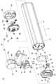
図2を参照して、バッテリ装置10は、バッテリ12と、バッテリ装着部14とを含む。Referring to FIG. 2, the
バッテリ12は、バッテリ本体16と、バッテリ本体16の一端部に設けられる取付部18とを含む。The
さらに図3~図5を参照して、取付部18は、溝20を含む。溝20は、係止部70(後述)が通るためにバッテリ12の矢印Aで示す長手方向からみて少なくとも矢印Bで示す取り外し方向に延びる。この実施形態では、矢印Bで示す取り外し方向は、バッテリ装着部14からバッテリ12を取り外す方向であり、バッテリ12の他端部側を支点としてバッテリ12を揺動する方向である(図9参照)。このように溝20は、バッテリ12の一端部に設けられる。溝20は、矢印Bで示す取り外し方向の上流側の方が下流側よりも幅広に形成される。溝20は、ガイド部22を含む。ガイド部22は、係止部70を案内するためにバッテリ12の矢印Aで示す長手方向からみて少なくとも矢印Bで示す取り外し方向に延びる。このようにガイド部22は、バッテリ12の一端部に設けられる。3 to 5, the mounting
取付部18には、溝20の下流側端部に連通するように貫通孔24aが設けられ、貫通孔24aの隣には貫通孔24bが設けられる。これによって、バッテリ12の一端部に、第1移動規制部としての段部26が設けられるとともに、略T字状の受け部28が設けられる。受け部28の下面は、バッテリ本体16の下面と略面一になるように形成される。また、溝20の下流側には、貫通孔24aの一部を仕切るように板状部材30が設けられる。A through
また、取付部18には、ガイド凸部84a,84b(後述)が嵌る一対のガイド溝部32a,32bが、バッテリ12の矢印Aで示す長手方向からみて矢印Bで示す取り外し方向に沿うように設けられる。このようにガイド溝部32a,32bは、溝20を挟んでバッテリ12の一端部に設けられる。ガイド溝部32a,32bはそれぞれ、第1係合部86a,86b(後述)と係合可能な第2係合部34a,34bを有する。第2係合部34a,34bはそれぞれ、ガイド溝部32a,32bに返しを設けることによって形成される。The mounting
取付部18の貫通孔24aには、略角形状の規制解除部36が設けられる。規制解除部36はスリット38と短冊状のガイド部40とを有する(図2、図3参照)。規制解除部36は、スリット38内に板状部材30が差し込まれ、ガイド部40が後述する裏蓋48のスリット46に嵌ることによって、段部26と受け部28との間に位置決めされ、矢印Bで示す取り外し方向に略直交する方向に往復動可能となる。バッテリ装着部14にバッテリ12が装着された状態では、規制解除部36は、矢印Bで示す取り外し方向において、後述する第2移動規制部74の操作部78より下流側にある。受け部28と規制解除部36との間には、第2付勢部としてのバネ42が介挿される。バネ42は、規制解除部36を非係止位置P2から係止位置P1に向かう方向に付勢する。このようにして、規制解除部36は、係止部70を係止位置P1から非係止位置P2に移動させるためにバッテリ12の一端部に設けられ、かつバッテリ12の矢印Cで示す短手方向に動作するように構成される。また、ガイド溝部32a,32bにはそれぞれ、ダンパ44が設けられる。ダンパ44は、たとえばゴムなどの弾性部材からなる。バッテリ12の装着時には、ダンパ44によって、ガイド凸部84a,84bがガイド溝部32a,32bから押し出される方向に押圧され(バッテリ12の挿入方向とは逆方向に付勢され)、それに伴って、係止部70が段部26を押圧する。これにより、バッテリ12のがたつきを抑制できる。A substantially
このような取付部18の裏面には、スリット46を有する裏蓋48が嵌められ、複数のボルト50によって固定される。その状態の取付部18は、裏蓋48を挟んでバッテリ本体16の一端部に、複数のボルト52によって取り付けられる。A
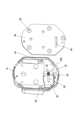
一方、図6を参照して、バッテリ本体16の他端部には、位置決め用の複数の凹部54が設けられ、端子56が露出するように設けられる。凹部54は、バッテリ12の回転防止部材としても機能する。On the other hand, referring to FIG. 6, the other end of the
図2を参照して、バッテリ装着部14は、それぞれバッテリ12の一端部および他端部を支持する第1支持部58および第2支持部60を有し、バッテリ12を着脱可能である。Referring to FIG. 2, the
図2および図5を参照して、第1支持部58は、上支持部62と、下支持部64とを含む。上支持部62と下支持部64とは、複数のボルト66によって一体化される。Referring to Figures 2 and 5, the
下支持部64は、凹部68を含む。凹部68には、係止部70が収容される。このように係止部70は、第1支持部58に設けられる。係止部70は、突出部72を有する。凹部68に係止部70が収容された状態では、突出部72は、下支持部64のバッテリ12側の端面から突出し、係止部70は、段部26に係止される係止位置P1と段部26に係止されない非係止位置P2との間を移動可能となる。この実施形態では、係止部70の係止位置P1および非係止位置P2は、バッテリ12の矢印Cで示す短手方向に沿って設けられる。なお、係止位置P1は、係止部70が段部26に係止されてバッテリ12がバッテリ装着部14から取り外し不能となる位置である。その一方、非係止位置P2は、係止部70が段部26に係止されずバッテリ12がバッテリ装着部14から取り外し可能となる位置である。後述する実施形態においても同様である。The
また、第1支持部58には、係止部70を係止位置P1に位置させて係止部70の非係止位置P2への移動を規制するために第2移動規制部74が設けられる。第2移動規制部74は、第1付勢部としてのバネ76と、操作部78と、ストッパ80とを含む。The
バネ76は、凹部68と係止部70との間に設けられる。バネ76によって、係止部70を非係止位置P2側から係止位置P1側に付勢する。また、上支持部62の側面に形成される貫通孔82に、操作部78が挿入される。第1支持部58内には、操作部78に連動しかつ係止部70に係止可能なストッパ80が収容される。図7(a),(b)に示すように、操作部78を回転させると、それに伴ってストッパ80が上下し、ストッパ80を係止部70に係止する位置に進退させることができる。The
また、図2および図5に戻って、第1支持部58には、一対のガイド凸部84a,84bが、バッテリ12の矢印Aで示す長手方向からみて矢印Bで示す取り外し方向に沿うように設けられる。ガイド凸部84a,84bは、係止部70よりも取り外し方向の上流側に設けられ、それぞれ第1係合部86a,86bを有する。第1係合部86a,86bはそれぞれ、ガイド凸部84a,84bに返しを設けることによって形成される。2 and 5, the
図2、図6および図10を参照して、第2支持部60は、収容部88と、蓋部90とを含む。収容部88と蓋部90とは、複数のボルト92によって一体化される。Referring to Figures 2, 6 and 10, the
収容部88は、貫通孔94を有し、貫通孔94にはケーブル96が挿通され、ケーブル96の端子98が蓋部90から露出するように位置決めされる。収容部88の内面と蓋部90の裏面との間には、複数のたとえばゴムからなる弾性部材100が介挿される。これによって、蓋部90は、収容部88に取り付けられた状態において、軸方向(収容部88に向かう方向)にやや変位可能となる。蓋部90の表面には、バッテリ12の位置決め用の複数の凹部54に嵌合可能な複数の凸部102が設けられる。The
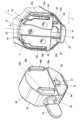
図8~図10(a),(b)を参照して、このような第1支持部58および第2支持部60は、ダウンチューブ2bの中空部2iにおいて、開口部2j近傍に設けられる。第1支持部58は、開口部2jの一端側近傍に複数のボルト104によって固定され、第2支持部60は、開口部2jの他端側近傍に複数のボルト106によって固定される。このようにして、バッテリ装着部14は、ダウンチューブ2b内に収まるように配置される。Referring to Figures 8 to 10(a) and (b), the
このようなバッテリ装着部14に対して、バッテリ12は、第2支持部60によって支持されるバッテリ12の他端部側を支点として、バッテリ12を揺動する方向に着脱される。このようにして、バッテリ12は、下パプ2bの中空部2iに対して開口部2jから出し入れ可能となる。バッテリ12は、バッテリ装着部14に装着されると、ダウンチューブ2b内に収まるように配置される。バッテリ12がバッテリ装着部14に装着された状態では、モータ7aに対して電気的に接続され、バッテリ12はモータ7aに対して電力を供給できる。The
図11(a)を参照して、バッテリ12がバッテリ装着部14に装着されかつ係止部70が係止位置P1に位置するとき、係止部70と段部26との掛かり代Xは、第1係合部86aと第2係合部34aとのクリアランスY1、および第1係合部86bと第2係合部34bとのクリアランスY2より大きい。これにより、図11(b)に示すように、第1係合部86a,86bがそれぞれ第2係合部34a,34bに係合する状態であっても、係止部70は段部26に係止される。Referring to FIG. 11(a), when the
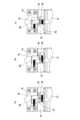
次に、図12~図14を参照して、操作部78および規制解除部36を操作したときのストッパ80および係止部70の動きについて説明する。Next, the movement of the
図12(a)、図13(a)および図14(a)に示す施錠状態では、係止部70はストッパ80によって係止されて係止位置P1から移動できない。In the locked state shown in Figures 12(a), 13(a) and 14(a), the locking
ついで、図12(b)、図13(b)および図14(b)を参照して、操作部78を回すと、ストッパ80は上昇して、ストッパ80の係止部70への係止は解除されて開錠状態となり、係止部70は移動可能となる。Next, referring to Figures 12(b), 13(b) and 14(b), when the operating
そして、図12(c),(d)、図13(c)および図14(c)を参照して、規制解除部36を押し込むと、それに伴って係止部70は係止位置P1から非係止位置P2へ移動する。このとき、規制解除部36を押し込みながら受け部28に指を引っ掛けることができるように、規制解除部36は、受け部28の操作部78側の側面より内側まで押し込まれる。これにより、段部26に対する係止部70の係止は解除され、係止部70は、バッテリ12の取付部18に形成された溝20を通ることが可能な状態になる。Referring to Figures 12(c), (d), 13(c) and 14(c), when the
図15を参照して、バッテリ装着部14からバッテリ12を取り外す動作について説明する。The operation of removing the
まず、図15(a)および(b)を参照して、上述のように、操作部78を回して開錠状態にした後、受け部28と規制解除部36とを矢印Cで示す短手方向からつまんで、規制解除部36を押し込む。すると、係止位置P1に位置する第1支持部58の係止部70が、非係止位置P2に移動する。ついで、バッテリ12を下方向へ引き抜く。すなわち、バッテリ装着部14に対して、バッテリ12を、バッテリ12の他端部側を支点として、矢印Bで示す取り外し方向に揺動させる。すると、図15(c)および(d)を参照して、係止部70は、バッテリ12の取付部18のガイド部22に沿って溝20を移動するとともに、バッテリ12のガイド溝部32a,32bから第1支持部58のガイド凸部84a,84bが抜き出されていく。さらに、図15(e)および(f)を参照して、係止部70が取付部18の溝20から離れるとともに、バッテリ12のガイド溝部32a,32bから第1支持部58のガイド凸部84a,84bが離れ、バッテリ12がバッテリ装着部14ひいては電動自転車1から取り外される。その後、操作部78を回して施錠状態にする。15(a) and (b), as described above, the operating
図16を参照して、バッテリ装着部14にバッテリ12を取り付けるとき動作について説明する。The operation of attaching the
まず、図16(a)および(b)を参照して、操作部78を回して開錠状態にした後、バッテリ12を上方向に押し込む。すなわち、バッテリ装着部14に対して、バッテリ12を、バッテリ12の他端部側を支点として、矢印Bで示す取り外し方向とは逆方向に揺動させる。すると、第1支持部58のガイド凸部84a,84bが、バッテリ12のガイド溝部32a,32bに挿入されるより先に、係止部70が、溝20に挿入される。さらに、図16(c)および(d)を参照して、係止部70が、ガイド部22に沿って溝20を移動するとともに、第1支持部58のガイド凸部84a,84bが、バッテリ12のガイド溝部32a,32bに挿入されていく。そして、図16(e)を参照して、係止部70が取付部18の溝20を通り過ぎて非係止位置P2まで進むと、係止部70はバネ76によってバッテリ12の矢印Cで示す短手方向に移動され、係止位置P1に至る。このとき、第1支持部58のガイド凸部84a,84bは、バッテリ12のガイド溝部32a,32bに奥まで挿入されるが、ダンパ44によってやや押し戻され、それに伴って、係止部70が段部26に押圧される。その後、操作部78を回して施錠状態にする。16(a) and (b), the operating
このような電動自転車1によれば、バッテリ装着部14にバッテリ12が装着された状態において、第1支持部58に設けられた第2移動規制部74が係止部70に作用することによって、第1支持部58に設けられた係止部70は係止位置P1に位置し、係止部70の非係止位置P2への移動が規制される。係止位置P1に位置する係止部70は、バッテリ12の一端部に設けられた第1移動規制部としての段部26によって係止されるので、バッテリ12をバッテリ装着部14から取り外すことができず、バッテリ装着部14へのバッテリ12の装着はロックされる。このような装着状態からバッテリ12を取り外すとき、第2移動規制部74による規制を解除して、係止部70を係止位置P1から非係止位置P2に移動させて、係止部70と段部26との係止状態を解消させた後、バッテリ12を取り出し方向に引き出してバッテリ装着部14から取り外す。このように、係止部70を係止位置P1から非係止位置P2に移動させた後、バッテリ12を引き出すだけで、バッテリ装着部14からバッテリ12を操作性良く取り外すことができる。With this type of
係止部70を段部26に係止させることによって、係止部70の取り外し方向への動きを容易に阻止することができる。By engaging the locking
第1付勢部としてのバネ76で係止部70を非係止位置P2側から係止位置P1側に付勢することによって、係止部70を係止位置P1に容易に位置させることができる。The
操作部78の操作にストッパ80を連動させて、ストッパ80を係止部70に係止する位置に容易に進退させることができる。したがって、操作部78の操作によって、係止部70を係止位置P1に位置させ、係止部70の非係止位置P2への移動を容易に抑制できる。The
係止部70が係止位置P1に位置するとき、操作部78を操作するだけでは、係止部70に対するストッパ80の係止を解除できるだけであり、係止部70はその場から移動しない。したがって、係止部70は段部26に係止されたままであり、バッテリ12の重力方向への移動を抑制でき、バッテリ12がバッテリ装着部14から不本意に取り外されることを抑制できる。When the locking
規制解除部36によって係止部70を係止位置P1から非係止位置P2に容易に移動させることができる。特に、係止部70を間接的に移動できるので、係止部70を直接操作できない場合に有効である。The
規制解除部36をバッテリ12の長手方向に動作させる場合、指を一方向にしか動かせず、規制解除部36を指でつまむ動作ができない。しかし、規制解除部36をバッテリ12の短手方向に動作させることによって、規制解除部36を指でつまむ動作が可能となり、バッテリ12の取り外し作業がさらに容易になる。When the
規制解除部36は、取り外し方向において、第2移動規制部74の操作部78より下流側にある。したがって、規制解除部36の操作と同時にバッテリ12を手で支持することができ、もう一方の手でバッテリ12を支える必要がなく、バッテリ12の取り外し作業が容易になる。バッテリ12をバッテリ装着部14から下方に取り外すときに特に効果的である。The
第2付勢部としてのバネ42によって規制解除部36を非係止位置P2から係止位置P1に向かう方向に付勢することによって、規制解除部36は、段部26と重ならない状態とすることができ、係止部70が入る空間を確保することができる。その結果、バッテリ12の装着時、係止部70が非係止位置P2から係止位置P1に移動する途中で係止部70が規制解除部36に当たらないため、係止部70の移動が円滑になる。また、規制解除部36を操作しやすい位置に配置させることができる。さらに、バッテリ12を取り外して単体で持ち運ぶとき、規制解除部36が一方向に付勢されているため、不快なガタつき音が出にくくなる。The
ガイド部22によって係止部70を案内させながら、バッテリ装着部14からバッテリ12を円滑に取り外すことができる。The
係止部70が溝20内を摺動することによって、バッテリ装着部14からバッテリ12を確実に取り外すことができる。The latching
溝12は、矢印Bで示す取り外し方向の上流側の方が下流側よりも幅広に形成されるので、係止部70を溝12に入れやすくなり、バッテリ12をバッテリ装着部14に容易に装着できる。The
ガイド溝部32a,32bにガイド凸部84a,84bが嵌ることによって、バッテリ装着部14に対してバッテリ12が傾いたり回転したりすることを抑制できる。By fitting the
ガイド溝部32a,32bとガイド部22とがバッテリ12の一端部に設けられ、ガイド凸部84a,84bと係止部70とが第1支持部58に設けられるので、バッテリ12の一端部側に注意を向ければよく、バッテリ12をバッテリ装着部14に容易に取り付けることができる。The
ガイド凸部84a,84bは、係止部70よりも取り外し方向の上流側に設けられる。したがって、係止部70をガイド部22に沿って移動させた後、ガイド凸部84a,84bをガイド溝部32a,32bに嵌めて移動させることができるので、バッテリ12をバッテリ装着部14に円滑に取り付けることができる。The
ガイド凸部84a,84bの第1係合部86a,86bがそれぞれ、ガイド溝部32a,32bの第2係合部34a,34bに係合することによって、バッテリ12の盗難を抑制できる。The
係止部70と段部26との掛かり代Xは、第1係合部86a,86bと第2係合部34a,34bとのクリアランスY1,Y2より大きいので、第1係合部86a,86bがそれぞれ第2係合部34a,34bに係合する状態であっても、係止部70は段部26に係止される。したがって、第1係合部86a,86bと第2係合部34a,34bとが係合しているか否かにかかわらず、係止位置P1に位置する係止部70を段部26に係止させることができ、係止部70と段部26との係止状態が不本意に解除されることを防止できる。The engagement allowance X between the locking
バッテリ12をバッテリ装着部14に取り付けたとき、ダンパ44によって係止部70と段部26とを相互に押し付けることができ、バッテリ12の取り外し方向のがたつきを抑制できる。When the
受け部28が略T字状に形成されることで指をかけやすく、バッテリ12を装着位置から引き出しやすくなる。The receiving
この発明に係るバッテリ装置10は、電動自転車1に好適に用いられる。The
上述の実施形態では、係止部70と規制解除部36とは別部品であったが、これに限定されない。規制解除部を兼ねる係止部が用いられてもよい。
図17~図19を参照して、規制解除部を兼ねる係止部70aを用いた実施形態について、バッテリ装着部14aからバッテリ12aを取り外す動作について説明する。 In the above embodiment, the locking
17 to 19, an operation of removing the
図17(a)、図18(a)および図19(a)に示す施錠状態では、係止部70aはストッパ80によって係止されて係止位置P1から移動できない。In the locked state shown in Figures 17(a), 18(a) and 19(a), the locking
ついで、図17(b)、図18(b)および図19(b)を参照して、操作部78を回して開錠状態にすると、ストッパ80は上昇して係止部70aへの係止は解除され、係止部70aは移動可能となる。Next, referring to Figures 17(b), 18(b) and 19(b), when the operating
そして、図17(c),(d)、図18(c)および図19(c)を参照して、係止部70aを押し込むと、係止部70aは係止位置P1から非係止位置P2へ移動する。これにより、段部26aに対する係止部70aの係止は解除され、係止部70aは、バッテリ12aの取付部18aに形成された溝20aを通ることが可能な状態になる。その後、係止部70aが溝20aを通過するように、バッテリ装着部14aに対して、バッテリ12aを、バッテリ12aの他端部側を支点として揺動させることによって、バッテリ装着部14aからバッテリ12aを取り外すことができる。Referring to Figures 17(c), (d), 18(c) and 19(c), when the locking
上述の実施形態では、係止部70の係止位置P1および非係止位置P2は、バッテリ12の短手方向に沿って設けられたが、これに限定されない。係止部の係止位置および非係止位置は、バッテリの長手方向に沿って設けられてもよい。In the above embodiment, the locking position P1 and the non-locking position P2 of the locking
図20および図21を参照して、係止部70bの係止位置P1および非係止位置P2がバッテリ12bの長手方向に沿って設けられる実施形態について、バッテリ装着部14bからバッテリ12bを取り外す動作について説明する。この場合、係止部70bは、バッテリ12bの矢印Aで示す長手方向に移動する。With reference to Figures 20 and 21, the operation of removing the
図20(a)、図21(a)に示す施錠状態では、係止部70bはストッパ80bによって係止されて係止位置P1から移動できない。In the locked state shown in Figures 20(a) and 21(a), the locking
ついで、図20(b)、図21(b)を参照して、操作部78を回して開錠状態にすると、ストッパ80bは上昇して係止部70bへの係止は解除され、係止部70bはバッテリ12bの矢印Aで示す長手方向へ移動可能となる。Next, referring to Figures 20(b) and 21(b), when the operating
そして、図20(c)、図21(c)を参照して、規制解除部36bを押し込むと、それに伴って係止部70bは係止位置P1から非係止位置P2へ移動する。これにより、段部26bに対する係止部70bの係止は解除され、係止部70bは、バッテリ12bの取付部18bに形成された溝20bを通ることが可能な状態になる。その後、係止部70bが溝20bを通過するように、バッテリ装着部14bに対して、バッテリ12bを、バッテリ12bの他端部側を支点として揺動させることによって、バッテリ装着部14bからバッテリ12bを取り外すことができる。20(c) and 21(c), when the
上述の実施形態では、バッテリ12はダウンチューブ2bから下方向に取り外されたが、これに限定されない。図21に示す電動自転車1aのように、バッテリ12は、ダウンチューブ2kから上方向に取り外されてもよい。すなわち、バッテリ12は、ダウンチューブ2kに設けられたバッテリ装置14に対して上側から着脱されてもよい。この場合、バッテリ12の略T字状の受け部28に指を引っかけることで、バッテリ12を容易に上方向へ引き上げることができる。In the above embodiment, the
上述の実施形態では、バッテリ装着部14にガイド凸部84a,84bが設けられ、バッテリ12にガイド溝部32a,32bが設けられたが、これに限定されない。バッテリにガイド凸部が設けられ、バッテリ装着部にガイド溝部が設けられてもよい。In the above embodiment, the
また、ガイド凸部およびガイド溝部は、第2支持部側(バッテリの他端部側)にのみ設けられてもよいし、第1支持部と第2支持部との間、すなわち下フレームおよびバッテリの外側面に設けられてもよい。The guide protrusion and guide groove may be provided only on the second support part side (the other end side of the battery), or may be provided between the first support part and the second support part, i.e., on the outer surface of the lower frame and the battery.
ガイド凸部およびガイド溝部のそれぞれの数は、2つに限定されず、任意でよい。ガイド凸部およびガイド溝部の数は、たとえば、1つずつでもよいし、3つずつ以上でもよい。The number of guide protrusions and guide grooves is not limited to two and may be any number. For example, the number of guide protrusions and guide grooves may be one each, or three or more each.
上述の実施形態では、バッテリ装着部14からのバッテリ12の取り外し方向は、バッテリ12の他端部側を支点としてバッテリ12を揺動する方向であったが、これに限定されない。バッテリ装着部からのバッテリの取り外し方向は、バッテリの長手方向に対する直交方向であってもよい。In the above embodiment, the direction in which the
上述の実施形態では、第2移動規制部74は、第1付勢部としてのバネ76と、操作部78と、ストッパ80とを含んだが、これに限定されない。第2移動規制部は、第1付勢部のみから構成されてもよい。この場合、係止部を押すことによって、第1付勢部による規制に抗して、係止部を係止位置P1から非係止位置P2に移動させることができる。また、第2移動規制部は、操作部およびストッパのみから構成されてもよい。In the above embodiment, the second
第1移動規制部は、段部に限定されず、係止部に係止可能な任意の手段を含む。The first movement restriction portion is not limited to a step portion, but may include any means capable of engaging with the engaging portion.
第1付勢部および第2付勢部は、バネに限定されず、ゴム等の弾性部材であってもよい。The first and second biasing parts are not limited to springs, but may be elastic members such as rubber.
図5を参照して、溝20を構成する直線状の側部Sは、必ずしも必要ではない。Referring to FIG. 5, the straight side portion S that constitutes the
上述の実施形態では、バッテリ装置10はダウンチューブ2b内に配置されたが、これに限定されない。バッテリ装置10は、パイプの表面に取り付けられてもよい。In the above embodiment, the
上述の実施形態では、バッテリ装置10はダウンチューブ2bに取り付けられたが、これに限定されない。バッテリ装置10は、たとえば、シートチューブ2cに取り付けられてもよく、バッテリ装置10が取り付けられるパイプは任意でよい。In the above embodiment, the
上述の実施形態では、この発明に係る電動自転車は電動アシスト自転車である場合について説明したが、これに限定されない。この発明に係る電動自転車は、バッテリからの電力を用いて走行可能な自転車であればよい。In the above embodiment, the electric bicycle according to the present invention has been described as an electrically assisted bicycle, but is not limited to this. The electric bicycle according to the present invention may be any bicycle that can be run using power from a battery.
電動自転車は、3輪以上の車輪を有していてもよい。An electric bicycle may have three or more wheels.
1,1a 電動自転車
10 バッテリ装置
12,12a,12b バッテリ
14,14a,14b バッテリ装着部
20,20a,20b 溝
22 ガイド部
26,26a,26b 段部
28 受け部
32a,32b ガイド溝部
34a,34b 第2係合部
36,36b 規制解除部
42,76 バネ
44 ダンパ
58 第1支持部
60 第2支持部
70,70a,70b 係止部
74 第2移動規制部
78 操作部
80,80b ストッパ
84a,84b ガイド凸部
86a,86b 第1係合部
A バッテリの長手方向
B バッテリの取り外し方向
C バッテリの短手方向
P1 係止位置
P2 非係止位置
X 係止部と段部との掛かり代
Y1,Y2 第1係合部と第2係合部とのクリアランス LIST OF
Claims (18)
Translated fromJapaneseそれぞれ前記バッテリの一端部および他端部を支持する第1支持部および第2支持部を有し、前記バッテリを着脱可能なバッテリ装着部と、
前記バッテリの一端部に設けられる第1移動規制部と、
前記第1移動規制部に係止される係止位置および前記第1移動規制部に係止されない非係止位置間を移動可能に前記第1支持部に設けられる係止部と、
前記係止部を前記係止位置に位置させて前記係止部の前記非係止位置への移動を規制するために、前記第1支持部に設けられる第2移動規制部とを備え、
前記バッテリ装着部からの前記バッテリの取り外し方向は、前記バッテリの前記他端部側を支点として前記バッテリを揺動する方向または前記バッテリの長手方向に対する直交方向であり、
前記係止部の前記係止位置および前記非係止位置は、前記バッテリの短手方向または長手方向に沿って設けられ、
前記係止位置は、前記係止部が前記第1移動規制部に係止されて前記バッテリが前記バッテリ装着部から取り外し不能となる位置であり、その一方、前記非係止位置は、前記係止部が前記第1移動規制部に係止されず前記バッテリが前記バッテリ装着部から取り外し可能となる位置であり、
前記第2移動規制部は、ストッパと、前記ストッパを前記係止部に係止する位置に進退させる操作部とを含み、前記係止部が前記第1移動規制部に係止された状態を維持しながら、前記操作部の操作によって、前記ストッパが前記係止部に係止される施錠状態と、前記ストッパの前記係止部への係止が解除される開錠状態とに、切替可能に構成される、バッテリ装置。 A battery;
a battery mounting section having a first support section and a second support section for supporting one end section and the other end section of the battery, respectively, to which the battery can be attached and detached;
A first movement restricting portion provided at one end of the battery;
a locking portion provided on the first support portion so as to be movable between a locking position where the locking portion is locked to the first movement restricting portion and a non-locking position where the locking portion is not locked to the first movement restricting portion;
a second movement restriction portion provided on the first support portion to position the locking portion at the locking position and restrict movement of the locking portion to the unlocking position,
a direction in which the battery is removed from the battery mounting portion is a direction in which the battery is swung around the other end side of the battery as a fulcrum or a direction perpendicular to a longitudinal direction of the battery,
The engaging position and the disengaging position of the engaging portion are provided along a short-side direction or a long-side direction of the battery,
the locking position is a position where the locking portion is locked to the first movement restricting portion so that the battery cannot be removed from the battery mounting portion, while the non-locking position is a positionwhere the locking portion is not locked to the first movement restricting portion so that the battery can be removed from the battery mounting portion,
The second movement restricting portion includes a stopper and an operating portion that moves the stopper forward and backward to a position where it engages with the engaging portion, and is configured to be switchable between a locked state in which the stopper is engaged with the engaging portion and an unlocked state in which the stopper is released from the engaging portion by operating the operating portion while maintaining the engaging portion engaged with the first movement restricting portion, in a battery device.
前記規制解除部は、前記取り外し方向において、前記第2移動規制部の前記操作部より下流側にある、請求項1から3のいずれかに記載のバッテリ装置。 a release portion provided at one end of the battery for moving the locking portion from the locking position to the unlocking position,
The battery device according to claim1 , wherein the restriction release portion is located downstream of the operationportion of the second movement restriction portion in the removal direction.
前記バッテリおよび前記バッテリ装着部の他方に設けられかつ前記ガイド凸部が嵌るガイド溝部とをさらに含む、請求項1から10のいずれかに記載のバッテリ装置。 a guide protrusion provided on either the battery or the battery mounting portion;
11. The battery device according to claim 1, further comprising a guide groove portion provided on the other of the battery and the battery mounting portion, into which the guide protrusion is fitted.
前記ガイド溝部は、前記バッテリの長手方向からみて前記取り外し方向に沿うように前記バッテリの一端部に設けられる、請求項11に記載のバッテリ装置。 the guide protrusion is provided on the first support portion so as to extend along the removal direction when viewed from a longitudinal direction of the battery,
The battery device according to claim11 , wherein the guide groove portion is provided at one end of the battery so as to extend along the removal direction when viewed in a longitudinal direction of the battery.
前記ガイド溝部は、前記第1係合部と係合可能な第2係合部を有する、請求項11から13のいずれかに記載のバッテリ装置。 The guide protrusion has a first engagement portion,
The battery device according to claim11 , wherein the guide groove portion has a second engagement portion engageable with the first engagementportion .
Priority Applications (3)
| Application Number | Priority Date | Filing Date | Title |
|---|---|---|---|
| JP2021126242AJP7701206B2 (en) | 2021-07-30 | 2021-07-30 | Battery device and electric bicycle |
| US17/873,233US12214651B2 (en) | 2021-07-30 | 2022-07-26 | Battery device and electric bicycle |
| DE102022119141.9ADE102022119141A1 (en) | 2021-07-30 | 2022-07-29 | Battery device and electric bicycle |
Applications Claiming Priority (1)
| Application Number | Priority Date | Filing Date | Title |
|---|---|---|---|
| JP2021126242AJP7701206B2 (en) | 2021-07-30 | 2021-07-30 | Battery device and electric bicycle |
Publications (2)
| Publication Number | Publication Date |
|---|---|
| JP2023020713A JP2023020713A (en) | 2023-02-09 |
| JP7701206B2true JP7701206B2 (en) | 2025-07-01 |
Family
ID=84890042
Family Applications (1)
| Application Number | Title | Priority Date | Filing Date |
|---|---|---|---|
| JP2021126242AActiveJP7701206B2 (en) | 2021-07-30 | 2021-07-30 | Battery device and electric bicycle |
Country Status (3)
| Country | Link |
|---|---|
| US (1) | US12214651B2 (en) |
| JP (1) | JP7701206B2 (en) |
| DE (1) | DE102022119141A1 (en) |
Families Citing this family (3)
| Publication number | Priority date | Publication date | Assignee | Title |
|---|---|---|---|---|
| DE102019204572B3 (en)* | 2019-04-01 | 2020-08-06 | Brose Antriebstechnik GmbH & Co. Kommanditgesellschaft, Berlin | Locking device for locking a power supply unit for a bicycle |
| NL2035116B1 (en)* | 2023-06-16 | 2024-12-20 | Koninklijke Gazelle N V | Bicycle battery assembly |
| USD1090832S1 (en)* | 2025-02-13 | 2025-08-26 | Kenneth Lin | Dual-layered microneedle carrier |
Citations (4)
| Publication number | Priority date | Publication date | Assignee | Title |
|---|---|---|---|---|
| JP2011207250A (en) | 2010-03-29 | 2011-10-20 | Sanyo Electric Co Ltd | Power-assisted bicycle |
| US20130241169A1 (en) | 2012-03-16 | 2013-09-19 | Specialized Bicycle Components, Inc. | Bicycle with integrated cable routing |
| JP2015140071A (en) | 2014-01-28 | 2015-08-03 | 株式会社シマノ | Power source holder for bicycle |
| JP2017043340A (en) | 2016-05-16 | 2017-03-02 | パナソニックIpマネジメント株式会社 | Battery device mounting structure and electric bicycle |
Family Cites Families (13)
| Publication number | Priority date | Publication date | Assignee | Title |
|---|---|---|---|---|
| US9914501B2 (en)* | 2014-03-18 | 2018-03-13 | Askoll Eva S.R.L. | Battery holder device for electric bicycle |
| TWM525556U (en)* | 2016-03-17 | 2016-07-11 | Td Hitech Energy Inc | Battery holder structure |
| JP7108914B2 (en) | 2018-03-02 | 2022-07-29 | パナソニックIpマネジメント株式会社 | Battery devices, motor units and electric bicycles |
| BE1026121B1 (en)* | 2018-03-20 | 2019-10-21 | Cowboy SA | ELECTRIC BICYCLE |
| US11572132B2 (en) | 2018-05-07 | 2023-02-07 | Trek Bicycle Corporation | Bicycle battery assembly |
| WO2020140089A1 (en)* | 2018-12-27 | 2020-07-02 | Uber Technologies, Inc. | Rechargeable battery and rechargeable battery holster for light electric vehicles |
| DE102019204572B3 (en)* | 2019-04-01 | 2020-08-06 | Brose Antriebstechnik GmbH & Co. Kommanditgesellschaft, Berlin | Locking device for locking a power supply unit for a bicycle |
| CN112550548B (en)* | 2019-09-10 | 2022-04-22 | 太普动力新能源(常熟)股份有限公司 | Locking structure and electric bicycle frame with same |
| TWI728524B (en)* | 2019-10-24 | 2021-05-21 | 達方電子股份有限公司 | Battery assembly |
| CN211766033U (en)* | 2020-01-20 | 2020-10-27 | 昆山睿恩新机电有限公司 | Electric vehicle battery box mounting structure |
| JP7411435B2 (en) | 2020-02-12 | 2024-01-11 | テルモ株式会社 | Liquid drug administration device |
| TWI759812B (en)* | 2020-07-31 | 2022-04-01 | 達方電子股份有限公司 | Battery assembly |
| DE202021100619U1 (en)* | 2021-02-09 | 2021-02-22 | Darfon Electronics Corp. | Battery assembly |
- 2021
- 2021-07-30JPJP2021126242Apatent/JP7701206B2/enactiveActive
- 2022
- 2022-07-26USUS17/873,233patent/US12214651B2/enactiveActive
- 2022-07-29DEDE102022119141.9Apatent/DE102022119141A1/enactivePending
Patent Citations (4)
| Publication number | Priority date | Publication date | Assignee | Title |
|---|---|---|---|---|
| JP2011207250A (en) | 2010-03-29 | 2011-10-20 | Sanyo Electric Co Ltd | Power-assisted bicycle |
| US20130241169A1 (en) | 2012-03-16 | 2013-09-19 | Specialized Bicycle Components, Inc. | Bicycle with integrated cable routing |
| JP2015140071A (en) | 2014-01-28 | 2015-08-03 | 株式会社シマノ | Power source holder for bicycle |
| JP2017043340A (en) | 2016-05-16 | 2017-03-02 | パナソニックIpマネジメント株式会社 | Battery device mounting structure and electric bicycle |
Also Published As
| Publication number | Publication date |
|---|---|
| US12214651B2 (en) | 2025-02-04 |
| US20230030226A1 (en) | 2023-02-02 |
| JP2023020713A (en) | 2023-02-09 |
| DE102022119141A1 (en) | 2023-02-02 |
Similar Documents
| Publication | Publication Date | Title |
|---|---|---|
| JP7701206B2 (en) | Battery device and electric bicycle | |
| US8201667B2 (en) | Braking system with single actuation for a stroller | |
| US6339699B1 (en) | Phone holder | |
| US20040124683A1 (en) | Seat slide device | |
| EP2586688A1 (en) | Charging port structure and straddled vehicle | |
| EP2913261B1 (en) | Power-assisted bicycle and battery case | |
| JP2018149881A (en) | Lock release lever mounting structure | |
| CN111301511A (en) | Steering column device | |
| JP6033666B2 (en) | Vehicle seat lock device | |
| US6942294B2 (en) | Child car seat | |
| JP2014121910A5 (en) | ||
| JP4301421B2 (en) | Bicycle battery locking device with auxiliary power | |
| TW593035B (en) | Motorcycle seat mounting structure | |
| JP3742834B2 (en) | Operation lever | |
| JP7573209B2 (en) | Lock unit and electric bicycle | |
| JP4502228B2 (en) | Battery detachable device for battery-assisted bicycle | |
| JP6199146B2 (en) | Electric assist bicycle | |
| JPH1191662A (en) | Locking device for motor bicycle stand | |
| JP2008196279A (en) | Lid opening operation apparatus | |
| CN1975077B (en) | Door handle device for vehicle | |
| JP4200839B2 (en) | Housing structure in vehicle | |
| JP3560782B2 (en) | Bicycle locking device with electric auxiliary power | |
| KR200172249Y1 (en) | Handle locking mechanism for low speed motor cycle | |
| JP3608909B2 (en) | Horseshoe tablets | |
| KR200175478Y1 (en) | Handle folder mechanism for low speed motor cycle |
Legal Events
| Date | Code | Title | Description |
|---|---|---|---|
| A621 | Written request for application examination | Free format text:JAPANESE INTERMEDIATE CODE: A621 Effective date:20240617 | |
| A977 | Report on retrieval | Free format text:JAPANESE INTERMEDIATE CODE: A971007 Effective date:20250213 | |
| A131 | Notification of reasons for refusal | Free format text:JAPANESE INTERMEDIATE CODE: A131 Effective date:20250225 | |
| A521 | Request for written amendment filed | Free format text:JAPANESE INTERMEDIATE CODE: A523 Effective date:20250422 | |
| TRDD | Decision of grant or rejection written | ||
| A01 | Written decision to grant a patent or to grant a registration (utility model) | Free format text:JAPANESE INTERMEDIATE CODE: A01 Effective date:20250617 | |
| A61 | First payment of annual fees (during grant procedure) | Free format text:JAPANESE INTERMEDIATE CODE: A61 Effective date:20250619 | |
| R150 | Certificate of patent or registration of utility model | Ref document number:7701206 Country of ref document:JP Free format text:JAPANESE INTERMEDIATE CODE: R150 |