JP7700985B2 - Circular dichroism spectrometer and polarizing element used therein - Google Patents
Circular dichroism spectrometer and polarizing element used thereinDownload PDFInfo
- Publication number
- JP7700985B2 JP7700985B2JP2021097787AJP2021097787AJP7700985B2JP 7700985 B2JP7700985 B2JP 7700985B2JP 2021097787 AJP2021097787 AJP 2021097787AJP 2021097787 AJP2021097787 AJP 2021097787AJP 7700985 B2JP7700985 B2JP 7700985B2
- Authority
- JP
- Japan
- Prior art keywords
- circularly polarized
- light
- polarized light
- handed circularly
- diffraction grating
- Prior art date
- Legal status (The legal status is an assumption and is not a legal conclusion. Google has not performed a legal analysis and makes no representation as to the accuracy of the status listed.)
- Active
Links
Images


Landscapes
- Spectrometry And Color Measurement (AREA)
- Investigating Or Analysing Materials By Optical Means (AREA)
Description
Translated fromJapanese本発明は、キラル化学や不斉化学等の分野における分析に用いられる円二色性分光測定装置およびこれに用いる偏光素子に関する。The present invention relates to a circular dichroism spectrometer used for analysis in fields such as chiral chemistry and asymmetric chemistry, and a polarizing element used therein.
近年、アルツハイマー病やパーキンソン病といったコンフォーメーション病と呼ばれるたんぱく質変性に基づく神経疾患に対する治療法の確立が急がれている。当分野においては、たんぱく質変性を的確に把握するため、キラル分子の光学活性を分析することが必須であり、そのために円二色性分光(円二色性スペクトル)測定技術が用いられている。In recent years, there has been an urgent need to establish treatments for neurological disorders caused by protein denaturation, known as conformational diseases, such as Alzheimer's disease and Parkinson's disease. In this field, it is essential to analyze the optical activity of chiral molecules in order to accurately understand protein denaturation, and for this purpose, circular dichroism spectroscopy (circular dichroism spectrum) measurement technology is used.
円二色性分光測定技術は、3次元的な異方性や高次構造が重要となる不斉合成の解析、たんぱく質の構造解析、および分子の自己組織化の解析、といった分野では特に欠かせない。この技術は物質の左右の円偏光に対する吸光度の差の波長分散を測定するものであり、深紫外からテラヘルツ領域に至るまで、いずれの波長帯においても、物質や分子の構造におけるキラリティや螺旋構造を反映した情報を得ることができる。Circular dichroism spectroscopy is particularly indispensable in fields such as the analysis of asymmetric synthesis, where three-dimensional anisotropy and higher-order structures are important, the structural analysis of proteins, and the analysis of molecular self-organization. This technique measures the wavelength dispersion of the difference in absorbance of a substance for left and right circularly polarized light, and can obtain information reflecting the chirality and helical structure of the structure of substances and molecules in any wavelength range, from deep ultraviolet to the terahertz region.
現在普及している円二色性スペクトルメータは、モノクロメータによる前分光方式を採用しており、波長毎に左右円偏光を生成する。このため、スペクトルデータの取得に長い時間(数分から10数分程度)を必要とし、測定対象に秒単位の比較的緩やかな変化が生じた場合であっても看過されてしまうことがある。そこで、パルス励起を利用した高速時間分解に基づく単一波長による円二色性測定が検討されている。しかしこの方法では、1回のパルス光による熱励起状態において単一の波長でしか円二色性が測定されないため、測定条件において大きな制約が生じる。Currently popular circular dichroism spectrometers use a monochromator-based prespectroscopic method, which generates left and right circularly polarized light for each wavelength. This requires a long time (several minutes to tens of minutes) to acquire spectral data, and even relatively gradual changes in the measurement target on the order of seconds may be overlooked. For this reason, single-wavelength circular dichroism measurement based on high-speed time resolution using pulse excitation is being considered. However, with this method, circular dichroism can only be measured at a single wavelength in a thermally excited state by a single pulse of light, which places significant restrictions on the measurement conditions.
一方で、近年、波長分散と偏光調整を同時に生じる偏光回折格子を利用した円二色性スペクトルメータの研究開発が進められている。例えば、白色光を試料に照射し、その透過光を、偏光回折格子を用いて右回り円偏光と左周り円偏光に分離して、それぞれのスペクトルを分析する方法がある(特許文献1、非特許文献1、2)。さらに精度を高めるためプリズムを用いてそれぞれの円偏光の波長分散性を調整する技術も検討されている(特許文献2)。On the other hand, in recent years, research and development has been progressing on circular dichroism spectrometers that use polarization diffraction gratings that simultaneously produce wavelength dispersion and polarization adjustment. For example, there is a method in which white light is irradiated onto a sample, and the transmitted light is separated into right-handed circularly polarized light and left-handed circularly polarized light using a polarization diffraction grating, and the spectra of each are analyzed (
しかし、前記円二色性分光測定技術は、高速性という点からは従来技術の課題を解決しているとも言えるが、試料に入射する光は円偏光ではなく直線偏光にならざるを得ず、そのため測定に誤差が生じるといった課題があった。Although the circular dichroism spectroscopy measurement technology described above can be said to solve the problems of conventional technology in terms of speed, the light incident on the sample must be linearly polarized rather than circularly polarized, which can lead to measurement errors.
本発明の一態様に係る円二色性分光測定装置は、測定対象に右回り円偏光と左回り円偏光を照射し、その透過光または反射光を偏光方向ごとに分光測定する円二色性分光測定装置であって、複数の波長成分を含む光束を発する光源と、前記光束を空間的に分割してそれぞれ右回り円偏光と左回り円偏光に変換する偏光素子と、前記測定対象を透過または反射した右回り円偏光と左回り円偏光をそれぞれ受光して分光測定を行う分光測定ユニットを具備した。A circular dichroism spectrometer according to one embodiment of the present invention is a circular dichroism spectrometer that irradiates a measurement object with right-handed circularly polarized light and left-handed circularly polarized light and performs spectroscopic measurement of the transmitted or reflected light for each polarization direction. The circular dichroism spectrometer includes a light source that emits a light beam containing multiple wavelength components, a polarizing element that spatially divides the light beam and converts it into right-handed circularly polarized light and left-handed circularly polarized light, respectively, and a spectroscopic measurement unit that receives the right-handed circularly polarized light and left-handed circularly polarized light that have been transmitted through or reflected from the measurement object and performs spectroscopic measurement.
前記偏光素子による1次回折光の波長ごとの光路を補正して測定対象に照射する補正部材をさらに具備してもよい。The device may further include a correction member that corrects the optical path of the first-order diffracted light for each wavelength by the polarizing element and irradiates the light onto the measurement object.
前記円二色性分光測定装置において、前記偏光素子は、格子ベクトル方向に連続的に回転する局所光軸を有する第1の偏光回折格子と、前記第1の偏光回折格子と等しい周期で前記格子ベクトル方向と逆方向に連続的に回転する局所光軸を有する第2の偏光回折格子を、同一平面上に対向して設けたものであってもよい。In the circular dichroism spectroscopic measurement device, the polarizing element may be a first polarizing diffraction grating having a local optical axis that rotates continuously in the direction of the grating vector, and a second polarizing diffraction grating having a local optical axis that rotates continuously in the opposite direction to the grating vector direction with a period equal to that of the first polarizing diffraction grating, the first polarizing diffraction grating being disposed opposite to the first polarizing diffraction grating on the same plane.
前記光束は直線偏光であってもよい。The light beam may be linearly polarized.
前記円二色性分光測定装置において、前記第1の偏光回折格子および前記第2の偏光回折格子における局所光軸の回転の周期は0.2μm以上100μm以下であってもよい。In the circular dichroism spectroscopic measurement device, the period of rotation of the local optical axis in the first polarization diffraction grating and the second polarization diffraction grating may be 0.2 μm or more and 100 μm or less.
前記円二色性分光測定装置において、前記第1の偏光回折格子および前記第2の偏光回折格子の厚みは0.1μm以上300μm以下であってもよい。In the circular dichroism spectrometer, the thickness of the first polarization diffraction grating and the second polarization diffraction grating may be 0.1 μm or more and 300 μm or less.
前記円二色性分光測定装置において、前記補正部材は前記1次回折光の波長に依存する回折角の差を逆補正する色分散材料により構成されてもよい。In the circular dichroism spectrometer, the correction member may be made of a color dispersion material that inversely corrects the difference in diffraction angle that depends on the wavelength of the first-order diffracted light.
前記円二色性分光測定装置において、空間的に分割された右回り円偏光と左回り円偏光の光束が測定対象の内部または反射面において全部または一部が重なるように、前記右回り円偏光の光束または前記左回り円偏光の光路を光束のいずれか一方または両方の光路を変更する集光素子をさらに具備してもよい。The circular dichroism spectrometer may further include a focusing element that changes the optical path of either the right-handed circularly polarized light beam or the left-handed circularly polarized light beam or both of the optical paths of the beams so that the spatially separated right-handed circularly polarized light beam and the left-handed circularly polarized light beam overlap in whole or in part inside the object to be measured or on the reflecting surface.
本発明の一態様に係る偏光素子は、前記円二色性分光測定装置に用いられる偏光素子であって、格子ベクトル方向に連続的に回転する局所光軸を有する第1の偏光回折格子と、前記第1の偏光回折格子と等しい周期で前記格子ベクトル方向と逆方向に連続的に回転する局所光軸を有する第2の偏光回折格子を、同一平面上に対向して設けたものである。The polarizing element according to one aspect of the present invention is a polarizing element used in the circular dichroism spectroscopy measurement device, and is configured to have a first polarizing diffraction grating having a local optical axis that rotates continuously in the direction of the grating vector, and a second polarizing diffraction grating having a local optical axis that rotates continuously in the opposite direction to the grating vector direction with the same period as the first polarizing diffraction grating, disposed opposite each other on the same plane.
前記偏光素子において、前記第1の偏光回折格子および前記第2の偏光回折格子における局所光軸の回転の周期は0.2μm以上100μm以下であってもよい。In the polarizing element, the period of rotation of the local optical axis in the first polarization diffraction grating and the second polarization diffraction grating may be 0.2 μm or more and 100 μm or less.
前記偏光素子において、前記第1の偏光回折格子および前記第2の偏光回折格子の厚みは0.1μm以上300μm以下であってもよい。In the polarizing element, the thickness of the first polarization diffraction grating and the second polarization diffraction grating may be 0.1 μm or more and 300 μm or less.
本発明の一態様によれば、測定対象に右回り円偏光と左回り円偏光を同時にしかも空間分離された状態で照射することができ、さらに右回り円偏光および左回り円偏光それぞれの分光分布を空間的に分離した状態で測定することができる。その結果、高速で正確な円二色性分光測定が可能となる。According to one aspect of the present invention, right-handed circularly polarized light and left-handed circularly polarized light can be irradiated simultaneously and spatially separated onto the object to be measured, and the spectral distributions of right-handed circularly polarized light and left-handed circularly polarized light can be measured in a spatially separated state. As a result, high-speed and accurate circular dichroism spectroscopy measurement is possible.
以下、本発明の一態様に係る実施の形態(以下、本実施の形態)について図面を参照しながら詳細に説明する。Below, an embodiment of the present invention (hereinafter, the present embodiment) will be described in detail with reference to the drawings.
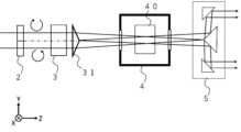
図1に、本実施の形態の円二色性分光測定装置のブロック図を示す。光路の特徴をより明確に示すため、偏光素子の格子方向(Y軸)から見たブロック図(同図(a))と、格子ベクトル方向(X軸)方向から見たブロック図(同図(b))を併記する。Figure 1 shows a block diagram of the circular dichroism spectroscopy measurement device of this embodiment. In order to more clearly show the characteristics of the optical path, the block diagram ((a)) seen from the lattice direction (Y axis) of the polarizing element and the block diagram ((b)) seen from the lattice vector direction (X axis) are shown together.
図1において、1は光源であり、複数の波長成分を含む光束を発するデバイスである。光源1は可視光領域のすべての波長の光を均等に含む白色光源であってもよい。また、一部の帯域においてガウシアンのような波長分布を有する光源であってもよい。また、特定の波長の複数の単色光を合成したものであってもよい。さらに、紫外光や赤外光、さらにはテラヘルツ波等、可視光領域外の光を含む光源であってもよい。また、本実施の形態において、前記光束は直線偏光であるとする。In FIG. 1, 1 is a light source, which is a device that emits a light beam containing multiple wavelength components.
2は偏光素子であり、前記光束に対し、図中X軸方向に波長分散を有する回折光を生じさせ、Y軸方向に右回りと左回りとを分けて円偏光に変換する機能を有する素子である。なお、偏光素子2の詳細な構成と動作については後述する。2 is a polarizing element, which generates diffracted light with wavelength dispersion in the X-axis direction of the light beam and converts the light into circularly polarized light by separating right-handed and left-handed light in the Y-axis direction. The detailed structure and operation of the polarizing
本実施の形態では、偏光素子2を透過した光束の1次回折光の一方のみが最終的に円二色性分光測定に用いられる。ただ、偏光素子2の回折格子の周期が一定であるため、光束を構成する波長(λ1>λ2>・・>λn)によって回折角が異なる。つまり、長波長ほど回折角が大きくなる。ここで生じる波長分散は後述の分光測定に利用される。その一方で、回折角に差があると分光測定ユニット6a、6bに到達する前に、長波長と短波長で光路にずれが生じる。このずれが大きいと分光分析に誤差が生じるおそれがある。そこで補正部材を用いて波長毎の光路を平行化するなどして、すべての波長の光が 分光測定ユニット6a、6bに到達するようにそれぞれの光路を補正する。 In this embodiment, only one of the first-order diffracted lights of the light beam transmitted through the polarizing
補正部材は、回折角の差を逆補正する色分散材料により構成されたプリズム等の光学部材よりなる補正部材3であってもよい。また、偏光素子2と分光測定ユニット6a、6bとの距離が比較的短ければ、図2に示すような可変スリット構造の補正部材30を用いて部分的に光路を揃えてもよい。つまりスリット幅を狭めれば波長分解能は得られるが、長波長および短波長側の回折光がある程度拡がると周辺にケラレが発生することがある。最悪、波長分布精度が低下する。スリット幅を拡げれば、中央部に各波長の光が重なる(白色化する)部分ができ、ケラレによる影響を軽減することができる。しかし一方で波長分解能は低下する。このように波長分解能と波長分布精度はトレードオフの関係にあるので、測定対象の性質に応じてスリット幅の最適値を適宜調整できるようにしてもよい。さらに、補正部材は、前記プリズム等を併用する構成であってもよい。The correction member may be a
補正部材3によって光路が揃えられた光束は、試料ホルダ4に保持された測定対象40に照射される。図1において、測定対象40を透過した光束は分離ユニット5によって右回り円偏光の光束と左回り円偏光の光束に分離され、それぞれが分光測定ユニット6a、6bに到達する。分光測定ユニット6a、6bはそれぞれの偏光に含まれるスペクトルを分析するマルチチャネル分光計であってもよい。The light beam, whose optical path has been aligned by the
分光測定ユニット6aには波長λ1~λnで分散が発生した右回り円偏光が、分光測定ユニット6bには同様に分散が発生した左回り円偏光が、それぞれ入射する。分光測定ユニット6a、6bはそれぞれの円偏光におけるスペクトルを測定し、コンピュータ7にその情報を転送する。コンピュータ7は、これらの情報から左右の円偏光に対する吸光度の差の波長分散を明らかにし、円二色性を算出する。 Right-handed circularly polarized light with dispersion occurring at wavelengths λ1 to λn is incident on the spectroscopic measurement unit 6a, and left-handed circularly polarized light with similar dispersion is incident on the spectroscopic measurement unit 6b. The spectroscopic measurement units 6a and 6b measure the spectra of the respective circularly polarized light and transfer the information to the computer 7. The computer 7 determines the wavelength dispersion of the difference in absorbance for the left-handed and right-handed circularly polarized light from this information and calculates circular dichroism.
以下に具体的な算出手段を示す。まず、試料ホルダ4に測定対象40を収めない状態で、右回り円偏光のスペクトル強度IR(λ)と左回り円偏光のスペクトル強度IL(λ)を測定する。これをバックグラウンドスペクトル強度と呼ぶ。次に、測定対象40を試料ホルダ4に収め、右回り円偏光の透過スペクトル強度IR’(λ)と左回り円偏光の透過スペクトル強度IL’(λ)を測定する。これら4つのスペクトルが測定されれば、右回り円偏光および左回り円偏光の吸光度AR(λ)およびAL(λ)はそれぞれ以下の計算式により計算される。
円二色性スペクトル測定においては、この左右円偏光の吸光度の差を楕円率角θで表すのが一般的である。すなわち、上式で求めた左右円偏光の吸光度から楕円率角θを、各波長λ(=λ1、λ2・・・λn)において、下記の式を用いて計算することで、円二色性スペクトルを導出することができる。
コンピュータ7は、分光測定ユニット6a、6bの出力を受け、予め設定したスペクトル更新時間毎に、予め設定した左右円偏光のスペクトル強度積分時間だけ分光測定を行う。この測定により得られた積算スペクトル強度から、予め測定および保存されていたバックグラウンドスペクトル強度を用いて、円二色性スペクトルを算出する。その結果をモニターに表示し、さらにデータを保存する。以上の処理により、逐次的に円二色性スペクトルの変化を高速に測定して記録することができる。The computer 7 receives the output of the spectroscopic measurement units 6a and 6b, and performs spectroscopic measurement for a preset spectral intensity integration time for left and right circularly polarized light at each preset spectrum update time. From the integrated spectral intensity obtained by this measurement, the computer calculates a circular dichroism spectrum using the background spectral intensity that was measured and stored in advance. The result is displayed on the monitor, and the data is also saved. Through the above process, it is possible to sequentially measure and record changes in the circular dichroism spectrum at high speed.
なお、光源1の出力の時間的揺らぎを補正するために、光源1から放射される光を二分し、一方を分光測定に用い、もう一方を時間的揺らぎの補正を行う参照光として用いる、いわゆる「ダブルビーム方式」を適用することもできる。この場合、後述の図5において使用していない反対側の回折光(+1次光)を参照光として用いることで、精度の高い高速測定を実施できる。In order to correct the temporal fluctuation of the output of the
ここで、本実施の形態における偏光素子2の構成と作用について詳しく説明する。図3に本実施の形態における偏光素子2の構成を示す。図3において、偏光素子2は、X軸(格子ベクトルk)方向に連続的に回転する局所光軸20aを有する(第1の)偏光回折格子2aと、偏光回折格子2aと等しい周期でX軸逆方向(格子ベクトルxk方向)に連続的に回転する局所光軸20bを有する(第2の)偏光回折格子2bとが、同一平面上に対向して設けられたものである。いずれの偏光回折格子においても局所光軸が360°回転する距離が回折格子の間隔に相当する。ここで、図3において楕円で示された局所光軸20a、20bは、屈折率の一軸異方性を表しており、この楕円の長軸は遅相軸を、短軸は進相軸をそれぞれ意味する。Here, the configuration and function of the
一般に、互いに逆回りの円偏光の干渉電界は、大きさの等しい直線偏光の偏光方位角が連続的に回転した周期性を有する。光配向性の液晶薄膜の表面上にこのような干渉電界が生じたとすると、この電界分布に沿って局所光軸が配向する。このとき、大きさが同じで複屈折(Δn)の向きが格子ベクトル(k)方向に連続的に回転した回折格子となる。このような回折格子は直交円偏光による偏光ホログラムとして知られている。In general, the interference electric field of counter-directional circularly polarized light has a periodicity in which the polarization azimuth angle of linearly polarized light of equal magnitude is continuously rotated. If such an interference electric field is generated on the surface of a photo-alignable thin liquid crystal film, the local optical axis will be oriented along this electric field distribution. At this time, a diffraction grating is formed in which the birefringence (Δn) direction is continuously rotated in the direction of the lattice vector (k) with the same magnitude. This type of diffraction grating is known as a polarization hologram using orthogonal circularly polarized light.
この格子内の屈折率変調(Δn)を図4のように成分分解すると、左右円偏光に対するブレーズド格子が対向して重畳していることと等価であると考えられる。従って、図5に示すように、入射光に含まれる左右の円偏光成分が、±1次回折光にそれぞれ分離して回折される特性(偏光分離特性)を有している。直線偏光は振幅が等しい左右円偏光の足し合わせであると考えられるので、この直線偏光を入射した場合、±1次回折光とも等しい効率で正確な左右円偏光が同時に生じる。When the refractive index modulation (Δn) in this grating is broken down into components as shown in Figure 4, it can be considered equivalent to a blazed grating for left and right circularly polarized light superimposed on each other. Therefore, as shown in Figure 5, the left and right circularly polarized components contained in the incident light have the property of being diffracted separately into ±1st order diffracted light (polarization separation property). Since linearly polarized light can be considered to be the sum of left and right circularly polarized light with equal amplitudes, when this linearly polarized light is incident, accurate left and right circularly polarized light is simultaneously generated with equal efficiency as the ±1st order diffracted light.
この回折特性を結合波理論に基づいて説明すると次のようになる。すなわち、入射光の回転電界成分(円偏光成分)が、回折格子を形成する周期的に回転した複屈折変調(局所光軸の変調)に結合するため、±1次回折光は純粋な左右円偏光成分のみがそれぞれ回折したものとなり、非調和成分は高次光として回折される。このような理由から、この±1次回折光を円二色性スペクトルの測定に適用している。しかしながら、±1次回折光は空間的に離れているため、左右円偏光を同一スポット内に得ることはできない。These diffraction characteristics can be explained based on coupled wave theory as follows. That is, the rotating electric field component (circularly polarized component) of the incident light is coupled to the periodically rotated birefringence modulation (modulation of the local optical axis) that forms a diffraction grating, so the ±1st order diffracted light is composed of only the pure left and right circularly polarized components diffracted, while the non-harmonic components are diffracted as higher order light. For this reason, this ±1st order diffracted light is used to measure circular dichroism spectra. However, because the ±1st order diffracted light is spatially separated, left and right circularly polarized light cannot be obtained in the same spot.
そこで本実施の形態においては、図3に示すように、互いに逆方向の格子ベクトルを有する偏光回折格子2a、2bを対向して配置することにより、この課題を解決している。すなわち、図5に示されるように、回折角の波長分散(λ1~λn)はそれぞれの偏光回折格子において格子ベクトルに沿って平行(X軸方向)に生じる。このとき、偏光方向で分離されている垂直(Y軸)方向には影響を与えない。結果として、分光された左右円偏光を4象限同時に生成できる。この光を測定対象40に照射し、出射光を後分光することで、先述のように円二色性スペクトルを得ることができる。 In this embodiment, this problem is solved by arranging
偏光回折格子2a、2bは、複屈折を有する回折格子であれば特に限定されない。実施例3で示すようなパターンのナノインプリントを施した樹脂によって構成された構造複屈折を利用したものであってもよい。また、ガラス、石英、サファイア等を光学基板として、これに微細加工を施して構造複屈折を発現させたものであってもよい。また、高分子が配向することで生じる複屈折を用いたものであってもよい。好ましくは液晶分子の配向分布を利用したものであってもよい。The
以上、本実施の形態において、特殊な偏光回折格子2a、2bの格子ベクトル(k)を図3のように対向させて配置することで、波長毎に展開された左右円偏光を同時に空間的に展開することが可能となる。なお、空間展開した光束を実際に観測した実験結果は後述の実施例1に示す。As described above, in this embodiment, by arranging the grating vectors (k) of the special
回折格子の周期は0.2μm以上100μm以下であるのが好ましい。先述のように、偏光回折格子2aおよび偏光回折格子2bにおける局所光軸(液晶分子等)の回転の周期(360°回転)は回折格子の周期(Λ)に相当する。回折格子の周期が長いと回折角が小さくなり、分光分析の精度が落ちる。逆に短いと、長波長側が回折限界を超えることがある。The period of the diffraction grating is preferably 0.2 μm or more and 100 μm or less. As mentioned above, the period of rotation (360° rotation) of the local optical axis (liquid crystal molecules, etc.) in the polarization diffraction grating 2a and the
偏光回折格子2aおよび偏光回折格子2bの厚みは、回折効率すなわち1次光の強度に関係する。しかし厚すぎると光束の透過率に影響する。厚みとしては、0.1μm以上300μm以下であることが好ましい。The thickness of the
図6に、分光測定ユニット6a、6bに到達する光束の概念図を示す。分光測定ユニット6aには偏光回折格子2aで回折された波長λ1~λnの光束が分散して入射する。また、分光測定ユニット6bには偏光回折格子2bで回折された波長λ1~λnの光束が分散して入射する。 6 shows a conceptual diagram of light beams reaching spectroscopic measurement units 6a and 6b. Light beams of wavelengths λ1 to λn diffracted by polarization grating 2a are dispersed and incident on spectroscopic measurement unit 6a. Light beams of wavelengths λ1 to λn diffracted by polarization grating 2b are dispersed and incident on spectroscopic measurement unit 6b.
以上、本実施の形態によれば、偏光回折格子2aおよび偏光回折格子2bで構成される偏光素子2を用いることで測定対象40に右回り円偏光と左回り円偏光を同時にしかも空間分離された状態で照射することができ、さらに右回り円偏光および左回り円偏光それぞれの分光分布を空間的に分離した状態で測定することができる。その結果、高速で正確な円二色性分光測定が可能となる。As described above, according to this embodiment, by using the
なお、本実施の形態において、分光の光路の補正のために補正部材3または補正部材30を用いたが、装置全体の仕様によっては、これらを省略してもよい。例えば、偏光回折格子2自体も、後述の実施例1(図8)に示す様に、ある程度の分光能力を有しているため、対象物の均質性が高く白色スポット化が不要で且つ波長分解能が多少低くてもよい場合には、積極的にこの偏光回折格子による波長分散作用を利用することができる。このとき補正部材は用いなくてもよい。また、分光測定ユニット6a、6bはCCD撮像素子のような民生機器用の部品でもよく、装置のコストを大幅に低減することができる。In this embodiment, the
また、本実施の形態において、測定対象40は溶液や懸濁液等の透過性の液体やゲルであってもよい。このとき試料ホルダ4は透明な石英や樹脂で形成された容器であってもよい。測定対象40が固体の場合あるいは金属薄膜等のように鏡面を有する場合は、試料ホルダ4はクランプ機能を有した機構部品であってもよい。In this embodiment, the
さらに、図7に示すように、右回り円偏光と左回り円偏光の光束が、測定対象40の内部で重なるように、集光素子31を設けてもよい。本実施の形態においては、集光素子30は屋根型のプリズムにより構成されている。この集光素子31をプリズムの稜線が両偏光の分割線と一致するように配置すれば、右回り円偏光の光束は図面上で下側に、左回り円偏光の光束は上側に、それぞれ屈折し、これらの円偏光は測定対象の位置でほぼ重なり合う。その結果、サイズの小さい測定対象や、均一性が低い測定対象に対する測定の精度を高めることができる。一旦重なり合った両偏光の光束は測定対象40を離れた後、再び発散し、分離ユニット5によってそれぞれの円偏光に分けられる。両偏光の重なり方であるが、全部が重なり合ってもよく、一部が重なり合ってもよい。また、図7のように両円偏光を互いに反対方向に屈折させてもよいが、一方を直進させてもよい。Furthermore, as shown in FIG. 7, a light collecting element 31 may be provided so that the right-handed circularly polarized light beam and the left-handed circularly polarized light beam overlap inside the
以下、本発明の実施例について説明する。
(実施例1)
本実施例では、試作した偏光素子による回折光を実際に測定した実験と結果について説明する。本実施例において、偏光素子は、縦×横×厚みが12mm×24mm×250μmの液晶板2枚から試作されたものである。それぞれの液晶板に格子ベクトルが互いに逆方向となるように液晶分子配向分布を持たせ偏光回折格子とした。これらの偏光回折格子を、格子ベクトルが互いに対向した配置で、同一平面上で貼り合わせて偏光素子とした。各偏光回折格子において、格子周期(液晶分子の360°回転周期)は2.5μmとした。光源はオーシャンオプティクス社製の白色光源(品番DH-2000-BAL)を用いた。この白色光を、試作した偏光素子に照射し、その透過光をCCDカメラで撮影した。結果を図8に示す。 Examples of the present invention will now be described.
Example 1
In this example, an experiment and results of actually measuring diffracted light by a prototype polarizing element will be described. In this example, the polarizing element was prototyped from two liquid crystal plates with a length x width x thickness of 12 mm x 24 mm x 250 μm. Each liquid crystal plate was given a liquid crystal molecular orientation distribution so that the lattice vectors were in the opposite directions to each other to form a polarizing diffraction grating. These polarizing diffraction gratings were laminated on the same plane with the lattice vectors facing each other to form a polarizing element. In each polarizing diffraction grating, the lattice period (360° rotation period of the liquid crystal molecules) was 2.5 μm. The light source used was a white light source manufactured by Ocean Optics (product number DH-2000-BAL). This white light was irradiated onto the prototype polarizing element, and the transmitted light was photographed with a CCD camera. The results are shown in FIG. 8.
図8(a)は偏光素子によって生じた回折光を撮影したものである。中心に0次光が、右にそれぞれ色分散を有する1次回折光(+1次光と-1次光)が確認される。この写真からは偏光の違いは分からないので、さらに偏光フィルターを通して回折光を撮影した。結果を同図(b)に示す。左側の回折光(-1次光)に着目すると、右回り円偏光が上半分に、左回りの円偏光が下半分に分割されていることが確認された。Figure 8 (a) shows an image of diffracted light produced by a polarizing element. Zeroth order light can be seen in the center, and first order diffracted light (+1st order light and -1st order light) with chromatic dispersion can be seen to the right. Since the difference in polarization cannot be seen from this image, the diffracted light was also photographed through a polarizing filter. The result is shown in Figure 8 (b). Focusing on the diffracted light on the left (-1st order light), it can be seen that it is split into right-handed circularly polarized light in the upper half and left-handed circularly polarized light in the lower half.
(実施例2)
本実施例では、本実施の形態の円二色性分光測定装置の時間応答性について検証を行った実験と、その結果について説明する。本実施の形態において、光源および偏光素子は実施例1と同じ構成のものを用いた。1次回折光(-1次光)の右回り円偏光と左回り円偏光にそれぞれ対応する分光測定ユニット(6a、6b)にはオーシャンオプティクス社製のマルチチャネル分光計(品番FLAME-S-UV-VIS-ES)を使用した。Example 2
In this example, an experiment was performed to verify the time response of the circular dichroism spectroscopic measurement device of this embodiment, and the results are described. In this embodiment, the light source and the polarizing element used were the same as those in Example 1. A multichannel spectrometer (product number FLAME-S-UV-VIS-ES) manufactured by Ocean Optics was used as the spectroscopic measurement units (6a, 6b) corresponding to the right-handed circularly polarized light and the left-handed circularly polarized light of the first-order diffracted light (-1st order light), respectively.
測定対象として520nmから560nmの波長帯に選択的円偏光反射を生じるカイラルネマチック液晶セルを用いた。この液晶セルを試料ホルダ4に固定し、ヒーター付きのファンで約40℃の熱風を吹き付けながら加熱した。加熱前後の外観写真を図9に示す。当初緑色に目視できた液晶セルは加熱後に脱色した。加熱中、300msec間隔で実施例1の装置を用いて円二色性(CD)分光特性を測定した。これを間引いて、4.2sec毎のスペクトルの変化をグラフ化した。1回の測定に要する時間は20sec程度であった。測定結果を図10に示す。なお、同図において、横軸は波長を、縦軸は円二色性(CD)値を示す。なお、スペクトルの時間変化を分かりやすく示すため、縦軸は任意単位(arb unit)としている。A chiral nematic liquid crystal cell that selectively reflects circularly polarized light in the wavelength range from 520 nm to 560 nm was used as the measurement target. This liquid crystal cell was fixed to a
約20secの間に、計6回のCD分光特性を図ることができたが、図10より明らかなように、この間CDスペクトル特性は大きく変化している。言い換えれば、本実施の形態の円二色性分光測定装置を用いれば、このように急激に変化する円二色性(CD)分光特性がリアルタイムで測定できることが実証された。A total of six CD spectral characteristics were measured over a period of approximately 20 seconds, and as is clear from FIG. 10, the CD spectral characteristics changed significantly during this period. In other words, it was demonstrated that the circular dichroism spectroscopic measurement device of this embodiment can be used to measure such rapidly changing circular dichroism (CD) spectral characteristics in real time.
(実施例3)
図11に、構造複屈折を有する偏光回折格子(格子間隔6.4μm)のナノインプリント用SiマスターモールドのSEM画像写真を示す。左側の写真の倍率は5000であり、右側の写真の倍率は60000である。左側の写真は、局所光軸が互いに逆方向に回転する偏光回折格子(2a、2bに相当)の境界付近を撮影したものである。右側の拡大画像において、おおむね200nmピッチの溝が形成されていることが確認された。このマスターモールドに形成されたパターンを樹脂材料に転写すれば、偏光回折格子を多数複製することができる。Example 3
FIG. 11 shows an SEM image of a Si master mold for nanoimprinting of a polarizing diffraction grating (grating interval 6.4 μm) having structural birefringence. The magnification of the left photograph is 5000, and the magnification of the right photograph is 60000. The left photograph was taken near the boundary of a polarizing diffraction grating (corresponding to 2a and 2b) whose local optical axes rotate in opposite directions. In the enlarged image on the right, it was confirmed that grooves with a pitch of approximately 200 nm were formed. If the pattern formed in this master mold is transferred to a resin material, a large number of polarizing diffraction gratings can be replicated.
本発明を用いれば、円二色性分光特性を迅速かつ正確に測定することでキラル分子の光学活性をリアルタイムで分析することができる。この機能は、アルツハイマー病やパーキンソン病等のコンフォーメーション病と呼ばれるたんぱく質変性に基づく神経疾患の診断や治療に活用することができる。By using this invention, the optical activity of chiral molecules can be analyzed in real time by quickly and accurately measuring the circular dichroism spectroscopic properties. This function can be used for the diagnosis and treatment of neurological disorders based on protein degeneration, known as conformational diseases, such as Alzheimer's disease and Parkinson's disease.
1 光源
2 偏光素子
2a、2b 偏光回折格子
20a、20b 局所光軸
3 補正部材
30 補正部材(可変スリット構造)
31 集光素子
4 試料ホルダ
40 測定対象
5 分離ユニット
6a、6b 分光測定ユニット
7 コンピュータ1
31
Claims (11)
Translated fromJapanese複数の波長成分を含む光束を発する光源と、
前記光束を空間的に分割してそれぞれ右回り円偏光と左回り円偏光に変換する偏光素子と、
前記測定対象を透過または反射した右回り円偏光と左回り円偏光をそれぞれ受光して分光測定を行う分光測定ユニットと、
前記偏光素子による1次回折光の波長ごとの光路を補正して測定対象に照射する補正部材と、
を備える円二色性分光測定装置。 A circular dichroism spectroscopic measurement device that irradiates a measurement object with right-handed circularly polarized light and left-handed circularly polarized light and performs spectroscopic measurement of the transmitted light or reflected light for each polarization direction,
A light source that emits a light beam including a plurality of wavelength components;
a polarizing element that spatially divides the light beam and converts it into right-handed circularly polarized light and left-handed circularly polarized light, respectively;
a spectroscopic measurement unit that receives right-handed circularly polarized light and left-handed circularly polarized light transmitted through or reflected by the measurement object and performs spectroscopic measurement;
a correction member that corrects an optical path for each wavelength of the first-order diffracted light by the polarizing element and irradiates the first-order diffracted light onto a measurement object;
A circular dichroism spectrometercomprising :
複数の波長成分を含む光束を発する光源と、
前記光束を空間的に分割してそれぞれ右回り円偏光と左回り円偏光に変換する偏光素子と、
前記測定対象を透過または反射した右回り円偏光と左回り円偏光をそれぞれ受光して分光測定を行う分光測定ユニットと、
を備え、
前記偏光素子は、格子ベクトル方向に連続的に回転する局所光軸を有する第1の偏光回折格子と、前記第1の偏光回折格子と等しい周期で前記格子ベクトル方向と逆方向に連続的に回転する局所光軸を有する第2の偏光回折格子を、前記光源が発する前記光束の光軸方向をZ軸方向、前記Z軸方向に直交し、回折光の波長分散を生じる方向をX軸方向、前記Z軸方向と前記X軸方向とに直交する方向をY軸方向とする場合、前記Y軸方向に対向して積層したものである円二色性分光測定装置。A circular dichroism spectroscopic measurement device that irradiates a measurement object with right-handed circularly polarized light and left-handed circularly polarized light and performs spectroscopic measurement of the transmitted light or reflected light for each polarization direction,
A light source that emits a light beam including a plurality of wavelength components;
a polarizing element that spatially divides the light beam and converts it into right-handed circularly polarized light and left-handed circularly polarized light, respectively;
a spectroscopic measurement unit that receives right-handed circularly polarized light and left-handed circularly polarized light transmitted through or reflected by the measurement object and performs spectroscopic measurement;
Equipped with
The polarizing element is a circular dichroism spectroscopic measurement device in which a first polarization diffraction grating having a local optical axis that rotates continuously in a grating vector direction and a second polarization diffraction grating having a local optical axis that rotates continuously in the opposite direction to the grating vector direction with a period equal to that of thefirst polarization diffraction grating are stacked opposite to each other in the Y-axis direction, where the optical axis direction of the light beam emitted by the light source is a Z-axis direction, a direction perpendicular to the Z-axis direction and in which wavelength dispersion of the diffracted light occurs is an X-axis direction, and a directionperpendicular to the Z-axis direction and the X-axis directionis a Y-axis direction.
複数の波長成分を含む光束を発する光源と、
前記光束を空間的に分割してそれぞれ右回り円偏光と左回り円偏光に変換する偏光素子と、
前記測定対象を透過または反射した右回り円偏光と左回り円偏光をそれぞれ受光して分光測定を行う分光測定ユニットと、
を備える円二色性分光測定装置に用いられる偏光素子であって、格子ベクトル方向に連続的に回転する局所光軸を有する第1の偏光回折格子と、前記第1の偏光回折格子と等しい周期で前記格子ベクトル方向と逆方向に連続的に回転する局所光軸を有する第2の偏光回折格子を、前記光源が発する前記光束の光軸方向をZ軸方向、前記Z軸方向に直交し、回折光の波長分散を生じる方向をX軸方向、前記Z軸方向と前記X軸方向とに直交する方向をY軸方向とする場合、前記Y軸方向に対向して積層したものである偏光素子。A circular dichroism spectroscopic measurement device that irradiates a measurement object with right-handed circularly polarized light and left-handed circularly polarized light and performs spectroscopic measurement of the transmitted light or reflected light for each polarization direction,
A light source that emits a light beam including a plurality of wavelength components;
a polarizing element that spatially divides the light beam and converts it into right-handed circularly polarized light and left-handed circularly polarized light, respectively;
a spectroscopic measurement unit that receives right-handed circularly polarized light and left-handed circularly polarized light transmitted through or reflected by the measurement object and performs spectroscopic measurement;
a first polarization diffraction grating having a local optical axis that rotates continuously in a grating vector direction and a second polarization diffraction grating having a local optical axis that rotates continuously in an opposite direction to the gratingvector direction with a period equal to that of the first polarization diffraction grating, the optical axis directionof the light beam emitted by the light source is defined as a Z-axis direction, a direction orthogonal to the Z-axis direction and in which wavelength dispersion of the diffracted light occurs is defined as an X-axis direction, and a direction orthogonal to the Z-axis direction and the X-axis direction is defined as a Y-axisdirection.
11. The polarizing element accordingto claim 9, wherein the first polarization diffraction grating and the second polarization diffraction gratinghave a thicknessin the Z-axis direction of 0.1 μm or more and 300 μm or less.
Priority Applications (1)
| Application Number | Priority Date | Filing Date | Title |
|---|---|---|---|
| JP2021097787AJP7700985B2 (en) | 2021-06-11 | 2021-06-11 | Circular dichroism spectrometer and polarizing element used therein |
Applications Claiming Priority (1)
| Application Number | Priority Date | Filing Date | Title |
|---|---|---|---|
| JP2021097787AJP7700985B2 (en) | 2021-06-11 | 2021-06-11 | Circular dichroism spectrometer and polarizing element used therein |
Publications (2)
| Publication Number | Publication Date |
|---|---|
| JP2022189286A JP2022189286A (en) | 2022-12-22 |
| JP7700985B2true JP7700985B2 (en) | 2025-07-01 |
Family
ID=84533080
Family Applications (1)
| Application Number | Title | Priority Date | Filing Date |
|---|---|---|---|
| JP2021097787AActiveJP7700985B2 (en) | 2021-06-11 | 2021-06-11 | Circular dichroism spectrometer and polarizing element used therein |
Country Status (1)
| Country | Link |
|---|---|
| JP (1) | JP7700985B2 (en) |
Families Citing this family (2)
| Publication number | Priority date | Publication date | Assignee | Title |
|---|---|---|---|---|
| CN118274964A (en)* | 2024-04-01 | 2024-07-02 | 中国人民解放军国防科技大学 | Polarization grating-based broad spectrum polarization feature detection system and method |
| CN118129908B (en)* | 2024-05-08 | 2024-07-09 | 中国科学院长春光学精密机械与物理研究所 | Polarization imaging spectrometer based on polarization grating spectral and polarization spectrum reconstruction method |
Citations (15)
| Publication number | Priority date | Publication date | Assignee | Title |
|---|---|---|---|---|
| JP2005017094A (en) | 2003-06-25 | 2005-01-20 | Fuji Photo Film Co Ltd | Target detector, target detecting method and target detecting reagent |
| JP2007101280A (en) | 2005-10-03 | 2007-04-19 | Jasco Corp | Optical system accessories and spectrophotometers using them |
| JP2008532085A (en) | 2005-03-01 | 2008-08-14 | ダッチ ポリマー インスティテュート | Polarization diffraction grating in mesogenic film |
| WO2008142723A2 (en) | 2007-05-18 | 2008-11-27 | Universita' Della Calabria | Method and device for measuring circular dichroism in real time |
| JP2010525394A (en) | 2007-04-16 | 2010-07-22 | ノース・キャロライナ・ステイト・ユニヴァーシティ | Low twist chiral liquid crystal polarization gratings and related fabrication methods |
| US20120188467A1 (en) | 2009-07-31 | 2012-07-26 | Boulder Nonlinear Systems, Inc. | Beam steering devices including stacked liquid crystal polarization gratings and related methods of operation |
| CN103389534A (en) | 2012-05-08 | 2013-11-13 | 香港科技大学 | Polarization converter and polarization conversion system |
| JP2014522986A (en) | 2011-07-18 | 2014-09-08 | ブイユーブイ・アナリティクス・インコーポレイテッド | Method and apparatus for vacuum ultraviolet (VUV) or shorter wavelength circular dichroism spectroscopy |
| WO2014181539A1 (en) | 2013-05-08 | 2014-11-13 | カラーリンク・ジャパン 株式会社 | Optical device |
| WO2017119362A1 (en) | 2016-01-07 | 2017-07-13 | 国立研究開発法人産業技術総合研究所 | Circularly-polarized-light input/output device |
| WO2019093228A1 (en) | 2017-11-13 | 2019-05-16 | 富士フイルム株式会社 | Optical element |
| WO2019111800A1 (en) | 2017-12-07 | 2019-06-13 | 横河電機株式会社 | Spectroscopic analyzer |
| US20190219447A1 (en) | 2015-07-05 | 2019-07-18 | Purdue Research Foundation | Sub-millimeter real-time circular dichroism spectrometer with metasurfaces |
| US20200025618A1 (en) | 2018-07-20 | 2020-01-23 | The Regents Of The University Of Michigan | Kirigami chiroptical modulators for circular dichroism measurements in terahertz and other parts of electromagnetic spectrum |
| WO2021124380A1 (en) | 2019-12-16 | 2021-06-24 | 日本分光株式会社 | Reflective polarized light separation and diffraction element and optical measurement device comprising same |
- 2021
- 2021-06-11JPJP2021097787Apatent/JP7700985B2/enactiveActive
Patent Citations (15)
| Publication number | Priority date | Publication date | Assignee | Title |
|---|---|---|---|---|
| JP2005017094A (en) | 2003-06-25 | 2005-01-20 | Fuji Photo Film Co Ltd | Target detector, target detecting method and target detecting reagent |
| JP2008532085A (en) | 2005-03-01 | 2008-08-14 | ダッチ ポリマー インスティテュート | Polarization diffraction grating in mesogenic film |
| JP2007101280A (en) | 2005-10-03 | 2007-04-19 | Jasco Corp | Optical system accessories and spectrophotometers using them |
| JP2010525394A (en) | 2007-04-16 | 2010-07-22 | ノース・キャロライナ・ステイト・ユニヴァーシティ | Low twist chiral liquid crystal polarization gratings and related fabrication methods |
| WO2008142723A2 (en) | 2007-05-18 | 2008-11-27 | Universita' Della Calabria | Method and device for measuring circular dichroism in real time |
| US20120188467A1 (en) | 2009-07-31 | 2012-07-26 | Boulder Nonlinear Systems, Inc. | Beam steering devices including stacked liquid crystal polarization gratings and related methods of operation |
| JP2014522986A (en) | 2011-07-18 | 2014-09-08 | ブイユーブイ・アナリティクス・インコーポレイテッド | Method and apparatus for vacuum ultraviolet (VUV) or shorter wavelength circular dichroism spectroscopy |
| CN103389534A (en) | 2012-05-08 | 2013-11-13 | 香港科技大学 | Polarization converter and polarization conversion system |
| WO2014181539A1 (en) | 2013-05-08 | 2014-11-13 | カラーリンク・ジャパン 株式会社 | Optical device |
| US20190219447A1 (en) | 2015-07-05 | 2019-07-18 | Purdue Research Foundation | Sub-millimeter real-time circular dichroism spectrometer with metasurfaces |
| WO2017119362A1 (en) | 2016-01-07 | 2017-07-13 | 国立研究開発法人産業技術総合研究所 | Circularly-polarized-light input/output device |
| WO2019093228A1 (en) | 2017-11-13 | 2019-05-16 | 富士フイルム株式会社 | Optical element |
| WO2019111800A1 (en) | 2017-12-07 | 2019-06-13 | 横河電機株式会社 | Spectroscopic analyzer |
| US20200025618A1 (en) | 2018-07-20 | 2020-01-23 | The Regents Of The University Of Michigan | Kirigami chiroptical modulators for circular dichroism measurements in terahertz and other parts of electromagnetic spectrum |
| WO2021124380A1 (en) | 2019-12-16 | 2021-06-24 | 日本分光株式会社 | Reflective polarized light separation and diffraction element and optical measurement device comprising same |
Also Published As
| Publication number | Publication date |
|---|---|
| JP2022189286A (en) | 2022-12-22 |
Similar Documents
| Publication | Publication Date | Title |
|---|---|---|
| JP7700985B2 (en) | Circular dichroism spectrometer and polarizing element used therein | |
| CN107356334B (en) | A kind of online scaling system of infrared spectrum polarization imager and calibrating method | |
| JP7716977B2 (en) | Snapshot Ellipsometer | |
| KR20090049226A (en) | Single Polarizer Focus Ellipsometer | |
| CN102155990A (en) | Debugging method of echelle grating spectrograph | |
| US7230697B2 (en) | Method and apparatus for multi-mode spectral imaging | |
| CN113295278B (en) | High Precision Stokes-Mueller Channel Spectral Polarization Detection System | |
| CN101281091A (en) | Phase difference measuring apparatus using light splitter | |
| Kossowski et al. | Metrology of metasurfaces: optical properties | |
| EP2669658B1 (en) | Surface plasmon sensor and refractive index measurement method | |
| Du et al. | Accurate wavelength calibration method for flat-field grating spectrometers | |
| Sheng et al. | Design and calibration of a Mueller matrix microscope based on liquid crystal variable retarders | |
| KR102015811B1 (en) | Apparatus for inspecting surfaceusing using spectroscopic ellipsometer | |
| RU2590344C1 (en) | Device for calibrating dichrograph of circular dichroism | |
| CN118274964A (en) | Polarization grating-based broad spectrum polarization feature detection system and method | |
| JP2018044865A (en) | Method of calibrating optical device | |
| Rodenhuis et al. | Performance of silicon immersed gratings: measurement, analysis, and modeling | |
| CN105181604A (en) | Multi-angle incident single shot ellipsometry measurement method | |
| Dai et al. | Snapshot Mueller spectropolarimeter imager | |
| CN114739513A (en) | A polarization spectrum measurement device | |
| CN105572042B (en) | Fourier transform spectrometer and its test method | |
| US20220196897A1 (en) | Optical bandpass filter | |
| JP2010139345A (en) | Birefringence measurement apparatus | |
| JP5060388B2 (en) | Online phase difference measuring device | |
| Liu et al. | Fabrication of the convex blazed grating |
Legal Events
| Date | Code | Title | Description |
|---|---|---|---|
| A621 | Written request for application examination | Free format text:JAPANESE INTERMEDIATE CODE: A621 Effective date:20240524 | |
| A977 | Report on retrieval | Free format text:JAPANESE INTERMEDIATE CODE: A971007 Effective date:20250321 | |
| A131 | Notification of reasons for refusal | Free format text:JAPANESE INTERMEDIATE CODE: A131 Effective date:20250328 | |
| A521 | Request for written amendment filed | Free format text:JAPANESE INTERMEDIATE CODE: A523 Effective date:20250527 | |
| TRDD | Decision of grant or rejection written | ||
| A01 | Written decision to grant a patent or to grant a registration (utility model) | Free format text:JAPANESE INTERMEDIATE CODE: A01 Effective date:20250603 | |
| A61 | First payment of annual fees (during grant procedure) | Free format text:JAPANESE INTERMEDIATE CODE: A61 Effective date:20250604 | |
| R150 | Certificate of patent or registration of utility model | Ref document number:7700985 Country of ref document:JP Free format text:JAPANESE INTERMEDIATE CODE: R150 |