Movatterモバイル変換


[0]ホーム

URL:


JP7700598B2 - Fastening tool - Google Patents

Fastening tool
Download PDF

Info

Publication number
JP7700598B2
JP7700598B2JP2021149654AJP2021149654AJP7700598B2JP 7700598 B2JP7700598 B2JP 7700598B2JP 2021149654 AJP2021149654 AJP 2021149654AJP 2021149654 AJP2021149654 AJP 2021149654AJP 7700598 B2JP7700598 B2JP 7700598B2
Authority
JP
Japan
Prior art keywords
guide member
screw
fastening tool
driver bit
moving
Prior art date
Legal status (The legal status is an assumption and is not a legal conclusion. Google has not performed a legal analysis and makes no representation as to the accuracy of the status listed.)
Active
Application number
JP2021149654A
Other languages
Japanese (ja)
Other versions
JP2023042385A (en
Inventor
通夫 山下
祐輔 大澤
和也 竹内
Current Assignee (The listed assignees may be inaccurate. Google has not performed a legal analysis and makes no representation or warranty as to the accuracy of the list.)
Max Co Ltd
Original Assignee
Max Co Ltd
Priority date (The priority date is an assumption and is not a legal conclusion. Google has not performed a legal analysis and makes no representation as to the accuracy of the date listed.)
Filing date
Publication date
Priority to JP2021149654ApriorityCriticalpatent/JP7700598B2/en
Application filed by Max Co LtdfiledCriticalMax Co Ltd
Priority to US17/687,365prioritypatent/US20220281083A1/en
Priority to AU2022201528Aprioritypatent/AU2022201528A1/en
Priority to US17/686,981prioritypatent/US12186843B2/en
Priority to CN202210213186.3Aprioritypatent/CN115008394A/en
Priority to US17/687,206prioritypatent/US12214457B2/en
Priority to TW111107917Aprioritypatent/TW202300256A/en
Priority to TW111107922Aprioritypatent/TW202300259A/en
Priority to AU2022201520Aprioritypatent/AU2022201520A1/en
Priority to US17/687,099prioritypatent/US20220281088A1/en
Priority to EP22160121.4Aprioritypatent/EP4104973B1/en
Priority to ES22160119Tprioritypatent/ES2983016T3/en
Priority to CN202210213315.9Aprioritypatent/CN115008395A/en
Priority to AU2022201529Aprioritypatent/AU2022201529A1/en
Priority to TW111107920Aprioritypatent/TW202300258A/en
Priority to CN202210212064.2Aprioritypatent/CN115091397A/en
Priority to EP22160138.8Aprioritypatent/EP4052852A1/en
Priority to AU2022201526Aprioritypatent/AU2022201526A1/en
Priority to CN202210212163.0Aprioritypatent/CN115008392A/en
Priority to EP22160125.5Aprioritypatent/EP4052850A1/en
Priority to US17/687,447prioritypatent/US12186844B2/en
Priority to EP22160134.7Aprioritypatent/EP4052851A1/en
Priority to US17/687,033prioritypatent/US20220281084A1/en
Priority to TW111107919Aprioritypatent/TW202300257A/en
Priority to TW111107915Aprioritypatent/TW202300255A/en
Priority to EP24166431.7Aprioritypatent/EP4364893A3/en
Priority to CN202210212510.XAprioritypatent/CN115008393A/en
Priority to EP22160123.0Aprioritypatent/EP4052849A1/en
Priority to CN202210213540.2Aprioritypatent/CN115008396A/en
Priority to TW111107916Aprioritypatent/TW202302285A/en
Priority to EP22160119.8Aprioritypatent/EP4052848B1/en
Publication of JP2023042385ApublicationCriticalpatent/JP2023042385A/en
Priority to JP2025064715Aprioritypatent/JP2025096493A/en
Application grantedgrantedCritical
Publication of JP7700598B2publicationCriticalpatent/JP7700598B2/en
Activelegal-statusCriticalCurrent
Anticipated expirationlegal-statusCritical

Links

Images

Landscapes

Description

Translated fromJapanese

本発明は、ネジにドライバビットを係合させ、ドライバビットでネジを押して締結対象物に押し付け、ドライバビットを回転させて捩じ込む締結工具に関する。The present invention relates to a fastening tool in which a driver bit is engaged with a screw, the driver bit is used to push the screw against an object to be fastened, and the driver bit is rotated to screw the screw in.

エアコンプレッサから供給される圧縮空気の空気圧や、ガスの燃焼圧を利用し、マガジンに装填された連結止め具を、ドライバガイドの先端から順次打ち出す可搬形の打込機と称す工具が知られている。There is a known tool known as a portable fastener driver that uses the air pressure of compressed air supplied by an air compressor or the combustion pressure of gas to drive connecting fasteners loaded in a magazine one by one from the tip of a driver guide.

ビットを回転させてネジを締めると共に、ネジを締める方向にビットを移動させる工具では、従来、エアモータでビットを回転させ、ネジを締める方向にはエア圧で移動させる空気圧式ネジ打ち機が提案されている(例えば、特許文献1参照)。As a tool that rotates a bit to tighten a screw and moves the bit in the direction to tighten the screw, a pneumatic screw driver has been proposed in which the bit is rotated by an air motor and moved in the direction to tighten the screw by air pressure (see, for example, Patent Document 1).

空気圧を利用した工具は、モータ等を備えていないため、制御回路等を構成する電子部品が実装される基板が不要である。一方、エアホースを接続して使用する必要があり、取り回し性が悪化する。Tools that use air pressure do not have motors or other components, so they do not require a circuit board on which electronic components that make up control circuits and the like are mounted. On the other hand, they require an air hose to be connected, which makes them difficult to handle.

これに対し、ネジを回転させるモータの駆動力でバネを圧縮し、バネの付勢でネジを打ち込むネジ打ち機が提案されている(例えば、特許文献2参照)。In response to this, a screw driver has been proposed in which a spring is compressed by the driving force of a motor that rotates the screw, and the screw is driven in by the force of the spring (see, for example, Patent Document 2).

特許第5262461号Patent No. 5262461特許第6197547号Patent No. 6197547

空気圧を利用するネジ打ち機、バネの付勢でネジを打ち込むネジ打ち機のいずれも、ネジを締める方向へのドライバビットの移動量を制御することが困難である。Whether it's a screw driver that uses air pressure or a screw driver that drives the screw with spring force, it's difficult to control the amount of movement of the driver bit in the direction to tighten the screw.

また、ハンドルを手で持って使用される電動のネジ打ち機では、ハンドルの下部にバッテリが取り付けられると共に、ハンドルとバッテリの間に基板が設けられる構成が提案されている。しかし、このような構成であると、ハンドルの延伸方向に沿った工具の寸法が拡大する。In addition, for electric screw drivers that are used by holding the handle in the hand, a configuration has been proposed in which a battery is attached to the bottom of the handle and a circuit board is provided between the handle and the battery. However, with this configuration, the dimensions of the tool increase along the extension direction of the handle.

本発明は、このような課題を解決するためされたもので、ネジを締める方向へのドライバビットの移動量の制御を容易とした締結工具を提供することを目的とする。The present invention has been developed to solve these problems, and aims to provide a fastening tool that makes it easy to control the amount of movement of the driver bit in the direction of tightening the screw.

また、本発明は、ハンドルの延伸方向に沿った工具の寸法が拡大することを抑制した締結工具を提供することを目的とする。The present invention also aims to provide a fastening tool that suppresses the expansion of the tool dimensions along the extension direction of the handle.

上述した課題を解決するため、本発明は、一の方向に延伸し、軸受に回転可能に支持される筒状の回転ガイド部材と、ドライバビットが着脱可能に挿入される開口を有し、回転ガイド部材の内部を、回転ガイド部材の延伸方向に沿った軸方向に移動すると共に、回転ガイド部材と共に回転する保持部材と、保持部材を回転ガイド部材に沿って前後方向に移動させる移動部材と、モータに駆動されて回転する回転部材と、移動部材に連結されると共に、回転部材の外周に沿って巻かれる可撓性を有した伝達部材とを備え、モータにより回転部材を回転させることで、ドライバビットに係合されたネジを締結対象物に押し付ける一の方向に、伝達部材で前記移動部材を移動させる締結工具である。In order to solve the above-mentioned problems, the present invention provides a fastening tool that includes a cylindrical rotating guide member that extends in one direction and is rotatably supported by a bearing, a holding member that has an opening into which a driver bit is removably inserted and moves inside the rotating guide member in an axial direction along the extension direction of the rotating guide member and rotates together with the rotating guide member, a moving member that moves the holding member in the forward and backward directions along the rotating guide member, a rotating member that is driven to rotate by a motor, and a flexible transmission member that is connected to the moving member and is wound around the outer periphery of the rotating member, and that moves the moving member by the transmission member in one direction to press a screw engaged with the driver bit against a fastening object by rotating the rotating member by the motor.

本発明では、モータの回転量を制御することで、ドライバビットに係合されたネジを締結対象物に押し付け、ネジを締める一の方向へのドライバビットの移動量が制御される。In the present invention, the amount of movement of the driver bit in one direction to tighten the screw by pressing the screw engaged with the driver bit against the object to be fastened is controlled by controlling the amount of rotation of the motor.

本発明では、モータの回転量を制御することで、ネジを締める一の方向へのドライバビットの移動量を制御でき、ドライバビットの移動量の制御が容易である。In the present invention, the amount of movement of the driver bit in one direction for tightening the screw can be controlled by controlling the amount of rotation of the motor, making it easy to control the amount of movement of the driver bit.

本実施の形態の締結工具の内部構造の一例を示す側断面図である。1 is a side cross-sectional view showing an example of an internal structure of a fastening tool according to an embodiment of the present invention.本実施の形態の締結工具の内部構造の一例を示す上面断面図である。FIG. 2 is a top cross-sectional view showing an example of the internal structure of the fastening tool of the present embodiment.本実施の形態の締結工具の内部構造の一例を示す正面断面図である。FIG. 2 is a front cross-sectional view showing an example of the internal structure of the fastening tool of the present embodiment.本実施の形態の締結工具の内部構造の一例を示す分解斜視図である。FIG. 2 is an exploded perspective view showing an example of an internal structure of the fastening tool of the present embodiment.本実施の形態の締結工具の一例を示す外観斜視図である。1 is an external perspective view showing an example of a fastening tool according to an embodiment of the present invention;本実施の形態の締結工具の要部構成の一例を示す斜視図である。FIG. 2 is a perspective view showing an example of a configuration of a main part of the fastening tool according to the present embodiment.本実施の形態の締結工具の要部構成の一例を示す斜視図である。FIG. 2 is a perspective view showing an example of a configuration of a main part of the fastening tool according to the present embodiment.本実施の形態の締結工具の要部構成の一例を示す断面斜視図である。FIG. 2 is a cross-sectional perspective view showing an example of a configuration of a main part of the fastening tool according to the present embodiment.本実施の形態の締結工具の要部構成の一例を示す断面斜視図である。FIG. 2 is a cross-sectional perspective view showing an example of a configuration of a main part of the fastening tool according to the present embodiment.本実施の形態の締結工具の要部構成の一例を示す断面斜視図である。FIG. 2 is a cross-sectional perspective view showing an example of a configuration of a main part of the fastening tool according to the present embodiment.本実施の形態の締結工具の要部構成の一例を示す上面断面図である。FIG. 2 is a top cross-sectional view showing an example of a configuration of a main part of the fastening tool of the present embodiment.本実施の形態の締結工具の内部構造の一例を示す上面断面図である。FIG. 2 is a top cross-sectional view showing an example of the internal structure of the fastening tool of the present embodiment.本実施の形態の締結工具の内部構造の一例を示す上面断面図である。FIG. 2 is a top cross-sectional view showing an example of the internal structure of the fastening tool of the present embodiment.着脱保持機構の一例を示す断面図である。FIG. 11 is a cross-sectional view showing an example of a detachable holding mechanism.着脱保持機構の一例を示す断面図である。FIG. 11 is a cross-sectional view showing an example of a detachable holding mechanism.着脱保持機構の一例を示す斜視図である。FIG. 13 is a perspective view showing an example of a detachable holding mechanism.着脱保持機構の一例を示す斜視図である。FIG. 13 is a perspective view showing an example of a detachable holding mechanism.本実施の形態のネジ送り部及びノーズ部の一例を示す斜視図である。FIG. 2 is a perspective view showing an example of a screw feed portion and a nose portion of the present embodiment.本実施の形態の締結工具の一例を示す後方から見た斜視図である。FIG. 2 is a rear perspective view showing an example of the fastening tool of the present embodiment.本実施の形態の締結工具の一例を示す後方から見た斜視図である。FIG. 2 is a rear perspective view showing an example of the fastening tool of the present embodiment.本実施の形態の締結工具の一例を示す後方から見た斜視図である。FIG. 2 is a rear perspective view showing an example of the fastening tool of the present embodiment.設定部の一例を示す斜視図である。FIG. 4 is a perspective view illustrating an example of a setting unit.本実施の形態の締結工具の動作の一例を示す側断面図である。5A to 5C are side cross-sectional views showing an example of the operation of the fastening tool of the present embodiment.本実施の形態の締結工具の動作の一例を示す上面断面図である。10A to 10C are top cross-sectional views showing an example of the operation of the fastening tool of the present embodiment.ネジの締結状態を示す断面図である。FIG. 4 is a cross-sectional view showing a fastened state of the screw.ネジの締結状態を示す断面図である。FIG. 4 is a cross-sectional view showing a fastened state of the screw.ネジの締結状態を示す断面図である。FIG. 4 is a cross-sectional view showing a fastened state of the screw.

以下、図面を参照して、本発明の締結工具の実施の形態について説明する。The following describes an embodiment of the fastening tool of the present invention with reference to the drawings.

<本実施の形態の締結工具の構成例>
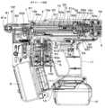
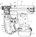
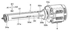
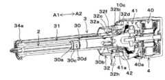
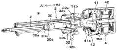
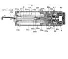
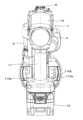
図1Aは、本実施の形態の締結工具の内部構造の一例を示す側断面図、図1Bは、本実施の形態の締結工具の内部構造の一例を示す上面断面図、図1Cは、本実施の形態の締結工具の内部構造の一例を示す正面断面図である。また、図2Aは、本実施の形態の締結工具の内部構造の一例を示す分解斜視図、図2Bは、本実施の形態の締結工具の一例を示す外観斜視図である。
<Configuration example of fastening tool according to this embodiment>
Fig. 1A is a side cross-sectional view showing an example of the internal structure of the fastening tool of this embodiment, Fig. 1B is a top cross-sectional view showing an example of the internal structure of the fastening tool of this embodiment, Fig. 1C is a front cross-sectional view showing an example of the internal structure of the fastening tool of this embodiment, Fig. 2A is an exploded perspective view showing an example of the internal structure of the fastening tool of this embodiment, and Fig. 2B is an external perspective view showing an example of the fastening tool of this embodiment.

本実施の形態の締結工具1は、ドライバビット2を回転可能、及び、軸方向に移動可能に保持するビット保持部3と、ビット保持部3で保持されたドライバビット2を回転させる第1の駆動部4と、ビット保持部3で保持されたドライバビット2を軸方向に移動させる第2の駆動部5を備える。Thefastening tool 1 of this embodiment includes abit holding unit 3 that holds thedriver bit 2 rotatably and axially movable, afirst drive unit 4 that rotates thedriver bit 2 held by thebit holding unit 3, and asecond drive unit 5 that moves thedriver bit 2 held by thebit holding unit 3 in the axial direction.

また、締結工具1は、ネジ200が収納されるネジ収納部6と、ネジ収納部6に収納されたネジを送るネジ送り部7と、ネジ200が締結される締結対象物に押し付けられると共に、ネジが射出されるノーズ部8を備える。Thefastening tool 1 also includes ascrew storage section 6 in which thescrew 200 is stored, ascrew feed section 7 that feeds the screw stored in thescrew storage section 6, and anose section 8 that is pressed against the object to be fastened and from which thescrew 200 is ejected.

更に、締結工具1は、工具本体10とハンドル11を備える。また、締結工具1は、ハンドル11の端部に、バッテリ12が着脱可能に取り付けられるバッテリ取付部13を備える。Furthermore, thefastening tool 1 includes atool body 10 and ahandle 11. Thefastening tool 1 also includes abattery attachment portion 13 at the end of thehandle 11 to which abattery 12 is detachably attached.

締結工具1は、工具本体10が矢印A1、A2で示すドライバビット2の軸方向に沿った一の方向に延伸し、工具本体10の延伸方向に対して交差する他の方向にハンドル11が延伸する。締結工具1は、工具本体10が延伸する方向、すなわち、矢印A1、A2で示すドライバビット2の軸方向を前後方向とする。また、締結工具1は、ハンドル11が延伸する方向を上下方向とする。更に、締結工具1は、工具本体10の延伸方向及びハンドル11の延伸方向に直交する方向を左右方向とする。In thefastening tool 1, thetool body 10 extends in one direction along the axial direction of thedriver bit 2 indicated by the arrows A1 and A2, and thehandle 11 extends in another direction intersecting the extension direction of thetool body 10. In thefastening tool 1, the direction in which thetool body 10 extends, i.e., the axial direction of thedriver bit 2 indicated by the arrows A1 and A2, is defined as the front-rear direction. In addition, in thefastening tool 1, the direction in which thehandle 11 extends is defined as the up-down direction. Furthermore, in thefastening tool 1, the direction perpendicular to the extension direction of thetool body 10 and the extension direction of thehandle 11 is defined as the left-right direction.

第1の駆動部4は、ハンドル11を挟んで、工具本体10の一方の側である後方に設けられる。また、第2の駆動部5は、ハンドル11を挟んで、工具本体10の他方の側である前方に設けられる。Thefirst drive unit 4 is provided on one side of thetool body 10, at the rear, across thehandle 11. Thesecond drive unit 5 is provided on the other side of thetool body 10, at the front, across thehandle 11.

ネジ収納部6は、複数のネジ200が連結帯で連結され、渦巻き状に巻かれた連結ネジが収納される。Thescrew storage section 6 storesmultiple screws 200 connected by a connecting band, forming a spirally wound connected screw.

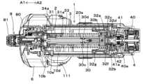
図3A、図3Bは、本実施の形態の締結工具の要部構成の一例を示す斜視図、図4A~図4Cは、本実施の形態の締結工具の要部構成の一例を示す断面斜視図、図5は、本実施の形態の締結工具の要部構成の一例を示す上面断面図であり、ビット保持部3及び第1の駆動部4の詳細を示す。次に、各図を参照して、ビット保持部3及び第1の駆動部4について説明する。Figures 3A and 3B are perspective views showing an example of the main configuration of the fastening tool of this embodiment, Figures 4A to 4C are cross-sectional perspective views showing an example of the main configuration of the fastening tool of this embodiment, and Figure 5 is a top cross-sectional view showing an example of the main configuration of the fastening tool of this embodiment, showing details of thebit holding unit 3 andfirst drive unit 4. Next, thebit holding unit 3 andfirst drive unit 4 will be described with reference to each figure.

ビット保持部3は、ドライバビット2を着脱可能に保持する保持部材30と、保持部材30をドライバビット2の軸方向に沿った矢印A1、A2で示す前後方向へ移動可能に支持すると共に、保持部材30と共に回転する回転ガイド部材31と、保持部材30を回転ガイド部材31に沿って前後方向に移動させる移動部材32と、移動部材32を矢印A2で示す後方向へ付勢する付勢部材33を備える。 Thebit holding portion 3 includes aholding member 30 that removably holds thedriver bit 2, arotating guide member 31 that supports theholding member 30 so that it can move in the forward and backward directions indicated by arrows A1 and A2 along the axial direction of thedriver bit 2 and rotates together with theholding member 30, a movingmember 32 that moves theholding member 30 in the forward and backward directions along therotatingguide member 31, and abiasing member 33 that biases the movingmember 32 in the rearward direction indicated by arrow A2.

保持部材30は、回転ガイド部材31の内径より外径が若干小さく、回転ガイド部材31の内側に入れられる例えば円柱状の部材で構成される。保持部材30は、ドライバビット2の軸方向に沿った前側の端部に、ドライバビット2の断面形状と合致した形状の開口30aが設けられる。保持部材30は、ドライバビット2を着脱可能に保持する着脱保持機構30cを開口30aに備える。保持部材30は、開口30aが回転ガイド部材31の内側に露出し、開口30aにドライバビット2が着脱可能に挿入される。Theholding member 30 is composed of, for example, a cylindrical member whose outer diameter is slightly smaller than the inner diameter of therotary guide member 31 and which is inserted inside therotary guide member 31. Theholding member 30 has an opening 30a at its front end along the axial direction of thedriver bit 2, the opening 30a having a shape that matches the cross-sectional shape of thedriver bit 2. The holdingmember 30 has adetachable holding mechanism 30c in theopening 30a that detachably holds thedriver bit 2. Theopening 30a of the holdingmember 30 is exposed to the inside of therotary guide member 31, and thedriver bit 2 is detachably inserted into theopening 30a.

回転ガイド部材31は、工具本体10の延伸方向、すなわち、ドライバビット2の軸方向に沿った矢印A1、A2で示す前後方向に沿って延伸する。回転ガイド部材31は、内側に保持部材30が入る円筒形状で、前側の端部が、工具本体10の外装を構成する樹脂製のケース10aの前側に設けられる金属製の前フレーム10bに、軸受の一例であるベアリング34aを介して回転可能に支持される。また、回転ガイド部材31は、後側の端部が第1の駆動部4と連結される。Therotation guide member 31 extends in the extension direction of thetool body 10, i.e., in the front-rear direction indicated by the arrows A1 and A2 along the axial direction of thedriver bit 2. Therotation guide member 31 is cylindrical with the retainingmember 30 inside, and its front end is rotatably supported via abearing 34a, which is an example of a bearing, on ametal front frame 10b provided on the front side of aresin case 10a that constitutes the exterior of thetool body 10. The rear end of therotation guide member 31 is connected to thefirst drive unit 4.

回転ガイド部材31は、ドライバビット2の軸方向に沿った矢印A1、A2で示す前後方向に延伸する溝部31aが、径方向に対向する側部の2箇所に形成される。回転ガイド部材31は、保持部材30を径方向に貫通し、保持部材30の両側方から突出した連結部材30bが溝部31aに入ることで、連結部材30bを介して保持部材30と連結される。Therotating guide member 31 hasgrooves 31a extending in the front-rear direction indicated by arrows A1 and A2 along the axial direction of thedriver bit 2, formed at two locations on the radially opposing sides. Therotating guide member 31 penetrates the holdingmember 30 in the radial direction, and the connectingmembers 30b protruding from both sides of the holdingmember 30 enter thegrooves 31a, so that therotating guide member 31 is connected to the holdingmember 30 via the connectingmembers 30b.

保持部材30は、ドライバビット2の回転方向に対して垂直方向に貫通した穴部が設けられ、この穴部に連結部材30bが挿入、ピン30fで固定される。連結部材30bは、断面形状が長円形状の筒状の部材で構成される。The holdingmember 30 has a hole that penetrates perpendicularly to the direction of rotation of thedriver bit 2, and the connectingmember 30b is inserted into this hole and fixed with apin 30f. The connectingmember 30b is composed of a cylindrical member with an oval cross-sectional shape.

連結部材30bは、長円形状の長手方向が、矢印A1、A2で示すドライバビット2の軸方向と平行な溝部31aの延伸方向に沿った向き、長円形状の短手方向が、矢印B1、B2方向で示す溝部31aの延伸方向と直交する向き、すなわち、回転ガイド部材31の回転方向に沿った向きとなる。そして、連結部材30bは、長円形状の短手方向の幅、すなわち、回転ガイド部材31の回転方向に沿った幅が、溝部31aの同方向に沿った幅より若干小さく構成される。The longitudinal direction of the oval shape of the connectingmember 30b is oriented along the extension direction of thegroove portion 31a which is parallel to the axial direction of thedriver bit 2 as indicated by the arrows A1 and A2, and the transverse direction of the oval shape is oriented perpendicular to the extension direction of thegroove portion 31a as indicated by the arrows B1 and B2, i.e., along the rotation direction of therotation guide member 31. The connectingmember 30b is configured so that the width of the transverse direction of the oval shape, i.e., the width along the rotation direction of therotation guide member 31, is slightly smaller than the width of thegroove portion 31a along the same direction.

これにより、溝部31aに入れられた連結部材30bは、回転ガイド部材31の軸方向に沿って移動可能に溝部31aに支持される。また、連結部材30bは、回転ガイド部材31に対して回転方向に沿った移動が、溝部31aの延伸する方向に沿った溝部31aの一方の側面と他方の側面との間で規制される。よって、連結部材30bは、回転ガイド部材31が回転する動作で、回転ガイド部材31の回転方向に応じて溝部31aの一方の側面または他方の側面に押され、回転ガイド部材31から回転方向である周方向の力を受ける。As a result, the connectingmember 30b inserted in thegroove 31a is supported in thegroove 31a so as to be movable along the axial direction of therotating guide member 31. Furthermore, the movement of the connectingmember 30b along the rotational direction relative to therotating guide member 31 is restricted between one side and the other side of thegroove 31a along the extension direction of thegroove 31a. Therefore, when therotating guide member 31 rotates, the connectingmember 30b is pressed against one side or the other side of thegroove 31a depending on the rotational direction of therotating guide member 31, and receives a circumferential force from therotating guide member 31 in the rotational direction.

従って、保持部材30は、回転ガイド部材31が回転すると、連結部材30bが回転ガイド部材31の溝部31aに押されることで、回転ガイド部材31と共に回転する。また、保持部材30は、連結部材30bが回転ガイド部材31の溝部31aにガイドされ、ドライバビット2の軸方向に沿った前後方向に移動する。Therefore, when therotary guide member 31 rotates, the connectingmember 30b is pressed into thegroove 31a of therotary guide member 31, and the holdingmember 30 rotates together with therotary guide member 31. In addition, the connectingmember 30b of the holdingmember 30 is guided by thegroove 31a of therotary guide member 31, and moves in the forward and backward directions along the axial direction of thedriver bit 2.

移動部材32は伝達部材の一例で、保持部材30と共に回転し、保持部材30を回転ガイド部材31に沿って前後方向に移動させる第1の移動部材32aと、ベアリング32bを介して第1の移動部材32aに支持され、ベアリング32bを介して第1の移動部材32aを押す第2の移動部材32cと、第2の移動部材32cの後側に取り付けられる緩衝部材32dを備える。The movingmember 32 is an example of a transmission member, and includes a first movingmember 32a that rotates together with the holdingmember 30 and moves the holdingmember 30 in the forward and backward directions along therotation guide member 31, a second movingmember 32c that is supported by the first movingmember 32a via abearing 32b and pushes the first movingmember 32a via thebearing 32b, and abuffer member 32d that is attached to the rear side of the second movingmember 32c.

第1の移動部材32aは、回転ガイド部材31の外径より内径が若干大きく、回転ガイド部材31の外側に入れられる例えば円筒状の部材で構成される。第1の移動部材32aは、回転ガイド部材31の溝部31aから突出した連結部材30bを介して保持部材30と連結されることで、回転ガイド部材31の軸方向に沿って移動可能に支持される。The first movingmember 32a is composed of, for example, a cylindrical member whose inner diameter is slightly larger than the outer diameter of therotating guide member 31 and is inserted outside therotating guide member 31. The first movingmember 32a is connected to the holdingmember 30 via a connectingmember 30b protruding from thegroove portion 31a of therotating guide member 31, and is supported so as to be movable along the axial direction of therotating guide member 31.

ベアリング32bは軸受の一例で、第1の移動部材32aの外周と第2の移動部材32cの内周の間に挿入される。第1の移動部材32aは、ベアリング32bの内輪を保持する軸受内輪保持部材を構成し、第2の移動部材32cは、ベアリング32bの外輪を保持する軸受外輪保持部材を構成する。ベアリング32bは、内輪が第1の移動部材32aの外周に回転方向と軸方向の移動を不能に支持され、外輪が第2の移動部材32cの内周に回転方向と軸方向の移動を不能に支持される。Bearing 32b is an example of a bearing, and is inserted between the outer periphery of first movingmember 32a and the inner periphery of second movingmember 32c. First movingmember 32a constitutes a bearing inner ring holding member that holds the inner ring of bearing 32b, and second movingmember 32c constitutes a bearing outer ring holding member that holds the outer ring of bearing 32b.Bearing 32b has an inner ring supported on the outer periphery of first movingmember 32a so as to be unable to move in the rotational direction or axial direction, and an outer ring supported on the inner periphery of second movingmember 32c so as to be unable to move in the rotational direction or axial direction.

これにより、第2の移動部材32cは、第1の移動部材32aに対して、軸方向に沿った前後方向への移動が規制された状態で、ベアリング32bを介して連結される。また、第2の移動部材32cは、ベアリング32bを介して第1の移動部材32aを回転可能に支持する。As a result, the second movingmember 32c is connected to the first movingmember 32a via thebearing 32b in a state in which movement in the forward and backward directions along the axial direction is restricted. In addition, the second movingmember 32c rotatably supports the first movingmember 32a via thebearing 32b.

従って、第1の移動部材32aは、第2の移動部材32cが軸方向に沿った前後方向に移動する動作で、ベアリング32bを介して第2の移動部材32cに押され、第2の移動部材32cと共に軸方向に沿った前後方向に移動する。また、第1の移動部材32aは、回転ガイド部材31に対して非回転な第2の移動部材32cに対して回転可能である。Therefore, when the second movingmember 32c moves in the forward and backward directions along the axial direction, the first movingmember 32a is pushed by the second movingmember 32c via thebearing 32b, and moves in the forward and backward directions along the axial direction together with the second movingmember 32c. In addition, the first movingmember 32a is rotatable relative to the second movingmember 32c, which is non-rotatable relative to therotation guide member 31.

付勢部材33は、本例ではコイルバネで構成され、回転ガイド部材31の外側で、工具本体10のケース10aの前側に設けられる前フレーム10bと、移動部材32の第2の移動部材32cとの間に入れられ、ベアリング32bの外輪の端面に接触するように配置されたばね座32fに当接する。付勢部材33は、移動部材32が矢印A1で示す前方向に移動することで圧縮され、移動部材32を矢印A2で示す後方向に付勢する。The biasingmember 33 is composed of a coil spring in this example, and is placed outside therotation guide member 31 between thefront frame 10b provided on the front side of thecase 10a of thetool body 10 and the second movingmember 32c of the movingmember 32, and abuts against aspring seat 32f arranged to contact the end face of the outer ring of thebearing 32b. The biasingmember 33 is compressed when the movingmember 32 moves in the forward direction indicated by arrow A1, and biases the movingmember 32 in the rearward direction indicated by arrow A2.

第1の駆動部4は、バッテリ12から供給される電気で駆動されるビット回転モータ40と、減速機41を備える。ビット回転モータ40は第1のモータの一例で、ビット回転モータ40の軸40aが、減速機41と連結され、減速機41の軸41aが、回転ガイド部材31に連結される。第1の駆動部4は、減速機41が遊星歯車を利用した構成で、ビット回転モータ40が回転ガイド部材31及び保持部材30と、保持部材30に保持されたドライバビット2と同軸上に配置される。Thefirst drive unit 4 includes abit rotation motor 40 driven by electricity supplied from thebattery 12, and areduction gear 41. Thebit rotation motor 40 is an example of a first motor, and theshaft 40a of thebit rotation motor 40 is connected to thereduction gear 41, and theshaft 41a of thereduction gear 41 is connected to therotation guide member 31. In thefirst drive unit 4, thereduction gear 41 is configured using a planetary gear, and thebit rotation motor 40 is arranged coaxially with therotation guide member 31, the holdingmember 30, and thedriver bit 2 held by the holdingmember 30.

第1の駆動部4は、工具本体10のケース10aの後側に設けられる金属製の後フレーム10cに、ビット回転モータ40及び減速機41が取り付けられ、減速機41の軸41aが、ベアリング42を介して後フレーム10cに支持される。回転ガイド部材31は、後側の端部が、減速機41の軸41aと連結され、軸41aが、ベアリング42を介して後フレーム10cに支持されることで、軸受の一例であるベアリング42を介して回転可能に支持される。Thefirst drive unit 4 has abit rotation motor 40 and areducer 41 attached to a metallicrear frame 10c provided on the rear side of thecase 10a of thetool body 10, and theshaft 41a of thereducer 41 is supported by therear frame 10c via abearing 42. The rear end of therotation guide member 31 is connected to theshaft 41a of thereducer 41, and theshaft 41a is supported by therear frame 10c via thebearing 42, so that therotation guide member 31 is rotatably supported via thebearing 42, which is an example of a bearing.

ビット保持部3と第1の駆動部4は、前フレーム10bと後フレーム10cが、前後方向に延伸する結合部材10dで連結されることで、一体に組み立てられ、前フレーム10bが、工具本体10のケース10aにネジ10eにより固定される。Thebit holding part 3 and thefirst drive part 4 are assembled together by connecting thefront frame 10b and therear frame 10c with a connectingmember 10d extending in the front-rear direction, and thefront frame 10b is fixed to thecase 10a of thetool body 10 with ascrew 10e.

また、ビット保持部3は、回転ガイド部材31の前側の端部が、工具本体10のケース10aの前側に固定される前フレーム10bにベアリング34aを介して支持され、回転ガイド部材31の後側の端部が、ケース10aの後側に固定される後フレーム10cに、減速機41の軸41a及びベアリング42を介して支持される。よって、ビット保持部3は、回転ガイド部材31が工具本体10に回転可能に支持される。The front end of therotary guide member 31 of thebit holding unit 3 is supported by afront frame 10b fixed to the front side of thecase 10a of thetool body 10 via abearing 34a, and the rear end of therotary guide member 31 is supported by arear frame 10c fixed to the rear side of thecase 10a via theshaft 41a of thereducer 41 and abearing 42. Thus, therotary guide member 31 of thebit holding unit 3 is rotatably supported by thetool body 10.

これにより、第1の駆動部4は、ビット回転モータ40により回転ガイド部材31を回転させる。ドライバビット2が保持される保持部材30は、回転ガイド部材31が回転すると、連結部材30bが回転ガイド部材31の溝部31aに押されることで、回転ガイド部材31と共に回転する。As a result, thefirst drive unit 4 rotates therotary guide member 31 using thebit rotation motor 40. When therotary guide member 31 rotates, the holdingmember 30 that holds thedriver bit 2 rotates together with therotary guide member 31 as the connectingmember 30b is pressed against thegroove portion 31a of therotary guide member 31.

ビット保持部3は、第2の移動部材32cにガイド部材32gが設けられる。結合部材10dは、ガイド部材32gの直径より若干大きな間隔を空けて、一対のガイド壁部10gが設けられ、一対のガイド壁部10gの間にガイド部材32gが入ることで、一対のガイド壁部10gがガイド部材32gの周面と対向する。Thebit holding unit 3 is provided with aguide member 32g on the second movingmember 32c. A pair ofguide walls 10g are provided on the connectingmember 10d with a gap slightly larger than the diameter of theguide member 32g, and theguide member 32g is inserted between the pair ofguide walls 10g, so that the pair ofguide walls 10g face the peripheral surface of theguide member 32g.

これにより、第2の移動部材32cは、ガイド部材32gが結合部材10dにガイドされることで、ドライバビット2の軸方向に沿った矢印A1、A2で示す前後方向に移動可能で、かつ、回転ガイド部材31に追従した回転が規制される。As a result, the second movingmember 32c can move in the forward and backward directions indicated by the arrows A1 and A2 along the axial direction of thedriver bit 2 by theguide member 32g being guided by the connectingmember 10d, and the rotation following therotation guide member 31 is restricted.

図6A及び図6Bは、本実施の形態の締結工具の内部構造の一例を示す上面断面図であり、第2の駆動部5の詳細を示す。次に、各図を参照して、第2の駆動部5について説明する。Figures 6A and 6B are top cross-sectional views showing an example of the internal structure of the fastening tool of this embodiment, showing details of thesecond drive unit 5. Next, thesecond drive unit 5 will be described with reference to each figure.

第2の駆動部5は、バッテリ12から供給される電気で駆動されるビット移動モータ50と、減速機51を備える。ビット移動モータ50はモータ、第2のモータの一例で、ビット移動モータ50の軸50aが、減速機51と連結され、減速機51の軸51aが回転部材の一例であるプーリ52と連結される。第2の駆動部5は、プーリ52がベアリング53を介して工具本体10に支持される。第2の駆動部5は、ビット移動モータ50の軸50aがハンドル11の延伸方向に沿って配置される。Thesecond drive unit 5 includes abit moving motor 50 driven by electricity supplied from thebattery 12, and areduction gear 51. Thebit moving motor 50 is an example of a motor, a second motor, and theshaft 50a of thebit moving motor 50 is connected to thereduction gear 51, and theshaft 51a of thereduction gear 51 is connected to apulley 52, which is an example of a rotating member. In thesecond drive unit 5, thepulley 52 is supported by thetool body 10 via abearing 53. In thesecond drive unit 5, theshaft 50a of thebit moving motor 50 is arranged along the extension direction of thehandle 11.

第2の駆動部5は、伝達部材の一例である線状のワイヤ54の一端がプーリ52に連結され、プーリ52が回転することでワイヤ54がプーリ52の外周52aに沿って巻かれる。また、ワイヤ54の他端が、移動部材32の第2の移動部材32cに設けたワイヤ連結部32hに連結される。伝達部材は、プーリ52等の回転部材の外周に沿って巻かれる可撓性を有したものであれば、繊維等で構成される紐、ゴム等で構成されるベルト、金属等で構成されるチェーンでも良い。伝達部材がチェーンで構成される場合、回転部材は歯部を有したスプロケットでも良い。In thesecond drive unit 5, one end of alinear wire 54, which is an example of a transmission member, is connected to thepulley 52, and as thepulley 52 rotates, thewire 54 is wound around theouter periphery 52a of thepulley 52. The other end of thewire 54 is connected to awire connecting portion 32h provided on the second movingmember 32c of the movingmember 32. The transmission member may be a string made of fiber or the like, a belt made of rubber or the like, or a chain made of metal or the like, as long as it has the flexibility to be wound around the outer periphery of a rotating member such as thepulley 52. When the transmission member is a chain, the rotating member may be a sprocket with teeth.

これにより、第2の駆動部5は、ビット移動モータ50によりプーリ52を回転させて、ワイヤ54を巻き取ることで、第2の移動部材32cを矢印A1で示す前方向に移動させる。ビット保持部3は、第2の移動部材32cが前方向に移動することで、ベアリング32bを介して第1の移動部材32aが押され、第1の移動部材32aが第2の移動部材32cと共に軸方向に沿った前方向に移動する。第1の移動部材32aが前方向に移動することで、第1の移動部材32aと連結部材30bを介して連結された保持部材30が前方向に移動し、保持部材30で保持されたドライバビット2が、矢印A1で示す前方向に移動する。As a result, thesecond drive unit 5 rotates thepulley 52 by thebit moving motor 50 and winds up thewire 54, thereby moving the second movingmember 32c in the forward direction indicated by the arrow A1. As the second movingmember 32c moves forward, the first movingmember 32a is pushed via thebearing 32b, and the first movingmember 32a moves forward along the axial direction together with the second movingmember 32c. As the first movingmember 32a moves forward, the holdingmember 30 connected to the first movingmember 32a via the connectingmember 30b moves forward, and thedriver bit 2 held by the holdingmember 30 moves forward as indicated by the arrow A1.

第2の駆動部5は、プーリ52においてワイヤ54が巻かれる部位の接線方向が、回転ガイド部材31の延伸方向に沿うように、締結工具1の左右方向における略中心に対し一方の側にオフセットされて配置される。すなわち、プーリ52の中心、本例では、ビット移動モータ50の軸50aが、回転ガイド部材31に対して一方の側にオフセットされ、プーリ52の軸方向から見て、プーリ52においてワイヤ54が巻かれる外周52aが、回転ガイド部材31と重なる配置である。Thesecond drive unit 5 is positioned offset to one side from approximately the center in the left-right direction of thefastening tool 1 so that the tangent direction of the portion of thepulley 52 around which thewire 54 is wound is aligned with the extension direction of therotary guide member 31. That is, the center of thepulley 52, in this example, theshaft 50a of thebit moving motor 50, is offset to one side from therotary guide member 31, and theouter periphery 52a around which thewire 54 is wound in thepulley 52 overlaps with therotary guide member 31 when viewed from the axial direction of thepulley 52.

また、プーリ52と第2の移動部材32cとの間のワイヤ54は、図6A,図6Bに示すように、プーリ52の径方向において、回転ガイド部材31の軸方向と平行となり、かつ、図1Aに示すように、プーリ52の径方向と直交するビット移動モータ50の軸方向においても、回転ガイド部材31の軸方向と平行となるように、プーリ52等が配置される。Thepulley 52 and the second movingmember 32c are arranged so that thewire 54 between thepulley 52 and the second movingmember 32c is parallel to the axial direction of therotary guide member 31 in the radial direction of thepulley 52 as shown in Figures 6A and 6B, and is also parallel to the axial direction of therotary guide member 31 in the axial direction of thebit moving motor 50, which is perpendicular to the radial direction of thepulley 52 as shown in Figure 1A.

更に、プーリ52にワイヤ54が重ねて巻かれると、巻き数に応じてプーリ52の中心からワイヤ54までの距離が変化することから、プーリ52が1回転したときのドライバビット2の移動量が変化する。また、プーリ52と第2の移動部材32cとの間でワイヤ54が延伸する方向と、回転ガイド部材31の軸方向に沿ったドライバビット2の移動方向との成す角度が変化する。Furthermore, when thewire 54 is wound around thepulley 52 in an overlapping manner, the distance from the center of thepulley 52 to thewire 54 changes depending on the number of turns, and therefore the amount of movement of thedriver bit 2 when thepulley 52 rotates once changes. Also, the angle between the direction in which thewire 54 extends between thepulley 52 and the second movingmember 32c and the direction in which thedriver bit 2 moves along the axial direction of therotation guide member 31 changes.

そこで、移動部材32を、一の方向に沿った移動可能範囲内で一方の端部から他方の端部まで移動させることで、ドライバビット2を所定量移動させるために必要なプーリ52の回転量αが、360°未満となるように、プーリ52の径等が設定される。Therefore, the diameter, etc. of thepulley 52 are set so that the amount of rotation α of thepulley 52 required to move the driver bit 2 a predetermined amount by moving the movingmember 32 from one end to the other end within the movable range along one direction is less than 360°.

これにより、ドライバビット2を所定量移動させるために、プーリ52がワイヤ54を巻き取る動作で、図6Bに示すように、プーリ52にワイヤ54が重ねて巻かれることがなく、ドライバビット2の移動量が不正確になることが抑制される。また、プーリ52と第2の移動部材32cとの間でワイヤ54が延伸する方向と、回転ガイド部材31の軸方向に沿ったドライバビット2の移動方向との平行度の変化が抑制される。As a result, when thepulley 52 winds thewire 54 to move the driver bit 2 a predetermined amount, thewire 54 is not wound around thepulley 52 in overlapping layers as shown in FIG. 6B, which prevents the amount of movement of thedriver bit 2 from becoming inaccurate. In addition, changes in the parallelism between the direction in which thewire 54 extends between thepulley 52 and the second movingmember 32c and the direction in which thedriver bit 2 moves along the axial direction of therotation guide member 31 are prevented.

従って、ビット移動モータ50の回転量と、保持部材30の移動量との関係が、保持部材30の移動可能範囲の全域において、1対1の関係となり、ビット移動モータ50の回転量を制御することで、回転ガイド部材31の軸方向に沿った保持部材30の移動量を制御できる。すなわち、ビット移動モータ50の回転量を制御することで、保持部材30に取り付けられたドライバビット2の移動量を制御可能となる。Therefore, the relationship between the amount of rotation of thebit moving motor 50 and the amount of movement of the holdingmember 30 is one-to-one throughout the entire movable range of the holdingmember 30, and by controlling the amount of rotation of thebit moving motor 50, it is possible to control the amount of movement of the holdingmember 30 along the axial direction of therotation guide member 31. In other words, by controlling the amount of rotation of thebit moving motor 50, it is possible to control the amount of movement of thedriver bit 2 attached to the holdingmember 30.

また、ワイヤ54の巻き取り量に関わらず、ワイヤ54に掛かる張力は回転ガイド部材31の軸方向に沿ったドライバビット2の移動方向と常に平行になり、ドライバビット2の移動及びドライバビット2を介してネジ200を押すための力の伝達効率の低下を抑制できる。In addition, regardless of the amount of winding of thewire 54, the tension applied to thewire 54 is always parallel to the movement direction of thedriver bit 2 along the axial direction of therotation guide member 31, which suppresses a decrease in the movement of thedriver bit 2 and the transmission efficiency of the force for pushing thescrew 200 via thedriver bit 2.

これにより、プーリ52と第2の移動部材32cとの間のワイヤ54が、移動部材32の移動方向に沿った直線状に延伸し、プーリ52でワイヤ54を巻き取る際の負荷の増加、プーリ52からワイヤ54が引き出される際の負荷の増加が抑制される。As a result, thewire 54 between thepulley 52 and the second movingmember 32c extends linearly along the direction of movement of the movingmember 32, suppressing the increase in load when thewire 54 is wound around thepulley 52 and when thewire 54 is pulled out from thepulley 52.

なお、ワイヤ54は、プーリ52に巻き取ることが可能な可撓性を有することから、第2の移動部材32cを押して移動部材32を後方へ移動させることができない。そこで、移動部材32が矢印A1で示す前方向に移動することで圧縮され、移動部材32を矢印A2で示す後方向に押す力を移動部材32に掛ける付勢部材33を備える。これにより、プーリ52でワイヤ54を巻き取り、ドライバビット2を前進させる構成で、前進後のドライバビット2を後進させることができる。Thewire 54 is flexible enough to be wound around thepulley 52, and therefore cannot push the second movingmember 32c to move the movingmember 32 backward. Therefore, a biasingmember 33 is provided that is compressed when the movingmember 32 moves forward as indicated by arrow A1, and applies a force to the movingmember 32 to push the movingmember 32 backward as indicated by arrow A2. This allows thewire 54 to be wound around thepulley 52, moving thedriver bit 2 forward, and allowing thedriver bit 2 to move backward after moving forward.

また、ドライバビット2を保持する保持部材30は、保持部材30に設けた連結部材30bと、回転ガイド部材31に設けた溝部31aとの係合で、回転ガイド部材31に対して前後方向に移動可能に支持されると共に、回転ガイド部材31と共に回転する。The holdingmember 30 that holds thedriver bit 2 is supported so as to be movable in the forward and backward directions relative to therotating guide member 31 by the engagement between the connectingmember 30b provided on the holdingmember 30 and thegroove portion 31a provided on therotating guide member 31, and rotates together with therotating guide member 31.

よって、ビット回転モータ40が回転ガイド部材31及び保持部材30と、保持部材30に保持されたドライバビット2と同軸上に配置される構成で、ビット回転モータ40を前後方向に移動させることなく、ドライバビット2を回転させると共に、ドライバビット2を前後方向に移動させる構成を実現することができる。Therefore, thebit rotation motor 40 is arranged coaxially with therotation guide member 31 and the holdingmember 30, and thedriver bit 2 held by the holdingmember 30, and a configuration can be realized in which thedriver bit 2 is rotated and moved in the forward and backward directions without moving thebit rotation motor 40 in the forward and backward directions.

なお、ビット回転モータ40をドライバビット2と同軸上に配置する構成では、送りネジを利用して、ビット回転モータ40の回転動作を、ドライバビット2の前後方向への移動に変換する構成が考えられる。In a configuration in which thebit rotation motor 40 is arranged coaxially with thedriver bit 2, a feed screw can be used to convert the rotational motion of thebit rotation motor 40 into forward and backward movement of thedriver bit 2.

しかし、送りネジを利用した構成では、モータ1回転あたりのドライバビット2の前進量を大きく取れないことから、モータの回転速度を上げても、ドライバビット2の移動速度を速くすることが難しい。However, with a configuration that uses a feed screw, the amount of advancement of thedriver bit 2 per motor revolution cannot be made large, so even if the motor rotation speed is increased, it is difficult to increase the movement speed of thedriver bit 2.

締結工具1では、ドライバビット2でネジ200を締結対象物に押し付けるまでの時間を短縮するため、ドライバビット2の移動速度を速くする必要があるが、送りネジを利用した構成では、ドライバビット2でネジ200を締結対象物に押し付けるまでの時間を短縮することが難しい。In thefastening tool 1, the movement speed of thedriver bit 2 needs to be increased in order to shorten the time it takes for thedriver bit 2 to press thescrew 200 against the object to be fastened, but with a configuration that uses a feed screw, it is difficult to shorten the time it takes for thedriver bit 2 to press thescrew 200 against the object to be fastened.

これに対し、ドライバビット2を保持する保持部材30が、回転ガイド部材31に対して前後方向に移動可能に支持され、第2の駆動部5によりプーリ52を回転させてワイヤ54を巻き取り、保持部材30を前方向に移動させる構成では、ビット移動モータ50の回転速度に応じて、ドライバビット2の移動速度を速くすることができる。よって、ドライバビット2でネジ200を締結対象物に押し付けるまでの時間を短縮することができる。In contrast, in a configuration in which the holdingmember 30 that holds thedriver bit 2 is supported so as to be movable in the forward and backward directions relative to therotating guide member 31, and thesecond driving unit 5 rotates thepulley 52 to wind up thewire 54 and move the holdingmember 30 forward, the movement speed of thedriver bit 2 can be increased according to the rotation speed of thebit movement motor 50. Therefore, the time until thedriver bit 2 presses thescrew 200 against the object to be fastened can be shortened.

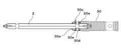
図7A、図7Bは、着脱保持機構の一例を示す断面図、図8A、図8Bは、着脱保持機構の一例を示す斜視図であり、着脱保持機構30cの詳細を示す。次に、各図を参照して、着脱保持機構30cについて説明する。Figures 7A and 7B are cross-sectional views showing an example of a detachable holding mechanism, and Figures 8A and 8B are perspective views showing an example of a detachable holding mechanism, showing details of thedetachable holding mechanism 30c. Next, thedetachable holding mechanism 30c will be described with reference to each figure.

着脱保持機構30cは、開口30a内に露出するボール30dと、ボール30dを開口30a内に露出する方向に押圧するバネ30eを備える。バネ30eは押圧部材の一例で、板バネ、コイル等の付勢部材、ゴム等の弾性部材で構成され、本例では、環状の板バネで構成され、保持部材30の外周に嵌められる。Theremovable holding mechanism 30c includes aball 30d exposed in theopening 30a and aspring 30e that presses theball 30d in the direction of exposure in theopening 30a. Thespring 30e is an example of a pressing member, and is made of a leaf spring, a biasing member such as a coil, or an elastic member such as rubber. In this example, it is made of an annular leaf spring, and is fitted around the outer periphery of the holdingmember 30.

ドライバビット2の差込み部20が、保持部材30の開口30aに挿入されると、着脱保持機構30cは、差込み部20に押されたボール30dが、環状のバネ30eの径が大きくなる方向にバネ30eを変形させながら、保持部材30の外周方向へ退避する。When theinsertion portion 20 of thedriver bit 2 is inserted into theopening 30a of the holdingmember 30, theball 30d of thedetachable holding mechanism 30c is pushed by theinsertion portion 20, and theball 30d deforms theannular spring 30e in a direction that increases the diameter of thespring 30e, while retracting toward the outer periphery of the holdingmember 30.

差込み部20の外周に形成された溝部20aが、ボール30dと対向する位置まで、ドライバビット2の差込み部20が保持部材30の開口30aに挿入されると、バネ30eで付勢されたボール30dが溝部20aに嵌る。これにより、ドライバビット2が保持部材30から不用意に抜けることが抑制される。When thedriver bit 2insertion portion 20 is inserted into theopening 30a of the holdingmember 30 until thegroove 20a formed on the outer periphery of theinsertion portion 20 faces theball 30d, theball 30d biased by thespring 30e fits into thegroove 20a. This prevents thedriver bit 2 from accidentally coming out of the holdingmember 30.

また、ドライバビット2を保持部材30から抜く方向に所定以上の力が掛かると、環状のバネ30eの径が大きくなる方向にバネ30eを変形させながら、ボール30dが退避することで、ドライバビット2を保持部材30から抜くことが可能である。In addition, when a force greater than a predetermined value is applied in the direction of removing thedriver bit 2 from the holdingmember 30, theball 30d retracts while deforming theannular spring 30e in a direction that increases the diameter of thespring 30e, allowing thedriver bit 2 to be removed from the holdingmember 30.

ドライバビット2の差込み部20が、保持部材30の開口30aに挿抜される動作では、ボール30dが保持部材30の外周方向へ退避する。このため、保持部材30の外周に、ボール30dが退避する空間が必要となる。一方、保持部材30は、筒状の回転ガイド部材31の内部に挿入されており、保持部材30の外周と回転ガイド部材31の内周の間には、ボール30dが退避する空間を確保できない。When theinsertion portion 20 of thedriver bit 2 is inserted into and removed from theopening 30a of the holdingmember 30, theball 30d retreats toward the outer periphery of the holdingmember 30. For this reason, a space is required on the outer periphery of the holdingmember 30 for theball 30d to retreat into. However, the holdingmember 30 is inserted inside the cylindricalrotating guide member 31, and no space can be secured between the outer periphery of the holdingmember 30 and the inner periphery of therotating guide member 31 for theball 30d to retreat into.

また、保持部材30の外周と回転ガイド部材31の内周の間に、ボール30dが退避する空間を確保するため、保持部材30と回転ガイド部材31との径差を設定すると、ドライバビット2の径方向の寸法が決められていることで、保持部材30の外径を小さくできないことから、回転ガイド部材31の外径を大きくする必要がある。このため、装置が大型化する。In addition, if a diameter difference between the holdingmember 30 and therotating guide member 31 is set to ensure a space for theball 30d to retreat between the outer periphery of the holdingmember 30 and the inner periphery of therotating guide member 31, the outer diameter of the holdingmember 30 cannot be reduced because the radial dimension of thedriver bit 2 is fixed, and therefore the outer diameter of therotating guide member 31 must be increased. This results in a larger device.

これに対し、回転ガイド部材31は、連結部材30bをガイドする溝部31aが設けられる。溝部31aは、回転ガイド部材31の内周側から外周側へ表裏貫通しており、回転ガイド部材31の軸方向に延伸する。In response to this, therotating guide member 31 is provided with agroove portion 31a that guides the connectingmember 30b. Thegroove portion 31a penetrates therotating guide member 31 from the inner periphery to the outer periphery, and extends in the axial direction of therotating guide member 31.

そこで、着脱保持機構30cは、ボール30dが、回転ガイド部材31の溝部31aの位置に合わせて設けられる。すなわち、保持部材30は、連結部材30bと、着脱保持機構30cのボール30dが、回転ガイド部材31の軸方向に沿った同軸上に設けられる。これにより、着脱保持機構30cは、回転ガイド部材31及び保持部材30が回転する動作、保持部材30が回転ガイド部材31に対して軸方向に移動する動作の何れでも、ボール30dが回転ガイド部材31の溝部31aに露出する。Thedetachable holding mechanism 30c is provided so that theball 30d is aligned with the position of thegroove 31a of therotating guide member 31. That is, the holdingmember 30 is provided so that the connectingmember 30b and theball 30d of thedetachable holding mechanism 30c are coaxially aligned with the axial direction of therotating guide member 31. As a result, theball 30d of thedetachable holding mechanism 30c is exposed to thegroove 31a of therotating guide member 31 when therotating guide member 31 and the holdingmember 30 rotate, or when the holdingmember 30 moves axially relative to therotating guide member 31.

従って、ドライバビット2の差込み部20が、保持部材30の開口30aに挿抜される動作で、保持部材30の外周方向へ退避するボール30dが、回転ガイド部材31の溝部31aに入る。Therefore, when theinsertion portion 20 of thedriver bit 2 is inserted into or removed from theopening 30a of the holdingmember 30, theball 30d, which retreats toward the outer periphery of the holdingmember 30, enters thegroove portion 31a of therotating guide member 31.

よって、筒状の回転ガイド部材31の内部に保持部材30が挿入される構成で、着脱保持機構30cのボール30dが退避する空間を確保できる。また、連結部材30bが入る溝部31aを、ボール30dが退避する空間として兼用することで、回転ガイド部材31に設けられる開口の面積が抑制され、強度を確保できる。Therefore, the holdingmember 30 is inserted inside the cylindricalrotating guide member 31, and a space for theball 30d of thedetachable holding mechanism 30c to retreat can be secured. In addition, thegroove 31a into which the connectingmember 30b is inserted is also used as the space for theball 30d to retreat, thereby reducing the area of the opening provided in therotating guide member 31 and ensuring strength.

更に、保持部材30と回転ガイド部材31との径差を大きくして、保持部材30の外周と回転ガイド部材31の内周の間に、ボール30dが退避する空間を確保する必要がなく、装置の大型化を抑制できる。Furthermore, by increasing the diameter difference between the holdingmember 30 and therotating guide member 31, there is no need to secure a space for theball 30d to retreat between the outer periphery of the holdingmember 30 and the inner periphery of therotating guide member 31, which prevents the device from becoming too large.

図9は、本実施の形態のネジ送り部及びノーズ部の一例を示す斜視図であり、ネジ送り部7及びノーズ部8の詳細を示す。次に、各図を参照して、ネジ送り部7及びノーズ部8について説明する。Figure 9 is a perspective view showing an example of the screw feed section and nose section of this embodiment, showing details of thescrew feed section 7 andnose section 8. Next, thescrew feed section 7 andnose section 8 will be described with reference to each figure.

ネジ送り部7は、ネジ送りモータ70と、ネジ送りモータ70の軸に減速機を介して取り付けられるピニオンギア71と、ピニオンギア71と噛み合うラックギア72と、ラックギア72と連結され、ネジ収納部6から送られる連結ネジと係合する係合部73を備える。Thescrew feed unit 7 includes ascrew feed motor 70, apinion gear 71 attached to the shaft of thescrew feed motor 70 via a reducer, arack gear 72 that meshes with thepinion gear 71, and anengagement unit 73 that is connected to therack gear 72 and engages with the connecting screw fed from thescrew storage unit 6.

ネジ送り部7は、ラックギア72が、連結ネジの送り方向に沿った上下方向に移動可能に支持される。ネジ送り部7は、ネジ送りモータ70が正転及び逆転することで、連結ネジと係合する係合部73が上下方向に移動し、連結ネジが送られる。Thescrew feed unit 7 has arack gear 72 supported so that it can move up and down along the feed direction of the connecting screw. When thescrew feed motor 70 rotates forward and backward, theengagement part 73 that engages with the connecting screw moves up and down, feeding the connecting screw.

ノーズ部8は、ネジ送り部7によりネジ200が供給されると共に、ドライバビット2が通る射出通路80と、射出通路80と連通する射出口81aを有し、締結対象物に接触するコンタクト部材81と、コンタクト部材81と連動して前後方向に移動するコンタクトアーム82と、コンタクトアーム82の移動量を規制する調整部83を備える。また、ノーズ部8は、ネジ収納部6から射出通路80までのネジ200が通る経路を開閉可能に覆うカバー部材88を備える。Thenose portion 8 is supplied with thescrew 200 by thescrew feed portion 7, and is equipped with aninjection passage 80 through which thedriver bit 2 passes, aninjection port 81a that communicates with theinjection passage 80 and acontact member 81 that contacts the object to be fastened, acontact arm 82 that moves in the forward and backward directions in conjunction with thecontact member 81, and anadjustment portion 83 that regulates the amount of movement of thecontact arm 82. Thenose portion 8 also includes acover member 88 that can be opened and closed to cover the path through which thescrew 200 passes from thescrew storage portion 6 to theinjection passage 80.

締結工具1は、射出通路80、コンタクト部材81及びコンタクトアーム82を構成する各部品が組み立てられてノーズ部8が構成され、工具本体10を構成する前フレーム10b及びノーズ本体部10fに固定される。また、締結工具1は、コンタクトアーム82に押されて作動するコンタクトスイッチ部84を備える。Thefastening tool 1 is configured by assembling the various parts that make up theinjection passage 80, thecontact member 81, and thecontact arm 82 to form thenose portion 8, which is fixed to thefront frame 10b and thenose body portion 10f that make up thetool body 10. Thefastening tool 1 also includes acontact switch portion 84 that is activated when pressed by thecontact arm 82.

ノーズ部8は、コンタクト部材81が矢印A1、A2で示す前後方向に移動可能に支持され、コンタクト部材81と連動してコンタクトアーム82が前後方向に移動する。ノーズ部8は、コンタクト部材81が図示しない付勢部材で前方向に付勢され、締結対象物に押し付けられて後方に移動したコンタクト部材81が、付勢部材で付勢されて前方向に移動する。Thenose portion 8 supports thecontact member 81 so that it can move in the forward and backward directions indicated by the arrows A1 and A2, and thecontact arm 82 moves in the forward and backward directions in conjunction with thecontact member 81. Thecontact member 81 of thenose portion 8 is biased forward by a biasing member (not shown), and thecontact member 81, which is pressed against the object to be fastened and moves rearward, is biased by the biasing member to move forward.

ノーズ部8は、コンタクト部材81が締結対象物に押し付けられてコンタクトアーム82が後方へ移動し、コンタクトスイッチ部84が作動するまでのコンタクトアーム82の移動量が調整部83で調整される。コンタクトスイッチ部84は、コンタクトアーム82に押されることで作動の有無が切り替えられ、本例では、コンタクトアーム82に押されておらず、コンタクトスイッチ部84が非作動な状態をコンタクトスイッチ部84のオフ、コンタクトアーム82に押されてコンタクトスイッチ部84が作動した状態をコンタクトスイッチ部84のオンとする。In thenose portion 8, thecontact member 81 is pressed against the object to be fastened, causing thecontact arm 82 to move backward, and the amount of movement of thecontact arm 82 until thecontact switch portion 84 is activated is adjusted by theadjustment portion 83. Thecontact switch portion 84 is switched between activated and inactivated when pressed by thecontact arm 82, and in this example, the state in which thecontact switch portion 84 is not pressed by thecontact arm 82 and is inactivated is referred to as the off state of thecontact switch portion 84, and the state in which thecontact switch portion 84 is pressed by thecontact arm 82 and is activated is referred to as the on state of thecontact switch portion 84.

次に、各図を参照して、締結工具1の制御及び操作に関する構成について説明する。締結工具1は、操作を受けるトリガ9と、トリガ9の操作で作動するトリガスイッチ部90を備える。トリガ9は、ハンドル11の前側に設けられ、ハンドル11を把持する手の指で操作可能に構成される。トリガスイッチ部90は、トリガ9に押されて作動する。Next, the configuration related to the control and operation of thefastening tool 1 will be described with reference to each figure. Thefastening tool 1 is equipped with atrigger 9 that receives an operation, and atrigger switch unit 90 that is actuated by operating thetrigger 9. Thetrigger 9 is provided on the front side of thehandle 11, and is configured to be operable by the fingers of the hand that grips thehandle 11. Thetrigger switch unit 90 is actuated when pressed by thetrigger 9.

トリガスイッチ部90は、トリガ9に押されることで作動の有無が切り替えられ、本例では、トリガ9が操作されておらず、トリガ9でトリガスイッチ部90が押されずトリガスイッチ部90が非作動な状態をトリガスイッチ部90のオフ、トリガ9が操作され、トリガ9に押されてトリガスイッチ部90が作動した状態をトリガスイッチ部90のオンとする。Thetrigger switch unit 90 is switched between being activated and not activated when pressed by thetrigger 9. In this example, thetrigger switch unit 90 is OFF when thetrigger 9 is not operated and thetrigger switch unit 90 is not pressed by thetrigger 9, resulting in an inactivated state, and thetrigger switch unit 90 is ON when thetrigger 9 is operated and pressed by thetrigger 9, resulting in an activated state.

締結工具1は、トリガ9の操作で作動するトリガスイッチ部90及びコンタクト部材81に押されて作動するコンタクトスイッチ部84の出力に基づき、第1の駆動部4、第2の駆動部5及びネジ送り部7を制御する制御部100を備える。Thefastening tool 1 is equipped with acontrol unit 100 that controls thefirst drive unit 4, thesecond drive unit 5, and thescrew feed unit 7 based on the output of atrigger switch unit 90 that is activated by operating thetrigger 9, and acontact switch unit 84 that is activated by being pressed by acontact member 81.

制御部100は、各種電子部品が実装された基板で構成され、ネジ収納部6とハンドル11との間で、ネジ収納部6の裏面側に設けた基板収納部111に設けられる。Thecontrol unit 100 is composed of a circuit board on which various electronic components are mounted, and is provided in the circuitboard storage section 111 provided on the back side of thescrew storage section 6 between thescrew storage section 6 and thehandle 11.

ハンドルを手で持って使用される電動工具では、ネジ等の消耗品が収納される収納部が、ハンドルの前方に設けられる。そして、ハンドルを手で把持できるようにするため、ハンドルと収納部の間には、手の指が入る空間が必要である。In power tools that are used by holding the handle in the hand, a storage section for storing consumables such as screws is provided in front of the handle. In order to be able to grip the handle with the hand, there needs to be space between the handle and the storage section large enough for the fingers to fit in.

そこで、締結工具1は、ネジ収納部6とハンドル11との間の空間を利用して、ネジ収納部6の裏面側に基板収納部111を備える。Therefore, thefastening tool 1 utilizes the space between thescrew storage section 6 and thehandle 11 to provide aboard storage section 111 on the back side of thescrew storage section 6.

ハンドルを手で持って使用される電動工具では、ハンドルの下部にバッテリが取り付けられると共に、ハンドルとバッテリの間に基板が設けられる構成が提案されている。このような構成であると、ハンドルの延伸方向に沿った電動工具の上下方向の寸法が拡大する。For power tools that are used by holding the handle in the hand, a configuration has been proposed in which a battery is attached to the bottom of the handle and a circuit board is provided between the handle and the battery. With this configuration, the vertical dimension of the power tool increases along the extension direction of the handle.

これに対し、ネジ収納部6の裏面側に基板収納部111を備えることで、ハンドル11の延伸方向に沿った締結工具1の上下方向の寸法が拡大することが抑制される。また、ネジ収納部6は、渦巻き状に巻かれた連結ネジが収納されるため、ネジ収納部6においてハンドル11と対向する面は略円形である。これにより、締結工具1の大型化を抑制しながら、基板収納部111の容積を確保できる。In response to this, by providing theboard storage section 111 on the back side of thescrew storage section 6, the vertical dimension of thefastening tool 1 along the extension direction of thehandle 11 is prevented from expanding. In addition, since thescrew storage section 6 stores a spirally wound connecting screw, the surface of thescrew storage section 6 facing thehandle 11 is approximately circular. This ensures the volume of theboard storage section 111 while preventing thefastening tool 1 from becoming larger.

図10A~図10Cは、本実施の形態の締結工具の一例を示す後方から見た斜視図、図11は、設定部の一例を示す斜視図であり、設定部110の詳細を示す。次に、各図を参照して、設定部110について説明する。Figures 10A to 10C are perspective views from the rear showing an example of a fastening tool according to this embodiment, and Figure 11 is a perspective view showing an example of a setting section, showing details of settingsection 110. Next, settingsection 110 will be described with reference to each figure.

締結工具1は、ドライバビット2を軸方向に沿った前後方向に移動させる第2の駆動部5を備え、第2の駆動部5がビット移動モータ50で駆動され、ビット移動モータ50で駆動されて回転するプーリ52とワイヤ54で連結された移動部材32及び移動部材32と連結された保持部材30が、回転ガイド部材31に沿って、ドライバビット2の軸方向に沿った前方向に移動する構成である。Thefastening tool 1 is equipped with asecond drive unit 5 that moves thedriver bit 2 forward and backward along the axial direction, and thesecond drive unit 5 is driven by abit moving motor 50. The movingmember 32 connected by awire 54 to apulley 52 driven and rotated by thebit moving motor 50, and the holdingmember 30 connected to the movingmember 32 are configured to move forward along the axial direction of thedriver bit 2 along therotating guide member 31.

これにより、ビット移動モータ50の回転量を制御することで、ドライバビット2の移動量(前進量)を制御できる。すなわち、ネジ200を締結する方向にドライバビット2を回転させるビット回転モータ40の回転に連動して、ビット移動モータ50を回転させることで、ネジ200の締結に伴い、ネジ200に追従して前進させるドライバビット2の前進量を、ビット移動モータ50の回転量で制御して、ドライバビット2の軸方向に沿った停止位置を制御できる。As a result, the amount of movement (advancement) of thedriver bit 2 can be controlled by controlling the amount of rotation of thebit movement motor 50. In other words, by rotating thebit movement motor 50 in conjunction with the rotation of thebit rotation motor 40, which rotates thedriver bit 2 in the direction of fastening thescrew 200, the amount of advancement of thedriver bit 2, which advances in response to thescrew 200 as thescrew 200 is fastened, can be controlled by the amount of rotation of thebit movement motor 50, thereby controlling the stop position of thedriver bit 2 along the axial direction.

そこで、締結工具1は、ドライバビット2の前進量を設定する設定部110を備える。設定部110は設定手段の一例で、複数の設定値の中から任意の設定値が選択可能、または、任意の設定値が無段階で選択可能に構成される。Thefastening tool 1 is therefore equipped with asetting unit 110 that sets the advance amount of thedriver bit 2. Thesetting unit 110 is an example of a setting means, and is configured to allow any setting value to be selected from a number of setting values, or to allow any setting value to be selected steplessly.

設定部110は、本例では、ボタンで構成される操作部110aで設定値が選択される構成である。また、操作部110aは、回転式のダイヤルで設定値が選択される構成でも良い。また、設定部110は、現在の設定値を作業者が容易に把握できるよう、ラベルや刻印等で現在値を示す方法や、LED等の表示部110bで現在値を示す方法等により、選択された設定値を表示する構成を備えても良い。In this example, thesetting unit 110 is configured such that a setting value is selected with anoperation unit 110a that is configured with buttons. Alternatively, theoperation unit 110a may be configured such that a setting value is selected with a rotary dial. Alternatively, thesetting unit 110 may be configured to display the selected setting value by a method of indicating the current value with a label or engraving, or by a method of indicating the current value with adisplay unit 110b such as an LED, so that the operator can easily grasp the current setting value.

設定部110は、ネジ収納部6の裏面側に設けた基板収納部111において、ハンドル11と対向する側の面の左右両側にそれぞれ設けられる。Thesetting section 110 is provided on both the left and right sides of the surface facing thehandle 11 in theboard storage section 111 provided on the back side of thescrew storage section 6.

これにより、締結工具1を後方からみた場合に、ハンドル11の左右両側から設定部110を視認することが可能である。This makes it possible to see thesetting section 110 from both the left and right sides of thehandle 11 when viewing thefastening tool 1 from the rear.

ハンドル11を手で持つ使用形態では、ネジ収納部6のハンドル11と対向する側の面が、締結工具1を持つ作業者に向く。これにより、ネジ収納部6の裏面側に設けた基板収納部111において、ハンドル11と対向する側の面に設定部110を備えることで、設定部110に設けた表示部110bが視線に入りやすい。よって、作業者が表示を見逃す可能性を低減できる。なお、表示部110bに表示される内容としては、ドライバビット2の前進量で規定されるネジ深さの設定値に加え、電源のON/OFFの状態、選択可能な各種運転モードの中から選択された運転モード、ネジの有無、ネジの残量、異常の有無等である。When thehandle 11 is held by hand, the surface of thescrew storage section 6 facing thehandle 11 faces the operator holding thefastening tool 1. As a result, by providing thesetting section 110 on the surface facing thehandle 11 in theboard storage section 111 provided on the back side of thescrew storage section 6, thedisplay section 110b provided on thesetting section 110 is easily visible. This reduces the possibility that the operator will miss the display. The contents displayed on thedisplay section 110b include the setting value of the screw depth determined by the advancement amount of thedriver bit 2, the power ON/OFF state, the operating mode selected from various selectable operating modes, the presence or absence of screws, the remaining amount of screws, the presence or absence of abnormalities, etc.

また、ハンドル11を手で持つ使用形態で、設定部110に設けたボタン等の操作部110aも視線に入りやすい。よって、一方の手でハンドル11を持った状態で、操作部110aを視認しながら、もう一方の手で操作部110aを操作でき、操作を確実にできる。更に、作業中に姿勢を変えたり、目線を大きく変えることなく表示部110bを見ることができ、これにより、連続作業中に警報等の報知に気付かないことを防ぐことができる。また、作業者が表示部110bや操作部110aを注視しようとして、無意識に射出口81aが作業者に向くことを防ぐことができる。In addition, when thehandle 11 is held in the hand, theoperation unit 110a, such as the buttons provided on thesetting unit 110, is easily visible. Therefore, while holding thehandle 11 with one hand, theoperation unit 110a can be operated with the other hand while visually checking theoperation unit 110a, ensuring reliable operation. Furthermore, thedisplay unit 110b can be seen without changing posture or significantly changing the line of sight during work, which prevents the operator from failing to notice notifications such as alarms during continuous work. In addition, it is possible to prevent theejection port 81a from unconsciously pointing toward the operator when the operator tries to focus on thedisplay unit 110b oroperation unit 110a.

更に、基板収納部111には、制御部100を構成する基板が収納されている。この基板において、ハンドル11と対向する側の面に、操作部110aを構成するスイッチ類等、表示部110bを構成するランプ類等を実装することで、制御部100とは別に、設定部110用の基板を省略できる。Furthermore, theboard storage section 111 stores the board that constitutes thecontrol section 100. By mounting the switches and the like that constitute theoperation section 110a and the lamps and the like that constitute thedisplay section 110b on the surface of this board that faces thehandle 11, it is possible to omit a board for thesetting section 110 separate from thecontrol section 100.

<本実施の形態の締結工具の動作例>
図12Aは、本実施の形態の締結工具の動作の一例を示す側断面図、図12Bは、本実施の形態の締結工具の動作の一例を示す上面断面図であり、次に、各図を参照して、本実施の形態の締結工具の締結動作について説明する。
<Operation example of the fastening tool according to the present embodiment>
FIG. 12A is a side cross-sectional view showing an example of the operation of the fastening tool of the present embodiment, and FIG. 12B is a top cross-sectional view showing an example of the operation of the fastening tool of the present embodiment. Next, the fastening operation of the fastening tool of the present embodiment will be described with reference to each figure.

締結工具1は、待機状態では、図1Aに示すように、ドライバビット2の先端が、射出通路80の後方の待機位置P1に位置し、射出通路80にネジ200を供給可能である。When thefastening tool 1 is in a standby state, as shown in FIG. 1A, the tip of thedriver bit 2 is located at a standby position P1 behind theinjection passage 80, and thescrew 200 can be supplied to theinjection passage 80.

制御部100は、コンタクト部材81が締結対象物に押し付けられ、コンタクトアーム82によりコンタクトスイッチ部84が押されてコンタクトスイッチ部84がオンとなり、トリガ9が操作されてトリガスイッチ部90がオンになると、第2の駆動部5のビット移動モータ50を駆動すると共に、所定のタイミングで、第1の駆動部4のビット回転モータ40を駆動する。When thecontact member 81 is pressed against the object to be fastened, thecontact arm 82 presses thecontact switch unit 84 to turn it on, and thetrigger 9 is operated to turn thetrigger switch unit 90 on, thecontrol unit 100 drives thebit movement motor 50 of thesecond drive unit 5 and also drives thebit rotation motor 40 of thefirst drive unit 4 at a predetermined timing.

ビット移動モータ50が駆動されて一の方向である正方向に回転すると、プーリ52が正方向に回転することでワイヤ54がプーリ52に巻き取られる。プーリ52にワイヤ54が巻き取られることで、ワイヤ54と連結された第2の移動部材32cが、回転ガイド部材31にガイドされ軸方向に沿った前方向に移動する。第2の移動部材32cが前方向に移動すると、第1の移動部材32aがベアリング32bを介して第2の移動部材32cに押され、第2の移動部材32cと共に、付勢部材33を圧縮しながら軸方向に沿った前方向に移動する。When thebit moving motor 50 is driven to rotate in one direction, the forward direction, thepulley 52 rotates in the forward direction, causing thewire 54 to be wound around thepulley 52. When thewire 54 is wound around thepulley 52, the second movingmember 32c connected to thewire 54 is guided by therotation guide member 31 and moves forward along the axial direction. When the second movingmember 32c moves forward, the first movingmember 32a is pushed by the second movingmember 32c via thebearing 32b, and moves forward along the axial direction together with the second movingmember 32c while compressing the biasingmember 33.

第1の移動部材32aが前方向に移動すると、第1の移動部材32aと連結部材30bで連結された保持部材30が、回転ガイド部材31の溝部31aに連結部材30bがガイドされて、ドライバビット2の軸方向に沿った前方向に移動する。When the first movingmember 32a moves forward, the holdingmember 30 connected to the first movingmember 32a by the connectingmember 30b moves forward along the axial direction of thedriver bit 2, with the connectingmember 30b being guided by thegroove 31a of therotation guide member 31.

これにより、保持部材30に保持されたドライバビット2が矢印A1で示す前方向に移動し、ノーズ部8の射出通路80に供給されたネジ200と係合してネジ200を前方向に移動させ、締結対象物に押し付ける。 As a result, thedriver bit 2 held by the holdingmember 30 moves forward as indicated by the arrow A1, engages with thescrew 200 supplied to theinjectionpassage 80 of thenose portion 8, and moves thescrew 200 forward, pressing it against the object to be fastened.

ビット回転モータ40が駆動されて一の方向である正方向に回転すると、回転ガイド部材31が正方向に回転する。回転ガイド部材31が正方向に回転すると、保持部材30と連結された連結部材30bが回転ガイド部材31の溝部31aに押されることで、保持部材30が回転ガイド部材31と共に回転する。When thebit rotation motor 40 is driven to rotate in one direction, the forward direction, therotation guide member 31 rotates in the forward direction. When therotation guide member 31 rotates in the forward direction, the connectingmember 30b connected to the holdingmember 30 is pressed against thegroove portion 31a of therotation guide member 31, causing the holdingmember 30 to rotate together with therotation guide member 31.

これにより、保持部材30に保持されたドライバビット2がネジ200を正方向(時計回り)に回転させ、締結対象物にねじ込む。制御部100は、第1の駆動部4でドライバビット2を回転させてネジを締結対象物にねじ込む動作に連動させて、ビット回転モータ40に掛かる負荷、ビット回転モータ40の回転数、ビット移動モータ50に掛かる負荷、ビット移動モータ50の回転数等に基づき、第2の駆動部5でドライバビット2を前方向に移動させることで、締結対象物にねじ込まれるネジにドライバビット2を追従させる。As a result, thedriver bit 2 held by the holdingmember 30 rotates thescrew 200 in the forward direction (clockwise) and screws it into the object to be fastened. Thecontrol unit 100, in conjunction with the operation of rotating thedriver bit 2 with thefirst drive unit 4 to screw the screw into the object to be fastened, moves thedriver bit 2 forward with thesecond drive unit 5 based on the load on thebit rotation motor 40, the rotation speed of thebit rotation motor 40, the load on thebit movement motor 50, the rotation speed of thebit movement motor 50, etc., to make thedriver bit 2 follow the screw being screwed into the object to be fastened.

制御部100は、図12A、図12Bに示すように、ドライバビット2の先端が、コンタクト部材81の射出口81aから突出し、所定の作動終了位置P2に到達すると、ビット回転モータ40の駆動を停止すると共に、ビット移動モータ50を逆転させる。制御部100は、ビット移動モータ50の回転数に基づき、ドライバビット2の先端が作動終了位置P2に到達したと判断する。As shown in Figures 12A and 12B, when the tip of thedriver bit 2 protrudes from theejection port 81a of thecontact member 81 and reaches a predetermined operation end position P2, thecontrol unit 100 stops driving thebit rotation motor 40 and reverses thebit movement motor 50. Thecontrol unit 100 determines that the tip of thedriver bit 2 has reached the operation end position P2 based on the number of rotations of thebit movement motor 50.

ビット移動モータ50が他の方向である逆方向に回転すると、プーリ52が逆方向に回転することでワイヤ54がプーリ52から引き出される。ワイヤ54がプーリ52から引き出されることで、第2の移動部材32cが前方向に移動することで圧縮されていた付勢部材33が伸び、第2の移動部材32cを後方向に押す。When thebit moving motor 50 rotates in the other direction, that is, in the reverse direction, thepulley 52 rotates in the reverse direction, causing thewire 54 to be pulled out from thepulley 52. When thewire 54 is pulled out from thepulley 52, the second movingmember 32c moves forward, causing the compressed biasingmember 33 to expand, and push the second movingmember 32c backward.

第2の移動部材32cは、付勢部材33により後方向に押されることで、回転ガイド部材31にガイドされ軸方向に沿った後方向に移動する。第2の移動部材32cが後方向に移動すると、第1の移動部材32aがベアリング32bを介して第2の移動部材32cに引かれ、第2の移動部材32cと共に軸方向に沿った後方向に移動する。The second movingmember 32c is pushed rearward by the biasingmember 33 and is guided by therotation guide member 31 to move rearward along the axial direction. When the second movingmember 32c moves rearward, the first movingmember 32a is pulled by the second movingmember 32c via thebearing 32b, and moves rearward along the axial direction together with the second movingmember 32c.

第1の移動部材32aが後方向に移動すると、第1の移動部材32aと連結部材30bで連結された保持部材30が、回転ガイド部材31の溝部31aに連結部材30bがガイドされて、ドライバビット2の軸方向に沿った後方向に移動する。When the first movingmember 32a moves rearward, the holdingmember 30 connected to the first movingmember 32a by the connectingmember 30b moves rearward along the axial direction of thedriver bit 2, with the connectingmember 30b being guided by thegroove portion 31a of therotation guide member 31.

これにより、保持部材30に保持されたドライバビット2が後方向に移動し、ドライバビット2の先端が、待機位置P1に戻る。なお、移動部材32は、第2の移動部材32cの後側にゴム等による緩衝部材32dを備えることで、第2の移動部材32cが後方向に移動する動作で、第2の移動部材32cが直接後フレーム10cに当たることが抑制され、音の発生や損傷を抑制することができる。制御部100は、第2の移動部材32cが付勢部材33により後方向に押され、ドライバビット2の先端が待機位置P1に戻ると、ビット移動モータ50の回転を停止させる。制御部100は、トリガスイッチ部90がオフになると、ネジ送りモータ70を一の方向に回転させることで、係合部73を下降させる。係合部73が次のネジ200と係合する位置まで下降すると、制御部100は、ネジ送りモータ70を逆転させることで、係合部73を上昇させ、次のネジ200を射出通路80に供給する。 As a result, thedriver bit 2 held by the holdingmember 30 moves rearward, and the tip of thedriver bit 2 returns to the standby position P1. The movingmember 32 includes a cushioningmember 32d made of rubber or the like on the rear side of the second movingmember 32c, which prevents the second movingmember 32c from directly hitting therear frame 10c when the second movingmember 32c moves rearward, thereby suppressing noise generation and damage. When the second movingmember 32c is pushed rearward by the biasingmember 33 and the tip of thedriver bit 2 returns to the standby position P1, thecontrol unit 100 stops the rotation of thebit moving motor 50. When thetrigger switch unit 90 is turned off, thecontrol unit 100 rotates thescrew feed motor 70 in one direction to lower theengagement unit 73. When the engagingportion 73 descends to a position where it engages with thenext screw 200 , thecontrol portion 100 reverses thescrew feed motor 70 to raise the engagingportion 73 and supply thenext screw 200 to theinjection passage 80 .

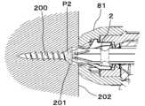
図13A~図13Cは、ネジの締結状態を示す断面図で、図13Aは、ネジ200の頭部201が、締結対象物202の表面から浮き上がったり埋まったりしない所謂面一な状態、図13Bは、ネジ200の頭部201が、締結対象物202から浮いた状態、図13Cは、ネジ200の頭部201が、締結対象物202に埋まった状態を示す。Figures 13A to 13C are cross-sectional views showing the fastening state of the screw. Figure 13A shows thehead 201 of thescrew 200 in a so-called flush state, neither floating above nor embedded in the surface of theobject 202 to be fastened. Figure 13B shows thehead 201 of thescrew 200 in a state floating above theobject 202 to be fastened. Figure 13C shows thehead 201 of thescrew 200 in a state embedded in theobject 202 to be fastened.

締結工具1は、ドライバビット2の先端が作動終了位置P2に到達したとき、ネジ200が皿ネジである場合、図13Aに示すように、ネジ200の頭部201の表面が、締結対象物202の表面と同一となる所謂面一な状態となるように、ドライバビット2の前進量が設定されていることが好ましい。なお、ネジ200は皿ネジに限らず、なべ、バインド、トラス等であれば、ネジ200の頭部201の座面が、締結対象物202の表面と接して、ネジ200の頭部201が締結対象物202から浮いた状態とならないように、ドライバビット2の前進量が設定されていることが好ましい。When the tip of thedriver bit 2 reaches the operation end position P2, if thescrew 200 is a flat head screw, it is preferable that the advance amount of thedriver bit 2 is set so that the surface of thehead 201 of thescrew 200 is flush with the surface of the object to be fastened 202, as shown in FIG. 13A. Note that thescrew 200 is not limited to a flat head screw, and if it is a pan head screw, bind, truss, etc., it is preferable that the advance amount of thedriver bit 2 is set so that the seat surface of thehead 201 of thescrew 200 does not come into contact with the surface of the object to be fastened 202 and thehead 201 of thescrew 200 does not float above the object to be fastened 202.

ドライバビット2の先端が作動終了位置P2に到達したとき、ネジ200の頭部201が、図13Bに示すように締結対象物202から浮いた状態である場合、ドライバビット2の前進量を増加させて、作動終了位置P2を前進させればよい。一方、ネジ200の頭部201が、図13Cに示すように締結対象物202に埋まった状態である場合、ドライバビット2の前進量を減少させて、作動終了位置P2を後退させればよい。When the tip of thedriver bit 2 reaches the operation end position P2, if thehead 201 of thescrew 200 is floating above theobject 202 to be fastened as shown in FIG. 13B, the advancement of thedriver bit 2 can be increased to advance the operation end position P2. On the other hand, if thehead 201 of thescrew 200 is embedded in theobject 202 to be fastened as shown in FIG. 13C, the advancement of thedriver bit 2 can be decreased to move the operation end position P2 backward.

そこで、ドライバビット2の移動量(前進量)を設定部110で設定可能とする。ドライバビット2の移動量(前進量)は、ビット移動モータ50の回転数(回転量)で規定される。そして、ドライバビット2の初期位置である待機位置P1を起点として、設定された回転量だけビット移動モータ50を回転させた後、ビット移動モータ50を回転停止または逆転させることで、作動終了位置P2が制御される。よって、締め込む深さを調整することができる。The amount of movement (advancement) of thedriver bit 2 can be set by thesetting unit 110. The amount of movement (advancement) of thedriver bit 2 is determined by the number of rotations (amount of rotation) of thebit moving motor 50. Then, starting from the standby position P1, which is the initial position of thedriver bit 2, thebit moving motor 50 is rotated the set amount of rotations, and the operation end position P2 is controlled by stopping or reversing the rotation of thebit moving motor 50. This makes it possible to adjust the tightening depth.

1・・・締結工具、10・・・工具本体、10a・・・ケース、10b・・・前フレーム、10c・・・後フレーム、10d・・・結合部材、10e・・・ネジ、10f・・・ノーズ本体部、11・・・ハンドル、12・・・バッテリ、13・・・バッテリ取付部、2・・・ドライバビット、3・・・ビット保持部、30・・・保持部材、30a・・・開口、30b・・・連結部材、31・・・回転ガイド部材、31a・・・溝部、32・・・移動部材、32a・・・第1の移動部材、32b・・・ベアリング(軸受)、32c・・・第2の移動部材、33・・・付勢部材、34a・・・ベアリング(軸受)、4・・・第1の駆動部、40・・・ビット回転モータ(第1のモータ)、40a・・・軸、41・・・減速機、41a・・・軸、42・・・ベアリング(軸受)、5・・・第2の駆動部、50・・・ビット移動モータ(モータ、第2のモータ)、50a・・・軸、51・・・減速機、51a・・・軸、52・・・プーリ(回転部材)、52a・・・外周、53・・・ベアリング、54・・・ワイヤ(伝達部材)、6・・・ネジ収納部、7・・・ネジ送り部、70・・・ネジ送りモータ、71・・・ピニオンギア、72・・・ラックギア、73・・・係合部、8・・・ノーズ部、80・・・射出通路、81・・・コンタクト部材、81a・・・射出口、82・・・コンタクトアーム、83・・・調整部、84・・・コンタクトスイッチ部、9・・・トリガ、90・・・トリガスイッチ部、100・・・制御部、110・・・設定部1: Fastening tool, 10: Tool body, 10a: Case, 10b: Front frame, 10c: Rear frame, 10d: Connecting member, 10e: Screw, 10f: Nose body, 11: Handle, 12: Battery, 13: Battery attachment section, 2: Driver bit, 3: Bit holding section, 30: Holding member, 30a: Opening, 30b: Connecting member, 31: Rotation guide member, 31a: Groove section, 32: Moving member, 32a: First moving member, 32b: Bearing, 32c: Second moving member, 33: Pressing member, 34a: Bearing, 4: First driving section, 40: Bit rotation motor (first motor), 40a: Shaft, 41: Reducer , 41a...shaft, 42...bearing (bearing), 5...second drive unit, 50...bit moving motor (motor, second motor), 50a...shaft, 51...reduction gear, 51a...shaft, 52...pulley (rotating member), 52a...periphery, 53...bearing, 54...wire (transmission member), 6...screw storage unit, 7...screw feed unit, 70...screw feed motor, 71...pinion gear, 72...rack gear, 73...engagement unit, 8...nose unit, 80...ejection passage, 81...contact member, 81a...ejection port, 82...contact arm, 83...adjustment unit, 84...contact switch unit, 9...trigger, 90...trigger switch unit, 100...control unit, 110...setting unit

Claims (6)

Translated fromJapanese
一の方向に延伸し、軸受に回転可能に支持される筒状の回転ガイド部材と、
ドライバビットが着脱可能に挿入される開口を有し、前記回転ガイド部材の内部を、前記回転ガイド部材の延伸方向に沿った軸方向に移動すると共に、前記回転ガイド部材と共に回転する保持部材と、
前記保持部材を前記回転ガイド部材に沿って前後方向に移動させる移動部材と、
モータに駆動されて回転する回転部材と、
前記移動部材に連結されると共に、前記回転部材の外周に沿って巻かれる可撓性を有した伝達部材とを備え、
前記モータにより前記回転部材を回転させることで、前記ドライバビットに係合されたネジを締結対象物に押し付ける一の方向に、前記伝達部材で前記移動部材を移動させる
締結工具。
A cylindrical rotation guide member extending in one direction and rotatably supported by a bearing;
a holding member having an opening into which a driver bit is detachably inserted, the holding member moving within the rotary guide member in an axial direction along the extension direction of the rotary guide member and rotating together with the rotary guide member;
a moving member that moves the holding member in a front-rear direction along the rotation guide member;
A rotating member that is driven to rotate by a motor;
a flexible transmission member that is connected to the moving member and that is wound around an outer periphery of the rotating member,
The fastening tool comprises a fastening member configured to rotate the rotating member by the motor, and to move the moving member by the transmission member in one direction for pressing the screw engaged with the driver bit against an object to be fastened.
前記伝達部材は、前記回転ガイド部材の延伸方向と平行な向きで延伸する
請求項1に記載の締結工具。
The fastening tool according to claim 1 , wherein the transmission member extends in a direction parallel to an extending direction of the rotation guide member.
前記回転部材の中心が、前記回転ガイド部材に対して一方の側にオフセットされ、前記回転部材の軸方向から見て、前記伝達部材が巻かれる前記回転部材の外周が、前記回転ガイド部材と重なる配置とした
請求項1または請求項2に記載の締結工具。
The fastening tool according to claim 1 or 2, wherein the center of the rotating member is offset to one side with respect to the rotating guide member, and the outer periphery of the rotating member around which the transmission member is wound overlaps with the rotating guide member when viewed in the axial direction of the rotating member.
前記モータの軸が、前記回転ガイド部材に対して一方の側にオフセットされる
請求項1~請求項3の何れか1項に記載の締結工具。
The fastening tool according to any one of claims 1 to 3, wherein a shaft of the motor is offset to one side with respect to the rotation guide member.
前記移動部材を、一の方向に沿った移動可能範囲内で一方の端部から他方の端部まで移動させるために必要な前記回転部材の回転量を360°未満とした
請求項1~請求項4の何れか1項に記載の締結工具。
The fastening tool according to any one of claims 1 to 4, wherein an amount of rotation of the rotatingmember required to move the movable member from one end to the other end within a movable range along one direction is less than 360°.
前記ドライバビットに係合されたネジを締結対象物に押し付ける一の方向に、前記移動部材が移動することで圧縮され、一の方向と反対の他の方向に前記移動部材を付勢する付勢部材を備えた
請求項1~請求項5の何れか1項に記載の締結工具。
The fastening tool according to any one of claims 1 to 5, further comprising a biasing member that is compressed by the movement of the moving member in one direction in which the screw engaged with the driver bit is pressed against an object to be fastened, and biases the moving member in another direction opposite to the one direction.
JP2021149654A2021-03-042021-09-14 Fastening toolActiveJP7700598B2 (en)

Priority Applications (32)

Application NumberPriority DateFiling DateTitle
JP2021149654AJP7700598B2 (en)2021-09-142021-09-14 Fastening tool
AU2022201528AAU2022201528A1 (en)2021-03-042022-03-04Fastening tool
US17/686,981US12186843B2 (en)2021-03-042022-03-04Fastening tool
CN202210213186.3ACN115008394A (en)2021-03-042022-03-04 Fastening tool
US17/687,206US12214457B2 (en)2021-03-042022-03-04Fastening tool
TW111107917ATW202300256A (en)2021-03-042022-03-04fastening tool
TW111107922ATW202300259A (en)2021-03-042022-03-04 fastening tool
AU2022201520AAU2022201520A1 (en)2021-03-042022-03-04Fastening tool
US17/687,099US20220281088A1 (en)2021-03-042022-03-04Fastening tool
EP22160121.4AEP4104973B1 (en)2021-03-042022-03-04Fastening tool
ES22160119TES2983016T3 (en)2021-03-042022-03-04 Fixing tool
CN202210213315.9ACN115008395A (en)2021-03-042022-03-04 Fastening tool
AU2022201529AAU2022201529A1 (en)2021-03-042022-03-04Fastening tool
TW111107920ATW202300258A (en)2021-03-042022-03-04fastening tool
CN202210212064.2ACN115091397A (en)2021-03-042022-03-04 Fastening tool
EP22160138.8AEP4052852A1 (en)2021-03-042022-03-04Fastening tool
US17/687,365US20220281083A1 (en)2021-03-042022-03-04Fastening tool
AU2022201526AAU2022201526A1 (en)2021-03-042022-03-04Fastening tool
TW111107916ATW202302285A (en)2021-03-042022-03-04fastening tool
US17/687,447US12186844B2 (en)2021-03-042022-03-04Fastening tool
EP22160134.7AEP4052851A1 (en)2021-03-042022-03-04Fastening tool
US17/687,033US20220281084A1 (en)2021-03-042022-03-04Fastening tool
TW111107919ATW202300257A (en)2021-03-042022-03-04fastening tool
TW111107915ATW202300255A (en)2021-03-042022-03-04fastening tool
EP24166431.7AEP4364893A3 (en)2021-03-042022-03-04Fastening tool
CN202210212510.XACN115008393A (en)2021-03-042022-03-04 Fastening tool
EP22160123.0AEP4052849A1 (en)2021-03-042022-03-04Fastening tool
CN202210213540.2ACN115008396A (en)2021-03-042022-03-04Fastening tool
EP22160125.5AEP4052850A1 (en)2021-03-042022-03-04Fastening tool
EP22160119.8AEP4052848B1 (en)2021-03-042022-03-04Fastening tool
CN202210212163.0ACN115008392A (en)2021-03-042022-03-04 Fastening tool
JP2025064715AJP2025096493A (en)2021-09-142025-04-10Fastening tool

Applications Claiming Priority (1)

Application NumberPriority DateFiling DateTitle
JP2021149654AJP7700598B2 (en)2021-09-142021-09-14 Fastening tool

Related Child Applications (1)

Application NumberTitlePriority DateFiling Date
JP2025064715ADivisionJP2025096493A (en)2021-09-142025-04-10Fastening tool

Publications (2)

Publication NumberPublication Date
JP2023042385A JP2023042385A (en)2023-03-27
JP7700598B2true JP7700598B2 (en)2025-07-01

Family

ID=85717291

Family Applications (2)

Application NumberTitlePriority DateFiling Date
JP2021149654AActiveJP7700598B2 (en)2021-03-042021-09-14 Fastening tool
JP2025064715APendingJP2025096493A (en)2021-09-142025-04-10Fastening tool

Family Applications After (1)

Application NumberTitlePriority DateFiling Date
JP2025064715APendingJP2025096493A (en)2021-09-142025-04-10Fastening tool

Country Status (1)

CountryLink
JP (2)JP7700598B2 (en)

Citations (7)

* Cited by examiner, † Cited by third party
Publication numberPriority datePublication dateAssigneeTitle
JP2011073110A (en)2009-09-302011-04-14Hitachi Koki Co LtdDriving machine
CN104972438A (en)2014-04-102015-10-14苏州宝时得电动工具有限公司Power tool
JP2016087703A (en)2014-10-292016-05-23日立工機株式会社Power work machine
JP2017509493A (en)2014-01-272017-04-06ローベルト ボッシュ ゲゼルシャフト ミット ベシュレンクテル ハフツング Machine tool equipment
JP2017213620A (en)2016-05-302017-12-07マックス株式会社tool
JP2018118294A (en)2017-01-272018-08-02株式会社マキタFastening tool
JP2019077024A (en)2017-10-262019-05-23マックス株式会社Tool and power tool

Family Cites Families (5)

* Cited by examiner, † Cited by third party
Publication numberPriority datePublication dateAssigneeTitle
JPS63300830A (en)*1987-05-281988-12-08Nitto Seiko Co Ltd Industrial robot screw tightening device
JPH0653039U (en)*1992-06-091994-07-19賢次 安藤 Shaft slide Axis-centered screwdriver
JPH06312382A (en)*1993-04-281994-11-08Makita CorpDrill bit storage structure for motor-driven tool
US5890405A (en)*1996-09-111999-04-06Becker; BurkhardAutomated screw driving device
JP2018118924A (en)*2017-01-252018-08-02太陽化学株式会社Separable cosmetic

Patent Citations (7)

* Cited by examiner, † Cited by third party
Publication numberPriority datePublication dateAssigneeTitle
JP2011073110A (en)2009-09-302011-04-14Hitachi Koki Co LtdDriving machine
JP2017509493A (en)2014-01-272017-04-06ローベルト ボッシュ ゲゼルシャフト ミット ベシュレンクテル ハフツング Machine tool equipment
CN104972438A (en)2014-04-102015-10-14苏州宝时得电动工具有限公司Power tool
JP2016087703A (en)2014-10-292016-05-23日立工機株式会社Power work machine
JP2017213620A (en)2016-05-302017-12-07マックス株式会社tool
JP2018118294A (en)2017-01-272018-08-02株式会社マキタFastening tool
JP2019077024A (en)2017-10-262019-05-23マックス株式会社Tool and power tool

Also Published As

Publication numberPublication date
JP2025096493A (en)2025-06-26
JP2023042385A (en)2023-03-27

Similar Documents

PublicationPublication DateTitle
JP2005288608A (en) Portable fastener driving tool
JP2005288607A (en) Portable fastener driving tool
JP7700598B2 (en) Fastening tool
JP7703960B2 (en) Fastening tool
EP4052848B1 (en)Fastening tool
NZ785849A (en)Fastening tool
JP7753645B2 (en) Fastening tool
US20230330820A1 (en)Fastening tool
JP7707579B2 (en) Fastening tool
JP7673427B2 (en) Fastening Tools
US12350793B2 (en)Fastening tool
JP7718195B2 (en) Fastening tool
NZ785832A (en)Fastening tool
JP2022135118A (en)fastening tool

Legal Events

DateCodeTitleDescription
RD02Notification of acceptance of power of attorney

Free format text:JAPANESE INTERMEDIATE CODE: A7422

Effective date:20220114

A621Written request for application examination

Free format text:JAPANESE INTERMEDIATE CODE: A621

Effective date:20240624

A977Report on retrieval

Free format text:JAPANESE INTERMEDIATE CODE: A971007

Effective date:20250226

A131Notification of reasons for refusal

Free format text:JAPANESE INTERMEDIATE CODE: A131

Effective date:20250311

A521Request for written amendment filed

Free format text:JAPANESE INTERMEDIATE CODE: A523

Effective date:20250410

TRDDDecision of grant or rejection written
A01Written decision to grant a patent or to grant a registration (utility model)

Free format text:JAPANESE INTERMEDIATE CODE: A01

Effective date:20250520

A61First payment of annual fees (during grant procedure)

Free format text:JAPANESE INTERMEDIATE CODE: A61

Effective date:20250602

R150Certificate of patent or registration of utility model

Ref document number:7700598

Country of ref document:JP

Free format text:JAPANESE INTERMEDIATE CODE: R150


[8]ページ先頭

©2009-2025 Movatter.jp