JP7700499B2 - Distributed power supply control device, control program, and distributed power supply system - Google Patents
Distributed power supply control device, control program, and distributed power supply systemDownload PDFInfo
- Publication number
- JP7700499B2 JP7700499B2JP2021073327AJP2021073327AJP7700499B2JP 7700499 B2JP7700499 B2JP 7700499B2JP 2021073327 AJP2021073327 AJP 2021073327AJP 2021073327 AJP2021073327 AJP 2021073327AJP 7700499 B2JP7700499 B2JP 7700499B2
- Authority
- JP
- Japan
- Prior art keywords
- power
- value
- command value
- distributed
- power source
- Prior art date
- Legal status (The legal status is an assumption and is not a legal conclusion. Google has not performed a legal analysis and makes no representation as to the accuracy of the status listed.)
- Active
Links
Images


Classifications
- Y—GENERAL TAGGING OF NEW TECHNOLOGICAL DEVELOPMENTS; GENERAL TAGGING OF CROSS-SECTIONAL TECHNOLOGIES SPANNING OVER SEVERAL SECTIONS OF THE IPC; TECHNICAL SUBJECTS COVERED BY FORMER USPC CROSS-REFERENCE ART COLLECTIONS [XRACs] AND DIGESTS
- Y02—TECHNOLOGIES OR APPLICATIONS FOR MITIGATION OR ADAPTATION AGAINST CLIMATE CHANGE
- Y02E—REDUCTION OF GREENHOUSE GAS [GHG] EMISSIONS, RELATED TO ENERGY GENERATION, TRANSMISSION OR DISTRIBUTION
- Y02E40/00—Technologies for an efficient electrical power generation, transmission or distribution
- Y02E40/10—Flexible AC transmission systems [FACTS]
- Y—GENERAL TAGGING OF NEW TECHNOLOGICAL DEVELOPMENTS; GENERAL TAGGING OF CROSS-SECTIONAL TECHNOLOGIES SPANNING OVER SEVERAL SECTIONS OF THE IPC; TECHNICAL SUBJECTS COVERED BY FORMER USPC CROSS-REFERENCE ART COLLECTIONS [XRACs] AND DIGESTS
- Y02—TECHNOLOGIES OR APPLICATIONS FOR MITIGATION OR ADAPTATION AGAINST CLIMATE CHANGE
- Y02E—REDUCTION OF GREENHOUSE GAS [GHG] EMISSIONS, RELATED TO ENERGY GENERATION, TRANSMISSION OR DISTRIBUTION
- Y02E40/00—Technologies for an efficient electrical power generation, transmission or distribution
- Y02E40/30—Reactive power compensation
Landscapes
- Supply And Distribution Of Alternating Current (AREA)
Description
Translated fromJapanese本発明は、分散電源から電力系統に供給する無効電力を制御して系統電圧を適正範囲に維持するための制御装置、制御プログラム、及び分散電源システムに関する。The present invention relates to a control device, a control program, and a distributed power supply system for controlling reactive power supplied from a distributed power supply to a power grid and maintaining the grid voltage within an appropriate range.
近年、太陽光発電システム等の分散電源の導入に伴い、有効電力出力の変動に起因する系統電圧の変動や適正範囲からの逸脱(電圧上限逸脱、電圧下限逸脱)等が発生している。
これらの問題を解決する対策の一つとして、従来より、SVC(静止型無効電力補償装置)を導入して電力系統に無効電力を供給することにより、系統電圧を適正範囲に制御する方法が知られている。 In recent years, with the introduction of distributed power sources such as photovoltaic power generation systems, fluctuations in active power output have led to system voltage fluctuations and deviations from the appropriate range (deviations from upper and lower voltage limits).
As one of the measures for solving these problems, a method has been known in the past in which a static var compensator (SVC) is introduced to supply reactive power to the power grid, thereby controlling the grid voltage within an appropriate range.
SVCの制御方式には電圧制御、電圧変動抑制制御等があり、何れもSVCの連系点電圧を計測し、その電圧に応じて無効電力を出力する。
例えば、電圧制御では、連系点電圧が電圧指令値またはその近傍値と一致するようにSVCが無効電力を出力する。電圧制御の応用としては、電圧上下限逸脱防止のために、電圧がある閾値を超過した場合に無効電力を出力する方式もある。また、電圧変動抑制制御では、連系点電圧から抽出した電圧変動成分に応じてこれを抑制するようにSVCが無効電力を出力する。
このように、SVCの設置は系統電圧の変動や適正範囲逸脱の対策として効果的であるが、送配電事業者や再生エネルギー発電事業者にとって、SVCを新たに導入することは設備費用が嵩むという問題がある。 SVC control methods include voltage control and voltage fluctuation suppression control, and all of them measure the interconnection point voltage of the SVC and output reactive power according to that voltage.
For example, in voltage control, the SVC outputs reactive power so that the interconnection point voltage matches the voltage command value or a value close to it. An application of voltage control is a method of outputting reactive power when the voltage exceeds a certain threshold to prevent deviation from the upper or lower voltage limits. In voltage fluctuation suppression control, the SVC outputs reactive power to suppress the voltage fluctuation component extracted from the interconnection point voltage.
As such, the installation of SVCs is effective as a countermeasure against fluctuations in grid voltage and deviations from the appropriate range, but for power transmission and distribution companies and renewable energy power generation companies, the introduction of new SVCs comes with the problem of high equipment costs.
SVCを設置する以外の電圧変動対策としては、分散電源が力率一定制御を行うことが考えられる。力率一定制御では、力率指令値に基づき、分散電源の有効電力出力に対して一定割合の無効電力を出力する。これにより、分散電源の有効電力出力の変動に起因する電圧変動を抑制する効果を期待できるが、電圧に応じた制御ではないため、連系点電圧を適正範囲に維持できるとは限らない。As a measure to combat voltage fluctuations other than installing SVCs, it is possible for the distributed power source to perform constant power factor control. With constant power factor control, a constant ratio of reactive power is output relative to the active power output of the distributed power source based on a power factor command value. This is expected to have the effect of suppressing voltage fluctuations caused by fluctuations in the active power output of the distributed power source, but because the control is not dependent on voltage, it is not necessarily possible to maintain the interconnection point voltage within an appropriate range.
力率一定制御に関連したその他の方式として、Watt-power factor mode(IEC/TR 61850-90-7)というものがある。この方式は力率指令値を固定するのではなく、分散電源の有効電力出力に応じた力率指令値特性カーブを定義し、この特性カーブに基づいて、有効電力出力に応じた無効電力を分散電源に出力させるものである。
この方式は、連系系統の特性に応じた力率指令値特性カーブを予め設定しておくことにより、連系点電圧を、力率一定制御よりも適正範囲に維持する効果を期待できる。しかし、電圧に応じた制御ではない点で力率一定制御と変わらないため、必ずしも連系点電圧を適正範囲に維持できるとは限らない。 Another method related to constant power factor control is the Watt-power factor mode (IEC/TR 61850-90-7). This method does not fix the power factor command value, but defines a power factor command value characteristic curve according to the active power output of the distributed power source, and based on this characteristic curve, makes the distributed power source output reactive power according to the active power output.
This method is expected to maintain the interconnection point voltage in an appropriate range more effectively than constant power factor control by setting in advance a power factor command value characteristic curve according to the characteristics of the interconnection system. However, since this method is the same as constant power factor control in that it is not a control according to voltage, it does not necessarily maintain the interconnection point voltage in an appropriate range.
また、SVCの電圧制御に近い方式として、Volt-var mode(IEC/TR 61850-90-7)というものがある。これは分散電源の連系点電圧に応じた無効電力出力特性カーブを定義し、連系点電圧に応じて前記特性カーブに基づき無効電力を出力するものである。この方式は、連系点電圧に応じた制御であるため、連系点電圧を適正範囲に維持する効果が期待できる。Also, there is a method similar to SVC voltage control called Volt-var mode (IEC/TR 61850-90-7). This defines a reactive power output characteristic curve according to the interconnection point voltage of the distributed power source, and outputs reactive power based on said characteristic curve according to the interconnection point voltage. Since this method is control according to the interconnection point voltage, it is expected to have the effect of maintaining the interconnection point voltage within an appropriate range.
しかし、例えば連系点電圧が下がっている場合、分散電源の有効電力出力がほぼゼロであっても無効電力を出力する等、分散電源自身に起因しない電圧変動要因に対しても補償を行うことから、本方式を実装している分散電源と実装していない分散電源との間で負担の軽重による不公平が生じる。更に、有効電力出力よりも無効電力出力を優先するように設定した場合、他の分散電源に起因する電圧変動に対して自ら無効電力を出力した結果、本来売電できるはずの有効電力が制限され、売電機会の損失が生じる可能性もある。However, because compensation is also performed for voltage fluctuation factors that are not caused by the distributed power source itself, such as outputting reactive power when the active power output of the distributed power source is almost zero when the interconnection point voltage is low, an unfair burden can arise between distributed power sources that implement this method and those that do not. Furthermore, if the system is set to prioritize reactive power output over active power output, the distributed power source will output reactive power in response to voltage fluctuations caused by other distributed power sources, limiting the active power that could otherwise be sold, which could result in lost opportunities to sell electricity.
なお、連系点電圧を適正範囲に維持する他の方法として、分散電源を構成するパワーコンディショナーの力率を連系点電圧に応じて制御する従来技術が、特許文献1に記載されている。
この従来技術は、前記パワーコンディショナーに対して、通信回線を経由して力率制御指令を出力する遠隔力率指令部を備え、系統電圧(連系点電圧)の測定値が不感帯の範囲内にある場合にも力率100%を目標値とし、最適化制御を行って連系点電圧を適正範囲に維持することを目的としている。 As another method for maintaining the interconnection point voltage within an appropriate range,
This conventional technology is equipped with a remote power factor command unit that outputs a power factor control command to the power conditioner via a communication line, and aims to set a power factor of 100% as a target value even when the measured value of the system voltage (interconnection point voltage) is within the dead band, and to perform optimization control to maintain the interconnection point voltage within an appropriate range.
特許文献1に記載された従来技術では、連系点電圧に応じてパワーコンディショナーの力率を徐々に変えていくため、例えばSVR(自動電圧調整器)のタップ切換等により連系点電圧が大きく急変した場合には、同文献の段落[0050],[0051]に指摘されているように適正な力率に収束するまでに時間がかかり、その結果、連系点電圧が適正範囲を逸脱するおそれがある。In the conventional technology described in
そこで、本発明の解決課題は、連系点電圧に応じた電圧-力率指令値特性カーブを定義し、連系点電圧が急変した場合でも上記特性カーブに従って分散電源の力率を所定値に調整することにより、連系点電圧を適正範囲に維持可能とした分散電源の制御装置、制御プログラム、及び分散電源システムを提供することにある。The problem to be solved by the present invention is to provide a control device, control program, and distributed power supply system for a distributed power supply that can maintain the interconnection point voltage within an appropriate range by defining a voltage-power factor command value characteristic curve according to the interconnection point voltage and adjusting the power factor of the distributed power supply to a predetermined value according to the characteristic curve even if the interconnection point voltage suddenly changes.
上記課題を解決するため、形態1に係る分散電源の制御装置は、
電力系統に連系された分散電源により前記電力系統に無効電力を供給するための制御装置であって、前記分散電源の力率を調整して前記無効電力を制御する制御装置において、
前記分散電源の出力電圧相当値に応じて力率指令値を連続的に変化させた電圧-力率指令値特性カーブを備え、前記出力電圧相当値に応じて前記電圧-力率指令値特性カーブから求めた力率指令値に従って前記分散電源を制御することを特徴とする。 In order to solve the above problems, a control device for a distributed power source according to a first aspect ofthe present invention comprises:
A control device for supplying reactive power to a power system from a distributed power source connected to the power system, the control device controlling the reactive power by adjusting a power factor of the distributed power source,
The power factor command value is continuously changed according to the output voltage equivalent value of the distributed power source, and the distributed power source is controlled according to the power factor command value calculated from the voltage-power factor command value characteristic curve according to the output voltage equivalent value.
形態2に係る分散電源の制御装置は、形態1に係る分散電源の制御装置において、
前記電圧-力率指令値特性カーブは、前記出力電圧相当値の所定範囲内において、前記出力電圧相当値が高くなるほど力率指令値が遅れ側に連続的に変化する特性を有することを特徴とする。A control device for a distributed power source according to a secondaspect of the present invention is the control device for a distributed power sourceaccording to the firstaspect ,
The voltage-power factor command value characteristic curve has a characteristic in which, within a predetermined range of the output voltage equivalent value, the power factor command value changes continuously to the lagging side as the output voltage equivalent value increases.
形態3に係る分散電源の制御装置は、形態1または2に係る分散電源の制御装置において、
前記電圧-力率指令値特性カーブから求めた力率指令値と前記分散電源の有効電力計測値とを用いて無効電力指令値を演算する手段と、
前記無効電力指令値と前記分散電源の無効電力計測値とを用いて前記分散電源を制御する手段と、
を備えたことを特徴とする。A control device for a distributed power source according to a thirdaspect is the control device for a distributed power sourceaccording to the first or secondaspect ,
a means for calculating a reactive power command value using a power factor command value obtained from the voltage-power factor command value characteristic curve and a measured active power value of the distributed power source;
a means for controlling the distributed power source using the reactive power command value and a reactive power measurement value of the distributed power source;
The present invention is characterized by comprising:
形態4に係る分散電源の制御装置は、形態1または2に係る分散電源の制御装置において、
前記力率指令値と前記分散電源の皮相電力最大値とを乗算して第1の有効電力制限値を求め、前記分散電源の有効電力計測値及び前記第1の有効電力制限値のうち低い値を有効電力指令値として選択する手段と、
前記分散電源の無効電力指令値、前記有効電力指令値、前記有効電力計測値及び無効電力計測値を用いて前記分散電源を制御する手段と、
を備えたことを特徴とする。A control device for a distributed power source according to a fourthaspect is the control device for a distributed power sourceaccording tothe first or second aspect ,
means for multiplying the power factor command value by a maximum apparent power value of the distributed power source to obtain a first active power limit value, and selecting the lower value of the active power measurement value of the distributed power source and the first active power limit value as an active power command value;
a means for controlling the distributed power source using a reactive power command value, an active power command value, an active power measurement value, and a reactive power measurement value of the distributed power source;
The present invention is characterized by comprising:
形態5に係る分散電源の制御装置は、形態4に係る分散電源の制御装置において、
前記第1の有効電力制限値と、前記分散電源が出力可能な有効電力最大値により制限される第2の有効電力制限値及び/または前記有効電力計測値と、のうち最も低い値を前記有効電力指令値として選択することを特徴とする。A control device for a distributed power source according to a fifthaspect is the control device for a distributed power sourceaccording to the fourthaspect ,
The method is characterized in that the lowest value among the first active power limit value, a second active power limit value limited by the maximum active power that the distributed power source can output and/or the active power measurement value isselected as the active power command value.
形態6に係る分散電源の制御装置は、形態1~5の何れか一の形態に係る分散電源の制御装置において、
前記出力電圧相当値に平均化処理を行った結果を前記電圧-力率指令値特性カーブに与えて力率指令値を求めることを特徴とする。A control device for a distributed power source according to a sixthaspect is a control device for a distributed power sourceaccording to anyone of the first to fifthaspects ,
The power factor command value is calculated by applying an averaging process to the output voltage equivalent value to the voltage-power factor command value characteristic curve.
形態7に係る制御プログラムは、電力系統に連系された分散電源の力率を調整して前記分散電源が前記電力系統に供給する無効電力を制御するための制御プログラムであって、
前記分散電源の出力電圧相当値に応じて連続的に変化する力率指令値を生成する機能と、
前記力率指令値と前記分散電源の有効電力計測値または有効電力指令値とを用いて前記分散電源の無効電力指令値を生成する機能と、
前記無効電力指令値と前記分散電源の無効電力計測値とを用いて前記分散電源が前記電力系統に供給する無効電力を制御する機能と、
を演算処理装置に実現させることを特徴とする。A control program according to a seventhaspect is a control program for adjusting a power factor of a distributed power source connected to an electric power grid to control reactive power supplied from the distributed power source to the electric power grid, the control program comprising:
a function of generating a power factor command value that changes continuously in response to an output voltage equivalent value of the distributed power source;
a function of generating a reactive power command value for the distributed power source using the power factor command value and an active power measurement value or an active power command value for the distributed power source;
a function of controlling reactive power supplied from the distributed power source to the power grid using the reactive power command value and a reactive power measurement value of the distributed power source;
The present invention is characterized in that the above is realized by a processor.
形態8に係る分散電源システムは、電力系統に複数台の分散電源が接続された分散電源システムにおいて、
形態3~5の何れか一の形態に係る分散電源の制御装置を用いて、前記複数台の分散電源を一括して制御するように構成され、
前記制御装置は、前記無効電力指令値を前記複数台の分散電源に分配する手段を備えたことを特徴とする。
A distributed power supply system according to an eighthaspect of the present invention is a distributed power supply system in which a plurality of distributed power supplies are connected to a power grid,
A control device for a distributed power sourceaccording to anyone ofaspects 3 to 5 is configured to collectively control the plurality of distributed power sources;
The control device is characterized by comprising a means for distributing the reactive power command value to the plurality of distributed power sources.
本発明によれば、電圧-力率指令値特性カーブに基づき、分散電源の出力電圧相当値、例えば連系点電圧に応じた力率指令値に従って分散電源の力率を調整することにより、電力系統に供給する無効電力を連続的に制御して連系点電圧を速やかに変化させ、適正範囲に維持することができる。
また、分散電源自身に起因しない電圧変動要因に対してまで過度に補償を行う恐れがないので、他の分散電源等に起因する電圧変動発生時に無効電力を出力することで本来売電できるはずの有効電力が制限されて売電機会を逸失する、という心配もない。このため、経済的な利益を期待することができる。 According to the present invention, by adjusting the power factor of the distributed power source in accordance with a power factor command value corresponding to a value equivalent to the output voltage of the distributed power source, for example, a value corresponding to the interconnection point voltage, based on a voltage-power factor command value characteristic curve, it is possible to continuously control the reactive power supplied to the power system, quickly change the interconnection point voltage, and maintain it within an appropriate range.
In addition, because there is no risk of excessive compensation being made for voltage fluctuation factors that are not caused by the distributed power source itself, there is no need to worry about the output of reactive power when voltage fluctuations occur due to other distributed power sources, etc., limiting the active power that could otherwise be sold, and resulting in the loss of opportunities to sell electricity. Therefore, economic benefits can be expected.
以下、図に沿って本発明の実施形態を説明する。
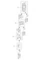
図1は、本発明の実施形態を含む電力系統の全体構成図である。図1において、例えば三相の交流電源20に接続された電力系統21には、変圧器40を介して分散電源30が接続されている。また、22は抵抗及びインダクタンスからなる系統インピーダンス、41は電力系統21との連系点、33は分散電源接続点を示す。 Hereinafter, an embodiment of the present invention will be described with reference to the drawings.
Fig. 1 is an overall configuration diagram of a power system including an embodiment of the present invention. In Fig. 1, a
分散電源30は、太陽電池パネル等の直流電力源31と、電力変換器の動作により直流/交流変換を行うパワーコンディショナシステム(PCS)等の発電部32と、発電部32を制御する制御装置50と、を備えている。
制御装置50は、連系点41の電圧Vm及び電流Im等に基づいて発電部32内の電力変換器を制御する。ここで、連系点41の電圧Vm及び電流Imに代えて分散電源接続点33の電圧及び電流を制御装置50に入力して制御に用いても良い。すなわち、請求項における「分散電源の出力電圧相当値」は、上述した連系点41の電圧や分散電源接続点33の電圧を含む概念である。 The
The
図示されていないが、分散電源としては、直流電力または機械的動力を交流電力(有効電力及び無効電力)に変換して出力する機能を備えていれば良い。このため、太陽光以外に風力等の再生可能エネルギーを利用して発生させた直流電力、または蓄電池や燃料電池等の直流電力を交流電力に変換する装置でも良いし、火力や水力を利用して発生させた機械的動力を交流電力に変換する同期発電機や誘導発電機等であっても良い。Although not shown, the distributed power source may have the function of converting DC power or mechanical power into AC power (active power and reactive power) and outputting it. For this reason, it may be a device that converts DC power generated using renewable energy sources such as wind power other than solar power, or DC power from a storage battery or fuel cell into AC power, or it may be a synchronous generator or induction generator that converts mechanical power generated using thermal or hydroelectric power into AC power.
次に、制御装置50の構成及び機能について説明する。
本実施形態における制御装置50の構成及び機能は、CPU(Central Processing Unit)やFPGA(Field-Programmable Gate Array)、ASIC(Application Specific Integrated Circuit)等を含む演算処理装置のハードウェア及びソフトフェア(プログラム)によって実現される。 Next, the configuration and functions of the
The configuration and functions of the
図2は、制御装置50の第1実施例の主要部を示すブロック図である。ここでは、第1実施例による無効電力の制御を、電圧-可変力率制御と呼ぶことにする。
図2において、連系点電圧(計測値)Vmは平均化処理手段としての一次遅れフィルタ(ローパスフィルタ)51に入力されて急峻な変動成分が除去された後、電圧・力率指令値特性カーブ52に与えられる。なお、一次遅れフィルタ51の構成は特に限定されない。また、平均化処理手段としては、一次遅れフィルタ51だけでなく移動平均処理を行う手段であっても良い。このことは、後述する他の実施例についても同様である。 2 is a block diagram showing the main parts of a first embodiment of the
2, the interconnection point voltage (measured value)Vm is input to a first-order lag filter (low-pass filter) 51 as an averaging processing means, where steep fluctuation components are removed, and then the voltage is applied to a voltage/power factor command value
電圧-力率指令値特性カーブ52は、例えば図3(a),(b)に示すように、連系点電圧Vmに応じて変化する分散電源30の力率指令値PFrefを設定したものであり、連系点電圧Vmと力率指令値PFrefとの関係は、数式またはテーブルとしてメモリに格納されている。 The voltage-power factor command value
図3(a)は、連系点電圧Vmが系統電圧の基準値V0(例えば、実効値100[V]の低圧配電系統では、101[V]等)以下の範囲では力率指令値PFrefを1.0(100%)とし、連系点電圧Vmが基準値V0より高い範囲では力率指令値PFrefを一定の傾きで「遅れ」側へ連続的に変化させる特性である。
また、図3(b)は、基準値V0を中心として連系点電圧Vmが高いほど力率指令値PFrefを「遅れ」側へ、連系点電圧Vmが低いほど「進み」側へ、連続的に変化させる特性である。
何れにしても、電圧-力率指令値特性カーブ52は、連系点電圧Vmの所定範囲内において、連系点電圧Vmが高くなるほど力率指令値が「遅れ」側へ連続的に変化する特性を有していれば良い。
図3(a),(b)から分かるように、連系点電圧がVm1である時の力率指令値PFref1は連系点電圧がVm2(Vm1<Vm2)である時の力率指令値PFref2よりも高くなり、1.0(100%)に近付いていく。 FIG. 3A shows a characteristic in which the power factor command value PFref is set to 1.0 (100%) when the interconnection point voltageVm is in a range below the system voltage reference valueV0 (for example, 101 [V] in a low-voltage distribution system with an effective value of 100 [V]), and the power factor command valuePFref is continuously changed to the “lagging” side at a constant gradient when the interconnection point voltageVm is in a range above thereference valueV0 .
FIG. 3B showsa characteristic in which the power factor command valuePFref is continuously changed toward the "lagging" side as the interconnection point voltageVm is higher, and toward the "leading" side as the interconnection point voltageVm is lower, with the reference value V0 as the center.
In any case, it is sufficient that the voltage-power factor command value
As can be seen from Figures 3(a) and (b), the power factor command value PFref1 when the interconnection point voltage is Vm1 is higher than the power factor command value PFref2 when the interconnection point voltage is Vm2 (Vm1 < Vm2 ), and approaches 1.0 (100%).
ここで、図3(a),(b)における力率指令値PFrefの「遅れ」とは、分散電源30を遅れ力率により運転して電力系統21に遅れ無効電力(誘導性の無効電力)を供給することであり、力率指令値PFrefの「進み」とは、分散電源30を進み力率により運転して電力系統21に進み無効電力(容量性の無効電力)を供給することである。
一般的に、電力系統の電圧を適正範囲に維持するためには、分散電源を原則的に0.85(85%)以上の遅れ力率で運転することが求められている。 Here, the “lag” of the power factor command value PFref in FIGS. 3( a) and 3(b) means that the distributed
Generally, in order to maintain the voltage of a power system within an appropriate range, a distributed power source is required to be operated with a lagging power factor of 0.85 (85%) or more in principle.
図2に戻って、電圧-力率指令値特性カーブ52から求めた力率指令値PFrefは、無効電力指令値演算部53に入力されている。また、図1に示した連系点41の電圧Vm及び電流Imから求めた有効電力計測値Pmも、無効電力指令値演算部53に入力されている。 2, the power factor command value PFref calculated from the voltage-power factor command value
無効電力指令値演算部53では、力率指令値PFrefに基づき、有効電力計測値Pmに対して一定割合の無効電力を出力するように、数式1に基づいて無効電力指令値Qrefを算出する。
[数式1]
Qref=Pm√{(1-PFref2)/PFref2} The reactive power command
[Formula 1]
Qref =Pm √{(1-PFref2 )/PFref2 }
上記の無効電力指令値Qrefは、無効電力計測値Qmと共に分散電源制御系54に入力される。なお、無効電力計測値Qmは、有効電力計測値Pmと同様に連系点41の電圧Vm及び電流Imから算出可能である。
分散電源制御系54は、無効電力計測値Qmが無効電力指令値Qrefに一致するように、図1における発電部32内の電力変換器を運転して電力系統21に出力する無効電力(無効電流)を調整し、これによって連系点41の電圧を制御する。 The reactive power command valueQref is input to the distributed
The distributed power
図2において、有効電力計測値、無効電力計測値、無効電力指令値の代わりに、有効電流計測値、無効電流計測値、無効電流指令値を用いても良い。
更に、平均化処理手段としての一次遅れフィルタ51は必須の構成ではないが、入力電圧から瞬時の変動成分を除去することにより、分散電源が過敏に反応して不安定になるのを回避することができる。 In FIG. 2, an active current measurement value, a reactive current measurement value, and a reactive current command value may be used instead of the active power measurement value, the reactive power measurement value, and the reactive power command value.
Furthermore, although the first-
次に、図4は、分散電源制御系54及び発電部32の主要部の構成を示している。
図4において、発電部32は、PWM(パルス幅変調)制御により直流電力源31の直流電力を交流電力に変換するインバータ部32aを備えている。 Next, FIG. 4 shows the configuration of the distributed power
In FIG. 4, the
分散電源制御系54内の制御指令演算部54aは、前述した無効電力指令値Qref及び無効電力計測値Qmと、センサ34,35により検出した入出力電圧Vd,Va及び電流Id,Ia等に基づいて、インバータ部32aに対する制御指令(電圧指令)を生成する。
PWM回路54bは、制御指令演算部54aからの制御指令とキャリアとを比較してPWMパルスを生成し、このPWMパルスに基づく駆動信号によりインバータ部32aの半導体スイッチング素子をオン・オフ制御して無効電力指令値Qref通りの無効電力をPCS接続端33から電力系統21に出力する。また、必要に応じて有効電力の制御も行う。 The control
The
以上のように、本発明の第1実施例によれば、連系点電圧Vmが高い場合には、分散電源30の有効電力に応じて、より誘導性の無効電力を出力し、連系点電圧Vmが低い場合には、分散電源30の有効電力に応じて(連系点電圧Vmが高い時よりも)誘導性の無効電力を減らすか、あるいは容量性の無効電力を出力することにより、連系点電圧Vmを適正範囲に維持することが可能になる。 As described above, according to the first embodiment of the present invention, when the interconnection point voltageVm is high, more inductive reactive power is output in accordance with the active power of the distributed
更に、分散電源30の有効電力に応じて無効電力を出力するので、分散電源自身の有効電力出力の変動に起因する電圧変動を抑制することができる。また、連系点電圧Vmが低下していても分散電源30の有効電力出力がほぼゼロであれば無効電力を出力しないため、分散電源自身に起因しない連系点電圧の変動要因に対してまで過度に補償を行うことはなく、同様に、電力系統21に連系している他の分散電源等に起因する電圧変動に対して無効電力を出力した結果、本来売電できるはずの有効電力が制限されて売電機会を逸失する恐れもない。 Furthermore, since reactive power is output according to the active power of the distributed
次いで、制御装置50の第2実施例、第3実施例による無効電力の制御を、図5を参照しつつ説明する。
まず、第2実施例は、第1実施例による電圧-可変力率制御と、発電部32のVA制限制御とを組み合わせたものであり、VA制限制御とは、発電部32から出力される皮相電力最大値VAmax(VA制約)を超えないように発電部32の有効電力及び無効電力を制御する方法である。 Next, reactive power control by second and third embodiments of the
First, the second embodiment is a combination of the voltage-variable power factor control according to the first embodiment and the VA limit control of the
具体的には、図5に示す有効電力VA制限値演算部55により、電圧-力率指令値特性カーブ52から求めた力率指令値PFrefとVA最大値VAmaxとを乗算し、VA制約と力率指令値PFrefとから採り得る最大の有効電力値としての有効電力VA制限値を求める。この有効電力VA制限値は、請求項における第1の有効電力制限値に相当する。
この第1の有効電力制限値としての有効電力VA制限値と有効電力計測値Pmとを低値優先部57により比較して低い方の値を選択し(図1の直流電力源31として蓄電池を用いる場合のように、正負両方向の有効電力が得られる時は、絶対値で低い方の値を選択し)、これを有効電力指令値Prefとして出力する。 5 multiplies the power factor command value PFref calculated from the voltage-power factor command value
The active power VA limit value as the first active power limit value is compared with the active power measurement valuePm by a lower
無効電力指令演算部53Aでは、力率指令値PFrefと有効電力指令値Prefとを用いて、数式2により無効電力指令値Qrefを演算する。
[数式2]
Qref=Pref√{(1-PFref2)/PFref2}
この無効電力指令値Qref、無効電力計測値Qm、有効電力指令値Pref、及び有効電力計測値Pmを分散電源制御系54Aに入力し、発電部32の有効電力制御、無効電力・電流制御、PWM制御等を行えば、発電部32のVAmaxを超えない範囲で所望の力率により連系点41の有効電力及び無効電力を制御することができる。 The reactive power command calculation unit 53A calculates a reactive power command value Qref according to Equation 2 using the power factor command value PFref and the active power command value Pref .
[Formula 2]
Qref =Pref √{(1-PFref2 )/PFref2 }
By inputting the reactive power command value Qref , the reactive power measurement value Qm , the active power command value Pref , and the active power measurement value Pm to the distributed power source control system 54A and performing active power control, reactive power/current control, PWM control, etc. of the
次に、第3実施例は、前述した第1,第2実施例に加えて、発電部32の有効電力制限制御を組み合わせたものであり、この有効電力制限制御は、発電部32から出力される有効電力を必要に応じて制限する制御方法である。本実施例における有効電力制限値は、請求項における第2の有効電力制限値に相当する。Next, the third embodiment combines the first and second embodiments described above with active power limit control of the
すなわち、図5における有効電力制限制御部56は、後述するように必要に応じて設定した有効電力制限値(第2の有効電力制限値)を出力する。低値優先部57では、この第2の有効電力制限値と、前述した第1の有効電力制限値である有効電力VA制限値及び/または有効電力計測値Pmのうち最も小さい値(第2の有効電力制限値と有効電力VA制限値、第2の有効電力制限値と有効電力計測値Pm、第2の有効電力制限値と有効電力VA制限値と有効電力計測値Pm、の三つの組み合わせについて、それぞれ最も小さい値)を選択し、選択した値を有効電力指令値Prefとして出力する。前記同様に、直流電力源31として蓄電池を用いる場合のように、正負両方向の有効電力が得られる時は、絶対値で低い方の値を選択し、有効電力指令値Prefとして出力する。 That is, the active power
ここで、有効電力制限制御部56は、必要に応じて様々な構成・機能を有する。
例えば、分散電源30が無効電力を出力してもなお連系点電圧Vmが高い時に有効電力出力を低下させたい場合は、連系点電圧Vmを有効電力制限制御部56に入力して連系点電圧Vmが所定の連系点電圧閾値を超過した場合に有効電力制限値を所望の値に低下させるように構成しても良い。
また、余剰電力や送電線容量等が問題になって分散電源30の有効電力出力を低下させたい場合には、外部から有効電力制限制御部56に入力された出力制限指令に基づいて有効電力制限値を所望の値に低下させるように構成しても良い。 Here, the active power
For example, in a case where it is desired to reduce the active power output when the interconnection point voltageVm is still high even when the distributed
In addition, when surplus power, transmission line capacity, etc. become an issue and it is desired to reduce the active power output of the distributed
次いで、電力系統21に連系された複数台の分散電源からなる分散電源システムに関する本発明の第4実施例を説明する。
図示されていないが、電力系統21に複数台の分散電源が連系されている場合には、各分散電源に前述した第1~第3実施例に係る制御装置50を実装しても良い。
或いは、複数台の分散電源を一括して制御する構成とし、無効電力指令値Qrefを各分散電源に分配しても良い。その場合の分配方法としては、例えば以下のような方法が考えられる。 Next, a fourth embodiment of the present invention will be described, which relates to a distributed power supply system including a plurality of distributed power supplies connected to the
Although not shown, when a plurality of distributed power sources are connected to the
Alternatively, a configuration may be adopted in which a plurality of dispersed power sources are collectively controlled, and the reactive power command valueQref may be distributed to each dispersed power source. In this case, the following method, for example, may be considered as a distribution method.
(1)無効電力指令値Qrefを分散電源の台数Nにより除算した値Qref n(n=1~N)を、各分散電源に対する無効電力指令値として分配する。この時の各分散電源に対する無効電力指令値を数式3に示す。
[数式3]
Qref n=Qref/N(1) The reactive power command value Qref is divided by the number N of distributed power sources to obtain a value Qref n (n=1 to N), which is then distributed as a reactive power command value to each distributed power source. The reactive power command value for each distributed power source at this time is shown in Equation 3.
[Formula 3]
Qref n =Qref /N
(2)無効電力指令値Qrefを、各分散電源の有効電力出力Pnに応じて分配する。この時の各分散電源に対する無効電力指令値を数式4に示す。
[数式4]
Qref n=Qref×(Pn/ΣPn)(2) The reactive power command valueQref is distributed according to the active power outputPn of each distributed power source. The reactive power command value for each distributed power source at this time is shown in Equation 4.
[Formula 4]
Qref n =Qref ×(Pn /ΣPn )
(3)無効電力指令値Qrefを、各分散電源の無効電力出力余力Qmargin nに応じて分配する。この時の各分散電源に対する無効電力指令値を数式5に示す。
ここで、無効電力出力余力Qmargin nとは、無効電力指令値Qrefに対して、n番目の分散電源が出力可能な無効電力Qref nが大きいか(余力があるか)小さいか(余力がない)を判断する指標である。
[数式5]
Qref n=Qref×(Qmargin n/ΣQmargin n)
例えば、無効電力指令値Qrefが“100”であり、3台(N=3)の分散電源の無効電力出力余力Qmargin 1,Qmargin 2,Qmargin 3がそれぞれ“85”,“45”,“70”である場合には、Qref 1に85×(100/200)=42.5を、Qref 2に22.5を、Qref 3に35.0をそれぞれ分配する。(3) The reactive power command valueQref is distributed in accordance with the reactive power output marginQmarginn of each distributed power source. The reactive power command value for each distributed power source at this time is shown in Equation 5.
Here, the reactive power output margin Qmargin n is an index for determining whether the reactive power Qref nthat the nth distributed power source can output is large (has margin) or small (has no margin) relative to the reactive power command value Q ref.
[Formula 5]
Qref n =Qref ×(Qmargin n /ΣQmargin n )
For example, if the reactive power command value Qref is “100” and the reactive power output margins Qmargin 1 , Qmargin 2 , and Qmargin 3 of three (N=3) distributed power sources are “85”, “45”, and “70”, respectively, then 85×(100/200)=42.5 is distributed to Qref 1 , 22.5 to Qref 2 , and 35.0 to Qref 3 .
更に他の分配方法として、次の方法がある。
(4)無効電力指令値Qrefを、各分散電源の無効電力出力の優先順位と前述した無効電力出力余力Qmargin nとに応じて分配する。この分配方法による手順を図6に示す。
図6において、まず、N台の分散電源のうちの1台を無効電力出力の優先順位1番として(n=1)、無効電力指令値演算部により算出された無効電力指令値Qrefを初期値としてセットする(ステップS1)。 Further distribution methods include the following.
(4) The reactive power command value Qref is distributed in accordance with the priority order of the reactive power output of each dispersed power source and the above-mentioned reactive power output margin Qmargin n . The procedure for this distribution method is shown in FIG.
In FIG. 6 , first, one of the N distributed power sources is assigned the highest priority in reactive power output (n=1), and the reactive power command value Qref calculated by the reactive power command value calculation unit is set as an initial value (step S1).
次に、その優先順位1番目の分散電源について、無効電力出力余力Qmargi1が無効電力指令値(初期値)のQref以下であるか否かを判断し、かつ、n<Nであることを確認する(ステップS2)。なお、無効電力出力余力Qmargi1が初期値のQrefを超えている場合(ステップS2 No)には、Qref n=Qref、つまり1番目の分散電源のみによって無効電力指令値Qrefに相当する無効電力を出力可能であるため、処理を終了する(ステップS6)。 Next, for the first-priority distributed power source, it is determined whether the reactive power output marginQmargi1 is equal to or less than the reactive power command value (initial value)Qref , and confirms that n<N (step S2). If the reactive power output marginQmargi1 exceeds the initial valueQref (No in step S2),Qrefn =Qref , that is, the first-priority distributed power source alone can output reactive power equivalent to the reactive power command valueQref , and the process ends (step S6).
優先順位1番目の分散電源の無効電力出力余力Qmargi1が初期値Qref以下であり、かつ、n<Nである場合(ステップS2 Yes)には、1番目の分散電源に対する無効電力指令値Qref 1=Qmargi1として当該分散電源の余力を最大限使用することとし(ステップS3)、次に、初期値QrefからQref 1を差し引いた値を新たな無効電力指令値Qrefとしてセットする(ステップS4)。
次いで、優先順位をインクリメントし(ステップS5)、以後は、ステップS2以降の処理をn=Nとなるまで繰り返し実行する。 If the reactive power output margin Qmargin1 of the first-priority distributed power source is equal to or less than the initial value Qref and n<N (Yes in step S2), the reactive power command value Qmargin1 for the first distributed power source is set to Q margin1 = Qmargin1 to maximize the margin of the first distributed power source (step S3), and then the value obtained by subtracting Qref1 from the initial value Qref is set as the new reactive power command value Qref (step S4).
Next, the priority is incremented (step S5), and thereafter, the processes from step S2 onwards are repeatedly executed until n=N.
上記のように、第4実施例によれば、無効電力指令値Qrefを種々の方法によって各分散電源に分配することにより、複数台の分散電源を一括して制御することが可能である。 As described above, according to the fourth embodiment, it is possible to collectively control a plurality of distributed power sources by distributing the reactive power command valueQref to each of the distributed power sources by various methods.
なお、本発明において、制御装置50による電圧-可変力率制御や分散電源制御機能の一部または全部を遠隔のサーバー等に実装し、分散電源30内の発電部32との間で通信を介して計測や制御を行っても良い。
また、電圧-力率指令値特性カーブを、直接または通信を介した遠隔制御により手動または自動的に変更しても良く、予め決定したスケジュールに基づき、あるいは特定のトリガー入力によって変更しても良い。 In the present invention, some or all of the voltage-variable power factor control and distributed power source control functions of the
Furthermore, the voltage-power factor command value characteristic curve may be changed manually or automatically by direct or remote control via communication, and may be changed based on a predetermined schedule or by a specific trigger input.
20:交流電源
21:電力系統
22:系統インピーダンス
30:分散電源
31:直流電力源
32:発電部(PCS)
32a:インバータ部
33:PCS接続端
34,35:センサ
40:変圧器
41:連系点
50:制御装置
51:一次遅れフィルタ
52:電圧-力率指令値特性カーブ
53,53A:無効電力指令値演算部
54,54A:分散電源制御系
54a:制御指令演算部
54b:PWM回路
55:有効電力VA制限値演算部
56:有効電力制限制御部
57:低値優先部20: AC power source 21: Power system 22: System impedance 30: Distributed power source 31: DC power source 32: Power generation unit (PCS)
32a: inverter section 33:
Claims (6)
Translated fromJapanese前記分散電源の出力電圧相当値に応じて力率指令値を連続的に変化させた電圧-力率指令値特性カーブを備え、前記出力電圧相当値に応じて前記電圧-力率指令値特性カーブから求めた力率指令値に従って前記分散電源を制御するものであり、
前記力率指令値と前記分散電源の皮相電力最大値とを乗算して第1の有効電力制限値を求め、前記分散電源の有効電力計測値及び前記第1の有効電力制限値のうち低い値を有効電力指令値として選択する手段と、
前記分散電源の無効電力指令値、前記有効電力指令値、前記有効電力計測値及び無効電力計測値を用いて前記分散電源を制御する手段と、
を備える、分散電源の制御装置。 A control device for supplying reactive power to a power system from a distributed power source connected to the power system, the control device controlling the reactive power by adjusting a power factor of the distributed power source,
a voltage-power factor command value characteristic curve that continuously changes a power factor command value in accordance with an output voltage equivalent value of the distributed power source, and the distributed power source is controlled in accordance with a power factor command value calculated from the voltage-power factor command value characteristic curve in accordance with the output voltage equivalent value;
means for multiplying the power factor command value by a maximum apparent power value of the distributed power source to obtain a first active power limit value, and selecting the lower value of the active power measurement value of the distributed power source and the first active power limit value as an active power command value;
a means for controlling the distributed power source using a reactive power command value, an active power command value, an active power measurement value, and a reactive power measurement value of the distributed power source;
A control device for a distributed power sourcecomprising :
前記電圧-力率指令値特性カーブは、
前記出力電圧相当値の所定範囲内において、前記出力電圧相当値が高くなるほど前記力率指令値が遅れ側に連続的に変化する特性を有する、分散電源の制御装置。 2. The control device for a distributed power source according to claim 1,
The voltage-power factor command value characteristic curve is
A control device for a distributed power source, the control device having a characteristic that, within a predetermined range of the output voltage equivalent value, the power factor command value continuously changes to the lagging side as theoutput voltage equivalent value becomes higher.
前記分散電源の出力電圧相当値に応じて力率指令値を連続的に変化させた電圧-力率指令値特性カーブを備え、前記出力電圧相当値に応じて前記電圧-力率指令値特性カーブから求めた力率指令値に従って前記分散電源を制御するものであり、
前記力率指令値と前記分散電源の皮相電力最大値とを乗算して第1の有効電力制限値を求め、前記第1の有効電力制限値と、前記分散電源が出力可能な有効電力最大値により制限される第2の有効電力制限値及び/または前記分散電源の有効電力計測値と、のうち最も低い値を有効電力指令値として選択する手段と、
前記分散電源の無効電力指令値、前記有効電力指令値、前記有効電力計測値及び無効電力計測値を用いて前記分散電源を制御する手段と、
を備える、分散電源の制御装置。 A control device for supplying reactive power to a power system from a distributed power source connected to the power system, the control device controlling the reactive power by adjusting a power factor of the distributed power source,
a voltage-power factor command value characteristic curve that continuously changes a power factor command value in accordance with an output voltage equivalent value of the distributed power source, and the distributed power source is controlled in accordance with a power factor command value calculated from the voltage-power factor command value characteristic curve in accordance with the output voltage equivalent value;
a means for multiplying the power factor command value by a maximum apparent power value of the distributed power source to obtain a first active power limit value, and selecting, as an active power command value, the lowest value of the first active power limit value, a second active power limit value limited by the maximum active power that the distributed power source can output and/or a measuredactive power valueof the distributed power source;
a means for controlling the distributed power source using a reactive power command value, an active power command value, an active power measurement value, and a reactive power measurement value of the distributed power source;
A control device for a distributed power sourcecomprising :
前記出力電圧相当値に平均化処理を行った結果を前記電圧-力率指令値特性カーブに与えて前記力率指令値を求める、分散電源の制御装置。 The control device for a distributed power source according to any one of claims1 to 3 ,
The control device for adistributed power source obtains the power factor command value by applying an averaging process to the output voltage equivalent value to the voltage-power factorcommand value characteristic curve.
前記分散電源の出力電圧相当値に応じて力率指令値を連続的に変化させた電圧-力率指令値特性カーブから、前記分散電源の出力電圧相当値に応じて連続的に変化する力率指令値を生成する機能と、
前記力率指令値と前記分散電源の皮相電力最大値とを乗算して第1の有効電力制限値を求め、前記分散電源の有効電力計測値及び前記第1の有効電力制限値のうち低い値を有効電力指令値として選択する機能と、
前記分散電源の無効電力指令値、前記有効電力指令値、前記有効電力計測値及び無効電力計測値を用いて前記分散電源を制御する機能と、
を演算処理装置に実現させることを特徴とする制御プログラム。 1. A control program for adjusting a power factor of a distributed power source connected to a power system to control reactive power supplied from the distributed power source to the power system, comprising:
a function of generating a power factor command value that changes continuously in accordance with the output voltage equivalent value of the distributed power source from a voltage-power factor command value characteristic curve in which the power factor command value is continuously changed in accordance with the output voltage equivalent value of the distributed power source;
a function of multiplying the power factor command value by a maximum apparent power value of the distributed power source to obtain a first active power limit value, and selecting the lower value of the active power measurement value of the distributed power source and the first active power limit value as an active power command value;
a function of controlling the distributed power source using a reactive power command value, an active power command value, an active power measurement value, and a reactive power measurement value of the distributed power source;
A control program for causing a processor to realize the above.
請求項1から3の何れか1項に記載された分散電源の制御装置を用いて、前記複数台の分散電源を一括して制御するように構成され、
前記制御装置は、前記無効電力指令値を前記複数台の分散電源に分配する、分散電源システム。In adistributed power supply system in which a plurality of distributed power supplies are connected to the power grid,
A system configured to collectively control the plurality of distributed power sources using the distributed power source control device according to any one of claims1 to 3 ,
The control device distributes the reactive power command value to the plurality ofdistributed power sources.
Priority Applications (1)
| Application Number | Priority Date | Filing Date | Title |
|---|---|---|---|
| JP2021073327AJP7700499B2 (en) | 2021-04-23 | 2021-04-23 | Distributed power supply control device, control program, and distributed power supply system |
Applications Claiming Priority (1)
| Application Number | Priority Date | Filing Date | Title |
|---|---|---|---|
| JP2021073327AJP7700499B2 (en) | 2021-04-23 | 2021-04-23 | Distributed power supply control device, control program, and distributed power supply system |
Publications (2)
| Publication Number | Publication Date |
|---|---|
| JP2022167502A JP2022167502A (en) | 2022-11-04 |
| JP7700499B2true JP7700499B2 (en) | 2025-07-01 |
Family
ID=83852692
Family Applications (1)
| Application Number | Title | Priority Date | Filing Date |
|---|---|---|---|
| JP2021073327AActiveJP7700499B2 (en) | 2021-04-23 | 2021-04-23 | Distributed power supply control device, control program, and distributed power supply system |
Country Status (1)
| Country | Link |
|---|---|
| JP (1) | JP7700499B2 (en) |
Citations (4)
| Publication number | Priority date | Publication date | Assignee | Title |
|---|---|---|---|---|
| JP2007231778A (en) | 2006-02-28 | 2007-09-13 | Mitsubishi Heavy Ind Ltd | Wind power generation system and method for controlling the same |
| JP2015192477A (en) | 2014-03-27 | 2015-11-02 | 株式会社東芝 | Control device, control method, and power generation system |
| JP2015220833A (en) | 2014-05-16 | 2015-12-07 | 田淵電機株式会社 | Controller of distributed power supply and control method of distributed power supply |
| JP2019126110A (en) | 2018-01-12 | 2019-07-25 | 株式会社Gsユアサ | Power control unit and control method of the same |
Family Cites Families (1)
| Publication number | Priority date | Publication date | Assignee | Title |
|---|---|---|---|---|
| JPH1084633A (en)* | 1996-09-06 | 1998-03-31 | Nissin Electric Co Ltd | Operation of solar power generation inverter |
- 2021
- 2021-04-23JPJP2021073327Apatent/JP7700499B2/enactiveActive
Patent Citations (4)
| Publication number | Priority date | Publication date | Assignee | Title |
|---|---|---|---|---|
| JP2007231778A (en) | 2006-02-28 | 2007-09-13 | Mitsubishi Heavy Ind Ltd | Wind power generation system and method for controlling the same |
| JP2015192477A (en) | 2014-03-27 | 2015-11-02 | 株式会社東芝 | Control device, control method, and power generation system |
| JP2015220833A (en) | 2014-05-16 | 2015-12-07 | 田淵電機株式会社 | Controller of distributed power supply and control method of distributed power supply |
| JP2019126110A (en) | 2018-01-12 | 2019-07-25 | 株式会社Gsユアサ | Power control unit and control method of the same |
Also Published As
| Publication number | Publication date |
|---|---|
| JP2022167502A (en) | 2022-11-04 |
Similar Documents
| Publication | Publication Date | Title |
|---|---|---|
| US8373312B2 (en) | Solar power generation stabilization system and method | |
| KR101431047B1 (en) | Coordinated Droop Control Apparatus and the Method for Stand-alone DC Micro-grid | |
| CN102170249B (en) | solar power system and operational approach thereof | |
| KR101849783B1 (en) | Power conversion system and method | |
| CN103004050B (en) | For controlling method and the control device of the center capacitor in wind power plant | |
| KR101426826B1 (en) | Variable Resistance Type Droop Control Appratus and the Method for Stand-alone Micro-grid | |
| CN105493372B (en) | The Sun can generate system | |
| KR102264862B1 (en) | System and Method for Controlling Inertial of Energy Storage System | |
| JP2013069267A (en) | Maximum power point tracking for power conversion system and method for the same | |
| CN104426155A (en) | System and method for voltage control of wind generator | |
| EP2485378A1 (en) | Control arrangement and method for regulating the output voltage of a dc source power converter connected to a multi-source dc system | |
| Xiao et al. | Flat tie-line power scheduling control of grid-connected hybrid microgrids | |
| KR102234527B1 (en) | SoC Management System and Method using Frequency Control at ESS Interfacing Generation Plant | |
| JP5830484B2 (en) | Reactive power ratio controller, reactive power ratio control method, and power generation system using the same | |
| KR20170021606A (en) | The battery energy storage system and reactive power compensation method using thereof | |
| CN109804557B (en) | Solar power generation system | |
| JP6768571B2 (en) | Power controller, method and power generation system | |
| KR20170104809A (en) | Apparatus and method for stabilizing voltage for direct current distribution system | |
| WO2021205701A1 (en) | Power conversion device | |
| KR20190026379A (en) | Grid-off microgrid system capable of maintaining rated voltage and rated frequency | |
| US12126178B2 (en) | Boosting reactive current injection from wind turbine generators | |
| JP7700499B2 (en) | Distributed power supply control device, control program, and distributed power supply system | |
| Aboelsoud et al. | Cooperative decentralized hierarchical based voltage control of DC microgrids | |
| JP7203325B2 (en) | power system | |
| KR102234526B1 (en) | SoC Management System and Method using Frequency Control and Adaptive Control at ESS Interfacing Generation Plant |
Legal Events
| Date | Code | Title | Description |
|---|---|---|---|
| RD03 | Notification of appointment of power of attorney | Free format text:JAPANESE INTERMEDIATE CODE: A7423 Effective date:20220927 | |
| RD04 | Notification of resignation of power of attorney | Free format text:JAPANESE INTERMEDIATE CODE: A7424 Effective date:20221006 | |
| A621 | Written request for application examination | Free format text:JAPANESE INTERMEDIATE CODE: A621 Effective date:20240313 | |
| A977 | Report on retrieval | Free format text:JAPANESE INTERMEDIATE CODE: A971007 Effective date:20250127 | |
| A131 | Notification of reasons for refusal | Free format text:JAPANESE INTERMEDIATE CODE: A131 Effective date:20250212 | |
| A521 | Request for written amendment filed | Free format text:JAPANESE INTERMEDIATE CODE: A523 Effective date:20250409 | |
| TRDD | Decision of grant or rejection written | ||
| A01 | Written decision to grant a patent or to grant a registration (utility model) | Free format text:JAPANESE INTERMEDIATE CODE: A01 Effective date:20250520 | |
| A61 | First payment of annual fees (during grant procedure) | Free format text:JAPANESE INTERMEDIATE CODE: A61 Effective date:20250602 | |
| R150 | Certificate of patent or registration of utility model | Ref document number:7700499 Country of ref document:JP Free format text:JAPANESE INTERMEDIATE CODE: R150 |