JP7699805B2 - Spinal Fixation Kit - Google Patents
Spinal Fixation KitDownload PDFInfo
- Publication number
- JP7699805B2 JP7699805B2JP2021132691AJP2021132691AJP7699805B2JP 7699805 B2JP7699805 B2JP 7699805B2JP 2021132691 AJP2021132691 AJP 2021132691AJP 2021132691 AJP2021132691 AJP 2021132691AJP 7699805 B2JP7699805 B2JP 7699805B2
- Authority
- JP
- Japan
- Prior art keywords
- pair
- outer sleeve
- pedicle screw
- extender
- actuator
- Prior art date
- Legal status (The legal status is an assumption and is not a legal conclusion. Google has not performed a legal analysis and makes no representation as to the accuracy of the status listed.)
- Active
Links
Images


Landscapes
- Surgical Instruments (AREA)
Description
Translated fromJapanese本発明は、脊椎固定術に用いられるエクステンダー、およびそのエクステンダーを含む脊椎固定術用キットに関する。The present invention relates to an extender for use in spinal fixation surgery, and a spinal fixation surgery kit including the extender.
脊椎固定術の一つの手技では、連続して並ぶ椎弓根にペディクルスクリューがねじ込まれ、それらのペディクルスクリュー同士が脊椎ロッドにより連結される。ペディクルスクリューは、雄ねじが形成されたアンカーと、アンカーを回転可能に保持するヘッドを含む。ヘッドには当該ヘッドをアンカーの軸方向と直交する方向に横断するチャンネルが設けられ、このチャンネルに脊椎ロッドが挿入される。チャンネルに挿入された脊椎ロッドは止めねじによってヘッドに固定される。In one spinal fixation technique, pedicle screws are screwed into adjacent pedicles and connected to each other by a spinal rod. The pedicle screw includes an anchor with an external thread and a head that rotatably holds the anchor. The head has a channel that crosses the head in a direction perpendicular to the axial direction of the anchor, and the spinal rod is inserted into the channel. The spinal rod inserted into the channel is fixed to the head by a set screw.
ペディクルスクリュー同士が脊椎ロッドにより連結される際、椎体間隔や脊椎の湾曲具合を調整するためにペディクルスクリューの向きや位置が調整される。このペディクルスクリューの向きや位置の調整には、ペディクルスクリューのヘッドに取り付けられてヘッドの長さを延長するエクステンダーが用いられることがある。When pedicle screws are connected to each other by a spinal rod, the direction and position of the pedicle screw are adjusted to adjust the vertebral space and the curvature of the spine. To adjust the direction and position of the pedicle screw, an extender is sometimes used that is attached to the head of the pedicle screw to extend the length of the head.
例えば、特許文献1には、図9(a)に示すようなエクステンダー100が開示されている。このエクステンダー100は、アウタースリーブ110と、アウタースリーブ110内に配置された一対のインナーアーム120を含む。For example,
より詳しくは、アウタースリーブ110は、筒状の基部111と、基部111から突出する一対のアーム部112を含む。アーム部112同士の間にはスリット115が形成されている。このスリット115は、図9(b)に示すように、エクステンダー100がペディクルスクリュー140に取り付けられたときに、ペディクルスクリュー140のヘッド141に設けられた脊椎ロッド挿入用のチャンネル142と連続する。すなわち、チャンネル142およびスリット115は、脊椎ロッドの可動範囲を規定する。各アーム部112の先端には、ペディクルスクリュー140のヘッド141との係合用のリッジ113が設けられている。More specifically, the
各インナーアーム120は、対応するアーム部112の内側面に沿ってアウタースリーブ110の軸方向に摺動可能となるようにアウタースリーブ110に保持されている。アウタースリーブ110の基部111には、インナーアーム120を移動するためのアクチュエータ130が取り付けられている。Each
アクチュエータ130は、アウタースリーブ110の基部111内に配置されてインナーアーム120と係合するナットを含む。ナットの外周面には雄ねじが形成されている一方、アウタースリーブ110の基部111の内周面にはその雄ねじと螺合する雌ねじが形成されている。このため、アクチュエータ130が回転操作を受けると、インナーアーム120がアクチュエータ130と共にアウタースリーブ110の軸方向に移動する。The
各インナーアーム120の末端には、アウタースリーブ110の軸方向に沿って開口する切欠きが形成されており、当該末端は略U字状となっている。上述したアウタースリーブ110のリッジ113は、その切欠き内に位置する。At the end of each
図9(b)に示すように、アウタースリーブ110のリッジ113がペディクルスクリュー140のヘッド141に設けられた係合溝143に係合した状態でインナーアーム120が前進すると、インナーアーム120の末端の上述したU字状の底に位置する支持面がヘッド141の端面に当接し、これによりヘッド141にエクステンダー100が固定される。As shown in FIG. 9(b), when the
ところで、ペディクルスクリューには、脊椎ロッド挿入用のチャンネルを延長するようにヘッドに一対のタブが設けられたものもある。このようなタブ付きペディクルスクリューに対しては、図9(a)に示すエクステンダー100を使用することができない。However, some pedicle screws have a pair of tabs on the head to extend the channel for inserting the spinal rod. For such pedicle screws with tabs, the
そこで、本発明は、タブ無しペディクルスクリューとタブ付きペディクルスクリューの双方に使用することができるエクステンダー、およびそのエクステンダーを含む脊椎固定術用キットを提供することを目的とする。Therefore, the present invention aims to provide an extender that can be used with both tabless pedicle screws and tabbed pedicle screws, and a spinal fixation kit that includes the extender.
前記課題を解決するために、本発明は、ペディクルスクリューに取り付けられるエクステンダーであって、筒状の基部および前記基部から突出する一対のアーム部を含み、各アーム部の先端に前記ペディクルスクリューとの係合用のリッジが設けられたアウタースリーブと、前記一対のアーム部の内側面に沿って前記アウタースリーブの軸方向に摺動可能となるように前記アウタースリーブに保持された一対のインナーアームと、前記アウタースリーブの基部に取り付けられた、回転操作を受けて前記一対のインナーアームを移動するアクチュエータと、を備え、前記一対のインナーアームのそれぞれにおける、対応する前記アーム部の内側面と重なり合う部分の厚さは、前記アウタースリーブの径方向における前記リッジの高さの1.5倍以下である、エクステンダーを提供する。In order to solve the above problem, the present invention provides an extender that is attached to a pedicle screw, comprising: an outer sleeve including a cylindrical base and a pair of arms protruding from the base, each arm having a ridge at the tip for engaging with the pedicle screw; a pair of inner arms held by the outer sleeve so as to be slidable in the axial direction of the outer sleeve along the inner surfaces of the pair of arms; and an actuator attached to the base of the outer sleeve for moving the pair of inner arms in response to a rotational operation, wherein the thickness of the portion of each of the pair of inner arms that overlaps with the inner surface of the corresponding arm is 1.5 times or less the height of the ridge in the radial direction of the outer sleeve.
上記の構成によれば、インナーアームの厚さが薄く設定されているので、ペディクルスクリューが一対のタブを有する場合は、それらのタブがインナーアームの内側に配置される。従って、エクステンダーをタブ無しペディクルスクリューとタブ付きペディクルスクリューの双方に使用することができる。According to the above configuration, the thickness of the inner arm is set to be thin, so if the pedicle screw has a pair of tabs, the tabs are positioned on the inside of the inner arm. Therefore, the extender can be used for both pedicle screws without tabs and pedicle screws with tabs.
例えば、前記アウタースリーブの基部の内周面には雌ねじが形成されており、前記アクチュエータは、外周面に前記雌ねじと螺合する雄ねじが形成された筒状体であり、前記一対のインナーアームのそれぞれにおける、前記アクチュエータ側の基端の外側面には、前記アウタースリーブの周方向に延びる連結溝が形成されており、前記アクチュエータにおける前記一対のインナーアーム側の末端の内周面には、前記連結溝と係合する連結突起が設けられて前記アウタースリーブの基部の内周面には雌ねじが形成されており、前記アクチュエータは、外周面に前記雌ねじと螺合する雄ねじが形成された筒状体であり、前記一対のインナーアームのそれぞれにおける、前記アクチュエータ側の基端の外側面には、前記アウタースリーブの周方向に延びる連結溝が形成されており、前記アクチュエータにおける前記一対のインナーアーム側の末端の内周面には、前記連結溝と係合する連結突起が設けられてもよい。For example, a female thread is formed on the inner peripheral surface of the base of the outer sleeve, the actuator is a cylindrical body having a male thread formed on the outer peripheral surface to screw into the female thread, a coupling groove extending in the circumferential direction of the outer sleeve is formed on the outer surface of the base end of each of the pair of inner arms on the actuator side, a coupling protrusion that engages with the coupling groove is provided on the inner peripheral surface of the end of the actuator on the pair of inner arms side, and a female thread is formed on the inner peripheral surface of the base of the outer sleeve, the actuator is a cylindrical body having a male thread formed on the outer peripheral surface to screw into the female thread, a coupling groove extending in the circumferential direction of the outer sleeve is formed on the outer surface of the base end of each of the pair of inner arms on the actuator side, and a coupling protrusion that engages with the coupling groove is provided on the inner peripheral surface of the end of the actuator on the pair of inner arms side.
前記一対のインナーアームのそれぞれにおける、前記基端を含む所定範囲は、前記アウタースリーブの径方向外向きに折り曲げられており、前記所定範囲の折れ曲がりが矯正された状態で前記インナーアームが前記アウタースリーブ内に配置されてもよい。この構成によれば、インナーアームの基端がアクチュエータの内周面に押し付けられるため、連結突起が連結溝から外れ難くすることができる。A predetermined range including the base end of each of the pair of inner arms may be bent radially outward of the outer sleeve, and the inner arm may be disposed within the outer sleeve with the bending of the predetermined range corrected. With this configuration, the base end of the inner arm is pressed against the inner circumferential surface of the actuator, making it difficult for the connecting protrusion to come off the connecting groove.
また、本発明は、上記のエクステンダーと、アンカー、ヘッドおよび一対のタブを含むペディクルスクリューと、を備え、前記エクステンダーが前記ペディクルスクリューに取り付けられたときに、前記一対のタブが前記一対のインナーアームの内側に配置される、脊椎固定術用キットを提供する。The present invention also provides a kit for spinal fixation surgery, comprising the above-mentioned extender and a pedicle screw including an anchor, a head, and a pair of tabs, and when the extender is attached to the pedicle screw, the pair of tabs are positioned inside the pair of inner arms.
本発明によれば、タブ無しペディクルスクリューとタブ付きペディクルスクリューの双方に使用することができるエクステンダーが提供される。The present invention provides an extender that can be used with both non-tabbed and tabbed pedicle screws.
図1に、本発明の一実施形態に係るエクステンダー3を含む脊椎固定術用キット1の使用状態を示す。図1では、キット1が3つのペディクルスクリュー2と、3つのエクステンダー3と、1つの脊椎ロッド10を含む。ただし、キット1に含まれるペディクルスクリュー2とエクステンダー3のセットの数は適宜変更可能であり、1つであっても2つまたは4つ以上であってもよい。また、キット1が複数の脊椎ロッド10を含んでもよい。Figure 1 shows a state in which a
図1では、3つのペディクルスクリュー2が連続して並ぶ椎弓根にねじ込まれ、それらのペディクルスクリュー2に3つのエクステンダー3がそれぞれ取り付けられている。ペディクルスクリュー2同士は脊椎ロッド10により連結される。In FIG. 1, three
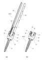
ペディクルスクリュー2は、図2(a)に示すタブ付きペディクルスクリュー2Aと、図2(b)に示すタブ無しペディクルスクリュー2Bを含む。ただし、ペディクルスクリュー2の全てがタブ付きペディクルスクリュー2Aであってもよいし、ペディクルスクリュー2の全てがタブ無しペディクルスクリュー2Bであってもよい。The
タブ無しペディクルスクリュー2Bは、雄ねじが形成されたアンカー21と、アンカー21を回転可能に保持する、略円柱状のヘッド22を含む。ヘッド22には当該ヘッド22をアンカー21の軸方向と直交する方向に横断するチャンネル25が設けられている。チャンネル25には、脊椎ロッド10が挿入される。The
より詳しくは、ヘッド22は、アンカー21に貫通される円盤部23と、円盤部23から立ち上がる、チャンネル25を挟んで互いに対向する一対の対向壁24を含む。対向壁24の内側面には、脊椎ロッド10の固定用の止めねじと螺合する雌ねじ26が形成されている。More specifically, the
さらに、双方の対向壁24の外側面には、エクステンダー3との係合用の係合溝27がそれぞれ設けられている。各係合溝27は、略円柱状のヘッド22の径方向外向きに開口するとともに、ヘッド22の周方向に延びている。Furthermore, an
タブ付きペディクルスクリュー2Aがタブ無しペディクルスクリュー2Bと相違する点は、一対のタブ28を有する点のみである。タブ付きペディクルスクリュー2Aでは、脊椎ロッド挿入用のチャンネル25を延長するように一対の対向壁24に一対のタブ28がそれぞれ設けられている。また、タブ付きペディクルスクリュー2Aでは、雌ねじ26が対向壁24の内側面だけでなくタブ28の内側面にも形成されている。The only difference between the
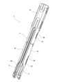
図3および図4に示すように、エクステンダー3は、アウタースリーブ4と、アウタースリーブ4内に配置された一対のインナーアーム5およびアクチュエータ6を含む。As shown in Figures 3 and 4, the
アウタースリーブ4は、筒状の基部41と、基部41からアウタースリーブ4の軸方向に沿って突出する一対のアーム部42を含む。アーム部42は互いに対向しており、各アーム部42の断面形状は円弧状である。The
アーム部42同士の間にはスリット44が形成されている。このスリット44は、図5(a)および(b)に示すように、エクステンダー3がペディクルスクリュー2に取り付けられたときに、ヘッド22に設けられた脊椎ロッド挿入用のチャンネル25と連続する。すなわち、チャンネル25およびスリット44は、脊椎ロッド10の可動範囲を規定する。A
図4に示すように、各アーム部42の先端からアーム部全長の約1/4の範囲では、各アーム部42の幅が細くなっている。各アーム部42の先端には、ペディクルスクリュー2のヘッド22に設けられた係合溝27との係合用のリッジ43が設けられている。As shown in FIG. 4, the width of each
各インナーアーム5は、ほぼ一定の円弧状の断面形状で基端5aから末端5bまで延びている。換言すれば、双方のインナーアーム5は、アウタースリーブ4のアーム部42の内側面に当接するパイプが、スリット44と同じ幅でカットされたような形状を有する。Each
各インナーアーム5は、対応するアーム部42の内側面に沿ってアウタースリーブ4の軸方向に摺動可能となるようにアウタースリーブ4に保持されている。本実施形態では、アウタースリーブ4の各アーム部42に、アウタースリーブ4の軸方向に延びる一対のスロット46が設けられている。一対のスロット46は、アウタースリーブ4の軸方向に並んでいる。Each
一方、各インナーアーム5の外側面には、一対のスロット46にそれぞれ嵌まり込む一対の突起53が設けられている。突起53がスロット46でガイドされることで、インナーアーム5がアウタースリーブ4の軸方向に摺動可能である。On the other hand, a pair of
また、突起53は先端に拡大部を有する一方、スロット46は基端(基部41側の端)に突起53の拡大部が挿通可能な幅広部を有し、スロット46の基端以外の部分の幅は突起53の拡大部よりも狭く設定されている。このため、突起53の拡大部がスロット46の基端以外の部分と係合することで、インナーアーム5が対応するアーム部42に保持される。In addition, while the
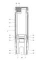
アクチュエータ6は、回転操作を受けて双方のインナーアーム5を移動するものであり、アウタースリーブ4の基部41に取り付けられている。アクチュエータ6は筒状体であり、アクチュエータ6のインナーアーム5側の末端が双方のインナーアーム5のアクチュエータ6側の基端5aと係合する。The
より詳しくは、図4に示すように、各インナーアーム5の基端5aの外側面には、アウタースリーブ4の周方向に延びる連結溝52が形成されている。一方、アクチュエータ6の末端の内周面には、図6に示すように、連結溝52と係合する連結突起63が設けられている。More specifically, as shown in FIG. 4, a connecting
また、アウタースリーブ4の基部41の内周面には雌ねじ45が形成されている。一方、アクチュエータ6の外周面には、雌ねじ45と螺合する雄ねじ61が形成されている。このため、アクチュエータ6が回転操作を受けると、双方のインナーアーム5がアクチュエータ6と共にアウタースリーブ4の軸方向に移動する。なお、アクチュエータ6のインナーアーム5と反対側の基端には、アクチュエータ6を回転させるための工具との係合用の切欠き62が形成されている。A
本実施形態では、図7に示すように、各インナーアーム5における、基端5aを含む所定範囲(例えば、インナーアーム全長の1/4~1/8の範囲)がアウタースリーブ4の径方向外向きに折り曲げられている。そして、インナーアーム5は、その所定範囲の折れ曲がりが矯正された状態でアウタースリーブ4内に配置されている。In this embodiment, as shown in FIG. 7, a predetermined range of each
図4に戻って、各インナーアーム5のアクチュエータ6と反対側の末端5bには、基端5aから末端5bに向かう方向に開口する切欠き51が形成されており、当該末端5bは略U字状となっている。上述したアウタースリーブ4のリッジ43は、その切欠き51内に位置する。Returning to FIG. 4, a
図8に示すように、アウタースリーブ4のリッジ43がペディクルスクリュー2のヘッド22の対向壁24に設けられた係合溝27に係合した状態でインナーアーム5が前進すると、インナーアーム5の末端5bの上述したU字状の底に位置する支持面50が対向壁24の端面に当接し、これによりヘッド22にエクステンダー3が固定される。As shown in FIG. 8, when the
さらに、本実施形態では、各インナーアーム5における、対応するアーム部42の内側面と重なり合う部分の厚さTが、アウタースリーブ4の径方向におけるリッジ43の高さHの1.5倍以下に設定されている。各インナーアーム5の厚さTはリッジ43の高さHの1.2倍以下であることがより望ましい。Furthermore, in this embodiment, the thickness T of the portion of each
このように、本実施形態ではインナーアーム5の厚さが薄く設定されているので、ペディクルスクリュー2がタブ付きペディクルスクリュー2Aである場合は、図5(a)に示すように、エクステンダー3がタブ付きペディクルスクリュー2Aに取り付けられたときに、タブ28がインナーアーム5の内側に配置される。従って、エクステンダー3をタブ無しペディクルスクリュー2Bとタブ付きペディクルスクリュー2Aの双方に使用することができる。In this embodiment, the thickness of the
(変形例)
本発明は上述した実施形態に限定されるものではなく、本発明の要旨を逸脱しない範囲で種々の変形が可能である。 (Modification)
The present invention is not limited to the above-described embodiment, and various modifications are possible without departing from the gist of the present invention.
例えば、前記実施形態では、インナーアーム5の基端5aを含む所定範囲がアウタースリーブ4の径方向外向きに折り曲げられていたが、インナーアーム5は、全長に亘ってストレートであってもよい。ただし、前記実施形態のような構成であれば、インナーアーム5の基端5aがアクチュエータ6の内周面に押し付けられるため、連結突起63が連結溝52から外れ難くすることができる。For example, in the above embodiment, a predetermined area including the
また、エクステンダー3によるペディクルスクリュー2の把持力を高めるために、アウタースリーブ4の各アーム部42の先端を含む所定範囲をアウタースリーブ4の径方向内向きに折り曲げてもよい。In addition, in order to increase the gripping force of the
1 脊椎固定術用キット
2 ペディクルスクリュー
21 アンカー
22 ヘッド
28 タブ
3 エクステンダー
4 アウタースリーブ
41 基部
42 アーム部
43 リッジ
44 雌ねじ
5 インナーアーム
52 連結溝
6 アクチュエータ
61 雄ねじ
63 連結突起 REFERENCE SIGNS
Claims (4)
Translated fromJapanese前記ペディクルスクリューに取り付けられるエクステンダーと、を備え、
前記エクステンダーは、
筒状の基部および前記基部から突出する一対のアーム部を含み、各アーム部の先端に前記ペディクルスクリューとの係合用のリッジが設けられたアウタースリーブと、
前記一対のアーム部の内側面に沿って前記アウタースリーブの軸方向に摺動可能となるように前記アウタースリーブに保持された一対のインナーアームであって、前記ペディクルスクリューが一対のタブを含む場合、前記エクステンダーが前記ペディクルスクリューに取り付けられたときに前記一対のタブが当該一対のインナーアームの内側に配置される一対のインナーアームと、
前記アウタースリーブの基部に取り付けられた、回転操作を受けて前記一対のインナーアームを前記アウタースリーブの軸方向に移動するアクチュエータと、を含み、
前記一対のインナーアームのそれぞれにおける、対応する前記アーム部の内側面と重なり合う部分の厚さは、前記アウタースリーブの径方向における前記リッジの高さの1.5倍以下である、脊椎固定術用キット。Pedicle screws and
an extenderattached to the pedicle screw;
The extender is
an outer sleeve including a cylindrical base and a pair of arms protruding from the base, each arm having a ridge at a tip thereof for engaging with the pedicle screw;
a pair of inner arms held by the outer sleeve so as to be slidable in the axial direction of the outer sleeve along inner surfaces of the pair of arm portions, wherein when the pedicle screw includes a pair of tabs, the pair of tabs are disposed inside the pair of inner arms when the extender is attached to the pedicle screw;
an actuator attached to a base of the outer sleeve andconfigured to move the pair of inner armsin the axial direction of the outer sleeve in response to a rotational operation,
A spinal fixation kit , wherein the thickness of the portion of each of the pair of inner arms that overlaps with the inner surface of the corresponding arm portion is 1.5 times or less the height of the ridge in the radial direction of the outer sleeve.
前記アクチュエータは、外周面に前記雌ねじと螺合する雄ねじが形成された筒状体であり、
前記一対のインナーアームのそれぞれにおける、前記アクチュエータ側の基端の外側面には、前記アウタースリーブの周方向に延びる連結溝が形成されており、
前記アクチュエータにおける前記一対のインナーアーム側の末端の内周面には、前記連結溝と係合する連結突起が設けられている、請求項1に記載の脊椎固定術用キット。 A female thread is formed on the inner peripheral surface of the base of the outer sleeve,
the actuator is a cylindrical body having an outer circumferential surface on which a male screw is formed to screw into the female screw,
a connecting groove extending in a circumferential direction of the outer sleeve is formed on an outer surface of a base end of each of the pair of inner arms on the actuator side,
2.The kit for spinal fixation according to claim 1, wherein said actuator has an inner circumferential surface at an end of said pair of inner arms, said inner circumferential surface being provided with a connecting protrusion which engages with said connecting groove.
Priority Applications (1)
| Application Number | Priority Date | Filing Date | Title |
|---|---|---|---|
| JP2021132691AJP7699805B2 (en) | 2021-08-17 | 2021-08-17 | Spinal Fixation Kit |
Applications Claiming Priority (1)
| Application Number | Priority Date | Filing Date | Title |
|---|---|---|---|
| JP2021132691AJP7699805B2 (en) | 2021-08-17 | 2021-08-17 | Spinal Fixation Kit |
Publications (2)
| Publication Number | Publication Date |
|---|---|
| JP2023027539A JP2023027539A (en) | 2023-03-02 |
| JP7699805B2true JP7699805B2 (en) | 2025-06-30 |
Family
ID=85330531
Family Applications (1)
| Application Number | Title | Priority Date | Filing Date |
|---|---|---|---|
| JP2021132691AActiveJP7699805B2 (en) | 2021-08-17 | 2021-08-17 | Spinal Fixation Kit |
Country Status (1)
| Country | Link |
|---|---|
| JP (1) | JP7699805B2 (en) |
Citations (3)
| Publication number | Priority date | Publication date | Assignee | Title |
|---|---|---|---|---|
| JP2015112479A (en) | 2013-12-09 | 2015-06-22 | ビーダーマン・テクノロジーズ・ゲゼルシャフト・ミット・ベシュレンクテル・ハフツング・ウント・コンパニー・コマンディートゲゼルシャフトBiedermann Technologies Gmbh & Co. Kg | Extension device for bone anchor, system of extension device and bone anchor, and vertebra stabilization system for use in low invasive surgery |
| US20160367295A1 (en) | 2015-06-16 | 2016-12-22 | Timo Biedermann | Extension device for a bone anchor |
| JP2019111331A (en) | 2017-12-22 | 2019-07-11 | ビーダーマン・テクノロジーズ・ゲゼルシャフト・ミット・ベシュレンクテル・ハフツング・ウント・コンパニー・コマンディートゲゼルシャフトBiedermann Technologies Gmbh & Co. Kg | Polyaxial bone anchoring device and system of instrument and polyaxial bone anchoring device |
- 2021
- 2021-08-17JPJP2021132691Apatent/JP7699805B2/enactiveActive
Patent Citations (3)
| Publication number | Priority date | Publication date | Assignee | Title |
|---|---|---|---|---|
| JP2015112479A (en) | 2013-12-09 | 2015-06-22 | ビーダーマン・テクノロジーズ・ゲゼルシャフト・ミット・ベシュレンクテル・ハフツング・ウント・コンパニー・コマンディートゲゼルシャフトBiedermann Technologies Gmbh & Co. Kg | Extension device for bone anchor, system of extension device and bone anchor, and vertebra stabilization system for use in low invasive surgery |
| US20160367295A1 (en) | 2015-06-16 | 2016-12-22 | Timo Biedermann | Extension device for a bone anchor |
| JP2019111331A (en) | 2017-12-22 | 2019-07-11 | ビーダーマン・テクノロジーズ・ゲゼルシャフト・ミット・ベシュレンクテル・ハフツング・ウント・コンパニー・コマンディートゲゼルシャフトBiedermann Technologies Gmbh & Co. Kg | Polyaxial bone anchoring device and system of instrument and polyaxial bone anchoring device |
Also Published As
| Publication number | Publication date |
|---|---|
| JP2023027539A (en) | 2023-03-02 |
Similar Documents
| Publication | Publication Date | Title |
|---|---|---|
| CN105361937B (en) | Polyaxial bone anchoring device | |
| JP4124739B2 (en) | Device for connecting a longitudinal member to a bone portion | |
| EP2097025B1 (en) | Multi-axial bone fixation apparatus | |
| CA2846149C (en) | Systems and methods for percutaneous spinal fusion | |
| JP5912166B2 (en) | Bone fixation device and modular system | |
| US20250312047A1 (en) | Clip unit, medical instrument, and attaching method of medical instrument | |
| TWI451856B (en) | Bone anchoring element and method of manufacturing the same | |
| EP2606842B1 (en) | Bone anchoring device | |
| EP2011445A2 (en) | Rod fixing apparatus for vertebra connecting member | |
| US20150351810A1 (en) | Vertebral column-stabilizing system and surgical fastening element for a vertebral column-stabilizing system | |
| CA2549795A1 (en) | Percutaneous access devices and bone anchor assemblies | |
| CN108836501B (en) | Method for producing deflectable insertion tools | |
| US9603632B1 (en) | Tulip bone screw assembly | |
| CN108784783A (en) | Deflectable insertion tool | |
| KR20240156452A (en) | Insertion-type clamping mechanism and clamping member thereof | |
| EP3838197B1 (en) | Instrument for use with a bone anchoring device | |
| JP7699805B2 (en) | Spinal Fixation Kit | |
| JP7208736B2 (en) | Instruments for use with receivers of bone fixation devices and systems comprising receivers and instruments | |
| JP7682513B2 (en) | Head stabilization device with removable torque applicator | |
| JP6697291B2 (en) | Endoscope bending tube | |
| WO2022029956A1 (en) | Clip indwelling device and clip | |
| KR20210085511A (en) | Bone fixation screw with expansion and restoration | |
| JP5599227B2 (en) | Bone anchor unit for spinal fixation | |
| US20140331818A1 (en) | Flexible tubular shaft | |
| JP7697682B2 (en) | Rod Reducer |
Legal Events
| Date | Code | Title | Description |
|---|---|---|---|
| A621 | Written request for application examination | Free format text:JAPANESE INTERMEDIATE CODE: A621 Effective date:20240502 | |
| A977 | Report on retrieval | Free format text:JAPANESE INTERMEDIATE CODE: A971007 Effective date:20250131 | |
| A131 | Notification of reasons for refusal | Free format text:JAPANESE INTERMEDIATE CODE: A131 Effective date:20250204 | |
| A521 | Request for written amendment filed | Free format text:JAPANESE INTERMEDIATE CODE: A523 Effective date:20250310 | |
| TRDD | Decision of grant or rejection written | ||
| A01 | Written decision to grant a patent or to grant a registration (utility model) | Free format text:JAPANESE INTERMEDIATE CODE: A01 Effective date:20250610 | |
| A61 | First payment of annual fees (during grant procedure) | Free format text:JAPANESE INTERMEDIATE CODE: A61 Effective date:20250611 | |
| R150 | Certificate of patent or registration of utility model | Ref document number:7699805 Country of ref document:JP Free format text:JAPANESE INTERMEDIATE CODE: R150 | |
| S533 | Written request for registration of change of name | Free format text:JAPANESE INTERMEDIATE CODE: R313533 | |
| R350 | Written notification of registration of transfer | Free format text:JAPANESE INTERMEDIATE CODE: R350 |