JP7699376B2 - Optical system and light guide optical element - Google Patents
Optical system and light guide optical elementDownload PDFInfo
- Publication number
- JP7699376B2 JP7699376B2JP2021506543AJP2021506543AJP7699376B2JP 7699376 B2JP7699376 B2JP 7699376B2JP 2021506543 AJP2021506543 AJP 2021506543AJP 2021506543 AJP2021506543 AJP 2021506543AJP 7699376 B2JP7699376 B2JP 7699376B2
- Authority
- JP
- Japan
- Prior art keywords
- light
- optical element
- guide optical
- partially reflective
- light guide
- Prior art date
- Legal status (The legal status is an assumption and is not a legal conclusion. Google has not performed a legal analysis and makes no representation as to the accuracy of the status listed.)
- Active
Links
Images


Classifications
- G—PHYSICS
- G02—OPTICS
- G02B—OPTICAL ELEMENTS, SYSTEMS OR APPARATUS
- G02B27/00—Optical systems or apparatus not provided for by any of the groups G02B1/00 - G02B26/00, G02B30/00
- G02B27/01—Head-up displays
- G02B27/017—Head mounted
- G02B27/0172—Head mounted characterised by optical features
- G—PHYSICS
- G02—OPTICS
- G02B—OPTICAL ELEMENTS, SYSTEMS OR APPARATUS
- G02B27/00—Optical systems or apparatus not provided for by any of the groups G02B1/00 - G02B26/00, G02B30/00
- G02B27/10—Beam splitting or combining systems
- G02B27/14—Beam splitting or combining systems operating by reflection only
- G02B27/145—Beam splitting or combining systems operating by reflection only having sequential partially reflecting surfaces
- G—PHYSICS
- G02—OPTICS
- G02B—OPTICAL ELEMENTS, SYSTEMS OR APPARATUS
- G02B6/00—Light guides; Structural details of arrangements comprising light guides and other optical elements, e.g. couplings
Landscapes
- Physics & Mathematics (AREA)
- General Physics & Mathematics (AREA)
- Optics & Photonics (AREA)
- Lens Barrels (AREA)
- Optical Elements Other Than Lenses (AREA)
Description
Translated fromJapanese本発明は、概して、ヘッドマウント・ディスプレイ装置に関し、特には、そのような装置の一部であるライトガイド光学素子に関する。The present invention relates generally to head mounted display devices, and in particular to light guide optical elements that are part of such devices.
実際のシーンとディスプレイ装置からの投影イメージの同時観察のために観者により装着される装置が周知であり、「ヘッドマウント・ディスプレイ」(HMD(head-mounted display))又は「ニア・アイ・ディスプレイ」(NED(near-eye display))として一般的に呼ばれている。そのような装置は、一般的に、ゴーグル又はめがね、若しくは、ヘルメット又はバイザー(visor)として構築されて観者の頭部に装着され、また、一つ又は二つのイメージ・プロジェクタ(各々が、電気光学ディスプレイ部品を含む)と、観者の目に投影イメージを伝送する光学部品を含む。本分野で知られているHMDの幾つかの構成においては、そのような光学部品の一つは、観者の目それぞれの前に位置付けられるライトガイドである。Devices worn by a viewer for simultaneous viewing of an actual scene and a projected image from a display device are known and are commonly referred to as "head-mounted displays" (HMDs) or "near-eye displays" (NEDs). Such devices are typically constructed as goggles or glasses, or a helmet or visor, worn on the viewer's head, and include one or two image projectors (each including an electro-optical display component) and optical components that transmit the projected image to the viewer's eyes. In some configurations of HMDs known in the art, one such optical component is a light guide positioned in front of each of the viewer's eyes.
そのようなライトガイド(「導波路」又は「基板」と代替して言及される)は、視野(即ち、ディスプレイ部品のスクリーンの角度サイズ)と観察窓(即ち、この窓の範囲内で観者の目がディスプレイ・スクリーンの全体を見るように位置付けられ、「アイ・モーション・ボックス(eye motion box)」としても知られる)を拡大するように働く。一般的に、そのようなライトガイドは、透明材料のブロック(又はスラブ)であり、2つの平行な主面を有し、ディスプレイ部品から投射されて平行化されたイメージを搬送する光がそれらの主面に沿って全内部反射により伝搬する。ブロックは、対応する観者の目に向けて主面の一つを介してその光の一部が外部結合されるように機能する、構造的な外部結合器(structural coupling-out arrangement)を含む。Such light guides (alternatively referred to as "waveguides" or "substrates") serve to expand the field of view (i.e. the angular size of the screen of the display component) and the viewing window (i.e. the window within which the viewer's eye is positioned to view the entire display screen, also known as the "eye motion box"). Typically, such light guides are blocks (or slabs) of transparent material, having two parallel major faces along which light projected from the display component and carrying a collimated image propagates by total internal reflection. The block includes a structural coupling-out arrangement that serves to couple a portion of that light out through one of the major faces towards the corresponding viewer's eye.
回折ライトガイドとして知られるライトガイドの幾つかの構成においては、外部結合器は、主面の一つ又は両方に回折構造を含む。反射ライトガイドや特には「ライトガイド光学素子(LOE(lightguide optical elements))」として知られる他の構成では、外部結合器は、斜めに角度付けられ、お互いに平行な部分的に反射する面のセットを含み、ファセットとしても代替的に知られ、ブロック内にある。In some configurations of light guides known as diffractive light guides, the outcoupler includes a diffractive structure on one or both of the major surfaces. In other configurations known as reflective light guides and specifically "light guide optical elements" (LOEs), the outcoupler includes a set of obliquely angled, partially reflective surfaces that are parallel to one another, alternatively known as facets, within a block.
HMDが眼鏡の形態にあるといった幾つかの場合、外部結合器は、外部の観察者に見られ難く、又は目に見えないことが望ましいだろう。In some cases, such as when the HMD is in the form of glasses, it may be desirable for the external coupler to be difficult to see or invisible to an external observer.
本発明は、ヘッドマウント・ディスプレイ(HMD)で用いられるライトガイドに改善を提供することを目指し、さもなければ、外部の観察者が、HMDを装着している観者の顔をそのようなライトガイドを介して観察する時に経験するような望まない視覚効果を低減する。そのような効果は、観者の目と顔から反射される光の一部がライトガイド内に結合されることにより生じ、従って、外部の観察者に到達する光を弱め、外部の観察者の視界においてライトガイドが明確に暗くなり、観者の顔と目をマスクする。先行技術のライトガイドにおける別の望まない視覚効果は、端面で反射されて後方に伝搬するライトガイド内の光により生じ、外部の観察者に向けて外部結合され、グレアとして感受される。従って、本発明の実施形態は、観者の顔と外部の観察者の間のライトガイドを介した光の透過を高め、外部の観察者に向けてライトガイドから放射される他の光の量を低減する様々な技術を提供する。The present invention seeks to provide an improvement to light guides used in head mounted displays (HMDs) that reduces the undesirable visual effects that an external observer would otherwise experience when viewing the face of an observer wearing an HMD through such a light guide. Such effects arise due to a portion of the light reflected from the observer's eyes and face being coupled into the light guide, thus attenuating the light that reaches the external observer and causing the light guide to appear noticeably dark in the external observer's field of view, masking the observer's face and eyes. Another undesirable visual effect in prior art light guides arises due to light within the light guide being reflected off an end face and propagating backwards, being outcoupled towards the external observer and perceived as glare. Thus, embodiments of the present invention provide various techniques to enhance the transmission of light through the light guide between the observer's face and the external observer, and to reduce the amount of other light that is emitted from the light guide towards the external observer.
非排他的な例として、部分的に反射する面を含むライトガイドの構成の実施形態に関する改善が記述される。そのような反射ライトガイド、又は従来のライトガイド光学素子(LOE)が、例えば、「基板により導光される光学ビーム拡大器」と題された米国特許第6,829,095号に記述されており、参照により本明細書に組み込まれる。しかしながら、本発明に係る改善は、全体又は部分において、HMD用のライトガイドの他の実施形態及び構成に適用可能である。By way of non-exclusive example, improvements are described with respect to embodiments of light guide configurations that include partially reflective surfaces. Such reflective light guides, or conventional light guide optical elements (LOEs), are described, for example, in U.S. Patent No. 6,829,095, entitled "Substrate-Guided Optical Beam Expander," which is incorporated herein by reference. However, the improvements of the present invention are applicable, in whole or in part, to other embodiments and configurations of light guides for HMDs.
詳細には、観者の目による、実際のシーンとライトガイド光学素子(LOE(Light-guide Optical Element))に導入された投影イメージの同時観察のためのライトガイド光学素子が開示され、当該LOEが、第1主面と前記第1主面に平行な第2主面を有する透明材料のブロックにして、前記ライトガイド光学素子に導入された投影イメージを搬送する光が、前記第1及び第2主面で内部反射により前記ライトガイド光学素子内で伝搬する、ブロックと、前記ブロック内にあり、前記第1主面に対して斜めに配向された、複数のお互いに平行な部分的に反射する面にして、当該部分的に反射する面は、前記第2主面を介して前記光の一部を外部結合するように構成される、複数のお互いに平行な部分的に反射する面を備え、
前記部分的に反射する面それぞれの反射率は、前記外部結合される光の全パワー(the total power of the light)が、前記ライトガイド光学素子に導入された前記投影イメージを搬送する前記光の全パワーの1/3未満になるように設定される。In particular, a light-guide optical element (LOE) for simultaneous observation by an observer's eyes of an actual scene and a projected image introduced into the LOE is disclosed, the LOE comprising: a block of transparent material having a first main surface and a second main surface parallel to the first main surface, where light carrying the projected image introduced into the LOE propagates within the LOE by internal reflection at the first and second main surfaces; and a plurality of mutually parallel partially reflective surfaces in the block, oriented obliquely with respect to the first main surface, the partially reflective surfaces being configured to outcouple a portion of the light via the second main surface;
The reflectivity of each of the partially reflective surfaces is set such that the total power of the light coupled out is less than ⅓ of the total power of the light carrying the projected image that is introduced into the light guide optical element.
幾つかの実施形態においては、前記部分的に反射する面それぞれの反射率は、前記外部結合される光の全パワーが、前記ライトガイド光学素子に導入された前記投影イメージを搬送する前記光の全パワーの1/5未満、幾つかの実施形態では1/10未満になるように設定される。In some embodiments, the reflectivity of each of the partially reflective surfaces is set so that the total power of the outcoupled light is less than 1/5, and in some embodiments less than 1/10, of the total power of the light carrying the projected image introduced into the light guide optical element.
幾つかの実施形態においては、前記部分的に反射する面それぞれの反射率が13%未満、幾つかの実施形態においては、5%未満である。In some embodiments, the reflectivity of each of the partially reflective surfaces is less than 13%, and in some embodiments, less than 5%.
観者の目による、実際のシーンと、第1方位(a first orientation)に偏光され、かつライトガイド光学素子(LOE(Light-guide Optical Element))に導入された光により搬送される投影イメージの同時観察のためのライトガイド光学素子も開示され、当該LOEが、第1主面と前記第1主面に平行な第2主面を有する透明材料のブロックにして、前記ライトガイド光学素子に導入された投影イメージを搬送する光が、前記第1及び第2主面で内部反射により前記ライトガイド光学素子内で伝搬する、ブロックと、前記ブロック内にあり、前記観者の目に向けて前記光の一部を外部結合するように前記第1主面に対して斜めに配向された、複数のお互いに平行な部分的に反射する面を備え、
前記第1方位に直交する第2方位に偏光された光に関する前記第1及び第2主面に垂直な方向における前記部分的に反射する面それぞれの反射率は、前記第1方位に偏光された光に関する前記方向におけるその反射率の1/3未満である。Also disclosed is a light-guide optical element (LOE) for simultaneous observation by an eye of an observer of an actual scene and of a projected image carried by light polarized in a first orientation and introduced into the light-guide optical element, the LOE being a block of transparent material having a first main surface and a second main surface parallel to the first main surface, where light carrying the projected image introduced into the light-guide optical element propagates within the light-guide optical element by internal reflection at the first and second main surfaces, and a plurality of mutually parallel partially reflecting surfaces within the block, oriented obliquely with respect to the first main surface to outcouple a portion of the light towards the eye of the observer,
The reflectivity of each of the partially reflective surfaces in a direction perpendicular to the first and second major surfaces for light polarized in a second orientation perpendicular to the first orientation is less than 1/3 of its reflectivity in that direction for light polarized in the first orientation.
第1偏光方位が、前記部分的に反射する面に関してS偏光であり得る。幾つかの実施形態においては、前記部分的に反射する面は、前記第1主面に垂直な方向を含む少なくとも約30度の角度範囲についてP偏光を実質的に透過する。The first polarization orientation can be S-polarized with respect to the partially reflective surface. In some embodiments, the partially reflective surface substantially transmits P-polarized light over an angular range of at least about 30 degrees that includes a direction perpendicular to the first major surface.
観者の目による、実際のシーンとライトガイド光学素子(LOE(Light-guide Optical Element))に導入された投影イメージの同時観察のためのライトガイド光学素子も開示され、当該LOEが、第1主面と前記第1主面に平行な第2主面を有する透明材料のブロックも開示され、第1主面と前記第1主面に平行な第2主面を有する透明材料のブロックにして、前記ライトガイド光学素子に導入された投影イメージを搬送する光が、前記第1及び第2主面で内部反射により前記ライトガイド光学素子内で第1方向に伝搬し、前記第1主面の外部で、かつこれに平行な平面において、所定サイズのアイ・モーション・ボックス(eye motion box)が定義される、ブロックと、前記ブロック内にあると共に、前記第1方向に沿って順に配置され、かつ前記アイ・モーション・ボックスに向けて前記光の一部を外部結合するべく前記第1主面に対して斜めに配向された、複数のお互いに平行で部分的に反射する面を備え、
前記アイ・モーション・ボックス内の任意の点に向けてそこから外部結合される前記光の一部に関する前記部分的に反射する面の配列の最後のものの反射率が、前記第1及び第2主面に垂直な方向に伝搬する光に関するその反射率の少なくとも2倍である。Also disclosed is a light-guide optical element (LOE) for simultaneous observation by an observer's eyes of an actual scene and a projected image introduced into the LOE, the LOE comprising a block of transparent material having a first main surface and a second main surface parallel to the first main surface, the block of transparent material having a first main surface and a second main surface parallel to the first main surface, the light carrying the projected image introduced into the light-guide optical element propagates in a first direction within the light-guide optical element by internal reflection at the first and second main surfaces, and an eye motion box of a predetermined size is defined outside and in a plane parallel to the first main surface, the block comprising a plurality of mutually parallel partially reflecting surfaces arranged in sequence along the first direction and obliquely oriented with respect to the first main surface for out-coupling a portion of the light towards the eye motion box,
The reflectivity of the last of the array of partially reflective surfaces for a portion of the light coupled out from it to any point within the eye motion box is at least twice its reflectivity for light propagating in a direction perpendicular to the first and second major surfaces.
幾つかの実施形態においては、前記アイ・モーション・ボックス内の任意の点に向けてそこから外部結合される前記光の一部に関する前記部分的に反射する面の配列の最後のものの反射率が、前記第1及び第2主面に垂直な方向に伝搬する光に関するその反射率の少なくとも4倍以上である。In some embodiments, the reflectivity of the last of the array of partially reflective surfaces for the portion of the light coupled out from it to any point within the eye motion box is at least four times greater than its reflectivity for light propagating in a direction perpendicular to the first and second major surfaces.
実施形態の幾つかにおいては、前記ブロックは、前記部分的に反射する面を通過した前記ライトガイド光学素子内を伝搬する光が入射する端面を有し、当該端面は、前記ライトガイド光学素子内に導入されて外部結合されない光を吸収するように構成された光吸収層で被覆される。光吸収層は、粗い端面に付与された黒色塗料として実施され得る。In some embodiments, the block has an end surface onto which light propagating through the light guide optical element passes through the partially reflective surface, and the end surface is coated with a light absorbing layer configured to absorb light that is not introduced into the light guide optical element and is not coupled out. The light absorbing layer may be implemented as a black paint applied to a roughened end surface.
観者による自然シーンとニア・アイ・イメージ・プロジェクタ(near-eye image projector)上のイメージの同時観察のための光学システムも開示され、当該光学システムが、請求項1乃至10のいずれか一項に記載のライトガイド光学素子;及び前記観者の少なくとも一つの目に対向する位置で前記ライトガイド光学素子を前記観者の頭部に支持するために設けられたサポート構造を備える。Also disclosed is an optical system for simultaneous viewing by an observer of a natural scene and an image on a near-eye image projector, the optical system comprising a light guide optical element according to any one of claims 1 to 10; and a support structure arranged to support the light guide optical element on the observer's head in a position facing at least one eye of the observer.
本発明は、次の添付図面を参照して単なる例として本明細書で記述される。
図1Aは、前置きとして、この例において観者により装着される眼鏡として形成されたヘッドマウント・ディスプレイ(HMD)を概略的に示し、HMDを装着する時に観者の目20の前に位置付けられる部分的に反射する面を有するライトガイド光学素子(LOE)10を含む。加えて、そこに供給される信号に応じてイメージを生成するように動作するイメージ・プロジェクタ22(これは、従って、電気光学ディスプレイ装置、又はLCOS装置といった空間光変調器を含む)と、平行化された状態のイメージに対応して光を投射するように構成されたコリメート光学アセンブリ(全て不図示)と、LOE10に投影イメージを結合するカップリング光学系24を含む。1A, by way of introduction, shows a schematic diagram of a head mounted display (HMD), in this example formed as glasses worn by a viewer, including a light guide optical element (LOE) 10 having a partially reflective surface that is positioned in front of the viewer's eyes 20 when the HMD is worn. In addition, the HMD includes an image projector 22 (which thus includes a spatial light modulator such as an electro-optical display device, or LCOS device) operative to generate an image in response to a signal provided thereto, a collimating optical assembly (all not shown) configured to project light corresponding to the image in a collimated state, and coupling optics 24 for coupling the projected image to the LOE 10.
HMDの幾つかの構成においては、単眼に関連して単一のイメージ・プロジェクタが設けられ、他の構成においては、観者の両目の一つに対応して各々が関連付けられた2つのイメージ・プロジェクタが設けられ、また更なる他の構成においては、対応の両目に関連付けられた2つのLOE内、又は、両方の目の前を延びる単一の長いLOE内にイメージを投射するように構成された単一のイメージ・プロジェクタが設けられる。In some configurations of HMDs, a single image projector is provided in association with a single eye, in other configurations, two image projectors are provided, each associated with one of the viewer's eyes, and in still other configurations, a single image projector is provided configured to project images into two LOEs associated with corresponding eyes, or into a single long LOE that extends in front of both eyes.
ライトガイド光学素子(LOE)10が図1Aに水平断面図で図示され、LOE内を伝搬し、観者に向けて放出されるように平行化されたイメージの選択された光線がトレースされる。LOE10は、基本的には長尺なブロック11であり、透明材料から構成され、2つのお互いに平行な主面、前面12及び後面14を有する。ブロック11の一端の近くには、入射窓に関連した内部結合器(coupling-in arrangement)が設けられ、これを介して平行化されたイメージがLOE内に導入される。この例においては、それは、傾斜反射面18であり、後面14においてそこに隣接して入射窓19が規定される。他のLOEでは、例えば、入射窓は、主面の一つに取り付けられた角度付けられたプリズムであり、又は、入射窓は、ブロックの一端面であり得る。ブロック11には、傾斜した部分的に反射する面16の配列が埋め込まれ、全てがお互いに平行であり、「ファセット」と呼ばれる。部分的に反射する面16の全集合に隣接して、後面14からある距離に及びそれに平行に、視界範囲17が規定され、アイ・モーション・ボックスとしても知られており、イメージの全体を見ることができるように観者の目が配置される領域を示し、目の動きと目20に関するHMDの場所に幾らかの自由度を許容する。A light guide optical element (LOE) 10 is illustrated in horizontal cross section in FIG. 1A, tracing selected rays of a collimated image as they propagate through the LOE and are emitted towards a viewer. The LOE 10 is essentially an elongated block 11, constructed from a transparent material, and has two mutually parallel major faces, a front face 12 and a rear face 14. Near one end of the block 11, a coupling-in arrangement is provided in association with an entrance window through which the collimated image is introduced into the LOE. In this example, it is an inclined reflective surface 18, adjacent to which an entrance window 19 is defined at the rear face 14. In other LOEs, for example, the entrance window may be an angled prism attached to one of the major faces, or the entrance window may be one end face of the block. Embedded in the block 11 is an array of inclined partially reflective faces 16, all parallel to each other and called "facets". Adjacent to the entire set of partially reflective surfaces 16, at a distance from and parallel to the rear surface 14, a viewing area 17 is defined, also known as the eye motion box, which indicates the area where the viewer's eyes are positioned to be able to see the entire image, allowing some freedom of eye movement and location of the HMD relative to the eyes 20.
図示例では入射窓が後面にあるが、HMDの他の構成では、対応のLOEが前面上又はブロック11の端面上に入射窓を有するように構成され得ることに留意されたい。本発明は、そのような構成も取り扱う。Note that while in the illustrated example the entrance window is on the rear surface, in other configurations of the HMD the corresponding LOE may be configured to have an entrance window on the front surface or on an end surface of the block 11. The present invention also addresses such configurations.
選択された光線により表されるように、カップリング光学系24からのイメージ搬送光は、入射窓19を介してブロック11に入射し、この例では、傾斜反射面18により偏向されて主面12及び14からの全内部反射を受けながらブロック11に沿って伝搬する。入射窓が端面上にある構成では、そこに入射した光は、直線的に進行し(即ち、偏向されず)、そのブロックに沿って伝搬する。この伝搬過程において、光は、部分的に反射する面(ファセット)16により途中で捉えられ、観察窓(アイ・モーション・ボックス)17内へ、その一部が偏向され、又は外部結合される。As represented by the selected rays, image-carrying light from coupling optics 24 enters block 11 through entrance window 19 and, in this example, is deflected by angled reflective surface 18 and propagates along block 11 undergoing total internal reflection from major faces 12 and 14. In configurations where the entrance window is on an end face, light incident thereon travels in a straight line (i.e., is not deflected) and propagates along the block. During this propagation, the light is intercepted by partially reflective facets 16 and some of it is deflected or outcoupled into observation window (eye motion box) 17.
(仮想現実装置や拡張現実装置といった)任意のニア・アイ・ディスプレイ装置(near-eye display device)のためのLOEの設計の主要な課題の一つは、エネルギー消費を低減するために光源から観者の目への光学的なスループットを最大化し、従って、バッテリー時間を長期化することにある。従って、最先端の反射LOE設計の一般的対策では、ファセットの全部の反射率を最大化し、観者の目に到達するイメージ強度を最大化している。同時に、観者により知覚される視野及び観察窓に亘って均一な強度のイメージを達成するために、ファセットの反射率が、典型的には、それらの間で変化する。より詳細には、ブロック11に沿って光が伝搬し、その一部が第1ファセットにより外部結合されるため、残りの光の強度が減じ、次のファセット以降が、同等の割合でより高い反射率を有するように求められ、外部結合される光の強度が一定に保たれる;即ち、光が交差する最後のファセットは、最大の反射率を有するべきである。One of the main challenges in designing an LOE for any near-eye display device (such as a virtual reality or augmented reality device) is to maximize the optical throughput from the light source to the viewer's eye in order to reduce energy consumption and therefore extend battery life. Thus, a common strategy in state-of-the-art reflective LOE design is to maximize the total reflectivity of the facets, maximizing the image intensity reaching the viewer's eye. At the same time, the reflectivity of the facets is typically varied between them to achieve an image of uniform intensity across the field of view and observation window as perceived by the viewer. More specifically, as light propagates along the block 11 and a portion of it is outcoupled by the first facet, the intensity of the remaining light is reduced and subsequent facets are required to have a higher reflectivity in an equal proportion, keeping the intensity of the outcoupled light constant; i.e., the last facet that the light crosses should have the maximum reflectivity.
HMDのパーツのものに特有のLOE設計における別の課題は、観者が自然シーンも明確に見ることができるのに十分な透明性を有しなければならないことである。この要求は、高い反射率が実際には低い透過率に等しく、従って、自然シーンから観者の目に到達する光が弱められることにおいて、上述したファセットの最大反射率の要求と対立する。従って、HMDのための従来のLOE設計は、妥協し、ファセットの反射率は、自然シーンからの光に関する透過率の値が所望の最小値を達成するように比例して減じられていた。Another challenge in LOE design, specific to parts of HMDs, is that they must be transparent enough to allow the viewer to clearly see natural scenes as well. This requirement conflicts with the requirement of maximum facet reflectance mentioned above, in that high reflectance actually equates to low transmittance, thus attenuating the light from the natural scene that reaches the viewer's eyes. Thus, conventional LOE designs for HMDs compromise and the reflectance of the facets is proportionally reduced to achieve a desired minimum transmittance value for light from natural scenes.
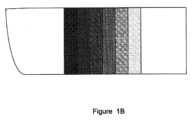
また、ある従来のLOE設計においては、(上述の解決すべき手段の項で言及したように)ファセットが外部の観察者により実質的に可視されるものである。これは、それらの透過率が相対的に低いためであり、従って、外部の観察者の目(不図示)へその主面12及び14に概して垂直な方向でLOEのブロック11を介して観者の顔及び目20から反射された光を減じられる。この効果が図1Bで概略的に証明されており、これは、外部の観察者の目に映るLOE10の前面図である。ここで、ファセット16は、暗さが変化する細片(strip)として見られ、観者の顔をぼんやりとさせる;最も左のファセットが最も暗く、なぜなら、最大の反射率、従って、最小の透過率に設計されているためである。これらの設計においては、ファセットは、外部の観察者により見られるグリアも生成することがあり、これは、残部の伝搬光が、ブロック11の端面15で反射され、その観察者の目に向けて前主面12を通じてファセット16により外部結合されるためである。Also, in some conventional LOE designs (as mentioned in the Solution to be Solved section above), the facets are substantially visible to an external observer because they have a relatively low transmittance, and therefore reduce light reflected from the observer's face and eye 20 through the block 11 of the LOE in a direction generally perpendicular to its major surfaces 12 and 14 to the external observer's eye (not shown). This effect is demonstrated diagrammatically in FIG. 1B, which is a front view of the LOE 10 as seen by the external observer's eye. Here, the facets 16 are seen as strips of varying darkness, obscuring the observer's face; the leftmost facet is the darkest because it is designed for maximum reflectance and therefore minimum transmittance. In these designs, the facets can also generate glia that is seen by the external observer, because the remaining propagating light is reflected off the end surface 15 of the block 11 and outcoupled by the facets 16 through the front major surface 12 to the observer's eye.
後述において、外部の観察者によるファセットの視認といった、上述の効果を低減するように設計された新規な特徴を含むライトガイド光学素子の例示の実施形態が記述される。これらの特徴は、それぞれ適切な例示の実施形態に関して記述されるが、幾つかの他の実施形態は、当業者により容易に想到されるように、2つ以上のこれらの特徴を同時に含むことができる。更には、幾つか又は全てのこれらの特徴は、様々な構成のLOEの実施形態、特には、反射及び回折LOEにおいて含まれることができる。Below, exemplary embodiments of light guide optical elements are described that include novel features designed to reduce the above-mentioned effects, such as the visibility of the facets by an external observer. Although these features are each described with respect to appropriate exemplary embodiments, some other embodiments may include two or more of these features simultaneously, as would be readily envisioned by one of ordinary skill in the art. Moreover, some or all of these features may be included in various configurations of LOE embodiments, particularly reflective and diffractive LOEs.
本発明のある実施形態の指針となる原理は、ファセット群の反射率を低減し、LOEを横切って透過する光に関してそれらの全体の透過率を高め、それらを透明に見えるようにし、外部の観察者に見えないようにすることである。The guiding principle of certain embodiments of the present invention is to reduce the reflectivity of the facets and increase their overall transmittance for light transmitted across the LOE, making them appear transparent and invisible to an outside observer.
更には、従来の典型的な最適化された反射LOE設計においては、ファセットの反射率は、対象の入射角の範囲、偏光方位及び波長バンドにおいて、第1から最後に入射するファセットへ、LOEに沿って変化し、典型的には10%~25%に亘る。入射角の対象の範囲は、LOE及びLOEが一つのパーツであるHMDの設計において光学幾何学的な考察により決定される。偏光方位及び波長バンドの関心の範囲は、イメージ・プロジェクタの特性によって又は動作要求によって大きく決定される。光学的な設計は、これらの関心の範囲内でファセットの反射率を最適化することを模索するが、これらの範囲外の入射角、偏光方位及び波長バンドのどの値の反射率の値も、典型的には、設計において制約されない。従って、本発明のある実施形態の更なる指針となる原理は、これらの範囲の一つ以上の外部のファセットの反射率を低減又は可能な範囲で最小化することにあり、LOEに亘る光に関してそれらの透過率を高める。Furthermore, in a typical conventional optimized reflective LOE design, the reflectivity of the facets varies along the LOE from the first to the last incident facet over the range of incidence angles, polarization orientations and wavelength bands of interest, typically ranging from 10% to 25%. The range of incidence angles of interest is determined by optical geometric considerations in the design of the LOE and the HMD of which the LOE is one part. The ranges of interest of polarization orientations and wavelength bands are largely determined by the image projector properties or by operational requirements. The optical design seeks to optimize the reflectivity of the facets within these ranges of interest, but reflectivity values for any values of incidence angles, polarization orientations and wavelength bands outside these ranges are typically not constrained in the design. Thus, a further guiding principle of certain embodiments of the present invention is to reduce or minimize, where possible, the reflectivity of facets outside one or more of these ranges, increasing their transmission for light across the LOE.
本発明の第1の例示の実施形態においては、若しくは本発明の第1の側面によれば、対象の角度範囲内のもの、偏光状態及び波長バンドを含む、各ファセットの全体的な反射率が、上述の先行技術の設計のものと比較して、設計により実質的に低減される。In a first exemplary embodiment of the present invention, or in accordance with a first aspect of the present invention, the overall reflectance of each facet, including within the angular ranges, polarization states and wavelength bands of interest, is substantially reduced by design as compared to the prior art designs described above.
図2は、LOE沿いに伝搬する光の強度(下降線群)とファセットの反射率の値(上昇線群)の比較プロットである。横軸は、LOE沿いの相対的な距離であり、縦軸は、最大値のパーセントである。点線は、仮想現実装置(これは、本発明の範囲外である)での使用のために設計されたLOEに関する最適値を表す。ここで、最適な設計は、LOEに入射した光エネルギーの全部を外部結合することであり、外部結合された光の強度を均一に維持しつつ、ディスプレイイメージを見ることの効率を最大化する。従って、伝搬光の強度を表す線31が直線的にゼロ付近まで下降し、配列されたファセットらの反射率を表す線32が反射率の対応の増加でほぼ指数的に上昇する。結果として、観者に向かって外部結合される光の強度は、おおよそ均一である。線らが最適な設定値を表すこと;実際には、傾斜線は、ファセットらに対応して部分的に段差に似ることに留意されたい。2 is a comparative plot of the intensity of light propagating along the LOE (lines that fall) versus the reflectance values of the facets (lines that rise). The horizontal axis is the relative distance along the LOE, and the vertical axis is the percent of maximum value. The dotted lines represent the optimum values for an LOE designed for use in a virtual reality device (which is outside the scope of this invention). Here, the optimum design would be to couple out all of the light energy incident on the LOE, maximizing the efficiency of viewing the display image while maintaining a uniform intensity of the outcoupled light. Thus, line 31, representing the intensity of the propagating light, falls linearly to near zero, while line 32, representing the reflectance of the array of facets, rises approximately exponentially with a corresponding increase in reflectance. As a result, the intensity of the light coupled out towards the viewer is approximately uniform. Note that the lines represent optimum settings; in reality, the sloping lines resemble steps in part corresponding to the facets.
破線は、ヘッドマウント・ディスプレイ(HMD)での使用のために設計された従来のLOEに関する典型的な値を表し、反射率は、自然シーンの相対的にクリアなビューを提供するために選択されている。これらの線は、点線に類似するものと見られるが、傾斜が減じられている。従って、ここでも(LOEに入射する光の最大の強度を意味する)100で開始する直線的な下降線34は、末端ではたった約50%に到達し、伝搬光エネルギーの約50%だけが(観察窓に向けて)外部結合されたことを意味する。対応して、上昇線35は、たったの約42に到達し、最後のファセットの反射率がたった約42%であることを意味する。これにより、その透過率が適切な入射角で約58%になり、それに沿って自然シーンが見られるLOEを横切る方向でも同じ程度で高いことが見込まれ、そのシーンが満足にクリアに見える程に十分に高い。The dashed lines represent typical values for a conventional LOE designed for use in a head mounted display (HMD), where the reflectance is selected to provide a relatively clear view of the natural scene. These lines can be seen to be similar to the dotted lines, but with a reduced slope. Thus, again, the linear descending line 34 starting at 100 (meaning the maximum intensity of the light incident on the LOE) reaches only about 50% at the end, meaning that only about 50% of the propagating light energy is coupled out (towards the observation window). Correspondingly, the ascending line 35 reaches only about 42, meaning that the reflectance of the last facet is only about 42%. This makes its transmission about 58% at the right angle of incidence, and is expected to be equally high across the LOE along which the natural scene is viewed, high enough that the scene appears satisfactorily clear.
上述のように、後者の透過率は、外部の観察者へのHMDのユーザーの顔及び目のぼかしとファセットに付随の可視性を回避するのに十分に高くない。これを訂正するため、本発明の第1側面に対応する本発明の例示の実施形態のファセットの反射率は、図2のプロット実線により表されるように更に十分に低減される。ここで、上昇実線38は、たったの約13に到達し、最後の(即ち、最大反射率)ファセットの全反射率が好ましくは、約13%を超えず(幾つかの特定の好適な実施形態では、約5%を超えない)、直線的な実線39は、たったの約63まで下降し、伝搬する光エネルギーのたった約37%が外部結合されることを意味する。結果として、最後のファセットの透過率がおよそ87%まで上がり、これは、ユーザーの顔を観察する外部の観察者へのファセットの可視性を顕著に低減する;他のファセットの透過率は、更に大きい。また、結果として、この好適な例において、LOE内に結合されるイメージ強度の少なくとも63%が最後のファセットを超えてLOEに沿って伝搬することを継続し、従って、無駄になる。他の特定の好適な例においては、最後のファセットを超えて伝搬する内部結合照明(coupled-in illumination)の比率は、2/3よりも大きく、ある特定の好適な場合、80%又は90%をも超える。従って、この実施形態においては、直感に反する設計の妥協が為され、外部の観察者により観察されるファセットの可視性をかなり低減又は不可視にするためにLOEの光学的な効率が顕著に低減される。
例示の実施形態においては、最後のファセットの反射率の低減は、先行技術の設計のその値に対して、13%/42%=0.31の係数であることに留意されたい。より一般的には、本発明のこの第1側面に係る実施形態において、ファセットの反射率は、従来の光学設計と比較して、0.5と0.1の間、好ましくは、0.4と0.25の間の係数で低減される。As mentioned above, the latter transmission is not high enough to avoid blurring of the face and eyes of the HMD user and the attendant visibility of the facets to an external observer. To correct this, the reflectance of the facets of the exemplary embodiment of the present invention corresponding to the first aspect of the present invention is further significantly reduced as represented by the plotted solid lines in FIG. 2. Here, the ascending solid line 38 reaches only about 13, with the total reflectance of the last (i.e., highest reflectance) facet preferably not exceeding about 13% (and in some particularly preferred embodiments, not exceeding about 5%), and the straight solid line 39 descends to only about 63, meaning that only about 37% of the propagating light energy is outcoupled. As a result, the transmission of the last facet rises to approximately 87%, which significantly reduces the visibility of the facet to an external observer looking at the user's face; the transmission of the other facets is even greater. Also, as a result, in this preferred example, at least 63% of the image intensity coupled into the LOE continues to propagate along the LOE beyond the last facet and is therefore wasted. In certain other preferred examples, the proportion of coupled-in illumination that propagates beyond the last facet is greater than 2/3, and in certain preferred cases even greater than 80% or 90%. Thus, in this embodiment, a counterintuitive design compromise is made in which the optical efficiency of the LOE is significantly reduced in order to significantly reduce or eliminate the visibility of the facets as viewed by an external observer.
It should be noted that in the illustrated embodiment, the reduction in reflectivity of the last facet is a factor of 13%/42%=0.31 relative to its value in the prior art design. More generally, in embodiments according to this first aspect of the invention, the reflectivity of the facet is reduced by a factor of between 0.5 and 0.1, preferably between 0.4 and 0.25, compared to conventional optical designs.
本発明の第2の例示の実施形態においては、本発明の第2の側面に対応し、LOEに入射した(又はLOE内に結合された)イメージ搬送光がファセットに関してS偏光されているものとする。これは、幾つかのHMD群においては、本来的に偏光された光を放射するイメージ・プロジェクタ(例えば、液晶ディスプレイ)それ自体のため、又は、イメージ・プロジェクタ(又はコリメートアセンブリ)とLOEの間で光路に挿入された偏光フィルターのためであり得る。この第2側面の新規な特徴によれば、P偏光に関するファセットの反射率が、S偏光に関するそれらの反射率と比較して、最小化され、又はかなり低減される。幾つかの実施形態においては、ファセットは、第1主面に垂直な光入射方向を含む少なくとも約30度の角度範囲においてP偏光に実質的に透明である。これによりP偏光に関するファセットの透過率が最大化され、観者の顔から発出されるより多くの光を外部の観察者に到達させ、従って、ファセットをより透明にし、その者にとって見難くする。この特徴は、従来の手法によるか、若しくは、本発明の第1側面に係るS偏光に関する反射率の最適化に加えて適用されることに留意されたい。「実質的に透明」との用語は、その通常の意味において用いられる。量的には、それは、典型的には95%を超え、最も好ましくは98%を超える透過率を示す。In a second exemplary embodiment of the present invention, corresponding to the second aspect of the present invention, the image-carrying light incident on (or coupled into) the LOE is assumed to be S-polarized with respect to the facets. In some HMDs, this may be due to the image projector (e.g., liquid crystal display) itself emitting inherently polarized light, or due to a polarizing filter inserted in the light path between the image projector (or collimating assembly) and the LOE. According to a novel feature of this second aspect, the reflectance of the facets for P-polarized light is minimized or significantly reduced compared to their reflectance for S-polarized light. In some embodiments, the facets are substantially transparent to P-polarized light in an angular range of at least about 30 degrees including the light incidence direction perpendicular to the first major surface. This maximizes the transmission of the facets for P-polarized light, allowing more light emanating from the viewer's face to reach the external observer, thus making the facets more transparent and less visible to him. It should be noted that this feature applies in addition to optimizing reflectivity for S-polarized light, either by conventional means or according to the first aspect of the invention. The term "substantially transparent" is used in its ordinary sense. Quantitatively, it typically refers to a transmission of greater than 95%, and most preferably greater than 98%.
図3Aは、例として、入射光線の角度の関数として、2つの偏光方位、端的には、P偏光とこれに直交するS偏光の従来のLOEにおける典型的なファセットの反射率を示す。図3Bは、本発明の第2側面に対応する例示の実施形態におけるLOEに関する反射率の同様のプロットである。この実施形態においては、関心の入射角の範囲内のS偏光の入射光の反射率が、効率的なディスプレイイメージ伝送と自然シーン可視性の間のバランス、即ち、典型的には10%~25%の範囲内、又は、上述の本発明の第1側面に係る低減された反射率を表す値に最適化される。しかしながら、図3Aと比較して図3Bに明らかに見られるように、ブロック主面に垂直な方向における又はこれに近いP偏光の入射光の反射率がかなり低減される。好ましくは、この低減は、少なくとも4倍、より好ましくは、少なくとも8倍である。追加又は代替として、その方向におけるP偏光に関する反射率の値は、好ましくは、S偏光に関するファセットの対応の反射率の値の1/3、より好ましくは1/5を超えない。FIG. 3A shows, by way of example, the reflectance of a typical facet of a conventional LOE for two polarization orientations, namely P-polarized light and the orthogonal S-polarized light, as a function of the angle of the incident light. FIG. 3B is a similar plot of reflectance for an LOE in an exemplary embodiment corresponding to the second aspect of the invention. In this embodiment, the reflectance of incident light of S-polarization within the range of incidence angles of interest is optimized for a balance between efficient display image transmission and natural scene visibility, i.e., typically within the range of 10% to 25%, or a value that represents the reduced reflectance according to the first aspect of the invention described above. However, as can be clearly seen in FIG. 3B compared to FIG.3A , the reflectance of incident light of P-polarization in or close to the direction perpendicular to the block major faces is significantly reduced. Preferably, this reduction is at least four times, more preferably at least eight times. Additionally or alternatively, the reflectance value for P-polarization in that direction is preferably no more than one-third, more preferably no more than one-fifth, of the corresponding reflectance value of the facet for S-polarization.
先の2つの側面の一つ又は両方に組み合わせ可能である本発明の第3側面に対応する本発明の第3の例示の実施形態においては、LOEに沿って伝搬し、到来したイメージ搬送光を着用者の目に向けて、より一般的にはアイ・モーション・ボックスに向けて偏向する入射角の範囲とは異なる入射角でのファセットのいずれかの反射率が、かなり低減される。そのように反射率が低減される範囲の入射角の範囲は、特には、観者の顔及び目から外部の観察者に向かうといったLOEを横切って透過する光の方向に対応するものを含む。これは、その方向に沿う透過率の増加に等しく、ファセットを見難くする。In a third exemplary embodiment of the present invention, corresponding to a third aspect of the present invention that can be combined with one or both of the previous two aspects, the reflectance of any of the facets is significantly reduced at angles of incidence different from the range of angles of incidence that propagate along the LOE and deflect the incoming image-bearing light towards the wearer's eyes, and more generally towards the eye motion box. The range of angles of incidence within which reflectance is reduced specifically includes those that correspond to the direction of light transmitted across the LOE, such as from the viewer's face and eyes towards an external observer. This equates to an increase in transmittance along that direction, making the facets harder to see.
ここで本発明の第3側面を更に説明し、例えば、図4Aを参照すると、例示の典型的なLOE10の部分図が示され、ディスプレイ信号の光線(即ち、イメージ搬送光)が左端からそこを通じて伝搬し、5つのファセット16らによって偏向(又は外部結合)される。図示の光線は、元々、表示されたイメージを亘るように選択された三点から発出された中心光線であり、端的には:実線42で図示された光線がイメージの中央点から発出し、長い破線41で図示された光線が(観者から観て)イメージの最も右から発出し、短い破線43で図示された光線が(観者から観て)イメージの最も左から発出する。明確に図示に見られるように、異なるイメージ点からの光線が異なるファセットを介して目20に到達する。例えば、最も左の点から目に到達する光線(短い破線)が主に第1の(最も左の)ファセット16aを通過し、中央点(実線)から目に到達する光線が主に第3の(中央の)ファセット16bを通過し、最も右の点から目に到達する光線(長い破線)が主に第5の(最も右の)ファセット16cを通過する。そのような光線について、対応のファセットで固有の入射角がある。より一般的には、各ファセットについて、アイ・モーション・ボックス(EMB)17内の任意の点に向けて光線を向ける所定範囲の入射角(イメージの対応の部分からの)があり、そこで目20に光線が入射する。Further illustrating the third aspect of the present invention, for example, referring to FIG. 4A, a partial view of an exemplary exemplary LOE 10 is shown in which display signal light rays (i.e., image-carrying light) propagate from the left edge through which they are deflected (or outcoupled) by five facets 16. The illustrated light rays are central rays originally emanating from three points selected across the displayed image, briefly: the light ray illustrated by solid line 42 emanates from the center point of the image, the light ray illustrated by long dashed line 41 emanates from the right-most point of the image (as seen by the viewer), and the light ray illustrated by short dashed line 43 emanates from the left-most point of the image (as seen by the viewer). As can be clearly seen in the illustration, the light rays from different image points reach the eye 20 via different facets. For example, a ray reaching the eye from the leftmost point (short dashed line) passes primarily through the first (leftmost) facet 16a, a ray reaching the eye from the center point (solid line) passes primarily through the third (center) facet 16b, and a ray reaching the eye from the rightmost point (long dashed line) passes primarily through the fifth (rightmost) facet 16c. For such a ray, there is a unique angle of incidence at the corresponding facet. More generally, for each facet, there is a range of angles of incidence (from the corresponding portion of the image) that direct the ray towards any point within the eye motion box (EMB) 17 where the ray enters the eye 20.
ここでイメージ搬送光が伝搬するファセットの配列において最後の(最も右の)ファセット16cに注目すると、これは、(上述し、また、例えば、図2のプロットの右端に示されるように)設計により最も高い反射率を有する;従って、LOEに亘って通過する光に慣例的に最小の透過率を持つものであり、(例えば、図1Bの最も左のバンドにより実証されるように)外部の観察者にとって最も目に見える。このファセット16cとこれにより反射される光線が図4Bに拡大して図示され、図4Aに詳細と付記された円領域が示される。図面に記入されたように、代表的な3つの光線が固有の入射角で到達することが観察できる。従って、本例においては、イメージ左からの光線(短い破線)が約30度で入射し、イメージ中央からの光線(実線)が約23度で入射し、イメージ右からの光線(長い破線)が約16度で入射する。同一の入射角が他のファセットの全てにも適用することに留意されたい。Focusing now on the last (right-most) facet 16c in the array of facets through which the image-carrying light propagates, this has the highest reflectivity by design (as discussed above and shown, for example, in the right-most plot in FIG. 2); therefore, it traditionally has the least transmission for light passing across the LOE, and is the most visible to an external observer (as demonstrated, for example, by the left-most band in FIG. 1B). This facet 16c and the rays reflected thereby are shown enlarged in FIG. 4B, with the circled area labeled Detail in FIG. 4A. As marked on the drawing, it can be observed that three representative rays arrive at unique angles of incidence. Thus, in this example, the rays from the image left (short dashed lines) are incident at approximately 30 degrees, the rays from the image center (solid lines) are incident at approximately 23 degrees, and the rays from the image right (long dashed lines) are incident at approximately 16 degrees. Note that the same angles of incidence apply to all of the other facets.
この場合、イメージの右側から(長い破線)のものだけが関心の光線であり、それだけがEMB17に到達する。より一般的には、16度近くの入射角の範囲でイメージの領域の近くから発出する光線がEMB17内に反射される。これは、設計により反射率が高く維持されなければならない(又は、本発明の第1及び/又は第2側面により可能性として低減された)範囲である。他方、上述した設計範囲とはかなり異なる角度で到来する光信号に関するファセット16cの反射率は、本発明の第3側面によれば、設計範囲の反射率の値に対して低減される。In this case, only rays from the right side of the image (long dashed line) are of interest, and only these reach the EMB 17. More generally, rays emanating from near the region of the image in a range of angles of incidence near 16 degrees are reflected into the EMB 17. This is the range in which reflectivity must remain high by design (or potentially reduced by the first and/or second aspects of the invention). On the other hand, the reflectivity of facet 16c for optical signals arriving at angles significantly different from the design ranges mentioned above is reduced relative to the design range reflectivity values according to the third aspect of the invention.
図4Aを再び参照すると、外部の観察者に向けて観者の顔から反射される光といった垂直矢印45により示される方向の上方にLOEを横切る光が見られ、(他の全ファセットと同様)上述した範囲とはかなり異なる入射角でファセット16cを通過する。図4Bに観察されるように、この角度は、約23度である。従って、本例においては、約23度の入射角の範囲が、ファセット16cの反射率がかなり低減されるべきものであり、横断方向(矢印45)の透過率を高め、従って、ファセットの可視性が低減される。Referring again to FIG. 4A, light traversing the LOE upward in the direction indicated by the vertical arrow 45, such as light reflected from the face of an external observer, is seen to pass through facet 16c (as well as all other facets) at an angle of incidence significantly different from the ranges mentioned above. As seen in FIG. 4B, this angle is approximately 23 degrees. Thus, in this example, a range of incidence angles of approximately 23 degrees is one in which the reflectivity of facet 16c should be significantly reduced, increasing the transmittance in the transverse direction (arrow 45), and thus reducing the visibility of the facet.
より一般的には、本発明の第3側面に係る実施形態においては、配列の最後のファセットの反射率は、そこからアイ・モーション・ボックス内の任意の点に向けて外部結合される光の部分について、好ましくは、主面に垂直な方向に伝搬する光に関するその反射率の少なくとも2倍である。More generally, in embodiments according to the third aspect of the invention, the reflectivity of the last facet of the array, for the portion of light that is coupled out from it towards any point within the eye motion box, is preferably at least twice its reflectivity for light propagating in a direction perpendicular to the major faces.
図4Cは、図4Aのファセット16cに関する設計目標を概略的に図示し、端的には、長方形51により図示されるように、(EMBに到達する光線について)16~21度の範囲内の入射角に関して反射率が相対的に高く、垂直線52らにより図示されるように、高い入射角、好ましくは、22~25度の範囲内の入射角に関して反射率が相対的に低い。図4Aのファセット16cについて反射率対入射角のプロット53(実線)がこれらの要件を満足するように図4Cにも見られ、従来のファセットに関して類似のプロット54(破線)と比較される。Figure 4C illustrates the design goals for facet 16c of Figure 4A in a simplified manner, namely, relatively high reflectivity for angles of incidence in the range of 16-21 degrees (for rays reaching the EMB), as illustrated by rectangles 51, and relatively low reflectivity for high angles of incidence, preferably in the range of 22-25 degrees, as illustrated by vertical lines 52. A plot 53 (solid line) of reflectivity versus angle of incidence for facet 16c of Figure 4A is also seen in Figure 4C to meet these requirements, and is compared to a similar plot 54 (dashed line) for a conventional facet.
LOEにおける他のファセットにも類似の設計的な検討が適用され、外部の観察者へのその可視性が更に低減され得ることに留意されたい。Note that similar design considerations may apply to other facets in the LOE, further reducing their visibility to an outside observer.
単独で有用であり、又は本発明の上述の側面の任意の一つ又は複数のものと組み合わされ、又は、(回折導波路を含む)ライトガイドの全構成に適用可能である、本発明の更なる側面が、ここで図5A及び図5Bを参照して開示される。図5Aに図示されるように、LOE10に沿って伝搬し、観察窓に向けて外部結合されない残余のイメージ搬送光は、伝搬を継続してLOEの端面15♯に到達する。この光の少なくとも一部がその端面で反射して戻され、LOEに沿って反対方向25に伝搬し、そこで、外部結合器が、典型的には、その光の一部をユーザーから離れる外方27に結合する。これは、LOEから発出して外部の観察者に見られる望まない輝き又はグレアに帰結し得る。この効果は、本発明の第1側面に係るLOEで特に明言でき、なぜなら、注入されたイメージ強度の相対的に大部分が、ファセットの全てを伝搬して端面15に到達するためである。Further aspects of the invention, useful alone or in combination with any one or more of the above aspects of the invention, or applicable to all configurations of light guides (including diffractive waveguides), are now disclosed with reference to Figures 5A and 5B. As illustrated in Figure 5A, the remaining image-carrying light propagating along the LOE 10 and not outcoupled towards the observation window continues to propagate to an end face 15# of the LOE. At least a portion of this light is reflected back at that end face and propagates in the opposite direction 25 along the LOE, where an outcoupler typically couples some of the light outward 27 away from the user. This can result in an unwanted glow or glare emanating from the LOE and seen by an external observer. This effect is particularly pronounced with the LOE according to the first aspect of the invention, because a relatively large portion of the injected image intensity propagates through all of the facets to reach the end face 15.
この効果を低減するため、本発明の本側面によれば、また、図5Bに図示されるように、光吸収コーティングフィルム又は層35がLOE10の端面15に塗布される。光吸収コーティングは、有利には、LOEの他の3つの側面のいずれにも塗布され得る。光吸収コーティング35は、黒色塗料の層として都合良く実施可能である。幾つかの実施形態においては、コーティングは、粗面を持つように構成され、これは、塗料の塗布前にLOEのエッジを粗面化することにより可能であり、又は、光学的な接着剤又は同種のものを用いてLOEの関連の側面に結合される粗いフィルム又は層を採用することで可能である。
図面に図示されたLOEの配向は、「サイド注入」型の実施と見なされ、ここでは、LOEに入射するイメージ照明が、サイドエッジ近くから入射し、横向きに伝搬することに留意されたい。図示の全ての特徴は、イメージがLOEの上面から注入されて下方に伝搬し、本発明の範囲内のものでもある「トップダウン」型の実施にも同等に適用可能であることに留意されたい。場合によっては、他の中間の配向も適用可能であり、明確に除外されない限り本発明の範囲内に含まれる。
上述の数値例は、単なる例であり、設計最適化過程において変化するものと理解される。本発明の様々な実施形態においては、2つ又はこれを超える本発明の側面が最適化された設計において組み合わされると理解される。
上述の記述は、単なる例だけの役割であることが意図され、添付請求項で規定されたように本発明の範囲内で多くの他の実施形態が可能であると理解される。To reduce this effect, in accordance with this aspect of the invention, and as illustrated in FIG. 5B, a light absorbing coating film or layer 35 is applied to end face 15 of LOE 10. A light absorbing coating may be advantageously applied to any of the other three sides of the LOE. Light absorbing coating 35 may conveniently be implemented as a layer of black paint. In some embodiments, the coating is configured to have a rough surface, which may be done by roughening the edge of the LOE prior to application of the paint, or by employing a rough film or layer that is bonded to the relevant side of the LOE using an optical adhesive or the like.
It should be noted that the orientation of the LOE illustrated in the drawings is considered a "side injection" type implementation, where the image illumination incident on the LOE enters near a side edge and propagates sideways. It should be noted that all of the features illustrated are equally applicable to a "top down" type implementation, where the image is injected from the top surface of the LOE and propagates downward, which is also within the scope of the present invention. Other intermediate orientations may also be applicable, and are included within the scope of the present invention unless expressly excluded.
It is understood that the numerical examples given above are merely examples and will vary during the design optimization process. It is understood that in various embodiments of the invention, two or more aspects of the invention are combined in an optimized design.
It will be understood that the above description is intended to serve as an example only, and that many other embodiments are possible within the scope of the invention as defined in the appended claims.
添付請求項が多項従属なしで起草される限りにおいて、これは、そのような多項従属を許容しない裁判管轄における形式的な要件を満足するためだけに為されたものである。請求項を多項従属とすることにより示唆される特徴の全ての可能な組み合わせが明確に予期され、また、本発明の一部と考えられるべきであることに留意されたい。To the extent that the appended claims have been drafted without multiple dependencies, this has been done merely to satisfy formal requirements in jurisdictions that do not permit such multiple dependencies. Please note that all possible combinations of features implied by making the claims multiple dependent are expressly contemplated and should be considered part of the present invention.
Claims (9)
Translated fromJapanese(a)ライトガイド光学素子(LOE (Light-guide Optical Element));及び
(b)前記観者の少なくとも一つの目に対向する位置で前記ライトガイド光学素子を前記観者の頭部に支持するために設けられたサポート構造を備え、
前記ライトガイド光学素子は、前記観者の少なくとも一つの目と前記自然シーンの間に配置された単一のライトガイド光学素子であり、かつ前記観者の少なくとも一つの目による、前記自然シーンと前記ライトガイド光学素子に導入された投影イメージの同時観察のためのライトガイド光学素子であり、
第1主面と前記第1主面に平行な第2主面を有する透明材料のブロックにして、前記ライトガイド光学素子に導入された前記投影イメージを搬送する光が、前記第1及び第2主面で内部反射により前記ライトガイド光学素子内で伝搬する、ブロックと、
前記ブロック内にあり、前記第1主面に対して斜めに配向された、複数のお互いに平行な部分的に反射する面にして、当該部分的に反射する面は、前記第2主面を介して前記光の一部を外部結合するように構成される、複数のお互いに平行な部分的に反射する面を備え、
前記部分的に反射する面それぞれの反射率は、前記外部結合される光の全パワーが、前記ライトガイド光学素子に導入された前記投影イメージを搬送する前記光の全パワーの1/3未満になるように設定され、
前記ライトガイド光学素子内に導入され、前記投影イメージを搬送する光が、前記複数のお互いに平行な部分的に反射する面に関してS偏光であり、
前記複数のお互いに平行な部分的に反射する面のP偏光に関する反射率は、それらのS偏光に関する反射率よりも低減されている、光学システム。 1. An optical system for simultaneous viewing by an observer of a natural scene and an image on a near-eye image projector, the optical system comprising:
(a) a light-guide optical element (LOE); and (b) a support structure configured to support the light-guide optical element on a head of the viewer at a position facing at least one eye of the viewer,
the light guide optical element being a single light guide optical element disposed between at least one eye of the observer and the natural scene, and for simultaneous observation by the at least one eye of the observer of the natural scene and a projected image introduced into the light guide optical element;
a block of transparent material having a first major surface and a second major surface parallel to the first major surface, wherein light carrying the projected image introduced into the light guide optical element propagates within the light guide optical element by internal reflection at the first and second major surfaces;
a plurality of parallel partially reflective surfaces within the block and oriented obliquely relative to the first major surface, the partially reflective surfaces configured to outcouple a portion of the light through the second major surface;
a reflectivity of each of the partially reflective surfaces is set such that a total power of the outcoupled light is less than one-third of a total power of the light carrying the projected image that is introduced into the light guide optical element;
light introduced into the light guide optical element and carrying the projected image is S-polarized with respect to the plurality of mutually parallel partially reflective surfaces;
An optical system, wherein the reflectivity of the plurality of mutually parallel partially reflective surfaces for P-polarized light is reduced relative to their reflectivity for S-polarized light .
第1主面と前記第1主面に平行な第2主面を有する透明材料のブロックにして、前記ライトガイド光学素子に導入された前記投影イメージを搬送する光が、前記第1及び第2主面で内部反射により前記ライトガイド光学素子内で伝搬する、ブロックと、
前記ブロック内にあり、前記第1主面に対して斜めに配向された、複数のお互いに平行な部分的に反射する面にして、当該部分的に反射する面は、前記第2主面を介して前記光の一部を外部結合するように構成される、複数のお互いに平行な部分的に反射する面を備え、
前記部分的に反射する面それぞれの反射率は、前記外部結合される光の全パワーが、前記ライトガイド光学素子に導入された前記投影イメージを搬送する前記光の全パワーの1/10未満になるように設定され、
前記ライトガイド光学素子内に導入され、前記投影イメージを搬送する光が、前記複数のお互いに平行な部分的に反射する面に関してS偏光であり、
前記複数のお互いに平行な部分的に反射する面のP偏光に関する反射率は、それらのS偏光に関する反射率よりも低減されている、ライトガイド光学素子。 A light-guide optical element (LOE) for simultaneous observation by an observer's eye of a real scene and a projected image introduced into the LOE, comprising:
a block of transparent material having a first major surface and a second major surface parallel to the first major surface, wherein light carrying the projected image introduced into the light guide optical element propagates within the light guide optical element by internal reflection at the first and second major surfaces;
a plurality of parallel partially reflective surfaces within the block and oriented obliquely relative to the first major surface, the partially reflective surfaces configured to outcouple a portion of the light through the second major surface;
a reflectivity of each of the partially reflective surfaces is set such that a total power of the outcoupled light is less than 1/10 of a total power of the light carrying the projected image that is introduced into the light guide optical element;
light introduced into the light guide optical element and carrying the projected image is S-polarized with respect to the plurality of mutually parallel partially reflective surfaces;
A light guide optical element, wherein the reflectance of the plurality of mutually parallel partially reflective surfaces for P-polarized light is reduced relative to their reflectance for S-polarized light .
第1主面と前記第1主面に平行な第2主面を有する透明材料のブロックにして、前記ライトガイド光学素子に導入された前記投影イメージを搬送する光が、前記第1及び第2主面で内部反射により前記ライトガイド光学素子内で伝搬する、ブロックと、
前記ブロック内にあり、前記第1主面に対して斜めに配向された、複数のお互いに平行な部分的に反射する面にして、当該部分的に反射する面は、前記第2主面を介して前記光の一部を外部結合するように構成される、複数のお互いに平行な部分的に反射する面を備え、
前記部分的に反射する面それぞれの反射率は、前記外部結合される光の全パワーが、前記ライトガイド光学素子に導入された前記投影イメージを搬送する前記光の全パワーの1/3未満になるように設定され、
前記部分的に反射する面それぞれの反射率が5%未満であり、
前記ライトガイド光学素子内に導入され、前記投影イメージを搬送する光が、前記複数のお互いに平行な部分的に反射する面に関してS偏光であり、
前記複数のお互いに平行な部分的に反射する面のP偏光に関する反射率は、それらのS偏光に関する反射率よりも低減されている、ライトガイド光学素子。 A light-guide optical element (LOE) for simultaneous observation by an observer's eye of a real scene and a projected image introduced into the LOE, comprising:
a block of transparent material having a first major surface and a second major surface parallel to the first major surface, wherein light carrying the projected image introduced into the light guide optical element propagates within the light guide optical element by internal reflection at the first and second major surfaces;
a plurality of parallel partially reflective surfaces within the block and oriented obliquely relative to the first major surface, the partially reflective surfaces configured to outcouple a portion of the light through the second major surface;
a reflectivity of each of the partially reflective surfaces is set such that a total power of the outcoupled light is less than one-third of a total power of the light carrying the projected image that is introduced into the light guide optical element;
each of said partially reflective surfaceshas a reflectivity of less than 5%;
light introduced into the light guide optical element and carrying the projected image is S-polarized with respect to the plurality of mutually parallel partially reflective surfaces;
A light guide optical element, wherein the reflectance of the plurality of mutually parallel partially reflective surfaces for P-polarized light is reduced relative to their reflectance for S-polarized light .
(a)ライトガイド光学素子(LOE (Light-guide Optical Element));及び
(b)前記観者の少なくとも一つの目に対向する位置で前記ライトガイド光学素子を前記観者の頭部に支持するために設けられたサポート構造を備え、
前記ライトガイド光学素子は、前記観者の少なくとも一つの目と前記自然シーンの間に配置された単一のライトガイド光学素子であり、かつ前記観者の少なくとも一つの目による、前記自然シーンと、第1方位に偏光され、かつ前記ライトガイド光学素子に導入された光により搬送される投影イメージの同時観察のためのライトガイド光学素子であり、
第1主面と前記第1主面に平行な第2主面を有する透明材料のブロックにして、前記ライトガイド光学素子に導入された前記投影イメージを搬送する光が、前記第1及び第2主面で内部反射により前記ライトガイド光学素子内で伝搬する、ブロックと、
前記ブロック内にあり、前記観者の目に向けて前記光の一部を外部結合するように前記第1主面に対して斜めに配向された、複数のお互いに平行な部分的に反射する面を備え、
前記第1方位に直交する第2方位に偏光された光に関する前記第1及び第2主面に垂直な方向における前記部分的に反射する面それぞれの反射率は、前記第1方位に偏光された光に関する前記方向におけるその反射率の1/3未満であり、
前記部分的に反射する面それぞれの反射率は、前記外部結合される光の全パワーが、前記ライトガイド光学素子に導入された前記投影イメージを搬送する前記光の全パワーの1/3未満になるように設定され、
前記ライトガイド光学素子内に導入され、前記投影イメージを搬送する光が、前記複数のお互いに平行な部分的に反射する面に関してS偏光であり、
前記複数のお互いに平行な部分的に反射する面のP偏光に関する反射率は、それらのS偏光に関する反射率よりも低減されている、光学システム。 1. An optical system for simultaneous viewing by an observer of a natural scene and an image on a near-eye image projector, the optical system comprising:
(a) a light-guide optical element (LOE); and (b) a support structure configured to support the light-guide optical element on a head of the viewer at a position facing at least one eye of the viewer,
the light guide optical element being a single light guide optical element disposed between at least one eye of the observer and the natural scene, and for simultaneous viewing, by the at least one eye of the observer, of the natural scene and a projected image carried by light polarized in a first orientation and introduced into the light guide optical element;
a block of transparent material having a first major surface and a second major surface parallel to the first major surface, wherein light carrying the projected image introduced into the light guide optical element propagates within the light guide optical element by internal reflection at the first and second major surfaces;
a plurality of parallel partially reflective surfaces within the block and oriented obliquely relative to the first major surface to outcouple a portion of the light toward the viewer's eye;
a reflectivity of each of the partially reflective surfaces in a direction perpendicular to the first and second major surfaces for light polarized in a second orientation orthogonal to the first orientationis less than one-third of its reflectivity in that direction for light polarized in the first orientation;
a reflectivity of each of the partially reflective surfaces is set such that a total power of the outcoupled light is less than one-third of a total power of the light carrying the projected image that is introduced into the light guide optical element;
light introduced into the light guide optical element and carrying the projected image is S-polarized with respect to the plurality of mutually parallel partially reflective surfaces;
An optical system, wherein the reflectivity of the plurality of mutually parallel partially reflective surfaces for P-polarized light is reduced relative to their reflectivity for S-polarized light .
Priority Applications (1)
| Application Number | Priority Date | Filing Date | Title |
|---|---|---|---|
| JP2025097071AJP2025123285A (en) | 2019-05-06 | 2025-06-10 | Transparent light guide for viewing scenes and near-eye displays |
Applications Claiming Priority (5)
| Application Number | Priority Date | Filing Date | Title |
|---|---|---|---|
| US201962843644P | 2019-05-06 | 2019-05-06 | |
| US62/843,644 | 2019-05-06 | ||
| US201962844771P | 2019-05-08 | 2019-05-08 | |
| US62/844,771 | 2019-05-08 | ||
| PCT/IB2020/054289WO2020225747A1 (en) | 2019-05-06 | 2020-05-06 | Transparent lightguide for viewing a scene and a near-eye display |
Related Child Applications (1)
| Application Number | Title | Priority Date | Filing Date |
|---|---|---|---|
| JP2025097071ADivisionJP2025123285A (en) | 2019-05-06 | 2025-06-10 | Transparent light guide for viewing scenes and near-eye displays |
Publications (2)
| Publication Number | Publication Date |
|---|---|
| JP2022532688A JP2022532688A (en) | 2022-07-19 |
| JP7699376B2true JP7699376B2 (en) | 2025-06-27 |
Family
ID=70680553
Family Applications (2)
| Application Number | Title | Priority Date | Filing Date |
|---|---|---|---|
| JP2021506543AActiveJP7699376B2 (en) | 2019-05-06 | 2020-05-06 | Optical system and light guide optical element |
| JP2025097071APendingJP2025123285A (en) | 2019-05-06 | 2025-06-10 | Transparent light guide for viewing scenes and near-eye displays |
Family Applications After (1)
| Application Number | Title | Priority Date | Filing Date |
|---|---|---|---|
| JP2025097071APendingJP2025123285A (en) | 2019-05-06 | 2025-06-10 | Transparent light guide for viewing scenes and near-eye displays |
Country Status (8)
| Country | Link |
|---|---|
| US (2) | US12117614B2 (en) |
| EP (1) | EP3966623A1 (en) |
| JP (2) | JP7699376B2 (en) |
| KR (2) | KR102862815B1 (en) |
| CN (2) | CN118131484A (en) |
| IL (1) | IL285571B2 (en) |
| TW (2) | TWI845670B (en) |
| WO (1) | WO2020225747A1 (en) |
Families Citing this family (27)
| Publication number | Priority date | Publication date | Assignee | Title |
|---|---|---|---|---|
| IL237337B (en) | 2015-02-19 | 2020-03-31 | Amitai Yaakov | Compact head-mounted display system having uniform image |
| CN110431467A (en) | 2017-01-28 | 2019-11-08 | 鲁姆斯有限公司 | Augmented reality imaging system |
| WO2019077614A1 (en) | 2017-10-22 | 2019-04-25 | Lumus Ltd. | ENHANCED REALITY DEVICE MOUNTED ON THE HEAD AND USING AN OPTICAL BENCH |
| CN111417883B (en) | 2017-12-03 | 2022-06-17 | 鲁姆斯有限公司 | Optical equipment alignment method |
| US10551544B2 (en) | 2018-01-21 | 2020-02-04 | Lumus Ltd. | Light-guide optical element with multiple-axis internal aperture expansion |
| MY203244A (en) | 2018-04-08 | 2024-06-19 | Lumus Ltd | Optical sample characterization |
| KR102752134B1 (en) | 2018-05-14 | 2025-01-08 | 루머스 리미티드 | Projector configuration with sub-optical aperture for near-eye display and corresponding optical system |
| IL278511B2 (en) | 2018-05-17 | 2025-01-01 | Lumus Ltd | Near-eye display having overlapping projector assemblies |
| IL259518B2 (en) | 2018-05-22 | 2023-04-01 | Lumus Ltd | Optical system and method for improvement of light field uniformity |
| MX2020012512A (en) | 2018-05-23 | 2021-02-16 | Lumus Ltd | Optical system including light-guide optical element with partially-reflective internal surfaces. |
| CN119595595A (en) | 2018-06-21 | 2025-03-11 | 鲁姆斯有限公司 | Technique for measuring refractive index non-uniformity between plates of light-guiding optical element (LOE) |
| EP3824335B1 (en) | 2018-07-16 | 2023-10-18 | Lumus Ltd. | Light-guide optical element employing polarized internal reflectors |
| CN112601993A (en) | 2018-08-26 | 2021-04-02 | 鲁姆斯有限公司 | Reflection suppression in near-eye displays |
| CN116184666A (en) | 2018-09-09 | 2023-05-30 | 鲁姆斯有限公司 | Optical system comprising a light-guiding optical element with two-dimensional expansion |
| US11947130B2 (en) | 2018-11-08 | 2024-04-02 | Lumus Ltd. | Optical devices and systems with dichroic beamsplitter color combiner |
| TWM642752U (en) | 2018-11-08 | 2023-06-21 | 以色列商魯姆斯有限公司 | Light-guide display with reflector |
| MX2021008808A (en) | 2019-01-24 | 2021-08-24 | Lumus Ltd | Optical systems including loe with three stage expansion. |
| WO2020174433A1 (en) | 2019-02-28 | 2020-09-03 | Lumus Ltd. | Compact collimated image projector |
| TWI800657B (en) | 2019-03-12 | 2023-05-01 | 以色列商魯姆斯有限公司 | Image projector |
| TWI845670B (en) | 2019-05-06 | 2024-06-21 | 以色列商魯姆斯有限公司 | Transparent lightguide for viewing a scene and a near-eye display |
| WO2021105982A1 (en) | 2019-11-25 | 2021-06-03 | Lumus Ltd. | Method of polishing a surface of a waveguide |
| IL270991B (en) | 2019-11-27 | 2020-07-30 | Lumus Ltd | Lightguide optical element for polarization scrambling |
| TWI884834B (en) | 2019-12-05 | 2025-05-21 | 以色列商魯姆斯有限公司 | Optical device and method of fabricating optical device |
| CN114787687B (en) | 2019-12-25 | 2024-07-30 | 鲁姆斯有限公司 | Systems and methods for eye tracking based on redirection of light from the eye using an optical arrangement associated with a light guide optical element |
| WO2021220267A1 (en) | 2020-04-30 | 2021-11-04 | Lumus Ltd. | Optical sample characterization |
| CN218848473U (en) | 2020-05-12 | 2023-04-11 | 鲁姆斯有限公司 | Equipment including projection optics and light guides |
| WO2024257610A1 (en)* | 2023-06-16 | 2024-12-19 | Agc株式会社 | Glass and method for producing glass |
Citations (9)
| Publication number | Priority date | Publication date | Assignee | Title |
|---|---|---|---|---|
| JP3757420B2 (en) | 1996-03-11 | 2006-03-22 | セイコーエプソン株式会社 | Head-mounted display device |
| JP2007010830A (en) | 2005-06-29 | 2007-01-18 | Nikon Corp | Image display optical system and image display apparatus |
| JP2011039490A (en) | 2009-07-17 | 2011-02-24 | Sony Corp | Image display device, head-mounted display, and light beam extending device |
| JP2011150231A (en) | 2010-01-25 | 2011-08-04 | Shimadzu Corp | Display device |
| CN104503087A (en) | 2015-01-25 | 2015-04-08 | 上海理湃光晶技术有限公司 | Polarization light guide planar waveguide optical display device |
| US20150268474A1 (en) | 2011-12-06 | 2015-09-24 | Beijing Institute Of Technology | Wearable display apparatus |
| JP2016177231A (en) | 2015-03-23 | 2016-10-06 | セイコーエプソン株式会社 | Light guide device, head-mounted display, and manufacturing method for light guide device |
| JP2018165744A (en) | 2017-03-28 | 2018-10-25 | セイコーエプソン株式会社 | Light guide device and display device |
| WO2019001145A1 (en) | 2017-06-26 | 2019-01-03 | 京东方科技集团股份有限公司 | Display system and image display method |
Family Cites Families (128)
| Publication number | Priority date | Publication date | Assignee | Title |
|---|---|---|---|---|
| CH563945A5 (en) | 1971-10-20 | 1975-07-15 | Balzers Patent Beteilig Ag | |
| JPH01298323A (en)* | 1988-05-27 | 1989-12-01 | Canon Inc | display device |
| JPH02182447A (en) | 1989-01-09 | 1990-07-17 | Mitsubishi Electric Corp | Dielectric multilayer reflective film |
| US6404550B1 (en) | 1996-07-25 | 2002-06-11 | Seiko Epson Corporation | Optical element suitable for projection display apparatus |
| US5944964A (en) | 1997-02-13 | 1999-08-31 | Optical Coating Laboratory, Inc. | Methods and apparatus for preparing low net stress multilayer thin film coatings |
| US6231992B1 (en) | 1998-09-04 | 2001-05-15 | Yazaki Corporation | Partial reflector |
| EP1284866B1 (en) | 2000-05-16 | 2008-07-30 | E.I. Du Pont De Nemours And Company | Donor element comprising an aqueous dispersion |
| ATE473464T1 (en)* | 2000-06-05 | 2010-07-15 | Lumus Ltd | OPTICAL BEAM EXPANDER WITH SUBSTRATE LIGHT WAVE GUIDE |
| IL136849A (en) | 2000-06-18 | 2004-09-27 | Beamus Ltd | Optical dynamic devices particularly for beam steering and optical communication |
| IL138895A (en) | 2000-10-05 | 2005-08-31 | Elop Electrooptics Ind Ltd | Optical switching devices |
| IL148804A (en) | 2002-03-21 | 2007-02-11 | Yaacov Amitai | Optical device |
| US20040199053A1 (en) | 2003-04-01 | 2004-10-07 | Scimed Life Systems, Inc. | Autosteering vision endoscope |
| IL157836A (en) | 2003-09-10 | 2009-08-03 | Yaakov Amitai | Optical devices particularly for remote viewing applications |
| IL157837A (en) | 2003-09-10 | 2012-12-31 | Yaakov Amitai | Substrate-guided optical device particularly for three-dimensional displays |
| IL157838A (en) | 2003-09-10 | 2013-05-30 | Yaakov Amitai | High brightness optical device |
| CN1957269A (en)* | 2004-05-17 | 2007-05-02 | 株式会社尼康 | Optical elements and combiner optical systems and image-display units |
| IL162573A (en) | 2004-06-17 | 2013-05-30 | Lumus Ltd | Substrate-guided optical device with very wide aperture |
| IL163361A (en) | 2004-08-05 | 2011-06-30 | Lumus Ltd | Optical device for light coupling into a guiding substrate |
| IL166799A (en) | 2005-02-10 | 2014-09-30 | Lumus Ltd | Substrate-guided optical device utilizing beam splitters |
| JP2008533507A (en) | 2005-02-10 | 2008-08-21 | ラマス リミテッド | Substrate guiding optical device especially for vision enhancement optical system |
| US10073264B2 (en) | 2007-08-03 | 2018-09-11 | Lumus Ltd. | Substrate-guide optical device |
| US7724443B2 (en) | 2005-02-10 | 2010-05-25 | Lumus Ltd. | Substrate-guided optical device utilizing thin transparent layer |
| EP1848966A1 (en) | 2005-02-17 | 2007-10-31 | Lumus Ltd | Personal navigation system |
| WO2006098097A1 (en) | 2005-03-14 | 2006-09-21 | Nikon Corporation | Image display optical system and image display |
| US7573640B2 (en) | 2005-04-04 | 2009-08-11 | Mirage Innovations Ltd. | Multi-plane optical apparatus |
| US20070155277A1 (en) | 2005-07-25 | 2007-07-05 | Avi Amitai | Mobile/portable and personal pre-recorded sound effects electronic amplifier device/gadget |
| US10261321B2 (en) | 2005-11-08 | 2019-04-16 | Lumus Ltd. | Polarizing optical system |
| IL171820A (en) | 2005-11-08 | 2014-04-30 | Lumus Ltd | Polarizing optical device for light coupling |
| EP1952189B1 (en)* | 2005-11-21 | 2016-06-01 | Microvision, Inc. | Display with image-guiding substrate |
| IL173715A0 (en) | 2006-02-14 | 2007-03-08 | Lumus Ltd | Substrate-guided imaging lens |
| IL174170A (en) | 2006-03-08 | 2015-02-26 | Abraham Aharoni | Device and method for binocular alignment |
| IL177618A (en) | 2006-08-22 | 2015-02-26 | Lumus Ltd | Substrate- guided optical device |
| US8212859B2 (en)* | 2006-10-13 | 2012-07-03 | Apple Inc. | Peripheral treatment for head-mounted displays |
| US9667954B2 (en)* | 2006-10-13 | 2017-05-30 | Apple Inc. | Enhanced image display in head-mounted displays |
| US8643948B2 (en) | 2007-04-22 | 2014-02-04 | Lumus Ltd. | Collimating optical device and system |
| IL183637A (en) | 2007-06-04 | 2013-06-27 | Zvi Lapidot | Distributed head-mounted display |
| US7747498B2 (en) | 2008-04-21 | 2010-06-29 | Bgc Partners, Inc. | Trading orders with decaying reserves |
| US11275482B2 (en) | 2010-02-28 | 2022-03-15 | Microsoft Technology Licensing, Llc | Ar glasses with predictive control of external device based on event input |
| US20150309316A1 (en) | 2011-04-06 | 2015-10-29 | Microsoft Technology Licensing, Llc | Ar glasses with predictive control of external device based on event input |
| US20120249797A1 (en) | 2010-02-28 | 2012-10-04 | Osterhout Group, Inc. | Head-worn adaptive display |
| JP5471986B2 (en) | 2010-09-07 | 2014-04-16 | 株式会社島津製作所 | Optical component and display device using the same |
| US9632315B2 (en) | 2010-10-21 | 2017-04-25 | Lockheed Martin Corporation | Head-mounted display apparatus employing one or more fresnel lenses |
| US9292973B2 (en) | 2010-11-08 | 2016-03-22 | Microsoft Technology Licensing, Llc | Automatic variable virtual focus for augmented reality displays |
| US9304319B2 (en) | 2010-11-18 | 2016-04-05 | Microsoft Technology Licensing, Llc | Automatic focus improvement for augmented reality displays |
| US8471967B2 (en)* | 2011-07-15 | 2013-06-25 | Google Inc. | Eyepiece for near-to-eye display with multi-reflectors |
| JP6127359B2 (en) | 2011-09-15 | 2017-05-17 | セイコーエプソン株式会社 | Virtual image display device and method of manufacturing virtual image display device |
| CN103946732B (en) | 2011-09-26 | 2019-06-14 | 微软技术许可有限责任公司 | Video based on the sensor input to perspective, near-eye display shows modification |
| CN206649211U (en)* | 2017-02-24 | 2017-11-17 | 北京耐德佳显示技术有限公司 | A kind of nearly eye display device using Waveguide mode optical element |
| US8917453B2 (en) | 2011-12-23 | 2014-12-23 | Microsoft Corporation | Reflective array waveguide |
| US8848289B2 (en) | 2012-03-15 | 2014-09-30 | Google Inc. | Near-to-eye display with diffractive lens |
| US9523852B1 (en) | 2012-03-28 | 2016-12-20 | Rockwell Collins, Inc. | Micro collimator system and method for a head up display (HUD) |
| JP6060512B2 (en)* | 2012-04-02 | 2017-01-18 | セイコーエプソン株式会社 | Head-mounted display device |
| IL219907A (en) | 2012-05-21 | 2017-08-31 | Lumus Ltd | Head-mounted display eyeball tracker integrated system |
| CN115494654B (en) | 2012-06-11 | 2025-08-01 | 奇跃公司 | Multi-depth planar three-dimensional display using waveguide reflector array projector |
| US10365768B2 (en) | 2012-12-20 | 2019-07-30 | Flatfrog Laboratories Ab | TIR-based optical touch systems of projection-type |
| ES2503441B1 (en) | 2013-03-05 | 2015-07-09 | Jose Manuel Sanchez De La Cruz | IMPACT DETECTOR-SIGNALER IN ROAD PROTECTION BARRIERS |
| US8913865B1 (en)* | 2013-06-27 | 2014-12-16 | Microsoft Corporation | Waveguide including light turning gaps |
| JP6225657B2 (en) | 2013-11-15 | 2017-11-08 | セイコーエプソン株式会社 | OPTICAL ELEMENT, IMAGE DISPLAY DEVICE, AND MANUFACTURING METHOD THEREOF |
| IL313875A (en) | 2013-11-27 | 2024-08-01 | Magic Leap Inc | Virtual and augmented reality systems and methods |
| US9915826B2 (en) | 2013-11-27 | 2018-03-13 | Magic Leap, Inc. | Virtual and augmented reality systems and methods having improved diffractive grating structures |
| CN106104364B (en) | 2014-04-02 | 2019-09-20 | 依视路国际公司 | According to the method for given spectacle frame calculating optical system |
| IL232197B (en) | 2014-04-23 | 2018-04-30 | Lumus Ltd | Compact head-mounted display system |
| CN112925100B (en) | 2014-09-29 | 2023-10-31 | 奇跃公司 | Optical system |
| IL235642B (en) | 2014-11-11 | 2021-08-31 | Lumus Ltd | Compact head-mounted display system protected by a hyperfine structure |
| IL236490B (en)* | 2014-12-25 | 2021-10-31 | Lumus Ltd | Optical component on a conductive substrate |
| IL236491B (en) | 2014-12-25 | 2020-11-30 | Lumus Ltd | A method for fabricating substrate-guided optical device |
| CN104536138B (en) | 2015-01-25 | 2017-04-05 | 上海理湃光晶技术有限公司 | Slab guide binocular optical display device with sawtooth sandwich |
| IL237337B (en) | 2015-02-19 | 2020-03-31 | Amitai Yaakov | Compact head-mounted display system having uniform image |
| US11016302B2 (en) | 2015-03-17 | 2021-05-25 | Raytrx, Llc | Wearable image manipulation and control system with high resolution micro-displays and dynamic opacity augmentation in augmented reality glasses |
| HK1256792A1 (en)* | 2015-09-23 | 2019-10-04 | Magic Leap, Inc. | Eye imaging with an off-axis imager |
| JP6577342B2 (en)* | 2015-11-16 | 2019-09-18 | 株式会社村上開明堂 | Cold mirror of head-up display device and head-up display device |
| CN108700714A (en)* | 2016-01-06 | 2018-10-23 | 伊奎蒂公司 | Head-mounted display with pivoting imaging light guide |
| JP6821918B2 (en) | 2016-02-18 | 2021-01-27 | 大日本印刷株式会社 | Light guide plate and display device |
| CN205787362U (en) | 2016-02-26 | 2016-12-07 | 中国航空工业集团公司洛阳电光设备研究所 | Optical waveguide components, two-dimensional expansion fiber waveguide device, head-up display and illuminator |
| CN107167919B (en) | 2016-03-07 | 2021-08-03 | 精工爱普生株式会社 | Light guide device and virtual image display device |
| JP6740366B2 (en) | 2016-05-18 | 2020-08-12 | ルーマス リミテッドLumus Ltd. | Head mount imaging device |
| US9964769B2 (en)* | 2016-06-10 | 2018-05-08 | Google Llc | Head-wearable displays with a tiled field of view using a single microdisplay |
| WO2018065975A1 (en) | 2016-10-09 | 2018-04-12 | Lumus Ltd | Aperture multiplier using a rectangular waveguide |
| KR20240160657A (en) | 2016-11-08 | 2024-11-11 | 루머스 리미티드 | Light-guide device with optical cutoff edge and corresponding production methods |
| EP4152077A1 (en) | 2016-11-30 | 2023-03-22 | Magic Leap, Inc. | Method and system for high resolution digitized display |
| DE212017000261U1 (en) | 2016-12-02 | 2019-08-05 | Lumus Ltd. | Optical system with compact collimator image projector |
| KR102296369B1 (en)* | 2016-12-31 | 2021-09-01 | 루머스 리미티드 | Retinal Imaging-Based Eye Tracker with Light-Guiding Optics |
| WO2018127913A1 (en) | 2017-01-04 | 2018-07-12 | Lumus Ltd. | Optical system for near-eye displays |
| CN108738358B (en) | 2017-02-22 | 2021-03-26 | 鲁姆斯有限公司 | Light guide optics |
| CN109416433B (en)* | 2017-03-22 | 2021-06-01 | 鲁姆斯有限公司 | Overlapping Reflector Construction |
| US10852543B2 (en) | 2017-03-28 | 2020-12-01 | Seiko Epson Corporation | Light guide device and display device |
| JP2018165740A (en) | 2017-03-28 | 2018-10-25 | セイコーエプソン株式会社 | Display device |
| IL251645B (en) | 2017-04-06 | 2018-08-30 | Lumus Ltd | Light-guide optical element and method of its manufacture |
| KR102456533B1 (en) | 2017-05-23 | 2022-10-19 | 삼성전자주식회사 | Apparatus for reconstruction of holograms and method thereof |
| GB201708963D0 (en) | 2017-06-06 | 2017-07-19 | Wave Optics Ltd | Head-mounted augmented reality system |
| EP4215980A1 (en) | 2017-07-19 | 2023-07-26 | Lumus Ltd. | Lcos illumination via loe |
| IL255049B (en) | 2017-10-16 | 2022-08-01 | Oorym Optics Ltd | A compact, high-efficiency head-up display system |
| US11513352B2 (en) | 2017-09-29 | 2022-11-29 | Lumus Ltd. | Augmented reality display |
| WO2019077614A1 (en) | 2017-10-22 | 2019-04-25 | Lumus Ltd. | ENHANCED REALITY DEVICE MOUNTED ON THE HEAD AND USING AN OPTICAL BENCH |
| JP6875542B2 (en)* | 2017-10-30 | 2021-05-26 | 株式会社日立エルジーデータストレージ | Light guide plate and video display device |
| WO2019102366A1 (en) | 2017-11-21 | 2019-05-31 | Lumus Ltd. | Optical aperture expansion arrangement for near-eye displays |
| IL275013B (en) | 2017-12-03 | 2022-08-01 | Lumus Ltd | Method and device for testing an optics device |
| CN111417883B (en) | 2017-12-03 | 2022-06-17 | 鲁姆斯有限公司 | Optical equipment alignment method |
| US20190170327A1 (en) | 2017-12-03 | 2019-06-06 | Lumus Ltd. | Optical illuminator device |
| KR102704523B1 (en) | 2017-12-10 | 2024-09-06 | 루머스 리미티드 | Image projector |
| KR20200102408A (en) | 2018-01-02 | 2020-08-31 | 루머스 리미티드 | Augmented Reality Display with Active Alignment and Corresponding Method |
| US10506220B2 (en) | 2018-01-02 | 2019-12-10 | Lumus Ltd. | Augmented reality displays with active alignment and corresponding methods |
| CN111587393B (en) | 2018-01-03 | 2021-11-23 | 萨贾德·阿里·可汗 | Method and system for compact display for occlusion functionality |
| US10551544B2 (en) | 2018-01-21 | 2020-02-04 | Lumus Ltd. | Light-guide optical element with multiple-axis internal aperture expansion |
| US11256004B2 (en)* | 2018-03-20 | 2022-02-22 | Invensas Bonding Technologies, Inc. | Direct-bonded lamination for improved image clarity in optical devices |
| MY203244A (en) | 2018-04-08 | 2024-06-19 | Lumus Ltd | Optical sample characterization |
| KR102752134B1 (en) | 2018-05-14 | 2025-01-08 | 루머스 리미티드 | Projector configuration with sub-optical aperture for near-eye display and corresponding optical system |
| IL278511B2 (en) | 2018-05-17 | 2025-01-01 | Lumus Ltd | Near-eye display having overlapping projector assemblies |
| IL259518B2 (en) | 2018-05-22 | 2023-04-01 | Lumus Ltd | Optical system and method for improvement of light field uniformity |
| MX2020012512A (en) | 2018-05-23 | 2021-02-16 | Lumus Ltd | Optical system including light-guide optical element with partially-reflective internal surfaces. |
| TWM587757U (en) | 2018-05-27 | 2019-12-11 | 以色列商魯姆斯有限公司 | Substrate-guide based optical systems with field curvature effect |
| CN119595595A (en) | 2018-06-21 | 2025-03-11 | 鲁姆斯有限公司 | Technique for measuring refractive index non-uniformity between plates of light-guiding optical element (LOE) |
| US11415812B2 (en) | 2018-06-26 | 2022-08-16 | Lumus Ltd. | Compact collimating optical device and system |
| EP3822694B1 (en) | 2018-07-10 | 2024-01-31 | Shimadzu Corporation | Image display device |
| EP3824335B1 (en)* | 2018-07-16 | 2023-10-18 | Lumus Ltd. | Light-guide optical element employing polarized internal reflectors |
| WO2020023266A1 (en) | 2018-07-23 | 2020-01-30 | Magic Leap, Inc. | Systems and methods for external light management |
| CN112601993A (en) | 2018-08-26 | 2021-04-02 | 鲁姆斯有限公司 | Reflection suppression in near-eye displays |
| TWI827663B (en) | 2018-09-06 | 2024-01-01 | 以色列商魯姆斯有限公司 | Near-eye display with laser diode illumination |
| CN116184666A (en) | 2018-09-09 | 2023-05-30 | 鲁姆斯有限公司 | Optical system comprising a light-guiding optical element with two-dimensional expansion |
| TWM642752U (en) | 2018-11-08 | 2023-06-21 | 以色列商魯姆斯有限公司 | Light-guide display with reflector |
| US11947130B2 (en) | 2018-11-08 | 2024-04-02 | Lumus Ltd. | Optical devices and systems with dichroic beamsplitter color combiner |
| JP3226277U (en) | 2018-11-11 | 2020-05-14 | ルムス エルティーディー. | Near eye display with intermediate window |
| MX2021008808A (en) | 2019-01-24 | 2021-08-24 | Lumus Ltd | Optical systems including loe with three stage expansion. |
| TWI845670B (en) | 2019-05-06 | 2024-06-21 | 以色列商魯姆斯有限公司 | Transparent lightguide for viewing a scene and a near-eye display |
| EP4028827B1 (en) | 2019-09-13 | 2025-03-19 | Arizona Board of Regents on behalf of the University of Arizona | Pupil matched occlusion-capable optical see-through head-mounted display |
| US11009737B1 (en) | 2019-09-17 | 2021-05-18 | Facebook Technologies, Llc | Occluder / dimmer based on polarization-selective scatterer and near-eye display containing same |
| WO2021055278A2 (en) | 2019-09-19 | 2021-03-25 | Akalana Management Llc | Optical systems with reflective prism input couplers |
| US11378391B2 (en) | 2020-02-14 | 2022-07-05 | Toyota Motor Engineering & Manufacturing North America, Inc. | Closed spray testing container for spray measurement verification |
- 2020
- 2020-05-06TWTW109115109Apatent/TWI845670B/enactive
- 2020-05-06WOPCT/IB2020/054289patent/WO2020225747A1/ennot_activeCeased
- 2020-05-06JPJP2021506543Apatent/JP7699376B2/enactiveActive
- 2020-05-06KRKR1020217028236Apatent/KR102862815B1/enactiveActive
- 2020-05-06TWTW113118218Apatent/TWI880746B/enactive
- 2020-05-06KRKR1020257031079Apatent/KR20250142979A/enactivePending
- 2020-05-06CNCN202410266005.2Apatent/CN118131484A/enactivePending
- 2020-05-06ILIL285571Apatent/IL285571B2/enunknown
- 2020-05-06USUS17/265,586patent/US12117614B2/enactiveActive
- 2020-05-06EPEP20725240.4Apatent/EP3966623A1/enactivePending
- 2020-05-06CNCN202080014384.6Apatent/CN113439230B/enactiveActive
- 2024
- 2024-08-29USUS18/818,684patent/US20240419000A1/enactivePending
- 2025
- 2025-06-10JPJP2025097071Apatent/JP2025123285A/enactivePending
Patent Citations (9)
| Publication number | Priority date | Publication date | Assignee | Title |
|---|---|---|---|---|
| JP3757420B2 (en) | 1996-03-11 | 2006-03-22 | セイコーエプソン株式会社 | Head-mounted display device |
| JP2007010830A (en) | 2005-06-29 | 2007-01-18 | Nikon Corp | Image display optical system and image display apparatus |
| JP2011039490A (en) | 2009-07-17 | 2011-02-24 | Sony Corp | Image display device, head-mounted display, and light beam extending device |
| JP2011150231A (en) | 2010-01-25 | 2011-08-04 | Shimadzu Corp | Display device |
| US20150268474A1 (en) | 2011-12-06 | 2015-09-24 | Beijing Institute Of Technology | Wearable display apparatus |
| CN104503087A (en) | 2015-01-25 | 2015-04-08 | 上海理湃光晶技术有限公司 | Polarization light guide planar waveguide optical display device |
| JP2016177231A (en) | 2015-03-23 | 2016-10-06 | セイコーエプソン株式会社 | Light guide device, head-mounted display, and manufacturing method for light guide device |
| JP2018165744A (en) | 2017-03-28 | 2018-10-25 | セイコーエプソン株式会社 | Light guide device and display device |
| WO2019001145A1 (en) | 2017-06-26 | 2019-01-03 | 京东方科技集团股份有限公司 | Display system and image display method |
Also Published As
| Publication number | Publication date |
|---|---|
| EP3966623A1 (en) | 2022-03-16 |
| US20210165231A1 (en) | 2021-06-03 |
| KR20250142979A (en) | 2025-09-30 |
| IL285571B2 (en) | 2024-12-01 |
| TW202436931A (en) | 2024-09-16 |
| KR102862815B1 (en) | 2025-09-19 |
| TWI880746B (en) | 2025-04-11 |
| CN113439230B (en) | 2024-04-02 |
| IL285571B1 (en) | 2024-08-01 |
| KR20220003503A (en) | 2022-01-10 |
| US20240419000A1 (en) | 2024-12-19 |
| IL285571A (en) | 2021-09-30 |
| JP2025123285A (en) | 2025-08-22 |
| WO2020225747A1 (en) | 2020-11-12 |
| TWI845670B (en) | 2024-06-21 |
| US12117614B2 (en) | 2024-10-15 |
| TW202043855A (en) | 2020-12-01 |
| CN118131484A (en) | 2024-06-04 |
| JP2022532688A (en) | 2022-07-19 |
| CN113439230A (en) | 2021-09-24 |
Similar Documents
| Publication | Publication Date | Title |
|---|---|---|
| JP7699376B2 (en) | Optical system and light guide optical element | |
| TWI871876B (en) | Near-eye displays | |
| JP7424635B2 (en) | Optical system including light-guiding optical element with two-dimensional expansion | |
| JP7580144B2 (en) | Overlapping Facets | |
| CN211905857U (en) | Near-eye display | |
| US11940625B2 (en) | Light-guide display with reflector | |
| KR102537642B1 (en) | LCOS lighting via LOE | |
| EP3587916B1 (en) | Compact head-mounted display system having uniform image | |
| JP2023088969A (en) | Light-guide optical element with multi-axis internal aperture expansion | |
| CN103975267B (en) | Compact Lighting Module for Head Mounted Displays | |
| JP7511274B2 (en) | Optical Waveguide Element for Polarization Scrambling | |
| EP2740004B1 (en) | Method and apparatus for a near-to-eye display | |
| KR20220110771A (en) | Light guiding optical elements employing complementary coated partial reflectors, and light guiding optical elements with reduced light scattering | |
| EP3822694B1 (en) | Image display device | |
| CN107861243B (en) | Optical Components and Display Devices | |
| US12111470B2 (en) | Optical system and mixed reality device | |
| WO2019239466A1 (en) | Image display device | |
| JP7755887B2 (en) | Light-directing optical element using a complementary coated partial reflector and light-directing optical element with reduced light scattering - Patents.com | |
| JP2017161563A (en) | Light guide device and virtual image display device |
Legal Events
| Date | Code | Title | Description |
|---|---|---|---|
| A621 | Written request for application examination | Free format text:JAPANESE INTERMEDIATE CODE: A621 Effective date:20230406 | |
| A977 | Report on retrieval | Free format text:JAPANESE INTERMEDIATE CODE: A971007 Effective date:20240325 | |
| A131 | Notification of reasons for refusal | Free format text:JAPANESE INTERMEDIATE CODE: A131 Effective date:20240409 | |
| A521 | Request for written amendment filed | Free format text:JAPANESE INTERMEDIATE CODE: A523 Effective date:20240709 | |
| A131 | Notification of reasons for refusal | Free format text:JAPANESE INTERMEDIATE CODE: A131 Effective date:20240903 | |
| A521 | Request for written amendment filed | Free format text:JAPANESE INTERMEDIATE CODE: A523 Effective date:20241202 | |
| A131 | Notification of reasons for refusal | Free format text:JAPANESE INTERMEDIATE CODE: A131 Effective date:20250116 | |
| A521 | Request for written amendment filed | Free format text:JAPANESE INTERMEDIATE CODE: A523 Effective date:20250416 | |
| TRDD | Decision of grant or rejection written | ||
| A01 | Written decision to grant a patent or to grant a registration (utility model) | Free format text:JAPANESE INTERMEDIATE CODE: A01 Effective date:20250513 | |
| A61 | First payment of annual fees (during grant procedure) | Free format text:JAPANESE INTERMEDIATE CODE: A61 Effective date:20250610 | |
| R150 | Certificate of patent or registration of utility model | Ref document number:7699376 Country of ref document:JP Free format text:JAPANESE INTERMEDIATE CODE: R150 |