JP7698306B2 - Searching device and program for acquiring echo images - Google Patents
Searching device and program for acquiring echo imagesDownload PDFInfo
- Publication number
- JP7698306B2 JP7698306B2JP2021182897AJP2021182897AJP7698306B2JP 7698306 B2JP7698306 B2JP 7698306B2JP 2021182897 AJP2021182897 AJP 2021182897AJP 2021182897 AJP2021182897 AJP 2021182897AJP 7698306 B2JP7698306 B2JP 7698306B2
- Authority
- JP
- Japan
- Prior art keywords
- probe
- information
- image
- echo
- image data
- Prior art date
- Legal status (The legal status is an assumption and is not a legal conclusion. Google has not performed a legal analysis and makes no representation as to the accuracy of the status listed.)
- Active
Links
Images


Landscapes
- Ultra Sonic Daignosis Equipment (AREA)
Description
Translated fromJapanese本発明は、所望とするエコー画像を取得する際に、被検者の体表面に当てるプローブの適切な位置や姿勢を探索するためのエコー画像取得用の探索装置及びプログラムに関する。The present invention relates to a search device and program for obtaining an echo image, which searches for the appropriate position and posture of a probe to be placed on the subject's body surface when obtaining a desired echo image.
近年、日本では死亡率上位を占める心疾患に対して、非侵襲的で高精度な診断が可能な経胸壁心エコー検査(以下、「心エコー検査」と称する)が注目されている。心エコー検査においては、心エコー画像の鮮明性を担保するために、音響窓と呼ばれる適切な超音波入射部位からプローブを当てることが推奨される。それ以外の部位から心エコー画像を取得すると、アーチファクトと呼ばれる虚像や画像の歪みにより鮮明な心エコー画像を取得することが困難となる。ここで、病状の診断に使われる基本断面は、音響窓の位置にて、プローブの角度を微調整することで描出可能であるが、基本断面の描出を行うためのプローブの操作技術に熟練を要する。In recent years, transthoracic echocardiography (hereafter referred to as "echocardiography") has been attracting attention as a non-invasive and highly accurate method of diagnosis for heart disease, which is one of the leading causes of death in Japan. In echocardiography, it is recommended to place the probe at an appropriate ultrasound incidence site, called an acoustic window, to ensure the clarity of echocardiographic images. If echocardiographic images are obtained from other sites, it becomes difficult to obtain clear echocardiographic images due to false images and image distortions called artifacts. Here, the basic cross sections used to diagnose the condition can be depicted by finely adjusting the angle of the probe at the position of the acoustic window, but skilled technique is required to operate the probe to depict the basic cross sections.
すなわち、心エコー画像の鮮明性に影響を与える肺や、心エコー画像を欠落させる胸骨、肋骨が、心臓の周囲に存在するため、前記基本断面を得るには、適切となる数少ないプローブの位置及び姿勢を探索する必要がある。ところが、被検者への呼吸指示や体位指示を行っても、心臓の位置や向きには個人差があるため、被検者に対する適切なプローブの位置情報及び姿勢情報を事前に特定できない。また、心エコー検査では、心臓の3次元的構造の把握や細部まで鮮明に描出することを必要とされることから、高い技術や経験則を要するとともに、検査が長時間になり易く被検者への負担が増大する。In other words, since the heart is surrounded by the lungs, which affect the clarity of echocardiographic images, and the sternum and ribs, which cause echocardiographic images to be obscured, it is necessary to search for a small number of suitable probe positions and orientations in order to obtain the basic cross-sections. However, even if the subject is instructed to breathe and position, the position and orientation of the heart vary from person to person, so it is not possible to specify in advance the appropriate probe position and orientation information for the subject. In addition, echocardiographic examination requires the understanding of the three-dimensional structure of the heart and the ability to clearly depict even the finest details, which requires high skill and experience, and the examination tends to take a long time, increasing the burden on the subject.
この心エコー検査による心疾患の早期発見は、医師不足や前述の検査手技の困難性のために十分に行われていないことから、本発明者らは、心エコー検査による心疾患の早期発見を促すべく、遠隔操作や自律動作による支援を目的としたロボットの開発を進めてきた。ロボットによって、基本断面と呼ばれる診断用画像を自動的に取得できれば、効率的な支援が可能になる。Early detection of heart disease through echocardiography is not being performed sufficiently due to a shortage of doctors and the difficulty of the examination procedure described above. Therefore, the inventors have been developing a robot that aims to provide support through remote control and autonomous operation in order to promote early detection of heart disease through echocardiography. If the robot could automatically obtain diagnostic images called basic cross sections, efficient support would be possible.
ところで、オペレータの遠隔操作により、ロボットアームの先端に取り付けられた超音波診断装置のプローブを患者の患部に当てて患部の超音波画像を取得するロボットが知られている(例えば、特許文献1参照)。There is a known robot that, under remote control by an operator, applies a probe of an ultrasound diagnostic device attached to the tip of a robot arm to an affected area of a patient to obtain an ultrasound image of the affected area (see, for example, Patent Document 1).
しかしながら、特許文献1等の従来のロボットを心エコー検査に利用した場合でも、基本断面を適切に取得できるプローブの位置や姿勢は、依然、医師等が超音波画像を目視しながら決定するため、医師等の経験や技術に依存することは変わらず、ロボットによる心エコー検査の自動化や効率化を十分に発揮することができない。However, even when conventional robots such as those described in Patent Document 1 are used in echocardiography, the position and orientation of the probe that can properly obtain the basic cross section is still determined by the doctor or other medical professional while visually observing the ultrasound image, and so remains dependent on the doctor's experience and skill, preventing the robot from fully automating and streamlining echocardiography.
本発明は、このような課題に着目して案出されたものであり、その目的は、エコー検査において所望とするエコー画像を取得可能なプローブの位置情報や姿勢情報を自動的に探索することができるエコー画像取得用の探索装置及びプログラムを提供することにある。The present invention was devised with an eye on these problems, and its purpose is to provide a search device and program for acquiring echo images that can automatically search for position information and posture information of a probe that can acquire a desired echo image in an echo examination.
前記目的を達成するため、本発明は、主として、被検体の体表面にプローブを接触させることで体内のエコー画像を取得する超音波画像撮像装置により、所望とする前記エコー画像を得るために適切となる前記プローブの配置状態を探索する装置であって、相互に異なる前記配置状態で撮像された前記エコー画像に前記プローブの配置情報をそれぞれ対応させた複数の画像データを解析し、適切となる前記配置状態における前記配置情報を所望情報として決定する画像処理部を備え、前記画像処理部では、複数の前記エコー画像における所定部位の描出状況に基づいて、所定の前記画像データが特定され、当該画像データを取得した際の前記配置情報から前記所望情報が決定される、という構成を採っている。To achieve the above object, the present invention is primarily an apparatus for searching for an appropriate probe positioning state for obtaining a desired echo image using an ultrasound imaging device that acquires an internal echo image by contacting a probe with the body surface of a subject, and is equipped with an image processing unit that analyzes multiple image data in which the probe positioning information is associated with the echo images captured in mutually different positioning states, and determines the positioning information in the appropriate positioning state as desired information, and the image processing unit specifies the specified image data based on the depiction status of a specified part in the multiple echo images, and determines the desired information from the positioning information when the image data was acquired.
なお、本特許請求の範囲及び本明細書においては、プローブPの位置及び姿勢の各方向については、特に明示しない限り、図1に示される方向とされる。すなわち、プローブPの位置を表す直交3軸の座標における「x軸方向」は、被検者の頭尾方向とされ、同「y軸方向」は、被検者の横(左右)方向とされ、同「z軸方向」は、被検者の体表面の法線方向とされる。また、同図に示される向きのプローブPの下端中央部分を回転中心としたときに、「ロール方向」は、ビーム走査面Fに直交する軸(前記x軸)回りの回転方向とされ、「ピッチ方向」は、ビーム走査面Fを前後に揺動させる方向(前記y軸回り)の回転方向とされ、「ヨー方向」は、前記z軸回りの回転方向とされる。In the claims and this specification, the directions of the position and posture of the probe P are the directions shown in FIG. 1 unless otherwise specified. That is, the "x-axis direction" in the coordinate system of three orthogonal axes representing the position of the probe P is the head-tail direction of the subject, the "y-axis direction" is the lateral (left-right) direction of the subject, and the "z-axis direction" is the normal direction of the subject's body surface. In addition, when the center of the lower end of the probe P oriented as shown in the figure is the center of rotation, the "roll direction" is the direction of rotation around the axis (the x-axis) perpendicular to the beam scanning surface F, the "pitch direction" is the direction of rotation (around the y-axis) that swings the beam scanning surface F back and forth, and the "yaw direction" is the direction of rotation around the z-axis.
本発明によれば、所望とするエコー画像を取得可能なプローブの位置情報や姿勢情報を自動的に特定することができる。このため、ロボットの遠隔操作による心エコー検査における診断時に、プローブの所定範囲の移動や回転を行うことで、所望とする心エコー画像を自動的に取得することができ、ロボットによる自動化や効率化により、心エコー検査の一層の普及が期待できる。According to the present invention, it is possible to automatically identify the position information and posture information of the probe that can obtain the desired echo image. Therefore, when diagnosing with echocardiography by remote operation of a robot, the desired echocardiogram can be automatically obtained by moving and rotating the probe within a specified range, and it is expected that the automation and efficiency achieved by the robot will lead to further widespread use of echocardiography.
以下、本発明の実施形態について図面を参照しながら説明する。The following describes an embodiment of the present invention with reference to the drawings.
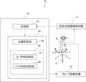
図1には、本実施形態に係るエコー画像取得用の探索装置を含む心エコー検査システムの概略構成を表した図が示されている。この図において、前記心エコー検査システム10は、医師と離れた場所にいる被検者の心エコー検査を可能にするシステムである。具体的に、この心エコー検査システム10は、被検体の胸部の体表面にプローブPを接触させることで、心臓のエコー画像(以下、「心エコー画像」と称する)を撮像する超音波画像撮像装置11と、プローブPを移動させるプローブ移動装置12と、取得したエコー画像を処理、解析することにより、プローブPの位置情報、姿勢情報からなる配置情報について、所望とする心エコー画像が得られる際の適切なプローブPの配置状態を探索する探索装置13とを備えている。Figure 1 shows a schematic configuration of an echocardiography system including a search device for acquiring echocardiograms according to this embodiment. In this figure, the
前記超音波画像撮像装置11としては、2次元若しくは3次元の心エコー検査を行うための超音波画像(エコー画像)を取得できる公知の超音波診断装置が適用される。つまり、この超音波画像撮像装置11では、プローブPによるビーム走査によって、ビーム走査面Fと同一断面における2次元の断層画像である心エコー画像が取得される。A known ultrasound diagnostic device capable of acquiring ultrasound images (echo images) for performing two-dimensional or three-dimensional echocardiography is used as the
前記プローブ移動装置12は、医師等の遠隔操作により、プローブPを保持する保持部(図示省略)を動作させることで、プローブPに対し、直交3軸方向の並進運動と直交3軸回りの回転運動とからなる6自由度の動作を可能にするロボットからなる。当該ロボットは、本発明の本質的な要素でないため、詳細な構成等の説明を省略する。The
また、前記プローブPには、その位置情報及び姿勢情報を検出可能な公知のセンサ(図示省略)が設けられている。このセンサでは、所定地点を原点とする直交3軸の各座標における位置情報と、当該3軸回りの回転角度である姿勢情報とからなる3次元の配置情報を取得可能になっている。なお、ここでのセンサとしては、加速度センサ、磁気センサ、光学センサ等、前記配置情報を取得可能な限りにおいて、種々の機器を採用することができる。また、前記配置情報における座標系は、所定の位置を原点として事前に設定される。The probe P is also provided with a known sensor (not shown) capable of detecting its position information and attitude information. This sensor is capable of acquiring three-dimensional position information consisting of position information at each coordinate of three orthogonal axes with a specified point as the origin, and attitude information which is the rotation angle around the three axes. Note that various devices can be used as the sensor here, such as an acceleration sensor, a magnetic sensor, an optical sensor, etc., as long as they are capable of acquiring the position information. Furthermore, the coordinate system for the position information is set in advance with a specified position as the origin.
前記探索装置13は、CPU等の演算処理装置及びメモリやハードディスク等の記憶装置等からなるコンピュータによって構成されている。The
この探索装置13は、超音波画像撮像装置11で取得した心エコー画像を含む画像データ等を保存する記憶部15と、記憶部15から抽出された画像データを解析し、心エコー検査に適切となるプローブPの配置状態における前記配置情報を所望情報として決定する画像処理部16とを備えている。This
前記画像データは、プローブPに取り付けられた前記センサの検出結果から、心エコー画像を取得した際のプローブPの位置情報及び姿勢情報を当該心エコー画像に対応させたデータである。前記記憶部13には、プローブPの移動時や回転時における所定のタイミング毎に画像データが逐次保存される。The image data is data that corresponds the position information and posture information of the probe P when the echocardiogram image is acquired to the echocardiogram based on the detection results of the sensor attached to the probe P. The image data is sequentially stored in the
前記画像処理部16では、心エコー検査において病状の診断に用いられる基本断面のうち、最も所見の多い傍胸骨左縁左室長軸断面と呼ばれる対象断面の心エコー画像を取得可能となるプローブPの位置情報及び姿勢情報が、所望位置情報及び所望姿勢情報(所望情報)として決定されるようになっている。The
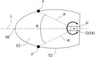
傍胸骨左縁左室長軸断面のエコー画像としては、図2に模式的に示されるように、扇型の外形の上側頂部に右室51が描出され、同下側に左室壁52、左室53、僧帽弁54及び左房55等が描出される。As shown in FIG. 2, the left parasternal border left ventricular long axis section echo image depicts the
ここで、プローブPの位置情報としては、心エコー画像を取得可能に体表面に対して一義的に定まる体表面への押圧方向であるz軸方向を除くx軸方向及びy軸方向の2自由度の位置情報が対象となる。また、プローブPの姿勢情報としては、心エコー画像を中心軸上に移動させるために一義的に定まるロール方向を除くヨー方向及びピッチ方向の2自由度の角度情報が対象となる。The position information of the probe P here refers to position information with two degrees of freedom in the x-axis and y-axis directions, excluding the z-axis direction, which is the direction of pressure against the body surface that is uniquely determined with respect to the body surface so that an echocardiogram can be obtained. In addition, the posture information of the probe P refers to angle information with two degrees of freedom in the yaw and pitch directions, excluding the roll direction, which is uniquely determined to move the echocardiogram onto the central axis.
前記画像処理部16では、プローブ移動装置12によるプローブPの移動や回転による走査により、相互に異なるプローブPの配置状態で得られた複数の心エコー画像の中から、所定部位となる左室壁52や僧帽弁54の描出状況に基づいて、所定の前記画像データを特定し、当該画像データを取得した際のプローブPの配置情報から、所望位置情報及び所望姿勢情報が決定される。The
具体的に、画像処理部16は、基点となる僧帽弁54の描出状況に応じ、心エコー画像の対象断面を取得するのに適切となるプローブPの所望位置情報を探索する位置探索部18と、心エコー画像の対象断面を取得するのに適切となるプローブPの所望姿勢情報を探索する姿勢探索部19とにより構成される。Specifically, the
前記位置探索部18では、僧帽弁54が心エコー画像に表れるプローブPのx軸及びy軸方向の座標からなる所望位置情報を探索する。The
すなわち、ここでは、学習済みの画像データに基づき、所定の物体を認識する深層学習モデル等を利用したYOLO等の公知の物体検出システムが適用されており、プローブPの各位置で取得した心エコー画像の中から、予め学習した僧帽弁54の存在とその確率を表す推定値が算出される。そして、当該推定値の最も高い心エコー画像を取得したプローブPの位置を表すx軸及びy軸方向の座標が所望位置情報とされる。なお、物体検出システムとしては、心エコー画像の中から僧帽弁54の存在等を推定可能な限りにおいて、様々な手法の他のシステムや装置類を採用することができる。That is, here, a known object detection system such as YOLO that utilizes a deep learning model that recognizes a specific object based on trained image data is applied, and an estimate representing the presence and probability of the
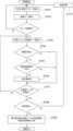
所望位置情報の探索及び決定の手順について、図3のフローチャートを用いながら以下に説明する。The procedure for searching and determining the desired location information is explained below with reference to the flowchart in Figure 3.
先ず、プローブPのヨー方向及びピッチ方向の角度を所定値に固定した所定の姿勢で、プローブ移動装置12の動作により、プローブPが、被検者の胸部表面の所定範囲に沿って走査される(ステップS101)。この際、n箇所の各位置で都度取得した画像データが記憶部15に保存される(ステップS102)。そして、前記所定範囲でのプローブPの走査が終了したら、位置探索部18により、記憶部15に保存された取得位置毎の全ての画像データについて、それぞれ次の画像処理が行われる。つまり、座標(xi,yi)となる所定位置(i=1、2・・・n)の画像データが記憶部15から抽出され(ステップS103)、当該1フレームの心エコー画像について僧帽弁54の検出が行われる(ステップS104)。そして、僧帽弁54が検出された心エコー画像について、公知の画像処理により、僧帽弁54が、予め設定された心エコー画像の所定の端部領域に位置するか否かが判定される(ステップS105)。そこで、僧帽弁54が、前記端部領域に位置しない場合に、その心エコー画像内での僧帽弁54の推定値が、その画像データに対応して記録された状態で、画像データに保存される(ステップS106)。なお、以上の手順で僧帽弁54が検出されない場合、また、僧帽弁54が前記端部領域に位置する場合には、他の位置で取得された画像データについて、同一の画像処理が行われる。First, in a predetermined posture in which the angles of the probe P in the yaw direction and the pitch direction are fixed to predetermined values, the probe P is scanned along a predetermined range of the subject's chest surface by the operation of the probe moving device 12 (step S101). At this time, image data acquired at each of the n positions is stored in the memory unit 15 (step S102). Then, when the scanning of the probe P in the predetermined range is completed, the
以上の画像処理が、プローブPの走査によって取得された全ての画像データについて行われた後(ステップS107)、前記推定値の有無が判定される(ステップS108)。ここで、前記推定値が記録された画像データが存在する場合には、その中で最大の前記推定値を有する画像データが推定値が高いと判定され、その取得時の位置情報がプローブPの所望位置情報として決定される(ステップS109)。一方、全ての画像データについて、僧帽弁54が検出されない場合、或いは、心エコー画像の前記端部領域でのみ僧帽弁54が検出された場合には、前記推定値が記録された画像データが存在しないため、プローブPのヨー方向及びピッチ方向の角度を別の値に変更して姿勢を変えた上で(ステップS110)、再度、胸部表面の前記所定範囲に沿ってプローブPを走査させ、前述の処理が繰り返し行われる。After the above image processing is performed for all image data acquired by scanning the probe P (step S107), the presence or absence of the estimated value is determined (step S108). Here, if image data with the estimated value recorded exists, the image data with the largest estimated value among them is determined to have a high estimated value, and the position information at the time of acquisition is determined to be the desired position information of the probe P (step S109). On the other hand, if the
なお、プローブPの所望位置情報の探索、決定の手順としては、前述に限定されるものではなく、次の変形例の手順により行うこともできる。The procedure for searching and determining the desired position information of the probe P is not limited to the above, but can also be performed according to the following modified procedure.
前述の手順では、プローブPが移動した領域内の各位置で画像データを全て取得した後で、前述の画像処理を行っているが、当該変形例では、プローブPが移動する経路上の各位置にて、前述の画像処理を都度行い、所定の前記推定値の画像データが得られた時点で、その位置情報がプローブの所望位置情報として決定される。In the above procedure, the above image processing is performed after all image data is acquired at each position within the area traveled by the probe P, but in this modified example, the above image processing is performed each time at each position on the path traveled by the probe P, and when image data of a specified estimated value is obtained, that position information is determined as the desired position information of the probe.
すなわち、図4に示されるように、先ず、プローブPのヨー方向及びピッチ方向の角度を所定値に固定した所定の姿勢で、プローブ移動装置12の動作により、所定の経路に沿ってプローブが走査され(ステップS201)、最初の位置で画像データが取得される(ステップS202)。次に、当該位置での画像データについて、位置探索部18により僧帽弁54の検出が行われる(ステップS203)。そして、僧帽弁54が検出された心エコー画像について、前述と同様に、僧帽弁54が、予め設定された心エコー画像の端部領域に位置するか否かが判定される(ステップS204)。その後、僧帽弁54が、前記端部領域に位置しない場合に、その画像データにおける僧帽弁54の推定値が、予め設定した閾値以上か否かについて判定される(ステップS205)。当該推定値が閾値以上の場合には、推定値が高いと判定され、プローブ移動装置12による経路移動が停止され(ステップS206)、その際のプローブPの位置情報が所望位置情報として決定される(ステップS207)。一方、位置探索部18により僧帽弁54が検出されない場合、僧帽弁54が前記端部領域に位置する場合、或いは、前記推定値が閾値未満の場合には、プローブPが、次の位置に移動して同様の画像処理が行われる。そして、予め設定された経路の全域をプローブPが移動しても、前述の処理により所望位置情報が得られない場合には、プローブPのヨー方向及びピッチ方向の角度を別の値に変更して姿勢を変えた上で(ステップS208)、再度、プローブPが前記経路上を移動し、前述の手順で画像処理が行われる。That is, as shown in FIG. 4, first, in a predetermined posture in which the angles of the yaw direction and pitch direction of the probe P are fixed to a predetermined value, the probe is scanned along a predetermined path by the operation of the probe moving device 12 (step S201), and image data is acquired at the initial position (step S202). Next, the
なお、前記変形例では、当該推定値の閾値を使って所望位置情報を決定しているが、当該変形例に対する変更点として、図5に示されるように、経路上のプローブPの移動に伴って取得される心エコー画像の推定値が連続的に上昇し続けるまでプローブPの移動を継続し(ステップS205A)、高い推定値と判定される最大の推定値を有する最後のプローブの位置を所望位置情報とする(ステップS207A)態様も採用可能である。In the above modified example, the desired position information is determined using the threshold value of the estimated value. However, as a modification to the modified example, as shown in FIG. 5, it is also possible to continue moving the probe P until the estimated value of the echocardiogram image acquired as the probe P moves along the path continues to increase continuously (step S205A), and to determine the position of the last probe having the maximum estimated value, which is determined to be a high estimated value, as the desired position information (step S207A).
前記姿勢探索部19は、図6に示されるように、左室の先端の心尖56と僧帽弁54とを結ぶ直線である左室長軸Lに沿う断面を描出可能となるように、プローブPのヨー方向における所望姿勢情報となる所望ヨー角度を探索するヨー角度探索部21と、腱索と乳頭筋が連ならない位置での僧帽弁54を認識するためのプローブPのピッチ方向における所望姿勢情報となる所望ピッチ角度を探索するピッチ角度探索部22とを備えている。As shown in FIG. 6, the
前記ヨー角度探索部21では、以下の概念に基づいて、左室長軸Lに沿う心エコー画像を描出可能なプローブPのヨー方向の回転角度が、所望ヨー角度として決定される。The yaw
左室長軸Lの角度を推定するために、心臓の左室形状に着目する。図6に示されるように、左室53は、回転楕円体に近似することが可能で、その中心軸は左室長軸Lに一致する。また回転楕円体の対称性より、左室長軸L上の任意の点Oを通る断面には、左室長軸Lに対して対称な断面が存在すると考えられる。つまり、これら断面が得られるプローブPの回転角度の中央値は、左室長軸Lに一致することになる。ここで、左室長軸Lが心尖56から僧帽弁54を結ぶ直線であることを考慮すると、僧帽弁54を通る左室の断面Aには左室長軸に対して対称な断面A´が存在する。次に、左室長軸Lを含む断面が得られるプローブPの回転角度から、ヨー方向時計回りにプローブPを回転させた際の断面に着目する。この際、プローブPにより描出される断面の左室壁52の形状は、画像左端の外周部分の一部が開放したチューブ状の形状(開放状態)から、同外周部分が連続して閉塞する楕円形状若しくは円形状(閉塞状態)に変化する。また、逆方向にプローブを回転した際も同様に左室壁52の形状が変化する。ここで、左室壁52の形状が、開放状態と閉塞状態との間で変化する2か所の境界地点Fの間のヨー角度である臨界角度θに着目をすると、臨界角度θの中央値が左室長軸Lに沿う断面を取得可能なプローブPの所望ヨー角度であると考えられる。In order to estimate the angle of the left ventricular long axis L, attention is paid to the shape of the left ventricle of the heart. As shown in FIG. 6, the
そこで、前記ヨー角度探索部21では、次の処理が行われる。すなわち、僧帽弁54の位置を中心とし、プローブPをヨー方向に回転させた際に取得された心エコー画像に、当該取得時のヨー方向の角度(ヨー角度)に対応して記憶部15に保存された画像データから、公知の画像処理によって、左室壁53の形状が閉塞状態と開放状態との間で変化する際の心エコー画像が特定される。そして、当該心エコー画像に紐付いているプローブPのヨー角度から臨界角度を求め、その中央値が、左室長軸Lに沿って描出される断面の得られるプローブPの所望ヨー角度として決定される。The yaw
所望ヨー角度の探索及び決定の手順について、図7のフローチャートを用いながら以下に説明する。The procedure for searching for and determining the desired yaw angle is explained below with reference to the flowchart in Figure 7.
先ず、前述した所望位置情報に対応する位置にプローブPを移動し、当該位置と、ピッチ方向の角度を所定値に固定した所定の姿勢を維持した状態で、プローブ移動装置12により、プローブPを360度の範囲で全周回転させながら走査する(ステップS301)。この際、n箇所の各ヨー角度で都度取得した画像データが記憶部15に保存される(ステップS302)。そして、プローブPの全周回転が終了したら、ヨー角度探索部21により、記憶部15に保存されたヨー角度毎の全ての画像データについて、それぞれ次の画像処理が行われる。つまり、角度(εi)となる所定のヨー角度(i=1、2・・・n)における対象の画像データと、その前後所定数の各フレームの画像データとが記憶部15から抽出される(ステップS303)。そして、公知の画像処理により、当該対象の画像データについて、その前後の所定数のフレーム(例えば、5フレーム)連続で、左室壁52の一部が開放しない状態となる閉塞左室壁が検出されたか否かが判定される(ステップS304)。そして、閉塞左室壁が前記所定数連続して検出された対象の画像データは、検出画像データとして記録される(ステップS305)。なお、閉塞左室壁が前記所定数連続して検出されない場合には、別のヨー角度で取得された次の対象の心エコー画像について、同一の画像処理が行われる。First, the probe P is moved to a position corresponding to the desired position information described above, and while maintaining the position and a predetermined posture with the pitch angle fixed to a predetermined value, the probe P is rotated 360 degrees by the
以上の画像処理が、ヨー方向における全周のプローブPの走査によって取得された全ての画像データについて行われた後(ステップS306)、前記検出画像データの存否が判定される(ステップS307)。そして、検出画像データが存在する場合には、前後フレームでの対比により、当該検出画像データを検出し始めた時のプローブPの2箇所のヨー角度から、臨界角度が算出される(ステップS308)。その上で、臨界角度の中央値が算出され、当該中央値に対応するプローブPのヨー角度が、所望ヨー角度として決定される(ステップS309)。一方、全ての画像データについて、閉塞左室壁が検出されない場合には、プローブPのピッチ方向の角度を別の値に変更して姿勢を変えた上で(ステップS310)、再度、前述の処理が行われる。After the above image processing is performed for all image data acquired by scanning the entire circumference of the probe P in the yaw direction (step S306), the presence or absence of the detected image data is determined (step S307). If detected image data exists, a critical angle is calculated from the yaw angles of two points of the probe P when the detected image data began to be detected by comparing the previous and next frames (step S308). The median of the critical angles is then calculated, and the yaw angle of the probe P corresponding to the median is determined as the desired yaw angle (step S309). On the other hand, if an obstructed left ventricular wall is not detected for all image data, the angle in the pitch direction of the probe P is changed to another value to change the posture (step S310), and the above processing is performed again.
前記ピッチ角度探索部22では、左室長軸Lを含む傍胸骨左縁左室長軸断面において、左室の乳頭筋や腱索が描出されないようにする必要があることから、左室53の乳頭筋や腱索が描出されない僧帽弁54の中央位置におけるプローブPの所望ピッチ角度が探索される。The pitch
このピッチ角度探索部22では、僧帽弁54を撮像可能な所望位置情報に対応する位置にプローブPを移動した上で、所望ヨー角度でのプローブPの姿勢とした状態で、プローブPのピッチ方向の角度(ピッチ角度)を変化させながら、乳頭筋や腱索が連ならない僧帽弁54が心エコー画像に描出されるピッチ角度で得られた画像データを特定することで、プローブPの所望ピッチ角度が決定される。In this pitch
すなわち、ここでは、前記位置探索部18と同様の物体検出システムが適用されており、プローブPの各ピッチ角度で取得した画像データの中から、予め学習した乳頭筋や腱索が連ならない僧帽弁54の存在とその確率を表す推定値が算出される。そして、前述した実施形態や変形例における位置探索部18と同様の手順により、推定値が高いと判定された画像データを取得した際のプローブPのピッチ角度が所望ピッチ角度とされる。That is, an object detection system similar to the
以上の画像処理部16での画像処理により、適切な傍胸骨左縁左室長軸断面が得られるプローブPの位置情報及び姿勢情報が特定され、これら配置情報に対応するプローブPの位置及び姿勢で取得された心エコー画像が、診断に有用となる傍胸骨左縁左室長軸断面として用いられることになる。By performing the image processing in the
なお、本発明における探索装置13は、心エコー画像に限らず所望とするエコー画像を得るために適切となるプローブPの配置状態を探索するために、複数のエコー画像における所定部位の描出状況に基づいて、適切となる画像データを特定し、当該画像データを取得した際のプローブPの配置情報を所望情報として決定することも可能である。The
また、前記画像処理部16としては、所望情報の把握状況に応じて、前記位置探索部18及び姿勢探索部19の何れか一方のみを設ける態様を採用することもできる。また、画像処理部16では、同様の手法により、他の心臓弁等の部位の描出状況に基づいて、所望とする他の基本断面を得るためのプローブPの所望位置情報及び所望姿勢情報を決定することも可能である。The
更に、前記実施形態では、プローブ移動装置12による動作により、プローブPの移動及び回転を行っているが、本発明はこれに限らず、プローブPの移動及び回転を操作者の手動で行い、探索装置13により、適切なプローブPの位置及び姿勢を自動的に特定することもできる。Furthermore, in the above embodiment, the probe P is moved and rotated by the operation of the
その他、本発明における装置各部の構成や処理手順は、前述の説明に限定されるものではなく、実質的に同様の作用を奏する限りにおいて、種々の変更が可能である。In addition, the configuration and processing procedures of each part of the device in the present invention are not limited to the above description, and various modifications are possible as long as they produce substantially the same effect.
11 超音波画像撮像装置
13 探索装置
16 画像処理部
18 位置探索部
19 姿勢探索部
21 ヨー角度探索部
22 ピッチ角度探索部
P プローブ
L 左室長軸 REFERENCE SIGNS
Claims (4)
Translated fromJapanese相互に異なる前記配置状態で撮像された前記エコー画像に前記プローブの配置情報をそれぞれ対応させた複数の画像データを解析し、適切となる前記配置状態における前記配置情報を所望情報として決定する画像処理部を備え、
前記画像処理部では、複数の前記エコー画像における所定部位の描出状況に基づいて、所定の前記画像データが特定され、当該画像データを取得した際の前記配置情報から前記所望情報が決定され、
前記画像処理部は、前記配置情報として前記プローブの姿勢情報を用い、前記所望情報として、心臓の前記エコー画像の対象断面を取得するのに適切となる前記プローブの所望姿勢情報を探索する姿勢探索部を含み、
前記姿勢探索部は、左室の先端の心尖と僧帽弁とを結ぶ直線である左室長軸に沿う前記エコー画像を取得可能となる前記プローブのヨー方向におけるヨー角度を前記所望姿勢情報として探索するヨー角度探索部を備え、
前記ヨー角度探索部では、前記プローブをヨー方向に回転させながら都度取得された前記各画像データを取得順に対比したときの左室領域の形状変化から、左室壁の開放状態と閉塞状態の2箇所の境界地点の間の前記ヨー角度である臨界角度を推定し、当該臨界角度の中央値となる前記ヨー角度を、前記左室長軸に沿う前記対象断面が得られる前記所望姿勢情報とすることを特徴とするエコー画像取得用の探索装置。 1. An apparatus for searching for an appropriate probe arrangement state for obtaining a desired echo image by using an ultrasound imaging apparatus that acquires an echo image of the inside of a body by contacting the probe with a body surface of a subject, the apparatus comprising:
an image processing unit that analyzes a plurality of image data in which the echo images captured in the mutually different arrangement states correspond to arrangement information of the probe, and determines the arrangement information in the appropriate arrangement state as desired information;
In the image processing unit, the predetermined image data is specified based on a depiction state of a predetermined part in the plurality of echo images, and the desired information is determined from the arrangement information at the time when the image data was acquired,
the image processing unit includes a posture search unit that uses posture information of the probe as the arrangement information and searches for desired posture information of the probe that is appropriate for acquiring a target cross section of the echo image of the heart as the desired information;
the posture search unit includes a yaw angle search unit that searches, as the desired posture information, a yaw angle in a yaw direction of the probe that enables acquisition of the echo image along a left ventricular long axis that is a straight line connecting an apex at the tip of the left ventricle and a mitral valve,
the yaw angle search unit estimates a critical angle, which is the yaw angle between two boundary points between an open state and a closed state of the left ventricular wall, from a change in shape of the left ventricular region when the image data acquired each time while rotating the probe in a yaw direction is compared in order of acquisition, and the yaw angle that is a median value of the critical angles is set as the desired posture information for obtaining the target cross section along the left ventricular long axis .
前記位置探索部では、学習済みの前記画像データに基づき、前記各エコー画像内の前記心臓弁を認識する物体検出システムにより、前記各エコー画像内での前記心臓弁の存在の可能性を表す推定値が算出され、当該推定値が高いと判定された前記エコー画像に対応する前記位置情報が、前記所望位置情報とされることを特徴とする請求項1記載のエコー画像取得用の探索装置。 the image processing unit includes a position search unit that uses position information of the probe as the arrangement information, and searches for desired position information of the probe that is appropriate for acquiring a target cross section of the echo image of the heart, as the desired information, in accordance with a depiction state of a cardiac valve that is a base point;
2. The search device for acquiring echo images as described in claim 1, wherein the position search unit calculates an estimated value representing the possibility of the presence of the heart valve in each of the echo images using an object detection system that recognizes the heart valve in each of the echo images based on the learned image data, and the position information corresponding to the echo image for which the estimated value is determined to be high is set as the desired position information.
前記ピッチ角度探索部では、学習済みの前記画像データに基づき、前記エコー画像内において前記腱索と前記乳頭筋が連ならない前記僧帽弁を認識する物体検出システムにより、当該僧帽弁の前記各エコー画像内での存在の可能性を表す推定値が算出され、当該推定値の最も高い前記エコー画像に対応するピッチ角度が前記所望姿勢情報とされることを特徴とする請求項1又は2記載のエコー画像取得用の探索装置。the posture searching unit includes a pitch angle searching unit configured to search for a pitch angle in a pitch direction of the probe for recognizing a mitral valve in which chordae tendineae and papillary muscles are not connected, as the desired posture information;
3. The searching device for acquiring echo images according to claim 1 or 2, characterized in that in the pitch angle searching unit, an estimate representing a possibility of the presence of the mitral valve in each of the echo images is calculated by an object detection system that recognizes the mitral valve in which the chordae tendineae and the papillary muscles are not connected in the echo images based on the learned image data,and the pitch angle corresponding to the echo image with the highest estimate is regarded as the desired posture information.
相互に異なる前記配置状態で撮像された前記エコー画像に前記プローブの配置情報をそれぞれ対応させた複数の画像データを解析し、適切となる前記配置状態における前記配置情報を所望情報として決定する画像処理部としてコンピュータを機能させ、
前記画像処理部では、複数の前記エコー画像における所定部位の描出状況に基づいて、所定の前記画像データが特定され、当該画像データを取得した際の前記配置情報から前記所望情報が決定され、
前記画像処理部は、前記配置情報として前記プローブの姿勢情報を用い、前記所望情報として、心臓の前記エコー画像の対象断面を取得するのに適切となる前記プローブの所望姿勢情報を探索する姿勢探索部を含み、
前記姿勢探索部は、左室の先端の心尖と僧帽弁とを結ぶ直線である左室長軸に沿う前記エコー画像を取得可能となる前記プローブのヨー方向におけるヨー角度を前記所望姿勢情報として探索するヨー角度探索部を備え、
前記ヨー角度探索部では、前記プローブをヨー方向に回転させながら都度取得された前記各画像データを取得順に対比したときの左室領域の形状変化から、左室壁の開放状態と閉塞状態の2箇所の境界地点の間の前記ヨー角度である臨界角度を推定し、当該臨界角度の中央値となる前記ヨー角度を、前記左室長軸に沿う前記対象断面が得られる前記所望姿勢情報とすることを特徴とするエコー画像取得用の探索装置のプログラム。
A program for an ultrasound imaging device that acquires an internal echo image by contacting a probe with a body surface of a subject, the program searching for an appropriate probe arrangement state for obtaining a desired echo image, the program comprising:
a computer that functions as an image processing unit that analyzes a plurality of image data in which the echo images captured in the mutually different placement states correspond to the placement information of the probe, and determines the placement information in the appropriate placement state as desired information;
In the image processing unit, the predetermined image data is specified based on a depiction state of a predetermined part in the plurality of echo images, and the desired information is determined from the arrangement information at the time when the image data was acquired,
the image processing unit includes a posture search unit that uses posture information of the probe as the arrangement information and searches for desired posture information of the probe that is appropriate for acquiring a target cross section of the echo image of the heart as the desired information;
the posture search unit includes a yaw angle search unit that searches, as the desired posture information, a yaw angle in a yaw direction of the probe that enables acquisition of the echo image along a left ventricular long axis that is a straight line connecting an apex at the tip of the left ventricle and a mitral valve,
the yaw angle searching unit estimates a critical angle, which is the yaw angle between two boundary points between an open state and a closed state of the left ventricular wall, from a change in shape of the left ventricular region when the image data acquired each time while rotating the probe in a yaw direction is compared in order of acquisition, and the yaw angle that is a median value of the critical angles is set as the desired posture information for obtaining the target cross section along the left ventricular long axis .
Priority Applications (1)
| Application Number | Priority Date | Filing Date | Title |
|---|---|---|---|
| JP2021182897AJP7698306B2 (en) | 2021-11-09 | 2021-11-09 | Searching device and program for acquiring echo images |
Applications Claiming Priority (1)
| Application Number | Priority Date | Filing Date | Title |
|---|---|---|---|
| JP2021182897AJP7698306B2 (en) | 2021-11-09 | 2021-11-09 | Searching device and program for acquiring echo images |
Publications (2)
| Publication Number | Publication Date |
|---|---|
| JP2023070601A JP2023070601A (en) | 2023-05-19 |
| JP7698306B2true JP7698306B2 (en) | 2025-06-25 |
Family
ID=86331645
Family Applications (1)
| Application Number | Title | Priority Date | Filing Date |
|---|---|---|---|
| JP2021182897AActiveJP7698306B2 (en) | 2021-11-09 | 2021-11-09 | Searching device and program for acquiring echo images |
Country Status (1)
| Country | Link |
|---|---|
| JP (1) | JP7698306B2 (en) |
Citations (3)
| Publication number | Priority date | Publication date | Assignee | Title |
|---|---|---|---|---|
| JP2009056125A (en) | 2007-08-31 | 2009-03-19 | Canon Inc | Ultrasound image diagnostic system and control method thereof |
| JP2011104194A (en) | 2009-11-19 | 2011-06-02 | Waseda Univ | Ultrasonic diagnostic apparatus, probe state detector for the same and program |
| JP2017502729A (en) | 2013-12-09 | 2017-01-26 | コーニンクレッカ フィリップス エヌ ヴェKoninklijke Philips N.V. | Image guidance using model-based segmentation |
- 2021
- 2021-11-09JPJP2021182897Apatent/JP7698306B2/enactiveActive
Patent Citations (3)
| Publication number | Priority date | Publication date | Assignee | Title |
|---|---|---|---|---|
| JP2009056125A (en) | 2007-08-31 | 2009-03-19 | Canon Inc | Ultrasound image diagnostic system and control method thereof |
| JP2011104194A (en) | 2009-11-19 | 2011-06-02 | Waseda Univ | Ultrasonic diagnostic apparatus, probe state detector for the same and program |
| JP2017502729A (en) | 2013-12-09 | 2017-01-26 | コーニンクレッカ フィリップス エヌ ヴェKoninklijke Philips N.V. | Image guidance using model-based segmentation |
Non-Patent Citations (1)
| Title |
|---|
| 一般社団法人日本超音波検査学会 走査法の標準化 循環器,2019年03月,https://www.jss.org/committee/standard/doc/standardization_junkanki.pdf |
Also Published As
| Publication number | Publication date |
|---|---|
| JP2023070601A (en) | 2023-05-19 |
Similar Documents
| Publication | Publication Date | Title |
|---|---|---|
| JP7268087B2 (en) | Image capture guidance using model-based segmentation | |
| JP6110404B2 (en) | Method and apparatus for interactive display of 3D ultrasound images | |
| JP7375140B2 (en) | Ultrasonic diagnostic equipment, medical image diagnostic equipment, medical image processing equipment, and medical image processing programs | |
| JP4427548B2 (en) | Apparatus and method for analyzing locally deformable motion | |
| US9687204B2 (en) | Method and system for registration of ultrasound and physiological models to X-ray fluoroscopic images | |
| JP7286773B2 (en) | Systems and methods for quantitative abdominal aortic aneurysm analysis using 3D ultrasound imaging | |
| KR20170016461A (en) | Landmark detection with spatial and temporal constraints in medical imaging | |
| JP6393698B2 (en) | Data display and processing algorithms for 3D imaging systems | |
| EP4255311B1 (en) | Robotized imaging system | |
| JP2010082333A (en) | Ultrasonic inspection robot system, and control method for ultrasonic inspection robot | |
| JP7698306B2 (en) | Searching device and program for acquiring echo images | |
| Wang et al. | Autonomous robotic system for carotid artery ultrasound scanning with visual servo navigation | |
| CN115136254A (en) | Medical imaging systems, devices and methods for visualizing deployment status of in vivo therapeutic devices | |
| Roelandt et al. | Precordial multiplane echocardiography for dynamic anyplane, paraplane and three-dimensional imaging of the heart | |
| JP7696641B2 (en) | Ultrasound image search device and program | |
| Novotny et al. | Gpu based real-time instrument tracking with three dimensional ultrasound | |
| JP2024520236A (en) | Ultrasound Imaging System | |
| EP4005492A1 (en) | Guided acquisition of a 3d representation of an anatomical structure | |
| JP7534735B2 (en) | Ultrasound image analysis device and ultrasound image analysis method | |
| CN119454096B (en) | A method and device for autonomously scanning thyroid lesions using an ultrasonic robot | |
| CN118750023B (en) | Robotic ultrasonic elastic imaging method and system | |
| JP2025077664A (en) | Image processing device and image processing method | |
| Koolwal et al. | An incremental method for registering electroanatomic mapping data to surface mesh models of the left atrium | |
| WO2024233972A1 (en) | Automated transesophageal echocardiogram control and sensor analysis system |
Legal Events
| Date | Code | Title | Description |
|---|---|---|---|
| A621 | Written request for application examination | Free format text:JAPANESE INTERMEDIATE CODE: A621 Effective date:20240627 | |
| A977 | Report on retrieval | Free format text:JAPANESE INTERMEDIATE CODE: A971007 Effective date:20250221 | |
| A131 | Notification of reasons for refusal | Free format text:JAPANESE INTERMEDIATE CODE: A131 Effective date:20250226 | |
| A521 | Request for written amendment filed | Free format text:JAPANESE INTERMEDIATE CODE: A523 Effective date:20250408 | |
| TRDD | Decision of grant or rejection written | ||
| A01 | Written decision to grant a patent or to grant a registration (utility model) | Free format text:JAPANESE INTERMEDIATE CODE: A01 Effective date:20250604 | |
| A61 | First payment of annual fees (during grant procedure) | Free format text:JAPANESE INTERMEDIATE CODE: A61 Effective date:20250606 | |
| R150 | Certificate of patent or registration of utility model | Ref document number:7698306 Country of ref document:JP Free format text:JAPANESE INTERMEDIATE CODE: R150 |