JP7697167B2 - Panel clamping device - Google Patents
Panel clamping deviceDownload PDFInfo
- Publication number
- JP7697167B2 JP7697167B2JP2021094611AJP2021094611AJP7697167B2JP 7697167 B2JP7697167 B2JP 7697167B2JP 2021094611 AJP2021094611 AJP 2021094611AJP 2021094611 AJP2021094611 AJP 2021094611AJP 7697167 B2JP7697167 B2JP 7697167B2
- Authority
- JP
- Japan
- Prior art keywords
- clamping device
- threaded rod
- panel
- clamp plate
- plates
- Prior art date
- Legal status (The legal status is an assumption and is not a legal conclusion. Google has not performed a legal analysis and makes no representation as to the accuracy of the status listed.)
- Active
Links
Images


Landscapes
- Manipulator (AREA)
Description
Translated fromJapanese本発明は、パネルのクランプ装置に関し、特に、ALC(軽量気泡コンクリート)パネルなどの建築用パネルをクランプして設置するためのパネルのクランプ装置に関するものである。The present invention relates to a panel clamping device, and in particular to a panel clamping device for clamping and installing architectural panels such as ALC (lightweight aerated concrete) panels.
大型の建築物などでは壁材にALCパネルが広く用いられている。ALCパネルの建て込み工程においては、その重量が大きいため施工においては、吊上げ装置が必要とされる。ALC panels are widely used as wall materials in large buildings. Because of the weight of the ALC panels, lifting equipment is required during the construction process.
ALCパネルは、一般に、幅300~600mm、長さ5~6m、最大重量350kg程度であり、通常横長にして置かれており、これを搬送・設置装置で縦長になるように起こしながら建て込み場所まで搬送し、建築物に建て込みしていく。ALC panels are generally 300-600 mm wide, 5-6 m long, and weigh up to 350 kg. They are usually laid out horizontally, and are then transported to the installation site, where they are erected on the building, while being turned upright using a transport and installation device.
従来の建て込み工法として、ALCパネルを固縛したスリングベルトをクレーンなどで引掛けて持ち上げる方法が知られている。A conventional construction method involves using a crane or similar device to hook sling belts that secure the ALC panels together and lift them up.
また、別の工法として、マニピュレータ(例えば、商品名:ジラフ)等の搬送・設置装置に大流量の吸着能力を付加した装置を使用し、ALCパネルを吸着して吊上げて搬送・設置で搬送、建て込みを行う工法が知られている。ここで「ジラフ」とは、建設現場におけるガラス・ボード板材などの設置工事の重量物を「持ち上げ・下げ、回転、移動、設置をする」作業などに最適な、新しいタイプの自走式運搬・設置機をいう(以下同。)。Another known construction method is to use a manipulator (for example, product name: Giraffe) or other transport and installation device with a high-flow suction capacity to suction and lift the ALC panels, transporting and setting them down. Here, "Giraffe" refers to a new type of self-propelled transport and installation machine that is ideal for tasks such as "lifting, lowering, rotating, moving and setting" heavy objects such as glass and board materials when installing them at construction sites (same below).
さらにまた、リンクに連結したクランプ片を備えたクランプ部と、リンクと連結するスライダに取付けたワイヤ緊着できる懸吊部を備え、クランプ片をパネルに嵌め、吊り具をワイヤにより吊上げる建築用パネルの吊り具も開示されている(特許文献1参照)。Furthermore, a hanging device for architectural panels has been disclosed that includes a clamp section with a clamp piece connected to a link, and a hanging section that can be attached to a wire attached to a slider that connects to the link, in which the clamp piece is fitted to the panel and the hanging device is lifted by a wire (see Patent Document 1).
従来の固縛による方法は、パネルを引き起こす際、あるところで下端が地切りして空中に浮き、パネルが揺れて触れ回るおそれがある。この状態のパネルを人手で案内して位置決めをするが、作業者のパネルへの接近が避けられず、熟練を要する危険度の高い作業となる。With the conventional method of fastening panels, when the panels are raised, the bottom end breaks the ground at a certain point and floats in the air, which can cause the panel to swing and touch things around. In this state, the panel needs to be manually guided into position, but this means that workers cannot avoid getting close to the panels, making it a highly dangerous job that requires skill.
これに対し、マニピュレータによる吸着を利用する工法は、パネルを任意の姿勢で静止できるため、安全性は向上するが、ALCのような通気性のあるパネルでは、外部電源を利用した大型の真空ポンプが不可欠であるとともに、吸着パッドとして凹凸のあるALCの表面になじむ特殊なスポンジゴム製のものが必要で、高価になることが避けられない。
さらに、特許文献1のようなワイヤによる吊上げ工法は、パネルが揺れて触れ回り、前述の固縛方式と同様の問題があった。 In contrast, a method that uses suction with a manipulator improves safety by allowing the panel to be held still in any position; however, for breathable panels such as ALC, a large vacuum pump powered by an external power source is essential, and suction pads made of special sponge rubber that conforms to the uneven surface of ALC are required, making the method unavoidably expensive.
Furthermore, the wire-based lifting method as described in Patent Document 1 causes the panels to swing and move around, which is a problem similar to that of the previously described fastening method.
本発明は、かかる従来技術の課題を解決し、重量の大きいワークでもクランプして搬送・設置装置で搬送及び建て込みが可能で、安全性及び確実性の向上をはかるとともに、ワークの最小幅が最大幅の半分であってもクランプ板がこれに対応可能な機能を備え、かつ別途に動力が不要で低価格のパネルのクランプ装置を提供することを目的とする。The present invention aims to solve the problems of the conventional technology by providing a low-cost panel clamping device that can clamp even heavy workpieces and transport and set them up using a transport/installation device, improves safety and reliability, and has a clamp plate that can accommodate a workpiece whose minimum width is half its maximum width, without requiring a separate power source.
本発明のパネルのクランプ装置は、上下に配置された上部クランプ板及び下部クランプ板と、前記上部クランプ板及び下部クランプ板の端縁に軸で回転自在に連結された4本のリンクからなるパンタグラフ機構と、前記上部クランプ板及び下部クランプ板を接近又は後退自在に支持するガイド手段と、前記パンタグラフ機構の中央に設けられた、前記リンクの連結部材にねじ込まれ、前記パンタグラフ機構を外側方に開き又は内側方に閉じるように移動させて前記上部クランプ板及び下部クランプ板を接近又は後退させ、前記両クランプ板でパネルをクランプ又は解放する回転手段付きのねじ棒と、前記上下部クランプ板、パンタグラフ機構、ガイド手段、及びねじ棒を支持する支持フレームと、を備えたことを特徴とする。The panel clamping device of the present invention is characterized by comprising: an upper clamp plate and a lower clamp plate arranged above and below; a pantograph mechanism consisting of four links rotatably connected to the edge of the upper clamp plate and the lower clamp plate by an axis; a guide means for supporting the upper clamp plate and the lower clamp plate so that they can move toward or away from each other; a screw rod with a rotating means screwed into the connecting member of the link provided in the center of the pantograph mechanism and moving the pantograph mechanism so as to open outward or close inward, thereby moving the upper clamp plate and the lower clamp plate toward or away from each other, thereby clamping or releasing the panel with both clamp plates; and a support frame for supporting the upper and lower clamp plates, the pantograph mechanism, the guide means, and the screw rod.
前記ガイド手段は、前記支持フレームに固着され上下方向に向くガイドレールと、該ガイドレールに移動自在に装着されたリニアガイドブロックからなるリニアガイドを備え、前記上下部クランプ板と前記リニアガイドブロックとをガイド柱で連結したものであることが好ましい。It is preferable that the guide means includes a linear guide consisting of a guide rail fixed to the support frame and facing in the vertical direction, and a linear guide block movably attached to the guide rail, and that the upper and lower clamp plates and the linear guide block are connected by a guide column.
前記ねじ棒の回転手段は、ハンドルであることが好ましい。The means for rotating the threaded rod is preferably a handle.
前記ねじ棒の回転手段は、アクチュエータであり、該アクチュエータの動力で前記ねじ棒を回転させるようにすることが好ましい。The means for rotating the threaded rod is preferably an actuator, and the threaded rod is rotated by the power of the actuator.
前記ねじ棒は台形ねじであることが好ましい。The threaded rod is preferably a trapezoidal thread.
前記ねじ棒にはラチェットホイールが取付けられ、該ラチェットホイールに噛み合う爪により該ねじ棒の逆回転を防止することが好ましい。It is preferable that a ratchet wheel is attached to the threaded rod, and a pawl that engages with the ratchet wheel prevents the threaded rod from rotating in the reverse direction.
前記ねじ棒のハンドル及び前記ラチェットホイールに遠隔操作機構を接続し、該ハンドル及びラチェットホイールの操作を遠隔で行うようにすることが好ましい。It is preferable to connect a remote control mechanism to the handle of the threaded rod and the ratchet wheel so that the handle and the ratchet wheel can be operated remotely.
前記上下部クランプ板のクランプ面に滑り止め兼傷付き防止板を設けることが好ましい。It is preferable to provide anti-slip and anti-scratch plates on the clamping surfaces of the upper and lower clamping plates.
前記上下部クランプ板に実際に発生したクランプ力を表示するクランプ力表示手段を設けることが好ましい。It is preferable to provide a clamping force display means that displays the clamping force actually generated on the upper and lower clamping plates.
前記支持フレームに、パネルを自動搬送及び建築物に建て込む搬送・設置装置のアームを取付けることが好ましい。It is preferable to attach the arm of a transport and installation device to the support frame, which automatically transports the panels and installs them into the building.
前記搬送・設置装置はジラフ(登録商標)であることが好ましい。The transport and installation device is preferably Giraffe (registered trademark).
本発明によれば、重量の大きいパネル(ワーク)でもクランプして搬送・設置装置で搬送及び建て込みが可能で、人手によらず、安全性及び確実性が向上するとともに、パネルの最小幅が最大幅の半分であってもクランプ板がこれに対応可能であり、1台のクランプ装置で多種のパネルに対応でき、かつ別途に動力が不要で低価格のパネルのクランプ装置とすることができる。According to the present invention, even heavy panels (workpieces) can be clamped and transported and erected using the transport/installation device, which improves safety and reliability without relying on human labor, and the clamp plate can accommodate panels whose minimum width is half their maximum width, making it possible to use a single clamp device to accommodate a wide variety of panels, and providing a low-cost panel clamp device that does not require additional power.
以下、本発明を、図面に表わした実施形態を用いてより詳細に説明する。但し、本発明は、これら実施形態に限定されるものではなく、本発明の趣旨を逸脱しない範囲で種々変更して実施することが可能である。The present invention will be described in more detail below using the embodiments shown in the drawings. However, the present invention is not limited to these embodiments, and various modifications can be made without departing from the spirit of the present invention.
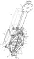
図1は、本発明の実施形態に係るパネルのクランプ装置の斜視図、図2は、同ガイド手段の斜視図である。なお、以下の説明において、上下又は左右の用語は図面の状態での方向を示すもので、実際の使用状態における方向を示すものではない。Figure 1 is a perspective view of a panel clamping device according to an embodiment of the present invention, and Figure 2 is a perspective view of the guide means. Note that in the following explanation, the terms up, down, left, and right indicate directions in the state of the drawings, and do not indicate directions in the actual state of use.
図1において、クランプ装置Aは、横方向に延びる長尺の支持フレーム1に支持されている。以下、クランプ装置Aの構成を説明する。In FIG. 1, the clamp device A is supported by a long support frame 1 that extends laterally. The configuration of the clamp device A is described below.
クランプ装置Aには、上下で相対向する一対の上部クランプ板6aと下部クランプ板6bとを備えている。上部クランプ板6aには前部の左右両端に下方に延びるガイド柱7b、7cが固着され、下部クランプ板6bには前部の左右両端に上方に延びるガイド柱7a、7dが固着されている。ガイド柱7a、7b、7c、7dはそれぞれリニアガイドブロック3a、3b、3c、3dにボルト10により固定されている。上下部クランプ板6a、6bのクランプ面にはゴム材等の滑り止め兼傷付き防止板8がボルト9により取付けられている。The clamp device A is equipped with a pair of upper and
上下部クランプ板6a、6bの前部には、以下のように4本のリンク13a、13b、13c、13dからなるパンタグラフ機構13が取付けられている。上部クランプ板6aの前部には2本の支持軸15が固着され、下部クランプ板6bの前部にも2本の支持軸16が固着されている。上部の支持軸15には上部のリンク13a、13bが回転自在に取付けられ、下部の支持軸16には下部のリンク13c、13dが回転自在に取付けられている。それぞれのリンク13a、13b、13c、13dの連結端部にはねじ孔18付きの連結板19a、19bがピン20により連結され、それぞれのねじ孔18にはねじ棒24がねじ込まれている。連結板19aと連結板19bではねじ込まれるねじ棒24のねじの向きが,一方が右ねじ、他方が左ねじで逆ねじになっている。ねじ棒24の両端部は支持フレーム1に固着されたブラケット21に回転自在に支持されている。ねじ棒24の一端にはハンドル25が取付けられ、他端にはラチェット26が取付けられ、ラチェット26には逆回転防止爪27が噛み合っている。A
図1において、支持フレーム1の左右には、位置合わせ用の当て板4及び位置合わせ用目印5が設けられている。支持フレーム1の途中には搬送・設置装置30(図4参照)に取付けるための固定フランジ35が設けられている。In FIG. 1, alignment plates 4 and
図2は、図1のY方向から見た斜視図であって、クランプ装置Aのガイド手段を示す斜視図である。横方向に延びる支持フレーム1には、ガイドプレート33が固着され、ガイドプレート33には上下方向を向く4本の平行なガイドレール2a、2b、2c、2dが固着されている。ガイドレール2a、2b、2c、2dには、これに沿って上下に移動するリニアガイドブロック3a、3b、3c、3dが装着されている。このガイドレール2a、2b、2c、2dとリニアガイドブロック3a、3b、3c、3dとでリニアガイドGを構成している。リニアガイドブロック3a、3b、3c、3dに上記ガイド柱7a、7b、7c、7dが固着されている。Figure 2 is a perspective view seen from the Y direction of Figure 1, showing the guide means of the clamp device A. A
次に、ワークW(この例では幅300~600mmの長尺のALCパネル)のクランプ時の動作を説明する(図3参照)。位置合わせ用当て4及び目印5をワークWに当ててクランプ位置を決め、ハンドル25を時計方向に回転させると、ねじ棒24の回転により連結板19a、19b及びパンタグラフ機構13のリンク13a、13b、13c、13dが左右に開く方向に移動し、これにより、上下のリンク13a、13b、13c、13dの上下端部が接近する方向に移動し、上下部クランプ板6a、6bは接近する方向に移動する。このとき、各ガイド柱7a、7b、7c、7dもリニアガイドブロック3a、3b、3c、3dによりガイドレール2a、2b、2c、2dに沿って移動する。そして、図3に示すように、上下部クランプ板6a、6bでワークWを上下(ワーク両側)からクランプする。なお、ラチェット26も回転し、逆回転防止爪27によりねじ棒24の逆回転が防止される。ワークWをクランプして把持後にトルクレンチ(図示せず)で設定トルクを与えるようにすることも可能である。ねじ棒24に台形ねじを使用することにより、ねじ棒24のセルフロック機能でワークWを確実に保持することができる。Next, the operation when clamping the workpiece W (in this example, a long ALC panel with a width of 300 to 600 mm) will be described (see Figure 3). The positioning stopper 4 and the
図4は、搬送・設置装置によりワークの搬送作業、図5はワークの設置(建て込み)の作業を示している。
図5に示すように、支持フレーム1の中央に固定フランジ35を配置し、その両側方に2台のクランプ装置Aを配置する。そして、上下部クランプ板6a、6bにより、前述のようにしワークWを2か所でクランプする。 FIG. 4 shows the workpiece transport operation by the transport and installation device, and FIG. 5 shows the workpiece installation (setting up) operation.
5, a fixed
図4に示すように、ワークWは横向きに置かれている。搬送・設置装置30の上下に旋回するアーム31をほぼ水平の状態に設定し、アーム31の先端の取付け部32を支持フレーム1の固定フランジ35に固定する。そして、図4に示すように、アーム31を水平状態から少しずつ起こしながら搬送し、最終的の図5に示すように、ワークWを垂直に保持し、この状態で建築物に建て込みを行う。As shown in Figure 4, the workpiece W is placed horizontally. The
搬送・設置装置としては、ジラフ(登録商標)が好適であるが、他の産業用ロボット、バランサなどのアーム式のマニピュレータも使用可能である。The Giraffe (registered trademark) is a suitable transport and installation device, but other industrial robots and arm-type manipulators such as balancers can also be used.
上記実施形態において、種々の変形が可能である。例えば、ねじ棒24のハンドル25を手で回転させてクランプ板6a、6bを移動させてクランプすることができるとともに、ハンドル25及びラチェット26の操作は、ワイヤなどの遠隔操作機構を接続して機械的に遠隔操作することも可能である。また、ねじ棒24の回転手段にモータなどのアクチュエータを使用し、アクチュエータの動力でねじ棒24を回転させるようにすることも可能である。さらに、ワークWを把持後にねじ棒24をトルクレンチで操作し、クランプ板6a、6bに設定トルクを付与することも可能である。また、ねじ棒24に台形ねじを使用することにより、台形ねじのセルフロック機能により設定トルクを保持することができる。さらに、クランプ板6a、6bに面圧センサなど、実際に発生したクランプ力を表示するクランプ力表示手段を設けてクランプ力を表示することも可能である。In the above embodiment, various modifications are possible. For example, the
以上のように、本実施形態のパネルのクランプ装置は、ワークを強固にクランプして搬送や建て込みを行うことができるため、ワークの揺れがなくなり、安全性が向上する。さらに、ガイド手段と併せて、パンタグラフ機構13を用いたねじ式ジャッキの構造をクランプ構造に利用しているため、クランプ操作時に上下部クランプ板6a、6bが同じ面上で平行運動をする。これを活かしてガイド柱7a、7b、7c、7dを、いわゆる入れ子構造にすることで、上下部クランプ板6a、6bが内方や外方に飛び出すことがなくなり、建て込み時にクランプ装置Aと周囲との干渉が回避できる。加えて、パンタグラフ機構13を用いたねじ式ジャッキの構造は、最小限の可動で最大のクランプ力、すなわちワーク重量の3倍以上のクランプ力が得られる。また、ガイド柱7a、7b、7c、7dが入れ子構造であることからクランプ板6a、6bの可動範囲が大きいため、ワークの最小幅が最大幅の半分の場合でもクランプ板6a、6b、6c、6dが必要な範囲を可動でき、確実にクランプすることができる。また、ラチェット26によりねじ棒24の逆回転を防止し、安全性を向上させることができる。As described above, the panel clamp device of this embodiment can firmly clamp the workpiece for transport and installation, eliminating the shaking of the workpiece and improving safety. Furthermore, since the screw-type jack structure using the
1 支持フレーム
2a、2b、2c、2d ガイドレール(リニアガイド)
3a、3b、3c、3d リニアガイドブロック(リニアガイド)
6a 上部クランプ板
6b 下部クランプ板
7a、7b、7c、7d ガイド柱
8 滑り止兼傷付き防止板
13 パンタグラフ機構
13a、13b、13c、13d リンク
15、16 軸
18 ねじ孔
19a、19b 連結板
24 ねじ棒
25 ハンドル(回転手段)
26 ラチェットホイール
27 逆回転防止爪
30 搬送・設置装置
A クランプ装置
W パネル(ワーク)
1
3a, 3b, 3c, 3d Linear guide block (linear guide)
6a
26
Claims (11)
Translated fromJapanese前記上部クランプ板及び下部クランプ板の端縁に軸で回転自在に連結された4本のリンクからなるパンタグラフ機構と、
前記上部クランプ板及び下部クランプ板を接近又は後退自在に支持するガイド手段と、
前記パンタグラフ機構の中央に設けられた、前記リンクの連結部材にねじ込まれ、前記パンタグラフ機構を外側方に開き又は内側方に閉じるように移動させて前記上部クランプ板及び下部クランプ板を接近又は後退させ、前記両クランプ板でパネルをクランプ又は解放する回転手段付きのねじ棒と、
前記上下部クランプ板、パンタグラフ機構、ガイド手段、及びねじ棒を支持する支持フレームと、を備えたことを特徴とするパネルのクランプ装置。 An upper clamp plate and a lower clamp plate arranged vertically;
a pantograph mechanism consisting of four links rotatably connected to the ends of the upper clamp plate and the lower clamp plate by shafts;
a guide means for supporting the upper clamp plate and the lower clamp plate so as to be able to approach or retreat;
a screw rod with a rotating means provided at the center of the pantograph mechanism, which is screwed into the connecting member of the link and moves the pantograph mechanism so as to open outward or close inward, thereby moving the upper clamp plate and the lower clamp plate closer or further back, and clamping or releasing a panel with both clamp plates;
a support frame for supporting the upper and lower clamp plates, a pantograph mechanism, a guide means, and a threaded rod, said support frame comprising:
Priority Applications (1)
| Application Number | Priority Date | Filing Date | Title |
|---|---|---|---|
| JP2021094611AJP7697167B2 (en) | 2021-06-04 | 2021-06-04 | Panel clamping device |
Applications Claiming Priority (1)
| Application Number | Priority Date | Filing Date | Title |
|---|---|---|---|
| JP2021094611AJP7697167B2 (en) | 2021-06-04 | 2021-06-04 | Panel clamping device |
Publications (2)
| Publication Number | Publication Date |
|---|---|
| JP2022186407A JP2022186407A (en) | 2022-12-15 |
| JP7697167B2true JP7697167B2 (en) | 2025-06-24 |
Family
ID=84442177
Family Applications (1)
| Application Number | Title | Priority Date | Filing Date |
|---|---|---|---|
| JP2021094611AActiveJP7697167B2 (en) | 2021-06-04 | 2021-06-04 | Panel clamping device |
Country Status (1)
| Country | Link |
|---|---|
| JP (1) | JP7697167B2 (en) |
Families Citing this family (1)
| Publication number | Priority date | Publication date | Assignee | Title |
|---|---|---|---|---|
| JP7619752B2 (en) | 2022-12-27 | 2025-01-22 | ダイハツ工業株式会社 | Material Handling Equipment |
Citations (3)
| Publication number | Priority date | Publication date | Assignee | Title |
|---|---|---|---|---|
| WO2000037747A1 (en) | 1998-12-18 | 2000-06-29 | Jukka Inkeroinen | Device for installing light-weight panel units, installing device and attaching device |
| JP2005350945A (en) | 2004-06-10 | 2005-12-22 | Hitachi Constr Mach Co Ltd | Grip force control device and dismantling machine |
| JP2007303126A (en) | 2006-05-10 | 2007-11-22 | Hitachi Constr Mach Co Ltd | Demolition machine |
Family Cites Families (4)
| Publication number | Priority date | Publication date | Assignee | Title |
|---|---|---|---|---|
| JPS6087689U (en)* | 1983-11-19 | 1985-06-15 | トキコ株式会社 | gripping device |
| DE3734302A1 (en)* | 1986-10-09 | 1988-04-21 | Fraunhofer Ges Forschung | GRIPPERS FOR INDUSTRIAL ROBOTS |
| JPH08666B2 (en)* | 1992-03-23 | 1996-01-10 | 殖産住宅相互株式会社 | Working equipment for building materials |
| US5971378A (en)* | 1998-06-22 | 1999-10-26 | Ventek, Inc. | Soft squeeze clamp and expansion device |
- 2021
- 2021-06-04JPJP2021094611Apatent/JP7697167B2/enactiveActive
Patent Citations (3)
| Publication number | Priority date | Publication date | Assignee | Title |
|---|---|---|---|---|
| WO2000037747A1 (en) | 1998-12-18 | 2000-06-29 | Jukka Inkeroinen | Device for installing light-weight panel units, installing device and attaching device |
| JP2005350945A (en) | 2004-06-10 | 2005-12-22 | Hitachi Constr Mach Co Ltd | Grip force control device and dismantling machine |
| JP2007303126A (en) | 2006-05-10 | 2007-11-22 | Hitachi Constr Mach Co Ltd | Demolition machine |
Non-Patent Citations (1)
| Title |
|---|
| 新製品 ジラフ!,トーヨーコーケン株式会社 ブログページ [online],日本,トーヨーコーケン株式会社,2016年10月21日,[検索日 令和6年10月16日],インターネット <URL: https://blog.toyokoken.co.jp/2016/10/21/49> |
Also Published As
| Publication number | Publication date |
|---|---|
| JP2022186407A (en) | 2022-12-15 |
Similar Documents
| Publication | Publication Date | Title |
|---|---|---|
| US12006188B2 (en) | Building element lift enhancer | |
| KR102585413B1 (en) | Automated mounting device for performing assembly jobs in an elevator shaft of an elevator system | |
| JP5766706B2 (en) | Adjusting head for lifting device | |
| KR101390789B1 (en) | Air balancing apparatus for handling flat products | |
| KR100804669B1 (en) | Construction robot | |
| JP7697167B2 (en) | Panel clamping device | |
| KR101141133B1 (en) | Lug attaching equipment | |
| WO2023184882A1 (en) | Material lifting device | |
| JPH0616366A (en) | Outer wall installation by shiftable lifter and device therefor | |
| WO2020088726A1 (en) | Apparatus and method for mounting panels | |
| US6666282B2 (en) | Impact tool carriage system | |
| JP2023043729A (en) | Template positioning device | |
| CN112678672A (en) | Lifting appliance tool, lifting method and production line | |
| JP3034960B2 (en) | Equipment installed in hoistway | |
| JP2002308569A (en) | Power assist type lifting equipment | |
| CN114275664A (en) | Building construction steel pipe hoist device | |
| CN219081047U (en) | Building decoration furred ceiling auxiliary assembly | |
| CN111075179B (en) | Robot scaffold for construction | |
| CN110002345A (en) | Based on the assembled architecture automation hoisting platform from jacking steel platform | |
| KR102664102B1 (en) | Apparatus for handling system support structure | |
| CN218434590U (en) | Assembled hoist and mount construction equipment | |
| CN220487147U (en) | Positioning device for curtain wall construction | |
| JPH063022Y2 (en) | Inversion device for lining boards, etc. | |
| CN112499490B (en) | A movable and lightweight balcony crane | |
| JP2001107553A (en) | Guide rail for temporary scaffold |
Legal Events
| Date | Code | Title | Description |
|---|---|---|---|
| A621 | Written request for application examination | Free format text:JAPANESE INTERMEDIATE CODE: A621 Effective date:20240418 | |
| A977 | Report on retrieval | Free format text:JAPANESE INTERMEDIATE CODE: A971007 Effective date:20241009 | |
| A131 | Notification of reasons for refusal | Free format text:JAPANESE INTERMEDIATE CODE: A131 Effective date:20241022 | |
| A601 | Written request for extension of time | Free format text:JAPANESE INTERMEDIATE CODE: A601 Effective date:20241223 | |
| A521 | Request for written amendment filed | Free format text:JAPANESE INTERMEDIATE CODE: A523 Effective date:20250221 | |
| A131 | Notification of reasons for refusal | Free format text:JAPANESE INTERMEDIATE CODE: A131 Effective date:20250305 | |
| A521 | Request for written amendment filed | Free format text:JAPANESE INTERMEDIATE CODE: A523 Effective date:20250430 | |
| TRDD | Decision of grant or rejection written | ||
| A01 | Written decision to grant a patent or to grant a registration (utility model) | Free format text:JAPANESE INTERMEDIATE CODE: A01 Effective date:20250513 | |
| A61 | First payment of annual fees (during grant procedure) | Free format text:JAPANESE INTERMEDIATE CODE: A61 Effective date:20250514 | |
| R150 | Certificate of patent or registration of utility model | Ref document number:7697167 Country of ref document:JP Free format text:JAPANESE INTERMEDIATE CODE: R150 |