JP7696842B2 - Terminal device, base station device, and communication method - Google Patents
Terminal device, base station device, and communication methodDownload PDFInfo
- Publication number
- JP7696842B2 JP7696842B2JP2021574016AJP2021574016AJP7696842B2JP 7696842 B2JP7696842 B2JP 7696842B2JP 2021574016 AJP2021574016 AJP 2021574016AJP 2021574016 AJP2021574016 AJP 2021574016AJP 7696842 B2JP7696842 B2JP 7696842B2
- Authority
- JP
- Japan
- Prior art keywords
- pusch
- dmrs
- value
- terminal device
- dci format
- Prior art date
- Legal status (The legal status is an assumption and is not a legal conclusion. Google has not performed a legal analysis and makes no representation as to the accuracy of the status listed.)
- Active
Links
Images


Classifications
- H—ELECTRICITY
- H04—ELECTRIC COMMUNICATION TECHNIQUE
- H04L—TRANSMISSION OF DIGITAL INFORMATION, e.g. TELEGRAPHIC COMMUNICATION
- H04L27/00—Modulated-carrier systems
- H04L27/26—Systems using multi-frequency codes
- H—ELECTRICITY
- H04—ELECTRIC COMMUNICATION TECHNIQUE
- H04W—WIRELESS COMMUNICATION NETWORKS
- H04W72/00—Local resource management
- H04W72/04—Wireless resource allocation
- H—ELECTRICITY
- H04—ELECTRIC COMMUNICATION TECHNIQUE
- H04W—WIRELESS COMMUNICATION NETWORKS
- H04W72/00—Local resource management
- H04W72/12—Wireless traffic scheduling
Landscapes
- Engineering & Computer Science (AREA)
- Computer Networks & Wireless Communication (AREA)
- Signal Processing (AREA)
- Mobile Radio Communication Systems (AREA)
Description
Translated fromJapanese 本発明は、端末装置、基地局装置、および、通信方法に関する。
本願は、2020年1月29日に日本に出願された特願2020-012257号について優先権を主張し、その内容をここに援用する。 The present invention relates to a terminal device, a base station device, and a communication method.
This application claims priority to Japanese Patent Application No. 2020-012257, filed in Japan on January 29, 2020, the contents of which are incorporated herein by reference.
セルラー移動通信の無線アクセス方式および無線ネットワーク(以下、「Long Term Evolution (LTE)」、または、「EUTRA:Evolved Universal Terrestrial Radio Access」とも呼称される)が、第三世代パートナーシッププロジェクト(3GPP:3rd Generation Partnership Project)において検討されている。LTEにおいて、基地局装置はeNodeB(evolved NodeB)、端末装置はUE(User Equipment)とも呼称される。LTEは、基地局装置がカバーするエリアをセル状に複数配置するセルラー通信システムである。単一の基地局装置は複数のサービングセルを管理してもよい。 A radio access method and a radio network for cellular mobile communication (hereinafter also referred to as "Long Term Evolution (LTE)" or "EUTRA: Evolved Universal Terrestrial Radio Access") are being studied in the3rd Generation Partnership Project (3GPP). In LTE, a base station device is also referred to as an evolved NodeB (eNodeB), and a terminal device is also referred to as a User Equipment (UE). LTE is a cellular communication system in which areas covered by a base station device are arranged in a cell shape. A single base station device may manage multiple serving cells.
3GPPでは、国際電気通信連合(ITU:International Telecommunication Union)が策定する次世代移動通信システムの規格であるIMT(International Mobile Telecommunication)―2020に提案するため、次世代規格(NR: New Radio)の検討が行われている(非特許文献1)。NRは、単一の技術の枠組みにおいて、eMBB(enhanced Mobile BroadBand)、mMTC(massive Machine Type Communication)、URLLC(Ultra Reliable and Low Latency Communication)の3つのシナリオを想定した要求を満たすことが求められている。3GPP is currently studying the next-generation standard (NR: New Radio) to propose it for IMT (International Mobile Telecommunication)-2020, a standard for next-generation mobile communication systems formulated by the International Telecommunication Union (ITU) (Non-Patent Document 1). NR is required to meet the requirements of three scenarios, eMBB (enhanced Mobile BroadBand), mMTC (massive Machine Type Communication), and URLLC (Ultra Reliable and Low Latency Communication), within a single technology framework.
3GPPにおいて、NRによってサポートされるサービスの拡張の検討が行われている(非特許文献2)。3GPP is currently studying the expansion of services supported by NR (Non-Patent Document 2).
本発明の一態様は、効率的に通信を行う端末装置、該端末装置に用いられる通信方法、効率的に通信を行う基地局装置、該基地局装置に用いられる通信方法を提供する。One aspect of the present invention provides a terminal device that communicates efficiently, a communication method used in the terminal device, a base station device that communicates efficiently, and a communication method used in the base station device.
(1)本発明の第1の態様は、端末装置であって、PUSCHのスケジューリングに用いられるDCIフォーマットを受信する受信部と、前記PUSCHを複数のスロットにおいて送信する送信部と、を備え、前記トランスポートブロックのサイズは、前記DCIフォーマットにより示されるターゲット符号化率に基づき与えられ、前記ターゲット符号化率は1以上であり、前記PUSCHの実効符号化率は1以下であり、前記実効符号化率は、前記トランスポートブロックのサイズを、前記PUSCHの変調次数と前記PUSCHのリソースエレメントの数との積で割った値である。(1) A first aspect of the present invention is a terminal device comprising: a receiving unit that receives a DCI format used for scheduling a PUSCH; and a transmitting unit that transmits the PUSCH in a plurality of slots, wherein the size of the transport block is given based on a target coding rate indicated by the DCI format, the target coding rate is 1 or more, the effective coding rate of the PUSCH is 1 or less, and the effective coding rate is a value obtained by dividing the size of the transport block by the product of the modulation order of the PUSCH and the number of resource elements of the PUSCH.
(2)本発明の第2の態様は、端末装置であって、PUSCHのスケジューリングに用いられるDCIフォーマットを受信する受信部と、前記PUSCHを送信する送信部と、を備え、ターゲット符号化率は前記DCIフォーマットに含まれるMCSフィールドの値に少なくとも基づき決定され、前記PUSCHが複数のスロットに配置される場合に、前記ターゲット符号化率と第1の作用素とに少なくとも基づき前記PUSCHに含まれるトランスポートブロックのサイズを決定し、前記PUSCHが1つのスロットに配置される場合に、前記ターゲット符号化率に少なくとも基づき前記PUSCHに含まれるトランスポートブロックのサイズを決定し、前記トランスポートブロックの前記サイズの決定のために前記第1の作用素が用いられない。(2) A second aspect of the present invention is a terminal device comprising a receiving unit that receives a DCI format used for scheduling a PUSCH and a transmitting unit that transmits the PUSCH, wherein a target coding rate is determined based at least on a value of an MCS field included in the DCI format, and when the PUSCH is placed in multiple slots, a size of a transport block included in the PUSCH is determined based at least on the target coding rate and a first operator, and when the PUSCH is placed in one slot, a size of a transport block included in the PUSCH is determined based at least on the target coding rate, and the first operator is not used to determine the size of the transport block.
(3)本発明の第3の態様は、端末装置であって、1または複数のPUSCHのスケジューリングに用いられるDCIフォーマットを受信する受信部と、複数のスロットで前記1または複数のPUSCHを送信する送信部と、を備え、前記1または複数のPUSCHのいずれか、または、全部に関連するDMRSは、前記複数のスロットのうちの第1のセットに配置され、前記第1のセットは、前記複数のスロットの先頭のスロットから、Xスロットまでを含み、前記複数のスロットのうち、前記第1のセット以外のスロットに前記DMRSは配置されず、1)上位層の信号、2)前記DCIフォーマット、または、前記複数のスロットの数に少なくとも基づき前記Xの値を決定し、前記DMRSが配置されるスロットにおいて、前記DMRSが配置されるOFDMシンボルのパターンは、前記DCIフォーマットに含まれる時間領域のPUSCHリソース割り当て情報に基づき与えられる。(3) A third aspect of the present invention is a terminal device comprising: a receiving unit that receives a DCI format used for scheduling one or more PUSCHs; and a transmitting unit that transmits the one or more PUSCHs in multiple slots, wherein a DMRS associated with any or all of the one or more PUSCHs is placed in a first set of the multiple slots, the first set including the first slot of the multiple slots through X slots, and the DMRS is not placed in any slots of the multiple slots other than the first set, and the value of X is determined based at least on 1) a signal of a higher layer, 2) the DCI format, or the number of the multiple slots, and in the slot in which the DMRS is placed, the pattern of OFDM symbols in which the DMRS is placed is given based on time domain PUSCH resource allocation information included in the DCI format.
(4)本発明の第4の態様は、端末装置であって、1または複数のPUSCHのスケジューリングに用いられるDCIフォーマットを受信する受信部と、複数のスロットで前記1または複数のPUSCHを送信する送信部と、を備え、前記1または複数のPUSCHのいずれか、または、全部に関連するDMRSは、前記複数のスロットのうち、mod(i,X)=nを満たすインデックスiのスロットに配置され、前記DMRSは、前記mod(i,X)=nを満たさないインデックスiのスロットに配置されず、前記インデックスiは、1)無線フレーム内のスロットのインデックス、または、2)前記複数のスロットにおけるインデックスであり、前記nは、整数であり、1)上位層の信号、2)前記DCIフォーマット、または、前記複数のスロットの数に少なくとも基づき前記Xの値を決定し、前記DMRSが配置されるスロットにおいて、前記DMRSが配置されるOFDMシンボルのパターンは、前記DCIフォーマットに含まれる時間領域のPUSCHリソース割り当て情報に基づき与えられる。(4) A fourth aspect of the present invention is a terminal device comprising: a receiving unit that receives a DCI format used for scheduling one or more PUSCHs; and a transmitting unit that transmits the one or more PUSCHs in multiple slots, wherein a DMRS associated with any or all of the one or more PUSCHs is placed in a slot of the multiple slots with index i that satisfies mod (i, X) = n, and the DMRS is not placed in a slot of index i that does not satisfy mod (i, X) = n, wherein the index i is 1) an index of a slot in a radio frame or 2) an index in the multiple slots, and n is an integer, and the value of X is determined based at least on 1) a signal of a higher layer, 2) the DCI format, or the number of the multiple slots, and the pattern of OFDM symbols in which the DMRS is placed in the slot in which the DMRS is placed is given based on time-domain PUSCH resource allocation information included in the DCI format.
(5)本発明の第5の態様は、基地局装置であって、PUSCHのスケジューリングに用いられるDCIフォーマットを送信する送信部と、前記PUSCHを複数のスロットにおいて受信する受信部と、を備え、前記トランスポートブロックのサイズは、前記DCIフォーマットにより示されるターゲット符号化率に基づき与えられ、前記ターゲット符号化率は1以上であり、前記PUSCHの実効符号化率は1以下であり、前記実効符号化率は、前記トランスポートブロックのサイズを、前記PUSCHの変調次数と前記PUSCHのリソースエレメントの数との積で割った値である。(5) A fifth aspect of the present invention is a base station device comprising a transmitter unit that transmits a DCI format used for scheduling a PUSCH and a receiver unit that receives the PUSCH in multiple slots, wherein the size of the transport block is given based on a target coding rate indicated by the DCI format, the target coding rate is 1 or more, the effective coding rate of the PUSCH is 1 or less, and the effective coding rate is a value obtained by dividing the size of the transport block by the product of the modulation order of the PUSCH and the number of resource elements of the PUSCH.
(6)本発明の第6の態様は、基地局装置であって、PUSCHのスケジューリングに用いられるDCIフォーマットを送信する送信部と、前記PUSCHを受信する受信部と、を備え、ターゲット符号化率は前記DCIフォーマットに含まれるMCSフィールドの値に少なくとも基づき決定され、前記PUSCHが複数のスロットに配置される場合に、前記ターゲット符号化率と第1の作用素とに少なくとも基づき前記PUSCHに含まれるトランスポートブロックのサイズを決定し、前記PUSCHが1つのスロットに配置される場合に、前記ターゲット符号化率に少なくとも基づき前記PUSCHに含まれるトランスポートブロックのサイズを決定し、前記トランスポートブロックの前記サイズの決定のために前記第1の作用素が用いられない。(6) A sixth aspect of the present invention is a base station device comprising a transmitter that transmits a DCI format used for scheduling a PUSCH and a receiver that receives the PUSCH, wherein a target coding rate is determined based at least on a value of an MCS field included in the DCI format, and when the PUSCH is placed in multiple slots, a size of a transport block included in the PUSCH is determined based at least on the target coding rate and a first operator, and when the PUSCH is placed in one slot, a size of the transport block included in the PUSCH is determined based at least on the target coding rate, and the first operator is not used to determine the size of the transport block.
(7)本発明の第7の態様は、基地局装置であって、1または複数のPUSCHのスケジューリングに用いられるDCIフォーマットを送信する送信部と、複数のスロットで前記1または複数のPUSCHを受信する受信部と、を備え、前記1または複数のPUSCHのいずれか、または、全部に関連するDMRSは、前記複数のスロットのうちの第1のセットに配置され、前記第1のセットは、前記複数のスロットの先頭のスロットから、Xスロットまでを含み、前記複数のスロットのうち、前記第1のセット以外のスロットに前記DMRSは配置されず、端末装置は、1)上位層の信号、2)前記DCIフォーマット、または、前記複数のスロットの数に少なくとも基づき前記Xの値を決定し、前記DMRSが配置されるスロットにおいて、前記DMRSが配置されるOFDMシンボルのパターンは、前記DCIフォーマットに含まれる時間領域のPUSCHリソース割り当て情報に基づき与えられる。(7) A seventh aspect of the present invention is a base station device comprising: a transmitter that transmits a DCI format used for scheduling one or more PUSCHs; and a receiver that receives the one or more PUSCHs in multiple slots, wherein a DMRS associated with any or all of the one or more PUSCHs is placed in a first set of the multiple slots, the first set including the first slot of the multiple slots through X slots, and the DMRS is not placed in any slots of the multiple slots other than the first set, and a terminal device determines the value of X based at least on 1) a higher layer signal, 2) the DCI format, or the number of the multiple slots, and in the slot in which the DMRS is placed, the pattern of OFDM symbols in which the DMRS is placed is given based on time-domain PUSCH resource allocation information included in the DCI format.
(8)本発明の第8の態様は、基地局装置であって、1または複数のPUSCHのスケジューリングに用いられるDCIフォーマットを送信する送信部と、複数のスロットで前記1または複数のPUSCHを受信する受信部と、を備え、前記1または複数のPUSCHのいずれか、または、全部に関連するDMRSは、前記複数のスロットのうち、mod(i,X)=nを満たすインデックスiのスロットに配置され、前記DMRSは、前記mod(i,X)=nを満たさないインデックスiのスロットに配置されず、前記インデックスiは、1)無線フレーム内のスロットのインデックス、または、2)前記複数のスロットにおけるインデックスであり、前記nは、整数であり、端末装置は、1)上位層の信号、2)前記DCIフォーマット、または、前記複数のスロットの数に少なくとも基づき前記Xの値を決定し、前記DMRSが配置されるスロットにおいて、前記DMRSが配置されるOFDMシンボルのパターンは、前記DCIフォーマットに含まれる時間領域のPUSCHリソース割り当て情報に基づき与えられる。(8) An eighth aspect of the present invention is a base station device comprising: a transmitter that transmits a DCI format used for scheduling one or more PUSCHs; and a receiver that receives the one or more PUSCHs in multiple slots, wherein a DMRS associated with any or all of the one or more PUSCHs is placed in a slot of the multiple slots with index i that satisfies mod (i, X) = n, and the DMRS is not placed in a slot of index i that does not satisfy mod (i, X) = n, wherein the index i is 1) an index of a slot in a radio frame or 2) an index in the multiple slots, and n is an integer, and a terminal device determines the value of X based at least on 1) a signal of a higher layer, 2) the DCI format, or the number of the multiple slots, and in the slot in which the DMRS is placed, the pattern of the OFDM symbol in which the DMRS is placed is given based on time-domain PUSCH resource allocation information included in the DCI format.
(9)本発明の第9の態様は、端末装置に用いられる通信方法であって、PUSCHのスケジューリングに用いられるDCIフォーマットを受信するステップと、前記PUSCHを複数のスロットにおいて送信するステップと、を備え、前記トランスポートブロックのサイズは、前記DCIフォーマットにより示されるターゲット符号化率に基づき与えられ、前記ターゲット符号化率は1以上であり、前記PUSCHの実効符号化率は1以下であり、前記実効符号化率は、前記トランスポートブロックのサイズを、前記PUSCHの変調次数と前記PUSCHのリソースエレメントの数との積で割った値である。(9) A ninth aspect of the present invention is a communication method for use in a terminal device, comprising the steps of receiving a DCI format used for scheduling a PUSCH and transmitting the PUSCH in a plurality of slots, wherein the size of the transport block is given based on a target coding rate indicated by the DCI format, the target coding rate is 1 or more, the effective coding rate of the PUSCH is 1 or less, and the effective coding rate is a value obtained by dividing the size of the transport block by the product of the modulation order of the PUSCH and the number of resource elements of the PUSCH.
(10)本発明の第10の態様は、端末装置に用いられる通信方法であって、PUSCHのスケジューリングに用いられるDCIフォーマットを受信するステップと、前記PUSCHを送信するステップと、を備え、ターゲット符号化率は前記DCIフォーマットに含まれるMCSフィールドの値に少なくとも基づき決定され、前記PUSCHが複数のスロットに配置される場合に、前記ターゲット符号化率と第1の作用素とに少なくとも基づき前記PUSCHに含まれるトランスポートブロックのサイズを決定し、前記PUSCHが1つのスロットに配置される場合に、前記ターゲット符号化率に少なくとも基づき前記PUSCHに含まれるトランスポートブロックのサイズを決定し、前記トランスポートブロックの前記サイズの決定のために前記第1の作用素が用いられない。(10) A tenth aspect of the present invention is a communication method for use in a terminal device, comprising the steps of receiving a DCI format used for scheduling a PUSCH and transmitting the PUSCH, wherein a target coding rate is determined based at least on a value of an MCS field included in the DCI format, and when the PUSCH is placed in multiple slots, a size of a transport block included in the PUSCH is determined based at least on the target coding rate and a first operator, and when the PUSCH is placed in one slot, a size of a transport block included in the PUSCH is determined based at least on the target coding rate, and the first operator is not used to determine the size of the transport block.
(11)本発明の第11の態様は、端末装置に用いられる通信方法であって、1または複数のPUSCHのスケジューリングに用いられるDCIフォーマットを受信するステップと、複数のスロットで前記1または複数のPUSCHを送信するステップと、を備え、前記1または複数のPUSCHのいずれか、または、全部に関連するDMRSは、前記複数のスロットのうちの第1のセットに配置され、前記第1のセットは、前記複数のスロットの先頭のスロットから、Xスロットまでを含み、前記複数のスロットのうち、前記第1のセット以外のスロットに前記DMRSは配置されず、前記端末装置は、1)上位層の信号、2)前記DCIフォーマット、または、前記複数のスロットの数に少なくとも基づき前記Xの値を決定し、前記DMRSが配置されるスロットにおいて、前記DMRSが配置されるOFDMシンボルのパターンは、前記DCIフォーマットに含まれる時間領域のPUSCHリソース割り当て情報に基づき与えられる。(11) An eleventh aspect of the present invention is a communication method used in a terminal device, comprising the steps of receiving a DCI format used for scheduling one or more PUSCHs, and transmitting the one or more PUSCHs in multiple slots, wherein a DMRS associated with any or all of the one or more PUSCHs is placed in a first set of the multiple slots, the first set includes the first slot of the multiple slots through X slots, and the DMRS is not placed in any slots other than the first set among the multiple slots, and the terminal device determines the value of X based on at least 1) a signal of a higher layer, 2) the DCI format, or the number of the multiple slots, and in the slot in which the DMRS is placed, the pattern of OFDM symbols in which the DMRS is placed is given based on time-domain PUSCH resource allocation information included in the DCI format.
(12)本発明の第12の態様は、端末装置に用いられる通信方法であって、1または複数のPUSCHのスケジューリングに用いられるDCIフォーマットを受信するステップと、複数のスロットで前記1または複数のPUSCHを送信するステップと、を備え、前記1または複数のPUSCHのいずれか、または、全部に関連するDMRSは、前記複数のスロットのうち、mod(i,X)=nを満たすインデックスiのスロットに配置され、前記DMRSは、前記mod(i,X)=nを満たさないインデックスiのスロットに配置されず、前記インデックスiは、1)無線フレーム内のスロットのインデックス、または、2)前記複数のスロットにおけるインデックスであり、前記nは、整数であり、前記端末装置は、1)上位層の信号、2)前記DCIフォーマット、または、前記複数のスロットの数に少なくとも基づき前記Xの値を決定し、前記DMRSが配置されるスロットにおいて、前記DMRSが配置されるOFDMシンボルのパターンは、前記DCIフォーマットに含まれる時間領域のPUSCHリソース割り当て情報に基づき与えられる。(12) A twelfth aspect of the present invention is a communication method used in a terminal device, comprising the steps of receiving a DCI format used for scheduling one or more PUSCHs, and transmitting the one or more PUSCHs in a plurality of slots, wherein a DMRS associated with any or all of the one or more PUSCHs is placed in a slot of the plurality of slots with index i that satisfies mod (i, X) = n, and the DMRS is not placed in a slot of index i that does not satisfy mod (i, X) = n, wherein the index i is 1) an index of a slot in a radio frame, or 2) an index in the plurality of slots, and the n is an integer, and the terminal device determines the value of X based at least on 1) a signal of a higher layer, 2) the DCI format, or the number of the plurality of slots, and in the slot in which the DMRS is placed, the pattern of the OFDM symbols in which the DMRS is placed is given based on time-domain PUSCH resource allocation information included in the DCI format.
(13)本発明の第13の態様は、基地局装置に用いられる通信方法であって、PUSCHのスケジューリングに用いられるDCIフォーマットを送信するステップと、前記PUSCHを複数のスロットにおいて受信するステップと、を備え、前記トランスポートブロックのサイズは、前記DCIフォーマットにより示されるターゲット符号化率に基づき与えられ、前記ターゲット符号化率は1以上であり、前記PUSCHの実効符号化率は1以下であり、前記実効符号化率は、前記トランスポートブロックのサイズを、前記PUSCHの変調次数と前記PUSCHのリソースエレメントの数との積で割った値である。(13) A thirteenth aspect of the present invention is a communication method for use in a base station device, comprising the steps of transmitting a DCI format used for scheduling a PUSCH and receiving the PUSCH in a plurality of slots, wherein the size of the transport block is given based on a target coding rate indicated by the DCI format, the target coding rate is 1 or more, the effective coding rate of the PUSCH is 1 or less, and the effective coding rate is a value obtained by dividing the size of the transport block by the product of the modulation order of the PUSCH and the number of resource elements of the PUSCH.
(14)本発明の第14の態様は、基地局装置に用いられる通信方法であって、PUSCHのスケジューリングに用いられるDCIフォーマットを送信するステップと、前記PUSCHを受信するステップと、を備え、ターゲット符号化率は前記DCIフォーマットに含まれるMCSフィールドの値に少なくとも基づき決定され、前記PUSCHが複数のスロットに配置される場合に、前記ターゲット符号化率と第1の作用素とに少なくとも基づき前記PUSCHに含まれるトランスポートブロックのサイズを決定し、前記PUSCHが1つのスロットに配置される場合に、前記ターゲット符号化率に少なくとも基づき前記PUSCHに含まれるトランスポートブロックのサイズを決定し、前記トランスポートブロックの前記サイズの決定のために前記第1の作用素が用いられない。(14) A fourteenth aspect of the present invention is a communication method for use in a base station device, comprising the steps of transmitting a DCI format used for scheduling a PUSCH and receiving the PUSCH, wherein a target coding rate is determined based at least on a value of an MCS field included in the DCI format, and when the PUSCH is placed in multiple slots, a size of a transport block included in the PUSCH is determined based at least on the target coding rate and a first operator, and when the PUSCH is placed in one slot, a size of a transport block included in the PUSCH is determined based at least on the target coding rate, and the first operator is not used to determine the size of the transport block.
(15)本発明の第15の態様は、基地局装置に用いられる通信方法であって、1または複数のPUSCHのスケジューリングに用いられるDCIフォーマットを送信するステップと、複数のスロットで前記1または複数のPUSCHを受信するステップと、を備え、前記1または複数のPUSCHのいずれか、または、全部に関連するDMRSは、前記複数のスロットのうちの第1のセットに配置され、前記第1のセットは、前記複数のスロットの先頭のスロットから、Xスロットまでを含み、前記複数のスロットのうち、前記第1のセット以外のスロットに前記DMRSは配置されず、端末装置は、1)上位層の信号、2)前記DCIフォーマット、または、前記複数のスロットの数に少なくとも基づき前記Xの値を決定し、前記DMRSが配置されるスロットにおいて、前記DMRSが配置されるOFDMシンボルのパターンは、前記DCIフォーマットに含まれる時間領域のPUSCHリソース割り当て情報に基づき与えられる。(15) A fifteenth aspect of the present invention is a communication method used in a base station device, comprising the steps of transmitting a DCI format used for scheduling one or more PUSCHs, and receiving the one or more PUSCHs in a plurality of slots, wherein a DMRS associated with any or all of the one or more PUSCHs is placed in a first set of the plurality of slots, the first set including the first slot of the plurality of slots through X slots, and the DMRS is not placed in any slots of the plurality of slots other than the first set, and the terminal device determines the value of X based at least on 1) a signal of a higher layer, 2) the DCI format, or the number of the plurality of slots, and in the slot in which the DMRS is placed, the pattern of the OFDM symbols in which the DMRS is placed is given based on time-domain PUSCH resource allocation information included in the DCI format.
(16)本発明の第16の態様は、基地局装置に用いられる通信方法であって、1または複数のPUSCHのスケジューリングに用いられるDCIフォーマットを送信するステップと、複数のスロットで前記1または複数のPUSCHを受信するステップと、を備え、前記1または複数のPUSCHのいずれか、または、全部に関連するDMRSは、前記複数のスロットのうち、mod(i,X)=nを満たすインデックスiのスロットに配置され、前記DMRSは、前記mod(i,X)=nを満たさないインデックスiのスロットに配置されず、前記インデックスiは、1)無線フレーム内のスロットのインデックス、または、2)前記複数のスロットにおけるインデックスであり、前記nは、整数であり、端末装置は、1)上位層の信号、2)前記DCIフォーマット、または、前記複数のスロットの数に少なくとも基づき前記Xの値を決定し、前記DMRSが配置されるスロットにおいて、前記DMRSが配置されるOFDMシンボルのパターンは、前記DCIフォーマットに含まれる時間領域のPUSCHリソース割り当て情報に基づき与えられる。(16) A sixteenth aspect of the present invention is a communication method used in a base station device, comprising the steps of transmitting a DCI format used for scheduling one or more PUSCHs, and receiving the one or more PUSCHs in a plurality of slots, wherein a DMRS associated with any or all of the one or more PUSCHs is placed in a slot of the plurality of slots with index i that satisfies mod (i, X) = n, and the DMRS is not placed in a slot of index i that does not satisfy mod (i, X) = n, wherein the index i is 1) an index of a slot in a radio frame, or 2) an index in the plurality of slots, and the n is an integer, and the terminal device determines the value of X based at least on 1) a signal of a higher layer, 2) the DCI format, or the number of the plurality of slots, and in the slot in which the DMRS is placed, the pattern of the OFDM symbols in which the DMRS is placed is given based on time-domain PUSCH resource allocation information included in the DCI format.
この発明の一態様によれば、端末装置は効率的に通信を行うことができる。また、基地局装置は効率的に通信を行うことができる。According to one aspect of the present invention, a terminal device can communicate efficiently. Also, a base station device can communicate efficiently.
以下、本発明の実施形態について説明する。The following describes an embodiment of the present invention.
floor(C)は、実数Cに対する床関数であってもよい。例えば、floor(C)は、実数Cを超えない範囲で最大の整数を出力する関数であってもよい。ceil(D)は、実数Dに対する天井関数であってもよい。例えば、ceil(D)は、実数Dを下回らない範囲で最小の整数を出力する関数であってもよい。mod(E,F)は、EをFで除算した余りを出力する関数であってもよい。mod(E,F)は、EをFで除算した余りに対応する値を出力する関数であってもよい。exp(G)=e^Gである。ここで、eはネイピア数である。H^IはHのI乗を示す。max(J,K)は、J、および、Kのうちの最大値を出力する関数である。ここで、JとKが等しい場合に、max(J,K)はJまたはKを出力する関数である。min(L,M)は、L、および、Mのうちの最大値を出力する関数である。ここで、LとMが等しい場合に、min(L,M)はLまたはMを出力する関数である。round(N)は、Nに最も近い値の整数値を出力する関数である。floor(C) may be a floor function for real number C. For example, floor(C) may be a function that outputs the largest integer not exceeding real number C. ceil(D) may be a ceiling function for real number D. For example, ceil(D) may be a function that outputs the smallest integer not below real number D. mod(E,F) may be a function that outputs the remainder when E is divided by F. mod(E,F) may be a function that outputs a value corresponding to the remainder when E is divided by F. exp(G)=e^G. Here, e is Napier's constant. H^I indicates H to the power I. max(J,K) is a function that outputs the maximum value of J and K. Here, max(J,K) is a function that outputs J or K when J and K are equal. min(L,M) is a function that outputs the maximum value of L and M. Here, when L and M are equal, min(L, M) is a function that outputs L or M. round(N) is a function that outputs the integer value closest to N.
本実施形態の一態様に係る無線通信システムにおいて、OFDM(Orthogonal Frequency Division Multiplex)が少なくとも用いられる。OFDMシンボルは、OFDMの時間領域の単位である。OFDMシンボルは、少なくとも1または複数のサブキャリア(subcarrier)を含む。OFDMシンボルは、ベースバンド信号生成において時間連続信号(time―continuous signal)に変換される。下りリンクにおいて、CP-OFDM(Cyclic Prefix ― Orthogonal Frequency Division Multiplex)が少なくとも用いられる。上りリンクにおいて、CP-OFDM、または、DFT-s-OFDM(Discrete FourierTransform ― spread ― Orthogonal Frequency Division Multiplex)のいずれかが用いられる。DFT-s-OFDMは、CP-OFDMに対して変形プレコーディング(Transform precoding)が適用されることで与えられてもよい。In a wireless communication system according to one aspect of the present embodiment, at least OFDM (Orthogonal Frequency Division Multiplex) is used. An OFDM symbol is a unit of OFDM in the time domain. An OFDM symbol includes at least one or more subcarriers. The OFDM symbol is converted into a time-continuous signal in baseband signal generation. In the downlink, at least CP-OFDM (Cyclic Prefix - Orthogonal Frequency Division Multiplex) is used. In the uplink, either CP-OFDM or DFT-s-OFDM (Discrete Fourier Transform - spread - Orthogonal Frequency Division Multiplex) is used. DFT-s-OFDM may be provided by applying transform precoding to CP-OFDM.
OFDMシンボルは、OFDMシンボルに付加されるCPを含んだ呼称であってもよい。つまり、あるOFDMシンボルは、該あるOFDMシンボルと、該あるOFDMシンボルに付加されるCPを含んで構成されてもよい。The OFDM symbol may be a name including a CP added to the OFDM symbol. In other words, a certain OFDM symbol may be composed of the certain OFDM symbol and a CP added to the certain OFDM symbol.
図1は、本実施形態の一態様に係る無線通信システムの概念図である。図1において、無線通信システムは、端末装置1A~1C、および基地局装置3(BS#3: Base station#3)を少なくとも含んで構成される。以下、端末装置1A~1Cを端末装置1(UE#1: UserEquipment#1)とも呼称する。Figure 1 is a conceptual diagram of a wireless communication system according to one aspect of this embodiment. In Figure 1, the wireless communication system is configured to include at least terminal devices 1A to 1C and a base station device 3 (BS#3: Base station#3). Hereinafter, terminal devices 1A to 1C are also referred to as terminal device 1 (UE#1: UserEquipment#1).
基地局装置3は、1または複数の送信装置(または、送信点、送受信装置、送受信点)を含んで構成されてもよい。基地局装置3が複数の送信装置によって構成される場合、該複数の送信装置のそれぞれは、異なる位置に配置されてもよい。The
基地局装置3は、1または複数のサービングセル(serving cell)を提供してもよい。サービングセルは、無線通信に用いられるリソースのセットとして定義されてもよい。また、サービングセルは、セル(cell)とも呼称される。The
サービングセルは、1つの下りリンクコンポーネントキャリア(下りリンクキャリア)、および/または、1つの上りリンクコンポーネントキャリア(上りリンクキャリア)を少なくとも含んで構成されてもよい。サービングセルは、2つ以上の下りリンクコンポーネントキャリア、および/または、2つ以上の上りリンクコンポーネントキャリアを少なくとも含んで構成されてもよい。下りリンクコンポーネントキャリア、および、上りリンクコンポーネントキャリアは、コンポーネントキャリア(キャリア)とも呼称される。The serving cell may be configured to include at least one downlink component carrier (downlink carrier) and/or one uplink component carrier (uplink carrier). The serving cell may be configured to include at least two or more downlink component carriers and/or two or more uplink component carriers. The downlink component carrier and the uplink component carrier are also referred to as component carriers (carriers).
例えば、1つのコンポーネントキャリアのために、1つのリソースグリッドが与えられてもよい。また、1つのコンポーネントキャリアとあるサブキャリア間隔の設定(subcarrier spacing configuration)μのために、1つのリソースグリッドが与えられてもよい。ここで、サブキャリア間隔の設定μは、ヌメロロジ(numerology)とも呼称される。リソースグリッドは、Nsize,μgrid,xNRBsc個のサブキャリアを含む。リソースグリッドは、共通リソースブロックNstart,μgrid,xから開始される。共通リソースブロックNstart,μgrid,xは、リソースグリッドの基準点とも呼称される。リソースグリッドは、Nsubframe,μsymb個のOFDMシンボルを含む。xは、送信方向を示すサブスクリプトであり、下りリンク、または、上りリンクのいずれかを示す。あるアンテナポートp、あるサブキャリア間隔の設定μ、および、ある送信方向xのセットに対して1つのリソースグリッドが与えられる。 For example, one resource grid may be provided for one component carrier. Also, one resource grid may be provided for one component carrier and a certain subcarrier spacing configuration μ, where the subcarrier spacing configuration μ is also referred to as numerology. The resource grid includes Nsize,μgrid,x NRBsc subcarriers. The resource grid starts from a common resource block Nstart,μgrid,x , which is also referred to as the reference point of the resource grid. The resource grid includes Nsubframe,μsymb OFDM symbols, wherex is a subscript indicating the transmission direction, either downlink or uplink. One resource grid is provided for a set of an antenna port p, a certain subcarrier spacing configuration μ, and a certain transmission direction x.
Nsize,μgrid,xとNstart,μgrid,xは、上位層パラメータ(CarrierBandwidth)に少なくとも基づき与えられる。該上位層パラメータは、SCS固有キャリア(SCS specific carrier)とも呼称される。1つのリソースグリッドは、1つのSCS固有キャリアに対応する。1つのコンポーネントキャリアは、1または複数のSCS固有キャリアを備えてもよい。SCS固有キャリアは、システム情報に含まれてもよい。それぞれのSCS固有キャリアに対して、1つのサブキャリア間隔の設定μが与えられてもよい。 Nsize,μgrid,x and Nstart,μgrid,x are given based on at least a higher layer parameter (CarrierBandwidth), which is also called SCS specific carrier. One resource grid corresponds to one SCS specific carrier. One component carrier may comprise one or more SCS specific carriers. The SCS specific carriers may be included in the system information. For each SCS specific carrier, one subcarrier spacing setting μ may be given.
サブキャリア間隔(SCS: SubCarrier Spacing)Δfは、Δf=2μ・15kHzであってもよい。例えば、サブキャリア間隔の設定μは0、1、2、3、または、4のいずれかを示してもよい。 The SubCarrier Spacing (SCS) Δf may be Δf=2μ ·15 kHz. For example, the Subcarrier Spacing setting μ may represent any of 0, 1, 2, 3, or 4.
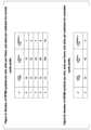
図2は、本実施形態の一態様に係るサブキャリア間隔の設定μ、スロットあたりのOFDMシンボル数Nslotsymb、および、CP(cyclic Prefix)設定の関係を示す一例である。図2Aにおいて、例えば、サブキャリア間隔の設定μが2であり、CP設定がノーマルCP(normal cyclic prefix)である場合、Nslotsymb=14、Nframe,μslot=40、Nsubframe,μslot=4である。また、図2Bにおいて、例えば、サブキャリア間隔の設定μが2であり、CP設定が拡張CP(extended cyclic prefix)である場合、Nslotsymb=12、Nframe,μslot=40、Nsubframe,μslot=4である。 Fig. 2 is an example showing the relationship between the subcarrier spacing setting μ, the number of OFDM symbols per slot Nslotsymb , and CP (cyclic prefix) setting according to one aspect of the present embodiment. In Fig. 2A, for example, when the subcarrier spacing setting μ is 2 and the CP setting is normal cyclic prefix (CP), Nslotsymb = 14, Nframe, μslot = 40, and Nsubframe, μslot = 4. Also, in Fig. 2B, for example, when the subcarrier spacing setting μ is 2 and the CP setting is extended cyclic prefix (CP), Nslotsymb = 12, Nframe, μslot = 40, and Nsubframe, μslot = 4.
本実施形態の一態様に係る無線通信システムにおいて、時間領域の長さの表現のために時間単位(タイムユニット)Tcが用いられてもよい。時間単位Tcは、Tc=1/(Δfmax・Nf)である。Δfmax=480kHzである。Nf=4096である。定数κは、κ=Δfmax・Nf/(ΔfrefNf,ref)=64である。Δfrefは、15kHzである。Nf,refは、2048である。 In a wireless communication system according to an aspect of the present embodiment, a time unitTc may be used to express a length in the time domain. The time unitTc isTc =1/(Δfmax ·Nf ).Δfmax =480 kHz.Nf =4096. The constant κ is κ=Δfmax ·Nf /(ΔfrefNf,ref )=64.Δfref is 15 kHz.Nf,ref is 2048.
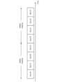
下りリンクにおける信号の送信、および/または、上りリンクにおける信号の送信は、長さTfの無線フレーム(システムフレーム、フレーム)により編成されてもよい(organized into)。Tf=(ΔfmaxNf/100)・Ts=10msである。“・”は乗算を示す。無線フレームは、10個のサブフレームを含んで構成される。サブフレームの長さTsf=(ΔfmaxNf/1000)・Ts=1msである。サブフレームあたりのOFDMシンボル数はNsubframe,μsymb=NslotsymbNsubframe,μslotである。 The transmission of signals in the downlink and/or the transmission of signals in the uplink may be organized into radio frames (system frames, frames) of lengthTf , whereTf =(ΔfmaxNf /100)·Ts = 10 ms. "·" indicates multiplication. A radio frame is made up of 10 subframes. The length of a subframeTsf = (ΔfmaxNf/ 1000)·Ts = 1 ms. The number of OFDM symbols per subframe is Nsubframe,μsymb=NslotsymbNsubframe,μslot .
あるサブキャリア間隔の設定μのために、サブフレームに含まれるスロットの数とインデックスが与えられてもよい。例えば、スロットインデックスnμsは、サブフレームにおいて0からNsubframe,μslot-1の範囲の整数値で昇順に与えられてもよい。サブキャリア間隔の設定μのために、無線フレームに含まれるスロットの数とインデックスが与えられてもよい。また、スロットインデックスnμs,fは、無線フレームにおいて0からNframe,μslot-1の範囲の整数値で昇順に与えられてもよい。連続するNslotsymb個のOFDMシンボルが1つのスロットに含まれてもよい。Nslotsymb=14である。 For a certain subcarrier spacing setting μ, the number and index of slots included in a subframe may be given. For example, the slot index nμs may be given in ascending order as integer values ranging from 0 to Nsubframe,μslot −1 in the subframe. For a certain subcarrier spacing setting μ, the number and index of slots included in a radio frame may be given. Also, the slot index nμs,f may be given in ascending order as integer values ranging from 0 to Nframe,μslot −1 in the radio frame. Nslotsymb consecutive OFDM symbols may be included in one slot.N slotsymb =14.
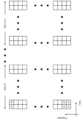
図3は、本実施形態の一態様に係るリソースグリッドの構成方法の一例を示す図である。図3の横軸は、周波数領域を示す。図3において、コンポーネントキャリア300におけるサブキャリア間隔μ1のリソースグリッドの構成例と、該あるコンポーネントキャリアにおけるサブキャリア間隔μ2のリソースグリッドの構成例を示す。このように、あるコンポーネントキャリアに対して、1つまたは複数のサブキャリア間隔が設定されてもよい。図3において、μ1=μ2-1であることを仮定するが、本実施形態の種々の態様はμ1=μ2-1の条件に限定されない。 Fig. 3 is a diagram showing an example of a method for configuring a resource grid according to one aspect of this embodiment. The horizontal axis in Fig. 3 indicates the frequency domain. Fig. 3 shows a configuration example of a resource grid with a subcarrier spacing of μ1 in a
コンポーネントキャリア300は、周波数領域において所定の幅を備える帯域である。The
ポイント(Point)3000は、あるサブキャリアを特定するための識別子である。ポイント3000は、ポイントAとも呼称される。共通リソースブロック(CRB: Common resource block)セット3100は、サブキャリア間隔の設定μ1に対する共通リソースブロックのセットである。 A
共通リソースブロックセット3100のうち、ポイント3000を含む共通リソースブロック(図3中の右上がり斜線で示されるブロック)は、共通リソースブロックセット3100の基準点(reference point)とも呼称される。共通リソースブロックセット3100の基準点は、共通リソースブロックセット3100におけるインデックス0の共通リソースブロックであってもよい。Of the common
オフセット3011は、共通リソースブロックセット3100の基準点から、リソースグリッド3001の基準点までのオフセットである。オフセット3011は、サブキャリア間隔の設定μ1に対する共通リソースブロックの数によって示される。リソースグリッド3001は、リソースグリッド3001の基準点から始まるNsize,μgrid1,x個の共通リソースブロックを含む。 The offset 3011 is the offset from the reference point of the common resource block set 3100 to the reference point of the
オフセット3013は、リソースグリッド3001の基準点から、インデックスi1のBWP(BandWidth Part)3003の基準点(Nstart,μBWP,i1)までのオフセットである。 Offset 3013 is the offset from the reference point of
共通リソースブロックセット3200は、サブキャリア間隔の設定μ2に対する共通リソースブロックのセットである。 Common
共通リソースブロックセット3200のうち、ポイント3000を含む共通リソースブロック(図3中の左上がり斜線で示されるブロック)は、共通リソースブロックセット3200の基準点とも呼称される。共通リソースブロックセット3200の基準点は、共通リソースブロックセット3200におけるインデックス0の共通リソースブロックであってもよい。Of the common
オフセット3012は、共通リソースブロックセット3200の基準点から、リソースグリッド3002の基準点までのオフセットである。オフセット3012は、サブキャリア間隔μ2に対する共通リソースブロックの数によって示される。リソースグリッド3002は、リソースグリッド3002の基準点から始まるNsize,μgrid2,x個の共通リソースブロックを含む。 The offset 3012 is the offset from the reference point of the common resource block set 3200 to the reference point of the
オフセット3014は、リソースグリッド3002の基準点から、インデックスi2のBWP3004の基準点(Nstart,μBWP,i2)までのオフセットである。 Offset 3014 is the offset from the reference point of
図4は、本実施形態の一態様に係るリソースグリッド3001の構成例を示す図である。図4のリソースグリッドにおいて、横軸はOFDMシンボルインデックスlsymであり、縦軸はサブキャリアインデックスkscである。リソースグリッド3001は、Nsize,μgrid1,xNRBsc個のサブキャリアを含み、Nsubframe,μsymb個のOFDMシンボルを含む。リソースグリッド内において、サブキャリアインデックスkscとOFDMシンボルインデックスlsymによって特定されるリソースは、リソースエレメント(RE: Resource Element)とも呼称される。 Fig. 4 is a diagram showing a configuration example of a
リソースブロック(RB: Resource Block)は、NRBsc個の連続するサブキャリアを含む。リソースブロックは、共通リソースブロック、物理リソースブロック(PRB: Physical Resource Block)、および、仮想リソースブロック(VRB: Virtual Resource Block)の総称である。ここで、NRBsc=12である。 A resource block (RB) includes NRBsc consecutive subcarriers, and is a collective term for a common resource block, a physical resource block (PRB), and a virtual resource block (VRB), where NRBsc =12.
リソースブロックユニットは、1つのリソースブロックにおける1OFDMシンボルに対応するリソースのセットである。つまり、1つのリソースブロックユニットは、1つのリソースブロックにおける1OFDMシンボルに対応する12個のリソースエレメントを含む。A resource block unit is a set of resources corresponding to one OFDM symbol in one resource block. That is, one resource block unit includes 12 resource elements corresponding to one OFDM symbol in one resource block.
あるサブキャリア間隔の設定μに対する共通リソースブロックは、ある共通リソースブロックセットにおいて、周波数領域において0から昇順にインデックスが付される(indexing)。あるサブキャリア間隔の設定μに対する、インデックス0の共通リソースブロックは、ポイント3000を含む(または、衝突する、一致する)。あるサブキャリア間隔の設定μに対する共通リソースブロックのインデックスnμCRBは、nμCRB=ceil(ksc/NRBsc)の関係を満たす。ここで、ksc=0のサブキャリアは、ポイント3000に対応するサブキャリアの中心周波数と同一の中心周波数を備えるサブキャリアである。 The common resource blocks for a given subcarrier spacing setting μ are indexed in a given common resource block set in the frequency domain, starting from 0 in ascending order. The common resource block with
あるサブキャリア間隔の設定μに対する物理リソースブロックは、あるBWPにおいて、周波数領域において0から昇順にインデックスが付される。あるサブキャリア間隔の設定μに対する物理リソースブロックのインデックスnμPRBは、nμCRB=nμPRB+Nstart,μBWP,iの関係を満たす。ここで、Nstart,μBWP,iは、インデックスiのBWPの基準点を示す。 The physical resource blocks for a given subcarrier spacing setting μ are indexed in the frequency domain in ascending order starting from 0 in a given BWP. The physical resource block index nμPRB for a given subcarrier spacing setting μ satisfies the relationship nμCRB = nμPRB + Nstart,μBWP,i , where Nstart,μBWP,i denotes the reference point of the BWP with index i.
BWPは、リソースグリッドに含まれる共通リソースブロックのサブセットとして定義される。BWPは、該BWPの基準点Nstart,μBWP,iから始まるNsize,μBWP,i個の共通リソースブロックを含む。下りリンクキャリアに対して設定されるBWPは、下りリンクBWPとも呼称される。上りリンクコンポーネントキャリアに対して設定されるBWPは、上りリンクBWPとも呼称される。 A BWP is defined as a subset of common resource blocks included in a resource grid. A BWP includes N size,μBWP,i common resource blocks starting from the reference point N start,μBWP,i of the BWP. The BWP configured for a downlink carrier is also called downlink BWP. The BWP configured for an uplink component carrier is also called uplink BWP.
アンテナポートは、あるアンテナポートにおけるシンボルが伝達されるチャネルが、該あるアンテナポートにおけるその他のシンボルが伝達されるチャネルから推定できることによって定義されてもよい(An antenna port is defined such that the channel over which a symbol on the antenna port is conveyed can be inferred from the channel over which another symbol on the same antenna port is conveyed)。例えば、チャネルは、物理チャネルに対応してもよい。また、シンボルは、OFDMシンボルに対応してもよい。また、シンボルは、リソースブロックユニットに対応してもよい。また、シンボルは、リソースエレメントに対応してもよい。An antenna port may be defined such that the channel over which a symbol on the antenna port is conveyed can be inferred from the channel over which another symbol on the same antenna port is conveyed. For example, the channel may correspond to a physical channel. The symbol may correspond to an OFDM symbol. The symbol may correspond to a resource block unit. The symbol may correspond to a resource element.
1つのアンテナポートにおいてシンボルが伝達されるチャネルの大規模特性(large scale property)が、もう一つのアンテナポートにおいてシンボルが伝達されるチャネルから推定できることは、2つのアンテナポートはQCL(Quasi Co-Located)であると呼称される。大規模特性は、チャネルの長区間特性を少なくとも含んでもよい。大規模特性は、遅延拡がり(delay spread)、ドップラー拡がり(Doppler spread)、ドップラーシフト(Doppler shift)、平均利得(average gain)、平均遅延(average delay)、および、ビームパラメータ(spatial Rx parameters)の一部または全部を少なくとも含んでもよい。第1のアンテナポートと第2のアンテナポートがビームパラメータに関してQCLであるとは、第1のアンテナポートに対して受信側が想定する受信ビームと第2のアンテナポートに対して受信側が想定する受信ビームとが同一であることであってもよい。第1のアンテナポートと第2のアンテナポートがビームパラメータに関してQCLであるとは、第1のアンテナポートに対して受信側が想定する送信ビームと第2のアンテナポートに対して受信側が想定する送信ビームとが同一であることであってもよい。端末装置1は、1つのアンテナポートにおいてシンボルが伝達されるチャネルの大規模特性が、もう一つのアンテナポートにおいてシンボルが伝達されるチャネルから推定できる場合、2つのアンテナポートはQCLであることが想定されてもよい。2つのアンテナポートがQCLであることは、2つのアンテナポートがQCLであることが想定されることであってもよい。When the large scale properties of a channel through which a symbol is transmitted at one antenna port can be estimated from the channel through which a symbol is transmitted at another antenna port, the two antenna ports are said to be Quasi Co-Located (QCL). The large scale properties may include at least the long-range properties of the channel. The large scale properties may include at least some or all of the delay spread, Doppler spread, Doppler shift, average gain, average delay, and spatial Rx parameters. The first antenna port and the second antenna port being QCL with respect to beam parameters may be the same as the receiving beam assumed by the receiving side for the first antenna port and the receiving beam assumed by the receiving side for the second antenna port. The first antenna port and the second antenna port being QCL with respect to the beam parameters may mean that the transmission beam assumed by the receiving side for the first antenna port and the transmission beam assumed by the receiving side for the second antenna port are the same. The
キャリアアグリゲーション(carrier aggregation)は、集約された複数のサービングセルを用いて通信を行うことであってもよい。また、キャリアアグリゲーションは、集約された複数のコンポーネントキャリアを用いて通信を行うことであってもよい。また、キャリアアグリゲーションは、集約された複数の下りリンクコンポーネントキャリアを用いて通信を行うことであってもよい。また、キャリアアグリゲーションは、集約された複数の上りリンクコンポーネントキャリアを用いて通信を行うことであってもよい。Carrier aggregation may be performing communication using a plurality of aggregated serving cells. Also, carrier aggregation may be performing communication using a plurality of aggregated component carriers. Also, carrier aggregation may be performing communication using a plurality of aggregated downlink component carriers. Also, carrier aggregation may be performing communication using a plurality of aggregated uplink component carriers.
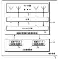
図5は、本実施形態の一態様に係る基地局装置3の構成例を示す概略ブロック図である。図5に示されるように、基地局装置3は、無線送受信部(物理層処理部)30、および/または、上位層処理部34の一部または全部を少なくとも含む。無線送受信部30は、アンテナ部31、RF(Radio Frequency)部32、および、ベースバンド部33の一部または全部を少なくとも含む。上位層処理部34は、媒体アクセス制御層処理部35、および、無線リソース制御(RRC:Radio Resource Control)層処理部36の一部または全部を少なくとも含む。Figure 5 is a schematic block diagram showing an example configuration of a
無線送受信部30は、無線送信部30a、および、無線受信部30bの一部または全部を少なくとも含む。ここで、無線送信部30aに含まれるベースバンド部と無線受信部30bに含まれるベースバンド部の装置構成は同一であってもよいし、異なってもよい。また、無線送信部30aに含まれるRF部と無線受信部30bに含まれるRF部の装置構成は同一であってもよいし、異なってもよい。また、無線送信部30aに含まれるアンテナ部と無線受信部30bに含まれるアンテナ部の装置構成は同一であってもよいし、異なってもよい。The
例えば、無線送信部30aは、PDSCHのベースバンド信号を生成し、送信してもよい。例えば、無線送信部30aは、PDCCHのベースバンド信号を生成し、送信してもよい。例えば、無線送信部30aは、PBCHのベースバンド信号を生成し、送信してもよい。例えば、無線送信部30aは、同期信号のベースバンド信号を生成し、送信してもよい。例えば、無線送信部30aは、PDSCH DMRSのベースバンド信号を生成し、送信してもよい。例えば、無線送信部30aは、PDCCH DMRSのベースバンド信号を生成し、送信してもよい。例えば、無線送信部30aは、CSI-RSのベースバンド信号を生成し、送信してもよい。例えば、無線送信部30aは、DL PTRSのベースバンド信号を生成し、送信してもよい。For example, the wireless transmitting unit 30a may generate and transmit a baseband signal of the PDSCH. For example, the wireless transmitting unit 30a may generate and transmit a baseband signal of the PDCCH. For example, the wireless transmitting unit 30a may generate and transmit a baseband signal of the PBCH. For example, the wireless transmitting unit 30a may generate and transmit a baseband signal of a synchronization signal. For example, the wireless transmitting unit 30a may generate and transmit a baseband signal of the PDSCH DMRS. For example, the wireless transmitting unit 30a may generate and transmit a baseband signal of the PDCCH DMRS. For example, the wireless transmitting unit 30a may generate and transmit a baseband signal of the CSI-RS. For example, the wireless transmitting unit 30a may generate and transmit a baseband signal of the DL PTRS.
例えば、無線送信部30bは、PRACHを受信してもよい。例えば、無線送信部30bは、PUCCHを受信し、復調してもよい。無線送信部30bは、PUSCHを受信し、復調してもよい。例えば、無線送信部30bは、PUCCH DMRSを受信してもよい。例えば、無線送信部30bは、PUSCH DMRSを受信してもよい。例えば、無線送信部30bは、UL PTRSを受信してもよい。例えば、無線送信部30bは、SRSを受信してもよい。For example, the wireless transmitting unit 30b may receive a PRACH. For example, the wireless transmitting unit 30b may receive and demodulate a PUCCH. The wireless transmitting unit 30b may receive and demodulate a PUSCH. For example, the wireless transmitting unit 30b may receive a PUCCH DMRS. For example, the wireless transmitting unit 30b may receive a PUSCH DMRS. For example, the wireless transmitting unit 30b may receive a UL PTRS. For example, the wireless transmitting unit 30b may receive an SRS.
上位層処理部34は、下りリンクデータ(トランスポートブロック)を、無線送受信部30(または、無線送信部30a)に出力する。上位層処理部34は、MAC(Medium Access Control)層、パケットデータ統合プロトコル(PDCP:Packet Data Convergence Protocol)層、無線リンク制御(RLC:Radio Link Control)層、RRC層の処理を行なう。The upper
上位層処理部34が備える媒体アクセス制御層処理部35は、MAC層の処理を行う。The media access control
上位層処理部34が備える無線リソース制御層処理部36は、RRC層の処理を行う。無線リソース制御層処理部36は、端末装置1の各種設定情報/パラメータ(RRCパラメータ)の管理をする。無線リソース制御層処理部36は、端末装置1から受信したRRCメッセージに基づいてRRCパラメータをセットする。The radio resource control
無線送受信部30(または、無線送信部30a)は、変調、符号化などの処理を行う。無線送受信部30(または、無線送信部30a)は、下りリンクデータを変調、符号化、ベースバンド信号生成(時間連続信号への変換)することによって物理信号を生成し、端末装置1に送信する。無線送受信部30(または、無線送信部30a)は、物理信号をあるコンポーネントキャリアに配置し、端末装置1に送信してもよい。The radio transceiver unit 30 (or the radio transmitter unit 30a) performs processing such as modulation and encoding. The radio transceiver unit 30 (or the radio transmitter unit 30a) generates a physical signal by modulating, encoding, and generating a baseband signal (converting to a time-continuous signal) the downlink data, and transmits the physical signal to the
無線送受信部30(または、無線受信部30b)は、復調、復号化などの処理を行う。無線送受信部30(または、無線受信部30b)は、受信した物理信号を、分離、復調、復号し、復号した情報を上位層処理部34に出力する。無線送受信部30(または、無線受信部30b)は、物理信号の送信に先立ってチャネルアクセス手順を実施してもよい。The wireless transceiver unit 30 (or the wireless receiver unit 30b) performs processes such as demodulation and decoding. The wireless transceiver unit 30 (or the wireless receiver unit 30b) separates, demodulates, and decodes the received physical signal, and outputs the decoded information to the upper
RF部32は、アンテナ部31を介して受信した信号を、直交復調によりベースバンド信号(baseband signal)に変換し(ダウンコンバート:down convert)、不要な周波数成分を除去する。RF部32は、処理をしたアナログ信号をベースバンド部に出力する。The
ベースバンド部33は、RF部32から入力されたアナログ信号(analog signal)をディジタル信号(digital signal)に変換する。ベースバンド部33は、変換したディジタル信号からCP(Cyclic Prefix)に相当する部分を除去し、CPを除去した信号に対して高速フーリエ変換(FFT:Fast Fourier Transform)を行い、周波数領域の信号を抽出する。The
ベースバンド部33は、データを逆高速フーリエ変換(IFFT:Inverse Fast Fourier Transform)して、OFDMシンボルを生成し、生成されたOFDMシンボルにCPを付加し、ベースバンドのディジタル信号を生成し、ベースバンドのディジタル信号をアナログ信号に変換する。ベースバンド部33は、変換したアナログ信号をRF部32に出力する。The
RF部32は、ローパスフィルタを用いてベースバンド部33から入力されたアナログ信号から余分な周波数成分を除去し、アナログ信号を搬送波周波数にアップコンバート(up convert)し、アンテナ部31を介して送信する。また、RF部32は送信電力を制御する機能を備えてもよい。RF部32を送信電力制御部とも称する。The
端末装置1に対して、1または複数のサービングセル(または、コンポーネントキャリア、下りリンクコンポーネントキャリア、上りリンクコンポーネントキャリア)が設定されてもよい。One or more serving cells (or component carriers, downlink component carriers, uplink component carriers) may be configured for the
端末装置1に対して設定されるサービングセルのそれぞれは、PCell(Primary cell、プライマリセル)、PSCell(Primary SCG cell、プライマリSCGセル)、および、SCell(Secondary Cell、セカンダリセル)のいずれかであってもよい。Each of the serving cells configured for the
PCellは、MCG(Master Cell Group)に含まれるサービングセルである。PCellは、端末装置1によって初期接続確立手順(initial connection establishment procedure)、または、接続再確立手順(connection re-establishment procedure)を実施するセル(実施されたセル)である。The PCell is a serving cell included in the MCG (Master Cell Group). The PCell is a cell in which the
PSCellは、SCG(Secondary Cell Group)に含まれるサービングセルである。PSCellは、同期を伴う再設定手順(Reconfiration with synchronization)において、端末装置1によってランダムアクセスが実施されるサービングセルである。The PSCell is a serving cell included in an SCG (Secondary Cell Group). The PSCell is a serving cell to which random access is performed by the
SCellは、MCG、または、SCGのいずれに含まれてもよい。The SCell may be included in either the MCG or the SCG.
サービングセルグループ(セルグループ)は、MCG、および、SCGを少なくとも含む呼称である。サービングセルグループは、1または複数のサービングセル(または、コンポーネントキャリア)を含んでもよい。サービングセルグループに含まれる1または複数のサービングセル(または、コンポーネントキャリア)は、キャリアアグリゲーションにより運用されてもよい。The term "serving cell group" (cell group) refers to at least an MCG and an SCG. A serving cell group may include one or more serving cells (or component carriers). One or more serving cells (or component carriers) included in a serving cell group may be operated by carrier aggregation.
サービングセル(または、下りリンクコンポーネントキャリア)のそれぞれに対して1または複数の下りリンクBWPが設定されてもよい。サービングセル(または、上りリンクコンポーネントキャリア)のそれぞれに対して1または複数の上りリンクBWPが設定されてもよい。One or more downlink BWPs may be configured for each serving cell (or downlink component carrier). One or more uplink BWPs may be configured for each serving cell (or uplink component carrier).
サービングセル(または、下りリンクコンポーネントキャリア)に対して設定される1または複数の下りリンクBWPのうち、1つの下りリンクBWPがアクティブ下りリンクBWPに設定されてもよい(または、1つの下りリンクBWPがアクティベートされてもよい)。サービングセル(または、上りリンクコンポーネントキャリア)に対して設定される1または複数の上りリンクBWPのうち、1つの上りリンクBWPがアクティブ上りリンクBWPに設定されてもよい(または、1つの上りリンクBWPがアクティベートされてもよい)。Of one or more downlink BWPs configured for a serving cell (or a downlink component carrier), one downlink BWP may be set as an active downlink BWP (or one downlink BWP may be activated). Of one or more uplink BWPs configured for a serving cell (or an uplink component carrier), one uplink BWP may be set as an active uplink BWP (or one uplink BWP may be activated).
PDSCH、PDCCH、および、CSI-RSは、アクティブ下りリンクBWPにおいて受信されてもよい。端末装置1は、アクティブ下りリンクBWPにおいてPDSCH、PDCCH、および、CSI-RSを受信してもよい。PUCCH、および、PUSCHは、アクティブ上りリンクBWPにおいて送信されてもよい。端末装置1は、アクティブ上りリンクBWPにおいてPUCCH、および、PUSCHを送信してもよい。アクティブ下りリンクBWP、および、アクティブ上りリンクBWPは、アクティブBWPとも呼称される。The PDSCH, PDCCH, and CSI-RS may be received in an active downlink BWP. The
PDSCH、PDCCH、および、CSI-RSは、アクティブ下りリンクBWP以外の下りリンクBWP(インアクティブ下りリンクBWP)において受信されなくてもよい。端末装置1は、アクティブ下りリンクBWP以外の下りリンクBWPにおいてPDSCH、PDCCH、および、CSI-RSを受信しなくてもよい。PUCCH、および、PUSCHは、アクティブ上りリンクBWP以外の上りリンクBWP(インアクティブ上りリンクBWP)において送信されなくてもよい。端末装置1は、アクティブ上りリンクBWP以外の上りリンクBWPにおいてPUCCH、および、PUSCHを送信しなくてもよい。インアクティブ下りリンクBWP、および、インアクティブ上りリンクBWPは、インアクティブBWPとも呼称される。The PDSCH, PDCCH, and CSI-RS may not be received in a downlink BWP (inactive downlink BWP) other than the active downlink BWP. The
下りリンクのBWP切り替え(BWP switch)は、1つのアクティブ下りリンクBWPをディアクティベート(deactivate)し、該1つのアクティブ下りリンクBWP以外のインアクティブ下りリンクBWPのいずれかをアクティベート(activate)するために用いられる。下りリンクのBWP切り替えは、下りリンク制御情報に含まれるBWPフィールドにより制御されてもよい。下りリンクのBWP切り替えは、上位層のパラメータに基づき制御されてもよい。Downlink BWP switch is used to deactivate one active downlink BWP and activate any of the inactive downlink BWPs other than the one active downlink BWP. Downlink BWP switch may be controlled by a BWP field included in downlink control information. Downlink BWP switch may be controlled based on higher layer parameters.
上りリンクのBWP切り替えは、1つのアクティブ上りリンクBWPをディアクティベート(deactivate)し、該1つのアクティブ上りリンクBWP以外のインアクティブ上りリンクBWPのいずれかをアクティベート(activate)するために用いられる。上りリンクのBWP切り替えは、下りリンク制御情報に含まれるBWPフィールドにより制御されてもよい。上りリンクのBWP切り替えは、上位層のパラメータに基づき制御されてもよい。Uplink BWP switching is used to deactivate one active uplink BWP and activate any inactive uplink BWP other than the one active uplink BWP. Uplink BWP switching may be controlled by a BWP field included in downlink control information. Uplink BWP switching may be controlled based on higher layer parameters.
サービングセルに対して設定される1または複数の下りリンクBWPのうち、2つ以上の下りリンクBWPがアクティブ下りリンクBWPに設定されなくてもよい。サービングセルに対して、ある時間において、1つの下りリンクBWPがアクティブであってもよい。Of one or more downlink BWPs configured for a serving cell, two or more downlink BWPs may not be configured as active downlink BWPs. For a serving cell, one downlink BWP may be active at a given time.
サービングセルに対して設定される1または複数の上りリンクBWPのうち、2つ以上の上りリンクBWPがアクティブ上りリンクBWPに設定されなくてもよい。サービングセルに対して、ある時間において、1つの上りリンクBWPがアクティブであってもよい。Of one or more uplink BWPs configured for a serving cell, two or more uplink BWPs may not be configured as active uplink BWPs. For a serving cell, one uplink BWP may be active at a given time.
図6は、本実施形態の一態様に係る端末装置1の構成例を示す概略ブロック図である。図6に示されるように、端末装置1は、無線送受信部(物理層処理部)10、および、上位層処理部14の一または全部を少なくとも含む。無線送受信部10は、アンテナ部11、RF部12、および、ベースバンド部13の一部または全部を少なくとも含む。上位層処理部14は、媒体アクセス制御層処理部15、および、無線リソース制御層処理部16の一部または全部を少なくとも含む。Figure 6 is a schematic block diagram showing an example configuration of a
無線送受信部10は、無線送信部10a、および、無線受信部10bの一部または全部を少なくとも含む。ここで、無線送信部10aに含まれるベースバンド部13と無線受信部10bに含まれるベースバンド部13の装置構成は同一であってもよいし、異なってもよい。また、無線送信部10aに含まれるRF部12と無線受信部10bに含まれるRF部12の装置構成は同一であってもよいし、異なってもよい。また、無線送信部10aに含まれるアンテナ部11と無線受信部10bに含まれるアンテナ部11の装置構成は同一であってもよいし、異なってもよい。The
例えば、無線送信部10aは、PRACHのベースバンド信号を生成し、送信してもよい。例えば、無線送信部10aは、PUCCHのベースバンド信号を生成し、送信してもよい。無線送信部10aは、PUSCHのベースバンド信号を生成し、送信してもよい。例えば、無線送信部10aは、PUCCH DMRSのベースバンド信号を生成し、送信してもよい。例えば、無線送信部10aは、PUSCH DMRSのベースバンド信号を生成し、送信してもよい。例えば、無線送信部10aは、UL PTRSのベースバンド信号を生成し、送信してもよい。例えば、無線送信部10aは、SRSのベースバンド信号を生成し、送信してもよい。For example, the wireless transmission unit 10a may generate and transmit a baseband signal of the PRACH. For example, the wireless transmission unit 10a may generate and transmit a baseband signal of the PUCCH. The wireless transmission unit 10a may generate and transmit a baseband signal of the PUSCH. For example, the wireless transmission unit 10a may generate and transmit a baseband signal of the PUCCH DMRS. For example, the wireless transmission unit 10a may generate and transmit a baseband signal of the PUSCH DMRS. For example, the wireless transmission unit 10a may generate and transmit a baseband signal of the UL PTRS. For example, the wireless transmission unit 10a may generate and transmit a baseband signal of the SRS.
例えば、無線受信部10bは、PDSCHを受信し、復調してもよい。例えば、無線受信部10bは、PDCCHを受信し、復調してもよい。例えば、無線受信部10bは、PBCHを受信し、復調してもよい。例えば、無線受信部10bは、同期信号を受信してもよい。例えば、無線受信部10bは、PDSCH DMRSを受信してもよい。例えば、無線受信部10bは、PDCCH DMRSを受信してもよい。例えば、無線受信部10bは、CSI-RSを受信してもよい。例えば、無線受信部10bは、DL PTRSを受信してもよい。For example, the wireless receiver 10b may receive and demodulate a PDSCH. For example, the wireless receiver 10b may receive and demodulate a PDCCH. For example, the wireless receiver 10b may receive and demodulate a PBCH. For example, the wireless receiver 10b may receive a synchronization signal. For example, the wireless receiver 10b may receive a PDSCH DMRS. For example, the wireless receiver 10b may receive a PDCCH DMRS. For example, the wireless receiver 10b may receive a CSI-RS. For example, the wireless receiver 10b may receive a DL PTRS.
上位層処理部14は、上りリンクデータ(トランスポートブロック)を、無線送受信部10(または、無線送信部10a)に出力する。上位層処理部14は、MAC層、パケットデータ統合プロトコル層、無線リンク制御層、RRC層の処理を行なう。The upper
上位層処理部14が備える媒体アクセス制御層処理部15は、MAC層の処理を行う。The media access control
上位層処理部14が備える無線リソース制御層処理部16は、RRC層の処理を行う。無線リソース制御層処理部16は、端末装置1の各種設定情報/パラメータ(RRCパラメータ)の管理をする。無線リソース制御層処理部16は、基地局装置3から受信したRRCメッセージに基づいてRRCパラメータをセットする。The radio resource control
無線送受信部10(または、無線送信部10a)は、変調、符号化などの処理を行う。無線送受信部10(または、無線送信部10a)は、上りリンクデータを変調、符号化、ベースバンド信号生成(時間連続信号への変換)することによって物理信号を生成し、基地局装置3に送信する。無線送受信部10(または、無線送信部10a)は、物理信号をあるBWP(アクティブ上りリンクBWP)に配置し、基地局装置3に送信してもよい。The wireless transceiver unit 10 (or the wireless transmitter unit 10a) performs processes such as modulation and encoding. The wireless transceiver unit 10 (or the wireless transmitter unit 10a) generates a physical signal by modulating, encoding, and generating a baseband signal (converting to a time-continuous signal) the uplink data, and transmits the physical signal to the
無線送受信部10(または、無線受信部10b)は、復調、復号化などの処理を行う。無線送受信部10(または、無線受信部30b)は、あるサービングセルのあるBWP(アクティブ下りリンクBWP)において、物理信号を受信してもよい。無線送受信部10(または、無線受信部10b)は、受信した物理信号を、分離、復調、復号し、復号した情報を上位層処理部14に出力する。無線送受信部10(無線受信部10b)は物理信号の送信に先立ってチャネルアクセス手順を実施してもよい。The wireless transceiver unit 10 (or the wireless receiver unit 10b) performs processes such as demodulation and decoding. The wireless transceiver unit 10 (or the wireless receiver unit 30b) may receive a physical signal in a certain BWP (active downlink BWP) of a certain serving cell. The wireless transceiver unit 10 (or the wireless receiver unit 10b) separates, demodulates, and decodes the received physical signal, and outputs the decoded information to the upper
RF部12は、アンテナ部11を介して受信した信号を、直交復調によりベースバンド信号に変換し(ダウンコンバート:down convert)、不要な周波数成分を除去する。RF部12は、処理をしたアナログ信号をベースバンド部13に出力する。The
ベースバンド部13は、RF部12から入力されたアナログ信号をディジタル信号に変換する。ベースバンド部13は、変換したディジタル信号からCP(Cyclic Prefix)に相当する部分を除去し、CPを除去した信号に対して高速フーリエ変換(FFT:Fast Fourier Transform)を行い、周波数領域の信号を抽出する。The
ベースバンド部13は、上りリンクデータを逆高速フーリエ変換(IFFT:Inverse Fast Fourier Transform)して、OFDMシンボルを生成し、生成されたOFDMシンボルにCPを付加し、ベースバンドのディジタル信号を生成し、ベースバンドのディジタル信号をアナログ信号に変換する。ベースバンド部13は、変換したアナログ信号をRF部12に出力する。The
RF部12は、ローパスフィルタを用いてベースバンド部13から入力されたアナログ信号から余分な周波数成分を除去し、アナログ信号を搬送波周波数にアップコンバート(up convert)し、アンテナ部11を介して送信する。また、RF部12は送信電力を制御する機能を備えてもよい。RF部12を送信電力制御部とも称する。The
以下、物理信号(信号)について説明を行う。Below, we will explain physical signals (signals).
物理信号は、下りリンク物理チャネル、下りリンク物理シグナル、上りリンク物理チャネル、および、上りリンク物理チャネルの総称である。物理チャネルは、下りリンク物理チャネル、および、上りリンク物理チャネルの総称である。物理シグナルは、下りリンク物理シグナル、および、上りリンク物理シグナルの総称である。Physical signal is a general term for the downlink physical channel, downlink physical signal, uplink physical channel, and uplink physical channel. Physical channel is a general term for the downlink physical channel and uplink physical channel. Physical signal is a general term for the downlink physical signal and uplink physical signal.
上りリンク物理チャネルは、上位層において発生する情報を運ぶリソースエレメントのセットに対応してもよい。上りリンク物理チャネルは、上りリンクコンポーネントキャリアにおいて用いられる物理チャネルであってもよい。上りリンク物理チャネルは、端末装置1によって送信されてもよい。上りリンク物理チャネルは、基地局装置3によって受信されてもよい。本実施形態の一態様に係る無線通信システムにおいて、少なくとも下記の一部または全部の上りリンク物理チャネルが用いられてもよい。
・PUCCH(Physical Uplink Control CHannel)
・PUSCH(Physical Uplink Shared CHannel)
・PRACH(Physical Random Access CHannel) The uplink physical channel may correspond to a set of resource elements carrying information generated in a higher layer. The uplink physical channel may be a physical channel used in an uplink component carrier. The uplink physical channel may be transmitted by a
・PUCCH (Physical Uplink Control CHannel)
・PUSCH (Physical Uplink Shared CHannel)
・PRACH (Physical Random Access CHannel)
PUCCHは、上りリンク制御情報(UCI:Uplink Control Information)を送信するために用いられてもよい。PUCCHは、上りリンク制御情報を伝達(deliver, transmission, convey)するために送信されてもよい。上りリンク制御情報は、PUCCHに配置(map)されてもよい。端末装置1は、上りリンク制御情報が配置されたPUCCHを送信してもよい。基地局装置3は、上りリンク制御情報が配置されたPUCCHを受信してもよい。The PUCCH may be used to transmit uplink control information (UCI). The PUCCH may be transmitted to deliver, transmit, convey the uplink control information. The uplink control information may be mapped to the PUCCH. The
上りリンク制御情報(上りリンク制御情報ビット、上りリンク制御情報系列、上りリンク制御情報タイプ)は、チャネル状態情報(CSI:Channel State Information)、スケジューリングリクエスト(SR:Scheduling Request)、HARQ-ACK(Hybrid Automatic Repeat request ACKnowledgement)情報の一部または全部を少なくとも含む。The uplink control information (uplink control information bits, uplink control information sequence, uplink control information type) includes at least some or all of the channel state information (CSI: Channel State Information), scheduling request (SR: Scheduling Request), and HARQ-ACK (Hybrid Automatic Repeat request ACKnowledgement) information.
チャネル状態情報は、チャネル状態情報ビット、または、チャネル状態情報系列とも呼称される。スケジューリングリクエストは、スケジューリングリクエストビット、または、スケジューリングリクエスト系列とも呼称される。HARQ-ACK情報は、HARQ-ACK情報ビット、または、HARQ-ACK情報系列とも呼称される。The channel state information is also referred to as a channel state information bit or a channel state information sequence. The scheduling request is also referred to as a scheduling request bit or a scheduling request sequence. The HARQ-ACK information is also referred to as a HARQ-ACK information bit or a HARQ-ACK information sequence.
HARQ-ACK情報は、トランスポートブロック(または、TB:Transport block, MAC PDU:Medium Access Control Protocol Data Unit, DL-SCH:Downlink-Shared Channel, UL-SCH:Uplink-Shared Channel, PDSCH:Physical Downlink Shared Channel, PUSCH:Physical Uplink Shared CHannel)に対応するHARQ-ACKを少なくとも含んでもよい。HARQ-ACKは、トランスポートブロックに対応するACK(acknowledgement)またはNACK(negative-acknowledgement)を示してもよい。ACKは、トランスポートブロックの復号が成功裏に完了していること(has been decoded)を示してもよい。NACKは、トランスポートブロックの復号が成功裏に完了していないこと(has not been decoded)を示してもよい。HARQ-ACK情報は、1または複数のHARQ-ACKビットを含むHARQ-ACKコードブックを含んでもよい。The HARQ-ACK information may include at least a HARQ-ACK corresponding to a transport block (or TB: Transport block, MAC PDU: Medium Access Control Protocol Data Unit, DL-SCH: Downlink-Shared Channel, UL-SCH: Uplink-Shared Channel, PDSCH: Physical Downlink Shared Channel, PUSCH: Physical Uplink Shared CHannel). The HARQ-ACK may indicate an ACK (acknowledgement) or a NACK (negative-acknowledgement) corresponding to the transport block. The ACK may indicate that the decoding of the transport block has been successfully completed. The NACK may indicate that the decoding of the transport block has not been successfully completed. The HARQ-ACK information may include a HARQ-ACK codebook including one or more HARQ-ACK bits.
HARQ-ACK情報と、トランスポートブロックが対応することは、該HARQ-ACK情報と、該トランスポートブロックの伝達に用いられるPDSCHが対応することを意味してもよい。Correspondence between HARQ-ACK information and a transport block may mean that the HARQ-ACK information corresponds to the PDSCH used to transmit the transport block.
HARQ-ACKは、トランスポートブロックに含まれる1つのCBG(Code Block Group)に対応するACKまたはNACKを示してもよい。HARQ-ACK may indicate an ACK or NACK corresponding to one CBG (Code Block Group) included in the transport block.
スケジューリングリクエストは、初期送信(new transmission)のためのPUSCH(または、UL-SCH)のリソースを要求するために少なくとも用いられてもよい。スケジューリングリクエストビットは、正のSR(positive SR)または、負のSR(negative SR)のいずれかを示すために用いられてもよい。スケジューリングリクエストビットが正のSRを示すことは、“正のSRが送信される”とも呼称される。正のSRは、端末装置1によって初期送信のためのPUSCH(または、UL-SCH)のリソースが要求されることを示してもよい。正のSRは、上位層によりスケジューリングリクエストがトリガされることを示してもよい。正のSRは、上位層によりスケジューリングリクエストを送信することが指示された場合に、送信されてもよい。スケジューリングリクエストビットが負のSRを示すことは、“負のSRが送信される”とも呼称される。負のSRは、端末装置1によって初期送信のためのPUSCH(または、UL-SCH)のリソースが要求されないことを示してもよい。負のSRは、上位層によりスケジューリングリクエストがトリガされないことを示してもよい。負のSRは、上位層によりスケジューリングリクエストを送信することが指示されない場合に、送信されてもよい。The scheduling request may be used at least to request PUSCH (or UL-SCH) resources for an initial transmission. The scheduling request bit may be used to indicate either a positive SR or a negative SR. The scheduling request bit indicating a positive SR is also referred to as "a positive SR is transmitted". A positive SR may indicate that a PUSCH (or UL-SCH) resource is requested by the
チャネル状態情報は、チャネル品質指標(CQI: Channel Quality Indicator)、プレコーダ行列指標(PMI:Precoder Matrix Indicator)、および、ランク指標(RI: Rank Indicator)の一部または全部を少なくとも含んでもよい。CQIは、伝搬路の品質(例えば、伝搬強度)、または、物理チャネルの品質に関連する指標であり、PMIは、プレコーダに関連する指標である。RIは、送信ランク(または、送信レイヤ数)に関連する指標である。The channel state information may include at least some or all of a Channel Quality Indicator (CQI), a Precoder Matrix Indicator (PMI), and a Rank Indicator (RI). The CQI is an indicator related to the quality of the propagation path (e.g., propagation strength) or the quality of the physical channel, and the PMI is an indicator related to the precoder. The RI is an indicator related to the transmission rank (or the number of transmission layers).
チャネル状態情報は、チャネル測定のために少なくとも用いられる物理信号(例えば、CSI-RS)を受信することに少なくとも基づき与えられてもよい。チャネル状態情報は、チャネル測定のために少なくとも用いられる物理信号を受信することに少なくとも基づき、端末装置1によって選択されてもよい。チャネル測定は、干渉測定を含んでもよい。The channel state information may be provided based at least on receiving a physical signal (e.g., CSI-RS) used at least for channel measurement. The channel state information may be selected by the
PUCCHは、PUCCHフォーマットに対応してもよい。PUCCHは、PUCCHフォーマットを伝達するために用いられるリソースエレメントのセットであってもよい。PUCCHは、PUCCHフォーマットを含んでもよい。The PUCCH may correspond to a PUCCH format. The PUCCH may be a set of resource elements used to convey the PUCCH format. The PUCCH may include the PUCCH format.
PUSCHは、トランスポートブロック、および/または、上りリンク制御情報を送信するために用いられてもよい。PUSCHは、UL-SCHに対応するトランスポートブロック、および/または、上りリンク制御情報を送信するために用いられてもよい。PUSCHは、トランスポートブロック、および/または、上りリンク制御情報を伝達するために用いられてもよい。PUSCHは、UL-SCHに対応するトランスポートブロック、および/または、上りリンク制御情報を伝達するために用いられてもよい。トランスポートブロックは、PUSCHに配置されてもよい。UL-SCHに対応するトランスポートブロックは、PUSCHに配置されてもよい。上りリンク制御情報は、PUSCHに配置されてもよい。端末装置1は、トランスポートブロック、および/または、上りリンク制御情報が配置されたPUSCHを送信してもよい。基地局装置3は、トランスポートブロック、および/または、上りリンク制御情報が配置されたPUSCHを受信してもよい。The PUSCH may be used to transmit a transport block and/or uplink control information. The PUSCH may be used to transmit a transport block corresponding to the UL-SCH and/or uplink control information. The PUSCH may be used to transmit a transport block and/or uplink control information. The PUSCH may be used to transmit a transport block corresponding to the UL-SCH and/or uplink control information. The transport block may be arranged in the PUSCH. The transport block corresponding to the UL-SCH may be arranged in the PUSCH. The uplink control information may be arranged in the PUSCH. The
PRACHは、ランダムアクセスプリアンブルを送信するために用いられてもよい。PRACHは、ランダムアクセスプリアンブルを伝達するために用いられてもよい。PRACHの系列xu,v(n)は、xu,v(n)=xu(mod(n+Cv,LRA))によって定義される。xuはZC(Zadoff Chu)系列であってもよい。xuはxu=exp(-jπui(i+1)/LRA)によって定義される。jは虚数単位である。また、πは円周率である。Cvは、PRACH系列のサイクリックシフト(cyclic shift)に対応する。LRAは、PRACH系列の長さに対応する。LRAは、839、または、139である。iは、0からLRA-1の範囲の整数である。uはPRACH系列のための系列インデックスである。端末装置1は、PRACHを送信してもよい。基地局装置3は、PRACHを受信してもよい。 The PRACH may be used to transmit a random access preamble. The PRACH may be used to convey the random access preamble. A PRACH sequence xu,v (n) is defined by xu,v (n)=xu (mod(n+Cv ,LRA )).xu may be a ZC (Zadoff Chu) sequence.xu is defined byxu =exp(-jπui(i+1)/LRA ), where j is the imaginary unit, and π is the constant of pi.Cv corresponds to a cyclic shift of the PRACH sequence.LRA corresponds to the length of the PRACH sequence.LRA is 839 or 139. i is an integer ranging from 0 toLRA -1. u is a sequence index for the PRACH sequence. The
あるPRACH機会に対して、64個のランダムアクセスプリアンブルが定義される。ランダムアクセスプリアンブルは、PRACH系列のサイクリックシフトCv、および、PRACH系列のための系列インデックスuに少なくとも基づき特定される(決定される、与えられる)。 For a given PRACH opportunity, 64 random access preambles are defined, which are identified (determined, given) based on at least a cyclic shift Cv of the PRACH sequence and a sequence index u for the PRACH sequence.
上りリンク物理シグナルは、リソースエレメントのセットに対応してもよい。上りリンク物理シグナルは、上位層において発生する情報を運ばなくてもよい。上りリンク物理シグナルは、上りリンクコンポーネントキャリアにおいて用いられる物理シグナルであってもよい。端末装置1は、上りリンク物理シグナルを送信してもよい。基地局装置3は、上りリンク物理シグナルを受信してもよい。本実施形態の一態様に係る無線通信システムにおいて、少なくとも下記の一部または全部の上りリンク物理シグナルが用いられてもよい。
・UL DMRS(UpLink Demodulation Reference Signal)
・SRS(Sounding Reference Signal)
・UL PTRS(UpLink Phase Tracking Reference Signal) The uplink physical signal may correspond to a set of resource elements. The uplink physical signal may not carry information generated in a higher layer. The uplink physical signal may be a physical signal used in an uplink component carrier. The
・UL DMRS (UpLink Demodulation Reference Signal)
・SRS (Sounding Reference Signal)
・UL PTRS (UpLink Phase Tracking Reference Signal)
UL DMRSは、PUSCHのためのDMRS、および、PUCCHのためのDMRSの総称である。UL DMRS is a general term for DMRS for PUSCH and DMRS for PUCCH.
PUSCHのためのDMRS(PUSCHに関連するDMRS、PUSCHに含まれるDMRS、PUSCHに対応するDMRS)のアンテナポートのセットは、該PUSCHのためのアンテナポートのセットに基づき与えられてもよい。つまり、PUSCHのためのDMRSのアンテナポートのセットは、該PUSCHのアンテナポートのセットと同じであってもよい。The set of antenna ports for the DMRS for the PUSCH (DMRS related to the PUSCH, DMRS included in the PUSCH, DMRS corresponding to the PUSCH) may be given based on the set of antenna ports for the PUSCH. That is, the set of antenna ports for the DMRS for the PUSCH may be the same as the set of antenna ports for the PUSCH.
PUSCHの送信と、該PUSCHのためのDMRSの送信は、1つのDCIフォーマットにより示されてもよい(または、スケジューリングされてもよい)。PUSCHと、該PUSCHのためのDMRSは、まとめてPUSCHと呼称されてもよい。PUSCHを送信することは、PUSCHと、該PUSCHのためのDMRSを送信することであってもよい。The transmission of the PUSCH and the transmission of the DMRS for the PUSCH may be indicated (or scheduled) by one DCI format. The PUSCH and the DMRS for the PUSCH may be collectively referred to as the PUSCH. Transmitting the PUSCH may be transmitting the PUSCH and the DMRS for the PUSCH.
PUSCHは、該PUSCHのためのDMRSから推定されてもよい。つまり、PUSCHの伝搬路(propagation path)は、該PUSCHのためのDMRSから推定されてもよい。The PUSCH may be estimated from the DMRS for the PUSCH. That is, the propagation path of the PUSCH may be estimated from the DMRS for the PUSCH.
PUCCHのためのDMRS(PUCCHに関連するDMRS、PUCCHに含まれるDMRS、PUCCHに対応するDMRS)のアンテナポートのセットは、PUCCHのアンテナポートのセットと同一であってもよい。The set of antenna ports for DMRS for PUCCH (DMRS associated with PUCCH, DMRS included in PUCCH, DMRS corresponding to PUCCH) may be the same as the set of antenna ports for PUCCH.
PUCCHの送信と、該PUCCHのためのDMRSの送信は、1つのDCIフォーマットにより示されてもよい(または、トリガされてもよい)。PUCCHのリソースエレメントへのマッピング(resource element mapping)、および/または、該PUCCHのためのDMRSのリソースエレメントへのマッピングは、1つのPUCCHフォーマットにより与えられてもよい。PUCCHと、該PUCCHのためのDMRSは、まとめてPUCCHと呼称されてもよい。PUCCHを送信することは、PUCCHと、該PUCCHのためのDMRSを送信することであってもよい。The transmission of the PUCCH and the transmission of the DMRS for the PUCCH may be indicated (or triggered) by one DCI format. The mapping of the PUCCH to resource elements and/or the mapping of the DMRS for the PUCCH to resource elements may be provided by one PUCCH format. The PUCCH and the DMRS for the PUCCH may be collectively referred to as the PUCCH. Transmitting the PUCCH may be transmitting the PUCCH and the DMRS for the PUCCH.
PUCCHは、該PUCCHのためのDMRSから推定されてもよい。つまり、PUCCHの伝搬路は、該PUCCHのためのDMRSから推定されてもよい。The PUCCH may be estimated from the DMRS for the PUCCH. That is, the propagation path of the PUCCH may be estimated from the DMRS for the PUCCH.
下りリンク物理チャネルは、上位層において発生する情報を運ぶリソースエレメントのセットに対応してもよい。下りリンク物理チャネルは、下りリンクコンポーネントキャリアにおいて用いられる物理チャネルであってもよい。基地局装置3は、下りリンク物理チャネルを送信してもよい。端末装置1は、下りリンク物理チャネルを受信してもよい。本実施形態の一態様に係る無線通信システムにおいて、少なくとも下記の一部または全部の下りリンク物理チャネルが用いられてもよい。
・PBCH(Physical Broadcast Channel)
・PDCCH(Physical Downlink Control Channel)
・PDSCH(Physical Downlink Shared Channel) The downlink physical channel may correspond to a set of resource elements carrying information generated in a higher layer. The downlink physical channel may be a physical channel used in a downlink component carrier. The
・PBCH (Physical Broadcast Channel)
・PDCCH (Physical Downlink Control Channel)
・PDSCH (Physical Downlink Shared Channel)
PBCHは、MIB(MIB: Master Information Block)、および/または、物理層制御情報を送信するために用いられてもよい。PBCHは、MIB、および/または、物理層制御情報を伝達(deliver, transmission, convey)するために送信されてもよい。BCHは、PBCHに配置(map)されてもよい。端末装置1は、MIB、および/または、物理層制御情報が配置されたPBCHを受信してもよい。基地局装置3は、MIB、および/または、物理層制御情報が配置されたPBCHを送信してもよい。物理層制御情報は、PBCHペイロード、タイミングに関係するPBCHペイロードとも呼称される。MIBは、1または複数の上位層パラメータを含んでもよい。The PBCH may be used to transmit the MIB (Master Information Block) and/or physical layer control information. The PBCH may be transmitted to deliver, transmit, convey the MIB and/or physical layer control information. The BCH may be mapped to the PBCH. The
物理層制御情報は、8ビットを含む。物理層制御情報は、下記の0Aから0Dの一部または全部を少なくとも含んでもよい。0A)無線フレームビット0B)ハーフ無線フレーム(ハーフシステムフレーム、ハーフフレーム)ビット0C)SS/PBCHブロックインデックスビット0D)サブキャリアオフセットビットThe physical layer control information includes 8 bits. The physical layer control information may include at least some or all of the following bits 0A to 0D: 0A) Radio frame bit 0B) Half radio frame (half system frame, half frame) bit 0C) SS/PBCH block index bit 0D) Subcarrier offset bit
無線フレームビットは、PBCHが送信される無線フレーム(PBCHが送信されるスロットを含む無線フレーム)を示すために用いられる。無線フレームビットは、4ビットを含む。無線フレームビットは、10ビットの無線フレーム指示子のうちの4ビットにより構成されてもよい。例えば、無線フレーム指示子は、インデックス0からインデックス1023までの無線フレームを特定するために少なくとも用いられてもよい。The radio frame bits are used to indicate the radio frame in which the PBCH is transmitted (the radio frame including the slot in which the PBCH is transmitted). The radio frame bits include 4 bits. The radio frame bits may be composed of 4 bits of a 10-bit radio frame indicator. For example, the radio frame indicator may be used at least to identify radio frames from
ハーフ無線フレームビットは、PBCHが送信される無線フレームのうち、該PBCHが前半の5つのサブフレーム、または、後半の5つのサブフレームのどちらで送信されるかを示すために用いられる。ここで、ハーフ無線フレームは、5つのサブフレームを含んで構成されてもよい。また、ハーフ無線フレームは、無線フレームに含まれる10つのサブフレームのうち、前半の5つのサブフレームにより構成されてもよい。また、ハーフ無線フレームは、無線フレームに含まれる10つのサブフレームのうち、後半の5つのサブフレームにより構成されてもよい。The half radio frame bit is used to indicate whether the PBCH is transmitted in the first five subframes or the last five subframes of the radio frame in which the PBCH is transmitted. Here, the half radio frame may be configured to include five subframes. Also, the half radio frame may be configured to include the first five subframes of the ten subframes included in the radio frame. Also, the half radio frame may be configured to include the last five subframes of the ten subframes included in the radio frame.
SS/PBCHブロックインデックスビットは、SS/PBCHブロックインデックスを示すために用いられる。SS/PBCHブロックインデックスビットは、3ビットを含む。SS/PBCHブロックインデックスビットは、6ビットのSS/PBCHブロックインデックス指示子のうちの3ビットにより構成されてもよい。SS/PBCHブロックインデックス指示子は、インデックス0からインデックス63までのSS/PBCHブロックを特定するために少なくとも用いられてもよい。The SS/PBCH block index bits are used to indicate the SS/PBCH block index. The SS/PBCH block index bits include 3 bits. The SS/PBCH block index bits may be composed of 3 bits of a 6-bit SS/PBCH block index indicator. The SS/PBCH block index indicator may be used at least to identify SS/PBCH blocks from
サブキャリアオフセットビットは、サブキャリアオフセットを示すために用いられる。サブキャリアオフセットは、PBCHがマッピングされる先頭のサブキャリアと、インデックス0の制御リソースセットがマッピングされる先頭のサブキャリアの間の差を示すために用いられてもよい。The subcarrier offset bit is used to indicate a subcarrier offset. The subcarrier offset may be used to indicate the difference between the first subcarrier to which the PBCH is mapped and the first subcarrier to which the control resource set with
PDCCHは、下りリンク制御情報(DCI:Downlink Control Information)を送信するために用いられてもよい。PDCCHは、下りリンク制御情報を伝達(deliver, transmission, convey)するために送信されてもよい。下りリンク制御情報は、PDCCHに配置(map)されてもよい。端末装置1は、下りリンク制御情報が配置されたPDCCHを受信してもよい。基地局装置3は、下りリンク制御情報が配置されたPDCCHを送信してもよい。The PDCCH may be used to transmit downlink control information (DCI). The PDCCH may be transmitted to deliver, transmit, convey the downlink control information. The downlink control information may be mapped to the PDCCH. The
下りリンク制御情報は、DCIフォーマットに対応してもよい。下りリンク制御情報は、DCIフォーマットに含まれてもよい。下りリンク制御情報は、DCIフォーマットの各フィールドに配置されてもよい。The downlink control information may correspond to a DCI format. The downlink control information may be included in the DCI format. The downlink control information may be arranged in each field of the DCI format.
DCIフォーマット0_0、DCIフォーマット0_1、DCIフォーマット1_0、および、DCIフォーマット1_1は、それぞれ異なるフィールドのセットを含むDCIフォーマットである。上りリンクDCIフォーマットは、DCIフォーマット0_0、および、DCIフォーマット0_1の総称である。下りリンクDCIフォーマットは、DCIフォーマット1_0、および、DCIフォーマット1_1の総称である。DCI format 0_0, DCI format 0_1, DCI format 1_0, and DCI format 1_1 are DCI formats that each include a different set of fields. The uplink DCI format is a general term for DCI format 0_0 and DCI format 0_1. The downlink DCI format is a general term for DCI format 1_0 and DCI format 1_1.
DCIフォーマット0_0は、あるセルの(または、あるセルに配置される)PUSCHのスケジューリングのために少なくとも用いられる。DCIフォーマット0_0は、1Aから1Eのフィールドの一部または全部を少なくとも含んで構成される。
1A)DCIフォーマット特定フィールド(Identifier field for DCI formats)
1B)周波数領域リソース割り当てフィールド(Frequency domain resource assignmentfield)
1C)時間領域リソース割り当てフィールド(Time domain resource assignment field)
1D)周波数ホッピングフラグフィールド(Frequency hopping flag field)
1E)MCSフィールド(MCS field: Modulation and Coding Scheme field) DCI format 0_0 is used at least for scheduling a PUSCH of a certain cell (or arranged in a certain cell). DCI format 0_0 includes at least some or all of fields 1A to 1E.
1A) Identifier field for DCI formats
1B) Frequency domain resource assignment field
1C) Time Domain Resource Assignment Field
1D) Frequency hopping flag field
1E) MCS field (Modulation and Coding Scheme field)
DCIフォーマット特定フィールドは、該DCIフォーマット特定フィールドを含むDCIフォーマットが上りリンクDCIフォーマットであるか下りリンクDCIフォーマットであるかを示してもよい。DCIフォーマット0_0に含まれるDCIフォーマット特定フィールドは、0を示してもよい(または、DCIフォーマット0_0が上りリンクDCIフォーマットであることを示してもよい)。The DCI format specification field may indicate whether the DCI format containing the DCI format specification field is an uplink DCI format or a downlink DCI format. The DCI format specification field contained in DCI format 0_0 may indicate 0 (or may indicate that DCI format 0_0 is an uplink DCI format).
DCIフォーマット0_0に含まれる周波数領域リソース割り当てフィールドは、PUSCHのための周波数リソースの割り当てを示すために少なくとも用いられてもよい。The frequency domain resource allocation field included in DCI format 0_0 may be used at least to indicate the allocation of frequency resources for the PUSH.
DCIフォーマット0_0に含まれる時間領域リソース割り当てフィールドは、PUSCHのための時間リソースの割り当てを示すために少なくとも用いられてもよい。The time domain resource allocation field included in DCI format 0_0 may be used at least to indicate the allocation of time resources for PUSH.
周波数ホッピングフラグフィールドは、PUSCHに対して周波数ホッピングが適用されるか否かを示すために少なくとも用いられてもよい。The frequency hopping flag field may be used at least to indicate whether frequency hopping is applied to the PUSH.
DCIフォーマット0_0に含まれるMCSフィールドは、PUSCHのための変調方式、および/または、ターゲット符号化率の一部または全部を示すために少なくとも用いられてもよい。該ターゲット符号化率は、PUSCHのトランスポートブロックのためのターゲット符号化率であってもよい。PUSCHのトランスポートブロックのサイズ(TBS: Transport Block Size)は、該ターゲット符号化率、および、該PUSCHのための変調方式の一部または全部に少なくとも基づき与えられてもよい。The MCS field included in DCI format 0_0 may be used to indicate at least a part or all of a modulation scheme and/or a target coding rate for the PUSCH. The target coding rate may be a target coding rate for a transport block of the PUSCH. The size of the transport block (TBS: Transport Block Size) of the PUSCH may be given based at least on the target coding rate and a part or all of a modulation scheme for the PUSCH.
DCIフォーマット0_0は、CSI要求(CSIリクエスト)に用いられるフィールドを含まなくてもよい。つまり、DCIフォーマット0_0によってCSIが要求されなくてもよい。DCI format 0_0 may not include a field used for a CSI request. In other words, CSI may not be requested by DCI format 0_0.
DCIフォーマット0_0は、キャリアインディケータフィールドを含まなくてもよい。つまり、DCIフォーマット0_0によってスケジューリングされるPUSCHが配置される上りリンクコンポーネントキャリアは、該DCIフォーマット0_0を含むPDCCHが配置される上りリンクコンポーネントキャリアと同一であってもよい。DCI format 0_0 may not include a carrier indicator field. In other words, the uplink component carrier on which the PUSCH scheduled by DCI format 0_0 is arranged may be the same as the uplink component carrier on which the PDCCH including the DCI format 0_0 is arranged.
DCIフォーマット0_0は、BWPフィールドを含まなくてもよい。つまり、DCIフォーマット0_0によってスケジューリングされるPUSCHが配置される上りリンクBWPは、該DCIフォーマット0_0を含むPDCCHが配置される上りリンクBWPと同一であってもよい。DCI format 0_0 may not include a BWP field. In other words, the uplink BWP in which the PUSCH scheduled by DCI format 0_0 is placed may be the same as the uplink BWP in which the PDCCH including the DCI format 0_0 is placed.
DCIフォーマット0_1は、あるセルの(あるセルに配置される)PUSCHのスケジューリングのために少なくとも用いられる。DCIフォーマット0_1は、2Aから2Hのフィールドの一部または全部を少なくとも含んで構成される。
2A)DCIフォーマット特定フィールド
2B)周波数領域リソース割り当てフィールド
2C)上りリンクの時間領域リソース割り当てフィールド
2D)周波数ホッピングフラグフィールド
2E)MCSフィールド
2F)CSIリクエストフィールド(CSI request field)
2G)BWPフィールド(BWP field)2H)キャリアインディケータフィールド(Carrier indicator field) DCI format 0_1 is used at least for scheduling a PUSCH of a certain cell (configured in a certain cell). DCI format 0_1 includes at least a part or all of fields 2A to 2H.
2A) DCI format specific field 2B) Frequency domain resource allocation field 2C) Uplink time domain resource allocation field 2D) Frequency hopping flag field 2E) MCS field 2F) CSI request field
2G) BWP field 2H) Carrier indicator field
DCIフォーマット0_1に含まれるDCIフォーマット特定フィールドは、0を示してもよい(または、DCIフォーマット0_1が上りリンクDCIフォーマットであることを示してもよい)。The DCI format specific field included in DCI format 0_1 may indicate 0 (or may indicate that DCI format 0_1 is an uplink DCI format).
DCIフォーマット0_1に含まれる周波数領域リソース割り当てフィールドは、PUSCHのための周波数リソースの割り当てを示すために少なくとも用いられてもよい。The frequency domain resource allocation field included in DCI format 0_1 may be used at least to indicate the allocation of frequency resources for the PUSH.
DCIフォーマット0_1に含まれる時間領域リソース割り当てフィールドは、PUSCHのための時間リソースの割り当てを示すために少なくとも用いられてもよい。The time domain resource allocation field included in DCI format 0_1 may be used at least to indicate the allocation of time resources for the PUSH.
DCIフォーマット0_1に含まれるMCSフィールドは、PUSCHのための変調方式、および/または、ターゲット符号化率の一部または全部を示すために少なくとも用いられてもよい。The MCS field included in DCI format 0_1 may be used to indicate at least some or all of the modulation scheme and/or target coding rate for the PUSH.
DCIフォーマット0_1にBWPフィールドが含まれる場合、該BWPフィールドは、PUSCHが配置される上りリンクBWPを示すために用いられてもよい。DCIフォーマット0_1にBWPフィールドが含まれない場合、PUSCHが配置される上りリンクBWPは、該PUSCHのスケジューリングに用いられるDCIフォーマット0_1を含むPDCCHが配置される上りリンクBWPと同一であってもよい。ある上りリンクコンポーネントキャリアにおいて端末装置1に設定される上りリンクBWPの数が2以上である場合、該ある上りリンクコンポーネントキャリアに配置されるPUSCHのスケジューリングに用いられるDCIフォーマット0_1に含まれるBWPフィールドのビット数は、1ビット以上であってもよい。ある上りリンクコンポーネントキャリアにおいて端末装置1に設定される上りリンクBWPの数が1である場合、該ある上りリンクコンポーネントキャリアに配置されるPUSCHのスケジューリングに用いられるDCIフォーマット0_1に含まれるBWPフィールドのビット数は、0ビットであってもよい(または、該ある上りリンクコンポーネントキャリアに配置されるPUSCHのスケジューリングに用いられるDCIフォーマット0_1にBWPフィールドが含まれなくてもよい)。When the BWP field is included in the DCI format 0_1, the BWP field may be used to indicate the uplink BWP in which the PUSCH is arranged. When the BWP field is not included in the DCI format 0_1, the uplink BWP in which the PUSCH is arranged may be the same as the uplink BWP in which the PDCCH including the DCI format 0_1 used for scheduling the PUSCH is arranged. When the number of uplink BWPs set in the
CSIリクエストフィールドは、CSIの報告を指示するために少なくとも用いられる。The CSI request field is used at least to indicate the reporting of CSI.
DCIフォーマット0_1にキャリアインディケータフィールドが含まれる場合、該キャリアインディケータフィールドは、PUSCHが配置される上りリンクコンポーネントキャリアを示すために用いられてもよい。DCIフォーマット0_1にキャリアインディケータフィールドが含まれない場合、PUSCHが配置される上りリンクコンポーネントキャリアは、該PUSCHのスケジューリングに用いられるDCIフォーマット0_1を含むPDCCHが配置される上りリンクコンポーネントキャリアと同一であってもよい。あるサービングセルグループにおいて端末装置1に設定される上りリンクコンポーネントキャリアの数が2以上である場合(あるサービングセルグループにおいて上りリンクのキャリアアグリゲーションが運用される場合)、該あるサービングセルグループに配置されるPUSCHのスケジューリングに用いられるDCIフォーマット0_1に含まれるキャリアインディケータフィールドのビット数は、1ビット以上(例えば、3ビット)であってもよい。あるサービングセルグループにおいて端末装置1に設定される上りリンクコンポーネントキャリアの数が1である場合(あるサービングセルグループにおいて上りリンクのキャリアアグリゲーションが運用されない場合)、該あるサービングセルグループに配置されるPUSCHのスケジューリングに用いられるDCIフォーマット0_1に含まれるキャリアインディケータフィールドのビット数は、0ビットであってもよい(または、該あるサービングセルグループに配置されるPUSCHのスケジューリングに用いられるDCIフォーマット0_1にキャリアインディケータフィールドが含まれなくてもよい)。When the DCI format 0_1 includes a carrier indicator field, the carrier indicator field may be used to indicate the uplink component carrier on which the PUSCH is arranged. When the DCI format 0_1 does not include a carrier indicator field, the uplink component carrier on which the PUSCH is arranged may be the same as the uplink component carrier on which the PDCCH including the DCI format 0_1 used for scheduling the PUSCH is arranged. When the number of uplink component carriers configured in the
DCIフォーマット1_0は、あるセルの(あるセルに配置される)PDSCHのスケジューリングのために少なくとも用いられる。DCIフォーマット1_0は、3Aから3Fの一部または全部を少なくとも含んで構成される。
3A)DCIフォーマット特定フィールド
3B)周波数領域リソース割り当てフィールド
3C)時間領域リソース割り当てフィールド
3D)MCSフィールド
3E)PDSCH_HARQフィードバックタイミング指示フィールド(PDSCH to HARQ feedback timing indicator field)
3F)PUCCHリソース指示フィールド(PUCCH resource indicator field) DCI format 1_0 is used at least for scheduling a PDSCH of a certain cell (configured in a certain cell). DCI format 1_0 includes at least a part or all of 3A to 3F.
3A) DCI format specific field 3B) Frequency domain resource allocation field 3C) Time domain resource allocation field 3D) MCS field 3E) PDSCH to HARQ feedback timing indicator field
3F) PUCCH resource indicator field
DCIフォーマット1_0に含まれるDCIフォーマット特定フィールドは、1を示してもよい(または、DCIフォーマット1_0が下りリンクDCIフォーマットであることを示してもよい)。The DCI format specific field included in DCI format 1_0 may indicate 1 (or may indicate that DCI format 1_0 is a downlink DCI format).
DCIフォーマット1_0に含まれる周波数領域リソース割り当てフィールドは、PDSCHのための周波数リソースの割り当てを示すために少なくとも用いられてもよい。The frequency domain resource allocation field included in DCI format 1_0 may be used at least to indicate the allocation of frequency resources for the PDSCH.
DCIフォーマット1_0に含まれる時間領域リソース割り当てフィールドは、PDSCHのための時間リソースの割り当てを示すために少なくとも用いられてもよい。The time domain resource allocation field included in DCI format 1_0 may be used at least to indicate the allocation of time resources for PDSCH.
DCIフォーマット1_0に含まれるMCSフィールドは、PDSCHのための変調方式、および/または、ターゲット符号化率の一部または全部を示すために少なくとも用いられてもよい。該ターゲット符号化率は、PDSCHのトランスポートブロックのためのターゲット符号化率であってもよい。PDSCHのトランスポートブロックのサイズ(TBS: Transport Block Size)は、該ターゲット符号化率、および、該PDSCHのための変調方式の一部または全部に少なくとも基づき与えられてもよい。The MCS field included in DCI format 1_0 may be used to indicate at least some or all of a modulation scheme and/or a target coding rate for the PDSCH. The target coding rate may be a target coding rate for a transport block of the PDSCH. The size of the transport block (TBS) of the PDSCH may be given based on at least some or all of the target coding rate and the modulation scheme for the PDSCH.
PDSCH_HARQフィードバックタイミング指示フィールドは、PDSCHの最後のOFDMシンボルが含まれるスロットから、PUCCHの先頭のOFDMシンボルが含まれるスロットまでのオフセットを示すために少なくとも用いられてもよい。The PDSCH_HARQ feedback timing indication field may be used at least to indicate the offset from the slot containing the last OFDM symbol of the PDSCH to the slot containing the first OFDM symbol of the PUCCH.
PUCCHリソース指示フィールドは、PUCCHリソースセットに含まれる1または複数のPUCCHリソースのうちのいずれかのインデックスを示すフィールドであってもよい。PUCCHリソースセットは、1または複数のPUCCHリソースを含んでもよい。The PUCCH resource indication field may be a field indicating an index of one or more PUCCH resources included in a PUCCH resource set. The PUCCH resource set may include one or more PUCCH resources.
DCIフォーマット1_0は、キャリアインディケータフィールドを含まなくてもよい。つまり、DCIフォーマット1_0によってスケジューリングされるPDSCHが配置される下りリンクコンポーネントキャリアは、該DCIフォーマット1_0を含むPDCCHが配置される下りリンクコンポーネントキャリアと同一であってもよい。DCI format 1_0 may not include a carrier indicator field. In other words, the downlink component carrier on which the PDSCH scheduled by DCI format 1_0 is arranged may be the same as the downlink component carrier on which the PDCCH including the DCI format 1_0 is arranged.
DCIフォーマット1_0は、BWPフィールドを含まなくてもよい。つまり、DCIフォーマット1_0によってスケジューリングされるPDSCHが配置される下りリンクBWPは、該DCIフォーマット1_0を含むPDCCHが配置される下りリンクBWPと同一であってもよい。DCI format 1_0 may not include a BWP field. In other words, the downlink BWP in which the PDSCH scheduled by DCI format 1_0 is arranged may be the same as the downlink BWP in which the PDCCH including the DCI format 1_0 is arranged.
DCIフォーマット1_1は、あるセルの(または、あるセルに配置される)PDSCHのスケジューリングのために少なくとも用いられる。DCIフォーマット1_1は、4Aから4Iの一部または全部を少なくとも含んで構成される。
4A)DCIフォーマット特定フィールド
4B)周波数領域リソース割り当てフィールド
4C)時間領域リソース割り当てフィールド
4E)MCSフィールド
4F)PDSCH_HARQフィードバックタイミング指示フィールド
4G)PUCCHリソース指示フィールド
4H)BWPフィールド
4I)キャリアインディケータフィールド DCI format 1_1 is used at least for scheduling a PDSCH of a certain cell (or arranged in a certain cell). DCI format 1_1 includes at least some or all of 4A to 4I.
4A) DCI format specific field 4B) Frequency domain resource allocation field 4C) Time domain resource allocation field 4E) MCS field 4F) PDSCH_HARQ feedback timing indication field 4G) PUCCH resource indication field 4H) BWP field 4I) Carrier indicator field
DCIフォーマット1_1に含まれるDCIフォーマット特定フィールドは、1を示してもよい(または、DCIフォーマット1_1が下りリンクDCIフォーマットであることを示してもよい)。The DCI format specific field contained in DCI format 1_1 may indicate 1 (or may indicate that DCI format 1_1 is a downlink DCI format).
DCIフォーマット1_1に含まれる周波数領域リソース割り当てフィールドは、PDSCHのための周波数リソースの割り当てを示すために少なくとも用いられてもよい。The frequency domain resource allocation field included in DCI format 1_1 may be used at least to indicate the allocation of frequency resources for the PDSCH.
DCIフォーマット1_1に含まれる時間領域リソース割り当てフィールドは、PDSCHのための時間リソースの割り当てを示すために少なくとも用いられてもよい。The time domain resource allocation field included in DCI format 1_1 may be used at least to indicate the allocation of time resources for the PDSCH.
DCIフォーマット1_1に含まれるMCSフィールドは、PDSCHのための変調方式、および/または、ターゲット符号化率の一部または全部を示すために少なくとも用いられてもよい。The MCS field included in DCI format 1_1 may be used to indicate at least some or all of the modulation scheme and/or target coding rate for the PDSCH.
DCIフォーマット1_1にPDSCH_HARQフィードバックタイミング指示フィールドが含まれる場合、該PDSCH_HARQフィードバックタイミング指示フィールドは、PDSCHの最後のOFDMシンボルが含まれるスロットから、PUCCHの先頭のOFDMシンボルが含まれるスロットまでのオフセットを示すために少なくとも用いられてもよい。DCIフォーマット1_1にPDSCH_HARQフィードバックタイミング指示フィールドが含まれない場合、PDSCHの最後のOFDMシンボルが含まれるスロットから、PUCCHの先頭のOFDMシンボルが含まれるスロットまでのオフセットは上位層のパラメータによって特定されてもよい。If DCI format 1_1 includes a PDSCH_HARQ feedback timing indication field, the PDSCH_HARQ feedback timing indication field may be used at least to indicate an offset from the slot containing the last OFDM symbol of the PDSCH to the slot containing the first OFDM symbol of the PUCCH. If DCI format 1_1 does not include a PDSCH_HARQ feedback timing indication field, the offset from the slot containing the last OFDM symbol of the PDSCH to the slot containing the first OFDM symbol of the PUCCH may be specified by a higher layer parameter.
PUCCHリソース指示フィールドは、PUCCHリソースセットに含まれる1または複数のPUCCHリソースのうちのいずれかのインデックスを示すフィールドであってもよい。The PUCCH resource indication field may be a field indicating an index of one or more PUCCH resources included in the PUCCH resource set.
DCIフォーマット1_1にBWPフィールドが含まれる場合、該BWPフィールドは、PDSCHが配置される下りリンクBWPを示すために用いられてもよい。DCIフォーマット1_1にBWPフィールドが含まれない場合、PDSCHが配置される下りリンクBWPは、該PDSCHのスケジューリングに用いられるDCIフォーマット1_1を含むPDCCHが配置される下りリンクBWPと同一であってもよい。ある下りリンクコンポーネントキャリアにおいて端末装置1に設定される下りリンクBWPの数が2以上である場合、該ある下りリンクコンポーネントキャリアに配置されるPDSCHのスケジューリングに用いられるDCIフォーマット1_1に含まれるBWPフィールドのビット数は、1ビット以上であってもよい。ある下りリンクコンポーネントキャリアにおいて端末装置1に設定される下りリンクBWPの数が1である場合、該ある下りリンクコンポーネントキャリアに配置されるPDSCHのスケジューリングに用いられるDCIフォーマット1_1に含まれるBWPフィールドのビット数は、0ビットであってもよい(または、該ある下りリンクコンポーネントキャリアに配置されるPDSCHのスケジューリングに用いられるDCIフォーマット1_1にBWPフィールドが含まれなくてもよい)。When the BWP field is included in the DCI format 1_1, the BWP field may be used to indicate the downlink BWP in which the PDSCH is arranged. When the BWP field is not included in the DCI format 1_1, the downlink BWP in which the PDSCH is arranged may be the same as the downlink BWP in which the PDCCH including the DCI format 1_1 used for scheduling the PDSCH is arranged. When the number of downlink BWPs set in the
DCIフォーマット1_1にキャリアインディケータフィールドが含まれる場合、該キャリアインディケータフィールドは、PDSCHが配置される下りリンクコンポーネントキャリアを示すために用いられてもよい。DCIフォーマット1_1にキャリアインディケータフィールドが含まれない場合、PDSCHが配置される下りリンクコンポーネントキャリアは、該PDSCHのスケジューリングに用いられるDCIフォーマット1_1を含むPDCCHが配置される下りリンクコンポーネントキャリアと同一であってもよい。あるサービングセルグループにおいて端末装置1に設定される下りリンクコンポーネントキャリアの数が2以上である場合(あるサービングセルグループにおいて下りリンクのキャリアアグリゲーションが運用される場合)、該あるサービングセルグループに配置されるPDSCHのスケジューリングに用いられるDCIフォーマット1_1に含まれるキャリアインディケータフィールドのビット数は、1ビット以上(例えば、3ビット)であってもよい。あるサービングセルグループにおいて端末装置1に設定される下りリンクコンポーネントキャリアの数が1である場合(あるサービングセルグループにおいて下りリンクのキャリアアグリゲーションが運用されない場合)、該あるサービングセルグループに配置されるPDSCHのスケジューリングに用いられるDCIフォーマット1_1に含まれるキャリアインディケータフィールドのビット数は、0ビットであってもよい(または、該あるサービングセルグループに配置されるPDSCHのスケジューリングに用いられるDCIフォーマット1_1にキャリアインディケータフィールドが含まれなくてもよい)。When the DCI format 1_1 includes a carrier indicator field, the carrier indicator field may be used to indicate the downlink component carrier on which the PDSCH is arranged. When the DCI format 1_1 does not include a carrier indicator field, the downlink component carrier on which the PDSCH is arranged may be the same as the downlink component carrier on which the PDCCH including the DCI format 1_1 used for scheduling the PDSCH is arranged. When the number of downlink component carriers configured in the
PDSCHは、トランスポートブロックを送信するために用いられてもよい。PDSCHは、DL-SCHに対応するトランスポートブロックを送信するために用いられてもよい。PDSCHは、トランスポートブロックを伝達するために用いられてもよい。PDSCHは、DL-SCHに対応するトランスポートブロックを伝達するために用いられてもよい。トランスポートブロックは、PDSCHに配置されてもよい。DL-SCHに対応するトランスポートブロックは、PDSCHに配置されてもよい。基地局装置3は、PDSCHを送信してもよい。端末装置1は、PDSCHを受信してもよい。The PDSCH may be used to transmit a transport block. The PDSCH may be used to transmit a transport block corresponding to the DL-SCH. The PDSCH may be used to transmit a transport block. The PDSCH may be used to transmit a transport block corresponding to the DL-SCH. The transport block may be placed in the PDSCH. The transport block corresponding to the DL-SCH may be placed in the PDSCH. The
下りリンク物理シグナルは、リソースエレメントのセットに対応してもよい。下りリンク物理シグナルは、上位層において発生する情報を運ばなくてもよい。下りリンク物理シグナルは、下りリンクコンポーネントキャリアにおいて用いられる物理シグナルであってもよい。下りリンク物理シグナルは、基地局装置3により送信されてもよい。下りリンク物理シグナルは、端末装置1により送信されてもよい。本実施形態の一態様に係る無線通信システムにおいて、少なくとも下記の一部または全部の下りリンク物理シグナルが用いられてもよい。
・同期信号(SS:Synchronization signal)
・DL DMRS(DownLink DeModulation Reference Signal)
・CSI-RS(Channel State Information-Reference Signal)
・DL PTRS(DownLink Phase Tracking Reference Signal) The downlink physical signal may correspond to a set of resource elements. The downlink physical signal may not carry information generated in a higher layer. The downlink physical signal may be a physical signal used in a downlink component carrier. The downlink physical signal may be transmitted by a
・Synchronization signal (SS)
・DL DMRS (DownLink DeModulation Reference Signal)
・CSI-RS (Channel State Information-Reference Signal)
・DL PTRS (DownLink Phase Tracking Reference Signal)
同期信号は、端末装置1が下りリンクの周波数領域、および/または、時間領域の同期をとるために少なくとも用いられてもよい。同期信号は、PSS(Primary Synchronization Signal)、および、SSS(Secondary Synchronization Signal)の総称である。The synchronization signal may be used at least for the
図7は、本実施形態の一態様に係るSS/PBCHブロックの構成例を示す図である。図7において、横軸は時間軸(OFDMシンボルインデックスlsym)であり、縦軸は周波数領域を示す。また、斜線のブロックは、PSSのためのリソースエレメントのセットを示す。また、格子線のブロックはSSSのためのリソースエレメントのセットを示す。また、横線のブロックは、PBCH、および、該PBCHのためのDMRS(PBCHに関連するDMRS、PBCHに含まれるDMRS、PBCHに対応するDMRS)のためのリソースエレメントのセットを示す。 Fig. 7 is a diagram showing an example of the configuration of an SS/PBCH block according to one aspect of this embodiment. In Fig. 7, the horizontal axis indicates the time axis (OFDM symbol indexlsym ), and the vertical axis indicates the frequency domain. The diagonal line block indicates a set of resource elements for the PSS. The grid line block indicates a set of resource elements for the SSS. The horizontal line block indicates a set of resource elements for the PBCH and the DMRS for the PBCH (DMRS related to the PBCH, DMRS included in the PBCH, and DMRS corresponding to the PBCH).
図7に示されるように、SS/PBCHブロックは、PSS、SSS、および、PBCHを含む。また、SS/PBCHブロックは、連続する4つのOFDMシンボルを含む。SS/PBCHブロックは、240サブキャリアを含む。PSSは、1番目のOFDMシンボルにおける57番目から183番目のサブキャリアに配置される。SSSは、3番目のOFDMシンボルにおける57番目から183番目のサブキャリアに配置される。1番目のOFDMシンボルの1番目から56番目のサブキャリアはゼロがセットされてもよい。1番目のOFDMシンボルの184番目から240番目のサブキャリアはゼロがセットされてもよい。3番目のOFDMシンボルの49番目から56番目のサブキャリアはゼロがセットされてもよい。3番目のOFDMシンボルの184番目から192番目のサブキャリアはゼロがセットされてもよい。2番目のOFDMシンボルの1番目から240番目のサブキャリアであって、かつ、PBCHのためのDMRSが配置されないサブキャリアにPBCHが配置される。3番目のOFDMシンボルの1番目から48番目のサブキャリアであって、かつ、PBCHのためのDMRSが配置されないサブキャリアにPBCHが配置される。3番目のOFDMシンボルの193番目から240番目のサブキャリアであって、かつ、PBCHのためのDMRSが配置されないサブキャリアにPBCHが配置される。4番目のOFDMシンボルの1番目から240番目のサブキャリアであって、かつ、PBCHのためのDMRSが配置されないサブキャリアにPBCHが配置される。As shown in FIG. 7, the SS/PBCH block includes a PSS, an SSS, and a PBCH. The SS/PBCH block also includes four consecutive OFDM symbols. The SS/PBCH block includes 240 subcarriers. The PSS is placed in the 57th to 183rd subcarriers in the first OFDM symbol. The SSS is placed in the 57th to 183rd subcarriers in the third OFDM symbol. The 1st to 56th subcarriers in the first OFDM symbol may be set to zero. The 184th to 240th subcarriers in the first OFDM symbol may be set to zero. The 49th to 56th subcarriers in the third OFDM symbol may be set to zero. The 184th to 192nd subcarriers in the third OFDM symbol may be set to zero. The PBCH is arranged in the 1st to 240th subcarriers of the second OFDM symbol, and in subcarriers in which a DMRS for the PBCH is not arranged. The PBCH is arranged in the 1st to 48th subcarriers of the third OFDM symbol, and in subcarriers in which a DMRS for the PBCH is not arranged. The PBCH is arranged in the 193rd to 240th subcarriers of the third OFDM symbol, and in subcarriers in which a DMRS for the PBCH is not arranged. The PBCH is arranged in the 1st to 240th subcarriers of the fourth OFDM symbol, and in subcarriers in which a DMRS for the PBCH is not arranged.
PSS、SSS、PBCH、および、PBCHのためのDMRSのアンテナポートは、同一であってもよい。The antenna ports for PSS, SSS, PBCH, and DMRS for PBCH may be the same.
あるアンテナポートにおけるPBCHのシンボルが伝達されるPBCHは、該PBCHがマップされるスロットに配置されるPBCHのためのDMRSであって、該PBCHが含まれるSS/PBCHブロックに含まれる該PBCHのためのDMRSによって推定されてもよい。The PBCH to which a PBCH symbol is transmitted at a certain antenna port may be estimated by a DMRS for the PBCH that is placed in the slot to which the PBCH is mapped and is included in the SS/PBCH block in which the PBCH is included.
DL DMRSは、PBCHのためのDMRS、PDSCHのためのDMRS、および、PDCCHのためのDMRSの総称である。DL DMRS is a general term for DMRS for PBCH, DMRS for PDSCH, and DMRS for PDCCH.
PDSCHのためのDMRS(PDSCHに関連するDMRS、PDSCHに含まれるDMRS、PDSCHに対応するDMRS)のアンテナポートのセットは、該PDSCHのためのアンテナポートのセットに基づき与えられてもよい。つまり、PDSCHのためのDMRSのアンテナポートのセットは、該PDSCHのためのアンテナポートのセットと同じであってもよい。The set of antenna ports for the DMRS for the PDSCH (DMRS associated with the PDSCH, DMRS included in the PDSCH, DMRS corresponding to the PDSCH) may be given based on the set of antenna ports for the PDSCH. That is, the set of antenna ports for the DMRS for the PDSCH may be the same as the set of antenna ports for the PDSCH.
PDSCHの送信と、該PDSCHのためのDMRSの送信は、1つのDCIフォーマットにより示されてもよい(または、スケジューリングされてもよい)。PDSCHと、該PDSCHのためのDMRSは、まとめてPDSCHと呼称されてもよい。PDSCHを送信することは、PDSCHと、該PDSCHのためのDMRSを送信することであってもよい。The transmission of the PDSCH and the transmission of the DMRS for the PDSCH may be indicated (or scheduled) by one DCI format. The PDSCH and the DMRS for the PDSCH may be collectively referred to as the PDSCH. Transmitting the PDSCH may be transmitting the PDSCH and the DMRS for the PDSCH.
PDSCHは、該PDSCHのためのDMRSから推定されてもよい。つまり、PDSCHの伝搬路は、該PDSCHのためのDMRSから推定されてもよい。もし、あるPDSCHのシンボルが伝達されるリソースエレメントのセットと、該あるPDSCHのためのDMRSのシンボルが伝達されるリソースエレメントのセットが同一のプレコーディングリソースグループ(PRG: Precoding Resource Group)に含まれる場合、あるアンテナポートにおける該PDSCHのシンボルが伝達されるPDSCHは、該PDSCHのためのDMRSによって推定されてもよい。The PDSCH may be estimated from the DMRS for the PDSCH. That is, the propagation path of the PDSCH may be estimated from the DMRS for the PDSCH. If a set of resource elements in which a symbol of a certain PDSCH is transmitted and a set of resource elements in which a symbol of the DMRS for the certain PDSCH is transmitted are included in the same precoding resource group (PRG), the PDSCH in which the symbol of the PDSCH in a certain antenna port is transmitted may be estimated by the DMRS for the PDSCH.
PDCCHのためのDMRS(PDCCHに関連するDMRS、PDCCHに含まれるDMRS、PDCCHに対応するDMRS)のアンテナポートは、PDCCHのためのアンテナポートと同一であってもよい。The antenna port for DMRS for PDCCH (DMRS associated with PDCCH, DMRS included in PDCCH, DMRS corresponding to PDCCH) may be the same as the antenna port for PDCCH.
PDCCHは、該PDCCHのためのDMRSから推定されてもよい。つまり、PDCCHの伝搬路は、該PDCCHのためのDMRSから推定されてもよい。もし、あるPDCCHのシンボルが伝達されるリソースエレメントのセットと、該あるPDCCHのためのDMRSのシンボルが伝達されるリソースエレメントのセットにおいて同一のプレコーダが適用される(適用されると想定される、適用されると想定する)場合、あるアンテナポートにおける該PDCCHのシンボルが伝達されるPDCCHは、該PDCCHのためのDMRSによって推定されてもよい。The PDCCH may be estimated from the DMRS for the PDCCH. That is, the propagation path of the PDCCH may be estimated from the DMRS for the PDCCH. If the same precoder is applied (assumed to be applied, assumed to be applied) to a set of resource elements in which a symbol of a certain PDCCH is transmitted and a set of resource elements in which a symbol of a DMRS for the certain PDCCH is transmitted, the PDCCH in which the symbol of the PDCCH in a certain antenna port is transmitted may be estimated by the DMRS for the PDCCH.
BCH(Broadcast CHannel)、UL-SCH(Uplink-Shared CHannel)およびDL-SCH(Downlink-Shared CHannel)は、トランスポートチャネルである。MAC層で用いられるチャネルはトランスポートチャネルと呼称される。MAC層で用いられるトランスポートチャネルの単位は、トランスポートブロック(TB)またはMAC PDU(Protocol Data Unit)とも呼称される。MAC層においてトランスポートブロック毎にHARQ(Hybrid Automatic Repeat reQuest)の制御が行なわれる。トランスポートブロックは、MAC層が物理層に渡す(deliver)データの単位である。物理層において、トランスポートブロックはコードワードにマップされ、コードワード毎に変調処理が行なわれる。BCH (Broadcast CHannel), UL-SCH (Uplink-Shared CHannel), and DL-SCH (Downlink-Shared CHannel) are transport channels. Channels used in the MAC layer are called transport channels. The unit of transport channel used in the MAC layer is also called a transport block (TB) or MAC PDU (Protocol Data Unit). In the MAC layer, HARQ (Hybrid Automatic Repeat reQuest) control is performed for each transport block. A transport block is a unit of data that the MAC layer delivers to the physical layer. In the physical layer, transport blocks are mapped to code words, and modulation processing is performed for each code word.
サービングセルごとに、1つのUL-SCH、および、1つのDL-SCHが与えられてもよい。BCHは、PCellに与えられてもよい。BCHは、PSCell、SCellに与えられなくてもよい。For each serving cell, one UL-SCH and one DL-SCH may be provided. BCH may be provided to the PCell. BCH may not be provided to the PSCell or SCell.
BCCH(Broadcast Control CHannel)、CCCH(Common Control CHannel)、および、DCCH(Dedicated Control CHannel)は、ロジカルチャネルである。例えば、BCCHは、MIB、または、システム情報を送信するために用いられるRRC層のチャネルである。また、CCCH(Common Control CHannel)は、複数の端末装置1において共通なRRCメッセージを送信するために用いられてもよい。ここで、CCCHは、例えば、RRC接続されていない端末装置1のために用いられてもよい。また、DCCH(Dedicated Control CHannel)は、端末装置1に専用のRRCメッセージを送信するために少なくとも用いられてもよい。ここで、DCCHは、例えば、RRC接続されている端末装置1のために用いられてもよい。BCCH (Broadcast Control CHannel), CCCH (Common Control CHannel), and DCCH (Dedicated Control CHannel) are logical channels. For example, BCCH is a channel of the RRC layer used to transmit MIB or system information. CCCH (Common Control CHannel) may also be used to transmit RRC messages common to multiple
RRCメッセージは、1または複数のRRCパラメータ(情報要素)を含む。例えば、RRCメッセージは、MIBを含んでもよい。また、RRCメッセージは、システム情報を含んでもよい。また、RRCメッセージは、CCCHに対応するメッセージを含んでもよい。また、RRCメッセージは、DCCHに対応するメッセージを含んでもよい。DCCHに対応するメッセージを含むRRCメッセージは、個別RRCメッセージとも呼称される。The RRC message includes one or more RRC parameters (information elements). For example, the RRC message may include an MIB. The RRC message may include system information. The RRC message may include a message corresponding to a CCCH. The RRC message may include a message corresponding to a DCCH. An RRC message including a message corresponding to a DCCH is also referred to as an individual RRC message.
ロジカルチャネルにおけるBCCHは、トランスポートチャネルにおいてBCH、または、DL-SCHにマップされてもよい。ロジカルチャネルにおけるCCCHは、トランスポートチャネルにおいてDL-SCHまたはUL-SCHにマップされてもよい。ロジカルチャネルにおけるDCCHは、トランスポートチャネルにおいてDL-SCHまたはUL-SCHにマップされてもよい。The BCCH in the logical channel may be mapped to the BCH or DL-SCH in the transport channel. The CCCH in the logical channel may be mapped to the DL-SCH or UL-SCH in the transport channel. The DCCH in the logical channel may be mapped to the DL-SCH or UL-SCH in the transport channel.
トランスポートチャネルにおけるUL-SCHは、物理チャネルにおいてPUSCHにマップされてもよい。トランスポートチャネルにおけるDL-SCHは、物理チャネルにおいてPDSCHにマップされてもよい。トランスポートチャネルにおけるBCHは、物理チャネルにおいてPBCHにマップされてもよい。The UL-SCH in the transport channel may be mapped to the PUSCH in the physical channel. The DL-SCH in the transport channel may be mapped to the PDSCH in the physical channel. The BCH in the transport channel may be mapped to the PBCH in the physical channel.
上位層パラメータ(上位層のパラメータ)は、RRCメッセージ、または、MAC CE(Medium Access Control Control Element)に含まれるパラメータである。つまり、上位層パラメータは、MIB、システム情報、CCCHに対応するメッセージ、DCCHに対応するメッセージ、および、MAC CEに含まれる情報の総称である。Upper layer parameters (upper layer parameters) are parameters included in RRC messages or MAC CE (Medium Access Control Control Element). In other words, upper layer parameters are a collective term for the MIB, system information, messages corresponding to CCCH, messages corresponding to DCCH, and information included in MAC CE.
端末装置1が行う手順は、以下の5Aから5Cの一部または全部を少なくとも含む。
5A)セルサーチ(cell search)
5B)ランダムアクセス(random access)
5C)データ通信(data communication) The procedure performed by the
5A) Cell Search
5B) Random Access
5C) Data communication
セルサーチは、端末装置1によって時間領域と周波数領域に関する、あるセルとの同期を行い、物理セルID(physical cell identity)を検出するために用いられる手順である。つまり、端末装置1は、セルサーチによって、あるセルとの時間領域、および、周波数領域の同期を行い、物理セルIDを検出してもよい。Cell search is a procedure used by the
PSSの系列は、物理セルIDに少なくとも基づき与えられる。SSSの系列は、物理セルIDに少なくとも基づき与えられる。The PSS sequence is assigned based at least on the physical cell ID. The SSS sequence is assigned based at least on the physical cell ID.
SS/PBCHブロック候補は、SS/PBCHブロックの送信が許可される(可能である、予約される、設定される、規定される、可能性がある)リソースを示す。SS/PBCH block candidates indicate resources on which transmission of SS/PBCH blocks is permitted (possible, reserved, configured, defined, possible).
あるハーフ無線フレームにおけるSS/PBCHブロック候補のセットは、SSバーストセット(SS burst set)とも呼称される。SSバーストセットは、送信ウィンドウ(transmission window)、SS送信ウィンドウ(SS transmission window)、または、DRS送信ウィンドウ(Discovery Refeence Signal transmission window)とも呼称される。SSバーストセットは、第1のSSバーストセット、および、第2のSSバーストセットを少なくとも含んだ総称である。A set of SS/PBCH block candidates in a half radio frame is also called an SS burst set. The SS burst set is also called a transmission window, an SS transmission window, or a Discovery Reference Signal transmission window (DRS) transmission window. The SS burst set is a general term that includes at least the first SS burst set and the second SS burst set.
基地局装置3は、1個または複数個のインデックスのSS/PBCHブロックを所定の周期で送信する。端末装置1は、該1個または複数個のインデックスのSS/PBCHブロックの少なくともいずれかのSS/PBCHブロックを検出し、該SS/PBCHブロックに含まれるPBCHの復号を試みてもよい。The
ランダムアクセスは、メッセージ1、メッセージ2、メッセージ3、および、メッセージ4の一部または全部を少なくとも含む手順である。Random access is a procedure that includes at least some or all of
メッセージ1は、端末装置1によってPRACHが送信される手順である。端末装置1は、セルサーチに基づき検出したSS/PBCHブロック候補のインデックスに少なくとも基づき、1または複数のPRACH機会の中から選択される1つのPRACH機会において、PRACHを送信する。PRACH機会のそれぞれは、時間領域と周波数領域のリソース少なくとも基づき定義される。
端末装置1は、SS/PBCHブロックが検出されるSS/PBCHブロック候補のインデックスに対応するPRACH機会の中から選択される1つのランダムアクセスプリアンブルを送信する。The
メッセージ2は、端末装置1によってRA-RNTI(Random Access - Radio Network Temporary Identifier)でスクランブルされたCRC(Cyclic Redundancy Check)を伴うDCIフォーマット1_0の検出を試みる手順である。端末装置1は、セルサーチに基づき検出したSS/PBCHブロックに含まれるPBCHに含まれるMIBに基づき与えられる制御リソースセット、および、探索領域セットの設定に基づき示されるリソースにおいて、該DCIフォーマットを含むPDCCHの検出を試みる。
メッセージ3は、メッセージ2手順によって検出されたDCIフォーマット1_0に含まれるランダムアクセスレスポンスグラントによりスケジューリングされるPUSCHを送信する手順である。ここで、ランダムアクセスレスポンスグラント(random access response grant)は、該DCIフォーマット1_0によりスケジューリングされるPDSCHに含まれるMAC CEにより示される。
ランダムアクセスレスポンスグラントに基づきスケジューリングされるPUSCHは、メッセージ3 PUSCH、または、PUSCHのいずれかである。メッセージ3 PUSCHは、衝突解決ID(contention resolution identifier) MAC CEを含む。衝突解決ID MAC CEは、衝突解決IDを含む。The PUSCH scheduled based on the random access response grant is either a
メッセージ3 PUSCHの再送は、TC-RNTI(Temporary Cell - Radio Network Temporary Identifier)に基づきスクランブルされたCRCを伴うDCIフォーマット0_0によってスケジューリングされる。
メッセージ4は、C-RNTI(Cell - Radio Network Temporary Identifier)、または、TC-RNTIのいずれかに基づきスクランブルされたCRCを伴うDCIフォーマット1_0の検出を試みる手順である。端末装置1は、該DCIフォーマット1_0に基づきスケジューリングされるPDSCHを受信する。該PDSCHは、衝突解決IDを含んでもよい。
データ通信は、下りリンク通信、および、上りリンク通信の総称である。Data communication is a general term for downlink communication and uplink communication.
データ通信において、端末装置1は、制御リソースセット、および、探索領域セットに基づき特定されるリソースにおいてPDCCHの検出を試みる(PDCCHをモニタする、PDCCHを監視する)。In data communication, the
制御リソースセットは、所定数のリソースブロックと、所定数のOFDMシンボルにより構成されるリソースのセットである。周波数領域において、制御リソースセットは連続的なリソースにより構成されてもよい(non-interleaved mapping)し、分散的なリソースにより構成されてもよい(interleaver mapping)。A control resource set is a set of resources consisting of a predetermined number of resource blocks and a predetermined number of OFDM symbols. In the frequency domain, a control resource set may consist of continuous resources (non-interleaved mapping) or distributed resources (interleaver mapping).
制御リソースセットを構成するリソースブロックのセットは、上位層パラメータにより示されてもよい。制御リソースセットを構成するOFDMシンボルの数は、上位層パラメータにより示されてもよい。The set of resource blocks constituting the control resource set may be indicated by a higher layer parameter. The number of OFDM symbols constituting the control resource set may be indicated by a higher layer parameter.
端末装置1は、探索領域セットにおいてPDCCHの検出を試みる。ここで、探索領域セットにおいてPDCCHの検出を試みることは、探索領域セットにおいてPDCCHの候補の検出を試みることであってもよいし、探索領域セットにおいてDCIフォーマットの検出を試みることであってもよいし、制御リソースセットにおいてPDCCHの検出を試みることであってもよいし、制御リソースセットにおいてPDCCHの候補の検出を試みることであってもよいし、制御リソースセットにおいてDCIフォーマットの検出を試みることであってもよい。The
探索領域セットは、PDCCHの候補のセットとして定義される。探索領域セットは、CSS(Common Search Space)セットであってもよいし、USS(UE-specific Search Space)セットであってもよい。端末装置1は、タイプ0PDCCH共通探索領域セット(Type0 PDCCH common search space set)、タイプ0aPDCCH共通探索領域セット(Type0a PDCCH common search space set)、タイプ1PDCCH共通探索領域セット(Type1 PDCCH common search space set)、タイプ2PDCCH共通探索領域セット(Type2 PDCCH common search space set)、タイプ3PDCCH共通探索領域セット(Type3 PDCCH common search space set)、および/または、UE個別PDCCH探索領域セット(UE-specific search space set)の一部または全部においてPDCCHの候補の検出を試みる。The search space set is defined as a set of PDCCH candidates. The search space set may be a Common Search Space (CSS) set or a UE-specific Search Space (USS) set. The
タイプ0PDCCH共通探索領域セットは、インデックス0の共通探索領域セットとして用いられてもよい。タイプ0PDCCH共通探索領域セットは、インデックス0の共通探索領域セットであってもよい。The
CSSセットは、タイプ0PDCCH共通探索領域セット、タイプ0aPDCCH共通探索領域セット、タイプ1PDCCH共通探索領域セット、タイプ2PDCCH共通探索領域セット、および、タイプ3PDCCH共通探索領域セットの総称である。USSセットは、UE個別PDCCH探索領域セットとも呼称される。The CSS set is a collective term for the
ある探索領域セットは、ある制御リソースセットに関連する(含まれる、対応する)。探索領域セットに関連する制御リソースセットのインデックスは、上位層パラメータにより示されてもよい。A search space set is associated with (contained in, corresponds to) a control resource set. The index of the control resource set associated with the search space set may be indicated by a higher layer parameter.
ある探索領域セットに対して、6Aから6Cの一部または全部が少なくとも上位層パラメータにより示されてもよい。
6A)PDCCHの監視間隔(PDCCH monitoring periodicity)
6B)スロット内のPDCCHの監視パターン(PDCCH monitoring pattern within a slot)
6C)PDCCHの監視オフセット(PDCCH monitoring offset) For a given search area set, some or all of 6A to 6C may be indicated by at least higher layer parameters.
6A) PDCCH monitoring periodicity
6B) PDCCH monitoring pattern within a slot
6C) PDCCH monitoring offset
ある探索領域セットの監視機会(monitoring occasion)は、該ある探索領域セットに関連する制御リソースセットの先頭のOFDMシンボルが配置されるOFDMシンボルに対応してもよい。ある探索領域セットの監視機会は、ある探索領域セットに関連する制御リソースセットの先頭のOFDMシンボルから始まる該制御リソースセットのリソースに対応してもよい。該探索領域セットの監視機会は、PDCCHの監視間隔、スロット内のPDCCHの監視パターン、および、PDCCHの監視オフセットの一部または全部に少なくとも基づき与えられる。A monitoring occasion for a search space set may correspond to an OFDM symbol in which the first OFDM symbol of a control resource set associated with the search space set is located. A monitoring occasion for a search space set may correspond to a resource of a control resource set starting from the first OFDM symbol of the control resource set associated with the search space set. The monitoring occasion for the search space set is given based on at least some or all of the monitoring interval of the PDCCH, the monitoring pattern of the PDCCH in the slot, and the monitoring offset of the PDCCH.
図8は、本実施形態の一態様に係る探索領域セットの監視機会の一例を示す図である。図8において、プライマリセル301に探索領域セット91、および、探索領域セット92が設定され、セカンダリセル302に探索領域セット93が設定され、セカンダリセル303に探索領域セット94が設定されている。Figure 8 is a diagram showing an example of a monitoring opportunity for a search area set according to one aspect of this embodiment. In Figure 8, a search area set 91 and a search area set 92 are set in a
図8において、格子線で示されるブロックは探索領域セット91を示し、右上がり対角線で示されるブロックは探索領域セット92を示し、左上がり対角線で示されるブロックは探索領域セット93を示し、横線で示されるブロックは探索領域セット94を示している。In Figure 8, the blocks indicated by grid lines represent search area set 91, the blocks indicated by diagonal lines slanting upward to the right represent search area set 92, the blocks indicated by diagonal lines slanting upward to the left represent search area set 93, and the blocks indicated by horizontal lines represent search area set 94.
探索領域セット91の監視間隔は1スロットにセットされ、探索領域セット91の監視オフセットは0スロットにセットされ、探索領域セット91の監視パターンは、[1,0,0,0,0,0,0,1,0,0,0,0,0,0]にセットされている。つまり、探索領域セット91の監視機会はスロットのそれぞれにおける先頭のOFDMシンボル(OFDMシンボル#0)および8番目のOFDMシンボル(OFDMシンボル#7)に対応する。The monitoring interval of the search area set 91 is set to 1 slot, the monitoring offset of the search area set 91 is set to 0 slots, and the monitoring pattern of the search area set 91 is set to [1, 0, 0, 0, 0, 0, 1, 0, 0, 0, 0, 0, 0]. That is, the monitoring opportunities of the search area set 91 correspond to the first OFDM symbol (OFDM symbol #0) and the eighth OFDM symbol (OFDM symbol #7) in each of the slots.
探索領域セット92の監視間隔は2スロットにセットされ、探索領域セット92の監視オフセットは0スロットにセットされ、探索領域セット92の監視パターンは、[1,0,0,0,0,0,0,0,0,0,0,0,0,0]にセットされている。つまり、探索領域セット92の監視機会は偶数スロットのそれぞれにおける先頭のOFDMシンボル(OFDMシンボル#0)に対応する。The monitoring interval of the search area set 92 is set to 2 slots, the monitoring offset of the search area set 92 is set to 0 slots, and the monitoring pattern of the search area set 92 is set to [1, 0, 0, 0, 0, 0, 0, 0, 0, 0, 0, 0, 0]. That is, the monitoring opportunity of the search area set 92 corresponds to the first OFDM symbol (OFDM symbol #0) in each of the even slots.
探索領域セット93の監視間隔は2スロットにセットされ、探索領域セット93の監視オフセットは0スロットにセットされ、探索領域セット93の監視パターンは、[0,0,0,0,0,0,0,1,0,0,0,0,0,0]にセットされている。つまり、探索領域セット93の監視機会は偶数スロットのそれぞれにおける8番目のOFDMシンボル(OFDMシンボル#7)に対応する。The monitoring interval of search area set 93 is set to 2 slots, the monitoring offset of search area set 93 is set to 0 slots, and the monitoring pattern of search area set 93 is set to [0,0,0,0,0,0,0,0,1,0,0,0,0,0,0,0]. That is, the monitoring opportunity of search area set 93 corresponds to the 8th OFDM symbol (OFDM symbol #7) in each of the even slots.
探索領域セット94の監視間隔は2スロットにセットされ、探索領域セット94の監視オフセットは1スロットにセットされ、探索領域セット94の監視パターンは、[1,0,0,0,0,0,0,0,0,0,0,0,0,0]にセットされている。つまり、探索領域セット94の監視機会は奇数スロットのそれぞれにおける先頭のOFDMシンボル(OFDMシンボル#0)に対応する。The monitoring interval of the search area set 94 is set to 2 slots, the monitoring offset of the search area set 94 is set to 1 slot, and the monitoring pattern of the search area set 94 is set to [1, 0, 0, 0, 0, 0, 0, 0, 0, 0, 0, 0, 0]. That is, the monitoring opportunity of the search area set 94 corresponds to the first OFDM symbol (OFDM symbol #0) in each odd slot.
タイプ0PDCCH共通探索領域セットは、SI-RNTI(System Information-Radio Network Temporary Identifier)によってスクランブルされたCRC(Cyclic Redundancy Check)系列を伴うDCIフォーマットのために少なくとも用いられてもよい。The
タイプ0aPDCCH共通探索領域セットは、SI-RNTI(System Information-Radio Network Temporary Identifier)によってスクランブルされたCRC(Cyclic Redundancy Check)系列を伴うDCIフォーマットのために少なくとも用いられてもよい。The Type 0a PDCCH common search space set may be used at least for DCI formats with a CRC (Cyclic Redundancy Check) sequence scrambled by the SI-RNTI (System Information-Radio Network Temporary Identifier).
タイプ1PDCCH共通探索領域セットは、RA-RNTI(Random Access-Radio Network Temporary Identifier)によってスクランブルされたCRC系列、および/または、TC-RNTI(Temporary Cell-Radio Network Temporary Identifier)によってスクランブルされたCRC系列を伴うDCIフォーマットのために少なくとも用いられてもよい。A
タイプ2PDCCH共通探索領域セットは、P-RNTI(Paging- Radio Network Temporary Identifier)によってスクランブルされたCRC系列を伴うDCIフォーマットのために用いられてもよい。A
タイプ3PDCCH共通探索領域セットは、C-RNTI(Cell-Radio Network Temporary Identifier)によってスクランブルされたCRC系列を伴うDCIフォーマットのために用いられてもよい。A
UE個別PDCCH探索領域セットは、C-RNTIによってスクランブルされたCRC系列を伴うDCIフォーマットのために少なくとも用いられてもよい。The UE dedicated PDCCH search space set may be used at least for DCI formats with CRC sequences scrambled by the C-RNTI.
下りリンク通信において、端末装置1は、下りリンクDCIフォーマットを検出する。検出された下りリンクDCIフォーマットは、PDSCHのリソース割り当てに少なくとも用いられる。該検出された下りリンクDCIフォーマットは、下りリンク割り当て(downlink assignment)とも呼称される。端末装置1は、該PDSCHの受信を試みる。該検出された下りリンクDCIフォーマットに基づき示されるPUCCHリソースに基づき、該PDSCHに対応するHARQ-ACK(該PDSCHに含まれるトランスポートブロックに対応するHARQ-ACK)を基地局装置3に報告する。In downlink communication, the
上りリンク通信において、端末装置1は、上りリンクDCIフォーマットを検出する。検出されたDCIフォーマットは、PUSCHのリソース割り当てに少なくとも用いられる。該検出された上りリンクDCIフォーマットは、上りリンクグラント(uplink grant)とも呼称される。端末装置1は、該PUSCHの送信を行う。In uplink communication, the
設定されるスケジューリング(configured grant)においては、PUSCHをスケジューリングする上りリンクグラントは、該PUSCHの送信周期ごとに設定される。上りリンクDCIフォーマットによってPUSCHがスケジューリングされる場合に該上りリンクDCIフォーマットによって示される情報の一部または全部は、設定されるスケジューリングの場合に設定される上りリンクグラントにより示されてもよい。In configured scheduling, an uplink grant for scheduling a PUSCH is configured for each transmission period of the PUSCH. When a PUSCH is scheduled by an uplink DCI format, some or all of the information indicated by the uplink DCI format may be indicated by an uplink grant configured in the case of configured scheduling.
上りリンクグラントにより示されるPUSCHの時間リソースの割り当てにより、1または複数のPUSCHの時間リソースが決定されてもよい。つまり、1つの上りリンクグラントにより、1または複数のPUSCHがスケジューリングされてもよい。なお、以下では、“1または複数のPUSCH”を、“PUSCH”と呼称する場合がある。特に、1または複数のPUSCHのそれぞれを区別することなく、技術内容の説明が可能である場合に、“1または複数のPUSCH”は、“PUSCH”と呼称されるかもしれない。One or more PUSCH time resources may be determined by the allocation of PUSCH time resources indicated by the uplink grant. In other words, one or more PUSCHs may be scheduled by one uplink grant. In the following, "one or more PUSCHs" may be referred to as "PUSCH". In particular, when the technical content can be explained without distinguishing between one or more PUSCHs, "one or more PUSCHs" may be referred to as "PUSCH".
PUSCHのフォーマットは、トランスポートブロックの配置周期、変調シンボルの系列の配置周期、該PUSCHのためのDMRSの配置周期、および、該PUSCHのコヒーレンス周期、の一部または全部に少なくとも基づき与えられてもよい。端末装置1がPUSCHを送信する場合、該端末装置1はトランスポートブロックの配置周期、変調シンボルの系列の配置周期、該PUSCHのためのDMRSの配置周期、および、該PUSCHのコヒーレンス周期、の一部または全部に少なくとも基づき該PUSCHのフォーマットを決定してもよい。基地局装置3が端末装置1より送信されるPUSCHを受信する場合、該基地局装置3はトランスポートブロックの配置周期、変調シンボルの系列の配置周期、該PUSCHのためのDMRSの配置周期、および、該PUSCHのコヒーレンス周期、の一部または全部に少なくとも基づき該PUSCHのフォーマットを決定してもよい。The format of the PUSCH may be given based on at least some or all of the transport block allocation period, the modulation symbol sequence allocation period, the DMRS allocation period for the PUSCH, and the coherence period of the PUSCH. When the
例えば、あるPUSCHのフォーマットにおいて、PUSCHの時間リソースは8スロットであり、トランスポートブロックの配置周期は4スロットであり、変調シンボルの系列の配置周期が2スロットであり、該PUSCHのためのDMRSの配置周期が2スロットであり、該PUSCHのコヒーレンス周期が4スロットであってもよい。ここで、PUSCHのコヒーレンス周期をトランスポートブロックの配置周期と等しくなるよう設定することにより、該トランスポートブロックの復調/復号に用いられるチャネル推定を一括で実施できることから、伝送特性の改善が見込まれるかもしれない。For example, in a certain PUSCH format, the time resource of the PUSCH may be 8 slots, the transport block allocation period may be 4 slots, the modulation symbol sequence allocation period may be 2 slots, the DMRS allocation period for the PUSCH may be 2 slots, and the coherence period of the PUSCH may be 4 slots. Here, by setting the coherence period of the PUSCH to be equal to the transport block allocation period, the channel estimation used for demodulation/decoding of the transport block can be performed in a lump, which may lead to improved transmission characteristics.
例えば、あるPUSCHのフォーマットにおいて、PUSCHの時間リソースは8スロットであり、トランスポートブロックの配置周期は8スロットであり、変調シンボルの系列の配置周期が1スロットであり、該PUSCHのためのDMRSの配置周期が1スロットであり、該PUSCHのコヒーレンス周期が4スロットであってもよい。ここで、PUSCHのコヒーレンス周期に対してDMRSの配置周期を短くすることにより、1回のチャネル推定に活用できる時間領域のDMRSのリソース数を増やすことができることから伝送特性の改善が見込まれるかもしれない。For example, in a certain PUSCH format, the time resource of the PUSCH may be 8 slots, the transport block allocation period may be 8 slots, the modulation symbol sequence allocation period may be 1 slot, the DMRS allocation period for the PUSCH may be 1 slot, and the coherence period of the PUSCH may be 4 slots. Here, by shortening the DMRS allocation period relative to the PUSCH coherence period, it is possible to increase the number of DMRS resources in the time domain that can be utilized for one channel estimation, which may lead to improved transmission characteristics.
例えば、あるPUSCHのフォーマットにおいて、PUSCHの時間リソースは8スロットであり、トランスポートブロックの配置周期は8スロットであり、変調シンボルの系列の配置周期が4スロットであり、該PUSCHのためのDMRSの配置周期が1スロットであり、該PUSCHのコヒーレンス周期が1スロットであってもよい。ここで、変調シンボルの系列の配置周期を長く設定することにより、符号化ビットの変調シンボルをより効果的に時間領域に配置できることから伝送特性が見込まれるかもしれない。For example, in a certain PUSCH format, the time resource of the PUSCH may be 8 slots, the transport block allocation period may be 8 slots, the modulation symbol sequence allocation period may be 4 slots, the DMRS allocation period for the PUSCH may be 1 slot, and the coherence period of the PUSCH may be 1 slot. Here, by setting the modulation symbol sequence allocation period to be long, the modulation symbols of the coded bits can be more effectively allocated in the time domain, which may lead to improved transmission characteristics.
例えば、上りリンクグラントにより示されるPUSCHの時間リソースは、複数のスロットを含んでもよい。ここで、1つの上りリンクグラントにより示されるPUSCHの時間リソースが複数のスロットに含まれる場合においても、PUSCHは1つであってもよいし、複数であってもよい。例えば、PUSCHがスロットごとに定義される場合、PUSCHはスロットの数と同じであってもよい。For example, the time resource of the PUSCH indicated by the uplink grant may include multiple slots. Here, even if the time resource of the PUSCH indicated by one uplink grant is included in multiple slots, the number of PUSCHs may be one or multiple. For example, when the PUSCH is defined for each slot, the number of PUSCHs may be the same as the number of slots.
図9は、本実施形態の一態様に係るPUSCHのフォーマットの一例を示す図である。図9において、横軸は時間軸を示す。また、図9において、時間軸上に複数のスロット(図9においては8スロット)が示されている。ここで、図9の複数のスロットは、時間的に早い順番でスロット#0(slot #0)からスロット#7(slot #7)のように、インデックスが付されている。図9において、複数のスロットは時間領域において連続的に配置されているが、本発明の態様は、複数のスロットが時間領域において連続的に配置されることに限定されない。例えば、本発明の態様において、複数のスロットは、上りリンク送信が可能なスロットにより構成されてもよい。つまり、本発明の態様において、複数のスロットが下りリンク送信が可能なスロットを含まない構成であってもよい。Figure 9 is a diagram showing an example of a PUSCH format according to one aspect of this embodiment. In Figure 9, the horizontal axis indicates the time axis. Also, in Figure 9, multiple slots (8 slots in Figure 9) are shown on the time axis. Here, the multiple slots in Figure 9 are indexed in order of the earliest time, such as slot #0 (slot #0) to slot #7 (slot #7). In Figure 9, the multiple slots are arranged contiguously in the time domain, but the aspect of the present invention is not limited to the multiple slots being arranged contiguously in the time domain. For example, in the aspect of the present invention, the multiple slots may be configured by slots capable of uplink transmission. In other words, in the aspect of the present invention, the multiple slots may be configured not to include slots capable of downlink transmission.
図9に示される一例において、1つの上りリンクグラントは、スロット#0からスロット#7を含む8つのスロットにおいて送信されるPUSCHを示してもよい。ここで、該PUSCHは、1つのトランスポートブロックを含んでもよい。ここで、該PUSCHのトランスポートブロックの配置周期(TB mapping period)は、8スロットであってもよい。また、該PUSCHの変調シンボルの系列の配置周期(modulation symbol mapping period)は、4スロットであってもよい。また、該PUSCHのためのDMRSの配置周期(DMRS mapping period)は、2であってもよい。また、該PUSCHのためのDMRSのコヒーレンス周期(Channel coference)は、2であってもよい。In an example shown in FIG. 9, one uplink grant may indicate a PUSCH transmitted in eight slots including
トランスポートブロックの配置周期は、あるトランスポートブロックが含まれるスロットの数に対応してもよい。例えば、トランスポートブロックの配置周期の1周期分の長さX0にわたって、該あるトランスポートブロックが配置されてもよい。例えば、X0は、RRCパラメータに少なくとも基づき決定されてもよい。例えば、X0は、RRCパラメータにより示されてもよい。例えば、X0は、上位層の信号に少なくとも基づき決定されてもよい。例えば、X0は、上位層の信号により示されてもよい。例えば、X0は、該トランスポートブロックを含んで送信されるPUSCHのスケジューリングに用いられる上りリンクグラントにより示されてもよい。例えば、X0は、該トランスポートブロックを含んで送信されるPUSCHのスケジューリングに用いられる上りリンクグラントに少なくとも基づき決定されてもよい。例えば、X0は、1つのDCIフォーマットにより示されてもよい。例えば、X0は、1つのDCIフォーマットに少なくとも基づき決定されてもよい。The transport block allocation period may correspond to the number of slots including a certain transport block. For example, the certain transport block may be allocated over a length X0 of one period of the transport block allocation period. For example, X0 may be determined based at least on an RRC parameter. For example, X0 may be indicated by an RRC parameter. For example, X0 may be determined based at least on a higher layer signal. For example, X0 may be indicated by a higher layer signal. For example, X0 may be indicated by an uplink grant used for scheduling a PUSCH including the transport block and transmitted. For example, X0 may be determined based at least on an uplink grant used for scheduling a PUSCH including the transport block and transmitted. For example, X0 may be indicated by one DCI format. For example, X0 may be determined based at least on one DCI format.
例えば、X0は、スロットの数を示してもよい。例えば、X0は、OFDMシンボルの数を示してもよい。For example, X0 may indicate the number of slots. For example, X0 may indicate the number of OFDM symbols.
例えば、X0は、1つの上りリンクグラントによりスケジューリングされるPUSCHの時間領域の構成(例えば、PUSCHの時間リソース)に少なくとも基づき与えられてもよい。例えば、X0は、1つの上りリンクグラントによりスケジューリングされるPUSCHの時間領域の構成に少なくとも基づき決定されてもよい。例えば、端末装置1は、1つの上りリンクグラントによりスケジューリングされるPUSCHの時間領域の構成に少なくとも基づき、X0を決定してもよい。例えば、基地局装置3は、1つの上りリンクグラントによりスケジューリングされるPUSCHの時間領域の構成に少なくとも基づき、X0を決定してもよい。For example, X0 may be given based at least on the configuration of the time domain of the PUSCH scheduled by one uplink grant (e.g., the time resource of the PUSCH). For example, X0 may be determined based at least on the configuration of the time domain of the PUSCH scheduled by one uplink grant. For example, the
X0をPUSCHの時間領域の構成に少なくとも基づき制御することにより、PUSCHの時間領域の構成に関わらず、所望のデータレートが実現されるかもしれない。ダイナミックTDDなどにおいては、PUSCHの時間領域の構成として所定の構成を常に用いることができるとは限らず、X0の制御は好適である。By controlling X0 based at least on the configuration of the time domain of the PUSCH, a desired data rate may be achieved regardless of the configuration of the time domain of the PUSCH. In dynamic TDD, etc., it is not always possible to use a predetermined configuration as the configuration of the time domain of the PUSCH, and controlling X0 is preferable.
例えば、PUSCHの時間領域の構成が第1の構成である場合に、X0は第1の値であってもよい。また、PUSCHの時間領域の構成が該第1の構成と異なる第2の構成である場合に、X0は該第1の値とは異なる第2の値であってもよい。例えば、PUSCHの時間リソースが第1のスロット数である場合に、X0は第1の値であってもよい。また、PUSCHの時間リソースが該第1のスロットとは異なる第2のスロットである場合に、X0は該第1の値とは異なる第2の値であってもよい。For example, when the time domain configuration of the PUSCH is a first configuration, X0 may be a first value. Also, when the time domain configuration of the PUSCH is a second configuration different from the first configuration, X0 may be a second value different from the first value. For example, when the time resource of the PUSCH is a first number of slots, X0 may be a first value. Also, when the time resource of the PUSCH is a second slot different from the first slot, X0 may be a second value different from the first value.
例えば、PUSCHの時間領域の構成は、PUSCHが配置されるスロットの数であってもよい。例えば、PUSCHの時間領域の構成は、PUSCHが配置されるOFDMシンボルの数であってもよい。例えば、PUSCHの時間領域の構成は、PUSCHのためのDMRSの時間領域の構成であってもよい。For example, the time domain configuration of the PUSCH may be the number of slots in which the PUSCH is arranged. For example, the time domain configuration of the PUSCH may be the number of OFDM symbols in which the PUSCH is arranged. For example, the time domain configuration of the PUSCH may be the time domain configuration of the DMRS for the PUSCH.
図10は、本実施形態の一態様に係る変調シンボルの配置の一例を示す図である。図10において、横軸は時間軸を示し、縦軸は周波数軸を示す。また、図10において、時間周波数領域において敷き詰められたブロックのそれぞれは、1つのリソースエレメントを示す。また、図10において、スロットがx1個配置される構成が示されている。Figure 10 is a diagram showing an example of an arrangement of modulation symbols according to one aspect of this embodiment. In Figure 10, the horizontal axis indicates the time axis, and the vertical axis indicates the frequency axis. Also, in Figure 10, each of the blocks laid out in the time-frequency domain indicates one resource element. Also, in Figure 10, a configuration in which x1 slots are arranged is shown.
1つのトランスポートブロックから生じる変調シンボルの系列は、周波数ファースト時間セカンド方式(Frequency-first Time-second manner)に基づき、x1個のスロットに含まれるリソースエレメントに配置されてもよい。周波数ファースト時間セカンド方式は、時間周波数領域に並んだ複数のリソースエレメントに対して、下記の手順に基づき変調シンボルを配置する方式であってもよい。
手順1)時間領域の先頭のリソースエレメントのセットを特定し、手順2に進む
手順2)特定されたリソースエレメントのセットにおける周波数領域の先頭のリソースエレメントから順番に変調シンボルを配置する
手順3)該特定されたリソースエレメントのセットと比較して、時間領域において次のリソースエレメントのセットを特定し、手順2)に進む A sequence of modulation symbols resulting from one transport block may be arranged in resource elements included in x1 slots in a frequency-first time-second manner. The frequency-first time-second manner may be a manner in which modulation symbols are arranged in a plurality of resource elements arranged in the time-frequency domain in accordance with the following procedure.
Step 1) Identify the set of resource elements at the beginning of the time domain, and proceed to step 2. Step 2) Arrange modulation symbols in order from the beginning of the resource elements in the frequency domain in the identified set of resource elements. Step 3) Identify the next set of resource elements in the time domain by comparing with the identified set of resource elements, and proceed to step 2.
例えば、図10における手順1は、リソースエレメントA1、リソースエレメントA2、および、リソースエレメントA3を少なくとも含むリソースエレメントのセットを特定することであってもよい。また、図10における手順2は、リソースエレメントA1から順番に、リソースエレメントA2を通ってリソースエレメントA3まで、変調シンボルを配置することであってもよい。また、図10における手順3は、リソースエレメントA4、リソースエレメントA5、および、リソースエレメントA6を少なくとも含むリソースエレメントのセットを特定することであってもよい。また、図10における手順3の後の手順2は、リソースエレメントA4から順番に、リソースエレメントA5を通ってリソースエレメントA6まで、変調シンボルを配置することであってもよい。For example,
例えば、1つのトランスポートブロックから生じる変調シンボルの系列は、変調シンボルの配置周期の1周期分の長さX1に含まれるリソースエレメントに対して、周波数ファースト時間セカンド方式に基づき配置されてもよい。例えば、X1は、RRCパラメータにより示されてもよい。例えば、X1は、RRCパラメータに少なくとも基づき決定されてもよい。例えば、X1は、上位層の信号に少なくとも基づき決定されてもよい。例えば、X1は、該トランスポートブロックを含んで送信されるPUSCHのスケジューリングに用いられる上りリンクグラントにより示されてもよい。例えば、X1は、該トランスポートブロックを含んで送信されるPUSCHのスケジューリングに用いられる上りリンクグラントに少なくとも基づき決定されてもよい。例えば、X1は、1つのDCIフォーマットにより示されてもよい。例えば、X1は、1つのDCIフォーマットに少なくとも基づき決定されてもよい。For example, a sequence of modulation symbols resulting from one transport block may be arranged based on a frequency-first, time-second scheme for resource elements included in a length X1 of one modulation symbol arrangement period. For example, X1 may be indicated by an RRC parameter. For example, X1 may be determined at least based on an RRC parameter. For example, X1 may be determined at least based on a higher layer signal. For example, X1 may be indicated by an uplink grant used for scheduling a PUSCH including the transport block and transmitted. For example, X1 may be determined at least based on an uplink grant used for scheduling a PUSCH including the transport block and transmitted. For example, X1 may be indicated by one DCI format. For example, X1 may be determined at least based on one DCI format.
例えば、X1はスロットの数を示してもよい。例えば、X1は、OFDMシンボルの数を示してもよい。For example, X1 may indicate the number of slots. For example, X1 may indicate the number of OFDM symbols.
例えば、第1の制御情報に少なくとも基づき端末装置1がX1を決定する場合、1つのトランスポートブロックから生じる変調シンボルの系列は、変調シンボルの系列の配置周期の1周期分の長さX1に含まれるリソースエレメントに対して、周波数ファースト時間セカンド方式に基づき配置されてもよい。例えば、該第1の制御情報は、RRCパラメータ、上位層の信号、該トランスポートブロックを含んで送信されるPUSCHのスケジューリングに用いられる上りリンクグラント、および、1つのDCIフォーマットの一部または全部に少なくとも基づき決定されてもよい。For example, when the
端末装置1が該第1の制御情報を保持している場合においても、メッセージ3 PUSCHに含まれるトランスポートブロックから生じる変調シンボルの系列は、1つのスロットに含まれるリソースエレメントに対して、周波数ファースト時間セカンド方式に基づき配置されてもよい。つまり、端末装置1が該第1の制御情報を保持している場合においても、メッセージ3 PUSCHに含まれるトランスポートブロックに対してX1は1スロットであってもよい。Even when the
例えば、端末装置1がある制御情報を保持することは、端末装置1に該ある制御情報に基づく設定が行われることであってもよい。例えば、端末装置1がある制御情報を保持することは、端末装置1が該ある制御情報に基づく処理を実施することであってもよい。For example, the holding of certain control information by the
例えば、端末装置1が第1の制御情報を保持していることは、端末装置1がX1を保持していることであってもよい。例えば、第1の制御情報は、X1を示す情報であってもよい。例えば、第1の制御情報は、X1を示す情報以外の情報であるが、該X1を決定するために用いられる情報であってもよい。For example, the fact that
端末装置1が該第1の制御情報を保持している場合においても、ランダムアクセスレスポンスグラントによりスケジューリングされるPUSCHに含まれるトランスポートブロックから生じる変調シンボルの系列は、1つのスロットに含まれるリソースエレメントに対して、周波数ファースト時間セカンド方式に基づき配置されてもよい。つまり、端末装置1が該第1の制御情報を保持している場合においても、ランダムアクセスレスポンスグラントによりスケジューリングされるPUSCHに含まれるトランスポートブロックに対してX1は1スロットであってもよい。Even when the
端末装置1が該第1の制御情報を保持していない場合、PUSCHに含まれるトランスポートブロックから生じる変調シンボルの系列は、1つのスロットに含まれるリソースエレメントに対して、周波数ファースト時間セカンド方式に基づき配置されてもよい。つまり、端末装置1が該第1の制御情報を保持していない場合、PUSCHに含まれるトランスポートブロックに対してX1は1スロットであってもよい。When the
例えば、X1は、1つの上りリンクグラントによりスケジューリングされるPUSCHの時間領域の構成に少なくとも基づき与えられてもよい。例えば、X1は、1つの上りリンクグラントによりスケジューリングされるPUSCHの時間領域の構成に少なくとも基づき決定されてもよい。例えば、端末装置1は、1つの上りリンクグラントによりスケジューリングされるPUSCHの時間領域の構成に少なくとも基づき、X1を決定してもよい。例えば、基地局装置3は、1つの上りリンクグラントによりスケジューリングされるPUSCHの時間領域の構成に少なくとも基づき、X1を決定してもよい。For example, X1 may be given based at least on the configuration of the time domain of the PUSCH scheduled by one uplink grant. For example, X1 may be determined based at least on the configuration of the time domain of the PUSCH scheduled by one uplink grant. For example, the
X1をPUSCHの時間領域の構成に少なくとも基づき制御することにより、PUSCHの時間領域の構成に基づき、符号化ビットの変調シンボルを好適に配置できるかもしれない。By controlling X1 based at least on the time domain configuration of the PUSH, it may be possible to suitably arrange the modulation symbols of the coded bits based on the time domain configuration of the PUSH.
例えば、PUSCHの時間領域の構成が第1の構成である場合に、X1は第1の値であってもよい。また、PUSCHの時間領域の構成が該第1の構成と異なる第2の構成である場合に、X1は該第1の値とは異なる第2の値であってもよい。例えば、PUSCHの時間リソースが第1のスロット数である場合に、X1は第1の値であってもよい。また、PUSCHの時間リソースが該第1のスロットとは異なる第2のスロットである場合に、X1は該第1の値とは異なる第2の値であってもよい。For example, when the time domain configuration of the PUSCH is a first configuration, X1 may be a first value. Also, when the time domain configuration of the PUSCH is a second configuration different from the first configuration, X1 may be a second value different from the first value. For example, when the time resource of the PUSCH is a first number of slots, X1 may be a first value. Also, when the time resource of the PUSCH is a second slot different from the first slot, X1 may be a second value different from the first value.
例えば、X1は、X0に少なくとも基づき与えられてもよい。例えば、X1は、X0に少なくとも基づき決定されてもよい。例えば、端末装置1は、X0に少なくとも基づき、X1を決定してもよい。例えば、基地局装置3は、X0に少なくとも基づき、X1を決定してもよい。For example, X1 may be given based at least on X0. For example, X1 may be determined based at least on X0. For example,
X1をX0に少なくとも基づき制御することにより、トランスポートブロックの配置周期に基づき、符号化ビットの変調シンボルを好適に配置できるかもしれない。By controlling X1 based at least on X0, it may be possible to optimally arrange the modulation symbols of the coded bits based on the transport block arrangement period.
例えば、X0が第1の値である場合に、X1は第2の値であってもよい。また、X0が該第1の値とは異なる第3の値である場合に、X1は該第2の値とは異なる第4の値であってもよい。For example, when X0 is a first value, X1 may be a second value. Also, when X0 is a third value different from the first value, X1 may be a fourth value different from the second value.
例えば、変調シンボルの系列は、1つのトランスポートブロックから生じる符号化ビットの系列の変調(modulation)により生成されてもよい。例えば、変調の方式は、QPSK(Quadarature Phase Shift Keying)、または、16QAM(Quadarature Amplitude Modulation)、64QAM、256QAM、(1/2)π BPSK(Binary Phase Shift Keying)であってもよい。ここで、変調シンボルの系列の生成に先立って、符号化ビットの系列に対して所定のスクランブルが実施されてもよい。For example, the sequence of modulation symbols may be generated by modulation of a sequence of coded bits resulting from one transport block. For example, the modulation method may be QPSK (Quadarature Phase Shift Keying), 16QAM (Quadarature Amplitude Modulation), 64QAM, 256QAM, (1/2)π BPSK (Binary Phase Shift Keying). Here, a predetermined scrambling may be performed on the sequence of coded bits prior to generating the sequence of modulation symbols.
例えば、変調シンボルの系列の先頭の変調シンボルに含まれる符号化ビットの位置は、RV(Redandancy Version)によって与えられてもよい。RVは、変調シンボルの系列の生成において用いられる符号化ビットの系列の先頭の符号化ビットの位置を示す情報である。例えば、RVを示す情報は、RRCパラメータ、上位層の信号、トランスポートブロックを含んで送信されるPUSCHのスケジューリング情報に用いられる上りリンクグラント、または、1つのDCIフォーマットの少なくともいずれかに含まれてもよい。例えば、RVは、RRCパラメータ、上位層の信号、トランスポートブロックを含んで送信されるPUSCHのスケジューリング情報に用いられる上りリンクグラント、または、1つのDCIフォーマットのいずれかに少なくとも基づき与えられてもよい。For example, the position of the coding bit included in the first modulation symbol of the sequence of modulation symbols may be given by RV (Redandancy Version). RV is information indicating the position of the first coding bit of the sequence of coding bits used in generating the sequence of modulation symbols. For example, information indicating the RV may be included in at least one of the RRC parameters, the higher layer signal, the uplink grant used in the scheduling information of the PUSCH transmitted including the transport block, or one DCI format. For example, the RV may be given based on at least one of the RRC parameters, the higher layer signal, the uplink grant used in the scheduling information of the PUSCH transmitted including the transport block, or one DCI format.
例えば、変調シンボルの系列の配置周期の1周期ごとに1つのRVが与えられてもよい。例えば、変調シンボルの系列の配置周期の1周期ごとに、該変調シンボルの系列の先頭の変調シンボルに含まれる符号化ビットが与えられてもよい。例えば、変調シンボルの系列の配置周期の1周期ごとに1つのRVのそれぞれを示す情報は、RRCパラメータ、上位層の信号、トランスポートブロックを含んで送信されるPUSCHのスケジューリング情報に用いられる上りリンクグラント、または、1つのDCIフォーマットの少なくともいずれかに含まれてもよい。例えば、変調シンボルの系列の配置周期の1周期ごとの1つのRVは、RRCパラメータ、上位層の信号、トランスポートブロックを含んで送信されるPUSCHのスケジューリング情報に用いられる上りリンクグラント、または、1つのDCIフォーマットのいずれかに少なくとも基づき決定されてもよい。For example, one RV may be provided for each period of the allocation period of the modulation symbol sequence. For example, a coding bit included in the first modulation symbol of the modulation symbol sequence may be provided for each period of the allocation period of the modulation symbol sequence. For example, information indicating each of the one RVs for each period of the allocation period of the modulation symbol sequence may be included in at least one of the RRC parameters, the higher layer signal, the uplink grant used for the scheduling information of the PUSCH transmitted including the transport block, or one DCI format. For example, one RV for each period of the allocation period of the modulation symbol sequence may be determined based on at least one of the RRC parameters, the higher layer signal, the uplink grant used for the scheduling information of the PUSCH transmitted including the transport block, or one DCI format.
図9に示される一例において、スロット#0からスロット#3を含む1周期に対して1つのRVが示されてもよく、スロット#4からスロット#7を含む1周期に対して1つのRVが示されてもよい。In the example shown in FIG. 9, one RV may be shown for one period including
例えば、1つの上りリンクグラントによりスケジューリングされるPUSCHにおいて、PUSCHの時間領域に含まれる1または複数の変調シンボルの系列の配置周期のうちの先頭の1周期に対して、1つのRVが示されてもよい。ここで、該1つのRVを示す情報は、RRCパラメータ、上位層の信号、トランスポートブロックを含んで送信されるPUSCHのスケジューリング情報に用いられる上りリンクグラント、または、1つのDCIフォーマットの少なくともいずれかに含まれてもよい。ここで、該先頭の1周期以外で、かつ、該PUSCHの時間領域に含まれる1または複数の変調シンボルの系列の配置周期のそれぞれに対するRVは、該1つのRVに少なくとも基づき与えられてもよい。For example, in a PUSCH scheduled by one uplink grant, one RV may be indicated for the first period of the allocation periods of one or more modulation symbol sequences included in the time domain of the PUSCH. Here, information indicating the one RV may be included in at least one of an RRC parameter, a higher layer signal, an uplink grant used for scheduling information of the PUSCH transmitted including a transport block, or one DCI format. Here, the RV for each of the allocation periods of one or more modulation symbol sequences included in the time domain of the PUSCH other than the first period may be given based at least on the one RV.
DMRSの配置周期は、時間領域のDMRSの配置のパターンが適用される周期である。例えば、DMRSの配置周期の1周期の長さがX2である場合、時間領域のDMRSの配置パターンが長さX2ごとに適用されてもよい。The DMRS placement period is the period in which the time-domain DMRS placement pattern is applied. For example, if the length of one period of the DMRS placement period is X2, the time-domain DMRS placement pattern may be applied every X2 in length.
例えば、DMRSの配置パターンは、長さX2においてDMRSがマップされるOFDMシンボルのインデックスのセットを示す情報であってもよい。ここで、該OFDMシンボルのインデックスは、参照ポイント(インデックスが0であるとみなされるOFDMシンボル)を基準としたOFDMシンボルのインデックスであってもよい。例えば、PUSCHの時間領域に含まれるDMRSの配置周期のうちのある1周期に対する参照ポイントは、該1周期に含まれる先頭のOFDMシンボルであってもよい。例えば、PUSCHの時間領域に含まれるDMRSの配置周期のうちのある1周期に対する参照ポイントは、該1周期に含まれるあるOFDMシンボルにより決定されてもよい。例えば、X2は、RRCパラメータに少なくとも基づき決定されてもよい。例えば、X2は、RRCパラメータにより示されてもよい。例えば、X2は、上位層の信号に少なくとも基づき決定されてもよい。例えば、X2は、上位層のパラメータにより示されてもよい。例えば、X2は、該トランスポートブロックを含んで送信されるPUSCHのスケジューリングに用いられる上りリンクグラントにより示されてもよい。例えば、X2は、該トランスポートブロックを含んで送信されるPUSCHのスケジューリングに用いられる上りリンクグラントに少なくとも基づき決定されてもよい。例えば、X2は、1つのDCIフォーマットにより示されてもよい。例えば、X2は、1つのDCIフォーマットに少なくとも基づき決定されてもよい。For example, the DMRS arrangement pattern may be information indicating a set of indexes of OFDM symbols to which the DMRS is mapped in a length X2. Here, the index of the OFDM symbol may be an index of the OFDM symbol based on a reference point (an OFDM symbol whose index is considered to be 0). For example, the reference point for one period among the arrangement periods of the DMRS included in the time domain of the PUSCH may be the first OFDM symbol included in the one period. For example, the reference point for one period among the arrangement periods of the DMRS included in the time domain of the PUSCH may be determined by a certain OFDM symbol included in the one period. For example, X2 may be determined at least based on an RRC parameter. For example, X2 may be indicated by an RRC parameter. For example, X2 may be determined at least based on a signal of a higher layer. For example, X2 may be indicated by a parameter of a higher layer. For example, X2 may be indicated by an uplink grant used for scheduling the PUSCH transmitted including the transport block. For example, X2 may be determined based at least on an uplink grant used for scheduling a PUSCH including the transport block. For example, X2 may be indicated by one DCI format. For example, X2 may be determined based at least on one DCI format.
例えば、X2は、スロットの数を示してもよい。例えば、X2は、OFDMシンボルの数を示してもよい。For example, X2 may indicate the number of slots. For example, X2 may indicate the number of OFDM symbols.
つまり、第2の制御情報に少なくとも基づき端末装置1がX2を決定する場合、PUSCHのためのDMRSの配置パターンは、X2スロットごとに適用されてもよい。例えば、該第2の制御情報は、RRCパラメータ、上位層の信号、該PUSCHのスケジューリングに用いられる上りリンクグラント、および、1つのDCIフォーマットの一部または全部に少なくとも基づき決定されてもよい。That is, when the
端末装置1が該第2の制御情報を保持している場合においても、メッセージ3 PUSCHのためのDMRSの配置パターンは、1スロットごとに適用されてもよい。つまり、端末装置1が該第2の制御情報を保持している場合においても、メッセージ3 PUSCHに対してX2は1スロットであってもよい。Even when the
例えば、端末装置1が第2の制御情報を保持していることは、端末装置1がX2を保持していることであってもよい。例えば、第2の制御情報は、X2を示す情報であってもよい。例えば、第2の制御情報は、X2を示す情報以外の情報であるが、該X2を決定するために用いられる情報であってもよい。For example, the fact that
端末装置1が該第2の制御情報を保持している場合においても、ランダムアクセスレスポンスグラントによりスケジューリングされるPUSCHのためのDMRSの配置パターンは、1スロットごとに適用されてもよい。つまり、端末装置1が該第2の制御情報を保持している場合においても、ランダムアクセスレスポンスグラントによりスケジューリングされるPUSCHに対してX2は1スロットであってもよい。Even when the
端末装置1が該第2の制御情報を保持していない場合、PUSCHのためのDMRSの配置パターンは、1スロットごとに適用されてもよい。つまり、端末装置1が該第2の制御情報を保持していない場合、PUSCHに対してX2は1スロットであってもよい。If the
例えば、X2は、1つの上りリンクグラントによりスケジューリングされるPUSCHの時間領域の構成に少なくとも基づき与えられてもよい。例えば、X2は、1つの上りリンクグラントによりスケジューリングされるPUSCHの時間領域の構成に少なくとも基づき決定されてもよい。例えば、端末装置1は、1つの上りリンクグラントによりスケジューリングされるPUSCHの時間領域の構成に少なくとも基づき、X2を決定してもよい。例えば、基地局装置3は、1つの上りリンクグラントによりスケジューリングされるPUSCHの時間領域の構成に少なくとも基づき、X2を決定してもよい。For example, X2 may be given based at least on the configuration of the time domain of the PUSCH scheduled by one uplink grant. For example, X2 may be determined based at least on the configuration of the time domain of the PUSCH scheduled by one uplink grant. For example, the
X2をPUSCHの時間領域の構成に少なくとも基づき制御することにより、PUSCHの時間領域の構成に基づき、DMRSの配置を好適に実施できるかもしれない。X2により、時間領域のDMRSの密度が制御されることから、PUSCHの時間領域の構成が異なれば、好適な時間領域のDMRSの密度が異なってもよい。By controlling X2 based at least on the time domain configuration of the PUSCH, it may be possible to preferably implement DMRS placement based on the time domain configuration of the PUSCH. Since the density of the time domain DMRS is controlled by X2, the preferred time domain DMRS density may be different if the time domain configuration of the PUSCH is different.
例えば、PUSCHの時間領域の構成が第1の構成である場合に、X2は第1の値であってもよい。また、PUSCHの時間領域の構成が該第1の構成と異なる第2の構成である場合に、X2は該第1の値とは異なる第2の値であってもよい。例えば、PUSCHの時間リソースが第1のスロット数である場合に、X2は第1の値であってもよい。また、PUSCHの時間リソースが該第1のスロットとは異なる第2のスロットである場合に、X2は該第1の値とは異なる第2の値であってもよい。For example, when the time domain configuration of the PUSCH is a first configuration, X2 may be a first value. Also, when the time domain configuration of the PUSCH is a second configuration different from the first configuration, X2 may be a second value different from the first value. For example, when the time resource of the PUSCH is a first number of slots, X2 may be a first value. Also, when the time resource of the PUSCH is a second slot different from the first slot, X2 may be a second value different from the first value.
例えば、X2は、X0に少なくとも基づき与えられてもよい。例えば、X2は、X0に少なくとも基づき決定されてもよい。例えば、端末装置1は、X0に少なくとも基づき、X1を決定してもよい。例えば、基地局装置3は、X0に少なくとも基づき、X1を決定してもよい。For example, X2 may be given based at least on X0. For example, X2 may be determined based at least on X0. For example,
X2をX0に少なくとも基づき制御することにより、トランスポートブロックの配置周期に基づき、DMRSの配置を好適に実施できるかもしれない。By controlling X2 based at least on X0, it may be possible to optimally place DMRS based on the transport block placement period.
例えば、X0が第1の値である場合に、X2は第2の値であってもよい。また、X0が該第1の値とは異なる第3の値である場合に、X2は該第2の値とは異なる第4の値であってもよい。For example, when X0 is a first value, X2 may be a second value. Also, when X0 is a third value different from the first value, X2 may be a fourth value different from the second value.
例えば、X2は、X1に少なくとも基づき与えられてもよい。例えば、X2は、X1に少なくとも基づき決定されてもよい。例えば、端末装置1は、X1に少なくとも基づき、X2を決定してもよい。例えば、基地局装置3は、X1に少なくとも基づき、X2を決定してもよい。For example, X2 may be given based at least on X1. For example, X2 may be determined based at least on X1. For example,
X2をX1に少なくとも基づき制御することにより、変調シンボルの系列の配置周期に基づき、DMRSの配置を好適に実施できるかもしれない。変調シンボルの系列の配置とDMRSの配置は同一の層の処理(リソースエレメントマッピング層の処理)であるため、例えば、X2=X1に設定してもよい。By controlling X2 based at least on X1, it may be possible to suitably arrange DMRS based on the arrangement period of the modulation symbol sequence. Since the arrangement of the modulation symbol sequence and the arrangement of the DMRS are the same layer of processing (resource element mapping layer processing), for example, X2 may be set to X1.
例えば、X1が第1の値である場合に、X2は第2の値であってもよい。また、X1が該第1の値とは異なる第3の値である場合に、X2は該第2の値とは異なる第4の値であってもよい。For example, when X1 is a first value, X2 may be a second value. When X1 is a third value different from the first value, X2 may be a fourth value different from the second value.
コヒーレンス周期は、無線区間情報が同一であるとみなすことのできる周期であってもよい。例えば、無線区間情報は、あるリソースエレメントに配置される変調シンボルが無線区間に送信されるにあたって変動する位相、および/または、振幅に関する情報であってもよい。無線区間情報は、変調シンボルの送信に先立って適用されるプレコーダの影響を含む情報であってもよい。The coherence period may be a period in which the wireless section information can be considered to be the same. For example, the wireless section information may be information regarding the phase and/or amplitude that varies when a modulation symbol placed in a certain resource element is transmitted to the wireless section. The wireless section information may be information including the effect of a precoder applied prior to transmission of the modulation symbol.
端末装置1は、コヒーレンス周期を超えて、無線区間情報が同一であるとみなされるようにPUSCHを生成しなくてもよい。端末装置1はコヒーレンス周期内において無線区間情報が同一であるとみなされるようにPUSCHを生成してもよい。The
基地局装置3は、コヒーレンス周期を超えて、無線区間情報が同一であるとみなさなくてもよい。基地局装置3は、コヒーレンス周期内において無線区間情報が同一であるとみなしてもよい。The
例えば、コヒーレンス周期内のある変調シンボルによって、該コヒーレンス周期内のもう一つの変調シンボルの無線区間情報が推定できてもよい。また、コヒーレンス周期は、該コヒーレンス周期内のある変調シンボルによって、該コヒーレンス周期内のもう一つの変調シンボルの無線区間情報が推定できるように設定されてもよい。For example, a certain modulation symbol in a coherence period may be used to estimate wireless section information of another modulation symbol in the coherence period. Also, the coherence period may be set so that a certain modulation symbol in the coherence period may be used to estimate wireless section information of another modulation symbol in the coherence period.
例えば、PUSCHのコヒーレンス周期の1周期の長さX3は、RRCパラメータに少なくとも基づき決定されてもよい。例えば、X3は、RRCパラメータにより示されてもよい。例えば、X3は、上位層の信号に少なくとも基づき決定されてもよい。例えば、X3は上位層の信号により示されてもよい。例えば、X3は、該トランスポートブロックを含んで送信されるPUSCHのスケジューリングに用いられる上りリンクグラントにより示されてもよい。例えば、X3は、該トランスポートブロックを含んで送信されるPUSCHのスケジューリングに用いられる上りリンクグラントに少なくとも基づき決定されてもよい。例えば、X3は、1つのDCIフォーマットにより示されてもよい。例えば、X3は、1つのDCIフォーマットに少なくとも基づき決定されてもよい。For example, the length X3 of one cycle of the coherence cycle of the PUSCH may be determined based at least on an RRC parameter. For example, X3 may be indicated by an RRC parameter. For example, X3 may be determined based at least on a higher layer signal. For example, X3 may be indicated by a higher layer signal. For example, X3 may be indicated by an uplink grant used for scheduling the PUSCH including the transport block and transmitted. For example, X3 may be determined based at least on an uplink grant used for scheduling the PUSCH including the transport block and transmitted. For example, X3 may be indicated by one DCI format. For example, X3 may be determined based at least on one DCI format.
つまり、第3の制御情報に少なくとも基づき端末装置1がX3を決定する場合、X3スロットにおいて、無線区間情報が同一であるとみなされてもよい。例えば、該第3の制御情報は、RRCパラメータ、上位層の信号、該PUSCHのスケジューリングに用いられる上りリンクグラント、および、1つのDCIフォーマットの一部または全部に少なくとも基づき決定されてもよい。That is, when the
端末装置1が該第3の制御情報を保持している場合においても、メッセージ3 PUSCHのための無線区間情報は、1スロットにおいて無線区間情報が同一であるとみなされてもよい。つまり、端末装置1が該第3の制御情報を保持している場合においても、メッセージ3 PUSCHに対してX3は1スロットであってもよい。Even when the
例えば、端末装置1が第3の制御情報を保持していることは、端末装置1がX3を保持していることであってもよい。例えば、第3の制御情報は、X3を示す情報であってもよい。例えば、第3の制御情報は、X3を示す情報以外の情報であるが、該X3を決定するために用いられる情報であってもよい。For example, the fact that
端末装置1が該第3の制御情報を保持している場合においても、ランダムアクセスレスポンスグラントによりスケジューリングされるPUSCHのための無線区間情報は、1スロットにおいて無線区間情報が同一であるとみなされてもよい。つまり、端末装置1が該第3の制御情報を保持している場合においても、ランダムアクセスレスポンスグラントによりスケジューリングされるPUSCHに対してX3は1スロットであってもよい。Even when the
端末装置1が該第3の制御情報を保持していない場合、PUSCHのための無線区間情報は、1スロットにおいて無線区間情報が同一であるとみなされてもよい。つまり、端末装置1が該第3の制御情報を保持していない場合、PUSCHに対してX3は1スロットであってもよい。If the
例えば、X3は、1つの上りリンクグラントによりスケジューリングされるPUSCHの時間領域の構成に少なくとも基づき与えられてもよい。例えば、X3は、1つの上りリンクグラントによりスケジューリングされるPUSCHの時間領域の構成に少なくとも基づき決定されてもよい。例えば、端末装置1は、1つの上りリンクグラントによりスケジューリングされるPUSCHの時間領域の構成に少なくとも基づき、X3を決定してもよい。例えば、基地局装置3は、1つの上りリンクグラントによりスケジューリングされるPUSCHの時間領域の構成に少なくとも基づき、X3を決定してもよい。For example, X3 may be given based at least on the configuration of the time domain of the PUSCH scheduled by one uplink grant. For example, X3 may be determined based at least on the configuration of the time domain of the PUSCH scheduled by one uplink grant. For example, the
X3をPUSCHの時間領域の構成に少なくとも基づき制御することにより、PUSCHの時間領域の構成に基づき、基地局装置3のチャネル推定の動作を好適に制御できるかもしれない。By controlling X3 based at least on the time domain configuration of the PUSCH, it may be possible to suitably control the channel estimation operation of the
例えば、PUSCHの時間領域の構成が第1の構成である場合に、X3は第1の値であってもよい。また、PUSCHの時間領域の構成が該第1の構成と異なる第2の構成である場合に、X3は該第1の値とは異なる第2の値であってもよい。例えば、PUSCHの時間リソースが第1のスロット数である場合に、X3は第1の値であってもよい。また、PUSCHの時間リソースが該第1のスロットとは異なる第2のスロットである場合に、X3は該第1の値とは異なる第2の値であってもよい。For example, when the time domain configuration of the PUSCH is a first configuration, X3 may be a first value. Also, when the time domain configuration of the PUSCH is a second configuration different from the first configuration, X3 may be a second value different from the first value. For example, when the time resource of the PUSCH is a first number of slots, X3 may be a first value. Also, when the time resource of the PUSCH is a second slot different from the first slot, X3 may be a second value different from the first value.
例えば、X3は、X0に少なくとも基づき与えられてもよい。例えば、X3は、X0に少なくとも基づき決定されてもよい。例えば、端末装置1は、X0に少なくとも基づき、X3を決定してもよい。例えば、基地局装置3は、X0に少なくとも基づき、X3を決定してもよい。For example, X3 may be given based at least on X0. For example, X3 may be determined based at least on X0. For example,
X3をX0に少なくとも基づき制御することにより、トランスポートブロックの配置周期に基づき、基地局装置3のチャネル推定の動作を好適に制御できるかもしれない。By controlling X3 based at least on X0, it may be possible to suitably control the channel estimation operation of
例えば、X0が第1の値である場合に、X3は第2の値であってもよい。また、X0が該第1の値とは異なる第3の値である場合に、X3は該第2の値とは異なる第4の値であってもよい。For example, when X0 is a first value, X3 may be a second value. Also, when X0 is a third value different from the first value, X3 may be a fourth value different from the second value.
例えば、X3は、X1に少なくとも基づき与えられてもよい。例えば、X3は、X1に少なくとも基づき決定されてもよい。例えば、端末装置1は、X1に少なくとも基づき、X3を決定してもよい。例えば、基地局装置3は、X1に少なくとも基づき、X3を決定してもよい。For example, X3 may be given based at least on X1. For example, X3 may be determined based at least on X1. For example,
X3をX1に少なくとも基づき制御することにより、変調シンボルの系列の配置周期に基づき、基地局装置3のチャネル推定の動作を好適に制御できるかもしれない。By controlling X3 based at least on X1, it may be possible to suitably control the channel estimation operation of
例えば、X1が第1の値である場合に、X3は第2の値であってもよい。また、X1が該第1の値とは異なる第3の値である場合に、X3は該第2の値とは異なる第4の値であってもよい。For example, when X1 is a first value, X3 may be a second value. When X1 is a third value different from the first value, X3 may be a fourth value different from the second value.
例えば、X3は、X2に少なくとも基づき与えられてもよい。例えば、X3は、X2に少なくとも基づき決定されてもよい。例えば、端末装置1は、X2に少なくとも基づき、X3を決定してもよい。例えば、基地局装置3は、X2に少なくとも基づき、X3を決定してもよい。For example, X3 may be given based at least on X2. For example, X3 may be determined based at least on X2. For example,
X3をX2に少なくとも基づき制御することにより、DMRSの配置周期に基づき、基地局装置3のチャネル推定の動作を好適に制御できるかもしれない。DMRSの配置周期により時間領域の密度を制御できることから、基地局装置3のチャネル推定の動作を制御することは好適である。By controlling X3 based at least on X2, it may be possible to suitably control the channel estimation operation of the
例えば、X2が第1の値である場合に、X3は第2の値であってもよい。また、X2が該第1の値とは異なる第3の値である場合に、X3は該第2の値とは異なる第4の値であってもよい。For example, when X2 is a first value, X3 may be a second value. When X2 is a third value different from the first value, X3 may be a fourth value different from the second value.
例えば、X2は、X3に少なくとも基づき与えられてもよい。例えば、X2は、X3に少なくとも基づき決定されてもよい。例えば、端末装置1は、X3に少なくとも基づき、X2を決定してもよい。例えば、基地局装置3は、X3に少なくとも基づき、X2を決定してもよい。For example, X2 may be given based at least on X3. For example, X2 may be determined based at least on X3. For example,
図9に示されるように、トランスポートブロックの配置周期、変調シンボルの系列の配置周期、該PUSCHのためのDMRSの配置周期、および、該PUSCHのコヒーレンス周期のそれぞれは、異なる値であってもよいし、それぞれ個別に設定されてもよい。As shown in FIG. 9, the transport block allocation period, the modulation symbol sequence allocation period, the DMRS allocation period for the PUSH, and the coherence period for the PUSH may each be a different value or may be set individually.
図9に示されるような柔軟なPUSCHのフォーマットをサポートされることは好適である。例えば、端末装置1が複数のサービス(例えば、ブロードバンドサービス、低遅延サービス、自動車用サービス等)をサポートする場合、それぞれのサービスに対して好適なPUSCHのフォーマットを構成することが可能である。It is preferable to support a flexible PUSH format as shown in Figure 9. For example, if the
柔軟なPUSCHのフォーマットをサポートすることは、所定の送信電力を確保するためにも好適である。例えば、条約や各国の法規制、または、それらに準ずる仕様等により、単位時間あたりの最大送信電力が規定される場合、トランスポートブロックの配置周期を複数のスロットに設定することにより、該配置周期を1つのスロットにする場合と比較してより大きな最大送信電力の確保が可能である。Supporting flexible PUSCH formats is also advantageous for ensuring a specified transmission power. For example, when the maximum transmission power per unit time is specified by a treaty, a national law, or a specification equivalent thereto, by setting the transport block allocation period to multiple slots, it is possible to ensure a larger maximum transmission power than when the allocation period is set to one slot.
一方で、トランスポートブロックの配置周期を複数のスロットに設定することにより、期待されるデータレート(伝送速度、スループット等とも呼称される)が劣化することが懸念される。On the other hand, there is a concern that setting the transport block allocation period to multiple slots may result in a degradation of the expected data rate (also called transmission speed, throughput, etc.).
トランスポートブロックの配置周期に応じて、トランスポートブロックのサイズを変化させることにより、上記の懸念の解消が少なくとも期待される。By varying the size of the transport block depending on the transport block placement period, it is expected that at least the above concerns will be alleviated.
端末装置1は、以下の手順1から手順3の一部または全部に少なくとも基づきトランスポートブロックを決定してもよい。
手順1)時間長X4内のリソースエレメントの数NREを決定する
手順2)情報ビットの中間値(Intermediate number of information bits)Ninfo=NRE・R・Qm・vを決定する手順3)トランスポートブロックのサイズを決定する The
Step 1) Determine the number of resource elementsNRE within the time length X4. Step 2) Determine the intermediate number of information bitsNinfo =NRE ·R·Qm ·v. Step 3) Determine the size of the transport block.
手順1は、さらに手順1aおよび手順1bの一部または全部を少なくとも含んでもよい。手順1a)NaRE=NRBsc・Nshsymb-NPRBDMRS-NPRBohを決定する手順1b)NRE=min(X5,NaRE)・nPRBを決定する
手順1aにおいて、Nshsymbは、時間長X4内においてPUSCHのために割り当てられるOFDMシンボルの数であってもよい。NPRBDMRSは、該PUSCHのためのDMRSが配置されるリソースエレメントを考慮したオーバーヘッド値である。NPRBDMRSは、該PUSCHのために割り当てられるOFDMシンボルにおいてDMRSが配置されるリソースエレメントの1PRB当たりの数であってもよい。NPRBohは、PUSCHのためのDMRS以外の要素によって起因するオーバーヘッドを考慮する値である。ここで、該要素は、制御リソースセット、または、CSI-RSの配置に起因するオーバーヘッドを少なくとも含んでもよい。ここで、NPRBohは、RRCパラメータにより示される。端末装置1がNPRBohを保持している場合においても、メッセージ3 PUSCHの送信においてNPRBohが0であると想定されてもよい。また、端末装置1がNPRBohを保持していない場合、PUSCHの送信においてNPRBohが0であると想定されてもよい。 In procedure 1a, Nshsymb may be the number of OFDM symbols allocated for PUSCH within time length X4. NPRBDMRS is an overhead value taking into account resource elements in which the DMRS for the PUSCH is arranged. NPRBDMRS may be the number of resource elements per PRB in which the DMRS is arranged in the OFDM symbol allocated for the PUSCH.N PRBoh is a value taking into account overhead caused by elements other than the DMRS for the PUSCH. Here, the elements may include at least overhead caused by the control resource set or the arrangement of the CSI-RS. Here, NPRBoh is indicated by an RRC parameter. Even if the
例えば、X4は第4の制御情報により与えられてもよい。該第4の制御情報は、RRCパラメータ、上位層の信号、該PUSCHのスケジューリングに用いられる上りリンクグラント、および、1つのDCIフォーマットの一部または全部に少なくとも基づき決定されてもよい。For example, X4 may be provided by a fourth control information. The fourth control information may be determined based on at least some or all of an RRC parameter, a higher layer signal, an uplink grant used for scheduling the PUSCH, and one DCI format.
端末装置1が該第4の制御情報を保持している場合においても、メッセージ3 PUSCHに対してX4は1スロットであってもよい。Even when the
例えば、端末装置1が第4の制御情報を保持していることは、端末装置1がX4を保持していることであってもよい。例えば、第4の制御情報は、X4を示す情報であってもよい。例えば、第4の制御情報は、X4を示す情報以外の情報であるが、該X4を決定するために用いられる情報であってもよい。For example, the fact that
端末装置1が該第4の制御情報を保持している場合においても、ランダムアクセスレスポンスグラントによりスケジューリングされるPUSCHに対してX4は1スロットであってもよい。Even when the
端末装置1が該第4の制御情報を保持していない場合、PUSCHに対してX4は1スロットであってもよい。If the
例えば、該第4の制御情報は、トランスポートブロックの配置周期であってもよい。例えば、時間長X4は、トランスポートブロックの配置周期がX0であることに少なくとも基づき与えられてもよい。例えば、時間長X4は、トランスポートブロックの配置周期がX0であることに少なくとも基づき決定されてもよい。例えば、端末装置1は、トランスポートブロックの配置周期がX0であることに少なくとも基づき、時間長X4を決定してもよい。例えば、基地局装置3は、トランスポートブロックの配置周期がX0であることに少なくとも基づき、時間長X4を決定してもよい。For example, the fourth control information may be a transport block allocation period. For example, the time length X4 may be given based at least on the fact that the transport block allocation period is X0. For example, the time length X4 may be determined based at least on the fact that the transport block allocation period is X0. For example, the
例えば、該第4の制御情報は、変調シンボルの系列の配置周期であってもよい。例えば、時間長X4は、変調シンボルの系列の配置周期がX1であることに少なくとも基づき与えられてもよい。例えば、時間長X4は、変調シンボルの系列の配置周期がX1であることに少なくとも基づき決定されてもよい。例えば、端末装置1は、変調シンボルの系列の配置周期がX1であることに少なくとも基づき、時間長X4を決定してもよい。例えば、基地局装置3は、変調シンボルの系列の配置周期がX1であることに少なくとも基づき、時間長X4を決定してもよい。For example, the fourth control information may be an arrangement period of a sequence of modulation symbols. For example, the time length X4 may be given based at least on the fact that the arrangement period of the sequence of modulation symbols is X1. For example, the time length X4 may be determined based at least on the fact that the arrangement period of the sequence of modulation symbols is X1. For example, the
例えば、X4は、1つの上りリンクグラントによりスケジューリングされるPUSCHの時間領域の構成に少なくとも基づき与えられてもよい。例えば、X4は、1つの上りリンクグラントによりスケジューリングされるPUSCHの時間領域の構成に少なくとも基づき決定されてもよい。例えば、端末装置1は、1つの上りリンクグラントによりスケジューリングされるPUSCHの時間領域の構成に少なくとも基づき、X4を決定してもよい。例えば、基地局装置3は、1つの上りリンクグラントによりスケジューリングされるPUSCHの時間領域の構成に少なくとも基づき、X4を決定してもよい。For example, X4 may be given based at least on the configuration of the time domain of the PUSCH scheduled by one uplink grant. For example, X4 may be determined based at least on the configuration of the time domain of the PUSCH scheduled by one uplink grant. For example, the
X4をPUSCHの時間領域の構成に少なくとも基づき制御することにより、PUSCHの時間領域の構成に関わらず所望のデータレートを実現できるかもしれない。例えば、PUSCHの時間リソースが10スロットである場合にX4を10スロットに設定することにより、PUSCHの時間リソースが1スロットである場合にX4を1スロットに設定する場合と同程度のデータレートが期待される。By controlling X4 based at least on the configuration of the time domain of the PUSCH, it may be possible to achieve a desired data rate regardless of the configuration of the time domain of the PUSCH. For example, by setting X4 to 10 slots when the time resource of the PUSCH is 10 slots, a data rate equivalent to that of setting X4 to 1 slot when the time resource of the PUSCH is 1 slot is expected.
例えば、PUSCHの時間領域の構成が第1の構成である場合に、X4は第1の値であってもよい。また、PUSCHの時間領域の構成が該第1の構成と異なる第2の構成である場合に、X4は該第1の値とは異なる第2の値であってもよい。例えば、PUSCHの時間リソースが第1のスロット数である場合に、X4は第1の値であってもよい。また、PUSCHの時間リソースが該第1のスロットとは異なる第2のスロットである場合に、X4は該第1の値とは異なる第2の値であってもよい。For example, when the time domain configuration of the PUSCH is a first configuration, X4 may be a first value. Also, when the time domain configuration of the PUSCH is a second configuration different from the first configuration, X4 may be a second value different from the first value. For example, when the time resource of the PUSCH is a first number of slots, X4 may be a first value. Also, when the time resource of the PUSCH is a second slot different from the first slot, X4 may be a second value different from the first value.
例えば、X4は、X0に少なくとも基づき与えられてもよい。例えば、X4は、X0に少なくとも基づき決定されてもよい。例えば、端末装置1は、X0に少なくとも基づき、X4を決定してもよい。例えば、基地局装置3は、X0に少なくとも基づき、X4を決定してもよい。For example, X4 may be given based at least on X0. For example, X4 may be determined based at least on X0. For example,
X4をX0に少なくとも基づき制御することにより、トランスポートブロックの配置周期に関わらず所定のデータレートを実現できるかもしれない。例えば、X0が10スロットである場合にX4を10スロットに設定することにより、X0が1スロットである場合にX4を1スロットに設定する場合と同程度のデータレートが期待される。By controlling X4 based at least on X0, a predetermined data rate may be achieved regardless of the transport block allocation period. For example, by setting X4 to 10 slots when X0 is 10 slots, a data rate equivalent to that of setting X4 to 1 slot when X0 is 1 slot is expected.
例えば、X0が第1の値である場合に、X4は第2の値であってもよい。また、X0が該第1の値とは異なる第3の値である場合に、X4は該第2の値とは異なる第4の値であってもよい。For example, when X0 is a first value, X4 may be a second value. Also, when X0 is a third value different from the first value, X4 may be a fourth value different from the second value.
例えば、X4は、X1に少なくとも基づき与えられてもよい。例えば、X4は、X1に少なくとも基づき決定されてもよい。例えば、端末装置1は、X1に少なくとも基づき、X4を決定してもよい。例えば、基地局装置3は、X1に少なくとも基づき、X4を決定してもよい。For example, X4 may be given based at least on X1. For example, X4 may be determined based at least on X1. For example,
X4をX1に少なくとも基づき制御することにより、変調シンボルの配置周期に関わらず所定のデータレートを実現できるかもしれない。例えば、X1が10スロットである場合にX4を10スロットに設定することにより、X1が1スロットである場合にX4を1スロットに設定する場合と同程度のデータレートが期待される。By controlling X4 based at least on X1, a predetermined data rate may be achieved regardless of the modulation symbol allocation period. For example, by setting X4 to 10 slots when X1 is 10 slots, a data rate equivalent to that of setting X4 to 1 slot when X1 is 1 slot is expected.
例えば、X1が第1の値である場合に、X4は第2の値であってもよい。また、X1が該第1の値とは異なる第3の値である場合に、X4は該第2の値とは異なる第4の値であってもよい。For example, when X1 is a first value, X4 may be a second value. When X1 is a third value different from the first value, X4 may be a fourth value different from the second value.
例えば、X4は、X2に少なくとも基づき与えられてもよい。例えば、X4は、X2に少なくとも基づき決定されてもよい。例えば、端末装置1は、X2に少なくとも基づき、X4を決定してもよい。例えば、基地局装置3は、X2に少なくとも基づき、X4を決定してもよい。For example, X4 may be given based at least on X2. For example, X4 may be determined based at least on X2. For example,
X4をX2に少なくとも基づき制御することにより、DMRSの配置周期に関わらず所定のデータレートを実現できるかもしれない。例えば、X2が10スロットである場合にX4を10スロットに設定することにより、X2が1スロットである場合にX4を1スロットに設定する場合と同程度のデータレートが期待される。By controlling X4 based at least on X2, a predetermined data rate may be achieved regardless of the DMRS allocation period. For example, by setting X4 to 10 slots when X2 is 10 slots, a data rate equivalent to that of setting X4 to 1 slot when X2 is 1 slot is expected.
例えば、X2が第1の値である場合に、X4は第2の値であってもよい。また、X2が該第1の値とは異なる第3の値である場合に、X4は該第2の値とは異なる第4の値であってもよい。For example, when X2 is a first value, X4 may be a second value. When X2 is a third value different from the first value, X4 may be a fourth value different from the second value.
例えば、X4は、X3に少なくとも基づき与えられてもよい。例えば、X4は、X3に少なくとも基づき決定されてもよい。例えば、端末装置1は、X3に少なくとも基づき、X4を決定してもよい。例えば、基地局装置3は、X3に少なくとも基づき、X4を決定してもよい。For example, X4 may be given based at least on X3. For example, X4 may be determined based at least on X3. For example,
X4をX3に少なくとも基づき制御することにより、コヒーレンス周期に関わらず所定のデータレートを実現できるかもしれない。例えば、X3が10スロットである場合にX4を10スロットに設定することにより、X3が1スロットである場合にX4を1スロットに設定する場合と同程度のデータレートが期待される。By controlling X4 based at least on X3, a given data rate may be achieved regardless of the coherence period. For example, by setting X4 to 10 slots when X3 is 10 slots, a data rate comparable to that of setting X4 to 1 slot when X3 is 1 slot is expected.
例えば、X3が第1の値である場合に、X4は第2の値であってもよい。また、X3が該第1の値とは異なる第3の値である場合に、X4は該第2の値とは異なる第4の値であってもよい。For example, when X3 is a first value, X4 may be a second value. Also, when X3 is a third value different from the first value, X4 may be a fourth value different from the second value.
例えば、手順1bにおいて、nPRBは、該PUSCHのために割り当てられるPRBの数であってもよい。 For example, in procedure 1b, nPRB may be the number of PRBs allocated for the PUSCH.
例えば、X5は第5の制御情報に少なくとも基づき決定されてもよい。該第5の制御情報は、RRCパラメータ、上位層の信号、該PUSCHのスケジューリングに用いられる上りリンクグラント、または、1つのDCIフォーマットの少なくともいずれかに少なくとも基づき決定されてもよい。For example, X5 may be determined based at least on the fifth control information. The fifth control information may be determined based at least on at least one of an RRC parameter, a higher layer signal, an uplink grant used for scheduling the PUSCH, or one DCI format.
例えば、端末装置1が該第5の制御情報を保持している場合においても、メッセージ3 PUSCHに対してX5は156REであってもよい。For example, even when
例えば、端末装置1が第5の制御情報を保持していることは、端末装置1がX5を保持していることであってもよい。例えば、第5の制御情報は、X5を示す情報であってもよい。例えば、第4の制御情報は、X5を示す情報以外の情報であるが、該X5を決定するために用いられる情報であってもよい。For example, the fact that
例えば、端末装置1が該第5の制御情報を保持している場合においても、ランダムアクセスレスポンスグラントによりスケジューリングされるPUSCHに対してX5は156REであってもよい。For example, even when the
例えば、端末装置1が該第5の制御情報を保持していない場合、PUSCHに対してX5は156REであってもよい。For example, if the
例えば、X5は、1つの上りリンクグラントによりスケジューリングされるPUSCHの時間領域の構成に少なくとも基づき与えられてもよい。例えば、X5は、1つの上りリンクグラントによりスケジューリングされるPUSCHの時間領域の構成に少なくとも基づき決定されてもよい。例えば、端末装置1は、1つの上りリンクグラントによりスケジューリングされるPUSCHの時間領域の構成に少なくとも基づき、X5を決定してもよい。例えば、基地局装置3は、1つの上りリンクグラントによりスケジューリングされるPUSCHの時間領域の構成に少なくとも基づき、X5を決定してもよい。For example, X5 may be given based at least on the configuration of the time domain of the PUSCH scheduled by one uplink grant. For example, X5 may be determined based at least on the configuration of the time domain of the PUSCH scheduled by one uplink grant. For example, the
例えば、X5は、X0に少なくとも基づき与えられてもよい。例えば、X5は、X0に少なくとも基づき決定されてもよい。例えば、端末装置1は、X0に少なくとも基づき、X5を決定してもよい。例えば、基地局装置3は、X0に少なくとも基づき、X5を決定してもよい。For example, X5 may be given based at least on X0. For example, X5 may be determined based at least on X0. For example,
例えば、X5は、X1に少なくとも基づき与えられてもよい。例えば、X5は、X1に少なくとも基づき決定されてもよい。例えば、端末装置1は、X1に少なくとも基づき、X5を決定してもよい。例えば、基地局装置3は、X1に少なくとも基づき、X5を決定してもよい。For example, X5 may be given based at least on X1. For example, X5 may be determined based at least on X1. For example,
例えば、X5は、X2に少なくとも基づき与えられてもよい。例えば、X5は、X2に少なくとも基づき決定されてもよい。例えば、端末装置1は、X2に少なくとも基づき、X5を決定してもよい。例えば、基地局装置3は、X2に少なくとも基づき、X5を決定してもよい。For example, X5 may be given based at least on X2. For example, X5 may be determined based at least on X2. For example,
例えば、X5は、X3に少なくとも基づき与えられてもよい。例えば、X5は、X3に少なくとも基づき決定されてもよい。例えば、端末装置1は、X3に少なくとも基づき、X5を決定してもよい。例えば、基地局装置3は、X3に少なくとも基づき、X5を決定してもよい。For example, X5 may be given based at least on X3. For example, X5 may be determined based at least on X3. For example,
例えば、X5は、X4に少なくとも基づき与えられてもよい。例えば、X5は、X4に少なくとも基づき決定されてもよい。例えば、端末装置1は、X4に少なくとも基づき、X5を決定してもよい。例えば、基地局装置3は、X4に少なくとも基づき、X5を決定してもよい。For example, X5 may be given based at least on X4. For example, X5 may be determined based at least on X4. For example,
X5はX4スロットあたりにデータに割り当てるリソースエレメントの数の総数として見積もられる値であるから、X5がX4に基づき制御されることは好適である。Since X5 is a value estimated as the total number of resource elements to be allocated to data per X4 slot, it is preferable that X5 is controlled based on X4.
例えば、X4が第1の値である場合に、X5は第2の値であってもよい。また、X4が該第1の値とは異なる第3の値である場合に、X5は該第2の値とは異なる第4の値であってもよい。For example, when X4 is a first value, X5 may be a second value. Also, when X4 is a third value different from the first value, X5 may be a fourth value different from the second value.
手順2において、Rは、上りリンクグラントに含まれるMCSフィールドの値により決定されるターゲット符号化率である。手順2において、Qmは、PUSCHの変調方式の次数、または、PUSCHの変調次数である。手順2において、vはPUSCHのレイヤ数である。レイヤ数は、空間多重数等とも呼称される。つまり、レイヤは、空間的なストリームの数であってもよい。 In
手順3において、Ninfoの値に基づき、手順3aと手順3cの切り替えが行われる。例えば、Ninfoの値が所定の値以下である場合に、手順3aが行われてもよい。また、Ninfoの値が該所定の値を超える場合に、手順3cが行われてもよい。ここで、例えば、該所定の値は3824であってもよい。 In
手順3aにおいて、Nainfo=max(24,floor(Ninfo/2)・2^n)により、Nainfoが与えられる。手順3aにおいて、n=max(3,floor(Ninfo)-6)である。 In step 3a,Nainfo is given by Na info =max(24,floor(Ninfo /2)·2^n ). In step 3a, n=max(3,floor(Ninfo )−6).
例えば、手順3aが実施されたのち、手順3bが実施されてもよい。For example, step 3a may be performed followed by step 3b.
手順3bにおいて、所定のテーブルに含まれるトランスポートブロックのサイズの候補値から、1つの値が選択される。ここで、該所定のテーブルは、TBSの候補値として、24、32、40、48、56、64、72、80、88、96、104、112、120、128、136、144、152、160、168、176、184、192、208、224、240、256、272、288、304、320、336、352、368、384、408、432、456、480、504、528、552、576、608、640、672、704、736、768、808、848、888、928、984、1032、1064、1128、1160、1192、1224、1256、1288、1320、1352、1416、1480、1544、1608、1672、1736、1800、1864、1928、2024、2088、2152、2216、2280、2408、2472、2536、2600、2664、2728、2792、2856、2976、3104、3240、3368、3496、3624、3753、3824の一部または全部を少なくとも含んでもよい。つまり、該所定のテーブルは、該所定の値を上回らない範囲における整数値のセットを含んでもよい。In step 3b, one value is selected from the candidate values of the transport block size contained in a predetermined table. Here, the predetermined table contains the following candidate values of TBS: 24, 32, 40, 48, 56, 64, 72, 80, 88, 96, 104, 112, 120, 128, 136, 144, 152, 160, 168, 176, 184, 192, 208, 224, 240, 256, 272, 288, 304, 320, 336, 352, 368, 384, 408, 432, 456, 480, 504, 528, 552, 576, 608, 640, 672, 704, 736, 768, 808, 848, 888, 928, 984, 1032, 1064, 1128, 1160, 1192, 1224, 1256, 1288, 1320, 1352, 1416, 1480, 1544, 1608, 1672, 1736, 1800, 1864, 1928, 2024, 2088, 2152, 2216, 2280, 2408, 2472, 2536, 2600, 2664, 2728, 2792, 2856, 2976, 3104, 3240, 3368, 3496, 3624, 3753, 3824. That is, the predetermined table may include a set of integer values in a range not exceeding the predetermined value.
例えば、手順3bにおいて、Nainfoを下回らない範囲で最もNainfoに値が近いTBSの候補値を、該所定のテーブルから決定してもよい。 For example, in step 3b, a candidate value of TBS that is closest toNainfo within a range not belowNainfo may be determined from the predetermined table.
手順3cにおいて、Nainfo=max(3840,2^n・round((Ninfo-24)/2^n))により、Nainfoが与えられる。手順3cにおいて、n=floor(log2(Ninfo-24))-5で与えられる。 In step 3c,Nainfo is given by Na info =max(3840,2^n·round((Ninfo - 24)/2^n)). In step 3c,n is givenby n=floor(log2(Ninfo - 24)) - 5.
例えば、手順3cが実施されたのち、手順3dが実施されてもよい。For example, step 3c may be performed followed by step 3d.
手順3dにおいて、トランスポートブロックのサイズNTBSが決定される。例えば、Rが1/4以下である場合、NTBS=8・C・ceil((Nainfo+24)/(8・C))-24で与えられる。ここで、C=ceil((Nainfo+24)/3816)で与えられる。 In step 3d, the size of the transport block NTBS is determined, for example, if R is less than or equal to ¼, NTBS = 8·C·ceil((Nainfo + 24)/(8·C)) - 24, where C = ceil((Nainfo + 24)/3816).
手順3dにおいて、例えば、Rが1/4を超え、かつ、Nainfoが8424を超える場合、NTBS=8・C・ceil((Nainfo+24)/(8・C))-24で与えられる。ここで、C=ceil((Nainfo+24)/8424)で与えられる。 In step 3d, for example, when R exceeds 1/4 and Nainfo exceeds 8424, NTBS is given by 8·C·ceil((Nainfo +24)/(8·C))−24, where C is given by C=ceil((Nainfo +24)/8424).
手順3dにおいて、例えば、Rが1/4を超え、かつ、Nainfoが8424以下である場合、NTBS=8・ceil((Nainfo+24)/8)-24で与えられる。 In step 3d, for example, when R exceeds 1/4 and Nainfo is equal to or smaller than 8424, NTBS is given by 8·ceil((Nainfo +24)/8)−24.
トランスポートブロックの配置周期が大きくなればなるほど、期待されるデータレートの低下が懸念される。そこで、トランスポートブロックの配置周期が大きくなる場合を考慮して、トランスポートブロックのサイズを制御する仕組みを導入することが好適である。The larger the transport block allocation period, the greater the concern of a decrease in the expected data rate. Therefore, it is preferable to introduce a mechanism for controlling the size of the transport block, taking into account the case where the transport block allocation period becomes large.
例えば、ターゲット符号化率Rの制御が行われてもよい。ここで、ターゲット符号化率Rは1を超える値であってもよい。ターゲット符号化率Rが1を超える場合に、トランスポートブロックの配置周期X0が1スロットであれば、トランスポートブロックの実効符号化率は1を超えることが期待されるため、一般的に通信は不可能である。一方、トランスポートブロックの配置周期が1を超える値であったとしても、トランスポートブロックの配置周期X0が1スロットを超える値であれば、該トランスポートブロックの実効符号化率は1を下回り、好適な通信を実現できる。For example, the target coding rate R may be controlled. Here, the target coding rate R may be a value exceeding 1. When the target coding rate R exceeds 1, if the transport block allocation period X0 is one slot, the effective coding rate of the transport block is expected to exceed 1, and therefore communication is generally impossible. On the other hand, even if the transport block allocation period is a value exceeding 1, if the transport block allocation period X0 is a value exceeding one slot, the effective coding rate of the transport block falls below 1, and suitable communication can be realized.
例えば、ターゲット符号化率Rは所定の値を超える値であってもよい。所定の値は、0.93から1までの範囲に含まれる値であってもよい。該所定の値は、New Radioによりサポートされる実効符号化率に近い値である。For example, the target coding rate R may be greater than a predetermined value. The predetermined value may be a value in the range of 0.93 to 1. The predetermined value is close to an effective coding rate supported by New Radio.
New Radioによりサポートされるターゲット符号化率Rmaxは、およそ、948/1024である。つまり、該所定の値は、該New Radioによりサポートされるターゲット符号化率Rmaxに近い値であってもよい。The target coding rate Rmax supported by New Radio is approximately 948/1024. In other words, the predetermined value may be a value close to the target coding rate Rmax supported by the New Radio.
実効符号化率は、トランスポートブロックのサイズを、該トランスポートブロックが配置される周期に含まれるPUSCHのリソースエレメントの数と、該PUSCHの変調方式の次数との積によって割ることによって計算されてもよい。The effective coding rate may be calculated by dividing the size of the transport block by the product of the number of PUSH resource elements included in the period in which the transport block is placed and the order of the modulation scheme of the PUSH.
PUSCHのスケジューリングに用いられる上りリンクグラントに含まれるMCSフィールドは、1つのインデックスを示してもよい。ここで、第1の場合に、第1のMCSテーブルと該1つのインデックスに基づき、ターゲット符号化率が与えられてもよい。また、第2の場合に、第2のMCSテーブルと該1つのインデックスに基づき、ターゲット符号化率が与えられてもよい。ここで、該第1のMCSテーブルに含まれるすべてのターゲット符号化率は該所定の値以下であってもよい。また、該第1のMCSテーブルに含まれるターゲット符号化率の少なくとも一部は該所定の値を超えてもよい。また、該第1のMCSテーブルに含まれるすべてのターゲット符号化率のうちでQPSK変調に対応するもののすべては該所定の値以下であってもよい。また、該第1のMCSテーブルに含まれるターゲット符号化率のうちでQPSKに対応するものの少なくとも一部は該所定の値を超えてもよい。The MCS field included in the uplink grant used for scheduling the PUSCH may indicate one index. Here, in the first case, a target coding rate may be given based on the first MCS table and the one index. Also, in the second case, a target coding rate may be given based on the second MCS table and the one index. Here, all target coding rates included in the first MCS table may be equal to or less than the predetermined value. Also, at least some of the target coding rates included in the first MCS table may exceed the predetermined value. Also, all of the target coding rates included in the first MCS table that correspond to QPSK modulation may be equal to or less than the predetermined value. Also, at least some of the target coding rates included in the first MCS table that correspond to QPSK may exceed the predetermined value.
端末装置1は、PUSCHのスケジューリングに用いられる上りリンクグラントに含まれるMCSフィールドにより示されるインデックスに基づき、該第1のMCSテーブルを参照するか該第2のMCSテーブルを参照するかを決定してもよい。The
基地局装置3は、PUSCHのスケジューリングに用いられる上りリンクグラントに含まれるMCSフィールドにより示されるインデックスに基づき、該第1のMCSテーブルを参照するか該第2のMCSテーブルを参照するかを決定してもよい。The
例えば、該第1の場合は、該上りリンクグラントのDCIフォーマットに付加されるCRC系列がC-RNTIでスクランブルされており、該PUSCHの信号波形がDFT-s-OFDMであり、かつ、トランスポートブロックの配置周期X0が1スロットである場合であってもよい。For example, in the first case, the CRC sequence added to the DCI format of the uplink grant may be scrambled with the C-RNTI, the signal waveform of the PUSH may be DFT-s-OFDM, and the transport block allocation period X0 may be one slot.
例えば、該第1の場合は、該上りリンクグラントのDCIフォーマットに付加されるCRC系列がC-RNTIでスクランブルされており、該PUSCHの信号波形がDFT-s-OFDMであり、かつ、変調シンボルの系列の配置周期X1が1スロットである場合であってもよい。For example, in the first case, the CRC sequence added to the DCI format of the uplink grant may be scrambled with the C-RNTI, the signal waveform of the PUSH may be DFT-s-OFDM, and the allocation period X1 of the sequence of modulation symbols may be one slot.
例えば、該第2の場合は、該上りリンクグラントのDCIフォーマットに付加されるCRC系列が該C-RNTIでスクランブルされており、該PUSCHの信号波形が該DFT-s-OFDMであり、かつ、トランスポートブロックの配置周期X0が1スロットを超える整数である場合であってもよい。For example, the second case may be a case in which the CRC sequence added to the DCI format of the uplink grant is scrambled with the C-RNTI, the signal waveform of the PUSH is the DFT-s-OFDM, and the transport block allocation period X0 is an integer greater than one slot.
例えば、該第2の場合は、該上りリンクグラントのDCIフォーマットに付加されるCRC系列が該C-RNTIでスクランブルされており、該PUSCHの信号波形が該DFT-s-OFDMであり、かつ、変調シンボルの系列の配置周期X1が1スロットを超える場合であってもよい。For example, in the second case, the CRC sequence added to the DCI format of the uplink grant may be scrambled with the C-RNTI, the signal waveform of the PUSH may be DFT-s-OFDM, and the allocation period X1 of the sequence of modulation symbols may exceed one slot.
さらに、第3の場合に、第3のMCSテーブルと該1つのインデックスに基づき、ターゲット符号化率が与えられてもよい。Furthermore, in a third case, a target coding rate may be given based on a third MCS table and the one index.
該第3の場合は、該上りリンクグラントのDCIフォーマットに付加されるCRC系列が該C-RNTIでスクランブルされており、該PUSCHの信号波形が該DFT-s-OFDMであり、トランスポートブロックの配置周期X0が1スロットであり、かつ、該第3のMCSテーブルが設定されることを示すRRCパラメータが端末装置1によって保持される場合であってもよい。The third case may be a case in which the CRC sequence added to the DCI format of the uplink grant is scrambled with the C-RNTI, the signal waveform of the PUSH is the DFT-s-OFDM, the transport block allocation period X0 is one slot, and an RRC parameter indicating that the third MCS table is set is held by the
該第3の場合は、該上りリンクグラントのDCIフォーマットに付加されるCRC系列が該C-RNTIでスクランブルされており、該PUSCHの信号波形が該DFT-s-OFDMであり、変調シンボルの系列の配置周期X1が1スロットであり、かつ、該第3のMCSテーブルが設定されることを示すRRCパラメータが端末装置1によって保持される場合であってもよい。The third case may be a case in which the CRC sequence added to the DCI format of the uplink grant is scrambled with the C-RNTI, the signal waveform of the PUSH is the DFT-s-OFDM, the allocation period X1 of the modulation symbol sequence is one slot, and an RRC parameter indicating that the third MCS table is set is held by the
例えば、該第1のテーブルは、64QAMの次数以下の変調方式を含んでもよい。該第1のテーブルは、64QAMの次数を超える変調方式(例えば、256QAM等)を含まなくてもよい。For example, the first table may include modulation schemes with orders of 64QAM or less. The first table may not include modulation schemes with orders greater than 64QAM (e.g., 256QAM, etc.).
例えば、該第2のテーブルは、64QAMの次数以下の変調方式を含んでもよい。該第2のテーブルは、64QAMの次数を超える変調方式(例えば、256QAM等)を含まなくてもよい。For example, the second table may include modulation schemes with orders of 64QAM or less. The second table may not include modulation schemes with orders of 64QAM or more (e.g., 256QAM, etc.).
例えば、該第3のテーブルは、64QAMの次数を超える変調方式(例えば、256QAM等)を含んでもよい。For example, the third table may include modulation formats beyond the order of 64QAM (e.g., 256QAM, etc.).
該第2の場合においても、メッセージ3 PUSCHに対して該第1のテーブルが用いられてもよい。該第2の場合においても、ランダムアクセスレスポンスグラントによりスケジューリングされるPUSCHに対して該第1のテーブルが用いられてもよい。In the second case, the first table may be used for the
例えば、ターゲット符号化率Rは、1つの上りリンクグラントによりスケジューリングされるPUSCHの時間領域の構成に少なくとも基づき与えられてもよい。例えば、ターゲット符号化率Rは、1つの上りリンクグラントによりスケジューリングされるPUSCHの時間領域の構成に少なくとも基づき決定されてもよい。例えば、端末装置1は、1つの上りリンクグラントによりスケジューリングされるPUSCHの時間領域の構成に少なくとも基づき、ターゲット符号化率Rを決定してもよい。例えば、基地局装置3は、1つの上りリンクグラントによりスケジューリングされるPUSCHの時間領域の構成に少なくとも基づき、ターゲット符号化率Rを決定してもよい。For example, the target coding rate R may be given based at least on the configuration of the time domain of the PUSCH scheduled by one uplink grant. For example, the target coding rate R may be determined based at least on the configuration of the time domain of the PUSCH scheduled by one uplink grant. For example, the
ターゲット符号化率RをPUSCHの時間領域の構成に少なくとも基づき制御することにより、PUSCHの時間領域の構成に関わらず所望のデータレートを実現できるかもしれない。例えば、PUSCHの時間リソースが10スロットである場合にターゲット符号化率Rを4程度に設定することにより、PUSCHの時間リソースが1スロットである場合にターゲット符号化率Rを0.4に設定する場合と同程度のデータレートが期待される。By controlling the target coding rate R based at least on the configuration of the time domain of the PUSCH, it may be possible to achieve a desired data rate regardless of the configuration of the time domain of the PUSCH. For example, by setting the target coding rate R to about 4 when the time resource of the PUSCH is 10 slots, a data rate equivalent to that when the target coding rate R is set to 0.4 when the time resource of the PUSCH is 1 slot is expected.
例えば、PUSCHの時間領域の構成が第1の構成である場合に、ターゲット符号化率Rは第1の値であってもよい。また、PUSCHの時間領域の構成が該第1の構成と異なる第2の構成である場合に、ターゲット符号化率Rは該第1の値とは異なる第2の値であってもよい。例えば、PUSCHの時間リソースが第1のスロット数である場合に、ターゲット符号化率Rは第1の値であってもよい。また、PUSCHの時間リソースが該第1のスロットとは異なる第2のスロットである場合に、ターゲット符号化率Rは該第1の値とは異なる第2の値であってもよい。For example, when the time domain configuration of the PUSCH is a first configuration, the target coding rate R may be a first value. Also, when the time domain configuration of the PUSCH is a second configuration different from the first configuration, the target coding rate R may be a second value different from the first value. For example, when the time resource of the PUSCH is a first number of slots, the target coding rate R may be a first value. Also, when the time resource of the PUSCH is a second slot different from the first slot, the target coding rate R may be a second value different from the first value.
例えば、ターゲット符号化率Rは、X0に少なくとも基づき与えられてもよい。例えば、ターゲット符号化率Rは、X0に少なくとも基づき決定されてもよい。例えば、端末装置1は、X0に少なくとも基づき、ターゲット符号化率Rを決定してもよい。例えば、基地局装置3は、X0に少なくとも基づき、ターゲット符号化率Rを決定してもよい。For example, the target coding rate R may be given based at least on X0. For example, the target coding rate R may be determined based at least on X0. For example, the
ターゲット符号化率RをX0に少なくとも基づき制御することにより、トランスポートブロックの配置周期に関わらず所定のデータレートを実現できるかもしれない。例えば、X0が10スロットである場合にターゲット符号化率Rを4程度に設定することにより、X0が1スロットである場合にターゲット符号化率Rを0.4程度に設定する場合と同程度のデータレートが期待される。By controlling the target coding rate R based at least on X0, it may be possible to achieve a predetermined data rate regardless of the transport block allocation period. For example, by setting the target coding rate R to about 4 when X0 is 10 slots, a data rate similar to that of setting the target coding rate R to about 0.4 when X0 is 1 slot is expected.
例えば、X0が第1の値である場合に、ターゲット符号化率Rは第2の値であってもよい。また、X0が該第1の値とは異なる第3の値である場合に、ターゲット符号化率Rは該第2の値とは異なる第4の値であってもよい。For example, when X0 is a first value, the target coding rate R may be a second value. Also, when X0 is a third value different from the first value, the target coding rate R may be a fourth value different from the second value.
例えば、ターゲット符号化率Rは、X1に少なくとも基づき与えられてもよい。例えば、ターゲット符号化率Rは、X1に少なくとも基づき決定されてもよい。例えば、端末装置1は、X1に少なくとも基づき、ターゲット符号化率Rを決定してもよい。例えば、基地局装置3は、X1に少なくとも基づき、ターゲット符号化率Rを決定してもよい。For example, the target coding rate R may be given based at least on X1. For example, the target coding rate R may be determined based at least on X1. For example, the
ターゲット符号化率RをX1に少なくとも基づき制御することにより、変調シンボルの配置周期に関わらず所定のデータレートを実現できるかもしれない。例えば、X1が10スロットである場合にターゲット符号化率Rを4程度に設定することにより、X1が1スロットである場合にターゲット符号化率Rを0.4程度に設定する場合と同程度のデータレートが期待される。By controlling the target coding rate R based at least on X1, a predetermined data rate may be achieved regardless of the modulation symbol allocation period. For example, by setting the target coding rate R to about 4 when X1 is 10 slots, a data rate similar to that of setting the target coding rate R to about 0.4 when X1 is 1 slot is expected.
例えば、X1が第1の値である場合に、ターゲット符号化率Rは第2の値であってもよい。また、X1が該第1の値とは異なる第3の値である場合に、ターゲット符号化率Rは該第2の値とは異なる第4の値であってもよい。For example, when X1 is a first value, the target coding rate R may be a second value. When X1 is a third value different from the first value, the target coding rate R may be a fourth value different from the second value.
例えば、ターゲット符号化率Rは、X2に少なくとも基づき与えられてもよい。例えば、ターゲット符号化率Rは、X2に少なくとも基づき決定されてもよい。例えば、端末装置1は、X2に少なくとも基づき、ターゲット符号化率Rを決定してもよい。例えば、基地局装置3は、X2に少なくとも基づき、ターゲット符号化率Rを決定してもよい。For example, the target coding rate R may be given based at least on X2. For example, the target coding rate R may be determined based at least on X2. For example, the
ターゲット符号化率RをX2に少なくとも基づき制御することにより、DMRSの配置周期に関わらず所定のデータレートを実現できるかもしれない。例えば、X2が10スロットである場合にターゲット符号化率Rを4程度に設定することにより、X2が1スロットである場合にターゲット符号化率Rを0.4に設定する場合と同程度のデータレートが期待される。By controlling the target coding rate R based at least on X2, a predetermined data rate may be achieved regardless of the DMRS allocation period. For example, by setting the target coding rate R to about 4 when X2 is 10 slots, a data rate similar to that when the target coding rate R is set to 0.4 when X2 is 1 slot is expected.
例えば、X2が第1の値である場合に、ターゲット符号化率Rは第2の値であってもよい。また、X2が該第1の値とは異なる第3の値である場合に、ターゲット符号化率Rは該第2の値とは異なる第4の値であってもよい。For example, when X2 is a first value, the target coding rate R may be a second value. When X2 is a third value different from the first value, the target coding rate R may be a fourth value different from the second value.
例えば、ターゲット符号化率Rは、X3に少なくとも基づき与えられてもよい。例えば、ターゲット符号化率Rは、X3に少なくとも基づき決定されてもよい。例えば、端末装置1は、X3に少なくとも基づき、ターゲット符号化率Rを決定してもよい。例えば、基地局装置3は、X3に少なくとも基づき、ターゲット符号化率Rを決定してもよい。For example, the target coding rate R may be given based at least on X3. For example, the target coding rate R may be determined based at least on X3. For example, the
ターゲット符号化率RをX3に少なくとも基づき制御することにより、コヒーレンス周期に関わらず所定のデータレートを実現できるかもしれない。例えば、X3が10スロットである場合にターゲット符号化率Rを4程度に設定することにより、X3が1スロットである場合にターゲット符号化率Rを0.4程度に設定する場合と同程度のデータレートが期待される。By controlling the target coding rate R based at least on X3, a predetermined data rate may be achieved regardless of the coherence period. For example, by setting the target coding rate R to about 4 when X3 is 10 slots, a data rate similar to that of setting the target coding rate R to about 0.4 when X3 is 1 slot is expected.
例えば、X3が第1の値である場合に、ターゲット符号化率Rは第2の値であってもよい。また、X3が該第1の値とは異なる第3の値である場合に、ターゲット符号化率Rは該第2の値とは異なる第4の値であってもよい。For example, when X3 is a first value, the target coding rate R may be a second value. When X3 is a third value different from the first value, the target coding rate R may be a fourth value different from the second value.
例えば、トランスポートブロックのサイズを決定する手順(手順1から手順3の一部または全部)において、トランスポートブロックのサイズを制御してもよい。For example, the size of the transport block may be controlled in the steps for determining the size of the transport block (part or all of
例えば、第1の作用素は、トランスポートブロックのサイズの制御に用いられてもよい。つまり、第1の作用素は、該手順における変数の少なくともいずれかに作用し、トランスポートブロックのサイズを制御するために用いられてもよい。For example, the first operator may be used to control the size of the transport block. That is, the first operator may act on at least one of the variables in the procedure and be used to control the size of the transport block.
例えば、トランスポートブロックの配置周期X0が1スロットを超える場合、トランスポートブロックの第1のサイズは第1の作用素に少なくとも基づき与えられてもよい。例えば、トランスポートブロックの配置周期X0が1スロットを超える場合、トランスポートブロックのサイズは第1の作用素に少なくとも基づき決定されてもよい。例えば、トランスポートブロックの配置周期X0が1スロットを超える場合、端末装置1はトランスポートブロックのサイズを第1の作用素に少なくとも基づき決定してもよい。例えば、トランスポートブロックの配置周期X0が1スロットを超える場合、基地局装置3はトランスポートブロックのサイズを第1の作用素に少なくとも基づき決定してもよい。For example, when the transport block allocation period X0 exceeds one slot, the first size of the transport block may be given based at least on the first operator. For example, when the transport block allocation period X0 exceeds one slot, the size of the transport block may be determined based at least on the first operator. For example, when the transport block allocation period X0 exceeds one slot, the
例えば、トランスポートブロックの配置周期X0が1スロットである場合、トランスポートブロックの第2のサイズは第1の作用素に基づかず与えられてもよい。例えば、トランスポートブロックの配置周期X0が1スロットである場合、トランスポートブロックのサイズは第1の作用素に基づかず決定されてもよい。例えば、トランスポートブロックの配置周期X0が1スロットである場合、端末装置1はトランスポートブロックのサイズを第1の作用素に基づかず決定してもよい。例えば、トランスポートブロックの配置周期X0が1スロットである場合、基地局装置3はトランスポートブロックのサイズを第1の作用素に基づかず決定してもよい。ここで、第1の作用素は、該第1のサイズが該第2のサイズより大きくなるように作用する作用素であってもよい。ここで、該第1のサイズの決定に用いられる種々のパラメータの値は、該第2のサイズの決定に用いられる種々のパラメータの値と同一であってもよい。For example, when the transport block allocation period X0 is one slot, the second size of the transport block may be given without being based on the first operator. For example, when the transport block allocation period X0 is one slot, the size of the transport block may be determined without being based on the first operator. For example, when the transport block allocation period X0 is one slot, the
例えば、変調シンボルの系列の配置周期X1が1スロットを超える場合、トランスポートブロックの第1のサイズは第1の作用素に少なくとも基づき与えられてもよい。例えば、変調シンボルの系列の配置周期X1が1スロットを超える場合、トランスポートブロックのサイズは第1の作用素に少なくとも基づき決定されてもよい。例えば、変調シンボルの系列の配置周期X1が1スロットを超える場合、端末装置1はトランスポートブロックのサイズを第1の作用素に少なくとも基づき決定してもよい。例えば、変調シンボルの系列の配置周期X1が1スロットを超える場合、基地局装置3はトランスポートブロックのサイズを第1の作用素に少なくとも基づき決定してもよい。For example, when the arrangement period X1 of the sequence of modulation symbols exceeds one slot, the first size of the transport block may be given based at least on the first operator. For example, when the arrangement period X1 of the sequence of modulation symbols exceeds one slot, the size of the transport block may be determined based at least on the first operator. For example, when the arrangement period X1 of the sequence of modulation symbols exceeds one slot, the
例えば、変調シンボルの系列の配置周期X1が1スロットである場合、トランスポートブロックの第2のサイズは第1の作用素に基づかず与えられてもよい。例えば、変調シンボルの系列の配置周期X1が1スロットである場合、トランスポートブロックのサイズは第1の作用素に基づかず決定されてもよい。例えば、変調シンボルの系列の配置周期X1が1スロットである場合、端末装置1はトランスポートブロックのサイズを第1の作用素に基づかず決定してもよい。例えば、変調シンボルの系列の配置周期X1が1スロットである場合、基地局装置3はトランスポートブロックのサイズを第1の作用素に基づかず決定してもよい。ここで、第1の作用素は、該第1のサイズが該第2のサイズより大きくなるように作用する作用素であってもよい。ここで、該第1のサイズの決定に用いられる種々のパラメータの値は、該第2のサイズの決定に用いられる種々のパラメータの値と同一であってもよい。For example, when the arrangement period X1 of the sequence of modulation symbols is one slot, the second size of the transport block may be given without being based on the first operator. For example, when the arrangement period X1 of the sequence of modulation symbols is one slot, the size of the transport block may be determined without being based on the first operator. For example, when the arrangement period X1 of the sequence of modulation symbols is one slot, the
例えば、第1の作用素は、トランスポートブロックのサイズの決定に関する手順1aにおいて用いられてもよい。例えば、手順1aにおいて、第1の作用素に少なくとも基づき、NaREが制御されてもよい。例えば、手順1aにおいて、NRBsc・Nshsymbに第1の作用素として与えられる値が乗算されてもよい。ここで、該第1の作用素として与えられる値は1を超える値であってもよい。例えば、手順1aにおいて、第1の作用素として与えられる値はNPRBohであってもよい。例えば、手順1aにおいて、NaRE=NRBsc・Nshsymb-NPRBDMRS-NPRBoh+XによりNaREが与えられ、該Xは第1の作用素として与えられる値であってもよい。 For example, the first operator may be used in procedure 1a related to determining the size of a transport block. For example, in procedure 1a, NaRE may be controlled based at least on the first operator. For example, in procedure 1a, NRBsc ·Nshsymb may be multiplied by a value given as the first operator. Here, the value given as the first operator may be a value greater than 1. For example, in procedure 1a, the value given as the first operator may be NPRBoh . For example, in procedure 1a, NaRE may be given byNa RE =NRBsc ·Nshsymb -NPRBDMRS -NPRBoh +X, where X may be the value given as the first operator.
例えば、第1の作用素は、トランスポートブロックのサイズの決定に関する手順1bにおいて用いられてもよい。例えば、手順1bにおいて、第1の作用素に少なくとも基づき、NREが制御されてもよい。例えば、手順1bにおいて、min(X5,NaRE)・nPRBに第1の作用素として与えられる値が乗算されてもよい。例えば、手順1bにおいて、X5に第1の作用素として与えられる値が乗算されてもよい。例えば、手順1bにおいて、NaREに第1の作用素として与えられる値が乗算されてもよい。例えば、手順1bにおいて、NRE=min(X5,NaRE)・nPRB+XによりNREが与えられ、該Xは第1の作用素として与えられる値であってもよい。 For example, the first operator may be used in procedure 1b related to determining the size of a transport block. For example, in procedure 1b, NRE may be controlled based at least on the first operator. For example, in procedure 1b, min(X5, NaRE )·nPRB may be multiplied by a value given as the first operator. For example, in procedure 1b, X5 may be multiplied by a value given as the first operator. For example, in procedure 1b, NaRE may be multiplied by a value given as the first operator. For example, in procedure 1b, NRE may be given by NRE = min(X5, NaRE )·nPRB + X, where X may be a value given as the first operator.
例えば、第1の作用素は、トランスポートブロックのサイズの決定に関する手順2に少なくとも用いられてもよい。例えば、手順2において、Ninfo=NRE・R・Qm・vに第1の作用素として与えられる値が乗算されてもよい。例えば、手順2において、Ninfo=NRE・R・Qm・v+XによりNinfoが与えられ、該Xは第1の作用素として与えられる値であってもよい。 For example, the first operator may be used at least in
例えば、第1の作用素は、トランスポートブロックのサイズの決定に関する手順3に少なくとも用いられてもよい。例えば、NTBS=8・C・ceil((Nainfo+24)/(8・C))・X-24によりNTBSが与えられ、該Xは第1の作用素として与えられる値であってもよい。例えば、NTBS=8・C・ceil((Nainfo+24)・X/(8・C))-24によりNTBSが与えられ、該Xは第1の作用素として与えられる値であってもよい。例えば、NTBS=8・C・ceil((Nainfo・X+24)/(8・C))-24によりNTBSが与えられ、該Xは第1の作用素として与えられる値であってもよい。例えば、NTBS=8・C・ceil((Nainfo+24)/(8・C))-24+XによりNTBSが与えられ、該Xは第1の作用素として与えられる値であってもよい。 For example, the first operator may be used at least in
例えば、第1の作用素は、NTBSに少なくとも用いられてもよい。例えば、トランスポートブロックのサイズは、NTBSに第1の作用素として与えられる値が乗算されることにより与えられてもよい。 For example, the first operator may be used for at least NTBS . For example, the size of the transport block may be given by multiplying NTBS by a value given as the first operator.
第1の作用素は、第6の制御情報に少なくとも基づき決定されてもよい。例えば、該第6の制御情報は、RRCパラメータ、上位層の信号、PUSCHのスケジューリングに用いられる上りリンクグラント、または、1つのDCIフォーマットの少なくともいずれかに少なくとも基づき決定されてもよい。The first operator may be determined based at least on sixth control information. For example, the sixth control information may be determined based at least on at least one of an RRC parameter, a higher layer signal, an uplink grant used for scheduling the PUSCH, or one DCI format.
例えば、端末装置1が第6の制御情報を保持していることは、端末装置1がX6を保持していることであってもよい。例えば、第6の制御情報は、X6を示す情報であってもよい。例えば、第6の制御情報は、X6を示す情報以外の情報であるが、該X6を決定するために用いられる情報であってもよい。For example, the fact that
端末装置1が該第6の制御情報を保持している場合においても、メッセージ3 PUSCHに含まれるトランスポートブロックのサイズの決定において、第1の作用素が用いられなくてもよい。Even when the
端末装置1が該第6の制御情報を保持している場合においても、ランダムアクセスレスポンスグラントによりスケジューリングされるPUSCHに含まれるトランスポートブロックのサイズの決定において、第1の作用素が用いられなくてもよい。Even when the
端末装置1が該第6の制御情報を保持していない場合、PUSCHに含まれるトランスポートブロックのサイズの決定において、第1の作用素が用いられなくてもよい。If the
例えば、X6は、1つの上りリンクグラントによりスケジューリングされるPUSCHの時間領域の構成に少なくとも基づき与えられてもよい。例えば、X6は、1つの上りリンクグラントによりスケジューリングされるPUSCHの時間領域の構成に少なくとも基づき決定されてもよい。例えば、端末装置1は、1つの上りリンクグラントによりスケジューリングされるPUSCHの時間領域の構成に少なくとも基づき、X6を決定してもよい。例えば、基地局装置3は、1つの上りリンクグラントによりスケジューリングされるPUSCHの時間領域の構成に少なくとも基づき、X6を決定してもよい。For example, X6 may be given based at least on the configuration of the time domain of the PUSCH scheduled by one uplink grant. For example, X6 may be determined based at least on the configuration of the time domain of the PUSCH scheduled by one uplink grant. For example, the
X6をPUSCHの時間領域の構成に少なくとも基づき制御することにより、PUSCHの時間領域の構成に関わらず所望のデータレートを実現できるかもしれない。By controlling X6 based at least on the time domain configuration of the PUSH, it may be possible to achieve the desired data rate regardless of the time domain configuration of the PUSH.
例えば、PUSCHの時間領域の構成が第1の構成である場合に、X6は第1の値であってもよい。また、PUSCHの時間領域の構成が該第1の構成と異なる第2の構成である場合に、X6は該第1の値とは異なる第2の値であってもよい。例えば、PUSCHの時間リソースが第1のスロット数である場合に、X6は第1の値であってもよい。また、PUSCHの時間リソースが該第1のスロットとは異なる第2のスロットである場合に、X6は該第1の値とは異なる第2の値であってもよい。For example, when the time domain configuration of the PUSCH is a first configuration, X6 may be a first value. Also, when the time domain configuration of the PUSCH is a second configuration different from the first configuration, X6 may be a second value different from the first value. For example, when the time resource of the PUSCH is a first number of slots, X6 may be a first value. Also, when the time resource of the PUSCH is a second slot different from the first slot, X6 may be a second value different from the first value.
例えば、X6は、X0に少なくとも基づき与えられてもよい。例えば、X6は、X0に少なくとも基づき決定されてもよい。例えば、端末装置1は、X0に少なくとも基づき、X6を決定してもよい。例えば、基地局装置3は、X0に少なくとも基づき、X6を決定してもよい。For example, X6 may be given based at least on X0. For example, X6 may be determined based at least on X0. For example,
X6をX0に少なくとも基づき制御することにより、トランスポートブロックの配置周期に関わらず所定のデータレートを実現できるかもしれない。By controlling X6 based at least on X0, it may be possible to achieve a specified data rate regardless of the transport block placement period.
例えば、X0が第1の値である場合に、X6は第2の値であってもよい。また、X0が該第1の値とは異なる第3の値である場合に、X6は該第2の値とは異なる第4の値であってもよい。For example, when X0 is a first value, X6 may be a second value. Also, when X0 is a third value different from the first value, X6 may be a fourth value different from the second value.
例えば、X6は、X1に少なくとも基づき与えられてもよい。例えば、X6は、X1に少なくとも基づき決定されてもよい。例えば、端末装置1は、X1に少なくとも基づき、X6を決定してもよい。例えば、基地局装置3は、X1に少なくとも基づき、X6を決定してもよい。For example, X6 may be given based at least on X1. For example, X6 may be determined based at least on X1. For example,
ターゲット符号化率RをX1に少なくとも基づき制御することにより、変調シンボルの系列の配置周期に関わらず所定のデータレートを実現できるかもしれない。By controlling the target coding rate R based at least on X1, it may be possible to achieve a predetermined data rate regardless of the arrangement period of the modulation symbol sequence.
例えば、X1が第1の値である場合に、X6は第2の値であってもよい。また、X1が該第1の値とは異なる第3の値である場合に、X6は該第2の値とは異なる第4の値であってもよい。For example, when X1 is a first value, X6 may be a second value. When X1 is a third value different from the first value, X6 may be a fourth value different from the second value.
例えば、X6は、X2に少なくとも基づき与えられてもよい。例えば、X6は、X2に少なくとも基づき決定されてもよい。例えば、端末装置1は、X2に少なくとも基づき、X6を決定してもよい。例えば、基地局装置3は、X2に少なくとも基づき、X6を決定してもよい。For example, X6 may be given based at least on X2. For example, X6 may be determined based at least on X2. For example,
ターゲット符号化率RをX2に少なくとも基づき制御することにより、DMRSの配置周期に関わらず所定のデータレートを実現できるかもしれない。By controlling the target coding rate R based at least on X2, it may be possible to achieve a specified data rate regardless of the DMRS deployment period.
例えば、X2が第1の値である場合に、X6は第2の値であってもよい。また、X2が該第1の値とは異なる第3の値である場合に、X6は該第2の値とは異なる第4の値であってもよい。For example, when X2 is a first value, X6 may be a second value. When X2 is a third value different from the first value, X6 may be a fourth value different from the second value.
例えば、X6は、X3に少なくとも基づき与えられてもよい。例えば、X6は、X3に少なくとも基づき決定されてもよい。例えば、端末装置1は、X3に少なくとも基づき、X6を決定してもよい。例えば、基地局装置3は、X3に少なくとも基づき、X6を決定してもよい。For example, X6 may be given based at least on X3. For example, X6 may be determined based at least on X3. For example,
ターゲット符号化率RをX3に少なくとも基づき制御することにより、コヒーレンス周期に関わらず所定のデータレートを実現できるかもしれない。By controlling the target coding rate R based at least on X3, it may be possible to achieve a given data rate regardless of the coherence period.
例えば、X3が第1の値である場合に、X6は第2の値であってもよい。また、X3が該第1の値とは異なる第3の値である場合に、X6は該第2の値とは異なる第4の値であってもよい。For example, when X3 is a first value, X6 may be a second value. When X3 is a third value different from the first value, X6 may be a fourth value different from the second value.
例えば、X6は、X4に少なくとも基づき与えられてもよい。例えば、X6は、X4に少なくとも基づき決定されてもよい。例えば、端末装置1は、X4に少なくとも基づき、X6を決定してもよい。例えば、基地局装置3は、X4に少なくとも基づき、X6を決定してもよい。For example, X6 may be given based at least on X4. For example, X6 may be determined based at least on X4. For example,
X6をX4に少なくとも基づき制御することにより、トランスポートブロックのサイズの決定方法に関わらず所定のデータレートを実現できるかもしれない。By controlling X6 based at least on X4, it may be possible to achieve a given data rate regardless of how the transport block size is determined.
例えば、X4が第1の値である場合に、X6は第2の値であってもよい。また、X4が該第1の値とは異なる第3の値である場合に、X6は該第2の値とは異なる第4の値であってもよい。For example, when X4 is a first value, X6 may be a second value. Also, when X4 is a third value different from the first value, X6 may be a fourth value different from the second value.
図11は、本実施形態の一態様に係るPUSCHのためのDMRSの配置例を示す図である。図11において、該PUSCHのためのDMRSの配置周期は1スロットであることが想定されている。図11において、横軸は時間軸を示し、縦軸は周波数軸を示す。また、図11における時間領域において、2スロット分のOFDMシンボルに対応するリソースエレメントが示されている。また、図11における周波数領域において、1PRB分に対応するリソースエレメントが示されている。また、図11に示される28個のOFDMシンボルは、時間領域において昇順にl=0からl=27までのインデックスが付されている。また、図11において、該PUSCHはOFDMシンボルl=3からl=27までに配置されることが示されている。Figure 11 is a diagram showing an example of the arrangement of DMRS for PUSCH according to one aspect of the present embodiment. In Figure 11, it is assumed that the arrangement period of the DMRS for the PUSCH is one slot. In Figure 11, the horizontal axis indicates the time axis, and the vertical axis indicates the frequency axis. In addition, in the time domain in Figure 11, resource elements corresponding to two slots of OFDM symbols are shown. In addition, in the frequency domain in Figure 11, resource elements corresponding to one PRB are shown. In addition, the 28 OFDM symbols shown in Figure 11 are indexed in ascending order from l = 0 to l = 27 in the time domain. In addition, in Figure 11, it is shown that the PUSCH is arranged in OFDM symbols l = 3 to l = 27.
例えば、DMRSの配置は、参照地点lstartと配置パターンとに少なくとも基づき与えられてもよい。例えば、DMRSの配置は、参照地点lstartと配置パターンとに少なくとも基づき決定されてもよい。例えば、端末装置1は、参照地点lstartと配置パターンとに少なくとも基づきDMRSの配置を決定してもよい。例えば、基地局装置3は、参照地点lstartと配置パターンとに少なくとも基づきDMRSの配置を決定してもよい。 For example, the arrangement of the DMRS may be given based at least on the reference point lstart and the arrangement pattern. For example, the arrangement of the DMRS may be determined based at least on the reference point lstart and the arrangement pattern. For example, the
配置パターンは、DMRSが配置されるOFDMシンボルインデックスのセットを少なくとも含んでもよい。ここで、DMRSの配置パターンにおけるOFDMシンボルインデックスl=0となる地点を、参照地点lstartとする。 The allocation pattern may include at least a set of OFDM symbol indexes in which the DMRS is allocated. Here, a point where OFDM symbol index l=0 in the allocation pattern of the DMRS is defined as a reference point lstart .
図11において、スロット#0に対する参照地点l0startは、スロット#0においてPUSCHの送信が開始される地点(つまり、OFDMシンボルインデックスl=3の地点)にセットされる。つまり、OFDMシンボルインデックスl=3がスロット#0に対する参照地点l0startである。ここで、スロット#0に対する配置パターンは0、4、8であるため、斜線、および、格子線で示されるリソースエレメントにDMRSが配置される。図11に示されるように、DMRSは周波数方向には一定の間隔を空けて配置されることがある。特に、斜線のリソースエレメントのDMRSは、フロントロードDMRS(flont-loaded DMRS)とも呼称される。また、格子線のリソースエレメントのDMRSは、追加DMRS(additional DMRS)とも呼称される。 In FIG. 11, the reference point l0start for
図11において、スロット#1に対する参照地点l1startは、スロット#1においてPUSCHの送信が開始される地点(つまり、OFDMシンボルインデックスl=14の地点)にセットされる。つまり、OFDMシンボルインデックスl=14がスロット#0に対する参照地点l1startである。ここで、スロット#1に対する配置パターンは0、5、10であるため、斜線、および、格子線で示されるリソースエレメントにDMRSが配置される。特に、横線のリソースエレメントのDMRSは、フロントロードDMRSとも呼称される。また、縦線のリソースエレメントのDMRSは、追加DMRSとも呼称される。 In FIG. 11, the reference point l1start for
図11にも示されるように、DMRSの配置パターンは、スロットごとに異なってもよいし、スロットごとに設定されてもよい。例えば、DMRSの配置パターンは、スロットにおいてPUSCHのために用いられるOFDMシンボルの数に基づき決定されてもよい。As shown in FIG. 11, the DMRS arrangement pattern may be different for each slot or may be set for each slot. For example, the DMRS arrangement pattern may be determined based on the number of OFDM symbols used for PUSCH in the slot.
図11に示されるような、時間領域におけるまばらなDMRSの配置は、端末装置1が高速に移動しているような環境においては好適だが、端末装置1が低速で移動している、または、端末装置1が移動していない場合にはリソースの効率的な利用とは言えない場合がある。そこで、PUSCHが複数のスロットにわたって配置される場合には、DMRSの配置をさらに限定するような設定が好適である。As shown in Fig. 11, the sparse arrangement of DMRS in the time domain is suitable in an environment in which the
例えば、DMRSが配置されるスロットは、DMRSの配置周期X2に少なくとも基づき与えられてもよい。例えば、DMRSが配置されるスロットは、DMRSの配置周期X2に少なくとも基づき決定されてもよい。例えば、端末装置1は、DMRSの配置周期X2に少なくとも基づき、該DMRSの配置周期のうちの1周期におけるどのスロットにDMRSが配置されるかを決定してもよい。例えば、基地局装置3は、DMRSの配置周期X2に少なくとも基づき、該DMRSの配置周期のうちの1周期におけるどのスロットにDMRSが配置されるかを決定してもよい。For example, the slot in which the DMRS is placed may be given based at least on the DMRS placement period X2. For example, the slot in which the DMRS is placed may be determined based at least on the DMRS placement period X2. For example, the
図12は、本実施形態の一態様に係るPUSCHのためのDMRSが配置されるスロットの例を示す図である。図12に横軸は時間軸を示す。また、図12において、時間軸上に複数のスロット(図12においては8スロット)が示されている。ここで、図12の複数のスロットは、時間的に早い順番でスロット#0(slot #0)からスロット#3(slot #3)のように、DMRSの配置周期ごとにインデックスが付されている。図12において、複数のスロットは時間領域において連続的に配置されているが、本発明の態様は、複数のスロットが時間領域において連続的に配置されることに限定されない。例えば、本発明の態様において、複数のスロットは、上りリンク送信が可能なスロットにより構成されてもよい。つまり、本発明の態様において、複数のスロットが下りリンク送信が可能なスロットを含まない構成であってもよい。Figure 12 is a diagram showing an example of a slot in which a DMRS for a PUSCH according to one aspect of the present embodiment is arranged. In Figure 12, the horizontal axis indicates the time axis. Also, in Figure 12, a plurality of slots (8 slots in Figure 12) are shown on the time axis. Here, the plurality of slots in Figure 12 are indexed for each DMRS arrangement period, such as slot #0 (slot #0) to slot #3 (slot #3) in order of early time. In Figure 12, the plurality of slots are arranged contiguously in the time domain, but the aspect of the present invention is not limited to the plurality of slots being arranged contiguously in the time domain. For example, in the aspect of the present invention, the plurality of slots may be configured by slots capable of uplink transmission. In other words, in the aspect of the present invention, the plurality of slots may be configured not to include slots capable of downlink transmission.
例えば、図12において、PUSCHのためのDMRSはスロット#0、スロット#1、スロット#4、および、スロット#5に配置されてもよい。一方で、図12において、PUSCHのためのDMRSはスロット#2、スロット#3、スロット#6、および、スロット#7に配置されなくてもよい。For example, in FIG. 12, the DMRS for the PUSCH may be placed in
例えば、PUSCHのためのDMRSが配置されるスロットは、DMRSの配置周期のうちの1周期における先頭のX7スロットに配置されてもよい。一方で、PUSCHのためのDMRSが配置されると決定されないスロットにDMRSが配置されなくてもよい。For example, the slot in which the DMRS for the PUSCH is placed may be placed in the first X7 slot in one of the DMRS placement periods. On the other hand, the DMRS does not have to be placed in a slot in which it is not determined that the DMRS for the PUSCH is placed.
例えば、PUSCHのためのDMRSが配置されるスロットは、DMRSの配置周期のうちの1周期において、X7スロットの周期性を備えてもよい。例えば、PUSCHのためのDMRSが配置されるスロットiは、mod(i,X7)=Zを満たす値であってもよい。ここで、Zは、RRCパラメータ、上位層の信号、PUSCHのスケジューリングに用いられる上りリンクグラント、または、1つのDCIフォーマットの少なくともいずれかに含まれてもよい。For example, the slot in which the DMRS for the PUSCH is arranged may have a periodicity of X7 slots in one period of the DMRS arrangement period. For example, the slot i in which the DMRS for the PUSCH is arranged may be a value that satisfies mod(i,X7)=Z. Here, Z may be included in at least one of the RRC parameters, the higher layer signal, the uplink grant used for scheduling the PUSCH, or one DCI format.
例えば、X7は、第7の制御情報に少なくとも基づき決定されてもよい。例えば、該第7の制御情報は、RRCパラメータ、上位層の信号、PUSCHのスケジューリングに用いられる上りリンクグラント、または、1つのDCIフォーマットの少なくともいずれかに少なくとも基づき決定されてもよい。For example, X7 may be determined based at least on the seventh control information. For example, the seventh control information may be determined based at least on at least one of an RRC parameter, a higher layer signal, an uplink grant used for scheduling the PUSCH, or one DCI format.
端末装置1が該第7の制御情報を保持している場合においても、メッセージ3 PUSCHのためのDMRSは全てのスロットに配置されてもよい。Even when the
例えば、端末装置1が第7の制御情報を保持していることは、端末装置1がX7を保持していることであってもよい。例えば、第7の制御情報は、X7を示す情報であってもよい。例えば、第7の制御情報は、X7を示す情報以外の情報であるが、該X7を決定するために用いられる情報であってもよい。For example, the fact that
端末装置1が該第7の制御情報を保持している場合においても、ランダムアクセスレスポンスグラントによりスケジューリングされるPUSCHのためのDMRSは全てのスロットに配置されてもよい。Even when the
端末装置1が該第7の制御情報を保持していない場合、PUSCHのためのDMRSは全てのスロットに配置されてもよい。If the
例えば、X7は、1つの上りリンクグラントによりスケジューリングされるPUSCHの時間領域の構成に少なくとも基づき与えられてもよい。例えば、X7は、1つの上りリンクグラントによりスケジューリングされるPUSCHの時間領域の構成に少なくとも基づき決定されてもよい。例えば、端末装置1は、1つの上りリンクグラントによりスケジューリングされるPUSCHの時間領域の構成に少なくとも基づき、X7を決定してもよい。例えば、基地局装置3は、1つの上りリンクグラントによりスケジューリングされるPUSCHの時間領域の構成に少なくとも基づき、X7を決定してもよい。For example, X7 may be given based at least on the configuration of the time domain of the PUSCH scheduled by one uplink grant. For example, X7 may be determined based at least on the configuration of the time domain of the PUSCH scheduled by one uplink grant. For example, the
X7をPUSCHの時間領域の構成に少なくとも基づき制御することにより、PUSCHの時間領域の構成に基づき該PUSCHのDMRSの時間領域の密度を制御することができるかもしれない。By controlling X7 based at least on the time domain configuration of the PUSCH, it may be possible to control the time domain density of the DMRS of the PUSCH based on the time domain configuration of the PUSCH.
例えば、PUSCHの時間領域の構成が第1の構成である場合に、X7は第1の値であってもよい。また、PUSCHの時間領域の構成が該第1の構成と異なる第2の構成である場合に、X7は該第1の値とは異なる第2の値であってもよい。例えば、PUSCHの時間リソースが第1のスロット数である場合に、X7は第1の値であってもよい。また、PUSCHの時間リソースが該第1のスロットとは異なる第2のスロットである場合に、X7は該第1の値とは異なる第2の値であってもよい。For example, when the time domain configuration of the PUSCH is a first configuration, X7 may be a first value. Also, when the time domain configuration of the PUSCH is a second configuration different from the first configuration, X7 may be a second value different from the first value. For example, when the time resource of the PUSCH is a first number of slots, X7 may be a first value. Also, when the time resource of the PUSCH is a second slot different from the first slot, X7 may be a second value different from the first value.
例えば、X7は、X0に少なくとも基づき与えられてもよい。例えば、X7は、X0に少なくとも基づき決定されてもよい。例えば、端末装置1は、X0に少なくとも基づき、X7を決定してもよい。例えば、基地局装置3は、X0に少なくとも基づき、X7を決定してもよい。For example, X7 may be given based at least on X0. For example, X7 may be determined based at least on X0. For example,
X7をX0に少なくとも基づき制御することにより、トランスポートブロックの配置周期に基づき該PUSCHのDMRSの時間領域の密度を制御することができるかもしれない。例えば、トランスポートブロックごとに所定のDMRSの配置が実現されることは好適である。By controlling X7 based at least on X0, it may be possible to control the density of the time domain of the DMRS of the PUSCH based on the transport block allocation period. For example, it is preferable to realize a predetermined DMRS allocation for each transport block.
例えば、X0が第1の値である場合に、X7は第2の値であってもよい。また、X0が該第1の値とは異なる第3の値である場合に、X7は該第2の値とは異なる第4の値であってもよい。For example, when X0 is a first value, X7 may be a second value. Also, when X0 is a third value different from the first value, X7 may be a fourth value different from the second value.
例えば、X7は、X1に少なくとも基づき与えられてもよい。例えば、X7は、X1に少なくとも基づき決定されてもよい。例えば、端末装置1は、X1に少なくとも基づき、X7を決定してもよい。例えば、基地局装置3は、X1に少なくとも基づき、X7を決定してもよい。For example, X7 may be given based at least on X1. For example, X7 may be determined based at least on X1. For example,
X7をX1に少なくとも基づき制御することにより、変調シンボルの系列の配置周期に基づき該PUSCHのDMRSの時間領域の密度を制御することができるかもしれない。例えば、変調シンボルの配置とDMRSの配置の実装が容易になるかもしれない。By controlling X7 based at least on X1, it may be possible to control the time domain density of the DMRS of the PUSCH based on the allocation period of the modulation symbol sequence. For example, it may be easier to implement the allocation of the modulation symbols and the allocation of the DMRS.
例えば、X1が第1の値である場合に、X7は第2の値であってもよい。また、X1が該第1の値とは異なる第3の値である場合に、X7は該第2の値とは異なる第4の値であってもよい。For example, when X1 is a first value, X7 may be a second value. When X1 is a third value different from the first value, X7 may be a fourth value different from the second value.
例えば、X7は、X2に少なくとも基づき与えられてもよい。例えば、X7は、X2に少なくとも基づき決定されてもよい。例えば、端末装置1は、X2に少なくとも基づき、X7を決定してもよい。例えば、基地局装置3は、X2に少なくとも基づき、X7を決定してもよい。For example, X7 may be given based at least on X2. For example, X7 may be determined based at least on X2. For example,
X7をX2に少なくとも基づき制御することにより、DMRSの配置周期に基づき該PUSCHのDMRSの時間領域の密度を制御することができるかもしれない。DMRSの配置周期とDMRSの時間領域の密度の設定により、柔軟なDMRSの配置を実現できる。By controlling X7 based at least on X2, it may be possible to control the density of the time domain of the DMRS of the PUSCH based on the DMRS allocation period. By setting the DMRS allocation period and the density of the DMRS time domain, flexible DMRS allocation can be realized.
例えば、X2が第1の値である場合に、X7は第2の値であってもよい。また、X2が該第1の値とは異なる第3の値である場合に、X7は該第2の値とは異なる第4の値であってもよい。For example, when X2 is a first value, X7 may be a second value. When X2 is a third value different from the first value, X7 may be a fourth value different from the second value.
例えば、X7は、X3に少なくとも基づき与えられてもよい。例えば、X7は、X3に少なくとも基づき決定されてもよい。例えば、端末装置1は、X3に少なくとも基づき、X7を決定してもよい。例えば、基地局装置3は、X3に少なくとも基づき、X7を決定してもよい。For example, X7 may be given based at least on X3. For example, X7 may be determined based at least on X3. For example,
X7をX3に少なくとも基づき制御することにより、コヒーレンス周期に基づき該PUSCHのDMRSの時間領域の密度を制御することができるかもしれない。コヒーレンス周期とDMRSの時間領域の密度の設定により、端末の移動速度に基づきDMRS密度を制御できるかもしれない。By controlling X7 based at least on X3, it may be possible to control the density of the time domain of the DMRS of the PUSCH based on the coherence period. By setting the coherence period and the density of the time domain of the DMRS, it may be possible to control the DMRS density based on the moving speed of the terminal.
例えば、X3が第1の値である場合に、X7は第2の値であってもよい。また、X3が該第1の値とは異なる第3の値である場合に、X7は該第2の値とは異なる第4の値であってもよい。For example, when X3 is a first value, X7 may be a second value. Also, when X3 is a third value different from the first value, X7 may be a fourth value different from the second value.
例えば、X7は、X4に少なくとも基づき与えられてもよい。例えば、X7は、X4に少なくとも基づき決定されてもよい。例えば、端末装置1は、X4に少なくとも基づき、X7を決定してもよい。例えば、基地局装置3は、X4に少なくとも基づき、X7を決定してもよい。For example, X7 may be given based at least on X4. For example, X7 may be determined based at least on X4. For example,
X7をX4に少なくとも基づき制御することにより、トランスポートブロックのサイズの決定方法に基づき該PUSCHのDMRSの時間領域の密度を制御することができるかもしれない。By controlling X7 based at least on X4, it may be possible to control the time domain density of the DMRS of the PUSH based on the method for determining the size of the transport block.
例えば、X4が第1の値である場合に、X7は第2の値であってもよい。また、X4が該第1の値とは異なる第3の値である場合に、X7は該第2の値とは異なる第4の値であってもよい。For example, when X4 is a first value, X7 may be a second value. Also, when X4 is a third value different from the first value, X7 may be a fourth value different from the second value.
図13は、本実施形態の一態様に係るPUSCHのためのDMRSの配置例を示す図である。図13において、該PUSCHのためのDMRSの配置周期は2スロットであることが想定されている。図13において、横軸は時間軸を示し、縦軸は周波数軸を示す。また、図13における時間領域において、2スロット分のOFDMシンボルに対応するリソースエレメントが示されている。また、図13における周波数領域において、1PRB分に対応するリソースエレメントが示されている。また、図13に示される28個のOFDMシンボルは、時間領域において昇順にl=0からl=27までのインデックスが付されている。また、図13において、該PUSCHはOFDMシンボルl=3からl=27までに配置されることが示されている。Figure 13 is a diagram showing an example of the arrangement of DMRS for PUSCH according to one aspect of the present embodiment. In Figure 13, it is assumed that the arrangement period of the DMRS for the PUSCH is two slots. In Figure 13, the horizontal axis indicates the time axis, and the vertical axis indicates the frequency axis. In addition, in the time domain in Figure 13, resource elements corresponding to two slots of OFDM symbols are shown. In addition, in the frequency domain in Figure 13, resource elements corresponding to one PRB are shown. In addition, the 28 OFDM symbols shown in Figure 13 are indexed in ascending order from l = 0 to l = 27 in the time domain. In addition, in Figure 13, it is shown that the PUSCH is arranged in OFDM symbols l = 3 to l = 27.
図13において、DMRSの配置パターンはOFDMシンボルインデックス0、8、16を含む。つまり、DMRSの参照地点lstartを基準として0番目、8番目および16番目のOFDMシンボルにDMRSが配置される。 13, the DMRS arrangement pattern includes
図13に示されるように、DMRSの配置周期の1周期ごとにDMRSの配置パターンが適用されてもよい。ここで、DMRSの配置パターンは、0からX2*14OFDMシンボル-1の範囲の整数値のセットにより構成されてもよい。特に、DMRSの配置パターンに含まれるOFDMシンボルのインデックスのうちの少なくとも1つは、13を超える値であってもよい。13, a DMRS placement pattern may be applied for each DMRS placement period. Here, the DMRS placement pattern may be configured with a set of integer values ranging from 0 to X2*14 OFDM symbols-1. In particular, at least one of the indexes of the OFDM symbols included in the DMRS placement pattern may be a value greater than 13.
以下、本実施形態の一態様に係る種々の装置の態様を説明する。Various aspects of the device relating to one aspect of this embodiment are described below.
(1)上記の目的を達成するために、本発明の態様は、以下のような手段を講じた。すなわち、本発明の第1の態様は、端末装置であって、PUSCHのスケジューリングに用いられるDCIフォーマットを受信する受信部と、前記PUSCHを複数のスロットにおいて送信する送信部と、を備え、前記トランスポートブロックのサイズは、前記DCIフォーマットにより示されるターゲット符号化率に基づき与えられ、前記ターゲット符号化率は1以上であり、前記PUSCHの実効符号化率は1以下であり、前記実効符号化率は、前記トランスポートブロックのサイズを、前記PUSCHの変調次数と前記PUSCHのリソースエレメントの数との積で割った値である。(1) In order to achieve the above object, the aspects of the present invention take the following measures. That is, a first aspect of the present invention is a terminal device, comprising a receiving unit that receives a DCI format used for scheduling a PUSCH, and a transmitting unit that transmits the PUSCH in a plurality of slots, wherein the size of the transport block is given based on a target coding rate indicated by the DCI format, the target coding rate is 1 or more, the effective coding rate of the PUSCH is 1 or less, and the effective coding rate is a value obtained by dividing the size of the transport block by the product of the modulation order of the PUSCH and the number of resource elements of the PUSCH.
(2)また、本発明の第1の態様において、前記DCIフォーマットは、インデックスを示し、第1の場合に、第1のMCSテーブルと前記インデックスに基づきターゲット符号化率が与えられ、第2の場合に、第2のMCSテーブルと前記インデックスに基づきターゲット符号化率が与えられ、前記第1のMCSテーブルに含まれるすべてのターゲット符号化率は1以下であり、前記第2のMCSテーブルに含まれるターゲット符号化率の少なくとも1つは、1以上である。(2) Also, in a first aspect of the present invention, the DCI format indicates an index, and in a first case, a target coding rate is given based on a first MCS table and the index, and in a second case, a target coding rate is given based on a second MCS table and the index, and all target coding rates included in the first MCS table are less than or equal to 1, and at least one of the target coding rates included in the second MCS table is greater than or equal to 1.
(3)また、本発明の第1の態様において、前記DCIフォーマットは、インデックスを示し、前記端末装置は、第1のMCSテーブルと第2のMCSテーブルを少なくとも含むMCSテーブルのセットから、1つのMCSテーブルを選択し、前記1つのMCSテーブルと前記インデックスに基づきターゲット符号化率を決定し、前記第1のMCSテーブルに含まれるすべてのターゲット符号化率は1以下であり、前記第2のMCSテーブルに含まれるターゲット符号化率の少なくとも1つは、1以上である。(3) Also, in the first aspect of the present invention, the DCI format indicates an index, and the terminal device selects one MCS table from a set of MCS tables including at least a first MCS table and a second MCS table, and determines a target coding rate based on the one MCS table and the index, and all target coding rates included in the first MCS table are less than or equal to 1, and at least one of the target coding rates included in the second MCS table is greater than or equal to 1.
(4)また、本発明の第1の態様において、前記第1のMCSテーブルは64QAMを少なくとも含むMCSテーブルであり、前記第2のMCSテーブルに含まれるターゲット符号化率の少なくとも1つは、1以上であり、第3の場合に、第3のMCSテーブルと前記インデックスに基づきターゲット符号化率が与えられ、前記第3のMCSテーブルは256QAMを少なくとも含むMCSテーブルであり、前記第1の場合は、前記DCIフォーマットに付加されるCRCがC-RNTIでスクランブルされ、前記PUSCHの信号波形はDFT-S-OFDMであり、前記第3のMCSテーブルを示すRRCパラメータが設定されず、かつ、1つのスロットに前記PUSCHが配置される場合であり、前記第2の場合は、前記DCIフォーマットに付加される前記CRCが前記C-RNTIでスクランブルされ、前記PUSCHの信号波形は前記DFT-S-OFDMであり、かつ、複数のスロットに前記PUSCHが配置される場合であり、前記第3の場合は、前記DCIフォーマットに付加される前記CRCが前記C-RNTIでスクランブルされ、前記PUSCHの前記信号波形は前記DFT-S-OFDMであり、前記第3のMCSテーブルを示す前記RRCパラメータが設定され、かつ、前記1つのスロットに前記PUSCHが配置される場合である。(4) In the first aspect of the present invention, the first MCS table is an MCS table including at least 64 QAM, and at least one of the target coding rates included in the second MCS table is 1 or more. In the third case, a target coding rate is given based on a third MCS table and the index, and the third MCS table is an MCS table including at least 256 QAM. In the first case, a CRC added to the DCI format is scrambled with a C-RNTI, the signal waveform of the PUSCH is DFT-S-OFDM, and an RRC parameter indicating the third MCS table is set. the first case is a case where the CRC added to the DCI format is scrambled with the C-RNTI, the signal waveform of the PUSCH is the DFT-S-OFDM, and the PUSCH is placed in a plurality of slots; and the third case is a case where the CRC added to the DCI format is scrambled with the C-RNTI, the signal waveform of the PUSCH is the DFT-S-OFDM, the RRC parameter indicating the third MCS table is set, and the PUSCH is placed in the one slot.
(5)また、本発明の第2の態様は、端末装置であって、PUSCHのスケジューリングに用いられるDCIフォーマットを受信する受信部と、前記PUSCHを送信する送信部と、を備え、ターゲット符号化率は前記DCIフォーマットに含まれるMCSフィールドの値に少なくとも基づき決定され、前記PUSCHが複数のスロットに配置される場合に、前記ターゲット符号化率と第1の作用素とに少なくとも基づき前記PUSCHに含まれるトランスポートブロックのサイズを決定し、前記PUSCHが1つのスロットに配置される場合に、前記ターゲット符号化率に少なくとも基づき前記PUSCHに含まれるトランスポートブロックのサイズを決定し、前記トランスポートブロックの前記サイズの決定のために前記第1の作用素が用いられない。(5) A second aspect of the present invention is a terminal device comprising a receiving unit that receives a DCI format used for scheduling a PUSCH and a transmitting unit that transmits the PUSCH, wherein a target coding rate is determined based at least on a value of an MCS field included in the DCI format, and when the PUSCH is placed in multiple slots, a size of a transport block included in the PUSCH is determined based at least on the target coding rate and a first operator, and when the PUSCH is placed in one slot, a size of the transport block included in the PUSCH is determined based at least on the target coding rate, and the first operator is not used to determine the size of the transport block.
(6)また、本発明の第2の態様において、前記第1の作用素は、前記PUSCHが複数のスロットに配置される場合の前記トランスポートブロックの前記サイズが、前記PUSCHが1つのスロットに配置される場合の前記トランスポートブロックの前記サイズより大きくなるようにセットされる。(6) Also, in a second aspect of the present invention, the first operator is set so that the size of the transport block when the PUSH is placed in multiple slots is larger than the size of the transport block when the PUSH is placed in one slot.
(7)また、本発明の第2の態様において、前記PUSCHがランダムアクセス応答によりスケジューリングされる場合、前記PUSCHが前記複数のスロットに配置されるか否かに関わらず、前記トランスポートブロックの前記サイズの決定のために前記第1の作用素が用いられない。(7) Also, in the second aspect of the present invention, when the PUSH is scheduled by a random access response, the first operator is not used to determine the size of the transport block, regardless of whether the PUSH is placed in the multiple slots or not.
(8)また、本発明の第2の態様において、前記第1の作用素は、NRE,NaRE,NRBsc,Nshsymb,NPRBDMRS,NPRBoh,Ninfo,Nainfo,および、NTBSの一部または全部の値に乗算される値であって、かつ、前記第1の作用素は、1より大きい。 (8) Also, in the second aspect of the present invention,the first operator is a value that is multiplied by some or all ofthe valuesof NRE, N aRE, NRBsc, Nshsymb, NPRBDMRS, NPRBoh,Ninfo,Nainfo,andNTBS,and the first operator is greater than1 .
(9)また、本発明の第2の態様において、前記第1の作用素は、前記DCIフォーマットにより示され、前記第1の作用素に少なくとも基づき前記複数のスロットの数が決定される。(9) Also, in a second aspect of the present invention, the first operator is indicated by the DCI format, and the number of the plurality of slots is determined based at least on the first operator.
(10)また、本発明の第2の態様において、前記PUSCHが複数のスロットに配置される場合に、前記複数のスロットの数に少なくとも基づき前記第1の作用素が決定される。(10) Also, in a second aspect of the present invention, when the PUSH is placed in multiple slots, the first operator is determined based at least on the number of the multiple slots.
(11)また、本発明の第3の態様は、端末装置であって、1または複数のPUSCHのスケジューリングに用いられるDCIフォーマットを受信する受信部と、複数のスロットで前記1または複数のPUSCHを送信する送信部と、を備え、前記1または複数のPUSCHのいずれか、または、全部に関連するDMRSは、前記複数のスロットのうちの第1のセットに配置され、前記第1のセットは、前記複数のスロットの先頭のスロットから、Xスロットまでを含み、前記複数のスロットのうち、前記第1のセット以外のスロットに前記DMRSは配置されず、前記端末装置は、1)上位層の信号、2)前記DCIフォーマット、または、前記複数のスロットの数に少なくとも基づき前記Xの値を決定し、前記DMRSが配置されるスロットにおいて、前記DMRSが配置されるOFDMシンボルのパターンは、前記DCIフォーマットに含まれる時間領域のPUSCHリソース割り当て情報に基づき与えられる。(11) A third aspect of the present invention is a terminal device comprising: a receiving unit that receives a DCI format used for scheduling one or more PUSCHs; and a transmitting unit that transmits the one or more PUSCHs in multiple slots, wherein a DMRS associated with any or all of the one or more PUSCHs is placed in a first set of the multiple slots, the first set including the first slot of the multiple slots through X slots, and the DMRS is not placed in any slots of the multiple slots other than the first set, and the terminal device determines the value of X based at least on 1) a signal of a higher layer, 2) the DCI format, or the number of the multiple slots, and in the slot in which the DMRS is placed, the pattern of the OFDM symbols in which the DMRS is placed is given based on time-domain PUSCH resource allocation information included in the DCI format.
(12)また、本発明の第4の態様は、端末装置であって、1または複数のPUSCHのスケジューリングに用いられるDCIフォーマットを受信する受信部と、複数のスロットで前記1または複数のPUSCHを送信する送信部と、を備え、前記1または複数のPUSCHのいずれか、または、全部に関連するDMRSは、前記複数のスロットのうち、mod(i,X)=nを満たすインデックスiのスロットに配置され、前記DMRSは、前記mod(i,X)=nを満たさないインデックスiのスロットに配置されず、前記インデックスiは、1)無線フレーム内のスロットのインデックス、または、2)前記複数のスロットにおけるインデックスであり、前記nは、整数であり、前記端末装置は、1)上位層の信号、2)前記DCIフォーマット、または、前記複数のスロットの数に少なくとも基づき前記Xの値を決定し、前記DMRSが配置されるスロットにおいて、前記DMRSが配置されるOFDMシンボルのパターンは、前記DCIフォーマットに含まれる時間領域のPUSCHリソース割り当て情報に基づき与えられる。(12) A fourth aspect of the present invention is a terminal device comprising: a receiving unit that receives a DCI format used for scheduling one or more PUSCHs; and a transmitting unit that transmits the one or more PUSCHs in multiple slots, wherein a DMRS associated with any or all of the one or more PUSCHs is placed in a slot of the multiple slots with index i that satisfies mod (i, X) = n, and the DMRS is not placed in a slot of index i that does not satisfy mod (i, X) = n, wherein the index i is 1) an index of a slot in a radio frame, or 2) an index in the multiple slots, and n is an integer, and the terminal device determines the value of X based on at least 1) a signal of a higher layer, 2) the DCI format, or the number of the multiple slots, and in the slot in which the DMRS is placed, the pattern of the OFDM symbol in which the DMRS is placed is given based on time-domain PUSCH resource allocation information included in the DCI format.
(13)また、本発明の第5の態様は、基地局装置であって、PUSCHのスケジューリングに用いられるDCIフォーマットを送信する送信部と、前記PUSCHを複数のスロットにおいて受信する受信部と、を備え、前記トランスポートブロックのサイズは、前記DCIフォーマットにより示されるターゲット符号化率に基づき与えられ、前記ターゲット符号化率は1以上であり、前記PUSCHの実効符号化率は1以下であり、前記実効符号化率は、前記トランスポートブロックのサイズを、前記PUSCHの変調次数と前記PUSCHのリソースエレメントの数との積で割った値である。(13) A fifth aspect of the present invention is a base station device comprising: a transmitter unit that transmits a DCI format used for scheduling a PUSCH; and a receiver unit that receives the PUSCH in a plurality of slots, wherein the size of the transport block is given based on a target coding rate indicated by the DCI format, the target coding rate is 1 or more, the effective coding rate of the PUSCH is 1 or less, and the effective coding rate is a value obtained by dividing the size of the transport block by the product of the modulation order of the PUSCH and the number of resource elements of the PUSCH.
(14)また、本発明の第5の態様において、前記DCIフォーマットは、インデックスを示し、第1の場合に、第1のMCSテーブルと前記インデックスに基づきターゲット符号化率が与えられ、第2の場合に、第2のMCSテーブルと前記インデックスに基づきターゲット符号化率が与えられ、前記第1のMCSテーブルに含まれるすべてのターゲット符号化率は1以下であり、前記第2のMCSテーブルに含まれるターゲット符号化率の少なくとも1つは、1以上である。(14) Also, in a fifth aspect of the present invention, the DCI format indicates an index, and in a first case, a target coding rate is given based on a first MCS table and the index, and in a second case, a target coding rate is given based on a second MCS table and the index, and all target coding rates included in the first MCS table are less than or equal to 1, and at least one of the target coding rates included in the second MCS table is greater than or equal to 1.
(15)また、本発明の第5の態様において、前記DCIフォーマットは、インデックスを示し、前記端末装置は、第1のMCSテーブルと第2のMCSテーブルを少なくとも含むMCSテーブルのセットから、1つのMCSテーブルを選択し、前記1つのMCSテーブルと前記インデックスに基づきターゲット符号化率を決定し、前記第1のMCSテーブルに含まれるすべてのターゲット符号化率は1以下であり、前記第2のMCSテーブルに含まれるターゲット符号化率の少なくとも1つは、1以上である。(15) Also, in a fifth aspect of the present invention, the DCI format indicates an index, and the terminal device selects one MCS table from a set of MCS tables including at least a first MCS table and a second MCS table, and determines a target coding rate based on the one MCS table and the index, and all target coding rates included in the first MCS table are less than or equal to 1, and at least one of the target coding rates included in the second MCS table is greater than or equal to 1.
(16)また、本発明の第5の態様において、前記第1のMCSテーブルは64QAMを少なくとも含むMCSテーブルであり、前記第2のMCSテーブルに含まれるターゲット符号化率の少なくとも1つは、1以上であり、第3の場合に、第3のMCSテーブルと前記インデックスに基づきターゲット符号化率が与えられ、前記第3のMCSテーブルは256QAMを少なくとも含むMCSテーブルであり、前記第1の場合は、前記DCIフォーマットに付加されるCRCがC-RNTIでスクランブルされ、前記PUSCHの信号波形はDFT-S-OFDMであり、前記第3のMCSテーブルを示すRRCパラメータが設定されず、かつ、1つのスロットに前記PUSCHが配置される場合であり、前記第2の場合は、前記DCIフォーマットに付加される前記CRCが前記C-RNTIでスクランブルされ、前記PUSCHの信号波形は前記DFT-S-OFDMであり、かつ、複数のスロットに前記PUSCHが配置される場合であり、前記第3の場合は、前記DCIフォーマットに付加される前記CRCが前記C-RNTIでスクランブルされ、前記PUSCHの前記信号波形は前記DFT-S-OFDMであり、前記第3のMCSテーブルを示す前記RRCパラメータが設定され、かつ、前記1つのスロットに前記PUSCHが配置される場合である。(16) In addition, in the fifth aspect of the present invention, the first MCS table is an MCS table including at least 64QAM, and at least one of the target coding rates included in the second MCS table is 1 or more; in the third case, a target coding rate is given based on a third MCS table and the index; the third MCS table is an MCS table including at least 256QAM; in the first case, a CRC added to the DCI format is scrambled with a C-RNTI; the signal waveform of the PUSCH is DFT-S-OFDM; and an RRC parameter indicating the third MCS table is set. the first case is a case where the CRC added to the DCI format is scrambled with the C-RNTI, the signal waveform of the PUSCH is the DFT-S-OFDM, and the PUSCH is placed in a plurality of slots; and the third case is a case where the CRC added to the DCI format is scrambled with the C-RNTI, the signal waveform of the PUSCH is the DFT-S-OFDM, the RRC parameter indicating the third MCS table is set, and the PUSCH is placed in the one slot.
(17)また、本発明の第6の態様は、基地局装置であって、PUSCHのスケジューリングに用いられるDCIフォーマットを送信する送信部と、前記PUSCHを受信する受信部と、を備え、ターゲット符号化率は前記DCIフォーマットに含まれるMCSフィールドの値に少なくとも基づき決定され、前記PUSCHが複数のスロットに配置される場合に、前記ターゲット符号化率と第1の作用素とに少なくとも基づき前記PUSCHに含まれるトランスポートブロックのサイズを決定し、前記PUSCHが1つのスロットに配置される場合に、前記ターゲット符号化率に少なくとも基づき前記PUSCHに含まれるトランスポートブロックのサイズを決定し、前記トランスポートブロックの前記サイズの決定のために前記第1の作用素が用いられない。(17) Also, a sixth aspect of the present invention is a base station device comprising a transmitter unit that transmits a DCI format used for scheduling a PUSCH and a receiver unit that receives the PUSCH, wherein a target coding rate is determined based at least on a value of an MCS field included in the DCI format, and when the PUSCH is placed in multiple slots, a size of a transport block included in the PUSCH is determined based at least on the target coding rate and a first operator, and when the PUSCH is placed in one slot, a size of the transport block included in the PUSCH is determined based at least on the target coding rate, and the first operator is not used to determine the size of the transport block.
(18)また、本発明の第6の態様において、前記第1の作用素は、前記PUSCHが複数のスロットに配置される場合の前記トランスポートブロックの前記サイズが、前記PUSCHが1つのスロットに配置される場合の前記トランスポートブロックの前記サイズより大きくなるようにセットされる。(18) Also, in a sixth aspect of the present invention, the first operator is set so that the size of the transport block when the PUSH is placed in multiple slots is larger than the size of the transport block when the PUSH is placed in one slot.
(19)また、本発明の第6の態様において、前記PUSCHがランダムアクセス応答によりスケジューリングされる場合、前記PUSCHが前記複数のスロットに配置されるか否かに関わらず、前記トランスポートブロックの前記サイズの決定のために前記第1の作用素が用いられない。(19) Also, in a sixth aspect of the present invention, when the PUSH is scheduled by a random access response, the first operator is not used to determine the size of the transport block, regardless of whether the PUSH is placed in the multiple slots or not.
(20)また、本発明の第6の態様において、前記第1の作用素は、NRE,NaRE,NRBsc,Nshsymb,NPRBDMRS,NPRBoh,Ninfo,Nainfo,および、NTBSの一部または全部の値に乗算される値であって、かつ、前記第1の作用素は、1より大きい。 (20) Also, in a sixth aspect of the present invention,the first operator is a value that is multiplied by some or all ofthe valuesof NRE, N aRE, NRBsc, Nshsymb, NPRBDMRS, NPRBoh,Ninfo,Nainfo,andNTBS,and the first operator is greater than1 .
(21)また、本発明の第6の態様において、前記第1の作用素は、前記DCIフォーマットにより示され、前記第1の作用素に少なくとも基づき前記複数のスロットの数が決定される。(21) Also, in a sixth aspect of the present invention, the first operator is indicated by the DCI format, and the number of the plurality of slots is determined based at least on the first operator.
(22)また、本発明の第6の態様において、前記PUSCHが複数のスロットに配置される場合に、前記複数のスロットの数に少なくとも基づき前記第1の作用素が決定される。(22) Also, in a sixth aspect of the present invention, when the PUSH is placed in multiple slots, the first operator is determined based at least on the number of the multiple slots.
(23)また、本発明の第7の態様は、基地局装置であって、1または複数のPUSCHのスケジューリングに用いられるDCIフォーマットを送信する送信部と、複数のスロットで前記1または複数のPUSCHを受信する受信部と、を備え、前記1または複数のPUSCHのいずれか、または、全部に関連するDMRSは、前記複数のスロットのうちの第1のセットに配置され、前記第1のセットは、前記複数のスロットの先頭のスロットから、Xスロットまでを含み、前記複数のスロットのうち、前記第1のセット以外のスロットに前記DMRSは配置されず、前記端末装置は、1)上位層の信号、2)前記DCIフォーマット、または、前記複数のスロットの数に少なくとも基づき前記Xの値を決定し、前記DMRSが配置されるスロットにおいて、前記DMRSが配置されるOFDMシンボルのパターンは、前記DCIフォーマットに含まれる時間領域のPUSCHリソース割り当て情報に基づき与えられる。(23) A seventh aspect of the present invention is a base station device comprising: a transmitter that transmits a DCI format used for scheduling one or more PUSCHs; and a receiver that receives the one or more PUSCHs in multiple slots, wherein a DMRS associated with any or all of the one or more PUSCHs is placed in a first set of the multiple slots, the first set including the first slot of the multiple slots through X slots, and the DMRS is not placed in any slots of the multiple slots other than the first set, and the terminal device determines the value of X based at least on 1) a signal of a higher layer, 2) the DCI format, or the number of the multiple slots, and in the slot in which the DMRS is placed, the pattern of the OFDM symbols in which the DMRS is placed is given based on time-domain PUSCH resource allocation information included in the DCI format.
(24)また、本発明の第8の態様は、基地局装置であって、1または複数のPUSCHのスケジューリングに用いられるDCIフォーマットを送信する送信部と、複数のスロットで前記1または複数のPUSCHを受信する受信部と、を備え、前記1または複数のPUSCHのいずれか、または、全部に関連するDMRSは、前記複数のスロットのうち、mod(i,X)=nを満たすインデックスiのスロットに配置され、前記DMRSは、前記mod(i,X)=nを満たさないインデックスiのスロットに配置されず、前記インデックスiは、1)無線フレーム内のスロットのインデックス、または、2)前記複数のスロットにおけるインデックスであり、前記nは、整数であり、前記端末装置は、1)上位層の信号、2)前記DCIフォーマット、または、前記複数のスロットの数に少なくとも基づき前記Xの値を決定し、前記DMRSが配置されるスロットにおいて、前記DMRSが配置されるOFDMシンボルのパターンは、前記DCIフォーマットに含まれる時間領域のPUSCHリソース割り当て情報に基づき与えられる。(24) Also, an eighth aspect of the present invention is a base station device comprising: a transmitter that transmits a DCI format used for scheduling one or more PUSCHs; and a receiver that receives the one or more PUSCHs in a plurality of slots, wherein a DMRS associated with any or all of the one or more PUSCHs is placed in a slot of the plurality of slots with index i that satisfies mod (i, X) = n, and the DMRS is not placed in a slot of index i that does not satisfy mod (i, X) = n, wherein the index i is 1) an index of a slot in a radio frame or 2) an index in the plurality of slots, and the n is an integer, and the terminal device determines the value of X based at least on 1) a signal of a higher layer, 2) the DCI format, or the number of the plurality of slots, and in the slot in which the DMRS is placed, the pattern of the OFDM symbol in which the DMRS is placed is given based on time-domain PUSCH resource allocation information included in the DCI format.
本発明の一態様に関わる基地局装置3、および端末装置1で動作するプログラムは、本発明の一態様に関わる上記実施形態の機能を実現するように、CPU(Central Processing Unit)等を制御するプログラム(コンピュータを機能させるプログラム)であっても良い。そして、これら装置で取り扱われる情報は、その処理時に一時的にRAM(Random Access Memory)に蓄積され、その後、Flash ROM(Read Only Memory)などの各種ROMやHDD(Hard Disk Drive)に格納され、必要に応じてCPUによって読み出し、修正・書き込みが行われる。The
尚、上述した実施形態における端末装置1、基地局装置3の一部、をコンピュータで実現するようにしても良い。その場合、この制御機能を実現するためのプログラムをコンピュータが読み取り可能な記録媒体に記録して、この記録媒体に記録されたプログラムをコンピュータシステムに読み込ませ、実行することによって実現しても良い。In addition, a part of the
尚、ここでいう「コンピュータシステム」とは、端末装置1、又は基地局装置3に内蔵されたコンピュータシステムであって、OSや周辺機器等のハードウェアを含むものとする。また、「コンピュータ読み取り可能な記録媒体」とは、フレキシブルディスク、光磁気ディスク、ROM、CD-ROM等の可搬媒体、コンピュータシステムに内蔵されるハードディスク等の記憶装置のことをいう。The "computer system" referred to here is a computer system built into the
さらに「コンピュータ読み取り可能な記録媒体」とは、インターネット等のネットワークや電話回線等の通信回線を介してプログラムを送信する場合の通信線のように、短時間、動的にプログラムを保持するもの、その場合のサーバやクライアントとなるコンピュータシステム内部の揮発性メモリのように、一定時間プログラムを保持しているものも含んでも良い。また上記プログラムは、前述した機能の一部を実現するためのものであっても良く、さらに前述した機能をコンピュータシステムにすでに記録されているプログラムとの組み合わせで実現できるものであっても良い。Furthermore, "computer-readable recording medium" may also include something that dynamically stores a program for a short period of time, such as a communication line when transmitting a program via a network such as the Internet or a communication line such as a telephone line, or something that stores a program for a fixed period of time, such as volatile memory within a computer system that serves as a server or client in such cases. The above program may also be one that realizes part of the functions described above, or one that can realize the functions described above in combination with a program already recorded in the computer system.
また、上述した実施形態における基地局装置3は、複数の装置から構成される集合体(装置グループ)として実現することもできる。装置グループを構成する装置の各々は、上述した実施形態に関わる基地局装置3の各機能または各機能ブロックの一部、または、全部を備えてもよい。装置グループとして、基地局装置3の一通りの各機能または各機能ブロックを有していればよい。また、上述した実施形態に関わる端末装置1は、集合体としての基地局装置と通信することも可能である。The
また、上述した実施形態における基地局装置3は、EUTRAN(Evolved Universal Terrestrial Radio Access Network)および/またはNG-RAN(NextGen RAN,NR RAN)であってもよい。また、上述した実施形態における基地局装置3は、eNodeBおよび/またはgNBに対する上位ノードの機能の一部または全部を有してもよい。In addition, the
また、上述した実施形態における端末装置1、基地局装置3の一部、又は全部を典型的には集積回路であるLSIとして実現してもよいし、チップセットとして実現してもよい。端末装置1、基地局装置3の各機能ブロックは個別にチップ化してもよいし、一部、又は全部を集積してチップ化してもよい。また、集積回路化の手法はLSIに限らず専用回路、又は汎用プロセッサで実現しても良い。また、半導体技術の進歩によりLSIに代替する集積回路化の技術が出現した場合、当該技術による集積回路を用いることも可能である。In addition, some or all of the
また、上述した実施形態では、通信装置の一例として端末装置を記載したが、本願発明は、これに限定されるものではなく、屋内外に設置される据え置き型、または非可動型の電子機器、たとえば、AV機器、キッチン機器、掃除・洗濯機器、空調機器、オフィス機器、自動販売機、その他生活機器などの端末装置もしくは通信装置にも適用出来る。In addition, in the above-described embodiment, a terminal device is described as an example of a communication device, but the present invention is not limited to this and can also be applied to terminal devices or communication devices such as stationary or non-movable electronic devices installed indoors or outdoors, such as AV equipment, kitchen equipment, cleaning/washing equipment, air conditioning equipment, office equipment, vending machines, and other household appliances.
以上、この発明の実施形態に関して図面を参照して詳述してきたが、具体的な構成はこの実施形態に限られるものではなく、この発明の要旨を逸脱しない範囲の設計変更等も含まれる。また、本発明の一態様は、請求項に示した範囲で種々の変更が可能であり、異なる実施形態にそれぞれ開示された技術的手段を適宜組み合わせて得られる実施形態についても本発明の技術的範囲に含まれる。また、上記各実施形態に記載された要素であり、同様の効果を奏する要素同士を置換した構成も含まれる。Although an embodiment of the present invention has been described above in detail with reference to the drawings, the specific configuration is not limited to this embodiment, and design modifications and the like that do not depart from the gist of the present invention are also included. Furthermore, various modifications of one aspect of the present invention are possible within the scope of the claims, and embodiments obtained by appropriately combining the technical means disclosed in different embodiments are also included in the technical scope of the present invention. Also included are configurations in which elements described in the above embodiments are substituted for elements that have the same effect.
本発明の一態様は、例えば、通信システム、通信機器(例えば、携帯電話装置、基地局装置、無線LAN装置、或いはセンサーデバイス)、集積回路(例えば、通信チップ)、又はプログラム等において、利用することができる。One aspect of the present invention can be used, for example, in a communication system, a communication device (e.g., a mobile phone device, a base station device, a wireless LAN device, or a sensor device), an integrated circuit (e.g., a communication chip), or a program.
1(1A、1B、1C) 端末装置
3 基地局装置
10、30 無線送受信部
11、31 アンテナ部
12、32 RF部
13、33 ベースバンド部
14、34 上位層処理部
15、35 媒体アクセス制御層処理部
16、36 無線リソース制御層処理部
91、92、93、94 探索領域セット
300 コンポーネントキャリア
301 プライマリセル
302、303 セカンダリセル
3000 ポイント
3001、3002 リソースグリッド
3003、3004 BWP
3011、3012、3013、3014 オフセット
3100、3200 共通リソースブロックセット1 (1A, 1B, 1C)
3011, 3012, 3013, 3014 Offset 3100, 3200 Common resource block set
Claims (4)
Translated fromJapanese前記PUSCHを送信する送信部と、
を備え、
前記PUSCHにおいて送信されるトランスポートブロックのサイズは、NRE = X * min(156, NaRE) * nPRBによって決定され、
前記NaREは、NRBsc * Nshsymb - NPRBDMRS - NPRBohによって決定され、
前記nPRBは、前記PUSCHに対して割り当てられたPRBの数であり、
前記NRBscは、サブキャリアごとのリソースブロック数であり、
前記Nshsymbは、期間における前記PUSCHに対して割り当てられたOFDMシンボル数であり、
前記NPRBDMRSは、1PRBに対するDMRSに対して割り当てられたリソースエレメント数であり、
前記NPRBohは、PUSCHのためのDMRS以外の要素によって起因するオーバーヘッドを考慮する値であり、第1のRRCパラメータによって示され、
前記Xは、トランスポートブロックのサイズを制御する値であり、第2のRRCパラメータによって提供される、
端末装置。 A receiving unit for receiving a downlink control information format for scheduling a physical uplink shared channel (PUSCH);
A transmission unit that transmits the PUSCH;
Equipped with
The size of the transport block transmitted in the PUSCH is determined by NRE = X * min (156, NaRE ) * nPRB ,
The NaRE is determined by NRBsc *Nshsymb - NPRBDMRS - NPRBoh ;
The nPRB is the number of PRBs allocated to the PUSCH,
The NRBsc is the number of resource blocks per subcarrier;
The Nshsymb is the number of OFDM symbols allocated to the PUSCH in a period,
The NPRBDMRS is the number of resource elements allocated for DMRS for one PRB;
The NPRBohis a value that takes into account overhead caused by factors other than the DMRS for the PUSCH, and is indicated by a first RRC parameter;
Xis a value that controls the size of a transport block and is provided by a second RRC parameter.
Terminal device.
周期が1の場合、前記サイズは、NRE = min(156, NaRE) * nPRBによって決定される、
請求項1に記載の端末装置。 If the period for which one RV is assigned is greater than oneslot , the size is determined by NRE = X * min (156, NaRE ) * nPRB ,
For a period of 1, the size is determined by NRE = min(156, NaRE ) * nPRB .
The terminal device according to claim 1 .
前記PUSCHを受信する受信部と、
を備え、
前記PUSCHにおいて受信されるトランスポートブロックのサイズは、NRE = X * min(156, NaRE) * nPRBによって決定され、
前記NaREは、NRBsc * Nshsymb - NPRBDMRS - NPRBohによって決定され、
前記nPRBは、前記PUSCHに対して割り当てられたPRBの数であり、
前記NRBscは、サブキャリアごとのリソースブロック数であり、
前記Nshsymbは、期間における前記PUSCHに対して割り当てられたOFDMシンボル数であり、
前記NPRBDMRSは、1PRBに対するDMRSに対して割り当てられたリソースエレメント数であり、
前記NPRBohは、PUSCHのためのDMRS以外の要素によって起因するオーバーヘッドを考慮する値であり、第1のRRCパラメータによって示され、
前記Xは、トランスポートブロックのサイズを制御する値であり、第2のRRCパラメータによって提供される、
基地局装置。 A transmitter that transmits a downlink control information format for scheduling a physical uplink shared channel (PUSCH);
A receiving unit that receives the PUSCH;
Equipped with
The size of the transport block received on the PUSCH is determined by NRE = X * min (156, NaRE ) * nPRB ,
The NaRE is determined by NRBsc *Nshsymb - NPRBDMRS - NPRBoh ;
The nPRB is the number of PRBs allocated to the PUSCH,
The NRBsc is the number of resource blocks per subcarrier;
The Nshsymb is the number of OFDM symbols allocated to the PUSCH in a period,
The NPRBDMRS is the number of resource elements allocated for DMRS for one PRB;
The NPRBohis a value that takes into account overhead caused by factors other than the DMRS for the PUSCH, and is indicated by a first RRC parameter;
Xis a value that controls the size of a transport block and is provided by a second RRC parameter.
Base station equipment.
物理上りリンク共用チャネル(PUSCH)のスケジューリングのための下りリンク制御情報フォーマットを受信する受信過程と、
前記PUSCHを送信する送信過程と、
を有し、
前記PUSCHにおいて送信されるトランスポートブロックのサイズは、NRE = X * min(156, NaRE) * nPRBによって決定され、
前記NaREは、NRBsc * Nshsymb - NPRBDMRS - NPRBohによって決定され、
前記nPRBは、前記PUSCHに対して割り当てられたPRBの数であり、
前記NRBscは、サブキャリアごとのリソースブロック数であり、
前記Nshsymbは、期間における前記PUSCHに対して割り当てられたOFDMシンボル数であり、
前記NPRBDMRSは、1PRBに対するDMRSに対して割り当てられたリソースエレメント数であり、
前記NPRBohは、PUSCHのためのDMRS以外の要素によって起因するオーバーヘッドを考慮する値であり、第1のRRCパラメータによって示され、
前記Xは、トランスポートブロックのサイズを制御する値であり、第2のRRCパラメータによって提供される、
通信方法。 A communication method for use in a terminal device, comprising:
A receiving step of receiving a downlink control information format for scheduling a physical uplink shared channel (PUSCH);
a transmitting step of transmitting the PUSCH;
having
The size of the transport block transmitted in the PUSCH is determined by NRE = X * min (156, NaRE ) * nPRB ,
The NaRE is determined by NRBsc *Nshsymb - NPRBDMRS - NPRBoh ;
The nPRB is the number of PRBs allocated to the PUSCH,
The NRBsc is the number of resource blocks per subcarrier;
The Nshsymb is the number of OFDM symbols allocated to the PUSCH in a period,
The NPRBDMRS is the number of resource elements allocated for DMRS for one PRB;
The NPRBohis a value that takes into account overhead caused by factors other than the DMRS for the PUSCH, and is indicated by a first RRC parameter;
Xis a value that controls the size of a transport block and is provided by a second RRC parameter.
Communication methods.
Applications Claiming Priority (3)
| Application Number | Priority Date | Filing Date | Title |
|---|---|---|---|
| JP2020012257 | 2020-01-29 | ||
| JP2020012257 | 2020-01-29 | ||
| PCT/JP2021/002416WO2021153493A1 (en) | 2020-01-29 | 2021-01-25 | Terminal device, base station device, and communication method |
Publications (3)
| Publication Number | Publication Date |
|---|---|
| JPWO2021153493A1 JPWO2021153493A1 (en) | 2021-08-05 |
| JPWO2021153493A5 JPWO2021153493A5 (en) | 2024-01-09 |
| JP7696842B2true JP7696842B2 (en) | 2025-06-23 |
Family
ID=77078228
Family Applications (1)
| Application Number | Title | Priority Date | Filing Date |
|---|---|---|---|
| JP2021574016AActiveJP7696842B2 (en) | 2020-01-29 | 2021-01-25 | Terminal device, base station device, and communication method |
Country Status (2)
| Country | Link |
|---|---|
| JP (1) | JP7696842B2 (en) |
| WO (1) | WO2021153493A1 (en) |
Citations (1)
| Publication number | Priority date | Publication date | Assignee | Title |
|---|---|---|---|---|
| WO2018229958A1 (en) | 2017-06-15 | 2018-12-20 | 株式会社Nttドコモ | User terminal and wireless communication method |
Family Cites Families (1)
| Publication number | Priority date | Publication date | Assignee | Title |
|---|---|---|---|---|
| US9197385B2 (en)* | 2013-03-28 | 2015-11-24 | Sharp Laboratories Of America, Inc. | Systems and methods for demodulation reference signal selection |
- 2021
- 2021-01-25WOPCT/JP2021/002416patent/WO2021153493A1/ennot_activeCeased
- 2021-01-25JPJP2021574016Apatent/JP7696842B2/enactiveActive
Patent Citations (1)
| Publication number | Priority date | Publication date | Assignee | Title |
|---|---|---|---|---|
| WO2018229958A1 (en) | 2017-06-15 | 2018-12-20 | 株式会社Nttドコモ | User terminal and wireless communication method |
Non-Patent Citations (1)
| Title |
|---|
| CAICT,PUSCH enhancements for URLLC,3GPP TSG RAN WG1 Meeting #98 R1-1909353,2019年08月16日,pp.1-8,URL : https://www.3gpp.org/ftp/tsg_ran/WG1_RL1/TSGR1_98/Docs/R1-1909352.zip |
Also Published As
| Publication number | Publication date |
|---|---|
| WO2021153493A1 (en) | 2021-08-05 |
| JPWO2021153493A1 (en) | 2021-08-05 |
Similar Documents
| Publication | Publication Date | Title |
|---|---|---|
| CN112005607A (en) | Terminal device, base station device, and communication method | |
| CN115004646B (en) | Terminal device, base station device and communication method | |
| WO2022138742A1 (en) | Terminal device, base station device, and communication method | |
| US20230093299A1 (en) | Terminal apparatus, base station apparatus, and communication method | |
| CN116762455A (en) | Terminal device, base station device and communication method | |
| WO2022071171A1 (en) | Terminal device, base station device, and communication method | |
| WO2022030479A1 (en) | Terminal device, base station device, and communication method | |
| JP7704589B2 (en) | Terminal device, base station device, and communication method | |
| WO2022181597A1 (en) | Terminal device, base station device, and communication method | |
| JP2024160191A (en) | Terminal device and base station device | |
| WO2022080295A1 (en) | Terminal device, base station device, and communication method | |
| JP2024094447A (en) | Terminal device, base station device, and communication method | |
| JP7696842B2 (en) | Terminal device, base station device, and communication method | |
| JP7601854B2 (en) | Terminal device, base station device, and communication method | |
| JP7727661B2 (en) | Terminal device, base station device, and communication method | |
| JP7738012B2 (en) | Terminal device, base station device, and communication method | |
| JP7745553B2 (en) | Terminal device, base station device, and communication method | |
| WO2024084986A1 (en) | Terminal device and base station device | |
| JP2025108799A (en) | Terminal device, base station device, and communication method | |
| WO2023190165A1 (en) | Terminal device, base station device, and communication method | |
| WO2024034443A1 (en) | Terminal device, base station device, and communication method | |
| JP2025108798A (en) | Terminal device, base station device, and communication method | |
| WO2024034447A1 (en) | Terminal device, base station device, and communication method | |
| JP2024081813A (en) | Terminal device, base station device, and communication method | |
| WO2024034441A1 (en) | Terminal device, base station device, and communication method |
Legal Events
| Date | Code | Title | Description |
|---|---|---|---|
| A521 | Request for written amendment filed | Free format text:JAPANESE INTERMEDIATE CODE: A523 Effective date:20231225 | |
| A621 | Written request for application examination | Free format text:JAPANESE INTERMEDIATE CODE: A621 Effective date:20231225 | |
| A131 | Notification of reasons for refusal | Free format text:JAPANESE INTERMEDIATE CODE: A131 Effective date:20250225 | |
| A521 | Request for written amendment filed | Free format text:JAPANESE INTERMEDIATE CODE: A523 Effective date:20250403 | |
| TRDD | Decision of grant or rejection written | ||
| A01 | Written decision to grant a patent or to grant a registration (utility model) | Free format text:JAPANESE INTERMEDIATE CODE: A01 Effective date:20250603 | |
| A61 | First payment of annual fees (during grant procedure) | Free format text:JAPANESE INTERMEDIATE CODE: A61 Effective date:20250611 | |
| R150 | Certificate of patent or registration of utility model | Ref document number:7696842 Country of ref document:JP Free format text:JAPANESE INTERMEDIATE CODE: R150 |