JP7695939B2 - Magnetic Field Probe for Determining Implantable Marker Placement Using Two or More Detection Zones - Patent application - Google Patents
Magnetic Field Probe for Determining Implantable Marker Placement Using Two or More Detection Zones - Patent applicationDownload PDFInfo
- Publication number
- JP7695939B2 JP7695939B2JP2022538194AJP2022538194AJP7695939B2JP 7695939 B2JP7695939 B2JP 7695939B2JP 2022538194 AJP2022538194 AJP 2022538194AJP 2022538194 AJP2022538194 AJP 2022538194AJP 7695939 B2JP7695939 B2JP 7695939B2
- Authority
- JP
- Japan
- Prior art keywords
- probe
- marker
- magnetic
- marker detection
- 170abcd
- Prior art date
- Legal status (The legal status is an assumption and is not a legal conclusion. Google has not performed a legal analysis and makes no representation as to the accuracy of the status listed.)
- Active
Links
Images


Classifications
- A—HUMAN NECESSITIES
- A61—MEDICAL OR VETERINARY SCIENCE; HYGIENE
- A61B—DIAGNOSIS; SURGERY; IDENTIFICATION
- A61B34/00—Computer-aided surgery; Manipulators or robots specially adapted for use in surgery
- A61B34/20—Surgical navigation systems; Devices for tracking or guiding surgical instruments, e.g. for frameless stereotaxis
- A—HUMAN NECESSITIES
- A61—MEDICAL OR VETERINARY SCIENCE; HYGIENE
- A61B—DIAGNOSIS; SURGERY; IDENTIFICATION
- A61B5/00—Measuring for diagnostic purposes; Identification of persons
- A61B5/06—Devices, other than using radiation, for detecting or locating foreign bodies ; Determining position of diagnostic devices within or on the body of the patient
- A61B5/061—Determining position of a probe within the body employing means separate from the probe, e.g. sensing internal probe position employing impedance electrodes on the surface of the body
- A61B5/062—Determining position of a probe within the body employing means separate from the probe, e.g. sensing internal probe position employing impedance electrodes on the surface of the body using magnetic field
- A—HUMAN NECESSITIES
- A61—MEDICAL OR VETERINARY SCIENCE; HYGIENE
- A61B—DIAGNOSIS; SURGERY; IDENTIFICATION
- A61B5/00—Measuring for diagnostic purposes; Identification of persons
- A61B5/74—Details of notification to user or communication with user or patient; User input means
- A61B5/7405—Details of notification to user or communication with user or patient; User input means using sound
- A—HUMAN NECESSITIES
- A61—MEDICAL OR VETERINARY SCIENCE; HYGIENE
- A61B—DIAGNOSIS; SURGERY; IDENTIFICATION
- A61B5/00—Measuring for diagnostic purposes; Identification of persons
- A61B5/74—Details of notification to user or communication with user or patient; User input means
- A61B5/742—Details of notification to user or communication with user or patient; User input means using visual displays
- A—HUMAN NECESSITIES
- A61—MEDICAL OR VETERINARY SCIENCE; HYGIENE
- A61B—DIAGNOSIS; SURGERY; IDENTIFICATION
- A61B90/00—Instruments, implements or accessories specially adapted for surgery or diagnosis and not covered by any of the groups A61B1/00 - A61B50/00, e.g. for luxation treatment or for protecting wound edges
- A61B90/39—Markers, e.g. radio-opaque or breast lesions markers
- A—HUMAN NECESSITIES
- A61—MEDICAL OR VETERINARY SCIENCE; HYGIENE
- A61B—DIAGNOSIS; SURGERY; IDENTIFICATION
- A61B34/00—Computer-aided surgery; Manipulators or robots specially adapted for use in surgery
- A61B34/20—Surgical navigation systems; Devices for tracking or guiding surgical instruments, e.g. for frameless stereotaxis
- A61B2034/2046—Tracking techniques
- A61B2034/2051—Electromagnetic tracking systems
- A—HUMAN NECESSITIES
- A61—MEDICAL OR VETERINARY SCIENCE; HYGIENE
- A61B—DIAGNOSIS; SURGERY; IDENTIFICATION
- A61B90/00—Instruments, implements or accessories specially adapted for surgery or diagnosis and not covered by any of the groups A61B1/00 - A61B50/00, e.g. for luxation treatment or for protecting wound edges
- A61B90/39—Markers, e.g. radio-opaque or breast lesions markers
- A61B2090/3954—Markers, e.g. radio-opaque or breast lesions markers magnetic, e.g. NMR or MRI
- A61B2090/3958—Markers, e.g. radio-opaque or breast lesions markers magnetic, e.g. NMR or MRI emitting a signal
- A—HUMAN NECESSITIES
- A61—MEDICAL OR VETERINARY SCIENCE; HYGIENE
- A61B—DIAGNOSIS; SURGERY; IDENTIFICATION
- A61B2562/00—Details of sensors; Constructional details of sensor housings or probes; Accessories for sensors
- A61B2562/02—Details of sensors specially adapted for in-vivo measurements
- A61B2562/0223—Magnetic field sensors
- A—HUMAN NECESSITIES
- A61—MEDICAL OR VETERINARY SCIENCE; HYGIENE
- A61B—DIAGNOSIS; SURGERY; IDENTIFICATION
- A61B2562/00—Details of sensors; Constructional details of sensor housings or probes; Accessories for sensors
- A61B2562/04—Arrangements of multiple sensors of the same type
- A61B2562/043—Arrangements of multiple sensors of the same type in a linear array
Landscapes
- Health & Medical Sciences (AREA)
- Life Sciences & Earth Sciences (AREA)
- Engineering & Computer Science (AREA)
- Surgery (AREA)
- General Health & Medical Sciences (AREA)
- Public Health (AREA)
- Biomedical Technology (AREA)
- Heart & Thoracic Surgery (AREA)
- Medical Informatics (AREA)
- Molecular Biology (AREA)
- Veterinary Medicine (AREA)
- Animal Behavior & Ethology (AREA)
- Pathology (AREA)
- Physics & Mathematics (AREA)
- Biophysics (AREA)
- Nuclear Medicine, Radiotherapy & Molecular Imaging (AREA)
- Robotics (AREA)
- Human Computer Interaction (AREA)
- Oral & Maxillofacial Surgery (AREA)
- Measurement Of Length, Angles, Or The Like Using Electric Or Magnetic Means (AREA)
- Measurement And Recording Of Electrical Phenomena And Electrical Characteristics Of The Living Body (AREA)
- Magnetic Treatment Devices (AREA)
- Measuring Magnetic Variables (AREA)
- Endoscopes (AREA)
Description
Translated fromJapanese[分野]
本開示は、埋め込み型マーカの角度配設を決定するための磁場プローブ、プローブを備える検出ユニット、及び埋め込み型マーカの角度配設を検出する方法に関する。[Field]
The present disclosure relates to a magnetic field probe for determining the angular disposition of an implanted marker, a detection unit comprising the probe, and a method for detecting the angular disposition of an implanted marker.
[背景]
侵襲的な治療及び療法中でも、非侵襲的な治療及び療法中でも、医療専門家が関心領域を正確に位置特定することができることは重要である。多くの場合、専門家は、関心領域を見つけて覚えておくために視覚と手動操作に依拠し、皮膚の外面にマークを付けることが多い。実際には、X線及び/又は超音波などの撮像機器を使用して位置特定を支援することもできる。しかし、これは、撮像技術を使用して関心領域を周囲の組織から区別することができることに依拠する。関心領域の位置特定可能性の不正確さは、すべての領域が治療されるわけではない又は治療が不完全になることを意味し得る。これは、腫瘍の除去、ポリープの除去、美容整形、組織の除去及び/又は矯正、埋め込み型デバイスの位置決定(例えば、Implanonなどの避妊デバイスを位置決定する必要があり得る)を含む、治療と美容との両方の処置及び治療にとって問題である。[background]
During both invasive and non-invasive treatments and therapies, it is important for medical professionals to be able to accurately locate the area of interest. Often, professionals rely on vision and manual manipulation to find and remember the area of interest, often marking the outer surface of the skin. In practice, imaging equipment such as x-ray and/or ultrasound can be used to assist with the localization. However, this relies on being able to distinguish the area of interest from the surrounding tissue using imaging techniques. Inaccuracies in the localization of the area of interest can mean that not all areas are treated or that the treatment is incomplete. This is problematic for both therapeutic and cosmetic procedures and treatments, including tumor removal, polyp removal, cosmetic surgery, tissue removal and/or correction, and implantable device location (e.g., birth control devices such as Implanon may need to be located).
例えば、がんスクリーニング後に病変の切除や除去が処方された場合、外科医は病変の位置及び範囲を知る必要がある。臨床診療における現在のゴールデンスタンダードは、外科的処置の直前に標的に金属アンカワイヤを配置することを必要とし、これは感染及びワイヤの移動の危険がある。より新しいソリューションは、放射性マーカを使用するが、放射性物質の使用は厳しく管理及び規制されている。電磁及びRFID(無線周波数識別)マーカが開発されているが、これらは嵩張り、故障しやすい。関心領域を位置特定する際の不正確さにより、病変の不完全な切除又は除去が生じ、追加の治療が必要になり得る。For example, if resection or removal of a lesion is prescribed after cancer screening, the surgeon needs to know the location and extent of the lesion. The current gold standard in clinical practice requires the placement of metal anchor wires at the target immediately prior to the surgical procedure, which carries the risk of infection and wire migration. Newer solutions use radioactive markers, but the use of radioactive materials is tightly controlled and regulated. Electromagnetic and RFID (radio frequency identification) markers have been developed, but these are bulky and prone to failure. Imprecision in locating the area of interest can result in incomplete resection or removal of the lesion, requiring additional treatment.
さらに、スクリーニング処置の改善は、患者のより小さい早期の病変がよりいっそう識別されるようになることを意味する。この早期検出は患者にとってより有益であるが、小さな病変を外科医が識別して位置特定するのは難しいことがある。それらは触知できない可能性も高い。術中の撮像は、面倒であり費用がかかることが多い。In addition, improvements in screening procedures mean that smaller, earlier lesions in patients are increasingly being identified. While this earlier detection is more beneficial for patients, small lesions can be difficult for surgeons to identify and locate. They are also unlikely to be palpable. Intraoperative imaging is often cumbersome and expensive.
近年、埋め込み型磁気マーカ(シード)の使用が提案されている。これらは、放射性マーカと比較してより高い安全性を提供するが、それでも、マーカの配設(位置決定)を検出するために医療専門家はかなりの労力が必要である。非常に小さい磁気マーカを使用して非常に小さい関心領域をマークするとき、これはさらに難しくなる。Recently, the use of implantable magnetic markers (seeds) has been proposed. These offer greater safety compared to radioactive markers, but still require significant effort from medical professionals to detect the placement (localization) of the marker. This becomes even more difficult when very small magnetic markers are used to mark very small areas of interest.
米国特許第7,561,051号には、磁石を位置特定するため、及び/又は磁石に対する装置の向きを決定するための装置が記載されている。一実施形態では、この装置は、複数の離間された位置でのセンサ読取りを可能にするように往復して可動である多軸磁場センサを含む。別の実施形態では、装置は、直線に沿って配列された複数の多軸磁場センサを含む。この装置は、組織切除、体腔内の医療デバイスの動きの追跡、及び内臓の動きの追跡を含めた多くの医療及び他の用途で使用することができる。U.S. Patent No. 7,561,051 describes an apparatus for locating a magnet and/or determining the orientation of a device relative to a magnet. In one embodiment, the apparatus includes a multi-axis magnetic field sensor that is movable back and forth to allow sensor readings at multiple spaced locations. In another embodiment, the apparatus includes multiple multi-axis magnetic field sensors arranged along a line. The apparatus can be used in many medical and other applications, including tissue ablation, tracking the movement of medical devices within a body cavity, and tracking the movement of internal organs.
国際公開第2018/045465号には、2つ以上の磁気センサを含む検出デバイスを使用して位置及び向きが測定又は検出される磁気シードを使用して、腫瘍などの解剖学的関心領域の位置及び範囲をマークするためのシステム及び方法が記載されている。1つ又は複数の磁気シードが埋め込まれて、解剖学的関心領域の中心及び範囲をマーク及び定義し、磁気センサベースの検出器システムを使用して、磁気シードの位置を正確に識別する。WO 2018/045465 describes a system and method for marking the location and extent of an anatomical region of interest, such as a tumor, using magnetic seeds whose position and orientation are measured or detected using a detection device that includes two or more magnetic sensors. One or more magnetic seeds are implanted to mark and define the center and extent of the anatomical region of interest, and a magnetic sensor-based detector system is used to precisely identify the location of the magnetic seeds.
米国特許出願公開第2016/0051164A1号には、第1の磁力計及び第1の加速度計を有する第1のセンサと、第2の磁力計及び第2の加速度計を有する第2のセンサとを含むプローブが、マーカまでの距離及び方向を決定するように構成されることが記載されている。マーカは磁気的でよく、特定の位置をマークするために患者の体内に外科的に挿入することができる。プローブを使用してマーカを位置特定し、それにより位置を識別することができる。プローブは、第1のセンサからの出力及び第2のセンサからの出力を受信し、マーカまでの距離及び方向を決定するマイクロプロセッサを含むことがある。US 2016/0051164 A1 describes a probe including a first sensor having a first magnetometer and a first accelerometer, and a second sensor having a second magnetometer and a second accelerometer, configured to determine a distance and direction to a marker. The marker may be magnetic and may be surgically inserted into a patient's body to mark a specific location. The probe may be used to locate the marker, thereby identifying the location. The probe may include a microprocessor that receives an output from the first sensor and an output from the second sensor and determines a distance and direction to the marker.
米国特許第6,129,668号には、患者内の留置医療デバイスに結合された磁石の位置を検出するためのデバイスが、それぞれ既知の様式で配置されたセンサ要素を有する3セット以上の磁気センサを使用することが記載されている。各センサ要素は、磁石によって生成された磁場強度を感知し、3次元空間での磁石の方向を示すデータを提供する。磁石の位置及び向きの初期推定は、予測磁場値を生成する。予測値と測定値との差に基づいて、デバイスは磁石の新たな位置を推定し、新たな予測磁場強度値を計算する。この反復プロセスは、予測値が望ましい許容度内で測定値と一致するまで続く。2次元ディスプレイは、検出器のハウジングに対する磁石の位置の標示を提供する。ディスプレイの深さインジケータ部分を使用して、磁石の深さの相対的又は絶対的な標示を提供することができる。U.S. Patent No. 6,129,668 describes a device for detecting the position of a magnet coupled to an indwelling medical device within a patient that uses three or more sets of magnetic sensors, each with a sensor element arranged in a known manner. Each sensor element senses the magnetic field strength generated by the magnet and provides data indicative of the magnet's orientation in three-dimensional space. An initial estimate of the magnet's location and orientation generates a predicted magnetic field value. Based on the difference between the predicted value and the measured value, the device estimates a new location of the magnet and calculates a new predicted magnetic field strength value. This iterative process continues until the predicted value matches the measured value within a desired tolerance. A two-dimensional display provides an indication of the magnet's position relative to the detector housing. A depth indicator portion of the display can be used to provide a relative or absolute indication of the magnet's depth.
外科医を最適にサポートするためには、マークされた位置までの距離と方向との両方を提供することが重要である。本発明の目的は、磁気マーカ又は誘導磁気ビーコンに関する改良された方向性検出を提供することである。To optimally support the surgeon, it is important to provide both the distance and the direction to the marked location. The object of the present invention is to provide improved directional detection for magnetic markers or inductive magnetic beacons.
[全般的な言明]
本開示の第1の態様によれば、埋め込み型マーカの角度配設を決定するための磁場プローブであって、マーカが、使用時に磁場を生成するように構成され、プローブが、遠位端と、遠位端に近い第1の磁気センサと、第1の磁気センサと近位端との間に配設された第2の磁気センサとを備え、第1及び第2の磁気センサが、使用時に、マーカの1つ又は複数の磁場ベクトルを決定するように構成及び配置され、プローブが、プローブ長手方向軸に沿って遠位端から延びる2つ以上のマーカ検出区域を定義し、1つ又は複数の磁場ベクトルを使用して、埋め込み型マーカに対する角度配設を決定し、角度配設が2つ以上のマーカ検出区域のうちの1つと実質的に一致するかどうかを判断し、それによって、マーカが、2つ以上のマーカ検出区域のうちの1つの中にあることを決定するようにさらに構成される、磁場プローブが提供される。[General Statement]
According to a first aspect of the present disclosure, there is provided a magnetic field probe for determining an angular disposition of an implantable marker, the marker configured to generate a magnetic field in use, the probe comprising a distal end, a first magnetic sensor proximate the distal end, and a second magnetic sensor disposed between the first magnetic sensor and the proximal end, the first and second magnetic sensors configured and arranged to determine one or more magnetic field vectors of the marker in use, the probe defining two or more marker detection zones extending from the distal end along a probe longitudinal axis, and further configured to determine an angular disposition relative to the implantable marker using the one or more magnetic field vectors and determine whether the angular disposition substantially coincides with one of the two or more marker detection zones, thereby determining that the marker is within one of the two or more marker detection zones.
2つ以上のマーカ検出区域を定義し、磁気マーカがこれら2つ以上のマーカ検出区域のうちの1つの中にあるように見えるかどうかを判断するようにプローブを構成することによって、プローブに対するマーカの配設を示すための単純化された決定アルゴリズムが提供される。例えば、マーカが2つ以上のマーカ検出区域のうちの1つの中にある確率を決定することができる。代替として、角度配設が第1又は第2のマーカ検出区域と実質的に一致するかどうかが決定される。By defining two or more marker detection zones and configuring the probe to determine whether the magnetic marker appears to be within one of the two or more marker detection zones, a simplified decision algorithm is provided for indicating the placement of the marker relative to the probe. For example, a probability that the marker is within one of the two or more marker detection zones may be determined. Alternatively, it may be determined whether the angular placement substantially coincides with the first or second marker detection zones.
さらに、例えば、範囲、形状、向き、配設、スケーリング、分解能、角度境界、長手方向範囲、横方向範囲、及びそれらの任意の組合せなど、2つ以上の検出区域に関連する1つ又は複数のパラメータ又は態様を変更することによって、ユーザに直感的な方法で探索パラメータを変更することが可能になる。言い換えると、区域は、ソフトウェア制御式のコリメータとして作用するように構成される。従来技術のプローブに勝るさらなる利点は、磁気マーカの角度配設を決定するためにプローブを連続的に動かす必要がないことである。Furthermore, by varying one or more parameters or aspects associated with two or more detection zones, such as, for example, range, shape, orientation, arrangement, scaling, resolution, angular boundaries, longitudinal range, lateral range, and any combination thereof, it becomes possible to vary the search parameters in a manner that is intuitive to the user. In other words, the zones are configured to act as software-controlled collimators. A further advantage over prior art probes is that the probe does not need to be continuously moved to determine the angular arrangement of the magnetic markers.
2つ以上のマーカ検出区域が長手方向軸に関して実質的に対称になるようにプローブを構成及び配置することが有利であり得る。It may be advantageous to configure and arrange the probe so that two or more marker detection areas are substantially symmetrical about the longitudinal axis.
プローブがハンドヘルド棒として使用できるようになるので、ユーザはこれを特に直感的に認識し、検出区域は、棒状プローブをその長手方向軸の周りで回転させても大きな影響を受けない。Users find this particularly intuitive as the probe can be used as a handheld wand, and the detection area is not significantly affected by rotating the wand probe around its longitudinal axis.
使用の直感性を高めることができる構成は、プローブの遠位端に対するマーカの角度配設を決定する、プローブの長手方向軸に対するマーカの角度配設を決定する、プローブの遠位端に対するマーカの長手方向及び/又は横方向配設を決定する、又はそれらの任意の組合せを行うようにプローブをさらに構成及び配置することを含むことがある。Configurations that can enhance intuitiveness of use may include further configuring and arranging the probe to determine the angular disposition of the marker relative to the distal end of the probe, determine the angular disposition of the marker relative to the longitudinal axis of the probe, determine the longitudinal and/or lateral disposition of the marker relative to the distal end of the probe, or any combination thereof.
2つ以上のマーカ検出区域を、プローブ長手方向軸に実質的に垂直な、実質的に円形、卵形、楕円形、三角形、長方形、又は正方形の長手方向断面を有するように構成及び配置することが有利であり得る。例えば、プローブ長手方向軸がY軸に沿って延びる場合、長手方向断面は、X-Y平面又はY-Z平面内に決定されることがある。It may be advantageous to configure and arrange two or more marker detection areas to have a substantially circular, oval, elliptical, triangular, rectangular, or square longitudinal cross-section substantially perpendicular to the probe longitudinal axis. For example, if the probe longitudinal axis extends along the Y axis, the longitudinal cross-section may be determined in the X-Y or Y-Z plane.
追加として又は代替として、2つ以上の区域は、実質的に円弧、セグメント、円筒、又は円錐形状を有するように構成及び配置されることがある。追加として又は代替として、2つ以上の区域は、放物線、直線、又は双曲線の形状を有するように構成及び配置されることがある。Additionally or alternatively, the two or more sections may be configured and arranged to have a substantially arc, segment, cylindrical, or conical shape. Additionally or alternatively, the two or more sections may be configured and arranged to have a substantially parabolic, linear, or hyperbolic shape.
2つ以上のソフトウェア構成可能な検出区域を提供することによって、ユーザは、例えば人体又は動物の体内でのマーカの予想される位置、予想される近接性、予想される磁場強度、及び予想されるマーカの向きに特に適した構成を選択することができる。ユーザは、マーカの位置決定に特に効率的であると個人的に判断した構成を選択することもできる。2つ以上の検出区域を複数の寸法で構成することができるので、これらの形状及び断面形状の2つ以上を組み合わせることができる。単純な形状及び/又は複雑な形状を使用することができる。By providing two or more software configurable detection areas, a user can select a configuration that is particularly suited to the expected location of the marker, expected proximity, expected magnetic field strength, and expected orientation of the marker, for example within a human or animal body. A user can also select a configuration that he or she personally determines to be particularly efficient for locating the marker. Two or more of these shapes and cross-sectional shapes can be combined, as two or more of the detection areas can be configured in multiple dimensions. Simple and/or complex shapes can be used.
2つ以上のマーカ検出区域は、マーカへの(ユーザによって)予想される近接性及び/又は向きに応じて、特定の構成を採用するように構成及び配置されることもある。これは、(プローブによって)測定及び/又は推定される近接性及び/又は向きに応じて、ある程度自動化されることもある。様々な程度での任意の組合せも可能である。Two or more marker detection zones may be constructed and arranged to adopt a particular configuration depending on the expected (by the user) proximity and/or orientation to the marker. This may also be automated to some extent depending on the measured and/or estimated (by the probe) proximity and/or orientation. Any combination to various degrees is also possible.
追加として又は代替として、2つ以上のマーカ検出区域は、範囲、形状、向き、配設、スケーリング、分解能、角度境界、長手方向範囲、横方向範囲、及びそれらの任意の組合せからなる群から選択されるパラメータに関して異なることがある。追加として又は代替として、2つ以上のマーカ検出区域は、1つ又は複数の境界を共有することがあり、1つ又は複数の軸に沿って隣接することがあり、1つ又は複数の軸に沿って隣接しないことがあり、又はそれらの任意の組合せであり得る。Additionally or alternatively, the two or more marker detection areas may differ with respect to a parameter selected from the group consisting of range, shape, orientation, arrangement, scaling, resolution, angular bounds, longitudinal extent, lateral extent, and any combination thereof. Additionally or alternatively, the two or more marker detection areas may share one or more bounds, may be adjacent along one or more axes, may be non-adjacent along one or more axes, or any combination thereof.
ソフトウェア構成可能な検出区域を提供するさらなる利点は、ユーザが2つ以上のマーカ検出区域を構成及び配置することができることである。これは、例えば、粗い/細かいマーカ検出区域構成を提供することができる。プローブの遠位端が磁気マーカに近づくにつれて、より小さい角度を有するマーカ検出区域が、精度及び感度をさらに高めることができる。An additional benefit of providing software configurable detection areas is that the user can configure and position more than one marker detection area. This can provide, for example, a coarse/fine marker detection area configuration. As the distal end of the probe approaches the magnetic marker, a marker detection area with a smaller angle can further increase accuracy and sensitivity.
本開示の別の態様によれば、プローブは、プローブ長手方向軸に沿って遠位端から延びるさらなるマーカ検出区域を定義し、角度配設が3つ以上のマーカ検出区域のうちの1つと実質的に一致するかどうかを判断し、それによって、マーカが、3つ以上のマーカ検出区域のうちの1つの中にあることを決定するようにさらに構成される。According to another aspect of the present disclosure, the probe is further configured to define an additional marker detection zone extending from the distal end along the probe longitudinal axis and to determine whether the angular arrangement substantially coincides with one of the three or more marker detection zones, thereby determining that the marker is within one of the three or more marker detection zones.
ソフトウェア構成可能な検出区域を提供するさらなる利点は、ユーザが任意の数のマーカ検出区域を構成及び配置することができることである。An additional advantage of providing software configurable detection areas is that the user can configure and place any number of marker detection areas.
代替として、プローブが、プローブ長手方向軸に沿って遠位端から延びるさらなるマーカ検出区域を定義し、角度配設が、さらなるマーカ検出区域と実質的に一致するかどうか、第1のマーカ検出区域及びさらなるマーカ検出区域の両方と実質的に一致するかどうか、第2のマーカ検出区域及びさらなるマーカ検出区域の両方と実質的に一致するかどうか、第1のマーカ検出区域又はさらなるマーカ検出区域のいずれとも一致しないかどうか、第2のマーカ検出区域又はさらなるマーカ検出区域のいずれとも一致しないかどうか、又はそれらの任意の組合せを判断するようにさらに構成される。Alternatively, the probe defines a further marker detection area extending from the distal end along the probe longitudinal axis, and is further configured to determine whether the angular arrangement substantially coincides with the further marker detection area, whether substantially coincides with both the first marker detection area and the further marker detection area, whether substantially coincides with both the second marker detection area and the further marker detection area, whether does not coincide with either the first marker detection area or the further marker detection area, whether does not coincide with either the second marker detection area or the further marker detection area, or any combination thereof.
ソフトウェア構成可能な検出区域を提供する別の利点は、ユーザが様々な程度の特別な重畳を有するさらなるマーカ検出区域を構成及び配置することができることである。これらは、実質的に固定されていても、動的でも、又はそれらの任意の組合せでもよい。Another advantage of providing software configurable detection areas is that the user can configure and place additional marker detection areas with various degrees of special overlap. These may be substantially fixed, dynamic, or any combination thereof.
本開示の別の態様によれば、プローブは、1つ又は複数の1D、2D、又は3Dアレイに含まれる複数の磁気センサを備えることがある。According to another aspect of the present disclosure, the probe may include multiple magnetic sensors included in one or more 1D, 2D, or 3D arrays.
これにより、磁気センサの濃度(又は充填密度)を上げることができる。これらの追加の磁気センサは、例えば感度、精度、及び信頼性などのパラメータを増加させるように構成及び配置されることがある。一般に、遠位端での感度の上昇により、プローブをさらに直感的に使用できるようになる。This allows for an increased concentration (or packing density) of magnetic sensors. These additional magnetic sensors may be configured and positioned to increase parameters such as sensitivity, accuracy, and reliability. In general, increased sensitivity at the distal end makes the probe more intuitive to use.
本開示のさらに別の態様によれば、プローブは、背景磁場を測定するための1つ又は複数の補償センサをさらに備えることがあり、使用時のマーカの1つ又は複数の角度配設の決定において背景磁場がさらに考慮に入れられる。According to yet another aspect of the present disclosure, the probe may further comprise one or more compensation sensors for measuring a background magnetic field, which is further taken into account in determining one or more angular arrangements of the markers in use.
有利には、既存のセンサ又は専用センサが、地球の磁場などの背景磁場を測定(又は検出)するように構成されることがある。配設の決定は、精度及び感度をさらに高めるために、背景測定を使用して補償することができる。Advantageously, existing or dedicated sensors may be configured to measure (or detect) background magnetic fields, such as the Earth's magnetic field. The placement decisions can be compensated using the background measurements to further increase accuracy and sensitivity.
本開示のさらに別の態様によれば、プローブは、マーカに含まれる磁気双極子及び/又は誘導磁気双極子への角度配設を決定するように構成及び配置される。According to yet another aspect of the present disclosure, the probe is constructed and arranged to determine an angular orientation to a magnetic dipole and/or an induced magnetic dipole contained in the marker.
ソフトウェア構成可能な検出区域を提供することによって、ユーザは、例えば、予想される磁場強度や予想されるマーカ向きなどに特に適した構成を選択することができる。By providing a software configurable detection area, the user can select a configuration that is specifically suited to, for example, the expected magnetic field strength or expected marker orientation.
本開示のさらなる態様によれば、プローブは、オーディオフィードバックを提供するようにさらに構成及び配置され、オーディオ特性は、マーカへの近接度に依存する。追加として又は代替として、角度配設が第1又は第2のマーカ検出区域に実質的に一致するかどうかに応じてオーディオ特性が異なる。任意選択で、オーディオ特性は、ピッチ、ボリューム、ラウドネス、振幅、空間位置、持続時間、休止の期間、トーン、ビープ音、ビープ音間の休止期間、周波数、周波数スペクトル、又はそれらの任意の組合せである。According to a further aspect of the present disclosure, the probe is further configured and arranged to provide audio feedback, with the audio characteristics depending on the proximity to the marker. Additionally or alternatively, the audio characteristics differ depending on whether the angular arrangement substantially coincides with the first or second marker detection area. Optionally, the audio characteristics are pitch, volume, loudness, amplitude, spatial location, duration, period of pause, tone, beep, period of pause between beeps, frequency, frequency spectrum, or any combination thereof.
プローブが、粗い及び細かいマーカ検出区域を提供するようにさらに構成及び配置されると有利であり得る。また、プローブが、プローブの遠位端がマーカに近づくときに、マーカ検出区域をより小さい角度で選択するようにさらに構成及び配置されると有利であり得る。It may be advantageous for the probe to be further configured and arranged to provide coarse and fine marker detection areas. It may also be advantageous for the probe to be further configured and arranged to select a marker detection area at a smaller angle as the distal end of the probe approaches the marker.
本開示の別の態様によれば、プローブは、1つ又は複数のセンサからの1つ又は複数の測定値、1つ又は複数の適切なパラメータ、ユーザによって提供される1つ又は複数のパラメータ、ユーザによる選択、又はそれらの任意の組合せに基づいて、2つ以上の検出区域の1つ又は複数の態様を決定するように構成及び配置される。According to another aspect of the present disclosure, the probe is configured and arranged to determine one or more aspects of the two or more detection zones based on one or more measurements from one or more sensors, one or more suitable parameters, one or more parameters provided by a user, a user selection, or any combination thereof.
ソフトウェア構成可能な検出区域は、構成における高い柔軟性を提供する。Software configurable detection areas provide high flexibility in configuration.
本開示のさらに別の態様によれば、検出器ユニットが、埋め込み型マーカの角度配設を検出するために提供されることがあり、検出器ユニットは、本開示による磁気プローブを備える。According to yet another aspect of the present disclosure, a detector unit may be provided for detecting the angular disposition of the implantable marker, the detector unit comprising a magnetic probe according to the present disclosure.
任意選択で、検出器がディスプレイをさらに備え、検出器が、決定の結果をディスプレイでユーザに示すように構成及び配置される。任意選択で、検出器ユニットが、ディスプレイで第1及び第2のマーカ検出区域を示すようにさらに構成及び配置される。Optionally, the detector further comprises a display, the detector configured and arranged to show the result of the determination to a user on the display. Optionally, the detector unit is further configured and arranged to show the first and second marker detection areas on the display.
本開示の別の態様によれば、埋め込み型マーカの角度配設を決定するための方法が提供され、マーカは、使用時に磁場を生成するように構成され、方法は、
遠位端を備えるプローブを提供し、プローブが、遠位端に近い第1の磁気センサと、第1の磁気センサと近位端との間に配設された第2の磁気センサとをさらに備え、第1及び第2の磁気センサが、使用時に、マーカの1つ又は複数の磁場ベクトルを決定するように構成及び配置されること、
プローブ長手方向軸に沿って遠位端から延びる2つ以上のマーカ検出区域を定義するようにプローブを構成及び配置すること、
1つ又は複数の磁場ベクトルを使用して、埋め込み型マーカに対する角度配設を決定すること、並びに
角度配設が2つ以上のマーカ検出区域のうちの1つと実質的に一致するかどうかを判断すること
を含む方法が提供される。 According to another aspect of the present disclosure, there is provided a method for determining an angular disposition of an implanted marker, the marker being configured to generate a magnetic field in use, the method comprising:
providing a probe comprising a distal end, the probe further comprising a first magnetic sensor proximate the distal end and a second magnetic sensor disposed between the first magnetic sensor and the proximal end, the first and second magnetic sensors constructed and arranged to determine, in use, one or more magnetic field vectors of a marker;
constructing and arranging the probe to define two or more marker detection areas extending from the distal end along a longitudinal axis of the probe;
A method is provided that includes determining an angular orientation relative to an implanted marker using one or more magnetic field vectors, and determining whether the angular orientation substantially coincides with one of two or more marker detection zones.
任意選択で、この方法はさらに、角度配設が第1又は第2のマーカ検出区域と実質的に一致するかどうかを決定することを含む。Optionally, the method further includes determining whether the angular arrangement substantially coincides with the first or second marker detection area.
追加として又は代替として、この方法は、人体又は動物の体内でのマーカの予想される位置、予想される近接性、予想される磁場強度、及び予想されるマーカの向きに合わせて、プローブを構成及び配置することを含む。Additionally or alternatively, the method includes configuring and positioning the probe for the expected location, expected proximity, expected magnetic field strength, and expected orientation of the marker within the human or animal body.
[図面の簡単な説明]
本発明のいくつかの実施形態の特徴及び利点、並びにそれらが達成される方法は、添付図面と共に成される本発明の以下の詳細な説明を検討すればより容易に明らかになろう。添付図面は、好ましい例示的実施形態を示し、必ずしも一律の縮尺では描かれていない。[Brief description of the drawings]
The features and advantages of certain embodiments of the present invention, and the manner in which they are accomplished, will become more readily apparent from a consideration of the following detailed description of the invention taken in conjunction with the accompanying drawings, which illustrate preferred exemplary embodiments and are not necessarily drawn to scale.
[詳細な説明]
以下の詳細な説明では、本開示の理解を助けるために多くの非限定的な具体的な詳細が与えられている。方法のコンピュータ処理部は、任意のタイプのクライアント、ネットワーク、サーバ、及びデータベース要素を含む任意のタイプのスタンドアロンシステム又はクライアント-サーバ互換システムに実装することができることが当業者には明らかであろう。[Detailed Description]
In the following detailed description, numerous non-limiting specific details are provided to aid in the understanding of the present disclosure. It will be apparent to one skilled in the art that the computer processing unit of the method can be implemented in any type of stand-alone or client-server compatible system, including any type of client, network, server, and database elements.
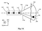
図1Aは、埋め込み型マーカ200の配設(位置決定)を検出するための磁場プローブ100を通る長手方向断面を示す。図示されるように、磁気マーカ200は、関心領域をマークするために皮膚300の外面の下に埋め込まれる。これは、皮膚の外面よりも数ミリメートル又は数センチメートル下であり得る。これを深さと呼ぶこともある。マーカ200は、使用時に磁場を生成するように構成され、例えば磁気双極子を備えることがある。FIG. 1A shows a longitudinal section through a
マーカは、注射などによって簡便に埋め込むことができる。注射は、例えば、軟組織若しくは臓器への注射、又は気管支鏡による肺気管支への送達、若しくは大腸内視鏡による大腸への送達であり得る。埋め込みの方法は、例えば、必要な深さ、実施すべきその後の処置、関心領域のサイズ、関心領域の位置、領域内の組織のタイプ、及び領域を取り囲む組織のタイプに応じて決まることがある。検出の直前又は少し前にマーカを埋め込むことができる。The markers can be conveniently implanted, such as by injection. Injection can be, for example, into soft tissue or an organ, or delivered to the lung bronchi by a bronchoscope, or to the large intestine by a colonoscope. The method of implantation can depend, for example, on the depth required, the subsequent procedure to be performed, the size of the region of interest, the location of the region of interest, the type of tissue within the region, and the type of tissue surrounding the region. The markers can be implanted immediately before or shortly before detection.
典型的には、磁気双極子を備える適切なマーカ200は、概して円柱形であり、
-直径1.45mm、長さ2.19mm、及び残留磁場(Br)1.43T(ネオジムN52)、又は
-直径1.75mm、長さ5mm、及び残留磁場(Br)1.43T(ネオジムN52)
である。 Typically, a
- diameter 1.45 mm, length 2.19 mm, and residual magnetic field (Br) 1.43 T (neodymium N52), or - diameter 1.75 mm,
It is.
直径1.45mm及び長さ4.7mmを有するマーカも適していることがある。Markers with a diameter of 1.45 mm and a length of 4.7 mm may also be suitable.
より高いグレードのネオジムが利用可能になるとき、それらも本発明の実施形態で有利に使用され得る。As higher grades of neodymium become available, they may also be used advantageously in embodiments of the present invention.
追加として又は代替として、マーカ200は、誘導磁気双極子を備えることがある。磁場プローブ100は、双極子磁場の特性に基づいてマーカ200の角度配設を決定するので、そのような磁場を生成するためのマーカ200の構成及び配置はそれほど重要ではない。技法の組合せを使用して、複数の磁気双極子を生成することもできる。本開示の文脈において、角度配設は、角度配置と同義とみなすことができ、プローブに対するマーカ200の相対位置の角度成分である。Additionally or alternatively, the
プローブ100は、遠位端160を備える。磁場プローブは、プローブ長手方向軸150に沿って延びることがある。同じ及び異なる実施形態の異なる視線を比較しやすくするために、軸も定義されている。図面の平面(紙面)は、互いに実質的に垂直なX600及びY700内にある。X軸600は下から上に延び、Y軸700は右から左に延びる。Z軸800は、X600及びY700に実質的に垂直であり、図面の平面から(紙面の外へ)出る。長手方向軸150は、ここでは、Y軸700に実質的に平行であるものとして示されている。The
プローブ100は、以下で述べるように、プローブ基準とマーカ200との間の角度配設を決定するようにさらに構成及び配置される。この角度配設は、XYにおける角度配設180(図1Aに示される)、YZにおける角度配設190(図1Bに示される)、XZにおける角度配設(図1A又は1Bには示されていない)、及びそれらの任意の組合せを含むことがある。プローブ基準は、長手方向軸150に沿ったプローブ100の1つ又は複数の点、遠位端160、近位端165、又はそれらの任意の組合せであり得る。The
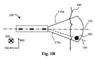
図1Bは、埋め込み型マーカ200の配設(位置決定)を検出するための磁場プローブ100を通るさらなる長手方向断面を示す。図面の平面(紙面)は、互いに実質的に垂直なY700及びZ800内にある。Z軸800は下から上に延び、Y軸700は右から左に延びる。X軸600は、Z800及びY700に実質的に垂直であり、図面の平面に(紙面に向かって)入る。長手方向軸150は、ここでも、Y軸700に実質的に平行であるものとして示されている。プローブ100は、プローブ基準とマーカ200との間の角度配設を決定するようにさらに構成及び配置され、角度配設は、以下で述べるようにYZ角度配設190を含むことがある。1B shows a further longitudinal section through the
この例では、遠位端160は、皮膚(300)の外面の近くに配設されるように構成及び配置される。In this example, the
追加として又は代替として、遠位端160は、以下のように構成及び配置することができる。
-皮膚(300)の外面に接触する;
-皮膚(300)の外面を通して挿入される;
-体腔に挿入される;又は
-それらの任意の組合せ。 Additionally or alternatively,
- in contact with the outer surface of the skin (300);
- inserted through the outer surface of the skin (300);
- inserted into a body cavity; or - any combination thereof.
ユーザは、遠位端160のプローブ長手方向軸150とマーカ200との間の角度配設の標示を提供されることに特に関心があり得る。これは、プローブ100が、長手方向軸150に沿って延ばされることによってハンドヘルドであるように構成及び配置され、遠位端160又は先端に対するマーカ200の方向を決定するための直感的な構成を提供するときに特に有利である。A user may be particularly interested in being provided with an indication of the angular arrangement between the probe
マーカ200の角度配設180、190は、度又はラジアンなどの任意の簡便なパラメータで定義及び/又は表現することができる。The
プローブ100は、マーカ200によって生成される局所磁場(Bx、By、Bz)のベクトルを少なくとも測定するように構成された少なくとも第1の磁気センサ110及び第2の磁気センサ120を備える。これらの特性は、ソフトウェアアルゴリズムを使用して1つ又は複数の角度配設180、190を決定するために使用される。The
遠位端160は、皮膚300の外面から離して配設することができる。スペーサを使用して一定の距離を維持することができ、又は、プローブ100が皮膚300の外面に接触するようにさらに構成及び配置される場合には、距離はゼロであり得る。プローブ100は、プローブ100の遠位端160とマーカ200との間の距離をさらに減少することができる凹みを生成するために、皮膚300の外面に押し付けられるようにさらに構成及び配置されることがある。一般に、プローブ100とマーカとの間の距離が小さいほど、測定される信号の振幅は大きくなる。いくつかの治療では、プローブ100は、プローブ100とマーカ200との間の距離をさらに減少するために、皮膚300の外面を通して及び/又は体腔内に挿入されるようにさらに構成及び配置されることがある。これは、例えば外科的切開又は自然開口部を介するものでよい。The
プローブ100は、検出ユニット又はデバイス(図示せず)に含まれることがある。1つ又は複数の配設を決定するための機能を磁気プローブ100のハードウェア及びソフトウェアとして実装することができる、又はそれらを検出器の残りの部分のハードウェア及びソフトウェアとして実装することができることが当業者には明らかであろう。機能は、磁気プローブ100と検出器ユニットの残りの部分との間で簡便に分割することもできる。The
プローブ100に関する検出ユニット又はデバイスは、以下のうちの1つ又は複数を備えることがある。
-プローブ100の近位端165に取り付けるように構成された、任意選択の電気的及び/又は機械的接続。取付けを解放可能にすると有利であり得る。接続は、無線でもよく、プローブ100と検出器の残りの部分との間でのデータ伝送を少なくとも可能にするように構成及び配置されてもよい;
-プローブ磁気センサにエネルギーを供給するための電源;
-磁気センサ測定値を収集し、適切なソフトウェアアルゴリズムを使用して1つ又は複数の角度配設180、190(角度傾斜)を決定するように構成されたプロセッサ;
-任意選択で、決定の結果をユーザに示すためにディスプレイを提供することもできる。好ましくは、マーカ200に対する1つ又は複数の角度配設180、190がグラフィカル表示される。追加として又は代替として、1つ又は複数の検出区域(以下で述べる)が示され、直感的なフィードバックを提供する。追加として又は代替として、数字を表示することもできる。 The detection unit or device for the
- an optional electrical and/or mechanical connection configured for attachment to the
- a power supply for supplying energy to the probe magnetic sensor;
- a processor configured to collect the magnetic sensor measurements and determine one or more
- Optionally, a display may be provided to show the result of the determination to the user. Preferably, one or more
追加として又は代替として、オーディオフィードバックを提供することもできる。これについては以下でより詳細に述べる。距離(配設)は、例えば相対値及び/又は絶対値として表示されることがある。オーディオフィードバックは、例えば自動車のパーキングセンサで物体までの距離が異なるトーンで示されるのと同様に提供されることがある。Additionally or alternatively, audio feedback may be provided, as described in more detail below. Distances may be displayed, for example, as relative and/or absolute values. Audio feedback may be provided, for example, in a similar manner to how parking sensors in a car indicate the distance to an object with different tones.
マーカ200への近接度に依存するように構成されることがあるオーディオ特性の他の例としては、ピッチ、ボリューム、ラウドネス、振幅、空間位置、持続時間、休止の期間、トーン、ビープ音、ビープ音間の休止期間、周波数、周波数スペクトル、又はそれらの任意の組合せが挙げられる。Other examples of audio characteristics that may be configured to depend on proximity to the
プローブが2つ以上の検出区域を定義するように構成されている場合、標示及び/又はオーディオフィードバックは、角度配設(180、190)が、
-第1のマーカ検出区域と実質的に一致するかどうか;
-第2のマーカ検出区域と実質的に一致するかどうか;
-第1及び第2の検出区域の両方と実質的に一致するかどうか;
-第1又は第2の検出区域のいずれとも実質的に一致しないかどうか;又は
-それらの任意の組合せ
に応じて異なることがある。 If the probe is configured to define two or more detection zones, the indication and/or audio feedback may be provided based on whether the angular arrangement (180, 190) is:
- whether it substantially coincides with the first marker detection area;
- whether it substantially coincides with the second marker detection area;
- substantially coincides with both the first and second detection areas;
- may not substantially coincide with either the first or second detection area; or - may differ according to any combination thereof.
プローブ100は、以下のような2つ以上の磁気センサを備える。
-110:プローブ100の遠位端160に近い第1の磁気センサ;及び
-120:第1の磁気センサ110とプローブ100の近位端165との間に配設された第2の磁気センサ。言い換えると、第1の磁気センサ110よりも遠位端160からさらに離れている。 The
-110: a first magnetic sensor closer to the
センサ110、120は、使用時、マーカ200の磁場の1つ又は複数のB場3Dベクトル測定値を決定するように構成及び配置される。典型的には、センサ出力は、B場の3Dベクトルである。2つ以上のセンサを用いて角度配設を導出することができる。In use, the
第1のセンサ110及び第2のセンサ120に関連する第1の測定値及び第2の測定値は、マーカ200の1つ又は複数の角度配設180、190を決定するためにソフトウェアアルゴリズムで使用される。角度配設180、190は、全体としてプローブ100に関連するマーカ200への方向の測定(又は推定)である。The first and second measurements associated with the first and
任意選択で、プローブは、第3の磁気センサ130を備えることがある。第3の磁気センサ130は、有利には、第1の磁気センサ110及び第2の磁気センサ120よりもプローブ100の近位端165に近い(言い換えると、遠位端160からさらに離れている)。第3の磁気センサ130は、(地球からの)自然発生磁場、測定及び決定が行われる環境内で機器が作動されていることにより存在する人工磁場、及び/又は関心領域内若しくはその周辺の組織によって生成される反磁場などの背景磁場を検出するための補償センサとして構成及び配置することができる。Optionally, the probe may include a third
追加として又は代替として、3つの磁気検出器を使用して3つの磁場成分Bx、By、Bzを測定する3軸ホールセンサなどの磁気センサ110、120、典型的にはそのようなホールセンサパッケージは、3つ(3D)の実質的に相互に垂直な検出器を備えるICであり、プローブ内のほぼ同じ物理的位置で3つの自由度の測定を提供する。センサ110、120は、同じタイプでも異なるタイプでもよい。Additionally or alternatively,
本開示では、センサと検出器とは、時として交換可能に使用される。一般に、センサは、1つ又は複数の検出器を備える単一のカプセル化されたパッケージである。単一の磁気検出器を備えるセンサは、センサ又は検出器とみなすことができる。In this disclosure, sensor and detector are sometimes used interchangeably. Generally, a sensor is a single encapsulated package that includes one or more detectors. A sensor with a single magnetic detector can be considered a sensor or a detector.
センサパッケージが、マーカ200の磁場の特定のBベクトルに関する実質的に異なる値を測定するのに十分に大きい検出器間の物理的離間距離を有する2つの検出器を備える場合、本開示の観点では、そのようなパッケージは2つのセンサを備えている。各検出器は、プローブ100内の実質的に異なるセンサ位置(又は配設)に関するマーカ200の磁場のBベクトル測定を提供する。検出器間の物理的離間距離が小さすぎる(検出器が、特定のBベクトルに関して実質的に同じ値を測定する)場合、本開示の観点では、そのようなパッケージは、1つのセンサを備えている。各検出器は、プローブ100内の実質的に同じ位置(又は配設)に関するマーカ200のベクトル測定を提供する。If the sensor package includes two detectors with a physical separation between them large enough to measure substantially different values for a particular B vector of the magnetic field of the
いくつかのパッケージでは、2つ以上の検出器が異なる向きを測定するように構成されることがあり、例えば、いくつかのホールセンサパッケージは、互いに実質的に垂直に向けられた3つの検出器を備えることに留意されたい。それらの検出器は、実質的に同じ位置(又は配設)に関連付けられたBベクトルを測定するので、同じ(1つの)センサに含まれていると考えられる。Note that in some packages, two or more detectors may be configured to measure different orientations; for example, some Hall sensor packages include three detectors oriented substantially perpendicular to one another. The detectors are considered to be included in the same (single) sensor because they measure B vectors associated with substantially the same location (or orientation).
図1Aに示されているように、少なくとも2つの磁気センサ110、120の1Dアレイを使用することができる。センサ110、120は、プローブ100の長手方向軸150に沿って配設されて図示されているが、それらの相対位置(配設)は測定及び/又は設計データから決定されてソフトウェアアルゴリズムで考慮(考察)され得るので、これは必須ではない。プローブ100は、センサ110、120からのBベクトル測定値を任意のプローブ100の基準面又は基準軸に変換するように構成及び配置される。センサ110、120を長手方向軸150に沿って配設し、この長手方向軸150を角度測定のための基準として使用することは、測定データの幾何学的変換を単純化するので特に有利である。As shown in FIG. 1A, a 1D array of at least two
これらの磁気検出器110、120は、磁力計、磁束ゲートセンサ、地磁気センサ、ローレンツ力デジタルMEMS、磁気誘導センサ、磁気抵抗センサ、ホールセンサ、磁気トンネル接合、及びそれらの任意の組合せなど、任意の適切なタイプのものでよい。小型であり3軸検出を含む多くのICパッケージが利用可能である。したがって、単純なPCB設計、及び好ましくはより小さいプローブ直径で「多軸」ソリューションを提供することができる。以下に提案されるセンサパッケージは一例である。それらはデジタルであり、したがって、アナログ設計があまり必要とされないのでインターフェースが比較的簡単である。These
TIDRV425フラックスゲートセンサ(1D)
技術:フラックスゲート
サイズ:4×4×0.8mm
範囲:±2mT(単軸)
分解能:(アナログ、ADCによる)
RMSノイズ:0.42μT@1000Hz(0.2μT@50Hz)
オフセット:8.3μT+1.4μTヒステリシス+0.4温度ドリフト
利得誤差:0.3%
絶対最大磁場:>2T(任意の方向で)
注:良好なゼロ磁場オフセット性能を有する補正センサを使用することによって、オフセットを低減することができる。別のタイプのセンサは、例えば、プローブ100に統合されて、フラックスゲートに関するある程度のオフセット及び/又はドリフト補正を提供することがある。好ましくは、そのような補正センサは、磁気マーカ200の磁場特性の影響を低減するために、近位端の近くに又は近位端に位置される。TIDRV425 Fluxgate Sensor (1D)
Technology: Fluxgate Size: 4 x 4 x 0.8 mm
Range: ±2mT (single axis)
Resolution: (analog, depending on ADC)
RMS noise: 0.42μT@1000Hz (0.2μT@50Hz)
Offset: 8.3μT + 1.4μT Hysteresis + 0.4 temperature drift Gain error: 0.3%
Absolute maximum magnetic field: >2T (in any direction)
NOTE: The offset can be reduced by using a correction sensor with good zero field offset performance. Another type of sensor may be integrated into the
Bosch BMM150 3軸デジタル地磁気センサ(3D)
技術:FlipCore
サイズ:1.56×1.56×0.6mm
範囲:±1.2mT(x,y);±2mT(z)
分解能:3μT(LSB)
RMSノイズ:0.3μT@20サンプル/秒
オフセット:40μT(ソフトウェア補償なし)、2μT(補償後、典型的に)
利得誤差:5%(補償後)
絶対最大磁場:>7T(任意の方向で)Bosch BMM150 3-Axis Digital Geomagnetic Sensor (3D)
Technology: FlipCore
Size: 1.56 x 1.56 x 0.6 mm
Range: ±1.2mT (x,y); ±2mT (z)
Resolution: 3μT (LSB)
RMS noise: 0.3 μT @ 20 samples/sec Offset: 40 μT (without software compensation), 2 μT (after compensation, typically)
Gain error: 5% (after compensation)
Absolute maximum magnetic field: >7T (in any direction)
ST LIS3MDL(1D)
技術:ローレンツ力デジタルMEMS
サイズ:2×2×1mm
範囲:±1.6mT(x,y,z)(ユーザ選択可能:0.4、0.8、1.2mT)
分解能:0.015μT(LSB)(@0.4mT範囲;0.06μT@1.6mT範囲)
RMSノイズ:0.3μT(x,y);0.4μT(z)@1.2mT範囲
オフセット:100μT;磁場>5mT(印加)のときにドリフト
利得誤差:0.15%フルスケール(最良あてはめ直線、非線形)
絶対最大磁場:<0.1T(任意の方向で)ST LIS3MDL (1D)
Technology: Lorentz force digital MEMS
Size: 2 x 2 x 1 mm
Range: ±1.6 mT (x, y, z) (user selectable: 0.4, 0.8, 1.2 mT)
Resolution: 0.015μT (LSB) (@0.4mT range; 0.06μT @1.6mT range)
RMS noise: 0.3 μT (x,y); 0.4 μT (z) @ 1.2 mT range Offset: 100 μT; drift when field > 5 mT (applied) Gain error: 0.15% full scale (best fit straight line, non-linear)
Absolute maximum magnetic field: <0.1T (in any direction)
ST IIS2MDC(3D)
技術:3軸デジタル出力磁力計
高精度、超低出力
ノイズ:0.3μT(使用可能なローパスフィルタ又はオフセットキャンセレーションによる)。20サンプル/秒で1SD。
オフセットエラー:6μT;20℃範囲にわたって1.2μTに修正可能。3Tで測定されたヒステリシスは、5mTフィールドで53μT及び13μT
オフセット変化:温度と共に、0.03μT/℃
利得誤差:1.5%(典型)、7%(最大)
利得変化:温度と共に、0.03%/℃ST IIS2MDC (3D)
Technology: 3-axis digital output magnetometer. High accuracy, ultra-low output noise: 0.3 μT (with available low pass filter or offset cancellation). 1 SD at 20 samples/sec.
Offset error: 6 μT; correctable to 1.2 μT over a 20°C range. Hysteresis measured at 3T is 53 μT and 13 μT in a 5 mT field.
Offset change: with temperature, 0.03 μT/° C.
Gain error: 1.5% (typical), 7% (maximum)
Gain change with temperature: 0.03%/°C
Melexis MLX90393 Micropower Triaxis Magnetometer(3D)
技術:ホール効果
サイズ:3×3×1mm
範囲:±5-50mT(x,y,z)(ユーザ選択可能)
分解能:0.16μT(x,y);0.3μT(z)(LSB)
RMSノイズ:0.7μT(x,y);0.9μT(z)@50サンプル/秒
オフセット:0μT 2.7μT/℃温度ドリフト(オンチップ補償利用可能)
利得誤差:<1%交差軸感度+3%温度超過
絶対最大磁場:-Melexis MLX90393 Micropower Triaxis Magnetometer (3D)
Technology: Hall effect Size: 3 x 3 x 1 mm
Range: ±5-50mT(x,y,z) (user selectable)
Resolution: 0.16μT (x, y); 0.3μT (z) (LSB)
RMS noise: 0.7μT (x,y); 0.9μT (z) @ 50 samples/sec Offset: 0μT 2.7μT/°C temperature drift (on-chip compensation available)
Gain Error: <1% Cross-Axis Sensitivity +3% Over Temperature Absolute Maximum Magnetic Field: -
MEMSIC MMC3416xPJ(3D)
技術:AMR
サイズ:1.6×1.6×0.6mm
範囲:±1.6mT(x,y,z)(ユーザ選択可能:0.4、0.8、1.2mT)
分解能:0.015μT(LSB)(@0.4mT範囲;0.06μT@1.6mT範囲)
RMSノイズ:0.15μT@125サンプル/秒
オフセット:再現可能性誤差0.1%フルスケール=1.6μT
利得誤差:-
絶対最大磁場:1TMEMSIC MMC3416xPJ (3D)
Technology: AMR
Size: 1.6 x 1.6 x 0.6 mm
Range: ±1.6 mT (x, y, z) (user selectable: 0.4, 0.8, 1.2 mT)
Resolution: 0.015μT (LSB) (@0.4mT range; 0.06μT @1.6mT range)
RMS noise: 0.15μT @ 125 samples/sec Offset: Repeatability error 0.1% Full scale = 1.6μT
Gain error: -
Absolute maximum magnetic field: 1T
AKM AK09970N(3D)
技術:ホール効果
サイズ:3×3×0.6mm
範囲:±36mT(x,y);±102mT(z)
分解能:1.1μT(LSB)
RMSノイズ:5μT@100サンプル/秒
オフセット:743μT(x,y)、1050μT(z)
利得誤差:10%
絶対最大磁場:-AKM AK09970N (3D)
Technology: Hall effect Size: 3 x 3 x 0.6 mm
Range: ±36 mT (x,y); ±102 mT (z)
Resolution: 1.1μT (LSB)
RMS noise: 5 μT @ 100 samples/sec Offset: 743 μT (x, y), 1050 μT (z)
Gain error: 10%
Absolute maximum magnetic field: -
PNI RM3100センサシステム(3D)
技術:磁気誘導
サイズ:15.24×12.8×3×10.5mm
範囲:±800μT(z)
分解能:13nT(LSB)
RMSノイズ:15nT@100サンプル/秒
オフセット:再現可能性8nTヒステリシス15nT
利得誤差:線形0.5%
絶対最大磁場:-
注:センサシステムは、3つのコイル、及びデジタルインターフェースを有するドライバICを含む。PNI RM3100 Sensor System (3D)
Technology: Magnetic induction Size: 15.24 x 12.8 x 3 x 10.5 mm
Range: ±800 μT (z)
Resolution: 13nT (LSB)
RMS noise: 15nT @ 100 samples/sec Offset: repeatability 8nT Hysteresis 15nT
Gain error: Linear 0.5%
Absolute maximum magnetic field: -
Note: The sensor system includes three coils and a driver IC with a digital interface.
40mm~50mmの長手方向センサアレイの長さ400が好ましい。A longitudinal sensor array length 400 of 40mm to 50mm is preferred.
各センサ110、120は、地球の磁場などの任意の背景磁場及びマーカ200の磁場を含むことがある任意の局所磁場のB場3Dベクトルをそれぞれ測定する。これらの測定値はソフトウェアアルゴリズムに提供され、ソフトウェアアルゴリズムは、測定値を、向き、感度、センサ離間距離などの物理的パラメータと組み合わせて、プローブ100の所定の基準位置に対する磁気マーカ200の角度配設180、190を決定する。Each
本発明の基礎となる洞察の1つは、傾斜(角度配設)がゼロであるとき(言い換えると、マーカ200がプローブ100の長手方向軸150に沿って、例えばY-Z平面700-800内に配設されるとき)、長手方向軸に沿って配設されたすべてのセンサ110、120で測定される磁場が実質的に同じ方向であることである。これがハンドヘルドプローブ100で検出されるとき、プローブ100は、実質的にマーカ200の方向を「向いて」いる。One of the insights underlying the present invention is that when the tilt (angular orientation) is zero (in other words, when the
ハンドヘルド用途では、ユーザは、例えばY-Z平面700-800内でプローブ100を異なる傾斜に回転させることができ、それにより長手方向軸150が皮膚300に対して複数の向きを有する。磁場ベクトル測定値を継続的に監視し、各センサ110、120によって測定される磁場方向の偏差の程度(差)を決定することによって、マーカ200に対する相対的な傾斜(角度配設)の標示を提供することができる。偏差の程度が所定の閾値よりも低いとき、プローブ100は、マーカ200を実質的に「向いて」いる。In handheld applications, the user can rotate the
測定の精度を向上させるために、ノイズをできるだけ低減するようにプローブ100を構成することが有利であり得る。これは、例えば、以下のことによって行われる。
-より高感度のセンサ110、120を使用すること;
-より強い磁場を提供するマーカ200を使用すること;
より多数のセンサ110、120を使用することによって;
1つ又は複数の平均化フィルタを使用することによって;及び
それらの任意の組合せ。 To improve the accuracy of the measurements, it may be advantageous to configure the
- using more
- Using a
By using a larger number of
By using one or more averaging filters; and any combination thereof.
マーカ200に含まれる磁気双極子を原点とし、双極子モーメントmがZ方向800に向いている場合、球面極座標での磁場は次式によって与えられる。
Br=2|m|cosθ/r3
Bθ=|m|sinθ/r3
Bφ=0 (式1) If the magnetic dipole contained in the
Br =2 | m | cosθ/r3
Bθ = | m | sin θ/r3
Bφ =0 (Formula 1)
図3Aは、概して円形の磁力線401、402、403、404のシミュレートされた概略図を示し、Y-Z 700-800の原点で磁気双極子200によって生成された磁場のY-Z平面700-800での断面を表す。Z軸800は、0を通過する、下部での-4から上部での+4までの公称距離単位を表す。また、Y軸700は、0を通過する、右側の-1から左側の+5までの公称距離単位を表す。双極子モーメントmは、Z軸800に沿って配設される。X軸600は、図面の平面に(紙面に向かって)入る。磁力線401、402、403、404はすべてY-Z 700-800の原点(0,0)を通過し、原点から放射状に広がる磁力線を示す。
-第1の磁力線401は、1距離単位の公称直径を有し、Y-Z 700-800座標(0,0)、(0.5,-0.5)、(1,0)、(0.5,0.5)をほぼ通過する。
-第2の磁力線402は、2距離単位の公称直径を有し、Y-Z 700-800座標(0,0)、(1,-1)、(2,0)、(1,1)を通過する。
-第3の磁力線403は、3距離単位の公称直径を有し、X-Y 600-700座標(0,0)、(1.5,-1.5)、(3,0)、(1.5,1.5)をほぼ通過する。
-第4の磁力線404は、4距離単位の公称直径を有し、Y-Z 700-800座標(0,0)、(2,-2)、(4,0)、(2,2)をほぼ通過する。 3A shows a simulated schematic diagram of generally circular
- The first
- The second
- The third
- The fourth
わかりやすくするために、4本の磁力線のみが示されている。実際には、さらなる磁力線が存在し、適切な感度の磁気センサ110、120を用いて測定可能である。For clarity, only four magnetic field lines are shown. In reality, more magnetic field lines exist and can be measured using
また、プローブ100の6つの向きも示されており、それぞれが傾斜181~186を表す。プローブ100は、長手方向軸150に沿った4公称距離単位の延在長さを有する。各位置において、遠位端160が双極子200を「向いて」いるのでY-Z角度配設190は約0度であり、センサ110、120によって測定されるベクトル測定値間の偏差は非常に低い又はほぼゼロである。
-第1の傾斜181。プローブ100は、(0,-4)から(0,0)まで延び、遠位端160は、Y-Z 700-800の原点(0,0)と一致する。磁力線401、402、403、404は、すべてのセンサ110、120に関して、約0(又は180)度でプローブ100と交差する。
-第2の傾斜182。プローブ100は、ほぼ(2,-3.3)から(0,0)まで延び、遠位端160は、Y-Z 700-800の原点(0,0)と一致する。磁力線401、402、403、404は、約50度でプローブ100と交差する。
-第3の傾斜183。プローブ100は、ほぼ(3.4,-2)から(0,0)まで延び、遠位端160は、Y-Z 700-800の原点(0,0)と一致する。磁力線401、402、403、404は、約70度でプローブ100と交差する。
-第4の傾斜184。プローブ100は、ほぼ(4,0)から(0,0)まで延び、遠位端160は、Y-Z 700-800の原点(0,0)と一致する。磁力線401、402、403、404は、約90度でプローブ100と交差する。
-第5の傾斜185。プローブ100は、ほぼ(3.4,2)から(0,0)まで延び、遠位端160は、Y-Z 700-800の原点(0,0)と一致する。磁力線401、402、403、404は、約110度でプローブ100と交差する。
-第6の傾斜186。プローブ100は、ほぼ(2,3.3)から(0,0)まで延び、遠位端160は、Y-Z 700-800の原点(0,0)と一致する。磁力線401、402、403、404は、約130度でプローブ100と交差する。 Also shown are six orientations of the
-
- A
- A
-
-
- Sixth tilt 186 . The
したがって、マーカ200によって生成される磁気双極子の磁場のこの特性を利用することによって、ほぼゼロのYZ角度配設190を有するプローブ100の向きは、磁気センサ110、120によって測定される磁場方向の偏差が非常に低い又はほぼゼロである向きによって決定することができる。好ましくは、偏差は約15度未満である。Therefore, by utilizing this property of the magnetic dipole field generated by the
磁力線401、402、403、404は、実質的に同じ角度でプローブ100の磁気センサ110、120と交差する。磁力線401、402、403、404の角度は、プローブ100がマーカ200によって生成された磁気双極子と成す角度に大きく依存する。これは、双極子磁場が自己相似であるからである。すなわち、双極子200から遠い磁力線は、双極子200に近い磁力線と実質的に同じ形状を有する。The
この関係500は図3Bに示されている。横軸に沿って、プローブ傾斜θ550の値が左から右に0から180度までプロットされ、縦軸に沿って、プローブ平面575での磁場の傾斜の値が、下側での-90度から上側での+90度までプロットされている。この関係は、以下の点を通過する。This
プローブ100が一定のZ800配設で異なる傾斜に動かされる場合、θは、マーカ200からのセンサ110、120の位置に関係付けられる。
tan(θ)=Zsen/Ysen
tan(α)=tan(θ)/2=(Zsen/Ysen)/2 When the
tan(θ)=Zsen /Ysen
tan(α)=tan(θ)/2=(Zsen /Ysen )/2
図7は、プローブが磁気双極子に直接向いているときの、予想される磁場成分を示す。Figure 7 shows the expected magnetic field components when the probe is pointed directly at the magnetic dipole.
磁気マーカ200は、マーカ磁気軸900に沿って長手方向に延ばされている。マーカ磁気軸900は、磁石の双極子モーメント(ベクトル)の軸である。双極子モーメント900と実質的に整列された磁気マーカ200を使用することが簡便であるが、マーカ200の他の形状及び他の整列を使用することもできる。The
図示される場合には、プローブ長手方向軸150は、磁気マーカ200に方向付けられている(プローブは、磁気マーカ200の磁気双極子の中心に向けられている)。プローブの長手方向軸150は、傾斜θでマーカ磁気軸900と交差される。In the illustrated case, the probe
球座標(r,θ,φ)を有する検出位置970で、プローブ長手方向軸150と実質的に垂直に交差する横方向軸950が示されている。検出位置970には、磁気マーカ200によって生成された磁場(B)920が存在し、検出可能である。検出位置970で、磁場ベクトル930Bは、横方向軸950に対して角度αで検出可能である。At
図示される場合には、プローブが磁気マーカ200に直接向いているので、方位角方向での磁場ベクトル930Bの成分(Bφ)はほぼゼロであると考えることができる。角度αは、主に、磁気マーカ200の磁気双極子に対するプローブの傾斜θに対応すると考えることができる。In the illustrated case, the component of the magnetic field vector 930B in the azimuthal direction (Bφ) can be considered to be approximately zero, since the probe is pointing directly at the
したがって、磁気マーカ200の角度配設を決定するために、磁場ベクトル930Bは、以下の2つの成分を有すると考えることができる。
|B|sinα=Br(半径方向rでのプローブ長手方向軸150に沿って)
|B|cosα=Bθ(傾斜θの方向に沿って) Therefore, for purposes of determining the angular orientation of the
|B| sin α=Br (along the probe
|B|cosα=Bθ (along the direction of inclination θ)
従来技術のシステムでは、1Dラインのセンサを使用して、距離の測定値と方向の測定値との両方を提供することができる。しかし、プローブが磁気マーカ200に直接向いていないとき、精度が低くなることがある。Prior art systems can use 1D line sensors to provide both distance and direction measurements. However, accuracy can be reduced when the probe is not pointed directly at the
図3A及び図3Bから、1Dラインに配設された2つ以上の磁気センサがほぼ同じ磁場角度αを示すとき、プローブが磁気マーカ200を向いていることを当業者は理解されよう。測定された磁場の振幅から、磁気双極子200までの距離を計算することができる。3A and 3B, one skilled in the art will understand that the probe is pointing toward the
複数のセンサが異なる角度αを示すとき、プローブは磁気マーカ200からずれた方向を向いている。プローブが磁気マーカ200からどれだけずれた方向を向いているかを示す指標として、様々なセンサにわたる角度の偏差に関する任意の人工的な尺度を使用することができる。When the sensors indicate different angles α, the probe is pointing in a direction that is misaligned from the
図4A及び4Bは、プローブ100が30.0度の固定傾斜θ191、192、193、194、195、196で異なるXY角度配設190を通して走査されたときに、長手方向軸150に沿って配設された各磁気センサ110、120で得られた測定値を示す。各磁気センサ110、120で測定されたB場ベクトルを比較することによって、プローブがマーカ200を実質的に直接「向いて」いるXY角度配設190(言い換えると、XY角度配設190が実質的にゼロであるとき)は、グラフが切片を有する点(ゼロ切片又は「切片=0」の点とも呼ばれる)を識別することによって決定することができる。4A and 4B show measurements taken at each of the
図4Aは、センサでのB場傾斜の測定を示し(単位は度)、磁場傾斜は、縦軸に-75度から+90度まで、及び横軸にプローブZ800配設で-50mmから+50mmまでプロットされている。4つのグラフが示され、遠位端160からY軸700に沿って10.0mm、15.0mm、20.0mm、及び25.0mm(図の左側に下から上へこの順序で示されている)の距離で長手方向軸150に沿って配設された各センサ110、120に関するものである。各グラフは、つぶれたS字形を成し、同じゼロ切片(横軸での0mm)を通過する。Figure 4A shows the measurement of the B-field gradient at the sensor (in degrees), where the magnetic field gradient is plotted on the vertical axis from -75 degrees to +90 degrees, and on the horizontal axis from -50 mm to +50 mm for the probe Z800 arrangement. Four graphs are shown, for each
図4Bは、図4Aと同様のデータを示す(4つのグラフ。遠位端160からY軸700に沿って10.0mm、15.0mm、20.0mm、及び25.0mm(図の左側に下から上へこの順序で示されている)の距離で長手方向軸150に沿って配設された各センサ110、120に関するものである)。図4Bは、用いられる縦軸が-4から+6までのB場傾斜のタンジェントであるという点で図4Aとは異なる。タンジェント関数を使用する利点は、特性がほぼ線形になり、ゼロ切片の位置(横軸での0mm)を推定及び/又は決定するためにより簡単に使用することができることである。Figure 4B shows similar data to Figure 4A (four graphs, one for each
同様に、B場の傾斜の違いを使用して、遠位端に最も近い磁気センサ、すなわち10.0mmでのセンサと比較して、15.0mm、20.0mm、及び25.0mmで測定された値を比べることができる。これらのグラフは、図5Aにおいて、10.0mm(基準)、15.0mm、20.0mm、及び25.0mmの順に、図の左側で下から上にこの順序で示されている。10.0mmの値とのB場傾斜の差が、縦軸に-12度から+55度までプロットされている。横軸は、-50mmから+50mmまでの配設を示す。他の値が10.0mmの値と比較されるので、10.0mmの値は、0の差分線で水平線として示されている。ここでも、グラフはどれもゼロ切片(横軸での0mm)で切片を有する。Similarly, the difference in B-field slope can be used to compare values measured at 15.0 mm, 20.0 mm, and 25.0 mm compared to the magnetic sensor closest to the distal end, i.e., the sensor at 10.0 mm. These graphs are shown in FIG. 5A from bottom to top on the left side of the figure in the order 10.0 mm (reference), 15.0 mm, 20.0 mm, and 25.0 mm. The difference in B-field slope from the 10.0 mm value is plotted on the vertical axis from -12 degrees to +55 degrees. The horizontal axis shows the arrangement from -50 mm to +50 mm. The 10.0 mm value is shown as a horizontal line with a difference line of 0, since the other values are compared to the 10.0 mm value. Again, all graphs have an intercept at zero (0 mm on the horizontal axis).
図5Bは、図5Aと同様のデータを示す(10.0mm(基準)、15.0mm、20.0mm、25.0mmの順に、図面の左側にこの順序で)。他の値が10.0mmの値と比較されるので、10.0mmの値は、0の差分線で水平線として示されている。図5Bは、用いられる縦軸が-3から+3までのB場傾斜のタンジェントであるという点で図5Aとは異なる。タンジェント関数を使用する利点は、特性がほぼ線形になり、ゼロ切片の位置(横軸での0mm)を推定及び/又は決定するためにより簡単に使用することができることである。Figure 5B shows similar data to Figure 5A (10.0 mm (reference), 15.0 mm, 20.0 mm, 25.0 mm, in that order on the left side of the drawing). The 10.0 mm value is shown as a horizontal line with a difference line of 0 as other values are compared to it. Figure 5B differs from Figure 5A in that the vertical axis used is the tangent of the B field slope from -3 to +3. The advantage of using the tangent function is that the characteristic becomes approximately linear and can be more easily used to estimate and/or determine the location of the zero intercept (0 mm on the horizontal axis).
したがって、B場傾斜角の偏差は、マーカに対する角度配設の尺度として使用することができる。偏差が最小であるとき、プローブはマーカに直接向いている。偏差は、例えば以下のものを使用して定量化することができる。
-絶対平均。言い換えると、磁場の平均に対する磁場角度が監視される。これは好ましい選択肢である。基準としての磁場の平均は、より強い磁場に対してより大きい重みを置き、それによりSNRを高くすることができる。遠位端160に最も近い磁場を使用することもできるが、これは、ノイズを低減するための追加の手段を必要とすることがある。
-図4Bに示されるB場タンジェントの平均。
-上記の平均を使用する代わりに、平均タンジェントを使用することができる。 Therefore, the deviation in the B-field tilt angle can be used as a measure of the angular disposition relative to the marker. When the deviation is minimal, the probe is pointing directly at the marker. The deviation can be quantified, for example, using the following:
- Absolute average. In other words, the magnetic field angle relative to the magnetic field average is monitored. This is the preferred option. The magnetic field average as a criterion places a higher weight on stronger magnetic fields, which may result in a higher SNR. The magnetic field closest to the
- the average of the B field tangents shown in FIG.4B .
Instead of using the average above, the tangent of the average can be used.
図1Aは、プローブ長手方向軸150に沿って遠位端160から延びるマーカ検出区域170a、170bをさらに示す。XY平面600-700に三角形断面で実質的に対称に示されているが、これは必須ではない。任意の断面形状を使用することができる。マーカ検出区域は、主に、破線で示されるような2つ以上の角度境界170a、170bによって決定することができる。追加として及び任意選択で、プローブ100の遠位端160の近位での2つ以上の角度境界170a、170bの間の距離が事前決定及び/又は制御されることがある。追加として及び任意選択で、マーカ検出区域がプローブ100の遠位端160から長手方向軸150に沿って延びる範囲(湾曲した破線として示される)が事前決定又は制御されることがある。1A further illustrates
同様に、図1Bは、プローブ長手方向軸150に沿って遠位端160から延びるマーカ検出区域170c、170dのさらなる範囲を示す。YZ平面700-800に三角形断面で実質的に対称に示されているが、これは必須ではない。任意の断面形状を使用することができる。区域は、XY600-700及び/又はYZ700-800内で範囲を有することがある。Similarly, FIG. 1B shows further extents of
マーカ検出区域は、主に、破線で示されるような2つ以上の角度境界170c、170dによって決定することができる。追加として及び任意選択で、プローブ100の遠位端160の近位での2つ以上の角度境界170c、170dの間の距離が事前決定及び/又は制御されることがある。追加として及び任意選択で、マーカ検出区域がプローブ100の遠位端160から長手方向軸150に沿って延びる範囲(湾曲した破線として示される)が事前決定又は制御されることがある。The marker detection zone may be determined primarily by two or more
図1A及び1Bに示される断面は実質的に同じ形状であり、異なる範囲を有するが、これは必須ではない。例えば、マーカ検出区域170a、170b、170c、170dは、任意選択で、長手方向軸150に実質的に垂直に、実質的に円形、円弧形、セグメント、卵形、楕円形、三角形、長方形、又は正方形の横方向断面を有することがある。1A and 1B are substantially the same shape and have different extents, but this is not required. For example,
マーカ検出区域170a、170b、170c、170dが長手方向軸150に関して実質的に対称である場合、特にプローブがハンドヘルドであるように構成されるとき、マーカ200を見つけるためのより直感的なプローブ100を提供することができる。例えば、マーカ検出区域を円柱又は円錐形として定義することができる。円錐形のマーカ検出区域は、放物線、直線、又は双曲線の形状をさらに有することがある。
・放物線=遠位端160の近位でより広い角度であり、より負のY700配設に向かって遠位端から離れるにつれてより狭い角度である。
・直線=遠位端160の近位でも、より負のY700配設に向けて遠位端160から離れても、ほぼ同じ角度である。これは、集束ビームと呼ばれることもある。
・双曲線=遠位端160の近位でより狭い角度であり、より負のY700配設に向かって遠位端から離れるにつれてより広い角度である。 If the
Parabola = wider angle proximal to the
Straight line = Approximately the same angle proximal to the
- Hyperbolic = narrower angle proximal to the
マーカ検出区域170a、170b、170c、170dは、ソフトウェアを使用して定義することができる。例えば、B場ベクトルの測定中、マーカ検出区域170a、170b、170c、170dの外側にあると推定/測定される角度配設180、190は抑制されることがある。言い換えると、ソフトウェアは、マーカ200がマーカ検出区域170a、170b、170c、170d内にあることをベクトル測定値が示しているように見える場合にのみ、角度配設の計算においてベクトル測定値を考慮に入れるように構成することができる。言い換えると、区域は、ソフトウェア制御式のコリメータとして作用するように構成される。追加として及び任意選択で、マーカ検出区域が長手方向軸150に沿って延びる範囲を使用して、長手方向で制限されたマーカ検出区域内にマーカ200があるかどうかを判断することもできる。The
ソフトウェアで区域を定義することは、円柱、スリット、及び円錐などの単純な形状を使用することができることを意味する。代替として又は追加として、複雑な形状を使用することもできる。例えば、プローブ100の遠位端160の近くでは細い円錐であり、遠位端160から離れるにつれてより広く扇状に広がる、又は遠位端160から直進する(円柱形の)ビームを定義する。Defining the area in software means that simple shapes such as cylinders, slits, and cones can be used. Alternatively or additionally, complex shapes can be used. For example, a narrow cone near the
これは、簡単なゴニオメトリックテストとして実装して、所望の検出体積を実現することができる。マーカ200が区域170a、170b、170c、170dの縁部にあるように見える場合、ノイズにより、マーカ200が時として除外され、時として使用されることになり得る。実装することができるソリューションとして、以下のものを挙げられる。
1)測定に関するヒステリシス。例えば、区域170a、170b、170c、170dの内側にあるとみなされると、B場ベクトル測定が抑制される前にかなりの距離及び/又は角度の移動が生じるはずである。
2)本願と同一出願人による先行特許出願であるオランダ特許第2022093号に記載されている3D位置決定出力も、ある程度の不確実性を有することがある。位置の不確実性が空間内のヒートマップであると考えられる場合、それに区域170a、170b、170c、170dを乗算し、次いで体積全体にわたって積分することができる。積分値が閾値を超えている場合、それらの値は、角度配設180、190の決定に使用される。
3)区域170a、170b、170c、170dの重みを成形してテーパを付ける。例えば、プローブ100は、B場ベクトルを評価し、ヤコビアンを返すように構成及び配置することができ、ヤコビアンを使用して、推定されるマーカ200位置の不確実性の指標を与えることができる。これは、GPSシステムでの不確実性に伴う問題を軽減するために通常使用される手法に類似している。
4)距離に依存するオーディオピッチを決定するために、提案される実施形態は、推定される位置に区域170a、170b、170c、170dの形状を乗算することである。代替として、不確実性の領域に区域170a、170b、170c、170dの形状を乗算することができる。角度配設180、190の信頼度を示す積分値を、音のボリュームとして出力することができ、音のピッチは、横方向及び/又は長手方向配設(距離)を示すことがある。例えば、ビープ音間の休止期間の間に逆の関係を使用することができる。すなわち、より短い休止が、より高い近位度(又は近接性)を示す。 This can be implemented as a simple goniometric test to achieve the desired detection volume. If the
1) Hysteresis with respect to the measurement: for example, to be considered inside the
2) The 3D position determination output described in the commonly assigned prior patent application, Dutch Patent No. 2022093, may also have some uncertainty. If the position uncertainty is considered to be a heat map in space, it can be multiplied by the
3) Shape and taper the weights of the
4) To determine the distance-dependent audio pitch, a proposed embodiment is to multiply the estimated position by the shape of the
プローブ100は、プローブ100の遠位端160など、プローブ100での適切な基準点に対するマーカ200の長手方向及び/又は横方向配設を決定するようにさらに構成及び配置することができる。
The
プローブ100が最初にマーカ200を向くように方向付けられる場合、マーカ200までの距離(長手方向及び/又は横方向配設)を高い精度で推定することができる。When the
プローブ100がマーカ200に向いているとき、Br=-Byである(プローブ100のY軸700はマーカ200に向くが、rは、マーカ200から、プローブ100に含まれる磁気センサ110、120に向く)。When the
Bφ=0であるので、磁場の大きさの2乗は次式によって与えられる。
上記の式から、Br及びBθに関して次式が成り立つ。
このソリューションは、図1及び図2に示されているものを含む、様々なセンサ配置で実装することができる。This solution can be implemented with a variety of sensor arrangements, including those shown in Figures 1 and 2.
図2A~図2Fは、本発明で使用することができるさらなるプローブ構成を示す。Figures 2A-2F show additional probe configurations that can be used in the present invention.
例えば、以下のようである。
図2A。磁場センサ110、120は、実質的に長手方向軸又はY軸700に沿って配置される。この例では、磁場センサは、プローブ長手方向軸150に沿って配置される。磁場センサは、PCBなどの適切な基板に配置される。基板は、X-Y平面600-700内にある。1つ又は複数のさらなるセンサ130を近位端165に配設することができ、任意の背景磁場を補償するために提供することができ、又は遠位端により近いセンサ1110、120から主センサ離間距離にあるように構成及び配置することができる。 For example,
2A. The
これは、1D幾何形状と考えることができる。磁場センサは、実質的に軸に沿って配置される。This can be thought of as a 1D geometry. The magnetic field sensors are positioned substantially along the axis.
背景磁場が十分に均一でない場合、又は背景磁場センサがマーカ(図示せず)の双極子磁場を感知する場合(マーカは背景磁場センサに近いので)、背景磁場を局所で差し引くと有利であり得る。If the background magnetic field is not sufficiently homogeneous or if the background magnetic field sensor senses the dipole magnetic field of a marker (not shown) (because the marker is close to the background magnetic field sensor), it may be advantageous to subtract the background magnetic field locally.
例えば、双極子磁場が空間にわたって変化しているのでB場の勾配を測定し、背景磁場が均一である(少なくとも測定範囲、例えば2つの隣接するセンサ間の距離にわたって)と仮定する。この手法は、3つの方向600、700、800すべてにおいて湾曲に対する感度を有する3Dアレイで使用することができる。For example, measure the gradient of the B-field as the dipole magnetic field varies over space, and assume that the background magnetic field is uniform (at least over the measurement range, e.g., the distance between two adjacent sensors). This approach can be used in 3D arrays with sensitivity to curvature in all three
3Dアレイは、実質的に平面に沿って、さらに上記平面に実質的に垂直な少なくとも1つの軸に沿って配置された磁場センサを備える。3Dアレイは、実質的に第1の平面に沿って、さらに第1の平面に実質的に垂直な第2の平面に沿って配置された磁場センサを備えることもある。The 3D array comprises magnetic field sensors arranged substantially along a plane and along at least one axis substantially perpendicular to the plane. The 3D array may also comprise magnetic field sensors arranged substantially along a first plane and along a second plane substantially perpendicular to the first plane.
2Dアレイで使用することができるさらなる手法を以下に述べる。2Dアレイは、実質的に平面に沿って配置された磁場センサを備える。均一な磁場に関して、∂Br/∂r及び∂Bθ/∂r=0である。これは、プローブの長さ(Y軸700及び/又は長手方向軸150)に沿った磁場の差を取ることによって実装することができる。磁場は、プローブがマーカに含まれる磁石に向いているとき、rと整列される。rは-y方向であり、|Bθ|=√(Bx2+Bz2)である。 A further approach that can be used with 2D arrays is described below. A 2D array comprises magnetic field sensors arranged substantially along a plane. For a uniform magnetic field, ∂Br/∂r and ∂Bθ/∂r=0. This can be implemented by taking the difference in the magnetic field along the length of the probe (Y-
双極子に関しては、
ここで、偏微分項は、次式によって近似することができる。
図2B。センサ110、120、130は、実質的に長手方向軸又はY軸700に沿って位置するように積み重ねられる。この例では、センサは、プローブ長手方向軸150に沿って配置されている。各センサは、それ独自の小さなPCB(片側又は両側にセンサを有することがある)上にあり得る。各PCBは、XZ平面600-800内に配設される。この配置は、センサの充填密度を高める。FIG. 2B. The
図2C。磁場センサ110、120、130は、実質的に長手方向軸又はY軸700に沿って配置される。この例では、磁場センサは、図2Aと同様に、プローブ長手方向軸150に沿って配置されている。磁場センサは、PCBなどの適切な基板上に配置される。基板は、X-Y平面600-700内にある。この例では、2Dアレイが提供される。センサのさらなる列(一部のみ見える)が、図示される基板の下面に沿って配設される。言い換えると、センサ110、120、130は、横方向軸800に沿って異なる配設で、しかし基板の両側に提供される。この配置は、センサ110の充填密度を増加させ、また磁場勾配を推測できるようにする。上下に隣接するセンサ110、120、130の磁場測定値は、例えば平均化することができる。これは、隣接するセンサ110、120、130間の空間内の線に実質的に沿ったB場ベクトル測定値を提供する。2C. The
図2D。磁場センサ110、120は、実質的に長手方向軸又はY軸700に沿って配置される(一部のみ見える)。この例では、磁場センサは、図2Cと同様に、プローブ長手方向軸150に沿って配置されている。磁場センサは、PCBなどの適切な基板に配置される。基板は、X-Y平面600-700内にある。この例では、3Dアレイが提供される。センサのさらなる2列(一部のみ見える)が、図示される基板の下面に沿って配設される。言い換えると、センサ110、120は、横方向軸800に沿って異なる配設で、しかし基板の両側に提供される。センサ110、120はまた、X-Z平面600-800において三角形の配置で3つ1組としてグループ化されていると考えることもできる。ただ1つのグループのセンサ110、120が見える。Figure 2D. The
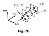
図2E。図2Bと同様にセンサ110、120、130が積み重ねられ、センサは、三角形配置で3つ1組としてのグループで存在し、各グループが、X-Z平面600-800内にあるPCB上に配設される。FIG. 2E. As in FIG. 2B,
PCBは、実質的に長手方向軸又はY軸700に沿って配設される。この例では、PCBは、プローブ長手方向軸150に沿って配置されている。各センサは、それ独自の小さなPCB(片側又は両側にセンサを有することがある)上にあり得る。各PCBは、XZ平面600-800内に配設される。言い換えると、センサ110、120、130は、3Dアレイとして提供される。この配置は、センサ110、120の充填密度をさらに増加させ、また磁場勾配を推測できるようにする。The PCBs are disposed substantially along the longitudinal or Y-
図2F。センサ110、120、130は3つの基板セクションに配設され、各基板セクションが長手方向軸又はY軸700に沿って延びる。3つの基板セクションは、それらの長手方向縁部によって相互に取り付けられ、X-Z平面内の横断面が三角形になるように配置された三角形の横方向600-800断面を有する中空基板配置を形成する。言い換えると、3Dアレイは、センサの1Dアレイを3つ使用して提供され、各1Dアレイは別個の基板セクションに配設され、センサの各1Dアレイは、プローブの長手方向軸700に実質的に平行に、長手方向軸700に沿って配設される。2F. The
この配置は、センサ110、120の充填密度を大幅に増加させ、また磁場勾配を推測できるようにする。この配置はまた、比較的円筒形のパッケージ内に多数のセンサを充填することを可能にし、「フロントセンサ」とマーカ(図示せず)との間の距離も短縮する。This arrangement significantly increases the packing density of the
実施形態2:3Dセンサアレイ及び磁場強度勾配
プローブ100のさらなる実施形態に関して、3Dセンサグリッド110、120を使用して、磁場強度の空間勾配を測定することができる(例えば、図2D又は図2Eに示されるレイアウト)。正方形/立方体のグリッドが可能である。Embodiment 2: 3D Sensor Array and Magnetic Field Strength Gradient With respect to a further embodiment of the
磁場強度は、距離の推定を与え、左側/右側(上側/下側に関しても同様)のセンサ間の距離及び磁場の相対強度は、方向の推定を与える。シードが左に向けて位置される場合、左側のセンサは右側のセンサよりも強い信号を感知する。この差は、横方向変位に関する(相対)尺度として使用することができる。左側/右側のセンサと上側/下側のセンサの差が最小限に抑えられている場合、棒は本質的にマーカの方を向いている。The magnetic field strength gives an estimate of the distance, and the distance and relative magnetic field strength between the left/right (and similarly for top/bottom) sensors gives an estimate of the direction. If the seed is positioned towards the left, the left sensor will sense a stronger signal than the right sensor. This difference can be used as a (relative) measure for the lateral displacement. If the difference between the left/right and top/bottom sensors is minimized, the rod is essentially pointing towards the marker.
図6は、センサからのL-R信号を横方向変位に変換するために使用することができる、差動測定対横方向変位特性の一例を示す。各センサ(L及びR)から、磁場の大きさが測定される。差動測定は、隣接するセンサでの磁場強度を比較することによって行われる。隣接するセンサは、例えば、左と右、前と後ろ、上と下である。差がゼロの場合、マーカ200は、センサ間の中間点の近くに配設される。差が正の場合、マーカは、より右側に配設される。差が負の場合、マーカは、より左側に配設される。Figure 6 shows an example of a differential measurement versus lateral displacement characteristic that can be used to convert the L-R signals from the sensors to lateral displacement. From each sensor (L and R), the magnitude of the magnetic field is measured. The differential measurement is made by comparing the magnetic field strength at adjacent sensors, e.g., left and right, front and back, top and bottom. If the difference is zero, the
X軸は、-3.0から+3.0まで、変位Xをセンチメートル(cm)で示す。Y軸は、-0.60から0.60まで、L-R信号を示す。長さ4mm及び直径2mmのNdFeBから作られた円筒形の磁気マーカ200を使用して、X=-2.0、-1.0、0、+1.0、及び+2.0の横方向配設でL-R信号を測定した。これらは、それらの変位値でドットとして示されている。これらの距離は、磁気マーカ200の寸法の5~20倍の範囲内にある。X=0で、磁気マーカ200は、プローブ長手方向軸150上に配設される。これらの値に基づいて、特性が当てはめられており、(-2.5,-0.52775)から(2.5,0.52775)までの直線である。言い換えれば、距離Xは、L-R=0.2111Xから計算することができる。この例では、線形の曲線あてはめの相関係数(R2)は0.9328である。The X-axis shows the displacement X in centimeters (cm) from -3.0 to +3.0. The Y-axis shows the L-R signal from -0.60 to 0.60. Using a cylindrical
ソフトウェア構成可能な検出区域を提供するさらなる利点は、異なる範囲、異なる形状、異なる角度境界、異なる長手方向範囲、異なる横方向範囲、及びそれらの任意の組合せで、2つ以上のマーカ検出区域を構成することができることである。これらの2つ以上のマーカ検出区域は、1つ又は複数の境界を共有することがあり、1つ又は複数の軸に沿って隣接することがあり、1つ又は複数の軸に沿って隣接しないことがあり、又はそれらの任意の組合せであり得る。An additional advantage of providing software configurable detection areas is that two or more marker detection areas can be configured with different extents, different shapes, different angular boundaries, different longitudinal extents, different lateral extents, and any combination thereof. These two or more marker detection areas may share one or more boundaries, may be adjacent along one or more axes, may be non-adjacent along one or more axes, or any combination thereof.
例えば、図8A及び図8Bは、複数の異なる範囲を有する検出区域の2つの例を示す。図示の視線及び示されているプローブ101は、図1Bに示されているプローブ100と同様である。For example, Figures 8A and 8B show two examples of detection zones having different ranges. The illustrated line of sight and the
図8Aは、プローブ長手方向軸150に沿って遠位端160から延びる第2のマーカ検出区域171c、171dを示す。YZ平面700-800に三角形断面で実質的に対称に示されているが、これは必須ではない。任意の断面形状を使用することができる。FIG. 8A shows second
第2のマーカ検出区域は、破線で示されるように2つ以上の角度境界171c、171dによって主に決定することができる。例えば、長手方向軸150に対して±22.5度である。言い換えると、45度のマーカ検出角度で、プローブ長手方向軸150に対して実質的に対称に配設される。The second marker detection zone may be primarily determined by two or more
追加として及び任意選択で、プローブ101の遠位端160の近位での2つ以上の角度境界171c、171d間の距離が事前決定及び/又は制御されることがあり、例えば18.5mmである。追加として及び任意選択で、第2のマーカ検出区域がプローブ101の遠位端160から長手方向軸150に沿って延びる範囲(湾曲した破線として示される)が事前決定又は制御されることがあり、例えば29mmである。Additionally and optionally, the distance between the two or more
図8Aは、第2のマーカ検出区域171c、171dの長手方向範囲から延び、プローブ101の遠位端160からさらに離れて延びる第3のマーカ検出区域172c、172dをさらに示す。FIG. 8A further shows a third
YZ平面700-800に円弧形断面で実質的に対称に示されているが、これは必須ではない。任意の断面形状を使用することができる。Although shown substantially symmetrical with an arc-shaped cross section in the YZ plane 700-800, this is not required. Any cross-sectional shape may be used.
第3のマーカ検出区域は、破線で示されるように2つ以上の角度境界172c、172dによって主に決定することができる。例えば、長手方向軸150に対して±30度である。言い換えると、60度のマーカ検出角度で、プローブ長手方向軸150に対して実質的に対称に配設される。The third marker detection zone may be primarily determined by two or more
追加として及び任意選択で、第2のマーカ検出区域171c、171dの長手方向範囲の近位での2つ以上の角度境界172c、172d間の距離は、例えば47mmである。追加として及び任意選択で、第3のマーカ検出区域172c、172dが、第2のマーカ検出区域171c、171dの長手方向範囲からさらに長手方向軸150に沿って延びる範囲(曲線の破線として示される)が事前決定又は制御されることがあり、例えば20mmである。Additionally and optionally, the distance between the two or more
図8Bは、プローブ長手方向軸150に沿って遠位端160から延びる第4のマーカ検出区域173c、173dを示す。YZ平面700-800に三角形断面で実質的に対称に示されているが、これは必須ではない。任意の断面形状を使用することができる。FIG. 8B shows fourth
第4のマーカ検出区域は、破線で示されるように2つ以上の角度境界173c、173dによって主に決定することができる。例えば、長手方向軸150に対して±10度である。言い換えると、20度のマーカ検出角度で、プローブ長手方向軸150に対して実質的に対称に配設される。The fourth marker detection zone may be primarily determined by two or more
追加として及び任意選択で、プローブ101の遠位端160の近位での2つ以上の角度境界173c、173d間の距離が事前決定及び/又は制御されることがあり、例えば5mmである。追加として及び任意選択で、第4のマーカ検出区域がプローブ101の遠位端160から長手方向軸150に沿って延びる範囲(湾曲した破線として示される)が事前決定又は制御されることがあり、例えば33mmである。Additionally and optionally, the distance between the two or more
図8Bは、第4のマーカ検出区域173c、173dの長手方向範囲から延び、プローブ101の遠位端160からさらに離れて延びる第5のマーカ検出区域174c、174dをさらに示す。FIG. 8B further shows a fifth
YZ平面700-800に円弧形断面で実質的に対称に示されているが、これは必須ではない。任意の断面形状を使用することができる。Although shown substantially symmetrical with an arc-shaped cross section in the YZ plane 700-800, this is not required. Any cross-sectional shape may be used.
第5のマーカ検出区域は、破線で示されるように2つ以上の角度境界174c、174dによって主に決定することができる。例えば、長手方向軸150に対して±30度である。言い換えると、60度のマーカ検出角度で、プローブ長手方向軸150に対して実質的に対称に配設される。The fifth marker detection zone may be primarily determined by two or more
追加として及び任意選択で、第4のマーカ検出区域173c、173dの長手方向範囲の近位での2つ以上の角度境界174c、174d間の距離は、例えば47mmである。追加として及び任意選択で、第5のマーカ検出区域174c、174dが第4のマーカ検出区域173c、173dの長手方向範囲から長手方向軸150に沿って延びる範囲(湾曲した破線として示される)が事前決定又は制御されることがあり、例えば20mmである。Additionally and optionally, the distance between the two or more
さらなるマーカ検出区域を、様々な程度の特別な重畳で構成及び配置することもできる。これらは、実質的に固定されていても、動的でも、又はそれらの任意の組合せでもよい。これは、粗い/細かいマーカ検出区域構成を提供することができる。例えば、プローブ101の遠位端160が磁気マーカ200に近づくにつれて(例えば30~40mm未満、又は約35mm未満)、精度、選択性、及び感度をさらに高めるために、より小さい角度を有するマーカ検出区域を自動的に選択することができる。Additional marker detection zones can also be configured and positioned with various degrees of special overlap. These can be substantially fixed, dynamic, or any combination thereof. This can provide a coarse/fine marker detection zone configuration. For example, as the
ソフトウェア構成可能な検出区域を提供する別の利点は、2つ以上のマーカ検出区域を定義することができ、角度配置180、190が
-第1のマーカ検出区域170abcd、171cd、172cd、173cd、174cdと実質的に一致するかどうか;
-第2のマーカ検出区域170abcd、171cd、172cd、173cd、174cdと実質的に一致するかどうか;
-第1及び第2の検出区域170abcd、171cd、172cd、173cd、174cdの両方と実質的に一致するかどうか;
-第1又は第2の検出区域170abcd、171cd、172cd、173cd、174cdのいずれとも一致しないかどうか;又は
-それらの任意の組合せ
を判断するようにプローブをさらに構成及び配置することができることである。 Another advantage of providing software configurable detection areas is that two or more marker detection areas can be defined, whether the
- whether it substantially coincides with the second marker detection areas 170abcd,171cd,172cd ,173cd , 174cd;
- whether it substantially coincides with both the first and second detection areas 170abcd,171cd,172cd ,173cd , 174cd;
- does not match any of the first or second detection areas 170abcd,171cd,172cd ,173cd , 174cd; or - any combination thereof.
例えば、範囲、形状、向き、配設、スケーリング、分解能、角度境界、長手方向範囲、横方向範囲、及びそれらの任意の組合せなど、1つ又は複数の検出区域に関連する1つ又は複数のパラメータ又は態様を変更することによって、ユーザに直感的な方法で探索パラメータを変更することが可能になる。Varying one or more parameters or aspects associated with one or more detection areas, such as range, shape, orientation, arrangement, scaling, resolution, angular boundaries, longitudinal range, lateral range, and any combination thereof, allows the search parameters to be altered in a manner that is intuitive to the user.
検出区域の1つ又は複数の構成可能な態様は、1つ又は複数のセンサからの1つ又は複数の測定値に基づいて、及び/又は1つ又は複数の適切なパラメータに基づいて、プローブによって自動的に決定することができる。追加として又は代替として、ユーザは、決定に影響を与えるために1つ又は複数のパラメータを提供することができる。One or more configurable aspects of the detection zone may be determined automatically by the probe based on one or more measurements from one or more sensors and/or based on one or more suitable parameters. Additionally or alternatively, a user may provide one or more parameters to influence the determination.
追加として又は代替として、決定はユーザが選択可能であり得る。個々の検出区域を使用することは特に直感的であり、それによりユーザはプローブの使用を変更することができる。例えば、「より遠くの」検出区域では、より大きく速い動きが促され、「より近くの」検出区域では、より小さく遅い動きが促されることがある。Additionally or alternatively, the decision may be user selectable. Using individual detection areas is particularly intuitive, allowing the user to vary the use of the probe. For example, a "further" detection area may encourage larger and faster movements, and a "closer" detection area may encourage smaller and slower movements.
追加として又は代替として、ユーザ選択は、治療又は療法に基づくことがある。追加として又は代替として、ユーザ選択は、侵襲的又は非侵襲的使用に基づくことがある。追加として又は代替として、ユーザ選択は、ハンドヘルド棒としての使用に基づくことがある。Additionally or alternatively, user selection may be based on treatment or therapy. Additionally or alternatively, user selection may be based on invasive or non-invasive use. Additionally or alternatively, user selection may be based on use as a handheld wand.
追加として又は代替として、ユーザは、例えば人体又は動物の体内でのマーカの予想される位置、予想される近接性、予想される磁場強度、及び予想されるマーカの向きに特に適した構成を選択することができる。1つ又は複数のマーカ検出区域は、マーカへの(ユーザによって)予想される近接性及び/又は向きに応じて、特定の構成を採用するように構成及び配置されることもある。これは、(プローブによって)測定及び/又は推定される近接性及び/又は向きに応じて、ある程度自動化されることもある。様々な程度での任意の組合せも可能である。Additionally or alternatively, the user may select a configuration that is particularly suited to the expected location of the marker, expected proximity, expected magnetic field strength, and expected orientation of the marker, for example within the human or animal body. One or more marker detection zones may be configured and arranged to adopt a particular configuration depending on the expected proximity and/or orientation (by the user) to the marker. This may also be automated to some extent depending on the measured and/or estimated proximity and/or orientation (by the probe). Any combination to various degrees is also possible.
追加として又は代替として、ユーザは、マーカの位置決定に特に効率的であると個人的に判断した構成を選択することもできる。Additionally or alternatively, the user may select a configuration that they personally determine to be particularly efficient for determining marker location.
1つ又は複数の検出区域を複数の寸法で構成することができるので、これらの形状及び断面形状の1つ又は複数を組み合わせることができる。単純な形状及び/又は複雑な形状を使用することができる。ソフトウェア構成可能な検出区域を提供するさらなる利点は、ユーザが2つ以上のマーカ検出区域を構成及び配置することができることである。これは、例えば、粗い/細かいマーカ検出区域構成を提供することができる。プローブの遠位端が磁気マーカに近づくにつれて、より小さい角度を有するマーカ検出区域が、精度及び感度をさらに高めることができる。One or more of these shapes and cross-sectional shapes can be combined since one or more detection areas can be configured in multiple dimensions. Simple and/or complex shapes can be used. A further advantage of providing software configurable detection areas is that the user can configure and position more than one marker detection area. This can provide, for example, a coarse/fine marker detection area configuration. As the distal end of the probe approaches the magnetic marker, a marker detection area with a smaller angle can further increase accuracy and sensitivity.
さらに、プローブは、プローブの向きの測定を提供するために追加のセンサを備えることがある。例えば、IMU(慣性測定ユニット)センサからのプローブのピッチ、ロール、及びヨー角、背景磁場センサからの背景磁場に対する向き、又は他の入力である。この向きは、磁気マーカ200の配設を決定するとき、及び/又は検出区域の構成可能な態様を決定するときにも考慮することができる。Additionally, the probe may include additional sensors to provide measurements of the probe's orientation, such as the pitch, roll, and yaw angles of the probe from an IMU (Inertial Measurement Unit) sensor, orientation relative to a background magnetic field from a background magnetic field sensor, or other input. This orientation may also be taken into account when determining the placement of the
位置情報を与える任意の他の入力も同様に使用することができる。例えば、光学式マウスで使用されるセンサと同様の光学式センサを使用して、皮膚の表面の接触点を決定することができる。Any other input that provides positional information can be used as well. For example, an optical sensor similar to that used in an optical mouse can be used to determine the contact points on the surface of the skin.
特定の例示的実施形態に関連して本発明を述べてきたが、添付の特許請求の範囲に記載されている本発明の精神及び範囲から逸脱することなく、開示された実施形態に対して、当業者に明らかな様々な変更、置換、及び代替を施すことができることを理解されたい。Although the present invention has been described with reference to certain exemplary embodiments, it should be understood that various modifications, substitutions, and alterations apparent to those skilled in the art may be made to the disclosed embodiments without departing from the spirit and scope of the invention as set forth in the appended claims.
特に有利な実施形態は、以下のように要約することができる。
A.埋め込み型マーカ(200)の角度配設(180、190)を決定するための磁場プローブ(100、101)であって、マーカ(200)が、使用時に磁場を生成するように構成され、プローブが、
遠位端(160)と、
遠位端(160)に近い第1の磁気センサ(110)と、
第1の磁気センサ(110)と近位端(165)との間に配設された第2の磁気センサ(120)とを備え、第1及び第2の磁気センサが、使用時に、マーカ(200)の1つ又は複数の磁場ベクトルを決定するように構成及び配置され、
プローブが、
プローブ長手方向軸(150)に沿って遠位端(160)から延びる1つ又は複数のマーカ検出区域(170abcd、171cd、172cd、173cd、174cd)を定義し、
1つ又は複数の磁場ベクトルを使用して、埋め込み型マーカ(200)に対する角度配設(180、190)を決定し、
角度配設(180、190)が1つ又は複数のマーカ検出区域(170abcd、171cd、172cd、173cd、174cd)と実質的に一致するかどうかを判断する
ようにさらに構成される、磁場プローブ(100、101)。 Particularly advantageous embodiments can be summarized as follows:
A. A magnetic field probe (100, 101) for determining the angular disposition (180, 190) of an implantable marker (200), the marker (200) being configured to generate a magnetic field in use, the probe comprising:
A distal end (160);
a first magnetic sensor (110) proximate the distal end (160);
a second magnetic sensor (120) disposed between the first magnetic sensor (110) and the proximal end (165), the first and second magnetic sensors constructed and arranged to determine, in use, one or more magnetic field vectors of the marker (200);
The probe is
defining one or more marker detection areas (170abcd, 171cd, 172cd, 173cd, 174cd) extending from the distal end (160) along the probe longitudinal axis (150);
determining an angular orientation (180, 190) relative to the implantable marker (200) using the one or more magnetic field vectors;
The magnetic field probe (100, 101), further configured to determine whether the angular arrangement (180, 190) substantially coincides with one or more marker detection areas (170abcd, 171cd, 172cd, 173cd, 174cd).
B.角度配設(180、190)が、
第1のマーカ検出区域(170abcd、171cd、172cd、173cd、174cd)と実質的に一致するかどうか、
第2のマーカ検出区域(170abcd、171cd、172cd、173cd、174cd)と実質的に一致するかどうか、
第1及び第2の両方のマーカ検出区域(170abcd、171cd、172cd、173cd、174cd)と実質的に一致するかどうか、
第1のマーカ検出区域又は第2のマーカ検出区域(170abcd、171cd、172cd、173cd、174cd)のいずれとも一致しないかどうか、又は
それらの任意の組合せ
を判断するようにさらに構成された、実施形態Aによるプローブ。B. The angular arrangement (180, 190) is
whether it substantially coincides with the first marker detection area (170abcd,171cd,172cd ,173cd , 174cd);
whether it substantially coincides with the second marker detection area (170abcd,171cd,172cd ,173cd , 174cd);
whether it substantially coincides with both the first and second marker detection areas (170abcd,171cd,172cd ,173cd , 174cd);
A probe according to embodiment A, further configured to determine whether the first marker detection zone does not match any of the first marker detection zones or the second marker detection zones (170abcd,171cd,172cd ,173cd , 174cd), or any combination thereof.
Q.埋め込み型マーカ(200)の角度配設を検出するための検出器ユニットであって、実施形態A~Bのいずれかに記載の磁気プローブ(100、101)を備える、検出器ユニット。Q. A detector unit for detecting the angular arrangement of an implantable marker (200), the detector unit comprising a magnetic probe (100, 101) according to any one of embodiments A to B.
R.埋め込み型マーカ(200)の角度配設(180、190)を決定するための方法であって、マーカ(200)が、使用時に磁場を生成するように構成され、方法が、
遠位端(160)を備えるプローブ(100、101)を提供し、プローブが、遠位端(160)に近い第1の磁気センサ(110)と、第1の磁気センサ(110)と近位端(165)との間に配設された第2の磁気センサ(120)とをさらに備え、第1及び第2の磁気センサが、使用時に、マーカ(200)の1つ又は複数の磁場ベクトルを決定するように構成及び配置されること、
プローブ長手方向軸(150)に沿って遠位端(160)から延びる1つ又は複数のマーカ検出区域(170abcd、171cd、172cd、173cd、174cd)を定義するようにプローブを構成及び配置すること、
1つ又は複数の磁場ベクトルを使用して、埋め込み型マーカ(200)に対する角度配設(180、190)を決定すること、並びに
角度配設(180、190)が1つ又は複数のマーカ検出区域(170abcd、171cd、172cd、173cd、174cd)と実質的に一致するかどうかを判断すること
を含む方法。R. A method for determining an angular disposition (180, 190) of an implantable marker (200), the marker (200) being configured to generate a magnetic field in use, the method comprising:
providing a probe (100, 101) comprising a distal end (160), the probe further comprising a first magnetic sensor (110) proximal to the distal end (160) and a second magnetic sensor (120) disposed between the first magnetic sensor (110) and the proximal end (165), the first and second magnetic sensors constructed and arranged to determine, in use, one or more magnetic field vectors of a marker (200);
constructing and arranging the probe to define one or more marker detection areas (170abcd, 171cd, 172cd, 173cd, 174cd) extending from a distal end (160) along a probe longitudinal axis (150);
A method comprising: determining an angular arrangement (180, 190) relative to an implantable marker (200) using one or more magnetic field vectors; and determining whether the angular arrangement (180, 190) substantially coincides with one or more marker detection areas (170abcd, 171cd, 172cd, 173cd, 174cd).
図面で使用される参照番号
100 磁場プローブの第1の実施形態
101 磁場プローブの第2の実施形態
110 第1のセンサ
120 第2のセンサ
130 第3のセンサ
150 プローブ長手方向軸
160 プローブの遠位端
165 プローブの近位端
170a、170b X-Y平面内のマーカ検出区域の範囲
170c、170d Y-Z平面内のマーカ検出区域の範囲
171c、171d Y-Z平面内の第2のマーカ検出区域の範囲
172c、172d Y-Z平面内の第3のマーカ検出区域の範囲
173c、173d Y-Z平面内の第4のマーカ検出区域の範囲
174c、174d Y-Z平面内の第5のマーカ検出区域の範囲
180 XY角度配設
190 YZ角度配設
191 第1の傾斜θ
192 第2の傾斜θ
193 第3の傾斜θ
194 第4の傾斜θ
195 第5の傾斜θ
196 第6の傾斜θ
200 埋め込み型磁気マーカ又は誘導磁気マーカ
300 皮膚の外面
401 第1の磁力線
402 第2の磁力線
403 第3の磁力線
404 第4の磁力線
500 傾斜関係
550 プローブの傾斜
575 プローブ面での磁場の傾斜
600 X軸
700 Y軸
800 Z軸
900 磁気マーカ軸
920 磁場
930 磁気ベクトル
950 横方向軸
970 検出位置Reference numbers used in the drawings: 100 first embodiment of
192 Second inclination θ
193 Third inclination θ
194 Fourth inclination θ
195 Fifth inclination θ
196 Sixth inclination θ
200 Implantable or inductive
Claims (14)
Translated fromJapanese遠位端(160)と、
前記プローブ(100、101)の前記遠位端(160)の第1の磁気センサ(110)と、
前記第1の磁気センサ(110)と前記プローブ(100、101)の近位端(165)との間に配設された第2の磁気センサ(120)とを備え、前記第1及び第2の磁気センサが、使用時に、前記磁気双極子の1つ又は複数の磁場ベクトルを決定するように構成及び配置され、
前記プローブ(100、101)が、
プローブ長手方向軸(150)に沿って前記遠位端(160)から延びる2つ以上のマーカ検出区域(170abcd、171cd、172cd、173cd、174cd)を定義し、
前記1つ又は複数の磁場ベクトルを使用して、前記磁気双極子に対する前記角度配設(180、190)を決定し、
前記磁気双極子に対する前記角度配設(180、190)が前記2つ以上のマーカ検出区域(170abcd、171cd、172cd、173cd、174cd)のうちの1つと一致する場合には、前記埋め込み型マーカ(200)が前記2つ以上のマーカ検出区域のうちの1つの中にあることを決定し、
前記磁気双極子に対する前記角度配設(180、190)が前記2つ以上のマーカ検出区域(170abcd、171cd、172cd、173cd、174cd)のうちの前記1つと一致しない場合には、前記1つ又は複数の磁場ベクトルを使用して前記角度配設を決定することを抑制する
ようにさらに構成される、磁場プローブ(100、101)。 A magnetic field probe (100, 101) for determining an angular disposition (180, 190) of an implantable marker (200), said marker comprising a magnetic dipole configured to generate a magnetic field in use, said probe (100, 101) comprising:
A distal end (160);
a first magnetic sensor (110) at the distal end (160) of the probe (100, 101);
a second magnetic sensor (120) disposed between the first magnetic sensor (110) and a proximal end (165) of the probe (100, 101), the first and second magnetic sensors being constructed and arranged to, in use, determine one or more magnetic field vectors of the magnetic dipole;
The probe (100, 101)
defining two or more marker detection zones (170abcd, 171cd, 172cd, 173cd, 174cd) extending from said distal end (160) along a probe longitudinal axis (150);
determining the angular arrangement (180, 190) relative to the magnetic dipole using the one or more magnetic field vectors;
determining that the implantable marker (200) is within one of the two or more marker detection zones (170abcd, 171cd, 172cd, 173cd, 174cd) if the angular arrangement (180, 190) relative to the magnetic dipole coincideswith one of the two or more marker detection zones (170abcd, 171cd, 172cd, 173cd, 174cd);
A magnetic field probe (100, 101) further configured to inhibit determining the angular arrangement using the one or more magnetic field vectors if the angular arrangement (180, 190) relative to the magneticdipole does not coincide with one of the two or moremarker detection areas (170abcd, 171cd, 172cd, 173cd, 174cd).
範囲、形状、向き、配設、スケーリング、分解能、角度境界、長手方向範囲、横方向範囲、又はそれらの任意の組合せ
からなる群から選択されるパラメータに関して異なる、請求項1~4のいずれか一項に記載のプローブ。 The two or more marker detection areas (171cd, 172cd, 173cd, 174cd)
The probes of any one of claims 1 to 4, differing with respect to a parameter selected from the group consisting of range, shape, orientation, arrangement, scaling, resolution, angular boundaries, longitudinal range, lateral range, or any combination thereof.
前記磁気双極子に対する前記角度配設(180、190)が3つ以上のマーカ検出区域(170abcd、171cd、172cd、173cd、174cd)のうちの1つと一致するかを判断し、それによって、前記マーカ(200)が、前記3つ以上のマーカ検出区域(170abcd、171cd、172cd、173cd、174cd)のうちの前記1つの中にあることを決定する
ようにさらに構成される、請求項1~5のいずれか一項に記載のプローブ。 defining further marker detection areas (170abcd, 171cd, 172cd, 173cd, 174cd) extending from said distal end (160) along the probe longitudinal axis (150);
The probe of any one of claims 1to 5, further configured to determine whether the angular arrangement (180, 190) relative to the magnetic dipolecoincides with one of three or more marker detection zones (170abcd, 171cd, 172cd, 173cd, 174cd), thereby determining that the marker (200) is within the one of the three or more marker detection zones (170abcd, 171cd, 172cd, 173cd, 174cd).
前記磁気双極子に対する前記角度配設(180、190)が、
(1)前記さらなるマーカ検出区域(170abcd、171cd、172cd、173cd、174cd)と一致するか、
(2)前記第1のマーカ検出区域及びさらなるマーカ検出区域(170abcd、171cd、172cd、173cd、174cd)の両方と一致するか、
(3)前記第2のマーカ検出区域及びさらなるマーカ検出区域(170abcd、171cd、172cd、173cd、174cd)の両方と一致するか、
(4)前記第1のマーカ検出区域又はさらなるマーカ検出区域(170abcd、171cd、172cd、173cd、174cd)のいずれとも一致しないか、
(5)前記第2のマーカ検出区域又はさらなるマーカ検出区域(170abcd、171cd、172cd、173cd、174cd)のいずれとも一致しないか、又は
(6)上記(1)~(5)の任意の組合せであるか、
を前記プローブが判断するようにさらに構成される、請求項1~6のいずれか一項に記載のプローブ。 the probe definesa first marker detection area, a second marker detection area, and further marker detection areas (170abcd, 171cd, 172cd, 173cd, 174cd) extending from the distal end (160) along a probe longitudinal axis (150);
The angular arrangement (180, 190)relative to the magnetic dipole is
(1) coincideswith the further marker detection area (170abcd,171cd,172cd ,173cd , 174cd);
(2) coincideswith both the first marker detection area and the additional marker detection area (170abcd,171cd,172cd ,173cd , 174cd); or
(3) coincideswith both the second marker detection area and the further marker detection area (170abcd,171cd,172cd ,173cd , 174cd); or
(4) does not match any of the first marker detection areas or any of the further marker detection areas (170abcd,171cd,172cd ,173cd , 174cd);
(5) does not match any of the second marker detection areas or any of the further marker detection areas (170abcd,171cd,172cd ,173cd , 174cd); or
(6)Any combination of the above (1) to (5),
The probe of any one of claims 1 to 6, whereinthe probe is further configured to determine:
前記プローブ(100、101)が、オーディオフィードバックを提供するようにさらに構成及び配置され、前記磁気双極子に対する前記角度配設(180、190)が前記第1又は第2のマーカ検出区域(170abcd、171cd、172cd、173cd、174cd)に一致するかに応じてオーディオ特性が異なる、請求項1~10のいずれか一項に記載のプローブ。the two or more marker detection zones (170abcd, 171cd, 172cd, 173cd, 174cd) include a first marker detection zone (170abcd, 171cd, 172cd, 173cd, 174cd) and a second marker detection zone (170abcd, 171cd, 172cd, 173cd, 174cd);
The probe (100, 101) of any one of claims 1 to 10, further constructed and arranged to provide audio feedback, the audio characteristics being different depending on whether the angular arrangement (180, 190) relativeto the magnetic dipole correspondsto the first or second marker detection area (170abcd,171cd,172cd ,173cd , 174cd).
前記磁気マーカ(200)が、使用時に磁場を生成するように構成された磁気双極子を備え、
前記方法が、
遠位端(160)を備えるプローブ(100、101)を提供し、前記プローブが、前記遠位端(160)の第1の磁気センサ(110)と、前記第1の磁気センサ(110)と前記プローブ(100、101)の近位端(165)との間に配設された第2の磁気センサ(120)とをさらに備え、前記第1及び第2の磁気センサが、使用時に、前記磁気双極子の1つ又は複数の磁場ベクトルを決定するように構成及び配置されること、
前記プローブが、プローブ長手方向軸(150)に沿って前記遠位端(160)から延びる2つ以上のマーカ検出区域(170abcd、171cd、172cd、173cd、174cd)を定義するように構成及び配置されること、
前記プローブが、前記1つ又は複数の磁場ベクトルを使用して、前記磁気双極子に対する前記角度配設(180、190)を決定すること、
前記プローブが、前記磁気双極子に対する前記角度配設(180、190)が前記2つ以上のマーカ検出区域(170abcd、171cd、172cd、173cd、174cd)のうちの1つと一致する場合には、前記磁気マーカ(200)が前記2つ以上のマーカ検出区域のうちの1つの中にあることを決定すること、並びに
前記プローブが、前記磁気双極子に対する前記角度配設(180、190)が前記2つ以上のマーカ検出区域(170abcd、171cd、172cd、173cd、174cd)のうちの前記1つと一致しない場合には、1つ又は複数の磁場ベクトルの決定を抑制すること、
を含む方法。A method for determining an angular orientation (180, 190) of amagnetic marker (200), comprising:
the magnetic marker (200) comprises a magnetic dipole configured to generate a magnetic field in use;
The method further comprising:
providing a probe (100, 101) comprising a distal end (160), said probe further comprising a first magnetic sensor (110) at said distal end (160) and a second magnetic sensor (120) disposed between said first magnetic sensor (110) and a proximal end (165) of said probe (100, 101), said first and second magnetic sensors constructed and arranged to determine, in use, one or more magnetic field vectors of said magnetic dipole;
said probeconstructed andarranged to define two or more marker detection zones (170abcd, 171cd, 172cd, 173cd, 174cd) extending from said distal end (160) along a probe longitudinal axis (150);
the probe determining the angular arrangement (180, 190) relative to the magnetic dipole using the one or more magnetic field vectors;
determining thatthe magnetic marker (200) is within one of the two or more marker detection zones (170abcd, 171cd, 172cd, 173cd, 174cd) if the angular arrangement (180, 190) relative to the magnetic dipolecoincides with one of the two or more marker detection zones (170abcd, 171cd, 172cd, 173cd, 174cd); and
suppressing the determination of one or more magnetic field vectors when the angular arrangement (180, 190) of the probe relative to the magnetic dipole does not coincide with the one of the two or more marker detection areas (170abcd, 171cd, 172cd, 173cd, 174cd);
The method includes:
Applications Claiming Priority (3)
| Application Number | Priority Date | Filing Date | Title |
|---|---|---|---|
| NL2024545ANL2024545B1 (en) | 2019-12-20 | 2019-12-20 | Magnetic field probe for determining an angular disposition of an implantable marker |
| NL2024545 | 2019-12-20 | ||
| PCT/IB2020/062259WO2021124300A1 (en) | 2019-12-20 | 2020-12-20 | Magnetic field probe for determining a disposition of an implantable marker using two or more detection zones |
Publications (3)
| Publication Number | Publication Date |
|---|---|
| JP2023507658A JP2023507658A (en) | 2023-02-24 |
| JPWO2021124300A5 JPWO2021124300A5 (en) | 2023-12-21 |
| JP7695939B2true JP7695939B2 (en) | 2025-06-19 |
Family
ID=69156479
Family Applications (1)
| Application Number | Title | Priority Date | Filing Date |
|---|---|---|---|
| JP2022538194AActiveJP7695939B2 (en) | 2019-12-20 | 2020-12-20 | Magnetic Field Probe for Determining Implantable Marker Placement Using Two or More Detection Zones - Patent application |
Country Status (7)
| Country | Link |
|---|---|
| US (1) | US11672615B2 (en) |
| EP (1) | EP4090280A1 (en) |
| JP (1) | JP7695939B2 (en) |
| CN (1) | CN115038403B (en) |
| CA (1) | CA3162504A1 (en) |
| NL (1) | NL2024545B1 (en) |
| WO (1) | WO2021124300A1 (en) |
Families Citing this family (5)
| Publication number | Priority date | Publication date | Assignee | Title |
|---|---|---|---|---|
| GB2582123B (en) | 2018-01-25 | 2021-04-28 | Endomagnetics Ltd | Systems and methods for detecting magnetic markers for surgical guidance |
| CN114403925A (en)* | 2022-01-21 | 2022-04-29 | 山东黄金职业病防治院 | Breast cancer ultrasonic detection system |
| WO2024042365A1 (en)* | 2022-08-23 | 2024-02-29 | Molli Surgical Inc. | Sensor optimization to identify location and orientation of anisotropic magnet field from a permanent magnet |
| NL2035534B1 (en) | 2023-08-03 | 2025-02-18 | Sirius Medical Systems B V | Magnetic field probe for determining a disposition to an implantable marker using additional detection zones |
| CN119147621B (en)* | 2024-11-14 | 2025-04-15 | 安测智能科技(洛阳)有限公司 | Steel wire rope defect detection method and device based on variable magnetic field array |
Citations (5)
| Publication number | Priority date | Publication date | Assignee | Title |
|---|---|---|---|---|
| JP2003526099A (en) | 2000-03-07 | 2003-09-02 | コミツサリア タ レネルジー アトミーク | Method and corresponding device for determining the position or orientation of an object using a magnetic field |
| US20160051164A1 (en) | 2014-08-24 | 2016-02-25 | Health Beacons, Inc. | Probe for determining magnetic marker locations |
| JP2019520128A (en) | 2016-06-01 | 2019-07-18 | ベクトン・ディキンソン・アンド・カンパニーBecton, Dickinson And Company | Invasive medical devices and systems including magnetic regions |
| JP2019146957A (en) | 2018-01-25 | 2019-09-05 | エンドマグネティクス リミテッド | Systems and methods for detecting magnetic markers for surgical guidance |
| JP2019535339A (en) | 2016-09-09 | 2019-12-12 | サニーブルック リサーチ インスティテュート | System and method for localization and imaging of magnetic potential lesions |
Family Cites Families (5)
| Publication number | Priority date | Publication date | Assignee | Title |
|---|---|---|---|---|
| US5558091A (en)* | 1993-10-06 | 1996-09-24 | Biosense, Inc. | Magnetic determination of position and orientation |
| US6129668A (en)* | 1997-05-08 | 2000-10-10 | Lucent Medical Systems, Inc. | System and method to determine the location and orientation of an indwelling medical device |
| US7561051B1 (en)* | 2005-04-20 | 2009-07-14 | Creare Inc. | Magnet locating apparatus and method of locating a magnet using such apparatus |
| CN107126182B (en)* | 2007-01-19 | 2020-06-16 | 桑尼布鲁克健康科学中心 | Scanning mechanism for imaging probe |
| NL2022093B1 (en) | 2018-11-29 | 2020-06-26 | Sirius Medical Systems B V | The present disclosure relates to a magnetic field probe for determining a disposition of an implantable magnetic marker, a detection unit comprising the probe and a method of detecting the disposition of an implantable magnetic marker. |
- 2019
- 2019-12-20NLNL2024545Apatent/NL2024545B1/enactive
- 2020
- 2020-12-20EPEP20845618.6Apatent/EP4090280A1/enactivePending
- 2020-12-20CNCN202080095128.4Apatent/CN115038403B/enactiveActive
- 2020-12-20CACA3162504Apatent/CA3162504A1/enactivePending
- 2020-12-20WOPCT/IB2020/062259patent/WO2021124300A1/ennot_activeCeased
- 2020-12-20JPJP2022538194Apatent/JP7695939B2/enactiveActive
- 2022
- 2022-06-15USUS17/841,212patent/US11672615B2/enactiveActive
Patent Citations (5)
| Publication number | Priority date | Publication date | Assignee | Title |
|---|---|---|---|---|
| JP2003526099A (en) | 2000-03-07 | 2003-09-02 | コミツサリア タ レネルジー アトミーク | Method and corresponding device for determining the position or orientation of an object using a magnetic field |
| US20160051164A1 (en) | 2014-08-24 | 2016-02-25 | Health Beacons, Inc. | Probe for determining magnetic marker locations |
| JP2019520128A (en) | 2016-06-01 | 2019-07-18 | ベクトン・ディキンソン・アンド・カンパニーBecton, Dickinson And Company | Invasive medical devices and systems including magnetic regions |
| JP2019535339A (en) | 2016-09-09 | 2019-12-12 | サニーブルック リサーチ インスティテュート | System and method for localization and imaging of magnetic potential lesions |
| JP2019146957A (en) | 2018-01-25 | 2019-09-05 | エンドマグネティクス リミテッド | Systems and methods for detecting magnetic markers for surgical guidance |
Also Published As
| Publication number | Publication date |
|---|---|
| CN115038403A (en) | 2022-09-09 |
| EP4090280A1 (en) | 2022-11-23 |
| CA3162504A1 (en) | 2021-06-24 |
| WO2021124300A1 (en) | 2021-06-24 |
| NL2024545B1 (en) | 2021-09-02 |
| US11672615B2 (en) | 2023-06-13 |
| JP2023507658A (en) | 2023-02-24 |
| CN115038403B (en) | 2025-05-16 |
| US20220323160A1 (en) | 2022-10-13 |
Similar Documents
| Publication | Publication Date | Title |
|---|---|---|
| JP7695939B2 (en) | Magnetic Field Probe for Determining Implantable Marker Placement Using Two or More Detection Zones - Patent application | |
| US11513168B2 (en) | Magnetic field probe for determining a disposition of an implantable magnetic marker | |
| EP3288449B1 (en) | Medical device position location systems, devices and/or methods | |
| EP1126787B1 (en) | Determining the location and orientation of an indwelling medical device | |
| EP1181891B1 (en) | A system for detecting a position of a magnet associated with an indwelling medical device | |
| US6129668A (en) | System and method to determine the location and orientation of an indwelling medical device | |
| US8249689B2 (en) | Coil arrangement for electromagnetic tracking method and system | |
| CA2505464C (en) | Catheter tracking with phase information | |
| JP2004215992A (en) | Detecting device for position and posture of medical insertion instrument into body cavity and detecting method thereof | |
| EP3448515B1 (en) | Navigation and local thermometry | |
| CN109922727B (en) | Systems and methods for magnetically occult lesion localization and imaging | |
| JP4458676B2 (en) | Device for estimating the location and orientation of an object during magnetic resonance imaging | |
| JP2020036897A (en) | Single axis sensor (SAS) with Hall sensor using external magnet | |
| HK40073466A (en) | Magnetic field probe for determining a disposition of an implantable marker using two or more detection zones | |
| NL2035534B1 (en) | Magnetic field probe for determining a disposition to an implantable marker using additional detection zones | |
| HK40049518A (en) | Magnetic field probe for determining a disposition of an implantable magnetic marker |
Legal Events
| Date | Code | Title | Description |
|---|---|---|---|
| A521 | Request for written amendment filed | Free format text:JAPANESE INTERMEDIATE CODE: A523 Effective date:20220826 | |
| A521 | Request for written amendment filed | Free format text:JAPANESE INTERMEDIATE CODE: A523 Effective date:20231213 | |
| A621 | Written request for application examination | Free format text:JAPANESE INTERMEDIATE CODE: A621 Effective date:20231213 | |
| A977 | Report on retrieval | Free format text:JAPANESE INTERMEDIATE CODE: A971007 Effective date:20240830 | |
| A131 | Notification of reasons for refusal | Free format text:JAPANESE INTERMEDIATE CODE: A131 Effective date:20240903 | |
| A601 | Written request for extension of time | Free format text:JAPANESE INTERMEDIATE CODE: A601 Effective date:20241121 | |
| A601 | Written request for extension of time | Free format text:JAPANESE INTERMEDIATE CODE: A601 Effective date:20250131 | |
| A521 | Request for written amendment filed | Free format text:JAPANESE INTERMEDIATE CODE: A523 Effective date:20250227 | |
| TRDD | Decision of grant or rejection written | ||
| A01 | Written decision to grant a patent or to grant a registration (utility model) | Free format text:JAPANESE INTERMEDIATE CODE: A01 Effective date:20250513 | |
| A61 | First payment of annual fees (during grant procedure) | Free format text:JAPANESE INTERMEDIATE CODE: A61 Effective date:20250609 | |
| R150 | Certificate of patent or registration of utility model | Ref document number:7695939 Country of ref document:JP Free format text:JAPANESE INTERMEDIATE CODE: R150 |