JP7693665B2 - A non-combustion heated aerosol generating device including means for authenticating an aerosol-generating article by internal irradiation thereof - Google Patents
A non-combustion heated aerosol generating device including means for authenticating an aerosol-generating article by internal irradiation thereofDownload PDFInfo
- Publication number
- JP7693665B2 JP7693665B2JP2022529726AJP2022529726AJP7693665B2JP 7693665 B2JP7693665 B2JP 7693665B2JP 2022529726 AJP2022529726 AJP 2022529726AJP 2022529726 AJP2022529726 AJP 2022529726AJP 7693665 B2JP7693665 B2JP 7693665B2
- Authority
- JP
- Japan
- Prior art keywords
- aerosol
- generating article
- light source
- article
- generating
- Prior art date
- Legal status (The legal status is an assumption and is not a legal conclusion. Google has not performed a legal analysis and makes no representation as to the accuracy of the status listed.)
- Active
Links
Images


Classifications
- A—HUMAN NECESSITIES
- A24—TOBACCO; CIGARS; CIGARETTES; SIMULATED SMOKING DEVICES; SMOKERS' REQUISITES
- A24F—SMOKERS' REQUISITES; MATCH BOXES; SIMULATED SMOKING DEVICES
- A24F40/00—Electrically operated smoking devices; Component parts thereof; Manufacture thereof; Maintenance or testing thereof; Charging means specially adapted therefor
- A24F40/60—Devices with integrated user interfaces
- A—HUMAN NECESSITIES
- A24—TOBACCO; CIGARS; CIGARETTES; SIMULATED SMOKING DEVICES; SMOKERS' REQUISITES
- A24F—SMOKERS' REQUISITES; MATCH BOXES; SIMULATED SMOKING DEVICES
- A24F40/00—Electrically operated smoking devices; Component parts thereof; Manufacture thereof; Maintenance or testing thereof; Charging means specially adapted therefor
- A24F40/50—Control or monitoring
- A24F40/53—Monitoring, e.g. fault detection
- A—HUMAN NECESSITIES
- A24—TOBACCO; CIGARS; CIGARETTES; SIMULATED SMOKING DEVICES; SMOKERS' REQUISITES
- A24D—CIGARS; CIGARETTES; TOBACCO SMOKE FILTERS; MOUTHPIECES FOR CIGARS OR CIGARETTES; MANUFACTURE OF TOBACCO SMOKE FILTERS OR MOUTHPIECES
- A24D1/00—Cigars; Cigarettes
- A24D1/02—Cigars; Cigarettes with special covers
- A—HUMAN NECESSITIES
- A24—TOBACCO; CIGARS; CIGARETTES; SIMULATED SMOKING DEVICES; SMOKERS' REQUISITES
- A24D—CIGARS; CIGARETTES; TOBACCO SMOKE FILTERS; MOUTHPIECES FOR CIGARS OR CIGARETTES; MANUFACTURE OF TOBACCO SMOKE FILTERS OR MOUTHPIECES
- A24D1/00—Cigars; Cigarettes
- A24D1/04—Cigars; Cigarettes with mouthpieces or filter-tips
- A—HUMAN NECESSITIES
- A24—TOBACCO; CIGARS; CIGARETTES; SIMULATED SMOKING DEVICES; SMOKERS' REQUISITES
- A24D—CIGARS; CIGARETTES; TOBACCO SMOKE FILTERS; MOUTHPIECES FOR CIGARS OR CIGARETTES; MANUFACTURE OF TOBACCO SMOKE FILTERS OR MOUTHPIECES
- A24D1/00—Cigars; Cigarettes
- A24D1/20—Cigarettes specially adapted for simulated smoking devices
- A—HUMAN NECESSITIES
- A24—TOBACCO; CIGARS; CIGARETTES; SIMULATED SMOKING DEVICES; SMOKERS' REQUISITES
- A24F—SMOKERS' REQUISITES; MATCH BOXES; SIMULATED SMOKING DEVICES
- A24F40/00—Electrically operated smoking devices; Component parts thereof; Manufacture thereof; Maintenance or testing thereof; Charging means specially adapted therefor
- A24F40/20—Devices using solid inhalable precursors
- A—HUMAN NECESSITIES
- A24—TOBACCO; CIGARS; CIGARETTES; SIMULATED SMOKING DEVICES; SMOKERS' REQUISITES
- A24F—SMOKERS' REQUISITES; MATCH BOXES; SIMULATED SMOKING DEVICES
- A24F40/00—Electrically operated smoking devices; Component parts thereof; Manufacture thereof; Maintenance or testing thereof; Charging means specially adapted therefor
- A24F40/50—Control or monitoring
- G—PHYSICS
- G01—MEASURING; TESTING
- G01N—INVESTIGATING OR ANALYSING MATERIALS BY DETERMINING THEIR CHEMICAL OR PHYSICAL PROPERTIES
- G01N21/00—Investigating or analysing materials by the use of optical means, i.e. using sub-millimetre waves, infrared, visible or ultraviolet light
- G01N21/17—Systems in which incident light is modified in accordance with the properties of the material investigated
- G01N21/25—Colour; Spectral properties, i.e. comparison of effect of material on the light at two or more different wavelengths or wavelength bands
- G01N21/31—Investigating relative effect of material at wavelengths characteristic of specific elements or molecules, e.g. atomic absorption spectrometry
- G—PHYSICS
- G02—OPTICS
- G02B—OPTICAL ELEMENTS, SYSTEMS OR APPARATUS
- G02B6/00—Light guides; Structural details of arrangements comprising light guides and other optical elements, e.g. couplings
- G02B6/24—Coupling light guides
- G02B6/42—Coupling light guides with opto-electronic elements
- G02B6/4298—Coupling light guides with opto-electronic elements coupling with non-coherent light sources and/or radiation detectors, e.g. lamps, incandescent bulbs, scintillation chambers
Landscapes
- Physics & Mathematics (AREA)
- Spectroscopy & Molecular Physics (AREA)
- Health & Medical Sciences (AREA)
- Life Sciences & Earth Sciences (AREA)
- Chemical & Material Sciences (AREA)
- Analytical Chemistry (AREA)
- Biochemistry (AREA)
- General Health & Medical Sciences (AREA)
- General Physics & Mathematics (AREA)
- Immunology (AREA)
- Pathology (AREA)
- Engineering & Computer Science (AREA)
- Human Computer Interaction (AREA)
- Inspection Of Paper Currency And Valuable Securities (AREA)
- Investigating Materials By The Use Of Optical Means Adapted For Particular Applications (AREA)
Description
Translated fromJapanese本発明は、エアロゾル発生物品及び装置の分野、特に非燃焼加熱式物品及び装置に関する。The present invention relates to the field of aerosol generating articles and devices, and in particular to non-combustion heating articles and devices.
電子タバコ及び気化器が近年人気を集めている。主に、次の2つのタイプ、即ちeリキッド又はゲルなどの液体気化基質を加熱することにより、吸入可能な蒸気又はエアロゾルを生成する液体気化器と、装置に挿入されたタバコを含有するエアロゾル発生消耗物品を加熱することでエアロゾルを発生させる非燃焼加熱式装置とがある。非燃焼加熱式システムは、香り付き液体由来のエアロゾルよりも本来のタバコの香り及び味を提供することを意図したものである。これらの作動原理は、エアロゾル形成物質(例えば、グリセリン又はプロピレングリコール)を含むタバコ葉などの材料を加熱することであり、このエアロゾル形成物質が加熱中に気化し、タバコ材料からニコチン及び香り成分を抽出する蒸気を作り出す。この物質は、従来の巻きタバコの通常の燃焼温度よりも低い200~400℃に加熱される。非燃焼加熱式装置は、典型的には、内部チャンバを含むハンドヘルド装置であり、この内部チャンバは、タバコロッド消耗品などの消耗物品と、吸入可能なエアロゾルを発生させるために消耗物品をチャンバに挿入すると、この消耗物品を内部的/又は外部的に加熱する加熱手段とを受け付けるように構成される。加熱手段は、装置に配置された充電式バッテリによって電力供給され、加熱手段及びバッテリのいずれも、センサ、回路類並びに多くの場合にIC及び/又はマイクロプロセッサを含む電子制御機構によって電子制御される。Electronic cigarettes and vaporizers have become popular in recent years. There are two main types: liquid vaporizers, which generate an inhalable vapor or aerosol by heating a liquid vaporization substrate such as e-liquid or gel, and non-combustion heating devices, which generate an aerosol by heating an aerosol-generating consumable article containing tobacco inserted into the device. Non-combustion heating systems are intended to provide a more authentic tobacco aroma and taste than aerosols derived from flavored liquids. Their working principle is to heat a material such as tobacco leaves that contains an aerosol-forming substance (e.g., glycerin or propylene glycol), which vaporizes during heating, creating a vapor that extracts nicotine and flavor components from the tobacco material. The substance is heated to 200-400°C, which is lower than the normal combustion temperature of a conventional cigarette. Non-combustion heating devices are typically handheld devices that include an internal chamber configured to receive a consumable item, such as a tobacco rod consumable, and a heating means that heats the consumable item internally and/or externally upon insertion of the consumable item into the chamber to generate an inhalable aerosol. The heating means is powered by a rechargeable battery disposed in the device, and both the heating means and the battery are electronically controlled by sensors, circuitry, and an electronic control mechanism that often includes an IC and/or a microprocessor.
所与のエアロゾル発生物品の所与の非燃焼加熱式装置との適合性及び/又はエアロゾル発生物品の真正性を確保するために、物品に関する情報を含む印(indicium)をその外側表面に配置して提供することがこれまで提案されてきており、その印は、相応に設計された読み取り手段を有する非燃焼加熱式装置内への挿入後に読取られるか、又は、例えばハンドヘルド端末若しくはスマートフォンといった別個のリーダを用いるなど、外部からの読み取りを通じて読取られることができる。場合によっては、上記印は、例えば理想的な温度範囲又は時間に応じた加熱のプロファイルなど、物品を適切に消費するために非燃焼加熱式装置に設定されるべきパラメータに関する情報も含み得る。To ensure the compatibility of a given aerosol-generating article with a given non-combustion heating device and/or the authenticity of the aerosol-generating article, it has been proposed to provide an indicium containing information about the article, arranged on its outer surface, which can be read after insertion into the non-combustion heating device with correspondingly designed reading means or through external reading, for example with a separate reader, such as a handheld terminal or a smartphone. In some cases, the indicium may also contain information about the parameters that should be set in the non-combustion heating device for proper consumption of the article, such as, for example, an ideal temperature range or a heating profile as a function of time.
既存の光学的に読取可能な印は、主に2D又は3Dタイプのバーコードなどの従来のコードに依拠する。他のタイプの印は、100μm未満のサイズ又はさらに1μm未満のサイズを有する個々の要素のアレイに収容される情報コードを含み、そのために補助なしで人間の目により細部を観察することは非常に困難である。個々の要素は、例えば、インク、穴、エンボス、空洞又は回折構造などの微細構造で形成され得る。Existing optically readable markings are mainly based on conventional codes such as barcodes of 2D or 3D type. Other types of markings include information codes contained in arrays of individual elements having a size of less than 100 μm or even less than 1 μm, which makes it very difficult for the unaided human eye to observe the details. The individual elements can be formed, for example, of inks, holes, embossments, cavities or microstructures such as diffractive structures.
光学的に読取可能な印のすべては、少なくとも印の一部分に向けられる光ビームの提供に適した光源の使用に依拠する。光ビームと印との相互作用は、少なくとも印の一部によって発せられる反射光ビーム及び/又は回折光ビームであり得る少なくとも1つの二次光ビームをもたらす。All optically readable markings rely on the use of a light source suitable for providing a light beam that is directed at at least a portion of the marking. The interaction of the light beam with the marking results in at least one secondary light beam, which may be a reflected light beam and/or a diffracted light beam, emitted by at least a portion of the marking.
既存の非燃焼加熱式装置は、光学部品、とりわけ検出器及び光源を内部に配置することが難しいコンパクトな装置である。エアロゾル発生消耗物品をエアロゾル発生装置に挿入する場合、光学リーダの他の光学部品に加えて照射光源を配置するために利用可能な空間は、それほど多くない。Existing non-combustion heating devices are compact devices in which it is difficult to place optical components, particularly detectors and light sources. When an aerosol-generating consumable is inserted into the aerosol-generating device, there is not much space available to place the illumination light source in addition to the other optical components of the optical reader.
加えて、LEDなどの単純な光源で照射することによって読取可能な印は、容易く模造される傾向がある。In addition, markings that are readable by illumination with a simple light source such as an LED tend to be easily counterfeited.
例えば、国際公開第2018/050701 A1号パンフレットに記載されているエアロゾル発生装置は、物品を受け付ける装置の空洞の周辺及び支持体の上に配置された光源を含む。国際公開第2018/050701 A1号パンフレットの光源は、周辺、したがって物品の外部から物品の包装材上に光を照射して、物品の包装材に組み込まれた発光材料を励起するように適合されている。For example, the aerosol generating device described in WO 2018/050701 A1 includes a light source arranged around the cavity of the device for receiving the article and on the support. The light source in WO 2018/050701 A1 is adapted to irradiate light from the periphery, and thus from outside the article, onto the packaging material of the article to excite a luminescent material incorporated in the packaging material of the article.
このため、装置内の限られた利用可能な空間に適合し、同時にエアロゾル発生物品に適用された印の光学的効果の模造をより困難なものにして、識別及び模造をしにくくする他の照射の解決策を見出すニーズが存在する。より具体的には、個々のエアロゾル発生物品を、当該物品と共に使用するために設計されたエアロゾル発生装置の外側では容易に識別することができないようにするというニーズが存在する。Therefore, there is a need to find other illumination solutions that fit into the limited available space within the device while at the same time making the optical effect of the indicia applied to the aerosol-generating article more difficult to imitate, making it more difficult to identify and counterfeit. More specifically, there is a need to make individual aerosol-generating articles less easily identifiable outside of the aerosol-generating device with which they are designed.
本発明の発明者らは、このような装置の空洞内に光学的な光源が延在するエアロゾル発生装置を提供するという、上で議論した問題に対する解決策を見出した。The inventors of the present invention have found a solution to the problems discussed above by providing an aerosol generating device in which an optical light source extends within the cavity of such device.
第1の態様では、本発明は、外側本体部に配置される、電源部及び空洞を備えるエアロゾル発生装置に関する。その空洞は、外側本体部においてアクセス可能な開口を有し、エアロゾル発生物品の消費可能なセグメントの少なくとも当該空洞内への挿入時に当該物品を受け付けるように構成される。エアロゾル発生装置は、上記空洞内で、上記開口の反対側の端部から延在する光学的な光源をさらに備え、それにより、上記空洞へエアロゾル発生物品が挿入されると、上記光源は当該物品の上記消費可能な部分に貫入する。エアロゾル発生装置は、光学リーダシステムをさらに備える。In a first aspect, the present invention relates to an aerosol generating device comprising a power supply and a cavity disposed in an outer body portion. The cavity has an accessible opening in the outer body portion and is configured to receive at least a consumable segment of an aerosol generating article upon insertion of the article into the cavity. The aerosol generating device further comprises an optical light source extending within the cavity from an opposite end of the opening, such that the light source penetrates the consumable portion of the aerosol generating article upon insertion of the article into the cavity. The aerosol generating device further comprises an optical reader system.
エアロゾル発生装置の空洞内に延在する光源を使用して、当該光源が、空洞へのエアロゾル発生物品の挿入時に上記消費可能な部分に貫入するようにすることで、エアロゾル発生物品の外部に光源を置くことを要しない形で物品に印を設けることができ、そうした印の設計の高度な柔軟性がもたらされる。さらに、そうした印を認識し及び模造することは困難である。By using a light source that extends into the cavity of the aerosol generating device, such that the light source penetrates the consumable portion upon insertion of the aerosol generating article into the cavity, indicia can be provided on the article without requiring a light source to be external to the aerosol generating article, providing a high degree of flexibility in the design of such indicia. Furthermore, such indicia are difficult to recognize and counterfeit.
一実施形態では、上記光源は、導波路を含む。導波路を使用すると、光源をエアロゾル発生物品から離隔させて配置することが可能になり、それにより、一方では消耗製品の内部に電気部品が導入されないようにし、他方では光源の電気部品がエアロゾル発生装置の利用可能な空間、特に空洞の外部に配置されるように設計の柔軟性がもたらされる。In one embodiment, the light source includes a waveguide. The use of a waveguide allows the light source to be located at a distance from the aerosol generating article, which on the one hand avoids the introduction of electrical components inside the consumable product, and on the other hand provides design flexibility so that the electrical components of the light source are located outside the available space, especially the cavity, of the aerosol generating device.
一実施形態では、上記光源は、散光器、V字形照射チップ(tip)、球状照射チップ、金属反射器チップ、円錐形状チップのうちの1つである照射先端部を含む。照射チップの形状が異なれば、エアロゾル発生製品の外側表面に配置された印を照らす照射光ビームの提供可能な特性も異なる。チップによって提供される照射光ビームは、集束光ビーム若しくは拡散光ビームであり得るか、又は発散光ビームであり得るか、又は複数の異なる形状の光ビームで構成される光ビームであり得る。In one embodiment, the light source includes an illumination tip that is one of a diffuser, a V-shaped illumination tip, a spherical illumination tip, a metal reflector tip, and a cone-shaped tip. Different shapes of illumination tips can provide different characteristics of an illumination light beam that illuminates an indicia disposed on the exterior surface of the aerosol-generating product. The illumination light beam provided by the tip can be a focused or diverging light beam, a diverging light beam, or a light beam made up of multiple differently shaped light beams.
一実施形態では、上記照射先端部は、電気的にアドレス指定可能な光源、好ましくはLED光源を含む。LEDなどの光源をエアロゾル発生物品の内部に直接配置すると、電気的にアドレス指定可能な光源以外の追加の光学部品を必要としないため、実現が容易な機構を提供することが可能になる。In one embodiment, the illumination tip includes an electrically addressable light source, preferably an LED light source. Placing a light source, such as an LED, directly inside the aerosol-generating article can provide a mechanism that is easy to implement since no additional optical components are required other than the electrically addressable light source.
一実施形態では、上記光源は、集光導波路を含む。上記光源に近接して集光導波路を使用すると、光源に接近して、例えば上記照射先端部に接近して位置するエアロゾル発生物質についての情報を収集することが可能になる。In one embodiment, the light source includes a collection waveguide. The use of a collection waveguide in proximity to the light source allows for the collection of information about aerosol generating material located close to the light source, for example, close to the illumination tip.
第2の態様では、本発明は、ある分量のエアロゾル発生材料を含む消費可能セグメントを含むエアロゾル発生物品に関し、好ましくはそれらは包装材内に配置される。消費可能セグメントの第1端には吸い口セグメントが取り付けられ得る。エアロゾル発生物品が吸い口セグメントを含む場合、消費可能セグメント及び吸い口セグメントのいずれも、必ずしもそうではないものの、共通の長手方向軸に沿って延在し得る。エアロゾル発生物品は、少なくとも物品の一部分であって、200nmと25μmとの間のある波長を有する光を少なくとも部分的に透過させる一部分に配置された少なくとも1つの印を含む。In a second aspect, the present invention relates to an aerosol-generating article that includes a consumable segment that includes a quantity of aerosol-generating material, preferably disposed within a packaging material. A mouthpiece segment may be attached to a first end of the consumable segment. When the aerosol-generating article includes a mouthpiece segment, both the consumable segment and the mouthpiece segment may, but do not necessarily, extend along a common longitudinal axis. The aerosol-generating article includes at least one indicia disposed on at least a portion of the article that is at least partially transparent to light having a wavelength between 200 nm and 25 μm.
一実施形態では、印を含む上記物品の一部分は、少なくとも2つの別個の透過帯域を含み、当該透過帯域の各々は200nm(UV)と25μm(赤外線)との間のある波長を中心とする。In one embodiment, the portion of the article containing the indicia includes at least two distinct transmission bands, each of which is centered at a wavelength between 200 nm (UV) and 25 μm (infrared).
一実施形態では、上記印は、上記一部分の外周の少なくとも25%、好ましくは少なくとも50%にわたって延在する。物品の外周の重要な部分に沿って延在する印は、光学リーダ機構による印の感知をエアロゾル発生装置内の物品の特定の向きにあまり依存しないか又はさらにまったく依存しないようにする解決策を提供する。In one embodiment, the indicia extends over at least 25%, preferably at least 50%, of the circumference of the portion. Indicia extending along a significant portion of the circumference of the article provides a solution that makes sensing of the indicia by the optical reader mechanism less or even completely dependent on the particular orientation of the article within the aerosol generating device.
一実施形態では、上記印は、上記包装材の内部又は上に配置される構造体によって構成される少なくとも1つのコードを含む。In one embodiment, the indicia includes at least one code formed by a structure disposed within or on the packaging material.
有利な一実施形態では、上記コードは、上記包装材におけるアパーチャを含む。コードの要素としてアパーチャを使用すると、検出される光の強度及び/又は光学リーダシステムによって提供されるコードの画像のコントラストも向上する。In an advantageous embodiment, the code includes an aperture in the packaging material. The use of an aperture as an element of the code also improves the intensity of the light detected and/or the contrast of the image of the code provided by the optical reader system.
一実施形態では、上記コードは、上記包装材の内部又は上に配置されるメサ(mesas)を含む。変形例において、上記メサは、光学的に不透明な材料、好ましくは金属又はインクで作られる。ドットなどのメサを堆積すると、生産プロセスにおいて実装が容易な解決策を提供することが可能になる。In one embodiment, the code includes mesas arranged in or on the packaging material. In a variant, the mesas are made of an optically opaque material, preferably metal or ink. Depositing the mesas as dots makes it possible to provide a solution that is easy to implement in the production process.
一実施形態では、上記印は、複数の光学構造体のアレイを含み、そのうちの少なくとも2つの構造体は、異なる透過特性を有する。印に2つ以上の光学構造体を使用すると、印を複雑化することが可能になり、印の読み取りがより複雑になることでコードの模造がより困難になる。In one embodiment, the indicium includes an array of optical structures, at least two of which have different transmission characteristics. Using more than one optical structure in the indicium allows for a more complex indicium, making the indicium more difficult to read and therefore more difficult to counterfeit.
一実施形態では、上記光学構造体のアレイは、異なる透過特性を有する複数の帯状構造体である。異なる透過特性を有する帯状構造体に沿って光学コードを配置することは、オンライン生産プロセスによく適合する。 In one embodiment, the array of optical structures isa plurality of strips having different transmission characteristics. Arranging the optical code alongstrips having different transmission characteristics is well suited for on-line production processes.
一実施形態では、上記複数の帯状構造体のうちの少なくとも1つは、正弦波形を有し、及び/又は、上記複数の帯状構造体のうちの少なくとも1つは、線状ストリップのアレイを含む。光学コードを含む所定の形状の帯状構造体を提供することにより、読み取りをより複雑にすることが可能になり、それによりコードの模造がより困難になる。 In one embodiment, at least one of the plurality ofbands has a sinusoidal waveform and/or at least one of the plurality ofbands comprises an array of linear strips. Providinga band of a predetermined shape that includes an optical code allows for greater complexity in reading, thereby making the code more difficult to counterfeit.
第3の態様では、本発明は、先に説明したようなエアロゾル発生装置とエアロゾル発生物品とを含むエアロゾル発生システムにさらに関する。In a third aspect, the present invention further relates to an aerosol generating system comprising an aerosol generating device as described above and an aerosol generating article.
エアロゾル発生システムの一実施形態では、光源の照射先端部は、エアロゾル発生物品内に延在し、上記物品が空洞の端部まで上記空洞内に挿入された際に、長手方向でその認証部の水準に合うように配置される。In one embodiment of the aerosol generating system, the illuminating tip of the light source extends into the aerosol generating article and is positioned so that it is aligned longitudinally with the authentication portion when the article is inserted into the cavity up to the end of the cavity.
本発明を、特定の実施形態に関して、添付図面を参照しながら説明するが、本発明は、それに限定されない。説明する図面は、概略的なものにすぎず、非限定的である。図面において、いくつかの要素のサイズは、例示目的のために誇張され、縮尺通りに描かれていない場合がある。The present invention will now be described with respect to particular embodiments and with reference to the accompanying drawings, in which the invention is not limited thereto. The drawings described are only schematic and are non-limiting. In the drawings, the size of some of the elements may be exaggerated and not drawn to scale for illustrative purposes.
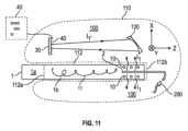
図11は、本発明によるエアロゾル発生システムのためのエアロゾル発生装置100を表す。このエアロゾル発生装置100は、外側本体部110を含み、電源部及び空洞112がそこに配置される。先に説明したようなエアロゾル発生物品1の挿入のZ軸を画定する空洞112は、外側本体部110でアクセス可能な開口112aを有する。エアロゾル発生装置100は、開口112aの反対側のその端部112bから当該空洞112内に延在する光学的な光源2をさらに含み、それにより、当該空洞112へのその挿入時、当該光源2は、エアロゾル発生物品1の消費可能な部分1bに貫入する。11 depicts an
図1~図3に図示される変形例において、光源2は、挿入されるエアロゾル発生物品1の対称軸に対して中心に配置されてもよく、又は中心から外れて配置されてもよい。In the variations illustrated in Figures 1 to 3, the
本発明では、光源2は、エアロゾル発生装置100の一部であり、且つ当該エアロゾル発生装置100に挿入されたエアロゾル発生消耗物品1の内部から少なくとも1つの光ビームを提供するように配置される光学系として定義される。In the present invention, the
図11で明らかなように、エアロゾル発生装置100は、外側本体部110に配置され、且つエアロゾル発生物品の内部、好ましくはエアロゾル発生物品1の消費可能セグメント1bの内部からの照射時に少なくとも1つの印10、10'を読み取るように構成された光学リーダシステムをさらに含む。エアロゾル発生装置100は、少なくとも光源2及び光学リーダシステムからの照射を制御し、命令して、当該印10の読み取りに応じて物品を認証するように構成された制御ユニット(図面には示されていない)をさらに含む。As can be seen in FIG. 11, the
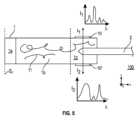
エアロゾル発生装置1の光源2は、好ましくは、エアロゾル発生物質11の内部に照射光ビームI1を提供する、実質的に剛性で鋭い光導波路を含む。光導波路は、図1~図5に図示されるような少なくとも2つの光ビームI1、I2を提供するように構成され得る。その目的のため、図1、図2、図5及び図6~図10の変形例に図示されるように、光導波路の照射先端部2'は、様々な光放射作用を提供する様々な形状を有してよい。そうした実施形態において、照射先端部2'は、散光器、V字形照射チップ、球状照射チップ、金属反射器チップ、円錐形状チップのうちの1つであり得る。代わりに、2つの照射光ビームI1、I2が、図3に示したような二股に分かれた導波路2の2つの照射ヘッドにより、又は図4に表したようなエアロゾル発生物品の消費可能セグメント1bに挿入された2つの別個の導波路2a、2bにより発せられてもよい。The
図5に図示される変形例では、光源2は、エアロゾル発生物品1の内部から、2つの異なる印10、10'であって、それぞれの印10、10'が異なる放射光スペクトル(I1-λ、I2-λ)を検出器(図示されていない)に提供する印10、10'を照射し得る2つの異なる光ビームI1、I2を提供するように構成され得る。In the variation illustrated in FIG. 5, the
図6は、動作時に、横方向の光ビームI1、I2を所定の方向に投影する形状に形成された2つの楔状部を含む先端部2'を図示する。光導波路2は、好ましくは、環状の断面或いは正方形若しくは矩形又はZ軸に直角に画定された任意の他のX-Y断面を有することができるマルチモード光導波路である。Figure 6 illustrates the
図7は、動作時に、光ビームI1、I2を様々な方向に提供し、先端部2'を取り囲むすべての方向に照射を提供し得る球状の先端部2'を図示する。Figure 7 illustrates a
図8は、円錐形状に形成された端部26と、光出力結合素子又は構造体24とを含む先端部2'を図示する。円錐形状に形成された端部は、例えば、より少ない力で光素子20をコンパクトなエアロゾル物質11中に導入するための機械的な機能を有するのみであってよい。Figure 8 illustrates a
図9は、その端部に楔形の反射器が配置された先端部2'の変形例を図示する。Figure 9 illustrates a modified
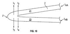
図10は、2つの導光部分21、23であって、それぞれの部分21、23が光ビームIinA、IinBを導く導光部分21、23を有する光導波路2の一変形例を図示する。このような変形例は、例えば、先端部2'に2つ以上の異なる光ビーム、例えば2つの異なる偏光ビーム又は異なるスペクトル分布を有する光ビームを提供するために使用され得る。先端部2'は、少なくとも4つの異なる光ビームI1~I4をエアロゾル発生物品の内部に提供するような形状に形成され得る。変形例では、光導波路2は、出力結合器として定義された横方向の出力結合構造を含み得る。実施形態では、照射導波路20の少なくとも一方の側に複数の出力結合器を配置し得る。 10 illustrates a variation of the
一実施形態では、当該照射先端部2'は、電気的にアドレス指定可能(electrically addressable)な光源、好ましくはLED光源である。In one embodiment, the
エアロゾル発生装置100は、当該光源2によってエアロゾル発生物品1の内部から照らされる印10によって提供される光を投影するように適合された光学投影システムを含む光学拡大リーダシステムをさらに含み得る。投影光I1'は、例えば、凹面鏡120によって仮想画像平面40上に集束され得る。図11は、当該仮想画像平面40に映されたドットパターンを図示する。拡大リーダシステムによって提供される拡大の係数は、2倍を超えてもよく、好ましくは10倍を超えてもよい。変形例において、光学リーダは、印10よりも小さい投影画像を提供する画像サイズ縮小システムであってもよい。好ましくは、光学リーダは、印10、10'に接触するか若しくは近接して配置されるか、又は図11に示されているようにそれから遠隔に配置された検出器30を含む。図11の実現化の例では、光源200、好ましくはLEDは、光ファイバ2の入力結合面に配置される。当該LED光源は、パルスLEDであり得る。エアロゾル物品から放射される光の強度I1が非常に低い変形例では、当該光源200と当該検出器30とを接続するロックイン検出手段が当該エアロゾル発生装置100に設けられ得る。変形例において、図示されていないが、エアロゾル発生物品1は、2つの異なる印10、10'を含んでいてもよく、各印10、10'は、おそらく異なる第2の光学拡大システムと関連付けられ得る。The
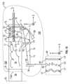
図11の構成の一変形例を示す図12に図示されるように、印10は、複数のコード、ここでは少なくとも3つの異なるコード11、13、15を含むことができ、それらは、エアロゾル発生装置100の空洞112に挿入され、エアロゾル発生物品1の消費可能セグメント1bの端部セグメント1cにおいて照射光源2が貫入すると、エアロゾル発生物品1の内部から照らされる。各コード11、13、15の照射は、エアロゾル発生物品1に挿入された、光ビームIinを導く光導波路2の3つの異なる出力結合部210、220、230の1つによって提供することができる。光ビームI1は物品1のセグメント1cからその外側表面を通って発し、反射光に焦点を当てた鏡120に印10が作用し、恐らくは光学フィルタF1、F2、F3を通って、仮想画像平面40上に集束する。集束した光ビームI1'は、検出器30の検出面に位置する画像平面40内に印10のコード11、13、15からなる画像41~43を形成する。当該画像41~43の形状及び強度は、例えば、検出器のアレイによって検出されるか、又は画像は、画像解析手段を含み得る検出器(イメージャ)30によって映される。図11の例では、印10の各コード11、13、15は、波長記号λ1、λ2、λ3によって図示される、異なる狭帯域又は広帯域スペクトル成分を有する3つの異なる画像41~43を提供するように構成される。 As illustrated in Fig. 12, which shows a variation of the configuration of Fig. 11, the
図13は、本発明によるエアロゾル発生システムの有利な一変形例の概略図を示し、図では、エアロゾル発生装置100の照射システムは、このシステム用に設計された物品1のエアロゾル発生消費可能セグメント1bの自由端部で開口1dに挿入するために配置された光源2を含む。したがって、照射光源2を、物品1と接触することなく、この物品に挿入することができる。図13の実施形態における光源2は、Z=Z2と、エアロゾル発生物品1の先端部の位置であるZ=Z4との間に位置決めされた印10の中心にある位置Z=Z3に位置する。Figure 13 shows a schematic diagram of an advantageous variant of an aerosol generating system according to the invention, in which the irradiation system of the
図14は、エアロゾル発生物品1に挿入された照射光源2を含み、それにより、光放射部分が物品1のエアロゾル発生物質11の外部に位置するエアロゾル発生装置100のさらなる実施形態を示す。図14の実施形態は、エアロゾル発生物質11を含むセグメント1bが入射光ビームI1を透過させないときに有用であり得る。その場合、光エミッタの先端部2'は、少なくとも部分的な放射光ビームI1の透過性を有する物品1の区域に押し進めることができる。例えば、図14の例では、光放射チップ2'は、光学的に不透明なエアロゾル発生物質を通じて押し進められ、少なくとも部分的に光を透過させる緩衝材又はフィルタ部1dに配置された印10を下方から照らす。少なくとも部分的に光を透過させる緩衝材又はフィルタ部1dが、例えば、少なくとも紙シートによって構成されてもよい。14 shows a further embodiment of an
実施の変形例において、エアロゾル発生システムは、光源2の照射先端部2'がエアロゾル発生物品1内に延在し、及び当該物品が、空洞112の端部112bまで当該空洞112に挿入されたとき、長手方向でその認証部10の水準に合うように配置されるように構成されてもよい。図14に図示される変形例では、照射先端部2'は、少なくとも印10の一部分に面し、それにより、少なくとも1つの横方向の断面は、当該印10及び当該先端部2'と交差する。In a variation of the implementation, the aerosol generating system may be configured such that the emitting
他の変形例において、当該先端部2'によって放射される光ビームが、空洞の長手方向軸に対して90°とは異なる放射角度αによって放射されることで、横方向の断面が、当該先端部2'と同様に、当該印10とも交差しないようになされてもよい。変形例において、放射光ビームの中心軸は、10°~89°、好ましくは30°~70°、さらにより好ましくは45°~60°の角度αを有することができる。放射角度を小さくすることにより、当該照射先端部2'から空洞軸の方向に画定される長手方向の距離b=a/tan(α)である距離bにある印10を物品1の内部から照射することが可能になり、ここで、aは、包装材表面までの先端部2'の半径方向の距離であり、この半径方向の距離aは、空洞軸と直交するものとして定義される。In another variant, the light beam emitted by the
他の変形例では、光源2は、任意の湾曲した形状を有することができ、少なくともその先端部2'は、空洞112の長手方向軸に対する法線に対して-90°~+90°の任意の角度下で物品1の内部から物品1の外側表面を照らすことができる。In other variations, the
一実施形態において、光源2は、装置の操作の間、印を少なくとも2度照らすことを提供するために、物品1の内部で少なくとも2回引っ込んで、再挿入し得るように構成されてもよく、それにより印10の照射及び検出の信頼性の向上を可能にし得る。In one embodiment, the
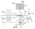
図15は、さらなる実施形態を示しており、エアロゾル発生物品1に部分的に挿入された照射システム2が含まれ、それにより2つの対向する印10-12及び14が光ビームI1、I2によって照らされる。図15は、2つの印10、12の変形例も図示しており、これらの印は、包装材の対向する両側に近接して配置され、それぞれの印による光ビームによって提供される光学情報1000、1200の重ね合せを含む放射光ビームI1'を提供する。図15に図示される画像平面40は、当該2つの接近している印10、12からの2つの異なるパターンの重ね合せの一例を描いている。Figure 15 shows a further embodiment, including an
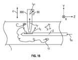
図16は、エアロゾル発生物品1に挿入された照射システム2と、物品1のエアロゾル発生物質11に部分的に挿入され、照射システム2の放射部に近接した光検出システム300、30とを含むエアロゾル発生装置100の一実施形態を示す。図16の実施形態は、エアロゾル発生物質が照射光ビームI1をあまり透過させない場合に有用であり得る。変位長さdで横方向の集光器300を光放射先端部2'の近傍に挿入することにより、エアロゾル発生物質11の光学特性に関する情報を収集することができる。一変形例では、図示されていないが、光放射素子2が集光素子を含んでもよく、集光素子は、別の光導波路と同じものであってもよく、光チップ2'の近傍において、光放射チップ2'の近隣にあるエアロゾル発生物質の光学特性についての情報を提供する後方散光を集めるように構成される。16 shows an embodiment of an
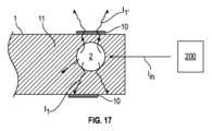
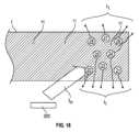
図17に図示される有利な一実施形態において、エアロゾル発生装置100は、その光源への機械的接続又は電気的接続を必要とすることなく、エアロゾル発生物品1に埋め込まれている光発生源2をトリガする手段を含む。図17は、外部光源200が、光を散乱するか、又は入射光を別の波長を有する放射光に変換する物質に光Iinを提供する一例を描いている。図18は、エアロゾル発生物質が複数の光再放射成分又は化合物21~28を含む、図17の実施形態の一変形例を描いている。 In an advantageous embodiment illustrated in Figure 17, the
図19は、エアロゾル発生物品1に導入されるように構成された光導波路2の別の有利な実施形態を示す。光導波路2は、光ビームIinを導くための光放射導波路2aを含み、且つ光放射先端部2'を含む。光導波路2に対して、第2の導波路2bが配置されて、後方散乱光I1'を収集し及び方向付けして、エアロゾル発生物品1の外部に位置する検出器システムに出力光ビームIoutを提供する。 19 shows another advantageous embodiment of an
Claims (20)
Translated fromJapanese前記エアロゾル発生装置(100)は、
前記開口(112a)を通じて前記空洞に挿入された前記エアロゾル発生物品(1)の少なくとも一部を照らすように配置された光学的な光源と、前記光源による照射後に前記エアロゾル発生物品から出る光を検出することにより前記少なくとも1つの印を読み取るように配置された光学リーダシステムと、をさらに備え、
前記光源は、前記空洞(112)内で、前記開口(112a)の反対側の端部から延在し、前記空洞(112)への挿入時に、前記エアロゾル発生物品(1)の少なくとも一部に貫入して、前記エアロゾル発生物品(1)の内部から前記エアロゾル発生物品(1)の前記少なくとも一部を照らす、エアロゾル発生装置(100)。 An aerosol generating device (100), comprising: a power supply portion and a cavity (112) disposed in an outer body portion (110), the cavity (112) having an accessible opening (112a) in the outer body portion and configured to receive an aerosol generating article (1)including at least one indicia ;
The aerosol generating device (100) comprises:
an optical light source arranged to illuminate at least a portion of the aerosol-generating article (1) inserted into the cavity through the opening (112a); and an optical reader system arranged toread the at least one indicia by detecting light emerging from the aerosol-generating article after illumination by the light source,
The light source extends from an end opposite the opening (112a) within the cavity (112) and penetrates at least a portion of the aerosol-generating article (1) when inserted into the cavity (112) to illuminate at least a portion of the aerosol-generating article (1) from inside the aerosol-generating article (1).
少なくとも1つの印(10、10'、12、12')が前記エアロゾル発生物品(1)内に又は少なくとも認証部分(1c)に配置され、前記認証部分(1c)の少なくとも一部は、200nmと25μmとの間のある波長を有する光を少なくとも部分的に透過させ、それにより、前記エアロゾル発生物品(1)の内部から光を照射されると前記印(10、10'、12、12')が光学リーダシステムで読取可能である、
エアロゾル発生物品(1)。 1. An aerosol-generating article (1) comprising a consumable segment (1b) containing a quantity of aerosol-generating material (11) and a mouthpiece segment (1a) attached to a first end of the consumable segment,
At least one indicia (10, 10', 12, 12') is disposed in the aerosol-generating article (1) or at least in an authentication portion (1c), at least a part of the authentication portion (1c) being at least partially transparent to light having a wavelength between 200 nm and 25 μm, whereby the indicia (10, 10', 12, 12') is readable by an optical reader system when illuminated with light from inside the aerosol-generating article (1).
An aerosol-generating article (1).
Applications Claiming Priority (3)
| Application Number | Priority Date | Filing Date | Title |
|---|---|---|---|
| EP20159602.0 | 2020-02-26 | ||
| EP20159602 | 2020-02-26 | ||
| PCT/EP2021/053848WO2021170465A1 (en) | 2020-02-26 | 2021-02-17 | Heat-not-burn aerosol-generating device comprising means for authenticating an aerosol-generating article by internal illumination thereof |
Publications (3)
| Publication Number | Publication Date |
|---|---|
| JP2023515914A JP2023515914A (en) | 2023-04-17 |
| JPWO2021170465A5 JPWO2021170465A5 (en) | 2024-01-23 |
| JP7693665B2true JP7693665B2 (en) | 2025-06-17 |
Family
ID=69740271
Family Applications (1)
| Application Number | Title | Priority Date | Filing Date |
|---|---|---|---|
| JP2022529726AActiveJP7693665B2 (en) | 2020-02-26 | 2021-02-17 | A non-combustion heated aerosol generating device including means for authenticating an aerosol-generating article by internal irradiation thereof |
Country Status (5)
| Country | Link |
|---|---|
| US (1) | US20230069161A1 (en) |
| EP (1) | EP4110108B1 (en) |
| JP (1) | JP7693665B2 (en) |
| KR (1) | KR20220146431A (en) |
| WO (1) | WO2021170465A1 (en) |
Families Citing this family (2)
| Publication number | Priority date | Publication date | Assignee | Title |
|---|---|---|---|---|
| CN115363276A (en)* | 2022-09-27 | 2022-11-22 | 深圳麦克韦尔科技有限公司 | Atomization device |
| WO2024235806A1 (en)* | 2023-05-12 | 2024-11-21 | Philip Morris Products S.A. | Consumable classification based on transparency of plug element |
Citations (6)
| Publication number | Priority date | Publication date | Assignee | Title |
|---|---|---|---|---|
| JP2018512141A (en) | 2015-04-07 | 2018-05-17 | フィリップ・モーリス・プロダクツ・ソシエテ・アノニム | Aerosol-forming substrate sachet, method for producing the same, and aerosol generator for use with the sachet |
| JP2018529322A (en) | 2015-08-31 | 2018-10-11 | ブリティッシュ アメリカン タバコ (インヴェストメンツ) リミテッドBritish American Tobacco (Investments) Limited | Device for heating smoking material |
| WO2019129378A1 (en) | 2017-12-29 | 2019-07-04 | Jt International S.A. | Inhaler with optical recognition and consumable therefor |
| WO2019185749A1 (en) | 2018-03-29 | 2019-10-03 | Nicoventures Trading Limited | Apparatus for generating aerosol from an aerosolisable medium, an article of aerosolisable medium and a method of operating an aerosol generating apparatus |
| JP2019528710A (en) | 2016-09-14 | 2019-10-17 | フィリップ・モーリス・プロダクツ・ソシエテ・アノニム | Aerosol generation system and method for controlling the same |
| CN110418580A (en) | 2016-12-09 | 2019-11-05 | 莱战略控股公司 | Aerosol delivery device sensing system including infrared sensor and related methods |
Family Cites Families (2)
| Publication number | Priority date | Publication date | Assignee | Title |
|---|---|---|---|---|
| KR102343546B1 (en)* | 2013-12-03 | 2021-12-28 | 필립모리스 프로덕츠 에스.에이. | Aerosol-generating article and electrically operated system incorporating a taggant |
| RU2700202C2 (en)* | 2014-12-16 | 2019-09-13 | Филип Моррис Продактс С.А. | Tobacco sachet for use in tobacco evaporator |
- 2021
- 2021-02-17WOPCT/EP2021/053848patent/WO2021170465A1/ennot_activeCeased
- 2021-02-17JPJP2022529726Apatent/JP7693665B2/enactiveActive
- 2021-02-17EPEP21704826.3Apatent/EP4110108B1/enactiveActive
- 2021-02-17USUS17/800,314patent/US20230069161A1/enactivePending
- 2021-02-17KRKR1020227026789Apatent/KR20220146431A/enactivePending
Patent Citations (6)
| Publication number | Priority date | Publication date | Assignee | Title |
|---|---|---|---|---|
| JP2018512141A (en) | 2015-04-07 | 2018-05-17 | フィリップ・モーリス・プロダクツ・ソシエテ・アノニム | Aerosol-forming substrate sachet, method for producing the same, and aerosol generator for use with the sachet |
| JP2018529322A (en) | 2015-08-31 | 2018-10-11 | ブリティッシュ アメリカン タバコ (インヴェストメンツ) リミテッドBritish American Tobacco (Investments) Limited | Device for heating smoking material |
| JP2019528710A (en) | 2016-09-14 | 2019-10-17 | フィリップ・モーリス・プロダクツ・ソシエテ・アノニム | Aerosol generation system and method for controlling the same |
| CN110418580A (en) | 2016-12-09 | 2019-11-05 | 莱战略控股公司 | Aerosol delivery device sensing system including infrared sensor and related methods |
| WO2019129378A1 (en) | 2017-12-29 | 2019-07-04 | Jt International S.A. | Inhaler with optical recognition and consumable therefor |
| WO2019185749A1 (en) | 2018-03-29 | 2019-10-03 | Nicoventures Trading Limited | Apparatus for generating aerosol from an aerosolisable medium, an article of aerosolisable medium and a method of operating an aerosol generating apparatus |
Also Published As
| Publication number | Publication date |
|---|---|
| WO2021170465A1 (en) | 2021-09-02 |
| EP4110108B1 (en) | 2024-04-03 |
| KR20220146431A (en) | 2022-11-01 |
| US20230069161A1 (en) | 2023-03-02 |
| EP4110108A1 (en) | 2023-01-04 |
| JP2023515914A (en) | 2023-04-17 |
Similar Documents
| Publication | Publication Date | Title |
|---|---|---|
| JP7693665B2 (en) | A non-combustion heated aerosol generating device including means for authenticating an aerosol-generating article by internal irradiation thereof | |
| TWI770728B (en) | An electrically operated smoking device including an optical projection system for identifying smoking articles comprising an indicium | |
| KR20220119612A (en) | Aerosol-generating systems and devices having a waveguide arrangement for authenticating an aerosol-generating article | |
| TWI338128B (en) | Optical-based sensing devices | |
| JP6903583B2 (en) | Aerosol delivery devices including waveguides and related methods | |
| KR20230022182A (en) | Consumables for aerosol-generating devices comprising information codes and aerosol-generating devices for detecting them | |
| US20230346042A1 (en) | Aerosol provision device, aerosol generating article and aerosol provision system | |
| ES2367564T3 (en) | PROCEDURE AND DEVICE FOR THE AUTHENTICATION OF DOCUMENTS AND OBJECTS. | |
| EP3813574B1 (en) | Electronic cigarette with optical vaporisation system | |
| JP2021516038A (en) | Inhalers with optical recognition and consumables for them | |
| EP2917898B1 (en) | An authentication device | |
| JP2001286449A5 (en) | ||
| WO2010109029A1 (en) | 3d biometric scanner | |
| KR20230016642A (en) | Methods and systems for identifying smoking articles | |
| WO2021249778A1 (en) | Smoking article for aerosol generation device comprising information code | |
| JP2013027684A (en) | Portable laser hair removal apparatus of multi purpose use | |
| EA044350B1 (en) | NON-COMBUSTION HEATING DEVICE GENERATING AEROSOL, CONTAINING MEANS FOR AUTHENTICATION OF THE AEROSOL-GENERATING PRODUCT THROUGH ITS INTERNAL LIGHTING | |
| EP4164423A1 (en) | Aerosol-generating article and device for identifying a smoking article | |
| JP2023506366A (en) | Articles for aerosol generating devices, including information codes | |
| JP2024531031A (en) | Non-combustion heated aerosol generating device including a transparent heater | |
| EP4516131A1 (en) | Aerosol-generating device | |
| WO2021105895A1 (en) | Device and method for detecting reactive luminescent nano- or micro- particles | |
| EA043544B1 (en) | AEROSOL GENERATING SYSTEM AND DEVICE HAVING A WAVEGUIDE LAYOUT FOR AUTHENTICATION OF AEROSOL GENERATING PRODUCTS | |
| JPWO2021170465A5 (en) | ||
| CA2471401C (en) | Packaged optical sensors on the side of optical fibres |
Legal Events
| Date | Code | Title | Description |
|---|---|---|---|
| A521 | Request for written amendment filed | Free format text:JAPANESE INTERMEDIATE CODE: A523 Effective date:20240112 | |
| A621 | Written request for application examination | Free format text:JAPANESE INTERMEDIATE CODE: A621 Effective date:20240112 | |
| A977 | Report on retrieval | Free format text:JAPANESE INTERMEDIATE CODE: A971007 Effective date:20250128 | |
| A131 | Notification of reasons for refusal | Free format text:JAPANESE INTERMEDIATE CODE: A131 Effective date:20250207 | |
| A521 | Request for written amendment filed | Free format text:JAPANESE INTERMEDIATE CODE: A523 Effective date:20250428 | |
| TRDD | Decision of grant or rejection written | ||
| A01 | Written decision to grant a patent or to grant a registration (utility model) | Free format text:JAPANESE INTERMEDIATE CODE: A01 Effective date:20250512 | |
| A61 | First payment of annual fees (during grant procedure) | Free format text:JAPANESE INTERMEDIATE CODE: A61 Effective date:20250605 | |
| R150 | Certificate of patent or registration of utility model | Ref document number:7693665 Country of ref document:JP Free format text:JAPANESE INTERMEDIATE CODE: R150 |