JP7691887B2 - Substrate transport robot and method for controlling substrate transport robot - Google Patents
Substrate transport robot and method for controlling substrate transport robotDownload PDFInfo
- Publication number
- JP7691887B2 JP7691887B2JP2021136257AJP2021136257AJP7691887B2JP 7691887 B2JP7691887 B2JP 7691887B2JP 2021136257 AJP2021136257 AJP 2021136257AJP 2021136257 AJP2021136257 AJP 2021136257AJP 7691887 B2JP7691887 B2JP 7691887B2
- Authority
- JP
- Japan
- Prior art keywords
- substrate
- holding hand
- gap
- transport
- storage unit
- Prior art date
- Legal status (The legal status is an assumption and is not a legal conclusion. Google has not performed a legal analysis and makes no representation as to the accuracy of the status listed.)
- Active
Links
Images


Classifications
- H—ELECTRICITY
- H01—ELECTRIC ELEMENTS
- H01L—SEMICONDUCTOR DEVICES NOT COVERED BY CLASS H10
- H01L21/00—Processes or apparatus adapted for the manufacture or treatment of semiconductor or solid state devices or of parts thereof
- H01L21/67—Apparatus specially adapted for handling semiconductor or electric solid state devices during manufacture or treatment thereof; Apparatus specially adapted for handling wafers during manufacture or treatment of semiconductor or electric solid state devices or components ; Apparatus not specifically provided for elsewhere
- H01L21/677—Apparatus specially adapted for handling semiconductor or electric solid state devices during manufacture or treatment thereof; Apparatus specially adapted for handling wafers during manufacture or treatment of semiconductor or electric solid state devices or components ; Apparatus not specifically provided for elsewhere for conveying, e.g. between different workstations
- H01L21/67763—Apparatus specially adapted for handling semiconductor or electric solid state devices during manufacture or treatment thereof; Apparatus specially adapted for handling wafers during manufacture or treatment of semiconductor or electric solid state devices or components ; Apparatus not specifically provided for elsewhere for conveying, e.g. between different workstations the wafers being stored in a carrier, involving loading and unloading
- H01L21/67778—Apparatus specially adapted for handling semiconductor or electric solid state devices during manufacture or treatment thereof; Apparatus specially adapted for handling wafers during manufacture or treatment of semiconductor or electric solid state devices or components ; Apparatus not specifically provided for elsewhere for conveying, e.g. between different workstations the wafers being stored in a carrier, involving loading and unloading involving loading and unloading of wafers
- B—PERFORMING OPERATIONS; TRANSPORTING
- B25—HAND TOOLS; PORTABLE POWER-DRIVEN TOOLS; MANIPULATORS
- B25J—MANIPULATORS; CHAMBERS PROVIDED WITH MANIPULATION DEVICES
- B25J11/00—Manipulators not otherwise provided for
- B25J11/0095—Manipulators transporting wafers
- B—PERFORMING OPERATIONS; TRANSPORTING
- B25—HAND TOOLS; PORTABLE POWER-DRIVEN TOOLS; MANIPULATORS
- B25J—MANIPULATORS; CHAMBERS PROVIDED WITH MANIPULATION DEVICES
- B25J13/00—Controls for manipulators
- B25J13/08—Controls for manipulators by means of sensing devices, e.g. viewing or touching devices
- B—PERFORMING OPERATIONS; TRANSPORTING
- B25—HAND TOOLS; PORTABLE POWER-DRIVEN TOOLS; MANIPULATORS
- B25J—MANIPULATORS; CHAMBERS PROVIDED WITH MANIPULATION DEVICES
- B25J15/00—Gripping heads and other end effectors
- B25J15/0014—Gripping heads and other end effectors having fork, comb or plate shaped means for engaging the lower surface on a object to be transported
- B—PERFORMING OPERATIONS; TRANSPORTING
- B25—HAND TOOLS; PORTABLE POWER-DRIVEN TOOLS; MANIPULATORS
- B25J—MANIPULATORS; CHAMBERS PROVIDED WITH MANIPULATION DEVICES
- B25J19/00—Accessories fitted to manipulators, e.g. for monitoring, for viewing; Safety devices combined with or specially adapted for use in connection with manipulators
- B25J19/02—Sensing devices
- B25J19/021—Optical sensing devices
- B25J19/023—Optical sensing devices including video camera means
- B—PERFORMING OPERATIONS; TRANSPORTING
- B25—HAND TOOLS; PORTABLE POWER-DRIVEN TOOLS; MANIPULATORS
- B25J—MANIPULATORS; CHAMBERS PROVIDED WITH MANIPULATION DEVICES
- B25J9/00—Programme-controlled manipulators
- B25J9/16—Programme controls
- B25J9/1628—Programme controls characterised by the control loop
- B25J9/163—Programme controls characterised by the control loop learning, adaptive, model based, rule based expert control
- B—PERFORMING OPERATIONS; TRANSPORTING
- B25—HAND TOOLS; PORTABLE POWER-DRIVEN TOOLS; MANIPULATORS
- B25J—MANIPULATORS; CHAMBERS PROVIDED WITH MANIPULATION DEVICES
- B25J9/00—Programme-controlled manipulators
- B25J9/16—Programme controls
- B25J9/1628—Programme controls characterised by the control loop
- B25J9/1653—Programme controls characterised by the control loop parameters identification, estimation, stiffness, accuracy, error analysis
- B—PERFORMING OPERATIONS; TRANSPORTING
- B25—HAND TOOLS; PORTABLE POWER-DRIVEN TOOLS; MANIPULATORS
- B25J—MANIPULATORS; CHAMBERS PROVIDED WITH MANIPULATION DEVICES
- B25J9/00—Programme-controlled manipulators
- B25J9/16—Programme controls
- B25J9/1656—Programme controls characterised by programming, planning systems for manipulators
- B25J9/1664—Programme controls characterised by programming, planning systems for manipulators characterised by motion, path, trajectory planning
- B—PERFORMING OPERATIONS; TRANSPORTING
- B25—HAND TOOLS; PORTABLE POWER-DRIVEN TOOLS; MANIPULATORS
- B25J—MANIPULATORS; CHAMBERS PROVIDED WITH MANIPULATION DEVICES
- B25J9/00—Programme-controlled manipulators
- B25J9/16—Programme controls
- B25J9/1694—Programme controls characterised by use of sensors other than normal servo-feedback from position, speed or acceleration sensors, perception control, multi-sensor controlled systems, sensor fusion
- B25J9/1697—Vision controlled systems
- H—ELECTRICITY
- H01—ELECTRIC ELEMENTS
- H01L—SEMICONDUCTOR DEVICES NOT COVERED BY CLASS H10
- H01L21/00—Processes or apparatus adapted for the manufacture or treatment of semiconductor or solid state devices or of parts thereof
- H01L21/67—Apparatus specially adapted for handling semiconductor or electric solid state devices during manufacture or treatment thereof; Apparatus specially adapted for handling wafers during manufacture or treatment of semiconductor or electric solid state devices or components ; Apparatus not specifically provided for elsewhere
- H01L21/67005—Apparatus not specifically provided for elsewhere
- H01L21/67242—Apparatus for monitoring, sorting or marking
- H01L21/67259—Position monitoring, e.g. misposition detection or presence detection
- H01L21/67265—Position monitoring, e.g. misposition detection or presence detection of substrates stored in a container, a magazine, a carrier, a boat or the like
- H—ELECTRICITY
- H01—ELECTRIC ELEMENTS
- H01L—SEMICONDUCTOR DEVICES NOT COVERED BY CLASS H10
- H01L21/00—Processes or apparatus adapted for the manufacture or treatment of semiconductor or solid state devices or of parts thereof
- H01L21/67—Apparatus specially adapted for handling semiconductor or electric solid state devices during manufacture or treatment thereof; Apparatus specially adapted for handling wafers during manufacture or treatment of semiconductor or electric solid state devices or components ; Apparatus not specifically provided for elsewhere
- H01L21/677—Apparatus specially adapted for handling semiconductor or electric solid state devices during manufacture or treatment thereof; Apparatus specially adapted for handling wafers during manufacture or treatment of semiconductor or electric solid state devices or components ; Apparatus not specifically provided for elsewhere for conveying, e.g. between different workstations
- H01L21/67763—Apparatus specially adapted for handling semiconductor or electric solid state devices during manufacture or treatment thereof; Apparatus specially adapted for handling wafers during manufacture or treatment of semiconductor or electric solid state devices or components ; Apparatus not specifically provided for elsewhere for conveying, e.g. between different workstations the wafers being stored in a carrier, involving loading and unloading
- H01L21/67766—Mechanical parts of transfer devices
- H—ELECTRICITY
- H01—ELECTRIC ELEMENTS
- H01L—SEMICONDUCTOR DEVICES NOT COVERED BY CLASS H10
- H01L21/00—Processes or apparatus adapted for the manufacture or treatment of semiconductor or solid state devices or of parts thereof
- H01L21/67—Apparatus specially adapted for handling semiconductor or electric solid state devices during manufacture or treatment thereof; Apparatus specially adapted for handling wafers during manufacture or treatment of semiconductor or electric solid state devices or components ; Apparatus not specifically provided for elsewhere
- H01L21/68—Apparatus specially adapted for handling semiconductor or electric solid state devices during manufacture or treatment thereof; Apparatus specially adapted for handling wafers during manufacture or treatment of semiconductor or electric solid state devices or components ; Apparatus not specifically provided for elsewhere for positioning, orientation or alignment
- H01L21/681—Apparatus specially adapted for handling semiconductor or electric solid state devices during manufacture or treatment thereof; Apparatus specially adapted for handling wafers during manufacture or treatment of semiconductor or electric solid state devices or components ; Apparatus not specifically provided for elsewhere for positioning, orientation or alignment using optical controlling means
Landscapes
- Engineering & Computer Science (AREA)
- Robotics (AREA)
- Mechanical Engineering (AREA)
- General Physics & Mathematics (AREA)
- Physics & Mathematics (AREA)
- Condensed Matter Physics & Semiconductors (AREA)
- Manufacturing & Machinery (AREA)
- Computer Hardware Design (AREA)
- Microelectronics & Electronic Packaging (AREA)
- Power Engineering (AREA)
- Human Computer Interaction (AREA)
- Multimedia (AREA)
- Container, Conveyance, Adherence, Positioning, Of Wafer (AREA)
Description
Translated fromJapaneseこの開示は、基板搬送ロボットおよび基板搬送ロボットの制御方法に関し、特に、基板を保持する基板保持ハンドを備える基板搬送ロボットおよび基板搬送ロボットの制御方法に関する。This disclosure relates to a substrate transport robot and a method for controlling the substrate transport robot, and in particular to a substrate transport robot equipped with a substrate holding hand for holding a substrate, and a method for controlling the substrate transport robot.
従来、基板を保持する基板保持ハンドを備える基板搬送ロボットが知られている(たとえば、特許文献1参照)。Conventionally, substrate transport robots equipped with substrate holding hands for holding substrates are known (see, for example, Patent Document 1).
上記特許文献1には、複数の基板が収納されたカセットから基板を搬出する基板搬送ロボットが開示されている。基板搬送ロボットは、予め教示されたティーチングデータに基づいて、ハンドによりカセットから基板を搬出する。また、上記特許文献1には、カセットに収納された複数の基板を撮影するカメラと、カメラにより撮影された画像を処理する制御部とが開示されている。そして、制御部は、カメラにより撮影された画像に基づいて、カセット内に配置された複数の基板の傾斜角度や湾曲状態などを取得する。制御部は、取得した基板の傾斜角度や湾曲状態などに基づいて、基板を搬出するためのティーチングデータを補正する。すなわち、取得した基板の傾斜角度や湾曲状態などに基づいて、カセットに侵入するハンドの移動経路や位置などが変更される。これにより、カセットにおいて基板が傾斜した状態で配置されている場合や、基板が湾曲している場合でも、カセットから基板を搬出することが可能になる。The above-mentioned
ここで、カセットには複数の基板が所定の間隔を隔てて積層するように配置されている。このため、上記特許文献1のように、取得した基板の傾斜角度や湾曲状態などに基づいて、カセットに侵入するハンドの移動経路や位置などが変更された場合では、ハンドが、搬出対象となる基板に隣り合うように配置されている基板に干渉する場合がある。また、ハンドに搬送されている基板が、隣り合うように配置されている基板に干渉する場合がある。このため、基板を搬送する際に、基板が干渉するという問題点がある。Here, multiple substrates are arranged in the cassette so that they are stacked at a predetermined interval. For this reason, as in
この開示は、上記のような課題を解決するためになされたものであり、この開示の1つの目的は、基板を搬送する際に、基板が干渉するのを抑制することが可能な基板搬送ロボットおよび基板搬送ロボットの制御方法を提供することである。This disclosure has been made to solve the problems described above, and one objective of this disclosure is to provide a substrate transport robot and a method for controlling the substrate transport robot that can suppress interference between substrates when transporting the substrates.
この開示の第1の局面による基板搬送ロボットは、複数の基板を収納するための収納部から基板を搬出することと収納部に基板を搬入することとのうちの少なくとも一方を行う基板搬送ロボットであって、ロボットアームと、ロボットアームの先端に取り付けられ、基板を保持する基板保持ハンドと、収納部に収納される複数の基板を撮影する撮影部と、収納部に収納される複数の基板が配置されている配列方向に沿って移動し基板を検出する光学センサと、制御部と、を備え、制御部は、前記光学センサの検出結果と撮影部により撮影された画像とに基づいて、収納部内における基板保持ハンドの位置と基板との間の隙間と、基板保持ハンドによって搬送されている基板と基板保持ハンドに搬送されている基板に隣り合う基板との間の隙間と、収納部に収納される基板同士の間の隙間と、のうちの少なくとも1つを含む搬送隙間を取得し、取得した搬送隙間の大きさに基づいて、収納部から基板を搬出することと収納部に基板を搬入することとのうちの少なくとも一方を行うようにロボットアームおよび基板保持ハンドの動作を制御する。 A substrate transport robot according to a first aspect of this disclosure is a substrate transport robot that performs at least one of removing a substrate from a storage unit for storing a plurality of substrates and transporting a substrate into the storage unit, and includes a robot arm, a substrate holding hand attached to the tip of the robot arm and holding a substrate, an imaging unit that images the plurality of substrates stored inthe storage unit, an optical sensor that moves along the arrangement direction in which the plurality of substrates stored in the storage unit are arranged and detects the substrate, and a control unit, and basedonthe detection result of the optical sensor and the image captured by the imaging unit, the control unit obtains a transport gap that includes at least one of the gap between the position of the substrate holding hand and the substrate in the storage unit, the gap between the substrate being transported by the substrate holding hand and a substrate adjacent to the substrate being transported by the substrate holding hand, and the gap between the substrates stored in the storage unit, and controls the operation of the robot arm and the substrate holding hand to perform at least one of removing the substrate from the storage unit and transporting the substrate into the storage unit based on the size of the obtained transport gap.
この開示の第1の局面による基板搬送ロボットでは、上記のように、制御部は、撮影部により撮影された画像に基づいて、収納部内における基板保持ハンドの位置と基板との間の隙間と、基板保持ハンドによって搬送されている基板と基板保持ハンドに搬送されている基板に隣り合う基板との間の隙間と、収納部に収納される基板同士の間の隙間と、のうちの少なくとも1つを含む搬送隙間を取得し、取得した搬送隙間の大きさに基づいて、収納部から基板を搬出することと収納部に基板を搬入することとのうちの少なくとも一方を行うようにロボットアームおよび基板保持ハンドの動作を制御する。これにより、基板の傾斜角度や湾曲状態などに基づいて収納部に侵入する基板保持ハンドの移動経路や位置などを変更した場合でも、搬送隙間の大きさが不十分な場合には、収納部から基板を搬出すること、または、収納部に基板を搬入することを行わないように制御することができる。このため、基板保持ハンドが、搬出対象となる基板に隣り合うように配置されている基板に干渉することや、基板保持ハンドに搬送されている基板が、隣り合うように配置されている基板に干渉することを抑制することができる。その結果、基板を搬送する際に、基板が干渉するのを抑制することができる。 In the substrate transport robot according to the first aspect of the disclosure, as described above, the control unit acquires a transport gap including at least one of the gap between the position of the substrate holding hand in the storage unit and the substrate, the gap between the substrate being transported by the substrate holding hand and the substrate adjacent to the substrate being transported by the substrate holding hand, and the gap between the substrates stored in the storage unit based on the image captured by the image capturing unit, and controls the operation of the robot arm and the substrate holding hand to perform at leastone of unloading the substrate from the storage unit and loading the substrate into the storage unit based on the size of the acquired transport gap. This allows control not to unload the substrate from the storage unit or load the substrate into the storage unit when the size of the transport gap is insufficient, even if the movement path or position of the substrate holding hand entering the storage unit is changed based on the inclination angle or curvature of the substrate. This makes it possible to suppress interference between the substrate holding hand and a substrate arranged adjacent to the substrate to be unloaded, or interference between a substrate being transported by the substrate holding hand and a substrate arranged adjacent to the substrate. As a result, interference between the substrates can be suppressed when transporting the substrates.
また、収納部に収納されている基板の配列方向に沿って光学センサを移動させて基板の位置などを検出して搬送隙間を取得することも可能である。一方、この場合では、光学センサが基板の一方側端部などの一部のみを検出するので、基板の中央部および他方側端部における搬送隙間を正確に取得することが困難である。そこで、上記のように撮影部により撮影された画像に基づいて搬送隙間を取得することにより、基板の一方側端部だけでなく中央部および他方側端部における搬送隙間を取得することができる。その結果、基板を搬送する際に、基板が干渉するのを適切に抑制することができる。It is also possible to obtain the transport gap by detecting the position of the substrate by moving the optical sensor along the arrangement direction of the substrates stored in the storage unit. However, in this case, since the optical sensor detects only a part of the substrate, such as one end, it is difficult to accurately obtain the transport gap at the center and the other end of the substrate. Therefore, by obtaining the transport gap based on an image captured by the image capture unit as described above, it is possible to obtain the transport gap not only at one end of the substrate but also at the center and the other end. As a result, interference between the substrates can be appropriately suppressed when the substrates are transported.
この開示の第2の局面による基板搬送ロボットの制御方法は、複数の基板を収納するための収納部から基板を搬出することと収納部に基板を搬入することとのうちの少なくとも一方を行う基板搬送ロボットの制御方法であって、撮影部により収納部に収納される複数の基板を撮影することと、収納部に収納される複数の基板が配置されている配列方向に沿って移動する光学センサにより基板を検出することと、光学センサの検出結果と撮影部により撮影された画像とに基づいて、収納部内における基板搬送ロボットの基板保持ハンドの位置と基板との間の隙間と、基板保持ハンドによって搬送されている基板と基板保持ハンドに搬送されている基板に隣り合う基板との間の隙間と、収納部に収納される基板同士の間の隙間と、のうちの少なくとも1つを含む搬送隙間を取得することと、取得した搬送隙間の大きさに基づいて、収納部から基板を搬出することと収納部に基板を搬入することとのうちの少なくとも一方を行うように基板搬送ロボットのロボットアームおよび基板保持ハンドの動作を制御すること、とを備える。なお、基板搬送ロボットの制御方法は、ティーチングデータや制御パラメータにより基板搬送ロボットに教示される方法を含む。 A method for controlling a substrate transport robot according to a second aspect of the present disclosure is a method for controlling a substrate transport robot that performs at least one of unloading a substrate from a storage unit for storing a plurality of substrates and loading the substrate into the storage unit, the method comprising: photographing the substrates stored in the storage unitby an imaging unit; detecting the substrates by an optical sensor that moves along an arrangement direction in which the substrates stored in the storage unit are arranged; acquiring a transport gap including at least one of a gap between a position of a substrate holding hand of the substrate transport robot in the storage unit and the substrate in the storage unit based on the detection result of the optical sensor and the image captured by the imaging unit, a gap between a substrate being transported by the substrate holding hand and a substrate adjacent to the substrate being transported by the substrate holding hand, and a gap between substrates stored in the storage unit; and controlling an operation of a robot arm and a substrate holding hand of the substrate transport robot to perform at least one of unloading the substrate from the storage unit and loading the substrate into the storage unit based on a size of the acquired transport gap. Note that the method for controlling the substrate transport robot includes a method in which the substrate transport robot is taught by teaching data or a control parameter.
この開示の第2の局面による基板搬送ロボットの制御方法は、上記のように、撮影部により収納部に収納される複数の基板を撮影することと、撮影部により撮影された画像に基づいて、収納部内における基板搬送ロボットの基板保持ハンドの位置と基板との間の隙間と、基板保持ハンドによって搬送されている基板と基板保持ハンドに搬送されている基板に隣り合う基板との間の隙間とのうちの少なくとも1つを含む搬送隙間を取得することと、取得した搬送隙間の大きさに基づいて、収納部から基板を搬出することと収納部に基板を搬入することとのうちの少なくとも一方を行うように基板搬送ロボットのロボットアームおよび基板保持ハンドの動作を制御すること、とを備える。これにより、基板の傾斜角度や湾曲状態などに基づいて収納部に侵入する基板保持ハンドの移動経路や位置などを変更した場合でも、搬送隙間の大きさが不十分な場合には、収納部から基板を搬出すること、または、収納部に基板を搬入することを行わないように制御することができる。このため、基板保持ハンドが、搬出対象となる基板に隣り合うように配置されている基板に干渉することや、基板保持ハンドに搬送されている基板が、隣り合うように配置されている基板に干渉することを抑制することができる。その結果、基板を搬送する際に、基板が干渉するのを抑制することが可能な基板搬送ロボットの制御方法を提供することができる。 The method for controlling a substrate transport robot according to a second aspect of the disclosure includes, as described above, photographing a plurality of substrates stored in a storage unit by an imaging unit, acquiring a transport gap including at least one of a gap between a position of a substrate holding hand of the substrate transport robot in the storage unit and a substrate, and a gap between a substrate being transported by the substrate holding hand and a substrate adjacent to the substrate being transported by the substrate holding hand based on the image photographed by the imaging unit, and controlling the operation of the robot arm and the substrate holding hand of the substrate transport robot to perform at leastone of unloading the substrate from the storage unit and loading the substrate into the storage unit based on the size of the acquired transport gap. This makes it possible to control the substrate not to be unloaded from the storage unit or not to be loaded into the storage unit when the size of the transport gap is insufficient, even if the movement path or position of the substrate holding hand entering the storage unit is changed based on the inclination angle or curvature state of the substrate. This makes it possible to suppress interference of the substrate holding hand with a substrate arranged adjacent to the substrate to be unloaded, or interference of the substrate being transported by the substrate holding hand with a substrate arranged adjacent to the substrate to be unloaded. As a result, it is possible to provide a method for controlling a substrate transport robot that is capable of suppressing interference between substrates when transporting the substrates.
また、収納部に収納されている基板の配列方向に沿って光学センサを移動させて基板の位置などを検出して搬送隙間を取得することも可能である。一方、この場合では、光学センサが基板の一方側端部などの一部のみを検出するので、基板の中央部および他方側端部における搬送隙間を正確に取得することが困難である。そこで、上記のように撮影部により撮影された画像に基づいて搬送隙間を取得することにより、基板の一方側端部だけでなく中央部および他方側端部における搬送隙間を取得することができる。その結果、基板の中央部および他方側端部の干渉を抑制することが可能な基板搬送ロボットの制御方法を提供することができる。It is also possible to obtain the transport gap by moving an optical sensor along the arrangement direction of the substrates stored in the storage unit to detect the substrate position, etc. In this case, however, since the optical sensor detects only a portion of the substrate, such as one side end, it is difficult to accurately obtain the transport gap at the center and other side end of the substrate. Therefore, by obtaining the transport gap based on an image captured by the capture unit as described above, it is possible to obtain the transport gap not only at one side end of the substrate but also at the center and other side end. As a result, it is possible to provide a method for controlling a substrate transport robot that can suppress interference at the center and other side end of the substrate.
本開示によれば、基板を搬送する際に、基板が干渉するのを抑制することができる。According to the present disclosure, interference between substrates can be suppressed when the substrates are transported.
以下、本開示を具体化した本開示の一実施形態を図面に基づいて説明する。Below, one embodiment of the present disclosure that embodies this disclosure will be described with reference to the drawings.
図1~図7を参照して、本実施形態による基板搬送ロボット100の構成について説明する。The configuration of the
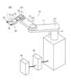
図1および図2に示すように、基板搬送ロボット100は、たとえば、半導体ウエハ、プリント基板などの基板1を搬送する。基板搬送ロボット100は、複数の基板1を収納するための収納部200から基板1を搬出することと収納部200に基板1を搬入することとのうちの少なくとも一方を行う。As shown in Figures 1 and 2, the
基板搬送ロボット100は、ロボットアーム10と、ロボットアーム10の先端に取り付けられ、基板1を保持する基板保持ハンド20と、を備えている。また、基板搬送ロボット100は、基板搬送ロボット100の動作を制御する制御部30を備えている。The
ロボットアーム10は、水平多関節ロボットアームである。ロボットアーム10は、第1ロボットアーム11と、第2ロボットアーム12とを含んでいる。第1ロボットアーム11は、一方端部を回動中心として後述する昇降軸13に対して回動可能に構成されている。具体的には、第1ロボットアーム11の一方端部は、第1関節JT1を介して昇降軸13に回動可能に接続されている。第2ロボットアーム12は、一方端部を回動中心として第1ロボットアーム11に対して回動可能に構成されている。具体的には、第2ロボットアーム12の一方端部は、第2関節JT2を介して第1ロボットアーム11の他方端部に回動可能に接続されている。また、第2ロボットアーム12の他方端部には、第3関節JT3を介して基板保持ハンド20が回動可能に接続されている。第1関節JT1、第2関節JT2および第3関節JT3の各関節には、回転駆動の駆動源であるサーボモータと、サーボモータの出力軸の回転位置を検出する回転位置センサとが配置されている。The
また、基板搬送ロボット100は、ロボットアーム10を昇降させる昇降軸13を備えている。昇降軸13には、サーボモータと、サーボモータの出力軸の回転位置を検出する回転位置センサとが配置されている。The
基板保持ハンド20には、ブレード21が設けられている。ブレード21は、基板1を支持する薄板状の支持板である。ブレード21は、先端が二股に分かれた形状を有している。ブレード21では、二股に分かれた部分の先端には、各々、一対の支持部22が配置されている。また、ブレード21の基端には、一対の支持部23が配置されている。一対の支持部22と、一対の支持部23とは、略円形状の基板1の外周縁部の裏面を下側から支持する。The
本実施形態では、図3に示すように、基板搬送ロボット100は、収納部200に収納される複数の基板1が配置されている配列方向に沿って移動する光学センサ24を備えている。光学センサ24は、基板保持ハンド20の先端に配置されている。具体的には、光学センサ24は、二股に分かれたブレード21の先端に配置されている。光学センサ24は、たとえば、透過型のセンタである。光学センサ24は、投光部24aと受光部24bとを含む。投光部24aは、受光部24bに向けて検出光を出射する。検出光は、たとえば、赤外光である。なお、反射型のセンサの光学センサ24を用いてもよい。In this embodiment, as shown in FIG. 3, the
本実施形態では、図4に示すように、光学センサ24は、複数の基板1が配置されている配列方向に沿って基板保持ハンド20により移動される。具体的には、光学センサ24は、ロボットアーム10が昇降軸13によって昇降されることにより、複数の基板1の配列方向に沿って移動する。配列方向とは、上下方向である。ロボットアーム10は、ブレード21の二股に分かれた先端の間に基板1の端部が位置する状態で、昇降する。これにより、ブレード21の二股に分かれた先端の間に基板1が位置する場合には、受光部24bに向かって出射される検出光が遮られる。これにより、基板1の存在が検知される。ブレード21の二股に分かれた先端の間に基板1が位置しない場合には、受光部24bに向かって出射される検出光が受光部24bに受光される。これにより、基板1が存在しないことが検知される。受光部24bの検知結果は、制御部30に入力される。基板1の有無は、制御部30により判定される。制御部30には、受光部24bの検知結果とともに、昇降軸13のサーボモータの出力軸の回転位置を検出する回転位置センサの検知結果も入力される。これにより、制御部30は、昇降軸13の位置と基板1の有無の情報とを関連付けて取得する。つまり、制御部30は、基板1が配置される鉛直方向の位置を取得する。また、制御部30は、受光部24bの検知結果に基づいて、基板1の形状を取得する。基板1の形状とは、たとえば、水平面に沿った形状や、湾曲した形状である。In this embodiment, as shown in FIG. 4, the
本実施形態では、図4に示すように、基板搬送ロボット100は、収納部200に収納される複数の基板1を撮影する撮影部25を備えている。撮影部25は、たとえば、2次元カメラからなる。なお、撮影部25を、3次元カメラから構成してもよい。また、撮影部25は、1回の撮影で収納部200に収納される全ての基板1を撮影することができない。このため、収納部200に収納される全ての基板1を撮影するためには、撮影部25によって複数回の撮影を行う必要がある。撮影部25は、収納部200に収納される複数の基板1を、収納部200の外側から撮影する。In this embodiment, as shown in FIG. 4, the
本実施形態では、撮影部25は、ロボットアーム10または基板保持ハンド20に配置されている。具体的には、本実施形態では、撮影部25は、基板保持ハンド20の基端側に配置されている。つまり、撮影部25は、基板保持ハンド20のJT3軸周りの回動に伴って回動する。また、撮影部25は、昇降軸13によるロボットアーム10および基板保持ハンド20の昇降に伴って昇降する。In this embodiment, the photographing
本実施形態では、基板搬送ロボット100は、報知部40を備えている。報知部40は、音声や画像によって、後述する収納部201からの基板1の搬出ができないこと、および、収納部202への基板1の搬入ができないことを報知する。In this embodiment, the
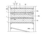
図5に示すように、収納部200は、複数の基板1を収納する。複数の基板1は、収納部200内において、上下方向に並べて配置されている。複数の基板1は、互いに所定の間隔を隔てた状態で配置されている。収納部200の内側面には、基板1が載置される突出部200aが配置されている。突出部200aは、水平方向に沿って突出している。基板1は、突出部200aの上に載置される。As shown in FIG. 5, the
図2に示すように、収納部200は、予め基板1が収納されている収納部201と、基板搬送ロボット100によって収納部201から搬出された基板1が搬入される収納部202と、を含む。As shown in FIG. 2, the
図5に示すように、収納部200には、複数の基板1が配置されている。図5の上から1つ目および3つ目の基板1は、水平面に沿った形状を有する。図5の上から2つ目の基板1は、下方に湾曲した形状を有する。図5の上から4つ目の基板1は、互いに高さ位置の異なる突出部200aに載置されることにより、水平面に対して傾斜している。As shown in FIG. 5,
ここで、本実施形態では、制御部30は、撮影部25により撮影された画像に基づいて、収納部200内における基板保持ハンド20の位置と基板1との間の隙間と、基板保持ハンド20に搬送されている基板1と基板保持ハンド20に搬送されている基板1に隣り合う基板1との間の隙間と、収納部200に収納される基板1同士の間の隙間と、のうちの少なくとも一方を含む搬送隙間Cを取得する。そして、制御部30は、取得した搬送隙間Cの大きさに基づいて、収納部201から基板1を搬出することと収納部202に基板1を搬入することとのうちの少なくとも一方を行うようにロボットアーム10および基板保持ハンド20の動作を制御する。なお、本実施形態では、取得した搬送隙間Cの大きさに基づいて、基板1の搬出と搬入との両方が行われる。また、本実施形態では、搬送隙間Cは、収納部200内における基板保持ハンド20の位置と基板1との間の隙間と、基板保持ハンド20に搬送されている基板1と基板保持ハンド20に搬送されている基板1に隣り合う基板1との間の隙間と、収納部200に収納される基板1同士の間の隙間と、の全てを含む。Here, in this embodiment, the
本実施形態では、搬送隙間Cは、収納部200内における、基板保持ハンド20の上面20aと、基板保持ハンド20よりも上方に隣り合うように配置される基板1の下面1bとの間の隙間C1と、収納部200内における、基板保持ハンド20の下面20bと、基板保持ハンド20よりも下方に隣り合うように配置される基板1の上面1aとの間の隙間C2と、を含む。ここで、基板保持ハンド20の上面20aとは、ブレード21の上面と、支持部22の上面と支持部23の上面とを含む。つまり、基板保持ハンド20の上側の全領域である。基板保持ハンド20の下面20bとは、ブレード21の下面を含む。つまり、基板保持ハンド20の下側の全領域である。すなわち、搬送隙間Cは、図5のハッチングされた領域である。つまり、収納部200に基板保持ハンド20が侵入する方向から見た場合の、基板保持ハンド20と、上側に隣り合う基板1および下側に隣り合う基板1との間の隙間を意味する。In this embodiment, the transport gap C includes a gap C1 between the
本実施形態では、図6に示すように、搬送隙間Cは、基板保持ハンド20に搬送されている基板1の上面1aと、基板保持ハンド20よりも上方に隣り合うように配置される基板1の下面1bとの間の隙間C3と、基板1を搬送している基板保持ハンド20の下面20bと、基板保持ハンド20よりも下方に隣り合うように配置される基板1の上面1aとの間の隙間C4と、を含む。つまり、搬送隙間Cは、図6の上から1つ目と2つ目のハッチングされた領域を含む。In this embodiment, as shown in FIG. 6, the transport gap C includes a gap C3 between the
搬送隙間Cは、収納部200に収納される基板1同士の間の隙間C5を含む。具体的には、搬送隙間Cは、図6の上から3つ目のハッチングされた領域を含む。なお、図6では、隙間C5は、1つのみ記載しているが、実際には、隙間C5は、収納部200に収納される全ての基板1に対して取得される。The transport gap C includes the gap C5 between the
本実施形態では、制御部30は、撮影部25により撮影された画像に基づいて、基板1の形状と位置との少なくとも一方を取得し、搬送隙間Cの大きさを取得する。具体的には、制御部30は、撮影部25により撮影された画像を画像解析することにより、基板1の形状と位置との両方を取得する。たとえば、制御部30は、撮影部25により撮影された画像に基づいて、基板1の水平面に沿った形状や、湾曲した形状を取得する。また、制御部30は、撮影部25により撮影された画像に基づいて、基板1の位置を取得する。In this embodiment, the
本実施形態では、制御部30は、撮影部25により撮影された画像に基づいて取得された基板1の形状と位置との少なくとも一方を、光学センサ24の検出結果に基づいて補正する。ここで、光学センサ24の検出精度は、撮影部25の検出精度よりも高い。そこで、制御部30は、高精度の光学センサ24の検出結果に基づいて、撮影部25による基板1の形状と位置との少なくとも一方を補正する。なお、本実施形態では、基板1の形状と位置との両方が補正される。In this embodiment, the
本実施形態では、図4に示すように、制御部30は、光学センサ24により基板1が検出された位置において、複数の基板1を撮影するように撮影部25を制御する。上記のように、光学センサ24は、ロボットアーム10が昇降軸13によって昇降されることにより、複数の基板1の配列方向に移動する。たとえば、光学センサ24は、ロボットアーム10が上昇されることにより上昇する。そして、ブレード21の二股に分かれた先端の間に基板1が位置した際に、受光部24bに向かって出射される検出光が基板1により遮られる。これにより、制御部30は、撮影部25に撮影を行わせる。制御部30は、基板1が検出される毎に、または、所定の枚数の基板1が検出される毎に、撮影部25に撮影を行わせる。In this embodiment, as shown in FIG. 4, the
本実施形態では、制御部30は、予め教示された基板1を搬送する際の基板保持ハンド20の移動経路に基づいて、収納部200内における基板保持ハンド20の位置を取得する。具体的には、基板搬送ロボット100には、収納部201から基板1を搬出するための移動経路と、収納部202に基板1を搬入するための移動経路とが、予め教示されている。これにより、制御部30は、予め教示された移動経路に基づいて、収納部201または収納部202に基板保持ハンド20が挿入された状態での位置を取得することができる。また、制御部30は、予め教示された移動経路に基づいて取得した基板保持ハンド20の位置と、撮影部25により撮影された画像から取得され光学センサ24の検出結果に基づいて補正された基板1の形状および位置と、に基づいて、隙間C1およびC2を取得する。また、制御部30は、予め教示された基板1を搬送する際の基板保持ハンド20の移動経路および基板1の形状に基づいて、隙間C3およびC4を取得する。In this embodiment, the
複数の基板1が配置されている収納部201に対しては、収納部201から基板1を搬出する前に、光学センサ24を上方向に1度移動させながら、撮影部25により複数回、基板1を撮影する。これにより、制御部30は、収納部201に配置される全ての基板1の位置および形状を取得する。基板1が搬入される収納部202に対しては、たとえば、基板1が搬入される前に、奇数段目の突出部200aに基板1が配置されているとする。この場合、光学センサ24を上方向に1度移動させながら、奇数段目の突出部200aに載置された基板1が撮影部25により複数回撮影される。これにより、制御部30は、収納部202の奇数段目の突出部200aに配置される基板1の位置および形状を取得する。For the
そして、本実施形態では、制御部30は、検出した搬送隙間Cの大きさが、基板1を搬送可能な大きさであると判定した場合、収納部201から基板1を搬出することと収納部202に基板1を搬入することとのうちの少なくとも一方を行うようにロボットアーム10および基板保持ハンド20の動作を制御する。本実施形態では、制御部30は、基板1の搬出と搬入との両方を行うようにロボットアーム10および基板保持ハンド20の動作を制御する。制御部30は、検出した搬送隙間Cの大きさが、収納部201にから基板保持ハンド20により基板1を搬出する際に、基板保持ハンド20や基板保持ハンド20に保持された基板1が、隣り合う基板1に干渉しない程度に十分に大きいと判定する。この場合、制御部30は、収納部200から基板1を搬出するようにロボットアーム10および基板保持ハンド20の動作を制御する。また、制御部30は、検出した搬送隙間Cの大きさが、収納部202に基板保持ハンド20により基板1を搬入する際に、基板保持ハンド20や基板保持ハンド20に保持された基板1が、隣り合う基板1に干渉しない程度に十分に大きいと判定する。この場合、制御部30は、収納部202に基板1を搬入するようにロボットアーム10および基板保持ハンド20の動作を制御する。In this embodiment, when the
本実施形態では、制御部30は、検出した搬送隙間Cの大きさが、基板1を搬送可能な大きさではないと判定した場合、検出した搬送隙間Cの大きさに基づいて予め教示された基板1の搬送経路を補正する。たとえば、制御部30は、下方に湾曲した基板1を搬出する際の、下方の基板1との間の隙間C2の大きさが、基板1を搬送可能な大きさではないと判定する。この場合、基板1が下方に湾曲しているため、予め教示された搬送経路に沿って基板保持ハンド20を収納部201に侵入させると基板保持ハンド20と基板1とが干渉してしまう。そこで、制御部30は、基板保持ハンド20の収納部201に侵入させる搬送経路を下方に修正する。これにより、基板保持ハンド20と基板1との干渉が抑制される。In this embodiment, when the
本実施形態では、制御部30は、予め教示された基板1の搬送経路を補正しても、収納部200から基板1を搬出することと収納部200に基板1を搬入することとのうちの少なくとも一方ができないと判定した場合、基板1の搬入と搬出とのうちの少なくとも一方ができないことを報知部40に報知させる制御を行う。本実施形態では、制御部30は、収納部201からの基板1の搬出ができないこと、および、収納部202への基板1の搬入ができないことの両方を報知部40に報知させる制御を行う。なお、搬出可能と判定された基板1は、搬出される。これにより、基板1同士の間の隙間が大きくなるので、搬出できないと判定された基板1も搬出可能になる場合がある。この場合、一旦搬出できないと判定された基板1も搬出される。また、収納部202に搬入される基板1のうち、搬入可能と判定された基板1は搬入される。In this embodiment, when the
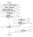
次に、図7を参照して、基板搬送ロボット100の動作について説明する。なお、以下では、収納部201からの基板1の搬出動作について説明するが、収納部202への基板1の搬入動作も同様に行われる。Next, the operation of the
まず、ステップS1において、制御部30は、図4に示すように、ロボットアーム10を移動させることにより、基板保持ハンド20を、収納部201に収納される基板1の下方に移動させる。そして、制御部30は、昇降軸13によってロボットアーム10を上方に移動させる。そして、制御部30は、基板保持ハンド20に配置される光学センサ24により、基板1の有無を検出する。First, in step S1, the
ステップS2において、制御部30は、光学センサ24により基板1が検出された位置において、複数の基板1を撮影するように撮影部25を制御する。なお、制御部30は、昇降軸13によってロボットアーム10を上方に移動させたのち、基板保持ハンド20を昇降軸13側に移動させる。In step S2, the
ステップS3において、制御部30は、撮影部25により撮影された画像に基づいて、基板1の形状と位置とを取得する。また、制御部30は、撮影部25により撮影された画像に基づいて取得された基板1の形状と位置とを、光学センサ24の検出結果に基づいて補正する。In step S3, the
ステップS4において、制御部30は、撮影部25により撮影された画像に基づいて、収納部200内における基板保持ハンド20の位置と基板1との間の隙間と、基板保持ハンド20によって搬送されている基板1と基板保持ハンド20に搬送されている基板1に隣り合う基板1との間の隙間と、収納部200に収納される基板1同士の間の隙間と、のうちの少なくとも一方を含む搬送隙間Cを取得する。具体的には、制御部30は、光学センサ24の検出結果に基づいて補正された基板1の形状と位置とに基づいて、搬送隙間Cを取得する。In step S4, the
ステップS5において、制御部30は、取得した搬送隙間Cの大きさが、基板1を搬送可能な大きさであるか否かを判定する。In step S5, the
ステップS5において、yesの場合、ステップS6において、制御部30は、収納部200から基板1を搬出するように、ロボットアーム10および基板保持ハンド20の動作を制御する。If the answer is yes in step S5, in step S6, the
ステップS5において、noの場合、ステップS7において、制御部30は、検出した搬送隙間Cの大きさに基づいて予め教示された基板1の搬送経路を補正する。If the answer is no in step S5, in step S7, the
ステップS8において、制御部30は、補正後の搬送経路によって、収納部200から基板1を搬出することが可能か否かを判定する。In step S8, the
ステップS8において、yesの場合、ステップS6において、制御部30は、収納部200から基板1を搬出するように、ロボットアーム10および基板保持ハンド20の動作を制御する。If the answer is yes in step S8, in step S6, the
ステップS8において、noの場合、ステップS9において、制御部30は、収納部200から基板1を搬出することができないことを報知部40に報知させる制御を行う。If the answer is no in step S8, in step S9, the
[本実施形態の効果]
本実施形態では、以下のような効果を得ることができる。 [Effects of this embodiment]
In this embodiment, the following effects can be obtained.
本実施形態では、上記のように、制御部30は、撮影部25により撮影された画像に基づいて、収納部200内における基板保持ハンド20の位置と基板1との間の隙間と、基板保持ハンド20によって搬送されている基板1と基板保持ハンド20に搬送されている基板1に隣り合う基板1と、収納部200に収納される基板1同士の間の隙間と、の間の隙間とのうちの少なくとも一方を含むである搬送隙間Cを取得し、取得した搬送隙間Cの大きさに基づいて、収納部200から基板1を搬出することと収納部200に基板1を搬入することとのうちの少なくとも一方を行うようにロボットアーム10および基板保持ハンド20の動作を制御する。これにより、基板1の傾斜角度や湾曲状態などに基づいて収納部200に侵入する基板保持ハンド20の移動経路や位置などを変更した場合でも、搬送隙間Cの大きさが不十分な場合には、収納部200から基板1を搬出すること、または、収納部200に基板1を搬入することを行わないように制御することができる。このため、基板保持ハンド20が、搬出対象となる基板1に隣り合うように配置されている基板1に干渉することや、基板保持ハンド20に搬送されている基板1が、隣り合うように配置されている基板1に干渉することを抑制することができる。その結果、基板1を搬送する際に、基板1が干渉するのを抑制することができる。In this embodiment, as described above, the
また、収納部200に収納されている基板1の配列方向に沿って光学センサ24を移動させて基板1の位置などを検出して搬送隙間Cを取得することも可能である。一方、この場合では、光学センサ24が基板1の一方側端部などの一部のみを検出するので、基板1の中央部および他方側端部における搬送隙間Cを正確に取得することが困難である。そこで、上記のように撮影部25により撮影された画像に基づいて搬送隙間Cを取得することにより、基板1の一方側端部だけでなく中央部および他方側端部における搬送隙間Cを取得することができる。その結果、基板1を搬送する際に、基板1が干渉するのを適切に抑制することができる。It is also possible to move the
本実施形態では、上記のように、搬送隙間Cは、収納部200内における、基板保持ハンド20の上面20aと、基板保持ハンド20よりも上方に隣り合うように配置される基板1の下面1bとの間の隙間C1と、収納部200内における、基板保持ハンド20の下面20bと、基板保持ハンド20よりも下方に隣り合うように配置される基板1の上面1aとの間の隙間C2と、を含む。これにより、基板保持ハンド20の上面20a側に配置される基板1と下面20b側に配置される基板1との両方に対して干渉することを抑制することができる。その結果、基板1を搬送する際に、基板1が干渉するのをより抑制することができる。In this embodiment, as described above, the transport gap C includes a gap C1 between the
本実施形態では、上記のように、制御部30は、撮影部25により撮影された画像に基づいて、基板1の形状と位置との少なくとも一方を取得し、搬送隙間Cの大きさを取得する。これにより、基板1の形状と位置との少なくとも一方を反映した状態で、搬送隙間Cを取得することができる。その結果、基板1を搬送する際に、基板1が干渉するのをさらに抑制することができる。In this embodiment, as described above, the
本実施形態では、上記のように、制御部30は、撮影部25により撮影された画像に基づいて取得された基板1の形状と位置との少なくとも一方を、光学センサ24の検出結果に基づいて補正する。これにより、撮影部25により撮影された画像では、適切に基板1の形状と位置との少なくとも一方が取得できない場合でも、比較的精度の高い光学センサ24の検出結果に基づいて、基板1の形状と位置との少なくとも一方を適切に取得することができる。In this embodiment, as described above, the
本実施形態では、上記のように、制御部30は、光学センサ24により基板1が検出された位置において、複数の基板1を撮影するように撮影部25を制御する。これにより、基板1の数が比較的多く、1回の撮影部25の撮影で全ての基板1を撮影することができない場合でも、複数回の撮影によって複数の基板1の全体を撮影することができる。In this embodiment, as described above, the
本実施形態では、上記のように、撮影部25は、ロボットアーム10または基板保持ハンド20に配置され、光学センサ24は、基板保持ハンド20の先端に配置され、複数の基板1が配置されている配列方向に沿って基板保持ハンド20により移動される。これにより、基板保持ハンド20の移動に伴って光学センサ24とともに撮影部25を移動させることができる。In this embodiment, as described above, the photographing
本実施形態では、上記のように、制御部30は、予め教示された基板1を搬送する際の基板保持ハンド20の移動経路に基づいて、収納部200内における基板保持ハンド20の位置を取得する。これにより、実際に基板保持ハンド20を収納部200の内部に挿入して基板保持ハンド20と基板1との両方を撮影部25により撮影をすることなく搬送隙間Cを取得することができる。In this embodiment, as described above, the
本実施形態では、上記のように、制御部30は、検出した搬送隙間Cの大きさが、基板1を搬送可能な大きさであると判定した場合、収納部200から基板1を搬出することと収納部200に基板1を搬入することとのうちの少なくとも一方を行うようにロボットアーム10および基板保持ハンド20の動作を制御する。これにより、搬送隙間Cの大きさが基板1の搬送に不十分な状態で、基板1の搬出および搬入の少なくとも一方が行われるのを抑制することができる。その結果、他の基板1や基板保持ハンド20との干渉に起因する基板1の損傷を抑制することができる。In this embodiment, as described above, when the
本実施形態では、上記のように、制御部30は、検出した搬送隙間Cの大きさが、基板1を搬送可能な大きさではないと判定した場合、検出した搬送隙間Cの大きさに基づいて予め教示された基板1の搬送経路を補正する。これにより、搬送隙間Cの大きさが基板1の搬送に不十分である場合でも、基板1の搬送経路を補正することによって、他の基板1や基板保持ハンド20との干渉を抑制しながら基板1の搬出および搬入の少なくとも一方を行うことができる。In this embodiment, as described above, when the
本実施形態では、上記のように、制御部30は、予め教示された基板1の搬送経路を補正しても、収納部200から基板1を搬出することと収納部200に基板1を搬入することとのうちの少なくとも一方ができないと判定した場合、基板1の搬入と搬出とのうちの少なくとも一方ができないことを報知部40に報知させる制御を行う。これにより、作業者は、基板1の搬出および搬入の少なくとも一方ができないことを認知することができる。In this embodiment, as described above, when the
本実施形態では、上記のように、搬送隙間Cは、基板保持ハンド20に搬送されている基板1の上面1aと、基板保持ハンド20よりも上方に隣り合うように配置される基板1の下面1bとの間の隙間と、基板1を搬送している基板保持ハンド20の下面20bと、基板保持ハンド20よりも下方に隣り合うように配置される基板1の上面1aとの間の隙間と、を含む。これにより、基板1が基板保持ハンド20に搬送されている最中の搬送隙間Cも取得されるので、基板1を搬送する際に、基板1が干渉するのをより抑制することができる。In this embodiment, as described above, the transport gap C includes the gap between the
[変形例]
なお、今回開示された実施形態は、すべての点で例示であって制限的なものではないと考えられるべきである。本開示の範囲は、上記した実施形態の説明ではなく特許請求の範囲によって示され、さらに特許請求の範囲と均等の意味および範囲内でのすべての変更(変形例)が含まれる。 [Modification]
It should be noted that the embodiments disclosed herein are illustrative and not restrictive in all respects. The scope of the present disclosure is indicated by the claims, not by the description of the embodiments described above, and further includes all modifications (variations) within the meaning and scope of the claims.
たとえば、上記実施形態では、制御部30は、取得した搬送隙間Cの大きさに基づいて、収納部201から基板1を搬出することと収納部202に基板1を搬入することとの両方を行うようにロボットアーム10および基板保持ハンド20の動作を制御する例を示したが、本開示はこれに限られない。たとえば、制御部30は、取得した搬送隙間Cの大きさに基づいて、収納部201から基板1を搬出することと、収納部202に基板1を搬入することとのうちの一方のみを行うように、ロボットアーム10および基板保持ハンド20の動作を制御してもよい。For example, in the above embodiment, the
また、上記実施形態では、搬送隙間Cは、基板保持ハンド20の上面20aと基板1の下面1bとの間の隙間C1と、基板保持ハンド20の下面20bと、基板1の上面1aとの間の隙間C2とを含む例を示したが、本開示はこれに限られない。たとえば、収納部201に配置される基板1の間の距離が比較的大きい場合などでは、搬送隙間Cとして、基板保持ハンド20の上面20aと基板1の下面1bとの間の隙間C1と、基板保持ハンド20の下面20bと、基板1の上面1aとの間の隙間C2とのうちの一方のみを考慮してもよい。In the above embodiment, the transport gap C includes the gap C1 between the
また、上記実施形態では、制御部30は、撮影部25により撮影された画像に基づいて、基板1の形状と位置との両方を取得する例を示したが、本開示はこれに限られない。たとえば、制御部30は、撮影部25により撮影された画像に基づいて、基板1の形状または位置の一方のみを取得してもよい。In addition, in the above embodiment, an example has been shown in which the
また、上記実施形態では、撮影部25により撮影された画像に基づいて取得された基板1の形状と位置とが、光学センサ24の検出結果に基づいて補正される例を示したが、本開示はこれに限られない。たとえば、撮影部25により撮影された画像に基づいて取得された基板1の形状と位置との精度が搬送隙間Cの取得のために十分であれば、光学センサ24の検出結果に基づく補正を行わなくてもよい。In addition, in the above embodiment, an example has been shown in which the shape and position of the
また、上記実施形態では、制御部30は、光学センサ24により基板1が検出された位置において、複数の基板1を撮影するように撮影部25を制御する例を示したが、本開示はこれに限られない。たとえば、制御部30は、予め定められた位置において、複数の基板1を撮影するように撮影部25を制御してもよい。また、撮影部25の視野が比較的大きい場合、制御部30は、1回の撮影によって基板1の全てを撮影するように撮影部25を制御してもよい。In the above embodiment, the
また、上記実施形態では、撮影部25が基板保持ハンド20に配置されている例を示したが、本開示はこれに限られない。たとえば、撮影部25をロボットアーム10に配置してもよい。In addition, in the above embodiment, an example was shown in which the photographing
また、上記実施形態では、光学センサ24が基板保持ハンド20の先端に配置されている例を示したが、本開示はこれに限られない。たとえば、光学センサ24を基板保持ハンド20の先端以外の部分に配置してもよい。In addition, in the above embodiment, an example has been shown in which the
また、上記実施形態では、基板搬送ロボット100にブレード21が1つ配置されている例を示したが、本開示はこれに限られない。たとえば、図8に示す基板搬送ロボット110のように、2つ以上のブレード21が配置されていてもよい。In addition, in the above embodiment, an example in which one
また、上記実施形態では、搬送隙間Cが、収納部200内における基板保持ハンド20の位置と基板1との間の隙間と、基板保持ハンド20に搬送されている基板1と基板保持ハンド20に搬送されている基板1に隣り合う基板1との間の隙間と、収納部200に収納される基板1同士の間の隙間と、のうちの全てを含む例を示したが、本開示はこれに限られない。たとえば、搬送隙間Cが、収納部200内における基板保持ハンド20の位置と基板1との間の隙間と、基板保持ハンド20に搬送されている基板1と基板保持ハンド20に搬送されている基板1に隣り合う基板1との間の隙間と、収納部200に収納される基板1同士の間の隙間と、のうちの1つまたは2つのみを含んでいてもよい。In the above embodiment, an example was shown in which the transport gap C includes all of the gap between the position of the
1 基板
1a 上面
1b 下面
10 ロボットアーム
20 基板保持ハンド
20a 上面
20b 下面
24 光学センサ
25 撮影部
30 制御部
40 報知部
100、110 基板搬送ロボット
200、201、202 収納部
C 搬送隙間 REFERENCE SIGNS
Claims (12)
Translated fromJapaneseロボットアームと、
前記ロボットアームの先端に取り付けられ、前記基板を保持する基板保持ハンドと、
前記収納部に収納される前記複数の基板を撮影する撮影部と、
前記収納部に収納される前記複数の基板が配置されている配列方向に沿って移動し前記基板を検出する光学センサと、
制御部と、を備え、
前記制御部は、
前記光学センサの検出結果と前記撮影部により撮影された画像とに基づいて、前記収納部内における前記基板保持ハンドの位置と前記基板との間の隙間と、前記基板保持ハンドによって搬送されている前記基板と前記基板保持ハンドに搬送されている前記基板に隣り合う前記基板との間の隙間と、前記収納部に収納される前記基板同士の間の隙間と、のうちの少なくとも1つを含む搬送隙間を取得し、
取得した前記搬送隙間の大きさに基づいて、前記収納部から前記基板を搬出することと前記収納部に前記基板を搬入することとのうちの少なくとも一方を行うように前記ロボットアームおよび前記基板保持ハンドの動作を制御する、基板搬送ロボット。 A substrate transport robot that performs at least one of unloading a substrate from a storage unit for storing a plurality of substrates and loading the substrate into the storage unit,
A robot arm;
a substrate holding hand attached to a tip of the robot arm and holding the substrate;
an imaging unit that images the plurality of substrates stored in the storage unit;
an optical sensor that moves along an arrangement direction in which the plurality of substrates stored in the storage unit are arranged and detects the substrates;
A control unit,
The control unit is
based onthe detection result of the optical sensor and the image capturedby the imaging unit, acquire a transport gap including at least one of a gap between the position of the substrate holding hand and the substrate in the storage unit, a gap between the substrate being transported by the substrate holding hand and a substrate adjacent to the substrate being transported by the substrate holding hand, and a gap between the substrates stored in the storage unit;
A substrate transport robot that controls the operation of the robot arm and the substrate holding hand to perform at least one of unloading the substrate from the storage section and loading the substrate into the storage section based on the size of the acquired transport gap.
前記収納部内における、前記基板保持ハンドの上面と、前記基板保持ハンドよりも上方に隣り合うように配置される前記基板の下面との間の隙間と、
前記収納部内における、前記基板保持ハンドの下面と、前記基板保持ハンドよりも下方に隣り合うように配置される前記基板の上面との間の隙間と、を含む、請求項1に記載の基板搬送ロボット。 The conveying gap is
a gap between an upper surface of the substrate holding hand and a lower surface of the substrate arranged adjacent to the substrate holding hand and above the substrate holding hand in the storage section;
The substrate transport robot according to claim 1 , further comprising: a gap between a lower surface of the substrate holding hand and an upper surface of the substrate arranged adjacent to and below the substrate holding hand within the storage section.
前記撮影部により撮影された画像に基づいて、前記基板の形状と位置との少なくとも一方を取得し、前記搬送隙間の大きさを取得する、請求項1または2に記載の基板搬送ロボット。 The control unit is
3. The substrate transport robot according to claim 1, further comprising: a capturing section configured to capture an image of the substrate and a capturing section configured to capture a size of the transport gap based on the captured image.
前記撮影部により撮影された画像に基づいて取得された前記基板の形状と位置との少なくとも一方を、前記光学センサの検出結果に基づいて補正する、請求項3に記載の基板搬送ロボット。Thecontrol unit is
The substrate transport robot according to claim 3 , wherein at least one of the shape and the position of the substrate acquired based on the image captured by the imaging unit is corrected based on the detection result of the optical sensor.
前記光学センサは、前記基板保持ハンドの先端に配置され、前記複数の基板が配置されている配列方向に沿って前記基板保持ハンドにより移動される、請求項4または5に記載の基板搬送ロボット。 the imaging unit is disposed on the robot arm or the substrate holding hand,
6. The substrate transport robot according to claim 4, wherein the optical sensor is disposed at a tip of the substrate holding hand, and is moved by the substrate holding hand along an arrangement direction in which the plurality of substrates are arranged.
前記制御部は、予め教示された前記基板の前記搬送経路を補正しても、前記収納部から前記基板を搬出することと前記収納部に前記基板を搬入することとのうちの少なくとも一方ができないと判定した場合、前記基板の搬入と搬出とのうちの少なくとも一方ができないことを前記報知部に報知させる制御を行う、請求項9に記載の基板搬送ロボット。 Further comprising a notification unit,
The substrate transport robot of claim 9, wherein when the control unit determines that at least one of removing the substrate from the storage unit and loading the substrate into the storage unit cannot be performed even after correcting the previously taught transport path of the substrate, the control unit controls the notification unit to notify that at least one of loading and unloading the substrate cannot be performed.
前記基板保持ハンドに搬送されている前記基板の上面と、前記基板保持ハンドよりも上方に隣り合うように配置される前記基板の下面との間の隙間と、
前記基板を搬送している前記基板保持ハンドの下面と、前記基板保持ハンドよりも下方に隣り合うように配置される前記基板の上面との間の隙間と、を含む、請求項1~10のいずれか1項に記載の基板搬送ロボット。 The conveying gap is
a gap between an upper surface of the substrate being transported by the substrate holding hand and a lower surface of the substrate disposed adjacent to the substrate holding hand and above the substrate holding hand;
A substrate transport robot as described in any one of claims 1 to 10, comprising a gap between a lower surface of the substrate holding hand transporting the substrate and an upper surface of the substrate arranged adjacent to and below the substrate holding hand.
撮影部により前記収納部に収納される前記複数の基板を撮影することと、
前記収納部に収納される前記複数の基板が配置されている配列方向に沿って移動する光学センサにより前記基板を検出することと、
前記光学センサの検出結果と前記撮影部により撮影された画像とに基づいて、前記収納部内における前記基板搬送ロボットの基板保持ハンドの位置と前記基板との間の隙間と、前記基板保持ハンドによって搬送されている前記基板と前記基板保持ハンドに搬送されている前記基板に隣り合う前記基板との間の隙間と、前記収納部に収納される前記基板同士の間の隙間と、のうちの少なくとも1つを含む搬送隙間を取得することと、
取得した前記搬送隙間の大きさに基づいて、前記収納部から前記基板を搬出することと前記収納部に前記基板を搬入することとのうちの少なくとも一方を行うように前記基板搬送ロボットのロボットアームおよび前記基板保持ハンドの動作を制御すること、とを備える、基板搬送ロボットの制御方法。 1. A method for controlling a substrate transport robot that performs at least one of unloading a substrate from a storage unit for storing a plurality of substrates and loading the substrate into the storage unit, comprising:
taking images of the plurality of substrates stored in the storage unit by an imaging unit;
detecting the substrate by an optical sensor that moves along an arrangement direction in which the substrates stored in the storage unit are arranged;
acquiring a transport gap including at least oneof a gap between the position of the substrate holding hand of the substrate transport robot in the storage unit and the substrate, a gap between the substrate being transported by the substrate holding hand and a substrate adjacent to the substrate being transported by the substrate holding hand, and a gap between the substrates stored in the storage unit based on the detection result of the optical sensor and the image captured by the imaging unit;
and controlling the operation of the robot arm and the substrate holding hand of the substrate transport robot to perform at least one of unloading the substrate from the storage section and loading the substrate into the storage section based on the size of the acquired transport gap.
Priority Applications (7)
| Application Number | Priority Date | Filing Date | Title |
|---|---|---|---|
| JP2021136257AJP7691887B2 (en) | 2021-08-24 | 2021-08-24 | Substrate transport robot and method for controlling substrate transport robot |
| CN202280045845.5ACN117581349A (en) | 2021-08-24 | 2022-08-17 | Substrate transfer robot and control method of substrate transfer robot |
| KR1020247006670AKR20240039020A (en) | 2021-08-24 | 2022-08-17 | Substrate transfer robot and control method of substrate transfer robot |
| PCT/JP2022/031051WO2023026917A1 (en) | 2021-08-24 | 2022-08-17 | Substrate transport robot and control method for substrate transport robot |
| US18/291,706US20240253233A1 (en) | 2021-08-24 | 2022-08-17 | Substrate conveying robot and control method for substrate conveying robot |
| TW111131896ATWI825943B (en) | 2021-08-24 | 2022-08-24 | Substrate transport robot and control method for substrate transport robot |
| JP2025091882AJP2025116168A (en) | 2021-08-24 | 2025-06-02 | Substrate transport robot and method for controlling substrate transport robot |
Applications Claiming Priority (1)
| Application Number | Priority Date | Filing Date | Title |
|---|---|---|---|
| JP2021136257AJP7691887B2 (en) | 2021-08-24 | 2021-08-24 | Substrate transport robot and method for controlling substrate transport robot |
Related Child Applications (1)
| Application Number | Title | Priority Date | Filing Date |
|---|---|---|---|
| JP2025091882ADivisionJP2025116168A (en) | 2021-08-24 | 2025-06-02 | Substrate transport robot and method for controlling substrate transport robot |
Publications (2)
| Publication Number | Publication Date |
|---|---|
| JP2023030876A JP2023030876A (en) | 2023-03-08 |
| JP7691887B2true JP7691887B2 (en) | 2025-06-12 |
Family
ID=85321910
Family Applications (2)
| Application Number | Title | Priority Date | Filing Date |
|---|---|---|---|
| JP2021136257AActiveJP7691887B2 (en) | 2021-08-24 | 2021-08-24 | Substrate transport robot and method for controlling substrate transport robot |
| JP2025091882APendingJP2025116168A (en) | 2021-08-24 | 2025-06-02 | Substrate transport robot and method for controlling substrate transport robot |
Family Applications After (1)
| Application Number | Title | Priority Date | Filing Date |
|---|---|---|---|
| JP2025091882APendingJP2025116168A (en) | 2021-08-24 | 2025-06-02 | Substrate transport robot and method for controlling substrate transport robot |
Country Status (6)
| Country | Link |
|---|---|
| US (1) | US20240253233A1 (en) |
| JP (2) | JP7691887B2 (en) |
| KR (1) | KR20240039020A (en) |
| CN (1) | CN117581349A (en) |
| TW (1) | TWI825943B (en) |
| WO (1) | WO2023026917A1 (en) |
Families Citing this family (4)
| Publication number | Priority date | Publication date | Assignee | Title |
|---|---|---|---|---|
| JP7356269B2 (en)* | 2019-07-01 | 2023-10-04 | 川崎重工業株式会社 | Robot control device, robot and robot system equipped with the same |
| JP2021091078A (en) | 2019-12-10 | 2021-06-17 | 川崎重工業株式会社 | Controller for robot |
| JP2024080228A (en)* | 2022-12-02 | 2024-06-13 | 株式会社安川電機 | Substrate transport device and substrate transport method |
| JP2025047269A (en)* | 2023-09-21 | 2025-04-03 | 株式会社Screenホールディングス | Substrate transfer device and substrate processing apparatus including the same |
Citations (5)
| Publication number | Priority date | Publication date | Assignee | Title |
|---|---|---|---|---|
| JP2004200214A (en) | 2002-12-16 | 2004-07-15 | Y E Data Inc | Method for carrying thin wafer |
| JP2004273867A (en) | 2003-03-11 | 2004-09-30 | Okamoto Machine Tool Works Ltd | Method of carrying out extremely thin wafer and multistage type storing cassette to be used therefor |
| JP2008053307A (en) | 2006-08-22 | 2008-03-06 | Toshiba Matsushita Display Technology Co Ltd | Substrate storing device and substrate processing device equipped therewith |
| JP2011134822A (en) | 2009-12-24 | 2011-07-07 | Kawasaki Heavy Ind Ltd | Substrate storage condition detecting device, and method of detecting substrate storage condition |
| JP2021114493A (en) | 2020-01-16 | 2021-08-05 | 株式会社ディスコ | Processing equipment |
Family Cites Families (2)
| Publication number | Priority date | Publication date | Assignee | Title |
|---|---|---|---|---|
| JP3399728B2 (en)* | 1995-11-22 | 2003-04-21 | 大日本スクリーン製造株式会社 | Substrate transfer device |
| JPH11116049A (en)* | 1997-10-16 | 1999-04-27 | Nikon Corp | Substrate transfer method and substrate transfer device |
- 2021
- 2021-08-24JPJP2021136257Apatent/JP7691887B2/enactiveActive
- 2022
- 2022-08-17CNCN202280045845.5Apatent/CN117581349A/enactivePending
- 2022-08-17KRKR1020247006670Apatent/KR20240039020A/enactivePending
- 2022-08-17WOPCT/JP2022/031051patent/WO2023026917A1/ennot_activeCeased
- 2022-08-17USUS18/291,706patent/US20240253233A1/enactivePending
- 2022-08-24TWTW111131896Apatent/TWI825943B/enactive
- 2025
- 2025-06-02JPJP2025091882Apatent/JP2025116168A/enactivePending
Patent Citations (5)
| Publication number | Priority date | Publication date | Assignee | Title |
|---|---|---|---|---|
| JP2004200214A (en) | 2002-12-16 | 2004-07-15 | Y E Data Inc | Method for carrying thin wafer |
| JP2004273867A (en) | 2003-03-11 | 2004-09-30 | Okamoto Machine Tool Works Ltd | Method of carrying out extremely thin wafer and multistage type storing cassette to be used therefor |
| JP2008053307A (en) | 2006-08-22 | 2008-03-06 | Toshiba Matsushita Display Technology Co Ltd | Substrate storing device and substrate processing device equipped therewith |
| JP2011134822A (en) | 2009-12-24 | 2011-07-07 | Kawasaki Heavy Ind Ltd | Substrate storage condition detecting device, and method of detecting substrate storage condition |
| JP2021114493A (en) | 2020-01-16 | 2021-08-05 | 株式会社ディスコ | Processing equipment |
Also Published As
| Publication number | Publication date |
|---|---|
| KR20240039020A (en) | 2024-03-26 |
| US20240253233A1 (en) | 2024-08-01 |
| TW202317335A (en) | 2023-05-01 |
| WO2023026917A1 (en) | 2023-03-02 |
| JP2023030876A (en) | 2023-03-08 |
| JP2025116168A (en) | 2025-08-07 |
| CN117581349A (en) | 2024-02-20 |
| TWI825943B (en) | 2023-12-11 |
Similar Documents
| Publication | Publication Date | Title |
|---|---|---|
| JP7691887B2 (en) | Substrate transport robot and method for controlling substrate transport robot | |
| JP7097691B2 (en) | Teaching method | |
| JP5132904B2 (en) | Substrate positioning method, substrate position detection method, substrate recovery method, and substrate position deviation correction apparatus | |
| CN102376612B (en) | Substrate transfer device, substrate transfer method, and recording medium for recording program | |
| TWI638426B (en) | Stripping device, stripping system, stripping method and information memory medium | |
| CN104723362A (en) | Robotic system and detection method | |
| JP7357549B2 (en) | Substrate displacement detection method, substrate position abnormality determination method, substrate transfer control method, and substrate displacement detection device | |
| KR20150052230A (en) | Device and method for detecting position of semiconductor substrate | |
| JP2010161192A (en) | Alignment apparatus for semiconductor wafer | |
| JP2016072384A (en) | Substrate processing apparatus and substrate processing method | |
| KR20160033049A (en) | Alignment apparatus and substrate processing apparatus | |
| US20090016857A1 (en) | Substrate-replacing apparatus, substrate-processing apparatus, and substrate-inspecting apparatus | |
| JP5529522B2 (en) | Substrate storage state detection device and substrate storage state detection method | |
| CN115039214A (en) | Substrate conveying device and substrate position deviation measuring method | |
| JP2024048046A (en) | Substrate transport system and image correction method | |
| US20250105039A1 (en) | Substrate transporting device and substrate processing device equipped with the same | |
| JP7597603B2 (en) | Wafer Processing Equipment | |
| TW202501694A (en) | Semiconductor manufacturing apparatus system and method for detecting abnormality of inspection target | |
| JP2023043003A (en) | End state confirmation device | |
| JP4472451B2 (en) | Substrate transport apparatus, image forming apparatus including the same, and substrate transport method | |
| JP2023161815A (en) | Substrate transfer robot system and substrate transfer robot | |
| JP2025042538A (en) | Substrate transport robot system and substrate detection method | |
| JP2005022712A (en) | Electronic element accommodating device |
Legal Events
| Date | Code | Title | Description |
|---|---|---|---|
| A621 | Written request for application examination | Free format text:JAPANESE INTERMEDIATE CODE: A621 Effective date:20240415 | |
| A871 | Explanation of circumstances concerning accelerated examination | Free format text:JAPANESE INTERMEDIATE CODE: A871 Effective date:20240415 | |
| A131 | Notification of reasons for refusal | Free format text:JAPANESE INTERMEDIATE CODE: A131 Effective date:20240716 | |
| A521 | Request for written amendment filed | Free format text:JAPANESE INTERMEDIATE CODE: A523 Effective date:20240909 | |
| A131 | Notification of reasons for refusal | Free format text:JAPANESE INTERMEDIATE CODE: A131 Effective date:20241210 | |
| A521 | Request for written amendment filed | Free format text:JAPANESE INTERMEDIATE CODE: A523 Effective date:20250204 | |
| TRDD | Decision of grant or rejection written | ||
| A01 | Written decision to grant a patent or to grant a registration (utility model) | Free format text:JAPANESE INTERMEDIATE CODE: A01 Effective date:20250507 | |
| A61 | First payment of annual fees (during grant procedure) | Free format text:JAPANESE INTERMEDIATE CODE: A61 Effective date:20250602 | |
| R150 | Certificate of patent or registration of utility model | Ref document number:7691887 Country of ref document:JP Free format text:JAPANESE INTERMEDIATE CODE: R150 |