JP7688730B2 - Aerosol Delivery Device - Google Patents
Aerosol Delivery DeviceDownload PDFInfo
- Publication number
- JP7688730B2 JP7688730B2JP2023572846AJP2023572846AJP7688730B2JP 7688730 B2JP7688730 B2JP 7688730B2JP 2023572846 AJP2023572846 AJP 2023572846AJP 2023572846 AJP2023572846 AJP 2023572846AJP 7688730 B2JP7688730 B2JP 7688730B2
- Authority
- JP
- Japan
- Prior art keywords
- aerosol
- delivery device
- generating
- generating material
- outlet
- Prior art date
- Legal status (The legal status is an assumption and is not a legal conclusion. Google has not performed a legal analysis and makes no representation as to the accuracy of the status listed.)
- Active
Links
Images


Classifications
- A—HUMAN NECESSITIES
- A24—TOBACCO; CIGARS; CIGARETTES; SIMULATED SMOKING DEVICES; SMOKERS' REQUISITES
- A24F—SMOKERS' REQUISITES; MATCH BOXES; SIMULATED SMOKING DEVICES
- A24F40/00—Electrically operated smoking devices; Component parts thereof; Manufacture thereof; Maintenance or testing thereof; Charging means specially adapted therefor
- A24F40/40—Constructional details, e.g. connection of cartridges and battery parts
- A24F40/48—Fluid transfer means, e.g. pumps
- A24F40/485—Valves; Apertures
- A—HUMAN NECESSITIES
- A24—TOBACCO; CIGARS; CIGARETTES; SIMULATED SMOKING DEVICES; SMOKERS' REQUISITES
- A24F—SMOKERS' REQUISITES; MATCH BOXES; SIMULATED SMOKING DEVICES
- A24F40/00—Electrically operated smoking devices; Component parts thereof; Manufacture thereof; Maintenance or testing thereof; Charging means specially adapted therefor
- A24F40/40—Constructional details, e.g. connection of cartridges and battery parts
- A24F40/42—Cartridges or containers for inhalable precursors
- A—HUMAN NECESSITIES
- A24—TOBACCO; CIGARS; CIGARETTES; SIMULATED SMOKING DEVICES; SMOKERS' REQUISITES
- A24F—SMOKERS' REQUISITES; MATCH BOXES; SIMULATED SMOKING DEVICES
- A24F40/00—Electrically operated smoking devices; Component parts thereof; Manufacture thereof; Maintenance or testing thereof; Charging means specially adapted therefor
- A24F40/40—Constructional details, e.g. connection of cartridges and battery parts
- A24F40/48—Fluid transfer means, e.g. pumps
- A—HUMAN NECESSITIES
- A24—TOBACCO; CIGARS; CIGARETTES; SIMULATED SMOKING DEVICES; SMOKERS' REQUISITES
- A24F—SMOKERS' REQUISITES; MATCH BOXES; SIMULATED SMOKING DEVICES
- A24F40/00—Electrically operated smoking devices; Component parts thereof; Manufacture thereof; Maintenance or testing thereof; Charging means specially adapted therefor
- A24F40/50—Control or monitoring
- A24F40/57—Temperature control
Description
Translated fromJapanese本発明は、エアロゾル供給デバイス、エアロゾル供給システム、及びエアロゾルを生成する方法に関する。The present invention relates to an aerosol delivery device, an aerosol delivery system, and a method for generating an aerosol.
電子タバコ(eシガレット)などの電子エアロゾル供給システムは一般に、典型的にはニコチンを含む配合物を含む原料液体のリザーバを含み、エアロゾルは、それから、例えば加熱気化によって生成される。したがって、エアロゾル供給システム用のエアロゾル供給源は、例えばウィッキング又は毛細管作用によってリザーバから原料液体を受け取るように配置された加熱要素を有するヒーターを備えてもよい。使用者がデバイスで吸引する間、電力が加熱要素に供給されて、加熱要素の近くにある原料液体を気化して、使用者による吸引のためのエアロゾルを生成する。このようなデバイスは通常、システムの吸い口端部から離れたところに配置された1つ以上の空気入口穴を備える。使用者が、システムの吸い口端部に接続された吸い口で吸うと、空気は入口穴を通って引き込まれ、エアロゾル供給源を通過する。エアロゾル供給源と吸い口の開口との間を接続する流路があり、その結果、エアロゾル供給源を通過する空気は、エアロゾル供給源からエアロゾルの一部を運びながら、流路に沿って吸い口開口に引き込まれ続ける。エアロゾルを運ぶ空気は、使用者による吸引のための吸い口の開口を通ってエアロゾル供給システムを出る。Electronic aerosol delivery systems, such as electronic cigarettes (e-cigarettes), generally include a reservoir of liquid feedstock, typically including a nicotine-containing formulation, from which an aerosol is generated, for example by heating and vaporization. Thus, an aerosol source for an aerosol delivery system may include a heater having a heating element arranged to receive the liquid feedstock from the reservoir, for example by wicking or capillary action. While a user draws on the device, power is supplied to the heating element to vaporize the liquid feedstock proximate the heating element to generate an aerosol for inhalation by the user. Such devices typically include one or more air inlet holes arranged away from the mouthpiece end of the system. When a user draws on a mouthpiece connected to the mouthpiece end of the system, air is drawn through the inlet holes and passes through the aerosol source. There is a flow path connecting between the aerosol source and the mouthpiece opening, such that air passing through the aerosol source continues to be drawn along the flow path to the mouthpiece opening, carrying a portion of the aerosol from the aerosol source. The air carrying the aerosol exits the aerosol delivery system through the mouthpiece opening for inhalation by the user.
他のエアロゾル供給デバイスは、タバコ又はタバコ派生物などの固体材料からエアロゾルを生成する。このようなデバイスは、上記の液体をベースにしたシステムとほぼ同様な態様で動作し、この場合、固体タバコ材料は、気化温度まで加熱されてエアロゾルを生成し、その後、使用者によって吸引される。Other aerosol delivery devices generate an aerosol from a solid material, such as tobacco or a tobacco derivative. Such devices operate in a manner similar to the liquid-based systems described above, in that the solid tobacco material is heated to a vaporization temperature to generate an aerosol that is then inhaled by the user.
ほとんどのエアロゾル供給デバイスにおいて、使用者は、各パフで同じ味がするように、及び/又は同じ所望の効果が得られるように、パフごとの均一な送達を求める。しかしながら、上記のデバイスはいつも均一な送達を提供することができるとは限らない。In most aerosol delivery devices, users desire a uniform delivery from puff to puff so that each puff tastes the same and/or provides the same desired effect. However, such devices are not always able to provide a uniform delivery.
これらの課題のいくつかに対処することを助けようとする様々な手法を説明する。We describe various approaches that attempt to help address some of these challenges.
一態様によれば、エアロゾル生成材料の複数の部分を備えるエアロゾル生成品からエアロゾルを生成するためのエアロゾル供給デバイスが提供され、本エアロゾル供給デバイスは、
複数のエアロゾル生成領域に隣り合って配置され、複数のエアロゾル生成領域と流体連通する複数のエアロゾル伝送流路と、
複数のエアロゾル生成領域を選択的に制御するように構成された制御回路と
を備える。 According to one aspect, there is provided an aerosol delivery device for generating an aerosol from an aerosol generating product comprising a plurality of portions of an aerosol-generating material, the aerosol delivery device comprising:
a plurality of aerosol transmission channels disposed adjacent the plurality of aerosol-generation regions and in fluid communication with the plurality of aerosol-generation regions;
and a control circuit configured to selectively control the plurality of aerosol-generation regions.
様々な実施形態によれば、複数のエアロゾル伝送流路のそれぞれは、要求に応じて開閉するように構成することができる個々のバルブを備えてもよい。より詳細には、制御回路は、加熱ユニットの特定の加熱要素を作動させるかどうかに応じて、したがって特定のエアロゾル生成領域を作動させるかどうかに応じて、個々のバルブ(複数可)を開閉するように構成されてもよい。したがって、制御回路によって、複数の加熱要素のどれを作動させるかに応じて、複数の個々のバルブのどれかを、任意の組合せで、同時に開けるか閉じるかしてもよく、例えば、複数のバルブのすべてが開状態である、又はバルブのすべてが閉状態である、又は複数のバルブの任意の割合のバルブが開状態であり、複数のバルブの残りの割合のバルブが閉状態であることが認識されよう。According to various embodiments, each of the plurality of aerosol transmission channels may include an individual valve that may be configured to open or close as required. More specifically, the control circuit may be configured to open or close the individual valve(s) depending on whether a particular heating element of the heating unit is activated, and thus whether a particular aerosol generating region is activated. It will be appreciated that the control circuit may thus simultaneously open or close any of the plurality of individual valves in any combination depending on which of the plurality of heating elements is activated, for example, all of the plurality of valves being open, or all of the valves being closed, or any percentage of the plurality of valves being open and the remaining percentage of the plurality of valves being closed.
様々な実施形態によれば、各エアロゾル生成領域から生成されるエアロゾルは、他のエアロゾル生成領域を横切って流れることのないように配置することができる。したがって、各エアロゾル生成領域からの空気流は、所望により調整することができる。様々な実施形態によれば、各エアロゾル生成領域からの空気流路は、同じ経路長を有するように配置することができ、これにより、より均一な感覚的体験をセッションの過程中に達成することができる。According to various embodiments, the aerosol generated from each aerosol-generation region can be positioned such that it does not flow across the other aerosol-generation regions. Thus, the airflow from each aerosol-generation region can be adjusted as desired. According to various embodiments, the air flow paths from each aerosol-generation region can be positioned to have the same path length, thereby achieving a more uniform sensory experience over the course of a session.
任意選択で、エアロゾル供給デバイスは、エアロゾル生成材料の複数の部分を備えるエアロゾル生成品を受け入れるためのチャンバをさらに備える。Optionally, the aerosol delivery device further comprises a chamber for receiving an aerosol product comprising a plurality of portions of the aerosol generating material.
任意選択で、各エアロゾル生成領域は、それぞれの加熱要素によって画定されている。Optionally, each aerosol-generation region is defined by a respective heating element.
任意選択で、エアロゾル供給デバイスは出口をさらに備え、制御回路は、異なるエアロゾル生成領域で生成されるエアロゾルの均一性が出口を出るときに実質的に一定であるように、複数のエアロゾル生成領域のそれぞれの加熱プロファイルを設定するように構成される。Optionally, the aerosol delivery device further comprises an outlet, and the control circuitry is configured to set a heating profile for each of the plurality of aerosol-generation regions such that the uniformity of the aerosol generated in the different aerosol-generation regions is substantially constant when it exits the outlet.
任意選択で、制御回路は、エアロゾル供給デバイスの出口からのエアロゾル生成材料のそれぞれの部分の距離に関係なく実質的に一定量のエアロゾルがエアロゾル供給デバイスの出口を通過するように、エアロゾル生成材料のそれぞれの部分からある量のエアロゾルを生成するように、複数のエアロゾル生成領域のそれぞれの加熱プロファイルを設定するように構成される。Optionally, the control circuitry is configured to set a heating profile for each of the plurality of aerosol-generating regions to generate a quantity of aerosol from each portion of the aerosol-generating material such that a substantially constant amount of aerosol passes through the outlet of the aerosol delivery device regardless of the distance of each portion of the aerosol-generating material from the outlet of the aerosol delivery device.
任意選択で、制御回路は、複数のエアロゾル生成領域に、エアロゾル供給デバイスの出口からのそれぞれの部分の距離に比例する量のエアロゾルをエアロゾル生成材料のそれぞれの部分から生成させるように加熱プロファイルを設定するように構成される。Optionally, the control circuitry is configured to set a heating profile to cause the multiple aerosol-generating regions to generate an amount of aerosol from each portion of the aerosol-generating material that is proportional to the distance of the respective portion from the outlet of the aerosol delivery device.
任意選択で、制御回路は、少なくとも1つのエアロゾル生成領域の動作温度が、エアロゾル供給デバイスの出口からのエアロゾル生成材料のそれぞれの部分の距離に基づくように加熱プロファイルを設定するように構成される。Optionally, the control circuitry is configured to set a heating profile such that an operating temperature of at least one aerosol-generating region is based on a distance of each portion of the aerosol-generating material from an outlet of the aerosol delivery device.
任意選択で、制御回路は、エアロゾル供給デバイスの出口に近いエアロゾル生成領域の動作温度が、エアロゾル供給デバイスの出口からより遠い加熱要素の動作温度よりも低くなるように加熱プロファイルを設定するように構成される。Optionally, the control circuitry is configured to set the heating profile such that an operating temperature of the aerosol generation region closer to the outlet of the aerosol delivery device is lower than an operating temperature of a heating element further from the outlet of the aerosol delivery device.
任意選択で、制御回路は、少なくとも1つのエアロゾル生成領域の加熱時間が、エアロゾル供給デバイスの出口からのエアロゾル生成材料のそれぞれの部分の距離に基づくように加熱プロファイルを設定するように構成される。Optionally, the control circuitry is configured to set a heating profile such that a heating time of at least one aerosol-generating region is based on a distance of each portion of the aerosol-generating material from an outlet of the aerosol delivery device.
任意選択で、複数のエアロゾル伝送流路は、複数のエアロゾル生成領域によって生成され複数のエアロゾル伝送流路を通るエアロゾルの流れを選択的に制御するための1つ以上のバルブをさらに備える。Optionally, the plurality of aerosol transmission channels further comprise one or more valves for selectively controlling the flow of aerosol generated by the plurality of aerosol generation regions through the plurality of aerosol transmission channels.
任意選択で、1つ以上のバルブは、複数のエアロゾル生成領域の作動又は作動停止に応答して制御回路によって選択的に制御されるか、作動されるか、又は作動停止される。Optionally, one or more valves are selectively controlled, activated, or deactivated by a control circuit in response to activation or deactivation of the plurality of aerosol-generating regions.
任意選択で、複数のエアロゾル生成領域はそれぞれ、外部大気と流体連通する少なくとも1つの空気供給孔を備える。Optionally, each of the plurality of aerosol-generating regions includes at least one air supply hole in fluid communication with the outside atmosphere.
任意選択で、空気供給孔の少なくともいくつか又はそれぞれは、それぞれのエアロゾル生成領域を通るエアロゾルの流れを選択的に制御するためのバルブを備える。Optionally, at least some or each of the air supply holes includes a valve for selectively controlling the flow of aerosol through the respective aerosol-generation region.
任意選択で、複数のエアロゾル伝送流路は、エアロゾル供給デバイスの出口と流体連通している。Optionally, the plurality of aerosol transmission channels are in fluid communication with an outlet of the aerosol delivery device.
任意選択で、エアロゾル供給デバイスの出口までの複数のエアロゾル伝送流路の流路長は実質的に同じである。Optionally, the flow path lengths of the multiple aerosol transmission flow paths to the outlet of the aerosol delivery device are substantially the same.
任意選択で、複数のエアロゾル伝送流路は、中央エアロゾル伝送流路によって画定された容積部によって囲まれている。Optionally, the multiple aerosol transmission channels are surrounded by a volume defined by the central aerosol transmission channel.
任意選択で、中央エアロゾル伝送流路は、エアロゾル供給デバイスの出口と流体連通している。Optionally, the central aerosol transmission channel is in fluid communication with an outlet of the aerosol delivery device.
任意選択で、中央エアロゾル伝送流路は、外部大気と流体連通する1つ以上の空気供給孔を備える。Optionally, the central aerosol transmission channel includes one or more air supply holes in fluid communication with the outside atmosphere.
任意選択で、複数のエアロゾル伝送流路の少なくともいくつか又はそれぞれは中央エアロゾル伝送流路に流れ込む。Optionally, at least some or each of the multiple aerosol transmission channels flow into a central aerosol transmission channel.
任意選択で、複数のエアロゾル生成領域は円周の周りに均等に配置され、各エアロゾル伝送流路は、各エアロゾル生成領域からそれぞれの各エアロゾル伝送流路を通る流路長が実質的に同じになるように、半径方向内向き又は外向きに延在する。Optionally, the multiple aerosol generation regions are evenly spaced around the circumference, and each aerosol transmission channel extends radially inward or outward such that the flow path length from each aerosol generation region through each respective aerosol transmission channel is substantially the same.
別の態様によれば、
上記のようなエアロゾル供給デバイスと、
エアロゾル生成材料の複数の部分を備えるエアロゾル生成品と
を具備するエアロゾル供給システムが提供される。 According to another aspect,
an aerosol delivery device as described above;
and an aerosol generator comprising a plurality of portions of an aerosol-generating material.
任意選択で、(i)エアロゾル生成材料の各部分は実質的に同じである、又は(ii)エアロゾル生成材料の複数の部分の少なくともいくつかは実質的に異なる。Optionally, (i) each portion of the aerosol-generating material is substantially the same, or (ii) at least some of the portions of the aerosol-generating material are substantially different.
任意選択で、エアロゾル生成品は実質的に平面状である。Optionally, the aerosol generator is substantially planar.
別の態様によれば、
複数のエアロゾル生成領域に隣り合って配置された複数のエアロゾル伝送流路を備えるエアロゾル供給デバイスを用意するステップであって、複数のエアロゾル伝送流路が複数のエアロゾル生成領域と流体連通している、ステップと、
エアロゾルを、複数のエアロゾル伝送流路のうちの1つ以上に通過させるステップと
を含むエアロゾルを生成する方法が提供される。 According to another aspect,
providing an aerosol delivery device comprising a plurality of aerosol transmission channels disposed adjacent a plurality of aerosol-generation regions, the aerosol transmission channels being in fluid communication with the aerosol-generation regions;
and passing the aerosol through one or more of a plurality of aerosol transmission channels.
本発明の第1及び他の態様に関して上で説明した本発明の特徴及び態様は、本発明の他の態様による本発明の実施形態に等しく適用可能であり、上記の特定の組合せに限らずそれらと適宜組み合わされてもよいことは認識されよう。It will be appreciated that the features and aspects of the invention described above with respect to the first and other aspects of the invention are equally applicable to embodiments of the invention according to other aspects of the invention and may be combined therewith as appropriate, without being limited to the specific combinations set out above.
次に、様々な実施形態を単なる例として、添付図面を参照して説明する。Various embodiments will now be described, by way of example only, with reference to the accompanying drawings, in which:
[詳細な説明]
本明細書では、特定の例及び実施形態の態様及び特徴を論じる又は説明する。特定の例及び実施形態におけるいくつかの態様及び特徴は、従来から具現化されている場合もあり、それらについては、説明を簡略にするために、詳細を論じる/説明することはしない。したがって、詳細に説明しない、本明細書で論じる装置及び方法の態様及び特徴は、そのような態様及び特徴を具現化するための任意の従来技術に従って具現化することができることは認識されよう。Detailed Description
Aspects and features of certain examples and embodiments are discussed or described herein. Some aspects and features in certain examples and embodiments may be conventionally embodied, and will not be discussed/described in detail for brevity. Thus, it will be recognized that aspects and features of the apparatus and methods discussed herein that are not described in detail may be embodied in accordance with any conventional technique for embodying such aspects and features.
本開示は、「非燃焼性」エアロゾル供給システムに関する。「非燃焼性」エアロゾル供給システムとは、使用者へのエアロゾルの送達を促進するために、エアロゾル供給システムのエアロゾル生成材料構成物(又はその成分)を燃焼させない、又は燃やさないシステムである。さらに、当該技術分野では一般的であるように、「蒸気」及び「エアロゾル」という用語、並びに「気化する」、「揮発させる」、及び「エアロゾル化する」等の関連の用語は概ね互換的に使用することができる。The present disclosure relates to "non-combustible" aerosol delivery systems. A "non-combustible" aerosol delivery system is one that does not combust or burn the aerosol-generating material constituents (or components thereof) of the aerosol delivery system to facilitate delivery of the aerosol to a user. Additionally, as is common in the art, the terms "vapor" and "aerosol," as well as related terms such as "vaporize," "volatilize," and "aerosolize," may be used generally interchangeably.
いくつかの実施形態では、非燃焼性エアロゾル供給システムは、エアロゾル生成材料(それらのうちの1つ又は複数は加熱されてもよい)の組合せを使用してエアロゾルを生成するためのハイブリッドシステムである。エアロゾル生成材料のそれぞれは、例えば、固体、液体、又はゲルの形態であってもよく、ニコチンを含んでも含まなくてもよい。いくつかの実施形態では、ハイブリッドシステムは、液体又はゲルのエアロゾル生成材料と、固体のエアロゾル生成材料とを備える。固体のエアロゾル生成材料は、植物系材料、例えば、タバコ又は非タバコ製品を含んでもよい。In some embodiments, the non-combustion aerosol delivery system is a hybrid system for generating an aerosol using a combination of aerosol-generating materials, one or more of which may be heated. Each of the aerosol-generating materials may be, for example, in solid, liquid, or gel form and may or may not contain nicotine. In some embodiments, the hybrid system comprises a liquid or gel aerosol-generating material and a solid aerosol-generating material. The solid aerosol-generating material may include a plant-based material, for example, tobacco or a non-tobacco product.
典型的には、非燃焼性エアロゾル供給デバイスは、非燃焼性エアロゾル供給デバイスとともに使用するためのエアロゾル生成品(消耗品と呼ばれることもある)とを備えてもよい。しかしながら、それ自体がエアロゾル生成構成要素にパワーを与えるための手段を備える物品は、それ自体、非燃焼性エアロゾル供給システムを形成することができると考えられる。Typically, a non-combustion aerosol delivery device may include an aerosol generating article (sometimes referred to as a consumable) for use with the non-combustion aerosol delivery device. However, it is contemplated that an article that itself includes a means for powering an aerosol generating component may itself form a non-combustion aerosol delivery system.
エアロゾル生成品は、その一部又は全部が、使用者の使用中に消費されることが意図される。エアロゾル生成品は、エアロゾル生成材料を含んでもよいし、エアロゾル生成材料のみからなってもよい。消耗品は、エアロゾル生成材料を備える、又はそれよりなる物品であり、その一部又は全部が、使用者の使用中に消費されることが意図される。消耗品は、エアロゾル生成材料収納領域、エアロゾル生成材料移送構成要素、エアロゾル生成領域、ハウジング、ラッパー、吸い口、フィルター、及び/又はエアロゾル改質剤など、1つ以上の他の構成要素を備えてもよい。消耗品はまた、使用時にエアロゾル生成材料にエアロゾルを生成させるために熱を放出するヒーターなどのエアロゾル生成器を備えてもよい。ヒーターは、例えば、可燃性材料、電気伝導によって加熱可能な材料、又はサセプタを備えてもよい。エアロゾル生成品は、フィルター又はエアロゾル改質物質(例えば、エアロゾル改質物質の中若しくは上を通るエアロゾルに香味を加える、又はその他特性を変えるための成分)などの1つ以上の他の要素を含んでもよい。An aerosol generating product is intended to be consumed, in part or in whole, during use by a user. An aerosol generating product may include an aerosol generating material or consist of an aerosol generating material. A consumable is an article that comprises or consists of an aerosol generating material and is intended to be consumed, in part or in whole, during use by a user. A consumable may comprise one or more other components, such as an aerosol generating material storage area, an aerosol generating material transport component, an aerosol generating area, a housing, a wrapper, a mouthpiece, a filter, and/or an aerosol modifier. A consumable may also comprise an aerosol generator, such as a heater that releases heat to cause the aerosol generating material to generate an aerosol during use. The heater may comprise, for example, a combustible material, a material that can be heated by electrical conduction, or a susceptor. An aerosol generating product may comprise one or more other elements, such as a filter or an aerosol modifier (e.g., an ingredient for adding flavor or otherwise changing the properties of the aerosol passing through or over the aerosol modifier).
非燃焼性エアロゾル供給デバイスは、いつもというわけではないが、再使用可能なエアロゾル供給デバイス及び交換可能なエアロゾル生成品の両方を含むモジュール式アセンブリを備えることが多い。いくつかの実施様態では、非燃焼性エアロゾル供給デバイスは、パワー源及び制御器(又は制御回路)を備えてもよい。パワー源は、例えば、バッテリー又は再充電可能なバッテリーなどの電源であってもよい。いくつかの実施様態では、非燃焼性エアロゾル供給デバイスはまた、エアロゾル生成構成要素を備えてもよい。しかしながら、他の実施様態では、エアロゾル生成品が、エアロゾル生成構成要素を部分的に又は完全に備えてもよい。Non-combustible aerosol delivery devices often, but not always, comprise a modular assembly that includes both a reusable aerosol delivery device and a replaceable aerosol generating product. In some embodiments, the non-combustible aerosol delivery device may comprise a power source and a controller (or control circuitry). The power source may be, for example, a power source such as a battery or a rechargeable battery. In some embodiments, the non-combustible aerosol delivery device may also comprise an aerosol generating component. However, in other embodiments, the aerosol generating product may comprise, in part or in full, the aerosol generating component.
エアロゾル生成構成要素(エアロゾル生成器)は、エアロゾル生成材料からエアロゾルを生成させるように構成された装置である。いくつかの実施様態では、エアロゾル生成構成要素は、エアロゾル生成材料から1つ以上の揮発成分を放出させてエアロゾルを形成するようにエアロゾル生成材料と相互作用することができるヒーターである。いくつかの実施形態では、エアロゾル生成構成要素は、加熱することなくエアロゾル生成材料からエアロゾルを生成することができる。例えば、エアロゾル生成構成要素は、例えば、振動的手段、機械的手段、加圧手段、又は静電気的手段のうちの1つ以上によって、熱を加えることなくエアロゾル生成材料からエアロゾルを生成することができる。The aerosol generating component (aerosol generator) is a device configured to generate an aerosol from an aerosol-generating material. In some embodiments, the aerosol generating component is a heater that can interact with the aerosol-generating material to release one or more volatile components from the aerosol-generating material to form an aerosol. In some embodiments, the aerosol generating component can generate an aerosol from the aerosol-generating material without applying heat. For example, the aerosol generating component can generate an aerosol from the aerosol-generating material without applying heat, for example, by one or more of vibrational, mechanical, pressurized, or electrostatic means.
いくつかの実施様態では、ヒーターは、例えば、1つ以上のニクロム抵抗ヒーター(複数可)及び/又は1つ以上のセラミックヒーター(複数可)を含む1つ以上の電気抵抗ヒーターを備えてもよい。ヒーターは、使用時に、エアロゾル生成材料を備える物品が挿入又はその他配置されるチャンバを形成することができる1つ以上のサセプタを備える構成体を含む1つ以上の誘導ヒーターを備えてもよい。これに代えて、又はこれに加えて、1つ以上のサセプタは、エアロゾル生成材料に備えられてもよい。他のヒーター構成体も使用されてもよい。In some embodiments, the heater may comprise one or more electrical resistance heaters, including, for example, one or more nichrome resistance heater(s) and/or one or more ceramic heater(s). The heater may comprise one or more induction heaters, including a configuration comprising one or more susceptors that, in use, may form a chamber into which an article comprising the aerosol-generating material is inserted or otherwise disposed. Alternatively, or in addition, one or more susceptors may be provided with the aerosol-generating material. Other heater configurations may also be used.
非燃焼性エアロゾル供給デバイスとともに使用するためのエアロゾル生成品は、エアロゾル生成材料を備える。エアロゾル生成材料は、例えば、加熱される、照射される、又は任意の他の方法でエネルギーを加えられると、エアロゾルを生成することができる材料である。エアロゾル生成材料は、例えば、固体、液体、又は半固体(ゲルなど)の形態であってもよく、それは活性物質及び/又は香味料を含んでもよいし含まなくてもよい。An aerosol generating article for use with a non-combustible aerosol delivery device comprises an aerosol generating material. The aerosol generating material is a material that can generate an aerosol when, for example, heated, irradiated, or in any other manner energized. The aerosol generating material may be in the form of, for example, a solid, liquid, or semi-solid (such as a gel), which may or may not contain an active agent and/or a flavoring.
エアロゾル生成材料は、結合剤及びエアロゾル形成材料を含んでもよい。任意選択で、活性剤及び/又は充填剤も存在してもよい。任意選択で、水などの溶媒も存在し、エアロゾル生成材料の1つ以上の他の成分は、溶媒に溶けても溶けなくてもよい。いくつかの実施形態では、エアロゾル生成材料は植物系材料を実質的に含まない。特に、いくつかの実施形態では、エアロゾル生成材料はタバコを実質的に含まない。The aerosol-generating material may include a binder and an aerosol-forming material. Optionally, an active agent and/or a filler may also be present. Optionally, a solvent, such as water, may also be present, and one or more other components of the aerosol-generating material may or may not be soluble in the solvent. In some embodiments, the aerosol-generating material is substantially free of plant-based material. In particular, in some embodiments, the aerosol-generating material is substantially free of tobacco.
エアロゾル生成材料は、エアロゾル生成フィルムを含んでもよく、又はエアロゾル生成フィルムであってもよい。エアロゾル生成フィルムは、ゲル化剤などの結合剤を、水などの溶媒、エアロゾル形成剤、及び活性物質などの1つ以上の他の成分を組み合わせてスラリーを形成し、次いで、エアロゾル生成フィルムを形成するために、スラリーを加熱して溶媒の少なくとも一部を揮発させることによって形成することができる。スラリーは、加熱されて、溶媒の少なくとも約60重量%、70重量%、80重量%、85重量%、又は90重量%を除去することができる。エアロゾル生成フィルムは、連続フィルムであってもよいし、支持体上のフィルムの個別部分の構成体などの不連続フィルムであってもよい。エアロゾル生成フィルムはタバコを実質的に含まなくてもよい。The aerosol-generating material may include or be an aerosol-generating film. The aerosol-generating film may be formed by combining a binder, such as a gelling agent, with a solvent, such as water, an aerosol-forming agent, and one or more other ingredients, such as an active agent, to form a slurry, and then heating the slurry to volatilize at least a portion of the solvent to form an aerosol-generating film. The slurry may be heated to remove at least about 60%, 70%, 80%, 85%, or 90% by weight of the solvent. The aerosol-generating film may be a continuous film or a discontinuous film, such as a construction of individual portions of film on a substrate. The aerosol-generating film may be substantially free of tobacco.
エアロゾル生成フィルムは、シートを含んでもよく、又はシートであってもよく、それは、任意選択で、細断されて細断シートを形成してもよい。The aerosol-generating film may include or be a sheet, which may optionally be chopped to form chopped sheets.
必要に応じて、エアロゾル生成材料は、活性成分、キャリア成分、香料、及び1つ以上の他の機能成分のうちの任意の1つ以上を含んでもよい。Optionally, the aerosol-generating material may include any one or more of an active ingredient, a carrier ingredient, a flavoring, and one or more other functional ingredients.
エアロゾル生成材料は、キャリア支持体(又はキャリア構成要素)上に、又はその中に存在して基体を形成してもよい。キャリア支持体は、例えば、紙、カード、段ボール、厚紙、再生エアロゾル生成材料、プラスチック材料、セラミック材料、複合材料、ガラス、金属、若しくは合金であってもよい、又はそれらを含んでもよい。The aerosol-generating material may be on or in a carrier support (or carrier component) to form a substrate. The carrier support may be or include, for example, paper, card, corrugated board, cardboard, recycled aerosol-generating material, plastic material, ceramic material, composite material, glass, metal, or alloy.
いくつかの実施様態では、非燃焼性エアロゾル供給デバイスとともに使用するための物品は、エアロゾル生成材料、又はエアロゾル生成材料を受け入れるための領域を備えてもよい。いくつかの実施様態では、非燃焼性エアロゾル供給デバイスとともに使用するためのエアロゾル生成品は吸い口を備えてもよい、又は、これに代えて、非燃焼性エアロゾル供給デバイスは、エアロゾル生成品と連通する吸い口を備えてもよい。エアロゾル生成材料を受け入れるための領域は、エアロゾル生成材料を収納するための収納領域であってもよい。例えば、この収納領域はリザーバであってもよい。In some embodiments, an article for use with a non-combustible aerosol delivery device may comprise an aerosol generating material or an area for receiving an aerosol generating material. In some embodiments, an aerosol generating article for use with a non-combustible aerosol delivery device may comprise a mouthpiece, or alternatively, the non-combustible aerosol delivery device may comprise a mouthpiece in communication with the aerosol generating article. The area for receiving the aerosol generating material may be a storage area for storing the aerosol generating material. For example, the storage area may be a reservoir.
図1は、本開示の特定の実施形態によるエアロゾル供給システムの概略断面図である。エアロゾル生成システム1は、2つの主要な構成要素、すなわちエアロゾル供給デバイス2及びエアロゾル生成品4を備える。Figure 1 is a schematic cross-sectional view of an aerosol delivery system according to a particular embodiment of the present disclosure. The aerosol generation system 1 comprises two main components: an
エアロゾル供給デバイス2は、外側ハウジング21、電源22、制御回路23、エアロゾル生成領域を画定する複数のエアロゾル生成構成要素24、チャンバ25、吸い口端部26、空気入口27、空気出口28、接触感知パネル29、吸引センサ30、及び使用終了表示器31を備える。The
エアロゾル生成構成要素24は加熱要素24と呼ぶことができる。外側ハウジング21は、任意の適切な材料、例えばプラスチック材料から形成されてもよい。外側ハウジング21は、外側ハウジング21内に電源22、制御回路23、エアロゾル生成構成要素24、チャンバ25、及び吸引センサ30が配置されるように構成される。外側ハウジング21はまた、以下でより詳細に説明する空気入口27及び空気出口28を画定する。接触感知パネル29及び使用終了表示器は、外側ハウジング21の外側に配置される。The
外側ハウジング21は、吸い口端部26をさらに含む。外側ハウジング21及び吸い口端部26は、単一の構成要素として形成される(すなわち、吸い口端部26は外側ハウジング21の一部を形成する)。吸い口端部26は、空気出口28を含む外側ハウジング21の領域として画定され、使用者が吸い口端部26の周りに唇を快適に置いて空気出口28と係合することができるような形状である。図1では、外側ハウジング21の厚さは、空気出口28に向かって薄くなって、使用者の唇によってより容易に収めることができるエアロゾル供給デバイス2の相対的に薄い部分を提供する。しかしながら、他の実施様態では、吸い口端部26は、外側ハウジング21とは別個のものであるが外側ハウジング21に結合することができる取外し可能な構成要素であってもよく、それは、洗浄及び/又は別の吸い口端部26との交換のために取り外すことができる。The
電源22は、エアロゾル供給デバイス2に動作電力を供給するように構成される。電源22は、バッテリーなどの任意の適切な電源であってもよい。例えば、電源22は、リチウムイオン電池などの再充電可能なバッテリーを備えてもよい。電源22は、取外し可能であってもよいし、エアロゾル供給デバイス2の一体化した部分を形成してもよい。いくつかの実施様態では、電源22は、USBポート(図示せず)などの関連する接続ポートを介して、又は適切な無線レシーバ(図示せず)を介して、エアロゾル供給デバイス2を外部電源(主電源など)と接続することによって再充電されてもよい。The
制御回路23は、エアロゾル供給デバイスの動作を制御してエアロゾル供給デバイス2の特定の動作機能を提供するように適切に構成/プログラムされる。制御回路23は、エアロゾル供給デバイスの動作の様々な態様に関連する様々なサブユニット/回路要素を論理的に備えるように考慮されてもよい。例えば、制御回路23は、電源22の再充電を制御するための論理サブユニットを備えてもよい。これに加えて、制御回路23は、例えば、エアロゾル供給デバイス2から、又はエアロゾル供給デバイス2へのデータ転送を容易にするために通信用の論理サブユニットを備えてもよい。しかしながら、制御回路23の主要な機能は、以下でより詳細に説明するように、エアロゾル生成材料のエアロゾル化を制御することである。制御回路23の機能は、例えば、所望の機能を提供するように構成された、1つ以上の適切にプログラムされたプログラム可能なコンピュータ(複数可)、及び/又は、1つ以上の適切に構成された特定用途向け集積回路(複数可)/回路/チップ(複数可)/チップセット(複数可)を使用して、様々な異なる方法で提供することができることは認識されよう。制御回路23は、電源23に接続され、電源22から電力を受け取り、エアロゾル供給デバイス2の他の構成要素への電源供給を分配又は制御するように構成されてもよい。The
説明されている実施様態では、エアロゾル供給デバイス2は、エアロゾル生成品4を受け入れるように配置されたチャンバ25をさらに備える。In the described embodiment, the
エアロゾル生成品4は、キャリア構成要素42及びエアロゾル生成材料44を備えてもよい。エアロゾル生成品4は、図2A~図2Cにさらに詳細に示される。図2Aは、エアロゾル生成品4の上面図であり、図2Bは、エアロゾル生成品4の長手方向(長さ)軸線に沿った端面図であり、図2Cは、エアロゾル生成品4の幅方向軸線に沿った側面図である。The aerosol generating product 4 may comprise a
エアロゾル生成品4は、この実施様態ではカードで形成されたキャリア構成要素42を備えてもよい。キャリア構成要素42はエアロゾル生成品4の大部分を形成し、エアロゾル生成材料44が配置される基部として機能する。The aerosol generating product 4 may include a
キャリア構成要素42は、図2A~図2Cに示すように、長さl、幅w、及び厚さtcを有するほぼ立方体の形状である。具体的な例として、キャリア構成要素42の長さは30~80mmであってもよく、幅は7~25mmであってもよく、厚さは0.2~1mmであってもよい。しかしながら、上記はキャリア構成要素42の例示的な寸法であり、他の実施様態では、キャリア構成要素42は、必要に応じて、異なる寸法を有してもよいことを認識すべきである。いくつかの実施様態では、キャリア構成要素42は、使用者によるエアロゾル生成品4の取り扱いを容易にするのを助けるために、キャリア構成要素42の長さ方向及び/又は幅方向に延在する1つ以上の突起を備えてもよい。 The
図1及び図2に示す例では、エアロゾル生成品4は、キャリア構成要素42の表面に配置されたエアロゾル生成材料44の複数の個別部分を備える。より詳細には、エアロゾル生成品4は、2×3の配列に配置された、44a~44fと符号が付けられたエアロゾル生成材料44の6つの個別部分を備える。しかしながら、他の実施様態では、これより多い若しくは少ない数の個別部分が設けられてもよく、及び/又は、これらの部分は異なる配列(例えば、1×6の配列)に配置されてもよいことを認識すべきである。図示の例では、エアロゾル生成材料44は、構成要素キャリア42の単一の表面上の離散的な別々の位置に配置される。エアロゾル生成材料44の個別部分は、円形のフットプリントを有するように示されているが、エアロゾル生成材料44の個別部分は、必要に応じて、正方形又は長方形などの任意の他のフットプリントを採り得ることを認識すべきである。エアロゾル生成材料44の個別部分は、図2A~図2Cに示すように、直径d及び厚さtaを有する。厚さtaは、任意の適切な値を採ってもよく、例えば、厚さtaは、50μm~1.5mmの範囲にあってもよい。いくつかの実施形態では、厚さtaは、約50μm~約200μm、又は約50μm~約100μm、又は約60μm~約90μmであり、約77μmが適切である。他の実施形態では、厚さtaは、200μmより厚くてもよく、例えば、約50μm~約400μm、又は~約1mm、又は~約1.5mmであってもよい。 In the example shown in Figures 1 and 2, the aerosol generating product 4 comprises a plurality of individual portions of aerosol-generating
エアロゾル生成材料44の個別部分は、個別部分のそれぞれが個別に又は選択的にエネルギーを与えられて(例えば、加熱されて)エアロゾルを生成することができるように互いから離れている。いくつかの実施様態では、エアロゾル生成材44のこれらの部分は20mg以下の質量を有してもよく、その結果、所与のエアロゾル生成品24によって、任意の1回でエアロゾル化される材料の量は比較的少ない。例えば、1つの部分の質量は、20mg以下、又は10mg以下、又は5mg以下であってもよい。もちろん、エアロゾル生成品4の全質量は20mgより重くてもよいことは認識すべきである。The individual portions of the aerosol-generating
エアロゾル生成品4は、すべてが同じエアロゾル生成材料から形成されたエアロゾル生成材料の複数の部分を備えてもよい。これに代えて、エアロゾル生成品4は、少なくとも2つの部分が異なるエアロゾル生成材料から形成された、エアロゾル生成材料44の複数の部分を含んでもよい。The aerosol generating product 4 may comprise multiple portions of
チャンバ25は、エアロゾル生成品4を取外し可能に受け入れるのに適した大きさである。図示されていないが、エアロゾル供給デバイス2は、チャンバ25へのアクセスを可能にするためにヒンジ付きドア又は外側ハウジング21の取外し可能な部分を備えてもよく、その結果、使用者は、チャンバ25にエアロゾル生成品4を挿入すること、及び/又はチャンバ25からエアロゾル生成品4を取り外すことができる。ヒンジ付きドア又は外側ハウジング21の取外し可能な部分はまた、閉じたときにチャンバ25内にエアロゾル生成品4を保持するように機能することができる。エアロゾル生成品4が使い尽くされたとき、又は使用者が単に異なるエアロゾル生成品4に切り替えることを望むとき、エアロゾル生成品4は、エアロゾル供給デバイス2から取り外され、その場所に交換のエアロゾル生成品4をチャンバ25に配置することができる。これに代えて、エアロゾル供給デバイス2は、チャンバ25と連通し、エアロゾル生成品4をチャンバ25に挿入することができる永久的な開口を含んでもよい。このような実施様態では、エアロゾル生成品4をエアロゾル供給デバイス2のチャンバ25内に保持するための保持機構が設けられてもよい。The
図1に見られるように、エアロゾル供給デバイス2は、いくつかのエアロゾル生成構成要素24を備える。説明されている実施様態では、エアロゾル生成構成要素24は加熱要素24であり、より詳細には、抵抗加熱要素24である。抵抗加熱要素24は、電流を受け取り、その電気エネルギーを熱に変換する。抵抗加熱要素24は、電流を受け取ると熱を生成するニクロム(Ni20Cr80)などの任意の適切な抵抗加熱材料から形成されてもよい、又はそれらを含んでもよい。一実施様態では、加熱要素24は、抵抗通路が配置された電気絶縁基板、例えば、PCBを備えてもよい。As seen in FIG. 1, the
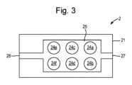
図3は、加熱要素24の配置をより詳細に示すエアロゾル供給デバイス2の断面上面図である。図1及び図3では、加熱要素24は、加熱要素24の表面がチャンバ25の表面の一部を形成するように配置されている。すなわち、加熱要素24の外面は、チャンバの内面と面一になっている。より詳細には、チャンバ25の内面と面一になっている加熱要素24の外面は、加熱要素24に電流を通したときに加熱される(すなわち、その温度が上昇する)加熱要素24の表面である。Figure 3 is a cross-sectional top view of the
加熱要素24は、エアロゾル生成品4がチャンバ25に受け入れられたときに、各加熱要素24がエアロゾル生成材料44の対応する個別部分と位置が合うように配置されて、それぞれのエアロゾル生成領域を画定する。したがって、この例では、6つの加熱要素24が、図2A~図2Cに示したエアロゾル生成材料44の6つの個別部分の2×3の配列の配置に大まかに対応した2×3の配列で配置され、以て、6つのエアロゾル生成領域を画定する。しかしながら、上で論じたように、加熱要素24の数は、異なる実施様態では異なっていてもよく、例えば、8、10、12、14個などの加熱要素24があってもよい。いくつかの実施様態では、加熱要素24の数は、6個以上であるが、20個以下である。The
より詳細には、加熱要素24は、図3では24a~24fの符号が付けられており、各加熱要素24は、参照符号24/44の後の対応する文字によって示されるように、エアロゾル生成材料44の対応する部分と位置が合うように配置されて、それぞれのエアロゾル生成領域を画定すると理解すべきである。したがって、加熱要素24のそれぞれは、エアロゾル生成材料44の対応する部分を加熱するために個別に作動させることができる。More specifically, the
加熱要素24は、チャンバ25の内面と面一に示されているが、他の実施様態では、加熱要素24は、チャンバ25内に突出してもよい。いずれの場合も、エアロゾル生成品4は、チャンバ25内に存在するときに、加熱要素24の表面と接触し、その結果、加熱要素24によって生成された熱は、キャリア構成要素42を通ってエアロゾル生成材料44に伝導される。Although the
いくつかの実施様態では、熱伝達効率を改善するために、チャンバは、キャリア構成要素42をヒーター要素24に押し付けるようにキャリア構成要素42の表面に力を加える構成要素を備えてもよく、以て、エアロゾル生成材料44への伝導による熱伝達効率を上昇させる。これに加えて、又はこれに代えて、ヒーター要素24は、エアロゾル生成品4に向かう方向/エアロゾル生成品4から離れる方向に移動するように構成されてもよく、エアロゾル生成材料44を備えないキャリア構成要素42の表面に押し付けられてもよい。In some embodiments, to improve heat transfer efficiency, the chamber may include a component that applies a force to a surface of the
使用時、エアロゾル供給デバイス2(より詳細には制御回路23)は、使用者の入力に応答して加熱要素24に電力を供給するように構成される。概して、制御回路23は、エアロゾル生成材料44の対応する部分を加熱してエアロゾルを生成するように加熱要素24に選択的に電力を印加するように構成される。使用者がエアロゾル供給デバイス2で吸引する(すなわち、吸い口端部26で吸引する)と、空気は空気入口27を通ってエアロゾル供給デバイス2に引かれ、チャンバ25に入り、ここで、エアロゾル生成材料44を加熱することによって生成されたエアロゾルと混合し、次いで、空気出口28を経て使用者の口へ引かれる。すなわち、エアロゾルは、吸い口端部26及び空気出口28を通って使用者に送達される。In use, the aerosol delivery device 2 (more specifically, the control circuit 23) is configured to provide power to the
図1のエアロゾル供給デバイス2は、接触感知パネル29及び吸引センサ30を含んでよい。接触感知パネル29及び吸引センサ30は、共に、エアロゾルの生成を引き起こすために使用者の入力を受け取るための機構として機能し、したがって、より広くは、使用者入力機構と呼ばれることがある。受け取られた使用者の入力は、使用者がエアロゾルを生成したいことを示していると言える。The
接触感知パネル29は、静電容量式タッチセンサであってもよく、エアロゾル供給デバイス2の使用者が指又は別の適切な導電性の物体(例えばスタイラス)を接触感知パネルに置くことによって操作することができる。説明されている実施様態では、接触感知パネルは、エアロゾル生成を開始するために使用者が押すことができる領域を含む。制御回路23は、接触感知パネル29からの信号を受け、この信号を用いて、使用者が接触感知パネル29のこの領域を押しているかどうか(すなわち、作動させているかどうか)を判定するように構成することができる。制御回路23がこの信号を受けた場合、制御回路23は、電源22から加熱要素24のうちの1つ以上に電力を供給するように構成される。電力は、接触が検出された瞬間から予め定められた時間(例えば3秒間)供給されてもよいし、接触が検出された時間の長さに対応して供給されてもよい。他の実施様態では、接触感知パネル29は、使用者が作動することができるボタンなどに置き換えられてもよい。The touch
吸引センサ30は、使用者がエアロゾル供給デバイス2で吸引することによって生じる圧力の低下又は空気の流れを検出するように構成された圧力センサ又はマイクロフォン等であってもよい。吸引センサ30は、空気流路と流体連通して(すなわち、入口27と出口28との間の空気流路と流体連通して)配置される。上記と同様の態様で、制御回路23は、吸引センサからの信号を受け、この信号を用いて、使用者がエアロゾル供給システム1で吸引しているかを判定するように構成することができる。制御回路23がこの信号を受けた場合、制御回路23は、電源22から加熱要素24のうちの1つ以上に電力を供給するように構成される。電力は、吸引が検出された瞬間から予め定められた時間(例えば3秒間)供給されてもよいし、吸引が検出された時間の長さに対応して供給されてもよい。The
説明されている例では、接触感知パネル29及び吸引センサ30の両方が、吸引のためのエアロゾルの生成を開始したいと使用者が思っていることを検出する。制御回路23は、接触感知パネル29及び吸引センサ30の両方からの信号が検出されたときのみ、加熱要素24に電力を供給するように構成されてもよい。これは、使用者入力機構の1つが偶発的に作動することから加熱要素24が意図せずに作動することを防止するのを助けることができる。しかしながら、他の実施様態では、エアロゾル供給システム1は、接触感知パネル29及び吸引センサ30のうちの一方のみを有してもよい。In the illustrated example, both the contact
エアロゾル供給システム1の動作のこれらの態様(すなわち、パフ検出及び接触検出)は、それ自体、確立した技法に従って(例えば、従来の吸引センサ及び吸引センサ信号処理技法を用いて、並びに、従来のタッチセンサ及びタッチセンサ信号処理技法を用いて)実行することができる。These aspects of the operation of the aerosol delivery system 1 (i.e., puff detection and contact detection) can themselves be performed in accordance with established techniques (e.g., using conventional suction sensors and suction sensor signal processing techniques, and using conventional touch sensors and touch sensor signal processing techniques).
いくつかの実施様態では、接触感知パネル29及び吸引センサ30のいずれか一方又は両方からの信号を検出したことに応答して、制御回路23は、個々の加熱要素24のそれぞれに電力を順次供給するように構成される。In some embodiments, in response to detecting a signal from either or both of the contact
より詳細には、制御回路23は、接触感知パネル29及び吸引センサ30のいずれか一方又は両方から受けた信号の検出の順序に応答して、個々の加熱要素23のそれぞれに順次電力を供給するように構成される。例えば、制御回路23は、(例えば、エアロゾル供給デバイス2のスイッチが最初に入れられたときから)信号が最初に検出されたとき、複数の加熱要素24のうちの第1の加熱要素24に電力を供給するように構成されてもよい。信号が止まると、又は信号が検出されてから予め定められた時間が経過したことに応答して、制御回路23は、第1の加熱要素24が作動された(したがって、エアロゾル生成材料44の対応する個別部分が加熱された)ことを記録する。制御回路23は、接触感知パネル29及び吸引センサ30のいずれか一方又は両方からの次の信号を受けたことに応答して、第2の加熱要素24を作動させることを決定する。したがって、接触感知パネル29及び吸引センサ30のいずれか一方又は両方からの信号を制御回路23が受けたとき、制御回路23は、第2の加熱要素24を作動させる。この処理は、残りの加熱要素24に対して繰り返され、その結果、すべての加熱要素24が順次作動させられる。More specifically, the
事実上、この操作は、各吸引に対して、エアロゾル生成材料44の個別部分の異なる部分が加熱され、エアロゾルはそれから生成されることを意味する。言い換えれば、エアロゾル生成材料の単一の個別部分は、使用者の吸引ごとに加熱される。In effect, this operation means that for each inhalation, a different portion of the discrete portion of aerosol-generating
他の実施様態では、制御回路23は、接触感知パネル29及び吸引センサ30のいずれか一方若しくは両方からの次の信号に応答して第2の加熱要素24を作動させるべきであると決定する前に、第1の加熱要素24を複数回(例えば2回)作動させる、又は、複数の加熱要素24のそれぞれを1回作動させ、すべての加熱要素24が1回作動されたときに、次の信号が検出されると、加熱要素を順次2回目作動させるように構成されてもよい。In other embodiments, the
このような順次作動させることは、「順次作動モード」と呼ばれることがあり、これは主に、吸引ごとに均一なエアロゾルを送達するように設計される(これは、例えば、生成された全エアロゾル、又は送達された全成分によって測定することができる)。したがって、このモードは、エアロゾル生成品4のエアロゾル生成材料44の各部分が実質的に同一であるとき、すなわち、部分44a~44fが同じ材料から形成されているときに最も有効であり得る。Such sequential actuation is sometimes referred to as a "sequential mode of actuation" and is primarily designed to deliver a uniform aerosol per inhalation (which may be measured, for example, by total aerosol generated or total components delivered). Thus, this mode may be most effective when each portion of the aerosol-generating
いくつかの他の実施様態では、接触感知パネル29及び吸引センサ30のいずれか一方又は両方からの信号の検出に応答して、制御回路23は、加熱要素24の1つ以上に同時に電力を供給するように構成される。In some other embodiments, in response to detecting a signal from either or both of the contact
そのような実施様態では、制御回路23は、予め定められた構成に対応して、加熱要素24のうちの選択された加熱要素に電力を供給するように構成されてもよい。予め定められた構成は、使用者によって選択又は決定された構成であってもよい。In such an embodiment, the
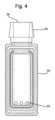
図4は、一構成によるエアロゾル供給デバイスの概略断面図である。中央エアロゾル伝送流路50をさらに備えるエアロゾル供給デバイスの内部断面が示されており、中央エアロゾル伝送流路50は、エアロゾル生成品の全体を取り囲むように配置された容積部を形成する。したがって、容積部はまた、各加熱要素及びエアロゾル生成材料の対応する部分も取り囲み、すなわち中央エアロゾル伝送流路50の容積部は、エアロゾル生成領域のそれぞれを取り囲んでいる。4 is a schematic cross-sectional view of an aerosol delivery device according to one configuration. The internal cross-section of the aerosol delivery device is shown further comprising a central
中央伝送流路50は、空気出口28を画定する開口を有する吸い口26に接続され、1つ以上の空気孔52を備え、空気孔52は外部大気と流体連通しており、その結果、中央エアロゾル伝送流路50は、エアロゾル生成材料の複数の部分がそれぞれの加熱要素によって加熱されるときに生成されるエアロゾルを伝送しやすくすることができる。この例では、空気入口27を省略することができる。The
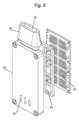
図5は、エアロゾル供給デバイスの一部の等角分解図であり、このエアロゾル供給デバイスは、図4を参照して説明したような中央エアロゾル伝送流路50と、この例では2×5の構成である複数の加熱要素24とを備える。この例では、複数の加熱要素24のそれぞれは、関連するエアロゾル伝送流路54を有する。この例では、複数のエアロゾル伝送流路54は、中央エアロゾル伝送流路50によって画定された容積部によって囲まれている。それぞれのエアロゾル伝送流路によって囲まれた複数の加熱要素24のそれぞれは、外部大気と流体連通する個々の空気供給孔(図示せず)を有して、加熱要素24がエアロゾル生成材料を加熱するときに生成されるエアロゾル生成材料を流れやすくしている。この例では、空気入口を省略することができる。5 is an isometric exploded view of a portion of an aerosol delivery device including a central
いくつかの例では、複数のエアロゾル伝送流路54のそれぞれは、要求に応じて開閉するように構成された個々のバルブ(図示せず)を備えてもよい。より詳細には、制御回路は、特定の加熱要素24を作動させるかどうかに応じて、したがって特定のエアロゾル生成領域を作動させるかどうかに応じて、個々のバルブ(複数可)を開閉するように構成されてもよい。したがって、制御回路によって、複数の加熱要素24のどれを作動させるかに応じて、複数の個々のバルブのどれかを、任意の組合せで、同時に開けるか閉じるかしてもよい、例えば、複数のバルブのすべてが開状態である、又はバルブのすべてが閉状態である、又は複数のバルブの任意の割合のバルブが開状態であり、複数のバルブの残りの割合のバルブが閉状態であることが認識されよう。In some examples, each of the plurality of
これに加えて又はこれに代えて、空気入口孔52は、要求に応じて開閉するように構成された個々のバルブ(図示せず)を備えて、特定のエアロゾル生成領域から空気が流れることを可能にしてもよい。より詳細には、制御回路は、特定の加熱要素24を作動させるかどうかに応じて、したがって特定のエアロゾル生成領域を作動させるかどうかに応じて、個々のバルブ(複数可)を開閉するように構成されてもよい。したがって、制御回路によって、複数の加熱要素24のどれを作動させるかに応じて、複数の個々のバルブのどれかを、任意の組合せで、同時に開けるか閉じるかしてもよい、例えば、複数のバルブのすべてが開状態である、又はバルブのすべてが閉状態である、又は複数のバルブの任意の割合のバルブが開状態であり、複数のバルブの残りの割合のバルブが閉状態であることが認識されよう。Additionally or alternatively, the air inlet holes 52 may include individual valves (not shown) configured to open and close on demand to allow air to flow from a particular aerosol-generating region. More specifically, the control circuit may be configured to open and close the individual valve(s) depending on whether a
いくつかの例では、中央エアロゾル伝送流路によって画定される容積部は、複数のエアロゾル伝送流路54が中央伝送流路50と流体連通するように、複数のエアロゾル伝送流路を囲む。In some examples, the volume defined by the central aerosol transmission passage surrounds multiple
使用時、エアロゾル供給デバイス(より詳細には制御回路)は、使用者の入力に応答して、加熱要素24及び個々のバルブ(存在する場合)に電力を供給するように構成される。概して、制御回路は、エアロゾルを生成するために、加熱要素24に選択的に電力を加え、続いて、エアロゾル生成材料の対応する部分を加熱してエアロゾルを生成するように構成され、加熱要素(複数可)24が加熱されている間、制御回路は、必要な量のエアロゾルを形成することができるようにそれぞれのバルブを閉じたままにするように構成される。使用者がエアロゾル供給デバイスを吸引する(すなわち、吸い口端部26で吸引する)と、制御回路は選択的にバルブを開き、空気が、複数のエアロゾル伝送流路54の個々の空気供給孔を通ってエアロゾル供給デバイス内に引き込まれ、そこでエアロゾル生成材料を加熱することによって生成されたエアロゾルと混合する。混合物は、個々のエアロゾル伝送流路54を通って空気出口28を経て使用者の口に流れる。すなわち、エアロゾルは、吸い口端部26及び空気出口28を通って使用者に送達される。In use, the aerosol delivery device (more specifically, the control circuit) is configured to provide power to the
いくつかの例では、制御回路が、複数の加熱要素24に選択的に電力を加えるように構成されているとき、使用者がエアロゾル供給デバイスを吸引し(すなわち、吸い口端部26で吸引し)、制御回路が、対応するバルブを開け、空気が、複数のエアロゾル伝送流路54の個々の空気供給孔を通ってエアロゾル供給デバイス内に引き込まれると、空気は、エアロゾル伝送流路のそれぞれでエアロゾル生成材料を加熱することによって生成されたエアロゾルと混合する。次いで、空気とエアロゾルとの個々の混合物は、空気出口28を経て使用者の口に流れる前に、中央エアロゾル伝送流路50でさらに混合する。In some examples, when the control circuitry is configured to selectively apply power to the plurality of
いくつかの例では、エアロゾル生成品は実質的に平面状とすることができ、エアロゾル供給デバイスのチャンバに受け入れ可能である。制御回路は、加熱要素24によってエアロゾル生成材料44を加熱することによって生成されるエアロゾルが、空気出口28を通って吸い口26から出るときに、その均一性が実質的に同じになるように、加熱要素24の加熱プロファイルを与える及び/又は変更するように構成されてもよく、例えば、あるエアロゾル生成材料44の部分が、別のエアロゾル材料の部分に対して長い距離移動しなければならない場合、吸い口から離れた部分の加熱要素24に与えられる加熱プロファイルは、加熱温度を上昇させて、又は加熱要素24をより長い期間作動させて、より多くの量のエアロゾルを生成するようにしてもよい。In some examples, the aerosol generating product can be substantially planar and can be received in the chamber of the aerosol delivery device. The control circuitry can be configured to provide and/or modify the heating profile of the
いくつかの例では、制御回路は、共通のエアロゾル化/加熱プロファイルに従ってエアロゾル生成材料のいくつかの部分をエアロゾル化するように構成されてもよく、一方、エアロゾル生成材料の残りの部分のエアロゾル化/加熱プロファイルは、その部分のエアロゾル伝送流路54から出口28までの距離に従って設定される。In some examples, the control circuitry may be configured to aerosolize some portions of the aerosol generating material according to a common aerosolization/heating profile, while the aerosolization/heating profile for the remaining portions of the aerosol generating material is set according to the distance of that portion from the
前述のように、図1のエアロゾル供給デバイス2は、接触感知パネル29及び吸引センサ30を含む。接触感知パネル29及び吸引センサ30は、共に、エアロゾルの生成及び複数のバルブの選択的な開閉を引き起こすために使用者の入力を受け取るための機構として機能し、したがって、より広くは、使用者入力機構と呼ばれることがある。受け取られた使用者の入力は、使用者がエアロゾルを生成したいことを示していると言える。As previously mentioned, the
接触感知パネル29は、静電容量式タッチセンサであってもよく、エアロゾル供給デバイス2の使用者が指又は別の適切な導電性の物体(例えばスタイラス)を接触感知パネルに置くことによって操作することができる。説明されている実施様態では、接触感知パネルは、エアロゾル生成を開始するために使用者が押すことができる領域を含む。制御回路23は、接触感知パネル29からの信号を受け、この信号を用いて、使用者が接触感知パネル29のこの領域を押しているかどうか(すなわち、作動させているかどうか)を判定するように構成することができる。制御回路23がこの信号を受けた場合、制御回路23は、電源22から加熱要素24のうちの1つ以上及び1つ以上のバルブに電力を供給するように構成される。電力は、接触が検出された瞬間から予め定められた時間(例えば3秒間)供給されてもよいし、接触が検出された時間の長さに対応して供給されてもよい。他の実施様態では、接触感知パネル29は、使用者が作動することができるボタンなどに置き換えられてもよい。The touch
吸引センサ30は、使用者がエアロゾル供給デバイス2で吸引することによって生じる圧力の低下又は空気の流れを検出するように構成された圧力センサ又はマイクロフォン等であってもよい。吸引センサ30は、空気流路と流体連通して(すなわち、エアロゾル伝送流路54の個々の空気入口、空気入口孔52、及び出口28の間の空気流路と流体連通して)配置される。上記と同様の態様で、制御回路23は、吸引センサからの信号を受け、この信号を用いて、使用者がエアロゾル供給システム1で吸引しているかを判定するように構成することができる。制御回路23がこの信号を受けた場合、制御回路23は、上記の態様で、電源22から加熱要素24のうちの1つ以上及び1つ以上のバルブに電力を供給するように構成される。電力は、吸引が検出された瞬間から予め定められた時間(例えば3秒間)供給されてもよいし、吸引が検出された時間の長さに対応して供給されてもよい。The
説明されている例では、接触感知パネル29及び吸引センサ30の両方が、吸引のためのエアロゾルの生成を開始したいと使用者が思っていることを検出する。制御回路23は、接触感知パネル29及び吸引センサ30の両方からの信号が検出されたときのみ、加熱要素24及びそれぞれのバルブに電力を供給するように構成されてもよい。これは、使用者入力機構の1つが偶発的に作動することから加熱要素24が意図せずに作動することを防止するのを助けることができる。しかしながら、他の実施様態では、エアロゾル供給システム1は、接触感知パネル29及び吸引センサ30のうちの一方のみを有してもよい。In the illustrated example, both the touch
エアロゾル供給システム1の動作のこれらの態様(すなわち、パフ検出及び接触検出)は、それ自体、確立した技法に従って(例えば、従来の吸引センサ及び吸引センサ信号処理技法を用いて、並びに、従来のタッチセンサ及びタッチセンサ信号処理技法を用いて)実行することができる。These aspects of the operation of the aerosol delivery system 1 (i.e., puff detection and contact detection) can themselves be performed in accordance with established techniques (e.g., using conventional suction sensors and suction sensor signal processing techniques, and using conventional touch sensors and touch sensor signal processing techniques).
いくつかの実施様態では、接触感知パネル29及び吸引センサ30のいずれか一方又は両方からの信号を検出したことに応答して、制御回路23は、個々の加熱要素24のそれぞれ及びそれぞれのバルブに電力を順次供給するように構成される。In some embodiments, in response to detecting a signal from either or both of the contact
より詳細には、制御回路23は、接触感知パネル29及び吸引センサ30のいずれか一方又は両方から受けた信号の検出の順序に応答して、個々の加熱要素24のそれぞれ及びそれぞれのバルブに順次電力を供給するように構成される。例えば、制御回路23は、(例えば、エアロゾル供給デバイス2のスイッチが最初に入れられたときから)信号が最初に検出されたとき、エアロゾルを生成するために、複数の加熱要素24のうちの第1の加熱要素24に電力を供給し、それぞれのバルブを閉状態に保つようにそれらに電力を供給して構成されてもよい。信号が止まると、又は信号が検出されてから予め定められた時間が経過したことに応答して、制御回路23は、第1の加熱要素24が作動され(したがって、エアロゾル生成材料44の対応する個別部分が加熱され)、次いで、空気とエアロゾルとの混合物が流れることができるように、それぞれのバルブを開けたことを記録する。制御回路23は、接触感知パネル29及び吸引センサ30のいずれか一方又は両方からの次の信号を受けたことに応答して、第2の加熱要素24を作動させ、要素24がエアロゾル生成材料44の部分を加熱している間、第2のバルブを閉じることを決定する。したがって、接触感知パネル29及び吸引センサ30のいずれか一方又は両方からの信号を制御回路23が受けたとき、制御回路23は、第2の加熱要素24を作動させる。この処理は、残りの加熱要素24に対して繰り返され、その結果、すべての加熱要素24が順次作動させられ、それぞれのバルブが順次かつ選択的に開閉される。事実上、この操作は、各吸引に対して、エアロゾル生成材料44の個別部分の異なる部分が加熱され、エアロゾルはそれから生成されることを意味する。言い換えれば、エアロゾル生成材料の単一の個別部分は、使用者の吸引ごとに加熱される。他の例では、エアロゾル生成材料44の複数の個別部分は、制御パネル29によって制御されるように、使用者が望むようなパフ特性及び香味プロファイルに応じて、前述のように、中央エアロゾル伝送流路50で加熱及び混合することができる。More specifically, the
ここで認識するように、中央エアロゾル伝送流路50によって画定される容積部が複数のエアロゾル伝送流路54を囲み、その結果、複数のエアロゾル伝送流路54が中央伝送流路50と流体連通し、任意選択の個々のバルブと組み合わさっている例では、有利なことに、特定のエアロゾル生成区域で生成されたエアロゾルは他のすべての区域を横切って移動する必要がなく、使用者の要求に応じて、エアロゾル生成材料を調整して送達することができることを意味する。これにより、所望のパフ特性、例えば、体積又は流量を提供するようにエアロゾル生成材料44を混合することもできる。さらに、エアロゾル生成品4が、異なる種類又は香味特性のエアロゾル生成材料44を備える場合、使用者は、使用者が操作するときに制御回路23及び接触感知パネル29によって容易にされるように使用時に香味プロファイルをさらにカスタマイズすることができる。As will be appreciated, in the example where the volume defined by the central
いくつかの例では、エアロゾル伝送流路54は、吸い口26及び空気出口28までのエアロゾル伝送流路54の流路長が実質的に同じになるように配置及び構成されてもよい。他の例では、流路長は同じでなくてもよい。In some examples, the
他の例では、中央エアロゾル伝送流路50が存在せず、エアロゾル伝送流路54のそれぞれは、空気出口28と直接連通し、すなわち、エアロゾル伝送流路54のそれぞれは、空気出口28への別個の流路を有する。In another example, there is no central
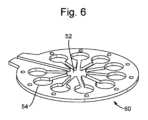
図6は、代替の実施形態による図4のエアロゾル供給装置の一部の等角図である。代替の構成で配置された複数のエアロゾル伝送流路54の部分が示されている。この例では、図6に示すように、エアロゾル伝送流路54、エアロゾル生成領域、及び対応する加熱要素は、円形要素60の円周の周りに均等に分配されている。エアロゾル伝送流路54のそれぞれは、出口及び/又は吸い口(図示せず)に流れる前に、中央エアロゾル伝送流路50に直接流れ込む。エアロゾル伝送流路54のそれぞれは、制御可能なバルブを備えることができるそれぞれの空気入口と位置合わせすることができる。Figure 6 is an isometric view of a portion of the aerosol delivery device of Figure 4 according to an alternative embodiment. A portion of a plurality of
この例では、エアロゾル伝送流路54、エアロゾル生成領域、及び対応する加熱要素が円形要素60の円周の周りに均等に分配されているので、エアロゾル生成領域からそれぞれのエアロゾル伝送流路54を通る流路長は、エアロゾル生成領域に対して実質的に同じになる。In this example, the
図7は、そのような実施様態による接触感知パネル29の上面図である。図7は、前述したような外側ハウジング21及び接触感知パネル29を概略的に示している。接触感知パネル29は、6つの加熱要素のそれぞれに対応する6つの領域29a~29f、及び前述のように、使用者が吸引を開始すること、又はエアロゾルを生成することを望んでいることを示すための領域に対応する領域29gを備える。Figure 7 is a top view of the touch
6個より多くの加熱エレメント、例えばn個の加熱要素がある例では、接触感知パネル29の領域もn個ある。In an example where there are more than six heating elements, for example n heating elements, there are also n areas of the touch
上記の例の6つの領域29a~29fはそれぞれ、6つの対応する加熱要素のそれぞれ、及びそれぞれのバルブ(存在する場合)への電力供給を制御するために使用者が触れることができる接触感知領域に対応する。説明されている実施様態では、各加熱要素及びそれぞれのバルブは、複数の状態、例えば、加熱要素及びバルブに電力が供給されないオフ状態、加熱要素及びバルブに第1のレベルの電力が供給される低電力状態、並びに加熱要素及びバルブに、第1のレベルの電力より大きい第2のレベルの電力が供給される高電力状態を有することができる。しかしながら、他の実施様態では、これより少ない又は多い状態が、加熱要素に利用可能であってもよい。例えば、各加熱要素は、加熱要素に電力が供給されないオフ状態、及び加熱要素に電力が供給されるオン状態、又はそれらの任意の組合せを有してもよい。Each of the six
したがって、使用者は、エアロゾルを生成する前に、接触感知パネル29と対話することによって、どの加熱要素(及び、それに続いてエアロゾル生成材料のどの部分)を加熱するか(及び、任意選択的に、それらをどの程度まで加熱するか)を設定することができる。例えば、使用者は、異なる状態(例えば、オフ、低電力、高電力、オフなど)を循環させるために領域29a~29fを繰り返しタップしてもよい。これに代えて、使用者は、異なる状態を循環させるために領域29a~29fを押して保持してもよい。この場合、押されている時間が状態を決定する。Thus, a user can configure which heating elements (and subsequently which portions of the aerosol-generating material) are heated (and, optionally, to what extent) prior to generating an aerosol by interacting with the touch-
接触感知パネル29は、それぞれの領域29a~29fごとに、加熱要素が現在どの状態であるかを示す1つ以上の表示器を備えてもよい。例えば、接触感知パネルは、1つ以上のLED又は同様の照明要素を備えてもよく、LEDの強度は、加熱要素の現在の状態を示す。これに代えて、カラーのLED又は同様の照明要素が設けられてもよく、色が現在の状態を示す。これに代えて、接触感知パネル29は、加熱要素の現在の状態を表示する表示要素(例えば、透明な接触感知パネル29の下にあってもよく、又は接触感知パネル29の領域29a~29fに隣り合って設けられてもよい)を備えてもよい。The touch
使用者が加熱要素の構成を設定すると、接触感知パネル29(より詳細には接触感知パネル29の領域29g)及び吸引センサのいずれか一方又は両方からの信号の検出に応答して、制御回路が、予め設定された構成に従って、選択された加熱要素に電力を供給するように構成される。Once the user has set the heating element configuration, the control circuit is configured to supply power to the selected heating element in accordance with the pre-set configuration in response to detection of signals from either or both of the contact sensitive panel 29 (more specifically,
したがって、このような同時に加熱要素を作動させることは、「同時作動モード」と呼ばれることがあり、これは主に、使用者にセッションごとに、又はパフごとでさえ、その体験のカスタマイズを可能にさせるという意図で、所与のエアロゾル生成品からカスタマイズ可能なエアロゾルを送達するように設計される。したがって、このモードは、エアロゾル生成品のエアロゾル生成材料の部分が互いに異なる場合に最も効果的であり得る。例えば、図2Aを参照すると、部分44a及び44bが1つの材料で形成され、部分44c及び44dが異なる材料で形成されている場合などである。したがって、この動作モードでは、使用者は、任意の所与の瞬間にどの部分をエアロゾル化するか、したがってエアロゾルのどの組合せを供給するかを選択することができる。Such simultaneous activation of heating elements may therefore be referred to as a "simultaneous activation mode," which is primarily designed to deliver customizable aerosols from a given aerosol generating product with the intent of allowing the user to customize their experience from session to session, or even puff to puff. This mode may therefore be most effective when the portions of the aerosol generating material of the aerosol generating product are different from one another. For example, referring to FIG. 2A,
同時作動モード及び順次作動モードの両方において、制御回路は、例えば、加熱要素のそれぞれが予め定められた回数、順次作動させられたとき、又は、所与の加熱要素が予め定められた回数及び/若しくは所与の累積作動時間及び/若しくは所与の累積作動電力で作動させられたとき、エアロゾル生成品の使用の終了を示す警告信号を生成するように構成されてもよい。図1では、エアロゾル供給デバイス2は使用終了表示器31を含み、これは、この実施様態ではLEDである。しかしながら、他の実施様態では、使用終了表示器31は、使用者に警告信号を与えることができる任意の機構を備えてもよい、すなわち、使用終了表示器31は、光学信号を送達する光学要素、音声信号を送達する音発生器、及び/又は触覚信号を送達する振動器であってもよい。いくつかの実施様態では、表示器31は、(例えば、接触感知パネルが表示要素を含む場合)接触感知パネルと組み合わせられてもよい、又は他の態様で提供されてもよい。エアロゾル供給デバイス2は、警告信号が出力されているときには、エアロゾル供給デバイス2の次の作動を妨げることができる。使用者がエアロゾル生成品4を交換するとき、及び/又は、ボタン(図示せず)などの手動手段を介して警告信号を切ると、警告信号を切ることができ、制御回路23がリセットされる。In both the simultaneous and sequential operation modes, the control circuitry may be configured to generate a warning signal indicating the end of use of the aerosol generation product, for example, when each of the heating elements has been sequentially activated a predetermined number of times, or when a given heating element has been activated a predetermined number of times and/or with a given cumulative activation time and/or a given cumulative activation power. In FIG. 1, the
より詳細には、順次作動モードが使われる実施様態では、制御回路23は、使用期間中に受け取った接触感知パネル29及び吸引センサ30のいずれか一方又は両方からの信号の回数を数え、回数が予め定められた数に到達すると、エアロゾル生成品4がその寿命の終わりに到達したと決定されるように構成されてもよい。例えば、6つのエアロゾル生成材料44の個別部分を備える物品4に対しては、予め定められた数は、目下のその実施様態に応じて、6、12、18などとすることができる。More specifically, in an embodiment in which a sequential mode of operation is used, the
同時作動モードが使われる実施様態では、制御回路23は、エアロゾル生成材料44の個別部分の1つ又はそれぞれが加熱される回数を数えるように構成されてもよい。例えば、制御回路23は、ニコチン含有部分が何回加熱されたかを数え、それが予め定められた数に到達すると、エアロゾル生成品4の寿命の終わりを決定することができる。これに代えて、制御回路23は、エアロゾル生成材料44の各個別部分に対して、その部分が加熱されたときに別々に数えるように構成されてもよい。各部分は、同じ又は異なる予め定められた回数を有するものとしてもよく、エアロゾル生成材料の各部分に対する回数のいずれか1つが予め定められた数に到達すると、制御回路23は、エアロゾル生成品4の寿命の終わりを決定する。In embodiments in which the simultaneous mode of operation is used, the
実施様態のいずれにおいても、制御回路23はまた、エアロゾル生成材料の部分が加熱された時間の長さ、及び/又は、エアロゾル生成材料の部分が加熱された温度を計算に入れてもよい。この点について、制御回路23は、個別の作動を数えるのではなく、エアロゾル生成材料44の各部分が受けた加熱状態を示す累積パラメータを計算するように構成されてもよい。このパラメータは、例えば、累積時間であってもよく、その材料への温度は、累積時間に加えられる時間の長さを調節するために使用される。例えば、200℃で3秒間加熱された部分は、累積時間に3秒寄与することができ、一方、300℃以上で3秒間加熱された部分は、累積時間に4.5秒寄与することができる。In any of the embodiments, the
エアロゾル生成品4の寿命の終わりを決定するための上記の技法は、エアロゾル生成品4の寿命の終わりを決定する方法の網羅的なリストとして理解すべきではなく、実際には、任意の他の適切な方法が、本開示の原理に従って使用されてもよい。The above techniques for determining the end of life of the aerosol generating product 4 should not be understood as an exhaustive list of methods for determining the end of life of the aerosol generating product 4, and indeed any other suitable method may be used in accordance with the principles of the present disclosure.
上記のエアロゾル供給システム1の実施様態では、エアロゾル生成構成要素24を使用して選択的にエアロゾル化することができ、任意選択でそれぞれのバルブを有するそれぞれのエアロゾル伝送流路54によって囲まれた、エアロゾル生成材料44の複数の(個別)部分が設けられる。このようなエアロゾル供給システム1は、より大きな大きさの材料を加熱するように設計された他のシステムを超える利点を提供する。特に、所与の吸引に対して、エアロゾル生成材料の選択された部分(複数可)のみがエアロゾル化されることは、全体としてよりエネルギー効率の高いシステムをもたらす。In the above-described embodiment of the aerosol delivery system 1, multiple (discrete) portions of the aerosol-generating
加熱システムでは、パフごとに十分な量のエアロゾルを使用者に送達する際、いくつかのパラメータがこのシステムの全体的な有効性に影響を与える。一方では、エアロゾル生成材料の厚さは、エアロゾル生成材料が動作温度に到達する(そしてその後、エアロゾルを生成する)速さに影響するので重要である。これは、いくつかの理由で重要であるが、材料のより厚い部分を加熱する場合と比較して同じほど長く加熱要素が作動する必要がないことがあるので、電源22からのエネルギーのより効率的な使用につながることがある。他方では、加熱されるエアロゾル生成材料の総質量は、生成され、その後使用者に送達することができるエアロゾルの総量に影響を与える。加えて、エアロゾル生成材料が加熱される温度もまた、エアロゾル生成材料が動作温度に到達する速さ及び生成されるエアロゾルの量の両方に影響を与えることがある。In a heating system, several parameters affect the overall effectiveness of the system in delivering a sufficient amount of aerosol per puff to the user. On the one hand, the thickness of the aerosol-generating material is important because it affects how quickly the aerosol-generating material reaches an operating temperature (and subsequently generates aerosol). This is important for several reasons, but it can also lead to a more efficient use of energy from the
本開示によれば、エアロゾル生成材料の部分の異なる部分を加熱してパフごとにエアロゾルを生成するように設計されたエアロゾル生成構成要素24(加熱要素24など)の配列を有するエアロゾル供給デバイス2が、いくつかの例において、加熱条件がほぼ同じであっても、1パフ当たりに使用者に送達されるエアロゾルの量に不一致が生じ得ることを見出した。In accordance with the present disclosure, it has been discovered that an
これは、エアロゾル生成材料44のいくつかの部分が、吸い口26の開口28に対して相対的に異なる空間距離に設けられ、その結果、エアロゾルがエアロゾル生成材料の部分に隣り合う場所で最初に形成されたとき、そのエアロゾルが移動しなければならない距離が異なることがあるという事実に部分的に起因していると考えられる。This may be due in part to the fact that some portions of the aerosol-generating
図8は、図3を複製したものであるが、これに加えて、D1及びD2と符号が付けられた2つの矢印を含む。D1は、加熱要素24aから吸い口端部26の出口28まで延在し、一方、D2は、加熱要素24fから出口28まで延在している。認識すべきように、矢印D1及びD2は、エアロゾル生成材料44a及び44fのそれぞれの部分によってそれぞれの加熱要素24a及び24fを使用して生成されたエアロゾルが通る距離を表す。Figure 8 replicates Figure 3, but additionally includes two arrows labeled D1 and D2. D1 extends from
一般に、高温のエアロゾルは移動するにつれて温度が下がり凝縮する。したがって、エアロゾルが移動しなければならない距離が長ければ長いほど、エアロゾルは温度が下がり凝縮する可能性が高くなる。凝縮物はまた、例えば、図8の例のチャンバ25の表面など、移動中に接する表面に堆積することがある。エアロゾルが移動する距離が長いほど、エアロゾルが表面に接する機会が増えることが一因となり、また、エアロゾルが移動して温度が下がると粒子の大きさが大きくなることにより、堆積する可能性はさらに高くなる。図8では、D1はD2よりもかなり長いことが分かり、したがって、例えば、加熱要素24aにおいて部分44aによって生成されたエアロゾルは、加熱要素24fにおいて部分44fによって生成されたエアロゾルと比較すると、デバイス2の出口28を出るときにエアロゾル量/体積が少ない可能性が高い。同様に、加熱要素24c及び24dにおいて部分44c及び44dによって生成されたエアロゾルは、加熱要素24e及び24fにおいて部分44e及び44fによって生成されたエアロゾルと比較すると、出口を出るエアロゾルの量が少ない可能性が高くなり得るが、加熱要素24a及び24bにおいて部分44a及び44bによって生成されたエアロゾルと比較すると、出口28を出るエアロゾルの量が多い可能性が高くなり得る。この影響は、加熱要素の数が増加すると(例えば、2×6の配列)、さらにより顕著になることがある。Generally, hot aerosols cool and condense as they travel. Thus, the longer the distance the aerosol must travel, the more likely it is that the aerosol will cool and condense. Condensate may also deposit on surfaces it comes into contact with during its travel, such as the surface of
距離D1及びD2は、出口28に配置された共通点に対して評価されてもよい。例えば、共通点は、出口28によって画定される断面積の中心であってもよい。Distances D1 and D2 may be evaluated relative to a common point located at
したがって、エアロゾル伝送流路54、50、及び、任意選択で、選択的に開閉することができるそれぞれのバルブを含むことにより、空気流、したがってエアロゾル混合物は、加熱要素24によって画定された他のエアロゾル生成領域のすべてを横切って移動する必要はない。したがって、エアロゾル伝送流路54の設計に応じて、エアロゾル伝送流路50のそれぞれ、したがってエアロゾルが、空気出口28への実質的に同じ経路長又は画定された空気経路を有することが可能であり得る。これはまた、使用者の要求に応じて調整された送達を可能とし得る。Thus, by including the
加えて、他の例では、制御回路23は、出口28からのエアロゾル生成材料44のそれぞれの部分の距離に基づいて、エアロゾル生成材料44のそれぞれの部分からエアロゾルの量を生成するように、加熱要素24のそれぞれに加熱プロファイルを与えるように構成されてもよい。したがって、空気出口28を通って吸い口26に到達するエアロゾルの均一性は、それぞれの加熱要素24によって加熱されるエアロゾル生成材料44のすべての部分に対して実質的に同じとなる。In addition, in another example, the
このように、エアロゾルが出口28に移動するときに、その他の方法による凝縮又は損失によるエアロゾルの損失を補償するように、エアロゾル生成材料44のそれぞれの部分から生成されるエアロゾルの量を設定することができる。言い換えれば、エアロゾル生成構成要素24は、出口28からエアロゾル生成材料44のそれぞれの部分までの距離にかかわらず、実質的に一定の量のエアロゾルが出口28を通過するように、エアロゾル生成材料44のそれぞれの部分からある量のエアロゾルを生成するように構成される。したがって、使用者は、より均一な吸引体験、したがって均一な感覚的体験を得ることができる。In this way, the amount of aerosol generated from each portion of the aerosol-generating
この点について、「より均一な吸引体験」という表現によって、除外されるものではないが、セッションにおける各パフが、味、又は送達される成分の割合において同じであることを必ずしも示唆するのではないことをここでは認識すべきである。In this regard, it should be recognized that the expression "a more uniform inhalation experience" does not necessarily imply, but does not preclude, that each puff in a session will be identical in taste or proportion of delivered ingredients.
一方では、エアロゾル生成品4は、同じ配合又は組成を有するエアロゾル生成材料の複数の部分を備えてもよく、作動の「順次モード」に従ってエアロゾル化されてもよい。この場合、本開示の原理に従って、エアロゾル生成材料44の各部分は、模擬標準吸引を用いて(例えば、Coresta推奨法81、CRM81に従って)測定されたときに出口28を出るエアロゾルの量が実質的に同じになるように、出口28からの距離及びそれぞれのエアロゾル伝送流路54の長さに応じた量だけエアロゾル化される。この場合、それぞれ順次作動されて、出口28を出るエアロゾルの量が実質的に同じになる。On the other hand, the aerosol generating product 4 may comprise multiple portions of aerosol generating material having the same formulation or composition and may be aerosolized according to a "sequential mode" of operation. In this case, in accordance with the principles of the present disclosure, each portion of the
他方では、エアロゾルが上記のようにカスタマイズ可能であるように、エアロゾル生成品4が、異なるエアロゾル生成材料の部分を備える場合、本開示の原則は、同じタイプのエアロゾル生成材料の部分に対して適用される。言い換えれば、エアロゾル生成材料の所与のタイプ(例えば、ニコチンリッチ固体)に対しては、エアロゾル供給デバイス2は、出口28からのその部分までの距離、及びまた、それぞれのエアロゾル伝送流路54の流路の長さにかかわらず、その部分から生成されるエアロゾルの均一な量を出力するように構成される。これらの実施様態では、エアロゾルの総量は、(例えば、エアロゾル生成材料の他の部分が同時に加熱されるため)変わることがある。言い換えれば、出口28を出るエアロゾル全体に寄与するエアロゾルの量は実質的に同じであり、したがって、その特定の部分からの送達は一貫している。On the other hand, if the aerosol generating product 4 comprises portions of different aerosol generating materials such that the aerosol is customizable as described above, the principles of the present disclosure apply to portions of the same type of aerosol generating material. In other words, for a given type of aerosol generating material (e.g., a nicotine-rich solid), the
出口からエアロゾル生成材料の部分までの距離に基づいて生成されるエアロゾルの量は、関係する距離の長さ、材料のタイプ、及び出力する目標エアロゾルに依存すると思われる。しかしながら、いくつかの実施様態では、出力されるエアロゾル量の増加は、出力される目標エアロゾル量の50%以下、40%以下、30%以下、20%以下、又は10%以下のことがある。The amount of aerosol generated based on the distance from the outlet to the portion of the aerosol-generating material may depend on the length of the distance involved, the type of material, and the target aerosol output. However, in some embodiments, the increase in the amount of aerosol output may be 50% or less, 40% or less, 30% or less, 20% or less, or 10% or less of the target aerosol output.
図8を参照すると、ほとんどの例では、制御回路23は、エアロゾル生成構成要素24に、エアロゾル生成材料44のそれぞれの部分の配置が出口28から離れるほど、エアロゾル生成材料44のそれぞれの部分からより多くの量のエアロゾルを生成させるように構成されることを認識すべきである。したがって、出口28からより離れたエアロゾル生成材料の部分からより多くのエアロゾルを生成することによって、運ばれるエアロゾルの相対的により多くが出口28に到達する可能性がより高い。言い換えれば、より多くのエアロゾルが生成されて、エアロゾルが出口に移動するときのエアロゾルの損失を補償する(それぞれのエアロゾル伝送流路54によって画定される経路長が、加熱要素24によって画定されるすべての加熱区域の間で実質的に同じでない場合)。8, it should be appreciated that in most instances, the
これに加えて、又はこれに代えて、システム1の詳細に応じて、エアロゾル生成材料の部分の一部のみが、出口28からの距離に基づいてエアロゾル化されることがある。例えば、所与のシステム1に対して、出口28からの距離に最も大きな影響を受けるのは、出口28から最も遠いエアロゾル生成の部分、すなわち部分44a及び44b(加熱要素24a及び24bに対応)であることを経験的に見出すことができる。すなわち、例えば、エアロゾル化されたとき、部分44c~44fは、出口28からの距離が異なるにもかかわらず、出口28から出るときに同様の量のエアロゾルを生じるが、部分44a及び44bはエアロゾル化されたとき、部分44c~44fと比較して、生成されるエアロゾルの量が例えば20%少ないことがある。したがって、制御回路23は、共通のエアロゾル化/加熱プロファイルに従ってエアロゾル生成材料のいくつかの部分のエアロゾル化をさせるように構成されてもよく、一方、エアロゾル生成材料の残りの部分のエアロゾル化/加熱プロファイルは、出口28からその部分までの距離に従って設定される。Additionally or alternatively, depending on the details of the system 1, only a portion of the aerosol-generating material may be aerosolized based on the distance from the
出口28からより遠い部分は、より多くのエアロゾルを生成するために、より多くエアロゾル化又は加熱されるように構成されることを論じたが、制御回路23は、出口28により近いエアロゾル生成材料の部分から相対的により少ないエアロゾルを生成するように構成されてもよいことを同様に認識すべきである。Although it has been discussed that portions further from the
追加的に生成されるエアロゾルの量は、失われるエアロゾルの量と全く同じでないことがあることを認識すべきである。例えば、4mgのエアロゾルがエアロゾル生成材料のある部分から生成され、そのエアロゾルが出口28に移動するときにそのエアロゾルの1mgが失われると想定する。同じ部分44から5mgのエアロゾルを生成するようにエアロゾル生成構成要素を制御することが、出口28で4mgのエアロゾルが出力されることにつながるとは限らないことがある。実際には、生じる損失は生成されるエアロゾルの量に比例すると考えられる。上記の例では、生じた4mgのうちの25%が、エアロゾルが出口28に運ばれるときに失われる。したがって、生成されるエアロゾルの量を5mgに増大させたとき、損失は依然として25%であり、それによって、出口28に到達するのは3.75mgになる。It should be recognized that the amount of additional aerosol generated may not be exactly the same as the amount of aerosol lost. For example, assume that 4 mg of aerosol is generated from a portion of the aerosol-generating material, and 1 mg of the aerosol is lost as the aerosol travels to the
より一般的に言えば、制御回路23は、エアロゾル生成構成要素24に、出口28からエアロゾル生成材料44の部分までの距離の関数に基づいて、エアロゾル生成材料44の部分からある量のエアロゾルを生成させるように構成される。More generally, the
この関数は、エアロゾル生成材料44のいくつかの部分を試験して、エアロゾルの損失が出口からの距離によってどのように変化するかを決定することによって経験的に見出すことができる。この関数はまた、一般的に、チャンバ及び/又は空気流路の形状に依存することがあることを認識すべきである。第一次近似として、生成されるエアロゾルと距離との間の関係は線形とすることができる。例えば、距離1mm増加あたり追加で生成されるエアロゾルの量は、例えば、0.01mg/mmに設定することができる。This function can be found empirically by testing several portions of the aerosol-generating
上記の実施様態では、エアロゾル生成構成要素は、エアロゾル生成材料の部分を加熱するように配置された加熱要素24である。加熱要素24を使用してエアロゾル生成材料の部分から生成されるエアロゾルの量を調節しようとするとき、加熱要素24の目標上昇温度を調節することができる、及び/又はエアロゾル生成材料を加熱する時間を調節することができる。In the above embodiment, the aerosol generating component is a
すなわち、いくつかの実施様態では、制御回路23は、出口28からエアロゾル生成材料のそれぞれの部分までの距離に基づいて、少なくとも1つの加熱要素24の動作温度を設定するように構成される。動作温度は、加熱要素24が到達するように制御される目標温度として定められてもよい。言い換えれば、加熱要素24に供給される電力は、その電力が加熱要素24を目標温度に到達させるのに十分であるように設定される。目標温度を上げると、エアロゾル生成材料に伝達されるエネルギー量が実質的に増加する。しかしながら、ほとんどの実施様態では、目標動作温度に対する上限が課される。その理由は、その上限を超えて材料を加熱するとエアロゾル生成材料44が炭化する、又は燃えることがあるからである。That is, in some embodiments, the
これに加えて又はこれに代えて、いくつかの実施様態では、制御回路23は、出口28からエアロゾル生成材料のそれぞれの部分までの距離に基づいて、少なくとも1つの加熱要素24の加熱プロファイル、例えば加熱時間を設定するように構成される。加熱時間(すなわち、加熱要素が作動している時間)はまた、生成されるエアロゾルの量を変更するように設定されてもよく、それによって、加熱時間を長くすると、一般に、生成されるエアロゾルが相対的に多くなる。上記のように、加熱要素24は、吸引センサ30若しくは接触感知パネル29の一方若しくは両方からの信号が止まったとき、又は信号を受けてから予め定められた時間が経過したときのいずれかでスイッチが切られてもよい。しかしながら、上記の実施様態によれば、コントロールユニット23は、例えば、加熱要素を予め定められた閾値を超えて加熱させることによって(又は、これに代えて、閾値を上げることによって)、又は、信号が止まってからも加熱させ続けることによって、加熱要素24をより長い時間作動させてもよい。この技法はまた、上記のような動作温度の調節と組み合わされてもよい。Additionally or alternatively, in some embodiments, the
図9は、本開示の別の実施形態によるエアロゾル供給システム200の概略断面図である。エアロゾル供給システム200は、図1に関連して説明したものと大まかに類似する構成要素を含むが、参照番号は200を加えられている。効率化のために、類似の参照番号を有する構成要素は、特に断らない限り、図1及び図2A~図2Cの対応するものとほぼ同じであると理解すべきである。Figure 9 is a schematic cross-sectional view of an
エアロゾル供給デバイス202は、外側ハウジング221、電源222、制御回路223、誘導コイル224a、チャンバ225、吸い口端部226、空気入口227、空気出口228、接触感知パネル229、吸引センサ230、及び使用終了表示器231を備える。The
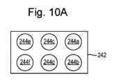
エアロゾル生成品204は、図10A~図10Cにさらに詳細に示すように、キャリア構成要素242、エアロゾル生成材料244、及びサセプタ要素244bを備える。図10Aは、エアロゾル生成品4の上面図であり、図10Bは、エアロゾル生成品204の長手方向(長さ)軸線に沿った端面図であり、図10Cは、エアロゾル生成品204の幅方向軸線に沿った側面図である。The
前述したように、エアロゾル伝送流路54、中央エアロゾル伝送流路50、及びそれぞれのバルブ(存在する場合)を含む図5に示したようなエアロゾル供給デバイスは、図9及び図10に示したエアロゾル生成システムに適合することができ、図5に関連して説明したのと実質的に同じように動作する。図9及び図10は、誘導を用いてエアロゾル生成材料244を加熱して吸引用のエアロゾルを生成するエアロゾル供給システム200を表す。As previously mentioned, an aerosol delivery device such as that shown in FIG. 5, including the
説明されている実施様態では、エアロゾル生成構成要素224は、2つの部品、すなわち、エアロゾル供給デバイス202に配置された誘導コイル224a及びエアロゾル生成品204に配置されたサセプタ224bから形成される。したがって、説明されているこの実施様態では、各エアロゾル生成構成要素224は、エアロゾル生成品204とエアロゾル供給デバイス202との間で分散された要素を備える。In the described embodiment, the aerosol generating component 224 is formed from two parts: an
誘導加熱は、サセプタと呼ばれる導電性物体に変動磁場を侵入させることによってその物体を加熱するプロセスである。このプロセスは、ファラデーの電磁誘導の法則及びオームの法則によって説明される。誘導ヒーターは、電磁石と、この電磁石に交流電流などの変動電流を流すためのデバイスとを備えることがある。電磁石及び加熱しようとする物体が、電磁石によって生じた変動磁場がこの物体に侵入するように適切な相対位置に配置されると、この物体内に1つ以上の渦電流が発生する。この物体は電流の流れに対して抵抗を有する。したがって、この物体内にこのような渦電流が生成されると、物体の電気抵抗に抗して流れ、それによってこの物体が加熱される。このプロセスは、ジュール加熱、オーム加熱、又は抵抗加熱と呼ばれる。Induction heating is the process of heating an electrically conductive object, called a susceptor, by penetrating a changing magnetic field into the object. The process is described by Faraday's law of electromagnetic induction and Ohm's law. An induction heater may comprise an electromagnet and a device for passing a changing electric current, such as an alternating current, through the electromagnet. When the electromagnet and the object to be heated are placed in the proper relative positions such that the changing magnetic field produced by the electromagnet penetrates the object, one or more eddy currents are generated in the object. The object has a resistance to the flow of electric current. Thus, when such eddy currents are generated in the object, they flow against the electrical resistance of the object, thereby heating the object. This process is called Joule heating, Ohmic heating, or resistive heating.
サセプタは、交流磁場などの変動磁場の侵入によって加熱可能な材料である。サセプタは、導電性材料であってもよく、その結果、変動磁場がそれに侵入することによって、サセプタが誘導加熱される。サセプタは、磁性体であってもよく、その結果、変動磁場がそれに侵入することによって、サセプタが磁気ヒステリシス加熱される。サセプタは、導電性及び磁性の両方を有してもよく、その結果、サセプタは両方の加熱機構によって加熱可能である。The susceptor is a material that can be heated by the penetration of a fluctuating magnetic field, such as an alternating magnetic field. The susceptor may be an electrically conductive material, such that the susceptor is inductively heated by the penetration of a fluctuating magnetic field therethrough. The susceptor may be a magnetic material, such that the susceptor is magnetically heated by the penetration of a fluctuating magnetic field therethrough. The susceptor may be both electrically conductive and magnetic, such that the susceptor can be heated by both heating mechanisms.
磁気ヒステリシス加熱は、磁性材料からなる物体に変動磁場を侵入させることによってその物体を加熱するプロセスである。磁性材料は、原子スケールの磁石すなわち磁気双極子を多く含んでいると考えることができる。磁場がこのような材料に侵入すると、磁気双極子は磁場に沿って整列する。したがって、交流磁場(例えば、電磁石によって生じるもの)などの変動磁場が磁性材料に侵入すると、磁気双極子の向きは、印加された変動磁場に応じて変化する。このような磁気双極子の再配向によって、磁性材料内に熱が生成される。Magnetic hysteresis heating is the process of heating an object made of a magnetic material by subjecting it to a varying magnetic field. A magnetic material can be thought of as containing many atomic-scale magnets or magnetic dipoles. When a magnetic field enters such a material, the magnetic dipoles align themselves along the magnetic field. Thus, when a varying magnetic field, such as an alternating magnetic field (e.g., produced by an electromagnet), enters a magnetic material, the orientation of the magnetic dipoles changes in response to the applied varying magnetic field. This reorientation of the magnetic dipoles produces heat in the magnetic material.
物体が導電性及び磁性の両方を有するときは、その物体に変動磁場を侵入させると、その物体にジュール加熱及び磁気ヒステリシス加熱の両方を生じさせることができる。さらに、磁性材料を使用すると、磁場を強めることができ、それによりジュール加熱を強めることができる。When an object is both conductive and magnetic, the introduction of a varying magnetic field into the object can cause both Joule heating and magnetic hysteresis heating in the object. Furthermore, the use of magnetic materials can enhance the magnetic field, thereby enhancing Joule heating.
説明されたこの実施様態では、サセプタ224bはアルミニウム箔から形成されているが、他の実施様態では他の金属及び/又は導電性材料が使用されてもよいことを認識すべきである。図9に見られるように、キャリア構成要素242は、キャリア構成要素242の表面に配置されたエアロゾル生成材料244の個別部分に大きさ及び位置が対応するいくつかのサセプタ224bを備える。すなわち、サセプタ224bは、エアロゾル生成材料244の個別部分と同様の幅及び長さを有する。In the illustrated embodiment, the
サセプタは、キャリア構成要素242に埋め込まれて示されている。しかしながら、他の実施様態では、サセプタ224bは、キャリア構成要素242の表面に配置されてもよい。The susceptor is shown embedded in the
エアロゾル供給デバイス202は、図9に概略的に示された複数の誘導コイル224aを備える。誘導コイル224aは、チャンバ225に隣り合って示されており、所与のコイルが周りに巻かれている回転軸線が、チャンバ225内に延び、エアロゾル生成品204のキャリア構成要素242の平面にほぼ垂直であるように配置された概ね平坦なコイルである。図9では、巻線は正確には示されておらず、任意の適切な誘導コイルが使用されてもよいことを認識すべきである。The
制御回路223は、誘導コイル224aのいずれか1つ以上に流す交流電流を生成するような機構を備える。この交流電流は、上記のように交流磁場を生成し、これが対応するサセプタ224b(複数可)の温度を上げる。サセプタ224b(複数可)によって生成された熱は、それに応じてエアロゾル生成材料244の部分に伝達される。The
図1及び図2A~図2Cに関連して上で説明したように、制御回路223は、接触感知パネル229及び/又は吸引センサ230からの信号を受けたことに応答して、誘導コイル224aに電流を供給するように構成される。前に説明したように、どの加熱要素24が制御回路23によって加熱されるかを選択するための技法のいずれも、使用者の吸引用のエアロゾルを生成するために、制御回路223による接触感知パネル229及び/又は吸引センサ230からの信号を受けることに応答して、どの誘導コイル224aがエネルギーを与えられる(したがって、エアロゾル生成材料244のどの部分がそれに続いて加熱される)かを選択することに類似して適用することができる。1 and 2A-2C, the
上記では、誘導コイル224a及びサセプタ224bがエアロゾル生成品204とデバイス202との間に分散された誘導加熱エアロゾル供給システムを説明したが、誘導コイル224a及びサセプタ224bがエアロゾル供給デバイス202内にのみ配置された誘導加熱エアロゾル供給システムが提供されてもよい。例えば、図9及び図10A~図10Cを参照して、サセプタ224bは、誘導コイル224aの上方に設けられて、(図1に示したエアロゾル供給システム1と類似の方法で)サセプタ224bがキャリア構成要素242の下面に接触するように配置されてもよい。Although the above describes an inductively heated aerosol delivery system in which the
したがって、図9は、本開示に説明した技法を適用することができ、誘導加熱がエアロゾル供給デバイス202に使用されて、使用者の吸引用のエアロゾルを生成することができる、より具体的な実施様態を説明している。Thus, FIG. 9 illustrates a more specific embodiment in which the techniques described in this disclosure can be applied and inductive heating can be used in the
上記では、エアロゾル生成材料の個別部分にエネルギーを与えるためにエアロゾル生成構成要素24(例えば、ヒーター要素)の配列が設けられたシステムを説明したが、他の実施様態では、エアロゾル生成品4及び/又はエアロゾル生成構成要素24は互いに対して移動するように構成されてもよい。すなわち、エアロゾル生成品4のキャリア構成要素42に設けられたエアロゾル生成材料44の個別部分よりもエアロゾル生成構成要素24が少なくてもよく、その結果、エアロゾル生成材料44の個別部分のそれぞれに個別にエネルギーを与えることができるようにするために、エアロゾル生成品4とエアロゾル生成構成要素24との相対移動が必要となる。例えば、可動加熱要素24がチャンバ25に対して移動することができるように、可動加熱要素24はチャンバ25内に設けられてもよい。このようにして、可動加熱要素24は、加熱要素24がエアロゾル生成材料44の個別部分のそれぞれと位置合わせすることができるように、(例えば、キャリア構成要素42の幅方向及び長さ方向に)並進移動することができる。この手法は、同様の使用者体験を提供しながら、必要とするエアロゾル生成材料44の個別部分の数を減少させることができる。While the above describes a system in which an array of aerosol generating components 24 (e.g., heater elements) are provided to energize individual portions of the aerosol generating material, in other embodiments, the aerosol generating product 4 and/or the
上記では、エアロゾル生成材料44の離散的、空間的に別の部分がキャリア構成要素42に配置される実施様態を説明したが、他の実施様態では、エアロゾル生成材料が離散的、空間的に別の部分に設けられず、その代わりにエアロゾル生成材料44の連続シートとして設けられてもよいことを認識すべきである。これらの実施様態では、エアロゾル生成材料44のシートの特定の領域は、上記とほぼ同じ態様でエアロゾルを生成するように選択的に加熱されてもよい。しかしながら、これらの部分が空間的に別であるかどうかにかかわらず、本開示は、エアロゾル生成材料44の部分を加熱(又はエアロゾル化)することを説明した。特に、加熱要素24(又は、より詳細には、温度が上昇するように設計された加熱要素24の表面)の寸法に基づいて、エアロゾル生成材料の連続シート上に(エアロゾル生成材料の部分に相当する)領域が画定されてもよい。この点について、加熱要素24の対応する領域が、エアロゾル生成材料のシートに投影されたとき、エアロゾル生成材料の領域又は部分を画定すると考えられてもよい。本開示によれば、エアロゾル生成材料の各領域又は各部分は20mg以下の質量を有することがあるが、連続シート全体は20mgより大きい質量を有してもよい。While the above describes an embodiment in which discrete, spatially distinct portions of the aerosol-generating
上記では、エアロゾル供給デバイス2に取り付けられた接触感知パネル29を用いてエアロゾル供給デバイス2を設定又は操作することができる実施様態を説明したが、その代わりにエアロゾル供給デバイス2は遠隔で設定又は制御されてもよい。例えば、制御回路23は、制御回路23にスマートフォンなどの遠隔デバイスと通信することを可能にする、対応する通信回路(例えば、Bluetooth(登録商標))を備えてもよい。したがって、接触感知パネル29は、実質的に、スマートフォン上で走るアプリなどを用いて実装されてもよい。次いで、スマートフォンは、使用者の入力又は設定を制御回路23に送信することができ、制御回路23は、受信した入力又は設定に基づいて動作するように構成されてもよい。While the above describes an embodiment in which the
上記では、エアロゾル生成材料44にエネルギーを与える(例えば、エアロゾル生成材料44を加熱する)ことによってエアロゾルが生成され、その後、使用者によって吸引される実施様態を説明したが、いくつかの実施様態では、使用者によって吸引される前にエアロゾルの1つ以上の特性を改変するために、生成されたエアロゾルがエアロゾル改質構成要素の中又は上を通ってもよいことを認識すべきである。例えば、エアロゾル供給デバイス2、202は、エアロゾル生成材料44の下流の空気流路に挿入された空気透過性インサート(図示せず)を備えてもよい(例えば、インサートは出口28に配置されてもよい)。インサートは、エアロゾルが使用者の口に入る前、インサートを通過するときに、エアロゾルの香味、温度、粒子の大きさ、ニコチン濃度などのいずれか1つ以上を変化させる材料を含んでもよい。例えば、インサートは、タバコ又は処理済みタバコを含んでもよい。このようなシステムは、ハイブリッドシステムと呼ばれることがある。インサートは、任意の適切なエアロゾル改質材料を含んでもよく、これは上記のエアロゾル生成材料を含んでもよい。While the above describes an embodiment in which an aerosol is generated by applying energy to the aerosol-generating material 44 (e.g., heating the aerosol-generating material 44) and then inhaled by a user, it should be recognized that in some embodiments, the generated aerosol may pass through or over an aerosol-modifying component to modify one or more properties of the aerosol before being inhaled by the user. For example, the
加熱要素24が、エアロゾル生成材料の部分からエアロゾルが生成される動作温度になるようにエアロゾル生成材料(又はその部分)に熱を供給するように構成されていることを上述したが、いくつかの実施様態では、加熱要素24は、エアロゾル生成材料の部分を予熱温度(これは動作温度より低い)に予熱するように構成される。予熱温度においては、これらの部分が予熱温度に加熱されると、より少ない量のエアロゾルが生成される、又はエアロゾルは生成されない。特に、いくつかの実施様態では、制御回路は、第1の予め定められた期間が始まる前に(すなわち、エアロゾルを吸引しようとする使用者の意図を示す信号を受け取る前に)電力/エネルギーを供給するように構成される。しかしながら、エアロゾル生成材料の温度を予熱温度から動作温度まで上げるために必要なエネルギー量はより少なく、したがってシステムの応答性は向上するが、総エネルギー消費量は増加する。これは、動作温度に到達するために比較的大きなエネルギー量を供給する必要のあるエアロゾル生成材料の比較的厚い部分、例えば、400μmを超える厚さを有する部分に対して特に適していることがある。しかしながら、このような実施様態では、(例えば、電源22からの)エネルギー消費は、比較的高いことがある。Although it has been noted above that the
上記では、エアロゾル供給デバイス2が使用終了表示器31を備える実施様態を説明したが、使用終了表示器31は、エアロゾル供給デバイス2から離れた別のデバイスによって提供されてもよいことを認識すべきである。例えば、いくつかの実施様態では、エアロゾル供給デバイス2の制御回路23は、例えば、エアロゾル供給デバイス2とスマートフォン又はスマートウォッチなどの遠隔デバイスとの間のデータ転送を可能にする通信機構を備えてもよい。これらの実施様態では、エアロゾル生成品4が使用終了に到達したと制御回路23が決定すると、制御回路23は信号を遠隔デバイスに送信するように構成され、遠隔デバイスは、(例えば、スマートフォンのディスプレイを使用して)警告信号を生成するように構成される。他の遠隔デバイス、及び警告信号を生成するための他の機構が、上記のように使用されてもよい。Although the above describes an embodiment in which the
加えて、エアロゾル生成材料の部分がキャリア構成要素42上に設けられるとき、これらの部分は、いくつかの実施様態では、キャリア構成要素42の平面にほぼ垂直な方向に脆弱領域、例えば、貫通孔又は比較的薄いエアロゾル生成材料の領域を含んでもよい。これは、エアロゾル生成材料の最も熱い部分がキャリア構成要素に直接接触する領域である場合(言い換えれば、熱が、キャリア構成要素42に接触するエアロゾル生成材料の表面に主に加えられるシナリオ)にあり得る。したがって、貫通孔は、キャリア構成要素42とエアロゾル生成材料44との間にエアロゾルを潜在的に蓄積させるのではなく、生成されたエアロゾルが逃げ、環境/エアロゾル供給デバイス2を通る空気の流れに放出されるための経路を提供することができる。エアロゾルのこのような蓄積は、いくつかの実施様態では、エアロゾル生成材料をキャリア構成要素42から浮き上がらせ、したがってエアロゾル生成材料への熱伝達の効率を下げるので、システムの加熱効率を下げ得る。エアロゾル生成材料の各部分は、必要に応じて1つ以上の脆弱領域を備えてもよい。In addition, when portions of aerosol-generating material are provided on the
いくつかの実施様態では、エアロゾル生成品4は、読取可能なバーコード又はRFIDタグなどの識別子を備えてもよく、エアロゾル供給デバイス2は、対応する読取器を備える。エアロゾル生成品がエアロゾル供給デバイス2のチャンバ25に挿入されると、エアロゾル供給デバイス2は、エアロゾル生成品4に付いている識別子を読み取るように構成されてもよい。制御回路23は、エアロゾル生成品4の存在を認識する(したがって、加熱を許可する及び/又は寿命終了表示器をリセットする)、又はエアロゾル生成材料の部分のタイプ及び/若しくはエアロゾル生成品4に対する位置を識別するように構成されてもよい。これは、制御回路23がどの部分をエアロゾル化するか、並びに/又は、例えば、エアロゾル生成温度及び/若しくは加熱時間を調節することによって、これらの部分がエアロゾル化される方法に影響を与えることができる。エアロゾル生成品4を認識するための任意の適切な技法が使用されてもよい。In some embodiments, the aerosol generating product 4 may be provided with an identifier, such as a readable bar code or RFID tag, and the
したがって、エアロゾル生成材料の部分を備える物品からエアロゾルを生成するためのエアロゾル供給デバイスが説明された。本デバイスは、エアロゾル生成材料の部分を備えるエアロゾル生成品を受け入れるためのチャンバ、及びチャンバに流体的に結合された出口を備える。少なくとも1つのエアロゾル生成構成要素は、エアロゾル生成品がチャンバに受け入れられているとき、エアロゾル生成材料の部分のうちの1つ以上にエアロゾル化プロセスを行うように構成される。本デバイスは、エアロゾル生成構成要素を制御するための制御回路をさらに備える。制御回路は、少なくとも1つのエアロゾル生成構成要素に、出口からエアロゾル生成材料のそれぞれの部分までの距離に基づいて、エアロゾル生成材料のそれぞれの部分からある量のエアロゾルを生成させるように構成される。したがって、本デバイスは、エアロゾル生成の相対的な位置に応じた、使用者への移行中のエアロゾルの損失を考慮することを可能にすることができる。エアロゾル供給システム及びエアロゾルを生成するための方法についても説明されている。Thus, an aerosol delivery device for generating an aerosol from an article comprising a portion of an aerosol-generating material has been described. The device comprises a chamber for receiving an aerosol product comprising a portion of the aerosol-generating material, and an outlet fluidly coupled to the chamber. At least one aerosol generating component is configured to perform an aerosolization process on one or more of the portions of the aerosol-generating material when the aerosol product is received in the chamber. The device further comprises a control circuit for controlling the aerosol generating component. The control circuit is configured to cause the at least one aerosol generating component to generate an amount of aerosol from each portion of the aerosol-generating material based on a distance of the respective portion of the aerosol-generating material from the outlet. Thus, the device can allow for the loss of aerosol during transit to a user depending on the relative location of the aerosol generation. An aerosol delivery system and a method for generating an aerosol are also described.
上記の実施形態は、いくつかの点で、いくつかの特定の例示的なエアロゾル供給システムに注目したが、同じ原理を他の技術を使ったエアロゾル供給システムに対して適用することができることは認識されよう。すなわち、エアロゾル供給システムの様々な態様が機能する特定の態様は、本明細書で説明した例の基本的な原理には直接関係しない。Although the above embodiments have focused in some respects on certain specific exemplary aerosol delivery systems, it will be appreciated that the same principles may be applied to aerosol delivery systems using other technologies; that is, the particular manner in which various aspects of the aerosol delivery systems function is not directly related to the underlying principles of the examples described herein.
様々な課題に対処し、技術を進歩させるため、本開示は、特許請求される発明(複数可)を実施することが可能な様々な実施形態を例証によって示している。本開示の利点及び特徴は、実施形態のうちの代表的な例にすぎず、すべての利点や特徴を網羅したものでもなければ、他の利点や特徴を排除するものでもない。これらは、特許請求される発明(複数可)の理解及び教示を助けるためだけに提示されている。本開示の利点、実施形態、例、機能、特徴、構造、及び/又は他の態様は、特許請求の範囲によって規定されたとおりに本開示を限定するもの、又は特許請求の範囲の均等物を制限するものと考えるべきではなく、特許請求の範囲から逸脱することなく他の実施形態を利用することができること、及び変形を施すことができることを理解されたい。様々な実施形態が、本明細書で詳細に説明されたもの以外の、開示された要素、構成要素、特徴、部品、ステップ、手段などの様々な組合せを適切に備えてもよく、それらのみから構成されてもよく、又は実質的にそれらから構成されてもよく、したがって、従属請求項の特徴は、特許請求の範囲に明示的に記載されたもの以外の組合せで、独立請求項の特徴と組み合わされてもよいことは認識されよう。本開示は、現在は特許請求されていないが将来特許請求される可能性のある他の発明を含む可能性がある。To address various problems and advance the art, the present disclosure illustrates, by way of example, various embodiments in which the claimed invention(s) may be practiced. The advantages and features of the present disclosure are merely representative examples of embodiments and are not exhaustive or exclusive of all advantages or features. They are presented solely to aid in the understanding and teaching of the claimed invention(s). The advantages, embodiments, examples, features, features, structures, and/or other aspects of the present disclosure should not be construed as limiting the disclosure as defined by the claims or the equivalents of the claims, but rather, it should be understood that other embodiments may be utilized and modifications may be made without departing from the scope of the claims. It will be recognized that the various embodiments may suitably comprise, consist of, or consist essentially of various combinations of the disclosed elements, components, features, parts, steps, means, etc., other than those specifically described herein, and thus the features of the dependent claims may be combined with the features of the independent claims in combinations other than those expressly set forth in the claims. This disclosure may include other inventions that are not currently claimed but may be claimed in the future.
Claims (19)
Translated fromJapanese複数のエアロゾル生成領域に隣り合って配置され、前記複数のエアロゾル生成領域と流体連通する複数のエアロゾル伝送流路と、
前記複数のエアロゾル生成領域を選択的に制御するように構成された制御回路と、
出口と、を備え、
前記制御回路が、異なる前記エアロゾル生成領域で生成されるエアロゾルの均一性が前記出口を出るときに実質的に一定であるように、前記複数のエアロゾル生成領域のそれぞれの加熱プロファイルを設定するように構成された、
を備えるエアロゾル供給デバイス。 1. An aerosol delivery device for generating an aerosol from an aerosol generating product comprising a plurality of portions of an aerosol-generating material, the aerosol delivery device comprising:
a plurality of aerosol transmission channels disposed adjacent the plurality of aerosol-generation regions and in fluid communication with the plurality of aerosol-generation regions;
a control circuit configured to selectively control the plurality of aerosol-generation regions; and
an exit;
the control circuit is configured to set a heating profile for each of the plurality of aerosol-generation regions such that a uniformity of the aerosol generated in the different aerosol-generation regions is substantially constant upon exiting the outlet;
1. An aerosol delivery device comprising:
エアロゾル生成材料の複数の部分を備えるエアロゾル生成品と
を具備するエアロゾル供給システム。 The aerosol delivery device of claim 1 ;
and an aerosol generator comprising a plurality of portions of an aerosol-generating material.
エアロゾルを、前記複数のエアロゾル伝送流路のうちの1つ以上に通過させるステップと
を含み、
前記複数のエアロゾル生成領域のそれぞれの加熱プロファイルは、異なる前記エアロゾル生成領域で生成されるエアロゾルの均一性が前記出口を出るときに実質的に一定であるようになっている、エアロゾルを生成する方法。
providing an aerosol delivery device comprisingan outlet and a plurality of aerosol transmission channels disposed adjacent a plurality of aerosol-generation regions, the aerosol transmission channels being in fluid communication with the aerosol-generation regions;
and passing the aerosol through one or more of the plurality of aerosol transmission channels;
A method for generating an aerosol, wherein the heating profile of each of the plurality of aerosol-generation regions is such that the uniformity of the aerosol generated in the different aerosol-generation regions is substantially constant when it leaves the outlet .
Applications Claiming Priority (3)
| Application Number | Priority Date | Filing Date | Title |
|---|---|---|---|
| GB2107711.0 | 2021-05-28 | ||
| GBGB2107711.0AGB202107711D0 (en) | 2021-05-28 | 2021-05-28 | Aerosol provision device |
| PCT/EP2022/064477WO2022248708A1 (en) | 2021-05-28 | 2022-05-27 | Aerosol provision device |
Publications (2)
| Publication Number | Publication Date |
|---|---|
| JP2024519152A JP2024519152A (en) | 2024-05-08 |
| JP7688730B2true JP7688730B2 (en) | 2025-06-04 |
Family
ID=76741443
Family Applications (1)
| Application Number | Title | Priority Date | Filing Date |
|---|---|---|---|
| JP2023572846AActiveJP7688730B2 (en) | 2021-05-28 | 2022-05-27 | Aerosol Delivery Device |
Country Status (8)
| Country | Link |
|---|---|
| US (1) | US20240245131A1 (en) |
| EP (1) | EP4346463A1 (en) |
| JP (1) | JP7688730B2 (en) |
| KR (1) | KR20240009426A (en) |
| CN (1) | CN117396091A (en) |
| BR (1) | BR112023024840A2 (en) |
| GB (1) | GB202107711D0 (en) |
| WO (1) | WO2022248708A1 (en) |
Families Citing this family (7)
| Publication number | Priority date | Publication date | Assignee | Title |
|---|---|---|---|---|
| US11369148B1 (en)* | 2015-01-29 | 2022-06-28 | Lawrence F. Glaser | E-cigarettes, e-cigars, vape-device public safety and protection mechanisms |
| GB201717498D0 (en)* | 2017-10-24 | 2017-12-06 | British American Tobacco Investments Ltd | Aerosol provision device |
| GB201717497D0 (en) | 2017-10-24 | 2017-12-06 | British American Tobacco Investments Ltd | A mouthpiece assembly |
| WO2024189222A1 (en)* | 2023-03-16 | 2024-09-19 | Nicoventures Trading Limited | Aerosol delivery controllers, systems and methods |
| KR20240141408A (en)* | 2023-03-20 | 2024-09-27 | 주식회사 케이티앤지 | Aerosol generating device comprising heater |
| GB202313877D0 (en)* | 2023-09-12 | 2023-10-25 | Nicoventures Trading Ltd | Aerosol forming article |
| CN120419703A (en)* | 2024-02-04 | 2025-08-05 | 深圳市合元科技有限公司 | Aerosol-generating products |
Citations (4)
| Publication number | Priority date | Publication date | Assignee | Title |
|---|---|---|---|---|
| JP2018509158A (en) | 2015-03-10 | 2018-04-05 | アール・エイ・アイ・ストラテジック・ホールディングス・インコーポレイテッド | Aerosol delivery device comprising a microfluidic delivery component |
| JP2019504671A (en) | 2016-01-11 | 2019-02-21 | サイケ メディカル リミテッドSyqe Medical Ltd. | Personal vaporizer |
| WO2020201702A1 (en) | 2019-04-05 | 2020-10-08 | Nicoventures Trading Limited | Aerosol generating system |
| JP2021506276A (en) | 2017-12-15 | 2021-02-22 | アール・エイ・アイ・ストラテジック・ホールディングス・インコーポレイテッド | Aerosol delivery device with multiple aerosol delivery routes |
Family Cites Families (3)
| Publication number | Priority date | Publication date | Assignee | Title |
|---|---|---|---|---|
| US8881737B2 (en)* | 2012-09-04 | 2014-11-11 | R.J. Reynolds Tobacco Company | Electronic smoking article comprising one or more microheaters |
| JP7646541B2 (en)* | 2018-11-13 | 2025-03-17 | フィリップ・モーリス・プロダクツ・ソシエテ・アノニム | Heater Array |
| WO2020097737A1 (en)* | 2018-11-16 | 2020-05-22 | Hexo Operations Inc. | Apparatus and methods for multi-chamber, multi-atomizer vaporization devices |
- 2021
- 2021-05-28GBGBGB2107711.0Apatent/GB202107711D0/ennot_activeCeased
- 2022
- 2022-05-27KRKR1020237040772Apatent/KR20240009426A/enactivePending
- 2022-05-27JPJP2023572846Apatent/JP7688730B2/enactiveActive
- 2022-05-27WOPCT/EP2022/064477patent/WO2022248708A1/ennot_activeCeased
- 2022-05-27BRBR112023024840Apatent/BR112023024840A2/ennot_activeApplication Discontinuation
- 2022-05-27CNCN202280038290.1Apatent/CN117396091A/enactivePending
- 2022-05-27EPEP22730873.1Apatent/EP4346463A1/enactivePending
- 2022-05-27USUS18/564,219patent/US20240245131A1/enactivePending
Patent Citations (4)
| Publication number | Priority date | Publication date | Assignee | Title |
|---|---|---|---|---|
| JP2018509158A (en) | 2015-03-10 | 2018-04-05 | アール・エイ・アイ・ストラテジック・ホールディングス・インコーポレイテッド | Aerosol delivery device comprising a microfluidic delivery component |
| JP2019504671A (en) | 2016-01-11 | 2019-02-21 | サイケ メディカル リミテッドSyqe Medical Ltd. | Personal vaporizer |
| JP2021506276A (en) | 2017-12-15 | 2021-02-22 | アール・エイ・アイ・ストラテジック・ホールディングス・インコーポレイテッド | Aerosol delivery device with multiple aerosol delivery routes |
| WO2020201702A1 (en) | 2019-04-05 | 2020-10-08 | Nicoventures Trading Limited | Aerosol generating system |
Also Published As
| Publication number | Publication date |
|---|---|
| EP4346463A1 (en) | 2024-04-10 |
| CN117396091A (en) | 2024-01-12 |
| JP2024519152A (en) | 2024-05-08 |
| BR112023024840A2 (en) | 2024-02-20 |
| GB202107711D0 (en) | 2021-07-14 |
| KR20240009426A (en) | 2024-01-22 |
| US20240245131A1 (en) | 2024-07-25 |
| WO2022248708A1 (en) | 2022-12-01 |
Similar Documents
| Publication | Publication Date | Title |
|---|---|---|
| JP7688730B2 (en) | Aerosol Delivery Device | |
| US20240245140A1 (en) | Aerosol provision device | |
| JP7353974B2 (en) | Aerosol generator | |
| CN109414068B (en) | Aerosol-generating system | |
| CN111712149B (en) | Aerosol generating device and control method thereof | |
| KR102621313B1 (en) | Aerosol generating device with mouthpiece detection function | |
| CA3208833A1 (en) | Aerosol provision system | |
| KR20210091308A (en) | aerosol delivery system | |
| JP7743540B2 (en) | Aerosol Delivery Device | |
| JP7697052B2 (en) | Aerosol Delivery Device | |
| US20240251860A1 (en) | Aerosol provision device | |
| US20240260661A1 (en) | Aerosol provision device | |
| CN117460431A (en) | Aerosol supply device | |
| KR102807222B1 (en) | Aerosol generator using incoming air heating | |
| KR102768932B1 (en) | Aerosol generating device | |
| KR20240140395A (en) | Aerosol generating device with air blade heater | |
| TW202425833A (en) | An aerosol provision device and a method of heating an aerosol-generating material | |
| JP2025505846A (en) | Aerosol delivery device with magnetic flux concentrator | |
| KR20230120298A (en) | Aerosol generator with cigarette discrimination function | |
| KR20230127505A (en) | An aerosol-generating device capable of recognizing a tip and a method for controlling the same |
Legal Events
| Date | Code | Title | Description |
|---|---|---|---|
| A521 | Request for written amendment filed | Free format text:JAPANESE INTERMEDIATE CODE: A523 Effective date:20240118 | |
| A621 | Written request for application examination | Free format text:JAPANESE INTERMEDIATE CODE: A621 Effective date:20240118 | |
| A977 | Report on retrieval | Free format text:JAPANESE INTERMEDIATE CODE: A971007 Effective date:20250122 | |
| A131 | Notification of reasons for refusal | Free format text:JAPANESE INTERMEDIATE CODE: A131 Effective date:20250204 | |
| A521 | Request for written amendment filed | Free format text:JAPANESE INTERMEDIATE CODE: A523 Effective date:20250430 | |
| TRDD | Decision of grant or rejection written | ||
| A01 | Written decision to grant a patent or to grant a registration (utility model) | Free format text:JAPANESE INTERMEDIATE CODE: A01 Effective date:20250513 | |
| A61 | First payment of annual fees (during grant procedure) | Free format text:JAPANESE INTERMEDIATE CODE: A61 Effective date:20250523 | |
| R150 | Certificate of patent or registration of utility model | Ref document number:7688730 Country of ref document:JP Free format text:JAPANESE INTERMEDIATE CODE: R150 |