JP7687117B2 - Method for controlling robot system and robot system - Google Patents
Method for controlling robot system and robot systemDownload PDFInfo
- Publication number
- JP7687117B2 JP7687117B2JP2021125103AJP2021125103AJP7687117B2JP 7687117 B2JP7687117 B2JP 7687117B2JP 2021125103 AJP2021125103 AJP 2021125103AJP 2021125103 AJP2021125103 AJP 2021125103AJP 7687117 B2JP7687117 B2JP 7687117B2
- Authority
- JP
- Japan
- Prior art keywords
- moving stage
- robot system
- robot
- tool
- robot arm
- Prior art date
- Legal status (The legal status is an assumption and is not a legal conclusion. Google has not performed a legal analysis and makes no representation as to the accuracy of the status listed.)
- Active
Links
Images


Classifications
- B—PERFORMING OPERATIONS; TRANSPORTING
- B25—HAND TOOLS; PORTABLE POWER-DRIVEN TOOLS; MANIPULATORS
- B25J—MANIPULATORS; CHAMBERS PROVIDED WITH MANIPULATION DEVICES
- B25J9/00—Programme-controlled manipulators
- B25J9/16—Programme controls
- B25J9/1694—Programme controls characterised by use of sensors other than normal servo-feedback from position, speed or acceleration sensors, perception control, multi-sensor controlled systems, sensor fusion
- B25J9/1697—Vision controlled systems
- B—PERFORMING OPERATIONS; TRANSPORTING
- B25—HAND TOOLS; PORTABLE POWER-DRIVEN TOOLS; MANIPULATORS
- B25J—MANIPULATORS; CHAMBERS PROVIDED WITH MANIPULATION DEVICES
- B25J13/00—Controls for manipulators
- B25J13/08—Controls for manipulators by means of sensing devices, e.g. viewing or touching devices
- B—PERFORMING OPERATIONS; TRANSPORTING
- B25—HAND TOOLS; PORTABLE POWER-DRIVEN TOOLS; MANIPULATORS
- B25J—MANIPULATORS; CHAMBERS PROVIDED WITH MANIPULATION DEVICES
- B25J9/00—Programme-controlled manipulators
- B25J9/0096—Programme-controlled manipulators co-operating with a working support, e.g. work-table
- B—PERFORMING OPERATIONS; TRANSPORTING
- B41—PRINTING; LINING MACHINES; TYPEWRITERS; STAMPS
- B41J—TYPEWRITERS; SELECTIVE PRINTING MECHANISMS, i.e. MECHANISMS PRINTING OTHERWISE THAN FROM A FORME; CORRECTION OF TYPOGRAPHICAL ERRORS
- B41J29/00—Details of, or accessories for, typewriters or selective printing mechanisms not otherwise provided for
- B41J29/38—Drives, motors, controls or automatic cut-off devices for the entire printing mechanism
- B—PERFORMING OPERATIONS; TRANSPORTING
- B41—PRINTING; LINING MACHINES; TYPEWRITERS; STAMPS
- B41J—TYPEWRITERS; SELECTIVE PRINTING MECHANISMS, i.e. MECHANISMS PRINTING OTHERWISE THAN FROM A FORME; CORRECTION OF TYPOGRAPHICAL ERRORS
- B41J3/00—Typewriters or selective printing or marking mechanisms characterised by the purpose for which they are constructed
- B41J3/407—Typewriters or selective printing or marking mechanisms characterised by the purpose for which they are constructed for marking on special material
- B41J3/4073—Printing on three-dimensional objects not being in sheet or web form, e.g. spherical or cubic objects
- G—PHYSICS
- G05—CONTROLLING; REGULATING
- G05B—CONTROL OR REGULATING SYSTEMS IN GENERAL; FUNCTIONAL ELEMENTS OF SUCH SYSTEMS; MONITORING OR TESTING ARRANGEMENTS FOR SUCH SYSTEMS OR ELEMENTS
- G05B2219/00—Program-control systems
- G05B2219/30—Nc systems
- G05B2219/40—Robotics, robotics mapping to robotics vision
- G05B2219/40584—Camera, non-contact sensor mounted on wrist, indep from gripper
- G—PHYSICS
- G05—CONTROLLING; REGULATING
- G05B—CONTROL OR REGULATING SYSTEMS IN GENERAL; FUNCTIONAL ELEMENTS OF SUCH SYSTEMS; MONITORING OR TESTING ARRANGEMENTS FOR SUCH SYSTEMS OR ELEMENTS
- G05B2219/00—Program-control systems
- G05B2219/30—Nc systems
- G05B2219/45—Nc applications
- G05B2219/45013—Spraying, coating, painting
- G—PHYSICS
- G05—CONTROLLING; REGULATING
- G05B—CONTROL OR REGULATING SYSTEMS IN GENERAL; FUNCTIONAL ELEMENTS OF SUCH SYSTEMS; MONITORING OR TESTING ARRANGEMENTS FOR SUCH SYSTEMS OR ELEMENTS
- G05B2219/00—Program-control systems
- G05B2219/30—Nc systems
- G05B2219/45—Nc applications
- G05B2219/45065—Sealing, painting robot
Landscapes
- Engineering & Computer Science (AREA)
- Robotics (AREA)
- Mechanical Engineering (AREA)
- Human Computer Interaction (AREA)
- Manufacturing & Machinery (AREA)
- Manipulator (AREA)
Description
Translated fromJapanese本発明は、ロボットシステムの制御方法およびロボットシステムに関する。The present invention relates to a control method for a robot system and a robot system.
特許文献1には、ロボットアームの先端にヘッドスライドユニットを介してスプレーノズルが支持されたロボットを有し、前記スプレーノズルから塗料を噴射することにより対象物の表面を塗装するロボットシステムが開示されている。このようなロボットシステムでは、ロボットアームを動かしてスプレーノズルを対象物の未塗装領域に対向させる移動ステップと、ロボットアームを停止させた状態とし、ヘッドスライドユニットによってスプレーノズルを対象物に対して移動させながら未塗装領域の塗装作業を行う塗装ステップと、を繰り返すことにより、対象物全体の塗装を行う。Patent Document 1 discloses a robot system that has a robot with a spray nozzle supported via a head slide unit at the tip of a robot arm, and that paints the surface of an object by spraying paint from the spray nozzle. In such a robot system, the entire object is painted by repeating a movement step in which the robot arm is moved to bring the spray nozzle into opposition to an unpainted area of the object, and a painting step in which the robot arm is stopped and the head slide unit is used to move the spray nozzle relative to the object while painting the unpainted area.
しかしながら、特許文献1のロボットシステムとインクジェットヘッドを用いて印刷を行う場合、前回の印刷ステップで印刷された領域に対して今回の印刷ステップで印刷された領域がずれてしまい、印刷の品質が低下するおそれがある。However, when printing is performed using the robot system and inkjet head of Patent Document 1, the area printed in the current printing step may be misaligned with the area printed in the previous printing step, which may result in reduced print quality.
本発明のロボットシステムの制御方法は、移動ステージと、前記移動ステージに取り付けられた工具と、前記移動ステージまたは対象物の一方を保持するロボットアームと、カメラと、を備え、前記工具を用いて前記対象物に対して所定の作業を行うロボットシステムの制御方法であって、
前記ロボットアームを第1姿勢とするステップと、
前記第1姿勢を維持した状態で、前記移動ステージによって前記工具を前記対象物に対して移動させながら前記対象物の第1領域に前記作業を行うステップと、
前記ロボットアームを第2姿勢とするステップと、
前記第2姿勢を維持した状態で、前記カメラを用いて前記対象物を撮像し、撮像結果に基づいて前記移動ステージの駆動により前記工具の位置を補正するステップと、
前記第2姿勢を維持した状態で、前記移動ステージによって前記工具を前記対象物に対して移動させながら前記対象物の第2領域に前記作業を行うステップと、を含む。 A method for controlling a robot system according to the present invention is a method for controlling a robot system comprising: a moving stage; a tool attached to the moving stage; a robot arm that holds either the moving stage or an object; and a camera, the robot system performing a predetermined task on the object using the tool, the method comprising the steps of:
setting the robot arm in a first position;
performing the work on a first region of the object while moving the tool relative to the object by the moving stage while maintaining the first attitude;
setting the robot arm in a second posture;
a step of capturing an image of the object using the camera while maintaining the second attitude, and correcting a position of the tool by driving the moving stage based on an image capturing result;
and performing the work on a second area of the object while maintaining the second attitude and moving the tool relative to the object by the moving stage.
本発明のロボットシステムは、移動ステージと、前記移動ステージに取り付けられた工具と、前記移動ステージまたは対象物の一方を保持するロボットアームと、カメラと、を備え、前記工具を用いて対象物に対して所定の作業を行うロボットシステムであって、
前記ロボットアームを第1姿勢とし、
前記第1姿勢を維持した状態で、前記移動ステージによって前記工具を前記対象物に対して移動させながら前記対象物の第1領域に前記作業を行い、
前記ロボットアームを第2姿勢とし、
前記第2姿勢を維持した状態で、前記カメラを用いて前記対象物を撮像し、撮像結果に基づいて前記移動ステージの駆動により前記工具の位置を補正し、
前記第2姿勢を維持した状態で、前記移動ステージによって前記工具を前記対象物に対して移動させながら前記対象物の第2領域に前記作業を行う。 A robot system according to the present invention includes a moving stage, a tool attached to the moving stage, a robot arm that holds either the moving stage or an object, and a camera, and performs a predetermined operation on the object using the tool,
The robot arm is in a first position;
performing the work on a first region of the object while moving the tool relative to the object by the moving stage while maintaining the first attitude;
The robot arm is placed in a second position;
While maintaining the second attitude, the object is imaged using the camera, and the position of the tool is corrected by driving the moving stage based on the image-capturing result;
While maintaining the second attitude, the work is performed on a second region of the object while the tool is moved relative to the object by the moving stage.
以下、ロボットシステムの制御方法およびロボットシステムの好適な実施形態を添付図面に基づいて説明する。Below, a control method for a robot system and a preferred embodiment of the robot system are described with reference to the attached drawings.
<第1実施形態>
図1は、第1実施形態に係るロボットシステムの全体構成を示す斜視図である。図2は、移動ステージを示す平面図である。図3は、印刷工程を示すフローチャートである。図4は、印刷面を複数の領域に分割した状態を示す図である。図5ないし図8は、それぞれ、印刷ステップでのロボットシステムの動きを説明する図である。図9は、印刷ステップの効果を説明するための図である。図10ないし図13は、それぞれ、印刷ステップでのロボットシステムの動きを説明する図である。図14ないし図16は、印刷方法の変形例を示す図である。図17は、ロボットシステムの変形例を示す図である。 First Embodiment
FIG. 1 is a perspective view showing the overall configuration of a robot system according to a first embodiment. FIG. 2 is a plan view showing a moving stage. FIG. 3 is a flowchart showing a printing process. FIG. 4 is a diagram showing a state in which a printing surface is divided into a plurality of regions. FIGS. 5 to 8 are diagrams explaining the movement of the robot system in the printing step. FIG. 9 is a diagram explaining the effect of the printing step. FIGS. 10 to 13 are diagrams explaining the movement of the robot system in the printing step. FIGS. 14 to 16 are diagrams showing modified examples of the printing method. FIG. 17 is a diagram showing a modified example of the robot system.
図1に示すロボットシステム100は、ロボット200と、ロボット200の駆動を制御するロボット制御装置900と、対象物Qを支持および固定する固定部材700と、カメラ800と、を有する。The
ロボット200は、6つの駆動軸を有する6軸ロボットである。ロボット200は、床に固定された基台210と、基台210に接続されたロボットアーム220と、ロボットアーム220に移動ステージ300を介して接続された工具400と、を有する。The
また、ロボットアーム220は、複数のアーム221、222、223、224、225、226が回動自在に連結されたロボティックアームであり、6つの関節J1~J6を備えている。このうち、関節J2、J3、J5は、曲げ関節であり、関節J1、J4、J6は、ねじり関節である。また、関節J1、J2、J3、J4、J5、J6には、それぞれ、駆動源であるモーターMと、モーターMの回転量(アームの回動角)を検出するエンコーダーEとが設置されている。The
そして、アーム226の先端部に移動ステージ300を介して工具400が接続されている。すなわち、移動ステージ300はアーム226に保持され、工具400は移動ステージ300に取り付けられている。工具400としては、特に限定されず、目的の作業に応じて適宜設定することができるが、本実施形態では、プリンターヘッド、その中でも特にインクジェットヘッド410が用いられている。インクジェットヘッド410は、図示しないインク室およびインク室の壁面に配置された振動板と、インク室に繋がるインク吐出孔411と、を有し、振動板が振動することによりインク室内のインクがインク吐出孔411から吐出する構成となっている。ただし、インクジェットヘッド410の構成としては、特に限定されない。また、プリンターヘッドとしては、インクジェットヘッド410に限定されない。The
また、図2に示すように、インクジェットヘッド410とロボットアーム220とを接続する移動ステージ300は、アーム226に接続された基部310と、基部310に対して移動するステージ320と、基部310に対してステージ320を移動させる移動機構330と、を有する。互いに直交する3軸をX軸、Y軸およびZ軸としたとき、ステージ320は、基部310に対してZ軸まわりに回転可能なθステージ320θと、θステージ320θに対してY軸に沿う方向に移動可能なYステージ320Yと、Yステージ320Yに対してX軸に沿う方向に移動可能なXステージ320Xと、を有し、Xステージ320Xにインクジェットヘッド410が装着されている。Xステージ320XとYステージ320Yは、リニアガイドによってそれぞれX軸方向およびY軸方向に直動案内されており、リニアガイドのレール方向において滑らかにガタ無く移動することができる。As shown in FIG. 2, the
また、移動機構330は、θステージ320θを基部310に対してZ軸まわりに移動させるθ移動機構330θと、Yステージ320Yをθステージ320θに対してY軸に沿う方向に移動させるY移動機構330Yと、Xステージ320XをYステージ320Yに対してX軸に沿う方向に移動させるX移動機構330Xと、を有する。The
また、θ移動機構330θ、Y移動機構330YおよびX移動機構330Xは、それぞれ、駆動源として圧電アクチュエーター340を有する。これにより、移動ステージ300の小型化および軽量化を図ることができる。減速機を用いずにダイレクト駆動を行えるので、更なる軽量化および小型化を図ることができる。また、移動ステージ300の駆動精度が向上する。なお、圧電アクチュエーター340は、圧電素子の伸縮を利用して振動する構成であり、振動を各ステージ320θ、320X、320Yに伝達することにより、各ステージ320θ、320X、320Yを移動させる。ただし、駆動源としては、特に限定されず、例えば、電磁モーターを用いてもよい。The θ movement mechanism 330θ, the
図1に示すように、カメラ800は、ロボットアーム220の先端側を向いた状態でアーム225に配置されている。このようにカメラ800をロボットアーム220に配置することにより、比較的近距離からカメラ800で対象物Qを撮像することができ、より鮮明な画像データDを得ることができる。また、例えば、後述する第2実施形態のようにカメラ800を移動ステージ300に配置する場合と比べ、移動ステージ300にかかる荷重が小さくなり、その分、移動ステージ300の加速度および減速度を大きく設定することができる。そのため、作業にかかる時間を短縮することができ、生産性が向上する。As shown in FIG. 1, the
アーム225の先端側にインクジェットヘッド410が位置する関係は、アーム226以外のアーム221~224、226がそれぞれどのように動いても維持される。そのため、アーム226にカメラ800を配置することにより、カメラ800は、常に、インクジェットヘッド410の先端側を撮像することができる。したがって、インクジェットヘッド410を用いて対象物Qへの印刷を行う際の姿勢、つまり、インクジェットヘッド410が対象物Qに対して如何なる姿勢で対向しても、当該姿勢において対象物Qを撮像することができる。ただし、カメラ800の配置は、特に限定されず、アーム221~224、226に配置されていてもよい。The position of the
このようなカメラ800は、分光カメラであり、平面イメージに加え、画素毎の分光データ(スペクトル情報)を取得することができる。そのため、カメラ800が取得した画像データDに基づく画像認識をより精度よく行うことができる。ただし、カメラ800としては、特に限定されない。Such a
また、ロボット制御装置900は、関節J1~J6、移動ステージ300、インクジェットヘッド410およびカメラ800の駆動を制御して、ロボット200に後述する所定の作業を行わせる。このようなロボット制御装置900は、例えば、コンピューターから構成され、情報を処理するプロセッサー(CPU)と、プロセッサーに通信可能に接続されたメモリーと、外部インターフェースと、を有する。また、メモリーにはプロセッサーにより実行可能な各種プログラムが保存され、プロセッサーは、メモリーに記憶された各種プログラム等を読み込んで実行することができる。The
以上、ロボットシステム100の構成について説明した。このようなロボットシステム100は、ロボット制御装置900がシステムの各部を制御することにより、例えば、図1に示すように、対象物Qの表面に設けられた印刷面Q1にインクジェットヘッド410を用いて所望の模様を印刷する作業(以下単に「印刷作業」ともいう。)を行うことができる。The configuration of the
図3に示すように、印刷作業は、印刷準備ステップS1と、印刷面Q1への印刷を行う印刷ステップS2と、を含んでいる。以下、各工程について順に説明する。As shown in FIG. 3, the printing process includes a printing preparation step S1 and a printing step S2 in which printing is performed on the printing surface Q1. Each step will be described below in order.
[印刷準備ステップS1]
印刷準備ステップS1では、まず、印刷面Q1の形状を算出する。本実施形態では、予め対象物Qの3DデータであるCADデータを取得し、このCADデータに基づいて印刷面Q1の形状を算出する。これにより、印刷面Q1の形状をより簡単にかつ精度よく算出することができる。 [Print preparation step S1]
In the printing preparation step S1, first, the shape of the printing surface Q1 is calculated. In this embodiment, CAD data, which is 3D data of the object Q, is acquired in advance, and the shape of the printing surface Q1 is calculated based on this CAD data. This makes it possible to calculate the shape of the printing surface Q1 more easily and accurately.
ただし、印刷面Q1の形状を算出する方法としては、特に限定されず、例えば、カメラ800あるいは別のカメラで取得した対象物Qの撮像データに基づいて印刷面Q1の形状を算出してもよい。また、他にも、深度センサーを用いて印刷面Q1の形状を算出してもよいし、印刷面Q1に縞模様の光パターンと投射するプロジェクターと、光パターンが照射された状態の印刷面Q1を撮像するカメラと、を用いて位相シフト法により印刷面Q1の形状を算出してもよい。However, the method for calculating the shape of the printing surface Q1 is not particularly limited, and for example, the shape of the printing surface Q1 may be calculated based on image data of the object Q acquired by the
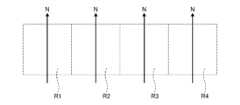
次に、印刷面Q1の形状に基づいて印刷面Q1を複数の領域Rに分割する。例えば、図4に示す例では、印刷面Q1を一列に並ぶ4つの領域R1、R2、R3、R4に均等に分割している。ただし、複数の領域Rへの分割方法は、特に限定されず、大きさや形状が互いに異なっていてもよいし、一列に並んでいなくてもよい。Next, the printing surface Q1 is divided into a plurality of regions R based on the shape of the printing surface Q1. For example, in the example shown in FIG. 4, the printing surface Q1 is divided evenly into four regions R1, R2, R3, and R4 arranged in a line. However, the method of division into the plurality of regions R is not particularly limited, and the regions may have different sizes and shapes, and may not be arranged in a line.
次に、4つの領域R1、R2、R3、R4の印刷順を決定する。本実施形態では、並び順に領域R1、R2、R3、R4の順で印刷する。これにより、印刷作業中のロボット200の無駄な動きが少なくなり、印刷ステップS2を効率的に行うことができる。そのため、タクトタイムが短くなり、生産性が向上する。ただし、印刷順としては、特に限定されない。Next, the printing order of the four regions R1, R2, R3, and R4 is determined. In this embodiment, the regions are printed in the order R1, R2, R3, and R4. This reduces unnecessary movement of the
さらに、各領域R1、R2、R3、R4におけるロボット200の作動条件を決定する。作動条件としては、特に限定されないが、例えば、各領域R1、R2、R3、R4におけるロボットアーム220の姿勢や、移動軌跡、加速度、減速度および最大速度、インク吐出量およびインク吐出間隔等のインクジェットヘッド410の出力条件等が挙げられる。Furthermore, the operating conditions of the
[印刷ステップS2]
印刷ステップS2は、インクジェットヘッド410を用いて印刷面Q1への印刷を行うステップである。このような印刷ステップS2は、印刷準備ステップS1において決定した作動条件に基づいて行われ、図3に示すように、領域R1に印刷する単位印刷ステップS21と、領域R2に印刷する単位印刷ステップS22と、領域R3に印刷する単位印刷ステップS23と、領域R4に印刷する単位印刷ステップS24と、を含んでいる。 [Printing step S2]
The printing step S2 is a step of printing on the printing surface Q1 using the
なお、単位印刷ステップS23、S24は、単位印刷ステップS22の繰り返しであるため、以下では、図5ないし図7に基づいて、単位印刷ステップS21、S22についてのみ説明し、単位印刷ステップS23、S24については、その説明を省略する。Note that since unit printing steps S23 and S24 are repetitions of unit printing step S22, only unit printing steps S21 and S22 will be described below with reference to Figures 5 to 7, and a description of unit printing steps S23 and S24 will be omitted.
≪単位印刷ステップS21≫
単位印刷ステップS21は、ロボットアーム220を第1姿勢とするロボットアーム駆動ステップS211と、第1姿勢を維持した状態で、移動ステージ300によってインクジェットヘッド410を対象物Qに対して移動させながら、領域R1への印刷を行う作業ステップS212と、を含む。 <<Unit Printing Step S21>>
The unit printing step S21 includes a robot arm driving step S211 for setting the
ロボットアーム駆動ステップS211では、図5に示すように、ロボットアーム220を駆動して第1姿勢とし、インクジェットヘッド410を領域R1と対向させる。この際のインクジェットヘッド410と領域R1との離間距離は、インクジェットヘッド410に予め設定されている適正ギャップ内とする。また、第1姿勢では、移動ステージ300の駆動によるインクジェットヘッド410の可動域が領域R1の全域と重なっている。In the robot arm driving step S211, as shown in FIG. 5, the
次に、ロボットアーム220を第1姿勢に維持したまま、すなわち、ロボットアーム220を動かさずに作業ステップS212を行う。作業ステップS212では、まず、図6に示すように、移動ステージ300を駆動してインクジェットヘッド410を移動開始位置P1まで移動させる。次に、図7に示すように、移動ステージ300を駆動してインクジェットヘッド410を移動開始位置P1から矢印Nに沿って移動終了位置P2まで移動させつつ、所定のタイミングでインクジェットヘッド410からインクを吐出し、領域R1への印刷を行う。Next, while maintaining the
≪単位印刷ステップS22≫
単位印刷ステップS22は、図3に示すように、ロボットアーム220を第1姿勢から第2姿勢とするロボットアーム駆動ステップS221と、カメラ800を用いて対象物Qを撮像し、撮像結果に基づいてインクジェットヘッド410の位置を補正する補正ステップS222と、移動ステージ300によってインクジェットヘッド410を対象物Qに対して移動させながら領域R2への印刷を行う作業ステップS223と、を含んでいる。 <<Unit Printing Step S22>>
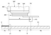
As shown in FIG. 3, the unit printing step S22 includes a robot arm driving step S221 for changing the
ロボットアーム駆動ステップS221では、図8に示すように、ロボットアーム220を駆動して第2姿勢とし、インクジェットヘッド410を領域R2と対向させる。この際のインクジェットヘッド410と領域R2との離間距離は、インクジェットヘッド410に予め設定されている適正ギャップ内とする。また、第2姿勢では、移動ステージ300の駆動によるインクジェットヘッド410の可動域が領域R2の全域と重なっている。In the robot arm driving step S221, as shown in FIG. 8, the
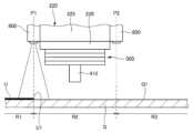
ここで、ロボットアーム220を第1姿勢から第2姿勢に変化させる際、実際の移動軌跡が指定された移動軌跡に対してずれ、第2姿勢における実際のインクジェットヘッド410の位置が指定された位置からずれるおそれがある。このように、実際のインクジェットヘッド410の位置が指定された位置からずれた状態で領域R2に印刷を行ってしまうと、図9に示すように、領域R1、R2のつなぎ目で印刷ずれが生じ、印刷品質が低下する。そこで、次の補正ステップS222では、このような領域R1、R2のつなぎ目での印刷ずれを抑制するためにインクジェットヘッド410の位置を補正する。When the
補正ステップS222では、まず、図10に示すように、ロボットアーム220を第2姿勢に維持したままカメラ800で印刷面Q1を撮像する。そして、当該撮像により得られた画像データDに含まれる作業基準点P0を画像認識により認識する。本実施形態では、領域R1に印刷された模様Uの領域R2側の端部U1が作業基準点P0として用いられる。In the correction step S222, first, as shown in FIG. 10, the
前述したように、本実施形態では、カメラ800が分光カメラであり、画素毎の分光データ(スペクトル情報)を取得することができる。そのため、作業基準点P0の画像認識をより精度よく行うことができる。また、作業基準点P0をより確実にカメラ800の視野内に位置させるために、本実施形態では、カメラ800がロボットアーム220の領域R1側に位置するように第2姿勢(特に、アーム225の向き)が決定されている。ただし、第2姿勢でのカメラ800の向きは、作業基準点P0を含む画像を撮像することができれば、特に限定されない。As described above, in this embodiment, the
次に、図11に示すように、作業基準点P0に基づいて、ロボットアーム220を第2姿勢に維持したまま移動ステージ300の駆動によってインクジェットヘッド410の位置を補正する。図11に示す例では、Yステージ320YをY軸方向に移動させてインクジェットヘッド410の位置を補正している。Next, as shown in FIG. 11, the position of the
具体的には、まず、画像データD内での作業基準点P0の位置に基づいて実際のインクジェットヘッド410の位置を検出する。次に、検出したインクジェットヘッド410の位置と目標位置とのずれを検出する。次に、検出したずれに基づいて、目標位置となるようにインクジェットヘッド410の位置を補正する。インクジェットヘッド410の位置補正は、ロボットアーム220を第2姿勢に維持したまま移動ステージ300の駆動により行われる。これにより、インクジェットヘッド410の位置補正を精度よく行うことができる。特に、本実施形態では、移動ステージ300がXステージ320X、Yステージ320Yおよびθステージ320θからなる3軸自由度の構成であるため、インクジェットヘッド410の位置補正をより精度よく行うことができる。Specifically, first, the actual position of the
次に、ロボットアーム220を第2姿勢に維持したまま作業ステップS223を行う。作業ステップS223では、まず、図12に示すように、移動ステージ300を駆動してインクジェットヘッド410を移動開始位置P1まで移動させる。次に、図13に示すように、移動ステージ300を駆動してインクジェットヘッド410を移動開始位置P1から矢印Nに沿って移動終了位置P2まで移動させつつ、所定のタイミングでインクジェットヘッド410からインクを吐出し、領域R2への印刷を行う。Next, while maintaining the
このような単位印刷ステップS22によれば、領域R1、R2のつなぎ目での印刷ずれを効果的に抑制することができ、印刷品質の低下を効果的に抑制することができる。また、このようにロボットアーム220を停止した状態とすることで、ロボットアーム220の関節で駆動するモーターや減速機に起因する振動や軌跡のぶれの影響を受けることがなくなり、さらに移動ステージ300を駆動した状態であれば移動ステージ300が持つリニアガイドに倣って摺動するため、移動方向に沿って精度の良い印刷を行うことができる。By using this unit printing step S22, it is possible to effectively prevent printing misalignment at the seam between regions R1 and R2, and to effectively prevent deterioration of print quality. Furthermore, by stopping the
以上のような単位印刷ステップS22に続けて、単位印刷ステップS23、S24を同様に行うことにより、印刷面Q1全域への印刷が終了する。図3に示すように、印刷面Q1への印刷が終了すると、所定数の対象物Qへの印刷作業を行ったか否かを判断し、行った場合は、ロボットシステム100による作業を終える。一方、行っていない場合は、新たな対象物Qを固定部材700に固定し直し、印刷ステップS2から印刷作業を行う。Following the unit printing step S22 as described above, unit printing steps S23 and S24 are performed in the same manner, thereby completing printing on the entire printing surface Q1. As shown in FIG. 3, when printing on the printing surface Q1 is completed, it is determined whether printing work has been performed on a predetermined number of objects Q, and if so, the work by the
以上、本実施形態のロボットシステム100について説明した。このようなロボットシステム100の制御方法は、前述したように、移動ステージ300と、移動ステージ300に取り付けられた工具400と、移動ステージ300または対象物Qの一方を保持するロボットアーム220と、カメラ800と、を備え、工具400を用いて対象物Qに対して所定の作業を行うロボットシステム100の制御方法であって、ロボットアーム220を第1姿勢とするステップであるロボットアーム駆動ステップS211と、第1姿勢を維持した状態で、移動ステージ300によって工具400を対象物Qに対して移動させながら対象物Qの第1領域である領域R1に作業を行うステップである作業ステップS212と、ロボットアーム220を第2姿勢とするステップであるロボットアーム駆動ステップS221と、第2姿勢を維持した状態で、カメラ800を用いて対象物Qを撮像し、撮像結果に基づいて移動ステージ300の駆動により工具400の位置を補正するステップである補正ステップS222と、第2姿勢を維持した状態で、移動ステージ300によって工具400を対象物Qに対して移動させながら対象物Qの第2領域である領域R2に作業を行う作業ステップS223と、を含む。このような制御方法によれば、領域R1、R2のつなぎ目での作業ずれを効果的に抑制することができ、作業品質の低下を効果的に抑制することができる。The
また、前述したように、ロボットアーム220は、移動ステージ300を保持する。これにより、対象物Qへの作業を行い易くなる。また、前述したように、移動ステージ300は、工具400を保持する。これにより、対象物Qへの作業を行い易くなる。As described above, the
また、前述したように、ロボットシステム100の制御方法では、移動ステージ300は、駆動源として圧電アクチュエーター340を有している。これにより、移動ステージ300の小型化および軽量化を図ることができる。また、移動ステージ300の駆動精度が向上し、さらには、工具400を等速移動させ易くなる。As described above, in the control method of the
また、前述したように、工具400は、プリンターヘッドとしてのインクジェットヘッド410である。これにより、対象物Qへの印刷作業を行うことができる。そのため、利便性の高いロボットシステム100となる。As described above, the
また、前述したように、補正ステップS222では、領域R1に形成された作業跡すなわち印刷された模様Uに基づいて工具400の位置を補正する。これにより、工具400の補正を容易かつ精度よく行うことができる。As described above, in the correction step S222, the position of the
また、前述したように、カメラは、ロボット200に配置されている。これにより、対象物Qを撮像し易くなる。また、例えば、後述する第2実施形態のように、カメラ800を移動ステージ300に配置する場合と比べて、移動ステージ300にかかる荷重が小さくなり、その分、移動ステージ300の加速度および減速度を大きく設定することができる。そのため、作業にかかる時間を短縮することができ、生産性が向上する。As described above, the camera is disposed on the
また、前述したように、カメラ800は、分光カメラである。これにより、補正ステップS222での画像認識をより精度よく行うことができる。As mentioned above, the
また、前述したように、ロボットシステム100は、移動ステージ300と、移動ステージ300に取り付けられた工具400と、移動ステージ300または対象物Qの一方を保持するロボットアーム220と、カメラ800と、を備え、工具400を用いて対象物Qに対して所定の作業を行うロボットシステム100であって、ロボットアーム220を第1姿勢とし、第1姿勢を維持した状態で、移動ステージ300によって工具400を対象物Qに対して移動させながら対象物Qの第1領域である領域R1に作業を行い、ロボットアーム220を第2姿勢とし、第2姿勢を維持した状態で、カメラ800を用いて対象物Qを撮像し、撮像結果に基づいて移動ステージ300の駆動により工具400の位置を補正し、第2姿勢を維持した状態で、移動ステージ300によって工具400を対象物Qに対して移動させながら対象物Qの第2領域である領域R2に作業を行う。このような構成のロボットシステム100によれば、領域R1、R2のつなぎ目での作業ずれを効果的に抑制することができ、作業品質の低下を効果的に抑制することができる。As described above, the
以上、ロボットシステム100について説明したが、ロボットシステム100としては、特に限定されない。例えば、本実施形態では、印刷ステップS2におけるインクジェットヘッド410の移動方向である矢印Nが領域R1、R2、R3、R4の並び方向(ロボットアーム220の移動方向)に沿っているが、例えば、図14に示すように、各領域R1、R2、R3、R4でのインクジェットヘッド410の移動方向が領域R1、R2、R3、R4の並び方向に対して直交(交差)していてもよい。また、図15に示すように、各領域R1、R2、R3、R4でのインクジェットヘッド410の移動方向が2次元状に蛇行していてもよい。また、本実施形態では、領域Rが一列に並んでいるが、図16に示すように、2列以上に並んでいてもよい。Although the
また、ロボットアーム220にカメラ800を複数台配置してもよい。例えば、図17に示す例では、アーム225に、アーム225を介して対向するように2台のカメラ800を配置している。このような構成によれば、2台のカメラ800を用いてより広い視野の画像データDを取得することができる。また、補正ステップS222において、いずれかのカメラ800で端部U1(作業基準点P0)を含む画像データDを取得すればよくなるため、第2姿勢の自由度が高まり、ロボットアーム220の駆動の効率化を図ることができる。In addition,
<第2実施形態>
図18は、第2実施形態に係るロボットシステムを示す図である。 Second Embodiment
FIG. 18 is a diagram illustrating a robot system according to the second embodiment.
本実施形態のロボットシステム100は、カメラ800の配置が異なること以外は、前述した第1実施形態のロボットシステム100と同様である。そのため、以下の説明では、本実施形態に関し、前述した第1実施形態との相違点を中心に説明し、同様の事項に関してはその説明を省略する。また、本実施形態における各図において、前述した実施形態と同様の構成については、同一符号を付している。The
図18に示すように、本実施形態では、カメラ800が移動ステージ300のステージ320、特にXステージ320Xに配置されている。これにより、ロボットアーム220を第2姿勢に維持した状態においても、移動ステージ300の駆動によってカメラ800を移動させることができる。そのため、第2姿勢でのカメラ800の撮像可能範囲が広くなり、補正ステップS222において、より確実に、印刷面Q1上の作業基準点P0を撮像することができる。また、作業基準点P0が大きく、1枚の画像では全域を撮像しきれない場合等には、異なる位置からの撮像により得られた複数の画像データDに基づいて作業基準点P0を認識してもよい。As shown in FIG. 18, in this embodiment, the
以上のように、本実施形態のロボットシステム100の制御方法では、カメラ800は、移動ステージ300に配置されている。これにより、ロボットアーム220を第2姿勢に維持した状態においても、移動ステージ300の駆動によってカメラ800を移動させることができる。そのため、第2姿勢でのカメラ800の撮像可能範囲が広くなり、補正ステップS222において、より確実に、印刷面Q1上の作業基準点P0を撮像することができる。As described above, in the control method of the
このような第2実施形態によっても、前述した第1実施形態と同様の効果を発揮することができる。This second embodiment can achieve the same effects as the first embodiment described above.
<第3実施形態>
図19は、第3実施形態にロボットシステムで用いる作業基準点P0を示す図である。 Third Embodiment
FIG. 19 is a diagram showing a task reference point P0 used in the robot system according to the third embodiment.
本実施形態のロボットシステム100は、作業基準点P0が異なること以外は、前述した第1実施形態のロボットシステム100と同様である。そのため、以下の説明では、本実施形態に関し、前述した第1実施形態との相違点を中心に説明し、同様の事項に関してはその説明を省略する。また、本実施形態における各図において、前述した実施形態と同様の構成については、同一符号を付している。The
図19に示すように、本実施形態では、印刷面Q1に配置されたマーカーKを作業基準点P0として用いる。マーカーKとしては、識別可能であれば、特に限定されず、例えば、凹凸、印刷等により形成することができる。As shown in FIG. 19, in this embodiment, a marker K placed on the printing surface Q1 is used as the work reference point P0. There are no particular limitations on the marker K as long as it is identifiable, and it can be formed, for example, by projections and recesses, printing, etc.
本実施形態の補正ステップS222では、まず、ロボットアーム220を第2姿勢に維持したままカメラ800で印刷面Q1を撮像する。そして、当該撮像により得られた画像データDに含まれるマーカーKを作業基準点P0として画像認識する。次に、画像データD内のマーカーKの位置に基づいて実際のインクジェットヘッド410の位置を検出し、目標位置とのずれに基づいてインクジェットヘッド410の位置を補正する。前述した第1実施形態では、模様Uによっては作業基準点P0を認識し難い場合もあり得る。これに対して、本実施形態では、印刷面Q1に予め配置されたマーカーKを作業基準点P0として用いるため、より精度よくかつ確実に作業基準点P0を認識することができる。In the correction step S222 of this embodiment, first, the
以上のように、本実施形態のロボットシステム100の制御方法では、補正ステップS222では、対象物Qに配置されたマーカーKに基づいて工具400の位置を補正する。これにより、より精度よくかつ確実に作業基準点P0を認識することができる。As described above, in the control method for the
このような第3実施形態によっても、前述した第1実施形態と同様の効果を発揮することができる。This third embodiment can achieve the same effects as the first embodiment described above.
<第4実施形態>
図20は、第4実施形態にロボットシステムの全体構成を示す斜視図である。 Fourth Embodiment
FIG. 20 is a perspective view showing an overall configuration of a robot system according to the fourth embodiment.
本実施形態のロボットシステム100は、移動ステージ300および工具400の配置が異なること以外は、前述した第1実施形態のロボットシステム100と同様である。そのため、以下の説明では、本実施形態に関し、前述した第1実施形態との相違点を中心に説明し、同様の事項に関してはその説明を省略する。また、本実施形態における各図において、前述した実施形態と同様の構成については、同一符号を付している。The
図20に示すように、本実施形態では、ロボットアーム220の先端部すなわちアーム226にハンド600が配置されており、作業時にはこのハンド600で対象物Qを把持する。一方、移動ステージ300は、ロボットアーム220と離間して固定部材700に固定されており、この移動ステージ300にインクジェットヘッド410が配置されている。As shown in FIG. 20, in this embodiment, a
このような第4実施形態によっても、前述した第1実施形態と同様の効果を発揮することができる。なお、この他にも、例えば、ハンド600が移動ステージ300を介してアーム226に接続され、インクジェットヘッド410がロボットアーム220と離間して固定部材700に固定されている構成であってもよい。また、インクジェットヘッド410がアーム226に接続され、ロボットアーム220と離間した状態で、ハンド600が移動ステージ300を介して固定部材700に接続されている構成であってもよい。The fourth embodiment can achieve the same effects as the first embodiment. In addition to this, for example, the
以上、本発明のロボットシステムの制御方法およびロボットシステムを図示の実施形態に基づいて説明したが、本発明は、これに限定されるものではなく、各部の構成は、同様の機能を有する任意の構成のものに置換することができる。また、本発明に、他の任意の構成物が付加されていてもよい。また、各実施形態を適宜組み合わせてもよい。The above describes the control method for a robot system and the robot system of the present invention based on the illustrated embodiment, but the present invention is not limited to this, and the configuration of each part can be replaced with any configuration having a similar function. In addition, any other configuration may be added to the present invention. Furthermore, each embodiment may be combined as appropriate.
また、工具400としては、インクジェットヘッド410に限定されず、例えば、レーザー加工用の工具、はんだ付け作業用の工具、溶接用の工具等、工具の移動軌跡と同期して行う作業用の工具等が挙げられる。The
100…ロボットシステム、200…ロボット、210…基台、220…ロボットアーム、221…アーム、222…アーム、223…アーム、224…アーム、225…アーム、226…アーム、300…移動ステージ、310…基部、320…ステージ、320X…Xステージ、320Y…Yステージ、320θ…θステージ、330…移動機構、330X…X移動機構、330Y…Y移動機構、330θ…θ移動機構、340…圧電アクチュエーター、400…工具、410…インクジェットヘッド、411…インク吐出孔、600…ハンド、700…固定部材、800…カメラ、900…ロボット制御装置、D…画像データ、E…エンコーダー、J1…関節、J2…関節、J3…関節、J4…関節、J5…関節、J6…関節、K…マーカー、M…モーター、N…矢印、P0…作業基準点、P1…移動開始位置、P2…移動終了位置、Q…対象物、Q1…印刷面、R…領域、R1…領域、R2…領域、R3…領域、R4…領域、S1…印刷準備ステップ、S2…印刷ステップ、S21…単位印刷ステップ、S211…ロボットアーム駆動ステップ、S212…作業ステップ、S22…単位印刷ステップ、S221…ロボットアーム駆動ステップ、S222…補正ステップ、S223…作業ステップ、S23…単位印刷ステップ、S24…単位印刷ステップ、U…模様、U1…端部100...robot system, 200...robot, 210...base, 220...robot arm, 221...arm, 222...arm, 223...arm, 224...arm, 225...arm, 226...arm, 300...moving stage, 310...base, 320...stage, 320X...X stage, 320Y...Y stage, 320θ...θ stage, 330...moving mechanism, 330X...X moving mechanism, 330Y...Y moving mechanism, 330θ...θ moving mechanism, 340...piezoelectric actuator, 400...tool, 410...inkjet head, 411...ink ejection hole, 600...hand, 700...fixing member, 800...camera, 900...robot control device, D...image data, E...end Coder, J1... joint, J2... joint, J3... joint, J4... joint, J5... joint, J6... joint, K... marker, M... motor, N... arrow, P0... work reference point, P1... movement start position, P2... movement end position, Q... object, Q1... printing surface, R... area, R1... area, R2... area, R3... area, R4... area, S1... printing preparation step, S2... printing step, S21... unit printing step, S211... robot arm driving step, S212... work step, S22... unit printing step, S221... robot arm driving step, S222... correction step, S223... work step, S23... unit printing step, S24... unit printing step, U... pattern, U1... end
Claims (11)
Translated fromJapanese前記ロボットアームを第1姿勢とするステップと、
前記ロボットアームの前記第1姿勢を維持した状態で、前記移動ステージによって前記工具を前記対象物に対して移動させながら前記対象物の第1領域に前記作業を行うステップと、
前記ロボットアームを第2姿勢とするステップと、
前記ロボットアームの前記第2姿勢を維持した状態で、前記カメラを用いて前記対象物を撮像し、撮像結果に基づいて前記移動ステージの駆動により前記工具の位置を補正するステップと、
前記ロボットアームの前記第2姿勢を維持した状態で、前記移動ステージによって前記工具を前記対象物に対して移動させながら前記対象物の第2領域に前記作業を行うステップと、を含むことを特徴とするロボットシステムの制御方法。 1. A method for controlling a robot system comprising: a moving stage; a tool attached to the moving stage; a robot arm that holds one of the moving stage or an object; and a camera, the robot system performing a predetermined operation on the object using the tool, the method comprising the steps of:
setting the robot arm in a first position;
performing the work on a first region of the object while moving the tool relative to the object by the moving stage in a state where the first attitudeof the robot arm is maintained;
setting the robot arm in a second posture;
a step of capturing an image of the object using the camera while maintaining the second attitudeof the robot arm , and correcting a position of the tool by driving the moving stage based on the captured image;
and performing the work on a second area of the object while moving the tool relative to the object by the moving stage while maintaining the second postureof the robot arm .
前記ロボットアームを第1姿勢とし、
前記ロボットアームの前記第1姿勢を維持した状態で、前記移動ステージによって前記工具を前記対象物に対して移動させながら前記対象物の第1領域に前記作業を行い、
前記ロボットアームを第2姿勢とし、
前記ロボットアームの前記第2姿勢を維持した状態で、前記カメラを用いて前記対象物を撮像し、撮像結果に基づいて前記移動ステージの駆動により前記工具の位置を補正し、
前記ロボットアームの前記第2姿勢を維持した状態で、前記移動ステージによって前記工具を前記対象物に対して移動させながら前記対象物の第2領域に前記作業を行うことを特徴とするロボットシステム。 1. A robot system comprising: a moving stage; a tool attached to the moving stage; a robot arm that holds one of the moving stage and an object; and a camera, the robot system performing a predetermined operation on the object using the tool,
The robot arm is in a first position;
performing the work on a first region of the object while moving the tool relative to the object by the moving stage while maintaining the first postureof the robot arm ;
The robot arm is placed in a second position;
while maintaining the second attitudeof the robot arm , capturing an image of the object using the camera, and correcting a position of the tool by driving the moving stage based on the captured image;
A robot system characterized in that, while maintaining the second postureof the robot arm , the work is performed on a second area of the object while the tool is moved relative to the object by the moving stage.
Priority Applications (3)
| Application Number | Priority Date | Filing Date | Title |
|---|---|---|---|
| JP2021125103AJP7687117B2 (en) | 2021-07-30 | 2021-07-30 | Method for controlling robot system and robot system |
| CN202210892377.7ACN115674216B (en) | 2021-07-30 | 2022-07-27 | Control method of robot system and robot system |
| US17/875,452US12263604B2 (en) | 2021-07-30 | 2022-07-28 | Control method for robot system and robot system |
Applications Claiming Priority (1)
| Application Number | Priority Date | Filing Date | Title |
|---|---|---|---|
| JP2021125103AJP7687117B2 (en) | 2021-07-30 | 2021-07-30 | Method for controlling robot system and robot system |
Publications (2)
| Publication Number | Publication Date |
|---|---|
| JP2023020000A JP2023020000A (en) | 2023-02-09 |
| JP7687117B2true JP7687117B2 (en) | 2025-06-03 |
Family
ID=85037698
Family Applications (1)
| Application Number | Title | Priority Date | Filing Date |
|---|---|---|---|
| JP2021125103AActiveJP7687117B2 (en) | 2021-07-30 | 2021-07-30 | Method for controlling robot system and robot system |
Country Status (3)
| Country | Link |
|---|---|
| US (1) | US12263604B2 (en) |
| JP (1) | JP7687117B2 (en) |
| CN (1) | CN115674216B (en) |
Families Citing this family (1)
| Publication number | Priority date | Publication date | Assignee | Title |
|---|---|---|---|---|
| DE102022204724B4 (en)* | 2022-05-13 | 2024-10-31 | Robert Bosch Gesellschaft mit beschränkter Haftung | Method for controlling a robot device |
Citations (4)
| Publication number | Priority date | Publication date | Assignee | Title |
|---|---|---|---|---|
| JP2016221602A (en) | 2015-05-28 | 2016-12-28 | セイコーエプソン株式会社 | Robot, control device and program |
| US20180201029A1 (en) | 2015-05-29 | 2018-07-19 | The Boeing Company | System for printing images on a surface and method thereof |
| JP2019188521A (en) | 2018-04-24 | 2019-10-31 | セイコーエプソン株式会社 | Mobile device, hand, robot, and control method of mobile device |
| JP2020138292A (en) | 2019-02-28 | 2020-09-03 | セイコーエプソン株式会社 | Robot system and control method |
Family Cites Families (35)
| Publication number | Priority date | Publication date | Assignee | Title |
|---|---|---|---|---|
| US4761085A (en) | 1987-04-01 | 1988-08-02 | International Business Machines Corporation | Printer with enhanced bidirectional logic seeking for increased through-put |
| JPH0231850A (en)* | 1988-07-20 | 1990-02-01 | Mitsubishi Heavy Ind Ltd | Coating device |
| JP2739764B2 (en) | 1989-12-15 | 1998-04-15 | 富士通株式会社 | Robot scanning speed control method |
| JPH06226579A (en) | 1993-02-09 | 1994-08-16 | Sony Corp | Minute feed device |
| US6913934B2 (en)* | 1998-08-13 | 2005-07-05 | Symyx Technologies, Inc. | Apparatus and methods for parallel processing of multiple reaction mixtures |
| JP2003251584A (en) | 2002-02-28 | 2003-09-09 | Nachi Fujikoshi Corp | Locus control device |
| CA2522097C (en)* | 2003-04-28 | 2012-09-25 | Stephen James Crampton | Cmm arm with exoskeleton |
| US20060068109A1 (en) | 2004-09-15 | 2006-03-30 | Airbus Deutschland Gmbh | Painting device, painting arrangement, method for painting a curved surface of an object, and use of an inkjet device for painting an aircraft |
| JP4341572B2 (en)* | 2005-03-29 | 2009-10-07 | ブラザー工業株式会社 | Punch for punch formation and nozzle for inkjet head |
| US20090167817A1 (en) | 2007-12-31 | 2009-07-02 | Exatec Llc | Apparatus and method for printing three dimensional articles |
| JP4565023B2 (en)* | 2008-07-04 | 2010-10-20 | ファナック株式会社 | Article take-out device |
| JP2011180059A (en) | 2010-03-03 | 2011-09-15 | Stanley Electric Co Ltd | Device and method for support of visual inspection |
| DE102012005087A1 (en) | 2011-03-28 | 2012-10-04 | Heidelberger Druckmaschinen Aktiengesellschaft | Device for printing surfaces with multiple, movable print heads |
| JP2016068290A (en) | 2014-09-26 | 2016-05-09 | パナソニックIpマネジメント株式会社 | Inkjet printing device and method for the same |
| US9452616B1 (en) | 2015-05-29 | 2016-09-27 | The Boeing Company | System and method for printing an image on a surface |
| JP6822320B2 (en)* | 2016-08-30 | 2021-01-27 | セイコーエプソン株式会社 | Control devices, robot systems and robot control methods |
| US10384482B2 (en) | 2016-10-06 | 2019-08-20 | The Boeing Company | Actuated print head assembly for a contoured surface |
| US10846882B2 (en)* | 2016-11-08 | 2020-11-24 | Thermo Electron Scientific Instruments Llc | System and method of dimensional calibration for an analytical microscope |
| DE102016014920A1 (en) | 2016-12-14 | 2018-06-14 | Dürr Systems Ag | Printhead with sliding and / or rotating mechanism for at least one row of nozzles |
| AU2018211005B2 (en) | 2017-01-17 | 2023-11-02 | Graco Minnesota, Inc. | Systems for automated mobile painting of structures |
| JP2018171668A (en)* | 2017-03-31 | 2018-11-08 | セイコーエプソン株式会社 | Control device, robot, and robot system |
| JP2019059004A (en)* | 2017-09-28 | 2019-04-18 | セイコーエプソン株式会社 | Robot system |
| JP6784660B2 (en) | 2017-11-28 | 2020-11-11 | ファナック株式会社 | Input device and robot control system |
| JP2019119027A (en)* | 2018-01-10 | 2019-07-22 | キヤノン株式会社 | Method of controlling robot system, and robot system |
| JP7225560B2 (en) | 2018-04-26 | 2023-02-21 | セイコーエプソン株式会社 | CONTROL DEVICE, ROBOT SYSTEM, AND DISPLAY CONTROL METHOD |
| BE1026046B1 (en)* | 2018-08-29 | 2019-09-24 | Viage SPRL | Real size surveying printer for the building |
| JP2020163499A (en) | 2019-03-28 | 2020-10-08 | セイコーエプソン株式会社 | Object detection method, object detection device and robot system |
| JP7275759B2 (en)* | 2019-03-28 | 2023-05-18 | セイコーエプソン株式会社 | OBJECT DETECTION METHOD, OBJECT DETECTION DEVICE, AND ROBOT SYSTEM |
| JP2020196060A (en)* | 2019-05-31 | 2020-12-10 | セイコーエプソン株式会社 | Teaching method |
| US20220379337A1 (en) | 2019-08-30 | 2022-12-01 | Kyocera Corporation | Coating device, coating film, and coating method |
| JP7259688B2 (en)* | 2019-10-02 | 2023-04-18 | 新東工業株式会社 | Shot processing apparatus and shot processing method |
| US11845270B2 (en) | 2020-04-07 | 2023-12-19 | Abb Schweiz Ag | Ink-jet type vehicle coating machine and vehicle coating method |
| JP7491124B2 (en)* | 2020-07-29 | 2024-05-28 | セイコーエプソン株式会社 | Three-dimensional object printing device and three-dimensional object printing method |
| JP2022137549A (en)* | 2021-03-09 | 2022-09-22 | セイコーエプソン株式会社 | Three-dimensional object printing device and three-dimensional object printing method |
| JP2022142924A (en)* | 2021-03-17 | 2022-10-03 | セイコーエプソン株式会社 | Three-dimensional object printer |
- 2021
- 2021-07-30JPJP2021125103Apatent/JP7687117B2/enactiveActive
- 2022
- 2022-07-27CNCN202210892377.7Apatent/CN115674216B/enactiveActive
- 2022-07-28USUS17/875,452patent/US12263604B2/enactiveActive
Patent Citations (4)
| Publication number | Priority date | Publication date | Assignee | Title |
|---|---|---|---|---|
| JP2016221602A (en) | 2015-05-28 | 2016-12-28 | セイコーエプソン株式会社 | Robot, control device and program |
| US20180201029A1 (en) | 2015-05-29 | 2018-07-19 | The Boeing Company | System for printing images on a surface and method thereof |
| JP2019188521A (en) | 2018-04-24 | 2019-10-31 | セイコーエプソン株式会社 | Mobile device, hand, robot, and control method of mobile device |
| JP2020138292A (en) | 2019-02-28 | 2020-09-03 | セイコーエプソン株式会社 | Robot system and control method |
Also Published As
| Publication number | Publication date |
|---|---|
| US20230036260A1 (en) | 2023-02-02 |
| CN115674216B (en) | 2025-08-01 |
| CN115674216A (en) | 2023-02-03 |
| JP2023020000A (en) | 2023-02-09 |
| US12263604B2 (en) | 2025-04-01 |
Similar Documents
| Publication | Publication Date | Title |
|---|---|---|
| US11964396B2 (en) | Device and method for acquiring deviation amount of working position of tool | |
| WO2014020739A1 (en) | Work machine provided with articulated robot and electric component mounting machine | |
| CN112835324B (en) | trajectory control device | |
| JP7687117B2 (en) | Method for controlling robot system and robot system | |
| KR20210117307A (en) | Industrial robotic device with improved tooling path generation, and method for operating industrial robotic device according to improved tooling path | |
| JP2025093980A (en) | Substrate positioning device for deposition apparatus and method thereof - Patents.com | |
| JP5445462B2 (en) | Line head unit and drawing apparatus | |
| JP7465648B2 (en) | Adhesive application device, adhesive application method, and rotor manufacturing method | |
| JP7666199B2 (en) | Method for controlling robot system and robot system | |
| JP2011104733A (en) | Robot | |
| JP2014007213A (en) | Component mounting apparatus and component mounting method | |
| TW202339858A (en) | Liquid material coating method and coating device | |
| KR20090011265A (en) | Automatic calibration of the center point offset according to the scan head skew | |
| JP7242856B2 (en) | Robot control system and robot control method | |
| CN113905859B (en) | Robot control system and robot control method | |
| US20240173962A1 (en) | Printing method and robot system | |
| JP2025018519A (en) | Robot system and position detection method | |
| JP2024078702A (en) | Printing method and robot system | |
| JP5873320B2 (en) | Component mounting equipment | |
| JP2025081142A (en) | Robot trajectory measurement system, robot trajectory measurement method, and robot driving method | |
| JP7055185B2 (en) | Droplet ejection device, droplet ejection method, program and computer storage medium | |
| JP2024124722A (en) | Printing method and robot system | |
| JP2022064544A (en) | Discharge device, movement locus correction method of discharge device, and movement locus correction program of discharge device | |
| CN120307255A (en) | Method for controlling robot and robot system | |
| CN117885452A (en) | Printing method, end effector, and robot system |
Legal Events
| Date | Code | Title | Description |
|---|---|---|---|
| RD04 | Notification of resignation of power of attorney | Free format text:JAPANESE INTERMEDIATE CODE: A7424 Effective date:20210917 | |
| RD03 | Notification of appointment of power of attorney | Free format text:JAPANESE INTERMEDIATE CODE: A7423 Effective date:20211104 | |
| A621 | Written request for application examination | Free format text:JAPANESE INTERMEDIATE CODE: A621 Effective date:20240603 | |
| A977 | Report on retrieval | Free format text:JAPANESE INTERMEDIATE CODE: A971007 Effective date:20241129 | |
| A131 | Notification of reasons for refusal | Free format text:JAPANESE INTERMEDIATE CODE: A131 Effective date:20241217 | |
| A521 | Request for written amendment filed | Free format text:JAPANESE INTERMEDIATE CODE: A523 Effective date:20250213 | |
| TRDD | Decision of grant or rejection written | ||
| A01 | Written decision to grant a patent or to grant a registration (utility model) | Free format text:JAPANESE INTERMEDIATE CODE: A01 Effective date:20250422 | |
| A61 | First payment of annual fees (during grant procedure) | Free format text:JAPANESE INTERMEDIATE CODE: A61 Effective date:20250505 | |
| R150 | Certificate of patent or registration of utility model | Ref document number:7687117 Country of ref document:JP Free format text:JAPANESE INTERMEDIATE CODE: R150 |