JP7686580B2 - Systems and methods for tricuspid valve treatment - Google Patents
Systems and methods for tricuspid valve treatmentDownload PDFInfo
- Publication number
- JP7686580B2 JP7686580B2JP2021573565AJP2021573565AJP7686580B2JP 7686580 B2JP7686580 B2JP 7686580B2JP 2021573565 AJP2021573565 AJP 2021573565AJP 2021573565 AJP2021573565 AJP 2021573565AJP 7686580 B2JP7686580 B2JP 7686580B2
- Authority
- JP
- Japan
- Prior art keywords
- implant
- shaft
- assembly
- elongate shaft
- delivery system
- Prior art date
- Legal status (The legal status is an assumption and is not a legal conclusion. Google has not performed a legal analysis and makes no representation as to the accuracy of the status listed.)
- Active
Links
Images


Classifications
- A—HUMAN NECESSITIES
- A61—MEDICAL OR VETERINARY SCIENCE; HYGIENE
- A61F—FILTERS IMPLANTABLE INTO BLOOD VESSELS; PROSTHESES; DEVICES PROVIDING PATENCY TO, OR PREVENTING COLLAPSING OF, TUBULAR STRUCTURES OF THE BODY, e.g. STENTS; ORTHOPAEDIC, NURSING OR CONTRACEPTIVE DEVICES; FOMENTATION; TREATMENT OR PROTECTION OF EYES OR EARS; BANDAGES, DRESSINGS OR ABSORBENT PADS; FIRST-AID KITS
- A61F2/00—Filters implantable into blood vessels; Prostheses, i.e. artificial substitutes or replacements for parts of the body; Appliances for connecting them with the body; Devices providing patency to, or preventing collapsing of, tubular structures of the body, e.g. stents
- A61F2/02—Prostheses implantable into the body
- A61F2/24—Heart valves ; Vascular valves, e.g. venous valves; Heart implants, e.g. passive devices for improving the function of the native valve or the heart muscle; Transmyocardial revascularisation [TMR] devices; Valves implantable in the body
- A61F2/2412—Heart valves ; Vascular valves, e.g. venous valves; Heart implants, e.g. passive devices for improving the function of the native valve or the heart muscle; Transmyocardial revascularisation [TMR] devices; Valves implantable in the body with soft flexible valve members, e.g. tissue valves shaped like natural valves
- A61F2/2418—Scaffolds therefor, e.g. support stents
- A—HUMAN NECESSITIES
- A61—MEDICAL OR VETERINARY SCIENCE; HYGIENE
- A61F—FILTERS IMPLANTABLE INTO BLOOD VESSELS; PROSTHESES; DEVICES PROVIDING PATENCY TO, OR PREVENTING COLLAPSING OF, TUBULAR STRUCTURES OF THE BODY, e.g. STENTS; ORTHOPAEDIC, NURSING OR CONTRACEPTIVE DEVICES; FOMENTATION; TREATMENT OR PROTECTION OF EYES OR EARS; BANDAGES, DRESSINGS OR ABSORBENT PADS; FIRST-AID KITS
- A61F2/00—Filters implantable into blood vessels; Prostheses, i.e. artificial substitutes or replacements for parts of the body; Appliances for connecting them with the body; Devices providing patency to, or preventing collapsing of, tubular structures of the body, e.g. stents
- A61F2/02—Prostheses implantable into the body
- A61F2/24—Heart valves ; Vascular valves, e.g. venous valves; Heart implants, e.g. passive devices for improving the function of the native valve or the heart muscle; Transmyocardial revascularisation [TMR] devices; Valves implantable in the body
- A61F2/2427—Devices for manipulating or deploying heart valves during implantation
- A61F2/2436—Deployment by retracting a sheath
- A—HUMAN NECESSITIES
- A61—MEDICAL OR VETERINARY SCIENCE; HYGIENE
- A61F—FILTERS IMPLANTABLE INTO BLOOD VESSELS; PROSTHESES; DEVICES PROVIDING PATENCY TO, OR PREVENTING COLLAPSING OF, TUBULAR STRUCTURES OF THE BODY, e.g. STENTS; ORTHOPAEDIC, NURSING OR CONTRACEPTIVE DEVICES; FOMENTATION; TREATMENT OR PROTECTION OF EYES OR EARS; BANDAGES, DRESSINGS OR ABSORBENT PADS; FIRST-AID KITS
- A61F2/00—Filters implantable into blood vessels; Prostheses, i.e. artificial substitutes or replacements for parts of the body; Appliances for connecting them with the body; Devices providing patency to, or preventing collapsing of, tubular structures of the body, e.g. stents
- A61F2/02—Prostheses implantable into the body
- A61F2/24—Heart valves ; Vascular valves, e.g. venous valves; Heart implants, e.g. passive devices for improving the function of the native valve or the heart muscle; Transmyocardial revascularisation [TMR] devices; Valves implantable in the body
- A61F2/2427—Devices for manipulating or deploying heart valves during implantation
- A61F2/2439—Expansion controlled by filaments
- A—HUMAN NECESSITIES
- A61—MEDICAL OR VETERINARY SCIENCE; HYGIENE
- A61F—FILTERS IMPLANTABLE INTO BLOOD VESSELS; PROSTHESES; DEVICES PROVIDING PATENCY TO, OR PREVENTING COLLAPSING OF, TUBULAR STRUCTURES OF THE BODY, e.g. STENTS; ORTHOPAEDIC, NURSING OR CONTRACEPTIVE DEVICES; FOMENTATION; TREATMENT OR PROTECTION OF EYES OR EARS; BANDAGES, DRESSINGS OR ABSORBENT PADS; FIRST-AID KITS
- A61F2/00—Filters implantable into blood vessels; Prostheses, i.e. artificial substitutes or replacements for parts of the body; Appliances for connecting them with the body; Devices providing patency to, or preventing collapsing of, tubular structures of the body, e.g. stents
- A61F2/02—Prostheses implantable into the body
- A61F2/24—Heart valves ; Vascular valves, e.g. venous valves; Heart implants, e.g. passive devices for improving the function of the native valve or the heart muscle; Transmyocardial revascularisation [TMR] devices; Valves implantable in the body
- A61F2/2442—Annuloplasty rings or inserts for correcting the valve shape; Implants for improving the function of a native heart valve
- A61F2/2466—Delivery devices therefor
- A—HUMAN NECESSITIES
- A61—MEDICAL OR VETERINARY SCIENCE; HYGIENE
- A61F—FILTERS IMPLANTABLE INTO BLOOD VESSELS; PROSTHESES; DEVICES PROVIDING PATENCY TO, OR PREVENTING COLLAPSING OF, TUBULAR STRUCTURES OF THE BODY, e.g. STENTS; ORTHOPAEDIC, NURSING OR CONTRACEPTIVE DEVICES; FOMENTATION; TREATMENT OR PROTECTION OF EYES OR EARS; BANDAGES, DRESSINGS OR ABSORBENT PADS; FIRST-AID KITS
- A61F2/00—Filters implantable into blood vessels; Prostheses, i.e. artificial substitutes or replacements for parts of the body; Appliances for connecting them with the body; Devices providing patency to, or preventing collapsing of, tubular structures of the body, e.g. stents
- A61F2/95—Instruments specially adapted for placement or removal of stents or stent-grafts
- A61F2/9517—Instruments specially adapted for placement or removal of stents or stent-grafts handle assemblies therefor
Landscapes
- Health & Medical Sciences (AREA)
- Cardiology (AREA)
- Engineering & Computer Science (AREA)
- Biomedical Technology (AREA)
- Heart & Thoracic Surgery (AREA)
- Transplantation (AREA)
- Oral & Maxillofacial Surgery (AREA)
- Vascular Medicine (AREA)
- Life Sciences & Earth Sciences (AREA)
- Animal Behavior & Ethology (AREA)
- General Health & Medical Sciences (AREA)
- Public Health (AREA)
- Veterinary Medicine (AREA)
- Prostheses (AREA)
- Media Introduction/Drainage Providing Device (AREA)
Description
Translated fromJapanese本明細書に開示されている特定の実施形態は、概して、内腔または体腔の中に植え込みのためのプロテーゼと、プロテーゼのための送達システムとに関する。詳細には、プロテーゼおよび送達システムは、いくつかの実施形態において、置換三尖心臓弁などの置換心臓弁に関する。Certain embodiments disclosed herein relate generally to prostheses for implantation within a lumen or body cavity and delivery systems for the prostheses. In particular, the prostheses and delivery systems relate in some embodiments to replacement heart valves, such as replacement tricuspid heart valves.
4つの大動脈弁、肺動脈弁、僧帽弁、および三尖弁を含む、ヒトの心臓弁は、基本的に一方向弁として機能し、ポンプ作用する心臓と同期して動作する。弁は、血液が下流に流れることを可能とするが、血液が上流に流れるのを阻止する。病気にかかった心臓弁は、弁の狭窄または逆流などの障害を呈し、これは血流を制御するための弁の機能を妨げる。そのような障害は、心臓の血液ポンプ効率を低下させ、衰弱し、生命にかかわる状態であり得る。例えば、弁の機能不全は、心臓肥大および心室の膨張などの症状につながる可能性がある。したがって、機能が低下した心臓弁を修復する、または置き換えるための方法および装置を開発するために、広範囲にわたる努力がなされてきた。Human heart valves, including the four aortic, pulmonary, mitral, and tricuspid valves, essentially function as one-way valves and operate in sync with the pumping heart. The valves allow blood to flow downstream but block blood from flowing upstream. Diseased heart valves exhibit impairments such as valve stenosis or regurgitation, which impede the valve's ability to control blood flow. Such impairments reduce the heart's blood-pumping efficiency and can be debilitating and life-threatening conditions. For example, valve malfunction can lead to symptoms such as cardiac hypertrophy and ventricular distension. Thus, extensive efforts have been made to develop methods and devices to repair or replace compromised heart valves.
機能が低下した心臓弁に関連する問題を是正するためにプロテーゼが存在する。例えば、機能が低下した生来の心臓弁を置き換えるために、機械的および組織ベースの心臓弁プロテーゼを使用することができる。より最近では、かなりの労力は、置換心臓弁を開発すること、とりわけ、開心術を介するよりも患者に対する外傷が少なく送達することができる組織ベースの置換心臓弁を開発することに専念されてきた。置換弁は、最小限の侵襲性の処置を通して、およびさらには経皮処置を通して送達されるように設計されている。そのような置換弁は、その後、生来の弁の環帯に送達される拡張式フレームに接続された組織ベースの弁本体を含む場合が多い。Prostheses exist to correct the problems associated with compromised heart valves. For example, mechanical and tissue-based heart valve prostheses can be used to replace compromised native heart valves. More recently, significant effort has been dedicated to developing replacement heart valves, and in particular tissue-based replacement heart valves that can be delivered with less trauma to the patient than via open-heart surgery. Replacement valves are designed to be delivered through minimally invasive procedures, and even through percutaneous procedures. Such replacement valves often include a tissue-based valve body connected to an expandable frame that is then delivered to the annulus of the native valve.
これに限定するものではないが、送達のためにコンパクトにすることができ、その後、制御された配置のために制御可能に拡張することができる置換心臓弁を含めたプロテーゼインプラントの開発は、特に困難であることが証明されている。さらなる課題は、内腔内組織、例えば任意の体腔内または空洞内の組織に対して、傷をつけないようなやり方で固定されるそのようなプロテーゼの能力に関連する。The development of prosthetic implants, including but not limited to replacement heart valves, that can be compacted for delivery and then controllably expanded for controlled placement has proven particularly challenging. A further challenge relates to the ability of such prostheses to be secured in an atraumatic manner to endoluminal tissue, e.g., tissue within any body cavity or cavity.
人体の中の所望の場所にプロテーゼを送達すること、例えば、置換心臓弁を三尖弁に送達することもまた課題であり得る。心臓内または他の解剖学的場所において処置を実施するための進入路を獲得することは、曲がりくねった血管系を通して経皮的あるいは開放式または半開放式外科処置を介するデバイスの送達を必要とし得る。所望の場所でのプロテーゼの展開を制御する能力もまた課題であり得る。Delivering a prosthesis to a desired location within the human body, for example, delivering a replacement heart valve to a tricuspid valve, can also be a challenge. Gaining access to perform a procedure within the heart or other anatomical location can require delivery of the device percutaneously through a tortuous vascular system or via an open or semi-open surgical procedure. The ability to control the deployment of the prosthesis at the desired location can also be a challenge.
本開示の実施形態は、これに限定するものではないが、置換心臓弁などのプロテーゼに向けられている。本開示の実施形態は、限定されることはないが置換心臓弁などのプロテーゼを、身体の中の所望の場所へ送達および/または制御可能に展開するための送達システム、デバイス、および/または使用の方法に向けられてもよい。いくつかの実施形態において、置換心臓弁、および置換心臓弁を三尖弁などの生来の心臓弁に送達するための方法が提供される。Embodiments of the present disclosure are directed to prostheses, such as, but not limited to, replacement heart valves. Embodiments of the present disclosure may also be directed to delivery systems, devices, and/or methods of use for delivering and/or controllably deploying prostheses, such as, but not limited to, replacement heart valves, to a desired location in the body. In some embodiments, replacement heart valves and methods for delivering replacement heart valves to a native heart valve, such as the tricuspid valve, are provided.
いくつかの実施形態において、送達システムおよび方法が、置換心臓弁を生来の三尖弁の場所へと送達するために提供されている。いくつかの実施形態において、送達システムの構成要素が、右心房の中のプロテーゼを生来の三尖弁の中の場所へと操縦するために、送達システムの曲げを容易にする。いくつかの実施形態において、カプセルが、生来の三尖弁の場所への送達のためにプロテーゼを収容するために提供される。他の実施形態において、送達システムおよび方法は、生来の三尖弁以外の場所へのインプラントの送達のために適合され得る。In some embodiments, delivery systems and methods are provided for delivering a replacement heart valve to the location of the native tricuspid valve. In some embodiments, components of the delivery system facilitate bending of the delivery system to steer the prosthesis in the right atrium to a location in the native tricuspid valve. In some embodiments, a capsule is provided to house the prosthesis for delivery to the location of the native tricuspid valve. In other embodiments, the delivery systems and methods may be adapted for delivery of an implant to a location other than the native tricuspid valve.
本開示は、限定されることはないが、以下の実施形態を含む。This disclosure includes, but is not limited to, the following embodiments:
インプラントのための送達システムであって、送達システムは、細長いシャフトであって、遠位端と、インプラントを保持するためのインプラント保持領域と、細長いシャフトの遠位端を第1の方向へ偏向させるように構成される曲げ部分と、曲げ部分の近位に位置決めされる一部分とを有する細長いシャフトを備える。偏向機構が、第1の方向と反対である第2の方向に向けて曲げ部分を偏向させるために、曲げ部分の近位に位置決めされる一部分を偏向させるように構成される。A delivery system for an implant, the delivery system comprising an elongate shaft having a distal end, an implant holding region for holding an implant, a bent portion configured to deflect the distal end of the elongate shaft in a first direction, and a portion positioned proximal to the bent portion. A deflection mechanism is configured to deflect the portion positioned proximal to the bent portion to deflect the bent portion toward a second direction opposite the first direction.
インプラントのための送達システムであって、送達システムは、細長いシャフトであって、遠位端と、インプラントを保持するためのインプラント保持領域と、細長いシャフトの遠位端を第1の平面へ偏向させるように構成される曲げ部分と、曲げ部分の近位に位置決めされる一部分とを有する細長いシャフトを備える。偏向機構が、第1の平面に対して垂直でない1つまたは複数の平面において、曲げ部分の近位に位置決めされる一部分を偏向させるように構成される。A delivery system for an implant, the delivery system comprising an elongate shaft having a distal end, an implant holding region for holding the implant, a bent portion configured to deflect the distal end of the elongate shaft into a first plane, and a portion positioned proximally of the bent portion. A deflection mechanism is configured to deflect the portion positioned proximally of the bent portion in one or more planes that are not perpendicular to the first plane.
インプラントのための送達システムであって、送達システムは、細長いシャフトであって、遠位端と、インプラントを保持するためのインプラント保持領域と、細長いシャフトの遠位端を第1の方向へ偏向させるように構成される第1の曲げ部分と、第1の曲げ部分に近接して位置決めされ、細長いシャフトの遠位端を第2の方向へ偏向させるように構成される第2の曲げ部分と、第2の曲げ部分の近位に位置決めされる一部分とを有する細長いシャフトを備える。偏向機構が、第1の曲げ部分と、第2の曲げ部分と、第2の曲げ部分の近位に位置決めされる一部分とを偏向させるように構成され得る。A delivery system for an implant, the delivery system comprising an elongate shaft having a distal end, an implant holding region for holding an implant, a first bent portion configured to deflect the distal end of the elongate shaft in a first direction, a second bent portion positioned proximate the first bent portion and configured to deflect the distal end of the elongate shaft in a second direction, and a portion positioned proximal to the second bent portion. A deflection mechanism may be configured to deflect the first bent portion, the second bent portion, and the portion positioned proximal to the second bent portion.
インプラントのための送達システムであって、送達システムは、インプラントを保持するためのインプラント保持領域と、遠位端を有し、インプラント保持領域を取り囲むカプセルとを有する細長いシャフトを備え、カプセルの遠位端は細長いシャフトの遠位先端を形成する。A delivery system for an implant, the delivery system comprising an elongate shaft having an implant holding region for holding the implant and a capsule having a distal end and surrounding the implant holding region, the distal end of the capsule forming a distal tip of the elongate shaft.
インプラントのための送達システムであって、送達システムは、インプラントを保持するためのインプラント保持領域と、遠位へ延在し、ガイドワイヤの一部分の周りに曲がるように構成される可撓性シースを備える遠位先端とを有する細長いシャフトを備える。A delivery system for an implant, the delivery system comprising an elongate shaft having an implant holding region for holding the implant and a distal tip including a flexible sheath extending distally and configured to bend around a portion of a guidewire.
インプラントのための送達システムであって、送達システムは、インプラントを保持するためのインプラント保持領域と、半球形または放物形を有する遠位先端とを有する細長いシャフトを備える。A delivery system for an implant, the delivery system comprising an elongate shaft having an implant holding region for holding the implant and a distal tip having a hemispherical or parabolic shape.
インプラントのための送達システムであって、送達システムは、インプラントの展開のためにインプラントが通過させられるための通路を取り囲む壁であって、インプラントの展開の間に通路における曲げを定める曲げを有するように構成される壁を有する細長いシャフトを備える。A delivery system for an implant, the delivery system comprising an elongate shaft having walls surrounding a passageway through which the implant is passed for deployment of the implant, the walls being configured to have a bend that defines a bend in the passageway during deployment of the implant.
インプラントのための送達システムであって、送達システムは、軸方向の次元を有し、インプラントを保持するためのインプラント保持領域と、インプラントが、細長いシャフトから、軸方向の次元に対して横切る方向に展開させられるためのポートとを有する細長いシャフトを備える。A delivery system for an implant, the delivery system comprising an elongate shaft having an axial dimension, an implant holding area for holding the implant, and a port for deploying the implant from the elongate shaft in a direction transverse to the axial dimension.
インプラントのための送達システムであって、送達システムは、インプラントを保持するためのインプラント保持領域を有し、ループを形成するために180度を越えて曲がるように構成される細長いシャフトを備える。A delivery system for an implant, the delivery system comprising an elongated shaft having an implant holding region for holding the implant and configured to bend greater than 180 degrees to form a loop.
インプラントのための送達システムであって、送達システムは、インプラントを保持するためのインプラント保持領域を取り囲むカプセルと、カプセルを細長いシャフトの一部分に結合するヒンジとを有する細長いシャフトを備える。A delivery system for an implant, the delivery system comprising an elongated shaft having a capsule surrounding an implant holding area for holding the implant and a hinge connecting the capsule to a portion of the elongated shaft.
インプラントのための送達システムであって、送達システムは、軸に沿って延在し、外側表面と、インプラントを保持するためのインプラント保持領域とを有する細長いシャフトを備える。1つまたは複数の支持体が、細長いシャフトの外側表面から径方向外向きに延在し、軸に対して横切る細長いシャフトの偏向に抗するように外部表面と接触するように構成され得る。A delivery system for an implant, the delivery system comprising an elongate shaft extending along an axis and having an outer surface and an implant holding region for holding an implant. One or more supports may extend radially outward from the outer surface of the elongate shaft and be configured to contact the outer surface to resist deflection of the elongate shaft transverse to the axis.
システムが、患者の弁環帯の中での植え込みのために構成されるプロテーゼ心臓弁を備える。システムは、患者の身体の一部分の中に固定されるように構成されるアンカーを備える。システムは、プロテーゼ心臓弁をアンカーに結合するように構成されるつなぎ綱を備える。The system includes a prosthetic heart valve configured for implantation within a valve annulus of a patient. The system includes an anchor configured to be secured within a portion of a patient's body. The system includes a tether configured to couple the prosthetic heart valve to the anchor.
患者の生来の弁の置換えのためのプロテーゼ弁であって、プロテーゼ弁は、患者の生来の弁の環帯の中に係留されるように構成され、プロテーゼ弁環帯を形成するプロテーゼ心臓弁本体を備える。システムは、プロテーゼ心臓弁本体に結合され、診断または治療のデバイスを受け入れるように構成されるポートを備える。A prosthetic valve for replacement of a patient's native valve, the prosthetic valve comprising a prosthetic heart valve body configured to be anchored within the annulus of the patient's native valve to form a prosthetic valve annulus. The system comprises a port coupled to the prosthetic heart valve body and configured to receive a diagnostic or therapeutic device.
患者の三尖弁を治療するための方法であって、方法は、インプラントのための送達装置を患者の右心房へと通すステップを含む。方法は、インプラントを患者の三尖弁へと展開するステップを含む。A method for treating a tricuspid valve of a patient, the method including passing a delivery device for an implant into the right atrium of the patient. The method includes deploying the implant into the patient's tricuspid valve.
患者の三尖弁を治療するための方法であって、方法は、患者の三尖弁環帯の中でプロテーゼ心臓弁を展開するステップを含む。方法は、アンカーを患者の身体の中の一部分に展開するステップを含む。方法は、プロテーゼ心臓弁をアンカーに結合するつなぎ綱を提供するステップを含む。A method for treating a tricuspid valve in a patient, the method including deploying a prosthetic heart valve in the patient's tricuspid annulus. The method includes deploying an anchor to a portion of the patient's body. The method includes providing a tether that couples the prosthetic heart valve to the anchor.
方法が、診断または治療のデバイスを、プロテーゼ弁環帯を形成するプロテーゼ心臓弁本体に位置決めされるポートに通過させるステップを含む。The method includes passing a diagnostic or therapeutic device through a port positioned in a prosthetic heart valve body that forms a prosthetic valve annulus.
方法が、患者の心臓の機能をペース調整するように、ペースメーカーペーシングリードを通じて、および、プロテーゼ心臓弁本体を通じて、電気エネルギーを提供するために、患者の心臓弁環帯の中に位置決めされるプロテーゼ心臓弁本体にペースメーカーペーシングリードを結合するステップを含む。The method includes coupling a pacemaker pacing lead to a prosthetic heart valve body positioned within the patient's heart valve annulus to provide electrical energy through the pacemaker pacing lead and through the prosthetic heart valve body to pace a function of the patient's heart.
方法が、インプラントのための送達装置を患者の心臓の一部分へと送達するステップであって、送達装置は、軸に沿って延在し、外側表面を有する細長いシャフトを備える、ステップを含む。方法は、1つまたは複数の支持体を細長いシャフトの外側表面から径方向外向きに拡張させるステップを含む。方法は、軸に対して横切る細長いシャフトの偏向に抗するために、1つまたは複数の支持体を送達装置の外部の表面に接触させるステップを含む。The method includes delivering a delivery device for an implant to a portion of a patient's heart, the delivery device comprising an elongate shaft extending along an axis and having an outer surface. The method includes extending one or more supports radially outward from the outer surface of the elongate shaft. The method includes contacting the one or more supports with an exterior surface of the delivery device to resist deflection of the elongate shaft transverse to the axis.
本明細書および図面は、患者の正常な心臓弁の置換えまたは修復のためなど、患者の血管系において使用するように構成される、置換心臓弁、送達システムおよび方法の複数の実施形態の文脈において本開示の態様および特徴を提供する。これらの実施形態は、患者の大動脈弁、三尖弁、僧帽弁または肺動脈弁などの特有の弁の置換えに関連して考察され得る。しかしながら、本明細書で考察される特徴および概念は、心臓弁インプラント以外のデバイスに適用され得ることを理解されたい。例えば、送達システム、置換心臓弁、および方法は、動脈、静脈内または他の体腔内または他の場所内など、体内の他の場所で使用するために、例えば他のタイプの拡張式プロテーゼなどの医療用インプラントに適用することができる。加えて、弁、送達システムおよび方法などの特有の特徴は、限定として捉えるべきではなく、本明細書で考察される任意の一実施形態の特徴は、要望通りに、かつ適切な場合に、他の実施形態の特徴と組み合わせることができる。本明細書に記載されている実施形態のうちの特定のものは、経大腿の送達アプローチとの関連で記載されているが、これらの実施形態は、例えば、経心尖、経心房、または経頸静脈のアプローチなど、他の送達アプローチのために使用されてもよい。さらに、特定の実施形態と関連して記載されている特徴のうちの特定のものは、異なる送達アプローチとの関連で記載されているものを含め、他の実施形態と組み合わされてもよい。The present specification and drawings provide aspects and features of the present disclosure in the context of multiple embodiments of replacement heart valves, delivery systems, and methods configured for use in a patient's vasculature, such as for replacing or repairing a patient's normal heart valves. These embodiments may be discussed in the context of replacing a specific valve, such as a patient's aortic, tricuspid, mitral, or pulmonary valve. However, it should be understood that the features and concepts discussed herein may be applied to devices other than heart valve implants. For example, the delivery systems, replacement heart valves, and methods may be applied to medical implants, such as other types of expandable prostheses, for use elsewhere in the body, such as in an artery, vein, or other body cavity or elsewhere. In addition, the specific features of the valves, delivery systems, and methods, etc., should not be taken as limiting, and features of any one embodiment discussed herein may be combined with features of other embodiments, as desired and appropriate. Although certain of the embodiments described herein are described in the context of a transfemoral delivery approach, these embodiments may be used for other delivery approaches, such as, for example, a transapical, transatrial, or transjugular approach. Additionally, certain of the features described in connection with a particular embodiment may be combined with other embodiments, including those described in connection with different delivery approaches.
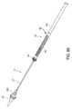
図1は、本開示の一実施形態による送達デバイス、送達組立体、または送達システム10の一実施形態を示す。送達システム10は、身体の中で、置換心臓弁などのプロテーゼを展開するために使用できる。いくつかの実施形態において、送達システム10は、プロテーゼを適切に送達するために二平面偏向アプローチを使用することができる。置換心臓弁は、患者の三尖心臓弁の環帯または他の心臓弁の場所に、種々のやり方で、例えば開腹手術、最小限の侵襲性の手術および経皮または患者の血管系を通る経カテーテル送達などによって送達され得る。例の経大腿アプローチは、2015年2月20日に出願された米国特許出願公開第2015/0238315号において見出すことができ、その特許出願の全体が、その全体において、本明細書によって参照により組み込まれている。送達システム10は、経皮送達アプローチに関連して、より具体的には経大腿動脈送達アプローチに関連して記載されるが、送達システム10の特徴は、経心先端、経右房または経頸静脈送達アプローチ用の送達システムを含む、他の送達システムに適用され得ることを理解されたい。FIG. 1 illustrates an embodiment of a delivery device, delivery assembly, or
送達システム10は、この明細書の他の場所で記載されるように、置換心臓弁などのプロテーゼを体内で展開するのに使用されてよい。送達システム10は、図3Aに示される、プロテーゼまたはインプラント70の第1の端部301および第2の端部303などのプロテーゼの一部を受け入れる、および/またはカバーすることができる。例えば、送達システム10は、拡張式プロテーゼまたはインプラント70を送達するのに使用されてよく、インプラント70は、第1の端部301と、第2の端部303とを含み、この場合、第2の端部303は、第1の端部301より前に展開または拡張されるように構成される。The
図2Aは、送達システム10に、具体的にはインプラント保持領域16に挿入され得るインプラント70の一例をさらに示す。図2Aにおいて、理解しやすくするために、プロテーゼは、図示されるむき出しの金属フレームのみで示される。プロテーゼまたはインプラント70は、任意の数の異なる形態をとることができる。プロテーゼのためのフレームの具体的な例が図3Aに示されているが、本出願において開示されているものを含め、他の設計およびフレーム構成が使用されてもよいことが理解されるものである。インプラント70は、プロテーゼフレームが拡張した構成にあるときに近位へ延在する遠位(または心室)アンカー80、および、プロテーゼフレームが拡張した構成にあるときに遠位へ延在する近位(または心房)アンカー82など、アンカーの1つまたは複数のセットを含み得る。プロテーゼは、第1の端部301においてキノコ形のタブ74において途切れ得る支柱72をさらに備え得る。さらなる検討は、その全体において本明細書によって参照により組み込まれている2015年11月19日に発行された米国特許出願公開第2015/0328000(A1)号において見出すことができる。FIG. 2A further illustrates one example of an
いくつかの実施形態において、送達システム10は、図3Bに示されるなど、置換大動脈弁と併せて使用され得る。いくつかの実施形態において、送達システム10は、置換大動脈弁を支持し送達するように修正される場合がある。しかしながら、以下で検討されている処置および構造は、置換三尖弁および置換大動脈弁のために同様に使用できる。In some embodiments, the
プロテーゼについての追加の詳細および例の設計は、米国特許第8,403,983号、米国特許第8,414,644号、米国特許第8,652,203号、米国特許出願公開第2011/0313515号、米国特許出願公開第2012/0215303号、米国特許出願公開第2014/0277390号、米国特許出願公開第2014/0277422号、米国特許出願公開第2014/0277427号、米国特許出願公開第2018/0021129号、および米国特許出願公開第2018/0055629号に記載されており、それらの特許および特許出願公開の全体が、本明細書によって参照により組み込まれており、本明細書の一部とされている。置換心臓弁およびプロテーゼのさらなる詳細および実施形態と、植え込みのためのその方法とは、米国特許出願公開第2015/0328000号および米国特許出願公開第2016/0317301号に記載されており、それらの各々の全体が、本明細書によって参照により組み込まれており、本明細書の一部とされている。Additional details and example designs for the prosthesis are described in U.S. Patent No. 8,403,983, U.S. Patent No. 8,414,644, U.S. Patent No. 8,652,203, U.S. Patent Application Publication No. 2011/0313515, U.S. Patent Application Publication No. 2012/0215303, U.S. Patent Application Publication No. 2014/0277390, U.S. Patent Application Publication No. 2014/0277422, U.S. Patent Application Publication No. 2014/0277427, U.S. Patent Application Publication No. 2018/0021129, and U.S. Patent Application Publication No. 2018/0055629, the entireties of which are hereby incorporated by reference and made a part of this specification. Further details and embodiments of replacement heart valves and prostheses and methods for implantation thereof are described in U.S. Patent Application Publication Nos. 2015/0328000 and 2016/0317301, each of which is hereby incorporated by reference in its entirety and made a part of this specification.
送達システム10は比較的可撓性であり得る。いくつかの実施形態において、送達システム10は、経中隔アプローチ(例えば、右心房と左心房との間で経中隔の穿刺を介して)を通じて僧帽弁の場所へと置換心臓弁を送達するのに特に適している。しかしながら、送達システム10は、数ある場所の中でも三尖弁の場所へと置換心臓弁を送達するのに適することができる。The
図1に示されているように、送達システム10は、近位端11と遠位端13とを備えるシャフト組立体または細長いシャフト12を備えることができ、ハンドル14が細長いシャフト12の近位端に結合されている。細長いシャフト12は、血管系を介して治療場所にインプラント70を進めるためにインプラントを保持するのに使用され得る。送達システム10は、細長いシャフト12の望ましくない動きを阻止し得る、細長いシャフト12を取り囲む比較的剛性の継続型(または一体式)シース51をさらに備え得る。継続型シース51は、ハンドル14の近位の細長いシャフト12の近位端において、例えばシースハブにおいて装着することができる。細長いシャフト12は、この目的のために使用することができるその遠位端に、インプラント保持領域16(図2A~図2Bに示され、図2Aは、インプラント70を示しており、図2Bは、インプラント70が除去されている)を含むことができる。いくつかの実施形態において、細長いシャフト12は、体内でインプラント70を進めるために、インプラント保持領域16において圧縮された状態で拡張式プロテーゼを保持することができる。細長いシャフト12はその後、治療場所でインプラント70の制御された拡張を可能にするのに使用されてよい。いくつかの実施形態において、細長いシャフト12は、以下で詳細に考察するように、インプラント70の連続する制御された拡張を可能にするのに使用されてよい。インプラント保持領域16は、図2A~図2Bに、送達システム10の遠位端で示されているが、他の場所にある場合もある。いくつかの実施形態において、インプラント70は、例えば本明細書で考察される内側シャフト組立体18の回転を通してインプラント保持領域16内で回転されてもよい。As shown in FIG. 1, the
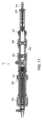
図2A~図2Bの断面図に示されるように、送達システム10の遠位端は、以下でより詳細に記載されるような外側シース組立体22、中間シャフト組立体21、レール組立体20、内側シャフト組立体18およびノーズコーン組立体31などの1つまたは複数の副次的組立体を含むことができる。いくつかの実施形態において、送達システム10は、本明細書に開示される組立体を全く持たない場合もある。例えば、いくつかの実施形態において、完全な中間シャフト組立体が送達システム10に組み込まれない場合がある。いくつかの実施形態では、以下で開示される組立体は、考察されるものとは異なる半径方向の順番である場合もある。As shown in the cross-sectional views of Figures 2A-2B, the distal end of the
詳細には、開示される送達システム10の実施形態は、送達システム10の遠位端を操縦するためにレール組立体20内の縦式レールを利用してよく、これによりインプラントを患者の体内に適切に配置されることを可能にする。以下でより詳細に考察するように、操縦式レールは、例えば、ハンドル14から概ね遠位端まで送達システム10の中を通って延在するレールシャフトであり得る。いくつかの実施形態において、操縦式レールは、インプラント保持領域16の近位で終わる遠位端を有する。ユーザはレールの遠位端の屈曲作用を操作することができ、これによりレールを具体的な方向に屈曲させることができる。好ましい実施形態では、レールは、その長さに沿って2つ以上の屈曲部を有し、これにより屈曲の複数の方向を提供する。レールが屈曲するとき、それが他の組立体に当たって押圧することで他の組立体も同様に屈曲させ、これにより、送達システム10の他の組立体は、対応する単一のユニットとしてレールと共に進むように構成され、よって送達システム10の遠位端の十分な操縦性を提供することができる。In particular, the disclosed embodiments of the
レールが、患者の体内の具体的な場所へと操縦されると、インプラント70を、レールに対する他のシース/シャフトの移動を介してレールに沿って、またはレールに対して進めることができ、体内へと解放することができる。例えば、インプラント70を生来の僧帽弁に向けて誘導するためなど、レールは、体内の所望の位置へと屈曲させることができる。他の組立体(例えば、外側シース組立体22、中間シャフト組立体21、内側組立体18およびノーズコーン組立体31)は、レールの屈曲部に受動的に従うことができる。さらに、インプラント70を(例えばインプラント保持領域16内で)解放または拡張することなく、圧縮位置にインプラント70を維持しながら、他の組立体(例えば、外側シース組立体22、中間シャフト組立体21、内側組立体18およびノーズコーン組立体31)をレールに対して一緒に(例えば、相対的に一緒に、1つのアクチュエータで順番に、同時に、ほとんど同時に、一度に、厳密に一度に)進めることができる。他の組立体(例えば、外側シース組立体22、中間シャフト組立体21、内側組立体18およびノーズコーン組立体31)は、レールに対して遠位方向または近位方向に進めることができる。いくつかの実施形態において、外側シース組立体22、中間シャフト組立体21および内側組立体18のみがレールの上で一緒に進められる。よってノーズコーン組立体31は、同じ位置に留まっていてもよい。インプラント70をインプラント保持領域16から解放するために、組立体を内側組立体18に対して、個別に、連続して、または同時に並進させることができる。Once the rail is steered to a specific location within the patient's body, the
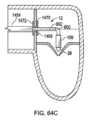
図2Cは、シース組立体を示しており、明確には、レール組立体20に沿って一体に遠位へと並進している外側シース組立体22と、中間シャフト組立体21と、内側シャフト組立体18と、ノーズコーン組立体31とを示しており、組立体についてのさらなる詳細は以下にある。いくつかの実施形態において、外側シース組立体22、中間シャフト組立体21、内側シャフト組立体18およびノーズコーン組立体31は、一緒に(例えば、相対的に一緒に、1つのアクチュエータで順番に、同時に、ほとんど同時に、一度に、厳密に一度に)並進する。この遠位の並進は、インプラント70がインプラント保持領域16内で圧縮構成で留まる間に生じてよい。2C shows the sheath assembly, specifically the
図2A~図2Cに示され、および図4~図8にさらに示されるように、最も外側の組立体で始まって、送達システムは、インプラント保持領域16を取り囲み、インプラントが半径方向に拡張するのを阻止するために、半径方向外側のカバー、またはシースを形成する外側シース組立体22を含むことができる。具体的には、外側シース組立体22は、インプラントの遠位端の半径方向の拡張が半径方向に拡張するのを阻止することができる。半径方向内側に移動し、中間シャフト組立体21は、その遠位端が、インプラント70の近位端などのプロテーゼの一部を圧縮構成で半径方向に保持するための外側保持部材または外側保持リング42に装着された中間シャフトハイポチューブ43で構成され得る。中間シャフト組立体21は、外側シース組立体22の内腔内に配置され得る。さらに内側に移動しレール組立体20は、上記に挙げたように、および以下でさらに記載されるように操縦性のために構成され得る。レール組立体20は、中間シャフト組立体21の内腔内に配置されてよい。さらに内側に移動し、内側シャフト組立体18は、その遠位端が、プロテーゼ、例えばプロテーゼの近位端を軸方向に維持するための内側保持部材または内側保持リング40(PEEKリングなど)に装着された内側シャフトで構成され得る。内側シャフト組立体18は、レール組立体20の内腔内に配置され得る。さらに、最も半径方向内側の組立体は、ノーズコーン28に接続されたその遠位端を有するノーズコーンシャフト27を含むノーズコーン組立体31であってよい。ノーズコーン28は、先細になった先端を有することができる。ノーズコーン組立体31は好ましくは、内側シャフト組立体18の内腔内に配置されてよい。ノーズコーン組立体31は、その中を通過するためのガイドワイヤのための内腔を含むことができる。2A-2C, and further illustrated in FIGS. 4-8, beginning with the outermost assembly, the delivery system can include an
細長いシャフト12、より具体的にはノーズコーン組立体31、内側組立体18、レール組立体20、中間シャフト組立体21および外側シース組立体22は、インプラント保持領域16(図2Aに示される)内に位置決めされたインプラント70を治療場所に送達するように一括して構成され得る。副次的組立体のうちの1つまたは複数はその後、インプラント70が治療場所で解放されることを可能にするために移動され得る。例えば、副次的組立体のうちの1つまたは複数は、他の副次的組立体のうちの1つまたは複数に対して可動であってよい。ハンドル14は、以下でもより詳細に記載されているように、様々な副次的組立体の移動を制御するために使用され得る様々な制御機構を備え得る。このように、インプラント70は、送達システム10上に制御可能に装填されて、その後体内で展開され得る。さらに、ハンドル14は、レール組立体20に対して操縦を提供し、送達システム10の遠位端の屈曲/曲げ/操縦を可能にすることができる。The
以下で検討されているように、内側保持部材40と、外側保持リング42と、外側シース組立体22とは、インプラント70をコンパクトな構成で保持するために協働することができる。内側保持部材40は、図2Aでは、インプラント70の近位端301において支柱72に係合して示される。例えば内側保持部材40上の半径方向に延在する歯の間に位置するスロットは、インプラント70の近位端上のマッシュルーム形状のタブで終わってよい支柱72を受け入れ、それと係合することができる。中間シャフト組立体21は、内側保持部材40の上に位置決めすることができるため、インプラント70の第1の端部301は、内側保持部材40と外側保持リング42との間に捕捉され、これによりそれを中間シャフト組立体21と内側保持部材40との間で送達システム10にしっかりと装着する。外側シース組立体22は、インプラント70の第2の端部303を覆うように位置決めすることができる。As discussed below, the inner retaining
外側保持部材42は、近位端において近位管44に装着され得る中間シャフトハイポチューブ43の遠位端に装着されてよく、近位管は近位端においてハンドル14に装着することができる。外側保持部材42は、圧縮位置にあるとき、インプラント70にさらなる安定性を提供することができる。インプラント70の近位端がそれらの間に捕捉され、送達システム10にしっかりとそれを装着するように、外側保持部材42を内側保持部材40の上に位置決めすることができる。外側保持部材42は、インプラント70の一部、詳細には、第1の端部301を取り巻くことができ、よってインプラント70が拡張するのを阻止することができる。さらに、中間シャフト組立体21は、外側シース組立体22の中へと、内側組立体18に対して近位方向に並進させることができ、したがって外側保持部材42内で保持されるインプラント70の第1の端部301を露出させることができる。この方法において、外側保持部材42は、インプラント70を固定するのを助ける、または送達システム10からそれを解放するのを助けるのに使用することができる。外側保持部材42は、円筒形または細長い管形状を有することができ、外側保持リングと呼ばれる場合もあるが、特定の形状に限定されない。The outer retaining
図2Aに示されているように、遠位アンカー80は送達構成で配置させることができ、遠位アンカー80は概して遠位(図示されているように、プロテーゼフレームの主本体から軸方向に離れるように、および、送達システムのハンドルから離れるよう)を指す。遠位アンカー80は、外側シース組立体22によってこの送達構成に抑制することができる。したがって、外側シース22が、近位方向に引き抜かれるとき、遠位アンカー80は、展開構成(例えば概ね近位方向を指す)に位置を反転する(例えば、おおよそ180度屈曲する)ことができる。図2Aはまた、外側シース組立体22内でその送達構成で遠位方向に延在する近位アンカー82も示す。他の実施形態では、遠位アンカー80は、送達構成で概して近位を指すように保持でき、プロテーゼフレームの本体に押し付けることができる。As shown in FIG. 2A, the distal anchor 80 can be positioned in a delivery configuration, with the distal anchor 80 pointing generally distally (as shown, axially away from the main body of the prosthesis frame and away from the handle of the delivery system). The distal anchor 80 can be constrained in this delivery configuration by the
送達システム10は、インプラント70があらかじめ導入された状態でユーザに提供されてよい。他の実施形態において、インプラント70は、使用のすぐ前に、医師または看護師などによって、送達システムに装填される場合もある。The
図4~図8は、異なる組立体が近位方向に並進され、詳細に記載される送達システム10のさらなる図を示す。Figures 4-8 show further views of the
図4に示される最も外側の組立体で始めて、外側シース組立体22は、その近位端においてハンドル14に直接装着された外側近位シャフト102と、その遠位端において装着された外側ハイポチューブ104とを含むことができる。カプセル106をその後、外側ハイポチューブ104の概ね遠位端において装着することができる。いくつかの実施形態において、カプセル106は、28フレンチ以下のサイズであり得る。外側シース組立体22のこれらの構成要素は、他の副次的組立体が通過するための内腔を形成することができる。Beginning with the outermost assembly shown in FIG. 4, the
カプセル106は、外側近位シャフト102の遠位端に配置することができる。カプセル106は、プラスチックまたは金属材料で形成された管であり得る。いくつかの実施形態において、カプセル106は、ePTFEまたはPTFEで形成される。いくつかの実施形態において、このカプセル106は、引き裂きを防ぎ、自動拡張式インプラントをコンパクトな構成で維持するのを助けるために比較的厚みがある。いくつかの実施形態において、カプセル106の材料は、外側ハイポチューブ104上のコーティングと同じ材料である。示されるように、カプセル106は、外側ハイポチューブ104より大きな直径を有することができるが、一部の実施形態では、カプセル106は、ハイポチューブ104と同様の直径を有する場合がある。いくつかの実施形態において、カプセル106は、より大きな直径の遠位部分、およびより小さい直径の近位部分を含む場合がある。いくつかの実施形態において、2つの部分の間に段差またはテーパが存在する場合がある。カプセル106は、インプラント70をカプセル106内で圧縮位置に保持するように構成され得る。カプセル106のさらなる構造の詳細が以下で考察される。The
外側シース組立体22は、他の組立体に対して個別に摺動可能であるように構成される。さらに、外側シース組立体22は、中間シャフト組立体21、内側組立体18およびノーズコーン組立体31と一緒にレール組立体20に対して遠位方向および近位方向に摺動することができる。The
半径方向内側に移動すると、次の組立体は、中間シャフト組立体21である。図5は、図4と同様の図であるが、外側シース組立体22が除去され、これにより中間シャフト組立体21を露出している。Moving radially inward, the next assembly is the
中間シャフト組立体21は、その近位端において中間シャフト近位管44に概ね装着される中間シャフトハイポチューブ43であって、中間シャフト近位管44は、その近位端においてハンドル14に装着することができる、中間シャフトハイポチューブ43と、中間シャフトハイポチューブ43の遠位端に配置された外側保持リング42とを含むことができる。よって、外側保持リング42は、概ね中間シャフトハイポチューブ43の遠位端において装着することができる。中間シャフト組立体21のこれらの構成要素は、他の副次的組立体が通過するための内腔を形成することができる。The
外側保持リング42は、図2Aに関して考察したように、インプラント70と係合するのに使用することができるプロテーゼ保持機構として構成することができる。例えば、外側保持リング42は、インプラント70上の支柱72を半径方向に覆うように構成されたリングまたはカバーであってよい。外側保持リング42はまた、インプラント保持領域16の一部と見なすことができ、インプラント保持領域16の近位端にあってもよい。以下で考察する、インプラント70の支柱または他の部品が内側保持部材40と係合した状態で、外側保持リング42が、インプラント70と内側保持部材40の両方を覆うことで、インプラント70を送達システム10上に固定することができる。よって、インプラント70を内側シャフト組立体18の内側保持部材40と中間シャフト組立体21の外側保持リング42との間に挟むことができる。2A. The
中間シャフト組立体21は、他の組立体に対して個別に摺動可能であるように配置される。さらに、中間シャフト組立体21は、外側シース組立体22、内側組立体18およびノーズコーン組立体31と一緒にレール組立体20に対して遠位方向および近位方向に摺動することができる。The
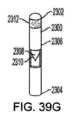
次に、中間シャフト組立体21の半径方向内側は、レール組立体20である。図6Aは、おおよそ図5と同じ図を示すが、中間シャフト組立体21が除去され、これによりレール組立体20が露出している。図6Bは、引っ張りワイヤを見るためにレール組立体20の断面図をさらに示す。レール組立体20は、その近位端でハンドル14に対して概ね装着されるレールシャフト132(またはレール)を含むことができる。レールシャフト132は、近位端においてハンドルに直接装着されたレール近位シャフト134と、レール近位シャフト134の遠位端に装着されたレールハイポチューブ136とで構成され得る。レールシャフト132は近位レールシャフト部分603と遠位レールシャフト部分601とを備え得る。レールハイポチューブ136は、その遠位端において非外傷性のレール先端をさらに備え得る。さらに、レールハイポチューブ136の遠位端は、図6Aに示されるように内側保持部材40の近位端に当接することができる。いくつかの実施形態において、レールハイポチューブ136の遠位端は、内側保持部材40から離れて離間される場合がある。レールシャフト組立体20のこれらの構成要素は、他の副次的が通過するための内腔を形成することができる。Next, radially inward of the
図6Bに示されるように、レールハイポチューブ136の内側表面には、レールハイポチューブ136に力を加え、レール組立体20を操縦するのに使用することができる1つまたは複数の引っ張りワイヤが装着される。引っ張りワイヤは、以下で考察する、ハンドル14のノブからレールハイポチューブ136まで遠位方向に延在することができる。いくつかの実施形態において、引っ張りワイヤは、レールハイポチューブ136上の異なる長手方向の場所に装着することができ、これによりレールハイポチューブ136内に複数の屈曲場所を提供し、多次元の操縦を可能にすることができる。As shown in FIG. 6B, the inner surface of the
いくつかの実施形態において、遠位引っ張りワイヤ138が、レールハイポチューブ136の遠位区域まで延在することができ、2本の近位引っ張りワイヤ140は、レールハイポチューブ136の近位区域まで延在することができるが、それ以外の数の引っ張りワイヤが使用される場合もあり、特定の数の引っ張りワイヤは限定ではない。例えば、2本の引っ張りワイヤが遠位の場所まで延在する場合があり、単一の引っ張りワイヤが近位の場所まで延在する場合もある。いくつかの実施形態において、レールハイポチューブ136の内側に装着されたリング状構造は、引っ張りワイヤコネクタとして知られており、例えば近位リング137および遠位リング135など、引っ張りワイヤのための装着場所として使用することができる。いくつかの実施形態において、レール組立体20は、遠位引っ張りワイヤコネクタ135含み、近位引っ張りワイヤコネクタ137を含む場合がある。いくつかの実施形態において、引っ張りワイヤは、レールハイポチューブ136の内側表面に直接接続される場合がある。In some embodiments, the
遠位引っ張りワイヤ138は、(そのままで、またはコネクタ135を介してのいずれかで)概ねレールハイポチューブ136の遠位端において接続することができる。近位引っ張りワイヤ140は、(そのままで、またはコネクタ137を介してのいずれかで)近位端からレールハイポチューブ136までの長さのおおよそ1/4、1/3または1/2の場所において接続することができる。いくつかの実施形態において、遠位引っ張りワイヤ138は、レールハイポチューブ136の内側に装着された小さい直径の引っ張りワイヤ内腔139(例えば、管、ハイポチューブ、シリンダ)を通過することができる。これは、ワイヤ138が、遠位接続部に対して近位の場所においてレールハイポチューブ136を引っ張るのを阻止することができる。さらに、内腔139は、レールハイポチューブ136の近位部分を強化し、望ましくない屈曲を阻止するために圧縮コイルとして作用することができる。したがって、いくつかの実施形態において、内腔139は、レールハイポチューブ136の近位の半分の部分のみに配置される。いくつかの実施形態において、長手方向に離間された、または長手方向に隣接する複数の内腔139が、遠位ワイヤ138ごとに使用される場合がある。いくつかの実施形態において、単一の内腔139が遠位ワイヤ138ごとに使用される。いくつかの実施形態において、内腔139は、レールハイポチューブ136の遠位の半分の中に延在することができる。いくつかの実施形態において、内腔139は、レールハイポチューブ136の外側表面に装着される。いくつかの実施形態において、内腔139は使用されない。The
近位引っ張りワイヤ140の対に関して、両方向に操縦することを可能にするためにワイヤは互いからおおよそ180°離間され得る。同様に、遠位引っ張りワイヤ138の対が使用される場合、両方向に操縦することを可能にするためにワイヤは互いからおおよそ180°離間され得る。いくつかの実施形態において、遠位引っ張りワイヤ138の対と近位引っ張りワイヤ140の対とが互いからおおよそ90°で離間され得る。いくつかの実施形態において、遠位引っ張りワイヤ138の対および近位引っ張りワイヤ140の対は、互いからおおよそ0°離間される場合がある。しかしながら引っ張りワイヤのための他の場所も同様に使用することができ、引っ張りワイヤの具体的な場所は限定ではない。いくつかの実施形態において、遠位引っ張りワイヤ138は、レールハイポチューブ136の内腔内に装着された内腔139を通過することができる。これは、遠位引っ張りワイヤ138に対する軸方向の力がレールハイポチューブ136の近位区域内で屈曲部を形成するのを阻止することができる。For the pair of
図6Cは、近位引っ張りワイヤ140の位置が図6Bに示された位置から180°移動した実施形態を示している。図6Cに示された近位引っ張りワイヤ140の位置は、レールハイポチューブ136の近位部分を、図6Bにおいて可能な方向と反対の方向に曲げさせることができる。例えば、図6Bの実施形態において、レールハイポチューブ136の遠位部分が遠位引っ張りワイヤ138の引っ張りによって下向き方向に偏向させられるとき、レールハイポチューブ136の近位部分は下向き方向に対して左方へ偏向させられ得る(レールハイポチューブ136の近位端からレールハイポチューブ136の遠位端の方を見るとき)。しかしながら、図6Cの実施形態において、レールハイポチューブ136の遠位部分が遠位引っ張りワイヤ138の引っ張りによって下向き方向に偏向させられるとき、レールハイポチューブ136の近位部分は下向き方向に対して右方へ偏向させられ得る(レールハイポチューブ136の近位端からレールハイポチューブ136の遠位端の方を見るとき)。このような変化は、レールハイポチューブ136の近位部分と、したがって細長いシャフト12とを、図6Bに示されている実施形態において可能な方向と反対の方向に偏向させることができる。レールシャフト132におけるカットの厚さも、反対の方向の偏向を可能とするために変化させられてもよい。6C illustrates an embodiment in which the position of the
レール組立体20は、内側シャフト組立体18とノーズコーン組立体31の上を摺動可動であるように配置される。いくつかの実施形態において、外側シース組立体22、中間シャフト組立体21、内側シャフト組立体18およびノーズコーン組立体31は、レール組立体20の屈曲と共に、または屈曲なしで近位方向および遠位方向などに、レール組立体20に沿って、またはレール組立体20に対して一緒に摺動するように構成されてよい。いくつかの実施形態において、外側シース組立体22、中間シャフト組立体21、内側シャフト組立体18およびノーズコーン組立体31は、それらがレール組立体20に沿って、またはレール組立体20に対して同時に摺動するとき、インプラント70を圧縮位置に保持するように構成されてよい。The
半径方向内側に移動すると、次の組立体は内側シャフト組立体18である。図7は、図6Aとほとんど同じ図を示すが、レール組立体20が除去され、これにより内側シャフト組立体18を露出している。Moving radially inward, the next assembly is the
内側シャフト組立体18は、その近位端においてハンドル14に概ね装着された内側シャフト122と、内側シャフト122の遠位端に位置する内側保持リング40とを含むことができる。内側シャフト122自体は、近位端においてハンドル14に直接装着された内側近位シャフト129と、内側近位シャフト129の遠位端に装着された遠位区域126とで構成され得る。よって、内側保持リング40は、概ね遠位区域126の遠位端に装着され得る。内側シャフト組立体18のこれらの構成要素は、他の副次的組立体が通過するための内腔を形成することができる。The
内側保持部材40は、図2Aに関して考察したように、インプラント70と係合するのに使用することができるプロテーゼ保持機構として構成され得る。例えば、内側保持部材40は、リングであってよく、インプラント70上の支柱72と係合するように構成された複数のスロットを含むことができる。内側保持部材40はまた、インプラント保持領域16の一部として構成される場合もあり、インプラント保持領域16の近位端にあってもよい。インプラント70の支柱または他の部分が内側保持部材40と係合した状態で、外側保持リング42が、プロテーゼと内側保持部材40の両方を覆うことで、プロテーゼを送達システム10上に固定することができる。よって、インプラント70を内側シャフト組立体18の内側保持部材40と中間シャフト組立体21の外側保持リング42との間に挟むことができる。2A. The
内側シャフト組立体18は、他の組立体に対して個別に摺動可能であるように配置される。さらに、内側シャフト組立体18は、外側シース組立体22、中間シャフト組立体21およびノーズコーン組立体31と一緒にレール組立体20に対して遠位方向および近位方向に摺動することができる。The
内側シャフト組立体18からさらに内側に移動すると、図8にも見られるノーズコーン組立体31がある。これは、ノーズコーンシャフト27であってよく、またいくつかの実施形態では、その遠位端上にノーズコーン28を有する場合がある。ノーズコーン28は、非外傷性の進入のため、および静脈血管系への損傷を最小限にするためにポリウレタンで作成され得る。ノーズコーン28はまた、蛍光透視法の下で視認性を提供するために放射線不透過性であり得る。Moving further inward from the
ノーズコーンシャフト27は、ガイドワイヤを摺動可能に収容するようにサイズが決められ、そのように構成されることで、送達システム10を血管系を通ってガイドワイヤの上を進めることができる内腔を含んでよい。しかしながら、本明細書で考察されるシステム10の実施形態は、ガイドワイヤを使用しない場合があり、したがってノーズコーンシャフト27は中実であり得る。ノーズコーンシャフト27は、ノーズコーン28からハンドルまで接続されてよい、または他の組立体などの異なる部分で形成されてもよい。さらに、ノーズコーンシャフト27は、上記に詳細に記載したものと同様にプラスチックまたは金属などの異なる材料で形成されてもよい。The
いくつかの実施形態において、ノーズコーンシャフト27は、ノーズコーンシャフト27の一部に位置するガイドワイヤシールド1200を含む。In some embodiments, the
ノーズコーン組立体31は、他の組立体に対して個別に摺動可能に配置される。さらに、ノーズコーン組立体31は、外側シース組立体22、中間シャフト組立体21および内側組立体18と一緒にレール組立体20に対して近位方向および遠位方向に摺動することができる。The
いくつかの実施形態において、1つまたは複数のスペーサスリーブ(図示せず)を送達システム10の異なる組立体の間で使用することができる。例えば、スペーサスリーブは、中間シャフト組立体とレール組立体20との間に、一般に中間43とレールハイポチューブ136との間に同心に配置され得る。いくつかの実施形態において、スペーサスリーブは、中間シャフト組立体21の内側表面上など、中間シャフト組立体21のハイポチューブ43内に概ね埋め込むことができる。いくつかの実施形態において、スペーサスリーブは、概ねレールハイポチューブ136の中で、レール組立体20と内側組立体18との間に同心に配置される場合がある。いくつかの実施形態において、スペーサスリーブは、外側シース組立体22と中間シャフト組立体21との間で使用される場合がある。いくつかの実施形態において、スペーサスリーブは、内側シャフト組立体18とノーズコーン組立体31との間で使用される場合がある。いくつかの実施形態において、上記に挙げたスペーサスリーブのうちの4つ、3つ、2つまたは1つが使用される場合がある。スペーサスリーブは、上記の位置のいずれかで使用することができる。In some embodiments, one or more spacer sleeves (not shown) may be used between different assemblies of the
上記で考察したように、外側シース組立体22、中間シャフト組立体21、内側組立体18およびレール組立体20は、外側ハイポチューブ104、中間シャフトハイポチューブ、遠位区域126およびレールハイポチューブ136をそれぞれ収容することができる。これらのハイポチューブ/区域/シャフトの各々は、いくつかのスロットを含むようにレーザ切断され、これにより、送達システムがたどるための屈曲経路を形成することができる。As discussed above, the
例えば図9は、レールハイポチューブ136の一実施形態を示す。レールハイポチューブ136はまた、いくつかの円周方向スロットを含むことができる。レールハイポチューブ136は、いくつかの異なる区域に概ね分けることができる。最も近位の端部には、カットされない(またはスロットが付けられない)ハイポチューブ区域231がある。遠位方向に移動すると、次の区域は、近位のスロット付きハイポチューブ区域233である。この区域は、レールハイポチューブ136内に切り取られたいくつかの円周方向スロットを含む。一般に、2つのスロットが、円周のほぼ半分を形成する各々の円周方向の場所の周りで切り取られる。したがって、2つの背骨状の部分が、ハイポチューブ136の長さに完全に延在するスロットの間に形成される。これは、近位引っ張りワイヤ140によってガイドすることができる区域である。さらに遠位方向に移動すると、近位引っ張りワイヤ140が接続し、これによりスロットが回避され得る場所237である。この区域は、近位方向にスロットが付けられた区域のちょうど遠位である。For example, FIG. 9 shows one embodiment of the
近位引っ張りワイヤ接続領域を遠位方向にたどると、遠位のスロット付きのハイポチューブ区域235がある。この区域は、近位のスロット付きのハイポチューブ区域233と同様であるが、同等の長さで切り取られた、著しく多いスロットを有する。よって、遠位方向にスロットが付けられた区域235は、近位方向にスロットが付けられたハイポチューブ区域233よりも容易な屈曲を提供する。近位のスロット付きハイポチューブ区域233および遠位のスロット付きの区域235は、レールシャフトの曲げ部分を含んでもよい。いくつかの実施形態において、近位のスロット付きのハイポチューブ区域233は、1/2インチの半径でおおよそ90度の屈曲を受けるように構成することができ、その一方で、遠位のスロット付きの区域235は、1/2インチの範囲内でおおよそ180度で屈曲することができる。さらに、図9に示されるように、遠位方向にスロットが付けられたハイポチューブ区域235は、近位方向にスロットが付けられたハイポチューブ区域233の背骨状の部分からオフセットされている。したがって、2つの区域は、異なる屈曲パターンを達成し、レール組立体20の三次元の操縦を可能にすることになる。いくつかの実施形態において、背骨状の部分は、オフセット30度、45度または90度であり得るが、特定のオフセットは限定ではない。いくつかの実施形態において、近位方向にスロットが付けられたハイポチューブ区域233は、圧縮コイルを含むことができる。これは、近位方向にスロットが付けられたハイポチューブ区域233が、遠位方向にスロットが付けられた区域235の特有の屈曲のために剛性を保持するのを可能にする。Following the proximal pull wire connection region distally is the distal slotted
遠位のスロット付きのハイポチューブ区域235の最も遠位の端部には、これもまたレールハイポチューブ136のスロットがない区域である、遠位引っ張りワイヤ接続領域241がある。At the distal-most end of the distal slotted
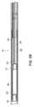
ハンドル14は送達システム10の近位端に配置されている。ハンドル14の実施形態が図10に示されている。ハンドル14の断面が図11に示されている。ハンドル14は、送達システム10の異なる構成要素を操縦することができる回転可能ノブなどのアクチュエータをいくつか備え得る。ハンドル14の動作は、置換弁プロテーゼまたはインプラント70の送達に関連して記載されているが、ハンドル14および送達システム10は、他のデバイスを送達するために使用することもできる。The handle 14 is disposed at the proximal end of the
ハンドル14は、2つのハウジング、すなわち、レールハウジング202および送達ハウジング204から概して成り、レールハウジング202は送達ハウジング204の周りの周囲に配置されている。レールハウジング202の内側表面は、送達ハウジング204の外側表面と噛み合うように構成された捩じ込み可能区域を備え得る。したがって、送達ハウジング204は、後で詳述されているように、レールハウジング202の中で摺動する(例えば、捩じれる)ように構成されている。レールハウジング202は送達ハウジング204の長さの2分の1の周りを概して取り囲み、したがって、送達ハウジング204はレールハウジング202の外側で近位と遠位との両方に延在する。The handle 14 is generally comprised of two housings, a
レールハウジング202は、2つの回転可能ノブ、すなわち、遠位引っ張りワイヤノブ206および近位引っ張りワイヤノブ208を収容することができる。しかしながら、レールハウジング202における回転可能ノブの数は、使用される引っ張りワイヤの数に応じて変わってもよい。遠位引っ張りワイヤノブ206の回転は近位への力を提供し、それによって、遠位引っ張りワイヤ138に軸方向の張力を提供し、レールハイポチューブ136の遠位のスロット付き区域を曲げさせることができる。遠位引っ張りワイヤノブ206はいずれの方向にも回転させることができ、いずれの方向での曲げも許容し、これによって前側-後側の角度を制御することができる。近位引っ張りワイヤノブ208の回転は近位への力を提供し、それによって、近位引っ張りワイヤ140に軸方向の張力を提供し、レールハイポチューブ136の近位のスロット付き区域133を曲げさせることができ、これによって内側-外側の角度を制御することができる。近位引っ張りワイヤノブ208はいずれの方向にも回転させることができ、いずれの方向での曲げも許容することができる。したがって、両方のノブが作動させられるとき、レールハイポチューブ136に2つの曲げができ、それによって、レールシャフト132の三次元の操縦を可能にし、延いては送達システム10の遠位端の三次元の操縦を可能にする。さらに、レールシャフト132の近位端がレールハウジング202の内部表面において連結される。The
レールシャフト132の曲げは、システム、具体的には遠位端を、生来の三尖弁においてなど、患者の所望の場所に位置決めするために使用できる。いくつかの実施形態において、引っ張りワイヤノブ206/208の回転は、送達システム10の遠位端を、例えば三尖弁または僧帽弁といった治療される弁の近位の所望の位置へと操縦するのを助けることができる。The bending of the rail shaft 132 can be used to position the system, specifically the distal end, at a desired location in the patient, such as at the native tricuspid valve. In some embodiments, rotation of the
送達ハウジング204に移ると、内側シャフト組立体18、外側シース組立体22、中間シャフト組立体21、およびノーズコーンシャフト組立体31の近位端がハンドル14の送達ハウジング204の内側表面に連結され得る。したがって、それらはレール組立体20およびレールハウジング202に対して軸方向に移動することができる。Moving to the
回転可能な外側シースノブ210は、送達ハウジング204の遠位端に配置でき、レールハウジング202の遠位にある。外側シースノブ210の回転は、外側シース組立体22を軸方向において近位へと引っ張り、それによってカプセル106をインプラント70から引っ張り、インプラント70の遠位端303を解放する。したがって、外側シース組立体22は、送達システム10における他のシャフトに対して個別に並進させられる。インプラント70の遠位端303が初めに解放でき、一方でインプラント70の近位端301は、内側保持部材40と外側保持部材42との間で径方向に圧縮されたままとすることができる。A rotatable
回転可能な中間シャフトノブ214が、いくつかの実施形態では回転可能な外側シースノブ210の近位において、送達ハウジング204に配置でき、レールハウジング202の遠位にある。中間シャフトノブ214の回転は、中間シャフト組立体21を軸方向において近位へ引っ張り、したがって、外側保持リング42をインプラント70から離すように引っ張り、インプラント70の内側保持部材40および近位端301の覆いを外し、それによってインプラント70を解放する。したがって、中間シャフト組立体21は、送達システム10における他のシャフトに対して個別に並進させられる。A rotatable
送達ハウジング204の近位端に配置され、そのためレールハウジング202の近位に配置されるのは、回転可能な深さノブ212であり得る。深さノブ212が回転させられるとき、送達ハウジング204の全体が、同じ場所に留まるレールハウジング202に対して遠位または近位へ移動する。したがって、送達システム10の遠位端と、内側シャフト組立体18と、外側シース組立体22と、中間シャフト組立体21と、ノーズコーンシャフト組立体31とは、レール組立体20に対して近位または遠位へ一緒に(例えば、同時に)移動し、一方、インプラント70は圧縮構成で留まる。いくつかの実施形態において、深さノブ212の作動は、内側シャフト組立体18、外側シース組立体22、中間シャフト組立体21、およびノーズコーンシャフト組立体31をレール組立体20に対して連続的に移動させることができる。いくつかの実施形態において、深さノブ212の作動は、内側シャフト組立体18、外側シース組立体22、および中間シャフト組立体21をレール組立体20に対して一緒に移動させることができる。したがって、レールシャフト132は特定の方向において一列にさせることができ、他の組立体は、インプラント70を解放せずに最終的に位置決めするために、レールシャフト132に対して遠位または近位に移動することができる。構成要素は、レールシャフト132に沿って、おおよそ1cm、2cm、3cm、5cm、6cm、7cm、8cm、9cm、または10cm前進させることができる。構成要素は、レールシャフト132に沿って、おおよそ1cm、2cm、3cm、5cm、6cm、7cm、8cm、9cm、または10cmを越えて前進させることができる。これの例は図2Cに示されている。そのため、カプセル106と外側保持リング42とは、先に詳述されているように、いくつかの実施形態において連続的に、内側組立体18に対して個別に引き込むことができ、インプラント70を解放する。そのため、レール組立体20以外の組立体は、深さノブ212を反対方向において回転させることで、レールシャフト132にわたって戻すように引き込むことができる。Disposed at the proximal end of the
ハンドル14は、ノーズコーンシャフト27を移動させ、延いてはノーズコーン28を移動させるための機構(ノブ、ボタン、ハンドル)216をさらに備え得る。例えば、ノブ216は、ハンドル14の近位端から延在するノーズコーン組立体31の一部分であり得る。したがって、使用者は、他のシャフトに対して個別に、ノーズコーンシャフト27を遠位または近位へと並進させるためにノブ216を引っ張るかまたは押すことができる。これは、ノーズコーン28を外側シース組立体22/カプセル106へと近位へ並進するのに有利であり得、したがって、患者からの送達システム10の引き込みを容易にする。The handle 14 may further include a mechanism (knob, button, handle) 216 for moving the
いくつかの実施形態において、ハンドル14は、先に詳述されたノブ216によってノーズコーンシャフト27の並進を防止するために、バネ係止部などの係止部218を提供することができる。いくつかの実施形態において、係止部218は常に作動していることができ、したがって、ノーズコーンシャフト27は、使用者が係止部218を係合解除しない場合には移動しない。係止部は、例えば、ハンドル14におけるボタン218が押されるまで常に係合させられるバネ係止部であってよく、それによって、バネ係止部を解放し、ノーズコーンシャフト27を近位/遠位へ並進させることができる。いくつかの実施形態において、バネ係止部218は、近位または遠位のいずれかの運動で、ノーズコーンシャフト27の一方向の移動を可能にし、反対方向の運動を防止する。In some embodiments, the handle 14 can provide a
ハンドル14は、送達システム10の異なる管腔を洗い流すための連通フラッシュポートをさらに備え得る。いくつかの実施形態において、ハンドル14における単一のフラッシュポートが複数の組立体に流体連結を提供し得る。いくつかの実施形態において、フラッシュポートは外側シース組立体22への流体連結を提供し得る。いくつかの実施形態において、フラッシュポートは外側シース組立体22および中間シャフト組立体21への流体連結を提供し得る。いくつかの実施形態において、フラッシュポートは外側シース組立体22、中間シャフト組立体21、およびレール組立体20への流体連結を提供し得る。いくつかの実施形態において、フラッシュポートは外側シース組立体22、中間シャフト組立体21、レール組立体20、および内側組立体18への流体連結を提供し得る。したがって、いくつかの実施形態において、レールシャフト132、外側保持リング42、およびカプセル106は、単一のフラッシュポートによってすべて洗い流すことができる。The handle 14 may further include communicating flush ports for flushing different lumens of the
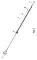
図12Aは、細長いシャフト12が真っ直ぐの構成にある状態での細長いシャフト12の遠位部分の側面図である。カプセル106は、外側ハイポチューブ104とノーズコーン28との間に位置決めされて示されている。Figure 12A is a side view of the distal portion of the
細長いシャフト12は、細長いシャフト12を曲げ部分において曲げさせることができる1つまたは複数の曲げ部分を備え得る。図12Aに示された実施形態では、例えば、細長いシャフト12は2つの曲げ部分600、602を備える。曲げ部分600は、図6Bおよび図6Cに示されている遠位レール部分601に対応することができ、曲げ部分602は、図6Bおよび図6Cに示されている近位レール部分603に対応することができる。それによって、曲げ部分600、602は、互いと垂直でない平面において細長いシャフト12を曲げるように構成でき、曲げ部分600は、鉛直平面と呼ぶことができる平面において曲がることができ、曲げ部分602は、それに応じて水平平面と呼ぶことができる平面において曲がることができる。曲げ部分600、602は、カプセル106に収容されるインプラント70の展開のための所望の位置においてカプセル106を配向するために、曲がるように構成され得る。The
カプセル106(および、カプセル106に収容されたインプラント保持領域16)は、本明細書に開示されている手法で、曲げ部分600、602に対して摺動するように構成され得る。例えば、外側シース組立体22、中間シャフト組立体21、内側シャフト組立体18、およびノーズコーン組立体31は、レール組立体20からのカプセル106の距離または深さを変えるために、(レール組立体20の一部としての)曲げ部分600、602に対して摺動するように構成され得る。外側シース組立体22は、患者の三尖弁からのインプラント保持領域の距離を変えるために、レール組立体20に対して摺動するように構成され得る。The capsule 106 (and the
図12Bを参照すると、カプセル106の近位に位置決めされ、カプセル106と曲げ部分602との間に位置決めされる曲げ部分600は、細長いシャフト12の遠位端をある方向(図12Bに示されているように、下方向と称されてもよい)に偏向させるように示されている。曲げ部分600は、細長いシャフト12の遠位端を平面(鉛直平面と称されてもよい)において偏向させる。曲げ部分600は、それに応じて、カプセル106、細長いシャフト12の遠位端、および、カプセル106の中に位置決めされたインプラント保持領域16の配向を変化させる。With reference to FIG. 12B, a
図12Cは、曲げ部分602が曲げられると、図12Aおよび図12Bに示されている細長いシャフト12の上面図を示している。図12Cには、曲げ部分600の近位に位置決めされる曲げ部分602は、細長いシャフト12の遠位端をある方向(図12Cに示されているように、右方向と称されてもよい)に偏向させるように示されている。曲げ部分602は、細長いシャフト12の遠位端を平面(水平平面と称されてもよい)において偏向させる。曲げ部分602は、それに応じて、カプセル106、細長いシャフト12の遠位端、および、カプセル106の中に位置決めされたインプラント保持領域16の配向を変化させる。12C shows a top view of the
それに応じて、曲げ部分602は、曲げ部分600がカプセル106を偏向させ得る平面に対して垂直である平面において、曲げ部分600およびカプセル106を偏向させることができる。偏向の直交する平面は、カプセル106の三次元の操縦を可能にすることができる。In response, bending
図12Cに示されているような曲げ部分602は、細長いシャフト12の遠位端を右方向へと偏向させるように構成され得る。偏向のこのような方向は、図6Cに示されている引っ張りワイヤの構成によって提供され得る。The
細長いシャフト12の追加または種々の移動が望まれてもよい。このような追加または種々の移動は、細長いシャフト12の遠位端でナビゲートされる様々な患者の生体構造、または、細長いシャフト12の種々の使用を含み得る様々な理由のため、望まれる可能性がある。Additional or different movements of the
図13A~図13Dは、偏向機構が細長いシャフト12の一部分の偏向を提供するために利用され得る実施形態を示している。図13Aを参照すると、偏向機構は、細長いシャフト12の一部分614の上に延在するシース610を備え得る。細長いシャフト12の一部分614は、曲げ部分602および曲げ部分600の近位に位置決めされる一部分を備え得る。しかしながら、他の実施形態では、シース610は、細長いシャフト12の他の一部分の上に延在してもよく、可及的には、細長いシャフト12の遠位端へと延在する。13A-13D illustrate embodiments in which a deflection mechanism may be utilized to provide deflection of a portion of the
シース610は、図13Aにおいて断面図で示されており、細長いシャフト12の偏向を提供するために偏向するように構成され得る。シースは、シース610の偏向を制御するために利用される制御デバイスを備え得る。制御デバイスは、図13Aに示されているような引っ張りつなぎ綱612を備えてもよく、引っ張りつなぎ綱612は、引っ張りワイヤまたはつなぎ綱の他の形態を備え得る。他の実施形態では、歯車、レール、または制御デバイスの他の形態など、制御デバイスの他の形態が利用されてもよい。引っ張りつなぎ綱612は、引っ張りつなぎ綱612の後退が細長いシャフト12を引っ張りつなぎ綱612に向かう方向に偏向させることができるように、細長いシャフト12において配向させられ得る。The
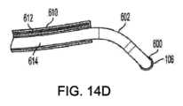
図13Bを参照すると、曲げ部分600は、細長いシャフト12の遠位端を方向605(図13Bに示されているように、下方向と称されてもよい)に偏向させている。しかしながら、偏向機構は、曲げ部分600が細長いシャフト12の遠位端を偏向させた方向605と反対である方向607に向けて曲げ部分600、602を偏向させるために、曲げ部分600および曲げ部分602の近位に位置決めされている細長いシャフト12の一部分614を偏向させている。偏向機構は、曲げ部分602と、曲げ部分600と、カプセル106と、カプセル106の中に収容されたインプラント保持領域16と、ノーズコーン28とを、曲げ部分600が細長いシャフト12の遠位端を偏向させた方向と反対である方向に向けて同じく偏向させている。したがって、偏向機構は、細長いシャフト12の遠位端から所望の植え込み場所への高さまたは距離を作り出すために、細長いシャフト12を偏向させるために利用され得る。13B, the
偏向機構は、曲げ部分600が細長いシャフト12の遠位端を偏向させたのと同じ平面(同一平面)において細長いシャフト12の一部分614を偏向させている。The deflection mechanism deflects a
偏向機構は、図12A~図12Cに示されているのと同様の手法で、曲げ部分600、602に細長いシャフト12のそれぞれの遠位部分を曲げさせるために利用されてもよい。図13Cを参照すると、例えば、偏向機構は、細長いシャフト12の近位部分614を偏向させているが、曲げ部分600は、細長いシャフト12の遠位端を図13Bに示された方向に偏向させ続けており、曲げ部分602は、曲げ部分600を、図12Cに関して記載されているような垂直方向に偏向している。細長いシース610の形態での偏向機構は、曲げ部分600が細長いシャフト12の遠位端を偏向させた方向から離れる方向に向けて曲げ部分600、602を偏向させるために、曲げ部分600および曲げ部分602の近位にある細長いシャフト12の一部分614を偏向させ続ける。The deflection mechanism may be utilized to cause bending
偏向機構は、曲げ部分600および曲げ部分602の近位にある細長いシャフト12の一部分614の複数の偏向の方向を提供するように構成され得る。例えば、シース610の形態での偏向機構は、シース610が上に延在する細長いシャフト12の一部分の周りに回転するように構成され得る。このような回転は、細長いシャフト12を引っ張りつなぎ綱612の種々の位置に向けて偏向させるために、細長いシャフト12に対する引っ張りつなぎ綱612の位置を移動させることができる。それによって、細長いシャフト12の様々な偏向の方向が結果的に生じることができる。例えば、図13Dは、曲げ部分600が偏向させられ得るのに向かう方向605と反対である複数の方向を(矢印を介して)示している細長いシースの正面図を示している。The deflection mechanism may be configured to provide multiple directions of deflection of the
図14Aは、細長いシャフト12の上に延在するシース610の斜視図を示している。シース610は、図1に示されたシース51の代わりに、または、シース51との組合せで、利用できる。シース610は遠位端616と近位端618とを有し得る。シース610の近位端618は、細長いシャフト12の周りでのシース610の回転を制御するために利用され得る回転制御ハウジング620に結合され得る。外科医または他の使用者などの使用者は、細長いシャフト12の周りでのシース610の回転を制御することで、シース610によって引き起こされる細長いシャフト12の偏向の方向を制御するために、回転制御ハウジング620を把持することができる。シース610の近位端618は偏向制御ハウジング622に代替または追加で結合することができ、偏向制御ハウジング622は、シース610を偏向させるために引っ張りつなぎ綱612を近位へと引くために利用でき、また、シース610を真っ直ぐにするために引っ張りつなぎ綱612を遠位方向に解放するために利用できる。偏向制御ハウジング622は、外科医または他の使用者などの使用者がシース610を把持して制御するように構成され得る。FIG. 14A shows a perspective view of a
制御ハウジング620、622は、単一の制御ハウジングを望まれるように形成するために一体化されてもよい。一実施形態では、制御ハウジング620、622の制御は、望まれるように、ハンドル14で一体化されてもよい、または、ハンドル14と別体のままであってもよい。The
図14B~図14Dは、図13Aに示された位置に対して細長いシャフト12の周りに90°回転したシース610の形態での偏向機構を示している。シース610は、望まれるように、回転制御ハウジング620の使用を通じて、または、他の方法を通じて、回転させることができる。引っ張りつなぎ綱612の相対位置が、図14Dに示されているように、90°回転している。図14Dを参照すると、シース610は、曲げ部分600が細長いシャフト12の遠位端を偏向させた方向に対して垂直である方向に向けて、細長いシャフト12を偏向させることができる。シース610は、曲げ部分602の遠位にある細長いシャフト12の一部分を曲げ部分602が偏向させるのと同じ平面において、細長いシャフト12を偏向させることができる。14B-14D show a deflection mechanism in the form of a
シース610の形態での偏向機構は、望まれるように、細長いシャフト12に対して任意の角度位置において、細長いシャフト12に対して様々な配向を有することができる。それによって、シース610の形態での偏向機構は、曲げ部分600が細長いシャフト12の遠位端を偏向させた方向に対して垂直であってもなくてもよい複数の方向に、細長いシャフト12の一部分614を偏向させるように構成できる。シース610の形態での偏向機構は、細長いシャフト12の一部分614を、曲げ部分600が細長いシャフト12の遠位端を偏向させた方向と反対である様々な方向に向けて偏向させることができ、それら様々な方向は、曲げ部分600が細長いシャフト12の遠位端を偏向させた方向と正反対である方向(180°)、および、正反対(180°)と垂直方向(90°)との間である様々な他の方向(例えば、数ある中でも135°)であり得る。The deflection mechanism in the form of the
シース610の形態での偏向機構は、曲げ部分600が細長いシャフト12の遠位端を偏向させた方向に向かう方向に細長いシャフト12の一部分614を偏向させるためにシース610が回転させられる場合、そのような偏向を提供するように構成され得る。The deflection mechanism in the form of the
シース610の形態での偏向機構は、シース610の回転を介して一部分614の偏向の方向を変えるように構成され得るだけでなく、実施形態では、シース610の回転なしで、シース610の種々の偏向の方向を可能にする複数の引っ張りつなぎ綱または他の制御デバイスで構成されてもよい。例えば、等しく離間された4つの引っ張りつなぎ綱(互いから90°で離間される)がシース610で利用される場合、引っ張りつなぎ綱の移動の組合せによって、シース610の様々な偏向の方向を提供することができる。他の構成がシース610の偏向の方向を変えるために利用されてもよい。少なくとも1つの引っ張りつなぎ綱が実施形態において利用され得る。The deflection mechanism in the form of the
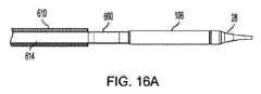
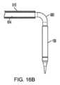
図13A~図14Dの実施形態は、垂直平面において曲がるように構成される2つの曲げ部分600、602を有する細長いシャフト12を示している。しかしながら、曲げ部分600、602の構成および使用は、望まれるように、他の実施形態において変えられてもよい。例えば、図15A~図16Cは、曲げ部分602が排除された実施形態を示しており、シース610が、曲げ部分602の代わりに細長いシャフト12の偏向を制御する。したがって、シース610は、細長いシャフト12を、曲げ部分600が細長いシャフト12の遠位端を偏向させた方向と反対である方向に向けて偏向させるように構成でき、その方向は、曲げ部分600が細長いシャフト12の遠位端を偏向させた方向と正反対である方向(180°)、および、正反対(180°)と垂直方向(90°)との間である様々な他の方向(例えば、数ある中でも135°)であり得る。図15A~図15Cは、曲げ部分600が細長いシャフト12の遠位端を偏向させた方向と反対である方向に向けて曲げ部分600を偏向させるために、細長いシャフト12の一部分を偏向させるシース610を示している。The embodiment of Figures 13A-14D shows the
シース610は、一部分614の偏向の方向を変えるために、図15A~図15Cに示された配向から回転させられ得る。図16A~図16Cは、曲げ部分600の偏向の平面に対して垂直である平面において一部分614を偏向させるために、図15A~図15Cに示された配向から90°回転したシース610を示している。図13A~図14Dに関連して詳述されているように、シース610は、他の実施形態において、シース610の回転なしで、シース610の種々の偏向の方向を可能にする複数の引っ張りつなぎ綱または他の制御デバイスで構成されてもよい。The
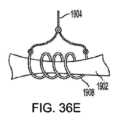
他の形態の偏向機構が利用されてもよい。例えば、図17は、引っ張りつなぎ綱630の形態での偏向機構の実施形態を示している。引っ張りつなぎ綱630は、例えばレールシャフト132といった細長いシャフト12の一部分に結合される遠位端632を有し得る。レールシャフト132は、本明細書で開示されているように内側シャフトの上に延在してもよく、本明細書に開示されているようにレールシャフト132の上に延在する外側シースを有してもよい。遠位端632は、レール近位シャフト134に、または、レールハイポチューブ136もしくはレールシャフト132の曲げ部分634、636の近位にあるレールシャフト132の他の一部分に、結合してもよい。例えば、図17に示されているように、遠位端632は、カットされない(または、スロットが付けられない)ハイポチューブ区域231の近位にある一部分に結合してもよい。Other forms of deflection mechanism may be utilized. For example, FIG. 17 illustrates an embodiment of a deflection mechanism in the form of a tension tether 630. The tension tether 630 may have a
引っ張りつなぎ綱630は、レールシャフト132の一部分638を偏向させ、延いては、曲げ部分634、636の近位にある細長いシャフト12を偏向させるために、後退させられるように構成され得る。それによって、曲げ部分634は、細長いシャフト12の遠位端をある方向に偏向させるように構成でき、引っ張りつなぎ綱630は、曲げ部分634が細長いシャフト12の遠位端を偏向させた方向と反対である方向に向けて曲げ部分634、636を偏向させるために、細長いシャフト12を偏向させるように構成できる。引っ張りつなぎ綱630は、所定位置において、引っ張りつなぎ綱630が後退させられるときに曲げ部分634が細長いシャフト12の遠位端を偏向させた方向と反対である配向で、レールシャフト132に結合させられ得る。The tension tether 630 can be configured to be retracted to deflect a
単一の引っ張りつなぎ綱630が図17に示されているが、複数の引っ張りつなぎ綱が、望まれているように他の実施形態で利用されてもよい。例えば、等しく離間された4つの引っ張りつなぎ綱(互いから90°で離間される)がレールシャフト132に結合される場合、引っ張りつなぎ綱の移動の組合せによって、細長いシャフト12の様々な偏向の方向を提供することができる。他の構成が細長いシャフト12の偏向の方向を変えるために利用されてもよい。したがって、1つまたは複数の引っ張りつなぎ綱は、細長いシャフト12を、曲げ部分634が細長いシャフト12の遠位端を偏向させた方向と反対である方向に向けて偏向させるように構成でき、その方向は、曲げ部分634が細長いシャフト12の遠位端を偏向させた方向と正反対である方向(180°)、および、正反対(180°)と垂直方向(90°)とを含めてそれらの間である様々な他の方向(例えば、数ある中でも135°)であり得る。17, multiple pull tethers may be utilized in other embodiments as desired. For example, if four equally spaced pull tethers (spaced 90° from one another) are coupled to the rail shaft 132, a combination of movements of the pull tethers may provide various directions of deflection of the
図18A~図18Bは、細長いシャフト12の一部分におけるカット640と、細長いシャフト12をカット640の場所において偏向させるために後退させられ得る引っ張りシャフト642とを備える偏向機構の実施形態を示している。図18Aを参照すると、カット640は、所望の場所においてレールシャフト132に位置決めされ得る。このような場所は、レールハイポチューブ136またはレールシャフト132の曲げ部分634、636の近位であり得る。例えば、図18Aに示されているように、カット640は、カットされない(または、スロットが付けられない)ハイポチューブ区域231の近位であり得る。18A-18B show an embodiment of a deflection mechanism comprising a
カット640は、カット640において、曲げ部分634が細長いシャフト12の遠位端を偏向させた方向から離れる方向に偏向するために、レールシャフト132を付勢する構成を有し得る。The
図18Bを参照すると、レールシャフト132の断面図が示されている。偏向機構は、レールシャフト132の中に位置決めされ得る内側シャフトまたは引っ張りシャフト642を備えてもよい。引っ張りシャフト642は、レールシャフト132と、内側シャフト組立体18などの内側シャフトまたはノーズコーン組立体31との間に位置決めされ得る。他の実施形態では、内側シャフトまたは引っ張りシャフト642は他の場所に設けられてもよい。Referring to FIG. 18B, a cross-sectional view of the rail shaft 132 is shown. The deflection mechanism may include an inner shaft or
内側シャフトまたは引っ張りシャフト642は、それに結合される停止部644を備え得る。レールシャフト132、特には、カット640の遠位のレールシャフト132の一部分は、停止部646を備え得る。偏向機構は、引っ張りシャフト642が近位へ引かれるとき、停止部644が停止部646に接触し、近位への力をレールシャフト132に加え、特には、カット640を含むレールシャフト132の一部分に加えるように構成され得る。偏向の付勢方向を提供するカット640は、レールシャフト132と、それに応じて細長いシャフト12とを、曲げ部分634が細長いシャフト12の遠位端を偏向させた方向と反対の方向にあり得るこの偏向の方向に偏向させることができる。そのため、引っ張りシャフト642は、停止部644、646の間の力を低減してレールシャフト132を真っ直ぐにさせるために、遠位へと移動させられ得る。図18Bは、互いから離間する停止部644,646を示しているが、内側シャフトまたは引っ張りシャフト642は、停止部644、646が互いと接触するために近位へ引かれ得る。The inner or pulling
単一の引っ張りシャフト642が図18Bに示されているが、複数の引っ張りシャフトが、望まれているように他の実施形態で利用されてもよい。例えば、対応する停止部を伴う等しく離間された4つの引っ張りシャフト(互いから90°で離間される)が利用される場合、引っ張りシャフトの移動の組合せによって、細長いシャフト12の様々な偏向の方向を提供することができる。カットパターンは、様々な偏向の方向が可能であるように提供され得る。他の構成が細長いシャフト12の偏向の方向を変えるために利用されてもよい。したがって、1つまたは複数の引っ張りシャフトは、細長いシャフト12を偏向して、曲げ部分634、636を、曲げ部分634が細長いシャフト12の遠位端を偏向させた方向と反対である方向に向けて偏向させるように構成でき、その方向は、曲げ部分634が細長いシャフト12の遠位端を偏向させた方向と正反対である方向(180°)、および、正反対(180°)と垂直方向(90°)とを含めてそれらの間である様々な他の方向(例えば、数ある中でも135°)であり得る。18B, multiple pull shafts may be utilized in other embodiments as desired. For example, if four equally spaced pull shafts (spaced 90° from each other) with corresponding stops are utilized, a combination of movements of the pull shafts can provide various directions of deflection of the
図19A~図19Bは、図17A~図18Bの実施形態の外観図を示している。シース610は、図17~図18Bに示されている偏向機構で利用されてもされなくてもよい。それによって、外側シース組立体22は、偏向機構が外側シース組立体22の中に収容された状態で、細長いシャフト12の外側表面を備え得る。19A-19B show external views of the embodiment of FIGS. 17A-18B. The
図19Aに示されているように、曲げ部分600は、細長いシャフト12の遠位端をある方向に偏向させることができる。偏向機構は、細長いシャフト12の遠位端の方向と反対である方向に向けて曲げ部分600を偏向させるために、細長いシャフト12の近位部分614を偏向させることができる。図19Bは、曲げ部分600、602が細長いシャフト12のそれぞれの遠位部分を偏向させるために動作し続けることができることを示している。As shown in FIG. 19A, the bending
偏向機構は、細長いシャフト12の追加または種々の移動を提供するために利用されてもよい。このような追加または種々の移動は、細長いシャフト12の遠位端でナビゲートされる様々な患者の生体構造、または、細長いシャフト12の種々の使用を含み得る様々な理由のため、望まれる可能性がある。The deflection mechanism may be utilized to provide additional or different translation of the
偏向機構は、置換三尖弁を含み得る置換心臓弁の送達に向けて、細長いシャフト12を移動させるために利用され得る。本明細書における実施形態の多くが置換三尖弁に関連して検討されているが、偏向機構は、僧帽置換弁、大動脈弁、肺動脈弁の送達を含め、様々な他の植え込みのために、または、三尖弁、僧帽弁、大動脈弁、もしくは肺動脈弁の修復を含め、弁修復処置のために、利用されてもよい。The deflection mechanism may be utilized to move the
図20A~図21は、患者の三尖弁を治療するための細長いシャフト12の使用を示している。細長いシャフト12は血管内の手法で患者の身体へと通すことができ、この手法は、患者の血管系の経皮的進入を含み得る。例えば、細長いシャフト12は、同側大腿静脈へと進入させられ、右心房1076に向けて前進させられ得る。経頸静脈アプローチ、または、経心尖のアプローチを含む他のアプローチを含め、他の前進方法が他の実施形態で利用されてもよい。20A-21 illustrate the use of the
図20Aに示されているように、細長いシャフト12は、患者の心臓の右心房1076にアプローチする、または到達するために、下大静脈1079を通じて前進させられ得る。右心室1077、三尖弁尖1087を含む三尖弁1083、三尖弁環帯1085、および上大静脈1081も示されている。As shown in FIG. 20A, the
送達システムは、本明細書において検討されている偏向機構の使用を含み得る。図20Aに示されているように、シース610の形態での偏向機構が利用され得るが、図17~図19Bに示されている偏向機構を含め、偏向機構の他の形態が利用されてもよいことは理解されるものである。The delivery system may include the use of a deflection mechanism as discussed herein. As shown in FIG. 20A, a deflection mechanism in the form of a
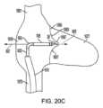
細長いシャフト12は、カプセル106に収容されたインプラントを所望の手法で三尖弁1083へと展開するために、カプセル106と、延いてはインプラント保持領域16とが配向されるように、偏向させられる細長いシャフト12の遠位端で、右心房1076に向けて前進させられ得る。図20Aにおいて描写されているように、細長いシャフト12の遠位端は、細長いシャフト12の遠位端およびカプセル106(および、展開されるインプラントのためのカプセルの遠位端における展開ポート)を、三尖弁1083の中心軸と一列にするために、三尖弁1083に向かう方向への偏向を必要とし得る。他の展開の方法について、他の偏向の方向が望まれてもよい。The
曲げ部分600、602は、細長いシャフト12の遠位端を所望の方向へと偏向させるために利用され得る。曲げ部分600、602は、細長いシャフトの遠位端を垂直な平面同士において偏向させて、2つの偏向の平面を提供するように構成され得る。曲げ部分600、602は、図6Cに示されているのと同様に構成でき、近位の曲げ部分602は、遠位の曲げ部分600の偏向の下方向(または心室方向)に対して、右方向(または前方向)に細長いシャフト12の遠位部分を偏向させるように構成されている。このような構成は、人の心臓の中で、下大静脈1079に対して三尖弁1083の位置を担うことができる。The
しかしながら、追加の移動が、本明細書に開示されている偏向機構によって提供されてもよい。シース610の形態での偏向機構は、曲げ部分600が細長いシャフト12の遠位端を偏向させた方向と反対の方向において曲げ部分600、602を偏向させるために、細長いシャフト12の近位部分を偏向させるように利用され得る。このような偏向は、細長いシャフト12の近位部分と曲げ部分600、602とを心房方向に偏向させること(または、三尖弁1083からの高さを提供すること)を含み得る。カプセル106と細長いシャフト12の遠位端とは、心房方向において偏向させられてもよい(または、三尖弁1083からの高さを提供する)。However, additional movement may be provided by the deflection mechanisms disclosed herein. A deflection mechanism in the form of a
偏向機構は、右心房1076の形状、三尖弁1083の大きさおよび相対位置、ならびに、下大静脈1079の形状を含み得る患者の生体構造の形状を担うために利用されてもよい。例えば、図20Aに示されているように、曲げ部分600から細長いシャフト12の遠位端への距離は、曲げ部分600の遠位の細長いシャフト12の曲げ半径が大きすぎて、患者の右心房1076の形状にもよるが、細長いシャフト12の遠位端を三尖弁1083へと適切に方向付けすることができない可能性がある。したがって、偏向機構は、曲げ部分600が細長いシャフト12の遠位端を偏向させる方向と反対の方向に向けて曲げ部分600を偏向させるために利用されてもよい。The deflection mechanism may be utilized to account for the shape of the patient's anatomy, which may include the shape of the
図20Bを参照すると、シース610の形態での偏向機構は、本明細書に記載されているように、細長いシャフト12の近位部分を偏向させることができる。細長いシャフト12の近位部分の偏向は、患者の下大静脈1079の中で全体的または部分的(少なくとも部分的)に起こり得る。偏向は、三尖弁から離れる方向における三尖弁1083からの高さを作り出すために、曲げ部分600、602を移動させることができる。それによって、細長いシャフト12の遠位端は、曲げ部分600が細長いシャフト12の遠位端を三尖弁1083に向けて偏向させるために、より大きなクリアランス空間を有してもよい。図20Bに示されているように、偏向機構はシースの近位部分の曲線を形成することができるが、他の形態の偏向が結果的に生じてもよい。曲げ部分600は、図20Bにおいて、細長いシャフト12の遠位端の偏向を開始している。With reference to FIG. 20B, a deflection mechanism in the form of a
図20Cを参照すると、曲げ部分600は、細長いシャフト12の遠位端を方向605へ偏向させている。方向は、三尖弁1083の軸と一列にされ得る、またはそうでなければ、所望の配向で方向付けられ得る。シース610の形態での偏向機構は、方向605と反対である方向607に曲げ部分600を偏向させるために、細長いシャフト12の近位部分を偏向させている。それによって、カプセル106は三尖弁1083からの高さを増加させており、カプセル106に収容されているインプラントの展開を可能にしている。Referring to FIG. 20C, the
シース610の形態での偏向機構は、細長いシャフト12の近位部分の様々な偏向の方向と、曲げ部分600、602、カプセル106、および細長いシャフト12の遠位端の対応する様々な偏向の方向とを提供することができる。図14A~図14Dに関連して検討されているように、例えば、シース610は、曲げ部分600によって提供される偏向の方向に対して垂直の方向、および、曲げ部分600によって提供される偏向の方向に向かう方向を含め、様々な偏向の方向を提供することができる。このような様々な偏向の方向は、右心房の中で、または、細長いシャフト12が中に位置決めされる下大静脈1079または他の領域の中で、細長いシャフト12の遠位端の追加的な操縦性および軌道の変化を可能にすることができる。シース610の形態での偏向機構は、心房方向と心室方向との両方において、および、様々な他の方向について、偏向を提供することができる。The deflection mechanism in the form of the
図20A~図20Cに示された偏向機構の動作は図13A~図14Dに示されたシース610に限定されず、図15A~図19Bに示された偏向機構の使用も含む。例えば、シース610が、図15A~図16Cに関連して詳述されているように細長いシャフト12の近位の曲げ部分602の偏向を提供する状態で、この部分が排除されてもよい。さらに、偏向機構は、図17~図19Bの実施形態に関連して検討されているように、外側シース組立体22の中に位置決めされてもよい。心房方向と心室方向との両方における様々な偏向の方向と、様々な他の方向とが結果的に生じる可能性がある。The operation of the deflection mechanism shown in Figures 20A-20C is not limited to the
偏向機構は、曲げ部分600が細長いシャフト12の遠位端を偏向させる平面に対して垂直でない1つまたは複数の平面において、細長いシャフト12の近位部分を偏向させるために利用されてもよい。The deflection mechanism may be utilized to deflect the proximal portion of the
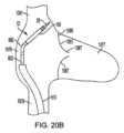
図21は、上大静脈1081からのアプローチにおける偏向機構の使用を示している。アプローチは、経頸静脈のアプローチであり得る、または、患者の身体への他の進入位置を介してであり得る。曲げ部分600、602は、図6Bに示されているのと同様に構成でき、近位の曲げ部分602は、遠位の曲げ部分600の偏向の下方向(または心室方向)に対して、左方向(または後方向)に細長いシャフト12の遠位部分を偏向させるように構成されている。このような構成は、人の心臓の中で、上大静脈1081に対して三尖弁1083の位置を担うことができる。方法は、インプラントのための送達装置を患者の右心房へと通すことを含み得る。21 illustrates the use of a deflection mechanism in an approach from the
偏向機構は、図20A~図20Cに示されているのと同様に、曲げ部分600が細長いシャフト12の遠位端を偏向させた方向605と反対である方向607に曲げ部分600を偏向させるために、細長いシャフト12の近位部分を偏向させることができる。同様に、図13A~図19Bに関連して検討されているように、他の形態の偏向機構が利用されてもよく、他の偏向の方向が結果生じてもよい。The deflection mechanism may deflect a proximal portion of the
カプセル106の中に収容されたインプラント70は、生来の三尖弁1083を置き換えるために、三尖弁環帯1085の中に位置決めされるように展開され得る。細長いシャフト12の遠位端が生来の三尖弁1083に対して望まれるように配向されると、解放機構が、カプセル106の遠位端における展開ポート611からインプラント70を展開するために利用され得る。弁に対する展開ポート611の高さは、下大静脈または上大静脈の中で送達装置を偏向させることで変化させられてもよい。図22A~図22Cは、送達システム10の解放機構を示す。インプラント70および送達システム10の体内への最初の挿入中、インプラント70は、図2Aに示されるのと同様にシステム10内に配置することができる。インプラント70の遠位端303、および具体的には遠位アンカー80は、外側シース組立体22のカプセル106内に抑制され、これによりインプラント70の拡張を阻止する。同様のものが図2Aに示されており、遠位アンカー80は、カプセル内に位置決めされたとき、遠位方向に延在することができる。インプラント70の近位端301は、カプセル106内に、および内側保持部材40の一部の中に抑制され、よってカプセル106と内側保持部材40との間に概ね拘束される。The
インプラント70が送達システム10内に装填されると、ユーザは、ガイドワイヤを患者の中に所望の場所まで通すことができる。ガイドワイヤは、ノーズコーン組立体31の内腔を通過し、よって送達システム10を、ガイドワイヤをたどって患者の体内を通って全体的に進めることができる。送達システム10は、ユーザが手動でハンドル14を軸方向に移動させることによって進めることができる。いくつかの実施形態において、送達システム10は、ハンドル14の制御を操作しつつ、スタンド内に配置することができる。Once the
概して心臓において一度、使用者は、レール組立体20の操縦動作を開始でき、具体的には、遠位引っ張りワイヤノブ206および/または近位引っ張りワイヤノブ208を用いて曲げ部分600、602の操縦動作を開始できる。ノブのいずれかを回すことで、使用者は、(遠位端または近位端のいずれかにおいて)レール組立体20の屈曲/曲げを提供することで、1つ、2つ、またはより多くの場所における送達システム10の遠位端を所望の構成へと曲げることができる。先に検討されているように、使用者は、送達システム10を三尖弁に向けて方向付けるために、レール組立体20に複数の曲げを提供することができる。具体的には、レール組立体20の曲げは、送達システム10の遠位端、延いてはカプセル106を、生来の三尖弁を通る中心軸に沿って、三尖弁に向けて方向付けることができる。したがって、外側シース組立体22、中間シャフト組立体21、内側組立体18、およびノーズコーン組立体31が、圧縮されたインプラント70と、レール組立体20にわたって一緒に前進させられるとき、カプセル106は、インプラント70の適切な解放のための軸と正に一直線になって進む。Once generally at the heart, the user can initiate steering of the
使用者は偏向機構も利用でき、偏向機構は、生来の三尖弁からの高さを作り出すことができる、またはそうでなければ、細長いシャフト12の遠位端を望まれるように配向することができる。細長いシャフト12の曲げ部分の高さは、三尖弁から変えられてもよい。A deflection mechanism is also available to the user that can create a height from the native tricuspid valve or otherwise orient the distal end of the
システム10は、本明細書において検討されている曲げ部分および偏向機構、または他の技術の使用を通じて、生来の三尖弁などの患者の身体における具体的な場所へと位置決めされ得る。The
使用者は、送達システム10の遠位端のさらなる細かい調整のためのスタンドにおいて、ハンドル14自体を回転および/または移動させることもできる。使用者は、インプラント70の解放のための送達システム10を身体において配向するために、ハンドル14自体を移動させると共に、近位引っ張りワイヤノブ208および/または遠位引っ張りワイヤノブ206を続けて回すことができる。使用者は、近位または遠位など、レール組立体20に対して他の組立体をさらに移動させることもできる。The user can also rotate and/or move the handle 14 itself in the stand for further fine adjustment of the distal end of the
使用者は、偏向機構の動作を制御するために、図14Aに示されているような回転制御ハウジング620または偏向制御ハウジング622などの制御機構、または他の制御機構を利用することができる。A user may utilize a control mechanism, such as the rotation control housing 620 or the
細長いシャフト12の遠位端が望まれているように配向されると、使用者は深さノブ212を回転させることができる。検討されているように、このノブ212の回転は、内側シャフト組立体18、中間シャフト組立体21、外側シース組立体22、およびノーズコーン組立体31をレール組立体20にわたって/通じて一緒に前進させ、一方、インプラント70はインプラント保持領域16の中に圧縮構成で留まる。例えば、内側シャフト組立体18、中間シャフト組立体21、および/または外側シース組立体22のいずれかの剛性のため、これらの組立体は、レール組立体20によって一列にされた方向で真っ直ぐ前に進む。Once the distal end of the
解放位置にくると、使用者は外側シースノブ210を回転させることができ、外側シースノブ210は、他の組立体に対して、具体的には内側組立体18に対して、図22Aに示されているようにハンドル14に向かう近位方向において、外側シース組立体22(延いては、カプセル106)を個別に並進させる。そうすることによって、インプラント70の遠位端303は体内で覆いが外され、拡張を開始することが可能になる。この時点で、遠位アンカー80は、近位方向に反転することができ、遠位端303は、半径方向外向きに拡張し始める。例えば、システム10が生来の三尖弁の場所へと送達された場合、遠位アンカー80は右心室の中で径方向外向きに拡張する。遠位アンカー80は、乳頭の上方で、三尖弁環帯および三尖弁尖の下方に配置され得る。Once in the release position, the user can rotate the
いくつかの実施形態において、遠位アンカー80は、径方向に拡張するにつれて、右心室における索に接触し得るおよび/または索の間で延び得ると共に、弁尖に接触する。いくつかの実施形態において、遠位アンカー80は、腱に接触する、および/または腱の間に延在する、または弁膜に接触しない場合がある。インプラント70の位置に応じて、遠位アンカー80の遠位端は、腱が生来の弁膜の自由縁部に接続する場所であっても、またはその場所より下であってもよい。In some embodiments, as the distal anchor 80 expands radially, it may contact and/or extend between the chordae in the right ventricle and contact the leaflets. In some embodiments, the distal anchor 80 may contact and/or extend between the tendons, or may not contact the leaflets. Depending on the location of the
図示されている実施形態に示されているように、インプラント70の遠位端303は外向きに拡張させられる。インプラント70の近位端301は、近位端301が半径方向にコンパクトになった状態のままであるように、このステップ中に外側保持リングによって覆われたままであり得ることに留意されたい。このとき、システム10は、遠位アンカー80が三尖弁の弁尖を掴んで係合するように近位へ引き込むことができる、または、インプラント70を再位置決めするために近位へ移動させることができる。例えば、組立体は、レール組立体20に対して近位へ移動させることができる。さらに、偏向機構は、細長いシャフト12を三尖弁に対して近位へ引くために利用されてもよい。さらに、システム10は捩じられてもよく、これは、遠位アンカー80に、遠位アンカーのうちの少なくとも一部が間で延び得るのに通る索に張力を掛けさせることができる。しかしながら、いくつかの実施形態において、遠位アンカー80は索に張力を掛けない可能性がある。いくつかの実施形態において、遠位アンカー80は、外側シース組立体22を引き抜いた後のシステム10のいかなるさらなる移動もなしに、生来の弁膜を捕らえ、腱の間にあってよい。As shown in the illustrated embodiment, the
このステップの間、システム10は、遠位または心室のアンカー80に生来の三尖弁の弁尖を適切に掴ませるために、近位または遠位へ移動させられ得る。これは、外側シース組立体22、中間シャフト組立体21、内側組立体18、およびノーズコーン組立体31をレール組立体20に対して移動させることで行われ得る。具体的には、心室アンカー80の先端は、生来の弁尖がアンカー80とインプラント70の本体との間に位置決めされるように、生来の環帯の心室側と係合するために近位へ移動させられ得る。インプラント70がその最終的な位置にあるとき、索に張力があってもなくてもよいが、遠位アンカー80は索のうちの少なくとも一部の間に配置され得る。During this step, the
インプラント70の近位端301は、カプセル106の後退の後、外側保持リング42に留まることになる。カプセル106は、インプラント保持領域を取り囲むことができ、インプラントを展開するために近位へ後退させられ得る。図22Bに示されているように、インプラント70の遠位端303が完全に拡張させられると(または、この位置でできるだけ完全に拡張させられると)、外側保持リング42は、内側保持部材40を露出させることでインプラント70の近位端301の拡張を開始するために、他の組立体に対して、具体的には、内側組立体18に対して、個別に近位へ引き込むことができる。例えば、三尖弁の置換処置において、遠位または心室のアンカー80が、腱索のうちの少なくとも一部の間に位置決めされた後、および/または、生来の三尖弁環帯と係合した後、インプラント70の近位端301は右心房の中で拡張させられ得る。The
外側保持リング42は、インプラント70の近位端310が、図22Cに示されているようにその完全に拡張した構成へと径方向に拡張し得るように、近位へ移動させられ得る。インプラント70は弁へと展開させられ得る。インプラント70の拡張および解放の後、内側組立体18、ノーズコーン組立体31、中間シャフト組立体21、および外側シース組立体22は、それらの元の位置へと戻されるように、レール組立体20に沿って、または、レール組立体20に対して、同時に引き込まれ得る。いくつかの実施形態において、それらはレール組立体20に対して引っ込められず、伸長位置に留まる。さらに、ノーズコーン28は、ノブ216を近位へ並進させることなどで、拡張させられたインプラント70の中心を通じて外側シース組立体22へと引き込むことができる。そのため、システム10は患者から除去することができる。The
いくつかの実施形態において、インプラント70は、使用者がインプラント70の適切な位置決めのために特定の基準点を見ることができるように、蛍光透視法の下で送達され得る。さらに、心エコー検査法がインプラント70の適切な位置決めのために使用できる。In some embodiments, the
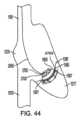
ここで、心臓83の生来の三尖弁の中に位置決めされる置換心臓弁(インプラント70)の実施形態の一部分の概略的な描写を示す図23が参照される。生来の三尖弁の一部分が概略的に示されており、環帯1085の上方に位置させられる右心房1076と、環帯1085の下方に位置させられる右心室1077とを含め、典型的な生体構造を表している。右心房1076と右心室1077とは三尖環帯1085を通じて互いと連通している。同じく図23において概略的に示されているのは、三尖弁尖1087の下流端を右心室1077の乳頭筋に連結する腱索1089を有する生来の三尖弁尖1087である。環帯1085の上流に(右心房1076に向けて)配置されたインプラント70の一部分は、上で環状に位置決めされると称することができる。概して環帯1085の中の一部分は、中で環状に位置決めされると称することができる。環帯1085の下流の一部分は、下で環状に(右心室1077に向けて)位置決めされると称することができる。Reference is now made to FIG. 23, which shows a schematic depiction of a portion of an embodiment of a replacement heart valve (implant 70) positioned within the native tricuspid valve of the heart 83. A portion of the native tricuspid valve is shown diagrammatically, depicting typical anatomy, including the
図23に示されているように、置換心臓弁(例えば、インプラント70)は、三尖環帯1085が遠位アンカー80と近位アンカー82との間に配置されるように位置決めされ得る。いくつかの状況において、インプラント70は、例えば図23において示されているように、遠位アンカー80の端または先端が環帯1085と接触するように位置決めされ得る。いくつかの状況において、インプラント70は、遠位アンカー80の端または先端が環帯1085と接触しないように位置決めされ得る。いくつかの状況において、インプラント70は、遠位アンカー80が弁尖1087の周りに延在しないように位置決めされ得る。As shown in FIG. 23, the replacement heart valve (e.g., implant 70) may be positioned such that the
図23に示されているように、置換心臓弁またはインプラント70は、遠位アンカー80の端または先端が三尖環帯1085の心室側となり、近位アンカー82の端または先端が三尖環帯1085の心房側となるように位置決めされ得る。遠位アンカー80は、遠位アンカー80の端または先端が、腱索1089が生来の弁尖の自由端に連結する場所を越えて生来の弁尖の心室側となるように位置決めされ得る。遠位アンカー80は、腱索1089のうちの少なくとも一部の間で延びることができ、図23に示されているものなどの一部の状況において、環帯1085の心室側と接触または係合することができる。いくつかの状況において、遠位アンカー80が環帯1085と接触しない可能性があり得るが、遠位アンカー80が生来の弁尖1087となおも接触できることも考えられる。いくつかの状況において、遠位アンカー80は、環帯1085および/または弁尖の心室側を越えて右心室1077の組織と接触することができる。As shown in FIG. 23, the replacement heart valve or
望まれるようにインプラント70が展開すると、図13A~図19Bに関して開示されている偏向機構は、患者の心臓からの細長いシャフト12の除去を可能とするように細長いシャフト12を偏向させるために利用され得る。Once the
図24は、細長いシャフト12の先端を形成するノーズコーン28の側方からの斜視図を示している。ノーズコーン28は、カプセル106の端を閉じ(部分的な断面図で示されている)、カプセル106の遠位に位置決めされる先端本体700を備える。先端本体700は、近位部分702と遠位部分704とを備え、近位部分702から遠位部分704へと先細りとなっている。開口706が、ガイドワイヤ708が通過するために、先端本体700の遠位部分704に位置決めされている。先端本体700の遠位部分704は、先細りとされている硬い突出区域710を含み得る。硬い突出区域の先細りの外形は、患者の血管系への侵入の容易性を許容することができ、患者の血管系の中に細長いシャフト12の先端を通過させるのを助けることができる。24 shows a side perspective view of the
しかしながら、注目すべきことに、硬い突出区域710は、硬い突出区域710との接触において患者の身体の一部分と干渉する可能性がある、または、患者の身体の一部分を潜在的に損傷させる可能性がある。例えば、ノーズコーン28が患者の心臓の右心室へと通される場合、潜在的に、硬い突出区域710は、右心室の内部に影響を与え、右心室の内部を潜在的に穿刺またはそうでなければ損傷する可能性がある。注目すべきことに、開口706においてガイドワイヤ708ともつれる可能性もある。硬い突出区域710の長さは、細長いシャフト12の遠位端の操縦性を阻害する可能性もある。Notably, however, the stiff protruding
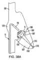
図25Aおよび図25Bは、遠位へ延在し、ガイドワイヤ708の一部分の周りで曲がるように構成される可撓性シース712を備える細長いシャフト12の遠位先端の実施形態を示している。遠位先端は、近位部分716と遠位部分718とを有する先端本体714を備えることができ、遠位先端は、近位部分716から遠位部分718への方向において先細りである外側表面720を有し得る。先端本体714は、カプセル106の遠位に位置決めでき、カプセル106の遠位端およびその近くに位置決めされ得る。先端本体714は、カプセル106によって包囲されたインプラント70をカプセル106から展開させるために、カプセル106に対して可動であり得る。25A and 25B show an embodiment of a distal tip of the
外側表面720は、先端本体714の近位部分716から可撓性シース712の近位部分722へと先細りであり得る。可撓性シース712は、可撓性シース712の近位部分722から可撓性シース712の遠位端724へと延在し得る。可撓性シース712は、可撓性シース712の近位部分722から可撓性シース712の遠位端724へと円筒形を有し得る。The
可撓性シース712は、ガイドワイヤ708の端において湾曲構成726を有するガイドワイヤ708のために、ガイドワイヤ708の先頭の湾曲の上に延在するように構成される長さを有し得る。したがって、可撓性シース712は、ガイドワイヤと患者の身体の一部分との間の接触による怪我の可能性を低減するために、ガイドワイヤ708の先頭の湾曲を覆うことができる。図25Bは、例えば、患者の右心室1077の中の遠位先端を示している。可撓性シース712は、ガイドワイヤ708が右心室の中に位置決めされるとき、ガイドワイヤ708の周りに曲げられる。可撓性シース712は、患者の右心室1077の内部壁に別の方法で接触する可能性のあるガイドワイヤ708の一部分を覆う。さらに、可撓性シース712は、患者の右心室1077の内部壁との穿刺または他の干渉の可能性を低減するために、可撓性である。ガイドワイヤ708に沿っての可撓性シース712の湾曲は、追加的に、ガイドワイヤ708のもつれの可能性を低減することができる。The
図26~図28は、細長いシャフト12の遠位の外形を縮小することができる細長いシャフト12の遠位先端の実施形態を示している。このような特徴は、細長いシャフト12を様々な血管の形状においてより容易にナビゲートまたは偏向させるために利用され得る。例えば、図20A~図21に示されている方法において、細長いシャフト12の縮小した遠位の外形は、右心房1076の中で、および、右心房1076に向けて、細長いシャフト12のより良好な操縦性を可能にすることができる。FIGS. 26-28 show embodiments of the distal tip of the
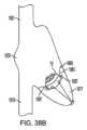
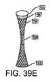
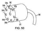
図26は、半球形を有する細長いシャフト12の遠位先端の実施形態を示している。遠位先端は、近位部分732と遠位部分734とを有する先端本体730を備えることができ、近位部分732から遠位部分734への方向において先細りである外側表面736を有し得る。先端本体730は、カプセル106の遠位に位置決めでき、カプセル106の遠位端およびその近くに位置決めされ得る。先端本体730は、カプセル106によって包囲されたインプラント70をカプセル106から展開させるために、カプセル106に対して可動であり得る。半球形の先端本体は、遠位先端の遠位端738の凸状の外形を形成することができる。外側表面736は、先端本体730の近位部分732から先端本体730の遠位端738へと凸状であり得る。先端本体730は、その遠位端738において、ガイドワイヤ708が通過するための開口739を備え得る。FIG. 26 illustrates an embodiment of a distal tip of an
図27は、放物形を有する細長いシャフト12の遠位先端の実施形態を示している。遠位先端は、近位部分742と遠位部分744とを有する先端本体740を備えることができ、近位部分742から遠位部分744への方向において先細りである外側表面746を有し得る。先端本体740は、カプセル106の遠位に位置決めでき、カプセル106の遠位端およびその近くに位置決めされ得る。先端本体740は、カプセル106によって包囲されたインプラント70をカプセル106から展開させるために、カプセル106に対して可動であり得る。放物形の先端本体は、遠位先端の遠位端748の凸状の外形を形成することができる。外側表面746は、先端本体740の近位部分742から先端本体740の遠位端748へと凸状であり得る。先端本体740は、その遠位端748において、ガイドワイヤ708が通過するための開口749を備え得る。FIG. 27 illustrates an embodiment of a distal tip of an
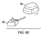
図28は、カプセル106の遠位端750が細長いシャフト12の遠位先端を形成する実施形態を示している。カプセルの遠位端750は、インプラントの遠位端(またはアンカー80)の上に延在し、細長いシャフト12の遠位先端に滑らかな外形を提供することができる丸め部分752を備え得る。したがって、遠位先端は、非外傷性の丸められた先端を備え得る。カプセルは、カプセル106の先頭の縁に平面状の外形を有する部分754を備え得る。その部分754は、インプラントが展開させられる開口またはポート756を備え得る。FIG. 28 illustrates an embodiment in which the distal end 750 of the
カプセル106は、弾性である遠位端705を有するように構成でき、カプセル106の中に位置決めされたインプラント70の形に順応することができる。タイ層などが、インプラント70に対するカプセル106の弾性を提供するために、カプセル106に追加されてもよい。カプセル106は、例えば、小さいデュロメータの弾性タイ層を伴うePTFE先端を備え得る。インプラント70が展開すると、インプラントは、インプラント70の遠位への移動を受け入れるために遠位端750の丸め部分752が拡張している状態で、カプセル106からポート756を通じて遠位へ前進させることができる。カプセル106の遠位端705におけるポート756または開口は、ガイドワイヤ708を通過させるように構成され得る。The
図28に示された実施形態において、別体の先端本体が細長いシャフト12の遠位先端に存在しなくてもよく、したがって細長いシャフト12の遠位の外形を縮小する。In the embodiment shown in FIG. 28, a separate tip body may not be present at the distal tip of the
図25A~図28の遠位先端の実施形態の1つまたは複数の特徴は、単独で利用されてもよい、または、本明細書に開示されている送達システムの任意の他の実施形態、他のシステム、もしくは他の方法と共に利用されてもよい。One or more features of the distal tip embodiments of Figures 25A-28 may be utilized alone or in conjunction with any other embodiments of a delivery system, other systems, or other methods disclosed herein.
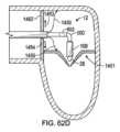
図29は、インプラント806がその展開のために通過させられるための通路804を取り囲む壁802で構成されている細長いシャフト800の実施形態を示している。壁802は、インプラント806の展開の間、通路804において曲げを定める曲げ808を有するように構成され得る。FIG. 29 illustrates an embodiment of an
壁802は操縦可能となるように構成でき、制御機構が壁802を操縦するために利用され得る。例えば、引っ張りつなぎ綱810または他の形態の制御機構が、壁802の曲げの方向を制御するように、さらに具体的には、インプラント806が通過させられる開口またはポート812を所望の配向へと方向付けるように、壁802を操縦するために利用され得る。The
一実施形態において、壁802は操縦可能でなくてもよいが、壁は、壁802によって所望の配向で実施された曲げを有し得る。In one embodiment, the
通路804は、インプラント806が展開される展開通路を有し得る。通路804は、インプラント806を保持するように構成でき、インプラント保持領域を備え得る。通路804は、右心房1706、または患者の心臓もしくは血管系の他の部分のアプローチおよび進入において、インプラント806を保持するように構成され得る。The
インプラント806は、インプラント806の軸方向の次元814に対して横切る方向に曲がるように構成される可撓性インプラントとなるように構成され得る。それによって、インプラント806は、インプラント806の展開のために、インプラント806の軸方向の次元814に対して横切る方向において、通路804の中で曲がるように構成され得る。押込みシャフト815などの展開デバイスが、展開のためにインプラント806をポート812から押すために利用されてもよい。拡張可能バルーンなどの他の形態の展開デバイスが望まれるように利用されてもよい。The implant 806 may be configured to be a flexible implant configured to bend in a direction transverse to the
インプラント806は、拡張可能インプラントであってよく、患者の身体の所望の部分への展開のために自己拡張であってもよい。インプラント806は、インプラント70と同様に構成され得るが、曲げ展開通路を通過するときにインプラント806の軸方向の次元814に対して横切る方向に曲がるように構成されてもよい。このような構成は、横方向においてより大きな可撓性を可能とするために、より細くされたインプラント70のフレームによって提供され得る。The implant 806 may be an expandable implant or may be self-expanding for deployment to a desired portion of the patient's body. The implant 806 may be configured similarly to the
細長いシャフト12の構成要素は、外側シース組立体、中間シャフト組立体、レール組立体、内側シャフト組立体、およびノーズコーン組立体の使用を含め、細長いシャフト800と共に利用されてもよい。組立体のうちのいずれかかまたはすべてが、インプラント806の展開を実施または支援するために利用されてもよい。本明細書で開示されている偏向機構が利用されてもよい。細長いシャフト800の1つまたは複数の特徴は、単独で利用されてもよい、または、本明細書に開示されている送達システムの任意の他の実施形態、他のシステム、もしくは他の方法と共に利用されてもよい。The components of the
インプラント806の展開の間に通路804において曲げを定める曲げ808を有する壁802の使用は、細長いシャフト800の縮小した横方向外形を含む便益を提供することができる。例えば、図20A~図21に示されているように、細長いシャフト12のカプセル106は、曲げ部分600について、細長いシャフト12のための比較的大きい回転半径を形成することができる。通路804における曲げの使用は、比較的より小さい回転半径を伴って、細長いシャフト800の縮小した横方向外形を可能にすることができる。したがって、ポート812は、細長いシャフト800が縮小した横方向外形を有する状態で、可撓性インプラント806の展開のために三尖弁1083に近接するように移動させることができる。インプラントは、インプラント(プロテーゼ三尖弁であり得る)を展開するために、曲げ展開通路に通過させられ得る。The use of the
図30は、軸方向の次元902を有し、軸方向の次元902に対して横切る方向で展開させられるインプラント906のためのポート904を有する細長いシャフト900の実施形態を示している。細長いシャフト900は側壁908を備えることができ、ポート904は側壁908に位置決めされ得る。30 illustrates an embodiment of an elongate shaft 900 having an axial dimension 902 and a port 904 for an implant 906 that is deployed in a direction transverse to the axial dimension 902. The elongate shaft 900 can include a sidewall 908, and the port 904 can be positioned in the sidewall 908.
側壁908は操縦可能となるように構成でき、制御機構が側壁908を操縦するために利用され得る。例えば、引っ張りつなぎ綱909または他の形態の制御機構が、ポート904を所望の配向へ方向付けるように側壁908を操縦するために利用され得る。The sidewall 908 can be configured to be steerable, and a control mechanism can be utilized to steer the sidewall 908. For example, a
細長いシャフト900は、インプラント906を保持するためのインプラント保持領域910を備え得る。インプラント906は、インプラント906の軸方向の次元において展開されるように構成でき、インプラント906の軸方向の次元においてポート904を通じて出る。インプラント906は、展開の前にインプラント906の軸方向の次元において圧縮されるように構成され得る。The elongate shaft 900 may include an implant holding region 910 for holding an implant 906. The implant 906 may be configured to be deployed in an axial dimension of the implant 906 and exit through a port 904 in an axial dimension of the implant 906. The implant 906 may be configured to be compressed in an axial dimension of the implant 906 prior to deployment.
展開機構が、インプラント906をポート904から展開するために利用され得る。展開機構は、図30に示されているようにポート904からインプラント906を押し出すように構成される膨張可能本体912を備え得る、または、他の実施形態では、他の形態の展開機構が利用され得る。インプラントは、細長いシャフトの軸方向の次元に対して横切る方向において、ポート904を通じて展開され得る。A deployment mechanism may be utilized to deploy the implant 906 from the port 904. The deployment mechanism may comprise an
インプラント906は、拡張可能インプラントとでき、患者の身体の所望の部分への展開のために自己拡張であってもよい。インプラント906は、インプラント70と同様に構成され得るが、インプラント906の軸方向の次元において圧縮されるように構成されてもよい。Implant 906 can be an expandable implant and may be self-expanding for deployment to a desired portion of the patient's body. Implant 906 can be configured similarly to implant 70, but may be configured to be compressed in the axial dimension of implant 906.
細長いシャフト12の構成要素は、外側シース組立体、中間シャフト組立体、レール組立体、内側シャフト組立体、およびノーズコーン組立体の使用を含め、細長いシャフト900と共に利用されてもよい。組立体のうちのいずれかかまたはすべてが、インプラント906の展開を実施または支援するために利用されてもよい。本明細書で開示されている偏向機構が利用されてもよい。細長いシャフト900の1つまたは複数の特徴は、単独で利用されてもよい、または、本明細書に開示されている送達システムの任意の他の実施形態、他のシステム、もしくは他の方法と共に利用されてもよい。The components of the
軸方向の次元902を有し、軸方向の次元902に対して横切る方向で展開させられるインプラント906のためのポート904を有する細長いシャフト900の使用は、細長いシャフト900の縮小した横方向外形を含む便益を提供することができる。例えば、図20A~図21に示されているように、細長いシャフト12のカプセル106は、曲げ部分600について、細長いシャフト12のための比較的大きい回転半径を形成することができる。軸方向の次元902に対して横切る方向で展開させられるインプラント906のためのポート904の使用は、細長いシャフト900の縮小した横方向外形を可能にすることができる。したがって、ポート904は、細長いシャフト900が縮小した横方向外形を有する状態で、インプラント906の展開のために三尖弁1083に近接するように移動させることができる。The use of an elongate shaft 900 having an axial dimension 902 and a port 904 for an implant 906 deployed transversely to the axial dimension 902 can provide benefits including a reduced lateral profile of the elongate shaft 900. For example, as shown in FIGS. 20A-21, the
図31は、ループ1302を形成するために180度を越えて曲がるように構成されている細長いシャフト1300の実施形態を示している。シャフト1300は、細長いシャフト12と同様に構成され得るが、ループ1302を形成するために180度を越えて曲がるように構成され得る。このような特徴は、シャフト1300の外径に沿って延在し、180度を越えてシャフト1300を曲げるために遠位への力を加える押込みシャフトなど、180度を越えての曲げをもたらすように構成されている制御機構によって提供され得る。他の機構が同様に利用されてもよい。したがって、細長いシャフト1300は、患者の身体の中の所望の場所に位置決めされ得るループ1302を形成することができる。31 illustrates an embodiment of an
例えば、図31に示されているように、ループ1302は、インプラント70が三尖弁1083へと展開されることになる実施形態において、右心房1076の中に位置決めされ得る。ループ1302は、右心房1076の壁からのカプセル106の遠位端のより大きなクリアランスを可能とするために、右心房1076の中に位置決めされ得る。ループ1302は、三尖弁1083から離れるように、心房方向において方向付けられ得る。細長いシャフトは、インプラント保持領域が曲げ部分の遠位に位置決めされた状態で、細長いシャフトの曲げ部分において曲がるように構成されている。For example, as shown in FIG. 31 , the
細長いシャフトは、患者の右心房の中に少なくとも部分的にループを形成するために、180度を越えて曲げられる。細長いシャフト1300の曲げの度合いは望まれるように変化でき、例えば、曲げの度合いは、一実施形態では200度を越えてもよく、一実施形態では230度を越えてもよく、一実施形態では250度を越えてもよく、一実施形態では270度を越えてもよい。他の曲げの度合いが望まれるように利用され得る。細長いシャフト1300の1つまたは複数の特徴は、単独で利用されてもよい、または、本明細書に開示されている送達システムの任意の他の実施形態、他のシステム、もしくは他の方法と共に利用されてもよい。The elongate shaft is bent greater than 180 degrees to form a loop at least partially within the patient's right atrium. The degree of bend of the
細長いシャフト12の構成要素は、外側シース組立体、中間シャフト組立体、レール組立体、内側シャフト組立体、およびノーズコーン組立体の使用を含め、細長いシャフト1300と共に利用されてもよい。組立体のうちのいずれかかまたはすべてが、インプラント保持領域によって保持されたインプラント70の展開を実施または支援するために利用されてもよい。本明細書で開示されている偏向機構が利用されてもよい。The components of the
図32A~図33Bは、カプセルを細長いシャフトの一部分に結合するヒンジを含む細長いシャフトの実施形態を示している。図32Aは、例えば、ヒンジ1404を伴う遠位部分1402を有する細長いシャフト1400を示している。ヒンジ1404はカプセル106の近位部分1406に結合している。カプセル106は、三尖弁1083に対する所望の配向でカプセル106のポート1408を配置するように、ヒンジ1404の周りに回転するように構成されている。図32Bは、例えば、ヒンジ1404の周りに回転させられ、ポート1408が三尖弁1083に向けて配向された状態でのカプセル106を示している。FIGS. 32A-33B show an embodiment of an elongate shaft including a hinge connecting a capsule to a portion of the elongate shaft. FIG. 32A, for example, shows an
図33Aは、細長いシャフト1400の遠位部分1402におけるヒンジ1404が、カプセル106の近位部分1406とカプセル106の遠位部分1410との間に位置決めされたカプセルの中央部分1407においてカプセル106に結合する実施形態を示している。したがって、カプセルは、三尖弁1083に対する所望の配向でカプセル106のポート1408を配置するように、ヒンジ1404の周りに枢動するように構成され得る。図33Bは、例えば、ヒンジ1404の周りに回転させられ、ポート1408が三尖弁1083に向けて配向された状態でのカプセル106を示している。FIG. 33A illustrates an embodiment in which a
図32A~図33Bに示されたカプセル106は、制御機構の使用を通じてヒンジ1404の周りに回転させることができ、制御機構は、カプセル106の回転を制御するように構成された押込みシャフト、引っ張りシャフト、または他のデバイスを備え得る。インプラントは、展開機構によってカプセル106から展開されるように構成でき、展開機構は、インプラントをカプセル106から展開するための膨張可能本体などを備え得る。The
カプセル106は、望まれるように、0度から360度またはより大きな角度の間を含め、様々な角度までヒンジ1404の周りに回転するように構成され得る。カプセル106は、例えば、三尖弁1083または他の送達場所に対する所望の配向において、カプセル106のポート1408の所望の配向を提供するために回転させられ得る。The
ヒンジ1404は、開口部を通じて延びるピンを備え得る、または、望まれるようなヒンジの他の形態を含み得る。The
細長いシャフト12の構成要素は、外側シース組立体、中間シャフト組立体、レール組立体、内側シャフト組立体、およびノーズコーン組立体の使用を含め、細長いシャフト1400と共に利用されてもよい。組立体のうちのいずれかかまたはすべてが、インプラント保持領域によって保持されたインプラント70の展開を実施または支援するために利用されてもよい。本明細書に開示されている偏向機構が利用されてもよい。細長いシャフト1400の1つまたは複数の特徴は、単独で利用されてもよい、または、本明細書に開示されている送達システムの任意の他の実施形態、他のシステム、もしくは他の方法と共に利用されてもよい。The components of the
図34A~図34Bは、細長いシャフト12からのインプラントの展開のために利用され得る方法を示している。図34Aを参照すると、方法は、細長いシャフト12のカプセル106を患者の心臓の右心房1076の中で位置決めすることを含み得る。次に、曲げ部分600がカプセル106をある方向に偏向させるために利用され得る。細長いシャフト12は、カプセル106を三尖弁1083に対して所望の配向で位置決めするために、例えば細長いシャフト12を患者の心臓から後退させることで、近位へと並進させられ得る。34A-34B illustrate a method that may be utilized for deployment of the implant from the
図34Bは、例えば、カプセル106を三尖弁1083に対して所望の位置で配置するために、近位方向に後退させられている細長いシャフト12を示している。次に、インプラントは、本明細書に開示されている方法を用いて、植え込みのためのカプセル106から三尖弁1083へと展開され得る。図34A~図34Bの方法は、単独で利用されてもよい、または、本明細書に開示されている送達システムの任意の他の実施形態、他のシステム、もしくは他の方法と共に利用されてもよい。FIG. 34B illustrates the
インプラントを展開する、または、本明細書に開示されているシステムおよび装置を利用する様々な他の方法が、利用されてもよい。Various other methods of deploying implants or utilizing the systems and devices disclosed herein may be used.
図62A~図64Cは、細長いシャフト12の外側表面から径方向外向きに延在し、細長いシャフト12が沿って延在する軸に対して横切る細長いシャフトの偏向に抗するように外部表面と接触するように構成される1つまたは複数の支持体を利用する実施形態を示している。実施形態は、本明細書で開示されている任意の他の実施形態と共に利用され得る。FIGS. 62A-64C show an embodiment utilizing one or more supports extending radially outward from the outer surface of the
図62Aは、例えば、腕部の形態での1つまたは複数の支持体1450が利用され得る実施形態を示している。支持体1450は、図62Aにおいて、展開していない構成、拡張していない構成、または真っ直ぐになった構成で示されており、支持体1450は、細長いシャフト12の外側表面に押し潰されている。支持体1450は、支持体1450の遠位先端1452から、ハンドル14の位置へと、または、患者の身体の外部へのアクセスのための別の位置へと、近位へ延在し得る。FIG. 62A illustrates an embodiment in which one or
支持体1450は、細長いシャフト12の外側表面に沿って、細長いシャフト12および支持体1450の上で延在するシース1454によって、図62Aに示された展開していない構成、拡張していない構成、または真っ直ぐになった構成で保持され得る。シース1454は、例えば、図1に示されている、または、例として図13Aにおいてシース610として示されているシース51と同様に、構成され得る。実施形態において、シース1454は、支持体1450を望まれるように覆いを外すかまたは覆うために、細長いシャフト12の外側表面に沿って近位および/または遠位に摺動するように構成され得る。シース1454の近位部分は、例えば、シース1454を近位または遠位に移動させるために制御され得る。The
支持体1450は支持体1450の遠位先端1452へと延在することができる。各々の支持体1450は、シース1454および細長いシャフト12の外側表面から径方向外向きに延在するように構成され得る支持体1450の遠位先端1452と近位部分との間に中間部分1456を有し得る。各々の支持体1450は、細長いシャフト12の外側表面から径方向外向きに延在するように成形でき、実施形態では、細長いシャフト12の外側表面から径方向外向きに延在するように付勢され得る。例えば、支持体1450は、径方向外向きに延在するようにあらかじめ成形され得る形状記憶材料を含んでもよい。形状記憶材料は、ニチノールまたは他の形態の形状記憶材料を含み得る。実施形態では、支持体1450は、ステンレス鋼または別の材料など、他の材料から作られてもよい。The
支持体1450は外部表面に接触するように各々構成され得る。外部表面は、患者の心臓の一部分を含め、患者の血管系の一部分を含み得る。例えば、実施形態では、支持体1450は、患者の心臓の心房壁(心房中隔を含み得る)または他の部分と接触するように構成され得る。支持体1450は非外傷性となるように構成され得る。中間部分1456および遠位先端1452の各々は、例えば、心臓の壁への損傷の可能性を低減するために、丸められ得る、または、滑らかにされ得る。The
各々の支持体1450は、細長いシャフト12が沿って延在する軸に対して横切る方向において、細長いシャフト12の偏向を低減するのに十分な硬さであり得る。しかしながら、支持体1450は、拡張していない構成(図62Aに示されている)から拡張した構成(図62Bに示されている)へと径方向外向きに延びるために可撓性であり得る。支持体1450は、シース1454が近位へ後退させされることで、または、支持体1450がシース1454の遠位端1458に対して遠位に前進させられることで、外向きに偏向することができる。Each
図62Bは、例えばシース1454に対して遠位へ前進させられている支持体1450を示している。支持体1450は、図62Bに示されている拡張した構成において、径方向外向きに延在している。支持体1450の中間部分1456は、シース1454の遠位端1458から支持体1450の遠位先端1452へと外向きに突出している。支持体1450は、細長いシャフト12が沿って延在する軸1460に対して横切る細長いシャフト12の偏向に抗するように位置決めされている。FIG. 62B illustrates the
実施形態では、支持体1450は遠位へ前進させられ得る、および/または、シース1454は、支持体1450を拡張させるために近位へ後退させられ得る。In embodiments, the
図62C~図62Eは、支持体1450を利用する送達装置を利用する例示の方法を示している。図62Cは、例えば、送達装置がインプラントを僧帽弁1461へと送達するために利用され得ることを示している。送達装置の細長いシャフト12は、例えば、右心房1076と左心房1075との間の心房中隔1462を経中隔で通過させられ得る。例えば、細長いシャフト12を心房中隔1462に通過させる穿刺が、心房中隔1462において行われてもよい。支持体1450は、この時点ではシース1454によって覆われた拡張していない構成で留まり得る。送達装置は左心房1075の中に位置決めされる。62C-62E show an example method of utilizing a delivery device utilizing the
図62Dは、インプラント保持領域を取り囲むカプセル106が、例えば、心室方向において、左心室1073に向けて、曲げ部分600を介して偏向させることができることを示している。曲げ部分602を含む1つまたは複数の他の曲げ部分は、僧帽弁1461に関して望まれているように、カプセル106を一列にするために利用され得る。例えば、曲げ部分602は、カプセルを、本明細書に開示されている方法に従って、曲げ部分600の曲げの平面に対して横切って延在する平面においてカプセルを偏向させることができる。様々な偏向の方向が利用されてもよい。FIG. 62D illustrates that the
カプセル106が所定位置で一列にされている場合、カプセル106の深さは、本明細書に開示されている方法を利用して、心室方向に増加させられ得る。しかしながら、心室方向における深さの増加は、細長いシャフト12に心房方向1463(図62Dに印されている)に加えられる力をもたらす可能性がある。さらに、心房方向に向かう深さの低下は、細長いシャフト12に心室方向1464(図62Dに印されている)に加えられる力をもたらす可能性がある。このような力は、カプセル106の移動から生じる可能性がある、または、僧帽弁1461の索または弁尖などの構造とのカプセル106の接触から生じる可能性がある。細長いシャフト12における力は、心房中隔1462の穿刺に応力を提供することができる。実施形態では、応力は、望ましくない可能性のある心房中隔1462の穿刺の大きさを増加させる可能性があり、また、穿刺が封止する時間を増加させる、または、穿刺の封止の可能性を低下させる可能性がある。When the
細長いシャフト12の偏向と、心房中隔1462への可及的な応力とを低減するために、支持体1450は、患者の心臓の壁に接触するように径方向外向きに拡張させられ得る。図62Dは、例えば、図62Bに示されているような構成において拡張させられた支持体1450を示している。支持体1450は、拡張していない状態から拡張した状態へと移動する。支持体1450の遠位先端1452および/または中間部分1456は、細長いシャフト12を支持するために心房壁と接触することができる。支持体1450は、心房方向1463および/または心室方向1464における力に望まれるように抗するために位置決めされ得る。実施形態では、他の方向(例えば、心房方向1463および/または心室方向1464に対して横切る)が望まれるように利用されてもよい。心房壁は、図62Dに示されているような心房壁の相対する部分を備え得る、または、実施形態において心房中隔の壁を備え得る。To reduce deflection of the
支持体1450は、曲げ部分600、602の近位に位置決めされ得る、または、望まれるように他の場所に位置決めされ得る。支持体1450は、カプセル106の深さの増加の間、または、細長いシャフト12によって実施される他の展開処置の間に、所定位置で留まることができる。図62Eは、例えば、カプセル106の深さが心室方向において増加させられるときの所定位置における支持体1450を示している。The
インプラントが展開すると、支持体1450は、図62Aに示されているような展開していない構成、拡張していない構成、または真っ直ぐになった構成へと後退させることができ、患者の身体から引き込むことができる。支持体1450は、細長いシャフト12と共に引き込むことができる。Once the implant is deployed, the
実施形態では、シース1454は利用されなくてもよく、支持体1450は、細長いシャフト12に直接的に結合されてもよく、細長いシャフト12から径方向外向きに延びてもよい。別体の制御機構が、このような実施形態で支持体1450の展開を制御するために利用されてもよい。In embodiments, the
支持体1450は、細長いシャフト12の偏向を有益に低減することができ、心房中隔1462における応力を低減することができる。それによって、細長いシャフト12の望ましくない偏向の可能性の低下のため、カプセル106の変更および深さの制御の正確性を向上させることができる。さらに、心房中隔1462への低下した応力は、心房中隔1462の穿刺の大きさの望ましくない増加の可能性を低下させることができる。このような特徴は、穿刺が封止する時間を短縮することができる、または、穿刺の封止の可能性を高めることができる。心房中隔のより小さい穿刺は、心臓弁インプラントの展開に続いて、穿刺を封止するために利用される閉塞体を必要とする可能性を低下させ得る。それによって、インプラント展開処置のためのステップの減少が結果としてもたらされる。The
支持体1450は、患者の身体の中の他の場所への展開でさらに利用されてもよい。例えば、図62Fは、支持体1450が三尖弁への展開のために利用されている実施形態を示している。送達装置は右心房1076の中に位置決めされる。支持体1450は、細長いシャフト12から径方向外向きに延在でき、右心房壁と接触することができる。望まれるように下大静脈1079または上大静脈1081など、患者の血管系の他の接触の位置が利用されてもよい。The
支持体の形態は、実施形態において変化させられてもよい。The morphology of the support may be varied in the embodiment.
例えば、図63A~図63Bは、支持体1466が膨張可能本体を備える実施形態を示している。支持体1466は、図63Bに示されているような拡張または展開した構成へと、図63Aに示されているような展開していない構成、拡張していない構成、または真っ直ぐになった構成から移動するように、流体などで膨張させられるように構成されてもよい。図63Aは、シース1454が支持体1466の上に延在している、拡張していない構成または偏向していない構成での支持体を示している。次に、支持体1466は、図63Bに示されているように、拡張した構成または膨張した構成へと、充填内腔などを介して膨張させられ得る。For example, FIGS. 63A-63B show an embodiment in which the
図63Bを参照すると、支持体1466は、図62Eまたは図62Fに示されている支持体1450に関して検討されているのと同様の手法で、細長いシャフト12の偏向に抗するために、心房壁と接触することができる。実施形態では、1つまたは複数の膨張可能本体が利用され得る。膨張可能本体は、矩形もしくは他の形(例えば回転楕円体)を有することができ、または、実施形態における円板などの他の形を有することができる。さらに、膨張可能本体の構成は、膜を備え得るか、メッシュ本体を備え得るか、または、実施形態において他の形態を有し得る。With reference to FIG. 63B, the
図64A~図64Bは、支持体1468が、細長いシャフト12から径方向外向きに延在するように構成されるメッシュを備える実施形態を示している。メッシュは、細長いシャフト12から径方向外向きに各々が延在する複数の円板1470、1472として構成され得る。円板1470、1472は心房中隔の穿刺の両側に位置決めされるように構成され得るが、他の場所が実施形態で利用されてもよい。実施形態では、単一の円板が利用されてもよい、または、より多くの数の円板(例えば、3つの円板、または4つの円板)が望まれるように利用されてもよい。FIGS. 64A-64B show an embodiment in which the
支持体1468は、心房中隔の穿刺を封止するように構成される1つまたは複数の閉塞体として構成され得る。それによって、支持体は、心房の間の流体の流れを低減することができ、実施形態において細長いシャフト12を偏向から支持することができる。The
例えば、図64Bは、展開していない構成、拡張していない構成、または真っ直ぐになった構成での支持体1468を示している。シース1454は支持体1468の上に延在している。つなぎ綱1474が、支持体1468をシース1454または細長いシャフト12に結合することができる。支持体1468は、心房中隔および展開部位における穿刺に対して、所望の位置に配置され得る。For example, FIG. 64B shows the
図64Cは、細長いシャフト12から展開して径方向外向きに延びる支持体1468を示している。心房中隔に対して円板1470、1472の表面積は、細長いシャフト12の偏向の可能性を低減することができる。円板1470は左心房に位置決めさせられ、他の円板1472は右心房に位置決めさせられ得る。円板の位置および構成は実施形態において変化させられてもよい。例えば、円板1470、1472は、展開において拡張するように構成されたメッシュ材料から作られ得る。材料は、ニチノールなどの形状記憶材料または他の形態の形状記憶材料を含み得る。実施形態では、円板は、膨張可能本体を備え得る、または、他の形態の閉塞体を備え得る。FIG. 64C shows
支持体1468は、心臓弁インプラントの展開において後退および引き込まれるか、または、心房中隔の穿刺の中で所定位置に留まるかのいずれかであり得る。支持体1468は、展開に続いて、閉塞体として所定位置に留まることができる。The
実施形態では、様々な他の形態のメッシュ本体および円板が、本明細書において支持体として利用され得る。支持体は、僧帽弁もしくは三尖弁、または望まれるように他の弁への展開のために使用されてもよい。支持体の実施形態の1つまたは複数の特徴は、本明細書に開示されている送達システムの任意の他の実施形態、他のシステム、または他の方法と共に利用されてもよい。In embodiments, various other forms of mesh bodies and discs may be utilized as supports herein. The supports may be used for deployment in the mitral or tricuspid valves, or other valves as desired. One or more features of the support embodiments may be utilized with any other embodiments of the delivery system, other systems, or other methods disclosed herein.
本明細書で開示されているインプラントは、患者の身体の一部分の中で固定されるように構成されるアンカーと共に利用され得る。アンカーは、患者の心臓の中の所望の植え込み場所にインプラントをさらに固定するように供することができる。インプラントは、プロテーゼ心臓弁を備えることができ、特には、患者の三尖弁環帯1085の中での植え込みのために構成されるプロテーゼ心臓弁を備えることができる。インプラントは、プロテーゼ三尖心臓弁を備え、本明細書に開示されているインプラントを備え得る。The implants disclosed herein may be utilized with an anchor configured to be secured within a portion of a patient's body. The anchor may serve to further secure the implant to a desired implantation location within the patient's heart. The implant may comprise a prosthetic heart valve, and in particular, a prosthetic heart valve configured for implantation within the patient's
図35~図38Bは、本明細書に開示されているインプラントで利用され得るアンカーの実施形態を示している。図35は、例えば、患者の心臓の三尖弁環帯1085の中の所定位置におけるインプラント70を示している。インプラント70は、生来の弁フラップを置き換えるためのプロテーゼ弁フラップを備える。アンカー1800が利用され、患者の心臓の下大静脈1079の中に固定されるように構成されている。アンカー1800は、下大静脈1079の中で固定されるステントを備え得る。つなぎ綱1802が、インプラントを三尖弁環帯1085の中の所定位置に固定するために、アンカー1800からインプラント70へと結合することができる。つなぎ綱1802は、インプラント70に加えられる心房方向における力に抗するために、剛性であり得る。一実施形態では、アンカー1800は、下大静脈1079におけるアンカーの代替、またはそのアンカーとの組合せで、患者の心臓の上大静脈1081の中に位置決めされてもよい。心房ボールアンカーが特定の実施形態において利用されてもよい。35-38B show embodiments of anchors that may be utilized in the implants disclosed herein. FIG. 35 shows, for example, an
図36Aは、アンカー1900が患者の右心室1077の調節帯1902に固定されるように構成されている実施形態を示している。アンカー1900は、インプラント70に結合する1つまたは複数のつなぎ綱1904に結合し得る。つなぎ綱1904は、インプラント70を三尖弁環帯1085の中に固定するために、心房方向においてインプラント70に加えられる力に抗するように構成され得る。FIG. 36A illustrates an embodiment in which an
アンカー1900は様々な形態を有することができる。アンカー1900は、図36Aおよび図36Bに示されているようなフックを備えてもよい。一実施形態では、アンカー1900は、図36Dに示されているようなループ1906、または、図36Eに示されているような複数のループ1908(1つまたは複数のループ)の形態を有し得る。一実施形態では、アンカー1900は、図36Cに示されているような調節帯1902の一部分を覆うためのカバー1910の形態を有し得る。カバー1910は、図36Cに示されているようなV字形の構成を有し得る、または、図36Fにおいてカバー1912で示されているようなU字形の構成を有し得る。The
アンカーは、インプラント70の植え込みの過程の間に、または、つなぎ綱1904がアンカーとインプラント70との間に結合される別の過程において、調節帯1902に展開され得る。アンカーの追加の形態は、アンカーを調節帯1902に固定するために、調節帯1902の一部分にわたって拡張される返しまたは拡張可能体を備え得る。The anchors may be deployed to the
図37は、アンカー2000が患者の右心室1077の壁に固定され得るように構成されている実施形態を示している。例えば、アンカー2000は、圧縮状態または展開していない状態で、壁における穿刺を通過させられ、右心室1077の壁の外面に配置される拡張可能体を備え得る。拡張可能体は、アンカー2000が穿刺を戻るように通過するのを防止するために、穿刺の大きさより大きい寸法を有するように拡張させられ得る。1つまたは複数のつなぎ綱2002が、インプラントを三尖弁環帯1085の中の所定位置に固定するために、アンカー2000からインプラント70へと結合することができる。他の実施形態でのアンカー2000は、右心室1077の壁に結合するための返しまたはフックを含め、他の形態を有してもよい。アンカー2000は、インプラント70の植え込みの過程の間に、または、つなぎ綱2002がアンカー2000とインプラント70との間に結合される別の過程において、右心室1077の壁に展開および固定され得る。37 illustrates an embodiment in which the
本明細書に開示されている実施形態は患者の三尖弁環帯の中で展開されてもよく、アンカーは患者の身体の中の一部分に展開されてもよい。つなぎ綱は、プロテーゼ心臓弁をアンカーに結合して提供され得る。アンカーは、つなぎ綱でプロテーゼ心臓弁に結合されてもよい。The embodiments disclosed herein may be deployed in the tricuspid annulus of a patient and the anchor may be deployed to a portion of the patient's body. A tether may be provided connecting the prosthetic heart valve to the anchor. The anchor may be connected to the prosthetic heart valve with a tether.
図38Aは、インプラント70(インプラント70に存在するカバーで示されている)が、患者の右心房1076の中で展開させられ、次に、インプラント70を三尖弁1083の弁尖1087に結合するために心室方向において移動させられる実施形態を示している。インプラント70は、インプラント70をカプセル106から右心房1076へと展開することを含め、本明細書において開示されている方法を利用して、右心房1076において展開させられ得る。インプラント70は様々な方法で心室方向において移動させられ得る。一実施形態において、図38Aに示されているように、インプラント70は1つまたは複数のつなぎ綱2102に結合され得る。つなぎ綱2102は、弁尖1087に結合するためにインプラント70を心室方向に移動させるために、心房1076から離すように引かれるように構成され得る。つなぎ綱2102は、右心室1077の壁に位置決めされたアンカー2100に結合でき、つなぎ綱2102を心房1076から離すように引くためにアンカー2100を通じて引き込まれるように構成され得る。他の実施形態では、他の方法がつなぎ綱2102を心房1076から離すように引くために利用されてもよい。一実施形態では、レール構造が、弁尖1087に結合するためにインプラント70を心室方向で案内するために利用され得る。FIG. 38A illustrates an embodiment in which the implant 70 (shown with a cover present on the implant 70) is deployed in the
一実施形態では、細長いシャフト12は、弁尖1087に結合するためにインプラント70を心室方向で押すために利用され得る。一実施形態では、別の押込みデバイス(上大静脈1081を通過させられ得るデバイスなど)がインプラント70を心室方向で押すために利用されてもよい。方法の組合せが望まれるように利用され得る。三尖弁環帯において所定位置にあるインプラント70は、図38Bに示されている。In one embodiment, the
実施形態では、インプラントは、望まれるように、心臓弁フラップまたは弁尖1087の上に延在し、心臓弁フラップまたは弁尖1087に係留するための遠位アンカーを備えてもよい。インプラント70は心臓弁フラップまたは弁尖1087に係留されてもよい。実施形態では、このような遠位アンカーは除外されてもよい。In embodiments, the implant may include a distal anchor for extending over and anchoring to the heart valve flap or
図13A~図38Bおよび図62A~図64Cに関して開示されているシステム、装置、および方法は、望まれるような組合せ、代用、または任意の他の変形において、本出願において開示されている任意の実施形態と共に利用され得る。The systems, devices, and methods disclosed with respect to Figures 13A-38B and 62A-64C may be utilized with any of the embodiments disclosed in this application in any combination, substitution, or any other variation as desired.
本明細書において開示されているシステム、装置、および方法に従って利用されるインプラントは、診断または治療のデバイスを受け入れるように構成され得るポートを備え得る。このような診断または治療のデバイスはペースメーカーペーシングリードを備え得る。このようなインプラントの実施形態は図39A~図44に示されている。Implants utilized in accordance with the systems, devices, and methods disclosed herein may include a port that may be configured to receive a diagnostic or therapeutic device. Such a diagnostic or therapeutic device may include a pacemaker pacing lead. Embodiments of such implants are shown in Figures 39A-44.
図39Aを参照すると、拡張した構成でのインプラント1500の実施形態が示されている。インプラント1500は、内側フレーム1520と、外側フレーム1540と、弁本体1560と、外側スカート1580および内側スカート1590などの1つまたは複数のスカートとを備え得る。With reference to FIG. 39A, an embodiment of an
最初に内側フレーム1520を参照すると、内側フレーム1520は内側フレーム本体1522と内側フレーム係留特徴部1524とを備え得る。内側フレーム本体1522は、上方領域1522aと、中間領域1522bと、下方領域1522cとを有し得る。図示されているように、内側フレーム本体1522は、上方領域1522aおよび下方領域1522cの直径が中間領域1522bの直径より小さくなるように、概して球根状の形を有し得る。Referring first to the
図示されている内側フレーム本体1522は球根状であるが、内側フレーム本体1522が1つまたは複数の領域に沿って概して円筒形となるように、上方領域1522a、中間領域1522b、および/または下方領域1522cの直径が同じであってもよいことは、理解されるものである。さらに、内側フレーム本体1522の全部または一部が、限定されることはないが、D字形、楕円形、または卵形の断面など、非円形の断面を有してもよい。Although the illustrated
次に図39Aに示されている外側フレーム1540を参照すると、外側フレーム1540は、任意の適切な留め具および/または他の技術を用いて内側フレーム1520に取り付けられ得る。外側フレーム1540が内側フレーム1520と別の構成要素として示されているが、フレーム1520、1540が単一または一体で形成され得ることは、理解されるものである。Referring now to the
図示されている実施形態に示されているように、外側フレーム1540は外側フレーム本体1542を備え得る。外側フレーム本体1542は、上方領域1542aと、中間領域1542bと、下方領域1542cとを有し得る。As shown in the illustrated embodiment, the
外側フレーム本体1542の上方領域1542aは第1の区域1546aと第2の区域1546bとを備え得る。第1の区域1546aは、内側フレーム1520の大きさおよび/または形に概して一致するように大きさおよび/または形が決定され得る。The upper region 1542a of the
外側フレーム本体1542の中間領域1542bは、上方領域1542aの外向きに延在する区域1546bから概して下向きに延在し得る。The intermediate region 1542b of the
中間領域1542bおよび下方領域1542cは円筒形として説明されているが、上端、下端、および/またはそれらの間の部分の直径が異なってもよいことは、理解されるものである。例えば、外側フレーム本体1542の全部または一部が、限定されることはないが、D字形、楕円形、またはそうでなければ卵形の断面など、非円形の断面を有してもよい。Although the middle region 1542b and the lower region 1542c are described as cylindrical, it is understood that the diameters of the upper and lower ends and/or portions therebetween may vary. For example, all or a portion of the
外側フレーム本体1542などの外側フレーム1540は、生来の三尖弁などの生来の弁にインプラント1500を取り付けまたは固定するために使用されてもよい。例えば、外側フレーム本体1542の中間領域1542bおよび/または係留特徴部1524は、収縮期および/または拡張期などの心臓周期の1つまたは複数の局面の間、生来の弁環帯、生来の弁環帯の先の組織、生来の弁尖、および/または、植え込み位置またはその周りの他の組織と接触または係合するように位置決めされ得る。An
図39Aに示されたインプラント1500を引き続き参照すると、弁本体1560は、内側フレーム本体1522の内部の中で内側フレーム1520に取り付けられている。弁本体1560は、弁本体1560を通る第1の方向での血流を許可し、弁本体1560を通る第2の方向での血流を阻止するために、一方向弁として機能する。With continued reference to the
弁本体1560は、継ぎ目において結合される例えば3つ弁尖1562といった複数の弁尖1562を備え得る。弁本体1560は1つまたは複数の中間構成要素1564を備え得る。中間構成要素1564は、弁尖1562のうちの少なくとも一部分が中間構成要素1564を介してフレーム1520に結合されるように、弁尖1562の一部分または全体と内側フレーム1520との間に位置決めされ得る。The
次に図39Aに示されている外側スカート1580を参照すると、外側スカート1580の形態でのカバーが内側フレーム1520および/または外側フレーム1540に取り付けられ得る。図示されているように、外側スカート1580は、外側フレーム1540の外部の一部分または全体の周りに位置決めされて固定され得る。Referring now to the
次に図39Aに示されている内側スカート1590を参照すると、内側スカート1590の形態でのカバーが弁本体1560および外側スカート1580に取り付けられ得る。Referring now to the
インプラント1500は内側フレーム1520、外側フレーム1540、弁本体1560、およびスカート1580、1590を含むとして記載されているが、インプラント1500がすべての構成要素を含む必要がないことは、理解されるものである。Although the
インプラント1500は、弁本体1560に結合され、ペースメーカーリードを備え得る診断または治療のデバイスを受け入れるように構成されるポート1591を備え得る。図39Aに示されているようなポート1591は、インプラント1500を通じてペースメーカーリードを案内するために、インプラント1500の高さに沿って延在する管を備え得る。ポート1591の管は入口開口1592と出口開口1593とを備えることができ、中心内腔1594が入口開口1592と出口開口1593との間で延在する。管は、円筒形を有し得る、または、図39Aに示されているように反対に逆にされた漏斗での形を有し得る。管は、入口開口1592から中心内腔1594に沿って出口開口1593へと通されるペースメーカーリードを有するように構成され得る。The
ポート1591は弁本体1560の外側フレーム1540に位置決めされ得る。弁本体1560は、弁尖1562が位置決めされる弁環帯1595を形成でき、ポート1591は、弁環帯1595の外側に位置決めできる。それによって、ポート1591を通過するペースメーカーリードは、弁尖1562の移動との干渉を回避することができる。The
ポート1591は、インプラント1500の外側スカート1580を通過するように構成でき、外側フレーム1540の開口の中、および、外側フレーム1540の支柱同士の間を通過することができる。他の場所のポート1591が他の実施形態で利用されてもよい。The
図39Bは、カバーまたはスカート(または布)1580/1590の設計への変更を伴う図39Aの実施形態の代替を示している。図示されているように、スカート1580/1590は内側フレーム1520と外側フレーム1540との両方に接触することができる。スカート1580/1590は、外側フレーム1540の内側から始まり、外側フレーム1540の外側へと移行し、次に内側フレーム1520の外側の底に付着し、次に内側フレーム1520の外側に沿って上へ進むことができる。スカート1580/1590を閉じることで、これは凝血形成/塞栓を回避/低減することができる。FIG. 39B shows an alternative to the embodiment of FIG. 39A with a change to the design of the cover or skirt (or fabric) 1580/1590. As shown, the
したがって、ポート1591は、図39Bに示されているように、スカート1580の上方部分とスカート1580の下方部分との両方を通過することができる。Thus,
図39C~図39Dは、拡張した構成におけるインプラント1600の実施形態の図をそれぞれ示している。インプラント1600は、先に記載されているインプラント1500と構造が同様であり得る。インプラント1600は、内側フレーム1620と、外側フレーム1640と、弁本体1660と、外側スカート1680および内側スカート1690などの1つまたは複数のスカートとを備え得る。ポート1591の斜視図が、インプラント1600の上面から延在して示されている。39C-39D each show a view of an embodiment of an
最初に図39C~図39Dに示されている外側フレーム1640を参照すると、外側フレーム1640は、任意の知られている留め具および/または技術を用いて内側フレーム1620に取り付けられ得る。外側フレーム1640は、内側フレーム1620とは別個の構成要素として示されるが、フレーム1620、1640は、統一されて、または1つの物で形成することができることを理解されたい。Referring first to the
図示されている実施形態に示されているように、外側フレーム1640は外側フレーム本体1642を備え得る。外側フレーム本体1642は、上方領域1642aと、中間領域1642bと、下方領域1642cとを有し得る。外側フレーム本体1642の上方領域1642aの少なくとも一部は、内側フレーム1620の上方領域1622aのサイズおよび/または形状と概ね一致するようにサイズを決めることができる、および/または成形することができる。As shown in the illustrated embodiment, the
完全に拡張した構成などの拡張した構成にあるとき、外側フレーム本体1642は、図39Aとの関連で先に記載されている外側フレーム本体1542の形と同様の形を有し得る。しかしながら、外側フレーム本体1642の全部または一部が、限定されることはないが、D字形、楕円形、またはそうでなければ卵形の断面など、非円形の断面を有してもよいことは、理解されるものである。When in an expanded configuration, such as a fully expanded configuration, the
図39Cに示されているインプラント1600を引き続き参照すると、外側フレーム本体1642は、セル1646a~1646cを形成する支柱のうちの少なくとも一部を伴う複数の支柱を備え得る。With continued reference to the
セル1646aの上方列は、「ハート」形などの不規則な八角形形状を有することができる。このような追加の空間は、外側フレーム1640が、ひだがつけられるときに、より小さな外形を保持することを可能にすることが有益であり得る。セル1646aは、支柱の組合せを介して形成することができる。図示の実施形態に示されるように、セル1646aの上方列は、繰り返す「V」字型を形成するジグザグまたは波状形状を有する円周方向に伸長可能な支柱1648aのセットから形成することができる。The upper row of cells 1646a can have an irregular octagonal shape, such as a "heart" shape. Such additional space can be beneficial to allow the
セル1646aの中間部分は、「V字」形の各々の底端から下向きに延在する支柱1648bのセットから形成され得る。The middle portion of the cell 1646a may be formed from a set of struts 1648b extending downwardly from the bottom end of each "V" shape.
セル1646aの下方部分は、繰り返しの「V字」形を形成するジグザグまたはうねる形を有する周方向に拡張可能な支柱1648cのセットから形成され得る。The lower portion of the cell 1646a may be formed from a set of circumferentially
セル1646b、1646cの中間および/または下方の列は、第1の列1646aと異なる形を有し得る。セル1646bの中間列およびセル1646cの下方列は、ダイアモンド形状または概ねダイアモンド形状を有することができる。ダイアモンド形状または概ねダイアモンド形状は、支柱の組合せを介して形成することができる。The middle and/or lower row of cells 1646b, 1646c may have a different shape than the first row 1646a. The middle row of cells 1646b and the lower row of cells 1646c may have a diamond shape or a generally diamond shape. The diamond shape or a generally diamond shape may be formed via a combination of struts.
セル1646aの上方部分は、セル1646bがセル1646aと支柱を共用するように、周方向に拡張可能な支柱1648cのセットから形成され得る。セル1646bの下方部分は、円周方向に伸長可能な支柱1648dのセットから形成することができる。図示の実施形態に示されるように、円周方向に伸長可能な支柱1648dのうちの1つまたは複数は、外側フレーム1640の長手方向軸に対して概ね平行な下方向に概ね延在することができる。The upper portion of cell 1646a can be formed from a set of circumferentially
セル1646cの上方部分は、セル1646cがセル1646bと支柱を共有するように、円周方向に伸長可能な支柱1648dのセットから形成することができる。セル1646cの下方部分は、円周方向に伸長可能な支柱1648eのセットから形成することができる。円周方向に伸長可能な支柱1648eは、下方向に概ね延在することができる。The upper portion of cell 1646c can be formed from a set of circumferentially extensible struts 1648d such that cell 1646c shares a strut with cell 1646b. The lower portion of cell 1646c can be formed from a set of circumferentially extensible struts 1648e. The circumferentially extensible struts 1648e can extend generally in a downward direction.
図示されている実施形態に示されているように、インプラント1600ははとめ1650のセットを備え得る。はとめ1650の上方のセットは、外側フレーム本体1642の上方領域1642aから延在し得る。図示されているように、はとめ1650の上方のセットは、セル1646Aの上方頂点など、セル1646aの上方部分から延在し得る。はとめ1650の上方セットは、外側フレーム1640を内側フレーム1620に装着するのに使用することができる。As shown in the illustrated embodiment, the
外側フレーム1640は、上方領域1642aの上方端においてそこから、または上方端に近接して延在する一セットのロックタブ1652を含むことができる。示されるように、ロックタブ1652は、はとめ1650のセットから上向きに延在することができる。外側フレーム1640は、12個のロックタブ1652を含むことができるが、より多くの数の、またはより少ない数のロックタブが使用される場合があることを理解されたい。ロックタブ1652は、長手方向に延びる支柱1652aを含むことができる。支柱の上端において、ロックタブ1652は拡大されたヘッド1652bを備え得る。図示されているように、拡大されたヘッド1652bは、長手方向の支柱1652aで「キノコ」形を形成する半円形または半楕円形を有し得る。ロックタブ1652は、拡大されたヘッド1652bを通して位置決めされ得るはとめ1652cを含むことができる。ロックタブ1652が、他の場所にはとめを備えてもよい、または、2つ以上のはとめを備えてもよいことは、理解されるものである。The
ロックタブ1652は複数の種類の送達システムと有利に使用できる。例えば、支柱の形および拡大されたヘッド1652bは、先に記載されている内側保持部材40など、送達システムに基づかれる「スロット」に外側フレーム1640を固定するために使用できる。はとめ1652cおよび/またははとめ1650は、外側フレーム1640を、外側フレーム1640およびインプラント1600の送達を制御するために縫合糸、ワイヤまたはフィンガーを利用するものなど、「係留」ベースの送達システムに固定するのに使用することができる。これは、外側フレーム1640およびインプラント1600を本来の位置で捕らえ直し、位置決めし直すのを有利に促進することができる。The locking tabs 1652 can be advantageously used with multiple types of delivery systems. For example, the post shape and enlarged head 1652b can be used to secure the
外側フレーム本体1642などの外側フレーム1640は、生来の三尖弁などの生来の弁にインプラント1600を取り付けまたは固定するために使用されてもよい。例えば、外側フレーム本体1642の中間領域1642bおよび/または係留特徴部1624は、収縮期および/または拡張期などの心臓周期の1つまたは複数の局面の間、生来の弁環帯、生来の弁環帯の先の組織、生来の弁尖、および/または、植え込み位置またはその周りの他の組織と接触または係合するように位置決めされ得る。別の例として、外側フレーム本体1642と内側フレームアンカー機構1624との間に位置決めされた体腔の組織、例えば生来の弁膜および/または生来の弁環帯などに係合する、またはそれらを挟むことで、インプラント1600を組織にさらに固定することができるように、外側フレーム本体1642は、内側フレームアンカー機構1624に対してサイズが決められ、位置決めすることができる。示されるように、内側フレームアンカー機構1624は、9個のアンカーを含むが、より少ない数、またはより多くの数のアンカーが使用される場合があることを理解されたい。いくつかの実施形態において、個々のアンカーの数は、弁本体1660に関する継ぎ目の数の倍数として選択することができる。The
弁本体1660は、継ぎ目において結合される例えば3つの弁尖1662といった複数の弁尖1662を備え得る。 弁本体1660は、1つまたは複数の中間構成要素1664を含むことができる。The
次に図39Cに示されている外側スカート1680を参照すると、カバーまたは外側スカート1680が内側フレーム1620および/または外側フレーム1640に取り付けられ得る。外側スカート1680は、外側フレーム1640の外側の一部、またはその全体を囲むように位置決めされ、そこに固定することができる。内側スカート1690は、弁本体1660および外側スカート1680に装着することができる。Referring now to the
インプラント1600は、内側フレーム1620、外側フレーム1640、弁本体1660、およびスカート1680、1690を含むように記載されてきたが、インプラント1600は、すべての構成要素を含む必要はないことを理解されたい。例えば、いくつかの実施形態において、インプラント1600は、内側フレーム1620、外側フレーム1640および弁本体1660を含むが、スカート1680は省略する場合がある。さらに、インプラント1600の構成要素は、別個の構成要素として記載され図示されてきたが、インプラント1600の1つまたは複数の構成要素は、一体式にまたは1つの物で形成される場合があることを理解されたい。例えば、いくつかの実施形態において、内側フレーム1620および外側フレーム1640は、単一の構成要素として一体式にまたは1つの物で形成される場合がある。Although the
図39Cを参照すると、ポート1591の上端がスカート1680の上面および外側フレーム1640から延びて示されている。開口1592は、開口1592を通るペースメーカーペーシングリードを備え得る診断または治療のデバイスへと使用者を通すことができるように、スカート1680および外側フレーム1640の上面の上方に持ち上げられ得る。With reference to FIG. 39C, the upper end of the
図39Dは、インプラント1600の下面図を示しており、出口開口1593の位置を示している。Figure 39D shows an underside view of the
図39E~図39Gを参照すると、ポートは様々な形態を有し得る。ポートはインプラントから隔離されて示されている。図39Eを参照すると、ポート1591の管の本体は、中心内腔1594を収縮させる付勢を呈する編まれた材料または織物材料から作られ得る。中心内腔1594の収縮は、ポート1591を通る血液の逆流を防止するために、ペースメーカーペーシングリードを備え得る診断または治療のデバイスがポート1591を通じて挿入されるとき、診断または治療のデバイスとの封止を形成することができる。編まれた材料は、織り合わされて熱設定されたニチノールワイヤなどのワイヤから作られ得る。他の材料が望まれるように利用されてもよい。Referring to Figs. 39E-39G, the port may have a variety of configurations. The port is shown isolated from the implant. Referring to Fig. 39E, the tubular body of the
ポート1591は、ポート1591の位置、特には、撮像においてポート1591の開口1592の位置を特定する放射線不透過性マーカー1597などの位置マーカーを備え得る。The
図39Fは、入口開口2202と、出口開口2204と、入口開口2202と出口開口2204との間に位置決めされる本体2206とを有する管を備えるポート2200の実施形態を示している。本体2206は、ペースメーカーペーシングリードを備え得る診断または治療のデバイスが通過する中心内腔2208を取り囲むことができる。本体2206は、中心内腔2208に向けて付勢されるように構成されたフルオロエラストマまたはシリコーンなどのエラストマ材料などのポリマから作られ得る。中心内腔2208に向けた本体2206の付勢は、ポート2200を通る血液の逆流を防止するために、ポート2200を通じて挿入されるときにペースメーカーペーシングリードとの封止を形成することができる。他の材料が望まれるように利用されてもよい。FIG. 39F illustrates an embodiment of a
ポート2200は、ポート2200の位置、特には、撮像においてポート2200の開口2202の位置を特定する放射線不透過性マーカー2210などの位置マーカーを備え得る。The
図39Gは、入口開口2302と、出口開口2304と、入口開口2302と出口開口2304との間に位置決めされる本体2306とを有する管を備えるポート2300の実施形態を示している。本体2306は、ペースメーカーペーシングリードが通過する中心内腔2308を取り囲み得る。中心内腔2308は、それに位置決めされる弁2310を備えることができ、弁2310は、ポート2300を通る血液の逆流を防止するために、ペースメーカーペーシングリードを備え得る診断または治療のデバイスがポート2300を通じて挿入されるとき、診断または治療のデバイスとの封止を形成することができる。弁2310はダックビル弁または他の形態の弁を備え得る。39G illustrates an embodiment of a
ポート2300は、ポート2300の位置、特には、撮像においてポート2300の開口2302の位置を特定する放射線不透過性マーカー2312などの位置マーカーを備え得る。本体2306は、ポリマ、エラストマ、シリコーン、または編まれた材料から作られ得る。他の材料が望まれるように利用されてもよい。The
本明細書で開示されているポートの任意の実施形態は、患者の身体への解放のために薬剤コーティングの外面もしくは内面のいずれか、またはそれら両方に植え付けられてもよい。さらに、コーティングが、親水性、疎水性、または抗血栓性を伴う表面を提供するために、外面もしくは内面のいずれか、またはそれら両方に提供されてもよい。Any embodiment of the port disclosed herein may be implanted with a drug coating on either the exterior or interior surface, or both, for release into the patient's body. Additionally, coatings may be provided on either the exterior or interior surface, or both, to provide a surface with hydrophilic, hydrophobic, or anti-thrombogenic properties.
図40A~図40Bは、インプラント1500の弁本体1560に開口を備えるポート2400の実施形態を示している。ポート2400は、図40Aに示されているような外側スカート1580を備え得るインプラント1500のカバーまたはスカートを通じて延びることができる。開口は、ペースメーカーペーシングリードが開口を通じて通されるとき、ポート2400を通る血液の逆流を防止するために、ポート2400を通じて挿入されるときに材料がペースメーカーペーシングリードとの封止を形成することができるように、開口の中心に向けて付勢される材料から作られ得る。例えば、弾性材料はペーシングリードと封止を形成することができる。図40Bに示されているように、開口は、リードに通過させるための通路を持たせるために、外側フレームの支柱同士の間に位置決めされ得る。開口は、ポート2400の位置、特には、撮像においてポート2400の開口の位置を特定する放射線不透過性マーカーなどの位置マーカーによって取り囲まれ得る。40A-40B show an embodiment of a
図41は、ポート2500が弁本体1660の引き裂き可能部分を備える実施形態を示している。引き裂き可能部分は、図41に示されているような外側スカート1680の引き裂き可能部分であり得る。引き裂き可能部分は、診断または治療のデバイスを通過させることができる。引き裂き可能部分は、引き裂き可能部分を通過するために穿刺デバイスまたはペースメーカーペーシングリードによって貫通させられるように構成され得る。スカート1680における結果生じる開口を取り囲む材料は、ポート2500を通る血液の逆流を防止するために、開口に向けて付勢されるように構成され得る。引き裂き可能部分は、逆流がリードに当たるフラップに加えられるため、ペーシングリードと封止するために、ペーシングリードに押し付くフラップを形成する。弾性材料が、リードに当たる封止を形成するために使用され得る。図41に示されているように、開口は、ペーシングリードのための通路を許容するために、外側フレームの支柱同士の間に位置決めされ得る。開口は、ポート2500の位置、特には、撮像においてポート2500の開口の位置を特定する放射線不透過性マーカーなどの位置マーカーによって取り囲まれ得る。FIG. 41 illustrates an embodiment in which the
一実施形態では、ポートが、外側弁本体と心臓弁の環帯との間の位置決めのための、外側弁本体の外側に位置決めされ得る。ポートは、診断または治療のデバイスが通過させられる材料などのループを備え得る。In one embodiment, a port may be positioned on the exterior of the outer valve body for positioning between the outer valve body and the annulus of the heart valve. The port may comprise a loop of material or the like through which a diagnostic or therapeutic device may be passed.
図42は、図39Cに示されているようなポート1591の使用を示している。ペースメーカーペーシングリード2600を備え得る診断または治療のデバイスはポート1591を通過させられ得る。ペースメーカーペーシングリード2600の先端2602は右心室の中に位置決めされ得る。FIG. 42 illustrates the use of a
図43は、図40Bに示されているようなポート2400の使用を示している。ペースメーカーペーシングリード2600を備え得る診断または治療のデバイスはポート2400を通過させられ得る。ペースメーカーペーシングリード2600の先端2602は右心室の中に位置決めされ得る。FIG. 43 illustrates the use of a
方法が、診断または治療のデバイスを、プロテーゼ心臓弁本体に位置決めされるポートに通過させることを含み得る。プロテーゼ心臓弁本体はプロテーゼ心臓弁環帯を形成し得る。ポートは、診断または治療のデバイスが通過させられるための管を備え得る。The method may include passing a diagnostic or therapeutic device through a port positioned in a prosthetic heart valve body. The prosthetic heart valve body may form a prosthetic heart valve annulus. The port may include a tube through which the diagnostic or therapeutic device is passed.
図44は、インプラント1600とペースメーカーペーシングリード2600との間に電気的連結を形成するために、ポート2700がペースメーカーペーシングリード2600に結合するように構成されている実施形態を示している。ペースメーカーペーシングリード2600の先端2702は、ポート2700に結合し、電気エネルギーをインプラント1600に提供するように構成され得る。インプラント1600のフレームは、患者の心臓の機能をペース調整するために電気エネルギーを提供することができる。ペースメーカーペーシングリード2600は、図44に示されているように、インプラントフレームに直接的に結合することができる。インプラントフレームは、ニチノールまたは別の導電性材料から作られ得る。インプラントは、患者の身体と接触しており、患者の心臓の機能をペース調整するために電気エネルギーを患者の身体に提供することができる1つまたは複数の電気端子2703を備え得る。例えば、端子は、インプラントの本体の外側にあり得る、または、患者の心臓の一部分と接触しているインプラントの弁尖アンカーまたは他の部分に位置決めされ得る。FIG. 44 illustrates an embodiment in which a
本明細書で開示されている実施形態では、プロテーゼ弁本体は、本明細書で開示されている方法を利用して、患者の心臓弁環帯に展開させることができる。弁本体は、心臓弁環帯の中で拡張させることができ、心臓弁フラップまたは心臓弁の弁尖に係留させることができる。弁本体は患者の心臓弁に接触させることができる。In embodiments disclosed herein, a prosthetic valve body can be deployed into a patient's heart valve annulus using the methods disclosed herein. The valve body can be expanded within the heart valve annulus and anchored to a heart valve flap or leaflet of the heart valve. The valve body can be contacted with the patient's heart valve.
方法が、患者の心臓の機能をペース調整するように、ペースメーカーペーシングリードを通じて、および、プロテーゼ心臓弁本体を通じて、電気エネルギーを提供するために、患者の心臓弁環帯の中に位置決めされるプロテーゼ心臓弁本体にペースメーカーペーシングリードを結合することを含み得る。方法は、フレームを通じて電気エネルギーを提供することを含み得る。プロテーゼ弁本体は、患者の心臓の一部分と接触している1つまたは複数の電気端子を備え得る。電気エネルギーが、患者の心臓の機能をペース調整するために、ペースメーカーペーシングリードを通じて、および、プロテーゼ心臓弁本体を通じて、提供され得る。The method may include coupling a pacemaker pacing lead to a prosthetic heart valve body positioned within the patient's heart valve annulus to provide electrical energy through the pacemaker pacing lead and through the prosthetic heart valve body to pace the function of the patient's heart. The method may include providing electrical energy through the frame. The prosthetic valve body may include one or more electrical terminals in contact with a portion of the patient's heart. Electrical energy may be provided through the pacemaker pacing lead and through the prosthetic heart valve body to pace the function of the patient's heart.
伝導障害がインプラントのときに検出される場合、または、慢性的に伝導の問題が時間と共に現れる場合、ペースメーカーペーシングリードのためのポートの任意の実施形態が緊急で利用されてもよい。Any embodiment of the port for a pacemaker pacing lead may be utilized on an emergency basis if a conduction disorder is detected at the time of implant or if chronic conduction problems emerge over time.
診断または治療のデバイスは、ペースメーカーペーシングリードを備え得るだけでなく、カテーテル、またはインプラントに通過させられる他の医療用デバイスなど、他の形態のデバイスを備え得る。The diagnostic or therapeutic device may include a pacemaker pacing lead, but may also include other forms of devices, such as a catheter or other medical device that is passed into the implant.
本明細書で開示されているインプラントの実施形態は、単独で、または、望まれているように実施形態にわたって、利用され得る。このような実施形態は、三尖弁、僧帽弁、または、望まれているように他の弁で利用されてもよい。インプラントの実施形態の特徴は、望まれているように実施形態にわたって組み合わされてもよい。The implant embodiments disclosed herein may be utilized alone or across embodiments as desired. Such embodiments may be utilized in tricuspid, mitral, or other valves as desired. Features of the implant embodiments may be combined across embodiments as desired.
本明細書で開示されている実施形態のいずれかおよびすべてが、動力付きにインプラント送達システムと共に利用されてもよい。さらに、任意およびすべての実施形態において、送達システムは、送達装置を作動させるための少なくとも1つのモータの制御のために、プロセッサを利用してもよい。さらに、任意およびすべての実施形態において、送達システムは、本明細書で開示されているようなセンサを備え得る。送達システムは、患者の身体の状態または送達装置の状態のうちの1つまたは複数を感知するように構成されるセンサを備え得る。プロセッサは、センサによって提供された信号を処理してよく、この信号は、プロセッサへのフィードバック信号を含んでよい。Any and all of the embodiments disclosed herein may be utilized with a powered implant delivery system. Additionally, in any and all embodiments, the delivery system may utilize a processor for control of at least one motor for actuating the delivery device. Additionally, in any and all embodiments, the delivery system may include a sensor as disclosed herein. The delivery system may include a sensor configured to sense one or more of a patient's body condition or a delivery device condition. The processor may process a signal provided by the sensor, which may include a feedback signal to the processor.
このようなシステムの特徴は、2019年4月23日に出願された米国仮特許出願第62/837,641号に開示されており、その全体の内容が本明細書において参照により組み込まれている。このようなシステムの特徴は、2020年4月21日に出願されたPCT出願PCT/US2020/029138にも開示されており、その全体の内容が(PCT出願PCT/US2020/029138についての米国内段階での出願と共に)本明細書において参照により組み込まれている。Features of such a system are disclosed in U.S. Provisional Patent Application No. 62/837,641, filed April 23, 2019, the entire contents of which are incorporated herein by reference. Features of such a system are also disclosed in PCT Application PCT/US2020/029138, filed April 21, 2020, the entire contents of which are incorporated herein by reference (together with the U.S. national phase filing of PCT Application PCT/US2020/029138).
図45を参照すると、細長いシャフト12と、ハンドル15の形態での筐体とが、インプラント70を患者の身体の中の場所へと送達するように構成される送達装置を形成し得る。送達装置は、図45に示されているようなシース610の使用を含み得る、本明細書に開示されている偏向機構を備え得る。送達システム10は、送達装置の少なくとも一部を作動させるように構成された少なくとも1つのモータを含んでよい。送達装置の少なくとも一部の作動は、送達装置の一部(細長いシャフトを含む)の偏向または送達装置の他の移動を含んでよく、送達装置の動作の作動を含んでよい。動作には、送達装置の他の動作の中でも、身体のその場所へのインプラント70の展開(完全であっても、部分的であっても)が含まれてよい。モータは、図46に示されるようなモータ500を備えてよい、またはモータの他の形態の中でも、図61に示される複数のモータ502を備えてもよい(すなわち、少なくとも1つのモータを備えてよい)。45, the
図45に示されるように、ハンドル15の形態のハウジングは、細長いシャフト12の近位端11において位置決めされてよい。細長いシャフト12の近位端11はハンドル15に結合され得る。ハンドル15は、少なくとも1つのモータを制御するように構成された制御デバイス504を含んでよい。図45に示されるような制御デバイス504は、複数のボタンを含んでよいが、他の実施形態では、他の形態の制御デバイスが利用されてもよい。制御デバイス504は、図45に示されるようにハンドル15上に位置決めされてよい、または離れた場所に配置されてもよい。As shown in FIG. 45, a housing in the form of a
図46は、送達装置の少なくとも一部を作動させるために利用され得るモータ500と、作動機構506とを含むハンドル15の断面図を示す。種々の実施形態において、モータおよび作動機構は、血管系を通って前進する間に引っ張りワイヤを作動させるように使用されてよい。モータおよび作動機構は、インプラントを治療箇所において展開し解放するためにシャフト/シースを作動させるのに使用されてよい。ハンドル15の本体は、遠位部分508および近位部分510を含む複数の部品を含んでよい。図46に示されるような遠位部分508は、作動機構506を保持するように構成されてよく、近位部分510はモータ500を保持するように構成されてよい。他の実施形態において、他の構成要素が、それぞれの遠位部分508および近位部分510内に位置決めされてもよく、特定の実施形態では、ハンドル15は、単一の本体を含む場合がある。図46に示される実施形態では、遠位部分508および近位部分510は、カプラー512、514(図49および図50で印がつけられる)を介して一緒に結合するように構成されてよく、特定の実施形態では互いから分離可能であってもよい。FIG. 46 shows a cross-sectional view of the
作動機構506は、図46に示されるような形態をとってよく、複数の駆動ロッド518a~g(駆動ロッド518f~gが図48で印がつけられる)と係合するように構成された複数のアダプタ516a~gを含んでよい。各アダプタ516a~gは、複数の開口部を含むプレートまたは他の本体を備えてよい。図47は、アダプタ516aの前方平面図を示す。図47に示されるアダプタ516aは、開口部520a~gおよび522を含んでよい。開口部520a~gは各々、それぞれの駆動ロッド518a~gがその中を通過する(図48に表現されるように)ことを可能にするように構成されてよい。開口部520b~gは、滑らかな座面であるように各々構成されてよく、この座面は、それぞれの駆動ロッド518b~gに係合しない。しかしながら開口部520aは、駆動ロッド518aに係合するねじ込み面または他の表面を有して構成されてもよい。例えば、駆動ロッド518aは、ギアねじ切りを含んでよく、開口部520aは、ギアねじ切りに合致するねじ切りを含んでもよい。そのような構成は、駆動ロッド518aが、駆動ロッド518aが回転する方向に基づいてアダプタ516aを2方向(遠位および近位)に作動させることを可能にする。他の実施形態では他の形態の係合が利用されてもよい。The actuation mechanism 506 may take the form shown in FIG. 46 and may include a plurality of adapters 516a-g configured to engage a plurality of
中央開口部522は、作動機構506の他の構成要素、組立体コネクタなどが、中央開口部を通過して、残りのそれぞれのアダプタ516a~gに結合することを可能にしてよい。The
図48は、代表的な駆動ロッド518a~gが開口部520a~gを通って延在している状態のアダプタ516aの斜視図を示す。Figure 48 shows a perspective view of the adapter 516a with
他のアダプタ516b~gは、アダプタ516aと同様に構成されてよいが、各それぞれのアダプタ516b~gは、残りの開口部が滑らかな座面を備えた状態で、それぞれの駆動ロッド518b~gに係合するように構成された開口部を有してよい。例えば、アダプタ516bに関して、開口部520bと同等の開口部は、駆動ロッド518bに係合するように構成され、その一方で開口部520a、520c~gに対する残りの同等の開口部は、滑らかな座面を備えてよい。アダプタ516c~gは、それぞれの駆動ロッド518c~gに係合するように構成された同様のそれぞれの開口部を有する。この方法において、単一の駆動ロッド518a~gは、それぞれの専用のアダプタ516a~gを作動させるように構成されてよい。残りの駆動ロッドは、アダプタに係合せずに、残りのアダプタを通過してよい。The
図46を参照すると、アダプタ516a~gは、ハンドル15を備えるハウジングの内部空洞の中で摺動するように構成されてよい。アダプタ516a~gの外側表面は、例えばハンドル15内の軌道上に位置決めされてよい、またはそうでなければハンドル15内で摺動または移動するように構成されてもよい。With reference to FIG. 46, the adapters 516a-g may be configured to slide within an internal cavity of a housing that includes the
駆動ロッド518a~gは、ハンドル15の内部に沿って長手方向に延在してよく、それぞれのアダプタ516a~gに係合するように構成されてよい。例えば、図46は、駆動ロッド518aによって係合されたアダプタ516a、および駆動ロッド518eによって係合されたアダプタ516gを示す(アダプタ516gは、駆動ロッド518eによって係合されるように構成された構成において、例えばアダプタ516gが駆動ロッド518gによって係合されている他の構成が利用されてもよい)。駆動ロッド518a~gの近位端は、モータ500に係合し、モータ500によって作動されるように構成されてよい。The
アダプタ516a~gは、引っ張りワイヤ組立体138、140を含め、組立体(外側シース組立体22、中間シャフト組立体21、レール組立体20、内側組立体18およびノーズコーン組立体31)のそれぞれの部分に結合する組立体コネクタに結合されてよい。特定の実施形態において、アダプタ516a~gは、組立体の各々を備える特定の構成要素に結合してよく、例えばアダプタ516aは、特定の実施形態ではノーズコーンシャフト27に直接結合してもよい。組立体コネクタへのアダプタ516a~gの結合は、アダプタ516aが外側シース組立体22のための組立体コネクタ521に結合するようなものであってよい。アダプタ516bは、中間シャフト組立体21のための組立体コネクタ523に結合してよい。アダプタ516cは、レール組立体20のための組立体コネクタ524に結合してよい。アダプタ516dは、遠位引っ張りワイヤ138のための組立体コネクタに結合してよい、または遠位引っ張りワイヤ138に直接結合してもよい。アダプタ516eは、近位引っ張りワイヤ140のための組立体コネクタに結合してよい、または近位引っ張りワイヤ140に直接結合してもよい。アダプタ516fは、内側組立体18のための組立体コネクタ526に結合してよい。アダプタ516gは、ノーズコーン組立体31のための組立体コネクタ528に結合してよい。組立体コネクタ521、523、524、526、528は、互いの上に同心に延在するシースを備えてよい、またはロッド、ワイヤまたは他の形態のコネクタを備えてもよい。組立体コネクタ521、523、524、526、528は、それぞれのアダプタ516a~gの中央開口部(例えば図47に示される開口部522)を通過するように構成されてよい。The adapters 516a-g may be coupled to assembly connectors that couple to respective portions of the assembly (
組立体コネクタ521、523、524、526、528は、それぞれの組立体を作動させるために、それぞれのアダプタ516a、b、c、f、gに結合された近位部分と、それぞれの組立体の一部に結合された遠位部分とを有してよい。例えば、組立体コネクタ521は、組立体コネクタ521の移動が外側カバー、すなわち外側シース組立体22のシースを移動させてカプセル106内のインプラント70を露出させるように外側シース組立体22に結合してよい。組立体コネクタ523は、組立体コネクタ523の移動が外側保持部材42を移動させるように中間シャフト組立体21に結合してよい。組立体コネクタ524は、組立体コネクタ524の移動がレール組立体20を移動させるようにレール組立体20に結合してよい。アダプタ516dおよび516eの移動は、それぞれの引っ張りワイヤ138、140を移動させてよい。組立体コネクタ526は、組立体コネクタ526の移動が内側保持部材40を移動させるように内側組立体18に結合してよい。組立体コネクタ528は、組立体コネクタ528の移動が、ノーズコーン28を移動させるようにノーズコーン組立体31に結合してよい。それぞれの駆動ロッド518a~gは、それぞれのアダプタ516a~g、およびこれに従って組立体(外側シース組立体22、中間シャフト組立体21、レール組立体20、内側組立体18およびノーズコーン組立体31)のそれぞれの部分を選択的に移動させるようにモータ500によって作動されてよい。
組立体(外側シース組立体22、中間シャフト組立体21、レール組立体20、内側組立体18およびノーズコーン組立体31)の動きは、所望の移動(例えば偏向)または動作(例えばインプラントの展開)を生み出すための、引っ張りワイヤ138、140を含み得る、それぞれの組立体の並進であってよい。例えば、モータ500は、レール組立体20のレールシャフトを内側組立体18の内側シースおよび外側シース組立体22の外側シースに対して並進させるように構成されてよい。モータ500は、特定の実施形態において、外側シース組立体22の外側シースを内側組立体18の内側シースに対して並進させるように構成されてよい。モータ500は、所望の結果を生み出すために、組立体のいずれかを互いに対して並進させるように構成されてよい。モータ500は、例えば引っ張りワイヤ138、140を作動させることによってレール組立体20を操縦するように構成されてよい。他の移動は、細長いシャフト12の深さを作動させること、および例えばインプラント70の完全なまたは部分的展開など、細長いシャフト12の動作を作動させることを含んでよい。移動は、本明細書に開示されている偏向機構のものであり得る。The movement of the assemblies (
他の実施形態において、モータ500による送達装置の作動は、図46に示されるのとは異なるやり方で生じる場合がある。一実施形態において、作動機構506の構成は、図46に示される構成と異なる場合がある。In other embodiments, actuation of the delivery device by the
送達システム10は、モータ500の動作を制御し、これにより送達装置の一部の作動を制御するように構成されたコントローラ530を含んでよい。図46に示されるようなコントローラ530は、入力デバイスおよび出力デバイス(アイテム532として印がつけられる)を含んでよい。コントローラ530は、メモリ534と、プロセッサ536とを含んでよい。コントローラは、電源538を含んでよい。The
入力デバイスおよび出力デバイス532は、電気信号を伝達するように構成された電気ポートまたは電気端子を含む、複数の構成を有してよい。入力デバイスは、モータ500から、ならびに送達システム10上に位置決めされたセンサから信号を受信するように構成されてよい。出力デバイスは、プロセッサ536またはシステム10の他の構成要素から受信し得る信号をモータ500またはシステム10の他の構成要素に伝達するように構成されてよい。特定の実施形態において、入力デバイスおよび出力デバイス532は、Wi-Fiまたはブルートゥース(登録商標)デバイスまたは無線通信用に構成された他のデバイスなどの無線伝送デバイスを備えてよい。コントローラ530が送達装置から離れた場所に位置決めされる一実施形態において、入力デバイスおよび出力デバイス532は、インターネットまたは他の形態の通信媒体を介して情報を送受信するように構成されてもよい。他の実施形態において、他の形態の入力デバイスおよび出力デバイスが利用されてもよい。The input and output devices 532 may have multiple configurations, including electrical ports or terminals configured to transmit electrical signals. The input devices may be configured to receive signals from the
メモリ534は、プロセッサ536による動作のためのプログラム、ならびにコントローラ530に記憶されるように望まれる他のデータを記憶するように構成されてよい。メモリ534は、患者に関する、および処置中のモータ500および送達装置の動作に関するデータを記憶およびログ記録し、これによりシステムが過去の事象から学習することを可能にするように構成されてよい。学習の態様は、過去に肯定的な結果を生んだ処置を識別することが可能なアルゴリズムに基づいてよく、これによりシステムが処置を継続的に改良して成功の確率を高める。好ましくは、データは、異なる患者、異なる臨床医および/または異なる病院からプールすることができる。データの編集は、将来の処置における精度を高め結果を改善するのに使用することができる。これは、例えば、新たな患者の特徴を、過去に治療した患者と比較することによって達成することができる。同様の解剖学的構造および/または患者の性別、年齢および健康などの他のパラメータを有する過去の患者に対する処置からのデータがとりわけ有益である。臨床医のスキルレベルおよび経験量および/または病院で利用可能な設備などの他のパラメータがアルゴリズムに組み込まれる場合もある。データは、過去の植え込み処置から、または患者の特徴からのデータを利用するマシンラーニングアルゴリズムで使用されてよい。The
メモリ534は、ハードディスク、ソリッドステートメモリ、種々の形態のRAMまたはROM、あるいは他の形態のメモリを含む、種々の形態のメモリを備えてよい。一実施形態においてメモリ534は、記憶および/またはデータ分析のためにコントローラ530から取り外し可能であるように構成されてよい。別個のメモリ534が、コントローラ530にインストールされてもよい、または特定の形態の動作に関して、要望通りにコントローラ530内に交換される、またはコントローラ530から交換されてもよい。
プロセッサ536は、本明細書に開示されるプロセスを実行するように構成されてよく、例えばシステム10の構成要素、例えばモータ500に信号を提供して所望のプロセスを実行するように構成されてよい。プロセッサ536は、モータ500または少なくとも1つのモータ500を稼働させて、送達装置の少なくとも一部を作動させるように構成されてよい。プロセッサ536は、少なくとも1つのモータ500を稼働させて送達装置の少なくとも一部を移動させる(例えば細長いシャフト12の深さを偏向させる、または制御する)、または送達装置の動作を実行するように構成されてよく、動作は、インプラント70を送達装置から展開することを含んでよい。プロセッサ536は、メモリ534に記憶されたプロセスを実施するように構成されてよい。プロセッサ536は、制御デバイス(例えば制御デバイス504)またはシステム10のセンサなど、システム10の構成要素から信号を受信するように構成されてよい。プロセッサ536は、そのような信号に基づいて処理し、動作を実行するように構成されてよい。プロセッサ536は、マイクロプロセッサ、または要望通りに他の形態のプロセッサを備えてよい。一実施形態においてプロセッサ536は、複数のプロセッサを備えてもよく、一実施形態ではクラウドコンピューティング環境などに分散されてもよい。The
電源538は、コントローラ530の構成要素に電力を提供するように構成されてよい、モータ500またはシステム10の他の構成要素に電力を提供するように構成されてもよい。電源538は、特定の実施形態による1つまたは複数のバッテリを備えてよく、これらは、コントローラ530または要望通りにシステム10の他の構成要素から再充電可能であり、脱着可能であってよい。一実施形態において、電源538は、ACプラグなどの電源プラグを備えてよく、AC電力をシステム10によって使用可能な電力に変換するための電力レギュレータを含んでよい。他の形態の電源538(例えば中でもスーパーキャパシタ、太陽電池)が、要望通りに他の実施形態で使用される場合もある。The power source 538 may be configured to provide power to components of the controller 530, may be configured to provide power to the
コントローラ530の構成要素は、図46に示されるように一緒に位置決めされてよい、または要望通りに分散されてもよい。コントローラ530の構成要素は、別個のハウジングまたは制御ボックス内に位置決めされてよく、ケーブルなどを使用して送達装置に結合されてよい。図46は、コントローラ530の送達装置へのケーブルによる接続を示している。他の実施形態において、コントローラ530の1つまたは複数の構成要素と送達装置との間で無線通信が可能であってもよい。他の実施形態において、コントローラ530の構成要素は、例えば、図61に示される構成で、送達装置のハウジング内に位置決めされてもよい。The components of the controller 530 may be positioned together as shown in FIG. 46 or may be distributed as desired. The components of the controller 530 may be positioned in a separate housing or control box and coupled to the delivery device using a cable or the like. FIG. 46 shows a cabled connection of the controller 530 to the delivery device. In other embodiments, wireless communication may be possible between one or more components of the controller 530 and the delivery device. In other embodiments, the components of the controller 530 may be positioned within the housing of the delivery device, for example in the configuration shown in FIG. 61.
電力および信号コネクタ540が、コントローラ530と送達装置との間に延在してよい。例えば信号コネクタ540は、ハンドル15の一部に沿って延在して示され、電気カプラー542においてハンドル15の遠位部分508と近位部分510との間に結合してよい。電力コネクタ540は、コントローラ530の電源538からモータ500まで延在してよい。A power and
図49は、ハンドル15の遠位部分508の斜視図を示す。ハンドル15の遠位部分508は、近位部分510(図50に示される)から分離するように構成されてよい。そのような構成により、送達装置のハンドル15の特定の部分が、インプラントの送達において利用され、その後、遠位部分508の滅菌または廃棄が行われ得るように、ハンドル15の別の部分(例えば近位部分510)から分離されることを可能にしてよい。このプロセスは、近位部分510内に位置決めされたモータ500を含み得る、またはコントローラ530を含み得るシステム10の電気構成要素を、患者の身体の一部に挿入される、または接触する構成要素から分離してよい。これは、システム10の再利用性を高め、システム10の滅菌に関連する全体の複雑さを低減させてよい。図49に示されるように、駆動ロッド518a~gの近位部分は、ハンドル15の近位部分510内のそれぞれの開口部544a~gに結合するためにハンドル15の遠位部分508から近位方向に延在してよい。駆動ロッド518a~gの近位部分がそれぞれの開口部544a~gに結合することで、モータ500が駆動ロッド518a~gに係合するのを可能にし得る。電気カプラー542およびカプラー512はまた、ハンドル15の遠位部分508から突出して示される。FIG. 49 shows a perspective view of the
図50は、ハンドル15の近位部分510の斜視図を示す。近位部分510は、ケーブ546、または近位部分510をコントローラ530に結合する他のコネクタを含んでよく、これは、制御ボックスなどに収容されてよい。FIG. 50 shows a perspective view of the
図49を再び参照すると、制御デバイス504は、複数のボタンを含むように、ハンドル15の遠位部分508上に示される。制御デバイス504は、ユーザからの入力を受信して、モータ500を動作させ、これにより送達装置の一部を作動させるように構成されてよい。制御デバイス504は、信号をモータ500に直接送信するように構成されてよい、または処理のためにコントローラ530のプロセッサ536に送信されてもよい。制御デバイス504は、送達装置の偏向および移動を制御するように構成されてよい。制御デバイス504は、インプラント70の展開などの送達装置の動作を制御するように構成されてよい。制御デバイス504は、多様な形態を有してよく、また図49に示されるように送達装置の特定の移動または動作を制御するように指定された部分を有してよい。Referring again to FIG. 49, the
図49の制御デバイス504は、レール組立体20を制御する、およびとりわけレール組立体20の偏向の方向を制御するボタン548を含んでよく、偏向の方向は少なくとも2つの平面内であってよい。ボタン548は、レール組立体20の操縦を制御するように構成されてよい。ユーザは、所望のボタン548を押すことで、モータに、所望の方向に偏向させるように送達装置を作動させてよい。図49の制御デバイス504は、例えば外側シース組立体22、中間シャフト組立体21、内側組立体18およびノーズコーン組立体31を含む組立体をレール組立体20に対して摺動させることによって、細長いシャフト12の深さを制御するボタン550を含んでよい。ボタン550は、ユーザが深さを増減することを可能にし得る。図49の制御デバイス504は、インプラント70の展開を作動させるボタン552を含んでよい。例えば、ボタン552は、インプラント70を展開するために外側シース組立体22および中間シャフト組立体21を後退させるようにモータに送達装置を作動させてよい。図49の制御デバイス504は、ノーズコーン28を進める、または後退させるために、ノーズコーン組立体31の移動を作動させるボタン554を含んでよい。送達装置を偏向させるため、または送達装置の動作を実行するために制御の種々の構成が利用されてよい。制御デバイス504からの制御信号は、動作のためにモータ500に直接送信されてよい、または送達装置の少なくとも一部を作動させるためにモータ500を稼働させるために、処理のためにプロセッサ536に送信されてもよい。制御デバイス504の構成は他の実施形態では変更されてもよい。制御信号は、本明細書に開示されている偏向機構を動作させるために利用され得る。The
利用され得る制御デバイスの他の実施形態には、数ある制御デバイスの形態の中でも、ボタン、ジョイスティック、タッチパッド、タッチスクリーン、ノブ、または運動感知デバイスがある。Other embodiments of control devices that may be utilized include buttons, joysticks, touchpads, touchscreens, knobs, or motion sensing devices, among other control device forms.
システム10は、種々の形態を有し得る出力デバイスを含んでよい。出力デバイスは、送達装置の状態または患者の状態の示し得る出力をユーザに提供するように構成されてよい。出力デバイスは、送達装置の状態または患者の状態の指標を提供するように構成されてよい。出力デバイスは、送達装置の状態または患者の状態を示すために照明し得る光源を含んでよい。光源は、患者の身体の表面に接触している、または接近していることを示すために照明してよい(送達装置の状態)、あるいは患者の体内で感知されている正確なまたは不正確な圧力など患者の身体の特定の状態を示すために照明してもよい。振動アクチュエータなど、触覚デバイスを含め、出力デバイスの他の形態が利用されてもよく、これらは、送達装置の状態または患者の状態を示してよい。出力デバイスは、タッチスクリーンのディスプレイスクリーンを含んでよい。出力デバイスは、図59に示されるようなディスプレイスクリーン584を含んでよい。出力デバイスは、出力デバイスの他の形態の中でも、ディスプレイスクリーン、光源、スピーカーまたは触覚デバイスのうちの1つまたは複数を含んでよい。種々の形態の出力デバイスが要望通りに利用されてよい。出力デバイス上に生成された指標は、画像、データ、音声、光または触覚信号のうちの1つまたは複数を含んでよい。出力デバイスは、プロセッサ536によって提供された出力に基づいて指標を提供するように構成されてよい。The
少なくとも1つのモータによる送達装置の作動は、細長いシャフト12の並進を含んでよく、細長いシャフト12の近位端におけるハウジングの並進を含んでよい。送達装置の軸方向の並進が提供されてよい。図51は、例えば、細長いシャフト572と、ハウジング574とを含む送達装置の側部斜視図を示す。送達装置は、患者の身体576内へと大腿切断式に通されている。細長いシャフト572は、細長いシャフト12と同様に構成されてよい。ハウジング574は、ハンドル15を形成するハウジングと同様に構成されてよいが、ハウジング574は、ユーザによる把持のためのハンドルを備えていない場合がある。むしろハウジング574は、モータを含んでよい、またはモータ駆動レール577、または患者の体内への送達装置の軸方向の移動を作動させる他の組立体に沿って移動するように構成されてもよい。送達装置の軸方向の移動は、制御デバイスによって制御されてよく、制御デバイスは、ハウジング574に近接して位置決めされてよい、またはハウジング574から離れて配置されてもよい。Actuation of the delivery device by at least one motor may include translation of the
モータ500は、外側シース組立体22、中間シャフト組立体21、内側組立体18、レール組立体20、遠位引っ張りワイヤ138を含む組立体、近位引っ張りワイヤ140を含む組立体、およびノーズコーン組立体31のうちの1つまたは複数を選択的に移動させることで、送達装置を作動させるように構成され得る。モータは、任意の他の方法を実施するように構成され得る、または、図13A~図44および図62A~図64Cの実施形態を含め、本明細書に開示されている任意の実施形態で利用され得る。The
特定の実施形態では、プロセッサ536が、送達装置の動作を実施するために、組立体または細長いシャフト12の他の部分を自動的に移動させるために利用されてもよい。例えば、細長いシャフト12の深さを増大する、またはインプラント70を展開するためのリクエストがなされた場合、このときプロセッサ536は、細長いシャフト12の対応する組立体または他の部分を移動させるためにモータ500を制御するために、プログラム(メモリ534に記憶されてよい)を稼働するように構成されてよい。移動の補償を要求するリクエストがなされた場合、このときプロセッサ536は、そのような補償を自動的に実行するために、細長いシャフト12の対応する組立体または他の部分を移動させるためにモータ500を制御するために、プログラム(メモリ534に記憶されてよい)を稼働するように構成されてよい。プロセッサ536は、組立体のうちの別の組立体の動きを補償するために、組立体のうちの1つを移動させるようにモータを稼働するように構成されてよい。細長いシャフト12の組立体または他の部分の特定の移動または移動の組合せは、メモリ534にプログラミングされ、プロセッサ536によって稼働されてよい。上記で考察したように、プログラムされた移動は、これ以前の処置から「学習した」、詳細には、同様の解剖学的構造および/または他の特徴を有する患者に対して行われたこれ以前の処置から学習したデータに基づいてよい。移動は、過去の植え込み処置から、または患者の特徴からのデータを利用するマシンラーニングアルゴリズムに基づいてよい。したがって、同様の解剖学的構造を有する患者に対して首尾よく行われた手順のステップを繰り返すことができ、これにより、現在の患者に対する処置が成功する可能性を高めることができる。プロセッサ536は、所望のやり方で送達装置の一部を作動させるためにモータ500を自動的に稼働するように構成されてよい。In certain embodiments, the
システム10は、送達装置の状態を感知するように構成されたセンサを含んでよく、患者の状態を感知するように構成されたセンサを含んでよい。The
特定の実施形態では、センサは送達装置の状態を感知するのに利用されてよい。センサは、組立体のうちの1つまたは複数の移動および/または位置を特定するのに利用され得る位置センサを備えてよい。例えば、位置センサは、モータ500が組立体の位置および移動を追跡するために組立体を移動させた量を感知するように構成されてよい。モータ500は、位置センサからの信号に基づいて種々の組立体の移動を追跡し、所望の移動(例えば組立体の同時の移動、または1つまたは複数の組立体の補償のための移動)を実行するように配線されてよい。一実施形態において、位置センサからの信号は、プロセッサ536が所望の移動を実行するためにプロセッサ536に提供されてよい。位置センサからの信号は、プロセッサ536に対するフィードバック信号であってよい。例えば、位置センサは、細長いシャフト12の一部が、細長いシャフト12の別の部分の移動に応答して移動していることを感知してよく、プロセッサ536は、この信号に基づいて補償のための移動を生み出すようにモータ500を稼働してよい。送達装置の位置を示す指標が、本明細書で考察されるように出力デバイスに提供されてよい。指標は、位置センサによって感知された位置に基づいて提供されてよい。In certain embodiments, sensors may be utilized to sense the status of the delivery device. The sensors may include position sensors that may be utilized to determine the movement and/or position of one or more of the assemblies. For example, the position sensors may be configured to sense the amount the
センサは、モータトルクセンサの形態で送達装置の状態を感知するのに利用されてよい。センサは、モータ500によって及ぼされるトルクの量を特定するのに利用されてよい。
モータトルクセンサは、例えば、モータ500によって引き込まれる電流の量を感知することが可能な電流引き込みセンサであってよい。トルクの量が特定の量を超えた場合、モータ500は、その動作を自動的に停止する、または逆転させる、あるいはトルクを減少させるように構成されてよい。一実施形態においてモータトルクセンサからの信号は、プロセッサ536が所望の移動を実行するためにプロセッサ536に提供されてよい。モータトルクセンサからの信号は、プロセッサ536に対するフィードバック信号であってよい。例えば、プロセッサ536は、この信号に基づいて、その動作を自動的に停止する、または逆転させる、あるいはトルクを減少させるようにモータ500を稼働してよい。送達装置のモータのトルクを示す指標が、本明細書で考察されるように出力デバイスに提供されてよい。指標は、モータトルクセンサによって感知されたトルクに基づいて提供されてよい。 A sensor may be utilized to sense the condition of the delivery device in the form of a motor torque sensor. The sensor may be utilized to determine the amount of torque being exerted by the
The motor torque sensor may be, for example, a current draw sensor capable of sensing the amount of current drawn by the
図52を参照すると、患者の状態を感知するように構成されたセンサが利用されてよい。そのようなセンサは、送達装置上に要望通りに位置決めされてよい。患者の状態を感知するように構成されたセンサは、周辺圧力センサ578を含んでよい。そのような圧力センサ578は、患者の体内で流体圧力などの圧力を感知するように構成されてよい。圧力センサ578は、インプラント70の送達中およびその後に利用されて、展開されたインプラント70が植え込みの後に要望通りに動作しているどうか特定する、または植え込み前、および植え込みの後に患者の状態を全体的にモニタしてもよい。図52に示される実施形態では、圧力センサ578は、ノーズコーン28上に位置決めされてよく、圧力センサは、他の場所の中でも、カプセル106上に位置決めされてもよい。圧力センサ578のこの特定の構成の場合、1つの圧力センサが、インプラント70の植え込み中に右心室に位置決めされてよく、1つの圧力センサが、植え込み中に右心房に位置決めされてよい。よって、植え込みの後で、僧帽弁にわたる圧力勾配を特定することができる。圧力センサ578からの信号は、ユーザへの指示のために出力デバイス(出力デバイス568、570または他の出力デバイスなど)に提供されてよい。一実施形態において、圧力センサ578によって感知された圧力は、送達装置を作動させるために、プロセッサ536などのシステム10に対するフィードバックとして利用されてもよい。例えば、不正確な圧力が読み取られた場合、プロセッサ536は、インプラントを展開し直す、または別の動作を実行するように送達装置を作動させてよい。他の実施形態において、圧力センサ578の他の位置および他の圧力読み取り値が提供されてもよい。52, sensors configured to sense the patient's condition may be utilized. Such sensors may be positioned as desired on the delivery device. The sensors configured to sense the patient's condition may include an ambient pressure sensor 578. Such pressure sensor 578 may be configured to sense pressure, such as fluid pressure, within the patient's body. The pressure sensor 578 may be utilized during and after delivery of the
一実施形態において、送達装置の状態を感知するように構成されたセンサは、送達装置と患者の身体の表面との間の空間関係を感知するように構成されたセンサを含んでよい。そのようなセンサは、送達装置上に位置決めされてよい。そのようなセンサは、接触センサ580を含んでよい。接触センサ580は、力変換器またはロードセル、あるいは送達装置に加えられた力を感知するように構成された他の形態の接触センサ580を備えてよい。示されるように、接触センサ580は、ノーズコーン28上または他の場所(概ね細長いシャフト12の外側表面上など)の上を含めた、細長いシャフト12上の様々な位置に位置決めされてよい。接触センサ580は、細長いシャフト12が患者の身体の一部に接触するとき信号を提供するように構成されてよい。そのような信号は、細長いシャフト12による、患者の身体の損傷の可能性を示してよい。接触センサ580からの信号は、ユーザへの指示のために出力デバイス(出力デバイス568、570または他の出力デバイスなど)に提供されてよい。一実施形態において、接触センサ580によって感知された接触は、送達装置を作動させるために、プロセッサ536などのシステム10に対するフィードバックとして利用されてもよい。例えば表面との接触が感知された場合、このときプロセッサ536は、その表面から離れるように移動する、またはモータ500の動作を停止するように送達装置を作動させてよい。他の実施形態において、接触センサ580の他の位置および他の接触センサが提供されてもよい。In one embodiment, the sensor configured to sense the state of the delivery device may include a sensor configured to sense a spatial relationship between the delivery device and a surface of the patient's body. Such a sensor may be positioned on the delivery device. Such a sensor may include a
一実施形態において、送達装置の状態を感知するように構成されたセンサは近接センサ582を含んでよい。近接センサ582は、送達装置と患者の身体の表面との間の空間関係を感知するように構成されてよい。そのようなセンサは、送達装置上に位置決めされてよい。近接センサ582は、超音波またはエコー信号あるいは視覚的識別の使用を含め、患者の身体の一部までの距離を感知するためのデバイスを備えてよい。示されるように、近接センサ582は、ノーズコーン28または他の場所(細長いシャフト12の概ね外側表面上など)を含めた、細長いシャフト12上の様々な位置に位置決めされてよい。近接センサ582は、細長いシャフト12が患者の身体の一部に接近するとき信号を提供するように構成されてよく、そのような信号をユーザへの指示のために出力デバイス(出力デバイス568、570または他の出力デバイスなど)に提供してよい。一実施形態において、近接センサ582によって感知された近接は、送達装置を作動させるために、プロセッサ536などのシステム10に対するフィードバックとして利用されてもよい。例えば、特定の表面(例えば、血管の内壁)に対する近接が感知された場合、プロセッサ536は、その表面から離れるように移動するように送達装置を作動させる、またはモータ500の動作を停止してもよい。したがって、血管の内壁を損傷することなく、送達装置を患者の血管系を通して進めることができる。この「スマートカテーテル」技術は、現在の「ブラインドカテーテル」に対して大きな改善を提供することができる。例えばこの技術は、血管切開の可能性を低減させる、またはなくすことができ、血管切開の可能性は、現在の送達システムに伴う重要で命にかかわるリスクである。実施形態を説明の目的で記載してきたが、近接センサ582の他の位置および他の近接読み取り値が提供される場合があることを理解されたい。In one embodiment, the sensor configured to sense the status of the delivery device may include a
図53~図55は、患者の状態を感知するように構成されたセンサの一実施形態を示す。センサは、患者の体内の流体流れ(例えば、血流)を感知し得る流量センサを備える。複数のセンサ583a~l(図54に印がつけられる)が送達装置上に位置決めされ、センサ583a~lの離間した配列を形成してよい。センサ583a~lは、局所的流体流れを感知するように構成されてよく、そのため、センサ583a~lは、他のセンサ583a~lによって感知された流体流れと異なる体内の局所的領域内の流体流れを感知してよい。図53は、センサ583a~cをカプセル106上で見ることができる、細長いシャフト12の遠位端の斜視図を示す。図54は、センサ583a~lの離間した配列を示す、カプセル106の断面図を示す。センサ583a~lは、インプラント70のための展開場所に近接する特定の場所において流体流れを感知するように、送達装置上に位置決めされてよい。そのような特定の場所は、カプセル106または送達装置の別の部分を含んでよい。53-55 show an embodiment of a sensor configured to sense a patient condition. The sensor comprises a flow sensor that can sense fluid flow (e.g., blood flow) within the patient's body. A plurality of sensors 583a-l (marked in FIG. 54) may be positioned on the delivery device to form a spaced array of sensors 583a-l. The sensors 583a-l may be configured to sense localized fluid flow, such that the sensors 583a-l may sense fluid flow in a localized area within the body that is different from the fluid flow sensed by the other sensors 583a-l. FIG. 53 shows a perspective view of the distal end of the
図55は、センサ583a~lの例示の動作を示す。インプラント70は、一方の遠位アンカー80aが弁膜1108を捕らえており、別の遠位アンカー80bが弁膜1108を捕らえていない状態で三尖弁に展開されてよい。センサ583k、583lは、捕らえ損ねた弁膜1108による血液の流れを感知してよく、これに従って信号を提供してよい。センサ583a~lは、捕らえられた弁膜1108に近接するセンサ583f、583gと、捕らえ損ねた弁膜1108に近接するセンサ583k、583lとの間の格差のある流量を感知するように構成されてよい。流量センサ583a~lは、流量が感知されたとき、信号を提供するように構成されてよく、そのような信号をユーザへの指示のために出力デバイス(出力デバイス568、570または他の出力デバイスなど)に提供してよい。一実施形態において、流量センサ583a~lによって感知された流量は、送達装置を作動させるために、プロセッサ536などのシステム10に対するフィードバックとして利用されてもよい。例えば、弁膜を捕らえ損ねたことを示す流量が感知された場合、このときプロセッサ536は、インプラント70を展開し直す、または別の動作を実行するように送達装置を作動させてよい。他の実施形態において、流量センサ583a~lの他の位置および他の流量読み取り値が提供されてもよい。FIG. 55 illustrates an example operation of sensors 583a-l. The
送達装置の状態を感知するように構成されたセンサおよび患者の状態を感知するように構成されたセンサは、送達装置に結合されてよい。しかしながら特定の実施形態において、送達装置の状態を感知するように構成されたセンサおよび患者の状態を感知するように構成されたセンサは、送達装置に結合されない場合があり、患者の身体の外側にあってもよい。The sensor configured to sense the status of the delivery device and the sensor configured to sense the status of the patient may be coupled to the delivery device. However, in certain embodiments, the sensor configured to sense the status of the delivery device and the sensor configured to sense the status of the patient may not be coupled to the delivery device and may be external to the patient's body.
送達装置の状態を感知するように構成されたセンサおよび患者の状態を感知するように構成されたセンサからの信号は、多様なやり方で利用されてよい。一実施形態において、信号は、ユーザへの指示のために出力デバイス(出力デバイス568、570または他の出力デバイスなど)に提供されてよい。例えば、送達装置の状態は、多様な形態でユーザに示されてよく、例えば、出力デバイスは、出力デバイスの他の形態の中でも、ディスプレイスクリーン、光源、スピーカーまたは触覚デバイスのうちの1つまたは複数を含んでよい。出力デバイス上に生成された指標は、画像、データ、音声、光または触覚信号のうちの1つまたは複数を含んでよい。ユーザは、この指標に基づいてこれに従って行動することが可能であり得る。例えば、指標が、送達装置が患者の身体の一部と接触したことを示した場合、このときユーザは、これに従って行動して、送達装置を身体から離れるように移動させてよい。患者の身体の状態も同様に、多様な形態でユーザに示されてよい。The signals from the sensors configured to sense the status of the delivery device and the sensor configured to sense the status of the patient may be utilized in a variety of ways. In one embodiment, the signals may be provided to an output device (such as output devices 568, 570 or other output devices) for indication to a user. For example, the status of the delivery device may be indicated to the user in a variety of forms, for example, the output device may include one or more of a display screen, a light source, a speaker or a haptic device, among other forms of output devices. The indication generated on the output device may include one or more of an image, data, sound, light or haptic signal. The user may be able to act based on the indication. For example, if the indication indicates that the delivery device has come into contact with a part of the patient's body, then the user may act and move the delivery device away from the body. The status of the patient's body may likewise be indicated to the user in a variety of forms.
実施形態では、送達装置の状態を感知するように構成されたセンサおよび患者の状態を感知するように構成されたセンサからの信号は、プロセッサ536に提供されてよい。プロセッサ536は、1つまたは複数のセンサによって感知された患者の身体の状態または送達装置の状態のうちの1つまたは複数に基づいて多様な出力を提供してよい。出力の1つのそのような形態は、送達装置を伴う植え込み処置に関するデータのログを含む。そのようなデータのログは、メモリ534に記憶されてよい。データは、分析のためにユーザによるその後の検索のために記憶されてよい、または送達装置によって取得された行動のログを記録してもよい。例えば、センサ信号の他の形態の中でも、位置センサ信号は、送達装置の移動を記録するためにログ記録されてよい。In an embodiment, signals from sensors configured to sense a condition of the delivery device and sensors configured to sense a condition of the patient may be provided to a
プロセッサ536は、1つまたは複数のセンサによって感知された患者の身体の状態または送達装置の状態に基づいて出力デバイスに出力を提供してよい。出力は、ユーザへの指示のために出力デバイス(出力デバイス568、570または他の出力デバイスなど)上に指標をもたらしてよい。例えば、送達装置の状態は多様な形態でユーザに示されてよく、例えば、出力デバイスは、出力デバイスの他の形態の中でも、ディスプレイスクリーン、光源、スピーカーまたは触覚デバイスのうちの1つまたは複数を含んでよい。プロセッサ536は、信号を処理してユーザに対して所望の指標を生成してよい。例えば、センサ583a~lは、インプラント70の展開中に血液の流れを感知してよく、プロセッサ536は、これらの信号を処理して、捕捉し損ねた弁膜が生じたことの指標をユーザに提供してよい。The
プロセッサ536は、1つまたは複数のセンサによって感知された患者の身体の状態または送達装置の状態に基づいたモータ500の制御を含む出力を提供してよい。プロセッサ536は、センサからの信号に基づいて送達装置を作動させるようにモータ500を稼働するように構成されてよい。センサからの信号は、プロセッサがモータ500の動作を制御するためにプロセッサ536に入力されるフィードバック信号を含んでよい。例えば、接触センサ580または近接センサ582からの信号は、送達装置が患者の身体の表面に接触したこと、または患者の身体の表面に近接していることのフィードバックとして、プロセッサ536に提供されてよい。プロセッサ536は、これに従って、患者の身体の表面を回避する、または患者の身体の表面から後退するようにモータ500を稼働する出力を提供してよい。流量センサ583a~lからの信号は、プロセッサ536に、インプラント70を展開し直す、または送達装置の一部を移動させて弁膜1108を捕らえ直すためにモータ500に出力を提供させてよい。位置センサからの信号は、送達装置が正しい移動を実行しているかどうかに関してプロセッサ536にフィードバックを提供してよく、プロセッサ536は、必要に応じて、補正移動を実行する(例えば、必要であれば細長いシャフト12を偏向させる)ようにモータ500を稼働してもよい。プロセッサ536は、1つまたは複数のセンサによって感知された患者の身体の状態または送達装置の状態に基づいて自動的に応答し、出力を生成するようにプログラムされてよい。プロセッサ536のプログラミングは、メモリ534に記憶されプロセッサ536によって稼働されてよい。The
送達システムは、中程度から重篤な三尖弁逆流を煩う患者を治療するための置換え三尖弁の経皮送達のための方法において使用することができる。しかしながら本明細書に記載される送達システムは、弁の修復用インプラント、ならびに他の心臓弁へのインプラントの送達および他のインプラントの送達など、他の方法の一部として同様に使用することができることを理解されたい。The delivery system can be used in a method for percutaneous delivery of a replacement tricuspid valve to treat patients suffering from moderate to severe tricuspid regurgitation. However, it should be understood that the delivery system described herein can be used as part of other methods as well, such as implants for valve repair, as well as delivery of implants to other heart valves and other implants.
一実施形態において、方法は、インプラントを特定の身体の場所に送達するために、患者の身体の一部の中で送達装置を伸長させるステップを含んでよい。送達システム10は、同側大腿静脈内に配置され、右心房に向けて進めることができる。したがって、生来の三尖弁と一致するように置換え三尖弁を位置決めするために、ユーザが送達システム10を心臓の複雑な領域を通して操縦することができることは有利であり得る。この作業は、ガイドワイヤの使用と共に、またはガイドワイヤを使用せずに実行することができる。送達システムの遠位端を左心房に向けて、または左心房内に進めることができる。次に、モータ500は、送達システム10の遠位端に適切な領域を狙わせるために、レール組立体20または偏向機構を作動させるように動作させられ得る。モータ500は、本明細書で考察されるようにプロセッサ536によって稼働されてよい。モータ500は、インプラントを植え込みのために所望の場所に配置するように、レール組立体20において様々な曲げを作り出すために、および、様々な手法で細長いシャフト12を偏向させるために、動作させられ得る。In one embodiment, the method may include extending a delivery device within a portion of a patient's body to deliver an implant to a particular body location. The
モータ500の動作は、プロセッサ536によって稼働されてよい。ユーザは、制御デバイス504を使用してプロセッサ536に入力を提供してよい。The operation of the
さらに本明細書で考察されるセンサが、特定の実施形態で利用されてよい。送達装置は、送達装置に結合され、患者の身体の状態または送達装置の状態のうちの1つまたは複数を感知するように構成された1つまたは複数のセンサを含んでよい。プロセッサ536は、1つまたは複数のセンサによって感知された患者の身体の状態または送達装置の状態のうちの1つまたは複数に基づいて出力を提供するように構成されてよい。例えば、プロセッサは、送達装置の状態に基づいて、送達装置の少なくとも一部に患者の身体の表面を回避させる、または患者の身体の表面から後退させてもよい。Furthermore, sensors as discussed herein may be utilized in certain embodiments. The delivery device may include one or more sensors coupled to the delivery device and configured to sense one or more of a patient's body condition or a delivery device condition. The
本明細書に開示されているような、送達システムとのプロセッサ、1つもしくは複数のセンサ、および/または1つもしくは複数のモータの使用は、任意の他の方法を実施するために構成されてもよい、または、図13A~図44および図62A~図64Cの実施形態を含め、本明細書に開示されている任意の実施形態で利用されてもよい。The use of a processor, one or more sensors, and/or one or more motors with a delivery system as disclosed herein may be configured to perform any other method or may be utilized with any embodiment disclosed herein, including the embodiments of Figures 13A-44 and 62A-64C.
実施形態では、送達システム10は、中程度から重篤な三尖弁逆流を煩う患者を治療するために置換三尖弁の経皮送達のための方法で使用することができる。そのような方法は、本明細書で開示されるシステムまたはデバイスのいずれかを利用してよい。図56を参照すると、例えば、送達装置は、特定の身体の場所にインプラントを送達するために、患者の身体の一部の中で伸長されてよい。患者の身体の一部は、右心房1076であってよく、インプラントを送達するための身体の場所は、生来の三尖弁心臓弁1083であってよい。送達装置は、例えば本明細書で開示したものと同様のやり方で、患者の身体の一部の中で伸長されてよく、送達装置は、同側大腿静脈1074内に配置され、右心房1076に向けて進めることができる。他の進入方法が要望通りに利用されてもよい。In an embodiment, the
送達装置は、下大静脈1079内で右心房1076の中へと伸長されてよい。1つまたは複数のモータが、本明細書で考察されるようにプロセッサ536によって稼働されてよく、送達装置を右心房1076の中へと伸長させるのに利用されてよい。The delivery device may be extended within the
送達装置は、生来の三尖弁と一致するように置換三尖弁を位置決めするために、心臓の複雑な領域を通るように操縦されてよい。モータ500は、送達装置の遠位端が適切な領域を標的とするように、レール組立体20を作動させるために稼働されてよい。例えばモータ500は、レール組立体20を三尖弁心臓弁1083に対して所望の配向に操縦するために利用されてよい。モータ500は、本明細書で考察されるようにプロセッサ536によって稼働されてよい。レール組立体20は、送達装置の遠位端が生来の三尖弁心臓弁1083と同軸に配向されるように、1つまたは複数の屈曲部を形成してよい。The delivery device may be steered through complex regions of the heart to position the replacement tricuspid valve in alignment with the native tricuspid valve. The
図57は、例えば、送達装置が生来の三尖弁心臓弁1083に向けて右心房1076内で偏向されているのを示す。1つまたは複数の屈曲部が、右心房1076および/または下大静脈1079内に形成されてよい。インプラント70が生来の三尖弁心臓弁1083と同軸に位置決めされると、外側シース組立体22、中間シャフト組立体21、内側組立体18およびノーズコーン組立体31を右心室1077に向けてレール組立体20に対して遠位方向に(例えば、モータ500を使用して)一緒に進めることができる。細長いシャフト12の深さは、本明細書に開示されるモータ500の動作によって変更されてよく、モータはプロセッサ536によって稼働されてよい。他の組立体のレール組立体20上での近位/遠位の並進によって心室-心房移動が可能になる。さらに、本明細書に開示されているような偏向機構が利用されてもよい。本明細書に開示されている他の実施形態からの他の特徴が、望まれるように利用されてもよい。FIG. 57, for example, shows the delivery device being deflected in the
細長いシャフト12の深さは、カプセル106が生来の三尖弁心臓弁1083に対して所望の場所に位置決めされるまで変更されてよい。インプラント70の遠位端303、具体的には遠位アンカー80は、外側シース組立体22のカプセル106内に抑制されてよく、よってインプラント70の拡張を阻止する。図2Aに示されるものと同様に、遠位アンカー80は、カプセル内に位置決めされるとき、遠位方向に延在することができる。インプラント70の近位端301は、カプセル106内および内側保持部材40の一部の中に抑制され、よってカプセル106と内側保持部材40との間に概ね拘束される。インプラント70はその後、生来の三尖弁心臓弁1082に展開されてよい。図58は、例えば、生来の三尖弁心臓弁1082に展開されたインプラント70を示す。インプラント70の遠位アンカーは、三尖弁心臓弁1083の弁膜1087の上に延在する。送達装置は、その後、患者の右心房1076から引き抜かれてよい。The depth of the
方法は、本明細書に開示されるシステムおよびデバイスを利用してよい。例えば、モータ500は、送達装置の一部を偏向させる、またはインプラントを身体の一部に展開してよい。モータは、図13A~図44および図62A~図64Cの実施形態の動作を制御することを含め、本明細書で開示されている偏向機構、または、本明細書で開示されている実施形態の他の特徴を動作させることができる。モータ500の動作は、プロセッサ536によって稼働されてよい。ユーザは、制御デバイス504を使用してプロセッサ536に入力を提供してよい。システム10は、本明細書で考察される操縦機構または他の技術の使用を通して位置決めすることができる。送達システム10は、ユーザが手動でハンドル15を軸方向に移動させることによって進めることができる。いくつかの実施形態において、送達システム10は、ハンドル15の制御を操作しつつ、スタンド内に配置することができる。The method may utilize the systems and devices disclosed herein. For example, the
送達装置は、図1に示される形態で利用されてよい、または他の形態の送達装置が利用されてもよく、例えばインプラントを生来の三尖弁に送達するように構成された送達装置が利用されてよい。The delivery device may be utilized in the configuration shown in FIG. 1, or other configurations of the delivery device may be utilized, such as a delivery device configured to deliver the implant to the native tricuspid valve.
他の実施形態では、インプラントを生来の三尖心臓弁へと送達する他の方法が利用されてもよく、例えば、経心尖、経中隔、または他の方法が利用されてもよい。In other embodiments, other methods of delivering the implant to the native tricuspid heart valve may be used, for example, transapical, transseptal, or other methods may be used.
弁インプラントのための他の場所には、大動脈弁または肺動脈弁および患者の身体の他の弁が含まれてよい。他の形態のインプラントが要望通りに他の身体の場所に送達されてもよい。Other locations for valve implants may include the aortic or pulmonary valves and other valves in the patient's body. Other forms of implants may be delivered to other body locations as desired.
いくつかの実施形態では、インプラント70は、蛍光透視法の下で送達され得ることで、ユーザは、インプラント70を適切に位置決めするために特定の基準点を見ることができる。さらに、インプラント70を適切に位置決めするために、心エコー検査法が使用される場合がある。In some embodiments, the
一実施形態において、近接センサ582は、患者の身体の内部および患者の身体の表面からの細長いシャフト12の空間関係のモデルを提供するように構成されてよい。そのようなモデルは、ディスプレイスクリーンとして図59および図60に示される出力デバイス584、586上に(モニタ上および仮想現実または拡張現実ディスプレイ上に)提供されてよい。そのようなモデルはまた、所望であれば、患者の身体の外に位置決めされた他のセンサによって提供されてもよい。そのようなモデルは、ユーザが見るための、および患者の身体を通るようにナビゲートし、インプラント70を所望の場所に送達するためのフィードバックとしてのプロセッサ536による使用のための患者の身体の二次元マップまたは三次元マップであってよい。In one embodiment, the
図59は、送達装置の動作がユーザによって離れた場所で行われ得る一実施形態を示す。ユーザは、送達装置および細長いシャフト12の移動を制御するために、ジョイスティックまたは他の形態の制御デバイスなどの制御デバイス588を利用してよい。制御デバイス588は、送達装置の動きを感知して送達装置を制御するように構成されてよい。ユーザは、ディスプレイスクリーンの形態で出力デバイス584上に細長いシャフト12の位置を見ることができる。位置は、蛍光透視法または心エコー検査法を使用するセンサを介する位置の外部感知を含む、多様なやり方で提供されてよい。位置はまた、細長いシャフト12の近接センサからの信号によって生成された画像を介して提供されてもよい。近接センサは、細長いシャフト12と患者の身体の表面との間の空間関係の画像を生成するように構成されてよい。図54に示されるような、細長いシャフト12の軸方向の移動のためのモータを含む構成が、処置のリモート制御のために同様に利用されてよい。FIG. 59 illustrates an embodiment in which the operation of the delivery device may be performed remotely by a user. The user may utilize a
図60は、出力デバイス586が仮想現実または拡張現実ディスプレイ上のディスプレイスクリーンの形態である一実施形態を示す。ディスプレイは、ユーザによる着用のためのヘルメット(または強化された視覚化を可能にする他のヘッドセット)を含んでよく、この場合、ユーザは、ディスプレイスクリーンによって提供される視野を変えるために自分の頭を動かすことが可能である。図59に関して考察した実施形態と同様に、出力デバイス586において見られる細長いシャフト12の位置および患者の心臓の位置は、蛍光透視法または心エコー検査を介する位置の外部感知を含め、多様なやり方で提供されてよい。位置はまた、細長いシャフト12の近接センサからの信号によって生成された画像を介して提供されてもよい。近接センサは、細長いシャフト12と患者の身体の表面との間の空間関係の画像を生成するように構成されてよい。図51に示されるような細長いシャフト12の軸方向の移動のためのモータを含む構成が、処置のリモート制御のために同様に利用されてよい。FIG. 60 illustrates an embodiment in which the output device 586 is in the form of a display screen on a virtual or augmented reality display. The display may include a helmet (or other headset allowing enhanced visualization) for wear by the user, where the user can move their head to change the field of view provided by the display screen. As with the embodiment discussed with respect to FIG. 59, the position of the
例示の方法では、使用者(例えば、臨床医)が、本明細書で開示されている構成要素(例えば、数ある構成要素の中でも、プロセッサ、モータ、および1つまたは複数のセンサ)の使用によって支援され得る入力を提供してもよい。実施形態では、しかしながら植え込み処置は自律式に行われてもよい(すなわち、手術中の環境に適合する)。プロセッサは、送達装置の自律制御を実行して、植え込み処置を実行してもよい。ユーザは、処置中にいくつかの入力を提供してもよく、そのため処置は、半自律式に行われてもよい。したがって、方法は、自律式または半自律式に(または少なくとも半自律式に)行われてよい。他の自律的な処置には、図13A~図44および図62A~図64Cの実施形態に関して開示された方法を自律的に実施することを含み得る。In an exemplary method, a user (e.g., a clinician) may provide inputs that may be assisted by use of the components disclosed herein (e.g., a processor, a motor, and one or more sensors, among other components). In an embodiment, however, the implantation procedure may be performed autonomously (i.e., adapted to the intraoperative environment). The processor may perform autonomous control of the delivery device to perform the implantation procedure. The user may provide some inputs during the procedure, such that the procedure may be performed semi-autonomously. Thus, the method may be performed autonomously or semi-autonomously (or at least semi-autonomously). Other autonomous procedures may include autonomously performing the methods disclosed with respect to the embodiments of Figures 13A-44 and 62A-64C.
方法は、インプラントを特定の身体の場所に送達するために、患者の身体の一部の中で送達装置を伸長させるステップを含んでよい。送達装置は、本明細書に開示される送達装置の任意の実施形態と同様に構成されてよい。送達装置は、本明細書に開示される患者の身体の一部の中で伸長されてよい。インプラントは、本明細書に開示される任意のインプラントと同様に構成されてよく、身体の場所は、本明細書に開示される任意の場所を含んでよい。The method may include extending a delivery device within a portion of the patient's body to deliver the implant to a particular body location. The delivery device may be configured similarly to any embodiment of a delivery device disclosed herein. The delivery device may be extended within a portion of the patient's body. The implant may be configured similarly to any embodiment of an implant disclosed herein, and the body location may include any location disclosed herein.
送達装置は、患者の体内の送達装置の細長いシャフトなど、モータが送達装置を進めることを介して患者の身体の一部の中で伸長されてよい。モータは、プロセッサ536によって制御されてよい。例えばモータ駆動レール577、または送達装置の患者の体内への軸方向の移動を作動させる他の組立体が利用されてよい。他の実施形態において、送達装置を患者の身体の一部の中で伸長させるために他の方法が利用されてもよい。The delivery device may be extended within a portion of the patient's body via a motor advancing the delivery device, such as an elongated shaft of the delivery device within the patient's body. The motor may be controlled by the
プロセッサ536は、送達装置を作動させるためにプログラムを稼働させてよい。プロセッサ536は、送達装置を所望の場所に、および所望の展開動作のために作動させるために一連の移動でプログラムされてよい。例えば、プロセッサ536は、蛍光透視法または心エコー検査を介する位置の外部感知に基づいて、および/または細長いシャフト12の近接センサからの信号を介して特定されている位置に基づいて、所望の送達場所、ならびに所望の送達場所に到達するためにたどるべき経路および配向を特定するように構成されてよい。プログラムされた一連の移動は、所望の植え込み場所までの経路の幾何学形状および所望の植え込み場所の配向に基づいて提供されてよい。送達装置の移動および展開は、プロセッサ536に事前にプログラムされてよく、たどるべき患者の体内の所望の場所までの特定の経路に基づいて個別化されてよい。特定の実施形態において、マシンラーニングアルゴリズムがプロセッサ536によって利用されて、送達装置の作動を制御してもよい。例えば、経路および配向は、同様の特徴を有する患者に対するこれ以前の処置からのデータによっても補完される。プロセッサ536およびプログラミングは、開示されるような患者の身体の一部の中で送達装置を伸長させるのに利用されてよい。The
プロセッサ536は、継続してプログラムに従ってよく、1つまたは複数のセンサから信号を受信してよい。プロセッサ536は、ステップ846においてプロセッサ536に出力を生成させる、(本明細書で考察されるように)センサからのフィードバックを受信してよい。センサからの信号は、本明細書で関して開示したものと同様のやり方でプロセッサ536によって利用されてよい。例えばプロセッサ536は、データのログ848を生成するように構成されてよい。プロセッサ536は、指標850を生成するように構成されてよい。指標は、ユーザが処置に介入するかどうか判断するために提供されてよい。例えば、ユーザ(例えば臨床医)が、自律式に稼働された送達装置が特定の表面に接触したこと、またはインプラントを不適切に展開したことの指標を受け取った場合、このとき、ユーザは、そのような作動を修正するように試みるために介入してよい。The
プロセッサ536は、送達装置の作動を生み出すように構成されてよい。作動は、プロセッサ536が、本明細書で考察されるようなセンサからのフィードバックを使用して最小限の人の干渉で、または人の干渉なしに、経路および動作を修正して処置を完了するために提供されてよい。例えば、位置センサが、送達装置が意図される経路から逸脱していることを示す場合、プロセッサ536は経路を自動的に調節してよい。近接センサが、送達装置が特定の表面に近づいていることを示した場合、このときプロセッサ536は、経路を自動的に調節してよい。プロセッサ536は、インプラントの送達のための任意の所望の場所にナビゲートするために使用されてよい。本明細書に開示されるセンサのいずれか、およびそのようなセンサからのフィードバック作用は、そのような方法において利用されてよい。特定の実施形態において、ユーザは、処置を修正するために処置中に何らかの入力を提供してよい、またはそうでなければ処置を制御するために入力を提供してもよい。The
プロセッサ536によって生じる作動は、過去の植え込み処置から、または患者の特徴からのデータを利用するマシンラーニングアルゴリズムに基づいてよい。作動は、これ以前の処置から「学習した」、およびとりわけ同様の解剖学的構造および/または他の特徴を有する患者に対して行われたこれ以前の処置から「学習した」データに基づいてよい。したがって、同様の解剖学的構造を有する患者に対して首尾よく行われた手順のステップを繰り返すことができ、これにより、現在の患者に対する処置が成功する可能性を高めることができる。マシンラーニングアルゴリズムは、送達装置の作動を制御するためにプロセッサ536によって利用されてよい。The operation caused by the
プロセッサ536は、送達装置の所望の作動を生み出すためにモータ500を稼働するように構成されてよい。プロセッサ536は、送達装置を所望の身体の場所に偏向させるためにモータを自動的に稼働するように構成されてよい。プロセッサ536は、送達装置を少なくとも2つの平面内で偏向させるためにモータを自動的に稼働するように構成されてよい。プロセッサ536は、インプラント70を所望の場所に自動的に展開し、送達処置を完了するように構成されてよい。プロセッサ536は、ユーザによる制御または介入なしに特定の実施形態における送達装置を完了するように構成されてよい。プロセッサ536は、出力デバイス上の指標として、植え込みのそのような確認を提供するように構成されてよく、その結果、ユーザは、インプラントが埋め込まれていることを知らされる。The
方法は、患者の体内での心臓弁の置換えまたは修復のために利用されてよい。心臓弁は、大動脈心臓弁、僧帽弁心臓弁、三尖弁心臓弁または肺動脈心臓弁のうちの1つまたは複数を含んでよい。他の弁または植え込みのための身体の場所が、他の実施形態において治療されてもよい。The method may be utilized for replacement or repair of a heart valve within a patient's body. The heart valve may include one or more of an aortic heart valve, a mitral heart valve, a tricuspid heart valve, or a pulmonary heart valve. Other valves or body locations for implantation may be treated in other embodiments.
図61は、図46に示される装置と同様に構成された送達装置の一実施形態を示しているが、送達装置の作動を制御するために複数のモータ502が利用されてよい。複数のモータ502は、例えば、送達装置の一部を作動させるように構成されたそれぞれのアダプタ590、592、594に係合するように各々構成されてよい。モータ502は、送達装置の作動を生じさせるためにアダプタ590、592、594の線形移動を実行するように構成されてよい。さらに図61の実施形態では、図46のプロセッサ、メモリならびに入力デバイスおよび出力デバイスが、ハンドル内に位置決めされたプリント回路基板596上に設けられてよい。バッテリパックまたは他の形態の電源などの電源598もまた、ハンドル内で利用されてよい。図61の実施形態は、送達処置を実行する、センサからフィードバックを受信する、ならびに所望であればデータのログ記録を実行するためのプロセッサを含めた、自給式ハンドルユニットを備えてよい。61 illustrates an embodiment of a delivery device configured similarly to the device shown in FIG. 46, but
本明細書に開示されるモータは、とりわけ、電磁式、ステッパー、油圧式、圧電式を含めた多様な形態のモータを含んでよい。図45~図61に関して本明細書で開示されている方法、システム、および装置は、本明細書に開示されている任意の実施形態で利用され得る。例えば、図13A~図44または図62A~図64Cの実施形態のいずれかのシステム、装置、または方法のいずれかの作動および制御は、図45~図61の実施形態のシステム、装置、または方法の動作の下で行うことができる。The motors disclosed herein may include motors of various forms, including electromagnetic, stepper, hydraulic, piezoelectric, among others. The methods, systems, and devices disclosed herein with respect to Figures 45-61 may be utilized with any of the embodiments disclosed herein. For example, the operation and control of any of the systems, devices, or methods of any of the embodiments of Figures 13A-44 or 62A-64C may be undertaken under the operation of the systems, devices, or methods of the embodiments of Figures 45-61.
本明細書で開示されているシステムおよび方法の多くは、プロテーゼ三尖弁インプラントの植え込みに関して検討されているが、システムおよび方法が、心臓弁の修復のためのインプラントを含め、様々なインプラントを送達するために利用され得ることは、理解されるものである。例えば、他のタイプのインプラントの中でも、本明細書でに示される他のタイプの心臓弁インプラント(例えば、大動脈弁インプラントおよび他の修復インプラント)が利用され得る。Although many of the systems and methods disclosed herein are discussed with respect to implanting a prosthetic tricuspid valve implant, it is understood that the systems and methods may be utilized to deliver a variety of implants, including implants for heart valve repair. For example, other types of heart valve implants illustrated herein (e.g., aortic valve implants and other repair implants), among other types of implants, may be utilized.
本明細書に開示される方法およびシステムは特定の実施形態において、インプラントの送達に制限されないが、任意の医学的介入または患者の体内への挿入に拡張されてよく、これらは体内で医療処置を実行することを含んでよい。本明細書に開示される方法およびシステムは、カテーテルの一般的な使用において要望通りに利用されてよい。例えば、図61に示されるハンドルおよびそこに開示される構成要素は、特定の実施形態において一般的なカテーテルハンドルを備えてよい。さらに、送達装置の構成は、他の実施形態では修正される場合がある。例えば、大動脈弁送達装置に関して、インプラント保持領域および送達装置の他の特徴部の構成は修正されてもよい。The methods and systems disclosed herein are not limited to delivery of implants in certain embodiments, but may extend to any medical intervention or insertion into a patient's body, including performing a medical procedure therein. The methods and systems disclosed herein may be utilized as desired in general use of catheters. For example, the handle shown in FIG. 61 and the components disclosed therein may comprise a general catheter handle in certain embodiments. Additionally, the configuration of the delivery device may be modified in other embodiments. For example, with respect to an aortic valve delivery device, the configuration of the implant holding area and other features of the delivery device may be modified.
本明細書における実施形態の多くが置換三尖弁に関連して検討されているが、偏向機構および本明細書に開示されている他の実施形態は、僧帽置換弁、大動脈弁、肺動脈弁の送達を含め、様々な他の植え込みのために、または、三尖弁、僧帽弁、大動脈弁、もしくは肺動脈弁の修復を含め、弁修復処置のために、利用されてもよい。Although many of the embodiments herein are discussed in connection with replacement tricuspid valves, the deflection mechanisms and other embodiments disclosed herein may be utilized for a variety of other implantations, including delivery of mitral replacement valves, aortic valves, pulmonary valves, or for valve repair procedures, including repair of tricuspid, mitral, aortic, or pulmonary valves.
上述の記載から、インプラント送達システムのための進歩的製品およびアプローチが開示されることが理解されるであろう。いくつかの構成要素、技術および態様が、特定の範囲の独自性で記載されてきたが、本開示の精神および範囲から逸脱することなく、特有の設計、構造および方法論で多くの変更を行うことができることは明白である。From the foregoing description, it will be appreciated that an advanced product and approach for an implant delivery system is disclosed. Although certain components, techniques, and aspects have been described with a certain degree of uniqueness, it will be apparent that many variations in the specific design, construction, and methodology can be made without departing from the spirit and scope of the present disclosure.
別々の実装形態の文脈で本開示に記載される特定の特徴は、単一の実装形態において組み合わせて実装することもできる。逆に、単一の実装形態の文脈において記載される種々の特徴は、複数の実装形態において別々に、または任意の好適な副次的組合せにおいて実装することもできる。さらに、特徴は、特定の組合せにおいて機能するように上記で記載され得るが、特許請求される組合せからの1つまたは複数の特徴は、一部のケースにおいては組合せから削除される場合があり、この組合せは、任意の副次的組合せとして、または任意の副次的組合せの変形形態として特許請求される場合がある。Certain features described in this disclosure in the context of separate implementations may also be implemented in combination in a single implementation. Conversely, various features that are described in the context of a single implementation may also be implemented in multiple implementations separately or in any suitable subcombination. Furthermore, although features may be described above as functioning in a particular combination, one or more features from a claimed combination may in some cases be deleted from the combination, and the combination may be claimed as any subcombination or as a variation of any subcombination.
さらに、方法は、特定の順序で図面に描かれる、または明細書に記載され得るが、そのような方法は、示される特定の順序または連続する順序で実行される必要はなく、望まれる結果を達成するためにすべての方法を実行する必要もない。描かれない、または記載されない他の方法を一例の方法およびプロセスに組み込むことができる。例えば、1つまたは複数の追加の方法を、記載される方法のいずれかの後に、それと同時に、またはその間に実行することができる。さらに、方法は、他の実装形態においては再構成される、または再度順序付けされる場合がある。また、上記に記載される実装形態における種々のシステム構成要素の分離は、すべての実装形態においてそのような分離を必要とするように理解すべきではなく、記載される構成要素およびシステムは一般に、単一の製品に一緒に統合することができる、または複数の製品にパッケージ化することもできる。追加として、他の実装形態は、本開示の範囲内である。In addition, although methods may be depicted in the drawings or described in the specification in a particular order, such methods need not be performed in the particular order or sequential order shown, nor need all methods be performed to achieve the desired results. Other methods not depicted or described can be incorporated into the example methods and processes. For example, one or more additional methods can be performed after, simultaneously with, or during any of the described methods. Furthermore, methods may be rearranged or resequenced in other implementations. Also, the separation of various system components in the implementations described above should not be understood to require such separation in all implementations, and the components and systems described can generally be integrated together in a single product or packaged in multiple products. Additionally, other implementations are within the scope of this disclosure.
「できる(can)」、「できる(could)」、「~の可能性がある(might)」または「~でよい(may)」などの仮定的な文言は、そうでないことが具体的に述べられていなければ、または使用されるような文脈の中でそれ以外に理解されるのでなければ、特定の実施形態が、特定の特徴、要素および/またはステップを含む、または含まないことを伝えることが一般に意図される。よって、そのような仮定的な言葉は、特徴、要素および/またはステップが、いずれにしても1つまたは複数の実施形態に必要とされることを示唆することは一般に意図されない。Predicate language such as "can," "could," "might," or "may" is generally intended to convey that a particular embodiment includes or does not include certain features, elements, and/or steps, unless specifically stated otherwise or understood otherwise in the context as it is used. Thus, such predicate language is generally not intended to suggest that features, elements, and/or steps are required in any way for one or more embodiments.
「X、YおよびZのうちの少なくとも1つ」などの接続的な文言は、そうでないことが具体的に指定されていなければ、アイテム、用語などが、X、YまたはZのいずれかであり得ることを伝えるために一般に使用されるような文脈で別の方法で理解される。よって、そのような接続的な言葉は、特定の実施形態が、Xのうちの少なくとも1つ、Yのうちの少なくとも1つおよびZのうちの少なくとも1つの存在を必要とすることを示唆することは一般に意図されない。Conjunctive language such as "at least one of X, Y, and Z" is otherwise understood in the context as generally used to convey that an item, term, etc., can be either X, Y, or Z, unless specifically specified otherwise. Thus, such conjunctive language is generally not intended to suggest that a particular embodiment requires the presence of at least one of X, at least one of Y, and at least one of Z.
本明細書で使用されるときの「おおよそ」、「約」、「概して」および「実質的に」などの本明細書で使用される程度の文言は、なおも所望の機能を実行する、または所望の結果を達成する、指定される値、量または特徴に近い特定の値、量または特徴を表す。例えば、用語「おおよそ」、「約」、「概して」および「実質的に」は、指定される量の10%以下の範囲内、5%以下の範囲内、1%以下の範囲内、0.1%以下の範囲内、および0.01%以下の範囲内である特定の量を指してよい。指定される量が0である場合(例えば、1つもない、全く持たない)、上記に列挙した範囲は、特有の範囲である場合があり、その値の特定の%の範囲内ではない。例えば、指定される量の10wt./vol.%以下の範囲内、5wt./vol.%以下の範囲内、1wt./vol.%以下の範囲内、0.1wt./vol.%以下の範囲内および0.01wt./vol.%以下の範囲内である。As used herein, degree words such as "approximately," "about," "generally," and "substantially" refer to a particular value, amount, or characteristic that is close to the specified value, amount, or characteristic, yet still performs a desired function or achieves a desired result. For example, the terms "approximately," "about," "generally," and "substantially" may refer to a particular amount that is within 10% or less, within 5% or less, within 1% or less, within 0.1% or less, and within 0.01% or less of the specified amount. When the specified amount is zero (e.g., none, none at all), the ranges listed above may be specific ranges and not within a particular % of the value. For example, within 10 wt./vol.% or less, within 5 wt./vol.% or less, within 1 wt./vol.% or less, within 0.1 wt./vol.% or less, and within 0.01 wt./vol.% or less of the specified amount.
いくつかの実施形態を添付の図面に関連して記載してきた。図面は、変倍するように描かれているが、そのような縮尺は、限定ではなく、示されるもの以外の寸法および比率が企図され、開示される発明の範囲内である。距離、角度などは、単なる例示であり、示されるデバイスの実際の寸法およびレイアウトに対する正確な関係性を必ずしも担うわけではない。構成要素は、追加する、除去する、および/または配列し直すことができる。さらに、種々の実施形態に関連する任意の特定の特徴、態様、方法、特性、特徴、品質、属性、要素などの本明細書の開示は、本明細書に記載されるすべての他の実施形態において使用することができる。追加として、本明細書に記載される任意の方法は、列挙されるステップを実行するのに適した任意のデバイスを使用して実施され得ることが理解されよう。Some embodiments have been described in connection with the accompanying drawings. Although the drawings are drawn to scale, such scale is not limiting and dimensions and proportions other than those shown are contemplated and are within the scope of the disclosed invention. Distances, angles, etc. are merely illustrative and do not necessarily bear a precise relationship to the actual dimensions and layout of the devices shown. Components can be added, removed, and/or rearranged. Furthermore, any particular features, aspects, methods, properties, characteristics, qualities, attributes, elements, etc. disclosed herein in connection with various embodiments can be used in all other embodiments described herein. Additionally, it will be understood that any method described herein can be implemented using any device suitable for performing the recited steps.
いくつかの実施形態およびその変形形態が詳細に記載されてきたが、同じものを使用する他の修正形態および方法が当業者には明らかであろう。したがって、本明細書の独自かつ進歩的開示または特許請求の範囲の範囲から逸脱することなく、種々の用途、修正形態、材料および代用品を等価物で作成することができることを理解されたい。
本発明のさらなる態様は、以下の項の主題によって提供される。
[項1]
インプラントのための送達システムであって、
細長いシャフトであって、
遠位端、
前記インプラントを保持するためのインプラント保持領域、
前記細長いシャフトの前記遠位端を第1の方向へ偏向させるように構成される曲げ部分、および、
前記曲げ部分の近位に位置決めされる一部分
を有する細長いシャフトと、
前記第1の方向と反対である第2の方向に向けて前記曲げ部分を偏向させるために、前記曲げ部分の近位に位置決めされる前記一部分を偏向させるように構成される偏向機構と
を備える送達システム。
[項2]
前記遠位端はノーズコーンを備える、項1に記載の送達システム。
[項3]
前記インプラント保持領域は前記遠位端と前記曲げ部分との間に位置決めされる、項1または2に記載の送達システム。
[項4]
前記曲げ部分は、前記インプラント保持領域を前記第1の方向へと偏向させるように構成される、項1から3のいずれか一項に記載の送達システム。
[項5]
前記第2の方向は前記第1の方向と同一平面上にある、項1から4のいずれか一項に記載の送達システム。
[項6]
前記偏向機構は、前記細長いシャフトの一部分の上に延在するシースを備える、項1から5のいずれか一項に記載の送達システム。
[項7]
前記偏向機構は、前記シースを偏向させるように構成される少なくとも1つの引っ張りつなぎ綱を備える、項6に記載の送達システム。
[項8]
前記シースは、前記シースが上に延在する前記細長いシャフトの前記一部分の周りで回転するように構成される、項6または7に記載の送達システム。
[項9]
前記細長いシャフトは、
内側シャフトと、
前記内側シャフトの上に延在するレールシャフトと、
前記レールシャフトの上に延在する外側シースと
を備え、
前記偏向機構は、前記レールシャフトに結合される引っ張りつなぎ綱を備える、項1から5のいずれか一項に記載の送達システム。
[項10]
前記レールシャフトは前記曲げ部分を備える、項9に記載の送達システム。
[項11]
前記レールシャフトは、前記細長いシャフトの前記遠位端を、前記第1の方向に対して垂直である方向に向けて偏向させるように構成される第2の曲げ部分を備える、項10に記載の送達システム。
[項12]
前記細長いシャフトは、
内側シャフトと、
前記内側シャフトの上に延在し、1つまたは複数のカットを有するレールシャフトと、
前記レールシャフトの上に延在する外側シースと
を備え、
前記偏向機構は、前記レールシャフトにおける停止部と、前記1つまたは複数のカットにおいて前記レールシャフトの偏向を引き起こすために、前記レールシャフトにおける前記停止部に力を加えるように構成される前記内側シャフトにおける停止部とを備える、項1から5のいずれか一項に記載の送達システム。
[項13]
前記内側シャフトは、前記内側シャフトにおける前記停止部に、前記レールシャフトにおける前記停止部に前記力を加えさせるために、近位へ引かれるように構成される、項12に記載の送達システム。
[項14]
前記偏向機構は、前記曲げ部分の近位に位置決めされる前記一部分を複数の方向に偏向させるように構成される、項1から13のいずれか一項に記載の送達システム。
[項15]
前記複数の方向のうちの少なくとも1つは、前記第1の方向に向かう方向を含む、項14に記載の送達システム。
[項16]
前記複数の方向のうちの少なくとも1つは、前記第1の方向に対して垂直である方向を含む、項14または15に記載の送達システム。
[項17]
前記曲げ部分は第1の曲げ部分であり、前記細長いシャフトは、前記細長いシャフトの前記遠位端を、前記第1の方向に対して垂直である方向に向けて偏向させるように構成される第2の曲げ部分を備える、項1から16のいずれか一項に記載の送達システム。
[項18]
前記第2の曲げ部分は、前記第1の曲げ部分と、前記曲げ部分の近位に位置決めされる前記一部分との間に位置決めされ、前記偏向機構は、前記第1の曲げ部分および前記第2の曲げ部分を前記第2の方向に向けて偏向させるように構成される、項17に記載の送達システム。
[項19]
前記インプラント保持領域を取り囲むカプセルをさらに備える、項1から18のいずれか一項に記載の送達システム。
[項20]
前記カプセルは、前記インプラントを展開するために後退させられるように構成される、項19に記載の送達システム。
[項21]
インプラントのための送達システムであって、
細長いシャフトであって、
遠位端、
前記インプラントを保持するためのインプラント保持領域、
前記細長いシャフトの前記遠位端を第1の平面において偏向させるように構成される曲げ部分、および、
前記曲げ部分の近位に位置決めされる一部分
を有する細長いシャフトと、
前記第1の平面に対して垂直でない1つまたは複数の平面において、前記曲げ部分の近位に位置決めされる前記一部分を偏向させるように構成される偏向機構と
を備える送達システム。
[項22]
前記偏向機構は、前記細長いシャフトの少なくとも一部分の上に延在するシースを備え、前記シースが上に延在する前記細長いシャフトの前記一部分の周りに回転するように構成される、項21に記載の送達システム。
[項23]
前記シースに結合され、前記第1の平面に対して垂直でない1つまたは複数の平面において前記シースを偏向させるように構成される引っ張りつなぎ綱をさらに備える、項22に記載の送達システム。
[項24]
前記引っ張りつなぎ綱は、前記曲げ部分の近位に位置決めされる前記一部分が偏向させられる平面を変えるために、前記シースが上に延在する前記細長いシャフトの前記一部分の周りに回転するように構成される、項23に記載の送達システム。
[項25]
前記細長いシャフトは、
内側シャフトと、
前記内側シャフトの上に延在するレールシャフトと、
前記レールシャフトの上に延在する外側シースと
を備え、
前記偏向機構は、前記レールシャフトに結合される引っ張りつなぎ綱を備える、項21に記載の送達システム。
[項26]
前記レールシャフトは前記曲げ部分を備える、項25に記載の送達システム。
[項27]
前記曲げ部分は第1の曲げ部分であり、前記レールシャフトは、前記細長いシャフトの前記遠位端を、前記第1の平面に対して垂直である方向に向けて偏向させるように構成される第2の曲げ部分を備える、項25または26に記載の送達システム。
[項28]
前記細長いシャフトは、
内側シャフトと、
前記内側シャフトの上に延在し、1つまたは複数のカットを有するレールシャフトと、
前記レールシャフトの上に延在する外側シースと
を備え、
前記偏向機構は、前記レールシャフトにおける停止部と、前記1つまたは複数のカットにおいて前記レールシャフトの偏向を引き起こすために、前記レールシャフトにおける前記停止部に力を加えるように構成される前記内側シャフトにおける停止部とを備える、項21に記載の送達システム。
[項29]
前記内側シャフトは、前記内側シャフトにおける前記停止部に、前記レールシャフトにおける前記停止部に前記力を加えさせるために、近位へ引かれるように構成される、項28に記載の送達システム。
[項30]
前記偏向機構は、前記曲げ部分の近位に位置決めされる前記一部分を複数の方向に偏向させるように構成される、項21から29のいずれか一項に記載の送達システム。
[項31]
インプラントのための送達システムであって、
細長いシャフトであって、
遠位端、
前記インプラントを保持するためのインプラント保持領域、
前記細長いシャフトの前記遠位端を第1の方向へ偏向させるように構成される第1の曲げ部分、
前記第1の曲げ部分の近位に位置決めされ、前記細長いシャフトの前記遠位端を第2の方向へ偏向させるように構成される第2の曲げ部分、および、
前記第2の曲げ部分の近位に位置決めされる一部分
を有する細長いシャフトと、
前記第1の曲げ部分と、前記第2の曲げ部分と、前記第2の曲げ部分の近位に位置決めされる前記一部分とを偏向させるように構成される偏向機構と
を備える送達システム。
[項32]
前記偏向機構は、前記細長いシャフトの一部分の上に延在するシースを備える、項31に記載の送達システム。
[項33]
前記偏向機構は、前記シースを偏向させるように構成される少なくとも1つの引っ張りつなぎ綱を備える、項32に記載の送達システム。
[項34]
前記少なくとも1つの引っ張りつなぎ綱は、前記第1の曲げ部分と、前記第2の曲げ部分と、前記第2の曲げ部分の近位に位置決めされる前記一部分とが偏向させられる平面を変えるために、前記シースが上に延在する前記細長いシャフトの前記一部分の周りに回転するように構成される、項33に記載の送達システム。
[項35]
前記細長いシャフトは、
内側シャフトと、
前記内側シャフトの上に延在し、前記第1の曲げ部分および前記第2の曲げ部分を備えるレールシャフトと、
前記レールシャフトの上に延在する外側シースと
を備え、
前記偏向機構は、前記レールシャフトに結合される引っ張りつなぎ綱を備える、項31に記載の送達システム。
[項36]
前記細長いシャフトは、
内側シャフトと、
前記内側シャフトの上に延在し、前記第1の曲げ部分および前記第2の曲げ部分を備え、1つまたは複数のカットを有するレールシャフトと、
前記レールシャフトの上に延在する外側シースと
を備え、
前記偏向機構は、前記レールシャフトにおける停止部と、前記1つまたは複数のカットにおいて前記レールシャフトの偏向を引き起こすために、前記レールシャフトにおける前記停止部に力を加えるように構成される前記内側シャフトにおける停止部とを備える、項31に記載の送達システム。
[項37]
前記内側シャフトは、前記内側シャフトにおける前記停止部に、前記レールシャフトにおける前記停止部に前記力を加えさせるために、近位へ引かれるように構成される、項36に記載の送達システム。
[項38]
前記第2の方向は前記第1の方向に対して垂直である、項31から37のいずれか一項に記載の送達システム。
[項39]
前記偏向機構は、前記第1の曲げ部分と、前記第2の曲げ部分と、前記第2の曲げ部分の近位に位置決めされる前記一部分とを、前記第1の方向と反対である方向に向けて偏向させるように構成される、項31から38のいずれか一項に記載の送達システム。
[項40]
前記偏向機構は、前記曲げ部分の近位に位置決めされる前記一部分を複数の方向に偏向させるように構成される、項31から39のいずれか一項に記載の送達システム。
[項41]
インプラントのための送達システムであって、前記送達システムは、
前記インプラントを保持するためのインプラント保持領域と、
遠位端を有し、前記インプラント保持領域を取り囲むカプセルと
を有する細長いシャフトを備え、前記カプセルの前記遠位端は前記細長いシャフトの遠位先端を形成する、送達システム。
[項42]
前記カプセルの前記遠位端は平面状の外形を有する、項41に記載の送達システム。
[項43]
前記カプセルの前記遠位端の少なくとも一部分は丸められる、項41または42に記載の送達システム。
[項44]
前記カプセルの前記遠位端は、前記インプラントが前記インプラント保持領域に位置決めされるとき、前記インプラントの遠位部分を取り囲むように構成される、項41から43のいずれか一項に記載の送達システム。
[項45]
前記カプセルの前記遠位端は弾性である、項41から44のいずれか一項に記載の送達システム。
[項46]
前記カプセルの前記遠位端は、前記インプラントが通過させられるための開口を形成する、項41から45のいずれか一項に記載の送達システム。
[項47]
前記カプセルの前記遠位端は、前記インプラントが前記インプラント保持領域に位置決めされるとき、前記インプラントに順応するように構成される、項41から46のいずれか一項に記載の送達システム。
[項48]
インプラントのための送達システムであって、
前記インプラントを保持するためのインプラント保持領域と、
遠位へ延在し、ガイドワイヤの一部分の周りに曲がるように構成される可撓性シースを備える遠位先端と
を有する細長いシャフトを備える送達システム。
[項49]
前記遠位先端は近位部分と遠位部分とを備え、前記遠位先端は、前記近位部分から前記遠位部分への方向において先細りである、項48に記載の送達システム。
[項50]
前記細長いシャフトは、前記インプラント保持領域の上に延在するカプセルを備え、先端本体が前記遠位先端を形成し、前記先端本体は前記カプセルに対して可動である、項48または49に記載の送達システム。
[項51]
前記先端本体は前記カプセルの遠位端に位置決めされる、項50に記載の送達システム。
[項52]
前記先端本体の外側表面が前記先端本体の近位部分から前記可撓性シースの近位部分へと先細りである、項51に記載の送達システム。
[項53]
前記可撓性シースは、前記可撓性シースの前記近位部分から前記可撓性シースの遠位端へと円筒形を有する、項52に記載の送達システム。
[項54]
前記カプセルは、前記インプラントを前記インプラント保持領域から展開するために近位へ後退するように構成される、項50から53のいずれか一項に記載の送達システム。
[項55]
インプラントのための送達システムであって、
前記インプラントを保持するためのインプラント保持領域と、
半球形または放物形を有する遠位先端と
を有する細長いシャフトを備える送達システム。
[項56]
前記遠位先端の遠位端が凸状の外形を有する、項55に記載の送達システム。
[項57]
前記細長いシャフトは、前記インプラント保持領域の上に延在するカプセルを備え、先端本体が前記遠位先端を形成し、前記先端本体は前記カプセルに対して可動である、項55または56に記載の送達システム。
[項58]
前記先端本体は前記カプセルの遠位端に位置決めされる、項57に記載の送達システム。
[項59]
前記先端本体の外側表面が前記先端本体の近位部分から前記先端本体の遠位端へと凸状である、項57または58に記載の送達システム。
[項60]
前記カプセルは、前記インプラントを前記インプラント保持領域から展開するために近位へ後退するように構成される、項57から59のいずれか一項に記載の送達システム。
[項61]
前記遠位先端は、ガイドワイヤが通過するように構成される、項55から60のいずれか一項に記載の送達システム。
[項62]
インプラントのための送達システムであって、
前記インプラントの展開のために前記インプラントが通過させられるための通路を取り囲む壁であって、前記インプラントの展開の間に前記通路における曲げを定める曲げを有するように構成される壁を有する細長いシャフトを備える送達システム。
[項63]
前記通路は、前記インプラントを保持するためのインプラント保持領域を備える、項62に記載の送達システム。
[項64]
前記壁は操縦可能であり、前記システムは、前記壁を操縦するための制御機構をさらに備える、項62または63に記載の送達システム。
[項65]
前記制御機構は、前記壁の前記曲げの方向を制御するように構成される、項64に記載の送達システム。
[項66]
ポートが、前記インプラントの展開のために前記インプラントが通過させられるための前記通路の遠位端に位置決めされる、項62から65のいずれか一項に記載の送達システム。
[項67]
可撓性インプラントであって、前記通路内で前記可撓性インプラントの軸方向の次元に対して横切って曲がるように構成される、可撓性インプラントをさらに備える、項62から66のいずれか一項に記載の送達システム。
[項68]
前記通路の遠位端が、前記可撓性インプラントの展開のために、前記可撓性インプラントが前記軸方向の次元において通過させられるための開口を有する、項67に記載の送達システム。
[項69]
インプラントのための送達システムであって、
軸方向の次元を有し、
前記インプラントを保持するためのインプラント保持領域と、
前記インプラントが、細長いシャフトから、前記軸方向の次元に対して横切る方向に展開させられるためのポートと
を有する前記細長いシャフトを備える送達システム。
[項70]
前記ポートは前記細長いシャフトの側壁に位置決めされる、項69に記載の送達システム。
[項71]
前記ポートは前記インプラント保持領域に隣接する、項69または70に記載の送達システム。
[項72]
前記ポートを通じて前記インプラントを展開するための展開機構をさらに備える、項69から71のいずれか一項に記載の送達システム。
[項73]
前記展開機構は膨張可能本体を備える、項72に記載の送達システム。
[項74]
前記インプラント保持領域は、前記細長いシャフトの前記軸方向の次元に対して横切って延在する前記インプラントの軸方向の次元で、前記インプラントを保持するように構成される、項69から73のいずれか一項に記載の送達システム。
[項75]
前記細長いシャフトの前記軸方向の次元に対して横切って延在する前記インプラントの前記軸方向の次元で、前記インプラント保持領域内に位置決めされるインプラントをさらに備える、項74に記載の送達システム。
[項76]
インプラントのための送達システムであって、
前記インプラントを保持するためのインプラント保持領域を有し、ループを形成するために180度を越えて曲がるように構成される細長いシャフトを備える送達システム。
[項77]
前記細長いシャフトは、前記ループを形成するために200度を越えて曲がるように構成される、項76に記載の送達システム。
[項78]
前記細長いシャフトは、前記ループを形成するために230度を越えて曲がるように構成される、項76に記載の送達システム。
[項79]
前記細長いシャフトは、前記ループを形成するために250度を越えて曲がるように構成される、項76に記載の送達システム。
[項80]
前記細長いシャフトは、前記ループを形成するために270度を越えて曲がるように構成される、項76に記載の送達システム。
[項81]
前記細長いシャフトは、前記細長いシャフトの曲げ部分において180度を越えて曲がるように構成され、前記インプラント保持領域は前記曲げ部分の遠位に位置決めされる、項76に記載の送達システム。
[項82]
前記細長いシャフトは、前記インプラントが展開させられるための、前記インプラント保持領域の遠位に位置決めされるポートを備える、項76から81のいずれか一項に記載の送達システム。
[項83]
インプラントのための送達システムであって、
前記インプラントを保持するためのインプラント保持領域を取り囲むカプセルと、
前記カプセルを細長いシャフトの一部分に結合するヒンジと
を有する前記細長いシャフトを備える送達システム。
[項84]
前記カプセルは近位部分と遠位部分とを備え、前記カプセルの前記近位部分は前記ヒンジに結合される、項83に記載の送達システム。
[項85]
前記カプセルは、近位部分と、遠位部分と、前記近位部分と前記遠位部分との間に位置決めされる中央部分とを備え、前記カプセルの前記中央部分は前記ヒンジに結合される、項83または84に記載の送達システム。
[項86]
前記カプセルは、前記ヒンジの周りで回転位置へと回転するように構成され、前記カプセルは、前記カプセルが回転位置にあるときに前記インプラントが前記カプセルから展開するように構成される、項83から85のいずれか一項に記載の送達システム。
[項87]
前記カプセルは、前記カプセルが回転位置にあるときに前記インプラントが展開させられるためのポートを備える、項83から86のいずれか一項に記載の送達システム。
[項88]
前記カプセルが前記回転位置にあるときに前記インプラントを前記カプセルから展開するための展開機構をさらに備える、項86または87に記載の送達システム。
[項89]
前記ヒンジの周りでの前記カプセルの回転を制御するための制御機構をさらに備える、項83から88のいずれか一項に記載の送達システム。
[項90]
インプラントのための送達システムであって、
軸に沿って延在し、外側表面、および、前記インプラントを保持するためのインプラント保持領域を有する細長いシャフトと、
前記細長いシャフトの前記外側表面から径方向外向きに延在し、前記軸に対して横切る前記細長いシャフトの偏向に抗するように外部表面と接触するように構成される1つまたは複数の支持体と
を備える送達システム。
[項91]
前記細長いシャフトの前記外側表面の上に延在するシースをさらに備え、前記1つまたは複数の支持体は前記シースから径方向外向きに延在するように構成される、項90に記載の送達システム。
[項92]
前記細長いシャフトは、前記インプラント保持領域を第1の方向へ偏向させるように構成される曲げ部分を備え、前記1つまたは複数の支持体は、前記曲げ部分の近位の前記外側表面から径方向外向きに延在するように構成される、項90または91に記載の送達システム。
[項93]
前記曲げ部分は第1の曲げ部分であり、前記細長いシャフトは、前記第1の曲げ部分の近位に位置決めされ、前記インプラント保持領域を前記第1の方向に対して横切る第2の方向へ偏向させるように構成される第2の曲げ部分を備え、前記1つまたは複数の支持体は、前記第2の曲げ部分の近位の前記外側表面から径方向外向きに延在するように構成される、項92に記載の送達システム。
[項94]
前記1つまたは複数の支持体は、拡張していない状態から拡張した状態へと移動するように構成される、項90から93のいずれか一項に記載の送達システム。
[項95]
前記1つまたは複数の支持体は1つまたは複数の膨張可能本体を備える、項90から94のいずれか一項に記載の送達システム。
[項96]
前記1つまたは複数の支持体は1つまたは複数のメッシュ本体を備える、項90から95のいずれか一項に記載の送達システム。
[項97]
前記1つまたは複数の支持体は1つまたは複数の円板を備える、項90から96のいずれか一項に記載の送達システム。
[項98]
前記1つまたは複数の支持体は1つまたは複数の閉塞体を備える、項90から97のいずれか一項に記載の送達システム。
[項99]
前記1つまたは複数の支持体は1つまたは複数の腕部を備える、項90から94のいずれか一項に記載の送達システム。
[項100]
前記送達システムの少なくとも一部分を作動させるように構成される少なくとも1つのモータと、
前記送達システムの少なくとも前記一部分を作動させるために前記少なくとも1つのモータを動作させるように構成されるプロセッサと
をさらに備える、項1から99のいずれか一項に記載の送達システム。
[項101]
患者の身体の状態または前記送達システムの状態のうちの1つまたは複数を感知するように構成される1つまたは複数のセンサをさらに備え、前記プロセッサは、前記1つまたは複数のセンサからの信号に基づいて前記送達システムの少なくとも前記一部分を作動させるために前記少なくとも1つのモータを動作させるように構成される、項100に記載の送達システム。
[項102]
前記プロセッサは、前記1つまたは複数のセンサによって感知された患者の身体の前記状態または前記送達システムの前記状態のうちの前記1つまたは複数に基づいて出力を提供するように構成される、項101に記載の送達システム。
[項103]
患者の弁環帯の中での植え込みのために構成されるプロテーゼ心臓弁と、
患者の身体の一部分の中に固定されるように構成されるアンカーと、
前記プロテーゼ心臓弁を前記アンカーに結合するように構成されるつなぎ綱と
を備えるシステム。
[項104]
前記プロテーゼ心臓弁はプロテーゼ弁フラップを備える、項103に記載のシステム。
[項105]
前記プロテーゼ心臓弁は、心臓弁フラップの上に延在するように構成される複数のアンカーを備える、項103または104に記載のシステム。
[項106]
前記アンカーはステントを備える、項103から105のいずれか一項に記載のシステム。
[項107]
前記ステントは、下大静脈または上大静脈のうちの1つまたは複数に固定されるように構成される、項106に記載のシステム。
[項108]
前記アンカーは、患者の右心室の壁に固定されるように構成される、項103から105のいずれか一項に記載のシステム。
[項109]
前記アンカーは、患者の右心室の調節帯に固定されるように構成される、項103から105のいずれか一項に記載のシステム。
[項110]
前記アンカーは、フック、返し、カバー、ループ、または拡張可能体のうちの1つまたは複数を備える、項109に記載のシステム。
[項111]
前記プロテーゼ心臓弁はプロテーゼ三尖心臓弁を備える、項103から110のいずれか一項に記載のシステム。
[項112]
患者の生来の弁の置換えのためのプロテーゼ弁であって、
患者の生来の弁の環帯の中に係留されるように構成され、プロテーゼ弁環帯を形成するプロテーゼ心臓弁本体と、
前記プロテーゼ心臓弁本体に結合され、診断または治療のデバイスを受け入れるように構成されるポートと
を備えるプロテーゼ弁。
[項113]
前記ポートは、前記診断または治療のデバイスが通過させられるための管を備える、項112に記載のプロテーゼ弁。
[項114]
前記管は、織物、編まれた材料、またはポリマから作られる、項113に記載のプロテーゼ弁。
[項115]
前記管は、前記診断または治療のデバイスが通過させられるための弁を備える、項113または114に記載のプロテーゼ弁。
[項116]
前記プロテーゼ心臓弁本体は外側フレーム本体と内側フレーム本体とを備え、前記ポートは前記外側フレーム本体に位置決めされる、項112から115のいずれか一項に記載のプロテーゼ弁。
[項117]
前記ポートは、前記外側フレーム本体の外側フレームの上に延在するカバーに位置決めされる、項116に記載のプロテーゼ弁。
[項118]
前記ポートは前記プロテーゼ心臓弁本体の引き裂き可能部分を備える、項116または117に記載のプロテーゼ弁。
[項119]
前記ポートは、前記診断または治療のデバイスとの封止を形成するように構成される、項112から118のいずれか一項に記載のプロテーゼ弁。
[項120]
前記ポートは前記プロテーゼ弁環帯の外部に位置決めされる、項112から119のいずれか一項に記載のプロテーゼ弁。
[項121]
撮像マーカーが前記ポートの場所を特定する、項112から120のいずれか一項に記載のプロテーゼ弁。
[項122]
前記診断または治療のデバイスはペースメーカーペーシングリードを備える、項112から121のいずれか一項に記載のプロテーゼ弁。
[項123]
患者の三尖弁を治療するための方法であって、
インプラントのための送達装置を前記患者の右心房へと通すステップと、
前記インプラントを前記患者の三尖弁へと展開するステップと
を含む方法。
[項124]
前記送達装置は、前記インプラントを保持するためのインプラント保持領域を有する細長いシャフトを備える、項123に記載の方法。
[項125]
前記送達装置は、前記インプラントが展開させられるための展開ポートを備え、前記方法は、前記患者の三尖弁からの前記展開ポートの高さを変えるために、下大静脈または上大静脈の中で前記送達装置を偏向させるステップをさらに含む、項124に記載の方法。
[項126]
前記細長いシャフトは、前記細長いシャフトの遠位部分を前記患者の三尖弁に向けて方向付けるように構成される曲げ部分を備える、項124または125に記載の方法。
[項127]
前記患者の三尖弁からの前記曲げ部分の高さを変えるステップをさらに含む、項126に記載の方法。
[項128]
前記曲げ部分と、前記曲げ部分の近位にある前記細長いシャフトの一部分とを、前記患者の三尖弁から離れる方向において偏向するステップをさらに含む、項126または127に記載の方法。
[項129]
シースが前記細長いシャフトの上に位置決めされ、前記方法は、前記シースを用いて前記細長いシャフトの一部分を偏向させるステップをさらに含む、項124から128のいずれか一項に記載の方法。
[項130]
前記細長いシャフトの偏向の方向を変えるために前記シースを回転させるステップをさらに含む、項129に記載の方法。
[項131]
前記細長いシャフトは、レールシャフトの上に延在する外側シースを備え、前記外側シースは、前記患者の三尖弁からの前記インプラント保持領域の距離を変えるために、前記レールシャフトに対して摺動するように構成される、項124に記載の方法。
[項132]
前記細長いシャフトは、遠位端を有し、前記インプラント保持領域を取り囲むカプセルを備え、前記カプセルの前記遠位端は前記細長いシャフトの遠位先端を形成する、項124から131のいずれか一項に記載の方法。
[項133]
前記細長いシャフトは、遠位へ延在し、ガイドワイヤの一部分の周りに曲がるように構成される可撓性シースを備える遠位先端を備える、項124から131のいずれか一項に記載の方法。
[項134]
前記ガイドワイヤが前記患者の右心室に位置決めされるとき、前記可撓性シースを前記ガイドワイヤの前記一部分の周りに曲げるステップをさらに含む、項133に記載の方法。
[項135]
前記細長いシャフトは、半球形または放物形を有する遠位先端を備える、項124から132のいずれか一項に記載の方法。
[項136]
前記インプラントはプロテーゼ三尖弁であり、前記方法は、前記プロテーゼ三尖弁を展開するために、前記プロテーゼ三尖弁を前記細長いシャフトの曲げ展開通路に通過させるステップをさらに含む、項124から135のいずれか一項に記載の方法。
[項137]
前記プロテーゼ三尖弁は軸方向の次元を有し、前記プロテーゼ三尖弁は、前記曲げ展開通路を通過するとき、前記軸方向の次元に対して横切って曲がる、項136に記載の方法。
[項138]
前記細長いシャフトは軸方向の次元を有し、前記方法は、前記インプラントを、前記軸方向の次元に対して横切る方向において、前記細長いシャフトのポートを通じて展開させるステップをさらに含む、項124から137のいずれか一項に記載の方法。
[項139]
ループを形成するために180度を越えて前記細長いシャフトを曲げるステップをさらに含む、項124から138のいずれか一項に記載の方法。
[項140]
前記ループは前記患者の右心房の中に少なくとも部分的に位置決めされる、項139に記載の方法。
[項141]
前記細長いシャフトは、前記インプラントを保持するためにインプラント保持領域を取り囲むカプセルと、前記カプセルを前記細長いシャフトの一部分に結合するヒンジとを備える、項124から140のいずれか一項に記載の方法。
[項142]
前記カプセルを前記ヒンジの周りに枢動させるステップをさらに含む、項141に記載の方法。
[項143]
前記送達装置の少なくとも一部分が、プロセッサによって動作させられる少なくとも1つのモータによって作動させられる、項123から142のいずれか一項に記載の方法。
[項144]
前記送達装置は、前記送達装置に結合され、患者の身体の状態または送達装置の状態のうちの1つまたは複数を感知するように構成される1つまたは複数のセンサを備える、項123から143のいずれか一項に記載の方法。
[項145]
患者の三尖弁を治療するための方法であって、
患者の三尖弁環帯の中でプロテーゼ心臓弁を展開するステップと、
アンカーを患者の身体の中の一部分に展開するステップと、
前記プロテーゼ心臓弁を前記アンカーに結合するつなぎ綱を提供するステップと
を含む方法。
[項146]
前記アンカーを前記つなぎ綱で前記プロテーゼ心臓弁に結合するステップをさらに含む、項145に記載の方法。
[項147]
前記アンカーはステントを備える、項145または146に記載の方法。
[項148]
前記ステントを前記患者の下大静脈または上大静脈の中に固定するステップをさらに含む、項147に記載の方法。
[項149]
前記アンカーを前記患者の右心室の調節帯に固定するステップをさらに含む、項145または146に記載の方法。
[項150]
前記アンカーは、フック、返し、カバー、ループ、または拡張可能体のうちの1つまたは複数を備える、項149に記載の方法。
[項151]
前記アンカーは、患者の右心室の壁に固定されるように構成される、項145または146に記載の方法。
[項152]
前記プロテーゼ心臓弁を前記患者の心臓弁の心臓弁フラップに係留するステップをさらに含む、項145から151のいずれか一項に記載の方法。
[項153]
診断または治療のデバイスを、プロテーゼ弁環帯を形成するプロテーゼ心臓弁本体に位置決めされるポートに通過させるステップを含む方法。
[項154]
前記プロテーゼ心臓弁本体は患者の三尖心臓弁環帯に位置決めされ、前記診断または治療のデバイスは前記患者の右心室へと前記ポートを通過させられる、項153に記載の方法。
[項155]
前記ポートは、前記診断または治療のデバイスが通過させられるための管を備える、項153または154に記載の方法。
[項156]
前記管は、織物、編まれた材料、またはポリマから作られる、項155に記載の方法。
[項157]
前記管は、前記診断または治療のデバイスが通過させられるための弁を備える、項155に記載の方法。
[項158]
前記ポートは前記プロテーゼ心臓弁本体の引き裂き可能部分を備える、項153に記載の方法。
[項159]
前記プロテーゼ心臓弁本体は外側フレーム本体と内側フレーム本体とを備え、前記ポートは前記外側フレーム本体に位置決めされる、項153から158のいずれか一項に記載の方法。
[項160]
前記ポートは、前記外側フレーム本体の外側フレームの上に延在するカバーに位置決めされる、項159に記載の方法。
[項161]
前記ポートは、前記診断または治療のデバイスとの封止を形成する、項153から160のいずれか一項に記載の方法。
[項162]
前記ポートは前記プロテーゼ弁環帯の外部に位置決めされる、項153から161のいずれか一項に記載の方法。
[項163]
前記ポートの場所を特定するために、前記プロテーゼ心臓弁本体における撮像マーカーを撮像するステップをさらに含む、項153から162のいずれか一項に記載の方法。
[項164]
前記診断または治療のデバイスはペースメーカーペーシングリードを備える、項153から163のいずれか一項に記載の方法。
[項165]
患者の心臓の機能をペース調整するように、ペースメーカーペーシングリードを通じて、および、プロテーゼ心臓弁本体を通じて、電気エネルギーを提供するために、前記患者の心臓弁環帯の中に位置決めされる前記プロテーゼ心臓弁本体に前記ペースメーカーペーシングリードを結合するステップを含む方法。
[項166]
前記プロテーゼ心臓弁本体はフレームを備え、前記方法は、前記フレームを通じて電気エネルギーを提供するステップを含む、項165に記載の方法。
[項167]
前記フレームは前記患者の心臓弁と接触している、項166に記載の方法。
[項168]
前記プロテーゼ心臓弁本体は、前記患者の心臓の一部分と接触している1つまたは複数の電気端子を備える、項165から167のいずれか一項に記載の方法。
[項169]
前記患者の心臓の機能をペース調整するために、前記ペースメーカーペーシングリードを通じて、および、前記プロテーゼ心臓弁本体を通じて、前記電気エネルギーを提供するステップをさらに含む、項165から168のいずれか一項に記載の方法。
[項170]
前記プロテーゼ心臓弁本体を前記患者の心臓弁環帯に展開するステップをさらに含む、項165から169のいずれか一項に記載の方法。
[項171]
前記プロテーゼ心臓弁本体を前記患者の心臓弁環帯の中で拡張させるステップをさらに含む、項165から170のいずれか一項に記載の方法。
[項172]
前記プロテーゼ心臓弁本体を前記患者の心臓弁の心臓弁フラップに係留するステップをさらに含む、項165から171のいずれか一項に記載の方法。
[項173]
前記プロテーゼ心臓弁本体を前記患者の心臓弁に接触させるステップをさらに含む、項165から172のいずれか一項に記載の方法。
[項174]
前記プロテーゼ心臓弁本体は三尖心臓弁環帯または僧帽心臓弁環帯の中に位置決めされる、項165から173のいずれか一項に記載の方法。
[項175]
インプラントのための送達装置を患者の心臓の一部分へと送達するステップであって、前記送達装置は、軸に沿って延在し、外側表面を有する細長いシャフトを備える、ステップと、
1つまたは複数の支持体を前記細長いシャフトの前記外側表面から径方向外向きに拡張させるステップと、
前記軸に対して横切る前記細長いシャフトの偏向に抗するために、前記1つまたは複数の支持体を前記送達装置の外部の表面に接触させるステップと
を含む方法。
[項176]
前記表面は心房壁である、項175に記載の方法。
[項177]
前記表面は心房中隔の壁である、項175または176に記載の方法。
[項178]
前記送達装置は前記患者の心臓の心房の中に位置決めされる、項175から177のいずれか一項に記載の方法。
[項179]
前記インプラントを、前記患者の心臓の僧帽弁または三尖弁に展開するステップをさらに含む、項175から178のいずれか一項に記載の方法。
[項180]
前記送達装置はインプラント保持領域と曲げ部分とを備え、前記方法は、前記曲げ部分の近位で前記1つまたは複数の支持体を拡張させるステップと、前記曲げ部分における前記インプラント保持領域を第1の方向へと偏向させるステップとを含む、項175から179のいずれか一項に記載の方法。
[項181]
前記曲げ部分は第1の曲げ部分であり、前記方法は、前記第1の曲げ部分の近位に位置決めされる第2の曲げ部分における前記インプラント保持領域を、前記第1の方向に対して横切る第2の方向へ偏向させるステップをさらに含む、項180に記載の方法。
[項182]
前記1つまたは複数の支持体は1つまたは複数の膨張可能本体を備える、項175から181のいずれか一項に記載の方法。
[項183]
前記1つまたは複数の支持体は1つまたは複数のメッシュ本体を備える、項175から182のいずれか一項に記載の方法。
[項184]
前記1つまたは複数の支持体は1つまたは複数の腕部を備える、項175から181のいずれか一項に記載の方法。 Although several embodiments and variations thereof have been described in detail, other modifications and methods of using the same will be apparent to those skilled in the art. It is therefore to be understood that various applications, modifications, materials and substitutions can be made with equivalents without departing from the scope of the unique and inventive disclosure or claims herein.
Further aspects of the invention are provided by the subject matter of the following sections.
[Section 1]
1. A delivery system for an implant, comprising:
An elongated shaft,
Distal end,
an implant holding area for holding said implant;
a bending portion configured to deflect the distal end of the elongate shaft in a first direction; and
A portion located proximally of the bent portion.
an elongated shaft having
a deflection mechanism configured to deflect the portion positioned proximal to the bent portion to deflect the bent portion toward a second direction opposite to the first direction;
A delivery system comprising:
[Section 2]
Item 1, wherein the distal end comprises a nose cone.
[Section 3]
3. The delivery system of claim 1 or 2, wherein the implant holding area is positioned between the distal end and the bent portion.
[Section 4]
4. The delivery system of any one of claims 1 to 3, wherein the bending portion is configured to bias the implant holding area in the first direction.
[Section 5]
5. The delivery system of any one of claims 1 to 4, wherein the second direction is coplanar with the first direction.
[Section 6]
6. The delivery system of any one of claims 1 to 5, wherein the deflection mechanism comprises a sheath extending over a portion of the elongate shaft.
[Section 7]
Item 7. The delivery system of item 6, wherein the deflection mechanism comprises at least one tension tether configured to deflect the sheath.
[Section 8]
Item 8. The delivery system of item 6 or 7, wherein the sheath is configured to rotate about the portion of the elongate shaft over which the sheath extends.
[Section 9]
The elongated shaft comprises:
An inner shaft;
a rail shaft extending over the inner shaft;
an outer sheath extending over the rail shaft;
Equipped with
6. The delivery system of any one of claims 1 to 5, wherein the deflection mechanism comprises a tension tether coupled to the rail shaft.
[Section 10]
[Section 11]
Item 11. The delivery system of
[Section 12]
The elongated shaft comprises:
An inner shaft;
a rail shaft extending over the inner shaft and having one or more cuts;
an outer sheath extending over the rail shaft;
Equipped with
6. The delivery system of any one of claims 1 to 5, wherein the deflection mechanism comprises a stop on the rail shaft and a stop on the inner shaft configured to apply a force to the stop on the rail shaft to cause deflection of the rail shaft at the one or more cuts.
[Section 13]
[Section 14]
Item 14. The delivery system of any one of items 1 to 13, wherein the deflection mechanism is configured to deflect the portion positioned proximal to the bent portion in multiple directions.
[Section 15]
[Section 16]
[Section 17]
17. The delivery system of any one of claims 1 to 16, wherein the bent portion is a first bent portion and the elongate shaft comprises a second bent portion configured to deflect the distal end of the elongate shaft toward a direction perpendicular to the first direction.
[Section 18]
[Section 19]
Item 19. The delivery system of any one of items 1 to 18, further comprising a capsule surrounding the implant holding area.
[Section 20]
20. The delivery system of claim 19, wherein the capsule is configured to be retracted to deploy the implant.
[Section 21]
1. A delivery system for an implant, comprising:
An elongated shaft,
Distal end,
an implant holding area for holding said implant;
a bending portion configured to deflect the distal end of the elongate shaft in a first plane; and
A portion located proximally of the bent portion.
an elongated shaft having
a deflection mechanism configured to deflect the portion positioned proximal to the bent portion in one or more planes that are not perpendicular to the first plane;
A delivery system comprising:
[Section 22]
22. The delivery system of
[Section 23]
23. The delivery system of
[Section 24]
24. The delivery system of claim 23, wherein the tension tether is configured to rotate about the portion of the elongate shaft over which the sheath extends to change the plane in which the portion positioned proximal to the bent portion is deflected.
[Section 25]
The elongated shaft comprises:
An inner shaft;
a rail shaft extending over the inner shaft;
an outer sheath extending over the rail shaft;
Equipped with
22. The delivery system of
[Section 26]
26. The delivery system of claim 25, wherein the rail shaft comprises the bent portion.
[Section 27]
27. The delivery system of claim 25 or 26, wherein the bent portion is a first bent portion and the rail shaft comprises a second bent portion configured to deflect the distal end of the elongate shaft toward a direction perpendicular to the first plane.
[Section 28]
The elongated shaft comprises:
An inner shaft;
a rail shaft extending over the inner shaft and having one or more cuts;
an outer sheath extending over the rail shaft;
Equipped with
22. The delivery system of
[Section 29]
29. The delivery system of
[Section 30]
30. The delivery system of any one of
[Section 31]
1. A delivery system for an implant, comprising:
An elongated shaft,
Distal end,
an implant holding area for holding said implant;
a first bend portion configured to deflect the distal end of the elongate shaft in a first direction;
a second bent portion positioned proximal to the first bent portion and configured to deflect the distal end of the elongate shaft in a second direction; and
a portion positioned proximal to the second bent portion
an elongated shaft having
a deflection mechanism configured to deflect the first bent portion, the second bent portion, and the portion positioned proximal to the second bent portion;
A delivery system comprising:
[Section 32]
32. The delivery system of
[Section 33]
33. The delivery system of claim 32, wherein the deflection mechanism comprises at least one tension tether configured to deflect the sheath.
[Section 34]
34. The delivery system of claim 33, wherein the at least one tension tether is configured to rotate about the portion of the elongate shaft over which the sheath extends to change the plane in which the first bent portion, the second bent portion, and the portion positioned proximal to the second bent portion are deflected.
[Section 35]
The elongated shaft comprises:
An inner shaft;
a rail shaft extending over the inner shaft and including the first bent portion and the second bent portion;
an outer sheath extending over the rail shaft;
Equipped with
32. The delivery system of
[Section 36]
The elongated shaft comprises:
An inner shaft;
a rail shaft extending over the inner shaft, the rail shaft including the first bent portion and the second bent portion, and the rail shaft having one or more cuts;
an outer sheath extending over the rail shaft;
Equipped with
32. The delivery system of
[Section 37]
37. The delivery system of claim 36, wherein the inner shaft is configured to be pulled proximally to cause the stop on the inner shaft to apply the force to the stop on the rail shaft.
[Section 38]
Item 38. The delivery system of any one of
[Section 39]
Item 39. The delivery system of any one of
[Section 40]
40. The delivery system of any one of
[Section 41]
1. A delivery system for an implant, the delivery system comprising:
an implant holding area for holding the implant;
a capsule having a distal end and surrounding the implant holding area;
wherein the distal end of the capsule forms a distal tip of the elongate shaft.
[Section 42]
42. The delivery system of claim 41, wherein the distal end of the capsule has a planar profile.
[Section 43]
43. The delivery system of
[Section 44]
44. The delivery system of any one of claims 41 to 43, wherein the distal end of the capsule is configured to surround a distal portion of the implant when the implant is positioned in the implant holding area.
[Section 45]
45. The delivery system of any one of claims 41 to 44, wherein the distal end of the capsule is elastic.
[Section 46]
46. The delivery system of any one of claims 41 to 45, wherein the distal end of the capsule forms an opening through which the implant is passed.
[Section 47]
47. The delivery system of any one of claims 41 to 46, wherein the distal end of the capsule is configured to conform to the implant when the implant is positioned in the implant holding area.
[Section 48]
1. A delivery system for an implant, comprising:
an implant holding area for holding the implant;
a distal tip including a flexible sheath extending distally and configured to bend around a portion of the guidewire;
A delivery system comprising an elongate shaft having a
[Section 49]
49. The delivery system of claim 48, wherein the distal tip comprises a proximal portion and a distal portion, the distal tip tapering in a direction from the proximal portion to the distal portion.
[Section 50]
50. The delivery system of claim 48 or 49, wherein the elongate shaft comprises a capsule extending over the implant holding region, a tip body forming the distal tip, and the tip body being movable relative to the capsule.
[Section 51]
51. The delivery system of claim 50, wherein the tip body is positioned at a distal end of the capsule.
[Section 52]
52. The delivery system of
[Section 53]
53. The delivery system of claim 52, wherein the flexible sheath has a cylindrical shape from the proximal portion of the flexible sheath to the distal end of the flexible sheath.
[Section 54]
54. The delivery system of any one of paragraphs 50 to 53, wherein the capsule is configured to retract proximally to deploy the implant from the implant holding area.
[Section 55]
1. A delivery system for an implant, comprising:
an implant holding area for holding the implant;
a distal tip having a hemispherical or parabolic shape;
A delivery system comprising an elongate shaft having a
[Section 56]
56. The delivery system of claim 55, wherein the distal end of the distal tip has a convex profile.
[Section 57]
57. The delivery system of claim 55 or 56, wherein the elongate shaft comprises a capsule extending over the implant holding region, a tip body forming the distal tip, and the tip body being movable relative to the capsule.
[Section 58]
58. The delivery system of claim 57, wherein the tip body is positioned at a distal end of the capsule.
[Section 59]
59. The delivery system of claim 57 or 58, wherein the outer surface of the tip body is convex from the proximal portion of the tip body to the distal end of the tip body.
[Section 60]
60. The delivery system of any one of paragraphs 57 to 59, wherein the capsule is configured to retract proximally to deploy the implant from the implant holding area.
[Section 61]
61. The delivery system of any one of paragraphs 55 to 60, wherein the distal tip is configured to allow a guidewire to pass therethrough.
[Section 62]
1. A delivery system for an implant, comprising:
A delivery system comprising an elongate shaft having walls surrounding a passageway through which the implant is passed for deployment of the implant, the walls being configured to have a bend that defines a bend in the passageway during deployment of the implant.
[Section 63]
63. The delivery system of claim 62, wherein the passage comprises an implant holding area for holding the implant.
[Section 64]
Item 64. The delivery system of item 62 or 63, wherein the wall is steerable, and the system further comprises a control mechanism for steering the wall.
[Section 65]
Item 65. The delivery system of item 64, wherein the control mechanism is configured to control the direction of the bending of the wall.
[Section 66]
66. The delivery system of any one of claims 62 to 65, wherein a port is positioned at a distal end of the passage through which the implant is passed for deployment of the implant.
[Section 67]
67. The delivery system of any one of paragraphs 62 to 66, further comprising a flexible implant configured to bend within the passageway transverse to an axial dimension of the flexible implant.
[Section 68]
68. The delivery system of claim 67, wherein the distal end of the passage has an opening through which the flexible implant is passed in the axial dimension for deployment of the flexible implant.
[Section 69]
1. A delivery system for an implant, comprising:
It has an axial dimension,
an implant holding area for holding the implant;
a port through which the implant can be deployed from the elongate shaft in a direction transverse to the axial dimension;
A delivery system comprising the elongate shaft having
[Section 70]
70. The delivery system of claim 69, wherein the port is positioned in a sidewall of the elongate shaft.
[Section 71]
71. The delivery system of
[Section 72]
72. The delivery system of any one of claims 69 to 71, further comprising a deployment mechanism for deploying the implant through the port.
[Section 73]
73. The delivery system of
[Section 74]
74. The delivery system of any one of claims 69 to 73, wherein the implant holding region is configured to hold the implant with an axial dimension of the implant extending transversely to the axial dimension of the elongate shaft.
[Section 75]
75. The delivery system of
[Section 76]
1. A delivery system for an implant, comprising:
A delivery system comprising an elongate shaft having an implant holding region for holding the implant and configured to bend greater than 180 degrees to form a loop.
[Section 77]
77. The delivery system of claim 76, wherein the elongate shaft is configured to bend greater than 200 degrees to form the loop.
[Section 78]
77. The delivery system of claim 76, wherein the elongate shaft is configured to bend greater than 230 degrees to form the loop.
[Section 79]
77. The delivery system of claim 76, wherein the elongate shaft is configured to bend greater than 250 degrees to form the loop.
[Section 80]
77. The delivery system of claim 76, wherein the elongate shaft is configured to bend greater than 270 degrees to form the loop.
[Section 81]
77. The delivery system of claim 76, wherein the elongate shaft is configured to bend greater than 180 degrees at a bend in the elongate shaft, and the implant holding region is positioned distal to the bend.
[Section 82]
82. The delivery system of any one of claims 76 to 81, wherein the elongate shaft comprises a port positioned distal to the implant holding region through which the implant can be deployed.
[Section 83]
1. A delivery system for an implant, comprising:
a capsule surrounding an implant holding area for holding the implant;
a hinge connecting the capsule to a portion of the elongate shaft;
A delivery system comprising the elongate shaft having
[Section 84]
84. The delivery system of claim 83, wherein the capsule comprises a proximal portion and a distal portion, the proximal portion of the capsule being coupled to the hinge.
[Section 85]
85. The delivery system of claim 83 or 84, wherein the capsule comprises a proximal portion, a distal portion, and a central portion positioned between the proximal portion and the distal portion, the central portion of the capsule being coupled to the hinge.
[Section 86]
86. The delivery system of any one of claims 83 to 85, wherein the capsule is configured to rotate about the hinge into a rotated position, and the capsule is configured such that the implant is deployed from the capsule when the capsule is in the rotated position.
[Section 87]
87. The delivery system of any one of clauses 83 to 86, wherein the capsule comprises a port through which the implant is deployed when the capsule is in a rotated position.
[Section 88]
88. The delivery system of claim 86 or 87, further comprising a deployment mechanism for deploying the implant from the capsule when the capsule is in the rotated position.
[Section 89]
89. The delivery system of any one of claims 83 to 88, further comprising a control mechanism for controlling rotation of the capsule about the hinge.
[Section 90]
1. A delivery system for an implant, comprising:
an elongate shaft extending along an axis and having an outer surface and an implant holding area for holding the implant;
one or more supports extending radially outward from the outer surface of the elongate shaft and configured to contact an exterior surface to resist deflection of the elongate shaft transverse to the axis;
A delivery system comprising:
[Section 91]
91. The delivery system of claim 90, further comprising a sheath extending over the outer surface of the elongate shaft, the one or more supports being configured to extend radially outward from the sheath.
[Section 92]
92. The delivery system of claim 90 or 91, wherein the elongate shaft includes a bent portion configured to deflect the implant holding area in a first direction, and the one or more supports are configured to extend radially outward from the outer surface proximal to the bent portion.
[Section 93]
93. The delivery system of claim 92, wherein the bent portion is a first bent portion, the elongate shaft includes a second bent portion positioned proximal to the first bent portion and configured to deflect the implant holding area in a second direction transverse to the first direction, and the one or more supports are configured to extend radially outward from the outer surface proximal to the second bent portion.
[Section 94]
94. The delivery system of any one of paragraphs 90 to 93, wherein the one or more supports are configured to move from an unexpanded state to an expanded state.
[Section 95]
95. The delivery system of any one of claims 90 to 94, wherein the one or more supports comprise one or more expandable bodies.
[Section 96]
96. The delivery system of any one of paragraphs 90 to 95, wherein the one or more supports comprise one or more mesh bodies.
[Section 97]
97. The delivery system of any one of paragraphs 90 to 96, wherein the one or more supports comprise one or more discs.
[Section 98]
98. The delivery system of any one of paragraphs 90 to 97, wherein the one or more supports comprise one or more occluders.
[Section 99]
95. The delivery system of any one of claims 90 to 94, wherein the one or more supports comprise one or more arms.
[Section 100]
at least one motor configured to actuate at least a portion of the delivery system;
a processor configured to operate the at least one motor to actuate at least the portion of the delivery system;
Item 1-99. The delivery system of any one of items 1 to 99, further comprising:
[Section 101]
The delivery system of
[Section 102]
[Section 103]
a prosthetic heart valve configured for implantation within a valve annulus of a patient;
an anchor configured to be secured within a portion of a patient's body;
a tether configured to couple the prosthetic heart valve to the anchor;
A system comprising:
[Section 104]
The system of claim 103, wherein the prosthetic heart valve comprises a prosthetic valve flap.
[Section 105]
105. The system of
[Section 106]
106. The system of any one of paragraphs 103 to 105, wherein the anchor comprises a stent.
[Section 107]
107. The system of
[Section 108]
106. The system of any one of clauses 103 to 105, wherein the anchor is configured to be secured to a wall of the patient's right ventricle.
[Section 109]
106. The system of any one of paragraphs 103 to 105, wherein the anchor is configured to be secured to a right ventricular regulating band of the patient.
[Section 110]
The system of claim 109, wherein the anchor comprises one or more of a hook, a barb, a cover, a loop, or an expandable body.
[Section 111]
111. The system of any one of paragraphs 103 to 110, wherein the prosthetic heart valve comprises a prosthetic tricuspid heart valve.
[Section 112]
1. A prosthetic valve for replacement of a patient's native valve, comprising:
a prosthetic heart valve body configured to be anchored within the annulus of the patient's native valve and forming a prosthetic valve annulus;
a port coupled to the prosthetic heart valve body and configured to receive a diagnostic or therapeutic device;
A prosthetic valve comprising:
[Section 113]
Item 113. The prosthetic valve of item 112, wherein the port comprises a tube through which the diagnostic or therapeutic device is passed.
[Section 114]
Item 114. The prosthetic valve of item 113, wherein the tube is made from a woven material, a braided material, or a polymer.
[Section 115]
15. The prosthetic valve of claim 113 or 114, wherein the tube comprises a valve through which the diagnostic or therapeutic device is passed.
[Section 116]
116. The prosthetic valve of any one of paragraphs 112 to 115, wherein the prosthetic heart valve body comprises an outer frame body and an inner frame body, and the port is positioned in the outer frame body.
[Section 117]
Item 117. The prosthetic valve of item 116, wherein the port is positioned in a cover that extends over the outer frame of the outer frame body.
[Section 118]
118. The prosthetic valve of claim 116 or 117, wherein the port comprises a tearable portion of the prosthetic heart valve body.
[Section 119]
119. The prosthetic valve of any one of paragraphs 112 to 118, wherein the port is configured to form a seal with the diagnostic or therapeutic device.
[Section 120]
120. The prosthetic valve of any one of paragraphs 112 to 119, wherein the port is positioned outside the prosthetic valve annulus.
[Section 121]
121. The prosthetic valve of any one of paragraphs 112 to 120, wherein an imaging marker identifies the location of the port.
[Section 122]
122. The prosthetic valve of any one of paragraphs 112 to 121, wherein the diagnostic or therapeutic device comprises a pacemaker pacing lead.
[Section 123]
1. A method for treating a tricuspid valve in a patient, comprising:
passing a delivery device for the implant into the right atrium of the patient;
deploying the implant into the patient's tricuspid valve;
The method includes:
[Section 124]
124. The method of claim 123, wherein the delivery device comprises an elongate shaft having an implant holding region for holding the implant.
[Section 125]
Item 125. The method of item 124, wherein the delivery device includes a deployment port through which the implant is deployed, the method further comprising the step of deflecting the delivery device within the inferior vena cava or superior vena cava to vary the height of the deployment port from the patient's tricuspid valve.
[Section 126]
126. The method of claim 124 or 125, wherein the elongate shaft comprises a bent portion configured to direct a distal portion of the elongate shaft toward the patient's tricuspid valve.
[Section 127]
Item 127. The method of
[Section 128]
128. The method of
[Section 129]
129. The method of any one of clauses 124 to 128, wherein a sheath is positioned over the elongate shaft, the method further comprising the step of deflecting a portion of the elongate shaft using the sheath.
[Section 130]
130. The method of
[Section 131]
125. The method of claim 124, wherein the elongate shaft comprises an outer sheath extending over a rail shaft, the outer sheath configured to slide relative to the rail shaft to vary the distance of the implant holding area from the patient's tricuspid valve.
[Section 132]
132. The method of any one of claims 124 to 131, wherein the elongate shaft has a distal end and comprises a capsule surrounding the implant holding area, the distal end of the capsule forming a distal tip of the elongate shaft.
[Section 133]
132. The method of any one of clauses 124 to 131, wherein the elongate shaft extends distally and comprises a distal tip comprising a flexible sheath configured to bend around a portion of the guidewire.
[Section 134]
134. The method of claim 133, further comprising bending the flexible sheath around the portion of the guidewire when the guidewire is positioned in the patient's right ventricle.
[Section 135]
133. The method of any one of clauses 124 to 132, wherein the elongate shaft comprises a distal tip having a hemispherical or parabolic shape.
[Section 136]
136. The method of any one of claims 124 to 135, wherein the implant is a prosthetic tricuspid valve, the method further comprising passing the prosthetic tricuspid valve through a bending deployment passage of the elongate shaft to deploy the prosthetic tricuspid valve.
[Section 137]
137. The method of
[Section 138]
138. The method of any one of claims 124 to 137, wherein the elongate shaft has an axial dimension, and the method further comprises the step of deploying the implant through a port in the elongate shaft in a direction transverse to the axial dimension.
[Section 139]
139. The method of any one of clauses 124 to 138, further comprising bending the elongate shaft beyond 180 degrees to form a loop.
[Section 140]
140. The method of
[Section 141]
141. The method of any one of claims 124 to 140, wherein the elongate shaft comprises a capsule surrounding an implant holding area for holding the implant, and a hinge connecting the capsule to a portion of the elongate shaft.
[Section 142]
142. The method of claim 141, further comprising the step of pivoting the capsule about the hinge.
[Section 143]
143. The method of any one of clauses 123 to 142, wherein at least a portion of the delivery device is actuated by at least one motor operated by a processor.
[Section 144]
144. The method of any one of clauses 123 to 143, wherein the delivery device comprises one or more sensors coupled to the delivery device and configured to sense one or more of a patient's body condition or a condition of the delivery device.
[Section 145]
1. A method for treating a tricuspid valve in a patient, comprising:
deploying a prosthetic heart valve within the patient's tricuspid annulus;
deploying the anchor in a portion of the patient's body;
providing a tether connecting the prosthetic heart valve to the anchor;
The method includes:
[Section 146]
146. The method of claim 145, further comprising the step of connecting the anchor to the prosthetic heart valve with the tether.
[Section 147]
147. The method of claim 145 or 146, wherein the anchor comprises a stent.
[Section 148]
148. The method of claim 147, further comprising the step of fixing the stent in the patient's inferior vena cava or superior vena cava.
[Section 149]
147. The method of claim 145 or 146, further comprising the step of fixing the anchor to a right ventricular regulating band of the patient.
[Section 150]
150. The method of claim 149, wherein the anchor comprises one or more of a hook, a barb, a cover, a loop, or an expandable body.
[Section 151]
147. The method of claim 145 or 146, wherein the anchor is configured to be secured to a wall of the patient's right ventricle.
[Section 152]
152. The method of any one of paragraphs 145 to 151, further comprising anchoring the prosthetic heart valve to a heart valve flap of the patient's heart valve.
[Section 153]
The method includes passing a diagnostic or therapeutic device through a port positioned in a prosthetic heart valve body that forms a prosthetic valve annulus.
[Section 154]
154. The method of claim 153, wherein the prosthetic heart valve body is positioned in the patient's tricuspid heart valve annulus and the diagnostic or therapeutic device is passed through the port into the patient's right ventricle.
[Section 155]
155. The method of claim 153 or 154, wherein the port comprises a tube through which the diagnostic or therapeutic device is passed.
[Section 156]
156. The method of claim 155, wherein the tube is made from a woven material, a braided material, or a polymer.
[Section 157]
156. The method of claim 155, wherein the tube comprises a valve through which the diagnostic or therapeutic device is passed.
[Section 158]
154. The method of claim 153, wherein the port comprises a tearable portion of the prosthetic heart valve body.
[Section 159]
159. The method of any one of paragraphs 153 to 158, wherein the prosthetic heart valve body comprises an outer frame body and an inner frame body, and the port is positioned in the outer frame body.
[Section 160]
Item 160. The method of item 159, wherein the port is positioned in a cover extending over the outer frame of the outer frame body.
[Section 161]
161. The method of any one of clauses 153 to 160, wherein the port forms a seal with the diagnostic or therapeutic device.
[Section 162]
162. The method of any one of clauses 153 to 161, wherein the port is positioned outside the prosthetic valve annulus.
[Section 163]
163. The method of any one of clauses 153 to 162, further comprising imaging an imaging marker on the prosthetic heart valve body to identify the location of the port.
[Section 164]
164. The method of any one of clauses 153 to 163, wherein the diagnostic or therapeutic device comprises a pacemaker pacing lead.
[Section 165]
1. A method comprising: coupling a pacemaker pacing lead to a prosthetic heart valve body positioned within a heart valve annulus of a patient to provide electrical energy through the pacemaker pacing lead and through the prosthetic heart valve body to pace a function of the patient's heart.
[Section 166]
166. The method of claim 165, wherein the prosthetic heart valve body comprises a frame, the method including the step of providing electrical energy through the frame.
[Section 167]
167. The method of claim 166, wherein the frame is in contact with the patient's heart valve.
[Section 168]
168. The method of any one of clauses 165 to 167, wherein the prosthetic heart valve body comprises one or more electrical terminals in contact with a portion of the patient's heart.
[Section 169]
169. The method of any one of clauses 165 to 168, further comprising the step of providing the electrical energy through the pacemaker pacing lead and through the prosthetic heart valve body to pace a function of the patient's heart.
[Section 170]
170. The method of any one of paragraphs 165 to 169, further comprising the step of deploying the prosthetic heart valve body into the patient's heart valve annulus.
[Section 171]
171. The method of any one of paragraphs 165 to 170, further comprising the step of expanding the prosthetic heart valve body within the patient's heart valve annulus.
[Section 172]
172. The method of any one of paragraphs 165 to 171, further comprising anchoring the prosthetic heart valve body to a heart valve flap of the patient's heart valve.
[Section 173]
173. The method of any one of clauses 165 to 172, further comprising contacting the prosthetic heart valve body with the patient's heart valve.
[Section 174]
174. The method of any one of clauses 165 to 173, wherein the prosthetic heart valve body is positioned within the tricuspid heart valve annulus or the mitral heart valve annulus.
[Section 175]
Delivering a delivery device for the implant to a portion of the patient's heart, the delivery device comprising an elongate shaft extending along an axis and having an outer surface;
extending one or more supports radially outward from the outer surface of the elongate shaft;
contacting the one or more supports against an exterior surface of the delivery device to resist deflection of the elongate shaft transverse to the axis;
The method includes:
[Section 176]
176. The method of claim 175, wherein the surface is an atrial wall.
[Section 177]
177. The method of claim 175 or 176, wherein the surface is the wall of the atrial septum.
[Section 178]
178. The method of any one of clauses 175 to 177, wherein the delivery device is positioned within an atrium of the patient's heart.
[Section 179]
179. The method of any one of paragraphs 175 to 178, further comprising deploying the implant in a mitral or tricuspid valve of the patient's heart.
[Section 180]
178. The method of any one of claims 175 to 179, wherein the delivery device comprises an implant holding area and a bent portion, the method comprising expanding the one or more supports proximal to the bent portion and deflecting the implant holding area at the bent portion in a first direction.
[Section 181]
Item 181. The method of
[Section 182]
182. The method of any one of clauses 175 to 181, wherein the one or more supports comprise one or more expandable bodies.
[Section 183]
183. The method of any one of clauses 175 to 182, wherein the one or more supports comprise one or more mesh bodies.
[Section 184]
182. The method of any one of paragraphs 175 to 181, wherein the one or more supports comprise one or more arms.
10 送達システム
11 近位端
12 細長いシャフト
14 ハンドル
15 ハンドル
16 インプラント保持領域
18 内側シャフト組立体、内側組立体
20 レール組立体、レールシャフト組立体
21 中間シャフト組立体
22 外側シース組立体、外側シース
27 ノーズコーンシャフト
28 ノーズコーン
31 ノーズコーン組立体
40 内側保持リング、内側保持部材
42 外側保持部材、外側保持リング
43 中間シャフトハイポチューブ、ハイポチューブ
44 近位管、中間シャフト近位管
51 シース、継続型シース
70 インプラント
72 支柱
80 遠位アンカー
80a、80b 遠位アンカー
82 近位アンカー
83 心臓
102 外側近位シャフト
104 外側ハイポチューブ
106 カプセル
122 内側シャフト
126 遠位区域
129 内側近位シャフト、内側近位区域
132 レールシャフト
134 レール近位シャフト
135 遠位リング、遠位引っ張りワイヤコネクタ
136 レールハイポチューブ
137 近位リング、近位引っ張りワイヤコネクタ
138 遠位引っ張りワイヤ、引っ張りワイヤ組立体
139 内腔
140 近位引っ張りワイヤ、引っ張りワイヤ組立体
231 カットされないハイポチューブ区域、スロットが付けられないハイポチューブ区域
233 近位のスロット付きのハイポチューブ区域
235 遠位のスロット付きのハイポチューブ区域
237 スロットが回避される場所
241 遠位引っ張りワイヤ接続領域
301 第1の端部、インプラント70の近位端
303 第2の端部、インプラント70の遠位端
500、502 モータ
504 制御デバイス
506 作動機構
508 ハンドルの遠位部分
510 ハンドルの近位部分
512、514 カプラー
516a~g アダプタ
518a~g 駆動ロッド
520a~g 開口部
521、523、524、526、528 組立体コネクタ
522 開口部、中央開口部
530 コントローラ
532 入力デバイスおよび出力デバイス
534 メモリ
536 プロセッサ
538 電源
540 電力コネクタ、信号コネクタ
542 電気カプラー
544a~g 開口部
546 ケーブル
548、550、552、554 ボタン
568 出力デバイス
570 出力デバイス
572 細長いシャフト
574 ハウジング
576 患者の身体
577 モータ駆動レール
578 周辺圧力センサ、圧力センサ
580 接触センサ
582 近接センサ
583a~l センサ、流量センサ
584 出力デバイス、ディスプレイスクリーン
586 出力デバイス
588 制御デバイス
590、592、594 アダプタ
596 プリント回路基板
598 電源
848 データのログ
850 指標、出力
1074 同側大腿静脈
1076 右心房
1077 右心室
1079 下大静脈
1082 三尖弁心臓弁
1083 三尖弁心臓弁
1087 弁膜
1108 弁膜
1200 ガイドワイヤシールド
1600 インプラント
1620 内側フレーム
1622a 上方領域
1624 内側フレームアンカー機構
1640 外側フレーム
1642 外側フレーム本体
1642a 上方領域
1646a~c セル
1648a、1648d、1648e 支柱
1650 はとめ
1652 ロックタブ
1652a 支柱
1652b 拡大されたヘッド
1652c はとめ
1660 弁本体
1664 中間構成要素
1680 外側スカート
1690 内側スカート 10 Delivery Systems
11 Proximal end
12 Long and thin shaft
14 Handle
15 Handle
16 Implant Retention Area
18 Inner shaft assembly, inner assembly
20 Rail assembly, rail shaft assembly
21 Intermediate shaft assembly
22 Outer sheath assembly, outer sheath
27 Nose cone shaft
28 Nosecone
31 Nosecone assembly
40 Inner retaining ring, inner retaining member
42 Outer retaining member, outer retaining ring
43 Intermediate shaft hypotube, hypotube
44 Proximal tube, intermediate shaft proximal tube
51 Sheath, continuous sheath
70 Implants
72 Pillar
80 Distal Anchor
80a, 80b Distal anchor
82 Proximal Anchor
83 Heart
102 outer proximal shaft
104 Outer Hypotube
106 Capsules
122 Inner Shaft
126 Distal Segment
129 Inner Proximal Shaft, Inner Proximal Section
132 Rail shaft
134 Rail Proximal Shaft
135 Distal ring, distal pull wire connector
136 Rail Hypotube
137 Proximal ring, proximal pull wire connector
138 Distal pull wire, pull wire assembly
139 Lumen
140 Proximal pull wire, pull wire assembly
231 Uncut hypotube section, unslotted hypotube section
233 Proximal slotted hypotube section
235 Distal slotted hypotube section
237 Where slots are avoided
241 Distal pull wire connection area
301 first end, proximal end of
303 second end, distal end of
500, 502 motor
504 Control Device
506 Operating Mechanism
508 Distal part of handle
510 Proximal part of handle
512, 514 coupler
516a~g adapter
518a~g Drive rod
520a-g opening
521, 523, 524, 526, 528 Assembly Connector
522 Opening, central opening
530 Controller
532 Input and Output Devices
534 Memory
536 processor
538 Power supply
540 Power Connectors, Signal Connectors
542 Electric Coupler
544a-g opening
546 Cable
548, 550, 552, 554 buttons
568 Output Devices
570 Output Device
572 Long and thin shaft
574 Housing
576 Patient's Body
577 Motor Driven Rail
578 Ambient pressure sensor, pressure sensor
580 Contact Sensor
582 Proximity Sensor
583a~l Sensors, flow rate sensors
584 Output Device, Display Screen
586 Output Devices
588 Control Device
590, 592, 594 Adapters
596 Printed Circuit Board
598 Power supply
848 Data logging
850 index, output
1074 Ipsilateral femoral vein
1076 Right atrium
1077 Right ventricle
1079 Inferior vena cava
1082 Tricuspid heart valve
1083 Tricuspid Heart Valve
1087 Valve
1108 Valve
1200 Guidewire Shield
1600 Implants
1620 Inner frame
1622a upper region
1624 Inner frame anchor mechanism
1640 Outer Frame
1642 Outer frame body
1642a upper region
1646a-c Cell
1648a, 1648d, 1648e posts
1650 Hatome
1652 Lock Tab
1652a Post
1652b Enlarged Head
1652c Hatome
1660 Valve body
1664 Intermediate Component
1680 Outer skirt
1690 Inner Skirt
Claims (19)
Translated fromJapanese細長いシャフトであって、
遠位端、
前記インプラントを保持するためのインプラント保持領域、
前記細長いシャフトの前記遠位端を第1の方向へ偏向させるように構成される第1の曲げ部分、および、
前記第1の曲げ部分の近位に位置決めされると共に、前記細長いシャフトの前記遠位端を第2の方向へ偏向させるように構成される第2の曲げ部分であって、前記第2の方向への偏向は前記第1の方向への偏向に対して垂直である、2の曲げ部分
を有する細長いシャフトと、
前記第1の方向と反対である第3の方向に向けて前記細長いシャフトの第3の曲げ部分を偏向させるために、前記第1の曲げ部分および前記第2の曲げ部分の近位に位置決めされる前記細長いシャフトの前記第3の曲げ部分を偏向させるように構成される偏向機構と
を備える送達システム。 1. A delivery system for an implant, comprising:
An elongated shaft,
Distal end,
an implant holding area for holding said implant;
a first bend portion configured to deflect the distal end of the elongate shaft in a first direction; and
a second bent portion positioned proximal to thefirst bent portion and configured to deflect the distal end of the elongate shaft in a second direction, the deflection in the second direction being perpendicular to the deflection in the first direction;
an elongated shaft having
a deflection mechanism configured to deflecta third bent portion of the elongate shaftpositionedproximal to the first bent portion and the second bent portion to deflect the third bent portion of the elongate shaft toward a third direction opposite the first direction.
内側シャフトと、
前記内側シャフトの上に延在するレールシャフトと、
前記レールシャフトの上に延在する外側シースと
を備え、
前記偏向機構は、前記レールシャフトに結合される引っ張りつなぎ綱を備える、請求項1から5のいずれか一項に記載の送達システム。 The elongated shaft comprises:
An inner shaft;
a rail shaft extending over the inner shaft;
an outer sheath extending over the rail shaft;
6. The delivery system of claim 1, wherein the deflection mechanism comprises a tension tether coupled to the rail shaft.
内側シャフトと、
前記内側シャフトの上に延在し、1つまたは複数のカットを有するレールシャフトと、
前記レールシャフトの上に延在する外側シースと
を備え、
前記偏向機構は、前記レールシャフトにおける停止部と、前記1つまたは複数のカットにおいて前記レールシャフトの偏向を引き起こすために、前記レールシャフトにおける前記停止部に力を加えるように構成される前記内側シャフトにおける停止部とを備える、請求項1から5のいずれか一項に記載の送達システム。 The elongated shaft comprises:
An inner shaft;
a rail shaft extending over the inner shaft and having one or more cuts;
an outer sheath extending over the rail shaft;
6. The delivery system of claim 1, wherein the deflection mechanism comprises a stop on the rail shaft and a stop on the inner shaft configured to apply a force to the stop on the rail shaft to cause deflection of the rail shaft at the one or more cuts.
Priority Applications (1)
| Application Number | Priority Date | Filing Date | Title |
|---|---|---|---|
| JP2025019351AJP2025081389A (en) | 2019-10-23 | 2025-02-07 | Systems and methods for tricuspid valve treatment |
Applications Claiming Priority (3)
| Application Number | Priority Date | Filing Date | Title |
|---|---|---|---|
| US201962925027P | 2019-10-23 | 2019-10-23 | |
| US62/925,027 | 2019-10-23 | ||
| PCT/US2020/054786WO2021080782A1 (en) | 2019-10-23 | 2020-10-08 | Systems and methods for tricuspid valve treatment |
Related Child Applications (1)
| Application Number | Title | Priority Date | Filing Date |
|---|---|---|---|
| JP2025019351ADivisionJP2025081389A (en) | 2019-10-23 | 2025-02-07 | Systems and methods for tricuspid valve treatment |
Publications (3)
| Publication Number | Publication Date |
|---|---|
| JP2022553115A JP2022553115A (en) | 2022-12-22 |
| JPWO2021080782A5 JPWO2021080782A5 (en) | 2023-08-21 |
| JP7686580B2true JP7686580B2 (en) | 2025-06-02 |
Family
ID=73038425
Family Applications (2)
| Application Number | Title | Priority Date | Filing Date |
|---|---|---|---|
| JP2021573565AActiveJP7686580B2 (en) | 2019-10-23 | 2020-10-08 | Systems and methods for tricuspid valve treatment |
| JP2025019351APendingJP2025081389A (en) | 2019-10-23 | 2025-02-07 | Systems and methods for tricuspid valve treatment |
Family Applications After (1)
| Application Number | Title | Priority Date | Filing Date |
|---|---|---|---|
| JP2025019351APendingJP2025081389A (en) | 2019-10-23 | 2025-02-07 | Systems and methods for tricuspid valve treatment |
Country Status (6)
| Country | Link |
|---|---|
| US (1) | US20220287836A1 (en) |
| EP (1) | EP4048206A1 (en) |
| JP (2) | JP7686580B2 (en) |
| CN (1) | CN114585329A (en) |
| CA (1) | CA3143060A1 (en) |
| WO (1) | WO2021080782A1 (en) |
Families Citing this family (24)
| Publication number | Priority date | Publication date | Assignee | Title |
|---|---|---|---|---|
| US20090276040A1 (en) | 2008-05-01 | 2009-11-05 | Edwards Lifesciences Corporation | Device and method for replacing mitral valve |
| CA2961053C (en) | 2009-04-15 | 2019-04-30 | Edwards Lifesciences Cardiaq Llc | Vascular implant and delivery system |
| NZ596179A (en) | 2009-04-29 | 2014-05-30 | Cleveland Clinic Foundation | Apparatus and method for replacing a diseased cardiac valve |
| US8652203B2 (en) | 2010-09-23 | 2014-02-18 | Cardiaq Valve Technologies, Inc. | Replacement heart valves, delivery devices and methods |
| US8449599B2 (en) | 2009-12-04 | 2013-05-28 | Edwards Lifesciences Corporation | Prosthetic valve for replacing mitral valve |
| US9439763B2 (en) | 2013-02-04 | 2016-09-13 | Edwards Lifesciences Corporation | Prosthetic valve for replacing mitral valve |
| US20140277427A1 (en) | 2013-03-14 | 2014-09-18 | Cardiaq Valve Technologies, Inc. | Prosthesis for atraumatically grasping intralumenal tissue and methods of delivery |
| US9532870B2 (en) | 2014-06-06 | 2017-01-03 | Edwards Lifesciences Corporation | Prosthetic valve for replacing a mitral valve |
| KR20170066470A (en) | 2014-09-28 | 2017-06-14 | 카디오키네틱스 인크. | Apparatuses for treating cardiac dysfunction |
| US10531951B2 (en) | 2014-11-26 | 2020-01-14 | Edwards Lifesciences Corporation | Transcatheter prosthetic heart valve and delivery system |
| WO2016153918A1 (en) | 2015-03-20 | 2016-09-29 | Cardiokinetix, Inc. | Systems and methods for delivering an implantable device |
| ES2982566T3 (en) | 2019-04-23 | 2024-10-16 | Edwards Lifesciences Corp | Motorized implant delivery system |
| US20210369454A1 (en)* | 2020-02-10 | 2021-12-02 | Synedcor LLC | System and Method for Percutaneously Delivering a Tricuspid Valve |
| EP4247297A1 (en) | 2020-12-18 | 2023-09-27 | Edwards Lifesciences Corporation | Storage jar assembly for aprosthetic heart valve |
| WO2022167443A1 (en)* | 2021-02-03 | 2022-08-11 | Tricares SAS | Replacement heart valve prosthesis with a predefined passage |
| WO2023285967A1 (en)* | 2021-07-16 | 2023-01-19 | Medtronic, Inc. | Transcatheter valve delivery system with omnidirectional steering and methods of use thereof |
| EP4410241A4 (en)* | 2021-09-29 | 2025-10-01 | Venus Medtech Hangzhou Inc | Artificial heart valve stent for atrioventricular valves, interventional instrument, control handle, delivery system, loading method, and delivery method |
| EP4452133A1 (en)* | 2021-12-20 | 2024-10-30 | Boston Scientific Scimed Inc. | Devices, systems, and methods for positioning an anchor for an artificial chordae tendineae |
| EP4472569A1 (en)* | 2022-02-04 | 2024-12-11 | Medtronic, Inc. | Transcatheter valve recapture devices and methods |
| US20230397985A1 (en)* | 2022-06-09 | 2023-12-14 | St. Jude Medical, Cardiology Division, Inc. | Shunt To Avoid Ventricle Overload And Conduit For Lead Placement |
| JP2025530248A (en)* | 2022-09-07 | 2025-09-11 | エドワーズ ライフサイエンシーズ コーポレイション | Delivery devices for prosthetic devices |
| WO2025125997A1 (en)* | 2023-12-12 | 2025-06-19 | Medtronic, Inc. | A prosthesis for engaging an electrical lead |
| WO2025144761A1 (en) | 2023-12-29 | 2025-07-03 | Edwards Lifesciences Corporation | Delivery systems for prosthetic heart valves and imaging systems |
| WO2025160120A1 (en)* | 2024-01-23 | 2025-07-31 | Boston Scientific Scimed, Inc. | Replacement heart valve system, implant delivery system, and method of deploying a replacement heart valve implant |
Citations (3)
| Publication number | Priority date | Publication date | Assignee | Title |
|---|---|---|---|---|
| WO2005039428A2 (en) | 2003-10-17 | 2005-05-06 | Edwards Lifesciences Ag | Heart valve leaflet locator |
| JP2016518948A (en) | 2013-05-20 | 2016-06-30 | エドワーズ ライフサイエンシーズ コーポレイションEdwards Lifesciences Corporation | Prosthetic heart valve delivery device |
| US20190008640A1 (en) | 2017-07-06 | 2019-01-10 | Edwards Lifesciences Corporation | Steerable rail delivery system |
Family Cites Families (19)
| Publication number | Priority date | Publication date | Assignee | Title |
|---|---|---|---|---|
| US7998112B2 (en)* | 2003-09-30 | 2011-08-16 | Abbott Cardiovascular Systems Inc. | Deflectable catheter assembly and method of making same |
| US8579936B2 (en)* | 2005-07-05 | 2013-11-12 | ProMed, Inc. | Centering of delivery devices with respect to a septal defect |
| CN102292053A (en) | 2008-09-29 | 2011-12-21 | 卡迪尔克阀门技术公司 | Heart valve |
| US9636205B2 (en)* | 2009-01-16 | 2017-05-02 | Claret Medical, Inc. | Intravascular blood filters and methods of use |
| WO2010096347A1 (en)* | 2009-02-20 | 2010-08-26 | Boston Scientific Scimed, Inc. | Asymmetric dual directional steerable catheter sheath |
| CA2961053C (en) | 2009-04-15 | 2019-04-30 | Edwards Lifesciences Cardiaq Llc | Vascular implant and delivery system |
| US8652203B2 (en) | 2010-09-23 | 2014-02-18 | Cardiaq Valve Technologies, Inc. | Replacement heart valves, delivery devices and methods |
| US9730790B2 (en) | 2009-09-29 | 2017-08-15 | Edwards Lifesciences Cardiaq Llc | Replacement valve and method |
| WO2011163275A2 (en) | 2010-06-21 | 2011-12-29 | Cardiaq Valve Technologies, Inc. | Replacement heart valve |
| US9155619B2 (en)* | 2011-02-25 | 2015-10-13 | Edwards Lifesciences Corporation | Prosthetic heart valve delivery apparatus |
| US9681951B2 (en) | 2013-03-14 | 2017-06-20 | Edwards Lifesciences Cardiaq Llc | Prosthesis with outer skirt and anchors |
| US9730791B2 (en) | 2013-03-14 | 2017-08-15 | Edwards Lifesciences Cardiaq Llc | Prosthesis for atraumatically grasping intralumenal tissue and methods of delivery |
| US20140277427A1 (en) | 2013-03-14 | 2014-09-18 | Cardiaq Valve Technologies, Inc. | Prosthesis for atraumatically grasping intralumenal tissue and methods of delivery |
| EP3107497B1 (en) | 2014-02-21 | 2020-07-22 | Edwards Lifesciences CardiAQ LLC | Delivery device for controlled deployment of a replacement valve |
| EP4470506A3 (en) | 2014-05-19 | 2025-01-08 | Edwards Lifesciences CardiAQ LLC | Replacement mitral valve with annular flap |
| US10376363B2 (en) | 2015-04-30 | 2019-08-13 | Edwards Lifesciences Cardiaq Llc | Replacement mitral valve, delivery system for replacement mitral valve and methods of use |
| US10350066B2 (en)* | 2015-08-28 | 2019-07-16 | Edwards Lifesciences Cardiaq Llc | Steerable delivery system for replacement mitral valve and methods of use |
| US10350062B2 (en) | 2016-07-21 | 2019-07-16 | Edwards Lifesciences Corporation | Replacement heart valve prosthesis |
| WO2018039631A1 (en) | 2016-08-26 | 2018-03-01 | Edwards Lifesciences Corporation | Multi-portion replacement heat valve prosthesis |
- 2020
- 2020-10-08WOPCT/US2020/054786patent/WO2021080782A1/ennot_activeCeased
- 2020-10-08CACA3143060Apatent/CA3143060A1/enactivePending
- 2020-10-08JPJP2021573565Apatent/JP7686580B2/enactiveActive
- 2020-10-08CNCN202080072372.9Apatent/CN114585329A/enactivePending
- 2020-10-08EPEP20799913.7Apatent/EP4048206A1/enactivePending
- 2022
- 2022-02-25USUS17/681,660patent/US20220287836A1/enactivePending
- 2025
- 2025-02-07JPJP2025019351Apatent/JP2025081389A/enactivePending
Patent Citations (3)
| Publication number | Priority date | Publication date | Assignee | Title |
|---|---|---|---|---|
| WO2005039428A2 (en) | 2003-10-17 | 2005-05-06 | Edwards Lifesciences Ag | Heart valve leaflet locator |
| JP2016518948A (en) | 2013-05-20 | 2016-06-30 | エドワーズ ライフサイエンシーズ コーポレイションEdwards Lifesciences Corporation | Prosthetic heart valve delivery device |
| US20190008640A1 (en) | 2017-07-06 | 2019-01-10 | Edwards Lifesciences Corporation | Steerable rail delivery system |
Also Published As
| Publication number | Publication date |
|---|---|
| JP2022553115A (en) | 2022-12-22 |
| EP4048206A1 (en) | 2022-08-31 |
| WO2021080782A1 (en) | 2021-04-29 |
| CA3143060A1 (en) | 2021-04-29 |
| US20220287836A1 (en) | 2022-09-15 |
| CN114585329A (en) | 2022-06-03 |
| JP2025081389A (en) | 2025-05-27 |
Similar Documents
| Publication | Publication Date | Title |
|---|---|---|
| JP7686580B2 (en) | Systems and methods for tricuspid valve treatment | |
| JP7515515B2 (en) | Powered Implant Delivery System | |
| CN210962456U (en) | Heart valve prosthesis delivery system | |
| US20240398564A1 (en) | Systems and methods for force reduction in delivery systems | |
| CN109996581B (en) | Methods and systems for rapid retrieval of transcatheter heart valve delivery systems | |
| US20230240849A1 (en) | Valve delivery system | |
| EP3107497B1 (en) | Delivery device for controlled deployment of a replacement valve | |
| CN104470471B (en) | Catheter delivery system for introducing an expandable heart valve prosthesis and medical device for treating a heart valve defect | |
| CN110996855A (en) | Steerable Rail Delivery System | |
| US20250000647A1 (en) | Guide catheter for prosthetic cardiac valve delivery systems | |
| WO2025144761A1 (en) | Delivery systems for prosthetic heart valves and imaging systems |
Legal Events
| Date | Code | Title | Description |
|---|---|---|---|
| A521 | Request for written amendment filed | Free format text:JAPANESE INTERMEDIATE CODE: A523 Effective date:20230809 | |
| A621 | Written request for application examination | Free format text:JAPANESE INTERMEDIATE CODE: A621 Effective date:20230809 | |
| A977 | Report on retrieval | Free format text:JAPANESE INTERMEDIATE CODE: A971007 Effective date:20240514 | |
| A131 | Notification of reasons for refusal | Free format text:JAPANESE INTERMEDIATE CODE: A131 Effective date:20240527 | |
| A521 | Request for written amendment filed | Free format text:JAPANESE INTERMEDIATE CODE: A523 Effective date:20240724 | |
| A02 | Decision of refusal | Free format text:JAPANESE INTERMEDIATE CODE: A02 Effective date:20241015 | |
| A521 | Request for written amendment filed | Free format text:JAPANESE INTERMEDIATE CODE: A523 Effective date:20250207 | |
| TRDD | Decision of grant or rejection written | ||
| A01 | Written decision to grant a patent or to grant a registration (utility model) | Free format text:JAPANESE INTERMEDIATE CODE: A01 Effective date:20250430 | |
| A61 | First payment of annual fees (during grant procedure) | Free format text:JAPANESE INTERMEDIATE CODE: A61 Effective date:20250521 | |
| R150 | Certificate of patent or registration of utility model | Ref document number:7686580 Country of ref document:JP Free format text:JAPANESE INTERMEDIATE CODE: R150 |