JP7686569B2 - Systems and methods for personalized oral care - Google Patents
Systems and methods for personalized oral careDownload PDFInfo
- Publication number
- JP7686569B2 JP7686569B2JP2021560856AJP2021560856AJP7686569B2JP 7686569 B2JP7686569 B2JP 7686569B2JP 2021560856 AJP2021560856 AJP 2021560856AJP 2021560856 AJP2021560856 AJP 2021560856AJP 7686569 B2JP7686569 B2JP 7686569B2
- Authority
- JP
- Japan
- Prior art keywords
- fluid
- oral
- user
- insert
- manifold
- Prior art date
- Legal status (The legal status is an assumption and is not a legal conclusion. Google has not performed a legal analysis and makes no representation as to the accuracy of the status listed.)
- Active
Links
Images


Classifications
- A—HUMAN NECESSITIES
- A61—MEDICAL OR VETERINARY SCIENCE; HYGIENE
- A61C—DENTISTRY; APPARATUS OR METHODS FOR ORAL OR DENTAL HYGIENE
- A61C17/00—Devices for cleaning, polishing, rinsing or drying teeth, teeth cavities or prostheses; Saliva removers; Dental appliances for receiving spittle
- A61C17/02—Rinsing or air-blowing devices, e.g. using fluid jets or comprising liquid medication
- A61C17/0211—Rinsing or air-blowing devices, e.g. using fluid jets or comprising liquid medication specially adapted for rinsing the teeth of at least one jaw simultaneously
- A—HUMAN NECESSITIES
- A61—MEDICAL OR VETERINARY SCIENCE; HYGIENE
- A61C—DENTISTRY; APPARATUS OR METHODS FOR ORAL OR DENTAL HYGIENE
- A61C17/00—Devices for cleaning, polishing, rinsing or drying teeth, teeth cavities or prostheses; Saliva removers; Dental appliances for receiving spittle
- A61C17/02—Rinsing or air-blowing devices, e.g. using fluid jets or comprising liquid medication
- A61C17/0202—Hand-pieces
- A—HUMAN NECESSITIES
- A61—MEDICAL OR VETERINARY SCIENCE; HYGIENE
- A61C—DENTISTRY; APPARATUS OR METHODS FOR ORAL OR DENTAL HYGIENE
- A61C17/00—Devices for cleaning, polishing, rinsing or drying teeth, teeth cavities or prostheses; Saliva removers; Dental appliances for receiving spittle
- A61C17/02—Rinsing or air-blowing devices, e.g. using fluid jets or comprising liquid medication
- A61C17/0208—Rinsing or air-blowing devices, e.g. using fluid jets or comprising liquid medication combined with means providing suction
- A—HUMAN NECESSITIES
- A61—MEDICAL OR VETERINARY SCIENCE; HYGIENE
- A61C—DENTISTRY; APPARATUS OR METHODS FOR ORAL OR DENTAL HYGIENE
- A61C17/00—Devices for cleaning, polishing, rinsing or drying teeth, teeth cavities or prostheses; Saliva removers; Dental appliances for receiving spittle
- A61C17/02—Rinsing or air-blowing devices, e.g. using fluid jets or comprising liquid medication
- A61C17/024—Rinsing or air-blowing devices, e.g. using fluid jets or comprising liquid medication with constant liquid flow
- A—HUMAN NECESSITIES
- A61—MEDICAL OR VETERINARY SCIENCE; HYGIENE
- A61C—DENTISTRY; APPARATUS OR METHODS FOR ORAL OR DENTAL HYGIENE
- A61C17/00—Devices for cleaning, polishing, rinsing or drying teeth, teeth cavities or prostheses; Saliva removers; Dental appliances for receiving spittle
- A61C17/16—Power-driven cleaning or polishing devices
- A61C17/22—Power-driven cleaning or polishing devices with brushes, cushions, cups, or the like
- A61C17/228—Self-contained intraoral toothbrush, e.g. mouth-guard toothbrush without handle
- A—HUMAN NECESSITIES
- A61—MEDICAL OR VETERINARY SCIENCE; HYGIENE
- A61C—DENTISTRY; APPARATUS OR METHODS FOR ORAL OR DENTAL HYGIENE
- A61C17/00—Devices for cleaning, polishing, rinsing or drying teeth, teeth cavities or prostheses; Saliva removers; Dental appliances for receiving spittle
- A61C17/16—Power-driven cleaning or polishing devices
- A61C17/22—Power-driven cleaning or polishing devices with brushes, cushions, cups, or the like
- A61C17/32—Power-driven cleaning or polishing devices with brushes, cushions, cups, or the like reciprocating or oscillating
- A61C17/34—Power-driven cleaning or polishing devices with brushes, cushions, cups, or the like reciprocating or oscillating driven by electric motor
- A61C17/3409—Power-driven cleaning or polishing devices with brushes, cushions, cups, or the like reciprocating or oscillating driven by electric motor characterized by the movement of the brush body
- A61C17/3481—Vibrating brush body, e.g. by using eccentric weights
- A—HUMAN NECESSITIES
- A61—MEDICAL OR VETERINARY SCIENCE; HYGIENE
- A61C—DENTISTRY; APPARATUS OR METHODS FOR ORAL OR DENTAL HYGIENE
- A61C19/00—Dental auxiliary appliances
- A61C19/04—Measuring instruments specially adapted for dentistry
- A61C19/05—Measuring instruments specially adapted for dentistry for determining occlusion
- A—HUMAN NECESSITIES
- A61—MEDICAL OR VETERINARY SCIENCE; HYGIENE
- A61C—DENTISTRY; APPARATUS OR METHODS FOR ORAL OR DENTAL HYGIENE
- A61C17/00—Devices for cleaning, polishing, rinsing or drying teeth, teeth cavities or prostheses; Saliva removers; Dental appliances for receiving spittle
- A61C17/02—Rinsing or air-blowing devices, e.g. using fluid jets or comprising liquid medication
- A61C17/028—Rinsing or air-blowing devices, e.g. using fluid jets or comprising liquid medication with intermittent liquid flow
- A—HUMAN NECESSITIES
- A61—MEDICAL OR VETERINARY SCIENCE; HYGIENE
- A61C—DENTISTRY; APPARATUS OR METHODS FOR ORAL OR DENTAL HYGIENE
- A61C9/00—Impression cups, i.e. impression trays; Impression methods
- A61C9/0006—Impression trays
- A—HUMAN NECESSITIES
- A61—MEDICAL OR VETERINARY SCIENCE; HYGIENE
- A61C—DENTISTRY; APPARATUS OR METHODS FOR ORAL OR DENTAL HYGIENE
- A61C9/00—Impression cups, i.e. impression trays; Impression methods
- A61C9/004—Means or methods for taking digitized impressions
Landscapes
- Health & Medical Sciences (AREA)
- Life Sciences & Earth Sciences (AREA)
- Public Health (AREA)
- Epidemiology (AREA)
- Animal Behavior & Ethology (AREA)
- General Health & Medical Sciences (AREA)
- Dentistry (AREA)
- Veterinary Medicine (AREA)
- Oral & Maxillofacial Surgery (AREA)
- Engineering & Computer Science (AREA)
- Biomedical Technology (AREA)
- Biophysics (AREA)
- Dental Tools And Instruments Or Auxiliary Dental Instruments (AREA)
Description
Translated fromJapanese本願は、それぞれが、参照することによってその全体として本明細書に組み込まれる、2019年4月15日に出願された米国仮特許出願第62/833,926号、および2019年7月29日に出願された米国仮特許出願第62/879,983号の優先権を主張する。This application claims priority to U.S. Provisional Patent Application No. 62/833,926, filed April 15, 2019, and U.S. Provisional Patent Application No. 62/879,983, filed July 29, 2019, each of which is incorporated herein by reference in its entirety.
歯ブラシによる歯磨き、歯間清掃(例えば、フロッシング)、および消毒液を用いた口腔洗浄は、歯周病、歯茎の疾患(例えば、歯肉炎)、および/または歯を失うことを予防するために歯科医師によって推奨される方法である。しかしながら、種々の理由により、その定期的歯科衛生実践の一部として、これらのステップの全てを含む個人は殆どいない。十分な清掃がないと、口内の細菌レベルは、上昇し、虫歯、歯茎の疾患の可能性を増加させ得、全身性炎症さえも引き起こし得る。上昇したレベルの炎症は、心臓血管疾患(例えば、アテローム性動脈硬化プラーク、心臓発作、脳卒中を発症する)、および他の疾患または症状の危険性の増加に結び付けられている。Brushing, flossing, and rinsing the mouth with an antiseptic solution are methods recommended by dentists to prevent periodontal disease, gum disease (e.g., gingivitis), and/or tooth loss. However, for a variety of reasons, few individuals include all of these steps as part of their regular dental hygiene practice. Without adequate cleaning, bacterial levels in the mouth can rise, increasing the likelihood of tooth decay, gum disease, and even systemic inflammation. Elevated levels of inflammation have been linked to increased risk of cardiovascular disease (e.g., developing atherosclerotic plaques, heart attacks, strokes), and other diseases or conditions.
現在、高速流体噴射を提供する水フロス装置、ならびに振動剛毛を伴う電動歯ブラシが、利用可能である。高速剛毛運動は、手動ブラッシングよりも効率的に歯垢および/または生物膜を除去することができる。しかしながら、これらのデバイスは、使用することが煩雑で時間がかかり得、一貫した徹底的な口腔ケアの可能性を低減させるであろう。故に、口腔ケアのための改良されたデバイスおよび方法が、望ましい。Currently, water flossers that provide high velocity fluid jets, as well as powered toothbrushes with vibrating bristles, are available. High velocity bristle motion can remove plaque and/or biofilm more efficiently than manual brushing. However, these devices can be cumbersome and time consuming to use, reducing the likelihood of consistent and thorough oral care. Thus, improved devices and methods for oral care are desirable.
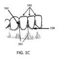
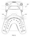
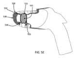
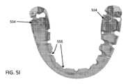
本明細書に説明されるものは、包括的な個人化された口腔ケアを提供するためのシステムおよび方法である。口腔ケアのためのシステムの一変形例は、ユーザの口腔に従って定寸および成形され、複数の流体ノズルを有する、口腔挿入物を備える。本システムは、口腔挿入物に取り付けられるハンドルを備えてもよく、ハンドルは、口腔挿入物の流体ノズルと流体リザーバとの間に流体連通を提供する、流体導管を有してもよい。本システムは、リザーバからの流体を加圧するように構成される、流体ポンプと、加圧流体を口腔挿入物のノズルに送達および分配するように構成される、流体切替装置等の流体レギュレータとを備えてもよい。流体リザーバは、水、消毒液、液体薬剤、風味付けされた溶液、洗浄液、研磨液、微生物叢収集流体、および/または上記に列挙される溶液の任意の組み合わせ、ならびに同等物を含有してもよい。流体はまた、口臭を低減させることに役立ち得、フッ素を添加され得る、作用物質を含んでもよい。口腔挿入物の流体ノズルは、ノズルによって成形される流体噴射が歯間空間の中に指向され得るように、ユーザの歯の間の歯間空間と対応する領域に位置してもよい。代替として、または加えて、流体ノズルは、歯間空間の場所からのオフセットに位置してもよいが、歯間空間に向かって指向されてもよい(例えば、流体ノズルは、流体噴射軸が歯間空間に向けられ得るように、角度を付けられてもよい)。いくつかの変形例では、流体ノズルは、口腔挿入物の外面に沿った陥凹内に位置してもよい。陥凹は、フレア形状を有してもよく、陥凹の狭くなった領域が、流体ノズルの出口開口部に位置し、陥凹の幅が、外向きに増加し、陥凹の広がった領域の幅は、流体噴射スプレーの妨げのない拡散を可能にし得る。いくつかの変形例では、陥凹の広がった領域の幅は、流体噴射スプレーの幅に近似し得る。流体ノズル出口開口部を囲繞する陥凹(例えば、くぼみ、空洞等)は、流体噴射を指向することに役立ち得る。歯の間の空間/間隙を通して通過する流体噴射は、フロッシング効果を発生させ得、それらの空間/間隙内に引っ掛かっている残渣および/または生物膜を除去することに役立ち得る。随意に、流体は、消毒液(および/または任意の他の溶液)から成ってもよく、歯間空間を通して通過した後、口腔内で、かつその全体を通して循環し、微生物群集を低減させる、および/または細菌ならびに/もしくは真菌成長等を抑制し得る。Described herein are systems and methods for providing comprehensive personalized oral care. One variation of a system for oral care includes an oral insert sized and shaped according to a user's oral cavity and having multiple fluid nozzles. The system may include a handle attached to the oral insert, which may have a fluid conduit providing fluid communication between the fluid nozzle of the oral insert and a fluid reservoir. The system may include a fluid pump configured to pressurize fluid from the reservoir and a fluid regulator, such as a fluid switcher, configured to deliver and dispense the pressurized fluid to the nozzle of the oral insert. The fluid reservoir may contain water, disinfectant, liquid medication, flavored solutions, cleaning solutions, polishing solutions, microbiota collection fluids, and/or any combination of the solutions listed above, and the like. The fluid may also include an agent that may help reduce oral odor and may be fluoridated. The fluid nozzle of the oral insert may be located in an area corresponding to the interdental space between the user's teeth such that a fluid jet shaped by the nozzle may be directed into the interdental space. Alternatively or in addition, the fluid nozzle may be located offset from the location of the interdental space, but directed toward the interdental space (e.g., the fluid nozzle may be angled so that the fluid jet axis may be directed toward the interdental space). In some variations, the fluid nozzle may be located within a recess along the outer surface of the oral insert. The recess may have a flared shape, with a narrowed region of the recess located at the exit opening of the fluid nozzle, and the width of the recess increasing outward, and the width of the widened region of the recess may allow for unhindered diffusion of the fluid jet spray. In some variations, the width of the widened region of the recess may approximate the width of the fluid jet spray. A recess (e.g., a dimple, cavity, etc.) surrounding the fluid nozzle exit opening may help direct the fluid jet. The fluid jet passing through the spaces/gaps between the teeth may create a flossing effect and help remove debris and/or biofilms trapped within those spaces/gaps. Optionally, the fluid may consist of an antiseptic solution (and/or any other solution) which, after passing through the interdental spaces, may circulate within and throughout the oral cavity to reduce microbial populations and/or inhibit bacterial and/or fungal growth, etc.
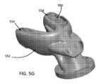
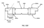
口腔挿入物はまた、ユーザの口腔の後または舌側領域から前または顔側領域に流体を導くように構成される、流出導管を備えてもよい。流出導管は、流体がユーザの口の中に蓄積しないように、歯間空間を通して通過され、口腔の全体を通して循環された後に、加圧流体の放出を助長するように定寸および成形されてもよい。流出導管は、口腔挿入物の上側部分と下側部分との間に位置する、中心ポートを備えてもよく、中心部分の後開口部は、流体をユーザの口腔の前および/または顔側領域に導くように構成されてもよい。随意に、流出導管はまた、第1の側面流体空洞と、第2の側面流体空洞とを備えてもよく、第1および第2の側面流体空洞は、中心ポートと流体連通する。The oral insert may also include an outflow conduit configured to direct fluid from a posterior or lingual region of the oral cavity to an anterior or facial region of the oral cavity of the user. The outflow conduit may be sized and shaped to facilitate release of pressurized fluid after it has been passed through interdental spaces and circulated throughout the oral cavity so that fluid does not accumulate in the user's mouth. The outflow conduit may include a central port located between the upper and lower portions of the oral insert, and a posterior opening of the central portion may be configured to direct fluid to the anterior and/or facial region of the oral cavity of the user. Optionally, the outflow conduit may also include a first side fluid cavity and a second side fluid cavity, the first and second side fluid cavities being in fluid communication with the central port.
ユーザの口腔を清掃するためのシステムの一変形例は、流体リザーバと、口腔挿入物とを備えてもよい。口腔挿入物は、ユーザの上歯を受容するように定寸および成形される、上側部分と、ユーザの下歯を受容するように定寸および成形される、下側部分と、上側部分および下側部分内に位置し、ユーザの歯の間の歯間空間に向かって指向される、複数の流体ノズルと、上側部分と下側部分との間に位置する、流出導管とを備えてもよい。流出導管は、ユーザの口腔の後または舌側領域から前または顔側領域に流体を導くように構成されてもよい。流体流出導管は、口腔挿入物の中心領域に位置する中心ポートを備えてもよく、中心ポートの後開口部は、ユーザの口腔の後または舌側領域からユーザの口腔の前または顔側領域に流体を導くように構成されてもよい。いくつかの変形例では、流体流出導管は、口腔挿入物の中心領域に位置する中心ポートと、口腔挿入物の右側の第1の流体空洞と、口腔挿入物の左側の第2の流体空洞とを備えてもよく、第1および第2の流体空洞は、中心ポートと流体連通してもよい。中心ポートの前領域は、口腔挿入物の前領域から延在(例えば、突出)してもよく、中心ポートの前延在部は、ユーザの口腔の後または舌側領域からの流体流を組み合わせるように、かつ組み合わせられた流体流をユーザの口腔の前または顔側領域に導くように構成される、1つまたはそれを上回る凹曲面を有する、テーパ状形状を有してもよい。第1および第2の流体空洞はそれぞれ、一定の周辺を伴う断面を有する、後区分と、ユーザの口腔の前方領域に向かって断面積が増加する断面を有する、ロフト状区分とを有してもよい。第1の流体空洞は、ユーザの口腔の後方領域内に位置する第1の開口部を有してもよく、第2の流体空洞は、ユーザの口腔の後方領域内に位置する第2の開口部を有してもよく、第1および第2の開口部の周辺縁の周囲の口腔挿入物の表面は、凹状または凸状輪郭を備えてもよい。例えば、第1の開口部および第2の開口部は、テーパ状の伸長形状を有してもよく、伸長形状は、口腔挿入物の中心領域から側方に延在するにつれて狭くなる寸法を有する。One variation of a system for cleaning a user's oral cavity may include a fluid reservoir and an oral cavity insert. The oral cavity insert may include an upper portion sized and shaped to receive the user's upper teeth, a lower portion sized and shaped to receive the user's lower teeth, a plurality of fluid nozzles located within the upper and lower portions and directed toward the interdental spaces between the user's teeth, and an outflow conduit located between the upper and lower portions. The outflow conduit may be configured to direct fluid from a posterior or lingual region of the user's oral cavity to an anterior or facial region. The fluid outflow conduit may include a central port located in a central region of the oral cavity insert, and a rear opening of the central port may be configured to direct fluid from a posterior or lingual region of the user's oral cavity to an anterior or facial region of the user's oral cavity. In some variations, the fluid outflow conduit may comprise a central port located in a central region of the oral insert, a first fluid cavity on the right side of the oral insert, and a second fluid cavity on the left side of the oral insert, and the first and second fluid cavities may be in fluid communication with the central port. The front region of the central port may extend (e.g., protrude) from the front region of the oral insert, and the front extension of the central port may have a tapered shape with one or more concave curved surfaces configured to combine fluid flows from the posterior or lingual region of the user's oral cavity and to direct the combined fluid flows to the anterior or facial region of the user's oral cavity. The first and second fluid cavities may each have a posterior section having a cross-section with a constant perimeter and a lofted section having a cross-section that increases in cross-sectional area toward the anterior region of the user's oral cavity. The first fluid cavity may have a first opening located in a posterior region of the user's oral cavity, and the second fluid cavity may have a second opening located in a posterior region of the user's oral cavity, and the surface of the oral insert around the peripheral edges of the first and second openings may include a concave or convex contour. For example, the first and second openings may have a tapered elongated shape, with the elongated shape having a narrowing dimension as it extends laterally from a central region of the oral insert.
加えて、ユーザの口腔を清掃するためのシステムは、流体リザーバおよび口腔挿入物の複数の流体ノズルと流体連通する流体導管を備える、ハンドルを備えてもよい。いくつかの変形例では、口腔挿入物は、ユーザの下顎骨および/または上顎骨の曲率と対応する、U字形曲線を有してもよい。口腔挿入物の上側部分は、ユーザの上顎骨の曲率と対応する、U字形曲線を有し、口腔挿入物の下側部分は、ユーザの下顎骨の曲率と対応する、U字形曲線を有する。いくつかの変形例では、流体ノズルはそれぞれ、口腔挿入物の外面に沿った陥凹内に位置してもよい。陥凹は、流体ノズルの開口部における第1の端部と、口腔挿入物の外面に沿った開口部における第2の端部とを有してもよい。陥凹は、外面に沿った開口部の断面積が、流体ノズル開口部の断面積を上回るように、フレア形状を有してもよい。例えば、外面に沿った開口部の直径は、流体ノズル開口部の直径を上回り得る。フレア形状の陥凹の第1の端部は、円形状を有してもよく、第2の端部は、楕円体形状を有してもよい。いくつかの変形例では、陥凹は、1つまたはそれを上回る凹状輪郭を有する、および/または円形もしくは楕円体形状を有してもよい。In addition, the system for cleaning the user's oral cavity may include a handle with a fluid conduit in fluid communication with the fluid reservoir and the multiple fluid nozzles of the oral insert. In some variations, the oral insert may have a U-shaped curve corresponding to the curvature of the user's mandible and/or maxilla. An upper portion of the oral insert has a U-shaped curve corresponding to the curvature of the user's maxilla, and a lower portion of the oral insert has a U-shaped curve corresponding to the curvature of the user's mandible. In some variations, the fluid nozzles may each be located within a recess along the outer surface of the oral insert. The recess may have a first end at an opening of the fluid nozzle and a second end at an opening along the outer surface of the oral insert. The recess may have a flared shape such that the cross-sectional area of the opening along the outer surface exceeds the cross-sectional area of the fluid nozzle opening. For example, the diameter of the opening along the outer surface may exceed the diameter of the fluid nozzle opening. A first end of the flared recess may have a circular shape and a second end may have an ellipsoidal shape. In some variations, the recess may have one or more concave contours and/or have a circular or ellipsoidal shape.
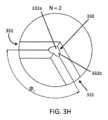
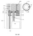
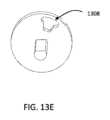
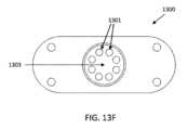
いくつかの変形例では、口腔挿入物は、複数の流体マニホールドと、マニホールドコネクタとを備えてもよく、複数の流体マニホールドは、複数の流体ノズルと流体連通してもよく、各流体マニホールドは、マニホールドコネクタ内のマニホールド開口部において終端する。ハンドルは、口腔挿入物を取外可能に保定するように構成される、取付機構と、流体切替装置アセンブリとを備えてもよく、流体切替装置アセンブリは、モータと、モータに接続される回転子とを備えてもよい。取付機構は、マニホールドコネクタとハンドルとの間に水密界面を提供するように構成される、シールリングを備えてもよい。ハンドルはさらに、流体切替装置アセンブリと口腔挿入物との間に位置する、エラストマ振動ダンパを備えてもよい。マニホールドコネクタのマニホールド開口部は、円に配列されてもよく、回転子は、モータが回転可能平板を回転させるにつれて、マニホールドコネクタにおけるマニホールド開口部のそれぞれと連続的に整合するように構成される、第1の流体開口を有する、回転可能平板であってもよい。マニホールドコネクタのマニホールド開口部は、開口部間の間隔によって相互から離間されてもよく、回転可能平板の第1の流体開口は、第1の流体開口が、少なくとも1つのマニホールド開口部との流体接続を常に維持するように、開口部間の間隔を上回る幅を有してもよい。いくつかの変形例では、回転可能平板は、第2の流体開口を有してもよい。第2の流体開口は、第1の流体開口の半径方向に反対側にあり得る。マニホールドコネクタのマニホールド開口部は、円に配列されてもよく、流体切替装置アセンブリはさらに、マニホールドコネクタ内のマニホールド開口部と整合されるように構成される、複数の流体チャネルを有する、マニホールドブロックを備えてもよい。回転子は、モータが回転可能平板を回転させるにつれて、マニホールドコネクタ内の流体チャネルのそれぞれと連続的に整合するように構成される、流体開口を有する、回転可能平板であってもよい。代替として、マニホールドコネクタのマニホールド開口部は、円に配列されてもよく、回転子は、モータがバレルを回転させるにつれて、マニホールドコネクタ内のマニホールド開口部のそれぞれと連続的に整合するように構成される、第1の流体開口を有する、回転可能バレルであってもよい。いくつかの変形例では、回転可能バレルは、第2の流体開口を有してもよい。第2の流体開口は、第1の流体開口の半径方向に反対側にあり得る。マニホールドコネクタのマニホールド開口部は、開口部間の間隔によって相互から離間されてもよく、回転可能バレルの第1の流体開口は、第1の流体開口が、少なくとも1つのマニホールド開口部との流体接続を常に維持するように、開口部間の間隔を上回る幅を有してもよい。In some variations, the oral insert may include a plurality of fluid manifolds and a manifold connector, the plurality of fluid manifolds may be in fluid communication with the plurality of fluid nozzles, each fluid manifold terminating at a manifold opening in the manifold connector. The handle may include an attachment mechanism configured to removably retain the oral insert, and a fluid switcher assembly, the fluid switcher assembly may include a motor and a rotor connected to the motor. The attachment mechanism may include a seal ring configured to provide a watertight interface between the manifold connector and the handle. The handle may further include an elastomeric vibration damper located between the fluid switcher assembly and the oral insert. The manifold openings of the manifold connector may be arranged in a circle, and the rotor may be a rotatable plate having a first fluid opening configured to sequentially align with each of the manifold openings in the manifold connector as the motor rotates the rotatable plate. The manifold openings of the manifold connector may be spaced apart from one another by a spacing between the openings, and the first fluid opening of the rotatable plate may have a width that exceeds the spacing between the openings such that the first fluid opening always maintains a fluid connection with at least one manifold opening. In some variations, the rotatable plate may have a second fluid opening. The second fluid opening may be radially opposite the first fluid opening. The manifold openings of the manifold connector may be arranged in a circle, and the fluidic switcher assembly may further comprise a manifold block having a plurality of fluid channels configured to be aligned with the manifold openings in the manifold connector. The rotor may be a rotatable plate having fluid openings configured to sequentially align with each of the fluid channels in the manifold connector as the motor rotates the rotatable plate. Alternatively, the manifold openings of the manifold connector may be arranged in a circle, and the rotor may be a rotatable barrel having a first fluid opening configured to sequentially align with each of the manifold openings in the manifold connector as the motor rotates the barrel. In some variations, the rotatable barrel may have a second fluid opening. The second fluid opening may be radially opposite the first fluid opening. The manifold openings of the manifold connector may be spaced apart from one another by a spacing between the openings, and the first fluid opening of the rotatable barrel may have a width that exceeds the spacing between the openings such that the first fluid opening always maintains a fluid connection with at least one manifold opening.
いくつかの変形例では、口腔挿入物は、随意に、上側部分および下側部分の外面に沿って配置される、エラストマ基板を備えてもよい。上側および下側部分は、剛性基板を備えてもよい。エラストマ基板との剛性上側および下側部分の組み合わせは、ハイブリッド口腔挿入物を構成し得る。エラストマ基板は、複数の流体ノズルと整合する、複数の開口を備えてもよい。エラストマ基板は、ユーザの歯の頬側表面および舌側表面の場所と対応する、テクスチャ加工表面を備えてもよい。いくつかの変形例では、エラストマ基板は、随意に、ユーザの歯の表面に沿って振動する、および/または別様に機械的に揺動する、ならびに/もしくは平行移動する、および/またはそれに接触するように手動で作動されるように構成され得る、テクスチャ加工表面を備えてもよい。歯の顔側表面、舌側表面、咬合表面、近心表面、遠位表面、および/または切縁に沿ったテクスチャ加工表面の振動は、それらの歯表面に沿ってブラッシング効果を発生させ得る。いくつかの変形例では、エラストマ基板のテクスチャ加工表面(剛毛を含み得る)は、ユーザの歯の顔側表面、舌側表面、咬合表面、近心表面、遠位表面、および/または切縁の場所と対応する領域に位置してもよい。随意に、ハンドルはさらに、エラストマ基板の振動運動を引き起こす、振動機構を備えてもよい。ハンドルは、振動機構からの振動運動がエラストマ基板に伝達されるように、口腔挿入物に取り付けられてもよい。流体導管は、複数の流体ノズルへの流体流動を調整するように構成される、流体弁(例えば、流体レギュレータまたは切替装置)を備えてもよく、流体導管は、流体導管を通して流体流動によって引き起こされる振動が、振動機構からの振動運動と合体し、エラストマ基板の振動を引き起こし得るように、振動機構に機械的に結合されてもよい。振動機構は、偏心回転質量振動モータ、および/または線形共振アクチュエータ、ならびに/もしくは電磁振動モータを備えてもよい。In some variations, the oral insert may optionally include an elastomeric substrate disposed along the outer surfaces of the upper and lower portions. The upper and lower portions may include a rigid substrate. The combination of the rigid upper and lower portions with the elastomeric substrate may constitute a hybrid oral insert. The elastomeric substrate may include a plurality of openings that align with the plurality of fluid nozzles. The elastomeric substrate may include a textured surface that corresponds to the location of the buccal and lingual surfaces of the user's teeth. In some variations, the elastomeric substrate may optionally include a textured surface that may be configured to vibrate and/or otherwise mechanically rock and/or translate along and/or manually actuate to contact the surfaces of the user's teeth. Vibration of the textured surface along the facial, lingual, occlusal, mesial, distal, and/or incisal surfaces of the teeth may generate a brushing effect along those tooth surfaces. In some variations, the textured surface of the elastomeric substrate (which may include bristles) may be located in an area corresponding to the location of the facial, lingual, occlusal, mesial, distal, and/or incisal surfaces of the user's teeth. Optionally, the handle may further include a vibration mechanism that induces a vibrational motion of the elastomeric substrate. The handle may be attached to the oral insert such that the vibrational motion from the vibration mechanism is transmitted to the elastomeric substrate. The fluid conduit may include a fluid valve (e.g., a fluid regulator or a switching device) configured to regulate the fluid flow to the multiple fluid nozzles, and the fluid conduit may be mechanically coupled to the vibration mechanism such that vibrations caused by the fluid flow through the fluid conduit may combine with the vibrational motion from the vibration mechanism to induce vibration of the elastomeric substrate. The vibration mechanism may include an eccentric rotating mass vibration motor, and/or a linear resonant actuator, and/or an electromagnetic vibration motor.
いくつかの変形例では、口腔挿入物の上側および下側部分は、硬度計上の第1のデュロメータ値を有する材料から成ってもよく、エラストマ基板は、第1のデュロメータよりも低い硬度計上の第2のデュロメータ値を有する材料から成ってもよい。例えば、第1のデュロメータ値は、約60ショアA~約100ショアDであってもよい。エラストマ基板は、生体適合性エラストマから成ってもよく、剛性基板は、生体適合性UV硬化性フォトポリマーから成ってもよい。In some variations, the upper and lower portions of the oral insert may be made of a material having a first durometer value on the hardness scale, and the elastomeric substrate may be made of a material having a second durometer value on the hardness scale that is lower than the first durometer. For example, the first durometer value may be from about 60 Shore A to about 100 Shore D. The elastomeric substrate may be made of a biocompatible elastomer, and the rigid substrate may be made of a biocompatible UV-curable photopolymer.
いくつかの変形例では、エラストマ基板は、口腔挿入物に解放可能に取り付けられてもよい。例えば、口腔挿入物はさらに、上側部分および/または下側部分上の第1の取付構造と、エラストマ基板上の第2の取付構造とを備えてもよく、取付構造は、相互係止するように構成される。第1の取付構造は、溝を備えてもよく、第2の取付構造は、第1および第2の取付構造が相互係止するように、溝と整合されるように構成される突出部を備えてもよい。代替として、または加えて、解放可能取付機構は、エラストマ基板を口腔挿入物と接合する接着剤を備えてもよい。口腔挿入物はさらに、上側部分および/または下側部分上の第1の取付構造と、エラストマ基板上の第2の取付構造とを備えてもよく、第1および第2の取付構造は、1つまたはそれを上回る磁性材料から成ってもよい。In some variations, the elastomeric substrate may be releasably attached to the oral insert. For example, the oral insert may further comprise a first attachment structure on the upper and/or lower portions and a second attachment structure on the elastomeric substrate, the attachment structures being configured to interlock. The first attachment structure may comprise a groove, and the second attachment structure may comprise a protrusion configured to align with the groove such that the first and second attachment structures interlock. Alternatively or additionally, the releasable attachment mechanism may comprise an adhesive that bonds the elastomeric substrate to the oral insert. The oral insert may further comprise a first attachment structure on the upper and/or lower portions and a second attachment structure on the elastomeric substrate, the first and second attachment structures being comprised of one or more magnetic materials.
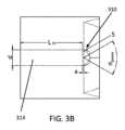
口腔ケアのためのシステムのいくつかの変形例は、流体開口部と、流体をハンドルに提供するように構成される、底面上の逆止弁と、高架板と流体開口部との間に間隙が存在するように、流体開口部にわたって配置される高架板とを備える、流体リザーバを備えてもよい。高架板の幅は、流体開口部の幅を上回り得る。例えば、高架板の幅は、流体開口部の幅の少なくとも2倍であり得る。Some variations of systems for oral care may include a fluid reservoir that includes a fluid opening, a check valve on a bottom surface configured to provide fluid to the handle, and an elevated plate disposed across the fluid opening such that a gap exists between the elevated plate and the fluid opening. The width of the elevated plate may be greater than the width of the fluid opening. For example, the width of the elevated plate may be at least twice the width of the fluid opening.
いくつかの変形例では、口腔挿入物はさらに、エラストマ基板を備えてもよい。エラストマ基板との口腔挿入物の組み合わせは、ハイブリッド口腔挿入物を構成し得る。ハイブリッド口腔挿入物は、剛性基板(例えば、本明細書に説明される口腔挿入物のうちのいずれか)と、剛性基板に取り付けられるエラストマ基板とを備えてもよい。エラストマ基板は、エラストマ基板が剛性基板に取り付けられるときに複数の流体ノズルと整合する、複数の開口を有してもよい。いくつかの変形例では、エラストマ基板は、随意に、ユーザの歯の表面に沿って振動する、および/または別様に機械的に揺動する、ならびに/もしくは平行移動する、および/またはそれに接触するように手動で作動されるように構成され得る、テクスチャ加工表面を備えてもよい。歯の顔側表面、舌側表面、咬合表面、近心表面、遠位表面、および/または切縁に沿ったテクスチャ加工表面の振動は、それらの歯表面に沿ってブラッシング効果を発生させ得る。いくつかの変形例では、エラストマ基板のテクスチャ加工表面(剛毛を含み得る)は、ユーザの歯の顔側表面、舌側表面、咬合表面、近心表面、遠位表面、および/または切縁の場所と対応する領域に位置してもよい。ハイブリッド口腔挿入物を備える、口腔ケアシステムは、推奨される口腔ケアステップのうちの2つまたはそれを上回るものを組み合わせてもよく、すなわち、単一のステップで、フロッシング、ブラッシング、および/または洗浄の機能を組み合わせる(例えば、フロッシングおよび洗浄、フロッシングおよびブラッシング、フロッシング、ブラッシングおよび洗浄等)。これは、ユーザがより徹底的な毎日の口腔ケアルーチンを採用することに役立ち得る。随意に、ハンドルは、振動機構、運動を誘発するための機構、または手動で揺動もしくはアクティブ化される能力を備えてもよい。いくつかの変形例では、エラストマ基板は、剛性基板に解放可能に取り付けられてもよい。エラストマ基板は、第1の硬度値(すなわち、デュロメータ)を伴う材料から成ってもよく、剛性基板は、第1の硬度値よりも高い(すなわち、より硬質である、より剛性である)第2の硬度値(すなわち、デュロメータ)を伴う材料から成ってもよい。例えば、エラストマ基板は、エラストマから作製されてもよく、剛性基板は、UV硬化性フォトポリマー等のポリマーから作製されてもよい。エラストマ基板は、任意の好適な柔軟、可撓性、および/または形状適合材料から作製されてもよく、これは、剛性基板とユーザの歯および歯茎との間により軟質ならびに/もしくは平滑な界面を提供することによって、口腔内のハイブリッド口腔挿入物の全体的快適性を改良することに役立ち得る。口腔ケアのためのシステムの別の変形例は、ユーザの口腔に従って定寸および成形され、複数の流体ノズルを有する、剛性基板(エラストマ基板を伴わない)を備える、口腔挿入物を備える。流体リザーバ、溶液、振動機構、ならびに本明細書に説明される構成要素および/または特徴のうちのいずれかは、剛性基板およびエラストマ基板を伴う口腔挿入物(すなわち、ハイブリッド口腔挿入物)ならびに/もしくはエラストマ基板ではなく剛性基板を伴う口腔挿入物と併用されてもよい。In some variations, the oral insert may further comprise an elastomeric substrate. The combination of the oral insert with the elastomeric substrate may constitute a hybrid oral insert. The hybrid oral insert may comprise a rigid substrate (e.g., any of the oral inserts described herein) and an elastomeric substrate attached to the rigid substrate. The elastomeric substrate may have a plurality of openings that align with the plurality of fluid nozzles when the elastomeric substrate is attached to the rigid substrate. In some variations, the elastomeric substrate may optionally comprise a textured surface that may be configured to vibrate and/or otherwise mechanically rock and/or translate along and/or manually actuate to contact the user's tooth surfaces. Vibration of the textured surface along the facial, lingual, occlusal, mesial, distal, and/or incisal surfaces of the teeth may generate a brushing effect along those tooth surfaces. In some variations, the textured surface of the elastomeric substrate (which may include bristles) may be located in areas corresponding to the facial, lingual, occlusal, mesial, distal, and/or incisal locations of the user's teeth. An oral care system with a hybrid oral insert may combine two or more of the recommended oral care steps, i.e., combine the functions of flossing, brushing, and/or cleaning in a single step (e.g., flossing and cleaning, flossing and brushing, flossing, brushing and cleaning, etc.). This may help the user adopt a more thorough daily oral care routine. Optionally, the handle may include a vibration mechanism, a mechanism for inducing motion, or the ability to be manually oscillated or activated. In some variations, the elastomeric substrate may be releasably attached to a rigid substrate. The elastomeric substrate may be made of a material with a first hardness value (i.e., durometer), and the rigid substrate may be made of a material with a second hardness value (i.e., durometer) that is higher (i.e., harder, stiffer) than the first hardness value. For example, the elastomeric substrate may be made of an elastomer, and the rigid substrate may be made of a polymer, such as a UV-curable photopolymer. The elastomeric substrate may be made of any suitable soft, flexible, and/or conformable material, which may help improve the overall comfort of the hybrid oral insert in the oral cavity by providing a softer and/or smoother interface between the rigid substrate and the user's teeth and gums. Another variation of the system for oral care includes an oral insert that includes a rigid substrate (without an elastomeric substrate) that is sized and shaped according to the user's oral cavity and has multiple fluid nozzles. The fluid reservoir, solution, vibration mechanism, and any of the components and/or features described herein may be used in conjunction with oral inserts with rigid and elastomeric substrates (i.e., hybrid oral inserts) and/or oral inserts with rigid substrates rather than elastomeric substrates.
ハイブリッド口腔挿入物の一変形例は、ユーザの口腔に従って定寸および成形される剛性基板と、剛性基板に取り付けられるエラストマ基板とを備えてもよい。剛性基板は、ユーザの歯の間の歯間空間と対応する剛性基板の領域に(および/または随意に、限定ではないが、咬合表面、顔側表面、ならびに/もしくは舌側表面を含む、他の歯表面に沿った凹面に)位置する、複数の流体ノズルを備えてもよく、エラストマ基板は、エラストマ基板が剛性基板に取り付けられるときに複数の流体ノズルと整合する、複数の開口を備えてもよい。エラストマ基板はさらに、ユーザの歯の顔側表面、舌側表面、咬合表面、近心表面、遠位表面、および/または切縁の場所と対応する、テクスチャ加工表面を備えてもよい。いくつかの変形例では、エラストマ基板は、振動するように構成されてもよく、随意に、テクスチャ加工表面は、ユーザの歯の咬合表面および/または切縁の場所と対応する、エラストマ基板の領域に位置してもよい。口腔挿入物はさらに、剛性基板の複数の流体ノズルと流体連通する流体導管を備える、ハンドルを備えてもよい。いくつかの変形例では、ハンドルはさらに、エラストマ基板の振動運動を引き起こす、振動機構を備えてもよい。ハンドルは、剛性基板が振動運動を振動機構からエラストマ基板に伝達するように、剛性基板に取り付けられてもよい。代替として、または加えて、ハンドルは、剛性基板に取り付けられてもよく、振動機構は、エラストマ基板に機械的に結合される。流体導管は、複数の流体ノズルへの流体流動を調整するように構成される、流体弁を備えてもよく、流体導管は、流体導管を通して流体流動によって引き起こされる振動が、振動機構からの振動運動と合体し、エラストマ基板の振動を引き起こすように、振動機構に機械的に結合されてもよい。振動機構は、偏心回転質量振動モータ、および/または線形共振アクチュエータ、ならびに/もしくは電磁振動モータを備えてもよい。One variation of a hybrid oral insert may include a rigid substrate sized and shaped according to the oral cavity of a user, and an elastomeric substrate attached to the rigid substrate. The rigid substrate may include a plurality of fluid nozzles located in areas of the rigid substrate corresponding to the interdental spaces between the user's teeth (and/or optionally in concave surfaces along other tooth surfaces, including but not limited to occlusal, facial, and/or lingual surfaces), and the elastomeric substrate may include a plurality of openings that align with the plurality of fluid nozzles when the elastomeric substrate is attached to the rigid substrate. The elastomeric substrate may further include a textured surface that corresponds to the facial, lingual, occlusal, mesial, distal, and/or incisal locations of the user's teeth. In some variations, the elastomeric substrate may be configured to vibrate, and optionally the textured surface may be located in areas of the elastomeric substrate corresponding to the occlusal and/or incisal locations of the user's teeth. The oral insert may further comprise a handle comprising a fluid conduit in fluid communication with the plurality of fluid nozzles of the rigid substrate. In some variations, the handle may further comprise a vibration mechanism for inducing a vibrational motion of the elastomeric substrate. The handle may be attached to the rigid substrate such that the rigid substrate transmits the vibrational motion from the vibration mechanism to the elastomeric substrate. Alternatively or additionally, the handle may be attached to the rigid substrate and the vibration mechanism is mechanically coupled to the elastomeric substrate. The fluid conduit may comprise a fluid valve configured to regulate fluid flow to the plurality of fluid nozzles, and the fluid conduit may be mechanically coupled to the vibration mechanism such that vibrations caused by the fluid flow through the fluid conduit combine with the vibrational motion from the vibration mechanism to induce vibration of the elastomeric substrate. The vibration mechanism may comprise an eccentric rotating mass vibration motor, and/or a linear resonant actuator, and/or an electromagnetic vibration motor.
いくつかの変形例では、剛性基板は、硬度計上の第1のデュロメータ値を有する材料から成ってもよく、エラストマ基板は、第1のデュロメータよりも低い硬度計上の第2のデュロメータ値を有する材料から成ってもよい。例えば、第1のデュロメータ値は、約60ショアA~約100ショアDであってもよい。エラストマ基板は、生体適合性エラストマから成ってもよく、剛性基板は、生体適合性UV硬化性フォトポリマーから成ってもよい。In some variations, the rigid substrate may be made of a material having a first durometer value on the hardness scale, and the elastomeric substrate may be made of a material having a second durometer value on the hardness scale that is lower than the first durometer. For example, the first durometer value may be from about 60 Shore A to about 100 Shore D. The elastomeric substrate may be made of a biocompatible elastomer, and the rigid substrate may be made of a biocompatible UV-curable photopolymer.
いくつかの変形例では、エラストマ基板は、剛性基板に解放可能に取り付けられてもよい。例えば、口腔挿入物はさらに、剛性基板上の第1の取付構造と、エラストマ基板上の第2の取付構造とを備えてもよく、取付構造は、相互係止するように構成される。第1の取付構造は、溝を備えてもよく、第2の取付構造は、第1および第2の取付構造が相互係止するように、溝と整合されるように構成される突出部を備えてもよい。代替として、または加えて、解放可能取付機構は、エラストマ基板を剛性基板と接合する接着剤を備えてもよい。口腔挿入物はさらに、剛性基板上の第1の取付構造と、エラストマ基板上の第2の取付構造とを備えてもよく、第1および第2の取付構造は、1つまたはそれを上回る磁性材料から成ってもよい。In some variations, the elastomeric substrate may be releasably attached to the rigid substrate. For example, the oral insert may further comprise a first attachment structure on the rigid substrate and a second attachment structure on the elastomeric substrate, the attachment structures being configured to interlock. The first attachment structure may comprise a groove, and the second attachment structure may comprise a protrusion configured to align with the groove such that the first and second attachment structures interlock. Alternatively or additionally, the releasable attachment mechanism may comprise an adhesive that bonds the elastomeric substrate to the rigid substrate. The oral insert may further comprise a first attachment structure on the rigid substrate and a second attachment structure on the elastomeric substrate, the first and second attachment structures may be comprised of one or more magnetic materials.
エラストマ基板のテクスチャ加工表面は、溝および/または突出部の反復パターンを備えてもよい。エラストマ基板は、ユーザの上歯に接触するように構成される、上面と、ユーザの下歯に接触するように構成される、下面と、上面と下面との間に跨架する、スタンドオフ構造とを備えてもよい。スタンドオフ構造は、第1のスタンドオフ構造であってもよく、エラストマ基板は、上面と下面との間に跨架する、第2のスタンドオフ構造を備えてもよい。第1のスタンドオフ構造は、エラストマ基板の左側に位置してもよく、第2のスタンドオフ構造は、エラストマ基板の右側に位置してもよい。いくつかの変形例では、第1および第2のスタンドオフ構造は、エラストマ基板の上面と下面との間に跨架する、垂直柱であってもよく、それらがユーザの大臼歯、小臼歯、または犬歯のうちの1つまたはそれを上回るものと整合するように位置してもよい。The textured surface of the elastomeric substrate may comprise a repeating pattern of grooves and/or protrusions. The elastomeric substrate may comprise an upper surface configured to contact the user's upper teeth, a lower surface configured to contact the user's lower teeth, and a standoff structure spanning between the upper and lower surfaces. The standoff structure may be a first standoff structure and the elastomeric substrate may comprise a second standoff structure spanning between the upper and lower surfaces. The first standoff structure may be located on the left side of the elastomeric substrate and the second standoff structure may be located on the right side of the elastomeric substrate. In some variations, the first and second standoff structures may be vertical posts spanning between the upper and lower surfaces of the elastomeric substrate and may be positioned such that they align with one or more of the user's molars, premolars, or canines.
ハイブリッド口腔挿入物のいくつかの変形例における剛性基板は、ユーザの上歯を受容するように構成される上側トラフを有する、上側部分と、ユーザの下歯を受容するように構成される下側トラフを有する、下側部分と、剛性基板の上側部分と下側部分との間に位置し、ユーザの口腔の後または舌側領域から前または顔側領域に流体を導くように構成される、流体流出導管とを備えてもよい。流体流出導管は、剛性基板の中心領域に位置する中心ポートを備えてもよく、中心ポートの後開口部は、ユーザの口腔の後または舌側領域からユーザの口腔の前または顔側領域に流体を導くように構成される。代替として、または加えて、流体流出導管は、剛性基板の中心領域に位置する中心ポートと、剛性基板の右側の第1の流体空洞と、剛性基板の左側の第2の流体空洞とを備えてもよく、第1および第2の流体空洞は、中心ポートと流体連通してもよい。中心ポートの前領域は、剛性基板の前領域から延在してもよく、中心ポートの前延在部は、1つまたはそれを上回る凹曲面を有する、テーパ状形状を有してもよい。1つまたはそれを上回る凹曲面は、ユーザの口腔の後または舌側領域からの流体流を組み合わせるように、かつ組み合わせられた流体流をユーザの口腔の前または顔側領域に導くように構成されてもよい。第1および第2の流体空洞はそれぞれ、一定の周辺を伴う断面を有する、後区分と、ユーザの口腔の前方領域に向かって断面積が増加する断面を有する、ロフト状区分とを有してもよい。第1の流体空洞は、ユーザの口腔の後方領域内に位置する第1の開口部を有してもよく、第2の流体空洞は、ユーザの口腔の後方領域内に位置する第2の開口部を有してもよい。第1および第2の開口部の周辺縁の周囲の剛性基板の表面は、凹状または凸状輪郭を備えてもよい。例えば、第1の開口部および第2の開口部は、テーパ状の伸長形状を有してもよく、伸長形状は、基板の中心領域から側方に延在するにつれて狭くなる寸法を有する。The rigid substrate in some variations of the hybrid oral insert may include an upper portion having an upper trough configured to receive the user's upper teeth, a lower portion having a lower trough configured to receive the user's lower teeth, and a fluid outflow conduit located between the upper and lower portions of the rigid substrate and configured to direct fluid from a posterior or lingual region of the user's oral cavity to an anterior or facial region of the user's oral cavity. The fluid outflow conduit may include a central port located in a central region of the rigid substrate, the rear opening of the central port configured to direct fluid from a posterior or lingual region of the user's oral cavity to an anterior or facial region of the user's oral cavity. Alternatively or in addition, the fluid outflow conduit may include a central port located in a central region of the rigid substrate, a first fluid cavity on the right side of the rigid substrate, and a second fluid cavity on the left side of the rigid substrate, the first and second fluid cavities being in fluid communication with the central port. The anterior region of the central port may extend from the anterior region of the rigid substrate, and the anterior extension of the central port may have a tapered shape with one or more concave curved surfaces. The one or more concave curved surfaces may be configured to combine fluid flows from the posterior or lingual region of the user's oral cavity and direct the combined fluid flows to the anterior or facial region of the user's oral cavity. The first and second fluid cavities may each have a posterior section having a cross-section with a constant perimeter and a lofted section having a cross-section that increases in cross-sectional area toward the anterior region of the user's oral cavity. The first fluid cavity may have a first opening located in the posterior region of the user's oral cavity, and the second fluid cavity may have a second opening located in the posterior region of the user's oral cavity. The surface of the rigid substrate around the peripheral edges of the first and second openings may include a concave or convex contour. For example, the first opening and the second opening may have a tapered elongated shape, the elongated shape having a dimension that narrows as it extends laterally from a central region of the substrate.
いくつかの変形例では、剛性基板は、ユーザの下顎および/または上顎弓の曲率と対応する、U字形曲線を有してもよい。剛性基板の上側部分は、ユーザの上顎骨の曲率と対応する、U字形曲線を有してもよく、剛性基板の下側部分は、ユーザの下顎骨の曲率と対応する、U字形曲線を有してもよい。In some variations, the rigid substrate may have a U-shaped curve that corresponds to the curvature of the user's mandible and/or maxillary arch. An upper portion of the rigid substrate may have a U-shaped curve that corresponds to the curvature of the user's maxillary bone, and a lower portion of the rigid substrate may have a U-shaped curve that corresponds to the curvature of the user's mandible.
ハイブリッド口腔挿入物の一変形例は、ユーザの口腔に従って定寸および成形される、剛性基板と、剛性基板に取り付けられる、エラストマ基板と、エラストマ基板の振動運動を引き起こす、振動機構とを備えてもよい。エラストマ基板は、ユーザの歯の頬側表面および舌側表面の場所と対応する、テクスチャ加工表面を備えてもよい。エラストマ基板は、ユーザの上歯に接触するように構成される、上面と、ユーザの下歯に接触するように構成される、下面と、上面と下面との間に跨架する、スタンドオフ構造とを備えてもよい。One variation of a hybrid oral insert may include a rigid substrate sized and shaped according to the mouth of a user, an elastomeric substrate attached to the rigid substrate, and a vibrating mechanism that induces a vibrating motion of the elastomeric substrate. The elastomeric substrate may include a textured surface that corresponds to the location of the buccal and lingual surfaces of the user's teeth. The elastomeric substrate may include an upper surface configured to contact the user's upper teeth, a lower surface configured to contact the user's lower teeth, and a standoff structure spanning between the upper and lower surfaces.
本明細書に説明される個人化された口腔ケアシステムのうちのいずれかは、流体リザーバと、流体リザーバに接続可能であり、流体ノズルまたは開口部と流体連通する、流体流入ポートと、流体流出ポートとを備える、カスタマイズされた口腔挿入物と、口腔挿入物の流体流出導管またはポートに取り付けられるように構成される、収集チャンバとを備えてもよい。カスタマイズされた口腔挿入物はさらに、ユーザの上歯を受容するように構成される、上側基板と、ユーザの下歯を受容するように構成される、下側基板と、上側および下側基板内に位置する、流体ノズルまたは開口部の配列とを備えてもよく、流体流入ポートは、流体ノズルまたは開口部と連通してもよい。口腔ケアシステムはさらに、流体リザーバ内に微生物叢収集流体を備えてもよい。微生物叢収集流体は、生理食塩水から成ってもよい。随意に、収集コンテナ内のサンプル安定化流体であって、サンプル安定化流体は、保存液等の液体懸濁液から成る。収集チャンバは、スナップロックおよび/または任意の好適な解放可能取付機構によって口腔挿入物に取り付けられるように構成される。収集チャンバは、開口部と、開口部にわたって除去可能に配置される、液密カバーとを備えてもよい。Any of the personalized oral care systems described herein may include a fluid reservoir, a customized oral insert including a fluid inlet port connectable to the fluid reservoir and in fluid communication with a fluid nozzle or opening, and a fluid outlet port, and a collection chamber configured to be attached to a fluid outlet conduit or port of the oral insert. The customized oral insert may further include an upper substrate configured to receive the user's upper teeth, a lower substrate configured to receive the user's lower teeth, and an array of fluid nozzles or openings located in the upper and lower substrates, and the fluid inlet port may be in communication with the fluid nozzles or openings. The oral care system may further include a microbiota collection fluid in the fluid reservoir. The microbiota collection fluid may comprise saline. Optionally, a sample stabilizing fluid in the collection container, the sample stabilizing fluid comprising a liquid suspension, such as a preservative fluid. The collection chamber is configured to be attached to the oral insert by a snap lock and/or any suitable releasable attachment mechanism. The collection chamber may include an opening and a liquid-tight cover that is removably positioned over the opening.
口腔微生物叢サンプルを収集するための方法の一変形例は、口腔挿入物をユーザの口腔の中に挿入するステップであって、口腔挿入物は、微生物叢収集流体を含有する流体リザーバと流体連通する、1つまたはそれを上回る流体開口部と、流体流出導管またはポートとを備える、ステップと、約40psiまたはそれを上回る流体圧力において、流体リザーバから口腔挿入物までユーザの口腔の中に微生物叢収集流体を送達するステップと、流体流出導管またはポートに結合される収集チャンバを使用して、ある体積の微生物叢収集流体を蓄積することによって、口腔微生物叢サンプルを収集するステップとを含んでもよい。流体圧力は、約40psi~約200psiであってもよい。口腔挿入物の1つまたはそれを上回る流体ノズルもしくは開口部は、流体開口部からの流体噴射が歯肉縁下領域に向かって指向されるように、ユーザの口腔の歯肉縁下領域および/または歯間領域と対応する位置に配列されてもよい。微生物叢収集流体をユーザの口腔の中に送達するステップは、1つまたはそれを上回る流体開口部を通してユーザの口腔の歯肉縁下領域および/または歯間領域に微生物叢収集流体を指向するステップを含んでもよい。微生物叢収集流体は、生理食塩水から成ってもよい。収集チャンバは、サンプル安定化流体を含有してもよい。微生物叢収集流体を送達するステップは、規定持続時間にわたって微生物叢収集流体を口腔挿入物に圧送するステップを含んでもよい。規定持続時間は、約1秒~約10秒であってもよい。随意に、微生物叢サンプルを収集するための方法は、口腔挿入物をユーザの口腔の中に挿入する前に、口腔挿入物を通して微生物叢収集流体を圧送することによって、口腔挿入物をプライミングするステップを含んでもよい。口腔挿入物をプライミングするステップは、約1秒~約20秒の規定持続時間にわたって口腔挿入物を通して微生物叢収集流体を圧送するステップを含んでもよい。方法は、口腔挿入物をプライミングした後に、収集チャンバを流体流出ポートに結合するステップを含んでもよい。いくつかの変形例では、本方法は、口腔微生物叢サンプルを収集した後に、液密カバーを用いて収集チャンバをシールするステップを含んでもよい。One variation of a method for collecting an oral microbiota sample may include inserting an oral insert into a user's oral cavity, the oral insert comprising one or more fluid openings in fluid communication with a fluid reservoir containing a microbiota collection fluid and a fluid outlet conduit or port; delivering the microbiota collection fluid from the fluid reservoir to the oral insert into the user's oral cavity at a fluid pressure of about 40 psi or greater; and collecting the oral microbiota sample by accumulating a volume of the microbiota collection fluid using a collection chamber coupled to the fluid outlet conduit or port. The fluid pressure may be from about 40 psi to about 200 psi. One or more fluid nozzles or openings of the oral insert may be arranged in a position corresponding to the subgingival and/or interdental regions of the user's oral cavity such that a fluid jet from the fluid opening is directed toward the subgingival region. Delivering the microbiota collection fluid into the user's oral cavity may include directing the microbiota collection fluid to the subgingival and/or interdental regions of the user's oral cavity through one or more fluid openings. The microbiota collection fluid may be comprised of saline. The collection chamber may contain a sample stabilizing fluid. Delivering the microbiota collection fluid may include pumping the microbiota collection fluid into the oral insert for a prescribed duration. The prescribed duration may be from about 1 second to about 10 seconds. Optionally, the method for collecting a microbiota sample may include priming the oral insert by pumping the microbiota collection fluid through the oral insert prior to inserting the oral insert into the user's oral cavity. Priming the oral insert may include pumping the microbiota collection fluid through the oral insert for a prescribed duration of from about 1 second to about 20 seconds. The method may include coupling the collection chamber to a fluid outlet port after priming the oral insert. In some variations, the method may include sealing the collection chamber with a liquid-tight cover after collecting the oral microbiome sample.
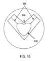
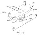
また、本明細書に開示されるものは、口腔走査のための歯科用シムデバイスである。歯科用シムデバイスは、選択された位置で上および下歯を位置付け、維持する、上面と、下面とをそれぞれ有する、第1および第2の整合部分と、第1の整合部分と第2の整合部分との間に跨架する長さを有する、ブリッジ部分と、第1ならびに第2の整合部分および/またはブリッジ部分の顔側表面上の1つまたはそれを上回る配向位置合わせマーカとを備えてもよい。第1および第2の整合部分の上面ならびに下面は、上および下歯の切縁および/または咬合表面に接触してもよい。いくつかの変形例では、上面は、第1の表面積と、第1の幅とを有してもよく、下面は、第2の表面積と、第2の幅とを有してもよく、第1の幅は、第2の幅を上回り得る。代替として、または加えて、第1の表面積は、第2の表面積を上回り得る。第1および第2の整合部分はそれぞれ、上歯と下歯との間に固定垂直オフセットを留保するように定寸される、側壁を備えてもよく、例えば、固定垂直オフセットは、約5mm~約20mmであってもよい。側壁は、剛性材料から成ってもよく、および/または上面ならびに下面は、上および下歯の輪郭に形状適合するように構成される、柔軟材料から成ってもよい。柔軟材料は、成型可能であり得る、および/または柔軟材料は、ゴム様材料、歯科用ワックス、歯科用印象材料、歯肉障壁材料、ならびに発泡体のうちの1つまたはそれを上回るものから成ってもよい。いくつかの変形例では、柔軟材料は、弾性状態から剛性状態に硬化可能であり得、例えば、柔軟材料は、化学硬化、熱硬化、室温硬化、および光硬化のうちの1つまたはそれを上回るものを使用して、硬化可能であり得る。ブリッジ部分の長さは、歯列弓の曲線に近似する曲線を有してもよく、および/または曲線状長さは、歯列弓の曲線もしくは幅と整合するように構成されてもよい。ブリッジ部分の曲線状長さはさらに、凸状顔側表面を備えてもよい。凸状顔側表面は、顔側表面の上側部分が前方に突出し、顔側表面の下側部分に向かって内向きにテーパ化するように、テーパ状であり得る。ブリッジ部分は、可撓性材料から成ってもよい。曲線状長さの第1の端部は、第1の整合部分に取り付けられてもよく、ブリッジ長さの第2の端部は、第2の整合部分に取り付けられてもよい。第1および第2の整合部分の上面ならびに下面は、上および下歯の舌側および/または顔側表面に接触してもよい。上および下歯の選択された位置は、閉咬された(例えば、顎閉鎖)位置であってもよい。ブリッジ部分の長さは、1つまたはそれを上回る直線状区画を備えてもよい。いくつかの変形例では、ブリッジ部分の長さは、設置タブを備えてもよい。第1および第2の整合部分、ブリッジ部分、および/または配向位置合わせマーカは、非反射性の非透明材料から作製されてもよい。例えば、第1および第2の整合部分、ブリッジ部分、ならびに配向位置合わせマーカは、不透明材料から作製されてもよい。Also disclosed herein is a dental shim device for intraoral scanning. The dental shim device may include first and second matching portions having upper and lower surfaces, respectively, for positioning and maintaining the upper and lower teeth in selected positions, a bridge portion having a length spanning between the first and second matching portions, and one or more orientation registration markers on the facial surfaces of the first and second matching portions and/or the bridge portion. The upper and lower surfaces of the first and second matching portions may contact the incisal and/or occlusal surfaces of the upper and lower teeth. In some variations, the upper surface may have a first surface area and a first width, and the lower surface may have a second surface area and a second width, where the first width may be greater than the second width. Alternatively or additionally, the first surface area may be greater than the second surface area. The first and second matching portions may each comprise a sidewall sized to reserve a fixed vertical offset between the upper and lower teeth, for example, the fixed vertical offset may be from about 5 mm to about 20 mm. The sidewalls may be comprised of a rigid material, and/or the upper and lower surfaces may be comprised of a flexible material configured to conform to the contours of the upper and lower teeth. The flexible material may be moldable, and/or the flexible material may comprise one or more of a rubber-like material, dental wax, dental impression material, gum barrier material, and foam. In some variations, the flexible material may be hardenable from an elastic state to a rigid state, for example, the flexible material may be hardenable using one or more of a chemical cure, a heat cure, a room temperature cure, and a light cure. The length of the bridge portion may have a curve that approximates the curve of the dental arch, and/or the curved length may be configured to match the curve or width of the dental arch. The curved length of the bridge portion may further comprise a convex facial surface. The convex facial surface may be tapered such that an upper portion of the facial surface protrudes forward and tapers inward toward a lower portion of the facial surface. The bridge portion may be made of a flexible material. A first end of the curved length may be attached to the first matching portion and a second end of the bridge length may be attached to the second matching portion. The upper and lower surfaces of the first and second matching portions may contact the lingual and/or facial surfaces of the upper and lower teeth. The selected positions of the upper and lower teeth may be in a closed bite (e.g., jaw closure) position. The bridge portion length may include one or more linear segments. In some variations, the bridge portion length may include a mounting tab. The first and second matching portions, the bridge portion, and/or the orientation alignment marker may be made of a non-reflective, non-transparent material. For example, the first and second matching portions, the bridge portion, and the orientation alignment marker may be made of an opaque material.
いくつかの変形例では、配向位置合わせマーカは、ブリッジ部分の長さに沿って中間に位置する、垂直正中線インジケータを備えてもよい。配向位置合わせマーカは、非対称配列を形成してもよい。1つまたはそれを上回る配向位置合わせマーカは、1つまたはそれを上回る配向位置合わせマーカに対する個々の上および下歯の位置が一意であるように、成形され、位置付けられてもよい。1つまたはそれを上回る配向位置合わせマーカは、上および下歯の相対位置を1つまたはそれを上回る配向位置合わせマーカに位置合わせすることによって、上弓と下弓との間の整合が判定され得るように、配列および成形されてもよい。配向位置合わせマーカは、第1ならびに第2の整合部分および/またはブリッジ部分の顔側表面から延在する、1つまたはそれを上回る3D構造を備えてもよい。代替として、または加えて、配向位置合わせマーカは、第1ならびに第2の整合部分および/またはブリッジ部分の顔側表面上に位置する、1つまたはそれを上回る視覚的印を備えてもよい。いくつかの変形例では、1つまたはそれを上回る視覚的印は、斜交平行パターン、および/または相互に対して既知の場所において半円ならびに/もしくはブロックおよび/または切り欠きとして成形される、隆起ならびに/もしくは陥没領域を含んでもよい。代替として、または加えて、1つまたはそれを上回る視覚的印は、非一様な斜交平行パターンを含んでもよい。In some variations, the orientation alignment marker may comprise a vertical midline indicator located midway along the length of the bridge portion. The orientation alignment marker may form an asymmetric arrangement. The one or more orientation alignment markers may be shaped and positioned such that the position of each upper and lower tooth relative to the one or more orientation alignment markers is unique. The one or more orientation alignment markers may be arranged and shaped such that alignment between the upper and lower arches can be determined by aligning the relative positions of the upper and lower teeth to the one or more orientation alignment markers. The orientation alignment marker may comprise one or more 3D structures extending from the facial surfaces of the first and second alignment portions and/or bridge portions. Alternatively or in addition, the orientation alignment marker may comprise one or more visual indicia located on the facial surfaces of the first and second alignment portions and/or bridge portions. In some variations, the one or more visual indicia may include cross-hatched patterns and/or raised and/or depressed areas shaped as semicircles and/or blocks and/or notches at known locations relative to one another. Alternatively or in addition, the one or more visual indicia may include a non-uniform cross-hatched pattern.
随意に、口腔シムデバイスが、第1および第2の整合部分に接触するように構成され、着用者の口腔の外側の解剖学的構造と係合するように構成される、安定化構造を備えてもよい。安定化構造は、着用者の顎、額、および頬のうちの1つまたはそれを上回るものと係合するように構成されてもよい。Optionally, the oral shim device may include a stabilizing structure configured to contact the first and second mating portions and configured to engage an anatomical structure outside the wearer's oral cavity. The stabilizing structure may be configured to engage one or more of the wearer's chin, forehead, and cheeks.
口腔データを取得するための歯科用シムデバイスは、上歯列弓の上歯に接触する表面と、上側トレイの曲線状部分から延在する上側ハンドルとを備える、上側トレイと、下歯列弓の下歯に接触する表面と、下側トレイの曲線状部分から延在する下側ハンドルとを備える、下側トレイと、上側トレイおよび下側トレイに係合する、調節可能噛合継手とを備えてもよく、調節可能噛合継手は、上側トレイと下側トレイとの間のオフセットおよび角度を調節するように構成されてもよい。調節可能噛合継手は、上側トレイ上の凹状溝と、凹状溝の反対側の下側トレイ上のボールとを備え、ボールは、上側トレイと下側トレイとの間のオフセットおよび角度を調節するように凹状溝内で移動可能である。凹状溝は、凹状空洞を備えてもよい。代替として、または加えて、凹状溝は、凹状溝内の位置においてボールに係合し、オフセットおよび角度を留保するように構成される、曲線を備えてもよい。随意に、上側トレイの歯接触表面は、上歯の輪郭に形状適合するように構成される、柔軟材料から成ってもよく、下側トレイの歯接触表面は、下歯の輪郭に形状適合するように構成される、柔軟材料から成ってもよい。A dental shim device for acquiring oral data may include an upper tray including a surface that contacts the upper teeth of the upper dental arch and an upper handle extending from a curved portion of the upper tray, a lower tray including a surface that contacts the lower teeth of the lower dental arch and a lower handle extending from a curved portion of the lower tray, and an adjustable mating joint that engages the upper tray and the lower tray, the adjustable mating joint being configured to adjust the offset and angle between the upper tray and the lower tray. The adjustable mating joint includes a recessed groove on the upper tray and a ball on the lower tray opposite the recessed groove, the ball being movable within the recessed groove to adjust the offset and angle between the upper tray and the lower tray. The recessed groove may include a recessed cavity. Alternatively or in addition, the recessed groove may include a curve configured to engage the ball at a position within the recessed groove and retain the offset and angle. Optionally, the tooth-contacting surface of the upper tray may be made of a flexible material configured to conform to the contours of the upper teeth, and the tooth-contacting surface of the lower tray may be made of a flexible material configured to conform to the contours of the lower teeth.
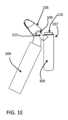
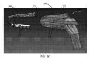
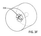
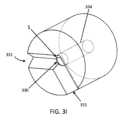
口腔ケアのためのシステムの一変形例は、ユーザの口腔に従って定寸および成形される、上側部分ならびに下側部分と、ユーザの歯の間の歯間空間に向かって指向される、複数の流体ノズルと、上側部分と下側部分との間に位置し、ユーザの口腔の前または顔側領域にユーザの口内で循環する流体を導くように構成される、流出導管とを有する、口腔挿入物(またはマウスピース)を備えてもよい。口腔挿入物はまた、流体ノズルと流体連通する、1つまたはそれを上回る流体マニホールドを備えてもよく、流体マニホールドは、流体ノズルから口腔挿入物の一方の端部におけるマニホールドコネクまで延在してもよい。マニホールドコネクタは、ハンドルに解放可能に取り付けられるように構成されてもよい。口腔挿入物の上側および下側部分は、それぞれ、ユーザの上および下歯に従って定寸ならびに成形される、トレイ、バンド、および/またはキャリアをそれぞれ有してもよく、いくつかの変形例では、剛性材料から作製されてもよい。例えば、上側および下側部分は、ユーザの下顎および/または上顎弓の曲率に近似し得るように曲線状であり得る、歯受容トレイを備えてもよい。口腔挿入物は、システムポンプによって供給される流体の上昇した圧力レベルに耐えることに役立つように剛性材料から作製されてもよい。One variation of a system for oral care may include an oral insert (or mouthpiece) having upper and lower portions sized and shaped according to the oral cavity of a user, a plurality of fluid nozzles directed toward the interdental spaces between the teeth of the user, and an outlet conduit located between the upper and lower portions and configured to direct fluid circulating in the user's mouth to the front or facial region of the oral cavity of the user. The oral insert may also include one or more fluid manifolds in fluid communication with the fluid nozzles, which may extend from the fluid nozzles to a manifold connector at one end of the oral insert. The manifold connector may be configured to be releasably attached to the handle. The upper and lower portions of the oral insert may each have a tray, band, and/or carrier sized and shaped according to the upper and lower teeth of the user, respectively, and in some variations may be made of a rigid material. For example, the upper and lower portions may include a tooth-receiving tray, which may be curved to approximate the curvature of the user's mandible and/or maxillary arch. The oral insert may be made from a rigid material to help withstand the elevated pressure levels of the fluid delivered by the system pump.
いくつかの変形例では、口腔挿入物は、剛性材料から作製されてもよく、ユーザの歯にわたってカスタマイズされた流体流動を提供するように位置付けられる開口部を伴う複数の流体ノズルの配列を備えてもよい。いくつかの変形例では、流体ノズルは、上側および下側部分の外面(すなわち、歯に面する、および/または歯肉に面する表面)に沿った陥凹(例えば、くぼみ、空洞、凹状輪郭等)内に位置してもよい。流体ノズル開口部は、陥凹の最内部分に位置してもよく、陥凹は、流体ノズル開口部からの流体噴射のスプレーに近似する形状を有してもよい。例えば、陥凹は、フレア状であり得、および/またはテーパ状形状を有してもよく、流体ノズル開口部は、陥凹の最も狭い部分に位置する。口腔挿入物上の流体ノズルの場所は、ユーザの歯の歯科走査に基づいて判定されてもよく、したがって、各口腔挿入物は、ユーザの口腔幾何学形状に適応するようにカスタマイズされる。例えば、口腔挿入物の流体ノズルは、歯の間の歯間空間と対応する、上側および下側部分の領域上に位置してもよい。代替として、または加えて、流体ノズルは、歯間空間からある距離に位置してもよいが、流体噴射が歯間空間に印加され得るように、歯間空間に向かって角度を付けられてもよい。複数の流体ノズルの開口部からの流体噴射は、同時に複数の歯を清掃し得、ユーザの口の具体的かつ一意の構造に対する流体ノズルの場所および幾何学形状は、歯表面の迅速および/または効果的な清掃を促進することに役立ち得る。いくつかの変形例では、口腔挿入物は、ノズルのそれぞれの開口部が具体的な歯の特徴または構造を標的化するように位置付けられる、複数の流体ノズルのカスタム配列、ならびに任意の口腔および/または歯科用デバイスもしくはインプラント、例えば、恒久的および除去可能な歯科修復物/補綴、歯列矯正器具等(例えば、クラウン、ブリッジ、インプラント、ブレース、保定装置、義歯、および同等物)を備えてもよい。In some variations, the oral insert may be made of a rigid material and may include an array of multiple fluid nozzles with openings positioned to provide customized fluid flow across the user's teeth. In some variations, the fluid nozzles may be located within recesses (e.g., depressions, cavities, concave contours, etc.) along the outer surfaces (i.e., tooth-facing and/or gum-facing surfaces) of the upper and lower portions. The fluid nozzle openings may be located in the innermost portions of the recesses, and the recesses may have a shape that approximates a spray of fluid jets from the fluid nozzle openings. For example, the recesses may be flared and/or have a tapered shape, and the fluid nozzle openings are located in the narrowest portions of the recesses. The location of the fluid nozzles on the oral inserts may be determined based on a dental scan of the user's teeth, such that each oral insert is customized to accommodate the user's oral geometry. For example, the fluid nozzles of the oral inserts may be located on areas of the upper and lower portions that correspond with the interdental spaces between the teeth. Alternatively or in addition, the fluid nozzle may be located at a distance from the interdental space, but angled toward the interdental space so that the fluid jet may be applied to the interdental space. Fluid jets from multiple fluid nozzle openings may clean multiple teeth simultaneously, and the location and geometry of the fluid nozzle relative to the specific and unique structure of the user's mouth may help promote rapid and/or effective cleaning of tooth surfaces. In some variations, the oral insert may comprise a custom arrangement of multiple fluid nozzles, with each nozzle opening positioned to target a specific tooth feature or structure, as well as any oral and/or dental devices or implants, such as permanent and removable dental restorations/prosthetics, orthodontic appliances, etc. (e.g., crowns, bridges, implants, braces, retainers, dentures, and the like).
1つまたはそれを上回る流出導管は、ユーザの口腔(例えば、後および/または舌側領域)内で循環する加圧流体を口腔の前および/または顔側領域に向かって導き、ユーザの口から退出させるように構成されてもよい。いくつかの変形例では、流出導管は、口腔挿入物の後部分から口腔挿入物の前部分まで延在する、中心チャネルまたはポートを備えてもよい。随意に、中心チャネルと接続し、口腔の左および右側から中心チャネルまでの流体流動を促進することに役立つ、1つまたはそれを上回る側面流体空洞が存在し得る。流出導管の寸法は、口腔挿入物の全体的寸法がユーザの口内に快適に嵌合する一方、ユーザの口から加圧流体の急速な放出も提供するように、選択されてもよい。流出導管の境界を画定する口腔挿入物の表面の輪郭は、ユーザの口腔内から口の開口部に向かって効率的な流体の動的流動を助長するように平滑化および/または平縁化されてもよい。The one or more outflow conduits may be configured to direct pressurized fluid circulating within the user's oral cavity (e.g., posterior and/or lingual regions) toward the anterior and/or facial regions of the oral cavity and out of the user's mouth. In some variations, the outflow conduit may comprise a central channel or port extending from the posterior portion of the oral insert to the anterior portion of the oral insert. Optionally, there may be one or more side fluid cavities connecting with the central channel and helping to facilitate fluid flow from the left and right sides of the oral cavity to the central channel. The dimensions of the outflow conduit may be selected such that the overall dimensions of the oral insert fit comfortably within the user's mouth while also providing for rapid release of pressurized fluid from the user's mouth. The contours of the surfaces of the oral insert that define the boundaries of the outflow conduit may be smoothed and/or beveled to encourage efficient dynamic flow of fluid from within the user's oral cavity toward the opening of the mouth.
随意に、エラストマ基板が、本明細書に説明される口腔挿入物またはマウスピースのうちのいずれかとともに含まれてもよい。口腔挿入物(剛性基板を備え得る)およびエラストマ基板の組み合わせは、ハイブリッド口腔挿入物と称され得る。口腔ケアのためのシステムのいくつかの変形例は、ハイブリッド口腔挿入物を構成してもよい。ハイブリッド口腔挿入物は、複数の陥凹付き流体ノズルと、1つまたはそれを上回る流体マニホールドと、マニホールドコネクタと、1つまたはそれを上回る流出導管とを有する、剛性基板(例えば、本明細書に説明される口腔挿入物のうちのいずれかと類似する)と、剛性基板に取り付けられるエラストマ基板とを備える。ハイブリッド口腔挿入物は、エラストマ基板が剛性基板に取り付けられるときに複数の流体ノズルと整合する、複数の開口を有する、エラストマ基板を備えてもよい。エラストマ基板は、テクスチャ加工表面(上記および本明細書に説明されるような)を有してもよい、またはテクスチャ加工表面を有していなくてもよい。一変形例では、エラストマ基板は、歯の頬側および/または舌側ならびに/もしくは咬合および/または切縁もしくは表面、ならびに/もしくは近心および/または遠位表面と対応する、エラストマ基板の領域におけるテクスチャ加工表面ならびに/もしくは突出構造を備えてもよい。エラストマ基板上の随意のテクスチャ加工表面および/または突出部は、(例えば、共振的または非共振的に)振動ならびに/もしくは揺動するように構成されてもよい。いくつかの変形例では、口腔挿入物は、ハンドルに結合されてもよく、ハンドルは、エラストマ基板の任意の機械的運動(例えば、振動、揺動、平行移動、発振等)を引き起こす振動機構と、振動機構に給電する随意のバッテリとを備えてもよい。振動機構の一実施例は、電磁石と、エラストマ基板に機械的に結合される磁気質量とを備えてもよい。電磁石の極性を変化させることは、磁気質量を移動または振動させ、それによって、エラストマ基板において揺動もしくは振動を引き起こし得る。代替として、または加えて、振動機構は、偏心回転質量(ERM)モータおよび/または線形共振アクチュエータ(LRA)を備えてもよい。代替として、または加えて、振動機構は、各モータの運動の間の位置位相関係が、制御可能な指向性振動を生成するように制御される、二重逆回転ERMを備えてもよい。代替として、または加えて、振動アクチュエータは、電気的に、手動で、および/または(例えば、油圧によって、空気圧によって)システムを通した流体(例えば、水、空気等)の流動によって、駆動されてもよい。Optionally, an elastomeric substrate may be included with any of the oral inserts or mouthpieces described herein. The combination of an oral insert (which may include a rigid substrate) and an elastomeric substrate may be referred to as a hybrid oral insert. Some variations of systems for oral care may constitute a hybrid oral insert. A hybrid oral insert comprises a rigid substrate (e.g., similar to any of the oral inserts described herein) having a plurality of recessed fluid nozzles, one or more fluid manifolds, a manifold connector, and one or more outflow conduits, and an elastomeric substrate attached to the rigid substrate. A hybrid oral insert may comprise an elastomeric substrate having a plurality of openings that align with the plurality of fluid nozzles when the elastomeric substrate is attached to the rigid substrate. The elastomeric substrate may have a textured surface (as described above and herein) or may not have a textured surface. In one variation, the elastomeric substrate may comprise a textured surface and/or protruding structure in areas of the elastomeric substrate corresponding to the buccal and/or lingual and/or occlusal and/or incisal edges or surfaces and/or mesial and/or distal surfaces of the teeth. The optional textured surface and/or protrusions on the elastomeric substrate may be configured to vibrate and/or oscillate (e.g., resonantly or non-resonantly). In some variations, the oral insert may be coupled to a handle, which may comprise a vibration mechanism that induces any mechanical motion (e.g., vibration, rocking, translation, oscillation, etc.) of the elastomeric substrate and an optional battery that powers the vibration mechanism. One example of a vibration mechanism may comprise an electromagnet and a magnetic mass mechanically coupled to the elastomeric substrate. Changing the polarity of the electromagnet may move or vibrate the magnetic mass, thereby inducing rocking or vibration in the elastomeric substrate. Alternatively or additionally, the vibration mechanism may comprise an eccentric rotating mass (ERM) motor and/or a linear resonant actuator (LRA). Alternatively or additionally, the vibration mechanism may comprise dual counter-rotating ERMs where the position phase relationship between the motion of each motor is controlled to generate controllable directional vibration. Alternatively or additionally, the vibration actuators may be driven electrically, manually, and/or by the flow of fluid (e.g., water, air, etc.) through the system (e.g., hydraulically, pneumatically).
いくつかの変形例では、エラストマ基板は、本明細書に説明される振動機構のうちのいずれかに機械的に結合されてもよい一方、他の変形例では、エラストマ基板は、振動するように構成されなくてもよい。例えば、ハイブリッド口腔挿入物の一変形例は、テクスチャ加工表面を有し、振動するように構成される、エラストマ基板を備えてもよい一方、別の変形例では、ハイブリッド口腔挿入物は、テクスチャ加工表面を有しておらず、振動するように構成されない、エラストマ基板を備えてもよい。これらの変形例では、ハイブリッド口腔挿入物は、流体ノズルを備える、剛性基板を備えてもよい、または代替として、いずれの流体ノズルも伴わない剛性基板を備えてもよい。口腔システムは、本明細書に説明されるような剛性基板を有するが、エラストマ基板を伴わない口腔挿入物を備えてもよい。In some variations, the elastomeric substrate may be mechanically coupled to any of the vibration mechanisms described herein, while in other variations, the elastomeric substrate may not be configured to vibrate. For example, one variation of a hybrid oral insert may include an elastomeric substrate having a textured surface and configured to vibrate, while in another variation, the hybrid oral insert may include an elastomeric substrate not having a textured surface and not configured to vibrate. In these variations, the hybrid oral insert may include a rigid substrate with a fluid nozzle, or alternatively, may include a rigid substrate without any fluid nozzles. The oral system may include an oral insert having a rigid substrate as described herein, but without an elastomeric substrate.
個人化された口腔ケアシステムはまた、流体リザーバと口腔挿入物との間の流体流動を調整する、1つまたはそれを上回る弁、ポンプ、および/またはマニホールドを備えてもよい。例えば、口腔ケアシステムはまた、流体ノズルを通した流体流動(例えば、流体ノズルの開口部を通して出現する流体噴射)を制御する、および/または協調させる、コントローラを備える、ベースステーションを備えてもよい。ベースシステム制御は、随意に、ハイブリッド口腔挿入物のエラストマまたは形状適合基板の振動を制御してもよい。ベースステーションはまた、流体リザーバと連通する流体ポンプと、ハンドルドックとを備えてもよい。ハンドルは、流体ポンプと流体連通する流体レギュレータを備えてもよく、流体レギュレータは、加圧流体を口腔挿入物内の流体マニホールドに送達および/または分配するように構成されてもよい。例えば、流体レギュレータは、モータと、ひいては、流体をノズルに供給する、口腔挿入物の1つまたはそれを上回る流体マニホールドに流体を分配する、回転子とを有する、流体切替装置アセンブリを備えてもよい。口腔挿入物は、マニホールドコネクタが流体切替装置アセンブリと流体接続するように、ハンドルに解放可能に取り付けられるように構成される、マニホールドコネクタを備えてもよい。ハンドルは、口腔挿入物のマニホールドコネクタとの水密係合を提供するように構成される、1つまたはそれを上回るシールを有する、取付機構を備えてもよい。いくつかの変形例では、ハンドル流体切替装置アセンブリは、マニホールドコネクタ内のマニホールド開口部と整合されるように構成される、複数の流体チャネルを有する、マニホールドブロックを備えてもよい。随意に、ベースステーションは、流体リザーバドックを備えてもよい。いくつかの変形例では、ハンドルドックはまた、振動機構をアクティブ化するために使用され得る、エネルギーを随意のハンドルバッテリ内に貯蔵する、(例えば、誘導充電による)ハンドル充電ドックであってもよい。代替として、または加えて、振動機構への電力は、ベースステーション上の電源とハンドル内に位置する1つもしくは複数の振動アクチュエータとの間の電気接続(例えば、ワイヤ)によって提供されてもよい。代替として、または加えて、エラストマおよび/または剛性挿入物の機械的運動が、手動で作動されてもよい。The personalized oral care system may also include one or more valves, pumps, and/or manifolds that regulate the fluid flow between the fluid reservoir and the oral insert. For example, the oral care system may also include a base station that includes a controller that controls and/or coordinates the fluid flow through the fluid nozzle (e.g., the fluid jet emerging through the opening of the fluid nozzle). The base system control may optionally control the vibration of the elastomeric or conformable substrate of the hybrid oral insert. The base station may also include a fluid pump in communication with the fluid reservoir and a handle dock. The handle may include a fluid regulator in fluid communication with the fluid pump, which may be configured to deliver and/or distribute pressurized fluid to a fluid manifold in the oral insert. For example, the fluid regulator may include a fluid switcher assembly having a motor and a rotor that, in turn, supplies fluid to the nozzle and distributes fluid to one or more fluid manifolds of the oral insert. The oral insert may include a manifold connector configured to be releasably attached to the handle such that the manifold connector fluidly connects with the fluid switch assembly. The handle may include an attachment mechanism having one or more seals configured to provide a watertight engagement with the manifold connector of the oral insert. In some variations, the handle fluid switch assembly may include a manifold block having a plurality of fluid channels configured to be aligned with manifold openings in the manifold connector. Optionally, the base station may include a fluid reservoir dock. In some variations, the handle dock may also be a handle charging dock (e.g., by inductive charging) that stores energy in an optional handle battery that may be used to activate the vibration mechanism. Alternatively or in addition, power to the vibration mechanism may be provided by an electrical connection (e.g., wires) between a power source on the base station and one or more vibration actuators located in the handle. Alternatively or in addition, mechanical movement of the elastomeric and/or rigid insert may be manually actuated.
個人化された口腔ケアシステムは、歯を清掃すること、および/または歯もしくは修復物の上または間に、もしくは歯科器具の周囲に、または歯肉溝内に形成され得る、生物膜を妨害することとの関連で説明されるが、本明細書に説明されるシステムはまた、口腔への薬剤または予防薬の適用、歯のホワイトニング、口腔消毒、消毒液、洗浄液等のために使用され得ることを理解されたい。流体リザーバ内の流体は、消毒液、抗生物質流体、洗浄液、界面活性剤、pH平衡、抗菌もしくは抗真菌薬剤、フッ化物添加流体、水、生理食塩水、および/または口臭を緩和する化合物のうちの1つまたはそれを上回るものを含有してもよい。Although the personalized oral care system is described in the context of cleaning teeth and/or disrupting biofilms that may form on or between teeth or restorations, around dental appliances, or within the gingival sulcus, it should be understood that the system described herein may also be used for application of medications or prophylactics to the oral cavity, tooth whitening, oral disinfection, disinfectants, irrigation fluids, and the like. The fluid in the fluid reservoir may contain one or more of a disinfectant fluid, an antibiotic fluid, a irrigation fluid, a surfactant, a pH balance, an antibacterial or antifungal agent, a fluoridated fluid, water, saline, and/or a compound that reduces breath odor.
個人化された口腔ケアシステムは、口腔挿入物の流体出力ポート(例えば、流体流出導管またはポート)に取り付けられるように構成される、収集チャンバを備えてもよい。流体流出ポートに取り付けられたとき、ユーザの口腔内で循環された流体(例えば、微生物叢収集流体)の一部またはサンプルが、収集チャンバによって捕捉されてもよい。収集チャンバ内の微生物叢収集流体サンプルは、ユーザの口腔微生物叢の内容を判定するように分析されてもよい。微生物叢収集流体は、生理食塩水から成ってもよい。収集チャンバは、口腔微生物叢の含有物を保存する(例えば、その劣化を防止する、または低減させる)ことに役立ち得る、流体サンプル安定化化合物を含有してもよい。随意に、流体サンプル安定化化合物は、口腔微生物叢の含有物と反応し、検査/分析の間にそれらの含有物の検出を促進し得る。例えば、微生物叢収集化合物は、微生物叢のある内容と特異的に反応し得る結合部位を有する、1つまたはそれを上回る検出マーカから成ってもよく、検出マーカの陽性識別は、微生物叢のある成分の存在を示すであろう。検出マーカは、蛍光タグ等の光学マーカから成ってもよい。いくつかの変形例では、サンプル安定化化合物は、液体懸濁液および/または保存液から成ってもよい。収集コンテナは、任意の好適な機械的係合、例えば、ねじ嵌合、スナップ嵌合、摩擦嵌合、および/または磁気係合を使用して、口腔挿入物に取り付けられてもよい。随意に、収集チャンバは、流出ポートを介してユーザの口腔から退出する流体を受容する、流体入口ポートを備えてもよく、流体入口ポートは、チャンバから外への流体流動を防止しながら、チャンバの中への流体流動を許容するように構成される、一方向弁を備えてもよい。収集チャンバは、開口部と、収集流体サンプルが入手された後に、(流体入口ポートと別個であり得る)開口部にわたって配置されるように構成される、液密カバーを備えてもよい。The personalized oral care system may include a collection chamber configured to be attached to a fluid output port (e.g., a fluid outflow conduit or port) of the oral insert. When attached to the fluid outflow port, a portion or sample of the fluid (e.g., microbiota collection fluid) circulated in the user's oral cavity may be captured by the collection chamber. The microbiota collection fluid sample in the collection chamber may be analyzed to determine the contents of the user's oral microbiota. The microbiota collection fluid may be comprised of saline. The collection chamber may contain a fluid sample stabilizing compound that may help preserve (e.g., prevent or reduce deterioration of) the contents of the oral microbiota. Optionally, the fluid sample stabilizing compound may react with the contents of the oral microbiota and facilitate detection of those contents during testing/analysis. For example, the microbiota collection compound may be comprised of one or more detection markers having binding sites that may specifically react with certain contents of the microbiota, and positive identification of the detection markers would indicate the presence of certain components of the microbiota. The detection marker may be comprised of an optical marker, such as a fluorescent tag. In some variations, the sample stabilizing compound may comprise a liquid suspension and/or a preservative solution. The collection container may be attached to the oral insert using any suitable mechanical engagement, such as a threaded fit, a snap fit, a friction fit, and/or a magnetic engagement. Optionally, the collection chamber may include a fluid inlet port that receives fluid exiting the user's oral cavity via the outlet port, and the fluid inlet port may include a one-way valve configured to allow fluid flow into the chamber while preventing fluid flow out of the chamber. The collection chamber may include an opening and a liquid-tight cover configured to be placed over the opening (which may be separate from the fluid inlet port) after the collection fluid sample has been obtained.
微生物叢収集流体は、本明細書に説明されるデバイスおよび方法のうちのいずれかを使用して、上昇した流体圧力において口腔挿入物の流体開口部またはノズルを介してユーザの口腔に送達されてもよい。例えば、流体リザーバのポンプ機構は、約40psiまたはそれを上回る、約40psi~約200psi等の圧力において流体を口腔挿入物に提供してもよい。各流体ノズルから退出し、歯表面または構造に衝突する、流体圧力は、約10psi~約150psiであってもよい。いくつかの変形例では、微生物叢収集流体は、個人化された口腔ケアシステムの流体リザーバ内に位置し、口腔挿入物への送達のために加圧されてもよい。上昇した流体圧力(すなわち、口腔洗浄または含漱を超える任意の圧力)において微生物叢収集流体を導入すること、および/またはユーザの口腔の具体的領域において収集流体を指向することは、それらの領域内で口腔微生物叢の収集を促進し得る。例えば、上昇した圧力において収集流体を歯および/または歯肉縁下領域の間の歯間空間に指向する流体ノズルを伴う口腔挿入物が、それらの空間からの口腔洗浄(例えば、ユーザがその口の中で収集流体を含漱すること)よりも効率的な微生物叢サンプルの収集を促進し得る。口腔挿入物ノズルからの流体噴射は、到達することが困難な面積(例えば、歯間空間、歯肉縁下領域、隙間、凹面等の口腔洗浄または含漱によって典型的にはアクセス不可能である面積)内で生物膜を妨害および/または除去し得、これは、それらの面積内の微生物叢内容が収集および分析されることを可能にし得る。例えば、上昇した圧力(例えば、約40psiまたはそれを上回る)における流体噴射が、到達することが困難な面内に位置し得る細菌を遊離させ、収集流体を用いて、流出ポートに向かって収集チャンバの中に細菌を掃引し得る。これは、口腔洗浄または含漱と比較して、ユーザの口腔微生物叢のより正確および/または包括的な測定を提供し得る。ユーザの口腔微生物叢のサンプルが、細菌含有物、および/または真菌含有物、ならびに/もしくはウイルス含有物、および/またはタンパク質含有物(DNAもしくはRNA等の核酸を含む)、pHレベルに関して、分析されてもよく、そのようなデータは、ユーザの口腔の健康のメトリックを計算するために使用されてもよい。口腔の健康メトリックの一実施例は、ユーザの歯茎の炎症状態/レベルを表す、歯茎健康スコアを含んでもよい。プロセッサによる収集された微生物叢サンプルの分析は、口腔内の細菌種のタイプおよび/または数量、共生対病原性細菌の比、高リスクならびに/もしくは低リスク病原体が存在するかどうか、情報目的のための病原体タイプと全身性疾患との間の相関等を出力してもよい。The microbiota collection fluid may be delivered to the user's oral cavity through the fluid openings or nozzles of the oral insert at elevated fluid pressure using any of the devices and methods described herein. For example, a pump mechanism of the fluid reservoir may provide fluid to the oral insert at a pressure of about 40 psi or greater, such as from about 40 psi to about 200 psi. The fluid pressure exiting each fluid nozzle and impacting the tooth surface or structure may be from about 10 psi to about 150 psi. In some variations, the microbiota collection fluid may be located in a fluid reservoir of the personalized oral care system and pressurized for delivery to the oral insert. Introducing the microbiota collection fluid at elevated fluid pressure (i.e., any pressure in excess of oral irrigation or gargling) and/or directing the collection fluid at specific regions of the user's oral cavity may facilitate collection of oral microbiota in those regions. For example, an oral insert with a fluid nozzle that directs collection fluid at elevated pressure into interdental spaces between teeth and/or subgingival regions may facilitate collection of microbiota samples from those spaces more efficiently than oral rinsing (e.g., a user rinsing their mouth with collection fluid). The fluid jet from the oral insert nozzle may disturb and/or remove biofilms in areas that are difficult to reach (e.g., areas that are typically inaccessible by oral rinsing or rinsing, such as interdental spaces, subgingival regions, crevices, concave surfaces, etc.), which may allow the microbiota content in those areas to be collected and analyzed. For example, a fluid jet at elevated pressure (e.g., about 40 psi or greater) may liberate bacteria that may be located in surfaces that are difficult to reach and sweep the bacteria into a collection chamber toward an outlet port with the collection fluid. This may provide a more accurate and/or comprehensive measurement of a user's oral microbiota compared to oral rinsing or rinsing. A sample of the user's oral microbiome may be analyzed for bacterial content, and/or fungal content, and/or viral content, and/or protein content (including nucleic acids such as DNA or RNA), pH level, and such data may be used to calculate metrics of the user's oral health. One example of an oral health metric may include a gum health score, which represents the inflammation status/level of the user's gums. Analysis of the collected microbiome samples by the processor may output the type and/or quantity of bacterial species in the oral cavity, the ratio of commensal to pathogenic bacteria, whether high-risk and/or low-risk pathogens are present, correlations between pathogen types and systemic diseases for informational purposes, etc.
個人化された口腔ケアシステムは、口腔清掃モードと、サンプル収集モードとを有してもよい。口腔清掃モードでは、本システムは、リザーバから口腔挿入物に、かつユーザの口腔の中に加圧流体(例えば、水、消毒剤、または本明細書に説明される流体のうちのいずれか)の連続流動を提供するように構成されてもよい。サンプル収集モードでは、本システムは、リザーバから口腔挿入物に加圧微生物叢収集流体のバーストを提供するように構成されてもよい。バースト持続時間は、約1秒~約20秒、例えば、約1秒~約10秒、約5秒~約15秒等にわたって持続してもよい。モードは、ベースステーション上のモードボタンを押すこと(またはダイヤルもしくはスイッチを回すことによって)所望のモードに設定されてもよく、これは、次いで、リザーバと口腔挿入物との間の流体流動を調整する、1つまたはそれを上回る弁および/またはポンプの動作を調節してもよい。随意に、口腔ケアシステムは、微生物叢収集プライミングモードを有してもよく、微生物叢収集流体は、口腔微生物叢サンプルの収集の前に、(例えば、口腔挿入物をユーザの口の中に設置する前に)口腔挿入物を通して圧送される。プライミングモードの間に口腔挿入物を通して圧送される微生物叢収集流体は、廃棄されてもよく、口腔微生物叢サンプルを汚染もしくは希釈し得る、任意の残留流体および/または生物学的物質を一掃することに役立ち得る。プライミングモードでは、加圧流体は、加圧流体がサンプル収集モードで口腔挿入物の中に圧送される持続時間と同一である、またはそれと異なり得る、持続時間にわたって口腔挿入物の中に圧送されてもよく、持続時間は、ユーザによって事前プログラムまたは選択されてもよい。例えば、加圧流体は、プライミングモードの間に約1秒~約60秒、口腔挿入物の中に圧送されてもよい。プライミングが完了した後、収集チャンバは、微生物叢サンプル収集に備えて口腔挿入物の流出ポートに取り付けられてもよい。The personalized oral care system may have an oral cleaning mode and a sample collection mode. In the oral cleaning mode, the system may be configured to provide a continuous flow of pressurized fluid (e.g., water, disinfectant, or any of the fluids described herein) from the reservoir to the oral insert and into the user's oral cavity. In the sample collection mode, the system may be configured to provide a burst of pressurized microbiota collection fluid from the reservoir to the oral insert. The burst duration may last for about 1 second to about 20 seconds, e.g., about 1 second to about 10 seconds, about 5 seconds to about 15 seconds, etc. The mode may be set to the desired mode by pressing a mode button (or turning a dial or switch) on the base station, which may then regulate the operation of one or more valves and/or pumps that regulate the fluid flow between the reservoir and the oral insert. Optionally, the oral care system may have a microbiota collection priming mode, in which a microbiota collection fluid is pumped through the oral insert prior to collection of an oral microbiota sample (e.g., prior to placing the oral insert in the user's mouth). The microbiota collection fluid pumped through the oral insert during the priming mode may be discarded and may serve to clear out any residual fluid and/or biological material that may contaminate or dilute the oral microbiota sample. In the priming mode, pressurized fluid may be pumped into the oral insert for a duration that may be the same as or different from the duration that pressurized fluid is pumped into the oral insert in the sample collection mode, and the duration may be pre-programmed or selected by the user. For example, pressurized fluid may be pumped into the oral insert for about 1 second to about 60 seconds during the priming mode. After priming is complete, a collection chamber may be attached to the outlet port of the oral insert in preparation for microbiota sample collection.
また、本明細書に開示されるものは、ユーザの口腔幾何学形状に関連する画像データの入手および上歯と下歯との間の整合(例えば、相互に対する上弓および下弓の位置)に関連するデータの入手の間にユーザの歯を位置付けるために使用され得る、歯科用シムデバイスである。口腔幾何学形状および整合データは、口腔挿入物がユーザの口腔内に設置されるときに(すなわち、ユーザが口腔挿入物にわたって下方に閉咬するときに)ある程度のユーザ快適性を提供しながら、清掃効率を促進するように具体的な歯の構造に位置付けられる流体ノズルを有する、カスタマイズされた口腔挿入物(例えば、剛性基板およびエラストマ基板を伴うハイブリッド口腔挿入物、または剛性基板のみを伴う口腔挿入物)を発生させるために、プロセッサによって使用されてもよい。いくつかの変形例では、プロセッサは、入手された口腔幾何学形状および整合データを使用して、ユーザの口腔のモデルを発生させ、ユーザの口腔のモデルに基づいて、所望の場所に位置付けられる流体ノズルを有する、口腔挿入物を発生させてもよい。歯および/または歯肉縁ならびに/もしくは歯肉の間の歯間空間、頬側小窩、裂溝、および同等物の間の場所を識別する画像データが、それらの歯の構造と対応する場所において流体ノズルを伴う口腔挿入物を発生させるために、プロセッサによって使用されてもよい。歯科用シムデバイスは、選択された位置で上および下歯を位置付け、維持する、上面と、下面とをそれぞれ有する、第1および第2の整合部分と、第1の整合部分と第2の整合部分との間に跨架する長さを有する、ブリッジ部分と、第1および第2の整合部分ならびにブリッジ部分の顔側表面上の1つまたはそれを上回る配向位置合わせマーカとを備えてもよい。配向位置合わせマーカは、非対称配列を有してもよく、および/または1つまたはそれを上回る配向位置合わせマーカに対する個々の上および下歯の位置が一意であるように、成形され、位置付けられてもよい。1つまたはそれを上回る配向位置合わせマーカへの上および下歯の相対位置の位置合わせは、上弓と下弓との間の整合を判定するように、プロセッサによって使用されてもよい。いくつかの変形例では、配向位置合わせマーカは、第1および第2の整合部分ならびにブリッジ部分の顔側表面から延在する、1つまたはそれを上回る3D構造、および/または第1ならびに第2の整合部分およびブリッジ部分の顔側表面上に位置する、1つまたはそれを上回る視覚的印を備えてもよい。視覚的印の実施例は、斜交平行パターン、および/または相互に対して既知の場所において半円ならびに/もしくはブロックおよび/または切り欠きならびに/もしくは垂直溝または突出部として成形される、隆起ならびに/もしくは陥没領域を含んでもよい。Also disclosed herein is a dental shim device that may be used to position a user's teeth during acquisition of image data related to the user's oral geometry and acquisition of data related to alignment between upper and lower teeth (e.g., the position of the upper and lower arches relative to one another). The oral geometry and alignment data may be used by a processor to generate a customized oral insert (e.g., a hybrid oral insert with a rigid and elastomeric substrate, or an oral insert with only a rigid substrate) having fluid nozzles positioned at specific tooth structures to promote cleaning efficiency while providing a degree of user comfort when the oral insert is placed in the user's oral cavity (i.e., when the user closes their jaws downwards over the oral insert). In some variations, the processor may use the acquired oral geometry and alignment data to generate a model of the user's oral cavity and generate an oral insert having fluid nozzles positioned at desired locations based on the model of the user's oral cavity. Image data identifying locations between teeth and/or gingival margins and/or interdental spaces, buccal pits, fissures, and the like between the teeth may be used by the processor to generate an oral cavity insert with a fluid nozzle at a location corresponding to those tooth structures. The dental shim device may comprise first and second matching portions having upper and lower surfaces, respectively, for positioning and maintaining the upper and lower teeth at selected positions, a bridge portion having a length spanning between the first and second matching portions, and one or more orientation registration markers on the facial surfaces of the first and second matching portions and the bridge portion. The orientation registration markers may have an asymmetric arrangement and/or may be shaped and positioned such that the position of each individual upper and lower tooth relative to the one or more orientation registration markers is unique. The registration of the relative positions of the upper and lower teeth to the one or more orientation registration markers may be used by the processor to determine the alignment between the upper and lower arches. In some variations, the orientation alignment marker may comprise one or more 3D structures extending from the facial surfaces of the first and second matching portions and the bridge portion, and/or one or more visual indicia located on the facial surfaces of the first and second matching portions and the bridge portion. Examples of visual indicia may include cross-hatched patterns, and/or raised and/or depressed areas shaped as semicircles and/or blocks and/or notches and/or vertical grooves or protrusions at known locations relative to one another.
第1および第2の整合部分の上面ならびに下面は、ユーザの口腔の中に挿入されたときに、上および下歯の切縁および/または咬合表面に接触してもよい。第1および第2の整合部分はそれぞれ、上歯と下歯との間に固定垂直オフセットを留保するように定寸される、側壁を備えてもよい。上面および下面は、上および下歯の輪郭に形状適合するように構成される、柔軟材料から成ってもよい。いくつかの変形例では、柔軟材料は、ゴム様材料、歯科用ワックス、歯科用印象材料、歯肉障壁材料、および発泡体のうちの1つまたはそれを上回るものから成ってもよい。ブリッジ部分の長さは、歯列弓の曲線(例えば、上弓または下弓のいずれか、上および下弓の平均曲率、上および下弓の複合曲率等)に近似する曲線を有してもよく、可撓性材料から成ってもよい。随意に、歯科用シムデバイスは、第1および第2の整合部分に接触するように、かつ着用者の口腔の外側の解剖学的構造、例えば、着用者の顎、額、および/または頬と係合するように構成される、安定化構造を備えてもよい。随意に、シムは、ユーザの口腔の中へのシムの挿入を促進するように、ブリッジ部分および/または整合部分の一方もしくは両方に結合され得る、1つまたはそれを上回るハンドルもしくは設置タブを備えてもよい。The upper and lower surfaces of the first and second matching portions may contact the incisal and/or occlusal surfaces of the upper and lower teeth when inserted into the user's oral cavity. The first and second matching portions may each include a sidewall that is sized to retain a fixed vertical offset between the upper and lower teeth. The upper and lower surfaces may be made of a flexible material configured to conform to the contours of the upper and lower teeth. In some variations, the flexible material may be made of one or more of a rubber-like material, dental wax, dental impression material, gingival barrier material, and foam. The length of the bridge portion may have a curve that approximates the curve of the dental arch (e.g., either the upper or lower arch, the average curvature of the upper and lower arches, the combined curvature of the upper and lower arches, etc.) and may be made of a flexible material. Optionally, the dental shim device may include a stabilizing structure configured to contact the first and second matching portions and to engage an anatomical structure outside the wearer's oral cavity, such as the wearer's chin, forehead, and/or cheeks. Optionally, the shim may include one or more handles or placement tabs that may be coupled to one or both of the bridge portion and/or matching portion to facilitate insertion of the shim into the user's oral cavity.
口腔幾何学形状および/または整合画像データの入手の間にユーザの歯を位置付けるために使用され得る、歯科用シムデバイスの別の変形例は、上歯列弓の上歯に接触する表面と、上側ハンドルと有する、上側トレイと、 下歯列弓の下歯に接触する表面と、下側ハンドルとを有する、下側トレイとを備えてもよく、上側および下側ハンドルは、ユーザがシムデバイスを容易に把持し、シムデバイスを挿入し、位置付け、除去することを可能にするように構成されてもよい。一変形例では、上側トレイおよび下側トレイは、事前判定された垂直オフセットを伴って相互に対して固定されてもよい。代替として、いくつかの変形例は、上側トレイおよび下側トレイに係合する、調節可能噛合継手を備えてもよく、調節可能噛合継手は、上側トレイと下側トレイとの間のオフセットを調節するように構成されてもよい。調節可能噛合継手は、上側トレイ上の凹状溝と、凹状溝の反対側の下側トレイ上のボールとを備えてもよい。ボールは、上側トレイと下側トレイとの間のオフセットおよび角度を調節するように凹状溝内で移動可能であり得る。いくつかの変形例では、凹状溝は、凹状溝内の位置においてボールに係合し、オフセットおよび角度を留保するように構成される、1つまたはそれを上回る曲線(例えば、円錐形もしくはテーパ状曲線)を備えてもよい。上側トレイの歯接触表面は、上歯の輪郭に形状適合するように構成される、柔軟材料から成ってもよく、下側トレイの歯接触表面は、下歯の輪郭に形状適合するように構成される、柔軟材料から成ってもよい。柔軟材料の実施例は、ゴム様材料、歯科用ワックス、歯科用印象材料、歯肉障壁材料、および発泡体のうちの1つまたはそれを上回るものを含んでもよい。シムデバイスのトレイは、ユーザの口腔の中に挿入されてもよく、ユーザは、その顎を閉鎖し、トレイをともに閉咬することを求められ得る。閉咬されたとき、上側および下側ハンドル上のマーカの間の距離が、測定されてもよく、上および下歯は、柔軟材料に印象を残してもよい。トレイがユーザの口から除去された後、外部スキャナが、上側および下側トレイの歯接触表面の画像データを入手するために使用されてもよく、柔軟材料は、上および下歯の印象を含有してもよい。柔軟材料の歯の印象の画像は、上側トレイと下側トレイとの間のオフセットおよび角度、ならびに上側ハンドルと下側ハンドルとの間の測定された距離とともに、その歯、歯肉縁の輪郭、および上ならびに下弓の歯の間の整合を含む、ユーザの口腔のモデルを発生させるために使用されてもよい。キットが、ユーザの口腔内の異なる領域の歯の印象を入手するための1つまたはそれを上回る歯科用トレイおよび/または歯科用シムを備えてもよい。例えば、キットは、上歯および下歯の完全な印象を入手するために使用され得る、柔軟材料を含有する、1つまたはそれを上回る歯科用トレイのセットと、規定オフセットにおいて上顎および下顎前歯(例えば、前歯および/または小臼歯)の印象を入手するために使用され得る、1つまたはそれを上回る歯科用シムのセットとを備えてもよい。歯科用トレイおよび/または歯科用シム内の印象の複数の走査は、ユーザの口腔のモデルを発生させるように組み合わせられてもよい。プロセッサが、本モデルを使用し、本明細書に説明される口腔ケアシステムのうちのいずれかのためのカスタマイズされた口腔挿入物(例えば、流体ノズルのカスタマイズされた配列を伴う)を発生させてもよい。Another variation of a dental shim device that may be used to position a user's teeth during acquisition of oral geometry and/or alignment image data may include an upper tray having a surface that contacts the upper teeth of the upper dental arch and an upper handle, and a lower tray having a surface that contacts the lower teeth of the lower dental arch and a lower handle, which may be configured to allow a user to easily grasp, insert, position, and remove the shim device. In one variation, the upper and lower trays may be fixed relative to one another with a pre-determined vertical offset. Alternatively, some variations may include an adjustable mating joint that engages the upper and lower trays, which may be configured to adjust the offset between the upper and lower trays. The adjustable mating joint may include a concave groove on the upper tray and a ball on the lower tray opposite the concave groove. The ball may be movable within the recessed groove to adjust the offset and angle between the upper and lower trays. In some variations, the recessed groove may comprise one or more curves (e.g., conical or tapered curves) configured to engage the ball at a position within the recessed groove and retain the offset and angle. The tooth-contacting surface of the upper tray may be comprised of a soft material configured to conform to the contours of the upper teeth, and the tooth-contacting surface of the lower tray may be comprised of a soft material configured to conform to the contours of the lower teeth. Examples of soft materials may include one or more of a rubber-like material, dental wax, dental impression material, gum barrier material, and foam. The tray of the shim device may be inserted into the oral cavity of a user, and the user may be asked to close their jaws and bite the tray together. When biting closed, the distance between the markers on the upper and lower handles may be measured, and the upper and lower teeth may leave an impression in the soft material. After the trays are removed from the user's mouth, an external scanner may be used to obtain image data of the tooth-contacting surfaces of the upper and lower trays, and the flexible material may contain impressions of the upper and lower teeth. The image of the flexible material tooth impressions may be used to generate a model of the user's oral cavity, including its teeth, gingival contours, and alignment between the teeth of the upper and lower arches, along with the offset and angle between the upper and lower trays and the measured distance between the upper and lower handles. The kit may include one or more dental trays and/or dental shims for obtaining impressions of teeth in different areas of the user's oral cavity. For example, the kit may include a set of one or more dental trays containing flexible material that may be used to obtain complete impressions of the upper and lower teeth, and a set of one or more dental shims that may be used to obtain impressions of the upper and lower anterior teeth (e.g., anterior teeth and/or bicuspids) at the prescribed offsets. Multiple scans of impressions in dental trays and/or dental shims may be combined to generate a model of the user's oral cavity. A processor may use this model to generate a customized oral cavity insert (e.g., with a customized arrangement of fluid nozzles) for any of the oral care systems described herein.
いくつかの変形例では、ユーザの口腔幾何学形状および上弓と下弓との間の整合の入手された画像データは、写真データおよび/またはビデオデータであってもよい。画像データは、内部走査方法(例えば、口腔内スキャナを使用する)および/または外部走査方法を使用して入手されてもよい。In some variations, the obtained image data of the user's oral geometry and the alignment between the upper and lower arches may be photographic data and/or video data. The image data may be obtained using internal scanning methods (e.g., using an intraoral scanner) and/or external scanning methods.
図1A-1Cは、本明細書に説明される口腔の領域を図示する、口腔生体構造および歯の構造の概略描写である。図1Aは、下顎骨または下顎の歯(140)のセットの上面図を描写する(但し、類似用語が、上顎骨または上顎の歯および構造を指すために使用されてもよい)。各歯(142)は、舌に接触する(またはそれの最近傍にある)歯の領域である、頬または唇および舌側表面(146)に接触する歯の領域である、顔側表面(144)を有してもよい。顔側表面は、例えば、臼歯の頬側表面および前歯の唇側表面であってもよい。舌側表面はまた、上顎歯のための口蓋側表面とも称され得る。臼歯は、咬合表面(148)を有してもよく、前歯は、切縁または表面(150)を有してもよい。咬合(または切縁)表面は、咀嚼を補助する、および/または対向する歯の咬合(もしくは切縁)表面と向かい合って面する、歯の領域である。弓正中線から外方を向く歯の表面が、遠位表面(152)と称され得る一方、弓正中線(151)に向かって面する歯の表面は、近心表面(154)と称され得る。図1Bは、歯(142)の最長寸法に沿って延在する、および/または歯の咬合表面(148)もしくは切縁(150)と略垂直である、長軸(156)を有し得る、単一の歯(142)の側面図を描写する。歯の表面に沿った、または歯の咬合表面もしくは切縁に最も近い歯茎(例えば、歯肉、歯肉組織)の縁または境界は、歯肉縁(158)と称され得る。歯肉縁(158)は、各歯の底部に沿った1つまたはそれを上回る曲線を有してもよく、歯毎の歯肉縁の曲率半径および長さは、変動し得る。歯肉と歯の表面との間の空間または領域(160)は、歯肉溝(160)と称され得る。歯間歯肉(161)は、2本の隣接する歯の間に位置する歯茎組織であってもよい。図1Cは、複数の歯(142)の側面図を描写する。各歯(142)の間の空間または間隙は、歯間空間または間隙(162)と称され得、1本の歯の近心表面および隣接する歯の遠位表面、または中切歯の場合、2本の歯の近心表面によって画定され得る。ユーザの口腔の左側は、2本の中切歯の間の歯間空間の左側にある(例えば、弓正中線の左側にある)口腔の領域であってもよく、ユーザの口腔の右側は、2本の中切歯の歯間空間の右側にある(例えば、弓正中線の右側にある)口腔の領域であってもよい。本明細書に開示される口腔挿入物の流体ノズルは、ユーザの歯の間の歯間空間に位置付けられる、および/または指向されるものとして説明されるが、流体ノズルのうちのいずれかは、限定ではないが、歯肉縁、歯間歯肉、ならびに/もしくは歯の顔側、咬合、舌側表面を含む、ユーザの口腔の任意の解剖学的領域または構造に向かって位置付けられる、および/または指向され得ることを理解されたい。
システム概観 1A-1C are schematic depictions of oral anatomy and dental structure illustrating the regions of the oral cavity described herein. FIG. 1A depicts a top view of a set of mandibular or lower jaw teeth (140) (although similar terms may be used to refer to maxillary or upper jaw teeth and structures). Each tooth (142) may have a facial surface (144), which is the area of the tooth that contacts the cheek or lips and a lingual surface (146), which is the area of the tooth that contacts (or is closest to) the tongue. A facial surface may be, for example, the buccal surface of a molar tooth and the labial surface of an anterior tooth. A lingual surface may also be referred to as a palatal surface for maxillary teeth. A molar tooth may have an occlusal surface (148) and an anterior tooth may have an incisal edge or surface (150). The occlusal (or incisal) surface is the area of a tooth that aids in chewing and/or faces opposite the occlusal (or incisal) surface of an opposing tooth. The surface of the tooth that faces away from the arch midline (151) may be referred to as the distal surface (152), while the surface of the tooth that faces toward the arch midline (151) may be referred to as the mesial surface (154). Figure IB depicts a side view of a single tooth (142) that may have a long axis (156) that extends along the longest dimension of the tooth (142) and/or is generally perpendicular to the occlusal surface (148) or incisal edge (150) of the tooth. The edge or border of the gum (e.g., gingiva, gingival tissue) along the surface of the tooth or closest to the occlusal surface or incisal edge of the tooth may be referred to as the gingival margin (158). The gingival margin (158) may have one or more curves along the base of each tooth, and the radius of curvature and length of the gingival margin for each tooth may vary. The space or area (160) between the gingiva and the tooth surface may be referred to as the gingival sulcus (160). The interdental gingiva (161) may be the gum tissue located between two adjacent teeth. FIG. 1C depicts a side view of multiple teeth (142). The space or gap between each tooth (142) may be referred to as the interdental space or gap (162) and may be defined by the mesial surface of one tooth and the distal surface of an adjacent tooth, or in the case of central incisors, the mesial surfaces of two teeth. The left side of the user's oral cavity may be the area of the oral cavity to the left of the interdental space between the two central incisors (e.g., to the left of the arch midline), and the right side of the user's oral cavity may be the area of the oral cavity to the right of the interdental space between the two central incisors (e.g., to the right of the arch midline). Although the fluid nozzles of the oral inserts disclosed herein are described as being positioned and/or directed at the interdental space between the user's teeth, it should be understood that any of the fluid nozzles may be positioned and/or directed toward any anatomical area or structure of the user's oral cavity, including, but not limited to, the gingival margin, the interdental gingiva, and/or the facial, occlusal, lingual surfaces of the teeth.
System Overview
個人化された口腔ケアのためのシステムの一変形例が、図1Dに描写される。システム(100)は、流体リザーバ(103)と、ハンドル(104)と、ハンドル(104)に結合されるカスタマイズされた口腔挿入物またはマウスピース(180)とを有する、ベースステーション(102)を備えてもよい。口腔挿入物は、ユーザの口腔に従って定寸および成形される、上側部分ならびに下側部分と、ユーザの歯の間の歯間空間に向かって指向される、上側および下側部分内の場所における複数の流体ノズルと、上側部分と下側部分との間に位置し、ユーザの口腔の前または顔側領域にユーザの口内で循環する流体を導くように構成される、流出導管とを備えてもよい。1つまたはそれを上回る流体導管もしくは管(181)は、流体を口腔挿入物(180)に分配する流体レギュレータを有する、ハンドル(104)に流体リザーバ(103)を接続してもよい。システム(100)は、随意に、ハンドル(104)のための充電ステーション(101)を備えてもよい。ハンドル(104)は、人間工学的または効率的使用のためにハンドル上で種々に位置付けられ得る、望ましくあり得るような1つまたはそれを上回る制御ボタン(例えば、開始/停止ボタン、流体流動調節ダイヤル、振動調節および/またはアクティブ化ダイヤル)を備えてもよい。代替として、または加えて、1つまたはそれを上回る制御ボタンは、ベースステーション(102)上に位置してもよい。例えば、システムは、ベース上に1つまたはそれを上回る制御ボタンを備えてもよく、ハンドル上にいずれの制御ボタンも備えなくてもよい。他の変形例では、個人化された口腔ケアシステムは、ハンドルを全く有していなくてもよく、代替として、ベースステーションリザーバからの流体を口腔挿入物に直接接続する、1つまたはそれを上回る流体導管もしくは管を備えてもよい。カスタマイズされた口腔ケアシステムの流体リザーバ内に留保される流体は、水、生理食塩水、口内洗浄液または洗口液(例えば、フッ化物および/または殺菌もしくは他の清掃ならびに/もしくは歯保護流体を含有する)、および/または上記に説明されるもの等の任意の他の望ましい添加剤であってもよい。口腔挿入物は、ユーザの口腔、歯肉幾何学形状、および歯の構造(ならびに任意の口腔および/または歯科用デバイスもしくはインプラント)の一意の幾何学形状に従って配列される、流体開口部を有する、複数の流体ノズルを備えてもよい。口腔および/または歯科用デバイスもしくはインプラントの実施例は、限定ではないが、恒久的および除去可能な歯科修復物/補綴、歯列矯正器具等(例えば、クラウン、ブリッジ、インプラント、ブレース、保定装置、義歯、および同等物)を含んでもよい。流体開口部および/または流体ノズルはそれぞれ、具体的な歯の特徴を標的化するように位置付けられてもよい。いくつかの変形例では、流体開口部および/または流体ノズルは、口腔挿入物の外面(例えば、歯および歯肉に面する口腔挿入物の表面)に沿った陥凹内に位置してもよい。口腔挿入物の内部部分内で、流体ノズルは、1つまたはそれを上回る内部流体マニホールドに接続されてもよい。1つの流体マニホールドが、流体(例えば、加圧流体)を1つまたはそれを上回る流体ノズルに供給してもよい。例えば、口腔挿入物は、流体を64個の流体ノズルに供給し得る、8つのマニホールドを備えてもよい。これらのマニホールドの入口は、ハンドルおよび/または1つまたはそれを上回る管が接続され得る、標準化コネクタの形態でマウスピースの後(例えば、舌側)領域(または人間工学的ならびに/もしくは効率的な使用のために望ましい場所)から延在してもよい。例えば、口腔挿入物は、マニホールドコネクタ内のマニホールド開口部においてそれぞれ終端する、複数の流体マニホールドを備えてもよい。ハンドル(104)は、口腔挿入物のマニホールドコネクタに解放可能に係合するように構成される、取付機構を備えてもよい。取付機構は、流体レギュレータからの加圧流体が、マニホールドコネクタと流体レギュレータとの間の界面において流体漏出を殆どまたは全く伴わずに、流体マニホールドに移送され得るように、水密係合を促進するための1つまたはそれを上回るシールリングを備えてもよい。One variation of a system for personalized oral care is depicted in FIG. 1D. The system (100) may include a base station (102) having a fluid reservoir (103), a handle (104), and a customized oral insert or mouthpiece (180) coupled to the handle (104). The oral insert may include upper and lower portions sized and shaped according to the user's oral cavity, multiple fluid nozzles at locations within the upper and lower portions oriented toward the interdental spaces between the user's teeth, and an outflow conduit located between the upper and lower portions and configured to direct fluid circulating in the user's mouth to the front or facial region of the user's oral cavity. One or more fluid conduits or tubes (181) may connect the fluid reservoir (103) to the handle (104), which has a fluid regulator that distributes fluid to the oral insert (180). The system (100) may optionally include a charging station (101) for the handle (104). The handle (104) may include one or more control buttons (e.g., a start/stop button, a fluid flow adjustment dial, a vibration adjustment and/or an activation dial) as may be desirable, which may be variously positioned on the handle for ergonomic or efficient use. Alternatively or in addition, the one or more control buttons may be located on the base station (102). For example, the system may include one or more control buttons on the base and no control buttons on the handle. In other variations, the personalized oral care system may not have a handle at all, and may instead include one or more fluid conduits or tubes that connect fluid from the base station reservoir directly to the oral insert. The fluid retained in the fluid reservoir of the customized oral care system may be water, saline, mouthwash or rinse (e.g., containing fluoride and/or antiseptic or other cleaning and/or tooth-protecting fluid), and/or any other desired additives, such as those described above. The oral insert may include multiple fluid nozzles with fluid openings arranged according to the unique geometry of the user's oral cavity, gum geometry, and tooth structure (as well as any oral and/or dental devices or implants). Examples of oral and/or dental devices or implants may include, but are not limited to, permanent and removable dental restorations/prostheses, orthodontic appliances, and the like (e.g., crowns, bridges, implants, braces, retainers, dentures, and the like). Each of the fluid openings and/or fluid nozzles may be positioned to target specific dental features. In some variations, the fluid openings and/or fluid nozzles may be located within recesses along the outer surface of the oral insert (e.g., the surface of the oral insert facing the teeth and gums). Within the interior portion of the oral insert, the fluid nozzles may be connected to one or more internal fluid manifolds. One fluid manifold may supply fluid (e.g., pressurized fluid) to one or more fluid nozzles. For example, the oral insert may include eight manifolds that may supply fluid to 64 fluid nozzles. The inlets of these manifolds may extend from the rear (e.g., lingual) region of the mouthpiece (or wherever desired for ergonomic and/or efficient use) in the form of a standardized connector to which the handle and/or one or more tubes may be connected. For example, the oral insert may include multiple fluid manifolds, each terminating at a manifold opening in the manifold connector. The handle (104) may include an attachment mechanism configured to releasably engage the manifold connector of the oral insert. The attachment mechanism may include one or more sealing rings to promote a watertight engagement such that pressurized fluid from the fluid regulator may be transferred to the fluid manifold with little or no fluid leakage at the interface between the manifold connector and the fluid regulator.
いくつかの変形例では、口腔挿入物は、流体ノズルを介して口腔の中に導入された流体の放出を可能にする、流体流出導管、チャネル、またはポートを備えてもよい。流体流出導管は、中心ポートまたはチャネルと、口腔の種々の部分から中心ポートまで延在し、流体を排出する、複数の側方チャネルとを備えてもよい。代替として、流体流出導管は、口腔の舌側部分から延在し、流体を排出する、単一の中心ポートまたはチャネルを備えてもよい。流体流出導管の曲率および設置は、流体を蓄積し、シンクまたは排出管に流出および流入し得るように、口腔の前部分に向かって蓄積された流体を指向するように構成されてもよい。In some variations, the oral cavity insert may include a fluid outflow conduit, channel, or port that allows for the release of fluid introduced into the oral cavity through the fluid nozzle. The fluid outflow conduit may include a central port or channel and multiple side channels that extend from various portions of the oral cavity to the central port and drain the fluid. Alternatively, the fluid outflow conduit may include a single central port or channel that extends from a lingual portion of the oral cavity and drains the fluid. The curvature and placement of the fluid outflow conduit may be configured to accumulate the fluid and direct the accumulated fluid toward the anterior portion of the oral cavity so that it may drain and flow into a sink or drain.
図1Iは、口腔挿入物(180)の一変形例を描写する。口腔挿入物(180)は、剛性材料から作製されてもよく、ユーザの上歯を受容するように構成されるトレイを有する、上側部分(182)と、ユーザの下歯を受容するように構成されるトレイを有する、下側部分(184)と、上側部分および下側部分内に位置する、複数の流体ノズル(186)と、上側部分と下側部分との間に位置する、流出導管(190)とを備えてもよい。上側および下側部分のトレイは、ユーザの歯、歯茎、硬口蓋、軟口蓋、他の口腔構造を受容する、および/またはそれとともに関節運動する、ならびに/もしくは1つまたはそれを上回る歯に対応する輪郭を有し得る、突出部、スロット、または陥凹を備え得る、1つまたはそれを上回る整合特徴を備えてもよい。これらの整合特徴は、口腔挿入物がユーザの口の中の所望の位置に着座されることを確実にすることに役立ち得る。いくつかの変形例では、流体ノズル(186)のうちの1つまたはそれを上回るものは、上側および下側トレイの歯および/または歯肉に面する表面に沿った陥凹もしくはくぼみ(185)内に位置してもよい。陥凹(185)および流体ノズル(186)は、ユーザの歯の間の歯間空間と対応する上側および下側トレイの領域に、および/または流体ノズルが流体噴射を歯間空間に指向することを可能にする(例えば、歯間空間の場所と必ずしも対応しない場合がある)場所に位置してもよい。陥凹(185)は、フレア状またはテーパ状形状を有してもよく、および/または1つまたはそれを上回る凹状輪郭を有してもよく、流体ノズル開口部は、陥凹の狭い部分に位置する。陥凹の幅は、流体ノズル開口部から外向きに延在するにつれて増加し得る。フレア状陥凹の増加した幅は、流体噴射スプレーが妨げられずに拡張することを可能にし得る。いくつかの変形例では、フレア状陥凹の中心軸は、流体噴射の方向と整合されてもよい。流出導管(190)は、口腔挿入物の後領域と前領域との間に延在し得、流体放出開口部(193)において終端する注ぎ口または伸長噴出口(192)として、前領域において前方に突出し得る、中心ポートもしくはチャネル(191)を備えてもよい。代替として、または加えて、流出導管は、第1の側面流体空洞またはチャネルと、第2の側面流体空洞またはチャネルとを備えてもよい。側面流体空洞は、中心ポートの中に漏斗状になってもよい、またはそれぞれ、別個の流体放出開口部を伴うそれらの独自の伸長噴出口を有してもよい。流出導管の形状、定寸、および表面輪郭は、ユーザの口腔生体構造(例えば、口腔のサイズ、歯の場所等)に従って構成され、ユーザの口から流体を排出する際に流体の動的効率を助長するように構成されてもよい。いくつかの変形例では、ユーザの口に送達される流体は、その歯を効果的に清掃する、および/または歯間空間内に閉じ込められた粒子を遊離させるために、高い流体率において加圧ならびに/もしくは送達されてもよい。口腔の中への流体流動(すなわち、流体流入)の増加した率および/または圧力により、口腔挿入物の流出導管は、流体流入と同一の率、もしくはそれを上回る率における流体放出を可能にするように、定寸および成形されてもよい。口腔挿入物(180)はまた、ハンドルから個々の流体ノズルに流体を分配する、一連の分岐および/またはネットワーク化内部流体チャネルであり得る、1つまたはそれを上回る流体マニホールドを備えてもよい。流体マニホールドは、口腔挿入物のマニホールドコネクタポート(194)内の一連のマニホールド開口部において終端してもよい。いくつかの変形例では、マニホールドコネクタは、流体マニホールドあたり1つの開口部を有してもよい、または流体マニホールドあたり1つまたはそれを上回る開口部を有してもよい。口腔挿入物がハンドルに接続されるとき、流体レギュレータ構成要素は、流体レギュレータがマニホールドの中への流体流動を制御するように、マニホールドコネクタと流体的に係合するように構成されてもよい。随意に、ハンドル内の流体レギュレータはさらに、マニホールドコネクタ内のマニホールド開口部と整合されるように構成される、複数の流体チャネルを有する、マニホールドブロックを備えてもよい。FIG. 1I depicts one variation of an oral insert (180). The oral insert (180) may be made of a rigid material and may include an upper portion (182) having a tray configured to receive a user's upper teeth, a lower portion (184) having a tray configured to receive a user's lower teeth, a plurality of fluid nozzles (186) located within the upper and lower portions, and an outflow conduit (190) located between the upper and lower portions. The trays of the upper and lower portions may include one or more alignment features that may include protrusions, slots, or recesses that receive and/or articulate with the user's teeth, gums, hard palate, soft palate, other oral structures, and/or may have a contour corresponding to one or more teeth. These alignment features may help ensure that the oral insert is seated in a desired position in the user's mouth. In some variations, one or more of the fluid nozzles (186) may be located within a recess or depression (185) along the tooth- and/or gum-facing surfaces of the upper and lower trays. The recesses (185) and fluid nozzles (186) may be located in areas of the upper and lower trays that correspond with the interdental spaces between the user's teeth and/or in locations that allow the fluid nozzles to direct the fluid jet to the interdental spaces (e.g., which may not necessarily correspond to the location of the interdental spaces). The recesses (185) may have a flared or tapered shape and/or one or more concave contours, with the fluid nozzle opening located in a narrow portion of the recess. The width of the recess may increase as it extends outward from the fluid nozzle opening. The increased width of the flared recess may allow the fluid jet spray to expand unhindered. In some variations, the central axis of the flared recess may be aligned with the direction of the fluid jet. The outflow conduit (190) may include a central port or channel (191) that may extend between the rear and front regions of the oral insert and may project forward in the front region as a spout or elongated spout (192) terminating in a fluid discharge opening (193). Alternatively or in addition, the outflow conduit may include a first side fluid cavity or channel and a second side fluid cavity or channel. The side fluid cavities may funnel into the central port or each may have their own elongated spout with separate fluid discharge opening. The shape, sizing, and surface contours of the outflow conduit may be configured according to the user's oral anatomy (e.g., oral cavity size, tooth location, etc.) and may be configured to promote dynamic efficiency of the fluid in expelling the fluid from the user's mouth. In some variations, the fluid delivered to the user's mouth may be pressurized and/or delivered at a high fluid rate to effectively clean the teeth and/or loosen particles trapped within the interdental spaces. With an increased rate and/or pressure of fluid flow (i.e., fluid inflow) into the oral cavity, the outlet conduit of the oral insert may be sized and shaped to allow fluid discharge at the same rate or greater than the fluid inflow. The oral insert (180) may also include one or more fluid manifolds, which may be a series of branched and/or networked internal fluid channels that distribute fluid from the handle to individual fluid nozzles. The fluid manifold may terminate in a series of manifold openings in the manifold connector port (194) of the oral insert. In some variations, the manifold connector may have one opening per fluid manifold or may have one or more openings per fluid manifold. When the oral insert is connected to the handle, the fluid regulator component may be configured to fluidly engage with the manifold connector such that the fluid regulator controls fluid flow into the manifold. Optionally, the fluid regulator in the handle may further include a manifold block having multiple fluid channels configured to be aligned with the manifold openings in the manifold connector.
個人化された口腔ケアシステムのいくつかの変形例では、流体流出導管、チャネル、またはポートに取り付けられるように構成される、収集チャンバを備えてもよい。本明細書に説明される口腔ケアシステムのうちのいずれかとともに含まれ得る、収集チャンバの一変形例が、図1E-1Gに描写される。収集チャンバ(107)は、収集空洞(105)と、チャンバ内の開口部にわたって除去可能に配置され得る(すなわち、収集空洞と流体連通する)、液密カバー(115)と、流体入口ポート(111)とを備えてもよい。流体入口ポート(111)は、収集空洞から突出し、口腔挿入物(106)の流出導管またはポート(109)の中に延在するように定寸および成形されてもよい。代替として、流体入口ポートは、概して、収集空洞(105)の外面に対して密着し得る。流体入口ポート(111)は、口腔挿入物の流出ポートに係合するように構成される、1つまたはそれを上回る機械的もしくは構造要素を備えてもよい。例えば、入口ポートは、摩擦嵌合によって口腔挿入物と係合するための増加した摩擦係数を伴う(例えば、ゴムのような、粘着性のある)表面を備えてもよい。代替として、または加えて、収集チャンバの流体入口ポートは、口腔挿入物内のねじ山付き突出部もしくは溝と対応し、ねじ嵌合を介して係合する、ねじ山付き溝または突出部を備えてもよい。代替として、または加えて、収集チャンバの流体入口ポートは、口腔挿入物の対応する溝もしくは突出辺縁と係合し、スナップ嵌合を介して係合するように構成される、1つまたはそれを上回る突出辺縁もしくは溝を備えてもよい。収集チャンバはまた、磁気機構を使用して口腔挿入物と係合してもよく、反対極性の磁気構成要素が、口腔挿入物および収集チャンバ上の対応する場所に配置される。収集空洞(105)の容積は、約5mL~約200mLであってもよい。Some variations of personalized oral care systems may include a collection chamber configured to be attached to a fluid outflow conduit, channel, or port. One variation of a collection chamber that may be included with any of the oral care systems described herein is depicted in FIGS. 1E-1G. The collection chamber (107) may include a collection cavity (105), a liquid-tight cover (115) that may be removably positioned over an opening in the chamber (i.e., in fluid communication with the collection cavity), and a fluid inlet port (111). The fluid inlet port (111) may be sized and shaped to protrude from the collection cavity and extend into an outflow conduit or port (109) of the oral insert (106). Alternatively, the fluid inlet port may generally be flush against the exterior surface of the collection cavity (105). The fluid inlet port (111) may include one or more mechanical or structural elements configured to engage an outflow port of the oral insert. For example, the inlet port may comprise a surface with an increased coefficient of friction (e.g., rubber-like, sticky) for engaging the oral insert via a friction fit. Alternatively or in addition, the fluid inlet port of the collection chamber may comprise a threaded groove or protrusion that corresponds to a threaded protrusion or groove in the oral insert and engages via a threaded fit. Alternatively or in addition, the fluid inlet port of the collection chamber may comprise one or more protruding edges or grooves that are configured to engage a corresponding groove or protruding edge of the oral insert and engage via a snap fit. The collection chamber may also engage the oral insert using a magnetic mechanism, with magnetic components of opposite polarity disposed in corresponding locations on the oral insert and the collection chamber. The volume of the collection cavity (105) may be from about 5 mL to about 200 mL.
図1Fは、サンプル収集の間の、すなわち、微生物叢収集流体がチャンバ内に蓄積されている際の収集チャンバの構成を描写する。カバー(115)は、開口部にわたって配置されなくてもよく(すなわち、チャンバは、大気または周囲圧力に開放しており)、これは、収集空洞内の収集流体および微生物叢サンプルの蓄積を促進することに役立ち得る。随意のサンプル安定化化合物(117)が、微生物叢サンプルが収集される前またはサンプルが収集された後のいずれかに、収集空洞(105)内に位置してもよい。安定化化合物の実施例は、ドデシル硫酸ナトリウムグリシン、N,N’-トランス-1,2-シクロヘキサンジイルビス[N-(カルボキシメチル)-、水和物、塩化リチウム、および/または他の溶液から成ってもよい。収集チャンバ(107)は、収集流体が収集空洞に流入することを可能にするが、そこから流出することを可能にしない、流体入口ポート(111)と収集空洞(105)との間の接合点に位置する、一方向弁等の取付構造(113)を備えてもよい。所望のサンプル体積が収集された後、収集チャンバは、口腔挿入物から取り外されてもよい。随意に、流体入口ポートは、収集チャンバの残りの部分から除去されてもよく、および/または流体入口ポートは、流出ポートから取り外されてもよい。図1Gに描写されるように、カバー(115)は、次いで、収集チャンバの開口部にわたって固着されてもよい。収集チャンバは、次いで、微生物叢内容の分析のために提出されてもよい。FIG. 1F depicts the configuration of the collection chamber during sample collection, i.e., when the microbiota collection fluid is accumulating in the chamber. The cover (115) may not be placed over the opening (i.e., the chamber is open to atmosphere or ambient pressure), which may help facilitate accumulation of the collection fluid and the microbiota sample in the collection cavity. An optional sample stabilization compound (117) may be located in the collection cavity (105) either before the microbiota sample is collected or after the sample is collected. Examples of stabilization compounds may consist of sodium dodecyl sulfate, glycine, N,N'-trans-1,2-cyclohexanediylbis[N-(carboxymethyl)-, hydrate, lithium chloride, and/or other solutions. The collection chamber (107) may include a mounting structure (113), such as a one-way valve, located at the junction between the fluid inlet port (111) and the collection cavity (105) that allows collection fluid to flow into the collection cavity but not out of it. After the desired sample volume has been collected, the collection chamber may be removed from the oral cavity insert. Optionally, the fluid inlet port may be removed from the remainder of the collection chamber and/or the fluid inlet port may be removed from the outlet port. A cover (115) may then be secured over the opening of the collection chamber, as depicted in FIG. 1G. The collection chamber may then be submitted for analysis of the microbiota content.
個人化された口腔ケアのためのシステムの別の変形例が、図1Hに描写される。システム(100’)は、流体リザーバ(103’)と、ハンドル(104’)と、ハンドル(104’)に結合されるカスタマイズされたハイブリッド口腔挿入物またはマウスピース(106’)とを有する、ベースステーション(102’)を備えてもよい。ハイブリッド口腔挿入物は、本明細書に説明される剛性基板およびエラストマ基板のうちのいずれか等の剛性基板(106a)と、エラストマ基板(106b)とを備えてもよい。1つまたはそれを上回る流体導管もしくは管(図示せず)は、流体リザーバ(103’)をハンドル(104’)に、およびハイブリッド口腔挿入物(106’)に接続してもよい。システム(100’)は、随意に、ハンドル(104’)のための充電ステーション(101’)を備えてもよい。ハンドル(104’)は、人間工学的または効率的使用のためにハンドル上で種々に位置付けられ得る、望ましくあり得るような1つまたはそれを上回る制御ボタン(例えば、開始/停止ボタン、流体流動調節ダイヤル、振動調節および/またはアクティブ化ダイヤル)を備えてもよい。代替として、または加えて、1つまたはそれを上回る制御ボタンは、ベースステーション(102’)上に位置してもよい。例えば、システムは、ベース上に1つまたはそれを上回る制御ボタンを備えてもよく、ハンドル上にいずれの制御ボタンも備えなくてもよい。他の変形例では、個人化された口腔ケアシステムは、ハンドルを全く有していなくてもよく、代替として、ベースステーションリザーバからの流体を口腔挿入物に直接接続する、1つまたはそれを上回る流体導管もしくは管を備えてもよい。カスタマイズされた口腔ケアシステムの流体リザーバ内に留保される流体は、水、生理食塩水、口内洗浄液または洗口液(例えば、フッ化物および/または殺菌もしくは他の清掃ならびに/もしくは歯保護流体を含有する)、および/または上記に説明されるもの等の任意の他の望ましい添加剤であってもよい。カスタマイズされたハイブリッド口腔挿入物の剛性基板(106a)は、ユーザの口腔、歯肉幾何学形状、および歯の構造(ならびに任意の口腔および/または歯科用デバイスもしくはインプラント)の一意の幾何学形状に従って配列される、流体開口部を有する、複数の流体ノズルを備えてもよい。口腔および/または歯科用デバイスもしくはインプラントの実施例は、限定ではないが、恒久的および除去可能な歯科修復物/補綴、歯列矯正器具等(例えば、クラウン、ブリッジ、インプラント、ブレース、保定装置、義歯、および同等物)を含んでもよい。流体開口部および/または流体ノズルはそれぞれ、具体的な歯の特徴を標的化するように位置付けられてもよい。いくつかの変形例では、流体開口部および/または流体ノズルは、口腔挿入物の外面に沿った陥凹内に位置してもよい。ハイブリッド口腔挿入物の内部部分内で、流体ノズルは、1つまたはそれを上回る内部流体マニホールドに接続されてもよい。これらのマニホールドの入口は、ハンドルおよび/または1つまたはそれを上回る管が接続され得る、標準化コネクタの形態でマウスピースの後(例えば、舌側)領域(または人間工学的ならびに/もしくは効率的な使用のために望ましい場所)から延在してもよい。例えば、口腔挿入物は、各流体マニホールドがマニホールドコネクタのマニホールド開口部において終端する、複数の流体マニホールドを備えてもよい。いくつかの変形例では、随意の振動機構が、ベースステーションおよび/またはハンドル上に位置してもよく、機械的運動をハイブリッド口腔挿入物に(例えば、剛性基板のみに、エラストマ基板のみに、または剛性基板およびエラストマ基板の両方に)与えるように構成されてもよい。Another variation of a system for personalized oral care is depicted in FIG. 1H. The system (100') may include a base station (102') having a fluid reservoir (103'), a handle (104'), and a customized hybrid oral insert or mouthpiece (106') coupled to the handle (104'). The hybrid oral insert may include a rigid substrate (106a), such as any of the rigid and elastomeric substrates described herein, and an elastomeric substrate (106b). One or more fluid conduits or tubes (not shown) may connect the fluid reservoir (103') to the handle (104') and to the hybrid oral insert (106'). The system (100') may optionally include a charging station (101') for the handle (104'). The handle (104') may include one or more control buttons as may be desirable (e.g., a start/stop button, a fluid flow adjustment dial, a vibration adjustment and/or activation dial), which may be variously positioned on the handle for ergonomic or efficient use. Alternatively or in addition, the one or more control buttons may be located on the base station (102'). For example, the system may include one or more control buttons on the base and none on the handle. In other variations, the personalized oral care system may not have a handle at all, and may instead include one or more fluid conduits or tubes that connect fluid from the base station reservoir directly to the oral insert. The fluid retained in the fluid reservoir of the customized oral care system may be water, saline, a mouthwash or rinse (e.g., containing fluoride and/or germicidal or other cleaning and/or tooth-protecting fluid), and/or any other desirable additives, such as those described above. The rigid substrate (106a) of the customized hybrid oral insert may comprise a plurality of fluid nozzles with fluid openings arranged according to the unique geometry of the user's oral cavity, gum geometry, and tooth structure (as well as any oral and/or dental devices or implants). Examples of oral and/or dental devices or implants may include, but are not limited to, permanent and removable dental restorations/prostheses, orthodontic appliances, etc. (e.g., crowns, bridges, implants, braces, retainers, dentures, and the like). Each of the fluid openings and/or fluid nozzles may be positioned to target a specific dental feature. In some variations, the fluid openings and/or fluid nozzles may be located within recesses along the outer surface of the oral insert. Within the interior portion of the hybrid oral insert, the fluid nozzles may be connected to one or more internal fluid manifolds. The inlets of these manifolds may extend from the rear (e.g., lingual) region of the mouthpiece (or wherever desired for ergonomic and/or efficient use) in the form of a standardized connector to which the handle and/or one or more tubes may be connected. For example, the oral insert may include multiple fluid manifolds, each terminating in a manifold opening of a manifold connector. In some variations, an optional vibration mechanism may be located on the base station and/or handle and configured to impart mechanical motion to the hybrid oral insert (e.g., to only the rigid substrate, to only the elastomeric substrate, or to both the rigid substrate and the elastomeric substrate).
代替として、個人化された口腔ケアのためのシステムは、ベースステーションと、ハンドルと、ハンドルに結合されるハイブリッド口腔挿入物とを備えてもよい。ハイブリッド口腔挿入物は、ユーザの口腔に従って定寸および成形される、いずれの流体ノズルも伴わない剛性基板と、剛性基板に取り付けられる、エラストマ基板とを備えてもよい。本変形例では、ベースステーションは、流体リザーバを有していなくてもよい。エラストマ基板は、随意に、歯の頬側および/または舌側ならびに/もしくは咬合および/または切縁もしくは表面(例えば、ユーザが1つまたはそれを上回る歯を欠損しているときは、例えば、歯の近心ならびに/もしくは遠位表面)と対応する、エラストマ基板の領域におけるテクスチャ加工表面および/または突出構造を備えてもよい。随意に、ベースステーションおよび/またはハンドルは、機械的運動をハイブリッド口腔挿入物に(例えば、剛性基板のみに、エラストマ基板のみに、または剛性基板およびエラストマ基板の両方に)与えるように構成され得る、振動機構を備えてもよい。Alternatively, the system for personalized oral care may include a base station, a handle, and a hybrid oral insert coupled to the handle. The hybrid oral insert may include a rigid substrate without any fluid nozzles, sized and shaped according to the user's oral cavity, and an elastomeric substrate attached to the rigid substrate. In this variation, the base station may not have a fluid reservoir. The elastomeric substrate may optionally include textured surfaces and/or protruding structures in areas of the elastomeric substrate that correspond to the buccal and/or lingual and/or occlusal and/or incisal edges or surfaces of the teeth (e.g., the mesial and/or distal surfaces of the teeth when the user is missing one or more teeth). Optionally, the base station and/or the handle may include a vibration mechanism that may be configured to impart mechanical motion to the hybrid oral insert (e.g., to only the rigid substrate, to only the elastomeric substrate, or to both the rigid substrate and the elastomeric substrate).
振動機構が、ハンドルの筐体内に封入され、ハイブリッド口腔挿入物のエラストマ基板のテクスチャ加工表面に結合されてもよい。随意に、エラストマ基板は、ユーザの歯の表面に対して振動および/または揺動するように構成されてもよく、これは、表面残渣を除去する、ならびに/もしくは生物膜の形成を妨害することに役立ち得る。振動機構は、ハンドル内に含まれてもよく、および/またはベースステーション上に含まれてもよい。振動機構の実施例は、限定ではないが、電磁モータ、偏心回転質量(ERM)モータ、および/または線形共振アクチュエータ(LRA)を含む。いくつかの変形例では、振動機構は、方向のセット(例えば、直線方向)に結果として生じた正味の力を提供するように逆回転される、2つのERM(例えば、逆回転質量作動機構)を備えてもよい。振動運動は、ランダム、直線、または回転運動であってもよい。振動機構によって発生される機械的運動は、剛性基板に伝達されてもよく、これは、次いで、運動をエラストマ基板に伝達する。代替として、または加えて、振動機構は、振動機構からの機械的運動がエラストマ基板において対応する揺動もしくは振動を引き起こすように、エラストマ基板に直接結合されてもよい。代替として、または加えて、エラストマ基板の振動もしくは揺動は、ハンドルから剛性基板までの流体流動運動、および/または剛性基板の内部マニホールドを通した流体流動、ならびに/もしくはエラストマ基板のテクスチャ加工部分と相互作用する複数の流体開口部から退出する流体流動に基づいて、発生されてもよい。例えば、脈動流体流動が、対応する脈動機械的運動をエラストマ基板に引き起こし得る。代替として、または加えて、剛性もしくはエラストマ基板の揺動が、手動で(例えば、ユーザによって)発生され、挿入物の剛性またはエラストマ部分内のスタンドオフ構造もしくは他の特徴によって誘導されてもよい。A vibration mechanism may be enclosed within the housing of the handle and coupled to the textured surface of the elastomeric substrate of the hybrid oral insert. Optionally, the elastomeric substrate may be configured to vibrate and/or rock against the surface of the user's teeth, which may help to remove surface debris and/or disrupt the formation of biofilms. The vibration mechanism may be included within the handle and/or on the base station. Examples of vibration mechanisms include, but are not limited to, electromagnetic motors, eccentric rotating mass (ERM) motors, and/or linear resonant actuators (LRAs). In some variations, the vibration mechanism may comprise two ERMs (e.g., counter-rotating mass actuated mechanisms) that are counter-rotated to provide a resultant net force in a set of directions (e.g., linear directions). The vibration motion may be random, linear, or rotational. The mechanical motion generated by the vibration mechanism may be transmitted to a rigid substrate, which then transmits the motion to the elastomeric substrate. Alternatively or additionally, the vibration mechanism may be directly coupled to the elastomeric substrate such that mechanical motion from the vibration mechanism induces a corresponding rocking or vibration in the elastomeric substrate. Alternatively or additionally, the rocking or vibration of the elastomeric substrate may be generated based on fluid flow motion from the handle to the rigid substrate and/or fluid flow through an internal manifold in the rigid substrate and/or fluid flow exiting a plurality of fluid openings that interact with the textured portion of the elastomeric substrate. For example, a pulsating fluid flow may induce a corresponding pulsating mechanical motion in the elastomeric substrate. Alternatively or additionally, the rocking of the rigid or elastomeric substrate may be generated manually (e.g., by a user) and induced by the rigidity of the insert or standoff structures or other features within the elastomeric portion.
図2A-2Cは、ハイブリッド口腔挿入物の変形例の斜視分解図である。ハイブリッド口腔挿入物(200)は、剛性基板(202)と、剛性基板(204)に取り付けられるように構成される、エラストマ基板(204)とを備えてもよい。剛性基板(204)は、流体開口部(208)を伴う複数の流体ノズル(206)を備えてもよく、複数の流体ノズルは、流体開口部の場所とともに、ユーザの口腔生体構造にカスタマイズされる配列にあってもよい。エラストマ基板(204)は、エラストマ基板が剛性基板に取り付けられるときに、開口部(210)が流体開口部(208)と非閉塞様式で整合されるように、流体開口部(208)のそれぞれと対応する、複数の開口部(210)を備えてもよい。剛性基板は、ユーザの上および下歯と対応する、上側および下側部分/トレイを備えてもよい。エラストマ基板は、剛性基板の上側および下側部分/トレイと対応する、上側および下側部分/トレイを備えてもよい。例えば、図2B-2Cに描写されるように、エラストマ基板(204)の凸状領域(212)は、剛性基板(202)の凹状領域(214)の中に嵌合する。エラストマ基板(204)は、ユーザの歯を受容するように定寸および成形される、剛性基板の少なくとも一部にわたって配置されてもよい。例えば、エラストマ基板は、ユーザの歯および/または歯茎ならびに/もしくは頬の内側の表面が、剛性基板と殆どまたは全く接触せずに、エラストマ基板に実質的に接触するように、剛性基板の全体ではないとしても大部分を被覆してもよい。歯、歯茎、および/または頬の内側の表面にわたって配置される、エラストマ基板が、ユーザ快適性を改良および向上させ得る。2A-2C are perspective exploded views of a variation of a hybrid oral insert. The hybrid oral insert (200) may comprise a rigid substrate (202) and an elastomeric substrate (204) configured to be attached to the rigid substrate (204). The rigid substrate (204) may comprise a plurality of fluid nozzles (206) with fluid openings (208), which may be in an arrangement customized to the oral anatomy of the user, along with the location of the fluid openings. The elastomeric substrate (204) may comprise a plurality of openings (210) corresponding to each of the fluid openings (208) such that when the elastomeric substrate is attached to the rigid substrate, the openings (210) are aligned in a non-occluding manner with the fluid openings (208). The rigid substrate may comprise upper and lower portions/trays corresponding to the upper and lower teeth of the user. The elastomeric substrate may comprise upper and lower portions/trays corresponding to the upper and lower portions/trays of the rigid substrate. For example, as depicted in FIGS. 2B-2C, the convex region (212) of the elastomeric substrate (204) fits into the concave region (214) of the rigid substrate (202). The elastomeric substrate (204) may be disposed over at least a portion of the rigid substrate that is sized and shaped to receive the teeth of the user. For example, the elastomeric substrate may cover most, if not all, of the rigid substrate such that the teeth and/or gums and/or inner cheek surfaces of the user are in substantial contact with the elastomeric substrate with little or no contact with the rigid substrate. The elastomeric substrate disposed over the teeth, gums, and/or inner cheek surfaces may improve and enhance user comfort.
随意に、本明細書に説明される口腔挿入物のうちのいずれかは、タグまたはチップリーダを有し得る、対応するハンドルおよび/またはベースステーションとペアリングされる、識別タグもしくはチップを備えてもよい。ベースステーションシステムコントローラは、識別タグまたはチップ毎に動作モードおよび/または設定(例えば、強度流動設定、流率設定、流体脈動パターン等)のセットを記憶する、メモリを備えてもよい。これは、そのマウスピースをハンドルに取り付けたときに、口腔ケアシステムがそれらの設定で自動的に動作し得るように、ユーザがその好ましい設定を設定および記憶することを可能にし得る。いくつかの変形例では、口腔挿入物は、NFC/RFIDチップを有してもよく、ハンドルは、下記にさらに説明されるように、NFC/RFIDチップリーダを有してもよい。代替として、または加えて、口腔挿入物は、ベースステーションが第1の口腔挿入物を第2の口腔挿入物と区別し得るように、ハンドル内の識別タグリーダによって検出もしくは感知され得る、明確に異なる物理的または機械的特性を有する識別タグを有してもよい。識別タグは、マニホールドコネクタおよび/または口腔挿入物とハンドルとの間の機械的界面に近接して位置し(例えば、ユーザによって取り付けられ、もしくは製造の間に配設され)てもよく、リーダは、口腔挿入物がハンドルに取り付けられるときに、その明確に異なる物理的および/または機械的特性が検出され得るように、タグがリーダに十分に近接して位置するように、ハンドル内に位置してもよい。いくつかの変形例では、タグおよびリーダは、口腔挿入物がハンドルに取り付けられるときに、相互と接触してもよい。例えば、タグおよび/またはリーダは、システムが識別タグの電気的性質を感知することを可能にする、電気接点もしくはピンを有してもよい。代替として、タグおよびリーダは、相互と接触していなくてもよく、リーダは、単に近接することによって、タグの物理的特性を感知することが可能であり得る。いくつかの変形例では、識別タグは、明確に異なる光学的性質を伴うバンド(例えば、弾性バンド)または接着パッチを備えてもよく、識別タグリーダは、ハンドル内の色または光センサであってもよい。例えば、口腔ケアシステムは、2人のユーザがベースステーションおよびハンドルを共有することを可能にし得る、少なくとも2色(例えば、黒色ならびに白色)および/または2つの光学的性質(例えば、反射性、非反射性)のバンドもしくはパッチを備えてもよい。代替として、または加えて、識別タグは、特定の極性または配向(例えば、N極、S極、極性なし)を有する、磁気構成要素を備えてもよく、識別タグリーダは、磁気センサであってもよい。代替として、または加えて、識別タグは、明確に異なる誘導性質(例えば、異なるワイヤコイル)を有する、誘導構成要素を備えてもよく、識別タグリーダは、インダクタンスセンサであってもよい。代替として、または加えて、識別タグは、明確に異なる容量性質(例えば、異なる誘電率)を有する、容量構成要素を備えてもよく、識別タグリーダは、容量センサであってもよい。代替として、または加えて、識別タグは、明確に異なる抵抗性質(例えば、異なる抵抗値、「短絡」対「開回路」)を有する、抵抗構成要素を備えてもよく、識別タグリーダは、電流または電圧センサであってもよい。口腔ケアシステムは、随意に、上記の識別タグのうちの1つまたはそれを上回るものを備えてもよく、いくつかの変形例では、第1のユーザは、第2のユーザの口腔挿入物と比べて区別するように、その個々の口腔挿入物に取り付けることを所望するタグを選択してもよい。識別タグは、同一のハンドルおよびベースステーションを共有するユーザの数に対応する、限定された数の明確に異なる物理的または機械的特性(例えば、2つ、3つ、4つ、5つ、6つ、7つ、8つ)を有してもよい。
口腔挿入物 Optionally, any of the oral inserts described herein may be equipped with an identification tag or chip that is paired with a corresponding handle and/or base station, which may have a tag or chip reader. The base station system controller may be equipped with a memory that stores a set of operating modes and/or settings (e.g., intensity flow settings, flow rate settings, fluid pulsation patterns, etc.) for each identification tag or chip. This may allow a user to set and store their preferred settings so that the oral care system may automatically operate with those settings when the mouthpiece is attached to the handle. In some variations, the oral insert may have an NFC/RFID chip and the handle may have an NFC/RFID chip reader, as further described below. Alternatively or in addition, the oral insert may have an identification tag with distinctly different physical or mechanical characteristics that can be detected or sensed by an identification tag reader in the handle so that the base station may distinguish a first oral insert from a second oral insert. The identification tag may be located (e.g., attached by a user or disposed during manufacture) in close proximity to the manifold connector and/or the mechanical interface between the oral insert and the handle, and the reader may be located within the handle such that the tag is located in sufficient proximity to the reader such that its distinct physical and/or mechanical properties may be detected when the oral insert is attached to the handle. In some variations, the tag and reader may contact each other when the oral insert is attached to the handle. For example, the tag and/or reader may have electrical contacts or pins that allow the system to sense the electrical properties of the identification tag. Alternatively, the tag and reader may not be in contact with each other and the reader may be able to sense the physical properties of the tag simply by being in close proximity. In some variations, the identification tag may comprise a band (e.g., an elastic band) or adhesive patch with distinct optical properties, and the identification tag reader may be a color or light sensor within the handle. For example, the oral care system may include bands or patches of at least two colors (e.g., black and white) and/or two optical properties (e.g., reflective, non-reflective), which may allow two users to share the base station and handle. Alternatively or in addition, the identification tag may include a magnetic component with a particular polarity or orientation (e.g., north pole, south pole, no polarity) and the identification tag reader may be a magnetic sensor. Alternatively or in addition, the identification tag may include an inductive component with distinctly different inductive properties (e.g., different wire coils) and the identification tag reader may be an inductance sensor. Alternatively or in addition, the identification tag may include a capacitive component with distinctly different capacitive properties (e.g., different dielectric constants) and the identification tag reader may be a capacitive sensor. Alternatively or in addition, the identification tag may include a resistive component with distinctly different resistive properties (e.g., different resistance values, "short circuit" vs. "open circuit") and the identification tag reader may be a current or voltage sensor. The oral care system may optionally include one or more of the identification tags described above, and in some variations, a first user may select the tag he or she wishes to attach to their respective oral insert to distinguish it from a second user's oral insert. The identification tags may have a limited number of distinct physical or mechanical characteristics (e.g., 2, 3, 4, 5, 6, 7, 8) corresponding to the number of users sharing the same handle and base station.
Oral Insert
図3Aは、口腔挿入物またはマウスピースの一変形例を描写する。口腔挿入物は、剛性材料から作製されてもよい。口腔ケアシステムのいくつかの変形例が、剛性基板から作製される口腔挿入物のみを有してもよい一方、他の変形例は、剛性口腔挿入物と、エラストマまたは形状適合基板と(すなわち、ハイブリッド口腔挿入物)を有してもよい。口腔挿入物(300)は、ユーザの1つまたはそれを上回る歯と対応する、1つまたはそれを上回る輪郭を有する、チャネルまたはトラフもしくは溝またはスロットを備えてもよい。輪郭は、口腔内スキャナまたは写真(例えば、3D口腔内走査、歯科用印象の3D走査)、写真、X線、物理的印象、口腔内および口腔外X線写真、円錐ビームコンピュータ断層撮影を含むコンピュータ断層撮影、磁気共鳴映像法、超音波、ならびに同等物を使用して、光学および/またはデジタル印象に基づいて成形されてもよい。いくつかの変形例では、マウスピースは、1つまたはそれを上回る歯に対応する輪郭を有していなくてもよいが、口内のマウスピースの正しい一貫した設置および整合を促進することに役立つための1つまたはそれを上回る整合特徴を備えてもよい。例えば、口腔挿入物またはマウスピースは、歯の周囲に嵌合するように定寸される2つの側壁および底壁によって画定される(例えば、上顎歯および/または下顎歯の顔側表面、舌側表面、ならびに咬合表面に接触するように構成される)、チャネルまたはトラフもしくは溝またはスロット(302)を備えてもよい。側壁および底壁は、1つまたはそれを上回る歯の解剖学的輪郭と対応する場合とそうではない場合がある、平滑化された表面および/または輪郭を有してもよい。いくつかの変形例では、1つまたはそれを上回る整合特徴は、トラフ内に歯を着座させることに役立つように、トラフ内に位置してもよい。例えば、整合特徴は、ユーザの歯、歯茎、硬口蓋、軟口蓋、他の口腔構造を受容する、および/またはそれとともに関節運動する、突出部、スロット、または陥凹を備えてもよく、ならびに/もしくは1つまたはそれを上回る歯に対応する輪郭を有してもよい。これらの整合特徴は、口腔挿入物がユーザの口の中の所望の位置に着座されることを確実にすることに役立ち得る。FIG. 3A depicts one variation of an oral insert or mouthpiece. The oral insert may be made of a rigid material. Some variations of the oral care system may have only an oral insert made of a rigid substrate, while other variations may have a rigid oral insert and an elastomeric or conformal substrate (i.e., a hybrid oral insert). The oral insert (300) may include a channel or trough or groove or slot having one or more contours corresponding to one or more teeth of the user. The contours may be formed based on optical and/or digital impressions using an intraoral scanner or photographs (e.g., 3D intraoral scans, 3D scans of dental impressions), photographs, x-rays, physical impressions, intraoral and extraoral x-rays, computed tomography including cone beam computed tomography, magnetic resonance imaging, ultrasound, and the like. In some variations, the mouthpiece may not have a contour corresponding to one or more teeth, but may include one or more alignment features to help promote correct and consistent placement and alignment of the mouthpiece in the mouth. For example, the oral insert or mouthpiece may comprise a channel or trough or groove or slot (302) defined by two side walls and a bottom wall that are sized to fit around the teeth (e.g., configured to contact the facial, lingual, and occlusal surfaces of the maxillary and/or mandibular teeth). The side and bottom walls may have smoothed surfaces and/or contours that may or may not correspond to the anatomical contours of one or more teeth. In some variations, one or more alignment features may be located within the trough to aid in seating the tooth within the trough. For example, the alignment features may comprise protrusions, slots, or recesses that receive and/or articulate with the user's teeth, gums, hard palate, soft palate, other oral structures, and/or may have contours that correspond to one or more teeth. These alignment features may help ensure that the oral insert is seated in a desired location within the user's mouth.
口腔挿入物の上側部分は、上顎歯または下顎歯(すなわち、上顎骨または下顎骨の曲線に沿った歯)の曲線と対応する曲線を有する、トラフ(302)を備えてもよい。例えば、上顎(または下顎)歯は、曲線に沿った上顎骨(または下顎骨)上に位置してもよく、口腔挿入物の曲線状トラフが、その曲線に近似し得る。口腔挿入物のいくつかの変形例は、ユーザの歯の解剖学的輪郭に合致する輪郭を有する、トラフを備えてもよいが、本変形例では、トラフ(302)の内壁は、ユーザの歯に対する流体開口部またはノズルのサイズ、形状、設置、および整合と関連付けられる、平滑表面および/または輪郭もしくは特徴を有してもよい。例えば、流体開口部を有する複数の流体ノズル(304)が、流体流動を歯の顔側および/または舌側表面に提供するために、トラフ内に、例えば、トラフの2つの側壁に沿って位置してもよい。流体開口部またはノズル(304)は、トラフの空間の中に延在する突出部を含んでもよい、もしくはトラフの側壁の内面に沿って密着する、またはそれに対して陥凹状であり得る。いくつかの変形例では、流体ノズルまたは開口部は、トラフの表面に沿った陥凹もしくはくぼみ内に位置してもよい。下記にさらに説明されるであろうように、流体開口部またはノズル(304)は、流体を歯の具体的領域に指向するように、カスタマイズされた場所に位置付けられてもよい。例えば、いくつかの流体開口部またはノズルは、歯間空間に向かい合って、および/または歯肉縁に沿って位置してもよい。いくつかの変形例では、流体開口部またはノズルの間の間隔もしくは距離は、歯間空間の間の距離、または歯のサイズおよび形状と対応し得る。1つまたはそれを上回る流体ノズルは、歯間空間および/または歯肉縁の場所からのオフセットに位置してもよいが、流体噴射軸が歯間空間に向けられ得るように、歯間空間に向かって角度を付けられてもよい。本明細書に説明される実施例は、歯間空間に向かって指向される、1つまたはそれを上回る流体ノズルを有するが、1つまたはそれを上回る流体ノズルは、図1A-1Cに説明および描写される解剖学的領域のうちのいずれかに向かって指向されることを理解されたい。The upper portion of the oral insert may include a trough (302) having a curve corresponding to the curve of the maxillary or mandibular teeth (i.e., teeth along the curve of the maxilla or mandible). For example, the maxillary (or mandibular) teeth may be located on the maxilla (or mandible) along a curve, and the curved trough of the oral insert may approximate that curve. Some variations of the oral insert may include a trough having a contour that matches the anatomical contours of the user's teeth, but in this variation, the inner wall of the trough (302) may have a smooth surface and/or a contour or feature associated with the size, shape, placement, and alignment of the fluid openings or nozzles to the user's teeth. For example, multiple fluid nozzles (304) with fluid openings may be located within the trough, for example along two side walls of the trough, to provide fluid flow to the facial and/or lingual surfaces of the teeth. The fluid openings or nozzles (304) may include protrusions that extend into the space of the trough, or may be flush along or recessed into the inner surface of the trough sidewall. In some variations, the fluid nozzles or openings may be located within a recess or depression along the surface of the trough. As will be further explained below, the fluid openings or nozzles (304) may be positioned in customized locations to direct fluid to specific areas of the teeth. For example, some fluid openings or nozzles may be located opposite the interdental spaces and/or along the gingival margin. In some variations, the spacing or distance between the fluid openings or nozzles may correspond to the distance between the interdental spaces or the size and shape of the teeth. One or more fluid nozzles may be located offset from the location of the interdental space and/or gingival margin, but angled toward the interdental space such that the fluid injection axis may be directed toward the interdental space. Although the embodiments described herein have one or more fluid nozzles directed toward the interdental space, it should be understood that the one or more fluid nozzles may be directed toward any of the anatomical regions described and depicted in FIGS. 1A-1C.
いくつかの口腔挿入物またはマウスピースは、上顎歯または下顎歯のいずれかにわたって嵌合するための単一のトラフを備えてもよいが、他の変形例では、口腔挿入物は、一方のトラフが、上顎歯に適応し、他方のトラフが、下顎歯に適応する(すなわち、上(上顎)および下(下顎)歯の両方が、同時に潅注される、または単一のマウスピースと直列であり得るように)、2つの対向トラフを備えてもよい。口腔挿入物(300)は、下顎歯にわたって嵌合するように構成され得る、第1のトラフ(302a)(例えば、下側トラフ)と、上顎歯にわたって嵌合するように構成され得る、第1のトラフの反対側の第2のトラフ(302b)(例えば、上側トラフ)とを備える。流体開口部またはノズルの第1のセットが、カスタマイズされた流体流動を下顎歯に提供するように、第1のトラフ(302a)内に位置してもよく、流体開口部またはノズルの第2のセットが、カスタマイズされた流体流動を上顎歯に提供するように第2のトラフ(302b)内に位置してもよい。いくつかの変形例では、流体開口部またはノズルは、流体潅注もしくは注入が所望される口腔の領域内のみで提供されてもよい。例えば、いくつかの変形例は、それぞれ、流体流動を歯の選択サブセットに提供する、別個のマウスピースを備えてもよい。これは、清掃以外の用途、例えば、薬剤、ホワイトニング溶液等の標的化された適用のために有用であり得る。本明細書に説明される流体開口部またはノズルのうちのいずれかが、下顎歯および上顎歯毎にカスタマイズされた流体流動を提供するために、トラフのいずれか一方もしくは両方で使用されてもよい。Some oral inserts or mouthpieces may include a single trough for fitting over either the maxillary or mandibular teeth, while in other variations the oral insert may include two opposing troughs, one trough to accommodate the maxillary teeth and the other trough to accommodate the mandibular teeth (i.e., both upper (maxillary) and lower (mandibular) teeth may be irrigated simultaneously or in series with a single mouthpiece). The oral insert (300) includes a first trough (302a) (e.g., a lower trough) that may be configured to fit over the mandibular teeth, and a second trough (302b) (e.g., an upper trough) opposite the first trough that may be configured to fit over the maxillary teeth. A first set of fluid openings or nozzles may be located in the first trough (302a) to provide customized fluid flow to the mandibular teeth, and a second set of fluid openings or nozzles may be located in the second trough (302b) to provide customized fluid flow to the maxillary teeth. In some variations, fluid openings or nozzles may be provided only in areas of the oral cavity where fluid irrigation or injection is desired. For example, some variations may include separate mouthpieces, each of which provides fluid flow to a select subset of teeth. This may be useful for applications other than cleaning, such as targeted application of medications, whitening solutions, etc. Any of the fluid openings or nozzles described herein may be used in either or both of the troughs to provide customized fluid flow for each mandibular and maxillary tooth.
口腔挿入物(300)はまた、流体流出導管(306)を備えてもよい。流体流出導管(306)は、ユーザの歯に適応するように成形される、口腔挿入物の一部から突出してもよい。流出導管(306)の突出部分(308)は、口腔内の流体の再指向を促進し、ユーザの口からシンクまたは排出管の中に退出するようにそれを指向することに役立ち得る、曲線および輪郭を有してもよい。突出部分(308)は、中心ポートであってもよく、流出導管は、口腔の種々の領域からの流体を蓄積し、流体を中心ポート(308)の中に指向する、1つまたはそれを上回る側方流体空洞もしくはチャネル(310)を備えてもよい。例えば、流出導管(306)は、中心ポート(308)と流体連通する、第1の(左)側方流体空洞(310a)と、第2の(右)側方流体空洞(310b)とを備えてもよい。代替として、流体流出導管は、口腔挿入物の後領域と前領域との間に延在する、単一の中心チャネルまたはポートを備えてもよい。The oral cavity insert (300) may also include a fluid outflow conduit (306). The fluid outflow conduit (306) may protrude from a portion of the oral cavity insert that is shaped to accommodate the user's teeth. The protruding portion (308) of the outflow conduit (306) may have curves and contours that may help to facilitate redirection of fluid within the oral cavity and direct it to exit the user's mouth into a sink or drain. The protruding portion (308) may be a central port, and the outflow conduit may include one or more lateral fluid cavities or channels (310) that accumulate fluid from various regions of the oral cavity and direct the fluid into the central port (308). For example, the outflow conduit (306) may include a first (left) lateral fluid cavity (310a) and a second (right) lateral fluid cavity (310b) in fluid communication with the central port (308). Alternatively, the fluid outflow conduit may comprise a single central channel or port extending between the posterior and anterior regions of the oral cavity insert.
本明細書に説明される口腔挿入物またはマウスピースは、ユーザの口腔および歯の構造の個々の幾何学形状に基づいて配列される、複数の流体開口部またはノズルを備えてもよい。具体的な歯の構造に対してノズルの位置をカスタマイズすることは、清掃有効性を促進することに役立ち得る。清掃有効性は、生物膜または残留物が標的表面もしくは特徴(例えば、歯または歯茎構造)から除去され得る、臨界剪断応力(すなわち、剪断応力閾値)を上回る剪断応力を発生させることによって達成され得る。ノズルが、ユーザの歯および/または歯茎構造に対して不正確に整合される場合、流体噴射が、歯もしくは歯茎構造に不適切に印加され得、これは、清掃有効性を損ない得、ある場合には、(歯茎ポケットから残渣を洗い流す代わりに)残渣を歯茎ポケットの中に押し込みさえし得る。ノズルの配列内のノズルの位置は、1つまたはそれを上回るノズルによって標的化される歯または歯茎特徴を特定し、特徴上の生物膜または残渣が妨害もしくは除去されるように、印加された流体噴射が特徴を横断して、またはそれに向かって移動するように、ノズルを配向し、ノズルからの流体が制御された様式で(例えば、一貫した流動または脈動流動を伴って)特徴に衝打し、生物膜または残留物が標的表面もしくは特徴(例えば、歯または歯茎構造)から除去され得る、剪断応力閾値を克服するような場所にノズルを位置付けることによって、判定されてもよい。いくつかの変形例では、ノズルのカスタマイズされた配列は、過剰歯、喪失または未萌出歯、融合(2本の発育中の歯が1本の歯に合併し、通常、腐敗する傾向がある溝を形成する)、双生(発育中の歯が2本の歯に分裂し、通常、腐敗する傾向がある溝を形成する)、部分的に萌出した歯、および不規則な幾何学形状を引き起こし得る多数の他の形成もしくは萌出問題を含む、任意の不規則な歯の生体構造および/または歯列矯正器具を考慮し得る。本明細書に開示されるカスタマイズされた流体開口部またはノズル配列は、カスタマイズされていないマウスピースまたはデバイス(すなわち、ユーザの口腔および歯の構造に基づいて配列されていない流体開口部またはノズルを有するマウスピース)によってそうでなければ見逃され得る、余剰表面、歯間領域、歯肉縁、隆起、溝、穴、および裂溝に適応し、それらを清掃してもよい。The oral inserts or mouthpieces described herein may include multiple fluid openings or nozzles arranged based on the individual geometry of the user's oral cavity and dental structure. Customizing the location of the nozzles to a specific dental structure can help promote cleaning effectiveness. Cleaning effectiveness can be achieved by generating a shear stress above a critical shear stress (i.e., a shear stress threshold) at which biofilm or debris can be removed from a target surface or feature (e.g., a tooth or gum structure). If the nozzle is inaccurately aligned to the user's teeth and/or gum structure, the fluid jet may be improperly applied to the teeth or gum structure, which can impair cleaning effectiveness and, in some cases, even push debris into the gum pocket (instead of flushing the debris from the gum pocket). The location of a nozzle within the array of nozzles may be determined by identifying a tooth or gum feature to be targeted by one or more nozzles, orienting the nozzle so that the applied fluid jet moves across or toward the feature such that biofilm or residue on the feature is disturbed or removed, and positioning the nozzle at a location such that fluid from the nozzle strikes the feature in a controlled manner (e.g., with a consistent or pulsating flow) to overcome a shear stress threshold where the biofilm or residue may be removed from the target surface or feature (e.g., tooth or gum structure). In some variations, the customized array of nozzles may take into account any irregular dental anatomy and/or orthodontic appliances, including supernumerary teeth, missing or unerupted teeth, fusion (two developing teeth merge into one tooth, forming a groove that is usually prone to decay), bifocals (developing teeth split into two teeth, forming a groove that is usually prone to decay), partially erupted teeth, and numerous other formation or eruption issues that may cause irregular geometries. The customized fluid opening or nozzle arrangements disclosed herein may accommodate and clean excess surfaces, interdental areas, gingival margins, ridges, grooves, pits, and fissures that may otherwise be missed by a non-customized mouthpiece or device (i.e., a mouthpiece having fluid openings or nozzles that are not arranged based on the structure of the user's mouth and teeth).
本明細書に説明される口腔挿入物またはマウスピースはまた、歯の幾何学形状の変化にも適応し得る。例えば、ユーザは、折れたもしくは喪失歯を有し得、および/または新しい歯もしくは修復物を有し得る。マウスピースのいくつかの変形例は、ユーザの歯のうちの1つまたはそれを上回るものの表面輪郭に対応する曲線および/または輪郭を有し得る、1つまたはそれを上回る遮蔽体を含んでもよい。遮蔽体は、喪失または折れた歯に対応するマウスピースの空間もしくは空洞の中に機械的に取り付けられ、または化学的に接合されてもよく、マウスピースから歯肉縁(例えば、歯肉縁にわたって数ミリメートル)まで延在してもよい。遮蔽体は、喪失または折れた歯のために意図された流体噴射が、歯が以前に位置していた陥凹に衝打しないように防止することに役立ち得る。遮蔽体はまた、ユーザ快適性のために望ましくあり得るように、流体噴射から(例えば、虫歯、保定された歯根、部分的に萌出した歯、露出した歯根に起因する、および/または歯科手技後の)特に敏感な歯もしくは歯茎を遮蔽するために使用されてもよい。The oral inserts or mouthpieces described herein may also accommodate changes in tooth geometry. For example, a user may have a broken or missing tooth and/or new teeth or restorations. Some variations of the mouthpiece may include one or more shields that may have curves and/or contours that correspond to the surface contour of one or more of the user's teeth. The shield may be mechanically attached or chemically bonded into a space or cavity in the mouthpiece that corresponds to the missing or broken tooth and may extend from the mouthpiece to the gingival margin (e.g., several millimeters beyond the gingival margin). The shield may help prevent the fluid jet intended for the missing or broken tooth from impacting the recess where the tooth was previously located. Shields may also be used to shield particularly sensitive teeth or gums (e.g., due to cavities, retained roots, partially erupted teeth, exposed roots, and/or following a dental procedure) from the fluid jet, as may be desirable for user comfort.
流体開口部またはノズルは、流体流入(すなわち、流体を口腔の中に導入すること)との関連で本明細書に説明されるが、流体開口部またはノズルのうちの1つまたはそれを上回るものは、望ましくあり得るように、流体放出(例えば、口腔から外に流体を導く、および/または吸引もしくは真空チャンバ等の能動放出方法に結合される)のために使用され得ることを理解されたい。Although the fluid openings or nozzles are described herein in the context of fluid inflow (i.e., introducing fluid into the oral cavity), it should be understood that one or more of the fluid openings or nozzles may be used for fluid ejection (e.g., directing fluid out of the oral cavity and/or coupled to an active ejection method such as suction or a vacuum chamber) as may be desirable.
口腔挿入物は、流体ノズルに接続される、1つまたはそれを上回る内部流体空洞もしくはマニホールドを備えてもよい。いくつかの変形例では、ハンドルは、ポンプおよび/または流体レギュレータを備えてもよく、その両方が、ベースステーションリザーバと流体接続し、ハンドル筐体内に封入されてもよい。口腔挿入物が複数のマニホールドを備える変形例では、ハンドルの流体レギュレータまたは流体切替装置アセンブリは、複数のマニホールドのそれぞれの中の流体流動を多重化および/または調整してもよい。ハンドルはまた、電子制御盤と、電子制御盤と通信し得る、1つまたはそれを上回るユーザ入力もしくは制御ボタンとを備えてもよい。電子制御盤は、コマンドを受信および/または中継し、ハンドルの中ならびにマウスピースへの流体流動を調整してもよい。The oral insert may include one or more internal fluid cavities or manifolds that are connected to the fluid nozzles. In some variations, the handle may include a pump and/or a fluid regulator, both of which may be in fluid communication with the base station reservoir and enclosed within the handle housing. In variations in which the oral insert includes multiple manifolds, the handle's fluid regulator or fluid switcher assembly may multiplex and/or regulate the fluid flow in each of the multiple manifolds. The handle may also include an electronic control board and one or more user input or control buttons that may communicate with the electronic control board. The electronic control board may receive and/or relay commands and regulate the fluid flow in the handle as well as to the mouthpiece.
口腔挿入物は、歯間空間からの残渣の除去を促進する、および/または歯の表面上の生物膜形成を妨害する流体流率および圧力(約10psi~約150psiの流体圧力)に適応し、それを持続し得る、剛性ならびに/もしくは硬度を有する任意の材料から成ってもよい。例えば、口腔挿入物は、約60ショアA~約100ショアDの硬度デュロメータ値を有する材料から作製されてもよい。本明細書に説明されるハイブリッド口腔挿入物の剛性基板を含む、口腔挿入物またはマウスピースは、ステレオリソグラフィ装置(SLA)、ポリマー噴射、電力堆積、結合剤噴射、選択的レーザ焼結(SLS)、融合堆積モデル化(FDM)、融合フィラメント加工(FFF)、指向型エネルギー堆積(DED)、直接金属レーザ焼結(DMLS)、選択的レーザ溶融(SLM)、電子ビーム溶融(EBM)、積層物体製造(LOM)、高速液体印刷(RLP)、バイオプリンティング、自己集合印刷(4D印刷としても公知である)、デジタル光投影(DLP)方法、または種々の3D印刷プロセスを利用するハイブリッドシステムを含み得る、1つまたはそれを上回る3D印刷(付加製造としても公知である)プロセスを利用して、製造されてもよい。製造はまた、3D印刷およびロボット、3D印刷および従来の手動フライス加工またはコンピュータ数値制御(CNC)機械加工、もしくは3D印刷および射出成型またはオーバーモールドを利用する、ハイブリッドプロセスを含んでもよい。製造はまた、使用されるプロセスおよび材料に応じて、種々の硬度、可撓性、色、またはテクスチャのためのシステムを含んでもよい。材料は、Carbon MPU100、Whip Mix Surgical Guide、KeySplint SoftTM、3D SystemsTM VisiJet SLClearTM、3D SystemsTM Accura ClearVueTM、NextDentTM Model ClearTM、またはStratasysTM Med620M等のUV硬化性フォトポリマー、UV硬化性セラミック、粉末ポリマー、粉末金属、粉末合金、粉末セラミック、粉末有機材料、フィラメントベースのプラスチック、フィラメントベースの金属、フィラメントベースのセラミック、フィラメントベースの有機材料を含んでもよい、または種々のプラスチック、金属、セラミック、有機材料、もしくはエンドユーザ特有である、またはベース材料としての具体的ユーザの遺伝データもしくは細胞から製造され得る、研究室環境内で成長され得る生物学的材料から成ってもよい。 The oral insert may be made of any material that has a rigidity and/or hardness that can accommodate and sustain fluid flow rates and pressures (fluid pressures of about 10 psi to about 150 psi) that facilitate removal of debris from interdental spaces and/or impede biofilm formation on tooth surfaces. For example, the oral insert may be made from a material having a hardness durometer value of about 60 Shore A to about 100 Shore D. The oral insert or mouthpiece, including the rigid substrate of the hybrid oral insert described herein, may be manufactured using one or more 3D printing (also known as additive manufacturing) processes, which may include stereolithography (SLA), polymer jetting, power deposition, binder jetting, selective laser sintering (SLS), fused deposition modeling (FDM), fused filament processing (FFF), directed energy deposition (DED), direct metal laser sintering (DMLS), selective laser melting (SLM), electron beam melting (EBM), laminated object manufacturing (LOM), rapid liquid printing (RLP), bioprinting, self-assembly printing (also known as 4D printing), digital light projection (DLP) methods, or hybrid systems that utilize various 3D printing processes. Manufacturing may also include hybrid processes that utilize 3D printing and robotics, 3D printing and conventional manual milling or computer numerical control (CNC) machining, or 3D printing and injection molding or overmolding. Manufacturing may also include systems for various hardness, flexibility, color, or texture depending on the process and materials used, such as Carbon MPU100, Whip Mix Surgical Guide, KeySprint Soft™ , 3D Systems™ VisiJet SLClear™ , 3D Systems™ Accura ClearVue™ , NextDent™ Model Clear™ , or Stratasys™ Med620. The materials may include UV curable photopolymers such asM , UV curable ceramics, powdered polymers, powdered metals, powdered alloys, powdered ceramics, powdered organic materials, filament-based plastics, filament-based metals, filament-based ceramics, filament-based organic materials, or may be comprised of a variety of plastics, metals, ceramics, organic materials, or biological materials that may be grown in a laboratory environment that are specific to the end user or may be manufactured from the genetic data or cells of a specific user as the base material.
下記に説明されるものは、特定の歯の構造または特徴にカスタマイズされる、流体ノズルおよび開口部配列の実施例である。流体開口部またはノズルの位置および/または配向(例えば、角度)は、1つの歯の構造もしくは特徴を標的化するように合わせられてもよいが、流体開口部またはノズルの位置は、流体流動ならびに/もしくは1つを上回る歯の構造または特徴からの生物膜もしくは残渣除去を最適化することに基づいて判定され得ることを理解されたい。
流体ノズル Described below are examples of fluid nozzle and opening arrangements that are customized to a particular tooth structure or feature. It should be understood that while the location and/or orientation (e.g., angle) of the fluid openings or nozzles may be tailored to target one tooth structure or feature, the location of the fluid openings or nozzles may be determined based on optimizing fluid flow and/or biofilm or debris removal from more than one tooth structure or feature.
Fluid Nozzle
ハイブリッド口腔挿入物の剛性基板を含む、口腔挿入物および/またはマウスピースは、歯の表面(例えば、歯の咬合、顔側、舌側、近心、および遠位表面の輪郭)から生物膜もしくは残渣を除去するための流体ノズルの1つまたはそれを上回るセットを備えてもよい。流体ノズルは、チャネルと、流体開口部とを備えてもよく、チャネルは、マニホールドと流体開口部との間に流体連通を提供するために、内部流体マニホールドの間に延在する。一変形例では、歯の表面から生物膜および/または残渣を除去するための流体開口部もしくはノズルは、表面と略垂直に配向され、(標的領域を横断して約0.014psiを上回る剪断応力閾値を克服するように)歯の事前判定された距離(例えば、約0mm~約10mm)内に設置されてもよい。代替として、または加えて、流体開口部もしくはノズルは、歯の長軸に対して0°~約90°、例えば、約0°~約30°(例えば、第3大臼歯に関して)、約35°~約55°、約45°~約90°、約45°等の任意の角度において配向されてもよい。ノズルの流体開口部の形状は、本明細書に説明される(例えば、下記にさらに説明され、図3C-3Rに描写されるような)任意の形状であってもよい。The oral insert and/or mouthpiece, including the rigid substrate of the hybrid oral insert, may comprise one or more sets of fluid nozzles for removing biofilm or debris from the tooth surface (e.g., the occlusal, facial, lingual, mesial, and distal surface contours of the tooth). The fluid nozzles may comprise channels and fluid openings, which extend between the internal fluid manifolds to provide fluid communication between the manifolds and the fluid openings. In one variation, the fluid openings or nozzles for removing biofilm and/or debris from the tooth surface may be oriented approximately perpendicular to the surface and placed within a pre-determined distance (e.g., from about 0 mm to about 10 mm) of the tooth (to overcome a shear stress threshold of greater than about 0.014 psi across the target area). Alternatively, or in addition, the fluid opening or nozzle may be oriented at any angle from 0° to about 90° relative to the long axis of the tooth, such as from about 0° to about 30° (e.g., for a third molar), from about 35° to about 55°, from about 45° to about 90°, about 45°, etc. The shape of the fluid opening of the nozzle may be any shape described herein (e.g., as further described below and depicted in Figures 3C-3R).
図3B-3Rは、望ましくあり得るように、単独で、または異なる形状およびサイズの流体開口部と組み合わせて、口腔挿入物もしくはマウスピースで使用され得る、種々の流体開口部またはノズル形状および幾何学形状を描写する。流体ノズルは、口腔挿入物内の内部マニホールドとユーザの歯に向かって流体を指向する流体開口部との間に延在する、チャネルまたは管腔を備えてもよい。チャネルまたは管腔は、円筒として成形されてもよく、例えば、図3Bおよび3Gに描写されるような長さ(Lin)と、直径(d)とを有してもよい。長さ(Lin)は、約20mm~約20mmであってもよく、直径(d)は、約2mm~約5mmであってもよい。チャネルの第1の端部が、内部マニホールドに接続してもよい一方、チャネルの第2の端部は、ユーザの歯にカスタマイズされ得るサイズおよび形状を有する、流体開口部内で終端してもよい。いくつかの変形例では、流体開口部の少なくとも一部にわたって配置される、曲面(S)が存在し得る。例えば、曲面(S)は、直径dを伴う半球として、またはその半軸のうちの一方が長さd/2である、楕円体として画定されてもよい。いくつかの変形例では、流体開口部は、N個の裂割を有する、多裂割形状を有してもよく、裂割は、例えば、図3Cおよび3Hに描写されるような角度分布(Φ1…ΦN-1)を有する。直径(d)、溝角度(θgroove)、および溝オフセット(a)(ならびにノズルの任意の他のパラメータ)のカスタマイズは、潅注または清掃されることが所望される、任意の個々の歯もしくは歯の群の口腔特徴(例えば、顔側、舌側、および/または咬合表面、ならびに/もしくは歯間空間、および/または歯肉縁)の幾何学形状に従って、流体流動プロファイルのカスタマイズを促進し得る。 3B-3R depict various fluid opening or nozzle shapes and geometries that may be used in the oral insert or mouthpiece, alone or in combination with fluid openings of different shapes and sizes, as may be desired. The fluid nozzle may comprise a channel or lumen that extends between an internal manifold in the oral insert and a fluid opening that directs fluid toward the user's teeth. The channel or lumen may be shaped as a cylinder and may have a length (Lin ) and a diameter (d), for example, as depicted in FIGS. 3B and 3G. The length (Lin ) may be from about 20 mm to about 20 mm, and the diameter (d) may be from about 2 mm to about 5 mm. A first end of the channel may connect to the internal manifold, while a second end of the channel may terminate in a fluid opening having a size and shape that may be customized to the user's teeth. In some variations, there may be a curved surface (S) disposed over at least a portion of the fluid opening. For example, the curved surface (S) may be defined as a hemisphere with diameter d, or as an ellipsoid with one of its semi-axes being of length d/2. In some variations, the fluid opening may have a multi-lobed shape with N number of lobes, the lobes having an angular distribution (Φ1 ...ΦN-1 ), for example, as depicted in Figures 3C and 3H. Customization of the diameter (d), groove angle (θgroove ), and groove offset (a) (as well as any other parameters of the nozzle) may facilitate customization of the fluid flow profile according to the geometry of the oral features (e.g., facial, lingual, and/or occlusal surfaces, and/or interdental spaces, and/or gingival margins) of any individual tooth or group of teeth desired to be irrigated or cleaned.
図3B-3Fは、3裂割または三重裂割形状を伴う流体開口部を有する、流体ノズルの変形例を描写する。図3B-3Dは、半径方向に対称の様式で配列される(すなわち、角度分布がΦ1=120°、Φ2=120°であるようなものである)、第1、第2、および第3の裂割(312a、312b、312c)を有する、流体開口部(310)を伴うノズルの一変形例を描写する。流体開口部(310)は、上記に説明されるような長さLinおよび直径dを有し得る、チャネルまたは管腔(314)の一方の端部にあってもよい。3裂割または三重裂割形状は、Y字形ノズルと称され得る。図3B-3Dの変形例では、Y字形ノズルは、流体開口部の3裂割形状を生成し、また、流体開口部(310)の少なくとも一部にわたって配置される曲面(S)も生成し得る、3つのV字溝(311)を備えてもよい。Y字形ノズルは、三重裂割の扇状シートスプレーを発生させ得る。随意に、流体はまた、V字溝によって生成されるチャネルまたは溝に沿って流動してもよい。図3E-3Fは、開口部(310)に類似する3つの裂割を有するが、V字溝(311)よりも短いV字溝(317)を伴う、流体開口部(316)の一変形例を描写する。流体開口部(310)および(316)の裂割は、それらが長いよりも幅が広くあり得る。 Figures 3B-3F depict variations of a fluid nozzle having a fluid opening with a three-lobed or triple-lobed shape. Figures 3B-3D depict a variation of a nozzle with a fluid opening (310) having first, second, and third lobes (312a, 312b, 312c) arranged in a radially symmetric manner (i.e., such that the angular distribution is Φ1=120°, Φ2=120°). The fluid opening (310) may be at one end of a channel or lumen (314), which may have a length Lin and a diameter d as described above. The three-lobed or triple-lobed shape may be referred to as a Y-shaped nozzle. In the variation of Figures 3B-3D, the Y-shaped nozzle may comprise three V-grooves (311) that create the three-lobed shape of the fluid opening and may also create a curved surface (S) disposed across at least a portion of the fluid opening (310). A Y-shaped nozzle can generate a triple-lobed fan-shaped sheet spray. Optionally, the fluid may also flow along the channels or grooves created by the V-grooves. Figures 3E-3F depict one variation of fluid opening (316) with a V-groove (317) that has three lobes similar to opening (310), but that is shorter than V-groove (311). The lobes of fluid openings (310) and (316) can be wider than they are long.
図3G-3Lは、2裂割または二重裂割形状を伴う流体開口部の変形例を描写する。図3G-3Iは、左右対称の様式で配列される(すなわち、角度分布がΦ1=120°であるようなものである)、第1および第2の裂割(332a、332b)を有する、流体開口部(330)を伴うノズルの一変形例を描写する。流体開口部(330)は、上記に説明されるような長さLinおよび直径dを有し得る、チャネルまたは管腔(334)の一方の端部にあってもよい。2裂割または二重裂割形状は、V字形ノズルと称され得る。図3G-3Iの変形例では、V字形ノズルは、流体開口部の2裂割形状を生成し、また、流体開口部(330)の少なくとも一部にわたって配置される曲面(S)も生成し得る、2つのV字溝(331)を備えてもよい。V字平坦ノズルは、二重裂割の扇形シートスプレーを発生させる、2つのV字溝を含有する。随意に、流体はまた、V字溝によって生成されるチャネルまたは溝に沿って流動してもよい。図3J-3Lは、2裂割またはV字形流体開口部もしくはノズルの他の変形例を描写する。図3J-3Lは、開口部(330に類似する2つの裂割を有するが、V字溝(331)よりも短いV字溝(337)を伴う、流体開口部(336)の一変形例を描写する。流体開口部(330)および(336)の裂割は、それらの長さに類似する(またはそれを上回る)幅を有してもよい。 Figures 3G-3L depict a variation of a fluid opening with a two-lobed or double-lobed shape. Figures 3G-3I depict a variation of a nozzle with a fluid opening (330) having first and second lobes (332a, 332b) arranged in a symmetrical manner (i.e., such that the angular distribution is Φ1=120°). The fluid opening (330) may be at one end of a channel or lumen (334), which may have a length Lin and a diameter d as described above. The two-lobed or double-lobed shape may be referred to as a V-shaped nozzle. In the variation of Figures 3G-3I, the V-shaped nozzle may comprise two V-grooves (331) that create the two-lobed shape of the fluid opening and may also create a curved surface (S) disposed across at least a portion of the fluid opening (330). The V-flat nozzle contains two V-grooves that generate a double-lobed fan-shaped sheet spray. Optionally, the fluid may also flow along the channel or groove created by the V-groove. Figures 3J-3L depict other variations of a two-split or V-shaped fluid opening or nozzle. Figures 3J-3L depict one variation of a fluid opening (336) with two splits similar to opening (330), but with a V-groove (337) that is shorter than V-groove (331). The splits in fluid openings (330) and (336) may have a width similar to (or greater than) their length.
図3M-3Rは、3裂割または三重裂割形状を有するが、角度Φlobe、θgroove、および直径(d)に関して種々の値を伴う、流体開口部またはノズルの付加的変形例を描写する。これらの変異型は、設計ライブラリから選択され、個々のユーザの口腔特徴に合致するように調整されてもよく、および/または歯の標的領域もしくは表面を横断する剪断応力対象範囲を増加させることに役立ち得る。図3Mは、半径方向に対称である3つの裂割を伴う流体開口部の一変形例を描写し、裂割の幅は、裂割が外向きに延在するにつれて実質的に一定であり得、曲線状裂割末端を有してもよい。図3Nは、半径方向に対称である3つの裂割を伴う流体開口部の一変形例を描写し、裂割の幅は、裂割が外向きに延在するにつれてテーパ化し、または狭くなってもよく、尖頭裂割末端を有してもよい。裂割の長さは、裂割の幅の約1.5~約2.5倍であってもよい。図3Oは、半径方向に対称である3つの裂割を伴う流体開口部の一変形例を描写し、裂割の幅は、裂割が外向きに延在するにつれてテーパ化し、または狭くなってもよく、尖頭裂割末端を有してもよい。裂割の長さは、裂割の幅の約3~約5倍であってもよい。図3Pは、裂割のうちの2つが相互から約180°であり、第3の裂割が他の2つの裂割から約90°である(例えば、T字形を形成する)、3つの裂割を伴う流体開口部の一変形例を描写する。第3の裂割は、第1および第2の裂割の長さを上回るまたはそれと等しい長さを有してもよい。図3Qは、図3Pの流体開口部と同様に配列される(すなわち、T字形である)3つの裂割を伴う流体開口部の一変形例を描写するが、しかしながら、裂割の幅は、裂割が外向きに延在するにつれてテーパ化し、または狭くなってもよく、尖頭裂割末端を有してもよい。裂割の長さは、裂割の幅の約1.5~約2.5倍であってもよい。図3Rは、図3Pの流体開口部と同様に配列される(すなわち、T字形である)3つの裂割を伴う流体開口部の一変形例を描写し、裂割の幅は、裂割が外向きに延在するにつれてテーパ化し、または狭くなってもよく、尖頭裂割末端を有してもよい。裂割の長さは、裂割の幅の約3~約5倍であってもよい。図3M-3Rの流体開口部またはノズルは、V字溝を有するものとして描写されるが、他の変形例では、V字溝が存在しない場合があることを理解されたい。ある設計または製造方法が、特定の形状を伴う流体開口部を発生させることの実施例として本明細書に説明されるが、任意の設計もしくは製造方法、例えば、押出技法、任意の3D印刷技法、および/またはレーザ切断技法が、所望に応じて使用され得ることを理解されたい。 3M-3R depict additional variations of fluid openings or nozzles having a three-cleft or triple-cleft shape, but with various values for angles Φlobe , θgroove , and diameter (d). These variants may be selected from a design library and tailored to match an individual user's oral characteristics and/or may serve to increase the shear stress coverage across a target area or surface of a tooth. FIG. 3M depicts one variation of a fluid opening with three radially symmetrical clefts, where the width of the cleft may be substantially constant as the cleft extends outward, and may have curved cleft ends. FIG. 3N depicts one variation of a fluid opening with three radially symmetrical clefts, where the width of the cleft may taper or narrow as the cleft extends outward, and may have pointed cleft ends. The length of the cleft may be about 1.5 to about 2.5 times the width of the cleft. FIG. 3O depicts a variation of a fluid opening with three radially symmetrical splits, where the split width may taper or narrow as the split extends outward and may have a pointed split end. The split length may be about 3 to about 5 times the split width. FIG. 3P depicts a variation of a fluid opening with three splits, where two of the splits are about 180° from each other and the third split is about 90° from the other two splits (e.g., forming a T-shape). The third split may have a length greater than or equal to the length of the first and second splits. FIG. 3Q depicts a variation of a fluid opening with three splits arranged similarly to the fluid opening of FIG. 3P (i.e., T-shaped), however, the split width may taper or narrow as the split extends outward and may have a pointed split end. The length of the crack may be about 1.5 to about 2.5 times the width of the crack. Figure 3R depicts one variation of a fluid opening with three cracks arranged similarly to the fluid opening of Figure 3P (i.e., T-shaped), the width of the crack may taper or narrow as the crack extends outward and may have a pointed crack end. The length of the crack may be about 3 to about 5 times the width of the crack. Although the fluid openings or nozzles of Figures 3M-3R are depicted as having a V-groove, it should be understood that in other variations, the V-groove may not be present. Although certain designs or manufacturing methods are described herein as examples of generating fluid openings with particular shapes, it should be understood that any design or manufacturing method may be used as desired, for example, extrusion techniques, any 3D printing techniques, and/or laser cutting techniques.
図3Sは、2裂割または二重裂割形状を有する、図3G-3Iに示される流体開口部(本明細書では「流体開口部」または「流体ノズル」と称される)の別の正面図を描写し、図3Tは、平縁状設計を有する、2裂割または二重裂割形状の流体ノズルの別の変形例の正面図を描写する。図3Sの流体開口部が、流体ノズルの頂点における中心V字溝(338)を描写する一方、図3Tは、2つの裂割(332aおよび332b)の間の流体ノズルの頂点におけるV字平縁(338a)と、V字溝(339)の代わりの切断平縁(339a)とを描写する。V字平縁(338a)は、流体ノズルの頂点に重複する、内向きに曲線状の輪郭であってもよい。本V字平縁(338a)は、流体ノズルの形状が、図3Sの流体ノズル(330)のものよりも丸みを帯びているように、曲線を流体ノズル(330)に追加してもよく、例えば、図3Tのノズルの側面裂割は、図3Sのノズルの側面裂割を上回る曲率半径を有してもよい。切断平縁(339a)は、同様に、流体ノズルの外部区分に沿って内向きに曲線状の輪郭であってもよい。平縁状流体ノズルはさらに、より平滑な指向された流体流動を促進し得る、および/またはより広い流体噴射を提供してもよい。平縁状流体開口部の曲線は、特に、ユーザの口が清掃サイクルの間に流体でほぼ完全に充填されるときに、多方向流体流動によって引き起こされる、流体乱流を低減させる、または限定し得る。3S depicts another front view of the fluid opening (herein referred to as "fluid opening" or "fluid nozzle") shown in FIGS. 3G-3I having a two- or double-split shape, and FIG. 3T depicts a front view of another variation of the two- or double-split fluid nozzle having a spur design. While the fluid opening in FIG. 3S depicts a central V-groove (338) at the apex of the fluid nozzle, FIG. 3T depicts a V-spur (338a) at the apex of the fluid nozzle between the two spurs (332a and 332b) and a cut spur (339a) instead of the V-groove (339). The V-spur (338a) may be an inwardly curved contour that overlaps the apex of the fluid nozzle. The V-shaped fillet (338a) may add curvature to the fluid nozzle (330) such that the shape of the fluid nozzle is more rounded than that of the fluid nozzle (330) of FIG. 3S, e.g., the side cleft of the nozzle of FIG. 3T may have a greater radius of curvature than the side cleft of the nozzle of FIG. 3S. The cut fillet (339a) may similarly be an inwardly curved contour along the exterior section of the fluid nozzle. The filleted fluid nozzle may further promote smoother directed fluid flow and/or provide a wider fluid jet. The curvature of the filleted fluid opening may reduce or limit fluid turbulence caused by multi-directional fluid flow, especially when the user's mouth is nearly completely filled with fluid during a cleaning cycle.
図3Uは、各陥凹(340)内に位置する流体ノズル(330)を伴う、口腔挿入物(380)の外面に沿った複数の陥凹(340)を描写する、口腔挿入物の一部の斜視図を描写する。口腔挿入物内の各陥凹(340)の形状は、遊隙容積(345)によって表され得る、ノズルからの流体噴射の拡散のシミュレートされた近似値に少なくとも部分的に基づいて判定されてもよい。陥凹(340)の形状は、次いで、各流体ノズル(330)から流体の妨げのない流動を提供するように構成されることができる。示されるように、陥凹(340)は、略円形、卵形、円錐形、または楕円体形状を有してもよい。図3Uはまた、各陥凹(340)が、陥凹内に位置する流体ノズル(330)の開口部に第1の端部(341a)を有し得、陥凹が、第1の端部(341a)と、本明細書では第2の端部(341b)と称される口腔挿入物の外面に沿った開口部との間に延在し得ることも示す。第2の端部(341b)は、第2の端部(341b)が外面(380a)の曲率と整合する一方、第1の端部(341a)が口腔挿入物の内面の中に陥凹状であり得るように、口腔挿入物(380)の外面(380a)と同一平面であり得る。加えて、陥凹(340)は、陥凹の内部表面が内向きに曲線状であるように、1つまたはそれを上回る凹状輪郭を有してもよい。陥凹は、外面に沿った開口部(すなわち、第2の端部341b)の断面積が、流体ノズル開口部(すなわち、第1の端部341a)の断面積を上回るように、フレア形状を有してもよい。加えて、第1の端部(341a)が、円形状を有してもよい一方、外面に沿った開口部は、楕円体形状を有してもよい。FIG. 3U depicts a perspective view of a portion of an oral insert depicting a plurality of recesses (340) along an exterior surface of the oral insert (380) with a fluid nozzle (330) located within each recess (340). The shape of each recess (340) within the oral insert may be determined based at least in part on a simulated approximation of the spread of the fluid jet from the nozzle, which may be represented by a clearance volume (345). The shape of the recesses (340) may then be configured to provide an unimpeded flow of fluid from each fluid nozzle (330). As shown, the recesses (340) may have a generally circular, ovoid, conical, or ellipsoidal shape. 3U also shows that each recess (340) may have a first end (341 a) at the opening of the fluid nozzle (330) located within the recess, and the recess may extend between the first end (341 a) and an opening along the outer surface of the oral insert, referred to herein as the second end (341 b). The second end (341 b) may be flush with the outer surface (380 a) of the oral insert (380), such that the first end (341 a) may be recessed into the inner surface of the oral insert, while the second end (341 b) matches the curvature of the outer surface (380 a). In addition, the recess (340) may have one or more concave contours such that the inner surface of the recess is inwardly curved. The recess may have a flared shape such that the cross-sectional area of the opening along the outer surface (i.e.,
図3Vは、陥凹内の流体ノズルの正面図を描写する。実施例として示されるように、陥凹の第1の端部(341a)および第2の端部(341b)は、(図3Uに示されるように)相互に面し、相互と整合されてもよい。しかしながら、図3Vに示されるように、正面図の視点から視認されるとき、円形端部は、同心状ではない場合がある。第1の端部(341a)および第2の端部(341b)は、例えば、ユーザの生体構造により良好に適するように、望ましくあり得るように同心円として提供され得ることを理解されたい。Figure 3V depicts a front view of the fluid nozzle within the recess. As shown by way of example, the first end (341a) and second end (341b) of the recess may face and be aligned with one another (as shown in Figure 3U). However, as shown in Figure 3V, when viewed from a front view perspective, the circular ends may not be concentric. It should be understood that the first end (341a) and second end (341b) may be provided as concentric circles as may be desirable, for example to better suit the anatomy of the user.
図3Wは、口腔挿入物の一変形例の後上面斜視図を描写する。実施例として、流体ノズル(330)は、外面(380a)から延在する突出部(333)の上に位置してもよい。FIG. 3W depicts a rear top perspective view of one variation of an oral insert. As an example, the fluid nozzle (330) may be located on a protrusion (333) extending from the outer surface (380a).
流体開口部はまた、表面の中に陥凹状であること、または表面から突出することなく、口腔挿入物の外面に沿って提供され得ることを理解されたい。すなわち、流体開口部(330)は、口腔挿入物(380)の外面(380a)と同一平面であり得る。It should be understood that the fluid openings may also be recessed into the surface or provided along the outer surface of the oral insert without protruding from the surface. That is, the fluid openings (330) may be flush with the outer surface (380a) of the oral insert (380).
ハイブリッド口腔挿入物または剛性マウスピースの剛性基板は、歯の異なる面積に対処し、それを清掃するための種々の形状を伴う上記に説明される流体ノズルのいずれかのうちの1つまたはそれを上回るものを備えてもよい。本明細書に説明される流体ノズルのうちのいずれかの任意の組み合わせが、望ましくあり得るように、任意の数の口腔挿入物またはマウスピースと(例えば、マウスピースの同一または異なるトラフ内等で)組み合わせられてもよい。
流体マニホールド The rigid substrate of the hybrid oral insert or rigid mouthpiece may comprise one or more of any of the fluid nozzles described above with various shapes to address and clean different areas of the teeth. Any combination of any of the fluid nozzles described herein may be combined with any number of oral inserts or mouthpieces (e.g., in the same or different troughs of the mouthpiece, etc.) as may be desirable.
Fluid Manifold
上記に説明されるように、口腔挿入物またはマウスピースは、複数の流体ノズルと流体接続している、口腔挿入物の内部分内の1つまたはそれを上回る流体マニホールドを備えてもよい。個々のマニホールドが、ノズルのセットへの流体流動を調整してもよく、(異なるマニホールドに接続され得る)ノズルの異なるセットへの流体流動と別個に、それらのノズルへの流体流動を調節してもよい。いくつかの変形例では、マウスピースの1つまたはそれを上回るマニホールドは、(例えば、ハンドルまたはベースステーションリザーバからの導管を介して)単一の流体入口に接続されてもよい。マニホールドは、望ましくあり得るように、流体流入または放出を促進し得る。1つまたはそれを上回るノズルは、マニホールド内の圧力が閾値流体圧力を超えた場合に、流体を口腔の中に放出するように構成されてもよい。これらの放出ノズルは、非放出ノズルよりも大きい開口を有してもよく、過剰なマニホールド圧力を軽減しながら、単に口腔を潅注するように設置されてもよい。いくつかの変形例では、流体ノズルは、異なるサイズの口に適応するために、かつ同時に口に流入する流体の量を管理するために、口腔挿入物またはマウスピース内のカスタマイズ可能な数のマニホールドを横断して分配されてもよい。いくつかの変形例では、ベースステーションが、清掃サイクルの間に段階的に流体を各マニホールドの中に指向してもよい。口腔挿入物の内部分内の1つまたはそれを上回る流体マニホールドは、口腔挿入物のマニホールドコネクタポート内の一連のマニホールド開口部において終端してもよい。As described above, the oral insert or mouthpiece may include one or more fluid manifolds within the interior portion of the oral insert that are in fluid communication with multiple fluid nozzles. Individual manifolds may regulate fluid flow to a set of nozzles, separately from the fluid flow to different sets of nozzles (which may be connected to different manifolds). In some variations, one or more manifolds of the mouthpiece may be connected to a single fluid inlet (e.g., via a conduit from the handle or base station reservoir). The manifold may facilitate fluid inflow or outflow, as may be desired. One or more nozzles may be configured to release fluid into the oral cavity if pressure within the manifold exceeds a threshold fluid pressure. These outflow nozzles may have larger openings than non-outflow nozzles and may be positioned to simply irrigate the oral cavity while relieving excess manifold pressure. In some variations, the fluid nozzles may be distributed across a customizable number of manifolds within the oral insert or mouthpiece to accommodate different sized mouths and to manage the amount of fluid flowing into the mouth at the same time. In some variations, the base station may direct fluid into each manifold in stages during a cleaning cycle. One or more fluid manifolds within the interior portion of the oral insert may terminate in a series of manifold openings in the manifold connector ports of the oral insert.
カスタマイズされたマウスピースは、例えば、マウスピース内に存在するマニホールドの数をベースステーションおよび/またはハンドルの遠位部分内に位置するリーダに通信する、埋め込みRFID/NFCチップもしくは任意の類似識別技術(例えば、1-WIRE ID(R)チップ)を備えてもよい。これは、ベースステーションが流体を既存のマニホールドに指向することのみを可能にし得る。ベースステーションは、一定の、または脈動する(例えば、約1Hz~約25Hz)が、ユーザ調節可能な流動をマウスピースの各マニホールドの中に指向してもよい。例えば、ハンドルおよび/またはベースステーション上の制御ボタンは、ユーザが流体圧力を快適なレベルに調節することを可能にし得る。流体圧力はまた、小児マウスピースのために、または歯列矯正器具を伴うもののために低減されてもよい。マウスピース内のNFC/RFIDチップは、ベースステーションおよび/またはハンドル内のNFC/RFIDリーダに伝送され得る、患者特有のデータ(例えば、製品使用頻度、ならびに/もしくは過去、現在、または将来の動作設定データ)を記憶してもよく、随意に、ベースステーション(例えば、ベースステーション内のシステムコントローラ)は、患者特有のデータ(例えば、年齢、サイズ、好ましい流体流動パラメータ、コンプライアンスメトリック、使用メトリック等)に基づいて、流体流動モードを推奨してもよい。例えば、ベースステーション内のシステムコントローラは、リザーバから口腔挿入物への流体流動を調節または修正してもよい。いくつかの変形例では、NFC/RFIDチップは、特定のユーザのためのモードおよび/または設定情報を記憶するために使用され得る、書換可能ならびに/もしくは非書換可能メモリ(例えば、OTPROM、EPROM、EEPROM、またはフラッシュメモリ)を含んでもよい。いくつかの変形例では、本情報は、全ての使用の終了時に変更され、または書き換えられ、したがって、使用された直近のモードおよび/または設定の最新の記録を提供してもよい。本NFC/RFIDチップはまた、一意の患者識別情報、マウスピースシリアル番号ならびに生産日、および/または実施された治療の回数等の製品使用情報を追跡および記憶するために使用されてもよい。本情報が口腔挿入物内に含有されるため、挿入物は、次いで、類似口腔ケアシステムの任意の他の互換性があるベースステーションと併用されてもよい。これは、口腔挿入物の携帯可能性を促進し得る。NFC/RFIDチップ内にユーザの好ましい設定を記憶することによって、ユーザは、旅行するとき、または休暇中に、(すなわち、システム全体ではなく)口腔挿入物のみを運搬する必要があり得る。いくつかの変形例では、ベースステーションは、個人の口のサイズ、その一意のマウスピース内のマニホールドの数、マニホールドのサイズおよび形状、ならびに同等物に応じて、流体圧力を自動的に調節してもよい。代替として、または加えて、口腔挿入物またはマウスピースは、ハンドルおよび/またはベースステーション内に対応するリーダを伴う、上記に説明される識別タグもしくはチップのうちのいずれかを備えてもよい。
口腔挿入物の流体流出導管 The customized mouthpiece may include, for example, an embedded RFID/NFC chip or any similar identification technology (e.g., a 1-WIRE ID® chip) that communicates the number of manifolds present in the mouthpiece to a reader located in the base station and/or distal portion of the handle. This may only allow the base station to direct fluid to existing manifolds. The base station may direct a constant or pulsating (e.g., about 1 Hz to about 25 Hz), but user-adjustable flow into each manifold of the mouthpiece. For example, control buttons on the handle and/or base station may allow the user to adjust the fluid pressure to a comfortable level. Fluid pressure may also be reduced for pediatric mouthpieces or for those with orthodontic appliances. The NFC/RFID chip in the mouthpiece may store patient-specific data (e.g., frequency of product use and/or past, current, or future operational setting data) that may be transmitted to the base station and/or NFC/RFID reader in the handle, and optionally the base station (e.g., a system controller in the base station) may recommend a fluid flow mode based on the patient-specific data (e.g., age, size, preferred fluid flow parameters, compliance metrics, usage metrics, etc.). For example, the system controller in the base station may adjust or modify the fluid flow from the reservoir to the oral insert. In some variations, the NFC/RFID chip may include rewritable and/or non-rewritable memory (e.g., OTPROM, EPROM, EEPROM, or flash memory) that may be used to store mode and/or setting information for a particular user. In some variations, this information may be changed or rewritten at the end of every use, thus providing an up-to-date record of the most recent mode and/or setting used. The NFC/RFID chip may also be used to track and store product usage information such as unique patient identification information, mouthpiece serial number and date of manufacture, and/or number of treatments performed. Because this information is contained within the oral insert, the insert may then be used with any other compatible base station of a similar oral care system. This may facilitate portability of the oral insert. By storing the user's preferred settings within the NFC/RFID chip, the user may only need to carry the oral insert (i.e., not the entire system) when traveling or on vacation. In some variations, the base station may automatically adjust the fluid pressure depending on the size of the individual's mouth, the number of manifolds in that unique mouthpiece, the size and shape of the manifolds, and the like. Alternatively or in addition, the oral insert or mouthpiece may be equipped with any of the identification tags or chips described above with a corresponding reader in the handle and/or base station.
Fluid Outlet Conduit of Oral Insert
いくつかの変形例では、口腔挿入物は、流体流出導管を備えてもよい。図4A-4Dは、(口腔の後または舌側領域内に着座されるであろう)口腔挿入物の後領域(404)から(口腔の前または顔側領域に位置するであろう)口腔挿入物の前領域(408)に流体を指向するように構成される、流体流出導管(402)を備える、口腔挿入物(400)の一変形例を描写する。口腔挿入物(400)は、剛性材料から作製されてもよく、口腔挿入物(400)は、随意の形状適合および/またはエラストマ基板の有無を問わず使用され得ることを理解されたい。流出導管(402)は、中心チャネル(410)と、中心チャネル(410)と流体連通する2つの側方チャネル(412a、412b)とを備えてもよい。代替として、流体流出導管は、口腔挿入物(400)の後領域(404)と前領域(408)との間に延在する、単一の中心チャネルまたはポートを備えてもよい。中心チャネル(410)は、ユーザの歯を受容するように構成される、口腔挿入物の曲線状トラフ領域(416)から延在する、前突出部分(414)を備えてもよい。いくつかの変形例では、中心チャネル(410)全体が、トラフ領域(416)から突出してもよい。中心チャネルは、U字形状の各側面が側方チャネル(412a、412b)のうちの一方と連通するように、U字形であってもよい。中心チャネル(410)の内壁は、マウスピースの正中線または中心に向かって流体流動を合併させるための1つまたはそれを上回る中心に指向された曲線を備えてもよい。いくつかの変形例では、流出導管の断面外形は、口腔清掃セッションの間に比較的に大きい流体流入の放出を許容するために十分な断面流体流動面積を有しながら、ユーザがマウスピースを挿入するためにその口を不快なほどに開放する必要がないように、比較的に低い高さ対幅比を伴う縦長形状であってもよい。In some variations, the oral insert may include a fluid outflow conduit. FIGS. 4A-4D depict one variation of an oral insert (400) including a fluid outflow conduit (402) configured to direct fluid from a posterior region (404) of the oral insert (which would be seated in the posterior or lingual region of the oral cavity) to an anterior region (408) of the oral insert (which would be located in the anterior or facial region of the oral cavity). It should be understood that the oral insert (400) may be made of a rigid material, and that the oral insert (400) may be used with or without an optional form-fitting and/or elastomeric substrate. The outflow conduit (402) may include a central channel (410) and two lateral channels (412a, 412b) in fluid communication with the central channel (410). Alternatively, the fluid outflow conduit may include a single central channel or port extending between the posterior region (404) and anterior region (408) of the oral insert (400). The central channel (410) may include a front projection (414) that extends from a curved trough region (416) of the oral insert that is configured to receive the teeth of the user. In some variations, the entire central channel (410) may project from the trough region (416). The central channel may be U-shaped such that each side of the U-shape communicates with one of the side channels (412a, 412b). The inner wall of the central channel (410) may include one or more centrally directed curves to merge the fluid flow toward the midline or center of the mouthpiece. In some variations, the cross-sectional profile of the outflow conduit may be elongated with a relatively low height-to-width ratio so that the user does not have to uncomfortably open their mouth to insert the mouthpiece while having a sufficient cross-sectional fluid flow area to allow for the release of a relatively large fluid inflow during an oral cleaning session.
一変形例では、側方流体空洞は、種々のサイズおよび幾何学形状の領域を備えてもよい。例えば、側方流体空洞またはチャネル(412a、412b)はそれぞれ、実質的に一定の断面幾何学形状を有する、後掃引区分(426a、426b)と、口腔挿入物の前領域に向かってサイズが徐々に増加する断面幾何学形状を有する、前ロフト状区分(428a、428b)とを有してもよい。例えば、前ロフト状区分(428a、428b)の幅は、口腔挿入物の前領域に向かって徐々に増加し得る。前ロフト状区分はまた、中心チャネル(410)に向かって流体流動を指向するための中心に指向された輪郭(430a、430b)を備えてもよい。図4Bは、図4Aの口腔挿入物の側面図を描写する。流体流出導管(402)は、口腔挿入物の上側(上顎)部分と下側(下顎)部分との間に位置する。これは、口腔挿入物の上側および下側部分の流体ノズルから流出導管の側方流体チャネルの中への流体の排出を助長し得る。流出導管(402)の全体的高さは、流体流が中心チャネル(410)に向かって、またはその内側でともに組み合わせられるにつれて、後領域(404)から前領域(408)まで増加する。In one variation, the lateral fluid cavities may comprise regions of various sizes and geometries. For example, the lateral fluid cavities or channels (412a, 412b) may each have a rear swept section (426a, 426b) with a substantially constant cross-sectional geometry and a front lofted section (428a, 428b) with a cross-sectional geometry that gradually increases in size toward the front region of the oral cavity insert. For example, the width of the front lofted section (428a, 428b) may gradually increase toward the front region of the oral cavity insert. The front lofted section may also comprise a centrally oriented contour (430a, 430b) for directing fluid flow toward the central channel (410). FIG. 4B depicts a side view of the oral cavity insert of FIG. 4A. The fluid outflow conduit (402) is located between the upper (maxillary) and lower (mandibular) portions of the oral cavity insert. This can aid in the ejection of fluid from the fluid nozzles in the upper and lower portions of the oral cavity insert into the lateral fluid channels of the outflow conduit. The overall height of the outflow conduit (402) increases from the rear region (404) to the front region (408) as the fluid flows combine together toward or within the central channel (410).
中心チャネル(410)は、前開口部(420)において終端してもよく、側方または側面流体空洞もしくはチャネル(412a、412b)はそれぞれ、後開口部(422a、422b)に接続されてもよい。前開口部および/または後開口部の周辺の周囲の口腔挿入物の表面は、1つまたはそれを上回る凹状もしくは凸状輪郭を有してもよい。例えば、図4Aおよび4Cに描写されるように、後開口部(422a、422b)の周辺は、流体が後口腔領域から口腔挿入物の後開口部の中に流動するにつれて、流体圧力勾配(例えば、圧力降下)を容易にする、または低減させることに役立ち得る、1つまたはそれを上回る凹状および/または凸状輪郭を備えてもよい。いくつかの変形例では、後開口部の周辺は、曲線状であり得、曲線状辺縁(424a、424b)は、側方流体空洞またはチャネルの中への流体の流動を促進し得る。後開口部(422a、422b)の形状もまた、側方流体空洞またはチャネルの中への流体の流動を促進するように選択されてもよい。図4Dは、後開口部(422)の一変形例の断面図を描写する。後開口部(422)は、最大幅(W1)を有する領域が、口腔挿入物の中心に向かって位置し、最小幅(W2)を伴う領域が側方に位置する、テーパ状形状を有する。The central channel (410) may terminate in a front opening (420), and the lateral or side fluid cavities or channels (412a, 412b) may be connected to the rear openings (422a, 422b), respectively. The surface of the oral cavity insert around the periphery of the front and/or rear openings may have one or more concave or convex contours. For example, as depicted in FIGS. 4A and 4C, the periphery of the rear openings (422a, 422b) may include one or more concave and/or convex contours that may help to facilitate or reduce the fluid pressure gradient (e.g., pressure drop) as fluid flows from the rear oral region into the rear opening of the oral insert. In some variations, the periphery of the rear opening may be curved, and the curved edges (424a, 424b) may facilitate the flow of fluid into the lateral fluid cavities or channels. The shape of the rear openings (422a, 422b) may also be selected to promote fluid flow into the lateral fluid cavities or channels. FIG. 4D depicts a cross-sectional view of one variation of the rear opening (422). The rear opening (422) has a tapered shape with a region having a maximum width (W1) located toward the center of the oral cavity insert and a region with a minimum width (W2) located to the side.
図4E-4Gは、それぞれ、流体流動のためのチャネルを有する、流体流出導管(402a、402b、403c)の一部の他の変形例の3つの上面図および後面図を描写する。本明細書では流体流出ポートとも称される、流体流出導管は、チャネルを含む。視覚的に明確にするために、側面チャネル(412a、412b)および中心チャネル(410)のみが、図4E-4Gに示される。しかしながら、本明細書に示されるチャネルは、例えば、以降でさらに詳細に説明される、図4I-4Nに示されるように、流体流出導管の他の部分と一体的であり得ることを理解されたい。Figures 4E-4G depict three top and rear views of other variations of a portion of a fluid outflow conduit (402a, 402b, 403c), each having a channel for fluid flow. The fluid outflow conduit, also referred to herein as a fluid outflow port, includes a channel. For visual clarity, only the side channels (412a, 412b) and the center channel (410) are shown in Figures 4E-4G. However, it should be understood that the channels shown herein may be integral with other portions of the fluid outflow conduit, for example, as shown in Figures 4I-4N, which are described in more detail below.
前述で説明されたように、流体流出導管は、前側(404)でともに合併し、中心チャネル(410)を形成する、側面チャネル(412a、412b)を含んでもよい。側面チャネルは、図4Hによって示される後面図でより明確に見られ得る、広いアーチ(図4E)または狭いアーチ(図4F、4G)内に提供されてもよい。図4Hは、広いアーチチャネル構成(402a)および狭いアーチチャネル構成(402b)を描写する。As previously described, the fluid outflow conduit may include side channels (412a, 412b) that merge together at the anterior side (404) to form a central channel (410). The side channels may be provided in wide arches (FIG. 4E) or narrow arches (FIGS. 4F, 4G), which may be seen more clearly in the posterior view shown by FIG. 4H. FIG. 4H depicts a wide arch channel configuration (402a) and a narrow arch channel configuration (402b).
流体流出チャネルの幅および形状は、ユーザの歯の生体構造により快適に嵌合するようにカスタマイズされ得る、または流体流出ポートのサイズ、形状、および幅は、ユーザに最良に適するため、もしくは、例えば、ユーザの口からの流体の高速放出を促進すること、または流体を収集チャンバの中により効率的に指向すること等の望ましい流体流率を促進するために、事前判定された幅のライブラリから選択され得ることを理解されたい。It should be appreciated that the width and shape of the fluid outflow channel may be customized to more comfortably fit the user's dental anatomy, or the size, shape, and width of the fluid outflow port may be selected from a library of pre-determined widths to best suit the user or to promote a desired fluid flow rate, such as, for example, to facilitate rapid release of fluid from the user's mouth or to more efficiently direct fluid into a collection chamber.
図4I-4Kは、種々の上および底外部表面曲率を有する、流体流出導管(402a、402b、402c)の変形例の側面図を描写する。再び、図4E-FHに描写される流体流出導管のように、流体流出導管は、口腔挿入物の前領域(404)から挿入物の後領域(408)に流体を指向するように構成されてもよい。流体は、次いで、前ポート(420)から退出してもよい。流体流出導管は、緊密なシールが形成され、流体が口腔ケアシステムの使用の間にユーザの口から溢流されないように、導管へのユーザの唇のシールのためのいくつかの表面を含んでもよい。例えば、表面の曲率は、ユーザの顔の正面における唇よりともに近づき得る、ユーザの唇の側面によってシールされることになる、側面に向かって狭くなり、またはテーパ状であり得、表面の曲率は、側面曲率よりも丸みを帯び得る。表面はまた、ユーザの唇が口腔挿入物の表面との連続(またはほぼ連続)接触を維持するように、ユーザの唇の輪郭により密接に合致するための溝もしくは複数の溝を含んでもよい。導管は、例えば、上側唇シール表面(441)と、側面唇シール表面(442)と、下側唇シール表面(443)とを含んでもよい。これらの表面は、ユーザが、使用の間に流体を溢すことなく、導管の周囲にその唇を容易かつ快適にシールし得るように、ユーザの唇の生体構造を辿るように構成される種々の曲率および輪郭で提供されてもよい。これらの表面の変形例が、例えば、図4I-4Kに描写される。4I-4K depict side views of variations of fluid outflow conduits (402a, 402b, 402c) having various top and bottom exterior surface curvatures. Again, like the fluid outflow conduit depicted in FIGS. 4E-FH, the fluid outflow conduit may be configured to direct fluid from the front region (404) of the oral insert to the rear region (408) of the insert. The fluid may then exit through the front port (420). The fluid outflow conduit may include some surface for the user's lips to seal against the conduit so that a tight seal is formed and fluid does not spill out of the user's mouth during use of the oral care system. For example, the surface curvature may be narrower or tapered towards the sides that will be sealed by the sides of the user's lips, which may be closer together than the lips in the front of the user's face, and the surface curvature may be more rounded than the side curvature. The surface may also include a groove or grooves to more closely conform to the contours of the user's lips so that the user's lips maintain continuous (or near continuous) contact with the surface of the oral insert. The conduit may include, for example, an upper lip sealing surface (441), a side lip sealing surface (442), and a lower lip sealing surface (443). These surfaces may be provided with various curvatures and contours configured to follow the anatomy of the user's lips so that the user may easily and comfortably seal their lips around the conduit during use without spilling fluid. Variations of these surfaces are depicted, for example, in Figures 4I-4K.
図4Jは、導管の上部から前ポート(420)までの曲率を有する、上側唇シール表面(441)を描写する。実施例として、上側唇シール表面は、ユーザの唇の生体構造により密接に合致するように、上側唇シール表面の側面と比較して、表面の中央に向かってより高い丸みを帯びた面積を含んでもよい。同様に、下側唇シール表面は、ユーザの唇の生体構造により密接に合致するように、下側唇シール表面の側面と比較して、表面の中央に向かってより低い丸みを帯びた面積を含んでもよい。導管はまた、導管からの流体流動放出を補助し得る、または、例えば、ユーザが導管を握持することも補助し得る、前ポートの下方の曲率(444)を含んでもよい。また、あるユーザの顔の生体構造に嵌合するためのより効果的または快適なシールを提供し得る、下側唇シール表面(443)において提供される平面が示される。FIG. 4J depicts an upper lip sealing surface (441) having a curvature from the top of the conduit to the front port (420). As an example, the upper lip sealing surface may include a more rounded area toward the center of the surface compared to the sides of the upper lip sealing surface to more closely conform to the anatomy of the user's lips. Similarly, the lower lip sealing surface may include a less rounded area toward the center of the surface compared to the sides of the lower lip sealing surface to more closely conform to the anatomy of the user's lips. The conduit may also include a curvature (444) below the front port that may aid in fluid flow release from the conduit or may also aid in the user's grip on the conduit, for example. Also shown is a flat surface provided at the lower lip sealing surface (443) that may provide a more effective or comfortable seal to fit the anatomy of some users' faces.
図4Kは、上側唇シール表面(441)から前ポート(420)までの連続輪郭と、下側唇シール表面(443)において提供される平面とを有する、導管を描写する。再び、これらの種々の曲率および輪郭は、ユーザの顔の生体構造に嵌合するためのより効果的、快適、または緊密なシールを提供し得る。FIG. 4K depicts a conduit having a continuous contour from the upper lip sealing surface (441) to the front port (420) and a flat surface provided at the lower lip sealing surface (443). Again, these various curvatures and contours may provide a more effective, comfortable, or tighter seal to fit the user's facial anatomy.
図4L-4Nは、ユーザの唇と流体流出導管との間に確実なシールを提供するように構成される、種々の側面曲率を有する、流体流出導管(402d、402e、402f)の変形例の上面図を描写する。側面曲率は、導管の側面唇シール表面において提供されてもよく、導管の左および右側に提供されてもよい。Figures 4L-4N depict top views of variations of fluid outflow conduits (402d, 402e, 402f) having various side curvatures configured to provide a secure seal between the user's lips and the fluid outflow conduit. The side curvatures may be provided at the side lip sealing surfaces of the conduit and may be provided on the left and right sides of the conduit.
図4Lは、わずかに丸みを帯びた側面唇シール表面(442d)を有する、導管(402d)を描写する。これらの表面は、したがって、わずかに凸状の形状を有してもよい。図4Mは、導管の前領域から後領域まで略直線状の表面(442e)を有する、導管(402e)を描写する。図4Nは、導管の内部に向かって内向きに曲線状である側面唇シール表面(442f)を有する、導管(402f)を描写する。これらの表面は、したがって、凹形状を有してもよい。Figure 4L depicts a conduit (402d) with slightly rounded side lip seal surfaces (442d). These surfaces may therefore have a slightly convex shape. Figure 4M depicts a conduit (402e) with a generally straight surface (442e) from the front region to the back region of the conduit. Figure 4N depicts a conduit (402f) with a side lip seal surface (442f) that is inwardly curved toward the interior of the conduit. These surfaces may therefore have a concave shape.
図4I-4Kに描写される流体流出導管の種々の上部および底部曲率ならびに輪郭は、ユーザの生体構造に最良に適するために、または望ましいもしくは効率的な流体流動を助長するために望ましくあり得る、任意の組み合わせで、図4L-4Nに描写される側面曲率および輪郭と組み合わせられ得ることを理解されたい。また、他の好適な形状、曲率、または輪郭が、ユーザの唇を導管にシールするために使用される、導管の種々の表面上に提供され得ることも理解されたい。側面唇シール、上側唇シール、および下側唇シール表面の選択は、概して、快適性および緊密なシールをユーザに提供しながら、導管からの効率的な流体流動を促進し得る。
口腔挿入物・ハンドル取付機構および係止機構 It will be appreciated that the various top and bottom curvatures and contours of the fluid outflow conduit depicted in Figures 4I-4K may be combined with the side curvatures and contours depicted in Figures 4L-4N in any combination that may be desirable to best suit the user's anatomy or to promote desired or efficient fluid flow. It will also be appreciated that other suitable shapes, curvatures, or contours may be provided on the various surfaces of the conduit that are used to seal the user's lips to the conduit. The selection of the side lip seal, upper lip seal, and lower lip seal surfaces may generally promote efficient fluid flow from the conduit while providing comfort and a tight seal to the user.
Oral Insert Handle Attachment and Locking Mechanism
本明細書に説明される口腔ケアシステムはまた、マウスピース(すなわち、口腔挿入物)およびハンドルをともに除去可能に結合するための固着または取付機構を備えてもよい。口腔挿入物およびハンドルは、種々の方法でともに結合される、または取り付けられてもよい。例えば、ハンドルは、口腔挿入物を取外可能に保定するように構成される、取付機構を含んでもよい。取付機構は、種々の口腔挿入物が、例えば、同一のハンドルと併用可能であり得るように、取付および除去の容易性を促進し得る。口腔挿入物およびハンドルの除去可能な結合を促進するために、口腔ケアシステムは、口腔挿入物部分と、ハンドル部分とを有する、取付機構を具備してもよく、口腔挿入物部分は、ハンドル部分と係合し、それに係止するように構成される。ロックは、次いで、口腔挿入物部分およびハンドル部分を分離するように係止解除されてもよい。The oral care systems described herein may also include a fastening or attachment mechanism for removably coupling the mouthpiece (i.e., oral insert) and the handle together. The oral insert and the handle may be coupled or attached together in a variety of ways. For example, the handle may include an attachment mechanism configured to removably retain the oral insert. The attachment mechanism may facilitate ease of attachment and removal, such that a variety of oral inserts may be compatible with the same handle, for example. To facilitate removable coupling of the oral insert and the handle, the oral care system may include an attachment mechanism having an oral insert portion and a handle portion, the oral insert portion configured to engage and lock with the handle portion. The lock may then be unlocked to separate the oral insert portion and the handle portion.
取付機構が、除去可能に結合される部分として提供されてもよい。これらの部分は、メス型部分およびオス型部分であってもよく、オス型部分は、少なくとも突出部を含み、メス型部分は、オス型部分の突出部を受容および保定するように構成される、空洞、陥凹、または溝を含む。いくつかの変形例では、オス型部分は、メス型部分によって受容される任意の要素を含む。いくつかの変形例では、口腔挿入物部分は、取付機構のメス型部分として提供されてもよく、ハンドル部分は、取付機構のオス型部分として提供されてもよい。いくつかの変形例では、口腔挿入物部分は、取付機構のオス型部分として提供されてもよく、ハンドル部分は、取付機構のメス型部分として提供されてもよい。The attachment mechanism may be provided as removably coupled parts. These parts may be female and male parts, with the male part including at least a protrusion and the female part including a cavity, recess, or groove configured to receive and retain the protrusion of the male part. In some variations, the male part includes any element that is received by the female part. In some variations, the oral insert part may be provided as the female part of the attachment mechanism and the handle part may be provided as the male part of the attachment mechanism. In some variations, the oral insert part may be provided as the male part of the attachment mechanism and the handle part may be provided as the female part of the attachment mechanism.
取付機構の部分は、例えば、溶接、接着剤、ねじ、熱かしめ、スナップ嵌合、リベット、超音波溶接、締まり嵌め、半径方向または軸方向ピン、プッシュナット、ナットおよびボルト係合、および/または同等物等の種々の好適な機構を用いて、ハンドルに、ならびに口腔挿入物に接続されてもよい。別の実施例として、ハンドルおよび/または口腔挿入物は、取付機構の一部と一体的であるように構築されてもよい。Portions of the attachment mechanism may be connected to the handle and to the oral insert using a variety of suitable mechanisms, such as, for example, welding, adhesives, screws, heat staking, snap fits, rivets, ultrasonic welding, interference fits, radial or axial pins, push nuts, nut and bolt engagements, and/or the like. As another example, the handle and/or oral insert may be constructed to be integral with portions of the attachment mechanism.
図11A-11Bは、それぞれ、プッシュボタン式解放を使用する口腔挿入物・ハンドル取付機構のための対応するオス型部分(1101)およびメス型部分(1102)の変形例を描写する。プッシュボタン取付機構は、オス型およびメス型部分を取り付けるため、ならびに取り外すためにボタン(1103)の押動を要求することによって、ユーザによる迅速接続および係止解除を促進し得る。プッシュボタン取付機構は、1つまたはそれを上回る半径方向シール(1104)の包含を可能にし、両部分をよりしっかりとともに保持し、例えば、流体がハンドルの内部の中に進入しないように、および/またはハンドルから漏出しないように防止し得る。FIGS. 11A-11B depict variations of corresponding male (1101) and female (1102) portions for an oral insert-handle attachment mechanism that uses a push-button release, respectively. The push-button attachment mechanism may facilitate quick connection and unlocking by the user by requiring the pressing of a button (1103) to attach and detach the male and female portions. The push-button attachment mechanism may allow for the inclusion of one or more radial seals (1104) to hold the portions together more securely, for example, to prevent fluids from entering the interior of the handle and/or leaking out of the handle.
図11Cは、それぞれ、摺動ラッチ式解放を使用する口腔挿入物・ハンドル取付機構のための対応するメス型部分(1105)およびオス型部分(1106)の別の変形例の側面図を描写する。図11D-11Eは、それぞれ、摺動ラッチ式解放取付機構のメス型(1105)およびオス型(1106)部分の斜視図を描写する。図11Fは、摺動ラッチ式解放取付機構のメス型(1105)部分の正面図を描写する。オス型部分(1106)は、(図11Dで最良に見られるように)メス型部分によって受容され得る、突出部(1113a)を含んでもよい。メス型部分(1105)は、オス型部分の突出部(1113a)をよりしっかりと固着するための受容スロット(1113c)をさらに含み得る、摺動ラッチ(1107)とともに孔(1113b)を具備してもよい。図11Dに示される図では、摺動ラッチ(1107)は、ロック(1109)に係合するように上および下に移動してもよい。摺動ラッチ(1107)の縁は、2つの部分をともに係止するために、噛合部分内の溝(1108)に係合してもよい。実施例として、ロック(1109)は、ロック係合溝(1110)を含み得る、オス型部分(1106)との係合のためのばね荷重ロックピンを含んでもよい。メス型(1105)およびオス型(1106)部分は両方とも、例えば、各部分を口腔挿入物またはハンドルのいずれかに取り付けるためのねじ山(1115)を含んでもよい。ばね荷重ロックピンはまた、相互に対する2つの部分の軸方向運動を介して自動的にアクティブ化されてもよく(運動およびオス型側面上の溝の中へのラッチの後続の係止を開始し)、オス型部分(1106)の面は、ピンを押下し、部分がともに結合されるにつれて溝の中に摺動し得るように、摺動ラッチを解放する。Figure 11C depicts a side view of another variation of corresponding female (1105) and male (1106) portions for an oral insert-handle attachment mechanism using a sliding latch release, respectively. Figures 11D-11E depict perspective views of the female (1105) and male (1106) portions of the sliding latch release attachment mechanism, respectively. Figure 11F depicts a front view of the female (1105) portion of the sliding latch release attachment mechanism. The male portion (1106) may include a protrusion (1113a) that may be received by the female portion (as best seen in Figure 11D). The female portion (1105) may include a hole (1113b) along with a sliding latch (1107), which may further include a receiving slot (1113c) for more securely securing the protrusion (1113a) of the male portion. In the view shown in FIG. 11D, the sliding latch (1107) may move up and down to engage the lock (1109). The edge of the sliding latch (1107) may engage a groove (1108) in the mating portion to lock the two portions together. As an example, the lock (1109) may include a spring-loaded locking pin for engagement with the male portion (1106), which may include a locking engagement groove (1110). Both the female (1105) and male (1106) portions may include threads (1115), for example, to attach each portion to either an oral insert or a handle. The spring-loaded locking pin may also be automatically activated via axial movement of the two portions relative to each other (initiating movement and subsequent locking of the latch into the groove on the male side), and the face of the male portion (1106) presses the pin down, releasing the sliding latch so that it can slide into the groove as the portions are coupled together.
図11Gは、ホース迅速結合部またはスリーブラッチ取付部を使用する、口腔挿入物・ハンドル取付機構のための対応するメス型(1105a)およびオス型(1106a)部分の別の変形例の分解図を描写する。ホース迅速結合部またはスリーブラッチ取付部はまた、上記に説明されるように、1つまたはそれを上回る半径方向シール(1104)の使用も可能にし得る。本取付機構は、種々の方法で動作されてもよい。一変形例では、メス型部分(1105a)上のリング(1116)が、手によって水平または横方向に手動で後退されてもよく、オス型部分(1106a)は、メス型部分の中に挿入されてもよく、リング(1116)は、オス型部分上の溝(1110a)にわたって嵌合し、それに係合するように、リングをその最初の位置に戻し、両部分をともに係止するために、解放されてもよい。2つの部分を接続解除するために、リングは、溝(1110a)から後退されてもよい。別の変形例では、オス型部分(1105b)は、リングの係合を伴わずにメス型部分と結合されてもよい。掛止が、挿入されたオス型部分とシールを生成し得る、メス型部分の内壁(1117)とのオス型部分の溝(1110a)の係合等によって、メス型部分(1105a)の中へのオス型部分(1106a)の挿入から自動的に生じ得る。本変形例におけるメス型部分からのオス型部分の解放は、解放ボタンを押動すること、またはカラーを引き戻すこと等によって、任意の好適な様式で遂行され得る。解放ボタンは、例えば、メス型部分からのオス型部分の側方運動を引き起こし、メス型部分から溝(1110a)を係脱させ得る。カラーを引き戻すことはまた、例えば、溝(1110a)からメス型部分を側方に移動させ得る。11G depicts an exploded view of another variation of corresponding female (1105a) and male (1106a) portions for an oral insert-handle attachment mechanism using a hose quick connect or sleeve latch attachment. The hose quick connect or sleeve latch attachment may also allow for the use of one or more radial seals (1104) as described above. This attachment mechanism may be operated in a variety of ways. In one variation, the ring (1116) on the female portion (1105a) may be manually retracted horizontally or laterally by hand, the male portion (1106a) may be inserted into the female portion, and the ring (1116) may be released to return the ring to its original position to fit over and engage the groove (1110a) on the male portion, locking both portions together. To disconnect the two portions, the ring may be retracted from the groove (1110a). In another variation, the male portion (1105b) may be coupled with the female portion without engagement of a ring. Latching may occur automatically from insertion of the male portion (1106a) into the female portion (1105a), such as by engagement of the male portion's groove (1110a) with the female portion's inner wall (1117), which may create a seal with the inserted male portion. Release of the male portion from the female portion in this variation may be accomplished in any suitable manner, such as by pressing a release button or pulling back on the collar. The release button may, for example, cause lateral movement of the male portion from the female portion, disengaging the groove (1110a) from the female portion. Pulling back on the collar may also, for example, move the female portion laterally from the groove (1110a).
図11Hは、「バヨネット式」ロックを使用する口腔挿入物・ハンドル取付機構のための対応するメス型(1105b)およびオス型(1106b)部分の別の変形例の分解図を描写する。一変形例では、オス型部分(1106b)等の1つの部分は、2つまたはそれを上回る突出ピン(1111)を含み、メス型部分(1105b)等の第2の部分は、少なくとも同数の受容溝および突出ピンの数を有する、リングまたはカラーと称される、回転リング(1116a)を含む。受容溝(1112)は、垂直部分および水平部分を有する、略L字形であり得る。いったんピンが溝の中まで挿入されると、カラーは、ばねまたは同等物を用いて自動的に、もしくは手動でのいずれかで回転することができる。溝はまた、ピンの保定を補助するために、溝のL字形の水平部分の端部等に切り欠きを含むことができる。ねじりばねまたは軸方向ばね等のばねを含み得る、応従性機構が、バヨネット式ロックの動作のために含まれてもよい。ねじりばねが、ピン(1111)にわたってカラー(1116a)を回転させるように作用してもよく、軸方向ばねは、受容溝(1112)内の定位置にしっかりと保持されるように、ピンに対してカラー(1116a)を下に引動することによって作用してもよい。バヨネット式ロックの解放は、ピン(1111)が溝(1112)の垂直部分と整合され、したがって、オス型部分(1106b)が軸方向に除去され得ることを可能にするように、カラー(1116a)を回転させることによって達成され得る。Figure 11H depicts an exploded view of another variation of corresponding female (1105b) and male (1106b) portions for an oral insert-handle attachment mechanism using a "bayonet" lock. In one variation, one portion, such as the male portion (1106b), includes two or more protruding pins (1111), and a second portion, such as the female portion (1105b), includes a rotating ring (1116a), referred to as a ring or collar, having at least an equal number of receiving grooves and protruding pins. The receiving groove (1112) may be generally L-shaped with a vertical portion and a horizontal portion. Once the pin is inserted into the groove, the collar can be rotated either automatically with a spring or the like, or manually. The groove may also include a notch, such as at the end of the horizontal portion of the L-shape of the groove, to aid in retention of the pin. A compliant mechanism, which may include a spring, such as a torsion spring or an axial spring, may be included for operation of the bayonet lock. A torsion spring may act to rotate collar (1116a) over pin (1111), and an axial spring may act by pulling collar (1116a) down against the pin so that it is held securely in place within receiving groove (1112). Release of the bayonet lock may be accomplished by rotating collar (1116a) so that pin (1111) is aligned with the vertical portion of groove (1112), thus allowing male portion (1106b) to be removed axially.
上記に説明されるようなメス型およびオス型側部分は、取付機構の口腔挿入物側またはハンドル側部分のいずれかのために使用され得ることを理解されたい。また、口腔挿入物およびハンドルは、除去可能に結合され得る部分として提供され得るが、口腔挿入物およびハンドルはまた、恒久的に係止された部品としても提供され得ることも理解されたい。恒久的係止配列では、口腔ケアシステムの使用は、システムの部分が、使用に先立って、組立、結合、または除去および再取付を要求しないように、一部のユーザのために簡略化されてもよい。恒久的係止配列は、口腔挿入物が、最初に、ハンドル部分の中に取り付けられ得、2つの部分が、次いで、恒久的にともに噛合または係止され得るように、提供されてもよい。It should be understood that the female and male side portions as described above may be used for either the oral insert or handle side portions of the attachment mechanism. It should also be understood that while the oral insert and handle may be provided as portions that may be removably joined, the oral insert and handle may also be provided as permanently locked parts. In a permanent locking arrangement, use of the oral care system may be simplified for some users such that no parts of the system require assembly, joining, or removal and reattachment prior to use. A permanent locking arrangement may be provided such that the oral insert may be first attached into the handle portion and the two portions may then be permanently mated or locked together.
いくつかの変形例では、口腔挿入物またはマウスピースをハンドルに解放可能に取り付けるための取付機構は、口腔挿入物をハンドルとしっかりと係合させるように構成され得る、1つまたはそれを上回るばねを備えてもよい。口腔挿入物とハンドルとの間の係合を促進することに加えて、1つまたはそれを上回るばねはまた、流体切替装置アセンブリと口腔挿入物のマニホールドコネクタとの間に水密係合を提供することに役立つように構成されてもよい。口腔挿入物・ハンドル取付機構の一変形例が、図17に図式的に描写される。口腔挿入物またはマウスピース(1700)は、マニホールドコネクタ(1702)と、マニホールドコネクタ(1702)の外周を中心として位置する、1つまたはそれを上回るピン(1704)とを備えてもよい。例えば、マニホールドコネクタ(1702)の外周から突出する2本のピン(1704)が存在し得、それらは、相互と半径方向に反対側に位置してもよい。口腔挿入物のマニホールドコネクタ上のピンは、取付機構のオス型部分を備えてもよい。随意に、マニホールドコネクタのマニホールド開口部(1703)に近接してマニホールドコネクタの外周の周囲に位置する、シールまたはガスケット(1701)が存在し得る。ハンドル(1706)上の取付機構は、マニホールドコネクタ(1702)を保定するように定寸および成形される、陥凹(1708)と、1つまたはそれを上回るピン(1704)の場所と対応する場所における陥凹(1708)の壁内の1つまたはそれを上回る垂直溝(図示せず)と、垂直溝の底部に交差する、水平溝(1710)とを備えてもよい。陥凹(1708)および垂直ならびに水平溝は、取付機構のメス型部分を備えてもよい。口腔挿入物は、ピン(1704)を陥凹(1708)の垂直溝と整合させ、ピンが垂直および水平溝の交差点に到達するまで、垂直溝に沿ってピンを摺動させることによって、陥凹(1708)の中にマニホールドコネクタ(1702)を押し込み、次いで、ピンが停止に到達する(例えば、それがさらなる水平または捻転運動を限定する)まで、ピンが垂直溝から離れるように水平溝(1710)に沿って摺動するように、マニホールドコネクタ(1702)を捻転させることによって、ハンドルと解放可能に係合されてもよい。口腔挿入物がハンドルと係合されるとき、マニホールド開口部(1703)は、ハンドル流体切替装置アセンブリのマニホールドブロックの開口部と整合されてもよい、または図17に描写される変形例のように、マニホールド開口部(1703)は、ハンドル流体切替装置アセンブリの回転子(1712)と接触してもよい。下記にさらに説明されるように、回転子(1712)は、回転するにつれてマニホールドコネクタのマニホールド開口部(1703)と連続的に整合するように構成される、1つまたはそれを上回る流体開口を備えてもよい。いくつかの変形例では、流体切替装置アセンブリは、回転子(1712)のシャフトを中心として位置する、ばね(1714)を備えてもよい。図17の変形例では、回転子は、垂直シャフトに取り付けられた平板回転子である。ばね(1714)は、回転子の平板と、ばね(1714)が回転子とともに回転することを可能にする回転可能軸受(図示せず)との間に配置されてもよい。口腔挿入物がハンドルと係合されるとき、マニホールドコネクタは、ばね(1714)に対して押動し、すなわち、下向きの力を用いて、それを圧縮する。ばねは、水平溝(1710)の壁に対してピン(1704)を押圧する、矢印(1715)によって表される、反対の力、すなわち、上向きの力を及ぼす。本ばね力は、加えて、ハンドルの陥凹内に口腔挿入物を固着させてもよい。1つまたはそれを上回るシールもしくはガスケット(1713)が、マニホールド開口部(1703)および/または回転子(1712)の流体開口の縁もしくは表面上に位置してもよく、上向きのばね力は、シール表面に沿って接触圧力を増加させることに役立ち得る。これは、口腔挿入物とハンドルとの間に水密シールを維持することに役立ち得る。本変形例では、ばね(1714)の上向きの力は、ハンドルへの口腔挿入物の確実な係合を促進するとともに、回転子とマニホールドコネクタとの間の水密界面を補強し得る。In some variations, the attachment mechanism for releasably attaching the oral insert or mouthpiece to the handle may comprise one or more springs that may be configured to securely engage the oral insert with the handle. In addition to facilitating engagement between the oral insert and the handle, the one or more springs may also be configured to help provide a watertight engagement between the fluid switcher assembly and the manifold connector of the oral insert. One variation of an oral insert-handle attachment mechanism is depicted diagrammatically in FIG. 17. The oral insert or mouthpiece (1700) may comprise a manifold connector (1702) and one or more pins (1704) located about the periphery of the manifold connector (1702). For example, there may be two pins (1704) protruding from the periphery of the manifold connector (1702), which may be located radially opposite one another. The pins on the manifold connector of the oral insert may comprise the male portion of the attachment mechanism. Optionally, there may be a seal or gasket (1701) located around the periphery of the manifold connector proximate to the manifold opening (1703) of the manifold connector. The attachment mechanism on the handle (1706) may comprise a recess (1708) sized and shaped to retain the manifold connector (1702), one or more vertical grooves (not shown) in the walls of the recess (1708) at locations corresponding to the locations of the one or more pins (1704), and a horizontal groove (1710) that intersects the bottom of the vertical groove. The recess (1708) and the vertical and horizontal grooves may comprise the female portion of the attachment mechanism. The oral insert may be releasably engaged with the handle by aligning the pin (1704) with the vertical groove of the recess (1708), forcing the manifold connector (1702) into the recess (1708) by sliding the pin along the vertical groove until it reaches the intersection of the vertical and horizontal grooves, and then twisting the manifold connector (1702) so that the pin slides along the horizontal groove (1710) away from the vertical groove until it reaches a stop (e.g., which limits further horizontal or twisting motion). When the oral insert is engaged with the handle, the manifold opening (1703) may be aligned with an opening in the manifold block of the handle fluid switch assembly, or, as in the variation depicted in FIG. 17, the manifold opening (1703) may contact the rotor (1712) of the handle fluid switch assembly. As described further below, the rotor (1712) may include one or more fluid openings configured to continuously align with the manifold openings (1703) of the manifold connector as it rotates. In some variations, the fluid switcher assembly may include a spring (1714) located about the shaft of the rotor (1712). In the variation of FIG. 17, the rotor is a flat plate rotor mounted on a vertical shaft. The spring (1714) may be disposed between the flat plate of the rotor and a rotatable bearing (not shown) that allows the spring (1714) to rotate with the rotor. When the oral insert is engaged with the handle, the manifold connector pushes against the spring (1714), i.e., compresses it with a downward force. The spring exerts an opposing force, i.e., an upward force, represented by arrow (1715), that presses the pin (1704) against the wall of the horizontal groove (1710). This spring force may additionally secure the oral insert within the recess of the handle. One or more seals or gaskets (1713) may be located on the edges or surfaces of the manifold opening (1703) and/or the fluid opening of the rotor (1712), and the upward spring force may help to increase the contact pressure along the sealing surfaces. This may help to maintain a watertight seal between the oral insert and the handle. In this variation, the upward force of the spring (1714) may promote secure engagement of the oral insert to the handle as well as reinforce the watertight interface between the rotor and the manifold connector.
口腔挿入物が(例えば、ピンが垂直溝と整合するまで口腔挿入物を捻転させ、次いで、水平溝から離れるように垂直溝に沿ってピンを摺動させることによって口腔挿入物を引き出すことによって)ハンドルから除去されるとき、ばね(1714)は、平板を上向きに押圧してもよい。いくつかの変形例では、陥凹(1708)は、口腔挿入物がない場合に平板の上向きの進行を限定する、陥凹の内面に沿った突出部(1716)を備えてもよい。随意に、突出部(1716)の下方の陥凹の一部は、ハンドルが口腔挿入物に取り付けられていないときに、回転子の回転が妨げられ得るように、増加した摩擦係数を有してもよい。
流体切替装置アセンブリ When the oral insert is removed from the handle (e.g., by twisting the oral insert until the pin aligns with the vertical groove, then pulling the oral insert out by sliding the pin along the vertical groove away from the horizontal groove), the spring (1714) may urge the plate upward. In some variations, the recess (1708) may include a protrusion (1716) along the inner surface of the recess that limits the upward travel of the plate in the absence of the oral insert. Optionally, the portion of the recess below the protrusion (1716) may have an increased coefficient of friction such that rotation of the rotor may be impeded when the handle is not attached to the oral insert.
Fluid Switch Assembly
(システムポンプによって加圧され得る)リザーバからの流体は、口腔挿入物内の1つまたはそれを上回る流体マニホールドを横断して流動を制御する、流体レギュレータを通して指向されてもよい。例えば、流体レギュレータは、流体を一度に(例えば、連続的に)1つのマニホールドに指向してもよく、および/または流体を一度に2つまたはそれを上回るマニホールドに指向してもよい。いくつかの変形例では、流体レギュレータは、口腔挿入物マニホールドへの流体の送達および分配を制御する、流体切替装置アセンブリを備えてもよい。流体切替装置アセンブリは、モータによる切替装置の運動が、マニホールドへの流体の送達を判定するように、モータと、モータに接続される切替装置とを備えてもよい。いくつかの変形例では、流体切替装置アセンブリは、回転弁等の回転子を備えてもよい。代替として、または加えて、流体切替装置アセンブリは、ソレノイド弁もしくは流体タービンを備えてもよい。モータを使用して、切替装置および流体マニホールドの相対位置を変化させることは、マニホールドを通した流体流動を変化させ得る。切替装置は、管状流体導管内に円筒形ピストンまたはバレルを有する、弁を備えてもよく、バレルは、管状流体導管内で回転し、マニホールドとのバレルの流体スロットまたは開口の整合に基づいて、流体があるマニホールドに流動することを可能にし得る。代替として、切替装置は、管状流体導管に沿って直線的に平行移動するように構成される、円筒形ピストンまたはバレルを有する、弁を備えてもよい。ピストンまたはバレルは、流体スロットまたは開口を備えてもよく、ピストンまたはバレルが、管状流体導管内で回転される、もしくはそれに沿って直線的に平行移動されるにつれて、流体開口は、流体マニホールド(または流体導管に沿って直線的に配列されるマニホールドのサブセット)と整合し、それによって、流体が、他のマニホールドではなく、そのマニホールド(またはマニホールドのそのサブセット)に流動することを可能にし得る。いくつかの実施例では、ピストンまたはバレルは、開口において終端する流体チャネルを備えてもよく、ピストンまたはバレルが、管状流体導管内で回転されるにつれて、流体開口は、流体マニホールド(または流体導管円周の周囲に半径方向に配列されるマニホールドのサブセット)と整合し、それによって、流体が、他のマニホールドではなく、そのマニホールド(またはマニホールドのそのサブセット)に流動することを可能にし得る。Fluid from a reservoir (which may be pressurized by a system pump) may be directed through a fluid regulator that controls the flow across one or more fluid manifolds in the oral cavity insert. For example, the fluid regulator may direct fluid to one manifold at a time (e.g., sequentially) and/or to two or more manifolds at a time. In some variations, the fluid regulator may include a fluid switcher assembly that controls the delivery and distribution of fluid to the oral cavity insert manifold. The fluid switcher assembly may include a motor and a switching device connected to the motor such that movement of the switching device by the motor determines the delivery of fluid to the manifold. In some variations, the fluid switcher assembly may include a rotor, such as a rotary valve. Alternatively, or in addition, the fluid switcher assembly may include a solenoid valve or a fluid turbine. Using a motor to change the relative position of the switching device and the fluid manifold may change the fluid flow through the manifold. The switching device may comprise a valve having a cylindrical piston or barrel within a tubular fluid conduit, where the barrel rotates within the tubular fluid conduit and may allow fluid to flow to one manifold based on alignment of a fluid slot or opening in the barrel with the manifold. Alternatively, the switching device may comprise a valve having a cylindrical piston or barrel configured to translate linearly along the tubular fluid conduit. The piston or barrel may comprise a fluid slot or opening, where as the piston or barrel rotates within or translates linearly along the tubular fluid conduit, the fluid opening may align with a fluid manifold (or a subset of manifolds linearly arranged along the fluid conduit), thereby allowing fluid to flow to that manifold (or that subset of manifolds) but not to other manifolds. In some examples, the piston or barrel may include fluid channels that terminate in openings, and as the piston or barrel is rotated within the tubular fluid conduit, the fluid openings may align with a fluid manifold (or a subset of manifolds arranged radially around the circumference of the fluid conduit), thereby allowing fluid to flow to that manifold (or that subset of manifolds) but not to other manifolds.
代替として、または加えて、切替装置は、モータによって回転される回転子を備えてもよい。回転子は、流体スロットまたは開口を伴う回転可能平板を備えてもよい。流体切替装置アセンブリは、口腔挿入物のマニホールドコネクタと直接係合するように構成されてもよい、またはマニホールドコネクタ内のマニホールド開口部と整合されるように構成される、複数の流体チャネルを有するマニホールドブロック等の中間流体構成要素を介して、マニホールドコネクタと間接的に係合してもよい。モータが回転子を回転させるにつれて、流体開口は、異なるマニホールド開口部と連続的に整合され、それによって、流体がそれらのマニホールドに流動することを可能にする。いくつかの変形例では、切替装置(例えば、バレル、ピストン、および/または平板)は、2つのマニホールドが同時に流体流動を受容し得るように、第2の流体開口を有してもよい。切替装置内の流体開口の数、および/または流体開口ならびにマニホールド開口部および間隔の相対的サイズ、ならびにモータ速度は、所望の脈動流体流動を達成するように調整されてもよい。加えて、1つまたはそれを上回る水密シールもしくはガスケットが、任意の流体漏出を限定する、または低減させるように、流体切替装置アセンブリの構成要素の間の接合部に位置してもよい。マニホールドコネクタを介して口腔挿入物を解放可能に保定する、ハンドル取付機構はまた、リザーバから口腔挿入物までの流体経路に沿った流体漏出を低減させることに役立つための1つまたはそれを上回る水密シールもしくはガスケットを有してもよい。Alternatively or in addition, the switching device may include a rotor that is rotated by the motor. The rotor may include a rotatable plate with fluid slots or openings. The fluid switching device assembly may be configured to directly engage the manifold connector of the oral cavity insert, or may indirectly engage the manifold connector through an intermediate fluid component, such as a manifold block having multiple fluid channels that are configured to align with manifold openings in the manifold connector. As the motor rotates the rotor, the fluid openings are successively aligned with different manifold openings, thereby allowing fluid to flow to those manifolds. In some variations, the switching device (e.g., barrel, piston, and/or plate) may have a second fluid opening such that two manifolds may simultaneously receive fluid flow. The number of fluid openings in the switching device, and/or the relative size of the fluid openings and manifold openings and spacing, as well as the motor speed, may be adjusted to achieve a desired pulsating fluid flow. Additionally, one or more watertight seals or gaskets may be located at the junctions between the components of the fluid switch assembly to limit or reduce any fluid leakage. The handle attachment mechanism that releasably retains the oral insert through the manifold connector may also have one or more watertight seals or gaskets to help reduce fluid leakage along the fluid path from the reservoir to the oral insert.
図12Aは、ハンドル(1201)の筐体内に位置し得る、流体切替装置アセンブリ(1200)の一変形例のブロック表現を描写する。口腔挿入物のマニホールドコネクタ(1202)の下側部分は、本明細書に説明される取付機構のうちのいずれかを使用して、ハンドルと解放可能に係合されてもよい。ハンドル取付機構は、マニホールドコネクタ(1202)と流体切替装置アセンブリ(1200)との間の水密係合を促進するためのシール機構(1204)を備えてもよい。随意に、いくつかの変形例では、流体切替装置アセンブリは、マニホールドブロック(1206)および/または振動ダンパ(1205)を備えてもよい。流体切替装置アセンブリ(1200)はまた、回転子(1212)に接続される、モータ(1208)およびギヤボックス(1210)を備えてもよい。回転子(1212)は、第1の端部においてモータおよびギヤボックスに取り付けられ、第2の端部上で平板(1214)に取り付けられる、シャフト(1213)を備えてもよい。他の場所に説明されるように、いくつかの変形例では、モータおよびギヤボックスは、振動を減衰させるように、エラストマまたはゴムエンクロージャ上もしくは内に搭載されてもよい。平板(1214)は、平板がモータによって回転されるにつれて、異なる流体マニホールド開口部と整合する、1つまたはそれを上回る流体スロットもしくは開口(図示せず)を有してもよい。いくつかの変形例では、平板(1214)は、円形であり、シャフト(1213)は、円形平板の中心において取り付けられてもよい。流体(加圧され得る)は、流体ライン(1215)を介して流体切替装置アセンブリに提供されてもよい。12A depicts a block representation of one variation of a fluid switch assembly (1200) that may be located within the housing of the handle (1201). A lower portion of the manifold connector (1202) of the oral insert may be releasably engaged with the handle using any of the attachment mechanisms described herein. The handle attachment mechanism may include a sealing mechanism (1204) to facilitate a watertight engagement between the manifold connector (1202) and the fluid switch assembly (1200). Optionally, in some variations, the fluid switch assembly may include a manifold block (1206) and/or a vibration damper (1205). The fluid switch assembly (1200) may also include a motor (1208) and a gearbox (1210) that are connected to the rotor (1212). The rotor (1212) may include a shaft (1213) that is attached to a motor and gearbox at a first end and to a plate (1214) on a second end. As described elsewhere, in some variations, the motor and gearbox may be mounted on or in an elastomer or rubber enclosure to dampen vibrations. The plate (1214) may have one or more fluid slots or openings (not shown) that align with different fluid manifold openings as the plate is rotated by the motor. In some variations, the plate (1214) may be circular and the shaft (1213) may be attached at the center of the circular plate. Fluid (which may be pressurized) may be provided to the fluid switch assembly via fluid lines (1215).
図12Bは、流体切替装置アセンブリ(1220)の一変形例の断面概略表現を描写する。口腔挿入物のマニホールドコネクタ(1222)下側部分は、本明細書に説明される取付機構のうちのいずれかを使用して、ハンドルと解放可能に係合されてもよい。図12Bの断面図は、マニホールド開口部(1225a、b)において終端する、コネクタ(1222)を通して延在する2つのマニホールド(1223a、b)を描写するが、しかしながら、コネクタは、任意の数のマニホールドおよび対応する開口部、例えば、2、3、4、5、6、7、8、9、10、12個等のマニホールドおよび/またはマニホールド開口部を有してもよい。ハンドル取付機構は、マニホールドコネクタ(1222)と流体切替装置アセンブリ(1220)との間の水密係合を促進するためのシール機構を備えてもよい。流体切替装置アセンブリ(1220)はまた、回転子(1232)に接続される、モータおよびギヤボックス(1228)を備えてもよい。回転子(1232)は、第1の端部上でモータおよびギヤボックスに取り付けられ、第2の端部上で平板(1234)に取り付けられる、シャフト(1233)を備えてもよい(いくつかの変形例では、シャフトおよび平板は、一体的に形成されてもよい)。平板(1234)は、平板がモータによって回転されるにつれて、異なる流体マニホールド開口部(細くなった線で図12Bの右上の差し込み図に示されるようなマニホールド開口部(1225))と整合する、1つまたはそれを上回る流体スロットもしくは開口(太線で平板およびその流体開口を描写する、図12Bの右上の差し込み図に示されるような開口(1236))を有してもよい。いくつかの変形例では、平板(1234)は、円形であり、シャフト(1233)は、円形平板の中心に取り付けられてもよい。平板(1234)は、平板(1234)がモータによって回転されるにつれて、異なる流体マニホールド開口部と整合する、1つまたはそれを上回る流体開口(1236)を有してもよい。流体(加圧され得る)は、流体ライン(1235)を介して流体リザーバから流体切替装置アセンブリに提供されてもよい。図12Bは、口腔挿入物のマニホールドコネクタと直接接触するものとして流体切替装置アセンブリを描写するが、他の変形例では、流体切替装置アセンブリは、口腔挿入物のマニホールドコネクタと接触しているマニホールドブロックと接触し得ることを理解されたい。随意に、1つまたはそれを上回るばねが、平板と回転子マウントまたは軸受との間に位置してもよく、これは、シール圧縮を提供することに役立ち得る。例えば、平板を中心として(例えば、シャフトの周囲に)半径方向に対称の配列で位置する、2つまたはそれを上回るばね(1237)が存在し得る、および/またはシャフトの周囲に配置され、平板の中心領域に接触する、ばね(例えば、コイルばね)が存在し得る。流体がモータおよびギヤボックスコンパートメントの中に流動しないように防止することに役立つように、シャフト(1233)を中心として配置される、1つまたはそれを上回るシールもしくはガスケット(1224)が存在し得る。12B depicts a cross-sectional schematic representation of one variation of the fluidic switch assembly (1220). The manifold connector (1222) lower portion of the oral insert may be releasably engaged with the handle using any of the attachment mechanisms described herein. The cross-sectional view of FIG. 12B depicts two manifolds (1223a,b) extending through the connector (1222) terminating in manifold openings (1225a,b), however, the connector may have any number of manifolds and corresponding openings, e.g., 2, 3, 4, 5, 6, 7, 8, 9, 10, 12, etc. manifolds and/or manifold openings. The handle attachment mechanism may include a sealing mechanism to facilitate a watertight engagement between the manifold connector (1222) and the fluidic switch assembly (1220). The fluidic switch assembly (1220) may also include a motor and gearbox (1228) connected to the rotor (1232). Rotor (1232) may comprise a shaft (1233) attached to a motor and gearbox on a first end and to a plate (1234) on a second end (in some variations, the shaft and plate may be integrally formed). Plate (1234) may have one or more fluid slots or openings (opening (1236) as shown in the top right inset of FIG. 12B, depicting the plate and its fluid openings in bold lines) that align with different fluid manifold openings (manifold openings (1225) as shown in the top right inset of FIG. 12B in thinned lines) as the plate is rotated by the motor. In some variations, plate (1234) may be circular and shaft (1233) may be attached to the center of the circular plate. The plate (1234) may have one or more fluid openings (1236) that align with different fluid manifold openings as the plate (1234) is rotated by the motor. Fluid (which may be pressurized) may be provided to the fluid switch assembly from a fluid reservoir via a fluid line (1235). While FIG. 12B depicts the fluid switch assembly as being in direct contact with the oral insert's manifold connector, it should be understood that in other variations, the fluid switch assembly may be in contact with a manifold block that is in contact with the oral insert's manifold connector. Optionally, one or more springs may be located between the plate and the rotor mount or bearing, which may help provide sealing compression. For example, there may be two or more springs (1237) located in a radially symmetric arrangement about the plate (e.g., around the shaft) and/or there may be a spring (e.g., a coil spring) disposed around the shaft and in contact with a central region of the plate. There may be one or more seals or gaskets (1224) disposed about the shaft (1233) to help prevent fluid from flowing into the motor and gearbox compartments.
図13A-13Gは、マニホールドコネクタ、および本明細書に説明される流体切替装置アセンブリのうちのいずれかと併用され得る、モータによって回転され得るシャフト上に搭載される平板を備える、回転子の変形例を描写する。これらの実施例は、口腔挿入物のマニホールドコネクタと流体切替装置アセンブリの回転子との間の相互作用を描写するが、類似構造および相互作用もまた、ハンドルのマニホールドブロックと流体切替装置アセンブリの回転子との間の界面に適用され得ることを理解されたい。図13Aは、円形平板(1304)と、円形平板(1304)の中心から延在するシャフト(1306)とを有する、平板回転子であり得る、回転子(1302)と界面接触する、口腔挿入物のマニホールドコネクタ(1300)を描写する。マニホールドコネクタ(1300)は、円に配列される複数のマニホールド開口部(1301)を備えてもよい。平板(1304)は、1つまたはそれを上回る流体開口(1308)を備えてもよい。13A-13G depict variations of a rotor comprising a plate mounted on a shaft that can be rotated by a motor that can be used with any of the manifold connectors and fluid switcher assemblies described herein. It should be understood that while these examples depict the interaction between the manifold connector of the oral insert and the rotor of the fluid switcher assembly, similar structures and interactions can also be applied to the interface between the manifold block of the handle and the rotor of the fluid switcher assembly. FIG. 13A depicts a manifold connector (1300) of the oral insert interfacing with a rotor (1302), which can be a flat plate rotor having a circular plate (1304) and a shaft (1306) extending from the center of the circular plate (1304). The manifold connector (1300) can comprise multiple manifold openings (1301) arranged in a circle. The plate (1304) can comprise one or more fluid openings (1308).
図13Bは、図13Aのマニホールドコネクタおよび回転子アセンブリの線13B-13Bからの端面図である。流体開口(1308)を有する平板回転子(1302)は、マニホールド開口部(1301)と整合される。マニホールド開口部は、例えば、口腔挿入物のマニホールドコネクタ(1300)またはハンドルのマニホールドブロックのいずれかのものであってもよい。いくつかの変形例では、マニホールドコネクタ(1300)は、1つまたはそれを上回る搭載開口部(1305)を備えてもよく、それを通して、1つまたはそれを上回る締結具(例えば、ねじ、ピン等)が、マニホールドコネクタを口腔挿入物の本体に取り付けるように挿入されてもよい。Figure 13B is an end view of the manifold connector and rotor assembly of Figure 13A from
図13Cは、平板回転子(1302)の底部斜視図である。平板回転子(1302)は、1つまたはそれを上回る流体スロットもしくは開口、例えば、流体スロットまたは開口(1308)を備えてもよい。流体開口(1308)は、台形状を有してもよいが、任意の望ましい形状を有してもよく、いくつかの変形例では、円形、楕円形、卵形、長方形、丸みを帯びた角を伴う長方形、三角形、丸みを帯びた角を伴う三角形等であり得る。いくつかの変形例では、流体開口は、非対称または不規則な形状、例えば、側方延在部または裂割(図13D)もしくは複数の側方延在部または裂割(図13E)を伴う卵形を有してもよい。平板回転子がモータ(図示せず)によって回転されるにつれて、流体開口(1308)は、マニホールドコネクタ(1300)のマニホールド開口部のサブセットと整合し、流体が、他のマニホールドではなく、それらのマニホールドの中に流動することを可能にする。いくつかの変形例では、流体開口(1308)の幅は、流体開口が少なくとも1つのマニホールド開口部との流体接続を常に維持するように、選択されてもよい。例えば、流体開口は、マニホールド開口部の間の間隔よりも大きい幅を有してもよい。1つまたはそれを上回る側方に延在する裂割を伴う流体開口(例えば、図13D-13E)はまた、切替装置を通した流体流動が少なくとも1つのマニホールド開口部まで継続することを確実にすることに役立ち得る。例えば、流体開口は、第1のマニホールド開口部との整合から第2のマニホールド開口部に遷移するにつれて、第1および第2のマニホールド開口部のいずれかまたは両方の間の流体接続を維持する、すなわち、第1のマニホールド開口部とのその接続を「断つ」前に、第2のマニホールド開口部との接続を「行う」ように、定寸および成形されてもよい。平板回転子は、1つを上回るマニホールドへの流体流動を可能にし得る、1つを上回る流体開口を有してもよい。例えば、平板回転子は、0°における第1の流体開口と、180°における第2の流体開口とを有してもよく、これは、相互と半径方向に反対側にあるマニホールドへの同時流体流動を可能にし得る。これは、1つのマニホールドから別のマニホールドに切り替えられるにつれて、加圧流体から生じ得る、任意の半径方向に指向された力を相殺する、またはその平衡を保つことに役立ち得る。13C is a bottom perspective view of the flat rotor (1302). The flat rotor (1302) may include one or more fluid slots or openings, such as fluid slots or openings (1308). The fluid openings (1308) may have a trapezoidal shape, but may have any desired shape, and in some variations may be circular, elliptical, oval, rectangular, rectangular with rounded corners, triangular, triangular with rounded corners, etc. In some variations, the fluid openings may have an asymmetric or irregular shape, such as an oval with a lateral extension or cleft (FIG. 13D) or multiple lateral extensions or clefts (FIG. 13E). As the flat rotor is rotated by a motor (not shown), the fluid openings (1308) align with a subset of the manifold openings of the manifold connector (1300), allowing fluid to flow into those manifolds and not into other manifolds. In some variations, the width of the fluid opening (1308) may be selected such that the fluid opening always maintains a fluid connection with at least one manifold opening. For example, the fluid opening may have a width greater than the spacing between the manifold openings. Fluid openings with one or more laterally extending splits (e.g., Figs. 13D-13E) may also help ensure that fluid flow through the switching device continues to at least one manifold opening. For example, the fluid opening may be sized and shaped to maintain a fluid connection between either or both of the first and second manifold openings as it transitions from alignment with a first manifold opening to a second manifold opening, i.e., "make" a connection with the second manifold opening before "breaking" its connection with the first manifold opening. A flat rotor may have more than one fluid opening that may allow fluid flow to more than one manifold. For example, a flat rotor may have a first fluid opening at 0° and a second fluid opening at 180°, which may allow for simultaneous fluid flow to manifolds that are radially opposite one another. This may help to counteract or balance any radially directed forces that may result from the pressurized fluid as it is switched from one manifold to another.
図13F-13Gは、マニホールドコネクタ(1300)またはマニホールドブロックの変形例の正面図を描写する。マニホールドコネクタ(1300)は、マニホールドあたり少なくとも1つのマニホールド開口部(1301)を備えてもよい。これらの実施例では、口腔挿入物は、マニホールドコネクタ(1300)内の8つの流体開口部において終端する、8つの流体マニホールドを有してもよい。他の変形例は、上記に説明されるような異なる数のマニホールドおよびマニホールド開口部を有し得ることを理解されたい。マニホールド開口部(1301)は、円形であり、コネクタ(1300)の中心(1303)を中心として半径方向に分配されてもよい。マニホールド開口部(1301)は、各マニホールド開口部の間の角度スパンおよび/または間隔が同一であるように、中心(1303)を中心として均一に位置してもよいが、他の変形例では、マニホールド開口部は、可変角度スパンならびに/もしくは間隔を伴って配列されてもよい。マニホールド開口部の間の角度スパンおよび/または間隔は、少なくとも部分的に個々の流体マニホールドの数ならびにサイズによって判定されてもよい。対応する平板回転子上の流体開口のサイズおよび形状は、上記に説明されるように、マニホールドコネクタ内のマニホールド開口部のサイズ、形状、および配列に従って選択されてもよい。図13Fは、マニホールドコネクタ(1300)またはマニホールドブロックの別の変形例を描写する。本変形例は、図13Eの変形例に類似し得るが、マニホールド開口部(1301’)は、丸みを帯びた角を伴う三角形またはテーパ状形状を有してもよい。13F-13G depict front views of variations of the manifold connector (1300) or manifold block. The manifold connector (1300) may include at least one manifold opening (1301) per manifold. In these examples, the oral cavity insert may have eight fluid manifolds terminating in eight fluid openings in the manifold connector (1300). It should be understood that other variations may have a different number of manifolds and manifold openings as described above. The manifold openings (1301) may be circular and radially distributed about the center (1303) of the connector (1300). The manifold openings (1301) may be uniformly located about the center (1303) such that the angular span and/or spacing between each manifold opening is the same, while in other variations the manifold openings may be arranged with variable angular span and/or spacing. The angular span and/or spacing between the manifold openings may be determined at least in part by the number and size of the individual fluid manifolds. The size and shape of the fluid openings on the corresponding flat rotor may be selected according to the size, shape, and arrangement of the manifold openings in the manifold connector, as described above. FIG. 13F depicts another variation of a manifold connector (1300) or manifold block. This variation may be similar to that of FIG. 13E, but the manifold openings (1301') may have a triangular or tapered shape with rounded corners.
図14A-14Fは、本明細書に説明される流体切替装置アセンブリのうちのいずれかと併用され得る、回転弁の概略描写である。これらは、流体チャネルを伴う円筒形バレルを有する回転弁と、半径方向に配列された流体マニホールド開口部を伴うマニホールドコネクタまたはマニホールドブロックとの間の相対的定寸および相互作用の概略描写であるが、しかしながら、類似機能原理が、切替装置(例えば、ソレノイド弁、回転可能平板、他のタイプの回転弁等)および流体マニホールドコネクタまたはマニホールドブロック(例えば、異なる数の開口部、開口部の異なる配列、異なる開口部形状等を有する)の他の変形例に適用可能であり得ることを理解されたい。図14A-14Bおよび14D-14Fは、8つの卵形のマニホールド開口部(1402)と、流体スロットまたは開口(1406)を伴うバレルもしくは円筒形回転弁(1404)とを有する、マニホールドコネクタまたはマニホールドブロック(1400)を描写する。回転弁(1404)は、流体開口(1406)が各マニホールド開口部(1402)まで円周方向に移動するように弁を回転させるモータに接続される、シャフトを有してもよい。流体切替装置アセンブリを通して流動する流体が、加圧され得るため、流体は、マニホールド開口部の間で遷移するにつれて、流体開口が瞬間的に遮断される場合、流体切替装置アセンブリ内で迅速に蓄積し得る。これは、回転弁がその回転を通して起動するにつれて、流動が加速および減速し得る、不規則な流体流動をもたらし得る。流動の本変化は、口腔挿入物まで伝送され得る振動力を発生させ得る、ハンドル加速および減速をもたらし得る。流体流動の極端な変化によって引き起こされる振動は、ユーザにとって不快感または苦痛を引き起こし得る。回転弁が「役に立たなくなる」(すなわち、次のマニホールドとの接続を行う前に、前のマニホールドへの接続を断つ)、最悪の場合において、不快な流体ハンマー様効果が、患者に伝達され得る。14A-14F are schematic depictions of rotary valves that may be used with any of the fluidic switching device assemblies described herein. These are schematic depictions of the relative sizing and interaction between a rotary valve having a cylindrical barrel with fluid channels and a manifold connector or manifold block with radially arranged fluidic manifold openings, however, it should be understood that similar functional principles may be applicable to other variations of switching devices (e.g., solenoid valves, rotatable plates, other types of rotary valves, etc.) and fluidic manifold connectors or manifold blocks (e.g., having different numbers of openings, different arrangements of openings, different opening shapes, etc.). FIGS. 14A-14B and 14D-14F depict a manifold connector or manifold block (1400) having eight oval manifold openings (1402) and a barrel or cylindrical rotary valve (1404) with fluidic slots or openings (1406). The rotary valve (1404) may have a shaft connected to a motor that rotates the valve so that the fluid openings (1406) move circumferentially to each manifold opening (1402). Because the fluid flowing through the fluid switcher assembly may be pressurized, the fluid may build up quickly within the fluid switcher assembly if the fluid openings are momentarily blocked as they transition between manifold openings. This may result in erratic fluid flow, where the flow may accelerate and decelerate as the rotary valve works through its rotation. This change in flow may result in handle acceleration and deceleration, which may generate vibration forces that may be transmitted to the oral insert. The vibrations caused by the extreme changes in fluid flow may cause discomfort or pain to the user. In the worst case, if the rotary valve "goes awry" (i.e., breaks connection to the previous manifold before making connection to the next manifold), an unpleasant fluid hammer-like effect may be transmitted to the patient.
図14A-14Bは、回転弁の流体開口が、回転するにつれて少なくとも1つのマニホールドとの流体接続を常に維持することを確実にすることによって、流体流動の変化を低減させるように構成される、回転弁を伴う流体切替装置アセンブリの一変形例を描写する。回転弁の流体開口は、少なくとも1つのマニホールド開口部に跨架し、マニホールドの間で回転しながら、弁が第2のマニホールドまで回転するにつれて、流体流動が第1のマニホールドに関してテーパ状になり得るように、2つのマニホールド開口部に跨架するように定寸および/または成形されてもよい。流体開口(1406)の幅W1は、マニホールド開口部(1402)の間の空間の幅W2を上回り得る。これは、回転弁(1404)の流体開口(1406)を通して流動する流体が、常に、流体マニホールドに接続され、マニホールドコネクタまたはマニホールドブロックの壁において「役に立たなく」ならないことを確実にすることに役立ち得る。回転弁(1404)が2つのマニホールドの間で遷移している間、低減した流体流動が、各マニホールドに提供されてもよい。回転している間に複数のマニホールド開口部と重複するように流体開口を定寸することは、より一貫した流体流動を維持することに役立ち、ユーザに不快感を引き起こし得る流体切替振動を低減させることに役立ち得る。14A-14B depict one variation of a fluid switcher assembly with a rotary valve configured to reduce changes in fluid flow by ensuring that the fluid opening of the rotary valve always maintains a fluid connection with at least one manifold as it rotates. The fluid opening of the rotary valve may be sized and/or shaped to span at least one manifold opening and to span two manifold openings such that the fluid flow may taper with respect to the first manifold as the valve rotates to the second manifold while rotating between the manifolds. The width W1 of the fluid opening (1406) may be greater than the width W2 of the space between the manifold openings (1402). This may help ensure that the fluid flowing through the fluid opening (1406) of the rotary valve (1404) is always connected to the fluid manifold and does not "get dead" at the manifold connector or the wall of the manifold block. Reduced fluid flow may be provided to each manifold while the rotary valve (1404) transitions between the two manifolds. Sizing the fluid openings to overlap with multiple manifold openings while rotating can help maintain a more consistent fluid flow and reduce fluid switching vibrations that can cause discomfort to the user.
図14Cは、垂直部分(1409)流体スロット(1407)の軸と垂直である、側方に延在する部分(1408)を有する、流体開口またはスロット(1407)を有する、回転弁(1405)の一変形例を描写する。延在部分(1408)は、垂直部分(1409)よりも大きい角度範囲に及んでもよい。垂直部分(1409)は、第1のマニホールドと整合されるが、延在部分(1408)は、第2の隣接するマニホールドと重複し、それによって、流体流動を第1および第2のマニホールドの両方に提供してもよい。第2のマニホールドへの流体流動は、延在部分(1408)の断面積が垂直部分(1409)の断面積未満であるため、第1のマニホールドへの流動未満であり得る。延在部分を有する流体開口を伴う回転弁は、弁が回転し、マニホールドの間で遷移するにつれて、流体流動を円滑化することに役立ち得る。延在または重複領域の相対的サイズは、マウスピースの流体ノズルにおける流体速度および/または(例えば、ハンドルを通した、ならびに/もしくは口腔挿入物を介した)ユーザへの振動に影響を及ぼし得る、異なる流体流動特性を有し得、所望の流体流動特性を取得するように調節されてもよい。図14Dは、回転弁スロットの延在領域のサイズが、スロットの垂直領域の側面と比較して、比較的に小さい(すなわち、マニホールドの間のわずかな流体重複)、システム内の各マニホールドにおける流体圧力のシミュレーションプロットを描写する。上部の線は、システムポンプにおける流体圧力を表し、曲線(例えば、実線、短鎖線、点線、長・短鎖線)はそれぞれ、経時的な特定のマニホールドにおける流体圧力を表す。本切替装置アセンブリ構成では、システムポンプにおける流体圧力は、実質的に変動し、これは、ハンドルおよび/または口腔挿入物において増加した振動を引き起こし得る。しかしながら、各マニホールドにおける流体圧力は、長時間周期にわたって高レベルに到達し、これは、流体ノズルにおいて高流体噴射退出速度を提供し、清掃有効性を促進し得る。図14Eは、回転弁スロットの延在領域のサイズが、スロットの垂直領域の側面と比較して、比較的に大きい(すなわち、マニホールドの間の大きい流体重複)、システム内の各マニホールドにおける流体圧力のシミュレーションプロットを描写する。上部の線は、システムポンプにおける流体圧力を表し、曲線(例えば、実線、短鎖線、点線、長・短鎖線)はそれぞれ、経時的な特定のマニホールドにおける流体圧力を表す。本切替装置アセンブリ構成では、システムポンプにおける流体圧力は、より一貫しており、これは、ハンドルおよび/または口腔挿入物における振動を低減させる、もしくは排除し得る。しかしながら、各マニホールドにおける流体圧力は、長時間周期にわたって高レベルに到達しない。これは、小重複構成と比較して、流体ノズルにおいてより低い流体噴射退出速度をもたらし得る。FIG. 14C depicts one variation of a rotary valve (1405) having fluid openings or slots (1407) with laterally extending portions (1408) that are perpendicular to the axis of the vertical portion (1409) fluid slots (1407). The extending portions (1408) may span a greater angular range than the vertical portion (1409). The vertical portion (1409) may be aligned with a first manifold, while the extending portions (1408) may overlap with a second adjacent manifold, thereby providing fluid flow to both the first and second manifolds. Fluid flow to the second manifold may be less than the flow to the first manifold because the cross-sectional area of the extending portions (1408) is less than the cross-sectional area of the vertical portion (1409). A rotary valve with fluid openings having extending portions may help smooth fluid flow as the valve rotates and transitions between manifolds. The relative sizes of the extension or overlap regions may have different fluid flow characteristics that may affect the fluid velocity at the fluid nozzle of the mouthpiece and/or vibration to the user (e.g., through the handle and/or via the oral insert) and may be adjusted to obtain desired fluid flow characteristics. FIG. 14D depicts a simulation plot of fluid pressure at each manifold in a system where the size of the extension region of the rotary valve slot is relatively small (i.e., little fluid overlap between the manifolds) compared to the sides of the vertical region of the slot. The top line represents the fluid pressure at the system pump, and the curves (e.g., solid line, short dash line, dotted line, long and short dash lines) each represent the fluid pressure at a particular manifold over time. In this changer assembly configuration, the fluid pressure at the system pump fluctuates substantially, which may cause increased vibration in the handle and/or oral insert. However, the fluid pressure at each manifold reaches a high level over a long period of time, which may provide a high fluid jet exit velocity at the fluid nozzle and promote cleaning effectiveness. FIG. 14E depicts a simulation plot of fluid pressure at each manifold in a system where the size of the rotary valve slot extension area is relatively large compared to the side of the slot vertical area (i.e., large fluid overlap between the manifolds). The top line represents the fluid pressure at the system pump, and the curves (e.g., solid line, short dash line, dotted line, long and short dash lines) each represent the fluid pressure at a particular manifold over time. In this changer assembly configuration, the fluid pressure at the system pump is more consistent, which may reduce or eliminate vibrations in the handle and/or oral insert. However, the fluid pressure at each manifold does not reach a high level for an extended period of time. This may result in a lower fluid jet exit velocity at the fluid nozzle compared to the small overlap configuration.
図14F-14Hは、回転弁がマニホールドの間で遷移するにつれて、ハンドル振動力を低減させることに役立つように構成される、回転弁を伴う流体切替装置アセンブリの他の変形例を描写する。図14A-14Cの変形例に加えて、または代替として、回転弁(1404)は、2つまたはそれを上回る流体開口を有してもよく、および/または偏心質量を備えてもよい。図14Fは、回転弁が、マニホールド開口部(1402)のそれぞれと連続的に整合することによってマニホールドの間で遷移する、1つの流体開口(例えば、図14A-14Bの変形例に類似する)を有する、流体切替装置アセンブリを描写する。弁の開口が、マニホールド開口部と完全に整合されるとき、マニホールドを通した完全流体流動は、矢印(1405)によって表される、半径方向成分を有する力を発生させ得る。弁が回転するにつれて、本半径方向力ベクトルは、(例えば、ハンドルを介して)ユーザに伝送され得る、振動を引き起こし得る。図14Gは、第1の流体開口(1406a)と、第1の流体開口の反対側に位置する第2の流体開口(1406b)とを有する、回転弁(1404)の一変形例を描写する。第1および第2の流体開口の角度間隔は、第1の流体開口が第1のマニホールド開口部に整合されるときに、第2の流体開口が第1のマニホールド開口部の反対側にある第2のマニホールド開口部に整合されるようなものであってもよい。代替として、第1および第2の流体開口の角度間隔は、第1の流体開口がマニホールド開口部に整合されるときに、第2の流体開口が2つのマニホールド開口部の間で遷移している(すなわち、単一のマニホールド開口部に整合されない)ようなものであってもよい。第1のマニホールド開口部と整合する第1の開口(1406a)によって発生される半径方向力、および第2のマニホールド開口部と整合する第2の開口(1406b)によって発生される半径方向力は、相互を相殺し得、これは、ユーザによって被られる正味振動力を低減させ得る。14F-14H depict other variations of a fluid switcher assembly with a rotary valve configured to help reduce handle vibration forces as the rotary valve transitions between manifolds. In addition to or as an alternative to the variations of FIGS. 14A-14C, the rotary valve (1404) may have two or more fluid openings and/or may include an eccentric mass. FIG. 14F depicts a fluid switcher assembly in which the rotary valve has one fluid opening (e.g., similar to the variations of FIGS. 14A-14B) that transitions between manifolds by successively aligning with each of the manifold openings (1402). When the valve opening is perfectly aligned with the manifold opening, full fluid flow through the manifold can generate a force having a radial component, represented by arrow (1405). As the valve rotates, this radial force vector can cause vibrations that can be transmitted to the user (e.g., via the handle). 14G depicts one variation of a rotary valve (1404) having a first fluid opening (1406a) and a second fluid opening (1406b) located opposite the first fluid opening. The angular spacing of the first and second fluid openings may be such that when the first fluid opening is aligned with a first manifold opening, the second fluid opening is aligned with a second manifold opening opposite the first manifold opening. Alternatively, the angular spacing of the first and second fluid openings may be such that when the first fluid opening is aligned with a manifold opening, the second fluid opening transitions between two manifold openings (i.e., is not aligned with a single manifold opening). The radial force generated by the first opening (1406a) that aligns with the first manifold opening and the radial force generated by the second opening (1406b) that aligns with the second manifold opening may cancel each other, which may reduce the net vibration force experienced by the user.
流体切替装置アセンブリは、任意の流体漏出を限定する、または低減させるように、流体切替装置アセンブリのその構成要素の間の接合部に位置し得る、1つまたはそれを上回る水密シール(例えば、ガスケット)を備えてもよい。例えば、シールが、モータへの流体漏出を防止することに役立つように、回転子のシャフトを中心として、回転子とマニホールドコネクタまたはマニホールドブロックとの間に、マニホールドブロックとマニホールドコネクタとの間に、マニホールドブロックとハンドル筐体の内壁との間に、マニホールドコネクタとハンドル筐体の内壁との間に、および/または切替装置アセンブリの流体含有コンパートメントの壁に沿って提供されてもよい。図15A-15Bは、例えば、突出部または陥凹の円周の周囲に位置する溝内に位置し得る、半径方向シールの変形例を描写する。図15Aは、口腔挿入物のマニホールドコネクタ(1502)と流体切替装置アセンブリのマニホールドブロック(1504)との間の界面に位置する、半径方向ロッドシール(1500)の一変形例の断面概略図を描写する。マニホールドコネクタ(1502)内のマニホールド(1506)は、突出部(1510)の端部に位置するマニホールド開口部(1508)で終端してもよい。突出部(1510)は、マニホールドブロック(1504)内の円筒形陥凹の中に嵌合するように構成されてもよい。半径方向ロッドシール(1500)は、マニホールドブロック(1504)の円筒形陥凹の壁内の円周方向溝内に位置してもよい。代替として、図15Bは、口腔挿入物のマニホールドコネクタ(1522)と流体切替装置アセンブリのマニホールドブロック(1524)との間の界面に位置する、半径方向ピストンシール(1520)の変形例の断面概略図を描写する。マニホールドコネクタ(1522)内のマニホールド(1526)は、円筒形陥凹(1530)等の陥凹内に位置するマニホールド開口部(1528)で終端してもよい。マニホールドブロック(1524)は、マニホールドコネクタ(1522)内の陥凹(1530)の中に嵌合するように構成され得る、突出部(1525)を備えてもよい。半径方向ピストンシール(1520)は、マニホールドブロック(1524)の突出部(1525)の外径の壁内の円周方向溝内に位置してもよい。The fluidic switch assembly may include one or more watertight seals (e.g., gaskets) that may be located at the junctions between its components of the fluidic switch assembly to limit or reduce any fluid leakage. For example, seals may be provided about the rotor shaft, between the rotor and the manifold connector or manifold block, between the manifold block and the manifold connector, between the manifold block and the inner wall of the handle housing, between the manifold connector and the inner wall of the handle housing, and/or along the walls of the fluid-containing compartments of the switch assembly to help prevent fluid leakage to the motor. FIGS. 15A-15B depict variations of radial seals that may be located, for example, in grooves located around the circumference of a protrusion or recess. FIG. 15A depicts a cross-sectional schematic of one variation of a radial rod seal (1500) located at the interface between the manifold connector (1502) of the oral insert and the manifold block (1504) of the fluidic switch assembly. The manifold (1506) in the manifold connector (1502) may terminate in a manifold opening (1508) located at the end of a protrusion (1510). The protrusion (1510) may be configured to fit into a cylindrical recess in the manifold block (1504). The radial rod seal (1500) may be located in a circumferential groove in the wall of the cylindrical recess of the manifold block (1504). Alternatively, FIG. 15B depicts a cross-sectional schematic view of a variation of a radial piston seal (1520) located at the interface between the manifold connector (1522) of the oral cavity insert and the manifold block (1524) of the fluid switcher assembly. The manifold (1526) in the manifold connector (1522) may terminate in a manifold opening (1528) located in a recess such as the cylindrical recess (1530). The manifold block (1524) may include a protrusion (1525) that may be configured to fit into a recess (1530) in the manifold connector (1522). The radial piston seal (1520) may be located in a circumferential groove in the outer diameter wall of the protrusion (1525) of the manifold block (1524).
図16A-16Bは、2つまたはそれを上回る構成要素の間の界面の表面に沿って位置するシールであり得る、面シールの変形例を描写する。図16Aは、マニホールドブロックのマニホールド開口部において、またはその周囲で、口腔挿入物のマニホールドコネクタ(1604)と界面接触する、ハンドルのマニホールドブロック(1602)の表面に沿って取り付けられ得る、オーバーモールドされた面シール(1600)の一変形例を描写する。代替として、図16Bは、ハンドルのマニホールドブロック(1612)のマニホールド開口部に外接する溝(1611)内に保定され得る、保定された面シール(1610)の一変形例を描写する。保定された面シール(1610)は、マニホールド開口部において、またはその近傍で、マニホールドコネクタ(1614)の表面と水密界面を生成してもよい。流体切替装置アセンブリおよび/またはハンドル取付機構は、望ましくあり得るように、単独で、もしくは組み合わせて、本明細書に説明されるシール構成のうちの1つまたはそれを上回るものを備えてもよい。
振動低減/ダンパ機構 16A-16B depict variations of face seals, which may be seals located along a surface of an interface between two or more components. FIG. 16A depicts a variation of an overmolded face seal (1600) that may be attached along a surface of the handle's manifold block (1602) that interfaces with the oral insert's manifold connector (1604) at or around the manifold opening of the manifold block. Alternatively, FIG. 16B depicts a variation of a retained face seal (1610) that may be retained within a groove (1611) that circumscribes the manifold opening of the handle's manifold block (1612). The retained face seal (1610) may create a watertight interface with a surface of the manifold connector (1614) at or near the manifold opening. The fluidic switcher assembly and/or handle attachment mechanism may comprise one or more of the seal configurations described herein, alone or in combination, as may be desired.
Vibration reduction/damper mechanism
図18は、本明細書では振動隔離機構または振動低減機構と称される、振動隔離機構を含む、口腔清掃システムのハンドル(1804)および口腔挿入物(18180)の変形例の側面切断ブロック表現を描写する。振動隔離機構は、ユーザの口に伝送される振動が最小限にされる、または排除されるように、ハンドル内で実施される力学および流体圧送によって引き起こされる振動を減衰させる、低減させる、吸収する、もしくは別様に排除するために使用されてもよい。加えて、ユーザに伝送される振動を最小限にすることはまた、ユーザの内耳への煩わしさまたは苦痛も低減させ得る。これらの振動は、例えば、ハンドル(1804)内に収納され得る、ギヤボックス(1802)およびモータ(1803)によって引き起こされ得る。振動隔離機構は、エラストマであり得、流体切替装置アセンブリと口腔挿入物(18180)との間に位置し得る、本明細書では振動ダンパまたは振動ダンプナと称される、振動ダンパ(1802)として提供されてもよい。振動ダンパ(1802)はまた、振動をさらに低減させ、定位置でしっかりと振動ダンパを保持するように、剛性板(1806)の間に挟持されてもよい。振動ダンパは、ニトリルゴム、シリコーンゴム、天然ゴム、熱可塑性エラストマ(TPE)、熱可塑性ウレタン(TPU)、Sorbothane(R)のうちの1つまたはそれを上回るものから作製されてもよい。ハンドル(1804)は、振動ダンパおよび/または剛性板を伴う振動ダンプナに適応するために十分な長さにおいて提供され得ることを理解されたい。代替として、または加えて、ハンドルのいくつかの変形例は、モータおよび/またはギヤボックスが取り付けられ得る、エラストマモータマウントを備えてもよい。エラストマモータマウントは、モータおよび/またはギヤボックスの少なくとも一部を包含ならびに/もしくは封入し、モータおよび/またはギヤボックス機構からの振動を吸収する、もしくは別様に減衰させてもよい。いくつかの変形例では、口腔ケアシステムは、(例えば、図18に描写されるような)ハンドル内の振動ダンパ、ならびに口腔挿入物(例えば、図5G-5Jに描写され、下記に説明されるようなエラストマ基板)と係合され得る、随意の振動ダンパを備えてもよい。いくつかの口腔ケアシステムが、ハンドル内に振動ダンパを有するのみであり、口腔挿入物内に振動ダンパを有していなくてもよい一方、他の口腔ケアシステムは、口腔挿入物内にダンパを有するのみであり、ハンドルには何も有していなくてもよい。
流体リザーバおよび渦板 FIG. 18 depicts a side cutaway block representation of a variation of the handle (1804) and oral insert (18180) of an oral cleaning system including a vibration isolation mechanism, referred to herein as a vibration isolation mechanism or vibration reduction mechanism. The vibration isolation mechanism may be used to dampen, reduce, absorb, or otherwise eliminate vibrations caused by the mechanics and fluid pumping implemented within the handle, such that vibrations transmitted to the user's mouth are minimized or eliminated. In addition, minimizing vibrations transmitted to the user may also reduce annoyance or pain to the user's inner ear. These vibrations may be caused, for example, by the gear box (1802) and motor (1803), which may be housed within the handle (1804). The vibration isolation mechanism may be provided as a vibration damper (1802), referred to herein as a vibration damper or vibration dampener, which may be elastomeric and may be located between the fluid switch assembly and the oral insert (18180). The vibration damper (1802) may also be sandwiched between rigid plates (1806) to further reduce vibration and hold the vibration damper securely in place. The vibration damper may be made from one or more of nitrile rubber, silicone rubber, natural rubber, thermoplastic elastomer (TPE), thermoplastic urethane (TPU), Sorbothane®. It should be appreciated that the handle (1804) may be provided in a length sufficient to accommodate the vibration dampener with the vibration damper and/or rigid plates. Alternatively or in addition, some variations of the handle may include an elastomeric motor mount to which the motor and/or gearbox may be attached. The elastomeric motor mount may contain and/or encapsulate at least a portion of the motor and/or gearbox and absorb or otherwise damp vibrations from the motor and/or gearbox mechanism. In some variations, the oral care system may include a vibration damper in the handle (e.g., as depicted in FIG. 18) as well as an optional vibration damper that may be engaged with the oral insert (e.g., an elastomeric substrate as depicted in FIGS. 5G-5J and described below). Some oral care systems may only have a vibration damper in the handle and not in the oral insert, while other oral care systems may only have a damper in the oral insert and none in the handle.
Fluid Reservoir and Vortex Plate
図19Aは、流体リザーバ(1903)の内部内の渦板の変形例の側面斜視切断図を描写する。図19Bは、本明細書では渦板または高架板と称される、渦板(1904)の変形例の上面斜視図を描写する。図19Aの切断図は、渦板(1904)が流体リザーバ(1903)のタンク排出管(1905)の上方に位置付けられ得ることを示す。高速で流体の噴射をマニホールドおよび流体ノズルの中に提供するために、流体は、治療の間に高流率において流体リザーバ(1903)から退出してもよい。高流率が使用されるとき、流体は、少なくとも約40mL/秒~約100mL/秒、例えば、約40mL/秒、約50mL/秒、約70mL/秒~約100mL/秒の率においてリザーバから引き出されてもよく、これは、渦の生成をもたらし得る。渦が、本明細書ではタンク排出管(1905)の「流体開口部」、「逆止弁吸入口」、または「逆止弁」と称される、逆止弁吸入口(1906)に到達した場合、空気を口腔清掃システムのポンプの中に吸い込ませ得る。これは、圧縮性気泡を流体流の中に注入させ得る。渦の影響は、システムの使用の間の流体リザーバの中への投入またはタップ充填動作に起因する、流体の初期旋回によって悪化され得る。したがって、タンク排出管(1905)の逆止弁(1906)にわたって配置される渦板(1904)は、流体リザーバからハンドルに流体を提供するために、高架板と流体開口部との間に間隙が存在するように、構成されてもよい。渦板(1904)の位置付けは、流体流動が逆止弁吸入口(1906)を通した流体流動の方向と同一線上または同軸ではないように、矢印(1907)によって表される、側面からの流体の側方流動を可能にし得る。逆止弁吸入口(1906)と直接一直線である代わりに、側面から逆止弁に向かって流動するように流体を指向することは、渦の形成を防止することに役立ち得る。FIG. 19A depicts a side perspective cutaway view of a variation of a vortex plate within the interior of the fluid reservoir (1903). FIG. 19B depicts a top perspective view of a variation of a vortex plate (1904), referred to herein as a vortex plate or elevated plate. The cutaway view of FIG. 19A shows that the vortex plate (1904) can be positioned above the tank outlet (1905) of the fluid reservoir (1903). To provide a jet of fluid at high speed into the manifold and fluid nozzle, the fluid can exit the fluid reservoir (1903) at a high flow rate during treatment. When a high flow rate is used, the fluid can be drawn from the reservoir at a rate of at least about 40 mL/sec to about 100 mL/sec, e.g., about 40 mL/sec, about 50 mL/sec, about 70 mL/sec to about 100 mL/sec, which can result in the generation of a vortex. If the vortex reaches the check valve inlet (1906), referred to herein as the "fluid opening", "check valve inlet", or "check valve" of the tank outlet (1905), it may cause air to be sucked into the pump of the oral cleaning system. This may cause compressible air bubbles to be injected into the fluid flow. The effect of the vortex may be exacerbated by the initial swirling of the fluid due to the input or tap-fill operation into the fluid reservoir during use of the system. Thus, the vortex plate (1904) positioned across the check valve (1906) of the tank outlet (1905) may be configured such that there is a gap between the elevated plate and the fluid opening to provide fluid from the fluid reservoir to the handle. The positioning of the vortex plate (1904) may allow lateral flow of fluid from the side, represented by arrow (1907), such that the fluid flow is not collinear or coaxial with the direction of fluid flow through the check valve inlet (1906). Directing the fluid to flow toward the check valve from the side, instead of directly in line with the check valve inlet (1906), can help prevent vortex formation.
渦形成の防止を促進するために、渦板(1904)は、逆止弁吸入口(1906)開口部のサイズより大きいサイズを具備してもよい。例えば、渦板の幅または直径は、開口部の幅または直径の約2倍等、流体開口部の幅または直径よりも大きくあり得る。例示的直径は、渦板の直径に関しては30mmであり、逆止弁吸入口の直径に関しては15mmである。より大きい渦板は、より長い側方流体流路を生成し、流体流動のさらなる割合が、より短い側方流体流路を有し得る、より小さい渦板と比較して、側方に移動していることを確実にすることに役立ち得る。To help prevent vortex formation, the vortex plate (1904) may have a size larger than the size of the check valve inlet (1906) opening. For example, the width or diameter of the vortex plate may be larger than the width or diameter of the fluid opening, such as about twice the width or diameter of the opening. An exemplary diameter is 30 mm for the vortex plate diameter and 15 mm for the check valve inlet diameter. A larger vortex plate creates a longer lateral fluid flow path and may help ensure that a greater proportion of the fluid flow is moving laterally compared to a smaller vortex plate, which may have a shorter lateral fluid flow path.
渦板(1904)は、例えば、支持脚部(1904a)によって流体開口部(1906)の上方に位置付けられてもよい。支持脚部は、渦板の下で流体の流動を可能にしながら、渦の形成を低減させる、または防止するための任意の好適な高さであってもよい。支持脚部(1904a)はまた、ねじ(1908)または他の固着手段が支持脚部を通して通過することを可能にすることによって、渦板(1904)を流体リザーバに固着させるように機能してもよい。渦板(1904)は、したがって、固着孔(1908)を具備してもよい。実施例として、渦板は、3つの固着孔を含んでもよい。
ハイブリッド口腔挿入物のエラストマ基板 Vortex plate (1904) may be positioned above fluid openings (1906), for example, by support legs (1904a). The support legs may be of any suitable height to reduce or prevent the formation of vortices while still allowing fluid flow underneath the vortex plate. The support legs (1904a) may also function to secure vortex plate (1904) to a fluid reservoir by allowing screws (1908) or other fastening means to pass through the support legs. Vortex plate (1904) may thus include fastening holes (1908). As an example, the vortex plate may include three fastening holes.
Elastomeric Substrates for Hybrid Oral Inserts
図5A-5Fは、ハイブリッド口腔挿入物とともに含まれ得る、随意のエラストマ基板の一変形例を描写する。エラストマ基板は、ハイブリッド口腔挿入物とユーザの口腔生体構造との間の界面が快適かつ人間工学的であり得るように、形状適合し、柔軟であり、および/または可撓性である材料から作製されてもよい。エラストマ基板は、流体流動を妨害しないように、剛性基板の流体ノズルおよび開口部の場所と対応する場所に位置する、複数の開口部を備えてもよい。エラストマ基板は、ユーザの上および下歯を受容するための上側トラフと、下側トラフとを備えてもよく、これらのトラフ領域の内面(すなわち、歯/歯茎接触表面)の輪郭は、変動し得る。例えば、図5Aおよび5Cは、トラフ(502)の内面が、臼歯(例えば、大臼歯)のうちのいくつかの輪郭に近似する輪郭(504)を有するが、前歯の輪郭に近似する輪郭を有していない、エラストマ基板(500)の一変形例を描写する。図5Bおよび5Dは、トラフ(512)の内面が、臼歯(例えば、大臼歯)のうちのいくつかの輪郭に近似する輪郭(514)と、前歯の輪郭に近似する付加的輪郭(516)とを有する、エラストマ基板(510)の一変形例を描写する。図5Dは、ユーザの歯の解剖学的輪郭に近似する輪郭(516)を描写する、明確にするために開口部が省略されたエラストマ基板(510)の上面図である。5A-5F depict one variation of an optional elastomeric substrate that may be included with the hybrid oral insert. The elastomeric substrate may be made of a material that is conformable, soft, and/or flexible so that the interface between the hybrid oral insert and the user's oral anatomy may be comfortable and ergonomic. The elastomeric substrate may include a plurality of openings located at locations corresponding to the locations of the fluid nozzles and openings in the rigid substrate so as not to impede fluid flow. The elastomeric substrate may include upper and lower troughs for receiving the user's upper and lower teeth, and the contours of the inner surfaces (i.e., teeth/gum contacting surfaces) of these trough regions may vary. For example, FIGS. 5A and 5C depict one variation of an elastomeric substrate (500) in which the inner surface of the trough (502) has a contour (504) that approximates the contour of some of the molar teeth (e.g., molars), but does not have a contour that approximates the contour of the front teeth. 5B and 5D depict one variation of an elastomeric substrate (510) in which the inner surface of the trough (512) has a contour (514) that approximates the contour of some of the molar teeth (e.g., molars) and an additional contour (516) that approximates the contour of an anterior tooth. FIG. 5D is a top view of the elastomeric substrate (510) with openings omitted for clarity, depicting the contour (516) that approximates the anatomical contour of a user's teeth.
随意に、本明細書に説明されるエラストマ基板のうちのいずれかは、ユーザの歯、歯茎、および/または頬の内側の表面に対するエラストマ基板の機械的振動または揺動が、残渣の除去を促進する、ならびに/もしくは生物膜の形成を妨害し得るように、溝を伴うテクスチャ加工表面、突出部、表面起伏、剛毛、任意のパターン化または反復表面輪郭を備えてもよい。そのような振動運動は、単一の軸に沿った運動(例えば、線に沿った運動)および/または複数の軸に沿った運動(例えば、円形運動、無作為化されたパターンにおける運動、一連の線もしくは曲線に沿った運動等)を含んでもよい。これらのテクスチャ加工表面および/または突出部は、ユーザの歯の頬側、舌側、咬合、ならびに/もしくは切縁または表面と対応する領域に位置してもよく、例えば、剛性基板の流体ノズル開口部に対応する開口部の間の領域内に位置してもよい。テクスチャがない場合があるエラストマ基板の領域は、ユーザの歯茎線および/またはユーザならびに/もしくは歯科医によって識別される任意の敏感な面積の直上の面積を含んでもよい。例えば、図5Cに示されるように、開口部(506)の間にあるエラストマ基板(500)の表面または領域(508)は、随意に、テクスチャ加工表面または突出部(例えば、剛毛、フィンガ様突起、リブ、フランジ、フラップ、および同等物)を備えてもよい。いくつかの変形例では、歯の咬合および/または切縁もしくは表面に接触する(またはほぼ接触する)ように構成される、エラストマ基板の表面または領域(509)は、テクスチャもしくは突出部を備えてもよい。別の実施例として、図5Dに描写されるエラストマ基板(510)の解剖学的輪郭(516)はまた、エラストマ基板の機械的振動または発振があるときに、残渣の除去を促進する、および/または生物膜の形成を妨害するために、十分なレベルの歯表面との接触を提供してもよい。Optionally, any of the elastomeric substrates described herein may include textured surfaces with grooves, protrusions, surface relief, bristles, any patterned or repeating surface contours, such that mechanical vibration or agitation of the elastomeric substrate against the inner surfaces of the user's teeth, gums, and/or cheeks may facilitate removal of debris and/or impede the formation of biofilm. Such vibrational motion may include motion along a single axis (e.g., motion along a line) and/or motion along multiple axes (e.g., circular motion, motion in a randomized pattern, motion along a series of lines or curves, etc.). These textured surfaces and/or protrusions may be located in areas corresponding to the buccal, lingual, occlusal, and/or incisal edges or surfaces of the user's teeth, e.g., in areas between openings corresponding to the fluid nozzle openings of the rigid substrate. Areas of the elastomeric substrate that may be devoid of texture may include areas directly above the user's gum line and/or any sensitive areas identified by the user and/or dentist. For example, as shown in FIG. 5C, the surface or region (508) of the elastomeric substrate (500) between the openings (506) may optionally include textured surfaces or protrusions (e.g., bristles, finger-like projections, ribs, flanges, flaps, and the like). In some variations, the surface or region (509) of the elastomeric substrate configured to contact (or nearly contact) the occlusal and/or incisal edges or surfaces of the teeth may include texture or protrusions. As another example, the anatomical contours (516) of the elastomeric substrate (510) depicted in FIG. 5D may also provide a sufficient level of contact with the tooth surface to facilitate removal of debris and/or impede the formation of a biofilm when there is mechanical vibration or oscillation of the elastomeric substrate.
上記に説明されるように、エラストマ基板は、上側トラフ領域または表面と、下側トラフ領域または表面とを備えてもよい。いくつかの変形例では、ハイブリッド口腔挿入物は、随意に、エラストマ基板の上側トラフ領域と下側トラフ領域との間に延在する、1つまたはそれを上回るスタンドオフ構造を備えてもよい。スタンドオフ構造は、エラストマ基板の上面および下面を相互に結合する、柱、ロッド、管、および/または任意のそのような伸長要素を備えてもよい。スタンドオフ構造はまた、エラストマ基板の上面と下面との間の最小距離または空間を維持することに役立ち得る。いくつかの変形例では、スタンドオフ構造は、エラストマ基板の上側および下側領域と同一の材料から成ってもよい。エラストマ基板、ならびに1つまたはそれを上回るスタンドオフ構造は、以下の材料のうちの1つまたはそれを上回るもの、すなわち、ポリシロキサン(シリコーン)、熱可塑性エラストマ(TPE)例えば、Kraton、ポリウレタン(TPU)、UV硬化性フォトポリマー、または押出可能ポリマーから成ってもよい。代替として、スタンドオフ構造は、エラストマ基板よりも剛性の材料から作製されてもよい。スタンドオフは、1つまたはそれを上回る3D印刷プロセスおよび/または射出成型ならびに/もしくはオーバーモールドを利用して、製造されてもよい。材料は、Carbon MPU100、Whip Mix Surgical Guide、KeySplint SoftTM、3D SystemsTM VisiJet SLClearTM、3D SystemsTM Accura ClearVueTM、NextDentTM Model ClearTM、またはStratasysTM Med620M等のUV硬化性フォトポリマー、UV硬化性セラミック、粉末ポリマー、粉末金属、粉末合金、粉末セラミック、粉末有機材料、フィラメントベースのプラスチック、フィラメントベースの金属、フィラメントベースのセラミック、フィラメントベースの有機材料、射出成型可能な熱可塑性物質を含んでもよい。スタンドオフ構造は、剛性基板と同一の様式で、および/またはそれと同一の材料を使用して、生産されてもよい。 As described above, the elastomeric substrate may comprise an upper trough region or surface and a lower trough region or surface. In some variations, the hybrid oral insert may optionally comprise one or more standoff structures extending between the upper and lower trough regions of the elastomeric substrate. The standoff structures may comprise posts, rods, tubes, and/or any such elongated elements that interconnect the upper and lower surfaces of the elastomeric substrate. The standoff structures may also help maintain a minimum distance or space between the upper and lower surfaces of the elastomeric substrate. In some variations, the standoff structures may be made of the same material as the upper and lower regions of the elastomeric substrate. The elastomeric substrate and the one or more standoff structures may be made of one or more of the following materials: polysiloxane (silicone), thermoplastic elastomer (TPE) such as Kraton, polyurethane (TPU), UV curable photopolymer, or extrudable polymer. Alternatively, the standoff structures may be made from a material that is more rigid than the elastomeric substrate. The standoffs may be manufactured utilizing one or more 3D printing processes and/or injection molding and/or overmolding. Materials mayinclude UV curable photopolymers, UV curable ceramics, powdered polymers,powderedmetals ,powdered alloys, powdered ceramics, powdered organic materials, filament-basedplastics , filament-based metals, filament-based ceramics, filament-based organic materials, injectionmoldable thermoplastics, such as Carbon MPU100, Whip Mix Surgical Guide, KeySprint Soft™ ,3D Systems™ VisiJet SLClear™, 3D Systems™ Accura ClearVue™, NextDent™ Model Clear™, or Stratasys™ Med620 M. The standoff structures may be produced in the same manner and/or using the same materials as the rigid substrate.
図5Eおよび5Fは、それぞれ、エラストマ基板の上側トラフ/表面(534)と下側トラフ/表面(536)との間に跨架する、スタンドオフ構造(532)を備える、エラストマ基板(530)の断面および上面図である。第2のスタンドオフ構造が、口腔挿入物の中心軸に対して対称(または略対称)の位置でエラストマ基板の反対側(描写せず)に位置する。エラストマ基板が振動するように構成される、いくつかの変形例では、スタンドオフ構造は、柔軟懸架システムとして作用し、顎構造からエラストマ基板の運動を隔離することに役立つ。スタンドオフ構造は、トラフの輪郭(ユーザの歯の輪郭と対応し得る)をスタンドオフ構造に結合するように構成される、楔着構造(531)を備えてもよい。例えば、スタンドオフ構造と界面接触する上側トラフ(534)の一部は、楔着構造(531)の突出部または隆起領域と対応する形状を有する、溝もしくはくぼみを備えてもよい。スタンドオフ構造は、随意に、空間または遊隙を提供し、口腔挿入物がスタンドオフ構造から独立して移動することを可能にするように構成され得る、チャンバまたは空洞(533)をその外周に沿って備えてもよい。いくつかの変形例では、エラストマ基板は、剛性基板の後部分が口腔の舌側構造に直接接触せず、より快適かつ人間工学的な嵌合を助長し得るように、臼歯(例えば、大臼歯)に巻着する、後壁部分(538)を有してもよい。図5Eおよび5Fに描写される変形例は、2つのスタンドオフ構造(左に一方および右に他方)を描写するが、他の変形例では、単一のスタンドオフ構造、または2つを上回るスタンドオフ構造、例えば、3、4、5、6、7、8、9、10個、もしくはそれを上回るスタンドオフ構造が存在し得ることを理解されたい。5E and 5F are cross-sectional and top views, respectively, of an elastomeric substrate (530) with a standoff structure (532) that spans between an upper trough/surface (534) and a lower trough/surface (536) of the elastomeric substrate. A second standoff structure is located on the opposite side (not depicted) of the elastomeric substrate in a symmetrical (or nearly symmetrical) position relative to the central axis of the oral insert. In some variations in which the elastomeric substrate is configured to vibrate, the standoff structure acts as a compliant suspension system and helps isolate the motion of the elastomeric substrate from the jaw structures. The standoff structure may include a wedging structure (531) configured to couple the contours of the trough (which may correspond to the contours of the user's teeth) to the standoff structure. For example, the portion of the upper trough (534) that interfaces with the standoff structure may include a groove or depression having a shape that corresponds to the protrusion or raised area of the wedging structure (531). The standoff structure may optionally include a chamber or cavity (533) along its periphery that may be configured to provide space or clearance and allow the oral insert to move independently of the standoff structure. In some variations, the elastomeric substrate may have a rear wall portion (538) that wraps around the molars (e.g., molars) so that the rear portion of the rigid substrate does not directly contact the lingual structures of the oral cavity, which may promote a more comfortable and ergonomic fit. While the variations depicted in Figures 5E and 5F depict two standoff structures (one on the left and the other on the right), it should be understood that in other variations there may be a single standoff structure or more than two standoff structures, e.g., 3, 4, 5, 6, 7, 8, 9, 10, or more standoff structures.
いくつかの変形例では、エラストマ基板は、(それを損傷または断裂することなく)剛性基板から除去可能ではないように、剛性基板上にオーバーモールドされる、もしくは別様に恒久的に添着されてもよい一方、他の変形例では、エラストマ基板は、剛性基板に解放可能に取り付けられてもよい。解放可能エラストマ基板は、ユーザの歯に接触すること、および/またはそれに対して振動することから摩滅するとき、交換されてもよく、剛性基板と歯との間の緩衝材として作用することによって、剛性基板上の摩耗を低減させることに役立ち得る。エラストマ基板は、接着剤、磁気構成要素、相互係止特徴、締結具、および同等物のうちの1つまたはそれを上回るものを備え得る、取付機構を備えてもよい。例えば、エラストマ基板は、以下の機構のうちの1つまたはそれを上回るもの、すなわち、接着剤を用いた接合、磁気取付、圧入、スナップ嵌合、任意の相互係止特徴(例えば、対応する突出部および溝、フック・ループ係合)等によって、剛性基板に取り付けられてもよい。エラストマ基板は、代替として、または加えて、ピン、ボルト、ねじ、および/またはスナップを使用して、剛性基板に取り付けられてもよい。
振動機構 In some variations, the elastomeric substrate may be overmolded or otherwise permanently affixed onto the rigid substrate such that it is not removable from the rigid substrate (without damaging or tearing it), while in other variations, the elastomeric substrate may be releasably attached to the rigid substrate. The releasable elastomeric substrate may be replaced when it wears out from contacting and/or vibrating against the user's teeth, and may help reduce wear on the rigid substrate by acting as a buffer between the rigid substrate and the teeth. The elastomeric substrate may comprise an attachment mechanism, which may comprise one or more of adhesives, magnetic components, interlocking features, fasteners, and the like. For example, the elastomeric substrate may be attached to the rigid substrate by one or more of the following mechanisms: adhesive bonding, magnetic attachment, press fit, snap fit, any interlocking features (e.g., corresponding protrusions and grooves, hook and loop engagement), etc. The elastomeric substrate may alternatively or additionally be attached to the rigid substrate using pins, bolts, screws, and/or snaps.
vibration mechanism
個人化された口腔ケアシステムのいくつかの変形例はさらに、振動機構を備えてもよい。振動機構の実施例は、限定ではないが、電磁モータ、偏心回転質量(ERM)モータ、および/または線形共振アクチュエータ(LRA)を含む。振動運動は、ランダム、直線、または回転運動であってもよい。振動機構によって発生される機械的運動は、剛性基板に伝達されてもよく、これは、次いで、運動をエラストマ基板に伝達する。例えば、振動機構は、ベースステーションおよび/またはハンドル上に位置してもよく、振動は、1つまたはそれを上回る機械的トランスデューサを使用して、ハイブリッド口腔挿入物に伝送されてもよい。代替として、または加えて、振動機構は、振動機構からの機械的運動がエラストマ基板において対応する揺動もしくは振動を引き起こすように、エラストマ基板に直接結合されてもよい。例えば、振動機構は、エラストマ基板と剛性基板との間に位置してもよい。Some variations of the personalized oral care system may further comprise a vibration mechanism. Examples of vibration mechanisms include, but are not limited to, electromagnetic motors, eccentric rotating mass (ERM) motors, and/or linear resonant actuators (LRAs). The vibration motion may be random, linear, or rotational. The mechanical motion generated by the vibration mechanism may be transferred to a rigid substrate, which then transfers the motion to the elastomeric substrate. For example, the vibration mechanism may be located on the base station and/or handle, and the vibration may be transmitted to the hybrid oral insert using one or more mechanical transducers. Alternatively, or in addition, the vibration mechanism may be directly coupled to the elastomeric substrate such that mechanical motion from the vibration mechanism causes a corresponding rocking or vibration in the elastomeric substrate. For example, the vibration mechanism may be located between the elastomeric substrate and the rigid substrate.
図6A-6Bは、エラストマ基板に直接結合され得る、振動機構の変形例を描写する。これらの変形例では、振動機構は、ハイブリッド口腔挿入物の一部であってもよく、口腔挿入物内の振動機構からハンドルおよび/またはベースステーションまで延在し、電力および制御信号を提供する、1つまたはそれを上回る電線が存在し得る。図6Aは、剛性支持構造(602)上に搭載される、エラストマ基板(600)と、剛性基板(604)と、エラストマ基板の剛性支持体(602)と剛性基板(604)との間に配置される、振動機構(620)とを備える、ハイブリッド口腔挿入物の一変形例を描写する。エラストマ基板(600)および剛性基板(604)は、上記に説明されるもののうちのいずれかであってもよい。振動機構(620)は、上記に説明される任意の機構、例えば、ERMおよび/またはLRAであってもよい。剛性支持体(602)は、剛性基板(604)に取り付けられることなく、振動機構(620)に取り付けられてもよい。振動機構(620)は、ユーザの歯の表面を横断して、またはそれに沿って、図6Aの矢印によって表されるように、側方に機械的運動を与えるように構成されてもよい。Figures 6A-6B depict variations of the vibration mechanism that may be directly bonded to the elastomeric substrate. In these variations, the vibration mechanism may be part of a hybrid oral insert, and there may be one or more electrical wires extending from the vibration mechanism in the oral insert to the handle and/or base station, providing power and control signals. Figure 6A depicts one variation of a hybrid oral insert comprising an elastomeric substrate (600) mounted on a rigid support structure (602), a rigid substrate (604), and a vibration mechanism (620) disposed between the rigid support (602) and the rigid substrate (604) of the elastomeric substrate. The elastomeric substrate (600) and the rigid substrate (604) may be any of those described above. The vibration mechanism (620) may be any of the mechanisms described above, e.g., an ERM and/or an LRA. The rigid substrate (602) may be attached to the vibration mechanism (620) without being attached to the rigid substrate (604). The vibrating mechanism (620) may be configured to impart mechanical motion laterally across or along the surface of the user's teeth, as represented by the arrows in FIG. 6A.
図6Bは、剛性支持構造(602)上に搭載される、エラストマ基板(600)と、剛性基板(607)と、剛性支持体(602)と剛性基板(607)との間に延在する、1つまたはそれを上回るスタンドオフ構造(606)と、エラストマ基板の剛性支持体(602)と剛性基板(607)との間に配置される、振動機構(620)とを備える、ハイブリッド口腔挿入物の一変形例を描写する。スタンドオフ構造(606)は、剛性であり得(例えば、剛性基板および/または剛性支持構造と同一の材料から作製される)、ならびに/もしくはエラストマ基板(600)および支持構造(602)の任意の機械的運動を用いて、それらが適応および/または偏向することを可能にする、ある程度の柔軟性ならびに/もしくは可撓性を有してもよい。エラストマ基板(600)および剛性基板(607)は、上記に説明されるもののうちのいずれかであってもよい。振動機構(620)は、上記に説明される任意の機構、例えば、ERMおよび/またはLRAであってもよい。剛性支持体(602)は、振動機構(620)に取り付けられてもよいが、スタンドオフ構造を介して剛性基板に結合されてもよい。振動機構(620)は、ユーザの歯の表面を横断して、またはそれに沿って、図6Bの矢印によって表されるように、側方に機械的運動を与えるように構成されてもよい。6B depicts one variation of a hybrid oral insert comprising an elastomeric substrate (600) mounted on a rigid support structure (602), a rigid substrate (607), one or more standoff structures (606) extending between the rigid support (602) and the rigid substrate (607), and a vibration mechanism (620) disposed between the rigid support (602) of the elastomeric substrate and the rigid substrate (607). The standoff structures (606) may be rigid (e.g., made from the same material as the rigid substrate and/or the rigid support structure) and/or may have some degree of softness and/or flexibility that allows them to adapt and/or deflect with any mechanical movement of the elastomeric substrate (600) and the support structure (602). The elastomeric substrate (600) and the rigid substrate (607) may be any of those described above. The vibration mechanism (620) may be any mechanism described above, such as an ERM and/or an LRA. The rigid support (602) may be attached to the vibration mechanism (620), or may be coupled to a rigid substrate via a standoff structure. The vibration mechanism (620) may be configured to impart mechanical motion laterally across or along the surface of the user's teeth, as represented by the arrows in FIG. 6B.
図6Cは、剛性支持構造(602)上に搭載される、エラストマ基板(600)と、剛性基板(609)と、剛性支持体(602)と剛性基板(609)との間に延在する、1つまたはそれを上回るスタンドオフ構造(610)と、エラストマ基板の剛性支持体(602)と剛性基板(609)との間に配置される、振動機構(620)とを備える、ハイブリッド口腔挿入物の一変形例を描写する。スタンドオフ構造(610)は、剛性であり得(例えば、剛性基板および/または剛性支持構造と同一の材料から作製される)、ならびに/もしくはエラストマ基板(600)および支持構造(602)の任意の機械的運動を用いて、それらが適応および/または偏向することを可能にする、ある程度の柔軟性ならびに/もしくは可撓性を有してもよい。本変形例では、スタンドオフ構造が剛性基板に直接接触しないように、スタンドオフ構造(610)と剛性基板(609)との間の界面に位置する、1つまたはそれを上回るエラストマ懸架構造(608)も存在し得る。懸架構造(608)は、(図6Bに描写される変形例と比較して)それらの運動が剛性基板からさらに分断されるように、エラストマ基板および剛性支持体の運動の一部を吸収してもよい。懸架構造(608)は、エラストマ基板に関して上記に説明されるもの等の任意の所望のエラストマ材料から作製されてもよい。いくつかの変形例では、懸架構造(608)は、懸架構造(608)を受容するための開口部(611)を有し得る、剛性基板(609)に対してその位置を保定するための外側辺縁を両側に有する、円筒形または管状であり得る。スタンドオフ構造(610)は、縮小された直径部分(614)が、懸架構造(608)の管腔を通して嵌合するように定寸される、種々の直径の伸長部分(612)と、懸架構造(608)に対してその位置を固着させることに役立つ、1つまたはそれを上回る増加した直径部分(616)とを有してもよい。エラストマ基板(600)および剛性基板(604)は、上記に説明されるもののうちのいずれかであってもよい。振動機構(620)は、上記に説明される任意の機構、例えば、ERMおよび/またはLRAであってもよい。剛性支持体(602)は、振動機構(620)に取り付けられてもよいが、スタンドオフ構造を介して剛性基板に結合されてもよい。振動機構(620)は、図6Cの矢印によって表されるように、複数の次元/軸において(例えば、少なくとも2つの運動軸に沿って)機械的運動を与えるように構成されてもよい。6C depicts one variation of a hybrid oral insert comprising an elastomeric substrate (600) mounted on a rigid support structure (602), a rigid substrate (609), one or more standoff structures (610) extending between the rigid support (602) and the rigid substrate (609), and a vibration mechanism (620) disposed between the rigid support (602) of the elastomeric substrate and the rigid substrate (609). The standoff structures (610) may be rigid (e.g., made from the same material as the rigid substrate and/or the rigid support structure) and/or may have a degree of softness and/or flexibility that allows them to adapt and/or deflect with any mechanical movement of the elastomeric substrate (600) and the support structure (602). In this variation, there may also be one or more elastomeric suspension structures (608) located at the interface between the standoff structures (610) and the rigid substrate (609) so that the standoff structures do not directly contact the rigid substrate. The suspension structures (608) may absorb some of the motion of the elastomeric substrate and the rigid support so that their motion is further decoupled from the rigid substrate (compared to the variation depicted in FIG. 6B). The suspension structures (608) may be made of any desired elastomeric material, such as those described above with respect to the elastomeric substrate. In some variations, the suspension structures (608) may be cylindrical or tubular with outer edges on both sides to hold their position relative to the rigid substrate (609), which may have openings (611) for receiving the suspension structures (608). The standoff structure (610) may have an extension portion (612) of various diameters, with a reduced diameter portion (614) sized to fit through a lumen of the suspension structure (608), and one or more increased diameter portions (616) that help to fix its position relative to the suspension structure (608). The elastomeric substrate (600) and the rigid substrate (604) may be any of those described above. The vibration mechanism (620) may be any of the mechanisms described above, e.g., ERM and/or LRA. The rigid support (602) may be attached to the vibration mechanism (620), but may also be coupled to the rigid substrate via the standoff structure. The vibration mechanism (620) may be configured to provide mechanical motion in multiple dimensions/axes (e.g., along at least two axes of motion), as represented by the arrows in FIG. 6C.
いくつかの変形例では、口腔挿入物は、随意に、流体流動特性の急激な変化および/または流体切替装置アセンブリならびに/もしくはシステムポンプ内のモータから生じ得る、不要な振動力を軽減することに役立つための柔軟またはエラストマ挿入物を備えてもよい。剛性基板と、エラストマ振動ダンパ基板とを備える、ハイブリッド口腔挿入物が、ユーザの顎に伝送される(ユーザ不快感を引き起こし得る)振動の量を低減させることに役立ち得る。図5G-5Hは、剛性口腔挿入物(本明細書に説明される口腔挿入物のうちのいずれかに類似する)と、エラストマ基板とを備える、一変形例を描写する。エラストマ基板付きの剛性口腔挿入物は、ハイブリッド口腔挿入物を備えてもよい。5I-5Jは、振動力を吸収することに役立ち、ユーザの顎へのそれらの伝送を低減させるために、本明細書に説明される口腔挿入物(552)(剛性材料から成り得る)のうちのいずれかと併用され得る、エラストマ基板(550)の変形例を描写する。いくつかの変形例では、エラストマ基板(550)は、口腔挿入物の上側および下側部分の底面に沿って配置されるように構成され得る、エラストマの平坦な弓形部品を備えてもよい。例えば、エラストマ基板(550)は、ユーザの歯の咬合表面に面する上および下歯保定部分の表面にわたって配置されるように構成されてもよい。いくつかの変形例では、エラストマ基板は、ユーザの口腔の生体構造に従って、3D印刷されてもよい。図5H-5Iに目を向けると、エラストマ基板(550)のいくつかの変形例は、ユーザの歯の表面の表面幾何学形状(例えば、第3大臼歯の咬合表面の輪郭)と対応し得る、複数の突出部およびくぼみを含み得る、1つまたはそれを上回る楔着特徴(554)を備えてもよい。楔着特徴(554)は、口腔挿入物の歯保定部分内にエラストマ基板を着座させることに役立ち得る。エラストマ基板は、口腔挿入物のノズル開口部と対応するための開口(555)のパターンを備えてもよい。いくつかの変形例では、図5Hに描写されるように、エラストマ基板(550)は、それぞれ、口腔挿入物の上側および下側部分のために、上側基板(550a)と、下側基板(550b)とを備えてもよい。随意に、図5Jに描写されるように、エラストマ基板(550)は、口腔挿入物上の対応するロック特徴(図示せず)と係合するように構成され得る、その裏面(すなわち、口腔挿入物に接触するエラストマ基板の側面)上に位置する、1つまたはそれを上回る相互係止特徴(558)を備えてもよい。いくつかの変形例では、相互係止特徴(558)は、口腔挿入物内の対応する陥凹と噛合するように定寸および成形される、突出部を備えてもよい。エラストマ基板の厚さは、口腔挿入物に及ぼされた場合に噛合力の大きさに関して触覚フィードバックを提供するように、および/またはユーザがその口の中に口腔挿入物を正しく着座させることに役立つように、選択されてもよい。
歯科用シムデバイス In some variations, the oral insert may optionally include a soft or elastomeric insert to help mitigate unwanted vibration forces that may result from sudden changes in fluid flow characteristics and/or motors in the fluid switcher assembly and/or system pump. A hybrid oral insert comprising a rigid substrate and an elastomeric vibration damper substrate may help reduce the amount of vibrations transmitted to the user's jaw that may cause user discomfort. Figures 5G-5H depict one variation that includes a rigid oral insert (similar to any of the oral inserts described herein) and an elastomeric substrate. A rigid oral insert with an elastomeric substrate may comprise a hybrid oral insert. Figures 5I-5J depict variations of an elastomeric substrate (550) that may be used in conjunction with any of the oral inserts (552) described herein (which may be made of a rigid material) to help absorb vibration forces and reduce their transmission to the user's jaw. In some variations, the elastomeric substrate (550) may comprise flat arcuate pieces of elastomer that may be configured to be placed along the bottom surfaces of the upper and lower portions of the oral insert. For example, the elastomeric substrate (550) may be configured to be placed across the surfaces of the upper and lower teeth retaining portions that face the occlusal surfaces of the user's teeth. In some variations, the elastomeric substrate may be 3D printed according to the anatomy of the user's oral cavity. Turning to Figures 5H-5I, some variations of the elastomeric substrate (550) may comprise one or more wedging features (554), which may include a plurality of protrusions and recesses that may correspond to the surface geometry of the user's teeth surfaces (e.g., the contour of the occlusal surface of a third molar). The wedging features (554) may help seat the elastomeric substrate within the teeth retaining portion of the oral insert. The elastomeric substrate may comprise a pattern of openings (555) to correspond with the nozzle openings of the oral insert. In some variations, as depicted in FIG. 5H, the elastomeric substrate (550) may comprise an upper substrate (550a) and a lower substrate (550b) for the upper and lower portions of the oral insert, respectively. Optionally, as depicted in FIG. 5J, the elastomeric substrate (550) may comprise one or more interlocking features (558) located on its underside (i.e., the side of the elastomeric substrate that contacts the oral insert) that may be configured to engage with a corresponding locking feature (not shown) on the oral insert. In some variations, the interlocking features (558) may comprise protrusions that are sized and shaped to mate with corresponding recesses in the oral insert. The thickness of the elastomeric substrate may be selected to provide tactile feedback regarding the amount of bite force exerted on the oral insert and/or to aid the user in properly seating the oral insert in their mouth.
Dental Shim Device
本明細書に説明されるカスタマイズされた口腔挿入物(例えば、ハイブリッド口腔挿入物、剛性基板のみを伴う口腔挿入物等)は、ユーザの歯のサイズ、場所、および輪郭、ならびに上歯と下歯との間の整合(例えば、相互に対する上弓および下弓の位置)を含む、ユーザの口腔幾何学形状の輪郭についての情報を含有する、画像データに基づいて発生されてもよい。口腔幾何学形状および整合データは、清掃および/またはユーザ快適性を促進するように具体的な歯の構造に位置付けられる流体ノズルを有する、カスタマイズされた口腔挿入物を発生させるために、プロセッサによって使用されてもよい。上歯と下歯との間の相対位置(例えば、下弓に対する上弓の整合およびその逆も同様)を表す整合データを捕捉するために、歯科用シムデバイスが、選択された位置に上歯および下歯を位置付け、維持するように、ユーザの口腔内に設置されてもよい。The customized oral inserts described herein (e.g., hybrid oral inserts, oral inserts with only a rigid substrate, etc.) may be generated based on image data that contains information about the contours of the user's oral geometry, including the size, location, and contours of the user's teeth, and the alignment between the upper and lower teeth (e.g., the position of the upper and lower arches relative to each other). The oral geometry and alignment data may be used by a processor to generate a customized oral insert having fluid nozzles positioned at specific tooth structures to facilitate cleaning and/or user comfort. To capture alignment data representing the relative positions between the upper and lower teeth (e.g., the alignment of the upper arch relative to the lower arch and vice versa), a dental shim device may be placed in the user's oral cavity to position and maintain the upper and lower teeth in selected positions.
一変形例では、歯科用シムデバイスは、上歯および/または下歯と同一の画像ならびに/もしくは視野内で捕捉され得る、シムデバイスの表面上に位置する1つまたはそれを上回る配向位置合わせマーカを備えてもよい。位置合わせマーカは、上歯と下歯との間の相対位置および/または整合が、位置合わせマーカに対する上歯の相対位置ならびに位置合わせマーカに対する下歯の相対位置に基づいて判定され得るように、視覚参照キューもしくは目印として使用されてもよい。配向位置合わせマーカは、非対称配列を有してもよく、および/または1つまたはそれを上回る配向位置合わせマーカに対する個々の上ならびに下歯の位置が一意であるように、成形され、位置付けられてもよい。同一の画像および/または視野内に歯ならびに位置合わせマーカの両方を含む、画像データは、上および下歯の相対位置を1つまたはそれを上回る配向位置合わせマーカに位置合わせすることによって、上弓と下弓との間の整合を判定することを促進し得る。配向位置合わせマーカは、口腔シムデバイスの表面、例えば、ユーザの口腔構造と同一の視野内で撮像され得る表面上に位置する、1つまたはそれを上回る3D構造および/または視覚的印を備えてもよい。例えば、1つまたはそれを上回る視覚的印は、斜交平行パターン、および/または相互に対して既知の場所において半円ならびに/もしくはブロックおよび/または切り欠きならびに/もしくは垂直溝または突出部として成形される、隆起ならびに/もしくは陥没領域を含んでもよい。In one variation, the dental shim device may include one or more orientation alignment markers located on the surface of the shim device that may be captured in the same image and/or field of view as the upper and/or lower teeth. The alignment markers may be used as visual reference cues or landmarks such that the relative positions and/or alignment between the upper and lower teeth may be determined based on the relative positions of the upper teeth to the alignment markers and the relative positions of the lower teeth to the alignment markers. The orientation alignment markers may have an asymmetric arrangement and/or may be shaped and positioned such that the positions of each upper and lower tooth relative to the one or more orientation alignment markers are unique. Image data including both the teeth and the alignment markers in the same image and/or field of view may facilitate determining the alignment between the upper and lower arches by aligning the relative positions of the upper and lower teeth to the one or more orientation alignment markers. The orientation alignment markers may comprise one or more 3D structures and/or visual indicia located on a surface of the oral shim device, e.g., a surface that may be imaged in the same field of view as the user's oral structures. For example, the one or more visual indicia may include cross-hatched patterns, and/or raised and/or depressed areas shaped as semicircles and/or blocks and/or notches and/or vertical grooves or protrusions at known locations relative to one another.
口腔シムデバイスは、上および下歯に接触する、上面と、下面とをそれぞれ有する、第1および第2の整合部分と、第1の整合部分と第2の整合部分との間に跨架する、ブリッジ部分とを備えてもよい。配向位置合わせマーカは、ユーザの歯および/または歯茎の同一の画像ならびに/もしくは視野内で走査および捕捉され得る、整合部分ならびにブリッジ部分の表面に沿って、例えば、整合部分およびブリッジ部分の顔側表面に沿って、配置されてもよい。第1および第2の整合部分はそれぞれ、上歯と下歯との間に固定垂直オフセットを留保するように定寸される、側壁を備えてもよい。整合部分の側壁の垂直寸法は、約5mm~約25mmであってもよい。いくつかの変形例では、整合部分の側壁は、後領域から前領域までテーパ状であり得る。テーパ状整合部分のための垂直寸法は、一方の領域から他方の領域まで、約12mm~約15mm、約14mm~約17mm、約16mm~約18mm等に変動し得る。側壁は、剛性材料から作製されてもよい。整合部分の上および下面は、ユーザの歯の輪郭に形状適合し得る、柔軟材料から作製されてもよい。これは、シムデバイスに対して固定位置に歯を位置付け、維持する(例えば、着座させる)ことを促進し得、画像データの入手の間に、上歯と、下歯と、シムデバイスとの間の整合を改変し得る、任意の位置偏移を低減させる、または防止することに役立ち得る。ブリッジ部分の長さは、歯列弓の曲線に近似する、および/または歯列弓(上弓ならびに下弓のいずれか一方もしくは両方)の曲線もしくは幅と整合する、全体的曲線状形状を有してもよい。いくつかの変形例では、ブリッジ部分は、歯列弓曲率に近似するように事前湾曲され得る、連続可撓性材料から成ってもよく、および/または歯列弓曲率に近似するように配列され得る、ヒンジを介して接続される1つまたはそれを上回る区画(例えば、曲線状もしくは直線状区画)を備えてもよい。The oral shim device may include first and second matching portions having upper and lower surfaces, respectively, that contact the upper and lower teeth, and a bridge portion that spans between the first and second matching portions. Orientation alignment markers may be positioned along the surfaces of the matching portions and bridge portion, e.g., along the facial surfaces of the matching portions and bridge portion, that may be scanned and captured within the same image and/or view of the user's teeth and/or gums. The first and second matching portions may each include a sidewall that is sized to retain a fixed vertical offset between the upper and lower teeth. The vertical dimension of the sidewall of the matching portion may be from about 5 mm to about 25 mm. In some variations, the sidewall of the matching portion may be tapered from the posterior region to the anterior region. The vertical dimension for the tapered matching portion may vary from about 12 mm to about 15 mm, from about 14 mm to about 17 mm, from about 16 mm to about 18 mm, etc., from one region to the other. The side walls may be made of a rigid material. The upper and lower surfaces of the matching portion may be made of a flexible material that can conform to the contours of the user's teeth. This may facilitate positioning and maintaining (e.g., seating) the teeth in a fixed position relative to the shim device and may help reduce or prevent any positional shifts that may alter the alignment between the upper and lower teeth and the shim device during acquisition of image data. The length of the bridge portion may have an overall curved shape that approximates the curve of the dental arch and/or matches the curve or width of the dental arch (either or both of the upper and lower arches). In some variations, the bridge portion may be made of a continuous flexible material that may be pre-curved to approximate the dental arch curvature and/or may include one or more sections (e.g., curved or straight sections) connected via hinges that may be arranged to approximate the dental arch curvature.
歯科用シムデバイスの別の変形例は、上側ハンドルと、上歯列弓の上歯に接触する表面とを有する、上側トレイと、下側ハンドルと、下歯列弓の下歯に接触する表面とを有する、下側トレイと、上側トレイおよび下側トレイに係合する、調節可能噛合継手とを備えてもよい。調節可能噛合継手は、上側トレイと下側トレイとの間に所望の垂直オフセットを提供するように構成されてもよい。調節可能噛合継手は、上側トレイ上の凹状溝と、凹状溝の反対側の下側トレイ上の突出部(例えば、ボール)とを備えてもよい(または逆も同様である)。突出部は、異なるユーザに関して変動し得る、上側トレイと下側トレイとの間の角度の範囲に適応するように、凹状溝内で移動可能であり得る。凹状溝は、凹状空洞を伴う内面を有してもよく、随意に、対応する/噛合する突出部に係合し、オフセットおよび/または角度を留保するように構成される、凹状空洞内の1つまたはそれを上回る曲線を有してもよい。上側トレイの歯接触表面は、上歯の輪郭に形状適合するように構成される、柔軟材料から成ってもよく、下側トレイの歯接触表面は、下歯の輪郭に形状適合するように構成される、柔軟材料から成ってもよい。使用時、上側トレイおよび下側トレイは、ユーザの口腔の中に挿入され、噛合継手の構成要素が係合されるように整合され、次いで、ユーザがその顎を閉鎖するにつれて、ともに閉咬されてもよい。2つのハンドルの間の垂直距離(例えば、ハンドル上の2つのマーカまたは切り欠きの間の距離)は、ユーザの顎が閉じられている(例えば、固定または設定された位置にある)間に、測定および記録(例えば、機械可読メモリ媒体内に記憶)されてもよい。トレイは、次いで、ユーザの口腔から除去されてもよく、柔軟材料上の印象の画像データが、スキャナによって入手されてもよい。2つのハンドルの間の垂直距離、トレイ内の歯科用印象の画像データ、および歯科用シムデバイスによって提供される上歯と下歯との間のオフセットは、閉咬された、またはユーザの口の中に位置付けられたときに上側トレイと下側トレイとの間の角度を計算するために、かつ上歯と下歯との間の相対的整合を判定するために、使用されてもよい。Another variation of the dental shim device may include an upper tray having an upper handle and a surface that contacts the upper teeth of the upper dental arch, a lower tray having a lower handle and a surface that contacts the lower teeth of the lower dental arch, and an adjustable mating joint that engages the upper and lower trays. The adjustable mating joint may be configured to provide a desired vertical offset between the upper and lower trays. The adjustable mating joint may include a recessed groove on the upper tray and a protrusion (e.g., a ball) on the lower tray opposite the recessed groove (or vice versa). The protrusion may be movable within the recessed groove to accommodate a range of angles between the upper and lower trays, which may vary for different users. The recessed groove may have an inner surface with a recessed cavity, and may optionally have one or more curves within the recessed cavity configured to engage a corresponding/mating protrusion and retain the offset and/or angle. The tooth-contacting surface of the upper tray may be made of a flexible material configured to conform to the contours of the upper teeth, and the tooth-contacting surface of the lower tray may be made of a flexible material configured to conform to the contours of the lower teeth. In use, the upper and lower trays may be inserted into a user's oral cavity, aligned so that the components of the interlocking joints are engaged, and then closed together as the user closes their jaws. The vertical distance between the two handles (e.g., the distance between two markers or notches on the handles) may be measured and recorded (e.g., stored in a machine-readable memory medium) while the user's jaws are closed (e.g., in a fixed or set position). The trays may then be removed from the user's oral cavity, and image data of the impression on the flexible material may be obtained by a scanner. The vertical distance between the two handles, the image data of the dental impressions in the tray, and the offset between the upper and lower teeth provided by the dental shim device may be used to calculate the angle between the upper and lower trays when closed-bite or positioned in the user's mouth, and to determine the relative alignment between the upper and lower teeth.
歯科用シムデバイスの歯接触表面に沿って(例えば、整合部分の上および下面に沿って、上側および下側トレイの内部表面に沿って)位置する柔軟材料は、歯および/または歯茎の輪郭に成型可能であり得る。本明細書に説明される歯科用シムデバイスのうちのいずれかと併用され得る、柔軟材料の実施例は、ゴム様材料、歯科用ワックス、歯科用印象材料、歯肉障壁材料、ゲル、ペースト、および発泡体のうちの1つまたはそれを上回るものを含んでもよい。柔軟材料は、随意に、例えば、化学硬化、熱硬化、室温硬化、および光硬化のうちの1つまたはそれを上回るものを使用して、弾性状態から剛性状態に硬化可能であり得る。The flexible material located along the tooth-contacting surfaces of the dental shim device (e.g., along the upper and lower surfaces of the matching portion, along the interior surfaces of the upper and lower trays) may be moldable to the contours of the teeth and/or gums. Examples of flexible materials that may be used with any of the dental shim devices described herein may include one or more of a rubber-like material, dental wax, dental impression material, gum barrier material, gel, paste, and foam. The flexible material may optionally be hardenable from an elastic state to a rigid state using, for example, one or more of a chemical cure, a heat cure, a room temperature cure, and a light cure.
図7Aは、ユーザの口腔構造の輪郭および上歯/弓と下歯/弓との間の相対的整合の画像データを入手するために、口腔内スキャナと併用され得る、歯科用シムデバイスの一変形例を描写する。歯科用シムデバイス(700)は、上面(703a)と、下面(703b)とを有する、第1の整合部分(702)と、上面(705a)と、下面(705b)とを有する、第2の整合部分(704)と、第1の整合部分と第2の整合部分との間に跨架する、ブリッジ部分(706)と、1つまたはそれを上回る配向位置合わせマーカ(708)とを備えてもよい。位置合わせマーカ(708)は、第1および第2の整合部分ならびにブリッジ部分の顔側表面に沿って位置してもよい。整合部分は、上面および底面を伴うブロックと、上面と底面との間に延在する側壁とを備えてもよい。ブリッジ部分は、それぞれ整合部分に取り付けられる、2つの端部を有する、ストリップを備えてもよい。図7Aおよび7Dに描写されるように、各整合部分(702、704)は、上面と下面との間に跨架する、側壁(710)を有してもよい。垂直寸法、例えば、高さHsidewallは、上歯と下歯との間に所望の垂直オフセットを留保するように選択されてもよく、約5mm~約25mmであってもよい。図7A-7Dのシムデバイス内の垂直寸法は、整合部分を横断して一様であるが、他の変形例では、垂直高さは、整合部分を横断して変動し得る(例えば、傾斜、角度付き、またはテーパ状表面を有する)。例えば、垂直高さは、変動し、上歯列弓と下歯列弓との間の所望の垂直オフセット、およびその垂直オフセットを画定するために使用される歯に少なくとも部分的に基づいて、判定されてもよい。例えば、垂直オフセットは、上顎大臼歯と下顎大臼歯、または上顎小臼歯と下顎小臼歯、もしくは上顎前歯と下顎前歯との間等の垂直距離によって画定され得る。ひいては、整合部分の高さは、歯列弓に沿った歯の場所および所望の垂直オフセットに基づいて判定されてもよい。整合部分の上および下面は、整合部分上にユーザの歯を着座させることに役立つための突出部および/または溝を備えてもよい。例えば、整合部分の舌側側面は、整合部分の上面(703a、705a)の上方に(および/または随意に、整合部分の下面(703b、705b)の下方に)延在する、壁延在部(712)を備えてもよい。図7Bは、相互に接続される、左区画(706a)と、中心区画(706b)と、右区画(706c)とを備え得る、ブリッジ部分(706)の一変形例を描写する。中心区画(706b)は、左および右区画(706a、706b)を上回る曲率半径を有してもよく、すなわち、左および右区画は、中心区画よりも直線状であり得る。区画(706a、706b、706c)は、ヒンジ、例えば、一体型または可撓性ヒンジを介して、相互に接続されてもよい。代替として、ブリッジ部分は、異なるユーザの歯列弓に適応するためにある程度の柔軟性を伴って、歯列弓の曲率に近似する、事前成形された曲線を伴う可撓性材料のストリップであってもよい。随意に、ブリッジ部分のある領域(例えば、ヒンジ領域、ブリッジ部分ストリップに沿った1つまたはそれを上回る長さ)は、上縁から底縁まで(例えば、上顎縁から下顎縁まで)テーパ状であり得る。これは、切縁(例えば、上顎切縁が下顎切縁にわたって突出し得る場所)の走査を促進することに役立ち得る。 7A depicts one variation of a dental shim device that may be used in conjunction with an intraoral scanner to obtain image data of the contours of a user's oral structure and the relative alignment between the upper and lower teeth/arches. The dental shim device (700) may comprise a first matching portion (702) having an upper surface (703a) and a lower surface (703b), a second matching portion (704) having an upper surface (705a) and a lower surface (705b), a bridge portion (706) spanning between the first and second matching portions, and one or more orientation registration markers (708). The registration markers (708) may be located along the facial surfaces of the first and second matching portions and the bridge portion. The matching portion may comprise a block with an upper surface and a bottom surface and a sidewall extending between the upper and bottom surfaces. The bridge portion may comprise a strip having two ends, each attached to a matching portion. As depicted in Figures 7A and 7D, each matching portion (702, 704) may have a sidewall (710) spanning between an upper surface and a lower surface. The vertical dimension, e.g., height Hsidewall , may be selected to preserve the desired vertical offset between the upper and lower teeth, and may be from about 5 mm to about 25 mm. While the vertical dimension in the shim device of Figures 7A-7D is uniform across the matching portion, in other variations, the vertical height may vary across the matching portion (e.g., having a slanted, angled, or tapered surface). For example, the vertical height may vary and be determined based at least in part on the desired vertical offset between the upper and lower dental arches, and the teeth used to define the vertical offset. For example, the vertical offset may be defined by the vertical distance between the upper and lower molars, or the upper and lower premolars, or the upper and lower anterior teeth, etc. The height of the matching portion may then be determined based on the location of the teeth along the dental arch and the desired vertical offset. The upper and lower surfaces of the matching portion may include protrusions and/or grooves to aid in seating the user's teeth on the matching portion. For example, the lingual side of the matching portion may include a wall extension (712) that extends above the upper surface (703a, 705a) of the matching portion (and/or optionally below the lower surface (703b, 705b) of the matching portion). Figure 7B depicts one variation of a bridge portion (706), which may include a left section (706a), a center section (706b), and a right section (706c) that are interconnected. The central section (706b) may have a greater radius of curvature than the left and right sections (706a, 706b), i.e., the left and right sections may be straighter than the central section. The sections (706a, 706b, 706c) may be interconnected via hinges, e.g., solid or flexible hinges. Alternatively, the bridge portion may be a strip of flexible material with a preformed curve that approximates the curvature of the dental arch, with some flexibility to accommodate different users' dental arches. Optionally, a region of the bridge portion (e.g., the hinge region, one or more lengths along the bridge portion strip) may be tapered from the top edge to the bottom edge (e.g., from the maxillary edge to the mandibular edge). This may help facilitate scanning of the incisal edge (e.g., where the maxillary incisal edge may protrude over the mandibular incisal edge).
配向位置合わせマーカ(708)は、前述に説明された特徴のうちのいずれかを備えてもよい。例えば、図7A、7B、および7Dに描写されるように、ブリッジ部分に沿って位置する位置合わせマーカ(708)は、垂直寸法を横断して非対称パターンで配列される隆起突出部であってもよく、随意に、図7Cに示されるように、ブリッジ部分(706)の中心正中線(711)に対称線を有する、鏡面対称配列を有してもよい。整合部分の側壁(710)に沿って位置する位置合わせマーカ(708)は、陥凹状であり、および/または側壁の表面上に印刷される視覚的印であってもよい(すなわち、表面から突出しない)。側壁上の位置合わせマーカ(708)は、図7A、7C、および7Dに描写されるように、側壁の垂直寸法に沿ってジグザグまたは交互パターンで配列されてもよい。配向位置合わせマーカは、ユーザの口腔生体構造およびシムデバイスの連続走査を可能にするように、ブリッジおよび/または整合部分に沿った規定位置において、斜交平行パターン、半円、ブロック、もしくは切り欠き等の上昇/陥没幾何学的特徴、垂直溝または突出部、ならびに同等物を含んでもよい配向位置合わせマーカは、上歯列弓と下歯列弓との間の整合を判定するために使用され得る、歯列弓の一方の端部から歯列弓の他方の端部までのユーザの歯およびシムデバイスの連続走査を可能にし得る。The orientation alignment markers (708) may comprise any of the features previously described. For example, as depicted in Figures 7A, 7B, and 7D, the alignment markers (708) located along the bridge portion may be raised protrusions arranged in an asymmetric pattern across the vertical dimension, and may optionally have a mirror symmetric arrangement with a line of symmetry at the center midline (711) of the bridge portion (706), as shown in Figure 7C. The alignment markers (708) located along the sidewalls (710) of the matching portion may be recessed and/or visual indicia printed on the surface of the sidewall (i.e., do not protrude from the surface). The alignment markers (708) on the sidewalls may be arranged in a zigzag or alternating pattern along the vertical dimension of the sidewall, as depicted in Figures 7A, 7C, and 7D. The orientation alignment markers may include raised/depressed geometric features such as cross-hatched patterns, semicircles, blocks, or notches, vertical grooves or protrusions, and the like, at defined locations along the bridge and/or matching portion to allow for continuous scanning of the user's oral anatomy and the shim device. The orientation alignment markers may allow for continuous scanning of the user's teeth and the shim device from one end of the dental arch to the other end of the dental arch, which may be used to determine the alignment between the upper and lower dental arches.
図8A-8Dは、ユーザの口腔構造の輪郭および上歯/弓と下歯/弓との間の相対的整合の画像データを入手するために使用され得る、歯科用シムデバイスの別の変形例を描写する。図8Aは、ユーザの口腔の中に挿入された歯科用シムデバイス(800)を描写する。歯科用シムデバイス(800)は、上側トレイの曲線状部分から延在する上側ハンドル(803)を有する、上側トレイ(802)と、下側トレイの曲線状部分から延在する下側ハンドル(805)を有する、下側トレイ(804)と、上側トレイおよび下側トレイに係合する、調節可能噛合継手(806)とを備えてもよい。取付継手(806)は、上側トレイと下側トレイとの間の垂直オフセットおよび角度を調節するように構成されてもよい。上側トレイおよび下側トレイ(802、804)は、それぞれ、上歯列弓の上歯および下歯列弓の下歯に接触する表面を備える、トラフをそれぞれ有してもよい。上側および下側ハンドルはそれぞれ、図8Bおよび8Cに描写されるように、切り欠き(813、815)等のマーカを備えてもよい。シムデバイス(800)が、ユーザの口腔内に挿入され、ユーザの顎によってともに閉咬されるとき、上側切り欠き(813)と下側切り欠き(815)との間の距離Dが、測定され、プロセッサメモリ内に記憶されてもよく、上ならびに下歯および/または弓の間の整合を判定するために、他の走査データと併用されてもよい。8A-8D depict another variation of a dental shim device that may be used to obtain image data of the contours of a user's oral structure and the relative alignment between the upper and lower teeth/arches. FIG. 8A depicts a dental shim device (800) inserted into a user's oral cavity. The dental shim device (800) may include an upper tray (802) having an upper handle (803) extending from a curved portion of the upper tray, a lower tray (804) having a lower handle (805) extending from a curved portion of the lower tray, and an adjustable mating joint (806) that engages the upper and lower trays. The attachment joint (806) may be configured to adjust the vertical offset and angle between the upper and lower trays. The upper and lower trays (802, 804) may each have a trough with a surface that contacts the upper teeth of the upper dental arch and the lower teeth of the lower dental arch, respectively. The upper and lower handles may each include markers, such as notches (813, 815), as depicted in FIGS. 8B and 8C. When the shim device (800) is inserted into a user's mouth and closed together with the user's jaws, the distance D between the upper notch (813) and the lower notch (815) may be measured and stored in processor memory and may be used in conjunction with other scan data to determine alignment between the upper and lower teeth and/or arches.
図8Bおよび8Cは、調節可能噛合継手(806)の一変形例を描写する。調節可能噛合継手(806)は、それぞれ、上側および下側トレイ上に、凹状溝(808)と、対応する突出部(810)とを備えてもよい。本変形例では、突出部(810)は、凹状溝(808)内に嵌合する、球体またはボールの形状を有する。上側および下側トレイが、ユーザの口内で閉咬されないとき、ボールは、溝内で移動することができるが、しかしながら、トレイが、ユーザの口内で閉咬されるとき、ボールは、凹状溝内の特定の場所で保定される。凹状溝および突出部のサイズならびに形状は、所望の垂直オフセット、例えば、Offsetverticalが、後上歯と後下歯との間で達成されるように、選択されてもよい。例えば、凹状溝は、円錐形、半球形、および/または異なるユーザの異なる口腔幾何学形状に適応するように溝内で突出部のある程度の運度を可能にする任意の形状であり得る、1つまたはそれを上回る曲線を伴う内部空洞を有してもよい。測定された距離値Dおよび選択された(すなわち、既知の)垂直オフセットOffsetverticalを用いて、上側および下側トレイの平面の間の角度Aが、計算されてもよい。これらのパラメータは、ユーザの上および下歯ならびに歯茎の輪郭の画像のデータとともに、プロセッサが、上ならびに下歯および/または歯列弓の間の整合を判定することを可能にし得る。 8B and 8C depict one variation of an adjustable interlocking joint (806). The adjustable interlocking joint (806) may include a recessed groove (808) and a corresponding protrusion (810) on the upper and lower trays, respectively. In this variation, the protrusion (810) has a sphere or ball shape that fits within the recessed groove (808). When the upper and lower trays are not bitten closed in the user's mouth, the ball can move within the groove, however, when the trays are bitten closed in the user's mouth, the ball is retained at a specific location within the recessed groove. The size and shape of the recessed groove and protrusion may be selected such that a desired vertical offset, e.g., Offsetvertical , is achieved between the rear upper and lower teeth. For example, the recessed groove may have an internal cavity with one or more curves, which may be conical, hemispherical, and/or any shape that allows some movement of the protrusions within the groove to accommodate different oral geometries of different users. Using the measured distance value D and the selected (i.e., known) vertical offset Offsetvertical , the angle A between the planes of the upper and lower trays may be calculated. These parameters, along with data of images of the user's upper and lower teeth and gum contours, may enable the processor to determine the alignment between the upper and lower teeth and/or dental arches.
ユーザの上および下歯ならびに歯茎の輪郭の画像データが、上側および下側トレイの歯接触表面の柔軟材料上に生成される、これらの歯の構造の印象を走査することによって、入手されてもよい。図8Dは、上側または下側トレイ(802、804)のいずれかの歯接触表面(820)の図を描写する。歯接触表面(820)は、ユーザの口腔幾何学形状の輪郭に形状適合する柔軟材料を有する、領域を備えてもよい。実施例として、図8Dは、トレイがそれらの歯の間に閉咬されたときに柔軟材料上に刻印されたユーザの大臼歯の輪郭(822)を描写する。柔軟材料は、歯接触表面(820)全体に沿って分配されてもよい、または接触表面の選択された領域(例えば、後領域、中心領域、および/または前方領域)に位置してもよい。柔軟材料は、前述で上記に説明された柔軟材料のうちのいずれかから成ってもよい。任意の画像入手デバイスまたはカメラが、上側および下側トレイの柔軟材料内の歯ならびに歯茎の印象を走査するために使用されてもよい。Image data of the contours of the user's upper and lower teeth and gums may be obtained by scanning impressions of these tooth structures made on the soft material of the tooth-contacting surfaces of the upper and lower trays. FIG. 8D depicts a view of the tooth-contacting surfaces (820) of either the upper or lower trays (802, 804). The tooth-contacting surfaces (820) may comprise areas having soft material that conform to the contours of the user's mouth geometry. As an example, FIG. 8D depicts the contours (822) of the user's molar teeth imprinted on the soft material when the tray is in a closed bite between those teeth. The soft material may be distributed along the entire tooth-contacting surface (820) or may be located in selected areas of the contact surface (e.g., posterior, central, and/or anterior regions). The soft material may be comprised of any of the soft materials described above in the foreground. Any image acquisition device or camera may be used to scan the impressions of the teeth and gums in the soft material of the upper and lower trays.
図8A-8Dのシムデバイスを使用して、ユーザの口腔生体構造の輪郭、場所、配向、および/または整合の画像データを入手するための1つの方法が、図8Eのフローチャートによって表される。方法(830)は、上側トレイをユーザの口腔の中に挿入するステップ(832)と、上側トレイと整合して下側トレイをユーザの口腔の中に挿入するステップ(834)と、上歯と下歯との間で上側および下側トレイをともに閉咬するステップ(836)と、上側および下側ハンドル上のマーカの間の距離を測定するステップ(838)と、ユーザの口腔から上側および下側トレイを除去するステップ(840)と、歯科用印象スキャナ等のカメラを使用して、上側トレイ内の上歯および歯茎の印象ならびに下側トレイ内の下歯および歯茎の印象を走査するステップ(842)とを含んでもよい。いくつかの変形例では、カメラは、写真(すなわち、静止画像もしくはスナップショット)および/またはビデオを入手し得る、任意の外部スキャナまたはカメラであってもよく、口腔内スキャナまたはカメラではない場合がある。方法(830)は、随意に、プロセッサメモリ内に測定された距離を記憶するステップを含んでもよく、上側および下側トレイの走査された印象および規定Offsetverticalと併せて、プロセッサは、ユーザの口腔構造の輪郭、ならびに上および下歯および/または歯列弓の整合を含む、ユーザの口腔のモデルを発生させ、ユーザの口腔幾何学形状のモデルを発生させるように構成されてもよい。 One method for obtaining image data of the contour, location, orientation, and/or alignment of a user's oral anatomy using the shim device of Figures 8A-8D is represented by the flow chart of Figure 8E. The method (830) may include inserting an upper tray into the user's oral cavity (832), inserting a lower tray into the user's oral cavity in alignment with the upper tray (834), closing the upper and lower trays together between the upper and lower teeth (836), measuring the distance between the markers on the upper and lower handles (838), removing the upper and lower trays from the user's oral cavity (840), and scanning the impression of the upper teeth and gums in the upper tray and the impression of the lower teeth and gums in the lower tray (842) using a camera, such as a dental impression scanner. In some variations, the camera may be any external scanner or camera capable of obtaining photographs (i.e., still images or snapshots) and/or video, and may not be an intraoral scanner or camera. The method (830) may optionally include storing the measured distances in a processor memory, and in conjunction with the scanned impressions of the upper and lower trays and the prescribed Offsetvertical , the processor may be configured to generate a model of the user's oral cavity, including contours of the user's oral structures and alignment of the upper and lower teeth and/or dental arches, to generate a model of the user's oral geometry.
シムデバイスの別の変形例は、図8F-8Iに描写される。図8Fは、両面シムデバイス(850)の斜視図を描写し、図8Hは、上面図を描写し、図8Iは、後面図を描写する。両面シムデバイス(850)は、上側トレイ(852)と、固定され、事前選択された垂直オフセットが存在するように、上側トレイに接続される、下側トレイ(854)と、設置タブ(856)とを備えてもよい。上側トレイ(852)および下側トレイ(854)は、それぞれ、上歯列弓および下歯列弓の曲率と対応する曲率をそれぞれ有してもよい。上側トレイおよび下側トレイ(852、854)は、それぞれ、上歯列弓の上歯および下歯列弓の下歯に接触する表面を備える、トラフをそれぞれ有してもよく、ユーザの歯の輪郭に形状適合し得る、柔軟材料を保定するように構成されてもよい。柔軟材料の実施例は、ゴム様材料、歯科用ワックス、歯科用印象材料、歯肉障壁材料、および発泡体のうちの1つまたはそれを上回るものを含んでもよい。設置タブ(856)は、上側および下側トレイの曲率に沿って中間に位置してもよく、例えば、ユーザの口内のシムデバイス(850)の位置付けを促進することに役立つように、シムデバイス(850)の対称軸に、またはそれに沿って位置してもよい。いくつかの変形例では、シムデバイス(850)はさらに、シムデバイス(850)上で閉咬されている間に、ユーザが呼吸することを可能にし得る、シムデバイスの前部分からシムデバイスの後部分まで通して延在する、1つまたはそれを上回るスロットもしくはチャネル(858)を備えてもよい。両面シムデバイス(850)は、任意の非反射性の非透明材料、または任意の不透明材料から作製されてもよい。図8Gは、事前選択された垂直オフセットを描写する、シムデバイス(850)の部分切断側面図である。いくつかの変形例では、垂直オフセットは、約5mm~約25mm、例えば、約10mm、約12mm、約16mm等であってもよい。歯科用シムデバイス(850)は、事前選択されたオフセットにおいて、上および下弓に沿って歯のサブセットの印象ならびに相対位置を捕捉するために使用されてもよい。例えば、歯科用シムデバイスは、小臼歯の前方にある歯(例えば、小臼歯まで、かつそれらを含む)の印象を取得するように構成されてもよい。事前選択されたオフセットにおける柔軟材料内の印象の走査データは、ユーザにカスタマイズされる口腔挿入物のモデルを構築するように、上および下弓に沿った歯の全セットの走査データと組み合わせられてもよい。Another variation of the shim device is depicted in FIGS. 8F-8I. FIG. 8F depicts a perspective view, FIG. 8H depicts a top view, and FIG. 8I depicts a rear view of a double-sided shim device (850). The double-sided shim device (850) may include an upper tray (852), a lower tray (854) connected to the upper tray such that there is a fixed, preselected vertical offset, and a mounting tab (856). The upper tray (852) and the lower tray (854) may have curvatures corresponding to the curvatures of the upper and lower dental arches, respectively. The upper and lower trays (852, 854) may each have a trough with a surface that contacts the upper teeth of the upper dental arch and the lower teeth of the lower dental arch, respectively, and may be configured to retain a flexible material that can conform to the contours of the teeth of a user. Examples of flexible materials may include one or more of a rubber-like material, dental wax, dental impression material, gum barrier material, and foam. The location tabs (856) may be located midway along the curvature of the upper and lower trays, for example, at or along the axis of symmetry of the shim device (850) to help facilitate positioning of the shim device (850) in the user's mouth. In some variations, the shim device (850) may further include one or more slots or channels (858) extending from the front portion of the shim device through to the rear portion of the shim device that may allow the user to breathe while biting closed on the shim device (850). The double-sided shim device (850) may be made from any non-reflective, non-transparent material, or any opaque material. FIG. 8G is a partial cutaway side view of the shim device (850) depicting a preselected vertical offset. In some variations, the vertical offset may be from about 5 mm to about 25 mm, e.g., about 10 mm, about 12 mm, about 16 mm, etc. The dental shim device (850) may be used to capture impressions and relative positions of a subset of teeth along the upper and lower arches at a preselected offset. For example, the dental shim device may be configured to take impressions of teeth anterior to the bicuspids (e.g., up to and including the bicuspids). The scan data of the impressions in the flexible material at the preselected offset may be combined with the scan data of the full set of teeth along the upper and lower arches to build a model of an oral cavity insert that is customized for the user.
図8F-8Iのシムデバイスを使用して、ユーザの口腔生体構造の輪郭、場所、配向、および/または整合の画像データを入手するための方法の一変形例が、図8Jのフローチャートによって表される。方法(880)は、両面シムの設置タブをユーザの咬合の中央平面と整合させ、両面シムをユーザの口腔の中に挿入するステップ(882)と、上歯と下歯との間で両面シムを閉咬する(884)ステップと、ユーザの口腔から両面シムを除去するステップ(886)と、歯科用印象スキャナを使用して、上側トレイ内の上歯および歯茎の印象ならびに下側トレイ内の下歯および歯茎の印象を走査するステップ(888)とを含んでもよい。両面シムデバイスは、上側および下側トレイ内の柔軟材料が硬化し、ユーザの歯の印象を保定するために必要とされる時間の長さに応じて、可変時間量にわたってユーザの口の中に留まってもよい。両面シムデバイスの上側および下側トレイからの印象は、本明細書に説明されるカメラのうちのいずれかを使用して、取得されてもよい。随意に、方法(880)はさらに、ユーザの上歯および歯茎ならびにユーザの下歯および歯茎の単一弓印象を走査するステップ(890)と、両面シムからの印象および単一弓印象の走査に基づいて、上弓と下弓との間の相対的整合を判定するステップ(892)とを含んでもよい。One variation of a method for obtaining image data of the contour, location, orientation, and/or alignment of a user's oral anatomy using the shim device of Figures 8F-8I is represented by the flow chart of Figure 8J. The method (880) may include aligning the placement tabs of the double-sided shim with the midplane of the user's bite and inserting the double-sided shim into the user's oral cavity (882), closing the double-sided shim between the upper and lower teeth (884), removing the double-sided shim from the user's oral cavity (886), and scanning the impression of the upper teeth and gums in the upper tray and the impression of the lower teeth and gums in the lower tray using a dental impression scanner (888). The double-sided shim device may remain in the user's mouth for a variable amount of time depending on the length of time required for the flexible material in the upper and lower trays to harden and retain the impression of the user's teeth. The impressions from the upper and lower trays of the double-sided shim device may be taken using any of the cameras described herein. Optionally, the method (880) may further include scanning (890) single-arch impressions of the user's upper teeth and gums and the user's lower teeth and gums, and determining (892) a relative alignment between the upper and lower arches based on the scans of the impressions from the double-sided shim and the single-arch impressions.
シムデバイスの別の変形例が、図10A-10Dに描写される。図10Aは、ユーザの口腔構造の輪郭および上歯/弓と下歯/弓との間の相対的整合の画像データを入手するために、口腔内スキャナと併用され得る、歯科用シムデバイスの一変形例を描写する。歯科用シムデバイス(1000)は、上面(1003a)と、下面(1003b)とを有する、第1の整合部分(1002)と、上面(1005a)と、下面(1005b)とを有する、第2の整合部分(1004)と、第1の整合部分と第2の整合部分との間に跨架する、ブリッジ部分(1006)と、1つまたはそれを上回る配向位置合わせマーカ(1008)とを備えてもよい。いくつかの変形例は、ユーザの自然な咬合を妨げることなく、シムデバイスが保持されることを可能にするように、シムのブリッジおよび/または整合部分から押出され得る、1つまたはそれを上回る設置タブ(1007)を備えてもよい。位置合わせマーカ(1008)は、第1ならびに第2の整合部分および/またはブリッジ部分の顔側表面に沿って位置してもよい。いくつかの変形例では、位置合わせマーカは、ブリッジ部分上のみ、整合部分上のみ、またはブリッジおよび整合部分の両方の上に位置してもよい。配向位置合わせマーカ(1008)は、前述で説明された特徴のうちのいずれかを備えてもよい。いくつかの変形例では、配向位置合わせマーカ(1008)は、ブリッジ部分(1006)の顔側表面のみに沿って位置してもよく、正中線インジケータ(1009)を含んでもよい。使用時、正中線インジケータ(1009)は、2つの弓のうちの少なくとも1つ、例えば、上顎弓の正中線と整合されてもよい。いくつかの変形例では、配向位置合わせマーカ(1008)は、菱形サイズが一様ではない、菱形パターンを備えてもよい。Another variation of a shim device is depicted in Figures 10A-10D. Figure 10A depicts one variation of a dental shim device that may be used in conjunction with an intraoral scanner to obtain image data of the contours of a user's oral structure and the relative alignment between the upper and lower teeth/arches. The dental shim device (1000) may include a first alignment portion (1002) having an upper surface (1003a) and a lower surface (1003b), a second alignment portion (1004) having an upper surface (1005a) and a lower surface (1005b), a bridge portion (1006) spanning between the first and second alignment portions, and one or more orientation alignment markers (1008). Some variations may include one or more mounting tabs (1007) that may be extruded from the bridge and/or matching portions of the shim to allow the shim device to be held without interfering with the user's natural occlusion. The alignment markers (1008) may be located along the facial surfaces of the first and second matching and/or bridge portions. In some variations, the alignment markers may be located only on the bridge portion, only on the matching portion, or on both the bridge and matching portions. The orientation alignment markers (1008) may include any of the features described above. In some variations, the orientation alignment markers (1008) may be located only along the facial surface of the bridge portion (1006) and may include a midline indicator (1009). In use, the midline indicator (1009) may be aligned with the midline of at least one of the two arches, for example, the maxillary arch. In some variations, the orientation alignment marker (1008) may comprise a diamond pattern with non-uniform diamond size.
整合部分は、上面および底面を伴うブロックと、上面と底面との間に延在する側壁とを備えてもよい。ブリッジ部分は、それぞれ整合部分に取り付けられる、2つの端部を有する、ストリップを備えてもよい。図10Aおよび10Bに描写されるように、各整合部分(1002、1004)は、上面と下面との間に跨架する、側壁を有してもよい。垂直寸法、例えば、高さHsidewallは、上歯と下歯との間に所望の垂直オフセットを留保するように選択されてもよく、約5mm~約25mmであってもよい。図10A-10Dのシムデバイス内の垂直寸法は、整合部分を横断して一様であるが、他の変形例では、垂直高さは、整合部分を横断して変動し得る(例えば、傾斜、角度付き、またはテーパ状表面を有する)。例えば、垂直高さは、変動し、上歯列弓と下歯列弓との間の所望の垂直オフセット、およびその垂直オフセットを画定するために使用される歯に少なくとも部分的に基づいて、判定されてもよい。例えば、垂直オフセットは、上顎大臼歯と下顎大臼歯、または上顎小臼歯と下顎小臼歯、もしくは上顎前歯と下顎前歯との間等の垂直距離によって画定され得る。ひいては、整合部分の高さは、歯列弓に沿った歯の場所および所望の垂直オフセットに基づいて判定されてもよい。整合部分の上面は、下面の幅Wbottom_platformを上回るWtop_platformを有してもよい。上幅Wtop_platformと下幅Wbottom_platformとの間の差異は、約3mm~約6mm、例えば、約4mm~約5mmであってもよい。一変形例では、上面の幅Wtop_platformは、約14mmであってもよい一方、下面の幅Wbottom_platformは、約9.6mmであってもよい。精密な寸法は、(例えば、年齢および/または性別に基づいて)ユーザの口腔の一般的にサイズに従って変動し得る。 The matching portion may comprise a block with a top and bottom surface and a sidewall extending between the top and bottom surfaces. The bridge portion may comprise a strip having two ends, each attached to the matching portion. As depicted in FIGS. 10A and 10B, each matching portion (1002, 1004) may have a sidewall spanning between the top and bottom surfaces. The vertical dimension, e.g., height Hsidewall , may be selected to preserve the desired vertical offset between the upper and lower teeth and may be from about 5 mm to about 25 mm. While the vertical dimension in the shim device of FIGS. 10A-10D is uniform across the matching portion, in other variations the vertical height may vary across the matching portion (e.g., having a slanted, angled, or tapered surface). For example, the vertical height may vary and be determined based at least in part on the desired vertical offset between the upper and lower dental arches and the teeth used to define the vertical offset. For example, the vertical offset may be defined by the vertical distance between the upper and lower molars, or the upper and lower premolars, or the upper and lower anterior teeth, etc. The height of the matching portion may then be determined based on the location of the tooth along the dental arch and the desired vertical offset. The top surface of the matching portion may have a Wtop_platform that is greater than the width Wbottom_platform of the lower surface. The difference between the top width Wtop_platform and the bottom width Wbottom_platform may be about 3 mm to about 6 mm, e.g., about 4 mm to about 5 mm. In one variation, the width Wtop_platform of the top surface may be about 14 mm, while the width Wbottom_platform of the lower surface may be about 9.6 mm. The exact dimensions may vary according to the general size of the user's oral cavity (eg, based on age and/or gender).
図10Bは、ブリッジ部分(1006)が凸状顔側表面(1010)を備え得、いくつかの変形例では、凸状顔側表面がテーパ状であり得る、シムデバイスの側面図を描写する。すなわち、ブリッジの顔側表面の上側部分は、前方に突出し、顔側表面の下側部分に向かって内向きに(例えば、上顎縁から下顎縁まで)テーパ化してもよい。これは、(例えば、上顎切縁が下顎切縁にわたって突出し得る)過蓋咬合を有し得るユーザにとって下顎前歯を走査することを促進することに役立ち得る。いくつかの変形例では、ブリッジ部分は、異なるユーザの歯列弓に適応するためにある程度の柔軟性を伴って、歯列弓の曲率に近似する、事前成形された曲線を伴う可撓性材料のストリップであってもよい。FIG. 10B depicts a side view of a shim device in which the bridge portion (1006) may include a convex facial surface (1010), which in some variations may be tapered. That is, an upper portion of the bridge facial surface may project forward and taper inward (e.g., from the maxillary margin to the mandibular margin) toward a lower portion of the facial surface. This may help facilitate scanning the mandibular anterior teeth for users who may have an overbite (e.g., the maxillary incisal edge may project over the mandibular incisal edge). In some variations, the bridge portion may be a strip of flexible material with a preformed curve that approximates the curvature of the dental arch, with some flexibility to accommodate different users' dental arches.
本明細書に説明される口腔シムデバイスは、口腔挿入物(例えば、本明細書に説明される口腔挿入物のうちのいずれか)のモデル化および作製のための口腔走査のために使用されるが、これらの口腔シムデバイスは、マウスガード、保定装置、および同等物のモデル化ならびに作製のためを含む、他の目的のために口腔走査の間に使用され得ることを理解されたい。
微生物叢サンプル収集のための方法 Although the oral shim devices described herein are used for oral scanning for modeling and fabrication of oral inserts (e.g., any of the oral inserts described herein), it should be understood that these oral shim devices may be used during oral scanning for other purposes, including for modeling and fabrication of mouth guards, retainers, and the like.
Methods for Microbiota Sample Collection
図9は、本明細書に説明される口腔ケアシステムのうちのいずれかを使用して、収集チャンバ内に口腔微生物叢サンプルを収集するための方法の一変形例を描写する。前述で説明されたように、ユーザは、サンプル収集に先立って、システムのベースステーション上でサンプル収集モード(および/または随意のプライミングモード)を選択してもよい。方法(900)は、口腔挿入物をユーザの口腔の中に挿入するステップ(903)と、上昇した流体圧力(例えば、約40psi~約200psiまたはそれを上回る)において微生物叢収集流体を口腔の中に送達するステップ(904)と、収集チャンバ内にある体積の微生物叢収集流体を蓄積することによって、口腔微生物叢サンプルを収集するステップ(905)とを含んでもよい。方法(900)は、随意に、口腔挿入物をプライミングするステップ(901)と、次いで、口腔挿入物をユーザの口腔の中に挿入することに先立って、収集チャンバを口腔挿入物に結合する、または取り付けるステップ(902)とを含んでもよい。口腔挿入物をプライミングするステップ(901)は、口腔挿入物をユーザの口腔の中に挿入する前に、口腔挿入物を通して微生物叢収集流体を圧送し、廃棄するステップを含んでもよい。口腔挿入物のプライミングの間に、微生物叢収集流体は、口腔挿入物の中に約1秒~約60秒圧送されてもよく、流体は、廃棄されてもよい。口腔微生物叢サンプルが収集された後、方法(900)は、随意に、液密カバーを用いて収集チャンバをシールし(906)、口腔挿入物から収集チャンバを分断するステップを含んでもよい。随意に、サンプル安定化化合物が、チャンバ内の収集流体の体積の蓄積の前、間、および/または後に、収集チャンバ内に提供されてもよい。微生物叢サンプルは、次いで、ユーザの微生物叢の内容および/または含有数量を測定するように分析されてもよい。例えば、ユーザの口腔微生物叢のサンプルは、細菌含有物、および/または真菌含有物、ならびに/もしくはウイルス含有物、および/またはタンパク質含有物(DNAもしくはRNA等の核酸を含む)、pHレベルに関して、分析されてもよく、そのようなデータは、ユーザの口腔の健康のメトリックを計算するために使用されてもよい。例えば、ユーザの歯茎の炎症状態/レベルを表す歯茎健康スコアが、ユーザの微生物叢の内容に基づいて計算されてもよい。プロセッサによる収集された微生物叢サンプルの分析は、口腔内の細菌種のタイプおよび/または数量、共生対病原性細菌の比、高リスクならびに/もしくは低リスク病原体が存在するかどうか、情報目的のための病原体タイプと全身性疾患との間の相関等を出力してもよい。口腔微生物叢データは、随意に、経時的に追跡されてもよい(例えば、プロセッサが、経時的に微生物叢プロファイルの変化を監視してもよい)。微生物叢分析の結果は、ユーザまたは臨床医による視認のためにディスプレイデバイスに出力されてもよい。FIG. 9 depicts one variation of a method for collecting an oral microbiota sample in a collection chamber using any of the oral care systems described herein. As previously described, a user may select a sample collection mode (and/or an optional priming mode) on the system's base station prior to sample collection. The method (900) may include inserting an oral insert into the user's oral cavity (903), delivering a microbiota collection fluid into the oral cavity at an elevated fluid pressure (e.g., about 40 psi to about 200 psi or more) (904), and collecting an oral microbiota sample by accumulating a volume of the microbiota collection fluid within the collection chamber (905). The method (900) may optionally include priming the oral insert (901) and then coupling or attaching the collection chamber to the oral insert (902) prior to inserting the oral insert into the user's oral cavity. Priming the oral insert (901) may include pumping a microbiota collection fluid through the oral insert and discarding it prior to inserting the oral insert into the user's oral cavity. During priming of the oral insert, the microbiota collection fluid may be pumped into the oral insert for about 1 second to about 60 seconds, and the fluid may be discarded. After the oral microbiota sample has been collected, the method (900) may optionally include sealing the collection chamber with a liquid-tight cover (906) to isolate the collection chamber from the oral insert. Optionally, a sample stabilizing compound may be provided in the collection chamber before, during, and/or after accumulation of the volume of collection fluid in the chamber. The microbiota sample may then be analyzed to determine the content and/or quantity of the user's microbiota. For example, a sample of the user's oral microbiome may be analyzed for bacterial content, and/or fungal content, and/or viral content, and/or protein content (including nucleic acids such as DNA or RNA), pH level, and such data may be used to calculate metrics of the user's oral health. For example, a gum health score representing the inflammation status/level of the user's gums may be calculated based on the content of the user's microbiome. Analysis of the collected microbiome samples by the processor may output the type and/or quantity of bacterial species in the oral cavity, the ratio of commensal to pathogenic bacteria, whether high-risk and/or low-risk pathogens are present, correlations between pathogen types and systemic diseases for informational purposes, etc. The oral microbiome data may optionally be tracked over time (e.g., the processor may monitor changes in the microbiome profile over time). Results of the microbiome analysis may be output to a display device for viewing by the user or clinician.
Claims (18)
Translated fromJapanese流体リザーバと、
口腔挿入物であって、前記口腔挿入物は、
ユーザの上歯を受容するように定寸および成形される上側部分と、
ユーザの下歯を受容するように定寸および成形される下側部分と、
前記上側部分および前記下側部分内に位置し、前記ユーザの歯の間の歯間空間に向かって指向される複数の流体ノズルと、
前記上側部分と前記下側部分との間に位置し、前記ユーザの口腔の後または舌側領域から前または顔側領域に流体を導くように構成され、収集チャンバが取り付けられるように構成されている流出導管と
を備える、口腔挿入物と
を備え、
前記流出導管は、前記口腔挿入物の中心領域に位置する中心ポートを備え、前記中心ポートの後開口部は、前記ユーザの口腔の前記後または舌側領域から前記ユーザの口腔の前記前または顔側領域に流体を導くように構成され、前記後開口部はテーパ状形状を有し、前記後開口部の最大幅を有する領域は前記口腔挿入物の中心に向かって位置し、前記後開口部の最小幅を有する領域は側方に位置し、前記収集チャンバは収集空洞を含み、前記口腔挿入物は、ハンドルに対して除去可能に接続され、前記ハンドルは、前記流体リザーバおよび前記口腔挿入物の前記複数の流体ノズルと流体連通する流体導管を含む、システム。 1. A system for cleaning an oral cavity of a user, the system comprising:
A fluid reservoir; and
An oral cavity insert, comprising:
an upper portion sized and shaped to receive the upper teeth of a user;
a lower portion sized and shaped to receive the lower teeth of a user;
a plurality of fluid nozzles located within the upper and lower portions and directed toward interdental spaces between the user's teeth;
an outflow conduit located between the upper and lower portions and configured to direct fluid from a posterior or lingual region to a front or facial region of the user's oral cavity, the outflow conduit configured to have a collection chamber attached thereto;
the outflow conduit comprises a central port located in a central region of the oral insert, a rear opening of the central port configured to direct fluid from the posterior or lingual region of the user's oral cavity to the anterior or facial region of the user's oral cavity, the rear opening having a tapered shape, a region of the rear opening having a maximum width located toward the center of the oral insert and a region of the rear opening having a minimum width located to a side, the collection chamberincluding a collection cavity, the oral insert removably connected to a handle, the handle including a fluid conduit in fluid communication with the fluid reservoir and the plurality of fluid nozzles of the oral insert .
Applications Claiming Priority (5)
| Application Number | Priority Date | Filing Date | Title |
|---|---|---|---|
| US201962833926P | 2019-04-15 | 2019-04-15 | |
| US62/833,926 | 2019-04-15 | ||
| US201962879983P | 2019-07-29 | 2019-07-29 | |
| US62/879,983 | 2019-07-29 | ||
| PCT/US2020/028311WO2020214697A1 (en) | 2019-04-15 | 2020-04-15 | Systems and methods for personalized oral care |
Publications (3)
| Publication Number | Publication Date |
|---|---|
| JP2022528978A JP2022528978A (en) | 2022-06-16 |
| JPWO2020214697A5 JPWO2020214697A5 (en) | 2023-04-07 |
| JP7686569B2true JP7686569B2 (en) | 2025-06-02 |
Family
ID=72838422
Family Applications (1)
| Application Number | Title | Priority Date | Filing Date |
|---|---|---|---|
| JP2021560856AActiveJP7686569B2 (en) | 2019-04-15 | 2020-04-15 | Systems and methods for personalized oral care |
Country Status (8)
| Country | Link |
|---|---|
| US (3) | US11141249B2 (en) |
| EP (1) | EP3955850A4 (en) |
| JP (1) | JP7686569B2 (en) |
| KR (1) | KR20220002949A (en) |
| CN (1) | CN114007542B (en) |
| AU (1) | AU2020257192B2 (en) |
| CA (1) | CA3137021A1 (en) |
| WO (1) | WO2020214697A1 (en) |
Families Citing this family (33)
| Publication number | Priority date | Publication date | Assignee | Title |
|---|---|---|---|---|
| SI3311770T1 (en) | 2006-04-20 | 2023-11-30 | Sonendo, Inc. | Apparatus for treating root canals of teeth |
| US7980854B2 (en) | 2006-08-24 | 2011-07-19 | Medical Dental Advanced Technologies Group, L.L.C. | Dental and medical treatments and procedures |
| US12114924B2 (en) | 2006-08-24 | 2024-10-15 | Pipstek, Llc | Treatment system and method |
| CN102724929B (en) | 2009-11-13 | 2016-04-13 | 索南多股份有限公司 | For liquid jet equipment and the method for dental treatment |
| CN103347462B (en) | 2010-10-21 | 2017-05-10 | 索南多股份有限公司 | Devices, methods and combinations for endodontics |
| CN110623765A (en) | 2012-03-22 | 2019-12-31 | 索南多股份有限公司 | Apparatus and method for cleaning teeth |
| US10631962B2 (en) | 2012-04-13 | 2020-04-28 | Sonendo, Inc. | Apparatus and methods for cleaning teeth and gingival pockets |
| US10363120B2 (en) | 2012-12-20 | 2019-07-30 | Sonendo, Inc. | Apparatus and methods for cleaning teeth and root canals |
| EP3943042B1 (en) | 2012-12-20 | 2024-03-13 | Sonendo, Inc. | Apparatus for cleaning teeth and root canals |
| US9877801B2 (en) | 2013-06-26 | 2018-01-30 | Sonendo, Inc. | Apparatus and methods for filling teeth and root canals |
| US11529219B2 (en)* | 2017-06-29 | 2022-12-20 | Dental Imaging Technologies Corporation | Automatic intraoral 3D scanner using light sheet active triangulation |
| EP3644894B1 (en) | 2017-06-30 | 2024-02-21 | Fresh Health Inc. | Systems and methods for personalized oral irrigation |
| US11281816B2 (en)* | 2020-07-21 | 2022-03-22 | Fresh Health Inc. | Systems and methods for manufacturing personalized oral care devices |
| US12279921B2 (en) | 2017-06-30 | 2025-04-22 | Fresh Health Inc. | Cleaning device for teeth |
| GB201802402D0 (en)* | 2018-02-14 | 2018-03-28 | Littlejohn Alexander | Apparatus and method for prosthodontics |
| JP7686569B2 (en) | 2019-04-15 | 2025-06-02 | フレッシュ ヘルス インコーポレイテッド | Systems and methods for personalized oral care |
| WO2021102265A1 (en)* | 2019-11-22 | 2021-05-27 | Emanate Biomedical Inc. | Oral appliance having medicament and methods of making |
| US12033317B2 (en)* | 2020-07-31 | 2024-07-09 | Xiamen Solex High-Tech Industries Co., Ltd. | Water flosser with image system |
| USD997355S1 (en) | 2020-10-07 | 2023-08-29 | Sonendo, Inc. | Dental treatment instrument |
| WO2022128467A1 (en)* | 2020-12-16 | 2022-06-23 | Koninklijke Philips N.V. | Oral care device adapted to reduce gag reflex |
| US20220226088A1 (en)* | 2021-01-20 | 2022-07-21 | OralKleen, LLC | Portable tooth cleaning system |
| USD1025361S1 (en)* | 2021-06-11 | 2024-04-30 | OrthodontiCell, Inc. | Dental mouthpiece |
| USD1079013S1 (en) | 2021-10-20 | 2025-06-10 | Swiftsure Innovations Inc. | Oral irrigation device |
| USD1088237S1 (en) | 2022-01-21 | 2025-08-12 | Swiftsure Innovations Inc. | Oral irrigation device |
| USD1084352S1 (en) | 2022-01-21 | 2025-07-15 | Swiftsure Innovations Inc. | Oral irrigation device |
| FR3137825A1 (en)* | 2022-07-12 | 2024-01-19 | Digicuto | DENTAL STABILIZATION BLOCKS, SYSTEMS AND METHODS |
| US12186148B2 (en)* | 2022-12-20 | 2025-01-07 | Fresh Health Inc. | Oral health device for simultaneously brushing the surfaces of and cleaning the interproximal spaces between a user's teeth |
| US12188499B2 (en)* | 2023-04-13 | 2025-01-07 | Fresh Health Inc. | Disrupting fluid flow in a fluid reservoir |
| CN116491985B (en)* | 2023-06-30 | 2023-12-12 | 首都医科大学附属北京口腔医院 | Miniature ultrasonic detection positioning device for oral cavity |
| US11992379B1 (en)* | 2023-09-29 | 2024-05-28 | Fresh Health Inc. | Oral health device having a handle with a manifold switching mechanism |
| KR20250125680A (en)* | 2024-02-15 | 2025-08-22 | 주식회사 에스엠디솔루션 | Oral irrigator |
| DE102024107673B3 (en)* | 2024-03-18 | 2025-06-26 | epitome GmbH | Device for the storage and supply of functional devices for oral hygiene |
| CN119318458B (en)* | 2024-10-16 | 2025-04-15 | 中南大学湘雅医院 | Dental image display method and dental handpiece |
Citations (3)
| Publication number | Priority date | Publication date | Assignee | Title |
|---|---|---|---|---|
| US20120219926A1 (en) | 2010-06-18 | 2012-08-30 | S2L, Llc | Cleaning Device for Teeth and Mouth, and Cleaning Methods |
| JP2017506138A (en) | 2014-02-21 | 2017-03-02 | キ ボン ヒョン | Oral cleaning device |
| US20190000599A1 (en) | 2017-06-30 | 2019-01-03 | Alpine Oral Tech, Inc. | Systems and methods for personalized oral irrigation |
Family Cites Families (100)
| Publication number | Priority date | Publication date | Assignee | Title |
|---|---|---|---|---|
| US1825353A (en)* | 1929-11-04 | 1931-09-29 | Robert W Hall | Vibrator |
| US3379192A (en) | 1965-05-10 | 1968-04-23 | Lamar G. Warren Jr. | Dental treatment device |
| US3527218A (en) | 1967-06-21 | 1970-09-08 | John R Westine | Means for cleansing teeth and gingival crevices |
| US3731675A (en) | 1971-05-03 | 1973-05-08 | J Kelly | Dental cleaning apparatus |
| US4164940A (en) | 1977-12-30 | 1979-08-21 | Quinby James D | Dental cleaning and massaging apparatus |
| US5082444A (en)* | 1989-04-10 | 1992-01-21 | Rhoades Clark J | Portable pressurized pulsed oralcavity cleaner |
| US5104315A (en) | 1990-04-11 | 1992-04-14 | Mckinley Earl O | Oral hygiene device |
| US5177827A (en)* | 1991-01-14 | 1993-01-12 | Ellison Benedict M | Electric-powered dental brush |
| USD346212S (en)* | 1992-04-13 | 1994-04-19 | Ernst Hosl | Portable oral douche |
| US5365624A (en) | 1993-03-02 | 1994-11-22 | Berns Michael S | Apparatus for automatic and simultaneous caring for teeth and gums |
| USD352104S (en)* | 1993-06-29 | 1994-11-01 | Clawson Burrell E | Humidifier manifold for a ventilator breathing circuit |
| USD371242S (en)* | 1994-10-07 | 1996-07-02 | Bausch & Lomb Incorporated | Electric toothbrush with combined charging base and brush-head container therefor |
| ES2117592B1 (en) | 1997-01-22 | 1999-03-16 | Querol Luis Maria Ilzarbe | STOMATOLOGICAL IRRIGATION DEVICE WITH INDIVIDUALIZED CUVETTE. |
| USD406405S (en) | 1997-05-08 | 1999-03-02 | Nobutaka Yoshida | Molar protector for sports |
| IL120892A (en) | 1997-05-22 | 2000-08-31 | Cadent Ltd | Method for obtaining a dental occlusion map |
| IL125659A (en) | 1998-08-05 | 2002-09-12 | Cadent Ltd | Method and apparatus for imaging three-dimensional structure |
| US6056710A (en) | 1998-12-18 | 2000-05-02 | Teledyne Industries, Inc. | Oral irrigator housing |
| USD438953S1 (en)* | 1999-04-12 | 2001-03-13 | Amdent Ab | Medicament dispenser |
| US6353956B1 (en) | 1999-09-03 | 2002-03-12 | Jason Berge | Combined ultrasonic toothbrush module |
| USD467659S1 (en)* | 2000-06-10 | 2002-12-24 | Ernst Muhlbauer Gmbh & Co. Kg | Cartridge for containing and mixing impression material for making dental impressions and casts |
| US6402707B1 (en) | 2000-06-28 | 2002-06-11 | Denupp Corporation Bvi | Method and system for real time intra-orally acquiring and registering three-dimensional measurements and images of intra-oral objects and features |
| US8567408B2 (en)* | 2000-09-08 | 2013-10-29 | Bite Tech, Inc. | Composite oral appliances and methods for manufacture |
| US7059853B2 (en)* | 2002-06-03 | 2006-06-13 | Cra Labs, Inc. | Oral irrigation and/or brushing devices and/or methods |
| EP1539019B1 (en) | 2002-07-22 | 2012-05-30 | Cadent Ltd. | A method for defining a finish line of a dental prosthesis |
| US7156661B2 (en) | 2002-08-22 | 2007-01-02 | Align Technology, Inc. | Systems and methods for treatment analysis by teeth matching |
| USD514705S1 (en)* | 2003-04-01 | 2006-02-07 | Kettenbach Gmbh & Co. Kg | Dual container assembly |
| USD505493S1 (en)* | 2003-08-29 | 2005-05-24 | Ryan Donald | Ovulation scope |
| US6893259B1 (en)* | 2004-03-08 | 2005-05-17 | Igor Reizenson | Oral hygiene device and method of use therefor |
| ATE483488T1 (en)* | 2004-04-02 | 2010-10-15 | Us Gov Health & Human Serv | AEROSOL DELIVERY SYSTEMS |
| US7698068B2 (en) | 2004-06-17 | 2010-04-13 | Cadent Ltd. | Method for providing data associated with the intraoral cavity |
| DE102004049950A1 (en)* | 2004-10-13 | 2006-05-04 | Johnki, Bernd J., Dr.med.dent. | Device for cleaning and / or care of teeth and / or gums |
| WO2006128021A2 (en) | 2005-05-25 | 2006-11-30 | Biolase Technology, Inc. | Device having activated textured surfaces for treating oral tissue |
| US20070203439A1 (en) | 2006-02-24 | 2007-08-30 | Water Pik, Inc. | Water jet unit and handle |
| FR2905258A1 (en) | 2006-09-01 | 2008-03-07 | Thierry Slama | Intra-oral device for e.g. cleaning teeth and gingiva, has channel to inlet and outlet, where inlet and outlet are located at zones such that fluid is supplied from exterior of mouth to zone of dental arch for acting on teething/gingiva |
| AU312051S (en)* | 2006-11-01 | 2006-12-18 | Antelco Pty Ltd | A shut-off adaptor for a watering system |
| WO2009001298A2 (en) | 2007-06-26 | 2008-12-31 | Densys Ltd. | Supplemental scene reference surface devices for three-dimensional mapping |
| US20090145448A1 (en)* | 2007-12-10 | 2009-06-11 | Paul Worlock | Smoking cylinder with cleanout |
| US20090208898A1 (en)* | 2008-02-15 | 2009-08-20 | Glen Kaplan | Fluid jet bristle aggitation toothbrush fixture |
| US20090229062A1 (en)* | 2008-03-16 | 2009-09-17 | Elizabeth Filby | Dental hygiene device |
| EP2288310A1 (en) | 2008-06-10 | 2011-03-02 | Koninklijke Philips Electronics N.V. | Mouthpiece for brushing teeth |
| US8359692B2 (en)* | 2008-09-08 | 2013-01-29 | Brewer Gerald K | Dental cleaning device |
| JP6114494B2 (en) | 2008-10-01 | 2017-04-12 | コーニンクレッカ フィリップス エヌ ヴェKoninklijke Philips N.V. | Segmented mouthpiece for oral care |
| US20110154595A1 (en) | 2008-10-02 | 2011-06-30 | Jeremiah R Hill | Mouth piece toothbrush |
| USD625406S1 (en)* | 2009-04-24 | 2010-10-12 | Panasonic Electric Works Co., Ltd. | Oral irrigator |
| US9022961B2 (en)* | 2009-07-30 | 2015-05-05 | Mcneil-Ppc., Inc. | Oral care cleaning and treating device |
| US9022960B2 (en) | 2009-07-30 | 2015-05-05 | Mcneil-Ppc, Inc. | Oral care cleaning and treating device |
| US8617090B2 (en) | 2009-07-30 | 2013-12-31 | Mcneil-Ppc, Inc. | Oral care device |
| CN102724929B (en) | 2009-11-13 | 2016-04-13 | 索南多股份有限公司 | For liquid jet equipment and the method for dental treatment |
| EP2525736A4 (en) | 2010-01-22 | 2013-08-21 | Prec Through Imaging Llc | SYSTEM AND METHOD FOR DENTAL IMPLANTATION |
| USD636119S1 (en)* | 2010-04-08 | 2011-04-12 | Put It Out, Inc. | Holder for lighter and cigarette |
| US20110318705A1 (en) | 2010-06-18 | 2011-12-29 | Sullivan John P | Hydro clean auto floss |
| DE202011111080U1 (en) | 2010-07-19 | 2019-05-20 | Align Technology Inc. | Systems for creating and interacting with three-dimensional virtual models |
| US9308064B2 (en) | 2010-07-26 | 2016-04-12 | Johnson & Johnson Consumer Inc. | Devices and methods for collecting and analyzing fluid samples from the oral cavity |
| AU2011301709A1 (en) | 2010-09-16 | 2013-03-21 | Airospace Enterprises Pty Ltd | Dental device |
| US8936031B2 (en) | 2010-12-18 | 2015-01-20 | Joshua Sahoo | Adjustable flossing mouthpiece |
| US20120189976A1 (en)* | 2011-01-25 | 2012-07-26 | Mcdonough Justin E | Oral care devices and systems |
| AU2012363114B2 (en) | 2011-06-17 | 2016-10-06 | Berry Plastics Corporation | Insulated sleeve for a cup |
| US8635731B2 (en) | 2011-07-13 | 2014-01-28 | Robert Garner | Teethbrush |
| DE102011079577A1 (en)* | 2011-07-21 | 2013-01-24 | Siemens Aktiengesellschaft | Oral coil of radio frequency receiver for magnetic resonance imaging system for generating magnetic resonance image of jaw region of patient, has shim elements for homogenization of static magnetic field |
| US9770643B2 (en) | 2011-10-07 | 2017-09-26 | Vj Designs, Llc | Supplement dispensing mouthguard |
| USD682431S1 (en) | 2012-01-17 | 2013-05-14 | Jan Westerlund | Dental bite block |
| CA2846770A1 (en) | 2013-03-15 | 2014-09-15 | P3 Athletics Inc. Trading As Px3 Sports Science | Performance enhancing bite regulator and method of custom fitting same |
| USD712542S1 (en) | 2013-03-15 | 2014-09-02 | PX3 Sports Science | Bite positioning fork |
| CN103554038B (en) | 2013-06-19 | 2015-10-14 | 云南大学 | Phenyl polyhalide nitrile quinazolinones and its production and use |
| USD732175S1 (en)* | 2013-07-08 | 2015-06-16 | Seal Innovation Inc. | Monitoring hub |
| USD765861S1 (en)* | 2013-08-20 | 2016-09-06 | Medical Corporation It | Abutment |
| USD735935S1 (en)* | 2013-10-07 | 2015-08-04 | Danny Lee Burrell | Combined holder and case for e-cigarette |
| WO2015058152A1 (en) | 2013-10-17 | 2015-04-23 | Plethora Corporation | Method for implementing design-for-manufacturability checks |
| CN203693808U (en)* | 2013-12-12 | 2014-07-09 | 洁碧有限公司 | Dental water sprayer |
| JP2018501880A (en)* | 2014-12-29 | 2018-01-25 | コーニンクレッカ フィリップス エヌ ヴェKoninklijke Philips N.V. | Air floss docking station charge detection |
| CA163260S (en)* | 2015-01-23 | 2016-02-12 | Philips Electronics Ltd | Refill station for toothcleaning apparatus |
| US11116614B2 (en)* | 2015-01-29 | 2021-09-14 | Koninklijke Philips N.V. | Mouthpiece with directed fluid jets |
| TWD172716S (en)* | 2015-02-13 | 2015-12-21 | 台達電子工業股份有限公司 | Nebulizer |
| US10195006B2 (en) | 2015-02-18 | 2019-02-05 | Adam Wayne Freiberg | Intraoral dental irrigation appliance |
| US9788922B2 (en) | 2015-04-08 | 2017-10-17 | Bennett H. Jacoby | Systems and methods for removal of dental biofilm using irrigation |
| USD767118S1 (en)* | 2015-05-13 | 2016-09-20 | MAQUET CARDIOPULMONARY GmbH | Roller pump |
| USD801521S1 (en)* | 2015-05-13 | 2017-10-31 | MAQUET CARDIOPULMONARY GmbH | Roller pump |
| USD800587S1 (en)* | 2015-08-31 | 2017-10-24 | Samsung Electronics Co., Ltd. | Wearable sensor attachment apparatus |
| WO2017066130A1 (en) | 2015-10-12 | 2017-04-20 | Wolgin Mark | Negative pressure wound therapy (npwt) for treatment of periodontal disease |
| US10215317B2 (en) | 2016-01-15 | 2019-02-26 | Lam Research Corporation | Additively manufactured gas distribution manifold |
| US10591898B2 (en) | 2016-06-02 | 2020-03-17 | PTC, Inc | CAD-based design control |
| USD797278S1 (en)* | 2016-08-25 | 2017-09-12 | Panasonic Intellectual Property Management Co., Ltd. | Oral waterjets tooth cleaning implement |
| US10413050B2 (en)* | 2016-10-12 | 2019-09-17 | Colgate-Palmolive Company | Teeth cleaning device |
| US20180116773A1 (en) | 2016-10-28 | 2018-05-03 | Yong Chen | Custom-made oral hygiene device for daily teeth cleaning and polishing |
| JP2018079253A (en)* | 2016-11-18 | 2018-05-24 | パナソニックIpマネジメント株式会社 | Oral cleaning device |
| US20180344440A1 (en) | 2017-06-01 | 2018-12-06 | Johnson & Johnson Consumer Inc. | Oral Care Cleaning System Utilizing Entrained Fluid |
| USD899596S1 (en)* | 2017-06-09 | 2020-10-20 | Blue Safety Gmbh | Bottle |
| US11281816B2 (en) | 2020-07-21 | 2022-03-22 | Fresh Health Inc. | Systems and methods for manufacturing personalized oral care devices |
| US12279921B2 (en)* | 2017-06-30 | 2025-04-22 | Fresh Health Inc. | Cleaning device for teeth |
| CA179554S (en)* | 2017-09-07 | 2018-12-03 | Fuzhou Miliqi Health Tech Co Ltd | Teeth cleaning device |
| USD861176S1 (en)* | 2017-09-29 | 2019-09-24 | Lg Electronics Inc. | Sleep tracker |
| CN108742909B (en)* | 2018-07-24 | 2024-11-29 | 深圳素士科技股份有限公司 | Nozzle for tooth cleaner and tooth cleaner |
| USD886278S1 (en)* | 2018-08-09 | 2020-06-02 | Zhili Lin | Portable mesh nebulizer |
| USD889634S1 (en)* | 2018-08-10 | 2020-07-07 | Otivio As | Pressure control unit |
| JP1629388S (en)* | 2018-08-24 | 2019-04-15 | ||
| USD893046S1 (en)* | 2018-10-03 | 2020-08-11 | Baxalta GmbH | Container unit |
| US10682211B1 (en) | 2019-02-07 | 2020-06-16 | Willo 32 Sas | Mixing system and a method of preparing an oral care composition |
| JP7686569B2 (en) | 2019-04-15 | 2025-06-02 | フレッシュ ヘルス インコーポレイテッド | Systems and methods for personalized oral care |
| USD887146S1 (en)* | 2019-04-23 | 2020-06-16 | Lander Enterprises, Llc | Child's automatic toothbrush |
| USD910084S1 (en)* | 2019-07-17 | 2021-02-09 | Shenzhen Forest Home Technology Co., Ltd. | Electric water bottle pump |
- 2020
- 2020-04-15JPJP2021560856Apatent/JP7686569B2/enactiveActive
- 2020-04-15WOPCT/US2020/028311patent/WO2020214697A1/ennot_activeCeased
- 2020-04-15AUAU2020257192Apatent/AU2020257192B2/enactiveActive
- 2020-04-15CACA3137021Apatent/CA3137021A1/enactivePending
- 2020-04-15CNCN202080044276.3Apatent/CN114007542B/enactiveActive
- 2020-04-15EPEP20791277.5Apatent/EP3955850A4/enactivePending
- 2020-04-15KRKR1020217036710Apatent/KR20220002949A/enactivePending
- 2020-10-08USUS17/066,383patent/US11141249B2/enactiveActive
- 2020-10-09USUS29/754,397patent/USD962422S1/enactiveActive
- 2020-10-09USUS29/754,398patent/USD956980S1/enactiveActive
Patent Citations (3)
| Publication number | Priority date | Publication date | Assignee | Title |
|---|---|---|---|---|
| US20120219926A1 (en) | 2010-06-18 | 2012-08-30 | S2L, Llc | Cleaning Device for Teeth and Mouth, and Cleaning Methods |
| JP2017506138A (en) | 2014-02-21 | 2017-03-02 | キ ボン ヒョン | Oral cleaning device |
| US20190000599A1 (en) | 2017-06-30 | 2019-01-03 | Alpine Oral Tech, Inc. | Systems and methods for personalized oral irrigation |
Also Published As
| Publication number | Publication date |
|---|---|
| AU2020257192A1 (en) | 2021-11-25 |
| USD956980S1 (en) | 2022-07-05 |
| EP3955850A1 (en) | 2022-02-23 |
| USD962422S1 (en) | 2022-08-30 |
| EP3955850A4 (en) | 2023-04-19 |
| CA3137021A1 (en) | 2020-10-22 |
| CN114007542A (en) | 2022-02-01 |
| CN114007542B (en) | 2024-04-12 |
| US11141249B2 (en) | 2021-10-12 |
| AU2020257192B2 (en) | 2025-04-03 |
| US20240407896A1 (en) | 2024-12-12 |
| KR20220002949A (en) | 2022-01-07 |
| JP2022528978A (en) | 2022-06-16 |
| WO2020214697A1 (en) | 2020-10-22 |
| US20220265406A1 (en) | 2022-08-25 |
| US20210085436A1 (en) | 2021-03-25 |
Similar Documents
| Publication | Publication Date | Title |
|---|---|---|
| JP7686569B2 (en) | Systems and methods for personalized oral care | |
| AU2023285741B2 (en) | Systems and methods for personalized oral irrigation | |
| JP6473834B2 (en) | Oral care device and oral care method | |
| AU2004249283B2 (en) | Periodontal medicament delivery tray | |
| CN104159539A (en) | Oral care device | |
| US20250312131A1 (en) | Cleaning device for teeth | |
| US12440318B2 (en) | Systems and methods for personalized oral care | |
| US12440317B2 (en) | Systems and methods for personalized oral care |
Legal Events
| Date | Code | Title | Description |
|---|---|---|---|
| RD03 | Notification of appointment of power of attorney | Free format text:JAPANESE INTERMEDIATE CODE: A7423 Effective date:20221028 | |
| RD04 | Notification of resignation of power of attorney | Free format text:JAPANESE INTERMEDIATE CODE: A7424 Effective date:20221110 | |
| A521 | Request for written amendment filed | Free format text:JAPANESE INTERMEDIATE CODE: A523 Effective date:20230330 | |
| A621 | Written request for application examination | Free format text:JAPANESE INTERMEDIATE CODE: A621 Effective date:20230330 | |
| A131 | Notification of reasons for refusal | Free format text:JAPANESE INTERMEDIATE CODE: A131 Effective date:20231205 | |
| A521 | Request for written amendment filed | Free format text:JAPANESE INTERMEDIATE CODE: A523 Effective date:20240216 | |
| A131 | Notification of reasons for refusal | Free format text:JAPANESE INTERMEDIATE CODE: A131 Effective date:20240514 | |
| A521 | Request for written amendment filed | Free format text:JAPANESE INTERMEDIATE CODE: A523 Effective date:20240726 | |
| A02 | Decision of refusal | Free format text:JAPANESE INTERMEDIATE CODE: A02 Effective date:20241029 | |
| A521 | Request for written amendment filed | Free format text:JAPANESE INTERMEDIATE CODE: A523 Effective date:20250220 | |
| TRDD | Decision of grant or rejection written | ||
| A01 | Written decision to grant a patent or to grant a registration (utility model) | Free format text:JAPANESE INTERMEDIATE CODE: A01 Effective date:20250430 | |
| A61 | First payment of annual fees (during grant procedure) | Free format text:JAPANESE INTERMEDIATE CODE: A61 Effective date:20250521 | |
| R150 | Certificate of patent or registration of utility model | Ref document number:7686569 Country of ref document:JP Free format text:JAPANESE INTERMEDIATE CODE: R150 |