JP7686070B2 - Transperineal puncture device guiding device - Google Patents
Transperineal puncture device guiding deviceDownload PDFInfo
- Publication number
- JP7686070B2 JP7686070B2JP2023530564AJP2023530564AJP7686070B2JP 7686070 B2JP7686070 B2JP 7686070B2JP 2023530564 AJP2023530564 AJP 2023530564AJP 2023530564 AJP2023530564 AJP 2023530564AJP 7686070 B2JP7686070 B2JP 7686070B2
- Authority
- JP
- Japan
- Prior art keywords
- needle holder
- guide
- holder device
- alignment plate
- pair
- Prior art date
- Legal status (The legal status is an assumption and is not a legal conclusion. Google has not performed a legal analysis and makes no representation as to the accuracy of the status listed.)
- Active
Links
Images


Classifications
- A—HUMAN NECESSITIES
- A61—MEDICAL OR VETERINARY SCIENCE; HYGIENE
- A61B—DIAGNOSIS; SURGERY; IDENTIFICATION
- A61B8/00—Diagnosis using ultrasonic, sonic or infrasonic waves
- A61B8/08—Clinical applications
- A61B8/0833—Clinical applications involving detecting or locating foreign bodies or organic structures
- A61B8/0841—Clinical applications involving detecting or locating foreign bodies or organic structures for locating instruments
- A—HUMAN NECESSITIES
- A61—MEDICAL OR VETERINARY SCIENCE; HYGIENE
- A61B—DIAGNOSIS; SURGERY; IDENTIFICATION
- A61B10/00—Instruments for taking body samples for diagnostic purposes; Other methods or instruments for diagnosis, e.g. for vaccination diagnosis, sex determination or ovulation-period determination; Throat striking implements
- A61B10/02—Instruments for taking cell samples or for biopsy
- A61B10/0233—Pointed or sharp biopsy instruments
- A—HUMAN NECESSITIES
- A61—MEDICAL OR VETERINARY SCIENCE; HYGIENE
- A61B—DIAGNOSIS; SURGERY; IDENTIFICATION
- A61B17/00—Surgical instruments, devices or methods
- A61B17/34—Trocars; Puncturing needles
- A61B17/3403—Needle locating or guiding means
- A—HUMAN NECESSITIES
- A61—MEDICAL OR VETERINARY SCIENCE; HYGIENE
- A61B—DIAGNOSIS; SURGERY; IDENTIFICATION
- A61B8/00—Diagnosis using ultrasonic, sonic or infrasonic waves
- A61B8/12—Diagnosis using ultrasonic, sonic or infrasonic waves in body cavities or body tracts, e.g. by using catheters
- A—HUMAN NECESSITIES
- A61—MEDICAL OR VETERINARY SCIENCE; HYGIENE
- A61B—DIAGNOSIS; SURGERY; IDENTIFICATION
- A61B8/00—Diagnosis using ultrasonic, sonic or infrasonic waves
- A61B8/44—Constructional features of the ultrasonic, sonic or infrasonic diagnostic device
- A—HUMAN NECESSITIES
- A61—MEDICAL OR VETERINARY SCIENCE; HYGIENE
- A61B—DIAGNOSIS; SURGERY; IDENTIFICATION
- A61B90/00—Instruments, implements or accessories specially adapted for surgery or diagnosis and not covered by any of the groups A61B1/00 - A61B50/00, e.g. for luxation treatment or for protecting wound edges
- A61B90/10—Instruments, implements or accessories specially adapted for surgery or diagnosis and not covered by any of the groups A61B1/00 - A61B50/00, e.g. for luxation treatment or for protecting wound edges for stereotaxic surgery, e.g. frame-based stereotaxis
- A61B90/11—Instruments, implements or accessories specially adapted for surgery or diagnosis and not covered by any of the groups A61B1/00 - A61B50/00, e.g. for luxation treatment or for protecting wound edges for stereotaxic surgery, e.g. frame-based stereotaxis with guides for needles or instruments, e.g. arcuate slides or ball joints
- A—HUMAN NECESSITIES
- A61—MEDICAL OR VETERINARY SCIENCE; HYGIENE
- A61B—DIAGNOSIS; SURGERY; IDENTIFICATION
- A61B90/00—Instruments, implements or accessories specially adapted for surgery or diagnosis and not covered by any of the groups A61B1/00 - A61B50/00, e.g. for luxation treatment or for protecting wound edges
- A61B90/50—Supports for surgical instruments, e.g. articulated arms
- A61B90/57—Accessory clamps
- A—HUMAN NECESSITIES
- A61—MEDICAL OR VETERINARY SCIENCE; HYGIENE
- A61B—DIAGNOSIS; SURGERY; IDENTIFICATION
- A61B17/00—Surgical instruments, devices or methods
- A61B17/34—Trocars; Puncturing needles
- A61B17/3403—Needle locating or guiding means
- A61B2017/3405—Needle locating or guiding means using mechanical guide means
- A61B2017/3407—Needle locating or guiding means using mechanical guide means including a base for support on the body
- A—HUMAN NECESSITIES
- A61—MEDICAL OR VETERINARY SCIENCE; HYGIENE
- A61B—DIAGNOSIS; SURGERY; IDENTIFICATION
- A61B17/00—Surgical instruments, devices or methods
- A61B17/34—Trocars; Puncturing needles
- A61B17/3403—Needle locating or guiding means
- A61B2017/3405—Needle locating or guiding means using mechanical guide means
- A61B2017/3409—Needle locating or guiding means using mechanical guide means including needle or instrument drives
- A—HUMAN NECESSITIES
- A61—MEDICAL OR VETERINARY SCIENCE; HYGIENE
- A61B—DIAGNOSIS; SURGERY; IDENTIFICATION
- A61B17/00—Surgical instruments, devices or methods
- A61B17/34—Trocars; Puncturing needles
- A61B17/3403—Needle locating or guiding means
- A61B2017/3413—Needle locating or guiding means guided by ultrasound
- A—HUMAN NECESSITIES
- A61—MEDICAL OR VETERINARY SCIENCE; HYGIENE
- A61B—DIAGNOSIS; SURGERY; IDENTIFICATION
- A61B90/00—Instruments, implements or accessories specially adapted for surgery or diagnosis and not covered by any of the groups A61B1/00 - A61B50/00, e.g. for luxation treatment or for protecting wound edges
- A61B90/36—Image-producing devices or illumination devices not otherwise provided for
- A61B90/37—Surgical systems with images on a monitor during operation
- A61B2090/378—Surgical systems with images on a monitor during operation using ultrasound
Landscapes
- Health & Medical Sciences (AREA)
- Life Sciences & Earth Sciences (AREA)
- Surgery (AREA)
- Medical Informatics (AREA)
- Veterinary Medicine (AREA)
- Pathology (AREA)
- Public Health (AREA)
- Engineering & Computer Science (AREA)
- Biomedical Technology (AREA)
- Heart & Thoracic Surgery (AREA)
- General Health & Medical Sciences (AREA)
- Molecular Biology (AREA)
- Animal Behavior & Ethology (AREA)
- Nuclear Medicine, Radiotherapy & Molecular Imaging (AREA)
- Biophysics (AREA)
- Physics & Mathematics (AREA)
- Radiology & Medical Imaging (AREA)
- Oral & Maxillofacial Surgery (AREA)
- Ultra Sonic Daignosis Equipment (AREA)
- Paper (AREA)
- Surgical Instruments (AREA)
- External Artificial Organs (AREA)
Description
Translated fromJapanese本発明は、医療用撮像装置とともに使用するための穿刺器具誘導装置に関し、より詳細には、医療用撮像装置プローブに対して患者の反復可能な位置に穿刺器具を誘導するための装置に関する。The present invention relates to a puncture device guidance device for use with a medical imaging device, and more particularly to a device for guiding a puncture device to a repeatable position on a patient relative to a medical imaging device probe.
超音波プローブなどの撮像装置は、多くの重要な医療処置を行う方法に変革をもたらしてきた。これらの医療機器は、撮像技術を利用して、人体組織及び/又は器官の状態を調査及び評価する。その結果、患者への障害を最小限に抑えながら、多くの非常に好結果で安全な処置を行うことが可能な診断及び治療上のプロトコルが開発されてきた。例えば、超音波プローブは、定期健診を実施するために、且つ、腫瘍又はその他の対象の組織領域の兆候を特定するために、例えば、人間及び動物の消化管及び生殖器官などのエンドキャビティ(endocavity)を調査するための許容されたモダリティになった。Imaging devices such as ultrasound probes have revolutionized the way many important medical procedures are performed. These medical devices utilize imaging technology to explore and evaluate the condition of human tissues and/or organs. As a result, diagnostic and therapeutic protocols have been developed that allow for many highly successful and safe procedures to be performed with minimal disruption to the patient. For example, ultrasound probes have become an accepted modality for investigating endocavities, such as the digestive tract and reproductive tract of humans and animals, to perform routine checkups and to identify signs of tumors or other tissue regions of interest.
生検針が直腸壁を通過する経直腸(TR:transrectal)超音波誘導前立腺生検の外来患者の診断処置は、多剤耐性菌の出現により、抗生物質の予防的投与を使用しても生検後の敗血症をあまり防がなくなっているため、患者にとってますます危険になっている。その直接的な結果として、医学界は、生検のための経会陰(TP:transperineal)アプローチを発展させている。この方法では、生検針は、滅菌することができる会陰皮膚を通過し、感染性合併症の危険性を完全に回避する。一方、針誘導のための経直腸超音波撮像の明確な利点は維持される。熟練した操作者は、超音波撮像及び生検の両方のためのフリーハンド技法を使用して、十分に目標を定めた生検を実施できる可能性があるが、これは非常に困難であり、多くの場合、手助けが必要となる。したがって、患者の安全性、適切な麻酔の実施、教示目的の技術の標準化、生検の一貫した精度、及び、ただ一人の操作者による処置が可能であることのために、特にこのアプローチが広く関連し、採用されるようになるにつれて、超音波プローブ/トランスデューサに接続された機械的誘導装置が不可欠になる。The outpatient diagnostic procedure of transrectal (TR) ultrasound-guided prostate biopsy, in which the biopsy needle passes through the rectal wall, has become increasingly dangerous for the patient because the emergence of multidrug-resistant bacteria means that the use of prophylactic antibiotics is no longer sufficient to prevent post-biopsy sepsis. As a direct result, the medical community has evolved the transperineal (TP) approach for biopsy. In this way, the biopsy needle passes through the perineal skin, which can be sterilized, completely avoiding the risk of infectious complications, while maintaining the clear advantages of transrectal ultrasound imaging for needle guidance. Although a skilled operator may be able to perform a well-targeted biopsy using freehand techniques for both ultrasound imaging and biopsy, this is very difficult and often requires assistance. Therefore, for patient safety, proper anesthesia administration, standardization of technique for teaching purposes, consistent accuracy of biopsy, and the ability to perform procedures with a single operator, a mechanical guide connected to the ultrasound probe/transducer becomes essential, especially as this approach becomes more widely relevant and adopted.
本発明は、医療用撮像装置とともに使用するための穿刺器具誘導装置に関する。より詳細には、医療用撮像装置プローブに対して患者の反復可能な位置に穿刺器具を誘導するための装置に関する。The present invention relates to a puncture device guidance device for use with a medical imaging device. More particularly, the present invention relates to a device for guiding a puncture device to a repeatable position in a patient relative to a medical imaging device probe.
以下の詳細な説明は、添付の図面を参照する。異なる図面における同一の参照番号は、同一又は類似の要素を識別してもよい。また、以下の詳細な説明は、本発明を限定するものではない。The following detailed description refers to the accompanying drawings. The same reference numbers in different drawings may identify the same or similar elements. Additionally, the following detailed description is not intended to limit the invention.
本明細書に記載の実施形態は、超音波プローブに対して規定位置に穿刺器具(例えば針)を配置することを容易にするための誘導装置に関する。より具体的には、以下に説明される誘導装置は、互いに対して、超音波プローブからの異なる規定距離で多数の経路を提供する構成要素を含む。Embodiments described herein relate to a guide device for facilitating placement of a puncture device (e.g., a needle) at a prescribed location relative to an ultrasound probe. More specifically, the guide device described below includes components that provide multiple paths at different prescribed distances from the ultrasound probe relative to each other.
例えば、一実施形態では、超音波プローブは、経直腸超音波プローブであってもよく、誘導装置は、超音波プローブに対する位置における生検針の誘導を容易にするように構成されていてもよい。本明細書に記載の実施例と一致して、針誘導装置は、複数の選択可能な誘導経路を含むことができ、同時に、針と超音波プローブとの間の角度配向及び軸方向の関係を維持しながら、固定された平行な針経路及び針の角度調整の両方を可能にすることができる。さらに、本明細書に記載の実施形態と一致して、針誘導装置は、規定の間隔で長手方向に前進可能であってもよい。For example, in one embodiment, the ultrasound probe may be a transrectal ultrasound probe and the guide may be configured to facilitate guidance of a biopsy needle in position relative to the ultrasound probe. Consistent with examples described herein, the needle guide may include multiple selectable guide paths and may allow for both a fixed parallel needle path and needle angular adjustment while simultaneously maintaining an angular orientation and axial relationship between the needle and the ultrasound probe. Additionally, consistent with embodiments described herein, the needle guide may be longitudinally advanceable at prescribed intervals.
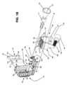
図1A及び図1Bは、それぞれ、本明細書に記載の実施例と一致する、超音波プローブとともに使用するための針誘導装置100を示す等角図及び分解等角図である。図示のように、針誘導装置100は、クランプ・スリーブ105と、ガイド・タワー110と、位置合わせプレート115と、針ホルダ装置120とを含む。使用前に、クランプ・スリーブ105は、超音波プローブ(図示せず)に固定することができ、ガイド・タワー110は、クランプ・スリーブ105に摺動結合することができる。図1A及び図1Bに示すように、針ホルダ装置120は、ガイド・タワー110内の複数の経路位置のうちの1つに挿入することができる。ルアー・ロック・トロカール針などのトロカール又は他の穿刺器具125は、以下に説明するように、針ホルダ装置120を通って受容され得る。位置合わせプレート115は、以下に説明するように、ガイド・タワー110に挿入されて、超音波プローブの長手方向軸に平行な誘導経路を提供することができる。使用中、ガイド・タワー110は、クランプ・スリーブ105及び超音波プローブに対して前方に摺動して前進し、選択された位置で患者に係合することができる。処置が完了すると、ガイド・タワー110は、患者から穿刺器具125を外すために、クランプ・スリーブ105及び超音波プローブに対して後退する。1A and 1B are isometric and exploded isometric views, respectively, of a
図1Bに示すように、クランプ・スリーブ105は、取付け部130と、ストラップ部136と、固定部140とを含む。本明細書に記載するように、取付け部130は、上面132と下面134とを有する押出成形された構成を含むことができる。取付け部130の上面132は、長手方向に調整可能な構成においてガイド・タワー110を支持するように構成することができる。例えば、図1Bに示すように、上面132は、上面132から上方に突出する一対のサイド・レール133を含む。以下に説明するように、サイド・レール133の各々は、図2Aに示すように、ガイド・タワー110内の対応するサイド・レール154内で摺動可能に受容されるように構成される。使用中に、ガイド・タワー110が取付け部130に対してあまりにも緩んで動くのを防ぐために、各サイド・レール133の許容誤差は、取付け部130とガイド・タワー110との間に、望ましくない動きに抵抗する摩擦関係が存在するようなものであってもよい。As shown in FIG. 1B, the
別の実施形態では、図1Bに示すように、取付け部130の上面132は、取付け部130の上面132から上方に突出する複数の長手方向に離間した、返し付き固定要素131を含んでいてもよい。返し付き固定要素131は、図2Aに示すように、ガイド・タワー110内のばねクリップ要素200によって係合するように構成される。いくつかの実施形態では、取付け部130の上面132は、図2Aに示すように、ガイド・タワー110の下面から下方に突出する停止要素205に係合するための停止係合部135も含んでいてもよい。ガイド・タワー110内の停止要素205が停止係合部135に当接すると、ガイド・タワー110は、クランプ・スリーブ105に対して、したがってクランプ・スリーブが固定されている超音波プローブに対して、前方に移動することが防止される。In another embodiment, as shown in FIG. 1B, the
他の実施形態では、ガイド・タワー110をクランプ・スリーブ105に固定するための他の機構が使用されてもよい。例えば、図1B及び図2Aの実施例に関連して上述したような、突起と戻り止め又は開口部との組み合わせを使用することにより、ガイド・タワー110を取付け部130に取り外し可能に固定することが可能になる。In other embodiments, other mechanisms for securing the
取付け部130の下面134は、トランスデューサ・プローブ(図示せず)の少なくとも一部の湾曲した外側形状に対応するほぼ湾曲した形状を含む。本明細書に記載の実施例と一致して、下面134は、トランスデューサ・プローブと、ブラキバルーン(brachyballoon)などの処置付属装置を収容するのに十分な針誘導装置100との間に画定された空間を形成するために、長手方向のチャネル又は溝を含んでもよい。The
クランプ・スリーブ105のストラップ部136は、針誘導装置100が取り付けられたトランスデューサ・プローブの一部の外面に最適に適合する、概して弾性又は可撓性の形状を含み得る。特に、ストラップ部136は、取付け部130の第1の側から延在する第1の側方部137と、第1の側方部137に対向する取付け部130の第2の側から延在する第2の側方部139とを含んでいてもよい。第1及び第2の側方部137/139は、固定部140でまとめて終端してもよい。図1A及び図1Bに示すように、一実施形態では、固定部140は、第1の側方部137の終端に形成されたカラー部140と、第2の側方部139の終端に形成されたねじ部142とを含むことができる。カラー部140は、クランプ・スリーブ105を超音波プローブ上に取り付ける間、ねじ部142の端部を受容するように適合された開口部を含んでいてもよい。The
クランプ・スリーブ105を超音波プローブに固定するために、取付け部130の下面134及び第1の側方部137の内面は、最初に超音波プローブの外面に接する。次いで、第2の側方部139は、その内面も超音波プローブの外面に接触するように曲げられ、それにより、ねじ部142がカラー部140に進入する。嵌合カラー部146を有するクランプ・ナット144は、ねじ部142上を螺進して、クランプ・ナット144上のカラー部146を、第1の側方部137内のカラー部140にクランプ係合し、したがって、クランプ・スリーブ105を超音波プローブに固定する。クランプ・スリーブ105を取り外すことが望まれるとき、クランプ・ナット144を逆行させることにより、カラー部140を取り外すことができる。To secure the
本明細書に記載の実施形態と一致して、側方部137/139の1つ又は複数は、撓曲を可能にするのに十分な厚さで形成され得る。いくつかの実施形態では、第2の側方部139のみが撓曲を可能にするように形成され、第1の側方部137は略剛性の構成を有する。いくつかの実施例では、クランプ・ナット144を除いたクランプ・スリーブ105の全体が、射出成形、3D印刷などによって一体的に形成され得る。Consistent with embodiments described herein, one or more of the
図1A及び図1Bに示すように、ガイド・タワー110は、本明細書に記載のように、安定したインターフェースをクランプ・スリーブ105に提供するための実質的にL字形の形状と、針ホルダ装置120に係合するための(図1Bにおいて線A-Aで示されるように、超音波プローブの長手方向の向きに対して)複数の半径方向に離間した針誘導経路とを含む。特に、ガイド・タワー110は、ほぼ平面の構成を有するスリーブ・インターフェース部150と、スリーブ・インターフェース部200から上方に突出する誘導経路部152とを含む。スリーブ・インターフェース部150の下面は、上述したように、スリーブ・インターフェース部150の下面から下方に突出してクランプ・スリーブ105内のサイド・レール133とインターフェースで連結するように構成された対向するサイド・レール154を含む。いくつかの実施形態では、サイド・レール154は、対向するC字形の形状を有し、そのC字形の形状は、サイド・レール133を捕捉し、取付け部130内のサイド・レール133がガイド・タワー110内のサイド・レール154内に位置するとき、クランプ・スリーブ105とガイド・タワー110との間の相対的な半径方向の移動を防止する一方で、それらの間で摺動する長手方向の動きを可能にする。1A and 1B, the
上述したように、ガイド・タワー110の底面図を示す図2Aに示すように、スリーブ・インターフェース部150は、クランプ・スリーブ105から上方に突出した返し付き固定要素131に係合するように構成された弾性ばねクリップ要素600を含む。As described above, and as shown in FIG. 2A, which illustrates a bottom view of the
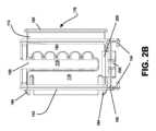
本明細書に記載の実施例と一致する一実施形態では、誘導経路部152は、スリーブ・インターフェース部150から略垂直に上方に突出する。図1A、図1B及び図2B(位置合わせプレート115が内部に位置するガイド・タワー110の背面図を示す)に示すように、誘導経路部152は、垂直誘導スロット156と、複数の針ホルダ装置受容カップ158と、位置合わせプレート受容スロット160とを含む。In one embodiment consistent with examples described herein, the
垂直誘導スロット156は、トランスデューサ内の長手方向の超音波撮像水晶振動子(ultrasound imaging crystals)と一直線になるようにガイド・タワー110内で中央に位置合わせされ、貫通するように設計された穿刺器具125(例えば、トロカール針)が、典型的な撮像条件の下で、撮像面内で一貫して可視化されるように、針誘導装置100が固定される。図2Bに示すように、垂直誘導スロット156は、挿入された穿刺器具が、針ホルダ装置誘導装置受容カップの位置の間で自由に移動することができるようにガイド・タワー110の高さのほぼ全体にわたって延在する。The
図1Bに示すように、針ホルダ装置受容カップ158は、誘導経路部152内及び垂直誘導スロット156の反対側に配置された、複数の対の位置合わせされた凹部又は開口部を備える。針ホルダ装置受容カップ158の各対は、以下にさらに詳細に説明するように、針ホルダ装置120のための複数の取付け位置を提供するために、隣接する針ホルダ装置受容カップ158の対に対して垂直方向に間隔を置いて配置される。本実施例では、5対の針ホルダ装置受容カップ158が設けられるが、他の実施形態は、より少ない針ホルダ装置受容カップ158を含んでいてもよく、又は、追加の針ホルダ装置受容カップ158が設けられてもよい。本明細書に記載の実施形態と一致して、各針ホルダ装置受容カップ158は、以下に説明するように、針ホルダ装置120のそれぞれの部分を受容するように構成されたほぼ円弧状の開口部を備える。いくつかの実施形態では、各針ホルダ装置受容カップ158の寸法は、針ホルダ装置120がその中に取り外し可能に捕捉されるような寸法である。例えば、各針ホルダ装置受容カップ158は、針ホルダ装置120に緊密な摩擦嵌合を提供するようなサイズであってもよい。他の実施形態では、各針ホルダ装置受容カップ158は、円弧が180°よりもわずかに大きい開口部を有することができ、その結果、針ホルダ装置120は、針ホルダ装置受容カップ158のそれぞれの対にスナップ嵌めされる。図1A~図2Bの針誘導装置100とは対照的に、針ホルダ装置受容カップ158は、位置合わせプレート受容スロット160の前方に配置される。As shown in FIG. 1B, the needle holder
図1Bに示すように、位置合わせプレート受容スロット160は、針ホルダ装置受容カップ158の後方の位置で、ガイド・タワー110内で横方向に延在するように構成される。位置合わせプレート受容スロット160は、その内部に位置合わせプレート115を受容するようなサイズで作られる。以下にさらに詳細に説明するように、針ホルダ装置120及び対応する穿刺器具125を特定の対の針ホルダ装置受容カップ158内で受容すると、位置合わせプレート115を位置合わせプレート受容スロット160内で前進させて、超音波プローブに対して規定された経路で穿刺器具125を確実に支持することができる。例えば、いくつかの実施形態では、位置合わせプレート115の形状により、穿刺器具125が平行な経路内に押し込まれるが、異なる形状が、異なる経路角度を適応させるために使用されてもよい。図1Bに示すように、一実施形態では、位置合わせプレート受容スロット160は、位置合わせプレート受容スロット160内の規定された深さで位置合わせプレート115の一部を受容するように構成された外側リム部161を含む。As shown in FIG. 1B, the alignment
図2Cは、本明細書に記載の実施例と一致する針ホルダ装置120の側面図である。図1A、図1B及び図2Cに示すように、針ホルダ装置120は、ガイド・タワー110に結合するための、及び、穿刺器具125を受容するためのアダプタを備える。いくつかの実施形態では、針ホルダ装置120は、針ホルダ装置120を通ってトロカール穿刺器具を受容するように構成され得る。FIG. 2C is a side view of a
一実施形態では、針ホルダ装置120は、本体部162と、係合肩部164と、ハンドル部166と、フランジ部168とを含む。図示のように、本体部162は、貫通する中央開口部169を有するほぼ管状の要素を含む。本体部162は、中央開口部169内に穿刺器具125を受容するように構成される。本体部162の前方端部は、係合肩部164で終端し、本体部162の後方端部は、フランジ部162で終端する。本体部162の中間部の外面はハンドル部166を形成し、ハンドル部166は、使用中に針ホルダ装置120の適切な配置をもたらすために操作することができる。In one embodiment, the
係合肩部164は、本体部162の前方端部の両側から外方に垂直に突出する一対の略円筒形の要素を含む。図1Aに示され、概ね上述したように、係合肩部164は、使用中に、選択された一対の針ホルダ装置受容カップ158内に受容されるように構成される。係合肩部164の円筒形状により、必要に応じて、位置合わせプレート受容スロット160内で位置合わせプレート115を前進させる前に、ハンドル部166によって受容カップ158内で針ホルダ装置120の上方及び下方への回転が可能になり、これにより、針ホルダ装置120の角度配向を固定する。Engagement shoulders 164 include a pair of generally cylindrical elements projecting perpendicularly outwardly from opposite sides of the forward end of
図1A、図1B及び図2Cに示すように、本明細書に記載の実施形態と一致して、漏斗部材170は、針ホルダ装置120内に挿入される前にルアー・ロック穿刺器具125に固定することができる。本明細書に記載の実施例と一致して、漏斗部材170は、穿刺器具インターフェース部171と、漏斗開口部172とを含む。穿刺器具インターフェース部171は、ルアー・ロックなどの穿刺器具125のインターフェース要素を受容するための同心管状構造を含む。この構成において、穿刺器具インターフェース部171は、ルアー・ロック穿刺器具125上の雄ねじを係合して保持するように構成された雌ねじ(図示せず)を含む。漏斗開口部172は、生検針などの穿刺器具の容易な進入を可能にするために、本体部162内の中央開口部(図示せず)よりも大きい内径又は円周を有する後方端部漏斗部材170における広口開口部を含む。1A, 1B, and 2C,
図1Bに示すように、位置合わせプレート115は、本体部176と、当接部178と、自由移動部179と、複数の経路保持チャネル180とを含む。概して、本体部176は、位置合わせプレート受容スロット160内に受容されるようなサイズの実質的に平坦な要素を含む。当接部178は、位置合わせプレート115が位置合わせプレート受容スロット160内に完全に挿入されたときに、位置合わせプレート受容スロット160の外側リム部161に当接するための表面を提供するフランジ部182を含む。As shown in FIG. 1B, the
本明細書に記載の実施形態と一致して、自由移動部179は、経路保持チャネル180と連通するスロット付き開口部を含む。経路保持チャネル180は、針ホルダ装置受容カップ158に対応するように離間された複数の弓状凹部を含む。自由移動部179と経路保持チャネル180との組み合わせにより、位置合わせプレート115のための2つの動作位置が提供される。Consistent with the embodiments described herein, the free-
第1の位置では、位置合わせプレート115は、自由移動部179が垂直誘導スロット160と位置合わせされるように、位置合わせプレート受容スロット160内に部分的に挿入される。これにより、針ホルダ装置120をガイド・タワー110に挿入することが可能になる。針ホルダ装置120がガイド・タワー110内及び選択された一対の針ホルダ装置受容カップ158内に挿入されると、位置合わせプレート115は、(フランジ部182が外側リム部161に当接するまで)位置合わせプレート受容スロット160内で前進する。この第2の位置では、針ホルダ装置120は、超音波プローブに対して平行な経路に保持される。図1A及び図1Bの実施例の位置合わせプレート115内の経路保持チャネル180の位置により、針ホルダ装置120のための平行な経路が提供されるが、他の実施形態では、経路保持チャネル180の位置は、他の角度配向を提供するために、針ホルダ装置受容カップ158に対してオフセットされ得る。In the first position, the
位置合わせプレート115は、位置合わせプレート受容スロット160内で持続的に保持されるように構成される。図1Bに示すように、位置合わせプレート115は、位置合わせプレート115が第1の位置にあるときに、スロット160の対応するリム部に係合して、位置合わせプレート115が位置合わせプレート受容スロット160から意図せずに外れるのを防ぐように構成された1つ又は複数のばねクリップ部184を含むことができる。The
組立及び使用中、針ホルダ装置120の係合肩部164は、最初に垂直方向に向けられ、針ホルダ装置120は、位置合わせプレートが第1の位置にあるとき、垂直誘導スロット156内に挿入され、位置合わせプレート115を通って前方に挿入される。次いで、針ホルダ装置120は、90°回転され、選択された一対の針ホルダ装置受容カップ158内に挿入される。次いで、位置合わせプレート115は、第2の位置に前進し、したがって針ホルダ装置120を選択された平行な経路内に捕捉する。During assembly and use, the engagement shoulders 164 of the
穿刺器具125がガイド・タワー110内の選択された平行経路内で(例えば、選択された一対の針ホルダ装置受容カップ158内で、位置合わせプレート115によってロックされて)据え付けられた後、ガイド・タワー110は、クランプ・スリーブ105及び超音波プローブに対して前方に摺動して前進し、選択された位置で患者に係合(例えば、穿刺)する。ガイド・タワーは、穿刺器具125の先端が患者の体内の所望の深さに達するまで、又はガイド・タワー110内の停止部205がクランプ・スリーブ105内の停止係合部135に当接するまで、さらに前進する。After the
本明細書に記載の実施例と一致して、患者の穿刺に続いて、位置合わせプレート115を、その第1の非ロッキング位置に戻すことができる。次いで、針ホルダ装置120は、針ホルダ装置受容カップ158を中心にして枢動するか、又は、針ホルダ装置受容カップ158から取り外して、第2の穿刺を必要とせずに新しい垂直位置に移動することができる。Consistent with the embodiments described herein, following the puncture of the patient, the
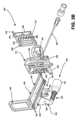
図3A及び図3Bは、それぞれ、本明細書に記載の実施例と一致する、超音波プローブとともに使用するための針誘導装置300の別の実施例を示す等角図及び分解等角図である。図示のように、針誘導装置300は、ガイド・プラットフォーム305と、ガイド・タワー310と、位置合わせプレート315と、針ホルダ装置320とを含む。使用前に、ガイド・プラットフォーム305は、超音波プローブ(図示せず)に固定することができ、ガイド・タワー310は、ガイド・プラットフォーム305に摺動結合することができる。図3A及び図3Bに示すように、針ホルダ装置320は、ガイド・タワー310内の複数の経路位置のうちの1つに挿入することができる。ルアー・ロック・トロカール針などのトロカール又は他の穿刺器具325は、以下に説明するように、針ホルダ装置320を通して受容され得る。他の実施形態では、穿刺器具325は、一体ユニットとして、針ホルダ装置320とともに形成することができ、その結果、穿刺器具325は、針ホルダ装置320から独立して取り外すことはできない。位置合わせプレート315は、以下に説明するように、ガイド・タワー310に挿入されて、超音波プローブの長手方向軸に平行な誘導経路を提供することができる。使用中、ガイド・タワー310は、ガイド・プラットフォーム305及び超音波プローブに対して前方に摺動して前進し、選択された位置で患者に係合する。処置が完了すると、ガイド・タワー310は、患者から穿刺器具325を外すために、ガイド・プラットフォーム305及び超音波プローブに対して後退する。3A and 3B are isometric and exploded isometric views, respectively, of another embodiment of a
図3Bに示すように、ガイド・プラットフォーム305は、取付け部330と、ストラップ部336と、固定部340とを含む。本明細書に記載のように、取付け部330は、上面332及び下面334を有する長手方向に押出成形された形状を含むことができる。取付け部330の上面332は、長手方向の調整可能な構成においてガイド・タワー310を支持するように構成することができる。例えば、図3Bに示すように、上面332は、上面332から上方に突出する一対のサイド・レール333を含む。以下に説明するように、サイド・レール333の各々は、図4Aに示すように、ガイド・タワー310内の対応するサイド・レール354内で摺動可能に受容されるように構成される。使用中に、ガイド・タワー310が取付け部330に対してあまりにも緩んで動くのを防ぐために、各サイド・レール333の許容誤差は、取付け部330とガイド・タワー310との間に、望ましくない動きに抵抗する摩擦関係が存在するようなものであってもよい。他の実施形態では、ガイド・タワー310をガイド・プラットフォーム305に固定するための他の機構が使用されてもよい。例えば、突起及び戻り止め又は開口部の組み合わせを使用することにより、ガイド・タワー310を取付け部330に取り外し可能に固定することが可能になる。As shown in FIG. 3B, the
図3A及び図3Bに示すように、取付け面330の前方端部は、上面332から垂直上方に突出する安定化機構335を含むことができる。安定化機構335は、穿刺器具325がその中を自由に移動できるように、その中に大きな中央開口部を有することができる。使用中、安定化機構335の前方端部は、患者(例えば患者の会陰部)に係合して、針誘導装置300と患者との間の関係を安定化させるように構成される。さらに、安定化機構335の後方端部は、ガイド・プラットフォーム305に対するガイド・タワー310の長手方向の移動に対して明確な停止部をさらに提供する。3A and 3B, the forward end of the mounting
取付け部330の下面334は、トランスデューサ・プローブ(図示せず)の少なくとも一部の湾曲した外側形状に対応するほぼ湾曲した形状を含む。ガイド・プラットフォーム305のストラップ部336は、針誘導装置300が取り付けられたトランスデューサ・プローブの一部の外面に最適に適合する、概して弾性又は可撓性の形状を含み得る。特に、ストラップ部336は、取付け部330の第1の側から延在する第1の側方部337と、第1の側方部337に対向する取付け部330の第2の側から延在する第2の側方部339とを含んでいてもよい。第1及び第2の側方部337/339は、固定部340でまとめて終端してもよい。図3A及び図3Bに示すように、一実施形態では、固定部340は、第1の側方部337の終端に形成されたカラー部341と、第2の側方部339の終端に形成されたねじ部342とを含むことができる。カラー部341は、ガイド・プラットフォーム305を超音波プローブ上に取り付ける間、ねじ部342の端部を受容するように適合された開口部を含んでいてもよい。The
ガイド・プラットフォーム305を超音波プローブに固定するために、取付け部330の下面334及び第1の側方部337の内面は、最初に超音波プローブの外面に接触する。次いで、第2の側方部339は、その内面も超音波プローブの外面に接触するように曲げられ、それにより、ねじ部342がカラー部341に進入する。嵌合カラー部346を有するクランプ・ナット344は、ねじ部342上を螺進して、クランプ・ナット344上のカラー部346を、第1の側方部337内のカラー部341にクランプ係合し、したがって、ガイド・プラットフォーム305を超音波プローブに固定する。ガイド・プラットフォーム305を取り外すことが望まれるとき、クランプ・ナット344を逆行させることにより、カラー部分341を外すことができる。To secure the
本明細書に記載の実施例と一致して、側方部337/339の1つ又は複数は、撓曲を可能にするのに十分な厚さで形成され得る。いくつかの実施形態では、第2の側方部339のみが撓曲を可能にするように形成され、第1の側方部337は略剛性の構成を有する。いくつかの実施例では、クランプ・ナット344を除いたガイド・プラットフォーム305の全体が、射出成形、3D印刷などによって一体的に形成され得る。Consistent with examples described herein, one or more of the
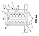
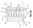
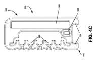
図4A及び図4Bは、それぞれ、ロック解除位置及びロック位置に位置合わせプレートを有するガイド・タワー310の背面図である。図4Cは、ガイド・タワー310の側面図である。図3A、図3B、及び図4A~図4Cに示すように、ガイド・タワー310は、本明細書に記載のように、安定したインターフェースをガイド・プラットフォーム305に提供するための実質的にフレーム状の形状と、針ホルダ装置320に係合するための(図3Aにおいて線A-Aで示されるように、超音波プローブの長手方向の向きに対して)複数の離間した針誘導経路とを含む。特に、ガイド・タワー310は、プラットフォーム・インターフェース部350と、プラットフォーム・インターフェース部350から上方に突出した誘導経路部352とを含む。プラットフォーム・インターフェース部350の下面は、上述したように、プラットフォーム・インターフェース部350の下面から下方に突出してガイド・プラットフォーム305内のサイド・レール333とインターフェースで連結するように構成された対向するサイド・レール354を含む。いくつかの実施形態では、サイド・レール354は、対向するC字形の形状を有し、そのC字形の形状は、サイド・レール333を捕捉し、取付け部330内のサイド・レール333がガイド・タワー310内のサイド・レール354内に位置するとき、ガイド・プラットフォーム305とガイド・タワー310との間の相対的な半径方向の移動を防止する一方で、それらの間で摺動する長手方向の動きを可能にする。4A and 4B are rear views of the
本明細書に記載の実施例と一致する一実施形態では、誘導経路部352は、プラットフォーム・インターフェース部350から略垂直に上方に突出する。図3A、図3B及び4Bに示すように、誘導経路部352は、垂直誘導スロット356と、複数の針ホルダ装置受容カップ358と、タワー前進ハンドル359と、位置合わせプレート受容スロット360とを含む。In one embodiment consistent with examples described herein, the
垂直誘導スロット356は、トランスデューサ内の長手方向の超音波撮像水晶振動子と一直線になるようにガイド・タワー310内で中央に位置合わせされ、貫通するように設計された穿刺器具325(例えば、トロカール針)が、典型的な撮像条件の下で、撮像面内で一貫して可視化されるように、針誘導装置300が固定される。図4Bに示すように、垂直誘導スロット356は、挿入された穿刺器具が、針誘導装置受容カップの位置の間で自由に移動することができるようにガイド・タワー310の高さのほぼ全体にわたって延在する。The
図3Bに示すように、針ホルダ装置受容カップ358は、誘導経路部352内及び垂直誘導スロット356の反対側に配置された、複数の対の位置合わせされた凹部又は開口部を備える。針ホルダ装置受容カップ358の各対は、以下にさらに詳細に説明するように、針ホルダ装置320のための複数の取付け位置を提供するために、隣接する針ホルダ装置受容カップ358の対に対して垂直方向に間隔を置いて配置される。本実施例では、5対の針ホルダ装置受容カップ358が設けられるが、他の実施形態は、より少ない針ホルダ装置受容カップ358を含んでいてもよく、又は、追加の針ホルダ装置受容カップ358が設けられてもよい。本明細書に記載の実施形態と一致して、各針誘導装置受容カップ358は、以下に説明するように、針ホルダ装置320のそれぞれの部分を受容するように構成されたほぼ円弧状の開口部を備える。いくつかの実施形態では、各針誘導装置受容カップ358の寸法は、針ホルダ装置320がその中に取り外し可能に捕捉されるような寸法である。例えば、各針誘導装置受容カップ358は、針ホルダ装置320に緊密な摩擦嵌合を提供するようなサイズであってもよい。他の実施形態では、各針誘導装置受容カップ358は、円弧が180°よりもわずかに大きい開口部を有することができ、その結果、針ホルダ装置320は、針ホルダ装置受容カップ358のそれぞれの対にスナップ嵌めされる。As shown in FIG. 3B, the needle holder
図3A、図3B及び図4Bに示すように、タワー前進ハンドル359は、プラットフォーム・インターフェース部350に近接してガイド・タワー310から横方向外方に突出している。使用中、操作者は、タワー前進ハンドル359をそれぞれ押すか又は引くことによって、ガイド・プラットフォーム305に沿ってガイド・タワー310を長手方向に手動で前進又は後退させることができる。As shown in FIGS. 3A, 3B, and 4B, a tower advancement handle 359 projects laterally outward from the
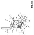
図3Bに示すように、位置合わせプレート受容スロット360は、針ホルダ装置受容カップ358の後方の位置で、ガイド・タワー310内で横方向に延在するように構成される。位置合わせプレート受容スロット360は、その内部に位置合わせプレート315を受容するようなサイズで作られる。以下にさらに詳細に説明するように、針ホルダ装置320及び対応する穿刺器具325を特定の対の針ホルダ装置受容カップ358内で受容すると、位置合わせプレート315を位置合わせプレート受容スロット360内で前進させて、超音波プローブに対して規定された経路で穿刺器具325を確実に支持することができる。例えば、いくつかの実施形態では、位置合わせプレート315の形状により、穿刺器具325が平行な経路内に押し込まれるが、異なる形状が、異なる経路角度を適応させるために使用されてもよい。一実施形態では、位置合わせプレート受容スロット360は、位置合わせプレート受容スロット360内で規定された深さで位置合わせプレート315の一部を受容するように構成された外側リム部を含む。図4Dは、本明細書に記載の実施例と一致する針ホルダ装置320の等角図である。図3A、図3B及び図4Dに示すように、針ホルダ装置320は、ガイド・タワー310に結合するための、及び、穿刺器具325を受容するためのアダプタを備える。いくつかの実施形態では、針ホルダ装置320は、針ホルダ装置320を通して穿刺器具を受容するように構成され得る。As shown in FIG. 3B, the alignment
一実施形態では、針ホルダ装置320は、本体部362と、係合肩部364と、ハンドル部366とを含む。図示のように、本体部362は、貫通する中央開口部368を有するほぼ管状の要素を含む。本体部362は、中央開口部368内に穿刺器具325を受容するように構成される。本体部362の前方端部は、係合肩部364で終端し、本体部362の後方端部は、ハンドル部366で終端し、ハンドル部366は、使用中に針ホルダ装置320の適切な配置をもたらすために操作することができる。図4Dに示すように、本体部362の中間部は、以下に説明するように、位置合わせプレート315内の経路保持チャネル380に係合するための位置合わせプレート係合面370を含むことができる。In one embodiment, the
例えば、ハンドル部366は、係合肩部364を針ホルダ装置受容カップ358に挿入したり、針ホルダ装置受容カップ358から取り外したり、針誘導装置を回転させてガイド・タワー310からの取り外しを可能にしたり、針ホルダ装置受容カップ358の間で針ホルダ装置320を上下させたり、針ホルダ装置320の手動の角度偏向に影響を及ぼしたりするために使用することができる。For example, the
係合肩部364は、本体部362の前方端部の両側から外方に垂直に突出する一対の略円筒形の要素を含む。図3Aに示され、概ね上述したように、係合肩部364は、使用中に、選択された一対の針ホルダ装置受容カップ358内に受容されるように構成される。係合肩部364の円筒形状により、必要に応じて、針ホルダ位置合わせプレート受容スロット360内で位置合わせプレート315を前進させる前に、ハンドル部366によって受容カップ358内で針ホルダ装置320の上方及び下方への回転が可能になり、これにより、針ホルダ装置320の角度配向を固定する。Engagement shoulders 364 include a pair of generally cylindrical elements projecting perpendicularly outward from opposite sides of the forward end of
図3B、図4A及び図4Bに示すように、位置合わせプレート315は、本体部376と、当接部378と、自由移動部379と、複数の経路保持チャネル380とを含む。概して、本体部376は、位置合わせプレート受容スロット360内に受容されるようなサイズの実質的に平坦な要素を含む。当接部378は、位置合わせプレート315が位置合わせプレート受容スロット360内に完全に挿入されたときに、位置合わせプレート受容スロット360の外側リム部に当接するための表面を提供するフランジ部382を含む。3B, 4A, and 4B, the
本明細書に記載の実施形態と一致して、自由移動部379は、経路保持チャネル380と連通するスロット付き開口部を含む。経路保持チャネル380は、針ホルダ装置受容カップ358に対応するように離間された複数の弓状凹部を含む。自由移動部379と経路保持チャネル380との組み合わせにより、位置合わせプレート315のための2つの動作位置が提供される。Consistent with the embodiments described herein, the free-
第1の位置では、位置合わせプレート315は、自由移動部379が垂直誘導スロット356と位置合わせされるように、位置合わせプレート受容スロット360内に部分的に挿入される。これにより、針ホルダ装置320を、ハンドル部366を介してガイド・タワー310に挿入することが可能になる。針ホルダ装置320がガイド・タワー310内及び選択された一対の針ホルダ装置受容カップ358内に挿入されると、位置合わせプレート315は、(フランジ部382が位置合わせプレート受容スロット360の外側リム部に当接するまで)位置合わせプレート受容スロット360内で前進する。この第2の位置では、針ホルダ装置受容カップ358の特定の対に対応する経路保持チャネル380は、超音波プローブに対して平行な経路で保持された針ホルダ装置320に針ホルダ装置320の位置合わせプレート係合面370を係合する。In the first position, the
図3A及び図3Bの実施例の位置合わせプレート315における経路保持チャネル380の位置により、針ホルダ装置320のための平行な経路が提供されるが、他の実施形態では、経路保持チャネル380の位置は、他の角度配向を提供するために、針ホルダ装置受容カップ358に対してオフセットされ得る。Although the location of the path-maintaining
図3B、図4A及び図4Bに示すように、位置合わせプレート315は、位置合わせプレート315が第1の位置にあるときに、スロット360の対応するリム部に係合して、位置合わせプレート315が位置合わせプレート受容スロット360から意図せずに外れるのを防ぐように構成された1つ又は複数のばねクリップ部384を含むことができる。As shown in FIGS. 3B, 4A, and 4B, the
組立及び使用中、針ホルダ装置320の係合肩部364は、最初に垂直方向に向けられ、針ホルダ装置320は、位置合わせプレートが第1の位置にあるとき、垂直誘導スロット356内に挿入され、位置合わせプレート315を通って前方に挿入される。次いで、針ホルダ装置320は、90°回転され、選択された一対の針ホルダ装置受容カップ358内に挿入される。次いで、位置合わせプレート315は、第2の位置に前進し、したがって針ホルダ装置320を選択された平行な経路内に捕捉する。During assembly and use, the
穿刺器具325がガイド・タワー310内の選択された平行経路内で(例えば、選択された一対の針ホルダ装置受容カップ358内で、位置合わせプレート315によってロックされて)据え付けられた後、ガイド・タワー310は、ガイド・プラットフォーム305及び超音波プローブに対して前方に摺動して前進し、選択された位置で患者に係合(例えば、穿刺)する。ガイド・タワー310は、穿刺器具325の先端が患者の体内の所望の深さに達するまで、又はガイド・タワー310がガイド・プラットフォーム305の前部で安定化機構335に当接するまで、さらに前進する。After the
本明細書に記載の実施例と一致して、患者の穿刺に続いて、位置合わせプレート315を、その第1の非ロッキング位置に戻すことができる。次いで、針ホルダ装置320は、針ホルダ装置受容カップ358を中心にして枢動するか、又は、針ホルダ装置受容カップ358から取り外して、第2の穿刺を必要とせずに新しい垂直位置に移動することができる。Consistent with the embodiments described herein, following the puncture of the patient, the
図5A及び図5Bは、それぞれ、本明細書に記載の実施例と一致する、超音波プローブとともに使用するための針誘導装置500の別の実施例を示す等角図及び分解等角図である。図示のように、針誘導装置500は、ガイド・プラットフォーム505と、ガイド・タワー510と、位置合わせプレート515と、針ホルダ装置520とを含む。使用前に、ガイド・プラットフォーム505は、超音波プローブ(図示せず)に固定することができ、ガイド・タワー510は、ガイド・プラットフォーム505に摺動結合することができる。投与の前に、トロカール針などの針又は他のタイプの穿刺器具525が、以下に説明するように、針ホルダ装置520に結合されてもよい。いくつかの実施形態では、穿刺器具525は、一体ユニットとして、針ホルダ装置520とともに形成することができ、その結果、穿刺器具525は、針ホルダ装置520から独立して取り外すことはできない。組み合わされた針ホルダ装置520及び穿刺器具525は、ガイド・タワー510内の複数の経路位置のうちの1つの中に配向されてもよい。使用中、ガイド・タワー510は、ガイド・プラットフォーム505及び超音波プローブに対して前方に摺動して前進し、選択された位置で患者に係合する。処置が完了すると、ガイド・タワー510は、患者から穿刺器具525を外すために、ガイド・プラットフォーム505及び超音波プローブに対して後退する。5A and 5B are isometric and exploded isometric views, respectively, of another embodiment of a
図5Bに示すように、ガイド・プラットフォーム505は、取付け部530と、ストラップ部535と、固定部540とを含む。本明細書に記載のように、取付け部530は、長手方向の調整可能な構成においてガイド・タワー510を支持するために、長手方向に押出成形された形状を含むことができる。例えば、図5Bに示すように、取付け部の側縁は、一対のサイド・レール533を形成することができる。以下に説明するように、サイド・レール533は、図5Aに示すように、ガイド・タワー510内の対応するサイド・レール554又はチャネル内で摺動可能に受容されるように構成される。使用中に、ガイド・タワー510が取付け部530に対してあまりにも緩んで動くのを防ぐために、各サイド・レール533の許容誤差は、取付け部530とガイド・タワー510との間に、望ましくない動きに抵抗する摩擦関係が存在するようなものであってもよい。いくつかの実施形態では、取付け部530の相対的な寸法は、取付け部530からガイド・タワー510が不用意に取り外されることを防ぐために、摩擦抵抗が後方端部で増加するように構成され得る。他の実施形態では、1つ又は複数の停止部、戻り止め部、又は係合部は、ガイド・タワー510とガイド・プラットフォーム505との間の相対移動を制限するために、レール533及び554のうちの1つ又は複数に設けられてもよい。例えば、図5A~図6Bに示すように、取付け部530の後方端部は、ガイド・プラットフォーム505からのガイド・タワー510の取り外しを防止する弾性停止クリップ534を含んでいてもよい。取り外しが必要な場合、クリップ534を手動で下方に撓ませて、ガイド・タワー510をガイド・プラットフォーム505から摺動させて取り外すことができる。5B, the
図5A及び図5Bに示すように、取付け部530の前方端部は、取付け部530から垂直上方に突出する安定化機構536を含むことができる。図示の実施例では、安定化機構536は、穿刺器具525がその中を自由に移動できるように、その中に大きな中央開口部又は窓537を含む。他の実施形態では、安定化機構536は、図6Cに示す安定化機構636及び開口部637などの穿刺器具経路に対して、ガイド・プラットフォーム505の一方の側面に設けられてもよい。図6Cに示す安定化機構636は中央開口部637を含むが、他の実施形態では、穿刺器具525が安定化機構を通って突出せず、むしろ側方に進むため、中央開口部は設けられなくてもよい。5A and 5B, the forward end of the mounting
使用中、安定化機構536の前方端部は、患者(例えば患者の会陰部)に係合して、針誘導装置500と患者との間の関係を安定化させるように構成される。さらに、安定化機構536の後方端部は、ガイド・プラットフォーム505に対するガイド・タワー510の長手方向の移動に対して明確な停止部をさらに提供する。いくつかの実施形態では、安定化機構536は、指標表示(例えば、番号、マークなど)をさらに含むことができ、貫通点における針の経路を迅速に確認することを可能にする。いくつかの実施形態では、このような指標表示は、使用中の視認性を容易にするために、暗闇で光る印刷フォーマットで提供されてもよい。In use, the forward end of the stabilizing
図5A及び図5Bに示すように、ストラップ部535は、一対のストラップ部材539及び540を含み、そのストラップ部材の各々は、トランスデューサ・プローブ(図示せず)の少なくとも一部の湾曲した外側形状に少なくともほぼ対応するように構成される。一実施形態では、ストラップ部材539/540は、図5A~図6Bに示すように、取付け部530と一体的に形成される。他の実施形態では、取付け部530の側面は、ストラップ部材539/540の上面を受容して、それらを取付け部530に枢動可能に固定するためのスロットを含むことができる。5A and 5B, the
本明細書に記載の実施形態と一致して、ストラップ部535と取付け部530の前方端部/安定化機構536との間の距離は、超音波プローブ及び針誘導装置500の作動長を最適化するように選択される。例えば、一実施形態では、ストラップ部535の前方端部と安定化機構536の後方端部との間の距離は、約1.27~2.54cm(0.5~1インチ)の範囲であってもよく、好ましくは、1.745cm(0.687インチ)の距離であってもよい。Consistent with the embodiments described herein, the distance between the
図示のように、ストップ部材539/540は、異なる直径及び形状を有するさまざまな超音波プローブに確実に取り付けることができるVプラットフォームを形成する。ストラップ部材539/540は、固定部546でまとめて終端する。図5A及び図5Bに示すように、一実施形態では、固定部546は、ストラップ部材540の終端に形成されたカラー部547と、ストラップ部材539の終端に結合されたロック・アセンブリ549とを含むことができる。カラー部547は、図6A及び図6Bに関して以下でさらに詳細に説明するように、ガイド・プラットフォーム505を超音波プローブ上に取り付ける間、ロック・アセンブリ549の一部を受容するように適合された開口部548を含むことができる。As shown, the
図6A及び図6Bは、それぞれ、ラッチが解除された構成におけるガイド・プラットフォーム505の等角図及び逆等角図である。図5A、図5B、図6A及び図6Bに示すように、ロック・アセンブリ549は、ロック取付け部600と、ねじ付きロッド602と、つまみねじ要素604とを含む。図6Aに示すように、ロック取付け部600は、内部にねじ付きロッド602の第1の端部606を受容するための受容チャネル又は開口部を形成するストラップ部材539の終端の一部を含む。一実施形態では、ロック取付け部600は、以下に説明するように、ねじ付きロッド602の対応する部分を受容するための一対の対向するスロット付き開口部601を含む。6A and 6B are isometric and reverse isometric views, respectively, of the
図6Aに示すように、ねじ付きロッド602は、第1のストラップ部材539と係合する第1の端部606と、第2のストラップ部材540と係合する第2の端部608を有する略円筒形のねじ付き構成を含む。一対のピボット要素610は、ねじ付きロッド602の第1の端部606の両側から外向きに突出している。ピボット要素610は、第1のストラップ部材539のロック取付け部600の開口部601内に受容されるように構成される。As shown in FIG. 6A, the threaded
図6Bに示すように、つまみねじ要素604は、ねじ付き受容開口部612と、ボール型係合インターフェース614と、ノブ部616とを含む。受容チャネル612は、ねじ付きロッド602の第2の端部608を受容するように構成される。ボール型係合インターフェース614は、カラー部547内の半球状係合部615にボール・ソケット方式で係合するように構成される。このようなボール・ソケット方式のクランプ・インターフェースは、さまざまなプローブ軸のサイズと形状にクランプするために適応させる必要がある複数のクランプ角度にわたって、より均一なクランプ力及び感触を促進する。As shown in FIG. 6B, the
ガイド・プラットフォーム505を超音波プローブに固定するために、ねじ付きロッド602は、ねじ付きロッド602の第2の端部606がカラー部547内の開口部548に入るまで、ピボット要素610を中心にして回転する。次いで、ノブ部616は、ねじ付きロッド602上を螺進して、ボール型係合インターフェース614がカラー547内の半球状係合部615に係合することになる。To secure the
本明細書に記載の実施形態と一致して、ストラップ部材539/540の1つ又は複数は、撓曲を可能にするのに十分な厚さで形成され得る。いくつかの実施形態では、ストラップ部材539/540のうちの一方のみが撓曲を可能にするように形成され、他方のストラップ部材539/540は、略剛性の構成を有する。Consistent with embodiments described herein, one or more of the
図7A、図7B及び図7Cは、本明細書に記載の実施形態と一致する、ガイド・タワー510の側面図、背面図、及び等角図である。図5A、図5B及び図7A~図7Cに示すように、本明細書に記載のように、ガイド・タワー510は、安定したインターフェースをガイド・プラットフォーム505に提供するための実質的にフレーム状の形状と、針ホルダ装置520に係合するための(図5Aにおいて線A-Aで示されるように、超音波プローブの長手方向の向きに対して)複数の離間した針誘導経路とを含む。特に、ガイド・タワー510は、プラットフォーム・インターフェース部550と、プラットフォーム・インターフェース部550から上方に突出した誘導経路部552とを含む。プラットフォーム・インターフェース部550の下面は、上記で簡単に説明したように、プラットフォーム・インターフェース部550の下面から下方に突出してガイド・プラットフォーム505内のサイド・レール533とインターフェースで連結するように構成された対向するサイド・レール554を含む。いくつかの実施形態では、サイド・レール554は、対向するC字形の形状を有し、そのC字形の形状は、サイド・レール533を捕捉し、取付け部530内のサイド・レール533がガイド・タワー510内のサイド・レール554内に位置するとき、ガイド・プラットフォーム505とガイド・タワー510との間の相対的な半径方向の移動を防止する一方で、それらの間で摺動する長手方向の動きを可能にする。7A, 7B, and 7C are side, rear, and isometric views of a
本明細書に記載の実施例と一致する一実施形態では、誘導経路部552は、プラットフォーム・インターフェース部550から略垂直に上方に突出する。図7Bに示すように、誘導経路部552は、垂直誘導スロット556と、複数の針ホルダ装置受容カップ558と、複数のばね要素部560と、ガイド・タワー係合及び表示部561と、位置合わせプレート受容スロット562と、位置合わせプレート調整アセンブリ563とを含む。In one embodiment consistent with examples described herein, the
垂直誘導スロット556は、トランスデューサ内の長手方向の超音波撮像水晶振動子と一直線になるようにガイド・タワー510内で中央に位置合わせされ、貫通するように設計された穿刺器具525が、典型的な撮像条件の下で、撮像面内で一貫して可視化されるように、針誘導装置500が固定される。図9Bに示すように、垂直誘導スロット556は、挿入された穿刺器具が、針ホルダ装置受容カップの位置の間で自由に移動することができるようにガイド・タワー510の高さのほぼ全体にわたって延在する。The
図5B、図7B及び図7Cに示すように、針ホルダ装置受容カップ558は、誘導経路部552内及び垂直誘導スロット556の反対側に配置された複数の対の位置合わせされた凹部又は開口部を備える。本明細書に記載の実施形態と一致して、各針ホルダ装置受容カップ558は、以下に説明するように、針ホルダ装置520のそれぞれの部分を受容するように構成されたほぼ円弧状又は溝状の開口部を備えていてもよい。本明細書に記載の実施例と一致して、ばね要素部560は、各針ホルダ受容カップ558に隣接して配置された複数の対の弾性機構を備える。図7Cに示すように、ばね要素部560は、後方に突出し、狭い偏向部566と、より大きな係合端部568とを含む。5B, 7B, and 7C, the needle holder
以下に説明するように、ばね要素部560は、選択された一対の針ホルダ受容カップ558内に針ホルダ装置を取り外し可能に捕捉するように、針ホルダ装置520の一部に係合するように構成される。針ホルダ装置受容カップ558/ばね要素部560の各対は、以下にさらに詳細に説明するように、針ホルダ装置520のために複数の取付け位置を提供するために、隣接する針ホルダ装置受容カップ558/ばね要素部560の対に対して垂直方向に間隔を置いて配置される。本実施例では、5対の針ホルダ装置受容カップ558が設けられるが、他の実施形態は、より少ない針ホルダ装置受容カップ558を含んでいてもよく、又は、追加の針ホルダ装置受容カップ558が設けられてもよい。As described below, the
図5B、図7B及び図7Cに示すように、ガイド・タワー係合及び表示部561は、受容カップ558/ばね要素部560に隣接して外方に突出するガイド・タワー510の一部を含んでいてもよい。ガイド・タワー係合及び表示部561は、ガイド・プラットフォーム505に沿ってガイド・タワー510を前進又は後退させる際に使用するための係合面を形成することができる。さらに、ガイド・タワー係合及び表示部561は、挿入された針ホルダ装置520の相対位置を示す表示及び/又はマークを含んでいてもよい。5B, 7B, and 7C, the guide tower engagement and
図5Bに示すように、位置合わせプレート受容スロット562は、針ホルダ装置受容カップ558の後方位置のガイド・タワー510の一方の側に形成される。位置合わせプレート受容スロット562は、その内部に位置合わせプレート515を受容するようなサイズで作られる。位置合わせプレート調整アセンブリ563は、位置合わせプレート受容スロット562とはガイド・タワー510の反対側に形成され、ねじ付き開口部570と調整ノブ590とを含む。ねじ付き開口部570は、位置合わせプレート受容スロット562と横方向に位置合わせされ、調整ノブ590から突出しているねじ付きボルト592を受容するように構成される。As shown in FIG. 5B, an alignment
針ホルダ装置520及び対応する穿刺器具525を特定の対の針ホルダ装置受容カップ558/ばね要素部560内で受容すると、調整ノブ590を回転させることによって、位置合わせプレート515を位置合わせプレート受容スロット562内で前進させて、超音波プローブに対して選択された位置/向きで穿刺器具525を確実に支持することができる。図5A~図7Eの実施例と一致して、位置合わせプレート515は、任意の選択された経路で、穿刺器具525を確実に保持することができる。Once the
図7D及び図7Eは、それぞれ、本明細書に記載の実施例と一致する、針ホルダ装置520の等角図及び上面図である。図5A、図5B、図62D及び図7Eに示すように、針ホルダ装置520は、ガイド・タワー510に結合するための、及び、穿刺器具525を受容するためのアダプタを備える。いくつかの実施形態では、針ホルダ装置520は、針ホルダ装置520を通して穿刺器具を受容するように構成され得る。一実施形態では、針ホルダ装置520は、本体部700と、係合肩部702と、位置合わせプレート係合部704と、針受容部706とを含む。図示のように、本体部700は、貫通する中央開口部708を有するほぼ管状の要素を含む。本体部700は、中央開口部708内に穿刺器具525を受容するように構成される。いくつかの実施形態では、本体部700は、ガイド・タワー510への挿入及びガイド・タワー510内での操作を容易にするための係合要素707(例えば、タブ、耳など)を含むことができる。7D and 7E are isometric and top views, respectively, of a
本体部700の前方端部は、係合肩部702で終端し、本体部700の後方端部は、針受容部706で終端し、これは、使用中に針ホルダ装置520の適切な配置をもたらすために操作することができる。例えば、本体部700の係合要素707は、係合肩部702を針ホルダ装置受容カップ558に挿入したり、針ホルダ装置受容カップ558から取り外したり、針ホルダ装置520を回転させてガイド・タワー510からの取り外しを可能にしたり、ホルダ装置受容カップ558の間で針ホルダ装置520を上下させたり、針ホルダ装置520の手動角度偏向に影響を及ぼしたりするために使用することができる。いくつかの実施形態では、針受容部706は、穿刺器具525内の対応する構造体を受容するための、スロット、キー、クリップ、ねじなどの1つ又は複数の回転固定要素を含み、針ホルダ装置520に対する穿刺器具525の軸方向の回転及び/又は長手方向の移動を防止することができる。The forward end of the
係合肩部702は、本体部700の前方端部の両端から外方に垂直に突出する一対の略円筒形の要素を含む。図5Aに示され、概ね上述したように、係合肩部702は、使用中に、選択された一対の針ホルダ装置受容カップ558内に受容されるように構成される。係合肩部702の円筒形の構成により、必要に応じて、位置合わせプレート受容スロット562内で位置合わせプレート515を前進させる前に、本体部700を介して、受容カップ558内で針ホルダ装置520の上方及び下方への回転が可能になり、これにより、針ホルダ装置520の角度配向を固定する。いくつかの実施形態では、係合肩部702は、係合肩部702から後方に突出する角度制限部716を含み、針ホルダ装置受容カップ558の一部に係合して、針ホルダ装置受容カップ558内の針ホルダ装置520の回転運動を制限するように構成される。The engagement shoulders 702 include a pair of generally cylindrical elements projecting perpendicularly outward from opposite ends of the forward end of the
図5A及び図7Eに示すように、位置合わせプレート係合部704は、本体部700内に形成され、特定の経路位置で位置合わせプレートの一部に係合するためのほぼ長方形の構成を含む。位置合わせプレート係合部704は、図7Dに示すように、その片側に長手方向に設けられた平行経路位置合わせ機構718をさらに含むことができる。以下に説明するように、平行経路位置合わせ機構718は、以下に説明するように、針ホルダ装置受容カップ558/ばね要素部560に対応する位置合わせプレート内の複数の戻り止め又はノッチ594のうちの1つに確実に係合することができる。5A and 7E, the alignment
図5Bに示すように、位置合わせプレート515は、本体部576と、自由移動部579と、針ホルダ装置係合部580とを含む。概して、位置合わせプレート本体部576は、位置合わせプレート受容スロット562内に受容されるようなサイズの実質的に平坦な要素を含む。本明細書に記載の実施形態と一致して、自由移動部579は、針ホルダ装置520の自由な移動を可能にする位置合わせプレート515を通る開口部を含む。針ホルダ装置係合部580は、針ホルダ装置520の位置合わせプレート係合部704にクランプ係合するように構成された自由移動部579の内側表面を含む。上記で簡単に説明したように、針ホルダ装置係合部580は、針ホルダ装置受容カップ558/ばね要素部560に対応する複数のノッチ又は戻り止め594を含んでいてもよい。ノッチ594は、選択された平行な経路の向きに針ホルダ装置を維持するために、位置合わせプレート係合部704内の経路位置合わせ機構718に係合するように構成される。いくつかの実施形態(図示せず)では、位置合わせプレート本体部576は、ガイド・プラットフォーム505上で長手方向に前後にガイド・タワー510を移動させる際に使用するための位置合わせプレートスロット562を通って延在するタブ又は他の係合手段を含んでいてもよい。As shown in FIG. 5B, the
使用者が平行な針経路を確立したいとき、使用者は、平行経路位置合わせ機構718を所望の平行経路に対応する特定の戻り止め又はノッチ594と位置合わせするように、針ホルダ装置520を回転させることができる。ノブ590の締め付け時に、位置合わせプレート515は、針ホルダ装置520に向かって付勢され、平行経路位置合わせ機構718を特定の戻り止め又はノッチ594内に据え付けることができる。ノブ592を締め続けることにより、針ホルダ装置520が所望の位置に効果的にクランプされる。When a user wishes to establish a parallel needle path, the user can rotate the
逆に、使用者が非平行な針経路を確立したいとき、使用者は、針ホルダ装置520を所望の非平行な向きに回転させることができる。このような向きでは、平行経路位置合わせ機構718は、ノッチ594のいずれとも位置合わせされない。ノブ590の締め付け時に、位置合わせプレート515は、針ホルダ装置520に向かって付勢され、針ホルダ装置係合部580を経路位置合わせ機構704/718にクランプ係合させる。ノブ590を締め続けることにより、針ホルダ装置520が所望の位置に効果的にクランプされる。Conversely, when a user wishes to establish a non-parallel needle path, the user can rotate the
図8は、本明細書に記載の実施形態と一致する、ガイド・タワー510及び位置合わせプレート515の代替実施例の等角図である。図8に示すように、図5A~図7Eの実施例とは対照的に、ガイド・タワー510は、位置合わせプレート受容スロット562とはガイド・タワー510の反対側に形成された位置合わせプレート調整アセンブリ800を含む。図示のように、位置合わせプレート調整アセンブリ800は、開口部802と、調整ノブ保持チャネル804と、調整ノブ806とを備える。開口部802は、位置合わせプレート515から突出するねじ付きボルト808を受容するように構成される。この実施形態では、調整ノブ806は、フランジ部810と、ねじ付きボルト808を受容するためのねじ付き開口部812とを含む。フランジ部810は、調整ノブ保持チャネル804内に受容され、調整ノブ806をガイド・タワー510に対して固定された横方向の関係で保持すると同時に、調整ノブ806の回転を可能にし、位置合わせプレート515を調整プレート受容スロット562内で横方向に移動させる。8 is an isometric view of an alternative embodiment of a
針ホルダ装置520及び対応する穿刺器具525を特定の対の針ホルダ装置受容カップ558/ばね要素部560内で受容すると、調整ノブ806によって、位置合わせプレート515を位置合わせプレート受容スロット562内で前進させて、超音波プローブに対して選択された位置/向きで穿刺器具525を確実に支持することができる。図5A~図7Eの実施例と一致して、位置合わせプレート515は、任意の選択された経路で穿刺器具525を確実に保持することができる。Once the
穿刺器具525は、ガイド・タワー510内の選択された平行経路内で(例えば、選択された一対の針ホルダ装置受容カップ558内で、位置合わせプレート515によってロックされて)据え付けられた後、ガイド・タワー510は、ガイド・プラットフォーム505及び超音波プローブに対して前方に摺動して前進し、選択された位置で患者に係合(例えば、穿刺)する。ガイド・タワー510は、穿刺器具525の先端が患者の体内の所望の深さに達するまで、又はガイド・タワー510がガイド・プラットフォーム305の前部で安定化機構536に当接するまで、さらに前進する。After the
本明細書に記載の実施例と一致して、患者の穿刺に続いて、調整ノブ590を回転させて、位置合わせプレート515を、その第1の非ロッキング位置に戻すことができる。次いで、針ホルダ装置520は、針ホルダ装置受容カップ558を中心にして枢動するか、又は、針ホルダ装置受容カップ558から取り外して、第2の穿刺を必要とせずに新しい垂直位置に移動することができる。Consistent with the embodiments described herein, following a patient puncture, the
例示的な実施形態の前述の説明は、例示及び説明を提供するが、網羅的であることを意図するものではなく、又は、本明細書に記載の実施形態を開示された正確な形態に限定することを意図するものではない。修正及び変形は、上記の教示に照らして可能であり、又は実施例の実行から得ることができる。The foregoing description of the exemplary embodiments provides illustration and description, but is not intended to be exhaustive or to limit the embodiments described herein to the precise forms disclosed. Modifications and variations are possible in light of the above teachings or may be acquired from practice of the examples.
以上、本発明を詳細に説明したが、本発明の趣旨を逸脱することなく、本発明が修正され得ることは、当業者には明らかであることが明確に理解される。本発明の趣旨及び範囲から逸脱することなく、本発明に対して、形態、設計、又は配置のさまざまな変更を行うことができる。したがって、上記の説明は、限定的なものではなく例示的なものとみなされ、本発明の真の範囲は、以下の特許請求の範囲に規定されるものである。Although the present invention has been described in detail above, it is clearly understood that those skilled in the art can easily understand that the present invention may be modified without departing from the spirit and scope of the present invention. Various changes in form, design, or arrangement may be made to the present invention without departing from the spirit and scope of the present invention. Therefore, the above description is to be regarded as illustrative rather than limiting, and the true scope of the present invention is defined in the following claims.
本出願の説明で使用される要素、動作、又は命令は、そのように明示的に記載されていない限り、本発明にとって重要であるか、又は必須であると解釈されるべきではない。また、本明細書で使用される冠詞「a」は、1つ又は複数のアイテムを含むことが意図される。さらに、「~に基づいて」という語句は、特に明記しない限り、「少なくとも部分的に基づいて」を意味することを意図している。No element, act, or instruction used in the description of this application should be construed as critical or essential to the invention unless expressly described as such. Also, as used herein, the article "a" is intended to include one or more items. Furthermore, the phrase "based on" is intended to mean "based at least in part on" unless otherwise specified.
特許請求の範囲において、クレーム要素を修飾するための「第1の」、「第2の」、「第3の」などの序数詞を使用すること自体は、1つのクレーム要素の別のクレーム要素に対する任意の優先度、優先順位、又は順序、方法の動作が実行される時間的順序、装置によって実行される命令が実行される時間的順序などを含むものではないが、クレーム要素を区別するために、特定の名称を有する1つの要素と、同じ名称を有する(が、序数詞の使用のために)別の要素とを区別するためのラベルとしてのみ使用される。In the claims, the use of ordinal terms such as "first," "second," "third," etc. to modify claim elements does not, of itself, imply any priority, precedence, or order of one claim element relative to another, the chronological order in which the operations of a method are performed, the chronological order in which instructions executed by an apparatus are executed, etc., but is used solely as a label to distinguish one element having a particular name from another element having the same name (but because of the use of the ordinal terms) to distinguish between claim elements.
Claims (16)
Translated fromJapanese前記ガイド・プラットフォームに摺動結合されたガイド・タワーと、
前記ガイド・タワーに取り外し可能に結合される針ホルダ装置と、
を備える、穿刺器具誘導装置であって、
前記ガイド・タワーは、前記ガイド・プラットフォームから上方に突出し、
前記ガイド・タワーは、垂直誘導スロットと、前記垂直誘導スロット内の間隔を置いた複数の垂直位置における複数の垂直取付け位置であって、前記複数の垂直取付け位置の各垂直取付け位置が、前記垂直誘導スロット内の対応する垂直位置において前記針ホルダ装置に係合する、複数の取付け位置とを含み、
前記針ホルダ装置が、
内部を貫通して延在する中央開口部を有する本体部と、
前記本体部から外方に延在する一対の係合肩部と
をさらに備え、
前記ガイド・タワー内の各垂直取付け位置が、前記超音波プローブからの垂直距離を規定する、前記垂直誘導スロットの反対側に位置する一対の針ホルダ装置受容カップを備え、
前記一対の針ホルダ装置受容カップのそれぞれが、前記針ホルダ装置内の前記一対の係合肩部の対応する係合肩部を枢動可能に受容するように構成される、
穿刺器具誘導装置。 a guide platform configured to be removably attached to the ultrasound probe;
a guide tower slidably coupled to the guide platform;
a needle holder device removably coupled to theguide tower;
A puncture instrument guiding device comprising:
the guide tower projects upwardly from the guide platform;
the guide tower including a vertical guide slot and a plurality of vertical mounting locations at a plurality of spaced apart vertical positions within the vertical guide slot, each vertical mounting location of the plurality of vertical mounting locations engaging the needle holder device at a corresponding vertical position within the vertical guide slot;
The needle holder device comprises:
a body having a central opening extending therethrough;
a pair of engagement shoulders extending outwardly from the body portion;
each vertical mounting location in the guide tower includes a pair of needle holder device receiving cups positioned on opposite sides of the vertical guide slot that define a vertical distance from the ultrasonic probe;
each of the pair of needle holder device receiving cups configured to pivotally receive a corresponding one of the pair of engagement shoulders in the needle holder device;
Puncture device guiding device.
前記ガイド・タワーに係合するための取付け部と、
前記取付け部に結合されたストラップ部と
を備え、
前記ストラップ部は、前記超音波プローブに取り外し可能に取り付けることができる、請求項1に記載の穿刺器具誘導装置。 The guide platform,
a mounting portion for engaging the guide tower;
a strap portion coupled to the mounting portion;
The puncture instrument guiding device according to claim 1 , wherein the strap portion is removably attachable to the ultrasonic probe.
前記取付け部の前記下面が、長手方向チャネルを通して付属装置を受容するための長手方向チャネルを備える、請求項2に記載の穿刺器具誘導装置。 a bottom surface of the mounting portion configured to engage the ultrasonic probe;
The puncture device introducer of claim 2 , wherein the underside of the mounting portion includes a longitudinal channel for receiving an accessory device therethrough.
前記取付け部の第1の側から突出する第1の側方部と、前記取付け部の第2の側から突出する第2の側方部と
をさらに備え、
前記第1の側方部が、開口部を内部に有するカラー部を含み、
前記第2の側方部が、ねじ部と、
前記ねじ部にねじ結合されたクランプ・ナットと、を含み、
組立中、前記カラー部の開口部が、前記ねじ部を受容し、前記クランプ・ナットが、前記カラー部に係合するために前記ねじ部に向かって前進する、請求項2に記載の穿刺器具誘導装置。 The strap portion is
a first lateral portion protruding from a first side of the mounting portion and a second lateral portion protruding from a second side of the mounting portion;
the first side portion includes a collar portion having an opening therein;
the second side portion having a threaded portion;
a clamp nut threadedly connected to the threaded portion,
The puncture device introducer of claim 2, wherein during assembly, an opening in the collar receives the threads and the clamp nut advances toward the threads to engage the collar.
前記一対のばね要素部が、隣接する対の針ホルダ装置受容カップ内に前記針ホルダ装置を取り外し可能に捕捉するように構成された弾性要素を含む、請求項1に記載の穿刺器具誘導装置。 a pair of spring elements disposed adjacent the pair of needle holder device receiving cups;
The puncture device introducer of claim 1 , wherein the pair of spring element portions includes a resilient element configured to releasably capture the needle holder device within an adjacent pair of needle holder device receiving cups.
前記ガイド・タワーが、横方向に貫通して延在する位置合わせプレート受容スロットを備え、
前記位置合わせプレートが、本体部と、複数の経路保持要素とを備え、
前記位置合わせプレートを前記位置合わせプレート受容スロット内に挿入することにより、前記複数の経路保持要素のうち、前記一対の針ホルダ装置受容カップに対応する1つの経路保持要素が、前記一対の針ホルダ装置受容カップと位置合わせされて、前記垂直誘導スロットを通る対応する経路を画定する、請求項1に記載の穿刺器具誘導装置。 Further comprising an alignment plate;
the guide tower includes an alignment plate receiving slot extending laterally therethrough;
the alignment plate comprising a body portion and a plurality of path-maintaining elements;
2. The puncture deviceguiding device of claim 1, wherein by inserting the alignment plate into the alignment plate receiving slot, one of the plurality of path retaining elements corresponding to the pair of needle holder devicereceiving cups is aligned with the pair of needle holder device receiving cups to define a corresponding path through the vertical guide slot.
前記経路保持チャネルが、前記一対の針ホルダ装置受容カップと位置合わせされる、請求項12に記載の穿刺器具誘導装置。the one of the plurality of path-maintaining elements comprising a path-maintaining channel formed in the body portion of the alignment plate;
The puncture device introducer of claim 12 , wherein the path-maintaining channel is aligned with the pair of needle holder devicereceiving cups.
前記ガイド・タワーが、横方向に貫通して延在する位置合わせプレート受容スロットと、
位置合わせプレート調整ノブと、
を備え、
前記位置合わせプレート調整ノブの回転により、前記位置合わせプレートが、前記針ホルダ装置の前記本体部に係合して、選択された位置で前記針ホルダ装置を保持する、請求項1に記載の穿刺器具誘導装置。 an alignment plate comprising a body portion, a free-moving portion, and a plurality of path-maintaining elements protruding into the free-moving portion,one path-maintaining element of the plurality of path-maintaining elements corresponding to the pair of needle holder device receiving cups;
the guide tower having an alignment plate receiving slot extending laterally therethrough;
Alignment plate adjustment knob;
Equipped with
The puncture device introducer of claim 1 , wherein rotation of the alignment plate adjustment knob causes the alignment plate to engage the body portion of the needle holder device to hold the needle holder device in a selected position.
前記複数の経路保持要素のうちの前記1つの経路保持要素が、前記平行経路位置合わせ機構を選択的に係合して、平行な経路の向きに前記針ホルダ装置を保持するように構成される、請求項14に記載の穿刺器具誘導装置。 the body portion of the needle holder device further comprising a parallel path alignment mechanism;
The puncture device guide device of claim14 , wherein the one of the plurality of path retaining elements is configured to selectively engage the parallel path alignment mechanism to retain the needle holder device in a parallel path orientation.
前記ガイド・プラットフォームの前記表面から延在し、前記表面の長さの少なくとも一部に沿って、第1の位置と第2の位置との間で摺動するように構成されたガイド・タワーと、
を備える、穿刺器具誘導装置であって、
前記ガイド・タワーは、
単一の垂直誘導スロットと、
前記ガイド・タワー上の複数の垂直位置に間隔を置いて配置された、複数の対の位置合わせされた針ホルダ装置受容カップであって、前記複数の対の位置合わせされた針ホルダ装置受容カップの各対の位置合わせされた針ホルダ装置受容カップが、前記垂直誘導スロットの第1の側方側に配置された第1の針ホルダ装置受容カップと、前記第1の側方側とは反対側の、前記垂直誘導スロットの第2の側方側に配置された第2の針ホルダ装置受容カップと、を含む、複数の対の位置合わせされた針ホルダ装置受容カップと、
前記ガイド・タワーに取り外し可能に結合された針ホルダ装置であって、本体部と、前記本体部から外方に延在する一対の係合肩部と、を含む、針ホルダ装置と、
を備え、
前記各対の位置合わせされた針ホルダ装置受容カップは、前記針ホルダ装置が前記超音波プローブに対する第1の経路角度と、前記超音波プローブに対する前記第1の経路角度とは異なる第2の経路角度との間で、前記複数の垂直位置のうちの対応する垂直位置で枢動可能となるように、前記一対の係合肩部を受容して、前記針ホルダ装置を前記対応する垂直位置で、前記垂直誘導スロット内に保持するように構成され、前記各対の位置合わせされた針ホルダ装置受容カップは、円弧状である、
穿刺器具誘導装置。 a guide platform having a surface and configured for removably mounting to an ultrasound probe;
a guide tower extending from the surface of the guide platform and configured to slide between a first position and a second position along at least a portion of the length of the surface;
A puncture instrument guiding device comprising:
The guide tower comprises:
A single vertical guidance slot;
a plurality of pairs of aligned needle holder device receiving cups spaced apart at a plurality of vertical locations on said guide tower, each pair of aligned needle holder device receiving cups including a first needle holder device receiving cup disposed on a first lateral side of said vertical guide slot and a second needle holder device receiving cup disposed on a second lateral side of said vertical guide slot opposite said first lateral side;
a needle holder device removably coupled to the guide tower, the needle holder device including a body portion and a pair of engagement shoulders extending outwardly from the body portion;
Equipped with
each pair of aligned needle holder device receiving cups is configured to receive the pair of engagement shoulders and hold the needle holder device in the vertical guiding slot at a corresponding vertical position among the plurality of vertical positions such that the needle holder device is pivotable between a first path angle relative to the ultrasonic probe and a second path angle different from the first path angle relative to the ultrasonic probe, the corresponding vertical position being one of the plurality of vertical positions; and each pair of aligned needle holder device receiving cups is arcuate.
Puncture device guiding device.
Applications Claiming Priority (5)
| Application Number | Priority Date | Filing Date | Title |
|---|---|---|---|
| US202063116980P | 2020-11-23 | 2020-11-23 | |
| US63/116,980 | 2020-11-23 | ||
| US202163233173P | 2021-08-13 | 2021-08-13 | |
| US63/233,173 | 2021-08-13 | ||
| PCT/US2021/060324WO2022109387A1 (en) | 2020-11-23 | 2021-11-22 | Transperineal puncture device guide |
Publications (2)
| Publication Number | Publication Date |
|---|---|
| JP2023550759A JP2023550759A (en) | 2023-12-05 |
| JP7686070B2true JP7686070B2 (en) | 2025-05-30 |
Family
ID=78918528
Family Applications (1)
| Application Number | Title | Priority Date | Filing Date |
|---|---|---|---|
| JP2023530564AActiveJP7686070B2 (en) | 2020-11-23 | 2021-11-22 | Transperineal puncture device guiding device |
Country Status (6)
| Country | Link |
|---|---|
| US (3) | US12075989B2 (en) |
| EP (3) | EP4613219A2 (en) |
| JP (1) | JP7686070B2 (en) |
| AU (2) | AU2021385089B2 (en) |
| CA (1) | CA3199285A1 (en) |
| WO (1) | WO2022109387A1 (en) |
Families Citing this family (2)
| Publication number | Priority date | Publication date | Assignee | Title |
|---|---|---|---|---|
| US12318114B2 (en)* | 2020-04-16 | 2025-06-03 | B-K Medical Aps | Needle guide for ultrasound-guided freehand biopsy and/or ablation needle insertion |
| CN115399849A (en) | 2022-09-27 | 2022-11-29 | 经方精密医疗(深圳)有限公司 | Transperineal puncture guide frame |
Citations (4)
| Publication number | Priority date | Publication date | Assignee | Title |
|---|---|---|---|---|
| US20040143150A1 (en) | 2002-08-07 | 2004-07-22 | Barzell Winston E. | Template grid system |
| US20120150714A1 (en) | 2010-12-10 | 2012-06-14 | Napoleon Enompagn Agbor | System for Trading Illiquid Assets by Liquidity Provisioning and Bid Value Swap (Financial Conductivity). |
| US20160022309A1 (en) | 2014-04-03 | 2016-01-28 | Corbin Clinical Resources, Llc | Transperineal Prostate Biopsy Device, Systems, and Methods of Use |
| US20180116630A1 (en) | 2015-09-25 | 2018-05-03 | Perceptive Navigation, LLC | Image guided catheters and methods of use |
Family Cites Families (33)
| Publication number | Priority date | Publication date | Assignee | Title |
|---|---|---|---|---|
| US4911173A (en) | 1987-11-13 | 1990-03-27 | Diasonics, Inc. | Biopsy attachment for ultrasound probe |
| US5494039A (en) | 1993-07-16 | 1996-02-27 | Cryomedical Sciences, Inc. | Biopsy needle insertion guide and method of use in prostate cryosurgery |
| IL107523A (en) | 1993-11-07 | 2000-01-31 | Ultraguide Ltd | Articulated needle guide for ultrasound imaging and method of using same |
| US5800389A (en) | 1996-02-09 | 1998-09-01 | Emx, Inc. | Biopsy device |
| US6475152B1 (en) | 2000-03-13 | 2002-11-05 | Koninklijke Philips Electronics N.V. | Biopsy needle guide for attachment to an ultrasound transducer |
| US6398711B1 (en) | 2000-08-25 | 2002-06-04 | Neoseed Technology Llc | Pivoting needle template apparatus for brachytherapy treatment of prostate disease and methods of use |
| US6702749B2 (en) | 2001-07-24 | 2004-03-09 | Siemens Corporate Research, Inc. | Optical needle guide for ultrasound guided needle biopsy |
| US7559935B2 (en) | 2003-02-20 | 2009-07-14 | Medtronic, Inc. | Target depth locators for trajectory guide for introducing an instrument |
| US20050159676A1 (en) | 2003-08-13 | 2005-07-21 | Taylor James D. | Targeted biopsy delivery system |
| JP4550531B2 (en)* | 2004-09-10 | 2010-09-22 | 株式会社東芝 | Puncture adapter |
| US8788019B2 (en) | 2005-02-28 | 2014-07-22 | Robarts Research Institute | System and method for performing a biopsy of a target volume and a computing device for planning the same |
| DK176201B1 (en)* | 2005-04-05 | 2007-01-22 | Bk Medical Aps | Needle guide support device |
| US20070233157A1 (en) | 2006-03-29 | 2007-10-04 | Mark Joseph L | Flexible needle guide |
| JP4956038B2 (en) | 2006-04-14 | 2012-06-20 | 株式会社東芝 | Puncture adapter and ultrasonic probe |
| US7871405B2 (en)* | 2006-09-21 | 2011-01-18 | Boston Scientific Scimed, Inc. | Detachable grid |
| US7981041B2 (en) | 2007-01-17 | 2011-07-19 | The Regents Of The University Of California | Sonographically guided transvaginal or transrectal pelvic abscess drainage using trocar method and biopsy guide attachment |
| US9226731B2 (en) | 2007-05-21 | 2016-01-05 | The Board Of Regents Of The University Of Texas System | Optically guided needle biopsy system using multi-modal spectroscopy in combination with a transrectal ultrasound probe |
| US20100041990A1 (en)* | 2008-08-13 | 2010-02-18 | John Schlitt | Needle Guides for Catheter Delivery |
| WO2010125505A1 (en) | 2009-04-28 | 2010-11-04 | Koninklijke Philips Electronics N.V. | Biopsy guide system with an ultrasound transducer and method of using same |
| BR112012015204A2 (en)* | 2009-12-23 | 2019-09-24 | Medi Physics Inc | "Brachytherapy device, brachytherapy cuff, kit, and method for inserting a brachytherapy needle into a patient." |
| DE102010008491B4 (en)* | 2010-02-18 | 2018-01-04 | Pajunk Gmbh & Co. Kg Besitzverwaltung | Device for guiding a medical cannula on an ultrasound head |
| US9320494B2 (en)* | 2011-05-26 | 2016-04-26 | Best Medical International, Inc. | Cradle for an ultrasound probe |
| CN103619263B (en)* | 2011-06-23 | 2017-02-15 | C·R·巴德股份有限公司 | Needle guide with optional aspect |
| US20130150714A1 (en)* | 2011-12-13 | 2013-06-13 | Michael W. Howlett | Vascular acess device ultrasound guidance system |
| EP2836133B1 (en) | 2012-04-10 | 2018-08-29 | The Johns Hopkins University | Cohesive robot-ultrasound probe for prostate biopsy |
| US9655595B2 (en) | 2012-06-14 | 2017-05-23 | Arcitrax Inc. | System, method and device for prostate diagnosis and intervention |
| SG2012091609A (en) | 2012-12-11 | 2014-07-30 | Biobot Surgical Pte Ltd | An apparatus and method for biopsy and therapy |
| US10064681B2 (en) | 2014-04-03 | 2018-09-04 | Corbin Clinical Resources, Llc | Method, system, and device for planning and performing, guided and free-handed transperineal prostate biopsies |
| WO2015159129A1 (en) | 2014-04-16 | 2015-10-22 | B-K Medical Aps | Multi-purpose instrument guide |
| WO2017205468A1 (en)* | 2016-05-24 | 2017-11-30 | Civco Medical Instruments Co., Inc. | Low profile endocavity needle guides |
| US10959700B2 (en)* | 2017-08-22 | 2021-03-30 | Boehringer Technologies, Lp | Needle guide for ultrasound probe |
| RU2676632C1 (en) | 2017-11-22 | 2019-01-09 | Екатерина Дмитриевна Дубинская | Method for selection of treatment of pelvic organ prolapse after delivery in early stages of disease |
| US12303162B2 (en) | 2019-03-13 | 2025-05-20 | Exact Imaging Inc. | Needle guide for an angled endocavity transducer |
- 2021
- 2021-11-22JPJP2023530564Apatent/JP7686070B2/enactiveActive
- 2021-11-22CACA3199285Apatent/CA3199285A1/enactivePending
- 2021-11-22EPEP25190789.5Apatent/EP4613219A2/enactivePending
- 2021-11-22EPEP25190792.9Apatent/EP4613220A2/enactivePending
- 2021-11-22WOPCT/US2021/060324patent/WO2022109387A1/ennot_activeCeased
- 2021-11-22EPEP21827487.6Apatent/EP4247266A1/enactivePending
- 2021-11-22AUAU2021385089Apatent/AU2021385089B2/enactiveActive
- 2021-11-22USUS17/532,421patent/US12075989B2/enactiveActive
- 2024
- 2024-05-17USUS18/667,392patent/US20240299016A1/enactivePending
- 2024-07-26USUS18/785,545patent/US20250032099A1/enactivePending
- 2024-10-24AUAU2024227607Apatent/AU2024227607A1/enactivePending
Patent Citations (4)
| Publication number | Priority date | Publication date | Assignee | Title |
|---|---|---|---|---|
| US20040143150A1 (en) | 2002-08-07 | 2004-07-22 | Barzell Winston E. | Template grid system |
| US20120150714A1 (en) | 2010-12-10 | 2012-06-14 | Napoleon Enompagn Agbor | System for Trading Illiquid Assets by Liquidity Provisioning and Bid Value Swap (Financial Conductivity). |
| US20160022309A1 (en) | 2014-04-03 | 2016-01-28 | Corbin Clinical Resources, Llc | Transperineal Prostate Biopsy Device, Systems, and Methods of Use |
| US20180116630A1 (en) | 2015-09-25 | 2018-05-03 | Perceptive Navigation, LLC | Image guided catheters and methods of use |
Also Published As
| Publication number | Publication date |
|---|---|
| US20240299016A1 (en) | 2024-09-12 |
| US12075989B2 (en) | 2024-09-03 |
| US20220160339A1 (en) | 2022-05-26 |
| JP2023550759A (en) | 2023-12-05 |
| CA3199285A1 (en) | 2022-05-27 |
| EP4247266A1 (en) | 2023-09-27 |
| AU2021385089B2 (en) | 2024-07-25 |
| AU2021385089A1 (en) | 2023-06-22 |
| WO2022109387A1 (en) | 2022-05-27 |
| EP4613220A2 (en) | 2025-09-10 |
| US20250032099A1 (en) | 2025-01-30 |
| AU2024227607A1 (en) | 2024-11-14 |
| EP4613219A2 (en) | 2025-09-10 |
Similar Documents
| Publication | Publication Date | Title |
|---|---|---|
| US12207839B2 (en) | Needle guide devices for mounting on imaging transducers or adaptors on imaging transducer, imaging transducers for mounting needle guide devices and adaptors for imaging transducers for mounting needle guide devices thereon | |
| US20240299016A1 (en) | Transperineal puncture device guide | |
| US8449531B2 (en) | Instrument guide for use with needles and catheters | |
| US11771459B2 (en) | Handles for needle assemblies | |
| EP3629956B1 (en) | Surgical guidance systems and devices | |
| JP4476282B2 (en) | Stereotaxic biopsy adapter assembly | |
| US20220240904A1 (en) | Adjustable transperineal biopsy needle guide | |
| US20240366260A1 (en) | Transperineal puncture device guide | |
| CN219480220U (en) | Ligature forceps for hemorrhoid operation | |
| CN116471995A (en) | Transperineal puncturing device guide | |
| US20100125283A1 (en) | Universal needle guide | |
| CN218009896U (en) | Multipurpose ultrasonic-guided puncture preoperative positioning and fixed-point device | |
| CN218651961U (en) | Needle holder | |
| US20220370050A1 (en) | Medical needle guidance system | |
| US20240050076A1 (en) | Transperineal prostate biopsy devices, systems, and methods of use |
Legal Events
| Date | Code | Title | Description |
|---|---|---|---|
| A521 | Request for written amendment filed | Free format text:JAPANESE INTERMEDIATE CODE: A523 Effective date:20230719 | |
| A621 | Written request for application examination | Free format text:JAPANESE INTERMEDIATE CODE: A621 Effective date:20230719 | |
| A131 | Notification of reasons for refusal | Free format text:JAPANESE INTERMEDIATE CODE: A131 Effective date:20240711 | |
| A521 | Request for written amendment filed | Free format text:JAPANESE INTERMEDIATE CODE: A523 Effective date:20241011 | |
| A131 | Notification of reasons for refusal | Free format text:JAPANESE INTERMEDIATE CODE: A131 Effective date:20250107 | |
| A521 | Request for written amendment filed | Free format text:JAPANESE INTERMEDIATE CODE: A523 Effective date:20250407 | |
| TRDD | Decision of grant or rejection written | ||
| A01 | Written decision to grant a patent or to grant a registration (utility model) | Free format text:JAPANESE INTERMEDIATE CODE: A01 Effective date:20250422 | |
| A61 | First payment of annual fees (during grant procedure) | Free format text:JAPANESE INTERMEDIATE CODE: A61 Effective date:20250520 | |
| R150 | Certificate of patent or registration of utility model | Ref document number:7686070 Country of ref document:JP Free format text:JAPANESE INTERMEDIATE CODE: R150 |