JP7685575B2 - Method for verifying measurements for reliable PUR transmission - Google Patents
Method for verifying measurements for reliable PUR transmissionDownload PDFInfo
- Publication number
- JP7685575B2 JP7685575B2JP2023182026AJP2023182026AJP7685575B2JP 7685575 B2JP7685575 B2JP 7685575B2JP 2023182026 AJP2023182026 AJP 2023182026AJP 2023182026 AJP2023182026 AJP 2023182026AJP 7685575 B2JP7685575 B2JP 7685575B2
- Authority
- JP
- Japan
- Prior art keywords
- pur
- reference time
- transmission
- estimation
- uplink transmission
- Prior art date
- Legal status (The legal status is an assumption and is not a legal conclusion. Google has not performed a legal analysis and makes no representation as to the accuracy of the status listed.)
- Active
Links
Images


Classifications
- H—ELECTRICITY
- H04—ELECTRIC COMMUNICATION TECHNIQUE
- H04W—WIRELESS COMMUNICATION NETWORKS
- H04W72/00—Local resource management
- H04W72/02—Selection of wireless resources by user or terminal
- H—ELECTRICITY
- H04—ELECTRIC COMMUNICATION TECHNIQUE
- H04W—WIRELESS COMMUNICATION NETWORKS
- H04W52/00—Power management, e.g. Transmission Power Control [TPC] or power classes
- H04W52/04—Transmission power control [TPC]
- H04W52/06—TPC algorithms
- H04W52/14—Separate analysis of uplink or downlink
- H04W52/146—Uplink power control
- H—ELECTRICITY
- H04—ELECTRIC COMMUNICATION TECHNIQUE
- H04W—WIRELESS COMMUNICATION NETWORKS
- H04W24/00—Supervisory, monitoring or testing arrangements
- H04W24/10—Scheduling measurement reports ; Arrangements for measurement reports
- H—ELECTRICITY
- H04—ELECTRIC COMMUNICATION TECHNIQUE
- H04W—WIRELESS COMMUNICATION NETWORKS
- H04W52/00—Power management, e.g. Transmission Power Control [TPC] or power classes
- H04W52/04—Transmission power control [TPC]
- H04W52/18—TPC being performed according to specific parameters
- H04W52/24—TPC being performed according to specific parameters using SIR [Signal to Interference Ratio] or other wireless path parameters
- H04W52/242—TPC being performed according to specific parameters using SIR [Signal to Interference Ratio] or other wireless path parameters taking into account path loss
- H—ELECTRICITY
- H04—ELECTRIC COMMUNICATION TECHNIQUE
- H04W—WIRELESS COMMUNICATION NETWORKS
- H04W56/00—Synchronisation arrangements
- H04W56/004—Synchronisation arrangements compensating for timing error of reception due to propagation delay
- H04W56/0045—Synchronisation arrangements compensating for timing error of reception due to propagation delay compensating for timing error by altering transmission time
- H—ELECTRICITY
- H04—ELECTRIC COMMUNICATION TECHNIQUE
- H04W—WIRELESS COMMUNICATION NETWORKS
- H04W72/00—Local resource management
- H04W72/12—Wireless traffic scheduling
- H04W72/1263—Mapping of traffic onto schedule, e.g. scheduled allocation or multiplexing of flows
- H04W72/1268—Mapping of traffic onto schedule, e.g. scheduled allocation or multiplexing of flows of uplink data flows
- H—ELECTRICITY
- H04—ELECTRIC COMMUNICATION TECHNIQUE
- H04W—WIRELESS COMMUNICATION NETWORKS
- H04W72/00—Local resource management
- H04W72/50—Allocation or scheduling criteria for wireless resources
- H04W72/54—Allocation or scheduling criteria for wireless resources based on quality criteria
- H04W72/542—Allocation or scheduling criteria for wireless resources based on quality criteria using measured or perceived quality
- H—ELECTRICITY
- H04—ELECTRIC COMMUNICATION TECHNIQUE
- H04W—WIRELESS COMMUNICATION NETWORKS
- H04W72/00—Local resource management
- H04W72/04—Wireless resource allocation
Landscapes
- Engineering & Computer Science (AREA)
- Computer Networks & Wireless Communication (AREA)
- Signal Processing (AREA)
- Quality & Reliability (AREA)
- Mobile Radio Communication Systems (AREA)
Description
Translated fromJapanese [関連出願]
本願は、令和1年8月15日に出願された米国仮特許出願62/887,589号の利点を主張し、その開示は、全体の参照により本明細書に組み込まれる。 [Related Applications]
This application claims the benefit of U.S. Provisional Patent Application No. 62/887,589, filed Aug. 15, 2019, the disclosure of which is incorporated herein by reference in its entirety.
[技術分野]
本開示は一般に、無線ネットワーク通信の分野に関し、より詳細にはタイミングアドバンス(TA)検証および/またはパスロス(PL)推定のために使用される測定値を検証することに関し、TA検証および/またはPL推定はアップリンク送信のために使用される。 [Technical field]
The present disclosure relates generally to the field of wireless network communications, and more particularly to validating measurements used for Timing Advance (TA) validation and/or Path Loss (PL) estimation, where the TA validation and/or PL estimation are used for uplink transmissions.
第3世代パートナーシッププロジェクト(3GPP(登録商標))のメンバは、マシンツーマシン(M2M)および/または物のインターネット(IoT)関連のユースケースをカバーする技術を指定してきた。3GPPリリース13および14に関する最近の検討は新しいユーザ機器(UE)カテゴリ(Cat‐M1、Cat‐M2)を有するマシンタイプ通信(MTC)をサポートし、6つの物理リソースブロック(PRB)(Cat‐M2については24PRBまで)の低減された帯域幅をサポートするための強化、および新しい無線インタフェース(およびUEカテゴリ、Cat‐NB1およびCat‐NB2)を提供する狭帯域IoT(NB‐IoT)UEをサポートするための強化を含む。Members of the 3rd Generation Partnership Project (3GPP®) have specified technologies covering machine-to-machine (M2M) and/or Internet of Things (IoT) related use cases. Recent discussions on
MTCのための3GPPリリース13、14、および15において導入されたロングタームエボリューションエンハンスメント(LTE)は、「eMTC」と呼ばれ、帯域幅が制限されたUE(Cat‐M1)のサポートおよびカバレッジ強化のためのサポートを(限定ではなく)含む。これはNB‐IoT(任意のリリースに使用される表記法)から議論を分離するためであるが、サポートされる特徴は一般的なレベルで同様である。Long Term Evolution Enhancements (LTE) introduced in
「レガシー」LTEと、eMTCおよびNB‐IoTのために定義された手順およびチャネルとの間には、複数の違いがある。いくつかの重要な違いは、eMTCにおけるMPDCCH(MTC物理ダウンリンク制御チャネル)およびNB‐IoTにおけるNPDCCH(狭帯域物理ダウンリンク制御チャネル)と呼ばれる物理ダウンリンク制御チャネルなどの新しい物理チャネルと、NB-IoT(NPRACH)のための新しい物理ランダムアクセスチャネルとを含む。別の重要な違いは、これらの技術がサポートすることができるカバレッジレベル(カバレッジ強化レベルとしても知られる)である。送信された信号およびチャネルに繰り返しを適用することによって、eMTCおよびNB-IoTの両方はLTEと比較してはるかに低い信号対雑音比(SNR)レベルまでのUE動作を可能にし、すなわち、eMTCおよびNB‐IoTのための最低動作点であるEs/IoT≧-15dBは、「レガシー」LTEのための-6dBのEs/IoTと比較することができる。There are several differences between "legacy" LTE and the procedures and channels defined for eMTC and NB-IoT. Some key differences include new physical channels such as physical downlink control channels called MPDCCH (MTC Physical Downlink Control Channel) in eMTC and NPDCCH (Narrowband Physical Downlink Control Channel) in NB-IoT, and a new physical random access channel for NB-IoT (NPRACH). Another key difference is the coverage levels (also known as coverage enhancement levels) that these technologies can support. By applying repetition to the transmitted signals and channels, both eMTC and NB-IoT allow UE operation down to much lower signal-to-noise ratio (SNR) levels compared to LTE, i.e., a minimum operating point of Es/IoT ≥ -15 dB for eMTC and NB-IoT compared to an Es/IoT of -6 dB for "legacy" LTE.
<事前構成されたアップリンクリソースを用いた送信>
3GPP規格のリリース16では、NB-IoTおよびeMTC強化がアイドルモードおよび/または接続モードにおける事前構成されたアップリンクリソース(PUR)における送信と呼ばれる新しい特徴を含む。UEは、無線リソース制御(RRC)接続状態中にPURリソースを割り当てられ、また、サービングセルによってタイミングアドバンス(TA)値を割り当てられる。PURリソースは異なるタイプ、すなわち、専用の、コンテンションフリーの共有の、またはコンテンションベースの共有の、PURリソースとすることができる。PURリソースは、物理アップリンク共有チャネル(PUSCH)リソースなどの物理チャネルリソースとして定義される。すなわち、時間領域と周波数領域の両方に割り当てられたリソースである。NB-IoTの場合、PURリソースは、NB‐IoT PUSCH(NPUSCH)リソースと同じである。Cat-Mの場合、それは6つのPRB(例えば、UEカテゴリM1の場合)または24のRB(例えば、UEカテゴリM2の場合)を備えるPUSCHリソースと同じである。PUSCHおよびNPUSCHに類似して、繰り返しはPUR送信、特に、強化されたカバレッジの下で動作する場合、のためにも使用されることができる。 <Transmission using pre-configured uplink resources>
In Release 16 of the 3GPP standard, NB-IoT and eMTC enhancements include a new feature called transmission in preconfigured uplink resources (PUR) in idle and/or connected modes. The UE is assigned PUR resources during the Radio Resource Control (RRC) connected state and is also assigned a Timing Advance (TA) value by the serving cell. PUR resources can be of different types, i.e., dedicated, contention-free shared, or contention-based shared PUR resources. PUR resources are defined as physical channel resources, such as Physical Uplink Shared Channel (PUSCH) resources, i.e., resources allocated in both the time and frequency domains. For NB-IoT, PUR resources are the same as NB-IoT PUSCH (NPUSCH) resources. For Cat-M, it is the same as a PUSCH resource with 6 PRBs (e.g. for UE category M1) or 24 RBs (e.g. for UE category M2). Similar to PUSCH and NPUSCH, repetition can also be used for PUR transmissions, especially when operating under enhanced coverage.
UEはサービングセルが変化しない限り、アイドル状態のPURリソースを使用して送信するときに、事前構成されたTA値を使用する。サービングセルが変化する場合、古いサービングセルからのPURリソースおよびTA値は無効になる。さらに、UEはまた、信号強度(例えば、MTCにおける基準信号受信電力(RSRP)またはNB‐IoTにおけるNRSRP)の変化に基づいてTA値の有効性をチェックするように構成されうる。UEは、送信時の電波状況は、TAが構成された時の電波状況と同様であるという意味で、事前構成されたTA値が有効である場合に、PURを使用して送信することを許可される。例えば、PURを使用する送信時に測定された信号強度(例えば、RSRP)と、TA値が構成されたときに測定された信号強度(例えば、RSRP)との差の大きさが、所定の閾値未満である場合、UEは事前構成されたTA値が有効であると仮定する。TA値が有効である場合、UEは送信のためにPURリソースを使用することを許可され、そうではない場合、UEはPURを使用して送信を実行すべきではない。The UE uses the preconfigured TA value when transmitting using idle PUR resources as long as the serving cell does not change. If the serving cell changes, the PUR resources and TA value from the old serving cell become invalid. In addition, the UE may also be configured to check the validity of the TA value based on changes in signal strength (e.g., Reference Signal Received Power (RSRP) in MTC or NRSRP in NB-IoT). The UE is allowed to transmit using PUR if the preconfigured TA value is valid, in the sense that the radio conditions at the time of transmission are similar to those when the TA was configured. For example, if the magnitude of the difference between the signal strength (e.g., RSRP) measured at the time of transmission using PUR and the signal strength (e.g., RSRP) measured when the TA value was configured is less than a predefined threshold, the UE assumes that the preconfigured TA value is valid. If the TA value is valid, the UE is allowed to use the PUR resources for transmission, otherwise the UE should not perform transmission using PUR.
<MTCおよびNB-IOTの電力制御>
MTCの場合、PUSCH送信のためのUE送信電力の設定は、以下のように定義される。UEがサービングセルのための同時PUCCHなしでPUSCHを送信する場合、サービングセルcのためのサブフレーム/スロット/サブスロットiにおけるPUSCH送信のためのUE送信電力

For MTC, the setting of UE transmit power for PUSCH transmission is defined as follows: When the UE transmits PUSCH without a simultaneous PUCCH for the serving cell, the UE transmit power for PUSCH transmission in subframe/slot/subslot i for serving cell c is
UEがサービングセルのためのPUCCHと同時にPUSCHを送信する場合、サービングセルcのためのサブフレーム/スロット/サブスロットiにおけるPUSCH送信のためのUE送信電力

UEがサービングセルcのためにPUSCHを送信していない場合、PUSCHのためにDCIフォーマット3/3Aで受信されたTPCコマンドの累積のために、UEは、サービングセルcのためのサブフレームiにおけるPUSCH送信のためのUE送信電力

NB‐IOTの場合、サービングセルcのためのNB‐IoT ULスロットiにおけるNPUSCH送信のためのUE送信電力
強化されたランダムアクセス電力制御が適用されない場合のランダムアクセス応答許可に対応するNPUSCH(再)送信について、および他のすべてのNPUSCH送信について、割り当てられたNPUSCH RUの繰り返しの数が2より大きい場合:

For NPUSCH (re)transmissions corresponding to random access response grants when enhanced random access power control is not applied, and for all other NPUSCH transmissions, if the number of repetitions of the assigned NPUSCH RU is greater than 2:
特に、MTCおよびNB‐IoTの両方について、RSRPおよびNRSP測定値などの信号強度の測定値に依存する要素が電力制御アルゴリズムに存在する。この要素は、MTCおよびNB‐IOTについての、以下で定義されるパスロス推定値である。In particular, for both MTC and NB-IoT, there is an element in the power control algorithm that depends on signal strength measurements such as RSRP and NRSP measurements. This element is the path loss estimate, defined below for MTC and NB-IoT.
MTCの場合、PLcはサービングセルcについてUEにおいて計算されたダウンリンクのパスロス推定値(dB)であり、PLc= referenceSignalPower-higher layer filtered RSRPであり、ここで、referenceSignalPowerは上位レイヤによって提供され、RSRPは基準サービングセルについて定義され、上位レイヤフィルタ設定は基準サービングセルについて定義される。 For MTC, PLc is the downlink path loss estimate (dB) calculated at the UE for serving cell c, and PLc = referenceSignalPower-higher layer filtered RSRP, where referenceSignalPower is provided by higher layers, RSRP is defined for the reference serving cell, and the higher layer filter setting is defined for the reference serving cell.
NB‐IoTの場合、PLcはUEにおいてサービングセルcについて計算されたダウンリンクのパスロス推定値(dB)であり、PLc=nrs‐Power+nrs‐PowerOffsetNonAnchor-NRSRPであり、ここで、nrs‐Powerは上位レイヤによって提供され、nrs‐PowerOffsetNonAnchorは上位レイヤによって提供されない場合はゼロであり、NRSRPはサービングセルcについて定義される。 For NB-IoT, PLc is the downlink path loss estimate (dB) calculated at the UE for serving cell c, and PLc = nrs-Power + nrs-PowerOffsetNonAnchor - NRSRP, where nrs-Power is provided by higher layers, nrs-PowerOffsetNonAnchor is zero if not provided by higher layers, and NRSRP is defined for serving cell c.
<DRXサイクル動作>
LTEでは、間欠受信(DRX)サイクルを使用して、UEがバッテリを節約することを可能にする。DRXサイクルはRRCアイドル状態で使用されるが、RRC接続状態で使用することもできる。RRCアイドル状態で現在使用されるDRXサイクルの長さの例は320ms、640ms、1.28s、および2.56sである。RRC接続状態で現在使用されているDRXサイクルの長さの例は、2msから2.56sの範囲であってもよい。強化されたDRX(eDRX)サイクルは非常に長く、例えば、数秒~数分、さらには1時間以上の範囲であると予想される。eDRXサイクルの典型的な値は、4~10分の間でありうる。 <DRX cycle operation>
In LTE, a discontinuous reception (DRX) cycle is used to allow the UE to conserve battery. The DRX cycle is used in the RRC idle state, but can also be used in the RRC connected state. Example lengths of DRX cycles currently used in the RRC idle state are 320 ms, 640 ms, 1.28 s, and 2.56 s. Example lengths of DRX cycles currently used in the RRC connected state may range from 2 ms to 2.56 s. Enhanced DRX (eDRX) cycles are expected to be very long, for example, ranging from a few seconds to several minutes or even an hour or more. A typical value for the eDRX cycle may be between 4 and 10 minutes.
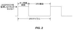
DRXサイクルは、ネットワークノードによって設定され、次のパラメータによって特徴付けられる:The DRX cycle is set by the network node and is characterized by the following parameters:
オン持続時間(デュレーション):DRXサイクルのオン持続時間中に、ネットワークノードによって構成される「onDurationTimer」と呼ばれるタイマーが実行されている。このタイマーはDRXサイクルの始めにおける連続する制御チャネルサブフレーム(例えば、PDCCH、ePDCCHサブフレーム)の数を指定する。これは、互換的にDRX ON期間とも呼ばれる。より具体的には、それはUEが制御チャネル(例えば、PDCCH、ePDCCH)を受信するためにDRXからウェイクアップした後のダウンリンクサブフレームにおける持続時間である。UEがオン持続時間中に制御チャネル(例えば、PDCCH、ePDCCH)の復号に成功した場合、UEはdrxインアクティビティタイマー(drx‐inactivity timer、以下を参照)を開始し、その満了まで起きたままでいる。onDurationTimerが実行中であるとき、UEは、DRXサイクルのDRX状態にあると見なされる。On Duration: During the on duration of a DRX cycle, a timer called "onDurationTimer", configured by the network node, is running. This timer specifies the number of consecutive control channel subframes (e.g., PDCCH, ePDCCH subframes) at the beginning of the DRX cycle. This is also interchangeably called the DRX ON period. More specifically, it is the duration in downlink subframes after the UE wakes up from DRX to receive a control channel (e.g., PDCCH, ePDCCH). If the UE successfully decodes a control channel (e.g., PDCCH, ePDCCH) during the on duration, the UE starts the drx-inactivity timer (see below) and stays awake until its expiration. When the onDurationTimer is running, the UE is considered to be in the DRX state of the DRX cycle.
drxインアクティビティタイマー:制御チャネル(例えば、PDCCH)がこのメディアアクセス制御(MAC)エンティティの初期ULまたはDLユーザデータ送信を示すサブフレームの後の連続する制御チャネル(例えば、PDCCH、ePDCCH)サブフレームの個数を指定する。また、これはネットワークノードによって設定される。drxインアクティビティタイマーが実行中であるとき、UEは非DRX状態にあると見なされ、すなわち、DRXは使用されない。drx inactivity timer: Specifies the number of consecutive control channel (e.g., PDCCH, ePDCCH) subframes after the subframe in which the control channel (e.g., PDCCH) indicates an initial UL or DL user data transmission for this medium access control (MAC) entity. It is also configured by the network node. When the drx inactivity timer is running, the UE is considered to be in a non-DRX state, i.e., DRX is not used.
アクティブ時間(Active time):この時間はUEが制御チャネル(例えば、PDCCH、ePDCCH)を監視する持続時間である。言い換えると、これは、UEが起きている間の合計持続時間である。これは、DRXサイクルの「オン持続時間」、インアクティビティタイマーが満了していない間にUEが連続受信を実行している時間、および1つのハイブリッド自動再送要求(HARQ)ラウンドトリップ時間(RTT)後にDL再送を待っている間にUEが連続受信を実行している時間を含む。最小アクティブ時間はオン持続時間の長さに等しく、最大アクティブ時間は未定義(無限大)である。Active time: This is the duration that the UE monitors the control channels (e.g., PDCCH, ePDCCH). In other words, this is the total duration during which the UE is awake. This includes the "on duration" of the DRX cycle, the time during which the UE performs continuous reception while the inactivity timer has not expired, and the time during which the UE performs continuous reception while waiting for a DL retransmission after one Hybrid Automatic Repeat Request (HARQ) Round Trip Time (RTT). The minimum active time is equal to the length of the on duration, and the maximum active time is undefined (infinity).
DRXサイクルのDRX ON及びDRX OFF持続時間の一例を図1に示す。LTEにおけるより詳細なパラメータを用いたDRX動作の一例を図2に示す。本明細書におけるDRX構成は、強化または拡張DRX(eDRX)構成であってもよい。従来の(レガシー)DRX関連の手順では、UEは最大2.56秒のDRXサイクル長で構成できる。しかし、拡張DRX(eDRX)をサポートするUEは少なくとも2.56秒よりも長く、典型的には2.56秒よりもはるかに長い、すなわち、数秒から数分のオーダーのDRXサイクルで構成されることができる。eDRX構成パラメータには、eDRXサイクル長とページングウィンドウ長(ページング時間ウィンドウ(PTW)長などとも呼ばれる)が含まれる。eDRXのPTW内で、UEはさらに1つ以上のレガシーDRXサイクルで構成される。An example of the DRX ON and DRX OFF durations of a DRX cycle is shown in FIG. 1. An example of DRX operation with more detailed parameters in LTE is shown in FIG. 2. The DRX configuration in this specification may be an enhanced or extended DRX (eDRX) configuration. In conventional (legacy) DRX-related procedures, a UE can be configured with a DRX cycle length of up to 2.56 seconds. However, a UE supporting extended DRX (eDRX) can be configured with a DRX cycle that is at least longer than 2.56 seconds, and typically much longer than 2.56 seconds, i.e., on the order of a few seconds to a few minutes. The eDRX configuration parameters include an eDRX cycle length and a paging window length (also referred to as a paging time window (PTW) length, etc.). Within the eDRX PTW, the UE is further configured with one or more legacy DRX cycles.
TAに関わる問題がある。事前構成されたアップリンクリソースを使用するRRC_IDLEモードでの送信は、UEがRRC_CONNECTED状態でTAコマンドを取得し、後でアップリンク送信のタイミングを調整するためにRRC_IDLE状態でそのTAを使用することによって実現される。しかしながら、RRC_IDLE状態のPURを使用したアップリンク送信は、TAコマンドを含むPUR設定の受信の直後または短時間内には行われない場合がある。典型的には、それは代わりに、時間的により後に起こる。送信の前に、UEは2つの無線リソース管理(RRM)測定を使用して行われる受信されたTAを検証することを要求され、そのうちの1つはTAが取得された時間の前後に実行され、第2の1つは検証が実行された時間の前後に実行される。さらに、MTCおよびNB‐IoTの両方の電力制御アルゴリズムはアップリンク送信電力を決定するためにパスロス(PL)推定値を利用し、このPLもRRM測定値から推定される。この振る舞いに関する問題は測定ウィンドウが定義されておらず、あいまいなUE振る舞いにつながり、TA検証およびPLを推定するために使用される測定がかなり古いものになる可能性があることである。この場合、これらの測定値はUEのモビリティ、周囲環境の変化、UEタイミングドリフトなどの様々な理由のために、UEの実際の無線状態を反映しないことがある。TA検証のためにそのような測定値を使用することは、不正確なTA検証結果および誤ったPL推定をもたらす可能性がある。There is a problem with TA. Transmission in RRC_IDLE mode using pre-configured uplink resources is achieved by the UE obtaining a TA command in RRC_CONNECTED state and later using that TA in RRC_IDLE state to adjust the timing of uplink transmission. However, uplink transmission using PUR in RRC_IDLE state may not occur immediately or within a short time after receiving the PUR configuration containing the TA command. Typically, it occurs later in time instead. Before transmission, the UE is required to verify the received TA, which is done using two Radio Resource Management (RRM) measurements, one of which is performed around the time the TA was obtained and the second one around the time the verification was performed. Furthermore, the power control algorithms of both MTC and NB-IoT utilize path loss (PL) estimates to determine the uplink transmit power, where PL is also estimated from RRM measurements. The problem with this behavior is that the measurement window is not defined, leading to ambiguous UE behavior and the measurements used to estimate TA validation and PL may be quite out of date. In this case, these measurements may not reflect the actual radio conditions of the UE due to various reasons such as UE mobility, changes in the surrounding environment, UE timing drift, etc. Using such measurements for TA validation may result in inaccurate TA validation results and erroneous PL estimation.
本明細書で説明される実施形態は、不正確なTA検証結果および誤ったPL推定につながる可能性がある問題に対処することを目的とする。無線デバイス(例えば、UE)に関連するいくつかの実施形態によれば、TA検証(バリデート)プロセスおよびPL推定は、UEにおける測定の可用性に基づいてUEにおいて適合される。TA検証プロセスおよびPL推定値を適応させることは意図された送信(例えば、PUR送信)に影響を及ぼし、これはUEが送信を実行すること、またはPUR送信を延期または中止(ドロップ)することを可能にし得る。適合は、利用可能な測定を、TA検証、電力制御のためのPL推定、またはPL変化推定のために使用できるかどうかを指定する測定ルールセットと比較することを含むことができる。(図3参照)測定が有効でない(例えば、ある時間範囲内で行われない)場合には、送信を延期またはドロップすることができる、あるいは他の測定を行うことができる。The embodiments described herein aim to address issues that may lead to inaccurate TA validation results and erroneous PL estimation. According to some embodiments related to a wireless device (e.g., a UE), the TA validation process and PL estimation are adapted at the UE based on the availability of measurements at the UE. Adapting the TA validation process and PL estimation may affect the intended transmission (e.g., a PUR transmission), which may allow the UE to perform the transmission or to postpone or abort (drop) the PUR transmission. The adaptation may include comparing the available measurements with a measurement rule set that specifies whether they can be used for TA validation, PL estimation for power control, or PL change estimation. (See FIG. 3) If the measurement is not valid (e.g., not made within a certain time range), the transmission may be postponed or dropped, or other measurements may be made.
いくつかの実施形態によれば、PURを使用するアイドルモードアップリンク送信など、アップリンク送信を実行するために無線デバイスによって実行される方法はサービングセルの信号測定M2が基準時刻T2の前および基準時刻T2までの所定の時間範囲内に完了したかどうかを判定することを含み、基準時刻T2はアップリンク送信機会に対応する。この方法はさらに、サービングセルの信号測定M2が所定の時間範囲内に完了していないと判定することに応じて、送信機会で送信するためのTAを検証する際に、および/または送信機会での送信の電力制御のためのPLを推定するために使用するために、後続のアップリンク送信機会への送信を保留するか、またはアップリンク送信をドロップするか、または所定の時間範囲内に入る追加のサービングセルの測定M2'を収集することの何れかを含む。According to some embodiments, a method performed by a wireless device to perform uplink transmission, such as idle mode uplink transmission using PUR, includes determining whether a serving cell signal measurement M2 is completed before and within a predetermined time range up to a reference time T2, where the reference time T2 corresponds to an uplink transmission opportunity. The method further includes, in response to determining that the serving cell signal measurement M2 is not completed within the predetermined time range, either withholding transmission to a subsequent uplink transmission opportunity, dropping the uplink transmission, or collecting additional serving cell measurements M2' that fall within the predetermined time range for use in validating a TA for transmitting at the transmission opportunity and/or estimating a PL for power control of transmission at the transmission opportunity.
いくつかの実施形態によれば、PURを使用するアイドルモードアップリンク送信などのアップリンク送信を実行するための無線デバイスによる方法は第1の基準時刻T1におけるTAを含む構成情報を取得することと、第2の基準時刻T2を第1の基準時刻T1と比較することと、を含み、第2の基準時刻T2は、TA検証、電力制御のためのパスロス(PL)推定、および/またはパスロスの変化推定が実行されるべき時間である。この方法は、第1の基準時刻T1と第2の基準時刻T2との間の時間差が所与の差分の閾値を満たさないと判定することに応答して、(a)無線デバイスにおいて利用可能な任意の測定値を使用して、または新しい測定を実行して、TA検証、電力制御のためのPL推定、および/またはPL変化推定を実行し、TA検証、電力制御のためのPL推定、および/またはPL変化推定に基づいてアップリンク送信を実行することと、(b)第3の基準時刻T3までアップリンク送信を延期することと、(c)アップリンク送信をドロップすることのうちの1つをさらに含む。According to some embodiments, a method by a wireless device for performing an uplink transmission, such as an idle mode uplink transmission using PUR, includes obtaining configuration information including a TA at a first reference time T1 and comparing a second reference time T2 to the first reference time T1, the second reference time T2 being a time at which TA verification, path loss (PL) estimation for power control, and/or path loss change estimation should be performed. In response to determining that a time difference between the first reference time T1 and the second reference time T2 does not meet a given difference threshold, the method further includes one of: (a) performing TA verification, PL estimation for power control, and/or PL change estimation using any measurements available at the wireless device or performing new measurements, and performing an uplink transmission based on the TA verification, PL estimation for power control, and/or PL change estimation; (b) postponing the uplink transmission until a third reference time T3; and (c) dropping the uplink transmission.
本発明のさらなる態様は、上記で要約された方法および上記で要約された無線中継ノードの機能実装に対応するデバイス、無線デバイス、UE、ネットワークノード、基地局、中継ノード、ネットワークデバイス、コンピュータプログラム製品またはコンピュータ可読記憶媒体を対象とする。Further aspects of the present invention are directed to a device, wireless device, UE, network node, base station, relay node, network device, computer program product or computer readable storage medium corresponding to the method summarized above and the implementation of the wireless relay node functionality summarized above.
実施形態の利点は、TA検証のために使用される測定値が、TAが受信され、TA検証が実行される時刻をより良く表す場合に、TA検証がより信頼できることを含む。他の利点には、受信ノードが送信を受信できる確率が高いことが含まれる。これらの技術がPUR送信に適用される場合、これは、PURリソースのより良好な使用を可能にする。Advantages of embodiments include that TA verification is more reliable when the measurements used for TA verification are more representative of the time when the TA is received and the TA verification is performed. Other advantages include a higher probability that the receiving node will be able to receive the transmission. When these techniques are applied to PUR transmissions, this allows for better utilization of PUR resources.
以下、本開示の例示的な実施形態を、本発明の概念の実施形態の例が示されている添付の図面を参照して、より完全に説明する。しかしながら、本発明の概念は、多くの異なる形態で具現化されてもよく、本明細書に記載された実施形態に限定されるものとして解釈されるべきではない。むしろ、これらの実施形態は本開示が徹底的かつ完全であり、本発明の概念の範囲を当業者に十分に伝えるように提供される。また、これらの実施形態は、相互に排他的ではないことにも留意されたい。一実施形態からの構成要素は、別の実施形態において存在/使用されると暗黙に想定することができる。本明細書に記載される任意の2つ以上の実施形態は、互いに組み合わされてもよい。実施形態はLTEまたはNRに関して説明されるが、技術または選択が関連し得る他の無線アクセス技術に適合され得る。Exemplary embodiments of the present disclosure will now be described more fully with reference to the accompanying drawings, in which examples of embodiments of the inventive concepts are shown. However, the inventive concepts may be embodied in many different forms and should not be construed as being limited to the embodiments set forth herein. Rather, these embodiments are provided so that this disclosure will be thorough and complete, and will fully convey the scope of the inventive concepts to those skilled in the art. It should also be noted that these embodiments are not mutually exclusive. Elements from one embodiment may be implicitly assumed to be present/used in another embodiment. Any two or more embodiments described herein may be combined with each other. Although the embodiments are described with respect to LTE or NR, they may be adapted to other radio access technologies where technology or selection may be relevant.
本明細書で説明される実施形態は、TA検証および/またはPL推定のために使用される測定値を検証することを対象とする。この検証がPUR送信に関連して実行される場合、これは、事前構成されたリソース(PUR)のより良好な使用につながる。The embodiments described herein are directed to validating measurements used for TA validation and/or PL estimation. If this validation is performed in conjunction with PUR transmission, this leads to better utilization of pre-configured resources (PUR).
本明細書で説明されるいくつかの実施形態では、より一般的な用語「ネットワークノード」が使用される。この用語は、任意のタイプの無線ネットワークノード、またはUEや別のネットワークノードと通信する任意のネットワークノードに対応することができる。ネットワークノードの例は、NodeB、MeNB、SeNB、MCGまたはSCGに属するネットワークノード、基地局(BS)、MSR BS、eNodeB、gNodeBなどのマルチスタンダード無線(MSR)無線ノード、ネットワークコントローラ、無線ネットワークコントローラ(RNC)、基地局コントローラ(BSC)、リレー、ドナーノード制御リレー、基地送受信局(BTS)、アクセスポイント(AP)、送信ポイント、送信ノード、RRU、RRH、分散アンテナシステム(DAS)内のノード、コアネットワークノード(例えば、MSC、MMEなど)、O&M、OSS、SON、測位ノード(例えば、E-SMLC)、MDT、試験装置(物理ノードまたはソフトウェア)などである。In some embodiments described herein, the more general term "network node" is used. This term can correspond to any type of radio network node, or any network node that communicates with a UE or another network node. Examples of network nodes are NodeB, MeNB, SeNB, network nodes belonging to an MCG or SCG, base station (BS), MSR BS, multi-standard radio (MSR) radio nodes such as eNodeB, gNodeB, network controller, radio network controller (RNC), base station controller (BSC), relay, donor node control relay, base transceiver station (BTS), access point (AP), transmission point, transmitting node, RRU, RRH, node in a distributed antenna system (DAS), core network node (e.g., MSC, MME, etc.), O&M, OSS, SON, positioning node (e.g., E-SMLC), MDT, test equipment (physical node or software), etc.
いくつかの実施形態では、非限定的な用語であるユーザ装置(UE)または無線デバイスが使用される。本明細書で使用されるように、この用語は、セルラーまたは移動通信システムにおいて、ネットワークノードおよび/または別のUEと通信する任意のタイプの無線デバイスを指す。UEの例は、ターゲットデバイス、デバイスツーデバイス(D2D)UE、マシンタイプUEまたはマシンツーマシン(M2M)通信が可能なUE、PDA、PAD、タブレット、モバイル端末、スマートフォン、ラップトップ埋め込み型(LEE)、ラップトップ搭載機器(LME)、USBドングル、ProSe UE、V2V UE、V2X UEなどである。In some embodiments, the non-limiting term User Equipment (UE) or wireless device is used. As used herein, the term refers to any type of wireless device that communicates with a network node and/or another UE in a cellular or mobile communication system. Examples of UEs are target devices, device-to-device (D2D) UEs, machine-type UEs or UEs capable of machine-to-machine (M2M) communication, PDAs, PADs, tablets, mobile terminals, smartphones, laptop embedded (LEE), laptop mounted equipment (LME), USB dongles, ProSe UEs, V2V UEs, V2X UEs, etc.
実施形態はLTE、例えば、MTCおよびNB‐IoTについて説明される。しかしながら、実施形態はUEが信号(例えば、データ)、例えば、LTE FDD/TDD、WCDMA(登録商標)/HSPA、GSM/GERAN、Wi Fi、WLAN、CDMA2000、5G、NRなどを受信および/または送信する任意のRATまたはマルチRATシステムに適用可能である。The embodiments are described for LTE, e.g., MTC and NB-IoT. However, the embodiments are applicable to any RAT or multi-RAT system in which a UE receives and/or transmits signals (e.g., data), e.g., LTE FDD/TDD, WCDMA/HSPA, GSM/GERAN, Wi-Fi, WLAN, CDMA2000, 5G, NR, etc.
本明細書で使用される「時間リソース」という用語は、時間の長さの観点で表現される任意の種類の物理リソースまたは無線リソースに対応しうる。時間リソースの例は、シンボル、ミニスロット、タイムスロット、サブフレーム、無線フレーム、TTI、ショートTTI、インターリーブ時間などである。As used herein, the term "time resource" may correspond to any type of physical or radio resource expressed in terms of a length of time. Examples of time resources are symbols, minislots, time slots, subframes, radio frames, TTIs, short TTIs, interleaved times, etc.
「セル1」と呼ばれることがある、第1のセルによってサービスを提供されるUEを備えるシナリオでは、セル1がネットワークノード(NW1)、たとえば基地局によって管理されるか、またはサービスを提供されるか、または動作される。UEは特定のセルに関して、例えば、セル1に関して、特定のカバレッジ強化(CE)レベルで動作する。UEは少なくともセル1から信号(例えば、ページング、WUS、NPDCCH、MPDCCH、NPDSCH、PDSCHなど)を受信するように構成される。UEはセル1および1つ以上の追加のセル、たとえば、隣接セル上で1つ以上の測定を実行するようにさらに構成され得る。In a scenario with a UE served by a first cell, sometimes referred to as "cell 1", cell 1 is managed or served or operated by a network node (NW1), e.g., a base station. The UE operates with respect to a particular cell, e.g., cell 1, at a particular coverage enhancement (CE) level. The UE is configured to receive signals (e.g., paging, WUS, NPDCCH, MPDCCH, NPDSCH, PDSCH, etc.) from at least cell 1. The UE may be further configured to perform one or more measurements on cell 1 and one or more additional cells, e.g., neighboring cells.
ネットワークノードNW1によってサービスを提供されるセル1の下で動作する無線デバイス(例えば、UE)に関連するいくつかの実施形態を説明する。いくつかの実施形態によれば、第1のステップにおいて、UEは、時間インスタンスT1においてPUR設定(構成)に関する情報を取得する。この情報は、以下のいずれか、またはすべてを含むことができるが、これらに限定されない:UEがPUR可能であるか否か;UEが任意のPUR送信リソース、例えば、周期的、非周期的リソースを割り当てられているか否か;PUR設定に関連するTA値;および異なるタイプでありうるPURリソースの、すなわち、専用、無競合共有、または競合ベースの共有PURリソース。PUR設定に関する取得された情報は、例えば、PUR送信周期(例えば、Nミリ秒毎にMミリ秒の持続時間にわたって行われるPUR送信リソース)、PUR開始位置、及びターゲットセルに関するタイミングアドバンス情報を含むことができる。PUR送信リソースは1つ以上の時間-周波数リソース(例えば、リソースブロック、サブキャリアなど)を含みうる。Some embodiments are described in relation to a wireless device (e.g., UE) operating under cell 1 served by network node NW1. According to some embodiments, in a first step, the UE obtains information about a PUR configuration at time instance T1. This information may include, but is not limited to, any or all of the following: whether the UE is PUR-enabled; whether the UE is assigned any PUR transmission resources, e.g., periodic, aperiodic resources; a TA value associated with the PUR configuration; and the PUR resources may be of different types, i.e., dedicated, contention-free shared, or contention-based shared PUR resources. The obtained information about the PUR configuration may include, for example, a PUR transmission periodicity (e.g., a PUR transmission resource that occurs every N milliseconds for a duration of M milliseconds), a PUR start position, and timing advance information about the target cell. The PUR transmission resources may include one or more time-frequency resources (e.g., resource blocks, subcarriers, etc.).
受信された構成は、使用するTA検証方法に関する情報、例えば、UEがセル1上のRRM測定値を使用してPUR送信の前にTAを検証することを要求されるかどうか、TAが常にセル1において有効であると仮定されるかどうか、またはUEがTAに関連する任意のタイマ(例えば、TAT)を使用するように構成されるかどうか、例えば、TAがタイマが満了するまで有効であると仮定されるようにすること、をさらに含み得る。本明細書で説明される実施形態は、UEがサービングセルの測定値の変化に基づいてTA検証を使用するように構成されていることを前提としている場合がある。The received configuration may further include information regarding the TA verification method to use, e.g., whether the UE is required to verify the TA before PUR transmission using RRM measurements on cell 1, whether the TA is assumed to be valid at all times in cell 1, or whether the UE is configured to use any timer (e.g., TAT) associated with the TA, e.g., such that the TA is assumed to be valid until the timer expires. The embodiments described herein may assume that the UE is configured to use TA verification based on changes in measurements of the serving cell.
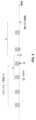
第2のステップでは、UEがルールセットに従って、第1の測定(M1)をT1に関連付ける。これらのルールの第1の態様によれば、時間インスタンスT1におけるセル1に関するUEの実際の無線状態を反映することを意図しているので、M1は、できるだけT1に近い時間にサービングセルによって送信された信号に対してUEによって実行される。これは、UEがTA値を含むPUR構成を取得した基準時刻をT1とする図3に例示される。別の例ではT1がUEが更新されたTAをNW1から取得する時間に対応する。例えば、T1はPUR送信に応答して送信される再送割り当て(グラント)、すなわちL1 ACK、すなわちL2/L3 ACKで取得されることができる。T1'は、M1がUEによってサービングセル上で実行される実際の時間である。より具体的には、UEが時間インスタンスT1'においてM1を完了している。測定M1は、N≧1であるN個のサンプルを使用して持続時間ΔT1にわたって実行される。UEは、典型的にはDRXサイクル当たり1つのサンプルを取得することができる。測定周期は、互換可能にL1測定周期、評価周期、測定時間などとも呼ばれる。In a second step, the UE associates a first measurement (M1) to T1 according to a set of rules. According to a first aspect of these rules, M1 is performed by the UE on signals transmitted by the serving cell at a time as close as possible to T1, since it is intended to reflect the actual radio conditions of the UE with respect to cell 1 at time instance T1. This is illustrated in FIG. 3, where T1 is the reference time at which the UE obtains a PUR configuration including a TA value. In another example, T1 corresponds to the time at which the UE obtains an updated TA from NW1. For example, T1 can be obtained in a retransmission assignment (grant) transmitted in response to a PUR transmission, i.e., the L1 ACK, i.e., the L2/L3 ACK. T1' is the actual time at which M1 is performed by the UE on the serving cell. More specifically, the UE has completed M1 at time instance T1'. The measurement M1 is performed over a duration ΔT1 using N samples, where N≧1. A UE can typically obtain one sample per DRX cycle. The measurement period is also interchangeably referred to as the L1 measurement period, evaluation period, measurement time, etc.
いくつかの実施形態に適用可能な規則によれば、UEはT1およびT1'が互いに時間的に密接に離間している場合にのみ、TA検証のためにM1を使用することを許可される。例えば、M1はT1とT1'との間の差の大きさが所定のマージン内にあるならば、TA検証のために使用されることが許される。1つの具体例では、UEが以下の条件が満たされる場合にのみ、TA検証のためにM1を使用することを許可される。
(T1-T01)≦T1'≦(T1+T02) (1)
T01=T02である特殊な場合:
(T1-T01)≦T1'≦(T1+T01) According to rules applicable to some embodiments, the UE is allowed to use M1 for TA verification only if T1 and T1' are closely spaced in time from each other. For example, M1 is allowed to be used for TA verification if the magnitude of the difference between T1 and T1' is within a predetermined margin. In one specific example, the UE is allowed to use M1 for TA verification only if the following conditions are met:
(T1-T01)≦T1'≦(T1+T02) (1)
The special case where T01=T02:
(T1-T01)≦T1'≦(T1+T01)
この原理は図4に示されており、ここでT1'はM1がUEによって完了された場合に、それが有効であると見なされる時間インスタンスである。これは、M1はT1-T01またはT1+T02よりも早く始まることができるが、フィルタリングに使用される最終サンプルおよび最終測定値は(1)の範囲内で利用可能であることを意味する。言い換えると、測定はT1-T01またはT1+T02よりも早く開始されている可能性があるが、最終サンプルおよび測定値は範囲(1)内のUEにおいて利用可能である。場合によっては、T01=T02である。This principle is illustrated in Figure 4, where T1' is the time instance at which M1 is considered valid if it has been completed by the UE. This means that M1 can start earlier than T1-T01 or T1+T02, but the final sample and measurement used for filtering are available within the range (1). In other words, the measurement may have started earlier than T1-T01 or T1+T02, but the final sample and measurement are available at the UE within the range (1). In some cases, T01=T02.
(1)の条件が満たされる場合、UEはそのような測定値(M1)を使用して、T1における測定値を表し、TA検証のために、および/またはPL推定値を提供するために、後にそれを使用することを許可される。しかしながら、上記の条件が満たされない場合、UEはT1の測定条件をより良く表すことができる新しい測定を実行し、TA検証のための後の使用のために、および/またはPL推定値を提供するために、それを格納することを要求される。If condition (1) is met, the UE is permitted to use such measurement (M1) to represent the measurement at T1 and to use it later for TA verification and/or to provide a PL estimate. However, if the above condition is not met, the UE is required to perform a new measurement that can better represent the measurement conditions at T1 and to store it for later use for TA verification and/or to provide a PL estimate.
PUR送信は通常、少量のデータからなり、非アクティブ状態(例えば、RRC_IDLE状態)から直接送信されるので、UEは、送信目的のためにRRC_CONNECTED状態に切り替わらないことによって、改善された電力消費を達成する。同様に、電力消費をさらに改善するために、UEは、TA検証目的のためのいかなる専用の測定も実行する必要がない。しかしながら、TA検証に使用される測定が(1)の条件を満たすことができることが重要である。このルールにより、UEは、UEにおいて利用可能な任意の利用可能な測定値を使用する自由を有する(これはUEが電力消費を低減するのを助ける)が、同時に、測定値が古くならないようにする。UEが(1)の条件を満たすことができる場合、それは測定が最大値‐T01または+T02の古さであることを意味し、無線状態はこの短い持続時間内であまり変化しない可能性が高い。したがって、UEはT1における無線状態を表すために、T1'において実行されるM1を使用することを許可される。Since PUR transmissions usually consist of a small amount of data and are transmitted directly from an inactive state (e.g., RRC_IDLE state), the UE achieves improved power consumption by not switching to the RRC_CONNECTED state for transmission purposes. Similarly, to further improve power consumption, the UE does not need to perform any dedicated measurements for TA verification purposes. However, it is important that the measurements used for TA verification can satisfy condition (1). By this rule, the UE has the freedom to use any available measurements available at the UE (which helps the UE to reduce power consumption), but at the same time, ensures that the measurements are not stale. If the UE can satisfy condition (1), it means that the measurements are at most −T01 or +T02 stale, and the radio conditions are likely not to change much within this short duration. Therefore, the UE is allowed to use M1 performed at T1' to represent the radio conditions at T1.
第3のステップでは、UEが別のルールセットに従って、第2の測定値(M2)をT2に関連付ける。T2は、UEがTA検証を実行しているとき、または、以前のステップから取得されたM1と、以下で説明するように取得されたM2と、の2つの測定を使用して、パスロスの変化を判定しているときの基準時刻である。M2はまた、サービングセルによって送信された信号上でUEによって実行され、ULの送信電力を決定するために、MTCおよびNB‐IoTの両方の電力制御アルゴリズムにおけるPL期間を推定するために、それ自体で使用され得る。M2は、実際には時間インスタンスT2'までにUEによって実行されるものと想定される。これは、測定がT2'よりも前に開始されたとしても、UEが時間T2'までに測定を完了したことを意味し、例えば、T2'-ΔT2であり、ここで、ΔT2=M2個の測定周期であり、その間に、UEはN個のサンプルに基づいて測定を実行し、ここで、N≧1である。UEはまた、典型的には、DRXサイクルごとに1つのサンプルを取得することができる。換言すれば、M2のフィルタリングに使用される最後のサンプルは既に利用可能であり、フィルタリングされた測定値は基準時刻T2の前に使用可能である。これは、UEがT1の前のT01時間単位とT1の後のT02時間単位の両方の測定を行うことが可能になる、M1と比較した重要な差である。この場合、実際にはT2でTA検証が行われるため、将来利用できるようになるであろう測定を待つ意味がない。したがって、一般的なルールとして、M2がUEによってT2までに完了し、時間インスタンス(T2-Tx)より早くない場合に、TA検証方法として有効であるとみなされる。図5は、TA検証の前にM2をT2に関連付けるためのルールを示す。In a third step, the UE associates a second measurement (M2) with T2 according to another set of rules. T2 is the reference time when the UE is performing TA verification or determining the path loss change using two measurements, M1 obtained from the previous step and M2 obtained as described below. M2 can also be used by itself to estimate the PL period in both MTC and NB-IoT power control algorithms performed by the UE on the signal transmitted by the serving cell to determine the UL transmit power. M2 is actually assumed to be performed by the UE by time instance T2'. This means that even if the measurement is started before T2', the UE has completed the measurement by time T2', e.g., T2'-ΔT2, where ΔT2=M2 measurement periods, during which the UE performs the measurement based on N samples, where N≧1. The UE can also typically obtain one sample per DRX cycle. In other words, the last sample used to filter M2 is already available and the filtered measurements are available before the reference time T2. This is an important difference compared to M1, which allows the UE to make measurements both T01 time units before T1 and T02 time units after T1. In this case, there is no point in waiting for measurements that will be available in the future, since the TA verification is actually done at T2. Therefore, as a general rule, M2 is considered valid as a TA verification method if it is completed by the UE by T2 and not earlier than the time instance (T2-Tx). Figure 5 shows the rules for associating M2 with T2 before TA verification.
より具体的には、M2は、以下の条件を満たす場合、TA検証方法のための有効な測定と見なされる。
(T2-Tx)≦ T2' ≦ T2 (2)
そうでない場合、M2は無効であると見なされ、その場合、UEは上記の条件を満たす新しい測定を実行する必要があってもよいし、T2の少なくともT3時間単位後に発生する任意の将来のPUR送信機会までPUR送信を遅延させてもよいし、またはPURをドロップし、レガシーRACH/EDTにフォールバックしてもよい。 More specifically, M2 is considered a valid measurement for the TA verification method if it meets the following conditions:
(T2-Tx)≦T2'≦T2 (2)
Otherwise, M2 is considered invalid, in which case the UE may need to perform new measurements that satisfy the above condition, may delay the PUR transmission until any future PUR transmission opportunity occurring at least T3 time units after T2, or may drop the PUR and fall back to legacy RACH/EDT.
第4のステップでは、いくつかの実施形態によれば、UEは例えば、M1およびM2がそれぞれ(1)および(2)の条件を満たしている場合に、ステップ2および3から取得された測定(M1およびM2)が有効であるとみなされることを条件として、TA検証および/またはパスロス推定を実行する。例えば、M1およびM2の両方の測定が両方とも有効である場合、UEはそれらを互いに対して比較することができ、それらの比較に基づいて、TAが有効であるかどうかを決定することができる。例えば、M1とM2との間の差の大きさが、所定の閾値(G)未満である場合、UEはTAが有効であると仮定することができ、そうではない場合、TAは無効である。UEはまた、例えば、セル変更に基づいて、TAを検証するための1つ以上の追加の方法を使用するように構成されてもよい。In a fourth step, according to some embodiments, the UE performs TA verification and/or path loss estimation, provided that the measurements (M1 and M2) obtained from steps 2 and 3 are considered valid if, for example, M1 and M2 satisfy conditions (1) and (2), respectively. For example, if both measurements of M1 and M2 are both valid, the UE may compare them against each other and, based on the comparison, may determine whether the TA is valid. For example, if the magnitude of the difference between M1 and M2 is less than a predefined threshold (G), the UE may assume that the TA is valid, otherwise the TA is invalid. The UE may also be configured to use one or more additional methods for verifying the TA, for example, based on a cell change.
UEが(M1およびM2の関係に基づく)信号強度ベースのTA検証方法のみを使用するように構成され、TAが信号強度に基づいて有効であると判定される場合、UEはPUR送信のためにTAを使用することができ、そうではない場合、UEは、PUR送信のためにTAを使用しない。M1およびM2の測定のうちの少なくとも1つが無効である場合、UEは、TAを検証するためにM1およびM2を使用することさえできなくてもよい。この場合、UEは、PUR送信のためにTAを使用しないか、またはTA検証の目的のために新しい専用の測定を実行する必要があり得る。If the UE is configured to use only the signal strength-based TA verification method (based on the relationship between M1 and M2) and the TA is determined to be valid based on the signal strength, the UE may use the TA for PUR transmission, otherwise the UE does not use the TA for PUR transmission. If at least one of the measurements of M1 and M2 is invalid, the UE may not even be able to use M1 and M2 to verify the TA. In this case, the UE may not use the TA for PUR transmission or may need to perform a new dedicated measurement for the purpose of TA verification.
無線デバイスに関連する別の実施形態を説明する。この実施形態の方法は無線デバイス(UE)がPUR設定を受信し、TAがネットワークノードから取得された時間に対応する基準時刻T1に関する情報を取得することを含むことができる。この方法は基準時刻T2、すなわち、UEがTA検証を実行することが予想されるときを判定することをさらに含むことができる。この方法には、T1とT2を比較し、比較の結果に基づいて、以下のいずれかの措置を講じることが含まれる:|T1-T2|≧Xを条件として、M1とM2を用いてTA検証を実施すること、T3だけPUR送信を延期すること、または(前の実施形態で説明したように)PUR送信をドロップすること。Another embodiment related to a wireless device is described. The method of this embodiment can include a wireless device (UE) receiving a PUR configuration and obtaining information about a reference time T1 corresponding to the time when the TA was obtained from a network node. The method can further include determining the reference time T2, i.e., when the UE is expected to perform TA verification. The method can include comparing T1 and T2 and taking one of the following actions based on the result of the comparison: perform TA verification using M1 and M2, postpone the PUR transmission by T3, or drop the PUR transmission (as described in the previous embodiment), provided that |T1-T2|≧X.
この実施形態による方法の第1のステップによれば、UEは、TAを含むPUR設定を受信する。この情報から、UEは、T1の基準時刻を知る。第2のステップでは、UEは、UEがTA検証を実行すること、および/またはPUR送信のためのPL推定値を提供することが予想される基準時刻T2を判定する。T2は、PUR構成から明示的または暗黙的に得ることができる。例えば、取得されたPUR構成から、UEは、UEがいつウェイクアップし、データを送信すると予想されるかを知る。あるいは、非周期的なPUR報告が設定されている場合、UEはいつデータがトリガーされたか、またはいつデータが送信可能であるかに関する情報を持つべきである。例えば、UEバッファにおいてデータが利用可能である場合、UEはPUR送信がいつ予想されるかを判定することができ、その前に(T2において)、UEはTA検証を実行する、および/またはPL推定値を提供しなければならない。したがって、T2はUEに知られている。さらに、T2に関連付けられるM2はUL送信電力を決定するために、MTCおよびNB-IoTの両方の電力制御アルゴリズムにおけるPL期間を推定するために、それ自体で使用されることができる。According to a first step of the method according to this embodiment, the UE receives a PUR configuration including a TA. From this information, the UE knows a reference time of T1. In a second step, the UE determines a reference time T2 at which the UE is expected to perform a TA verification and/or provide a PL estimate for a PUR transmission. T2 can be obtained explicitly or implicitly from the PUR configuration. For example, from the obtained PUR configuration, the UE knows when the UE is expected to wake up and transmit data. Alternatively, if aperiodic PUR reporting is configured, the UE should have information about when data is triggered or when data is available for transmission. For example, if data is available in the UE buffer, the UE can determine when a PUR transmission is expected, before which (at T2) the UE must perform a TA verification and/or provide a PL estimate. Thus, T2 is known to the UE. Furthermore, M2 associated with T2 can be used by itself to estimate the PL period in both MTC and NB-IoT power control algorithms to determine the UL transmit power.
第3のステップでは、UEが以前のステップで得られたT1およびT2の値を比較し、比較の結果に基づいて、TA検証またはパスロスの変更を実行する。例えば、UEはT1およびT2が特定の関数によって関連付けられていることを条件として、時間インスタンスT1'およびT2'によってそれぞれ(すなわち、それぞれ第2および第3のステップで説明された条件に従って)実行されるM1およびM2測定を使用することを要求され、そうではない場合、UEはTA検証方法および/またはPL推定のために、UEにおいて利用可能な任意の測定を使用することを許可される。この関数の例は、T1とT2との間の差、T1とT2との間の比較、重み付けされた比較などである。例えば、T1とT2との間の差の大きさが、所定の閾値Xよりも大きい場合、UEはTA検証のために、M1およびM2測定値(ここで、M1およびM2は前のセクションで説明したようなものである)を使用することを要求される:
|T1-T2| ≧ X (3)
そうではなく、上記の条件が満たされない場合(すなわち、|T1-T2|<X)、一例では、UEがTA検証のためにUEにおいて利用可能な任意の測定値を使用することを許可される。理論的根拠はT1とT2が時間的に大きく分離されている場合、無線状態はこれら2つの基準時刻の間で大きく変化し、次に、T1とT2にそれぞれ時間的に密接に実行されるM1とM2を使用して(例えば、それぞれT1'とT2'によって)、TA検証および/またはパスロス推定をより信頼できるものにすることができるということである。しかしながら、T1およびT2が時間的に近い場合、T1およびT2における無線状態は、互いに有意に異ならないことがある。したがって、UEは、任意の利用可能な測定値を使用することができる。UEが利用可能な測定値を有していない(例えば、M1およびM2が利用可能でない)か、または測定値が信頼できない場合、UEは、TA検証方法を実行することを回避することもできる。したがって、後者の場合、そのような測定に基づくTA検証を全く使用しない方がよい。代わりに、UEは別の方法(例えば、サービングセル測定変更)に基づいてTA検証方法を使用することを許可され得るが、この場合、UEはT1およびT2において専用測定を実行すべきである。これは、T1およびT2に時間的に近いM1およびM2を実行することと比較して、TA検証をより信頼できるものにする。UEが(3)の条件を満たすことができない場合の他のオプションは、ある時間単位(T3)だけ送信を延期すること、または送信を中止(ドロップ)することである。 In a third step, the UE compares the values of T1 and T2 obtained in the previous steps and performs a TA verification or a path loss modification based on the result of the comparison. For example, the UE is requested to use the M1 and M2 measurements performed by time instances T1' and T2', respectively (i.e. according to the conditions described in the second and third steps, respectively), provided that T1 and T2 are related by a certain function, otherwise the UE is allowed to use any measurement available in the UE for the TA verification method and/or PL estimation. Examples of this function are the difference between T1 and T2, the comparison between T1 and T2, a weighted comparison, etc. For example, if the magnitude of the difference between T1 and T2 is greater than a predefined threshold X, the UE is requested to use the M1 and M2 measurements (where M1 and M2 are as described in the previous section) for TA verification:
|T1-T2| ≧ X (3)
Otherwise, if the above condition is not met (i.e., |T1-T2|<X), in one example, the UE is allowed to use any measurements available at the UE for TA verification. The rationale is that if T1 and T2 are widely separated in time, the radio conditions will vary significantly between these two reference times, and then using M1 and M2 that are performed closely in time at T1 and T2, respectively (e.g., by T1' and T2', respectively), the TA verification and/or path loss estimation can be made more reliable. However, if T1 and T2 are close in time, the radio conditions at T1 and T2 may not differ significantly from each other. Thus, the UE can use any available measurements. If the UE does not have measurements available (e.g., M1 and M2 are not available) or the measurements are unreliable, the UE can also avoid performing the TA verification method. Thus, in the latter case, it is better not to use TA verification based on such measurements at all. Alternatively, the UE may be allowed to use a TA verification method based on another method (e.g., serving cell measurement change), but in this case the UE should perform dedicated measurements at T1 and T2, which makes the TA verification more reliable compared to performing M1 and M2 close in time to T1 and T2. Other options if the UE cannot meet condition (3) are to postpone the transmission by a certain time unit (T3) or to stop (drop) the transmission.
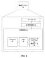
図6はUEのために本明細書で説明される技術を実行するように構成された例示的な無線デバイス50(たとえば、UE)を示す。無線デバイス50はまた、ネットワーク内で動作することができ、無線信号を介してネットワークノードまたは別の無線デバイスと通信することができる任意の無線デバイスを表すと見なされ得る。無線デバイス50はまた、様々なコンテキストにおいて、無線通信デバイス、ターゲットデバイス、デバイスツーデバイス(D2D)UE、マシンタイプUEまたはマシンツーマシン(M2M)通信が可能なUE、センサ内蔵UE、PDA(携帯情報端末)、ワイヤレスタブレット、モバイル端末、スマートフォン、ラップトップ埋め込み機器(LEE)、ラップトップマウント機器(LME)、ワイヤレスUSBドングル、カスタマ構内設備(CPE)などと呼ばれ得る。FIG. 6 illustrates an exemplary wireless device 50 (e.g., a UE) configured to perform the techniques described herein for the UE. The
無線デバイス50は、アンテナ54および送受信回路56を介して、1つ以上のネットワークノード30などの1つ以上の無線ノードまたは基地局と通信する。送受信回路56は、セルラ通信サービスを提供する目的で、無線アクセス技術に従って信号を送受信するように集合的に構成された送信器回路、受信器回路、および関連する制御回路を含んでもよい。The
また、無線デバイス50は、無線送受信回路56に動作可能に関連付けられ、制御する1つ以上の処理回路52を含む。処理回路52は1つ以上のデジタル処理回路62、例えば、1つ以上のマイクロプロセッサ、マイクロコントローラ、デジタル信号プロセッサ(DSP)、フィールドプログラマブルゲートアレイ(FPGA)、コンプレックスプログラマブル論理デバイス(CPLD)、特定用途向け集積回路(ASIC)、またはそれらの任意の組み合わせを備える。より一般的には、処理回路52が固定回路、または本明細書で開示される機能を実装するプログラム命令の実行を介して特に適合されるプログラマブル回路を備えることができ、または固定回路とプログラムされた回路との何らかの混合を備えることができる。処理回路52は、マルチコアであってもよい。The
処理回路52はまた、メモリ64を含む。メモリ64は、いくつかの実施形態では1つ以上のコンピュータプログラム66と、オプションで構成データ68とを格納する。メモリ64はコンピュータプログラム66のための非一時的記録装置を提供し、ディスクストレージ、ソリッドステートメモリストレージ、またはそれらの任意の組み合わせなどの1つ以上のタイプのコンピュータ可読媒体を備えることができる。非限定的な例として、メモリ64はSRAM、DRAM、EEPROM、およびフラッシュメモリのうちの任意の1つ以上を含み、これらは、処理回路52内にあってもよく、および/または処理回路52とは別個であってもよい。一般に、メモリ64は、コンピュータプログラム66の非一時的記憶を提供する1つ以上のタイプのコンピュータ可読記憶媒体と、無線デバイス50によって使用される任意の構成データ68とを含む。The processing circuitry 52 also includes a
したがって、いくつかの実施形態では、無線デバイス50の処理回路52がアップリンク送信を行うように構成される。アップリンク送信は例えば、PURを使用するアイドルモードアップリンク送信であってもよい。処理回路52はサービングセルの信号測定M2が基準時刻T2の前に所定の時間範囲内に完了したか否かを判定するように構成され、基準時刻T2はアップリンク送信機会に対応する。処理回路52はまた、サービングセルの信号測定M2が所定の時間範囲内に完了しなかったとの判定に応答して、送信機会で送信するためのTAを検証する際に、および/または送信機会での送信の電力制御のためのPLを推定するために使用するために、後続のアップリンク送信機会への送信を延期するか、またはアップリンク送信をドロップするか、または所定の時間範囲内に入る追加のサービングセル測定M2'を収集するように構成される。Thus, in some embodiments, the processing circuitry 52 of the
また、いくつかの実施形態によれば、処理回路52は、方法700を実行するように構成される。図7に示される方法700は、サービングセル信号測定M2が基準時刻T2の前に所定の時間範囲内に完了したか否かを判定するステップを含み、基準時刻T2はアップリンク送信機会、例えば、PURを使用する送信機会に対応する(ブロック702)。方法700はまた、サービングセルの信号測定M2が所定の時間範囲内に完了していないと判定することに応答して、後続のアップリンク送信機会への送信を延期するか、またはアップリンク送信をドロップするか、または所定の時間範囲内にある追加のサービングセル測定M2'を収集することを含む(ブロック704)。後者の場合、この追加のサービングセル測定M2'は送信機会において送信するためのTAを検証する際に、および/または送信機会において送信の電力制御のためのPLを推定するために使用され得る。Also, according to some embodiments, the processing circuitry 52 is configured to execute a
方法700は、TAが確立された時間に対応する基準時刻T1の周りの所定の時間範囲内でサービングセルの測定M1が行われたかどうかを確認(verify)することを含んでもよい。いくつかの実施形態または実施例では、方法は、サービングセルの測定M1が基準時刻T1の周りの所定の時間範囲内に完了したと判定することに応答して、TAの検証に応答して、アップリンク送信機会で送信するためにTAを検証し、アップリンク送信機会で送信することをさらに含んでもよい。ここで、TAを検証することは、測定M1と第2の測定M2との間の大きさの差が所与の差分閾値未満であると判定することに応答して、TAを検証することを含むことができる。The
いくつかの実施形態または実施例では方法700がサービングセルの測定M1が基準時刻T1の前後の所定の時間範囲内に行われなかったとの判定に応答して、後続の送信機会のためにTAを検証する際に使用するために、基準時刻T1の前後の所定の時間範囲内にある追加のサービングセルの測定M1'を収集すること、および/または例えばPURを使用して、後続の送信機会におけるPL変化を推定することをさらに含み得る。TAを検証することは、追加のサービングセルの測定値M1'と第2の測定値M2との間の大きさの差が所与の差分の閾値未満であると判定することに応答してTAを検証することを含んでもよく、その場合、TAの検証に応答してアップリンク送信機会をアップリンク送信に使用することができる。TAを検証することは第1の測定値M1と追加のサービングセル測定値M2'との間の大きさの差が所与の差分の閾値未満であるとの判定に応答してTAを検証することを含んでもよく、PURはTAの検証に応答してアップリンク送信のために使用されることができる。追加のサービングセル測定値M2'が収集される他の例では、追加のサービングセルの測定値M2'が所与の差分の閾値以上である場合があり、その場合、アップリンク送信は延期されるか、またはドロップされてもよい。In some embodiments or examples, the
いくつかの実施形態ではPL変化の推定が追加のサービングセルの測定M2'に基づいており、アップリンク送信機会は推定に応答して、アップリンク送信のために使用されてもよく、またはアップリンク送信は延期されてもよい。In some embodiments, the estimation of the PL change is based on measurements M2' of an additional serving cell, and in response to the estimation, the uplink transmission opportunity may be used for an uplink transmission or the uplink transmission may be postponed.
他の実施形態によれば、処理回路52は第1基準時刻T1においてTAを含む構成情報(例えば、PUR構成情報)を取得し、第2基準時刻T2を第1基準時刻T1と比較することによって、アップリンク送信、例えば、PURを用いたアイドルモードアップリンク送信を実行するように構成され、第2基準時刻T2は、電力制御および/またはパスロス変化推定のためのTA検証、PL推定が実行される時間である。いくつかの実施形態では、第2の基準時刻T2が構成情報から識別され得る。処理回路52は第1の基準時刻T1と第2の基準時刻T2との間の時間差が所与の差分の閾値を満たさないと判定することに応答して、以下のうちの1つを実行するようにさらに構成される:無線デバイスにおいて利用可能な任意の測定値を使用して、または新しい測定を実行して、TA検証、電力制御のためのPL推定、および/またはPL変化推定を実行し、TA検証、電力制御のためのPL推定、および/またはPL変化推定に基づいてアップリンク送信を実行すること;たとえば、第3の基準時刻T3までアップリンク送信を延期すること;およびアップリンク送信をドロップすること。According to other embodiments, the processing circuitry 52 is configured to perform an uplink transmission, e.g., an idle mode uplink transmission with PUR, by obtaining configuration information (e.g., PUR configuration information) including a TA at a first reference time T1 and comparing a second reference time T2 to the first reference time T1, the second reference time T2 being the time at which TA verification, PL estimation for power control and/or path loss change estimation is performed. In some embodiments, the second reference time T2 may be identified from the configuration information. In response to determining that the time difference between the first reference time T1 and the second reference time T2 does not meet the given difference threshold, the processing circuit 52 is further configured to perform one of the following: perform TA verification, PL estimation for power control, and/or PL change estimation using any measurements available in the wireless device or performing new measurements, and perform an uplink transmission based on the TA verification, PL estimation for power control, and/or PL change estimation; for example, postpone the uplink transmission until a third reference time T3; and drop the uplink transmission.
したがって、いくつかの実施形態によれば、処理回路52は、方法800を実行するように構成される。図8に示す方法800は第1の基準時刻T1におけるTAを含む構成情報、例えばPUR構成情報、を取得するステップ(ブロック802)と、第2の基準時刻T2を第1の基準時刻T1と比較するステップ(ブロック806)と、を含み、ここで、第2の基準時刻T2はTA検証、電力制御および/またはパスロス変化推定のためのPL推定が実行されるべき時刻である。いくつかの実施形態では、この方法が構成情報から第2の基準時刻T2を識別することを含むことができる(ブロック804)。方法800は、第1の基準時刻T1と第2の基準時刻T2との間の時間差が所与の差分の閾値を満たさないと判定することに応答して、以下のうちの1つを含む:無線デバイスにおいて利用可能な任意の測定値を使用して、または新しい測定値を実行して、TA検証、電力制御のためのPL推定、および/またはPL変化推定を実行し、TA検証、電力制御のためのPL推定、および/またはPL変化推定に基づいてアップリンク送信を実行すること;アップリンク送信を延期すること;およびアップリンク送信をドロップすること(ブロック808)。 Thus, according to some embodiments, the processing circuitry 52 is configured to perform a
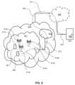
図9は、いくつかの実施形態による、無線アクセスネットワークなどのアクセスネットワーク911と、コアネットワーク914とを備える、3GPPタイプのセルラネットワークなどのテレコミュニケーション(電気通信)ネットワーク910を含む通信システムを示す。アクセスネットワーク911はNB、eNB、gNB、または他のタイプの無線アクセスポイントなどの複数の基地局912a、912b、912cを備え、それぞれは対応するカバレッジエリア913a、913b、913cを定義する。各基地局912a、912b、912cは、有線または無線接続915を介してコアネットワーク914に接続可能である。カバレッジエリア913cに位置する第1のUE991は、対応する基地局912cに無線で接続されるか、またはページングされるように構成される。カバレッジエリア913a内の第2のUE992は、対応する基地局912aに無線で接続可能である。この例では複数のUE991、992が示されているが、開示された実施形態は唯一のUEがカバレッジエリア内にあるか、または唯一のUEが対応する基地局912に接続している状況にも同様に適用可能である。9 illustrates a communication system including a
テレコミュニケーションネットワーク910はそれ自体がホストコンピュータ930に接続されており、これは、スタンドアロンサーバ、クラウド実施サーバ、分散サーバ、またはサーバファーム内の処理リソースのハードウェアおよび/またはソフトウェアに具現化されてもよい。ホストコンピュータ930は、サービスプロバイダの所有または制御下にあってもよく、またはサービスプロバイダによって、またはサービスプロバイダの代わりに操作されてもよい。テレコミュニケーションネットワーク910とホストコンピュータ930との間のコネクション921、922は、コアネットワーク914からホストコンピュータ930に直接拡張してもよく、あるいはオプションの中間ネットワーク920を介してもよい。中間ネットワーク920は、以下のうちの1つ、または2つ以上の組合せとすることができる:パブリックネットワーク、プライベートネットワーク、またはホストネットワーク;もしあれば、バックボーンネットワークまたはインターネットであってもよい中間ネットワーク920;特に、中間ネットワーク920は、2つ以上のサブネットワーク(図示せず)を含むことができる。The
図9の通信システムは、全体として、接続されたUE991、992の1つとホストコンピュータ930との間のコネクティビティを可能にする。コネクティビティは、オーバー・ザ・トップ(OTT)コネクション950として説明することができる。ホストコンピュータ930および接続されたUE991、992は、アクセスネットワーク911、コアネットワーク914、任意の中間ネットワーク920、および可能なさらなるインフラストラクチャ(不図示)を中継器として使用して、OTTコネクション950を介してデータおよび/または信号を通信するように構成される。OTTコネクション950は、OTTコネクション950が通過する参加通信デバイスがアップリンク通信およびダウンリンク通信のルーティングに気付かないという意味で、トランスペアレントであり得る。例えば、基地局912は、ホストコンピュータ930から発信されたデータを有する着信ダウンリンク通信が接続されたUE991に転送される(例えば、ハンドオーバされる)過去のルーティングについて通知されなくてもよいし、通知される必要はなくてもよい。同様に、基地局912は、ホストコンピュータ930に向けてUE991から発信される発信アップリンク通信の将来のルーティングを認識する必要はない。The communication system of FIG. 9 generally enables connectivity between one of the connected
先の段落で論じたUE、基地局、およびホストコンピュータの、一実施形態による例示的な実装形態を、図10を参照して以下に説明する。通信システム1000において、ホストコンピュータ1010は、通信システム1000の異なる通信デバイスのインタフェースとの有線または無線接続をセットアップし維持するように構成された通信インタフェース1016を含むハードウェア815を備える。ホストコンピュータ1010は、ストレージおよび/または処理能力を有することができる処理回路1018をさらに備える。特に、処理回路1018は、命令を実行するように適合された1つ以上のプログラマブルプロセッサ、特定用途向け集積回路、フィールドプログラマブルゲートアレイ、またはこれらの組み合わせ(不図示)を含んでもよい。ホストコンピュータ1010はホストコンピュータ1010に格納されているか、またはホストコンピュータ1010によってアクセス可能であり、処理回路1018によって実行可能なソフトウェア1011をさらに備える。ソフトウェア1011は、ホストアプリケーション1012を含む。ホストアプリケーション1012は、UE1030およびホストコンピュータ1010で終端するOTTコネクション1050を介して接続するUE1030などのリモートユーザにサービスを提供するように動作可能であってもよい。サービスをリモートユーザに提供する際に、ホストアプリケーション1012は、OTTコネクション1050を使用して送信されるユーザデータを提供することができる。An exemplary implementation according to one embodiment of the UE, base station, and host computer discussed in the previous paragraphs is described below with reference to FIG. 10. In the
通信システム1000は、電気通信システムに設けられ、ホストコンピュータ1010およびUE1030と通信することを可能にするハードウェア1025を含む基地局1020をさらに含む。ハードウェア1025は、通信システム1000の異なる通信装置のインタフェースとの有線または無線接続をセットアップおよび維持するための通信インタフェース1026と、基地局1020によって提供されるカバレッジエリア(図10には示されていない)に配置されたUE 1030との無線接続1070をセットアップおよび維持するための無線インタフェース1027とを含んでもよい。通信インタフェース1026は、ホストコンピュータ1010へのコネクション1060を容易にするように構成してもよい。コネクション1060は直接的なものであってもよいし、電気通信システムのコアネットワーク(図10には図示せず)及び/又は電気通信システムの外部の1つ以上の中間ネットワークを通過するものであってもよい。図示の実施形態では、基地局1020のハードウェア1025が1つ以上のプログラマブルプロセッサ、特定用途向け集積回路、フィールドプログラマブルゲートアレイ、または命令を実行するように適合されたこれら(図示せず)の組み合わせを含み得る処理回路1028をさらに含む。基地局1020はさらに、内部に記憶された、または外部接続を介してアクセス可能なソフトウェア1021を有する。The
通信システム1000は、既に参照したUE1030をさらに含む。そのハードウェア1035は、UE1030が現在配置されているカバレッジエリアにサービスを提供する基地局との無線接続1070をセットアップし維持するように構成された無線インタフェース1037を含むことができる。UE1030のハードウェア1035は処理回路1038を更に含み、処理回路は、命令を実行するように適合された1つ以上のプログラマブルプロセッサ、特定用途向け集積回路、フィールドプログラマブルゲートアレイ又はこれらの組合せ(不図示)を含み得る。UE1030はさらに、UE1030に記憶され、または処理回路1038によって実行可能であるソフトウェア1031を備える。ソフトウェア1031は、クライアントアプリケーション1032を含む。クライアントアプリケーション1032はホストコンピュータ1010のサポートにより、UE1030を介して人間または非人間のユーザにサービスを提供するように動作可能である。ホストコンピュータ1010において、実行中のホストアプリケーション1012は、UE1030およびホストコンピュータ1010で終端するOTTコネクション1050を介して、実行中のクライアントアプリケーション1032と通信することができる。ユーザにサービスを提供する際に、クライアントアプリケーション1032はホストアプリケーション1012からリクエストデータを受信し、リクエストデータに応答してユーザデータを提供してもよい。OTTコネクション1050は、リクエストデータとユーザデータの両方を転送することができる。クライアントアプリケーション1032は、ユーザと対話して、それが提供するユーザデータを生成することができる。The
図10に示されるホストコンピュータ1010、基地局1020、およびUE1030は、それぞれ、ホストコンピュータ1030、基地局1012a、1012b、1012cのうちの1つ、および図10のUE1091、1092のうちの1つと同一であり得ることに留意されたい。すなわち、これらのエンティティの内部動作は図10に示すようなものとすることができ、独立して、周囲のネットワークトポロジは、図9のものとすることができる。Note that the host computer 1010, base station 1020, and
図10ではOTTコネクション1050は、基地局1020を介したホストコンピュータ1010とユーザ機器1030との間の通信を図示するために、いかなる中間デバイスも明示的に参照せず、これらのデバイスを介したメッセージの正確なルーティングも示さず、抽象的に描かれている。ネットワークインフラストラクチャはルーティングを判定してもよく、これは、UE1030から、またはホストコンピュータ1010を操作するサービスプロバイダから、あるいはその両方から隠すように構成してもよい。OTTコネクション1050がアクティブである間、ネットワークインフラストラクチャはルーティングを動的に(例えば、負荷分散の考慮またはネットワークの再構成に基づいて)変更する決定をさらに行うことができる。In FIG. 10, the
UE1030と基地局1020との間の無線接続1070は対応する方法700および800とともに、無線デバイスおよびリレーノード30などのノードによって提供されるような、本開示全体にわたって説明される実施形態の開示に従う。本明細書に記載される実施形態は、改善されたTA検証およびPL推定を提供する。これらの実施形態の開示は、OTTコネクション1050を使用して、ネットワークおよびUE1030の信頼性、コネクション、データレート、キャパシティ、遅延時間、および/または電力消費を改善してもよい。The
1つ以上の実施形態が改善するデータレート、遅延時間、および他の要因を監視する目的で、測定手順を提供することができる。さらに、測定結果の変動に応答して、ホストコンピュータ1010とUE1030との間のOTTコネクション1050を再構成するためのオプションのネットワーク機能があってもよい。OTTコネクション1050を再構成するための測定手順および/またはネットワーク機能は、ホストコンピュータ1010のソフトウェア1011、またはUE1030のソフトウェア1031、またはその両方において実装され得る。実施形態ではOTTコネクション1050が通過する通信デバイス内、またはそれに関連付けられてセンサ(不図示)が配備されてもよい;センサは上で例示された監視量の値を供給することによって、またはソフトウェア1011、1031が監視量を計算または推定することができる他の物理量の値を供給することによって、測定手順に参加してもよい。OTTコネクション1050の再構成はメッセージフォーマット、再送設定、好ましいルーティングなどを含むことができる;再構成は、基地局1020に影響を及ぼす必要はなく、基地局1020には知られていないか、または知覚できないことがある。このような手順および機能性は当技術分野で公知であり、実施されていてもよい。所定の実施形態では、測定がスループット、伝搬時間、遅延時間などのホストコンピュータ1010の測定を容易にする独自のUEシグナリングを含むことができる。測定は、ソフトウェア1011、1031が伝搬時間、エラーなどを監視しながら、OTTコネクション1050を使用して、メッセージ、特に空または「ダミー」メッセージを送信させることによって実施することができる。Measurement procedures may be provided for the purpose of monitoring data rates, latency, and other factors that one or more embodiments improve upon. Additionally, there may be optional network functionality for reconfiguring the
図11は、通信システムにおいて実施される方法を示すフローチャートである。通信システムは、ホストコンピュータ、基地局、および図9および図10を参照して説明したUEを含む。本開示を簡単にするために、図11を参照する図面のみがこのセクションに含まれる。方法の最初のステップ1110において、ホストコンピュータはユーザデータを提供する。最初のステップ1110の任意選択のサブステップ1111において、ホストコンピュータはホストアプリケーションを実行することによってユーザデータを提供する。第2のステップ1120において、ホストコンピュータは、ユーザデータをUEに搬送する送信を開始する。任意選択の第3のステップ1130において、基地局は、本開示全体にわたって説明される実施形態の開示に従って、ホストコンピュータが開始した送信において搬送されたユーザデータをUEに送信する。オプションの第4のステップ1140において、UEは、ホストコンピュータによって実行されるホストアプリケーションに関連付けられたクライアントアプリケーションを実行する。Figure 11 is a flow chart illustrating a method implemented in a communication system. The communication system includes a host computer, a base station, and a UE as described with reference to Figures 9 and 10. To simplify this disclosure, only the figures that refer to Figure 11 are included in this section. In a first step 1110 of the method, the host computer provides user data. In an
図12は、通信システムにおいて実施される方法を示すフローチャートである。通信システムは、ホストコンピュータ、基地局、並びに図9および図10を参照して説明したUEを含む。本開示を簡単にするために、図12を参照する図面のみがこのセクションに含まれる。方法の最初のステップ1210において、ホストコンピュータはユーザデータを提供する。オプションのサブステップ(図示せず)では、ホストコンピュータがホストアプリケーションを実行することによってユーザデータを提供する。第2のステップ1220において、ホストコンピュータは、ユーザデータをUEに運ぶ送信を開始する。送信は、本開示全体にわたって説明される実施形態の教示に従って、基地局を介して通過することができる。オプションの第3のステップ1230において、UEは、送信で搬送されるユーザデータを受信する。12 is a flow chart illustrating a method implemented in a communication system. The communication system includes a host computer, a base station, and a UE as described with reference to FIGS. 9 and 10. To simplify this disclosure, only the figures that refer to FIG. 12 are included in this section. In a
図13は、通信システムにおいて実施される方法を示すフローチャートである。通信システムは、ホストコンピュータ、基地局、並びに図9および図10を参照して説明したUEを含む。本開示を簡単にするために、図13を参照する図面のみがこのセクションに含まれる。本方法のオプションの第1のステップ1310では、UEがホストコンピュータによって提供される入力データを受信する。さらに、または代替的に、オプションの第2のステップ1320において、UEはユーザデータを提供する。第2のステップ1320のオプションのサブステップ1321において、UEは、クライアントアプリケーションを実行することによって、ユーザデータを提供する。第1のステップ1310のさらなるオプションのサブステップ1311において、UEは、ホストコンピュータによって提供される受信された入力データに応答してユーザデータを提供するクライアントアプリケーションを実行する。ユーザデータを提供する際に、実行されたクライアントアプリケーションは、ユーザから受け取ったユーザ入力をさらに考慮してもよい。ユーザデータが提供された特定の方法にかかわらず、UEは、オプションの第3のサブステップ1330において、ユーザデータのホストコンピュータへの送信を開始する。本方法の第4のステップ1340において、ホストコンピュータは、本開示全体にわたって説明される実施形態の開示に従って、UEから送信されたユーザデータを受信する。13 is a flow chart illustrating a method implemented in a communication system. The communication system includes a host computer, a base station, and a UE as described with reference to FIGS. 9 and 10. To simplify this disclosure, only the figures that refer to FIG. 13 are included in this section. In an optional
図14は、通信システムにおいて実施される方法を示すフローチャートである。通信システムは、ホストコンピュータ、基地局、並びに図9および図10を参照して説明したUEを含む。本開示を簡単にするために、図14を参照する図面のみがこのセクションに含まれる。方法の任意選択の第1のステップ1410では本開示全体にわたって説明される実施形態の開示に従って、基地局はUEからユーザデータを受信する。任意選択の第2のステップ1420において、基地局は、受信したユーザデータのホストコンピュータへの送信を開始する。第3のステップ1430で、ホストコンピュータは、基地局によって開始された送信で運ばれるユーザデータを受信する。Figure 14 is a flow chart illustrating a method implemented in a communication system. The communication system includes a host computer, a base station, and a UE as described with reference to Figures 9 and 10. To simplify this disclosure, only the figures that refer to Figure 14 are included in this section. In an optional
上で詳細に論じたように、本明細書で説明した技術は例えば、図7および図8のプロセスフロー図に示すように、1つ以上のプロセッサによって実行されるコンピュータプログラム命令を使用して、全体的にまたは部分的に実施することができる。当然のことながら、これらの技術の機能実装は機能モジュールの観点から表されてもよく、各機能モジュールは、適切なプロセッサ内で実行されるソフトウェアの機能ユニット、または機能デジタルハードウェア回路、あるいは両方の何らかの組合せに対応する。As discussed in detail above, the techniques described herein may be implemented in whole or in part using computer program instructions executed by one or more processors, for example as illustrated in the process flow diagrams of Figures 7 and 8. It will be appreciated that the functional implementation of these techniques may be represented in terms of functional modules, each functional module corresponding to a functional unit of software executing in a suitable processor, or functional digital hardware circuitry, or some combination of both.
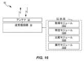
図15は、PURを使用するアイドルモードアップリンク送信などのアップリンク送信を実行するように構成された、無線デバイス50のための例示的な機能モジュールまたは回路アーキテクチャを示す。この実装は、サービングセルの信号測定値M2が送信機会に対応する基準時刻T2の前の所定の時間範囲内で取得されたかどうかを判定するための判定モジュール1502を含む。この実装はまた、サービングセルの信号測定値M2が所定の時間範囲内で取得されなかったとの判定に応答して、送信機会で送信するためのTAを検証する際に、および/または送信機会での送信の電力制御のためのPLを推定するために使用するために、後続の送信機会への送信を保留するか、または所定の時間範囲内に入る追加のサービングセル測定値M2'を収集するための実行モジュールを含む。この実装形態は、アップリンク送信を実行するためにモジュール1506を使用することも含むことができる。 FIG. 15 illustrates an exemplary functional module or circuit architecture for a
図16は、無線デバイス50のための別の例示的な機能モジュールまたは回路アーキテクチャを示す。機能実装は、第1の基準時刻T1におけるTAを含むPUR構成情報などの構成情報を取得するための取得モジュール1602と、構成情報から、TA検証、電力制御のためのPL推定、および/またはパスロス変化推定が実行されるべき第2の基準時刻T2を識別する識別モジュール1604と、を含む。この実装形態はまた、第2の基準時刻T2を第1の基準時刻T1と比較するための比較モジュール1606と、第1の基準時刻T1と第2の基準時刻T2との間の時間差が所与の差分閾値を満たさないと判定することに応答して、無線デバイスにおいて利用可能な任意の測定値を使用して、または新しい測定を実行して、TA検証、電力制御のためのPL推定、および/またはPL変化推定を実行し、(たとえば、PURリソースを使用する)TA検証、電力制御のためのPL推定、および/またはPL変化推定に基づいてアップリンク送信を実行すること;第3の基準時刻T3までアップリンク送信を延期すること;アップリンク送信をドロップすること;のうちの1つを実行するための実行モジュール1608と、を含む。16 illustrates another exemplary functional module or circuit architecture for a
<例示的な実施形態>
例示的な実施形態は以下の列挙された例を含むことができるが、これらに限定されない: Exemplary embodiments
Exemplary embodiments may include, but are not limited to, the following enumerated examples:
1.事前構成されたアップリンクリソース(PUR)を使用してアイドルモードアップリンク送信を実行するための、無線デバイスによって実行される方法であって、
サービングセルの信号測定M2が基準時刻T2の前の所定の時間範囲内で行われたかどうかを判定することであって、基準時刻T2はPURを使用する送信機会に対応する、ことと、
サービングセルの信号測定M2が所定の時間範囲内で取得されなかったとの判定に応答して、PURを使用する後続の送信機会への送信を保留すること、または送信機会で送信するためのタイミングアドバンス(TA)を検証する際に使用する、および/または送信機会における送信の電力制御のためのパスロス(PL)を推定するために、所定の時間範囲内に収まる追加のサービングセルの測定M2'を収集すること、の何れかを実行することと、
を含む方法。 1. A method performed by a wireless device for performing idle mode uplink transmissions using preconfigured uplink resources (PUR), comprising:
determining whether a serving cell signal measurement M2 has been made within a predetermined time range before a reference time T2, the reference time T2 corresponding to a transmission opportunity using PUR;
in response to determining that the serving cell signal measurement M2 was not obtained within a predetermined time range, either withholding transmission to a subsequent transmission opportunity using PUR or collecting additional serving cell measurements M2' that fall within a predetermined time range for use in validating a timing advance (TA) for transmitting at the transmission opportunity and/or estimating a path loss (PL) for power control of transmission at the transmission opportunity;
The method includes:
2.当該判定の前に、
TAが確立された時刻に対応する基準時刻T1の周りの所定の時間範囲内でサービングセル測定M1が行われたかどうかを確認することをさらに含む請求項1に記載の方法。 2. Before making such a decision:
The method of claim 1, further comprising: determining whether a serving cell measurement M1 is made within a predetermined time range around a reference time T1 corresponding to the time when the TA is established.
3.サービングセルの測定M1が基準時刻T1の前後の所定の時間範囲内に行われなかったと判定することに応答して、PURを使用して後続の送信機会で送信するためのTAを検証する際に使用する、および/またはPURを使用して後続の送信機会においてPLの変化を推定するために、基準時刻T1の前後の所定の時間範囲内に収まる追加のサービングセル測定M1'を収集することをさらに含む請求項2に記載の方法。3. The method of claim 2, further comprising, in response to determining that the serving cell measurement M1 was not made within a predetermined time range around the reference time T1, collecting additional serving cell measurements M1' that fall within a predetermined time range around the reference time T1 for use in validating a TA for transmitting at a subsequent transmission opportunity using the PUR and/or for estimating a change in PL at a subsequent transmission opportunity using the PUR.
4.TAを検証することは、追加のサービングセルの測定M1'と第2の測定値M2との間の大きさの差が所与の差分の閾値未満であると判定することに応答して、TAを検証することを含み、
PURはTAの検証に応答してアップリンク送信のために使用される、実施例3に記載の方法。 4. Validating the TA includes validating the TA in response to determining that a magnitude difference between the additional serving cell measurement M1′ and the second measurement M2 is less than a given difference threshold;
The method of embodiment 3, wherein the PUR is used for uplink transmission in response to verification of the TA.
5.TAを検証することは、第1の測定M1と追加のサービングセルの測定M2'との間の大きさの差が所与の差分の閾値未満であると判定することに応答して、TAを検証することを含み、
PURはTAの検証に応答してアップリンク送信のために使用される、実施例1に記載の方法。 5. Validating the TA includes validating the TA in response to determining that a magnitude difference between the first measurement M1 and the additional serving cell measurement M2' is less than a given difference threshold;
The method of embodiment 1, wherein the PUR is used for uplink transmission in response to verification of the TA.
6.PL変化を推定することは追加のサービングセル測定M2'に基づき、
PURは推定に応答して、アップリンク送信のために使用されるか、または保留される、実施例1~5のいずれか1つに記載の方法。 6. Estimating the PL change is based on additional serving cell measurements M2′,
6. A method as in any one of embodiments 1-5, wherein the PUR is used or reserved for uplink transmission in response to the estimation.
7.事前構成されたアップリンクリソース(PUR)を使用してアイドルモードアップリンク送信を実行するために無線デバイスによって実行される方法であって、
第1の基準時刻T1におけるタイミングアドバンス(TA)を含むPUR構成情報を取得することと、
PUR構成情報から、TA検証、電力制御のためのパスロス(PL)推定、および/またはパスロス変化の推定が実行される第2の基準時刻T2を識別することと、
第2の基準時刻T2と第1の基準時刻T1とを比較することと、
第1の基準時刻T1と第2の基準時刻T2との間の時間差が所与の差分の閾値を満たさないとの判定に応答して、
無線デバイスにおいて利用可能な任意の測定値を使用して、または新しい測定を実行して、TA検証、電力制御のためのPL推定、および/またはPLの変化の推定を実行し、TA検証、電力制御のためのPL推定、および/またはPL変化推定に基づいて、アップリンク送信のためにPURリソースを使用することと、
第3の基準時刻T3まで、アップリンク送信のためのPURリソースの使用を延期することと、
アップリンク送信のためのPURリソースの使用をドロップすることと、
のうちの1つを実行することと、を含む方法。 7. A method performed by a wireless device to perform idle mode uplink transmissions using preconfigured uplink resources (PUR), comprising:
Obtaining PUR configuration information including a timing advance (TA) at a first reference time T1;
Identifying a second reference time T2 from the PUR configuration information at which TA verification, path loss (PL) estimation for power control, and/or path loss change estimation are performed;
Comparing a second reference time T2 with a first reference time T1;
in response to determining that the time difference between the first reference time T1 and the second reference time T2 does not meet a given difference threshold,
performing TA verification, PL estimation for power control, and/or PL change estimation using any measurements available in the wireless device or performing new measurements, and using PUR resources for uplink transmission based on the TA verification, PL estimation for power control, and/or PL change estimation;
deferring use of the PUR resources for uplink transmission until a third reference time T3;
Dropping the use of PUR resources for uplink transmissions; and
and performing one of:
8. 実施例1~7のいずれか1項に記載の方法を実行するように適合された無線デバイス。8. A wireless device adapted to perform the method according to any one of the first to seventh embodiments.
9. 送受信回路と、該送受信回路と動作可能に関連づけられ、実施例1~7のいずれか1項に記載の方法を実行するように構成された処理回路と、を備える無線デバイス。9. A wireless device comprising a transceiver circuit and a processing circuit operatively associated with the transceiver circuit and configured to perform the method according to any one of the first to seventh embodiments.
10. 少なくとも1つの処理回路上で実行されると、少なくとも1つの処理回路に実施例1~7のいずれか1項に記載の方法を実行させる命令を含むコンピュータプログラム。10. A computer program comprising instructions that, when executed on at least one processing circuit, cause the at least one processing circuit to perform the method according to any one of Examples 1 to 7.
11.電気信号、光信号、無線信号、またはコンピュータ可読記憶媒体のうちの1つであるキャリアであって、実施例10に記載のコンピュータプログラムを含むキャリア。11. A carrier that is one of an electrical signal, an optical signal, a radio signal, or a computer-readable storage medium, the carrier including the computer program of example 10.
A1.ホストコンピュータを含む通信システムであって、
ユーザデータを提供するように構成された処理回路と、
ユーザ機器(UE)に送信するためにユーザデータをセルラネットワークに転送するように構成された通信インタフェースと、
を含み、
セルラネットワークは基地局を含み、UEは無線インタフェースおよび処理回路を有し、UEの処理回路は、実施例1~7を含む動作のいずれか1項を実行するように構成される通信システム。 A1. A communication system including a host computer,
a processing circuit configured to provide user data;
a communication interface configured to transfer user data toa cellular network for transmission to a user equipment (UE);
Including,
A communication system, whereinthe cellular network includes a base station, the UE has a radio interface and a processing circuit, and the processing circuit of the UE is configured to perform any one of the operations of embodiments 1 to 7, including the operations of embodiments 1 to 7.
A2.基地局をさらに含む前述の実施形態の通信システム。A2. The communication system of the above embodiment further including a base station.
A3.UEをさらに含み、UEが基地局と通信するように構成される、前述の2つの実施形態の通信システム。A3. The communication system of the two preceding embodiments further including a UE, the UE configured to communicate with the base station.
A4. ホストコンピュータの処理回路はホストアプリケーションを実行し、それによってユーザデータを提供するように構成され、
UEは、ホストアプリケーションに関連付けられたクライアントアプリケーションを実行するように構成された処理回路を備える、
前述の3つの実施形態の通信システム。 A4. The processing circuitry of the host computer is configured to execute a host application and thereby provide user data;
the UE comprises a processing circuit configured to execute a client application associated with the host application;
The communication system of any of the preceding three embodiments.
A5. ホストコンピュータと、基地局と、ユーザ装置(UE)とを含む通信システムにおいて実施される方法であって、
ホストコンピュータにおいて、ユーザデータを提供することと、
ホストコンピュータにおいて、基地局を含むセルラネットワークを介してUEにユーザデータを搬送する送信を開始することと、
を含み、
UEは実施形態1~7のいずれか1項のステップを実行する方法。
A5. A method implemented in a communication system including a host computer, a base station, and a user equipment (UE), comprising:
providing user data at a host computer;
Initiating, at the host computer, a transmission conveying user data to the UE overa cellular network including a base station;
Including,
A method in which the UE performs the steps of any one of embodiments 1 to 7.
A6.前記基地局において、ユーザデータを送信することをさらに含む、前述の実施形態の方法。A6. The method of any of the preceding embodiments, further comprising transmitting user data at the base station.
A7. 前記ユーザデータは、ホストアプリケーションを実行することによって、前記ホストコンピュータにおいて提供され、前記UEにおいて、前記ホストアプリケーションに関連付けられたクライアントアプリケーションを実行することをさらに含む、前述の2つの実施形態の方法。A7. The method of the two preceding embodiments, wherein the user data is provided at the host computer by executing a host application, and further comprising executing at the UE a client application associated with the host application.
A8. ユーザ装置(UE)から基地局への送信から生じるユーザデータを受信するように構成された通信インタフェースを備えるホストコンピュータを含む通信システムであって、UEは基地局と通信し、実施形態1~7のいずれかの動作を協働して実行するように構成された無線インタフェースおよび処理回路を備える、通信システム。A8. A communication system including a host computer having a communication interface configured to receive user data resulting from a transmission from a user equipment (UE) to a base station, the UE communicating with the base station and having a radio interface and processing circuitry configured to cooperatively perform any of the operations of embodiments 1 to 7.
A9. 基地局をさらに含む前述の実施形態の通信システム。A9. The communication system of the above embodiment further including a base station.
A10. UEをさらに含み、UEが基地局と通信するように構成される、前述の2つの実施形態の通信システム。A10. The communication system of the two preceding embodiments further including a UE, the UE being configured to communicate with the base station.
A11. ホストコンピュータの処理回路はホストアプリケーションを実行するように構成され、
UEはホストアプリケーションに関連付けられたクライアントアプリケーションを実行するようにさらに構成され、これによって、ホストコンピュータによって受信されるユーザデータを提供する、
前述の3つの実施形態の通信システム。 A11. The processing circuitry of the host computer is configured to execute a host application;
The UE is further configured to execute a client application associated with the host application, thereby providing user data for reception by the host computer;
The communication system of any of the preceding three embodiments.
A12. ホストコンピュータと、基地局と、ユーザ装置(UE)とを含む通信システムにおいて実施される方法であって、
ホストコンピュータにおいて、基地局から、基地局がUEから受信した送信から生じるユーザデータを受信し、UEは、実施形態1~7のいずれか1項のいずれかのステップを実行する方法。 A12. A method implemented in a communication system including a host computer, a base station, and a user equipment (UE), comprising:
A method in a host computer, comprising receiving, from a base station, user data resulting from a transmission received by the base station from a UE, the UE performing any of the steps of any one of embodiments 1 to 7.
A13. 基地局において、UEからユーザデータを受信することをさらに含む、前述の実施形態の方法。A13. The method of any of the preceding embodiments, further comprising receiving, at the base station, user data from the UE.
A14. 基地局において、受信されたユーザデータのホストコンピュータへの送信を開始することをさらに含む、前述の2つの実施形態の方法。A14. The method of the two preceding embodiments further comprising initiating, at the base station, transmission of the received user data to the host computer.
本発明の概念の原理から実質的に逸脱することなく、実施形態に対して多くの変形および修正を行うことができる。全てのそのような変形及び修正は、本発明の概念の範囲内に含まれることが意図される。したがって、上記で開示された主題は例示的であり、限定的ではないと考えられるべきであり、実施形態の例は、本発明の概念の精神および範囲内にある、すべてのそのような修正、強化、および他の実施形態を包含することが意図される。したがって、本発明の概念の範囲は法律によって許容される最大限まで、実施形態の例およびその均等物を含む本開示の最も広い許容可能な解釈によって決定されるべきであり、前述の詳細な説明によって限定または限定されるべきではない。Many variations and modifications can be made to the embodiments without substantially departing from the principles of the inventive concept. All such variations and modifications are intended to be included within the scope of the inventive concept. Accordingly, the subject matter disclosed above should be considered illustrative and not limiting, and the example embodiments are intended to encompass all such modifications, enhancements, and other embodiments that are within the spirit and scope of the inventive concept. Thus, the scope of the inventive concept should be determined by the broadest permissible interpretation of the present disclosure, including the example embodiments and their equivalents, to the fullest extent permitted by law, and should not be limited or restricted by the foregoing detailed description.
Claims (9)
Translated fromJapanese第1の基準時刻T1におけるタイミングアドバンス(TA)を含む構成情報を取得すること(802)と、
第2の基準時刻T2を前記第1の基準時刻T1と比較すること(806)であって、前記第2の基準時刻T2は、TA検証、電力制御のためのパスロス(PL)推定、および/またはパスロスの変化の推定が実行されるべき時刻である、ことと、
前記第1の基準時刻T1と前記第2の基準時刻T2との間の時間差が所与の差分の閾値未満であると判定したことに応答して、
前記無線デバイスにおいて利用可能な任意の測定を使用して、または新しい測定を実行して、前記TA検証、電力制御のためのPL推定、および/またはPL変化推定を実行し、前記TA検証、電力制御のためのPL推定、および/またはPL変化推定に基づいて前記アップリンク送信を実行することと、
前記アップリンク送信を延期するまたは前記アップリンク送信をドロップすることと、
のいずれかを実行すること(808)と、
を含む方法。 1. A method performed by a wireless device for performing, dropping, or suspending an uplink transmission, comprising:
Obtaining (802) configuration information including a timing advance (TA) at a first reference time T1;
comparing (806) a second reference time T2 with the first reference time T1, the second reference time T2 being a time at which TA verification, path loss (PL) estimation for power control, and/or estimation of path loss change should be performed;
in response to determining thata time difference between the first reference time T1 and the second reference time T2is less than a given difference threshold,
performing the TA verification, PL estimation for power control, and/or PL change estimation using any measurements available in the wireless device or performing new measurements, and performing the uplink transmission based on the TA verification, PL estimation for power control, and/or PL change estimation;
postponing or dropping the uplink transmission; and
and performing (808) any one of
The method includes:
Applications Claiming Priority (4)
| Application Number | Priority Date | Filing Date | Title |
|---|---|---|---|
| US201962887589P | 2019-08-15 | 2019-08-15 | |
| US62/887,589 | 2019-08-15 | ||
| JP2022509194AJP7373648B2 (en) | 2019-08-15 | 2020-08-14 | How to verify measurements for reliable PUR transmission |
| PCT/IB2020/057701WO2021028886A1 (en) | 2019-08-15 | 2020-08-14 | Methods for validating measurements for reliable pur transmissions |
Related Parent Applications (1)
| Application Number | Title | Priority Date | Filing Date |
|---|---|---|---|
| JP2022509194ADivisionJP7373648B2 (en) | 2019-08-15 | 2020-08-14 | How to verify measurements for reliable PUR transmission |
Publications (2)
| Publication Number | Publication Date |
|---|---|
| JP2024012358A JP2024012358A (en) | 2024-01-30 |
| JP7685575B2true JP7685575B2 (en) | 2025-05-29 |
Family
ID=72234875
Family Applications (2)
| Application Number | Title | Priority Date | Filing Date |
|---|---|---|---|
| JP2022509194AActiveJP7373648B2 (en) | 2019-08-15 | 2020-08-14 | How to verify measurements for reliable PUR transmission |
| JP2023182026AActiveJP7685575B2 (en) | 2019-08-15 | 2023-10-23 | Method for verifying measurements for reliable PUR transmission |
Family Applications Before (1)
| Application Number | Title | Priority Date | Filing Date |
|---|---|---|---|
| JP2022509194AActiveJP7373648B2 (en) | 2019-08-15 | 2020-08-14 | How to verify measurements for reliable PUR transmission |
Country Status (6)
| Country | Link |
|---|---|
| US (2) | US12069585B2 (en) |
| EP (1) | EP4014614B1 (en) |
| JP (2) | JP7373648B2 (en) |
| CN (1) | CN114586423B (en) |
| BR (1) | BR112022002620A2 (en) |
| WO (1) | WO2021028886A1 (en) |
Families Citing this family (1)
| Publication number | Priority date | Publication date | Assignee | Title |
|---|---|---|---|---|
| CN113259999B (en)* | 2020-02-10 | 2022-08-26 | 华为技术有限公司 | Method and device for configuring network resources |
Family Cites Families (4)
| Publication number | Priority date | Publication date | Assignee | Title |
|---|---|---|---|---|
| WO2013119160A1 (en) | 2012-02-07 | 2013-08-15 | Telefonaktiebolaget L M Ericsson (Publ) | Method and apparatus for transmit timing adjustment |
| US20150281989A1 (en)* | 2014-04-01 | 2015-10-01 | Qualcomm Incorporated | Delaying transmission of measurement report |
| US10716143B2 (en)* | 2016-03-31 | 2020-07-14 | Telefonaktiebolaget Lm Ericsson (Publ) | Method and device for timing correction in a channel access using a Listen-Before-Talk protocol |
| EP3668263B1 (en)* | 2018-12-14 | 2020-12-09 | ASUSTek Computer Inc. | Methods and apparatus for applying time alignment timer length for preconfigured uplink resources in a wireless communication system |
- 2020
- 2020-08-14USUS17/635,674patent/US12069585B2/enactiveActive
- 2020-08-14WOPCT/IB2020/057701patent/WO2021028886A1/ennot_activeCeased
- 2020-08-14EPEP20761318.3Apatent/EP4014614B1/enactiveActive
- 2020-08-14JPJP2022509194Apatent/JP7373648B2/enactiveActive
- 2020-08-14BRBR112022002620Apatent/BR112022002620A2/enunknown
- 2020-08-14CNCN202080072683.5Apatent/CN114586423B/enactiveActive
- 2023
- 2023-10-23JPJP2023182026Apatent/JP7685575B2/enactiveActive
- 2024
- 2024-08-20USUS18/809,805patent/US20250056420A1/enactivePending
Non-Patent Citations (1)
| Title |
|---|
| ZTE,Support for transmission in preconfigured UL resources for MTC[online],3GPP TSG RAN WG1 #96b R1-1904343,Internet<URL:https://www.3gpp.org/ftp/tsg_ran/WG1_RL1/TSGR1_96b/Docs/R1-1904343.zip>,2019年03月30日 |
Also Published As
| Publication number | Publication date |
|---|---|
| EP4014614A1 (en) | 2022-06-22 |
| EP4014614B1 (en) | 2024-12-04 |
| CN114586423B (en) | 2025-07-22 |
| US12069585B2 (en) | 2024-08-20 |
| JP2024012358A (en) | 2024-01-30 |
| WO2021028886A1 (en) | 2021-02-18 |
| JP2022544313A (en) | 2022-10-17 |
| JP7373648B2 (en) | 2023-11-02 |
| US20250056420A1 (en) | 2025-02-13 |
| BR112022002620A2 (en) | 2022-05-03 |
| CN114586423A (en) | 2022-06-03 |
| US20220330164A1 (en) | 2022-10-13 |
Similar Documents
| Publication | Publication Date | Title |
|---|---|---|
| EP3605932B1 (en) | Beam management methods, terminal device, network device and computer program | |
| US20200127883A1 (en) | Method and apparatus for beam failure recovery | |
| US10736033B2 (en) | Secondary cell group configuration | |
| CN110249694B (en) | Method and apparatus for controlling bandwidth portion switching | |
| CN112740577A (en) | Radio link monitoring and failure for NR unlicensed operation | |
| CN111869273A (en) | Method and apparatus for monitoring paging messages | |
| JP7574336B2 (en) | Determining the presence of a terminal with poor wireless quality and adjusting the reference signal used by the terminal | |
| EP4022960B1 (en) | Systems and methods for validating parameters | |
| CN102651908A (en) | Method and equipment for transmitting data | |
| EP3874829A1 (en) | Power-efficient configuration of time offset values | |
| US12041669B2 (en) | Method and apparatus for random access | |
| EP3711432B1 (en) | Window length of random access response in new radio | |
| CN114514771B (en) | Enhanced procedure for early measurement reporting | |
| US11057936B2 (en) | Mechanism for merging colliding RACH procedures | |
| JP2023500699A (en) | Semi-persistent channel state information reporting procedure with uplink clear channel assessment | |
| WO2022208490A1 (en) | Ul power control for transport block transmission over multiple slots | |
| US20250056420A1 (en) | Methods for validating measurements for reliable pur transmissions | |
| US12101804B2 (en) | Method and apparatus for data transmission and computer readable medium | |
| WO2021064676A1 (en) | Adapting maximum allowed cca failures based on single occasion periodicity | |
| EP4055759B1 (en) | Coreset search area optimization | |
| WO2024171149A1 (en) | Adaptation of sl synchronization source based on cca failures | |
| EP4523488A1 (en) | Wireless device, network node, and methods performed thereby, for handling downlink transmission | |
| WO2024079097A1 (en) | Handling of wireless device (wd) timers and triggers during network discontinuous transmission and reception |
Legal Events
| Date | Code | Title | Description |
|---|---|---|---|
| A521 | Request for written amendment filed | Free format text:JAPANESE INTERMEDIATE CODE: A523 Effective date:20231115 | |
| A621 | Written request for application examination | Free format text:JAPANESE INTERMEDIATE CODE: A621 Effective date:20231115 | |
| A131 | Notification of reasons for refusal | Free format text:JAPANESE INTERMEDIATE CODE: A131 Effective date:20241021 | |
| A601 | Written request for extension of time | Free format text:JAPANESE INTERMEDIATE CODE: A601 Effective date:20250121 | |
| A521 | Request for written amendment filed | Free format text:JAPANESE INTERMEDIATE CODE: A523 Effective date:20250228 | |
| TRDD | Decision of grant or rejection written | ||
| A01 | Written decision to grant a patent or to grant a registration (utility model) | Free format text:JAPANESE INTERMEDIATE CODE: A01 Effective date:20250421 | |
| A61 | First payment of annual fees (during grant procedure) | Free format text:JAPANESE INTERMEDIATE CODE: A61 Effective date:20250519 | |
| R150 | Certificate of patent or registration of utility model | Ref document number:7685575 Country of ref document:JP Free format text:JAPANESE INTERMEDIATE CODE: R150 |