JP7683902B2 - Inspection device and inspection system - Google Patents
Inspection device and inspection systemDownload PDFInfo
- Publication number
- JP7683902B2 JP7683902B2JP2020152175AJP2020152175AJP7683902B2JP 7683902 B2JP7683902 B2JP 7683902B2JP 2020152175 AJP2020152175 AJP 2020152175AJP 2020152175 AJP2020152175 AJP 2020152175AJP 7683902 B2JP7683902 B2JP 7683902B2
- Authority
- JP
- Japan
- Prior art keywords
- inspection
- abnormality
- unit
- inspection device
- image
- Prior art date
- Legal status (The legal status is an assumption and is not a legal conclusion. Google has not performed a legal analysis and makes no representation as to the accuracy of the status listed.)
- Active
Links
Images


Landscapes
- Analysing Materials By The Use Of Radiation (AREA)
Description
Translated fromJapanese本発明は、検査装置、および、検査システムに関する。The present invention relates to an inspection device and an inspection system.
従来、特許文献1(特開2014-048178号公報)に開示されているように、物品に対して電磁波としてのX線を照射し、検査画像としてのX線画像を作成することで、物品の異常を検出する検査装置が知られている。As disclosed in Patent Document 1 (JP 2014-048178 A), there is a known inspection device that detects abnormalities in an object by irradiating the object with X-rays as electromagnetic waves and creating an X-ray image as an inspection image.
上記の特許文献1に記載の検査装置では、X線透視像信号の値が、所定の閾値よりも小さい場合に検査対象に異物が混入していると判定する。また、上記の特許文献1では、異物ありと判定された領域(画素)を視認できるように、異物ありと判定された領域を赤色に塗りつぶす例が示されている。The inspection device described in the
上記の特許文献1に記載の検査装置では、異常確信度を、X線画像から容易に確認することができない。The inspection device described in
本開示の課題は、異常確信度を容易に確認することができる検査装置を提供することである。The objective of this disclosure is to provide an inspection device that can easily check the degree of certainty of anomalies.
第1観点に係る検査装置は、物品を検査する検査装置である。検査装置は、照射部と、検出部と、画像生成部と、表示部と、制御部と、を備える。照射部は、物品に電磁波を照射する。検出部は、物品を透過した又は物品に反射した電磁波を検出する。画像生成部は、検出部の検出結果に基づいて、物品の検査画像を生成する。表示部は、検査画像を表示する。制御部は、表示部における検査画像の表示態様を変更させる。制御部は、検査画像を構成する画素ごとに、異常状態の確からしさを示す異常確信度を算出する。制御部は、異常確信度の大きさに基づき画素の表示態様を変化させる。The inspection device according to the first aspect is an inspection device that inspects an object. The inspection device includes an irradiation unit, a detection unit, an image generation unit, a display unit, and a control unit. The irradiation unit irradiates an electromagnetic wave onto the object. The detection unit detects the electromagnetic wave that has passed through the object or been reflected by the object. The image generation unit generates an inspection image of the object based on the detection result of the detection unit. The display unit displays the inspection image. The control unit changes the display mode of the inspection image on the display unit. The control unit calculates an abnormality certainty indicating the likelihood of an abnormal state for each pixel constituting the inspection image. The control unit changes the display mode of the pixel based on the magnitude of the abnormality certainty.
この構成によれば、異常確信度を確認することが容易である。This configuration makes it easy to confirm the anomaly confidence level.
第2観点に係る検査装置は、第1観点に係る検査装置であって、画素は、画素値として色相を含む。制御部は、異常確信度の大きさに基づき画素の表示態様を変化させる際に、異なる異常確信度に対し異なる色相が対応するように変化させる。The inspection device according to the second aspect is the inspection device according to the first aspect, in which the pixels include a hue as a pixel value. When changing the display mode of the pixels based on the magnitude of the abnormality certainty, the control unit changes the display mode so that different hues correspond to different abnormality certainty.
第3観点に係る検査装置は、第1観点又は第2観点に係る検査装置であって、画素は、画素値として明度、輝度、彩度のうち少なくとも一つを含む。制御部は、異常確信度の大きさに基づき画素の表示態様を変化させる際に、異なる異常確信度に対し明度、輝度、彩度のうち少なくとも一つの大きさが異なるものが対応するように変化させる。The inspection device according to the third aspect is the inspection device according to the first or second aspect, in which the pixels include at least one of lightness, luminance, and saturation as pixel values. When changing the display mode of the pixels based on the magnitude of the abnormality certainty, the control unit changes the display mode of the pixels so that at least one of the lightness, luminance, and saturation has a different magnitude corresponding to different abnormality certainty.
第4観点に係る検査装置は、第1観点から第3観点のいずれかに記載の検査装置であって、制御部は、異常確信度が第1閾値以上である画素と、第1閾値未満である画素との表示態様を異ならせる。且つ、制御部は、異常確信度が第1閾値以上である画素については異常確信度に応じて表示態様を変化させ、検査画像を視覚的に区分して、表示部に表示させる。The inspection device according to the fourth aspect is the inspection device according to any one of the first to third aspects, in which the control unit differentiates the display mode of pixels whose anomaly confidence level is equal to or greater than a first threshold from pixels whose anomaly confidence level is less than the first threshold. Furthermore, the control unit changes the display mode of pixels whose anomaly confidence level is equal to or greater than the first threshold in accordance with the anomaly confidence level, visually dividing the inspection image and displaying it on the display unit.
第5観点に係る検査装置は、第4観点に係る検査装置であって、制御部は、異常確信度が第1閾値未満である画素については検査画像における画素値に基づいて表示部に表示させる。The inspection device according to the fifth aspect is the inspection device according to the fourth aspect, in which the control unit causes the display unit to display pixels whose abnormality confidence level is less than the first threshold value based on the pixel value in the inspection image.
第6観点に係る検査装置は、第1観点から第3観点のいずれかに記載の検査装置であって、制御部は、異常確信度が第1閾値以上である画素と、第1閾値未満である画素との表示態様を異ならせる。且つ、制御部は、第1閾値未満である画素については異常確信度に応じて表示態様を変化させ、検査画像を視覚的に区分して、表示部に表示させる。The inspection device according to the sixth aspect is the inspection device according to any one of the first to third aspects, in which the control unit differentiates the display mode of pixels whose anomaly confidence level is equal to or greater than a first threshold value from pixels whose anomaly confidence level is less than the first threshold value. The control unit also changes the display mode of pixels whose anomaly confidence level is less than the first threshold value according to the anomaly confidence level, visually dividing the inspection image and displaying it on the display unit.
第7観点に係る検査装置は、第6観点に係る検査装置であって、制御部は、異常確信度が第1閾値以上である画素と、第1閾値未満である画素との表示態様を異ならせる。且つ、制御部は、異常確信度が第1閾値以上である画素については検査画像における画素値に基づいて、表示部に表示させる。The inspection device according to the seventh aspect is the inspection device according to the sixth aspect, in which the control unit differentiates the display mode of pixels whose abnormality confidence level is equal to or greater than a first threshold value from pixels whose abnormality confidence level is less than the first threshold value. Furthermore, the control unit causes the display unit to display pixels whose abnormality confidence level is equal to or greater than the first threshold value based on pixel values in the inspection image.
第8観点に係る検査装置は、第6観点又は第7観点に係る検査装置であって、制御部は、異常確信度が第1閾値よりも小さい閾値である第2閾値未満である画素については、検査画像における画素値に基づいて表示部に表示させる。The inspection device according to the eighth aspect is the inspection device according to the sixth or seventh aspect, and the control unit causes the display unit to display, on the basis of the pixel value in the inspection image, pixels whose abnormality certainty is less than a second threshold value that is smaller than the first threshold value.
第9観点に係る検査装置は、第6観点から第8観点のいずれかに記載の検査装置であって、制御部は、異常確信度が第1閾値未満である画素であって、且つ、異常確信度が第1閾値以上である画素からの距離が所定範囲内に位置する画素を、検査画像における画素値に基づいて、表示部に表示させる。The inspection device according to the ninth aspect is the inspection device according to any one of the sixth to eighth aspects, in which the control unit causes the display unit to display, based on pixel values in the inspection image, pixels whose abnormality confidence level is less than a first threshold value and that are located within a predetermined distance from pixels whose abnormality confidence level is equal to or greater than the first threshold value.
第10観点に係る検査装置は、第6観点から第9観点のいずれかに記載の検査装置であって、制御部は、異常確信度が第1閾値未満である画素であって、且つ、異常確信度が第1閾値以上である画素からの距離が所定範囲内に位置する画素に対して、マーキングを行って表示させる。The inspection device according to the tenth aspect is the inspection device according to any one of the sixth to ninth aspects, in which the control unit performs marking and displays pixels whose abnormality confidence level is less than a first threshold value and that are located within a predetermined distance from a pixel whose abnormality confidence level is equal to or greater than the first threshold value.
第11観点に係る検査システムは、第1観点から第10観点のいずれかに記載の検査装置と、振分部と、を備える。振分部は、物品を、第1方向と、第1方向とは異なる第2方向とに振り分ける。検査装置の制御部は、検査画像に含まれる画素のうち、異常確信度の大きさが第1閾値以上である画素が所定数以上である場合に、検査画像に対応する物品に異常があると判断して、振分部に、物品を第1方向に振り分けさせる。制御部は、それ以外の場合に、検査画像に対応する物品に異常がないと判断して、振分部に、物品を第2方向に振り分けさせる。An inspection system according to an eleventh aspect includes an inspection device according to any one of the first to tenth aspects, and a sorting unit. The sorting unit sorts the items into a first direction and a second direction different from the first direction. When a predetermined number or more of pixels in the inspection image have an abnormality certainty level equal to or greater than a first threshold, the control unit of the inspection device determines that the item corresponding to the inspection image has an abnormality and causes the sorting unit to sort the items into the first direction. In other cases, the control unit determines that the item corresponding to the inspection image does not have an abnormality and causes the sorting unit to sort the items into the second direction.
この検査システムは、異常確信度を確認することが容易な検査装置を備えている。このため、第11観点に係る検査システムでは、作業効率が向上する。This inspection system is equipped with an inspection device that makes it easy to confirm the degree of certainty of anomaly. Therefore, the inspection system according to the eleventh aspect improves work efficiency.
本発明に係る検査装置および、検査システムでは、異常確信度の確認が容易である。The inspection device and inspection system of the present invention make it easy to confirm the degree of certainty of anomalies.
以下、本開示の一実施形態に係る検査装置について図面を参照しながら説明する。なお、以下の実施形態は、具体例であって、技術的範囲を限定するものではなく、趣旨を逸脱しない範囲で適宜変更可能である。また、以下の図面では各構成部材の大きさの関係が実際のものとは異なる場合がある。Below, an inspection device according to an embodiment of the present disclosure will be described with reference to the drawings. Note that the following embodiment is a specific example and does not limit the technical scope, and can be modified as appropriate without departing from the spirit of the invention. Also, the size relationships between the components in the following drawings may differ from the actual ones.
<第1実施形態>
(1)検査システムの全体構成
検査システム100及び検査システム100に含まれる検査装置10の概要を、図1及び図2を参照しながら説明する。 First Embodiment
(1) Overall Configuration of the Inspection System An overview of the
図1は、本開示に係る検査装置10の一実施形態であるX線検査装置の外観を示す斜視図である。なお、後述するように、本開示はX線検査装置のみに適用されるものではなく、多種多様な装置に適用可能である。図2は、検査装置10が組み込まれる検査システム100の概略図である。検査システム100は、検査装置10と、振分部70と、を備える。本実施形態に係る検査システム100では、検査装置10と振分部70とがそれぞれ別体に構成されている。検査装置10と振分部70とは、通信線等によって電気的に接続されている。この構成により、検査装置10の後述する制御部52は、検査装置10と、振分部70とを制御することができる。検査システム100は、物品Pの検査を行う。検査システム100において、物品Pは、前段コンベア60によって検査装置10まで搬送される。図2では、物品Pが搬送される方向は、矢印で示されている。FIG. 1 is a perspective view showing the appearance of an X-ray inspection device, which is an embodiment of the
検査装置10は、前段コンベア60によって連続的に搬送されてくる物品Pに電磁波としてのX線を照射することにより、物品Pの検査を行う。例えば、本実施形態に係る検査装置10は、物品Pの異物混入検査を行い、検査結果に基づいて物品Pを良品又は不良品に分類する。なお、後述するように、本開示に係る検査装置が行う検査は異物混入検査に限定されるものではなく、検査装置10は多種多様な検査を実施することができる。検査装置10によって行われた検査の結果は、制御部52によって、検査装置10の下流側に配置されている振分部70の振分部制御装置170に送られる。The
振分部制御装置170は、検査装置10において良品と判断された物品Pを、第1方向D1へ振り分けるように振分部70を制御する。第1方向D1は、例えば良品を排出する後段コンベア80へと向かう方向である。振分部制御装置170は、検査装置10において不良品と判断された物品Pを、第2方向D2へ振り分けるように振分部70を制御する。第2方向D2は、例えば不良品排出方向であり、第2方向D2に振り分けられた物品Pは、検査システム100から排出される。詳細は後述する。The sorting
なお、限定するものではないが、本実施形態における物品Pは、例えば鶏肉である。また、物品Pに含まれる異物は、例えば骨である。In this embodiment, the item P is, for example, chicken meat, but is not limited thereto. Furthermore, the foreign object contained in the item P is, for example, a bone.
(2)検査装置の詳細な説明
本実施形態に係る検査装置10は、主として、シールドボックス11と、搬送ユニット12と、照射部20と、検出部30と、表示部40と、制御装置50と、から構成される。 (2) Detailed Description of the Inspection Apparatus The
(2-1)シールドボックス
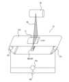
図3は、検査装置10のシールドボックス11の内部の概略図である。シールドボックス11は、検査装置10のケーシングである。図1に示されるように、シールドボックス11の両側面には、物品Pを搬出入するための開口11aが形成されている。開口11aは、シールドボックス11の外部から内部に物品Pを搬入するため、又は、シールドボックス11の内部から外部に物品Pを搬出するために用いられる。開口11aは、遮蔽のれん19により塞がれている。遮蔽のれん19は、シールドボックス11の内部から外部へのX線の漏洩を抑える。遮蔽のれん19は、タングステンシートから成形される。遮蔽のれん19は、物品Pが搬出入される時に物品Pによって押しのけられる。 (2-1) Shielding Box FIG. 3 is a schematic diagram of the inside of the
シールドボックス11の内部には、搬送ユニット12、照射部20、検出部30及び制御装置50等が収容されている。シールドボックス11の正面上部には、表示部40、入力用のキー、及び、電源スイッチ等が配置されている。The
(2-2)搬送ユニット
搬送ユニット12は、シールドボックス11の内部を通過するように物品Pを搬送するためのベルトコンベアである。図1に示されるように、搬送ユニット12は、シールドボックス11の両側面に形成された開口11aを貫通するように配置されている。 (2-2) Transport Unit The
搬送ユニット12は、主として、コンベアモータ12aと、エンコーダ12bと、コンベアローラ12cと、無端状のベルト12dとから構成されている。コンベアローラ12cは、コンベアモータ12aによって駆動される。コンベアローラ12cの駆動により、ベルト12dが回転し、ベルト12d上の物品Pが搬送される。図4において、物品Pが搬送される方向は矢印で示されている。The
搬送ユニット12による物品Pの搬送速度は、検査装置10のオペレータによって入力された設定速度に応じて変動する。制御装置50は、設定速度に基づいてコンベアモータ12aをインバータ制御し、物品Pの搬送速度を細かく制御する。搬送ユニット12のエンコーダ12bは、コンベアモータ12aの回転速度を検出することで物品Pの搬送速度を算出し、制御装置50に送信する。The transport speed of the item P by the
なお、搬送ユニット12は、搬送機構としてベルトコンベアを用いているが、ベルトコンベアの代わりにトップチェーンコンベア及び回転テーブル等を搬送機構として用いてもよい。Although the
(2-3)照射部
照射部20は、シールドボックス11内部の所定の位置まで搬送ユニット12によって搬送された物品Pに、電磁波の一例としてのX線を照射するX線源である。照射部20から照射されるX線には、様々なエネルギーのX線が含まれている。 (2-3) Irradiation Unit The
図3に示されるように、照射部20は、搬送ユニット12の上方に配置されている。照射部20は、搬送ユニット12の下方に配置される検出部30に向けて扇状のX線(放射光)を照射する。X線の照射範囲IRは、図3に示されるように、搬送ユニット12の搬送面に対して垂直であり、かつ、搬送ユニット12によって物品Pが搬送される方向に対して直交する方向に広がる。換言すると、照射部20から照射されるX線は、ベルト12dの幅方向に広がる。As shown in FIG. 3, the
(2-4)検出部
検出部30は、照射部20から照射されたX線を検出するセンサである。具体的には、検出部30は、搬送ユニット12によって搬送された物品Pを透過したX線である透過X線を検出する。 (2-4) Detection Section The
図3に示されるように、検出部30は、搬送ユニット12のベルト12dの下方に配置されている。検出部30は、複数のX線検出素子30aから構成されている。複数のX線検出素子30aは、搬送ユニット12によって物品Pが搬送される方向に直交する方向(ベルト12dの幅方向)に沿って一直線に水平に配置されている。As shown in FIG. 3, the
検出部30は、透過X線を検出し、検出された透過X線の強度に応じた電圧を示すX線透過信号を出力する。X線透過信号は、後述するように、物品Pの透過画像(検査画像)の生成に用いられる。図4は、検出部30によって検出される透過X線の強度の例を示すグラフである。グラフの横軸は、検出部30上の位置を表す。グラフの縦軸は、検出部30が検出した透過X線の強度を表す。The
物品Pの検査画像では、透過X線の検出量の多いところが明るく(輝度が高く)表示され、透過X線の検出量が少ないところが暗く(輝度が低く)表示される。すなわち、物品Pの検査画像の明暗(輝度)は、透過X線の検出量に依存する。図4に示されるように、物品Pを透過したX線の検出量は、物品Pを透過しなかったX線の検出量より低い。In the inspection image of the item P, areas where a large amount of transmitted X-rays is detected are displayed brightly (high brightness), and areas where a small amount of transmitted X-rays is detected are displayed darkly (low brightness). In other words, the brightness (brightness) of the inspection image of the item P depends on the amount of transmitted X-rays detected. As shown in Figure 4, the amount of X-rays that have passed through the item P is lower than the amount of X-rays that have not passed through the item P.
(2-5)表示部
本実施形態において、表示部40は、タッチパネル機能付きの液晶ディスプレイである。表示部40は、検査装置10の入力部としても機能する。表示部40には、例えば物品Pの検査結果等が表示される。また、図5に示されるように、表示部40には、物品Pの良否判断に関するパラメータの入力のための画面等が表示される。 (2-5) Display Unit In this embodiment, the
検査装置10のオペレータは、表示部40を操作して、検査パラメータ及び動作設定情報等を入力することができる。検査パラメータとは、物品Pの良否を判定するために必要なパラメータである。具体的には、検査パラメータは、物品Pに含まれる異常(異物)の有無を判定するために用いられる第1閾値K1等の閾値や、異常確信度等である。動作設定情報とは、物品Pの検査速度、及び、搬送ユニット12の搬送方向等の情報である。The operator of the
本実施形態において、第1閾値K1は、物品の異常確信度に関する閾値である。本実施形態においては、物品Pの検査画像を構成する画素の異常確信度の大きさが第1閾値K1以上となることで、又は、第1閾値K1以下となることで、検査画像の表示態様が変化する。詳細は後述する。In this embodiment, the first threshold K1 is a threshold related to the abnormality certainty of the item. In this embodiment, when the magnitude of the abnormality certainty of the pixels constituting the inspection image of the item P becomes equal to or greater than the first threshold K1, or becomes equal to or less than the first threshold K1, the display mode of the inspection image changes. Details will be described later.
本実施形態において、異常確信度は、物品Pに生じている異常状態の確からしさを示すパラメータである。物品Pに生じている異常状態とは、例えば、物品Pに異物が混入されている状態等を含む。異常確信度は、物品Pの検査画像を構成する画素から算出することができる。詳細は後述する。In this embodiment, the abnormality certainty is a parameter that indicates the likelihood of an abnormal state occurring in the item P. An abnormal state occurring in the item P includes, for example, a state in which a foreign object has been mixed into the item P. The abnormality certainty can be calculated from the pixels that make up the inspection image of the item P. Details will be described later.
本実施形態において、第1閾値K1は、異常確信度の上限又は下限を限度として設定することができる。限定するものではないが、本実施形態において、異常確信度の下限は0で、上限は255とする。本実施形態において、第1閾値K1は、例えば異常確信度150に設定されるものとする。In this embodiment, the first threshold K1 can be set to the upper or lower limit of the abnormality confidence level. Although not limited thereto, in this embodiment, the lower limit of the abnormality confidence level is 0 and the upper limit is 255. In this embodiment, the first threshold K1 is set to, for example, an abnormality confidence level of 150.
本開示に係る検査装置10は、第1閾値K1の大きさの変更をオペレータ(ユーザ)から受け付ける閾値変更部90を備える。後述する制御部52は、閾値変更部90が受け付けた変更に応じて、検査画像の画素の表示態様を変化させる。The
本実施形態において、閾値変更部90は、表示部40に表示される(図5参照)。検査装置10のオペレータは、閾値変更部90を通じて、第1閾値K1を変更することができる。第1閾値K1は、例えば図5に示すようなトグルスイッチ91を左右にスライドさせることで変更することができる。ただし、第1閾値K1の変更手段はこれに限定されるものではなく、第1閾値K1は、ボタン、目盛、手入力、タッチ操作、その他様々な手段によって、変更されるものであってもよい。In this embodiment, the
表示部40は、制御装置50に接続されており、制御装置50と信号の送受信を行う。表示部40によって入力された検査パラメータ及び動作設定情報は、制御装置50の記憶部51に記憶される。The
(2-6)制御装置
制御装置50は、主として、CPU、ROM、RAM及びHDD(ハードディスクドライブ)等によって構成されている。なお、HDDの代わりにSSD(ソリッドステートドライブ)が用いられてもよい。制御装置50は、図示されない表示制御回路、入力回路及び通信ポート等も備えている。表示制御回路は、表示部40の表示を制御する回路である。入力回路は、表示部40のタッチパネル及び入力キーを介してオペレータによって入力された入力データを取り込む回路である。通信ポートは、プリンタ等の外部機器、及び、LAN等のネットワークとの接続を可能にするポートである。 (2-6) Control Device The
図6は、制御装置50のブロック図である。制御装置50は、主として、記憶部51と、制御部52と、を有する。制御装置50は例えば、コンベアモータ12a、エンコーダ12b、照射部20、検出部30及び表示部40等に電気的に接続されている。制御装置50は、エンコーダ12bからコンベアモータ12aの回転数に関するデータを取得し、そのデータに基づいて物品Pの移動距離を算出する。制御装置50は、検出部30から出力されたX線透過信号を受信し、搬送ユニット12のベルト12d上の物品PがX線の照射範囲IRに到達したタイミングを検出する。Figure 6 is a block diagram of the
なお、本実施形態に係る制御装置50は、一実施例にすぎない。制御装置50は、本実施形態に係る制御装置50が発揮する機能と同様の機能を、論理回路等のハードウェアにより実現してもよいし、ハードウェアとソフトウェアとの組合せにより実現してもよい。The
また、制御装置50に代えて、又は、制御装置50とともに、本実施形態で説明する制御装置50の機能の一部又は全部を実現する制御装置を有してもよい。例えば、後述する画像生成部52aの機能は、制御装置50以外の制御装置によって実現されてもよい。In addition, instead of or together with the
また、制御装置50は、本実施形態で説明する機能の一部又は全部を有していなくてもよい。例えば、本実施形態で説明する制御装置50の機能の一部又は全部は、検査装置10とは別の場所に設置されるサーバ等により実現されてもよい。換言すると、制御装置50の機能は、検査装置10だけで実行されなくてもよく、検査装置10とは別に設置される図示しないサーバ等により実現されてもよい。The
(2-6-1)記憶部
記憶部51には、制御部52に実行させる各種プログラムが記憶されている。また、記憶部51には、表示部40からオペレータにより入力された検査パラメータ、デフォルト値として記憶されている検査パラメータ、及び異常(異物)検査の検査結果等が記憶される。オペレータにより入力された検査パラメータには、オペレータにより閾値変更部90を通じて入力された第1閾値K1を含む。記憶部51は、主として、画像記憶部51aと、教師データ記憶部51bと、を有する。 (2-6-1) Storage Unit The storage unit 51 stores various programs to be executed by the
(2-6-1-1)画像記憶部
画像記憶部51aは、検査画像に関するデータを記憶する。検査画像に関するデータとは、ここでは例えば異物無し画像データや、異物混み画像データである。異物無し画像データとは、異物や仮想異物を含まない物品Pに係る画像データのことを指す。異物無し画像データは、H×Wの2次元配列である。異物混み画像データとは、異物や仮想異物を含む物品Pに係る画像データのことを指す。異物混み画像データは、異物無し画像データと同様に、H×Wの2次元配列である。画像記憶部51aに記憶される異物混み画像データ及び異物無し画像データは、限定するものではないが、後述する画像生成部52aによって取得されるものであってもよい。 (2-6-1-1) Image Storage Unit The
具体的には、異物混み画像データは、例えば、異物を含む物品Pを検査装置10の搬送ユニット12に流し、画像生成部52aによる処理を経ることで取得されてもよい。この場合、異物は例えば、プラスチック片や金属片や骨等であってもよいし、異物混み画像データを取得するために用意されたテストピースであってもよい。あるいは、異物混み画像データは、例えば、検査画像の任意の場所に、仮想的な異物の画像を手動で追加することにより取得されてもよい。あるいは、異物混み画像データは、例えば、検査画像に仮想的な異物の画像を自動で追加するプログラムを実行することにより取得されてもよい。Specifically, the foreign-matter-containing image data may be obtained, for example, by feeding an item P containing foreign matter into the
このほか、異物混み画像データや異物無し画像データは、例えばオペレータによってデータ入力されることで、画像記憶部51aに記憶されるものであってもよい。In addition, image data containing foreign matter and image data without foreign matter may be stored in the
(2-6-1-2)教師データ記憶部
教師データ記憶部51bは、後述する学習部52cが物品Pに関する特徴を取得するために使用する教師データを記憶する。教師データは、主として、画像記憶部51aに記憶されている検査画像から抽出された画像データ、及び、その他のデータである。その他のデータは、例えば、物品Pの検査画像において、物品Pの異常(例えば、異物等)が存在する領域(例えば、異物等の異常に該当する画素の位置)に関するデータである。教師データの詳細及び利用方法については、後述する。 (2-6-1-2) Teacher Data Storage Unit The teacher
(2-6-2)制御部
制御部52は、記憶部51に記憶された各種プログラムを呼び出して実行し、検査装置10の各部の制御を行う。例えば、制御部52は、照射部20のX線照射タイミングや、X線照射量を制御する。 (2-6-2) Control Unit The
また、制御部52は、主として、画像生成部52aと、教師データ取得部52bと、学習部52cと、画像処理部52dと、検査部52eと、を有する。これらは、記憶部51に記憶されているプログラムを実行することによって実現される機能である。The
(2-6-2-1)画像生成部
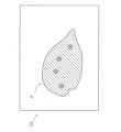
画像生成部52aは、検出部30によって検出された透過X線量に基づいて、図8に示すような物品PのX線画像(検査画像)を生成する。図8に示すように、物品Pの検査画像では、透過X線の検出量の多い領域が明るく(輝度が高く)表示され、透過X線の検出量が少ない領域が暗く(輝度が低く)表示される。すなわち、物品Pの検査画像の明暗(輝度)は、透過X線の検出量に依存する。画像生成部52aが生成する検査画像において、輝度が最低値である領域の画素は黒く、輝度が最高値である画素は白で表示される。換言すると、画像生成部52aが生成する検査画像は、無彩色の画像である。図8に示す領域A1、A2、A3、A4は、輝度が低い領域である。一方で、領域B1は、輝度が高い領域である。 (2-6-2-1) Image Generation Unit The
ただし、図8の表示は一例であり、実際には、輝度の高い領域であっても、異物が混入している恐れがあり、また、輝度が低い領域であっても、異物が混入しているとは限らない。このため、画像生成部52aで生成された段階の検査画像では、異物を確認することが容易ではない。However, the display in Figure 8 is only an example, and in reality, even areas with high brightness may contain foreign matter, and areas with low brightness do not necessarily contain foreign matter. For this reason, it is not easy to confirm foreign matter in the inspection image generated by the
画像生成部52aは、検出部30の各X線検出素子から出力されるX線透過信号を所定の短い時間間隔で取得し、取得したX線透過信号に基づいて検査画像を生成する。画像生成部52aは、扇状のX線の照射範囲IR(図4参照)を物品Pが通過する際に各X線検出素子から出力されるX線透過信号に基づいて、物品Pの検査画像を生成する。照射範囲IRにおける物品Pの有無は、検出部30が出力する信号の出力のタイミングにより判断される。The
画像生成部52aは、検出部30の各X線検出素子30aから得られる透過X線の強度に関する所定の時間間隔ごとのデータを時系列的に沿ってマトリックス状につなぎ合わせて、物品Pの検査画像を生成する。The
(2-6-2-2)教師データ取得部
教師データ取得部52bは、学習部52cが使用する教師データを、画像記憶部51aから取得する。画像記憶部51aには、異物無し画像データや、異物混み画像データが記憶されている。異物無し画像データとは、異物や仮想異物を含まない物品Pに係る画像データのことを指す。異物無し画像データは、H×Wの2次元配列である。異物混み画像データとは、異物や仮想異物を含む物品Pに係る画像データのことを指す。異物混み画像データは、異物無し画像データと同様に、H×Wの2次元配列である。 (2-6-2-2) Teacher Data Acquisition Unit The teacher
教師データ取得部52bは、画像記憶部51aに記憶されているこれらの異物無し画像データや、異物混み画像データを教師データとして取得する。例えば、教師データ取得部52bは、画像記憶部51aに予め記憶されている異物無し画像データや異物混み画像データを、合わせて数百枚又は数千枚取得する。The teacher
(2-6-2-3)学習部
学習部52cは、教師データ取得部52bが取得した教師データを用いて、学習モデル136の学習処理を実行する。学習モデル136に用いられる機械学習の例としては、ニューラルネットワーク、サポートベクターマシン、ランダムフォレスト等が挙げられる。 (2-6-2-3) Learning Unit The
学習部52cは、教師データ取得部52bが取得した異物無し画像データや異物混み画像データに係る多数の教師データを用いて学習モデル136を生成する。The
本実施形態では、図7に示すように、学習モデル136は、畳み込みニューラルネットワーク(CNN)130である。畳み込みニューラルネットワーク130は、入力層131、中間層132及び出力層133を含む。In this embodiment, as shown in FIG. 7, the
入力層131では、異物無し画像データや異物混み画像データからなる教師データが入力される。入力層131は、H×Wの2次元配列を入力できるように構成する。In the
中間層132は、畳み込み層132aとプーリング層132bとを有する。畳み込み層132aは、画像データの局所的な特徴を抽出する層である。プーリング層132bは、画像データの局所的な特徴をまとめる層である。畳み込み層132aとプーリング層132bとは、交互に繰り返す構成を取るものであってもよい。畳み込み層132a及びプーリング層132bの構成は、ResNet(Residual Network)等の代表的なモデルを用いてもよい。また、畳み込み層132a及びプーリング層132bの構成は、例えば、正解率が最良となるように、適宜カスタマイズされてもよい。中間層132の最後の層は、全結合層132cとする。畳み込み層132a及びプーリング層132bは、各層のノードを用いた演算によって、入力層131を通じて入力される異物無し画像データや異物混み画像データの特徴を抽出する。全結合層132cは、畳み込み層132a及びプーリング層132bを通して特徴部分が取り出された経過画像を1つのノードに結合し、活性化関数によって変換した値を特徴ベクトルとして出力する。限定するものではないが、中間層132では、活性化関数の一例としてReLU関数を用いる。全結合層132cが出力した特徴ベクトルは、出力層133に送出される。The
出力層133では、例えば、物品Pの異常状態の確からしさを示す異常確信度が出力される。本実施形態における異常状態とは、限定するものではないが、例えば物品Pに異物が含まれている状態である。出力層133の活性化関数は、例えば、シグモイド関数を用いる。The
畳み込みニューラルネットワーク130の損失関数は、例えば、交差エントロピーを用いる。畳み込みニューラルネットワーク130の最適化は、例えば最急降下法等を用いる。The loss function of the convolutional
学習部52cは、上記機械学習を実行することにより、画像生成部52aが生成した検査画像が入力されることで、検査画像を構成する画素ごとに、異常確信度を算出(出力)する学習モデル136を生成する。The
本実施形態に係る学習モデル136は、例えば、検査画像の輝度に基づいて異常確信度を算出するよう機械学習が行われたものであってもよい。この場合、検査画像において、画素値としての輝度が小さい領域の画素(換言すると、透過したX線の強度が弱い領域の画素)については、異常確信度を大きく算出するものであってもよい。また、該当画素の画素値と、近傍の画素の画素値との関係性から、異常確信度を算出するものであってもよい。The
本実施形態に係る学習モデル136は、画像生成部52aが生成した検査画像に対して自動的に異常確信度を算出する。ただし、検査画像は、画像生成部52aや検査部52e、その他記憶部51に記憶された各種プログラムを制御部52が実行することによって、学習モデル136に入力されるものであってもよい。この場合、学習モデル136は、検査画像が入力されるごとに異常確信度を算出する。The
ここでは、学習モデル136は、検査画像を構成する画素の異常確信度の大きさを、0~255の256段階に分類する。Here, the
(2-6-2-4)画像処理部
画像処理部52dは、画像生成部52aで生成された検査画像であって、学習モデル136によって画素ごとの異常確信度が算出された検査画像に対して画像処理を行う。画像処理部52dは、検査画像の画素ごとの異常確信度の大きさに基づき、検査画像を構成する画素の表示態様を変化させる。当該検査画像は、表示部40に表示される。 (2-6-2-4) Image Processing Unit The
詳細には、画像処理部52dは、検査画像を構成する画素ごとの異常確信度の大きさに基づき、検査画像の画素の表示態様を変化させる際に、異なる異常確信度に対し異なる色相が対応するように変化させる。In detail, when changing the display mode of the pixels of the inspection image based on the magnitude of the abnormality confidence for each pixel constituting the inspection image, the
(a)例えば、画像処理部52dは、異常確信度の大きさが第1閾値K1以上である検査画像の画素と、異常確信度の大きさが第1閾値K1未満である検査画像の画素との表示態様を異ならせる。なおかつ、画像処理部52dは、異常確信度の大きさが第1閾値K1以上である画素については異常確信度に応じて表示態様を変化させ、検査画像を視覚的に区分させる。以下、このような表示態様を、第1表示態様と呼ぶことがある。(a) For example, the
(b)上記の(a)で説明した態様(第1表示態様)で検査画像を表示する場合、好ましくは、画像処理部52dは、異常確信度の大きさが第1閾値K1未満である検査画像の画素については、検査画像における画素が有する画素値に基づいて表示部40に表示させる。以下、このような表示態様を、第2表示態様と呼ぶことがある。(b) When the test image is displayed in the manner described in (a) above (first display manner), the
以下、具体的に説明する。The details are explained below.
(a)第1表示態様
第1表示態様では、画像処理部52dは、異常確信度の大きさが第1閾値K1以上である画素については異常確信度に応じて表示態様を変化させ、検査画像を視覚的に区分させる。 (a) First display mode In the first display mode, the
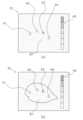
例えば、本実施形態に係る画像処理部52dは、画像生成部52aで生成された検査画像(図8参照)に対して、画像処理を行うことで、図9Aの(a)に示すような検査画像を作成し、表示部40のC1で示す領域(図5参照)に表示させる。For example, the
図9Aの(a)において、A1、A2、A3、A4で示される領域は、異常確信度の大きさが第1閾値K1以上の画素からなる領域である。上記の通り、本実施形態では、第1閾値K1は異常確信度150に設定されている。このため、図9Aの(a)において、A1、A2、A3、A4で示される領域は、異常確信度の大きさが150以上の画素からなる領域であると考えられる。換言すると、領域A1、A2、A3、A4は、異常確信度の大きさが第1閾値K1を上回る程度に、異常状態が生じている恐れがあると考えられる領域である。より具体的には、領域A1、A2、A3、A4には、例えば異物が混入している恐れがある。なお、図9Aの(a)に示すように、異常確信度の大きさが第1閾値K1未満である画素によって構成される領域は、表示部40に表示されていない。9A(a), the regions indicated by A1, A2, A3, and A4 are regions made up of pixels whose abnormality confidence level is equal to or greater than the first threshold K1. As described above, in this embodiment, the first threshold K1 is set to an abnormality confidence level of 150. Therefore, the regions indicated by A1, A2, A3, and A4 in FIG. 9A(a) are considered to be regions made up of pixels whose abnormality confidence level is equal to or greater than 150. In other words, the regions A1, A2, A3, and A4 are regions in which it is considered that an abnormal state may occur to the extent that the abnormality confidence level exceeds the first threshold K1. More specifically, the regions A1, A2, A3, and A4 may contain, for example, foreign matter. Note that, as shown in FIG. 9A(a), the regions made up of pixels whose abnormality confidence level is less than the first threshold K1 are not displayed on the
以下、図9の(a)においては、領域A1を構成する画素の異常確信度が最も大きく、A2、A3、A4、の順に、異常確信度が低下しているものとして説明する。本実施形態において、検査画像を構成する各画素の画素値としての色相は、第1閾値K1の大きさに応じて変化する。より具体的には、検査画像の各画素から算出される異常確信度の大きさが第1閾値K1をどの程度上回っているかに応じて、検査画像の各画素の表示態様は変化する。ここで、画像処理部52dは、例えば、異常確信度が大きい画素から順に、赤色、橙色、緑色、空色に対応させるとする。この場合、例えば、最も異常確信度が大きい画素からなるA1の領域が赤色に、次いで異常確信度が大きい画素からなるA2の領域が橙色に、次いで異常確信度が大きい画素からなるA3の領域が緑色に、次いで異常確信度が大きい画素からなるA4の領域が空色に対応しており、画像処理部52dは、各領域を、各領域が対応する色で表示部40に表示させる。ただし、これらの表示の態様はあくまでも一例であって、例えば、各異常確信度に対応する色は、適宜変更可能である。詳細は以下の(b)や変形例1Iで後述する。In the following, in FIG. 9A, the abnormality confidence of the pixels constituting the region A1 is the highest, and the abnormality confidence decreases in the order of A2, A3, and A4. In this embodiment, the hue as the pixel value of each pixel constituting the inspection image changes according to the magnitude of the first threshold K1. More specifically, the display mode of each pixel of the inspection image changes according to how much the magnitude of the abnormality confidence calculated from each pixel of the inspection image exceeds the first threshold K1. Here, the
なお、図面の都合上、本願図面において色相の変化は、ハッチングの態様を変化させることで表現している。For convenience of the drawings, changes in hue are represented in the drawings of this application by changing the hatching pattern.
このように、本実施形態に係る画像処理部52dは、異常確信度の大きさが第1閾値K1以上である画素と、異常確信度の大きさが第1閾値K1未満である画素と、の表示態様を異ならせている。なおかつ、画像処理部52dは、異常確信度の大きさが第1閾値K1以上である画素については異常確信度に応じて表示態様を変化させ、検査画像を視覚的に区分させている。In this manner, the
図9Aの(a)に示すように、本実施形態に係る検査装置10によって表示される検査画像では、異常確信度を確認することが容易である。As shown in FIG. 9A (a), the inspection image displayed by the
また、画像生成部52aで生成された無彩色の検査画像(図8参照)と比較して、画像処理部52dによる処理を経た有彩色の検査画像(図9Aの(a)参照)は、異物の有無や異常確信度の大きさを直感的に把握することができる。In addition, compared to the achromatic inspection image (see FIG. 8) generated by the
なお、図9Aの(a)に示すように、表示部40には、異常確信度の大きさに対応したカラーバー45が表示されていてもよい。これにより、本実施形態に係る検査装置10のオペレータは、異常確信度をより容易に確認することができる。図9Aの(a)では、上方から下方に向けて、確信度が大きいものから順に、表示される色相を並べて表示している。検査装置10のオペレータは、カラーバー45を確認することで、異常確信度が、第1閾値K1をどの程度上回っているかを確認することができる。ここでは、カラーバー45は、第1閾値K1に対する異常確信度の相対的な大きさを示すものである。例えば、カラーバー45の上部45aに表示されている色に対応した色が表示されている領域(図9Aの(a)では、領域A1)は、異常確信度が第1閾値K1を大きく上回っている画素によって構成されている領域である。また、カラーバー45の底部45bの色に対応した色が表示されている領域(図9Aの(a)では、領域A4)は、異常確信度が第1閾値K1を僅かに上回る画素によって構成されている領域である。この構成によれば、カラーバー45を参照することで、各領域を構成する画素の異常確信度が、第1閾値K1をどの程度上回っているのかを容易に確認することができる。As shown in FIG. 9A (a), the
ただし、カラーバー45による表示は、上記の例に限定されるものではなく、カラーバー45は、異常確信度の絶対的な大きさに対応するものであってもよい。例えば、カラーバー45には、256階調の色相が表示されているものであってもよい。この場合、カラーバーの上部45aは、異常確信度の最大値(ここでは、255)に対応する色を表示し、底部45bは、異常確信度の最小値(ここでは、0)に対応した色を表示する。また、この場合、第1閾値K1に対応する色相を示すマーク(矢印等)が、カラーバー45とともに表示されるものであってもよい。However, the display by the
また、第1閾値K1の変更は、カラーバー45から受け付けるものであってもよい。換言すると、カラーバー45は、閾値変更部90として機能するものであってもよい。この場合、カラーバー45は、図5に示すようなトグルスイッチ91を有するものであってもよい。あるいは、図9Aの(b)に示すように、表示部40には、カラーバー45とともに、閾値変更部90が表示されるものであってもよい。The change in the first threshold K1 may be received from the
なお、本実施形態においては、画像生成部52aで生成された検査画像は、画像処理部52dによる処理を経ることで、画素値としての色相を含む検査画像となる。In this embodiment, the inspection image generated by the
(b)第2表示態様
第2表示態様では、画像処理部52dは、異常確信度の大きさが第1閾値K1以上である画素については異常確信度に応じて表示態様を変化させ、検査画像を視覚的に区分させる。なおかつ、画像処理部52dは、異常確信度の大きさが第1閾値K1未満である検査画像の画素については、検査画像における画素が有する画素値に基づいて表示部40に表示させる。 (b) Second Display Mode In the second display mode, the
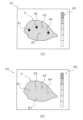
例えば、本実施形態に係る画像処理部52dは、画像生成部52aで生成された検査画像(図8参照)に対して、画像処理を行うことで、図10の(a)に示すような検査画像を作成し、表示部40のC1で示す領域に表示させる。For example, the
図10の(a)において、A1、A2、A3、で示される領域は、異常確信度の大きさが第1閾値K1以上の画素からなる領域である。図10の(a)において、領域A4、B1は、異常確信度の大きさが第1閾値K1未満の画素からなる領域である。In FIG. 10(a), the regions indicated by A1, A2, and A3 are regions made up of pixels whose abnormality confidence level is equal to or greater than the first threshold value K1. In FIG. 10(a), the regions A4 and B1 are regions made up of pixels whose abnormality confidence level is less than the first threshold value K1.
ここで、画像処理部52dは、例えば、異常確信度が大きい画素から順に、赤色、橙色、緑色、に対応させるとする。この場合、例えば、最も異常確信度が大きい画素からなるA1の領域が赤色に、次いで異常確信度が大きい画素からなるA2の領域が橙色に、次いで異常確信度が大きい画素からなるA3の領域が緑色に、対応しており、画像処理部52dは、各領域を、各領域が対応する色で表示部40に表示させる。ただし、これらの表示はあくまでも一例であって、適宜変更可能である。Here, the
また、図10の(a)に示すように、異常確信度の大きさが第1閾値K1未満である画素からなる領域A4、B1については、検査画像における画素が有する画素値に基づいて表示部40に表示されている。換言すると、制御部52は、異常確信度の大きさが第1閾値K1未満である画素からなる領域については、画像生成部52aによって生成された状態から特に処理を加えることなく、表示部40に表示する。なお、本願図面において、検査画像における画素値に基づいて表示される領域については、斜線のハッチングを付して表現している(図8参照)。As shown in FIG. 10(a), the regions A4 and B1, which are made up of pixels whose abnormality confidence level is less than the first threshold value K1, are displayed on the
このように、画像処理部52dは、異常確信度の大きさが第1閾値K1以上である画素については、異常確信度に応じて表示態様を変化させる一方で、異常確信度の大きさが第1閾値K1未満である画素については、画素が有する画素値に基づいて表示部40に表示させている。このため、本実施形態に係る検査装置10では、異常確信度を確認することが容易である。In this way, for pixels whose magnitude of abnormality confidence is equal to or greater than the first threshold K1, the
また、本実施形態に係る検査装置10のオペレータは、検査画像において、物品Pと、異常確信度が第1閾値K1を超える画素からなる領域と、の関係を確認することが容易である。例えば、物品Pと、異常確信度が第1閾値K1を超える画素からなる領域と、の位置関係を確認することが容易である。このように、本実施形態に係る検査装置10では、異常確信度をより容易に確認することができる。In addition, an operator of the
(2-6-2-5)検査部
検査部52eは、学習モデル136によって算出された異常確信度を用いて、物品Pに異常が生じているか否か(物品Pが良品であるか否か)を判断する。限定するものではないが、本実施形態における異常状態とは、物品Pに異物が混入されている状態である。 (2-6-2-5) Inspection Unit The
検査部52eは、学習モデル136に入力された検査画像に含まれる画素のうち、第1閾値K1を超える異常確信度を有する画素が所定数以上である場合に、検査画像に対応する物品Pに異常がある(物品Pは不良品である)と判断して、振分部70に、物品Pを第1方向D1に振分けさせる。なお、所定数、とは、所定割合、を意味するものとして解釈することもできる。より詳細には、本実施形態に係る検査システム100の制御部52の一機能としての検査部52eは、学習モデル136に入力された検査画像に含まれる画素のうち、第1閾値K1以上の異常確信度を有する画素が所定割合以上存在する場合に、検査画像に対応する物品Pに異常がある(物品Pは不良品である)と判断して、振分部70に、物品Pを第1方向D1に振分けさせる。When a predetermined number or more of pixels having an abnormality confidence level exceeding the first threshold K1 are present among the pixels included in the inspection image input to the
検査部52eは、上記以外の場合に、検査画像に対応する物品Pに異常がない(物品Pは良品である)と判断して、振分部70に、物品Pを第2方向D2に振り分けさせる。In cases other than those described above, the
本実施形態において、検査部52eは、例えば検査の結果を振分部制御装置170に送る。振分部制御装置170は、検査装置10において良品と判断された物品Pを、第1方向D1へ振り分けるように振分部70を制御する。第1方向D1は、例えば良品を排出する後段コンベア80へと向かう方向である。振分部制御装置170は、検査装置10において不良品と判断された物品Pを、第2方向D2へ振り分けるように振分部70を制御する。第2方向D2は、例えば不良品排出方向であり、第2方向D2に振り分けられた物品Pは、検査システム100から排出される。In this embodiment, the
なお、検査部52eは、学習モデル136に入力された検査画像に含まれる画素のうち、第1閾値K1以上の異常確信度を有する画素が、所定数以上連続して存在する場合や、所定範囲内に所定数以上存在している場合に、検査画像に対応する物品Pに異常がある(物品Pは不良品である)と判断するものであってもよい。The
(3)検査装置の動作
本実施形態に係る検査システム100が行う動作について、図11を用いて説明する。なお、図11に示される処理の流れはあくまでも一例であり、矛盾のない範囲で適宜変更されてもよい。例えば各ステップの前後に、図示されていない他のステップが含まれていてもよく、互いに矛盾しない範囲で各ステップの順序が適宜変更されてもよい。 (3) Operation of the Inspection Apparatus The operation of the
(3-1)
まず、ステップS1では、検査システム100のオペレータによって、検査装置10の閾値変更部90から第1閾値K1が設定(入力)される。 (3-1)
First, in step S<b>1 , an operator of the
次に、ステップS2では、画像生成部52aが、X線検出素子30aから出力されたX線透過信号を用いて、ベルト12dを流れる物品PのX線画像(検査画像)を生成する。Next, in step S2, the
次に、ステップS3では、学習モデル136によって検査画像を構成する画素の異常確信度が算出される。Next, in step S3, the
次に、ステップS4では、画像処理部52dが、ステップS1で設定された第1閾値K1やステップS3で算出された異常確信度に基づき、検査画像に対して画像処理を行う。Next, in step S4, the
次に、ステップS5では、検査部52eが、ステップS3で算出された異常確信度に基づき、異常判定を実行する。異常判定の結果は、制御装置50や振分部制御装置170に信号として出力される。Next, in step S5, the
ステップS5で不合格(異常あり)と判定された場合には、ステップS6に進む。If step S5 determines that the test has failed (there is an abnormality), proceed to step S6.
ステップS6では、表示部40に、検査に不合格であった旨を示す表示と、ステップS4で作成された検査画像とが表示される。換言すると、異常確信度が第1閾値K1以上の画素からなる領域と、第1閾値K1未満の画素からなる領域とで、検査画像の表示態様が異なる検査画像が表示される。In step S6, the
次に、ステップS7では、振分部制御装置170から、振分部70に対し、検査に不合格の物品Pを第2方向D2へ振り分けるように命令がなされる。Next, in step S7, the sorting
一方、ステップS5で合格(異常なし)と判定された場合には、ステップS8に進む。ステップS8では、表示部40に、異常検査に合格であった旨を示す表示と、ステップS4で作成された検査画像とが表示される。On the other hand, if it is determined to be a pass (no abnormalities) in step S5, the process proceeds to step S8. In step S8, the
次に、ステップS9では、異常検査に合格した物品Pが、第1方向D1へと搬送される。Next, in step S9, the item P that has passed the abnormality inspection is transported in the first direction D1.
(4)制御部の機能
以下、本開示に係る検査装置10の制御部52の機能について説明する。 (4) Functions of the Control Unit The functions of the
本実施形態において、制御部52は、記憶部51に記憶されている所定のプログラムを実施することで、画像生成部52a、教師データ取得部52b、学習部52c、画像処理部52d及び検査部52eとして機能する。ここでは、特に、制御部52が有する画像処理部52dとしての機能について説明する。In this embodiment, the
(4-1)
従来技術に係る検査装置では、X線透視像信号の値が、所定の閾値よりも小さい場合に検査対象に異物が混入していると判定する。これは、異常確信度が所定の閾値よりも大きいことと対応している。また、従来技術に係る検査装置では、異物ありと判定された領域(画素)を視認できるように、異物ありと判定された領域に対して、着色処理(例えば、赤色に塗りつぶす処理など)を行うことがある。このため、従来技術に係る検査装置では、図23の(a)に示すような検査画像が表示部に表示されることが考えられる。 (4-1)
In the inspection device according to the conventional technology, when the value of the X-ray fluoroscopic image signal is smaller than a predetermined threshold, it is determined that a foreign object is present in the inspection object. This corresponds to the abnormality certainty being greater than a predetermined threshold. In addition, in the inspection device according to the conventional technology, a coloring process (e.g., a process of filling in red) may be performed on the area (pixel) determined to have a foreign object so that the area can be visually recognized. For this reason, in the inspection device according to the conventional technology, it is considered that an inspection image such as that shown in FIG. 23(a) is displayed on the display unit.
図23の(a)は、従来技術に係る検査装置によって生成された検査画像の一例である。図23の(a)では、異物ありと判定された領域a1、a2、a3、a4のそれぞれを構成する画素に、着色処理が行われているものとする。図23の(a)において、画素から算出される異常確信度は、領域a1が最も大きく、領域a2、領域a3、領域a4、領域b1の順に異常確信度が低下するものとする。なお、領域b1は、異常確信度が第1閾値K1未満の画素からなる領域であるものとする。しかしながら、図23の(a)に示す通り、従来技術に係る検査画像には、領域a1、a2、a3、a4、の各領域を構成する画素に係る異常確信度の大きさが反映されていない。このため、例えば検査装置から誤検出が生じていることが判明した際に、適切な第1閾値K1を把握する事が困難である。以下、具体的に説明する。Figure 23 (a) is an example of an inspection image generated by an inspection device according to the conventional technology. In Figure 23 (a), it is assumed that coloring processing is performed on the pixels constituting each of the regions a1, a2, a3, and a4 that are determined to contain a foreign object. In Figure 23 (a), it is assumed that the abnormality confidence calculated from the pixels is the largest in region a1, and the abnormality confidence decreases in the order of region a2, region a3, region a4, and region b1. It is assumed that region b1 is an area consisting of pixels whose abnormality confidence is less than the first threshold value K1. However, as shown in Figure 23 (a), the magnitude of the abnormality confidence of the pixels constituting each of the regions a1, a2, a3, and a4 is not reflected in the inspection image according to the conventional technology. For this reason, for example, when it is found that a false detection has occurred from the inspection device, it is difficult to grasp the appropriate first threshold value K1. A specific explanation will be given below.
例えば、従来技術に係る検査装置において、検査用のサンプルの物品Pを切り開いて異物の有無を確認するなどして、物品Pの図23の(a)に示される領域a1、a2、a3には異物が含まれているが、領域a4には実際には異物が含まれていない(領域a4の異物は誤検出である)ことが判明した場合を想定する。この場合、オペレータは、領域a1、a2、a3を構成する画素の異常確信度の大きさを下回り、かつ、領域a4の異常確信度の大きさを上回るように、第1閾値K1の設定を変更する必要がある。しかしながら、図23の(a)には、領域a1、a2、a3及びa4の各領域を構成する画素の異常確信度の大きさが反映されていない。換言すると、領域a1、a2、a3及びa4を構成する画素の異常確信度の大きさが、第1閾値K1をどの程度上回っているのかが示されていない。このため、従来技術の検査装置に係るオペレータは、領域a1、a2、a3を構成する画素の異常確信度を下回り、かつ、領域a4の異常確信度を上回る第1閾値K1を見出すために、第1閾値K1の微調整を繰り返す必要があった。具体的には、第1閾値K1を実際に増減させて、異常確信度が第1閾値K1を上回る領域を確認し(異常確信度が第1閾値K1を上回らなくなる領域を確認し)、所望の結果が得られるかを試す必要があった。そのため、オペレータは、適切な第1閾値K1を設定するための調整に時間がかかっていた。For example, in a conventional inspection device, a sample item P for inspection is cut open to check for the presence or absence of foreign matter, and it is assumed that areas a1, a2, and a3 shown in FIG. 23(a) of the item P contain foreign matter, but area a4 does not actually contain foreign matter (the foreign matter in area a4 is a false positive). In this case, the operator needs to change the setting of the first threshold K1 so that the abnormality confidence of the pixels constituting areas a1, a2, and a3 is lower than that of the pixels constituting areas a1, a2, and a3, and exceeds that of area a4. However, FIG. 23(a) does not reflect the abnormality confidence of the pixels constituting areas a1, a2, a3, and a4. In other words, it is not shown to what extent the abnormality confidence of the pixels constituting areas a1, a2, a3, and a4 exceeds the first threshold K1. For this reason, an operator of an inspection device of the conventional technology had to repeatedly fine-tune the first threshold K1 to find a first threshold K1 that is below the anomaly confidence level of the pixels that make up areas a1, a2, and a3 and exceeds the anomaly confidence level of area a4. Specifically, the operator had to actually increase or decrease the first threshold K1 to check the area where the anomaly confidence level exceeds the first threshold K1 (check the area where the anomaly confidence level no longer exceeds the first threshold K1) and try to see if the desired result could be obtained. For this reason, the operator had to spend a lot of time making adjustments to set an appropriate first threshold K1.
また、例えば、従来技術に係る検査装置において、物品Pの図23の(a)に示される領域a1、a2、a4には異物が含まれているが、領域a3には実際には異物が含まれていないことが判明した場合を想定する。この場合、領域a3の異物は誤検出であるが、領域a4の異物は正しく検出されていることになる。そのため、異物検出を確実に行うためには、領域a4に対応する異物が確実に検出されるように第1閾値K1を設定することが必要となる。しかしながら、領域a3を構成する画素の異常確信度は、領域a4を構成する画素の異常確信度よりも大きい。そのため、領域a3の異物が誤検出されず、且つ領域a4の異物が検出されるように第1閾値K1を設定することは不可能である。しかしながら、従来技術に係る検査装置において、オペレータは、領域a3及び領域a4を構成する画素の異常確信度がどの程度第1閾値K1を上回っているか、表示により即座に把握することができない。そのため、オペレータは、実際に第1閾値K1の値を増減させて、領域a3及び/又は領域a4における各々の異常確信度が第1閾値K1を超えて又は下回って、領域a3及び領域a4における着色処理の有無が変化する様子を確認するまでは、領域a3が誤検出されず、且つ領域a4が検出されるように第1閾値K1を設定することは不可能であるという事実を認識することができなかった。そのため、オペレータは、設定不可能な調整を試みてしまい、適切な第1閾値K1を設定するための調整に無用な時間を費やす可能性があった。なお、この場合は、例えば、領域a4に係る異物の検出を優先するため、領域a3に係る誤検出を許容して、領域a3の異常確信度及び領域a4の異常確信度がいずれも第1閾値K1を上回るように調整するのが好ましい。For example, in an inspection device according to the prior art, it is assumed that the areas a1, a2, and a4 shown in FIG. 23(a) of the item P contain foreign matter, but the area a3 does not actually contain foreign matter. In this case, the foreign matter in the area a3 is erroneously detected, but the foreign matter in the area a4 is correctly detected. Therefore, in order to reliably detect foreign matter, it is necessary to set the first threshold value K1 so that the foreign matter corresponding to the area a4 is reliably detected. However, the abnormality confidence of the pixels constituting the area a3 is greater than the abnormality confidence of the pixels constituting the area a4. Therefore, it is impossible to set the first threshold value K1 so that the foreign matter in the area a3 is not erroneously detected and the foreign matter in the area a4 is detected. However, in an inspection device according to the prior art, an operator cannot immediately grasp from the display to what extent the abnormality confidence of the pixels constituting the areas a3 and a4 exceeds the first threshold value K1. Therefore, the operator could not recognize the fact that it is impossible to set the first threshold value K1 so that the region a3 is not erroneously detected and the region a4 is detected until the operator actually increases or decreases the value of the first threshold value K1 and checks whether or not the coloring process is performed in the region a3 and the region a4 by checking whether or not the coloring process is performed in the region a3 and the region a4 is performed by exceeding or falling below the first threshold value K1. Therefore, the operator may attempt an adjustment that cannot be set, and waste time in adjusting to set an appropriate first threshold value K1. In this case, for example, in order to prioritize the detection of a foreign object in the region a4, it is preferable to allow the erroneous detection in the region a3 and adjust so that the abnormality confidence of the region a3 and the abnormality confidence of the region a4 both exceed the first threshold value K1.
このように、従来技術に係る検査装置では、画素の異常確信度の大きさが、検査画像に反映されていない。この場合、従来技術に係る検査装置において、例えば異常の誤検出が抑制されるような最適な第1閾値K1を把握することは、非常に時間のかかる作業となる。As such, in the inspection device according to the conventional technology, the magnitude of the anomaly confidence level of a pixel is not reflected in the inspection image. In this case, in the inspection device according to the conventional technology, for example, determining the optimal first threshold value K1 that suppresses false detection of an anomaly is a very time-consuming task.
(4-2)
一方で、本実施形態に係る検査装置10では、画像処理部52dによる画像処理が行われる。本実施形態に係る画像処理部52dは、検査画像を構成する画素から算出される異常確信度の大きさに基づき、検査画像を構成する画素の表示態様を変化させる。 (4-2)
On the other hand, in the
詳細には、画像処理部52dは、大きさが異なる異常確信度に対し異なる色相が対応するように表示態様を変化させる。In detail, the
例えば、画像処理部52dは、異常確信度の大きさが第1閾値K1以上である画素と、第1閾値K1未満である画素との表示態様を異ならせる。なおかつ、画像処理部52dは、第1閾値K1以上である画素については異常確信度の大きさに応じて表示態様を変化させる。For example, the
また、例えば画像処理部52dは、異常確信度の大きさが第1閾値K1未満である検査画像の画素については、検査画像における画素が有する画素値に基づいて表示部40に表示させる。Furthermore, for example, the
このため、表示部40には、例えば図10の(b)に示すような検査画像が表示される。図10の(b)に示す通り、検査画像には、領域A1、A2、A3、A4、の各領域を構成する画素に係る異常確信度が反映されている。このため、例えば検査装置10から誤検出が生じていることが判明した際に、適切な第1閾値K1を把握することが容易である。以下、具体的に説明する。For this reason, the
例えば、検査装置10において、検査用のサンプルの物品Pを切り開いて異物の有無を確認するなどして、物品Pの図10の(b)に示される領域A1、A2、A3には異物が含まれているが、領域A4には異物が含まれていない(領域A4の異物は誤検出である)ことが判明した場合を想定する。この場合、オペレータは、領域A1、A2、A3を構成する画素の異常確信度を下回り、かつ、領域A4を構成する画素の異常確信度を上回るように、第1閾値K1を変更する必要がある。図10の(b)に示すように、検査画像には、領域A1、A2、A3及びA4を構成する画素の異常確信度の大きさが反映されている。換言すると、領域A1、A2、A3及びA4を構成する画素の異常確信度の大きさが、第1閾値K1をどの程度上回っているのかが示されている。このため、ここでは、領域A3を構成する画素の異常確信度の大きさを下回り、かつ、領域A4を構成する画素の異常確信度の大きさを上回るように第1閾値K1の変更を行うことで、誤検出が抑制されることがオペレータに容易に確認される。For example, assume that the
また、例えば、検査装置10において、物品Pの図10の(b)に示される領域A1、A2、A4には異物が含まれているが、領域A3には実際には異物が含まれていないことが判明した場合を想定する。この場合、領域A3の異物は誤検出であるが、領域A4の異物は正しく検出されていることになる。ここで、オペレータは、検査装置10における領域A1、A2、A3の表示の態様(例えば、異常確信度の大きさに対応させた色)を確認すれば、即座に領域A3を構成する画素の異常確信度が領域A4を構成する画素の異常確信度よりも大きいことを理解できる。そのため、領域A3が誤検出されず、且つ領域A4が検出されるように第1閾値K1を設定することは不可能であるという事実を、実際に第1閾値K1の値を増減させることなく認識することができる。したがって、オペレータは、無用な調整を試みることがなくなる。Also, for example, assume that the
このように、本実施形態に係る検査装置10では、最適な第1閾値K1を容易に把握することができる。また、これにより、オペレータは、最適な第1閾値K1を設定するための調整を、従来よりも短い時間で行うことができるようになる。In this way, the
(4-3)
また、本実施形態に係る検査装置10では、異常確信度の大きさに応じて色相を変化させることで、異常確信度の大きい領域を2次元的に表示することができる。例えば、本実施形態に係る検査装置10の制御部52は、図12に示すような検査画像を表示部40の領域C1に表示させる。図12では、物品Pのベルト12dにおける搬送方向をXとして、物品Pの幅方向をYとする。 (4-3)
Furthermore, in the
図12では、領域A1と領域A2とが、物品Pの搬送方向Xにおいて共通する座標であるX1に、それぞれ位置している。一方で、領域A1は幅方向YにおいてY1に、領域A2は幅方向YにおいてY2に、それぞれ位置することから、領域A1と領域A2とは明確に区別されて表示部40に表示される。In FIG. 12, area A1 and area A2 are located at a common coordinate X1 in the conveying direction X of item P. On the other hand, area A1 is located at Y1 in the width direction Y, and area A2 is located at Y2 in the width direction Y, so area A1 and area A2 are displayed on the
あるいは、図12では、領域A1と領域A5とが、物品Pの幅方向Yにおいて共通する座標であるY1にそれぞれ位置している。しかしながら、領域A1は搬送方向XにおいてX1に、領域A5は搬送方向XにおいてX2に、それぞれ位置することから、領域A1と領域A5とは明確に区別されて表示部40に表示される。Alternatively, in FIG. 12, area A1 and area A5 are each located at a common coordinate Y1 in the width direction Y of item P. However, since area A1 is located at X1 in the conveying direction X and area A5 is located at X2 in the conveying direction X, area A1 and area A5 are displayed on the
このように、物品Pに、異常確信度が所定の閾値(基準値)を超えている画素からなる領域が複数存在する場合であって、当該複数の領域が搬送方向又は幅方向のいずれかにおいて共通する座標に位置する場合であっても、本実施形態における検査装置10では、各領域の正確な位置と、各領域を構成する画素の異常確信度の大きさと、を同時に表示部40に表示することができている。換言すると、本実施形態に係る検査装置10では、異常が生じている恐れがある画素からなる領域の2次元的な表示と、異常が生じている恐れがある画素からなる領域における異常確信度の大きさの表示と、が両立されている。In this way, even if there are multiple areas on an item P made up of pixels whose abnormality confidence exceeds a predetermined threshold (reference value) and the multiple areas are located at common coordinates in either the conveyance direction or the width direction, the
このため、本実施形態に係る検査装置10のオペレータは、物品Pの検査画像において、異常が生じている恐れがある画素からなる領域を正確に、確認することができ、かつ、当該領域における異常確信度の大きさを正確に確認することができる。As a result, an operator of the
また、本実施形態に係る検査装置10のオペレータは、異常が生じている恐れがある画素からなる領域を直ちに確認することができ、かつ、当該領域における異常確信度の大きさを直ちに確認することができる。In addition, an operator of the
また、本実施形態の検査装置10に係るオペレータは、異常確信度が、閾値(基準値)をどの程度上回っているのか、直ちに把握(理解)することができる。In addition, an operator using the
(5)特徴
(5-1)
本実施形態に係る検査装置10は、物品Pを検査する検査装置10である。検査装置10は、照射部20と、検出部30と、画像生成部52aと、表示部40と、制御部52と、を備える。照射部20は、物品Pに電磁波を照射する。なお、限定するものではないが、本実施形態において、電磁波はX線である。検出部30は、物品Pを透過したX線を検出する。画像生成部52aは、検出部30の検出結果に基づいて、物品Pの検査画像を生成する。表示部40は、検査画像を表示する。制御部52は、表示部40における検査画像の表示態様を変更させる。制御部52は、検査画像を構成する画素ごとに、異常状態の確からしさを示す異常確信度を算出する。制御部52は、異常確信度の大きさに基づき画素の表示態様を変化させる。 (5) Features (5-1)
The
この検査装置10では、異常確信度を確認することが容易である。This
(5-2)
本実施形態に係る検査装置10では、画素は、画素値として色相を含む。制御部52は、異常確信度の大きさに基づき画素の表示態様を変化させる際に、異なる異常確信度に対し異なる色相が対応するように変化させる。 (5-2)
In the
この検査装置10では、異常確信度を確認することが容易である。This
(5-3)
本実施形態に係る検査装置10では、制御部52は、異常確信度が第1閾値K1以上である画素と、第1閾値K1未満である画素との表示態様を異ならせる。且つ、制御部52は、異常確信度が第1閾値K1以上である画素については異常確信度に応じて表示態様を変化させ、検査画像を視覚的に区分して、表示部40に表示させる。 (5-3)
In the
この検査装置10では、異常確信度を確認することが容易である。This
また、この検査装置10では、最適な第1閾値K1を容易に把握することができる。In addition, with this
また、この検査装置10では、異常が生じている恐れがある領域を容易に確認することができる。さらに、この検査装置10では、当該領域における異常確信度の大きさを容易に確認することができる。In addition, with this
また、この検査装置10では、異常が生じている恐れがある領域を直ちに確認することができる。さらに、この検査装置10では、当該領域における異常確信度の大きさを直ちに確認することができる。In addition, with this
(5-4)
本実施形態に係る検査装置10では、制御部52は、異常確信度が第1閾値K1未満である画素については、検査画像における画素値に基づいて表示部40に表示させる。 (5-4)
In the
この検査装置10では、異常確信度を確認することが容易である。This
また、この検査装置10では、検査画像において、物品Pと、異常確信度が第1閾値K1を超える領域と、の関係を確認することが容易である。このため、この検査装置10では、異常確信度をより容易に確認することができる。In addition, with this
また、この検査装置10では、最適な第1閾値K1を容易に把握することができる。In addition, with this
また、この検査装置10では、異常が生じている恐れがある領域を容易に確認することができる。さらに、この検査装置10では、当該領域における異常確信度の大きさを容易に確認することができる。In addition, with this
また、この検査装置10では、異常が生じている恐れがある領域を直ちに確認することができる。さらに、この検査装置10では、当該領域における異常確信度の大きさを直ちに確認することができる。In addition, with this
(5-5)
本実施形態に係る検査システム100は、検査装置10と、振分部70と、を備える。振分部70は、物品Pを、第1方向D1と、第1方向D1とは異なる第2方向D2とに振り分ける。制御部52は、検査画像に含まれる画素のうち、異常確信度の大きさが第1閾値K1以上である画素が所定数以上である場合に、検査画像に対応する物品Pに異常があると判断して、振分部70に、物品Pを第1方向D1に振り分けさせる。制御部52は、それ以外の場合に、検査画像に対応する物品Pに異常がないと判断して、振分部70に、物品Pを第2方向D2に振り分けさせる。 (5-5)
The
この検査システム100は、異常確信度を確認することが容易な検査装置10を備えている。このため、本実施形態に係る検査システム100では、作業効率が向上する。This
(6)変形例
上記実施形態は、以下の変形例に示すように適宜変形が可能である。各変形例は、矛盾が生じない範囲で、本実施形態に係る変形例や他の実施形態に係る変形例と組み合わせて適用されてもよい。なお、上記の第1実施形態と同様の構成については同様の符号を付し、その詳細な説明は省略する。 (6) Modifications The above embodiment can be modified as appropriate as shown in the following modifications. Each modification may be applied in combination with the modification according to this embodiment and the modification according to another embodiment to the extent that no contradiction occurs. Note that the same reference numerals are used for configurations similar to those of the first embodiment, and detailed descriptions thereof will be omitted.
(6-1)変形例1A
上記実施形態では、制御部52(画像処理部52d)が、異常確信度の大きさに基づき検査画像の画素の表示態様を変化させる際に、異なる異常確信度に対し異なる色相が対応するように変化させる検査装置10について説明した。しかしながら、本開示に係る検査装置の例はこれに限定されるものではなく、例えば検査装置は、検査画像の画素値として、明度、輝度、彩度のうち少なくとも一つを含むものであってもよい。この場合、検査装置は、制御部が異常確信度の大きさに基づき画素の表示態様を変化させる際に、明度、輝度、彩度のうち少なくとも一つの大きさが異なるものが対応するように変化させる検査装置であってもよい。例えば検査装置は、制御部が異常確信度の大きさに基づき画素の表示態様を変化させる際に、異常確信度の大きさに対応して輝度が変化するように、検査画像の画素の表示態様を変化させるものであってもよい。 (6-1) Modification 1A
In the above embodiment, the control unit 52 (
あるいは、本変形例に係る検査装置は、異なる異常確信度に対し、異なる色相とともに、明度、輝度、彩度のうち少なくとも一つの大きさが異なるものが対応するように、検査画像の画素の表示態様を変化させるものであってもよい。例えば検査装置は、異常確信度の大きさに応じて、色相とともに、輝度が変化するように、検査画像の画素の表示態様を変化させるものであってもよい。Alternatively, the inspection device according to this modified example may change the display mode of pixels of the inspection image so that different anomaly certainty levels correspond to different hues as well as different magnitudes of at least one of lightness, luminance, and saturation. For example, the inspection device may change the display mode of pixels of the inspection image so that luminance changes along with hue depending on the magnitude of the anomaly certainty level.
本変形例に係る検査装置は、表示部40が有する性能の制約上、表示部40に表示可能な色相が限定される場合等に有効である。例えば、本変形例に係る検査装置は、表示部40として安価なディスプレイ等を用いる場合であっても、異常確信度を明確に反映させることができる。このため、本変形例においては、検査装置の低コスト化が実現される。The inspection device according to this modified example is effective in cases where the hues that can be displayed on the
また、本変形例に係る検査装置は、上記実施形態と同様に、異常確信度の確認が容易である。Furthermore, the inspection device according to this modified example makes it easy to confirm the degree of certainty of anomalies, just like the above embodiment.
(6-2)変形例1B
上記実施形態では、電磁波の一例としてのX線を物品Pに照射する検査装置10について説明した。しかしながら、本開示に係る検査装置の例はこれに限定されるものではなく、例えば検査装置は、赤外線を物品Pに照射するものであってもよい。この場合、異常確信度は、物品Pを透過又は反射した赤外線の量や強度に基づいて算出されるものであってもよい。 (6-2) Modification 1B
In the above embodiment, the
このほか、本開示に係る検査装置は、物品の検査において一般的に用いられる光によって対象物品の検査を行う装置であれば、紫外線および可視光等を用いて物品Pの検査を行う装置に適用可能である。In addition, the inspection device according to the present disclosure can be applied to devices that inspect item P using ultraviolet light, visible light, etc., as long as the device inspects the target item using light that is commonly used in inspecting items.
また、本変形例に係る検査装置は、上記実施形態と同様に、異常確信度の確認が容易である。Furthermore, the inspection device according to this modified example makes it easy to confirm the degree of certainty of anomalies, just like the above embodiment.
(6-3)変形例1C
上記実施形態では、機械学習を行うことで生成された学習モデル136によって算出された異常確信度を用いて物品の検査を行う検査装置10について説明した。しかしながら、本開示に係る検査装置の例はこれに限定されるものではない。すなわち、本開示に係る検査装置において、異常確信度の算出手段は、適宜選択されればよい。 (6-3) Modification 1C
In the above embodiment, the
本変形例における検査装置は、例えば、X線透過信号の強度を異常確信度とするものであってもよい。この場合、容易な構成で異常確信度を算出することができる。The inspection device in this modified example may, for example, use the intensity of the X-ray transmission signal as the abnormality confidence level. In this case, the abnormality confidence level can be calculated with a simple configuration.
また、本変形例に係る検査装置は、上記実施形態と同様に、異常確信度の確認が容易である。Furthermore, the inspection device according to this modified example makes it easy to confirm the degree of certainty of anomalies, just like the above embodiment.
(6-4)変形例1D
上記実施形態では、物品Pの検査として、異物混入検査を行う検査装置10について説明した。しかしながら、本開示に係る検査装置が行う検査はこれに限定されるものではなく、例えば検査装置は、割れ検査や、欠品検査や、物品内部の空洞検査や、形状検査を行うものであってもよい。また、物品Pは上記実施形態で説明したものに限定されず、様々な物品P(例えば袋状の物品など)を検査対象とすることができる。この場合、異常状態とは、物品Pに割れ(ひび割れ)が生じている状態や、物品Pの内容物が破損している状態や、物品Pの内容物の欠品状態や、物品Pの内部に空洞部分が存在している状態や、物品Pが変形している状態を指すものであってもよい。この場合に、検査装置10は、これらの異常状態が発生している確からしさを、各画素毎に異常確信度として算出する。 (6-4) Modification 1D
In the above embodiment, the
また、本変形例に係る検査装置は、変形例1Aに示す構成と組み合わせることで、噛みこみ検査を行うものであってもよい。この場合、物品は例えば内容物を含む袋状の物品であり、異常状態とは、当該物品のシール部において内容物の噛み込みが生じている状態を指すものであってもよい。The inspection device according to this modification may also be combined with the configuration shown in modification 1A to perform a jam inspection. In this case, the article may be, for example, a bag-shaped article containing contents, and the abnormal state may refer to a state in which the contents are jammed in the sealed portion of the article.
(6-5)変形例1E
上記実施形態では、異常確信度が第1閾値K1以上である画素と、第1閾値K1未満である画素との表示態様を異ならせて、検査画像を表示部40に表示する検査装置10について説明した。しかしながら、本開示に係る検査装置が行う表示の態様はこれに限定されるものではなく、例えば検査装置は、閾値を考慮することなく、異常確信度の大きさに基づき画素の表示態様を変化させた検査画像を表示部40に表示させるものであってもよい。 (6-5) Modification 1E
In the above embodiment, the
本変形例に係る検査装置は、例えば、図13の(a)に示すような検査画像を表示部40に表示させる。ここでは、検査画像を構成する全画素の異常確信度の大きさが、検査画像に反映されている。また、ここでは、異なる異常確信度に対し異なる色相が対応するように、検査画像の表示態様が変化している。換言すると、本変形例に係る検査装置では、異常確信度が全面的にカラーマップ化された検査画像が、表示部40の領域C1に表示される。The inspection device according to this modified example displays an inspection image, for example, as shown in FIG. 13(a) on the
また、本変形例に係る検査装置は、例えば図13の(b)に示すように、物品Pの輪郭を抽出して表示するものであってもよい。この場合、異常確信度の大きさを確認することがさらに容易になる。The inspection device according to this modified example may also extract and display the outline of the item P, as shown in FIG. 13(b), for example. In this case, it becomes even easier to confirm the magnitude of the abnormality certainty.
なお、本変形例に係る検査装置は、上記実施形態において、第1閾値K1を最小値(最小単位)に設定する事でも実現される。The inspection device according to this modified example can also be realized by setting the first threshold value K1 to the minimum value (smallest unit) in the above embodiment.
本変形例に係る検査装置は、上記実施形態と同様に、異常確信度の確認が容易である。The inspection device according to this modified example makes it easy to confirm the degree of certainty of anomalies, just like the above embodiment.
(6-6)変形例1F
上記実施形態では、異常確信度が第1閾値K1以上である画素と、第1閾値K1未満である画素との表示態様を異ならせて、検査画像を表示部40に表示する検査装置10について説明した。しかしながら、本開示に係る検査装置の例はこれに限定されるものではない。例えば検査装置は、異常確信度が第1閾値K1以上である画素についてマーキングを行うものであってもよい。本変形例に係るマーキングは、限定するものではないが、例えば画素の異常確信度が第1閾値K1以上であると判定された領域を、円で囲む処理である(図14参照)。ただし、本変形例にかかるマーキングの態様はこれに限定されるものではなく、例えば異常確信度が第1閾値K1以上であると判定された領域を矩形で囲む処理であってもよい。この場合、囲まれた領域の内部が、異常確信度に応じた表示態様(例えば、色)として表示される。 (6-6) Modification 1F
In the above embodiment, the
本変形例においては、異常確信度の大きさが第1閾値K1以上である画素からなる領域が強調して表示されるため、異常状態の見落としが抑制される。本変形例に係る検査装置は例えば、物品Pに混入された異物が極小である場合等に有効である。In this modified example, the area consisting of pixels whose abnormality certainty level is equal to or greater than the first threshold value K1 is highlighted, which reduces the risk of overlooking an abnormal state. The inspection device according to this modified example is effective, for example, in cases where the foreign matter mixed into the item P is extremely small.
本変形例に係る検査装置は、上記実施形態と同様に、異常確信度の確認が容易である。The inspection device according to this modified example makes it easy to confirm the degree of certainty of anomalies, just like the above embodiment.
(6-7)変形例1G
上記実施形態では、検査装置10の制御部52が、学習部52cによって学習モデル136の機械学習を行う例について説明した。しかしながら、本開示に係る検査装置の例はこれに限定されるものではなく、例えば、検査装置と学習部とはそれぞれ別体であってもよい。 (6-7) Modification 1G
In the above embodiment, an example has been described in which the
また、本開示に係る検査装置は、検査装置とは別体の機械学習装置(図示省略)が有する学習部によって生成された学習モデルを用いるものであってもよい。この場合、検査装置は機械学習装置と有線又は無線で接続されることにより、機械学習装置によって生成された学習モデルと通信を行うものであってもよい。この場合、検査装置は、外部のクラウドサーバと通信して、このクラウドサーバから機械学習装置によって生成された学習モデルをダウンロードして用いるように構成されていても良い。The inspection device according to the present disclosure may also use a learning model generated by a learning unit of a machine learning device (not shown) separate from the inspection device. In this case, the inspection device may be connected to the machine learning device via a wired or wireless connection, and communicate with the learning model generated by the machine learning device. In this case, the inspection device may be configured to communicate with an external cloud server and download and use the learning model generated by the machine learning device from the cloud server.
(6-8)変形例1H
上記実施形態では、検査装置10の制御部52が、学習部52cによって学習モデル136の機械学習を行う例について説明した。しかしながら、本開示に係る検査装置の例はこれに限定されるものではなく、例えば検査装置は、予め機械学習済みの学習モデルを用いるものであってもよい。 (6-8) Modification 1H
In the above embodiment, an example has been described in which the
例えば、検査装置10とは別体の機械学習装置によって予め機械学習が行われた学習モデルを用いるものであってもよい。For example, a learning model that has been machine-learned in advance by a machine learning device separate from the
(6-9)変形例1I
上記実施形態では、制御部52は、異常確信度の大きさが第1閾値K1以上である検査画像の画素と、異常確信度の大きさが第1閾値K1未満である検査画像の画素と、の表示態様を異ならせることで、検査画像を視覚的に区分して表示部40に表示させると説明した。 (6-9) Modification 1I
In the above embodiment, it was explained that the
異常確信度の大きさが第1閾値K1以上である検査画像の画素と、異常確信度の大きさが第1閾値K1未満である検査画像の画素と、の表示態様を異ならせる表示の一例として、上記実施形態では、図9Aの(a)や、図10の(a)に示すような表示態様を説明したが、本開示に係る検査装置による表示の例は、これらに限定されるものではない。As an example of a display in which the display mode of pixels of an inspection image whose magnitude of abnormality confidence is equal to or greater than the first threshold value K1 is different from that of pixels of an inspection image whose magnitude of abnormality confidence is less than the first threshold value K1, the display modes shown in FIG. 9A(a) and FIG. 10(a) have been described in the above embodiment, but examples of displays by the inspection device according to the present disclosure are not limited to these.
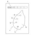
本変形例に係る検査装置では、例えば図9Bに示すように、異常確信度の大きさが第1閾値K1未満である画素からなる領域については表示部40に表示させず、且つ、物品Pの輪郭部分を示す画素については抽出して表示部40に表示させることで、異常確信度の大きさが第1閾値K1以上である検査画像の画素と、異常確信度の大きさが第1閾値K1未満である検査画像の画素と、の表示態様を異ならせてもよい。In the inspection device according to this modified example, as shown in FIG. 9B, for example, the
また、本変形例に係る検査装置では、異常確信度が第1閾値K1未満である画素からなる領域の輝度、明度、彩度、色相等に、補正を行うことで、異常確信度が第1閾値K1以上である画素からなる領域と、異常確信度が第1閾値K1未満である画素からなる領域と、を視覚的に区分して表示部40に表示させるものであってもよい。例えば、異常確信度が第1閾値K1未満である画素からなる領域の色相を、一律に白色に変化させて表示させるものであってもよい。In addition, the inspection device according to this modified example may perform corrections to the luminance, brightness, saturation, hue, etc. of a region made up of pixels whose abnormality confidence level is less than the first threshold value K1, so that a region made up of pixels whose abnormality confidence level is equal to or greater than the first threshold value K1 and a region made up of pixels whose abnormality confidence level is less than the first threshold value K1 are visually distinguished and displayed on the
あるいは、異常確信度が第1閾値K1未満の画素からなる領域については、例えば輝度を小さくする等の補正を行うものであってもよい。Alternatively, for regions consisting of pixels whose abnormality confidence level is less than the first threshold K1, corrections such as reducing the brightness may be performed.
本変形例に係る検査装置は、上記実施形態と同様に、異常確信度が第1閾値K1以上である画素からなる領域と、異常確信度が第1閾値K1未満である画素からなる領域と、の表示態様を視覚的に区分させることができる。As in the above embodiment, the inspection device according to this modified example can visually distinguish the display mode between an area made up of pixels whose abnormality confidence level is equal to or greater than the first threshold value K1 and an area made up of pixels whose abnormality confidence level is less than the first threshold value K1.
本変形例に係る検査装置は、上記実施形態と同様に、異常確信度の確認が容易である。The inspection device according to this modified example makes it easy to confirm the degree of certainty of anomalies, just like the above embodiment.
(6-10)変形例1J
上記実施形態では説明を省略したが、画像処理部52dによって処理が行われた検査画像は、処理が行われた際に設定されていた第1閾値K1とともに、記憶部51に記憶されるものであってもよい。また、記憶部51に記憶される検査画像は、オペレータによって確認可能な態様で、記憶部51に記憶されるものであってもよい。これにより、オペレータは例えば、第1閾値K1の変更の履歴と、各変更に伴い表示された検査画像の履歴とを適宜確認することができる。 (6-10) Modification 1J
Although not described in the above embodiment, the inspection image processed by the
本変形例に係る検査装置では、オペレータは、過去に行った第1閾値K1の変更の履歴と、各変更に伴い表示された検査画像の履歴とを参照することができる。このため、本変形例の検査装置に係るオペレータは、適切な第1閾値K1をより容易に把握することができる。In the inspection device of this modified example, the operator can refer to the history of past changes to the first threshold value K1 and the history of the inspection images displayed following each change. This allows the operator of the inspection device of this modified example to more easily determine the appropriate first threshold value K1.
(6-11)変形例1K
上記実施形態では、表示部40には、カラーバー45が表示されていてもよいと説明した。しかしながら、本開示に係る検査装置の例はこれに限定されるものではなく、検査装置は例えば、カラーバー45とともに、又はカラーバー45に代えて、数値化された異常確信度を表示部40に表示させるものであってもよい。 (6-11) Modification 1K
In the above embodiment, it has been described that the
異常確信度が、学習モデル136によって、大きさに応じて256段階に分類されることは上記の通りである。本変形例に係る検査装置では、異常確信度の大きさが第1閾値K1以上である画素が所定数又は所定割合集合している領域が検出された検査画像は、当該領域を構成する画素の異常確信度の大きさが数値として視覚的に表示される。例えば、本変形例に係る検査装置では、当該領域を構成する画素の異常確信度の大きさを示す数値のうち、最も大きい異常確信度の数値が表示される。あるいは、例えば、当該領域を構成する画素の異常確信度の大きさを示す数値のうち、最も小さい異常確信度の数値が表示される。As described above, the abnormality confidence level is classified into 256 levels according to the magnitude by the
あるいは、例えば、本変形例に係る検査装置では、図15の(a)に示すような検査画像が表示部40の領域C1に表示される。図15の(a)では、領域を構成する画素の異常確信度の大きさを示す数値のうち、最も大きい異常確信度の数値が、第1閾値K1をどの程度上回っているのかが数値として表示される。これにより、例えば第1閾値K1が150に設定されている場合に、図15の(a)の領域A1を確認したオペレータは、領域A1を構成する画素の異常確信度の最大値が199であることを把握する。Alternatively, for example, in the inspection device according to this modified example, an inspection image as shown in FIG. 15(a) is displayed in area C1 of the
このように、本変形例に係る検査装置では、検査画像の画素の異常確信度の大きさが数値として表示部40に表示されるため、オペレータは、異常確信度の詳細な大きさを容易に確認することができる。In this way, in the inspection device of this modified example, the magnitude of the abnormality confidence of the pixels of the inspection image is displayed as a numerical value on the
また、本変形例に係る検査装置は、図15の(a)における領域A1及び領域A5や、領域A2及び領域A6のように、異なる異常確信度の大きさを有する複数の画素からなる領域が重複している場合であっても、各領域における異常確信度の大きさの確認が容易である。In addition, the inspection device according to this modified example makes it easy to confirm the magnitude of abnormality confidence in each region, even when regions consisting of multiple pixels with different abnormality confidence levels overlap, such as regions A1 and A5, or regions A2 and A6 in FIG. 15(a).
本変形例に係る検査装置は、上記実施形態と同様に、異常確信度の確認が容易である。The inspection device according to this modified example makes it easy to confirm the degree of certainty of anomalies, just like the above embodiment.
また、本変形例に係る検査装置は、異常確信度が数値化されて検査画像に反映されるため、異常確信度の詳細な大きさが確認できる。In addition, the inspection device according to this modified example converts the abnormality confidence level into a numerical value and reflects it in the inspection image, allowing the detailed magnitude of the abnormality confidence level to be confirmed.
(6-12)変形例1L
変形例1Dで説明したように、本開示に係る検査装置は、物品Pとして、袋状の物品を検査するものであってもよい。検査装置が袋状の物品を検査する場合、袋状の物品におけるシール部等のように、異物として誤検出されやすい領域の画素や、当該領域の付近の領域の画素に対して、マスク処理が行われることが考えられる。 (6-12) Modification Example 1L
As described in Modification 1D, the inspection device according to the present disclosure may inspect a bag-shaped article as the article P. When the inspection device inspects a bag-shaped article, it is considered that a mask process is performed on pixels in an area that is likely to be erroneously detected as a foreign object, such as a seal portion of the bag-shaped article, and pixels in an area near the area.
本変形例に係る検査装置は、マスク処理が行われた領域の画素と、異常確信度の大きさに基づき表示態様を変化させた画素と、が視覚的に区分された検査画像を表示部40に表示するものであってもよい。The inspection device according to this modified example may display an inspection image on the
本変形例に係る検査装置は、上記実施形態と同様に、異常確信度の確認が容易である。The inspection device according to this modified example makes it easy to confirm the degree of certainty of anomalies, just like the above embodiment.
また、本変形例に係る検査装置は、異物として誤検出されやすい領域の画素にマスク処理を行うことで、異物の誤検出を抑制することができる。In addition, the inspection device according to this modified example can suppress erroneous detection of foreign objects by performing mask processing on pixels in areas that are likely to be erroneously detected as foreign objects.
(6-13)変形例1M
上記実施形態では、それぞれが別体に構成された検査装置10と振分部70とが、通信線等によって接続されることで、検査システム100を構成する例について説明した。しかしながら、本開示に係る検査システム100の例はこれに限定されるものではなく、例えば検査システム100は、一体に構成された検査装置10と振分部70とを備えるものであってもよい。 (6-13) Modification 1M
In the above embodiment, an example has been described in which the
<第2実施形態>
(1)第2実施形態に係る検査装置
本開示の第2実施形態に係る検査システム100及び検査システム100に含まれる検査装置110について説明する。 Second Embodiment
(1) Inspection Apparatus According to a Second Embodiment An
なお、第2実施形態に係る検査装置110は、第1実施形態に係る検査装置10が有する機能と、第2実施形態に係る検査装置110が有する機能と、を切り替え可能に構成された検査装置であってもよい。換言すると、本開示は、第1実施形態に係る検査装置10が有する機能と、第2実施形態に係る検査装置110が有する機能と、の両方の機能を有する検査装置によって実施されるものであってもよい。この場合、例えば検査装置110は、第1実施形態に係る検査装置10が有する機能と、第2実施形態に係る検査装置110が有する機能と、を切り替えるボタン等を表示部140に有するものであってもよい。The
図16は、検査システム100に含まれる検査装置110が有する制御装置150のブロック構成図である。検査システム100は、検査装置110の構成を除き、第1実施形態に係る検査システム100と実質的に共通した構成を採る。また、検査装置110は、制御装置150の構成を除き、第1実施形態に係る検査装置10と実質的に共通した構成を採る。以下では、説明の簡略化のため、第1実施形態との相違点についてのみ説明する。Figure 16 is a block diagram of the
(2)表示部
表示部140は、タッチパネル機能付きの液晶ディスプレイである。表示部140は、検査装置110の入力部としても機能する。表示部140には、例えば物品Pの検査結果等が表示される。また、図15に示されるように、表示部140には、物品Pの良否判断に関するパラメータの入力のための画面等が表示される。 (2) Display Unit The
検査装置110のオペレータは、表示部140を操作して、検査パラメータ及び動作設定情報等を入力することができる。検査パラメータとは、物品Pの良否を判定するために必要なパラメータである。具体的には、検査パラメータは、物品Pに含まれる異常(異物)の有無を判定するために用いられる第1閾値K1や第2閾値K2等の閾値や、異常確信度等である。動作設定情報とは、物品Pの検査速度、及び、搬送ユニット12の搬送方向等の情報である。The operator of the
第1閾値K1及び第2閾値K2は、異常確信度に関する閾値である。第2閾値K2は、第1閾値K1よりも小さい閾値である。動作設定情報とは、物品Pの検査速度、及び、搬送ユニット12の搬送方向等の情報である。The first threshold K1 and the second threshold K2 are thresholds related to the degree of certainty of anomaly. The second threshold K2 is a threshold smaller than the first threshold K1. The operation setting information is information such as the inspection speed of the item P and the conveying direction of the conveying
本実施形態において、第1閾値K1は、物品の異常確信度に関する閾値である。本実施形態においては、物品Pの検査画像を構成する画素の異常確信度の大きさが第1閾値K1以上となることで、又は第1閾値K1以下となることで、検査画像の表示態様が変化する。In this embodiment, the first threshold K1 is a threshold related to the abnormality certainty of the item. In this embodiment, when the magnitude of the abnormality certainty of the pixels constituting the inspection image of the item P becomes equal to or greater than the first threshold K1, or becomes equal to or less than the first threshold K1, the display mode of the inspection image changes.
本実施形態において、第2閾値K2は、物品の異常確信度に関する閾値である。本実施形態に係る制御装置150は、異常確信度の大きさが第2閾値K2未満である画素は、検査画像における画素値に基づいて表示部140に表示させる。詳細は後述する。In this embodiment, the second threshold K2 is a threshold related to the abnormality certainty of the item. The
本実施形態において、第1閾値K1及び第2閾値K2は、異常確信度の上限又は下限を限度として設定することができる。限定するものではないが、本実施形態において、異常確信度の下限は0で、上限は255とする。本実施形態において、第1閾値K1は、例えば異常確信度150に設定される。本実施形態において、第2閾値K2は、例えば異常確信度5に設定される。このように、第2閾値K2を異常確信度の下限に近い数値に設定することで、検査画像における異常確信度が小さい領域を画素値に基づいて表示させることができる。第1閾値K1及び第2閾値K2は、閾値変更部190によって適宜変更可能である。In this embodiment, the first threshold K1 and the second threshold K2 can be set to the upper or lower limit of the abnormality confidence level. Although not limited thereto, in this embodiment, the lower limit of the abnormality confidence level is 0, and the upper limit is 255. In this embodiment, the first threshold K1 is set to, for example, an abnormality confidence level of 150. In this embodiment, the second threshold K2 is set to, for example, an abnormality confidence level of 5. In this way, by setting the second threshold K2 to a value close to the lower limit of the abnormality confidence level, areas in the inspection image with low abnormality confidence levels can be displayed based on pixel values. The first threshold K1 and the second threshold K2 can be changed as appropriate by the
本開示に係る検査装置110は、第1閾値K1の大きさの変更をオペレータ(ユーザ)から受け付ける閾値変更部190を備える。後述する制御部152は、閾値変更部190が受け付けた変更に応じて、画素の表示態様を変更させる。The
本実施形態において、閾値変更部190は、表示部140に表示される(図17参照)。検査装置110のオペレータは、閾値変更部190を通じて、第1閾値K1及び第2閾値K2を変更することができる。第1閾値K1は、例えば図17に示すようなトグルスイッチ191で変更可能である。第2閾値K2は、例えば図17に示すような矢印192で変更可能である。ただし、第1閾値K1及び第2閾値K2の変更手段はこれらに限定されるものではなく、ボタンや目盛操作、手入力、その他様々な手段によって、適宜変更することが可能である。In this embodiment, the
表示部140は、制御装置150に接続されており、制御装置150と信号の送受信を行う。表示部140によって入力された検査パラメータ及び動作設定情報は、制御装置150の記憶部151に記憶される。The
(3)制御装置
制御装置150は、記憶部151と制御部152とを有する。 (3) Control Device The
制御部152は、記憶部151に記憶された各種プログラムを呼び出して実行し、検査装置110の各部の制御を行う。例えば、制御部152は、照射部20のX線照射タイミングや、X線照射量を制御する。The control unit 152 calls up and executes various programs stored in the memory unit 151, and controls each part of the
また、制御部152は、主として、画像生成部52aと、教師データ取得部52bと、学習部52cと、画像処理部152dと、と、検査部52eと、を有する。これらは、記憶部151に記憶されているプログラムを実行することによって実現される機能である。The control unit 152 mainly includes an
以下、画像処理部152dについて説明する。The
(3-1)画像処理部
画像処理部152dは、画像生成部52aで生成された検査画像であって、学習モデル136によって画素ごとの異常確信度が算出された検査画像に画像処理を行う。画像処理部152dは、検査画像の画素ごとの異常確信度の大きさに基づき、検査画像を構成する画素の表示態様を変化させる。当該検査画像は、表示部140に表示される。 (3-1) Image Processing Unit
詳細には、画像処理部152dは、検査画像を構成する画素ごとの異常確信度の大きさに基づき、検査画像の画素の表示態様を変化させる際に、異なる異常確信度に対し異なる色相が対応するように変化させる。当該検査画像は、表示部140に表示される。In detail, when changing the display mode of the pixels of the test image based on the magnitude of the abnormality certainty for each pixel constituting the test image, the
(a)例えば画像処理部152dは、異常確信度の大きさが第1閾値K1以上である画素と、第1閾値K1未満である画素との表示態様を異ならせる。且つ、画像処理部152dは、異常確信度の大きさが第1閾値K1未満である画素については異常確信度の大きさに応じて表示態様を変化させ、検査画像を視覚的に区分して、表示部140に表示させる。以下、このような表示態様を、第1表示態様と呼ぶことがある。(a) For example, the
(b)上記の(a)で説明した態様(第1表示態様)で検査画像を表示する場合、好ましくは、画像処理部152dは、異常確信度の大きさが第1閾値K1以上である画素と、第1閾値K1未満である画素との表示態様を異ならせる。且つ、画像処理部152dは、異常確信度の大きさが第1閾値K1以上である画素からなる領域については、検査画像における画素値に基づいて表示部140に表示させる。以下、このような表示態様を、第2表示態様と呼ぶことがある。(b) When the test image is displayed in the mode (first display mode) described in (a) above, preferably, the
(c)上記の(a)又は(b)で説明した態様(第1表示態様又は第2表示態様)で検査画像を表示する場合、さらに好ましくは、画像処理部152dは、異常確信度の大きさが第1閾値K1未満である画素のうち、異常確信度の大きさが第1閾値K1よりも小さい閾値である第2閾値K2未満である画素については、検査画像における画素値に基づいて表示部140に表示させる。以下、このような表示態様を、第3表示態様と呼ぶことがある。(c) When the test image is displayed in the mode described in (a) or (b) above (first display mode or second display mode), more preferably, the
(d)上記の(a)~(c)のうちいずれかに示す態様(第1表示態様から第3表示態様のうちいずれか)で検査画像を表示する場合、さらに好ましくは、画像処理部152dは、異常確信度が第1閾値K1未満である画素であって、且つ、異常確信度が第1閾値K1以上である画素からの距離が所定範囲内に位置する画素に対して、マーキングを行って表示部140に表示させる。(d) When the test image is displayed in any of the modes (a) to (c) above (any of the first to third display modes), it is more preferable that the
以下、具体的に説明する。The details are explained below.
(a)第1表示態様
第1表示態様では、画像処理部152dは、異常確信度の大きさが第1閾値K1未満である画素については異常確信度の大きさに応じて表示態様を変化させ、検査画像を視覚的に区分して、表示部140に表示させる。 (a) First display mode In the first display mode, the
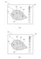
例えば、本実施形態に係る画像処理部152dは、画像生成部52aで生成された検査画像(図8参照)に対して、画像処理を行うことで、図18の(a)に示すような検査画像を作成する。For example, the
図18の(a)において、A1、A2、A4で示される領域は、異常確信度の大きさが第1閾値K1以上の画素からなる領域である。図18の(a)において、A3、B1で表示される領域は、異常確信度の大きさが第1閾値K1未満の画素からなる領域である。上記の通り、本実施形態では、第1閾値K1は異常確信度150に設定されている。このため、図18の(a)のA1、A2、A4で示される領域は、異常確信度の大きさが150以上の画素からなる領域であると考えられる。一方で、図18の(a)のA3、B1で示される領域は、異常確信度の大きさが150未満の画素からなる領域であると考えられる。In FIG. 18(a), the areas indicated by A1, A2, and A4 are areas made up of pixels whose abnormality confidence level is equal to or greater than the first threshold value K1. In FIG. 18(a), the areas indicated by A3 and B1 are areas made up of pixels whose abnormality confidence level is less than the first threshold value K1. As described above, in this embodiment, the first threshold value K1 is set to an abnormality confidence level of 150. For this reason, the areas indicated by A1, A2, and A4 in FIG. 18(a) are considered to be areas made up of pixels whose abnormality confidence level is equal to or greater than 150. On the other hand, the areas indicated by A3 and B1 in FIG. 18(a) are considered to be areas made up of pixels whose abnormality confidence level is less than 150.
図18の(a)においては、A3、B1の順に、異常確信度が低下しているものとして説明する。ここで、画像処理部152dは、例えば、異常確信度が大きい順に、空色、青色、に対応させるものとする。この場合、A3の領域が空色に、B1の領域が青色に対応しており、画像処理部152dは、各領域を、各領域が対応する色で表示部140に表示させる。ただし、これらの表示はあくまでも一例であって、適宜変更可能である。In FIG. 18(a), the explanation will be given assuming that the abnormality confidence decreases in the order of A3, B1. Here, the
なお、図18の(a)に示すように、ここでは、異常確信度が第1閾値K1以上の画素からなる領域については、表示部140に表示させていない。ただし、異常確信度の大きさが第1閾値K1以上である画素からなる領域の表示の態様は、これに限定されるものではない。詳細は、以下の(b)や変形例2Aで後述する。As shown in FIG. 18(a), the
このように、画像処理部152dは、異常確信度の大きさが第1閾値K1以上である画素と、第1閾値K1未満である画素との表示態様を異ならせている。且つ、画像処理部152dは、異常確信度の大きさが第1閾値K1未満である画素については異常確信度の大きさに応じて表示態様を変化させ、検査画像を視覚的に区分して、表示部140に表示させている。In this way, the
また、本実施形態に係る検査装置110では、異常確信度の大きさが第1閾値K1を下回る画素の表示態様が、異常確信度の大きさに応じて変化する。このため、検査装置110のオペレータは、異常確信度が第1閾値K1を下回る画素の中で、比較的異常確信度が大きい画素について容易に確認することができる。このため、本実施形態に係る検査装置110のオペレータは、第1閾値K1の変更(調整)を行うことなく、検査画像における異常の取り逃がし(未検出)の有無を確認することができる。In addition, in the
(b)第2表示態様
第2表示態様では、画像処理部152dは、異常確信度の大きさが第1閾値K1以上である画素からなる領域については、検査画像における画素値に基づいて表示部140に表示させる。 (b) Second display mode In the second display mode, the
例えば、本実施形態に係る画像処理部152dは、画像生成部52aで生成された検査画像(図8参照)に対して、画像処理を行うことで、図19の(a)に示すような検査画像を作成する。For example, the
図19の(a)において、A1、A2、A4で示される領域は、異常確信度の大きさが第1閾値K1以上の画素からなる領域である。図19の(a)において、A3、B1で表示される領域は、異常確信度の大きさが第1閾値K1未満の画素からなる領域である。In FIG. 19(a), the regions indicated by A1, A2, and A4 are regions made up of pixels whose abnormality confidence level is equal to or greater than the first threshold value K1. In FIG. 19(a), the regions indicated by A3 and B1 are regions made up of pixels whose abnormality confidence level is less than the first threshold value K1.
図19の(a)では、A3、B1の順に、異常確信度の大きさが低下しているものとして説明する。ここで、画像処理部152dは、例えば、異常確信度が大きい順に、空色、青色、に対応させるものとする。この場合、A3の領域が空色に、B1の領域が青色に対応しており、画像処理部152dは、各領域を、各領域が対応する色で表示部140に表示させる。ただし、これらの表示はあくまでも一例であって、適宜変更可能である。In FIG. 19(a), the abnormality confidence level decreases in the order of A3, B1. Here, the
また、図19の(a)に示すように、異常確信度の大きさが第1閾値K1以上である画素からなる領域A1、A2、A4については、検査画像における画素が有する画素値に基づいて表示部140に表示されている。Also, as shown in FIG. 19(a), areas A1, A2, and A4 consisting of pixels whose abnormality confidence level is equal to or greater than the first threshold value K1 are displayed on the
このように、画像処理部152dは、異常確信度が第1閾値K1以上である画素と、第1閾値K1未満である画素との表示態様を異ならせる。且つ、画像処理部152dは、異常確信度が第1閾値K1以上である画素からなる領域については検査画像における画素値に基づいて、表示部140に表示させている。In this way, the
このため、検査装置110のオペレータは、異常確信度が第1閾値K1を下回る画素の中で、比較的異常確信度が大きい画素について容易に確認することができる。Therefore, the operator of the
また、本実施形態に係る検査装置110では、異常確信度の大きさが第1閾値K1を下回る画素の表示態様が変化し、異常確信度の大きさが第1閾値K1以上の画素は、検査画像における画素値に基づいて表示部140に表示される。このため、検査装置110のオペレータは、異物として表示されている領域が、確かに異物足り得るものであるのか、検査画像における画素値に基づいて判断することができる。より具体的には、検査装置110のオペレータは、異常確信度の大きさが第1閾値K1以上である画素からなる領域について、検査画像に表示される輝度に基づいて判断することができる。また、検査装置110のオペレータは、学習モデル136の学習精度を確認することができる。In addition, in the
また、本実施形態に係る検査装置110のオペレータは、第1閾値K1の変更(調整)を行うことなく、検査画像における異常の取り逃がし(未検出)の有無を確認することができる。In addition, an operator of the
(c)第3表示態様
第3表示態様では、画像処理部152dは、異常確信度の大きさが第2閾値K2未満である画素については、検査画像における画素値に基づいて表示部140に表示させる。 (c) Third Display Mode In the third display mode,
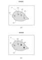
例えば、本実施形態に係る画像処理部152dは、画像生成部52aで生成された検査画像(図8参照)に対して、画像処理を行うことで、図20の(a)に示すような検査画像を作成する。For example, the
図20の(a)において、A1、A2、A4で示される領域は、異常確信度の大きさが第1閾値K1以上の画素からなる領域である。図20の(a)において、A3で表示される領域は、異常確信度の大きさが第1閾値K1未満の画素からなる領域である。図20の(a)において、B1で表示される領域は、異常確信度の大きさが第1閾値K1未満であり、かつ、異常確信度の大きさが第2閾値K2未満である画素からなる領域である。この場合、画像処理部152dは、領域A3を、領域A3の画素の異常確信度に対応する色(例えば空色)で表示部140に表示させる。20(a), the areas indicated by A1, A2, and A4 are areas made up of pixels whose abnormality confidence level is equal to or greater than the first threshold K1. In FIG. 20(a), the area indicated by A3 is an area made up of pixels whose abnormality confidence level is less than the first threshold K1. In FIG. 20(a), the area indicated by B1 is an area made up of pixels whose abnormality confidence level is less than the first threshold K1 and less than the second threshold K2. In this case, the
また、図20の(a)に示すように、異常確信度が第1閾値K1以上である画素からなる領域A1、A2、A4と、異常確信度が第2閾値K2未満である画素からなる領域B1については、検査画像における画素が有する画素値に基づいて表示部140に表示されている。Also, as shown in FIG. 20(a), regions A1, A2, and A4 consisting of pixels whose abnormality confidence level is equal to or greater than the first threshold value K1, and region B1 consisting of pixels whose abnormality confidence level is less than the second threshold value K2 are displayed on the
このように、画像処理部152dは、異常確信度が第1閾値K1よりも小さい閾値である第2閾値K2未満である画素については、検査画像における画素値に基づいて表示部140に表示させている。In this way, for pixels whose abnormality confidence level is less than the second threshold K2, which is a threshold smaller than the first threshold K1, the
本実施形態に係る検査装置110のオペレータは、検査画像の画素における異常確信度が第1閾値K1未満の領域であって、かつ、検査画像の画素における異常確信度が第2閾値K2以上である領域について確認することができる。このため、この検査装置110では、異常確信度を確認することが容易である。An operator of the
なお、本実施形態において、第2閾値K2は、異常確信度の下限に近い数値に設定されている。このため、本実施形態に係る検査装置110のオペレータは、明らかに異常が生じている恐れがない領域(異常確信度の大きさが第2閾値K2未満である領域)については、異常確信度の表示がされていない検査画像を確認することができる。ここでは、「明らかに異常が生じている恐れがない領域」とは例えば、領域B1を指す。このため、本実施形態に係る検査装置110では、実際の物品Pの様子を確認しながら、異常の有無を確認することができる。従って、本実施形態に係る検査装置110のオペレータは、異常確信度をより容易に確認することができる。In this embodiment, the second threshold K2 is set to a value close to the lower limit of the abnormality confidence level. Therefore, the operator of the
本実施形態に係る検査装置110のオペレータは、第1閾値K1の変更(調整)を行うことなく、検査画像における異常の取り逃がし(未検出)の有無を確認することができる。An operator of the
(d)第4表示態様
第4表示態様では、画像処理部152dは、異常確信度が第1閾値K1未満である画素であって、且つ、異常確信度が第1閾値K1以上である画素からの距離が所定範囲内に位置する画素に対して、マーキングを行って表示させる。 (d) Fourth display mode In the fourth display mode, the
例えば、本実施形態に係る画像処理部152dは、画像生成部52aで生成された検査画像(図8参照)に対して、画像処理を行うことで、図21に示すような検査画像を作成する。For example, the
図21において、A1、A2、で示される領域は、異常確信度の大きさが第1閾値K1以上の画素からなる領域である。図21において、A3、A4で表示される領域は、異常確信度の大きさが第1閾値K1未満の画素からなる領域である。図21において、B1で表示される領域は、異常確信度の大きさが第1閾値K1未満であり、かつ、異常確信度の大きさが第2閾値K2未満である画素からなる領域である。In FIG. 21, the areas indicated by A1 and A2 are areas made up of pixels whose abnormality confidence level is equal to or greater than the first threshold K1. In FIG. 21, the areas indicated by A3 and A4 are areas made up of pixels whose abnormality confidence level is less than the first threshold K1. In FIG. 21, the area indicated by B1 is an area made up of pixels whose abnormality confidence level is less than the first threshold K1 and less than the second threshold K2.
ここで、画像処理部152dは、異常確信度の大きさが第1閾値K1未満であって且つ第2閾値K2以上である画素からなる領域であるA3、A4については、異常確信度の大きさに応じて表示態様を変化させ、検査画像を視覚的に区分して、表示部140に表示させる。画像処理部152dは、例えば、異常確信度が大きい順に、空色、青色、に対応させるものとする。この場合、A3の領域が空色に、A4の領域が青色に対応しており、画像処理部152dは、各領域を、各領域が対応する色で表示部140に表示させる。Here, for A3 and A4, which are regions made up of pixels whose magnitude of abnormality confidence is less than the first threshold K1 and equal to or greater than the second threshold K2, the
さらに、画像処理部152dは、異常確信度の大きさが第1閾値K1未満であって、且つ、異常確信度が第1閾値K1以上である画素(ここでは、領域A1、A2を構成する画素)からの距離が所定範囲内に位置する画素に対して、マーキングを行っている。Furthermore, the
このように、画像処理部152dは、異常確信度が第1閾値K1未満である画素であって、且つ、異常確信度が第1閾値K1以上である画素からの距離が所定範囲内に位置する画素に対して、マーキングを行って表示部140に表示させている。In this way, the
本実施形態に係る検査装置110は、異常確信度の大きさが第1閾値K1以上の画素からなる領域と、異常確信度の大きさが第1閾値K1未満の画素からなる領域と、を視覚的に明確に区分して表示する。このため、検査装置110のオペレータは、異常確信度をより容易に確認することができる。The
(4)制御部の機能
以下、本開示に係る検査装置110の制御部152の機能について説明する。 (4) Functions of the Control Unit The following describes the functions of the control unit 152 of the
本実施形態において、制御部152は、記憶部151に記憶されている所定のプログラムを実施することで、画像生成部52a、教師データ取得部52b、学習部52c、画像処理部152d及び検査部52eとして機能する。ここでは、制御部152が有する画像処理部152dとしての機能について説明する。In this embodiment, the control unit 152 functions as an
(4-1)
従来技術に係る検査装置では、X線透視像信号の値が、所定の閾値よりも小さい場合に検査対象に異物が混入していると判定する。これは、異常確信度が所定の閾値よりも大きいことと対応している。また、従来技術に係る検査装置では、異物ありと判定された領域(画素)を視認できるように、異物ありと判定された領域に着色処理(例えば、赤色に塗りつぶす処理など)を行うことがある。このため、従来技術に係る検査装置では、図23の(b)に示すような検査画像が表示部に表示されることが考えられる。 (4-1)
In the inspection device according to the conventional technology, when the value of the X-ray fluoroscopic image signal is smaller than a predetermined threshold, it is determined that a foreign object is present in the inspection object. This corresponds to the abnormality certainty being greater than a predetermined threshold. In addition, in the inspection device according to the conventional technology, a coloring process (e.g., a process of filling in red) may be performed on the area (pixel) determined to have a foreign object so that the area can be visually recognized. For this reason, in the inspection device according to the conventional technology, it is considered that an inspection image such as that shown in FIG. 23(b) is displayed on the display unit.
図23の(b)は、従来技術に係る検査装置によって生成された検査画像の一例である。図23の(b)において、領域a1、a2のそれぞれを構成する画素には着色処理が行われているものとする。また図23の(b)において、領域a3、a4、b1のそれぞれを構成する画素については、検査画像における画素値に基づいて表示されているものとする。図23の(b)において、画素の異常確信度は領域a1が最も大きく、領域a2、領域a3、領域a4、領域b1の順に異常確信度が低下するものとする。なお、領域a3、a4及び領域b1は、異常確信度の大きさが第1閾値K1未満の画素からなる領域とする。しかしながら、図23の(b)に示すように、従来技術に係る検査画像には、領域a1、a2、a3、a4、の各領域を構成する画素に係る異常確信度の大きさが反映されていない。このため、例えば検査装置から未検出が生じていることが判明した際に、適切な第1閾値K1を把握することが困難となる。以下、具体的に説明する。Figure 23(b) is an example of an inspection image generated by an inspection device according to the conventional technology. In Figure 23(b), it is assumed that the pixels constituting each of the regions a1 and a2 have been colored. In Figure 23(b), it is assumed that the pixels constituting each of the regions a3, a4, and b1 are displayed based on the pixel values in the inspection image. In Figure 23(b), it is assumed that the abnormality confidence of the pixels is the highest in region a1, and the abnormality confidence decreases in the order of region a2, region a3, region a4, and region b1. It is assumed that regions a3, a4, and region b1 are regions consisting of pixels whose abnormality confidence is less than the first threshold K1. However, as shown in Figure 23(b), the abnormality confidence of the pixels constituting each of the regions a1, a2, a3, and a4 is not reflected in the inspection image according to the conventional technology. For this reason, for example, when it is found that non-detection has occurred from the inspection device, it is difficult to grasp the appropriate first threshold K1. A specific explanation will be given below.
ここでは、従来技術に係る検査装置において、検査用のサンプルの物品Pを切り開いて異物の有無を確認するなどして、物品Pの図23の(b)に示される領域a1、a2、に加えて、実際には領域a3にも異物が含まれている(領域a3の異物は未検出である)ことが判明した場合を想定する。この場合、オペレータは、領域a1、a2を構成する画素の異常確信度だけでなく、領域a3を構成する画素の異常確信度をも下回るように、第1閾値K1を変更する必要がある。一方で、第1閾値K1の変更次第では、領域a3の異常確信度のみならず、領域a4の異常確信度をも下回ることで、領域a4の誤検出を招く恐れがある。しかしながら、図23の(b)には、領域a1、a2、a3及びa4を構成する画素の異常確信度の大きさが反映されていない。このため、オペレータは、領域a1、a2、a3を構成する画素の異常確信度を下回り、かつ、領域a4を構成する画素の異常確信度を上回る第1閾値K1を把握するために、第1閾値K1の微調整を繰り返す必要があった。Here, in the conventional inspection device, a sample item P for inspection is cut open to check for the presence or absence of foreign matter, and it is assumed that in addition to the areas a1 and a2 shown in FIG. 23(b) of the item P, a foreign matter is actually contained in the area a3 (the foreign matter in the area a3 is not detected). In this case, the operator needs to change the first threshold value K1 so that it is lower than not only the abnormality confidence of the pixels constituting the areas a1 and a2 but also the abnormality confidence of the pixels constituting the area a3. On the other hand, depending on the change in the first threshold value K1, it may be lower than not only the abnormality confidence of the area a3 but also the abnormality confidence of the area a4, which may lead to a false detection of the area a4. However, the magnitude of the abnormality confidence of the pixels constituting the areas a1, a2, a3, and a4 is not reflected in FIG. 23(b). For this reason, the operator had to repeatedly fine-tune the first threshold value K1 in order to determine a first threshold value K1 that was lower than the abnormality confidence level of the pixels that make up areas a1, a2, and a3, and higher than the abnormality confidence level of the pixels that make up area a4.
このように、従来技術に係る検査装置では、画素の異常確信度の大きさが、検査画像に反映されない場合がある。この場合、従来技術に係る検査装置において、異常の未検出がない最適な第1閾値K1を把握することは、非常に時間のかかる作業となっている。As such, in conventional inspection devices, the magnitude of the anomaly confidence level of a pixel may not be reflected in the inspection image. In such cases, it is a very time-consuming task for conventional inspection devices to determine the optimal first threshold value K1 that results in no undetected anomalies.
(4-2)
一方で、本実施形態における検査装置110では、画像処理部152dによる画像処理が行われる。 (4-2)
On the other hand, in the
本実施形態に係る画像処理部152dは、検査画像を構成する画素から算出される異常確信度の大きさに基づき、検査画像を構成する画素の表示態様を変化させる。The
例えば、本実施形態に係る画像処理部152dは、上記の第1表示態様~第4表示態様で説明した処理を行い、検査画像を表示させる。For example, the
このため、表示部140には、例えば図21に示すような検査画像が表示される。図21では、領域A1と領域A2と領域B1を構成する画素については検査画像の画素値に基づいて表示されており、領域A3、A4の画素については異常確信度の大きさに応じて表示態様が変化している。ここでは、領域A1、A2は異常確信度の大きさが第1閾値K1以上の画素からなる領域であり、領域A3、A4は異常確信度の大きさが第1閾値K1未満かつ第2閾値K2以上の画素からなる領域であり、領域B1は異常確信度の大きさが第2閾値K2未満の画素からなる領域である。また、異常確信度の大きさが第1閾値K1未満の画素であって、領域A1、A3からの距離が所定範囲内に位置する画素に対して、マーキングが行われている。For this reason, the
ここでは、検査用のサンプルの物品Pを切り開いて異物の有無を確認するなどして、物品Pには、図21に示される領域A1、A2、に加えて、領域A3にも異物が含まれている(領域A3の異物は未検出である)ことが判明した場合を想定する。また、領域A4には異物が含まれていないことが判明した場合を想定する。本実施形態に係る検査装置110においては、図21に示すように、領域A3、A4を構成する画素の異常確信度が反映されている。換言すると、領域A3、A4の異常確信度が、第1閾値K1をどの程度下回っているのかが示されている。Here, we will assume that an inspection sample item P is cut open to check for the presence of foreign matter, and that it is found that the item P contains foreign matter in area A3 in addition to areas A1 and A2 shown in FIG. 21 (no foreign matter in area A3 has been detected). We will also assume that it is found that area A4 does not contain foreign matter. In the
このため、領域A3を構成する画素の異常確信度を下回り、且つ、領域A4を構成する画素の異常確信度を上回るように第1閾値K1を変更することで、未検出が抑制されることが、検査装置110のオペレータに容易に確認される。Therefore, by changing the first threshold K1 so that it is lower than the abnormality confidence level of the pixels that make up area A3 and higher than the abnormality confidence level of the pixels that make up area A4, the operator of the
このように、本実施形態に係る検査装置110では、最適な第1閾値K1を容易に把握することができる。また、本実施形態に係る検査装置110では、最適な第1閾値K1をただちに把握することができる。In this way, the
(5)特徴
(5-1)
本実施形態に係る検査装置110では、制御部152は、異常確信度が第1閾値K1以上である画素と、第1閾値K1未満である画素との表示態様を異ならせる。且つ、制御部152は、第1閾値K1未満である画素については異常確信度に応じて表示態様を変化させ、検査画像を視覚的に区分して、表示部140に表示させる。 (5) Features (5-1)
In the
本実施形態に係る検査装置110のオペレータは、検査画像における異常確信度が第1閾値K1を超えない領域の中で、比較的異常確信度が大きい領域について確認することができる。このため、この検査装置110では、異常確信度を確認することが容易である。An operator of the
また、本実施形態に係る検査装置110のオペレータは、第1閾値K1の調整を行うことなく、検査画像における異常の取り逃がし(未検出)の有無を確認することができる。In addition, an operator of the
また、本実施形態に係る検査装置110のオペレータは、異常の取り逃がし(未検出)が発生した際は、最適な第1閾値K1を容易に把握することができる。In addition, the operator of the
(5-2)
本実施形態に係る検査装置110では、制御部152は、異常確信度が第1閾値K1以上である画素と、第1閾値K1未満である画素との表示態様を異ならせる。且つ、画像処理部152dは、異常確信度が第1閾値K1以上である画素からなる領域については検査画像における画素値に基づいて、表示部140に表示させる。 (5-2)
In the
本実施形態に係る検査装置110のオペレータは、検査画像における異常確信度が第1閾値K1を超えない領域の中で、比較的異常確信度が大きい領域について確認することができる。このため、この検査装置110では、異常確信度を確認することが容易である。An operator of the
また、本実施形態に係る検査装置110のオペレータは、第1閾値K1の調整を行うことなく、検査画像における異常の取り逃がし(未検出)の有無を確認することができる。In addition, an operator of the
また、本実施形態に係る検査装置110のオペレータは、異常の取り逃がし(未検出)が発生した際は、最適な第1閾値K1を容易に把握することができる。In addition, the operator of the
また、本実施形態に係る検査装置110のオペレータは、異物として表示されている領域が、確かに異物足り得るものであるのか、検査画像における画素値に基づいて判断することができる。In addition, an operator of the
(5-3)
本実施形態に係る検査装置110では、制御部152は、異常確信度が第1閾値K1よりも小さい閾値である第2閾値K2未満である画素については、検査画像における画素値に基づいて表示部140に表示させる。 (5-3)
In the
本実施形態に係る検査装置110のオペレータは、検査画像における異常確信度が第1閾値K1を超えない領域であって、かつ、検査画像における異常確信度が第2閾値K2異常である領域、について確認することができる。このため、この検査装置110では、異常確信度を確認することが容易である。An operator of the
また、本実施形態に係る検査装置110のオペレータは、明らかに異常が生じている恐れが無い領域については、異常確信度の表示がされていない検査画像を確認することができる。このため、この検査装置110では、異常確信度の大きさをより容易に確認することができる。In addition, an operator of the
本実施形態に係る検査装置110のオペレータは、第1閾値K1の調整を行うことなく検査画像における異常の取り逃がし(未検出)の有無を確認することができる。An operator of the
また、本実施形態に係る検査装置110のオペレータは、異常の取り逃がし(未検出)が発生した際は、最適な第1閾値K1を容易に把握することができる。In addition, the operator of the
(5-4)
本実施形態に係る検査装置110では、制御部152は、異常確信度が第1閾値K1未満である画素であって、且つ、異常確信度が第1閾値K1以上である画素からの距離が所定範囲内に位置する画素に対して、マーキングを行って表示させる。 (5-4)
In the
本実施形態に係る検査装置110は、異常確信度の大きさが第1閾値K1以上の画素からなる領域と、異常確信度の大きさが第1閾値K1未満の画素からなる領域と、を視覚的に明確に区分して表示する。このため、この検査装置110のオペレータは、異常確信度をより容易に確認することができる。The
また、本実施形態に係る検査装置110のオペレータは、異常の取り逃がし(未検出)が発生した際は、最適な第1閾値K1を容易に把握することができる。In addition, the operator of the
(6)変形例
上記実施形態は、以下の変形例に示すように適宜変形が可能である。各変形例は、矛盾が生じない範囲で、本実施形態に係る変形例や他の実施形態に係る変形例と組み合わせて適用されてもよい。なお、上記の第2実施形態と同様の構成については同様の符号を付し、その詳細な説明は省略する。 (6) Modifications The above embodiment can be modified as appropriate as shown in the following modifications. Each modification may be applied in combination with the modification according to this embodiment or the modification according to another embodiment to the extent that no contradiction occurs. Note that the same reference numerals are used for configurations similar to those of the second embodiment, and detailed descriptions thereof will be omitted.
(6-1)変形例2A
上記実施形態では、制御部152(画像処理部152d)が、異常確信度の大きさに基づき検査画像の画素の表示態様を変化させる際に、異なる異常確信度に対し異なる色相が対応するように変化させる検査装置110について説明した。しかしながら、本開示に係る検査装置の例はこれに限定されるものではなく、例えば検査装置は、検査画像の画素値として、明度、輝度、彩度のうち少なくとも一つを含むものであってもよい。 (6-1) Modification 2A
In the above embodiment, the control unit 152 (
本変形例に係る検査装置は、制御部が異常確信度の大きさに基づき画素の表示態様を変化させる際に、明度、輝度、彩度のうち少なくとも一つの大きさが異なるものが対応するように変化させる検査装置であってもよい。例えば検査装置は、異常確信度の大きさに応じて、輝度が変化するように、検査画像の画素の表示態様を変化させるものであってもよい。The inspection device according to this modified example may be an inspection device that changes at least one of the lightness, luminance, and saturation so that the magnitude of the lightness, luminance, and saturation is different when the control unit changes the display mode of the pixel based on the magnitude of the abnormality certainty. For example, the inspection device may change the display mode of the pixel of the inspection image so that the luminance changes according to the magnitude of the abnormality certainty.
あるいは、本変形例に係る検査装置は、異なる異常確信度に対し、異なる色相とともに、明度、輝度、彩度のうち少なくとも一つの大きさが異なるものが対応するように、検査画像の画素の表示態様を変化させるものであってもよい。例えば検査装置は、異常確信度の大きさに応じて、色相とともに、輝度が変化するように、検査画像の画素の表示態様を変化させるものであってもよい。Alternatively, the inspection device according to this modified example may change the display mode of pixels of the inspection image so that different anomaly certainty levels correspond to different hues as well as different magnitudes of at least one of lightness, luminance, and saturation. For example, the inspection device may change the display mode of pixels of the inspection image so that luminance changes along with hue depending on the magnitude of the anomaly certainty level.
本変形例は、例えば表示部140の性能の制約上、表示部140に表示可能な色相の数が限定される場合等に有効である。換言すると、本変形例に係る検査装置は、表示部140として、安価なディスプレイ等を用いる場合であっても、異常確信度を明確に反映させることができる。このため、本変形例においては、検査装置の低コスト化が実現される。This modified example is effective in cases where the number of hues that can be displayed on the
本変形例に係る検査装置は、上記実施形態と同様に、異常確信度の確認が容易である。The inspection device according to this modified example makes it easy to confirm the degree of certainty of anomalies, just like the above embodiment.
(6-2)変形例2B
上記実施形態では、表示部140にカラーバー45が表示されている例について説明した。しかしながら、本開示に係る検査装置の例はこれに限定されるものではなく、例えば検査装置は、カラーバー45とともに、又はカラーバー45に代えて、数値化された異常確信度を表示部140に表示させるものであってもよい。 (6-2) Modification 2B
In the above embodiment, an example has been described in which the
例えば、本変形例に係る検査装置では、図15の(b)に示すような検査画像が表示部140の領域C1に表示される。図15の(b)では、各領域を構成する画素の異常確信度の大きさを示す数値のうち、最も大きい異常確信度の数値が、第1閾値K1に対してどの程度不足しているのかが数値として表示される。これにより、例えば第1閾値K1が150に設定されている場合に、図15の(b)の領域A1を確認したオペレータは、領域A1を構成する画素の異常確信度の最大値が140であることを把握できる。For example, in the inspection device according to this modified example, an inspection image as shown in FIG. 15(b) is displayed in area C1 of the
このように、本変形例に係る検査装置では、検査画像の画素の異常確信度の大きさが数値として表示部140に表示されるため、オペレータは、異常確信度の詳細な大きさを容易に確認することができる。In this way, in the inspection device of this modified example, the magnitude of the abnormality confidence of the pixels of the inspection image is displayed as a numerical value on the
また、本変形例に係る検査装置は、図15の(b)における領域A1及び領域A5や、領域A2及び領域A6のように、異なる異常確信度の大きさを有する複数の画素からなる領域が重複している場合であっても、各領域における異常確信度の大きさの確認が容易である。In addition, the inspection device according to this modified example makes it easy to confirm the magnitude of abnormality confidence in each region, even when regions consisting of multiple pixels with different abnormality confidence levels overlap, such as regions A1 and A5, or regions A2 and A6 in FIG. 15(b).
本変形例に係る検査装置は、上記実施形態と同様に、異常確信度の確認が容易である。The inspection device according to this modified example makes it easy to confirm the degree of certainty of anomalies, just like the above embodiment.
また、本変形例に係る検査装置は、異常確信度が数値化されて検査画像に反映されるため、異常確信度の詳細な大きさが確認できる。In addition, the inspection device according to this modified example converts the abnormality confidence level into a numerical value and reflects it in the inspection image, allowing the detailed magnitude of the abnormality confidence level to be confirmed.
(6-3)変形例2C
上記実施形態では、制御部152は、異常確信度が第1閾値K1以上である画素からなる領域と、第1閾値K1未満である画素との表示態様を異ならせることで、検査画像を視覚的に区分して表示部140に表示させると説明した。 (6-3) Modification 2C
In the above embodiment, it was explained that the control unit 152 visually divides the inspection image and displays it on the
異常確信度が第1閾値K1以上である画素からなる領域と、第1閾値K1未満である画素との表示態様を異ならせることで、検査画像を視覚的に区分して表示部140に表示させる態様の一例として、上記実施形態では図18の(a)や図19の(a)に示すような表示態様を説明したが、本開示に係る検査装置による表示の例は、これらに限定されるものではない。In the above embodiment, the display modes shown in FIG. 18(a) and FIG. 19(a) are described as examples of a manner in which the inspection image is visually divided and displayed on the
本変形例に係る検査装置では、例えば図18の(b)に示すように、異常確信度が第1閾値K1以上である画素からなる領域を表示させず、且つ、物品Pの輪郭部分を示す画素については抽出して表示させることで、異常確信度が第1閾値K1以上である画素からなる領域と、第1閾値K1未満である画素からなる領域との表示態様を異ならせてもよい。In the inspection device according to this modified example, as shown in FIG. 18(b), for example, the display manner of the area made up of pixels whose abnormality confidence level is equal to or greater than the first threshold value K1 may be made different from that of the area made up of pixels whose abnormality confidence level is less than the first threshold value K1 by not displaying the area made up of pixels whose abnormality confidence level is equal to or greater than the first threshold value K1 and by extracting and displaying the pixels that indicate the contour portion of the item P.
あるいは、本変形例に係る検査装置では、例えば図19の(b)に示すように、異常確信度が第1閾値K1以上である画素については画素値に基づいて表示させ、且つ、物品Pの輪郭部分を示す画素については抽出して表示させることで、異常確信度が第1閾値K1以上である画素からなる領域と、第1閾値K1未満である画素との表示態様を異ならせてもよい。Alternatively, in the inspection device according to this modified example, as shown in (b) of FIG. 19, for example, pixels whose abnormality confidence level is equal to or greater than the first threshold value K1 may be displayed based on the pixel value, and pixels showing the contour of the item P may be extracted and displayed, thereby differentiating the display mode of the area made up of pixels whose abnormality confidence level is equal to or greater than the first threshold value K1 from the pixels whose abnormality confidence level is less than the first threshold value K1.
また、本変形例に係る検査装置では、異常確信度が第1閾値K1以上である画素からなる領域の輝度、明度、彩度、色相等に、補正を行うことで、異常確信度が第1閾値K1以上である画素からなる領域と、異常確信度が第1閾値K1未満である画素からなる領域と、を視覚的に区分して表示部140に表示させるものであってもよい。例えば、異常確信度が第1閾値K1以上である画素からなる領域の色相を、一律に白色に変化させて表示させるものであってもよい。In addition, the inspection device according to this modified example may perform corrections to the luminance, brightness, saturation, hue, etc. of a region made up of pixels whose abnormality confidence level is equal to or greater than the first threshold value K1, thereby visually distinguishing between a region made up of pixels whose abnormality confidence level is equal to or greater than the first threshold value K1 and a region made up of pixels whose abnormality confidence level is less than the first threshold value K1 and displaying the region on the
あるいは、異常確信度が第1閾値K1以上の画素からなる領域については、例えば輝度を小さくする等の補正を行うものであってもよい。Alternatively, for regions consisting of pixels whose abnormality confidence is equal to or greater than the first threshold K1, corrections such as reducing the brightness may be performed.
本変形例に係る検査装置は、上記実施形態と同様に、異常確信度が第1閾値K1以上である画素からなる領域と、異常確信度が第1閾値K1未満である画素からなる領域と、の表示態様を視覚的に区分させることができる。As in the above embodiment, the inspection device according to this modified example can visually distinguish the display mode between an area made up of pixels whose abnormality confidence level is equal to or greater than the first threshold value K1 and an area made up of pixels whose abnormality confidence level is less than the first threshold value K1.
本変形例に係る検査装置は、上記実施形態と同様に、異常確信度の確認が容易である。The inspection device according to this modified example makes it easy to confirm the degree of certainty of anomalies, just like the above embodiment.
(6-4)変形例2D
上記実施形態では、異常確信度が第1閾値K1よりも小さい閾値である第2閾値K2未満である画素については、検査画像における画素値に基づいて表示部140に表示させる検査装置について説明した。例えば、上記実施形態では、異常確信度が第1閾値K1以上である画素からなる領域については、検査画像における画素が有する画素値に基づいて表示部140に表示させる検査装置について説明した(図20の(a)参照)。しかしながら、本開示に係る検査装置の例はこれに限定されるものではない。 (6-4) Modification 2D
In the above embodiment, an inspection device has been described that displays pixels whose abnormality certainty is less than the second threshold K2, which is a threshold lower than the first threshold K1, on the
本変形例に係る検査装置は、例えば、図20の(b)に示すように、異常確信度が第1閾値K1以上である画素は表示せず、且つ、異常確信度が第2閾値K2未満である画素については検査画像における画素が有する画素値に基づいて表示部140に表示させるものであってもよい。For example, as shown in FIG. 20(b), the inspection device according to this modified example may not display pixels whose abnormality confidence level is equal to or greater than a first threshold value K1, and may display pixels whose abnormality confidence level is less than a second threshold value K2 on the
(6-5)変形例2E
上記実施形態では説明を省略したが、画像処理部152dは、異常確信度の大きさが第1閾値K1未満である画素であって、且つ、異常確信度の大きさが第1閾値K1以上である画素からの距離が所定範囲内に位置する画素を、検査画像における画素値に基づいて、表示部140に表示させるものであってもよい。 (6-5) Modification 2E
Although not described in the above embodiment, the
上記の第2表示形態では、異常確信度の大きさが第1閾値K1未満である画素については異常確信度に応じて表示態様を変化させ、異常確信度の大きさが第1閾値K1以上である画素については検査画像における画素値に基づいて表示部140に表示させると説明した。In the second display form described above, for pixels whose magnitude of abnormality confidence is less than the first threshold K1, the display mode is changed according to the abnormality confidence, and for pixels whose magnitude of abnormality confidence is equal to or greater than the first threshold K1, the display is made on the
しかしながら、上記態様によって検査画像を表示した場合、異常確信度が大きい領域と、異常確信度が小さい領域との境界部分の把握が困難になる恐れがある。より具体的には、異物と思われる領域の輪郭の視認性が低下する恐れがある。However, when an examination image is displayed in the above manner, it may be difficult to grasp the boundary between an area with a high degree of abnormality certainty and an area with a low degree of abnormality certainty. More specifically, the visibility of the outline of an area that is suspected to contain a foreign body may be reduced.
本変形例に係る検査装置では、異常確信度の大きさが第1閾値K1以上である画素からの距離が所定範囲内に位置する画素を、検査画像における画素値に基づいて、表示部140に表示させる(図22参照)。また、本変形例に係る検査装置は、図22に示すように、物品Pの輪郭を抽出して表示するものであってもよい。In the inspection device according to this modification, pixels located within a predetermined distance from a pixel whose abnormality certainty level is equal to or greater than the first threshold value K1 are displayed on the
本変形例に係る検査装置では、異常確信度が第1閾値K1以上である画素からなる領域と、異常確信度が第1閾値K1未満である画素からなる領域と、の表示態様の視覚的な区分がより明確になされる。このため、本変形例に係る検査装置のオペレータは、異物の全体像を直感的に把握することができる。In the inspection device according to this modification, the visual distinction between the display mode of the region consisting of pixels whose abnormality confidence level is equal to or greater than the first threshold value K1 and the region consisting of pixels whose abnormality confidence level is less than the first threshold value K1 is made clearer. Therefore, the operator of the inspection device according to this modification can intuitively grasp the overall picture of the foreign object.
<他の実施形態>
以上、本開示に係る実施形態を説明したが、特許請求の範囲の趣旨及び範囲から逸脱することなく、形態や詳細の多様な変更が可能なことが理解されるであろう。 <Other embodiments>
Although the embodiments according to the present disclosure have been described above, it will be understood that various changes in form and details are possible without departing from the spirit and scope of the claims.
本開示は、上記各実施形態そのままに限定されるものではない。本開示は、実施段階ではその要旨を逸脱しない範囲で構成要素を変形して具体化できる。また、本開示は、上記各実施形態に開示されている複数の構成要素の適宜な組み合わせにより種々の開示を形成できる。例えば、実施形態に示される全構成要素から幾つかの構成要素は削除してもよい。さらに、異なる実施形態に構成要素を適宜組み合わせてもよい。したがって、本実施形態はあらゆる点で一例に過ぎず、限定するものではないと考えるべきであり、これにより、当業者に自明のあらゆる修正が実施形態に含まれることが意図される。The present disclosure is not limited to the above-described embodiments as they are. In the implementation stage, the present disclosure can be embodied by modifying the components without departing from the gist of the disclosure. In addition, the present disclosure can be formed into various disclosures by appropriately combining the multiple components disclosed in the above-described embodiments. For example, some components may be deleted from all the components shown in the embodiments. Furthermore, the components may be appropriately combined in different embodiments. Therefore, the present embodiment should be considered to be merely an example in all respects and not limiting, and it is intended that any modifications obvious to a person skilled in the art are included in the embodiments.
10、110 検査装置
20 照射部
30 検出部
40、140 表示部
52、152 制御部
52a 画像生成部
100 検査システム
P 物品10, 110
Claims (11)
Translated fromJapanese前記物品に電磁波を照射する照射部と、
前記物品を透過した又は前記物品に反射した前記電磁波を検出する検出部と、
前記検出部の検出結果に基づいて、前記物品の検査画像を生成する画像生成部と、
前記検査画像を表示する表示部と、
前記表示部における前記検査画像の表示態様を変更させる制御部と、
を備え、
前記制御部は、前記検査画像を構成する画素ごとに、異常状態の確からしさを示す異常確信度を算出し、前記異常確信度の大きさに基づき前記画素の表示態様を変化させ、
前記制御部は、前記異常確信度が第1閾値以上の前記画素の色相を前記異常確信度に対応させて変化させる、
検査装置。 An inspection device for inspecting an item, comprising:
An irradiation unit that irradiates the article with electromagnetic waves;
A detection unit that detects the electromagnetic waves that have passed through the article or that have been reflected by the article;
an image generating unit that generates an inspection image of the article based on a detection result of the detection unit;
A display unit that displays the inspection image;
A control unit that changes a display mode of the inspection image on the display unit;
Equipped with
the control unit calculates an abnormality certainty level indicating a likelihood of an abnormal state for each pixel constituting the inspection image, and changes a display mode of the pixel based on a magnitude of the abnormality certainty level;
The control unit changes a hue of the pixelhaving the abnormality certainty equal to or greater than a first thresholdin response to the abnormality certainty .
Inspection equipment.
前記制御部は、前記異常確信度の大きさに基づき前記画素の表示態様を変化させる際に、異なる前記異常確信度に対し異なる色相が対応するように変化させる、
請求項1に記載の検査装置。 the pixel includes a hue as a pixel value;
the control unit, when changing the display mode of the pixel based on the magnitude of the abnormality certainty degree, changes the display mode such that different hues correspond to different abnormality certainty degrees.
2. The inspection device according to claim 1.
前記制御部は、前記異常確信度の大きさに基づき前記画素の表示態様を変化させる際に、異なる前記異常確信度に対し明度、輝度、彩度のうち少なくとも一つの大きさが異なるものが対応するように変化させる、
請求項1又は2に記載の検査装置。 The pixel includes at least one of lightness, luminance, and saturation as a pixel value;
when changing the display mode of the pixel based on the magnitude of the abnormality certainty degree, the control unit changes the display mode of the pixel so that at least one of lightness, luminance, and saturation has a different magnitude corresponding to the different abnormality certainty degrees.
3. The inspection device according to claim 1 or 2.
請求項1から3のいずれか1項に記載の検査装置。 the control unit causes a display mode of a pixel whose anomaly certainty is equal to or greater than a first threshold value to be different from a display mode of a pixel whose anomaly certainty is less than the first threshold value, and changes a display mode of a pixel whose anomaly certainty is equal to or greater than the first threshold value in accordance with the anomaly certainty, thereby visually dividing the inspection image and displaying the inspection image on the display unit.
The inspection device according to any one of claims 1 to 3.
請求項4に記載の検査装置。 The control unit causes the display unit to display, for the pixel whose abnormality certainty is less than the first threshold, based on a pixel value in the inspection image.
5. The inspection apparatus according to claim 4.
請求項6に記載の検査装置。 the control unit causes a pixel whose abnormality certainty level is equal to or greater than a first threshold value to have a different display mode from a pixel whose abnormality certainty level is less than the first threshold value, and causes the display unit to display the pixel whose abnormality certainty level is equal to or greater than the first threshold value based on a pixel value in the inspection image.
7. The inspection device according to claim 6.
請求項6又は7に記載の検査装置。 The control unit causes the display unit to display, on the basis of a pixel value in the inspection image, a pixel having an abnormality certainty level that is less than a second threshold value that is smaller than the first threshold value.
8. The inspection device according to claim 6 or 7.
前記異常確信度が前記第1閾値未満である画素であって、且つ、前記異常確信度が前記第1閾値以上である前記画素からの距離が所定範囲内に位置する前記画素を、前記検査画像における画素値に基づいて、前記表示部に表示させる、
請求項6から8のいずれか1項に記載の検査装置。 The control unit is
displaying, on the display unit, pixels whose anomaly certainty is less than the first threshold and that are located within a predetermined distance from the pixels whose anomaly certainty is equal to or greater than the first threshold, based on pixel values in the inspection image;
The inspection device according to any one of claims 6 to 8.
請求項6から9のいずれか1項に記載の検査装置。 the control unit performs marking and displays the pixels whose abnormality certainty is less than the first threshold value and that are located within a predetermined distance from the pixels whose abnormality certainty is equal to or greater than the first threshold value.
The inspection device according to any one of claims 6 to 9.
物品を、第1方向と、前記第1方向とは異なる第2方向とに振り分ける、振分部と、
を備え、
前記検査装置の前記制御部は、前記検査画像に含まれる前記画素のうち、
前記異常確信度の大きさが前記第1閾値以上である前記画素が所定数以上である場合に、前記検査画像に対応する前記物品に異常があると判断して、前記振分部に、前記物品を前記第1方向に振り分けさせるとともに、
それ以外の場合に、前記検査画像に対応する前記物品に異常がないと判断して、前記振分部に、前記物品を前記第2方向に振り分けさせる、
検査システム。 An inspection device according to any one of claims 4 to 10,
A sorting unit that sorts the articles into a first direction and a second direction different from the first direction;
Equipped with
The control unit of the inspection device detects, among the pixels included in the inspection image,
When the number of the pixels whose magnitude of the abnormality certainty is equal to or greater than the first threshold is equal to or greater than a predetermined number, it is determined that the item corresponding to the inspection image has an abnormality, and causes the sorting unit to sort the item in the first direction;
otherwise, it is determined that there is no abnormality in the object corresponding to the inspection image, and the sorting unit sorts the object in the second direction.
Inspection system.
Priority Applications (1)
| Application Number | Priority Date | Filing Date | Title |
|---|---|---|---|
| JP2020152175AJP7683902B2 (en) | 2020-09-10 | 2020-09-10 | Inspection device and inspection system |
Applications Claiming Priority (1)
| Application Number | Priority Date | Filing Date | Title |
|---|---|---|---|
| JP2020152175AJP7683902B2 (en) | 2020-09-10 | 2020-09-10 | Inspection device and inspection system |
Publications (2)
| Publication Number | Publication Date |
|---|---|
| JP2022046237A JP2022046237A (en) | 2022-03-23 |
| JP7683902B2true JP7683902B2 (en) | 2025-05-27 |
Family
ID=80779816
Family Applications (1)
| Application Number | Title | Priority Date | Filing Date |
|---|---|---|---|
| JP2020152175AActiveJP7683902B2 (en) | 2020-09-10 | 2020-09-10 | Inspection device and inspection system |
Country Status (1)
| Country | Link |
|---|---|
| JP (1) | JP7683902B2 (en) |
Families Citing this family (1)
| Publication number | Priority date | Publication date | Assignee | Title |
|---|---|---|---|---|
| JP7609136B2 (en)* | 2022-07-21 | 2025-01-07 | 株式会社豊田中央研究所 | Information processing system, information processing method, and information processing program |
Citations (8)
| Publication number | Priority date | Publication date | Assignee | Title |
|---|---|---|---|---|
| US6091846A (en) | 1996-05-31 | 2000-07-18 | Texas Instruments Incorporated | Method and system for anomaly detection |
| US6577757B1 (en) | 1999-07-28 | 2003-06-10 | Intelligent Reasoning Systems, Inc. | System and method for dynamic image recognition |
| US20080152082A1 (en) | 2006-08-16 | 2008-06-26 | Michel Bouchard | Method and apparatus for use in security screening providing incremental display of threat detection information and security system incorporating same |
| JP2011112650A (en) | 2009-11-27 | 2011-06-09 | Ge Sensing & Inspection Technologies Gmbh | Computed tomography method, computer software, calculation device and computed tomography system for determining volumetric representation of sample |
| JP2014048178A (en) | 2012-08-31 | 2014-03-17 | Ishida Co Ltd | Article inspection device and article inspection method |
| JP5607156B2 (en) | 2009-07-16 | 2014-10-15 | ビューラー ソーテックス リミテッド | Inspection apparatus and method using pattern recognition |
| WO2019235022A1 (en) | 2018-06-08 | 2019-12-12 | 株式会社イシダ | Inspection device |
| JP2020128941A (en) | 2019-02-08 | 2020-08-27 | 株式会社大道産業 | Device, method, and program for detecting foreign matter |
- 2020
- 2020-09-10JPJP2020152175Apatent/JP7683902B2/enactiveActive
Patent Citations (8)
| Publication number | Priority date | Publication date | Assignee | Title |
|---|---|---|---|---|
| US6091846A (en) | 1996-05-31 | 2000-07-18 | Texas Instruments Incorporated | Method and system for anomaly detection |
| US6577757B1 (en) | 1999-07-28 | 2003-06-10 | Intelligent Reasoning Systems, Inc. | System and method for dynamic image recognition |
| US20080152082A1 (en) | 2006-08-16 | 2008-06-26 | Michel Bouchard | Method and apparatus for use in security screening providing incremental display of threat detection information and security system incorporating same |
| JP5607156B2 (en) | 2009-07-16 | 2014-10-15 | ビューラー ソーテックス リミテッド | Inspection apparatus and method using pattern recognition |
| JP2011112650A (en) | 2009-11-27 | 2011-06-09 | Ge Sensing & Inspection Technologies Gmbh | Computed tomography method, computer software, calculation device and computed tomography system for determining volumetric representation of sample |
| JP2014048178A (en) | 2012-08-31 | 2014-03-17 | Ishida Co Ltd | Article inspection device and article inspection method |
| WO2019235022A1 (en) | 2018-06-08 | 2019-12-12 | 株式会社イシダ | Inspection device |
| JP2020128941A (en) | 2019-02-08 | 2020-08-27 | 株式会社大道産業 | Device, method, and program for detecting foreign matter |
Also Published As
| Publication number | Publication date |
|---|---|
| JP2022046237A (en) | 2022-03-23 |
Similar Documents
| Publication | Publication Date | Title |
|---|---|---|
| US11977036B2 (en) | Inspection device | |
| JP6537008B1 (en) | Inspection device | |
| US7570787B2 (en) | X-ray inspection apparatus and method for creating an image processing procedure for the X-ray inspection apparatus | |
| US12430739B2 (en) | Training data generation device, inspection device and program | |
| AU2006201717B2 (en) | X-ray inspection apparatus | |
| JP7683902B2 (en) | Inspection device and inspection system | |
| JP5864404B2 (en) | X-ray inspection equipment | |
| JP7422023B2 (en) | X-ray image processing device and X-ray image processing method | |
| JP2002098653A (en) | X-ray inspection equipment | |
| US11598729B2 (en) | X-ray inspection device | |
| JP7751019B2 (en) | Method and apparatus for detecting anomalies in two-dimensional digital images of products | |
| JP2015137858A (en) | Inspection device | |
| JP2005031069A (en) | X-ray inspection equipment | |
| JP7727451B2 (en) | Baggage Inspection System | |
| JP6306352B2 (en) | X-ray inspection equipment | |
| JP6144584B2 (en) | Damage inspection device | |
| US20240242459A1 (en) | Method for detecting alarm objects in items of luggage in a detection apparatus | |
| EP4632672A1 (en) | X-ray inspection apparatus | |
| JP5947674B2 (en) | X-ray inspection equipment | |
| JP2009080029A (en) | X-ray inspection device |
Legal Events
| Date | Code | Title | Description |
|---|---|---|---|
| A621 | Written request for application examination | Free format text:JAPANESE INTERMEDIATE CODE: A621 Effective date:20230907 | |
| A977 | Report on retrieval | Free format text:JAPANESE INTERMEDIATE CODE: A971007 Effective date:20240712 | |
| A131 | Notification of reasons for refusal | Free format text:JAPANESE INTERMEDIATE CODE: A131 Effective date:20240827 | |
| A521 | Request for written amendment filed | Free format text:JAPANESE INTERMEDIATE CODE: A523 Effective date:20240920 | |
| A02 | Decision of refusal | Free format text:JAPANESE INTERMEDIATE CODE: A02 Effective date:20241112 | |
| A521 | Request for written amendment filed | Free format text:JAPANESE INTERMEDIATE CODE: A523 Effective date:20250207 | |
| TRDD | Decision of grant or rejection written | ||
| A01 | Written decision to grant a patent or to grant a registration (utility model) | Free format text:JAPANESE INTERMEDIATE CODE: A01 Effective date:20250507 | |
| A61 | First payment of annual fees (during grant procedure) | Free format text:JAPANESE INTERMEDIATE CODE: A61 Effective date:20250508 | |
| R150 | Certificate of patent or registration of utility model | Ref document number:7683902 Country of ref document:JP Free format text:JAPANESE INTERMEDIATE CODE: R150 |