JP7678489B1 - Thrust generation method - Google Patents
Thrust generation methodDownload PDFInfo
- Publication number
- JP7678489B1 JP7678489B1JP2024040569AJP2024040569AJP7678489B1JP 7678489 B1JP7678489 B1JP 7678489B1JP 2024040569 AJP2024040569 AJP 2024040569AJP 2024040569 AJP2024040569 AJP 2024040569AJP 7678489 B1JP7678489 B1JP 7678489B1
- Authority
- JP
- Japan
- Prior art keywords
- gear
- weight
- thrust
- rotation
- speed
- Prior art date
- Legal status (The legal status is an assumption and is not a legal conclusion. Google has not performed a legal analysis and makes no representation as to the accuracy of the status listed.)
- Active
Links
Images


Landscapes
- Connection Of Motors, Electrical Generators, Mechanical Devices, And The Like (AREA)
Abstract
Translated fromJapanese
Description
Translated fromJapanese本発明は、推力発生方法に関し、特に、重りを備えた回転体の回転速度の速度変化により、推力を発生させる推力発生方法に関する。The present invention relates to a method for generating thrust, and in particular to a method for generating thrust by changing the rotational speed of a rotating body equipped with a weight.
従来より、回転運動を利用した推力の発生装置に関し、数々の技術が提案されている。
例えば、特許文献1には、回転に依る慣性運動エネルギーを利用する自己推進機関に関して、移動子を回転するリングに固着し、特定の位置で固着状態を解き放ち、本体自身で受け止め、移動子をリングに回収し再び回転する方法が開示される。
また、特許文献2には、回転運動を前進直線運動に変換するための装置に関して、質量体を回転させ衝撃頂点で質量体の回転半径を変化させることにより、所望の推力を生成する技術が開示されている。 Conventionally, various techniques have been proposed for thrust generating devices that utilize rotational motion.
For example,
Furthermore,
このように、種々の推力発生装置が提案されているが、そのほとんどは理論的に錯誤があり推力は発生しない。
例えば、特許文献1に記載の機関では、移動子をリングに固着する方法と固着状態を解き放つ方法、かつ、移動子をリングに回収する方法が実現困難である。
また、特許文献2に記載の装置は、衝撃頂点から衝撃体への衝撃の変換によって、衝撃駆動板に最大の力が生じ、衝撃体ブッシングを介して誘導された動きベクトル(文献2添付図:図10)の方向に推力が働くが、動きベクトルの反対方向にも遠心力による推力が働くので激しく振動してしまい、有効な推力を得られない。 As described above, various thrust generating devices have been proposed, but most of them are theoretically incorrect and do not generate thrust.
For example, in the engine described in
In addition, in the device described in
本発明はこのような状況に鑑みてなされたものであり、実現可能な推力発生方法を提供することを目的とする。The present invention was made in consideration of these circumstances, and aims to provide a feasible method of generating thrust.
本発明の推力発生方法は、重りを備えた回転体を回転させ、当該重りの回転に対し、回転速度に周期的な(脈動的な、継続的な)速度変化を発生させることにより、速度が速い方向への推力を発生させる推力発生装置における推力発生方法において、前記回転体は、当該回転体の縁からの距離が一定ではない位置に回転軸を有する偏心歯車であって、前記偏心歯車と噛み合う他の歯車による駆動力を受けて、前記偏心歯車が回転軸を中心に回転することにより、前記偏心歯車に備えた重りの回転の周速度が変化して前記推力を発生させることを特徴とする。 The thrust generating method of the present invention is a thrust generating method for a thrust generating device that generates a thrust in a direction of increased speed by rotating a rotating body equipped with a weight and generating a periodic (pulsating, continuous) change in the rotational speed of the rotation of the weight, characterized in that the rotating bodyis an eccentric gear having a rotation axis at a position that is not a constant distance from the edge of the rotating body,and the eccentric gear rotates around the rotation axis when it receives a driving force from another gear that meshes with theeccentricgear , thereby changing the peripheral speed of rotation of the weight attached to the eccentric gear and generating the thrust.
本発明の推力発生方法は、重りを備えた回転体を回転させ、当該重りの回転に対し、回転速度に周期的な速度変化を発生させることにより、速度が速い方向への推力を発生させる推力発生装置における推力発生方法において、前記回転体は、縁からの距離が一定ではない位置に回転軸を有する歯車であり、当該歯車と噛み合う他の歯車から動力を受けて当該歯車が回転軸を中心に回転することにより、当該歯車に備えた重りの回転の周速度が変化して前記推力を発生させることを特徴とする。 The thrust generating method of the present invention is a thrust generating method for a thrust generating device that generates a thrust in a direction of increased speed by rotating a rotating body equipped with a weight and generating a periodic speed change in the rotation speed of the weight's rotation, characterized in that the rotating bodyis a gear having a rotation axis at a position that is not a constant distance from the edge, and the gear rotates about its rotation axis by receiving power from another gear that meshes with the gear, changing the peripheral speed of rotation of the weight attached tothe gear, thereby generating the thrust.
本発明によれば、重りを備えた回転体を回転させ、当該重りの回転に対し回転速度に周期的な(脈動的な、継続的な)速度変化を連続して与えることによりブレの少ない安定した推力を連続して得ることができる。According to the present invention, a rotor equipped with a weight is rotated, and a periodic (pulsating, continuous) speed change is continuously applied to the rotation speed of the weight, thereby making it possible to continuously obtain a stable thrust with little vibration.
本発明の実施形態について、図面を参照して説明する。ただし、以下に説明する実施形態は、あくまでも例示であり、以下に明示しない種々の変形や技術の適用を排除する意図はない。即ち、本発明は、その効果を奏する限りにおいて種々変形(各実施例を組み合わせる等)して実施することができる。また、以下の図面の記載において、同一又は類似の部分には同一又は類似の符号を付して表している。図面は模式的なものであり、必ずしも実際の寸法や比率等とは一致しない。図面相互間においても互いの寸法の関係や比率が異なる部分が含まれていることがある。また、以下の説明が不必要に冗長になることを避け、当業者の理解を容易にするために、既によく知られた事項の詳細説明や実質的に同一の構成に対する重複説明を省略する場合がある。The embodiments of the present invention will be described with reference to the drawings. However, the embodiments described below are merely examples, and are not intended to exclude the application of various modifications and techniques not specified below. In other words, the present invention can be implemented in various modifications (such as combining the various embodiments) as long as the effects of the present invention are achieved. In addition, in the following description of the drawings, identical or similar parts are represented by the same or similar symbols. The drawings are schematic and do not necessarily correspond to actual dimensions, ratios, etc. Even between the drawings, there may be parts with different dimensional relationships and ratios. In addition, in order to avoid the following description becoming unnecessarily redundant and to facilitate understanding by those skilled in the art, detailed descriptions of already well-known matters and duplicate descriptions of substantially identical configurations may be omitted.
<第一実施形態>
図1乃至図5を参照して、本発明の第一実施形態について説明する。
図1、図2は第一実施形態による本発明の推力発生方法を実現する推力発生装置100の機構を示す概略説明図であり、図3、図4は推力発生装置100の概略断面図である。図1、図2は、推力発生装置100を上部から観察した際の機構の概略を示すものである。First Embodiment
A first embodiment of the present invention will be described with reference to FIGS. 1 to 5. FIG.
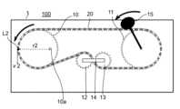
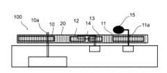
Figures 1 and 2 are schematic explanatory diagrams showing the mechanism of a
推力発生装置100は、重り15を備えた回転体としての歯車11を回転させ、当該重り15の回転に対し、回転速度に周期的な(脈動的な、継続的な)速度変化を発生させることにより、速度が速い方向への推力を発生させることを必須の構成とする。The
歯車10は、本発明における他の回転体の一例であり、筐体1の内部に備えた駆動源であるモーター2から、シャフト2aを介して駆動力を受けて駆動回転する。本実施形態において、歯車10は、偏心歯車であり、歯車10の中心からずれた位置に、シャフト2aからの駆動力を受けて回転する回転軸10aを備える。言い換えれば、歯車10の縁からの距離が一定ではない位置に回転軸10aを備える。The
歯車11は、本発明における回転体の一例であり、チェーン20は、本発明における張設部材の一例である。歯車11は、チェーン20により卷装されており、歯車10が駆動回転すると、チェーン20を介して駆動力が伝達されて歯車11が回転軸11aを中心に回転する。歯車11は、その回転中心である回転軸11aの箇所にてシャフト4aに固定連結されており、シャフト4aは、筐体1内部の支持部4に回転可能に軸支されている。The
また、歯車11には、重り15が備えられている。重り15は、歯車11の回転と連動して回転する。なお、同図の例では重り15を、歯車11の回転に連動して回転するシャフト4aに設置したが、重り15は、歯車11の回転に連動して回転するよう構成すれば、他の箇所に設置してもよい。
調節用歯車13は、筐体1内部の回転バネ付き支持部3とシャフト3aにて弾性支持されている。 In addition, the
The
図1及び図3において、歯車10が、モーター2から駆動力を得て、反時計回りに回転をすると、チェーン20を介して歯車11及び重り15も反時計回りに回転する。
図2及び図4は、図1及び図3における歯車10が180度回転した状態を示す。
歯車10の回転速度を一定とした場合、歯車10を偏心歯車としたことにより、歯車10のチェーン20と接する箇所の周速度v、すなわち、回転する歯車10の円周の接線方向速度を変化させることができる。 In Figs. 1 and 3, when the
2 and 4 show the state where the
When the rotational speed of
図1において、歯車10のチェーン20と接する箇所L1の周速度v1は、歯車10の回転中心である回転軸10aから当該箇所L1までの距離をr1、回転の角速度ωとするとき、周速度v1=r1ωで表すことができる。
図2において、歯車10のチェーン20と接する箇所L2の周速度v2は、歯車10の回転中心である回転軸10aから当該箇所L2までの距離をr2、回転の角速度ωとするとき、周速度v2=r2ωで表すことができる。 In FIG. 1, the peripheral speed v1 of a point L1 of the
In FIG. 2, the peripheral speed v2 of the point L2 of the
歯車10の回転速度は一定であることから角速度ωも一定である。よって、回転軸10aからチェーン20と接する箇所L1又はL2までの距離rに比例して周速度vが変化する。図1及び図2の例の場合、距離r1より距離r2が大きく、周速度v1より周速度v2が大きい。よって、歯車10からチェーン20に伝達される動力も、図1の状態より図2の状態のほうが大きくなる。Since the rotational speed of the
そして、図1の状態から図2の状態に至る際に、歯車10からの駆動力が、チェーン20を介して、筐体1内部の回転バネ付き支持部3にシャフト3aを介して弾性支持された調節用歯車13と、当該調節用歯車13と連結部14にて連結された調節用歯車12によって、適切に歯車11に伝達される。チェーン20から歯車11に伝達される動力もまた、図1の状態より図2までの状態のほうが大きくなり、歯車11の回転速度も、図1の状態より図2までの状態のほうが大きくなる。When moving from the state shown in Fig. 1 to the state shown in Fig. 2, the driving force from
図5は、歯車10、及び、重り15を備えた歯車11の回転の様子を示す説明図である。チェーン20等の他の部材は図示を省略している。
歯車10の回転角が0度、90度、180度、270度のときの、歯車10と重り15を備えた歯車11の様子を図示している。回転角0度のときの歯車10、及び、重り15を備えた歯車11の回転の様子は図1と同様であり、回転角180度のときの歯車10、及び、重り15を備えた歯車11の回転の様子は図2と同様である。
歯車10の各回転角における重り15を備えた歯車11の回転速度の大きさを矢印の太さ及び長さで模式的に示した。同図に示すように、回転速度が連続して変化する。 5 is an explanatory diagram showing the rotation of the
The figures show the
The thickness and length of the arrows show the magnitude of the rotation speed of the
このように、歯車10の周速度、具体的には、歯車10のチェーン20と接する箇所の周速度を変化させることにより、チェーン20を介して動力が伝達される歯車11に回転速度の速度変化を連続して与えることができる。そして、歯車11に備えた重り15も、歯車11と同様に回転速度が変化する。重り15が回転することにより、重り15による遠心力が歯車11の回転の中心(回転軸11a)から外側へ働き、歯車11の外側方向へ推力が発生する。歯車11が回転している間、重り15による遠心力は歯車11の360度方向に常に発生しているが、歯車11の回転速度が周期的に変化することにより、重り15による遠心力も周期的に変化する。そして、歯車11の回転速度が最も速いときに、最も大きな遠心力が発生する。常に同じ箇所で回転速度が最も速くなるよう構成することにより、一方向にのみ常に大きな遠心力が生まれ、当該一方向への推力を得ることができる。すなわち、図1乃至図4の例では、図中右方向へ推力が発生する。In this way, by changing the peripheral speed of the
歯車10が1回回転するごとに歯車11の周速度が1回変化する。歯車10及び歯車11が回転する毎に、歯車11及び重り15の回転速度が周期的に(脈動的に、継続的に)速度変化を繰り返す。これにより、ブレの少ない安定した推力を歯車11の外側へ(速度が速い方向へ)、連続して得ることができる。The peripheral speed of
なお、重り15を備えた歯車11の回転速度が十分速く、所定速度以上になると、速度が速い方向への推力をより安定して発生させることができる。第一実施形態にて図示した構成の場合、すなわち、歯車10の回転速度が最も低速のとき(r1が最小のとき)に、歯車11の重り15が歯車11の左下に位置する構成の場合、重り15を備えた歯車11の回転速度が所定速度以上になると推力発生装置100の右方向(図中右方向)への推力を得る。図5において歯車10の回転角が0度から270度となるときに重り15による遠心力が最も大きくなり、推力発生装置100の右側方向への推力が発生する。なお、重り15の速度変化の周期を移相させることにより、推力発生方向を調節することができる。例えば、周期を180度移相させれば、逆方向へ推力を得る。When the rotation speed of the
推力発生装置100によれば、重り15を備えた歯車11を回転させ、当該重り15の回転に対し、周期的な速度変化を連続して与えることにより有効な推力を発生させることができる。また、重り15を備えた歯車11の回転速度が変動を繰り返すことにより、ブレの少ない安定した推力を連続して得ることができる。The
さらに、歯車10の周速度、具体的には、歯車10のチェーン20と接する箇所の周速度の変化量、すなわち、図1及び図2の例では、周速度v1と周速度v2の差を調節することにより、推力の大きさを調節することができる。例えば、周速度の変化量が小さければ、歯車10からチェーン20に伝わる動力の変化量も小さくなり、歯車11の回転速度の変動も小さくなる。そして、推力の大きさも小さくなる。Furthermore, the magnitude of the thrust can be adjusted by adjusting the circumferential speed of the
なお、本実施形態では、歯車10を、当該歯車10の中心からずれた位置に回転軸10aを備えた偏心歯車とすることにより、歯車10のチェーン20と接する箇所の周速度vを変化させたが、重り15の周速度vを変化させることができれば他の構成でもよい。例えば、歯車10又は歯車11を非円形形状に形成してもよい。非円形形状であれば、回転軸からチェーン20と接する箇所までの距離rを変化させることができ、周速度vを変化させることができる。In this embodiment, the
また、本実施形態では、歯車10と歯車11を同じ大きさで構成し、歯車10が1回回転すると歯車11も1回回転するよう構成したが、本発明はこの構成に限定されない。歯車10と歯車11の大きさを相違させてもよく、また、両歯車の回転数を相違させてもよい。In addition, in this embodiment, gears 10 and 11 are configured to be the same size, and
<第二実施形態>
図6A、図6B及び図7を参照して、本発明の第二実施形態について説明する。
図6A、図6Bは第二実施形態による本発明の推力発生方法を実現する推力発生装置300の機構を示す概略説明図である。
推力発生装置300は、重り35を備えた回転体としての歯車31を回転させ、当該重り35の回転に対し、回転速度に周期的な(脈動的な、継続的な)速度変化を発生させることにより、速度が速い方向への推力を発生させることを必須の構成とする。Second Embodiment
A second embodiment of the present invention will be described with reference to FIGS. 6A, 6B and 7. FIG.
6A and 6B are schematic explanatory diagrams showing the mechanism of a
The
歯車30は、例えば、円柱状歯車により構成される。歯車30は、駆動源であるモーター32から、シャフト32aを介して駆動力を受け駆動回転する。
歯車31は、例えば、かさ歯車により構成されている。具体的には、図中歯車31の左側の面の円周に放射状に歯車が形成されており、当該歯車部分が、歯車30と噛み合うよう構成されている。そして、歯車31は、歯車30から駆動力を受け回転する。歯車31は、当該歯車31の縁からの距離が一定ではない位置に回転軸31aを備える。本実施形態の歯車31は、偏心歯車であり、歯車31の中心からずれた位置に回転軸31aを備えた例を示す。 The
図7は、歯車31の回転の様子を示す説明図である。同図は、図6A、図6Bの右側から歯車30と歯車31を観察した様子を示し、歯車30と歯車31以外の部材は図示を省略している。同図の例では、歯車31は、歯車30と図中Sで示す箇所にて噛み合いながら、回転軸31aを中心に回転する(図7(A)→図7(B)→図7(C))。図6A(図7(A))に示す状態から歯車31が180度回転した状態を図6B(図7(C))に示す。更に回転が進み、歯車31が360度回転すると図6A(図7(A))に示す状態へ戻る。Figure 7 is an explanatory diagram showing the rotation of
歯車31は、重り35を備える。具体的には、歯車31に固定されたシャフト34に重り35が備えられており、当該重り35は歯車31の回転と連動して回転する。シャフト34は、筐体301の支持部33にて回転可能に軸支されている。The
重り35が回転することにより、重り35による遠心力が歯車31の回転の中心(回転軸31a)から外側へ働き、歯車31の外側方向へ推力が発生する。歯車31が回転している間、重り35による遠心力は歯車31の360度方向に常に発生しているが、歯車31を偏心歯車としたことにより、重り35による遠心力も周期的に変化する。つまり、重り35の回転の周速度が変化する。そして、歯車31と歯車30が噛み合う部分Sが歯車31の回転軸31aから最も近いときに、重り35の回転速度が最も速くなり、最も大きな遠心力が発生する。常に同じ箇所で回転速度が最も速くなるよう構成することにより、一方向にのみ常に大きな遠心力が生まれ、当該一方向への推力を得ることができる。すなわち、同図の例では、図中下方向へ推力が発生する。When the
歯車31が回転する毎に、歯車31及び重り35の回転速度が周期的に(脈動的に、継続的に)速度変化を繰り返す。これにより、ブレの少ない安定した推力を歯車31の外側へ(速度が速い方向へ)、連続して得ることができる。歯車31の回転速度が十分速く、所定速度以上になると、速度が速い方向への推力をより安定して発生させることができる。Every
推力発生装置300によれば、重り35を備えた歯車31を回転させ、当該重り35の回転に対し、周期的な速度変化を連続して与えることにより有効な推力を発生させることができる。また、重り35を備えた歯車31の回転速度が変動を繰り返すことにより、ブレの少ない安定した推力を連続して得ることができる。The
なお、本実施形態では、歯車31を、当該歯車31の中心からずれた位置に回転軸31aを備えた偏心歯車とすることにより、重り35による遠心力を周期的に変化させるよう構成したが、重り35による遠心力を周期的に変化させることができれば他の構成でもよい。例えば、歯車31を当該歯車31の縁からの距離が一定ではない位置に回転軸31aを備えてもよい。また、歯車31を非円形形状にて形成し、中心に回転軸を設けてもよい。非円形形状であれば、回転軸31aから歯車31と歯車30の接点までの距離rを変化させることができ、周速度vを変化させることができる。In this embodiment, the
また、歯車31は、歯車30を介してモーター32からの駆動力を受けるため、歯車31の回転速度は、モーター32により制御することができる。そのため、例えば、モーター32をステッピングモーター等により構成し、周期的(脈動的、継続的)な駆動力を歯車30に与えることにより、歯車31に対し、回転速度に周期的な(脈動的な、継続的な)速度変化を発生させることにより、重り35による遠心力を周期的に変化させ、推力を得てもよい。この場合、歯車31の回転軸は歯車31の中心に構成してもよい。In addition, since
<第三実施形態>
図8を参照して、本発明の第三実施形態について説明する。
図8は第三実施形態による本発明の推力発生方法を実現する推力発生装置400の機構を示す概略説明図である。本実施形態では、非円形歯車を本発明の回転体として用いた推力発生装置400について説明する。
推力発生装置400は、重り45を備えた回転体としての歯車41を回転させ、当該重り45の回転に対し、回転速度に周期的な(脈動的な、継続的な)速度変化を発生させることにより、速度が速い方向への推力を発生させることを必須の構成とする。Third Embodiment
A third embodiment of the present invention will be described with reference to FIG.
8 is a schematic explanatory diagram showing the mechanism of a
The
歯車40は、本発明の他の回転体の一例であり、縁からの距離が一定ではない位置に回転軸を有し、筐体401の内部に備えた駆動源であるモーター42から、シャフト42aを介して駆動力を受けて駆動回転する。本実施形態において、歯車40は、非円形形状に形成された非円形歯車であり、モーター42からの駆動力をシャフト42aを介して受けて回転軸40aを中心に回転する。
歯車41は、本発明における回転体の一例である。歯車41は、非円形形状に形成された非円形歯車であり、歯車40と噛み合い歯車40が駆動回転すると、駆動力が伝達されて歯車41が回転軸41aを中心に回転する。歯車41は、その回転中心である回転軸41aの箇所にてシャフト44aに固定連結されており、シャフト44aは、筐体401内部の支持部44に回転可能に軸支されている。
また、歯車41には、重り45が備えられている。重り45は、歯車41の回転と連動して回転する。なお、同図の例では重り45を、歯車41の回転に連動して回転するシャフト44aに設置したが、重り45は、歯車41の回転に連動して回転するよう構成すれば、他の箇所に設置してもよい。The
図9は、推力発生装置400の歯車40及び歯車41の説明図である。図8の上方から歯車40及び歯車41を観察した際の図であり、非円形歯車形状に形成された歯車40及び歯車41の噛み合い構造を見やすくするため、他の部材の図示を省略している。
歯車40が、モーター42から駆動力を得て、回転軸40aを中心に時計回りに回転をすると、歯車40と噛み合う歯車41は、歯車40から動力を得て回転軸41aを中心に反時計回りに回転する。歯車41の回転に連動して重り45も回転する。 Fig. 9 is an explanatory diagram of the
When the
歯車40が1回回転する毎に、歯車41及び重り45の周速度が1回変化する。歯車41及び重り45の回転速度が周期的に(脈動的に、継続的に)速度変化を繰り返す。これにより、ブレの少ない安定した推力を歯車41の外側へ(速度が速い方向へ)、連続して得ることができる。Each
推力発生装置400によれば、重り45を備えた歯車41を回転させ、当該重り45の回転に対し、周期的な速度変化を連続して与えることにより有効な推力を発生させることができる。また、重り45を備えた歯車41の回転速度が変動を繰り返すことにより、ブレの少ない安定した推力を連続して得ることができる。
歯車40及び歯車41の歯の数を調節することにより、回転速度の制御、回転速度の変化量を制御することができる。 The
By adjusting the number of teeth of the
<第四実施形態>
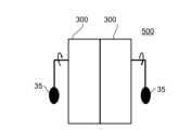
第四実施形態による推力発生装置500は、上述した任意の実施形態の推力発生装置を組み合わせて構成することができる。本実施形態では、第二実施形態の推力発生装置300を2台組み合わせて構成された例について説明する。図10は第四実施形態による推力発生装置500の説明図である。
図10中左の推力発生装置300の筐体内部に備えるモーター(不図示)と、図10中右の推力発生装置300の筐体内部に備えるモーター(不図示)は、重りの側から見て、それぞれ相対する方向に重りが回転する。推力発生装置500による推力として、左右の各推力発生装置300によって筐体の自転を相殺し同一方向へ推力が発生する。すなわち、2台の推力発生装置300による推力の合力を得ることができる。<Fourth embodiment>
The
A motor (not shown) provided inside the housing of the
なお、本発明における回転体(他の回転体を含む)は、歯車に限らず、例えば、滑車でもよい。また、張設部材は、チェーンに限らない。例えば、チェーン、ワイヤロープ、ベルト、又は、これらの組み合わせにより構成してもよい。The rotating body (including other rotating bodies) in the present invention is not limited to gears and may be, for example, pulleys. Furthermore, the tensioning member is not limited to a chain. For example, it may be a chain, a wire rope, a belt, or a combination of these.
上述した各実施形態では、歯車10(30、40)を介して、重り15(35、45)の回転に対し、回転速度の速度変化を与える構成について説明したが、本発明はこのような構成に限定されるものではない。重り15(35、45)の回転に対し、回転速度の速度変化を周期的に発生させて、一方向への推力を発生させれば、どのような手法で歯車11(31、41)を回転させてもよく、また、どのような手法で重り15(35、45)の回転に対して周期的な速度変化を発生させてもよい。In each of the above-described embodiments, a configuration has been described in which a speed change in rotational speed is applied to the rotation of the weight 15 (35, 45) via the gear 10 (30, 40), but the present invention is not limited to such a configuration. As long as a speed change in rotational speed is periodically generated for the rotation of the weight 15 (35, 45) to generate a thrust in one direction, any method may be used to rotate the gear 11 (31, 41), and any method may be used to generate a periodic speed change for the rotation of the weight 15 (35, 45).
歯車11(31、41)に動力源を直接設置してもよい。例えば、ステッピングモーター等の動力源を歯車11(31、41)に直接設置して、当該動力源によって重り15(35、45)の回転に対し周期的な速度変化を発生させることにより重り15(35、45)による遠心力が所望の一方向において最大となるよう調節し、推力を発生させてもよい。
なお、第二実施形態の推力発生装置300において、歯車31にステッピングモーター等の動力源を直接設置する場合、歯車31の回転軸31aを、歯車31の中心に構成してもよい。 A power source may be directly installed on the gear 11 (31, 41). For example, a power source such as a stepping motor may be directly installed on the gear 11 (31, 41) and the power source may generate a periodic speed change in the rotation of the weight 15 (35, 45) to adjust the centrifugal force of the weight 15 (35, 45) to be maximum in a desired direction, thereby generating thrust.
In the
なお、当該動力源、及び、上述した各実施形態におけるモーター2(32、42)は、例えば、ギアモータ及び外部電力又は取り外しが自由な乾電池や充電用電池である。回転動力を伝達することができれば、どのようなものでもよく、例えば、内燃機関、外燃機関等を利用した駆動装置であってもよい。The power source and the motor 2 (32, 42) in each of the above-mentioned embodiments are, for example, a gear motor and external power, or a removable dry cell or rechargeable battery. Anything that can transmit rotational power is acceptable, and may be, for example, a drive device that utilizes an internal combustion engine, an external combustion engine, etc.
また、上述した各実施形態では、重り15(35、45)を、歯車11(31、41)の回転に連動して回転するシャフト4a(34、44a)に設置したが、重り15(35、45)は、歯車11(31、41)の回転に連動して回転するよう構成すれば、他の箇所に設置してもよい。In addition, in each of the above-described embodiments, the weight 15 (35, 45) is installed on the
さらに、重り15(35、45)の回転の回転速度(周速度)の変化量の調節、又は、歯車11(31、41)の回転軸11a(31a、41a)から重り15(35、45)の距離、又は、重り15(35、45)の重さを調節することにより、推力の大きさを調整することができる。例えば、重り15(35、45)の回転速度(周速度)の変化量が大きければ、発生する推力が大きくなる。また、歯車11(31、41)の回転軸11a(31a、41a)から重り15(35、45)の距離が大きいほど、発生する推力が大きくなる。また、重り15(35、45)の重さが大きいほど、発生する推力も大きくなる。Furthermore, the magnitude of the thrust can be adjusted by adjusting the amount of change in the rotational speed (circumferential speed) of the weight 15 (35, 45), or by adjusting the distance from the
以上、本発明の推力発生方法を実現する各実施形態に係る推力発生装置100乃至500の構成についての説明を行った。各実施形態はそれぞれ単独で実施してもよいし、任意の実施形態を組み合わせて実施してもよい。なお、上述した推力発生装置100乃至500の構成は、本発明の推力発生方法の基本的な要点を解説したに過ぎない。すなわち、本発明に係る推力発生方法の技術的範囲は、上述した各実施形態に記載の範囲に限定されるものではなく、特許請求の範囲の記載の範囲内において、多様な変更又は改良を加えることが可能である。
本発明の適用範囲は上述した構成に限定されることはない。本発明は、重りを備えた回転体を用いて推力を発生させることができる推力発生方法に対し、広く適用することができる。 The configurations of the
The scope of application of the present invention is not limited to the above-mentioned configurations. The present invention can be widely applied to thrust generation methods that can generate thrust using a rotating body equipped with a weight.
100、300、400、500 推力発生装置
1、301、401 筐体
2、32、42 モーター(動力源)
2a、32a、42a シャフト
3 回転バネ付き支持部、3a シャフト
4a、34、44a シャフト
10、30、40 歯車(他の回転体)、10a 回転軸
11、31、41 歯車(回転体)
11a、31a、41a 回転軸
12、13 調節用歯車
14 連結部
15、35、45 重り
20 チェーン(張設部材) 100, 300, 400, 500
2a, 32a,
11a, 31a,
15, 35, 45
Claims (2)
Translated fromJapanese前記回転体は、当該回転体の縁からの距離が一定ではない位置に回転軸を有する偏心歯車であって、
前記偏心歯車と噛み合う他の歯車による駆動力を受けて、前記偏心歯車が回転軸を中心に回転することにより、前記偏心歯車に備えた重りの回転の周速度が変化して前記推力を発生させることを特徴とする推力発生方法。 A thrust generating method for a thrust generating device, which generates a thrust in a direction of increasing speed by rotating a rotor equipped with a weight and causing a periodic speed change in the rotation speed of the weight, comprising the steps of:
The rotating bodyis an eccentric gear having a rotation axis at a position where the distance from the edge of the rotating body is not constant,
a driving force appliedto the eccentric gear by another gear that meshes with the eccentric gear, the eccentric gear rotates about a rotation axis, and the peripheral speed of rotation of a weight attached tothe eccentric gear changes, thereby generating the thrust.
前記回転体は、縁からの距離が一定ではない位置に回転軸を有する歯車であり、
当該歯車と噛み合う他の歯車から動力を受けて当該歯車が回転軸を中心に回転することにより、当該歯車に備えた重りの回転の周速度が変化して前記推力を発生させることを特徴とする推力発生方法。 A thrust generating method for a thrust generating device, which generates a thrust in a direction of increasing speed by rotating a rotor equipped with a weight and causing a periodic speed change in the rotation speed of the weight, comprising the steps of:
the rotating bodyis a gear having a rotation axis at a position that is not uniformly spaced from the edge,
A method for generating thrust, comprising the steps of: rotatinga gear about a rotation axis when power is received from another gear that meshes with the gear , thereby changing the peripheral speed of rotation of a weight attached tothe gear and generating the thrust.
Priority Applications (1)
| Application Number | Priority Date | Filing Date | Title |
|---|---|---|---|
| JP2024040569AJP7678489B1 (en) | 2024-03-14 | 2024-03-14 | Thrust generation method |
Applications Claiming Priority (1)
| Application Number | Priority Date | Filing Date | Title |
|---|---|---|---|
| JP2024040569AJP7678489B1 (en) | 2024-03-14 | 2024-03-14 | Thrust generation method |
Publications (2)
| Publication Number | Publication Date |
|---|---|
| JP7678489B1true JP7678489B1 (en) | 2025-05-16 |
| JP2025140918A JP2025140918A (en) | 2025-09-29 |
Family
ID=95698079
Family Applications (1)
| Application Number | Title | Priority Date | Filing Date |
|---|---|---|---|
| JP2024040569AActiveJP7678489B1 (en) | 2024-03-14 | 2024-03-14 | Thrust generation method |
Country Status (1)
| Country | Link |
|---|---|
| JP (1) | JP7678489B1 (en) |
Citations (4)
| Publication number | Priority date | Publication date | Assignee | Title |
|---|---|---|---|---|
| JPS4624750Y1 (en)* | 1968-09-14 | 1971-08-26 | ||
| JPH06272741A (en)* | 1993-03-19 | 1994-09-27 | Hisashi Kaburagi | Speed changer |
| WO2001004491A1 (en) | 1999-07-13 | 2001-01-18 | Toyo Communication Equipment Co., Ltd. | Thrust generating device and moving body |
| JP2004270672A (en)* | 2003-03-08 | 2004-09-30 | Akira Shimizu | Centrifugal propulsion device |
- 2024
- 2024-03-14JPJP2024040569Apatent/JP7678489B1/enactiveActive
Patent Citations (4)
| Publication number | Priority date | Publication date | Assignee | Title |
|---|---|---|---|---|
| JPS4624750Y1 (en)* | 1968-09-14 | 1971-08-26 | ||
| JPH06272741A (en)* | 1993-03-19 | 1994-09-27 | Hisashi Kaburagi | Speed changer |
| WO2001004491A1 (en) | 1999-07-13 | 2001-01-18 | Toyo Communication Equipment Co., Ltd. | Thrust generating device and moving body |
| JP2004270672A (en)* | 2003-03-08 | 2004-09-30 | Akira Shimizu | Centrifugal propulsion device |
Also Published As
| Publication number | Publication date |
|---|---|
| JP2025140918A (en) | 2025-09-29 |
Similar Documents
| Publication | Publication Date | Title |
|---|---|---|
| US8866314B2 (en) | Method for operating a power rotary actuator and a power plant for carrying out said method | |
| US4241615A (en) | Vibrating device | |
| EP0821187A2 (en) | Oil pressure generator and power output apparatus | |
| EP2631506A1 (en) | Tuned mass damper | |
| EP2118520B1 (en) | Gyroscopic torque converter | |
| JP2011163521A (en) | Rotary drive unit | |
| JP7678489B1 (en) | Thrust generation method | |
| CN1334905A (en) | Continuously variable transmission | |
| US20080060460A1 (en) | Propulsion device employing conversion of rotary motion into a unidirectional linear force | |
| US5123292A (en) | Motivational generator | |
| US11359705B2 (en) | Machine generating centrifugal forces from effective elliptic trajectory | |
| RU2381078C2 (en) | Method to produce directed mechanical vibrations and device to this end | |
| TWI325219B (en) | ||
| US20110041630A1 (en) | Propulsion mechanism employing conversion of rotary motion into a unidirectional linear force | |
| CA2542911A1 (en) | Self regulating continuously variable transmission | |
| US20070137420A1 (en) | Method and device for self-contained inertial vehicular propulsion | |
| JP4931763B2 (en) | Rotational speed fluctuation generator | |
| RU180102U1 (en) | PLANETARY VIBRATOR WITH CONTROLLED CHARACTERISTICS AND CHAIN TRANSMISSION | |
| UA135744U (en) | TRACTION VECTOR GENERATOR FOR VEHICLE | |
| RU2552765C2 (en) | Rotation power drive | |
| ES1306747U (en) | Lever power multiplier device. (Machine-translation by Google Translate, not legally binding) | |
| WO2022024786A1 (en) | Rotational motion mechanism | |
| RU2224076C1 (en) | Boring device | |
| JP2024002976A (en) | Versatile system equipped with pair of mechanisms with eccentric elements capable of moving in rotation | |
| GB2411932A (en) | Mechanical torque converter with oscillating flywheels |
Legal Events
| Date | Code | Title | Description |
|---|---|---|---|
| A621 | Written request for application examination | Free format text:JAPANESE INTERMEDIATE CODE: A621 Effective date:20240321 | |
| A871 | Explanation of circumstances concerning accelerated examination | Free format text:JAPANESE INTERMEDIATE CODE: A871 Effective date:20240321 | |
| A131 | Notification of reasons for refusal | Free format text:JAPANESE INTERMEDIATE CODE: A131 Effective date:20240610 | |
| A521 | Request for written amendment filed | Free format text:JAPANESE INTERMEDIATE CODE: A523 Effective date:20240624 | |
| A131 | Notification of reasons for refusal | Free format text:JAPANESE INTERMEDIATE CODE: A131 Effective date:20240909 | |
| A521 | Request for written amendment filed | Free format text:JAPANESE INTERMEDIATE CODE: A523 Effective date:20241002 | |
| A131 | Notification of reasons for refusal | Free format text:JAPANESE INTERMEDIATE CODE: A131 Effective date:20241206 | |
| A521 | Request for written amendment filed | Free format text:JAPANESE INTERMEDIATE CODE: A523 Effective date:20250115 | |
| TRDD | Decision of grant or rejection written | ||
| A01 | Written decision to grant a patent or to grant a registration (utility model) | Free format text:JAPANESE INTERMEDIATE CODE: A01 Effective date:20250417 | |
| A61 | First payment of annual fees (during grant procedure) | Free format text:JAPANESE INTERMEDIATE CODE: A61 Effective date:20250421 | |
| R150 | Certificate of patent or registration of utility model | Ref document number:7678489 Country of ref document:JP Free format text:JAPANESE INTERMEDIATE CODE: R150 |