Movatterモバイル変換


[0]ホーム

URL:


JP7678135B2 - CONTROL DEVICE, ROBOT CONTROL SYSTEM, AND ROBOT CONTROL METHOD - Google Patents

CONTROL DEVICE, ROBOT CONTROL SYSTEM, AND ROBOT CONTROL METHOD
Download PDF

Info

Publication number
JP7678135B2
JP7678135B2JP2023563786AJP2023563786AJP7678135B2JP 7678135 B2JP7678135 B2JP 7678135B2JP 2023563786 AJP2023563786 AJP 2023563786AJP 2023563786 AJP2023563786 AJP 2023563786AJP 7678135 B2JP7678135 B2JP 7678135B2
Authority
JP
Japan
Prior art keywords
hand
finger
contact
gripping
unit
Prior art date
Legal status (The legal status is an assumption and is not a legal conclusion. Google has not performed a legal analysis and makes no representation as to the accuracy of the status listed.)
Active
Application number
JP2023563786A
Other languages
Japanese (ja)
Other versions
JPWO2023095928A1 (en
JPWO2023095928A5 (en
Inventor
友樹 山岸
一樹 大野
尚宏 阿南
敬之 石田
博昭 宮村
Current Assignee (The listed assignees may be inaccurate. Google has not performed a legal analysis and makes no representation or warranty as to the accuracy of the list.)
Kyocera Corp
Original Assignee
Kyocera Corp
Priority date (The priority date is an assumption and is not a legal conclusion. Google has not performed a legal analysis and makes no representation as to the accuracy of the date listed.)
Filing date
Publication date
Application filed by Kyocera CorpfiledCriticalKyocera Corp
Publication of JPWO2023095928A1publicationCriticalpatent/JPWO2023095928A1/ja
Publication of JPWO2023095928A5publicationCriticalpatent/JPWO2023095928A5/ja
Application grantedgrantedCritical
Publication of JP7678135B2publicationCriticalpatent/JP7678135B2/en
Activelegal-statusCriticalCurrent
Anticipated expirationlegal-statusCritical

Links

Images

Classifications

Landscapes

Description

Translated fromJapanese
関連出願へのクロスリファレンスCROSS-REFERENCE TO RELATED APPLICATIONS

本出願は、日本国特許出願2021-193651号(2021年11月29日出願)の優先権を主張するものであり、当該出願の開示全体を、ここに参照のために取り込む。This application claims priority to Japanese Patent Application No. 2021-193651 (filed November 29, 2021), the entire disclosure of which is incorporated herein by reference.

本開示は、制御装置、ロボット制御システム、及びロボット制御方法に関する。The present disclosure relates to a control device, a robot control system, and a robot control method.

物体把持まで時間を要せず、物体形状に依存しないで安定して未知の形状物体を把持することができるロボットの制御方法が知られている(例えば、特許文献1参照)。A control method for a robot is known that can stably grasp an object of unknown shape without requiring a certain amount of time to grasp the object and without depending on the object's shape (see, for example, Patent Document 1).

特開2003-245883号公報JP 2003-245883 A

本開示の一実施形態に係る制御装置は、把持対象物を把持可能であり、第1指及び第2指を有するハンド部を制御するハンド制御部を備える。前記ハンド制御部は、前記第1指及び前記第2指に連携している少なくとも1つのセンサから前記把持対象物から前記第1指及び前記第2指のそれぞれに作用する力を示す複数の力情報を取得する。前記ハンド制御部は、前記複数の力情報の関係に基づいて前記把持対象物に接触する前記第1指及び前記第2指の接触領域の適否を判定する。A control device according to an embodiment of the present disclosure includes a hand control unit capable of grasping an object to be grasped and configured to control a hand unit having a first finger and a second finger. The hand control unit acquires a plurality of pieces of force information indicating forces acting on the first finger and the second finger from the object to be grasped from at least one sensor connected to the first finger and the second finger. The hand control unit determines the suitability of the contact areas of the first finger and the second finger that come into contact with the object to be grasped based on the relationship between the plurality of pieces of force information.

本開示の一実施形態に係るロボット制御システムは、前記制御装置と、ハンド部を有するロボットとを備える。A robot control system according to one embodiment of the present disclosure comprises the control device and a robot having a hand portion.

本開示の一実施形態に係るロボット制御方法は、把持対象物を把持可能であり、第1指及び第2指を有するハンド部を制御する制御装置によって実行される。前記ロボット制御方法は、前記制御装置が、前記第1指及び前記第2指に連携している少なくとも1つのセンサから前記把持対象物から前記第1指及び前記第2指のそれぞれに作用する力を示す複数の力情報を取得することを含む。前記ロボット制御方法は、前記制御装置が、前記複数の力情報の関係に基づいて前記把持対象物に接触する前記第1指及び前記第2指の接触領域の適否を判定することを含む。A robot control method according to one embodiment of the present disclosure is executed by a control device that controls a hand unit capable of grasping an object to be grasped and having a first finger and a second finger. The robot control method includes the control device acquiring, from at least one sensor linked to the first finger and the second finger, a plurality of pieces of force information indicating forces acting on the first finger and the second finger from the object to be grasped. The robot control method includes the control device determining the suitability of contact areas of the first finger and the second finger that contact the object to be grasped based on a relationship between the plurality of pieces of force information.

一実施形態に係るロボット制御システムの構成例を示すブロック図である。1 is a block diagram showing an example of the configuration of a robot control system according to an embodiment.ハンド制御装置及びハンド部の構成例を表すブロック図である。2 is a block diagram showing a configuration example of a hand control device and a hand unit. FIG.ハンド部が把持対象物を把持する態様の一例を示す模式図である。4A to 4C are schematic diagrams showing an example of a manner in which a hand unit grasps an object to be grasped.把持対象物の中心と指の中心とが一致する例を示す模式図である。11 is a schematic diagram showing an example in which the center of a grasp object and the center of the fingers coincide with each other. FIG.把持対象物が一方の指に対して偏って位置する例を示す模式図である。11 is a schematic diagram showing an example in which a grasp target is positioned offset relative to one of the fingers. FIG.把持対象物が一方の指に対して偏って位置し、かつ、指の中心から外れて位置する例を示す模式図である。13 is a schematic diagram showing an example in which a grasp target is positioned offset relative to one of the fingers and off-center of the fingers; FIG.各指の接触力センサの出力の関係をプロットした2次元グラフの例である。13 is an example of a two-dimensional graph plotting the relationship between the outputs of the contact force sensor for each finger.図4Bの接触状態において各指の接触力センサの出力とモータの回転角度との関係の一例を示すグラフである。4C is a graph showing an example of the relationship between the output of the contact force sensor of each finger and the rotation angle of the motor in the contact state of FIG. 4B.図4Cの接触状態において各指の接触力センサの出力とモータの回転角度との関係の一例を示すグラフである。4D is a graph showing an example of the relationship between the output of the contact force sensor of each finger and the rotation angle of the motor in the contact state of FIG. 4C.一実施形態に係るロボット制御方法の手順例を示すフローチャートである。1 is a flowchart illustrating an example of a procedure of a robot control method according to an embodiment.

物体への接触の前後で把持の制御を切り替える場合、制御の不連続範囲において把持が不安定になることがある。把持の安定性の向上が求められる。When gripping control is switched before and after contact with an object, gripping can become unstable in the discontinuous range of control. It is necessary to improve gripping stability.

図1に示されるように、一実施形態に係るロボット制御システム1は、ロボット2と、制御装置70とを備える。ロボット2は、アーム3とハンド部4とを備える。アーム3は、関節とリンクとを備えてよい。ハンド部4は、把持対象物8(図3参照)を把持可能に構成される。本実施形態の制御装置70は、ロボット制御部10とハンド制御部20とを備える。なお、制御装置70は、少なくともハンド制御部20を有していればよい。ロボット制御部10は、ロボット2の動作を制御する情報に基づいてロボット2のアーム3を動作させてハンド部4を把持対象物8の位置まで移動させる。ハンド部4が把持対象物8の位置に近づく動作は、アプローチ動作とも称される。ロボット制御部10は、ハンド部4の把持対象物8へのアプローチ動作を制御する。ハンド制御部20は、ハンド部4を制御してハンド部4に把持対象物8を把持させる。As shown in FIG. 1, arobot control system 1 according to one embodiment includes arobot 2 and acontrol device 70. Therobot 2 includes anarm 3 and a hand unit 4. Thearm 3 may include a joint and a link. The hand unit 4 is configured to be able to grasp a grasped object 8 (see FIG. 3). Thecontrol device 70 of this embodiment includes arobot control unit 10 and ahand control unit 20. Note that thecontrol device 70 only needs to have at least thehand control unit 20. Therobot control unit 10 operates thearm 3 of therobot 2 based on information that controls the operation of therobot 2 to move the hand unit 4 to the position of the grasped object 8. The operation of the hand unit 4 approaching the position of the grasped object 8 is also referred to as an approach operation. Therobot control unit 10 controls the approach operation of the hand unit 4 to the grasped object 8. Thehand control unit 20 controls the hand unit 4 to grasp the grasped object 8.

ロボット制御部10及びハンド制御部20は、例えば以下に説明する動作を実行してよい。ロボット制御部10は、把持対象物8を把持できる位置にハンド部4を移動させるようにアーム3を制御する。ハンド制御部20は、ハンド部4が把持対象物8まで移動した状態で把持対象物8を把持するように把持対象物8を把持する目標位置を決定してハンド部4を制御する。ロボット制御部10は、ハンド部4が把持対象物8を把持した状態でハンド部4を上昇させるようにアーム3を制御することによって、把持対象物8を持ち上げて把持対象物8を移動させる目標地点まで移動させる。ハンド制御部20は、持ち上げた把持対象物8が目標地点まで移動した状態で把持対象物8の把持力を低下させて把持対象物8をハンド部4から離して目標地点に置く。Therobot control unit 10 and thehand control unit 20 may execute the operations described below, for example. Therobot control unit 10 controls thearm 3 to move the hand unit 4 to a position where the object to be grasped 8 can be grasped. Thehand control unit 20 determines a target position for grasping the object to be grasped 8 and controls the hand unit 4 so that the hand unit 4 grasps the object to be grasped 8 when it has moved to the object to be grasped 8. Therobot control unit 10 controls thearm 3 to raise the hand unit 4 when the hand unit 4 grasps the object to be grasped 8, thereby lifting the object to be grasped 8 and moving it to the target point to which the object to be grasped 8 is to be moved. When the lifted object to be grasped 8 has moved to the target point, thehand control unit 20 reduces the gripping force of the object to be grasped 8, and moves the object to be grasped 8 away from the hand unit 4 and places it at the target point.

ロボット制御部10は、ロボット2の動作を制御する情報を自身で生成して取得してよい。ロボット制御部10は、ネットワーク60を介して、又は、ネットワーク60を介さずに接続される情報処理装置50等の外部装置から、ロボット2の動作を制御する情報を取得してもよい。ハンド制御部20は、ハンド部4の動作を制御する情報を自身で生成して取得してよい。ハンド制御部20は、ロボット制御部10から、ハンド部4の動作を制御する情報を取得してもよい。ロボット制御部10とハンド制御部20とは一体に構成されてもよい。Therobot control unit 10 may generate and acquire information for controlling the operation of therobot 2 by itself. Therobot control unit 10 may acquire information for controlling the operation of therobot 2 via thenetwork 60, or from an external device such as aninformation processing device 50 connected without via thenetwork 60. Thehand control unit 20 may generate and acquire information for controlling the operation of the hand unit 4 by itself. Thehand control unit 20 may acquire information for controlling the operation of the hand unit 4 from therobot control unit 10. Therobot control unit 10 and thehand control unit 20 may be configured as one unit.

ロボット制御部10は、種々の機能を実行するための制御及び処理能力を提供するために、少なくとも1つのプロセッサを含んで構成されてよい。プロセッサは、ロボット制御部10の種々の機能を実現するプログラムを実行しうる。プロセッサは、単一の集積回路として実現されてよい。集積回路は、IC(Integrated Circuit)ともいう。プロセッサは、複数の通信可能に接続された集積回路及びディスクリート回路として実現されてよい。プロセッサは、他の種々の既知の技術に基づいて実現されてよい。Therobot control unit 10 may be configured to include at least one processor to provide control and processing power for performing various functions. The processor may execute programs that realize the various functions of therobot control unit 10. The processor may be realized as a single integrated circuit. An integrated circuit is also called an IC (Integrated Circuit). The processor may be realized as multiple communicatively connected integrated circuits and discrete circuits. The processor may be realized based on various other known technologies.

ロボット制御部10は、記憶部を備えてよい。記憶部は、磁気ディスク等の電磁記憶媒体を含んでよいし、半導体メモリ又は磁気メモリ等のメモリを含んでもよい。記憶部は、各種情報及びロボット制御部10で実行されるプログラム等を格納する。記憶部は、ロボット制御部10のワークメモリとして機能してよい。記憶部の少なくとも一部は、ロボット制御部10とは別体として構成されてもよい。Therobot control unit 10 may include a memory unit. The memory unit may include an electromagnetic storage medium such as a magnetic disk, or may include a memory such as a semiconductor memory or a magnetic memory. The memory unit stores various information and programs executed by therobot control unit 10. The memory unit may function as a work memory for therobot control unit 10. At least a part of the memory unit may be configured as a separate entity from therobot control unit 10.

図2に示されるように、ハンド制御部20は、状態推定部21と、変換部22と、位置制御部24と、加算器25、26及び27と、スイッチ29とを備える。ハンド制御部20は、少なくとも1つのプロセッサを含んで構成されてよい。ハンド制御部20は、記憶部を含んで構成されてよい。なお、各構成部の動作は後述されるが、以下簡単に説明される。状態推定部21は、ハンド部4の把持対象物8の把持状態を推定する。変換部22は、信号を変換する。変換部22は、把持力情報を位置情報へ変換することができる。位置制御部24は、ハンド部4の位置を制御する制御信号を出力する。加算器25、26、27は、信号を加算又は減算する。スイッチ29は、信号の出力経路の開閉を切り替える。2, thehand control unit 20 includes astate estimation unit 21, aconversion unit 22, aposition control unit 24,adders 25, 26 and 27, and aswitch 29. Thehand control unit 20 may include at least one processor. Thehand control unit 20 may include a memory unit. The operation of each component will be described later, but will be briefly explained below. Thestate estimation unit 21 estimates the gripping state of the object 8 to be gripped by the hand unit 4. Theconversion unit 22 converts signals. Theconversion unit 22 can convert gripping force information into position information. Theposition control unit 24 outputs a control signal that controls the position of the hand unit 4. Theadders 25, 26 and 27 add or subtract signals. Theswitch 29 switches the signal output path between open and closed.

ロボット制御部10は、ロボット制御部10に接続されたカメラなどから画像情報を取得し、ロボット2のアーム3の制御又は把持対象物8を認識するための画像処理等を実行する。ハンド制御部20は、例えば認識した把持対象物8を把持するように、ハンド部4を制御する。ロボット制御部10の演算負荷とハンド制御部20の演算負荷とは、互いに異なる。ロボット制御部10とハンド制御部20とは、別体で構成されてよい。ロボット制御部10は、ロボット2の本体又はアーム3の足元に設置されたコンピュータとして構成されてよい。ハンド制御部20は、ハンド部4の内部に組み込まれたCPU等のプロセッサとして構成されてよい。ハンド制御部20は、ロボット制御部10と同一又は類似に構成されてもよい。Therobot control unit 10 acquires image information from a camera or the like connected to therobot control unit 10, and performs image processing or the like to control thearm 3 of therobot 2 or to recognize the grasped object 8. Thehand control unit 20 controls the hand unit 4, for example, to grasp the recognized grasped object 8. The computational load of therobot control unit 10 and the computational load of thehand control unit 20 are different from each other. Therobot control unit 10 and thehand control unit 20 may be configured separately. Therobot control unit 10 may be configured as a computer installed on the main body of therobot 2 or at the foot of thearm 3. Thehand control unit 20 may be configured as a processor such as a CPU built into the inside of the hand unit 4. Thehand control unit 20 may be configured the same as or similar to therobot control unit 10.

ハンド部4は、モータ41と、エンコーダ42と、第1接触力センサ43A及び第2接触力センサ43Bと、力覚センサ44とを備える。第1接触力センサ43A及び第2接触力センサ43Bは、接触力センサ43とも総称される。モータ41は、例えばステッピングモータ等のサーボモータとして構成され、制御信号に基づいて回転角度を制御する。エンコーダ42は、モータの回転角度を検出してハンド制御部20に出力する。エンコーダ42は、ロボット2のアーム3又はハンド部4の位置若しくは姿勢、又は、速度若しくは加速度等を検出する。ハンド部4は、モーションセンサを更に備えてもよい。モーションセンサは、ロボット2のアーム3の関節に設置されてよい。The hand unit 4 includes amotor 41, anencoder 42, a firstcontact force sensor 43A, a secondcontact force sensor 43B, and aforce sensor 44. The firstcontact force sensor 43A and the secondcontact force sensor 43B are also collectively referred to as thecontact force sensor 43. Themotor 41 is configured as a servo motor such as a stepping motor, and controls the rotation angle based on a control signal. Theencoder 42 detects the rotation angle of the motor and outputs it to thehand control unit 20. Theencoder 42 detects the position or posture, or the speed or acceleration, etc. of thearm 3 or the hand unit 4 of therobot 2. The hand unit 4 may further include a motion sensor. The motion sensor may be installed at a joint of thearm 3 of therobot 2.

エンコーダ42、接触力センサ43及び力覚センサ44は、単にセンサとも称される。ハンド部4は、複数のセンサを有する。接触力センサ43及び力覚センサ44の説明は、後述される。Theencoder 42, thecontact force sensor 43, and theforce sensor 44 are also simply referred to as sensors. The hand unit 4 has multiple sensors. Thecontact force sensor 43 and theforce sensor 44 will be described later.

図3に示されるように、ハンド部4は、2本の指45A及び45Bを備える。ハンド部4は、モータ41を駆動することによって2本の指45A及び45Bの間隔を制御し、2本の指45A及び45Bによって把持対象物8を把持する。ハンド部4は、把持対象物8を把持した状態で、Z軸の正の方向に移動することによって、把持対象物8をZ軸方向に持ち上げる。図3において、Z軸の負の方向は、把持対象物8に重力が作用する方向に対応する。把持対象物8に重力が作用する方向は、鉛直方向とも称される。As shown in FIG. 3, the hand unit 4 has twofingers 45A and 45B. The hand unit 4 controls the distance between the twofingers 45A and 45B by driving themotor 41, and grasps the object to be grasped 8 with the twofingers 45A and 45B. While grasping the object to be grasped 8, the hand unit 4 moves in the positive direction of the Z axis to lift the object to be grasped 8 in the Z axis direction. In FIG. 3, the negative direction of the Z axis corresponds to the direction in which gravity acts on the object to be grasped 8. The direction in which gravity acts on the object to be grasped 8 is also referred to as the vertical direction.

指45Aは、把持対象物8に接触する部分に配された1又は複数の第1接触力センサ43Aを備える。指45Bは、把持対象物8に接触する部分に配された1又は複数の第2接触力センサ43Bを備える。第1接触力センサ43A及び第2接触力センサ43Bは、指45A及び45Bが把持対象物8を把持する場合に把持対象物8から指45A及び45Bに作用する力を検出する。指45A及び45Bに把持対象物8から作用する力は、接触力とも称される。第1接触力センサ43A及び第2接触力センサ43Bが検出した接触力の情報は、力情報とも称される。指45Aは、第1指とも称される。指45Bは、第2指とも称される。Finger 45A has one or more firstcontact force sensors 43A arranged in a portion that contacts the grasp object 8.Finger 45B has one or more secondcontact force sensors 43B arranged in a portion that contacts the grasp object 8. The firstcontact force sensor 43A and the secondcontact force sensor 43B detect the force acting onfingers 45A and 45B from the grasp object 8 whenfingers 45A and 45B grasp the grasp object 8. The force acting onfingers 45A and 45B from the grasp object 8 is also referred to as contact force. Information on the contact force detected by firstcontact force sensor 43A and secondcontact force sensor 43B is also referred to as force information.Finger 45A is also referred to as the first finger.Finger 45B is also referred to as the second finger.

第1接触力センサ43A及び第2接触力センサ43Bは、圧電センサ又は歪みゲージ等として構成されてよい。第1接触力センサ43A及び第2接触力センサ43Bは、複数の軸に沿った方向の力を検出できるように構成されてよい。第1接触力センサ43A及び第2接触力センサ43Bは、複数の方向それぞれの力に対応する複数のセンサを含んで構成されてよい。力情報は、第1接触力センサ43A及び第2接触力センサ43Bの検出結果だけでなく、ロボット2を駆動するモータに流れる電流を検出する電流センサの検出結果に基づいて取得されてもよい。The firstcontact force sensor 43A and the secondcontact force sensor 43B may be configured as a piezoelectric sensor or a strain gauge, etc. The firstcontact force sensor 43A and the secondcontact force sensor 43B may be configured to detect forces in directions along multiple axes. The firstcontact force sensor 43A and the secondcontact force sensor 43B may be configured to include multiple sensors corresponding to forces in multiple directions. The force information may be acquired based not only on the detection results of the firstcontact force sensor 43A and the secondcontact force sensor 43B, but also on the detection results of a current sensor that detects the current flowing in the motor that drives therobot 2.

ハンド部4は、2本の指45A及び45Bを支持する本体部分とロボット2のアーム3との間に配された1又は複数の力覚センサ44を備える。力覚センサ44は、2本の指45A及び45Bを介して本体部分に作用する力又はトルクを検出する。力覚センサ44は、Z軸の負の方向の力、つまり把持対象物8及びハンド部4に作用する重力を検出する。力覚センサ44は、圧電センサ又は歪みゲージ等として構成されてよい。力覚センサ44は、複数の方向それぞれの力又はトルクに対応する複数のセンサを含んで構成されてよい。力覚センサ44は、ハンド部4だけでなく、ロボット2のアーム3等に設置されてもよい。力覚センサ44が検出した力又はトルクの情報は、力情報に含まれる。The hand unit 4 is equipped with one ormore force sensors 44 arranged between the main body part supporting the twofingers 45A and 45B and thearm 3 of therobot 2. Theforce sensor 44 detects the force or torque acting on the main body part via the twofingers 45A and 45B. Theforce sensor 44 detects the force in the negative direction of the Z axis, that is, the gravity acting on the grasped object 8 and the hand unit 4. Theforce sensor 44 may be configured as a piezoelectric sensor or a strain gauge, etc. Theforce sensor 44 may be configured to include multiple sensors corresponding to forces or torques in multiple directions. Theforce sensor 44 may be installed not only in the hand unit 4 but also in thearm 3 of therobot 2, etc. Information on the force or torque detected by theforce sensor 44 is included in the force information.

第1接触力センサ43A及び第2接触力センサ43Bはそれぞれ、指45A及び45Bに作用する力を検出するので、指45A及び45Bに連携しているといえる。また、力覚センサ44は、指45A及び45Bを支持するハンド部4の本体部分に作用する力又はトルクを検出するので、指45A及び45Bに連携しているといえる。The firstcontact force sensor 43A and the secondcontact force sensor 43B detect the forces acting on thefingers 45A and 45B, respectively, and therefore can be said to be linked to thefingers 45A and 45B. In addition, theforce sensor 44 detects the force or torque acting on the main body part of the hand unit 4 that supports thefingers 45A and 45B, and therefore can be said to be linked to thefingers 45A and 45B.

ハンド制御部20は、エンコーダ42、接触力センサ43又は力覚センサ44等を含む複数のセンサの少なくとも1つの情報に基づいてハンド部4の位置を表す情報を取得してよい。ハンド部4の位置を表す情報は、ハンド部4の位置情報とも称される。ハンド部4の位置情報は、把持対象物8を把持する位置の情報を含んでもよい。Thehand control unit 20 may acquire information representing the position of the hand unit 4 based on information from at least one of a plurality of sensors including anencoder 42, acontact force sensor 43, or aforce sensor 44. The information representing the position of the hand unit 4 is also referred to as position information of the hand unit 4. The position information of the hand unit 4 may include information on the position at which the grasped object 8 is grasped.

ロボット制御部10がロボット2のハンド部4に把持対象物8を把持させる場合、ハンド制御部20は、以下に説明されるようにハンド部4を制御してよい。When therobot control unit 10 causes the hand unit 4 of therobot 2 to grasp the graspable object 8, thehand control unit 20 may control the hand unit 4 as described below.

ハンド制御部20は、位置制御部24からハンド部4のモータ41に対してモータ41の回転角度を制御する制御信号を出力する。また、ハンド制御部20は、位置制御部24からハンド部4のモータ41に対して指45A及び45Bで把持対象物8を把持する力を制御する情報を制御信号として出力する。ハンド制御部20は、ハンド部4に対して信号を増幅するドライバ28を介して制御信号を出力する。ドライバ28は、モータ41を動作させる(アクチュエートする)電圧を出力する。Thehand control unit 20 outputs a control signal from theposition control unit 24 to themotor 41 of the hand unit 4, which controls the rotation angle of themotor 41. Thehand control unit 20 also outputs information from theposition control unit 24 to themotor 41 of the hand unit 4 as a control signal, which controls the force with which thefingers 45A and 45B grip the object to be grasped 8. Thehand control unit 20 outputs the control signal to the hand unit 4 via adriver 28 that amplifies the signal. Thedriver 28 outputs a voltage that operates (actuates) themotor 41.

モータ41は、制御信号に基づいて回転角度を制御する。エンコーダ42は、モータ41の回転角度を検出してハンド制御部20の状態推定部21と加算器26とに出力する。モータ41に対して回転角度を制御する制御信号が出力され、かつ、モータ41の回転角度の検出結果がフィードバックされる制御ループは、内側の制御ループとも称され、接触力センサ43の出力を利用しない場合に単純な位置制御ループとして機能する。Themotor 41 controls the rotation angle based on the control signal. Theencoder 42 detects the rotation angle of themotor 41 and outputs it to thestate estimation unit 21 and theadder 26 of thehand control unit 20. The control loop in which a control signal for controlling the rotation angle is output to themotor 41 and the detection result of the rotation angle of themotor 41 is fed back is also called the inner control loop, and functions as a simple position control loop when the output of thecontact force sensor 43 is not used.

モータ41は、制御信号に含まれる、把持対象物8を把持する力を制御する情報に基づいて指45A及び45Bを動かす力を制御する。第1接触力センサ43Aは、指45Aが把持対象物8に接触した場合の接触力を検出してハンド制御部20の状態推定部21に出力する。第2接触力センサ43Bは、指45Bが把持対象物8に接触した場合の接触力を検出してハンド制御部20の状態推定部21に出力する。Themotor 41 controls the force that moves thefingers 45A and 45B based on information contained in the control signal that controls the force with which the grasp object 8 is grasped. The firstcontact force sensor 43A detects the contact force when thefinger 45A contacts the grasp object 8 and outputs it to thestate estimation unit 21 of thehand control unit 20. The secondcontact force sensor 43B detects the contact force when thefinger 45B contacts the grasp object 8 and outputs it to thestate estimation unit 21 of thehand control unit 20.

状態推定部21は、第1接触力センサ43A及び第2接触力センサ43Bが検出した接触力に基づいて、指45A及び45Bで把持対象物8を把持する力を算出する。把持対象物8を把持する力は、把持力とも称される。状態推定部21は、算出した把持力Tを加算器25に出力する。加算器25は、基準把持力refTから算出した把持力Tを減算した値をΔTとして変換部22に出力する。ΔTは、基準把持力refTからの上下限設定範囲を表す。なお、基準把持力refTは、把持対象物8毎に定められてもよい。基準把持力refTは、例えば、把持対象物8毎にユーザによって設定されてもよい。基準把持力refTは、例えば、把持対象物8毎に設定されて記憶部に保持されていてもよく、把持対象物8に応じて記憶部から読み込まれてもよい。なお、この場合、ロボット制御システム1は、ユーザ入力を受け付けるキーボード、ポインタ又はタッチパネル等の入力部を有していてもよい。Thestate estimation unit 21 calculates the force with which thefingers 45A and 45B grip the object 8 to be grasped based on the contact force detected by the firstcontact force sensor 43A and the secondcontact force sensor 43B. The force with which the object 8 to be grasped is also called the grip force. Thestate estimation unit 21 outputs the calculated grip force T to theadder 25. Theadder 25 outputs a value obtained by subtracting the calculated grip force T from the reference grip force refT as ΔT to theconversion unit 22. ΔT represents the upper and lower limit setting ranges from the reference grip force refT. The reference grip force refT may be determined for each object 8 to be grasped. The reference grip force refT may be set by the user for each object 8 to be grasped. The reference grip force refT may be set for each object 8 to be grasped and stored in the memory unit, or may be read from the memory unit according to the object 8 to be grasped. In this case, therobot control system 1 may have an input unit such as a keyboard, a pointer, or a touch panel that accepts user input.

変換部22は、ΔTをΔXに変換してスイッチ29に出力する。具体的には、変換部22は、例えば把持力Tを示すセンサ出力を、ハンド部4のモータ41の回転角度θへ変換することができる。なお、変換部22は、例えば記憶部に記憶されたセンサ出力と回転角度θとの関係を示すテーブル情報を介して、ΔTからΔXへの変換を行えばよい。なお、記憶部は、例えば不揮発メモリであってもよい。この場合、記憶部は、例えば、初期動作時、出荷時又は保守時における把持力情報から位置情報への変換テーブルを保持することができる。また、記憶部は、ロボット制御部10又はハンド制御部20の記憶部に限らず、ロボット制御部10又はハンド制御部20にネットワーク上で接続される記憶部であってもよい。この場合、変換部22は、例えば、識別情報を別途取得して、その識別情報に基づいて記憶部に記憶された変換テーブルを取得してもよい。なお、識別情報は、例えばロボット2の表面等に付与されたQRコード又はバーコード等であってもよく、ロボット制御部10に接続されたカメラなどから変換テーブルのアドレスなどの認識情報を取得してもよい。Theconversion unit 22 converts ΔT to ΔX and outputs it to theswitch 29. Specifically, theconversion unit 22 can convert, for example, a sensor output indicating the gripping force T into the rotation angle θ of themotor 41 of the hand unit 4. Theconversion unit 22 may convert ΔT to ΔX via table information indicating the relationship between the sensor output and the rotation angle θ stored in the storage unit. The storage unit may be, for example, a non-volatile memory. In this case, the storage unit may hold a conversion table from gripping force information to position information at the time of initial operation, shipment, or maintenance. The storage unit is not limited to the storage unit of therobot control unit 10 or thehand control unit 20, but may be a storage unit connected to therobot control unit 10 or thehand control unit 20 via a network. In this case, theconversion unit 22 may, for example, separately acquire identification information and acquire the conversion table stored in the storage unit based on the identification information. The identification information may be, for example, a QR code or a barcode attached to the surface of therobot 2, or recognition information such as the address of a conversion table may be obtained from a camera connected to therobot control unit 10.

ΔXは、モータ41の回転角度が制御目標からずれている値を表す。変換部22は、ΔXをフィルタに通してスイッチ29に出力してもよい。フィルタは、例えば制御系の安定性のために高周波成分をカットするローパスフィルタを含んでよい。スイッチ29が閉状態である場合、変換部22の出力は加算器27に入力される。加算器27は、ΔXとrefθとを加算して加算器26に出力する。ΔXとrefθとの加算結果は、把持力を考慮した場合のモータ41の回転角度の制御目標値を表す。加算器26は、加算器27から出力された把持力を考慮した場合のモータ41の回転角度の制御目標値から、エンコーダ42から出力されたモータ41の回転角度の検出結果を減算した値を位置制御部24に出力する。位置制御部24は、加算器26から入力された信号に基づいてモータ41を制御する。具体的に、位置制御部24は、エンコーダ42から取得したモータ41の回転角度の検出結果と制御目標値とに基づいて、モータ41の回転角度が制御目標値(refθ)に近づくようにモータ41を制御する。この制御を繰り返すことによって、ハンド部4の把持力は、制御目標値(refT)に近づけられる。なお、refθは、例えば、refTを回転角度へ変換した値であってもよい。ΔX represents the value by which the rotation angle of themotor 41 deviates from the control target. Theconversion unit 22 may pass ΔX through a filter and output it to theswitch 29. The filter may include, for example, a low-pass filter that cuts high-frequency components for the stability of the control system. When theswitch 29 is closed, the output of theconversion unit 22 is input to theadder 27. Theadder 27 adds ΔX and refθ and outputs the result to theadder 26. The result of the addition of ΔX and refθ represents the control target value of the rotation angle of themotor 41 when the gripping force is taken into account. Theadder 26 outputs a value obtained by subtracting the detection result of the rotation angle of themotor 41 output from theencoder 42 from the control target value of the rotation angle of themotor 41 when the gripping force is taken into account output from theadder 27 to theposition control unit 24. Theposition control unit 24 controls themotor 41 based on the signal input from theadder 26. Specifically, theposition control unit 24 controls themotor 41 so that the rotation angle of themotor 41 approaches the control target value (refθ) based on the detection result of the rotation angle of themotor 41 acquired from theencoder 42 and the control target value. By repeating this control, the gripping force of the hand unit 4 approaches the control target value (refT). Note that refθ may be, for example, a value obtained by converting refT into a rotation angle.

モータ41に対して把持力が出力され、かつ、把持力がフィードバックされる制御ループは、外側の制御ループとも称され、接触力センサ43の出力を利用した力(把持力)制御ループとして機能する。The control loop in which the gripping force is output to themotor 41 and fed back is also referred to as the outer control loop, and functions as a force (grip force) control loop that utilizes the output of thecontact force sensor 43.

ハンド制御部20は、スイッチ29の開閉によって、外側の制御ループを機能させる状態と機能させない状態とを制御できる。具体的に、ハンド制御部20は、スイッチ29を閉状態にすることによってΔXを位置制御部24にフィードバックさせて外側の制御ループを機能させる状態に制御できる。ハンド制御部20は、スイッチ29を開状態にすることによってΔXを位置制御部24にフィードバックさせずにrefθだけをフィードバックさせて外側の制御ループを機能させない状態に制御できる。状態推定部21は、エンコーダ42から取得したモータ41の回転角度の検出結果と、接触力センサ43から取得した把持力の検出結果とに基づいて、スイッチ29の開閉を制御する信号を出力する。Thehand control unit 20 can control the state in which the outer control loop is functioning or not functioning by opening and closing theswitch 29. Specifically, thehand control unit 20 can control the state in which the outer control loop is functioning by feeding back ΔX to theposition control unit 24 by closing theswitch 29. Thehand control unit 20 can control the state in which the outer control loop is not functioning by feeding back only refθ without feeding back ΔX to theposition control unit 24 by opening theswitch 29. Thestate estimation unit 21 outputs a signal that controls the opening and closing of theswitch 29 based on the detection result of the rotation angle of themotor 41 obtained from theencoder 42 and the detection result of the grip force obtained from thecontact force sensor 43.

状態推定部21は、指45A及び45Bによる把持状態に基づいて把持力をフィードバックする外側の制御ループを機能させるか決定する。言い換えれば、状態推定部21は、把持状態が安定しているか否かに基づいて、把持力をフィードバックするか否かを判断することができる。例えば図4Aに示されるように、把持対象物8の中心(Z軸方向の一点鎖線とY軸方向の一点鎖線との交点)がZ軸方向及びY軸方向の両方において指45A及び45Aの中間に位置する場合、指45A及び45Bそれぞれの接触力が均等になり安定に検出される。接触力が安定に検出されることによって、指45A及び45Bによる把持が把持力に基づいて安定に制御される。この場合、把持状態が安定しているともいえる。Thestate estimation unit 21 determines whether to operate an outer control loop that feeds back the gripping force based on the gripping state of thefingers 45A and 45B. In other words, thestate estimation unit 21 can determine whether to feed back the gripping force based on whether the gripping state is stable. For example, as shown in FIG. 4A, when the center of the gripping object 8 (the intersection of the dashed line in the Z-axis direction and the dashed line in the Y-axis direction) is located midway between thefingers 45A and 45A in both the Z-axis direction and the Y-axis direction, the contact forces of thefingers 45A and 45B become equal and are stably detected. By stably detecting the contact forces, the gripping by thefingers 45A and 45B is stably controlled based on the gripping forces. In this case, it can be said that the gripping state is stable.

一方、例えば図4Bに示されるように、把持対象物8の中心(Z軸方向の一点鎖線とY軸方向の一点鎖線との交点)がZ軸方向において指45A及び45Bの中間に位置するもののY軸方向において指45A及び45Bの一方に偏って位置する場合、把持対象物8は、指45A及び45Bの一方だけに先に接触したり、指45A及び45Bの一方に接触した後にY軸方向に動いて指45A及び45Bの他方に接触したりする。この場合、指45A及び45Bそれぞれの接触力が大きく変化し得る。また、指45A及び45Bそれぞれの接触力の差が大きくなり得る。その結果、指45A及び45Bそれぞれの接触力が安定に検出されない。接触力が安定に検出されないことによって、把持力に基づく把持の制御が不安定になる。この場合、把持状態が不安定であるともいえる。On the other hand, as shown in FIG. 4B, for example, when the center of the grasped object 8 (the intersection of the dashed line in the Z-axis direction and the dashed line in the Y-axis direction) is located in the middle of thefingers 45A and 45B in the Z-axis direction but is biased toward one of thefingers 45A and 45B in the Y-axis direction, the grasped object 8 may first contact only one of thefingers 45A and 45B, or may contact one of thefingers 45A and 45B and then move in the Y-axis direction to contact the other of thefingers 45A and 45B. In this case, the contact force of each of thefingers 45A and 45B may change significantly. In addition, the difference between the contact forces of thefingers 45A and 45B may become large. As a result, the contact forces of each of thefingers 45A and 45B are not stably detected. Since the contact force is not stably detected, the control of the grasp based on the grasp force becomes unstable. In this case, it can be said that the grasped state is unstable.

また、例えば図4Cに示されるように、把持対象物8の中心(Z軸方向の一点鎖線とY軸方向の一点鎖線との交点)がZ軸方向において指45A及び45Bの中間から外れて位置し、かつ、Y軸方向において指45A及び45Bの一方に偏って位置する場合、把持対象物8が指45A及び45Bの中心からずれることによって、第1接触力センサ43A又は第2接触力センサ43Bの少なくとも1つの出力が小さくなる。第1接触力センサ43A又は第2接触力センサ43Bの少なくとも1つの出力が小さくなることによって、把持力に基づく把持の制御が不安定になる。この場合、把持状態が不安定であるともいえる。Also, as shown in FIG. 4C, for example, if the center of the grasped object 8 (the intersection of the dashed dotted line in the Z-axis direction and the dashed dotted line in the Y-axis direction) is located away from the middle of thefingers 45A and 45B in the Z-axis direction and is biased toward one of thefingers 45A and 45B in the Y-axis direction, the grasped object 8 is shifted from the center of thefingers 45A and 45B, which reduces the output of at least one of the firstcontact force sensor 43A or the secondcontact force sensor 43B. The reduction in the output of at least one of the firstcontact force sensor 43A or the secondcontact force sensor 43B makes the grasp control based on the grasp force unstable. In this case, it can also be said that the grasped state is unstable.

状態推定部21は、把持力に基づく把持の制御が安定する場合に、指45A及び45Bが把持対象物8に接触する領域が適切であると判定してよい。一方で、状態推定部21は、把持力に基づく把持の制御が不安定である場合に、指45A及び45Bが把持対象物8に接触する領域が適切でないと判定してよい。すなわち、ハンド制御部20は、状態推定部21によって、把持対象物8の把持状態の安定を判定してよい。具体的には、ハンド制御部20は、状態推定部21によって、把持対象物8に接触する指45A及び45Bの接触領域の適否を判定してよい。ハンド制御部20は、状態推定部21によって、複数の力情報に基づいて指45A及び45Bの接触領域の適否を判定してよい。ハンド制御部20は、状態推定部21によって、複数の第1接触力センサ43A又は複数の第2接触力センサ43Bの複数の力情報に基づいて接触領域の適否を判定してよい。ハンド制御部20は、状態推定部21によって、少なくとも1つの力覚センサ44の複数の力情報に基づいて接触領域の適否を判定してもよい。Thestate estimation unit 21 may determine that the area where thefingers 45A and 45B contact the grasp object 8 is appropriate when the grasp control based on the grasp force is stable. On the other hand, thestate estimation unit 21 may determine that the area where thefingers 45A and 45B contact the grasp object 8 is inappropriate when the grasp control based on the grasp force is unstable. That is, thehand control unit 20 may determine the stability of the grasp state of the grasp object 8 by thestate estimation unit 21. Specifically, thehand control unit 20 may determine the appropriateness of the contact area of thefingers 45A and 45B that contacts the grasp object 8 by thestate estimation unit 21. Thehand control unit 20 may determine the appropriateness of the contact area of thefingers 45A and 45B based on multiple pieces of force information by thestate estimation unit 21. Thehand control unit 20 may determine the suitability of the contact area based on the multiple pieces of force information from the multiple firstcontact force sensors 43A or the multiple secondcontact force sensors 43B using thestate estimation unit 21. Thehand control unit 20 may determine the suitability of the contact area based on the multiple pieces of force information from at least oneforce sensor 44 using thestate estimation unit 21.

ハンド制御部20は、状態推定部21によって、複数の力情報に基づいて、指45A及び45Bに接触する把持対象物8の接触位置及び接触角度を推定してよい。ハンド制御部20は、状態推定部21によって、指45A及び45Bに接触する把持対象物8の接触位置及び接触角度に基づいて接触領域の適否を判定してよい。Thehand control unit 20 may estimate the contact position and contact angle of the grasp object 8 in contact with thefingers 45A and 45B using thestate estimation unit 21 based on multiple pieces of force information. Thehand control unit 20 may determine the suitability of the contact area based on the contact position and contact angle of the grasp object 8 in contact with thefingers 45A and 45B using thestate estimation unit 21.

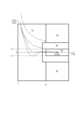
接触力センサ43の出力は、図5に例示される二次元のグラフで表され得る。図5のグラフにおいて、横軸は、第1接触力センサ43Aの出力(A)と第2接触力センサ43Bの出力(B)との和(A+B)を表す。縦軸は、第1接触力センサ43Aの出力(A)と第2接触力センサ43Bの出力(B)との差(A-B)と和(A+B)との比((A-B)/(A+B))を表す。The output of thecontact force sensor 43 can be represented by a two-dimensional graph as shown in Fig. 5. In the graph of Fig. 5, the horizontal axis represents the sum (A+B) of the output (A) of the firstcontact force sensor 43A and the output (B) of the secondcontact force sensor 43B. The vertical axis represents the ratio ((A-B)/(A+B)) of the difference (A-B) between the output (A) of the firstcontact force sensor 43A and the output (B) of the secondcontact force sensor 43B to the sum (A+B).

指45A及び45Bによる把持対象物8の把持状態は、図5のグラフ上の点として表される。指45A及び45Bが把持対象物8の把持を開始した場合、A+Bの値が大きくなる方向に点が移動する。把持対象物8が指45A及び45Bの中央に近づくほど|A-B|の値が小さくなる。通常の把持状態において、A+Bの値が大きくなるほど、|A-B|の値が0に近づく。把持状態を表す点は、図5において破線で例示されているように、A+Bの値が小さい領域(左側)から大きい領域(右側)へ向けて横軸(A-B=0の線)に近づくように移動する。通常の把持状態は、指45A及び45Bが両方とも把持対象物8に接触している状態に対応する。The gripping state of the grasped object 8 by thefingers 45A and 45B is represented as a point on the graph in FIG. 5. When thefingers 45A and 45B start to grip the grasped object 8, the point moves in the direction in which the value of A+B increases. The closer the grasped object 8 is to the center of thefingers 45A and 45B, the smaller the value of |A-B| becomes. In a normal gripping state, the larger the value of A+B becomes, the closer the value of |A-B| approaches 0. As illustrated by the dashed line in FIG. 5, the point representing the gripping state moves closer to the horizontal axis (the line A-B=0) from the region where the value of A+B is small (left side) to the region where it is large (right side). The normal gripping state corresponds to a state in which bothfingers 45A and 45B are in contact with the grasped object 8.

図5のグラフは、複数の領域に分けられる。A+B≦Laの領域は、R1で表される。把持状態を表す点がR1で表される領域に位置する場合、接触力センサ43に対する把持対象物8の中心軸ずれ、接触把持に伴う接触力センサ43の出力値低減、又は、接触力センサ43の一方だけと把持対象物8との接触が発生している。A+B>La、かつ、|A-B|/(A+B)<Lv(つまり、(A-B)/(A+B)<+Lvかつ(A-B)/(A+B)>-Lv)の領域は、R2で表される。把持状態を表す点がR2で表される領域に位置する場合、指45A及び45Bが適切な状態で把持対象物8に接触している。この場合、ハンド制御部20は、把持力に基づいて把持を制御できる。状態推定部21は、把持状態を表す点がR2で表される領域に位置する場合、指45A及び45Bの接触領域が適切であると判定する。R2で表される領域は、以下の式(1)で表される領域であってもよい。

Figure 0007678135000001
A+Bで除算している意味は、A+Bが大きくなるほど、センサ中心ずれに伴うセンサ出力値が減少するため、規格化(ノーマライズ)することで安定に判定ができる。 The graph in FIG. 5 is divided into a plurality of regions. The region of A+B≦La is represented by R1. When the point representing the gripping state is located in the region represented by R1, the central axis of the gripping object 8 relative to thecontact force sensor 43 is misaligned, the output value of thecontact force sensor 43 is reduced due to contact gripping, or only one of thecontact force sensors 43 is in contact with the gripping object 8. The region of A+B>La and |A-B|/(A+B)<Lv (that is, (A-B)/(A+B)<+Lv and (A-B)/(A+B)>-Lv) is represented by R2. When the point representing the gripping state is located in the region represented by R2, thefingers 45A and 45B are in contact with the gripping object 8 in an appropriate state. In this case, thehand control unit 20 can control the gripping based on the gripping force. When the point representing the gripping state is located in the region represented by R2, thestate estimation unit 21 determines that the contact region of thefingers 45A and 45B is appropriate. The region represented by R2 may be a region represented by the following formula (1).
Figure 0007678135000001
The reason for dividing by A+B is that the larger A+B is, the smaller the sensor output value associated with the sensor center deviation is. Therefore, normalization allows for stable determination.

一方で、A+B>La、かつ、|A-B|/(A+B)≧Lv(つまり、(A-B)/(A+B)≧+Lv又は(A-B)/(A+B)≦-Lv)の領域は、R3で表される。把持状態を表す点がR3に位置する場合、指45A及び45Bの一方だけが把持対象物8に接触している状態のままで指45A及び45Bが閉じる方向に移動している。この場合、ハンド制御部20は、把持力に基づいて把持を制御できない。状態推定部21は、把持状態を表す点がR3で表される領域に位置する場合、指45A及び45Bの接触領域が適切でないと判定する。なお、一般的に、センサ出力(A及びB)は、回転角度θの一次関数として表現することができたり、回転角度θとの関係を線形変換して一次関数として取り扱うことができたりする。このとき、回転角度θを無限大に近づけたときに|A-B|/(A+B)の値は収束していく。そのため、Lvは、例えばこの収束値に基づいて定めてもよい。具体的には、例えばLvは収束値に任意の整数又は小数等を加算した値であればよい。また、Laは、把持対象物の重量又は柔らかさ、あるいはハンド部4の設計等に応じて定まる任意の値であればよい。なお、センサ出力には、ノイズ成分が含まれていることがあるが、この場合は、上記任意の値にノイズ成分(例えば各センサのオフセット値)を加算した値をLaとしてもよい。なお、Lv又はLaは、上述した変換テーブルと同様に記憶部に記憶されていてもよい。On the other hand, the region where A+B>La and |A-B|/(A+B)≧Lv (i.e., (A-B)/(A+B)≧+Lv or (A-B)/(A+B)≦-Lv) is represented by R3. When the point representing the gripping state is located at R3, thefingers 45A and 45B move in the closing direction while only one of them is in contact with the gripping object 8. In this case, thehand control unit 20 cannot control the grip based on the gripping force. When the point representing the gripping state is located in the region represented by R3, thestate estimation unit 21 determines that the contact region of thefingers 45A and 45B is not appropriate. In general, the sensor outputs (A and B) can be expressed as a linear function of the rotation angle θ, or the relationship with the rotation angle θ can be linearly transformed and treated as a linear function. In this case, the value of |A-B|/(A+B) converges when the rotation angle θ approaches infinity. Therefore, Lv may be determined based on this convergence value, for example. Specifically, Lv may be a value obtained by adding an arbitrary integer or decimal to the convergence value. Furthermore, La may be an arbitrary value determined according to the weight or softness of the object to be grasped, or the design of the hand unit 4. Note that the sensor output may contain noise components. In this case, La may be a value obtained by adding the noise components (for example, the offset value of each sensor) to the arbitrary value. Note that Lv or La may be stored in the storage unit in the same manner as the above-mentioned conversion table.

R1とR2との間の領域、又は、R2とR3との間の領域は、R4で表される。R4で表される領域は、過渡状態領域とも称される。過渡状態は、スイッチ29が開状態と閉状態との間で遷移するときの状態に対応する。ハンド制御部20は、過渡状態領域において、例えばH又はLの2値を出力するデジタルセンサのチャタリング除去のように、指定回数連続で同じ判断をした結果を、把持状態を表す点がR2又はR3のどちらの領域に位置するか判定した結果として出力してよい。状態推定部21は、把持状態を表す点がR4で表される領域に位置する場合、指45A及び45Bの接触領域が適切でないと判定してよいし、把持状態を表す点がR2又はR3のどちらの領域に位置するか判定して接触領域の適否を判定してもよい。The region between R1 and R2, or the region between R2 and R3, is represented by R4. The region represented by R4 is also called the transient state region. The transient state corresponds to the state when theswitch 29 transitions between the open state and the closed state. Thehand control unit 20 may output the result of making the same judgment a specified number of times in succession in the transient state region, such as removing chattering from a digital sensor that outputs two values, H or L, as the result of determining whether the point representing the gripping state is located in the region R2 or R3. When the point representing the gripping state is located in the region represented by R4, thestate estimation unit 21 may determine that the contact region of thefingers 45A and 45B is not appropriate, or may determine whether the point representing the gripping state is located in the region R2 or R3 to determine whether the contact region is appropriate.

状態推定部21は、把持状態を表す点がR2で表される領域に位置する場合、把持力に基づいて把持を制御するようにスイッチ29を閉じる信号をスイッチ29に出力してよい。状態推定部21は、把持状態を表す点がR1又はR3で表される領域に位置する場合、把持力に基づかずに把持を制御するようにスイッチ29を開く信号をスイッチ29に出力してよい。このようにすることで、ハンド制御部20は、把持を制御するために把持力を利用するか把持状態に基づいて決定できる。その結果、把持力制御開始時に把持が安定に制御され得る。状態推定部21は、把持状態を表す点がR4で表される領域に位置する場合、スイッチ29の開閉信号を適宜決定して出力してもよい。When the point representing the gripping state is located in the area represented by R2, thestate estimation unit 21 may output a signal to switch 29 to closeswitch 29 so as to control the grip based on the grip force. When the point representing the gripping state is located in the area represented by R1 or R3, thestate estimation unit 21 may output a signal to switch 29 to openswitch 29 so as to control the grip not based on the grip force. In this manner, thehand control unit 20 can determine whether to use the grip force to control the grip based on the grip state. As a result, the grip can be stably controlled when grip force control starts. When the point representing the gripping state is located in the area represented by R4, thestate estimation unit 21 may appropriately determine and output an open/close signal forswitch 29.

把持状態を表す点がR2で表される領域に位置する場合、ハンド部4は、把持対象物8を安定に把持できる。言い換えれば、ハンド部4の把持接触状態は、把持対象物8に対する作業を実行可能な状態である。把持対象物8に対する作業を実行可能な状態は、作業可能状態とも称される。状態推定部21は、接触領域の適否の判定結果に基づいて、ハンド部4の把持接触状態が作業可能状態であるか判定してよい。When the point representing the grasping state is located in the area represented by R2, the hand unit 4 can stably grasp the grasped object 8. In other words, the grasping contact state of the hand unit 4 is a state in which work can be performed on the grasped object 8. A state in which work can be performed on the grasped object 8 is also referred to as a workable state. Thestate estimation unit 21 may determine whether the grasping contact state of the hand unit 4 is a workable state based on the result of determining whether the contact area is appropriate.

図5に例示されるグラフにおいて把持状態を表す点がR2で表される領域に位置する場合、状態推定部21は、把持対象物8に対する指45A及び45Bの接触領域が適切であると判定する。一方で、図5に例示されるグラフにおいて把持状態を表す点がR3で表される領域に位置する場合、状態推定部21は、把持対象物8に対する指45A及び45Bの接触領域が適切でないと判定する。言い換えれば、状態推定部21は、式(1)の中の|A-B|/(A+B)とLvとの大小関係に基づいて接触領域の適否を判定してよい。5, when the point representing the grasping state is located in the region represented by R2, thestate estimation unit 21 determines that the contact region of thefingers 45A and 45B with respect to the grasp object 8 is appropriate. On the other hand, when the point representing the grasping state is located in the region represented by R3 in the graph illustrated in FIG. 5, thestate estimation unit 21 determines that the contact region of thefingers 45A and 45B with respect to the grasp object 8 is inappropriate. In other words, thestate estimation unit 21 may determine the appropriateness of the contact region based on the magnitude relationship between |A-B|/(A+B) in equation (1) and Lv.

図5に例示されるグラフにおいて把持状態を表す点がR1で表される領域に位置する場合、指45A及び45Bが把持対象物8に十分に近づいておらず、把持対象物8に接触したり把持対象物8から離れたりする。つまり、把持対象物8に対する指45A及び45Bの接触状態が不安定である。この場合、状態推定部21は、指45A及び45Bに作用する接触力が適切でないと判定してよい。一方で、図5に例示されるグラフにおいて把持状態を表す点がR1で表される領域の外に位置する場合、指45A及び45Bが把持対象物8に十分に近づき、把持対象物8に接触し、把持対象物8から離れない。つまり、把持対象物8に対する指45A及び45Bの接触状態が安定である。この場合、状態推定部21は、指45A及び45Bに作用する接触力が適切であると判定してよい。言い換えれば、状態推定部21は、式(1)の中の(A+B)とLaとの大小関係に基づいて接触力の適否を判定してよい。When the point representing the gripping state in the graph illustrated in FIG. 5 is located in the region represented by R1, thefingers 45A and 45B are not sufficiently close to the gripping object 8, and they come into contact with the gripping object 8 and move away from the gripping object 8. In other words, the contact state of thefingers 45A and 45B with respect to the gripping object 8 is unstable. In this case, thestate estimation unit 21 may determine that the contact force acting on thefingers 45A and 45B is not appropriate. On the other hand, when the point representing the gripping state in the graph illustrated in FIG. 5 is located outside the region represented by R1, thefingers 45A and 45B are sufficiently close to the gripping object 8, come into contact with the gripping object 8, and do not move away from the gripping object 8. In other words, the contact state of thefingers 45A and 45B with respect to the gripping object 8 is stable. In this case, thestate estimation unit 21 may determine that the contact force acting on thefingers 45A and 45B is appropriate. In other words, thestate estimation unit 21 may determine whether the contact force is appropriate based on the magnitude relationship between (A+B) and La in the formula (1).

図5に例示されるグラフに基づく接触領域又は接触力の適否の判定は、第1接触力センサ43Aの力情報(A)と第2接触力センサ43Bの力情報(B)との関係に基づく判定であるといえる。つまり、ハンド制御部20は、状態推定部21によって、複数の力情報の関係に基づいて、接触領域又は接触力の適否を判定してよい。5 can be said to be a judgment based on the relationship between the force information (A) of the firstcontact force sensor 43A and the force information (B) of the secondcontact force sensor 43B. In other words, thehand control unit 20 may determine the suitability of the contact area or contact force using thestate estimation unit 21 based on the relationship between multiple pieces of force information.

状態推定部21は、把持状態を表す点がR1で表される領域から外に出た後で、把持状態を表す点がR2で表される領域の中に位置するか外に位置するか判定してよい。具体的に、状態推定部21は、複数の力情報の関係に基づいて指45A及び45Bの接触力が適切か判定し、接触力が適切であると判定した後で、複数の力情報の関係に基づいて指45A及び45Bの接触領域が適切か判定してよい。つまり、ハンド制御部20は、状態推定部21によって、複数の力情報の関係に基づいて、指45A及び45Bに作用する接触力の適否を判定してよい。また、ハンド制御部20は、状態推定部21によって、指45A及び45Bに作用する接触力の適否の判定結果に基づいて、指45A及び45Bの接触領域の適否、又は、ハンド部4の把持接触状態が作業可能状態であるかを判定してよい。After the point representing the gripping state goes outside the region represented by R1, thestate estimation unit 21 may determine whether the point representing the gripping state is located inside or outside the region represented by R2. Specifically, thestate estimation unit 21 may determine whether the contact force of thefingers 45A and 45B is appropriate based on the relationship between the multiple pieces of force information, and after determining that the contact force is appropriate, may determine whether the contact area of thefingers 45A and 45B is appropriate based on the relationship between the multiple pieces of force information. In other words, thehand control unit 20 may determine whether the contact force acting on thefingers 45A and 45B is appropriate based on the relationship between the multiple pieces of force information by thestate estimation unit 21. In addition, thehand control unit 20 may determine whether the contact area of thefingers 45A and 45B is appropriate or not, or whether the gripping contact state of the hand unit 4 is in a workable state based on the result of the determination by thestate estimation unit 21 of the appropriateness of the contact force acting on thefingers 45A and 45B.

ハンド制御部20は、ハンド部4の把持接触状態が作業可能状態であると判定した場合、その状態を維持するようにハンド部4を制御してよい。ハンド制御部20は、ハンド部4の把持接触状態が作業可能状態でないと判定した場合、把持対象物8に対するハンド部4の把持の仕方を変更するように、ハンド部4を制御してよい。ハンド制御部20は、把持の仕方として、ハンド部4による把持対象物8の把持位置又は把持姿勢を変更してよい。ハンド制御部20は、把持対象物8に対する指45A及び45Bの把持アプローチを変更してもよい。また、ハンド制御部20は、把持対象物8に対するハンド部4の把持アプローチを変更するように、ロボット制御部10に対してハンド部4の把持接触状態に関する情報を出力してよい。ロボット制御部10は、ハンド部4の把持接触状態に関する情報に基づいて、把持対象物8に対するハンド部4の把持アプローチを変更するように、ロボット2のアーム3等を制御してよい。When thehand control unit 20 determines that the gripping contact state of the hand unit 4 is a workable state, thehand control unit 20 may control the hand unit 4 to maintain that state. When thehand control unit 20 determines that the gripping contact state of the hand unit 4 is not a workable state, thehand control unit 20 may control the hand unit 4 to change the way in which the hand unit 4 grips the gripping object 8. As a gripping method, thehand control unit 20 may change the gripping position or gripping posture of the gripping object 8 by the hand unit 4. Thehand control unit 20 may change the gripping approach of thefingers 45A and 45B to the gripping object 8. In addition, thehand control unit 20 may output information regarding the gripping contact state of the hand unit 4 to therobot control unit 10 so as to change the gripping approach of the hand unit 4 to the gripping object 8. Therobot control unit 10 may control thearm 3 of therobot 2, etc. to change the gripping approach of the hand unit 4 to the gripping object 8 based on the information regarding the gripping contact state of the hand unit 4.

ハンド制御部20は、状態推定部21によって、ハンド部4の把持接触状態が作業可能状態でない場合、複数の力情報に基づいて、把持接触状態が作業可能状態でない原因を推定してよい。把持接触状態が作業可能状態でない原因は、例えば、把持対象物8が指45A及び45Bのそれぞれで把持されている位置、又は、把持対象物8が把持されている姿勢であり得る。When the grip contact state of the hand unit 4 is not a workable state, thehand control unit 20 may estimate the reason why the grip contact state is not a workable state based on multiple pieces of force information using thestate estimation unit 21. The reason why the grip contact state is not a workable state may be, for example, the position at which the grip object 8 is gripped by each of thefingers 45A and 45B, or the posture in which the grip object 8 is gripped.

ハンド制御部20は、把持接触状態が作業可能状態でない判定した場合、さらにその原因を推定してもよい。そして、ハンド制御部20は、その推定結果に基づいて、把持の仕方を変更するように制御してもよい。本実施形態では、状態推定部21が、接触領域が不適と判定した場合、状態推定部21が、さらに接触位置が不適か、接触角度が不適かさらに判定してもよい。そして、接触位置が不適の場合、ハンド制御部20は、ハンド部4による把持対象物8の把持位置を変更するように、ハンド部4を制御してもよい。また、接触角度が不適の場合、ハンド制御部20は、把持対象物8に対する指45A及び45Bの把持アプローチを変更してもよい。If thehand control unit 20 determines that the gripping contact state is not workable, it may further estimate the cause. Then, thehand control unit 20 may control to change the gripping method based on the estimation result. In this embodiment, if thestate estimation unit 21 determines that the contact area is inappropriate, thestate estimation unit 21 may further determine whether the contact position or the contact angle is inappropriate. Then, if the contact position is inappropriate, thehand control unit 20 may control the hand unit 4 to change the gripping position of the gripping object 8 by the hand unit 4. Also, if the contact angle is inappropriate, thehand control unit 20 may change the gripping approach of thefingers 45A and 45B to the gripping object 8.

なお、接触位置の判定は、例えば、力覚センサ44に基づいて判定することができる。例えば、力覚センサ44で検知するX軸、Y軸、Z軸のそれぞれの方向へ働く力をFx(t)、Fy(t)、Fz(t)とし、tを経過時間としたとき、評価値Etraが以下の式(2)によって算出される。そして、この評価値Etraが所定の閾値を超えたときに、接触位置が不適であると判定することができる。なお、t=0は、把持直前の時刻を示している。

Figure 0007678135000002
The contact position can be determined, for example, based on theforce sensor 44. For example, when the forces acting in the X-axis, Y-axis, and Z-axis directions detected by theforce sensor 44 are Fx(t), Fy(t), and Fz(t), respectively, and t is elapsed time, an evaluation value Etra is calculated by the following formula (2). When this evaluation value Etra exceeds a predetermined threshold, it can be determined that the contact position is inappropriate. Note that t=0 indicates the time immediately before grasping.
Figure 0007678135000002

また、接触角度の判定は、例えば、力覚センサ44に基づいて判定することができる。例えば、力覚センサ44で検知するX軸回り、Y軸回り、Z軸回りのそれぞれに働くモーメントをMx(t)、My(t)、Mz(t)とし、tを経過時間としたとき、評価値Mrotが以下の式(3)によって算出される。そして、この評価値Erotが所定の閾値を超えたときに、接触角度が不適であると判定することができる。なお、t=0は、把持直前の時刻を示している。

Figure 0007678135000003
The contact angle can be determined, for example, based on theforce sensor 44. For example, when the moments acting around the X-axis, Y-axis, and Z-axis detected by theforce sensor 44 are Mx(t), My(t), and Mz(t), respectively, and t is elapsed time, the evaluation value Mrot is calculated by the following formula (3). When this evaluation value Erot exceeds a predetermined threshold, it can be determined that the contact angle is inappropriate. Note that t=0 indicates the time immediately before grasping.
Figure 0007678135000003

図6及び図7に、第1接触力センサ43A及び第2接触力センサ43Bそれぞれの出力と、モータ41の回転角度との関係の例がグラフとして示される。グラフの横軸はモータ41の回転角度を表す。グラフの縦軸は、各接触力センサ43の出力を表す。モータ41の回転角度が大きくなるほど指45Aと指45Bとの間隔が狭くなる。その結果、モータ41の回転角度が大きくなるほど接触力センサ43の出力が大きくなる。6 and 7 are graphs showing examples of the relationship between the output of the firstcontact force sensor 43A and the secondcontact force sensor 43B and the rotation angle of themotor 41. The horizontal axis of the graph represents the rotation angle of themotor 41. The vertical axis of the graph represents the output of eachcontact force sensor 43. The greater the rotation angle of themotor 41, the narrower the gap betweenfingers 45A and 45B. As a result, the greater the rotation angle of themotor 41, the greater the output of thecontact force sensor 43.

図6に例示されるグラフは、第1接触力センサ43Aが第2接触力センサ43Bよりも先に把持対象物8に接触した場合の出力を示している。図6に例示されるように接触力センサ43の出力が変化する場合、図5において把持状態を表す点は、一点鎖線の曲線に沿って移動してR2で表される領域に入っていく。この場合、ハンド制御部20は、把持力に基づく把持の制御を開始できる。The graph illustrated in Figure 6 shows the output when the firstcontact force sensor 43A contacts the object to be grasped 8 before the secondcontact force sensor 43B. When the output of thecontact force sensor 43 changes as illustrated in Figure 6, the point representing the grasping state in Figure 5 moves along the dashed curve and enters the area represented by R2. In this case, thehand control unit 20 can start controlling the grasping based on the grasping force.

図7に例示されるグラフは、第1接触力センサ43Aが第2接触力センサ43Bよりも先に把持対象物8に接触し、かつ、第2接触力センサ43Bがその中心からずれた位置で把持対象物8に接触している場合の出力を示している。図7に例示されるように接触力センサ43の出力が変化する場合、図5において把持状態を表す点は、二点鎖線の曲線に沿って移動してR2で表される領域に入らないことがある。この場合、ハンド制御部20は、把持力に基づく把持の制御を開始できない。The graph illustrated in Figure 7 shows the output when the firstcontact force sensor 43A contacts the object to be grasped 8 before the secondcontact force sensor 43B, and the secondcontact force sensor 43B contacts the object to be grasped 8 at a position offset from its center. When the output of thecontact force sensor 43 changes as illustrated in Figure 7, the point representing the grasping state in Figure 5 may move along the two-dot chain curve and not enter the area represented by R2. In this case, thehand control unit 20 cannot start gripping control based on the gripping force.

以上述べてきたように、第1接触力センサ43Aの出力と第2接触力センサ43Bの出力との組み合わせを表す点が2次元平面にプロットされることによって、状態推定部21は、点がプロットされた位置に基づいて把持力に基づいて把持を制御するか把持力に基づかずに把持を制御するか決定できる。As described above, by plotting points representing the combination of the output of the firstcontact force sensor 43A and the output of the secondcontact force sensor 43B on a two-dimensional plane, thestate estimation unit 21 can decide whether to control the grip based on the grip force or to control the grip without based on the grip force based on the position where the point is plotted.

本実施形態に係るロボット制御部10又はハンド制御部20は、以上述べてきたように動作することによって、接触力センサ43の検出結果に基づいて、把持力に基づいて把持を制御するか把持力に基づかずに把持を制御するかを決定できる。その結果、把持の安定性が高められる。By operating as described above, therobot control unit 10 orhand control unit 20 according to this embodiment can determine whether to control the grip based on the grip force or not based on the grip force, based on the detection result of thecontact force sensor 43. As a result, the stability of the grip is improved.

具体的には、把持力が常にフィードバックされる場合と比較して、図4Bに示されるように把持対象物が一方の指だけに接触した場合など、第1接触力センサ及び第2接触力センサの出力が不安定になることによって、不安定な出力がフィードバックされ得る。これに対して、本願によれば、本実施形態に係るロボット制御部10又はハンド制御部20は、複数の接触力センサ43の出力の関係に基づいて、安定した把持状態であることを判定した後に、把持力をフィードバックすることができるため、把持の安定性が高められる。言い換えれば、把持状態が適正であると判定されるまでは把持力をフィードバックしないため、把持力制御開始時の制御安定性が確保され得る。Specifically, compared to the case where the gripping force is always fed back, an unstable output may be fed back due to the outputs of the first and second contact force sensors becoming unstable, such as when the object to be gripped is in contact with only one finger as shown in FIG. 4B. In contrast, according to the present application, therobot control unit 10 orhand control unit 20 according to the present embodiment can feed back the gripping force after determining that the gripping state is stable based on the relationship between the outputs of the multiplecontact force sensors 43, thereby improving the stability of gripping. In other words, the gripping force is not fed back until the gripping state is determined to be appropriate, so that control stability at the start of gripping force control can be ensured.

<フローチャートの例>
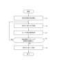
ロボット制御部10又はハンド制御部20は、図8に例示されるフローチャートの手順を含むロボット制御方法を実行してもよい。ロボット制御方法は、ロボット制御部10又はハンド制御部20を構成するプロセッサに実行させるロボット制御プログラムとして実現されてもよい。ロボット制御プログラムは、非一時的なコンピュータ読み取り可能な媒体に格納されてよい。
<Flowchart example>
Therobot control unit 10 or thehand control unit 20 may execute a robot control method including the steps of the flowchart illustrated in Fig. 8. The robot control method may be realized as a robot control program executed by a processor constituting therobot control unit 10 or thehand control unit 20. The robot control program may be stored in a non-transitory computer-readable medium.

ロボット制御部10は、把持対象物8の持ち上げを開始する(ステップS1)。具体的に、ロボット制御部10は、ハンド部4が把持対象物8を把持できるように、アーム3を制御することによって、ハンド部4を把持対象物8まで移動させる。ハンド制御部20は、ハンド部4が把持対象物8を把持するように、把持力に基づかずにハンド部4を制御する(ステップS2)。Therobot control unit 10 starts lifting the object to be grasped 8 (step S1). Specifically, therobot control unit 10 controls thearm 3 to move the hand unit 4 to the object to be grasped 8 so that the hand unit 4 can grasp the object to be grasped 8. Thehand control unit 20 controls the hand unit 4 to grasp the object to be grasped 8 without being based on the gripping force (step S2).

ハンド制御部20は、ハンド部4が把持対象物8の把持を開始している状態で、第1接触力センサ43A及び第2接触力センサ43Bの検出結果を取得する(ステップS3)。ハンド制御部20は、各センサによる接触力の検出結果の図5のグラフに対するプロットがR2で表される領域の範囲内に位置するか判定する(ステップS4)。When the hand unit 4 starts to grasp the grasp target 8, thehand control unit 20 acquires the detection results of the firstcontact force sensor 43A and the secondcontact force sensor 43B (step S3). Thehand control unit 20 determines whether the plot of the detection results of the contact forces by each sensor on the graph of Figure 5 is located within the range of the area represented by R2 (step S4).

ハンド制御部20は、接触力の検出結果のプロットがR2で表される領域の範囲内に位置しない場合(ステップS4:NO)、把持力に基づかずにハンド部4を制御するステップS2の手順に戻る。ハンド制御部20は、接触力の検出結果のプロットがR2で表される領域の範囲内に位置する場合(ステップS4:YES)、把持力に基づいてハンド部4を制御する(ステップS5)。ロボット制御部10及びハンド制御部20は、ステップS5の手順の実行後、図8のフローチャートの手順の実行を終了する。If the plot of the contact force detection results is not located within the range of the area represented by R2 (step S4: NO), thehand control unit 20 returns to the procedure of step S2, where thehand control unit 20 controls the hand unit 4 based on the grip force. If the plot of the contact force detection results is located within the range of the area represented by R2 (step S4: YES), thehand control unit 20 controls the hand unit 4 based on the grip force (step S5). After executing the procedure of step S5, therobot control unit 10 and thehand control unit 20 end execution of the procedure of the flowchart in FIG. 8.

(他の実施形態)
以上述べてきた実施形態において、ハンド部4が2本の指45A及び45Bを有する構成が説明されてきた。指の数は、2本に限られず、3本以上であってよい。ハンド部4が3本以上の指を有する場合、ハンド制御部20は、少なくとも2本の指に連携されたセンサの力情報に基づいて少なくとも2本の指の接触領域の適否を判定してよい。
Other Embodiments
In the above-described embodiment, a configuration has been described in which the hand unit 4 has twofingers 45A and 45B. The number of fingers is not limited to two, and may be three or more. When the hand unit 4 has three or more fingers, thehand control unit 20 may determine the suitability of the contact areas of at least two fingers based on force information of sensors linked to at least two fingers.

<指が3本以上の場合>
ハンド部4は、指45A(第1指)及び指45B(第2指)の他に、第3指を更に備えてよい。第3指は、1又は複数の第3接触センサを備える。ハンド制御部20は、状態推定部21によって、ハンド部4の第3指に連携しているセンサから第3指に作用する力を示す力情報を更に取得し、接触領域の適否を判定してよい。具体的に、状態推定部21は、以下に説明されるように接触領域の適否を判定してよい。
<If there are three or more fingers>
The hand unit 4 may further include a third finger in addition to thefinger 45A (first finger) and thefinger 45B (second finger). The third finger includes one or more third contact sensors. Thehand control unit 20 may further acquire force information indicating a force acting on the third finger from a sensor linked to the third finger of the hand unit 4 by thestate estimation unit 21, and may determine the suitability of the contact area. Specifically, thestate estimation unit 21 may determine the suitability of the contact area as described below.

ハンド部4が2本の指を備える場合、接触領域の適否を判定するために、以下の式(4)で表される評価値Eが算出された。評価値Eの式(4)は、図5に例示されるグラフの縦軸の値に対応する。

Figure 0007678135000004
When the hand unit 4 has two fingers, an evaluation value E represented by the following formula (4) is calculated to determine the suitability of the contact area. The formula (4) of the evaluation value E corresponds to the value on the vertical axis of the graph illustrated in FIG.
Figure 0007678135000004

一方で、ハンド部4の指が3本の場合の評価値Eは、以下の式(5)で表される。第3接触センサの出力はCで表されるとする。

Figure 0007678135000005
On the other hand, the evaluation value E when the hand unit 4 has three fingers is expressed by the following equation (5): The output of the third contact sensor is represented by C.
Figure 0007678135000005

また、指の数が4本以上に増えた場合でも、評価値Eは以下の式(6)で表される。

Figure 0007678135000006
Even if the number of fingers increases to four or more, the evaluation value E is expressed by the following formula (6).
Figure 0007678135000006

状態推定部21は、評価値Eを算出し、評価値Eが所定の閾値(図5の例においてLv)よりも小さくなる場合に、接触領域が適切であると判定してよい。Thestate estimation unit 21 calculates an evaluation value E, and may determine that the contact area is appropriate if the evaluation value E is smaller than a predetermined threshold value (Lv in the example of Figure 5).

<ステータス出力>
状態推定部21は、把持状態を離散状態として定義したステータス出力を生成し、外部コントローラに出力してよい。把持状態が離散状態として定義されることによって、各センサの力情報の組み合わせと把持状態との関係が定義される。
<Status output>
Thestate estimation unit 21 may generate a status output in which the grip state is defined as a discrete state, and output the status output to an external controller. By defining the grip state as a discrete state, a relationship between a combination of force information of each sensor and the grip state is defined.

ハンド部4の複数の力情報それぞれに基づく判定を順次実行する場合、判定に用いる力情報の数が増えるほど、把持状態を推定するために費やされる時間又は演算負荷が増大し得る。複数の力情報の組み合わせと把持状態との関係があらかじめ定義されることによって、状態推定部21は、把持状態を簡便に推定できる。また、ハンド部4は、把持動作を実行するための各制御事項を、離散的に管理または記録することによって、既に条件を満たす制御事項については演算処理を省き、ハンド制御部20の制御負荷を低減することができる。When judgments based on multiple pieces of force information from the hand unit 4 are performed sequentially, the more force information used in the judgment, the greater the time or computational load required to estimate the gripping state. By predefining the relationship between the combination of multiple pieces of force information and the gripping state, thestate estimation unit 21 can easily estimate the gripping state. Furthermore, by discretely managing or recording each control item for executing the gripping operation, the hand unit 4 can omit computational processing for control items that already satisfy the conditions, thereby reducing the control load on thehand control unit 20.

状態推定部21は、把持動作を実行するための各制御事項として、例えば、以下の表1に示されるように、接触力センサ43から入力される値と、エンコーダ42から入力される把持位置とに基づき推定される、把持判定出力、把持力出力、及び、ステータス出力の組み合わせを出力してよい。Thestate estimation unit 21 may output, as each control item for executing a gripping operation, a combination of a gripping judgment output, a gripping force output, and a status output estimated based on the value input from thecontact force sensor 43 and the gripping position input from theencoder 42, for example, as shown in Table 1 below.

Figure 0007678135000007

把持判定出力は、ハンド部4の制御に把持力をフィードバックするか決定するためにハンド部4による把持対象物8に対する接触が適正であるか判定した結果に対応する。把持力出力は、ハンド部4の制御にフィードバックする把持力に対応する。The gripping judgment output corresponds to the result of judging whether the contact of the hand unit 4 with the gripping object 8 is appropriate in order to decide whether to feed back the gripping force to the control of the hand unit 4. The gripping force output corresponds to the gripping force to be fed back to the control of the hand unit 4.

ステータス出力は、ハンド部4の把持状態として、ハンド部4による把持対象物8に対する接触が適正であるか又は把持位置が適切であるか判定した結果に対応する。ステータス出力は、把持対象物8に接触する指45A及び45Bの接触領域の適否の判定結果に対応するともいえる。The status output corresponds to the result of judging whether the contact of the hand unit 4 with the object to be grasped 8 is appropriate or whether the gripping position is appropriate, as the gripping state of the hand unit 4. The status output can also be said to correspond to the result of judging whether the contact area of thefingers 45A and 45B that contact the object to be grasped 8 is appropriate.

表1の2行目は、センサ入力が条件を満たし、かつ、把持位置が所定把持位置内である場合に対応する。センサ入力が条件を満たす場合は、第1接触力センサ43Aの出力A及び第2接触力センサ43Bの出力Bが上述した式(1)を満たす場合に対応する。この場合、状態推定部21は、把持判定出力として、ハンド部4が把持対象物8を把持するための接触が適正であると判定した結果を出力する。また、状態推定部21は、ハンド部4の制御にフィードバックする把持力として、第1接触力センサ43Aの出力Aと第2接触力センサ43Bの出力Bとの平均値を出力する。状態推定部21は、把持力をフィードバックするようにスイッチ29を閉状態にする信号を出力してもよい。また、状態推定部21は、ステータス出力として、ハンド部4による把持対象物8に対する接触が適正であると判定した結果を出力する。The second row of Table 1 corresponds to the case where the sensor input satisfies the condition and the grip position is within the predetermined grip position. The case where the sensor input satisfies the condition corresponds to the case where the output A of the firstcontact force sensor 43A and the output B of the secondcontact force sensor 43B satisfy the above-mentioned formula (1). In this case, thestate estimation unit 21 outputs, as the grip determination output, the result that the contact of the hand unit 4 to grip the grip object 8 is appropriate. In addition, thestate estimation unit 21 outputs the average value of the output A of the firstcontact force sensor 43A and the output B of the secondcontact force sensor 43B as the grip force to be fed back to the control of the hand unit 4. Thestate estimation unit 21 may output a signal to close theswitch 29 so as to feed back the grip force. In addition, thestate estimation unit 21 outputs, as the status output, the result that the contact of the hand unit 4 with the grip object 8 is appropriate.

表1の3行目は、センサ入力が条件を満たさず、かつ、把持位置が所定把持位置内である場合に対応する。センサ入力が条件を満たない場合は、第1接触力センサ43Aの出力A及び第2接触力センサ43Bの出力Bが上述した式(1)を満たさない場合に対応する。この場合、状態推定部21は、把持判定出力として、ハンド部4が把持対象物8を把持するための接触が適正でないと判定した結果を出力する。また、状態推定部21は、ハンド部4の制御に把持力をフィードバックしないように、把持力としてゼロを出力する。状態推定部21は、把持力をフィードバックしないようにスイッチ29を開状態にする信号を出力してもよい。また、状態推定部21は、ステータス出力として、ハンド部4による把持対象物8に対する接触が適正でないと判定した結果を出力する。The third row of Table 1 corresponds to the case where the sensor input does not satisfy the condition and the gripping position is within the specified gripping position. The case where the sensor input does not satisfy the condition corresponds to the case where the output A of the firstcontact force sensor 43A and the output B of the secondcontact force sensor 43B do not satisfy the above-mentioned formula (1). In this case, thestate estimation unit 21 outputs, as the gripping judgment output, the result that the contact of the hand unit 4 to grip the gripping object 8 is not appropriate. In addition, thestate estimation unit 21 outputs zero as the gripping force so as not to feed back the gripping force to the control of the hand unit 4. Thestate estimation unit 21 may output a signal to open theswitch 29 so as not to feed back the gripping force. In addition, thestate estimation unit 21 outputs, as the status output, the result that the contact of the hand unit 4 with the gripping object 8 is not appropriate.

表1の4行目は、センサ入力に基づいて判定せず、かつ、把持位置が所定把持位置外である場合に対応する。この場合、状態推定部21は、把持判定出力として、ハンド部4が把持対象物8を把持するための接触が適正か判定しない。また、状態推定部21は、ハンド部4の制御に把持力をフィードバックしないように、把持力としてゼロを出力する。状態推定部21は、把持力をフィードバックしないようにスイッチ29を開状態にする信号を出力してもよい。また、状態推定部21は、ステータス出力として、ハンド部4が把持対象物8を把持する位置が適切でないと判定した結果を出力する。The fourth row of Table 1 corresponds to a case where no judgment is made based on the sensor input and the gripping position is outside the specified gripping position. In this case, thestate estimation unit 21 does not judge whether the contact for the hand unit 4 to grip the gripping object 8 is appropriate as the grip judgment output. Furthermore, thestate estimation unit 21 outputs zero as the gripping force so as not to feed back the gripping force to the control of the hand unit 4. Thestate estimation unit 21 may output a signal to open theswitch 29 so as not to feed back the gripping force. Furthermore, thestate estimation unit 21 outputs the result of judging that the position at which the hand unit 4 grips the gripping object 8 is not appropriate as the status output.

状態推定部21は、表1に例示される関係をあらかじめ作成することによって、接触力の検出結果と把持位置との組み合わせに基づいて、把持接触状態を簡便に推定できる。By creating in advance the relationship illustrated in Table 1, thestate estimation unit 21 can easily estimate the gripping contact state based on a combination of the contact force detection results and the gripping position.

以上、ロボット制御システム100の実施形態を説明してきたが、本開示の実施形態としては、システム又は装置を実施するための方法又はプログラムの他、プログラムが記録された記憶媒体(一例として、光ディスク、光磁気ディスク、CD-ROM、CD-R、CD-RW、磁気テープ、ハードディスク、又はメモリカード等)としての実施態様をとることも可能である。プログラムは、非一時的なコンピュータ読み取り可能な媒体に格納されてよい。Although an embodiment of the robot control system 100 has been described above, the embodiment of the present disclosure can also be implemented as a method or program for implementing the system or device, or as a storage medium on which a program is recorded (for example, an optical disk, a magneto-optical disk, a CD-ROM, a CD-R, a CD-RW, a magnetic tape, a hard disk, or a memory card). The program may be stored in a non-transitory computer-readable medium.

また、プログラムの実装形態としては、コンパイラによってコンパイルされるオブジェクトコード、インタプリタにより実行されるプログラムコード等のアプリケーションプログラムに限定されることはなく、オペレーティングシステムに組み込まれるプログラムモジュール等の形態であってもよい。さらに、プログラムは、制御基板上のCPUにおいてのみ全ての処理が実施されるように構成されてもされなくてもよい。プログラムは、必要に応じて基板に付加された拡張ボード又は拡張ユニットに実装された別の処理ユニットに
よってその一部又は全部が実施されるように構成されてもよい。
The form of implementation of the program is not limited to application programs such as object code compiled by a compiler or program code executed by an interpreter, but may be a program module incorporated into an operating system, etc. Furthermore, the program may or may not be configured so that all processing is performed only by the CPU on the control board. The program may be configured so that a part or all of it is executed by another processing unit mounted on an expansion board or expansion unit added to the board as necessary.

本開示に係る実施形態について、諸図面及び実施例に基づき説明してきたが、当業者であれば本開示に基づき種々の変形又は改変を行うことが可能であることに注意されたい。従って、これらの変形又は改変は本開示の範囲に含まれることに留意されたい。例えば、各構成部等に含まれる機能等は論理的に矛盾しないように再配置可能であり、複数の構成部等を1つに組み合わせたり、或いは分割したりすることが可能である。Although the embodiments of the present disclosure have been described based on the drawings and examples, it should be noted that a person skilled in the art would be able to make various modifications or alterations based on the present disclosure. Therefore, it should be noted that these modifications or alterations are included in the scope of the present disclosure. For example, the functions, etc. included in each component, etc. can be rearranged so as not to cause logical inconsistencies, and multiple components, etc. can be combined into one or divided.

本開示において、X軸、Y軸、及びZ軸は、説明の便宜上設けられたものであり、互いに入れ替えられてよい。本開示に係る構成は、X軸、Y軸、及びZ軸によって構成される直交座標系を用いて説明されてきた。本開示に係る各構成の位置関係は、直交関係にあると限定されるものではない。In this disclosure, the X-axis, Y-axis, and Z-axis are provided for convenience of explanation and may be interchanged. The configuration according to this disclosure has been described using an orthogonal coordinate system formed by the X-axis, Y-axis, and Z-axis. The positional relationship of each configuration according to this disclosure is not limited to being orthogonal.

1 ロボット制御システム
2 ロボット(3:アーム)
4 ハンド部(41:モータ、42:エンコーダ、43(43A、43B):接触力センサ、44:力覚センサ、45A、45B:指)
8 把持対象物
10 ロボット制御装置
20 ハンド制御装置(21:状態推定部、22:変換部、24:位置制御部、25~27:加算器、29:スイッチ)
28 ドライバ
1Robot control system 2 Robot (3: Arm)
4 Hand unit (41: motor, 42: encoder, 43 (43A, 43B): contact force sensor, 44: force sensor, 45A, 45B: fingers)
8 Graspobject 10Robot control device 20 Hand control device (21: state estimation unit, 22: conversion unit, 24: position control unit, 25 to 27: adders, 29: switch)
28 Driver

Claims (12)

Translated fromJapanese
把持対象物を把持可能であり、第1指及び第2指を有するハンド部を制御するハンド制御部を備え、
前記ハンド制御部は、
前記第1指及び前記第2指に連携している少なくとも1つのセンサから前記把持対象物から前記第1指及び前記第2指のそれぞれに作用する力を示す複数の力情報を取得し、
前記複数の力情報の関係が前記複数の力情報の和が所定の値より大きく、かつ、前記複数の力情報の差の絶対値が所定の値より小さいという領域に位置するか否かに基づいて前記把持対象物に接触する前記第1指及び前記第2指の接触領域の適否を判定する、
制御装置。
A hand control unit is provided to control a hand unit capable of gripping a gripping object and having a first finger and a second finger;
The hand control unit includes:
acquiring a plurality of pieces of force information indicating forces acting on the first finger and the second finger from the object to be grasped from at least one sensor associated with the first finger and the second finger;
determiningwhether or not a contact area of the first finger and the second finger that contacts the object to be grasped is appropriate based on whether or not a relationship between the plurality of pieces of force information is located in a region where a sum of the plurality of pieces of force information is greater than a predetermined value and an absolute value of a difference between the plurality of pieces of force information is smaller than a predetermined value;
Control device.
前記ハンド制御部は、前記接触領域の適否に基づいて、前記把持対象物に対する前記ハンド部の把持接触状態が前記把持対象物に対する作業を実行可能な作業可能状態であるか判定する、請求項1に記載の制御装置。The control device according to claim 1, wherein the hand control unit determines whether the gripping contact state of the hand unit with respect to the gripping object is in a workable state in which work can be performed on the gripping object based on the suitability of the contact area. 前記ハンド制御部は、前記第1指及び前記第2指に配された複数の接触力センサの前記複数の力情報に基づき、前記接触領域の適否を判定する、請求項1に記載の制御装置。The control device according to claim 1, wherein the hand control unit determines whether the contact area is appropriate based on the force information from the contact force sensors arranged on the first finger and the second finger. 前記ハンド制御部は、前記ハンド部に配された、少なくとも1つの力覚センサの前記複数の力情報に基づき、前記接触領域の適否を判定する、請求項1に記載の制御装置。The control device according to claim 1, wherein the hand control unit determines whether the contact area is appropriate based on the multiple pieces of force information from at least one force sensor arranged in the hand unit. 前記ハンド制御部は、前記第1指及び前記第2指に接触する把持対象物の接触位置及び接触角度に基づいて、前記接触領域の適否を判定する、請求項1に記載の制御装置。The control device according to claim 1, wherein the hand control unit determines whether the contact area is appropriate based on the contact position and contact angle of the object to be grasped that contacts the first finger and the second finger. 前記ハンド制御部は、
前記複数の力情報の関係に基づいて、前記把持対象物に接触する前記第1指及び前記第2指の接触力の適否を判定するとともに、
前記接触力の適否に基づいて、前記把持対象物に対する前記ハンド部の把持接触状態が前記把持対象物に対する作業を実行可能な作業可能状態であるか判定する、請求項1に記載の制御装置。
The hand control unit includes:
determining whether or not the contact forces of the first finger and the second finger contacting the object to be grasped are appropriate based on a relationship between the plurality of pieces of force information; and
The control device according to claim 1 , further comprising: a controller configured to determine whether a gripping contact state of the hand unit with respect to the object to be grasped is a workable state in which work can be performed on the object to be grasped, based on whether the contact force is appropriate.
前記ハンド制御部は、前記把持接触状態が作業可能状態であると判定した場合、前記把持接触状態を前記作業可能状態のまま維持するように前記ハンド部を制御する、請求項6に記載の制御装置。The control device according to claim 6, wherein the hand control unit controls the hand unit so as to maintain the grip contact state in the workable state when the grip contact state is determined to be the workable state. 前記ハンド制御部は、前記把持接触状態が前記作業可能状態でない場合、前記把持対象物に対する前記ハンド部の把持の仕方を変更するように、前記ハンド部を制御する、請求項6に記載の制御装置。The control device according to claim 6, wherein the hand control unit controls the hand unit to change the way the hand unit grips the object to be gripped when the grip contact state is not the workable state. 前記ハンド制御部は、
前記把持接触状態が前記作業可能状態でない場合、前記複数の力情報に基づいて、前記把持接触状態が前記作業可能状態でない原因が、前記把持対象物が前記各指で把持されている位置であるか、前記把持対象物が把持されている姿勢であるかを推定する、請求項6に記載の制御装置。
The hand control unit includes:
7. The control device according to claim 6, wherein, when the gripping contact state is not the workable state, it is estimated based on the plurality of force information whether a cause of the gripping contact state not being the workable state is a position at which the gripping object is gripped by the fingers or a posture at which the gripping object is gripped.
前記ハンド制御部は、前記ハンド部が有する第3指に連携しているセンサから前記第3指に作用する力を示す力情報をさらに取得し、前記接触領域の適否を判定する、請求項1に記載の制御装置。The control device according to claim 1, wherein the hand control unit further acquires force information indicating a force acting on the third finger from a sensor connected to the third finger of the hand unit, and determines whether the contact area is appropriate. 請求項1から10までのいずれか一項に記載の制御装置と、ハンド部を有するロボットとを備える、ロボット制御システム。A robot control system comprising a control device according to any one of claims 1 to 10 and a robot having a hand unit. 把持対象物を把持可能であり、第1指及び第2指を有するハンド部を制御する制御装置が、前記第1指及び前記第2指に連携している少なくとも1つのセンサから前記把持対象物から前記第1指及び前記第2指のそれぞれに作用する力を示す複数の力情報を取得することと、
前記制御装置が、前記複数の力情報の関係が前記複数の力情報の和が所定の値より大きく、かつ、前記複数の力情報の差の絶対値が所定の値より小さいという領域に位置するか否かに基づいて前記把持対象物に接触する前記第1指及び前記第2指の接触領域の適否を判定することと
を含むロボット制御方法。
a control device that controls a hand unit capable of grasping a grasp object and having a first finger and a second finger, acquires a plurality of pieces of force information indicating forces acting on each of the first finger and the second finger from the grasp object from at least one sensor associated with the first finger and the second finger;
and determiningwhether or not the contact areas of the first finger and the second finger that come into contact with the object to be grasped are appropriate based on whether or not the relationship between the plurality of pieces of force information is located in a region where the sum of the plurality of pieces of force information is greater than a predetermined value and the absolute value of the difference between the plurality of pieces of force information is smaller than a predetermined value.
JP2023563786A2021-11-292022-11-29 CONTROL DEVICE, ROBOT CONTROL SYSTEM, AND ROBOT CONTROL METHODActiveJP7678135B2 (en)

Applications Claiming Priority (3)

Application NumberPriority DateFiling DateTitle
JP20211936512021-11-29
PCT/JP2022/044048WO2023095928A1 (en)2021-11-292022-11-29Control device, robot control system, and robot control method

Publications (3)

Publication NumberPublication Date
JPWO2023095928A1 JPWO2023095928A1 (en)2023-06-01
JPWO2023095928A5 JPWO2023095928A5 (en)2024-08-09
JP7678135B2true JP7678135B2 (en)2025-05-15

Family

ID=86539769

Family Applications (1)

Application NumberTitlePriority DateFiling Date
JP2023563786AActiveJP7678135B2 (en)2021-11-292022-11-29 CONTROL DEVICE, ROBOT CONTROL SYSTEM, AND ROBOT CONTROL METHOD

Country Status (5)

CountryLink
US (1)US20250018564A1 (en)
EP (1)EP4442411A1 (en)
JP (1)JP7678135B2 (en)
CN (1)CN118317855A (en)
WO (1)WO2023095928A1 (en)

Citations (8)

* Cited by examiner, † Cited by third party
Publication numberPriority datePublication dateAssigneeTitle
JP2009066714A (en)2007-09-132009-04-02Sony CorpControl device and method, program, and recording medium
JP2011224695A (en)2010-04-192011-11-10Toyota Motor CorpSystem for controlling holding of robot, and robot
JP2012011531A (en)2010-07-052012-01-19Yaskawa Electric CorpRobot apparatus and gripping method for use in robot apparatus
US20120239195A1 (en)2011-03-172012-09-20Harris CorporationRobotic grasping device with multi-force sensing at base of fingers
JP2014144526A (en)2013-01-302014-08-14Seiko Epson CorpRobot control method, robot control device, robot, and robot system
JP2015085455A (en)2013-10-312015-05-07セイコーエプソン株式会社 Robot, robot system, robot controller
WO2018212189A1 (en)2017-05-152018-11-22Thk株式会社Gripping system
JP2020049581A (en)2018-09-262020-04-02オムロン株式会社 End effector and end effector device

Family Cites Families (4)

* Cited by examiner, † Cited by third party
Publication numberPriority datePublication dateAssigneeTitle
US4715773A (en)*1985-06-041987-12-29Clemson UniversityMethod and apparatus for repositioning a mislocated object with a robot hand
JP3742876B2 (en)2002-02-252006-02-08国立大学法人岐阜大学 Robot hand, gripping control method of robot hand, robot and robot control method
US9605952B2 (en)*2012-03-082017-03-28Quality Manufacturing Inc.Touch sensitive robotic gripper
JP6634430B2 (en)*2017-11-272020-01-22スキューズ株式会社 Robot hand and robot hand control method

Patent Citations (8)

* Cited by examiner, † Cited by third party
Publication numberPriority datePublication dateAssigneeTitle
JP2009066714A (en)2007-09-132009-04-02Sony CorpControl device and method, program, and recording medium
JP2011224695A (en)2010-04-192011-11-10Toyota Motor CorpSystem for controlling holding of robot, and robot
JP2012011531A (en)2010-07-052012-01-19Yaskawa Electric CorpRobot apparatus and gripping method for use in robot apparatus
US20120239195A1 (en)2011-03-172012-09-20Harris CorporationRobotic grasping device with multi-force sensing at base of fingers
JP2014144526A (en)2013-01-302014-08-14Seiko Epson CorpRobot control method, robot control device, robot, and robot system
JP2015085455A (en)2013-10-312015-05-07セイコーエプソン株式会社 Robot, robot system, robot controller
WO2018212189A1 (en)2017-05-152018-11-22Thk株式会社Gripping system
JP2020049581A (en)2018-09-262020-04-02オムロン株式会社 End effector and end effector device

Also Published As

Publication numberPublication date
US20250018564A1 (en)2025-01-16
WO2023095928A1 (en)2023-06-01
JPWO2023095928A1 (en)2023-06-01
EP4442411A1 (en)2024-10-09
CN118317855A (en)2024-07-09

Similar Documents

PublicationPublication DateTitle
US11090814B2 (en)Robot control method
JP5835254B2 (en) Robot system and control method of robot system
US9682478B2 (en)Safety monitoring device for robot gripping and carrying workpiece
JP7206638B2 (en) ROBOT, CONTROL DEVICE, AND ROBOT CONTROL METHOD
US11602863B2 (en)Device, method and program for estimating weight and position of gravity center of load by using robot
JP2002018754A (en) Robot apparatus and control method therefor
WO2020194393A1 (en)Robot hand, robot hand control method, and program
JP7601137B2 (en) Control method, control system and program
CN113568313A (en) Method and system for variable admittance assisted assembly of large components based on operation intention recognition
CN111721391A (en)Device, method, and program for estimating weight and center of gravity position of load by robot
CN115768606A (en) Control device and control method
JP7678135B2 (en) CONTROL DEVICE, ROBOT CONTROL SYSTEM, AND ROBOT CONTROL METHOD
Yousefizadeh et al.Unknown external force estimation and collision detection for a cooperative robot
CN110794969B (en) Natural human-computer interaction method for non-contact force feedback
JPH10100089A (en) Grasping control method and object gripping method for articulated multi-fingered hand
US20110295419A1 (en)Applying workspace limitations in a velocity-controlled robotic mechanism
WO2023095927A1 (en)Control device, robot control system, and robot control method
JP2005034991A (en) Robot movement range limiting device and mobile robot
JPH05123987A (en)Gripping device
JP7537192B2 (en) Robot system and picking method
Ishihara et al.Force sensorless power assist control using operation force observer for nursing lift
JP2024142563A (en) ROBOT CONTROL DEVICE, ROBOT CONTROL METHOD, AND ROBOT SYSTEM
WO2025005185A1 (en)Processing device, robot system, end effector, and program
JP2019141976A (en)Control device, control method of robot, and robot system
JPH0211395B2 (en)

Legal Events

DateCodeTitleDescription
A521Request for written amendment filed

Free format text:JAPANESE INTERMEDIATE CODE: A523

Effective date:20240527

A621Written request for application examination

Free format text:JAPANESE INTERMEDIATE CODE: A621

Effective date:20240527

A131Notification of reasons for refusal

Free format text:JAPANESE INTERMEDIATE CODE: A131

Effective date:20241105

A601Written request for extension of time

Free format text:JAPANESE INTERMEDIATE CODE: A601

Effective date:20241223

A521Request for written amendment filed

Free format text:JAPANESE INTERMEDIATE CODE: A523

Effective date:20250228

TRDDDecision of grant or rejection written
A01Written decision to grant a patent or to grant a registration (utility model)

Free format text:JAPANESE INTERMEDIATE CODE: A01

Effective date:20250401

A61First payment of annual fees (during grant procedure)

Free format text:JAPANESE INTERMEDIATE CODE: A61

Effective date:20250501

R150Certificate of patent or registration of utility model

Ref document number:7678135

Country of ref document:JP

Free format text:JAPANESE INTERMEDIATE CODE: R150


[8]ページ先頭

©2009-2025 Movatter.jp