JP7677973B2 - Robotic endoscope device and robotic endoscope system - Google Patents
Robotic endoscope device and robotic endoscope systemDownload PDFInfo
- Publication number
- JP7677973B2 JP7677973B2JP2022537190AJP2022537190AJP7677973B2JP 7677973 B2JP7677973 B2JP 7677973B2JP 2022537190 AJP2022537190 AJP 2022537190AJP 2022537190 AJP2022537190 AJP 2022537190AJP 7677973 B2JP7677973 B2JP 7677973B2
- Authority
- JP
- Japan
- Prior art keywords
- robotic
- catheter
- user
- handle
- robotic endoscopic
- Prior art date
- Legal status (The legal status is an assumption and is not a legal conclusion. Google has not performed a legal analysis and makes no representation as to the accuracy of the status listed.)
- Active
Links
Images


Classifications
- A—HUMAN NECESSITIES
- A61—MEDICAL OR VETERINARY SCIENCE; HYGIENE
- A61B—DIAGNOSIS; SURGERY; IDENTIFICATION
- A61B34/00—Computer-aided surgery; Manipulators or robots specially adapted for use in surgery
- A61B34/20—Surgical navigation systems; Devices for tracking or guiding surgical instruments, e.g. for frameless stereotaxis
- A—HUMAN NECESSITIES
- A61—MEDICAL OR VETERINARY SCIENCE; HYGIENE
- A61B—DIAGNOSIS; SURGERY; IDENTIFICATION
- A61B34/00—Computer-aided surgery; Manipulators or robots specially adapted for use in surgery
- A61B34/30—Surgical robots
- A—HUMAN NECESSITIES
- A61—MEDICAL OR VETERINARY SCIENCE; HYGIENE
- A61B—DIAGNOSIS; SURGERY; IDENTIFICATION
- A61B1/00—Instruments for performing medical examinations of the interior of cavities or tubes of the body by visual or photographical inspection, e.g. endoscopes; Illuminating arrangements therefor
- A61B1/00064—Constructional details of the endoscope body
- A61B1/00103—Constructional details of the endoscope body designed for single use
- A—HUMAN NECESSITIES
- A61—MEDICAL OR VETERINARY SCIENCE; HYGIENE
- A61B—DIAGNOSIS; SURGERY; IDENTIFICATION
- A61B1/00—Instruments for performing medical examinations of the interior of cavities or tubes of the body by visual or photographical inspection, e.g. endoscopes; Illuminating arrangements therefor
- A61B1/00064—Constructional details of the endoscope body
- A61B1/00105—Constructional details of the endoscope body characterised by modular construction
- A—HUMAN NECESSITIES
- A61—MEDICAL OR VETERINARY SCIENCE; HYGIENE
- A61B—DIAGNOSIS; SURGERY; IDENTIFICATION
- A61B1/00—Instruments for performing medical examinations of the interior of cavities or tubes of the body by visual or photographical inspection, e.g. endoscopes; Illuminating arrangements therefor
- A61B1/00147—Holding or positioning arrangements
- A61B1/00149—Holding or positioning arrangements using articulated arms
- A—HUMAN NECESSITIES
- A61—MEDICAL OR VETERINARY SCIENCE; HYGIENE
- A61B—DIAGNOSIS; SURGERY; IDENTIFICATION
- A61B1/00—Instruments for performing medical examinations of the interior of cavities or tubes of the body by visual or photographical inspection, e.g. endoscopes; Illuminating arrangements therefor
- A61B1/00147—Holding or positioning arrangements
- A61B1/0016—Holding or positioning arrangements using motor drive units
- A—HUMAN NECESSITIES
- A61—MEDICAL OR VETERINARY SCIENCE; HYGIENE
- A61B—DIAGNOSIS; SURGERY; IDENTIFICATION
- A61B1/00—Instruments for performing medical examinations of the interior of cavities or tubes of the body by visual or photographical inspection, e.g. endoscopes; Illuminating arrangements therefor
- A61B1/005—Flexible endoscopes
- A61B1/0051—Flexible endoscopes with controlled bending of insertion part
- A61B1/0057—Constructional details of force transmission elements, e.g. control wires
- A—HUMAN NECESSITIES
- A61—MEDICAL OR VETERINARY SCIENCE; HYGIENE
- A61B—DIAGNOSIS; SURGERY; IDENTIFICATION
- A61B1/00—Instruments for performing medical examinations of the interior of cavities or tubes of the body by visual or photographical inspection, e.g. endoscopes; Illuminating arrangements therefor
- A61B1/005—Flexible endoscopes
- A61B1/01—Guiding arrangements therefore
- A—HUMAN NECESSITIES
- A61—MEDICAL OR VETERINARY SCIENCE; HYGIENE
- A61B—DIAGNOSIS; SURGERY; IDENTIFICATION
- A61B1/00—Instruments for performing medical examinations of the interior of cavities or tubes of the body by visual or photographical inspection, e.g. endoscopes; Illuminating arrangements therefor
- A61B1/267—Instruments for performing medical examinations of the interior of cavities or tubes of the body by visual or photographical inspection, e.g. endoscopes; Illuminating arrangements therefor for the respiratory tract, e.g. laryngoscopes, bronchoscopes
- A61B1/2676—Bronchoscopes
- A—HUMAN NECESSITIES
- A61—MEDICAL OR VETERINARY SCIENCE; HYGIENE
- A61B—DIAGNOSIS; SURGERY; IDENTIFICATION
- A61B34/00—Computer-aided surgery; Manipulators or robots specially adapted for use in surgery
- A61B34/10—Computer-aided planning, simulation or modelling of surgical operations
- A—HUMAN NECESSITIES
- A61—MEDICAL OR VETERINARY SCIENCE; HYGIENE
- A61B—DIAGNOSIS; SURGERY; IDENTIFICATION
- A61B34/00—Computer-aided surgery; Manipulators or robots specially adapted for use in surgery
- A61B34/25—User interfaces for surgical systems
- A—HUMAN NECESSITIES
- A61—MEDICAL OR VETERINARY SCIENCE; HYGIENE
- A61B—DIAGNOSIS; SURGERY; IDENTIFICATION
- A61B34/00—Computer-aided surgery; Manipulators or robots specially adapted for use in surgery
- A61B34/30—Surgical robots
- A61B34/32—Surgical robots operating autonomously
- A—HUMAN NECESSITIES
- A61—MEDICAL OR VETERINARY SCIENCE; HYGIENE
- A61B—DIAGNOSIS; SURGERY; IDENTIFICATION
- A61B34/00—Computer-aided surgery; Manipulators or robots specially adapted for use in surgery
- A61B34/30—Surgical robots
- A61B34/37—Leader-follower robots
- A—HUMAN NECESSITIES
- A61—MEDICAL OR VETERINARY SCIENCE; HYGIENE
- A61B—DIAGNOSIS; SURGERY; IDENTIFICATION
- A61B90/00—Instruments, implements or accessories specially adapted for surgery or diagnosis and not covered by any of the groups A61B1/00 - A61B50/00, e.g. for luxation treatment or for protecting wound edges
- A61B90/30—Devices for illuminating a surgical field, the devices having an interrelation with other surgical devices or with a surgical procedure
- A—HUMAN NECESSITIES
- A61—MEDICAL OR VETERINARY SCIENCE; HYGIENE
- A61B—DIAGNOSIS; SURGERY; IDENTIFICATION
- A61B90/00—Instruments, implements or accessories specially adapted for surgery or diagnosis and not covered by any of the groups A61B1/00 - A61B50/00, e.g. for luxation treatment or for protecting wound edges
- A61B90/36—Image-producing devices or illumination devices not otherwise provided for
- A61B90/361—Image-producing devices, e.g. surgical cameras
- A—HUMAN NECESSITIES
- A61—MEDICAL OR VETERINARY SCIENCE; HYGIENE
- A61B—DIAGNOSIS; SURGERY; IDENTIFICATION
- A61B1/00—Instruments for performing medical examinations of the interior of cavities or tubes of the body by visual or photographical inspection, e.g. endoscopes; Illuminating arrangements therefor
- A61B1/04—Instruments for performing medical examinations of the interior of cavities or tubes of the body by visual or photographical inspection, e.g. endoscopes; Illuminating arrangements therefor combined with photographic or television appliances
- A61B1/05—Instruments for performing medical examinations of the interior of cavities or tubes of the body by visual or photographical inspection, e.g. endoscopes; Illuminating arrangements therefor combined with photographic or television appliances characterised by the image sensor, e.g. camera, being in the distal end portion
- A—HUMAN NECESSITIES
- A61—MEDICAL OR VETERINARY SCIENCE; HYGIENE
- A61B—DIAGNOSIS; SURGERY; IDENTIFICATION
- A61B1/00—Instruments for performing medical examinations of the interior of cavities or tubes of the body by visual or photographical inspection, e.g. endoscopes; Illuminating arrangements therefor
- A61B1/06—Instruments for performing medical examinations of the interior of cavities or tubes of the body by visual or photographical inspection, e.g. endoscopes; Illuminating arrangements therefor with illuminating arrangements
- A61B1/0661—Endoscope light sources
- A61B1/0676—Endoscope light sources at distal tip of an endoscope
- A—HUMAN NECESSITIES
- A61—MEDICAL OR VETERINARY SCIENCE; HYGIENE
- A61B—DIAGNOSIS; SURGERY; IDENTIFICATION
- A61B1/00—Instruments for performing medical examinations of the interior of cavities or tubes of the body by visual or photographical inspection, e.g. endoscopes; Illuminating arrangements therefor
- A61B1/06—Instruments for performing medical examinations of the interior of cavities or tubes of the body by visual or photographical inspection, e.g. endoscopes; Illuminating arrangements therefor with illuminating arrangements
- A61B1/0661—Endoscope light sources
- A61B1/0684—Endoscope light sources using light emitting diodes [LED]
- A—HUMAN NECESSITIES
- A61—MEDICAL OR VETERINARY SCIENCE; HYGIENE
- A61B—DIAGNOSIS; SURGERY; IDENTIFICATION
- A61B17/00—Surgical instruments, devices or methods
- A61B2017/00477—Coupling
- A—HUMAN NECESSITIES
- A61—MEDICAL OR VETERINARY SCIENCE; HYGIENE
- A61B—DIAGNOSIS; SURGERY; IDENTIFICATION
- A61B34/00—Computer-aided surgery; Manipulators or robots specially adapted for use in surgery
- A61B34/10—Computer-aided planning, simulation or modelling of surgical operations
- A61B2034/101—Computer-aided simulation of surgical operations
- A61B2034/105—Modelling of the patient, e.g. for ligaments or bones
- A—HUMAN NECESSITIES
- A61—MEDICAL OR VETERINARY SCIENCE; HYGIENE
- A61B—DIAGNOSIS; SURGERY; IDENTIFICATION
- A61B34/00—Computer-aided surgery; Manipulators or robots specially adapted for use in surgery
- A61B34/20—Surgical navigation systems; Devices for tracking or guiding surgical instruments, e.g. for frameless stereotaxis
- A61B2034/2046—Tracking techniques
- A61B2034/2048—Tracking techniques using an accelerometer or inertia sensor
- A—HUMAN NECESSITIES
- A61—MEDICAL OR VETERINARY SCIENCE; HYGIENE
- A61B—DIAGNOSIS; SURGERY; IDENTIFICATION
- A61B34/00—Computer-aided surgery; Manipulators or robots specially adapted for use in surgery
- A61B34/20—Surgical navigation systems; Devices for tracking or guiding surgical instruments, e.g. for frameless stereotaxis
- A61B2034/2046—Tracking techniques
- A61B2034/2051—Electromagnetic tracking systems
- A—HUMAN NECESSITIES
- A61—MEDICAL OR VETERINARY SCIENCE; HYGIENE
- A61B—DIAGNOSIS; SURGERY; IDENTIFICATION
- A61B34/00—Computer-aided surgery; Manipulators or robots specially adapted for use in surgery
- A61B34/20—Surgical navigation systems; Devices for tracking or guiding surgical instruments, e.g. for frameless stereotaxis
- A61B2034/2046—Tracking techniques
- A61B2034/2055—Optical tracking systems
- A—HUMAN NECESSITIES
- A61—MEDICAL OR VETERINARY SCIENCE; HYGIENE
- A61B—DIAGNOSIS; SURGERY; IDENTIFICATION
- A61B34/00—Computer-aided surgery; Manipulators or robots specially adapted for use in surgery
- A61B34/20—Surgical navigation systems; Devices for tracking or guiding surgical instruments, e.g. for frameless stereotaxis
- A61B2034/2046—Tracking techniques
- A61B2034/2059—Mechanical position encoders
- A—HUMAN NECESSITIES
- A61—MEDICAL OR VETERINARY SCIENCE; HYGIENE
- A61B—DIAGNOSIS; SURGERY; IDENTIFICATION
- A61B34/00—Computer-aided surgery; Manipulators or robots specially adapted for use in surgery
- A61B34/20—Surgical navigation systems; Devices for tracking or guiding surgical instruments, e.g. for frameless stereotaxis
- A61B2034/2046—Tracking techniques
- A61B2034/2061—Tracking techniques using shape-sensors, e.g. fiber shape sensors with Bragg gratings
- A—HUMAN NECESSITIES
- A61—MEDICAL OR VETERINARY SCIENCE; HYGIENE
- A61B—DIAGNOSIS; SURGERY; IDENTIFICATION
- A61B34/00—Computer-aided surgery; Manipulators or robots specially adapted for use in surgery
- A61B34/20—Surgical navigation systems; Devices for tracking or guiding surgical instruments, e.g. for frameless stereotaxis
- A61B2034/2046—Tracking techniques
- A61B2034/2063—Acoustic tracking systems, e.g. using ultrasound
- A—HUMAN NECESSITIES
- A61—MEDICAL OR VETERINARY SCIENCE; HYGIENE
- A61B—DIAGNOSIS; SURGERY; IDENTIFICATION
- A61B34/00—Computer-aided surgery; Manipulators or robots specially adapted for use in surgery
- A61B34/25—User interfaces for surgical systems
- A61B2034/258—User interfaces for surgical systems providing specific settings for specific users
- A—HUMAN NECESSITIES
- A61—MEDICAL OR VETERINARY SCIENCE; HYGIENE
- A61B—DIAGNOSIS; SURGERY; IDENTIFICATION
- A61B34/00—Computer-aided surgery; Manipulators or robots specially adapted for use in surgery
- A61B34/30—Surgical robots
- A61B2034/301—Surgical robots for introducing or steering flexible instruments inserted into the body, e.g. catheters or endoscopes
- A—HUMAN NECESSITIES
- A61—MEDICAL OR VETERINARY SCIENCE; HYGIENE
- A61B—DIAGNOSIS; SURGERY; IDENTIFICATION
- A61B90/00—Instruments, implements or accessories specially adapted for surgery or diagnosis and not covered by any of the groups A61B1/00 - A61B50/00, e.g. for luxation treatment or for protecting wound edges
- A61B90/30—Devices for illuminating a surgical field, the devices having an interrelation with other surgical devices or with a surgical procedure
- A61B2090/309—Devices for illuminating a surgical field, the devices having an interrelation with other surgical devices or with a surgical procedure using white LEDs
- A—HUMAN NECESSITIES
- A61—MEDICAL OR VETERINARY SCIENCE; HYGIENE
- A61B—DIAGNOSIS; SURGERY; IDENTIFICATION
- A61B90/00—Instruments, implements or accessories specially adapted for surgery or diagnosis and not covered by any of the groups A61B1/00 - A61B50/00, e.g. for luxation treatment or for protecting wound edges
- A61B90/36—Image-producing devices or illumination devices not otherwise provided for
- A61B2090/364—Correlation of different images or relation of image positions in respect to the body
- A61B2090/365—Correlation of different images or relation of image positions in respect to the body augmented reality, i.e. correlating a live optical image with another image
- A—HUMAN NECESSITIES
- A61—MEDICAL OR VETERINARY SCIENCE; HYGIENE
- A61B—DIAGNOSIS; SURGERY; IDENTIFICATION
- A61B90/00—Instruments, implements or accessories specially adapted for surgery or diagnosis and not covered by any of the groups A61B1/00 - A61B50/00, e.g. for luxation treatment or for protecting wound edges
- A61B90/36—Image-producing devices or illumination devices not otherwise provided for
- A61B90/37—Surgical systems with images on a monitor during operation
- A61B2090/376—Surgical systems with images on a monitor during operation using X-rays, e.g. fluoroscopy
- A61B2090/3762—Surgical systems with images on a monitor during operation using X-rays, e.g. fluoroscopy using computed tomography systems [CT]
Landscapes
- Health & Medical Sciences (AREA)
- Life Sciences & Earth Sciences (AREA)
- Surgery (AREA)
- Engineering & Computer Science (AREA)
- General Health & Medical Sciences (AREA)
- Veterinary Medicine (AREA)
- Biomedical Technology (AREA)
- Heart & Thoracic Surgery (AREA)
- Medical Informatics (AREA)
- Molecular Biology (AREA)
- Animal Behavior & Ethology (AREA)
- Nuclear Medicine, Radiotherapy & Molecular Imaging (AREA)
- Public Health (AREA)
- Pathology (AREA)
- Physics & Mathematics (AREA)
- Biophysics (AREA)
- Optics & Photonics (AREA)
- Radiology & Medical Imaging (AREA)
- Robotics (AREA)
- Pulmonology (AREA)
- Oral & Maxillofacial Surgery (AREA)
- Otolaryngology (AREA)
- Physiology (AREA)
- Human Computer Interaction (AREA)
- Endoscopes (AREA)
Description
Translated fromJapanese参照
[1] 本出願は、2019年12月19日に出願された、米国仮特許出願第62/950,740号の優先権を主張するものであり、その全体が参照により本明細書に援用される。reference
[1] This application claims priority to U.S. Provisional Patent Application No. 62/950,740, filed December 19, 2019, which is incorporated by reference in its entirety.
発明の背景
[2] 肺癌の早期診断は極めて重要である。肺癌の5年生存率は、次の3つの最も有病率の高い癌、すなわち、乳癌(90%)、大腸癌(65%)、及び前立腺癌(99%)と比較して著しく低い、約18%である。2018年の記録では、肺癌による死亡は、合計142,000人であった。2. Background of the Invention
[2] Early diagnosis of lung cancer is crucial. The five-year survival rate for lung cancer is approximately 18%, significantly lower than the three most prevalent cancers: breast cancer (90%), colorectal cancer (65%), and prostate cancer (99%). In 2018, a total of 142,000 deaths were recorded from lung cancer.
[3] 概して、典型的な肺癌の診断及び外科的治療法は、医療提供者が使用する手技、臨床プロトコル、及び臨床現場に応じて大きく異なる可能性がある。一貫性のないプロセスは、患者及びヘルスケアシステムに高額の費用を負担させるだけでなく、癌の診断を遅らせる可能性がある。[3] Overall, typical lung cancer diagnosis and surgical treatment can vary widely depending on the procedures, clinical protocols, and clinical settings used by healthcare providers. Inconsistent processes can result in high costs for patients and healthcare systems as well as delays in cancer diagnosis.
発明の概要
[4] 本明細書では、信頼性及びコスト効率が改善された外科的処置又は診断動作を実施することを可能にする低侵襲システムの必要性が認識されている。本開示は、標準化された早期肺癌診断及び治療を少ないコストで可能にするシステム及び方法を提供する。本開示は、癌の早期診断及び治療のための、利用しやすく、よりコスト効率の高い方法及びシステムを提供する。本発明のいくつかの実施形態では、ロボット気管支鏡検査システムの少なくとも一部分は使い捨てである。例えば、カテーテル部分は、手術実施能力及び機能を保ちながら、低コストで使い捨て可能であるように設計され得る。その上、提供されるロボット気管支鏡検査システムは、追加コストを課すことなしに、気管支、肺などの到達するのが困難な組織にアクセスできるように設計される。提供されるロボットシステムは、心臓、膀胱及び肺組織などを含む様々な種類の組織を含む様々な低侵襲外科的処置で使用できることに留意されたい。Summary of the Invention
[4] It is recognized herein that there is a need for a minimally invasive system that allows for performing surgical or diagnostic procedures with improved reliability and cost efficiency. The present disclosure provides systems and methods that allow for standardized early lung cancer diagnosis and treatment at reduced cost. The present disclosure provides accessible and more cost-effective methods and systems for early cancer diagnosis and treatment. In some embodiments of the present invention, at least a portion of the robotic bronchoscopy system is disposable. For example, the catheter portion can be designed to be disposable at low cost while retaining surgical performance capabilities and functionality. Moreover, the provided robotic bronchoscopy system is designed to access difficult to reach tissues such as bronchi, lungs, etc. without imposing additional costs. It is noted that the provided robotic system can be used in a variety of minimally invasive surgical procedures involving various types of tissues including heart, bladder, and lung tissues, etc.
[5] 本開示のいくつかの態様によれば、ロボット内視鏡装置が提供される。装置は、近位端部と遠位端部とを含む使い捨て長尺部材を含み得、近位端部は、ロボットアームに取り外し可能に取り付けられる。遠位端部は、複数のプルワイヤであって、長尺部材の壁と一体化されたプルワイヤを含む。長尺部材は、本明細書全体を通して交換可能に使用することができる、気管支鏡、カテーテルと称されることもある。[5] According to some aspects of the present disclosure, a robotic endoscopic device is provided. The device may include a disposable elongate member having a proximal end and a distal end, the proximal end being removably attached to a robotic arm. The distal end includes a plurality of pull wires integral with a wall of the elongate member. The elongate member may also be referred to as a bronchoscope or a catheter, which may be used interchangeably throughout this specification.
[6] 一態様では、ロボット内視鏡装置が提供される。ロボット内視鏡装置は、近位端部と遠位端部とを含む使い捨て長尺部材であって、近位端部は、ハンドルを介してロボットアームに取り外し可能に取り付けられ、遠位端部は、撮像デバイス、位置センサ及び照明デバイスと一体化される、使い捨て長尺部材と、1つ又は複数のプルワイヤにより関節運動させる屈曲セクションとを含む。[6] In one aspect, a robotic endoscopic device is provided. The robotic endoscopic device includes a disposable elongate member having a proximal end and a distal end, the proximal end being removably attached to a robotic arm via a handle, the distal end being integrated with an imaging device, a position sensor, and an illumination device, and a bending section articulated by one or more pull wires.
[7] いくつかの実施形態では、遠位端部は、撮像デバイスと位置センサと照明デバイスとを受け入れるための構造を含む。いくつかの実施形態では、撮像デバイス、位置センサ、及び照明デバイスは、コンパクトな構成となるように配置される。いくつかの実施形態では、ハンドルは、画像データを処理するように、撮像デバイスと位置センサと照明デバイスとに電力を提供するように、又は外部デバイスとの通信を確立するように構成された1つ又は複数の構成要素を含む。[7] In some embodiments, the distal end includes structure for receiving an imaging device, a position sensor, and an illumination device. In some embodiments, the imaging device, the position sensor, and the illumination device are arranged in a compact configuration. In some embodiments, the handle includes one or more components configured to process image data, provide power to the imaging device, the position sensor, and the illumination device, or establish communication with an external device.
[8] いくつかの実施形態では、ハンドルは、ロボットアームに取り付けられた器具駆動機構にハンドルを結合するように構成されたインターフェースを含む。場合により、インターフェースは、電気的インターフェースと機械的インターフェースとを含む。場合により、機械的インターフェースは、ハンドルを器具駆動機構に着脱可能に結合するように構成される。場合により、装置は、位置合わせ機能部を備えた座屈防止機構を更に含む。例えば、位置合わせ機能部は、器具駆動機構と座屈防止機構との位置合わせを補助するように構成される。いくつかの例では、位置合わせ機能部は、磁性構成要素、レーザ又はクリックボタンを含む。いくつかの例では、座屈防止機構は、各々がリップ構造を含む一連の接続された筒体を含む。いくつかの例では、各筒体のリップ構造は、同じ直径の保持部を有する。[8] In some embodiments, the handle includes an interface configured to couple the handle to an instrument drive mechanism attached to the robotic arm. Optionally, the interface includes an electrical interface and a mechanical interface. Optionally, the mechanical interface is configured to removably couple the handle to the instrument drive mechanism. Optionally, the device further includes an anti-buckling mechanism with an alignment feature. For example, the alignment feature is configured to assist in aligning the instrument drive mechanism with the anti-buckling mechanism. In some examples, the alignment feature includes a magnetic component, a laser, or a click button. In some examples, the anti-buckling mechanism includes a series of connected cylinders, each including a lip structure. In some examples, the lip structure of each cylinder has a retaining portion of the same diameter.
[9] いくつかの実施形態では、ロボット内視鏡システムは、ロボット内視鏡装置と、ユーザがロボット内視鏡装置の移動を制御するように構成されたユーザインターフェースデバイスとを含む。場合により、ユーザインターフェースデバイスは、過去のユーザ挙動に基づいてパーソナライズされる。いくつかの例では、ユーザインターフェースデバイスは、機械学習アルゴリズムで訓練済みのモデルを用いてパーソナライズされる。場合により、ロボット内視鏡システムは、撮像デバイスにより撮影された画像データであって、1つ又は複数の構成要素の仮想レンダリングを重ね合わせた画像データを表示するように構成されたディスプレイを更に含む。いくつかの例では、1つ又は複数の構成要素の仮想レンダリングの表示は、ユーザにより選択的に有効又は無効にされる。[9] In some embodiments, the robotic endoscopic system includes a robotic endoscopic device and a user interface device configured for a user to control movement of the robotic endoscopic device. Optionally, the user interface device is personalized based on past user behavior. In some examples, the user interface device is personalized using a model trained with a machine learning algorithm. Optionally, the robotic endoscopic system further includes a display configured to display image data captured by the imaging device, the image data overlaid with a virtual rendering of the one or more components. In some examples, the display of the virtual rendering of the one or more components is selectively enabled or disabled by a user.
[10] いくつかの実施形態では、ハンドルと使い捨て長尺部材の両方は1回使い切りである。いくつかの実施形態では、1つ又は複数のプルワイヤは、選択された構成パターンに従って屈曲セクションに個別に取り付けられる。いくつかの実施形態では、ロボット内視鏡装置の関節運動の制御は、仮想マッピングアルゴリズムに少なくとも部分的に基づく。場合により、仮想マッピングアルゴリズムは、1つ又は複数のプルワイヤの状態の変化時に、選択された構成パターンを更新された構成パターンにマッピングする。[10] In some embodiments, both the handle and the disposable elongate member are single-use. In some embodiments, one or more pull wires are individually attached to the bending sections according to a selected configuration pattern. In some embodiments, control of the articulation of the robotic endoscopic device is based at least in part on a virtual mapping algorithm. Optionally, the virtual mapping algorithm maps the selected configuration pattern to an updated configuration pattern upon a change in state of one or more pull wires.
[11] 本開示の追加の態様及び利点は、本開示の例示的な実施形態のみが示され説明される、以下の詳細な説明から当業者に容易に明らかになるであろう。理解されるように、本開示は他の異なる実施形態が可能であり、そのいくつかの詳細は、本開示から全く逸脱することなく、様々な明らかな点において修正が可能である。よって、図面及び説明は、本質的に例示的なものとみなされるべきであり、制限的なものとみなされるべきではない。[11] Additional aspects and advantages of the present disclosure will become readily apparent to those skilled in the art from the following detailed description, in which only illustrative embodiments of the present disclosure are shown and described. As will be understood, the present disclosure is capable of other and different embodiments, and its several details are capable of modification in various obvious respects, all without departing from the present disclosure. Thus, the drawings and description are to be regarded as illustrative in nature, and not as restrictive.
参照による援用
[12] 本明細書において言及する全ての刊行物、特許及び特許出願は、あたかも個々の刊行物、特許又は特許出願が参照により援用されるように具体的且つ個別に示されるのと同程度に、参照により本明細書に援用される。参照により援用される刊行物及び特許又は特許出願が本明細書に含まれる開示内容と矛盾する範囲で、本明細書は、そのような矛盾する事項に取って代わる及び/又は優先することが意図されている。Incorporation by Reference
[12] All publications, patents, and patent applications mentioned in this specification are herein incorporated by reference to the same extent as if each individual publication, patent, or patent application was specifically and individually indicated to be incorporated by reference. To the extent that the publications and patents or patent applications incorporated by reference conflict with the disclosure contained herein, the specification is intended to supersede and/or take precedence over such conflicting matter.
図面の簡単な説明
[13] 本発明の新規な特徴は、添付の特許請求の範囲に詳細に記載されている。本発明の特徴及び利点のより良い理解は、本発明の原理が利用される、例示的な実施形態を明示する以下の詳細な説明と、添付の図面(また、本明細書における「図(Figure)」及び「図(FIG.)」)とを参照することにより得られるであろう。BRIEF DESCRIPTION OF THE DRAWINGS
[13] The novel features of the invention are set forth with particularity in the appended claims. A better understanding of the features and advantages of the present invention will be obtained by reference to the following detailed description that sets forth illustrative embodiments, in which the principles of the invention are utilized, and the accompanying drawings (also referred to herein as "Figure" and "FIG.").
発明の詳細な説明
[48] 本発明の様々な実施形態が本明細書で示され説明されているが、そのような実施形態が単に例として提供されているにすぎないことは当業者には明らかであろう。数多くの変形形態、変更形態、及び置換形態が、本発明から逸脱することなく、当業者に想到し得る。本明細書で説明する本発明の実施形態の様々な代替案が用いられ得ることが理解されるべきである。Detailed Description of the Invention
[48] While various embodiments of the present invention have been shown and described herein, it will be apparent to those skilled in the art that such embodiments are provided by way of example only. Numerous variations, modifications, and substitutions may occur to those skilled in the art without departing from the invention. It should be understood that various alternatives to the embodiments of the invention described herein may be used.
[49] 例示的な実施形態は主に気管支鏡を対象とするが、当業者であれば、これが限定的であるように意図されていないことを理解するであろう。また、本明細書で説明するデバイスは、限定されるものではないが、食道、肝臓、胃、結腸、尿路を含む、消化器系、又は限定されるものではないが、気管支、肺、及び様々な他のものを含む、呼吸器系などの患者の身体の他の解剖学的領域で、他の治療処置又は診断処置に使用され得る。[49] While the exemplary embodiments are directed primarily to bronchoscopes, those skilled in the art will appreciate that this is not intended to be limiting. Additionally, the devices described herein may be used for other therapeutic or diagnostic procedures in other anatomical regions of a patient's body, such as the digestive system, including but not limited to the esophagus, liver, stomach, colon, and urinary tract, or the respiratory system, including but not limited to the bronchi, lungs, and various others.
[50] 本明細書に開示する実施形態は、改善された診断及び治療を患者に提供するために、多くの方法のうちの1つ又は複数の方法で組み合わせることができる。開示する実施形態は、例えば、肺診断、外科手術、並びに他の組織及び臓器の外科手術の既知の方法との組み合わせなどの、改善された治療を提供するために、既存の方法及び装置と組み合わせることができる。本明細書で説明する構造及びステップのいずれか1つ又は複数を、本明細書で説明する方法及び装置のいずれか1つ又は複数の追加の構造及びステップと組み合わせることができ、図面及び補足する文章が実施形態による説明を提供することを理解されたい。[50] The embodiments disclosed herein can be combined in one or more of many ways to provide improved diagnosis and treatment to patients. The disclosed embodiments can be combined with existing methods and devices to provide improved treatment, such as, for example, in combination with known methods of pulmonary diagnosis, surgery, and surgery of other tissues and organs. It should be understood that any one or more of the structures and steps described herein can be combined with any one or more additional structures and steps of the methods and devices described herein, and that the figures and supporting text provide a description according to the embodiments.
[51] 本明細書で説明する治療計画及び診断又は外科的処置の定義は、肺の診断又は手術の文脈で提示されるが、本明細書で説明する方法及び装置は、身体の任意の組織、及び脳、心臓、肺、腸、眼、皮膚、腎臓、肝臓、膵臓、胃、子宮、卵巣、精巣、膀胱、耳、鼻、口などの身体の任意の臓器及び血管、骨髄、脂肪組織、筋肉、腺及び粘膜組織、脊髄及び神経組織、軟骨などの軟部組織、歯、骨などの生体硬組織、並びに洞、尿管、結腸、食道、肺通路、血管及び咽喉などの身体管腔及び通路を治療するために使用することができる。[51] Although the definitions of treatment plans and diagnostic or surgical procedures described herein are presented in the context of pulmonary diagnosis or surgery, the methods and devices described herein may be used to treat any tissue of the body and any organ and blood vessel of the body, such as the brain, heart, lungs, intestines, eyes, skin, kidneys, liver, pancreas, stomach, uterus, ovaries, testes, bladder, ears, nose, mouth, bone marrow, adipose tissue, muscle, glandular and mucosal tissue, spinal cord and nerve tissue, soft tissues such as cartilage, biological hard tissues such as teeth, bones, and body cavities and passageways, such as sinuses, ureters, colon, esophagus, pulmonary passageways, blood vessels and throat.
[52] 「少なくとも」、「よりも大きい」、又は「以上」という用語が一連の2つ以上の数値の最初の数値の前にあるときには常に、「少なくとも」、「よりも大きい」、又は「以上」という用語は、その一連の数値の各数値に適用される。例えば、1、2、又は3以上は、1以上、2以上、又は3以上と同等である。[52] Whenever the term "at least," "greater than," or "greater than or equal to" precedes the first number in a series of two or more numbers, the term "at least," "greater than," or "greater than or equal to" applies to every number in the series. For example, 1, 2, or 3 or more is equivalent to 1 or more, 2 or more, or 3 or more.
[53] 「超えない」、「未満」、又は「以下」という用語が一連の2つ以上の数値の最初の数値の前にあるときには常に、「超えない」、「未満」、又は「以下」という用語は、その一連の数値の各数値に適用される。例えば、3、2、又は1以下は、3以下、2以下、又は1以下と同等である。[53] Whenever the term "not exceeding," "less than," or "equal to or less than" appears before the first number in a series of two or more numbers, the term "not exceeding," "less than," or "equal to or less than" applies to each number in the series. For example, 3, 2, or 1 or less is equivalent to 3 or less, 2 or less, or 1 or less.
[54] 本明細書で使用される場合、プロセッサは、1つ若しくは複数のプロセッサ、例えば、単一のプロセッサ、又は例えば、分散処理システムの複数のプロセッサを包含する。本明細書で説明するコントローラ又はプロセッサは、概して、プロセスのステップを実行する命令を記憶するための有形媒体を含み、プロセッサは、例えば、中央処理装置、プログラマブルアレイ論理、ゲートアレイ論理、又はフィールドプログラマブルゲートアレイのうちの1つ又は複数を含み得る。場合により、1つ又は複数のプロセッサは、プログラマブルプロセッサ(例えば、中央処理装置(CPU)又はマイクロコントローラ)、デジタル信号プロセッサ(DSP)、フィールドプログラマブルゲートアレイ(FPGA)及び/又は1つ若しくは複数のAdvanced RISC Machine(ARM)プロセッサであり得る。場合により、1つ又は複数のプロセッサは、非一時的なコンピュータ可読媒体に動作可能に結合され得る。非一時的なコンピュータ可読媒体は、1つ又は複数のステップを実施するための1つ又は複数のプロセッサユニットにより実行可能な論理、コード、及び/又はプログラム命令を記憶することができる。非一時的なコンピュータ可読媒体は、1つ又は複数のメモリユニット(例えば、SDカード若しくはランダムアクセスメモリ(RAM)などのリムーバブルメディア又は外部ストレージ)を含むことができる。本明細書に開示する1つ又は複数の方法又は動作は、ASIC、専用コンピュータ、又は汎用コンピュータなどのハードウェアコンポーネント又はハードウェアとソフトウェアの組み合わせで実行することができる。[54] As used herein, a processor encompasses one or more processors, e.g., a single processor, or multiple processors, e.g., in a distributed processing system. A controller or processor as described herein generally includes a tangible medium for storing instructions for performing steps of a process, and a processor may include, e.g., one or more of a central processing unit, programmable array logic, gate array logic, or field programmable gate array. In some cases, the one or more processors may be a programmable processor (e.g., a central processing unit (CPU) or microcontroller), a digital signal processor (DSP), a field programmable gate array (FPGA), and/or one or more Advanced RISC Machine (ARM) processors. In some cases, the one or more processors may be operably coupled to a non-transitory computer-readable medium. The non-transitory computer-readable medium may store logic, code, and/or program instructions executable by one or more processor units to perform one or more steps. The non-transitory computer-readable medium may include one or more memory units (e.g., removable media or external storage, such as an SD card or random access memory (RAM)). One or more methods or operations disclosed herein may be performed by a combination of hardware components or hardware and software, such as an ASIC, a special-purpose computer, or a general-purpose computer.
[55] 本明細書で使用される場合、遠位及び近位という用語は、概して、装置を基準とした位置を指すことがあり、解剖学的基準とは反対であり得る。例えば、気管支鏡又はカテーテルの遠位位置は、患者の長尺部材の近位位置に対応し得、気管支鏡又はカテーテルの近位位置は、患者の長尺部材の遠位位置に対応し得る。[55] As used herein, the terms distal and proximal may generally refer to a location relative to the device, as opposed to an anatomical reference. For example, a distal location of a bronchoscope or catheter may correspond to a proximal location of an elongated member on a patient, and a proximal location of a bronchoscope or catheter may correspond to a distal location of an elongated member on a patient.
[56] 本明細書で説明するシステムは、カテーテルなどの長尺部分又は長尺部材を含む。「長尺部材」、「カテーテル」、「気管支鏡」という用語は、文脈上別段の示唆がない限り、本明細書全体を通して交換可能に使用される。長尺部材は、身体管腔又は体腔内に直接配置することができる。いくつかの実施形態では、システムは、長尺部材の移動及び/又は動作を駆動、支持、位置決め又は制御するためのロボットマニピュレータ(例えば、ロボットアーム)などの支持装置を更に含み得る。代替として又はそれに加えて、支持装置は、ロボットシステムを含んでも含まなくてもよい手持ち式デバイス又は他の制御デバイスであり得る。いくつかの実施形態では、システムは、対象者の身体内の標的部位への長尺部材の誘導案内を補助し及び/又は容易にする撮像システムなどの周辺デバイス及びサブシステムを更に含み得る。[56] The systems described herein include an elongated portion or member, such as a catheter. The terms "elongated member," "catheter," and "bronchoscope" are used interchangeably throughout this specification unless the context indicates otherwise. The elongated member can be placed directly within a body lumen or cavity. In some embodiments, the system may further include a support device, such as a robotic manipulator (e.g., a robotic arm) for driving, supporting, positioning, or controlling the movement and/or motion of the elongated member. Alternatively or in addition, the support device may be a handheld device or other control device that may or may not include a robotic system. In some embodiments, the system may further include peripheral devices and subsystems, such as an imaging system, that aid and/or facilitate navigation of the elongated member to a target site within the subject's body.
[57] 本開示のいくつかの実施形態では、ロボット気管支鏡検査システムは、改善された成果を伴う外科手術又は診断を低コストで実施するために提供される。例えば、ロボット気管支鏡検査システムは、完全に使い捨てにすることができる操縦可能なカテーテルを含み得る。これにより、コストが高く且つ操作が困難である可能性がある滅菌の要件が有益に緩和され得るが、滅菌又は衛生化は有効でない場合がある。その上、気管支鏡検査での1つの課題は、気道を通して誘導案内しながら肺の上葉に達することである。場合により、提供されるロボット気管支鏡検査システムは、小さな屈曲曲率を有する気道を通して自律的又は半自律的に誘導案内する能力を有するように設計され得る。代替として、ロボット気管支鏡検査システムは、視覚的誘導を伴う制御システムを通じて操作者により誘導案内され得る。[57] In some embodiments of the present disclosure, a robotic bronchoscopy system is provided to perform surgery or diagnosis at a low cost with improved outcomes. For example, the robotic bronchoscopy system may include a steerable catheter that can be fully disposable. This may beneficially reduce sterilization requirements, which may be costly and difficult to operate, but sterilization or sanitization may not be effective. Furthermore, one challenge in bronchoscopy is reaching the upper lobes of the lungs while navigating through the airways. In some cases, the robotic bronchoscopy system provided may be designed with the ability to autonomously or semi-autonomously navigate through airways with small curvatures. Alternatively, the robotic bronchoscopy system may be navigated by an operator through a control system with visual guidance.
[58] 典型的な肺癌の診断及び外科的治療法は、医療提供者が使用する手技、臨床プロトコル、及び臨床現場に応じて大きく異なる可能性がある。一貫性のないプロセスは、早期段階での肺癌の診断の遅れ、肺癌を診断して治療するためにヘルスケアシステム及び患者にかかる高額の費用、高リスクの臨床的及び処置上の合併症を生じさせる場合がある。提供されるロボット気管支鏡検査システムは、標準化された早期肺癌診断及び治療を可能にし得る。図1は、本明細書で説明するロボット気管支鏡検査システムにより可能となる標準化された肺癌診断の例示的なワークフロー100を示している。[58] Typical lung cancer diagnosis and surgical treatment can vary widely depending on the procedures, clinical protocols, and clinical settings used by healthcare providers. Inconsistent processes can result in delayed diagnosis of lung cancer at an early stage, high costs to the healthcare system and patients to diagnose and treat lung cancer, and high risk of clinical and procedural complications. The provided robotic bronchoscopy system can enable standardized early lung cancer diagnosis and treatment. FIG. 1 illustrates an exemplary workflow 100 for standardized lung cancer diagnosis enabled by the robotic bronchoscopy system described herein.
[59] 図1に図示するように、術前撮像は、病変を特定するために実施され得る。病変又は関心領域を特定するために、磁気共鳴(MR)、陽電子放出断層撮影(PET)、X線、コンピュータ断層撮影(CT)、及び超音波などの任意の好適な撮像モダリティが使用され得る。例えば、肺癌の疑いがある患者には術前CTスキャンが実施され、疑わしい肺結節は、CT画像で同定され得る。術前の撮像プロセスは、気管支鏡検査前に実施することができる。[59] As illustrated in FIG. 1, preoperative imaging may be performed to identify lesions. Any suitable imaging modality may be used to identify lesions or areas of interest, such as magnetic resonance (MR), positron emission tomography (PET), x-ray, computed tomography (CT), and ultrasound. For example, a patient suspected of having lung cancer may undergo a preoperative CT scan and suspicious lung nodules may be identified on the CT images. The preoperative imaging process may be performed prior to bronchoscopy.
[60] 次に、気管支鏡検査時にロボット気管支鏡を誘導案内するためのマップを生成するために、CT画像が解析され得る。例えば、病変又は関心領域(ROI)は、画像上でセグメント化され得る。肺が撮像されているときに、誘導案内経路を計画するために、病変への通路又は経路が、再構成された画像上で強調表示され得る。再構成された画像は、ロボット気管支鏡を標的組織又は標的部位へ誘導案内し得る。場合により、誘導案内経路は、3D画像データを使用して予め計画され得る。例えば、ロボット気管支鏡検査システムのロボット制御下でカテーテルを標的部位に向けて前進させ得る。手動で、自律的に又は半自律的に、カテーテルを標的部位に向けて操縦するか又は前進させ得る。一例では、カテーテルの移動は、挿入及び/又は操縦方向が自動的に制御され得るように画像誘導され得る。[60] The CT images may then be analyzed to generate a map for guiding the robotic bronchoscope during bronchoscopy. For example, a lesion or region of interest (ROI) may be segmented on the image. A passageway or path to the lesion may be highlighted on the reconstructed image to plan a navigation path as the lungs are imaged. The reconstructed image may guide the robotic bronchoscope to a target tissue or site. In some cases, the navigation path may be pre-planned using 3D image data. For example, the catheter may be advanced toward the target site under robotic control of the robotic bronchoscopy system. The catheter may be manually steered or advanced toward the target site autonomously or semi-autonomously. In one example, the movement of the catheter may be image-guided such that the insertion and/or steering direction may be automatically controlled.
[61] 場合により、術前撮像の病変位置は、患者の動き又は身体のずれに起因して正確でない場合がある。そのような場合、病変位置は、外科的処置(例えば、生検又は治療)前に確認され得る。正確な病変位置は、ロボット気管支鏡検査システムを用いて確認又は更新され得る。例えば、気管支鏡検査システムは、標的部位及び周辺領域のリアルタイムの生体内撮像を行って病変の位置を特定するために、X線透視法などの撮像モダリティに対するインターフェースを提供し得る。例では、Cアーム又はOアームX線透視撮像システムは、病変の位置を確認又は更新するためのトモシンセシス画像を生成するために使用され得る。生検などの外科的処置に進むと、生検又は他の外科的処置を手動で又は自動的に実施するために、生検ツール、ブラシ又は鉗子などの様々な外科用ツールが、カテーテルの作業チャネルに挿入され得る。[61] In some cases, the lesion location on preoperative imaging may not be accurate due to patient motion or body shift. In such cases, the lesion location may be confirmed prior to the surgical procedure (e.g., biopsy or treatment). The exact lesion location may be confirmed or updated using a robotic bronchoscopy system. For example, the bronchoscopy system may provide an interface to an imaging modality, such as fluoroscopy, to perform real-time in vivo imaging of the target site and surrounding areas to identify the location of the lesion. In an example, a C-arm or O-arm fluoroscopy imaging system may be used to generate tomosynthesis images to confirm or update the location of the lesion. Proceeding to a surgical procedure such as a biopsy, various surgical tools, such as a biopsy tool, brush, or forceps, may be inserted into the working channel of the catheter to perform the biopsy or other surgical procedure manually or automatically.
[62] 次に、病変又は他の任意の標的組織の試料は、カテーテルの作業チャネルに挿通されたツールにより得られ得る。システムは、作業チャネルへのツールの挿通中を含む、処置全体を通してカメラ可視化が維持されることを可能にする。場合により、組織試料は、組織採取の繰り返しが必要であるかどうかを判断するために、又は更なる行動を決定するために、迅速細胞診によりその場で迅速に評価され得る。場合により、迅速細胞診プロセスではまた、組織試料の迅速な分析が行われ、以下の外科的治療が決定され得る。例えば、迅速細胞診プロセスの結果として組織試料が悪性であると判断された場合、手動又はロボット処置具が、ロボット気管支鏡の作業チャネルに挿通され、肺癌の気管支内治療が実施され得る。これにより、有益には、診断及び治療を1回のセッションで実施することが可能となり、それにより、早期肺癌に的を絞った、痛みのない、迅速な治療が提供される。[62] A sample of the lesion or any other target tissue may then be obtained with a tool inserted through the working channel of the catheter. The system allows for camera visualization to be maintained throughout the entire procedure, including during insertion of the tool through the working channel. Optionally, the tissue sample may be rapidly evaluated in situ with a rapid cytology to determine if a repeat tissue sampling is necessary or to determine further action. Optionally, the rapid cytology process may also include a rapid analysis of the tissue sample to determine the following surgical treatment. For example, if the tissue sample is determined to be malignant as a result of the rapid cytology process, a manual or robotic treatment tool may be inserted through the working channel of the robotic bronchoscope to perform endobronchial treatment of the lung cancer. This advantageously allows diagnosis and treatment to be performed in a single session, thereby providing targeted, painless, and rapid treatment of early stage lung cancer.
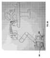
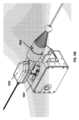
[63] 図2A及び図2Bは、本発明のいくつかの実施形態による、ロボット気管支鏡検査システム200、230の例を示している。図2Aに示すように、ロボット気管支鏡検査システム200は、操縦可能なカテーテル組立体を支持又は搬送するための、操縦可能なカテーテル組立体220及びロボット支持システム210を含み得る。操縦可能なカテーテル組立体は、気管支鏡とすることができる。いくつかの実施形態では、操縦可能なカテーテル組立体は、1回使い切りのロボット気管支鏡であり得る。いくつかの実施形態では、ロボット気管支鏡検査システム200は、ロボット支持システムのアームに取り付けられる器具駆動機構213を含み得る。器具駆動機構は、ロボットシステムを含んでも含まなくてもよい任意の好適なコントローラデバイス(例えば、手持ち式コントローラ)により提供され得る。器具駆動機構は、操縦可能なカテーテル組立体220に対する機械的及び電気的インターフェースを提供し得る。機械的インターフェースは、操縦可能なカテーテル組立体220が器具駆動機構に着脱可能に結合されることを可能にし得る。例えば、操縦可能なカテーテル組立体のハンドル部分は、磁石、ばね式レベルなどの、迅速取り付け/取り外し手段を介して器具駆動機構に取り付けることができる。場合により、操縦可能なカテーテル組立体は、ツールを使用せずに手動で器具駆動機構に結合され得るか又は器具駆動機構から取り外され得る。2A and 2B show examples of
[64] 操縦可能なカテーテル組立体220は、画像データを処理するように、電力を提供するように、又は他の外部デバイスとの通信を確立するように構成された構成要素を含み得るハンドル部分223を含み得る。例えば、ハンドル部分223は、操縦可能なカテーテル組立体220と器具駆動機構213及び他の任意の外部システム又はデバイスとの電気的な通信を可能にする回路及び通信要素を含み得る。別の例では、ハンドル部分223は、内視鏡の電子機器(例えば、カメラ及びLEDライト)に電力を供給するための電源などの回路要素を含み得る。場合により、ハンドル部分は、画像/映像データ及び/又はセンサデータを器具駆動機構の通信モジュールにより受信でき、画像/映像データ及び/又はセンサデータが他の外部デバイス/システムに送信され得るように、電気的インターフェース(例えば、プリント回路基板)を介して器具駆動機構213と電気的に通信し得る。代替として又はそれに加えて、器具駆動機構213は、機械的インターフェースのみを提供し得る。ハンドル部分は、センサデータを送信するため及び/又は制御信号を受信するためにモジュール式無線通信デバイス又は他の任意のユーザデバイス(例えば、携帯型/手持ち式デバイス又はコントローラ)と電気的に通信し得る。ハンドル部分の詳細については、本明細書で後に説明する。[64] The
[65] 操縦可能なカテーテル組立体220は、ハンドル部分に結合される可撓性長尺部材211を含み得る。いくつかの実施形態では、可撓性長尺部材は、シャフトと、操縦可能な先端と、操縦可能なセクションとを含み得る。操縦可能なカテーテル組立体は、1回使い切りのロボット気管支鏡であり得る。場合により、長尺部材のみは使い捨てであり得る。場合により、長尺部材の少なくとも一部分(例えば、シャフト、操縦可能な先端など)は使い捨てであり得る。場合により、ハンドル部分と長尺部材とを含む操縦可能なカテーテル組立体220全体を使い捨てにすることができる。可撓性長尺部材及びハンドル部分は、操縦可能なカテーテル組立体全体を低コストで廃棄できるように設計される。可撓性長尺部材及び操縦可能なカテーテル組立体についての詳細は、本明細書で後に説明する。[65] The
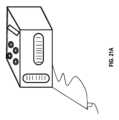
[66] いくつかの実施形態では、提供される気管支鏡システムはまた、ユーザインターフェースを含み得る。例示的なシステム230に図示するように、気管支鏡システムは、治療インターフェースモジュール231(ユーザコンソール側)及び/又は治療制御モジュール233(患者及びロボット側)を含み得る。治療インターフェースモジュールは、外科的処置中に操作者又はユーザが気管支鏡と相互作用することを可能にし得る。いくつかの実施形態では、治療制御モジュール233は、手持ち式コントローラであり得る。治療制御モジュールは、場合により、ユーザ入力経験を改善するために、既存のユーザデバイスに取り外し可能に結合された専用のユーザ入力デバイス及び1つ又は複数のアドオン要素を含み得る。例えば、物理的トラックボール又はローラは、物理的トラックボール又はローラが代替となるグラフィック要素に同様の機能を与えることにより、グラフィカルユーザインターフェース(GUI)上に表示される仮想グラフィック要素のうちの少なくとも1つ(例えば、タッチパッド上に表示される誘導案内矢印)の機能の代替となるか又はこの機能を補完することができる。ユーザデバイスの例としては、限定されるものではないが、モバイルデバイス、スマートフォン/携帯電話、タブレット、携帯情報端末(PDA)、ラップトップ又はノートブックコンピュータ、デスクトップコンピュータ、メディアコンテンツプレーヤなどが挙げられる。ユーザインターフェースデバイス及びユーザコンソールについての詳細は、本明細書で後に説明する。[66] In some embodiments, the provided bronchoscope system may also include a user interface. As illustrated in the
[67] 図2Bは、気管支鏡システムの異なる図を示している。ユーザコンソール231は、ロボット支持システム210に装着され得る。代替として又はそれに加えて、ユーザコンソール又はユーザコンソールの一部分(例えば、治療インターフェースモジュール)は、別個の移動カートに装着され得る。[67] FIG. 2B shows a different view of the bronchoscope system. The
ロボット管腔内プラットフォーム
[68] 一態様では、ロボット管腔内プラットフォームが提供される。場合により、ロボット管腔内プラットフォームは、気管支鏡検査プラットフォームであり得る。プラットフォームは、図1で説明した方法と一致する1つ又は複数の動作を実施するように構成され得る。図3~図7は、本発明のいくつかの実施形態による、ロボット管腔内プラットフォーム及びその構成要素又はサブシステムの様々な例を示している。いくつかの実施形態では、プラットフォームは、ロボット気管支鏡検査システムと、本開示のロボット気管支鏡検査システムと組み合わせて使用できる1つ又は複数のサブシステムとを含み得る。Robotic Intraluminal Platform
[68] In one aspect, a robotic endoluminal platform is provided. Optionally, the robotic endoluminal platform may be a bronchoscopy platform. The platform may be configured to perform one or more operations consistent with the method described in FIG. 1. FIGS. 3-7 illustrate various examples of a robotic endoluminal platform and its components or subsystems, according to some embodiments of the present invention. In some embodiments, the platform may include a robotic bronchoscopy system and one or more subsystems that may be used in combination with the robotic bronchoscopy system of the present disclosure.
[69] いくつかの実施形態では、1つ又は複数のサブシステムは、標的部位(例えば、病変を含む)のリアルタイム撮像を行うためのX線透視(トモシンセシス)撮像システムなどの撮像システムを含み得る。図3Aは、X線透視(トモシンセシス)撮像システム300の例を示している。例えば、X線透視(トモシンセシス)撮像システムは、図1で説明したように、外科的処置前又は外科的処置中に病変位置の正確な追跡又は確認を実施し得る。場合により、病変位置は、X線透視(トモシンセシス)撮像システム/ステーション(例えば、Cアーム)に関する位置データと、X線透視(トモシンセシス)撮像システムにより撮影された画像データとに基づいて追跡され得る。病変位置は、ロボット気管支鏡検査システムの座標フレームに登録され得る。X線透視(トモシンセシス)撮像システムの位置又は動きは、慣性計測ユニット(IMU)などの任意の好適な運動/位置センサ310、1つ又は複数のジャイロスコープ、速度センサ、加速度計、磁気計、位置センサ(例えば、全地球測位システム(GPS)センサ)、視覚センサ(例えば、カメラなどの、可視光、赤外光、又は紫外光を検出できる撮像デバイス)、近接センサ又は距離センサ(超音波センサ、ライダー、飛行時間型カメラ、又は深度カメラ)、高度センサ、高度センサ、姿勢センサ(例えば、コンパス)及び/又は磁場センサ(磁力計、電磁センサ、無線センサなど)を使用して測定され得る。X線透視(トモシンセシス)撮像ステーションの動き及び位置を追跡するための1つ又は複数のセンサは、壁取り付けカメラ320などの、撮像ステーション上に配置されるか又は撮像ステーションから遠く離れて位置し得る。図3Bは、対象者の画像撮影中の異なる(回転)姿勢のCアームX線透視(トモシンセシス)撮像システムを示している。様々な姿勢は、上記で説明したような1つ又は複数のセンサにより撮影され得る。[69] In some embodiments, one or more subsystems may include an imaging system, such as a tomosynthesis imaging system, for real-time imaging of the target site (e.g., including the lesion). FIG. 3A illustrates an example of a tomosynthesis imaging system 300. For example, the tomosynthesis imaging system may perform precise tracking or confirmation of the lesion location before or during the surgical procedure, as described in FIG. 1. In some cases, the lesion location may be tracked based on position data related to the tomosynthesis imaging system/station (e.g., C-arm) and image data captured by the tomosynthesis imaging system. The lesion location may be registered to the coordinate frame of the robotic bronchoscopy system. The position or movement of the fluoroscopic (tomosynthesis) imaging system may be measured using any suitable motion/position sensor 310, such as an inertial measurement unit (IMU), one or more gyroscopes, speed sensors, accelerometers, magnetometers, position sensors (e.g., Global Positioning System (GPS) sensors), visual sensors (e.g., imaging devices capable of detecting visible, infrared, or ultraviolet light, such as cameras), proximity or distance sensors (ultrasonic sensors, lidar, time-of-flight cameras, or depth cameras), altitude sensors, elevation sensors, attitude sensors (e.g., compasses), and/or magnetic field sensors (magnetometers, electromagnetic sensors, radio sensors, etc.). One or more sensors for tracking the movement and position of the fluoroscopic (tomosynthesis) imaging station may be located on the imaging station or remotely located from the imaging station, such as a wall-mounted camera 320. Figure 3B shows a C-arm fluoroscopic (tomosynthesis) imaging system in different (rotational) positions during imaging of a subject. The various poses can be captured by one or more sensors as described above.
[70] いくつかの実施形態では、病変の位置は、信号処理ユニット330を用いて、X線透視(トモシンセシス)撮像システムにより撮影された画像データにおいてセグメント化され得る。信号処理ユニットの1つ又は複数のプロセッサは、リアルタイムのX線透視画像/映像上に治療位置(例えば、病変)を更に重ね合わせるように構成され得る。例えば、処理ユニットは、治療位置又は標的部位の位置などの拡張情報を含む拡張層を生成するように構成され得る。場合により、拡張層はまた、この標的部位への経路を示すグラフィックマーカを含み得る。拡張層は、1つ又は複数のグラフィック要素(例えば、ボックス、矢印など)を含む実質的に透明な画像層であり得る。拡張層は、X線透視(トモシンセシス)撮像システムにより撮影された光学画像又は映像ストリームの光学ビューに畳重され、及び/又はディスプレイデバイス上に表示され得る。拡張層の透明度により、グラフィック要素が光学画像の上に重ね合わされた状態でユーザが光学画像を視認することが可能となる。場合により、セグメント化された病変画像と、病変に達するために長尺部材を誘導案内するための最適な経路の両方は、リアルタイムのトモシンセシス画像に重ね合わされ得る。これにより、操作者又はユーザが病変の正確な位置と気管支鏡の移動予定経路とを可視化することが可能となる。場合により、本明細書で説明するシステムの動作前に提供されるセグメント化及び再構成された画像(例えば、別の箇所で説明したようなCT画像)は、リアルタイムの画像に重ね合わされ得る。[70] In some embodiments, the location of the lesion may be segmented in the image data captured by the fluoroscopic (tomosynthesis) imaging system using the signal processing unit 330. One or more processors of the signal processing unit may be configured to further overlay the treatment location (e.g., the lesion) on the real-time fluoroscopic image/video. For example, the processing unit may be configured to generate an augmentation layer that includes augmentation information such as the location of the treatment location or the target site. In some cases, the augmentation layer may also include a graphic marker indicating a path to the target site. The augmentation layer may be a substantially transparent image layer that includes one or more graphic elements (e.g., boxes, arrows, etc.). The augmentation layer may be overlaid on the optical view of the optical image or video stream captured by the fluoroscopic (tomosynthesis) imaging system and/or displayed on a display device. The transparency of the augmentation layer allows the user to view the optical image with the graphic elements overlaid on top of the optical image. Optionally, both the segmented lesion image and the optimal path for guiding the elongated member to reach the lesion may be overlaid on the real-time tomosynthesis image, allowing the operator or user to visualize the exact location of the lesion and the proposed path of travel of the bronchoscope. Optionally, segmented and reconstructed images (e.g., CT images as described elsewhere) provided prior to operation of the systems described herein may be overlaid on the real-time image.
[71] いくつかの実施形態では、プラットフォームの1つ又は複数のサブシステムは、誘導案内及び位置特定サブシステムを含み得る。誘導案内及び位置特定サブシステムは、術前画像(例えば、術前CT画像)に基づいて仮想気道モデルを構築するように構成され得る。誘導案内及び位置特定サブシステムは、セグメント化された病変位置を3Dレンダリングされた気道モデルで特定するように構成され得、誘導案内及び位置特定サブシステムは、病変の位置に基づいて、外科的処置(例えば、生検)を実施するための病変への推奨される進入角度での主気管支から病変までの最適な経路を生成し得る。[71] In some embodiments, one or more subsystems of the platform may include a navigation and localization subsystem. The navigation and localization subsystem may be configured to construct a virtual airway model based on preoperative images (e.g., preoperative CT images). The navigation and localization subsystem may be configured to identify segmented lesion locations in the 3D rendered airway model, and the navigation and localization subsystem may generate an optimal path from the main bronchus to the lesion based on the location of the lesion with a recommended approach angle to the lesion for performing a surgical procedure (e.g., biopsy).
[72] 気管支鏡を標的部位に向けて駆動する前の登録ステップにおいて、システムは、レンダリングされた気道の仮想ビューを患者の気道に位置合わせし得る。画像登録は、単一の登録ステップから、又は単一の登録ステップと登録情報のリアルタイムの感覚的更新との組み合わせから構成され得る。登録された時点で、全ての気道は、術前のレンダリングされた気道に位置合わせされ得る。ロボット気管支鏡が標的部位に向かって進む間に、気道内の気管支鏡の位置が追跡され表示され得る。場合により、気道に対する気管支鏡の位置は、測位センサを使用して追跡され得る。他の種類のセンサ(例えば、カメラ)も、センサ融合技術を使用して、測位センサの代わりに又は測位センサと併せて使用することができる。電磁(EM)センサなどの測位センサは、カテーテルの遠位先端に埋め込まれ得、電磁場発生器は、処置中に患者の胴体の隣に位置決めされ得る。電磁場発生器は、EMセンサの位置を3D空間内に位置付け得るか、又はEMセンサの位置及び向きを5D又は6D空間内に位置付け得る。これにより、気管支鏡を標的部位に向けて駆動するときに、操作者に視覚的案内が提供され得る。[72] In a registration step prior to driving the bronchoscope towards the target site, the system may align a virtual view of the rendered airway to the patient's airway. Image registration may consist of a single registration step or a combination of a single registration step and real-time sensory updates of the registration information. Once registered, all airways may be aligned to the pre-operative rendered airway. The position of the bronchoscope within the airway may be tracked and displayed while the robotic bronchoscope advances towards the target site. Optionally, the position of the bronchoscope relative to the airway may be tracked using a positioning sensor. Other types of sensors (e.g., cameras) may also be used in place of or in conjunction with the positioning sensor using sensor fusion techniques. A positioning sensor, such as an electromagnetic (EM) sensor, may be embedded in the distal tip of the catheter, and an electromagnetic field generator may be positioned next to the patient's torso during the procedure. The electromagnetic field generator may position the position of the EM sensor in 3D space, or may position the position and orientation of the EM sensor in 5D or 6D space. This can provide visual guidance to the operator as he or she navigates the bronchoscope toward the target site.
[73] 図4Aは、最適な経路403とカテーテル401の先端位置と病変位置405を重ね合わせた仮想気道409を可視化するためのユーザインターフェースの例を示している。この例では、カテーテルの先端位置は、仮想気道モデル409に対してリアルタイムで表示され、それにより、視覚的誘導を提供する。図4Aの例に示すように、ロボット気管支鏡の駆動中に、最適な経路403が仮想気道モデル上に表示され重ね合わされ得る。上記で説明したように、仮想気道モデルは、リアルタイムのX線透視画像/映像(及び撮像システムの位置データ)に基づいて構築され得る。場合により、リアルタイムのX線透視画像/映像407のビューもまた、グラフィカルユーザインターフェース上に表示され得る。場合により、ユーザはまた、気管支鏡により撮影されたカメラビュー又は画像/映像411にリアルタイムでアクセスすることも許容され得る。[73] FIG. 4A shows an example of a user interface for visualizing a
[74] いくつかの実施形態では、ユーザインターフェースは、処置中にデバイスが標的へ誘導案内されるときに、ユーザが仮想レンダリング(例えば、気道)及び生のカメラビューを可視化することを可能にするユーザデバイスを更に含み得る。場合により、仮想レンダリングは、ライブカメラビューに重ね合わされ、ディスプレイデバイス上に表示され得る。場合により、システムは、仮想レンダリングの可視化を可能にするために、没入型仮想現実(VR)及び拡張現実(AR)対応システムなどの没入型技術と統合されるか、又は没入型技術を利用し得る。[74] In some embodiments, the user interface may further include a user device that allows the user to visualize a virtual rendering (e.g., of the airway) and a live camera view as the device is navigated to the target during the procedure. Optionally, the virtual rendering may be superimposed on the live camera view and displayed on a display device. Optionally, the system may be integrated with or utilize immersive technology, such as immersive virtual reality (VR) and augmented reality (AR) enabled systems, to enable visualization of the virtual rendering.
[75] 例えば、ユーザは、拡張現実システムの有無にかかわらず、これらのビュー上にオーバーレイ(例えば、経路、標的、血管系、他の解剖学的構造)を可視化し、それにより、処置中にユーザ情報を提供することが許容され得る。システムはまた、ユーザが使用事例又はユーザの好みに基づいてオーバーレイの表示を選択/制御することを許容し得る。[75] For example, the user may be allowed to visualize overlays (e.g., pathways, targets, vasculature, other anatomical structures) on these views with or without an augmented reality system, thereby providing user information during the procedure. The system may also allow the user to select/control the display of the overlays based on the use case or user preference.
[76] 図4Bは、拡張情報を伴う誘導案内ビューの例を示している。図4Bに示すように、誘導案内ビュー420は、仮想レンダリング、例えば、拡張現実情報を重ね合わせた生のカメラビュー421を少なくとも含み得る。仮想レンダリング又は重ね合わせた情報は、仮想気道423、仮想病変424、病変425へのパンされた仮想経路などの、複数の構成要素を含み得る。複数の仮想構成要素は、仮想/拡張現実デバイスの使用の有無にかかわらず可視化され得る。誘導案内ビューはまた、誘導案内方向(例えば、前方、上方、下方、後方、左、右)を示す方向インジケータ424を含み得る。[76] FIG. 4B shows an example of a navigation view with augmented information. As shown in FIG. 4B, the navigation view 420 may include at least a virtual rendering, e.g., a live camera view 421, overlaid with augmented reality information. The virtual rendering or overlaid information may include multiple components, such as a virtual airway 423, a virtual lesion 424, and a panned virtual path to the lesion 425. The multiple virtual components may be visualized with or without the use of a virtual/augmented reality device. The navigation view may also include a direction indicator 424 indicating the navigation direction (e.g., forward, up, down, back, left, right).
[77] 提供されるシステムは、有益には、ユーザの好みに基づいてユーザが仮想レンダリングの表示を制御することを可能にし得る。例えば、ユーザは、複数の構成要素から選択された1つ又は複数の構成要素の表示を有効/無効にし得る。図4Cは、ユーザが選択した仮想レンダリングを伴う誘導案内ビューの例を示している。例えば、ユーザは、気道の仮想レンダリングをオフに切り替えて、選択された病変424及び経路423の仮想レンダリングを重ね合わせた生のカメラビューを視認し得る。図4Dは、管腔内ビューの例を示している。例440では、仮想管腔426は、予定経路427及び/又は血管系429の仮想レンダリングと一緒に表示され得る。同様に、ユーザには、ビュー内において方向インジケータ428が与えられ得る。別の例441では、ユーザは、気道429及び胸膜430の仮想レンダリングを、これらの仮想構成要素が管腔ビューに重ね合わされるように有効にし得る。ユーザは、選択された任意の構成要素のオン/オフをいつでも切り替えることができる。[77] The provided system may advantageously allow a user to control the display of the virtual rendering based on the user's preferences. For example, a user may enable/disable the display of one or more selected components from a plurality of components. FIG. 4C shows an example of a navigation view with a user-selected virtual rendering. For example, a user may switch off the virtual rendering of the airway to view a live camera view with superimposed virtual renderings of the selected lesion 424 and pathway 423. FIG. 4D shows an example of an endoluminal view. In example 440, a virtual lumen 426 may be displayed together with a virtual rendering of the proposed pathway 427 and/or vasculature 429. Similarly, the user may be provided with a direction indicator 428 within the view. In another example 441, a user may enable virtual renderings of the airway 429 and pleura 430 such that these virtual components are superimposed on the lumen view. The user may switch on/off any selected component at any time.
[78] いくつかの実施形態では、プラットフォームの1つ又は複数のサブシステムは、手動若しくはロボット器具(例えば、生検用針、生検用鉗子、生検用ブラシ)及び/又は手動若しくはロボット治療器具(例えば、RFアブレーション器具、凍結器具、マイクロ波器具など)などの1つ又は複数の治療サブシステムを含み得る。[78] In some embodiments, one or more subsystems of the platform may include one or more therapeutic subsystems, such as manual or robotic instruments (e.g., biopsy needles, biopsy forceps, biopsy brushes) and/or manual or robotic therapeutic instruments (e.g., RF ablation instruments, cryoinstruments, microwave instruments, etc.).
[79] いくつかの実施形態では、プラットフォームの1つ又は複数のサブシステムは、治療インターフェースモジュール(ユーザコンソール側)及び/又は治療制御モジュール(患者及びロボット側)を含むユーザコンソールを含み得る。図5は、外科的処置中に操作者又はユーザが気管支鏡と相互作用することを可能にするユーザコンソールの例を示している。例510に示すように、ユーザコンソールは、誘導案内情報、ユーザ情報(例えば、制御パラメータ)、ロボット気管支鏡カメラビューなどの、気管支鏡の使用に関連する情報を表示するユーザインターフェース511を提供するように構成された治療インターフェースモジュールを含み得る。ユーザインターフェースは、ディスプレイ上に提供され得る。ディスプレイは、タッチスクリーンであってもなくてもよい。ディスプレイは、発光ダイオード(LED)画面、有機発光ダイオード(OLED)画面、液晶ディスプレイ(LCD)画面、プラズマ画面、又は他の任意の種類の画面であり得る。ディスプレイは、ソフトウェアアプリケーションを通じて(例えば、システム上で実行されたアプリケーションプログラミングインターフェース(API)を介して)レンダリングされたユーザインターフェース(UI)又はグラフィカルユーザインターフェース(GUI)を表示するように構成され得る。[79] In some embodiments, one or more subsystems of the platform may include a user console including a therapy interface module (user console side) and/or a therapy control module (patient and robot side). FIG. 5 shows an example of a user console that allows an operator or user to interact with the bronchoscope during a surgical procedure. As shown in example 510, the user console may include a therapy interface module configured to provide a user interface 511 that displays information related to the use of the bronchoscope, such as navigation guidance information, user information (e.g., control parameters), and robotic bronchoscope camera views. The user interface may be provided on a display. The display may or may not be a touch screen. The display may be a light emitting diode (LED) screen, an organic light emitting diode (OLED) screen, a liquid crystal display (LCD) screen, a plasma screen, or any other type of screen. The display may be configured to display a user interface (UI) or a graphical user interface (GUI) rendered through a software application (e.g., via an application programming interface (API) executed on the system).
[80] いくつかの実施形態では、ユーザコンソールは、治療制御インターフェース511と治療制御モジュール503とを含み得る。治療制御インターフェース及び治療制御モジュールは、別個の自己完結型構成要素であり得る。代替として又はそれに加えて、治療制御インターフェース及び治療制御モジュールは、一体化された単一の構成要素であり得る。例えば、治療制御モジュールは、治療インターフェースモジュールと通信するユーザ入力システム503を含み得る。代替として、治療制御モジュールは、独立型システムであり得る。[80] In some embodiments, the user console may include a therapy control interface 511 and a therapy control module 503. The therapy control interface and the therapy control module may be separate self-contained components. Alternatively or in addition, the therapy control interface and the therapy control module may be integrated into a single component. For example, the therapy control module may include a user input system 503 that communicates with the therapy interface module. Alternatively, the therapy control module may be a stand-alone system.
[81] 例520に示すようなユーザコンソール又はユーザコンソールの構成要素(例えば、治療インターフェースモジュール)は、ロボット支持システム523に装着され得る。代替として又はそれに加えて、ユーザコンソール又はユーザコンソールの構成要素(例えば、治療インターフェースモジュール)は、別個の移動カート513に装着され得る。移動カート513は、携帯型電子デバイス用の充電ポートを提供する電気パネルと電気的に通信する充電式電源、変換器、変圧器、並びに治療インターフェースモジュール用の特定用途向けソフトウェアを格納する1つ又は複数のコンピュータを含む搭載機器用の電源としての複数の交流及び直流コンセント用のサージ保護装置などの様々な要素を含み得る。[81] A user console or a component of a user console (e.g., a treatment interface module) as shown in example 520 may be mounted on a robotic support system 523. Alternatively or in addition, a user console or a component of a user console (e.g., a treatment interface module) may be mounted on a separate mobile cart 513. The mobile cart 513 may include various elements such as a rechargeable power supply in electrical communication with an electrical panel providing charging ports for portable electronic devices, converters, transformers, and surge protection for multiple AC and DC outlets as power sources for on-board equipment including one or more computers storing application specific software for the treatment interface module.
[82] いくつかの実施形態では、治療制御モジュール503は、例えば、医師がロボット内視鏡(例えば、気管支鏡)を容易に制御することを可能にするユーザインターフェース手持ち式デバイスを含み得る。いくつかの実施形態では、ユーザ入力デバイス又は制御デバイスは、カスタマイズされるか又はパーソナライズされ得る。携帯型ユーザインターフェースデバイス/システムについての詳細は、本明細書で後に説明する。代替として又はそれに加えて、治療制御モジュール503は、携帯型デバイスでなくてもよい。例えば、治療制御モジュールは、ロボット支持システムに一体化され得る。[82] In some embodiments, the therapy control module 503 may include, for example, a user interface handheld device that allows a physician to easily control a robotic endoscope (e.g., a bronchoscope). In some embodiments, the user input device or control device may be customized or personalized. More details about handheld user interface devices/systems are described later in this specification. Alternatively or additionally, the therapy control module 503 may not be a handheld device. For example, the therapy control module may be integrated into a robotic support system.
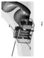
[83] 図6A及び図6Bは、治療制御システムを備えたシステムの例を示している。いくつかの実施形態では、治療制御システムは、ロボットアーム607と、器具駆動機構609と、ロボット制御ユニットと、灌注601及び吸引603システムなどの1つ又は複数の周辺機器とを含む、ロボット支持システム605を含むか又はロボット支持システム605と一体化され得る。ロボットアームは、ロボット気管支鏡611又は他のロボット器具の位置決めを開始し得る。器具駆動機構は、長尺部材又はロボット気管支鏡を2以上の自由度(例えば、関節運動)で制御するために使用され得る。灌注及び吸引システム601、603は、ロボットアーム基部用カート又はシステムの他の任意の部分に存在し得る。灌注及び吸引システムは、コネクタ又はルアーを通じて作業チャネルに接続され得る。灌注システムは生理食塩水などの流体を注入することができ、吸引システムは粘液又は生理食塩水又は他の物質を気道から吸引することができる。いくつかの実施形態では、灌注及び吸引システムは、カメラ可視化を利用して使用され得る。[83] Figures 6A and 6B show an example of a system with a therapy control system. In some embodiments, the therapy control system may include or be integrated with a
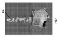
[84] 図7は、治療制御システムにおけるロボットカートの上部に装着されたロボットアーム710の例を示している。ロボットアーム710は、標的組織にアクセスするために、カテーテル組立体を初期位置(例えば、アクセス点)に自動的に位置決めし得る。いくつかの実施形態では、ロボットアームは、操作者により受動的に移動させることができる。そのような場合、操作者は、アームを任意の位置で押すことができ、アームは従順に移動する。ロボットはまた、人間とロボットとの相互作用を改善するために、従順モードで制御することもできる。例えば、ロボット技術の従順運動制御は、衝突回避戦略を採用し得、位置及び力の制御は、起こり得る衝突の影響を低減しつつ不必要なエネルギー消費を減らすように設計され得る。いくつかの実施形態では、器具駆動機構は、ロボットアームに装着され得る。アームは、操作者にとって便利な構成になるようにアームのエルボをアルゴリズム的又は受動的に移動させることを可能にする冗長自由度を有し得る。[84] Figure 7 shows an example of a
低コストで1回使い切りのロボット気管支鏡
[85] 本発明の一態様では、1回使い切りのロボット気管支鏡を提供する。ロボット気管支鏡は、本明細書の別の箇所で説明したような操縦可能なカテーテル組立体と同じものとすることができる。従来の内視鏡は設計が複雑である可能性があり、通常は、処置後に再使用されるように設計され、それらの処置は、各処置後に徹底的な洗浄、消毒又は滅菌を必要とする。既存の内視鏡は、多くの場合、内視鏡が洗浄、消毒及び滅菌プロセスに耐えることができるように、複雑な構造で設計される。提供されるロボット気管支鏡は、患者間の交差汚染及び感染を有益に抑制し得る1回使い切りの内視鏡とすることができる。場合により、ロボット気管支鏡は、予め滅菌されたパッケージで医師に届けられ、1回の使用後に廃棄されるように意図されている。A low-cost, single-use robotic bronchoscope
[85] In one aspect of the present invention, a single-use robotic bronchoscope is provided. The robotic bronchoscope may be the same as the steerable catheter assembly as described elsewhere herein. Conventional endoscopes can be complex in design and are usually designed to be reused after procedures that require extensive cleaning, disinfection or sterilization after each procedure. Existing endoscopes are often designed with complex structures so that the endoscope can withstand cleaning, disinfection and sterilization processes. The provided robotic bronchoscope may be a single-use endoscope that may beneficially reduce cross-contamination and infection between patients. In some cases, the robotic bronchoscope is delivered to the physician in a pre-sterilized package and is intended to be discarded after a single use.
[86] 図8~図10は、本発明のいくつかの実施形態による、ロボット気管支鏡の例を示している。図8に示すように、ロボット気管支鏡820は、ハンドル部分813と可撓性長尺部材811とを含み得る。いくつかの実施形態では、可撓性長尺部材811は、シャフトと、操縦可能な先端と、操縦可能なセクションとを含み得る。ロボット気管支鏡820は、図2で説明したような操縦可能なカテーテル組立体と同じものとすることができる。ロボット気管支鏡は、1回使い切りのロボット内視鏡であり得る。場合により、カテーテルのみは使い捨てであり得る。場合により、カテーテルの少なくとも一部分は使い捨てであり得る。場合により、ロボット気管支鏡全体を器具駆動機構から取り外してもよく、廃棄することができる。気管支鏡は、機能的動作を改善するために、気管支鏡のシャフトに沿って様々なレベルの剛性を有し得る。8-10 show examples of robotic bronchoscopes according to some embodiments of the present invention. As shown in FIG. 8, the
[87] ロボット気管支鏡は、器具駆動機構820に着脱可能に結合させることができる。器具駆動機構820は、ロボット支持システムのアームに又は本明細書の別の箇所で説明したような任意の作動支持システムに装着され得る。器具駆動機構は、ロボット気管支鏡820に対する機械的及び電気的インターフェースを提供し得る。機械的インターフェースは、ロボット気管支鏡820が器具駆動機構に着脱可能に結合されることを可能にし得る。例えば、ロボット気管支鏡のハンドル部分は、磁石及びばね式レベルなどの、迅速取り付け/取り外し手段を介して器具駆動機構に取り付けることができる。場合により、ロボット気管支鏡は、ツールを使用せずに手動で器具駆動機構に結合され得るか又は器具駆動機構から取り外され得る。[87] The robotic bronchoscope can be removably coupled to an
[88] 図9は、ロボット気管支鏡のハンドル部分913に対する機械的インターフェースを提供する器具駆動機構920の例を示している。例に示すように、器具駆動機構920は、カテーテルの1組のプルワイヤを回転駆動するように作動させる1組のモータを含み得る。カテーテル組立体のハンドル部分913は、ハンドル部分913のプーリ組立体が1組のモータにより駆動されるように、器具駆動機構に装着され得る。プーリの数は、プルワイヤの構成によって異なり得る。場合により、1つ、2つ、3つ、4つ、又はそれ以上のプルワイヤが、カテーテルを関節運動させるために利用され得る。[88] FIG. 9 illustrates an example of an
[89] ハンドル部分は、ロボット気管支鏡を低コストで使い捨てできるように設計され得る。例えば、従来型の手動及びロボット気管支鏡は、気管支鏡のハンドルの近位端部にケーブルを有し得る。ケーブルは、多くの場合、照明ファイバ、カメラビデオケーブル、他のセンサファイバ又はEMセンサなどのケーブル、又は形状感知ファイバを含む。このような複雑なケーブルは、気管支鏡のコストに加えてコストがかかる可能性がある。提供されるロボット気管支鏡は、機械的及び電気的機能を保ちながら、簡略化された構造及び構成要素を利用できるように、最適化された設計を有し得る。場合により、ロボット気管支鏡のハンドル部分は、カテーテルに対する機械的/電気的インターフェースを提供する一方で、ケーブルのない設計を採用し得る。[89] The handle portion may be designed to allow the robotic bronchoscope to be disposable at low cost. For example, conventional manual and robotic bronchoscopes may have cables at the proximal end of the bronchoscope handle. The cables often include illumination fibers, camera video cables, other sensor fibers or cables such as EM sensors, or shape sensing fibers. Such complex cables may be costly in addition to the cost of the bronchoscope. The provided robotic bronchoscope may have an optimized design to utilize simplified structures and components while retaining mechanical and electrical functionality. In some cases, the handle portion of the robotic bronchoscope may employ a cable-less design while providing a mechanical/electrical interface to the catheter.
[90] 図10は、本発明のいくつかの実施形態による、ロボット気管支鏡の例示的なハンドル部分1000を示している。場合により、ハンドル部分1000は、ハウジングであり得るか、又は画像データを処理するように、電力を提供するように、若しくは他の外部デバイスとの通信を確立するように構成された構成要素を含み得る。場合により、通信は、無線通信であり得る。例えば、無線通信は、Wi-Fi、電波式通信、Bluetooth、IR通信、又は他の種類の直接通信を含み得る。そのような無線通信能力は、プラグアンドプレイ方式でロボット気管支鏡機能を可能にし、1回の使用後に簡便に廃棄することができる。場合により、ハンドル部分は、ロボット気管支鏡又はカテーテル内に配置された電子機器(例えば、カメラ及びLED光源)に電力を供給するための電源などの回路要素を含み得る。[90] FIG. 10 illustrates an
[91] ハンドル部分は、ケーブル又はファイバを排除できるように、カテーテルと併せて設計され得る。例えば、カテーテル部分は、器具がロボット気管支鏡を通過することを可能にする単一の作業チャネル、並びにチップオンティップ(chip-on-tip)カメラなどの低コストの電子機器、発光ダイオード(LED)などの照明源、及びカテーテルの機械的構造に応じて最適な位置に位置するEMセンサを有する設計を採用し得る。これにより、ハンドル部分の設計の簡略化が可能となり得る。例えば、照明にLEDを使用することにより、ハンドル部分における終端は、電気はんだ付け又はワイヤ圧着のみに基づくことができる。例えば、ハンドル部分は、近位基板がハンドル部分のインターフェースに接続して器具駆動機構への電気的接続を確立する一方で、カメラケーブル、LEDケーブル及びEMセンサケーブルが終端する近位基板を含み得る。上記で説明したように、器具駆動機構は、ロボットアーム(ロボット支持システム)に取り付けられ、ハンドル部分に対する機械的及び電気的インターフェースを提供する。これにより、有利には、組み立て及び実装の効率が改善され、製造プロセス及びコストが簡素化され得る。場合により、ハンドル部分はカテーテルと一緒に、1回の使用後に廃棄され得る。[91] The handle portion may be designed in conjunction with the catheter to eliminate cables or fibers. For example, the catheter portion may employ a design with a single working channel that allows the instrument to pass through the robotic bronchoscope, as well as low-cost electronics such as a chip-on-tip camera, an illumination source such as a light-emitting diode (LED), and an EM sensor located at an optimal position depending on the mechanical structure of the catheter. This may allow for a simplified design of the handle portion. For example, by using LEDs for illumination, the termination in the handle portion may be based solely on electrical soldering or wire crimping. For example, the handle portion may include a proximal board on which the camera cable, the LED cable, and the EM sensor cable terminate, while the proximal board connects to an interface in the handle portion to establish an electrical connection to the instrument drive mechanism. As explained above, the instrument drive mechanism is attached to the robot arm (robot support system) and provides a mechanical and electrical interface to the handle portion. This may advantageously improve the efficiency of assembly and packaging and simplify the manufacturing process and costs. In some cases, the handle portion, together with the catheter, may be disposed of after a single use.
1回使い切りの操縦可能なカテーテル
[92] 図11は、本発明のいくつかの実施形態による、例示的な操縦可能なカテーテル1100を示している。いくつかの実施形態では、カテーテルは、1つ又は複数の構成要素がカテーテルと一体であり得る実質的に一体の設計を有し得、それにより、操縦可能なカテーテルの運動学的な動的性能を保ちながら、組み立て、製造プロセスを簡略化する。例に示すように、操縦可能なカテーテルは、検査対象の組織及び/又は領域に近接させる長尺部材1101又はプロービング部分を含み得る。長尺部材1101は、場合により、カテーテルと称されることもある。カテーテル1101は、本明細書の別の箇所で説明したようなツールが挿通されることを可能にする作業チャネル1103などの内部構造を含み得る。場合により、作業チャネルは、標準ツールとの適合性を有するように、約2mmの直径などの寸法を有し得る。Single-use steerable catheter
[92] FIG. 11 illustrates an
[93] カテーテル1101は、所望の可撓性又は曲げ剛性に好適な材料で構成され得る。場合により、カテーテルの材料は、実質的に可撓性を有する(例えば、様々な方向及び向きに屈曲することができる)のみならず内部構造(例えば、作業チャネル)に対する構造的支持も維持し得るように選択され得る。例えば、カテーテルは、ウレタン、ビニル(ポリ塩化ビニルなど)、ナイロン(ベスタミド、グリルアミドなど)、ポリウレタン、ポリエチレン、ポリプロピレン、ポリカーボネート、ポリエステル、シリコンエラストマー、アセテートなどの任意の好適な材料で作製することができる。場合により、材料は、ポリマー材料、生体適合性ポリマー材料であり得、カテーテルは、対象者に痛みを生じさせることなく曲率の小さな経路を通って前進するのに十分な可撓性を有し得る。場合により、カテーテルは、シースを含み得る。シースは、カテーテルと同じ長さでなくてもよい。シースは、所望の支持を提供するようにカテーテルよりも短くてもよい。代替として、カテーテルは、実質的に単一部品の構成要素であり得る。[93] The
[94] 場合により、カテーテルの遠位部分又は先端は、1つ又は複数の方向(例えば、ピッチ、ヨー)に操縦され得るように、実質的に可撓性を有し得る。いくつかの実施形態では、カテーテルは、長手軸線方向に沿って変化する曲げ剛性を有し得る。例えば、カテーテルは、異なる曲げ剛性(例えば、可撓性、半剛性、及び剛性)を有する複数のセグメントを含み得る。曲げ剛性は、異なる剛性/硬性を有する材料を選択すること、異なるセグメントにおいて構造を変化させること、追加の支持構成要素を加えること、又は上記の任意の組み合わせにより変化させ得る。場合により、カテーテルの近位端部は、大きく曲げる必要がなく、したがって、カテーテルの近位部分は、より大きな曲げ剛性を実現するために追加の機械的構造(例えば、追加の材料層)を用いて補強され得る。そのような設計は、カテーテルに支持及び安定性を提供し得る。場合により、変化する曲げ剛性は、カテーテルの押出成形中に異なる材料を使用することにより実現され得る。押出成形中の異なる材料の使用により、有利には、異なる材料の更なる締結又は組み付けなしに、押出製造プロセスにおいてカテーテルのシャフトに沿って異なる剛性度がもたらされ得る。[94] In some cases, the distal portion or tip of the catheter may be substantially flexible so that it may be steered in one or more directions (e.g., pitch, yaw). In some embodiments, the catheter may have a varying bending stiffness along the longitudinal axis. For example, the catheter may include multiple segments with different bending stiffnesses (e.g., flexible, semi-rigid, and rigid). The bending stiffness may be varied by selecting materials with different stiffness/rigidity, varying the structure in different segments, adding additional support components, or any combination of the above. In some cases, the proximal end of the catheter does not need to bend as much, and therefore the proximal portion of the catheter may be reinforced with additional mechanical structure (e.g., additional layers of material) to achieve a greater bending stiffness. Such a design may provide support and stability to the catheter. In some cases, the varying bending stiffness may be achieved by using different materials during extrusion of the catheter. The use of different materials during extrusion may advantageously result in different degrees of stiffness along the shaft of the catheter in the extrusion manufacturing process without further fastening or assembly of different materials.
[95] カテーテルの遠位部分は、1つ又は複数のプルワイヤ1105により操縦され得る。カテーテルの遠位部分は、プルワイヤにより曲げることができるように、コポリマー、ポリマー、金属、又は合金などの任意の好適な材料で作製され得る。いくつかの実施形態では、1つ又は複数のプルワイヤ1105の近位端部又は近位部分は、カテーテル組立体のハンドル部分内の様々な機構(例えば、ギヤ、プーリなど)に動作可能に結合され得る。プルワイヤ1105は、金属ワイヤ、ケーブル若しくは細線であり得るか、又はポリマーワイヤ、ケーブル若しくは細線であり得る。プルワイヤ1105はまた、天然若しくは有機材料又は天然若しくは有機繊維で作製することができる。プルワイヤ1105は、変形、著しい変形又は破損なしに様々な種類の荷重を支持することが可能な任意の種類の好適なワイヤ、ケーブル又は細線とすることができる。1つ又は複数のプルワイヤ1105の遠位端部又は遠位部分は、カテーテルの遠位部分にしっかりと固定されるか又は一体化され得、その結果、制御ユニットによるプルワイヤの操作により、少なくともカテーテルの遠位部分(例えば、可撓性セクション)を(例えば、上、下、ピッチ、ヨー、又はそれらの方向の間の任意の方向に)操縦するか又は関節運動させ得る力又は張力が遠位部分に加わり得る。[95] The distal portion of the catheter may be steered by one or
[96] 上記で説明したように、プルワイヤは、ステンレス鋼(例えば、SS316)、金属、合金、ポリマー、ナイロン又は生体適合性材料などの任意の好適な材料で作製され得る。プルワイヤは、ワイヤ、ケーブル、又は細線であり得る。いくつかの実施形態では、異なるプルワイヤは、プルワイヤの耐荷重能力に変化させるために異なる材料で作製され得る。いくつかの実施形態では、プルワイヤの異なるセクションは、プルに沿って剛性及び/又は耐荷重性を変化させるために異なる材料で作製され得る。いくつかの実施形態では、プルワイヤは、電気信号の伝送に利用され得る。[96] As discussed above, the pull wires may be made of any suitable material, such as stainless steel (e.g., SS316), metals, alloys, polymers, nylon, or biocompatible materials. The pull wires may be wires, cables, or thin wires. In some embodiments, different pull wires may be made of different materials to vary the load-bearing capabilities of the pull wires. In some embodiments, different sections of the pull wires may be made of different materials to vary stiffness and/or load-bearing along the pull. In some embodiments, the pull wires may be utilized to transmit electrical signals.
[97] カテーテルは、1つ又は複数の電子的構成要素をカテーテルに一体化させることができるような寸法を有し得る。例えば、遠位先端の外径は、約4~4.4ミリメートル(mm)であり得、作業チャネルの直径は、1つ又は複数の電子的構成要素がカテーテルの壁内又はカテーテルの隙間内に埋め込まれ得るように約2mmであり得る。しかしながら、異なる用途に基づいて、外径は、4mmよりも小さい又は4.4mmよりも大きい任意の範囲とすることができ、作業チャネルの直径は、ツールの寸法又は特定の用途に応じて任意の範囲とすることができることに留意されたい。[97] The catheter may have dimensions such that one or more electronic components may be integrated into the catheter. For example, the outer diameter of the distal tip may be about 4-4.4 millimeters (mm) and the diameter of the working channel may be about 2 mm such that one or more electronic components may be embedded within the wall of the catheter or within the interstices of the catheter. However, it should be noted that based on different applications, the outer diameter may be any range smaller than 4 mm or larger than 4.4 mm, and the diameter of the working channel may be any range depending on the dimensions of the tool or the particular application.
[98] 1つ又は複数の電子的構成要素は、撮像デバイス、照明デバイス、又はセンサを含み得る。いくつかの実施形態では、撮像デバイスは、ビデオカメラ1113であり得る。撮像デバイスは、画像データを撮影するための光学要素及び画像センサを含み得る。画像センサは、光の波長に応答して画像データを生成するように構成され得る。相補型金属酸化膜半導体(CMOS)又は電荷結合素子(CCD)などの画像データを撮影するために、様々な画像センサが用いられ得る。撮像デバイスは、安価なカメラであり得る。場合により、画像センサは、回路基板上に設けられ得る。回路基板は、撮像プリント回路基板(PCB)であり得る。PCBは、画像信号を処理するための複数の電子的要素を含み得る。例えば、CCDセンサ用の回路は、CCDセンサにより提供されたアナログ信号を増幅及び変換するためのA/D変換器及び増幅器を含み得る。任意選択的に、画像センサは、回路基板が必要でないように、アナログ信号をデジタル信号に変換するための増幅器及び変換器と一体化され得る。場合により、画像センサ又は回路基板の出力は、画像データ(デジタル信号)であり得、カメラ回路又はカメラのプロセッサにより更に処理することができる。場合により、画像センサは、光学センサのアレイを含み得る。[98] The one or more electronic components may include an imaging device, an illumination device, or a sensor. In some embodiments, the imaging device may be a
[99] 照明デバイスは、遠位先端に位置決めされた1つ又は複数の光源1111を含み得る。光源は、発光ダイオード(LED)、有機LED(OLED)、量子ドット、又は他の任意の好適な光源であり得る。場合により、光源は、コンパクト設計用の小型LED又はデュアルトーンフラッシュLED照明であり得る。[99] The illumination device may include one or more
[100] 撮像デバイス及び照明デバイスは、カテーテルに一体化され得る。例えば、カテーテルの遠位部分は、少なくとも撮像デバイス及び照明デバイスの寸法と一致する好適な構造を含み得る。撮像デバイス及び照明デバイスは、カテーテルに埋め込まれ得る。図12は、撮像デバイス及び照明デバイスが一体化されたカテーテルの例示的な遠位部分を示している。カメラは、遠位部分に位置し得る。例えば、カメラは、カテーテルの遠位先端における空洞1210に埋め込まれ得る。空洞1210は、空洞の遠位部分と一体に形成され得、カメラがカテーテルに対して移動しないように、カメラの長さ/幅と一致する寸法を有し得る。カメラは、組織又は臓器に対する近視野を提供するために、カテーテルの作業チャネル1220に隣接し得る。場合により、撮像デバイスの姿勢又は向きは、カテーテルの回転運動(例えば、ロール)を制御することにより制御され得る。[100] The imaging and illumination devices may be integrated into the catheter. For example, the distal portion of the catheter may include suitable structures that match at least the dimensions of the imaging and illumination devices. The imaging and illumination devices may be embedded in the catheter. FIG. 12 shows an exemplary distal portion of a catheter with an integrated imaging and illumination device. The camera may be located in the distal portion. For example, the camera may be embedded in a
[101] カメラへの電力は、有線ケーブルにより提供され得る。場合により、ケーブルワイヤは、カテーテルの遠位先端における照明要素又は他の回路のみならず、カメラにも電力を提供するワイヤ束内に位置し得る。カメラ及び/又は光源には、ワイヤ、銅線を介して、又はカテーテルの長さにわたって延在する他の任意の好適な手段を介して、ハンドル部分内に配置された電源から電力が供給され得る。場合により、組織又は臓器のリアルタイム画像又は映像は、外部ユーザインターフェース又はディスプレイに無線送信され得る。無線通信は、WiFi、Bluetooth、RF通信、又は他の形式の通信であり得る。場合により、カメラにより撮影された画像又は映像は、複数のデバイス又はシステムにブロードキャストされ得る。場合により、カメラからの画像及び/又は映像データは、ワイヤ、銅線、又は他の任意の好適な手段を介して、カテーテルの長さに沿って、ハンドル部分内に位置するプロセッサに送信され得る。画像又は映像データは、ハンドル部分内の無線通信構成要素を介して外部デバイス/システムに送信され得る。場合により、システムは、ワイヤが視認可能でないように又は操作者に対して露出されないように設計され得る。[101] Power to the camera may be provided by a wired cable. Optionally, the cable wires may be located in a wire bundle that provides power to the camera as well as to the lighting elements or other circuitry at the distal tip of the catheter. The camera and/or light source may be powered from a power source located in the handle portion via wires, copper wires, or any other suitable means that extend along the length of the catheter. Optionally, real-time images or videos of the tissue or organ may be wirelessly transmitted to an external user interface or display. The wireless communication may be WiFi, Bluetooth, RF communication, or other forms of communication. Optionally, images or videos captured by the camera may be broadcast to multiple devices or systems. Optionally, image and/or video data from the camera may be transmitted to a processor located in the handle portion along the length of the catheter via wires, copper wires, or any other suitable means. Image or video data may be transmitted to an external device/system via wireless communication components in the handle portion. Optionally, the system may be designed such that the wires are not visible or exposed to the operator.
[102] 従来の内視鏡検査では、照明光は、内視鏡の近位端部に位置する光源の光をロボット内視鏡の遠位端部に伝送するファイバケーブルにより提供され得る。本開示のいくつかの実施形態では、設計の複雑さを軽減するために、小型LEDライトが用いられ、カテーテルの遠位部分に埋め込まれ得る。場合により、遠位部分は、小型LED光源の寸法と一致する寸法を有する構造1230を含み得る。図示の例に示すように、2つの空洞1230は、2つのLED光源を受け入れるようにカテーテルと一体に形成され得る。例えば、遠位先端の外径は、約4~4.4ミリメートル(mm)であり得、カテーテルの作業チャネルの直径は、2つのLED光源が遠位端部に埋め込まれ得るように約2mmであり得る。外径は、4mmよりも小さい又は4.4mmよりも大きい任意の範囲とすることができ、作業チャネルの直径は、ツールの寸法又は特定の用途に応じて任意の範囲とすることができる。任意の数の光源が含まれ得る。遠位部分の内部構造は、任意の数の光源に適合するように設計され得る。[102] In conventional endoscopy, illumination light may be provided by a fiber optic cable that transmits light from a light source located at the proximal end of the endoscope to the distal end of the robotic endoscope. In some embodiments of the present disclosure, to reduce design complexity, a small LED light may be used and embedded in the distal portion of the catheter. Optionally, the distal portion may include a
[103] 場合により、LEDの各々は、近位ハンドルまで延在する電源ワイヤに接続され得る。いくつかの実施形態では、LEDは、後に束になって1本の撚線を形成する別々の電源ワイヤにはんだ付けされ得る。いくつかの実施形態では、LEDは、電力を供給するプルワイヤにはんだ付けされ得る。他の実施形態では、LEDは、1対の電源ワイヤに直接圧着又は接続され得る。場合により、生体適合性接着剤の薄層などの保護層は、光の放出を許容しつつ保護を提供するために、LEDの前面に貼り付けられ得る。場合により、追加のカバー1231は、遠位先端の前端面に配置されて、LEDの正確な位置決めと接着剤のための十分な空間とを提供し得る。カバー1231は、照明光が遮られないように、接着剤の屈折率と一致する透明材料で構成され得る。[103] Optionally, each of the LEDs may be connected to a power wire that extends to the proximal handle. In some embodiments, the LEDs may be soldered to separate power wires that are then bundled together to form a single stranded wire. In some embodiments, the LEDs may be soldered to a pull wire that provides power. In other embodiments, the LEDs may be crimped or connected directly to a pair of power wires. Optionally, a protective layer, such as a thin layer of biocompatible adhesive, may be applied to the front of the LEDs to provide protection while still allowing light emission. Optionally, an
[104] いくつかの実施形態では、1つ又は複数のセンサは、カテーテルの遠位部分内に埋め込まれ得る。従来のロボット気管支鏡では、先端位置を追跡するためにセンサが使用される場合があり、これらのセンサは、通常は遠位先端に位置し、それにより、先端の大型化をもたらす。提供される操縦可能なカテーテルは、1つ又は複数の電子的構成要素を束にしてコンパクトな設計を提供し得る。場合により、照明光源及び1つ又は複数の位置センサは、組み合わされて束になり得る。図13は、遠位部分に配置された電子的要素のコンパクトな構成の例を示している。いくつかの実施形態では、電磁(EM)センサなどの位置センサは、カテーテルの遠位先端の位置を正確に追跡するために使用され得る。場合により、1つ又は複数のEMセンサ1310は、遠位部分に配置され得、照明光源1320(例えば、LED)に隣接して又はその後ろに立体的構成で配置され得る。遠位端部に位置する電磁コイルは、内視鏡を解剖学的システム内に配置する間に内視鏡の遠位端部の位置及び向きを検出するために、電磁追跡システムと共に使用され得る。いくつかの実施形態では、コイルは、異なる軸線に沿った電磁場に対する感度を提供するように角度が付けられ、完全な6自由度(3つの位置自由度及び3つの角度自由度)を測定する能力を開示の誘導案内システムに与え得る。[104] In some embodiments, one or more sensors may be embedded in the distal portion of the catheter. In conventional robotic bronchoscopes, sensors may be used to track tip position, and these sensors are typically located at the distal tip, resulting in a large tip. The steerable catheter provided may bundle one or more electronic components to provide a compact design. In some cases, the illumination source and one or more position sensors may be combined into a bundle. FIG. 13 shows an example of a compact configuration of electronic elements located at the distal portion. In some embodiments, a position sensor, such as an electromagnetic (EM) sensor, may be used to accurately track the position of the distal tip of the catheter. In some cases, one or
[105] 場合により、EMセンサ及びLED光源は、束1300を形成し得る。EMセンサの電源ケーブルは、LEDのワイヤと束になって、空間の削減と複雑さの軽減とをもたらし得る。場合により、立体的な位置合わせによって、カテーテル遠位先端の正確な位置決め及び向き感知を可能にする示差5D測定又は融合6D測定が行われ得る。処置中に、患者の胴体の隣、下方又は上方に位置決めされた電磁場発生器は、EMセンサの位置を特定し、それにより、カテーテル先端の位置をリアルタイムで追跡し得る。[105] Optionally, the EM sensor and LED light source may form a
プルワイヤの構成及び設計
[106] ロボット気管支鏡は、カテーテルの関節運動を制御するための1つ又は複数のプルワイヤを含み得る。従来の内視鏡では、1つ又は複数のプルワイヤの遠位端部又は遠位部分は、制御リングにしっかりと固定されるか又は装着され得、その結果、制御ユニットによるプルワイヤの操作により、カテーテルの特定のセクション又は部分(例えば、遠位セクション)を(例えば、上、下、ピッチ、ヨー、又はそれらの方向の間の任意の方向に)操縦するか又は関節運動させ得る力又は張力が制御リングに加わり得る。図14は、制御リング構造1411に取り付けられたプルワイヤ1413の従来の構成と本開示の新規な構成1420の例を示している。制御リングは、カテーテル1415の遠位端部に取り付けられ得る。通常、プルワイヤの先端は、制御リング1411に溶着又ははんだ付けされ、制御リングはまた、溶着により遠位先端に取り付けられ得る。溶接プロセスは、コストがかかり、面倒であり、複雑である可能性がある。その上、1つのプルワイヤが断線した又は正常に機能しない場合には、操縦制御機能全体が影響を受ける場合がある。Pull wire configuration and design
[106] A robotic bronchoscope may include one or more pull wires for controlling articulation of the catheter. In a conventional endoscope, the distal end or portion of one or more pull wires may be rigidly secured or attached to a control ring such that manipulation of the pull wires by a control unit may apply a force or tension to the control ring that may steer or articulate (e.g., up, down, pitch, yaw, or any direction between those directions) a particular section or portion of the catheter (e.g., the distal section). FIG. 14 shows examples of conventional and
[107] 提供されるロボット気管支鏡は、個別に制御されるプルワイヤを含み得、プルワイヤの各々は、遠位部分に直接接続される。例1420に示すように、1つ又は複数のプルワイヤ1423は、遠位部分の一体形成構造1421に取り付けられ得る。例えば、一体形成構造1421は、遠位先端と共に成形される溝であり得る。溝は、遠位端部においてプルワイヤを簡便に圧着できるように、プルワイヤの遠位端部1421の寸法と一致する寸法又はサイズを有し得る。これにより、有利には、組み立て効率が改善され得る。いくつかの例では、プルワイヤは、プルワイヤの遠位端部がカテーテルの遠位部分に対して移動できないように、プルワイヤを遠位端部の溝に強固に固定され得る。[107] The provided robotic bronchoscope may include individually controlled pull wires, each of which is directly connected to the distal portion. As shown in example 1420, one or
[108] プルワイヤ構成はまた、遠位部分を操縦する際の信頼性の向上をもたらし得る。例えば、各プルワイヤは、遠位部分に個別に接続されて個別に制御されるので、関節運動力は、異なるプルワイヤ構成に応じて動的に調節され得る。例えば、関節運動力が再計算され得、プルワイヤを制御するための制御信号は、プルワイヤが断線した場合に、利用可能なプルワイヤに基づいて動的に調節され得る。[108] The pull wire configuration may also provide improved reliability in steering the distal portion. For example, because each pull wire is individually connected to the distal portion and individually controlled, articulation forces may be dynamically adjusted in response to different pull wire configurations. For example, articulation forces may be recalculated and control signals for controlling the pull wires may be dynamically adjusted based on available pull wires in the event of a pull wire break.
[109] また、遠位部分へのプルワイヤの簡便な組み付けにより、プルワイヤ構成を設計する上での自由度が与えられ得る。例えば、プルワイヤの数又は組み合わせは、異なる性能又は設計要件を満たすように動的に選択又は調節することができる。図15は、ロボットカテーテルシステム用のプルワイヤの様々な構成を示している。いくつかの実施形態では、プルワイヤを受け入れるための一体構造(溝)は、予め加工され得る。例えば、4つの溝がカテーテルと一体に形成され得、1つ又は複数のプルワイヤは、異なる構成1510、1530を形成するために複数の溝から選択された1つ又は複数の溝に固定接続/固定圧着され得る。例に示すように、任意の数の溝/スロット又は任意の所与のサブセットの溝/スロットは、一端部においてプルワイヤを受け入れるか又はプルワイヤに結合するように選択することができる。場合により、スロット/溝の組み合わせが、対応するプルワイヤに結合されるように選択された時点で、プルワイヤ構成パターンが形成され得、選択された溝/スロットとプルワイヤとのマッピング関係が、制御ユニットに送信され得る。次いで、制御信号は、所望の関節運動力を達成するために、マッピング関係に基づいて関節運動中に生成され得る。[109] The convenient assembly of pull wires to the distal portion may also provide freedom in designing the pull wire configuration. For example, the number or combination of pull wires may be dynamically selected or adjusted to meet different performance or design requirements. FIG. 15 illustrates various configurations of pull wires for a robotic catheter system. In some embodiments, integral structures (grooves) for receiving pull wires may be prefabricated. For example, four grooves may be integrally formed with the catheter, and one or more pull wires may be fixedly connected/fixedly crimped to one or more selected from the plurality of grooves to form
[110] 別の例では、予め加工された溝は、様々な構成を有し得る。例えば、3本プルワイヤ構成1520は、約120°離れた3つの溝を有し得る。場合により、仮想マッピングアルゴリズムは、3本ワイヤ構成を4本ワイヤ構成にマッピングし得る。仮想マッピングアルゴリズムはまた、1つ又は複数のプルワイヤが動作中に正常に機能していない/断線した場合に、新たなマッピング関係を更新するために利用することができる。仮想マッピングアルゴリズムは、1つ又は複数のプルワイヤの状態の変化時に、選択された構成パターンを更新された構成パターンにマッピングする。プルワイヤ構成のかかる一体の設計は、有利には、カテーテルの運動学的な動的性能を保ちながら、組み立て、製造プロセスを簡略化する。[110] In another example, the pre-machined grooves can have various configurations. For example, a three
膨張可能な先端を備えたガイドワイヤ
[111] いくつかの実施形態では、ガイドワイヤは、気管支鏡検査操作中に使用され得る。ガイドワイヤは通常、まず所望の気道に進入するように気管支鏡の先端をはるかに越えて挿入され、次いで、気管支鏡がガイドワイヤ上を摺動して選択された通路内に入ることを可能にし得る。ガイドワイヤの直径が気管支鏡の直径と比較して小さいので、ガイドワイヤは、ガイドワイヤを気道内にしっかりと固定するのに十分な剛性及び/又は十分な摩擦力を有しない場合がある。Guidewire with expandable tip
[111] In some embodiments, a guidewire may be used during a bronchoscopy procedure. A guidewire is typically first inserted well beyond the tip of the bronchoscope to enter the desired airway, and then the bronchoscope may be allowed to slide over the guidewire into the selected passageway. Because the guidewire diameter is small compared to the diameter of the bronchoscope, the guidewire may not have sufficient stiffness and/or sufficient friction to anchor the guidewire firmly within the airway.
[112] 本開示のガイドワイヤは、拡張可能な外径特徴部を先端に有し得る。図16は、膨張可能な先端を備えたガイドワイヤ1600の例を示している。ガイドワイヤ1601は、肺内の気道での誘導案内を補助するために、カテーテル/気管支鏡の作業チャネルに挿通され得る。場合により、ガイドワイヤは、カテーテルの先端を越えて所望の気道内まで延出させ得、次いで、カテーテルは、ガイドワイヤ上を摺動して所望の位置に達し得る。膨張可能な先端は、様々な好適な方法を使用して実装することができる。例えば、拡張可能なバルーンなどの追加の構成要素1603は、ガイドワイヤの遠位端部又はその近傍に位置決めされ得る。バルーンは、バルーンの膨張又は収縮のためのバルーン膨張源又はポンプに作業チャネルを通して接続され得る。[112] Guidewires of the present disclosure may have an expandable outer diameter feature at their tips. FIG. 16 shows an example of a
[113] 場合により、ガイドワイヤは、穿孔を含み得る。収縮させたバルーンの直径は、長尺アーム(例えば、気管支鏡用カテーテル)の直径と等しくてもよい。場合により、収縮させたバルーンの直径は、長尺アームよりも僅かに大きくてもよい。ガイドワイヤは、遠位側又は近位側に移動することが可能であり得る。ガイドワイヤは、結果として、バルーンをそれぞれ膨張及び収縮させる、ガイドワイヤへの空気の注入及びガイドワイヤからの空気の抜き取りのために、空気ポンプに取り付けられ得る。気道へのガイドワイヤの挿入中に、バルーンは収縮したままであり得る。適切な場所に達する間に、バルーンは、空気を送り込むことにより膨張させる。気管支鏡が所望の前方位置に達した時点で、ガイドワイヤが前方に移動することを可能にし得る、空気の排出によりバルーンを収縮させ得る。いくつかの実施形態では、膨張可能な先端は、その対応する膨張及び収縮制御機構と共に、形状記憶合金(SMA)、電気活性ポリマー(EAP)、及び強磁性流体などの、材料を使用して折り畳み可能なメッシュ構造で作製することができる。固定要素は、ガイドワイヤのしっかりとした固定を確実にするために他の任意の形態を有することができる。例えば、固定要素は、径方向に拡張又は折り畳み可能である金属ワイヤであり得る。固定要素は、固定要素の位置を変化させるために、特に固定要素を展開させるか又は折り畳み位置に戻すために直線的に摺動させるスライドアクチュエータにより作動させ得る。アクチュエータの摺動動作は、固定要素の位置(状態)の変化に変換され得る(例えば、固定要素は、展開し径方向に拡張して、ガイドワイヤを適所にしっかりと固定する構造を提供するか、又は逆に、固定要素は、径方向に収縮して折り畳み状態に戻される。[113] Optionally, the guidewire may include perforations. The diameter of the deflated balloon may be equal to the diameter of the long arm (e.g., bronchoscope catheter). Optionally, the diameter of the deflated balloon may be slightly larger than the long arm. The guidewire may be capable of moving distally or proximally. The guidewire may be attached to an air pump for injecting and withdrawing air from the guidewire, which results in the balloon being inflated and deflated, respectively. During insertion of the guidewire into the airway, the balloon may remain deflated. While reaching the appropriate location, the balloon may be inflated by pumping air in. Once the bronchoscope reaches the desired forward position, the balloon may be deflated by expelling air, which may allow the guidewire to move forward. In some embodiments, the inflatable tip may be made of a foldable mesh structure using materials such as shape memory alloys (SMA), electroactive polymers (EAP), and ferrofluids, along with its corresponding inflation and deflation control mechanisms. The fixation element can have any other form to ensure a firm fixation of the guidewire. For example, the fixation element can be a metal wire that is radially expandable or collapsible. The fixation element can be actuated by a sliding actuator that linearly slides to change the position of the fixation element, in particular to deploy the fixation element or return it to a collapsed position. The sliding action of the actuator can be translated into a change in the position (state) of the fixation element (e.g., the fixation element deploys and radially expands to provide a structure that securely fixes the guidewire in place, or conversely, the fixation element contracts radially and returns to a collapsed state).
座屈防止デバイス
[114] いくつかの実施形態では、カテーテルは、可撓性を有するように設計され得る。気管支鏡を用いて機構を伸長させることによりカテーテルの可撓性部分が患者に挿入されるときに、1つ又は複数のセクションが屈曲又は座屈し得る。そのような場合、気管支鏡を患者に向けて前進させる間にカテーテルが座屈するのを防止するために、座屈防止機構は、カテーテルを支持するために、ロボット気管支鏡のハンドル部分に結合され得る。伸縮機構などの座屈防止機構が知られているが、カテーテルの可撓性部分は依然として屈曲又は座屈し得る。既存の座屈防止デバイスは、両端部が開放端である複数の筒状要素を含み得る。筒状要素の直径は、徐々に増大し得る。これらの筒状要素は互いに結合され得、互いの中に折り畳み又は拡張可能であり得る。最小径の筒体の直径は長尺部材の直径よりも大きいので、筒体を延出させたときに長尺部材が前方に移動することができる。直径差により、座屈防止デバイスを格納する又は取り外すときに、カテーテルを回収できなくなる。しかしながら、カテーテルは、伸縮機構の直径がカテーテルの外径よりも大きいセグメントでは、依然として座屈し得る。Anti-buckling device
[114] In some embodiments, the catheter may be designed to be flexible. When the flexible portion of the catheter is inserted into the patient by using a bronchoscope to extend the mechanism, one or more sections may bend or buckle. In such cases, an anti-buckling mechanism may be coupled to the handle portion of the robotic bronchoscope to support the catheter to prevent the catheter from buckling while advancing the bronchoscope towards the patient. Although anti-buckling mechanisms such as telescoping mechanisms are known, the flexible portion of the catheter may still bend or buckle. Existing anti-buckling devices may include multiple tubular elements that are open-ended at both ends. The diameter of the tubular elements may gradually increase. These tubular elements may be coupled to each other and may be collapsible or expandable into each other. The diameter of the smallest diameter of the cylinder is larger than the diameter of the elongated member, allowing the elongated member to move forward when the cylinder is extended. The diameter difference prevents the catheter from being retrieved when the anti-buckling device is retracted or removed. However, the catheter may still buckle in segments where the diameter of the telescoping mechanism is larger than the outer diameter of the catheter.
[115] 本開示は、改良された座屈防止機構を提供する。座屈防止機構は、挿入シャフトの座屈を防止するために使用される。図17は、本発明のいくつかの実施形態による、例示的な座屈防止機構1700を示している。座屈防止機構1700は、挿入及び引き抜き中のカテーテルの座屈防止を達成するための内部機構を備えた伸縮式伸長デバイスであり得る。座屈防止機構1700は、一端部がロボット気管支鏡のハンドル部分に着脱可能に接続され得、他端部が支持面1701に着脱可能に接続され得る。例に示すように、座屈防止管は、器具駆動機構上のブラケットに取り付けられ得、処置後に迅速取り外し機構により取り外し及び使い捨て可能であり得る。支持アームは、気管内管マウントを支持するロボット移動カートであって、座屈防止管が圧縮されるときに座屈防止管の遠位端部が押し当たるための支持面を提供するロボット移動カートにより支持され得る。支持アームは、回転し、垂直方向に上下に並進するように制御され得、及び/又は、ブームアームを患者の口の上に正確に位置決めし気管内管マウントに取り付けることができるように、拡張及び収縮するブームアームであり得る。支持アームの位置決めは、カテーテルの進入点の位置を追跡し得るロボットアームの移動と同期され得る。[115] The present disclosure provides an improved anti-buckling mechanism. The anti-buckling mechanism is used to prevent buckling of the insertion shaft. FIG. 17 shows an exemplary anti-buckling mechanism 1700, according to some embodiments of the present invention. The anti-buckling mechanism 1700 can be a telescoping extension device with an internal mechanism to achieve anti-buckling of the catheter during insertion and withdrawal. The anti-buckling mechanism 1700 can be removably connected at one end to a handle portion of a robotic bronchoscope and at the other end to a support surface 1701. As shown in the example, the anti-buckling tube can be attached to a bracket on an instrument drive mechanism and can be removable and disposable after the procedure with a quick release mechanism. The support arm can be supported by a robotic mobile cart that supports an endotracheal tube mount and provides a support surface for the distal end of the anti-buckling tube to bear against when the anti-buckling tube is compressed. The support arm can be controlled to rotate, translate vertically up and down, and/or can be a boom arm that extends and retracts so that it can be precisely positioned over the patient's mouth and attached to the endotracheal tube mount. The positioning of the support arm can be synchronized with the movement of the robotic arm, which can track the position of the catheter entry point.
[116] 座屈防止機構は、カテーテルが座屈するのを防止するための内部機能部を有するように設計され得る。図18Aは、本発明のいくつかの実施形態による、座屈防止機構の内部構造の例を示している。場合により、座屈防止機構は、1回の使用後に廃棄できる分離可能なデバイスとすることができる。座屈防止デバイスは、筒直径が徐々に減少する複数の筒体1801を含み得る。筒体は、軸方向の軸線に沿って同心状に組み付けられるか又は接続され得る。各筒体は、薄壁筒体1801と、内側リップ1802を備えた近位端部と、カテーテル/シースよりも僅かに大きい直径1804の通し孔を備えた近位閉鎖部1803とから構成され得る。全ての筒体の通し孔の直径は、カテーテルの移動が座屈防止デバイスに対して断面平面において制限され得るように、同じであり得る。筒要素はまた、外側停止リップ1805(すなわち、筒体の外径よりも僅かに大きい径方向突出部)と、筒構造の遠位開口部におけるストッパ1806とを含み得る。いくつかの実施形態では、近位閉鎖部1803及び外側リップ1805は、一体の単一要素であり得る。代替として、近位閉鎖部1803及び外側リップ1805は、個別に互いに組み付けられ得る。いくつかの実施形態では、近位閉鎖部1803及び外側リップ1805が一体の単一部品である場合、近位閉鎖部1803及び外側リップ1805は、筒要素の近位端部に組み付けられた、円板の形態であり得る。場合により、近位閉鎖部1803及び外側リップ1805は、筒要素と一体に形成され得る。内側リップ及び外側停止リップは、座屈防止デバイスを伸長させる間の筒体の離脱を防止し得る。[116] The anti-buckling mechanism may be designed with internal features to prevent the catheter from buckling. FIG. 18A shows an example of the internal structure of the anti-buckling mechanism according to some embodiments of the present invention. In some cases, the anti-buckling mechanism may be a separable device that can be disposed of after a single use. The anti-buckling device may include
[117] 近位円板の中心に位置する通し孔は、カテーテルが駆動軸線に沿って滑らかに摺動することを可能にし得、テレスコープを伸長させたときに、カテーテルの屈曲又は座屈を防止するために垂直な圧縮を提供し得る。いくつかの実施形態では、テレスコープは、大きな力での挿入中の急激な座屈事象を防止するために、加圧された粘性流体(例えば、シリコン油、緩衝液)で満たすことができる。2つの取り付けアドオン(プレート)は、近位取り付けプレートがロボットアームに締結された状態で、座屈防止デバイス全体の遠位端部と近位端部の両方に設けられ得る。遠位プレートは、アドオン機能により患者のベッドに締結された固定具に取り付けられ得る。いくつかの実施形態では、固定具は、ベッドに締結された支柱とすることができ、その場合、座屈防止デバイスが折り畳まれるときに、患者に余分な力は加わらない。他の実施形態では、固定具は、ベッドにおける手摺とすることができる。[117] A centrally located hole in the proximal disc may allow the catheter to slide smoothly along the drive axis and may provide vertical compression to prevent bending or buckling of the catheter when the telescope is extended. In some embodiments, the telescope may be filled with a pressurized viscous fluid (e.g., silicon oil, buffer solution) to prevent sudden buckling events during high force insertion. Two mounting add-ons (plates) may be provided at both the distal and proximal ends of the entire anti-buckling device, with the proximal mounting plate fastened to the robot arm. The distal plate may be attached to a fixture fastened to the patient's bed by the add-on function. In some embodiments, the fixture may be a post fastened to the bed, in which case no extra force is applied to the patient when the anti-buckling device is folded. In other embodiments, the fixture may be a handrail on the bed.
[118] 図18B及び図18Cは、座屈防止機構1810とハンドル1811との組立体の例を示している。図18Bは、座屈防止機構がハンドルに接続されており格納状態にあることを示し、図18Cは、座屈防止機構を完全に伸長させていることを示している。[118] Figures 18B and 18C show an example of an assembly of an
[119] 場合により、本明細書におけるシステム及びデバイスは、座屈防止機構と内視鏡とを組み立てるための簡略化された組み立てフローを可能にし得る。例えば、座屈防止機構及びスコープハンドルは、座屈防止機構とスコープハンドルとの側面接続により組み立てられ、組み立てられた部品を単一の部品として上から器具駆動機構上に装着し得る。この簡便な組立性により、有益には、器具駆動機構の状態及び現在位置にかかわらず、スコープハンドル及び座屈防止組立体をロボットアームに結合することが可能となる。図18Dは、側面接続機能部を備えたスコープハンドル及び座屈防止管組立体の例を示している。座屈防止管1827は、側面接続機能部1821、1823を介してハンドル1825に着脱可能に接続することができる。スコープハンドル1821上のコネクタは、2つの別個の部品を接続するために、座屈防止機構1823上の対応するコネクタに側方から取り付けられ得る。場合により、コネクタは、座屈防止機構上の2つのコネクタに接続されるようにハンドルの両側に位置し得る。任意の好適な機構(ボタン、ピン、留め具、磁石)は、座屈防止管をハンドルに着脱可能に結合するために利用され得る。組み立てられた座屈防止機構及びハンドルが図18Eに示されている。[119] In some cases, the systems and devices herein may enable a simplified assembly flow for assembling the anti-buckling mechanism and the endoscope. For example, the anti-buckling mechanism and the scope handle may be assembled with a side connection between the anti-buckling mechanism and the scope handle, and the assembled parts may be mounted from above onto the instrument drive mechanism as a single part. This simplified assembly advantageously allows the scope handle and anti-buckling assembly to be coupled to a robotic arm regardless of the state and current position of the instrument drive mechanism. FIG. 18D shows an example of a scope handle and anti-buckling tube assembly with side connection features. The
[120] 図18Eは、ユーザが、ハンドル1833のインターフェースを介して座屈防止管1835とスコープとの接続組立体を器具駆動機構1831上に配置することを可能にする例を図示している。組立体を器具駆動機構に装着する前にスコープと座屈防止機構とを組み立てることにより、ワークフローが簡略化され得る。[120] FIG. 18E illustrates an example where a user may place the
[121] 座屈防止機構は、移動させるために比較的直線的な軌跡を必要とし得る。場合により、そのような軌跡は、折り畳み状態にある座屈防止機構と患者側コネクタとの位置合わせにより確保され得る。図18Fは、患者側コネクタ1841及びIDM1841の例を示している。例えば、患者側コネクタは、患者側マウントに固定され(例えば、患者用ベッドに取り付けられ)得る。位置合わせワークフローは、折り畳まれた座屈防止機構1845を位置合わせ誘導又はフィードバックにより患者側コネクタと整列させることを含み得る。例えば、ユーザは、器具駆動機構(IDM)を患者側コネクタと位置合わせするのを補助され、座屈防止機構と患者側コネクタとが適切に位置合わせされたことのフィードバック(例えば、可視/触知/可聴フィードバック)が与えられ得る。図18Gは、患者側コネクタとIDMとの位置合わせにより標的位置まで移動させた座屈防止機構の別の例を示している。[121] The anti-buckling mechanism may require a relatively linear trajectory to move. In some cases, such a trajectory may be ensured by alignment of the anti-buckling mechanism in a folded state with the patient connector. FIG. 18F shows an example of a
[122] 場合により、位置合わせプロセスは、座屈防止機構を取り付ける前に、IDMと座屈防止患者側のコネクタとを用いて実施され得る。別の場合には、位置合わせプロセスは、座屈防止機構が取り付けられた状態で実施され得る。位置合わせ機能部は、クリック位置合わせ、レーザ位置合わせ、磁石、可視インジケータ、又は触知/可聴フィードバックを使用することを含み得る。図18Hは、位置合わせ機能部1851、1857の例を示している。図示の例では、クリックボタン又は磁石などの機械的位置合わせ機能部は、位置合わせに関するフィードバックインジケータを提供するために、患者側コネクタ1853及びIDM1855上に設けられ得る。例えば、位置合わせが完了したときに、クリックボタン又は磁石は、適切な位置合わせを示す触知、可聴又は可視信号をトリガーし得る。場合により、色付きドット/目印、スロット、隆起部などの可視インジケータは、位置合わせを補助するためにIDM上に設けられ得る。[122] In some cases, the alignment process may be performed with the IDM and the anti-buckling patient connector prior to attachment of the anti-buckling mechanism. In other cases, the alignment process may be performed with the anti-buckling mechanism attached. The alignment features may include using click alignment, laser alignment, magnets, visual indicators, or tactile/audible feedback. FIG. 18H shows examples of alignment features 1851, 1857. In the illustrated example, mechanical alignment features such as click buttons or magnets may be provided on the
[123] 図18Hに図示するように、IDMにおけるレーザ1857は、患者側コネクタに狙いを定めて患者側コネクタへの直線的な位置合わせを確実にするために使用され得る。図18Iに示すように、座屈防止機構の遠位端部及び患者側コネクタ上の磁石は、位置合わせを補助し、構成要素が適切に位置合わせされたことの可視/触知フィードバックをユーザに提供し得る。[123] As shown in FIG. 18H, a
ユーザインターフェース
[124] ユーザインターフェースは、タッチスクリーンモニタ、ジョイスティック、キーボード、及び図19の例に示すような他の対話型デバイスなどの、様々なデバイスを含み得る。いくつかの実施形態では、ユーザは、ユーザ入力デバイスを使用してロボットアームの動き及びカテーテルの動きを誘導案内及び/又は制御することが可能であり得る。ユーザ入力デバイスは、ボタン、マウス、ジョイスティック、トラックボール、タッチパッド、ペン、画像取得デバイス、モーションキャプチャデバイス、マイクロホン、タッチスクリーン、手持ち式リストジンバル、骨格外グローブ、又は仮想現実システムや拡張現実システムなどの他のユーザ対話システムなどの、任意の種類のユーザ対話構成要素を有することができる。場合により、ユーザ入力デバイスは、タッチ感知ディスプレイ画面と物理的に接触する接触式スタイラスデバイスであり得、ユーザは、ディスプレイ画面上で接触式スタイラスデバイスを移動させることによりロボットシステムを制御し得る。User Interface
[124] The user interface may include a variety of devices, such as a touch screen monitor, joystick, keyboard, and other interactive devices, as shown in the example of FIG. 19. In some embodiments, a user may be able to navigate and/or control the movement of the robotic arm and the movement of the catheter using a user input device. The user input device may have any type of user interaction component, such as a button, mouse, joystick, trackball, touchpad, pen, image acquisition device, motion capture device, microphone, touch screen, handheld wrist gimbal, extraskeletal glove, or other user interaction system, such as a virtual reality system or an augmented reality system. In some cases, the user input device may be a touch-sensitive stylus device that makes physical contact with a touch-sensitive display screen, and the user may control the robotic system by moving the touch-sensitive stylus device across the display screen.
[125] いくつかの実施形態では、治療制御モジュールは、手持ち式コントローラ1930であり得る。治療制御モジュールは、専用のパーソナライズされた又はカスタマイズされたユーザ入力デバイスを含み得る。場合により、1つ又は複数のアドオン要素1910は、治療制御モジュール1930のユーザ入力経験を改善するために、既存のユーザデバイス1920に取り外し可能に結合され得る。例えば、1つ又は複数の物理的ユーザ入力デバイス又はアドオン要素1920(例えば、トラックボール、ジョイスティック又はローラ)は、触覚により又はBluetoothを介して、ユーザデバイス上に提供されるグラフィカルユーザインターフェース(GUI)1910に結合され得る。例えば、トラックボール、ジョイスティック、又はローラ1920は、トラックボール、ジョイスティック、又はローラ1920が代替となるグラフィック要素に同様の機能を与えることにより、グラフィカルユーザインターフェース(GUI)上に表示される仮想グラフィック要素のうちの少なくとも1つ(例えば、誘導案内矢印、スライダバー1911)の機能の代替となるか又はこの機能を補完し得る。アドオン要素は、アドオン要素を介して受信したユーザ入力を、GUI上にレンダリングする仮想グラフィック要素により受信した入力にマッピングできるように、タッチスクリーンでの物理的接触を介して、IOポート、有線又は無線通信を介してGUIに結合され得る。ユーザデバイスの例としては、限定されるものではないが、モバイルデバイス、スマートフォン/携帯電話、タブレット、携帯情報端末(PDA)、ラップトップ又はノートブックコンピュータ、デスクトップコンピュータ、メディアコンテンツプレーヤなどが挙げられる。ユーザインターフェースデバイス及びユーザコンソールについての詳細は、本明細書で後に説明する。[125] In some embodiments, the therapy control module may be a handheld controller 1930. The therapy control module may include a dedicated personalized or customized user input device. In some cases, one or more add-on elements 1910 may be removably coupled to an existing user device 1920 to improve the user input experience of the therapy control module 1930. For example, one or more physical user input devices or add-on elements 1920 (e.g., trackballs, joysticks, or rollers) may be coupled to a graphical user interface (GUI) 1910 provided on the user device by touch or via Bluetooth. For example, the trackball, joystick, or roller 1920 may replace or complement the functionality of at least one of the virtual graphic elements (e.g., navigation arrows, slider bar 1911) displayed on the graphical user interface (GUI) by providing a similar functionality to the graphic element that the trackball, joystick, or roller 1920 replaces. The add-on elements may be coupled to the GUI via physical contact on a touch screen, via IO ports, wired or wireless communication, such that user input received through the add-on elements can be mapped to input received by a virtual graphic element rendered on the GUI. Examples of user devices include, but are not limited to, mobile devices, smart phones/cell phones, tablets, personal digital assistants (PDAs), laptop or notebook computers, desktop computers, media content players, etc. More details about user interface devices and user consoles are provided later in this specification.
[126] 別の例では、ユーザ入力デバイスは、カメラ(例えば、ディスプレイに位置する撮像センサ)であり得、ユーザ入力は、ユーザが見ている場所などの、網膜情報を含み得る。標的位置に対する仮想構成要素の新たな位置合わせを確認するためのユーザ入力(例えば、トリガを引くか又は腹腔鏡の手持ち式コントローラ上のボタンを押すこと、音声命令などによる)。仮想構成要素の向き(例えば、シャフトの回転の向き)は、タッチパッド、トラックボール、又は腹腔鏡の手持ち式コントローラ又は他のデバイスへの他の好適な入力を用いて調節され得る。ユーザデバイス[126] In another example, the user input device may be a camera (e.g., an imaging sensor located on the display) and the user input may include retinal information, such as where the user is looking. User input to confirm the new alignment of the virtual component to the target location (e.g., by pulling a trigger or pressing a button on the laparoscope's handheld controller, voice command, etc.). The orientation of the virtual component (e.g., the rotational orientation of the shaft) may be adjusted using a touchpad, trackball, or other suitable input to the laparoscope's handheld controller or other device. User Device
[127] いくつかの実施形態では、ユーザは、利き手又はユーザインターフェースデバイスを駆動する速度(例えば、ロボット長尺部材を前後に駆動するためにジョイスティック上のレバーを移動させる速度)などの、ユーザの個人的な好みに基づいてユーザインターフェースをパーソナライズすることが許容され得る。機械学習又は深層学習などの人工知能方法は、ユーザ挙動に基づいてユーザインターフェースデバイスをパーソナライズするために使用され得る。一例として、機械学習方法は、適合して特化されるように、ボタンの使用、レバーの使用、ボタン又はレバーの使用頻度、クリック数又はジョイスティック上のレバーを移動させる速度などの、ユーザ挙動に基づいて学習するために使用され得る。例えば、ユーザインターフェースは、ボタン及びレバーの使用に対するユーザの好みに基づいて、特定のタスクのためにそれらのボタン又はレバーの組み合わせを使用するように適合され得る。[127] In some embodiments, a user may be allowed to personalize the user interface based on the user's personal preferences, such as handedness or the speed at which the user interface device is actuated (e.g., the speed at which a lever on a joystick is moved to drive a robotic elongate member back and forth). Artificial intelligence methods, such as machine learning or deep learning, may be used to personalize the user interface device based on user behavior. As an example, machine learning methods may be used to learn based on user behavior, such as button usage, lever usage, frequency of button or lever usage, number of clicks, or the speed at which a lever on a joystick is moved, to adapt and specialize. For example, the user interface may be adapted to use a combination of buttons and levers for a particular task based on the user's preferences for using those buttons or levers.
[128] いくつかの実施形態では、訓練データは、ユーザインターフェース相互作用履歴データ又は模擬データを含み得る。人工知能アルゴリズムは、ユーザ挙動又はインターフェースとのユーザ相互作用に適合するように訓練され得る。[128] In some embodiments, the training data may include user interface interaction history data or simulated data. Artificial intelligence algorithms may be trained to adapt to user behavior or user interactions with the interface.
[129] いくつかの実施形態では、訓練データは、別の箇所で説明したように、ユーザインターフェース相互作用履歴データ又はユーザ相互作用模擬データ並びに処置の撮像データ及び/又は映像データを含み得る。ユーザインターフェース相互作用データは、長尺部材を駆動している間のユーザの特定の相互作用を識別するために、リアルタイムの撮像データに関してタイムスタンプが付けられ、注記され得る。組み合わされた訓練データセットを有することにより、人工知能アルゴリズムがユーザの経験レベルを確認することを可能にし得、その場合、ユーザインターフェースは、ユーザの動きに適合し得るだけでなく、ユーザインターフェースはまた、例えば可視又は可聴メッセージによりユーザを訓練して長尺部材を駆動する際にユーザを案内するのを補助し得る。[129] In some embodiments, the training data may include user interface interaction history data or simulated user interaction data as well as imaging and/or video data of the procedure, as described elsewhere. The user interface interaction data may be time-stamped and annotated with respect to the real-time imaging data to identify the user's specific interactions while driving the elongate member. Having a combined training data set may allow the artificial intelligence algorithm to ascertain the user's experience level, in which case the user interface may not only adapt to the user's movements, but may also help train the user, for example with visual or audible messages, to guide the user in driving the elongate member.
[130] 限定されるものではないが、ニューラルネットワークなどの様々な人工知能モデルを実行することができる。人工知能モデルは、訓練済みモデル又は訓練済み機械学習アルゴリズムであり得る。機械学習アルゴリズムは、サポートベクターマシン(SVM)、単純ベイズ分類、線形回帰モデル、分位点回帰モデル、ロジスティック回帰モデル、ランダムフォレスト、ニューラルネットワーク、畳み込みニューラルネットワーク(CNN)、再帰型ニューラルネットワーク(RNN)、勾配ブースト分類器又はリプレッサ、又は別の教師あり若しくは教師なし機械学習アルゴリズム(例えば、敵対的生成ネットワーク(GAN)、サイクルGANなど)などの任意の種類の機械学習ネットワークとすることができる。図20は、個々のユーザ入力に応答して制御信号を生成するためのニューラルネットワークモデルの例を示している。様々な種類のニューラルネットワークを使用することができる。ニューラルネットワークは、深層学習を支援し得る。ニューラルネットワークは、教師あり若しくは教師なし訓練を使用する畳み込み深層ニューラルネットワーク及び/又は再帰型ニューラルネットワークであり得る。いくつかの実施形態では、ニューラルネットワークは、強化学習を支援し得る。[130] Various artificial intelligence models can be implemented, such as, but not limited to, neural networks. The artificial intelligence model can be a trained model or a trained machine learning algorithm. The machine learning algorithm can be any type of machine learning network, such as a support vector machine (SVM), a naive Bayes classification, a linear regression model, a quantile regression model, a logistic regression model, a random forest, a neural network, a convolutional neural network (CNN), a recurrent neural network (RNN), a gradient boosted classifier or repressor, or another supervised or unsupervised machine learning algorithm (e.g., a generative adversarial network (GAN), a cycle GAN, etc.). FIG. 20 shows an example of a neural network model for generating control signals in response to individual user inputs. Various types of neural networks can be used. The neural network can support deep learning. The neural network can be a convolutional deep neural network and/or a recurrent neural network using supervised or unsupervised training. In some embodiments, the neural network can support reinforcement learning.
[131] ニューラルネットワークへの入力は、図20の例に示すようなユーザインターフェースデバイスに関するユーザ相互作用及び挙動を含み得る。入力はまた、ユーザによる長尺部材の操作及び駆動を示す、タイムスタンプ付きのリアルタイムの画像及び/又は映像データを含み得る。ニューラルネットワークは、ユーザインターフェースデバイスの様々な態様のユーザインターフェースを用いる際のユーザの好みを示す、入力データから特徴を抽出し得る。例えば、レバーに対するボタンを用いる際のユーザの好み、ユーザの利き手、ユーザによるレバーを移動させる速度など。[131] Inputs to the neural network may include user interactions and behaviors with respect to a user interface device, such as the example shown in FIG. 20. The inputs may also include time-stamped real-time image and/or video data showing the manipulation and actuation of the elongated member by the user. The neural network may extract features from the input data indicative of the user's preferences in using various aspects of the user interface of the user interface device, such as the user's preference in using buttons versus levers, the user's handedness, the speed at which the user moves a lever, etc.
[132] ニューラルネットワークの出力層は、1つ又は複数の出力ノードを含み得る。各出力ノードは、ユーザインターフェースデバイスとの相互作用及び長尺部材の駆動に関するユーザ挙動に基づく決定を表し得る。出力は、ユーザが取り得る異なる行動の尤度を出力し得る。長尺部材の位置に基づいて、1つ又は複数の行動は、所定の閾値よりも高い尤度を有し得る。いくつかの実施形態では、リアルタイムの画像データと、長尺部材の先端の位置と、ニューラルネットワークの出力により提示される尤度とに基づいて、可視表示及び/又は可聴表示が、グラフィカルユーザインターフェース上に表示されて、例えば、長尺部材の駆動を停止する、駆動角度を変える、駆動を加速又は減速させる、プルワイヤを使用して長尺部材の先端を特定の方向に屈曲させるなどの、行動を取るようにユーザを誘導し得る。ニューラルネットワークはまた、ジョイスティック若しくは他の任意のユーザインターフェースデバイス上の特定のタッチボタン、押しボタン又はレバーの使用をパーソナライズするなど、ユーザインターフェースデバイスの要素の機能をパーソナライズし得る。[132] The output layer of the neural network may include one or more output nodes. Each output node may represent a decision based on user behavior regarding interaction with the user interface device and actuation of the elongate member. The output may output the likelihood of different actions that the user may take. Based on the position of the elongate member, one or more actions may have a likelihood higher than a predefined threshold. In some embodiments, based on the real-time image data, the position of the tip of the elongate member, and the likelihoods presented by the output of the neural network, visual and/or audible indications may be displayed on the graphical user interface to guide the user to take an action, such as, for example, stopping actuation of the elongate member, changing the actuation angle, accelerating or decelerating the actuation, or using a pull wire to bend the tip of the elongate member in a particular direction. The neural network may also personalize the functionality of elements of the user interface device, such as personalizing the use of a particular touch button, push button, or lever on a joystick or any other user interface device.
[133] 訓練データセットは、ローカルメモリ又はローカルサーバなどのローカルストレージに記憶され得る。訓練データセットはまた、クラウドサーバなどのリモートデータセットに記憶される。訓練は、オンライン又はオフラインで行われ得る。訓練データセットは、ニューラルネットワークの学習及び機能性を高めるためにリアルタイムで更新され得る。[133] The training dataset may be stored in local storage, such as a local memory or a local server. The training dataset may also be stored in a remote storage, such as a cloud server. Training may be performed online or offline. The training dataset may be updated in real time to enhance the learning and functionality of the neural network.
[134] 場合により、プラットフォームは、開発後の継続的な訓練又は改良を伴う深層学習モデルを提供し得る。プラットフォームにより提供される深層学習モデルは、時間の経過とともに異なる個人、異なる外科手術に適合するように動的に調節及び調整され得る。プラットフォームにより提供される予測モデルは、(例えば、実行中に、開発後に)時間の経過とともに継続的に改良され得る。そのような継続的な訓練及び改良は、ほとんどユーザ入力又はユーザ介入なしに自動的に実施され得る。[134] In some cases, the platform may provide deep learning models with continuous training or refinement after development. Deep learning models provided by the platform may be dynamically adjusted and tailored to suit different individuals and different surgical procedures over time. Predictive models provided by the platform may be continuously refined over time (e.g., on the fly, after development). Such continuous training and refinement may be performed automatically with little user input or intervention.
[135] いくつかの実施形態では、提供されるロボット管腔内プラットフォームは、データ処理及び予測/推論がエッジ又はエッジゲートウェイ(例えば、気管支鏡、ロボットシステム、ユーザデバイス)で実施され、その間、予測モデルが、クラウド/データセンタ上で構築、開発及び訓練され、推論のためにユーザデバイス又は制御デバイス(例えば、ハードウェアアクセラレータ)で実行される、エッジインテリジェンスパラダイムを用い得る。場合により、深層学習モデルは、クラウド上で予め訓練され、実行のためにユーザデバイス、制御システム又はエッジコンピューティングシステムに送信され得る。場合により、深層学習モデルは、新たなセンサデータ及びユーザフィードバックが収集されるときに、継続的な訓練を経験し得る。継続的な訓練は、クラウド又はサーバ上で実施され得る。場合により、センサデータは、継続的な訓練のためにモデルを更新するために使用されるクラウドに送信され得、更新されたモデル(更新されたモデルのパラメータなど)は、実行のためにローカルシステム又はエッジシステム(例えば、気管支鏡検査システム、ロボットシステム、ユーザデバイス、気管支鏡検査システムのソフトウェアアプリケーション)にダウンロードされ得る。[135] In some embodiments, the provided robotic endoluminal platform may use an edge intelligence paradigm where data processing and prediction/inference are performed at the edge or edge gateway (e.g., bronchoscope, robotic system, user device), while predictive models are built, developed and trained on the cloud/data center and executed on the user device or control device (e.g., hardware accelerator) for inference. In some cases, deep learning models may be pre-trained on the cloud and sent to the user device, control system or edge computing system for execution. In some cases, deep learning models may undergo continuous training as new sensor data and user feedback are collected. The continuous training may be performed on the cloud or server. In some cases, sensor data may be sent to the cloud used to update the model for continuous training, and the updated model (e.g., updated model parameters) may be downloaded to the local system or edge system (e.g., bronchoscopy system, robotic system, user device, bronchoscopy system software application) for execution.
携帯型ハンドヘルドアドオンモジュール
[136] ロボット気管支鏡は、ロボットプラットフォームと連動するように設計される。カテーテルの電子機器及び機械的動きは、ロボットプラットフォームにより制御される。しかしながら、処置の開始時に、医師は、気管支鏡を通して主気道を手動で検査する必要がある場合がある。本開示は、医師がロボット支持システムを使用せずに気管支鏡を手動で操作するための携帯型ハンドルアドオンモジュールを提供する。例えば、ロボット気管支鏡のハンドル部分は、ロボット気管支鏡がロボット支持システムの器具駆動機構、携帯型ハンドルデバイス、コントローラ又はユーザインターフェースデバイス、モジュール式無線通信デバイス及び様々な他のものに着脱可能に接続されることを可能にする統一されたインターフェースを有し得る。Portable Handheld Add-on Module
[136] The robotic bronchoscope is designed to work with a robotic platform. The electronics and mechanical movement of the catheter are controlled by the robotic platform. However, at the beginning of the procedure, the physician may need to manually inspect the main airways through the bronchoscope. The present disclosure provides a handheld handle add-on module for the physician to manually operate the bronchoscope without using a robotic support system. For example, the handle portion of the robotic bronchoscope may have a unified interface that allows the robotic bronchoscope to be removably connected to the instrument drive mechanism, handheld handle device, controller or user interface device, modular wireless communication device, and various others of the robotic support system.
[137] 携帯型ハンドルアドオンモジュール設計の例が以下で図21Aに示されている。モジュールは、ハンドル内の近位基板に接続する電気的インターフェースを有し得る。電気的インターフェースは、信号接続を含み得る。複数の整合する機械式プーリがハンドルのキャプスタンに係合し得る。2つ以上のメイノブにより、ロボット気管支鏡の遠位先端を関節運動させることができる全てのプーリの組み合わせ運動が可能となる。アドオンモジュールは、有線接続、無線接続又はその両方の組み合わせを通じてユーザインターフェースに接続され得る。例えば、モジュール内部のWiFiチップなどの通信モジュールは、気管支鏡から複数の携帯型ディスプレイに映像をブロードキャストし得る。携帯型ハンドルアドオンモジュールは、ハンドル内のケーブルに加えてカメラにバックアップ電源を提供するためのバッテリなどの電源を含み得る。代替として又はそれに加えて、ケーブル/有線通信を使用することができる。[137] An example of a portable handle add-on module design is shown below in FIG. 21A. The module may have an electrical interface that connects to a proximal board in the handle. The electrical interface may include a signal connection. Multiple matching mechanical pulleys may engage a capstan in the handle. Two or more main knobs allow for the combined motion of all pulleys that can articulate the distal tip of the robotic bronchoscope. The add-on module may be connected to a user interface through a wired connection, a wireless connection, or a combination of both. For example, a communication module such as a WiFi chip inside the module may broadcast video from the bronchoscope to multiple portable displays. The portable handle add-on module may include a power source such as a battery to provide backup power to the camera in addition to the cable in the handle. Alternatively or in addition, cable/wired communication may be used.
[138] 上述のように、ロボット気管支鏡は、プラグアンドプレイ方式で外部デバイスとのインターフェースをとることができるように設計され得る。図21Bは、様々なシステム、デバイス及びモジュールと併せて使用されるロボット気管支鏡の様々な例を示している。第1のシナリオ2110では、ロボット気管支鏡のハンドル部分2111は、上記で説明したように、機械的及び電気的インターフェースを介して携帯型ハンドルアドオンモジュール2117に接続され得る。例えば、携帯型ハンドルアドオンモジュールは、カテーテルの1組のプルワイヤを回転駆動するように作動させる駆動要素(例えば、モータ)2113を含む機械的インターフェースを提供し得る。場合により、携帯型ハンドルアドオンモジュール2117はまた、センサデータ及び/又は制御信号を送信するためにハンドル部分2111内の近位基板と電気的に通信する電気的インターフェース2115を提供し得る。いくつかの実施形態では、同じロボット気管支鏡2121は、例2120に示すように、携帯型ハンドルアドオンモジュールとロボット支持システムとに着脱可能に接続され、携帯型ハンドルアドオンモジュールとロボット支持システムとを切り替え得る。ロボット気管支鏡は、器具駆動機構2123と携帯型ハンドルアドオンモジュール2117との簡便な切り替えを可能にする統一されたインターフェースを有し得る。いくつかの実施形態では、器具駆動機構、携帯型ハンドルアドオンモジュール、又はその両方は、機械的インターフェースのみを提供し得る。シナリオ2130に示すように、モジュール式無線通信デバイス2131(例えば、WiFiモジュール)が提供され得、モジュール式無線通信デバイス2131(例えば、WiFiモジュール)は、ロボット気管支鏡の電気通信能力を拡張するためにハンドル部分2133に着脱可能に結合させることができる。例えば、モジュール式無線通信デバイス2131(例えば、WiFiモジュール)は、センサデータを外部デバイスに送信するため及び/又は外部制御システムから制御信号を受信するためにハンドル部分と電気的に通信し得る。これにより、有利には、ロボット気管支鏡が、基礎となるシステムの電気通信能力にかかわらず、既存のロボットシステム、ユーザデバイス又は手術システムと共に使用されるか又はこれと一体化されることが可能となり得る。[138] As mentioned above, the robotic bronchoscope may be designed to be able to interface with external devices in a plug-and-play manner. FIG. 21B shows various examples of a robotic bronchoscope used in conjunction with various systems, devices, and modules. In a
携帯型ロボットコーンビームCT
[139] 従来のコーンビームCT機は、C字形状又はO字形状を備えた同じ機械的構造上にエミッタ及びレシーバパネルを有し得る。エミッタとレシーバパネルとの接続により、コーンビームCTが大型化する可能性がある。この過大設計は、使用事例に制限を課し、かなり狭い手術室内の大きな空間を占有する。Portable robotic cone beam CT
[139] A conventional cone beam CT machine may have an emitter and a receiver panel on the same mechanical structure with a C-shape or an O-shape. The connection between the emitter and the receiver panel may make the cone beam CT machine large. This oversized design imposes limitations on use cases and occupies a large amount of space in a rather small operating room.
[140] 本明細書では、エミッタとレシーバパネルとの機械的接続を切り離すための設計について説明する。図22は、例示的な携帯型ロボットコーンビームCTを示している。エミッタ及びレシーバパネルは、図22の例に示すように、2つの別個のロボットアームに別々に装着することができる。使用時に、2台のロボットは同じ座標系を移動することができる。制御アルゴリズムは、2台のロボットが同期運動して移動することを確実にし得る。[140] Designs are described herein for decoupling the mechanical connection between the emitter and receiver panels. FIG. 22 shows an exemplary portable robotic cone beam CT. The emitter and receiver panels can be separately mounted on two separate robot arms as shown in the example of FIG. 22. In use, the two robots can move in the same coordinate system. A control algorithm can ensure that the two robots move in synchronous motion.
[141] 加えて、患者のゲーティング運動、すなわち、呼吸について、患者の動きを追跡するために、追加の外部センサ、すなわち、IMU、EMセンサ、又は画像センサを追加することができる。患者の位置変化は、IMU、EMセンサ、又は画像センサなどのセンサを使用して追跡することができる。感知信号は、2つのロボットアームに命令するために使用することができる。場合により、ロボットアームのいずれか一方又は両方が移動して患者の動きを追跡することができ、これにより、追跡時に関心領域(ROI)での患者の動きに対してエミッタ及びレシーバを実質的に静止させる。ROIは、システムが自動的に又は医師が手動で決定できる標的部位又は標的位置を含み得る。追跡はまた、限定されるものではないが、外部カメラ及び患者の身体上の1つ又は複数の追跡装置などの、他の機構を使用して行うことができる。[141] Additionally, additional external sensors, i.e., IMU, EM, or image sensors, can be added to track patient movement for patient gating motion, i.e., breathing. Patient position changes can be tracked using sensors such as IMU, EM, or image sensors. The sensed signals can be used to command the two robotic arms. Optionally, either one or both of the robotic arms can move to track the patient's movement, thereby making the emitter and receiver substantially stationary with respect to the patient's movement in a region of interest (ROI) when tracking. The ROI can include a target site or target location that can be determined automatically by the system or manually by the physician. Tracking can also be done using other mechanisms, such as, but not limited to, an external camera and one or more tracking devices on the patient's body.
[142] コーンビームCTが非限定的な例であることが、当業者に理解されるべきである。本明細書で説明する設計は、X線透視機、従来型のCT機、及びMRI機などの他の撮像モダリティで使用され得る。[142] It should be understood by those skilled in the art that cone beam CT is a non-limiting example. The designs described herein may be used with other imaging modalities, such as fluoroscopes, conventional CT machines, and MRI machines.
[143] 本発明の好ましい実施形態が本明細書で示され説明されているが、そのような実施形態が単に例として提供されているにすぎないことは当業者には明らかであろう。ここで、数多くの変形形態、変更形態、及び置換形態が、本発明から逸脱することなく、当業者に想到するであろう。本明細書で説明する本発明の実施形態の様々な代替案が、本発明を実施する際に用いられ得ることが理解されるべきである。以下の特許請求の範囲が本発明の範囲を規定することと、この特許請求の範囲内の方法及び構造、並びにそれらの同等物が、特許請求の範囲により網羅されることが意図されている。[143] While preferred embodiments of the present invention have been shown and described herein, it will be apparent to those skilled in the art that such embodiments are provided by way of example only. Numerous variations, modifications, and substitutions will now occur to those skilled in the art without departing from the invention. It is to be understood that various alternatives to the embodiments of the invention described herein may be employed in practicing the invention. It is intended that the following claims define the scope of the invention and that methods and structures within the scope of the claims and their equivalents be covered thereby.
Claims (19)
Translated fromJapanese近位端部と遠位端部とを含む使い捨て長尺部材であって、前記近位端部は、ハンドルを介してロボットアームに取り外し可能に取り付けられ、前記遠位端部は、撮像デバイス、位置センサ及び照明デバイスと一体化され、前記ハンドルは、前記ロボットアームに取り付けられた器具駆動機構に前記ハンドルを結合するように構成されたインターフェースを含む、使い捨て長尺部材と、
1つ又は複数のプルワイヤにより関節運動させる屈曲セクションと、
座屈防止機構であって、前記器具駆動機構は、目標位置にあるコネクタと前記器具駆動機構との位置合わせを介して前記座屈防止機構が前記目標位置まで移動するのを補助する位置合わせ機能部を備える座屈防止機構と
を含む、ロボット内視鏡装置。 A robotic endoscope device, comprising:
a disposable elongate member including a proximal end and a distal end, the proximal end removably attached to a robotic arm via a handle, the distal end integrated with an imaging device, a position sensor and an illumination device, the handle including an interface configured to couple the handle to an instrument drive mechanism attached to the robotic arm;
a bending section articulated by one or more pull wires;
a buckling prevention mechanism, the instrument drive mechanism including an alignment feature that assists the buckling prevention mechanism in moving to the target position through alignment of the instrument drive mechanism with a connector at the target position;
A robotic endoscopic device comprising:
Priority Applications (1)
| Application Number | Priority Date | Filing Date | Title |
|---|---|---|---|
| JP2025076483AJP2025121959A (en) | 2019-12-19 | 2025-05-01 | Systems and methods for robotic bronchoscopy |
Applications Claiming Priority (3)
| Application Number | Priority Date | Filing Date | Title |
|---|---|---|---|
| US201962950740P | 2019-12-19 | 2019-12-19 | |
| US62/950,740 | 2019-12-19 | ||
| PCT/US2020/065999WO2021127426A1 (en) | 2019-12-19 | 2020-12-18 | Systems and methods for robotic bronchoscopy |
Related Child Applications (1)
| Application Number | Title | Priority Date | Filing Date |
|---|---|---|---|
| JP2025076483ADivisionJP2025121959A (en) | 2019-12-19 | 2025-05-01 | Systems and methods for robotic bronchoscopy |
Publications (2)
| Publication Number | Publication Date |
|---|---|
| JP2023507970A JP2023507970A (en) | 2023-02-28 |
| JP7677973B2true JP7677973B2 (en) | 2025-05-15 |
Family
ID=76476684
Family Applications (2)
| Application Number | Title | Priority Date | Filing Date |
|---|---|---|---|
| JP2022537190AActiveJP7677973B2 (en) | 2019-12-19 | 2020-12-18 | Robotic endoscope device and robotic endoscope system |
| JP2025076483APendingJP2025121959A (en) | 2019-12-19 | 2025-05-01 | Systems and methods for robotic bronchoscopy |
Family Applications After (1)
| Application Number | Title | Priority Date | Filing Date |
|---|---|---|---|
| JP2025076483APendingJP2025121959A (en) | 2019-12-19 | 2025-05-01 | Systems and methods for robotic bronchoscopy |
Country Status (7)
| Country | Link |
|---|---|
| US (1) | US20220313375A1 (en) |
| EP (1) | EP4076247A4 (en) |
| JP (2) | JP7677973B2 (en) |
| KR (1) | KR20220143817A (en) |
| CN (2) | CN115334991B (en) |
| AU (1) | AU2020405169A1 (en) |
| WO (1) | WO2021127426A1 (en) |
Families Citing this family (28)
| Publication number | Priority date | Publication date | Assignee | Title |
|---|---|---|---|---|
| WO2021142669A1 (en)* | 2020-01-15 | 2021-07-22 | Oppo广东移动通信有限公司 | Service transmission method and device |
| EP4107748A1 (en) | 2020-02-20 | 2022-12-28 | Smith&Nephew, Inc. | Methods for arthroscopic video analysis and devices therefor |
| EP4128149A1 (en) | 2020-04-03 | 2023-02-08 | Smith&Nephew, Inc. | Methods for arthroscopic surgery video segmentation and devices therefor |
| EP4128263A1 (en) | 2020-04-03 | 2023-02-08 | Smith & Nephew, Inc | User interface for digital markers in arthroscopy |
| EP4171392A4 (en)* | 2020-06-30 | 2024-07-24 | Precision Robotics (Hong Kong) Limited | FLEXIBLE ENDOSCOPE WITH DETACHABLE HEAD AND HANDLE |
| WO2022099316A1 (en)* | 2020-11-06 | 2022-05-12 | Regents Of The University Of Minnesota | Devices and expert systems for intubation and bronchoscopy |
| WO2022144695A2 (en)* | 2020-12-31 | 2022-07-07 | Ethicon, Inc. | Systems and methods for liquid flooding of lung to enhance endobronchial energy transfer for use in imaging, diagnosis and/or treatment |
| US12419703B2 (en) | 2022-08-01 | 2025-09-23 | Imperative Care, Inc. | Robotic drive system for achieving supra-aortic access |
| US20230052862A1 (en) | 2021-08-12 | 2023-02-16 | Imperative Care, Inc. | Sterile packaging assembly for robotic interventional device |
| WO2023081590A1 (en)* | 2021-11-05 | 2023-05-11 | Broncus Medical Inc. | Bronchoscopy assistant system based on image data of the operative field |
| WO2023147544A2 (en)* | 2022-01-28 | 2023-08-03 | Shifamed Holdings, Llc | Systems and methods for imaging and anatomical modeling |
| EP4302674A1 (en)* | 2022-07-05 | 2024-01-10 | Ambu A/S | Endoscope having a distal tip unit with a bulged portion |
| US20240041480A1 (en) | 2022-08-02 | 2024-02-08 | Imperative Care, Inc. | Multi catheter system with integrated fluidics management |
| KR20250109231A (en)* | 2022-11-18 | 2025-07-16 | 노아 메디컬 코퍼레이션 | System and method for a robotic endoscopic system using single-layer image synthesis and enhanced fluoroscopy |
| CN115721349A (en)* | 2022-11-21 | 2023-03-03 | 北京理工大学 | Robotic system for transbronchial interventional diagnosis and treatment |
| US20240181213A1 (en) | 2022-12-01 | 2024-06-06 | Imperative Care, Inc. | Drive table with shuttle |
| US20240181208A1 (en)* | 2022-12-01 | 2024-06-06 | Imperative Care, Inc. | Anti-buckling telescoping segments |
| WO2024137695A2 (en)* | 2022-12-20 | 2024-06-27 | Imperative Care, Inc. | Hub sensing through a sterile barrier in a robotic catheter assembly |
| AU2023415553A1 (en)* | 2022-12-30 | 2025-07-24 | Noah Medical Corporation | Systems and methods for endoscope localization |
| WO2024220904A1 (en)* | 2023-04-20 | 2024-10-24 | The Brigham And Women's Hospital, Inc. | Autonomous endoscopic robot |
| US12433693B2 (en) | 2023-04-29 | 2025-10-07 | Syncrobotix, Inc. | Rotary and linear actuated robotic catheter steering system |
| US12127804B1 (en) | 2023-04-29 | 2024-10-29 | Syncrobotix, Inc. | Simplified highly maneuverable surgical catheter and bronchoscope |
| US11950765B1 (en) | 2023-04-29 | 2024-04-09 | Syncrobotix, Inc. | Highly maneuverable surgical catheter and bronchoscope |
| US12127805B1 (en) | 2023-04-29 | 2024-10-29 | Syncrobotix, Inc. | Highly maneuverable surgical catheter and drive system |
| US12127737B1 (en)* | 2023-04-29 | 2024-10-29 | Syncrobotix, Inc. | System and method for operating a highly maneuverable surgical catheter and bronchoscope |
| US12377206B2 (en) | 2023-05-17 | 2025-08-05 | Imperative Care, Inc. | Fluidics control system for multi catheter stack |
| WO2025072476A1 (en)* | 2023-09-28 | 2025-04-03 | Noah Medical Corporation | Systems and methods for robotic endoluminal platform |
| CN117272839B (en)* | 2023-11-20 | 2024-02-06 | 北京阿迈特医疗器械有限公司 | Support press-holding performance prediction method and device based on neural network |
Citations (6)
| Publication number | Priority date | Publication date | Assignee | Title |
|---|---|---|---|---|
| JP2013519486A (en) | 2010-02-18 | 2013-05-30 | コーニンクレッカ フィリップス エレクトロニクス エヌ ヴィ | System and method for tumor motion simulation and motion correction using tracking bronchoscopy |
| CN106175892A (en) | 2016-07-23 | 2016-12-07 | 北华大学 | Multi-section retractable flexible puncture needle inner support device |
| JP2017502709A (en) | 2013-10-24 | 2017-01-26 | オーリス サージカル ロボティクス, インコーポレイテッド | System and associated method for robot-assisted endoluminal surgery |
| JP2017532171A (en) | 2014-09-29 | 2017-11-02 | ドン タオDONG, Tao | Disposable endoscope and its system |
| WO2018069992A1 (en) | 2016-10-12 | 2018-04-19 | オリンパス株式会社 | Insertion system |
| US20190269885A1 (en) | 2018-03-05 | 2019-09-05 | Intuitive Surgical Operations, Inc. | Deployable bellows for delivery of a flexible, elongate device and methods of use |
Family Cites Families (17)
| Publication number | Priority date | Publication date | Assignee | Title |
|---|---|---|---|---|
| US20040199052A1 (en)* | 2003-04-01 | 2004-10-07 | Scimed Life Systems, Inc. | Endoscopic imaging system |
| ES2552252T3 (en)* | 2004-03-23 | 2015-11-26 | Boston Scientific Limited | Live View System |
| US7811277B2 (en) | 2004-09-30 | 2010-10-12 | Boston Scientific Scimed, Inc. | Steerable device and system |
| JP2008043361A (en) | 2006-08-10 | 2008-02-28 | Olympus Medical Systems Corp | Endoscope tip device and storage container for storing the same |
| WO2009092059A2 (en)* | 2008-01-16 | 2009-07-23 | Catheter Robotics, Inc. | Remotely controlled catheter insertion system |
| EP3200718A4 (en)* | 2014-09-30 | 2018-04-25 | Auris Surgical Robotics, Inc | Configurable robotic surgical system with virtual rail and flexible endoscope |
| DE102015109368A1 (en)* | 2015-06-12 | 2016-12-15 | avateramedical GmBH | Device and method for robotic surgery and positioning aid |
| US10765306B2 (en)* | 2015-07-29 | 2020-09-08 | Tarek Ahmed Nabil Abou El Kheir | Advanced 3-dimensional endoscopic system with real dynamic convergence |
| WO2017048194A1 (en)* | 2015-09-17 | 2017-03-23 | Endomaster Pte Ltd | Improved flexible robotic endoscopy system |
| US10881385B2 (en)* | 2016-09-13 | 2021-01-05 | Intuitive Surgical Operations, Inc. | Radial telescoping guide apparatus for delivery of a flexible instrument and methods of use |
| US10244926B2 (en)* | 2016-12-28 | 2019-04-02 | Auris Health, Inc. | Detecting endolumenal buckling of flexible instruments |
| US10555778B2 (en) | 2017-10-13 | 2020-02-11 | Auris Health, Inc. | Image-based branch detection and mapping for navigation |
| CN111343896A (en)* | 2017-11-09 | 2020-06-26 | 恩达马斯特有限公司 | endoscope system |
| US11304699B2 (en) | 2017-12-28 | 2022-04-19 | Cilag Gmbh International | Method for adaptive control schemes for surgical network control and interaction |
| US11967422B2 (en)* | 2018-03-05 | 2024-04-23 | Medtech S.A. | Robotically-assisted surgical procedure feedback techniques |
| KR102567087B1 (en) | 2018-05-31 | 2023-08-17 | 아우리스 헬스, 인코포레이티드 | Robotic systems and methods for navigation of luminal networks detecting physiological noise |
| KR102813673B1 (en)* | 2018-10-05 | 2025-05-30 | 인튜어티브 서지컬 오퍼레이션즈 인코포레이티드 | Systems and methods for deploying medical devices |
- 2020
- 2020-12-18JPJP2022537190Apatent/JP7677973B2/enactiveActive
- 2020-12-18WOPCT/US2020/065999patent/WO2021127426A1/ennot_activeCeased
- 2020-12-18KRKR1020227024906Apatent/KR20220143817A/enactivePending
- 2020-12-18CNCN202080097099.5Apatent/CN115334991B/enactiveActive
- 2020-12-18AUAU2020405169Apatent/AU2020405169A1/enactivePending
- 2020-12-18EPEP20901776.3Apatent/EP4076247A4/enactivePending
- 2020-12-18CNCN202510411611.3Apatent/CN120477941A/enactivePending
- 2022
- 2022-06-13USUS17/838,796patent/US20220313375A1/enactivePending
- 2025
- 2025-05-01JPJP2025076483Apatent/JP2025121959A/enactivePending
Patent Citations (6)
| Publication number | Priority date | Publication date | Assignee | Title |
|---|---|---|---|---|
| JP2013519486A (en) | 2010-02-18 | 2013-05-30 | コーニンクレッカ フィリップス エレクトロニクス エヌ ヴィ | System and method for tumor motion simulation and motion correction using tracking bronchoscopy |
| JP2017502709A (en) | 2013-10-24 | 2017-01-26 | オーリス サージカル ロボティクス, インコーポレイテッド | System and associated method for robot-assisted endoluminal surgery |
| JP2017532171A (en) | 2014-09-29 | 2017-11-02 | ドン タオDONG, Tao | Disposable endoscope and its system |
| CN106175892A (en) | 2016-07-23 | 2016-12-07 | 北华大学 | Multi-section retractable flexible puncture needle inner support device |
| WO2018069992A1 (en) | 2016-10-12 | 2018-04-19 | オリンパス株式会社 | Insertion system |
| US20190269885A1 (en) | 2018-03-05 | 2019-09-05 | Intuitive Surgical Operations, Inc. | Deployable bellows for delivery of a flexible, elongate device and methods of use |
Also Published As
| Publication number | Publication date |
|---|---|
| AU2020405169A1 (en) | 2022-07-21 |
| JP2025121959A (en) | 2025-08-20 |
| KR20220143817A (en) | 2022-10-25 |
| EP4076247A1 (en) | 2022-10-26 |
| CN115334991A (en) | 2022-11-11 |
| JP2023507970A (en) | 2023-02-28 |
| WO2021127426A1 (en) | 2021-06-24 |
| CN115334991B (en) | 2025-04-22 |
| EP4076247A4 (en) | 2024-02-28 |
| US20220313375A1 (en) | 2022-10-06 |
| CN120477941A (en) | 2025-08-15 |
Similar Documents
| Publication | Publication Date | Title |
|---|---|---|
| JP7677973B2 (en) | Robotic endoscope device and robotic endoscope system | |
| US20240215856A1 (en) | Skeleton model instrument localization | |
| CN114601559B (en) | System and medium for positioning sensor based branch prediction | |
| AU2018347893B2 (en) | Robotic system configured for navigation path tracing | |
| JP7752136B2 (en) | Systems and methods for triple imaging hybrid probes | |
| CN110891469A (en) | System and method for registration of positioning sensors | |
| US12035881B2 (en) | Systems and methods for responsive insertion and retraction of robotic endoscope | |
| US11950868B2 (en) | Systems and methods for self-alignment and adjustment of robotic endoscope | |
| HK40080146A (en) | Systems and methods for robotic bronchoscopy | |
| US20250311912A1 (en) | Systems and methods for endoscope localization | |
| US20250082416A1 (en) | Systems and methods for robotic endoscope with integrated tool-in-lesion-tomosynthesis | |
| WO2025117590A1 (en) | Bendable medical apparatus having modular actuators | |
| CN118973513A (en) | Systems and methods for self-alignment and adjustment of robotic endoscopes | |
| WO2025059207A1 (en) | Medical apparatus with support structure and method of use thereof | |
| JP2025506137A (en) | Bronchoscope Graphical User Interface with Improved Navigation |
Legal Events
| Date | Code | Title | Description |
|---|---|---|---|
| A621 | Written request for application examination | Free format text:JAPANESE INTERMEDIATE CODE: A621 Effective date:20231215 | |
| A131 | Notification of reasons for refusal | Free format text:JAPANESE INTERMEDIATE CODE: A131 Effective date:20241106 | |
| A977 | Report on retrieval | Free format text:JAPANESE INTERMEDIATE CODE: A971007 Effective date:20241106 | |
| A521 | Request for written amendment filed | Free format text:JAPANESE INTERMEDIATE CODE: A523 Effective date:20250130 | |
| TRDD | Decision of grant or rejection written | ||
| A01 | Written decision to grant a patent or to grant a registration (utility model) | Free format text:JAPANESE INTERMEDIATE CODE: A01 Effective date:20250402 | |
| A61 | First payment of annual fees (during grant procedure) | Free format text:JAPANESE INTERMEDIATE CODE: A61 Effective date:20250501 | |
| R150 | Certificate of patent or registration of utility model | Ref document number:7677973 Country of ref document:JP Free format text:JAPANESE INTERMEDIATE CODE: R150 |