JP7677962B2 - Retrieval device with protruding features for thrombectomy - Patent Application 20070123633 - Google Patents
Retrieval device with protruding features for thrombectomy - Patent Application 20070123633Download PDFInfo
- Publication number
- JP7677962B2 JP7677962B2JP2022525183AJP2022525183AJP7677962B2JP 7677962 B2JP7677962 B2JP 7677962B2JP 2022525183 AJP2022525183 AJP 2022525183AJP 2022525183 AJP2022525183 AJP 2022525183AJP 7677962 B2JP7677962 B2JP 7677962B2
- Authority
- JP
- Japan
- Prior art keywords
- frame
- retrieval device
- protruding
- features
- protruding features
- Prior art date
- Legal status (The legal status is an assumption and is not a legal conclusion. Google has not performed a legal analysis and makes no representation as to the accuracy of the status listed.)
- Active
Links
Images


Classifications
- A—HUMAN NECESSITIES
- A61—MEDICAL OR VETERINARY SCIENCE; HYGIENE
- A61B—DIAGNOSIS; SURGERY; IDENTIFICATION
- A61B17/00—Surgical instruments, devices or methods
- A61B17/22—Implements for squeezing-off ulcers or the like on inner organs of the body; Implements for scraping-out cavities of body organs, e.g. bones; for invasive removal or destruction of calculus using mechanical vibrations; for removing obstructions in blood vessels, not otherwise provided for
- A61B17/221—Gripping devices in the form of loops or baskets for gripping calculi or similar types of obstructions
- A61B2017/2212—Gripping devices in the form of loops or baskets for gripping calculi or similar types of obstructions having a closed distal end, e.g. a loop
- A—HUMAN NECESSITIES
- A61—MEDICAL OR VETERINARY SCIENCE; HYGIENE
- A61B—DIAGNOSIS; SURGERY; IDENTIFICATION
- A61B17/00—Surgical instruments, devices or methods
- A61B17/22—Implements for squeezing-off ulcers or the like on inner organs of the body; Implements for scraping-out cavities of body organs, e.g. bones; for invasive removal or destruction of calculus using mechanical vibrations; for removing obstructions in blood vessels, not otherwise provided for
- A61B17/221—Gripping devices in the form of loops or baskets for gripping calculi or similar types of obstructions
- A61B2017/2215—Gripping devices in the form of loops or baskets for gripping calculi or similar types of obstructions having an open distal end
- A—HUMAN NECESSITIES
- A61—MEDICAL OR VETERINARY SCIENCE; HYGIENE
- A61F—FILTERS IMPLANTABLE INTO BLOOD VESSELS; PROSTHESES; DEVICES PROVIDING PATENCY TO, OR PREVENTING COLLAPSING OF, TUBULAR STRUCTURES OF THE BODY, e.g. STENTS; ORTHOPAEDIC, NURSING OR CONTRACEPTIVE DEVICES; FOMENTATION; TREATMENT OR PROTECTION OF EYES OR EARS; BANDAGES, DRESSINGS OR ABSORBENT PADS; FIRST-AID KITS
- A61F2/00—Filters implantable into blood vessels; Prostheses, i.e. artificial substitutes or replacements for parts of the body; Appliances for connecting them with the body; Devices providing patency to, or preventing collapsing of, tubular structures of the body, e.g. stents
- A61F2/01—Filters implantable into blood vessels
- A61F2/013—Distal protection devices, i.e. devices placed distally in combination with another endovascular procedure, e.g. angioplasty or stenting
Landscapes
- Health & Medical Sciences (AREA)
- Surgery (AREA)
- Life Sciences & Earth Sciences (AREA)
- Heart & Thoracic Surgery (AREA)
- Nuclear Medicine, Radiotherapy & Molecular Imaging (AREA)
- Vascular Medicine (AREA)
- Engineering & Computer Science (AREA)
- Biomedical Technology (AREA)
- Orthopedic Medicine & Surgery (AREA)
- Medical Informatics (AREA)
- Molecular Biology (AREA)
- Animal Behavior & Ethology (AREA)
- General Health & Medical Sciences (AREA)
- Public Health (AREA)
- Veterinary Medicine (AREA)
- Surgical Instruments (AREA)
Description
Translated fromJapanese本出願は、2019年11月1日に出願された「血栓摘出術のための突出フィーチャを有するステント」と題された米国仮出願第62/929,708号の利益を主張するものであり、その全体が参照により本明細書に組み込まれる。This application claims the benefit of U.S. Provisional Application No. 62/929,708, entitled "STENT HAVING PROJECTING FEATURES FOR THROMBOECTOMY," filed November 1, 2019, which is incorporated herein by reference in its entirety.
本説明は、概して、体内からの物体の機械的除去に関する。特に、本明細書に記載されているのは、血栓摘出術用のデバイス及び方法である。This description relates generally to the mechanical removal of objects from within the body. In particular, described herein are devices and methods for thrombectomy.
他の組織に損傷を与えないように、できるだけ侵襲性の低い方法で体から組織を取り除くことが望ましい場合がよくある。例えば、血餅などの血管系内から組織を除去すると、患者の状態と生活の質が向上する可能性がある。It is often desirable to remove tissue from the body in the least invasive way possible, so as not to damage other tissue. For example, removing tissue from within the vasculature, such as a blood clot, may improve a patient's condition and quality of life.
多くの血管系の問題は、血管を通る不十分な血流に起因する。不十分な又は不規則な血流の原因の1つは、血餅又は血栓と呼ばれる血管内の閉塞である。血栓は、手術などの外傷後やその他の原因など、様々な理由で発生し得る。例えば、米国で120万件を超える心臓発作の大部分は、冠状動脈内に形成される血餅(血栓)によって引き起こされる。Many vascular problems result from insufficient blood flow through blood vessels. One cause of insufficient or irregular blood flow is a blockage in a blood vessel called a blood clot or thrombus. Blood clots can occur for a variety of reasons, including after trauma such as surgery or from other causes. For example, the majority of the more than 1.2 million heart attacks in the United States are caused by blood clots (thrombi) that form in the coronary arteries.
血栓が形成されると、血栓は、形成された領域を通る血流を効果的に停止させる可能性がある。血栓が動脈の内径を横切って延在している場合、血栓は動脈を通る血流を遮断する可能性がある。冠状動脈の1つが100%血栓化すると、その動脈で血流が停止し、心臓壁の筋肉(心筋)に供給するためなど、酸素を運ぶ赤血球が不足する。このような血栓症は、失血を防ぐために必要となるものではなく、反ってアテローム性動脈硬化症による動脈壁の損傷によって動脈内で望ましくない形で引き起こされる可能性がある。したがって、アテローム性動脈硬化症の基礎疾患は、急性酸素欠乏症(虚血)を引き起こさないこともあるが、誘発された血栓症を介して急性虚血を引き起こす可能性がある。同様に、頸動脈の1つの血栓症は、頭蓋の重要な神経中枢への不十分な酸素供給のために脳卒中を引き起こす可能性がある。酸素欠乏は、筋肉の活動を減少又は阻害し、胸痛(狭心症)を引き起こす可能性があり、心筋の死につながる可能性があり、心臓をある程度永久に無効にする。心筋細胞死が広範囲に及ぶ場合、心臓は体の生命維持の必要性を供給するのに十分な血液を送り出すことができなくなる。虚血の程度は、側副血管の存在や必要な酸素を供給できる流れなど、多くの要因の影響を受ける。When a clot forms, it can effectively stop blood flow through the area where it formed. If the clot extends across the inner diameter of the artery, it can block blood flow through the artery. If one of the coronary arteries becomes 100% thrombosed, blood flow stops in that artery, resulting in a shortage of oxygen-carrying red blood cells, such as to supply the muscle of the heart wall (myocardium). Such thrombosis is not necessary to prevent blood loss, but can be undesirably caused in the artery by damage to the arterial wall due to atherosclerosis. Thus, the underlying disease of atherosclerosis may not cause acute oxygen deficiency (ischemia), but may cause acute ischemia through induced thrombosis. Similarly, thrombosis of one of the carotid arteries can cause a stroke due to insufficient oxygen supply to important nerve centers in the cranium. Oxygen deficiency reduces or inhibits muscle activity, can cause chest pain (angina pectoris), and can lead to the death of the heart muscle, rendering the heart permanently ineffective to some degree. When myocardial cell death is widespread, the heart is no longer able to pump enough blood to supply the body's vital needs. The degree of ischemia is influenced by many factors, including the presence of collateral vessels and flow that can provide the necessary oxygen.
体の深部の静脈に血栓が形成されることは、深部静脈血栓症として知られている。下腿や太ももに発生するような深部静脈血栓症は、その後腫れる可能性のある静脈に形成される可能性があり、深部静脈血栓症は緩み、肺塞栓症として知られる肺閉塞を引き起こす可能性がある。When a blood clot forms in a vein deep inside the body, it is known as deep vein thrombosis. Deep vein thrombosis, such as occurs in the lower leg or thigh, can form in veins that can then swell, causing a blockage in the lungs known as a pulmonary embolism.
臨床データは、血餅の除去が結果を改善するために有益であるか、或いは必要でさえあるかもしれないことを示す。例えば、末梢血管系では、発明と手順により切断の必要性を80%削減できる。動脈又は静脈系のこれらの状態を治療するためのモダリティの最終的な目標は、閉塞を取り除くか、開存性を迅速、安全、且つ費用効果の高い方法で回復することである。このことは、血栓の溶解、断片化、血栓の吸引、又はこれらの方法の組み合わせによって達成され得る。Clinical data indicates that removal of the clot may be beneficial or even necessary to improve outcomes. For example, in the peripheral vasculature, inventions and procedures can reduce the need for amputation by 80%. The ultimate goal of modalities to treat these conditions in the arterial or venous system is to remove the obstruction or restore patency in a rapid, safe, and cost-effective manner. This may be accomplished by clot lysis, fragmentation, clot aspiration, or a combination of these methods.
1つ又は複数の実装形態では、各図に示されている構成要素のすべてが必要とされるわけではなく、1つ又は複数の実装形態には、図に示されていない追加の構成要素が含まれる場合がある。構成要素の配置及びタイプの変更は、主題の開示の範囲から逸脱することなく行うことができる。追加の構成要素、異なる構成要素、又はより少ない構成要素が、主題の開示の範囲内で利用され得る。Not all of the components shown in each figure may be required in one or more implementations, and one or more implementations may include additional components not shown in the figures. Changes in the arrangement and type of components may be made without departing from the scope of the subject disclosure. Additional, different, or fewer components may be utilized within the scope of the subject disclosure.
以下に示す詳細な説明は、様々な実装の説明を意図したものであり、対象技術を実践できる唯一の実装を表すことを意図したものではない。当業者が理解するように、記載された実装は、すべて本開示の範囲から逸脱することなく、様々な異なる方法で修正することができる。したがって、図面及び説明は、本質的に例示的なものと見なされるべきであり、限定的なものではない。The detailed description set forth below is intended to describe various implementations and is not intended to represent the only implementations in which the subject technology may be practiced. As those skilled in the art will appreciate, the described implementations can be modified in a variety of different ways, all without departing from the scope of the present disclosure. Thus, the drawings and description are to be regarded as illustrative in nature, and not restrictive.
以下の開示は、血栓、又は人間の患者内の他の塊を除去、修正、輸送、及び/又は軽減するためのスパイク、フレイル、又は他の内向き又は外向きの突出フィーチャ(protruding feature;突出機能部分)を有する、回収デバイス又は足場などの拡張可能な構造を使用するためのデバイス、システム、及び方法、並びに関連するデバイス及び方法の様々な実施例を説明する。送達システムは、体の内腔(例えば、血管)内に拡張可能な構造を送達及び配置するように構成され得る。さらに、これらの送達システムは、体の内腔内において拡張可能な構造を展開及び拡張するように構成され得る。拡張可能な構造は、人間の患者内の血栓又は他の塊と係合するように構成され得る。さらに、これらの送達システムはまた、体の内腔内の拡張可能な構造を展開及び拡張するように構成され得る。送達システムはさらに、拡張された構造と相互作用し、血栓又は他の塊と共に、体の内腔から除去するために構造を崩壊させるように構成され得る。The following disclosure describes various embodiments of devices, systems, and methods for using expandable structures, such as retrieval devices or scaffolds, having spikes, flails, or other inwardly or outwardly protruding features to remove, modify, transport, and/or mitigate thrombi or other masses in a human patient, and related devices and methods. The delivery systems can be configured to deliver and position the expandable structures within a body lumen (e.g., a blood vessel). Further, these delivery systems can be configured to deploy and expand the expandable structures within the body lumen. The expandable structures can be configured to engage with thrombi or other masses within a human patient. Further, these delivery systems can also be configured to deploy and expand the expandable structures within the body lumen. The delivery systems can be further configured to interact with the expanded structures and collapse the structures for removal from the body lumen along with the thrombi or other masses.
本開示の様々な実施例の完全な理解を提供するために、特定の詳細が以下の説明及び図1~図27に示されている。本開示の様々な実施例の説明を不必要に曖昧にすることを回避するために、拡張可能な構造、内向き又は外向きの突出フィーチャ、及びそのような構造の製造に関連する構成要素又はデバイスにしばしば関連する周知の構造及びシステムを説明する他の詳細は以下では説明されない。さらに、図に示されている詳細及びフィーチャの多くは、本開示の特定の実施例の単なる例示である。したがって、他の実施例は、本開示の精神及び範囲から逸脱することなく、他の詳細及びフィーチャを有し得る。したがって、関連技術の当業者は、関連するデバイス、システム、及び手順を含む本技術が、追加の要素又はステップを伴う他の実施例を含み得、及び/又は図1~図27を参照して以下に示し、説明するフィーチャ又は手順のうちのいくつかを伴わない他の実施例を含み得ることを理解するであろう。さらに、本開示の様々な実施例は、図に示されているもの以外の構造を含むことができ、図に示されている構造に明確に限定されない。Specific details are set forth in the following description and in Figures 1-27 to provide a thorough understanding of the various embodiments of the present disclosure. Other details describing well-known structures and systems often associated with expandable structures, inwardly or outwardly protruding features, and components or devices related to the manufacture of such structures are not described below to avoid unnecessarily obscuring the description of the various embodiments of the present disclosure. Furthermore, many of the details and features shown in the figures are merely illustrative of certain embodiments of the present disclosure. Thus, other embodiments may have other details and features without departing from the spirit and scope of the present disclosure. Thus, those skilled in the relevant art will appreciate that the present technology, including associated devices, systems, and procedures, may include other embodiments with additional elements or steps and/or may include other embodiments without some of the features or procedures shown and described below with reference to Figures 1-27. Furthermore, the various embodiments of the present disclosure may include structures other than those shown in the figures and are not expressly limited to the structures shown in the figures.
図1~図4に示すように、拡張可能な回収デバイス100には、フレーム110と、内側に延在する複数の突出フィーチャ120とが備わっている。フレーム110は、回収デバイス100が送達シャフトから外された後、半径方向外向きに拡張するように構成され得る。突出フィーチャ120は、回収デバイス100が送達シャフトから外されるとき、及び/又はフレーム110が半径方向外向きに拡張するときに、フレーム110から半径方向内向きに拡張するように構成され得る。As shown in FIGS. 1-4, the
回収デバイス100は、制約から解放されると自己拡張することができる。追加的又は代替的に、回収デバイス100は、外部刺激(例えば、機械力、熱刺激、化学反応など)によって拡張可能であり得る。フレーム110は、回収デバイス100の圧縮、拡張、柔軟性、及び屈曲性をサポートするパターンに配置された複数の支柱112を含み得る。支柱112は、互いに接続されて、フレーム110内の管腔からフレーム110の外部へのように、フレーム110を通って延在する開口部108を形成し得る。フレーム110は、回収デバイス100の少なくとも一部に沿ってほぼ円筒形を形成し得る。各突出フィーチャ120の少なくとも一部は、フレーム110から少なくとも部分的に内側に(例えば、回収デバイス100の遠位端に向かって)延在し得る。例えば、各々の突出フィーチャ120の少なくとも一部は、回収デバイス100の長手方向軸に平行に延在し得る。各々の突出フィーチャ120の少なくとも一部(例えば、末端部分)は、フレーム110から少なくとも部分的に半径方向内側に延在し得る。さらなる実例により、各突出フィーチャ120の少なくとも一部は、フレーム110から遠位及び/又は近位に延在し得る。The
追加的又は代替的に、少なくともいくつかの突出フィーチャ120は、回収デバイス100が送達シャフトから外されるとき、及び/又はフレーム110が半径方向外向きに拡張するときに、フレーム110から半径方向外向きに拡張するように構成され得る。そのような突出フィーチャは、フレーム110の外側の血栓との相互作用を容易にすることができる。例えば、外向きの突出フィーチャは、回収デバイス100が血管内で動かされるときに、血栓又はその一部を血管壁からこすり落とすことができる。Additionally or alternatively, at least some of the protruding features 120 may be configured to extend radially outward from the
フレーム110、支柱112、及び/又は突出フィーチャ120は、例えば、ニチノール、コバルトクロム、ステンレス鋼、様々な他の金属又は金属合金のいずれか、又はそれらの組み合わせを含む様々な材料から構成又は形成され得る。フレーム110、支柱112、及び/又は突出フィーチャ120はまた、例えば、1つ又は複数のポリマー、ニチノール、プラスチック材料など、又はそれらの組み合わせを含む、生体吸収性生分解性、ナノ多孔性又は非生体吸収性、非生分解性、非ナノ多孔性材料から構成又は形成され得る。いくつかの実施例では、フレーム110及び支柱112は、生体吸収性材料から形成することができ、突出フィーチャ120は、ニチノールなどの非生体吸収性材料から形成することができる。The
突出フィーチャ120はまた、2つ以上の支柱112、フレーム110、又はそれらの組み合わせによって運ばれ得る。突出フィーチャ120は、例えば、1つ又は複数の支柱及び/又はフレーム110の一部を回収デバイス100の長手方向軸に向かって曲げるか又はねじることによって、フレーム(例えば、支柱112)と一体的に及び/又はモノリシックに(又は一体に)形成され得、又は、代替的に、突出フィーチャ120は、支柱112及び/又はフレーム110に沿った所望の位置に取り付けられた別々の、別個の構成要素であり得る。The protruding features 120 may also be carried by two or more of the
突出フィーチャ120は、回収デバイス100が折り畳み構成にある間、及び/又は回収デバイス100が拡張構成にあるときに、フレーム110の外周内に含まれ得る。例えば、突出フィーチャ120は、複数の支柱(strut)112の間の開口部108内に配置され得る。突出フィーチャ120のそれぞれは、回収デバイス100の中心軸190に向かって少なくとも部分的に延在するように移動することができる。例えば、図3に示すように、突出フィーチャ120のそれぞれは、中心軸190に向かって延在し得るが、到達することはできず、したがって、互いに接触したり交差したりすることはできない。突出フィーチャ120は、様々な形状及びフィーチャのうちの1つ又は複数を含み得る。例えば、突出フィーチャ120又はその一部は、直線、湾曲、らせん状(helical)、及び/又はらせん状(spiral)であり得る。突出フィーチャ120は、互いに同じ又は異なる寸法、形状、及び/又はフィーチャを有し得る。The protruding features 120 may be contained within the periphery of the
突出フィーチャ120は、同じ又は異なる軸方向位置、円周方向位置、及び/又は配向(例えば、近位又は遠位向き)を有し得る。例えば、突出フィーチャ120の少なくともいくつかは、軸方向に整列され、異なる円周方向の位置及び/又は配向で配置され得る。さらなる実例により、突出フィーチャ120の少なくともいくつかは、円周方向に整列され、異なる軸方向の位置及び/又は配向で配置され得る。さらなる実例により、突出フィーチャ120の少なくともいくつかは、同じ配向を有し、異なる軸方向及び/又は円周方向の位置で配置され得る。突出フィーチャ120の少なくともいくつかは、異なる軸方向及び円周方向の位置を有し得る。突出フィーチャ120の少なくともいくつかは、異なる軸方向の位置及び向きを有し得る。突出フィーチャ120の少なくともいくつかは、異なる円周方向の位置及び向きを有し得る。The protruding features 120 may have the same or different axial positions, circumferential positions, and/or orientations (e.g., proximal or distal orientations). For example, at least some of the protruding features 120 may be axially aligned and disposed at different circumferential positions and/or orientations. By further example, at least some of the protruding features 120 may be circumferentially aligned and disposed at different axial positions and/or orientations. By further example, at least some of the protruding features 120 may have the same orientation and disposed at different axial and/or circumferential positions. At least some of the protruding features 120 may have different axial and circumferential positions. At least some of the protruding features 120 may have different axial positions and orientations. At least some of the protruding features 120 may have different circumferential positions and orientations.
図4に示されるように、支柱112は、互いに接続され、複数の支柱112(例えば、2、3、4、5、6、7、8、又は8個を超える支柱)が頂点(vertex)114において互いに接続されるように配置され得る。突出フィーチャ120は、それぞれ、対応する頂点114から延在し得る。例えば、突出フィーチャ120は、開口部108の端部の頂点114から延在し得る。したがって、突出フィーチャ120は、フレーム110に接続された一端のみを有していてもよい。4, the
フレーム110は、頂点114に間隙116を形成して、フレーム110の崩壊及び拡張を容易にすることができる。例えば、支柱112は、フレーム110の移行を容易にするために、互いに近づいたり離れたりすることを可能にすることができる。このような動きは、図4に示すように、間隙116を設けることによって強化され得る。間隙116は、例えば、頂点114から延在する対応する突出フィーチャ120の反対側である頂点114の側に配置され得る。いくつかの実例では、間隙116は、平行なエッジで長手方向に延在し得るが、他の形状が企図される。したがって、フレーム110は、折り畳み構成と拡張構成との間を移行するための十分な柔軟性を提供し得る。The
突出フィーチャ120は、それらがフレーム110から半径方向内側に延在するときに角度160を形成するように(例えば、折り畳み構成から拡張構成に)移動することができる。折り畳み構成では、突出フィーチャ120は、概して長手方向又はより長手方向に延在し得る。拡張構成では、突出フィーチャ120は、少なくとも部分的に半径方向内側に延在し得る。それによって形成される角度160(例えば、フレーム110及び/又はフレーム110の中心軸に平行な基準に対して)は、任意の角度(例えば、0度から90度)であり得る。角度160は、展開中に回収デバイス100が拡張するときに角度160が形成されるように、形成中に選択され得る。角度160は、対応する突出フィーチャ120の遠位に面する側又は近位に面する側に形成することができる。角度160は、0、10、20、30、40、50、60、70、80、又は90度に等しいか、より小さいか、及び/又はより大きくてもよい。角度160は、任意の2つの突出フィーチャ120に対して同じであっても異なっていてもよい。The protruding features 120 can move (e.g., from a folded configuration to an expanded configuration) to form an
ここで図5~図9を参照すると、突出フィーチャ120は、血栓又は他の塊との係合を容易にするために、様々なフィーチャ及び/又は形状のうちの1つ又は複数を有し得る。Now referring to Figures 5-9, the protruding
図5に示されるように、突出フィーチャ120のうちの1つ又は複数は、丸みを帯びた形状のステム122及びヘッド124を含み得る。丸みを帯びたヘッド124は、他の構造に対して非外傷性を維持しながら、血栓又は他の塊との係合を容易にするような寸法にすることができる。As shown in FIG. 5, one or more of the protruding features 120 may include a
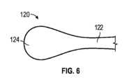
図6に示されるように、突出フィーチャ120のうちの1つ又は複数は、突出フィーチャ120の末端にステム122及び拡大ヘッド124を含み得る。例えば、ヘッド124は、ステム122の幅よりも大きい幅又は他の寸法を有していてもよい。拡大されたヘッド124は、血栓又は他の塊との係合を増大させるために、広い領域を覆うような寸法にすることができる。As shown in FIG. 6, one or more of the raised features 120 may include a
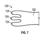
図7に示されるように、突出フィーチャ120のうちの1つ又は複数は、突出フィーチャ120の末端で互いに間隔を置いて配置されたステム122及び複数のヘッド124を含み得る。複数のヘッド124は、柔軟性を維持しながら、広い領域を覆うように寸法設定及び分布され得る。As shown in FIG. 7, one or more of the raised features 120 may include a
図8に示されるように、突出フィーチャ120のうちの1つ又は複数は、突出フィーチャ120のヘッド124を通って延在する開口部126を提供するループを備えたステム122及びヘッド124を含み得る。ループは、そこを通過できるようにしながら、広い領域を覆い得る。As shown in FIG. 8, one or more of the raised features 120 may include a
図9に示されるように、突出フィーチャ120のうちの1つ又は複数は、ステム122及び/又はヘッドにおいて、その外面に沿って表面フィーチャ128を含み得る。表面フィーチャ128は、パターン化されたテクスチャを形成するノッチ、カット、ディボット、ディンプル、リッジ、チャネルなどを含み得る。表面フィーチャ128は、突出フィーチャ120の長さに沿って分布され得る。任意の突出フィーチャ120は、様々な異なる表面フィーチャのうちの1つ又は複数を含み得る。As shown in FIG. 9, one or more of the raised features 120 may include surface features 128 along their outer surfaces at the
再び図1及び図2を参照すると、回収デバイス100は、フレーム110の近位に拡大された部分140を含み得る。拡大された部分140は、フレーム110と一体的に及び/又はモノリシックに形成され得る。拡大された部分140は、拡大された構成において、フレーム110の外寸よりも大きい外寸を呈し得る。したがって、拡大された部分140は、回収デバイス100が血管壁に沿って移動するときに、体の内腔の血管壁に係合及び/又はこすりつけて、血栓又は他の塊を血管壁から分離することができる。拡大された部分140は、回収デバイス100に沿って遠位に向けられる突起又は他のヘッド124を有し得る。1 and 2, the
回収デバイス100は、回収デバイス100を制御、位置決め、及び/又は調整するための構成要素に安全に接続するアンカー部分196を含み得る。例えば、アンカー部分196は、回収デバイス100を位置決め装置又は他の部材に安全に接続することができる。アンカー部分196は、回収デバイス100の中心軸190からオフセットされ得る。例えば、アンカー部分196は、回収デバイス100のフレーム110の一部と放射状に整列するか、隣接するか、又はその近くに配置され得る。回収デバイス100のフレーム110は、中間部分150によってアンカー部分196に接続され得る。中間部分150は、例えば、フレーム110の端部で異なる円周部分に接続するなど、フレーム110の異なる部分から延在する展開及び収縮のための柱の強度を補助するために様々な幅を有し得る複数の支柱を含み得る。中間部分150の支柱は、アンカー部分196に沿って同じ又は異なる軸方向位置に延在し得る。中間部分150の支柱の配置は、回収デバイス100の全長に沿って開いた中央空間を維持することができる。中間部分150は、回収デバイス100が血管壁に沿って移動するときに、体の内腔の血管壁に係合及び/又はこすりつけて、血栓又は他の塊を血管壁から分離することができる。The
図10~図13に示すように、アンカー部分196は、様々な配置の1つ又は複数で形成され得る。図10に示されるように、アンカー部分196は、アンカー部分196に沿った異なる軸方向位置から円周方向に延在する複数のリブ902を含み得る。リブ902は、位置決め装置との複数の接触点を提供するために、異なる軸方向位置に配置され得る。As shown in FIGS. 10-13, the
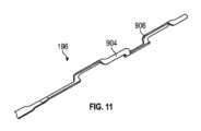
図11に示されるように、アンカー部分196は、異なる方向に延在する異なる部分を含み得る。例えば、アンカー部分196は、長手方向部分904及び円周部分906を含み得る。長手方向部分904の軸方向に隣接する対は、対応する円周部分906によって一緒に接続され得る。同様に、円周部分906の軸方向に隣接する対は、対応する長手方向部分904によって一緒に接続され得る。異なる長手方向部分904は、その上の異なる円周位置に配置された結合物を取り囲むように、異なる円周位置を有し得る。As shown in FIG. 11, the
図12に示されるように、アンカー部分196は、らせん状巻線908を含み得る。例えば、アンカー部分196は、その中に位置決め装置を受け入れるように構成された中央空間の周りにらせん状に巻くことができる。らせん状巻線908は、複数の(例えば、2、3、4、5、6、7、8、又は8を超える)ターンを含み得る。らせん状巻線908は、断面において、薄型を維持しながら位置決め装置と係合するための平坦な内側を提供する形状を含み得る。12, the
図13に示されるように、アンカー部分196は、複数の支柱910の配置を含み得る。支柱910は、位置決め装置を受け入れてそれに結合するための一般的に円筒形の形状を規定し得る。支柱910は、位置決め装置を受け入れるための空間の周りに長手方向及び/又は円周方向に延在し得る。支柱910は、任意の数のセルを形成することができ、それらは、互いに対して長さ及び/又は幅が変化し得る。As shown in FIG. 13, the
アンカー部分196は、回収デバイス100を位置決め装置に安全に接続することができる。例えば、アンカー部分196を位置決め装置に押し付けることができる。さらなる実例により、アンカー部分196を位置決め装置に結合することができる。追加的又は代替的に、スリーブは、アンカー部分196及び/又は位置決め装置の少なくとも一部の周りに提供され得る。例えば、ポリウレタン及びPebex(登録商標)(例えば、Pebex(登録商標)35D)を含む1つ又は複数の可撓性材料から成形された収縮チューブなどのチューブを、アンカー部分196及び/又は位置決め装置上のスリーブとして提供することができる。追加的又は代替的に、アンカー部分196は、回収デバイス100を位置決め装置に取り外し可能又は可逆的に接続することができる。例えば、アンカー部分196は、回収デバイス100を位置決め装置から制御可能に分離するための1つ又は複数の分離機構(例えば、電解、機械的、又は化学的)を備え得る。したがって、回収デバイス100は、制御可能に取り外して、標的の送達位置に残すことができる。The
図14~図16は、図1~図13に示されている回収デバイス100と共通のいくつかの機能を備えた変更された拡張可能な回収デバイス100を示している。したがって、共通の機能は、図1~図13で使用されているのと同じ番号で示され、上記の説明は、図14~図16の回収デバイス100に適用されると理解される。FIGS. 14-16 show a modified
図14~図16に示されるように、回収デバイス100は、任意選択で、回収デバイス100の遠位端に捕捉部材102を含み得る。捕捉部材102は、回収デバイス100が操作されるときに、血栓又は他の塊と相互作用するための係合及び/又は捕捉機能を提供し得る。例えば、捕捉部材102を使用して、血栓又は他の塊の遠位端に係合することができ、一方、フレーム110又は回収デバイス100の他の部分は、血栓又は他の塊の他の部分に係合する。さらなる実例により、捕捉部材102を使用して、血栓からの破片、他の塊、及び/又は任意の場所からの他の破片を捕捉することができる。As shown in FIGS. 14-16, the
捕捉部材102は、フレーム110の遠位端から遠位に延在する支柱又は他のフィーチャを含み得る。捕捉部材102は、フレーム110の外径から、回収デバイス100の遠位端でより小さな直径まで先細になり得る。捕捉部材102の支柱又は他のフィーチャは、フレーム110及び/又は回収デバイス100の他の部分と一体的に及び/又はモノリシックに形成することができる。或いは、捕捉部材102は、フレーム110の所望の位置に取り付けられた別々の、別個の構成要素を形成し得る。The
いくつかの実施例では、捕捉部材102は、例えば、捕捉部材102の支柱の上に配置された材料(例えば、PTFE、ダクロン、ナイロン及び/又はポリウレタンベースの材料などのポリアミド、シリコーンなど)を含み得る。いくつかの実施例では、材料は、捕捉部材102の外表面積全体を覆う。材料はメッシュ又はブレードにすることができる。いくつかの実施例では、材料は、回収デバイス100の内径を通る血流を可能にし、及び/又は回収デバイス100の外寸に血流を制限するようにさらに構成され得る。さらに、材料は、体の内腔の壁からの破片(例えば、血栓又は他の塊からの)が血流に入るのを防ぐように構成され得る。In some embodiments, the
図17は、図1~図16に示される回収デバイス100と共通のいくつかのフィーチャを有する修正された拡張可能な回収デバイス100を示す。したがって、共通の機能は、図1~図16で使用されているのと同じ番号で示され、上記の説明は、図17の回収デバイス100に適用されると理解される。FIG. 17 illustrates a modified
図17に示されるように、回収デバイス100は、そこでの相互作用のために、血栓、血餅、又は他の塊に拡張され得る。血栓の一部が中間フレーム部分110bと整列している場合、そのような部分は、近位フレーム部分110a及び遠位フレーム部分110cなどの対向するエンドフレーム部分の間に捕捉され得る。エンドフレーム部分110a及び110cは、中間フレーム部分110bの外側断面寸法(例えば、直径)よりも大きい外側断面寸法(例えば、直径)を有し得る。回収デバイス100が動かされると、血栓は、エンドフレーム部分110a及び110c、並びに中間フレーム部分110b、並びにそれらの間の及び/又はそれによって形成された遷移(例えば、テーパ部分又は階段状部分)によって促され得る。したがって、フレームは、突出フィーチャに加えて、血栓と係合してその動きを容易にすることができる。As shown in FIG. 17, the
図18は、図1~図17に示されている回収デバイス100と共通のいくつかの機能を備えた変更された拡張可能な回収デバイス100を示している。したがって、共通の機能は、図1~図17で使用されているのと同じ番号で示され、上記の説明は、図18の回収デバイス100に適用されると理解される。FIG. 18 illustrates a modified
図18に示されるように、回収デバイス100は、1つ又は複数のエンドフレーム部分と、1つ又は複数のエンドフレーム部分との間及び/又は隣接する中間フレーム部分とを有するフレームを含み得る。近位フレーム部分110a及び遠位フレーム部分110c及び/又は中間フレーム部分110bなどのエンドフレーム部分は、フレーム110に関して本明細書に記載されるフィーチャのうちの1つ又は複数を有し得る。エンドフレーム部分110a及び110cは、中間フレーム部分110bの外側断面寸法(例えば、直径)よりも大きい外側断面寸法(例えば、直径)を有し得る。エンドフレーム部分110a及び110cは、対応するエンドフレーム部分110a及び110cから半径方向内側に延在する、近位突出フィーチャ120a及び遠位突出フィーチャ120cなどの突出フィーチャを有し得る。中間フレーム部分110bは、中間フレーム部分110bから半径方向外向きに延在する突出フィーチャ120bを有し得る。突出フィーチャ120a及び/又は120bは、突出フィーチャ120に関して本明細書に記載されるフィーチャのうちの1つ又は複数を有し得る。任意選択で、中間フレーム部分110bから延在する中間突出フィーチャは、拡張構成において、エンドフレーム部分110a及び/又は110cの外側断面寸法(例えば、直径)を超えて半径方向に延在することができない。したがって、エンドフレーム部分110a及び110cは、フレーム110の最も外側の半径方向の範囲を規定することができる。突出フィーチャ120aは、エンドフレーム部分110a及び110c内からの血栓との係合を容易にすることができ、突出フィーチャ120bは、中間フレーム部分110bの外側からの血栓との係合を容易にすることができる。As shown in FIG. 18, the
図19は、図1~図18に示されている回収デバイス100と共通のいくつかの機能を備えた変更された拡張可能な回収デバイス100を示している。したがって、共通の機能は、図1~図18で使用されているのと同じ番号で示され、上記の説明は、図19の回収デバイス100に適用されると理解される。FIG. 19 illustrates a modified
図19に示されるように、エンドフレーム部分110a、中間フレーム部分110b、及び/又はそれらの間の及び/又はそれによって形成される遷移(例えば、テーパ部分)は、血栓と相互作用するための1つ又は複数のフィーチャを提供することができる。例えば、エンドフレーム部分110a、中間フレーム部分110b、及び/又はそれらの間の遷移(例えば、テーパ部分)は、中間フレーム部分110b及び/又は回収デバイス100の近位端に向かって軸方向に面するブレードフィーチャ132を規定することができる。ブレードフィーチャ132は、血栓と接触すると、血栓を切断、係合、又は他の方法で血栓と相互作用するように構成することができる。As shown in FIG. 19, the
本明細書に記載の回収デバイスは示されているフィーチャを有するが、様々な異なる回収デバイス及び他のデバイスを本明細書に記載の送達システムと共に使用できることが理解されよう。様々な機能を、限定ではなく例として以下に示す。Although the retrieval devices described herein have the features shown, it will be understood that a variety of different retrieval devices and other devices can be used with the delivery systems described herein. Various features are provided below by way of example and not limitation.
そのような回収デバイス及び他のデバイスに関して、本明細書に記載のフレーム110、支柱112、及び/又は突出フィーチャ120を形成するための材料は、強度、延性、硬度、弾性、柔軟性、曲げ弾性率、曲げ強度、可塑性、剛性、放射率、熱伝導率、比熱、熱拡散率、熱膨張、その他の様々な特性のいずれか、又はそれらの組み合わせなどの機械的及び/又は熱的特性に基づいて選択することができる。熱特性を有する材料から形成された場合、その材料を活性化して、所望の治療部位に熱処理を送達することができる。材料に関係なく、フレーム110、支柱112、及び/又は突出フィーチャ120は、レーザー切断又は他の適切な技術によって、チューブ又はソリッドワイヤなどのワイヤから形成することができる。ワイヤから形成される場合、ワイヤの一部は、化学エッチング又は別の適切な方法によって除去されて、回収デバイスの内部寸法を作成することができる。For such and other devices, materials for forming the
回収デバイス100は、血管を破裂させずに、血管を含む様々な体の内腔内に配置するための寸法及び形状にすることができる。例えば、いくつかの回収デバイス及び他の構造は、それらに解剖又は損傷を引き起こすことなく半径方向の強度を有し得る。本明細書に記載の回収デバイスが配置のために寸法決定及び成形され得る血管には、冠状動脈、末梢動脈、頸動脈、ウィリスの輪、前大脳動脈、中大脳動脈、後大脳動脈、任意のレンチキュロストリエート動脈、腎動脈、大腿動脈、脳静脈などの静脈、伏在静脈、動静脈瘻、又は治療部位を含む可能性のあるその他の血管などの動脈が含まれる。回収デバイス100は、立方体、直角プリズム、円筒、円錐、ピラミッド、又はそれらの変形を含む様々な形状を有し得る。
突出フィーチャ120を有する回収デバイス100は、様々な寸法を含み得る(薄型の送達状態及び拡張された展開状態の両方で)。これらの実施例は、解剖を治療及び/又は予防するなど、広範囲の寸法を覆う様々な状況での使用を可能にする拡張を提供することができる。形状に関係なく、回収デバイスは、約0.25mm、約0.5mm、約1mm、約2mm、約3mm、約4mm、約5mm、約6mm、約7mm、約8mm、約9mm、約10mm、約12mm、約14mm、約16mm、約18mm、約20mm、約30mm、約40mm、約50mm、約60mm、約70mm、約80mm、約90mm、又は約100mmの長さを有し得る。さらに、立方体、長方形のプリズム、又はピラミッドに成形された回収デバイスは、約0.25mm、約0.5mm、約1mm、約2mm、約3mm、約4mm、約5mm、約6mm、約7mm、約8mm、約9mm、約10mm、約12mm、約14mm、約16mm、約18mm、約20mm、約25mm、又は約30mmの幅を有し得る。さらに、円筒形又は円錐形に成形された回収デバイスは、約0.25mm、約0.5mm、約1mm、約2mm、約3mm、約4mm、約5mm、約6mm、約7mm、約8mm、約9mm、約10mm、約12mm、約14mm、約16mm、約18mm、約20mm、約25mm、約30mm、約35mm、約40mm、又は約50mmの直径を有し得る。回収デバイス100の幅又は直径は、回収デバイス100の長さに沿って漸減的に減少し得る。さらに、回収デバイス100は、回収デバイスの位置決め手順などの特定の手順のために体の内腔を準備するように寸法設定及び成形することができる。The
回収デバイス100及び/又は拡張状態にある他の拡張可能な構造は、約2mmから約10mmの断面寸法を有し得る。例えば、フレーム110は、約1mmから約9mmの断面寸法を有することができ、突出フィーチャ120は、それぞれ、約0.1mmから約4.5mmの長さを有し得る。いくつかの実施例では、回収デバイス100は、約4mmの全体断面寸法を有し、フレーム110は、約2mmの断面寸法を有し、突出フィーチャ120は、それぞれ、約1mmの長さを有する。いくつかの実施例では、回収デバイス100は、約6mmの全体断面寸法を有し、フレーム110は、約4mmの断面寸法を有し、突出フィーチャ120は、それぞれ、約1.5mmの長さを有する。さらなる実施例では、突出フィーチャ120は、回収デバイス又は他の拡張可能な構造の突出フィーチャ120の長さが異なるように、複数の長さを有し得る。例えば、回収デバイスは、約0.2mm、約0.5mm、及び約1mmの長さを有する突出フィーチャ120を含み得る。
回収デバイス100のプロファイルは、回収デバイス100が広範囲のカテーテル寸法と互換性があるような寸法にすることができる。本技術による実施例は、直径0.0254cm(0.010インチ)、0.03556cm(0.014インチ)、0.04572cm(0.018インチ)、0.0889cm(0.035インチ)、又は0.09652cm(0.038インチ)を有するガイドワイヤなどのガイドワイヤを受容するように設計された回収デバイス又は他の構造を含み得る。いくつかの実施例では、回収デバイス100は、それが押し通されるマイクロカテーテルを介して送達するための寸法及び設計が可能である。いくつかの実施例では、回収デバイス100は、モジュール式又は単一ユニットの送達システムを含む送達システムに組み込むことができる。The profile of the
回収デバイス100は、1つ又は複数の放射線不透過性マーカなど、体の内腔内の回収デバイス100を視覚化するためのマーキングを含み得る。放射線不透過性マーカは、Clearfil PhotoCorePLT(登録商標)、タンタル、チタン、タングステン、硫酸バリウム、酸化ジルコニウム、又は別の適切な放射線不透過性マーキングから形成され得る。マーキングは、回収デバイス100の近位部分、遠位部分、中間部分、又はそれらの組み合わせに形成することができる。マーキングは、バンド、コイル、クリップであり得、回収デバイス100の管の1つ又は複数の部分に充填され、回収デバイス100の1つ又は複数の部分にめっきされ、又はそれらの組み合わせであり得る。マーキングのタイプに関係なく、マーキングは、回収デバイス100の任意の部分に沿って、又はその任意の部分に、造られ、かしめられ、包まれ、又はおおわれ得る。
回収デバイス100は、湾曲を有するものを含む様々な解剖学的フィーチャを追跡するのに十分な柔軟性を有し得る。回収デバイス100の柔軟な特性は、それらが形成された材料によって提供することができる。さらに、柔軟な特性は、支柱112の2つ以上の列と係合し、それらの間に延在する部材の1つ又は複数を破壊することによって提供することもできる。さらに、回収デバイス100は、容易に展開及び拡張され、収縮され及び縮まらされ得る。回収デバイス100はまた、血管又は他の体の内腔内に容易に再配置することができる。
いくつかの実施例において、薬剤溶出化合物は、突出フィーチャ120、フレーム110、及び/又は支柱112の少なくとも一部にコーティングされる。コーティングは、薬物を送達するのに適した当業者に知られている任意の適切なコーティングであり得る。例えば、適切なコーティングには、雪コーティング又は壁に残るように構成されたエッジを有する結晶性コーティングが含まれるが、これらに限定されない。薬剤溶出性化合物は、そこに含まれる薬物を送達するのに適した様々な異なるパターン及び厚さにコーティングされた合成又は生物学的ポリマーであり得る。いくつかの実施例において、突出フィーチャ120自体は、薬剤溶出材料から構成され得る。本技術による薬剤溶出化合物及び/又は突出フィーチャ120によって運ばれる薬剤は、回収デバイス100が配置される治療部位を治療するのに適した任意の薬剤であり得、賦形剤を含んでもよいし含まなくてもよい。例えば、薬物は、抗増殖性、抗腫瘍性、遊走阻害剤、増強された治癒因子、免疫抑制剤、抗血栓剤、抗凝血剤、又は放射性化合物であり得る。いくつかの実施例では、薬剤溶出化合物及び/又は突出フィーチャ120は、2つ以上の薬剤を運ぶことができる。In some embodiments, the drug eluting compound is coated on at least a portion of the projecting
いくつかの実施例では、突出フィーチャ120は、薬物送達のためにより大きな表面積を提供すると予想されるテクスチャード加工された(例えば、リブ付きの)表面を含み得る。さらに、突出フィーチャ120は、リブ付きの表面(突出フィーチャの長手方向の平面に対して垂直、水平、放射状、又は円形)、クロスハッチングされた表面、等方性の表面、又は血栓の係合のためにより大きな表面積を提供するのに適した他の表面タイプなど、テクスチャード加工された表面を含み得る。In some examples, the raised features 120 may include a textured (e.g., ribbed) surface that is expected to provide a larger surface area for drug delivery. Additionally, the raised features 120 may include textured surfaces, such as ribbed surfaces (perpendicular, horizontal, radial, or circular relative to the longitudinal plane of the raised features), cross-hatched surfaces, isotropic surfaces, or other surface types suitable for providing a larger surface area for thrombus engagement.
突出フィーチャ120は、血栓、塞栓、血餅、閉塞、又はそれらの組み合わせと係合及び/又は貫通するような寸法及び形状にすることができる。さらに、回収デバイス100は、拡張位置にある間でさえ、血液が流れることを可能にすることができる。The protruding features 120 can be sized and shaped to engage and/or penetrate a thrombus, embolus, clot, occlusion, or combinations thereof. Additionally, the
さらに、回収デバイス100は、回収デバイス100の1つ又は複数の部分上に1つ又は複数の突出フィーチャ120を運ぶことができることが理解されよう。例えば、回収デバイス100は、約5つの突出フィーチャ、約10個の突出フィーチャ、約15個の突出フィーチャ、約20個の突出フィーチャ、約30個の突出フィーチャ、約40個の突出フィーチャ、約50個の突出フィーチャ、約60個の突出フィーチャ、約70個の突出フィーチャ、約80個の突出フィーチャ、約90個の突出フィーチャ、又は約100個の突出フィーチャを運ぶことができる。突出フィーチャ120は、フレーム110、支柱112、又はそれらの組み合わせによって運ぶことができる。突出フィーチャ120の数は、例えば、標的治療部位、治療される物体(例えば、血栓)、及び/又は回収デバイス100の寸法などに応じて変化し得る。さらに、回収デバイス100によって運ばれる突出フィーチャ120は、本明細書に開示される異なるタイプの突出フィーチャ120であり得る。Furthermore, it will be appreciated that the
本明細書に記載の実施例は、構造が配置された治療領域及び/又は隣接する体の内腔内の他のデバイス又は治療手段を通って流体(例えば、血液)が流れることを依然として可能にしながら、血管系などの体の内腔内の特定の領域に薬物を送達するための手段を有する1つ又は複数の構造のための送達システムを提供する。いくつかの実施例では、システムの1つ又は複数の領域が体の内腔から送達、展開、配置、及び/又は除去されている間、流体が治療領域を通って流れるのを一時的に防止される。さらに、送達システムは、治療部位の近位又は遠位で、回収デバイスを掻き集めること、回収デバイスを引っ張ること、回収デバイスを回転させること、又はそれらの組み合わせによって、治療のために体の内腔を準備するように構成することができる。いくつかの実施例では、送達システムは、機械的な力が加えられたときに回収デバイスを回転させるように構成することができる。The embodiments described herein provide a delivery system for one or more structures having means for delivering a drug to a specific region in a body lumen, such as the vasculature, while still allowing fluid (e.g., blood) to flow through the treatment region in which the structure is located and/or other devices or treatments in the adjacent body lumen. In some embodiments, fluid is temporarily prevented from flowing through the treatment region while one or more regions of the system are delivered, deployed, positioned, and/or removed from the body lumen. Additionally, the delivery system can be configured to prepare the body lumen for treatment by raking the retrieval device, pulling the retrieval device, rotating the retrieval device, or combinations thereof, proximal or distal to the treatment site. In some embodiments, the delivery system can be configured to rotate the retrieval device when a mechanical force is applied.
ここで図20~図27を参照すると、本明細書で説明される方法は、送達デバイス90の動作によって、標的送達位置への回収デバイス100の送達を提供する。本明細書では、それらの様々な段階の方法が議論及び図示されているが、各方法の複数の変形もまた企図されることが理解されるであろう。例えば、方法は、様々な操作の順序で、追加の操作で、又はより少ない操作で実行され得る。20-27, the methods described herein provide for delivery of a
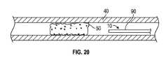
図20~図23は、血栓摘出法の例の段階を示している。図20に示されるように、送達システム10の送達デバイス90は、血栓50又は他の塊を含む血管40内の場所に持ち込むことができる。送達デバイス90は、血栓50の上流又は下流に配置することができる。送達デバイス90は、回収デバイスがその中に含まれている間に配置することができる。或いは、送達デバイス90を配置することができ、回収デバイスは、後の段階において送達デバイス90内で前進させることができる。送達デバイス90は、ガイドワイヤ及び/又は1つ又は複数の他のデバイスの助けを借りて配置することができる。20-23 show stages of an example thrombectomy procedure. As shown in FIG. 20, the
図21に示されるように、送達デバイス90は、血管40内及び血栓50を通って前進することができる。したがって、送達デバイス90の遠位端は、血栓50の遠位端に対して遠位に配置することができる。そのような操作は、回収デバイスが血栓50の少なくとも一部にまたがるように、回収デバイスを送達デバイス90内の位置に配置することができる。As shown in FIG. 21, the
図22に示されるように、回収デバイス100が所与の位置に維持されている間、送達デバイス90は近位に引っ込めることができる。送達デバイス90が回収デバイス100を外すとき、回収デバイス100は放射状に拡張することができる。回収デバイス100は、拘束から解放されると自己拡張することができる。追加的又は代替的に、回収デバイス100は、外部刺激(例えば、機械力、熱刺激、化学反応など)によって拡張可能であり得る。例えば、拡張可能なバルーンデバイス(図示せず)を提供して、回収デバイス100内で拡張することができる。このような拡張には、フレーム及び/又は拡大部分の拡張が含まれ得る。拡張構成では、フレーム及び/又は拡大部分は、血管40の内壁に係合することができる。さらに、回収デバイス100の拡張は、回収デバイス100のフレーム内及び血栓50内への突出フィーチャ120の展開を含み得る。回収デバイス100は、血栓の長さの少なくとも一部に延在し、係合することができる。図22に示されるように、回収デバイス100の少なくとも一部は、血栓50の遠位及び/又は近位に延在し得る。回収デバイス100が捕捉部材102を含む場合、捕捉部材102の少なくとも一部は、血栓50の少なくとも一部に対して遠位に延在し得る。As shown in FIG. 22, the
図23に示されるように、回収デバイス100は、送達デバイス90に向かって及び/又は送達デバイス90内に近位方向に引っ込めることができる。追加的又は代替的に、回収デバイス100は、送達デバイス90と共に別のデバイスに近位に引っ込めることができる。回収デバイス100が移動すると、回収デバイス100の拡大部分及び/又は中間部分は、血栓50を血管40の壁から分離することができる。さらに、回収デバイス100が引っ込められると、血栓50は、回収デバイス100によって運ばれ得る。例えば、回収デバイス100の突出フィーチャ120は、その様々な部分で血栓50と係合して、血栓50を回収デバイス100と共に近位に押しやることができる。回収デバイス100及び血栓50は、送達デバイス90及び/又は別のデバイス内に捕捉されるまで移動することができる。そのような捕捉は、送達デバイス90及び/又は別のデバイスの遠位端への流体の吸引によって促進及び/又は強化することができる。As shown in FIG. 23, the
図24~図27は、血栓摘出法の別の例の段階を示している。図24に示されるように、送達システム10の送達デバイス90は、血栓50又は他の塊を含む血管40内の場所に持ち込むことができる。送達デバイス90は、血栓50の上流又は下流に配置することができる。送達デバイス90は、回収デバイスがその中に含まれている間に配置することができる。或いは、送達デバイス90を配置することができ、回収デバイスは、後の段階で送達デバイス90内で前進させることができる。送達デバイス90は、ガイドワイヤ及び/又は1つ又は複数の他のデバイスの助けを借りて配置することができる。24-27 show steps in another example of a thrombectomy procedure. As shown in FIG. 24, the
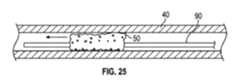
図25に示されるように、送達デバイス90は、血管40内及び血栓50を通って前進することができる。したがって、送達デバイス90の遠位端は、血栓50の遠位端に対して遠位に配置することができる。そのような操作は、回収デバイスが血栓50の少なくとも部分的又は完全に遠位に配置されるように、回収デバイス90内の位置に回収デバイスを配置することができる。As shown in FIG. 25, the
図26に示されるように、回収デバイス100が所与の位置に維持されている間、送達デバイス90は近位に引っ込めることができる。送達デバイス90が回収デバイス100を外すとき、回収デバイス100は放射状に拡張することができる。回収デバイス100は、拘束から解放されると自己拡張することができる。追加的又は代替的に、回収デバイス100は、外部刺激(例えば、機械力、熱刺激、化学反応など)によって拡張可能であり得る。例えば、拡張可能なバルーンデバイス(図示せず)を提供して、回収デバイス100内で拡張することができる。このような拡張には、フレーム及び/又は拡大部分の拡張が含まれ得る。拡張構成では、フレーム及び/又は拡大部分は、血管40の内壁に係合することができる。さらに、回収デバイス100の拡張は、回収デバイス100のフレーム内に突出フィーチャ120の展開を含み得る。図26に示されるように、回収デバイス100の少なくとも一部は、血栓50に対して少なくとも部分的又は完全に遠位に配置することができる。回収デバイス100が捕捉部材102を含む場合、捕捉部材102の少なくとも一部は、血栓50の少なくとも一部に対して遠位に延在し得る。As shown in FIG. 26, the
図27に示されるように、回収デバイス100は、送達デバイス90に向かって及び/又は送達デバイス90内に近位方向に引っ込めることができる。回収デバイス100は、血栓50に対して少なくとも部分的又は完全に遠位である位置に最初に配置及び拡張されたので、回収デバイス100は、血栓50内に近位に移動し、それによって血栓50と係合することができる。次に、回収デバイス100は、血栓50の長さの少なくとも一部と係合することができる。追加的又は代替的に、回収デバイス100は、送達デバイス90と共に別のデバイスに近位に引っ込めることができる。回収デバイス100が移動すると、回収デバイス100の拡大部分及び/又は中間部分は、血栓50を血管40の壁から分離することができる。さらに、回収デバイス100が引っ込められると、血栓50は、回収デバイス100によって運ばれることができる。例えば、回収デバイス100の突出フィーチャ120は、その様々な部分で血栓50と係合して、血栓50を回収デバイス100と共に近位に押しやることができる。回収デバイス100及び血栓50は、送達デバイス90及び/又は別のデバイス内に捕捉されるまで移動することができる。そのような捕捉は、送達デバイス90及び/又は別のデバイスの遠位端への流体の吸引によって促進及び/又は強化することができる。As shown in FIG. 27, the
本明細書に記載の送達システム、送達デバイス、及び/又は回収デバイスが配置のために寸法決定及び成形され得る血管には、冠状動脈、末梢動脈、頸動脈、ウィリスの輪、前大脳動脈、中大脳動脈、後大脳動脈、任意のレンチキュロストリエート動脈、腎動脈、大腿動脈、脳静脈などの静脈、伏在静脈、動静脈瘻、又は治療部位を含み得るその他の血管などの動脈が含まれる。他の血管も同様に企図され、送達システム、送達デバイス、及び/又は回収デバイスは、患者の体内の既知の目的地及び/又は移動経路に従って形成及び/又は選択することができる。Blood vessels in which the delivery systems, delivery devices, and/or retrieval devices described herein may be sized and shaped for placement include arteries such as coronary arteries, peripheral arteries, carotid arteries, the Circle of Willis, the anterior cerebral artery, the middle cerebral artery, the posterior cerebral artery, any lenticulostriate artery, renal arteries, femoral arteries, veins such as cerebral veins, saphenous veins, arteriovenous fistulas, or other vessels that may contain treatment sites. Other blood vessels are similarly contemplated, and the delivery systems, delivery devices, and/or retrieval devices may be shaped and/or selected according to known destinations and/or travel routes within the patient's body.
本開示の態様の様々な例を、便宜上の条項として以下に説明する。これらは例として提供されており、対象技術を制限するものではない。Various examples of aspects of the present disclosure are described below for convenience. These are provided as examples and are not intended to limit the subject technology.
条項A:相互接続された支柱を有し、折り畳み構成から拡張構成に拡張するように構成されたフレームと、フレームが拡張構成にある場合に、フレームから半径方向内側に延在する突出フィーチャと、フレームの近位端に接続されたアンカー部分と、を有する回収デバイス。Clause A: A retrieval device having a frame having interconnected struts and configured to expand from a collapsed configuration to an expanded configuration, a protruding feature extending radially inward from the frame when the frame is in the expanded configuration, and an anchor portion connected to a proximal end of the frame.
条項B:フレームを長手方向に通って延在する管腔と、フレームの外部から管腔まで延在する開口部とを規定するフレームであって、折り畳み構成から拡張構成に拡張するように構成されている、フレームと、フレームから延在する突出フィーチャであって、折り畳み構成では、突出フィーチャが開口部内で長手方向に延在し、拡張構成では、突出フィーチャが管腔内で半径方向内側に延在する、突出フィーチャと、を有する回収デバイス。Clause B: A retrieval device having a frame defining a lumen extending longitudinally through the frame and an opening extending from an exterior of the frame to the lumen, the frame being configured to expand from a collapsed configuration to an expanded configuration, and a protruding feature extending from the frame, where in the collapsed configuration the protruding feature extends longitudinally within the opening and where in the expanded configuration the protruding feature extends radially inward within the lumen.
条項C:送達システムの少なくとも一部を少なくとも部分的に血栓を横切って配置することであって、送達システムは、送達デバイスの管腔内にある間は折り畳み構成にある回収デバイスを含む送達デバイスを含む、ことと、送達デバイスの外部に回収デバイスを拡張することと、拡張構成において血栓を回収デバイスに係合させることであって、血栓との係合は、血栓を回収デバイスの突出フィーチャと接触させることを含み、突出フィーチャは、回収デバイスのフレームから半径方向内側に延在する、ことと、回収デバイスを送達デバイスに向かって引っ込めることと、を含む方法。Clause C: A method comprising: positioning at least a portion of a delivery system at least partially across a thrombus, the delivery system including a delivery device including a retrieval device in a collapsed configuration while within a lumen of the delivery device; expanding the retrieval device out of the delivery device; engaging the thrombus with the retrieval device in the expanded configuration, the engaging the thrombus including contacting the thrombus with a protruding feature of the retrieval device, the protruding feature extending radially inward from a frame of the retrieval device; and retracting the retrieval device toward the delivery device.
上記の条項の1つ又は複数は、以下で説明する機能の1つ又は複数を含み得る。以下の条項のいずれかを互いに任意の組み合わせで組み合わせて、それぞれの独立した条項、例えば、条項A、B、又はCに配置することができることに留意されたい。One or more of the above clauses may include one or more of the features described below. Please note that any of the following clauses may be combined with one another in any combination and placed into their own independent clauses, e.g. clauses A, B, or C.
条項1:突出フィーチャが、アンカー部分から半径方向内向き及び長手方向の両方に延在する。Clause 1: The protruding feature extends both radially inward and longitudinally from the anchor portion.
条項2:相互接続された支柱が、相互接続された支柱のうち複数の支柱が互いに接続されて頂点を形成するように配置され、突出フィーチャの1つが頂点から延在する。Clause 2: The interconnected struts are arranged such that a plurality of the interconnected struts are connected to one another to form a vertex, and one of the protruding features extends from the vertex.
条項3:相互接続された支柱が、突出フィーチャの1つとは反対側の頂点の側に間隙を形成する。Clause 3: The interconnected struts form a gap on the side of the apex opposite one of the protruding features.
条項4:突出フィーチャのそれぞれがステムを備えたフレームから延在し、突出フィーチャがそれぞれその端部で終端してヘッドを形成する。Clause 4: Each of the projecting features extends from a frame having a stem, and each of the projecting features terminates at an end thereof to form a head.
条項5:ヘッドがステムの幅よりも大きい幅を有する。Clause 5: The head has a width greater than the width of the stem.
条項6:ヘッドが、ステムから延在する複数の部分を有する。Clause 6: The head has multiple portions extending from the stem.
条項7:ヘッドが開口部を形成する。Clause 7: The head forms an opening.
条項8:ステムが、その長さに沿ってパターン化されたテクスチャを形成する。Clause 8: The stem forms a patterned texture along its length.
条項9:突出フィーチャがフレームとモノリシックに形成される。Clause 9: The protruding feature is formed monolithically with the frame.
条項10:フレームの遠位端に捕捉部材であって、捕捉部材は、捕捉部材がフレームから遠位方向に延在するにつれて、フレームの断面寸法からフレームの中心軸に向かって先細になる。Clause 10: A capture member at a distal end of the frame, the capture member tapering from a cross-sectional dimension of the frame toward a central axis of the frame as the capture member extends distally from the frame.
条項11:フレームの近位端に接続されたアンカー部分であって、フレームの中心軸から半径方向にオフセットされている、アンカー部分と、アンカー部分をフレームに接続する中間部分であって、管腔の一部を形成する、中間部分。Clause 11: An anchor portion connected to a proximal end of the frame, the anchor portion being radially offset from a central axis of the frame, and an intermediate portion connecting the anchor portion to the frame, the intermediate portion forming a portion of the lumen.
条項12:フレームが、近位フレーム部分と、中間フレーム部分と、遠位フレーム部分と、を規定し、近位フレーム部分及び遠位フレーム部分が、中間フレーム部分の断面寸法よりも大きい断面寸法を有する。Clause 12: The frame defines a proximal frame portion, an intermediate frame portion, and a distal frame portion, the proximal frame portion and the distal frame portion having a cross-sectional dimension greater than a cross-sectional dimension of the intermediate frame portion.
条項13:突出フィーチャは、近位フレーム部分から半径方向内側に延在する近位突出フィーチャと、遠位フレーム部分から半径方向内側に延在する遠位突出フィーチャと、を有し、回収デバイスは、中間フレーム部分から半径方向外向きに延在する中間突出フィーチャをさらに有する。Clause 13: The protruding features include a proximal protruding feature extending radially inward from the proximal frame portion and a distal protruding feature extending radially inward from the distal frame portion, and the retrieval device further includes an intermediate protruding feature extending radially outward from the intermediate frame portion.
条項14:回収デバイスを拡張することは、フレームを血栓内に拡張することを含む。Clause 14: Expanding the retrieval device includes expanding the frame into the thrombus.
条項15:回収デバイスを拡張することは、突出フィーチャをフレームの開口部内の位置からフレームを通って延在する管腔内の位置に移行させることを含む。Clause 15: Expanding the retrieval device includes transitioning the protruding feature from a position within the opening in the frame to a position within a lumen extending through the frame.
条項16:回収デバイスを拡張することは、突出フィーチャを長手方向に延在することから半径方向内側に延在することへと移行させることを含む。Clause 16: Expanding the retrieval device includes transitioning the protruding features from extending longitudinally to extending radially inward.
したがって、本開示は、患者の体の内腔からの血栓又は他の塊の係合及び捕捉を容易にする、内向きに面する突出フィーチャを有する回収デバイスを提供する。突出フィーチャは、回収デバイスのフレームから展開して、フレームの反対側に向かって半径方向内側に延在することができる。血栓に配置されると、突出フィーチャが血栓に係合し、回収デバイスが移動して捕捉を容易にするように促す。Thus, the present disclosure provides a retrieval device having inwardly facing protruding features that facilitate engagement and capture of a thrombus or other mass from a lumen in a patient's body. The protruding features can deploy from a frame of the retrieval device and extend radially inward toward opposite sides of the frame. When positioned on the thrombus, the protruding features engage the thrombus and encourage the retrieval device to move to facilitate capture.
単数形の要素への言及は、特に明記されていない限り、1つだけを意味するのではなく、1つ又は複数を意味する。例えば、「a」モジュールは1つ又は複数のモジュールを指す場合がある。「a」、「an」、「the」、又は「said」が続く要素は、さらなる制約なしに、追加の同じ要素の存在を排除するものではない。Reference to an element in the singular does not mean only one, but one or more, unless specifically stated otherwise. For example, "a" module may refer to one or more modules. An element followed by "a," "an," "the," or "said" does not, without further constraints, preclude the presence of additional identical elements.
見出し及び小見出しは、もしあれば、便宜のためにのみ使用され、本発明を限定するものではない。例示的なという言葉は、例又は実例として役立つことを意味するために使用される。「含む」、「有する」などの用語が使用される限り、そのような用語は、「含む」という用語が、請求項において過渡的な単語として使用される場合に解釈されるのと同様の方法で包括的であることを意図する。第1及び第2などの関係用語は、そのようなエンティティ又は動作間の実際のそのような関係又は順序を必ずしも必要又は暗示することなく、あるエンティティ又は動作を別のエンティティ又は動作から区別するために使用され得る。Headings and subheadings, if any, are used for convenience only and are not limiting of the invention. The word exemplary is used to mean serving as an example or illustration. To the extent that terms such as "comprises," "having," and the like are used, such terms are intended to be inclusive in the same manner as the term "comprises" is interpreted when used as a transitional word in the claims. Relative terms such as first and second may be used to distinguish one entity or operation from another entity or operation without necessarily requiring or implying an actual such relationship or order between such entities or operations.
ある態様、前記態様、別の態様、いくつかの態様、1つ又は複数の態様、ある実装、前記実装、別の実装、いくつかの実装、1つ又は複数の実装、ある実施例、前記実施例、別の実施例、いくつかの実施例、1つ又は複数の実施例、ある構成、前記構成、別の構成、いくつかの構成、1つ又は複数の構成、主題技術、開示、本開示、それらの他の変形例などは、便宜上のものであり、そのような句に関連する開示が対象技術に不可欠であること、又はそのような開示が対象技術のすべての構成に適用されることを意味するものではない。そのような句に関連する開示は、すべての構成、又は1つ又は複数の構成に適用され得る。そのような句に関連する開示は、1つ又は複数の例を提供し得る。1つ又はいくつかの態様などの句は、1つ又は複数の態様を指す場合があり、その逆もあり得、これは、他の前述の句と同様に適用される。Terms such as "an aspect," "the aspect," "another aspect," "some aspects," "one or more aspects," "an implementation," "the implementation," "another implementation," "some implementation," "one or more implementations," "an embodiment," "the embodiment," "another embodiment," "some embodiments," "one or more embodiments," "a configuration," "the configuration," "another configuration," "some configuration," "one or more configurations," the subject technology, the disclosure, the present disclosure, other variations thereof, and the like are for convenience and do not imply that disclosure associated with such phrases is essential to the subject technology or that such disclosure applies to all configurations of the subject technology. Disclosure associated with such phrases may apply to all configurations, or to one or more configurations. Disclosure associated with such phrases may provide one or more examples. Phrases such as "one or some aspects" may refer to one or more aspects, and vice versa, as with other aforementioned phrases.
一連のアイテムの前にある「の少なくとも1つ」という句において、アイテムのいずれかを区切る「及び」又は「又は」という用語は、リストの各メンバーではなく、リスト全体を変更する。「の少なくとも1つ」という句は、少なくとも1つの項目を選択する必要はなく、むしろ、この句は、アイテムのいずれか1つのうちの少なくとも1つ、及び/又はアイテムの任意の組み合わせのうちの少なくとも1つ、及び/又はアイテムのそれぞれのうちの少なくとも1つを含む意味を可能にする。実例として、「A、B、及びCの少なくとも1つ」又は「A、B、又はCの少なくとも1つ」という句のそれぞれは、Aのみ、Bのみ、又はCのみ、A、B、及びCの任意の組み合わせ、及び/又はA、B、及びCのそれぞれの少なくとも1つを指す。In the phrase "at least one of" preceding a list of items, the term "and" or "or" separating any of the items modifies the entire list, not each member of the list. The phrase "at least one of" does not require the selection of at least one item; rather, the phrase allows for a meaning including at least one of any one of the items, and/or at least one of any combination of the items, and/or at least one of each of the items. Illustratively, each of the phrases "at least one of A, B, and C" or "at least one of A, B, or C" refers to A only, B only, or C only, any combination of A, B, and C, and/or at least one of each of A, B, and C.
開示されたステップ、操作、又はプロセスの特定の順序又は階層は、例示的なアプローチの例示であることが理解される。特に明記されていない限り、ステップ、操作、又はプロセスの特定の順序又は階層は、異なる順序で実行される可能性があることが理解される。ステップ、操作、又はプロセスの一部は同時に実行され得る。付随する方法は、もしあれば、サンプルの順序で様々なステップ、操作又はプロセスの要素を提示し、提示された特定の順序又は階層に限定されることを意味しないと主張する。これらは、直列、線形、並列、又は異なる順序で実行され得る。It is understood that the specific order or hierarchy of steps, operations, or processes disclosed is illustrative of example approaches. Unless otherwise stated, it is understood that the specific order or hierarchy of steps, operations, or processes may be performed in different orders. Some of the steps, operations, or processes may be performed simultaneously. The accompanying methods present the various steps, operations, or process elements, if any, in a sample order, and are not meant to be limited to the specific order or hierarchy presented. These may be performed in serial, linear, parallel, or in a different order.
一態様では、結合などの用語は、直接結合されることを指す場合がある。別の態様では、結合されたなどの用語は、間接的に結合されていることを指す場合がある。In one aspect, terms such as bonded may refer to being directly bonded. In another aspect, terms such as bonded may refer to being indirectly bonded.
上、下、前、後、側面、水平、垂直などの用語は、通常の重力座標系ではなく、任意の座標系を指す。したがって、そのような用語は、重力座標系において上向き、下向き、斜め、又は水平に延在し得る。Terms such as top, bottom, front, back, side, horizontal, vertical, etc. refer to any coordinate system, not just the usual gravitational coordinate system. Thus, such terms may extend upward, downward, diagonally, or horizontally in the gravitational coordinate system.
本開示は、当業者が本明細書に記載の様々な態様を実施できるようにするために提供される。場合によっては、対象技術の概念を曖昧にすることを回避するために、よく知られている構造と構成要素がブロック図の形式で表示される。本開示は、対象技術の様々な例を提供し、対象技術はこれらの例に限定されない。これらの態様に対する様々な修正は、当業者には容易に明らかであり、本明細書に記載の原理は、他の態様に適用することができる。The present disclosure is provided to enable those skilled in the art to practice the various aspects described herein. In some cases, well-known structures and components are shown in block diagram form to avoid obscuring concepts of the subject technology. The present disclosure provides various examples of the subject technology, and the subject technology is not limited to these examples. Various modifications to these aspects will be readily apparent to those skilled in the art, and the principles described herein may be applied to other aspects.
本開示を通じて記載された、当業者に知られている、又は後に知られるようになる様々な態様の要素に相当するすべての構造的及び機能的同等物は、参照により本明細書に明示的に組み込まれ、特許請求の範囲に含まれることが意図される。さらに、本明細書に開示されるものは、そのような開示が特許請求の範囲に明示的に記載されているかどうかにかかわらず、公衆に捧げられることを意図するものではない。要素が「のための手段」という句を使用して明示的に引用されていない限り、又は方法クレームの場合、要素が「のためのステップ」という句を使用して引用されていない限り、合衆国法典第35編§112、第6段落、の規定に基づいてクレーム要素を解釈することはできない。All structural and functional equivalents to the elements of the various aspects described throughout this disclosure that are known or later become known to those skilled in the art are expressly incorporated herein by reference and are intended to be included in the claims. Moreover, nothing disclosed herein is intended to be dedicated to the public, regardless of whether such disclosure is expressly set forth in the claims. A claim element cannot be construed under the provisions of 35 U.S.C. § 112, sixth paragraph, unless the element is expressly recited using the phrase "means for" or, in the case of a method claim, unless the element is recited using the phrase "step for."
タイトル、背景、図面の簡単な説明、要約、及び図面は、本開示に組み込まれ、限定的な説明としてではなく、開示の例示的な例として提供される。クレームの範囲や意味を制限するために使用されないことを理解した上で提出される。さらに、詳細な説明では、説明が例示的な例を提供し、開示を合理化する目的で、様々な機能が様々な実装で一緒にグループ化されていることが分かる。開示の方法は、クレームされた主題が各クレームに明示的に記載されているよりも多くのフィーチャを必要とするという意図を反映していると解釈されるべきではない。むしろ、特許請求の範囲が反映するように、発明の主題は、単一の開示された構成又は操作のすべてのフィーチャよりも少ないものにある。クレームはここに詳細な説明に組み込まれ、各クレームは個別にクレームされた主題として独立している。The title, background, brief description of the drawings, abstract, and drawings are incorporated into this disclosure and are provided as illustrative examples of the disclosure, not as a limiting description. They are submitted with the understanding that they will not be used to limit the scope or meaning of the claims. Furthermore, in the detailed description, it will be seen that the description provides illustrative examples and that various features are grouped together in various implementations for the purpose of streamlining the disclosure. The method of disclosure should not be interpreted as reflecting an intention that the claimed subject matter requires more features than are expressly recited in each claim. Rather, as the claims reflect, inventive subject matter lies in less than all features of a single disclosed configuration or operation. The claims are hereby incorporated into the detailed description, with each claim standing on its own as separately claimed subject matter.
クレームは、本書に記載されている態様に限定されることを意図したものではなく、クレームの文言と一致する全範囲を与えられ、すべての法的同等物を包含するものとする。それにもかかわらず、いずれのクレームも、適用される特許法の要件を満たさない主題を包含することを意図しておらず、そのように解釈されるべきではない。The claims are not intended to be limited to the embodiments described herein, but are to be accorded the full scope consistent with the claim language and encompass all legal equivalents. Nonetheless, no claim is intended, and should not be construed, to encompass subject matter that does not comply with the requirements of applicable patent law.
Claims (14)
Translated fromJapanese前記フレームが前記拡張構成にあるときに、前記フレームから半径方向内側に延びる突出フィーチャであって、前記相互接続された支柱は、前記相互接続された支柱のうち複数の支柱が互いに接続されて頂点を形成するように配置され、前記突出フィーチャのうちの1つが前記頂点の第1の側から延び、また前記相互接続された支柱は、間隙を画成するように平行なエッジを形成してしており、前記間隙は、前記頂点の前記第1の側と反対の前記頂点の第2の側にある、突出フィーチャと、
前記フレームの近位端に接続されたアンカー部分と
を有する回収デバイス。 a frame having interconnected struts and configured to expand from a collapsed configuration to an expanded configuration;
a protruding feature extending radially inward from the frame when the frame is in the expanded configuration, the interconnected struts being arranged such that a plurality of the interconnected struts are connected to one another to form an apex, one of the protruding features extending froma first side of the apex and the interconnected strutsforming parallel edges to define a gap, the gapbeing ona second side of the apex opposite the first side of the apex;
and an anchor portion connected to a proximal end of the frame.
前記複数の頂点のうちの前記対応する1つの頂点の遠位側で前記フレームからそれぞれ延びる複数の突出フィーチャであって、
前記折り畳み構成において、前記突出フィーチャは、前記開口部内で長手方向に延び、
前記拡張構成において、前記突出フィーチャは、前記管腔内へと半径方向内側に延びる、
突出フィーチャと
を有する回収デバイス。 a frame having interconnected struts forming a plurality of vertices, the frame defining a lumen extending longitudinally through the frame and an opening extending from an exterior of the frame to the lumen, the interconnected struts having portions forming parallel edges proximal to a corresponding one of the plurality of vertices that define a gap, thereby allowing the interconnected struts to move toward and away from one another to facilitate transition of the frame from a collapsed configuration to an expanded configuration;
a plurality of protruding features each extending from the frame distal to a corresponding one of the plurality of vertices,
In the folded configuration, the projecting feature extends longitudinally within the opening;
In the expanded configuration, the protruding features extend radially inward into the lumen.
and a retrieval device having a protruding feature.
前記アンカー部分を前記フレームに接続する中間部分であって、前記管腔の一部を形成する中間部分と
をさらに有する、請求項9に記載の回収デバイス。 an anchor portion connected to a proximal end of the frame, the anchor portion being radially offset from a central axis of the frame;
The retrieval device of claim 9 , further comprising an intermediate portion connecting the anchor portion to the frame, the intermediate portion forming a portion of the lumen.
近位フレーム部分と、
中間フレーム部分と、
遠位フレーム部分と
を規定しており、前記近位フレーム部分及び前記遠位フレーム部分は、前記中間フレーム部分の断面寸法よりも大きい断面寸法を有している、請求項9に記載の回収デバイス。 The frame is
a proximal frame portion;
An intermediate frame portion;
and a distal frame portion, the proximal and distal frame portions having a cross-sectional dimension greater than a cross-sectional dimension of the intermediate frame portion.
前記近位フレーム部分から半径方向内側に延びる近位突出フィーチャと、
前記遠位フレーム部分から半径方向内側に延びる遠位突出フィーチャと
を有し、
前記回収デバイスは、前記中間フレーム部分から半径方向外側に延びる中間突出フィーチャをさらに有している、請求項12に記載の回収デバイス。 The raised feature is
a proximal protruding feature extending radially inward from the proximal frame portion;
a distal protruding feature extending radially inward from the distal frame portion;
The retrieval device of claim 12 , further comprising an intermediate protruding feature extending radially outward from the intermediate frame portion.
Applications Claiming Priority (3)
| Application Number | Priority Date | Filing Date | Title |
|---|---|---|---|
| US201962929708P | 2019-11-01 | 2019-11-01 | |
| US62/929,708 | 2019-11-01 | ||
| PCT/US2020/058364WO2021087362A1 (en) | 2019-11-01 | 2020-10-30 | Retrieval devices having protruding features for thrombectomy |
Publications (2)
| Publication Number | Publication Date |
|---|---|
| JP2022554265A JP2022554265A (en) | 2022-12-28 |
| JP7677962B2true JP7677962B2 (en) | 2025-05-15 |
Family
ID=73598198
Family Applications (1)
| Application Number | Title | Priority Date | Filing Date |
|---|---|---|---|
| JP2022525183AActiveJP7677962B2 (en) | 2019-11-01 | 2020-10-30 | Retrieval device with protruding features for thrombectomy - Patent Application 20070123633 |
Country Status (7)
| Country | Link |
|---|---|
| US (1) | US11877762B2 (en) |
| EP (1) | EP4051140A1 (en) |
| JP (1) | JP7677962B2 (en) |
| CN (1) | CN114901163B (en) |
| AU (1) | AU2020373059A1 (en) |
| CA (1) | CA3156693A1 (en) |
| WO (1) | WO2021087362A1 (en) |
Families Citing this family (8)
| Publication number | Priority date | Publication date | Assignee | Title |
|---|---|---|---|---|
| CN113796927B (en) | 2015-10-23 | 2025-03-04 | 伊纳里医疗公司 | Intravascular treatment of vascular occlusion and related devices, systems and methods |
| US20210001094A1 (en)* | 2018-03-09 | 2021-01-07 | C.R. Bard, Inc. | Inflatable medical balloon with continuous fiber |
| USD924403S1 (en)* | 2019-03-26 | 2021-07-06 | Legacy Ventures LLC | Thrombectomy device |
| US11633198B2 (en)* | 2020-03-05 | 2023-04-25 | Neuravi Limited | Catheter proximal joint |
| EP4463083A1 (en) | 2022-01-11 | 2024-11-20 | Inari Medical, Inc. | Devices for removing clot material from intravascularly implanted devices, and associated systems and methods |
| EP4498944A1 (en) | 2022-03-28 | 2025-02-05 | Elixir Medical Corporation | Aspiration catheters with expandable distal tip |
| CN115337080B (en)* | 2022-08-26 | 2025-02-11 | 广东博迈元通医疗科技有限公司 | Thrombectomy stent and thrombectomy device |
| WO2024167928A1 (en)* | 2023-02-06 | 2024-08-15 | Purdue Research Foundation | Mechanical thrombectomy devices and methods of use |
Citations (4)
| Publication number | Priority date | Publication date | Assignee | Title |
|---|---|---|---|---|
| JP2012502775A (en) | 2008-09-22 | 2012-02-02 | ホットスパー テクノロジーズ,インコーポレイテッド | Fluid recovery system and usage |
| JP2012510352A (en) | 2009-12-31 | 2012-05-10 | マインドフレーム, インコーポレイテッド | Blood flow repair and embolization management |
| CN109303588A (en) | 2018-10-23 | 2019-02-05 | 杭州亿科医疗器械有限公司 | Intracranial thrombus withdrawing device |
| WO2019055311A1 (en) | 2017-09-12 | 2019-03-21 | W. L. Gore & Associates, Inc. | Substrate with rotatable struts for medical device |
Family Cites Families (14)
| Publication number | Priority date | Publication date | Assignee | Title |
|---|---|---|---|---|
| US7063707B2 (en)* | 2002-03-06 | 2006-06-20 | Scimed Life Systems, Inc. | Medical retrieval device |
| US20080269774A1 (en)* | 2006-10-26 | 2008-10-30 | Chestnut Medical Technologies, Inc. | Intracorporeal Grasping Device |
| US7785301B2 (en)* | 2006-11-28 | 2010-08-31 | Vadim V Yuzhakov | Tissue conforming microneedle array and patch for transdermal drug delivery or biological fluid collection |
| US8167903B2 (en)* | 2008-06-04 | 2012-05-01 | Cook Medical Technologies Llc | Device for retrieving a foreign object located in a body vessel |
| WO2011028203A1 (en) | 2009-09-02 | 2011-03-10 | Reflow Medical Inc. | Systems, methods and devices for ablation, crossing, and cutting of occlusions |
| CN103417261B (en)* | 2012-05-14 | 2016-03-30 | 微创神通医疗科技(上海)有限公司 | Intracranial vessel gets pin device |
| CN111053593B (en) | 2013-08-27 | 2022-10-28 | 瑞弗罗医疗公司 | Formable reentry devices and systems and methods therefor |
| WO2015073704A1 (en)* | 2013-11-13 | 2015-05-21 | Covidien Lp | Galvanically assisted attachment of medical devices to thrombus |
| ES2906444T3 (en) | 2015-10-12 | 2022-04-18 | Reflow Medical Inc | Endoprostheses (stents) with drug delivery characteristics and associated systems. |
| EP3505091B1 (en)* | 2016-08-29 | 2022-09-21 | Terumo Kabushiki Kaisha | Medical device |
| AU2018249936B2 (en) | 2017-04-06 | 2024-05-02 | Reflow Medical, Inc. | Delivery systems for stents having protruding features |
| CN112888406B (en) | 2018-10-08 | 2025-03-18 | 瑞弗罗医疗公司 | Delivery system for stents with prominent features |
| WO2020087009A1 (en)* | 2018-10-26 | 2020-04-30 | Progressive NEURO, Inc. | Apparatus, system, and method for vasculature obstruction removal |
| CN111388056A (en) | 2020-04-23 | 2020-07-10 | 广州创景医疗科技有限公司 | Bolt taking support with barbs arranged at cross positions of silk screens |
- 2020
- 2020-10-30JPJP2022525183Apatent/JP7677962B2/enactiveActive
- 2020-10-30EPEP20812481.8Apatent/EP4051140A1/enactivePending
- 2020-10-30AUAU2020373059Apatent/AU2020373059A1/enactivePending
- 2020-10-30USUS17/085,739patent/US11877762B2/enactiveActive
- 2020-10-30CNCN202080091632.7Apatent/CN114901163B/enactiveActive
- 2020-10-30WOPCT/US2020/058364patent/WO2021087362A1/ennot_activeCeased
- 2020-10-30CACA3156693Apatent/CA3156693A1/enactivePending
Patent Citations (4)
| Publication number | Priority date | Publication date | Assignee | Title |
|---|---|---|---|---|
| JP2012502775A (en) | 2008-09-22 | 2012-02-02 | ホットスパー テクノロジーズ,インコーポレイテッド | Fluid recovery system and usage |
| JP2012510352A (en) | 2009-12-31 | 2012-05-10 | マインドフレーム, インコーポレイテッド | Blood flow repair and embolization management |
| WO2019055311A1 (en) | 2017-09-12 | 2019-03-21 | W. L. Gore & Associates, Inc. | Substrate with rotatable struts for medical device |
| CN109303588A (en) | 2018-10-23 | 2019-02-05 | 杭州亿科医疗器械有限公司 | Intracranial thrombus withdrawing device |
Also Published As
| Publication number | Publication date |
|---|---|
| US20210128184A1 (en) | 2021-05-06 |
| JP2022554265A (en) | 2022-12-28 |
| US11877762B2 (en) | 2024-01-23 |
| WO2021087362A1 (en) | 2021-05-06 |
| CA3156693A1 (en) | 2021-05-06 |
| EP4051140A1 (en) | 2022-09-07 |
| CN114901163B (en) | 2025-05-02 |
| CN114901163A (en) | 2022-08-12 |
| AU2020373059A1 (en) | 2022-05-26 |
Similar Documents
| Publication | Publication Date | Title |
|---|---|---|
| JP7677962B2 (en) | Retrieval device with protruding features for thrombectomy - Patent Application 20070123633 | |
| US20240293134A1 (en) | Axial lengthening thrombus capture system | |
| JP5161105B2 (en) | Removable blood vessel filter | |
| EP3579765B1 (en) | Axial lengthening thrombus capture system | |
| EP2428186B1 (en) | Vein filter | |
| CN109688946B (en) | Clot removal device for ischemic stroke treatment | |
| US10639139B2 (en) | Vein filter | |
| JP6591664B2 (en) | Embolization removal device | |
| EP3130297B1 (en) | Multi-pivot thrombectomy device | |
| JP6806442B2 (en) | Embolus formation system | |
| EP3156006B1 (en) | Stent and stent delivery device | |
| EP1616530B1 (en) | Vein filter | |
| KR102648209B1 (en) | thrombectomy device | |
| JP2023529158A (en) | Method and apparatus for restoring flow | |
| JP7706448B2 (en) | STENT HAVING PROTRUSIVE FEATURES FOR ANCHORAGE - Patent application | |
| JP2023536637A (en) | Intracranial stent for insertion into the cerebral sinus system and method of use | |
| HK40077880A (en) | Retrieval devices having protruding features for thrombectomy | |
| US20230414337A1 (en) | Embolic Protection Device | |
| KR20250056949A (en) | Collapsible and expandable support frame for catheter tip | |
| HK40079185A (en) | Stents having protruding features for anchoring |
Legal Events
| Date | Code | Title | Description |
|---|---|---|---|
| A621 | Written request for application examination | Free format text:JAPANESE INTERMEDIATE CODE: A621 Effective date:20230727 | |
| A977 | Report on retrieval | Free format text:JAPANESE INTERMEDIATE CODE: A971007 Effective date:20240222 | |
| A131 | Notification of reasons for refusal | Free format text:JAPANESE INTERMEDIATE CODE: A131 Effective date:20240227 | |
| A601 | Written request for extension of time | Free format text:JAPANESE INTERMEDIATE CODE: A601 Effective date:20240527 | |
| A521 | Request for written amendment filed | Free format text:JAPANESE INTERMEDIATE CODE: A523 Effective date:20240611 | |
| A131 | Notification of reasons for refusal | Free format text:JAPANESE INTERMEDIATE CODE: A131 Effective date:20240927 | |
| A601 | Written request for extension of time | Free format text:JAPANESE INTERMEDIATE CODE: A601 Effective date:20241227 | |
| A521 | Request for written amendment filed | Free format text:JAPANESE INTERMEDIATE CODE: A523 Effective date:20250123 | |
| TRDD | Decision of grant or rejection written | ||
| A01 | Written decision to grant a patent or to grant a registration (utility model) | Free format text:JAPANESE INTERMEDIATE CODE: A01 Effective date:20250401 | |
| A61 | First payment of annual fees (during grant procedure) | Free format text:JAPANESE INTERMEDIATE CODE: A61 Effective date:20250501 | |
| R150 | Certificate of patent or registration of utility model | Ref document number:7677962 Country of ref document:JP Free format text:JAPANESE INTERMEDIATE CODE: R150 |