JP7677811B2 - Security system, server, security device and work robot - Google Patents
Security system, server, security device and work robotDownload PDFInfo
- Publication number
- JP7677811B2 JP7677811B2JP2021039219AJP2021039219AJP7677811B2JP 7677811 B2JP7677811 B2JP 7677811B2JP 2021039219 AJP2021039219 AJP 2021039219AJP 2021039219 AJP2021039219 AJP 2021039219AJP 7677811 B2JP7677811 B2JP 7677811B2
- Authority
- JP
- Japan
- Prior art keywords
- work
- evacuation
- robot
- abnormality
- action
- Prior art date
- Legal status (The legal status is an assumption and is not a legal conclusion. Google has not performed a legal analysis and makes no representation as to the accuracy of the status listed.)
- Active
Links
Images


Classifications
- Y—GENERAL TAGGING OF NEW TECHNOLOGICAL DEVELOPMENTS; GENERAL TAGGING OF CROSS-SECTIONAL TECHNOLOGIES SPANNING OVER SEVERAL SECTIONS OF THE IPC; TECHNICAL SUBJECTS COVERED BY FORMER USPC CROSS-REFERENCE ART COLLECTIONS [XRACs] AND DIGESTS
- Y02—TECHNOLOGIES OR APPLICATIONS FOR MITIGATION OR ADAPTATION AGAINST CLIMATE CHANGE
- Y02E—REDUCTION OF GREENHOUSE GAS [GHG] EMISSIONS, RELATED TO ENERGY GENERATION, TRANSMISSION OR DISTRIBUTION
- Y02E30/00—Energy generation of nuclear origin
- Y02E30/30—Nuclear fission reactors
Landscapes
- Alarm Systems (AREA)
- Telephonic Communication Services (AREA)
Description
Translated fromJapanese本発明は、警備システム、サーバ、警備装置及び作業ロボットに関する。The present invention relates to a security system, a server, a security device, and a work robot.
従来、防災上の異常事態が発生した場合に、ロボットに所定の動作を行わせようとすることが知られている。Conventionally, it has been known to have a robot perform a specific action when an emergency situation occurs in terms of disaster prevention.
例えば、特許文献1には、掃除ロボットが火災センサを有しており、火災センサにより火災が発生したと判断した場合には、掃除ロボットを火災発生場所に向かわせ、利用者を出入口に誘導することが開示されている。For example, Patent Document 1 discloses that a cleaning robot has a fire sensor, and when the fire sensor determines that a fire has occurred, the cleaning robot heads toward the location of the fire and guides the user to the entrance or exit.
しかしながら、異常の発生現場へロボットが向かった方が良い場合がある一方、異常の発生現場にロボットが向かうと状況が悪化してしまうような場合も存在する。例えば、特許文献1のように掃除ロボットが火災発生場所に向かうと、利用者の避難の妨げとなる可能性がある。そのため、防災上の異常が発生した場合、ロボットに一律の動作を取らせることは好ましくない。However, while there are cases where it is better for a robot to head to the site where an abnormality has occurred, there are also cases where the situation may worsen if a robot heads to the site of the abnormality. For example, as in Patent Document 1, if a cleaning robot heads to the site of a fire, it may hinder the evacuation of users. Therefore, when a disaster prevention abnormality occurs, it is not desirable to have the robot take a uniform action.
本発明の目的は、防災上の異常が発生した場合、作業ロボットの動作を状況に応じて制御可能な警備システム、サーバ、警備装置及び作業ロボットを提供することである。The object of the present invention is to provide a security system, server, security device, and work robot that can control the operation of a work robot according to the situation when a disaster prevention abnormality occurs.
かかる課題を解決するための本発明の一態様によれば、施設内において自律移動可能で、少なくとも、所定の作業を行う作業動作、及び、施設の利用者の動線から退避する退避動作を実行可能な作業ロボットと、防災に関する異常を検知して異常信号を出力する警備装置と、を含む警備システムであって、作業ロボットは、作業動作を実行中に警備装置が異常信号を出力した場合、作業動作を中断又は終了して、退避動作を実行する、警備システムを提供する。According to one aspect of the present invention for solving such problems, a security system is provided that includes a work robot that can move autonomously within a facility and can perform at least a work action to perform a predetermined task and an evacuation action to move away from the flow of facility users, and a security device that detects an abnormality related to disaster prevention and outputs an abnormality signal, and when the security device outputs an abnormality signal while the work robot is performing a work action, the work robot interrupts or ends the work action and performs the evacuation action.
この警備システムにおいて、退避動作には、作業ロボットが利用者の動線を避けた位置に停止する動作又は作業ロボットのホームポジションに帰還する動作が含まれることが好ましい。In this security system, the evacuation action preferably includes an action of the work robot stopping at a position that avoids the user's traffic path or an action of the work robot returning to its home position.
この警備システムにおいて、作業ロボットは、現在位置情報を取得し、退避動作として、現在位置情報とホームポジションとの位置関係に応じて、利用者の動線を避けた位置に停止する動作と、ホームポジションに帰還する動作とのうち、いずれかを実行することが好ましい。In this security system, it is preferable that the work robot acquires current location information and, as an evacuation action, performs either an action of stopping at a position that avoids the user's traffic path or an action of returning to the home position, depending on the positional relationship between the current location information and the home position.
この警備システムにおいて、作業ロボットは、現在位置情報を取得し、利用者の動線を避けた位置は、通路の端位置と、通路から外れた位置に予め設定された退避位置とを含み、
利用者の動線を避けた位置として、作業ロボットの現在位置から退避位置までの距離が所定距離未満である場合は当該退避位置を設定し、所定距離以上である場合は通路の端位置を設定することが好ましい。 In this security system, the working robot acquires current position information, and the positions that avoid the user's traffic flow include the end positions of the aisles and the evacuation positions that are preset in positions off the aisles,
As a position that avoids the user's traffic flow, it is preferable to set the evacuation position when the distance from the current position of the work robot to the evacuation position is less than a predetermined distance, and to set the end position of the aisle when the distance is equal to or greater than the predetermined distance.
この警備システムにおいて、警備装置は、警備対象に利用者が存在するか否かを記憶する記憶手段を備え、作業ロボットは、異常が検知された場合であって、利用者が存在する場合は退避動作を実行し、利用者が存在しない場合は異常発生場所に移動する動作を実行することが好ましい。In this security system, the security device preferably includes a storage means for storing information on whether or not a user is present at the object of security, and when an abnormality is detected, the work robot preferably performs an evacuation action if a user is present, and performs an action of moving to the location where the abnormality has occurred if a user is not present.
本発明の他の態様によれば、施設内において自律移動可能で、少なくとも、所定の作業を行う作業動作、及び、施設の利用者の動線から退避する退避動作を実行可能な作業ロボット、及び、防災に関する異常を検知して、異常信号を出力する警備装置と通信可能に接続されたサーバであって、警備装置から異常信号を受信した場合、作業ロボットにより実行中の作業動作を中断又は終了して、退避動作を実行させるための制御信号を生成する制御部と、制御信号を作業ロボットへ送信するための送信部と、を有するサーバを提供する。According to another aspect of the present invention, there is provided a work robot capable of autonomous movement within a facility and capable of performing at least a work action to perform a predetermined task and an evacuation action to evacuate from the flow path of facility users, and a server communicably connected to a security device that detects an abnormality related to disaster prevention and outputs an abnormality signal, the server having a control unit that, when an abnormality signal is received from the security device, interrupts or ends the work action being performed by the work robot and generates a control signal for causing the work robot to perform the evacuation action, and a transmission unit that transmits the control signal to the work robot.
本発明の他の態様によれば、施設内において自律移動可能で、少なくとも、所定の作業を行う作業動作、及び、施設の利用者の動線から退避する退避動作を実行可能な作業ロボットと通信可能に接続された警備装置であって、防災に関する異常を検知するための検知部と、防災に関する異常を検知した場合、作業ロボットにより実行中の作業動作を中断又は終了して、退避動作を実行させるための制御信号を生成する制御部と、制御信号を作業ロボットへ送信するための送信部と、を有する警備装置を提供する。According to another aspect of the present invention, there is provided a security device communicatively connected to a work robot capable of autonomously moving within a facility and capable of performing at least a work action to perform a predetermined task and an evacuation action to evacuate from the flow of facility users, the security device having a detection unit for detecting an abnormality related to disaster prevention, a control unit for generating a control signal for interrupting or terminating the work action being performed by the work robot and performing the evacuation action when an abnormality related to disaster prevention is detected, and a transmission unit for transmitting the control signal to the work robot.
本発明の他の態様によれば、施設内において自律移動可能で、少なくとも、所定の作業を行う作業動作、及び、施設の利用者の動線から退避する退避動作を実行可能であって、防災に関する異常を検知して異常信号を出力する警備装置と通信可能に接続された作業ロボットであって、警備装置より異常信号を受信するための受信部と、作業ロボットの動作を行うための動作機構と、受信部が異常信号を受信した場合、実行中の作業動作を中断又は終了して、退避動作を実行するように動作機構を制御する制御部と、を有する作業ロボットを提供する。According to another aspect of the present invention, there is provided a work robot that is autonomously mobile within a facility and can perform at least a work operation to perform a predetermined task and an evacuation operation to evacuate from the flow path of facility users, and is communicatively connected to a security device that detects an abnormality related to disaster prevention and outputs an abnormality signal, the work robot having a receiving unit for receiving the abnormality signal from the security device, an operating mechanism for operating the work robot, and a control unit for controlling the operating mechanism to interrupt or end the work operation being performed and perform the evacuation operation when the receiving unit receives the abnormality signal.
本発明に係る警備システム、サーバ、警備装置及び作業ロボットは、防災上の異常が発生した場合、作業ロボットの動作を状況に応じて制御可能であるので、防災上の異常に応じた適切な対応が可能となる。The security system, server, security device, and work robot of the present invention can control the operation of the work robot according to the situation when a disaster prevention abnormality occurs, making it possible to respond appropriately to the disaster prevention abnormality.
以下、本発明の一実施形態に係る警備システムについて図を参照しつつ説明する。ただし、本発明は図面又は以下に記載される実施形態には限定されないことを理解されたい。Below, a security system according to one embodiment of the present invention will be described with reference to the drawings. However, it should be understood that the present invention is not limited to the drawings or the embodiment described below.
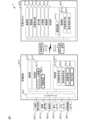
図1は、本発明の一実施形態に係る警備システムの概略構成を示す図である。図1に示すように、警備システム1は、サーバ10と、警備装置20と、作業ロボット30と、を有する。サーバ10は、警備センタ等に設置され、警備装置20及び作業ロボット30と通信可能に接続されて警備システム1全体を管理する。警備装置20は、サーバ10と通信接続され、例えば事務所、店舗、工場等の警備対象を警備する。作業ロボット30は、アクセスポイント40を介してサーバ10と通信接続され、警備装置20が設置された警備対象内で作業を行う。また、警備装置20は、有線/無線通信を介して、入退室操作端末250、警備操作部251、撮像部(カメラ)252、侵入センサ253、火災センサ254、設備機器センサ255等の種々の機器及びセンサと接続される。図1において、警備装置20及び作業ロボット30は1つだけ示されるが、警備システム1は、複数の警備装置20及び/又は作業ロボット30を有してもよい。1 is a diagram showing a schematic configuration of a security system according to an embodiment of the present invention. As shown in FIG. 1, the security system 1 has a
サーバ10は、インターネット等の広域通信網中のクラウドサーバ等である。サーバ10は、通信部11と、記憶部12と、制御部13と、を有する。The
通信部11は、Ethernet(登録商標)、IEEE802.11等の有線/無線通信規格に準じる通信インタフェース回路を有し、LAN及びインターネット等の広域通信網を介して警備装置20及び作業ロボット30と通信接続して各種信号を送受信する。通信部11は、サーバ10の送信部の一例である。The
記憶部12は、ROM、RAM、EPROM等の半導体メモリ、磁気ディスク(HDD)等の磁気記憶媒体及び/又はDVD-RAM等の光記憶媒体等を有する。記憶部12は、サーバ10の動作を制御するため制御部13が実行するコンピュータプログラムのコード及び各種データを記憶する。コンピュータプログラムは、DVD-ROM等のコンピュータ読取可能な記憶媒体や通信回線を介して公知の方法で記憶部12にインストールされることができる。
記憶部12は、作業ロボット30が作業を開始する時間及び作業のための移動経路を含むスケジュール情報121と、警備対象の地図を表す警備地図122と、を記憶する。スケジュール情報121には、作業動作の開始時刻と、時刻毎の作業動作の内容及び/又は作業場所と、が記憶されている。警備地図122の詳細については、後述する。なお、スケジュール情報121として作業を開始する時刻のみを記憶しておき、環境地図371に基づき作業ロボットが作業領域内で作業を行うスケジュールを自律的に生成してもよい。 The
The
制御部13は、CPU等のプロセッサとその周辺回路とを有し、当該プロセッサは、記憶部12に記憶されたコンピュータプログラムを実行することによってサーバ10の動作を制御する。制御部13として、マルチプロセッサ、マルチコアプロセッサ等が用いられてもよい。また、制御部13として、DSP、LSI、ASIC、FPGA等が用いられてもよい。
制御部13は、プロセッサ上で動作するプログラムの機能モジュールとして、取得手段131と、指示手段132と、を有する。制御部13及び各手段の動作については後で詳述する。 The
The
警備装置20は、利用者又はサーバ10により指示された警備モードに従って、警備対象に設置された侵入センサ253等の機器によって、侵入、火災、救急、設備故障等の異常を監視して警備を行う情報処理装置である。警備装置20は、通信部21と、記憶部22と、制御部23と、インタフェース部24と、を有する。警備装置20は、さらに、入退室操作端末250と、警備操作部251と、撮像部252と、侵入センサ253と、火災センサ254と、設備機器センサ255と、を有する。入退室操作端末250、警備操作部251、撮像部252、侵入センサ253、火災センサ254及び/又は設備機器センサ255の数は一つに限定されず、複数でもよい。The
通信部21は、Ethernet(登録商標)、IEEE802.11等の有線/無線通信規格に準じる通信インタフェース回路を有し、LANを介してインターネット等の広域通信網中のサーバ10と通信接続して各種情報を送受信する。通信部21は、警備装置20の送信部の一例である。The communication unit 21 has a communication interface circuit that conforms to wired/wireless communication standards such as Ethernet (registered trademark) and IEEE 802.11, and communicates with a
記憶部22は、半導体メモリ、磁気記憶媒体及び/又は光記憶媒体等を有する。記憶部22は、警備装置20の動作を制御するのに制御部23が実行するコンピュータプログラムのコード及び各種データを記憶する。コンピュータプログラムは、DVD-ROM等のコンピュータ読取可能な記憶媒体や通信回線を介して公知の方法で記憶部22にインストールされることができる。The storage unit 22 includes a semiconductor memory, a magnetic storage medium, and/or an optical storage medium. The storage unit 22 stores the code and various data of the computer program executed by the
警備システム1において、警備モードは、警備セットモードと、警備解除モードと、の少なくとも2種類のモードを有する。警備セットモードは、警備対象が無人であり、警備対象外から及び警備対象内での侵入を含む全ての異常の検知に対して異常発生をサーバ10に通知するモードである。警備解除モードは、警備対象が有人であり、火災発生や救急、非常通報、設備故障等の異常を検知した場合にはサーバ10に通知するが、警備対象内で人が検知されても侵入を通知しないモードである。通常、警備解除モードは、利用者が警備対象にて活動している日中に利用され、警備セットモードは、利用者全員が警備対象から離れる夜間、休日などに利用される。In the security system 1, there are at least two types of security modes: a security set mode and a security release mode. The security set mode is a mode in which the security target is unoccupied and the
制御部23は、CPU、マルチプロセッサ等のプロセッサとその周辺回路とを有し、当該プロセッサは、記憶部22に記憶されたコンピュータプログラムを実行することによって警備装置20の動作を制御する。制御部23として、DSP、LSI、ASIC、FPGA等が用いられてもよい。
制御部23は、プロセッサ上で動作するプログラムの機能モジュールとして、状態監視手段231と、異常監視手段232と、を有する。制御部23及び各手段の動作については後で詳述する。 The
The
インタフェース部24は、例えばUSB等のシリアルバス規格に準じるインタフェース回路を有し、入退室操作端末250、警備操作部251、撮像部252、侵入センサ253、火災センサ254及び設備機器センサ255と通信接続して各種信号を送受信する。なお、インタフェース部24は、シリアルバス規格に準じるインタフェース回路の代わりに、Ethernet(登録商標)、IEEE802.11、Bluetooth(登録商標)等の有線/無線通信規格に準じるインタフェース回路を有してもよい。The
入退室操作端末250は、警備対象の出入口等に設置され、利用者が警備対象への入室又は警備対象からの退室を要請する操作端末である。入退室操作端末250は、利用者のID、認証コード、指紋/顔/声等の生体情報等の認証情報を入力する、カードリーダ、ICスティックコンテナ、カメラ、マイク、タッチパネル等の入力部(図示せず)を有する。また、入退室操作端末250は、警備対象への入室又は警備対象からの退室を規制するために出入口の扉等に設置され、警備装置20から送信される解錠/施錠信号に従って解錠/施錠される電気錠等の入退室規制部(図示せず)を有する。入退室操作端末250は、利用者が入室操作又は退室操作を行なった場合、入室指示又は退室指示を生成する。或いは、入退室操作端末250は、入退室規制部によって入室又は退室の規制が解除された場合、入室指示又は退室指示を生成してもよい。The entry/
警備操作部251は、タッチパネル、ボタン等のユーザ入出力インタフェースを有し、利用者は、警備装置20に対して警備モードの切替等の操作を行う。また、警備操作部251は、警備装置を操作可能な利用者の認証情報の入力部(図示せず)を有してもよい。警備操作部251は、警備モードの切替操作が行われると、変更後の警備モードを含む警備モードの変更指示を生成する。
なお、警備操作部251の入力部は、救急搬送を依頼するための救急通報、不審者が侵入した際等の非常通報の指示、及び、異常発生場所を入力可能である。
警備操作部251は、救急通報の指示が入力されると、救急通報信号を生成し、非常通報の指示が入力されると、非常通報信号を生成する。異常発生場所が入力された場合には、救急通報信号及び非常通報信号には、入力された異常発生場所を示す場所情報が含まれる。 The
The input section of the
The
撮像部252は、CCD素子又はC-MOS素子等、可視光に感度を有する光電変換素子と、その光電変換素子上に像を結像する結像光学系と、光電変換素子から出力された電気信号を増幅し、アナログ/デジタル(A/D)変換するA/D変換器と、を有するカメラ等であり、警備対象の監視空間を撮影したRGB形式等のデジタル画像を逐次取得する。なお、撮像部252は、赤外線や超音波等を利用したカメラでもよい。The
侵入センサ253は、リードスイッチ及びマグネット等により警備対象の扉や窓等の開閉を検知するセンサ、熱源としての人体が発する熱を検知するセンサ、人体により赤外線が遮られたことを検知するセンサ等の、警備対象内に侵入した侵入者を検知するためのセンサである。侵入センサ253は、侵入者を検知すると、侵入が発生したことを示す異常検知信号を生成する。この異常検知信号には、各侵入センサ253の監視領域を示す場所情報が含まれる。
火災センサ254は、火災発生に伴う熱や煙、ガス漏れを検知するセンサであり、火災発生を検知すると、火災が発生したことを示す異常検知信号を生成する。この異常検知信号には、各火災センサ254の監視領域を示す場所情報が含まれる。なお、作業ロボット30にも火災センサを備えるようにしてもよい。
設備機器センサ255は、空調設備、防災設備、センサ等の種々の設備機器の動作異常やバッテリ切れ等を検知するセンサであり、動作異常等を検知すると、機器の故障を示す異常検知信号を生成する。 The
The fire sensors 254 are sensors that detect heat, smoke, and gas leaks associated with a fire, and when they detect a fire, they generate an abnormality detection signal indicating that a fire has occurred. This abnormality detection signal contains location information indicating the monitoring area of each fire sensor 254. The
The
警備操作部251へ入力される通報が示す異常、並びに撮像部252、侵入センサ253、火災センサ254及び設備機器センサ255等によって検知される異常は、防犯、防災、故障及び救急に分類することができる。侵入の発生及び非常通報は、防犯に関する異常に分類され、火災及びガス漏れの発生は、防災に関する異常に分類される。設備機器の動作異常等は、故障に関する異常に分類され、救急通報は、救急に関する異常に分類される。The abnormalities indicated by the reports input to the
入退室操作端末250、警備操作部251、撮像部252、侵入センサ253、火災センサ254及び設備機器センサ255は、生成した入室指示、退室指示、警備モードの変更指示、通報信号、異常検知信号又はデジタル画像を、インタフェース部24を介して制御部23に送信する。即ち、警備操作部251、侵入センサ253、火災センサ254及び設備機器センサ255は、異常検知部の一例であり、複数種類の異常を検知する。また、入退室操作端末250、警備操作部251及び撮像部252は、状態検知部の一例であり、警備対象に利用者が存在するか否かの判定に用いられる。なお、侵入センサ253及び火災センサ254の監視領域は、警備地図122に基づいてサーバ10により事前に設定される。The entry/
作業ロボット30は、警備対象内で清掃、運搬、点検等の種々の作業を行う自律移動可能なロボットである。作業ロボット30は、通信部31と、撮像部32と、位置検出部33と、走行部34と、作業部35と、電源部36と、記憶部37と、制御部38と、を有する。ここでは、作業ロボット30が掃除ロボットである場合について説明する。The
通信部31は、IEEE802.11等の無線通信規格に準じる通信インタフェース回路を有し、アクセスポイント40を経由してインターネット等の広域通信網を介してサーバ10と通信接続して各種情報を送受信する。通信部31は、作業ロボット30の受信部の一例である。The communication unit 31 has a communication interface circuit that conforms to wireless communication standards such as IEEE 802.11, and communicates with the
撮像部32は、CCD素子又はC-MOS素子等、可視光に感度を有する光電変換素子と、その光電変換素子上に像を結像する結像光学系と、光電変換素子から出力された電気信号を増幅し、アナログ/デジタル(A/D)変換するA/D変換器と、を有する内蔵カメラ等であり、RGB形式等のデジタル画像を取得する。The
位置検出部33は、Lidar、カメラ、超音波センサ、赤外線センサ、GPS等の入力機器の少なくとも1つを有し、作業ロボット30の現在位置及び障害物の位置等を導出するために用いられるレーザー光、画像等の情報を取得する。The
走行部34は、駆動輪及び走行用モータを有し、走行用モータの回転速度を変えることにより、作業ロボット30を多様な速度で前後左右に自在に移動させる。走行部34は、走行を安定させスムーズにするために補助輪等を更に有してもよい。
作業部35は、清掃、運搬、点検等の作業動作を行う。作業ロボット30が掃除ロボットである場合、作業部35は、埃を吸い込むための吸引ユニット、床面を拭き取るための拭き取りユニット等を有し、床面の清掃作業を行う。走行部34及び作業部35は、作業ロボット30が自律移動しながら作業動作を行うための動作機構である。 The running
The working
電源部36は、作業ロボット30の各部に電力を供給するための蓄電池等である。The
記憶部37は、半導体メモリ、磁気記憶媒体及び/又は光記憶媒体等を有する。記憶部37は、作業ロボット30の動作を制御するのに制御部38が実行するコンピュータプログラムのコード及び各種データを記憶する。コンピュータプログラムは、DVD-ROM等のコンピュータ読取可能な記憶媒体や通信回線を介して公知の方法で記憶部37にインストールされてもよい。
記憶部37は、作業領域内の壁や設備等の固定された障害物と台車や箱等の移動可能な障害物とを含む障害物の位置を有する環境地図371を記憶する。また、環境地図371は、退避位置420及びホームポジション460等の位置を有する。 The
The
制御部38は、CPU、MPU等のプロセッサとその周辺回路とを有し、当該プロセッサは、記憶部37に記憶されたコンピュータプログラムを実行することによって作業ロボット30の動作を制御する。制御部38として、DSP、LSI、ASIC、FPGA等が用いられてもよい。
制御部38は、プロセッサ上で動作するプログラムの機能モジュールとして、位置監視手段381と、動作制御手段382と、を有する。制御部38及び各手段の動作については後で詳述する。 The
The
図2は、警備システム1の警備対象の一例であるオフィスの平面図である。図2に示すように、オフィス100のフロア101は、作業ロボット30の作業領域である。フロア101は、壁102によって外部と区切られており、フロア101には、設備機器410、ドア430、パーティション440、ホームポジション(HP)460及び窓470が設けられる。また、オフィスの各所には、入退室操作端末250、警備操作部251、撮像部252、侵入センサ253、火災センサ254、設備機器センサ255等の異常を検知する種々の機器が1又は複数設置される。フロア101の利用者の動線を避けた位置には、作業ロボット30の退避位置420が配置される。なお、退避位置420は図2で示すような通路から外れた場所に限らず、通路の端を退避位置として構成してもよい。作業ロボット30の退避位置420が利用者の動線を避けた位置に配置されることにより、災害発生時等に作業ロボット30が利用者の移動の妨げとなることが抑制される。フロア101において、設備機器410、退避位置420及びパーティション440で囲まれた位置を除いた領域は、通路として使用される。なお、利用者の動線とは、施設内を利用者が移動するときに通常移動することが想定される通路を指し、例えば、通路のうち、通路幅の所定割合(例えば、通路の中央を基準に左右それぞれ80%)を利用者の動線とする。2 is a plan view of an office, which is an example of a security target of the security system 1. As shown in FIG. 2, the
ドア430は、フロア101と外部との出入口に配置され、入退室操作端末250によって解錠/施錠される。パーティション440は、オフィス100の利用者の座席の周囲に配置された衝立である。ホームポジション460には、作業ロボット30の電源部36を充電するための充電器(図示せず)が配置され、作業ロボット30は、作業を行わないときはホームポジション460で待機する。窓470は、オフィス100と屋外との間に配置され、侵入センサ253によって窓470からオフィス100への侵入者の有無が監視される。
警備地図122は、図2に示した警備装置20の警備対象かつ作業ロボット30の作業領域であるフロア101を表す地図であり、予めサーバ10の記憶部12に記憶される。警備地図122には、オフィス100のフロア101の形状が示される。また、警備地図122には、入退室操作端末250及び警備操作部251の位置、撮像部252により撮像される位置、侵入センサ253、火災センサ254及び設備機器センサ255により検知される位置等が示される。警備地図122には、退避位置420及びホームポジション460の位置、壁102、設備機器410、パーティション440等の固定された障害物の位置等がさらに示される。
フロア101の形状及び上述した各位置は、警備地図122内のある点を原点とする2次元座標で示される。座標は、緯度及び経度等でもよい。なお、警備地図122は、作業ロボット30の記憶部37に記憶される環境地図371と共通の座標を有する。 The
The shape of
図2の状態は、作業ロボット30が、HP460から経路481を通り退避位置420の図中の真下辺りまで作業を進めてきた際に、窓470から侵入者による侵入があった場合を表している。侵入者による侵入は侵入センサ253による検知により検知され、異常発生場所480は窓470の近辺として認識される。後述するように、異常発生場所480で異常が発生した場合、作業ロボット30の動作としては、異常発生場所480へ最短距離で向かう経路482を利用する場合、退避位置420へ退避する経路483を利用する場合、経路484を利用して作業を継続しながら異常発生場所480へ移動する場合等が考えられる。詳しい作業ロボット30の動作については後述する。The state in FIG. 2 shows a case where an intruder intrudes through
火災やガス漏れといった防災系の異常が検知された場合、現場の状況確認(撮影等)を行うことが求められるが、こうした異常では利用者の避難をともなうため、作業ロボット30が現場の状況確認に向かう最中に利用者の避難の妨げとなってしまうおそれがある。そこで、防災系の異常時には利用者の状況を踏まえて避難の妨げとならないように作業ロボット30を制御する必要がある。When a disaster prevention abnormality such as a fire or gas leak is detected, it is necessary to check the situation at the site (by taking photographs, etc.), but since such an abnormality requires the evacuation of users, there is a risk that the
図3は、警備システム1の全体処理の一例を示すシーケンス図である。この動作シーケンスは、予め各装置の各記憶部に記憶されているプログラムに基づいて、主に各装置の各制御部により、各装置の各要素と協働して実行される。Figure 3 is a sequence diagram showing an example of the overall processing of the security system 1. This operation sequence is executed mainly by each control unit of each device in cooperation with each element of each device, based on a program stored in advance in each memory unit of each device.
最初に、サーバ10の指示手段132は、スケジュール情報121に示される開始時刻になると、通信部11を介して作業ロボット30に所定の作業動作の開始を指示するための開始信号を送信する(ステップS100)。作業ロボット30の動作制御手段382は、通信部31を介してサーバ10から開始信号を受信すると、記憶部37に記憶される環境地図371及び現在位置情報等を初期化し、指示された作業動作を開始する。このとき、サーバ10の指示手段132は、開始信号と共に警備地図122における壁102、設備機器410、パーティション440等の固定された障害物の位置や退避位置420及びホームポジション460等の位置の情報を作業ロボット30に送信し、作業ロボット30の動作制御手段382は、受信した情報に基づいて環境地図371を初期化する。尚、作業ロボット30の制御部38は、事前に、サーバ10若しくは他の装置から通信部11を介して受信した情報又は作業ロボット30の操作部(図示せず)から取得した情報等に基づいて、予め環境地図371を初期化してもよい。また、制御部38は、事前に作業領域内を走行させて環境地図を構築することにより、固定された障害物の位置を予め記憶してもよい。First, when the start time indicated in the
作業ロボット30の動作制御手段382は、環境地図371に基づいて障害物を回避するよう走行部34を制御して作業ロボット30を走行させ、作業部35を制御して作業動作を行う。位置監視手段381は、定期的に、位置検出部33から取得した情報に基づいてSLAM(Simultaneous Localization and Mapping)等の手法により作業ロボット30の現在位置及び障害物の位置を取得する。位置監視手段381は、取得した現在位置を記憶部37に記憶し、障害物の位置が変化した場合、記憶部37に記憶された環境地図371を更新する(ステップS101)。The operation control means 382 of the
位置監視手段381は、取得した現在位置を示す現在位置信号を、通信部31を介してサーバ10に出力する(ステップS102)。
一方、サーバ10の取得手段131は、通信部11を介して作業ロボット30から現在位置信号を受信し、受信した現在位置信号に示される作業ロボット30の現在位置を現在位置情報として記憶部12に記憶する(ステップS103)。 The location monitoring means 381 outputs a current location signal indicating the acquired current location to the
Meanwhile, the acquisition means 131 of the
指示手段132は、スケジュール情報121に示される現在時刻に実行すべき作業動作の内容又は移動すべき場所と、作業ロボット30の現在位置とから、作業ロボット30に実行させる動作を決定する。指示手段132は、決定した動作を作業ロボット30に実行させるための動作信号を、通信部11を介して作業ロボット30に送信する(ステップS104)。作業ロボット30の動作制御手段382は、通信部31を介してサーバ10から動作信号を受信した場合、作業動作を継続又は変更したり指示された場所へ移動する等の指示された動作を実行する。尚、作業ロボットが作業を行うスケジュールを自律的に生成して実施する場合、この処理は省略できる。The instruction means 132 determines an operation to be performed by the
警備装置20の状態監視手段231は、利用者が警備装置20に対して警備モードの切替の操作を行ったかを監視し、利用者が警備モードの切替等の操作を行った場合に警備操作部251から警備モードの変更指示を受信する(ステップS105)。
警備モードの変更指示を受信した場合、状態監視手段231は、警備装置20の警備モードを、受信した変更指示に含まれる変更後の警備モードに変更する(ステップS106)。
状態監視手段231は、警備モードを示す状態信号を生成し、通信部21を介してサーバ10に出力する(ステップS107)。警備モードは、警備操作部251の入力部によって利用者によって設定される。
一方、サーバ10の取得手段131は、通信部11を介して警備装置20から状態信号を受信し、受信した状態信号に従って、警備対象に利用者が存在する状態か否かを判定して在室情報として記憶部12に記憶する(ステップS108)。このとき、取得手段131は、状態信号が警備セットモードを示す場合、警備対象に利用者が存在しない状態とし、状態信号が警備解除モードを示す場合、警備対象に利用者が存在する状態とする。 The status monitoring means 231 of the
When an instruction to change the security mode is received, the status monitoring means 231 changes the security mode of the
The status monitoring means 231 generates a status signal indicative of the security mode, and outputs it to the
Meanwhile, the acquisition means 131 of the
また、警備装置20の状態監視手段231は、利用者が入退室操作端末250に対して入室操作又は退室操作を行ったかを監視し、利用者が入室操作又は退室操作を行った場合に入退室操作端末250から入室指示又は退室指示を受信する。さらに、状態監視手段231は、定期的に撮像部252から、撮像部252が撮像した画像を受信する(ステップS109)。
入室指示、退室指示又は画像を受信した場合、状態監視手段231は、利用者の混雑状況又は利用者の移動状況を示す利用者信号を生成し、通信部21を介してサーバ10に出力する(ステップS110)。入室指示又は退室指示を受信した場合、状態監視手段231は、これまでに受信した入室指示及び退室指示の数に基づいて、警備対象に存在する在室人数を算出する。状態監視手段231は、在室人数が所定数を超える場合は混雑していることを示し、在室人数が所定数以下である場合は混雑していないことを示すように利用者信号を生成する。また、状態監視手段231は、撮像部252から画像を順次受信し、背景差分処理又はフレーム間差分処理により、各画像内で変化が発生した変化領域を検出し、検出した変化領域の中から所定のサイズを有する人物領域を抽出する。状態監視手段231は、各画像間で対応する人物領域を追跡し、人物領域の位置の変化量から各人物の移動量を検出する。状態監視手段231は、各人物の移動量の平均値、中央値又は最大値が所定閾値を超える場合は利用者の移動が多いことを示し、各人物の移動量の平均値、中央値又は最大値が所定閾値以下である場合は利用者の移動が少ないことを示すように利用者信号を生成する。
一方、サーバ10の取得手段131は、通信部11を介して警備装置20から利用者信号を受信し、受信した利用者信号に従って、利用者が混雑しているか否か、及び/又は、利用者の移動が多いか否かを記憶部12に記憶する(ステップS111)。
なお、サーバ10の取得手段131は、入室指示および退室指示または画像を受信し、受信した情報に基づき、ステップS107における警備対象に利用者が存在する状態か否かを判定してもよい。 The status monitoring means 231 of the
When an entry instruction, an exit instruction, or an image is received, the status monitoring means 231 generates a user signal indicating the user congestion status or the user movement status, and outputs it to the
Meanwhile, the acquisition means 131 of the
The acquisition means 131 of the
ここで、利用者が存在するか否かを判定する警備対象は、警備対象の施設全体であってもよいし、異常発生場所が含まれる部屋やフロアであってもよいし、異常発生場所の周囲所定範囲であってもよい。警備対象の施設全体を対象とする場合は、例えば、施設のいずれかの警備対象において、警備解除モードの場合や撮像部252により人物が撮影された場合、入室指示が退室指示を上回る場合に警備対象に利用者が存在すると判定する。また、部屋やフロアを対象とする場合は、上記説明における施設のいずれかの警備対象を対象の部屋やフロアに置き換えればよい。また、異常発生場所の周囲所定範囲を対象とする場合、画像による人物検知等により利用者の位置の特定を行い、異常発生場所の周囲所定範囲内に利用者が存在するか否かを判定すればよい。The security target for determining whether or not a user is present may be the entire facility of the security target, a room or floor including the location where the abnormality occurred, or a specified range around the location where the abnormality occurred. When the entire facility of the security target is the target, for example, it is determined that a user is present in the security target when any of the security targets in the facility is in security off mode, a person is photographed by the
また、警備装置20の異常監視手段232は、入退室操作端末250、警備操作部251、撮像部252、侵入センサ253、火災センサ254及び設備機器センサ255を監視し、異常が発生した場合に各部から異常検知信号又は通報信号を受信する(ステップS112)。
異常検知信号又は通報信号を受信した場合、異常監視手段232は、異常信号生成処理を実行する(ステップS113)。異常信号生成処理において、異常監視手段232は、異常の種類を示す種類情報及び異常発生場所を示す場所情報を含む異常信号を生成する。異常信号生成処理の詳細については後述する。
次に、異常監視手段232は、異常信号生成処理において生成した異常信号を、通信部21を介してサーバ10に出力する(ステップS114)。
一方、サーバ10の指示手段132は、通信部11を介して警備装置20から異常信号を受信し、受信した異常信号に含まれる異常の種類に応じて、制御信号生成処理を実行する(ステップS115)。制御信号生成処理において、指示手段132は、作業ロボット30に、異常信号、状態信号及び利用者信号に応じた動作を実行させるように制御するための制御信号を生成する。制御信号には、作業ロボット30に実行させる動作を示す動作情報及び異常発生場所を示す場所情報が含まれる。制御信号生成処理の詳細については後述する。
次に、指示手段132は、制御信号生成処理において生成した制御信号を、通信部11を介して作業ロボット30に出力する(ステップS116)。
一方、作業ロボット30の動作制御手段382は、通信部31を介してサーバ10から制御信号を受信し、受信した制御信号に含まれる動作に応じて、動作処理を実行する(ステップS117)。動作処理において、動作制御手段382は、受信した制御信号に含まれる動作を作業ロボット30に実行させる。動作処理の詳細については後述する。 In addition, the abnormality monitoring means 232 of the
When the abnormality detection signal or the notification signal is received, the abnormality monitoring means 232 executes an abnormality signal generation process (step S113). In the abnormality signal generation process, the abnormality monitoring means 232 generates an abnormality signal including type information indicating the type of abnormality and location information indicating the location where the abnormality has occurred. The abnormality signal generation process will be described in detail later.
Next, the abnormality monitoring means 232 outputs the abnormality signal generated in the abnormality signal generation process to the
Meanwhile, the instruction means 132 of the
Next, the instruction means 132 outputs the control signal generated in the control signal generation process to the
Meanwhile, the movement control means 382 of the working
異常発生場所は、警備操作部251の入力部による入力の場合は入力された箇所を示し、撮像部252によって取得された画像により異常が発見された場合には画像解析による該当箇所を示し、図2の場合の様に侵入センサ253による異常検知の場合は侵入センサの配置位置を示す。また、異常発生場所は、火災センサ254により火災が検知された場合には火災センサの配置位置を示し、設備機器センサ255による異常検知の場合は設備機器410がある場所を示すものとする。なお、警備装置20は、後述する様に、異常信号に、異常発生場所を示す場所情報も合わせて出力するものとする。The location of the abnormality indicates the location where the input was made by the input unit of the
図4は、警備装置20による異常信号生成処理の一例を示すフローチャートである。図4に示す動作のフローは、図3に示すシーケンス図のステップS113において実行される。Figure 4 is a flowchart showing an example of an abnormality signal generation process by the
まず、異常監視手段232は、受信した異常検知信号又は通報信号の種類を特定する(ステップS201)。
受信した信号が、侵入が発生したことを示す異常検知信号である場合、異常監視手段232は、種類情報として侵入を設定する(ステップS202)。
一方、受信した信号が、非常通報信号である場合、異常監視手段232は、種類情報として非常通報を設定する(ステップS203)。
一方、受信した信号が、火災が発生したことを示す異常検知信号である場合、異常監視手段232は、種類情報として火災を設定する(ステップS204)。
一方、受信した信号が、機器の故障が発生したことを示す異常検知信号である場合、異常監視手段232は、種類情報として故障を設定する(ステップS205)。
一方、受信した信号が、救急通報信号である場合、異常監視手段232は、種類情報として救急通報を設定する(ステップS206)。
次に、異常監視手段232は、異常信号に含まれる場所情報として、受信した各信号に含まれる場所情報を設定する。設定した種類情報及び場所情報を含む異常信号を生成し(ステップS207)、一連のステップを終了する。なお、受信した信号が、非常通報信号、又は、救急通報信号である場合、警備操作部251の入力部から異常発生場所の入力が無かった場合、異常監視手段232は、異常信号に含まれる場所情報としてブランクを設定する。 First, the abnormality monitoring means 232 identifies the type of the received abnormality detection signal or notification signal (step S201).
If the received signal is an abnormality detection signal indicating that an intrusion has occurred, the abnormality monitoring means 232 sets "intrusion" as the type information (step S202).
On the other hand, if the received signal is an emergency notification signal, the abnormality monitoring means 232 sets the type information to emergency notification (step S203).
On the other hand, if the received signal is an abnormality detection signal indicating that a fire has occurred, the abnormality monitoring means 232 sets fire as the type information (step S204).
On the other hand, if the received signal is an abnormality detection signal indicating that a device failure has occurred, the abnormality monitoring means 232 sets failure as the type information (step S205).
On the other hand, if the received signal is an emergency call signal, the abnormality monitoring means 232 sets the type information to emergency call (step S206).
Next, the abnormality monitoring means 232 sets the location information included in each received signal as the location information included in the abnormality signal. An abnormality signal including the set type information and location information is generated (step S207), and the series of steps ends. Note that if the received signal is an emergency call signal or an ambulance call signal, and if the location of the abnormality is not input from the input unit of the
図5は、サーバ10による制御信号生成処理の一例を示すフローチャートである。図5に示す動作のフローは、図3に示すシーケンス図のステップS115において実行される。Figure 5 is a flowchart showing an example of a control signal generation process by the
まず、指示手段132は、受信した異常信号に含まれる種類情報が示す異常の種類を特定する(ステップS301)。First, the indication means 132 identifies the type of abnormality indicated by the type information contained in the received abnormality signal (step S301).
異常の種類が侵入である場合、指示手段132は、図3のステップS108で記憶部12に記憶した在室情報を読み出し、警備対象に利用者が存在するか否かを判定する(ステップS302)。警備対象に利用者が存在しない場合、指示手段132は、動作情報として、作業動作をせずに異常発生場所に移動する第1対処動作を設定する(ステップS303)。一方、警備対象に利用者が存在する場合、指示手段132は、動作情報として、作業動作をしつつ異常発生場所に移動する第2対処動作を設定する(ステップS304)。
これにより、警備システム1は、侵入者が侵入した際に、利用者が存在しない場合は、作業ロボット30を侵入者の位置に直行させて、侵入者に対する対応を行わせることができる。一方、警備システム1は、侵入者が侵入した際に、利用者が存在する場合には、侵入者に作業ロボット30が作業中であると思わせることにより、侵入者を刺激して利用者に危害を及ぼすことを抑制しつつ、作業ロボット30を侵入者の位置に移動させることができる。 If the type of abnormality is an intrusion, the instruction means 132 reads the presence information stored in the
As a result, if an intruder intrudes and there is no user present, the security system 1 can have the
一方、異常の種類が非常通報である場合、指示手段132は、動作情報として第2対処動作を設定する(ステップS305)。異常の種類が非常通報である場合、通報を指示した利用者が必ず作業領域に存在するため、指示手段132は、作業領域に利用者が存在するか否かを判定することなく、動作情報として第2対処動作を設定する。On the other hand, if the type of abnormality is an emergency call, the instruction means 132 sets the second response action as the operation information (step S305). If the type of abnormality is an emergency call, the user who instructed the call is necessarily present in the work area, so the instruction means 132 sets the second response action as the operation information without determining whether or not a user is present in the work area.
一方、異常の種類が火災である場合、指示手段132は、図3のステップS108で記憶部12に記憶した在室情報を読み出し、警備対象に利用者が存在するか否かを判定する(ステップS306)。警備対象に利用者が存在しない場合、指示手段132は、動作情報として第1対処動作を設定する(ステップS307)。一方、警備対象に利用者が存在する場合、指示手段132は、図3のステップS111で記憶部12に記憶した情報を読み出し、利用者が混雑しているか否かを判定する(ステップS308)。利用者が混雑していない場合、指示手段132は、動作情報として第1対処動作を設定する(ステップS307)。一方、利用者が混雑している場合、指示手段132は、図3のステップS111で記憶部12に記憶した情報を読み出し、利用者の移動が多いか否かを判定する(ステップS309)。利用者の移動が少ない場合、指示手段132は、動作情報として第1対処動作を設定する(ステップS307)。一方、利用者の移動が多い場合、指示手段132は、動作情報として退避動作を設定する(ステップS310~S314)。On the other hand, if the type of abnormality is a fire, the instruction means 132 reads the presence information stored in the
退避動作は、利用者の動線から避けた位置に退避する動作であり、作業ロボット30がホームポジション460に帰還して停止する第1退避動作、作業ロボット30が所定の退避位置420に移動して停止する第2退避動作、及び、作業ロボット30が通路の端に避けて停止する第3退避動作の何れか1つが含まれる。なお、ホームポジションは、作業ロボット30が作業を行わないときに待機する場所であり、利用者の動線から外れた位置にあるため、ホームポジションに帰還して停止することで利用者の移動(避難)の妨げとなることを防止できる。このように、退避する動作として、利用者の動線から外れた位置に移動して停止することで利用者の移動の妨げにならないようにする。The evacuation operation is an operation to evacuate to a position away from the user's traffic line, and includes any one of a first evacuation operation in which the
ここで、退避先に移動する際にも、利用者の避難の妨げにならないよう配慮することが求められる。そこで、指示手段132は、図3のステップS103で記憶部12に記憶した現在位置情報に基づいて、作業ロボット30の現在位置と警備地図122内のホームポジション460の位置との間の距離を算出し、算出した距離が所定未満か否かを判定する(ステップS310)。算出した距離が所定未満の場合、指示手段132は、退避動作として第1退避動作を設定する(ステップS311)。一方、現在位置とホームポジション460との距離が所定以上の場合、指示手段132は、現在位置と警備地図122内の退避位置420との間の距離を算出し、算出した距離が所定未満か否かを判定する(ステップS312)。ここで、退避位置420が複数ある場合は、作業ロボット30に一番近い退避位置420と現在位置との距離を算出する。算出した距離が所定未満の場合、指示手段132は、退避動作として第2退避動作を設定する(ステップS313)。一方、現在位置と退避位置420との距離が所定以上の場合、指示手段132は、退避動作として第3退避動作を設定する(ステップS314)。Here, when moving to the evacuation destination, it is required to take care not to hinder the evacuation of the user. Therefore, the instruction means 132 calculates the distance between the current position of the
これにより、警備システム1は、作業ロボット30の現在位置に応じて、作業ロボット30の移動を極力少なくしつつ適切な場所に退避させることができる。ここで、 第3退避動作における退避位置は、現在位置から最も近い通路の端位置(すなわち、作業ロボット30の移動距離が最も少ない)、環境地図371から特定可能な通路幅が所定以上の通路の端位置(すなわち、作業ロボット30が避難の妨げになりにくい)などが用いられる。このように、作業ロボット30が退避位置までに要する移動や退避位置が避難の妨げになりやすいか否かを考慮して退避位置を設定する。また、通路幅が所定未満の通路や出口から所定範囲内は、避難してきた利用者が密集したり避難の邪魔になりやすいので退避位置から除外してもよい。
なお、本願発明では、所定の退避位置420に移動して停止する第2退避動作、及び、作業ロボット30が通路の端に避けて停止する第3退避動作を、所定の退避位置への移動として扱う場合がある。
なお、ステップS308又はS309の内の何れか一方又は両方は省略されてもよい。 As a result, the security system 1 can evacuate the working
In addition, in the present invention, the second evacuation operation in which the
Note that either or both of steps S308 and S309 may be omitted.
このように、指示手段132は、状態信号により利用者が存在しない状態であると判断した場合には異常発生場所に移動する対処動作を実行させ、状態信号により利用者が存在する状態であると判断した場合には退避動作を実行させるように、作業ロボット30を制御する。これにより、警備システム1は、災害が発生した場合に作業ロボット30が利用者の避難の妨げとなってしまうことを抑制しつつ、利用者が存在しない場合には作業ロボット30を異常発生場所に移動させて災害に適切に対応させることができる。
特に、指示手段132は、利用者が存在する状態であっても、利用者信号により利用者が混雑していない又は利用者の移動が少ない状況であると判断した場合には、対処動作を実行させるように、作業ロボット30を制御する。これにより、警備システム1は、利用者が存在する状態であっても、作業ロボット30が利用者の避難の妨げとならない程度である場合には、作業ロボット30を異常発生場所に移動させて災害に適切に対応させることができる。
一方、指示手段132は、利用者信号により利用者が混雑又は利用者の移動が多い状態であると判断した場合には、退避動作を実行させるように、作業ロボット30を制御する。特に、指示手段132は、退避動作において、作業ロボット30が自体の現在位置に応じて、ホームポジション460、退避位置420又は通路の端に移動して停止する動作をするように、作業ロボット30を制御する。これにより、警備システム1は、特に、利用者の往来が大きい場合に、作業ロボット30が利用者の避難の妨げとなってしまうことを抑制することが可能となる。 In this way, the instruction means 132 controls the
In particular, when the instruction means 132 determines based on a user signal that the situation is not crowded with users or that there is little movement of users, even if users are present, it controls the
On the other hand, when the instruction means 132 determines from the user signal that the area is crowded with users or that there is a lot of user movement, it controls the
一方、異常の種類が故障である場合、指示手段132は、動作情報として作業継続動作を設定する(ステップS315)。
一方、異常の種類が救急通報である場合、指示手段132は、動作情報として第1対処動作を設定する(ステップS316)。
次に、指示手段132は、制御信号に含まれる場所情報として、受信した異常信号に含まれる場所情報を設定し、設定した動作情報及び場所情報を含む制御信号を生成し(ステップS317)、一連のステップを終了する。
このように、指示手段132は、警備装置20から受信した異常信号及び状態信号に応じて、作業ロボット30を制御する。 On the other hand, if the type of abnormality is a malfunction, the instruction means 132 sets a work continuation operation as the operation information (step S315).
On the other hand, if the type of abnormality is an emergency call, the instruction means 132 sets the first response action as the action information (step S316).
Next, the instruction means 132 sets the location information contained in the received abnormality signal as the location information contained in the control signal, generates a control signal including the set operation information and location information (step S317), and terminates the series of steps.
In this way, the instruction means 132 controls the
図6は、作業ロボット30による動作処理の一例を示すフローチャートである。図6に示す動作のフローは、図3に示すシーケンス図のステップS117において実行される。Figure 6 is a flowchart showing an example of operation processing by the
まず、動作制御手段382は、受信した制御信号に含まれる動作情報が示す動作の種類を特定する(ステップS401)。
特定した動作が第1対処動作である場合、動作制御手段382は、第1対処動作を実行するように走行部34及び作業部35を制御し(ステップS402)、一連のステップを終了する。動作制御手段382は、作業部35の動作を停止し、作業ロボット30の現在位置から制御信号に含まれる場所情報に示される異常発生場所への最短経路を環境地図371から算出し、算出した経路を通って移動するように走行部34及び作業部35を制御する。
一方、特定した動作が第2対処動作である場合、動作制御手段382は、第2対処動作を実行するように走行部34及び作業部35を制御し(ステップS403)、一連のステップを終了する。動作制御手段382は、作業部35の動作を継続し、作業ロボット30の現在位置から制御信号に含まれる場所情報に示される異常発生場所への最短経路を環境地図371から算出し、算出した経路を通って移動するように走行部34及び作業部35を制御する。
これらの場合、作業ロボット30は、異常発生場所に到着した後に、異常発生場所を撮像部32で撮像した画像をサーバ10、警備装置20等に送信してもよい(撮像手段)。これにより、警備システム1は、異常発生場所の状況を管理者に通知することができる。 First, the operation control means 382 identifies the type of operation indicated by the operation information contained in the received control signal (step S401).
If the identified operation is the first response operation, the operation control means 382 controls the traveling
On the other hand, if the identified operation is the second response operation, the operation control means 382 controls the traveling
In these cases, after the
一方、特定した動作が退避動作である場合、動作制御手段382は、作業を中断して退避動作を実行するように走行部34及び作業部35を制御し(ステップS404~S406)、一連のステップを終了する。この場合、動作制御手段382は、作業部35の動作を終了する。退避動作として第1退避動作が設定されている場合、動作制御手段382は、作業ロボット30の現在位置からホームポジション460への最短経路を環境地図371から算出し、算出した経路を通って移動して停止するように走行部34及び作業部35を制御する。一方、退避動作として第2退避動作が設定されている場合、動作制御手段382は、作業ロボット30の現在位置から退避位置420への最短経路を環境地図371から算出し、算出した経路を通って移動して停止するように走行部34及び作業部35を制御する。また、退避動作として第3退避動作が設定されている場合、動作制御手段382は、現在位置情報と環境地図371とに基づいて、作業ロボット30に最も近い壁102又はパーティション440を検出する。動作制御手段382は、検出した位置に最短距離で移動することにより通路の端に避けて停止するように走行部34及び作業部35を制御する。
一方、特定した動作が作業継続である場合、動作制御手段382は、実行中の作業を継続するように走行部34及び作業部35を制御し(ステップS407)、一連のステップを終了する。 On the other hand, if the identified operation is an evacuation operation, the operation control means 382 controls the traveling
On the other hand, if the identified motion is to continue the work, the motion control means 382 controls the traveling
なお、作業ロボット30が移動する経路は、サーバ10によって警備地図122に基づいて算出され、制御信号によって指示されてもよい。その場合、動作制御手段382は、制御信号に含まれる経路に従って移動するように走行部34を制御する。The route along which the
図2に示すオフィス100において、例えば、侵入センサ253が異常発生場所480で侵入者を検知した場面で、作業ロボット30は、サーバ10から第1対処動作又は第2対処動作を指示する制御信号を受信し、経路482を通って異常発生場所480に移動する。一方、作業ロボット30は、サーバ10から第2退避動作を指示する制御信号を受信した場合、経路483を通って退避位置420に移動する。In the
以上説明してきたように、本発明に係る警備システム1において、火災等の防災上の異常が発生した場合、作業ロボット30の作業領域に利用者が存在するか否か、作業領域の混雑状況、利用者の移動状況等に応じて、作業ロボット30を利用者の避難の妨げとならないように退避して停止させたり、避難の妨げになる虞れが少ない場合は異常発生場所に移動して発生した災害に対して適切に対処させることができる。また、警備システム1では、作業ロボット30の現在位置と退避位置420やホームポジション460との位置関係によって、作業ロボット30をホームポジションに帰還させたり、所定の退避位置420や通路の端に退避して停止させるので、さらに利用者の避難の妨げにならないように抑制できる。このように、警備システム1は、特に、防災上の異常が発生した場合、利用者の状況や作業ロボット30の位置に応じて作業ロボット30を異なるように動作させることができるので、状況に応じた適切な対応が可能となる。As described above, in the security system 1 according to the present invention, when a disaster prevention abnormality such as a fire occurs, the
以上、本発明の好適な実施形態について説明してきたが、本発明はこれらの実施形態に限定されるものではない。
例えば、警備システム1は、クラウドコンピューティングの形態でサービスを提供できるように、ネットワーク上に複数のサーバ10を分散して配置し、各サーバ10が協働して、図3に示した各処理を分担してもよい。特に、警備システム1は、警備装置20を管理するサーバ10と、作業ロボット30を制御するサーバ10とを別個に設けて、各サーバ10が相互に連携して警備装置20及び作業ロボット30を管理してもよい。 Although the preferred embodiments of the present invention have been described above, the present invention is not limited to these embodiments.
For example, the security system 1 may have
上記実施形態では、警備システム1は、サーバ10、警備装置20及び作業ロボット30を有し、警備装置20と作業ロボット30との間に通信接続されたサーバ10が、警備装置20から受信した異常信号、状態信号、利用者信号等に基づいて制御信号を生成し、生成した制御信号を作業ロボット30に送信して作業ロボット30を制御した。しかしながら、警備装置20と作業ロボット30とは、直接通信接続され、サーバ10を介さずに異常信号、制御信号等を送受信してもよい。この場合、上記実施形態のサーバ10における制御信号の生成等に関する機能の全部を、警備装置20又は作業ロボット30が実現してもよく、一部の機能を警備装置20が実現し他の機能を作業ロボット30が実現してもよい。In the above embodiment, the security system 1 has a
図7は、本発明の他の実施形態に係る警備システム2の構成を示す図である。上記実施形態の警備システム1と対応する構成要素には同じ名前を使用し、以下では、上記実施形態の警備システム1と異なる点を中心に説明する。
本実施形態において、警備システム2は、互いに無線で通信接続される警備装置20-2と作業ロボット30-2とを有し、上記実施形態におけるサーバ10の制御信号に関する機能を、警備装置20-2が全て実現する。 7 is a diagram showing the configuration of a
In this embodiment, the
警備装置20-2の通信部21-2と作業ロボット30-2の通信部31-2とは、IEEE802.11、Bluetooth(登録商標)、特定小電力無線等の互いに対応する近距離無線通信規格に準じた通信インタフェース回路を有する。通信部21-2及び通信部31-2は、警備装置20-2と作業ロボット30-2との間を通信接続して各種信号を送受信する送信部及び受信部である。
警備装置20-2の記憶部22-2は、スケジュール情報221-2及び警備地図222-2を記憶する。
警備装置20-2の制御部23-2は、状態監視手段231-2及び異常監視手段232-2に加えて、取得手段233-2及び指示手段234-2を有する。 The communication unit 21-2 of the security device 20-2 and the communication unit 31-2 of the work robot 30-2 have communication interface circuits that comply with corresponding short-range wireless communication standards such as IEEE802.11, Bluetooth (registered trademark), specific low power radio, etc. The communication units 21-2 and 31-2 are a transmitting unit and a receiving unit that communicate between the security device 20-2 and the work robot 30-2 and transmit and receive various signals.
The storage unit 22-2 of the security device 20-2 stores schedule information 221-2 and a security map 222-2.
The control unit 23-2 of the security device 20-2 has an acquisition means 233-2 and an instruction means 234-2 in addition to a state monitoring means 231-2 and an abnormality monitoring means 232-2.
警備システム2では、図3に示した動作シーケンスのステップS100において、警備装置20-2の指示手段234-2は、通信部21-2を介して作業ロボット30-2に開始信号を送信する。
また、ステップS102において作業ロボット30-2の位置監視手段381-2は、現在位置信号を、通信部31-2を介して警備装置20-2に出力し、ステップS103において警備装置20-2の取得手段233-2は、作業ロボット30-2の現在位置を記憶部22-2に記憶する。また、ステップS104において指示手段234-2は、作業ロボット30-2に実行させる動作を決定し、動作信号を、通信部21-2を介して作業ロボット30-2に送信する。
また、ステップS107において、警備装置20-2の状態監視手段231-2は、状態信号を出力することなく、警備対象に利用者が存在するか否かを判定して在室情報として記憶部22-2に記憶する。
また、ステップS110において、状態監視手段231-2は、利用者信号を出力することなく、利用者が混雑しているか否か、及び/又は、利用者の移動が多いか否かを記憶部22-2に記憶する。また、ステップS106において入室指示及び退出指示の情報または画像から警備対象に利用者が存在するか否かを判定してもよい。
また、ステップS114において異常監視手段232-2は、異常信号を指示手段132に出力し、ステップS115及びS116で指示手段234-2は、制御信号生成処理を実行して制御信号を、通信部21-2を介して作業ロボット30-2に出力する。 In the
In step S102, the position monitoring means 381-2 of the work robot 30-2 outputs a current position signal to the security device 20-2 via the communication unit 31-2, and in step S103, the acquisition means 233-2 of the security device 20-2 stores the current position of the work robot 30-2 in the memory unit 22-2. In step S104, the instruction means 234-2 determines an operation to be executed by the work robot 30-2, and transmits an operation signal to the work robot 30-2 via the communication unit 21-2.
Also, in step S107, the status monitoring means 231-2 of the security device 20-2 determines whether or not a user is present in the area to be guarded without outputting a status signal, and stores this as presence information in the memory unit 22-2.
In step S110, the status monitoring means 231-2 stores in the storage unit 22-2 whether or not users are crowded and/or whether or not users are moving around a lot, without outputting a user signal. In step S106, it may be determined whether or not a user is present in the security target from the information or image of the entry instruction and the exit instruction.
Furthermore, in step S114 the abnormality monitoring means 232-2 outputs an abnormality signal to the instruction means 132, and in steps S115 and S116 the instruction means 234-2 executes a control signal generation process and outputs a control signal to the work robot 30-2 via the communication unit 21-2.
即ち、警備システム2では、警備装置20-2が、異常を検知した場合、状態検知部の検知結果に応じて、作業ロボット30-2を制御するための制御信号を生成し、異常の検知及び利用者の検知に応じて、作業ロボット30-2を制御する。
また、警備システム2において、作業ロボット30-2が移動する経路は、警備装置20-2によって算出され、制御信号によって指示されてもよい。その場合、動作制御手段382-2は、制御信号に含まれる経路に従って移動するように走行部34-2を制御する。 That is, in the
In the
図8は、本発明のさらに他の実施形態に係る警備システム3の構成を示す図である。本実施形態において、警備システム3は、警備システム2と同様に、互いに無線で通信接続される警備装置20-3と作業ロボット30-3とを有する。本実施形態では、上記実施形態におけるサーバ10の制御信号に関する機能を、作業ロボット30-3が全て実現する。Figure 8 is a diagram showing the configuration of a
警備装置20-3の通信部21-3と作業ロボット30-3の通信部31-3とは、互いに対応する近距離無線通信規格に準じた通信インタフェース回路を有し、警備装置20-3と作業ロボット30-3との間を通信接続して各種信号を送受信する送信部及び受信部である。
作業ロボット30-3の記憶部37-3は、環境地図371-3に加えて、スケジュール情報372-3及び警備地図373-3を記憶する。
作業ロボット30の制御部38-3は、位置監視手段381-3、動作制御手段382-3に加えて、取得手段383-3及び指示手段384-3を有する。 The communication unit 21-3 of the security device 20-3 and the communication unit 31-3 of the work robot 30-3 have communication interface circuits that conform to corresponding short-range wireless communication standards, and are a transmitter and a receiver that communicate between the security device 20-3 and the work robot 30-3 to send and receive various signals.
The memory unit 37-3 of the work robot 30-3 stores, in addition to the environmental map 371-3, schedule information 372-3 and a security map 373-3.
The control unit 38-3 of the working
警備システム3では、図3に示した動作シーケンスのステップS100において、作業ロボット30-3の動作制御手段382-3は、スケジュール情報372-3に基づいて自発的に作業動作を開始する。
また、ステップS102において、作業ロボット30-3の位置監視手段381-3は、現在位置信号を出力することなく、ステップS103において、作業ロボット30-3の現在位置を現在位置情報として記憶部37-3に記憶する。また、ステップS104において、指示手段384-3は、実行中の作業動作の内容と、作業ロボット30の現在位置とから、実行する動作を決定し、決定した動作を実行する。
また、ステップS107において、警備装置20-3の状態監視手段231-3は、状態信号を、通信部21-3を介して作業ロボット30-3に出力し、ステップS108において、作業ロボット30-3の取得手段383-3は、警備対象に利用者が存在するか否かを判定して在室情報として記憶部37-3に記憶する。
また、ステップS110において、状態監視手段231-3は、利用者信号を、通信部21-3を介して作業ロボット30-3に出力し、ステップS111において、作業ロボット30-3の取得手段383-3は、利用者が混雑しているか否か、及び/又は、利用者の移動が多いか否かを記憶部37-3に記憶する。
また、ステップS114において、異常監視手段232-3は、異常信号を、通信部21-3を介して作業ロボット30-3に出力する。ステップS115及びS116において、作業ロボット30-3の指示手段384-3は、制御信号生成処理を実行して制御信号を動作制御手段382-3に出力する。
即ち、この場合、作業ロボット30-3は、通信部31-3が異常信号、状態信号及び利用者信号を受信した場合、異常信号、状態信号及び利用者信号に応じた動作を実行させるように動作機構を制御する。 In
Furthermore, in step S102, the position monitoring means 381-3 of the work robot 30-3 does not output a current position signal, and in step S103, the current position of the work robot 30-3 is stored in the memory unit 37-3 as current position information. Furthermore, in step S104, the instruction means 384-3 determines an operation to be executed based on the content of the work operation being executed and the current position of the
Furthermore, in step S107, the status monitoring means 231-3 of the security device 20-3 outputs a status signal to the work robot 30-3 via the communication unit 21-3, and in step S108, the acquisition means 383-3 of the work robot 30-3 determines whether or not a user is present among the security targets and stores this as presence information in the memory unit 37-3.
Furthermore, in step S110, the status monitoring means 231-3 outputs a user signal to the work robot 30-3 via the communication unit 21-3, and in step S111, the acquisition means 383-3 of the work robot 30-3 stores in the memory unit 37-3 whether or not there is congestion of users and/or whether or not there is a lot of movement of users.
Furthermore, in step S114, the abnormality monitoring means 232-3 outputs an abnormality signal to the work robot 30-3 via the communications unit 21-3. In steps S115 and S116, the instruction means 384-3 of the work robot 30-3 executes a control signal generation process and outputs a control signal to the operation control means 382-3.
That is, in this case, when the communication unit 31-3 of the work robot 30-3 receives an abnormality signal, a status signal, and a user signal, it controls the operating mechanism to perform an operation according to the abnormality signal, the status signal, and the user signal.
警備システム2、3は、警備システム1と同様に、異常が発生した場合、利用者の有無に応じて、作業ロボット30-2、30-3の動作を制御可能であるので、状況に応じた適切な対応が可能となる。Like security system 1,
以上のように、本発明の範囲内で、実施される形態に合わせて様々な変更を行うことができる。As described above, various modifications can be made within the scope of the present invention to suit the implementation form.
1 警備システム、10 サーバ、11 通信部(送信部)、13 制御部、20 警備装置 23 制御部(状態検知部)、30 作業ロボット、31 通信部(受信部)、34 走行部(動作機構)、35 作業部(動作機構)、38 制御部、251 警備操作部(異常検知部)、253 侵入センサ(異常検知部)、254 火災センサ(異常検知部)、255 設備機器センサ(異常検知部)1 Security system, 10 Server, 11 Communication unit (transmission unit), 13 Control unit, 20
Claims (11)
Translated fromJapanese防災に関する異常を検知して異常信号を出力する警備装置と、を含む警備システムであって、
前記作業ロボットは、現在位置情報を取得し、前記作業動作を実行中に前記警備装置が前記異常信号を出力した場合、前記作業動作を中断又は終了して、前記退避動作を実行し、
前記退避動作には、前記作業ロボットが前記利用者の動線を避けた位置に停止する動作が含まれ、
前記退避動作における前記利用者の動線を避けた位置は、前記作業ロボットの現在位置に応じて、通路の端位置と、通路から外れた位置に予め設定された退避位置とのうち、いずれかに設定される、
ことを特徴とする警備システム。 a working robot capable of autonomously moving within a facility and capable of performing at least a work action to perform a predetermined work and an evacuation action to move away from a traffic line of users of the facility;
A security system including a security device that detects an abnormality related to disaster prevention and outputs an abnormality signal,
the work robotacquires current position information, and when the security device outputs the abnormality signal while the work robot is performing the work operation, the work robot interrupts or ends the work operation andperforms the evacuation operation;
the retreat operation includes an operation of the work robot stopping at a position that avoids a path of movement of the user,
a position avoiding the flow line of the user during the evacuation operation is set to either an end position of an aisle or a preset evacuation position off the aisle, depending on a current position of the working robot;
A security system characterized by:
防災に関する異常を検知して異常信号を出力する警備装置と、を含む警備システムであって、
前記退避動作には、前記作業ロボットが前記利用者の動線を避けた位置に停止する動作又は前記作業ロボットのホームポジションに帰還する動作が含まれ、
前記作業ロボットは、
現在位置情報を取得し、
前記作業動作を実行中に前記警備装置が前記異常信号を出力した場合、前記作業動作を中断又は終了して、前記退避動作を実行し、
前記退避動作として、前記現在位置情報と前記ホームポジションとの位置関係に応じて、前記利用者の動線を避けた位置に停止する動作と、前記ホームポジションに帰還する動作とのうち、いずれかを実行する、
ことを特徴とする警備システム。 a working robot capable of autonomously moving within a facility and capable of performing at least a work action to perform a predetermined work and an evacuation action to move away from a traffic line of users of the facility;
A security system including a security device that detects an abnormality related to disaster prevention and outputs an abnormality signal,
the retreat operation includes an operation of the work robot stopping at a position that avoids the flow of the user or an operation of the work robot returning to a home position,
The working robot includes:
Get current location information,
When the security device outputs the abnormal signal during the execution of the work operation, the work operation is interrupted or ended, and the evacuation operation isexecuted ;
As the evacuation operation, in accordance with a positional relationship between the current position information and the home position, one of an operation of stopping at a position avoiding a flow line of the user and an operation of returning to the home position is executed.
A security system characterized by:
防災に関する異常を検知して異常信号を出力する警備装置と、を含む警備システムであって、
前記作業ロボットは、前記作業動作を実行中に前記警備装置が前記異常信号を出力した場合、前記作業動作を中断又は終了して、前記退避動作を実行し、
前記警備装置は、警備対象に利用者が存在するか否かを記憶する記憶手段を備え、
前記作業ロボットは、前記異常が検知された場合であって、前記利用者が存在する場合は前記退避動作を実行し、前記利用者が存在しない場合は異常発生場所に移動する動作を実行する、
ことを特徴とする警備システム。 a working robot capable of autonomously moving within a facility and capable of performing at least a work action to perform a predetermined work and an evacuation action to move away from a traffic line of users of the facility;
A security system including a security device that detects an abnormality related to disaster prevention and outputs an abnormality signal,
When the security device outputs the abnormality signal while the work robot is performing the work operation, the work robot interrupts or ends the work operation andperforms the evacuation operation,
The security device includes a storage means for storing whether or not a user is present in the security target,
the working robot performs the evacuation action when the abnormality is detected and the user is present, and performs an action of moving to a location where the abnormality has occurred when the user is not present;
A security system characterized by:
前記警備装置から前記異常信号を受信した場合、前記作業ロボットにより実行中の作業動作を中断又は終了して、前記退避動作を実行させるための制御信号を生成する制御部と、
前記制御信号を前記作業ロボットへ送信するための送信部と、を有し、
前記退避動作には、前記作業ロボットが前記利用者の動線を避けた位置に停止する動作が含まれ、
前記退避動作における前記利用者の動線を避けた位置は、前記作業ロボットの現在位置に応じて、通路の端位置と、通路から外れた位置に予め設定された退避位置とのうち、いずれかに設定される、
ことを特徴とするサーバ。 A working robot capable of autonomously moving within a facility and capable of at least performing a work action to perform a predetermined work and an evacuation action to evacuate from a traffic line of users of the facility, and a server communicably connected to a security device that detects an abnormality related to disaster prevention and outputs an abnormality signal,
a control unit that, when receiving the abnormality signal from the security device, generates a control signal for interrupting or terminating the work operation being performed by the work robot and for executing the evacuation operation;
a transmitter for transmitting the control signal to the working robot,
the retreat operation includes an operation of the work robot stopping at a position that avoids a path of movement of the user,
a position avoiding the flow line of the user during the evacuation operation is set to either an end position of an aisle or a pre-set evacuation position off the aisle, depending on a current position of the working robot;
A server comprising:
前記警備装置から前記異常信号を受信した場合、前記作業ロボットにより実行中の作業動作を中断又は終了して、前記退避動作として、前記作業ロボットの現在位置情報と前記ホームポジションとの位置関係に応じて、前記利用者の動線を避けた位置に停止する動作と、前記ホームポジションに帰還する動作とのうち、いずれかを実行させるための制御信号を生成する制御部と、
前記制御信号を前記作業ロボットへ送信するための送信部と、
を有することを特徴とするサーバ。 a work robot capable of autonomous movement within a facility and capable of executing at least a work action to perform a predetermined task and an evacuation action to evacuate from a path of movement of users of the facility; and a server communicably connected to a security device that detects an abnormality related to disaster prevention and outputs an abnormality signal, the evacuation action including an action of the work robot stopping at a position that avoids the path of movement of the users or an action of the work robot returning to a home position;
a control unit that, when receiving the abnormality signal from the security device,generates a control signal to interrupt or end the work operation being performed by the work robot, and execute, as the evacuation operation, either an operation of stopping the work robot at a position avoiding the user's traffic path or an operation of returning to the home position, depending on a positional relationship between current position information of the work robot and the home position;
a transmitter for transmitting the control signal to the working robot;
A server comprising:
防災に関する異常を検知するための検知部と、
防災に関する異常を検知した場合、前記作業ロボットにより実行中の前記作業動作を中断又は終了して、前記退避動作を実行させるための制御信号を生成する制御部と、
前記制御信号を前記作業ロボットへ送信するための送信部と、を有し、
前記退避動作には、前記作業ロボットが前記利用者の動線を避けた位置に停止する動作が含まれ、
前記退避動作における前記利用者の動線を避けた位置は、前記作業ロボットの現在位置に応じて、通路の端位置と、通路から外れた位置に予め設定された退避位置とのうち、いずれかに設定される、
ことを特徴とする警備装置。 A security device that is communicably connected to a work robot that is autonomously movable within a facility and is capable of performing at least a work action to perform a predetermined work and an evacuation action to evacuate from a traffic line of users of the facility,
A detection unit for detecting an abnormality related to disaster prevention;
a control unit that, when detecting an abnormality related to disaster prevention, generates a control signal for interrupting or terminating the work operation being performed by the work robot and for executing the evacuation operation;
a transmitter for transmitting the control signal to the working robot,
the retreat operation includes an operation of the work robot stopping at a position that avoids a path of movement of the user,
a position avoiding the flow line of the user during the evacuation operation is set to either an end position of an aisle or a preset evacuation position off the aisle, depending on a current position of the working robot;
A security device characterized by:
防災に関する異常を検知するための検知部と、
防災に関する異常を検知した場合、前記作業ロボットにより実行中の前記作業動作を中断又は終了して、前記退避動作として、前記作業ロボットの現在位置情報と前記ホームポジションとの位置関係に応じて、前記利用者の動線を避けた位置に停止する動作と、前記ホームポジションに帰還する動作とのうち、いずれかを実行させるための制御信号を生成する制御部と、
前記制御信号を前記作業ロボットへ送信するための送信部と、を有する、
ことを特徴とする警備装置。 A security device communicably connected to a work robot capable of autonomously moving within a facility and capable of executing at least a work action to perform a predetermined task and an escape action to escape from a path of movement of users of the facility,the escape action including an action of the work robot stopping at a position that avoids the path of movement of the users or an action of the work robot returning to a home position,
A detection unit for detecting an abnormality related to disaster prevention;
a control unit that generates a control signal for interrupting or terminating the work operation being performed by the work robot when a disaster prevention abnormality is detected,and executing, as the evacuation operation, either an operation of stopping the work robot at a position avoiding the user's traffic path or an operation of returning to the home position, according to a positional relationship between current position information of the work robot and the home position;
A transmitter for transmitting the control signal to the work robot.
A security device characterized by:
前記警備装置より前記異常信号を受信するための受信部と、
前記作業ロボットの動作を行うための動作機構と、
前記受信部が前記異常信号を受信した場合、実行中の前記作業動作を中断又は終了して、前記退避動作を実行するように前記動作機構を制御する制御部と、を有し、
前記退避動作には、前記作業ロボットが前記利用者の動線を避けた位置に停止する動作が含まれ、
前記退避動作における前記利用者の動線を避けた位置は、前記作業ロボットの現在位置に応じて、通路の端位置と、通路から外れた位置に予め設定された退避位置とのうち、いずれかに設定される、
ことを特徴とする作業ロボット。 A working robot capable of autonomously moving within a facility, and capable of at least performing a work action to perform a predetermined task and an evacuation action to evacuate from a traffic line of users of the facility, and communicably connected to a security device that detects an abnormality related to disaster prevention and outputs an abnormality signal,
a receiving unit for receiving the abnormality signal from the security device;
an operating mechanism for operating the working robot;
a control unit that controls the operation mechanism to interrupt orend the work operation being performed and perform the evacuation operation when the receiving unit receives the abnormality signal,
the retreat operation includes an operation of the work robot stopping at a position that avoids a path of movement of the user,
a position avoiding the flow line of the user during the evacuation operation is set to either an end position of an aisle or a pre-set evacuation position off the aisle, depending on a current position of the working robot;
A working robot characterized by:
前記警備装置より前記異常信号を受信するための受信部と、
前記作業ロボットの動作を行うための動作機構と、
前記受信部が前記異常信号を受信した場合、実行中の前記作業動作を中断又は終了して、前記退避動作として、前記作業ロボットの現在位置情報と前記ホームポジションとの位置関係に応じて、前記利用者の動線を避けた位置に停止する動作と、前記ホームポジションに帰還する動作とのうち、いずれかを実行するように前記動作機構を制御する制御部と、を有する、
ことを特徴とする作業ロボット。 A work robot capable of autonomous movement within a facility, capable of at least performing a work action to perform a predetermined task and an evacuation action to evacuate from a path of movement of users of the facility, and communicatively connected to a security device that detects an abnormality related to disaster prevention and outputs an abnormality signal,wherein the evacuation action includes an action of the work robot stopping at a position that avoids the path of movement of the users or an action of the work robot returning to a home position,
a receiving unit for receiving the abnormality signal from the security device;
an operating mechanism for operating the working robot;
a control unit that controls the operationmechanism so that, when the receiving unit receives the abnormal signal, the work operation being performed is interrupted or ended, and, as the evacuation operation, either an operation of stopping the work robot at a position avoiding the user's traffic path or an operation of returning to the home position, depending on a positional relationship between current position information of the work robot and the home position.
A working robot characterized by:
Priority Applications (2)
| Application Number | Priority Date | Filing Date | Title |
|---|---|---|---|
| JP2021039219AJP7677811B2 (en) | 2021-03-11 | 2021-03-11 | Security system, server, security device and work robot |
| JP2025076144AJP2025105921A (en) | 2021-03-11 | 2025-05-01 | Security system, server, security device and work robot |
Applications Claiming Priority (1)
| Application Number | Priority Date | Filing Date | Title |
|---|---|---|---|
| JP2021039219AJP7677811B2 (en) | 2021-03-11 | 2021-03-11 | Security system, server, security device and work robot |
Related Child Applications (1)
| Application Number | Title | Priority Date | Filing Date |
|---|---|---|---|
| JP2025076144ADivisionJP2025105921A (en) | 2021-03-11 | 2025-05-01 | Security system, server, security device and work robot |
Publications (2)
| Publication Number | Publication Date |
|---|---|
| JP2022139019A JP2022139019A (en) | 2022-09-26 |
| JP7677811B2true JP7677811B2 (en) | 2025-05-15 |
Family
ID=83400005
Family Applications (2)
| Application Number | Title | Priority Date | Filing Date |
|---|---|---|---|
| JP2021039219AActiveJP7677811B2 (en) | 2021-03-11 | 2021-03-11 | Security system, server, security device and work robot |
| JP2025076144APendingJP2025105921A (en) | 2021-03-11 | 2025-05-01 | Security system, server, security device and work robot |
Family Applications After (1)
| Application Number | Title | Priority Date | Filing Date |
|---|---|---|---|
| JP2025076144APendingJP2025105921A (en) | 2021-03-11 | 2025-05-01 | Security system, server, security device and work robot |
Country Status (1)
| Country | Link |
|---|---|
| JP (2) | JP7677811B2 (en) |
Citations (5)
| Publication number | Priority date | Publication date | Assignee | Title |
|---|---|---|---|---|
| JP2012022467A (en) | 2010-07-13 | 2012-02-02 | Murata Mach Ltd | Autonomous mobile body |
| JP2012223847A (en) | 2011-04-19 | 2012-11-15 | Honda Motor Co Ltd | Device and method for controlling robot group |
| JP2014153972A (en) | 2013-02-12 | 2014-08-25 | Hochiki Corp | Warning system |
| JP2015532075A (en) | 2012-09-21 | 2015-11-05 | グーグル・インコーポレーテッド | Devices, methods, and related information processing for homes equipped with smart sensors |
| US20160266577A1 (en) | 2015-03-12 | 2016-09-15 | Alarm.Com Incorporated | Robotic assistance in security monitoring |
Family Cites Families (2)
| Publication number | Priority date | Publication date | Assignee | Title |
|---|---|---|---|---|
| JPH10161744A (en)* | 1996-12-02 | 1998-06-19 | Matsushita Electric Ind Co Ltd | Automatic guided vehicle and automatic guided vehicle system |
| JPH1185281A (en)* | 1997-09-09 | 1999-03-30 | Murata Mach Ltd | Unmanned truck system |
- 2021
- 2021-03-11JPJP2021039219Apatent/JP7677811B2/enactiveActive
- 2025
- 2025-05-01JPJP2025076144Apatent/JP2025105921A/enactivePending
Patent Citations (5)
| Publication number | Priority date | Publication date | Assignee | Title |
|---|---|---|---|---|
| JP2012022467A (en) | 2010-07-13 | 2012-02-02 | Murata Mach Ltd | Autonomous mobile body |
| JP2012223847A (en) | 2011-04-19 | 2012-11-15 | Honda Motor Co Ltd | Device and method for controlling robot group |
| JP2015532075A (en) | 2012-09-21 | 2015-11-05 | グーグル・インコーポレーテッド | Devices, methods, and related information processing for homes equipped with smart sensors |
| JP2014153972A (en) | 2013-02-12 | 2014-08-25 | Hochiki Corp | Warning system |
| US20160266577A1 (en) | 2015-03-12 | 2016-09-15 | Alarm.Com Incorporated | Robotic assistance in security monitoring |
Also Published As
| Publication number | Publication date |
|---|---|
| JP2022139019A (en) | 2022-09-26 |
| JP2025105921A (en) | 2025-07-10 |
Similar Documents
| Publication | Publication Date | Title |
|---|---|---|
| US10728505B2 (en) | Monitoring system | |
| JP5324286B2 (en) | Network robot system, robot control apparatus, robot control method, and robot control program | |
| EP3072432B1 (en) | Robot cleaner and robot cleaning system having the same | |
| US20190345000A1 (en) | Robotic destination dispatch system for elevators and methods for making and using same | |
| JP6158517B2 (en) | Alarm system | |
| JP2019012312A (en) | Autonomous traveling work device and autonomous traveling work system | |
| EP3367808A1 (en) | A control system for optimising emergency multi-storey building stairwell evacuation | |
| US11914363B2 (en) | Mobile robot, transport system, method, and computer-readable medium | |
| US20220308556A1 (en) | Delivery robot and notification method | |
| JP2006099726A (en) | Automated guided facility | |
| US11656621B2 (en) | Conveyance control system, non-transitory computer readable medium storing conveyance control program, and conveyance control method | |
| JP4940160B2 (en) | Mobile robot | |
| KR20180040255A (en) | Airport robot | |
| JP2003288118A (en) | Robot security system | |
| CN114852809A (en) | Autonomous mobility system, autonomous mobility method and storage medium | |
| US10690466B2 (en) | Mobile correctional facility robots | |
| JP7677811B2 (en) | Security system, server, security device and work robot | |
| JP7595490B2 (en) | Security system, server, security device and work robot | |
| JP7672847B2 (en) | Security system, server, security device and work robot | |
| JP7705255B2 (en) | Security system, server, security device and work robot | |
| JP4741940B2 (en) | Monitoring system and control device for mobile robot constituting the system | |
| KR20120053096A (en) | Network robot system, robot control apparatus, robot control method and robot control program | |
| KR20180038871A (en) | Robot for airport and method thereof | |
| KR102620941B1 (en) | Method and system for controling robot driving in a building | |
| JP2025125882A (en) | Security systems and security devices |
Legal Events
| Date | Code | Title | Description |
|---|---|---|---|
| A621 | Written request for application examination | Free format text:JAPANESE INTERMEDIATE CODE: A621 Effective date:20231213 | |
| A977 | Report on retrieval | Free format text:JAPANESE INTERMEDIATE CODE: A971007 Effective date:20241004 | |
| A131 | Notification of reasons for refusal | Free format text:JAPANESE INTERMEDIATE CODE: A131 Effective date:20241105 | |
| A601 | Written request for extension of time | Free format text:JAPANESE INTERMEDIATE CODE: A601 Effective date:20241227 | |
| A521 | Request for written amendment filed | Free format text:JAPANESE INTERMEDIATE CODE: A523 Effective date:20250304 | |
| TRDD | Decision of grant or rejection written | ||
| A01 | Written decision to grant a patent or to grant a registration (utility model) | Free format text:JAPANESE INTERMEDIATE CODE: A01 Effective date:20250401 | |
| A61 | First payment of annual fees (during grant procedure) | Free format text:JAPANESE INTERMEDIATE CODE: A61 Effective date:20250501 | |
| R150 | Certificate of patent or registration of utility model | Ref document number:7677811 Country of ref document:JP Free format text:JAPANESE INTERMEDIATE CODE: R150 |