JP7677608B2 - Biopsy Device and System - Google Patents
Biopsy Device and SystemDownload PDFInfo
- Publication number
- JP7677608B2 JP7677608B2JP2019562319AJP2019562319AJP7677608B2JP 7677608 B2JP7677608 B2JP 7677608B2JP 2019562319 AJP2019562319 AJP 2019562319AJP 2019562319 AJP2019562319 AJP 2019562319AJP 7677608 B2JP7677608 B2JP 7677608B2
- Authority
- JP
- Japan
- Prior art keywords
- biopsy
- pattern
- instrument
- movement
- specimen
- Prior art date
- Legal status (The legal status is an assumption and is not a legal conclusion. Google has not performed a legal analysis and makes no representation as to the accuracy of the status listed.)
- Active
Links
Images


Classifications
- A—HUMAN NECESSITIES
- A61—MEDICAL OR VETERINARY SCIENCE; HYGIENE
- A61B—DIAGNOSIS; SURGERY; IDENTIFICATION
- A61B10/00—Instruments for taking body samples for diagnostic purposes; Other methods or instruments for diagnosis, e.g. for vaccination diagnosis, sex determination or ovulation-period determination; Throat striking implements
- A61B10/02—Instruments for taking cell samples or for biopsy
- A61B10/0233—Pointed or sharp biopsy instruments
- A—HUMAN NECESSITIES
- A61—MEDICAL OR VETERINARY SCIENCE; HYGIENE
- A61B—DIAGNOSIS; SURGERY; IDENTIFICATION
- A61B1/00—Instruments for performing medical examinations of the interior of cavities or tubes of the body by visual or photographical inspection, e.g. endoscopes; Illuminating arrangements therefor
- A61B1/00002—Operational features of endoscopes
- A61B1/00039—Operational features of endoscopes provided with input arrangements for the user
- A—HUMAN NECESSITIES
- A61—MEDICAL OR VETERINARY SCIENCE; HYGIENE
- A61B—DIAGNOSIS; SURGERY; IDENTIFICATION
- A61B1/00—Instruments for performing medical examinations of the interior of cavities or tubes of the body by visual or photographical inspection, e.g. endoscopes; Illuminating arrangements therefor
- A61B1/00147—Holding or positioning arrangements
- A61B1/00149—Holding or positioning arrangements using articulated arms
- A—HUMAN NECESSITIES
- A61—MEDICAL OR VETERINARY SCIENCE; HYGIENE
- A61B—DIAGNOSIS; SURGERY; IDENTIFICATION
- A61B1/00—Instruments for performing medical examinations of the interior of cavities or tubes of the body by visual or photographical inspection, e.g. endoscopes; Illuminating arrangements therefor
- A61B1/00147—Holding or positioning arrangements
- A61B1/0016—Holding or positioning arrangements using motor drive units
- A—HUMAN NECESSITIES
- A61—MEDICAL OR VETERINARY SCIENCE; HYGIENE
- A61B—DIAGNOSIS; SURGERY; IDENTIFICATION
- A61B1/00—Instruments for performing medical examinations of the interior of cavities or tubes of the body by visual or photographical inspection, e.g. endoscopes; Illuminating arrangements therefor
- A61B1/005—Flexible endoscopes
- A61B1/01—Guiding arrangements therefore
- A—HUMAN NECESSITIES
- A61—MEDICAL OR VETERINARY SCIENCE; HYGIENE
- A61B—DIAGNOSIS; SURGERY; IDENTIFICATION
- A61B1/00—Instruments for performing medical examinations of the interior of cavities or tubes of the body by visual or photographical inspection, e.g. endoscopes; Illuminating arrangements therefor
- A61B1/012—Instruments for performing medical examinations of the interior of cavities or tubes of the body by visual or photographical inspection, e.g. endoscopes; Illuminating arrangements therefor characterised by internal passages or accessories therefor
- A61B1/018—Instruments for performing medical examinations of the interior of cavities or tubes of the body by visual or photographical inspection, e.g. endoscopes; Illuminating arrangements therefor characterised by internal passages or accessories therefor for receiving instruments
- A—HUMAN NECESSITIES
- A61—MEDICAL OR VETERINARY SCIENCE; HYGIENE
- A61B—DIAGNOSIS; SURGERY; IDENTIFICATION
- A61B1/00—Instruments for performing medical examinations of the interior of cavities or tubes of the body by visual or photographical inspection, e.g. endoscopes; Illuminating arrangements therefor
- A61B1/04—Instruments for performing medical examinations of the interior of cavities or tubes of the body by visual or photographical inspection, e.g. endoscopes; Illuminating arrangements therefor combined with photographic or television appliances
- A61B1/05—Instruments for performing medical examinations of the interior of cavities or tubes of the body by visual or photographical inspection, e.g. endoscopes; Illuminating arrangements therefor combined with photographic or television appliances characterised by the image sensor, e.g. camera, being in the distal end portion
- A—HUMAN NECESSITIES
- A61—MEDICAL OR VETERINARY SCIENCE; HYGIENE
- A61B—DIAGNOSIS; SURGERY; IDENTIFICATION
- A61B1/00—Instruments for performing medical examinations of the interior of cavities or tubes of the body by visual or photographical inspection, e.g. endoscopes; Illuminating arrangements therefor
- A61B1/06—Instruments for performing medical examinations of the interior of cavities or tubes of the body by visual or photographical inspection, e.g. endoscopes; Illuminating arrangements therefor with illuminating arrangements
- A61B1/0661—Endoscope light sources
- A61B1/0684—Endoscope light sources using light emitting diodes [LED]
- A—HUMAN NECESSITIES
- A61—MEDICAL OR VETERINARY SCIENCE; HYGIENE
- A61B—DIAGNOSIS; SURGERY; IDENTIFICATION
- A61B1/00—Instruments for performing medical examinations of the interior of cavities or tubes of the body by visual or photographical inspection, e.g. endoscopes; Illuminating arrangements therefor
- A61B1/06—Instruments for performing medical examinations of the interior of cavities or tubes of the body by visual or photographical inspection, e.g. endoscopes; Illuminating arrangements therefor with illuminating arrangements
- A61B1/07—Instruments for performing medical examinations of the interior of cavities or tubes of the body by visual or photographical inspection, e.g. endoscopes; Illuminating arrangements therefor with illuminating arrangements using light-conductive means, e.g. optical fibres
- A—HUMAN NECESSITIES
- A61—MEDICAL OR VETERINARY SCIENCE; HYGIENE
- A61B—DIAGNOSIS; SURGERY; IDENTIFICATION
- A61B1/00—Instruments for performing medical examinations of the interior of cavities or tubes of the body by visual or photographical inspection, e.g. endoscopes; Illuminating arrangements therefor
- A61B1/267—Instruments for performing medical examinations of the interior of cavities or tubes of the body by visual or photographical inspection, e.g. endoscopes; Illuminating arrangements therefor for the respiratory tract, e.g. laryngoscopes, bronchoscopes
- A61B1/2676—Bronchoscopes
- A—HUMAN NECESSITIES
- A61—MEDICAL OR VETERINARY SCIENCE; HYGIENE
- A61B—DIAGNOSIS; SURGERY; IDENTIFICATION
- A61B10/00—Instruments for taking body samples for diagnostic purposes; Other methods or instruments for diagnosis, e.g. for vaccination diagnosis, sex determination or ovulation-period determination; Throat striking implements
- A61B10/02—Instruments for taking cell samples or for biopsy
- A61B10/04—Endoscopic instruments, e.g. catheter-type instruments
- A—HUMAN NECESSITIES
- A61—MEDICAL OR VETERINARY SCIENCE; HYGIENE
- A61B—DIAGNOSIS; SURGERY; IDENTIFICATION
- A61B34/00—Computer-aided surgery; Manipulators or robots specially adapted for use in surgery
- A61B34/20—Surgical navigation systems; Devices for tracking or guiding surgical instruments, e.g. for frameless stereotaxis
- A—HUMAN NECESSITIES
- A61—MEDICAL OR VETERINARY SCIENCE; HYGIENE
- A61B—DIAGNOSIS; SURGERY; IDENTIFICATION
- A61B34/00—Computer-aided surgery; Manipulators or robots specially adapted for use in surgery
- A61B34/30—Surgical robots
- A—HUMAN NECESSITIES
- A61—MEDICAL OR VETERINARY SCIENCE; HYGIENE
- A61B—DIAGNOSIS; SURGERY; IDENTIFICATION
- A61B34/00—Computer-aided surgery; Manipulators or robots specially adapted for use in surgery
- A61B34/30—Surgical robots
- A61B34/32—Surgical robots operating autonomously
- A—HUMAN NECESSITIES
- A61—MEDICAL OR VETERINARY SCIENCE; HYGIENE
- A61B—DIAGNOSIS; SURGERY; IDENTIFICATION
- A61B5/00—Measuring for diagnostic purposes; Identification of persons
- A61B5/06—Devices, other than using radiation, for detecting or locating foreign bodies ; Determining position of diagnostic devices within or on the body of the patient
- A61B5/061—Determining position of a probe within the body employing means separate from the probe, e.g. sensing internal probe position employing impedance electrodes on the surface of the body
- A—HUMAN NECESSITIES
- A61—MEDICAL OR VETERINARY SCIENCE; HYGIENE
- A61B—DIAGNOSIS; SURGERY; IDENTIFICATION
- A61B5/00—Measuring for diagnostic purposes; Identification of persons
- A61B5/103—Measuring devices for testing the shape, pattern, colour, size or movement of the body or parts thereof, for diagnostic purposes
- A61B5/11—Measuring movement of the entire body or parts thereof, e.g. head or hand tremor or mobility of a limb
- A61B5/113—Measuring movement of the entire body or parts thereof, e.g. head or hand tremor or mobility of a limb occurring during breathing
- A—HUMAN NECESSITIES
- A61—MEDICAL OR VETERINARY SCIENCE; HYGIENE
- A61B—DIAGNOSIS; SURGERY; IDENTIFICATION
- A61B90/00—Instruments, implements or accessories specially adapted for surgery or diagnosis and not covered by any of the groups A61B1/00 - A61B50/00, e.g. for luxation treatment or for protecting wound edges
- A61B90/36—Image-producing devices or illumination devices not otherwise provided for
- A61B90/37—Surgical systems with images on a monitor during operation
- A—HUMAN NECESSITIES
- A61—MEDICAL OR VETERINARY SCIENCE; HYGIENE
- A61B—DIAGNOSIS; SURGERY; IDENTIFICATION
- A61B10/00—Instruments for taking body samples for diagnostic purposes; Other methods or instruments for diagnosis, e.g. for vaccination diagnosis, sex determination or ovulation-period determination; Throat striking implements
- A61B10/02—Instruments for taking cell samples or for biopsy
- A61B2010/0208—Biopsy devices with actuators, e.g. with triggered spring mechanisms
- A—HUMAN NECESSITIES
- A61—MEDICAL OR VETERINARY SCIENCE; HYGIENE
- A61B—DIAGNOSIS; SURGERY; IDENTIFICATION
- A61B10/00—Instruments for taking body samples for diagnostic purposes; Other methods or instruments for diagnosis, e.g. for vaccination diagnosis, sex determination or ovulation-period determination; Throat striking implements
- A61B10/02—Instruments for taking cell samples or for biopsy
- A61B2010/0225—Instruments for taking cell samples or for biopsy for taking multiple samples
- A—HUMAN NECESSITIES
- A61—MEDICAL OR VETERINARY SCIENCE; HYGIENE
- A61B—DIAGNOSIS; SURGERY; IDENTIFICATION
- A61B10/00—Instruments for taking body samples for diagnostic purposes; Other methods or instruments for diagnosis, e.g. for vaccination diagnosis, sex determination or ovulation-period determination; Throat striking implements
- A61B10/02—Instruments for taking cell samples or for biopsy
- A61B10/04—Endoscopic instruments, e.g. catheter-type instruments
- A61B2010/045—Needles
- A—HUMAN NECESSITIES
- A61—MEDICAL OR VETERINARY SCIENCE; HYGIENE
- A61B—DIAGNOSIS; SURGERY; IDENTIFICATION
- A61B17/00—Surgical instruments, devices or methods
- A61B2017/00017—Electrical control of surgical instruments
- A61B2017/00207—Electrical control of surgical instruments with hand gesture control or hand gesture recognition
- A—HUMAN NECESSITIES
- A61—MEDICAL OR VETERINARY SCIENCE; HYGIENE
- A61B—DIAGNOSIS; SURGERY; IDENTIFICATION
- A61B17/00—Surgical instruments, devices or methods
- A61B2017/00017—Electrical control of surgical instruments
- A61B2017/00212—Electrical control of surgical instruments using remote controls
- A—HUMAN NECESSITIES
- A61—MEDICAL OR VETERINARY SCIENCE; HYGIENE
- A61B—DIAGNOSIS; SURGERY; IDENTIFICATION
- A61B17/00—Surgical instruments, devices or methods
- A61B2017/00681—Aspects not otherwise provided for
- A61B2017/00694—Aspects not otherwise provided for with means correcting for movement of or for synchronisation with the body
- A61B2017/00699—Aspects not otherwise provided for with means correcting for movement of or for synchronisation with the body correcting for movement caused by respiration, e.g. by triggering
- A—HUMAN NECESSITIES
- A61—MEDICAL OR VETERINARY SCIENCE; HYGIENE
- A61B—DIAGNOSIS; SURGERY; IDENTIFICATION
- A61B17/00—Surgical instruments, devices or methods
- A61B2017/00743—Type of operation; Specification of treatment sites
- A61B2017/00809—Lung operations
- A—HUMAN NECESSITIES
- A61—MEDICAL OR VETERINARY SCIENCE; HYGIENE
- A61B—DIAGNOSIS; SURGERY; IDENTIFICATION
- A61B34/00—Computer-aided surgery; Manipulators or robots specially adapted for use in surgery
- A61B34/10—Computer-aided planning, simulation or modelling of surgical operations
- A61B2034/101—Computer-aided simulation of surgical operations
- A61B2034/105—Modelling of the patient, e.g. for ligaments or bones
- A—HUMAN NECESSITIES
- A61—MEDICAL OR VETERINARY SCIENCE; HYGIENE
- A61B—DIAGNOSIS; SURGERY; IDENTIFICATION
- A61B34/00—Computer-aided surgery; Manipulators or robots specially adapted for use in surgery
- A61B34/20—Surgical navigation systems; Devices for tracking or guiding surgical instruments, e.g. for frameless stereotaxis
- A61B2034/2046—Tracking techniques
- A61B2034/2051—Electromagnetic tracking systems
- A—HUMAN NECESSITIES
- A61—MEDICAL OR VETERINARY SCIENCE; HYGIENE
- A61B—DIAGNOSIS; SURGERY; IDENTIFICATION
- A61B34/00—Computer-aided surgery; Manipulators or robots specially adapted for use in surgery
- A61B34/20—Surgical navigation systems; Devices for tracking or guiding surgical instruments, e.g. for frameless stereotaxis
- A61B2034/2046—Tracking techniques
- A61B2034/2063—Acoustic tracking systems, e.g. using ultrasound
- A—HUMAN NECESSITIES
- A61—MEDICAL OR VETERINARY SCIENCE; HYGIENE
- A61B—DIAGNOSIS; SURGERY; IDENTIFICATION
- A61B34/00—Computer-aided surgery; Manipulators or robots specially adapted for use in surgery
- A61B34/20—Surgical navigation systems; Devices for tracking or guiding surgical instruments, e.g. for frameless stereotaxis
- A61B2034/2046—Tracking techniques
- A61B2034/2065—Tracking using image or pattern recognition
- A—HUMAN NECESSITIES
- A61—MEDICAL OR VETERINARY SCIENCE; HYGIENE
- A61B—DIAGNOSIS; SURGERY; IDENTIFICATION
- A61B90/00—Instruments, implements or accessories specially adapted for surgery or diagnosis and not covered by any of the groups A61B1/00 - A61B50/00, e.g. for luxation treatment or for protecting wound edges
- A61B90/30—Devices for illuminating a surgical field, the devices having an interrelation with other surgical devices or with a surgical procedure
- A61B2090/306—Devices for illuminating a surgical field, the devices having an interrelation with other surgical devices or with a surgical procedure using optical fibres
- A—HUMAN NECESSITIES
- A61—MEDICAL OR VETERINARY SCIENCE; HYGIENE
- A61B—DIAGNOSIS; SURGERY; IDENTIFICATION
- A61B90/00—Instruments, implements or accessories specially adapted for surgery or diagnosis and not covered by any of the groups A61B1/00 - A61B50/00, e.g. for luxation treatment or for protecting wound edges
- A61B90/30—Devices for illuminating a surgical field, the devices having an interrelation with other surgical devices or with a surgical procedure
- A61B2090/309—Devices for illuminating a surgical field, the devices having an interrelation with other surgical devices or with a surgical procedure using white LEDs
- A—HUMAN NECESSITIES
- A61—MEDICAL OR VETERINARY SCIENCE; HYGIENE
- A61B—DIAGNOSIS; SURGERY; IDENTIFICATION
- A61B90/00—Instruments, implements or accessories specially adapted for surgery or diagnosis and not covered by any of the groups A61B1/00 - A61B50/00, e.g. for luxation treatment or for protecting wound edges
- A61B90/36—Image-producing devices or illumination devices not otherwise provided for
- A61B90/361—Image-producing devices, e.g. surgical cameras
- A61B2090/3614—Image-producing devices, e.g. surgical cameras using optical fibre
- A—HUMAN NECESSITIES
- A61—MEDICAL OR VETERINARY SCIENCE; HYGIENE
- A61B—DIAGNOSIS; SURGERY; IDENTIFICATION
- A61B90/00—Instruments, implements or accessories specially adapted for surgery or diagnosis and not covered by any of the groups A61B1/00 - A61B50/00, e.g. for luxation treatment or for protecting wound edges
- A61B90/36—Image-producing devices or illumination devices not otherwise provided for
- A61B2090/364—Correlation of different images or relation of image positions in respect to the body
- A61B2090/365—Correlation of different images or relation of image positions in respect to the body augmented reality, i.e. correlating a live optical image with another image
- A—HUMAN NECESSITIES
- A61—MEDICAL OR VETERINARY SCIENCE; HYGIENE
- A61B—DIAGNOSIS; SURGERY; IDENTIFICATION
- A61B90/00—Instruments, implements or accessories specially adapted for surgery or diagnosis and not covered by any of the groups A61B1/00 - A61B50/00, e.g. for luxation treatment or for protecting wound edges
- A61B90/36—Image-producing devices or illumination devices not otherwise provided for
- A61B90/37—Surgical systems with images on a monitor during operation
- A61B2090/372—Details of monitor hardware
- A—HUMAN NECESSITIES
- A61—MEDICAL OR VETERINARY SCIENCE; HYGIENE
- A61B—DIAGNOSIS; SURGERY; IDENTIFICATION
- A61B90/00—Instruments, implements or accessories specially adapted for surgery or diagnosis and not covered by any of the groups A61B1/00 - A61B50/00, e.g. for luxation treatment or for protecting wound edges
- A61B90/36—Image-producing devices or illumination devices not otherwise provided for
- A61B90/37—Surgical systems with images on a monitor during operation
- A61B2090/373—Surgical systems with images on a monitor during operation using light, e.g. by using optical scanners
- A—HUMAN NECESSITIES
- A61—MEDICAL OR VETERINARY SCIENCE; HYGIENE
- A61B—DIAGNOSIS; SURGERY; IDENTIFICATION
- A61B90/00—Instruments, implements or accessories specially adapted for surgery or diagnosis and not covered by any of the groups A61B1/00 - A61B50/00, e.g. for luxation treatment or for protecting wound edges
- A61B90/36—Image-producing devices or illumination devices not otherwise provided for
- A61B90/37—Surgical systems with images on a monitor during operation
- A61B2090/376—Surgical systems with images on a monitor during operation using X-rays, e.g. fluoroscopy
- A—HUMAN NECESSITIES
- A61—MEDICAL OR VETERINARY SCIENCE; HYGIENE
- A61B—DIAGNOSIS; SURGERY; IDENTIFICATION
- A61B90/00—Instruments, implements or accessories specially adapted for surgery or diagnosis and not covered by any of the groups A61B1/00 - A61B50/00, e.g. for luxation treatment or for protecting wound edges
- A61B90/36—Image-producing devices or illumination devices not otherwise provided for
- A61B90/37—Surgical systems with images on a monitor during operation
- A61B2090/378—Surgical systems with images on a monitor during operation using ultrasound
- A61B2090/3782—Surgical systems with images on a monitor during operation using ultrasound transmitter or receiver in catheter or minimal invasive instrument
- A—HUMAN NECESSITIES
- A61—MEDICAL OR VETERINARY SCIENCE; HYGIENE
- A61B—DIAGNOSIS; SURGERY; IDENTIFICATION
- A61B90/00—Instruments, implements or accessories specially adapted for surgery or diagnosis and not covered by any of the groups A61B1/00 - A61B50/00, e.g. for luxation treatment or for protecting wound edges
- A61B90/39—Markers, e.g. radio-opaque or breast lesions markers
- A61B2090/3966—Radiopaque markers visible in an X-ray image
- A—HUMAN NECESSITIES
- A61—MEDICAL OR VETERINARY SCIENCE; HYGIENE
- A61B—DIAGNOSIS; SURGERY; IDENTIFICATION
- A61B90/00—Instruments, implements or accessories specially adapted for surgery or diagnosis and not covered by any of the groups A61B1/00 - A61B50/00, e.g. for luxation treatment or for protecting wound edges
- A61B90/50—Supports for surgical instruments, e.g. articulated arms
- A61B2090/502—Headgear, e.g. helmet, spectacles
- A—HUMAN NECESSITIES
- A61—MEDICAL OR VETERINARY SCIENCE; HYGIENE
- A61B—DIAGNOSIS; SURGERY; IDENTIFICATION
- A61B5/00—Measuring for diagnostic purposes; Identification of persons
- A61B5/06—Devices, other than using radiation, for detecting or locating foreign bodies ; Determining position of diagnostic devices within or on the body of the patient
- A61B5/061—Determining position of a probe within the body employing means separate from the probe, e.g. sensing internal probe position employing impedance electrodes on the surface of the body
- A61B5/062—Determining position of a probe within the body employing means separate from the probe, e.g. sensing internal probe position employing impedance electrodes on the surface of the body using magnetic field
- A—HUMAN NECESSITIES
- A61—MEDICAL OR VETERINARY SCIENCE; HYGIENE
- A61B—DIAGNOSIS; SURGERY; IDENTIFICATION
- A61B5/00—Measuring for diagnostic purposes; Identification of persons
- A61B5/08—Measuring devices for evaluating the respiratory organs
- A—HUMAN NECESSITIES
- A61—MEDICAL OR VETERINARY SCIENCE; HYGIENE
- A61B—DIAGNOSIS; SURGERY; IDENTIFICATION
- A61B5/00—Measuring for diagnostic purposes; Identification of persons
- A61B5/08—Measuring devices for evaluating the respiratory organs
- A61B5/0816—Measuring devices for examining respiratory frequency
- A—HUMAN NECESSITIES
- A61—MEDICAL OR VETERINARY SCIENCE; HYGIENE
- A61B—DIAGNOSIS; SURGERY; IDENTIFICATION
- A61B5/00—Measuring for diagnostic purposes; Identification of persons
- A61B5/72—Signal processing specially adapted for physiological signals or for diagnostic purposes
- A61B5/7271—Specific aspects of physiological measurement analysis
- A61B5/7285—Specific aspects of physiological measurement analysis for synchronizing or triggering a physiological measurement or image acquisition with a physiological event or waveform, e.g. an ECG signal
- A61B5/7292—Prospective gating, i.e. predicting the occurrence of a physiological event for use as a synchronisation signal
- A—HUMAN NECESSITIES
- A61—MEDICAL OR VETERINARY SCIENCE; HYGIENE
- A61B—DIAGNOSIS; SURGERY; IDENTIFICATION
- A61B6/00—Apparatus or devices for radiation diagnosis; Apparatus or devices for radiation diagnosis combined with radiation therapy equipment
- A61B6/02—Arrangements for diagnosis sequentially in different planes; Stereoscopic radiation diagnosis
- A61B6/03—Computed tomography [CT]
- A61B6/032—Transmission computed tomography [CT]
- A—HUMAN NECESSITIES
- A61—MEDICAL OR VETERINARY SCIENCE; HYGIENE
- A61B—DIAGNOSIS; SURGERY; IDENTIFICATION
- A61B6/00—Apparatus or devices for radiation diagnosis; Apparatus or devices for radiation diagnosis combined with radiation therapy equipment
- A61B6/12—Arrangements for detecting or locating foreign bodies
- A—HUMAN NECESSITIES
- A61—MEDICAL OR VETERINARY SCIENCE; HYGIENE
- A61B—DIAGNOSIS; SURGERY; IDENTIFICATION
- A61B6/00—Apparatus or devices for radiation diagnosis; Apparatus or devices for radiation diagnosis combined with radiation therapy equipment
- A61B6/50—Apparatus or devices for radiation diagnosis; Apparatus or devices for radiation diagnosis combined with radiation therapy equipment specially adapted for specific body parts; specially adapted for specific clinical applications
- A—HUMAN NECESSITIES
- A61—MEDICAL OR VETERINARY SCIENCE; HYGIENE
- A61B—DIAGNOSIS; SURGERY; IDENTIFICATION
- A61B90/00—Instruments, implements or accessories specially adapted for surgery or diagnosis and not covered by any of the groups A61B1/00 - A61B50/00, e.g. for luxation treatment or for protecting wound edges
- A61B90/30—Devices for illuminating a surgical field, the devices having an interrelation with other surgical devices or with a surgical procedure
Landscapes
- Health & Medical Sciences (AREA)
- Life Sciences & Earth Sciences (AREA)
- Surgery (AREA)
- Engineering & Computer Science (AREA)
- General Health & Medical Sciences (AREA)
- Molecular Biology (AREA)
- Veterinary Medicine (AREA)
- Public Health (AREA)
- Animal Behavior & Ethology (AREA)
- Biomedical Technology (AREA)
- Heart & Thoracic Surgery (AREA)
- Medical Informatics (AREA)
- Nuclear Medicine, Radiotherapy & Molecular Imaging (AREA)
- Pathology (AREA)
- Physics & Mathematics (AREA)
- Radiology & Medical Imaging (AREA)
- Biophysics (AREA)
- Optics & Photonics (AREA)
- Robotics (AREA)
- Pulmonology (AREA)
- Physiology (AREA)
- Oral & Maxillofacial Surgery (AREA)
- Otolaryngology (AREA)
- Microelectronics & Electronic Packaging (AREA)
- Human Computer Interaction (AREA)
- Dentistry (AREA)
- Gynecology & Obstetrics (AREA)
- Endoscopes (AREA)
- Measurement Of The Respiration, Hearing Ability, Form, And Blood Characteristics Of Living Organisms (AREA)
Description
Translated fromJapanese本出願は、2017年5月12日に出願された米国仮出願第62/505,777号の利益を主張し、その内容全体を参照により本明細書に援用する。This application claims the benefit of U.S. Provisional Application No. 62/505,777, filed May 12, 2017, the entire contents of which are incorporated herein by reference.
本明細書で開示されるシステムおよび方法は、医療手技、より具体的には生検システムおよび装置に関する。The systems and methods disclosed herein relate to medical procedures, and more specifically to biopsy systems and devices.
多くの手技では、患者の解剖学的構造内における案内と、組織部位との相互作用が必要となる。例えば、気管支鏡検査は、医師が気管支や細気管支などの患者の肺気道の内部状態を検査できる医療手技である。医療手技中に、気管支鏡として知られる薄くて柔軟な管状ツールを患者の口に挿入し、患者の喉から肺気道を経由して、後続の診断と治療のために特定された対象組織部位に向けて通してもよい。気管支鏡は、対象組織部位への経路を提供する内部管腔(「作業チャネル」)を有することができ、カテーテルおよび種々の医療器具を、作業チャネルを通して対象組織部位に挿入することができる。状況によっては、作業チャネルにツールを挿入して、対象組織部位から生検を取得することができる。Many procedures require navigation within a patient's anatomy and interaction with a tissue site. For example, bronchoscopy is a medical procedure that allows a physician to examine the interior of a patient's lung airways, such as the bronchi and bronchioles. During a medical procedure, a thin, flexible, tubular tool known as a bronchoscope may be inserted into the patient's mouth and passed down the patient's throat, through the lung airways, and toward an identified target tissue site for subsequent diagnosis and treatment. The bronchoscope may have an internal lumen (a "working channel") that provides a pathway to the target tissue site, and catheters and various medical instruments may be inserted through the working channel to the target tissue site. In some circumstances, tools may be inserted into the working channel to obtain a biopsy from the target tissue site.
本件開示のシステム、方法、および装置はそれぞれ、いくつかの革新的な態様を有し、そのうちの1つだけが本件開示の所望の属性を単独で担うものではない。The systems, methods, and devices disclosed herein each have several innovative aspects, no single one of which is solely responsible for the desired attributes of the disclosure.
一態様は、組織部位から1つまたは複数の生検検体からなる一組の生検検体の取得を支援するシステムであって、前記1つまたは複数の生検検体を収集可能な器具と、前記器具の動きを制御するアクチュエータと、実行可能な命令が格納された少なくとも1つのコンピュータ可読メモリと、1つまたは複数のプロセッサであって、前記少なくとも1つのコンピュータ可読メモリと通信し、前記命令を実行して前記システムに少なくとも前記組織部位内の1つまたは複数の検体位置を有する生検パターンにアクセスすること、前記生検パターンに従って前記機器の動きを計算すること、前記1つまたは複数の検体位置に対応する1つまたは複数の位置に前記器具を移動すること、を実行させる1つまたは複数のプロセッサと、を有するシステムである。One aspect is a system for assisting in obtaining a set of one or more biopsy specimens from a tissue site, the system comprising an instrument capable of collecting the one or more biopsy specimens, an actuator for controlling movement of the instrument, at least one computer-readable memory having executable instructions stored thereon, and one or more processors in communication with the at least one computer-readable memory and executing the instructions to cause the system to at least access a biopsy pattern having one or more specimen locations within the tissue site, calculate a movement of the instrument according to the biopsy pattern, and move the instrument to one or more locations corresponding to the one or more specimen locations.
いくつかの実装は、ユーザから情報を受信するユーザ入力装置をさらに有する。いくつかの実装は、前記生検パターンを表示するユーザインターフェース画面をさらに有する。Some implementations further include a user input device for receiving information from a user. Some implementations further include a user interface screen for displaying the biopsy pattern.
いくつかの実装では、前記1つまたは複数のプロセッサは、前記命令を実行して前記システムに少なくとも、ユーザから受信した情報に基づいて、前記生検パターンを調整させる、または前記1つまたは複数の位置への前記器具の前記動きを表す経路を調整させる。In some implementations, the one or more processors execute the instructions to cause the system to adjust the biopsy pattern or adjust a path representing the movement of the instrument to the one or more locations based on at least information received from a user.
いくつかの実装は、1つまたは複数の位置センサからなる一組の位置センサをさらに有し、前記1つまたは複数のプロセッサは、前記命令を実行して前記システムに少なくとも前記一組の位置センサからのデータ信号に基づいて(1)前記一組の位置センサの少なくとも1つの位置または(2)前記器具の遠位端の位置を計算すること、前記計算された位置に基づいて前記1つまたは複数の位置への動きを制御すること、
を実行させる。 Some implementations further include a set of one or more position sensors, the one or more processors executing the instructions to cause the system to calculate (1) a position of at least one of the set of position sensors based on data signals from at least the set of position sensors, or (2) a position of the distal end of the instrument, and control movement to the one or more positions based on the calculated position.
Execute the command.
いくつかの実装では、前記一組の位置センサの少なくとも1つは、前記器具の遠位端に
カメラを有する。いくつかの実装では、前記一組の位置センサの少なくとも1つは、前記器具の遠位端に超音波トランスデューサを有する。いくつかの実装では、前記超音波トランスデューサは、ラジアルスキャンまたはリニアスキャントランスデューサを含む。いくつかの実装では、前記一組の位置センサの少なくとも1つは、前記器具の遠位端に電磁(EM)センサを有する。いくつかの実装では、前記一組の位置センサの少なくとも1つは、X線イメージインテンシファイアおよびX線撮像装置を有する。 In some implementations, at least one of the set of position sensors comprises a camera at the distal end of the instrument. In some implementations, at least one of the set of position sensors comprises an ultrasound transducer at the distal end of the instrument. In some implementations, the ultrasound transducer comprises a radial scan or a linear scan transducer. In some implementations, at least one of the set of position sensors comprises an electromagnetic (EM) sensor at the distal end of the instrument. In some implementations, at least one of the set of position sensors comprises an x-ray image intensifier and an x-ray imager.
いくつかの実装では、前記器具は、前記組織部位に到達するスコープを有し、前記アクチュエータは、前記スコープの動きを制御し、前記1つまたは複数のプロセッサは、前記命令を実行すると前記システムに少なくとも前記生検パターンに応じて前記スコープの動きを計算すること、前記アクチュエータに、前記1つまたは複数の検体位置に対応する1つまたは複数の位置に前記スコープを移動させること、を実行させる。In some implementations, the instrument has a scope for reaching the tissue site, the actuator controls movement of the scope, and the one or more processors, upon executing the instructions, cause the system to calculate movement of the scope in response to at least the biopsy pattern and cause the actuator to move the scope to one or more positions corresponding to the one or more specimen positions.
いくつかの実装では、前記器具は、前記組織部位に到達するスコープと、(1)前記スコープ内に取り外し可能に配置される、または(2)前記スコープ内を通って延びる、前記1つまたは複数の生検検体を収集する収集装置と、を有する。いくつかの実装では、前記スコープは内視鏡である。いくつかの実装では、前記1つまたは複数のプロセッサはさらに、前記命令を実行して前記システムに少なくとも前記スコープを第1の位置に配置すること、第1の検体の収集を確認すること、前記第1の検体の収集の確認に応じて前記スコープを第2の位置に配置すること、を実行させる。In some implementations, the instrument includes a scope for reaching the tissue site, and a collection device (1) removably disposed within the scope or (2) extending through the scope for collecting the one or more biopsy samples. In some implementations, the scope is an endoscope. In some implementations, the one or more processors further execute the instructions to cause the system to at least place the scope in a first location, confirm collection of the first sample, and place the scope in a second location in response to confirmation of collection of the first sample.
いくつかの実装では、前記器具は、前記1つまたは複数の生検検体を取得する収集装置を有し、前記アクチュエータは、前記収集装置の動きを制御し、前記1つまたは複数のプロセッサは、前記命令を実行して前記システムに少なくとも前記生検パターンに応じて前記収集装置の動きを計算すること、前記収集装置を前記1つまたは複数の生検位置に対応する1つまたは複数の位置に移動することを実行させる。In some implementations, the instrument has a collector for obtaining the one or more biopsy samples, the actuator controls movement of the collector, and the one or more processors execute the instructions to cause the system to at least calculate movement of the collector in response to the biopsy pattern and to move the collector to one or more positions corresponding to the one or more biopsy positions.
いくつかの実装では、前記1つまたは複数のプロセッサはさらに、前記命令を実行して前記システムに少なくとも前記収集装置を作動させて、前記1つまたは複数の検体位置に対応する前記1つまたは複数の位置から前記1つまたは複数の生検検体を取得させることを実行させる。いくつかの実装では、前記収集装置は針を有する。いくつかの実装では、前記収集装置はさらに、前記収集装置の遠位端にマーカを有し、前記1つまたは複数のプロセッサは、前記命令を実行して前記システムに少なくとも前記マーカの動きに応じて前記収集装置の動きを決定すること、前記収集装置の前記動きに応じて前記1つまたは複数の検体位置を調整すること、を実行させる。In some implementations, the one or more processors further execute the instructions to cause the system to at least actuate the collector to obtain the one or more biopsy samples from the one or more locations corresponding to the one or more specimen locations. In some implementations, the collector comprises a needle. In some implementations, the collector further comprises a marker at a distal end of the collector, and the one or more processors execute the instructions to cause the system to at least determine a movement of the collector in response to a movement of the marker and adjust the one or more specimen locations in response to the movement of the collector.
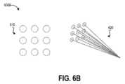
いくつかの実装では、前記生検パターンは、少なくとも2次元に配置された1つまたは複数の検体位置を有する。いくつかの実装では、前記生検パターンは、前記組織部位の形状に適合する形状に配置された1つまたは複数の検体位置を有する。いくつかの実装では、前記生検パターンは、中心が前記組織部位内に存在する形状の中に配置された1つまたは複数の検体位置を有する。いくつかの実装では、前記生検パターンは、少なくとも1つまたは複数の検体位置を有し、そのうち少なくとも1つの検体位置は前記組織部位の中心に対応する。いくつかの実装では、前記生検パターンは円形状または格子状に配置された1つまたは複数の検体位置を有する。いくつかの実装では、前記生検パターンはさらに、前記1つまたは複数の検体位置に対応する、1つまたは複数の刺入深度、1つまたは複数の採取速度、1つまたは複数の採取間隔、あるいは1つまたは複数の採取力を有する。In some implementations, the biopsy pattern has one or more specimen locations arranged in at least two dimensions. In some implementations, the biopsy pattern has one or more specimen locations arranged in a shape that conforms to the shape of the tissue site. In some implementations, the biopsy pattern has one or more specimen locations arranged in a shape whose center is within the tissue site. In some implementations, the biopsy pattern has at least one or more specimen locations, at least one specimen location corresponding to the center of the tissue site. In some implementations, the biopsy pattern has one or more specimen locations arranged in a circular or grid shape. In some implementations, the biopsy pattern further has one or more penetration depths, one or more collection rates, one or more collection intervals, or one or more collection forces corresponding to the one or more specimen locations.
別の態様は、組織部位から1つまたは複数の生検検体の取得を支援する装置であって、実行可能な命令が格納された少なくとも1つのコンピュータ可読メモリと、1つまたは複数のプロセッサであって、前記少なくとも1つのコンピュータ可読メモリと通信し、前記
命令を実行して前記装置に少なくとも前記組織部位から1つまたは複数の生検検体を取得するためのパターンであって、少なくとも2次元に配置された1つまたは複数の検体位置を有するパターンを決定すること、前記パターンに基づいて、ロボット医療システムの器具の遠位部分の動きの手技計画を決定すること、前記器具の前記遠位部分を、前記少なくとも2次元のパターンに対応する1つまたは複数の位置に誘導すること、を実行させる1つまたは複数のプロセッサと、を有する装置である。 Another aspect is an apparatus for assisting in obtaining one or more biopsy specimens from a tissue site, the apparatus having at least one computer readable memory having executable instructions stored thereon; and one or more processors in communication with the at least one computer readable memory and executing the instructions to cause the apparatus to: determine a pattern for obtaining one or more biopsy specimens from at least the tissue site, the pattern having one or more specimen locations disposed in at least two dimensions; determine a procedural plan for movement of a distal portion of an instrument of a robotic medical system based on the pattern; and steer the distal portion of the instrument to one or more locations corresponding to the at least two dimensional pattern.
いくつかの実装では、1つまたは複数のプロセッサが、前記少なくとも1つのコンピュータ可読メモリと通信し、前記命令を実行して前記装置に少なくとも手技計画を前記少なくとも1つのコンピュータ可読メモリに保存する。いくつかの実装では、1つまたは複数のプロセッサが、前記少なくとも1つのコンピュータ可読メモリと通信し、前記命令を実行して前記装置に少なくとも前記手技計画を前記ロボット医療システムに送信して前記ロボット医療システムの前記器具の前記遠位部分を誘導することを実行させる。いくつかの実装では、前記1つまたは複数のプロセッサは、前記命令を実行して前記装置に少なくとも一組の位置センサからのデータ信号に基づいて(1)前記一組の位置センサの少なくとも1つの位置または(2)前記器具の前記遠位部分の位置を計算すること、前記計算された位置に基づいて前記器具の動きを制御すること、を実行させる。In some implementations, one or more processors communicate with the at least one computer-readable memory and execute the instructions to cause the device to store at least the procedure plan in the at least one computer-readable memory. In some implementations, one or more processors communicate with the at least one computer-readable memory and execute the instructions to cause the device to transmit at least the procedure plan to the robotic medical system and guide the distal portion of the instrument of the robotic medical system. In some implementations, the one or more processors execute the instructions to cause the device to calculate (1) a position of at least one of the set of position sensors or (2) a position of the distal portion of the instrument based on data signals from at least one set of position sensors, and control the movement of the instrument based on the calculated position.
いくつかの実装では、前記一組の位置センサの少なくとも1つは、前記器具の遠位端に超音波トランスデューサを有する。いくつかの実装では、前記超音波トランスデューサは、ラジアルスキャンまたはリニアスキャントランスデューサを含む。いくつかの実装では、前記一組の位置センサの少なくとも1つは、前記器具の遠位端にEMセンサを有する。いくつかの実装では、前記一組の位置センサの少なくとも1つは、X線イメージインテンシファイアおよびX線撮像装置を有する。In some implementations, at least one of the set of position sensors includes an ultrasound transducer at the distal end of the instrument. In some implementations, the ultrasound transducer includes a radial scan or linear scan transducer. In some implementations, at least one of the set of position sensors includes an EM sensor at the distal end of the instrument. In some implementations, at least one of the set of position sensors includes an X-ray image intensifier and an X-ray imager.
いくつかの実装では、前記1つまたは複数のプロセッサは、前記命令を実行して前記装置に少なくとも前記パターンに応じてスコープの動きを計算すること、前記スコープの遠位部分を前記パターンに対応する前記1つまたは複数の位置に誘導すること、を実行させる。In some implementations, the one or more processors execute the instructions to cause the device to at least calculate a movement of a scope in response to the pattern and to guide a distal portion of the scope to the one or more positions corresponding to the pattern.
いくつかの実装では、前記1つまたは複数のプロセッサは、前記命令を実行して前記装置に少なくとも前記パターンに応じて収集装置の動きを計算すること、前記収集装置の遠位部分を前記パターンに対応する前記1つまたは複数の位置に誘導すること、を実行させる。In some implementations, the one or more processors execute the instructions to cause the device to at least calculate a movement of a collector in response to the pattern and to guide a distal portion of the collector to the one or more positions corresponding to the pattern.
いくつかの実装では、前記1つまたは複数のプロセッサは、前記命令を実行して前記装置に少なくとも前記収集装置を作動して、前記パターンに対応する前記1つまたは複数の位置から前記1つまたは複数の生検検体を取得することを実行させる。いくつかの実装では、前記1つまたは複数のプロセッサは、前記命令を実行して前記装置に少なくとも前記収集装置による前記生検検体の収集に応じて、前記収集装置に配置されたマーカの動きに基づいて、前記収集装置が前記生検検体を取得した1つまたは複数の採取位置を計算すること、前記1つまたは複数の採取位置と前記生検パターンの前記1つまたは複数の検体位置とを比較すること、前記1つまたは複数の採取位置に基づいて、前記生検パターンの前記1つまたは複数の検体位置を調整すること、を実行させる。In some implementations, the one or more processors execute the instructions to cause the device to at least operate the collection device to obtain the one or more biopsy samples from the one or more locations corresponding to the pattern. In some implementations, the one or more processors execute the instructions to cause the device to at least, in response to collection of the biopsy samples by the collection device, calculate one or more collection locations at which the collection device obtained the biopsy samples based on movement of a marker disposed on the collection device, compare the one or more collection locations to the one or more sample locations of the biopsy pattern, and adjust the one or more sample locations of the biopsy pattern based on the one or more collection locations.
いくつかの実装では、前記パターンは、前記組織部位の形状に適合する形状に配置された1つまたは複数の検体位置を有する。いくつかの実装では、前記生検パターンは、中心が前記組織部位内に存在する形状の中に配置された1つまたは複数の検体位置を有する。いくつかの実装では、前記生検パターンは、少なくとも1つまたは複数の検体位置を有し、そのうち少なくとも1つの検体位置は前記組織部位の中心に対応する。いくつかの実装
では、前記生検パターンは円形状または格子状に配置された1つまたは複数の検体位置を有する。いくつかの実装では、前記生検パターンはさらに、前記1つまたは複数の検体位置に対応する、1つまたは複数の刺入深度、1つまたは複数の採取速度、1つまたは複数の採取間隔、あるいは1つまたは複数の採取力を有する。 In some implementations, the pattern has one or more specimen locations arranged in a shape that conforms to the shape of the tissue site. In some implementations, the biopsy pattern has one or more specimen locations arranged in a shape whose center resides within the tissue site. In some implementations, the biopsy pattern has at least one or more specimen locations, at least one specimen location corresponding to a center of the tissue site. In some implementations, the biopsy pattern has one or more specimen locations arranged in a circular or grid shape. In some implementations, the biopsy pattern further has one or more penetration depths, one or more collection rates, one or more collection intervals, or one or more collection forces corresponding to the one or more specimen locations.
さらに別の態様は、患者の対象組織部位から1つまたは複数の検体を収集する方法であって、ロボット医療システムのユーザインターフェースを介して、前記対象組織部位内の前記1つまたは複数の検体のパターンを選択するユーザ入力を受信することと、前記ロボット医療システムの器具の遠位部分を、前記パターン内の第1の検体位置に対応する第1の位置に移動することと、前記器具を、前記パターン内の前記第1の検体位置で第1の組織検体を取得するように誘導することと、前記ロボット医療システムの前記器具の前記遠位部分を、前記パターン内の第2の検体位置に対応する第2の位置に移動することと、前記器具を、前記パターン内の前記第2の検体位置で第2の組織検体を取得するように誘導することと、を含む方法である。Yet another aspect is a method of collecting one or more specimens from a target tissue site of a patient, the method including receiving a user input via a user interface of a robotic medical system selecting a pattern of the one or more specimens in the target tissue site, moving a distal portion of an instrument of the robotic medical system to a first position corresponding to a first specimen position in the pattern, guiding the instrument to obtain a first tissue specimen at the first specimen position in the pattern, moving the distal portion of the instrument of the robotic medical system to a second position corresponding to a second specimen position in the pattern, and guiding the instrument to obtain a second tissue specimen at the second specimen position in the pattern.
いくつかの実装は、前記ユーザ入力を受信して、前記1つまたは複数の検体の前記パターンを、前記第1の検体位置または前記第2の検体位置に調整すること、をさらに含む。いくつかの実装では、前記パターンを調整することは、1つまたは複数の解剖学的特徴に基づく。いくつかの実装では、前記解剖学的特徴は、1つまたは複数の血管を有する。いくつかの実装では、前記パターンを調整することは、前記器具の前記遠位部分の初期位置を測定することと、前記器具の前記遠位部分の前記初期位置に基づいて、前記パターンを前記組織部位に適合させることを含む。Some implementations further include receiving the user input and adjusting the pattern of the one or more specimens to the first specimen location or the second specimen location. In some implementations, adjusting the pattern is based on one or more anatomical features. In some implementations, the anatomical features include one or more blood vessels. In some implementations, adjusting the pattern includes measuring an initial position of the distal portion of the instrument and fitting the pattern to the tissue site based on the initial position of the distal portion of the instrument.
いくつかの実装では、前記パターンを適合させることは、前記初期位置から前記第1の検体位置または前記第2の検体位置までに至る前記器具の前記遠位部分の経路を計算することを含む。いくつかの実装では、前記パターンを適合させることは、前記第1の検体位置または前記第2の検体位置における前記器具の、1つまたは複数の刺入深度、1つまたは複数の採取速度、1つまたは複数の採取間隔、あるいは1つまたは複数の採取力を調整することを含む。いくつかの実装では、前記パターンを調整することは、前記パターンを前記組織部位の形状に適合させることを含む。いくつかの実装では、前記パターンを調整することは、中心が前記組織部位内に存在する形状に前記パターンを適合させることを含む。いくつかの実装では、前記パターンを調整することは、前記パターンの少なくとも1つの検体位置が前記組織部位の中心に対応するように、前記パターンを調整することを含む。In some implementations, adapting the pattern includes calculating a path of the distal portion of the instrument from the initial location to the first or second specimen location. In some implementations, adapting the pattern includes adjusting one or more penetration depths, one or more sampling rates, one or more sampling intervals, or one or more sampling forces of the instrument at the first or second specimen location. In some implementations, adjusting the pattern includes adapting the pattern to a shape of the tissue site. In some implementations, adjusting the pattern includes adapting the pattern to a shape whose center is within the tissue site. In some implementations, adjusting the pattern includes adjusting the pattern such that at least one specimen location of the pattern corresponds to a center of the tissue site.
いくつかの実装は、前記器具を、前記第1の組織検体または前記第2の組織検体を取得するように誘導するときに、前記患者の呼吸数に基づいて前記器具の前記遠位部分の動きを調整することをさらに含む。Some implementations further include adjusting the movement of the distal portion of the instrument based on a respiratory rate of the patient when directing the instrument to obtain the first tissue sample or the second tissue sample.
いくつかの実装では、前記ロボット医療システムの前記器具の前記遠位部分を前記第2の位置に移動することは、前記第1の検体位置における前記第1の組織検体の収集の通知を受信した後に行われる。In some implementations, moving the distal portion of the instrument of the robotic medical system to the second location occurs after receiving notification of collection of the first tissue sample at the first sample location.
いくつかの実装は、前記ロボット医療システムの前記器具の前記遠位部分を、前記パターン内の第3の検体位置に対応する第3の位置に移動することと、前記パターン内の前記第3の検体位置に置いて第3の組織検体を取得するように前記器具を誘導することをさらに含む。いくつかの実装では、前記ロボット医療システムの前記器具の前記遠位部分を前記第3の位置に移動することは、前記第2の検体位置における前記第2の組織検体の収集の通知を受信した後に行われる。Some implementations further include moving the distal portion of the instrument of the robotic medical system to a third position corresponding to a third specimen location in the pattern and guiding the instrument to obtain a third tissue sample at the third specimen location in the pattern. In some implementations, moving the distal portion of the instrument of the robotic medical system to the third position occurs after receiving notification of collection of the second tissue sample at the second specimen location.
いくつかの実装では、前記ロボット医療システムの前記器具の前記遠位部分を前記第1の位置または前記第2の位置に移動することは、一組の位置センサからのデータ信号に基づいて、前記器具の前記遠位部分少なくとも1つの位置を計算することと、前記計算された少なくとも1つの位置に基づいて、前記器具の動きを制御することと、を含む。In some implementations, moving the distal portion of the instrument of the robotic medical system to the first position or the second position includes calculating at least one position of the distal portion of the instrument based on data signals from a set of position sensors, and controlling movement of the instrument based on the calculated at least one position.
いくつかの実装は、前記器具を作動して、前記パターン内の前記第1の対応する検体位置から前記第1の組織検体を取得することをさらに含む。いくつかの実装は、前記器具を作動して、前記パターン内の前記第2の対応する検体位置から前記第2の組織検体を取得することをさらに含む。いくつかの実装は、1つまたは複数のハードウェアプロセッサによって実行される。Some implementations further include operating the instrument to obtain the first tissue sample from the first corresponding sample location in the pattern. Some implementations further include operating the instrument to obtain the second tissue sample from the second corresponding sample location in the pattern. Some implementations are performed by one or more hardware processors.
さらに別の態様は、命令が格納されている非一時的なコンピュータ可読媒体であって、命令が実行されると少なくとも1つの計算装置に少なくとも1つまたは複数の生検検体のパターンを受信することであって、前記パターンは患者の対象組織部位内の少なくとも2次元に配置された1つまたは複数の生検位置を有する、こと、前記ロボット医療システムの器具の遠位部分を、前記少なくとも2次元のパターン内に配置された前記1つまたは複数の生検位置に対応する1つまたは複数の採取位置に移動すること、を実行させる。Yet another aspect is a non-transitory computer-readable medium having instructions stored thereon that, when executed, cause at least one computing device to receive a pattern of at least one or more biopsy specimens, the pattern having one or more biopsy locations arranged in at least two dimensions within a target tissue site of a patient, and move a distal portion of an instrument of the robotic medical system to one or more collection locations corresponding to the one or more biopsy locations arranged in the at least two-dimensional pattern.
いくつかの実装では、前記命令が実行されると前記少なくとも1つの計算装置に少なくとも一組の位置センサからのデータ信号に基づいて、前記器具の前記遠位部分の少なくとも1つの位置を計算すること、前記計算された少なくとも1つの位置に基づいて、前記器具の動きを制御すること、を実行させる。いくつかの実装では、前記命令が実行されると前記少なくとも1つの計算装置に少なくとも初期位置から前記1つまたは複数の採取位置に至るまでの前記器具の前記遠位部分の経路を計算させることを実行させる。In some implementations, the instructions, when executed, cause the at least one computing device to calculate at least one position of the distal portion of the instrument based on data signals from at least one set of position sensors, and control movement of the instrument based on the calculated at least one position. In some implementations, the instructions, when executed, cause the at least one computing device to calculate a path of the distal portion of the instrument from at least an initial position to the one or more harvesting positions.
いくつかの実装では、前記命令が実行されると前記少なくとも1つの計算装置に少なくとも前記パターンに応じて前記器具のスコープの動きを計算すること、前記スコープの遠位部分を前記1つまたは複数の採取位置に移動することを実行させる。いくつかの実装では、前記命令が実行されると前記少なくとも1つの計算装置に少なくとも前記パターンに応じて前記器具の収集装置の動きを計算すること、収集装置を前記1つまたは複数の採取位置に移動することを実行させる。In some implementations, the instructions, when executed, cause the at least one computing device to calculate a movement of the instrument's scope in response to at least the pattern and move a distal portion of the scope to the one or more collection locations. In some implementations, the instructions, when executed, cause the at least one computing device to calculate a movement of the instrument's collector in response to at least the pattern and move a collector to the one or more collection locations.
いくつかの実装では、前記命令が実行されると前記少なくとも1つの計算装置に少なくとも前記患者の前記組織部位の1つまたは複数の解剖学的特徴または前記患者の呼吸数に基づいて、前記1つまたは複数の生検検体の前記パターンを調整することを実行させる。いくつかの実装では、前記命令が実行されると前記少なくとも1つの計算装置に少なくとも、前記組織部位内の1つまたは複数の血管に基づいて、前記1つまたは複数の生検検体の前記パターンを調整することを実行させる。In some implementations, the instructions, when executed, cause the at least one computing device to adjust the pattern of the one or more biopsy samples based at least on one or more anatomical features of the tissue site of the patient or a respiratory rate of the patient. In some implementations, the instructions, when executed, cause the at least one computing device to adjust the pattern of the one or more biopsy samples based at least on one or more blood vessels within the tissue site.
いくつかの実装では、前記命令が実行されると前記少なくとも1つの計算装置に少なくとも前記器具の前記遠位部分の初期位置を測定すること、前記器具の前記遠位部分の前記初期位置に基づいて、前記1つまたは複数の生検検体のパターンを調整することを実行させる。In some implementations, the instructions, when executed, cause the at least one computing device to determine at least an initial position of the distal portion of the instrument and adjust the pattern of the one or more biopsy samples based on the initial position of the distal portion of the instrument.
いくつかの実装では、前記命令が実行されると前記少なくとも1つの計算装置に少なくとも、前記パターンを前記組織部位の形状に適合させることを実行させる。いくつかの実装では、前記命令が実行されると前記少なくとも1つの計算装置に少なくとも、中心が前記組織部位内に存在する形状に前記パターンを適合させることを実行させる。いくつかの実装では、前記命令が実行されると前記少なくとも1つの計算装置に少なくとも、前記パターンの少なくとも1つの採取位置が前記組織部位の中心に対応するように前記パターン
を調整することを実行させる。 In some implementations, the instructions, when executed, cause the at least one computing device to at least conform the pattern to a shape of the tissue site. In some implementations, the instructions, when executed, cause the at least one computing device to at least conform the pattern to a shape whose center is within the tissue site. In some implementations, the instructions, when executed, cause the at least one computing device to at least adjust the pattern such that at least one pick location of the pattern corresponds to a center of the tissue site.
いくつかの実装では、前記命令が実行されると前記少なくとも1つの計算装置に少なくとも、前記1つまたは複数の採取位置における前記器具の、1つまたは複数の刺入深度、1つまたは複数の採取速度、1つまたは複数の採取間隔、あるいは1つまたは複数の採取力を調整することを実行させる。In some implementations, the instructions, when executed, cause the at least one computing device to at least adjust one or more penetration depths, one or more sampling rates, one or more sampling intervals, or one or more sampling forces of the instrument at the one or more sampling locations.
いくつかの実装では、前記命令が実行されると前記少なくとも1つの計算装置に少なくとも、前記器具の前記遠位部分を作動して前記1つまたは複数の採取位置から前記1つまたは複数の生検検体を取得することを実行させる。いくつかの実装では、前記命令が実行されると前記少なくとも1つの計算装置に少なくとも、前記器具が前記1つまたは複数の生検検体を取得した1つまたは複数の収集位置を受信すること、前記1つまたは複数の収集位置に基づいて前記パターンを調整すること、を実行させる。In some implementations, the instructions, when executed, cause the at least one computing device to at least actuate the distal portion of the instrument to obtain the one or more biopsy samples from the one or more collection locations. In some implementations, the instructions, when executed, cause the at least one computing device to at least receive one or more collection locations from which the instrument obtained the one or more biopsy samples and adjust the pattern based on the one or more collection locations.
開示された態様は、開示された態様を限定するものではなく、例示するために提供される添付の図面および付録と併せて以下に記載され、同様の名称は同様の要素を意味する。The disclosed aspects are described below in conjunction with the accompanying drawings and appendix, which are provided to illustrate, but not to limit, the disclosed aspects, and where like designations refer to like elements.
(概説)
本開示の実施形態は、生検検体が収集される検体位置を含む生検パターンを受信することおよび/または生検パターン内の検体位置に基づいて医療器具の動きを計算することにより、種々の対象組織部位(例えば、肺の気管)における生検の検体位置に医療器具を案内するシステムおよび技術に関する。 (Overview)
Embodiments of the present disclosure relate to systems and techniques for guiding a medical instrument to a biopsy specimen location at various target tissue sites (e.g., the trachea of the lungs) by receiving a biopsy pattern including specimen locations where biopsy specimens are to be collected and/or calculating the movement of the medical instrument based on the specimen locations in the biopsy pattern.
医師が医療器具に生検ツールを挿入して、(例えば、気管支鏡検査を介して)組織検体を収集する場合、信頼できる体系的な方法でいくつかの異なる近傍の領域を生検する医師の能力により、収集される材料の量と診断に使用できる組織検体を収集する可能性とが高まることがある。さらに、対象組織部位で特定のパターン(例えば、事前定義パターンまたはユーザ定義パターン)で組織検体を生検する医師の能力により、対象組織部位からの生検検体の戦略的収集が可能となり、異種の組織検体を収集する可能性が高まることがある。しかし、医療器具の手動関節および/または手動生検は、制御、安定性、および利用可能な動きの自由度の制約により制限される場合がある。When a physician inserts a biopsy tool into a medical instrument to collect a tissue sample (e.g., via bronchoscopy), the physician's ability to biopsy several different adjacent areas in a reliable and systematic manner may increase the amount of material collected and the likelihood of collecting a diagnostically usable tissue sample. Additionally, the physician's ability to biopsy tissue samples in a specific pattern (e.g., a predefined or user-defined pattern) at a target tissue site may allow strategic collection of biopsy samples from a target tissue site and increase the likelihood of collecting a heterogeneous tissue sample. However, manual articulation of a medical instrument and/or manual biopsy may be limited by constraints on control, stability, and available freedom of movement.
開示されたシステムおよび技術は、気管支鏡生検ガイダンスシステムおよび誘導生検のための他のタイプの内視鏡手技を含む他の用途にメリットをもたらすことができる。解剖学における「ルーメン」とは、気道、血管、または腸の時点での臓器の内部の空間または空洞を指してもよい。本明細書で使用される「管腔網」とは、対象組織部位、例えば肺の気道、循環系、および胃腸系に至る少なくとも1つの管腔を有する解剖学的構造を指す。したがって、本開示は、気管支鏡検査に関連する生検ガイダンスシステムの例を提供するが、開示される態様は、生検ガイダンスのための他の医療システムに適用可能であることが理解されよう。加えて、本開示は、対象部位で生検検体を取得する例を提供するが、開示された態様は、特定のパターン(例えば、事前定義パターンまたはユーザ定義パターン)において医療器具の動きが有効な医療手技に対しても適用可能であることが理解されよう。The disclosed systems and techniques may provide benefits for other applications, including bronchoscopy biopsy guidance systems and other types of endoscopic procedures for guided biopsy. A "lumen" in anatomy may refer to a space or cavity within an organ at the point of an airway, blood vessel, or intestine. As used herein, a "luminal network" refers to an anatomical structure having at least one lumen leading to a target tissue site, such as the airways of the lungs, the circulatory system, and the gastrointestinal system. Thus, while the present disclosure provides examples of a biopsy guidance system related to bronchoscopy, it will be understood that the disclosed aspects are applicable to other medical systems for biopsy guidance. In addition, while the present disclosure provides examples of obtaining a biopsy specimen at a target site, it will be understood that the disclosed aspects are also applicable to medical procedures in which movement of a medical instrument in a specific pattern (e.g., a predefined pattern or a user-defined pattern) is effective.
本明細書で使用される「遠位」とは、使用中に患者に最も近い位置にあるスコープ、器具、またはツールの端部を指し、「近位」とは、オペレータ(例えば、医師またはロボット制御システム)に最も近い位置にあるスコープ、器具、またはツールの端部を指す。別の言い方をすると、スコープ、器具、ツール、および/またはロボットシステムの構成要素の相対位置は、本明細書ではオペレータの観点から記載されている。As used herein, "distal" refers to the end of the scope, instrument, or tool that is closest to the patient during use, and "proximal" refers to the end of the scope, instrument, or tool that is closest to the operator (e.g., the physician or the robotic control system). Stated differently, the relative positions of the scope, instrument, tool, and/or components of the robotic system are described herein from the perspective of the operator.
本明細書で使用される「約」または「およそ」という用語は、長さ、厚さ、量、期間、または他の測定可能な値の測定範囲を指す。そのような測定範囲は、開示された装置、システム、および技術でその役割を果たすために、その変動が適切である限り、指定された値のおよび値からプラスマイナス10%以下、好ましくはプラスマイナス5%以下、より好ましくはプラス/マイナス1%以下、さらにより好ましくはプラス/マイナス0.1%以下の変動を含む。As used herein, the term "about" or "approximately" refers to a range of measurements of a length, thickness, amount, duration, or other measurable value. Such ranges of measurements include variations of no more than plus or minus 10%, preferably no more than plus or minus 5%, more preferably no more than plus or minus 1%, and even more preferably no more than plus or minus 0.1% from the specified value and values, so long as such variations are appropriate for the disclosed devices, systems, and techniques to perform their functions.
例示の目的として、図面と併せて種々の実施形態を以下に説明する。開示された概念について、他にも多くの実装が可能であり、開示された実装で種々の利点を達成可能であることを理解されたい。見出しは、参照および種々のセクションの検索を支援するために本明細書に含まれる。これらの見出しは、それに関して記載される概念の範囲を制限するものではない。そのような概念は、明細書全体にわたっての適用可能性を有してもよい。For purposes of illustration, various embodiments are described below in conjunction with the drawings. It is to be understood that many other implementations of the disclosed concepts are possible and that various advantages may be achieved in the disclosed implementations. Headings are included herein to aid in reference and locating the various sections. These headings do not limit the scope of the concepts described therein. Such concepts may have applicability throughout the entire specification.
(生検ガイダンスシステム例の概要)
図1Aは、開示された生検システムおよび技術の1つまたは複数の態様を実装する例示的な動作環境100を示している。動作環境100は、患者101、患者101を支持す
るプラットフォーム102、内視鏡115の動きを案内する手術ロボットシステム110、手術ロボットシステム110の動作を制御するコマンドセンタ105、電磁(EM)制御器135、電磁場発生器120、および電磁センサ125、130を含む。図1Aは、図1Bにより詳細に示される、患者101内の管腔網140のおおよその範囲も示している。 (Outline of an example biopsy guidance system)
FIGURE 1A illustrates an
手術ロボットシステム110は、患者101の管腔網140を通して内視鏡115を位置決めし、内視鏡115の動きを案内し、場合によっては、収集装置(例えば、生検針、ブラシ、鉗子、など)を動かす1つ以上のロボットアームを含むことができる。コマンドセンタ105は、手術ロボットシステム110に通信可能に連結し、位置データを受信、および/またはユーザからの制御信号を提供する。本明細書で使用する「通信可能に連結」とは、これらに限定されないが、無線ワイドエリアネットワーク(WWAN)(例えば、1つ以上のセルラーネットワーク)、無線ローカルエリアネットワーク(WLAN)(例えば、IEEE802.11(Wi-Fi)などの1つ以上の規格で構成される)、Bluetooth、データ転送ケーブルなどを含む有線および/または無線データ転送媒体を指す。手術ロボットシステム110は、図1Cを基準にしてより詳細に述べられ、コマンドセンタ105は、図2を基準にしてより詳細に述べられる。The surgical
内視鏡115は、管状の柔軟な手術用器具であって、患者の解剖学的構造に挿入されて、解剖学的構造(例えば、生体組織、対象組織部位)の画像を取り込み、他の医療器具を対象組織部位に挿入するための作業チャネルを提供する手術用器具であってもよい。いくつかの実装形態では、内視鏡115は、気管支鏡とすることができる。内視鏡115は、その遠位端に1つ以上の位置センサを含むことができる。1つ以上の位置センサは、撮像装置(例えば、カメラまたは他のタイプの光学センサ)、超音波トランスデューサ、X線装置(例えば、X線イメージインテンシファイア、X線撮像装置、透視装置)および/または電磁センサから構成されてもよい。撮像装置は、光ファイバ、ファイバアレイ、感光性基板、および/または1つまたは複数のレンズなどの1つ以上の光学部品を含んでもよい。光学部品は、内視鏡115の先端の動きに対応して、撮像装置によって取り込まれた画像の視野が変化するように、内視鏡115の先端とともに動く。内視鏡115の遠位端には、1つ以上の超音波トランスデューサ(例えば、ラジアルスキャンまたはリニアスキャン超音波トランスデューサ)または解剖学的構造(例えば、生体組織)の画像を生成するように構成されたX線装置を設けることができる。撮像装置、超音波トランスデューサ、および/またはX線装置から生成された解剖学的構造の画像を使用して、内視鏡115の遠位端の位置および/または向きを特定してもよい。いくつかの実装形態では、1つ以上の患者の解剖学的構造のモデルを解剖学的構造の画像とともに使用して、内視鏡115の遠位端の位置および/または向きを特定してもよい。例として、術前手技を実行して患者の肺のCTスキャンをとることができ、計算システムは、これらのスキャンからのデータを使用して、患者の肺の3Dモデルを構築することができる。そのようなモデルによって、いくつかの例では、患者の気道の形状および/または直径を含む、肺管腔網の構造および接続性に関する3D情報の提供が可能となる。一部のCTスキャンは、息を止めた状態で実行されるため、患者の気道は、最大径まで拡張されている。次に、この管腔網のモデルは、内視鏡115の遠位端の1つ以上の位置センサからの画像と共に使用されて、遠位端の位置および/または向きを決定することができる。The
加えて、内視鏡115の遠位端には、管腔網140の周りに生成された電磁場内における遠位端の位置を追跡するための1つ以上の電磁センサを設けることができる。以下、内視鏡115の遠位端について、図3を参照してさらに説明する。Additionally, the distal end of the
電磁制御器135は、電磁場発生器120を制御して、変化する電磁場を発生させることができる。電磁場は、実施形態に応じて、時間変化および/または空間変化が可能であ
る。電磁場発生器120は、いくつかの実施形態では、電磁場発生ボードとすることができる。開示された生検ガイダンスシステムのいくつかの実施形態では、患者と患者を支持するプラットフォーム102との間に位置付けられた電磁場発生器ボードを使用することができ、電磁場発生器ボードは、その下に位置する導電性または磁性材料によって引き起こされる追跡歪みを最小限に抑える薄いバリアを組み込むことができる。他の実施形態では、電磁場発生器ボードは、例えば、患者の周りにおいて柔軟な設定オプションを提供することができる、手術ロボットシステム110に示されるものに類するロボットアームに取り付けることができる。 The
コマンドセンタ105、手術ロボットシステム110、および/または電磁制御器135に組み込まれた電磁空間測定システムは、電磁センサコイル、例えば、電磁センサ125、130が埋め込まれた、または設けられた、電磁場内の物体の位置を決定することができる。本明細書に記載の、制御され変化する電磁場内に電磁センサを配置すると、センサコイルに電圧が誘起される。これらの誘起電圧は、電磁空間測定システムによって使用され、電磁センサ、つまり、電磁センサを有する物体の位置および/または向きを計算することできる。磁場は、低磁場強度の磁場であり、人間の組織を安全に通過できるため、光学空間測定システムの照準線の制約なしに、物体の位置測定が可能となる。An electromagnetic spatial measurement system integrated into the
電磁センサ125は、内視鏡115の遠位端に連結され、電磁場内における遠位端の位置を追跡できる。電磁場は、電磁場発生器に対して静止しており、管腔網の3Dモデルの座標枠は、電磁場の座標枠にマッピングできる。An
図1Bは、図1Aの動作環境100における、生検のためにナビゲート可能な例示的な管腔網140を示す。管腔網140は、患者の気道150の分岐構造と、本明細書に記載の、生検のためにアクセス可能な結節155(または病変)とを含む。図示されるように、結節155は、気道150の周辺に位置する。内視鏡115は、第1の直径を有するため、その遠位端は、結節155の周りの、内視鏡115より小径の気道内に位置付けることができない。したがって、操縦可能なカテーテル145は、内視鏡115の作業チャネルから結節155までの残りの距離だけ延びる。操縦可能なカテーテル145は、器具、例えば、生検針、細胞診ブラシ、および/または組織採取鉗子を結節155の対象組織部位に通すことができる内腔を有してもよい。そのような実装では、内視鏡115の遠位端および操縦可能なカテーテル145の遠位端の両方に、気道150内のそれらの位置を追跡するための電磁センサを設けることができる。他の実施形態では、内視鏡115の全体径は、操縦可能なカテーテル145なしでその周辺に到達できる程度に小さくてもよく、または操縦可能ではないカテーテル(図示せず)を通して医療器具を展開するためにその周辺に近づく(例えば2.5から3cm以内)ことができる程度に小さくてもよい。内視鏡115を通して展開された医療器具には、電磁センサが備え付けられていてもよい。FIG. 1B illustrates an exemplary
いくつかの実施形態では、本明細書に記載の3D管腔網モデルの2D表示、または3Dモデルの断面は、図1Bのように見える。In some embodiments, a 2D representation of the 3D luminal network model described herein, or a cross section of the 3D model, appears as in FIG. 1B.
図1Cは、図1Bの管腔網140を通して器具の動きを案内するための手術ロボットシステム110の例示的なロボットアーム175を示している。手術ロボットシステム110は、1つ以上のロボットアーム、例えば、ロボットアーム175に連結された基部180を含む。ロボットアーム175は、関節165で連結された複数のアームセグメント170を含み、これによって、ロボットアーム175に多自由度を持たせる。一例として、ロボットアーム175の一実装は、7つのアームセグメントに対応する7つの自由度を有することができる。いくつかの実施形態では、ロボットアーム175は、ロボットアーム175の位置を維持するためにブレーキとカウンタバランスの組み合わせを使用するセットアップジョイントを含む。カウンタバランスは、ガススプリングおよび/またはコイル
スプリングを含んでもよい。ブレーキ、例えば、フェールセーフブレーキは、機械的および/または電気的部品を含んでもよい。また、ロボットアーム175は、重力補助受動支持型ロボットアームであってもよい。 FIG. 1C illustrates an exemplary
ロボットアーム175は、メカニズムチェンジャインターフェース(MCI)160を使用し、器械装置マニピュレータ(IDM)190に連結されてもよい。IDM190は取り外して、異なるタイプのIDM、例えば、内視鏡を操作するように構成された第1のタイプのIDM、または腹腔鏡を操作するように構成された第2のタイプのIDMと交換できる。MCI160は、空気圧、電力、電気信号、および光信号をロボットアーム175からIDM190に伝達するためのコネクタを含む。MCI160は、止めネジまたはベースプレートコネクタとすることができる。IDM190は、直接駆動、調和駆動、ギア駆動、ベルトおよびプーリ、磁気駆動などの技術を使用し、手術用器具、例えば、内視鏡115を操作する。MCI160は、IDM190のタイプに基づいて交換可能であり、特定のタイプの手術手技に合わせてカスタマイズすることができる。ロボットアーム175は、関節レベルのトルク感知機能(例えば、関節165またはその近くに位置付けられた1つ以上のトルクセンサを使用)および遠位端に手関節を含むことができる。The
手術ロボットシステム110のロボットアーム175は、細長い動部材を使用し、内視鏡115を操作することができる。細長い動部材は、プル・プッシュワイヤとも呼ばれるプルワイヤ、ケーブル、繊維、または可撓性シャフトを含んでもよい。例えば、ロボットアーム175は、内視鏡115に連結された複数のプルワイヤを作動させて、内視鏡115の先端の向きを変えることができる。プルワイヤは、例えば、ステンレス鋼、ケブラー、タングステン、炭素繊維などの、金属材料と非金属材料の両方を含んでもよい。内視鏡115は、細長い動部材によって加えられる力に応じて非線形挙動を示してもよい。非線形挙動は、内視鏡115の剛性および圧縮性、ならびに異なる細長い動部材間のたるみまたは剛性のばらつきに基づいてもよい。The
ロボットアーム175が患者に対する手術手技を実行または補助することができるように、基部180を位置付けることができる一方、医師などのユーザは、コマンドコンソールから快適に手術ロボットシステム110を制御してもよい。いくつかの実施形態では、基部180は、患者を支持するための手術台またはベッド(例えば、プラットフォーム102)に連結されてもよい。基部180は、図1Aに示すコマンドコンソール105に通信可能に連結され得る。The base 180 can be positioned so that the
基部180は、動力源182と、空気圧186と、中央処理装置、データバス、制御回路、メモリなどの構成要素を含む制御およびセンサ電子回路184と、ロボットアーム175を動かすためのモータなどの関連アクチュエータとを含むことができる。本明細書で使用される「アクチュエータ」という用語は、ロボットアーム175の位置および/または向きを物理的に調整するための機構を指してもよい。電子回路184は、本明細書に記載の生検ガイダンス技術を実装することができる。また、基部180内の電子回路184は、コマンドコンソールから送られる制御信号を処理および送信してもよい。いくつかの実施形態では、基部180は、手術ロボットシステム110を移動させるための車輪188と、車輪188用の車輪ロック/ブレーキ(図示せず)とを含む。手術ロボットシステム110の可動性は、手術室のスペースの制約に対応するのに役立つとともに、手術用機材の適切な位置付けおよび移動を容易にする。さらに、この可動性により、ロボットアーム175が患者、医師、麻酔医、または他の機材の邪魔にならないようにロボットアーム175を構成することができる。手技中、ユーザは、例えば、コマンドコンソールなどの制御装置を使用し、ロボットアーム175を制御してもよい。The base 180 can include a
図2は、例えば、例示的な動作環境100のコマンドコンソール105として使用可能
な例示的なコマンドコンソール200を示す。コマンドコンソール200は、コンソールベース201と、例えば、モニタなどのディスプレイモジュール202と、例えば、キーボード203およびジョイスティック204などの制御モジュールとを含む。いくつかの実施形態では、コマンドコンソール200機能のうちの1つ以上を、手術ロボットシステム110の基部180または手術ロボットシステム110に通信可能に連結された別のシステムに組み込んでもよい。医師などのユーザ205は、コマンドコンソール200を使用し、人間工学に基づいた位置から手術ロボットシステム110を遠隔制御する。 2 illustrates an
コンソールベース201は、例えば、図1A~図1Cに示す内視鏡115からのカメラ画像および追跡センサデータなどの信号を解釈および処理を担う、中央処理装置と、メモリユニットと、データバスと、関連するデータ通信ポートとを含んでもよい。いくつかの実施形態では、コンソールベース201と基部180の両方が信号処理を実行し、負荷を分散させている。また、コンソールベース201は、制御モジュール203および204を介してユーザ205によって提供されるコマンドおよび命令を処理してもよい。図2に示すキーボード203およびジョイスティック204に加えて、制御モジュールは、例えば、コンピュータマウス、トラックパッド、トラックボール、コントロールパッド、手持ち型リモートコントローラなどのコントローラ、および手のジェスチャーと指のジェスチャーを捕捉するセンサ(例えば、モーションセンサやカメラ)といった他の装置を含んでもよい。コントローラには、器具の操作(例えば、関節、駆動、水洗滌)にマッピングされた一連のユーザ入力(例えば、ボタン、ジョイスティック、方向パッド)を含めることができる。The
コマンドコンソール200を使用することで、ユーザ205は、生検検体が収集される1つ以上の検体位置から構成される生検パターンを入力することができる。いくつかの実施形態では、コマンドコンソール200を使用するユーザ205は、1つ以上のコマンドを入力して、生検パターンにアクセスし、または1つ以上のコマンドを入力して、生検パターンを(例えば、ディスプレイモジュール202を介して)表示してもよい。別の実施形態では、コマンドコンソール200を使用するユーザ205は、1つ以上のコマンドを入力して、医療器具(例えば、内視鏡115、ロボットアーム175)の検体位置への動きを計算してもよい。さらに別の実施形態では、コマンドコンソール200を使用するユーザ205は、1つ以上のコマンドを入力して、器具を検体位置へ動かしてもよい。Using the
ユーザ205は、速度モードまたは位置制御モードでコマンドコンソール200を使用し、内視鏡115などの手術用器具を制御することができる。速度モードでは、ユーザ205は、制御モジュールを使用した直接的な手動制御に基づいて、内視鏡115の遠位端のピッチおよびヨー運動を直接制御する。例えば、ジョイスティック204の動きは、内視鏡115の遠位端のヨーおよびピッチの動きにマッピングされてもよい。ジョイスティック204は、ユーザ205に触覚フィードバックを提供できる。例えば、ジョイスティック204は、振動することで、内視鏡115が特定の方向にさらに並進または回転できないことを示すことができる。また、コマンドコンソール200は、視覚フィードバック(例えば、ポップアップメッセージ)および/または音声フィードバック(例えば、ビープ音)を提供して、内視鏡115が最大並進または回転に達したことを示すことができる。以下により詳細に説明するように、患者の呼気中に安全モードで動作するシステムにより、触覚および/または視覚フィードバックも提供することができる。A
位置制御モードでは、コマンドコンソール200は、本明細書で記載の患者の管腔網の3次元(3D)マップと、位置センサからの入力とを使用して、手術用器具、例えば、内視鏡115、を制御する。コマンドコンソール200は、手術ロボットシステム110のロボットアーム175に制御信号を提供して、内視鏡115を対象位置に動かす。3Dマップに依存しているため、位置制御モードでは、患者の解剖学的構造の正確なマッピング
が必要になる場合がある。 In the position control mode, the
いくつかの実施形態では、ユーザ205は、コマンドコンソール200を使用することなく、手術ロボットシステム110のロボットアーム175を手動で操作することができる。手術室での準備中に、ユーザ205は、ロボットアーム175、内視鏡115(または複数の内視鏡)、および他の手術用機材を動かして、患者にアクセスしてもよい。手術ロボットシステム110は、ユーザ205からの力フィードバックおよび慣性制御に依存して、ロボットアーム175および機材の適切な構成を決定してもよい。In some embodiments, the
ディスプレイ202は、電子モニタ(例えば、LCDディスプレイ、LEDディスプレイ、タッチセンシティブディスプレイ)、ゴーグルまたは眼鏡等の仮想現実表示装置、および/または他のディスプレイデバイスなど、1つ以上のユーザインターフェース画面を含んでもよい。いくつかの実施形態では、ディスプレイモジュール202は、例えば、タッチスクリーンを備えたタブレットデバイスとして、制御モジュールと統合される。いくつかの実施形態では、ディスプレイ202のうちの1つは、生検パターンまたは生検パターン内の1つ以上の検体位置の仮想表現を表示してもよい。いくつかの実施形態では、ディスプレイ202のうちの1つは、患者の管腔網の3Dモデルおよび仮想生検情報(例えば、対象組織部位における生検パターンの仮想表現または電磁センサ位置に基づくモデル内の生検パターンの検体位置に向けた内視鏡の端部の経路の仮想表現)を表示することができる一方、ディスプレイ202のうちの他方は、内視鏡115の端部にあるカメラまたは他のセンシングデバイスから受信した画像情報を表示することができる。いくつかの実装形態では、ユーザ205は、統合ディスプレイ202および制御モジュールを使用して、データを確認し、手術ロボットシステム110にコマンドを入力することができる。ディスプレイ202は、立体映像装置、例えば、バイザまたはゴーグルを使用し、3D画像の2D描画および/または3D画像を表示することができる。3D画像は、患者の解剖学的構造を示すコンピュータ3Dモデルである「内部ビュー」(すなわち、内視鏡ビュー)を提供する。「内部ビュー」は、患者体内の仮想環境と、患者体内における内視鏡115の予想位置を提供する。ユーザ205は、「内部ビュー」モデルとカメラで取り込んだ実際の画像とを比較することで、頭の中で方位を見定めることと、内視鏡115が患者体内における正しい位置またはほぼ正しい位置にあることを確認することとを助ける。「内部ビュー」は、内視鏡115の遠位端の周りの解剖学的構造、例えば、患者の気道、循環血管、または腸もしくは結腸の形状に関する情報を提供する。ディスプレイモジュール202は、内視鏡115の遠位端の周りの解剖学的構造の3DモデルおよびCTスキャンを同時に表示することができる。さらに、ディスプレイモジュール202は、3DモデルおよびCTスキャン上に内視鏡115の遠位端の既に決定された経路を重畳させてもよい。The
いくつかの実施形態では、内視鏡115のモデルが3Dモデルとともに表示されて、手術手技の状態を示す助けとなる。例えば、CTスキャンによって、生検が必要となる可能性のある解剖学的構造内の結節を特定する。動作中、ディスプレイモジュール202は、内視鏡115の現在位置に対応する、内視鏡115によって取り込まれた基準画像を示してもよい。ディスプレイモジュール202は、ユーザ設定および特定の手術手技に応じて、異なる視点から見た内視鏡115のモデルを自動的に表示してもよい。例えば、ディスプレイモジュール202は、内視鏡115が患者の術部および生検パターン内の検体位置に近づくにつれて、内視鏡115の俯瞰透視像を表示する。In some embodiments, a model of the
図3は、本明細書に記載の、撮像および電磁気感知機能を有する例示的な内視鏡、例えば、図1A~図1Cの内視鏡115の遠位端300を示す。図3に示すように、内視鏡の遠位端300は、撮像装置315と、照明光源310とを含み、電磁センサコイル305の端部を含んでもよい。遠位端300は、内視鏡の作業チャネル320への開口部をさらに含み、開口部から、生検針、細胞診ブラシ、および鉗子などの手術用器具を内視鏡の軸
に沿って挿入することで、内視鏡の先端近くの領域にアクセスできるようにしてもよい。 Figure 3 illustrates a
照明光源310は、解剖学的空間の一部を照らす光を提供する。照明光源はそれぞれ、選択された波長または波長領域の光を発するように構成された1つ以上の発光素子とすることができる。波長は、例えば、可視スペクトル光、赤外光、X線(例えば、透視用)など、任意の好適な波長とすることができる。いくつかの実施形態では、照明光源310は、遠位端300に配置された発光ダイオード(LED)を含むことができる。いくつかの実施形態では、照明光源310は、内視鏡の全長にわたって延びる1つ以上の光ファイバを含むことで、遠位端300を介して遠隔光源、例えば、X線発生器からの光を伝達することができる。遠位端300が複数の照明光源310を含む場合、これら照明光源310はそれぞれ、同じまたは異なる波長の光を発するように構成することができる。The
撮像装置315は、例えば、電荷結合素子(CCD)または相補型金属酸化膜半導体(CMOS)画像センサなど、受光を表すエネルギーを電気信号に変換するように構成された任意の感光性基板または構造を含むことができる。撮像装置315のいくつかの例は、内視鏡の遠位端300から内視鏡の近位端における接眼レンズおよび/または画像センサに画像を送信するように構成された1つ以上の光ファイバ、例えば、光ファイバ束を含むことができる。撮像装置315は、種々の光学設計に必要な1つ以上のレンズおよび/または波長通過フィルタまたは波長カットオフフィルタをさらに含むことができる。照明光源310から放出された光により、撮像装置315は、患者の管腔網の内部の画像を取り込むことができる。次いで、これらの画像を、個々のフレームまたは一連の連続したフレーム(例えば、動画)として、本明細書に記載の処理を行うためにコマンドコンソール200などのコンピュータシステムに送信することができる。The
遠位端300に配置された電磁コイル305は、解剖学的システム内に配置されている間、内視鏡の遠位端300の位置および/または向きを検出するために電磁追跡システムとともに使用されてもよい。いくつかの実施形態では、コイル305は、異なる軸に沿った電磁場に対する感度を提供するように角度付けられてもよく、それによって、開示されたナビゲーションシステムに全6自由度、つまり、3つの位置自由度および3つの角度自由度、を測定する能力を付与する。他の実施形態では、単一のコイルのみが、その軸が内視鏡の軸に沿って配向された状態で、遠位端300上または内部に配置されてもよい。このようなシステムは回転対称であるため、その軸を中心とする回転に対しては感度を有さず、このような実装では5自由度しか検出できない。
図4は、本明細書に記載の例示的な生検ガイダンスシステム400の概略ブロック図を示す。以下により詳細に説明するように、システム400は、医療手技中に、いくつかの異なるソースからのデータを組み合わせて分析し、患者の解剖学的構造内における、医療器具(例えば、内視鏡115)の動き、位置、および/または向きに関する情報の推定を提供する。より具体的には、生検が行われる生検パターン内の検体位置に向かう医療器具(例えば、医療器具の遠位端および/または医療器具の検体収集装置)の動きを決定する。システム400は、生検パターンデータリポジトリ405および位置センサデータリポジトリ415を含むいくつかのデータリポジトリを含む。いくつかの実施形態では、システム400は、呼吸センサデータリポジトリ425を含んでもよい。以下の説明を明確にするために図4において個別に示されているが、データリポジトリの一部またはすべてを単一のメモリまたはメモリの組にまとめて格納できることが理解されよう。また、システム400は、検体位置計算器410および器具位置計算器420を含むいくつかの処理モジュールを含む。いくつかの実施形態では、システム400は、呼吸数および/または相特定器430を含んでもよい。各モジュールは、メモリに格納されたコンピュータが読み取り可能な一連の命令と、以下に記載の機能を同時に実行するための命令によって構成される1つ以上のプロセッサであるといえる。生検ガイダンスシステム400は、例えば、
上述の制御およびセンサ電子回路184および/またはコンソールベース201において、1つ以上のデータ記憶装置および1つ以上のハードウェアプロセッサとして実装され得る。生検ガイダンスシステム400は、いくつかの異なるソースからのデータを使用するものとして記載されているが、生検ガイダンスシステム400は、図4に示すものよりも多くの、少ない、および/または異なるデータソースを使用できることを理解されたい。 FIG. 4 shows a schematic block diagram of an exemplary biopsy guidance system 400 described herein. As described in more detail below, the system 400 combines and analyzes data from several different sources during a medical procedure to provide an estimate of information regarding the movement, position, and/or orientation of a medical instrument (e.g., endoscope 115) within a patient's anatomy. More specifically, it determines the movement of the medical instrument (e.g., the distal end of the medical instrument and/or the specimen collection device of the medical instrument) toward a specimen location within a biopsy pattern where the biopsy will be performed. The system 400 includes several data repositories, including a biopsy pattern data repository 405 and a position
The above-mentioned control and
生検パターンデータリポジトリ405は、1つ以上の生検パターンを特徴付ける生検パターンデータを格納するデータ記憶装置である。生検パターンデータリポジトリ405は、生検検体が収集される生検パターン内の1つ以上の検体位置を含んでもよい。1つ以上の検体位置は、少なくとも2次元で配置されてもよい。例示的な実施形態では、検体位置は、(x、y)形式のタプルとして格納することができ、xおよびyは、医療器具(例えば、内視鏡115)の遠位端の長手軸に垂直な平面上にある、医療器具の遠位端に対する1つ以上の検体位置の2次元座標を表す。別の例では、生検パターンデータの検体位置は、(x、y、z)形式のタプルとして格納でき、x、y、およびzは、3次元座標における1つ以上の検体位置の座標を表す。いくつかの実施形態では、生検パターンデータは、生検パターンの形状および/または中心位置といった特性を示してもよい。例えば、生検パターンは、円またはグリッド状に配置された1つ以上の検体位置から構成されてもよい。医療器具の収集装置がロボット制御される他の実施形態では、生検パターンデータは、1つ以上の検体位置における医療器具の1つ以上の刺入深度、1つ以上の採取速度、1つ以上の採取間隔、または1つ以上の採取力といった特性を示すデータを含んでもよい。The biopsy pattern data repository 405 is a data storage device that stores biopsy pattern data characterizing one or more biopsy patterns. The biopsy pattern data repository 405 may include one or more specimen locations within a biopsy pattern where a biopsy specimen is collected. The one or more specimen locations may be arranged in at least two dimensions. In an exemplary embodiment, the specimen locations may be stored as a tuple of (x,y) format, where x and y represent two-dimensional coordinates of the one or more specimen locations relative to the distal end of the medical instrument (e.g., endoscope 115) that lie on a plane perpendicular to the longitudinal axis of the distal end of the medical instrument. In another example, the specimen locations of the biopsy pattern data may be stored as a tuple of (x,y,z) format, where x, y, and z represent coordinates of the one or more specimen locations in three-dimensional coordinates. In some embodiments, the biopsy pattern data may indicate characteristics such as the shape and/or center location of the biopsy pattern. For example, a biopsy pattern may be composed of one or more specimen locations arranged in a circle or grid. In other embodiments in which the collection device of the medical instrument is robotically controlled, the biopsy pattern data may include data indicative of one or more penetration depths, one or more sampling rates, one or more sampling intervals, or one or more sampling forces of the medical instrument at one or more specimen locations.
生検パターンデータによって特性を示された生検パターンを、ユーザが選択または修正してもよい。例示的な実施形態では、ユーザは、マウスをクリックするか、タッチスクリーンに触れるなどして、対象組織部位(例えば、生検対象の結節または病変)の解剖学的モデル(例えば、3Dモデル)を表示することができるコンピュータディスプレイと協調することにより、対象組織部位における生検パターンの位置を選択することができる。別の例では、ユーザは、生検パターンの形状または中心位置を選択することができる。いくつかの実施形態では、解剖学的モデルおよび特定された対象組織部位の分析による生検パターンの特定をプログラムで行い、対象組織部位に適合した1つ以上の生検パターン(例えば、対象組織部位の形状に適合する生検パターン)を導出してもよい。自動的に特定された生検パターンは、医師によって修正されてもよい。A user may select or modify a biopsy pattern characterized by the biopsy pattern data. In an exemplary embodiment, a user may select a location of the biopsy pattern at the target tissue site by, for example, clicking a mouse or touching a touch screen in coordination with a computer display that may display an anatomical model (e.g., a 3D model) of the target tissue site (e.g., a nodule or lesion to be biopsied). In another example, a user may select a shape or a center location of the biopsy pattern. In some embodiments, the identification of the biopsy pattern by analysis of the anatomical model and the identified target tissue site may be performed programmatically to derive one or more biopsy patterns that fit the target tissue site (e.g., a biopsy pattern that fits the shape of the target tissue site). An automatically identified biopsy pattern may be modified by a physician.
位置センサデータリポジトリ415は、医療器具(例えば、内視鏡115)の遠位端の位置および/または向きといった特性を示す位置センサデータを格納するデータ記憶装置である。医療器具の遠位端の位置および/または向きは、1つまたは複数の位置センサ(例えば、電磁センサ、撮像装置、超音波トランスデューサ、またはX線装置)からのデータおよび/またはロボット位置データによって決定されてもよい。医療器具が遠位に1つ以上の電磁センサ(例えば、電磁センサ125および電磁センサコイル305)を含む実施形態では、電磁センサからのデータを使用して、電磁場内のセンサの位置および/または向きを特定することができる。電磁センサの位置センサデータは、(x、y、z、tn)形式のタプルとして格納することができ、x、y、およびzは、時間tnにおける電磁場内のセンサの座標を表す。いくつかの実施形態は、電磁センサタプル内に、器具のロール、ピッチ、およびヨーをさらに含めてもよい。位置センサデータリポジトリ415は、いくつかの異なる時間に対応する各内視鏡ベースのセンサについてのいくつかのそのようなタプルを格納することができる。医療器具が1つ以上の撮像装置(例えば、撮像装置315またはカメラ)、1つ以上の超音波トランスデューサ、および/または1つ以上のX線装置を含む実施形態では、画像データは、種々の実施形態における個別画像またはビデオシーケンスの一連の画像フレームとすることができる。 The position
ロボット位置データは、手術ロボットシステム110から受信したデータ、例えば、患
者の解剖学的構造内における手術ロボットシステム110による医療器具または医療器具の一部(例えば、器具の先端または遠位端)の物理的動きに関するデータである。ロボット位置データとしては、例えば、患者の解剖学的構造内において、特定の解剖学的部位に到達するかつ/またはその向き(例えば、内視鏡器具の始端および外装の一方または両方の特定のピッチ、ロール、ヨー、挿入、および後退)を変更するように器具の先端に対して指示するコマンドデータ、医療器具(例えば、器具先端または外装)の一部の挿入動作を表す挿入データ、IDMデータ(例えば、IDM 190からのデータ)、および、例えば解剖学的構造内で内視鏡を実際に動かす内視鏡の1つ以上のプルワイヤ、腱または軸の動きなど、医療器具の細長い部材の機械的な動きを表す機械的データが挙げられる。ロボット位置データは、医療器具(例えば、ロボットアーム175)の遠位端の1つ以上の制御器によって追跡されてもよい。 Robot position data is data received from the surgical
いくつかの実施形態では、システム400は、呼吸センサデータリポジトリ425を含んでもよい。呼吸センサデータリポジトリ425は、呼吸センサから導出された呼吸センサデータを格納するデータ記憶装置である。呼吸センサは、1つまたは複数の電磁センサ130、音響呼吸センサ、視野が管腔網の画像を取り込むように位置付けられた画像センサ、および人工呼吸器の膨張/収縮情報から構成され得る。いくつかの実施形態では、呼吸センサは、いくつかの電磁センサ130から構成され得る。また、呼吸センサデータリポジトリ405内のデータは、センサ毎に、経時的な電磁場内のセンサの位置を表す時間依存位置データを含むことができる。例えば、センサ毎の呼吸センサデータは、(x、y、z、tn)形式でタプルとして格納することができ、x、y、およびzは、時刻tnにおける電磁場内のセンサの座標を表す。呼吸センサデータリポジトリ425は、いくつかの異なる時間に対応する、センサ毎のいくつかのそのようなタプルを格納することができる。呼吸センサデータは、内視鏡115が気管支鏡であり、生検検体が肺で採取される実施形態において特に有用であり得る。 In some embodiments, the system 400 may include a respiratory sensor data repository 425. The respiratory sensor data repository 425 is a data store that stores respiratory sensor data derived from a respiratory sensor. The respiratory sensor may be comprised of one or more
検体位置計算器410は、生検パターンデータリポジトリ405からデータを受信し、いくつかの実施形態では、さらに位置センサデータ415および/または呼吸センサデータ425からデータを受信し、そのデータを分析して、生検パターン内の1つ以上の検体位置を計算するように構成されたモジュールである。いくつかの実施形態において、検体位置計算器410は、ユーザ入力装置(例えば、コマンドコンソール200)を使用するユーザからの1つ以上の入力に基づいて、生検パターン内の検体位置を決定するように構成されてもよい。例えば、ユーザ入力には、検体位置、検体位置での刺入深度や採取速度や採取間隔や採取力、生検パターンの形状、および/または上記の生検パターンの中心位置が含まれてもよい。他の実施形態では、検体位置計算器410はさらに、対象組織(例えば、血管網)の解剖学的特徴に基づいて生検パターン内の検体位置を調整するように構成されてもよい。例示的な実施形態では、検体位置計算器410は、対象組織部位近くの血管網内の血管を避けるように生検パターンを調整してもよい。例示的な実施形態では、検体位置計算器410は、組織部位の形状に適合するように生検パターンを調整してもよい。別の例では、検体位置計算器410は、中心が組織部位内に存在する形状の中に配置されるように、生検パターンを調整してもよい。さらに別の例では、検体位置計算器410は、生検パターン内の検体位置の少なくとも1つが組織部位の中心に対応するように生検パターンを調整してもよい。例示的な実施形態では、医療器具が1つ以上の生検検体を収集した後、検体位置計算器410は、医療器具の遠位端の動きによって(例えば、上記の位置センサによって)検出される、生検検体が収集される実際の位置に基づいて生検パターン内の1つ以上の検体位置を調整するように構成されてもよい。他の実施形態では、検体位置計算器410はさらに、ユーザからの1つ以上のユーザ入力に基づいて生検パターン内の検体位置を調整するように構成されてもよい。Specimen position calculator 410 is a module configured to receive data from biopsy pattern data repository 405, and in some embodiments, also from
器具位置計算器420は、位置センサデータリポジトリ415からデータを受信し、そ
のデータを使用して、医療器具(例えば、内視鏡)の遠位端の位置および/または向きを決定するモジュールである。例えば、器具位置計算器420は、1つ以上の位置センサからのデータを医療器具の遠位端の3Dモデル座標および/または向きに変換するように構成されてもよい。
いくつかの実施形態では、上記患者の解剖学的構造(例えば、対象組織部位)の1つ以上のモデルを位置データリポジトリ415からのデータとともに使用して、医療器具の遠位端の位置および/または向きを特定してもよい。例えば、術前手技では、患者の対象組織部位の解剖学的構造のCTスキャンを行うことができ、コンピューティングシステムは、これらのスキャンからのデータを使用して、解剖学的構造の3Dモデルを構築できる。このようなモデルは、対象組織部位の構造と接続性に関する3D情報を提供できる。次いで、異なる座標系間で1つ以上の物体の位置合わせを行う幾何変換を見つける「登録」として知られる処理を行い、電磁場発生器120の座標枠からのモデルの座標枠(例えば、CTスキャンによって生成された術前モデルの座標枠)への幾何変換を行ってもよい。この登録処理は、2016年9月17日に出願され、「管状網のナビゲーション」と題された米国出願第15/268,238号に記載されており、その開示は参照により本明細書に組み込まれる。幾何変換を行うためのデータ(例えば、異なる座標系における1つ以上の物体の位置)は、登録データとも呼ばれ、いくつかの実施形態では、継続的または定期的に更新されてもよい。In some embodiments, one or more models of the patient's anatomy (e.g., target tissue site) may be used in conjunction with data from the
医療器具がその遠位端に1つ以上の電磁センサを含む実施形態では、器具位置計算器420は、電磁センサの座標を3Dモデル座標に変換するように構成されてもよい。器具位置計算器420は、電磁場発生器の位置に対する電磁センサの初期位置を計算する。この位置は、3Dモデル内の位置にも対応している。電磁センサの初期位置を電磁座標枠からモデル座標枠に変換するために、器具位置計算器420は、電磁座標枠とモデル座標枠(例えば、登録データ)との間のマッピングにアクセスすることができる。器具の位置を3Dモデル座標枠に変換するために、器具位置計算器420は、3Dモデルの形状を表すデータ、電磁場と3Dモデルの座標枠間のマッピングを表すデータ、および/または電磁場における器具の位置を用いてもよい。In embodiments where the medical instrument includes one or more electromagnetic sensors at its distal end, the
医療器具が器具の遠位端に撮像装置、X線装置、および/または超音波トランスデューサを含む実施形態では、器具位置計算器420は、位置データリポジトリ415からのデータに基づく患者の1つ以上の解剖学的特徴(例えば、患者の主たる気管竜骨)を特定するように構成されてもよい。いくつかの実装形態では、器具位置計算器420は、物体認識技術を実装してもよく、これにより、器具位置計算器420は、分岐開口、病変、結節、または粒子などの画像データの視野に存在する物体を検出することができる。画像解析装置は、物体認識を使用し、特定された物体の種類、および確率として表される物体の位置、向き、および/またはサイズに関する情報を示す物体データを出力できる。一例として、物体認識を使用して、管腔網内の分岐点を示す物体を検出し、その位置、サイズ、および/または向きを決定することができる。いくつかの実施形態では、管腔網内の任意の画像において、各分岐は通常、暗い、ほぼ楕円形の領域として表示され、これらの領域は、最安定外部領域(MSER)などの領域検出アルゴリズムを使用し、プロセッサに物体として自動的に検出されてもよい。器具位置計算器420は、他の技術と組み合わせた光反射強度を使用して、気道を特定することができる。いくつかの実施形態では、器具位置計算器420は、例えば、自動化された特徴分析を介して、内視鏡の遠位端が解剖学的特徴にいつ到達したかを特定するようにさらに構成されてもよい。他の実施形態では、器具位置計算器420は、器具の遠位端と解剖学的特徴との間の相対関係に基づいて器具の遠位端の位置および/または向きを決定するようにさらに構成されてもよい。そのような画像ベースの分析は、電磁ベースの分析よりも患者の呼吸運動によるノイズの影響を受けにくい可能性がある。上述の患者の解剖学的構造の1つ以上のモデルは、医療器具の遠位端
の位置および/または向きを特定するために、位置データリポジトリ415からのデータとともに使用されてもよい。 In embodiments where the medical instrument includes an imaging device, an x-ray device, and/or an ultrasound transducer at the distal end of the instrument, the
いくつかの実施形態では、器具位置計算器420は、手術ロボットシステム110から受信したロボット位置データを使用して、医療器具の遠位端の位置および/または向きを決定してもよい。例えば、医療器具の遠位端の位置および/または向きは、医療器具の遠位端の動き(例えば、器具のピッチ、ロール、ヨー、挿入、および後退)を指示するコマンドデータまたは器具の遠位端の機械的な動き(例えば、制御器、プルワイヤ、腱、または軸の動き)を表す機械的データを累積的に追跡することによって計算されてもよい。In some embodiments, the
他の実施形態では、器具位置計算器420は、位置センサデータリポジトリ415および呼吸数および/または相特定器430からデータを受信し、そのデータを使用して、患者の管腔網の周期的な動きに由来する、位置センサから受信した信号の「ノイズ」を低減してもよい。例えば、いくつかの実装形態では、器具位置計算器420は、決定された呼吸数に基づいてフィルタを生成し、そのフィルタを位置センサからのデータに適用することができる。別の実施形態では、器具位置計算器420は、呼吸中における1つ以上の呼吸センサの変位の大きさを特定し、その変位値をバイアスとして位置センサデータにより示される位置に適用することができる。これは、例えば、時間tnで呼吸センサの変位を特定し、その変位を時間tnで器具位置にバイアスとして適用し、時間tn+1で次の呼吸センサの変位を特定し、その変位を時刻tn+1で器具位置にバイアスとして適用することなどで、動的に行うことができる。患者の周期的な呼吸運動の位置データを補償する方法は、2017年3月31日に出願され、「生理的ノイズを補償する管腔網のナビゲーション用ロボットシステム」と題された米国仮出願第62/480,257号に記載されており、その開示を参照により本明細書に援用する。 In other embodiments, the
いくつかの実施形態では、システム400は、呼吸数および/または相特定器430を含んでもよい。呼吸数および/または相特定器430は、呼吸センサデータリポジトリ425からデータを受信し、そのデータを分析して、呼吸数および/または呼吸相を計算するように構成されたモジュールである。呼吸数とは、例えば、吸気と呼気の連続するサイクルの間など、連続する相間の時間間隔を指す。相とは、呼吸サイクルが吸気相(例えば、患者が吸気している間)か呼気相(例えば、患者が呼気している間)かを示す。いくつかの実施形態は、フーリエ変換を使用して、種々の実施形態におけるセンサの1つまたはすべてからのデータを使用し、呼吸センサデータから呼吸数を抽出することができる。In some embodiments, the system 400 may include a respiration rate and/or phase identifier 430. The respiration rate and/or phase identifier 430 is a module configured to receive data from the respiration sensor data repository 425 and analyze the data to calculate a respiration rate and/or a respiration phase. Respiration rate refers to the time interval between successive phases, such as between successive cycles of inspiration and expiration. Phase indicates whether a respiration cycle is in the inspiration phase (e.g., while the patient is inhaling) or the expiration phase (e.g., while the patient is exhaling). Some embodiments may use a Fourier transform to extract the respiration rate from the respiration sensor data using data from one or all of the sensors in various embodiments.
器具動き計算器450は、いくつかの実施形態では、検体位置計算器410および/または器具位置計算器420および/またはさらに呼吸数および/または相特定器430からデータを受信し、そのデータを分析して、生検パターン内の1つ以上の検体位置へ向かう医療器具の動き(例えば、医療器具の遠位端の1つ以上の経路)を決定するように構成されたモジュールである。医療器具の動きは、ユーザによって選択されてもよいし、器具動き計算器450によって自動的に決定されてもよい。いくつかの実施形態では、ユーザは、マウスでクリックするか、タッチスクリーンに触れるなど、生検パターンおよび/または3Dモデルを表示することができるコンピュータディスプレイと協調することにより、対象位置を選択することができる。他の実施形態では、その動きは、プログラムにより(例えば、モデルおよび/または生検パターンの分析により)特定され、生検パターン内の検体位置への最短経路を導き出してもよい。その経路は、医師によって特定されてもよいし、自動的に特定された経路が医師によって修正されてもよい。The
いくつかの実施形態では、器具動き計算器450は、ユーザからの情報に基づいて1つ以上の位置への器具の動きを調整するようにさらに構成されてもよい。例えば、調整の各工程前および/または後の医療器具の動きは、ユーザ入力装置(例えば、コマンドコンソ
ール105またはコマンドコンソール200)を介してユーザに示されてもよく、および/またはユーザの入力によって調整されてもよい。医療器具の動きは、各調整後に1つ以上のコンピュータ可読メモリ(例えば、制御およびセンサ電子回路184のメモリ)に保存されてもよい。ユーザのコマンドで、器具動き計算器450は、器具の遠位端を案内するために、器具の動きに関するデータを、後述する器具制御器460に転送してもよい。別の例では、医療器具が1つまたは複数の生検検体を収集した後、器具動き計算器450は、医療器具の動きによって(例えば、上記の位置センサによって)検出される、生検検体を収集するために器具がとる実際の動きおよび/または器具が生検検体を収集する実際の位置に基づいて動きを調整するように構成されてもよい。いくつかの実施形態では、データは、器具の位置、向き、経路、姿勢などの変化を直接的または間接的に示してもよい。例えば、データは、生検パターン内の1つ以上の検体位置に到達するために医療器具がとる1つ以上の経路を含んでもよい。その代わりにまたはそれに加えて、データは、医療器具の遠位端の位置、向き、ピッチ、ロール、ヨー、挿入、後退、および/または偏向角を含んでもよい。 In some embodiments, the
器具制御器460は、器具動き計算器450からデータを受信し、このデータを使用して、手術ロボットシステム110の動作を指示して、器具の遠位部分を生検パターン内の1つ以上の検体位置に案内するモジュールである。器具制御器460は、医療器具の細長い部材の機械的な動き(例えば、器具の1つ以上のプルワイヤ、腱または軸の動き)を指示するように構成されてもよい。いくつかの実施形態では、器具制御器460は、医療器具の遠位端を生検パターン内の第1の検体位置に案内し、第1の検体位置での第1の生検検体の収集を確認するユーザ入力を受信するまで待機し、第1の検体の収集の確認に応じて、医療器具の遠位端を第2の検体位置に案内してもよい。これらの工程は、さらに生検検体を収集するために繰り返されてもよい。The instrument controller 460 is a module that receives data from the
本開示の1つ以上の態様に従って、図5Aは、本明細書に記載の、器具を動かして、組織部位からの1つ以上の生検検体からなる一組の生検検体の取得を支援する例示的な処理500のフローチャートを示す。処理500は、生検ガイダンスシステム400図4、図1の制御およびセンサ電子回路184、図1の手術ロボットシステム110などのロボット医療システム、および/または図2のコンソールベース201、またはその1つまたは複数の構成要素に実装可能である。例示的な処理500のブロックは、上述の例示的なシステムの1つ以上の構成要素によって実行されてもよいが、説明を簡単にするために、例示的な処理500は、システムによって実行されるものとして説明される。例示的な実装形態では、システムは、1または複数の生検検体を収集できる器具、器具の動きを制御するアクチュエータ、実行可能な命令が格納された少なくとも1つのコンピュータ可読メモリ、および少なくとも1つのコンピュータ可読メモリと通信し、命令を実行するように構成された1つ以上のプロセッサを含んでもよい。場合によっては、例示的な処理500のいくつかのブロックは、システムのユーザによって実行されるか、またはユーザ入力装置を介してユーザから受信したコマンドに基づいてシステムによって実行されてもよい。5A illustrates a flow chart of an
ブロック505で、システムは、組織部位内の1つ以上の検体位置から構成される生検パターンにアクセスしてもよい。特定の実施形態では、ユーザインターフェースを介して対象組織部位内の1つ以上の検体のパターンを特定するユーザ入力に基づいて、生検パターンにアクセスしてもよい。システムは、受信した使用入力に基づいて、例えば、生検パターンデータリポジトリ405から1つ以上の生検パターンにアクセスしてもよい。At
ブロック510で、システムは、生検パターンに従って器具の動きを計算してもよい。特定の実施形態では、器具の動きの計算は、一組の位置センサからのデータ信号に基づいて、一組の位置センサの少なくとも1つの位置および/または器具の遠位端の位置を計算することを含んでもよい。したがって、システムは、器具の遠位端の位置から1つ以上の
検体位置のそれぞれに器具を動かすために使用できる器具の動きを計算してもよい。いくつかの実施形態では、計算された器具の動きは、器具の位置、向き、経路、姿勢などの変化を直接的または間接的に示してもよい。例えば、計算された動きは、器具の遠位部分が生検パターン内の1つ以上の検体位置に到達するためにとる可能性がある1つ以上の経路から構成されてもよい。その代わりにまたはそれに加えて、データは、器具の遠位部分の位置、向き、ピッチ、ロール、ヨー、挿入、後退、および/または偏向角を含んでもよい。 At
ブロック515で、システムは、1つ以上の検体位置に対応する1つ以上の位置に向けて器具を動かしてもよい。これは、ブロック510で計算された器具の動きに基づいて器具の遠位部分を動かすシステムを含んでもよい。1つ以上の位置への器具の動きは、組織部位からの1つ以上の生検検体の収集を容易にし得る。いくつかの例示的な実施形態では、器具は、組織部位に到達するように構成されたスコープと、スコープ内を通って、組織部位から1つ以上の生検検体を収集するように構成された収集装置とを含んでもよい。At
本開示の1つ以上の態様に従って、図5Bは、本明細書に記載の1つ以上の検体の生検用器具を案内する例示的な処理550のフローチャートを示す。処理550は、生検ガイダンスシステム400図4、図1の制御およびセンサ電子回路184、図1の手術ロボットシステム110などのロボット医療システム、および/または図2のコンソールベース201、またはその1つまたは複数の構成要素に実装可能である。場合によっては、例示的な処理550の、例えば、ブロック565などのいくつかのブロックは、システムのユーザによって実行されてもよい。5B illustrates a flow chart of an
ブロック555において、検体位置計算器410は、ユーザインターフェースを介して、対象組織部位内の1つ以上の検体のパターンを選択するユーザ入力を受信することができる。特定の実施形態では、システムは、受信した使用入力に基づいて、例えば、生検パターンデータリポジトリ405からの1つ以上の生検パターンにアクセスしてもよい。上述のように、生検パターンは、対象組織部位内で生検が行われる1つ以上の検体位置からなる一組の検体位置を含んでもよい。いくつかの実装形態では、上記の生検パターンに関する1つ以上のユーザ入力に基づいて、生検パターンデータを作成または調整してもよい。生検パターンは、患者の対象組織部位(または対象組織部位の一部)内の生検検体位置の任意の2次元または3次元表示であり得る。また、生検パターンは、1つ以上の検体位置に対応する、刺入深度、1つ以上の採取速度、1つ以上の採取間隔、または1つ以上の採取力などの追加属性を含むことができる。At
ブロック560で、器具制御器460は、器具の遠位部分を、生検パターン内の第1の検体位置に対応する第1の位置に動かしてもよい。これは、器具の動きに関するデータを(例えば、器具動き計算器450から)受信し、受信したデータに基づいて器具の遠位部分を動かす器具制御器460を含んでもよい。いくつかの実施形態では、器具の動きに関するデータは、器具の位置、向き、経路、姿勢などの変化を直接的または間接的に示してもよい。例えば、データは、生検パターン内の1つ以上の検体位置に到達するために器具の遠位部分が通る可能性がある1つ以上の経路から構成されてもよい。その代わりにまたはそれに加えて、データは、器具の遠位部分の位置、向き、ピッチ、ロール、ヨー、挿入、後退、および/または偏向角を含んでもよい。At
上述のように、いくつかの実施形態では、第1の検体位置への器具の動きは、検体位置計算器410、器具位置計算器420、および/または呼吸数および/または相特定器430からのデータに基づいて(例えば、器具動き計算器450によって)計算されてもよい。検体位置計算器410からのデータは、生検パターン内の検体位置に関連しており、生検パターンデータリポジトリ405から導出されてもよい。器具位置計算器420から
のデータは、器具の遠位部分の位置および/または向きに関連しており、1つまたは複数の器具センサ(例えば、電磁センサ、撮像装置、X線装置、超音波トランスデューサ、または器具制御器)および/または位置センサデータリポジトリ415から導出されてもよい。いくつかの実施形態では、呼吸数および/または相特定器430からのデータは、呼吸による患者の解剖学的構造の動きに関連しており、1つまたは複数の呼吸センサおよび/または呼吸センサデータリポジトリ425から導出されてもよい。 As mentioned above, in some embodiments, the movement of the instrument to the first specimen position may be calculated (e.g., by instrument movement calculator 450) based on data from specimen position calculator 410,
ブロック565で、方法550は、生検パターン内の第1の検体位置で第1の組織検体を取得するように器具を案内することを含んでもよい。いくつかの実施形態では、器具(例えば、内視鏡115)は、生検パターン内の第1の検体位置で第1の組織検体を収集するために、器具を通してまたは器具に沿って挿入可能な収集装置のための案内または経路を提供する。例えば、いくつかの実施形態では、第1の組織検体は、収集装置を介して、例えば、内視鏡115の作業チャネル320に収集装置を手動で挿入することで、ユーザによって手動で収集されてもよい。上述のように、ブロック560で、器具制御器460は、パターン内の第1の検体位置に器具を位置付けることができ、これにより、収集装置のための経路または案内を提供することで、ユーザが第1の検体位置で第1の組織検体を収集するのを助けることができる。以下に説明する別の実施形態では、器具は、ロボット制御収集装置を含んでもよく、器具制御器460は、収集装置の動きを制御し、収集装置を作動させて、第1の検体位置で第1の組織検体を収集してもよい。At
ブロック565は、第1の検体位置で組織検体が収集されたと器具制御器が決定したときに終了してもよい。器具制御器は、いくつかの実施形態に従って、ユーザからの組織検体(例えば、第1の組織検体)の収集がユーザ入力装置(例えば、コマンドコンソール200)を介して完了したとの通知を受信する器具制御器に基づいて、組織検体が収集されたことを決定してもよい。場合によっては、ユーザ入力装置は、収集工程が完了したことを示すようにユーザに促してもよい。いくつかの実施形態では、器具制御器は、例えば、位置センサ(例えば、撮像装置、超音波トランスデューサ、X線装置および/または電磁センサ)を使用し、検体位置(例えば、第1の検体位置)から組織検体(例えば、第1の組織検体)の収集を検出してもよい。
ブロック570で、器具制御器460は、器具の遠位部分を、生検パターン内の第2の検体位置に対応する第2の位置に動かす。これは、器具の動きに関するデータを(例えば、器具動き計算器450から)受信し、受信したデータに基づいて器具の遠位部分を動かす器具制御器460を含んでもよい。上述のように、いくつかの実施形態では、第2の検体位置への器具の動きは、検体位置計算器410、器具位置計算器420、および/または呼吸数および/または相特定器430からのデータに基づいて(例えば、器具動き計算器450により)計算されてもよい。At
ブロック575では、方法550は、生検パターン内の第2の検体位置で第2の組織検体を取得するように器具を案内することを含んでもよい。ブロック565に関して上述したように、いくつかの実施形態では、器具(例えば、内視鏡115)は、器具に沿ってまたは器具を通して挿入され、生検パターン内の第2の検体位置で第2の組織検体を収集できる収集装置の案内または経路を提供する。例えば、いくつかの実施形態では、内視鏡115の作業チャネル320を通して収集装置を手動で挿入することにより、生検収集が手動で実行される。上述のように、ブロック570で、器具制御器460は、パターン内の第2の検体位置に器具を位置付けることができ、これにより、第2の検体位置に向かって器具を通るまたは器具に沿った(例えば、作業チャネル320を通る)経路を提供することで、ユーザが第2の検体位置で第2の組織検体を収集するのを助けることができる。ロボット制御により生検収集が行われる別の実施形態では、器具制御器460は、器具の収集装置の動きを制御し、収集装置に第2の検体位置で第2の組織検体を収集するように指
示してもよい。パターン内の追加の採取位置に対して、上記のブロックうちの1つ以上を繰り返すことができる。 At
本開示の1つ以上の態様に従って、図6Aおよび図6Bは、例示的な生検パターンおよび生検パターン内の検体位置への医療器具の遠位端の例示的な動きを示す。In accordance with one or more aspects of the present disclosure, FIGS. 6A and 6B show an exemplary biopsy pattern and an exemplary movement of the distal end of a medical instrument to a specimen location within the biopsy pattern.
図6Aは、生検組織が収集される一組の検体位置および検体位置への医療器具の遠位端の動き610から構成される生検パターン605を含む例示的な生検パターンデータ600Aを示す。生検パターン605は、医療器具の細長い部材の長手軸に垂直な平面上にある2次元の円に配置された6つの検体位置から構成される。医療器具の遠位端の動き610は、円形生検パターン604の中心に向けられた医療器具の遠位端から6つの検体位置までの最短直線経路を示す。FIG. 6A shows exemplary
図6Bは、一組の検体位置および検体位置への医療器具の遠位端の動き620から構成される生検パターン615を含む別の例示的な生検パターンデータ600Bを示す。生検パターン615は、医療器具の細長い部材の長手軸に垂直な平面上の2次元グリッドに配置された9つの検体位置から構成される。医療器具の遠位端の動き620は、垂直にグリッド状の生検パターン604の中心に向けられた医療器具の遠位端から9つの検体位置までの最短直線経路を示す。FIG. 6B shows another example
生検パターン605および/または615は、ユーザ入力から導出されるか、デフォルトの生検パターンとして生検パターンデータデポジトリ405に予め定められてもよい。生検パターン605および/または615、ならびに動き610および/または620は、ユーザ入力/出力装置(例えば、コマンドコンソール105またはコマンドコンソール200)を介してユーザに対して表示されてもよく、および/またはユーザ入力により調整されてもよい。例えば、ユーザは、ユーザ入力装置を介して、検体位置の数または生検パターンの形状のサイズを調整してもよい。別の例では、生検パターン605および/または615は、対象組織部位の形状および/または3Dランドスケープに適合するように(例えば、検体位置計算器410によって)調整されてもよい。いくつかの実施形態では、動き610および/または620は、ユーザおよび/または生検ガイダンスシステム400によって修正することができる。例えば、動き610および/または620をユーザに対して表示することができ、ユーザは、動き610および/または620を修正して、特定の解剖学的特徴を回避することができる。いくつかの実施形態では、動き610および/または620および/または検体位置をユーザに対して視覚的に示すことができ、いくつかの実施形態では、器具115から得られた画像上に老朽化させることができる。
(別の手術ロボットシステム例の概要)
図7Aおよび図7Bは、本明細書に記載の手術ロボットシステム710の別の例示的なロボットアーム775および/または795を示し、手術ロボットシステム710は、生検検体を収集するように構成されたロボット制御収集装置717から構成される器具(例えば、内視鏡715)から構成される。場合によっては、ロボット制御収集装置717は、第2ロボットアーム(例えば、ロボットアーム1775)によって制御されてもよく、収集装置は、第1ロボットアーム(例えば、ロボットアーム775)によって制御される内視鏡715の作業チャネルを通して挿入される。さらに、ロボットシステム710で1つ以上の追加のアームを使用して、他の構成要素を制御できることを理解されたい。一例として、追加のアーム(例えば、アーム775および1775とは別のアーム)が外装を制御してもよい。外装は、内視鏡が通る作業チャネルを備えた関節運動可能な器具であってもよい。外装の目的は、内視鏡に追加の関節点を提供し、追加的または代替的に、内視鏡に追加の構造的支持を提供することであり得る。 (Overview of another example of a surgical robot system)
7A and 7B show another exemplary
図7Aおよび図7Bでは、図1Cの実施形態および上記の説明を参照して上述した構成要素に類する構成要素は、使用する参照番号の前に番号「7」および/または「17」を「1」の代わりに付した同様の番号で特定される。例えば、構成要素702、704、および706は、それぞれ構成要素102、104、および106に類似することができ、構成要素1702、1704、および1706は、構成要素102、104、および106に類似することができる。図7の実施形態で使用可能なこれらの構成要素の追加の説明および実施形態については、上記の説明を参照することができる。7A and 7B, components similar to those described above with reference to the embodiment of FIG. 1C and the above description are identified by similar numbers with the numbers "7" and/or "17" preceding the reference numbers used instead of "1". For example, components 702, 704, and 706 can be similar to
図7Aを参照すると、手術ロボットシステム710は、1つ以上のロボットアーム(例えば、ロボットアーム775および/または1775)に連結された1つ以上の基部(例えば、基部780および/または1780)を含んでいる。いくつかの実施形態では、1つ以上のロボットアームが1つの基部に連結されてもよい。図7Aに示される実施形態に類する実施形態では、各基部は、単一のロボットアームを有する。ロボットアーム775および/または1775は、関節765および/または1765で連結された複数のアームセグメント770および/または1770を含み、これにより、ロボットアーム775および/または1775に複数の自由度が与えられる。ロボットアーム775および/または1775は、MCI760および/または1760を使用し、IDM790および/または1790に連結されてもよい。IDM790および/または1790は、直接駆動、調和駆動、ギア駆動、ベルトおよびプーリ、磁気駆動などを含む技術を使用し、内視鏡715などの医療器具を操作するように構成される。MCI760および/または1760は、空気圧、電力、電気信号、および光信号をロボットアーム775および/または1775からIDM790および/または1790に伝達するためのコネクタを含む。手術ロボットシステム710のロボットアーム775は、細長い動部材を使用し、内視鏡715を操作するように構成される。細長い動部材は、プル・プッシュワイヤとも呼ばれるプルワイヤ、ケーブル、繊維、または可撓性シャフトを含んでもよい。7A, the surgical
基部780および/または1780は、動力源782および/または1782、空気圧786および/または1786、車輪788および/または1788、中央処理装置、データ、バス、制御回路、メモリなどの構成要素を含む制御およびセンサ電子回路784および/または1784、およびロボットアーム775および/または1775を動かすモータなどの関連アクチュエータを含むことができる。電子回路784および/または1784は、本明細書に記載の生検ガイダンス技術を実装することができ、さらに、コマンドコンソールから送られる制御信号を処理および送信してもよい。The
図7Aの手術ロボットシステム710は、生検検体を収集するようにロボット制御および構成された収集装置717から構成される医療器具(例えば、内視鏡715)から構成される。収集装置717は、医療器具(例えば、内視鏡715の作業チャネル)を通り、医療器具内に取り外し可能に配置されるように構成される。そのようにして、手術ロボットシステム710が生検パターン内の対象組織部位または検体位置に医療器具を動かすと、医療器具内の収集装置717も医療器具の動きに基づいて間接的に検体位置に動かされる。次いで、手術ロボットシステム710は、(例えば、ロボットアーム1775を介して)収集装置717を作動させて、検体位置から生検検体を取得してもよい。手術ロボットシステム710のロボットアーム1775は、収集装置717を操作するように構成されている。このように、収集装置のいくつかの実施形態は、医療器具を動かす機能を有しておらず、それにより収集装置のコストとサイズが低減される。しかし、システムは、医療器具を介して、間接的ではあるが、特定の結節に対する複数の検体位置に収集装置を動かす機能を提供する。The surgical
図7Bに応じて、収集装置717は、針から構成されてもよい。いくつかの実施形態では、収集装置717は、収集装置717の遠位端またはその近くにマーカ719をさらに
備えてもよい。マーカ719は、放射線不透過性を有してもよく、マーカ719の放射線不透過性材料の例には、金、銀、タングステン、白金、タンタル、イリジウム、またはそれらの合金、または放射線不透過性高分子化合物が含まれるが、これらに限定されない。 7B, the
本開示の1つ以上の態様に従って、図8は、本明細書に記載の1つ以上の検体の生検のために医療器具(例えば、内視鏡715)を案内する例示的な処理800のフローチャートを示す。処理800は、図4の生検ガイダンスシステム400に類する生検ガイダンスシステムであって、図7の手術ロボットシステム710、図7の制御およびセンサ電子回路784、またはその1つまたは複数の構成要素を制御する生検ガイダンスシステムに実装可能である。8 illustrates a flow chart of an
ブロック805で、生検ガイダンスシステム(例えば、検体位置計算器410に類する検体位置計算器)は、(例えば、生検パターンデータリポジトリ405に類する生検パターンデータリポジトリからの)1つ以上の生検パターンにアクセスすることができる。例えば、生検パターンは、生検検体が収集される1つ以上の検体位置を含んでもよい。いくつかの実施形態では、生検パターンは、患者の対象組織部位(または対象組織部位の一部)内の生検検体位置の任意の2次元または3次元表示であり得る。別の実施形態では、生検パターンはさらに、1つ以上の検体位置での医療器具の1つ以上の刺入深度、1つ以上の採取速度、1つ以上の採取間隔、または1つ以上の採取力を含んでもよい。いくつかの実装では、生検パターンデータの少なくとも一部(例えば、生検パターン形状)を事前に決定し、生検ガイダンスシステム(例えば、生検パターンデータリポジトリ)に保存してもよい。他の実装では、生検パターンデータは、上記の生検パターンに関する1つ以上のユーザ入力に基づいて決定および/または調整されてもよい。例えば、ユーザ入力によって、これらに限定されないが、生検パターン内の検体位置の数、生検パターンのサイズと位置、または検体位置での刺入深度、採取速度、採取間隔、もしくは採取力を含む生検パターンの種々の態様を決定してもよい。At
ブロック810で、生検ガイダンスシステム(例えば、検体位置計算器)は、調整段階中に、患者の解剖学的特徴に基づいて生検パターンを調整することができる。いくつかの実装形態では、患者の解剖学的特徴は、上述したように位置センサ(例えば、撮像装置、超音波トランスデューサ、X線装置、および/または電磁センサ)および/または3Dモデルデータから導出したデータによって決定されてもよい。ブロック810に加えて、またはブロック810の代わりに実施され得る調整段階の種々の実装は、以下に記載の図9A~図9Cを参照してより詳細に説明される。At
ブロック815で、いくつかの実施形態では、生検ガイダンスシステム(例えば、検体位置計算器)は、呼吸による患者の解剖学的構造の周期的な動きを補償するために、呼吸数に基づいて生検パターンを調整してもよい呼吸数および/または相特定器(例えば、呼吸数および/または相特定器410に類するもの)は、例えば、フーリエ変換を使用して、呼吸数を抽出することで、1つまたは複数の呼吸センサからのデータから呼吸数を抽出することができる。フーリエ変換は、複数の呼吸センサを有する実施形態における1つ以上のセンサからのデータに適用でき、ある実施形態では、生検パターンは、呼吸数を決定し、収集装置を同じまたは類似の呼吸サイクルのポイントで作動させる生検ガイダンスシステムによって調整されてもよい。このようにして、生検ガイダンスシステムは、複数の検体にわたって一貫している呼吸サイクルのある時点で検体を採取してもよい。At
ブロック820で、生検ガイダンスシステム(例えば、器具動き計算器450に類する器具動き計算器)は、生検パターン内の検体位置に向かう医療器具(例えば、内視鏡715)の動きを計算し、そのデータに基づいて、器具の遠位端を生検パターン内の第1の検体位置に動かしてもよい。後者の工程は、例えば、器具制御器460に類する器具制御器
によって実施されてもよい。上述のように、第1の検体位置への医療器具の動きは、いくつかの実施形態では、検体位置計算器(例えば、検体位置計算器410に類するもの)、器具位置計算器(例えば、器具位置計算器420に類するもの)、および/または呼吸数/相特定器(例えば、呼吸数および/または相特定器430に類するもの)からのデータに基づいて(例えば、器具動き計算器によって)計算されてもよい。 At
ブロック825で、生検ガイダンスシステム(例えば、収集装置717の制御器または器具制御器460に類する器具制御器)は、収集装置717(例えば、針)を作動させて、生検パターン内の第1の検体位置から第1の組織検体を収集してもよい。いくつかの実施形態では、生検ガイダンスシステムは、収集装置717が医療器具の遠位端から外側に摺動し、対象組織部位に挿入して、第1の検体位置から第1の組織検体を収集するように、収集装置717を医療器具の作業チャネル(例えば、作業チャネル320に類するもの)を通して遠位に動かしてもよい。At
ブロック830で、いくつかの実施形態では、生検ガイダンスシステム(例えば、収集装置制御器または器具制御器)は、第1の検体位置からの第1の組織検体の収集を検出してもよい。いくつかの実装では、生検ガイダンスシステムは、ユーザ入力装置(例えば、コマンドコンソール200に類するコマンドコンソール)を介してユーザから第1の組織検体の収集の通知を受信してもよい。別の実装では、生検ガイダンスシステムは、位置センサ(例えば、撮像装置、超音波トランスデューサ、X線装置、および/または電磁センサ)を使用し、収集装置717の動きを追跡してもよい。例えば、生検ガイダンスシステムは、X線装置(例えば、X線イメージインテンシファイアおよびX線撮像装置)を使用し、収集装置717の遠位端にある放射線不透過性マーカ(例えば、マーカ719)を介して収集装置(例えば、針)の動きを追跡してもよい。At
ブロック835で、生検ガイダンスシステム(例えば、器具制御器)は、医療器具の動きに関するデータを(例えば、器具動き計算器から)受信し、そのデータに基づいて、器具の遠位端を生検パターン内の第2の検体位置に動かしてもよい。いくつかの実施形態では、データは、器具の位置、向き、経路、姿勢などの変化を直接的または間接的に示してもよい。例えば、データは、生検パターン内の1つ以上の検体位置に到達するために医療器具がとる1つ以上の経路を含んでもよい。その代わりにまたはそれに加えて、データは、医療器具の遠位端の位置、向き、ピッチ、ロール、ヨー、挿入、後退、および/または偏向角を含んでもよい。At
上述のように、医療器具の第2の検体位置への動きは、いくつかの実施形態では、検体位置計算器、器具位置計算器、および/または呼吸数/相特定器からのデータに基づいて(例えば、器具動き計算器によって)計算されてもよい。As described above, movement of the medical instrument to the second specimen position may, in some embodiments, be calculated (e.g., by an instrument movement calculator) based on data from the specimen position calculator, the instrument position calculator, and/or the respiratory rate/phase identifier.
ブロック840で、生検ガイダンスシステム(例えば、収集装置制御器または器具制御器)は、収集装置717を作動させて、生検パターン内の第2の検体位置から第2の組織検体を収集してもよい。いくつかの実施形態では、生検ガイダンスシステムは、収集装置717が医療器具の遠位端から外側に摺動し、対象組織部位に挿入して、第2の検体位置から第2の組織検体を収集するように、収集装置717を医療器具の作業チャネル(例えば、作業チャネル320に類するもの)を通して遠位に動かしてもよい。At
ブロック845で、いくつかの実施形態では、生検ガイダンスシステム(例えば、検体位置計算器)は、収集装置717の遠位端の動きを追跡して、収集装置717(例えば、針)が生検検体を取得した実際の生検位置を決定し、実際の生検位置に基づいて生検パターン内の1つ以上の検体位置を調整してもよい。上述のように、収集装置717の遠位端の移動は、X線装置(例えば、X線イメージインテンシファイアおよびX線撮像装置)を
使用し、収集装置717の遠位端で放射線不透過性マーカ(例えば、マーカ719)を追跡することにより決定されてもよい。 At
本明細書に記載の処理800の実施形態は、2つの検体位置で生検検体を収集する処理に関するが、ブロック830、835、および840に類する工程が任意の数の検体位置(例えば、単一の位置、第3の検体位置、第4の検体位置など)で実施されてもよい。Although the embodiment of
図9A~図9Cは、ブロック810での調整段階の実施を示している。図9Aを参照して説明される、例示的な処理900Aは、ブロック810に加えて、またはブロック810の代わりに使用され、医療器具のリアルタイム位置に基づいてパターンを対象組織部位に合うように調整することができる。ブロック905で、生検ガイダンスシステム(例えば、器具位置計算器420に類する器具位置計算器)は、医療器具(例えば、内視鏡715)の遠位端の初期位置を決定する。医療器具の遠位端の位置は、上述したように、位置センサ(例えば、撮像装置、超音波トランスデューサ、X線装置、および/または電磁センサ)、ロボット位置データ、および/または3Dモデルデータから導出されたデータによって決定されてもよい。ブロック910で、生検ガイダンスシステム(例えば、検体位置計算器410に類する検体位置計算器)は、医療器具の遠位端の初期位置に関するデータを受信し、医療器具の遠位端の初期位置と対象組織部位の位置に基づいて生検パターンを対象組織部位に適合させる。その適合には、収集装置が作動されると、収集装置の遠位端が生検パターンによって指定された方法で対象組織部位内に位置するように偏向角を調整することが含まれてもよい。9A-9C illustrate the implementation of the adjustment step at
図9Bを参照して説明される、別の例示的な処理900Bは、ブロック810に加えて、またはブロック810の代わりに使用され、形状、位置、サイズなどの組織部位に関するデータに基づいてパターンを調整することができる。ブロック915で、生検ガイダンスシステム(例えば、検体位置計算器410に類する検体位置計算器)は、生検パターンおよび対象組織部位に関するデータを受信し、生検パターンを対象組織部位の形状に適合させる。いくつかの実施形態では、対象組織部位に関するデータ(例えば、形状、術前モデル内の位置、または密度)は、ユーザ入力から(例えば、ユーザ入力装置またはコマンドコンソールを介して)導出されてもよい。他の実施形態では、対象組織部位に関する情報は、位置センサ(例えば、撮像装置、超音波トランスデューサ、および/またはX線装置)および/または3Dモデルデータから導出されたデータに基づいてもよい。限定ではなく例として、結節の形状が球形である場合、実施形態は、この球形を特定する形状データを受信し、それに応じて、生検ガイダンスシステムは、この球形をカバーする生検パターンの適合を行ってもよい。場合によっては、パターンには、いくつかの所望の検体数が含まれてもよい。この場合、生検ガイダンスシステムは、球形に適合されたパターン内に所望の数の検体を適合させてもよい。Another
図9Cを参照して説明される、別の例示的な処理900Cは、ブロック810に加えて、またはブロック810の代わりに使用され、患者の解剖学的特徴に基づいてパターンを調整することができる。ブロック920で、生検ガイダンスシステム(例えば、検体位置計算器410に類する検体位置計算器)は、生検パターンおよび対象組織部位に関するデータを受信し、生検パターン内の検体位置での器具の刺入深度、採取速度、採取間隔、または採取力を調整する。いくつかの実施形態では、この調整は、患者の解剖学的特徴(例えば、血管)に基づいてもよい。例えば、器具の刺入深度、採取速度、または採取力を調整して、収集装置717が血管の近くの領域に近づかないようにしてもよい。Another
処理800のいくつかの実施形態は、処理900A、900B、900Cのうちの1つ以上を使用して、ブロック810に加えて、またはブロック810の代わりに、生検パターンを調整することができる。Some embodiments of
本明細書に記載の実施形態は、患者の呼吸数から生じるノイズの検出および補償を行うものであるが、他の実施形態は、心拍数またはその他検出可能な特性など患者の他の生理的特性によって生じるノイズの検出および補償を行ってもよい。そのような場合、心拍数によって電磁データにノイズがのることがあり、これらの実施形態は、心拍数の周波数を検出し、上述の技術を使用して、心拍数によって生じるノイズを除去してもよい。患者が周期的な震えまたは身体の動きをするときに発生するような他のノイズアーチファクトも検出される場合がある。While the embodiments described herein detect and compensate for noise resulting from the patient's respiratory rate, other embodiments may detect and compensate for noise resulting from other physiological characteristics of the patient, such as heart rate or other detectable characteristics. In such cases, the electromagnetic data may be noisy due to the heart rate, and these embodiments may detect the frequency of the heart rate and use the techniques described above to remove the noise caused by the heart rate. Other noise artifacts, such as those that occur when the patient has periodic tremors or physical movements, may also be detected.
(システムの実装と用語)
本明細書で開示される実装は、組織検体の案内された生検のためのシステム、方法、および装置を提供する。 (System implementation and terminology)
Implementations disclosed herein provide systems, methods, and devices for guided biopsy of a tissue specimen.
本明細書で使用される用語「連結する」、「連結している」、「連結される」、または単語対の他の変形は、間接的な接続または直接的な接続のいずれかを示し得ることに留意されたい。例えば、第1の構成要素が第2の構成要素に「連結」される場合、第1の構成要素は、別の構成要素を介して間接的に第2の構成要素に接続されるか、第2の構成要素に直接接続されてもよい。It should be noted that, as used herein, the terms "couple," "connecting," "coupled," or other variations of word pairs may indicate either an indirect connection or a direct connection. For example, when a first component is "coupled" to a second component, the first component may be indirectly connected to the second component through another component, or directly connected to the second component.
本明細書に記載の方法は、プロセッサ可読媒体またはコンピュータ可読媒体上の1つ以上の命令として格納されてもよい。「コンピュータ可読媒体」という用語は、コンピュータまたはプロセッサがアクセスできる利用可能な媒体を指す。限定ではなく例として、そのような媒体は、命令またはデータ構造の形式で所望のプログラムコードを格納するために使用でき、コンピュータからアクセスできるRAM、ROM、EEPROM、フラッシュメモリ、CD-ROMまたは別の光学ディスク記憶装置、磁気ディスク記憶装置もしくは別の磁気記憶装置、またはその他媒体から構成されてもよい。コンピュータ可読媒体は、有形で非一時的であることに留意されたい。本明細書で使用される「コード」という用語は、計算装置またはプロセッサによって実行可能な/ソフトウェア、命令、コード、またはデータを指し得る。The methods described herein may be stored as one or more instructions on a processor-readable medium or computer-readable medium. The term "computer-readable medium" refers to an available medium that can be accessed by a computer or processor. By way of example and not limitation, such a medium may be used to store desired program code in the form of instructions or data structures and may consist of RAM, ROM, EEPROM, flash memory, CD-ROM or other optical disk storage, magnetic disk storage or other magnetic storage, or other medium accessible by a computer. It should be noted that a computer-readable medium is tangible and non-transitory. The term "code" as used herein may refer to software, instructions, code, or data that can be executed by a computing device or processor.
本明細書で開示される方法は、記載された方法を達成するための1つ以上の工程または行為から構成される。方法の工程および/または行為は、特許請求の範囲から逸脱することなく互いに入れ替えてもよい。言い換えれば、記載されている方法の適切な動作に対して、特定の順序の工程または行為を必要としない限り、特定の工程および/または行為の順序および/または使用は、特許請求の範囲から逸脱することなく修正されてもよい。The methods disclosed herein comprise one or more steps or acts for achieving the described method. The steps and/or acts of the methods may be interchanged with one another without departing from the scope of the claims. In other words, unless a particular order of steps or acts is required for the proper operation of the described method, the order and/or use of specific steps and/or acts may be modified without departing from the scope of the claims.
本明細書で使用される「複数」という用語は、2つ以上を意味する。例えば、複数の構成要素は、2つ以上の構成要素を示す。「決定」という用語には、さまざまな行為が含まれており、計算、算出、処理、導出、調査、検索(テーブル、データベース、または別のデータ構造の検索)、確認などが含まれ得る。また、「決定」には、受信(例えば、情報の受信)、アクセス(例えば、メモリ内のデータへのアクセス)などが含まれ得る。また、「決定」には、解決、選択、選定、確立などが含まれ得る。As used herein, the term "plurality" means two or more. For example, a plurality of components refers to two or more components. The term "determining" includes various acts and may include calculating, computing, processing, deriving, investigating, searching (searching a table, database, or another data structure), ascertaining, and the like. Also, "determining" may include receiving (e.g., receiving information), accessing (e.g., accessing data in a memory), and the like. Also, "determining" may include resolving, selecting, choosing, establishing, and the like.
「に基づいて」というフレーズは、特に明記されていない限り、「のみに基づいて」という意味ではない。つまり、「に基づいて」というフレーズは、「のみに基づいて」と「に少なくとも基づいて」の両方を表す。The phrase "based on" does not mean "based only on," unless expressly noted otherwise. That is, the phrase "based on" means both "based only on" and "based at least on."
開示された実装の前述の説明は、当業者が本発明を実施または使用できるようにするために提供される。これらの実装に対する種々の変形は、当業者には容易に明らかであり、本明細書で定義される包括的な原理は、本発明の範囲から逸脱することなく他の実装に適
用されてもよい。例えば、当業者は、ツールコンポーネントを締結、取り付け、連結、または係合する同等の方法、また特定の作動運動を発生させる同等の機構など、複数の対応する代替および同等の構造詳細を使用できることを理解されたい。したがって、本発明は、本明細書に示される実装に限定されることを意図するものではなく、本明細書に開示される原理および新規の特徴に一致する最も広い範囲を与えられるべきである。 The foregoing description of the disclosed implementations is provided to enable any person skilled in the art to make or use the present invention. Various modifications to these implementations will be readily apparent to those skilled in the art, and the generic principles defined herein may be applied to other implementations without departing from the scope of the present invention. For example, those skilled in the art will understand that they may use a number of corresponding alternatives and equivalent structural details, such as equivalent methods of fastening, attaching, connecting, or engaging tool components, and equivalent mechanisms for generating specific actuation movements. Thus, the present invention is not intended to be limited to the implementations shown herein, but is to be accorded the widest scope consistent with the principles and novel features disclosed herein.
Claims (22)
Translated fromJapanese前記一組の生検検体を収集可能な器具と、
前記器具の動きを制御するアクチュエータと、
実行可能な命令が格納された少なくとも1つのコンピュータ可読メモリと、
1つまたは複数のプロセッサであって、前記少なくとも1つのコンピュータ可読メモリと通信し、前記命令を実行して前記システムに少なくとも
前記一組の生検検体における複数の検体の位置の情報を有する、生検パターンにアクセスすること、
前記一組の生検検体のうちの1つ以上の生検検体が前記器具により収集された位置に基づいて前記生検パターン内の前記複数の検体の位置の情報の1つ以上の検体の位置の情報を調整すること、
調整された前記生検パターンにおける第1の位置への前記器具の第1の動きを計算すること、
前記アクチュエータを前記第1の動きに従って制御すること、
調整された前記生検パターンにおける第1の位置の次の位置である第2の位置への前記器具の第2の動きを計算すること、
前記アクチュエータを前記第2の動きに従って制御すること、
を実行させる1つまたは複数のプロセッサと、
を有することを特徴とするシステム。 1. A system for assisting in obtaining a set of biopsy specimens from a tissue site, the system comprising:
an instrument capable of collecting the set of biopsy samples;
an actuator for controlling the movement of the instrument;
at least one computer readable memory having executable instructions stored thereon;
one or more processors in communication with the at least one computer readable memory and executing the instructions to cause the system to at least access a biopsy pattern having information of locations of a plurality of specimens in the set of biopsy specimens;
adjusting sample location information of one or more of the plurality ofsample location information within the biopsy pattern based on a location at whichone or more biopsy samples of the set of biopsy samples were collected by the device;
calculating a first movement of the instrument to a first position in theadjustedbiopsy pattern;
controlling the actuator according to the first movement;
calculating a second movement of the instrument to a second position that is a position subsequent to the first position in theadjustedbiopsy pattern;
controlling the actuator according to the second movement;
and one or more processors for executing
A system comprising:
前記1つまたは複数のプロセッサは、前記命令を実行して前記システムに少なくとも
前記一組の位置センサからのデータ信号に基づいて(1)前記一組の位置センサの少なくとも1つの位置または(2)前記器具の遠位端の位置を計算すること、
前記計算された位置に基づいて前記複数の検体の位置への動きを制御すること、を実行させること特徴とする請求項1に記載のシステム。 a set of one or more position sensors;
The one or more processors execute the instructions to cause the system to at least calculate, based on data signals from the set of position sensors, (1) a position of at least one of the set of position sensors; or (2) a position of the distal end of the instrument;
2. The system of claim 1, further comprising: a controller configured to control movement of the plurality of analytes to positions based on the calculated positions.
前記組織部位に到達するスコープと、
(1)前記スコープ内に取り外し可能に配置される、または(2)前記スコープ内を通って延びる、前記一組の生検検体を収集する収集装置と、
を有することを特徴とする請求項1に記載のシステム。 The device comprises:
a scope for accessing the tissue site;
a collection device (1) removably disposed within the scope; or (2) extending through the scope, for collecting the set of biopsy samples;
2. The system of claim 1, further comprising:
前記スコープを第1の位置に配置すること、
第1の検体の収集を確認すること、
前記第1の検体の収集の確認に応じて前記スコープを第2の位置に配置すること、
を実行させることを特徴とする請求項6に記載のシステム。 The one or more processors further execute the instructions to place at least the scope in the system at a first location;
Confirming collection of the first specimen;
placing the scope in a second position in response to confirmation of collection of the first sample;
7. The system according to claim 6, further comprising:
前記アクチュエータは、前記収集装置の動きを制御し、
前記収集装置はさらに、前記収集装置の遠位端にマーカを有し、
前記1つまたは複数のプロセッサは、前記命令を実行して前記システムに少なくとも
前記マーカの動きに応じて前記収集装置の動きを決定すること、
前記収集装置の前記動きに応じて前記複数の検体の位置の情報のうちの少なくとも1つの検体の位置の情報を調整すること、
を実行させることを特徴とする請求項1に記載のシステム。 the instrument having a collection device for obtaining the set of biopsy samples;
the actuator controls the movement of the collection device;
the collection device further comprising a marker at a distal end of the collection device;
The one or more processors execute the instructions to provide the system with at least: determining movement of the collection device in response to movement of the marker;
adjusting at least one analyte location information of the plurality of analyte location information in response to the movement of the collection device;
2. The system according to claim 1, further comprising:
実行可能な命令が格納された少なくとも1つのコンピュータ可読メモリと、
1つまたは複数のプロセッサであって、前記少なくとも1つのコンピュータ可読メモリと通信し、前記命令を実行して前記装置に少なくとも
前記組織部位から複数の生検検体を取得するための生検パターンであって、少なくとも2次元に配置された複数の生検検体の位置の情報を有する、生検パターンを決定すること、
前記生検パターンに基づいて、ロボット医療システムの器具の遠位部分の動きの手技計画を決定すること、
前記器具の前記遠位部分を、前記少なくとも2次元のパターンに対応する複数の位置に誘導すること、
前記複数の生検検体のうちの1つ以上の生検検体が前記器具により収集された位置に基づいて前記生検パターン内の前記複数の生検検体の位置の情報の1つ以上の生検検体の位置の情報を調整すること
調整された前記生検パターンにおける第1の位置への前記器具の第1の動きを計算すること、
前記遠位部分を前記第1の動きに従って制御すること、
調整された前記生検パターンにおける第1の位置の次の位置である第2の位置への前記遠位部分の第2の動きを計算すること、
前記遠位部分を前記第2の動きに従って制御すること、
を実行させる1つまたは複数のプロセッサと、
を有することを特徴とする装置。 1. An apparatus for assisting in obtaining multiple biopsy specimens from a tissue site, comprising:
at least one computer readable memory having executable instructions stored thereon;
one or more processors in communication with the at least one computer readable memory and executing the instructions to cause the device to at least determine a biopsy pattern for obtaining a plurality of biopsy samples from the tissue site, the biopsy pattern having information of positions of the plurality of biopsy samples arranged in at least two dimensions;
determining a procedural plan of movement of a distal portion of an instrument of the robotic medical system based on the biopsy pattern;
steering the distal portion of the instrument to a plurality of positions corresponding to the at least two-dimensional pattern;
adjusting one or more of the plurality of biopsy sample positioninformation within the biopsy pattern based on a location where one or more of the plurality of biopsy samples were collected by the device.
calculating a first movement of the instrument to a first position in theadjustedbiopsy pattern;
controlling the distal portion according to the first movement;
calculating a second movement of the distal portion to a second position that is a position subsequent to the first position intheadjusted biopsy pattern;
controllingthe distal portion according to the second movement;
and one or more processors for executing
An apparatus comprising:
一組の位置センサからのデータ信号に基づいて(1)前記一組の位置センサの少なくとも1つの位置または(2)前記器具の前記遠位部分の位置を計算すること、
前記計算された位置に基づいて前記器具の動きを制御すること、
を実行させることを特徴とする請求項12に記載の装置。 The one or more processors execute the instructions to cause the device to calculate, based on data signals from at least a set of position sensors, (1) a position of at least one of the set of position sensors; or (2) a position of the distal portion of the instrument.
controlling movement of the instrument based on the calculated position;
13. The apparatus of claim 12, further comprising:
前記パターンに応じてスコープの動きを計算すること、
前記スコープの遠位部分を前記パターンに対応する前記複数の検体の位置に誘導すること、
を実行させることを特徴とする請求項12に記載の装置。 The one or more processors execute the instructions to cause the device to at least calculate a movement of a scope in response to the pattern;
directing a distal portion of the scope to locations of the plurality of specimens corresponding to the pattern;
13. The apparatus of claim 12, further comprising:
前記パターンに応じて収集装置の動きを計算すること、
前記収集装置の遠位部分を前記パターンに対応する前記複数の検体の位置に誘導すること、
前記収集装置による前記生検検体の収集に応じて、前記収集装置に配置されたマーカの動きに基づいて、前記収集装置が前記生検検体を取得した1つまたは複数の採取位置を計算すること、
前記1つまたは複数の採取位置と前記パターンの前記複数の検体の位置の情報のうちの少なくとも1つの検体の位置の情報とを比較すること、
前記比較に基づいて、前記パターンの複数の検体の位置の情報を調整すること、
を実行させることを特徴とする請求項12に記載の装置。 the one or more processors execute the instructions to cause the device to at least calculate a movement of a collection device in response to the pattern;
directing a distal portion of the collection device to a location of the plurality of specimens corresponding to the pattern;
calculating, in response to collection of the biopsy sample by the collection device, one or more collection locations at which the collection device obtained the biopsy sample based on movement of markers disposed on the collection device;
comparing the one or more collection locations with at least one analyte location information of the plurality of analyte location information of the pattern;
adjusting position information of the plurality of analytes of the pattern based on the comparison;
13. The apparatus of claim 12, further comprising:
組織部位から複数の生検検体を取得するためのパターンであって、少なくとも2次元に配置された複数の生検検体の位置の情報を有する、パターンを決定すること、
ロボット医療システムの器具の遠位部分を、前記少なくとも2次元のパターン内に配置された前記複数の生検検体の位置に対応する1つまたは複数の採取位置に移動すること、
前記複数の生検検体のうちの1つ以上の生検検体が前記器具により収集された位置に基づいて前記パターン内の前記複数の生検検体の位置の情報の1つ以上の生検検体の位置の情報を調整すること
調整された前記パターンにおける第1の位置への前記遠位部分の第1の動きを計算すること、
前記遠位部分を前記第1の動きに従って制御すること、
調整された前記パターンにおける第1の位置の次の位置である第2の位置への前記遠位部分の第2の動きを計算すること、
前記遠位部分を前記第2の動きに従って制御すること、
を実行させることを特徴とする非一時的なコンピュータ可読媒体。 A non-transitory computer readable medium having instructions stored thereon that, when executed, cause at least one computing device to at least: determine a pattern for obtaining a plurality of biopsy samples from a tissue site, the pattern having information about the locations of the plurality of biopsy samples arranged in at least two dimensions;
moving a distal portion of an instrument of a robotic medical system to one or more collection locations corresponding to locations of the plurality of biopsy specimens disposed within the at least two-dimensional pattern;
adjusting one or more of the plurality of biopsy samplepositional information within the pattern based on a location where one or more of the plurality of biopsy samples were collected by the device.
calculating a first movement of the distal portion to a first position inthe adjustedpattern ;
controlling the distal portion according to the first movement;
calculating a second movement of the distal portion to a second position that is a position subsequent to the first position inthe adjustedpattern ;
controlling the distal portion according to the second movement;
A non-transitory computer-readable medium having a program for executing the method.
一組の位置センサからのデータ信号に基づいて、前記器具の前記遠位部分の少なくとも1つの位置を計算すること、
前記計算された少なくとも1つの位置に基づいて、前記器具の動きを制御すること、を実行させることを特徴とする請求項17に記載の非一時的なコンピュータ可読媒体。 the instructions, when executed, cause the at least one computing device to calculate at least one position of the distal portion of the instrument based on data signals from at least one set of position sensors;
20. The non-transitory computer readable medium of claim 17, further comprising: a computer readable medium for executing a program for controlling a movement of the instrument based on the calculated at least one position.
前記器具が前記生検検体を取得した1つまたは複数の収集位置を受信すること、
前記1つまたは複数の収集位置に基づいて前記パターンを調整すること、
を実行させることを特徴とする請求項17に記載の非一時的なコンピュータ可読媒体。 receiving, when the instructions are executed, at least one computing device receiving one or more collection locations where the instrument obtained the biopsy sample;
adjusting the pattern based on the one or more collection locations;
20. The non-transitory computer-readable medium of claim 17, wherein the non-transitory computer-readable medium causes execution of the steps of:
Priority Applications (1)
| Application Number | Priority Date | Filing Date | Title |
|---|---|---|---|
| JP2023169847AJP2023171877A (en) | 2017-05-12 | 2023-09-29 | Biopsy apparatus and system |
Applications Claiming Priority (3)
| Application Number | Priority Date | Filing Date | Title |
|---|---|---|---|
| US201762505777P | 2017-05-12 | 2017-05-12 | |
| US62/505,777 | 2017-05-12 | ||
| PCT/US2018/031906WO2018208994A1 (en) | 2017-05-12 | 2018-05-09 | Biopsy apparatus and system |
Related Child Applications (1)
| Application Number | Title | Priority Date | Filing Date |
|---|---|---|---|
| JP2023169847ADivisionJP2023171877A (en) | 2017-05-12 | 2023-09-29 | Biopsy apparatus and system |
Publications (2)
| Publication Number | Publication Date |
|---|---|
| JP2020520691A JP2020520691A (en) | 2020-07-16 |
| JP7677608B2true JP7677608B2 (en) | 2025-05-15 |
Family
ID=64096669
Family Applications (2)
| Application Number | Title | Priority Date | Filing Date |
|---|---|---|---|
| JP2019562319AActiveJP7677608B2 (en) | 2017-05-12 | 2018-05-09 | Biopsy Device and System |
| JP2023169847APendingJP2023171877A (en) | 2017-05-12 | 2023-09-29 | Biopsy apparatus and system |
Family Applications After (1)
| Application Number | Title | Priority Date | Filing Date |
|---|---|---|---|
| JP2023169847APendingJP2023171877A (en) | 2017-05-12 | 2023-09-29 | Biopsy apparatus and system |
Country Status (7)
| Country | Link |
|---|---|
| US (2) | US11529129B2 (en) |
| EP (1) | EP3621520B1 (en) |
| JP (2) | JP7677608B2 (en) |
| KR (2) | KR102643758B1 (en) |
| CN (1) | CN110831498B (en) |
| AU (1) | AU2018265018B2 (en) |
| WO (1) | WO2018208994A1 (en) |
Families Citing this family (185)
| Publication number | Priority date | Publication date | Assignee | Title |
|---|---|---|---|---|
| US8414505B1 (en) | 2001-02-15 | 2013-04-09 | Hansen Medical, Inc. | Catheter driver system |
| WO2005087128A1 (en) | 2004-03-05 | 2005-09-22 | Hansen Medical, Inc. | Robotic catheter system |
| JP2009500086A (en) | 2005-07-01 | 2009-01-08 | ハンセン メディカル,インク. | Robotic guide catheter system |
| US9232959B2 (en) | 2007-01-02 | 2016-01-12 | Aquabeam, Llc | Multi fluid tissue resection methods and devices |
| US12290277B2 (en) | 2007-01-02 | 2025-05-06 | Aquabeam, Llc | Tissue resection with pressure sensing |
| ES2769535T3 (en) | 2008-03-06 | 2020-06-26 | Aquabeam Llc | Tissue ablation and cauterization with optical energy carried in a fluid stream |
| US9254123B2 (en) | 2009-04-29 | 2016-02-09 | Hansen Medical, Inc. | Flexible and steerable elongate instruments with shape control and support elements |
| US8672837B2 (en) | 2010-06-24 | 2014-03-18 | Hansen Medical, Inc. | Methods and devices for controlling a shapeable medical device |
| US20120071752A1 (en) | 2010-09-17 | 2012-03-22 | Sewell Christopher M | User interface and method for operating a robotic medical system |
| US20120191079A1 (en) | 2011-01-20 | 2012-07-26 | Hansen Medical, Inc. | System and method for endoluminal and translumenal therapy |
| US20130030363A1 (en) | 2011-07-29 | 2013-01-31 | Hansen Medical, Inc. | Systems and methods utilizing shape sensing fibers |
| EP3351196A1 (en) | 2012-02-29 | 2018-07-25 | Procept Biorobotics Corporation | Automated image-guided tissue resection and treatment |
| US10383765B2 (en) | 2012-04-24 | 2019-08-20 | Auris Health, Inc. | Apparatus and method for a global coordinate system for use in robotic surgery |
| US20130317519A1 (en) | 2012-05-25 | 2013-11-28 | Hansen Medical, Inc. | Low friction instrument driver interface for robotic systems |
| US20140148673A1 (en) | 2012-11-28 | 2014-05-29 | Hansen Medical, Inc. | Method of anchoring pullwire directly articulatable region in catheter |
| US10231867B2 (en) | 2013-01-18 | 2019-03-19 | Auris Health, Inc. | Method, apparatus and system for a water jet |
| US9668814B2 (en) | 2013-03-07 | 2017-06-06 | Hansen Medical, Inc. | Infinitely rotatable tool with finite rotating drive shafts |
| US10149720B2 (en) | 2013-03-08 | 2018-12-11 | Auris Health, Inc. | Method, apparatus, and a system for facilitating bending of an instrument in a surgical or medical robotic environment |
| US9566414B2 (en) | 2013-03-13 | 2017-02-14 | Hansen Medical, Inc. | Integrated catheter and guide wire controller |
| US9057600B2 (en) | 2013-03-13 | 2015-06-16 | Hansen Medical, Inc. | Reducing incremental measurement sensor error |
| US20140277334A1 (en) | 2013-03-14 | 2014-09-18 | Hansen Medical, Inc. | Active drives for robotic catheter manipulators |
| US9326822B2 (en) | 2013-03-14 | 2016-05-03 | Hansen Medical, Inc. | Active drives for robotic catheter manipulators |
| US11213363B2 (en) | 2013-03-14 | 2022-01-04 | Auris Health, Inc. | Catheter tension sensing |
| US9173713B2 (en) | 2013-03-14 | 2015-11-03 | Hansen Medical, Inc. | Torque-based catheter articulation |
| US20140276647A1 (en) | 2013-03-15 | 2014-09-18 | Hansen Medical, Inc. | Vascular remote catheter manipulator |
| US9271663B2 (en) | 2013-03-15 | 2016-03-01 | Hansen Medical, Inc. | Flexible instrument localization from both remote and elongation sensors |
| US9629595B2 (en) | 2013-03-15 | 2017-04-25 | Hansen Medical, Inc. | Systems and methods for localizing, tracking and/or controlling medical instruments |
| US10849702B2 (en) | 2013-03-15 | 2020-12-01 | Auris Health, Inc. | User input devices for controlling manipulation of guidewires and catheters |
| US9452018B2 (en) | 2013-03-15 | 2016-09-27 | Hansen Medical, Inc. | Rotational support for an elongate member |
| US20140276936A1 (en) | 2013-03-15 | 2014-09-18 | Hansen Medical, Inc. | Active drive mechanism for simultaneous rotation and translation |
| US10376672B2 (en) | 2013-03-15 | 2019-08-13 | Auris Health, Inc. | Catheter insertion system and method of fabrication |
| US9408669B2 (en) | 2013-03-15 | 2016-08-09 | Hansen Medical, Inc. | Active drive mechanism with finite range of motion |
| US9283046B2 (en) | 2013-03-15 | 2016-03-15 | Hansen Medical, Inc. | User interface for active drive apparatus with finite range of motion |
| US9014851B2 (en) | 2013-03-15 | 2015-04-21 | Hansen Medical, Inc. | Systems and methods for tracking robotically controlled medical instruments |
| US11020016B2 (en) | 2013-05-30 | 2021-06-01 | Auris Health, Inc. | System and method for displaying anatomy and devices on a movable display |
| WO2014201165A1 (en) | 2013-06-11 | 2014-12-18 | Auris Surgical Robotics, Inc. | System for robotic assisted cataract surgery |
| US10426661B2 (en) | 2013-08-13 | 2019-10-01 | Auris Health, Inc. | Method and apparatus for laser assisted cataract surgery |
| EP3060157B1 (en) | 2013-10-24 | 2019-12-11 | Auris Health, Inc. | System for robotic-assisted endolumenal surgery |
| EP3243476B1 (en) | 2014-03-24 | 2019-11-06 | Auris Health, Inc. | Systems and devices for catheter driving instinctiveness |
| US10046140B2 (en) | 2014-04-21 | 2018-08-14 | Hansen Medical, Inc. | Devices, systems, and methods for controlling active drive systems |
| US10569052B2 (en) | 2014-05-15 | 2020-02-25 | Auris Health, Inc. | Anti-buckling mechanisms for catheters |
| US10792464B2 (en) | 2014-07-01 | 2020-10-06 | Auris Health, Inc. | Tool and method for using surgical endoscope with spiral lumens |
| US9561083B2 (en) | 2014-07-01 | 2017-02-07 | Auris Surgical Robotics, Inc. | Articulating flexible endoscopic tool with roll capabilities |
| US9744335B2 (en) | 2014-07-01 | 2017-08-29 | Auris Surgical Robotics, Inc. | Apparatuses and methods for monitoring tendons of steerable catheters |
| EP3200718A4 (en) | 2014-09-30 | 2018-04-25 | Auris Surgical Robotics, Inc | Configurable robotic surgical system with virtual rail and flexible endoscope |
| US10499999B2 (en) | 2014-10-09 | 2019-12-10 | Auris Health, Inc. | Systems and methods for aligning an elongate member with an access site |
| US10314463B2 (en) | 2014-10-24 | 2019-06-11 | Auris Health, Inc. | Automated endoscope calibration |
| US11819636B2 (en) | 2015-03-30 | 2023-11-21 | Auris Health, Inc. | Endoscope pull wire electrical circuit |
| US20160287279A1 (en) | 2015-04-01 | 2016-10-06 | Auris Surgical Robotics, Inc. | Microsurgical tool for robotic applications |
| WO2016164824A1 (en) | 2015-04-09 | 2016-10-13 | Auris Surgical Robotics, Inc. | Surgical system with configurable rail-mounted mechanical arms |
| US9622827B2 (en) | 2015-05-15 | 2017-04-18 | Auris Surgical Robotics, Inc. | Surgical robotics system |
| CN108348133B (en) | 2015-09-09 | 2020-11-13 | 奥瑞斯健康公司 | Instrument Manipulators for Surgical Robotic Systems |
| JP6824967B2 (en) | 2015-09-18 | 2021-02-03 | オーリス ヘルス インコーポレイテッド | Tubular net navigation |
| US9949749B2 (en) | 2015-10-30 | 2018-04-24 | Auris Surgical Robotics, Inc. | Object capture with a basket |
| US9955986B2 (en) | 2015-10-30 | 2018-05-01 | Auris Surgical Robotics, Inc. | Basket apparatus |
| US10231793B2 (en) | 2015-10-30 | 2019-03-19 | Auris Health, Inc. | Object removal through a percutaneous suction tube |
| US10143526B2 (en) | 2015-11-30 | 2018-12-04 | Auris Health, Inc. | Robot-assisted driving systems and methods |
| US10932861B2 (en) | 2016-01-14 | 2021-03-02 | Auris Health, Inc. | Electromagnetic tracking surgical system and method of controlling the same |
| US10932691B2 (en) | 2016-01-26 | 2021-03-02 | Auris Health, Inc. | Surgical tools having electromagnetic tracking components |
| US11324554B2 (en) | 2016-04-08 | 2022-05-10 | Auris Health, Inc. | Floating electromagnetic field generator system and method of controlling the same |
| US10454347B2 (en) | 2016-04-29 | 2019-10-22 | Auris Health, Inc. | Compact height torque sensing articulation axis assembly |
| US11037464B2 (en) | 2016-07-21 | 2021-06-15 | Auris Health, Inc. | System with emulator movement tracking for controlling medical devices |
| US10463439B2 (en) | 2016-08-26 | 2019-11-05 | Auris Health, Inc. | Steerable catheter with shaft load distributions |
| US11241559B2 (en) | 2016-08-29 | 2022-02-08 | Auris Health, Inc. | Active drive for guidewire manipulation |
| KR20230096148A (en) | 2016-08-31 | 2023-06-29 | 아우리스 헬스, 인코포레이티드 | Length conservative surgical instrument |
| US9931025B1 (en)* | 2016-09-30 | 2018-04-03 | Auris Surgical Robotics, Inc. | Automated calibration of endoscopes with pull wires |
| US10136959B2 (en) | 2016-12-28 | 2018-11-27 | Auris Health, Inc. | Endolumenal object sizing |
| US10244926B2 (en) | 2016-12-28 | 2019-04-02 | Auris Health, Inc. | Detecting endolumenal buckling of flexible instruments |
| US10543048B2 (en) | 2016-12-28 | 2020-01-28 | Auris Health, Inc. | Flexible instrument insertion using an adaptive insertion force threshold |
| CN108934160B (en) | 2017-03-28 | 2021-08-31 | 奥瑞斯健康公司 | Shaft actuating handle |
| WO2018183727A1 (en) | 2017-03-31 | 2018-10-04 | Auris Health, Inc. | Robotic systems for navigation of luminal networks that compensate for physiological noise |
| EP3606400B1 (en) | 2017-04-07 | 2022-03-09 | Auris Health, Inc. | Patient introducer alignment |
| US10285574B2 (en) | 2017-04-07 | 2019-05-14 | Auris Health, Inc. | Superelastic medical instrument |
| KR102576296B1 (en) | 2017-05-17 | 2023-09-08 | 아우리스 헬스, 인코포레이티드 | Interchangeable working channels |
| US10022192B1 (en) | 2017-06-23 | 2018-07-17 | Auris Health, Inc. | Automatically-initialized robotic systems for navigation of luminal networks |
| WO2019005696A1 (en) | 2017-06-28 | 2019-01-03 | Auris Health, Inc. | Electromagnetic distortion detection |
| US11026758B2 (en) | 2017-06-28 | 2021-06-08 | Auris Health, Inc. | Medical robotics systems implementing axis constraints during actuation of one or more motorized joints |
| US10299870B2 (en) | 2017-06-28 | 2019-05-28 | Auris Health, Inc. | Instrument insertion compensation |
| CN116725667A (en) | 2017-06-28 | 2023-09-12 | 奥瑞斯健康公司 | System for providing positioning information and method for positioning an instrument within an anatomical structure |
| US10426559B2 (en) | 2017-06-30 | 2019-10-01 | Auris Health, Inc. | Systems and methods for medical instrument compression compensation |
| US10580157B2 (en)* | 2017-08-04 | 2020-03-03 | Capsovision Inc | Method and apparatus for estimating area or volume of object of interest from gastrointestinal images |
| US10464209B2 (en) | 2017-10-05 | 2019-11-05 | Auris Health, Inc. | Robotic system with indication of boundary for robotic arm |
| US10016900B1 (en) | 2017-10-10 | 2018-07-10 | Auris Health, Inc. | Surgical robotic arm admittance control |
| US10145747B1 (en) | 2017-10-10 | 2018-12-04 | Auris Health, Inc. | Detection of undesirable forces on a surgical robotic arm |
| US10555778B2 (en) | 2017-10-13 | 2020-02-11 | Auris Health, Inc. | Image-based branch detection and mapping for navigation |
| US11058493B2 (en) | 2017-10-13 | 2021-07-13 | Auris Health, Inc. | Robotic system configured for navigation path tracing |
| EP3492018A1 (en)* | 2017-11-30 | 2019-06-05 | Koninklijke Philips N.V. | Device and method for providing information about a biopsy taking process and biopsy system |
| EP3684282B1 (en) | 2017-12-06 | 2024-02-21 | Auris Health, Inc. | Systems to correct for uncommanded instrument roll |
| JP7208237B2 (en) | 2017-12-08 | 2023-01-18 | オーリス ヘルス インコーポレイテッド | Systems and medical devices for performing medical procedures |
| WO2019113391A1 (en) | 2017-12-08 | 2019-06-13 | Auris Health, Inc. | System and method for medical instrument navigation and targeting |
| CN111770736A (en) | 2017-12-11 | 2020-10-13 | 奥瑞斯健康公司 | Systems and methods for instrument-based insertion architectures |
| US11510736B2 (en) | 2017-12-14 | 2022-11-29 | Auris Health, Inc. | System and method for estimating instrument location |
| WO2019125964A1 (en) | 2017-12-18 | 2019-06-27 | Auris Health, Inc. | Methods and systems for instrument tracking and navigation within luminal networks |
| KR102264368B1 (en) | 2018-01-17 | 2021-06-17 | 아우리스 헬스, 인코포레이티드 | Surgical platform with adjustable arm support |
| USD901018S1 (en) | 2018-01-17 | 2020-11-03 | Auris Health, Inc. | Controller |
| EP3740150A4 (en) | 2018-01-17 | 2021-11-03 | Auris Health, Inc. | SURGICAL ROBOTIC SYSTEMS WITH IMPROVED ROBOTIC ARMS |
| USD932628S1 (en) | 2018-01-17 | 2021-10-05 | Auris Health, Inc. | Instrument cart |
| USD873878S1 (en) | 2018-01-17 | 2020-01-28 | Auris Health, Inc. | Robotic arm |
| USD901694S1 (en) | 2018-01-17 | 2020-11-10 | Auris Health, Inc. | Instrument handle |
| USD924410S1 (en) | 2018-01-17 | 2021-07-06 | Auris Health, Inc. | Instrument tower |
| KR20240118200A (en) | 2018-02-13 | 2024-08-02 | 아우리스 헬스, 인코포레이티드 | System and method for driving medical instrument |
| JP7225259B2 (en) | 2018-03-28 | 2023-02-20 | オーリス ヘルス インコーポレイテッド | Systems and methods for indicating probable location of instruments |
| CN117017505A (en) | 2018-03-28 | 2023-11-10 | 奥瑞斯健康公司 | Composite instrument and robotic system |
| WO2019191144A1 (en) | 2018-03-28 | 2019-10-03 | Auris Health, Inc. | Systems and methods for registration of location sensors |
| WO2019195146A1 (en)* | 2018-04-03 | 2019-10-10 | Boston Scientific Scimed, Inc. | Systems and methods for diagnosing and/or monitoring disease |
| US10872449B2 (en) | 2018-05-02 | 2020-12-22 | Covidien Lp | System and method for constructing virtual radial ultrasound images from CT data and performing a surgical navigation procedure using virtual ultrasound images |
| US11179213B2 (en) | 2018-05-18 | 2021-11-23 | Auris Health, Inc. | Controllers for robotically-enabled teleoperated systems |
| US10905499B2 (en) | 2018-05-30 | 2021-02-02 | Auris Health, Inc. | Systems and methods for location sensor-based branch prediction |
| KR102567087B1 (en) | 2018-05-31 | 2023-08-17 | 아우리스 헬스, 인코포레이티드 | Robotic systems and methods for navigation of luminal networks detecting physiological noise |
| JP7371026B2 (en) | 2018-05-31 | 2023-10-30 | オーリス ヘルス インコーポレイテッド | Path-based navigation of tubular networks |
| MX2020012904A (en) | 2018-05-31 | 2021-02-26 | Auris Health Inc | Image-based airway analysis and mapping. |
| JP7267309B2 (en) | 2018-06-07 | 2023-05-01 | オーリス ヘルス インコーポレイテッド | Robotic medical system with high-strength instruments |
| WO2020005370A1 (en) | 2018-06-27 | 2020-01-02 | Auris Health, Inc. | Systems and techniques for providing multiple perspectives during medical procedures |
| KR102712920B1 (en) | 2018-06-27 | 2024-10-07 | 아우리스 헬스, 인코포레이티드 | Alignment and attachment systems for medical devices |
| JP7391886B2 (en) | 2018-06-28 | 2023-12-05 | オーリス ヘルス インコーポレイテッド | Medical system incorporating pulley sharing |
| WO2020033318A1 (en) | 2018-08-07 | 2020-02-13 | Auris Health, Inc. | Combining strain-based shape sensing with catheter control |
| WO2020036685A1 (en) | 2018-08-15 | 2020-02-20 | Auris Health, Inc. | Medical instruments for tissue cauterization |
| WO2020036686A1 (en) | 2018-08-17 | 2020-02-20 | Auris Health, Inc. | Bipolar medical instrument |
| CN113164184B (en) | 2018-08-24 | 2024-06-14 | 奥瑞斯健康公司 | Medical instrument capable of being controlled manually and robotically |
| JP7427654B2 (en) | 2018-09-17 | 2024-02-05 | オーリス ヘルス インコーポレイテッド | Systems and methods for performing associated medical procedures |
| CN112770689B (en) | 2018-09-26 | 2024-07-19 | 奥瑞斯健康公司 | Systems and instruments for suction and irrigation |
| CN112804933B (en) | 2018-09-26 | 2024-10-18 | 奥瑞斯健康公司 | Articulating medical device |
| WO2020069080A1 (en) | 2018-09-28 | 2020-04-02 | Auris Health, Inc. | Devices, systems, and methods for manually and robotically driving medical instruments |
| KR102852843B1 (en) | 2018-09-28 | 2025-09-03 | 아우리스 헬스, 인코포레이티드 | System and method for docking medical devices |
| CN112804959B (en) | 2018-09-28 | 2025-01-28 | 奥瑞斯健康公司 | Robotic systems and methods for accompanying endoscopic and percutaneous medical procedures |
| US11576738B2 (en) | 2018-10-08 | 2023-02-14 | Auris Health, Inc. | Systems and instruments for tissue sealing |
| US11254009B2 (en) | 2018-12-20 | 2022-02-22 | Auris Health, Inc. | Systems and methods for robotic arm alignment and docking |
| WO2020131529A1 (en) | 2018-12-20 | 2020-06-25 | Auris Health, Inc. | Shielding for wristed instruments |
| CN113226202B (en) | 2018-12-28 | 2024-12-03 | 奥瑞斯健康公司 | Percutaneous sheath and method for robotic medical system |
| WO2020139973A1 (en) | 2018-12-28 | 2020-07-02 | Auris Health, Inc. | Medical instrument with articulable segment |
| EP3883492B1 (en) | 2019-01-25 | 2025-05-21 | Auris Health, Inc. | Vessel sealer with heating capabilities |
| US11857277B2 (en) | 2019-02-08 | 2024-01-02 | Auris Health, Inc. | Robotically controlled clot manipulation and removal |
| CN113453642B (en) | 2019-02-22 | 2025-06-03 | 奥瑞斯健康公司 | Surgical platform with motorized arm for adjustable arm support |
| US10945904B2 (en) | 2019-03-08 | 2021-03-16 | Auris Health, Inc. | Tilt mechanisms for medical systems and applications |
| WO2020197671A1 (en) | 2019-03-22 | 2020-10-01 | Auris Health, Inc. | Systems and methods for aligning inputs on medical instruments |
| EP3908201B1 (en) | 2019-03-25 | 2024-04-24 | Auris Health, Inc. | Instruments for medical stapling |
| US11617627B2 (en) | 2019-03-29 | 2023-04-04 | Auris Health, Inc. | Systems and methods for optical strain sensing in medical instruments |
| EP3952779A4 (en) | 2019-04-08 | 2023-01-18 | Auris Health, Inc. | SYSTEMS, PROCESSES AND WORKFLOW FOR CONCURRENT PROCEEDINGS |
| CN114126529A (en) | 2019-06-25 | 2022-03-01 | 奥瑞斯健康公司 | Medical instrument including a wrist with hybrid redirecting surfaces |
| US12023119B2 (en) | 2019-06-26 | 2024-07-02 | Auris Health, Inc. | Systems and methods for robotic arm alignment and docking |
| WO2020263629A1 (en) | 2019-06-27 | 2020-12-30 | Auris Health, Inc. | Systems and methods for a medical clip applier |
| WO2020264418A1 (en) | 2019-06-28 | 2020-12-30 | Auris Health, Inc. | Console overlay and methods of using same |
| WO2020263949A1 (en) | 2019-06-28 | 2020-12-30 | Auris Health, Inc. | Medical instruments including wrists with hybrid redirect surfaces |
| USD975275S1 (en) | 2019-08-15 | 2023-01-10 | Auris Health, Inc. | Handle for a medical instrument |
| USD978348S1 (en) | 2019-08-15 | 2023-02-14 | Auris Health, Inc. | Drive device for a medical instrument |
| US11896330B2 (en) | 2019-08-15 | 2024-02-13 | Auris Health, Inc. | Robotic medical system having multiple medical instruments |
| WO2021028883A1 (en) | 2019-08-15 | 2021-02-18 | Auris Health, Inc. | Medical device having multiple bending sections |
| US11272995B2 (en) | 2019-08-15 | 2022-03-15 | Auris Health, Inc. | Axial motion drive devices, systems, and methods for a robotic medical system |
| US11147633B2 (en) | 2019-08-30 | 2021-10-19 | Auris Health, Inc. | Instrument image reliability systems and methods |
| US11207141B2 (en) | 2019-08-30 | 2021-12-28 | Auris Health, Inc. | Systems and methods for weight-based registration of location sensors |
| EP4025921A4 (en) | 2019-09-03 | 2023-09-06 | Auris Health, Inc. | DETECTION AND COMPENSATION OF ELECTROMAGNETIC DISTORTION |
| CN114375182A (en) | 2019-09-10 | 2022-04-19 | 奥瑞斯健康公司 | System and method for kinematic optimization using shared robot degrees of freedom |
| WO2021059100A1 (en) | 2019-09-26 | 2021-04-01 | Auris Health, Inc. | Systems and methods for collision avoidance using object models |
| US10959792B1 (en) | 2019-09-26 | 2021-03-30 | Auris Health, Inc. | Systems and methods for collision detection and avoidance |
| US11737845B2 (en) | 2019-09-30 | 2023-08-29 | Auris Inc. | Medical instrument with a capstan |
| US11737835B2 (en) | 2019-10-29 | 2023-08-29 | Auris Health, Inc. | Braid-reinforced insulation sheath |
| US11871904B2 (en)* | 2019-11-08 | 2024-01-16 | Covidien Ag | Steerable endoscope system with augmented view |
| CN114727850A (en) | 2019-11-21 | 2022-07-08 | 奥瑞斯健康公司 | Systems and methods for draping surgical systems |
| CN114746002B (en)* | 2019-12-03 | 2025-09-02 | 波士顿科学国际有限公司 | Medical system including a medical imaging device having a light source and a member for moving a sensor in response to the sensor's detection of light |
| CN120093197A (en)* | 2019-12-19 | 2025-06-06 | 诺亚医疗集团公司 | Modular endoscopy systems and methods |
| CN114786611A (en)* | 2019-12-19 | 2022-07-22 | 柯惠Lp公司 | Systems and methods for mitigation of collisions in robotic systems |
| WO2021137108A1 (en) | 2019-12-31 | 2021-07-08 | Auris Health, Inc. | Alignment interfaces for percutaneous access |
| WO2021137109A1 (en) | 2019-12-31 | 2021-07-08 | Auris Health, Inc. | Alignment techniques for percutaneous access |
| CN114901188A (en) | 2019-12-31 | 2022-08-12 | 奥瑞斯健康公司 | Dynamic pulley system |
| EP4084721B1 (en) | 2019-12-31 | 2025-10-01 | Auris Health, Inc. | Anatomical feature identification and targeting |
| EP4084724A4 (en) | 2019-12-31 | 2023-12-27 | Auris Health, Inc. | ADVANCED BASKET DRIVE MODE |
| DE102020001954B4 (en)* | 2020-03-18 | 2023-06-22 | Franka Emika Gmbh | Device and method for recording a person's medical status |
| US11737663B2 (en) | 2020-03-30 | 2023-08-29 | Auris Health, Inc. | Target anatomical feature localization |
| US12370002B2 (en) | 2020-03-30 | 2025-07-29 | Auris Health, Inc. | Workspace optimization for robotic surgery |
| EP4129226A4 (en)* | 2020-04-24 | 2023-05-03 | Riverfield Inc. | Surgical system |
| EP3909515A1 (en)* | 2020-05-14 | 2021-11-17 | Syddansk Universitet | A robot system arranged for autonomously obtaining biological surface samples from a patient |
| US11087557B1 (en)* | 2020-06-03 | 2021-08-10 | Tovy Kamine | Methods and systems for remote augmented reality communication for guided surgery |
| US11701492B2 (en) | 2020-06-04 | 2023-07-18 | Covidien Lp | Active distal tip drive |
| CN115802975A (en) | 2020-06-29 | 2023-03-14 | 奥瑞斯健康公司 | System and method for detecting contact between a connecting rod and an external object |
| US11357586B2 (en) | 2020-06-30 | 2022-06-14 | Auris Health, Inc. | Systems and methods for saturated robotic movement |
| CN115734765A (en) | 2020-06-30 | 2023-03-03 | 奥瑞斯健康公司 | Robotic medical system with crash proximity indicator |
| US12383352B2 (en) | 2020-08-13 | 2025-08-12 | Covidien Lp | Endoluminal robotic (ELR) systems and methods |
| US12256923B2 (en) | 2020-08-13 | 2025-03-25 | Covidien Lp | Endoluminal robotic systems and methods for suturing |
| EP4203835A4 (en)* | 2020-08-26 | 2024-09-04 | Auris Health, Inc. | ROBOTIC CONTROLLED FIELD GENERATORS |
| WO2022144695A2 (en)* | 2020-12-31 | 2022-07-07 | Ethicon, Inc. | Systems and methods for liquid flooding of lung to enhance endobronchial energy transfer for use in imaging, diagnosis and/or treatment |
| EP4275215A1 (en)* | 2021-01-08 | 2023-11-15 | Expanded Existence, Inc. | System and method for remote optimization of medical procedures and technologies |
| CN114224495A (en)* | 2022-01-14 | 2022-03-25 | 苏州欧畅医疗科技有限公司 | Interventional robot with magnetic navigation and use method thereof |
| US12303220B2 (en) | 2022-01-26 | 2025-05-20 | Covidien Lp | Autonomous endobronchial access with an EM guided catheter |
| CN115414072B (en)* | 2022-08-31 | 2025-01-21 | 美的集团(上海)有限公司 | Throat swab sampling method and device, sampling equipment and computer program product |
| WO2025184115A1 (en)* | 2024-02-26 | 2025-09-04 | Covidien Lp | Sub-segment display of virtual target volume and sampling history |
Citations (7)
| Publication number | Priority date | Publication date | Assignee | Title |
|---|---|---|---|---|
| JP2005503882A (en) | 2001-10-02 | 2005-02-10 | ネオガイド システムズ, インコーポレイテッド | Steerable segmented endoscope and insertion method |
| JP2005334650A (en) | 2004-05-27 | 2005-12-08 | General Electric Co <Ge> | System, method, and article of manufacture for guiding end effector to target position within subject |
| US20120035440A1 (en) | 2006-04-12 | 2012-02-09 | Searete Llc, A Limited Liability Corporation Of State Of Delaware | Parameter-based navigation by a lumen traveling device |
| JP2015109982A (en) | 2005-02-28 | 2015-06-18 | ユニヴァーシティ オブ ワシントン | Capsule endoscope with tether for Barrett's esophageal screening |
| WO2016032848A1 (en) | 2014-08-23 | 2016-03-03 | Intuitive Surgical Operations, Inc. | Systems and methods for dynamic trajectory control |
| US20160073928A1 (en) | 2003-12-12 | 2016-03-17 | University Of Washington | Catheterscope 3d guidance and interface system |
| JP2017502709A (en) | 2013-10-24 | 2017-01-26 | オーリス サージカル ロボティクス, インコーポレイテッド | System and associated method for robot-assisted endoluminal surgery |
Family Cites Families (368)
| Publication number | Priority date | Publication date | Assignee | Title |
|---|---|---|---|---|
| US4644237A (en) | 1985-10-17 | 1987-02-17 | International Business Machines Corp. | Collision avoidance system |
| US4748969A (en) | 1987-05-07 | 1988-06-07 | Circon Corporation | Multi-lumen core deflecting endoscope |
| US4745908A (en) | 1987-05-08 | 1988-05-24 | Circon Corporation | Inspection instrument fexible shaft having deflection compensation means |
| AU642638B2 (en) | 1989-12-11 | 1993-10-28 | Caterpillar Inc. | Integrated vehicle positioning and navigation system, apparatus and method |
| US5194791A (en) | 1990-07-19 | 1993-03-16 | Mcdonnell Douglas Corporation | Compliant stereo vision target |
| US5251611A (en) | 1991-05-07 | 1993-10-12 | Zehel Wendell E | Method and apparatus for conducting exploratory procedures |
| JP3067346B2 (en) | 1991-10-30 | 2000-07-17 | 株式会社町田製作所 | Gravity direction indicator for endoscopes |
| US5408263A (en) | 1992-06-16 | 1995-04-18 | Olympus Optical Co., Ltd. | Electronic endoscope apparatus |
| NL9301210A (en) | 1993-07-09 | 1995-02-01 | Robert Philippe Koninckx | Image display system with image position correction. |
| US6690963B2 (en) | 1995-01-24 | 2004-02-10 | Biosense, Inc. | System for determining the location and orientation of an invasive medical instrument |
| US5769086A (en)* | 1995-12-06 | 1998-06-23 | Biopsys Medical, Inc. | Control system and method for automated biopsy device |
| US5672877A (en) | 1996-03-27 | 1997-09-30 | Adac Laboratories | Coregistration of multi-modality data in a medical imaging system |
| JP3585643B2 (en) | 1996-05-17 | 2004-11-04 | 三菱電機株式会社 | Navigation device |
| US6004016A (en) | 1996-08-06 | 1999-12-21 | Trw Inc. | Motion planning and control for systems with multiple mobile objects |
| US8182469B2 (en) | 1997-11-21 | 2012-05-22 | Intuitive Surgical Operations, Inc. | Surgical accessory clamp and method |
| US6580938B1 (en) | 1997-02-25 | 2003-06-17 | Biosense, Inc. | Image-guided thoracic therapy and apparatus therefor |
| EP2362286B1 (en) | 1997-09-19 | 2015-09-02 | Massachusetts Institute Of Technology | Robotic apparatus |
| WO2000007503A1 (en) | 1998-08-04 | 2000-02-17 | Intuitive Surgical, Inc. | Manipulator positioning linkage for robotic surgery |
| US6198974B1 (en) | 1998-08-14 | 2001-03-06 | Cordis Webster, Inc. | Bi-directional steerable catheter |
| DE19845267C1 (en) | 1998-10-01 | 2000-05-04 | Siemens Ag | Navigation support system for medical instruments, endoscopes, biopsy instrument, bronchoscope |
| US6459926B1 (en) | 1998-11-20 | 2002-10-01 | Intuitive Surgical, Inc. | Repositioning and reorientation of master/slave relationship in minimally invasive telesurgery |
| US6179776B1 (en) | 1999-03-12 | 2001-01-30 | Scimed Life Systems, Inc. | Controllable endoscopic sheath apparatus and related method of use |
| US6775404B1 (en) | 1999-03-18 | 2004-08-10 | University Of Washington | Apparatus and method for interactive 3D registration of ultrasound and magnetic resonance images based on a magnetic position sensor |
| US10820949B2 (en) | 1999-04-07 | 2020-11-03 | Intuitive Surgical Operations, Inc. | Medical robotic system with dynamically adjustable slave manipulator characteristics |
| US8442618B2 (en) | 1999-05-18 | 2013-05-14 | Mediguide Ltd. | Method and system for delivering a medical device to a selected position within a lumen |
| US6250577B1 (en) | 1999-06-08 | 2001-06-26 | Larry E. Koenig | Bearing apparatus for axially stressing a rotor element carried on a rotor shaft |
| US8004229B2 (en) | 2005-05-19 | 2011-08-23 | Intuitive Surgical Operations, Inc. | Software center and highly configurable robotic systems for surgery and other uses |
| US8271130B2 (en) | 2009-03-09 | 2012-09-18 | Intuitive Surgical Operations, Inc. | Master controller having redundant degrees of freedom and added forces to create internal motion |
| US7037258B2 (en) | 1999-09-24 | 2006-05-02 | Karl Storz Imaging, Inc. | Image orientation for endoscopic video displays |
| US7366562B2 (en) | 2003-10-17 | 2008-04-29 | Medtronic Navigation, Inc. | Method and apparatus for surgical navigation |
| US6458076B1 (en) | 2000-02-01 | 2002-10-01 | 5 Star Medical | Multi-lumen medical device |
| WO2001059643A1 (en) | 2000-02-10 | 2001-08-16 | Sony Corporation | Automatic device, information providing device, robot device, and transaction method |
| DE10011790B4 (en) | 2000-03-13 | 2005-07-14 | Siemens Ag | Medical instrument for insertion into an examination subject, and medical examination or treatment device |
| US6858005B2 (en) | 2000-04-03 | 2005-02-22 | Neo Guide Systems, Inc. | Tendon-driven endoscope and methods of insertion |
| US6837846B2 (en) | 2000-04-03 | 2005-01-04 | Neo Guide Systems, Inc. | Endoscope having a guide tube |
| DE10033723C1 (en) | 2000-07-12 | 2002-02-21 | Siemens Ag | Surgical instrument position and orientation visualization device for surgical operation has data representing instrument position and orientation projected onto surface of patient's body |
| EP1731087A3 (en) | 2000-07-14 | 2008-08-06 | Novadaq Technologies Inc. | Compact fluorescent endoscopy video system |
| EP1364183B1 (en) | 2001-01-30 | 2013-11-06 | Mako Surgical Corp. | Tool calibrator and tracker system |
| JP3808321B2 (en) | 2001-04-16 | 2006-08-09 | ファナック株式会社 | Robot controller |
| US7607440B2 (en) | 2001-06-07 | 2009-10-27 | Intuitive Surgical, Inc. | Methods and apparatus for surgical planning |
| US6835173B2 (en) | 2001-10-05 | 2004-12-28 | Scimed Life Systems, Inc. | Robotic endoscope |
| US7277833B2 (en) | 2002-02-06 | 2007-10-02 | Siemens Corporate Research, Inc. | Modeling of the workspace and active pending behavior of an endscope using filter functions |
| DE10210646A1 (en) | 2002-03-11 | 2003-10-09 | Siemens Ag | Method for displaying a medical instrument brought into an examination area of a patient |
| US20050256398A1 (en) | 2004-05-12 | 2005-11-17 | Hastings Roger N | Systems and methods for interventional medicine |
| US7998062B2 (en) | 2004-03-29 | 2011-08-16 | Superdimension, Ltd. | Endoscope structures and techniques for navigating to a target in branched structure |
| JP2005522274A (en) | 2002-04-17 | 2005-07-28 | スーパー ディメンション リミテッド | Techniques for navigating to targets in endoscopic and bifurcated structures |
| EP1581100A4 (en) | 2002-09-30 | 2009-01-21 | Stereotaxis Inc | A method and apparatus for improved surgical navigation employing electronic identification with automatically actuated flexible medical devices |
| KR100449765B1 (en) | 2002-10-12 | 2004-09-22 | 삼성에스디아이 주식회사 | Lithium metal anode for lithium battery |
| US7697972B2 (en) | 2002-11-19 | 2010-04-13 | Medtronic Navigation, Inc. | Navigation system for cardiac therapies |
| JP2007523757A (en) | 2003-06-20 | 2007-08-23 | ファナック ロボティクス アメリカ,インコーポレイティド | Tracking and mirroring of multiple robot arms |
| US9002518B2 (en) | 2003-06-30 | 2015-04-07 | Intuitive Surgical Operations, Inc. | Maximum torque driving of robotic surgical tools in robotic surgical systems |
| US7280863B2 (en) | 2003-10-20 | 2007-10-09 | Magnetecs, Inc. | System and method for radar-assisted catheter guidance and control |
| US20050107917A1 (en) | 2003-11-14 | 2005-05-19 | Smith Paul E. | Robotic system for sequencing multiple specimens between a holding tray and a microscope |
| KR20070003811A (en) | 2003-12-01 | 2007-01-05 | 뉴사우스 이노베이션즈 피티와이 리미티드 | Method for controlling a system formed of interdependent units |
| US8046049B2 (en) | 2004-02-23 | 2011-10-25 | Biosense Webster, Inc. | Robotically guided catheter |
| WO2005087128A1 (en) | 2004-03-05 | 2005-09-22 | Hansen Medical, Inc. | Robotic catheter system |
| ES2552252T3 (en) | 2004-03-23 | 2015-11-26 | Boston Scientific Limited | Live View System |
| US9345456B2 (en) | 2004-03-24 | 2016-05-24 | Devicor Medical Products, Inc. | Biopsy device |
| JP3922284B2 (en) | 2004-03-31 | 2007-05-30 | 有限会社エスアールジェイ | Holding device |
| US7303528B2 (en) | 2004-05-18 | 2007-12-04 | Scimed Life Systems, Inc. | Serialization of single use endoscopes |
| US7632265B2 (en) | 2004-05-28 | 2009-12-15 | St. Jude Medical, Atrial Fibrillation Division, Inc. | Radio frequency ablation servo catheter and method |
| US7197354B2 (en) | 2004-06-21 | 2007-03-27 | Mediguide Ltd. | System for determining the position and orientation of a catheter |
| US7772541B2 (en) | 2004-07-16 | 2010-08-10 | Luna Innnovations Incorporated | Fiber optic position and/or shape sensing based on rayleigh scatter |
| JP4709513B2 (en) | 2004-08-19 | 2011-06-22 | オリンパス株式会社 | Electric bending control device |
| US7395116B2 (en) | 2004-08-19 | 2008-07-01 | Medtronic, Inc. | Lead body-to-connector transition zone |
| JP4695420B2 (en) | 2004-09-27 | 2011-06-08 | オリンパス株式会社 | Bending control device |
| US7831294B2 (en) | 2004-10-07 | 2010-11-09 | Stereotaxis, Inc. | System and method of surgical imagining with anatomical overlay for navigation of surgical devices |
| JP4982637B2 (en) | 2004-12-15 | 2012-07-25 | クック メディカル テクノロジーズ エルエルシー | Flexible surgical needle device |
| US20060200026A1 (en) | 2005-01-13 | 2006-09-07 | Hansen Medical, Inc. | Robotic catheter system |
| US7763015B2 (en) | 2005-01-24 | 2010-07-27 | Intuitive Surgical Operations, Inc. | Modular manipulator support for robotic surgery |
| US8182433B2 (en) | 2005-03-04 | 2012-05-22 | Endosense Sa | Medical apparatus system having optical fiber load sensing capability |
| US8945095B2 (en) | 2005-03-30 | 2015-02-03 | Intuitive Surgical Operations, Inc. | Force and torque sensing for surgical instruments |
| US7963288B2 (en) | 2005-05-03 | 2011-06-21 | Hansen Medical, Inc. | Robotic catheter system |
| US7860609B2 (en) | 2005-05-06 | 2010-12-28 | Fanuc Robotics America, Inc. | Robot multi-arm control system |
| US20070016130A1 (en) | 2005-05-06 | 2007-01-18 | Leeflang Stephen A | Complex Shaped Steerable Catheters and Methods for Making and Using Them |
| US9789608B2 (en) | 2006-06-29 | 2017-10-17 | Intuitive Surgical Operations, Inc. | Synthetic representation of a surgical robot |
| US10555775B2 (en) | 2005-05-16 | 2020-02-11 | Intuitive Surgical Operations, Inc. | Methods and system for performing 3-D tool tracking by fusion of sensor and/or camera derived data during minimally invasive robotic surgery |
| US20070043455A1 (en) | 2005-07-26 | 2007-02-22 | Viswanathan Raju R | Apparatus and methods for automated sequential movement control for operation of a remote navigation system |
| US8079950B2 (en) | 2005-09-29 | 2011-12-20 | Intuitive Surgical Operations, Inc. | Autofocus and/or autoscaling in telesurgery |
| US7835785B2 (en) | 2005-10-04 | 2010-11-16 | Ascension Technology Corporation | DC magnetic-based position and orientation monitoring system for tracking medical instruments |
| US20070106147A1 (en) | 2005-11-01 | 2007-05-10 | Altmann Andres C | Controlling direction of ultrasound imaging catheter |
| US8498691B2 (en) | 2005-12-09 | 2013-07-30 | Hansen Medical, Inc. | Robotic catheter system and methods |
| DE102005059271B4 (en) | 2005-12-12 | 2019-02-21 | Siemens Healthcare Gmbh | catheter device |
| US7819859B2 (en) | 2005-12-20 | 2010-10-26 | Intuitive Surgical Operations, Inc. | Control system for reducing internally generated frictional and inertial resistance to manual positioning of a surgical manipulator |
| US8672922B2 (en) | 2005-12-20 | 2014-03-18 | Intuitive Surgical Operations, Inc. | Wireless communication in a robotic surgical system |
| US9586327B2 (en) | 2005-12-20 | 2017-03-07 | Intuitive Surgical Operations, Inc. | Hook and pivot electro-mechanical interface for robotic medical arms |
| US9266239B2 (en) | 2005-12-27 | 2016-02-23 | Intuitive Surgical Operations, Inc. | Constraint based control in a minimally invasive surgical apparatus |
| US7930065B2 (en) | 2005-12-30 | 2011-04-19 | Intuitive Surgical Operations, Inc. | Robotic surgery system including position sensors using fiber bragg gratings |
| US8469945B2 (en) | 2006-01-25 | 2013-06-25 | Intuitive Surgical Operations, Inc. | Center robotic arm with five-bar spherical linkage for endoscopic camera |
| US8161977B2 (en) | 2006-01-31 | 2012-04-24 | Ethicon Endo-Surgery, Inc. | Accessing data stored in a memory of a surgical instrument |
| EP1815949A1 (en) | 2006-02-03 | 2007-08-08 | The European Atomic Energy Community (EURATOM), represented by the European Commission | Medical robotic system with manipulator arm of the cylindrical coordinate type |
| EP1815950A1 (en) | 2006-02-03 | 2007-08-08 | The European Atomic Energy Community (EURATOM), represented by the European Commission | Robotic surgical system for performing minimally invasive medical procedures |
| US8191359B2 (en) | 2006-04-13 | 2012-06-05 | The Regents Of The University Of California | Motion estimation using hidden markov model processing in MRI and other applications |
| US8112292B2 (en) | 2006-04-21 | 2012-02-07 | Medtronic Navigation, Inc. | Method and apparatus for optimizing a therapy |
| US8628520B2 (en) | 2006-05-02 | 2014-01-14 | Biosense Webster, Inc. | Catheter with omni-directional optical lesion evaluation |
| ATE472980T1 (en) | 2006-05-17 | 2010-07-15 | Hansen Medical Inc | ROBOTIC INSTRUMENT SYSTEM |
| WO2007146984A2 (en) | 2006-06-13 | 2007-12-21 | Intuitive Surgical, Inc. | Control system configured to compensate for non-ideal actuator-to-joint linkage characteristics in a medical robotic system |
| KR101477133B1 (en) | 2006-06-13 | 2014-12-29 | 인튜어티브 서지컬 인코포레이티드 | Minimally invasive surgical system |
| US7505810B2 (en) | 2006-06-13 | 2009-03-17 | Rhythmia Medical, Inc. | Non-contact cardiac mapping, including preprocessing |
| JP4878526B2 (en) | 2006-09-05 | 2012-02-15 | 国立大学法人 名古屋工業大学 | Apparatus for measuring compressive force of flexible linear body |
| US8150498B2 (en) | 2006-09-08 | 2012-04-03 | Medtronic, Inc. | System for identification of anatomical landmarks |
| US20080108870A1 (en) | 2006-11-06 | 2008-05-08 | Wiita Bruce E | Apparatus and method for stabilizing an image from an endoscopic camera |
| US20140163664A1 (en) | 2006-11-21 | 2014-06-12 | David S. Goldsmith | Integrated system for the ballistic and nonballistic infixion and retrieval of implants with or without drug targeting |
| EP2104919A2 (en) | 2006-11-27 | 2009-09-30 | Koninklijke Philips Electronics N.V. | System and method for fusing real-time ultrasound images with pre-acquired medical images |
| DE102006061178A1 (en) | 2006-12-22 | 2008-06-26 | Siemens Ag | Medical system for carrying out and monitoring a minimal invasive intrusion, especially for treating electro-physiological diseases, has X-ray equipment and a control/evaluation unit |
| US7783133B2 (en) | 2006-12-28 | 2010-08-24 | Microvision, Inc. | Rotation compensation and image stabilization system |
| EP3533410B1 (en) | 2007-01-30 | 2022-04-13 | Auris Health, Inc. | Robotic instrument systems controlled using kinematics and mechanics models |
| JP4914735B2 (en) | 2007-02-14 | 2012-04-11 | オリンパスメディカルシステムズ株式会社 | Endoscope system for controlling the position of the treatment tool |
| US8821376B2 (en) | 2007-03-12 | 2014-09-02 | David Tolkowsky | Devices and methods for performing medical procedures in tree-like luminal structures |
| JP4550849B2 (en) | 2007-03-22 | 2010-09-22 | 株式会社東芝 | Mobile robot with arm |
| EP1972416B1 (en) | 2007-03-23 | 2018-04-25 | Honda Research Institute Europe GmbH | Robots with occlusion avoidance functionality |
| WO2008118481A2 (en) | 2007-03-26 | 2008-10-02 | Hansen Medical, Inc. | Robotic catheter systems and methods |
| EP2148629B1 (en) | 2007-04-16 | 2012-06-06 | NeuroArm Surgical, Ltd. | Frame mapping and force feedback methods, devices and systems |
| WO2009044287A2 (en) | 2007-04-16 | 2009-04-09 | The Governors Of The University Of Calgary | Methods, devices, and systems for automated movements involving medical robots |
| US9089256B2 (en) | 2008-06-27 | 2015-07-28 | Intuitive Surgical Operations, Inc. | Medical robotic system providing an auxiliary view including range of motion limitations for articulatable instruments extending out of a distal end of an entry guide |
| EP2158834A4 (en) | 2007-06-20 | 2012-12-05 | Olympus Medical Systems Corp | ENDOSCOPY SYSTEM, IMAGING SYSTEM AND IMAGE PROCESSING DEVICE |
| EP2626030A3 (en) | 2007-08-14 | 2017-03-08 | Koninklijke Philips N.V. | Robotic instrument systems and methods utilizing optical fiber sensors |
| US20130165945A9 (en) | 2007-08-14 | 2013-06-27 | Hansen Medical, Inc. | Methods and devices for controlling a shapeable instrument |
| EP2190530B1 (en) | 2007-09-13 | 2017-11-08 | Toby D. Henderson | Patient positioner system |
| US8180428B2 (en) | 2007-10-03 | 2012-05-15 | Medtronic, Inc. | Methods and systems for use in selecting cardiac pacing sites |
| US10498269B2 (en) | 2007-10-05 | 2019-12-03 | Covidien Lp | Powered surgical stapling device |
| JP5261495B2 (en) | 2007-11-01 | 2013-08-14 | 本田技研工業株式会社 | Real-time self-collision and obstacle avoidance using weight matrix |
| US20090184825A1 (en) | 2008-01-23 | 2009-07-23 | General Electric Company | RFID Transponder Used for Instrument Identification in an Electromagnetic Tracking System |
| US8219179B2 (en) | 2008-03-06 | 2012-07-10 | Vida Diagnostics, Inc. | Systems and methods for navigation within a branched structure of a body |
| US8343096B2 (en) | 2008-03-27 | 2013-01-01 | St. Jude Medical, Atrial Fibrillation Division, Inc. | Robotic catheter system |
| US8155479B2 (en) | 2008-03-28 | 2012-04-10 | Intuitive Surgical Operations Inc. | Automated panning and digital zooming for robotic surgical systems |
| JP5424570B2 (en) | 2008-04-10 | 2014-02-26 | Hoya株式会社 | Electronic endoscope processor, videoscope, and electronic endoscope apparatus |
| US9125562B2 (en) | 2009-07-01 | 2015-09-08 | Avinger, Inc. | Catheter-based off-axis optical coherence tomography imaging system |
| KR101479233B1 (en) | 2008-05-13 | 2015-01-05 | 삼성전자 주식회사 | How to control robot and its cooperative work |
| WO2009148317A1 (en) | 2008-06-05 | 2009-12-10 | Technische Universiteit Delft | Automatic catheter positioning system |
| US7720322B2 (en) | 2008-06-30 | 2010-05-18 | Intuitive Surgical, Inc. | Fiber optic shape sensor |
| US20100030061A1 (en) | 2008-07-31 | 2010-02-04 | Canfield Monte R | Navigation system for cardiac therapies using gating |
| CN102046059A (en) | 2008-08-08 | 2011-05-04 | 松下电器产业株式会社 | Control device and control method for cleaner, cleaner, control program for cleaner, and integrated electronic circuit |
| US8126114B2 (en) | 2008-09-12 | 2012-02-28 | Accuray Incorporated | Seven or more degrees of freedom robotic manipulator having at least one redundant joint |
| US9610131B2 (en) | 2008-11-05 | 2017-04-04 | The Johns Hopkins University | Rotating needle driver and apparatuses and methods related thereto |
| US8720448B2 (en) | 2008-11-07 | 2014-05-13 | Hansen Medical, Inc. | Sterile interface apparatus |
| US8083691B2 (en) | 2008-11-12 | 2011-12-27 | Hansen Medical, Inc. | Apparatus and method for sensing force |
| US8374723B2 (en) | 2008-12-31 | 2013-02-12 | Intuitive Surgical Operations, Inc. | Obtaining force information in a minimally invasive surgical procedure |
| KR100961661B1 (en) | 2009-02-12 | 2010-06-09 | 주식회사 래보 | Apparatus and method of operating a medical navigation system |
| US8120301B2 (en) | 2009-03-09 | 2012-02-21 | Intuitive Surgical Operations, Inc. | Ergonomic surgeon control console in robotic surgical systems |
| US8337397B2 (en) | 2009-03-26 | 2012-12-25 | Intuitive Surgical Operations, Inc. | Method and system for providing visual guidance to an operator for steering a tip of an endoscopic device toward one or more landmarks in a patient |
| EP2241179B1 (en) | 2009-04-16 | 2017-05-17 | DeLaval Holding AB | A milking parlour and method for operating the same |
| BRPI1007726A2 (en) | 2009-05-18 | 2017-01-31 | Koninl Philips Electronics Nv | Image-to-image registration method, Image-to-image registration system, Guided endoscopy camera position calibration method and Guided endoscopy camera calibration system |
| ES2388029B1 (en) | 2009-05-22 | 2013-08-13 | Universitat Politècnica De Catalunya | ROBOTIC SYSTEM FOR LAPAROSCOPIC SURGERY. |
| EP2441375A4 (en) | 2009-06-11 | 2015-03-11 | Olympus Medical Systems Corp | MEDICAL CONTROL DEVICE |
| JP4768086B2 (en) | 2009-07-02 | 2011-09-07 | パナソニック株式会社 | Robot, robot arm control device, and robot arm control program |
| US9492927B2 (en) | 2009-08-15 | 2016-11-15 | Intuitive Surgical Operations, Inc. | Application of force feedback on an input device to urge its operator to command an articulated instrument to a preferred pose |
| KR101680132B1 (en) | 2009-10-01 | 2016-11-28 | 마코 서지컬 코포레이션 | Tool, kit-of-parts for multi-functional tool, and robotic system for same |
| JP5077323B2 (en) | 2009-10-26 | 2012-11-21 | 株式会社安川電機 | Robot control system |
| CN102341057B (en) | 2009-11-10 | 2014-03-05 | 奥林巴斯医疗株式会社 | Multi-joint manipulator device and endoscope system with the device |
| KR101948703B1 (en) | 2009-11-13 | 2019-02-15 | 인튜어티브 서지컬 오퍼레이션즈 인코포레이티드 | Curved cannula and robotic manipulator |
| WO2012044334A2 (en) | 2009-11-13 | 2012-04-05 | Intuitive Surgical Operations, Inc. | Method and apparatus for hand gesture control in a minimally invasive surgical system |
| US8374819B2 (en) | 2009-12-23 | 2013-02-12 | Biosense Webster (Israel), Ltd. | Actuator-based calibration system for a pressure-sensitive catheter |
| US9675302B2 (en) | 2009-12-31 | 2017-06-13 | Mediguide Ltd. | Prolapse detection and tool dislodgement detection |
| CN102711586B (en) | 2010-02-11 | 2015-06-17 | 直观外科手术操作公司 | Method and system for automatically maintaining an operator selected roll orientation at a distal tip of a robotic endoscope |
| CN102770060B (en) | 2010-03-17 | 2015-03-25 | 奥林巴斯医疗株式会社 | Endoscope system |
| DE102010012621A1 (en) | 2010-03-24 | 2011-09-29 | Siemens Aktiengesellschaft | Method and device for automatically adapting a reference image |
| IT1401669B1 (en) | 2010-04-07 | 2013-08-02 | Sofar Spa | ROBOTIC SURGERY SYSTEM WITH PERFECT CONTROL. |
| JP4679668B1 (en) | 2010-04-21 | 2011-04-27 | 日本ライフライン株式会社 | catheter |
| DE102010029745A1 (en) | 2010-06-07 | 2011-12-08 | Kuka Laboratories Gmbh | Workpiece handling system and method for manipulating workpieces by means of cooperating manipulators |
| US20120130217A1 (en) | 2010-11-23 | 2012-05-24 | Kauphusman James V | Medical devices having electrodes mounted thereon and methods of manufacturing therefor |
| US8923949B2 (en)* | 2010-06-23 | 2014-12-30 | Biosense Webster (Israel) Ltd. | Transesophageal echocardiography capsule |
| US10737398B2 (en) | 2010-07-08 | 2020-08-11 | Vanderbilt University | Continuum devices and control methods thereof |
| US20120071752A1 (en) | 2010-09-17 | 2012-03-22 | Sewell Christopher M | User interface and method for operating a robotic medical system |
| US9101379B2 (en) | 2010-11-12 | 2015-08-11 | Intuitive Surgical Operations, Inc. | Tension control in actuation of multi-joint medical instruments |
| EP2476455A1 (en) | 2011-01-13 | 2012-07-18 | BIOTRONIK SE & Co. KG | Implantable electrode lead |
| US10391277B2 (en) | 2011-02-18 | 2019-08-27 | Voxel Rad, Ltd. | Systems and methods for 3D stereoscopic angiovision, angionavigation and angiotherapeutics |
| FR2972915B1 (en) | 2011-03-24 | 2013-04-19 | Gen Electric | MULTIPLAN MEDICAL IMAGING SYSTEM |
| US10362963B2 (en) | 2011-04-14 | 2019-07-30 | St. Jude Medical, Atrial Fibrillation Division, Inc. | Correction of shift and drift in impedance-based medical device navigation using magnetic field information |
| US8900131B2 (en) | 2011-05-13 | 2014-12-02 | Intuitive Surgical Operations, Inc. | Medical system providing dynamic registration of a model of an anatomical structure for image-guided surgery |
| US9675304B2 (en) | 2011-06-27 | 2017-06-13 | Koninklijke Philips N.V. | Live 3D angiogram using registration of a surgical tool curve to an X-ray image |
| US20130018306A1 (en) | 2011-07-13 | 2013-01-17 | Doron Moshe Ludwin | System for indicating catheter deflection |
| CN102973317A (en) | 2011-09-05 | 2013-03-20 | 周宁新 | Arrangement structure for mechanical arm of minimally invasive surgery robot |
| EP2745267B1 (en) | 2011-09-13 | 2016-12-28 | Koninklijke Philips N.V. | Vascular outlining with ostia visualization |
| EP2755591B1 (en) | 2011-09-16 | 2020-11-18 | Auris Health, Inc. | System for displaying an image of a patient anatomy on a movable display |
| US9452276B2 (en) | 2011-10-14 | 2016-09-27 | Intuitive Surgical Operations, Inc. | Catheter with removable vision probe |
| EP3372143B1 (en) | 2011-10-21 | 2020-09-02 | Viking Systems, Inc. | Steerable electronic stereoscopic endoscope |
| CA2856519C (en) | 2011-11-22 | 2020-11-03 | Ascension Technology Corporation | Tracking a guidewire |
| EP2785280A2 (en)* | 2011-12-02 | 2014-10-08 | Rainer Zotz | A device for performing diagnostics and/or therapy |
| US9504604B2 (en) | 2011-12-16 | 2016-11-29 | Auris Surgical Robotics, Inc. | Lithotripsy eye treatment |
| US8920368B2 (en) | 2011-12-22 | 2014-12-30 | St. Jude Medical, Atrial Fibrillation Division, Inc. | Multi-user touch-based control of a remote catheter guidance system (RCGS) |
| JP6290099B2 (en) | 2012-02-03 | 2018-03-07 | インテュイティブ サージカル オペレーションズ, インコーポレイテッド | Steerable flexible needle with implantable shape sensing function |
| US20130218005A1 (en) | 2012-02-08 | 2013-08-22 | University Of Maryland, Baltimore | Minimally invasive neurosurgical intracranial robot system and method |
| US9129417B2 (en) | 2012-02-21 | 2015-09-08 | Siemens Aktiengesellschaft | Method and system for coronary artery centerline extraction |
| US9230320B2 (en)* | 2012-03-30 | 2016-01-05 | University Of Louisville Research Foundation, Inc. | Computer aided diagnostic system incorporating shape analysis for diagnosing malignant lung nodules |
| US20140142591A1 (en) | 2012-04-24 | 2014-05-22 | Auris Surgical Robotics, Inc. | Method, apparatus and a system for robotic assisted surgery |
| US10383765B2 (en) | 2012-04-24 | 2019-08-20 | Auris Health, Inc. | Apparatus and method for a global coordinate system for use in robotic surgery |
| US20130305138A1 (en)* | 2012-05-14 | 2013-11-14 | Pacsthology Ltd. | Systems and methods for acquiring and transmitting high-resolution pathology images |
| US10039473B2 (en) | 2012-05-14 | 2018-08-07 | Intuitive Surgical Operations, Inc. | Systems and methods for navigation based on ordered sensor records |
| US10376178B2 (en) | 2012-05-14 | 2019-08-13 | Intuitive Surgical Operations, Inc. | Systems and methods for registration of a medical device using rapid pose search |
| WO2013171615A1 (en) | 2012-05-15 | 2013-11-21 | Koninklijke Philips N.V. | Brachytherapy apparatus |
| US9439627B2 (en)* | 2012-05-22 | 2016-09-13 | Covidien Lp | Planning system and navigation system for an ablation procedure |
| EP2854687B1 (en) | 2012-06-01 | 2022-08-24 | Intuitive Surgical Operations, Inc. | Systems for avoiding collisions between manipulator arms using a null-space |
| EP2879609B2 (en) | 2012-08-02 | 2022-12-21 | Koninklijke Philips N.V. | Controller definition of a robotic remote center of motion |
| US9226796B2 (en) | 2012-08-03 | 2016-01-05 | Stryker Corporation | Method for detecting a disturbance as an energy applicator of a surgical instrument traverses a cutting path |
| JP6420764B2 (en) | 2012-08-27 | 2018-11-07 | ファセット テクノロジーズ エルエルシーFacet Technologies, LLC | Twist loading mechanism of puncture device |
| US9008757B2 (en) | 2012-09-26 | 2015-04-14 | Stryker Corporation | Navigation system including optical and non-optical sensors |
| GB201220688D0 (en) | 2012-11-16 | 2013-01-02 | Trw Ltd | Improvements relating to electrical power assisted steering systems |
| WO2014081725A2 (en) | 2012-11-20 | 2014-05-30 | University Of Washington Through Its Center For Commercialization | Electromagnetic sensor integration with ultrathin scanning fiber endoscope |
| US20140148673A1 (en) | 2012-11-28 | 2014-05-29 | Hansen Medical, Inc. | Method of anchoring pullwire directly articulatable region in catheter |
| US8894610B2 (en) | 2012-11-28 | 2014-11-25 | Hansen Medical, Inc. | Catheter having unirail pullwire architecture |
| US10231867B2 (en) | 2013-01-18 | 2019-03-19 | Auris Health, Inc. | Method, apparatus and system for a water jet |
| DE102013100605A1 (en) | 2013-01-22 | 2014-07-24 | Rg Mechatronics Gmbh | Robotic system and method for controlling a robotic system for minimally invasive surgery |
| US11172809B2 (en) | 2013-02-15 | 2021-11-16 | Intuitive Surgical Operations, Inc. | Vision probe with access port |
| WO2014136702A1 (en) | 2013-03-06 | 2014-09-12 | Jx日鉱日石金属株式会社 | Titanium target for sputtering and manufacturing method thereof |
| US9867635B2 (en) | 2013-03-08 | 2018-01-16 | Auris Surgical Robotics, Inc. | Method, apparatus and system for a water jet |
| US10080576B2 (en) | 2013-03-08 | 2018-09-25 | Auris Health, Inc. | Method, apparatus, and a system for facilitating bending of an instrument in a surgical or medical robotic environment |
| US10149720B2 (en) | 2013-03-08 | 2018-12-11 | Auris Health, Inc. | Method, apparatus, and a system for facilitating bending of an instrument in a surgical or medical robotic environment |
| US9057600B2 (en) | 2013-03-13 | 2015-06-16 | Hansen Medical, Inc. | Reducing incremental measurement sensor error |
| EP2967623B1 (en) | 2013-03-14 | 2021-07-21 | SRI International | Compact robotic wrist |
| US9326822B2 (en) | 2013-03-14 | 2016-05-03 | Hansen Medical, Inc. | Active drives for robotic catheter manipulators |
| US9498601B2 (en) | 2013-03-14 | 2016-11-22 | Hansen Medical, Inc. | Catheter tension sensing |
| US9173713B2 (en) | 2013-03-14 | 2015-11-03 | Hansen Medical, Inc. | Torque-based catheter articulation |
| US9271663B2 (en) | 2013-03-15 | 2016-03-01 | Hansen Medical, Inc. | Flexible instrument localization from both remote and elongation sensors |
| US9014851B2 (en) | 2013-03-15 | 2015-04-21 | Hansen Medical, Inc. | Systems and methods for tracking robotically controlled medical instruments |
| US9629595B2 (en) | 2013-03-15 | 2017-04-25 | Hansen Medical, Inc. | Systems and methods for localizing, tracking and/or controlling medical instruments |
| US9782198B2 (en) | 2013-03-28 | 2017-10-10 | Koninklijke Philips N.V. | Localization of robotic remote center of motion point using custom trocar |
| WO2014167511A1 (en) | 2013-04-12 | 2014-10-16 | Koninklijke Philips N.V. | Shape sensed ultrasound probe for fractional flow reserve simulation |
| US9414859B2 (en) | 2013-04-19 | 2016-08-16 | Warsaw Orthopedic, Inc. | Surgical rod measuring system and method |
| US9387045B2 (en) | 2013-05-14 | 2016-07-12 | Intuitive Surgical Operations, Inc. | Grip force normalization for surgical instrument |
| US9592095B2 (en) | 2013-05-16 | 2017-03-14 | Intuitive Surgical Operations, Inc. | Systems and methods for robotic medical system integration with external imaging |
| US11020016B2 (en) | 2013-05-30 | 2021-06-01 | Auris Health, Inc. | System and method for displaying anatomy and devices on a movable display |
| WO2014201165A1 (en) | 2013-06-11 | 2014-12-18 | Auris Surgical Robotics, Inc. | System for robotic assisted cataract surgery |
| WO2015002097A1 (en) | 2013-07-02 | 2015-01-08 | オリンパスメディカルシステムズ株式会社 | Medical instrument |
| JP6037964B2 (en) | 2013-07-26 | 2016-12-07 | オリンパス株式会社 | Manipulator system |
| US10426661B2 (en) | 2013-08-13 | 2019-10-01 | Auris Health, Inc. | Method and apparatus for laser assisted cataract surgery |
| CN105451802B (en) | 2013-08-15 | 2019-04-19 | 直观外科手术操作公司 | Graphical user interface for catheter positioning and insertion |
| US10098566B2 (en) | 2013-09-06 | 2018-10-16 | Covidien Lp | System and method for lung visualization using ultrasound |
| WO2015042453A1 (en) | 2013-09-20 | 2015-03-26 | Canon U.S.A., Inc. | Control apparatus for tendon-driven device |
| DE102013220798A1 (en) | 2013-10-15 | 2015-04-16 | Kuka Laboratories Gmbh | Method for handling objects by means of at least two industrial robots, and associated industrial robots |
| US9737373B2 (en) | 2013-10-24 | 2017-08-22 | Auris Surgical Robotics, Inc. | Instrument device manipulator and surgical drape |
| CN103565529B (en) | 2013-11-11 | 2015-06-17 | 哈尔滨工程大学 | Robot-assisted multifunctional instrument arm for minimally invasive surgery |
| CN103735313B (en) | 2013-12-11 | 2016-08-17 | 中国科学院深圳先进技术研究院 | A kind of operating robot and state monitoring method thereof |
| WO2015093602A1 (en) | 2013-12-20 | 2015-06-25 | オリンパス株式会社 | Guide member for flexible manipulator, and flexible manipulator |
| CN103767659B (en) | 2014-01-02 | 2015-06-03 | 中国人民解放军总医院 | Digestion endoscope robot |
| WO2015110928A1 (en) | 2014-01-24 | 2015-07-30 | Koninklijke Philips N.V. | Virtual image with optical shape sensing device perspective |
| US10258417B2 (en) | 2014-01-24 | 2019-04-16 | Koninklijke Philips N.V. | Sensorless force control for transeopagel echocardiography probe |
| US10314656B2 (en) | 2014-02-04 | 2019-06-11 | Intuitive Surgical Operations, Inc. | Systems and methods for non-rigid deformation of tissue for virtual navigation of interventional tools |
| EP3492035B1 (en) | 2014-02-06 | 2022-10-05 | St. Jude Medical, Cardiology Division, Inc. | Elongate medical device including chamfered ring electrode and variable shaft |
| US20150223902A1 (en) | 2014-02-07 | 2015-08-13 | Hansen Medical, Inc. | Navigation with 3d localization using 2d images |
| WO2015126815A1 (en) | 2014-02-18 | 2015-08-27 | Siemens Aktiengesellschaft | System and method for real-time simulation of patient-specific cardiac electrophysiology including the effect of the electrical conduction system of the heart |
| JP6353665B2 (en) | 2014-02-21 | 2018-07-04 | オリンパス株式会社 | Manipulator initialization method, manipulator, and manipulator system |
| JP6138071B2 (en) | 2014-02-26 | 2017-05-31 | オリンパス株式会社 | Loosening correction mechanism, manipulator and manipulator system |
| EP3110360B1 (en) | 2014-02-27 | 2019-04-10 | Koninklijke Philips N.V. | System for performing a therapeutic procedure |
| JP6270537B2 (en) | 2014-02-27 | 2018-01-31 | オリンパス株式会社 | Medical system |
| KR20150103938A (en) | 2014-03-04 | 2015-09-14 | 현대자동차주식회사 | A separation membrane for lithium sulfur batteries |
| EP3119325B2 (en) | 2014-03-17 | 2022-04-13 | Intuitive Surgical Operations, Inc. | Systems and methods for control of imaging instrument orientation |
| CN104931059B (en) | 2014-03-21 | 2018-09-11 | 比亚迪股份有限公司 | Vehicle-mounted rescue navigation system and method |
| EP3243476B1 (en) | 2014-03-24 | 2019-11-06 | Auris Health, Inc. | Systems and devices for catheter driving instinctiveness |
| US10046140B2 (en) | 2014-04-21 | 2018-08-14 | Hansen Medical, Inc. | Devices, systems, and methods for controlling active drive systems |
| US20150305650A1 (en) | 2014-04-23 | 2015-10-29 | Mark Hunter | Apparatuses and methods for endobronchial navigation to and confirmation of the location of a target tissue and percutaneous interception of the target tissue |
| WO2015176074A2 (en) | 2014-05-16 | 2015-11-19 | Applied Medical Resources Corporation | Electrosurgical system |
| US9549781B2 (en) | 2014-05-30 | 2017-01-24 | The Johns Hopkins University | Multi-force sensing surgical instrument and method of use for robotic surgical systems |
| CA2966131A1 (en) | 2014-06-05 | 2015-12-10 | Medrobotics Corporation | Articulating robotic probes, systems and methods incorporating the same, and methods for performing surgical procedures |
| US10159533B2 (en) | 2014-07-01 | 2018-12-25 | Auris Health, Inc. | Surgical system with configurable rail-mounted mechanical arms |
| US9788910B2 (en) | 2014-07-01 | 2017-10-17 | Auris Surgical Robotics, Inc. | Instrument-mounted tension sensing mechanism for robotically-driven medical instruments |
| US20160270865A1 (en) | 2014-07-01 | 2016-09-22 | Auris Surgical Robotics, Inc. | Reusable catheter with disposable balloon attachment and tapered tip |
| US9561083B2 (en) | 2014-07-01 | 2017-02-07 | Auris Surgical Robotics, Inc. | Articulating flexible endoscopic tool with roll capabilities |
| US20170007337A1 (en) | 2014-07-01 | 2017-01-12 | Auris Surgical Robotics, Inc. | Driver-mounted torque sensing mechanism |
| US10792464B2 (en) | 2014-07-01 | 2020-10-06 | Auris Health, Inc. | Tool and method for using surgical endoscope with spiral lumens |
| US9744335B2 (en) | 2014-07-01 | 2017-08-29 | Auris Surgical Robotics, Inc. | Apparatuses and methods for monitoring tendons of steerable catheters |
| US9633431B2 (en) | 2014-07-02 | 2017-04-25 | Covidien Lp | Fluoroscopic pose estimation |
| US9603668B2 (en)* | 2014-07-02 | 2017-03-28 | Covidien Lp | Dynamic 3D lung map view for tool navigation inside the lung |
| US20160000414A1 (en) | 2014-07-02 | 2016-01-07 | Covidien Lp | Methods for marking biopsy location |
| ES2727963T3 (en) | 2014-07-22 | 2019-10-21 | Eximis Surgical Llc | Large volume tissue reduction and extraction system |
| US11351000B2 (en)* | 2014-07-28 | 2022-06-07 | Intuitive Surgical Operations, Inc. | Systems and methods for planning multiple interventional procedures |
| US20160051221A1 (en) | 2014-08-25 | 2016-02-25 | Covidien Lp | System and Method for Planning, Monitoring, and Confirming Treatment |
| JP6460690B2 (en) | 2014-09-16 | 2019-01-30 | キヤノン株式会社 | Robot apparatus, robot control method, program, and recording medium |
| WO2016041855A1 (en) | 2014-09-18 | 2016-03-24 | Koninklijke Philips N.V. | Ultrasound imaging apparatus |
| EP3200718A4 (en) | 2014-09-30 | 2018-04-25 | Auris Surgical Robotics, Inc | Configurable robotic surgical system with virtual rail and flexible endoscope |
| WO2016057778A1 (en) | 2014-10-08 | 2016-04-14 | SALMELA, Amy, M. | System for catheter manipulation |
| US10314463B2 (en) | 2014-10-24 | 2019-06-11 | Auris Health, Inc. | Automated endoscope calibration |
| US9974525B2 (en) | 2014-10-31 | 2018-05-22 | Covidien Lp | Computed tomography enhanced fluoroscopic system, device, and method of utilizing the same |
| DE102014222293A1 (en) | 2014-10-31 | 2016-05-19 | Siemens Aktiengesellschaft | Method for automatically monitoring the penetration behavior of a trocar held by a robot arm and monitoring system |
| JP2017537149A (en) | 2014-11-11 | 2017-12-14 | ヴァンダービルト ユニバーシティー | Methods for limiting acute kidney injury |
| EP4140432B1 (en)* | 2014-11-13 | 2025-08-06 | Intuitive Surgical Operations, Inc. | Systems for filtering localization data |
| US10966629B2 (en) | 2014-12-01 | 2021-04-06 | Koninklijke Philips N.V. | Virtually-oriented electromagnetic tracking coil for catheter based navigation |
| CN106998993B (en) | 2014-12-19 | 2019-01-08 | 奥林巴斯株式会社 | Plugging auxiliary apparatus and plug householder method |
| CN107105967B (en) | 2014-12-19 | 2019-06-25 | 奥林巴斯株式会社 | Plugging auxiliary apparatus and plug householder method |
| JP6342794B2 (en) | 2014-12-25 | 2018-06-13 | 新光電気工業株式会社 | Wiring board and method of manufacturing wiring board |
| WO2016144937A1 (en) | 2015-03-10 | 2016-09-15 | Covidien Lp | Measuring health of a connector member of a robotic surgical system |
| US10413377B2 (en) | 2015-03-19 | 2019-09-17 | Medtronic Navigation, Inc. | Flexible skin based patient tracker for optical navigation |
| US9302702B1 (en) | 2015-03-27 | 2016-04-05 | Proterra Inc. | Steering control mechanisms for an electric vehicle |
| JP6360455B2 (en) | 2015-03-30 | 2018-07-18 | 富士フイルム株式会社 | Inspection image browsing support device, operating method thereof and operating program |
| US10226193B2 (en) | 2015-03-31 | 2019-03-12 | Medtronic Ps Medical, Inc. | Wireless pressure measurement and monitoring for shunts |
| US20160287279A1 (en) | 2015-04-01 | 2016-10-06 | Auris Surgical Robotics, Inc. | Microsurgical tool for robotic applications |
| WO2016164824A1 (en) | 2015-04-09 | 2016-10-13 | Auris Surgical Robotics, Inc. | Surgical system with configurable rail-mounted mechanical arms |
| CN105030331A (en) | 2015-04-24 | 2015-11-11 | 长春理工大学 | Position sensor and three-dimensional laparoscope camera calibration device and method |
| US9622827B2 (en) | 2015-05-15 | 2017-04-18 | Auris Surgical Robotics, Inc. | Surgical robotics system |
| US20160354057A1 (en) | 2015-06-08 | 2016-12-08 | General Electric Company | Ultrasound imaging system and ultrasound-based method for guiding a catheter |
| US10347904B2 (en) | 2015-06-19 | 2019-07-09 | Solidenergy Systems, Llc | Multi-layer polymer coated Li anode for high density Li metal battery |
| US11723632B2 (en)* | 2015-07-28 | 2023-08-15 | Koninklijke Philips N.V. | Workflow of needle tip identification for biopsy documentation |
| US20170056215A1 (en) | 2015-09-01 | 2017-03-02 | Medtronic, Inc. | Stent assemblies including passages to provide blood flow to coronary arteries and methods of delivering and deploying such stent assemblies |
| CN108348133B (en) | 2015-09-09 | 2020-11-13 | 奥瑞斯健康公司 | Instrument Manipulators for Surgical Robotic Systems |
| WO2017048194A1 (en) | 2015-09-17 | 2017-03-23 | Endomaster Pte Ltd | Improved flexible robotic endoscopy system |
| JP6824967B2 (en) | 2015-09-18 | 2021-02-03 | オーリス ヘルス インコーポレイテッド | Tubular net navigation |
| ITUB20154977A1 (en) | 2015-10-16 | 2017-04-16 | Medical Microinstruments S R L | Medical instrument and method of manufacture of said medical instrument |
| US20170106904A1 (en) | 2015-10-16 | 2017-04-20 | Ford Global Technologies, Llc | Control Method For Vehicle With Electronic Steering Column Lock |
| US9955986B2 (en) | 2015-10-30 | 2018-05-01 | Auris Surgical Robotics, Inc. | Basket apparatus |
| US9949749B2 (en) | 2015-10-30 | 2018-04-24 | Auris Surgical Robotics, Inc. | Object capture with a basket |
| US10231793B2 (en) | 2015-10-30 | 2019-03-19 | Auris Health, Inc. | Object removal through a percutaneous suction tube |
| US10143526B2 (en) | 2015-11-30 | 2018-12-04 | Auris Health, Inc. | Robot-assisted driving systems and methods |
| CN105559850B (en) | 2015-12-17 | 2017-08-25 | 天津工业大学 | It is a kind of to be used for the surgical drill apparatus that robot assisted surgery has power sensing function |
| US10932861B2 (en) | 2016-01-14 | 2021-03-02 | Auris Health, Inc. | Electromagnetic tracking surgical system and method of controlling the same |
| US10932691B2 (en) | 2016-01-26 | 2021-03-02 | Auris Health, Inc. | Surgical tools having electromagnetic tracking components |
| US10485579B2 (en)* | 2016-02-25 | 2019-11-26 | Indian Wells Medical, Inc. | Steerable endoluminal punch |
| US11324554B2 (en) | 2016-04-08 | 2022-05-10 | Auris Health, Inc. | Floating electromagnetic field generator system and method of controlling the same |
| US10786224B2 (en)* | 2016-04-21 | 2020-09-29 | Covidien Lp | Biopsy devices and methods of use thereof |
| US10454347B2 (en) | 2016-04-29 | 2019-10-22 | Auris Health, Inc. | Compact height torque sensing articulation axis assembly |
| US11037464B2 (en) | 2016-07-21 | 2021-06-15 | Auris Health, Inc. | System with emulator movement tracking for controlling medical devices |
| KR20230096148A (en) | 2016-08-31 | 2023-06-29 | 아우리스 헬스, 인코포레이티드 | Length conservative surgical instrument |
| US9931025B1 (en) | 2016-09-30 | 2018-04-03 | Auris Surgical Robotics, Inc. | Automated calibration of endoscopes with pull wires |
| US10244926B2 (en) | 2016-12-28 | 2019-04-02 | Auris Health, Inc. | Detecting endolumenal buckling of flexible instruments |
| US10136959B2 (en) | 2016-12-28 | 2018-11-27 | Auris Health, Inc. | Endolumenal object sizing |
| US10543048B2 (en) | 2016-12-28 | 2020-01-28 | Auris Health, Inc. | Flexible instrument insertion using an adaptive insertion force threshold |
| CN107028659B (en) | 2017-01-23 | 2023-11-28 | 新博医疗技术有限公司 | Surgical navigation system and navigation method under guidance of CT image |
| EP3600112A4 (en)* | 2017-03-22 | 2020-10-28 | Intuitive Surgical Operations Inc. | Systems and methods for intelligently seeding registration |
| US11078945B2 (en) | 2017-03-26 | 2021-08-03 | Verb Surgical Inc. | Coupler to attach robotic arm to surgical table |
| CN108934160B (en) | 2017-03-28 | 2021-08-31 | 奥瑞斯健康公司 | Shaft actuating handle |
| WO2018183727A1 (en) | 2017-03-31 | 2018-10-04 | Auris Health, Inc. | Robotic systems for navigation of luminal networks that compensate for physiological noise |
| US10285574B2 (en) | 2017-04-07 | 2019-05-14 | Auris Health, Inc. | Superelastic medical instrument |
| EP3606400B1 (en) | 2017-04-07 | 2022-03-09 | Auris Health, Inc. | Patient introducer alignment |
| KR102576296B1 (en) | 2017-05-17 | 2023-09-08 | 아우리스 헬스, 인코포레이티드 | Interchangeable working channels |
| US10022192B1 (en) | 2017-06-23 | 2018-07-17 | Auris Health, Inc. | Automatically-initialized robotic systems for navigation of luminal networks |
| US11026758B2 (en) | 2017-06-28 | 2021-06-08 | Auris Health, Inc. | Medical robotics systems implementing axis constraints during actuation of one or more motorized joints |
| WO2019005696A1 (en) | 2017-06-28 | 2019-01-03 | Auris Health, Inc. | Electromagnetic distortion detection |
| US10299870B2 (en) | 2017-06-28 | 2019-05-28 | Auris Health, Inc. | Instrument insertion compensation |
| CN116725667A (en) | 2017-06-28 | 2023-09-12 | 奥瑞斯健康公司 | System for providing positioning information and method for positioning an instrument within an anatomical structure |
| US10426559B2 (en) | 2017-06-30 | 2019-10-01 | Auris Health, Inc. | Systems and methods for medical instrument compression compensation |
| US10464209B2 (en) | 2017-10-05 | 2019-11-05 | Auris Health, Inc. | Robotic system with indication of boundary for robotic arm |
| US10016900B1 (en) | 2017-10-10 | 2018-07-10 | Auris Health, Inc. | Surgical robotic arm admittance control |
| US10145747B1 (en) | 2017-10-10 | 2018-12-04 | Auris Health, Inc. | Detection of undesirable forces on a surgical robotic arm |
| US11058493B2 (en) | 2017-10-13 | 2021-07-13 | Auris Health, Inc. | Robotic system configured for navigation path tracing |
| US10555778B2 (en) | 2017-10-13 | 2020-02-11 | Auris Health, Inc. | Image-based branch detection and mapping for navigation |
| EP3684282B1 (en) | 2017-12-06 | 2024-02-21 | Auris Health, Inc. | Systems to correct for uncommanded instrument roll |
| JP7208237B2 (en) | 2017-12-08 | 2023-01-18 | オーリス ヘルス インコーポレイテッド | Systems and medical devices for performing medical procedures |
| WO2019113391A1 (en) | 2017-12-08 | 2019-06-13 | Auris Health, Inc. | System and method for medical instrument navigation and targeting |
| CN111770736A (en) | 2017-12-11 | 2020-10-13 | 奥瑞斯健康公司 | Systems and methods for instrument-based insertion architectures |
| US11510736B2 (en) | 2017-12-14 | 2022-11-29 | Auris Health, Inc. | System and method for estimating instrument location |
| WO2019125964A1 (en) | 2017-12-18 | 2019-06-27 | Auris Health, Inc. | Methods and systems for instrument tracking and navigation within luminal networks |
| KR102264368B1 (en) | 2018-01-17 | 2021-06-17 | 아우리스 헬스, 인코포레이티드 | Surgical platform with adjustable arm support |
| KR20240118200A (en) | 2018-02-13 | 2024-08-02 | 아우리스 헬스, 인코포레이티드 | System and method for driving medical instrument |
| JP2021514761A (en) | 2018-03-01 | 2021-06-17 | オーリス ヘルス インコーポレイテッド | Methods and systems for mapping and navigation |
| CN117017505A (en) | 2018-03-28 | 2023-11-10 | 奥瑞斯健康公司 | Composite instrument and robotic system |
| JP7225259B2 (en) | 2018-03-28 | 2023-02-20 | オーリス ヘルス インコーポレイテッド | Systems and methods for indicating probable location of instruments |
| WO2019191144A1 (en) | 2018-03-28 | 2019-10-03 | Auris Health, Inc. | Systems and methods for registration of location sensors |
| MX2020010220A (en) | 2018-03-29 | 2021-01-15 | Auris Health Inc | Robotically-enabled medical systems with multifunction end effectors having rotational offsets. |
| US10905499B2 (en) | 2018-05-30 | 2021-02-02 | Auris Health, Inc. | Systems and methods for location sensor-based branch prediction |
| MX2020012904A (en) | 2018-05-31 | 2021-02-26 | Auris Health Inc | Image-based airway analysis and mapping. |
| KR102567087B1 (en) | 2018-05-31 | 2023-08-17 | 아우리스 헬스, 인코포레이티드 | Robotic systems and methods for navigation of luminal networks detecting physiological noise |
| JP7371026B2 (en) | 2018-05-31 | 2023-10-30 | オーリス ヘルス インコーポレイテッド | Path-based navigation of tubular networks |
| US10744981B2 (en) | 2018-06-06 | 2020-08-18 | Sensata Technologies, Inc. | Electromechanical braking connector |
| JP7267309B2 (en) | 2018-06-07 | 2023-05-01 | オーリス ヘルス インコーポレイテッド | Robotic medical system with high-strength instruments |
| WO2020005370A1 (en) | 2018-06-27 | 2020-01-02 | Auris Health, Inc. | Systems and techniques for providing multiple perspectives during medical procedures |
| JP7391886B2 (en) | 2018-06-28 | 2023-12-05 | オーリス ヘルス インコーポレイテッド | Medical system incorporating pulley sharing |
| WO2020033318A1 (en) | 2018-08-07 | 2020-02-13 | Auris Health, Inc. | Combining strain-based shape sensing with catheter control |
| WO2020036685A1 (en) | 2018-08-15 | 2020-02-20 | Auris Health, Inc. | Medical instruments for tissue cauterization |
| WO2020036686A1 (en) | 2018-08-17 | 2020-02-20 | Auris Health, Inc. | Bipolar medical instrument |
| CN113164184B (en) | 2018-08-24 | 2024-06-14 | 奥瑞斯健康公司 | Medical instrument capable of being controlled manually and robotically |
| CN112770689B (en) | 2018-09-26 | 2024-07-19 | 奥瑞斯健康公司 | Systems and instruments for suction and irrigation |
| CN112804933B (en) | 2018-09-26 | 2024-10-18 | 奥瑞斯健康公司 | Articulating medical device |
| WO2020069080A1 (en) | 2018-09-28 | 2020-04-02 | Auris Health, Inc. | Devices, systems, and methods for manually and robotically driving medical instruments |
| KR102852843B1 (en) | 2018-09-28 | 2025-09-03 | 아우리스 헬스, 인코포레이티드 | System and method for docking medical devices |
| CN112804959B (en) | 2018-09-28 | 2025-01-28 | 奥瑞斯健康公司 | Robotic systems and methods for accompanying endoscopic and percutaneous medical procedures |
| US11576738B2 (en) | 2018-10-08 | 2023-02-14 | Auris Health, Inc. | Systems and instruments for tissue sealing |
| WO2020131529A1 (en) | 2018-12-20 | 2020-06-25 | Auris Health, Inc. | Shielding for wristed instruments |
| CN113226202B (en) | 2018-12-28 | 2024-12-03 | 奥瑞斯健康公司 | Percutaneous sheath and method for robotic medical system |
| CN113453642B (en) | 2019-02-22 | 2025-06-03 | 奥瑞斯健康公司 | Surgical platform with motorized arm for adjustable arm support |
- 2018
- 2018-05-09KRKR1020197036764Apatent/KR102643758B1/enactiveActive
- 2018-05-09EPEP18799192.2Apatent/EP3621520B1/enactiveActive
- 2018-05-09KRKR1020247006950Apatent/KR102695556B1/enactiveActive
- 2018-05-09JPJP2019562319Apatent/JP7677608B2/enactiveActive
- 2018-05-09USUS15/975,718patent/US11529129B2/enactiveActive
- 2018-05-09CNCN201880038750.4Apatent/CN110831498B/enactiveActive
- 2018-05-09AUAU2018265018Apatent/AU2018265018B2/enactiveActive
- 2018-05-09WOPCT/US2018/031906patent/WO2018208994A1/ennot_activeCeased
- 2022
- 2022-12-16USUS18/082,577patent/US20230190244A1/ennot_activeAbandoned
- 2023
- 2023-09-29JPJP2023169847Apatent/JP2023171877A/enactivePending
Patent Citations (7)
| Publication number | Priority date | Publication date | Assignee | Title |
|---|---|---|---|---|
| JP2005503882A (en) | 2001-10-02 | 2005-02-10 | ネオガイド システムズ, インコーポレイテッド | Steerable segmented endoscope and insertion method |
| US20160073928A1 (en) | 2003-12-12 | 2016-03-17 | University Of Washington | Catheterscope 3d guidance and interface system |
| JP2005334650A (en) | 2004-05-27 | 2005-12-08 | General Electric Co <Ge> | System, method, and article of manufacture for guiding end effector to target position within subject |
| JP2015109982A (en) | 2005-02-28 | 2015-06-18 | ユニヴァーシティ オブ ワシントン | Capsule endoscope with tether for Barrett's esophageal screening |
| US20120035440A1 (en) | 2006-04-12 | 2012-02-09 | Searete Llc, A Limited Liability Corporation Of State Of Delaware | Parameter-based navigation by a lumen traveling device |
| JP2017502709A (en) | 2013-10-24 | 2017-01-26 | オーリス サージカル ロボティクス, インコーポレイテッド | System and associated method for robot-assisted endoluminal surgery |
| WO2016032848A1 (en) | 2014-08-23 | 2016-03-03 | Intuitive Surgical Operations, Inc. | Systems and methods for dynamic trajectory control |
Also Published As
| Publication number | Publication date |
|---|---|
| AU2018265018A1 (en) | 2019-11-28 |
| JP2023171877A (en) | 2023-12-05 |
| CN110831498B (en) | 2022-08-12 |
| US20180325499A1 (en) | 2018-11-15 |
| AU2018265018B2 (en) | 2024-03-07 |
| KR20200007896A (en) | 2020-01-22 |
| EP3621520B1 (en) | 2025-09-24 |
| EP3621520A1 (en) | 2020-03-18 |
| JP2020520691A (en) | 2020-07-16 |
| US11529129B2 (en) | 2022-12-20 |
| EP3621520A4 (en) | 2021-02-17 |
| KR102643758B1 (en) | 2024-03-08 |
| KR102695556B1 (en) | 2024-08-20 |
| CN110831498A (en) | 2020-02-21 |
| KR20240035632A (en) | 2024-03-15 |
| US20230190244A1 (en) | 2023-06-22 |
| WO2018208994A1 (en) | 2018-11-15 |
Similar Documents
| Publication | Publication Date | Title |
|---|---|---|
| JP7677608B2 (en) | Biopsy Device and System | |
| US12285223B2 (en) | Systems and methods of registration for image-guided surgery | |
| JP7703738B2 (en) | SYSTEM AND METHOD FOR USING REGISTRATED FLUOROSCOPIC IMAGES IN IMAGE GUIDED SURGERY - Patent application | |
| US20220346886A1 (en) | Systems and methods of pose estimation and calibration of perspective imaging system in image guided surgery | |
| US11423542B2 (en) | Systems and methods of registration for image-guided surgery | |
| JP7282685B2 (en) | A robotic system for navigation of luminal networks with compensation for physiological noise | |
| CN110325138B (en) | Systems and methods for smart seed registration | |
| CN107690302B (en) | System and method for registration compensation in image-guided surgery | |
| JP2019531809A (en) | Continuous registration system and method for image guided surgery | |
| CN108024693A (en) | The system and method for tracking are utilized in image guided medical program | |
| KR20220058569A (en) | System and method for weight-based registration of position sensors |
Legal Events
| Date | Code | Title | Description |
|---|---|---|---|
| A521 | Request for written amendment filed | Free format text:JAPANESE INTERMEDIATE CODE: A821 Effective date:20210428 | |
| RD02 | Notification of acceptance of power of attorney | Free format text:JAPANESE INTERMEDIATE CODE: A7422 Effective date:20210428 | |
| A621 | Written request for application examination | Free format text:JAPANESE INTERMEDIATE CODE: A621 Effective date:20210507 | |
| RD04 | Notification of resignation of power of attorney | Free format text:JAPANESE INTERMEDIATE CODE: A7424 Effective date:20210511 | |
| A977 | Report on retrieval | Free format text:JAPANESE INTERMEDIATE CODE: A971007 Effective date:20220330 | |
| A131 | Notification of reasons for refusal | Free format text:JAPANESE INTERMEDIATE CODE: A131 Effective date:20220426 | |
| A601 | Written request for extension of time | Free format text:JAPANESE INTERMEDIATE CODE: A601 Effective date:20220726 | |
| A521 | Request for written amendment filed | Free format text:JAPANESE INTERMEDIATE CODE: A523 Effective date:20220802 | |
| A131 | Notification of reasons for refusal | Free format text:JAPANESE INTERMEDIATE CODE: A131 Effective date:20221122 | |
| A521 | Request for written amendment filed | Free format text:JAPANESE INTERMEDIATE CODE: A523 Effective date:20230221 | |
| A02 | Decision of refusal | Free format text:JAPANESE INTERMEDIATE CODE: A02 Effective date:20230530 | |
| A521 | Request for written amendment filed | Free format text:JAPANESE INTERMEDIATE CODE: A523 Effective date:20230929 | |
| A911 | Transfer to examiner for re-examination before appeal (zenchi) | Free format text:JAPANESE INTERMEDIATE CODE: A911 Effective date:20231013 | |
| A912 | Re-examination (zenchi) completed and case transferred to appeal board | Free format text:JAPANESE INTERMEDIATE CODE: A912 Effective date:20231215 | |
| A521 | Request for written amendment filed | Free format text:JAPANESE INTERMEDIATE CODE: A523 Effective date:20250110 | |
| RD04 | Notification of resignation of power of attorney | Free format text:JAPANESE INTERMEDIATE CODE: A7424 Effective date:20250219 | |
| A61 | First payment of annual fees (during grant procedure) | Free format text:JAPANESE INTERMEDIATE CODE: A61 Effective date:20250423 | |
| R150 | Certificate of patent or registration of utility model | Ref document number:7677608 Country of ref document:JP Free format text:JAPANESE INTERMEDIATE CODE: R150 |