JP7677153B2 - Optical Fiber - Google Patents
Optical FiberDownload PDFInfo
- Publication number
- JP7677153B2 JP7677153B2JP2021553455AJP2021553455AJP7677153B2JP 7677153 B2JP7677153 B2JP 7677153B2JP 2021553455 AJP2021553455 AJP 2021553455AJP 2021553455 AJP2021553455 AJP 2021553455AJP 7677153 B2JP7677153 B2JP 7677153B2
- Authority
- JP
- Japan
- Prior art keywords
- optical fiber
- less
- cladding
- core
- refractive index
- Prior art date
- Legal status (The legal status is an assumption and is not a legal conclusion. Google has not performed a legal analysis and makes no representation as to the accuracy of the status listed.)
- Active
Links
Images


Classifications
- G—PHYSICS
- G02—OPTICS
- G02B—OPTICAL ELEMENTS, SYSTEMS OR APPARATUS
- G02B6/00—Light guides; Structural details of arrangements comprising light guides and other optical elements, e.g. couplings
- G02B6/02—Optical fibres with cladding with or without a coating
- G02B6/02395—Glass optical fibre with a protective coating, e.g. two layer polymer coating deposited directly on a silica cladding surface during fibre manufacture
- C—CHEMISTRY; METALLURGY
- C03—GLASS; MINERAL OR SLAG WOOL
- C03B—MANUFACTURE, SHAPING, OR SUPPLEMENTARY PROCESSES
- C03B37/00—Manufacture or treatment of flakes, fibres, or filaments from softened glass, minerals, or slags
- C03B37/01—Manufacture of glass fibres or filaments
- C03B37/012—Manufacture of preforms for drawing fibres or filaments
- C03B37/014—Manufacture of preforms for drawing fibres or filaments made entirely or partially by chemical means, e.g. vapour phase deposition of bulk porous glass either by outside vapour deposition [OVD], or by outside vapour phase oxidation [OVPO] or by vapour axial deposition [VAD]
- C03B37/018—Manufacture of preforms for drawing fibres or filaments made entirely or partially by chemical means, e.g. vapour phase deposition of bulk porous glass either by outside vapour deposition [OVD], or by outside vapour phase oxidation [OVPO] or by vapour axial deposition [VAD] by glass deposition on a glass substrate, e.g. by inside-, modified-, plasma-, or plasma modified- chemical vapour deposition [ICVD, MCVD, PCVD, PMCVD], i.e. by thin layer coating on the inside or outside of a glass tube or on a glass rod
- G—PHYSICS
- G02—OPTICS
- G02B—OPTICAL ELEMENTS, SYSTEMS OR APPARATUS
- G02B6/00—Light guides; Structural details of arrangements comprising light guides and other optical elements, e.g. couplings
- G02B6/02—Optical fibres with cladding with or without a coating
- G—PHYSICS
- G02—OPTICS
- G02B—OPTICAL ELEMENTS, SYSTEMS OR APPARATUS
- G02B6/00—Light guides; Structural details of arrangements comprising light guides and other optical elements, e.g. couplings
- G02B6/02—Optical fibres with cladding with or without a coating
- G02B6/02004—Optical fibres with cladding with or without a coating characterised by the core effective area or mode field radius
- G02B6/02009—Large effective area or mode field radius, e.g. to reduce nonlinear effects in single mode fibres
- G—PHYSICS
- G02—OPTICS
- G02B—OPTICAL ELEMENTS, SYSTEMS OR APPARATUS
- G02B6/00—Light guides; Structural details of arrangements comprising light guides and other optical elements, e.g. couplings
- G02B6/02—Optical fibres with cladding with or without a coating
- G02B6/036—Optical fibres with cladding with or without a coating core or cladding comprising multiple layers
- G02B6/03616—Optical fibres characterised both by the number of different refractive index layers around the central core segment, i.e. around the innermost high index core layer, and their relative refractive index difference
- G02B6/03622—Optical fibres characterised both by the number of different refractive index layers around the central core segment, i.e. around the innermost high index core layer, and their relative refractive index difference having 2 layers only
- C—CHEMISTRY; METALLURGY
- C03—GLASS; MINERAL OR SLAG WOOL
- C03B—MANUFACTURE, SHAPING, OR SUPPLEMENTARY PROCESSES
- C03B2201/00—Type of glass produced
- C03B2201/06—Doped silica-based glasses
- C03B2201/08—Doped silica-based glasses doped with boron or fluorine or other refractive index decreasing dopant
- C03B2201/12—Doped silica-based glasses doped with boron or fluorine or other refractive index decreasing dopant doped with fluorine
- C—CHEMISTRY; METALLURGY
- C03—GLASS; MINERAL OR SLAG WOOL
- C03B—MANUFACTURE, SHAPING, OR SUPPLEMENTARY PROCESSES
- C03B2201/00—Type of glass produced
- C03B2201/06—Doped silica-based glasses
- C03B2201/20—Doped silica-based glasses doped with non-metals other than boron or fluorine
- C—CHEMISTRY; METALLURGY
- C03—GLASS; MINERAL OR SLAG WOOL
- C03B—MANUFACTURE, SHAPING, OR SUPPLEMENTARY PROCESSES
- C03B2201/00—Type of glass produced
- C03B2201/06—Doped silica-based glasses
- C03B2201/30—Doped silica-based glasses doped with metals, e.g. Ga, Sn, Sb, Pb or Bi
- C03B2201/50—Doped silica-based glasses doped with metals, e.g. Ga, Sn, Sb, Pb or Bi doped with alkali metals
- C—CHEMISTRY; METALLURGY
- C03—GLASS; MINERAL OR SLAG WOOL
- C03B—MANUFACTURE, SHAPING, OR SUPPLEMENTARY PROCESSES
- C03B2201/00—Type of glass produced
- C03B2201/06—Doped silica-based glasses
- C03B2201/30—Doped silica-based glasses doped with metals, e.g. Ga, Sn, Sb, Pb or Bi
- C03B2201/54—Doped silica-based glasses doped with metals, e.g. Ga, Sn, Sb, Pb or Bi doped with beryllium, magnesium or alkaline earth metals
- C—CHEMISTRY; METALLURGY
- C03—GLASS; MINERAL OR SLAG WOOL
- C03B—MANUFACTURE, SHAPING, OR SUPPLEMENTARY PROCESSES
- C03B2203/00—Fibre product details, e.g. structure, shape
- C03B2203/02—External structure or shape details
- C—CHEMISTRY; METALLURGY
- C03—GLASS; MINERAL OR SLAG WOOL
- C03B—MANUFACTURE, SHAPING, OR SUPPLEMENTARY PROCESSES
- C03B37/00—Manufacture or treatment of flakes, fibres, or filaments from softened glass, minerals, or slags
- C03B37/01—Manufacture of glass fibres or filaments
- C03B37/012—Manufacture of preforms for drawing fibres or filaments
- C03B37/01205—Manufacture of preforms for drawing fibres or filaments starting from tubes, rods, fibres or filaments
- C03B37/01225—Means for changing or stabilising the shape, e.g. diameter, of tubes or rods in general, e.g. collapsing
- C03B37/01228—Removal of preform material
- C—CHEMISTRY; METALLURGY
- C03—GLASS; MINERAL OR SLAG WOOL
- C03B—MANUFACTURE, SHAPING, OR SUPPLEMENTARY PROCESSES
- C03B37/00—Manufacture or treatment of flakes, fibres, or filaments from softened glass, minerals, or slags
- C03B37/01—Manufacture of glass fibres or filaments
- C03B37/012—Manufacture of preforms for drawing fibres or filaments
- C03B37/01205—Manufacture of preforms for drawing fibres or filaments starting from tubes, rods, fibres or filaments
- C03B37/01225—Means for changing or stabilising the shape, e.g. diameter, of tubes or rods in general, e.g. collapsing
- C03B37/01248—Means for changing or stabilising the shape, e.g. diameter, of tubes or rods in general, e.g. collapsing by collapsing without drawing
- C—CHEMISTRY; METALLURGY
- C03—GLASS; MINERAL OR SLAG WOOL
- C03B—MANUFACTURE, SHAPING, OR SUPPLEMENTARY PROCESSES
- C03B37/00—Manufacture or treatment of flakes, fibres, or filaments from softened glass, minerals, or slags
- C03B37/01—Manufacture of glass fibres or filaments
- C03B37/012—Manufacture of preforms for drawing fibres or filaments
- C03B37/014—Manufacture of preforms for drawing fibres or filaments made entirely or partially by chemical means, e.g. vapour phase deposition of bulk porous glass either by outside vapour deposition [OVD], or by outside vapour phase oxidation [OVPO] or by vapour axial deposition [VAD]
Landscapes
- Physics & Mathematics (AREA)
- Chemical & Material Sciences (AREA)
- Engineering & Computer Science (AREA)
- General Physics & Mathematics (AREA)
- Optics & Photonics (AREA)
- Life Sciences & Earth Sciences (AREA)
- General Life Sciences & Earth Sciences (AREA)
- Geochemistry & Mineralogy (AREA)
- Manufacturing & Machinery (AREA)
- Materials Engineering (AREA)
- Organic Chemistry (AREA)
- General Chemical & Material Sciences (AREA)
- Chemical Kinetics & Catalysis (AREA)
- Glass Compositions (AREA)
Description
Translated fromJapanese本開示は、光ファイバに関する。本出願は、2019年10月31日出願の日本出願第2019-198768号に基づく優先権を主張し、前記日本出願に記載された全ての記載内容を援用するものである。This disclosure relates to an optical fiber. This application claims priority to Japanese Application No. 2019-198768, filed on October 31, 2019, and incorporates by reference all of the contents of said Japanese application.
一般に、シリカ系ガラスのコアがアルカリ金属元素またはアルカリ土類金属元素を含んでいると、光ファイバ母材を線引して光ファイバを製造する際にコア部の粘性が低減されると共にガラスの再配列が促進される。よって、光ファイバのレイリ散乱起因の伝送損失が低減される。以下では、アルカリ金属元素及びアルカリ土類金属元素の双方を「アルカリ金属元素群」という。In general, when a silica-based glass core contains an alkali metal element or an alkaline earth metal element, the viscosity of the core is reduced and the rearrangement of the glass is promoted when the optical fiber preform is drawn to produce the optical fiber. This reduces the transmission loss of the optical fiber caused by Rayleigh scattering. In the following, both alkali metal elements and alkaline earth metal elements are referred to as the "alkali metal element group."
特許文献1には、コアにアルカリ金属元素が添加された光ファイバが開示されている。この光ファイバでは、コアのアルカリ金属元素濃度、及びクラッドのフッ素濃度を最適化することで、伝送損失の低減が図られている。
本開示の一実施形態に係る光ファイバは、シリカ系ガラスからなる。光ファイバは、中心軸を含むコアと、コアを取り囲むクラッドと、を備える。コアの屈折率は、クラッドの屈折率よりも大きい。コアは、塩素を含むと共に、アルカリ金属元素及びアルカリ土類金属元素からなる元素群のうちの1種類以上の元素を含む。純シリカの屈折率を基準としたコアの比屈折率差は、0.00%以上0.15%以下である。クラッドにおけるフッ素の平均濃度は、質量分率で1.2%以下である。An optical fiber according to an embodiment of the present disclosure is made of silica-based glass. The optical fiber includes a core including a central axis and a cladding surrounding the core. The refractive index of the core is greater than the refractive index of the cladding. The core contains chlorine and one or more elements selected from the group of elements consisting of alkali metal elements and alkaline earth metal elements. The relative refractive index difference of the core based on the refractive index of pure silica is 0.00% or more and 0.15% or less. The average concentration of fluorine in the cladding is 1.2% or less in mass fraction.
本開示の他の実施形態に係る光ファイバは、シリカ系ガラスからなる。光ファイバは、中心軸を含むコアと、コアを取り囲むクラッドと、を備える。コアの屈折率は、クラッドの屈折率よりも大きい。コアは、塩素を含むと共に、アルカリ金属元素及びアルカリ土類金属元素からなる元素群のうちの1種類以上の元素を含む。純シリカの屈折率を基準としたコアの比屈折率差は、-0.15%以上0.05%以下である。クラッドにおけるフッ素の平均濃度は、質量分率で1.4%以下である。An optical fiber according to another embodiment of the present disclosure is made of silica-based glass. The optical fiber includes a core including a central axis and a cladding surrounding the core. The refractive index of the core is greater than the refractive index of the cladding. The core contains chlorine and one or more elements selected from the group of elements consisting of alkali metal elements and alkaline earth metal elements. The relative refractive index difference of the core based on the refractive index of pure silica is -0.15% or more and 0.05% or less. The average concentration of fluorine in the cladding is 1.4% or less in mass fraction.
[本開示が解決しようとする課題][Problem that this disclosure aims to solve]
光ファイバ母材の状態ではコア部の中心部に添加されていたアルカリ金属元素群は、線引時に拡散する。これにより、アルカリ金属元素群を含むコアにおいて塩素が含有されていない場合(または、塩素含有量が少ない場合)、ガラス分子構造の結合が切断されてガラス欠陥が発生する。よって、得られた光ファイバでは、ガラス欠陥に由来して伝送損失が増加する。コア部が十分な量の塩素を含んでいる場合、その塩素がガラス欠陥に結合することで、ガラス欠陥の発生が抑制される。その結果、ガラス欠陥に由来する伝送損失の増加が抑制される。The alkali metal elements that were doped in the center of the core in the optical fiber preform diffuse during drawing. As a result, if the core containing the alkali metal elements does not contain chlorine (or if the chlorine content is low), the bonds in the glass molecular structure are broken and glass defects occur. As a result, the resulting optical fiber experiences increased transmission loss due to glass defects. If the core contains a sufficient amount of chlorine, the chlorine bonds with the glass defects, suppressing the occurrence of glass defects. As a result, the increase in transmission loss due to glass defects is suppressed.
特許文献1では、コアのアルカリ金属元素濃度、及びクラッドのフッ素濃度が伝送損失に影響するとされている。このことから分かるように、クラッドのフッ素濃度の揺らぎも伝送損失に影響する。つまり、クラッドのフッ素濃度を最適化することで伝送損失の低減を図ることができる。しかし、コアの屈折率が決定されると、カットオフなどの光学特性を一定の範囲に収めるために、クラッドの屈折率を決まった屈折率にせざるを得ない。よって、クラッドのフッ素濃度の設計には、実質的な自由度がないと考えられていた。このような考えの下では、クラッドのフッ素濃度を最適化し、伝送損失の更なる低減を図ることは困難である。In
そこで、伝送損失の更なる低減を図ることができる光ファイバを提供することを目的とする。Therefore, the objective is to provide an optical fiber that can further reduce transmission loss.
[本開示の効果]
本開示によれば、伝送損失の更なる低減を図ることができる光ファイバを提供することができる。[Effects of the present disclosure]
According to the present disclosure, it is possible to provide an optical fiber capable of achieving further reduction in transmission loss.
[本開示の実施形態の説明]
最初に本開示の実施態様を列記して説明する。一実施形態に係る光ファイバは、シリカ系ガラスからなる。光ファイバは、中心軸を含むコアと、コアを取り囲むクラッドと、を備える。コアの屈折率は、クラッドの屈折率よりも大きい。コアは、塩素を含むと共に、アルカリ金属元素及びアルカリ土類金属元素からなる元素群のうちの1種類以上の元素を含む。純シリカの屈折率を基準としたコアの比屈折率差は、0.00%以上0.15%以下である。クラッドにおけるフッ素の平均濃度は、質量分率で1.2%以下である。[Description of the embodiments of the present disclosure]
First, embodiments of the present disclosure will be listed and described. An optical fiber according to one embodiment is made of silica-based glass. The optical fiber includes a core including a central axis and a cladding surrounding the core. The refractive index of the core is greater than the refractive index of the cladding. The core includes chlorine and one or more elements selected from the group of elements consisting of alkali metal elements and alkaline earth metal elements. The relative refractive index difference of the core based on the refractive index of pure silica is 0.00% or more and 0.15% or less. The average concentration of fluorine in the cladding is 1.2% or less in mass fraction.
上記実施態様に係る光ファイバでは、クラッドにおけるフッ素の平均濃度は、質量分率で1.2%以下であるから、伝送損失の更なる低減を図ることができる。In the optical fiber of the above embodiment, the average fluorine concentration in the cladding is 1.2% or less in mass fraction, thereby enabling further reduction in transmission loss.
クラッドにおけるフッ素の平均濃度は、質量分率で1.1%以下であってもよい。この場合、伝送損失の更なる低減をより確実に図ることができる。The average fluorine concentration in the cladding may be 1.1% or less by mass fraction. In this case, further reduction in transmission loss can be achieved more reliably.
クラッドのうち、中心軸からの距離がコアの半径の1倍以上2倍以下である領域におけるフッ素の平均濃度は、質量分率で1.2%以下であってもよい。この場合、伝送損失の更なる低減を図ることができる。The average fluorine concentration in the cladding in a region that is at a distance from the central axis between 1 and 2 times the radius of the core may be 1.2% or less in mass fraction. In this case, the transmission loss can be further reduced.
クラッドのうち、中心軸からの距離がコアの半径の1倍以上2倍以下である領域におけるフッ素の平均濃度は、質量分率で1.1%以下であってもよい。この場合、伝送損失の更なる低減をより確実に図ることができる。The average fluorine concentration in the cladding in a region that is at a distance from the central axis between 1 and 2 times the radius of the core may be 1.1% or less in mass fraction. In this case, the transmission loss can be further reduced more reliably.
他の実施形態に係る光ファイバは、シリカ系ガラスからなる。光ファイバは、中心軸を含むコアと、コアを取り囲むクラッドと、を備える。コアの屈折率は、クラッドの屈折率よりも大きい。コアは、塩素を含むと共に、アルカリ金属元素及びアルカリ土類金属元素からなる元素群のうちの1種類以上の元素を含む。純シリカの屈折率を基準としたコアの比屈折率差は、-0.15%以上0.05%以下である。クラッドにおけるフッ素の平均濃度は、質量分率で1.4%以下である。An optical fiber according to another embodiment is made of silica-based glass. The optical fiber includes a core including a central axis and a cladding surrounding the core. The refractive index of the core is greater than the refractive index of the cladding. The core contains chlorine and one or more elements selected from the group of elements consisting of alkali metal elements and alkaline earth metal elements. The relative refractive index difference of the core based on the refractive index of pure silica is -0.15% or more and 0.05% or less. The average concentration of fluorine in the cladding is 1.4% or less in mass fraction.
上記他の実施態様に係る光ファイバでは、クラッドにおけるフッ素の平均濃度は、質量分率で1.4%以下であるから、伝送損失の更なる低減を図ることができる。In the optical fiber according to the other embodiment described above, the average fluorine concentration in the cladding is 1.4% or less by mass fraction, thereby enabling further reduction in transmission loss.
クラッドにおけるフッ素の平均濃度は、質量分率で1.3%以下であってもよい。この場合、伝送損失の更なる低減をより確実に図ることができる。The average fluorine concentration in the cladding may be 1.3% or less by mass fraction. In this case, further reduction in transmission loss can be achieved more reliably.
クラッドのうち、中心軸からの距離がコアの半径の1倍以上2倍以下である領域におけるフッ素の平均濃度は、質量分率で1.4%以下であってもよい。この場合、伝送損失の更なる低減を図ることができる。The average fluorine concentration in the cladding in a region that is at a distance from the central axis between 1 and 2 times the radius of the core may be 1.4% or less in mass fraction. In this case, the transmission loss can be further reduced.
クラッドのうち、中心軸からの距離がコアの半径の1倍以上2倍以下である領域におけるフッ素の平均濃度は、質量分率で1.3%以下であってもよい。この場合、伝送損失の更なる低減をより確実に図ることができる。The average fluorine concentration in the cladding region, the distance from the central axis of which is between 1 and 2 times the radius of the core, may be 1.3% or less in mass fraction. In this case, the transmission loss can be further reduced more reliably.
光ファイバの残留応力の最大値と最小値との差は、10MPa以上であってもよい。この場合、光ファイバのカットオフ波長を長くすることなどの特性の調整ができる。The difference between the maximum and minimum residual stresses of the optical fiber may be 10 MPa or more. In this case, it is possible to adjust the characteristics of the optical fiber, such as lengthening the cutoff wavelength.
光ファイバの実効断面積は、70μm2以上90μm2以下であってもよい。この場合、通信容量を確保することができる。 The effective area of the optical fiber may be 70 μm2 or more and 90 μm2 or less. In this case, communication capacity can be ensured.
クラッドの外径は、124μm以上126μm以下であり、光ファイバの残留応力は、中心軸からの距離が20μm以上55μm以下の領域において最大値となっていてもよい。この場合、この領域において残留応力を引張応力とし、これにより、光ファイバのカットオフ波長を長くすることができる。なお、本開示では、残留応力が引張応力である場合は、残留応力を「正値」で示し、残留応力が圧縮応力である場合は、残留応力を「負値」で示す。「残留応力の大小」は、この定義を踏まえたものとする。The outer diameter of the cladding may be 124 μm or more and 126 μm or less, and the residual stress of the optical fiber may be at a maximum value in a region where the distance from the central axis is 20 μm or more and 55 μm or less. In this case, the residual stress in this region is tensile stress, which makes it possible to lengthen the cutoff wavelength of the optical fiber. In this disclosure, if the residual stress is tensile stress, the residual stress is indicated as a "positive value," and if the residual stress is compressive stress, the residual stress is indicated as a "negative value." The "magnitude of residual stress" shall be based on this definition.
クラッドの外径は、124μm以上126μm以下であり、光ファイバにおいて、中心軸からの距離が50μm以上62.5μm以下の領域における残留応力の最小値は、10MPa以下であってもよい。この場合、この領域より内側において残留応力を引張応力とし、これにより、光ファイバのカットオフ波長を長くすることができる。The outer diameter of the cladding is 124 μm or more and 126 μm or less, and the minimum value of the residual stress in the region of the optical fiber that is 50 μm or more and 62.5 μm or less away from the central axis may be 10 MPa or less. In this case, the residual stress inside this region is tensile stress, which makes it possible to lengthen the cutoff wavelength of the optical fiber.
コアにおけるアルカリ金属元素及びアルカリ土類金属元素からなる元素群のうちの1種類以上の元素の平均濃度は、質量分率で0.2ppm以上200ppm以下であってもよい。この場合、0.2ppm以上であるため、レイリ散乱損失を十分に下げることができる。200ppm以下であるため、カリウム濃度揺らぎ由来のロス増を抑制することができる。The average concentration of one or more elements in the group of elements consisting of alkali metal elements and alkaline earth metal elements in the core may be 0.2 ppm or more and 200 ppm or less in mass fraction. In this case, since it is 0.2 ppm or more, it is possible to sufficiently reduce Rayleigh scattering loss. Since it is 200 ppm or less, it is possible to suppress the increase in loss due to potassium concentration fluctuation.
元素群は、ナトリウム、カリウム、セシウム、及びカルシウムからなってもよい。この場合、いずれの元素であっても、コアの粘性を低減させ、レイリ散乱損失を下げることができる。The group of elements may consist of sodium, potassium, cesium, and calcium. In this case, any of the elements can reduce the viscosity of the core and lower the Rayleigh scattering losses.
[本開示の実施形態の詳細]
本開示の光ファイバの具体例を、以下に図面を参照しつつ説明する。なお、本発明はこれらの例示に限定されるものではなく、請求の範囲によって示され、請求の範囲と均等の意味及び範囲内でのすべての変更が含まれることが意図される。図面の説明において同一の要素には同一の符号を付し、重複する説明を省略する。[Details of the embodiment of the present disclosure]
Specific examples of the optical fiber of the present disclosure will be described below with reference to the drawings. Note that the present invention is not limited to these examples, but is defined by the claims, and is intended to include all modifications within the meaning and scope of the claims. In the description of the drawings, the same elements are given the same reference numerals, and duplicate descriptions will be omitted.
図1は、実施形態に係る光ファイバの断面図を示す図である。図1に示されるように、本実施形態の光ファイバ1は、中心軸Cを含むコア10と、コア10を取り囲むクラッド20と、クラッド20を取り囲む不図示の樹脂被覆と、を備える。クラッド20は、コア10を取り囲む第1クラッド21と、第1クラッド21を取り囲む第2クラッド22と、を含んでいる。図1の断面図は、中心軸Cに対して垂直な断面を表している。光ファイバ1は、シリカ系ガラスからなる。コア10の屈折率は、クラッド20の屈折率よりも大きい。光ファイバ1の実効断面積は、例えば、70μm2以上90μm2以下である。光ファイバ1の残留応力の最大値と最小値との差は、例えば、10MPa以上である。 Fig. 1 is a diagram showing a cross-sectional view of an optical fiber according to an embodiment. As shown in Fig. 1, the
コア径(コア10の直径)は、例えば、8μm以上15μm以下である。第1クラッド径(第1クラッド21の外径)は、例えば、20μm以上60μm以下である。第2クラッド径(第2クラッド22の外径)は、例えば、124μm以上126μm以下である。本実施形態では、第2クラッド径は、クラッド径(クラッド20の外径)でもある。本実施形態では、コア径は、9μm以上10μm以下であり、クラッド径は、125μmである。The core diameter (diameter of core 10) is, for example, 8 μm or more and 15 μm or less. The first cladding diameter (outer diameter of first cladding 21) is, for example, 20 μm or more and 60 μm or less. The second cladding diameter (outer diameter of second cladding 22) is, for example, 124 μm or more and 126 μm or less. In this embodiment, the second cladding diameter is also the cladding diameter (outer diameter of cladding 20). In this embodiment, the core diameter is, for example, 9 μm or more and 10 μm or less, and the cladding diameter is 125 μm.
コア10は、塩素(Cl)及びフッ素(F)を含んでいる。コア10は、更に、アルカリ金属元素及びアルカリ土類金属元素からなる元素群(以下、「アルカリ金属元素群」という)のうちの1種類以上の元素を含んでいる。アルカリ金属元素群は、例えば、ナトリウム(Na)、カリウム(K)、セシウム(Cs)、及びカルシウム(Ca)からなっていてもよい。この場合、アルカリ金属元素群は、アルカリ金属元素として、ナトリウム、カリウム及びセシウムを含んでいると共に、アルカリ土類金属元素として、カルシウムを含んでいる。The core 10 contains chlorine (Cl) and fluorine (F). The core 10 further contains one or more elements selected from a group of elements consisting of alkali metal elements and alkaline earth metal elements (hereinafter referred to as the "alkali metal element group"). The alkali metal element group may be composed of, for example, sodium (Na), potassium (K), cesium (Cs), and calcium (Ca). In this case, the alkali metal element group contains sodium, potassium, and cesium as alkali metal elements, and calcium as an alkaline earth metal element.
純シリカの屈折率を基準としたコア10の比屈折率差は、例えば、0.00%以上0.15%以下であってもよく、0.05%以上0.07%以下であってもよい。この場合、クラッド20の平均フッ素濃度(Fave)は、例えば、質量分率で0.55%以上1.2%以下である。これにより、伝送損失の更なる低減を図ることができる。クラッド20の平均フッ素濃度(Fave)は、例えば、質量分率で0.60%以上1.1%以下であってもよい。これにより、伝送損失の更なる低減をより確実に図ることができる。 The relative refractive index difference of the core 10 based on the refractive index of pure silica may be, for example, 0.00% or more and 0.15% or less, or 0.05% or more and 0.07% or less. In this case, the average fluorine concentration (Fave ) of the
純シリカの屈折率を基準としたコア10の比屈折率差は、例えば、-0.15%以上0.05%以下であってもよく、-0.08%以上-0.05%以下であってもよい。この場合、クラッド20の平均フッ素濃度(Fave)は、例えば、質量分率で1.0%以上1.4%以下である。これにより、伝送損失の更なる低減を図ることができる。クラッド20の平均フッ素濃度(Fave)は、例えば、質量分率で1.1%以上1.3%以下であってもよい。これにより、伝送損失の更なる低減をより確実に図ることができる。 The relative refractive index difference of the core 10 based on the refractive index of pure silica may be, for example, −0.15% or more and 0.05% or less, or −0.08% or more and −0.05% or less. In this case, the average fluorine concentration (Fave ) of the
ここで、クラッド20の平均フッ素濃度(Fave)は、クラッド全領域におけるフッ素の平均濃度で定義されてもよいし、クラッド20のうち、中心軸からの距離がコア10の半径の1倍以上2倍以下である領域におけるフッ素の平均濃度で定義されてもよい。後者の場合、クラッド20の平均フッ素濃度は、クラッド20のコア径からコア径の2倍までの比較的コア近傍の範囲でのフッ素濃度の平均値を指し、以下の式(1)のように計算できる。F(r)は局所的なフッ素濃度、aはコア10の半径を指す。 Here, the average fluorine concentration (Fave ) of the

コア10におけるアルカリ金属元素群の元素の平均濃度は、質量分率で0.2ppm以上200ppm以下である。例えば、コア10がカリウムを含んでいる場合、コア10の平均K濃度は、以下の式(2)のように計算できる。K(r)は局所的なK濃度、aはコア10の半径を指す。The average concentration of the alkali metal element group elements in the

図2は、図1の光ファイバの製造方法を説明するフローチャートである。以下の説明では、具体的な条件の一例についても記載している。光ファイバは、準備工程(ステップS1)、添加工程(ステップS2)、縮径工程(ステップS3)、エッチング工程(ステップS4)、中実化工程(ステップS5)、延伸研削工程(ステップS6)、ロッドインコラプス工程(ステップS7)、OVD工程(ステップS8)及び線引工程(ステップS9)を順に経て製造される。Figure 2 is a flow chart explaining the method for manufacturing the optical fiber of Figure 1. The following explanation also describes an example of specific conditions. The optical fiber is manufactured through the steps of preparation (step S1), addition (step S2), diameter reduction (step S3), etching (step S4), solidification (step S5), stretch grinding (step S6), rod-in collapse (step S7), OVD (step S8), and drawing (step S9), in that order.
準備工程(ステップS1)では、アルカリ金属元素群(ドーパント)を拡散させるべきシリカ系ガラスのガラスパイプを準備する。このガラスパイプの元になるシリカ系ガラス円柱体は、一定濃度の塩素及び一定濃度のフッ素を含み、その他のドーパント及び不純物の濃度が質量分率で10ppm以下である。このシリカ系ガラスのガラスパイプの外径は30mm以上40mm以下であり、内径は15mm以上25mm以下である。In the preparation process (step S1), a glass pipe of silica-based glass into which an alkali metal element group (dopant) is to be diffused is prepared. The silica-based glass cylinder that is the base of this glass pipe contains a certain concentration of chlorine and a certain concentration of fluorine, and the concentrations of other dopants and impurities are 10 ppm or less by mass fraction. The outer diameter of this silica-based glass pipe is 30 mm or more and 40 mm or less, and the inner diameter is 15 mm or more and 25 mm or less.
添加工程(ステップS2)では、アルカリ土類金属群のドーパントとしてカリウム(K)元素をシリカ系ガラスのガラスパイプの内表面に添加する。原料として臭化カリウム(KBr)6g以上10g以下を用いる。この原料を外部熱源で温度750℃以上850℃以下に加熱して、原料蒸気を発生させる。1SLM(0℃、1013hPaでの体積に換算して1リットル/min)の流量の酸素からなるキャリアガスと共に原料蒸気をシリカ系ガラスのガラスパイプの内部に導入しながら、外部から酸水素バーナによってシリカ系ガラスのガラスパイプの外表面が温度1600℃以上1800℃以下となるようにシリカ系ガラスのガラスパイプを加熱する。このとき、30mm/min以上60mm/min以下の速さでバーナをトラバースさせて合計10ターン以上15ターン以下で加熱し、K元素をシリカ系ガラスのガラスパイプの内表面に拡散添加させる。In the doping step (step S2), potassium (K) element is added to the inner surface of the silica-based glass pipe as a dopant of the alkaline earth metal group. 6 g to 10 g of potassium bromide (KBr) is used as a raw material. This raw material is heated to a temperature of 750 ° C to 850 ° C by an external heat source to generate raw material vapor. While the raw material vapor is introduced into the inside of the silica-based glass pipe together with a carrier gas consisting of oxygen at a flow rate of 1 SLM (1 liter / min converted to a volume at 0 ° C, 1013 hPa), the silica-based glass pipe is heated from the outside by an oxyhydrogen burner so that the outer surface of the silica-based glass pipe has a temperature of 1600 ° C to 1800 ° C. At this time, the burner is traversed at a speed of 30 mm / min to 60 mm / min, and heated for a total of 10 turns to 15 turns, and the K element is diffused and doped into the inner surface of the silica-based glass pipe.
縮径工程(ステップS3)では、Kが添加されたシリカ系ガラスのガラスパイプを縮径する。このとき、シリカ系ガラスのガラスパイプの内部に酸素を0.5SLM以上1.0SLM以下で流しながら、外部熱源によってシリカ系ガラスのガラスパイプの外表面が2000℃以上2300℃以下となるようにシリカ系ガラスのガラスパイプを加熱する。外部熱源をトラバースさせて合計6ターン以上10ターン以下で加熱し、シリカガラスパイプを内径が3mm以上6mm以下になるまで縮径する。In the diameter reduction step (step S3), the silica-based glass pipe to which K has been added is reduced in diameter. At this time, while oxygen is flowed into the silica-based glass pipe at 0.5 SLM to 1.0 SLM, the silica-based glass pipe is heated by an external heat source so that the outer surface of the silica-based glass pipe is 2000°C to 2300°C. The external heat source is traversed to heat the pipe a total of 6 turns to 10 turns, and the silica glass pipe is reduced in diameter until the inner diameter is 3 mm to 6 mm.
エッチング工程(ステップS4)では、シリカ系ガラスのガラスパイプの内面をエッチングする。このとき、SF6(0.2SLM以上0.4SLM以下)及び塩素(0.5SLM以上1.0SLM以下)の混合ガスをシリカガラスパイプの内部に導入しながら、外部熱源でシリカガラスパイプを加熱して気相エッチングを行う。このようにすることで、目的のドーパントと共に添加された不純物を高濃度に含むパイプ内面を削ることができ、この不純物を除去することができる。 In the etching process (step S4), the inner surface of the silica-based glass pipe is etched. At this time, a mixed gas ofSF6 (0.2 SLM to 0.4 SLM) and chlorine (0.5 SLM to 1.0 SLM) is introduced into the silica glass pipe, while the silica glass pipe is heated by an external heat source to perform vapor phase etching. In this way, the inner surface of the pipe containing a high concentration of impurities added together with the target dopant can be scraped off, and the impurities can be removed.
中実化工程(ステップS5)では、シリカ系ガラスのガラスパイプを中実化する。中実化工程では、酸素(0.1SLM以上0.5SLM以下)及びHe(0.5SLM以上1.0SLM以下)の混合ガスをシリカガラスパイプ30の内部に導入し、シリカガラスパイプ内の絶対圧を97kPa以下に減圧しながら、表面温度を2000℃以上2300℃以下として、シリカガラスパイプ中実化する。この中実化により、コア部(外径20mm以上30mm以下)を得る。このロッドの外側にOVD(Outside vapor deposition)法またはコラプス法といった公知の方法でアルカリ金属元素群を含まないコア層を付与しても良い。In the collapsing process (step S5), the silica-based glass pipe is collapsible. In the collapsing process, a mixed gas of oxygen (0.1 SLM to 0.5 SLM) and He (0.5 SLM to 1.0 SLM) is introduced into the silica glass pipe 30, and the absolute pressure inside the silica glass pipe is reduced to 97 kPa or less while the surface temperature is set to 2000°C to 2300°C to collapsible the silica glass pipe. This collapsing process obtains a core portion (
延伸研削工程(ステップS6)では、コア部を延伸して直径20mm以上25mm以下とし、更にコア部の外周部を研削して直径15mm以上20mm以下とする。この部分が光ファイバのコアとなる。In the drawing and grinding process (step S6), the core portion is drawn to a diameter of 20 mm to 25 mm, and the outer periphery of the core portion is further ground to a diameter of 15 mm to 20 mm. This portion becomes the core of the optical fiber.
ロッドインコラプス工程(ステップS7)では、コア部の外側に第1クラッド部を設ける。このとき、フッ素が添加されたシリカ系ガラスのガラスパイプの内部にコア部を挿入して、外部熱源によって両者を加熱し一体化するロッドインコラプス法を用いる。このロッドインコラプス法による合成の結果、コア部及びその近傍の第1クラッド部の水分量は十分に低く抑制することが可能である。In the rod-in-collapse process (step S7), the first cladding is provided on the outside of the core. At this time, the rod-in-collapse method is used, in which the core is inserted into a glass pipe made of fluorine-doped silica-based glass, and the two are heated and integrated by an external heat source. As a result of synthesis using this rod-in-collapse method, it is possible to suppress the moisture content of the core and the first cladding in its vicinity to a sufficiently low level.
OVD工程(ステップS8)では、コア部及び第1クラッド部が一体化されてなるロッドを延伸して所定径とした後、そのロッドの外側にフッ素を含む第2クラッド部をOVD法により合成して、光ファイバ母材を製造する。In the OVD process (step S8), the rod consisting of the integrated core and first cladding is stretched to a predetermined diameter, and then a second cladding containing fluorine is synthesized on the outside of the rod using the OVD method to produce an optical fiber preform.
線引工程(ステップS9)では、以上の光ファイバ母材製造方法により製造された光ファイバ母材を線引することで光ファイバを得ることができる。この工程では、線引炉で光ファイバ母材を加熱して光ファイバを線引きし、次いで、線引路の下流に設置された徐冷炉で光ファイバを徐冷する。線引張力及び徐冷炉の温度は、各光ファイバ母材について、カットオフ波長が1530nm未満という条件を満たしつつ、伝送損失が最低となるよう調整される。In the drawing process (step S9), the optical fiber preform manufactured by the above-mentioned optical fiber preform manufacturing method is drawn to obtain an optical fiber. In this process, the optical fiber preform is heated in a drawing furnace to draw the optical fiber, and then the optical fiber is annealed in an annealing furnace installed downstream of the drawing path. The drawing tension and the temperature of the annealing furnace are adjusted for each optical fiber preform so as to minimize the transmission loss while satisfying the condition that the cutoff wavelength is less than 1530 nm.
光ファイバ1では、カットオフ波長が1530nm未満である。この条件を満足させるために、以下の方法1または方法2により、光ファイバ1の屈折率を光ファイバ母材の屈折率から変化させている。方法1は、線引工程において、線引張力を変化させることにより、光ファイバ1の内部の残留応力を変化させ、それに応じて光ファイバ1の屈折率を変化させる方法である。方法2は、線引工程において、徐冷によりガラスの最外周部を加熱することで、光ファイバ1の内部の残留応力を変化させ、それに応じて光ファイバ1の屈折率を変化させる方法である。特に、方法2は、線引時に徐冷しなかった光ファイバと比較して最外周部に残留する応力を小さくすることにより、相対的に引張応力であった部分の引張応力を更に大きくすることができるので、結果としてカットオフ波長を調整(長く)できる。このように線引工程において、屈折率を変化させて光学設計の調整を行うことで、光ファイバ母材のクラッド部に元々含まれるフッ素濃度を下げることができる。よって、クラッド20のフッ素濃度の揺らぎに起因する伝送損失の低減と、所望の光学特性とを両立できる。In the
上記方法1により、光ファイバ1の残留応力は、例えば、中心軸Cからの距離が20μm以上55μm以下の領域において最大値となっている。その最大値は、例えば5MPa以上50MPa以下の範囲である。光ファイバ1では、中心軸Cからの距離が20μm以上55μm以下の領域において残留応力が引張応力である部分を設けることで、カットオフ波長を長くすることができる。上記方法2により、中心軸Cからの距離が50μm以上62.5μm以下の領域における残留応力の最小値は、例えば、10MPa以下であるが、0Mpa以下であってもよい。すなわち残留応力は圧縮応力であってもよい。なお、クラッド20の外周面の中心軸Cからの距離は、例えば、62.5μmであるが、50μm以上75μm以下であれば同等の考え方で設計の調整が可能である。光ファイバ1では、中心軸Cからの距離が50μm以上62.5μm以下の領域よりも中心軸C側において残留応力を引張応力とし、これにより、カットオフ波長を長くすることができる。According to the
表1は、製造し評価した9種の光ファイバ1から9のそれぞれの諸元を纏めた表である。この表には、光ファイバ1から9のそれぞれについて、コアの平均K濃度(Kave)、波長1550nmにおける伝送損失(α1.55)、コア径、カットオフ波長、実効断面積(Aeff)、及びクラッドの平均フッ素濃度(Fave)が示されている。光ファイバ1から9では、クラッドの屈折率を基準としたコアの比屈折率差は0.25%から0.45%の間で変更されている。光ファイバ1から9の製造では、上述のように、線引張力及び徐冷炉の温度は、各光ファイバ母材について、カットオフ波長が1530nm未満という条件を満たしつつ、伝送損失が最低となるよう調整された。純シリカの屈折率を基準としたコアの比屈折率差は0.05%以上0.07%以下であった。濃度の測定は、例えばサンプル表面を研磨し、EPMA(Electron Probe Micro Analyzer)を用いて行った。このとき、加速電圧を20kV、プローブビーム径を1μm以下、測定間隔を100nm以下とした。 Table 1 is a table summarizing the specifications of each of the nine types of

図3は、光ファイバ1から9について、クラッドの平均フッ素濃度と波長1550nmにおける伝送損失との関係を示すグラフである。図3に示されるように、クラッドの平均フッ素濃度が質量分率で0.8%近傍において伝送損失が最低となる傾向が確認された。Figure 3 is a graph showing the relationship between the average fluorine concentration in the cladding and the transmission loss at a wavelength of 1550 nm for
表2は、製造し評価した9種の光ファイバ10から18のそれぞれの諸元を纏めた表である。この表には、光ファイバ10から18のそれぞれについて、コアの平均K濃度、波長1550nmにおける伝送損失、コア径、カットオフ波長、実効断面積、及びクラッドの平均フッ素濃度が示されている。光ファイバ10から18では、クラッドの屈折率を基準としたコアの比屈折率差は0.25%から0.45%の間で変更されている。光ファイバ10から18の製造においても、上述のように、線引張力及び徐冷炉の温度は、各光ファイバ母材について、カットオフ波長が1530nm未満という条件を満たしつつ、伝送損失が最低となるよう調整された。純シリカの屈折率を基準としたコアの比屈折率差は-0.08%以上-0.05%以下であった。濃度の測定は、例えばサンプル表面を研磨し、EPMA(Electron Probe Micro Analyzer)を用いて行った。このとき、加速電圧を20kV、プローブビーム径を1μm以下、測定間隔を100nm以下とした。Table 2 summarizes the specifications of the nine types of

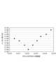
図4は、光ファイバ10から18について、クラッドの平均フッ素濃度と波長1550nmにおける伝送損失との関係を示すグラフである。図4に示されるように、クラッドの平均フッ素濃度が質量分率で1.2%近傍において伝送損失が最低となる傾向が確認された。Figure 4 is a graph showing the relationship between the average fluorine concentration in the cladding and the transmission loss at a wavelength of 1550 nm for
表3は、製造し評価した5種の光ファイバ19から23のそれぞれの諸元を纏めた表である。この表には、光ファイバ19から23のそれぞれについて、コアの平均K濃度(Kave)、波長1550nmにおける伝送損失(α1.55)、コア径、カットオフ波長、実効断面積(Aeff)、クラッドの平均フッ素濃度(Fave)、及びマイクロベンドロス(μベンドロス)が示されている。マイクロベンドロスは、IEC TR62221に規定されるメッシュボビン試験により測定された。光ファイバ19から23では、実効断面積を80μm2から124μm2まで変化させた。クラッドの屈折率を基準としたコアの比屈折率差は0.25%から0.45%の間で変更されている。実効断面積が90μm2を超えると、マイクロベンドロスが0.4dB/km以上に増大する傾向が確認された。
伝送損失は、コアに含まれるアルカリ金属元素群の濃度にも依存する。しかしながら、光ファイバ1から23では、アルカリ金属元素群の濃度を質量分率で40ppmに統一しているため、その影響は小さいと考えられる。The transmission loss also depends on the concentration of the alkali metal elements contained in the core. However, in
1…光ファイバ
10…コア
20…クラッド
21…第1クラッド
22…第2クラッド
C…中心軸REFERENCE SIGNS
Claims (12)
Translated fromJapanese中心軸を含むコアと、
前記コアを取り囲むクラッドと、を備え、
前記コアの屈折率は、前記クラッドの屈折率よりも大きく、
前記コアは、塩素を含むと共に、アルカリ金属元素及びアルカリ土類金属元素からなる元素群のうちの1種類以上の元素を含み、
純シリカの屈折率を基準とした前記コアの比屈折率差は、0.00%以上0.15%以下であり、
前記クラッドにおけるフッ素の平均濃度は、質量分率で0.6%以上1.2%以下であり、
前記クラッドの外径は、124μm以上126μm以下であり、
前記光ファイバにおいて、前記中心軸からの距離が50μm以上62.5μm以下の領域における残留応力の最小値は、10MPa以下であり、
前記領域における残留応力は、前記領域の全体にわたって引張応力である、
前記光ファイバの残留応力の最大値と最小値との差は、10MPa以上である、光ファイバ。 An optical fiber made of silica-based glass,
A core including a central axis;
a cladding surrounding the core;
the refractive index of the core is greater than the refractive index of the cladding;
the core includes chlorine and one or more elements selected from the group of elements consisting of alkali metal elements and alkaline earth metal elements;
The relative refractive index difference of the core based on the refractive index of pure silica is 0.00% or more and 0.15% or less,
The average fluorine concentration in the cladding is 0.6% or more and 1.2% or less in mass fraction,
The outer diameter of the cladding is 124 μm or more and 126 μm or less,
In the optical fiber, a minimum value of residual stress in a region that is at a distance from the central axis of the optical fiber that is equal to or greater than 50 μm and equal to or less than 62.5 μmis 10 MPa or less;
the residual stress in the region is a tensile stress throughout the region;
An optical fiber, wherein the difference between the maximum and minimum values of the residual stress of the optical fiber is 10 MPa or more .
中心軸を含むコアと、
前記コアを取り囲むクラッドと、を備え、
前記コアの屈折率は、前記クラッドの屈折率よりも大きく、
前記コアは、塩素を含むと共に、アルカリ金属元素及びアルカリ土類金属元素からなる元素群のうちの1種類以上の元素を含み、
純シリカの屈折率を基準とした前記コアの比屈折率差は、-0.15%以上0.05%以下であり、
前記クラッドにおけるフッ素の平均濃度は、質量分率で1.1%以上1.4%以下であり、
前記クラッドの外径は、124μm以上126μm以下であり、
前記光ファイバにおいて、前記中心軸からの距離が50μm以上62.5μm以下の領域における残留応力の最小値は、10MPa以下であり、
前記領域における残留応力は、前記領域の全体にわたって引張応力であり、
前記光ファイバの残留応力の最大値と最小値との差は、10MPa以上である、光ファイバ。 An optical fiber made of silica-based glass,
A core including a central axis;
a cladding surrounding the core;
the refractive index of the core is greater than the refractive index of the cladding;
the core includes chlorine and one or more elements selected from the group of elements consisting of alkali metal elements and alkaline earth metal elements;
The relative refractive index difference of the core based on the refractive index of pure silica is −0.15% or more and 0.05% or less,
The average fluorine concentration in the cladding is1.1% or more and 1.4% or less in mass fraction,
The outer diameter of the cladding is 124 μm or more and 126 μm or less,
In the optical fiber, a minimum value of residual stress in a region that is at a distance from the central axis of the optical fiber that is equal to or greater than 50 μm and equal to or less than 62.5 μmis 10 MPa or less;
the residual stress in the region is a tensile stress throughout the region;
An optical fiber, wherein the difference between the maximum and minimum values of the residual stress of the optical fiber is 10 MPa or more .
前記光ファイバの残留応力は、前記中心軸からの距離が20μm以上55μm以下の領域において最大値となっている、請求項1から請求項9のいずれか1項に記載の光ファイバ。 The outer diameter of the cladding is 124 μm or more and 126 μm or less,
10. The optical fiber according to claim1 , wherein the residual stress of the optical fiber is at a maximum value in a region at a distance from the central axis of the optical fiber that is equal to or greater than 20 μm and equal to or less than 55 μm.
Applications Claiming Priority (3)
| Application Number | Priority Date | Filing Date | Title |
|---|---|---|---|
| JP2019198768 | 2019-10-31 | ||
| JP2019198768 | 2019-10-31 | ||
| PCT/JP2020/039370WO2021085236A1 (en) | 2019-10-31 | 2020-10-20 | Optical fiber |
Publications (2)
| Publication Number | Publication Date |
|---|---|
| JPWO2021085236A1 JPWO2021085236A1 (en) | 2021-05-06 |
| JP7677153B2true JP7677153B2 (en) | 2025-05-15 |
Family
ID=75715963
Family Applications (1)
| Application Number | Title | Priority Date | Filing Date |
|---|---|---|---|
| JP2021553455AActiveJP7677153B2 (en) | 2019-10-31 | 2020-10-20 | Optical Fiber |
Country Status (5)
| Country | Link |
|---|---|
| US (1) | US12216309B2 (en) |
| EP (1) | EP4053605A4 (en) |
| JP (1) | JP7677153B2 (en) |
| CN (1) | CN114402240B (en) |
| WO (1) | WO2021085236A1 (en) |
Families Citing this family (1)
| Publication number | Priority date | Publication date | Assignee | Title |
|---|---|---|---|---|
| CN118964825B (en)* | 2024-10-14 | 2025-01-21 | 中国地质调查局长沙自然资源综合调查中心 | A mathematical weighting method for optimizing exploration geochemical data analysis |
Citations (5)
| Publication number | Priority date | Publication date | Assignee | Title |
|---|---|---|---|---|
| US20090274428A1 (en) | 2008-04-30 | 2009-11-05 | Xin Chen | Optical Fiber and a Method of Making |
| JP2013518312A (en) | 2010-01-29 | 2013-05-20 | コーニング インコーポレイテッド | Large effective area Ge-free fiber |
| JP2017076053A (en) | 2015-10-15 | 2017-04-20 | 住友電気工業株式会社 | Optical fiber |
| JP2018516386A (en) | 2015-04-15 | 2018-06-21 | コーニング インコーポレイテッド | Low loss optical fiber having a core region co-doped with fluorine and chlorine |
| WO2019172197A1 (en) | 2018-03-06 | 2019-09-12 | 住友電気工業株式会社 | Optical fiber |
Family Cites Families (23)
| Publication number | Priority date | Publication date | Assignee | Title |
|---|---|---|---|---|
| US5146534A (en) | 1991-11-12 | 1992-09-08 | At&T Bell Laboratories | SiO2 -based alkali-doped optical fiber |
| WO2000062106A1 (en)* | 1999-04-13 | 2000-10-19 | Sumitomo Electric Industries, Ltd. | Optical fiber and optical communication system comprising the same |
| US7068901B2 (en)* | 2002-04-16 | 2006-06-27 | Sumitomo Electric Industries, Ltd. | Optical fiber preform producing method, optical fiber production method, and optical fiber |
| JP4385681B2 (en)* | 2003-08-11 | 2009-12-16 | 住友電気工業株式会社 | Optical fiber preform manufacturing method and optical fiber manufacturing method |
| US7088900B1 (en)* | 2005-04-14 | 2006-08-08 | Corning Incorporated | Alkali and fluorine doped optical fiber |
| US7822307B1 (en)* | 2009-04-07 | 2010-10-26 | Sumitomo Electric Industries, Ltd. | Optical fiber ribbon for wiring of equipment and connector-attached optical fiber ribbon for wiring of equipment |
| US8655133B2 (en)* | 2010-02-26 | 2014-02-18 | Sumitomo Electric Industries, Ltd. | Optical fiber and optical communication system including same |
| JP2012162410A (en)* | 2011-02-03 | 2012-08-30 | Sumitomo Electric Ind Ltd | Method for producing optical fiber preform |
| JP5545236B2 (en)* | 2011-02-03 | 2014-07-09 | 住友電気工業株式会社 | Optical fiber preform manufacturing method |
| EP2506044A1 (en)* | 2011-03-29 | 2012-10-03 | Draka Comteq B.V. | Multimode optical fiber |
| CN102654602B (en) | 2012-05-08 | 2014-02-26 | 长飞光纤光缆有限公司 | A kind of optical fiber and its manufacturing method |
| US9020316B2 (en)* | 2013-02-28 | 2015-04-28 | Corning Incorporated | Low attenuation optical fibers with an F-graded index core |
| CN103149630B (en)* | 2013-03-06 | 2016-02-24 | 长飞光纤光缆股份有限公司 | A kind of low decay single-mode fiber |
| JP6268758B2 (en)* | 2013-06-10 | 2018-01-31 | 住友電気工業株式会社 | Optical fiber |
| EP3173388B1 (en)* | 2014-07-22 | 2018-09-12 | Sumitomo Electric Industries, Ltd. | Method of manufacturing optical fiber preform |
| JP6536036B2 (en)* | 2015-01-14 | 2019-07-03 | 住友電気工業株式会社 | Optical fiber |
| WO2016152507A1 (en)* | 2015-03-25 | 2016-09-29 | 住友電気工業株式会社 | Multicore optical fiber |
| JP6613604B2 (en)* | 2015-04-30 | 2019-12-04 | 住友電気工業株式会社 | Optical fiber preform |
| JP6620633B2 (en)* | 2016-03-25 | 2019-12-18 | 住友電気工業株式会社 | Optical fiber |
| JP2018008850A (en)* | 2016-07-14 | 2018-01-18 | 住友電気工業株式会社 | Multi-core optical fiber manufacturing method |
| PL3548942T3 (en)* | 2016-11-30 | 2022-05-02 | Corning Optical Communications LLC | Low attenuation optical fiber cable with small sized active particles |
| EP3665521B1 (en)* | 2017-08-08 | 2023-11-08 | Corning Research & Development Corporation | Rollable optical fiber ribbon with low attenuation, large mode field diameter optical fiber and cable |
| JP2019198768A (en) | 2019-09-03 | 2019-11-21 | 株式会社三洋物産 | Game machine |
- 2020
- 2020-10-20JPJP2021553455Apatent/JP7677153B2/enactiveActive
- 2020-10-20WOPCT/JP2020/039370patent/WO2021085236A1/ennot_activeCeased
- 2020-10-20CNCN202080064427.1Apatent/CN114402240B/enactiveActive
- 2020-10-20USUS17/754,581patent/US12216309B2/enactiveActive
- 2020-10-20EPEP20882049.8Apatent/EP4053605A4/enactivePending
Patent Citations (5)
| Publication number | Priority date | Publication date | Assignee | Title |
|---|---|---|---|---|
| US20090274428A1 (en) | 2008-04-30 | 2009-11-05 | Xin Chen | Optical Fiber and a Method of Making |
| JP2013518312A (en) | 2010-01-29 | 2013-05-20 | コーニング インコーポレイテッド | Large effective area Ge-free fiber |
| JP2018516386A (en) | 2015-04-15 | 2018-06-21 | コーニング インコーポレイテッド | Low loss optical fiber having a core region co-doped with fluorine and chlorine |
| JP2017076053A (en) | 2015-10-15 | 2017-04-20 | 住友電気工業株式会社 | Optical fiber |
| WO2019172197A1 (en) | 2018-03-06 | 2019-09-12 | 住友電気工業株式会社 | Optical fiber |
Also Published As
| Publication number | Publication date |
|---|---|
| EP4053605A4 (en) | 2022-12-28 |
| US12216309B2 (en) | 2025-02-04 |
| CN114402240B (en) | 2025-04-22 |
| WO2021085236A1 (en) | 2021-05-06 |
| EP4053605A1 (en) | 2022-09-07 |
| JPWO2021085236A1 (en) | 2021-05-06 |
| US20230266523A1 (en) | 2023-08-24 |
| CN114402240A (en) | 2022-04-26 |
Similar Documents
| Publication | Publication Date | Title |
|---|---|---|
| JP6187644B2 (en) | Optical fiber | |
| US10155687B2 (en) | Optical fiber preform | |
| US11181684B2 (en) | Optical fiber | |
| US11048040B2 (en) | Optical fiber | |
| US20150241629A1 (en) | Optical fiber and method for producing optical fiber preform | |
| EP3040749B1 (en) | Optical fiber having an alkali metal doped silica glass core | |
| DK202370061A1 (en) | Production method for optical fiber base material, and optical fiber base material | |
| US10656326B2 (en) | Optical fiber | |
| WO2023157505A1 (en) | Optical fiber | |
| JP7677153B2 (en) | Optical Fiber | |
| JP2014214079A (en) | Optical fiber preform | |
| WO2024190234A1 (en) | Multicore optical fiber | |
| JP7527114B2 (en) | Optical Fiber | |
| JPWO2023157505A5 (en) | ||
| WO2023286608A1 (en) | Optical fiber and optical fiber base material | |
| WO2024247623A1 (en) | Multicore optical fiber |
Legal Events
| Date | Code | Title | Description |
|---|---|---|---|
| A621 | Written request for application examination | Free format text:JAPANESE INTERMEDIATE CODE: A621 Effective date:20230921 | |
| A131 | Notification of reasons for refusal | Free format text:JAPANESE INTERMEDIATE CODE: A131 Effective date:20240604 | |
| A521 | Request for written amendment filed | Free format text:JAPANESE INTERMEDIATE CODE: A523 Effective date:20240722 | |
| A131 | Notification of reasons for refusal | Free format text:JAPANESE INTERMEDIATE CODE: A131 Effective date:20241105 | |
| A521 | Request for written amendment filed | Free format text:JAPANESE INTERMEDIATE CODE: A523 Effective date:20241226 | |
| TRDD | Decision of grant or rejection written | ||
| A01 | Written decision to grant a patent or to grant a registration (utility model) | Free format text:JAPANESE INTERMEDIATE CODE: A01 Effective date:20250401 | |
| A61 | First payment of annual fees (during grant procedure) | Free format text:JAPANESE INTERMEDIATE CODE: A61 Effective date:20250414 | |
| R150 | Certificate of patent or registration of utility model | Ref document number:7677153 Country of ref document:JP Free format text:JAPANESE INTERMEDIATE CODE: R150 |