JP7676605B2 - Foot presence signal processing system and method - Google Patents
Foot presence signal processing system and methodDownload PDFInfo
- Publication number
- JP7676605B2 JP7676605B2JP2024016982AJP2024016982AJP7676605B2JP 7676605 B2JP7676605 B2JP 7676605B2JP 2024016982 AJP2024016982 AJP 2024016982AJP 2024016982 AJP2024016982 AJP 2024016982AJP 7676605 B2JP7676605 B2JP 7676605B2
- Authority
- JP
- Japan
- Prior art keywords
- sensor
- foot
- footwear
- signal
- capacitive
- Prior art date
- Legal status (The legal status is an assumption and is not a legal conclusion. Google has not performed a legal analysis and makes no representation as to the accuracy of the status listed.)
- Active
Links
Images


Classifications
- A—HUMAN NECESSITIES
- A43—FOOTWEAR
- A43B—CHARACTERISTIC FEATURES OF FOOTWEAR; PARTS OF FOOTWEAR
- A43B7/00—Footwear with health or hygienic arrangements
- A43B7/14—Footwear with health or hygienic arrangements with foot-supporting parts
- A43B7/1405—Footwear with health or hygienic arrangements with foot-supporting parts with pads or holes on one or more locations, or having an anatomical or curved form
- A43B7/1415—Footwear with health or hygienic arrangements with foot-supporting parts with pads or holes on one or more locations, or having an anatomical or curved form characterised by the location under the foot
- A43B7/142—Footwear with health or hygienic arrangements with foot-supporting parts with pads or holes on one or more locations, or having an anatomical or curved form characterised by the location under the foot situated under the medial arch, i.e. under the navicular or cuneiform bones
- A—HUMAN NECESSITIES
- A43—FOOTWEAR
- A43B—CHARACTERISTIC FEATURES OF FOOTWEAR; PARTS OF FOOTWEAR
- A43B1/00—Footwear characterised by the material
- A43B1/0054—Footwear characterised by the material provided with magnets, magnetic parts or magnetic substances
- A—HUMAN NECESSITIES
- A43—FOOTWEAR
- A43B—CHARACTERISTIC FEATURES OF FOOTWEAR; PARTS OF FOOTWEAR
- A43B13/00—Soles; Sole-and-heel integral units
- A43B13/02—Soles; Sole-and-heel integral units characterised by the material
- A43B13/12—Soles with several layers of different materials
- A43B13/125—Soles with several layers of different materials characterised by the midsole or middle layer
- A—HUMAN NECESSITIES
- A43—FOOTWEAR
- A43B—CHARACTERISTIC FEATURES OF FOOTWEAR; PARTS OF FOOTWEAR
- A43B13/00—Soles; Sole-and-heel integral units
- A43B13/14—Soles; Sole-and-heel integral units characterised by the constructive form
- A—HUMAN NECESSITIES
- A43—FOOTWEAR
- A43B—CHARACTERISTIC FEATURES OF FOOTWEAR; PARTS OF FOOTWEAR
- A43B13/00—Soles; Sole-and-heel integral units
- A43B13/14—Soles; Sole-and-heel integral units characterised by the constructive form
- A43B13/18—Resilient soles
- A—HUMAN NECESSITIES
- A43—FOOTWEAR
- A43B—CHARACTERISTIC FEATURES OF FOOTWEAR; PARTS OF FOOTWEAR
- A43B17/00—Insoles for insertion, e.g. footbeds or inlays, for attachment to the shoe after the upper has been joined
- A—HUMAN NECESSITIES
- A43—FOOTWEAR
- A43B—CHARACTERISTIC FEATURES OF FOOTWEAR; PARTS OF FOOTWEAR
- A43B3/00—Footwear characterised by the shape or the use
- A43B3/0031—Footwear characterised by the shape or the use provided with a pocket, e.g. for keys or a card
- A—HUMAN NECESSITIES
- A43—FOOTWEAR
- A43B—CHARACTERISTIC FEATURES OF FOOTWEAR; PARTS OF FOOTWEAR
- A43B3/00—Footwear characterised by the shape or the use
- A43B3/34—Footwear characterised by the shape or the use with electrical or electronic arrangements
- A43B3/36—Footwear characterised by the shape or the use with electrical or electronic arrangements with light sources
- A—HUMAN NECESSITIES
- A43—FOOTWEAR
- A43B—CHARACTERISTIC FEATURES OF FOOTWEAR; PARTS OF FOOTWEAR
- A43B3/00—Footwear characterised by the shape or the use
- A43B3/34—Footwear characterised by the shape or the use with electrical or electronic arrangements
- A43B3/44—Footwear characterised by the shape or the use with electrical or electronic arrangements with sensors, e.g. for detecting contact or position
- A—HUMAN NECESSITIES
- A43—FOOTWEAR
- A43C—FASTENINGS OR ATTACHMENTS OF FOOTWEAR; LACES IN GENERAL
- A43C1/00—Shoe lacing fastenings
- A—HUMAN NECESSITIES
- A43—FOOTWEAR
- A43C—FASTENINGS OR ATTACHMENTS OF FOOTWEAR; LACES IN GENERAL
- A43C11/00—Other fastenings specially adapted for shoes
- A43C11/008—Combined fastenings, e.g. to accelerate undoing or fastening
- A—HUMAN NECESSITIES
- A43—FOOTWEAR
- A43C—FASTENINGS OR ATTACHMENTS OF FOOTWEAR; LACES IN GENERAL
- A43C11/00—Other fastenings specially adapted for shoes
- A43C11/14—Clamp fastenings, e.g. strap fastenings; Clamp-buckle fastenings; Fastenings with toggle levers
- A—HUMAN NECESSITIES
- A43—FOOTWEAR
- A43C—FASTENINGS OR ATTACHMENTS OF FOOTWEAR; LACES IN GENERAL
- A43C11/00—Other fastenings specially adapted for shoes
- A43C11/16—Fastenings secured by wire, bolts, or the like
- A43C11/165—Fastenings secured by wire, bolts, or the like characterised by a spool, reel or pulley for winding up cables, laces or straps by rotation
- A—HUMAN NECESSITIES
- A43—FOOTWEAR
- A43C—FASTENINGS OR ATTACHMENTS OF FOOTWEAR; LACES IN GENERAL
- A43C7/00—Holding-devices for laces
- A—HUMAN NECESSITIES
- A43—FOOTWEAR
- A43C—FASTENINGS OR ATTACHMENTS OF FOOTWEAR; LACES IN GENERAL
- A43C7/00—Holding-devices for laces
- A43C7/08—Clamps drawn tight by laces
- A—HUMAN NECESSITIES
- A61—MEDICAL OR VETERINARY SCIENCE; HYGIENE
- A61B—DIAGNOSIS; SURGERY; IDENTIFICATION
- A61B5/00—Measuring for diagnostic purposes; Identification of persons
- A61B5/103—Measuring devices for testing the shape, pattern, colour, size or movement of the body or parts thereof, for diagnostic purposes
- A61B5/1036—Measuring load distribution, e.g. podologic studies
- A—HUMAN NECESSITIES
- A61—MEDICAL OR VETERINARY SCIENCE; HYGIENE
- A61B—DIAGNOSIS; SURGERY; IDENTIFICATION
- A61B5/00—Measuring for diagnostic purposes; Identification of persons
- A61B5/68—Arrangements of detecting, measuring or recording means, e.g. sensors, in relation to patient
- A61B5/6801—Arrangements of detecting, measuring or recording means, e.g. sensors, in relation to patient specially adapted to be attached to or worn on the body surface
- A61B5/6802—Sensor mounted on worn items
- A61B5/6804—Garments; Clothes
- A61B5/6807—Footwear
- G—PHYSICS
- G01—MEASURING; TESTING
- G01D—MEASURING NOT SPECIALLY ADAPTED FOR A SPECIFIC VARIABLE; ARRANGEMENTS FOR MEASURING TWO OR MORE VARIABLES NOT COVERED IN A SINGLE OTHER SUBCLASS; TARIFF METERING APPARATUS; MEASURING OR TESTING NOT OTHERWISE PROVIDED FOR
- G01D5/00—Mechanical means for transferring the output of a sensing member; Means for converting the output of a sensing member to another variable where the form or nature of the sensing member does not constrain the means for converting; Transducers not specially adapted for a specific variable
- G01D5/12—Mechanical means for transferring the output of a sensing member; Means for converting the output of a sensing member to another variable where the form or nature of the sensing member does not constrain the means for converting; Transducers not specially adapted for a specific variable using electric or magnetic means
- G01D5/14—Mechanical means for transferring the output of a sensing member; Means for converting the output of a sensing member to another variable where the form or nature of the sensing member does not constrain the means for converting; Transducers not specially adapted for a specific variable using electric or magnetic means influencing the magnitude of a current or voltage
- G01D5/24—Mechanical means for transferring the output of a sensing member; Means for converting the output of a sensing member to another variable where the form or nature of the sensing member does not constrain the means for converting; Transducers not specially adapted for a specific variable using electric or magnetic means influencing the magnitude of a current or voltage by varying capacitance
- G—PHYSICS
- G01—MEASURING; TESTING
- G01L—MEASURING FORCE, STRESS, TORQUE, WORK, MECHANICAL POWER, MECHANICAL EFFICIENCY, OR FLUID PRESSURE
- G01L1/00—Measuring force or stress, in general
- G01L1/12—Measuring force or stress, in general by measuring variations in the magnetic properties of materials resulting from the application of stress
- G—PHYSICS
- G01—MEASURING; TESTING
- G01L—MEASURING FORCE, STRESS, TORQUE, WORK, MECHANICAL POWER, MECHANICAL EFFICIENCY, OR FLUID PRESSURE
- G01L1/00—Measuring force or stress, in general
- G01L1/14—Measuring force or stress, in general by measuring variations in capacitance or inductance of electrical elements, e.g. by measuring variations of frequency of electrical oscillators
- G01L1/142—Measuring force or stress, in general by measuring variations in capacitance or inductance of electrical elements, e.g. by measuring variations of frequency of electrical oscillators using capacitors
- G01L1/144—Measuring force or stress, in general by measuring variations in capacitance or inductance of electrical elements, e.g. by measuring variations of frequency of electrical oscillators using capacitors with associated circuitry
- G—PHYSICS
- G01—MEASURING; TESTING
- G01L—MEASURING FORCE, STRESS, TORQUE, WORK, MECHANICAL POWER, MECHANICAL EFFICIENCY, OR FLUID PRESSURE
- G01L5/00—Apparatus for, or methods of, measuring force, work, mechanical power, or torque, specially adapted for specific purposes
- G01L5/0009—Force sensors associated with a bearing
- G01L5/0014—Force sensors associated with a bearing by using capacitive sensors
- G—PHYSICS
- G01—MEASURING; TESTING
- G01L—MEASURING FORCE, STRESS, TORQUE, WORK, MECHANICAL POWER, MECHANICAL EFFICIENCY, OR FLUID PRESSURE
- G01L5/00—Apparatus for, or methods of, measuring force, work, mechanical power, or torque, specially adapted for specific purposes
- G01L5/0061—Force sensors associated with industrial machines or actuators
- G01L5/0071—Specific indicating arrangements, e.g. of overload
- G—PHYSICS
- G01—MEASURING; TESTING
- G01L—MEASURING FORCE, STRESS, TORQUE, WORK, MECHANICAL POWER, MECHANICAL EFFICIENCY, OR FLUID PRESSURE
- G01L5/00—Apparatus for, or methods of, measuring force, work, mechanical power, or torque, specially adapted for specific purposes
- G01L5/12—Apparatus for, or methods of, measuring force, work, mechanical power, or torque, specially adapted for specific purposes for measuring axial thrust in a rotary shaft, e.g. of propulsion plants
- G—PHYSICS
- G01—MEASURING; TESTING
- G01L—MEASURING FORCE, STRESS, TORQUE, WORK, MECHANICAL POWER, MECHANICAL EFFICIENCY, OR FLUID PRESSURE
- G01L5/00—Apparatus for, or methods of, measuring force, work, mechanical power, or torque, specially adapted for specific purposes
- G01L5/16—Apparatus for, or methods of, measuring force, work, mechanical power, or torque, specially adapted for specific purposes for measuring several components of force
- G01L5/165—Apparatus for, or methods of, measuring force, work, mechanical power, or torque, specially adapted for specific purposes for measuring several components of force using variations in capacitance
- G—PHYSICS
- G01—MEASURING; TESTING
- G01L—MEASURING FORCE, STRESS, TORQUE, WORK, MECHANICAL POWER, MECHANICAL EFFICIENCY, OR FLUID PRESSURE
- G01L5/00—Apparatus for, or methods of, measuring force, work, mechanical power, or torque, specially adapted for specific purposes
- G01L5/24—Apparatus for, or methods of, measuring force, work, mechanical power, or torque, specially adapted for specific purposes for determining value of torque or twisting moment for tightening a nut or other member which is similarly stressed
- G—PHYSICS
- G05—CONTROLLING; REGULATING
- G05B—CONTROL OR REGULATING SYSTEMS IN GENERAL; FUNCTIONAL ELEMENTS OF SUCH SYSTEMS; MONITORING OR TESTING ARRANGEMENTS FOR SUCH SYSTEMS OR ELEMENTS
- G05B15/00—Systems controlled by a computer
- G05B15/02—Systems controlled by a computer electric
- G—PHYSICS
- G05—CONTROLLING; REGULATING
- G05B—CONTROL OR REGULATING SYSTEMS IN GENERAL; FUNCTIONAL ELEMENTS OF SUCH SYSTEMS; MONITORING OR TESTING ARRANGEMENTS FOR SUCH SYSTEMS OR ELEMENTS
- G05B19/00—Programme-control systems
- G05B19/02—Programme-control systems electric
- G05B19/04—Programme control other than numerical control, i.e. in sequence controllers or logic controllers
- G05B19/048—Monitoring; Safety
- A—HUMAN NECESSITIES
- A43—FOOTWEAR
- A43B—CHARACTERISTIC FEATURES OF FOOTWEAR; PARTS OF FOOTWEAR
- A43B3/00—Footwear characterised by the shape or the use
- A43B3/34—Footwear characterised by the shape or the use with electrical or electronic arrangements
- A43B3/38—Footwear characterised by the shape or the use with electrical or electronic arrangements with power sources
- A—HUMAN NECESSITIES
- A43—FOOTWEAR
- A43C—FASTENINGS OR ATTACHMENTS OF FOOTWEAR; LACES IN GENERAL
- A43C1/00—Shoe lacing fastenings
- A43C1/003—Zone lacing, i.e. whereby different zones of the footwear have different lacing tightening degrees, using one or a plurality of laces
- A—HUMAN NECESSITIES
- A43—FOOTWEAR
- A43C—FASTENINGS OR ATTACHMENTS OF FOOTWEAR; LACES IN GENERAL
- A43C1/00—Shoe lacing fastenings
- A43C1/006—Rear lacing, i.e. with a lace placed on the back of the foot in place of, or in addition to the traditional front lace
- A—HUMAN NECESSITIES
- A43—FOOTWEAR
- A43C—FASTENINGS OR ATTACHMENTS OF FOOTWEAR; LACES IN GENERAL
- A43C1/00—Shoe lacing fastenings
- A43C1/02—Shoe lacing fastenings with elastic laces
- A—HUMAN NECESSITIES
- A43—FOOTWEAR
- A43C—FASTENINGS OR ATTACHMENTS OF FOOTWEAR; LACES IN GENERAL
- A43C1/00—Shoe lacing fastenings
- A43C1/04—Shoe lacing fastenings with rings or loops
- A—HUMAN NECESSITIES
- A43—FOOTWEAR
- A43C—FASTENINGS OR ATTACHMENTS OF FOOTWEAR; LACES IN GENERAL
- A43C1/00—Shoe lacing fastenings
- A43C1/06—Shoe lacing fastenings tightened by draw-strings
- A—HUMAN NECESSITIES
- A43—FOOTWEAR
- A43C—FASTENINGS OR ATTACHMENTS OF FOOTWEAR; LACES IN GENERAL
- A43C11/00—Other fastenings specially adapted for shoes
- G—PHYSICS
- G01—MEASURING; TESTING
- G01D—MEASURING NOT SPECIALLY ADAPTED FOR A SPECIFIC VARIABLE; ARRANGEMENTS FOR MEASURING TWO OR MORE VARIABLES NOT COVERED IN A SINGLE OTHER SUBCLASS; TARIFF METERING APPARATUS; MEASURING OR TESTING NOT OTHERWISE PROVIDED FOR
- G01D5/00—Mechanical means for transferring the output of a sensing member; Means for converting the output of a sensing member to another variable where the form or nature of the sensing member does not constrain the means for converting; Transducers not specially adapted for a specific variable
- G01D5/12—Mechanical means for transferring the output of a sensing member; Means for converting the output of a sensing member to another variable where the form or nature of the sensing member does not constrain the means for converting; Transducers not specially adapted for a specific variable using electric or magnetic means
- G01D5/14—Mechanical means for transferring the output of a sensing member; Means for converting the output of a sensing member to another variable where the form or nature of the sensing member does not constrain the means for converting; Transducers not specially adapted for a specific variable using electric or magnetic means influencing the magnitude of a current or voltage
- G01D5/142—Mechanical means for transferring the output of a sensing member; Means for converting the output of a sensing member to another variable where the form or nature of the sensing member does not constrain the means for converting; Transducers not specially adapted for a specific variable using electric or magnetic means influencing the magnitude of a current or voltage using Hall-effect devices
- G01D5/145—Mechanical means for transferring the output of a sensing member; Means for converting the output of a sensing member to another variable where the form or nature of the sensing member does not constrain the means for converting; Transducers not specially adapted for a specific variable using electric or magnetic means influencing the magnitude of a current or voltage using Hall-effect devices influenced by the relative movement between the Hall device and magnetic fields
- G—PHYSICS
- G01—MEASURING; TESTING
- G01D—MEASURING NOT SPECIALLY ADAPTED FOR A SPECIFIC VARIABLE; ARRANGEMENTS FOR MEASURING TWO OR MORE VARIABLES NOT COVERED IN A SINGLE OTHER SUBCLASS; TARIFF METERING APPARATUS; MEASURING OR TESTING NOT OTHERWISE PROVIDED FOR
- G01D5/00—Mechanical means for transferring the output of a sensing member; Means for converting the output of a sensing member to another variable where the form or nature of the sensing member does not constrain the means for converting; Transducers not specially adapted for a specific variable
- G01D5/12—Mechanical means for transferring the output of a sensing member; Means for converting the output of a sensing member to another variable where the form or nature of the sensing member does not constrain the means for converting; Transducers not specially adapted for a specific variable using electric or magnetic means
- G01D5/14—Mechanical means for transferring the output of a sensing member; Means for converting the output of a sensing member to another variable where the form or nature of the sensing member does not constrain the means for converting; Transducers not specially adapted for a specific variable using electric or magnetic means influencing the magnitude of a current or voltage
- G01D5/24—Mechanical means for transferring the output of a sensing member; Means for converting the output of a sensing member to another variable where the form or nature of the sensing member does not constrain the means for converting; Transducers not specially adapted for a specific variable using electric or magnetic means influencing the magnitude of a current or voltage by varying capacitance
- G01D5/2405—Mechanical means for transferring the output of a sensing member; Means for converting the output of a sensing member to another variable where the form or nature of the sensing member does not constrain the means for converting; Transducers not specially adapted for a specific variable using electric or magnetic means influencing the magnitude of a current or voltage by varying capacitance by varying dielectric
- G—PHYSICS
- G01—MEASURING; TESTING
- G01D—MEASURING NOT SPECIALLY ADAPTED FOR A SPECIFIC VARIABLE; ARRANGEMENTS FOR MEASURING TWO OR MORE VARIABLES NOT COVERED IN A SINGLE OTHER SUBCLASS; TARIFF METERING APPARATUS; MEASURING OR TESTING NOT OTHERWISE PROVIDED FOR
- G01D5/00—Mechanical means for transferring the output of a sensing member; Means for converting the output of a sensing member to another variable where the form or nature of the sensing member does not constrain the means for converting; Transducers not specially adapted for a specific variable
- G01D5/26—Mechanical means for transferring the output of a sensing member; Means for converting the output of a sensing member to another variable where the form or nature of the sensing member does not constrain the means for converting; Transducers not specially adapted for a specific variable characterised by optical transfer means, i.e. using infrared, visible, or ultraviolet light
- G01D5/32—Mechanical means for transferring the output of a sensing member; Means for converting the output of a sensing member to another variable where the form or nature of the sensing member does not constrain the means for converting; Transducers not specially adapted for a specific variable characterised by optical transfer means, i.e. using infrared, visible, or ultraviolet light with attenuation or whole or partial obturation of beams of light
- G01D5/34—Mechanical means for transferring the output of a sensing member; Means for converting the output of a sensing member to another variable where the form or nature of the sensing member does not constrain the means for converting; Transducers not specially adapted for a specific variable characterised by optical transfer means, i.e. using infrared, visible, or ultraviolet light with attenuation or whole or partial obturation of beams of light the beams of light being detected by photocells
- G—PHYSICS
- G05—CONTROLLING; REGULATING
- G05B—CONTROL OR REGULATING SYSTEMS IN GENERAL; FUNCTIONAL ELEMENTS OF SUCH SYSTEMS; MONITORING OR TESTING ARRANGEMENTS FOR SUCH SYSTEMS OR ELEMENTS
- G05B2219/00—Program-control systems
- G05B2219/20—Pc systems
- G05B2219/24—Pc safety
- G05B2219/24015—Monitoring
- Y—GENERAL TAGGING OF NEW TECHNOLOGICAL DEVELOPMENTS; GENERAL TAGGING OF CROSS-SECTIONAL TECHNOLOGIES SPANNING OVER SEVERAL SECTIONS OF THE IPC; TECHNICAL SUBJECTS COVERED BY FORMER USPC CROSS-REFERENCE ART COLLECTIONS [XRACs] AND DIGESTS
- Y02—TECHNOLOGIES OR APPLICATIONS FOR MITIGATION OR ADAPTATION AGAINST CLIMATE CHANGE
- Y02P—CLIMATE CHANGE MITIGATION TECHNOLOGIES IN THE PRODUCTION OR PROCESSING OF GOODS
- Y02P90/00—Enabling technologies with a potential contribution to greenhouse gas [GHG] emissions mitigation
- Y02P90/02—Total factory control, e.g. smart factories, flexible manufacturing systems [FMS] or integrated manufacturing systems [IMS]
Landscapes
- Physics & Mathematics (AREA)
- General Physics & Mathematics (AREA)
- Engineering & Computer Science (AREA)
- Health & Medical Sciences (AREA)
- Life Sciences & Earth Sciences (AREA)
- Chemical & Material Sciences (AREA)
- Analytical Chemistry (AREA)
- Public Health (AREA)
- General Health & Medical Sciences (AREA)
- Power Engineering (AREA)
- Microelectronics & Electronic Packaging (AREA)
- Automation & Control Theory (AREA)
- Molecular Biology (AREA)
- Biomedical Technology (AREA)
- Heart & Thoracic Surgery (AREA)
- Medical Informatics (AREA)
- Pathology (AREA)
- Surgery (AREA)
- Animal Behavior & Ethology (AREA)
- Biophysics (AREA)
- Veterinary Medicine (AREA)
- General Engineering & Computer Science (AREA)
- Dentistry (AREA)
- Oral & Maxillofacial Surgery (AREA)
- Combustion & Propulsion (AREA)
- Materials Engineering (AREA)
- Epidemiology (AREA)
- Footwear And Its Accessory, Manufacturing Method And Apparatuses (AREA)
- Switches That Are Operated By Magnetic Or Electric Fields (AREA)
- Force Measurement Appropriate To Specific Purposes (AREA)
- Electronic Switches (AREA)
- Wood Science & Technology (AREA)
- Measurement And Recording Of Electrical Phenomena And Electrical Characteristics Of The Living Body (AREA)
- Electrophonic Musical Instruments (AREA)
- Push-Button Switches (AREA)
Description
Translated fromJapanese 様々な状態をモニタするために、各種の靴型センサが提案されている。例えば、ブラウ
ン(Brown)は、「足の状態をモニタするためのセンサシューズ(Sensor shoe for monit
oring the condition of a foot)」と題する特許文献1において、靴型センサの幾つか
の例を提案している。ブラウンは、足力センサが、比較的薄く、平坦で、柔軟で、弾力的
な誘電材料の層からなるインソールを含むことができると述べている。この足力センサは
、加えられる圧縮力に基づいて変化する電気抵抗を有する導電性相互接続手段を含むこと
ができる。 Various shoe-type sensors have been proposed to monitor various conditions. For example, Brown et al. have proposed a “Sensor shoe for monitoring foot conditions”
In U.S. Pat. No. 5,399,633, entitled "Using the Condition of a Foot," Brown suggests several examples of shoe-type sensors. Brown states that the foot force sensor may include an insole made of a layer of a relatively thin, flat, flexible, resilient dielectric material. The foot force sensor may include a conductive interconnection means having an electrical resistance that changes based on the compressive force applied.
ブラウンはさらに、糖尿病患者、又は足の一部に過剰な圧力が加わると潰瘍を生じさせ
る傾向のある様々な種類の足の病気を患う人が着用すべき靴について論じている。靴本体
は力感知抵抗器(FSR:force sensing resistor)を含むことができ、抵抗器に結合さ
れたスイッチ回路は、閾値圧力レベルに到達した、又はそれを超えたことを着用者に警告
するためにアラームユニットを作動させることができる。 Brown further discusses a shoe to be worn by diabetics or those suffering from various types of foot ailments that tend to cause ulcers when excessive pressure is applied to any part of the foot. The shoe body can include a force sensing resistor (FSR), and a switch circuit coupled to the resistor can activate an alarm unit to alert the wearer that a threshold pressure level has been reached or exceeded.
履物製品を自動的に締め付ける装置が過去に提案されている。リウ(Liu)は、「自動
締付け靴(Automatic tightening shoe)」と題する特許文献2において、靴の上側部分
に取り付けられた第1のファスナと、開閉部材に接続され、第1のファスナと取り外し可
能に係合して開閉部材を締め付けられた状態に保持することのできる第2のファスナとを
提供する。リウは、靴底の踵部分に取り付けられた駆動ユニットを教示している。駆動ユ
ニットは、筐体と、筐体に回転可能に取り付けられたスプールと、引き紐の対と、モニタ
ユニットとを含む。各紐はスプールに接続された第1の端と、第2のファスナの紐穴に対
応する第2の端を有する。モータユニットはスプールに結合されている。リウは、モータ
ユニットが、筐体内のスプールの回転を駆動して、引き紐がスプールに巻き付けられて、
第2のファスナが第1のファスナに向かって引かれるように動作可能であることを教示し
ている。リウはまた、引き紐をその中に通すことのできる案内管ユニットも教示している
。 Devices for automatically tightening articles of footwear have been proposed in the past. Liu, in U.S. Patent No. 5,399,333, entitled "Automatic tightening shoe," provides a first fastener attached to an upper portion of the shoe and a second fastener connected to an closure member and capable of releasably engaging the first fastener to hold the closure member in a tightened condition. Liu teaches a drive unit attached to the heel portion of the sole. The drive unit includes a housing, a spool rotatably mounted to the housing, a pair of drawstrings, and a monitor unit. Each drawstring has a first end connected to the spool and a second end corresponding to an eyelet of the second fastener. A motor unit is coupled to the spool. Liu teaches that the motor unit drives rotation of the spool within the housing to cause the drawstring to be wound around the spool and to be tightened.
It teaches that the second fastener is operable to be drawn toward the first fastener. Liu also teaches a guide tube unit through which a drawstring can be threaded.
必ずしも正確な縮尺で描かれているとはかぎらない図面中、同様の番号は別の図の類似
の構成要素を表していることがある。異なる文字が末尾に付されている同様の番号は、同
様の構成要素の別の例を表していることがある。図面は、限定ではなく例として、本文書
中で論じられている各種の実施形態を概略的に示している。 In the drawings, which are not necessarily drawn to scale, like numbers may represent similar components in different figures. Like numbers suffixed with different letters may represent different instances of the similar components. The drawings illustrate generally, by way of example, and not by way of limitation, various embodiments discussed in the present document.
自動締付け靴紐の概念が初めて広く人気を博したのは、1989年に公開された映画、
「バック・トゥ・ザ・フューチャII(Back to the Future II)」の中でマーティ・マ
クフライ(Marty McFly)が履いた架空の電動紐締め(パワーレース:power-laced)Ni
ke(登録商標)スニーカーからである。Nike(登録商標)はそれ以降、「バック・
トゥ・ザ・フューチャII」の映画の小道具バージョンに外観が似ているパワーレースス
ニーカーのバージョンを少なくとも1つ発表したが、使用されていた内部の機械的システ
ムとその周囲の履物プラットフォームから、必ずしもこれらが大量生産又は日常的な使用
に向くものとは言えなかった。それに加えて、電動紐締め(motorized lacing)システム
のための過去の設計は比較的、製造コストの高さ、複雑さ、組立ての難しさ、有用性の欠
如、及び脆弱な又は壊れやすい機械的機構等の課題を伴っており、これらは多くの問題の
うちの幾つかを挙げたにすぎない。本発明者らは、とりわけ、上述の問題の一部又は全部
を解決する電動及び非電動紐締めエンジンを収容するためのモジュール式履物プラットフ
ォームを開発した。後述の構成要素は様々な利点を提供し、これには有用な構成要素、互
換的な自動紐締めエンジン、頑丈な機械的設計、ロバストな制御アルゴリズム、信頼性の
高い動作、効率的な組立てプロセス、小売レベルのカスタム化が含まれるが、これらに限
定されない。後述の構成要素の様々なその他の利点は、当業者にとって明らかであろう。 The concept of self-tightening shoelaces first gained widespread popularity in the 1989 film,
The fictional power-laced Ni-Ni shoes worn by Marty McFly in "Back to the Future II"
Nike® has since launched its "Backpack" line of sneakers.
While at least one version of a power lace sneaker that looks similar to the prop version in the movie "To the Future II" has been released, the internal mechanical system and surrounding footwear platform used did not necessarily make them suitable for mass production or everyday use. Additionally, past designs for motorized lacing systems have been relatively plagued with challenges such as high manufacturing costs, complexity, assembly difficulties, lack of usability, and weak or fragile mechanical mechanisms, to name just a few of the many issues. The inventors have developed, among other things, a modular footwear platform for housing motorized and non-motorized lacing engines that solves some or all of the above-mentioned problems. The components described below provide various advantages, including, but not limited to, useful components, interchangeable automatic lacing engines, robust mechanical design, robust control algorithms, reliable operation, efficient assembly process, and retail level customization. Various other advantages of the components described below will be apparent to those skilled in the art.
ある例において、モジュール式自動紐締め履物プラットフォームは、紐締めエンジンを
受容するための、履物製品の中のミッドソールに固定されたミッドソールプレートを含む
。ミッドソールプレートの設計により、購入時という遅い段階で紐締めエンジンを履物プ
ラットフォームに追加できる。ミッドソールプレート、及びモジュール式自動履物プラッ
トフォームのその他の態様により、異なるタイプの紐締めエンジンを互換的に使用できる
。例えば、後述の自動紐締めエンジンは、人力紐締めエンジンに取り換えることもできる
。あるいは、足存在感知又はその他の機能を有する全自動電動紐締めエンジンを標準的な
ミッドソールプレート内に収容できる。 In one example, the modular automatic lacing footwear platform includes a midsole plate secured to a midsole within a footwear product for receiving a lacing engine. The design of the midsole plate allows for a lacing engine to be added to the footwear platform as late as at the time of purchase. The midsole plate, and other aspects of the modular automatic footwear platform, allow for different types of lacing engines to be used interchangeably. For example, the automatic lacing engine described below may be replaced with a human-powered lacing engine. Alternatively, a fully automatic electric lacing engine with foot presence sensing or other functionality may be housed within a standard midsole plate.
本明細書で論じる自動履物プラットフォームはアウトソールアクチュエータインタフェ
ースを含むことができ、これは最終使用者に締付け制御のほか、例えば透明な保護用アウ
トソール材料を通じて投影されるLED照明を用いて視覚的フィードバックを提供する。
アクチュエータは、紐締めエンジン又はその他の自動履物プラットフォーム構成要素の状
態を示すために、触覚的及び視覚的フィードバックを使用者に提供できる。 The automated footwear platforms discussed herein can include an outsole actuator interface that provides the end user with tightening control as well as visual feedback using, for example, LED lighting projected through a transparent protective outsole material.
The actuators can provide tactile and visual feedback to the user to indicate the status of the lacing engine or other automated footwear platform components.
ある例において、履物プラットフォームは、足が靴の中にあることを検出するように構
成された足存在センサ(foot presence sensor)を含む。足が検出されると、1つ又は複
数の履物機能又はプロセスを、例えば自動的に、使用者によるさらなる入力又はコマンド
がなくても開始できる。例えば、足が履物の中でインソールに対して正しく収容される(
seated)のが検出されると、制御回路が紐締め、データ収集、履物診断、又はその他のプ
ロセスを自動的に開始することができる。 In one example, the footwear platform includes a foot presence sensor configured to detect when a foot is in the shoe. When a foot is detected, one or more footwear functions or processes can be initiated, e.g., automatically, without further input or commands by the user. For example, when the foot is properly seated in the footwear against the insole (e.g.,
When the footwear is detected as being seated, the control circuitry may automatically initiate lacing, data collection, footwear diagnostics, or other processes.
自動紐締め又は履物締付け機構を作動させる、又は開始させるのが早すぎると、その履
物に対するユーザーの使用感が悪くなりうる。例えば、足がインソールに対して完全に収
容されていないうちに紐締めエンジンが作動されると、使用者は足の残りの部分を履物の
中に入れにくくなる可能性があり、また使用者は紐締めの張力を手で調整しなければなら
ない可能性もある。本発明者らはそれゆえ、解決すべき課題は、足が適正に、又は完全に
履物製品の中に収容されたか否か、例えば爪先とミッドソールと踵部分がそれらに対応す
るインソールの部分と適正に位置合わせされたか否かを特定することを含むと認識した。
発明者らはさらに、課題は、例えばセンサのコストと組立てコストを下げ、装置の複雑さ
を軽減するためにできるだけ少ないセンサを用いて足の位置又は足の向きを正確に特定す
ることを含むと認識した。 Activating or initiating an automatic lacing or footwear tightening mechanism too early can result in a poor user experience with the footwear. For example, if the lacing engine is activated before the foot is fully seated in the insole, the user may have difficulty placing the remainder of the foot into the footwear and the user may have to manually adjust the lacing tension. The inventors have therefore recognized that the problem to be solved includes determining whether the foot is properly or completely seated in an article of footwear, for example, whether the toe, midsole, and heel portions are properly aligned with their corresponding portions of the insole.
The inventors have further recognised that challenges include accurately determining foot position or foot orientation using as few sensors as possible, for example to reduce sensor cost, assembly cost and device complexity.
これらの課題の解決策は、履物の土踏まず及び踵のうちの少なくとも一方の領域にセン
サを提供することを含む。ある例において、センサは付近の電界の変化を感知するように
構成された容量性センサである。電界の変化、又は容量の変化は、足が履物の中に入る時
又は出る時に実現され、これには足の一部分が足の他の部分よりセンサから遠くにある時
を含む。ある例では、容量性センサは、紐締めエンジンの筐体と一体化されるか、又はそ
の中に格納される。ある例において、容量性センサの少なくとも一部は、紐締めエンジン
の筐体の外側に提供され、筐体の中の電源又は処理回路との1つ又は複数の導電性相互接
続部を含む。 Solutions to these problems include providing a sensor in at least one of the arch and heel regions of the footwear. In some examples, the sensor is a capacitive sensor configured to sense a change in a nearby electric field. The change in the electric field, or change in capacitance, is realized when the foot enters or exits the footwear, including when one portion of the foot is farther from the sensor than another portion of the foot. In some examples, the capacitive sensor is integrated with or stored within the lacing engine housing. In some examples, at least a portion of the capacitive sensor is provided outside the lacing engine housing and includes one or more conductive interconnects with a power source or processing circuitry within the housing.
足存在検出で使用するのに適した容量性センサは、様々な構成を有することができる。
容量性センサは平板キャパシタを含むことができ、この場合、1つのプレート(電極)が
、例えばプレートの1つ又は複数にかかる圧力又は圧力の変化に応答して移動するように
構成される。ある例において、容量性センサは複数のトレース(trace)を含み、これは
例えば、インソールの上面と平行な、又はそれと一致する平面内に実質的に配置される。
このようなトレース(配線)は、エアギャップ(又はその他の材料、例えばスタイロフォ
ーム(Styrofoam))によって横方向に分離でき、励起回路により供給されるAC駆動信
号によって選択的に、又は周期的に駆動できる。ある例において、電極は交互に配置され
た櫛形構成を有することができる。このような容量性センサは、電極自体の相互の移動に
基づいて、及び、足又はその他の物体の有無又は移動による電極付近の電界の干渉に基づ
いて変化する容量信号を供給できる。 Capacitive sensors suitable for use in foot presence detection can have a variety of configurations.
The capacitive sensor may include a plate capacitor, where one plate (electrode) is configured to move, for example, in response to pressure or changes in pressure on one or more of the plates. In one example, the capacitive sensor includes multiple traces, for example, disposed substantially in a plane parallel to or coincident with the top surface of the insole.
Such traces can be laterally separated by air gaps (or other materials, such as Styrofoam) and can be selectively or cyclically driven by AC drive signals provided by an excitation circuit. In one example, the electrodes can have an interdigitated configuration. Such capacitive sensors can provide a capacitive signal that varies based on the movement of the electrodes themselves relative to one another and based on interference with the electric field near the electrodes due to the presence or movement of a foot or other object.
ある例において、容量型センサ(capacitance-based sensor)は、機械的センサより信
頼性が高い可能性があり、これは例えば、容量型センサは可動部品を含む必要がないから
である。容量型センサの電極は耐久性のある電界透過性材料でコーティング又は被覆でき
、それゆえ、電極は環境変化、濡れ、漏れ、塵埃、又はその他の汚染剤への直接的な曝露
から保護でき、人間又はその他の物質がセンサの電極と直接接触しない。 In some instances, capacitance-based sensors can be more reliable than mechanical sensors because, for example, they need not include moving parts. The electrodes of a capacitance-based sensor can be coated or covered with a durable, electric-field-transparent material, so that the electrodes can be protected from direct exposure to environmental changes, wetting, spills, dust, or other contaminants, and humans or other objects do not come into direct contact with the electrodes of the sensor.
ある例において、容量性センサは、センサにより検出された容量の大きさを示す、又は
容量の変化を示すアナログ出力信号を供給する。出力信号は足がセンサの付近にあるとき
に第1の値(例えば、低い容量に対応する)を有することができ、出力信号は足がないと
きに異なる第2の値(例えば、高い容量に対応する)を有することができる。 In one example, the capacitive sensor provides an analog output signal indicative of the amount of capacitance or change in capacitance detected by the sensor, The output signal can have a first value (e.g., corresponding to a low capacitance) when the foot is in the vicinity of the sensor, and the output signal can have a different second value (e.g., corresponding to a high capacitance) when the foot is not present.
ある例において、足があるときの出力信号は、さらなる情報を提供できる。例えば、歩
行ステップイベントに相関する容量信号の検出可能な変化が起こりうる。それに加えて、
容量信号における検出可能な長期のドリフトが発生する可能性があり、これは靴の構成要
素、例えばインソール、矯正器具(orthotic)、又はその他の構成要素の摩耗損耗及び残
りの寿命のうちの少なくとも一方を示すことができる。 In some instances, the output signal when the feet are present can provide further information. For example, there can be detectable changes in the capacitance signal that correlate with walking step events. In addition,
A detectable long-term drift in the capacitance signal can occur, which can indicate wear and/or remaining life of shoe components, such as insoles, orthotics, or other components.
ある例において、容量性センサは、センサにより感知される容量の大きさを示すデジタ
ル信号を供給するように構成された容量-デジタル変換回路を含み、又はそれに結合され
る。ある例において、容量性センサは、感知された容量値が所定の閾値容量条件を満たす
か否かを示す割込み信号又は論理信号を供給するように構成されたプロセッサ回路を含む
。ある例において、容量性センサは、ベースライン又は基準容量値に関する容量特性を測
定し、ベースライン又は基準は、環境変化又は感知される容量値に影響を与える可能性の
あるその他の変化に対応するように更新又は調整できる。 In some examples, the capacitive sensor includes or is coupled to a capacitance-to-digital conversion circuit configured to provide a digital signal indicative of the amount of capacitance sensed by the sensor. In some examples, the capacitive sensor includes a processor circuit configured to provide an interrupt or logic signal indicative of whether the sensed capacitance value meets a predetermined threshold capacitance condition. In some examples, the capacitive sensor measures capacitance characteristics relative to a baseline or reference capacitance value, and the baseline or reference can be updated or adjusted to accommodate environmental changes or other changes that may affect the sensed capacitance value.
ある例において、容量性センサは、靴のインソールの土踏まず又は踵領域付近の足の下
に提供される。容量性センサは、実質的に平坦又は扁平とすることができる。容量性セン
サは、硬質でも柔軟でもよく、足の輪郭に適合するように構成できる。場合によっては、
比較的低い誘電率、又は低い比誘電率を有し得るエアギャップが、容量性センサの一部と
靴を履いた時の足との間に存在する可能性がある。容量性センサと足部表面との間の空隙
を埋めるために、容量性センサの上方に、比較的高い誘電率、又は空気よりも高い比誘電
率を有することができるギャップ充填材を設けることができる。ギャップ充填材は圧縮可
能でも圧縮不能でもよい。ある例において、ギャップ充填材は、誘電率の値と履物用とし
ての適合性との間で適当な妥協を提供し、センサの十分な感度と足下での使用者にとって
の快適さを提供するように選択される。 In one example, the capacitive sensor is provided under the foot near the arch or heel area of the shoe insole. The capacitive sensor can be substantially flat or planar. The capacitive sensor can be rigid or flexible and can be configured to conform to the contours of the foot. In some cases,
An air gap, which may have a relatively low dielectric constant or a low relative permittivity, may exist between a portion of the capacitive sensor and the foot when the shoe is worn. A gap filler, which may have a relatively high dielectric constant or a relative permittivity higher than air, may be provided above the capacitive sensor to fill the air gap between the capacitive sensor and the surface of the foot. The gap filler may be compressible or incompressible. In one example, the gap filler is selected to provide a suitable compromise between the value of the dielectric constant and suitability for footwear, providing sufficient sensitivity of the sensor and comfort for the user underfoot.
以下に、電動紐締めエンジン、足存在センサ、ミッドソールプレート、及びプラットフ
ォームの他の各種の構成要素を含む自動履物プラットフォームの様々な構成要素について
論じる。この開示のほとんどが電動紐締めエンジンのためのトリガとして足の存在の感知
に焦点を当てているが、論じられている設計の多くの態様が人力紐締めエンジン、又は例
えばデータ収集や生理学的モニタ等の他の履物機能を自動化する足存在センサと接続可能
な他の回路もしくは機能にも応用可能である。例えば「自動履物プラットフォーム」で使
用されているような「自動」という用語は、所定の使用者入力を用いずに動作するシステ
ムだけをカバーするとは意図されていない。むしろ、「自動履物プラットフォーム」とい
う用語は、様々な電力式及び人力式の、自動的に作動され、及び人により作動される、履
物の紐又は保持システムを締め付けるための、又はアクティブな履物の他の態様を制御す
るための機構を含むことができる。 Below, various components of the automatic footwear platform are discussed, including the powered lacing engine, the foot presence sensor, the midsole plate, and various other components of the platform. While most of this disclosure focuses on sensing the presence of a foot as a trigger for the powered lacing engine, many aspects of the designs discussed are also applicable to a human-powered lacing engine, or other circuits or functions that can be interfaced with the foot presence sensor to automate other footwear functions, such as data collection or physiological monitoring. The term "automatic" as used, for example, in "automatic footwear platform" is not intended to cover only systems that operate without some user input. Rather, the term "automatic footwear platform" can include a variety of powered and human-powered, automatically and human-activated mechanisms for tightening footwear laces or retention systems or for controlling other aspects of active footwear.
図1は、ある例示的な実施形態によるアクティブな履物製品の構成要素の分解図の概略
を示す。図1の例は、紐締めエンジン110と、蓋120と、アクチュエータ130と、
ミッドソールプレート140と、ミッドソール155と、アウトソール165とを有する
電動紐締めシステム100を含む。システム100において、紐締めエンジン110は、
使用者により交換可能な構成要素を含むことができ、1つ又は複数の足存在センサを含む
ことができるか、又はそれに結合され得る。ある例において、紐締めエンジン110は、
容量性足存在センサを含むか、またはそれに結合されている。容量性足存在センサは、図
1の例には示されていないが、紐締めエンジン110の、足と対面する側に配置された複
数の電極を含むことができる。ある例において、容量性足存在センサの電極は、紐締めエ
ンジン110内に格納できるか、紐締めエンジン110の筐体と一体化できるか、又は紐
締めエンジン110の付近の他の箇所に配置して、紐締めエンジン110の内側の電源又
は処理回路に1つ又は複数の電気導体を用いて結合できる。 FIG. 1 illustrates a schematic exploded view of components of an active article of footwear according to an example embodiment. The example of FIG. 1 includes a
The shoe includes a
It may include user replaceable components and may include or be coupled to one or more foot presence sensors.
1, may include a plurality of electrodes disposed on the foot-facing side of the
図1の例における電動紐締めシステム100の組立ては、ミッドソールプレート140
をミッドソール155内に固定することから始まる。次に、アクチュエータ130は、ミ
ッドソールプレート140の側面の開口部の中に挿入でき、これは、例えばアウトソール
165の中に埋め込むことのできるインタフェースボタンの反対側である。次に、紐締め
エンジン110が、ミッドソールプレート140の中に挿入される。ある例において、紐
締めエンジン110は、履物の他の箇所に配置される1つ又は複数のセンサと結合され得
る。その他の組立て方法も同様に実行して、電動紐締めシステム100を構成できる。 The assembly of the
The assembly process begins with fastening the
ある例において、紐締めシステム100は、締め紐(lacing cable)の連続ループの下
に挿入され、締め紐は、紐締めエンジン110の中のスプールに位置合わせされる。組立
てを完了させるために、蓋120は、ミッドソールプレート140の固定手段の中に挿入
され、閉位置に固定され、ミッドソールプレート140のくぼみの中に引っ掛けることが
できる。蓋120は、紐締めエンジン110をとらえて、動作中に締め紐の位置合わせの
維持を助けることができる。 In one example, the
ミッドソールプレート140は、紐締めエンジンキャビティ141と、内側及び外側紐
ガイド142と、前方フランジ143と、後方フランジ144と、上側(上)面及び下側
(底)面と、アクチュエータ用切り欠き145とを含む。紐締めエンジンキャビティ14
1は、紐締めエンジン110を受容するように構成されている。この例では、紐締めエン
ジンキャビティ141は、紐締めエンジン110を側方及び前後方向に保持するが、紐締
めエンジン110をキャビティ141内にロックするための機構を含まない。任意選択に
より、紐締めエンジンキャビティ141は、紐締めエンジン110を紐締めエンジンキャ
ビティ141の中により確実に保持するために、1つ又は複数の側壁に沿って戻り止め(
detent)、つめ(tab)、又はその他の機械的機構を含む。 The
1 is configured to receive the
The term "detent,""tab," or other mechanical mechanism may be used.
紐ガイド142は、締め紐を、紐締めエンジン110に対して所定の位置に案内するの
を助けることができる。紐ガイド142は、面取りされた縁部と下方に傾く傾斜部とを含
み、締め紐を紐締めエンジン110に対して所望の位置に案内するのを助けることができ
る。この例では、紐ガイド142は、ミッドソールプレート140の側面に開口部を含み
、これらは典型的な締め紐の直径よりも何倍も広いが、他の寸法も使用できる。 The lace guides 142 can help guide the laces into position relative to the
図1の例において、ミッドソールプレート140は、成形された又は曲線を付けられた
前方フランジ143を含み、これはミッドソールプレート140の内側でさらに延在する
。例示的な前方フランジ143は、履物プラットフォームのアーチの下に追加の支持を提
供するように設計される。しかしながら、他の例では、前方フランジ143は内側ではあ
まり目立たなくてもよい。この例では、後方フランジ144が、内側と外側の両方に延長
部分を有する外径を含む。図示された後方フランジ144は、紐締めエンジン110にと
って強化された側方安定性を提供できる。 1, the
ある例において、1つ又は複数の電極をミッドソールプレート140の中に埋め込み、
又はそこに配置でき、足存在センサの一部、例えば容量性足存在センサの一部を形成でき
る。ある例において、紐締めエンジン110はセンサ回路を含み、これはミッドソールプ
レート140上の1つ又は複数の電極に電気的に結合されている。センサ回路は、電極か
らの感知された電界又は容量情報を用いて、ミッドソールプレート140の隣接領域内の
足の有無を特定するように構成できる。ある例において、電極は前方フランジ143の最
前縁から後方フランジ144の最後縁まで延在し、他の例では、電極はフランジの一方又
は両方の一部のみにわたって延在する。 In one example, one or more electrodes are embedded in the
or may be disposed therein and form part of a foot presence sensor, such as part of a capacitive foot presence sensor. In one example, the
ある例において、履物又は電動紐締めシステム100は、1つ又は複数のセンサを含む
か、これと接続し、これらは履物内に足があること、履物内に足がないこと、又は履物内
の足位置の特性をモニタし、又は特定できる。1つ又は複数のこのような足存在センサか
らの情報に基づき、電動紐締めシステム100を含む履物は、様々な機能を実行するよう
に構成できる。例えば、足存在センサは、履物の中の足の有無に関する二値情報を提供す
るように構成できる。ある例において足存在センサに結合されたプロセッサ回路は、デジ
タル又はアナログ信号情報を受信して解釈し、履物内の足の有無に関する二値情報を提供
する。足存在センサからの二値信号が、足があることを示す場合、電動紐締めシステム1
00の中の紐締めエンジン110を作動させることができ、例えば締め紐又はその他の履
物締め付け手段に対する張力を自動的に増減して、例えば足の周囲で履物をきつくし、又
は緩める。ある例において、紐締めエンジン110、又は履物製品のその他の部分は、足
存在センサからの信号を受信するか、解釈できるプロセッサ回路を含む。 In certain examples, the footwear or
00, can be operated to, for example, automatically increase or decrease tension on laces or other footwear tightening means to, for example, tighten or loosen the footwear around the foot. In some examples, the
ある例において、足存在センサは、足を履物に入れる時の足の位置に関する情報を提供
するように構成できる。電動紐締めシステム100は一般に、足が履物の中で、例えば履
物製品のインソールの全部又は一部に対して適切に位置付けられ、収容されたときにのみ
、例えば締め紐を締めるように作動させることができる。足の移動又は位置に関する情報
を感知する足存在センサは、足が、例えばインソールに関して、又は履物製品の他のある
機構に関して完全に又は部分的に収容されたか否かに関する情報を提供できる。自動紐締
め手順は、センサからの情報が、足が正しい位置にあることを示すまで、中断又は遅延で
きる。 In some examples, the foot presence sensor can be configured to provide information regarding the position of the foot as it is inserted into the footwear. The
ある例において、足存在センサは、履物の中の足の相対位置に関する情報を提供するよ
うに構成できる。例えば、足存在センサは、履物がある足にとって良好な「フィット」で
あるか否かを、例えば足の土踏まず、踵、爪先、又はその他の構成部分のうちの1つ又は
複数の、例えばこのような足の構成部分を受容するように構成された履物の対応する位置
に関する相対位置を特定することによって感知するように構成できる。ある例において、
足存在センサは、足又は足の構成部分の位置が時間の経過により、所定の、又は以前に記
録された基準位置に関して、例えば時間の経過による締め紐の緩み、又は足そのものの自
然の膨張と収縮によって変化したか否かを感知するように構成できる。 In some examples, the foot presence sensor can be configured to provide information regarding the relative position of the foot within the footwear. For example, the foot presence sensor can be configured to sense whether the footwear is a good "fit" for a given foot, e.g., by determining the relative position of one or more of the arch, heel, toe, or other components of the foot, e.g., with respect to corresponding locations of the footwear configured to receive such foot components.
The foot presence sensor can be configured to sense whether the position of the foot, or a component of the foot, has changed over time with respect to a predetermined or previously recorded reference position, for example due to loosening of laces over time, or the natural expansion and contraction of the foot itself.
ある例において、足存在センサは、電気、磁気、熱、容量、圧力、光、又はその他のセ
ンサ装置を含むことができ、これは体の存在に関する情報を感知し、又は受信するように
構成できる。例えば、電気センサは、少なくとも2つの電極間のインピーダンス特性を測
定するように構成されたインピーダンスセンサを含むことができる。足等の体が電極の付
近に、又はそれに隣接してあると、電気センサは第1の値を有するセンサ信号を供給でき
、足が電極から離れたところにあると、電気センサは異なる第2の値を有するセンサ信号
を供給できる。例えば、第1のインピーダンス値は、何も入っていない履物の状態に関連
付けることができ、より小さい第2のインピーダンス値は、占有されている履物の状態に
関連付けることができる。 In certain examples, the foot presence sensor can include an electrical, magnetic, thermal, capacitive, pressure, optical, or other sensor device that can be configured to sense or receive information regarding the presence of a body. For example, the electrical sensor can include an impedance sensor configured to measure an impedance characteristic between at least two electrodes. When a body, such as a foot, is near or adjacent to the electrodes, the electrical sensor can provide a sensor signal having a first value, and when the foot is away from the electrodes, the electrical sensor can provide a sensor signal having a different second value. For example, a first impedance value can be associated with an empty footwear state, and a second, smaller impedance value can be associated with an occupied footwear state.
電気センサは、AC信号生成器回路と、例えば無線周波数情報を含む高周波信号情報を
発信し、又は受信するように構成されるアンテナを含むことができる。アンテナに対する
体の近接性に基づき、1つ又は複数の電気信号特性、例えばインピーダンス、周波数、又
は信号振幅を受信して分析し、体が存在するか否かを特定できる。ある例において、受信
信号強度インジケータ(RSSI:received signal strength indicator)は、受信した
無線信号のパワーレベルに関する情報を提供する。例えばあるベースライン又は基準値に
対するRSSIの変化は、体の有無を識別するために使用できる。ある例において、例え
ば2.4GHz、3.6GHz、4.9GHz、5GHz、及び5.9GHzバンドのう
ちの1つ又は複数のWiFi周波数を使用できる。ある例において、キロヘルツ範囲、例
えば約400kHzの周波数を使用できる。ある例において、パワー信号の変化は、ミリ
ワット又はマイクロワットのレンジで検出できる。 The electrical sensor may include an AC signal generator circuit and an antenna configured to transmit or receive high frequency signal information, including, for example, radio frequency information. Based on the proximity of a body to the antenna, one or more electrical signal characteristics, such as impedance, frequency, or signal amplitude, may be received and analyzed to identify whether a body is present. In one example, a received signal strength indicator (RSSI) provides information regarding the power level of a received radio signal. For example, a change in RSSI relative to a baseline or reference value may be used to identify the presence or absence of a body. In one example, one or more WiFi frequencies, for example, 2.4 GHz, 3.6 GHz, 4.9 GHz, 5 GHz, and 5.9 GHz bands, may be used. In one example, a frequency in the kilohertz range, for example, about 400 kHz, may be used. In one example, a change in power signal may be detected in the milliwatt or microwatt range.
足存在センサは、磁気センサを含むことができる。第1の磁気センサは、磁石と磁力計
を含むことができる。ある例において、磁力計は、紐締めエンジン110又はその付近に
配置できる。磁石は、紐締めエンジン110から離れた場所、例えば第2のソール、又は
アウトソール165の上に着用されるように構成されたインソール等の中に配置できる。
ある例において、磁石は、発泡材、又は第2のソールの他の圧縮可能な材料の中に埋め込
まれる。使用者が、例えば立っているか、歩いているとき等に第2のソールを押し下げる
と、磁力計に対する磁石の位置の対応する変化が感知され、センサ信号を介して報告され
ることが可能である。 The foot presence sensor can include a magnetic sensor. The first magnetic sensor can include a magnet and a magnetometer. In one example, the magnetometer can be located at or near the
In one example, a magnet is embedded in a foam or other compressible material of the second sole, and when a user presses down on the second sole, such as while standing or walking, a corresponding change in the position of the magnet relative to the magnetometer can be sensed and reported via a sensor signal.
第2の磁気センサは、磁界の変化又は干渉(例えば、ホール効果による)を感知するよ
うに構成された磁界センサを含むことができる。体が第2の磁気センサの付近にあると、
センサは、周辺磁界に対する変化を示す信号を生成することができる。例えば、第2の磁
気センサは、検出された磁界の変化に応答して電圧出力信号を変化させるホール効果セン
サを含むことができる。出力信号の電圧変化は、例えば導体内の電流、及び電流に垂直な
磁界を横切る方向などに、電気信号導体にわたる電圧差が生成されることに起因するもの
であり得る。 The second magnetic sensor may include a magnetic field sensor configured to sense changes or interference in a magnetic field (e.g., via the Hall effect). When the body is in the vicinity of the second magnetic sensor,
The sensor can generate a signal indicative of a change to the surrounding magnetic field. For example, the second magnetic sensor can include a Hall effect sensor that changes a voltage output signal in response to a change in the detected magnetic field. The voltage change in the output signal can be due to a voltage difference being generated across the electrical signal conductor, such as across a current in the conductor and a magnetic field perpendicular to the current.
ある例において、第2の磁気センサは体からの電磁界信号を受信するように構成される
。例えば、ワルシャフスキー(Varshavsky)らは、「磁界に基づく識別情報を用いるセキ
ュリティのための装置、システム、及び方法(Devices, systems and methods for secur
ity using magnetic field based identification)」と題する米国特許第8,752,
200号明細書において、体の固有の電磁署名を認証に使用することを教示している。あ
る例において、履物製品の中の磁気センサは、現在の使用者が靴の所有者であることを、
検出された電磁署名を介して認証又は検証し、例えば所有者の1つ又は複数の指定された
紐締めの選好(例えば、締め付けのプロファイル)に応じて、その製品を自動的に紐締め
すべきであることを認証又は検証するために使用できる。 In one example, the second magnetic sensor is configured to receive electromagnetic field signals from the body. For example, Varshavsky et al., "Devices, systems and methods for security using magnetic field-based identification," in
U.S. Patent No. 8,752, entitled "Crystal Alignment Using Magnetic Field Based Identification"
In the '200 patent, the authors teach the use of the body's unique electromagnetic signature for authentication. In one example, a magnetic sensor in an article of footwear identifies the current user as the owner of the shoe.
Authentication or verification via the detected electromagnetic signature can be used to authenticate or verify that the product should be automatically laced, for example, according to the owner's one or more specified lacing preferences (e.g., tightness profile).
ある例において、足存在センサは、履物の一部の中又はその付近の温度変化を感知する
ように構成された熱センサを含む。着用者の足が履物製品の中に入ると、製品の内部温度
は、着用者自身の体温が履物製品の周辺温度と異なると変化する。それゆえ、熱センサは
温度変化に基づいて、足が存在する可能性があるか否かの標示(indication)を提供でき
る。 In one example, the foot presence sensor includes a thermal sensor configured to sense a temperature change in or near a portion of the footwear. When a wearer's foot enters the product of footwear, the product's internal temperature changes as the wearer's own body temperature differs from the ambient temperature of the product of footwear. Thus, the thermal sensor can provide an indication of whether a foot may be present based on the temperature change.
ある例において、足存在センサは、容量変化を感知するように構成された容量性センサ
を含む。容量性センサは、1つのプレート又は電極を含むことができ、又は容量性センサ
は、複数プレート又は複数電極構成を含むことができる。容量型足存在センサの様々な例
を本明細書でさらに説明する。 In certain examples, the foot presence sensor includes a capacitive sensor configured to sense capacitance changes. The capacitive sensor can include one plate or electrode, or the capacitive sensor can include a multi-plate or multi-electrode configuration. Various examples of capacitive foot presence sensors are further described herein.
ある例において、足存在センサは光学センサを含む。光学センサは、照準線が、例えば
履物キャビティの両側面の間等で中断されるか否かを特定するように構成できる。ある例
において、光学センサは、足を履物に挿入した時に足により覆われることができる光セン
サを含む。センサが感知された光又は明るさの状態の変化を示すと、足の存在又は位置の
標示を提供できる。 In one example, the foot presence sensor includes an optical sensor that can be configured to determine if the line of sight is interrupted, such as between the sides of the footwear cavity. In one example, the optical sensor includes a light sensor that can be covered by the foot when the foot is inserted into the footwear. When the sensor indicates a change in a sensed light or brightness state, it can provide an indication of the presence or position of the foot.
本明細書において論じられている様々なタイプの足存在センサの何れも、個別に使用す
ることができ、2つ又はそれ以上の異なるセンサ又は異なるタイプのセンサからの情報を
一緒に使用して、足があること、ないこと、足の向き、履物とのフィット具合に関するさ
らに多くの情報、又は足及びその履物との関係のうちの少なくとも一方に関する他の情報
を提供できる。 Any of the various types of foot presence sensors discussed herein can be used individually, or information from two or more different sensors or different types of sensors can be used together to provide further information regarding the presence or absence of a foot, the orientation of the foot, the fit of the footwear, or other information regarding at least one of the foot and its relationship to the footwear.
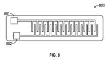
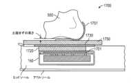
図2A~2Cは、幾つかの例示的な実施形態によるセンサシステムと電動紐締めエンジ
ンの概略を示す。図2Aは、ある例示的な紐締めエンジン110の各種の外部機構を紹介
しており、これには筐体構造150、ケースねじ108、紐通路112(紐案内レリーフ
112とも呼ばれる)、紐通路移行部114、スプールくぼみ115、ボタン開口部12
2、ボタン121、ボタン膜シール124、プログラミングヘッダ128、スプール13
1、及びスプール131内の紐溝132が含まれる。その他の設計も同様に使用できる。
例えば、他のタイプのスイッチ、例えば密閉型ドームスイッチ等を使用でき、又は膜シー
ル124をなくすこと等もできる。ある例において、紐締めエンジン110は、紐締めエ
ンジン110の内部の回路を紐締めエンジン110の外部の回路、例えば外部足存在セン
サ(又はその構成要素)、スイッチもしくはボタン等の外部アクチュエータ、又はその他
のデバイスもしくは構成要素と接続するための1つ又は複数の相互接続部又は電気コンタ
クトを含むことができる。 2A-2C show schematics of a sensor system and electric lacing engine according to some exemplary embodiments. FIG. 2A introduces various external features of one
2,
1, and a
For example, other types of switches may be used, such as sealed dome switches, or the
紐締めエンジン110は、1つ又は複数のねじ、例えばケースねじ108によって保持
できる。ケースねじ108は、第1の駆動機構の付近に配置して、紐締めエンジン110
の構造的完全性を向上させることができる。ケースねじ108はまた、例えば外部シーム
の超音波溶接のために筐体構造150を一体に保持する等、組立てプロセスを助けるよう
にも機能する。 The
The case screws 108 may also function to aid in the assembly process, such as by holding the
図2Aの例において、紐締めエンジン110は、エンジンが自動履物プラットフォーム
に組み込まれた時点で、靴紐又は締め紐を受承する紐通路112を含む。紐通路112は
、通路壁を含むことができ、これは面取り縁を有して、平滑な案内面を提供し、動作中、
締め紐はそれに接触して、またその中で移動できる。紐通路112の平滑な案内面部分は
、通路移行部114を含むことができ、これはスプールくぼみ115につながる紐通路1
12の幅広部分とすることができる。スプールくぼみ115は、通路移行部114から、
スプール131の形状に密接に適合する概して円形の部分へと移行する。スプールくぼみ
115は、スプールに巻かれた締め紐を保持することのほか、スプール131の位置を保
持することを支援できる。設計の他の態様は、スプール131を保持するためのその他の
手段を提供できる。図2Aの例において、スプール131は、平坦な上面を通って延びる
紐溝132と、反対側から下に向かって延在するスプールシャフト(図2Aでは示されず
)を有し、ヨーヨーの半分と似た形状である。 2A, the
The tightening lace can contact and move within it. The smooth guide surface portion of the
The
2A, the
紐締めエンジン110の外側は、自動履物プラットフォームの1つ又は複数の機構を作
動させ、又は調整するように構成できるボタン121を格納するボタン開口部122を含
む。ボタン121は、紐締めエンジン110に含まれる各種のスイッチを作動させるため
の外部インタフェースを提供できる。幾つかの例において、筐体構造150は、塵埃と水
から保護するためのボタン膜シール124を含む。この例では、ボタン膜シール124は
、厚さ最大数ミル(インチの千分の一)の透明なプラスチック(又は同様の材料)であり
、これを筐体構造150の上面から、例えば角部を覆って下方の外側へと接着できる。他
の例では、ボタン膜シール124は、ボタン121及びとボタン開口部122を覆う、接
着剤が裏に塗布された厚さ約2ミルのビニル製の膜である。その他のタイプのボタン及び
シーラントも同様に使用できる。 The exterior of the
図2Bは、上部102と下部104を含む筐体構造150を示す。この例では、上部1
02は、ケースねじ108、紐通路112、紐通路移行部114、スプールくぼみ115
、ボタン開口部122、及びボタンシールくぼみ126等の機構を含む。ある例において
、ボタンシールくぼみ126は、上部102のうち、ボタン膜シール124をはめ込むた
めに起伏を付けた部分である。 FIG. 2B shows a
02 includes
, a
図2Bの例において、下部104は、無線充電器アクセス105、ジョイント106、
及びグリース隔壁109等の機構を含む。また、明確に特定されていないが、ケースねじ
108を受容するためのケースねじベースのほか、グリース隔壁109内の、駆動機構の
一部を保持するための各種の機構も示されている。グリース隔壁109は、グリース又は
駆動機構の周囲の同様の組成物を、紐締めエンジン110の各種の電気構成要素から離し
て保持するように設計される。 In the example of FIG. 2B, the
and features such as a
筐体構造150は、上部102及び下部104の一方又は両方の中に、構造表面に埋め
込まれた、又はそこに取り付けられた1つ又は複数の電極170を含むことができる。図
2Bの例における電極170は、下部104に結合されているように示されている。ある
例において、電極170は、容量型足存在センサ回路の一部を含む(例えば、本明細書で
論じられている足存在センサ310参照)。それに加えて、又はその代わりに、電極17
0は、上部102に結合できる。上部102又は下部104に結合された電極170は、
無線電力伝送のために、又は容量型足存在センサ回路の一部として、又はその両方のため
に使用できる。ある例において、電極170は、筐体構造150の外面に配置された1つ
又は複数の部分を含み、他の例では、電極170は、筐体構造150の内面に配置された
1つ又は複数の部分を含む。 The
0 can be coupled to the
It can be used for wireless power transfer, or as part of a capacitive foot presence sensor circuit, or both. In some examples, the
図2Cは、ある例示的な実施形態による紐締めエンジン110の各種の内部構成要素を
示す。この例では、紐締めエンジン110は、スプール磁石136、Oリングシール13
8、ウォーム駆動部140、ブッシュ141、ウォーム駆動キー、ギアボックス148、
ギアモータ145、モータエンコーダ146、モータ回路基板147、ウォームギア15
1、回路基板160、モータヘッダ161、バッテリ接続部162、及び無線充電ヘッダ
163をさらに含む。スプール磁石136は、磁力計(図2Cでは示されず)による検出
を通じてスプール131の移動を追跡するのを助ける。Oリングシール138は、スプー
ルシャフトの周囲で紐締めエンジン110の中に侵入しうる塵埃及び水分を締め出すよう
に機能する。回路基板160は、例えば後述の容量性足存在センサ310等の足存在セン
サのための1つ又は複数のインタフェース又は相互接続部を含むことができる。ある例に
おいて、回路基板160は、足存在センサ310の一部を提供する1つ又は複数のトレー
ス又は導電面を含む。 2C illustrates various internal components of the
8,
2C , further includes a
この例では、紐締めエンジン110の主要な駆動構成要素は、ウォーム駆動部140、
ウォームギア151、ギアモータ145、及びギアボックス148を含む。ウォームギア
151は、ウォーム駆動部140及びギアモータ145の逆方向への駆動を阻止するよう
に設計され、これは、スプール131を介して締め紐から入力される主な力を比較的大型
のウォームギアとウォーム駆動歯とで分解できることを意味する。この配置により、ギア
ボックス148は、履物プラットフォームをアクティブに使用することから生じる力学的
負荷又は紐締めシステムの締付けから生じる締付け負荷の両方に耐えるのに十分な強度の
ギアを含める必要性から保護される。ウォーム駆動部140は、駆動システムの様々な壊
れやすい部分を保護するのを助ける追加の機構、例えばウォーム駆動キーを含む。この例
では、ウォーム駆動キーはウォーム駆動部140の、ギアボックス148から出るドライ
ブシャフトを通るピンと接続するモータ端の半径方向のスロットである。この配置により
、ウォーム駆動部140はウォーム駆動部140が軸方向に(ギアボックス148の反対
に)自由に移動できるようにし、これらの軸方向の負荷をブッシュ141と筐体構造15
0に伝達することによって、ギアボックス148又はギアモータ145に不当な軸方向の
力がかからない。 In this example, the main drive components of the
The
By transmitting to zero, no undue axial forces are applied to the
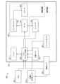
図3は、ある例示的な実施形態による電動紐締めシステム300の構成要素のブロック
図の概略を示す。システム300は、電動紐締めシステムの構成要素の、必ずしも全部で
はないが幾つかを含み、例えば、インタフェースボタン301と、容量性足存在センサ3
10と、プロセッサ回路を有するプリント回路基板アセンブリ(PCA)320、バッテ
リ321、充電コイル322、エンコーダ325、モーションセンサ324、及び駆動機
構340を包囲する筐体構造150とを含む。駆動機構340は、特に、モータ341、
トランスミッション342、及び紐スプール343を含むことができる。モーションセン
サ324は、特に、単一又は複数の軸加速度計、磁力計、ジャイロメータ、又は筐体構造
150の動き、もしくは筐体構造150の中の、又はそこに結合された1つ又は複数の構
成要素の動きを感知するように構成された他のセンサもしくは装置を含むことができる。 3 shows a schematic block diagram of components of a
10, a printed circuit board assembly (PCA) 320 having a processor circuit, a
3, a
図3の例において、プロセッサ回路320は、インタフェースボタン301、足存在セ
ンサ310、バッテリ321、充電コイル322、及び駆動機構340のうちの1つ又は
複数とデータ又は電力信号を通信する。トランスミッション342は、モータ341をス
プール343に結合して、駆動機構340を形成する。図3の例において、ボタン301
、足存在センサ310、及び環境センサ350は、筐体構造150の外部に、又は部分的
に外部に示されている。 In the example of Figure 3, the
,
代替的な実施形態において、ボタン301、足存在センサ310、及び環境センサ35
0のうちの1つ又は複数は、筐体構造150の中に入れることができる。ある例において
、足存在センサ310は、筐体構造150の中に配置され、センサが汗や塵埃又はデブリ
(debris)から保護される。筐体構造150の壁を通る接続を最少化又は排除することは
、アセンブリの耐久性と信頼性を高めるのに役立ちうる。 In an alternative embodiment, the
One or more of the
ある例において、プロセッサ回路320は、駆動機構340の1つ又は複数の態様を制
御する。例えば、プロセッサ回路320は、ボタン301、足存在センサ310、及びモ
ーションセンサ324のうちの少なくとも一つからの情報を受信し、それに応答して、例
えば足の周囲の履物をきつくする、又は緩めるように駆動機構340を制御するように構
成できる。ある例において、プロセッサ回路320は、それに加えて、又はその代わりに
、他の機能のうち、足存在センサ310又はその他のセンサからセンサ情報を取得又は記
録するための命令を発行するように構成される。ある例において、プロセッサ回路320
は、足存在センサ310を用いて足の存在を検出すること、足存在センサ310を用いて
足の向き又は位置を検出すること、又はモーションセンサ324を用いて所定のジェスチ
ャを検出することのうちの1つ又は複数に駆動機構340の動作を条件付ける。 In some examples, the
conditions operation of the
ある例において、システム300は環境センサ350を含む。環境センサ350からの
情報は、足存在センサ310のためのベースライン又は基準値を更新又は調整するために
使用できる。後にさらに説明するように、容量性足存在センサにより測定された容量値は
、例えばセンサ付近の周囲条件に応答して時間の経過と共に変化する可能性がある。した
がって、環境センサ350からの情報を用いて、プロセッサ回路320及び足存在センサ
310のうちの少なくとも一方は、測定又は感知された容量値を更新又は調整するように
構成できる。 In one example,
図4は、履物製品の使用者が立っているときの、履物製品400の中の標準的又は平均
的な足(左)と凹足(high arch foot)(右)に関する圧力分布データを示す図である。
この例では、比較的大きい足底圧力区域が踵領域401、母指球領域402(例えば、土
踏まずと爪先との間)、及び母指領域403(例えば、「足の親指」領域)に含まれるこ
とがわかる。しかしながら、前述のように、例えば土踏まず領域又はその付近等の中央領
域に、各種のアクティブな構成要素(例えば、足存在センサ310を含む)を含めること
が有利である可能性がある。一例においては、筐体構造150を含む履物製品を履いた使
用者にとって、土踏まず領域では、一般に、筐体構造150があまり目立たないか、煩わ
しくない可能性がある。 FIG. 4 illustrates pressure distribution data for a standard or average foot (left) and a high arch foot (right) in an article of
In this example, it can be seen that relatively large plantar pressure areas are included in
図4の例では、紐締めエンジンキャビティ141を土踏まず領域に提供できる。足存在
センサ310に対応する1つ又は複数の電極は、第1の位置405に、又はその付近に配
置できる。第1の位置405に配置された電極を用いて測定された容量値は、足が第1の
位置405にどれだけ近いかに応じて違う可能性がある。例えば、平均的な足と凹足につ
いては異なる容量値が得られ、これは、足そのものの表面が第1の位置405から異なる
距離にあるからである。ある例において、足存在センサ310及び紐締めエンジン110
のうちの少なくとも一方の位置は、例えば異なる使用者の異なる足の特徴に対応し、足存
在センサ310から得られる信号品質を向上させるように、(例えば、使用者が、又は販
売時点で技術者が)履物に関して調整できる。ある例において、足存在センサ310の感
度は、例えば駆動信号のレベルを高めることによって、又は足存在センサ310と足との
間に配置された誘電材料を変えることによって調整できる。 4, the
The position of at least one of the
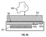
図5A及び5Bは、ある例示的な実施形態による履物製品のインソールの中の容量型足
存在センサの概略図である。容量型足存在センサは、センサを取り入れた製品が着用され
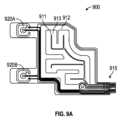
たときの物体又は体550、例えば足の、表面の下に提供できる。 5A and 5B are schematic diagrams of a capacitive foot presence sensor in an insole of an article of footwear according to an example embodiment. The capacitive foot presence sensor can be provided beneath the surface of an object or
図5Aにおいて、容量型足存在センサは、容量感知コントローラ回路502に結合され
た第1の電極アセンブリ501Aを含むことができる。ある例において、コントローラ回
路502は、プロセッサ回路320の中に含まれるか、またはプロセッサ回路320によ
って実行される機能を含む。図5Aの例では、第1の電極アセンブリ501A及びコント
ローラ回路502のうちの少なくとも一方は、筐体構造150の内側部分の中に含めるか
、又はそこに取り付けることができ、あるいは筐体構造150の中のPCAに結合できる
。ある例において、第1の電極アセンブリ501Aは、筐体構造150の足対向表面に、
又はそれに隣接して配置できる。ある例において、第1の電極アセンブリ501Aは、筐
体構造150の内側上面領域の全体に広がる複数のトレースを含む。 In Fig. 5A, the capacitive foot presence sensor can include a
In one example, the
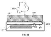
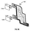
図5Bにおいて、容量型足存在センサは、容量感知コントローラ回路502に結合され
た第2の電極アセンブリ501Bを含むことができる。第2の電極アセンブリ501Bは
、筐体構造150の外側部分において、又はその付近に取り付けることができ、例えばフ
レキシブルコネクタ511を用いて筐体構造150の内側のPCAに電気的に結合できる
。ある例において、第2の電極アセンブリ501Bは、筐体構造150の足対向表面に、
又はそれに隣接して配置できる。ある例において、第2の電極アセンブリ501Bはフレ
キシブル回路を含み、これは筐体構造150の内面又は外面に固定され、1つ又は複数の
導体を介してプロセッサ回路320に結合される。 5B, the capacitive foot presence sensor can include a
In one example, the
ある例において、コントローラ回路502は、アトメル(Atmel)のATSAML21
E18B-MU、STマイクロエレクトロニクス(ST Microelectronics)のSTM32
L476M、又は他の同様のデバイスを含む。コントローラ回路502は、特に、第1の
電極アセンブリ501A又は第2の電極アセンブリ501Bの中の少なくとも1つの電極
ペアにAC駆動信号を供給し、それに応じて、電極ペアに対する物体又は体550の近接
性の、対応する変化に基づく電界の変化を感知するように構成でき、これについては後で
より詳しく説明する。ある例において、コントローラ回路502は、足存在センサ310
又はプロセッサ回路320を含むか、これを使用する。 In one example, the
E18B-MU, ST Microelectronics STM32
L476M, or other similar devices. The
or includes or uses a
各種の材料を、電極アセンブリ501と感知される物体又は体550との間に提供でき
る。例えば、電極絶縁筐体構造150の材料、インソールの材料、インサートの材料51
0、ソックスもしくはその他の足カバー、ボディテープ、キネシオロジーテープ(kinesi
ology tape)、又はその他の材料を、例えば履物の誘電特性を変化させ、それによって電
極アセンブリ501を含むか又は使用するセンサの容量検出感度に影響を与えるために、
体550と電極アセンブリ501との間に介在させることができる。コントローラ回路5
02は、例えば電極アセンブリ501を用いて感知された容量値の感度又は信号対ノイズ
比を向上させるために、介在材料の数又はタイプに基づいて励起又は感知パラメータを更
新又は調整するように構成できる。 Various materials can be provided between the electrode assembly 501 and the object or
0, socks or other foot coverings, body tape, kinesiology tape
501, for example, to change the dielectric properties of the footwear, thereby affecting the capacitive detection sensitivity of a sensor that includes or uses electrode assembly 501.
The controller circuit 501 may be disposed between the
02 may be configured to update or adjust excitation or sensing parameters based on the number or type of intervening materials, for example to improve the sensitivity or signal-to-noise ratio of capacitance values sensed using the electrode assembly 501.
図5A又は図5Bの例では、第1の電極アセンブリ501A及び第2の電極アセンブリ
501Bのうちの少なくとも一方は、コントローラ回路502の信号生成器により励起す
ることができ、その結果、電界を電極アセンブリの上側の足対向面から放射させることが
できる。ある例において、電極アセンブリの下の電界は、少なくとも一部に、感知電極の
下に配置されたドリブンシールド(driven shield)を用いてブロックできる。ドリブン
シールド及び電極アセンブリは、相互に電気的に絶縁できる。例えば、第1の電極アセン
ブリ501AがPCAの一つの面にあると、ドリブンシールドはPCAの下層、又は多層
PCAの複数の内側層の何れか1つにあるようにすることができる。ある例において、ド
リブンシールドは、第1の電極アセンブリ501Aの表面積と同じか、又はそれより大き
くすることができ、第1の電極アセンブリ501Aの直下で中心合わせすることができる
。ドリブンシールドは、駆動信号を受信し、それに応答して第1の電極アセンブリ501
Aにより生成された電界のX軸レッグ(X axis leg)と同じ極性、位相、及び振幅の電界
、またはそのうちの少なくとも一つが同じ電界を生成することができる。ドリブンシール
ドの電界は、第1の電極アセンブリ501Aの電界と反発し、それによってセンサフィー
ルドを、例えばPCAのアース面との不要な結合等、各種の寄生効果から絶縁することが
できる。ドリブンシールドは、第2の電極アセンブリ501Bで使用するために同様に提
供できる。例えば、第2の電極アセンブリ501Bは、図5Bの例に示されているように
筐体構造150の上方に提供でき、筐体構造150の一部はドリブンシールドとして使用
される導電性フィルムを含むことができる。それに加えて、又はその代わりに、ドリブン
シールドは、第2の電極アセンブリ501Bが筐体構造150の上以外の位置に提供され
ている場合、履物製品の他の箇所に提供できる。 In the example of FIG. 5A or 5B, at least one of the
The driven shield may generate an electric field of the same polarity, phase, and/or amplitude as the X axis leg of the electric field generated by the PCA. The electric field of the driven shield may repel the electric field of the
筐体構造150を配置するのに好ましい位置は履物の土踏まず区域であり、それは、そ
こが着用者により感じとられにくく、着用者にとって不快の原因となりにくい区域だから
である。履物内の足の存在を検出するために容量感知を使用する1つの利点は、容量性セ
ンサが土踏まず領域内にあり、使用者が比較的又は異常に高い土踏まずを有していても容
量性センサが適正に機能できることを含む。例えば、センサ駆動信号の振幅又は形態的特
徴(morphology characteristic)は、容量性センサから受信した信号の、検出された信
号対ノイズ比に基づいて変化させ、又は選択することができる。ある例において、センサ
駆動信号は、例えば第1の電極アセンブリ501A又は第2の電極アセンブリ501Bと
体550との間に配置された1つ又は複数の材料(例えば、ソックス、インソール等)の
変化に対応するために、履物が使用されるたびに更新又は調整できる。 A preferred location for placing the
ある例において、容量性センサの電極アセンブリ、例えば第1の電極アセンブリ501
A又は第2の電極アセンブリ501Bは、例えばX及びY軸の方向を向く電極間のような
、複数の電極間の信号の差を感知するように構成できる。ある例において、適当なサンプ
リング周波数は約2~50Hzの間とすることができる。幾つかの例において、容量型足
感知技術は、インソール又は足を包むソックスの汗(湿り気)に対して比較的不変である
可能性がある。このような水分の影響は、検出のダイナミックレンジの減少となる可能性
があり、これは、水分の存在が、測定される容量を増大させる可能性があるからである。
しかしながら、幾つかの例において、ダイナミックレンジは、履物の水分の予想レベル内
においては、この効果に対応するのに十分である。 In one example, an electrode assembly of a capacitive sensor, such as a first electrode assembly 501
The A or
However, in some instances, the dynamic range is sufficient to accommodate this effect within expected levels of moisture in footwear.
図6は、ある例示的な実施形態による足存在検出のための容量性センサシステム600
の概略を示す。システム600は、体550(例えば、アクティブな履物製品の中又はそ
の付近の足を表す)と、第1の電極601及び第2の電極602を含む。電極601及び
電極602は、例えば足存在センサ310の一部を含む、図5A又は図5Bの例の第1の
電極アセンブリ501A及び第2の電極アセンブリ501Bの全部又は一部を形成できる
。図6の例では、第1の電極601及び第2の電極602は、相互に、及び体550に関
して垂直に離間されているように示されているが、電極は、例えば図7~図9Cの例にお
いて詳細に示されているように、同様に水平にも離間できる。すなわち、ある例において
、電極は体550の下面に平行な平面内に配置できる。図6の例では、第1の電極601
は、送信電極として構成され、信号生成器610に結合される。ある例において、信号生
成器610は、図3の例のプロセッサ回路320の一部を含む。すなわち、プロセッサ回
路320は、駆動信号を生成し、それを第1の電極601に印加するように構成できる。 FIG. 6 illustrates a
6 is a schematic diagram of a
is configured as a transmitting electrode and coupled to a
信号生成器610からの駆動信号で第1の電極601を励起した結果として、電界61
5が主に第1の電極601及び第2の電極602間に生成されることができる。すなわち
、生成された電界615の各種の成分は、第1の電極601及び第2の電極602間に延
在することができ、生成された電界615のその他のフリンジ成分は他の方向に延在する
ことができる。例えば、フリンジ成分は、筐体構造150(図6の例では示されていない
)から離れる方向に、送信電極又は第1の電極601から延び、受信電極又は第2の電極
602に戻って終端することができる。 Exciting the
6 , fringe components of the generated
電界615に関する情報は、体550の近接性による電界615の変化に関する情報を
含め、第2の電極602によって感知され、又は受信されることができる。第2の電極6
02からの感知信号は、様々な回路を用いて処理され、体550の有無を示すアナログ又
はデジタル信号を提供するために使用できる。 Information regarding the
The sensed signal from 02 can be processed using various circuits and used to provide an analog or digital signal indicative of the presence or absence of a
例えば、第2の電極602が受信した電界615の電界強度は、アナログ容量表示信号
をデジタル信号に変換するよう構成されたシグマ-デルタ・アナログ-デジタル変換回路
(ADC)620を用いて測定できる。電極付近の電気環境は、体550等の物体が、そ
のフリンジ成分を含む電界615に侵入する場合に変化する。体550が電界内に入ると
、電界615の一部が、第2の電極602で受信及び終端される代わりに、アースに短絡
されるか、又は(例えば、空気中を通る代わりに)体550を通過してから第2の電極6
02で受信される。その結果、容量の変化が生じ、これは足存在センサ310及びプロセ
ッサ回路320のうちの少なくとも一方によって検出されることが可能である。 For example, the field strength of the
02, which results in a change in capacitance that can be detected by the
ある例において、第2の電極602は、電界情報を実質的に連続的に受信することがで
き、情報は、ADC620により連続的又は周期的にサンプリングされることが可能であ
る。ADC620からの情報は、オフセット621にしたがって処理又は更新でき、その
後、デジタル出力信号622を供給できる。ある例において、オフセット621は、容量
オフセットであり、これは、(例えば、プロセッサ回路320の内部で)指定又はプログ
ラムできるか、又は時間の経過による環境の変化、温度、又はその他の可変的な環境特性
を追跡するために使用される別のキャパシタに基づくようにすることができる。 In one example, the
ある例において、デジタル出力信号622は、例えば測定された容量値を所定の閾値と
比較することにより判定された、体550の有無に関する二値情報を含むことができる。
ある例において、デジタル出力信号622は、測定された容量に関する定性的情報を含み
、例えば(例えば、プロセッサ回路320により)体550がある、又はない可能性の標
示を提供するために使用できる。 In one example, the
In one example, the
周期的に、又は(例えばモーションセンサ324からの情報を使用した判定により)足
存在センサ310がアクティブでないときにはいつでも、容量値を測定し、基準値、ベー
スライン値、又は環境値として保存できる。足又は体が、足存在センサ310、第1の電
極601、及び第2の電極602に近付くと、測定された容量は、例えば保存された基準
値に関して減少又は増大する可能性がある。ある例において、1つ又は複数の閾値容量レ
ベルを、例えばプロセッサ回路320を有するオンチップレジスタに保存できる。測定さ
れた容量値が所定の閾値を超えた場合、体550が足存在センサ310を含む履物に存在
する(又は存在しない)と判定されることが可能である。 Periodically, or whenever the
足存在センサ310と、足存在センサ310の一部を含む電極601及び602は、以
下の幾つかの非限定的な例に示されているように、複数の異なる形態を取ることができる
。ある例において、足存在センサ310は、複数の電極又はプレート間の相互容量に関す
る情報を感知又は使用するように構成される。 The
ある例において、電極601及び602は、電極グリッドに配置される。グリッドを使
用する容量性センサは、グリッドの各行と各列の各交叉点において可変キャパシタを含む
ことができる。任意選択により、電極グリッドは、1つ又は複数の行又は列に配置された
電極を含む。電圧信号は、行又は列に印加でき、センサの表面に近い体又は足は、局所的
電界に影響を与えることができ、今度は相互容量効果を低減できる。ある例において、グ
リッド上の複数の点における容量変化は、例えば各軸の電圧を測定することによって、測
定され、体の位置を判定できる。ある例において、相互容量測定技術は、グリッドの方々
の複数の位置からの情報を同時に提供できる。 In one example,
ある例において、相互容量測定は、送信電極及び受信電極の直交グリッドを使用する。
このようなグリッド型センサシステムにおいて、測定値は、複数の離散的なX-Y座標ペ
アの各々について検出できる。ある例において、複数のキャパシタからの容量情報は、履
物の中の足の存在又は足の向きを判定するために使用できる。他の例において、1つ又は
複数のキャパシタからの容量情報は、ある時間にわたり取得され、分析されて、足の存在
又は足の向きを判定できる。ある例において、X検出座標及びY検出座標のうちの少なく
とも一方に関する変化率情報は、足が履物の中のインソールに関していつ適正又は完全に
収容されたか、又は収容されたか否かを判定するために使用できる。 In one example, the mutual capacitance measurement uses an orthogonal grid of transmitting and receiving electrodes.
In such a grid-type sensor system, measurements can be detected for each of a plurality of discrete X-Y coordinate pairs. In one example, capacitance information from a plurality of capacitors can be used to determine the presence or orientation of a foot in the footwear. In another example, capacitance information from one or more capacitors can be acquired over time and analyzed to determine the presence or orientation of a foot. In one example, rate of change information for at least one of the X and Y detection coordinates can be used to determine when or if the foot is properly or fully seated with respect to an insole in the footwear.
ある例において、自己容量型足存在センサは、相互容量センサと同じX-Yグリッドを
有することができるが、列と行は独立して動作できる。自己容量センサでは、各列又は行
における体の容量性負荷を独立して検出できる。 In one example, a self-capacitance foot presence sensor can have the same XY grid as a mutual capacitance sensor, but the columns and rows can operate independently. The self-capacitance sensor can detect the body's capacitive loading in each column or row independently.
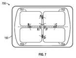
図7は、ある例示的な実施形態による第1の容量型足存在センサの概略図を示す。図7
の例では、第1の容量性センサ700は複数の平行な容量性プレートを含む。複数のプレ
ートは、筐体150の上又は中に配置され、例えば第1の容量性センサ700を含む履物
製品が着用されたときに足の裏に、又はその付近に配置される。ある例において、容量性
足存在センサ310は、第1の容量性センサ700を含むか、使用する。 7 illustrates a schematic diagram of a first capacitive foot presence sensor according to an exemplary embodiment.
In one example, the
図7の例では、4つの導電性キャパシタプレートが701~704として示されている
。プレートは、導電性フォイル等の導電材料で製作できる。フォイルは柔軟とすることが
でき、任意選択により、筐体構造150自体のプラスチックの中に埋め込むことができ、
又は筐体150とは独立させることができる。フィルム、インク、溶着金属、又はその他
の材料等、何れの導電材料も使用できると理解すべきである。図7の例では、プレート7
01~704は共通平面内に配置され、相互に離間されて、個別の導電素子又は電極を形
成する。 In the example of Figure 7, four conductive capacitor plates are shown as 701-704. The plates can be made of a conductive material, such as a conductive foil. The foil can be flexible and can optionally be embedded in the plastic of the
Or it can be separate from the
01-704 are disposed in a common plane and spaced apart from one another to form individual conductive elements or electrodes.
キャパシタの容量値は、キャパシタを形成する2枚のプレート間の材料の誘電率に機能
的に関連付けられている。第1の容量性センサ700の中で、キャパシタは、2つ又はそ
れ以上のキャパシタプレート701~704の各ペア間に形成できる。したがって、図7
においてキャパシタA、B、C、D、E、及びFとして指定されているように、キャパシ
タプレート701~704の6つの固有の組合せペアにより形成される6つの有効なキャ
パシタがある。任意選択により、プレートの2つ又はそれ以上を電気的に結合して、1つ
のプレートを形成できる。すなわち、ある例において、キャパシタは、電気的に結合され
て第1の導体を提供する第1のキャパシタプレート701及び第2のキャパシタプレート
702と、電気的に結合されて第2の導体を提供する第3及び第4のキャパシタプレート
703及び704とを用いて形成できる。 The capacitance of a capacitor is functionally related to the dielectric constant of the material between the two plates that form the capacitor. Within the
There are six effective capacitors formed by six unique combined pairs of capacitor plates 701-704, designated as capacitors A, B, C, D, E, and F in FIG. Optionally, two or more of the plates can be electrically coupled to form a single plate. That is, in one example, a capacitor can be formed with a
ある例において、第1のキャパシタプレート701及び第2のキャパシタプレート70
2間の容量性効果は、図7において文字Aで示される疑似キャパシタにより表される。第
1のキャパシタプレート701及び第3のキャパシタプレート703間の容量性効果は、
文字Bで示される疑似キャパシタにより表される。第2のキャパシタプレート702及び
第4のキャパシタプレート704間の容量性効果は、文字Cで示される疑似キャパシタに
より表される、等々である。当業者であれば、各疑似キャパシタがキャパシタプレートの
それぞれのペア間に延びる電界を表すことを理解するであろう。以下、識別しやすくする
ために、容量性プレートの各ペアにより形成されるキャパシタを、図7で使用される文字
(例えば、「A」、「B」等)で呼ぶことにより、疑似的に描かれたキャパシタを識別す
る。 In one example, the
The capacitive effect between the
7A, 7B, and 7C. The capacitive effect between the
図7の例におけるキャパシタプレートの各ペアについて、プレート間の有効誘電体は、
プレート間に配置されたエアギャップ(又はその他の材料)を含む。キャパシタプレート
の各ペアについて、容量性プレートのそれぞれのペアに近接する体又は足のどの部分も、
その容量性プレートのペアのための有効誘電体の一部となることができるか、又はそれに
影響を与えることができる。すなわち、キャパシタプレートの各ペア間に、それぞれのプ
レートペアまでの体の近接性に応じて可変誘電体を提供できる。例えば、体又は足がある
プレートペアに近いほど、有効誘電体の値は大きくなるかもしれない。誘電率の値が増え
るにつれて、容量値は増大する。このような容量値の変化は、プロセッサ回路320によ
って受信され、体が第1の容量センサ700に、又はその付近にあるか否かを示すために
使用できる。 For each pair of capacitor plates in the example of FIG. 7, the effective dielectric between the plates is
For each pair of capacitor plates, any part of the body or foot proximate to the respective pair of capacitive plates includes an air gap (or other material) disposed between the plates.
The dielectric constant can be a part of or affect the effective dielectric for that capacitive plate pair, i.e., a variable dielectric can be provided between each pair of capacitor plates depending on the proximity of the body to the respective plate pair. For example, the closer the body or foot is to a plate pair, the greater the value of the effective dielectric. As the dielectric constant value increases, the capacitance value increases. Such changes in capacitance value can be received by the
第1の容量性センサ700を含む足存在センサ310の例において、複数の容量性セン
サ駆動/モニタ回路を、プレート701~704に結合できる。例えば、別個の駆動/モ
ニタ回路を図7の例のキャパシタプレートの各ペアに関連付けることができる。例えば、
駆動/モニタ回路は、キャパシタプレートペアに駆動信号(例えば、時間的に変化する電
気励起信号)をキャパシタプレートペアに供給でき、それに応答して、容量表示値を受信
することができる。各駆動/モニタ回路は、関連するキャパシタ(例えば、第1のプレー
ト701及び第2のプレート702に対応するキャパシタ「A」)の可変容量値を測定す
るように構成でき、さらに、測定された容量値を示す信号を供給するように構成できる。
駆動/モニタ回路は、容量を測定するための何れの適当な構造を有することもできる。あ
る例において、例えば異なるキャパシタを用いて測定された容量値間の差の標示を提供す
るために、2つ又はそれ以上の駆動/モニタ回路を一緒に使用することができる。 In the example
The drive/monitor circuitry can provide drive signals (e.g., time-varying electrical excitation signals) to the capacitor plate pairs and can receive capacitance indications in response. Each drive/monitor circuit can be configured to measure the variable capacitance value of an associated capacitor (e.g., capacitor "A" corresponding to
The drive/monitor circuitry may have any suitable structure for measuring capacitance, and in some instances, two or more drive/monitor circuits may be used together, e.g., to provide an indication of the difference between capacitance values measured using different capacitors.
図8は、ある例示的な実施形態による第2の容量型足存在センサの概略図を示す。図8
の例は、第1の電極801及び第2の電極802を含む第2の容量性センサ800を含む
。足存在センサ310は、第2の容量性センサ800を含むか、又はそれを使用できる。
図8の例では、第1の電極801及び第2の電極802は、実質的に平坦な面に沿って、
例えば櫛状に配置される。ある例において、プロセッサ回路320等の駆動回路は、第1
の電極801及び第2の電極802に印加される励起又は刺激信号を生成するように構成
できる。同じ又は異なる回路は、第1の電極801及び第2の電極802間の容量の変化
を示す応答信号を感知するように構成できる。容量は、電極に対する体又は足の存在によ
り影響を受け得る。例えば、第1の電極801及び第2の電極802は、筐体構造150
の表面上又はその付近に配置でき、これは、例えば足が筐体構造150を含む履物内にあ
る場合の、足の付近である。 8 illustrates a schematic diagram of a second capacitive foot presence sensor according to an exemplary embodiment.
An example of the
In the example of FIG. 8, the
For example, the drive circuitry, such as the
The
, for example, near the foot when the foot is within footwear that includes the
ある例において、第2の容量性センサ800は、例えばX-Yグリッドで電極パターン
を形成するエッチングされた導電層を含む。それに加えて、又はその代わりに、第2の容
量性センサ800の電極は、導電材料の複数の別々の平行な層をエッチングすることによ
り、例えば垂直な線又はトラックを有するように提供され、グリッドを形成することがで
きる。この、又は他の容量性センサにおいて、体又は足と導電層又は電極との間の直接的
な接触は不要である。例えば、導電層又は電極は、筐体150の中に埋め込むことができ
、又は保護又は絶縁層でコーティングできる。その代わりに、検出対象の体又は足は、電
極の付近の電界特性と連動し、又はそれに影響を与えるようにすることができ、電界の変
化を検出できる。 In one example, the
ある例において、アース又は基準に対する第1の電極801に関して、及びアース又は
基準に対する第2の電極802に関して別々の容量値を測定できる。足存在検出で使用さ
れる信号は、第1の電極801及び第2の電極802に関して測定された別々の容量値の
差に基づくものとすることができる。すなわち、足存在又は足検出信号は、第1の電極8
01及び第2の電極802を用いて測定された別個の容量信号間の差に基づくものとする
ことができる。 In one example, separate capacitance values can be measured with respect to the
The capacitance measurement may be based on the difference between the separate capacitance signals measured using the
図9A及び図9Bは、ある例による第3の容量性センサ900の例の概略を示す。図9
Cは、第4の容量性センサ902の例の概略を示す。図9Aは、第3の容量性センサ90
0の概略上面図を示す。図9Bは、第3の容量性センサ900を含むセンサアセンブリ9
01の斜視図を示す。図9Cは、第4の容量性センサ902の概略上面図を示す。 9A and 9B show schematics of a third
FIG. 9C shows a schematic of an example of a
FIG. 9B shows a schematic top view of a
9C shows a schematic top view of a
図9Aの例では、第3の容量性センサ900は、第1の電極トレース911及び第2の
電極トレース912を有する電極領域を含む。第1の電極トレース911及び第2の電極
トレース912は、絶縁体トレース913により分離される。ある例において、第1の電
極トレース911及び第2の電極トレース912は、銅、炭素、もしくは銀又はその他の
導電材料とすることができ、FR4、フレックス、PET、もしくはITO又はその他の
材料等で製作された基板上に堆積させることができる。第3の容量性センサ900の基板
とトレースは、1つ又は複数の柔軟部分を含むことができる。 9A , the third
第1の電極トレース911及び第2の電極トレース912は、第3の容量性センサ90
0の基板の表面積の実質的に全体にわたって分布させることができる。電極トレースは、
第3の容量性センサ900が取り付けられたときに、筐体構造150の上側又は上面に接
触するように配置できる。ある例において、第1の電極トレース911及び第2の電極ト
レース912の一方又は両方は、幅約2mmとすることができる。絶縁体トレース913
は、ほぼ同じ幅とすることができる。ある例において、トレースの幅は、とりわけ、履物
の大きさもしくはインソールのタイプに基づいて選択できる。例として、例えば第3の容
量性センサ900を用いて測定される容量値の信号対ノイズ比を最大化するために、第1
の電極トレース911及び第2の電極トレース912について、又は絶縁体トレース91
3について、又はその両方について、例えばトレースと感知対象の体との間の距離、イン
ソールの材料、ギャップ充填材、筐体構造150の材料、又は履物内で使用されるその他
の材料に応じて異なるトレース幅を選択できる。 The
The electrode traces may be distributed over substantially the entire surface area of the substrate.
When the third
can be approximately the same width. In some examples, the width of the traces can be selected based on, among other things, the size of the footwear or the type of insole. For example, the first and second
The
For 3, or both, different trace widths can be selected depending, for example, on the distance between the trace and the body being sensed, the insole material, the gap filler, the material of the
第3の容量性センサ900は、コネクタ915を含むことができる。コネクタ915は
、適合するコネクタと結合でき、例えば筐体構造150の中のPCAに結合できる。適合
するコネクタは、第1の電極トレース911及び第2の電極トレース912をプロセッサ
回路320に電気的に結合するための1つ又は複数の導体を含むことができる。 The third
ある例において、第3の容量性センサ900は、入力信号導体920A及び入力信号導
体920Bを含む。入力信号導体920A及び入力信号導体920Bは、1つ又は複数の
入力デバイス、例えば図2Aの例のボタン121に対応するような、例えばドームボタン
又はその他のスイッチに結合されるように構成できる。 In one example, the third
図9Bはセンサアセンブリ901を示し、これは第3の容量性センサ900、ボタン1
21A及びボタン121B、及び膜シール124A及び膜シール124Bを含む。ある例
において、接着剤が、入力信号導体920A及び入力信号導体920Bの対応する導電表
面を、ボタン121A及びボタン121Bと結合する。膜シール124A及び膜シール1
24Bは、例えばボタン121A及びボタン121Bをデブリから保護するために、ボタ
ン121A及びボタン121Bを覆うように接着されることが可能である。 FIG. 9B shows a
21A and
24B may be glued over
図9Cの例では、第4の容量性センサ902は、第1の電極トレース921及び第2の
電極トレース922を有する電極領域を含む。第1の電極トレース921及び第2の電極
トレース922は、絶縁体トレース923により分離される。電極トレースは、各種の導
電材料を含むことができ、第4の容量性センサ902は、1つ又は複数の柔軟部分を含む
ことができる。第4の容量性センサ902は、コネクタ925を含むことができ、当該コ
ネクタ915は、適合するコネクタに結合でき、例えば筐体構造150内のPCAに結合
できる。 9C, the
本発明者らは、解決すべき課題が、例えば足存在センサの全部又は一部が検出対象の足
又は体から、例えばエアギャップ又はその他の介在材料により分離されているときに、容
量性足存在センサの適切な感度又は容量性足存在センサからの適切な応答を取得すること
を含むと認識した。本発明者らは、解決策が、特定の形状、大きさ、及び向きの複数の電
極を使用して、電極にエネルギー供給されたときに生成される電界の向きと相対強度を向
上させることを含むと認識した。すなわち、本発明者らは、容量性足存在感知において使
用するための最適な電極構成を特定した。 The inventors have recognized that the problem to be solved includes, for example, obtaining adequate sensitivity of or adequate response from a capacitive foot presence sensor when all or part of the foot presence sensor is separated from the foot or body being sensed, for example by an air gap or other intervening material. The inventors have recognized that the solution includes using multiple electrodes of specific shapes, sizes, and orientations to improve the orientation and relative strength of the electric fields that are generated when the electrodes are energized. That is, the inventors have identified an optimal electrode configuration for use in capacitive foot presence sensing.
ある例において、第4の容量性センサ902の複数の電極は、第1の電極トレース92
1及び第2の電極トレース922を含み、第1の電極トレース921及び第2の電極トレ
ース922の各々は、相互に実質的に平行に延びる複数の別個の指状部(finger)又はト
レースを含む。例えば、第1の電極トレース921及び第2の電極トレース922は、図
9Cに示されているように、交互に配置された複数の導電性指状部分を含むことができる
。 In one example, the electrodes of the
9C , the
ある例において、第2の電極トレース922は、境界線又は周辺部分を含むことができ
、これは実質的に第4の容量性センサ902の外周縁又は表面部分の周囲に延在し、実質
的に第1の電極トレース921を取り囲む。図9Cの例では、第2の電極トレース922
を含む境界線は、第4の容量性センサ902のアセンブリの上面の実質的に全部の周囲に
延在するが、他の幾つかの例では、境界線はセンサのより少ない部分の周囲に延在するこ
とができる。本発明者らはさらに、足の存在を検出するための最適な電界が、平行でない
1つ又は複数のトレース又は指状部分を含む代わりに、第1の電極トレース921及び第
2の電極トレース922の指状部のほとんど又は全部が相互に実質的に平行に配置された
ときに生成されると認識した。例えば、第4の容量性センサ902と異なり、図9Aの第
3の容量性センサ900は、例えば垂直に延びる指状部分を含む第1の電極トレース91
1の上側部分及び水平に延びる指状部分を含む第1の電極トレース911の下側部分等、
平行でない指状部を含む。第1の電極トレース921及び第2の電極トレース922の相
対的な厚さは、センサの感度をさらに高めるために調整できる。ある例において、第2の
電極トレース922は、第1の電極トレース921より3倍又はそれ以上厚い。 In one example, the
extends around substantially all of the top surface of the assembly of the
9. An upper portion of the
The relative thicknesses of the
ある例において、例えば第1の容量性センサ700、第2の容量性センサ800、第3
の容量性センサ900、及び第4の容量性センサ902を使用する足存在センサ310に
より測定された容量値は、図3のプロセッサ回路320等のコントローラ又はプロセッサ
回路に供給できる。測定された容量に応答して、プロセッサ回路320は、例えば足の周
囲の履物の張力を調整するために、駆動機構340を作動させることができる。調整作業
は任意選択により、少なくとも一部に、別個の「配線接続された(hard-wired)」構成要
素により実行でき、ソフトウェアを実行するプロセッサにより実行でき、又は配線接続さ
れた構成要素とソフトウェアとの組合せにより実行できる。ある例において、駆動機構3
40を作動させることは、(1)1つ又は複数の駆動/モニタ回路を用いて、例えばプロ
セッサ回路320を用いて足存在センサ310からの信号をモニタすること、(2)受信
した容量信号のうち、(例えば、プロセッサ回路320のメモリレジスタ、及びプロセッ
サ回路320とデータ通信するメモリ回路のうちの少なくとも一方の中に格納された)所
定の閾値と一致するか、それを超える容量を示すものがあれば、それはどれかを判定する
こと、(3)足存在センサ310の付近の体又は足の位置、大きさ、向き、又はその他の
特性を、例えば超過された各種の所定の閾値に基づいて特徴付けること、及び(4)その
特性に応じて、駆動機構340の作動を許可し、可能にし、調整し、又は抑制することを
含む。 In one example, for example, a
The capacitance values measured by
Activating 40 may include (1) monitoring signals from
図10は、履物センサからの足存在情報を使用することを含む方法1000の例を示す
フローチャートを示す。動作1010で、この例は、足存在センサ310からの足存在情
報を受信することを含む。足存在情報は、足が履物の中にあるか否かに関する二値情報(
例えば、図12~14の例において論じられる割込み信号参照)を含むことができ、又は
足が履物製品の中にある可能性の標示を含むことができる。情報は、足存在センサ310
からプロセッサ回路320に供給される電気信号を含むことができる。ある例において、
足存在情報は、履物の中の1つ又は複数のセンサに関する足の位置に関する定性的情報を
含む。 10 shows a flow chart illustrating an example of a
For example, the information may include an interrupt signal (see the examples of FIGS. 12-14) or may include an indication that the foot may be within the article of footwear.
In one example, the electrical signal provided to the
Foot presence information includes qualitative information regarding the position of the foot relative to one or more sensors in the footwear.
動作1020で、この例は、足が履物の中に完全に収容されたか否かを判定することを
含む。センサ信号が、足が完全に収容されたことを示す場合、この例は、動作1030に
おいて、駆動機構340を作動させることに続くことができる。例えば、動作1020で
、例えば足存在センサ310からの情報に基づいて足が完全に収容されたと判定されると
、前述のように駆動機構340を係合させてスプール131を介して靴紐を締めることが
できる。センサ信号が、足が完全に収容されていないことを示す場合、この例は、動作1
022において、ある所定の間隔(例えば、1~2秒又はそれ以上)にわたり遅延又は待
機することにより続くことができる。所定の遅延時間が経過すると、この例は動作101
0に戻ることができ、プロセッサ回路は、足存在センサ310からの情報を再度サンプリ
ングして、足が完全に収容されたか否かを再び判定することができる。 At
At 022, the example may continue by delaying or waiting for some predetermined interval (e.g., 1-2 seconds or more). After the predetermined delay has elapsed, the example returns to operation 101.
0 and the processor circuit can again sample the information from the
動作1030で駆動機構340が作動された後、プロセッサ回路320は、動作104
0で足位置情報をモニタするように構成されることができる。例えば、プロセッサ回路は
、履物の中の足の絶対位置又は相対位置に関する足存在センサ310からの情報を定期的
に、又は間欠的にモニタするように構成されることができる。ある例において、動作10
40で足位置情報をモニタすること、及び動作1010で足存在情報を受信することは、
同じ又は異なる足存在センサ310からの情報を受信することを含むことができる。例え
ば、動作1010及び1040において、足存在又は位置情報をモニタするために、異な
る電極を使用できる。 After the
The processor circuitry may be configured to monitor foot position information at
Monitoring foot position information at 40 and receiving foot presence information at
This may include receiving information from the same or different
動作1040で、この例は、履物に関連付けられる1つ又は複数のボタン、例えばボタ
ン121からの情報をモニタすることを含む。ボタン121からの情報に基づいて、駆動
機構340には、例えば使用者が履物を脱ぎたいときに、紐をほどく、又は緩めるように
指示できる。 At
ある例において、上記に加えて、又はその代わりに、駆動機構340を作動させるため
、又は紐を引っ張るためのフィードバック情報として紐張力情報をモニタ又は使用できる
。例えば、紐張力情報は、モータ341に供給される駆動電流を測定することによってモ
ニタできる。張力は、製造時に特徴付けることができ、又は使用者が事前設定もしくは調
整でき、及びモニタもしくは測定された駆動電流レベルに相関させることができる。 In certain examples, in addition to or instead of the above, string tension information can be monitored or used as feedback information to actuate
動作1050で、この例は、履物の中で足位置が変化したか否かを判定することを含む
。足位置の変化が足存在センサ310とプロセッサ回路320により検出されない場合、
この例は動作1052での遅延へと続くことができる。動作1052での所定の遅延間隔
の後、この例は動作1040に戻ることができ、足存在センサ310からの情報を再度サ
ンプリングして、足位置が変化したか否かを再び判定する。動作1052での遅延は、数
ミリ秒から数秒の範囲とすることができ、任意選択により、使用者が指定できる。 At
The example may continue with a delay at
ある例において、動作1052での遅延は、例えば履物の使用の特性を判定することに
応答して、プロセッサ回路320により自動的に判定されることができる。例えば、プロ
セッサ回路320が、着用者が激しい活動(例えば、ランニング、ジャンピング等)を行
っていると判定した場合、プロセッサ回路320は、動作1052で提供される遅延継続
時間を短縮できる。プロセッサ回路が、着用者が激しくない活動(例えば、ウォーキング
又は座っていること)に従事していると判断した場合、プロセッサ回路は、動作1052
で提供される遅延継続時間を延長できる。遅延継続時間を延長することにより、センサの
サンプリングイベントと、プロセッサ回路320及び足存在センサ310のうちの少なく
とも一方による対応する電力消費を遅らせることにより、バッテリの寿命を維持すること
ができる。ある例において、動作1050で位置変化が検出されると、この例は動作10
30に戻ることにより、例えば駆動機構340を作動させて、足の周囲の履物をきつくし
、又は緩めることに続くことができる。ある例において、プロセッサ回路320は、駆動
機構340のためヒステリシスコントローラを含むか、又は内蔵し、例えばわずかな足位
置変化が検出された場合に、不要な紐の巻上げを回避するのを助ける。 In certain examples, the delay at
The duration of the delay provided in
30, may continue to tighten or loosen the footwear around the foot, for example by actuating the
図11は、履物センサからの足存在情報を使用する方法1100の例を示すフローチャ
ートを示す。図11の例は、一例において、例えばプロセッサ回路320及び足存在セン
サ310を用いて実装できるような、ステートマシンの動作を参照するものとすることが
できる。 11 shows a flow chart illustrating an
状態1110は、アクティブな履物製品に関するデフォルト又はベースライン状態を表
す「出荷」状態を含むことができ、製品は、足存在センサ310からの情報により影響を
受けることのできる1つ又は複数の機構を含む。出荷状態1110で、履物の各種のアク
ティブな構成要素のスイッチを切るか、動作を停止させて、履物のバッテリ寿命を保つこ
とができる。
「電源投入」イベント1115に応答して、この例は「ディスエーブル」、すなわち非
アクティブ状態1120に移行できる。駆動機構340又はアクティブな履物の他の機構
は、ディスエーブル状態1120でスタンバイのままとすることができる。各種の入力を
、ディスエーブル状態1120から脱するためのトリガイベントとして使用できる。例え
ば、ボタン121のうちの1つからの使用者入力を用いて、ディスエーブル状態1120
からの移行を示すことができる。ある例において、モーションセンサ324からの情報は
起動信号として使用できる。モーションセンサ324からの情報は、履物の移動に関する
情報を含むことができ、例えば使用者が靴を準備位置に置くこと、又は使用者が足を履物
に入れ始めたことに対応できる。 In response to a "power on"
In one example, information from the
ステートマシンは、電源投入イベント1115の後、自動紐締めイネーブルイベント1
123に遭遇し、又はそれが受信されるまで、ディスエーブル状態1120のままとする
ことができる。自動紐締めイネーブルイベント1123は、使用者が手で(例えば、駆動
機構340への使用者の入力又はインタフェースデバイスを使用して)トリガでき、又は
例えばモーションセンサ324から受信したジェスチャ情報に応答して自動的にトリガさ
れることができる。自動紐締めイネーブルイベント1123に続き、較正イベント112
5が起こり得る。較正イベント1125は、例えばセンサに対する環境の影響を考慮する
ために、足存在センサ310の容量に関する基準又はベースライン値を設定することを含
むことができる。較正は、足存在センサ310自体から感知された情報に基づいて実行で
き、又はプログラムされ、もしくは指定された基準情報に基づくことができる。 The state machine starts after the power-on
The auto lacing enable
5 may occur. A
自動紐締めイネーブルイベント1123の後、ステートマシンは保持状態1130に入
り、「足存在信号を待機する」。状態1130で、ステートマシンは、足存在センサ31
0及びモーションセンサ324のうちの少なくとも一方からの割込み信号を待機できる。
例えば足が存在することを示す、又は足が存在する可能性が十分にあることを示す割込み
信号を受信すると、イベントレジスタはイベント1135で「足検出」を示すことができ
る。 After the auto lacing enable
0 and/or the
For example, upon receiving an interrupt signal indicating that a foot is present or that there is a good chance that a foot is present, the event register may indicate "foot detected" at
ステートマシンは、足検出イベント1135が発生すると、各種の機能へと移行し、又
はそれを開始できる。例えば、履物は、足検出イベント1135に応答して、駆動機構3
40を用いて張力特性をきつくし、又は調整するように構成できる。ある例において、プ
ロセッサ回路320は、検出イベント1135に応答して駆動機構340を作動させ、初
期の量だけ紐の張力を調整し、プロセッサ回路320は、さらに別の制御ジェスチャが検
出されるか、使用者入力を受信しないかぎり、又はそれまで、履物をさらにきつくするの
を遅延させる。すなわち、ステートマシンは「動作待機」状態1140へと移行できる。
ある例において、プロセッサ回路320は、足検出イベント1135の後、駆動機構34
0をイネーブルするが駆動機構を作動させない。状態1140で、ステートマシンは、感
知された追加の履物移動情報があるまで状態を保持するか、休止してから、初期調整又は
さらなる張力調整を開始できる。移動待機状態1140の後、ストンプ(stomp)/歩行
/起立イベント1145を検出でき、それに応答して、プロセッサ回路320は履物の張
力特性をさらに調整できる。 The state machine can transition to or initiate various functions upon the occurrence of a foot detect
40 to tighten or adjust the tension characteristic. In one example, the
In one example, the
0 but does not activate the drive mechanism. In
ストンプ/歩行/起立イベント1145は、例えばアクティブな履物の中の1つ又は複
数のセンサからの各種の個別の感知入力を含むことができる。例えば、ストンプイベント
は、(例えば、指定された、又は一般的な方向への)積極的加速と「上」又は「直立」方
向を示すモーションセンサ324からの情報を含むことができる。ある例において、スト
ンプイベントは、使用者が片方の膝を実質的に垂直かつ前方に持ち上げる「腿上げ」又は
キック型イベントを含む。モーションセンサ324からの加速度特性は、例えば加速度が
所定の閾値と一致し、又はそれを超えるか否かを判定するために分析できる。例えば、ゆ
っくりとした膝上げイベントは、ストンプイベントの応答をトリガしない可能性があり、
急激又は素早い膝上げイベントは、ストンプイベントの応答をトリガする可能性がある。 A stomp/walk/stand up
A sudden or quick knee lift event may trigger a stomp event response.
歩行イベントは、積極的歩行ステップパターンと「上」又は「直立」方向を示すモーシ
ョンセンサ324からの情報を含むことができる。ある例において、モーションセンサ3
24及びプロセッサ回路320のうちの少なくとも一方は、歩行ステップイベントを識別
するように構成され、歩行イベントは、歩行ステップイベントが識別されたとき、及び(
例えば、モーションセンサ324と共に含まれるか、それから分離されている)加速度計
が、履物が直立状態となったことを示したときに認めることができる。 A walking event may include information from a
At least one of the first and second sensors 24 and the
For example, an accelerometer (either included with or separate from the motion sensor 324) may indicate when the footwear is in an upright position.
起立イベントは、例えばモーションセンサから加速度又は履物の方向変化に関するさら
なる情報がなく、「上」又は「直立」方向を示すモーションセンサからの情報を含むこと
ができる。ある例において、起立イベントは、例えば以下でさらに説明するような容量性
足存在センサ310からの容量信号の変化に関する情報を用いて識別できる。すなわち、
足存在センサ310からの容量信号は、例えば使用者の足が履物に下方の圧力を加えてい
る時等、使用者が立っているか否かを示すことのできる信号変化を含むことができる。 A stand-up event may include information from a motion sensor indicating an "up" or "standing" orientation, for example, without further information from the motion sensor regarding acceleration or footwear directional change. In one example, a stand-up event may be identified using information regarding a change in a capacitive signal, for example, from a capacitive
The capacitive signal from the
ストンプ/歩行/起立イベント1145の具体的な例は限定的と考えられるものではな
く、その他の様々なジェスチャ、時間ベースの入力、又は使用者入力によるコントロール
を提供して、例えば足検出イベント1135で足が検出された後に履物の挙動をさらに制
御し、又はそれに影響を与えることができる。 The specific example of stomp/walk/stand up
ストンプ/歩行/起立イベント1145に続き、ステートマシンは「紐解き待機」状態
1150を含むことができる。紐解き待機状態1150は、履物を弛緩させ、張力を緩め
、又は靴紐を解く命令のための、使用者の入力及びジェスチャ情報のうちの少なくとも一
方を(例えばモーションセンサ324を使用して)モニタすることを含むことができる。
紐解き待機状態1150において、プロセッサ回路320等のステートマネージャは、紐
締めエンジン又は駆動機構340の紐が解かれ、足存在信号待機状態1130に戻るべき
であることを表示できる。すなわち、第1の例において、紐解きイベント1155は(例
えば、使用者入力に応答して)発生し、ステートマシンは履物を紐解き状態に移行させる
ことができ、ステートマシンは足存在信号待機状態1130に戻ることができる。第2の
例では、自動紐締めディスエーブルイベント1153が起こり、履物をディスエーブル状
態1120に移行させることができる。 Following the stomp/walk/stand up
In the wait for unlacing
図12は、容量性足存在センサからの第1の時間変化する情報のグラフ1200の概略
を示す。図12の例は容量対時間のグラフを含み、第1の時間変化する容量信号1201
がグラフ上でプロットされている。ある例において、第1の時間変化する容量信号120
1は、本明細書に記載の足存在センサ310を用いて取得できる。第1の時間変化する容
量信号1201は、測定された容量、又は前述のように足存在センサ310内の複数の電
極間の電界に与える体の影響の標示に対応できる。ある例において、第1の時間変化する
容量信号1201は、絶対又は相対容量値を表し、他の例では、信号は複数の異なる容量
信号間の差を表す。 12 is a schematic diagram of a
is plotted on the graph. In one example, the first time-varying
1 can be obtained using a
ある例において、第1の容量信号1201は、所定の第1の閾値容量値1211と比較
できる。足存在センサ310は、当該比較を実行するように構成でき、又はプロセッサ回
路320は、足存在センサ310からの容量情報を受信して比較を実行するように構成で
きる。図12の例では、第1の閾値容量値1211は、一定の非ゼロ値であると示されて
いる。第1の容量信号1201が、例えば時間T1で第1の閾値容量値1211と一致す
る、又はそれを超えると、足存在センサ310及びプロセッサ回路320のうちの少なく
とも一方は、第1の割込み信号INT1を供給できる。第1の割込み信号INT1は、足
存在センサ310により示される容量値が第1の閾値容量値1211と一致し、又はそれ
を超える限り高いままとすることができる。 In one example, the
ある例において、第1の割込み信号INT1は、図10の例の中の、例えば動作101
0又は1020で使用できる。動作1010で、足存在センサ310から足存在情報を受
信することは、例えばプロセッサ回路320において第1の割込み信号INT1を受信す
ることを含むことができる。ある例において、動作1020は、割込み信号情報を用いて
、足が履物の中に完全に収容されたか、又はその可能性が高いか否かを判定することを含
むことができる。例えば、プロセッサ回路320は、第1の割込み信号INT1の持続時
間をモニタし、足存在センサ310がどれだけの時間にわたり、第1の閾値容量値121
1を超える容量値を供給するかを判定できる。持続時間が所定の基準持続時間を超えた場
合、プロセッサ回路320は、足が完全に収容された、又はその可能性が高いと判定でき
る。 In one example, the first interrupt signal INT1 is generated in response to, for example, operation 101 in the example of FIG.
10 or 1020. Receiving foot presence information from the
It may be determined whether the capacitance value exceeds 1. If the duration exceeds a predetermined reference duration, the
ある例において、第1の割込み信号INT1は、図11の中の、例えば状態1130又
はイベント1135で使用できる。状態1130において、ステートマシンは、プロセッ
サ回路320からの、又は足存在センサ310からのINT1等の割込み信号を待機する
ように構成されることができる。イベント1135で、ステートマシンは、第1の割込み
信号INT1を受信することができ、それに応答して、1つ又は複数の以下の状態を開始
できる。 11, for example, at
ある例において、第1の閾値容量値1211は調整可能である。閾値は、例えば環境変
化による容量ベースライン又は基準の測定又は検出された変化に基づいて変更できる。あ
る例において、第1の閾値容量値1211は使用者が指定できる。使用者による閾値の指
定は、履物の感度に影響を与えることができる。ある例において、第1の閾値容量値12
11は、足存在センサ310の中の、又はその周囲の感知された環境又は材料の変化に応
答して自動的に調整できる。 In some examples, the first
11 can automatically adjust in response to sensed environmental or material changes in or around the
図13は、容量性足存在センサからの第2の時間変化する情報のグラフ1300の概略
を示す。図13の例は、第1の閾値容量値1211に近い第2の容量信号1202の変動
をどのように扱い、又は使用して、履物の中の足の存在又は向きに関するさらに多くの情
報を判定できるかを示す。 Figure 13 shows a schematic of a
ある例において、第2の容量信号1202は、足存在センサ310から受信され、第2
の容量信号1202は、第1の閾値容量値1211と比較される。とりわけ、使用者、使
用者の選好、履物のタイプ、又は環境もしくは環境特性に応じて、他の閾値も同様に使用
できる。図13の例では、第2の容量信号1202は、時間T2、T3、及びT4で第1
の閾値容量値1211と交差する可能性がある。ある例において、複数回の閾値との交差
は、例えば足が履物に入る時の移動経路を示すことにより、足存在センサ310によって
足存在を明確に識別するために使用できる。例えば、時間T2での第1の閾値交差及びT
3での第2の閾値交差を境界とする時間間隔は、足の爪先又は指節骨が足存在センサ31
0の電極に、又はその付近にある時の持続時間を示すことができる。第2の容量が第1の
閾値容量値1211より低いT3とT4との間の間隔は、足の中足骨関節又は中足骨が足
存在センサ310の電極の上又はその付近を移動するときの時間に対応することができる
。中足骨関節又は中足骨は、指節骨が履物の中へと移動するときに指節骨から足存在セン
サ310までの距離より長い距離だけ足存在センサ310から離間することができ、した
がって、その結果として測定されたT1とT4との間の容量はより小さくなり得る。時間
T4で、足の踵又は距骨は適所にスライドでき、土踏まずは足存在センサ310の電極の
上に収容されるようになり、それによって感知された容量は再び高い値に戻り、第1の閾
値容量値1211を超える。したがって、足存在センサ310又はプロセッサ回路320
は、時間T2とT3との間で第2の割込み信号INT2を供給し、時間T4の後に第3の
割込み信号INT3を供給するように構成できる。 In one example, a
The
In one example, multiple threshold crossings can be used to positively identify foot presence by the
The time interval bounded by the second threshold crossing at 3 is when the toe or phalanges are in contact with the foot presence sensor 31
0 electrodes. The interval between T3 and T4 during which the second capacitance is below the first
may be configured to provide a second interrupt signal INT2 between times T2 and T3, and a third interrupt signal INT3 after time T4.
ある例において、プロセッサ回路320は、割込み信号のシーケンスに基づいて足の存
在を明確に識別するように構成できる。例えば、プロセッサ回路320は、受信した割込
み信号に関する、及び受信した割込み信号間の1つ又は複数の間隔又は持続時間に関する
情報を使用できる。例えば、プロセッサ回路は、指定された持続時間により分離される割
込み信号のペアを探し、足の存在の明確な標示を提供するように構成できる。図13では
、例えば、T3とT4との間の持続時間は、例えばある程度の調整可能又は指定された許
容誤差で足の存在の標示を提供するために使用できる。ある例において、プロセッサ回路
320は、割込み信号をデータとして受信し、このデータを、例えばジェスチャによる使
用者入力の一部としての他の使用者入力信号と共に処理できる。ある例において、割込み
信号の有無に関する情報は、1つ又は複数の他の信号を有効にするか、又は却下するため
に使用できる。例えば、加速度計の信号は、割込み信号が現在受信されているか、最近受
信された場合に、プロセッサ回路320によって有効化されて、処理されることが可能で
あり、あるいは、加速度計の信号は、足存在センサに対応する割込み信号がない場合に、
プロセッサ回路320によって却下されることが可能である。 In one example, the
It is possible that the
図12及び図13の例は、足存在センサ310からの測定された容量値が、環境条件の
変化が存在する場合を含め、時間が経過しても確実に一定又は再現可能であるような実施
形態を示している。しかしながら、履物を使用する多くの場合、埋め込まれた電極におけ
る周囲容量変化が、例えば温度、湿度、又はその他の環境要因の変化により、常に、又は
予想外に発生する可能性がある。周囲容量の大きな変化は、例えばセンサのベースライン
又は基準容量特性を変化させることにより、足存在センサ310の作動に不利な影響を与
える可能性がある。 12 and 13 illustrate embodiments in which the measured capacitance value from the
図14は、容量性足存在センサからの第3の時間変化する情報のグラフ1400の概略
を示す。図14の例は、例えば各種の周囲条件の変化、使用シナリオの変化、又は履物の
構成要素の摩耗損耗もしくは劣化による基準容量の変化をどのように説明できるかを示す
。この例は、第2の閾値容量1212及び時間変化する基準容量1213と共にグラフ1
400上でプロットされた第3の容量信号1203を含む。図14の例では、時間変化す
る基準容量1213は時間が経つと増大する。他の例では、基準容量は時間と共に減少す
ることがあるか、又は履物の利用イベントの過程にわたり(例えば、1日、プレイされた
1つのゲーム、1人の使用者の設定又は選好等にわたり)変動しうる。ある例において、
基準容量は、履物そのものの各種の構成要素、例えばインソール、アウトソール、ソック
スライナ、矯正用インサート、又は履物のその他の構成要素のライフサイクルにわたり変
化し得る。 14 shows a schematic of a
14 includes a
The baseline volume may change over the life cycle of various components of the footwear itself, such as an insole, outsole, sock liner, orthotic insert, or other component of the footwear.
ある例において、第3の容量信号1203は、足存在センサ310から受信され、第3
の容量信号1203は、例えば足存在センサ310上の処理回路を使用するか、プロセッ
サ回路320を使用して、第2の閾値容量1212と比較される。時間変化する基準容量
1213を考慮又は使用しない例では、第3の容量信号1203の閾値との交差は、時間
T5、T6、及びT8で観察できる。しかしながら、第2の閾値容量1212は、例えば
足存在センサ310からの感知された情報によりリアルタイムで調整できる。第2の閾値
容量1212に合わせた調整は、時間変化する基準容量1213に基づくものとすること
ができる。 In one example, a
The
ある例において、第2の閾値容量1212は連続的に、時間変化する基準容量1213
の変化に対応する量だけ調整される。代替的な例では、第2の閾値容量1212は段階的
な増分で、例えば時間変化する基準容量1213の所定の閾値変化量に応答して調整され
る。段階式調整法は、図14において、図示された間隔にわたる第2の閾値容量1212
の段階的な増加により示されている。例えば、第2の閾値容量1212は、時間変化する
基準容量1213における所定の容量閾値増加ΔCに応答して、時間T7とT10で増加
する。図14の例では、第3の容量信号1203は基準補償された第2の閾値容量121
2と時間T5、T6、及びT9で交差する。それゆえ、閾値が基準補償されているか否か
に応じて、異なる割込み信号又は割込み信号タイミングを提供できる。例えば、時間T5
とT6との間では第4の割込み信号INT4を生成し、供給できる。第2の閾値容量12
12が基準補償されずに使用された場合、時間T8で第5の割込み信号INT5を生成し
、供給できる。しかしながら、基準補償された第2の閾値容量1212が使用されると、
第5の割込み信号INT5は第3の容量信号1203が補償済みの第2の閾値容量121
2と交差した時、図示されたように時間T9で生成され、供給される。 In one example, the
In an alternative example, the
14, the
2 at times T5, T6, and T9. Therefore, different interrupt signals or interrupt signal timings can be provided depending on whether the threshold is reference compensated or not. For example, at time T5
Between T1 and T6, the fourth interrupt signal INT4 can be generated and supplied.
If the reference-compensated
The fifth interrupt signal INT5 is generated when the
When it crosses 2, it is generated and provided at time T9 as shown.
閾値容量値をモニタし、更新するには論理回路を使用できる。このような論理回路は、
足存在センサ310に、又はプロセッサ回路320に組み込むことができる。更新された
閾値レベルは、自動的に供給されて、オンチップRAMに保存されうる。ある例において
、閾値更新を行うために使用者からの入力又は確認は不要である。 A logic circuit can be used to monitor and update the threshold capacitance value. Such a logic circuit may include:
The threshold level may be automatically provided and stored in on-chip RAM. In some instances, no input or confirmation from the user is required for the threshold update to occur.
図15は、容量性足存在センサからの第4の時間変化する情報のグラフ1500の概略
を示す。図15の例は、例えば各種の周囲条件の変化、使用シナリオの変化、又は履物の
構成要素の摩耗損耗もしくは劣化による基準容量の変化をどのように説明できるかを示す
。この例は、適応的閾値容量1214と共にグラフ1500上でプロットされた第4の容
量信号1204を含む。第4の容量信号1204は、足存在センサ310により供給でき
る。適応的閾値容量1214は、足存在センサ310により測定される容量の環境又は使
用ケース関連の変化を補償するのを助けるために使用できる。 FIG. 15 shows a schematic of a
ある例において、足存在センサ310又はプロセッサ回路320は、信号の大きさの変
化、例えば特定の大きさの閾値量より大きい変化について、第4の容量信号1204をモ
ニタするように構成されている。すなわち、第4の容量信号1204が、所定の閾値容量
大きさΔCと一致するか、又はそれを超える大きさ変化を含む場合、足存在センサ310
又プロセッサ回路320は割込み信号を供給できる。 In one example, the
The
ある例において、第4の容量信号1204の感知又は測定された容量値は、基準容量又
はベースラインと比較され、この基準又はベースラインは、所定の、又は時間変化する間
隔で更新できる。図15の例では、基準更新は、図のように時間T11、T12、T13
等で定期的に行われる。それに加えて、又はその代わりに、他の間隔、又は他のトリガイ
ベントに応答した更新も使用できる。 In one example, the sensed or measured capacitance value of the
etc. Additionally or alternatively, updates at other intervals, or in response to other triggering events, may be used.
図15の例では、初期基準容量は0とすることができ、又はx軸により表すことができ
る。第6の割込み信号INT6は、第4の容量信号1204が、以前に指定された基準に
対して所定の閾値容量大きさΔCより多い量だけ増大した後の時間T11で供給できる。
図15の例では、割込み信号は定期的に提供できるが、他の例では、容量の閾値変化を識
別するのと同時に割込み信号を提供できる。 15, the initial baseline capacitance may be 0, or may be represented by the x-axis. A sixth interrupt signal INT6 may be provided at a time T11 after the
In the example of FIG. 15, the interrupt signal may be provided periodically, while in other examples the interrupt signal may be provided upon identifying a threshold change in capacitance.
例えば時間T11におけるような、識別された閾値の変化の後、基準又はベースライン
容量を第1の容量基準C1に更新できる。時間T11に続いて、足存在センサ310又は
プロセッサ回路320は、信号の少なくともΔCの後続の変化、すなわちC1+ΔC又は
C1-ΔCの容量値を探すために第4の容量信号1204をモニタするように構成される
ことができる。 After an identified threshold change, such as at time T11, the reference or baseline capacitance may be updated to the first capacitance reference C1. Following time T11, the
最初に容量の増大を識別することを含む例では、割込み信号の状態は、その後の容量低
下を識別したことに応じて変化しうる。しかしながら、その後の時間にさらに容量増大が
識別された場合、基準容量を更新でき、その後の比較は更新された基準容量に基づいて行
うことができる。このシナリオは図15に示されている。例えば、時間T12で、第4の
容量信号1204の容量増大が検出され、基準は第2の容量基準C2に更新できる。第1
の容量変化及びその後の第2の容量変化が増大を表すため、第6の割込み信号INT6の
状態は変化しない可能性がある。時間T13で第4の容量信号1204の容量低下が検出
され、基準を第3の容量基準C3に更新できる。時間T13での容量変化は所定の閾値容
量大きさΔCより大きいため、第6の割込み信号INT6の状態は(例えば、割込みアサ
ート状態から非アサート状態に)変化しうる。 In an example involving initially identifying an increase in capacitance, the state of the interrupt signal may change in response to identifying a subsequent decrease in capacitance. However, if a further increase in capacitance is identified at a subsequent time, the reference capacitance may be updated and subsequent comparisons may be made based on the updated reference capacitance. This scenario is illustrated in FIG. 15. For example, at time T12, a capacitance increase in the
The state of the sixth interrupt signal INT6 may not change because the capacitance change at time T13 and the subsequent second capacitance change represent an increase. At time T13, a capacitance drop in the
ある例において、時間T11で検出された第1の変化とそれに対応する割込み信号IN
T6は、足が、足存在センサ310により感知され、履物の中にあると判定されたことを
表す。その後の基準容量の増大は、例えばセンサの、又はその周囲の環境変化による、足
存在センサ310により測定されたベースライン容量の変化を表す。時間T13で検出さ
れた変化は、足が履物から抜かれ、足存在センサ310の付近で感知されなくなったこと
を表すことができる。その後の容量変化(例えば時間T16)は、足が再び履物の中に入
れられたことを表すことができる。 In one example, a first change detected at time T11 and a corresponding interrupt signal IN
T6 represents a foot being sensed by
図16は、ある例示的な実施形態による容量性足存在センサからの時間変化する情報と
信号形態限界(signal morphology limit)のグラフ1600の概略を示す。この例は、
グラフ1600上でプロットされた第5の容量信号1205及び第6の容量信号1206
を含む。グラフ1600は、形態限界1601をさらに含む。形態限界1601は、足存
在センサ310からの容量信号の中のサンプリングされたセグメントと比較できる。比較
は、足存在センサ310又はプロセッサ回路320を用いて実行され、サンプリングされ
た特定のセグメントが形態限界1601に適合するか否かを判定できる。図16の例では
、形態限界は、それを超過すると、容量信号セグメントが、足存在センサ310の付近の
足の存在を表していない、又は表している可能性が低いことを示す下限を定める。 16 is a schematic diagram of a
The
第5の容量信号1205の図示されたサンプリング部分は、形態限界1601に適合す
る。図16の例では、形態限界1601は、容量信号の大きさの変化、すなわち落ち込み
、ドウェル(dwell)、及び回復を含む形態を定める。第5の容量信号1205が形態限
界1601の全部又は一部に適合したと識別された後、足の存在又は検出の成功を示す割
込み信号を供給できる。 The illustrated sampled portion of the
第6の容量信号1206の図示されたサンプリング部分は、形態限界1601に適合し
ない。例えば、第6の容量信号1206の急峻な減少と長いドウェル時間は、形態限界1
601により画定される境界の外にあり、したがって、例えば足が足存在センサ310に
より検出されないことを示すために、割込み信号は差し控えられる。 The illustrated sampled portion of the
601 and thus the interrupt signal is withheld to indicate that, for example, a foot is not detected by
形態限界1601は、一定又は可変とすることができる。例えば、形態限界は、基準容
量、環境、履物の使用ケース、使用者、感度の選好に関する情報、又はその他の情報に基
づいて調整できる。例えば、形態限界1601は、使用される履物のタイプによって異な
るようにすることができる。すなわち、バスケットボールシューズはランニングシューズ
とは異なる形態限界1601を有する可能性があり、これは少なくとも一部に、シューズ
の形状もしくは材料の違い、又は使用者が特定の履物製品を着脱するのにかかると予想さ
れる時間による。ある例において、形態限界1601は、例えば履物の着脱に関する使用
者の固有の選好又は手順に対応するために、使用者がプログラムできる。 The configuration limits 1601 can be fixed or variable. For example, the configuration limits can be adjusted based on information about a reference volume, an environment, a use case of the footwear, a user, sensitivity preferences, or other information. For example, the
前述のように、足存在センサ310は、関連する固定又は可変のベースライン又は基準
容量値を有することができる。基準容量値は、電極表面積、又は他の履物構成要素に関す
る電極の配置、又は履物の向き、又はセンサもしくは履物自体が使用される環境の関数と
することができる。すなわち、センサは、足が履物の中にないときに、幾つかの関連する
容量値を有することができ、その値は、1つ又は複数の材料の誘電効果、又はセンサの、
もしくはその付近の環境要因の関数とすることができる。ある例において、履物内の矯正
用インサート(例えば、インソール)は、容量性センサ、又はその付近の履物の誘電特性
を変化させる可能性がある。プロセッサ回路320は、任意選択により、ベースライン又
は基準特性が変化した時、例えばインソールが交換されたときに、足存在センサ310を
較正するように構成できる。ある例において、プロセッサ回路320は、ベースラインも
しくは基準容量の変化を自動的に検出するように構成でき、又は使用者入力又はコマンド
に応じてベースラインもしくは基準容量を更新するように構成できる。 As previously mentioned, the
The capacitance of the
図17は、履物製品のミッドソールの中の、誘電体スタックの下に配置された容量型足
存在センサの図の例1700の概略を示す。例1700は、例えば、容量性足存在センサ
1701からの情報に少なくとも部分的に基づいて作動する紐締めエンジン又は駆動機構
340を含むか、又は使用することができるような、筐体構造150を含む。容量性足存
在センサ1701は、センサの付近の体550の有無に基づいて容量又は容量表示信号を
供給するように構成できる。 17 shows a schematic of an example diagram 1700 of a capacitive foot presence sensor disposed beneath a dielectric stack in the midsole of an article of footwear. Example 1700 includes a
1つ又は複数の材料を、体550と容量性足存在センサ1701との間に提供でき、1
つ又は複数の材料は、センサの感度に影響を与えることができるか、又はセンサからの信
号の、信号対ノイズ比に影響を与えることができる。ある例において、1つ又は複数の材
料は、誘電体スタックを形成する。1つ又は複数の材料は、とりわけ、ソックス1751
、センサ、又はその付近における体550の土踏まずの高さによるエアギャップ、中敷き
1750、ベルクロ(登録商標)等のファスナ1730、又は誘電体充填材1720を含
むことができる。ある例において、容量性足存在センサ1701が筐体構造150の中に
提供されている場合、筐体構造150自体の上壁は誘電体スタックの一部である。ある例
において、矯正用インサートは、誘電体スタックの一部とすることができる。 One or more materials can be provided between the
The material or materials can affect the sensitivity of the sensor or can affect the signal to noise ratio of the signal from the sensor. In some examples, the material or materials form a dielectric stack. The material or materials can include, among others, the
, an air gap due to the arch height of the
本発明者らは、高い比誘電率、又は高いk値を持つ誘電体スタックを提供することによ
り、容量性足存在センサ1701の入力感度を向上できると認識した。高いk値を持つ様
々な材料をテストし、履物での有効性と適当さを評価した。ある例において、誘電体充填
材1720は、ネオプレン部材を含むことができる。ネオプレン部材は、履物の中で足の
下に使用するのに快適であり、かつ、例えばその代わりにエアギャップ又はその他の低い
k値の材料を有する場合と比較して、容量性足存在センサ1701の感度を高めるのに十
分な誘電効果を提供する硬さ又はデュロメータ特性(durometer characteristic)を有す
るように特定することができる。ある例において、ネオプレン部材は、約30ショアA硬
度値を有する独立気泡(closed-cell foam)材料を含む。 The inventors have recognized that the input sensitivity of the capacitive
図18は、容量性足存在センサ1701からの容量表示信号に与える誘電体充填材17
20の影響を示すグラフ1800を含む例の概略を示す。グラフ1800において、x軸
はデジタルサンプルの数を示し、かつ経過時間に対応し、y軸は容量性足存在センサ17
01により検出される相対容量値を示す。グラフ1800は、誘電体充填材1720の第
1のタイプの材料に対応する第1の容量表示信号1801、及び誘電体充填材1720の
第2の異なるタイプの材料に対応する第2の容量表示信号1802の時間的に整合された
重ね合わせを含む。 FIG. 18 illustrates the effect of
18 shows an example schematic including a
この例では、第1の信号1801は、誘電体充填材1720として第1の誘電部材が提
供された履物に対応する。第1の誘電部材は、例えば、第1の誘電k値(dielectric k-v
alue)を有するポリウレタン発泡材を含むことができる。グラフ1800は、第1の誘電
部材と足存在センサ1701とを含む履物製品の中に体550が挿入され、その後抜かれ
たことについての複数のインスタンスを示している。例えば、第1の信号1801の第1
の部分1820は、容量性足存在センサ1701により測定される基準又はベースライン
容量を示す。図18の例では、基準又はベースラインは0の値に規格化される。基準又は
ベースライン状態は、足が履物の中にないことに対応しうる。すなわち、第1の信号18
01の第1の部分1820は、足が履物の中にないことを示す。サンプル600付近に対
応する時間に、体550は履物の中に挿入された可能性があり、容量性足存在センサ17
01及び第1の誘電部材、又はその付近に位置している可能性がある。挿入後、第1の信
号1801の大きさは、例えば第1の量1811だけ変化し、足(又はその他の体の部位
)が履物の中にあることを示す。図18の例では、体550は、例えばサンプル600か
ら1400付近に対応するような、第1の信号1801の第2の部分1821に対応する
持続時間にわたり、履物の中に存在する。サンプル1400付近に対応する時間に、体5
50は履物から抜かれた可能性がある。体550が抜かれると、第1の信号1801は、
その基準値又はベースライン値に戻ることができる。 In this example, the
A
18,
When the
A return to that reference or baseline value may be achieved.
図18の例では、第2の信号1802は、第2の誘電部材が誘電体充填材1720とし
て提供された履物に対応する。第2の誘電部材は、例えば、上述の第1の誘電部材の第1
の誘電k値を超える第2の誘電k値を有するネオプレン発泡材を含むことができる。グラ
フ1800は、体550が第2の誘電部材及び足存在センサ1701を含む履物製品の中
に挿入され、その後、抜かれた複数のインスタンスを示している。第2の信号1802の
第1の部分1820は、容量性足存在センサ1701により測定された基準又はベースラ
イン容量を示し、図18の例では、第2の信号1802の第1の部分1820は、足が履
物の中にないことを示す。サンプル600付近に対応する時間に、体550は履物の中に
挿入された可能性があり、容量性足存在センサ1701及び第2の誘電部材、又はその付
近に位置している可能性がある。挿入後、第2の信号1802の大きさは、例えば第2の
量1812だけ変化し、足(又はその他の体の部位)が履物の中にあることを示す。この
例では、第2の量1812は第1の量1811を超える。大きさ変化の差は、誘電体充填
材1720に使用される材料のタイプに起因する。すなわち、第1の容量表示信号180
1及び第2の容量表示信号1802の大きさは、異なる誘電体スタックが使用されている
と異なる可能性がある。誘電体スタックが高いk値の誘電体充填材1720を含む場合、
大きさの差、すなわちベースラインからの差は、誘電体スタックが低いk値の誘電体充填
材1720を有する場合より大きい。 In the example of Figure 18, the
The
The magnitudes of the first and second capacitive indication signals 1802 may be different if a different dielectric stack is used. If the dielectric stack includes a high
The difference in magnitude, ie, the difference from the baseline, is greater when the dielectric stack has a low
ある例において、矯正用インサートは、履物の中の誘電体スタックの一部を含む。本発
明者らは、様々なテストを行って、各種の矯正用インサートが容量性足感知方式に与える
影響を評価した。全長型の、又は部分的長さの矯正用インソールをテストした。通常の(
部分的な長さの)矯正器具を履物に追加すると、スタックの全体的な誘電効果が増大し、
足の存在に対する電界感度が低下した。感知された信号振幅(例えば、感知された容量変
化に対応する)もまた、矯正器具があると低下した。しかしながら、ノイズフロアのRM
S振幅は、矯正器具があってもなくても同様であった。負荷又は無負荷条件での応答もま
た同様であった。 In one example, the orthotic insert comprises a portion of the dielectric stack in the footwear. The inventors performed various tests to evaluate the effect of various orthotic inserts on the capacitive foot sensing scheme. Full-length and partial-length orthotic insoles were tested. Regular (
Adding a partial-length orthotic to the footwear increases the overall dielectric effect of the stack,
The electric field sensitivity to the presence of the foot was reduced. The sensed signal amplitude (e.g., corresponding to the sensed capacitance change) was also reduced in the presence of the orthotic. However, the RMS of the noise floor
The S amplitude was similar with and without the orthotic. Responses under loaded or unloaded conditions were also similar.
矯正器具のテスト結果に基づき、通常の、又は全長型の矯正器具を用いて足が存在する
ことを検出するために容量感知を使用することは、信号対ノイズ分解能の点で実現可能で
ある。部分的長さ、又は全長型の矯正器具を使用した場合、約6dBという所望の最低値
を超えるSNRを、足の存在を分析するために使用でき、また低負荷と高負荷の両方の負
荷条件で使用できる。ある例において、足存在センサ310は、矯正器具により追加され
た誘電効果を補償するために、容量オフセット範囲を含むか、又は使用することができる
。 Based on orthotic testing results, using capacitive sensing to detect foot presence with a normal or full-length orthotic is feasible in terms of signal to noise resolution. With partial or full-length orthotics, SNRs above the desired minimum of about 6 dB can be used to analyze foot presence and can be used in both low and high load conditions. In some examples, the
全長型の矯正器具と足存在センサ310の電極との間のエアギャップの変化は、加わる
負荷に応じたSNRの測定可能な変化に対応しうる。例えば、図18の例で説明されてい
るように、高いk値の誘電材料が容量性足存在センサ、又はその付近に提供されると、低
いk値の誘電材料を含むか使用する例よりSNRを改善できる。 A change in the air gap between the full length orthotic and the electrodes of the
足の様々なゾーンが低負荷条件では同様に挙動することがわかり、例えば矯正器具の下
のギャップ距離の大きな変形は見られなかった。しかしながら、例えば使用者が立ってい
るとき等、高負荷条件では、矯正器具の土踏まず領域は圧縮される可能性があり、エアギ
ャップは実質的に縮小し、又はなくなる。それゆえ、感知条件下で、矯正器具がある場合
に測定される電界は、大きさの点で、量産又はOEMインソールを用いて測定された電界
と同様である可能性がある。足存在センサ310と検出対象の体との間にエアギャップを
生じさせる矯正器具又はOEM生産インソールの例では、エアギャップを補償するため、
又はそれを埋めるために様々な材料を提供又は追加できる。例えば、ネオプレン等のギャ
ップ充填発泡材を全長型矯正器具の裏側に提供できる。 It was found that the various zones of the foot behave similarly under low load conditions, e.g., no significant deformation of the gap distance under the orthotic was observed. However, under high load conditions, e.g., when the user is standing, the arch area of the orthotic may be compressed and the air gap may be substantially reduced or eliminated. Therefore, under sensing conditions, the electric field measured with the orthotic may be similar in magnitude to the electric field measured with a mass-produced or OEM insole. In the example of an orthotic or OEM produced insole that creates an air gap between the
Or, various materials can be provided or added to fill it in. For example, a gap-filling foam such as neoprene can be provided behind the full length orthotic.
ある例において、インソールに矯正器具を含めると、誘電体スタックの全体的な誘電体
の厚さが増大し、足の存在に対する電界感度が低下する。信号の振幅は矯正器具により小
さくなる。ノイズ特性のRMS振幅は、矯正器具があってもなくても同様であった。また
、容量性センサの感知電極と矯正器具の下面との間の空間を占有する誘電部材は、容量性
センサの感度に大きな影響を与える可能性があることもわかった。例えばk値が1.28
のポリウレタン発泡材は、誘電率、すなわちk値が約5.6のネオプレン発泡材を使用し
て測定された場合より、約70%小さい信号振幅を有する可能性がある。ノイズ振幅が等
しいとすると、これは約4.6dBのSNR差に相当する。 In one example, the inclusion of an orthotic in an insole increases the overall dielectric thickness of the dielectric stack, decreasing the electric field sensitivity to the presence of the foot. The signal amplitude is reduced with the orthotic. The RMS amplitude of the noise signature was similar with and without the orthotic. It was also found that the dielectric material occupying the space between the sensing electrode of the capacitive sensor and the underside of the orthotic can have a significant effect on the sensitivity of the capacitive sensor. For example, a dielectric material with a k value of 1.28
can have a signal amplitude that is about 70% smaller than that measured using neoprene foam, which has a dielectric constant, or k, value, of about 5.6. Assuming equal noise amplitudes, this corresponds to an SNR difference of about 4.6 dB.
それゆえ、カーボンファイバ製矯正器具を伴う足の存在を検出するために容量感知を使
用することは、信号対ノイズの点で実現可能である。足の存在を分析するのに必要な6d
Bの最低値を超えるSNRが測定された。 Therefore, using capacitive sensing to detect the presence of a foot with a carbon fiber orthotic is feasible in terms of signal to noise.
SNRs exceeding the lowest value of B were measured.
図19は、履物内の容量型足存在センサからの第3の容量表示信号1803の一部を示
すグラフ1900の例の概略を示す。グラフ1900において、x軸はデジタルサンプル
の数を示し、かつ経過時間に対応し、y軸は容量性足存在センサ1701により検出され
た相対容量測定値を示す。第3の信号1803からの情報は、とりわけ、例えば使用者が
座っている、又は立っているか否かを識別できる等、使用者が履物に下方の力を加えてい
るか否かを判定するため、又は歩数を判定するため、又は使用者の足取りの特性を判定す
るために使用できる。 19 shows an example of a
例えばx軸上のサンプル「0」に対応する初期時間に、第3の信号1803は、相対容
量スケール上の約0の基準又はベースライン値を有する可能性がある。1901で、すな
わちx軸上のサンプル175付近で、第3の信号1803は、例えば体550が履物の中
に挿入されていることに対応する履物を履くイベントを含む。第3の信号1803は、1
910で、又はサンプル10000付近で、履物を脱ぐイベントを含み、その後、第3の
信号1803はベースライン値に戻る。 At an initial time, for example corresponding to sample "0" on the x-axis, the
At 910, or around sample 10000, there is a footwear removal event, after which the
図19の例は、閾値1920をさらに含む。閾値1920は、体550が履物の中にあ
ることを示す相対容量値に対応させることができる。例えば、足又は体550が履物の中
にあると、第3の信号1803により示される相対容量は閾値1920を超え、足又は体
550が履物の中にないと、相対容量は閾値1920より低くなる可能性がある。後でさ
らに説明するように、各種の方法又は技術を用いて閾値1920を動的に調整でき、例え
ば、環境変化又は履物の材料の変化が考慮される。 The example of Figure 19 further includes a
例えばサンプル175と1000との間の間隔に対応する、それぞれ1901と191
0での履物を履くイベントと脱ぐイベントとの間で、履物製品の着用者は座位と立位との
間で複数回移行する可能性がある。座位と立位との間の移行は、例えば第3の信号180
3を供給する容量性センサの上の誘電体スタックを形成する履物材料の圧縮と弛緩による
第3の信号1803の変動に対応しうる。すなわち、使用者が立って誘電体スタックに下
方の力をかけると、誘電体スタック中の1つ又は複数の材料は圧縮される可能性があり、
使用者の足は容量性センサに近付く可能性があり、それによってセンサを用いて測定され
る相対容量が変化する。使用者が座り、誘電体スタックにかかる下方の力が軽減されると
、誘電体スタック材料は弛緩又は伸長し、使用者の足は容量性センサから離れる可能性が
ある。 For example, 1901 and 191 correspond to the interval between
Between the donning and doffing events at 0, the wearer of the article of footwear may transition between sitting and standing positions multiple times. Transitions between sitting and standing positions may be detected, for example, by the
The
The user's feet may move closer to the capacitive sensors, thereby changing the relative capacitance measured by the sensors. When the user sits down and the downward force on the dielectric stack is relieved, the dielectric stack material may relax or stretch, and the user's feet may move away from the capacitive sensors.
履くイベント1901は、第3の信号1803の動揺部分を含む。すなわち、スムーズ
又は静かな移行を示す代わりに、第3の信号1803は、使用者が足を履物の中の所定の
位置に収容する際に急激かつ不規則に変動する。ある例において、履くイベント1901
は、例えば自動又は手動の紐締め等の紐締めを含み、これは使用者が、誘電体スタックに
対するものを含め、履物の材料に様々な力を加えること、及び使用者が自分の足の周囲の
履物の張力を調整することに対応する可能性がある。図19の例では、1901での履く
イベントの後、使用者は、例えばサンプル200から275に対応する第1の持続時間1
931にわたり座る可能性がある。第1の持続時間1931にわたり、第3の信号180
3は約220の相対容量ユニットの平均値を有することができる。 The put-on
19 includes lacing, e.g., automatic or manual lacing, which may correspond to a user applying various forces to the footwear material, including against the dielectric stack, and a user adjusting the tension of the footwear around his or her foot. In the example of FIG. 19 , after a donning event at 1901, the user may perform a first duration 1
For the
3 may have an average value of about 220 relative capacity units.
第1の持続時間1931の後、使用者は立つ可能性があり、それによって誘電体スタッ
クの材料は圧縮され、使用者の足がスタックの下の容量性センサに近付く可能性がある。
使用者が完全に立ち上り、誘電体スタックを圧縮すると、第3の信号1803は第2の持
続時間1932にわたり、約120の相対容量ユニットの平均値を有する可能性がある。
すなわち、第3の信号1803の大きさは、使用者が座位から立位に移行する際、又は使
用者が誘電体スタックに最小の力を加える状態から誘電体スタックに最大の力を加える状
態まで移行し、誘電体スタックそのものの誘電特性が変化する際、第1の大きさ変化量1
951だけ変化しうる。ある例において、第1の大きさ変化量1951は、誘電体スタッ
クにかかる力の大きさに対応しうる。すなわち、第1の大きさ変化量1951は、とりわ
け、使用者の体重、又は例えば使用者が走っている時には歩いている時と比較してより大
きい力を誘電体スタックにかけると予想されることから、使用者が走っているか歩いてい
るかを判定するために使用できる。 After a
When the user stands up fully and compresses the dielectric stack, the
That is, the magnitude of the
951. In one example, the first magnitude change 1951 can correspond to a magnitude of force exerted on the dielectric stack. That is, the first magnitude change 1951 can be used to determine, among other things, the weight of the user or whether the user is running or walking since, for example, a user running is expected to exert a greater force on the dielectric stack compared to walking.
図19の例では、サンプル375の付近で、第3の信号1803は、使用者が座った姿
勢に戻ると約220の相対容量ユニットの値に戻る。使用者は、第3の持続時間1933
にわたって座り、その後次の相対容量変化が生じる。 In the example of FIG. 19, near sample 375, the
After this, the following relative volume change occurs:
第3の信号1803の(図19の例のサンプル500付近の後の)破線部分は、時間の
経過とx軸の目盛りの変更部分を示す。ある例において、サンプル0から500は、容量
性センサを内蔵する履物が新品である時、又はその履物に新しい誘電体スタックが使用さ
れた時に対応する。サンプル9,800付近以降のサンプルは、履物が古くなったか、部
分的に擦り切れたとき、又は誘電体スタックがつぶれて、弛緩した、もしくは使用されて
いない状態でも復元もしくは膨張しない時に対応する。 The dashed portion of the third signal 1803 (after about
図19の例では、第3の信号1803は、使用者の座った姿勢と立った姿勢との間の複
数回の移行を示す。この例では、第4の持続時間1934と第6の持続時間1936は履
物の中の誘電体スタックに最小の力又は圧力がかかる座った姿勢に対応する。第5の持続
時間1935は、誘電体スタックにかかる力が増大する立った位姿勢に対応する。この例
では、第4の持続時間1934及び第6の持続時間1936は、約240の相対容量ユニ
ットの平均値に対応しうる。すなわち、第4の持続時間1934及び第6の持続時間19
36の平均は、約220ユニットであった第1の持続時間1931及び第3の持続時間1
933の平均を超える可能性がある。ある例において、平均値間の差は、誘電体スタック
、又は履物の使用により時間が経つと変化するその他の履物材料の1つ又は複数の部分の
摩耗損耗に起因する可能性がある。この例では、第5の持続時間1935は、約150の
相対容量ユニットの平均値に対応する可能性があり、これは第3の持続時間1933の約
120ユニットの平均値を上回る。さらに、座った姿勢と立った姿勢との間、すなわち誘
電体スタックに力がかかっている、又はかかっていない時の間の差は、新品の履物の場合
と使用済みの履物について異なる可能性がある。第1の大きさ変化量1951は、新品の
履物に関する立った姿勢と座った姿勢との間の相対容量の約200ユニットの変化を示し
、第2の大きさ変化量1952は、より古い、又は使用済みの履物についての立った姿勢
と座った姿勢との間の相対容量の約150ユニットの変化を示す。図19の例では、第4
の持続時間1934から第6の持続時間1936はさらに、第1の持続時間1931から
第3の持続時間1933と比較して、比較的ノイズの多い信号を示し、これはさらに履物
又はセンサ構成要素の摩耗に起因する可能性がある。 In the example of FIG. 19 , the
The average of the
19 may exceed the average of the first and
The
図19はそれゆえ、第3の信号1803からの情報を、とりわけ、履物のライフサイク
ルの状態又は履物の利用特性を示すために使用できることを示している。情報は、例えば
、1つ又は複数の履物構成要素が摩耗した、又は消耗しており、最適又は十分な緩衝又は
足の保持を提供するのに利用できなくなっているかもしれないことを使用者に報告し、又
は警告することにより、使用者の怪我の防止に役立てるために使用できる。 19 therefore illustrates that information from the
ある例において、容量性足センサからの情報は、歩行ステップ頻度情報を得るか、又は
判定するために使用でき、これは、例えば使用者の歩幅がわかっているか判定可能である
場合等に、ステップ計数器又は歩数計として使用することができる。再び図19を参照す
ると、第3の信号1803の変動は、異なる歩行ステップイベントに対応する可能性があ
る。例えば、第2の持続時間1932は、例えば使用者の第1の足が地面についており、
その使用者の体重が使用者の履物に力を加えている時の使用者の歩行ステップの第1の部
分を含む間隔に対応する可能性があり、履物は第3の信号1803を供給する容量型足存
在センサを含む。第2の持続時間1932の後に、使用者はその体重を使用者の第1の足
からその第2の足に移動させる可能性がある。その結果、使用者が履物にかける圧力又は
力は軽減する可能性があり、それに対応する第3の信号1803の変化を観察できる。例
えば、第3の信号1803の大きさは、例えば第1の大きさ変化量1951だけ増大する
可能性がある。使用者がもう一歩進み、第1の足に戻ると、第3の信号1803の大きさ
は、例えば同じ、又は同様の第1の大きさ変化量1951だけ軽減する可能性がある。あ
る例において、大きさ変化は、使用者が履物にかける力に依存する可能性があり、又はそ
れに関連する可能性があり、それは、今度は使用者がどれだけ速く歩いているか、又は走
っているかに対応する可能性がある。例えば、より大きい大きさ変化量は走るペースに対
応する可能性があり、より小さい変化量は歩くペースに対応する可能性がある。 In one example, information from the capacitive foot sensor can be used to obtain or determine walking step frequency information, which can be used as a step counter or pedometer, such as when the user's stride length is known or determinable. Referring again to FIG. 19 , the variations in the
The footwear may correspond to an interval including a first portion of a user's walking step when the user's weight is exerting a force on the user's footwear, the footwear including a capacitive foot presence sensor providing a
ある例において、第3の信号1803の所定の部分の持続時間、間隔、又はサンプル数
は、歩行ステップ間隔又は歩数を判定するために使用できる。例えば、第1の持続時間1
931は、約75サンプルのサンプル数を有する可能性があり、第2の持続時間1932
は約50サンプルのサンプル数を有する可能性がある。第1の持続時間1931が使用者
の歩き又は歩行ステップサイクルのうち、第1の足が地面から離れている第1の部分に対
応し、第2の持続時間1932が使用者の歩き又は歩行ステップサイクルのうち、第1の
足が地面についている後半の第2の部分に対応する場合、使用者の歩行ステップ間隔は約
125サンプルとなり得る。サンプルレートに応じて、歩行ステップ間隔は、例えばプロ
セッサ回路320を用いてサンプル数情報を処理する等、歩く又は走るペースに相関させ
ることができる。 In one example, the duration, interval, or number of samples of the predetermined portion of the
931 may have a sample length of about 75 samples, and the
may have a sample count of approximately 50 samples. If the
ある例において、第3の信号1803の信号大きさ変化間の持続時間、間隔、又はサン
プル数は、歩行ステップ間隔又は歩数を判定するために使用できる。例えば特定の閾値大
きさ変化量より大きい大きさの変化はプロセッサ回路320によって識別可能であり、そ
の後、プロセッサ回路320は指定された大きさ変化間の間隔の長さを計算又は識別でき
る。例えば、第2の持続時間1932の開始は、プロセッサ回路320により、サンプル
325付近であると識別され、これは例えば第3の信号1803の中で観察される、所定
の閾値変化より大きい大きさ変化に対応する。第2の持続時間1932の終了は、プロセ
ッサ回路320により、サンプル375付近であると識別され、これは例えば第3の信号
1803の中で観察される、所定の閾値変化より大きい、次の大きさ変化に対応する。プ
ロセッサ回路320は、サンプル数間の差を計算して、第2の持続時間1932が持続時
間中約50サンプルであると判定できる。プロセッサ回路320は同様に、第3の信号1
803の何れかの1つ又は複数のセグメントの持続時間又はサンプル長さを判定できる。
すると、プロセッサ回路320は歩行ステップ間隔を判定でき、歩行ステップ間隔は、移
動した距離又は使用者が移動する速度を判定するために使用できる。ある例において、使
用者の歩幅に関する情報は、歩行ステップ間隔情報と共に、移動した距離を判定するため
に使用できる。 In one example, the duration, interval, or number of samples between signal magnitude changes in the
The duration or sample length of any one or more segments of 803 can be determined.
The
ある例において、使用者の歩幅の長さは明示されず、又は不明である。使用者の歩幅の
長さは、任意選択により、1つ又は複数のセンサ、例えば加速度計又は位置センサ(例え
ば、GPSセンサ)からの情報を足センサ情報と共に使用して判定できる。例えば、位置
センサからの情報は、所定の持続時間にわたり使用者が移動した総距離を示すことができ
る。プロセッサ回路320、又は履物に付属するその他のプロセッサは、第3の信号18
03を受信して、信号大きさ変化イベントの数を歩行ステップ及び移動距離と相関させて
、使用者の平均歩行ステップ又は歩幅の長さを判定できる。例えば、使用者が100メー
トルを30秒で移動し、足存在センサからの容量表示信号が同じ30秒の間隔内に100
回の信号大きさ変化イベントを示す場合、プロセッサ回路320又はその他のセンサは、
使用者の歩幅が、約100メートル/大きさ変化イベント100回=大きさ変化イベント
1回あたり1メートルであると判定できる。 In some instances, the user's stride length is not specified or is unknown. The user's stride length can optionally be determined using information from one or more sensors, such as an accelerometer or a position sensor (e.g., a GPS sensor), along with the foot sensor information. For example, information from a position sensor can indicate a total distance traveled by the user over a given duration. The
03 and the number of signal magnitude change events can be correlated with walking steps and distance traveled to determine the user's average walking step or stride length. For example, if a user travels 100 meters in 30 seconds and the capacitive indication signal from the foot presence sensor reaches 100 meters within the same 30 second interval,
1 signal magnitude change event, the
It can be determined that the user's stride length is approximately 100 meters/100 magnitude change events=1 meter per magnitude change event.
ある例において、第3の信号1803からの情報は、使用者の足取り特性、又は使用者
の足取りの変化を判定するために使用できる。プロセッサ回路320は、例えば、時間を
追って容量表示信号をモニタするように、例えば信号の変化を識別するように構成できる
。例えば、プロセッサ回路320は、履くイベントが検出された後の最初の(又はその他
の)持続時間又は最初の歩行ステップイベントをモニタできる。一般に、使用者は、使用
者が履物を履くたびに、同様の足取り等で、同様の方法で歩き始め、又は走り始めると予
想できる。プロセッサ回路320が、履物を履いた後の確立されたベースライン又は平均
的信号特性からの逸脱を検出した場合、使用者は警告されることが可能である。同様に、
プロセッサ回路320が怪我につながりかねないような、使用者の疲労に関連付けること
のできる利用特性又は逸脱を検出するように構成できる。例えば、確立されたベースライ
ン又は基準信号特性からの逸脱は、足又は足首が履物の中で回転又は滑ったことを示す可
能性があり、それは例えば、足位置の変化がそれに対応して容量型足存在センサにおける
、又はその付近の誘電特性を変化させる可能性があるからである。自動紐締めエンジンを
含む例において、足位置変化に関する情報は、使用者の足の周囲で履物を自動的にきつく
し、使用者の怪我の防止を助けるために使用できる。 In some examples, information from the
The
以下の態様は、本明細書で論じられている履物及びセンサの非限定的な概要を提供する
。
態様1は、対象(例えば、装置、システム、デバイス、方法、動作を行う手段、又はデ
バイスにより実行されたときにデバイスに動作を実行させることのできる命令を含むデバ
イス可読媒体)を含むか、使用でき、例えば、時間変化するセンサ信号を、履物に結合さ
れたセンサから受信することを含む方法を含むか、使用でき、センサは、センサに対する
足の近接性(proximity)に関する情報を感知するように構成されている。態様1の方法
は、プロセッサ回路を使用して、時間変化するセンサ信号の特性を識別し、識別された特
性に基づいて、履物に関する、又は足に関するデータ収集を、履物に結合された同じ、又
は異なるセンサを用いて開始すること、及び履物の自動機能を更新することのうちの少な
くとも1つを行うことを含むことができる。 The following aspects provide a non-limiting overview of the footwear and sensors discussed herein.
Aspect 1 may include or employ an object (e.g., an apparatus, system, device, method, means for performing an operation, or device-readable medium including instructions that when executed by a device can cause the device to perform an operation), such as a method that includes receiving a time-varying sensor signal from a sensor coupled to footwear, the sensor configured to sense information regarding the proximity of the foot to the sensor. The method of aspect 1 may include identifying, using a processor circuit, a characteristic of the time-varying sensor signal, and based on the identified characteristic, at least one of initiating data collection related to the footwear or related to the foot using the same or a different sensor coupled to the footwear, and updating an automated function of the footwear.
態様2は、態様1の対象を含むか使用し、又は任意選択で組み合わせて、時間変化する
センサ信号の特性を識別することが、時間変化するセンサ信号の中の一連の信号変化イベ
ントを識別することを含み、信号変化イベントは、信号の大きさ又は周波数が所定の閾値
変化量より大きい量だけ変化することに対応していることを任意選択で含むことができる
。 Aspect 2 may include or use, or optionally combine, the subject matter of aspect 1, and may optionally include identifying characteristics of the time-varying sensor signal including identifying a series of signal change events in the time-varying sensor signal, the signal change events corresponding to a change in signal magnitude or frequency by greater than a predetermined threshold change amount.
態様3は、態様2の対象を含むか使用し、又は任意選択で組み合わせて、プロセッサ回
路を使用して、一連の信号変化イベントを用いて歩数を判定することを含むことを任意選
択で含むことができる。 Aspect 3 may optionally include, including or using, or optionally in combination with the subject matter of aspect 2, including using a processor circuit to determine step count using a series of signal change events.
態様4は、態様2又は3のうちの1つ又は任意の組合せの対象を含むか使用し、又は任
意選択で組み合わせて、プロセッサ回路を使用して、一連の信号変化イベントを用いて足
着地力特性(foot strike force characteristic)を判定することを任意選択で含むこと
ができる。 Aspect 4 may include or use, or optionally combine, the subject matter of one or any combination of aspects 2 or 3, and may optionally include using a processor circuit to determine a foot strike force characteristic using the series of signal change events.
態様5は、態様2乃至4のうちの1つ又は任意の組合せの対象を含むか使用し、又は任
意選択で組み合わせて、環境特性の変化に応答して、所定の閾値変化量を変化させること
を任意選択で含むことができ、環境特性は履物が使用される環境に対応している。 Aspect 5 may include or utilize, or optionally combine, the subject matter of one or any combination of aspects 2-4, and may optionally include varying the predetermined threshold change amount in response to a change in an environmental characteristic, the environmental characteristic corresponding to the environment in which the footwear is to be used.
態様6は、態様1乃至5のうちの1つ又は任意の組合せの対象を含むか使用し、又は任
意選択で組み合わせて、時間変化するセンサ信号の特性を識別することが、プロセッサ回
路を使用して、時間変化するセンサ信号のうち、足着地(foot strike)に対応する第1
の部分を識別し、時間変化するセンサ信号のうち、足離地(foot lift)に対応する他の
第2の部分を識別すること、時間変化するセンサ信号の第1の部分及び第2の部分のタイ
ミングに関する情報を用いて、歩数、移動速度、又は移動距離を判定することを含むこと
を任意選択で含むことができる。 Aspect 6 includes or utilizes the subject matter of one or any combination of aspects 1-5, and optionally includes identifying a characteristic of the time-varying sensor signal using a processor circuit to identify a first characteristic of the time-varying sensor signal corresponding to a foot strike.
and identifying another second portion of the time-varying sensor signal corresponding to foot lift, and using information regarding the timing of the first and second portions of the time-varying sensor signal to determine the number of steps, speed of movement, or distance traveled.
態様7は、態様1乃至6のうちの1つ又は任意の組合せの対象を含むか使用し、又は任
意選択で組み合わせて、時間変化するセンサ信号の特性を識別することが、プロセッサ回
路を使用して、時間変化するセンサ信号のうち、足着地に対応する第1の部分を識別し、
時間変化するセンサ信号のうち、足離地に対応する他の第2の部分を識別すること、時間
変化するセンサ信号の第1の部分を用いて足着地力特性を判定することを含むことを任意
選択で含むか使用することができる。 Aspect 7 may include or utilize, or optionally combine, the subject matter of one or any combination of aspects 1-6, wherein identifying the characteristic of the time-varying sensor signal includes using a processor circuit to identify a first portion of the time-varying sensor signal corresponding to a foot strike;
Optionally, the method may include identifying another second portion of the time-varying sensor signal corresponding to foot off, and using the first portion of the time-varying sensor signal to determine the foot strike force characteristic.
態様8は、態様1乃至7のうちの1つ又は任意の組合せの対象を含むか使用し、又は任
意選択で組み合わせて、時間変化するセンサ信号の特性を識別することが、プロセッサ回
路を使用して、時間変化するセンサ信号のうち、足着地に対応する第1の部分を識別し、
時間変化するセンサ信号のうち、足離地に対応する他の第2の部分を識別すること、時間
変化するセンサ信号の第1の部分を用いて履物のインソール部材のライフサイクル状態を
判定することを含むことを任意選択で含むことができる。 Aspect 8 may include or utilize, or optionally combine, the subject matter of one or any combination of aspects 1-7, wherein identifying a characteristic of the time-varying sensor signal includes using a processor circuit to identify a first portion of the time-varying sensor signal corresponding to a foot strike;
Optionally, the method may include identifying another second portion of the time-varying sensor signal corresponding to foot off, and using the first portion of the time-varying sensor signal to determine a life cycle state of the insole member of the footwear.
態様9は、態様8の対象を含むか使用し、又は任意選択で組み合わせて、インソールが
使用者に十分な緩衝を提供していないことを、判定されたライフサイクル状態が示した場
合、使用者に対し履物状態標示(indication)を報告することを任意選択で含むことがで
きる。 Aspect 9 may include or utilize, or optionally combine, the subject matter of aspect 8, and may optionally include reporting a footwear condition indication to a user if the determined life cycle state indicates that the insole is not providing sufficient cushioning to the user.
態様10は、態様1乃至9のうちの1つ又は任意の組合せの対象を含むか使用し、又は
任意選択で組み合わせて、同じ、又は異なるセンサを用いてデータ収集を開始することが
、履物に結合された加速度計から履物活動情報を受信することを含むことを任意選択で含
むか使用することができる。
態様11は、態様1乃至10のうちの1つ又は任意の組合せの対象を含むか使用し、又
は任意選択で組み合わせて、履物の自動機能を更新することが、自動紐締めエンジンの動
作を開始又は阻止することを含み、紐締めエンジンは、足の周囲で履物をきつくし、又は
緩めるように構成されていることを任意選択で含むか使用することができる。 Aspect 11 may include or utilize, or optionally combine, the subject matter of one or any combination of aspects 1-10, where updating the automatic functionality of the footwear includes initiating or preventing operation of an automatic lacing engine, the lacing engine being configured to tighten or loosen the footwear around the foot.
態様12は、態様1乃至11のうちの1つ又は任意の組合せの対象を含むか使用し、又
は任意選択で組み合わせて、センサから時間変化するセンサ信号を受信することが、容量
性センサから時間変化する容量表示信号を受信することを含むことを任意選択で含むこと
ができる。 Aspect 12 may include or use, or optionally combine, the subject matter of one or any combination of Aspects 1-11, and optionally include where receiving a time-varying sensor signal from the sensor includes receiving a time-varying capacitance-indicative signal from a capacitive sensor.
態様13は、態様1乃至12のうちの1つ又は任意の組合せの対象を含むか使用し、又
は任意選択で組み合わせて、センサから時間変化するセンサ信号を受信することが、磁力
計から時間変化する磁界表示信号を受信することを含むことを任意選択で含むことができ
る。 Aspect 13 may include or use, or optionally combine, the subject matter of one or any combination of aspects 1-12, and optionally include where receiving a time-varying sensor signal from the sensor includes receiving a time-varying magnetic field indicative signal from a magnetometer.
態様14は、態様1乃至13のうちの1つ又は任意の組合せの対象を含むか使用し、又
は任意選択で組み合わせて、時間変化するセンサ信号を受信することが、足が履物に挿入
され、又は履物から抜かれている間を含み、時間変化するセンサ信号の特性を識別するこ
とは、足の爪先、土踏まず、及び踵部分が履物の中のセンサに近付く際の足の変化する近
接性特性(proximity characteristic)を識別することを含むことを任意選択で含むこと
ができる。
態様15は、対象(例えば、装置、システム、デバイス、方法、動作を行う手段、又は
デバイスにより実行されたときにデバイスに動作を実行させることのできる命令を含むデ
バイス可読媒体)を含むか、使用でき、例えば、履物のための足近接センサシステムを含
むか使用できる。態様15は、他の構成要素のうち、履物に結合され、センサに対する足
の近接性を示す時間変化するセンサ信号を供給するように構成された近接センサと、近接
センサに結合されたプロセッサ回路とを含むことができ、プロセッサ回路は、時間変化す
るセンサ信号の特性を識別し、識別された特性に基づいて、同じ近接センサを用いて、又
は履物に結合された異なるセンサを用いて、履物に関する、又は足に関するデータ収集を
開始すること、及び履物の自動機能を更新することのうちの少なくとも1つを行うように
構成される。
態様16は、態様15の対象を含むか使用し、又は任意選択で組み合わせて、履物のイ
ンソールに、又はインソールの付近に提供された複数の電極を含む容量性センサとしての
近接センサを任意選択で含むことができる。
態様17は、態様16の対象を含むか使用し、又は任意選択で組み合わせて、履物のイ
ンソールに、又はインソールの付近に提供され、履物の中に配置された1つ又は複数の磁
性体の位置変化に基づく磁界変化を検出するように構成された磁力計としての近接センサ
を任意選択で含むか使用することができる。
態様18は、態様15乃至17のうちの1つ又は任意の組合せの対象を含むか使用し、
又は任意選択で組み合わせて、時間と共に時間変化するセンサ信号の複数の特性を識別す
るように構成されたプロセッサ回路を任意選択で含むか使用することができ、特性の各々
は、所定の閾値変化量より大きい信号大きさ変化に対応し、プロセッサ回路は、特性を用
いて、歩数、足着地力、又は移動速度を判定するように構成されている。
Or optionally in combination, may optionally include or use a processor circuit configured to identify a number of characteristics of the sensor signal that vary over time, each of the characteristics corresponding to a signal magnitude change greater than a predetermined threshold change amount, and the processor circuit configured to use the characteristics to determine step count, foot strike force, or locomotion speed.
態様19は、態様15乃至18のうちの1つ又は任意の組合せの対象を含むか使用し、
又は任意選択で組み合わせて、時間変化するセンサ信号のうち、足着地に対応する第1の
部分を識別し、時間変化するセンサ信号のうち、足離地に対応する他の第2の部分を識別
するように構成されたプロセッサ回路を任意選択で含むか使用することができ、プロセッ
サ回路は、時間変化するセンサ信号の第1の部分及び第2の部分のタイミングに関する情
報を用いて、歩数、移動速度、又は移動距離を判定するように構成されている。 Aspect 19 includes or uses the subject matter of one or any combination of
Or optionally in combination, may optionally include or use a processor circuit configured to identify a first portion of the time-varying sensor signal that corresponds to foot-on and to identify another second portion of the time-varying sensor signal that corresponds to foot-off, and the processor circuit is configured to use information relating to the timing of the first and second portions of the time-varying sensor signal to determine the number of steps, speed of movement, or distance traveled.
態様20は、対象(例えば、装置、システム、デバイス、方法、動作を行う手段、又は
デバイスにより実行されたときにデバイスに動作を実行させることのできる命令を含むデ
バイス可読媒体)を含むか、使用でき、例えば、履物製品で使用するための自動履物シス
テムを含むか使用でき、システムは、製品内に配置されるように構成された紐締めエンジ
ン及び紐締めエンジン筐体と、筐体内に提供されたプロセッサ回路と、プロセッサ回路、
及び筐体内の1つ又は複数のポートに結合された電気相互接続部と、少なくとも部分的に
筐体の外部に提供され、電気相互接続部を用いてプロセッサ回路に結合された複数の電極
を含む容量性センサとを含み、容量性センサは、電極に対する体の近接性を感知して、電
極に対する体の変化する近接性を示す時間変化するセンサ信号を供給するように構成され
ている。態様20において、プロセッサ回路は、時間変化するセンサ信号の特性を識別し
、識別された特性に基づいて、同じ容量性センサを用いて、又は履物に結合された異なる
センサを用いて、履物に関する、又は足に関するデータ収集を開始すること、及び紐締め
エンジンの自動機能を更新することのうちの少なくとも1つを行うように構成されている
。
and an electrical interconnect coupled to one or more ports in the housing, and a capacitive sensor including a plurality of electrodes provided at least partially outside the housing and coupled to the processor circuit with the electrical interconnect, the capacitive sensor configured to sense a proximity of a body to the electrodes and provide a time-varying sensor signal indicative of a changing proximity of the body to the electrodes. In
これらの非限定的な態様はそれぞれ独立でき、又は他の態様又は本明細書に記載されて
いる例の1つ又は複数と様々な順列又は組合せで組み合わせることができる。
諸注意
上記の説明には、詳細な説明の一部をなす添付の図面への言及が含まれる。図面は、例
示として、本発明を実施できる具体的な実施形態を示している。これらの実施形態はまた
、本明細書において「例」と呼ばれる。このような例は、図示又は説明されたもの以外の
要素を含むことができる。しかしながら、本発明者らはまた、図示又は説明された要素だ
けで提供された例も想定する。さらに、本発明者らはまた、特定の例(又はそのうちの1
つ又は複数の態様)に関しても、本明細書で図示又は説明されたその他の例(又はそのう
ちの1つ又は複数の態様)に関しても、図示又は説明された要素(又はそのうちの1つ又
は複数の態様)のあらゆる組合せ又は順列を使用した例も想定する。 Each of these non-limiting aspects can be independent or can be combined in various permutations or combinations with one or more of the other aspects or examples described herein.
Notices The above description includes references to the accompanying drawings, which form a part of the detailed description. The drawings show, by way of illustration, specific embodiments in which the invention may be practiced. These embodiments are also referred to herein as "examples." Such examples may include elements other than those shown or described. However, the inventors also contemplate examples provided with only those elements shown or described. Moreover, the inventors also contemplate examples provided with only those elements shown or described.
With respect to any one or more aspects thereof, as well as any other example (or one or more aspects thereof) illustrated or described herein, examples using any combination or permutation of the illustrated or described elements (or one or more aspects thereof) are also contemplated.
本書において、用語「1つの」は、特許文書において一般的であるように、「少なくと
も1つの」又は「1つ又は複数の」という他の例又は利用とは別に、1つ又は1つより多
いことを含むために使用される。本書において、「又は」という用語は、特にことわりが
ないかぎり、非排他的orを指すために使用され、例えば「A又はB」は「BではなくA
」、「AではなくB」、及び「A及びB」を含む。また、以下の特許請求の範囲において
、「~を含む」及び「~を備える」という用語はオープンエンド型であり、すなわち、あ
る請求項の中でその用語に続いて列挙されたもの以外の要素を含むシステム、デバイス、
製品、組成物、調合物、又はプロセスも依然としてその請求項の範囲内に含まれるとみな
される。さらに、以下の特許を請求の範囲の中で、「第1の」、「第2の」、及び「第3
の」等の用語は単に表示名として使用され、その目的に対して数に関する要求事項を設定
するものではない。 In this document, the term "a" is used to include one or more than one, as is common in patent documents, apart from other instances or uses of "at least one" or "one or more." In this document, the term "or" is used to refer to a non-exclusive or, unless otherwise indicated, e.g., "A or B" means "A but not B."
"A" includes "B but not A," and "A and B." Also, in the following claims, the terms "including" and "comprising" are open-ended, i.e., they include systems, devices, or methods that include elements other than those recited following that term in a claim.
Any product, composition, formulation, or process is still considered to be within the scope of the claims.
" of " etc. are used merely as descriptive labels and do not set numerical requirements for that purpose.
「平行」、「垂直」、「丸」、又は「四角」等の幾何学用語は、文脈上他の解釈が必要
でないかぎり、絶対的な数学的精度を求めるものではない。その代わりに、このような幾
何学用語は、製造又はそれと同等の機能によるばらつきも許容する。例えば、ある例が「
丸」又は「概して丸」と説明されている場合、正確に円形ではない構成要素(例えば、若
干長丸、又は多数の辺を有する多角形のもの)も依然としてこの説明に包含される。 Geometric terms such as "parallel,""perpendicular,""round," or "square" do not require absolute mathematical precision unless the context otherwise requires. Instead, such geometric terms allow for variations due to manufacturing or equivalent features. For example, if an example reads:
When described as "round" or "generally round," components that are not exactly circular (e.g., slightly oval, or polygonal having multiple sides) are still included in the description.
本明細書に記載されている方法の例は、少なくとも部分的に機械又はコンピュータによ
り実装可能である。幾つかの例は、上の説明の中で説明されている方法を実行するように
電子機器を構成するように動作可能な命令でコード化されたコンピュータ可読媒体又は機
械可読媒体を含むことができる。このような方法の実行は、マイクロコード、アセンブリ
言語コード、より高レベルの言語コード、又はその他のコードを含むことができる。この
ようなコードは、様々な方法を実行するためのコンピュータ可読命令を含むことができる
。コードは、コンピュータプログラム製品の一部を形成してもよい。さらに、ある例にお
いて、コードは例えば実行時又はその他の時点で、1つ又は複数の揮発性、非一時的、又
は不揮発性有形コンピュータ可読媒体に有形で保存可能である。これらの有形コンピュー
タ可読媒体の例としては、ハードディスク、リムーバブル磁気ディスク、リムーバブル光
ディスク(例えば、コンパクトディスク及びデジタルビデオディスク)、磁気カセット、
メモリカード又はスティック、ランダムアクセスメモリ(RAM)、リードオンリメモリ
(ROM)、及びその他を含めることができるが、これらに限定されない。 Examples of the methods described herein can be at least partially machine or computer implemented. Some examples can include computer readable or machine readable media encoded with instructions operable to configure an electronic device to perform the methods described in the above description. Such method implementations can include microcode, assembly language code, higher level language code, or other code. Such code can include computer readable instructions for performing various methods. The code may form part of a computer program product. Furthermore, in some examples, the code can be tangibly stored, for example, at execution time or at other times, on one or more volatile, non-transitory, or non-volatile tangible computer readable media. Examples of these tangible computer readable media include hard disks, removable magnetic disks, removable optical disks (e.g., compact disks and digital video disks), magnetic cassettes,
These may include, but are not limited to, memory cards or sticks, random access memory (RAM), read only memory (ROM), and others.
上の説明は、限定的ではなく例示的であるものとする。例えば、上述の例(又はそのう
ちの1つ又は複数の態様)は相互に組み合わせて使用されてもよい。他の実施形態は、例
えば上の説明を読んだ当業者により使用可能である。この「要約」は、読者が技術的開示
の性質を素早く確認できるようにするために提供される。これは、それが特許請求項の範
囲又は意味を解釈又は限定するために使用されないとの理解のもとで提供される。また、
上記の「詳細な説明」において、開示を効率化するために、様々な特徴がグループ分けさ
れているかもしれない。これは、開示されているが特許請求に含まれない特徴が何れかの
請求項にとって不可欠であることを意図しているものとは解釈すべきでない。むしろ、発
明性のある対象は、開示された特定の実施形態の特徴の一部の中にあるかもしれない。そ
れゆえ、以下の特許請求項の範囲はここに、例又は実施形態として「詳細な説明」の中に
組み込まれ、各請求項は別々の実施形態として独立し、このような実施形態は様々な組合
せ又は順列で相互に組み合わせることができると想定される。本発明の範囲は、付属の特
許請求の範囲を、かかる請求項が受ける等価物範囲全体と共に参照して判断されるべきで
ある。 The above description is intended to be illustrative, not limiting. For example, the above examples (or one or more aspects thereof) may be used in combination with each other. Other embodiments may be used by one of ordinary skill in the art upon reading, for example, the above description. This Summary is provided to enable the reader to quickly ascertain the nature of the technical disclosure. It is provided with the understanding that it will not be used to interpret or limit the scope or meaning of the claims. Also,
In the above Detailed Description, various features may be grouped together for the purpose of streamlining the disclosure. This should not be construed as intending that a feature that is disclosed but not included in a claim is essential to any claim. Rather, the inventive subject matter may reside in some of the features of the particular embodiments disclosed. Thus, the following claims are hereby incorporated into the Detailed Description as an example or embodiment, with each claim standing on its own as a separate embodiment, and such embodiments can be combined with each other in various combinations or permutations. The scope of the present invention should be determined with reference to the appended claims, along with the full scope of equivalents to which such claims are entitled.
Claims (20)
Translated fromJapaneseプロセッサ回路を使用して、Using the processor circuit,
前記センサ信号のうち、足着地イベントに対応する第1の部分を識別すること、及び前記センサ信号のうち、足離地イベントに対応する他の第2の部分を識別することと、identifying a first portion of the sensor signal corresponding to a foot-on event, and identifying another second portion of the sensor signal corresponding to a foot-off event;
前記センサ信号の前記第1の部分を用いて前記履物のインソール部材のライフサイクル状態を判定することと、determining a life cycle state of an insole member of the footwear using the first portion of the sensor signal;
を含む、方法。A method comprising:
プロセッサ回路を使用して、Using the processor circuit,
第1の時間において、前記センサ信号のうち、第1のステップイベントに対応する部分を識別することと、identifying a portion of the sensor signal at a first time that corresponds to a first step event;
後の第2の時間において、前記センサ信号のうち、第2のステップイベントに対応する部分を識別することと、identifying a portion of the sensor signal at a later second time that corresponds to a second step event; and
前記センサ信号のうち、前記第1のステップイベントと前記第2のステップイベントとに対応する前記部分のドリフトを検出することと、detecting drift in the portions of the sensor signal corresponding to the first step event and the second step event;
前記検出されたドリフトを用いて前記履物の部材のライフサイクル状態を判定することと、determining a life cycle state of the footwear component using the detected drift; and
を含む、方法。A method comprising:
前記ドリフトを検出することは、前記容量型足存在センサの基準容量の変化を測定することを含む、請求項7に記載の方法。The method of claim 7 , wherein detecting the drift comprises measuring a change in a baseline capacitance of the capacitive foot presence sensor.
履物に結合され、容量表示信号を提供するように構成された第1のセンサであって、前記容量表示信号の変化は、前記第1のセンサに対する足の近接性の変化に対応する、第1のセンサと、a first sensor coupled to the footwear and configured to provide a capacitive indicative signal, a change in the capacitive indicative signal corresponding to a change in proximity of the foot to the first sensor;
前記第1のセンサに結合されたプロセッサ回路であって、a processor circuit coupled to the first sensor,
前記容量表示信号の変動を検出することと、detecting a variation in the capacitance indicative signal;
検出された前記変動に基づいて、前記履物の部材のライフサイクル状態を判定することと、determining a life cycle state of the footwear component based on the detected variations; and
を実行するように構成された前記プロセッサ回路と、the processor circuitry configured to execute
を備える、システム。A system comprising:
Applications Claiming Priority (11)
| Application Number | Priority Date | Filing Date | Title |
|---|---|---|---|
| US201662308657P | 2016-03-15 | 2016-03-15 | |
| US201662308667P | 2016-03-15 | 2016-03-15 | |
| US62/308,667 | 2016-03-15 | ||
| US62/308,657 | 2016-03-15 | ||
| US201662424959P | 2016-11-21 | 2016-11-21 | |
| US201662424939P | 2016-11-21 | 2016-11-21 | |
| US62/424,939 | 2016-11-21 | ||
| US62/424,959 | 2016-11-21 | ||
| PCT/US2017/022548WO2017161014A1 (en) | 2016-03-15 | 2017-03-15 | Foot presence signal processing systems and methods |
| JP2018549150AJP7077231B2 (en) | 2016-03-15 | 2017-03-15 | Foot presence signal processing system and method |
| JP2022081638AJP7434412B2 (en) | 2016-03-15 | 2022-05-18 | Foot presence signal processing system and method |
Related Parent Applications (1)
| Application Number | Title | Priority Date | Filing Date |
|---|---|---|---|
| JP2022081638ADivisionJP7434412B2 (en) | 2016-03-15 | 2022-05-18 | Foot presence signal processing system and method |
Publications (2)
| Publication Number | Publication Date |
|---|---|
| JP2024056794A JP2024056794A (en) | 2024-04-23 |
| JP7676605B2true JP7676605B2 (en) | 2025-05-14 |
Family
ID=59847273
Family Applications (15)
| Application Number | Title | Priority Date | Filing Date |
|---|---|---|---|
| JP2018549159AActiveJP6896758B2 (en) | 2016-03-15 | 2017-03-14 | Capacitive foot presence sensing for footwear |
| JP2018549149AActiveJP7086852B2 (en) | 2016-03-15 | 2017-03-15 | Foot presence sensing system for active footwear |
| JP2018549150AActiveJP7077231B2 (en) | 2016-03-15 | 2017-03-15 | Foot presence signal processing system and method |
| JP2018548842AActiveJP7132124B2 (en) | 2016-03-15 | 2017-03-15 | Foot presence detection using magnets in footwear |
| JP2018548653AActiveJP6882319B2 (en) | 2016-03-15 | 2017-03-15 | Capacitive foot presence detector for footwear |
| JP2021078734AActiveJP7268082B2 (en) | 2016-03-15 | 2021-05-06 | Capacitive Foot Presence Sensing Device for Footwear |
| JP2021096352AActiveJP7275197B2 (en) | 2016-03-15 | 2021-06-09 | Capacitive Foot Presence Sensing for Footwear |
| JP2022076282AActiveJP7346657B2 (en) | 2016-03-15 | 2022-05-02 | Foot presence detection using magnets inside footwear |
| JP2022081638AActiveJP7434412B2 (en) | 2016-03-15 | 2022-05-18 | Foot presence signal processing system and method |
| JP2022092876AActiveJP7375114B2 (en) | 2016-03-15 | 2022-06-08 | Foot presence sensing system for active footwear |
| JP2022098807AActiveJP7146133B2 (en) | 2016-03-15 | 2022-06-20 | Capacitive Foot Presence Sensing Device for Footwear |
| JP2023069159AActiveJP7733055B2 (en) | 2016-03-15 | 2023-04-20 | Capacitive foot presence detection device for footwear |
| JP2023076105APendingJP2023103308A (en) | 2016-03-15 | 2023-05-02 | Capacitive Foot Presence Sensing for Footwear |
| JP2023144423AActiveJP7630573B2 (en) | 2016-03-15 | 2023-09-06 | Foot Presence Detection Using Magnets in Footwear |
| JP2024016982AActiveJP7676605B2 (en) | 2016-03-15 | 2024-02-07 | Foot presence signal processing system and method |
Family Applications Before (14)
| Application Number | Title | Priority Date | Filing Date |
|---|---|---|---|
| JP2018549159AActiveJP6896758B2 (en) | 2016-03-15 | 2017-03-14 | Capacitive foot presence sensing for footwear |
| JP2018549149AActiveJP7086852B2 (en) | 2016-03-15 | 2017-03-15 | Foot presence sensing system for active footwear |
| JP2018549150AActiveJP7077231B2 (en) | 2016-03-15 | 2017-03-15 | Foot presence signal processing system and method |
| JP2018548842AActiveJP7132124B2 (en) | 2016-03-15 | 2017-03-15 | Foot presence detection using magnets in footwear |
| JP2018548653AActiveJP6882319B2 (en) | 2016-03-15 | 2017-03-15 | Capacitive foot presence detector for footwear |
| JP2021078734AActiveJP7268082B2 (en) | 2016-03-15 | 2021-05-06 | Capacitive Foot Presence Sensing Device for Footwear |
| JP2021096352AActiveJP7275197B2 (en) | 2016-03-15 | 2021-06-09 | Capacitive Foot Presence Sensing for Footwear |
| JP2022076282AActiveJP7346657B2 (en) | 2016-03-15 | 2022-05-02 | Foot presence detection using magnets inside footwear |
| JP2022081638AActiveJP7434412B2 (en) | 2016-03-15 | 2022-05-18 | Foot presence signal processing system and method |
| JP2022092876AActiveJP7375114B2 (en) | 2016-03-15 | 2022-06-08 | Foot presence sensing system for active footwear |
| JP2022098807AActiveJP7146133B2 (en) | 2016-03-15 | 2022-06-20 | Capacitive Foot Presence Sensing Device for Footwear |
| JP2023069159AActiveJP7733055B2 (en) | 2016-03-15 | 2023-04-20 | Capacitive foot presence detection device for footwear |
| JP2023076105APendingJP2023103308A (en) | 2016-03-15 | 2023-05-02 | Capacitive Foot Presence Sensing for Footwear |
| JP2023144423AActiveJP7630573B2 (en) | 2016-03-15 | 2023-09-06 | Foot Presence Detection Using Magnets in Footwear |
Country Status (7)
| Country | Link |
|---|---|
| US (15) | US10499711B2 (en) |
| EP (9) | EP4631384A2 (en) |
| JP (15) | JP6896758B2 (en) |
| KR (11) | KR102494900B1 (en) |
| CN (7) | CN109152445B (en) |
| TW (6) | TWI831198B (en) |
| WO (5) | WO2017160865A1 (en) |
Families Citing this family (93)
| Publication number | Priority date | Publication date | Assignee | Title |
|---|---|---|---|---|
| US10852069B2 (en) | 2010-05-04 | 2020-12-01 | Fractal Heatsink Technologies, LLC | System and method for maintaining efficiency of a fractal heat sink |
| EP3281297B1 (en)* | 2015-04-08 | 2024-01-03 | NIKE Innovate C.V. | Multi-antenna tuned wearable article |
| US20180231393A1 (en)* | 2015-06-23 | 2018-08-16 | Ipcomm Llc | Method for Calibrating Local Coordinates and Force Reference of Motion and Ground Reaction Force Analysis System |
| US12366496B2 (en) | 2015-06-23 | 2025-07-22 | Motion Metrics Limited | Methods for calibrating a motion and ground reaction force analysis system |
| US11033079B2 (en) | 2015-10-07 | 2021-06-15 | Puma SE | Article of footwear having an automatic lacing system |
| US11185130B2 (en) | 2015-10-07 | 2021-11-30 | Puma SE | Article of footwear having an automatic lacing system |
| US11103030B2 (en) | 2015-10-07 | 2021-08-31 | Puma SE | Article of footwear having an automatic lacing system |
| MX378226B (en) | 2015-12-02 | 2025-03-10 | Puma SE | PROCEDURE FOR TYING A SHOE, PARTICULARLY A SPORTS SHOE |
| CN108601420B (en)* | 2016-02-04 | 2020-12-01 | 3M创新有限公司 | Removable Footwear Deterioration Sensor Reader |
| US11026481B2 (en) | 2016-03-15 | 2021-06-08 | Nike, Inc. | Foot presence signal processing using velocity |
| KR102494900B1 (en) | 2016-03-15 | 2023-02-01 | 나이키 이노베이트 씨.브이. | Capacitive Foot Presence Detection for Footwear |
| US11357290B2 (en) | 2016-03-15 | 2022-06-14 | Nike, Inc. | Active footwear sensor calibration |
| US9961963B2 (en) | 2016-03-15 | 2018-05-08 | Nike, Inc. | Lacing engine for automated footwear platform |
| US11064768B2 (en) | 2016-03-15 | 2021-07-20 | Nike, Inc. | Foot presence signal processing using velocity |
| US10390589B2 (en)* | 2016-03-15 | 2019-08-27 | Nike, Inc. | Drive mechanism for automated footwear platform |
| US10827804B2 (en)* | 2016-03-15 | 2020-11-10 | Nike, Inc. | Lacing apparatus for automated footwear platform |
| US10104937B2 (en)* | 2016-03-15 | 2018-10-23 | Nike, Inc. | Input assembly for an article of manufacture |
| US20170273849A1 (en)* | 2016-03-28 | 2017-09-28 | Under Armour, Inc. | Active recorery system and method having capacitive proximity sensor |
| US10918156B2 (en)* | 2016-05-23 | 2021-02-16 | Lg Innotek Co., Ltd. | Pressure detection sensor and pressure detection insole including same |
| US12194344B2 (en)* | 2016-08-18 | 2025-01-14 | Sigmasense, Llc. | Plurality of layers of pressure sensors within a foot force detection system |
| MX2019005959A (en) | 2016-11-22 | 2019-07-10 | Puma SE | Method for fastening a shoe, in particular a sports shoe, and shoe, in particular sports shoe. |
| US11439192B2 (en) | 2016-11-22 | 2022-09-13 | Puma SE | Method for putting on or taking off a piece of clothing or for closing, putting on, opening, or taking off a piece of luggage |
| JP2018119906A (en)* | 2017-01-27 | 2018-08-02 | 日立金属株式会社 | Composite detection sensor and sensor cable |
| US11497275B2 (en) | 2017-02-27 | 2022-11-15 | Kornit Digital Technologies Ltd. | 3D printed articles of footwear with particles |
| WO2018157146A1 (en)* | 2017-02-27 | 2018-08-30 | Voxel8, Inc. | Systems and methods of 3d printing articles of footwear with property gradients |
| US11701813B2 (en) | 2017-02-27 | 2023-07-18 | Kornit Digital Technologies Ltd. | Methods for three-dimensionally printing and associated multi-input print heads and systems |
| US11470908B2 (en) | 2017-02-27 | 2022-10-18 | Kornit Digital Technologies Ltd. | Articles of footwear and apparel having a three-dimensionally printed feature |
| US11904614B2 (en) | 2017-02-27 | 2024-02-20 | Kornit Digital Technologies Ltd. | Multi-input print heads for three-dimensionally printing and associated systems and methods |
| US11857023B2 (en) | 2017-02-27 | 2024-01-02 | Kornit Digital Technologies Ltd. | Digital molding and associated articles and methods |
| KR102805177B1 (en)* | 2017-03-14 | 2025-05-08 | 나이키 이노베이트 씨.브이. | Footwear article and method for installing tensioning device |
| EP4129108B1 (en)* | 2017-05-31 | 2024-06-19 | Nike Innovate C.V. | Automated footwear lacing systems, devices, and techniques |
| KR20190009640A (en)* | 2017-07-19 | 2019-01-29 | 엘지전자 주식회사 | Apparatus for adjusting shoe lace and shoe including the same |
| KR102064591B1 (en)* | 2017-07-31 | 2020-01-09 | 충남대학교산학협력단 | Smart shoes system for calculating energy expenditure |
| US20190069759A1 (en)* | 2017-09-06 | 2019-03-07 | Biosense Webster (Israel) Ltd. | Single Handled ENT Tool |
| CN107549917A (en)* | 2017-10-17 | 2018-01-09 | 张友光 | A kind of night illumination slipper |
| WO2019076461A1 (en)* | 2017-10-19 | 2019-04-25 | Nathan Smith | Insole with sensors |
| EP3697251B1 (en) | 2017-10-20 | 2022-08-03 | Nike Innovate C.V. | Lacing architecture for automated footwear platform |
| KR102229928B1 (en)* | 2017-10-20 | 2021-03-19 | 나이키 이노베이트 씨.브이. | Support structure for automated footwear platform |
| CN113397265B (en)* | 2017-10-25 | 2023-08-29 | 耐克创新有限合伙公司 | Automatic footwear system with preset user profile |
| JP7151072B2 (en)* | 2017-11-15 | 2022-10-12 | セイコーエプソン株式会社 | robot |
| USD889086S1 (en)* | 2017-11-21 | 2020-07-07 | Altra Llc | Shoe sole |
| WO2019173827A1 (en)* | 2018-03-09 | 2019-09-12 | Case Western Reserve University | Customizable pressure sensor array |
| CN108851320B (en)* | 2018-04-27 | 2021-03-19 | 深圳市科迈爱康科技有限公司 | Intelligent navigation shoe and control method thereof |
| US10172409B1 (en) | 2018-05-31 | 2019-01-08 | Nike, Inc. | Intelligent electronic footwear and control logic for automated pedestrian collision avoidance |
| US11793275B2 (en) | 2018-06-14 | 2023-10-24 | Puma SE | Shoe, especially a sports shoe |
| KR102514651B1 (en) | 2018-08-27 | 2023-03-28 | 삼성전자주식회사 | Insole and shoes comprising the same |
| KR102588072B1 (en) | 2018-08-27 | 2023-10-12 | 삼성전자주식회사 | Method for manufacturing an insole |
| US11684110B2 (en)* | 2018-08-31 | 2023-06-27 | Nike, Inc. | Autolacing footwear |
| CN116369621A (en)* | 2018-08-31 | 2023-07-04 | 耐克创新有限合伙公司 | Automatic lacing footwear motor with notched spool |
| US11511440B2 (en) | 2018-11-16 | 2022-11-29 | Hewlett-Packard Development Company, L.P. | Object detection to activiate pressure sensors |
| EP4302626A3 (en) | 2018-11-30 | 2024-03-20 | Nike Innovate C.V. | Autolacing footwear motor having force-directing supports |
| KR102604085B1 (en) | 2018-12-12 | 2023-11-21 | 삼성전자주식회사 | Shoe type apparatus and control method thereof |
| US12130190B2 (en) | 2019-01-24 | 2024-10-29 | Ecco Sko A/S | Load sensing device for articles of footwear |
| JP7705799B2 (en)* | 2019-01-29 | 2025-07-10 | クリム8 | Textile elements such as clothing |
| USD906657S1 (en) | 2019-01-30 | 2021-01-05 | Puma SE | Shoe tensioning device |
| USD889805S1 (en) | 2019-01-30 | 2020-07-14 | Puma SE | Shoe |
| USD899053S1 (en) | 2019-01-30 | 2020-10-20 | Puma SE | Shoe |
| EP3937717A4 (en)* | 2019-03-14 | 2022-11-23 | NIKE Innovate C.V. | Touch interface for active footwear systems |
| DE102019203878B4 (en)* | 2019-03-21 | 2020-10-01 | Festo Se & Co. Kg | Sensor device |
| CN110113463B (en)* | 2019-04-04 | 2021-10-01 | 北京乐驾科技有限公司 | Mobile phone support based on capacitance detection, signal processing method and device |
| GB201904768D0 (en)* | 2019-04-04 | 2019-05-22 | Tech 21 Licensing Ltd | A pressure sensor incorporated into a resiliently deformable thermoplastic polymer |
| EP3972483A2 (en)* | 2019-05-23 | 2022-03-30 | T.J.Smith and Nephew,Limited | Systems and methods for monitoring and treating diabetic foot ulcers |
| JP2022535765A (en) | 2019-05-31 | 2022-08-10 | ナイキ イノベイト シーブイ | Adaptive support apparel system and method |
| US11236807B2 (en)* | 2019-06-03 | 2022-02-01 | Power Engineering & Mfg., Inc. | Actuators for use with an external controller |
| EP4013297A4 (en) | 2019-08-16 | 2023-12-13 | Poltorak Technologies, LLC | DEVICE AND METHOD FOR MEDICAL DIAGNOSTICS |
| JP6793417B1 (en)* | 2019-10-09 | 2020-12-02 | 株式会社ノーニューフォークスタジオ | Grounding mode evaluation system, footwear, information processing server, grounding mode evaluation method, and grounding mode evaluation program |
| US11484089B2 (en) | 2019-10-21 | 2022-11-01 | Puma SE | Article of footwear having an automatic lacing system with integrated sound damping |
| CN114945321A (en) | 2019-11-22 | 2022-08-26 | 耐克创新有限合伙公司 | Garment-based dynamic motion scoring |
| CN113023501B (en)* | 2019-12-09 | 2023-05-26 | 苏州星诺奇科技股份有限公司 | High-efficient driven rope belt elastic device and wearing article |
| KR102145754B1 (en)* | 2019-12-18 | 2020-08-19 | 이지연 | Shoes that are easy to wear as they are equipped with an expansion control device that does not use the hand |
| TWI711431B (en)* | 2020-01-17 | 2020-12-01 | 寶成工業股份有限公司 | Judgment method of left and right gait and analysis device thereof |
| CN120403632A (en) | 2020-05-15 | 2025-08-01 | 耐克创新有限合伙公司 | Smart electronic shoe system with automatic tactile, auditory and visual feedback navigation assistance |
| CN111637956B (en)* | 2020-05-25 | 2021-11-16 | 湖北交投智能检测股份有限公司 | Bridge span monitoring system and monitoring method based on polarized light |
| CN115666311A (en)* | 2020-05-29 | 2023-01-31 | 耐克创新有限合伙公司 | Footwear airbag with flexible electronic interconnect |
| US11842571B2 (en)* | 2020-07-29 | 2023-12-12 | Google Llc | System and method for exercise type recognition using wearables |
| US20220110401A1 (en)* | 2020-10-13 | 2022-04-14 | Nike, Inc. | Article of Footwear |
| FR3116900B1 (en) | 2020-11-27 | 2023-01-13 | Faurecia Sieges Dautomobile | Method for determining the occupancy state of a seat and corresponding determination system |
| US20220175091A1 (en)* | 2020-12-04 | 2022-06-09 | Nidec Corporation | Spool and lacing module provided with same |
| JP2022090802A (en)* | 2020-12-08 | 2022-06-20 | 日本電産株式会社 | Racing module |
| JP7636556B2 (en) | 2020-12-23 | 2025-02-26 | ナイキ イノベイト シーブイ | Gesture Recognition Device for Activating Footwear Motors |
| US12121366B2 (en)* | 2021-02-12 | 2024-10-22 | The Board Of Trustees Of The University Of Alabama | Sensorized shoelace-tensioning system and method |
| CN113633067B (en)* | 2021-08-12 | 2023-08-11 | 广东足行健健康科技有限公司 | Multifunctional intelligent massage insole |
| US20230122485A1 (en)* | 2021-10-15 | 2023-04-20 | Shimano Inc. | Cycling shoe system |
| CN114017928B (en)* | 2021-10-29 | 2023-06-09 | 广东万和新电气股份有限公司 | Intelligent shoe, water heater circulating system and preheating control method thereof |
| CN114098716B (en)* | 2021-11-15 | 2023-11-21 | 北京航空航天大学 | A method and device for obtaining movement posture |
| US12171306B2 (en) | 2021-11-16 | 2024-12-24 | Puma SE | Article of footwear having an automatic lacing system |
| KR102494468B1 (en)* | 2021-12-24 | 2023-02-08 | 주식회사 슈올즈 | Self-powered vibration functional shoes equipped with GPS device |
| CN114305390B (en)* | 2021-12-29 | 2023-09-05 | 北京航空航天大学 | Device and detection method for plantar pressure detection and slippage calibration |
| EP4554425A1 (en)* | 2022-07-13 | 2025-05-21 | NIKE Innovate C.V. | Recursive footwear-based body presence detection |
| KR20250036740A (en)* | 2022-07-13 | 2025-03-14 | 나이키 이노베이트 씨.브이. | Shoe-based body detector |
| GB2621995A (en)* | 2022-08-27 | 2024-03-06 | Movmenta Ltd | Shoe degradation sensor |
| US20250104543A1 (en)* | 2023-09-26 | 2025-03-27 | Tamika Blanchard | Movement tracking device producing an audible sound |
| KR102798152B1 (en)* | 2024-05-24 | 2025-04-21 | 정경환 | Shoes for barefoot walking exercise |
Citations (5)
| Publication number | Priority date | Publication date | Assignee | Title |
|---|---|---|---|---|
| JP2011509710A (en) | 2008-01-11 | 2011-03-31 | エソレス,エルエルシー | Intelligent straight insoles |
| JP2011519611A (en) | 2008-05-02 | 2011-07-14 | ナイキ インターナショナル リミテッド | Automatic shoelace system |
| JP2013059357A (en) | 2011-09-10 | 2013-04-04 | Denso Corp | Footwear |
| WO2014188350A1 (en) | 2013-05-22 | 2014-11-27 | Delma Immobiliare S.R.L. | Traceable footwear, tracking system for said footwear and network application for said tracking |
| WO2015053021A1 (en) | 2013-10-07 | 2015-04-16 | 株式会社村田製作所 | Shoe deterioration measurement device and shoe deterioration measurement system |
Family Cites Families (164)
| Publication number | Priority date | Publication date | Assignee | Title |
|---|---|---|---|---|
| US4152748A (en) | 1977-05-05 | 1979-05-01 | Arkans Edward J | Multiple transducer |
| CH674124A5 (en) | 1987-12-22 | 1990-05-15 | Raichle Sportschuh Ag | |
| DE3900777C2 (en)* | 1988-06-30 | 1999-06-24 | Lowa Sportschuhe Gmbh | Ski boots (cross slot tensioner for instep and heel rope) |
| JPH0582319U (en) | 1992-04-15 | 1993-11-09 | 清太郎 大内 | brush |
| JPH0596758U (en) | 1992-05-26 | 1993-12-27 | 横山産業株式会社 | Charcoal ignition device |
| US5449002A (en) | 1992-07-01 | 1995-09-12 | Goldman; Robert J. | Capacitive biofeedback sensor with resilient polyurethane dielectric for rehabilitation |
| US6033370A (en) | 1992-07-01 | 2000-03-07 | Preventive Medical Technologies, Inc. | Capacitative sensor |
| US5791068A (en) | 1992-07-20 | 1998-08-11 | Bernier; Rejeanne M. | Self-tightening shoe |
| CA2078270C (en) | 1992-09-15 | 1999-01-12 | Nicholas A. Rodgers | Signalling footwear |
| JP2675251B2 (en) | 1993-06-29 | 1997-11-12 | 住友ベークライト株式会社 | Continuous heat treatment method for composite tape |
| US6122960A (en) | 1995-12-12 | 2000-09-26 | Acceleron Technologies, Llc. | System and method for measuring movement of objects |
| US5929332A (en) | 1997-08-15 | 1999-07-27 | Brown; Norma | Sensor shoe for monitoring the condition of a foot |
| US5933102A (en) | 1997-09-24 | 1999-08-03 | Tanisys Technology, Inc. | Capacitive sensitive switch method and system |
| US6301964B1 (en) | 1997-10-14 | 2001-10-16 | Dyhastream Innovations Inc. | Motion analysis system |
| US6896128B1 (en) | 1998-03-26 | 2005-05-24 | Gregory G. Johnson | Automated tightening shoe |
| US6032387A (en) | 1998-03-26 | 2000-03-07 | Johnson; Gregory G. | Automated tightening and loosening shoe |
| US7096559B2 (en) | 1998-03-26 | 2006-08-29 | Johnson Gregory G | Automated tightening shoe and method |
| US7661205B2 (en) | 1998-03-26 | 2010-02-16 | Johnson Gregory G | Automated tightening shoe |
| JP2000014402A (en) | 1998-07-02 | 2000-01-18 | Matsushita Electric Ind Co Ltd | shoes |
| AU2342000A (en) | 1998-09-11 | 2000-04-17 | Loquitor Technologies Llc | Generation and detection of induced current using acoustic energy |
| DE19904744B4 (en) | 1999-02-05 | 2005-11-10 | Adidas International Marketing B.V. | shoe |
| US7334350B2 (en) | 1999-03-16 | 2008-02-26 | Anatomic Research, Inc | Removable rounded midsole structures and chambers with computer processor-controlled variable pressure |
| US6297811B1 (en) | 1999-06-02 | 2001-10-02 | Elo Touchsystems, Inc. | Projective capacitive touchscreen |
| CN2438353Y (en) | 2000-07-28 | 2001-07-11 | 周龙交 | Variable-ratio transmission-controlled shoelaces that automatically tie and untie interactive shoes |
| US6195921B1 (en) | 1999-09-28 | 2001-03-06 | Vinncente Hoa Gia Truong | Virtual intelligence shoe with a podiatric analysis system |
| US6593755B1 (en) | 2000-07-31 | 2003-07-15 | Banner Engineering Corporation | Method and apparatus for detection sensor shielding |
| DE10133489B4 (en) | 2001-07-10 | 2005-11-03 | Egon Voswinkel | Device for actuating a lacing device of a shoe |
| US6876135B2 (en) | 2001-10-05 | 2005-04-05 | Sri International | Master/slave electroactive polymer systems |
| JPWO2003036247A1 (en) | 2001-10-22 | 2005-09-29 | マイクロジェニックス株式会社 | Pressure sensor and monitor using the pressure sensor |
| TW521593U (en) | 2002-02-08 | 2003-02-21 | Kuen-Jung Liou | Shoes capable of being tightened electrically |
| US7154275B2 (en)* | 2002-12-10 | 2006-12-26 | Bae Systems Information And Electronic Systems Integration Inc. | Method and apparatus for detecting individuals using electrical field sensors |
| US7631382B2 (en) | 2003-03-10 | 2009-12-15 | Adidas International Marketing B.V. | Intelligent footwear systems |
| US7225565B2 (en) | 2003-03-10 | 2007-06-05 | Adidas International Marketing B.V. | Intelligent footwear systems |
| US7188439B2 (en) | 2003-03-10 | 2007-03-13 | Adidas International Marketing B.V. | Intelligent footwear systems |
| JP3855950B2 (en) | 2003-03-19 | 2006-12-13 | 株式会社デンソー | Capacitive humidity sensor |
| US9440089B2 (en) | 2003-12-05 | 2016-09-13 | Rio Grande Neurosciences, Inc. | Apparatus and method for electromagnetic treatment of neurological injury or condition caused by a stroke |
| US9433797B2 (en) | 2003-12-05 | 2016-09-06 | Rio Grande Neurosciences, Inc. | Apparatus and method for electromagnetic treatment of neurodegenerative conditions |
| US7355519B2 (en) | 2004-02-24 | 2008-04-08 | Kevin Grold | Body force alarming apparatus and method |
| US8141277B2 (en)* | 2004-03-01 | 2012-03-27 | Acushnet Company | Shoe with sensors, controller and active-response elements and method for use thereof |
| US7310895B2 (en) | 2004-03-01 | 2007-12-25 | Acushnet Company | Shoe with sensors, controller and active-response elements and method for use thereof |
| US20050198867A1 (en) | 2004-03-12 | 2005-09-15 | Frederick Labbe | Self tying shoe |
| CN100409780C (en) | 2004-03-30 | 2008-08-13 | 阿迪达斯国际经营管理有限公司 | Smart system for shoes |
| WO2006014622A2 (en) | 2004-07-19 | 2006-02-09 | Face Bradbury R | Footwear incorporating piezoelectric energy harvesting system |
| US20070209234A1 (en) | 2004-07-20 | 2007-09-13 | Lung-Chiao Chou | Automatic tying and loosing shoes |
| JP4481806B2 (en)* | 2004-12-03 | 2010-06-16 | アルプス電気株式会社 | Capacitance detection type sensor |
| DE102005004086A1 (en) | 2005-01-21 | 2006-07-27 | Xybermind Gmbh | Device and method for detecting movement |
| JP4545108B2 (en) | 2005-04-14 | 2010-09-15 | ジー−マン カンパニー,リミテッド | Functional footwear |
| US7497037B2 (en)* | 2005-04-15 | 2009-03-03 | Boston Ideas, Llc | Lighted footwear |
| JP4639979B2 (en) | 2005-06-15 | 2011-02-23 | 株式会社デンソー | Capacitance type mechanical quantity sensor and manufacturing method thereof |
| US8028443B2 (en) | 2005-06-27 | 2011-10-04 | Nike, Inc. | Systems for activating and/or authenticating electronic devices for operation with footwear |
| US20070006489A1 (en)* | 2005-07-11 | 2007-01-11 | Nike, Inc. | Control systems and foot-receiving device products containing such systems |
| US7911339B2 (en) | 2005-10-18 | 2011-03-22 | Apple Inc. | Shoe wear-out sensor, body-bar sensing system, unitless activity assessment and associated methods |
| US8874227B2 (en) | 2009-03-20 | 2014-10-28 | ElectroCore, LLC | Devices and methods for non-invasive capacitive electrical stimulation and their use for vagus nerve stimulation on the neck of a patient |
| US7827000B2 (en) | 2006-03-03 | 2010-11-02 | Garmin Switzerland Gmbh | Method and apparatus for estimating a motion parameter |
| US7712373B2 (en) | 2006-03-03 | 2010-05-11 | Nagle H Troy | Sensor device for real-time monitoring or relative movement using capacitive fabric sensors |
| US8087188B2 (en) | 2006-10-15 | 2012-01-03 | Frederick Labbe | Weight-activated tying shoe |
| US7752774B2 (en)* | 2007-06-05 | 2010-07-13 | Tim James Ussher | Powered shoe tightening with lace cord guiding system |
| US7676957B2 (en) | 2007-06-14 | 2010-03-16 | Johnson Gregory G | Automated tightening shoe |
| DE102007032821A1 (en) | 2007-07-12 | 2009-01-15 | Nora Systems Gmbh | Shoe for medical applications |
| KR20100065343A (en)* | 2007-08-27 | 2010-06-16 | 가부시키가이샤후지쿠라 | Headrest position adjustment device and headrest position adjustment method |
| US7943874B2 (en) | 2007-09-18 | 2011-05-17 | Honeywell International Inc. | Ground contact switch for personal navigation system |
| US20090102669A1 (en) | 2007-10-17 | 2009-04-23 | Shyuh Der Lin | Alarm clock with a proximity detector |
| DE102007050593B4 (en) | 2007-10-23 | 2017-10-05 | Adidas International Marketing B.V. | Active ventilated shoe |
| FR2924577B1 (en)* | 2007-12-07 | 2010-03-12 | Ct Tech Cuir Chaussure Maroqui | FOAMING ARTICLE WITH EASY CLAMP |
| CN102007465B (en)* | 2008-02-28 | 2015-05-20 | 纽约大学 | Method and apparatus and sensor pad for providing input to a processor |
| US9907359B2 (en) | 2008-05-02 | 2018-03-06 | Nike, Inc. | Lacing system with guide elements |
| FI121197B (en)* | 2008-05-16 | 2010-08-13 | Marimils Oy | Sensor for detecting conductive objects |
| DE102008027104A1 (en) | 2008-06-06 | 2009-12-10 | Cairos Technologies Ag | System and method for the mobile evaluation of shoe cushioning properties |
| US9462844B2 (en) | 2008-06-13 | 2016-10-11 | Nike, Inc. | Footwear having sensor system |
| US9549585B2 (en) | 2008-06-13 | 2017-01-24 | Nike, Inc. | Footwear having sensor system |
| WO2010048433A1 (en)* | 2008-10-22 | 2010-04-29 | Atmel Corporation | Sensor and method of sensing |
| US9063182B2 (en) | 2008-11-10 | 2015-06-23 | Google Technology Holdings LLC | Detecting three different open ranges in a flip device |
| US8231506B2 (en) | 2008-12-05 | 2012-07-31 | Nike, Inc. | Athletic performance monitoring systems and methods in a team sports environment |
| US8172722B2 (en) | 2008-12-05 | 2012-05-08 | Nike, Inc. | Athletic performance monitoring systems and methods in a team sports environment |
| US8627716B2 (en) | 2009-02-06 | 2014-01-14 | Pressure Profile Systems Inc. | Capacitive proximity tactile sensor |
| US20110054359A1 (en) | 2009-02-20 | 2011-03-03 | The Regents of the University of Colorado , a body corporate | Footwear-based body weight monitor and postural allocation, physical activity classification, and energy expenditure calculator |
| AU2010229989B2 (en) | 2009-03-25 | 2014-02-20 | Alsentis, Llc | Apparatus and method for determining a touch input |
| US9024907B2 (en) | 2009-04-03 | 2015-05-05 | Synaptics Incorporated | Input device with capacitive force sensor and method for constructing the same |
| CN201450760U (en) | 2009-04-29 | 2010-05-12 | 河北农业大学 | Suspended trencher |
| TWI406164B (en) | 2009-05-21 | 2013-08-21 | Ite Tech Inc | Touch panel dector with slider structure |
| US8480541B1 (en) | 2009-06-23 | 2013-07-09 | Randall Thomas Brunts | User footfall sensing control system for treadmill exercise machines |
| DE102009028924A1 (en) | 2009-08-27 | 2011-03-03 | Robert Bosch Gmbh | Capacitive sensor and actuator |
| KR101386545B1 (en)* | 2009-12-18 | 2014-04-17 | 오티스 엘리베이터 컴파니 | Detection of people relative to a passenger conveyor with a capacitive sensor |
| JP5540797B2 (en)* | 2010-03-19 | 2014-07-02 | ソニー株式会社 | Sensor device and display device |
| DE102010019841A1 (en)* | 2010-05-07 | 2011-11-10 | Ident Technology Ag | Printed circuit board for display and display module with display and printed circuit board |
| US8960022B2 (en) | 2010-06-15 | 2015-02-24 | Aito B.V. | Device for detecting the presence of at least one human finger on surface, and a method of using the device in the user interface of a machine, a device (in particular a portable device), or a system |
| US9940682B2 (en) | 2010-08-11 | 2018-04-10 | Nike, Inc. | Athletic activity user experience and environment |
| KR101685902B1 (en) | 2010-09-15 | 2016-12-13 | 삼성전자주식회사 | Touch sensing appratus and method for sensing approach |
| US8581731B2 (en) | 2011-02-16 | 2013-11-12 | Connor Kent Purks | Circuits, systems, and methods for monitoring and reporting foot impact, foot placement, shoe life, and other running/walking characteristics |
| US9095251B2 (en) | 2011-02-16 | 2015-08-04 | Bryce Benjamin Purks | Circuits, systems, and methods for monitoring and coaching a person's sideways spacing foot placement and roll, shoe life, and other running/walking characteristics |
| EP2675312B1 (en) | 2011-02-17 | 2017-01-18 | NIKE Innovate C.V. | Footwear having sensor system |
| CN105361330B (en) | 2011-02-17 | 2019-02-15 | 耐克创新有限合伙公司 | Shoes with sensing system |
| CA2827684C (en) | 2011-02-17 | 2016-09-27 | Nike International Ltd. | Footwear having sensor system |
| US8970230B2 (en) | 2011-02-28 | 2015-03-03 | Cypress Semiconductor Corporation | Capacitive sensing button on chip |
| US9993181B2 (en) | 2011-03-24 | 2018-06-12 | Med Hab, LLC | System and method for monitoring a runner'S gait |
| WO2012137897A1 (en)* | 2011-04-08 | 2012-10-11 | 株式会社村田製作所 | Displacement sensor, displacement detecting apparatus, and operation device |
| WO2012162140A2 (en)* | 2011-05-20 | 2012-11-29 | Brian James Vogt | Method and apparatus for cooling footwear |
| US20120304500A1 (en) | 2011-05-30 | 2012-12-06 | Thomas Bove | Magnetic Shoe Insert System |
| US8752200B2 (en) | 2011-07-12 | 2014-06-10 | At&T Intellectual Property I, L.P. | Devices, systems and methods for security using magnetic field based identification |
| US8904673B2 (en)* | 2011-08-18 | 2014-12-09 | Palidium, Inc. | Automated tightening shoe |
| US8935860B2 (en) | 2011-10-28 | 2015-01-20 | George Torres | Self-tightening shoe |
| JP5746604B2 (en)* | 2011-12-07 | 2015-07-08 | 株式会社東芝 | Communication device |
| US9411472B2 (en)* | 2011-12-08 | 2016-08-09 | Atmel Corporation | Touch sensor with adaptive touch detection thresholding |
| US10197259B2 (en) | 2012-01-09 | 2019-02-05 | L&P Property Management Company | Standalone capacitance sensor for furniture |
| CN202552364U (en) | 2012-01-16 | 2012-11-28 | 曾胜克 | Self-luminous shoes |
| US9352207B2 (en) | 2012-01-19 | 2016-05-31 | Nike, Inc. | Action detection and activity classification |
| CN103251170B (en) | 2012-02-16 | 2015-09-02 | 安德润普科技开发(深圳)有限公司 | A kind of pressure monitoring footwear |
| US11071344B2 (en) | 2012-02-22 | 2021-07-27 | Nike, Inc. | Motorized shoe with gesture control |
| US8739639B2 (en) | 2012-02-22 | 2014-06-03 | Nike, Inc. | Footwear having sensor system |
| US20130213144A1 (en)* | 2012-02-22 | 2013-08-22 | Nike, Inc. | Footwear Having Sensor System |
| JP2013205480A (en)* | 2012-03-27 | 2013-10-07 | Canon Inc | Image forming device |
| US9201548B2 (en) | 2012-05-03 | 2015-12-01 | Texas Instruments Incorporated | Material-discerning proximity sensing |
| US9582072B2 (en) | 2013-09-17 | 2017-02-28 | Medibotics Llc | Motion recognition clothing [TM] with flexible electromagnetic, light, or sonic energy pathways |
| US9164629B2 (en) | 2012-08-06 | 2015-10-20 | Stmicroelectronics Asia Pacific Pte Ltd | Touch screen panel with slide feature |
| WO2014036371A1 (en) | 2012-08-31 | 2014-03-06 | Nike International Ltd. | Motorized tensioning system |
| CN104822284B (en)* | 2012-08-31 | 2016-10-19 | 耐克创新有限合伙公司 | Motorized tensioning system with sensor |
| US9692875B2 (en) | 2012-08-31 | 2017-06-27 | Analog Devices, Inc. | Grip detection and capacitive gesture system for mobile devices |
| CN104352010A (en)* | 2012-09-11 | 2015-02-18 | 赵汤臣 | A slipper with lighting capabilities |
| FR2996673B1 (en) | 2012-10-05 | 2016-02-05 | Bostik Sa | CAPACITIVE SENSOR FOR DETECTING THE PRESENCE OF AN OBJECT AND / OR AN INDIVIDUAL. |
| US20140135954A1 (en) | 2012-11-13 | 2014-05-15 | John M. Vranish | Balance-assist shoe |
| US9066558B2 (en) | 2012-12-17 | 2015-06-30 | Nike, Inc. | Electronically controlled bladder assembly |
| WO2014100045A1 (en) | 2012-12-17 | 2014-06-26 | Qi2 ELEMENTS II, LLC | Foot-mounted sensor systems for tracking body movement |
| US9125595B2 (en)* | 2012-12-20 | 2015-09-08 | SmartMove, Inc. | System and insole for measuring information from the foot of a user and related method of providing same |
| US8922963B2 (en) | 2013-01-30 | 2014-12-30 | Monolithic Power Systems, Inc. | Electrostatic discharge protection circuit and method thereof |
| US11006690B2 (en)* | 2013-02-01 | 2021-05-18 | Nike, Inc. | System and method for analyzing athletic activity |
| US9322121B2 (en) | 2013-02-28 | 2016-04-26 | Regents Of The University Of Minnesota | Stitched stretch sensor |
| US20140260189A1 (en)* | 2013-03-15 | 2014-09-18 | Desen Corporation | Forced induction system with regenerative charge air control |
| US9410857B2 (en) | 2013-03-15 | 2016-08-09 | Nike, Inc. | System and method for analyzing athletic activity |
| CN203505737U (en)* | 2013-07-01 | 2014-04-02 | 叶忠 | Device for quickly lacing shoe |
| CN104337105A (en) | 2013-07-31 | 2015-02-11 | 北京红旗胜利科技发展有限责任公司 | Walking positioning shoe |
| CN203762364U (en)* | 2013-07-31 | 2014-08-13 | 北京红旗胜利科技发展有限责任公司 | A walking positioning shoe |
| WO2015042216A1 (en)* | 2013-09-20 | 2015-03-26 | Nike Innovate C.V. | Footwear having removable motorized adjustment system |
| US9681827B2 (en) | 2013-10-09 | 2017-06-20 | LEDO Networks, Inc. | Systems, methods, applications for smart sensing, motion activity monitoring, and motion activity pattern recognition |
| US9867985B2 (en) | 2014-03-24 | 2018-01-16 | Bioness Inc. | Systems and apparatus for gait modulation and methods of use |
| US9433254B2 (en)* | 2014-03-26 | 2016-09-06 | Step-Right LLC | Footwork activity instruction and evaluation apparatus and system |
| EP3131426B1 (en)* | 2014-04-14 | 2019-12-11 | Flyclip LLC | Lace adjuster assembly including feedback assembly for use in visualizing and measuring athletic performance |
| US10092065B2 (en) | 2014-04-15 | 2018-10-09 | Nike, Inc. | Footwear having motorized adjustment system and removable midsole |
| US9380834B2 (en)* | 2014-04-22 | 2016-07-05 | Nike, Inc. | Article of footwear with dynamic support |
| US20170049190A1 (en) | 2014-04-25 | 2017-02-23 | Mighty Styley Sl | Shoe |
| FR3023914B1 (en) | 2014-07-18 | 2017-07-21 | Feetme | NETWORK SYSTEM WITH CAPACITIVE PRESSURE AND SHEAR CAPACITIVE SENSOR CELLS AND METHOD OF MANUFACTURE |
| JP6568205B2 (en) | 2014-08-25 | 2019-08-28 | スリーエム イノベイティブ プロパティズ カンパニー | Capacitance-based touch device and method with reduced interference |
| US9687577B2 (en) | 2014-09-13 | 2017-06-27 | Sensor Electronic Technology, Inc. | Ultraviolet illuminator for footwear treatment |
| US10575591B2 (en) | 2014-10-07 | 2020-03-03 | Boa Technology Inc. | Devices, methods, and systems for remote control of a motorized closure system |
| US9582111B2 (en) | 2014-10-31 | 2017-02-28 | Semtech Corporation | Method and device for improved accuracy of proximity and touch detection in mobile devices |
| CN104652046B (en) | 2015-02-13 | 2016-10-05 | 晋江守正缝纫机械贸易有限公司 | Fungus flower automatic processing equipment |
| CN204561139U (en)* | 2015-04-23 | 2015-08-19 | 长沙格致电子科技有限公司 | A kind of inertial positioning shoe-pad |
| US20170002254A1 (en) | 2015-06-30 | 2017-01-05 | Exxonmobil Chemical Patents Inc. | Lubricant Compositions and Methods of Making and Using Same |
| WO2017033036A1 (en) | 2015-08-25 | 2017-03-02 | Feetme | Insoles for insertion into an article of footwear and system for monitoring a foot pressure |
| EP3358981B1 (en) | 2015-10-07 | 2019-07-17 | Puma Se | Shoe, in particular athletic shoe |
| MX378226B (en) | 2015-12-02 | 2025-03-10 | Puma SE | PROCEDURE FOR TYING A SHOE, PARTICULARLY A SPORTS SHOE |
| US9591891B1 (en) | 2015-12-07 | 2017-03-14 | Nike, Inc. | Article having sole assembly with cleats |
| CN105898460A (en) | 2015-12-10 | 2016-08-24 | 乐视网信息技术(北京)股份有限公司 | Method and device for adjusting panorama video play visual angle of intelligent TV |
| JP6711009B2 (en) | 2016-02-24 | 2020-06-17 | アイシン精機株式会社 | Vehicle operation detection device |
| US11357290B2 (en) | 2016-03-15 | 2022-06-14 | Nike, Inc. | Active footwear sensor calibration |
| US11064768B2 (en) | 2016-03-15 | 2021-07-20 | Nike, Inc. | Foot presence signal processing using velocity |
| US10390589B2 (en) | 2016-03-15 | 2019-08-27 | Nike, Inc. | Drive mechanism for automated footwear platform |
| KR102494900B1 (en) | 2016-03-15 | 2023-02-01 | 나이키 이노베이트 씨.브이. | Capacitive Foot Presence Detection for Footwear |
| US11026481B2 (en) | 2016-03-15 | 2021-06-08 | Nike, Inc. | Foot presence signal processing using velocity |
| WO2018170148A2 (en) | 2016-03-15 | 2018-09-20 | Walker Steven H | Foot presence signal processing using velocity |
| US20170273849A1 (en) | 2016-03-28 | 2017-09-28 | Under Armour, Inc. | Active recorery system and method having capacitive proximity sensor |
| CN205568006U (en) | 2016-04-20 | 2016-09-14 | 浙江工贸职业技术学院 | Take intelligent device and deodorant ventilative sports shoes |
| MX2019005959A (en) | 2016-11-22 | 2019-07-10 | Puma SE | Method for fastening a shoe, in particular a sports shoe, and shoe, in particular sports shoe. |
| KR102805177B1 (en) | 2017-03-14 | 2025-05-08 | 나이키 이노베이트 씨.브이. | Footwear article and method for installing tensioning device |
| EP3937717A4 (en) | 2019-03-14 | 2022-11-23 | NIKE Innovate C.V. | Touch interface for active footwear systems |
- 2017
- 2017-03-14KRKR1020187029690Apatent/KR102494900B1/enactiveActive
- 2017-03-14KRKR1020237003347Apatent/KR102698677B1/enactiveActive
- 2017-03-14EPEP25184828.9Apatent/EP4631384A2/enactivePending
- 2017-03-14EPEP17767355.5Apatent/EP3429406B1/enactiveActive
- 2017-03-14JPJP2018549159Apatent/JP6896758B2/enactiveActive
- 2017-03-14CNCN201780029822.4Apatent/CN109152445B/enactiveActive
- 2017-03-14CNCN202111400899.2Apatent/CN114287695A/enactivePending
- 2017-03-14WOPCT/US2017/022342patent/WO2017160865A1/ennot_activeCeased
- 2017-03-14CNCN202011074666.3Apatent/CN112471685B/enactiveActive
- 2017-03-14USUS15/458,625patent/US10499711B2/enactiveActive
- 2017-03-15KRKR1020227017939Apatent/KR102588978B1/enactiveActive
- 2017-03-15USUS15/459,889patent/US10172423B2/enactiveActive - Reinstated
- 2017-03-15USUS15/459,897patent/US11071355B2/enactiveActive
- 2017-03-15JPJP2018549149Apatent/JP7086852B2/enactiveActive
- 2017-03-15EPEP17767442.1Apatent/EP3429414A4/enactivePending
- 2017-03-15EPEP17767453.8Apatent/EP3429415B1/enactiveActive
- 2017-03-15WOPCT/US2017/022548patent/WO2017161014A1/ennot_activeCeased
- 2017-03-15KRKR1020237001876Apatent/KR102705666B1/enactiveActive
- 2017-03-15EPEP17767469.4Apatent/EP3429416A4/enactivePending
- 2017-03-15JPJP2018549150Apatent/JP7077231B2/enactiveActive
- 2017-03-15TWTW111116614Apatent/TWI831198B/enactive
- 2017-03-15CNCN201780028316.3Apatent/CN109414092B/enactiveActive
- 2017-03-15EPEP23156478.2Apatent/EP4218488B1/enactiveActive
- 2017-03-15KRKR1020187029261Apatent/KR102361930B1/enactiveActive
- 2017-03-15USUS15/460,060patent/US11213100B2/enactiveActive
- 2017-03-15TWTW107134260Apatent/TWI736797B/enactive
- 2017-03-15CNCN201780029823.9Apatent/CN109152446B/enactiveActive
- 2017-03-15EPEP20204643.9Apatent/EP3795023A1/enactivePending
- 2017-03-15TWTW113142443Apatent/TW202506023A/enunknown
- 2017-03-15EPEP22187318.5Apatent/EP4098142A1/enactivePending
- 2017-03-15KRKR1020217042316Apatent/KR102490819B1/enactiveActive
- 2017-03-15JPJP2018548842Apatent/JP7132124B2/enactiveActive
- 2017-03-15WOPCT/US2017/022533patent/WO2017161000A2/ennot_activeCeased
- 2017-03-15KRKR1020187029682Apatent/KR102404495B1/enactiveActive
- 2017-03-15TWTW106108511Apatent/TWI721132B/enactive
- 2017-03-15KRKR1020227026339Apatent/KR102609358B1/enactiveActive
- 2017-03-15CNCN201780029841.7Apatent/CN109152448B/enactiveActive
- 2017-03-15USUS15/459,402patent/US11044967B2/enactiveActive
- 2017-03-15EPEP17767420.7Apatent/EP3429410B1/enactiveActive
- 2017-03-15KRKR1020187029439Apatent/KR102345184B1/enactiveActive
- 2017-03-15WOPCT/US2017/022576patent/WO2017161037A1/ennot_activeCeased
- 2017-03-15CNCN201780029824.3Apatent/CN109152447B/enactiveActive
- 2017-03-15KRKR1020187029691Apatent/KR102404494B1/enactiveActive
- 2017-03-15WOPCT/US2017/022489patent/WO2017160969A1/ennot_activeCeased
- 2017-03-15TWTW110126544Apatent/TWI766763B/enactive
- 2017-03-15KRKR1020227002198Apatent/KR102428289B1/enactiveActive
- 2017-03-15JPJP2018548653Apatent/JP6882319B2/enactiveActive
- 2017-03-15TWTW113100565Apatent/TWI865288B/enactive
- 2017-05-31USUS15/610,179patent/US10448707B2/enactiveActive
- 2018
- 2018-11-21USUS16/197,905patent/US10758012B2/enactiveActive
- 2019
- 2019-02-20USUS16/280,732patent/US10477923B2/enactiveActive
- 2019-08-21USUS16/546,661patent/US12053057B2/enactiveActive
- 2019-10-21USUS16/658,647patent/US11889900B2/enactiveActive
- 2019-11-15USUS16/685,081patent/US10722000B2/enactiveActive
- 2020
- 2020-07-30USUS16/943,364patent/US20200352284A1/enactivePending
- 2021
- 2021-05-06JPJP2021078734Apatent/JP7268082B2/enactiveActive
- 2021-05-25USUS17/329,422patent/US20210274888A1/ennot_activeAbandoned
- 2021-06-09JPJP2021096352Apatent/JP7275197B2/enactiveActive
- 2021-06-22USUS17/354,166patent/US11857029B2/enactiveActive
- 2021-12-02USUS17/540,813patent/US11925239B2/enactiveActive
- 2022
- 2022-05-02JPJP2022076282Apatent/JP7346657B2/enactiveActive
- 2022-05-18JPJP2022081638Apatent/JP7434412B2/enactiveActive
- 2022-06-08JPJP2022092876Apatent/JP7375114B2/enactiveActive
- 2022-06-20JPJP2022098807Apatent/JP7146133B2/enactiveActive
- 2023
- 2023-04-20JPJP2023069159Apatent/JP7733055B2/enactiveActive
- 2023-05-02JPJP2023076105Apatent/JP2023103308A/enactivePending
- 2023-09-06JPJP2023144423Apatent/JP7630573B2/enactiveActive
- 2024
- 2024-02-07JPJP2024016982Apatent/JP7676605B2/enactiveActive
Patent Citations (5)
| Publication number | Priority date | Publication date | Assignee | Title |
|---|---|---|---|---|
| JP2011509710A (en) | 2008-01-11 | 2011-03-31 | エソレス,エルエルシー | Intelligent straight insoles |
| JP2011519611A (en) | 2008-05-02 | 2011-07-14 | ナイキ インターナショナル リミテッド | Automatic shoelace system |
| JP2013059357A (en) | 2011-09-10 | 2013-04-04 | Denso Corp | Footwear |
| WO2014188350A1 (en) | 2013-05-22 | 2014-11-27 | Delma Immobiliare S.R.L. | Traceable footwear, tracking system for said footwear and network application for said tracking |
| WO2015053021A1 (en) | 2013-10-07 | 2015-04-16 | 株式会社村田製作所 | Shoe deterioration measurement device and shoe deterioration measurement system |
Also Published As
Similar Documents
| Publication | Publication Date | Title |
|---|---|---|
| JP7676605B2 (en) | Foot presence signal processing system and method | |
| KR102871178B1 (en) | Capacitive foot presence sensing devices for footwear |
Legal Events
| Date | Code | Title | Description |
|---|---|---|---|
| A521 | Request for written amendment filed | Free format text:JAPANESE INTERMEDIATE CODE: A523 Effective date:20240306 | |
| A621 | Written request for application examination | Free format text:JAPANESE INTERMEDIATE CODE: A621 Effective date:20240306 | |
| A977 | Report on retrieval | Free format text:JAPANESE INTERMEDIATE CODE: A971007 Effective date:20250331 | |
| TRDD | Decision of grant or rejection written | ||
| A01 | Written decision to grant a patent or to grant a registration (utility model) | Free format text:JAPANESE INTERMEDIATE CODE: A01 Effective date:20250408 | |
| A61 | First payment of annual fees (during grant procedure) | Free format text:JAPANESE INTERMEDIATE CODE: A61 Effective date:20250430 | |
| R150 | Certificate of patent or registration of utility model | Ref document number:7676605 Country of ref document:JP Free format text:JAPANESE INTERMEDIATE CODE: R150 |