JP7676183B2 - Impact Tools - Google Patents
Impact ToolsDownload PDFInfo
- Publication number
- JP7676183B2 JP7676183B2JP2021058219AJP2021058219AJP7676183B2JP 7676183 B2JP7676183 B2JP 7676183B2JP 2021058219 AJP2021058219 AJP 2021058219AJP 2021058219 AJP2021058219 AJP 2021058219AJP 7676183 B2JP7676183 B2JP 7676183B2
- Authority
- JP
- Japan
- Prior art keywords
- light
- hammer
- cover
- disposed
- impact tool
- Prior art date
- Legal status (The legal status is an assumption and is not a legal conclusion. Google has not performed a legal analysis and makes no representation as to the accuracy of the status listed.)
- Active
Links
Images


Landscapes
- Details Of Spanners, Wrenches, And Screw Drivers And Accessories (AREA)
Description
Translated fromJapanese本明細書で開示する技術は、インパクト工具に関する。The technology disclosed in this specification relates to impact tools.
インパクト工具に係る技術分野において、特許文献1に開示されているような、ライトを備えるインパクトドライバが知られている。In the technical field related to impact tools, impact drivers equipped with lights, such as those disclosed in
ライトの破損を抑制するためには、ライトを保護することが有効である。Protecting the light is an effective way to prevent damage to the light.
本開示は、ライトを保護することを目的とする。The purpose of this disclosure is to protect the light.
本明細書は、インパクト工具を開示する。インパクト工具は、モータと、モータにより駆動される打撃機構と、先端工具が装着され打撃機構により回転方向に打撃されるアンビルと、打撃機構を収容するハンマケースと、を備えてもよい。インパクト工具は、ハンマケースの周囲の少なくとも一部に配置されるライト基板を備えてもよい。インパクト工具は、ライト基板の前面の少なくとも一部に配置される複数のライトを備えてもよい。インパクト工具は、少なくとも一部がライト基板よりも前方に配置されライトの光射出面から射出された照明光が通過する通過部を有するライトカバーを備えてもよい。This specification discloses an impact tool. The impact tool may include a motor, an impact mechanism driven by the motor, an anvil to which a tool tip is attached and which is struck in a rotational direction by the impact mechanism, and a hammer case that houses the impact mechanism. The impact tool may include a light board that is disposed on at least a portion of the periphery of the hammer case. The impact tool may include a plurality of lights that are disposed on at least a portion of the front surface of the light board. The impact tool may include a light cover that is at least partially disposed forward of the light board and has a passage portion through which illumination light emitted from the light emission surface of the light passes.
また、インパクト工具は、モータと、モータにより回転されるハンマと、少なくとも一部がハンマよりも前方に配置されハンマにより回転方向に打撃されるアンビルと、アンビルを回転可能に支持するベアリングと、ハンマを収容するハンマ収容部及びベアリングを支持するベアリング支持部を有するハンマケースと、を備えてもよい。インパクト工具は、アンビル及びアンビルの周辺を照明する複数のライトと、複数のライトが搭載されベアリング支持部の径方向外側に配置されるライト基板と、ハンマ収容部の外面の少なくとも一部を覆うハンマケースカバーと、ハンマケースカバーよりも前方に配置され少なくとも一部がライト基板及びライトよりも前方に配置されるライトカバーと、を備えてもよい。The impact tool may also include a motor, a hammer rotated by the motor, an anvil at least a portion of which is disposed forward of the hammer and struck in the rotational direction by the hammer, a bearing rotatably supporting the anvil, and a hammer case having a hammer housing portion that houses the hammer and a bearing support portion that supports the bearing. The impact tool may also include a plurality of lights that illuminate the anvil and the periphery of the anvil, a light board on which the plurality of lights are mounted and that is disposed radially outward of the bearing support portion, a hammer case cover that covers at least a portion of the outer surface of the hammer housing portion, and a light cover that is disposed forward of the hammer case cover and at least a portion of which is disposed forward of the light board and the light.
上記の構成によれば、ライトが保護される。The above configuration protects the light.
1つ又はそれ以上の実施形態において、インパクト工具は、モータと、モータにより駆動される打撃機構と、先端工具が装着され打撃機構により回転方向に打撃されるアンビルと、打撃機構を収容するハンマケースと、を備えてもよい。インパクト工具は、ハンマケースの周囲の少なくとも一部に配置されるライト基板を備えてもよい。インパクト工具は、ライト基板の前面の少なくとも一部に配置される複数のライトを備えてもよい。インパクト工具は、少なくとも一部がライト基板よりも前方に配置されライトの光射出面から射出された照明光が通過する通過部を有するライトカバーを備えてもよい。In one or more embodiments, the impact tool may include a motor, an impact mechanism driven by the motor, an anvil to which a tool tip is attached and which is struck in a rotational direction by the impact mechanism, and a hammer case that houses the impact mechanism. The impact tool may include a light board that is disposed on at least a portion of the periphery of the hammer case. The impact tool may include a plurality of lights that are disposed on at least a portion of the front surface of the light board. The impact tool may include a light cover that is at least partially disposed forward of the light board and has a passage portion through which illumination light emitted from the light emission surface of the light passes.
上記の構成では、ライトカバーによりライトが保護される。したがって、ライトの破損が抑制される。In the above configuration, the light cover protects the light, thus preventing damage to the light.
1つ又はそれ以上の実施形態において、ライトカバーは、ライト基板の前面及び側面に接触してもよい。In one or more embodiments, the light cover may contact the front and sides of the light substrate.
上記の構成では、ライトカバーによりライト基板の前面及び側面が保護される。In the above configuration, the light cover protects the front and sides of the light board.
1つ又はそれ以上の実施形態において、ライトカバーは、光射出面に対向する光透過部を有してもよい。通過部は、光透過部を含んでもよい。In one or more embodiments, the light cover may have a light-transmitting portion facing the light exit surface. The passing portion may include a light-transmitting portion.
上記の構成では、光透過部によりライトが保護される。ライトの光射出面から射出された照明光は、光透過部を透過して、インパクト工具の前方に照射される。In the above configuration, the light is protected by the light-transmitting portion. The illumination light emitted from the light exit surface of the light passes through the light-transmitting portion and is irradiated in front of the impact tool.
1つ又はそれ以上の実施形態において、光透過部は、光射出面から射出された照明光を拡散してもよい。In one or more embodiments, the light-transmitting portion may diffuse the illumination light emitted from the light exit surface.
上記の構成では、ライトの光射出面から射出された照明光が光透過部により拡散されるので、インパクト工具の前方の広い範囲に照射される。In the above configuration, the illumination light emitted from the light emission surface of the light is diffused by the light-transmitting portion, so that it is irradiated over a wide area in front of the impact tool.
1つ又はそれ以上の実施形態において、ライトカバーは、ライト基板の前面に対向する遮光部を有してもよい。In one or more embodiments, the light cover may have a light-shielding portion that faces the front surface of the light substrate.
上記の構成では、遮光部によりライトカバーの外部からライト基板が視認され難くなるので、インパクト工具の美感が向上する。また、ライト基板に対する外光の照射が抑制される。In the above configuration, the light shielding portion makes it difficult to see the light board from outside the light cover, improving the aesthetics of the impact tool. In addition, external light is prevented from reaching the light board.
1つ又はそれ以上の実施形態において、ライトカバーは、基板溝を有してもよい。ライト基板は、光射出面が前方を向くように基板溝に配置されてもよい。In one or more embodiments, the light cover may have a substrate groove. The light substrate may be positioned in the substrate groove such that the light exit surface faces forward.
上記の構成では、基板溝によりライトカバーとライト基板とが適正に位置合わせされる。In the above configuration, the board groove ensures proper alignment between the light cover and the light board.
1つ又はそれ以上の実施形態において、インパクト工具は、ライト基板とライトカバーとを固定する接着樹脂部を備えてもよい。接着樹脂部の少なくとも一部は、ライト基板の後面及び側面を覆ってもよい。In one or more embodiments, the impact tool may include an adhesive resin portion that secures the light board and the light cover. At least a portion of the adhesive resin portion may cover the rear and side surfaces of the light board.
上記の構成では、ライト基板とライトカバーとが接着樹脂部により固定される。また、ライト基板の後面及び側面が接着樹脂部により保護される。また、接着樹脂部によりライト基板及びライトが保護される。ライト基板及びライトは、接着樹脂部により、防塵及び防水される。In the above configuration, the light board and the light cover are fixed together by the adhesive resin part. The rear and side surfaces of the light board are also protected by the adhesive resin part. The light board and the light are also protected by the adhesive resin part. The light board and the light are protected from dust and water by the adhesive resin part.
1つ又はそれ以上の実施形態において、ハンマケースは、打撃機構の周囲に配置される第1筒部と、第1筒部よりも前方に配置され第1筒部の外径よりも小さい外径の第2筒部と、を有してもよい。ライトカバーは、第2筒部の周囲に配置されてもよい。In one or more embodiments, the hammer case may have a first cylindrical portion disposed around the striking mechanism, and a second cylindrical portion disposed forward of the first cylindrical portion and having an outer diameter smaller than the outer diameter of the first cylindrical portion. The light cover may be disposed around the second cylindrical portion.
上記の構成では、小径の第2筒部の周囲にライトカバーが配置されるので、インパクト工具の大型化が抑制される。特に、第1筒部の大型化(大径化)が抑制される。第1筒部の大型化(大径化)が抑制されるので、インパクト工具を用いる作業性が向上する。In the above configuration, the light cover is arranged around the small-diameter second cylindrical portion, which prevents the impact tool from becoming too large. In particular, the first cylindrical portion is prevented from becoming too large (larger in diameter). Since the first cylindrical portion is prevented from becoming too large (larger in diameter), the operability of using the impact tool is improved.
1つ又はそれ以上の実施形態において、第2筒部は、径方向外側に突出する角部を有してもよい。ライトカバーは、角部が配置される凹部を有してもよい。In one or more embodiments, the second cylindrical portion may have a corner that protrudes radially outward. The light cover may have a recess in which the corner is disposed.
上記の構成では、ライトカバーと第2筒部とが適正に位置合わせされる。また、ライトカバーと第2筒部との相対回転が抑制される。In the above configuration, the light cover and the second cylindrical portion are properly aligned. In addition, relative rotation between the light cover and the second cylindrical portion is suppressed.
1つ又はそれ以上の実施形態において、インパクト工具は、第2筒部に支持され、ライトカバーの前面の少なくとも一部に接触する固定部材を備えてもよい。In one or more embodiments, the impact tool may include a fixing member supported on the second barrel and in contact with at least a portion of the front surface of the light cover.
上記の構成では、固定部材により、ライトカバーが第2筒部から前方に抜けることが抑制される。また、前後方向におけるライトカバーと第2筒部との相対移動が抑制される。In the above configuration, the fixing member prevents the light cover from slipping forward from the second cylindrical portion. Also, the relative movement between the light cover and the second cylindrical portion in the front-rear direction is prevented.
1つ又はそれ以上の実施形態において、固定部材は、第2筒部に設けられた支持溝に配置されるリングスプリング、バンパ、金属スリーブ、及びサークリップの少なくとも一つを含んでもよい。In one or more embodiments, the fixing member may include at least one of a ring spring, a bumper, a metal sleeve, and a circlip that is disposed in a support groove provided in the second cylindrical portion.
上記の構成では、リングスプリング等により、ライトカバーが第2筒部から前方に抜けることが抑制される。また、リングスプリング等は第2筒部に着脱可能なので、第2筒部からライトカバーを外す作業又は交換する作業が円滑に実施される。そのため、ライト基板及びライトのメンテナンス性が向上する。In the above configuration, the ring spring or the like prevents the light cover from slipping forward from the second cylindrical portion. In addition, because the ring spring or the like is detachable from the second cylindrical portion, the light cover can be removed from the second cylindrical portion or replaced smoothly. This improves the ease of maintenance of the light board and the light.
1つ又はそれ以上の実施形態において、インパクト工具は、アンビルを支持するベアリングを備えてもよい。第2筒部は、ベアリングの周囲に配置されてもよい。In one or more embodiments, the impact tool may include a bearing that supports the anvil. The second tubular portion may be disposed about the bearing.
上記の構成では、ベアリングを支持する第2筒部の周囲にライトカバーが配置される。In the above configuration, a light cover is placed around the second cylindrical portion that supports the bearing.
1つ又はそれ以上の実施形態において、インパクト工具は、第1筒部の外面の少なくとも一部を覆うハンマケースカバーを備えてもよい。ライトカバーの少なくとも一部は、ハンマケースカバーに接触してもよい。In one or more embodiments, the impact tool may include a hammer case cover covering at least a portion of the outer surface of the first tubular portion. At least a portion of the light cover may contact the hammer case cover.
上記の構成では、ライトカバーの後部は、ハンマケースには接触せず、ハンマケースカバーに接触するので、ハンマケースの振動及び熱がライトカバーに伝達されることが抑制される。また、第1筒部は、ハンマケースカバーにより保護される。また、ハンマケースカバーにより、ハンマケースと周囲の物体との接触が抑制される。In the above configuration, the rear of the light cover does not contact the hammer case but does contact the hammer case cover, which prevents vibrations and heat from the hammer case from being transmitted to the light cover. The first cylindrical portion is also protected by the hammer case cover. The hammer case cover also prevents the hammer case from coming into contact with surrounding objects.
1つ又はそれ以上の実施形態において、ハンマケースカバーの前端部は、ライトカバーの後端部よりも径方向内側に配置されてもよい。In one or more embodiments, the front end of the hammer case cover may be located radially inward from the rear end of the light cover.
上記の構成では、ライトカバー周辺の大型化(大径化)が抑制される。The above configuration prevents the area around the light cover from becoming larger (larger in diameter).
1つ又はそれ以上の実施形態において、インパクト工具は、モータ及び第1筒部の少なくとも一部を収容するハウジングを備えてもよい。ハンマケースカバーは、ハウジングに固定されてもよい。In one or more embodiments, the impact tool may include a housing that houses the motor and at least a portion of the first barrel portion. The hammer case cover may be fixed to the housing.
上記の構成では、ハウジングにハンマケース及びハンマケースカバーのそれぞれが支持される。In the above configuration, the hammer case and hammer case cover are each supported on the housing.
1つ又はそれ以上の実施形態において、ハンマケースカバーは、ハウジングに掛けられるフック部を有してもよい。In one or more embodiments, the hammer case cover may have a hook portion that can be hooked onto the housing.
上記の構成では、ハウジングにハンマケースカバーを固定するときの作業性が向上する。The above configuration improves workability when fixing the hammer case cover to the housing.
1つ又はそれ以上の実施形態において、ハウジングは、左ハウジングと右ハウジングとを含んでもよい。ハンマケースカバーの少なくとも一部は、左ハウジングと右ハウジングとに挟まれてもよい。In one or more embodiments, the housing may include a left housing and a right housing. At least a portion of the hammer case cover may be sandwiched between the left housing and the right housing.
上記の構成では、ハウジングにハンマケースカバーを固定するときの作業性が向上する。The above configuration improves workability when fixing the hammer case cover to the housing.
1つ又はそれ以上の実施形態において、インパクト工具は、ライトカバーとハンマケースとの間に配置される緩衝部材を備えてもよい。In one or more embodiments, the impact tool may include a buffer member disposed between the light cover and the hammer case.
上記の構成では、ハンマケースの振動及び熱がライトカバーに伝達されることが抑制される。The above configuration prevents vibration and heat from the hammer case from being transmitted to the light cover.
1つ又はそれ以上の実施形態において、ライトは、アンビルの回転軸の周囲に複数設けられてもよい。In one or more embodiments, multiple lights may be provided around the axis of rotation of the anvil.
上記の構成では、アンビル及びアンビルの周辺が複数のライトにより適正に照明される。そのため、暗所においてもインパクト工具を用いる作業性の悪化が抑制される。In the above configuration, the anvil and the area around the anvil are properly illuminated by multiple lights. This prevents deterioration of operability when using an impact tool even in dark places.
1つ又はそれ以上の実施形態において、インパクト工具は、モータと、モータにより回転されるハンマと、少なくとも一部がハンマよりも前方に配置されハンマにより回転方向に打撃されるアンビルと、アンビルを回転可能に支持するベアリングと、ハンマを収容するハンマ収容部及びベアリングを支持するベアリング支持部を有するハンマケースと、を備えてもよい。インパクト工具は、アンビル及びアンビルの周辺を照明する複数のライトと、複数のライトが搭載されベアリング支持部の径方向外側に配置されるライト基板と、ハンマ収容部の外面の少なくとも一部を覆うハンマケースカバーと、ハンマケースカバーよりも前方に配置され少なくとも一部がライト基板及びライトよりも前方に配置されるライトカバーと、を備えてもよい。In one or more embodiments, the impact tool may include a motor, a hammer rotated by the motor, an anvil at least a portion of which is disposed forward of the hammer and struck in the rotational direction by the hammer, a bearing rotatably supporting the anvil, and a hammer case having a hammer housing portion that houses the hammer and a bearing support portion that supports the bearing. The impact tool may include a plurality of lights that illuminate the anvil and the periphery of the anvil, a light board on which the plurality of lights are mounted and that is disposed radially outward of the bearing support portion, a hammer case cover that covers at least a portion of the outer surface of the hammer housing portion, and a light cover that is disposed forward of the hammer case cover and at least a portion of which is disposed forward of the light board and the light.
上記の構成では、ライトカバーによりライトが保護される。したがって、ライトの破損が抑制される。In the above configuration, the light cover protects the light, thus preventing damage to the light.
[実施形態]
実施形態について図面を参照しながら説明する。実施形態においては、左、右、前、後、上、及び下の用語を用いて各部の位置関係について説明する。これらの用語は、インパクト工具1の中心を基準とした相対位置又は方向を示す。インパクト工具1は、動力源としてモータ6を有する。[Embodiment]
The embodiment will be described with reference to the drawings. In the embodiment, the positional relationship of each part will be described using the terms left, right, front, rear, top, and bottom. These terms indicate relative positions or directions based on the center of the
実施形態において、モータ6の回転軸AXと平行な方向を適宜、軸方向、と称し、回転軸AXの周囲を周回する方向を適宜、周方向又は回転方向、と称し、回転軸AXの放射方向を適宜、径方向、と称する。In the embodiment, the direction parallel to the rotation axis AX of the
回転軸AXは、前後方向に延伸する。軸方向一方側は、前方であり、軸方向他方側は、後方である。また、径方向において、回転軸AXに近い位置又は接近する方向を適宜、径方向内側、と称し、回転軸AXから遠い位置又は離隔する方向を適宜、径方向外側、と称する。The rotation axis AX extends in the front-to-rear direction. One axial side is the front, and the other axial side is the rear. In addition, in the radial direction, a position closer to the rotation axis AX or a direction approaching it will be referred to as the radial inner side, and a position farther from the rotation axis AX or a direction moving away will be referred to as the radial outer side.
<インパクト工具>
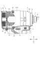
図1は、実施形態に係るインパクト工具1を示す斜視図である。図2は、実施形態に係るインパクト工具1の上部を示す側面図である。図3は、実施形態に係るインパクト工具1の上部を示す平面図である。図4は、実施形態に係るインパクト工具1の上部を示す断面図である。<Impact tools>
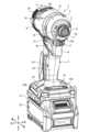
Fig. 1 is a perspective view showing an
実施形態において、インパクト工具1は、ねじ締め工具の一種であるインパクトドライバである。インパクト工具1は、ハウジング2と、リヤカバー3と、ハンマケース4と、ハンマケースカバー5と、モータ6と、減速機構7と、スピンドル8と、打撃機構9と、アンビル10と、ビットスリーブ11と、ファン12と、バッテリ装着部13と、トリガスイッチ14と、正逆転切換レバー15と、操作パネル16と、手元モード切換ボタン17と、ライトユニット18とを備える。In the embodiment, the
ハウジング2は、合成樹脂製である。実施形態において、ハウジング2は、ナイロン製である。ハウジング2は、左ハウジング2Lと、左ハウジング2Lの右方に配置される右ハウジング2Rとを含む。左ハウジング2Lと右ハウジング2Rとは、複数のねじ2Sにより固定される。ハウジング2は、一対の半割れハウジングにより構成される。The
ハウジング2は、モータ収容部21と、グリップ部22と、バッテリコネクト部23とを有する。The
モータ収容部21は、筒状である。モータ収容部21は、モータ6を収容する。The
グリップ部22は、モータ収容部21から下方に突出する。トリガスイッチ14は、グリップ部22の上部に設けられる。グリップ部22は、作業者に握られる。The
バッテリコネクト部23は、グリップ部22の下端部に接続される。前後方向及び左右方向のそれぞれにおいて、バッテリコネクト部23の外形の寸法は、グリップ部22の外形の寸法よりも大きい。The
リヤカバー3は、合成樹脂製である。リヤカバー3は、モータ収容部21の後方に配置される。リヤカバー3は、ファン12の少なくとも一部を収容する。ファン12は、リヤカバー3の内周側に配置されている。リヤカバー3は、モータ収容部21の後端部の開口を覆うように配置される。The
モータ収容部21は、吸気口19を有する。リヤカバー3は、排気口20を有する。ハウジング2の外部空間の空気は、吸気口19を介してハウジング2の内部空間に流入する。ハウジング2の内部空間の空気は、排気口20を介してハウジング2の外部空間に流出する。The
ハンマケース4は、金属製である。実施形態において、ハンマケース4は、アルミニウム製である。ハンマケース4は、筒状である。ハンマケース4は、モータ収容部21の前部に接続される。ハンマケース4の後部にベアリングボックス24が固定される。ベアリングボックス24の外周部にねじ山が形成される。ハンマケース4の内周部にねじ溝が形成される。ベアリングボックス24のねじ山とハンマケース4のねじ溝とが結合されることにより、ベアリングボックス24とハンマケース4とが固定される。ハンマケース4は、左ハウジング2Lと右ハウジング2Rとに挟まれる。ベアリングボックス24の一部及びハンマケース4の後部は、モータ収容部21に収容される。ベアリングボックス24は、モータ収容部21及びハンマケース4のそれぞれに固定される。The
ハンマケース4は、減速機構7、スピンドル8、打撃機構9、及びアンビル10の少なくとも一部を収容する。減速機構7の少なくとも一部は、ベアリングボックス24の内側に配置される。減速機構7は、複数のギヤを含む。The
ハンマケースカバー5は、ハンマケース4の表面の少なくとも一部を覆う。ハンマケースカバー5は、合成樹脂製である。実施形態において、ハンマケースカバー5は、ポリカーボネート樹脂製である。ハンマケースカバー5は、ハンマケース4を保護する。ハンマケースカバー5は、ハンマケース4とインパクト工具1の周囲の物体との接触を抑制する。ハンマケースカバー5は、ハンマケース4と作業者との接触を抑制する。The
モータ6は、インパクト工具1の動力源である。モータ6は、インナロータ型のブラシレスモータである。モータ6は、ステータ26と、ロータ27とを有する。ステータ26は、モータ収容部21に支持される。ロータ27の少なくとも一部は、ステータ26の内側に配置される。ロータ27は、ステータ26に対して回転する。ロータ27は、前後方向に延伸する回転軸AXを中心に回転する。The
ステータ26は、ステータコア28と、前インシュレータ29と、後インシュレータ30と、コイル31とを有する。The
ステータコア28は、ロータ27よりも径方向外側に配置される。ステータコア28は、積層された複数の鋼板を含む。鋼板は、鉄を主成分とする金属製の板である。ステータコア28は、筒状である。ステータコア28は、コイル31を支持する複数のティースを有する。The
前インシュレータ29は、ステータコア28の前部に設けられる。後インシュレータ30は、ステータコア28の後部に設けられる。前インシュレータ29及び後インシュレータ30のそれぞれは、合成樹脂製の電気絶縁部材である。前インシュレータ29は、ティースの表面の一部を覆うように配置される。後インシュレータ30は、ティースの表面の一部を覆うように配置される。The
コイル31は、前インシュレータ29及び後インシュレータ30を介してステータコア28に装着される。コイル31は、複数配置される。コイル31は、前インシュレータ29及び後インシュレータ30を介してステータコア28のティースの周囲に配置される。コイル31とステータコア28とは、前インシュレータ29及び後インシュレータ30により電気的に絶縁される。複数のコイル31は、ヒュージング端子38を介して接続される。The
ロータ27は、回転軸AXを中心に回転する。ロータ27は、ロータコア32と、ロータシャフト33と、ロータ磁石34と、センサ用磁石35とを有する。The
ロータコア32及びロータシャフト33のそれぞれは、鋼製である。ロータシャフト33は、ロータシャフト33の前部は、ロータコア32の前端面から前方に突出する。ロータシャフト33の後部は、ロータコア32の後端面から後方に突出する。The
ロータ磁石34は、ロータコア32に固定される。ロータ磁石34は、円筒状である。ロータ磁石34は、ロータコア32の周囲に配置される。The
センサ用磁石35は、ロータコア32に固定される。センサ用磁石35は、円環状である。センサ用磁石35は、ロータコア32の前端面及びロータ磁石34の前端面に配置される。The
前インシュレータ29にセンサ基板37が取り付けられる。センサ基板37は、ねじ29Sにより前インシュレータ29に固定される。センサ基板37は、中心に孔が設けられた円板状の回路基板と、回路基板に支持される回転検出素子とを有する。センサ基板37の少なくとも一部は、センサ用磁石35に対向する。回転検出素子は、ロータ27のセンサ用磁石35の位置を検出することにより、ロータ27の回転方向の位置を検出する。A sensor board 37 is attached to the
ロータシャフト33は、ロータベアリング39に回転可能に支持される。ロータベアリング39は、ロータシャフト33の前部を回転可能に支持する前側ロータベアリング39Fと、ロータシャフト33の後部を回転可能に支持する後側ロータベアリング39Rとを含む。The
前側ロータベアリング39Fは、ベアリングボックス24に保持される。ベアリングボックス24は、ベアリングボックス24の後面から前方に窪む凹部24Aを有する。前側ロータベアリング39Fは、凹部24Aに配置される。後側ロータベアリング39Rは、リヤカバー3に保持される。ロータシャフト33の前端部は、ベアリングボックス24の開口を介してハンマケース4の内部空間に配置される。The front rotor bearing 39F is held in the bearing box 24. The bearing box 24 has a
ロータシャフト33の前端部にピニオンギヤ41が形成される。ピニオンギヤ41は、減速機構7の少なくとも一部に連結される。ロータシャフト33は、ピニオンギヤ41を介して減速機構7に連結される。A
減速機構7は、モータ6よりも前方に配置される。減速機構7は、ロータシャフト33とスピンドル8とを連結する。減速機構7は、ロータ27の回転をスピンドル8に伝達する。減速機構7は、ロータシャフト33の回転速度よりも低い回転速度でスピンドル8を回転させる。減速機構7は、遊星歯車機構を含む。The
減速機構7は、複数のギヤを有する。減速機構7のギヤは、ロータ27により駆動される。The
減速機構7は、ピニオンギヤ41の周囲に配置される複数のプラネタリギヤ42と、複数のプラネタリギヤ42の周囲に配置されるインターナルギヤ43とを有する。ピニオンギヤ41、プラネタリギヤ42、及びインターナルギヤ43のそれぞれは、ハンマケース4及びベアリングボックス24に収容される。複数のプラネタリギヤ42のそれぞれは、ピニオンギヤ41に噛み合う。プラネタリギヤ42は、ピン42Pを介してスピンドル8に回転可能に支持される。スピンドル8は、プラネタリギヤ42により回転される。インターナルギヤ43は、プラネタリギヤ42に噛み合う内歯を有する。インターナルギヤ43は、ベアリングボックス24に固定される。インターナルギヤ43は、ベアリングボックス24に対して常に回転不可能である。The
モータ6の駆動によりロータシャフト33が回転すると、ピニオンギヤ41が回転し、プラネタリギヤ42がピニオンギヤ41の周囲を公転する。プラネタリギヤ42は、インターナルギヤ43の内歯に噛み合いながら公転する。プラネタリギヤ42の公転により、ピン42Pを介してプラネタリギヤ42に接続されているスピンドル8は、ロータシャフト33の回転速度よりも低い回転速度で回転する。When the
スピンドル8は、モータ6の少なくとも一部よりも前方に配置される。スピンドル8は、ステータ26よりも前方に配置される。スピンドル8の少なくとも一部は、ロータ27よりも前方に配置される。スピンドル8の少なくとも一部は、減速機構7の前方に配置される。スピンドル8は、ロータ27により回転される。スピンドル8は、減速機構7により伝達されたロータ27の回転力により回転する。The
スピンドル8は、フランジ部8Aと、フランジ部8Aから前方に突出するスピンドルシャフト部8Bとを有する。プラネタリギヤ42は、ピン42Pを介してフランジ部8Aに回転可能に支持される。スピンドル8の回転軸とモータ6の回転軸AXとは一致する。スピンドル8は、回転軸AXを中心に回転する。スピンドル8は、スピンドルベアリング44に回転可能に支持される。スピンドル8の後端部に周壁部8Cが設けられる。周壁部8Cは、スピンドルベアリング44を囲むように設けられる。スピンドルベアリング44は、周壁部8Cを支持する。The
ベアリングボックス24は、スピンドル8の周囲の少なくとも一部に配置される。スピンドルベアリング44は、ベアリングボックス24に保持される。ベアリングボックス24は、ベアリングボックス24の前面から後方に窪む凹部24Bを有する。スピンドルベアリング44は、凹部24Bに配置される。The bearing box 24 is disposed around at least a portion of the circumference of the
打撃機構9は、モータ6により駆動される。モータ6の回転力は、減速機構7及びスピンドル8を介して打撃機構9に伝達される。打撃機構9は、モータ6により回転するスピンドル8の回転力に基づいて、アンビル10を回転方向に打撃する。打撃機構9は、ハンマ47と、ボール48と、コイルスプリング49とを有する。ハンマ47を含む打撃機構9は、ハンマケース4に収容される。The
ハンマ47は、減速機構7よりも前方に配置される。ハンマ47は、スピンドル8の周囲に配置される。ハンマ47は、スピンドル8に保持される。ボール48は、スピンドル8とハンマ47との間に配置される。コイルスプリング49は、スピンドル8及びハンマ47のそれぞれに支持される。The
ハンマ47は、筒状である。ハンマ47は、スピンドルシャフト部8Bの周囲に配置される。ハンマ47は、スピンドルシャフト部8Bが配置される孔47Aを有する。The
ハンマ47は、モータ6により回転される。モータ6の回転力は、減速機構7及びスピンドル8を介してハンマ47に伝達される。ハンマ47は、モータ6により回転するスピンドル8の回転力に基づいて、スピンドル8と一緒に回転可能である。ハンマ47の回転軸とスピンドル8の回転軸とモータ6の回転軸AXとは一致する。ハンマ47は、回転軸AXを中心に回転する。The
ボール48は、鉄鋼のような金属製である。ボール48は、スピンドルシャフト部8Bとハンマ47との間に配置される。スピンドル8は、ボール48の少なくとも一部が配置されるスピンドル溝8Dを有する。スピンドル溝8Dは、スピンドルシャフト部8Bの外面の一部に設けられる。ハンマ47は、ボール48の少なくとも一部が配置されるハンマ溝47Bを有する。ハンマ溝47Bは、ハンマ47の内面の一部に設けられる。ボール48は、スピンドル溝8Dとハンマ溝47Bとの間に配置される。ボール48は、スピンドル溝8Dの内側及びハンマ溝47Bの内側のそれぞれを転がることができる。ハンマ47は、ボール48に伴って移動可能である。スピンドル8とハンマ47とは、スピンドル溝8D及びハンマ溝47Bにより規定される可動範囲において、軸方向及び回転方向のそれぞれに相対移動することができる。The
コイルスプリング49は、ハンマ47を前方に移動させる弾性力を発生する。コイルスプリング49は、フランジ部8Aとハンマ47との間に配置される。ハンマ47の後面にリング状の凹部47Cが設けられる。凹部47Cは、ハンマ47の後面から前方に窪む。凹部47Cの内側にワッシャ45が設けられる。コイルスプリング49の後端部は、フランジ部8Aに支持される。コイルスプリング49の前端部は、凹部47Cの内側に配置され、ワッシャ45に支持される。The
アンビル10の少なくとも一部は、ハンマ47よりも前方に配置される。アンビル10は、先端工具が挿入される工具孔10Aを有する。工具孔10Aは、アンビル10の前端部に設けられる。先端工具は、アンビル10に装着される。また、アンビル10は、スピンドルシャフト部8Bの前端部に接続されるスピンドル凸部10Bを有する。スピンドル凸部10Bは、アンビル10の後端部に設けられる。スピンドル凸部10Bは、スピンドルシャフト部8Bの前端部に設けられた凹部に挿入される。At least a portion of the
アンビル10は、ロッド状のアンビルボディ101と、アンビル突起部102とを有する。工具孔10Aは、アンビルボディ101の前端部に設けられる。先端工具は、アンビルボディ101に装着される。アンビル突起部102は、アンビル10の後端部に設けられる。アンビル突起部102は、アンビルボディ101の後端部から径方向外側に突出する。The
アンビル10は、ベアリング46に回転可能に支持される。アンビル10の回転軸とハンマ47の回転軸とスピンドル8の回転軸とモータ6の回転軸AXとは一致する。アンビル10は、回転軸AXを中心に回転する。ベアリング46は、ハンマケース4に保持される。実施形態において、ベアリング46は、前後方向に2つ配置される。The
なお、ベアリング46の種類として、鉄スリーブ(油含侵メタル)が例示される。An example of the type of bearing 46 is an iron sleeve (oil-impregnated metal).
ハンマ47の少なくとも一部は、アンビル突起部102に接触可能である。ハンマ47の前部に前方に突出するハンマ突起部が設けられる。ハンマ47のハンマ突起部とアンビル突起部102とが接触可能である。ハンマ47とアンビル突起部102とが接触している状態で、モータ6が駆動することにより、アンビル10は、ハンマ47及びスピンドル8と一緒に回転する。At least a portion of the
アンビル10は、ハンマ47により回転方向に打撃される。例えば、ねじ締め作業において、アンビル10に作用する負荷が高くなると、モータ6が発生する動力だけではアンビル10を回転させることができなくなる状況が発生する場合がある。モータ6が発生する動力だけではアンビル10を回転させることができなくなると、アンビル10及びハンマ47の回転が停止する。スピンドル8とハンマ47とは、ボール48を介して軸方向及び周方向のそれぞれに相対移動可能である。ハンマ47の回転が停止しても、スピンドル8の回転は、モータ6が発生する動力により継続される。ハンマ47の回転が停止している状態で、スピンドル8が回転すると、ボール48がスピンドル溝8D及びハンマ溝47Bのそれぞれにガイドされながら後方に移動する。ハンマ47は、ボール48から力を受け、ボール48に伴って後方に移動する。すなわち、ハンマ47は、アンビル10の回転が停止された状態で、スピンドル8が回転することにより、後方に移動する。ハンマ47が後方に移動することにより、ハンマ47とアンビル突起部102との接触が解除される。The
コイルスプリング49は、ハンマ47を前方に移動させる弾性力を発生する。後方に移動したハンマ47は、コイルスプリング49の弾性力により、前方に移動する。ハンマ47は、前方に移動するとき、ボール48から回転方向の力を受ける。すなわち、ハンマ47は、回転しながら前方に移動する。ハンマ47が回転しながら前方に移動すると、ハンマ47は、回転しながらアンビル突起部102に接触する。これにより、アンビル突起部102は、ハンマ47により回転方向に打撃される。アンビル10には、モータ6の動力とハンマ47の慣性力との両方が作用する。したがって、アンビル10は、高いトルクで回転軸AXを中心に回転することができる。The
ビットスリーブ11は、アンビル10の前部の周囲に配置される。ビットスリーブ11は、工具孔10Aに挿入された先端工具を保持する。The
ファン12は、モータ6のステータ26よりも後方に配置される。ファン12は、モータ6を冷却するための気流を生成する。ファン12は、ロータ27の少なくとも一部に固定される。ファン12は、ブッシュ12Aを介してロータシャフト33の後部に固定される。ファン12は、後側ロータベアリング39Rとステータ26との間に配置される。ファン12は、ロータ27の回転により回転する。ロータシャフト33が回転することにより、ファン12は、ロータシャフト33と一緒に回転する。ファン12が回転することにより、ハウジング2の外部空間の空気が、吸気口19を介してハウジング2の内部空間に流入する。ハウジング2の内部空間に流入した空気は、ハウジング2の内部空間を流通することにより、モータ6を冷却する。ハウジング2の内部空間を流通した空気は、ファン12が回転することにより、排気口20を介してハウジング2の外部空間に流出する。The
バッテリ装着部13は、バッテリコネクト部23の下部に配置される。バッテリ装着部13は、バッテリパック25に接続される。バッテリパック25は、バッテリ装着部13に装着される。バッテリパック25は、バッテリ装着部13に着脱可能である。バッテリパック25は、二次電池を含む。実施形態において、バッテリパック25は、充電式のリチウムイオン電池を含む。バッテリ装着部13に装着されることにより、バッテリパック25は、インパクト工具1に電力を供給することができる。モータ6は、バッテリパック25から供給される電力に基づいて駆動する。The
トリガスイッチ14は、グリップ部22に設けられる。トリガスイッチ14は、モータ6を起動するために作業者に操作される。トリガスイッチ14が操作されることにより、モータ6の駆動と停止とが切り換えられる。The
正逆転切換レバー15は、グリップ部22の上部に設けられる。正逆転切換レバー15は、作業者に操作される。正逆転切換レバー15が操作されることにより、モータ6の回転方向が正転方向及び逆転方向の一方から他方に切り換えられる。モータ6の回転方向が切り換えられることにより、スピンドル8の回転方向が切り換えられる。The forward/
操作パネル16は、バッテリコネクト部23に設けられる。操作パネル16は、モータ6の制御モードを切り換えるために作業者に操作される。操作パネル16は、打撃力スイッチ16Aと、専用スイッチ16Bとを有する。打撃力スイッチ16A及び専用スイッチ16Bのそれぞれは、作業者に操作される。打撃力スイッチ16A及び専用スイッチ16Bの少なくとも一方が操作されることにより、モータ6の制御モードが切り換えられる。The
手元モード切換ボタン17は、トリガスイッチ14の上部に設けられる。手元モード切換ボタン17は、作業者に操作される。手元モード切換ボタン17が操作されることにより、モータ6の制御モードが切り換えられる。The hand
<ライトユニット>
図5は、実施形態に係るインパクト工具1の上部を示す斜視図である。図6は、実施形態に係るインパクト工具1の上部を示す分解斜視図である。図7は、図5のA-A線断面矢視図である。図8は、図5のB-B線断面矢視図である。<Light unit>
Fig. 5 is a perspective view showing an upper part of the
インパクト工具1は、ライトユニット18と、固定部材50と、緩衝部材51とを備える。The
ライトユニット18は、照明光を射出する。ライトユニット18は、アンビル10及びアンビル10の周辺を照明光で照明する。ライトユニット18は、アンビル10の前方を照明光で照明する。また、ライトユニット18は、アンビル10に装着された先端工具及び先端工具の周辺を照明光で照明する。The
ライトユニット18は、ハンマケース4に支持される。ライトユニット18は、ハンマケース4の前部に配置される。ライトユニット18は、ハンマケース4の周囲の少なくとも一部に配置される。The
ハンマケース4は、第1筒部であるハンマ収容部401と、第2筒部であるベアリング支持部402とを有する。ハンマ収容部401は、筒状である。ハンマ収容部401は、打撃機構9の周囲に配置される。ハンマ収容部401は、少なくともハンマ47を収容する。ベアリング支持部402は、筒状である。ベアリング支持部402は、ハンマ収容部401よりも前方に配置される。ベアリング支持部402の外径は、ハンマ収容部401の外径よりも小さい。ベアリング支持部402は、ベアリング46の周囲に配置される。ベアリング支持部402は、ベアリング46を支持する。The
ライトユニット18は、ベアリング支持部402の周囲に配置される。ハンマケースカバー5は、ハンマ収容部401の外面の少なくとも一部を覆う。ハンマ収容部401の後部は、ハウジング2のモータ収容部21に収容される。The
ライトユニット18は、ライト基板60と、ライト61と、ライトカバー62と、接着樹脂部63とを有する。The
ライト基板60は、ハンマケース4の周囲の少なくとも一部に配置される。実施形態において、ライト基板60は、環状である。より詳しくは、ライト基板60は、略6角形状である。ライト基板60は、ベアリング支持部402の周囲に配置される。ライト基板60は、プリント配線板(PCB:Printed Circuit Board)を含む。ライト基板60は、ライト61に接続される配線を有する。The
ライト61は、照明光を射出する光源である。ライト61は、例えば発光ダイオード(LED:Light Emitting Diode)を含む。ライト61は、ライト基板60に支持される。ライト基板60の配線を介してライト61に電力が供給される。ライト61は、ライト基板60の前面の少なくとも一部に配置される。複数のライト61がライト基板60に配置される。ライト61は、照明光を射出する光射出面64を有する。光射出面64は、前方を向く。ライト61の前面は、光射出面64を含む。複数のライト61は、アンビル10及びアンビル10の周辺を照明する。The light 61 is a light source that emits illumination light. The light 61 includes, for example, a light emitting diode (LED). The light 61 is supported by the
ライトカバー62は、ライト基板60の前面を覆うように配置される。ライトカバー62の少なくとも一部は、ライト基板60及びライト61よりも前方に配置される。ライトカバー62は、ライト基板60の前面及び側面に接触する。ライト基板60の側面は、径方向内側を向く内側面及び径方向外側を向く外側面を含む。実施形態において、ライトカバー62は、環状である。ライトカバー62は、ベアリング支持部402の周囲に配置される。ライトカバー62は、ハンマケースカバー5よりも前方に配置される。The
ライトカバー62は、ライト61の光射出面64から射出された照明光が通過する通過部65を有する。実施形態において、ライトカバー62は、ライト61の光射出面64を覆うように配置される。ライトカバー62の少なくとも一部は、光射出面64に対向する。ライトカバー62は、光透過性の合成樹脂製である。実施形態において、ライトカバー62は、ポリカーボネート樹脂製である。光射出面64に対向するライトカバー62の一部は、光射出面64から射出された照明光を透過する光透過部として機能する。ライトカバー62の通過部65は、光透過部を含む。ライトカバー62は、光射出面64に接触してもよいし、光射出面64から離れていてもよい。The
通過部65は、レンズ作用を有しない。通過部65は、ライト61の光射出面64から射出された光を屈折させない。通過部65は、例えば平行平板でもよい。なお、通過部65は、レンズ作用を有してもよい。通過部65は、ライト61の光射出面64から射出された光を拡散してもよい。The passing
ライトカバー62は、ライト基板60及びライト61を保護する。ライトカバー62は、インパクト工具1の周囲の物体とライト基板60との接触を抑制する。また、ライトカバー62は、インパクト工具1の周囲の物体とライト61との接触を抑制する。ライトカバー62は、ライト基板60及びライト61に対する水分の浸入を抑制する防水機能を有する。ライトカバー62は、ライト基板60及びライト61に対する塵の侵入を抑制する防塵機能を有する。The
接着樹脂部63は、ライト基板60とライトカバー62とを固定する。接着樹脂部63の少なくとも一部は、ライト基板60の後面及び側面を覆う。The
固定部材50は、ライトカバー62の前面の少なくとも一部に接触する。固定部材50は、ベアリング支持部402に支持される。固定部材50は、ライトカバー62を含むライトユニット18がベアリング支持部402から前方に抜けないように、ライトカバー62の前面の少なくとも一部に接触する。The fixing
実施形態において、固定部材50は、リングスプリングを含む。ベアリング支持部402の外面に支持溝52が設けられる。支持溝52は、回転軸AXを囲むように形成される。リングスプリングは、支持溝52に配置される。なお、固定部材50は、リングスプリングに限定されず、例えばバンパ、金属スリーブ、及びサークリップ等でもよい。In the embodiment, the fixing
ライトカバー62の少なくとも一部は、ハンマケースカバー5に接触する。実施形態において、ライトカバー62の後部の少なくとも一部が、ハンマケースカバー5に接触する。ライトカバー62を含むライトユニット18は、固定部材50とハンマケースカバー5とにより前後方向から挟まれる。At least a portion of the
実施形態において、ハンマケースカバー5の前端部は、ライトカバー62の後端部よりも径方向内側に配置される。ライトカバー62の外面は、ハンマケースカバー5で覆われない。In this embodiment, the front end of the
緩衝部材51は、ライトカバー62とハンマケース4との間に配置される。緩衝部材51は、ハンマケース4の振動がライトユニット18に伝達されることを抑制する。緩衝部材51は、ハンマケース4の熱がライトユニット18に伝達されることを抑制する。緩衝部材51は、ライトユニット18に接触する。より詳しくは、緩衝部材51は、ライトカバー62及び接着樹脂部63に接触する。緩衝部材51は、ハンマケース4に接触する。ハンマケースカバー5と緩衝部材51とは、離れている。The cushioning
緩衝部材51として、合成樹脂製の多孔部材が例示される。多孔部材として、軟質ウレタンスポンジが例示される。An example of the cushioning
図7に示すように、ライトカバー62は、前側固定部62Aと、内側支持部62Bと、外側支持部62Cと、後側固定部62Dとを有する。前側固定部62Aは、ベアリング支持部402の外面に設けられた凹部402Aに嵌まる。内側支持部62Bは、径方向内側を向くライト基板60の内側面を支持する。内側支持部62Bとライト基板60の内側面とは接触可能である。外側支持部62Cは、径方向外側を向くライト基板60の外側面を支持する。外側支持部62Cとライト基板60の外側面とは接触可能である。後側固定部62Dは、ハンマケースカバー5の前端部に設けられた凹部5Eに嵌まる。As shown in FIG. 7, the
図6に示すように、ハンマケースカバー5の前端部の下部にノッチ5Fが設けられる。ライトカバー62の下部に設けられた係合部62Fは、ノッチ5Fに嵌まる。これにより、ハンマケースカバー5とライトカバー62とが相対的に回転することが抑制される。また、ライトカバー62の前端部の下部には、固定部材50の回転を抑制する係止部62Gが設けられる。係止部62Gにより、ライトカバー62と固定部材50とが相対的に回転することが抑制される。As shown in FIG. 6, a
図8に示すように、ライトカバー62は、凹部62Eを有する。凹部62Eは、ライトカバー62の後面から前方に凹むように形成される。凹部62Eにより形成される空間にライト61が配置される。As shown in FIG. 8, the
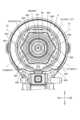
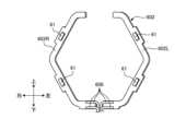
図9は、実施形態に係るライト基板60及びライト61とハンマケース4との関係を示す正面図である。ライト基板60は、ベアリング支持部402の径方向外側に配置される。ベアリング支持部402は、径方向外側に突出する角部403を有する。角部403は、回転軸AXの周囲に等間隔で6つ設けられる。実施形態において、ベアリング支持部402の少なくとも一部は、回転軸AXと直交する面内において6角形状である。以下の説明において、6つの角部403を含むベアリング支持部402の6角形状の部分を適宜、回り止め部404、と称する。Figure 9 is a front view showing the relationship between the
ライト基板60は、ベアリング支持部402の回り止め部404の外形に合わせて、6つの角部60Cを有する環状に形成されている。The
複数のライト61がライト基板60に搭載される。ライト61は、回転軸AXの周囲に複数設けられる。実施形態において、ライト61は、回転軸AXよりも左側に設けられる複数の左ライト611と、回転軸AXよりも右側に設けられる複数の右ライト612とを含む。右ライト612は、左ライト611と同じ数だけ設けられる。A number of
実施形態において、ライト61は、ライト基板60に4つ設けられる。左ライト611は、2つ設けられる。左ライト611は、左ライト611Aと左ライト611Bとを含む。右ライト612は、2つ設けられる。右ライト612は、右ライト612Aと右ライト612Bとを含む。In this embodiment, four
径方向において、回転軸AXと左ライト611Aとの距離と、回転軸AXと左ライト611Bとの距離と、回転軸AXと右ライト612Aとの距離と、回転軸AXと右ライト612Bとの距離とは、実質的に等しい。回転軸AXを通り且つ回転軸AXと直交する対角線La及び対角線Lbを規定した場合、左ライト611Aと右ライト612Bとは、対角線La上に配置され、左ライト611Bと右ライト612Aとは、対角線Lb上に配置される。また、左ライト611A及び右ライト612Aは、回転軸AXよりも上方に配置され、左ライト611B及び右ライト612Bは、回転軸AXよりも下方に配置される。上下方向において、左ライト611Aの位置と右ライト612Aの位置とは、実質的に等しい。上下方向において、左ライト611Bの位置と右ライト612Bの位置とは、実質的に等しい。左右方向において、左ライト611Aの位置と左ライト611Bの位置とは、実質的に等しい。左右方向において、右ライト612Aの位置と右ライト612Bの位置とは、実質的に等しい。回転軸AXを通り上下方向に延伸する対称軸を規定した場合、左ライト611(611A,611B)と右ライト612(612A,612B)とは、線対称である。In the radial direction, the distance between the rotation axis AX and the left light 611A, the distance between the rotation axis AX and the
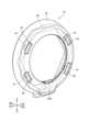
図10は、実施形態に係るライト基板60及びライト61とライトカバー62とを示す前方からの斜視図である。図11は、実施形態に係るライト基板60及びライト61とライトカバー62とを示す後方からの斜視図である。図12は、実施形態に係るライト基板60及びライト61とライトカバー62とを示す前方からの分解斜視図である。図13は、実施形態に係るライト基板60及びライト61とライトカバー62とを示す後方からの分解斜視図である。Figure 10 is a front perspective view showing the
ライトカバー62は、環状である。ライトカバー62は、ライト基板60が配置される基板溝66を有する。ライト基板60は、ライト61の光射出面64が前方を向くように基板溝66に配置される。The
ライトカバー62は、ベアリング支持部402の回り止め部404が配置される凹部67を有する。凹部67の内形は、回り止め部404の外形に合わせて6角形状である。凹部67は、回り止め部404の6つの角部403のそれぞれが配置される6つの角部67Cを有する。回り止め部404が凹部67に配置されることにより、ベアリング支持部402とライトカバー62との相対回転が抑制される。The
接着樹脂部63は、ライト基板60とライトカバー62とを固定する。接着樹脂部63の少なくとも一部は、ライト基板60の後面及び側面を覆う。ライト61の光射出面64が前方を向くようにライト基板60が基板溝66に配置された後、ライト基板60の後方からライト基板60とライトカバー62との境界に溶融状態の合成樹脂が供給される。合成樹脂が固化されることにより接着樹脂部63が形成される。合成樹脂が固化されることによりライト基板60とライトカバー62とが接着樹脂部63により固定される。The
図6に示すように、緩衝部材51は、環状である。緩衝部材51は、ベアリング支持部402の回り止め部404の周囲に配置される。緩衝部材51は、回り止め部404の外形に合わせて6つの角部51Cを有する環状に形成されている。緩衝部材51と回り止め部404との相対回転が抑制される。As shown in FIG. 6, the
ハンマケースカバー5は、ハウジング2のモータ収容部21に固定される。実施形態において、ハンマケースカバー5は、カバー部5Aと、リング部5Bと、フック部5Cとを有する。カバー部5Aは、ハンマ収容部401の外面の少なくとも一部を覆う。カバー部5Aは、筒状である。リング部5Bは、カバー部5Aの前端部に配置される。リング部5Bは、ライトカバー62の後端部に対向する。フック部5Cは、カバー部5Aの後部に配置される。フック部5Cは、ハウジング2に掛けられる。The
図14は、実施形態に係るインパクト工具1を示す分解斜視図である。ハウジング2は、左ハウジング2Lと右ハウジング2Rとを含む。実施形態において、ハンマケースカバー5の少なくとも一部は、左ハウジング2Lと右ハウジング2Rとに挟まれることによって、ハウジング2に固定される。実施形態において、カバー部5Aの後部及びフック部5Cが、左ハウジング2Lと右ハウジング2Rとに挟まれる。Figure 14 is an exploded perspective view showing an
フック部5Cは、カバー部5Aの左部及び右部のそれぞれに設けられる。左ハウジング2Lの内面及び右ハウジング2Rの内面のそれぞれに、フック部5Cが掛けられる凹部200が設けられる。The
ハンマケース4の一部に、ハンマケースカバー5を位置決めする凸部4Aが設けられる。ハンマケースカバー5の一部に開口5D(図6参照)が設けられる。開口5Dに凸部4Aが配置されることにより、ハンマケース4とハンマケースカバー5とが位置決めされる。A
インパクト工具1を組み立てる場合、ハンマ収容部401の外面がカバー部5Aに覆われるように、ハンマケース4とハンマケースカバー5とが接続される。開口5Dに凸部4Aが配置されることにより、ハンマ収容部401の外面がカバー部5Aに覆われる。また、ベアリング支持部402に緩衝部材51及びライトユニット18が装着される。緩衝部材51及びライトユニット18のそれぞれは、ベアリング支持部402の前方からベアリング支持部402に挿入される。緩衝部材51及びライトユニット18のそれぞれは、回り止め部404に装着される。緩衝部材51及びライトユニット18のそれぞれが回り止め部404に装着された後、固定部材50が支持溝52に配置される。ハンマケース4とハンマケースカバー5とが接続され、ベアリング支持部402に緩衝部材51とライトユニット18と固定部材50とが装着された後、ハンマケース4及びハンマケースカバー5の少なくとも一部が左ハウジング2Lと右ハウジング2Rとにより挟まれる。フック部5Cは、左ハウジング2L及び右ハウジング2Rのそれぞれに設けられている凹部に掛けられる。ハンマケース4及びハンマケースカバー5の少なくとも一部が左ハウジング2Lと右ハウジング2Rとにより挟まれた後、複数のねじ2Sにより左ハウジング2Lと右ハウジング2Rとが固定される。また、リヤカバー3がねじ3Sによりモータ収容部21の後部に固定される。When assembling the
<インパクト工具の動作>
次に、インパクト工具1の動作について説明する。例えば、加工対象にねじ締め作業を実施するとき、ねじ締め作業に使用される先端工具(ドライバビット)が、アンビル10の工具孔10Aに挿入される。工具孔10Aに挿入された先端工具は、ビットスリーブ11により保持される。先端工具がアンビル10に装着された後、作業者は、グリップ部22を握ってトリガスイッチ14を操作する。トリガスイッチ14が操作されると、バッテリパック25からモータ6に電力が供給され、モータ6が起動し、同時にライト61が点灯する。モータ6の起動により、ロータ27のロータシャフト33が回転する。ロータシャフト33が回転すると、ロータシャフト33の回転力がピニオンギヤ41を介してプラネタリギヤ42に伝達される。プラネタリギヤ42は、インターナルギヤ43の内歯に噛み合った状態で、自転しながらピニオンギヤ41の周囲を公転する。プラネタリギヤ42は、ピン42Pを介してスピンドル8に回転可能に支持される。プラネタリギヤ42の公転により、スピンドル8は、ロータシャフト33の回転速度よりも低い回転速度で回転する。<Operation of impact tool>
Next, the operation of the
ハンマ47とアンビル突起部102とが接触している状態で、スピンドル8が回転すると、アンビル10は、ハンマ47及びスピンドル8と一緒に回転する。アンビル10が回転することにより、ねじ締め作業が進行する。When the
ねじ締め作業の進行により、アンビル10に所定値以上の負荷が作用した場合、アンビル10及びハンマ47の回転が停止する。ハンマ47の回転が停止している状態で、スピンドル8が回転すると、ハンマ47は、後方に移動する。ハンマ47が後方に移動することにより、ハンマ47とアンビル突起部102との接触が解除される。後方に移動したハンマ47は、コイルスプリング49の弾性力により、ハンマ47は、回転しながら前方に移動する。ハンマ47が回転しながら前方に移動することにより、アンビル10は、ハンマ47により回転方向に打撃される。これにより、アンビル10は、高いトルクで回転軸AXを中心に回転する。そのため、ねじは加工対象に高いトルクで締め付けられる。When a load equal to or greater than a predetermined value acts on the
<効果>
以上説明したように、実施形態において、インパクト工具1は、モータ6と、モータ6により駆動される打撃機構9と、先端工具が装着され打撃機構9により回転方向に打撃されるアンビル10と、打撃機構9を収容するハンマケース4と、を備える。インパクト工具1は、ハンマケース4の周囲の少なくとも一部に配置されるライト基板60を備える。インパクト工具1は、ライト基板60の前面の少なくとも一部に配置される複数のライト61を備える。インパクト工具1は、少なくとも一部がライト基板60よりも前方に配置されライト61の光射出面64から射出された照明光が通過する通過部65を有するライトカバー62を備える。<Effects>
As described above, in the embodiment, the
上記の構成では、ライトカバー62によりライト61が保護される。したがって、ライト61の破損が抑制される。In the above configuration, the
実施形態において、ライトカバー62は、ライト基板60の前面及び側面に接触する。In an embodiment, the
上記の構成では、ライトカバー62によりライト基板60の前面及び側面が保護される。In the above configuration, the
実施形態において、ライトカバー62は、光射出面64に対向する光透過部を有する。通過部65は、光透過部を含む。In the embodiment, the
上記の構成では、光透過部によりライト61が保護される。ライト61の光射出面64から射出された照明光は、光透過部を透過して、インパクト工具1の前方に照射される。In the above configuration, the light 61 is protected by the light-transmitting portion. The illumination light emitted from the light-emitting
実施形態において、光透過部は、光射出面64から射出された照明光を拡散する。In the embodiment, the light-transmitting portion diffuses the illumination light emitted from the
上記の構成では、ライト61の光射出面64から射出された照明光が光透過部により拡散されるので、インパクト工具1の前方の広い範囲に照射される。In the above configuration, the illumination light emitted from the
実施形態において、ライトカバー62は、基板溝66を有する。ライト基板60は、光射出面64が前方を向くように基板溝66に配置される。In an embodiment, the
上記の構成では、基板溝66によりライトカバー62とライト基板60とが適正に位置合わせされる。In the above configuration, the
実施形態において、インパクト工具1は、ライト基板60とライトカバー62とを固定する接着樹脂部63を備える。接着樹脂部63の少なくとも一部は、ライト基板60の後面及び側面を覆う。In the embodiment, the
上記の構成では、ライト基板60とライトカバー62とが接着樹脂部63により固定される。また、ライト基板60の後面及び側面が接着樹脂部63により保護される。また、接着樹脂部63によりライト基板60及びライト61が保護される。ライト基板60及びライト61は、接着樹脂部63により、防塵及び防水される。In the above configuration, the
実施形態において、ハンマケース4は、打撃機構9の周囲に配置されるハンマ収容部401(第1筒部)と、ハンマ収容部401よりも前方に配置されハンマ収容部401の外径よりも小さい外径のベアリング支持部402(第2筒部)と、を有する。ライトカバー62は、ベアリング支持部402の周囲に配置される。In this embodiment, the
上記の構成では、小径のベアリング支持部402の周囲にライトカバー62が配置されるので、インパクト工具1の大型化が抑制される。特に、ハンマ収容部401の大型化(大径化)が抑制される。ハンマ収容部401の大型化(大径化)が抑制されるので、インパクト工具1を用いる作業性が向上する。In the above configuration, the
実施形態において、ベアリング支持部402は、径方向外側に突出する角部403を有してもよい。ライトカバー62は、角部403が配置される凹部67を有する。In an embodiment, the
上記の構成では、ライトカバー62とベアリング支持部402とが適正に位置合わせされる。また、ライトカバー62とベアリング支持部402との相対回転が抑制される。In the above configuration, the
実施形態において、インパクト工具1は、ベアリング支持部402に支持され、ライトカバー62の前面の少なくとも一部に接触する固定部材50を備える。In this embodiment, the
上記の構成では、固定部材50により、ライトカバー62がベアリング支持部402から前方に抜けることが抑制される。また、前後方向におけるライトカバー62とベアリング支持部402との相対移動が抑制される。In the above configuration, the fixing
実施形態において、固定部材50は、ベアリング支持部402に設けられた支持溝52に配置されるリングスプリング、バンパ、金属スリーブ、及びサークリップの少なくとも一つを含む。In an embodiment, the fixing
上記の構成では、リングスプリング等により、ライトカバー62がベアリング支持部402から前方に抜けることが抑制される。また、リングスプリング等はベアリング支持部402に着脱可能なので、ベアリング支持部402からライトカバー62を外す作業又は交換する作業が円滑に実施される。そのため、ライト基板60及びライト61のメンテナンス性が向上する。In the above configuration, the ring spring or the like prevents the
実施形態において、インパクト工具1は、アンビル10を支持するベアリング46を備える。ベアリング支持部402は、ベアリング46の周囲に配置される。In an embodiment, the
上記の構成では、ベアリング46を支持するベアリング支持部402の周囲にライトカバー62が配置される。In the above configuration, the
実施形態において、インパクト工具1は、ハンマ収容部401の外面の少なくとも一部を覆うハンマケースカバー5を備える。ライトカバー62の少なくとも一部は、ハンマケースカバー5に接触する。In the embodiment, the
上記の構成では、ライトカバー62の後部は、ハンマケース4には接触せず、ハンマケースカバー5に接触するので、ハンマケース4の振動及び熱がライトカバー62に伝達されることが抑制される。また、ハンマ収容部401は、ハンマケースカバー5により保護される。また、ハンマケースカバー5により、ハンマケース4と周囲の物体との接触が抑制される。In the above configuration, the rear of the
実施形態において、ハンマケースカバー5の前端部は、ライトカバー62の後端部よりも径方向内側に配置される。In this embodiment, the front end of the
上記の構成では、ライトカバー62周辺の大型化(大径化)が抑制される。The above configuration prevents the area around the
実施形態において、インパクト工具1は、モータ6及びハンマ収容部401の少なくとも一部を収容するハウジング2を備える。ハンマケースカバー5は、ハウジング2に固定される。In this embodiment, the
上記の構成では、ハウジング2にハンマケース4及びハンマケースカバー5のそれぞれが支持される。In the above configuration, the
実施形態において、ハンマケースカバー5は、ハウジング2に掛けられるフック部5Cを有する。In this embodiment, the
上記の構成では、ハウジング2にハンマケースカバー5を固定するときの作業性が向上する。The above configuration improves workability when fixing the hammer case cover 5 to the
実施形態において、ハウジング2は、左ハウジング2Lと右ハウジング2Rとを含む。ハンマケースカバー5の少なくとも一部は、左ハウジング2Lと右ハウジング2Rとに挟まれる。In this embodiment, the
上記の構成では、ハウジング2にハンマケースカバー5を固定するときの作業性が向上する。The above configuration improves workability when fixing the hammer case cover 5 to the
実施形態において、インパクト工具1は、ライトカバー62とハンマケース4との間に配置される緩衝部材51を備える。In this embodiment, the
上記の構成では、ハンマケース4の振動及び熱がライトカバー62に伝達されることが抑制される。The above configuration prevents vibration and heat from the
実施形態において、ライト61は、アンビル10の回転軸AXの周囲に複数設けられる。In this embodiment,
上記の構成では、アンビル10及びアンビル10の周辺が複数のライト61により適正に照明される。そのため、暗所においてもインパクト工具1を用いる作業性の悪化が抑制される。In the above configuration, the
<変形例>
図15は、変形例に係るライトユニット180を示す斜視図である。図15に示すように、ライトカバー620は、ライト61の光射出面64に対向する光透過部650と、ライト基板60の前面に対向する遮光部651とを有してもよい。ライトカバー620の一部に塗装液が塗装されることにより、遮光部651が形成される。<Modification>
Fig. 15 is a perspective view showing a
遮光部651により、ライトカバー620の外部からライト基板60が視認され難くなるので、インパクト工具1の美感が向上する。また、ライト基板60に対する外光の照射が抑制される。The
図15に示す例において、光透過部650は、ライトカバー620の一部でもよいし、ライトカバー620の開口に設けられた光学部材でもよい。光学部材は、レンズ作用を有してもよい。光学部材は、ライト61の光射出面64から射出された照明光を拡散してもよい。In the example shown in FIG. 15, the light-transmitting
図16は、変形例に係るライト基板601を示す図である。上述の実施形態において、ライト基板60は、環状であることした。図16に示すように、ライト基板601の一部にノッチ604が形成されてもよい。図16に示す例において、ノッチ604は、ライト基板601の上部に設けられる。ライト基板601の下部にリード線605が設けられる。Figure 16 is a diagram showing a
図17は、変形例に係るライト基板602を示す図である。図17に示すように、ライト基板602は、回転軸AXよりも左側に設けられる左ライト基板602Lと、回転軸AXよりも右側に設けられる右ライト基板602Rとを含んでもよい。図17に示す例において、左ライト基板602Lと下部と右ライト基板602Rの下部とは、リード線606により接続される。Figure 17 is a diagram showing a
図18は、変形例に係るライト基板603を示す図である。図18に示すように、ライト基板603が左ライト基板603Lと右ライト基板603Rとを有する場合において、左ライト基板603Lと右ライト基板603Rとがフレキシブルプリント基板607(FPC:Flexible Printed Circuits)により接続されてもよい。図18に示す例において、左ライト基板603Lの上部と右ライト基板603Rの上部とがフレキシブルプリント基板607により接続される。左ライト基板603Lの下部と右ライト基板603Rの下部とがリード線608により接続される。Figure 18 is a diagram showing a
上述の実施形態において、ライト61は、回転軸AXよりも左側に設けられる複数の左ライト611と、回転軸AXよりも右側に左ライト611と同じ数だけ設けられる右ライト612と、を含むこととした。ライト61は、回転軸AXの周囲に複数設けられていればよい。例えば、ライト61は、回転軸AXの上方に配置されてもよい。In the above embodiment, the
上述の実施形態において、ライトカバーの通過部は、ライトカバーの一部に設けられた開口でもよい。In the above-described embodiment, the passage of the light cover may be an opening provided in a part of the light cover.
上述の実施形態においては、インパクト工具1がインパクトドライバであることとした。インパクト工具1は、インパクトレンチでもよい。In the above embodiment, the
上述の実施形態において、インパクト工具1の電源は、バッテリパック25でなくてもよく、商用電源(交流電源)でもよい。In the above-described embodiment, the power source for the
1…インパクト工具、2…ハウジング、2L…左ハウジング、2R…右ハウジング、2S…ねじ、3…リヤカバー、3S…ねじ、4…ハンマケース、4A…凸部、5…ハンマケースカバー、5A…カバー部、5B…リング部、5C…フック部、5D…開口、5E…凹部、5F…ノッチ、6…モータ、7…減速機構、8…スピンドル、8A…フランジ部、8B…スピンドルシャフト部、8C…周壁部、8D…スピンドル溝、9…打撃機構、10…アンビル、10A…工具孔、10B…スピンドル凸部、11…ビットスリーブ、12…ファン、12A…ブッシュ、13…バッテリ装着部、14…トリガスイッチ、15…正逆転切換レバー、16…操作パネル、16A…打撃力スイッチ、16B…専用スイッチ、17…手元モード切換ボタン、18…ライトユニット、19…吸気口、20…排気口、21…モータ収容部、22…グリップ部、23…バッテリコネクト部、24…ベアリングボックス、24A…凹部、24B…凹部、25…バッテリパック、26…ステータ、27…ロータ、28…ステータコア、29…前インシュレータ、29S…ねじ、30…後インシュレータ、31…コイル、32…ロータコア、33…ロータシャフト、34…ロータ磁石、35…センサ用磁石、37…センサ基板、38…ヒュージング端子、39…ロータベアリング、39F…前側ロータベアリング、39R…後側ロータベアリング、41…ピニオンギヤ、42…プラネタリギヤ、42P…ピン、43…インターナルギヤ、44…スピンドルベアリング、45…ワッシャ、46…ベアリング、47…ハンマ、47A…孔、47B…ハンマ溝、47C…凹部、48…ボール、49…コイルスプリング、50…固定部材、51…緩衝部材、51C…角部、52…支持溝、60…ライト基板、60C…角部、61…ライト、62…ライトカバー、62A…前側固定部、62B…内側支持部、62C…外側支持部、62D…後側固定部、62E…凹部、62F…係合部、62G…係止部、63…接着樹脂部、64…光射出面、65…通過部、66…基板溝、67…凹部、67C…角部、101…アンビルボディ、102…アンビル突起部、180…ライトユニット、200…凹部、401…ハンマ収容部(第1筒部)、402…ベアリング支持部(第2筒部)、402A…凹部、403…角部、404…回り止め部、601…ライト基板、602…ライト基板、602L…左ライト基板、602R…右ライト基板、603…ライト基板、603L…左ライト基板、603R…右ライト基板、604…ノッチ、605…リード線、606…リード線、607…フレキシブルプリント基板、608…リード線、611…左ライト、611A…左ライト、611B…左ライト、612…右ライト、612A…右ライト、612B…右ライト、620…ライトカバー、650…光透過部、651…遮光部、AX…回転軸。1...Impact tool, 2...Housing, 2L...Left housing, 2R...Right housing, 2S...Screw, 3...Rear cover, 3S...Screw, 4...Hammer case, 4A...Convex portion, 5...Hammer case cover, 5A...Cover portion, 5B...Ring portion, 5C...Hook portion, 5D...Opening, 5E...Concave portion, 5F...Notch, 6...Motor, 7...Reduction mechanism, 8...Spindle, 8A...Flange portion, 8B...Spindle shaft portion, 8C...Circumferential wall portion, 8D...Spindle groove, 9...Impact mechanism, 10...Anvil, 10A...Tool hole, 10B...Spindle convex portion, 11...Bit sleeve, 12...Fan, 12A...Bush, 13...Battery mounting portion, 14...Trigger switch, 15...Forward/reverse switching lever, 16...Operation panel, 16A...Impact force Switch, 16B... Dedicated switch, 17... Handheld mode switching button, 18... Light unit, 19... Intake port, 20... Exhaust port, 21... Motor housing, 22... Grip section, 23... Battery connector, 24... Bearing box, 24A... Recess, 24B... Recess, 25... Battery pack, 26... Stator, 27... Rotor, 28... Stator core, 29... Front insulator, 29S... Screw, 30... Rear insulator, 31... Coil, 32... Rotor core, 33... Rotor shaft, 34... Rotor magnet, 35... Sensor magnet, 37... Sensor board, 38... Fusing terminal, 39... Rotor bearing, 39F... Front rotor bearing, 39R... Rear rotor bearing, 41... Pinion gear, 42 ...planetary gear, 42P...pin, 43...internal gear, 44...spindle bearing, 45...washer, 46...bearing, 47...hammer, 47A...hole, 47B...hammer groove, 47C...recess, 48...ball, 49...coil spring, 50...fixing member, 51...buffer member, 51C...corner, 52...support groove, 60...light board, 60C...corner, 61...light, 62...light cover, 62A...front fixing portion, 62B...inner support portion, 62C...outer support portion, 62D...rear fixing portion, 62E...recess, 62F...engagement portion, 62G...locking portion, 63...adhesive resin portion, 64...light exit surface, 65...passing portion, 66...board groove, 67...recess, 67C...corner, 101...anvil body, 102...anvil protrusion, 1 80...light unit, 200...recess, 401...hammer housing (first cylindrical portion), 402...bearing support (second cylindrical portion), 402A...recess, 403...corner, 404...rotation stopper, 601...light board, 602...light board, 602L...left light board, 602R...right light board, 603...light board, 603L...left light board, 603R...right light board, 604...notch, 605...lead wire, 606...lead wire, 607...flexible printed circuit board, 608...lead wire, 611...left light, 611A...left light, 611B...left light, 612...right light, 612A...right light, 612B...right light, 620...light cover, 650...light transmitting portion, 651...light shielding portion, AX...rotation axis.
Claims (19)
Translated fromJapanese前記モータにより駆動される打撃機構と、
先端工具が装着され前記打撃機構により回転方向に打撃されるアンビルと、
前記打撃機構を収容するハンマケースと、
前記ハンマケースの周囲の少なくとも一部に配置されるライト基板と、
前記ライト基板の前面の少なくとも一部に配置される複数のライトと、
少なくとも一部が前記ライト基板よりも前方に配置され前記ライトの光射出面から射出された照明光が通過する通過部を有するライトカバーと、を備え、
前記ハンマケースは、前記打撃機構の周囲に配置される第1筒部と、前記第1筒部よりも前方に配置され前記第1筒部の外径よりも小さい外径の第2筒部と、を有し、
前記ライトカバーは、前記第2筒部の周囲に配置され、
前記第2筒部は、径方向外側に突出する角部を有し、
前記ライトカバーは、前記角部が配置される凹部を有する、
インパクト工具。 A motor;
A striking mechanism driven by the motor;
an anvil to which a tip tool is attached and which is struck in a rotational direction by the striking mechanism;
A hammer case that houses the impact mechanism;
A light board disposed around at least a portion of the periphery of the hammer case;
A plurality of lights disposed on at least a portion of a front surface of the light substrate;
A light cover having a passage portion through which illumination light emitted from a light emission surface of the light passes, at least a portion of which is disposed forward of the light substrate,
The hammer case has a first cylindrical portion arranged around the striking mechanism, and a second cylindrical portion arranged forward of the first cylindrical portion and having an outer diameter smaller than an outer diameter of the first cylindrical portion,
the light cover is disposed around the second cylindrical portion,
The second cylindrical portion hasa corner portion protruding radially outward,
The light cover has a recess in whichthe corner portion is disposed.
Impact tool.
前記モータにより駆動される打撃機構と、
先端工具が装着され前記打撃機構により回転方向に打撃されるアンビルと、
前記打撃機構を収容するハンマケースと、
前記ハンマケースの周囲の少なくとも一部に配置されるライト基板と、
前記ライト基板の前面の少なくとも一部に配置される複数のライトと、
少なくとも一部が前記ライト基板よりも前方に配置され前記ライトの光射出面から射出された照明光が通過する通過部を有するライトカバーと、を備え、
前記ハンマケースは、前記打撃機構の周囲に配置される第1筒部と、前記第1筒部よりも前方に配置され前記第1筒部の外径よりも小さい外径の第2筒部と、を有し、
前記ライトカバーは、前記第2筒部の周囲に配置され、
前記第2筒部に支持され、前記ライトカバーの前面の少なくとも一部に接触する固定部材を備える、
インパクト工具。 A motor;
A striking mechanism driven by the motor;
an anvil to which a tip tool is attached and which is struck in a rotational direction by the striking mechanism;
A hammer case that houses the impact mechanism;
A light board disposed around at least a portion of the periphery of the hammer case;
A plurality of lights disposed on at least a portion of a front surface of the light substrate;
A light cover having a passage portion through which illumination light emitted from a light emission surface of the light passes, at least a portion of which is disposed forward of the light substrate,
The hammer case has a first cylindrical portion arranged around the striking mechanism, and a second cylindrical portion arranged forward of the first cylindrical portion and having an outer diameter smaller than an outer diameter of the first cylindrical portion,
the light cover is disposed around the second cylindrical portion,
a fixing member supported by the second cylindrical portion and in contact with at least a portion of the front surface of the light cover;
Impact tool.
請求項2に記載のインパクト工具。 The fixing member includes at least one of a ring spring, a bumper, a metal sleeve, and a circlip, the ring spring being disposed in a support groove provided in the second cylindrical portion.
3. An impact tool according to claim 2.
請求項1から請求項3のいずれか一項に記載のインパクト工具。 The light cover contacts the front and side surfaces of the light substrate.
An impact tool according to any one of claims 1 to 3.
前記通過部は、前記光透過部を含む、
請求項1から請求項4のいずれか一項に記載のインパクト工具。 the light cover has a light transmitting portion facing the light exit surface,
The passing portion includes the light transmitting portion.
An impact tool according to any one of claims 1 to 4.
請求項5に記載のインパクト工具。 The light transmitting portion diffuses the illumination light emitted from the light exit surface.
6. An impact tool according to claim 5.
請求項1から請求項6のいずれか一項に記載のインパクト工具。 The light cover has a light-shielding portion facing the front surface of the light board.
An impact tool according to any one of claims 1 to 6.
前記ライト基板は、前記光射出面が前方を向くように前記基板溝に配置される、
請求項1から請求項7のいずれか一項に記載のインパクト工具。 The light cover has a substrate groove,
The light substrate is disposed in the substrate groove so that the light exit surface faces forward.
An impact tool according to any one of the preceding claims.
前記接着樹脂部の少なくとも一部は、前記ライト基板の後面及び側面を覆う、
請求項8に記載のインパクト工具。 An adhesive resin portion is provided to fix the light board and the light cover,
At least a part of the adhesive resin part covers the rear surface and the side surface of the light substrate.
9. An impact tool according to claim 8.
前記第2筒部は、前記ベアリングの周囲に配置される、
請求項1から請求項9のいずれか一項に記載のインパクト工具。 a bearing for supporting the anvil;
The second cylindrical portion is disposed around the bearing.
An impact tool according to any one of the preceding claims.
前記ライトカバーの少なくとも一部は、前記ハンマケースカバーに接触する、
請求項1から請求項10のいずれか一項に記載のインパクト工具。 a hammer case cover covering at least a part of an outer surface of the first cylindrical portion;
At least a portion of the light cover contacts the hammer case cover.
An impact tool according to any one of the preceding claims.
請求項11に記載のインパクト工具。 A front end portion of the hammer case cover is disposed radially inward from a rear end portion of the light cover.
An impact tool according to claim 11.
前記ハンマケースカバーは、前記ハウジングに固定される、
請求項11又は請求項12に記載のインパクト工具。 a housing that accommodates the motor and at least a portion of the first cylindrical portion,
The hammer case cover is fixed to the housing.
An impact tool according to claim 11 or 12.
請求項13に記載のインパクト工具。 The hammer case cover has a hook portion that can be hung on the housing.
14. An impact tool according to claim 13.
前記ハンマケースカバーの少なくとも一部は、前記左ハウジングと前記右ハウジングとに挟まれる、
請求項13又は請求項14に記載のインパクト工具。 The housing includes a left housing and a right housing,
At least a portion of the hammer case cover is sandwiched between the left housing and the right housing.
An impact tool according to claim 13 or 14.
請求項1から請求項15のいずれか一項に記載のインパクト工具。 A buffer member is provided between the light cover and the hammer case.
An impact tool according to any one of the preceding claims.
請求項1から請求項16のいずれか一項に記載のインパクト工具。 The light is provided in plurality around the rotation axis of the anvil.
An impact tool according to any one of the preceding claims.
前記モータにより回転されるハンマと、
少なくとも一部が前記ハンマよりも前方に配置され前記ハンマにより回転方向に打撃されるアンビルと、
前記アンビルを回転可能に支持するベアリングと、
前記ハンマを収容するハンマ収容部及び前記ベアリングを支持するベアリング支持部を有するハンマケースと、
前記アンビル及び前記アンビルの周辺を照明する複数のライトと、
前記複数のライトが搭載され前記ベアリング支持部の径方向外側に配置されるライト基板と、
前記ハンマ収容部の外面の少なくとも一部を覆うハンマケースカバーと、
前記ハンマケースカバーよりも前方に配置され少なくとも一部が前記ライト基板及び前記ライトよりも前方に配置されるライトカバーと、を備え、
前記ライトカバーは、前記ベアリング支持部の周囲に配置され、
前記ベアリング支持部は、径方向外側に突出する角部を有し、
前記ライトカバーは、前記角部が配置される凹部を有する、
インパクト工具。 A motor;
a hammer rotated by the motor;
an anvil, at least a portion of which is disposed forward of the hammer and struck in a rotational direction by the hammer;
A bearing that rotatably supports the anvil;
a hammer case having a hammer accommodating portion for accommodating the hammer and a bearing support portion for supporting the bearing;
a plurality of lights for illuminating the anvil and the area surrounding the anvil;
a light board on which the plurality of lights are mounted and which is disposed radially outside the bearing support portion;
A hammer case cover that covers at least a part of an outer surface of the hammer accommodating portion;
A light cover is disposed forward of the hammer case cover and at least a portion of the light cover is disposed forward of the light board and the light,
The light cover is disposed around the bearing support portion,
The bearing support portion hasa corner portion protruding radially outward,
The light cover has a recess in whichthe corner portion is disposed.
Impact tool.
前記モータにより回転されるハンマと、
少なくとも一部が前記ハンマよりも前方に配置され前記ハンマにより回転方向に打撃されるアンビルと、
前記アンビルを回転可能に支持するベアリングと、
前記ハンマを収容するハンマ収容部及び前記ベアリングを支持するベアリング支持部を有するハンマケースと、
前記アンビル及び前記アンビルの周辺を照明する複数のライトと、
前記複数のライトが搭載され前記ベアリング支持部の径方向外側に配置されるライト基板と、
前記ハンマ収容部の外面の少なくとも一部を覆うハンマケースカバーと、
前記ハンマケースカバーよりも前方に配置され少なくとも一部が前記ライト基板及び前記ライトよりも前方に配置されるライトカバーと、を備え、
前記ライトカバーは、前記ベアリング支持部の周囲に配置され、
前記ベアリング支持部に支持され、前記ライトカバーの前面の少なくとも一部に接触する固定部材を備える、
インパクト工具。 A motor;
a hammer rotated by the motor;
an anvil, at least a portion of which is disposed forward of the hammer and struck in a rotational direction by the hammer;
A bearing that rotatably supports the anvil;
a hammer case having a hammer accommodating portion for accommodating the hammer and a bearing support portion for supporting the bearing;
a plurality of lights for illuminating the anvil and the area surrounding the anvil;
a light board on which the plurality of lights are mounted and which is disposed radially outside the bearing support portion;
A hammer case cover that covers at least a part of an outer surface of the hammer accommodating portion;
A light cover is disposed forward of the hammer case cover and at least a portion of the light cover is disposed forward of the light board and the light,
The light cover is disposed around the bearing support portion,
a fixing member supported by the bearing support portion and in contact with at least a portion of the front surface of the light cover;
Impact tool.
Priority Applications (1)
| Application Number | Priority Date | Filing Date | Title |
|---|---|---|---|
| JP2021058219AJP7676183B2 (en) | 2021-03-30 | 2021-03-30 | Impact Tools |
Applications Claiming Priority (1)
| Application Number | Priority Date | Filing Date | Title |
|---|---|---|---|
| JP2021058219AJP7676183B2 (en) | 2021-03-30 | 2021-03-30 | Impact Tools |
Publications (2)
| Publication Number | Publication Date |
|---|---|
| JP2022154945A JP2022154945A (en) | 2022-10-13 |
| JP7676183B2true JP7676183B2 (en) | 2025-05-14 |
Family
ID=83556856
Family Applications (1)
| Application Number | Title | Priority Date | Filing Date |
|---|---|---|---|
| JP2021058219AActiveJP7676183B2 (en) | 2021-03-30 | 2021-03-30 | Impact Tools |
Country Status (1)
| Country | Link |
|---|---|
| JP (1) | JP7676183B2 (en) |
Citations (5)
| Publication number | Priority date | Publication date | Assignee | Title |
|---|---|---|---|---|
| JP2008080484A (en) | 2006-09-25 | 2008-04-10 | Robert Bosch Gmbh | Hand-held type machine tool |
| JP2013039654A (en) | 2011-08-19 | 2013-02-28 | Hitachi Koki Co Ltd | Power tool |
| JP2013237119A (en) | 2012-05-15 | 2013-11-28 | Max Co Ltd | Power tool |
| JP2018008356A (en) | 2016-07-14 | 2018-01-18 | 株式会社マキタ | Power tool |
| JP2020124792A (en) | 2019-02-06 | 2020-08-20 | 株式会社マキタ | Electric tool |
- 2021
- 2021-03-30JPJP2021058219Apatent/JP7676183B2/enactiveActive
Patent Citations (6)
| Publication number | Priority date | Publication date | Assignee | Title |
|---|---|---|---|---|
| JP2008080484A (en) | 2006-09-25 | 2008-04-10 | Robert Bosch Gmbh | Hand-held type machine tool |
| US20100328929A1 (en) | 2006-09-25 | 2010-12-30 | Manfred Lutz | Hand-held power tool |
| JP2013039654A (en) | 2011-08-19 | 2013-02-28 | Hitachi Koki Co Ltd | Power tool |
| JP2013237119A (en) | 2012-05-15 | 2013-11-28 | Max Co Ltd | Power tool |
| JP2018008356A (en) | 2016-07-14 | 2018-01-18 | 株式会社マキタ | Power tool |
| JP2020124792A (en) | 2019-02-06 | 2020-08-20 | 株式会社マキタ | Electric tool |
Also Published As
| Publication number | Publication date |
|---|---|
| JP2022154945A (en) | 2022-10-13 |
Similar Documents
| Publication | Publication Date | Title |
|---|---|---|
| JP7691303B2 (en) | Impact Tools | |
| US20220388134A1 (en) | Power tool | |
| CN114670158A (en) | electrical tools | |
| US11913633B2 (en) | Power tool, light unit, and floodlight | |
| US12365080B2 (en) | Electric work machine | |
| US12196408B2 (en) | Power tool light cover | |
| US20230364756A1 (en) | Power tool | |
| US20250235990A1 (en) | Impact tool | |
| CN115674071A (en) | Power tools and impact drivers | |
| JP7676183B2 (en) | Impact Tools | |
| JP7754645B2 (en) | power tools | |
| JP2024059481A (en) | Electric work machine | |
| JP2023020813A (en) | Power tools and impact drivers | |
| JP7587457B2 (en) | Impact Tools | |
| JP7623834B2 (en) | Power tools | |
| JP2022141450A (en) | Electric tool | |
| JP2022154944A (en) | impact tool | |
| US20240100666A1 (en) | Electric work machine and screwing tool | |
| JP2023087502A (en) | impact tool | |
| US20250235989A1 (en) | Impact tool | |
| US20250073885A1 (en) | Power tool | |
| JP2023087501A (en) | impact tool | |
| JP2024080271A (en) | Screw tightening tool | |
| JP2024101985A (en) | Impact tool | |
| JP2025033384A (en) | Power tools |
Legal Events
| Date | Code | Title | Description |
|---|---|---|---|
| A621 | Written request for application examination | Free format text:JAPANESE INTERMEDIATE CODE: A621 Effective date:20231219 | |
| A977 | Report on retrieval | Free format text:JAPANESE INTERMEDIATE CODE: A971007 Effective date:20240620 | |
| A131 | Notification of reasons for refusal | Free format text:JAPANESE INTERMEDIATE CODE: A131 Effective date:20240730 | |
| A521 | Request for written amendment filed | Free format text:JAPANESE INTERMEDIATE CODE: A523 Effective date:20240927 | |
| A131 | Notification of reasons for refusal | Free format text:JAPANESE INTERMEDIATE CODE: A131 Effective date:20241210 | |
| A521 | Request for written amendment filed | Free format text:JAPANESE INTERMEDIATE CODE: A523 Effective date:20250129 | |
| TRDD | Decision of grant or rejection written | ||
| A01 | Written decision to grant a patent or to grant a registration (utility model) | Free format text:JAPANESE INTERMEDIATE CODE: A01 Effective date:20250422 | |
| A61 | First payment of annual fees (during grant procedure) | Free format text:JAPANESE INTERMEDIATE CODE: A61 Effective date:20250430 | |
| R150 | Certificate of patent or registration of utility model | Ref document number:7676183 Country of ref document:JP Free format text:JAPANESE INTERMEDIATE CODE: R150 |