JP7674827B2 - Lens device, imaging device, camera device, control method, and program - Google Patents
Lens device, imaging device, camera device, control method, and programDownload PDFInfo
- Publication number
- JP7674827B2 JP7674827B2JP2020199008AJP2020199008AJP7674827B2JP 7674827 B2JP7674827 B2JP 7674827B2JP 2020199008 AJP2020199008 AJP 2020199008AJP 2020199008 AJP2020199008 AJP 2020199008AJP 7674827 B2JP7674827 B2JP 7674827B2
- Authority
- JP
- Japan
- Prior art keywords
- information
- lens
- reward
- user
- unit
- Prior art date
- Legal status (The legal status is an assumption and is not a legal conclusion. Google has not performed a legal analysis and makes no representation as to the accuracy of the status listed.)
- Active
Links
Images


Classifications
- G—PHYSICS
- G02—OPTICS
- G02B—OPTICAL ELEMENTS, SYSTEMS OR APPARATUS
- G02B7/00—Mountings, adjusting means, or light-tight connections, for optical elements
- G02B7/02—Mountings, adjusting means, or light-tight connections, for optical elements for lenses
- H—ELECTRICITY
- H04—ELECTRIC COMMUNICATION TECHNIQUE
- H04N—PICTORIAL COMMUNICATION, e.g. TELEVISION
- H04N23/00—Cameras or camera modules comprising electronic image sensors; Control thereof
- H04N23/60—Control of cameras or camera modules
- H04N23/67—Focus control based on electronic image sensor signals
- G—PHYSICS
- G02—OPTICS
- G02B—OPTICAL ELEMENTS, SYSTEMS OR APPARATUS
- G02B7/00—Mountings, adjusting means, or light-tight connections, for optical elements
- G02B7/02—Mountings, adjusting means, or light-tight connections, for optical elements for lenses
- G02B7/021—Mountings, adjusting means, or light-tight connections, for optical elements for lenses for more than one lens
- G—PHYSICS
- G02—OPTICS
- G02B—OPTICAL ELEMENTS, SYSTEMS OR APPARATUS
- G02B7/00—Mountings, adjusting means, or light-tight connections, for optical elements
- G02B7/02—Mountings, adjusting means, or light-tight connections, for optical elements for lenses
- G02B7/04—Mountings, adjusting means, or light-tight connections, for optical elements for lenses with mechanism for focusing or varying magnification
- G—PHYSICS
- G03—PHOTOGRAPHY; CINEMATOGRAPHY; ANALOGOUS TECHNIQUES USING WAVES OTHER THAN OPTICAL WAVES; ELECTROGRAPHY; HOLOGRAPHY
- G03B—APPARATUS OR ARRANGEMENTS FOR TAKING PHOTOGRAPHS OR FOR PROJECTING OR VIEWING THEM; APPARATUS OR ARRANGEMENTS EMPLOYING ANALOGOUS TECHNIQUES USING WAVES OTHER THAN OPTICAL WAVES; ACCESSORIES THEREFOR
- G03B5/00—Adjustment of optical system relative to image or object surface other than for focusing
- G03B5/02—Lateral adjustment of lens
- H—ELECTRICITY
- H04—ELECTRIC COMMUNICATION TECHNIQUE
- H04N—PICTORIAL COMMUNICATION, e.g. TELEVISION
- H04N23/00—Cameras or camera modules comprising electronic image sensors; Control thereof
- H04N23/60—Control of cameras or camera modules
- H04N23/617—Upgrading or updating of programs or applications for camera control
- H—ELECTRICITY
- H04—ELECTRIC COMMUNICATION TECHNIQUE
- H04N—PICTORIAL COMMUNICATION, e.g. TELEVISION
- H04N23/00—Cameras or camera modules comprising electronic image sensors; Control thereof
- H04N23/60—Control of cameras or camera modules
- H04N23/65—Control of camera operation in relation to power supply
- H04N23/651—Control of camera operation in relation to power supply for reducing power consumption by affecting camera operations, e.g. sleep mode, hibernation mode or power off of selective parts of the camera
- H—ELECTRICITY
- H04—ELECTRIC COMMUNICATION TECHNIQUE
- H04N—PICTORIAL COMMUNICATION, e.g. TELEVISION
- H04N23/00—Cameras or camera modules comprising electronic image sensors; Control thereof
- H04N23/60—Control of cameras or camera modules
- H04N23/66—Remote control of cameras or camera parts, e.g. by remote control devices
- H04N23/663—Remote control of cameras or camera parts, e.g. by remote control devices for controlling interchangeable camera parts based on electronic image sensor signals
- H—ELECTRICITY
- H04—ELECTRIC COMMUNICATION TECHNIQUE
- H04N—PICTORIAL COMMUNICATION, e.g. TELEVISION
- H04N23/00—Cameras or camera modules comprising electronic image sensors; Control thereof
- H04N23/60—Control of cameras or camera modules
- H04N23/67—Focus control based on electronic image sensor signals
- H04N23/673—Focus control based on electronic image sensor signals based on contrast or high frequency components of image signals, e.g. hill climbing method
- H—ELECTRICITY
- H04—ELECTRIC COMMUNICATION TECHNIQUE
- H04N—PICTORIAL COMMUNICATION, e.g. TELEVISION
- H04N23/00—Cameras or camera modules comprising electronic image sensors; Control thereof
- H04N23/60—Control of cameras or camera modules
- H04N23/68—Control of cameras or camera modules for stable pick-up of the scene, e.g. compensating for camera body vibrations
- H04N23/681—Motion detection
- H04N23/6812—Motion detection based on additional sensors, e.g. acceleration sensors
- H—ELECTRICITY
- H04—ELECTRIC COMMUNICATION TECHNIQUE
- H04N—PICTORIAL COMMUNICATION, e.g. TELEVISION
- H04N23/00—Cameras or camera modules comprising electronic image sensors; Control thereof
- H04N23/60—Control of cameras or camera modules
- H04N23/68—Control of cameras or camera modules for stable pick-up of the scene, e.g. compensating for camera body vibrations
- H04N23/682—Vibration or motion blur correction
- H04N23/685—Vibration or motion blur correction performed by mechanical compensation
- H04N23/687—Vibration or motion blur correction performed by mechanical compensation by shifting the lens or sensor position
- H—ELECTRICITY
- H04—ELECTRIC COMMUNICATION TECHNIQUE
- H04N—PICTORIAL COMMUNICATION, e.g. TELEVISION
- H04N23/00—Cameras or camera modules comprising electronic image sensors; Control thereof
- H04N23/60—Control of cameras or camera modules
- H04N23/69—Control of means for changing angle of the field of view, e.g. optical zoom objectives or electronic zooming
- G—PHYSICS
- G03—PHOTOGRAPHY; CINEMATOGRAPHY; ANALOGOUS TECHNIQUES USING WAVES OTHER THAN OPTICAL WAVES; ELECTROGRAPHY; HOLOGRAPHY
- G03B—APPARATUS OR ARRANGEMENTS FOR TAKING PHOTOGRAPHS OR FOR PROJECTING OR VIEWING THEM; APPARATUS OR ARRANGEMENTS EMPLOYING ANALOGOUS TECHNIQUES USING WAVES OTHER THAN OPTICAL WAVES; ACCESSORIES THEREFOR
- G03B2205/00—Adjustment of optical system relative to image or object surface other than for focusing
- G03B2205/0053—Driving means for the movement of one or more optical element
- G03B2205/0069—Driving means for the movement of one or more optical element using electromagnetic actuators, e.g. voice coils
- G—PHYSICS
- G03—PHOTOGRAPHY; CINEMATOGRAPHY; ANALOGOUS TECHNIQUES USING WAVES OTHER THAN OPTICAL WAVES; ELECTROGRAPHY; HOLOGRAPHY
- G03B—APPARATUS OR ARRANGEMENTS FOR TAKING PHOTOGRAPHS OR FOR PROJECTING OR VIEWING THEM; APPARATUS OR ARRANGEMENTS EMPLOYING ANALOGOUS TECHNIQUES USING WAVES OTHER THAN OPTICAL WAVES; ACCESSORIES THEREFOR
- G03B3/00—Focusing arrangements of general interest for cameras, projectors or printers
- G03B3/10—Power-operated focusing
Landscapes
- Engineering & Computer Science (AREA)
- Multimedia (AREA)
- Signal Processing (AREA)
- Physics & Mathematics (AREA)
- General Physics & Mathematics (AREA)
- Optics & Photonics (AREA)
- Software Systems (AREA)
- Lens Barrels (AREA)
- Studio Devices (AREA)
- Focusing (AREA)
- Automatic Focus Adjustment (AREA)
Description
Translated fromJapanese本発明は、レンズ装置、撮像装置、カメラ装置、制御方法、及びプログラムに関する。The present invention relates to a lens device, an imaging device, a camera device, a control method, and a program.
従来、デジタルカメラは静止画の撮影を、ビデオカメラは動画の撮影をそれぞれ行うべく棲み分けがなされていた。しかしながら、近年、デジタルカメラにおいても動画を撮影して記録できるものが製品化されている。Traditionally, digital cameras were used to take still images, while video cameras were used to take moving images. However, in recent years, digital cameras that can also take and record moving images have been commercialized.
さらに、静止画撮影は、速写性を重要視するために、オートフォーカスや絞り、電動ズームなどの高速動作が必要となる。一方、動画撮影は、フォーカスや絞り、ズーム等の駆動部の作動音が大きいと、その作動音が、ノイズとして、記録されるべき音声とともに記録されてしまう。特許文献1には、この二つの課題を解決するレンズ装置が開示されている。Furthermore, still image shooting places importance on speed, so high-speed operations such as autofocus, aperture, and electric zoom are necessary. On the other hand, when shooting video, if the operating noises of the driving parts such as focus, aperture, and zoom are loud, the operating noises will be recorded as noise along with the audio that should be recorded.
また、撮影装置において、光学部材の駆動部に求められる性能は多岐にわたる。例えば、追従性のための駆動速度、正確な撮影条件設定のための光学部材位置決め精度、撮影時間確保のための低消費電力、動画撮影のための静音性能が挙げられる。それらの性能には、相互に依存関係がある。特許文献1に記載のレンズ装置は、動画撮影において、光学部材を駆動する速度や加速度を制限することにより、静音性能を実現している。In addition, in a photographing device, there are many different performance requirements for the drive unit of the optical member. For example, drive speed for tracking, optical member positioning accuracy for setting accurate photographing conditions, low power consumption to ensure sufficient shooting time, and quiet performance for video shooting are some of the requirements. These performance requirements are interdependent. The lens device described in
ところが、求められる静音性能は、ユーザにより異なりうる。また、求められる速度や加速度も、ユーザやレンズ装置の状態により異なりうる。さらに、求められる光学部材の位置決め精度も、ユーザやレンズ装置の状態により異なりうる。However, the required noise reduction performance may differ depending on the user. In addition, the required speed and acceleration may differ depending on the user and the state of the lens device. Furthermore, the required positioning accuracy of the optical components may differ depending on the user and the state of the lens device.
ここで、レンズ装置を用いて行われた機械学習により得られた機械学習モデル(学習済モデル)に基づいてレンズ装置の駆動制御を行いうるところ、当該機械学習のためにはレンズ装置に多くの駆動が必要となりうる。Here, the lens device may be driven and controlled based on a machine learning model (trained model) obtained by machine learning performed using the lens device, and the lens device may require a lot of driving for this machine learning.
本発明は、例えば、学習済モデルを得るのに有利なレンズ装置を提供することを目的とする。The present invention aims to provide, for example, a lens device that is advantageous for obtaining a trained model.
本発明の一実施態様に係るレンズ装置は、光学部材と、前記光学部材を駆動させる駆動部と、前記駆動部を制御する制御部とを有するレンズ装置であって、前記制御部は、第1の学習済モデルに基づいた速度もしくは加速度で前記光学部材が駆動するよう前記駆動部を制御し、前記第1の学習済モデルは、前記レンズ装置とは異なる装置に関する学習により得られた第2の学習済モデルを初期の学習済モデルとして前記レンズ装置に関する報酬情報に基づいた学習により得られた学習済モデルであり、前記報酬情報は、前記駆動部による消費電力に関する情報を含むことを特徴とする。 A lens device according to one embodiment of the present invention is a lens device having an optical element, a driving unit for driving the optical element, and a control unit for controlling the driving unit, wherein the control unit controls the driving unit so that the optical element is driven at a speed or acceleration based on a first trained model, and the first trained model is a trained model obtained by learningbased on reward information regarding the lens device, using a second trained model obtained by learning regarding a device different from the lens device as an initial trained model, and the reward information includes information regarding power consumption by the driving unit .
本発明によれば、例えば、学習済モデルを得るのに有利なレンズ装置を提供することができる。The present invention can provide, for example, a lens device that is advantageous for obtaining a trained model.
以下、本発明を実施するための例示的な実施例を、図面を参照して詳細に説明する。ただし、以下の実施例で説明する寸法、材料、形状、及び構成要素の相対的な位置等は任意であり、本発明が適用される装置の構成又は様々な条件に応じて変更できる。また、図面において、同一であるか又は機能的に類似している要素を示すために図面間で同じ参照符号を用いる。Below, exemplary embodiments for carrying out the present invention will be described in detail with reference to the drawings. However, the dimensions, materials, shapes, and relative positions of components described in the following embodiments are arbitrary and can be changed according to the configuration of the device to which the present invention is applied or various conditions. In addition, the same reference numerals are used between the drawings to indicate elements that are identical or functionally similar.
なお、以下において、学習済モデルとは、ディープラーニング等の任意の機械学習アルゴリズムに従った機械学習モデルに対して、事前にトレーニング(学習)を行ったモデルをいう。ただし、学習済モデルは、事前に学習を行っているが、それ以上の学習を行わないものではなく、追加の学習を行うこともできるものとする。In the following, a trained model refers to a model that has undergone prior training (learning) on a machine learning model that follows any machine learning algorithm, such as deep learning. However, although a trained model has undergone prior learning, this does not mean that it does not undergo further learning, and it is also possible for the model to undergo additional learning.
以下、図1乃至図19を参照して、本発明の実施例1に係る撮像システムについて説明する。本実施例では、撮像システムの一例としてカメラシステムについて説明する。Below, an imaging system according to a first embodiment of the present invention will be described with reference to Figs. 1 to 19. In this embodiment, a camera system will be described as an example of an imaging system.
<カメラシステムの構成>
以下、図1を参照して、本実施例に係るカメラシステムのシステム構成について説明する。図1は、本実施例に係るカメラシステムのシステム構成を示すブロック図である。<Camera system configuration>
The system configuration of the camera system according to this embodiment will be described below with reference to Fig. 1. Fig. 1 is a block diagram showing the system configuration of the camera system according to this embodiment.
本実施例に係るカメラシステムには、撮像装置の一例であるカメラ本体200と、レンズ装置の一例であるレンズ100とが設けられている。カメラ本体200とレンズ100は、結合機構であるマウント300を介して機械的及び電気的に接続されている。カメラ本体200は、マウント300に設けられた不図示の電源端子部を介してレンズ100に電源を供給する。また、カメラ本体200とレンズ100はマウント300に設けられた不図示の通信端子部を介して相互に通信を行う。The camera system according to this embodiment includes a
レンズ100は、撮像光学系を有する。撮像光学系は、焦点調節を行うフォーカスレンズ101、変倍を行うズームレンズ102、光量を調節する絞りユニット103、及び像振れ補正レンズ104を含む。フォーカスレンズ101とズームレンズ102は、不図示のレンズ保持枠によって保持されている。レンズ保持枠は、不図示のガイド軸により光軸方向(図中に破線で示す)に移動可能にガイドされている。The
フォーカスレンズ101は、フォーカスレンズ駆動部105を介して光軸方向に移動される。フォーカスレンズ101の位置は、フォーカスレンズ検出部106によって検出される。The
ズームレンズ102は、ズームレンズ駆動部107を介して光軸方向に移動される。ズームレンズ102の位置は、ズームレンズ検出部108によって検出される。The
絞りユニット103には、絞り羽根が設けられており、絞り駆動部109を介して絞り羽根を駆動し、光量調節動作を行う。絞りのF値は、絞り検出部110によって検出される。The
像振れ補正レンズ104は、像振れ補正レンズ駆動部112を介して光軸に直交する方向に移動され、手振れ等に起因する像振れを低減する。像振れ補正レンズ104の位置は、像揺れ補正レンズ検出部113によって検出される。The
フォーカスレンズ駆動部105、ズームレンズ駆動部107、絞り駆動部109、及び像振れ補正レンズ駆動部112には、例えば超音波モータが用いられている。なお、本実施例では超音波モータを用いたが、他のモータ(ボイスコイルモータ、DCモータ、又はステッピングモータ等)を用いてもよい。The
フォーカスレンズ検出部106、ズームレンズ検出部108、絞り検出部110、及び像揺れ補正レンズ検出部113は、例えばポテンションメーターやエンコーダを含む。また、駆動部がステッピングモータ等の、所定の駆動量をフィードバック無しに駆動できるモータを用いて構成されている場合は、駆動部の駆動量に基づいてレンズ等の位置を検出する手段を設けてもよい。この場合には、フォトインタラプタ等の検出センサを設けた所定位置まで光学部材を初期駆動し、初期駆動後は、モータ駆動量を基に光学部材の位置を特定することができる。The focus
揺れセンサ111は、レンズ100の揺れを検出するセンサである。揺れセンサ111は、例えばジャイロセンサ等を用いて構成されてよい。The
次に、レンズ100の駆動及び通信を制御するレンズマイクロコンピュータ(以下、レンズマイコン120という)について説明する。レンズマイコン120には、NN制御部121、レンズ装置情報管理部122、NNデータ記憶部123、動作ログ管理部124、制御部125、通信部126、及びレンズ個体情報管理部127が設けられている。Next, we will explain the lens microcomputer (hereinafter referred to as lens microcomputer 120) that controls the drive and communication of the
NN制御部121は、フォーカスレンズ101の位置を制御する制御部である。NN制御部121には、ニューラルネットワーク(以下、NN)アルゴリズムが実装されており、NN制御部121は、フォーカスレンズ101の目標位置等に基づいて、NNアルゴリズムによりフォーカスレンズ駆動部105の駆動指令を決定する。NNアルゴリズムの詳細については後述する。The
レンズ装置情報管理部122は、NN制御部121で使用するレンズ装置情報を管理する管理部である。ここで、レンズ装置情報は、撮影映像に影響を与えるレンズ装置の撮影条件に関する情報であって、例えば、焦点深度やフォーカス敏感度等を含む。The lens device
NNデータ記憶部123は、NNの結合重み付け係数であるウエイトを保持する記憶部である。また、動作ログ管理部124は、フォーカスレンズ101の駆動制御に関係する動作ログ情報を管理する管理部である。ここで、動作ログ情報は、NNアルゴリズムの制御結果を点数化する上で、点数を決める対象となる制御結果情報である。動作ログ情報は、例えば、フォーカスレンズの目標位置及び位置情報、フォーカスレンズの駆動速度及び加速度、並びにフォーカスレンズ駆動部105の消費電力等を含むことができる。The NN
制御部125は、ズームレンズ102、絞りユニット103、及び像振れ補正レンズ104のそれぞれの位置を制御するとともに、レンズ100とカメラ本体200との情報伝達を制御する。制御部125は、例えば、制御対象の目標位置又は速度と、制御対象の現在の位置又は速度との偏差に対して、PID(Proportional-Integral-Differential)制御により駆動指令を生成し、制御対象の制御を行う。The
通信部126は、カメラ本体200と通信するための通信部である。また、レンズ個体情報管理部127は、レンズ100のレンズ機種及び個体識別番号の少なくとも一方を示す情報であるレンズ個体情報(レンズ情報)を管理する管理部である。The
次に、カメラ本体200について説明する。カメラ本体200には、撮像素子201、A/D変換回路202、信号処理回路203、記録部204、表示部205、操作部206、カメラマイクロコンピュータ(以下、カメラマイコン210という)、及び学習部220が設けられている。Next, the
撮像素子201は、レンズ100から入射した光を映像電気信号に変換する撮像素子である。撮像素子201は、例えばCCDセンサやCMOSセンサである。A/D変換回路202は、撮像素子201から出力された映像電気信号をデジタル信号に変換するための変換回路である。信号処理回路203は、A/D変換回路202から出力されたデジタル信号を映像データに変換する信号処理回路である。The
記録部204は、信号処理回路203から出力された映像データを記録する記録部である。表示部205は、信号処理回路203から出力された映像データやユーザ要望情報等の各種情報を表示するための表示部である。表示部205は、公知の任意のモニタを用いて構成されてよい。The
操作部206は、ユーザがカメラを操作するための操作部である。操作部206は、例えばボタン等の公知の任意の入力部材を用いて構成されてよい。また、タッチパネルを用いて表示部205を構成する場合には、操作部206は表示部205と一体的に構成されてもよい。The
カメラマイクロコンピュータ(以下、カメラマイコン210)は、カメラ本体200を制御する制御マイクロコンピュータである。カメラマイコン210には、制御部211、及び通信部212が設けられている。The camera microcomputer (hereinafter, camera microcomputer 210) is a control microcomputer that controls the
制御部211は、信号処理回路203からの映像データ及び操作部206からのユーザの操作情報に基づいてレンズ100への駆動指令を行う制御部である。また、制御部211は、学習部220に対しての指令や情報伝達を制御も行う。The
通信部212は、レンズ100との通信を行うための通信部である。より具体的には、通信部212は、制御部211からの駆動指令を制御コマンドとしてレンズ100へ送信する。また、通信部212は、レンズ100からの情報の受信も行う。The
学習部220は、プロセッサ及び記憶装置を用いて構成されることができる。ここで、プロセッサは、CPU(Central Processing Unit)やGPU(Graphic Processing Unit)等の任意のプロセッサであってよい。また、記憶装置は、ROM(Read Only Memory)やRAM(Random Access Memory)、HDD(Hard Disc Drive)等の任意の記憶媒体を用いて構成されてよい。The
学習部220には、学習処理部221、動作ログ保持部222、報酬管理部223、機器制約報酬管理部224、ユーザ要望報酬管理部225、ユーザ要望管理部226、ユーザ要望保持部227、及び機器制約報酬情報保持部228が設けられている。また、学習部220には、ユーザ要望報酬変換情報保持部229、報酬情報保持部230、機械学習モデル保持部231、及び機械学習初期値管理部232が設けられている。なお、学習部220の各構成要素は、CPUやMPU等のプロセッサが記憶装置に記憶されたソフトウェアモジュールを実行することで実現されてよい。また、プロセッサは、例えば、GPUやFPGA(Field-Programmable Gate Array)等であってもよい。さらに、学習部220の各構成要素は、ASIC(Application Specific Integrated Circuit)等の特定の機能を果たす回路等によって構成されてもよい。The
学習処理部221は、NN制御部121に設けられたNNの学習処理を行う。本実施例では、学習処理部221は、NNを用いたフォーカスレンズ101の制御に関して、レンズ装置毎の機器的な制約情報及びユーザによる要望情報に基づく報酬情報に応じた動作の評価値を報酬とし、報酬が最大となるようにNNに対して強化学習を行う。The
機器制約報酬管理部224は、レンズ装置毎の機器的な制約情報に関する報酬情報である機器制約報酬情報を管理する。具体的には、機器制約報酬管理部224は、レンズ個体情報に含まれるレンズ機種情報に応じて、機器制約報酬情報保持部228に保持された機器制約報酬情報データベースから、レンズ100に対応する機器制約報酬情報を決定する。なお、機器制約報酬情報データベースには、レンズ機種情報と機器制約報酬情報が関連付けて記憶されている。The device constraint
ユーザ要望報酬管理部225は、ユーザによる要望情報に関する報酬情報であるユーザ要望報酬情報を管理する。ユーザ要望報酬変換情報保持部229は、レンズ個体情報のレンズ機種情報とユーザ要望報酬変換情報が関連付けて記憶されているユーザ要望報酬変換情報データベースを保持する。また、ユーザ要望報酬変換情報保持部229は、レンズ個体情報のレンズ機種情報に応じて、ユーザ要望報酬変換情報データベースからレンズ100に対応するユーザ要望報酬変換情報を決定する。ユーザ要望報酬変換情報保持部229は、決定したユーザ要望報酬変換情報を参照してユーザによって設定されたユーザ要望情報をユーザ要望報酬情報に変換する。ユーザ要望報酬管理部225は、ユーザによって設定されたユーザ要望情報に対応付けて、変換されたユーザ要望報酬情報を管理する。The user-requested reward management unit 225 manages user-requested reward information, which is reward information related to requested information by the user. The user-requested reward conversion information storage unit 229 stores a user-requested reward conversion information database in which the lens model information of the lens individual information and the user-requested reward conversion information are stored in association with each other. The user-requested reward conversion information storage unit 229 also determines user-requested reward conversion information corresponding to the
ユーザ要望管理部226は、ユーザによって設定された、現在の制御に適用されるべきユーザ要望情報を管理する。ユーザ要望保持部227は、ユーザによって設定されたユーザ要望情報を記憶したユーザ要望情報データベースを保持する。The user request management unit 226 manages user request information set by the user that should be applied to the current control. The user request storage unit 227 stores a user request information database that stores the user request information set by the user.
報酬管理部223は、機器制約報酬情報とユーザ要望報酬情報を結合し、報酬情報を決定し、管理する。報酬情報保持部230は、報酬情報を記憶した報酬情報データベースを保持する。The
機械学習モデル保持部231は、機械学習モデルを記憶した機械学習データベースを保持する。また、機械学習モデル保持部231は、レンズ個体情報及びユーザの要望に応じて、機械学習モデルデータベースから、NNの機械学習の初期値を定めるのに用いる学習済モデルを選択する。機械学習初期値管理部232は、機械学習モデル保持部231が選択した学習済モデルのウエイトを、NN制御部121のNNの機械学習を行う際のウエイトの初期値(機械学習初期値)として管理する。なお、機械学習モデルデータベースには、レンズ個体情報と、ユーザ要望情報と、報酬情報と、機械学習モデルとが対応付けて記憶されている。なお、機械学習モデルデータベースに記憶される報酬情報は、報酬情報データベースに記憶された報酬情報の識別番号等であってよい。The machine learning
動作ログ保持部222は、駆動指令に応じたフォーカスレンズ101の駆動制御に関する動作ログ情報を保持する。学習部220の記憶装置には、学習部220の各種構成要素を実装するためのプログラム、及び動作ログ保持部222が保持している動作ログ情報等の学習部220の各構成要素が保持する各種情報や各種データベース等が記憶されている。The operation log storage unit 222 stores operation log information related to the drive control of the
<撮影映像記録及び表示>
以下、図1に示したカメラシステムにおける撮影映像記録及び表示について説明する。レンズ100に入射した光は、フォーカスレンズ101、ズームレンズ102、絞りユニット103、及び像振れ補正レンズ104を通過し、撮像素子201に結像する。撮像素子201に結像した光は、撮像素子201にて電気信号に変換され、A/D変換回路202にてデジタル信号に変換され、信号処理回路203にて映像データに変換される。信号処理回路203から出力される映像データは記録部204に記録される。また、表示部205は、信号処理回路203から出力される映像データを基に映像を表示する。<Recording and display of recorded footage>
The following describes the recording and display of captured images in the camera system shown in Fig. 1. Light incident on the
<フォーカス制御>
次に、カメラ本体200がレンズ100のフォーカスを制御する方法について説明する。制御部211は、信号処理回路203から出力された映像データを基に、AF(オートフォーカス)制御を行う。<Focus control>
Next, a description will be given of a method in which the
具体的には、制御部211は、映像データのコントラストの明暗差が最も大きくなるように、フォーカスレンズ101を動かして、撮影被写体にフォーカスが合うように制御する。まず、制御部211は、フォーカスレンズ101を動かすためのフォーカス駆動量を駆動指令として通信部212に出力する。通信部212は、制御部211から駆動指令を受け取ると、フォーカス駆動の駆動指令を制御コマンドに変換し、マウント300の通信接点部を介してレンズ100へ送信する。Specifically, the
レンズ100の通信部126は、通信部212からの制御コマンドを受信すると、制御コマンドをフォーカス駆動の駆動指令に変換し、制御部125を介してNN制御部121に出力する。NN制御部121は、フォーカス駆動の駆動指令と、フォーカスレンズ検出部106が検出したフォーカスレンズ位置と、後述する撮影条件とをNNへの入力として用いて駆動信号を決定し、フォーカスレンズ駆動部105へ駆動信号を出力する。ここで、駆動信号の決定に用いられるNNは、NNデータ記憶部123に記憶されている学習済モデルのウエイトを有することで、当該学習済モデルと同様の処理を行うことができる。このため、NNは、学習の傾向に従ってレンズ100の構成及びユーザの要望に応じたフォーカスレンズの駆動量を出力することができる。When the
以上により、制御部211からの駆動指令に従い、フォーカスレンズ101が駆動される。このような動作により、制御部211は、映像データのコントラストの明暗差が最も大きくなるようにフォーカスレンズ101を動かすことで、適切なAF制御を行うことができる。また、駆動信号の決定に学習済モデルのウエイトを有するNNを用いることで、レンズ100の構成及びユーザの要望に応じたAF制御を行うことができる。As a result, the
<絞り制御>
次にカメラ本体200がレンズ100の絞りを制御する方法について説明する。制御部211は、信号処理回路203から出力された映像データを基に、露出制御を行う。具体的には、制御部211は、映像データの輝度値が一定となるように、目標となるF値を決定する。制御部211は、決定したF値を駆動指令として通信部212に出力する。通信部212は、制御部211から駆動指令を受け取ると、F値の駆動指令を制御コマンドに変換し、マウント300の通信接点部を介してレンズ100へ送信する。<Aperture control>
Next, a method in which the
レンズ100の通信部126は、通信部212からの制御コマンドを受信すると、F値の駆動指令に変換し、制御部125に出力する。制御部125は、F値の駆動指令と絞り検出部110が検出した絞りのF値とを基に駆動信号を決定し、絞り駆動部109へ駆動信号を出力する。以上により、映像データの輝度値が一定となるように、F値が制御され、適切な露光制御を行うことができる。When the
<ズーム制御>
次にカメラ本体200がレンズ100のズームを制御する方法について説明する。まず、ユーザが、操作部206を介してズーム操作を行う。制御部211は、操作部206から出力されたズーム操作量を基にズームレンズ102を動かすためのズーム駆動量を決定し、ズーム駆動量を駆動指令として通信部212に出力する。通信部212は、制御部211から駆動指令を受け取ると、ズーム駆動の駆動指令を制御コマンドに変換し、マウント300の通信接点部を介してレンズ100へ送信する。<Zoom Control>
Next, a method in which the
レンズ100の通信部126は、通信部212からの制御コマンドを受信すると、ズーム駆動の駆動指令に変換し、制御部125に出力する。制御部125は、ズーム駆動の駆動指令とズームレンズ検出部108が検出したズームレンズ位置とを基に駆動信号を決定し、ズームレンズ駆動部107へ駆動信号を出力する。以上により、操作部206に入力されたズーム操作に従い、ズームレンズ102が駆動され、ユーザがズームを操作することができる。When the
<防振制御>
次にレンズ100が防振制御を行う方法について説明する。制御部125は、揺れセンサ111から出力されたレンズ100の揺れ信号を基に、レンズ100の揺れを打ち消すように、像揺れ補正レンズ目標位置を決定する。制御部125は、像揺れ補正レンズ検出部113が検出した像揺れ補正レンズ位置と決定した像揺れ補正レンズ目標位置とを基に駆動信号を決定し、像振れ補正レンズ駆動部112へ駆動信号を出力する。以上により、防振が正しく制御され、撮像素子201にて撮影された像揺れを防ぐことができる。<Anti-vibration control>
Next, a method for the
<フォーカスレンズ制御に要求される4つの指標>
次に、フォーカスレンズ制御に要求される事項について説明する。フォーカスレンズ制御には、位置精度、速度、消費電力、及び静音の4つの要求事項がある。フォーカスレンズ制御では、それぞれの要求事項をバランスよく制御することが求められる。以下、それぞれの要求事項について説明する。<Four indices required for focus lens control>
Next, the requirements for focus lens control will be explained. There are four requirements for focus lens control: position accuracy, speed, power consumption, and quietness. Focus lens control requires that each of the requirements be controlled in a well-balanced manner. Each requirement will be explained below.
<フォーカスレンズ制御に要求される位置精度>
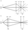
フォーカスレンズ制御に関する位置精度とは、フォーカスレンズを目標位置へ駆動する際に、目標位置に対してどれだけ正確にフォーカスレンズを駆動できるかを表す指標である。以下、フォーカスレンズ制御に関する位置精度について、図2(a)及び図2(b)を参照して説明する。図2(a)は焦点深度が浅い場合、図2(b)は焦点深度が深い場合におけるフォーカスレンズとフォーカス位置の関係を示している。図2(a)及び図2(b)は、レンズ構成は同じで、F値のみ異なる場合のフォーカスレンズとフォーカス位置の関係を示している。また、図2(a)及び図2(b)において、共通のものに対しては同じ参照符号を付している。<Positional accuracy required for focus lens control>
The positional accuracy of the focus lens control is an index that indicates how accurately the focus lens can be driven to a target position when the focus lens is driven to the target position. Hereinafter, the positional accuracy of the focus lens control will be described with reference to Fig. 2(a) and Fig. 2(b). Fig. 2(a) shows the relationship between the focus lens and the focus position when the focal depth is shallow, and Fig. 2(b) shows the relationship between the focus lens and the focus position when the focal depth is deep. Fig. 2(a) and Fig. 2(b) show the relationship between the focus lens and the focus position when the lens configuration is the same and only the F value is different. In Fig. 2(a) and Fig. 2(b), the same reference symbols are used for common parts.
図2(a)及び図2(b)において、フォーカスレンズ目標位置Gは、光軸上の主被写体の点物体Sの像が、撮像素子201上に合焦するフォーカスレンズ位置を示している。これに対し、フォーカスレンズ位置Cは、フォーカスレンズ目標位置Gを目標に駆動した後のフォーカス位置を示している。フォーカスレンズ位置Cは、フォーカスレンズ目標位置Gに対して、制御誤差Erの分だけ点物体S側の位置となっている。フォーカス位置Bpは、フォーカスレンズ位置がフォーカスレンズ位置Cのときの点物体Sの結像位置を示している。錯乱円δは撮像素子201上の錯乱円である。In Figures 2(a) and 2(b), focus lens target position G indicates the focus lens position where the image of point object S, the main subject on the optical axis, is focused on the
図2(a)におけるF値Faは、図2(b)におけるF値Fbよりも明るい値(小さい値)となっている。そのため、図2(a)における焦点深度幅2Faδは、図2(b)における焦点深度幅2Fbδよりも狭い範囲となっている。図2(a)における光線Cla及び光線Glaは、それぞれ、フォーカスレンズ位置C及びフォーカスレンズ目標位置Gにおける点物体Sの光線のうち、一番外側の光線を示している。また、図2(b)における光線Clb及び光線Glbは、それぞれ、フォーカスレンズ位置C及びフォーカスレンズ目標位置Gにおける点物体Sの光線のうち、一番外側の光線を示している。The F-number Fa in FIG. 2(a) is brighter (smaller) than the F-number Fb in FIG. 2(b). Therefore, the focal depth width 2Faδ in FIG. 2(a) is narrower than the focal depth width 2Fbδ in FIG. 2(b). The light rays Cla and Gla in FIG. 2(a) respectively indicate the outermost light rays of the light of the point object S at the focus lens position C and the focus lens target position G. The light rays Clb and Glb in FIG. 2(b) respectively indicate the outermost light rays of the light of the point object S at the focus lens position C and the focus lens target position G.
図2(a)において、点像直径Iaは、フォーカスレンズがフォーカスレンズ位置Cにあるときの点物体Sの撮像素子201上の点像の直径を示す。また、図2(b)において、点像直径Ibは、フォーカスレンズがフォーカスレンズ位置Cにあるときの点物体Sの撮像素子201上の点像の直径を示す。In FIG. 2(a), point image diameter Ia indicates the diameter of the point image of point object S on
ここで、図2(a)においては、フォーカス位置Bpは焦点深度幅2Faδの範囲外となっており、点像直径Iaは錯乱円δより大きく、中心の画素に収まらず隣の画素へ光が入射している。以上により、図2(a)においては、フォーカスレンズ位置Cでは点物体Sは非合焦となる。一方、図2(b)においては、フォーカス位置Bpは焦点深度幅2Fbδの範囲内となっており、点像直径Ibは錯乱円δより小さく、中心の画素に全ての光線が集光している。以上により、図2(b)において、フォーカスレンズ位置Cでは点物体Sは合焦となる。Here, in FIG. 2(a), the focus position Bp is outside the range of the focal depth width 2Faδ, the point image diameter Ia is larger than the circle of confusion δ, and the light does not fit into the central pixel and enters the neighboring pixel. As a result, in FIG. 2(a), the point object S is out of focus at the focus lens position C. On the other hand, in FIG. 2(b), the focus position Bp is within the range of the focal depth width 2Fbδ, the point image diameter Ib is smaller than the circle of confusion δ, and all light rays are focused on the central pixel. As a result, in FIG. 2(b), the point object S is in focus at the focus lens position C.
以上の通り、同じ位置精度を達成したとしても、F値等の撮影条件により、非合焦又は合焦に合焦状態が変化する。このことから、撮影条件により、フォーカスレンズ制御に要求される位置精度が変化することが分かる。As described above, even if the same positional accuracy is achieved, the focus state will change to out of focus or in focus depending on the shooting conditions such as the F-number. This shows that the positional accuracy required for focus lens control changes depending on the shooting conditions.
<フォーカスレンズ制御に要求される速度>
次に、フォーカスレンズ制御に関する速度について、図3(a)及び図3(b)を参照して説明する。ここで、フォーカスレンズ制御に関する速度とは、フォーカスレンズを駆動する際の移動速度(フォーカスレンズの駆動速度)のことである。なお、移動速度は、単位時間あたりの移動量と考えることで移動量に置き換えることができる。また、フォーカスが合っている位置の光軸方向の移動量のことをフォーカス移動量、移動速度をフォーカス移動速度とする。フォーカスレンズ移動量はフォーカス移動量と比例関係にある。フォーカスレンズ移動量とフォーカス移動量の比例定数をフォーカス敏感度という。フォーカス敏感度は、レンズの構成する光学系の位置関係(レンズ装置の構成)によって変化する。ここで、フォーカス移動量ΔBp、フォーカス敏感度Se、及びフォーカスレンズ移動量ΔPの関係は、フォーカス移動量ΔBp=フォーカス敏感度Se×フォーカスレンズ移動量ΔP(式1)で表すことができる。<Speed required for focus lens control>
Next, the speed related to the focus lens control will be described with reference to FIG. 3(a) and FIG. 3(b). Here, the speed related to the focus lens control refers to the movement speed when driving the focus lens (the driving speed of the focus lens). The movement speed can be replaced with the movement amount by considering it as the movement amount per unit time. Also, the movement amount in the optical axis direction of the focused position is called the focus movement amount, and the movement speed is called the focus movement speed. The focus lens movement amount is in a proportional relationship with the focus movement amount. The proportional constant between the focus lens movement amount and the focus movement amount is called the focus sensitivity. The focus sensitivity changes depending on the positional relationship of the optical system that constitutes the lens (the configuration of the lens device). Here, the relationship between the focus movement amount ΔBp, the focus sensitivity Se, and the focus lens movement amount ΔP can be expressed as the focus movement amount ΔBp = focus sensitivity Se × focus lens movement amount ΔP (Equation 1).
図3(a)はフォーカス敏感度Seが小さい場合、図3(b)はフォーカス敏感度Seが大きい場合におけるフォーカスレンズとフォーカス位置の関係を示している。図3(a)及び図3(b)は、レンズ構成は同じで、レンズと点物体Sとの距離が異なる場合を示している。また、図3(a)及び図3(b)において、共通のものに対しては同じ参照符号を付している。Figure 3(a) shows the relationship between the focus lens and the focus position when the focus sensitivity Se is small, and Figure 3(b) shows the relationship when the focus sensitivity Se is large. Figures 3(a) and 3(b) show cases where the lens configuration is the same but the distance between the lens and the point object S is different. In addition, the same reference symbols are used for common parts in Figures 3(a) and 3(b).
図3(a)において、フォーカス位置をフォーカス位置Bp1からフォーカス位置Bp2へ移動させる場合、フォーカスレンズをフォーカスレンズ位置LPa1からフォーカスレンズ位置LPa2へ移動する必要がある。このとき、フォーカスレンズの移動量ΔPaとフォーカス移動量ΔBpとの関係は式1に示す関係となる。同様に、図3(b)において、フォーカス位置をフォーカス位置Bp1からフォーカス位置Bp2へ移動させる場合、フォーカスレンズをフォーカスレンズ位置LPb1からフォーカスレンズ位置LPb2へ移動する必要がある。このときのフォーカスレンズの移動量ΔPaとフォーカス移動量ΔBpの関係も式1に示す関係となる。In FIG. 3(a), when moving the focus position from focus position Bp1 to focus position Bp2, it is necessary to move the focus lens from focus lens position LPa1 to focus lens position LPa2. At this time, the relationship between the focus lens movement amount ΔPa and the focus movement amount ΔBp is as shown in
図3(a)及び図3(b)に示す通り、フォーカス敏感度Seがより小さい場合には、同じフォーカス移動量ΔBp動かすために必要となるフォーカスレンズの移動量ΔPは大きくなる。つまり、図3(a)に示す場合に比べ、図3(b)に示す場合は、単位時間当たりのフォーカス移動量ΔBpを少なくできるため、結果としてフォーカスレンズ駆動速度が遅くしても、フォーカス移動速度としては同じにすることができる。As shown in Figures 3(a) and 3(b), when the focus sensitivity Se is smaller, the amount of focus lens movement ΔP required to move the same focus movement amount ΔBp becomes larger. In other words, compared to the case shown in Figure 3(a), the amount of focus movement ΔBp per unit time can be reduced in the case shown in Figure 3(b), so that the focus movement speed can be the same even if the focus lens drive speed is slower.
以上の通り、特定のフォーカス移動速度を達成するために必要となるフォーカスレンズ駆動速度は、フォーカス敏感度等の撮影条件により異なる。このことから、撮影条件により、求められるフォーカスレンズ駆動速度が変化することが分かる。As described above, the focus lens drive speed required to achieve a specific focus movement speed differs depending on the shooting conditions, such as focus sensitivity. This shows that the required focus lens drive speed changes depending on the shooting conditions.
<フォーカスレンズ制御に要求される消費電力>
フォーカスレンズ制御に関する消費電力とは、フォーカスレンズを駆動するために消費する電力のことである。消費電力は、フォーカスレンズの駆動時間、駆動速度又は駆動加速度変化に応じて変化する。例えば、駆動時間が長い場合、駆動速度が速い場合、及び駆動加速度変化が多い場合には、消費電力が多くなる。一方、消費電力を抑えることでバッテリ容量を有効活用することでき、メリットとして1回の充電で撮影可能な枚数を増やすことやバッテリを更に小型化することができる。<Power consumption required for focus lens control>
The power consumption related to focus lens control is the power consumed to drive the focus lens. The power consumption changes depending on the drive time, drive speed, or drive acceleration change of the focus lens. For example, if the drive time is long, the drive speed is fast, or the drive acceleration change is large, the power consumption increases. On the other hand, by suppressing the power consumption, the battery capacity can be effectively utilized, and the advantages are that the number of images that can be taken on a single charge can be increased and the battery can be further miniaturized.
<フォーカスレンズ制御に要求される静音>
フォーカスレンズ制御に関する静音とは、フォーカスレンズを駆動する際の駆動音の指標である。フォーカスレンズを駆動する際には、振動や摩擦などで駆動音が発生する。駆動音は、駆動速度又は駆動加速度変化に応じて変化する。例えば、駆動速度が速い場合や駆動加速度変化が多い場合には、駆動音が大きくなる。また、フォーカスレンズが停止する時間が長い程、駆動音が発生しない時間が長くなる。<Quiet operation required for focus lens control>
Quietness in focus lens control is an index of the drive noise generated when driving the focus lens. When driving the focus lens, drive noise is generated due to vibration, friction, and the like. The drive noise changes according to the drive speed or change in drive acceleration. For example, when the drive speed is fast or when there is a large change in drive acceleration, the drive noise becomes louder. Also, the longer the time that the focus lens is stopped, the longer the time that no drive noise is generated.
<位置精度と、速度、消費電力、及び静音との関係>
次に、フォーカスレンズ制御に関する位置精度と、フォーカスレンズ制御に関する速度、消費電力、及び静音との関係について、図4(a)及び図4(b)を参照して説明する。図4(a)は焦点深度が浅い場合、図4(b)は焦点深度が深い場合において、動きのある被写体に合焦し続けるためのフォーカスレンズ制御の動きの一例を示している。図4(a)及び図4(b)の横軸は時間経過を示し、縦軸はフォーカスレンズ位置を示す。ここで、図4(a)及び図4(b)において、フォーカスレンズ位置が紙面上側に行くと無限方向にフォーカスが合い、紙面下側に行くと至近方向にフォーカスが合う。なお、図4(a)及び図4(b)において、共通のものに対しては同じ参照符号を付している。<Relationship between position accuracy, speed, power consumption, and noise>
Next, the relationship between the position accuracy of the focus lens control and the speed, power consumption, and quietness of the focus lens control will be described with reference to Fig. 4(a) and Fig. 4(b). Fig. 4(a) shows an example of the movement of the focus lens control to keep the focus on a moving subject when the focal depth is shallow, and Fig. 4(b) shows an example of the movement of the focus lens control to keep the focus on a moving subject when the focal depth is deep. The horizontal axis of Fig. 4(a) and Fig. 4(b) indicates the elapsed time, and the vertical axis indicates the focus lens position. Here, in Fig. 4(a) and Fig. 4(b), when the focus lens position moves to the upper side of the paper, the focus is set in the infinity direction, and when the focus lens position moves to the lower side of the paper, the focus is set in the close direction. Note that the same reference symbols are used for common parts in Fig. 4(a) and Fig. 4(b).
図4(a)及び図4(b)において、フォーカスレンズ目標位置Gは、被写体の像を撮像素子201上に合焦させるときのフォーカスレンズ位置を示している。なお、図4(a)及び図4(b)の焦点深度幅は、それぞれ2Faδ,2Fbδである。図4(a)において、フォーカスレンズ目標位置Gを基準に、フォーカス位置が焦点深度の無限側の境界となるフォーカスレンズ位置を位置GalimI、至近側の境界となるフォーカスレンズ位置を位置GalimMで示す。同様に、図4(b)において、フォーカスレンズ目標位置Gを基準に、フォーカス位置が焦点深度の無限側の境界となるフォーカスレンズ位置を位置GblimI、至近側の境界となるフォーカスレンズ位置を位置GblimMで示す。また、図4(a)及び図4(b)には、それぞれ被写体が焦点深度内に収まるように制御されたフォーカスレンズ位置Ca,Cbが示されている。In FIG. 4(a) and FIG. 4(b), the focus lens target position G indicates the focus lens position when the image of the subject is focused on the
図4(b)に示す場合には、焦点深度が深いため、フォーカスレンズがフォーカスレンズ位置Cbの示す軌跡に制御されたとしても、被写体の像が焦点深度から外れることはない。一方、図4(a)に示す場合には、焦点深度が浅いため、図4(b)に示す場合に比べ、フォーカスレンズ位置Cbの軌跡をフォーカスレンズ目標位置Gとの偏差が少ない軌跡で制御する必要がある。In the case shown in FIG. 4(b), the focal depth is deep, so even if the focus lens is controlled to the trajectory indicated by the focus lens position Cb, the image of the subject will not deviate from the focal depth. On the other hand, in the case shown in FIG. 4(a), the focal depth is shallow, so it is necessary to control the trajectory of the focus lens position Cb to a trajectory with less deviation from the focus lens target position G compared to the case shown in FIG. 4(b).
図4(a)及び図4(b)に示す場合においては、共に被写体がフォーカスから外れることはないが、図4(b)に示すフォーカスレンズ位置Cbの制御の方が、図4(a)に示すフォーカスレンズ位置Caの制御よりも駆動量及び駆動速度を少なくできる。このように、求められる位置精度が低い撮影条件下においては、低速、低消費電力、及び静音の状態でフォーカスレンズを制御することができる。In both the cases shown in FIG. 4(a) and FIG. 4(b), the subject does not go out of focus, but the control of focus lens position Cb shown in FIG. 4(b) requires less drive amount and drive speed than the control of focus lens position Ca shown in FIG. 4(a). In this way, under shooting conditions where low positional accuracy is required, the focus lens can be controlled at a low speed, with low power consumption, and in a quiet state.
<速度と、位置精度、消費電力、及び静音との関係>
次に、フォーカスレンズ制御に関する速度と、フォーカスレンズ制御に関する位置精度、消費電力、静音との関係について、図5(a)及び図5(b)を参照して説明する。図5(a)及び図5(b)の横軸は、時間経過を示し、縦軸はフォーカスレンズ位置を示す。図5(a)は、図3(a)に示すフォーカスレンズ位置LPa1からフォーカスレンズ位置LPa2へ、時間T0~T1の間に駆動したフォーカスレンズ位置Caの変化を示している。同様に、図5(b)は、図3(b)に示すフォーカスレンズ位置LPb1からフォーカスレンズ位置LPb2へ、時間T0~T1の間に駆動したフォーカスレンズ位置Cbの変化を示している。また、図5(a)及び図5(b)のそれぞれにおいて、フォーカスレンズ位置Ca,Cbの変化の傾きはフォーカスレンズ速度を示す。<Relationship between speed, position accuracy, power consumption, and noise>
Next, the relationship between the speed of the focus lens control and the position accuracy, power consumption, and quietness of the focus lens control will be described with reference to Fig. 5(a) and Fig. 5(b). The horizontal axis of Fig. 5(a) and Fig. 5(b) indicates the passage of time, and the vertical axis indicates the focus lens position. Fig. 5(a) shows the change in the focus lens position Ca driven from the focus lens position LPa1 shown in Fig. 3(a) to the focus lens position LPa2 during the time T0 to T1. Similarly, Fig. 5(b) shows the change in the focus lens position Cb driven from the focus lens position LPb1 shown in Fig. 3(b) to the focus lens position LPb2 during the time T0 to T1. Also, in each of Fig. 5(a) and Fig. 5(b), the slope of the change in the focus lens positions Ca and Cb indicates the focus lens speed.
ここで、図3(a)及び図3(b)に示す通り、フォーカスレンズ位置LPa1からフォーカスレンズ位置LPa2へ移動したときのフォーカス移動量ΔBpは、フォーカスレンズ位置LPb1からフォーカスレンズ位置LPb2へ移動したときのフォーカス移動量ΔBpと同じである。これに対し、図5(a)に示されるフォーカスレンズ位置Caの変化の傾きは、図5(b)に示されるフォーカスレンズ位置Cbの変化の傾きよりも大きくなっており、図5(a)に示す例ではフォーカスレンズ速度が速いことが分かる。Here, as shown in Figures 3(a) and 3(b), the focus movement amount ΔBp when moving from focus lens position LPa1 to focus lens position LPa2 is the same as the focus movement amount ΔBp when moving from focus lens position LPb1 to focus lens position LPb2. In contrast, the slope of the change in focus lens position Ca shown in Figure 5(a) is larger than the slope of the change in focus lens position Cb shown in Figure 5(b), and it can be seen that the focus lens speed is fast in the example shown in Figure 5(a).
図5(a)及び図5(b)に示す通り、時間T0~T1の間に同じフォーカス移動量ΔBpだけ動かすためのフォーカスレンズ移動速度は、フォーカスレンズ位置Caの制御ではフォーカスレンズ位置Cbの制御に比べて速くフォーカスレンズを動かす必要がある。また、フォーカスレンズ位置Caの制御では速度が速いため、目標位置であるフォーカスレンズ位置LPa2到達後、位置が安定するまでにある程度に時間が必要となる。一方、フォーカスレンズ位置Cbの制御では速度が遅いため、目標位置であるフォーカスレンズ位置LPb2に到達後、直ぐに位置が安定する。これは位置精度に影響する。また、フォーカスレンズ位置Caの制御では、フォーカスレンズを速く駆動することから停止時において加速度変化が大きくなるため、フォーカスレンズ位置Cbの制御に比べ、消費電力が多くなり、駆動音も大きくなる。従って、求められる速度が低い撮影条件下においては、高い位置精度、低消費電力、及び静音の状態でフォーカスレンズを制御することができる。As shown in FIG. 5(a) and FIG. 5(b), the focus lens needs to be moved faster in the control of the focus lens position Ca to move the same focus movement amount ΔBp between times T0 and T1 than in the control of the focus lens position Cb. In addition, since the speed is fast in the control of the focus lens position Ca, it takes a certain amount of time for the position to stabilize after the target position, focus lens position LPa2, is reached. On the other hand, since the speed is slow in the control of the focus lens position Cb, the position stabilizes immediately after the target position, focus lens position LPb2, is reached. This affects the position accuracy. In addition, since the control of the focus lens position Ca drives the focus lens quickly, the change in acceleration when stopped is large, so the power consumption is higher and the driving sound is louder than the control of the focus lens position Cb. Therefore, under shooting conditions where the required speed is low, the focus lens can be controlled with high position accuracy, low power consumption, and quiet operation.
<レンズ装置情報>
次に、撮影条件に関連するレンズ装置情報について説明する。レンズ装置情報は、撮影映像に影響を与えるレンズ装置の撮影条件に関する情報である。本実施例では、フォーカスレンズ制御における要求事項をバランスよく制御するために、フォーカスレンズ制御で求められる位置精度及び速度を決めるためのレンズ装置情報を基にフォーカスレンズ制御を行う。レンズ装置情報は、レンズ装置情報管理部122により決定される。レンズ装置情報は、例えば、焦点深度やフォーカス敏感度等を含む。<Lens device information>
Next, lens device information related to shooting conditions will be described. The lens device information is information about the shooting conditions of the lens device that affect the captured image. In this embodiment, in order to control the requirements in the focus lens control in a well-balanced manner, focus lens control is performed based on lens device information for determining the position accuracy and speed required in the focus lens control. The lens device information is determined by the lens device
レンズ装置情報管理部122は、現在のF値と錯乱円の情報から式1に示す通り、焦点深度を決定することができる。また、レンズ装置情報管理部122は、フォーカス敏感度とフォーカスレンズ位置及びズームレンズ位置との関係を示す不図示の変換テーブルを保持し、フォーカスレンズ位置及びズームレンズ位置からフォーカス敏感度を決定することができる。なお、焦点深度やフォーカス敏感度の決定方法は、公知の任意の方法を用いて決定されてよい。The lens device
上述のように、フォーカスレンズ制御の要求事項は撮影条件の影響を受ける。このため、これらの撮影条件に関するレンズ装置情報を基にフォーカスレンズ制御を行うことで、撮影条件によって撮影映像が受ける影響を加味して、位置精度、速度、消費電力、及び静音のそれぞれの要求事項をバランスよく制御することができる。As mentioned above, the requirements for focus lens control are affected by the shooting conditions. Therefore, by controlling the focus lens based on lens device information related to these shooting conditions, it is possible to control the requirements for positional accuracy, speed, power consumption, and quietness in a well-balanced manner, taking into account the effects of the shooting conditions on the captured image.
<NNアルゴリズムとウエイト>
以下に、NN制御部121がNNアルゴリズムを用いて駆動指令を決定する方法について説明する。上述のように、NN制御部121にはNNが実装されている。NN制御部121は、NNデータ記憶部123に記録された学習済モデルの結合重み付け係数であるウエイトを参照し、参照したウエイトをNNのウエイトとして用いる。これにより、NN制御部121は、NNを学習済のNNとして用いることができる。NN制御部121は、学習済のNNにより駆動指令を決定することで、学習済モデルの学習の傾向に従って、レンズ100の構成及びユーザの要望に応じた駆動指令を決定することができる。<NN algorithm and weights>
The following describes a method in which the
図6は、本実施例に係るNNを用いたNN制御部121の入出力の構造を示す概念図である。目標位置X1は、制御部125から出力されたフォーカス駆動の駆動指令目標位置である。現在位置X2は、フォーカスレンズ検出部106から得られたフォーカスレンズ101の現在位置である。焦点深度X3はレンズ装置情報に含まれる焦点深度であり、フォーカス敏感度X4はレンズ装置情報に含まれるフォーカス敏感度である。また、駆動信号Y1はフォーカスレンズ101の駆動信号である。Figure 6 is a conceptual diagram showing the input/output structure of the
このように、本実施例では、フォーカス駆動の駆動指令、フォーカスレンズ101の現在位置、焦点深度、及びフォーカス敏感度を入力として、学習済モデルの出力として駆動信号が決定される。NN制御部121は、撮影条件に関するレンズ装置情報もNNへの入力として用いることで、撮影条件によって撮影映像が受ける影響を加味して、フォーカスレンズ101の制御を行うことができる。In this way, in this embodiment, the focus drive drive command, the current position of the
<撮影処理の流れ>
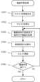
次に、図7を参照して、本実施例に係る一連の撮影処理について説明する。図7は、本実施例に係る一連の撮影処理の流れを示すフローチャートである。本実施例では、ユーザの操作に応じて撮影処理が開始されると、処理がステップS701に移行する。<Flow of shooting process>
Next, a series of image capturing processes according to this embodiment will be described with reference to Fig. 7. Fig. 7 is a flowchart showing the flow of a series of image capturing processes according to this embodiment. In this embodiment, when the image capturing process is started in response to a user operation, the process proceeds to step S701.
ステップS701では、NNを用いた制御に影響を与える撮影条件が設定される。例えば、本実施例に係る制御部211は、ステップS701において、信号処理回路203から出力された映像データを基に、露出制御を行い、F値を設定する。F値が設定されることで、焦点深度が設定される。なお、F値は、ユーザによる操作部206の操作に応じて設定されてもよい。In step S701, shooting conditions that affect control using the NN are set. For example, in step S701, the
ステップS702では、制御部211が、ユーザによる操作部206の操作に応じて機械学習を実施するか否かを判断する。制御部211が、機械学習を実施すると判断した場合には、処理はステップS703に移行する。In step S702, the
ステップS703では、本実施例に係るフォーカスレンズ制御に用いるNNの学習に関する報酬情報を決定する。上述のように、本実施例では、機械学習処理として、レンズ装置毎の機器的な制約情報及びユーザによる要望情報に基づく報酬情報に応じた動作の評価値を報酬とし、報酬が最大となるようにNNに対して強化学習を行う。そのため、本実施例では、機械学習処理に先立ち、レンズ100の構成及びユーザの要望に応じて報酬情報を決定する。具体的には、機器制約報酬管理部224、ユーザ要望報酬管理部225、及び報酬管理部223によって、レンズ個体情報及びユーザによって設定されたユーザ要望情報に基づいて、報酬情報を決定する。なお、報酬情報及び報酬情報の決定処理の詳細については、後述する。ステップS703において、報酬情報が決定されると、処理はステップS704に移行する。In step S703, reward information for learning the NN used for focus lens control in this embodiment is determined. As described above, in this embodiment, as a machine learning process, the evaluation value of the operation according to the reward information based on the equipment constraint information for each lens device and the user's request information is used as a reward, and reinforcement learning is performed on the NN so as to maximize the reward. Therefore, in this embodiment, prior to the machine learning process, the reward information is determined according to the configuration of the
ステップS704においては、学習部220によって、NNに対する機械学習処理が行われる。ここで、上述のように、レンズ装置を使用して機械学習を行う場合、機械学習時には多くの駆動が必要となり、駆動部が摩耗し駆動部の性能劣化に繋がることがある。また、機械学習には多くの時間が必要となるため、ユーザが実際に撮影したい時に撮影できない等、ユーザに負担が発生することがある。そこで本実施例では、学習部220が、予め学習を行った複数の学習済モデルから、レンズ100の構成及びユーザの要望に似た構成及び要望に対応する報酬情報を用いて学習を行った学習済モデルを選択する。学習部220は、選択した学習済モデルのウエイトを、NNのウエイトの初期値として用いる。In step S704, the
その後、学習部220は、ウエイトの初期値を設定したNNを備えたレンズ100を用いてフォーカス制御の動作ログ情報を取得し、ステップS703で決定した報酬情報に基づいて、フォーカス制御の評価値を報酬とした追加の学習を行う。このように、本実施例では、レンズ100の構成及びユーザの要望に一致又は類似する構成及び要望に対応する報酬情報を用いて学習を行った学習済モデルを用いて、いわゆる転移学習を行うことで、機械学習時における駆動部の駆動回数を減らすことができる。そのため、機械学習時における駆動部の摩耗を抑制することができるとともに、機械学習に係る時間を短くすることができる。なお、機械学習処理の詳細については、後述する。Then, the
一方で、ステップS702において、制御部211が、機械学習を実施しないと判断した場合には、処理はステップS705に移行する。ステップS705では、制御部211が、ユーザの操作に応じて、NN制御部121について用いる学習済モデルを選択する。例えば、表示部205は、機械学習モデル保持部231が保持する機械学習モデルデータベースに記憶されている学習済モデルを学習済モデルの選択肢として表示する。ユーザは表示部205に表示される学習済モデルの選択肢から使用する学習済モデルを選択することができ、NN制御部121は選択された学習済モデルのウエイトをNNのウエイトとして用いることで、学習傾向に従った駆動制御を行うことができる。ここで、表示部205が、学習済モデルの選択肢を表示する際には、学習済モデルの説明として、学習時のユーザ要望情報等を表示してもよい。On the other hand, if the
なお、ステップS705での学習済モデルの選択は、前回用いられた学習済モデルを自動的に選択するように行われてもよい。この場合には、ユーザの選択を省略することができ、ユーザによる操作の手間を低減することができる。また、制御部211は、例えば、レンズ100と一致又は類似するレンズ機種のレンズ装置、及びステップS701で設定された撮影条件と類似する撮影条件で取得されたデータを用いて学習が行われた学習済モデルを自動的に選択してもよい。ステップS704又はステップS705での処理が終了すると、処理はステップS706に移行する。The selection of the trained model in step S705 may be performed so as to automatically select the trained model used last time. In this case, the user's selection can be omitted, and the effort required of the user to perform the operation can be reduced. In addition, the
ステップS706では、ユーザの操作に応じて、撮影処理を行う。撮影処理では、ユーザの操作に従って、ズームや、揺れの補正、及びNN制御部121によるAFフォーカス制御が行われる。また、ユーザの操作に従って、撮像素子201を用いた映像データの取得や、記録部204への映像データの記憶、表示部205への映像の表示等が行われる。In step S706, shooting processing is performed in response to the user's operation. In the shooting processing, zooming, shake correction, and AF focus control by the
ステップS707では、制御部211が、操作部206を介してユーザから撮影終了の指示が入力された否かを判断する。制御部211によって撮影終了の指示が入力されていないと判断された場合には、処理はステップS706に戻り、撮影処理が継続される。これに対し、制御部211によって撮影終了の指示が入力されたと判断された場合には、制御部211は、一連の撮影処理を終了する。In step S707, the
このような、本実施例に係る一連の撮影処理では、予め学習を行っていた学習済モデルのウエイトをNNのウエイトの初期値として用いることで、NNの学習時における駆動部の駆動の回数を低減し、駆動部の摩耗を抑制することができる。また、機械学習に係る時間を短くすることができ、ユーザの負担を低減することができる。さらに、NNのウエイトの初期値を設定する際に、ユーザの要望に一致又は類似する要望に対応する報酬情報を用いて学習を行った学習済モデルのウエイトを参照することで、ユーザの要望に即したフォーカス制御を実現することができる。In this series of shooting processes according to the present embodiment, the weights of a trained model that has been trained in advance are used as the initial values of the weights of the NN, thereby reducing the number of times the drive unit is driven during training of the NN and suppressing wear on the drive unit. In addition, the time required for machine learning can be shortened, reducing the burden on the user. Furthermore, when setting the initial values of the weights of the NN, focus control that meets the needs of the user can be realized by referring to the weights of a trained model that has been trained using reward information that corresponds to or is similar to the needs of the user.
なお、本実施例では、撮影条件の設定は機械学習の実施判断の前に行う構成としたが、撮影条件の設定を行うタイミングはこれに限られない。撮影条件の設定は、ステップS704での機械学習処理及びステップS705での学習済モデルの選択の前に行われていればよい。そのため、例えば、ステップS702での機械学習実施の判断処理やステップS703での報酬情報の決定処理の後に撮影条件の設定が行われてもよい。In this embodiment, the shooting conditions are set before the decision to implement machine learning, but the timing for setting the shooting conditions is not limited to this. The shooting conditions may be set before the machine learning process in step S704 and the selection of the trained model in step S705. Therefore, for example, the shooting conditions may be set after the decision process to implement machine learning in step S702 and the process to determine reward information in step S703.
<報酬情報>
次に、図8及び図9を参照して、報酬情報の詳細について説明する。報酬情報は、動作ログ情報から得られるNNアルゴリズムの制御結果を点数化(評価)する上で、点数の基準となる情報である。報酬情報は、NNアルゴリズムの制御結果に対して、点数の境界値とその境界値で区切られた範囲毎に割り当てられた点数の情報を持つ。ここで、図8を参照して、報酬情報について説明する。<Remuneration Information>
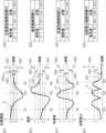
Next, the reward information will be described in detail with reference to Fig. 8 and Fig. 9. The reward information is information that serves as a standard for scoring (evaluating) the control results of the NN algorithm obtained from the operation log information. The reward information has information on boundary values of the scores and the scores assigned to each range delimited by the boundary values for the control results of the NN algorithm. Here, the reward information will be described with reference to Fig. 8.
図8の(a1)、(b1)、(c1)、及び(d1)は、それぞれ、NNアルゴリズムの制御結果を示す項目である位置精度、速度、加速度、及び消費電力に対して、学習時における時間経過に伴う変化と点数の境界値との関係の例を示している。ここで、図8の(a1)、(b1)、(c1)、及び(d1)の横軸は時間経過を示す。(a1), (b1), (c1), and (d1) in Fig. 8 show examples of the relationship between the change over time during learning and the score boundary values for position accuracy, speed, acceleration, and power consumption, which are items that indicate the control results of the NN algorithm. Here, the horizontal axis in (a1), (b1), (c1), and (d1) in Fig. 8 indicates the passage of time.
図8の(a2)、(b2)、(c2)、及び(d2)は、それぞれ、位置精度、速度、加速度、及び消費電力に対しての報酬情報のデータ構造の一例を示している。報酬情報のデータは、複数の境界値と、境界値で区切られた範囲で獲得できる点数で構成される。本実施例では、報酬情報のデータが2つの境界値と3つの点数で構成される例を示す。(a2), (b2), (c2), and (d2) in FIG. 8 show examples of the data structure of reward information for position accuracy, speed, acceleration, and power consumption, respectively. The reward information data is composed of multiple boundary values and points that can be obtained within the ranges defined by the boundary values. In this embodiment, an example is shown in which the reward information data is composed of two boundary values and three points.
ここで、NNの学習は、制御結果の獲得点数(評価値)が高得点となるように行われるため、境界値が各対象となる項目の目標に近い程、より高精度な制御となるように学習が行われる。例えば、位置精度の境界値が0に近い値になる程、位置精度が高い制御となるように学習される。また、報酬情報において、ある項目について他の項目に比べて点数を高く設定することにより、他の項目よりも学習の優先度が高いことを示すこともできる。例えば、位置精度よりも消費電力の点数を高くすることで、位置精度よりも消費電力を優先させる制御となるように学習が行われる。Here, the NN learns so that the control result will receive a high score (evaluation value), so that the closer the boundary value is to the target for each target item, the more accurate the control will be. For example, the closer the boundary value for position accuracy is to 0, the more accurate the control will be. In addition, by setting a higher score for a certain item in the reward information compared to other items, it is possible to indicate that the learning has a higher priority than the other items. For example, by setting a higher score for power consumption than for position accuracy, the NN learns so that control prioritizes power consumption over position accuracy.
図8の(a1)に示す縦軸は、フォーカスレンズの目標位置と現在位置との差である位置精度Eの値を示している。位置精度Eの正の方向は、目標位置に対して、現在位置が無限側にある場合を示し、負の方向は、目標位置に対して、現在位置が至近側にある場合を示す。なお、図8の(a1)では、位置精度Eが0に近い程、駆動制御における位置精度が高いことを示している。The vertical axis in (a1) of FIG. 8 indicates the value of position accuracy E, which is the difference between the target position and the current position of the focus lens. A positive value of position accuracy E indicates that the current position is on the infinity side of the target position, and a negative value indicates that the current position is on the close side of the target position. Note that in (a1) of FIG. 8, the closer the position accuracy E is to 0, the higher the position accuracy in the drive control.
図8の(a2)は、位置精度の報酬情報である位置精度報酬情報REのデータ構造の一例を示している。本実施例では、位置精度報酬情報REは、位置精度の報酬範囲を決める境界値E1,E2と、報酬範囲において獲得できる点数SE1,SE2,SE3により構成される。(a2) of FIG. 8 shows an example of the data structure of the location accuracy reward information RE, which is reward information for location accuracy. In this embodiment, the location accuracy reward information RE is composed of boundary values E1, E2 that determine the reward range for location accuracy, and points SE1, SE2, SE3 that can be earned within the reward range.
境界値E1,E2は、それぞれ、位置精度Eの報酬として与えられる点数の境界値を示している。ここで、-E1~E1の範囲を範囲AE1とし、範囲AE1を除く-E2~E2の範囲AE2とし、範囲AE1及び範囲AE2以外の範囲を範囲AE3とする。位置精度Eが、範囲AE1,AE2,AE3の範囲内の場合には、それぞれ、図8の(a2)が示す点数SE1,SE2,SE3が報酬として与えられる。ここで、点数SE1,SE2,SE3の関係は、点数SE1>点数SE2>点数SE3となり、位置精度Eが0に近い程、高い点数となるように設定される。The boundary values E1 and E2 each indicate the boundary value of the score given as a reward for the position accuracy E. Here, the range from -E1 to E1 is defined as range AE1, the range from -E2 to E2 excluding range AE1 is defined as range AE2, and the range other than range AE1 and range AE2 is defined as range AE3. When the position accuracy E is within the ranges AE1, AE2, and AE3, the scores SE1, SE2, and SE3 shown in (a2) of Figure 8 are given as rewards. Here, the relationship between the scores SE1, SE2, and SE3 is score SE1 > score SE2 > score SE3, and the scores are set so that the closer the position accuracy E is to 0, the higher the score.
図8の(a1)に示す通り、任意の時間TP1,TP2,Tp3における位置精度Eは、それぞれ、範囲AE2,AE3,AE1の範囲内である。従って、任意の時間TP1,TP2,Tp3において、獲得できる報酬はそれぞれ点数SE2,SE3,SE1となる。As shown in (a1) of FIG. 8, the position accuracy E at any time TP1, TP2, Tp3 is within the ranges AE2, AE3, AE1, respectively. Therefore, the rewards that can be obtained at any time TP1, TP2, Tp3 are points SE2, SE3, SE1, respectively.
ここで、例えば、境界値E1は±Fδ/2、及び境界値E2は±Fδの値が設定されることができる。この場合には、フォーカスレンズの目標位置に対して、現在位置が焦点深度内に制御されていれば、高い得点が加算され、焦点深度外となった場合に低い点数が加算される。また、フォーカスレンズが目標位置に近い程、獲得できる点数が高くなる。Here, for example, boundary value E1 can be set to ±Fδ/2, and boundary value E2 can be set to ±Fδ. In this case, if the current position is controlled to be within the focal depth relative to the target position of the focus lens, a high score is added, and if it is outside the focal depth, a low score is added. Also, the closer the focus lens is to the target position, the higher the score that can be obtained.
次に、図8の(b1)の縦軸は、フォーカスレンズの駆動速度Vの値を示している。駆動速度Vの正の方向は無限方向への駆動速度を示し、負の方向は至近方向への駆動速度を示している。駆動速度Vが0に近い程、駆動音が小さくなる。Next, the vertical axis of (b1) in FIG. 8 indicates the value of the drive speed V of the focus lens. The positive direction of the drive speed V indicates the drive speed toward infinity, and the negative direction indicates the drive speed toward the closest point. The closer the drive speed V is to 0, the quieter the drive sound becomes.
図8の(b2)は速度の報酬情報である速度報酬情報RVのデータ構造の一例を示している。本実施例では、速度報酬情報RVは速度の報酬範囲を決める境界値V1,V2と、報酬範囲において獲得できる点数SV1,SV2,SV3により構成される。Figure 8 (b2) shows an example of the data structure of speed reward information RV, which is speed reward information. In this embodiment, the speed reward information RV is composed of boundary values V1, V2 that determine the speed reward range, and points SV1, SV2, SV3 that can be earned within the reward range.
境界値V1,V2は、それぞれ、駆動速度Vの報酬として与えられる点数の境界値を示している。ここで、-V1~V1の範囲を範囲AV1とし、範囲AV1を除く-V2~V2の範囲を範囲AV2とし、範囲AV1及び範囲AV2以外の範囲を範囲AV3とする。駆動速度Vが、範囲AV1,AV2,AV3の範囲内の場合には、それぞれ、図8の(b2)が示す点数SV1,SV2,SV3が報酬として与えられる。ここで、点数SV1,SV2,SV3の点数の関係は点数SV1>点数SV2>点数SV3となり、駆動速度Vが0に近い程、高い点数となるように設定される。The boundary values V1 and V2 each indicate the boundary value of the score given as a reward for the drive speed V. Here, the range from -V1 to V1 is range AV1, the range from -V2 to V2 excluding range AV1 is range AV2, and the range other than range AV1 and range AV2 is range AV3. When the drive speed V is within the ranges AV1, AV2, and AV3, the scores SV1, SV2, and SV3 shown in (b2) of FIG. 8 are given as rewards. Here, the relationship between the scores SV1, SV2, and SV3 is score SV1>score SV2>score SV3, and the score is set so that the closer the drive speed V is to 0, the higher the score.
図8の(b1)が示す通り、任意の時間TP1,TP2,Tp3における駆動速度Vは、それぞれ、範囲AV2,AV3,AV1の範囲内である。従って、任意の時間TP1,TP2,Tp3において、駆動音に関連する駆動速度Vについて獲得できる報酬はそれぞれ点数SV2,SV3,SV1となる。As shown in (b1) of FIG. 8, the drive speed V at any time TP1, TP2, or Tp3 is within the ranges AV2, AV3, or AV1, respectively. Therefore, the rewards that can be obtained for the drive speed V related to the drive sound at any time TP1, TP2, or Tp3 are points SV2, SV3, or SV1, respectively.
ここで、例えば、境界値V1,V2は駆動速度と駆動音の関係に基づいて決定され、駆動速度を遅く制御する程、獲得できる点数が高くなるように点数が設定される。一般的に、駆動速度が遅い程、駆動音が小さくなるため、獲得した点数が高い程、静音を重視した制御が行えていることを示す。Here, for example, the boundary values V1 and V2 are determined based on the relationship between the drive speed and the drive noise, and the score is set so that the slower the drive speed is controlled, the higher the score that can be obtained. In general, the slower the drive speed, the quieter the drive noise, so the higher the score obtained indicates that control is being performed with an emphasis on quietness.
次に、図8の(c1)の縦軸は、フォーカスレンズの駆動加速度Aの値を示している。駆動加速度Aの正の方向は無限方向への駆動加速度を示し、負の方向は至近方向への駆動加速度を示している。駆動加速度Aが0に近い程、駆動音が小さくなる。Next, the vertical axis of (c1) in FIG. 8 indicates the value of the drive acceleration A of the focus lens. The positive direction of the drive acceleration A indicates the drive acceleration toward infinity, and the negative direction indicates the drive acceleration toward the closest point. The closer the drive acceleration A is to 0, the quieter the drive sound will be.
図8の(c2)は、加速度の報酬情報である加速度報酬情報RAのデータ構造の一例を示している。本実施例では、加速度報酬情報RAは、加速度の報酬範囲を決める境界値A1,A2と、報酬範囲において獲得できる点数SA1,SA2,SA3により構成される。(c2) in FIG. 8 shows an example of the data structure of acceleration reward information RA, which is reward information for acceleration. In this embodiment, the acceleration reward information RA is composed of boundary values A1, A2 that determine the reward range for acceleration, and points SA1, SA2, SA3 that can be earned within the reward range.
境界値A1,A2は、それぞれ、駆動加速度Aの報酬として与えられる点数の境界値を示している。ここで、-A1~A1の範囲を範囲AA1とし、範囲AA1を除く-A2~A2の範囲を範囲AA2とし、範囲AA1及び範囲AA2以外の範囲を範囲AA3とする。駆動加速度Aが、範囲AA1,AA2,AA3の範囲内の場合には、それぞれ、図8の(c2)が示す点数SA1,SA2,SA3が報酬として与えられる。ここで、点数SA1,SA2,SA3の点数の関係は、点数SA1>点数SA2>点数SA3となり、駆動加速度Aが0に近い程、高い点数となるように設定される。The boundary values A1 and A2 indicate the boundary values of the points given as a reward for the driving acceleration A. Here, the range from -A1 to A1 is range AA1, the range from -A2 to A2 excluding range AA1 is range AA2, and the range other than ranges AA1 and AA2 is range AA3. When the driving acceleration A is within ranges AA1, AA2, and AA3, the points SA1, SA2, and SA3 shown in (c2) of Figure 8 are given as rewards. Here, the relationship between the points SA1, SA2, and SA3 is point SA1 > point SA2 > point SA3, and the points are set so that the closer the driving acceleration A is to 0, the higher the point.
図8の(c1)が示す通り、任意の時間TP1,TP2,Tp3における駆動加速度Aは、それぞれ、範囲AA1,AA3,AA2の範囲内である。従って、任意の時間TP1,TP2,Tp3において、駆動音に関連する駆動加速度Aについて獲得できる報酬はそれぞれ点数SA1,SA3,SA2となる。As shown in (c1) of FIG. 8, the driving acceleration A at any time TP1, TP2, Tp3 is within the ranges AA1, AA3, AA2, respectively. Therefore, at any time TP1, TP2, Tp3, the reward that can be obtained for the driving acceleration A related to the driving sound is points SA1, SA3, SA2, respectively.
ここで、例えば、境界値A1,A2は駆動加速度と駆動音の関係に基づいて決定され、駆動加速度を小さく制御する程、獲得できる点数が高くなるように点数が設定される。一般的に、駆動加速度が小さい程、駆動音が小さくなるため、獲得した点数が高い程、静音を重視した制御が行えていることを示す。For example, the boundary values A1 and A2 are determined based on the relationship between the drive acceleration and the drive noise, and the score is set so that the lower the drive acceleration is controlled, the higher the score that can be obtained. Generally, the lower the drive acceleration, the quieter the drive noise will be, so the higher the score obtained indicates that the control is more focused on quietness.
次に、図8の(d1)の縦軸は、フォーカスレンズの消費電力Pの値を示している。消費電力Pが0に近い程、消費電力が小さくなる。Next, the vertical axis of (d1) in FIG. 8 indicates the value of the power consumption P of the focus lens. The closer the power consumption P is to 0, the smaller the power consumption is.
図8の(d2)は、消費電力の報酬情報である消費電力報酬情報RPのデータ構造の一例を示している。本実施例において、消費電力報酬情報RPは、消費電力の報酬範囲を決める境界値P1,P2と、報酬範囲において獲得できる点数SP1,SP2,SP3により構成される。(d2) in FIG. 8 shows an example of the data structure of power consumption reward information RP, which is reward information for power consumption. In this embodiment, the power consumption reward information RP is composed of boundary values P1 and P2 that determine the reward range for power consumption, and points SP1, SP2, and SP3 that can be acquired within the reward range.
境界値P1,P2は、それぞれ、消費電力Pの報酬として与えられる点数の境界値を示している。ここで、0~P1の範囲を範囲AP1とし、P1~P2の範囲を範囲AP2とし、範囲AP1及び範囲AP2以外の範囲を範囲AP3とする。消費電力Pが、それぞれ、範囲AP1,AP2,AP3の範囲内の場合には、図8の(d2)が示す点数SP1,SP2,SP3が報酬として与えられる。ここで、点数SP1,SP2,SP3の点数の関係は、点数SP1>点数SP2>点数SP3となり、消費電力Pが0に近い程、高い点数となるように設定される。The boundary values P1 and P2 indicate the boundary values of the points given as a reward for the power consumption P. Here, the range from 0 to P1 is range AP1, the range from P1 to P2 is range AP2, and the range outside ranges AP1 and AP2 is range AP3. When the power consumption P is within ranges AP1, AP2, and AP3, respectively, the points SP1, SP2, and SP3 shown in (d2) of Figure 8 are given as a reward. Here, the relationship between the points SP1, SP2, and SP3 is point SP1 > point SP2 > point SP3, and the points are set so that the closer the power consumption P is to 0, the higher the point.
図8の(d1)が示す通り、任意の時間TP1,TP2,TP3における消費電力Pは、それぞれ、範囲AP1,AP3,AP2の範囲内である。従って、任意の時間TP1,TP2,TN3において、消費電力Pについて獲得できる報酬はそれぞれ点数SP1,SP3,SP2となる。As shown in (d1) of FIG. 8, the power consumption P at any time TP1, TP2, or TP3 is within the ranges AP1, AP3, or AP2, respectively. Therefore, the rewards that can be obtained for the power consumption P at any time TP1, TP2, or TN3 are points SP1, SP3, or SP2, respectively.
ここで、例えば、境界値P1、P2は任意に決定され、消費電力を小さく制御する程、獲得できる点数が高くなるように点数が設定される。従って、獲得した点数が高くなる程、低消費電力を重視した制御が行えていることを示す。For example, the boundary values P1 and P2 are determined arbitrarily, and the score is set so that the more the power consumption is controlled to be low, the higher the score that can be obtained. Therefore, the higher the obtained score, the more the control is focused on low power consumption.
以上に示すように、位置制御誤差、速度、加速度、及び消費電力等の制御結果に対して、点数化するための報酬情報が設定される。学習処理部221は、このような報酬情報を用いて、学習時のフォーカスレンズ駆動に関する動作ログ情報を基にNNアルゴリズムの制御結果を単位時間毎に点数化し、単位時間毎の点数を累計することで、NNアルゴリズムの制御結果の累計点数(累積評価値)を決定することができる。また、NNアルゴリズムの制御結果に関して、位置制御誤差、速度、加速度、及び消費電力のそれぞれの得点を加算して合計得点を評価値とすることで、NNアルゴリズムのトータルとしての制御結果を点数化することができる。As described above, reward information for scoring control results such as position control error, speed, acceleration, and power consumption is set. Using such reward information, the
ここでは、消費電力を制御結果の一つとして使用している例を示しているが、速度及び加速度と消費電力との関係から、速度及び加速度の結果を用いて消費電力に対しての報酬情報を設定してもよい。Here, an example is shown in which power consumption is used as one of the control results, but reward information for power consumption may also be set using the results of speed and acceleration based on the relationship between speed and acceleration and power consumption.
なお、本実施例では、境界値の数を2つとしているが、境界値の数はこれに限られず、所望の構成に応じて3つ以上としてもよいし、境界値の数は必要に応じて可変としてもよい。また、本実施例では、点数を境界値により決定しているが、位置精度E、駆動速度V、駆動加速度A、及び消費電力Pを点数に変換する変換関数を用いて点数化する方法でもよい。この場合は、報酬情報として境界値及び境界値で区切られた範囲で獲得できる点数ではなく、変換関数及びその係数が報酬情報として設定される。In this embodiment, the number of boundary values is two, but the number of boundary values is not limited to this and may be three or more depending on the desired configuration, and the number of boundary values may be variable as necessary. Also, in this embodiment, the score is determined by the boundary values, but a method of scoring using a conversion function that converts the position accuracy E, drive speed V, drive acceleration A, and power consumption P into scores may also be used. In this case, the conversion function and its coefficients are set as the reward information, rather than the boundary values and the points that can be obtained within the range bounded by the boundary values.
ここで、本実施例では、レンズ装置の構成及びユーザの要望に即した学習を行うため報酬情報に、レンズ装置毎の機器的な制約情報に基づく機器制約報酬情報と、ユーザによる要望情報に基づくユーザ要望報酬情報とが含まれる。図9は、本実施例に係る報酬情報に含まれる機器制約報酬情報及びユーザ要望報酬情報のデータ構造の一例を示す。In this embodiment, in order to perform learning in accordance with the configuration of the lens device and the user's requests, the reward information includes device constraint reward information based on device constraint information for each lens device, and user request reward information based on user request information. Figure 9 shows an example of the data structure of the device constraint reward information and user request reward information included in the reward information in this embodiment.
まず、ユーザ要望報酬情報は、ユーザによって設定されるユーザ要望情報に応じて変更可能な報酬情報である。なお、ユーザ要望情報は、上述のように、ユーザ要望報酬変換情報を用いてユーザ要望報酬情報に変換される。ここで、ユーザ要望報酬変換情報は、レンズ機種ごとに予め設定されており、ユーザ要望報酬変換情報保持部229が保持するユーザ要望報酬変換情報データベースにおいて、レンズ機種情報と関連付けて記憶されている。なお、ユーザ要望報酬変換情報は、例えば、ユーザ要望情報をユーザ要望報酬情報に変換するための変換テーブルであってよい。First, the user-requested reward information is reward information that can be changed according to the user-requested information set by the user. As described above, the user-requested information is converted into the user-requested reward information using the user-requested reward conversion information. Here, the user-requested reward conversion information is set in advance for each lens model, and is stored in association with the lens model information in the user-requested reward conversion information database held by the user-requested reward conversion information holding unit 229. The user-requested reward conversion information may be, for example, a conversion table for converting the user-requested information into the user-requested reward information.
一方、機器制約報酬情報は、機器として、最低限守るべき制御を規定するための報酬情報である。そのため、機器制約報酬情報は、ユーザ要望報酬情報よりも境界値で決定する範囲が広い一方で、期待する目標から逸脱する場合に負の値を含む低い点数が設定される。本実施例では、機器制約報酬情報は、レンズ機種ごとに予め設定されており、機器制約報酬情報保持部228が保持する機器制約報酬情報データベースにおいて、レンズ機種情報と関連付けて記憶されている。なお、機器制約報酬情報は、例えば、レンズ機種ごとに駆動制御の実験を行った結果に基づいて設定されてよい。On the other hand, the device constraint compensation information is compensation information for specifying the minimum control that should be observed by the device. Therefore, the device constraint compensation information has a wider range determined by boundary values than the user desired compensation information, while a low score including negative values is set when there is deviation from the expected target. In this embodiment, the device constraint compensation information is set in advance for each lens model, and is stored in association with the lens model information in the device constraint compensation information database held by the device constraint compensation information holding unit 228. Note that the device constraint compensation information may be set, for example, based on the results of drive control experiments conducted for each lens model.
図9に示すように、本実施例では、機器制約報酬情報は、位置精度報酬情報REb、速度報酬情報RVb、加速度報酬情報RAb、及び消費電力報酬情報RPbで構成されている。また、ユーザ要望報酬情報は、位置精度報酬情報REu、速度報酬情報RVu、加速度報酬情報RAu、及び消費電力報酬情報RPuで構成されている。As shown in FIG. 9, in this embodiment, the device constraint reward information is composed of position accuracy reward information REb, speed reward information RVb, acceleration reward information RAb, and power consumption reward information RPb. In addition, the user desired reward information is composed of position accuracy reward information REu, speed reward information RVu, acceleration reward information RAu, and power consumption reward information RPu.
ここで、位置精度報酬情報REb及び位置精度報酬情報REuは、図8の(a2)に示す位置精度報酬情報REと同様のデータ構造を有する。具体的には、位置精度報酬情報REbは、境界値Eb1,Eb2を有し、境界値で区切られた範囲で獲得できる点数SEb1,SEb2,SEb3を有する。位置精度報酬情報REuは、境界値Eu1,Eu2を有し、境界値で区切られた範囲で獲得できる点数SEu1,SEu2,SEu3を有する。Here, the positional accuracy reward information REb and the positional accuracy reward information REu have the same data structure as the positional accuracy reward information RE shown in (a2) of FIG. 8. Specifically, the positional accuracy reward information REb has boundary values Eb1, Eb2, and has points SEb1, SEb2, and SEb3 that can be earned within the range bounded by the boundary values. The positional accuracy reward information REu has boundary values Eu1, Eu2, and has points SEu1, SEu2, and SEu3 that can be earned within the range bounded by the boundary values.
速度報酬情報RVb及び速度報酬情報RVuは、図8の(b2)に示す速度報酬情報RVと同様のデータ構造を有する。具体的には、速度報酬情報RVbは、境界値Vb1,Vb2を有し、境界値で区切られた範囲で獲得できる点数SVb1,SVb2,SVb3を有する。速度報酬情報RVuは、境界値Vu1,Vu2を有し、境界値で区切られた範囲で獲得できる点数SVu1,SVu2,SVu3を有する。The speed reward information RVb and the speed reward information RVu have the same data structure as the speed reward information RV shown in (b2) of FIG. 8. Specifically, the speed reward information RVb has boundary values Vb1 and Vb2, and has points SVb1, SVb2, and SVb3 that can be earned within the range bounded by the boundary values. The speed reward information RVu has boundary values Vu1 and Vu2, and has points SVu1, SVu2, and SVu3 that can be earned within the range bounded by the boundary values.
加速度報酬情報RAb及び加速度報酬情報RAuは、図8の(c2)に示す加速度報酬情報RAと同様のデータ構造を有する。具体的には、加速度報酬情報RAbは、境界値Ab1,Ab2を有し、境界値で区切られた範囲で獲得できる点数SAb1,SAb2,SAb3を有する。加速度報酬情報RAuは、境界値Au1,Au2を有し、境界値で区切られた範囲で獲得できる点数SAu1,SAu2,SAu3を有する。The acceleration reward information RAb and the acceleration reward information RAu have the same data structure as the acceleration reward information RA shown in (c2) of FIG. 8. Specifically, the acceleration reward information RAb has boundary values Ab1 and Ab2, and has points SAb1, SAb2, and SAb3 that can be earned within the range bounded by the boundary values. The acceleration reward information RAu has boundary values Au1 and Au2, and has points SAu1, SAu2, and SAu3 that can be earned within the range bounded by the boundary values.
消費電力報酬情報RPb及び消費電力報酬情報RPuは、図8の(d2)に示す消費電力報酬情報RPと同様のデータ構造を有する。具体的には、消費電力報酬情報RPbは、境界値Pb1,Pb2を有し、境界値で区切られた範囲で獲得できる点数SPb1,SPb2,SPb3を有する。消費電力報酬情報RPuは、境界値Pu1,Pu2を有し、境界値で区切られた範囲で獲得できる点数SPu1,SPu2,SPu3を有する。The power consumption remuneration information RPb and the power consumption remuneration information RPu have the same data structure as the power consumption remuneration information RP shown in (d2) of FIG. 8. Specifically, the power consumption remuneration information RPb has boundary values Pb1 and Pb2, and has points SPb1, SPb2, and SPb3 that can be earned within the range bounded by the boundary values. The power consumption remuneration information RPu has boundary values Pu1 and Pu2, and has points SPu1, SPu2, and SPu3 that can be earned within the range bounded by the boundary values.
<報酬情報の決定処理>
次に、図10乃至図14を参照して、ステップS703における報酬情報の決定処理について説明する。図10は、報酬情報の決定処理の流れを示すフローチャートである。<Remuneration Information Determination Process>
Next, the remuneration information determination process in step S703 will be described with reference to Figures 10 to 14. Figure 10 is a flowchart showing the flow of the remuneration information determination process.
まず、ステップS703において報酬情報の決定処理が開始されると、処理はステップS1001に移行する。ステップS1001では、レンズ100がカメラ本体200に装着された状態において、学習部220が、レンズ個体情報管理部127から制御部125、通信部126、通信部212、及び制御部211を介してレンズ個体情報を取得する。First, when the process of determining the remuneration information is started in step S703, the process proceeds to step S1001. In step S1001, with the
ステップS1002では、機器制約報酬管理部224が、レンズ個体情報のレンズ機種情報に応じて、機器制約報酬情報保持部228が保持する機器制約報酬情報データベースからレンズ100に対応する機器制約報酬情報を決定する。ここで、図11(a)乃至図11(d)を参照して、機器制約情報データベース及び機器制約情報データベースを用いた機器制約情報の決定方法について説明する。図11(a)乃至図11(d)は、機器制約報酬管理部224に保持されている機器制約報酬情報データベースのデータ構造の一例を示している。In step S1002, the device constraint
図11(a)は、位置精度報酬情報REbのデータベースのデータ構造の一例を示している。位置精度報酬情報REbのデータベースは、レンズ機種毎に、境界値及び点数が異なる複数の位置精度報酬情報REbで構成されている。図11(b)は、速度報酬情報RVbのデータベースのデータ構造の一例を示している。速度報酬情報RVbのデータベースは、レンズ機種毎に、境界値及び点数が異なる複数の速度報酬情報RVbで構成されている。図11(c)は、加速度報酬情報RAbのデータベースのデータ構造の一例を示している。加速度報酬情報RAbのデータベースは、レンズ機種毎に、境界値及び点数が異なる複数の加速度報酬情報RAbで構成されている。図11(d)は、消費電力報酬情報RPbのデータベースのデータ構造の一例を示している。消費電力報酬情報RPbのデータベースは、レンズ機種毎に、境界値及び点数が異なる複数の消費電力報酬情報RPbで構成されている。Fig. 11(a) shows an example of the data structure of the database of positional accuracy reward information REb. The database of positional accuracy reward information REb is composed of multiple pieces of positional accuracy reward information REb with different boundary values and scores for each lens model. Fig. 11(b) shows an example of the data structure of the database of speed reward information RVb. The database of speed reward information RVb is composed of multiple pieces of speed reward information RVb with different boundary values and scores for each lens model. Fig. 11(c) shows an example of the data structure of the database of acceleration reward information RAb. The database of acceleration reward information RAb is composed of multiple pieces of acceleration reward information RAb with different boundary values and scores for each lens model. Fig. 11(d) shows an example of the data structure of the database of power consumption reward information RPb. The database of power consumption reward information RPb is composed of multiple pieces of power consumption reward information RPb with different boundary values and scores for each lens model.
機器制約報酬管理部224は、レンズ個体情報のレンズ機種情報に応じて、位置精度報酬情報REbデータベースからレンズ100のレンズ機種に対応した位置精度報酬情報REbを決定する。例えば、機器制約報酬管理部224は、レンズ100が機種Aの場合には、位置精度報酬情報REbの境界値Eb1,Eb2をEb1TA,Eb2TAとし、点数SEb1,SEb2,SEb3をSEb1TA,SEb2TA,SEb3TAとする。The device constraint
同様に、機器制約報酬管理部224は、速度報酬情報RVbデータベース、加速度報酬情報RAbデータベース、及び消費電力報酬情報RPbデータベースのそれぞれから、速度報酬情報RVb、加速度報酬情報RAb、及び消費電力報酬情報RPbを決定する。なお、本実施例では、レンズ機種ごとに機器制約報酬情報データベースを構成する例を示したが、レンズ個体ごとに機器制約報酬情報データベースを構成してもよい。この場合には、機器制約報酬管理部224は、レンズ個体情報に含まれる個体識別番号により機器制約報酬情報を決定することができる。Similarly, the device constraint
次に、ステップS1003では、ユーザが操作部206を用いて、所定のユーザ要望情報のうちのいずれかを現在適用するユーザ要望情報として設定する。ユーザ要望管理部226は、制御部211を介して、ユーザによって選択されたユーザ要望情報を取得し、取得したユーザ要望情報を現在適用するユーザ要望情報として決定する。ここで、ユーザ要望情報には位置精度、静音、及び消費電力の各レベル情報が含まれる。レベル情報とは、要望情報に含まれる位置精度、静音、及び消費電力ごとに達成することが要求されるレベルを示す情報である。例えば、位置精度についてのレベル情報として、高、中、及び低のレベルに対応するレベル1、レベル2、及びレベル3が予め設定され、ユーザは位置精度について達成することが望まれるいずれかのレベルを選択することができる。Next, in step S1003, the user uses the
ここで、図12を参照して、ユーザ要望情報データベースを用いたユーザ要望情報の設定方法について説明する。ここで、ユーザ要望情報は、フォーカスレンズの駆動制御に対して、ユーザによって要求される達成すべきレベルを示すレベル情報を含む。本実施例では、ユーザ要望項目である、位置精度、静音、及び消費電力に対しての要求されるレベルを示す情報をユーザ要望情報の例として挙げている。Now, referring to FIG. 12, a method for setting user request information using a user request information database will be described. Here, the user request information includes level information indicating the level to be achieved that is required by the user for the drive control of the focus lens. In this embodiment, information indicating the required levels for the user request items of positional accuracy, quietness, and power consumption is given as an example of user request information.
図12は、ユーザ要望保持部227が保持しているユーザ要望情報データベースの構造の一例を示している。ユーザ要望情報データベースは、一つのユーザ要望情報データに対して、ユーザ要望ID、位置精度ユーザ要望情報Eu、静音ユーザ要望情報Su、消費電力ユーザ要望情報Pu、ユーザ識別情報、撮影条件、及び作成日時情報で構成されている。Figure 12 shows an example of the structure of the user request information database stored in the user request storage unit 227. For each user request information data, the user request information database is composed of a user request ID, positional accuracy user request information Eu, quietness user request information Su, power consumption user request information Pu, user identification information, shooting conditions, and creation date and time information.
ここでユーザ要望IDは、ユーザ要望情報データを一意に決定するユニークな数値が割り当てられる。位置精度ユーザ要望情報Euは、ユーザ要望項目の位置精度に対して要求されるレベルを示している。静音ユーザ要望情報Suは、ユーザ要望項目の静音に対して要求されるレベルを示している。消費電力ユーザ要望情報Puは、ユーザ要望項目の消費電力に対して要求されるレベルを示している。The user request ID is assigned a unique numerical value that uniquely determines the user request information data. The user request information Eu for position accuracy indicates the level required for the position accuracy of the user request item. The user request information Su for quietness indicates the level required for quietness of the user request item. The user request information Pu for power consumption indicates the level required for the power consumption of the user request item.
ユーザ識別情報は、ユーザ要望情報データの設定を行ったユーザを一意に識別する情報である。ユーザ識別情報は、ユーザ要望情報を生成する時に、ユーザによって設定される情報である。User identification information is information that uniquely identifies the user who set the user desired information data. User identification information is information that is set by the user when generating user desired information.
撮影条件は、ユーザ要望情報を設定するときの撮影条件を示す情報である。撮影条件は、例えば、レンズ100の設定であるズーム位置、フォーカス位置、絞り値、及び像揺れ補正状態等の撮影映像に影響を与える設定を含むことができる。また、撮影条件は、カメラ本体200の設定である動画撮影又は静止画撮影を示す情報、撮影モード、シャッタースピード、オートフォーカス制御、及び露光制御の設定等の撮影映像に影響を与える設定を含むことができる。作成日時情報は、ユーザ要望情報データが作成された日時を示す情報が記録されている。The shooting conditions are information indicating the shooting conditions when the user desired information is set. The shooting conditions can include, for example, settings of the
図12に示す例では、ユーザ要望情報データベースは、ユーザ要望情報u1,u2,u3の3つのユーザ要望情報で構成されている。ただし、ユーザ要望情報の数はこれに限られず、ユーザによって任意に増やしたり減らしたりされてよい。In the example shown in FIG. 12, the user request information database is composed of three pieces of user request information: user request information u1, u2, and u3. However, the number of pieces of user request information is not limited to this, and may be increased or decreased at the user's discretion.
以上のユーザ要望情報データベース構成により、一つのユーザ要望情報に対して、ユーザ要望情報のレベルの値及びユーザ要望情報を生成した時の情報を管理することができる。また、以上のデータベース構成により、学習済みの機械学習モデルで使用したユーザ要望情報のそれぞれの関連を容易に確認することができる。さらに、類似したユーザ要望情報により生成された報酬情報を用いて学習が行われた学習済モデルの検索を容易にすることができる。The above user request information database configuration makes it possible to manage the level value of the user request information and the information at the time the user request information was generated for each piece of user request information. Furthermore, the above database configuration makes it easy to check the relationship between each piece of user request information used in a trained machine learning model. Furthermore, it makes it easy to search for trained models that have been trained using reward information generated from similar user request information.
次に、複数のユーザ要望情報から現在適用するユーザ要望情報を設定する方法について説明する。ユーザは、操作部206を操作し、ユーザ要望情報u1,u2,u3のうちいずれかを選択する。選択されたユーザ要望情報は、制御部211を介してユーザ要望管理部226に伝えられる。ユーザ要望管理部226は、選択されたユーザ要望情報を現在適用するユーザ要望情報として管理する。以下では、一例として、ユーザがユーザ要望情報u1を選択したものとする。Next, a method for setting currently applied user desired information from multiple pieces of user desired information will be described. The user operates the
次に、現在適用するユーザ要望情報に対して、ユーザ要望項目のレベルの変更方法について説明する。ユーザは、操作部206を操作し、選択したユーザ要望情報u1の位置精度ユーザ要望情報Eu、静音ユーザ要望情報Su、及び消費電力ユーザ要望情報Puのレベルの設定を行う。Next, a method for changing the level of the user request item for the currently applied user request information will be described. The user operates the
ユーザが設定したレベルの情報は、制御部211を介してユーザ要望管理部226に伝えられる。ユーザ要望管理部226は、ユーザが設定したレベルの情報を現在適用するユーザ要望情報として決定し、ユーザ要望報酬管理部225に伝達する。図12に示す例では、位置精度ユーザ要望情報Eu、静音ユーザ要望情報Su、及び消費電力ユーザ要望情報Puについて、それぞれ、レベル1、レベル2、及びレベル3が設定された場合を示している。The information on the level set by the user is transmitted to the user request management unit 226 via the
以上により、ユーザは、ユーザ要望情報としてユーザ要望情報u1を選択し、それぞれのユーザ要望項目に対してレベルを設定することができる。また、ユーザ要望管理部226は、ユーザが設定したレベル情報に従い、ユーザ要望保持部227に対して、ユーザ要望情報データベースのユーザ要望情報u1の更新を要求することができる。この場合、ユーザ要望保持部227は、ユーザ要望情報u1の更新の要求に応じて、ユーザ要望情報データベースを更新することができる。As a result, the user can select user request information u1 as user request information and set a level for each user request item. Furthermore, the user request management unit 226 can request the user request storage unit 227 to update the user request information u1 in the user request information database according to the level information set by the user. In this case, the user request storage unit 227 can update the user request information database in response to the request to update the user request information u1.
本実施例では、既にユーザ要望情報データベースに存在しているユーザ要望情報を変更する場合について説明したが、所定のレベルで初期化されたユーザ要望情報を新規に作成し、各要望事項のレベル等を変更してもよい。また、別のユーザ要望情報をコピーして新たなユーザ要望情報を作成し、各要望事項のレベル等を変更してもよい。In this embodiment, a case where user request information that already exists in the user request information database is changed has been described, but it is also possible to create new user request information initialized at a predetermined level and change the level of each request, etc. Also, it is also possible to create new user request information by copying another user request information and change the level of each request, etc.
次に、ステップS1004において、ユーザ要望報酬管理部225は、ステップS1001において取得されたレンズ個体情報に基づいて、レンズ100のレンズ機種を特定する。また、ユーザ要望報酬管理部225は、現在適用するユーザ要望をユーザ要望管理部226から受け取る。ユーザ要望報酬管理部225は、レンズ個体情報と、受け取ったユーザ要望情報とに応じて、ユーザ要望報酬情報を決定する。Next, in step S1004, the user request reward management unit 225 identifies the lens model of the
より具体的には、ユーザ要望報酬管理部225は、ユーザ要望情報に含まれる位置精度、静音、及び消費電力の各レベル情報を受け取ると、レンズ機種情報とともにユーザ要望報酬変換情報保持部229に伝達する。ユーザ要望報酬変換情報保持部229は、まず、レンズ機種情報に応じて、ユーザ要望報酬変換情報データベースから、ユーザ要望情報の変換に用いるユーザ要望報酬変換情報を決定する。その後、ユーザ要望報酬変換情報保持部229は、決定したユーザ要望報酬変換情報を参照してユーザ要望情報に含まれる各レベル情報をユーザ要望報酬情報に変換する。More specifically, when the user-requested reward management unit 225 receives the level information of positional accuracy, quietness, and power consumption included in the user-requested information, it transmits this information together with the lens model information to the user-requested reward conversion information storage unit 229. The user-requested reward conversion information storage unit 229 first determines the user-requested reward conversion information to be used for converting the user-requested information from the user-requested reward conversion information database according to the lens model information. Thereafter, the user-requested reward conversion information storage unit 229 converts each level information included in the user-requested information into user-requested reward information by referring to the determined user-requested reward conversion information.
ここで、図13(a)乃至図13(c)を参照して、ユーザ要望報酬変換情報データベース及びユーザ要望報酬変換情報データベースを用いたユーザ要望報酬情報の決定方法について説明する。図13(a)乃至図13(c)は、ユーザ要望報酬変換情報データベースのデータ構造の一例を示している。Now, with reference to Figures 13(a) to 13(c), we will explain the user-requested reward conversion information database and a method for determining user-requested reward information using the user-requested reward conversion information database. Figures 13(a) to 13(c) show an example of the data structure of the user-requested reward conversion information database.
図13(a)は、位置精度ユーザ要望報酬変換情報UREuのデータベースのデータ構造の一例を示している。位置精度ユーザ要望報酬変換情報UREuは、レベルごとに、境界値及び点数が異なる複数の位置精度報酬情報REuで構成されている。また、位置精度ユーザ要望報酬変換情報UREuのデータベースは、レンズ機種ごとの位置精度ユーザ要望報酬変換情報UREuで構成されている。例えば、機種Aに対して、位置精度ユーザ要望情報がレベル1であるときに使用される位置精度報酬情報REuは、位置精度報酬情報REuTAL1となる。Figure 13 (a) shows an example of the data structure of a database of position accuracy user desired reward conversion information UREu. The position accuracy user desired reward conversion information UREu is composed of multiple position accuracy reward information REu with different boundary values and scores for each level. In addition, the database of position accuracy user desired reward conversion information UREu is composed of position accuracy user desired reward conversion information UREu for each lens model. For example, for model A, the position accuracy reward information REu used when the position accuracy user desired information is
図13(b)は、静音ユーザ要望報酬変換情報URSuのデータベースのデータ構造の一例を示している。静音ユーザ要望報酬変換情報URSuは、速度ユーザ要望報酬変換情報URVu及び加速度ユーザ要望報酬変換情報URAuで構成されている。速度ユーザ要望報酬変換情報URVu及び加速度ユーザ要望報酬変換情報URAuは、レベルごとに、境界値及び点数が異なる複数の速度報酬情報RVu及び加速度報酬情報RAuで構成されている。また、静音ユーザ要望報酬変換情報URSuデータベースは、レンズ機種ごとの速度ユーザ要望報酬変換情報URVu及び加速度ユーザ要望報酬変換情報URAuで構成されている。例えば、機種Aに対して、静音ユーザ要望情報がレベル1であるときに使用される速度報酬情報RVu及び加速度報酬情報RAuは、それぞれ、速度報酬情報RVuTAL1及び加速度報酬情報RAuTAL1となる。Figure 13 (b) shows an example of the data structure of the silent user requested reward conversion information URSu database. The silent user requested reward conversion information URSu is composed of speed user requested reward conversion information URVu and acceleration user requested reward conversion information URAu. The speed user requested reward conversion information URVu and acceleration user requested reward conversion information URAu are composed of multiple speed reward information RVu and acceleration reward information RAu with different boundary values and scores for each level. The silent user requested reward conversion information URSu database is composed of speed user requested reward conversion information URVu and acceleration user requested reward conversion information URAu for each lens model. For example, for model A, the speed reward information RVu and acceleration reward information RAu used when the silent user requested information is
図13(c)は、消費電力ユーザ要望報酬変換情報URPuのデータベースのデータ構造の一例を示している。消費電力ユーザ要望報酬変換情報URPuは、レベルごとに、境界値及び点数が異なる複数の消費電力報酬情報RPuで構成されている。また、消費電力ユーザ要望報酬変換情報URPuデータベースは、レンズ機種ごとの消費電力ユーザ要望報酬変換情報URPuで構成されている。例えば、機種Aに対して、消費電力ユーザ要望情報がレベル1であるときに使用される消費電力報酬情報RPuは、消費電力報酬情報RPuTAL1となる。Figure 13 (c) shows an example of the data structure of the power consumption user desired reward conversion information URPu database. The power consumption user desired reward conversion information URPu is composed of multiple pieces of power consumption reward information RPu with different boundary values and points for each level. The power consumption user desired reward conversion information URPu database is composed of power consumption user desired reward conversion information URPu for each lens model. For example, for model A, the power consumption reward information RPu used when the power consumption user desired information is
ここで、位置精度ユーザ要望報酬変換情報UREu、静音ユーザ要望報酬変換情報URSu、及び消費電力ユーザ要望報酬変換情報URPuは、レベル1、レベル2、レベル3の順にユーザ要望が高くなるように境界値及び点数の値が決定されている。具体的にはレベル1は、他に比べ、境界値が各項目の目標に近い値となっており、点数については高い点数となっている。The boundary values and score values for the position accuracy user desired reward conversion information UREu, the quietness user desired reward conversion information URSu, and the power consumption user desired reward conversion information URPu are determined so that user desires increase in the order of
例えば、レンズ100が機種Aの場合は、図13(a)乃至図13(b)に示す例では、ユーザ要望報酬変換情報保持部229は、ユーザ要望報酬変換情報データベースから機種Aに対応するユーザ要望報酬変換情報を決定する。ここで、ユーザが選択したユーザ要望情報がユーザ要望情報u1のときは、図12に示す例では、位置精度ユーザ要望情報Eu、静音ユーザ要望情報Su、及び消費電力ユーザ要望情報Puのレベルは、それぞれレベル1、レベル2、及びレベル3となる。この場合には、図13(a)乃至図13(b)に示す例では、ユーザ要望報酬変換情報保持部229は、機種Aに対応するユーザ要望報酬変換情報を参照して、ユーザ要望情報に含まれる各レベル情報をユーザ要望報酬情報に変換する。これにより、位置精度報酬情報REu、速度報酬情報RVu、加速度報酬情報RAu、及び消費電力報酬情報RPuは、それぞれ、位置精度報酬情報REuTAL1、速度報酬情報RVuTAL2、加速度報酬情報RAuTAL2、及び消費電力報酬情報RPuTAL3となる。For example, if the
なお、レンズ100がカメラ本体200に装着された後に、ユーザがユーザ要望情報を選択しなかった場合は、以前に装着されていたレンズの学習時に使用されたユーザ要望情報が使用されてよい。ユーザ要望情報は、レンズ機種に依存しない情報であるため、レンズ100の交換時に変更せず、そのまま使用することができる。また、レンズ交換前後において、ユーザは同じ要望を持つことが多いため、ユーザ要望情報を変更しないことで、ユーザに煩雑なユーザ要望設定を省略させることができる。If the user does not select user request information after the
また、本実施例では、レンズ機種ごとにユーザ要望報酬変換情報データベースを構成する例を示したが、レンズ個体ごとにユーザ要望報酬変換情報データベースを構成し、レンズ個体情報の個体識別番号によりユーザ要望報酬変換情報を決定してもよい。この場合には、ユーザ要望報酬管理部225は、レンズ個体情報に含まれる個体識別番号によりユーザ要望報酬情報を決定することができる。In addition, in this embodiment, an example has been shown in which a user-requested reward conversion information database is configured for each lens model, but a user-requested reward conversion information database may be configured for each individual lens, and the user-requested reward conversion information may be determined based on the individual identification number of the individual lens information. In this case, the user-requested reward management unit 225 can determine the user-requested reward information based on the individual identification number included in the individual lens information.
ステップS1004において、ユーザ要望報酬情報が決定されると、処理はステップS1005に移行する。ステップS1005では、報酬管理部223が、ステップS1002で決定した機器制約報酬情報と、ステップS1004で決定したユーザ要望報酬情報を結合し、図9に示すような報酬情報を決定する。なお、ステップS1002での機器制約報酬情報決定処理の前に、ステップS1003でのユーザ要望情報の取得処理及びステップS1004でのユーザ要望報酬情報の決定処理が行われてもよい。When the user requested reward information is determined in step S1004, the process proceeds to step S1005. In step S1005, the
前述したNNの学習では、図8を用いて説明したように、このように決定した機器制約報酬情報及びユーザ要望報酬情報のそれぞれの報酬情報を用いてフォーカス制御結果の点数を決定する。その後、決定したそれぞれの点数を加算し、累計点数を最終的な制御結果の点数(累計評価値)として決定する。そして、最終的な制御結果の点数を報酬として、報酬が最大となるように強化学習が行われる。In the above-mentioned learning of the NN, as explained using FIG. 8, the score of the focus control result is determined using the reward information of each of the device constraint reward information and the user desired reward information determined in this way. After that, each determined score is added, and the cumulative score is determined as the score of the final control result (cumulative evaluation value). Then, using the score of the final control result as the reward, reinforcement learning is performed so as to maximize the reward.
ここで、図14を参照して、上述した報酬情報を記憶する報酬情報データベースについて説明する。図14は、報酬情報データベースのデータ構造の一例を示している。報酬情報データベースは、一つの報酬情報データに対して、報酬情報ID、作成日時情報、機種情報、ユーザ要望情報u、機器制約報酬情報Rb、ユーザ要望報酬情報Ru、及びユーザ要望報酬変換情報URuで構成されている。Now, referring to FIG. 14, we will explain the reward information database that stores the above-mentioned reward information. FIG. 14 shows an example of the data structure of the reward information database. For each piece of reward information data, the reward information database is composed of a reward information ID, creation date and time information, model information, user requested information u, device constraint reward information Rb, user requested reward information Ru, and user requested reward conversion information URu.
ここで、報酬情報IDは、報酬情報データを一意に決定するユニークな数値が割り当てられる。作成日時情報は、報酬情報が作成された日時を示す情報が記録されている。機種情報は、報酬情報データの対象となるレンズ装置に関するレンズ個体情報のレンズ機種情報が記録されている。本実施例では機種情報として、レンズ機種を記録している例を示すが、個体識別番号等の報酬情報データの対象となるレンズ個体を識別する情報を記録してもよい。The remuneration information ID is assigned a unique numerical value that uniquely determines the remuneration information data. The creation date and time information records information indicating the date and time when the remuneration information was created. The model information records lens model information of the individual lens information related to the lens device that is the subject of the remuneration information data. In this embodiment, an example is shown in which the lens model is recorded as the model information, but information that identifies the individual lens that is the subject of the remuneration information data, such as an individual identification number, may also be recorded.
ユーザ要望情報uは、報酬情報データを生成するときに使用されたユーザ要望情報が記録されている。機器制約報酬情報Rbは、報酬情報に含まれる機器制約報酬情報を示す値が記録されている。ユーザ要望報酬情報Ruは、報酬情報に含まれるユーザ要望報酬情報を示す値が記録されている。ユーザ要望報酬変換情報URuは、ユーザ要望報酬情報Ruを生成するときに使用されたユーザ要望報酬変換情報が記録されている。User requested information u records the user requested information used when generating the reward information data. Device constraint reward information Rb records a value indicating the device constraint reward information included in the reward information. User requested reward information Ru records a value indicating the user requested reward information included in the reward information. User requested reward conversion information URu records the user requested reward conversion information used when generating the user requested reward information Ru.
図14に示す例において、例えば、報酬情報IDがRID1の報酬情報は、作成日時Date1のときに作成され、機器制約報酬情報RbA1及びユーザ要望報酬情報Ru1A1を含む。また、当該報酬情報について、ユーザ要望報酬情報Ru1A1を生成するときに使用されたユーザ要望情報u及びユーザ要望報酬変換情報URuは、それぞれ、ユーザ要望情報u1及びユーザ要望報酬変換情報URu1となる。In the example shown in FIG. 14, for example, reward information with reward information ID RID1 is created at creation date and time Date1, and includes device constraint reward information RbA1 and user requested reward information Ru1A1. Furthermore, for this reward information, the user requested information u and user requested reward conversion information URu used when generating user requested reward information Ru1A1 are user requested information u1 and user requested reward conversion information URu1, respectively.
また、報酬情報IDがRID3及びRID4の報酬情報は、機種情報及びユーザ要望情報は同じであるが、機器制約報酬情報データベース及びユーザ要望報酬変換情報データベースがバージョンアップ等により変化した場合の報酬情報を示している。機器制約報酬情報データベース及びユーザ要望報酬変換情報データベースが変化した場合には、機種情報及びユーザ要望情報は同じでも、機器制約報酬情報Rb、ユーザ要望報酬情報Ru、及びユーザ要望報酬変換情報URuが変化する。In addition, the reward information with reward information IDs RID3 and RID4 indicates reward information in a case where the model information and user request information are the same, but the device constraint reward information database and the user request reward conversion information database have changed due to a version upgrade, etc. When the device constraint reward information database and the user request reward conversion information database change, the device constraint reward information Rb, user request reward information Ru, and user request reward conversion information URu change even if the model information and user request information are the same.
以上の報酬情報データベースのデータ構造により、一つの報酬情報に対して、報酬情報の値及び報酬情報を生成したときの各種情報を管理することができる。本実施例では、機種情報、ユーザ要望情報u、機器制約報酬情報Rb、ユーザ要望報酬情報Ru、及びユーザ要望報酬変換情報URuに対して、実際の情報が記録された例を示している。しかしながら、機種情報、ユーザ要望情報u、機器制約報酬情報Rb、ユーザ要望報酬情報Ru、及びユーザ要望報酬変換情報URuの情報データ自体はそれぞれのデータベースで保持されてもよい。この場合には、報酬情報データベースには、それぞれデータベースから各種情報を一意に識別するID情報を含めることでこれら情報を管理することができる。The above data structure of the reward information database makes it possible to manage the value of reward information and various information when the reward information was generated for one piece of reward information. In this embodiment, an example is shown in which actual information is recorded for model information, user requested information u, device constraint reward information Rb, user requested reward information Ru, and user requested reward conversion information URu. However, the information data for model information, user requested information u, device constraint reward information Rb, user requested reward information Ru, and user requested reward conversion information URu may themselves be held in the respective databases. In this case, the reward information database can manage this information by including ID information that uniquely identifies various information from each database.
例えば、機種情報及びユーザ要望報酬情報のデータベースは不図示の情報保持部で保持されてよい。また、ユーザ要望情報u、機器制約報酬情報Rb、ユーザ要望報酬変換情報URuのデータベースは、それぞれ、ユーザ要望保持部227、機器制約報酬情報保持部228、ユーザ要望報酬変換情報保持部229に保持されてよい。For example, the database of model information and user requested reward information may be stored in an information storage unit not shown. Furthermore, the databases of user requested information u, device constraint reward information Rb, and user requested reward conversion information URu may be stored in the user request storage unit 227, the device constraint reward information storage unit 228, and the user requested reward conversion information storage unit 229, respectively.
以上のデータベース構成により、学習済の機械学習モデルで使用した報酬情報のそれぞれの関連を容易に確認することができる。さらに、類似した報酬情報を用いて学習が行われた学習済モデルの検索を容易にすることができる。The above database configuration makes it easy to check the relationship between each piece of reward information used in trained machine learning models. Furthermore, it makes it easy to search for trained models that were trained using similar reward information.
<機械学習処理>
次に、図15乃至図19を参照して、本実施例に係る機械学習処理について説明する。図15は、本実施例に係る機械学習処理の流れを示すフローチャートである。ステップS704において機械学習処理が開始されると、処理はステップS1501に移行する。<Machine learning processing>
Next, the machine learning process according to the present embodiment will be described with reference to Fig. 15 to Fig. 19. Fig. 15 is a flowchart showing the flow of the machine learning process according to the present embodiment. When the machine learning process is started in step S704, the process proceeds to step S1501.
ステップS1501において、機械学習初期値管理部232は、ステップS1001で取得したレンズ個体情報を基に、過去に学習した又は予め記録された学習済モデルの中から初期モデルとなる学習済モデルを選択する。また、機械学習初期値管理部232は、初期モデルとして選択した学習済モデルのウエイトをウエイトの初期値として決定し、学習処理部221に送る。なお、ウエイト初期値決定処理の詳細については後述する。In step S1501, the machine learning initial
ステップS1502では、学習処理部221が、制御部211へ、ウエイトの初期値を出力する。制御部211は、学習処理部221からウエイトの初期値を受け取ると、通信部212を介してレンズ100へウエイトの初期値を送る。レンズ100は、通信部126にてウエイトの初期値を受け取ると、制御部125を介してウエイトの初期値をNNデータ記憶部123に記憶させる。In step S1502, the
ステップS1503では、学習処理部221が、制御部211及び通信部212を介して、レンズ100へフォーカスレンズ101の駆動指令の送信及び動作ログ情報の取得要求を行う。ここで、学習処理部221は、フォーカスレンズ101の駆動指令として、予め学習用に決められた開始位置から停止位置まで特定の駆動パターンを保持し、保持している駆動パターンに従い駆動指令を送ることができる。なお、駆動パターンはランダムのパターンであってもよい。また、学習処理部221は、AF(オートフォーカス)制御を実行するためのフォーカスレンズ101の駆動指令を送ってもよい。In step S1503, the
レンズ100では、通信部126がフォーカスレンズ101の駆動指令を受信すると、制御部125がNN制御部121に対してフォーカスレンズ101の駆動指令を送る。NN制御部121は、駆動指令を受け取ると、NNデータ記憶部123に記憶されたウエイトをNNのウエイトとして用いて、フォーカスレンズ101の駆動制御を行う。In the
また、レンズ100では、通信部126が動作ログ情報の取得要求を受信すると、制御部125が動作ログ管理部124に対して動作ログ情報の出力要求を行う。ここで、動作ログ情報について説明する。動作ログ情報は、NNアルゴリズムの制御結果を点数化する上で、点数を決める対象となる制御結果情報である。In addition, in the
動作ログ管理部124は、図6に示す目標位置X1、現在位置X2、焦点深度X3、フォーカス敏感度X4、及び駆動信号Y1に対応するNNアルゴリズムの入出力情報を、NNアルゴリズムの制御周期毎に収集し記録する。例えば、動作ログ管理部124は、NN制御部121に入力された駆動指令やフォーカスレンズ検出部106によって検出されるフォーカスレンズの位置情報を動作ログ情報として記録する。さらに、例えば、動作ログ管理部124は、駆動指令からフォーカスレンズの目標位置、位置情報、及び位置精度Eを決定し、動作ログ情報として記録する。また、例えば、動作ログ管理部124は、フォーカスレンズの位置情報から、フォーカスレンズの速度及び加速度を算出し、動作ログ情報として記録する。さらに、フォーカスレンズ駆動部105の消費電力を測定するために不図示の電力検出部を設ける場合には、動作ログ管理部124は、電力検出部から得られるフォーカスレンズ駆動部105の消費電力の情報も動作ログ情報として記録することができる。The operation
動作ログ管理部124は、動作ログ情報の出力要求を受けると、フォーカスレンズ101の駆動時に記録した動作ログ情報を、制御部125及び通信部126を介してカメラ本体200に送信する。カメラ本体200に送られた動作ログ情報は、通信部212及び制御部211を介して、動作ログ保持部222に送られ、動作ログ保持部222によって保持される。When the operation
次に、ステップS1504において、学習処理部221は、報酬管理部223が保持している報酬情報及び動作ログ保持部222が保持している動作ログ情報を基に、初期値のウエイトに基づくNNアルゴリズムの制御結果を点数化する。なお、制御結果の点数化に関しては、上述したように、報酬情報を用いて、動作ログ情報を基にNNアルゴリズムの制御結果を単位時間毎に点数化し、単位時間毎の点数を累計することで、NNアルゴリズムの制御結果の累計点数を決定することができる。Next, in step S1504, the
次に、ステップS1505において、学習処理部221は、NNアルゴリズム制御結果の累計点数が最大化されるようにウエイトを更新する。ウエイトの更新には誤差逆伝搬法(Back Propagation)を使用するが、本実施例に係るウエイトの更新方法はこれに限定されるものではなく、公知の任意の手法を用いてよい。生成されたウエイトはS1502と同様の手順でNNデータ記憶部123に記憶される。Next, in step S1505, the
ステップS1506では、学習処理部221は、ウエイトの学習が完了したか否かを判断する。学習完了は、学習(ウエイトの更新)の反復回数が規定値に達したか、又は、更新時の動作ログ情報中の累計点数の変化量が規定値より小さいかなどにより判断することができる。学習処理部221によって学習が完了していないと判断された場合には、処理はステップS1503へ戻り、機械学習処理が続けられる。一方で、学習処理部221によって学習が完了したと判断された場合には、機械学習処理を終了させる。なお、学習が完了した機械学習モデルは、学習部220の記憶装置に記憶される機械学習モデルデータベースに追加され保持される。In step S1506, the
このような処理により、レンズ100の構成に基づく機器制約報酬情報、及びユーザ設定により変更されたユーザ要望に応じたユーザ要望報酬情報を基にNNの機械学習処理が実施される。これにより、レンズ100の構成及びユーザ要望に応じた適切な制御が行えるNNが生成される。なお、当該機械学習処理において更新された学習済モデル(NN)のウエイトは、ステップS1505で述べたように、カメラ本体200からレンズ100に送られてNNデータ記憶部123に記憶され、フォーカス駆動制御に使用されることができる。By this processing, machine learning processing of the NN is performed based on the device constraint reward information based on the configuration of the
なお、本実施例に係る機械学習の具体的なアルゴリズムとしては、NNを利用して、学習するための特徴量や結合重み付け係数を自ら生成する深層学習(ディープラーニング)が挙げられる。また、最近傍法、ナイーブベイズ法、決定木、サポートベクターマシンなども挙げられる。適宜、上記アルゴリズムのうち利用できるものを本実施例に適用することができる。Specific examples of the machine learning algorithms used in this embodiment include deep learning, which uses neural networks to generate features and weighting coefficients for learning. Other examples include nearest neighbor methods, naive Bayes methods, decision trees, and support vector machines. Any of the above algorithms that can be used can be applied to this embodiment as appropriate.
なお、GPUはデータをより多く並列処理することで効率的な演算を行うことができるので、ディープラーニングのような学習モデルを用いて複数回にわたり学習を行う場合にはGPUで処理を行うことが有効である。そこで、学習処理部221による処理にはCPUに加えてGPUを用いてもよい。具体的には、学習モデルを含む学習プログラムを実行する場合に、CPUとGPUが協働して演算を行うことで学習を行ってよい。なお、学習処理部221の処理はCPU又はGPUのみにより演算が行われてもよい。Note that a GPU can perform efficient calculations by processing more data in parallel, so it is effective to use a GPU for processing when performing learning multiple times using a learning model such as deep learning. Therefore, a GPU may be used in addition to a CPU for processing by the
次に、図16を参照して、機械学習モデルデータベースについて説明する。図16は、機械学習モデルデータベースのデータ構造の一例を示している。機械学習モデルデータベースは、一つの機械学習モデルデータに対して、機械学習モデルID、作成日時情報、報酬情報ID、機械学習モデルNN、及び機械学習モデル初期値NNiで構成されている。なお、機械学習モデルデータベースに記録されている機械学習モデルは、学習が行われた学習済モデルである。Next, the machine learning model database will be described with reference to FIG. 16. FIG. 16 shows an example of the data structure of the machine learning model database. For each piece of machine learning model data, the machine learning model database is composed of a machine learning model ID, creation date and time information, reward information ID, machine learning model NN, and machine learning model initial value NNi. Note that the machine learning models recorded in the machine learning model database are trained models that have undergone training.
機械学習モデルIDは、機械学習モデルデータを一意に決定するユニークな数値が割り当てられる。作成日時情報は、機械学習モデルが作成された日時を示す情報が記録されている。報酬情報IDは、機械学習モデルの生成に使用された図14に示す報酬情報を一意に決定するユニークな数値である。機械学習モデルNNは、機械学習モデルのウエイトを示す情報である。機械学習モデル初期値NNiは、機械学習モデルの生成時に機械学習モデルの初期値として使用された機械学習モデルのウエイトを示す情報である。ここで、機械学習モデルの生成に使用されたレンズ個体情報、ユーザ要望情報、ユーザ要望報酬変換情報、及び報酬情報は、報酬情報IDに基づいて報酬情報データベースより取得可能である。The machine learning model ID is assigned a unique number that uniquely determines the machine learning model data. The creation date and time information records information indicating the date and time when the machine learning model was created. The reward information ID is a unique number that uniquely determines the reward information shown in FIG. 14 that was used to generate the machine learning model. The machine learning model NN is information indicating the weight of the machine learning model. The machine learning model initial value NNi is information indicating the weight of the machine learning model that was used as the initial value of the machine learning model when the machine learning model was generated. Here, the lens individual information, user request information, user request reward conversion information, and reward information used to generate the machine learning model can be obtained from the reward information database based on the reward information ID.
図16に示す例において、例えば、機械学習モデルIDがNNID1である機械学習モデルは、作成日時Date1のときに生成され、機械学習モデルのウエイト情報は機械学習モデルNN1となる。また、学習時に使用された報酬情報は報酬情報RID1であり、学習開始時の機械学習モデルのウエイト情報は機械学習モデル初期値NNi1となる。In the example shown in FIG. 16, for example, a machine learning model with a machine learning model ID of NNID1 is generated at creation date and time Date1, and the weight information of the machine learning model is machine learning model NN1. In addition, the reward information used during learning is reward information RID1, and the weight information of the machine learning model at the start of learning is the machine learning model initial value NNi1.
以上の機械学習モデルデータベースのデータ構造により、一つの学習済モデルに対して、学習済モデルのウエイトを示す情報及び学習済モデルを生成したときの情報を管理することができる。本実施例では、機械学習モデル初期値NNiについて、実際のウエイトを示す情報を用いる例を示したが、初期モデルを示す機械学習モデルIDを用いてもよい。また、報酬情報IDではなく、実際の報酬情報IDが示す報酬情報データベースに記録している値を用いてもよい。また、機械学習モデルNN及び機械学習モデル初期値NNiとしては、ウエイトを示す情報だけでなく、ニューラルネットワーク構造の情報又はニューラルネットワーク構造のロジック情報を含めてもよい。The data structure of the machine learning model database described above makes it possible to manage, for one trained model, information indicating the weight of the trained model and information when the trained model was generated. In this embodiment, an example has been shown in which information indicating the actual weight is used for the machine learning model initial value NNi, but a machine learning model ID indicating the initial model may also be used. Furthermore, instead of the reward information ID, a value recorded in the reward information database indicated by the actual reward information ID may also be used. Furthermore, the machine learning model NN and the machine learning model initial value NNi may include not only information indicating the weight, but also information on the neural network structure or logic information on the neural network structure.
以上のデータベース構成により、学習済の機械学習モデルのそれぞれの関連を容易に確認することができる。さらに、類似した学習済の機械学習モデルの検索を容易にすることができる。The above database structure makes it easy to check the relationships between each trained machine learning model. It also makes it easy to search for similar trained machine learning models.
<ウエイト初期値決定処理>
次に、図17を参照して、ステップS1501におけるNNのウエイト初期値決定処理の詳細について説明する。図17は、ウエイト初期値決定処理の流れを示すフローチャートである。ステップS1501においてウエイト初期値決定処理が開始されると、処理はステップS1701に移行する。<Weight initial value determination process>
Next, the details of the NN weight initial value determination process in step S1501 will be described with reference to Fig. 17. Fig. 17 is a flowchart showing the flow of the weight initial value determination process. When the weight initial value determination process is started in step S1501, the process proceeds to step S1701.
ステップS1701では、機械学習初期値管理部232は、機械学習モデル保持部231に対して、学習済モデルの生成に使用されたレンズ装置のレンズ個体情報が、ステップS1001で取得したレンズ個体情報と一致する学習済モデルの選択を要求する。機械学習モデル保持部231は、機械学習モデルデータベース及び報酬情報データベースを参照して、学習済モデルの生成に使用されたレンズ装置のレンズ個体情報がレンズ100のレンズ個体情報と一致する機械学習モデルを選択する。In step S1701, the machine learning initial
次に、ステップS1702において、機械学習モデル保持部231は、選択した学習済モデルが複数あるか否かを判断する。機械学習モデル保持部231が、選択した学習済モデルが複数あると判断した場合には処理はステップS1703に移行する。一方で、機械学習モデル保持部231が、選択した学習済モデルは複数ではないと判断した場合には、処理はステップS1704に移行する。Next, in step S1702, the machine learning
ステップS1703では、機械学習モデル保持部231が、現在適用する報酬情報又はユーザ要望情報に最も近い報酬情報又はユーザ要望情報を用いて学習を行った学習済モデルを選択する。当該学習済モデルを選択方法の詳細については後述する。機械学習モデル保持部231が、現在適用する報酬情報又はユーザ要望情報に最も近い報酬情報又はユーザ要望情報を用いて学習を行った学習済モデルを選択すると、処理はステップS1705に移行する。In step S1703, the machine learning
これに対し、ステップS1704では、機械学習モデル保持部231は、ステップS1701で選択した学習済モデルがあるか否かを判断する。機械学習モデル保持部231が、ステップS1701で選択した学習済モデルがあると判断した場合には、処理はステップS1705に移行する。一方、機械学習モデル保持部231が、ステップS1701で選択した学習済モデルがないと判断した場合には、処理はステップS1706に移行する。In response to this, in step S1704, the machine learning
ステップS1705では、機械学習初期値管理部232が、機械学習モデル保持部231が選択した学習済モデルのウエイトをNNのウエイトの初期値として決定する。一方で、ステップS1706では、機械学習初期値管理部232が、予め決められたウエイトをNNのウエイトの初期値として決定する。なお、ステップS1706において、機械学習初期値管理部232は、予め決められたウエイトではなく、レンズ100が現在使用しているNNのウエイトをNNのウエイトの初期値としてもよい。In step S1705, the machine learning initial
以上により、機械学習初期値管理部232は、レンズ個体情報と、報酬情報又はユーザ要望情報とから、NNのウエイトの初期値を決定することができる。このような処理によれば、NN制御部121が用いるNNは、制御目標に最も近い学習済モデルのウエイトから機械学習を開始することができ、機械学習時の駆動部の駆動回数を低減し、機械学習時間を短くすることができる。As a result, the machine learning initial
なお、本実施例では、ステップS1701において、レンズ個体情報と一致している機種のレンズ装置を学習に用いた学習済モデルを選択した例を示した。これに対し、レンズ個体情報に類似製品の情報を予め含み、レンズ100の類似製品を学習に用いた学習済モデルを選択できるようにしてもよい。また、本実施例では、ステップS1704の判断処理をステップS1702の判断処理の後に行っているが、ステップS1704の判断処理をステップS1702の判断処理の前に行ってもよい。In this embodiment, an example is shown in which a trained model is selected in step S1701 using a lens device of a model that matches the lens individual information. In contrast, the lens individual information may include information on similar products in advance, so that a trained model is selected using a product similar to the
<報酬情報が最も近い学習済モデルの選択方法>
次に、図18(a)乃至図18(d)を参照して、ステップS1703において、機械学習モデル保持部231が、現在適用する報酬情報に最も近い報酬情報を用いて学習を行った学習済モデルを選択する方法について説明する。図18(a)乃至図18(d)は、報酬情報RID1~RID3におけるユーザ要望報酬情報の値の一例を示している。ここでは、ユーザ要望報酬情報は、位置精度報酬情報REu、速度報酬情報RVu、加速度報酬情報RAu、及び消費電力報酬情報RPuで構成され、図18(a)乃至図18(d)はそれぞれの報酬情報のデータ構造の一例を示している。以下では、報酬情報RID1が、実際に機械学習に用いられる報酬情報である例について説明する。<How to select the trained model with the closest reward information>
Next, with reference to Fig. 18(a) to Fig. 18(d), a method will be described in which the machine learning
この場合、機械学習モデル保持部231は、報酬情報RID2~RID3の中から報酬情報RID1に最も近い報酬情報を選択する。例えば、機械学習モデル保持部231は、報酬情報RID1の境界値Eu1R1,Eu2R1のそれぞれに対して、比較される報酬情報の境界値Eu1,Eu2との絶対値としての差を算出する。In this case, the machine learning
また、点数の値により、学習結果が変化する。このため、例えば、機械学習モデル保持部231は、報酬情報RID1の点数SEu1R1,SEu2R1,SEu3R1の比率を算出し、比較される報酬情報の点数SEu1,SEu2,SEu3の比率を算出する。さらに、機械学習モデル保持部231は、これらの算出した比率の絶対値としての差を算出する。Furthermore, the learning results change depending on the score values. For this reason, for example, the machine learning
ここで、上記境界値Eu1,Eu2に関する差及び点数SEu1,SEu2,SEu3の比率に関する差に関して、それぞれの差が小さい報酬情報ほど、報酬情報RID1に近い報酬情報となる。このため、機械学習モデル保持部231は、境界値Eu1,Eu2に関する差及び点数SEu1,SEu2,SEu3の比率に関する差を、それぞれの差が小さいほど報酬情報同士の類似度が大きくなるように、類似度を示す点数に変換する。この場合、類似度を示す点数が最も高い報酬情報が、報酬情報RID1に最も近い報酬情報となる。Here, the smaller the difference between the boundary values Eu1, Eu2 and the difference between the ratios of the scores SEu1, SEu2, and SEu3, the closer the reward information is to the reward information RID1. Therefore, the machine learning
機械学習モデル保持部231は、上記点数化を、速度報酬情報RVu、加速度報酬情報RAu、及び消費電力報酬情報RPuに対しても実施する。その後、機械学習モデル保持部231は、位置精度報酬情報REu、速度報酬情報RVu、加速度報酬情報RAu、及び消費電力報酬情報RPuについての類似度を示す点数の加算値が最も高い報酬情報を選択する。The machine learning
以上の方法で、報酬情報RID2~RID3の中から報酬情報RID1に最も近い報酬情報を選択することができる。機械学習モデル保持部231は、このようにして選択された報酬情報を用いて学習が行われた学習済モデルを、ステップS1703における、現在適用する報酬情報に最も近い報酬情報を用いて学習を行った学習済モデルとして選択する。By using the above method, it is possible to select reward information that is closest to reward information RID1 from reward information RID2 to RID3. The machine learning
なお、位置精度報酬情報REu、速度報酬情報RVu、加速度報酬情報RAu、及び消費電力報酬情報RPuの点数化に関しては、境界値の差及び点数比率の差のそれぞれに対して、機械学習結果の影響度に応じて、それぞれ固有の固定係数を乗算してもよい。また、境界値の差及び点数比率との差に関して予め決められた多項式関数から点数を算出してもよい。In addition, when converting the position accuracy reward information REu, the speed reward information RVu, the acceleration reward information RAu, and the power consumption reward information RPu into scores, the difference between the boundary values and the difference between the score ratios may each be multiplied by a unique fixed coefficient depending on the influence of the machine learning results. Also, the scores may be calculated from a predetermined polynomial function regarding the difference between the boundary values and the difference with the score ratios.
さらに、位置精度報酬情報REu、速度報酬情報RVu、加速度報酬情報RAu、及び消費電力報酬情報RPuのお互いの報酬情報の影響度を考慮し、それぞれについて算出された類似度を示す点数に対して、固有の固定係数を乗算してもよい。また、算出された類似度を示す点数に関して予め設定された多項式関数から報酬情報の影響度を考慮した点数を算出してもよい。Furthermore, taking into consideration the influence of each of the reward information, namely the position accuracy reward information REu, the speed reward information RVu, the acceleration reward information RAu, and the power consumption reward information RPu, the score indicating the calculated similarity for each may be multiplied by a unique fixed coefficient. Also, a score taking into consideration the influence of the reward information may be calculated from a preset polynomial function for the score indicating the calculated similarity.
また、本実施例では、報酬情報におけるユーザ要望報酬情報のみを用いて、現在適用する報酬情報に最も近い報酬情報を選択した。これに対して、報酬情報におけるユーザ要望報酬情報と機器制約報酬情報の両方から類似度を示す点数を算出し、当該点数に応じて、現在適用する報酬情報に最も近い報酬情報を選択してもよい。In addition, in this embodiment, only the user requested reward information in the reward information is used to select the reward information closest to the currently applied reward information. In contrast, a score indicating the similarity may be calculated from both the user requested reward information and the device constraint reward information in the reward information, and the reward information closest to the currently applied reward information may be selected based on the score.
なお、本実施例では、類似度を示す点数を算出したが、単純に境界値に関する差のみ又は点数の比率に関する差のみに基づいて、最も近い報酬情報を選択してもよい。また、この場合、位置精度報酬情報REu、速度報酬情報RVu、加速度報酬情報RAu、及び消費電力報酬情報RPuのそれぞれについて最も近い報酬情報を選択し、最も近い報酬情報として選択された項目が多い報酬情報を、総合的に最も近い報酬情報として選択してもよい。この場合も、報酬情報の影響度を考慮し、固定係数や多項式関数を用いて、総合的に最も近い報酬情報を選択してもよい。In this embodiment, a score indicating the similarity is calculated, but the closest reward information may be selected simply based on the difference in the boundary values or the difference in the score ratio. In this case, the closest reward information may be selected for each of the position accuracy reward information REu, speed reward information RVu, acceleration reward information RAu, and power consumption reward information RPu, and the reward information with the most items selected as the closest reward information may be selected as the overall closest reward information. In this case, too, the overall closest reward information may be selected using a fixed coefficient or a polynomial function, taking into account the influence of the reward information.
<ユーザ要望情報が最も近い学習済モデルの選択方法>
次に、図19を参照して、ステップS1703において、機械学習モデル保持部231が、現在適用するユーザ要望情報に最も近いユーザ要望情報を用いて学習を行った学習済モデルを選択する方法について説明する。図19は、ユーザ要望情報u1~u3におけるユーザ要望の値の一例を示している。ここで、ユーザ要望情報は、位置精度ユーザ要望情報Eu、静音ユーザ要望情報Su、及び消費電力ユーザ要望情報Puで構成されている。以下では、ユーザ要望情報u1が、実際に機械学習に用いられる報酬情報の生成に使用されたユーザ要望情報である例について説明する。<How toselect a trained model that most closely resembles user requirements>
Next, referring to Fig. 19, a method in which the machine learning
この場合、機械学習モデル保持部231は、ユーザ要望情報u2~u3の中からユーザ要望情報u1に最も近いユーザ要望情報を選択する。例えば、機械学習モデル保持部231は、ユーザ要望情報u1の位置精度ユーザ要望情報Euが示すレベル1に対して、比較されるユーザ要望情報の位置精度ユーザ要望情報Euとの絶対値としての差を算出する。In this case, the machine learning
ここで、上記位置精度ユーザ要望情報Euに関する差は、差が小さいユーザ要望情報ほど、ユーザ要望情報u1に近いユーザ要望情報となる。このため、機械学習モデル保持部231は、位置精度ユーザ要望情報Euに関する差を、当該差が小さいほどユーザ要望情報同士の類似度が大きくなるように、類似度を示す点数に変換する。この場合、類似度を示す点数が最も高いユーザ要望情報が、ユーザ要望情報u1に最も近いユーザ要望情報となる。Here, the smaller the difference in the location accuracy user desired information Eu, the closer the user desired information is to the user desired information u1. Therefore, the machine learning
機械学習モデル保持部231は、上記点数化を、静音ユーザ要望情報Su及び消費電力ユーザ要望情報Puに対しても実施する。その後、機械学習モデル保持部231は、位置精度ユーザ要望情報Eu、静音ユーザ要望情報Su、及び消費電力ユーザ要望情報Puについての類似度を示す点数の加算値が最も高いユーザ要望情報を選択する。The machine learning
以上の方法で、ユーザ要望情報u2~u3の中からユーザ要望情報u1に最も近いユーザ要望情報を選択することができる。機械学習モデル保持部231は、このようにして選択されたユーザ要望情報を用いて学習が行われた学習済モデルを、ステップS1703における、現在適用するユーザ要望情報に最も近いユーザ要望情報を用いて学習を行った学習済モデルとして選択する。By using the above method, it is possible to select the user desired information u1 that is closest to the user desired information u2 to u3. The machine learning
なお、位置精度ユーザ要望情報Eu、静音ユーザ要望情報Su、及び消費電力ユーザ要望情報Puの点数化に関しては、算出された絶対値としての差に対して、固有の固定係数を乗算してもよい。また、算出された絶対値としての差に関して予め決められた多項式関数から点数を算出してもよい。When converting the position accuracy user desired information Eu, the quietness user desired information Su, and the power consumption user desired information Pu into scores, the calculated absolute value difference may be multiplied by a specific fixed coefficient. Also, the score may be calculated from a predetermined polynomial function for the calculated absolute value difference.
さらに、位置精度ユーザ要望情報Eu、静音ユーザ要望情報Su、及び消費電力ユーザ要望情報Puのお互いのユーザ要望情報の影響度を考慮し、それぞれについて算出された類似度を示す点数に対して、固有の固定係数を乗算してもよい。また、算出された類似度を示す点数に関して予め設定された多項式関数からユーザ要望情報の影響を考慮した点数を算出してもよい。Furthermore, the position accuracy user desired information Eu, the quietness user desired information Su, and the power consumption user desired information Pu may be considered in terms of the degree of influence of each other's user desired information, and a unique fixed coefficient may be multiplied to the score indicating the calculated similarity for each. Also, a score considering the influence of the user desired information may be calculated from a preset polynomial function for the calculated score indicating the similarity.
なお、本実施例では、類似度を示す点数を算出したが、単純にユーザ要望情報に関する差のみに基づいて、最も近いユーザ要望情報を選択してもよい。また、この場合、位置精度ユーザ要望情報Eu、静音ユーザ要望情報Su、及び消費電力ユーザ要望情報Puのそれぞれについて最も近いユーザ要望情報を選択し、最も近いユーザ要望情報として選択された項目が多いユーザ要望情報を、総合的に最も近いユーザ要望情報として選択してもよい。この場合も、ユーザ要望情報の影響度を考慮し、固定係数や多項式関数を用いて、総合的に最も近いユーザ要望情報を選択してもよい。In this embodiment, a score indicating the degree of similarity is calculated, but the closest user-requested information may be selected simply based on the difference in the user-requested information. In this case, the closest user-requested information may be selected for each of the position accuracy user-requested information Eu, the quietness user-requested information Su, and the power consumption user-requested information Pu, and the user-requested information with the most items selected as the closest user-requested information may be selected as the user-requested information that is the closest overall. In this case, too, the influence of the user-requested information may be taken into consideration, and the user-requested information that is the closest overall may be selected using fixed coefficients or polynomial functions.
また、現在適用する報酬情報又はユーザ要望情報に最も近い報酬情報又はユーザ要望情報を用いて学習を行った学習済モデルを選択する方法としては、報酬情報又はユーザ要望情報とのうちのいずれに基づいて学習済モデルを選択するかが予め決められていてよい。また、例えば、ユーザ要望情報が最も近い学習済モデルについて複数の学習済モデルが選択された場合に、当該選択された複数の学習済モデルの中から報酬情報が最も近い学習済モデルを更に選択してもよい。これに対して、報酬情報が最も近い学習済モデルについて複数の学習済モデルが選択された場合に、当該選択された複数の学習済モデルの中からユーザ要望情報が最も近い学習済モデルを更に選択してもよい。In addition, as a method for selecting a trained model trained using reward information or user request information that is closest to the currently applied reward information or user request information, it may be predetermined whether the trained model is selected based on the reward information or the user request information. Also, for example, when multiple trained models are selected for the trained model with the closest user request information, a trained model with the closest reward information may be further selected from the selected multiple trained models. On the other hand, when multiple trained models are selected for the trained model with the closest reward information, a trained model with the closest user request information may be further selected from the selected multiple trained models.
さらに、報酬情報又はユーザ要望情報が最も近い学習済モデルについて複数の学習済モデルが選択された場合は、当該選択された複数の学習済モデルの中から一番新しく生成された学習済モデルを選択してもよい。また、学習済モデルと学習済モデルを用いて撮影された撮影映像と関連付けて管理し、上述のような処理により選択された複数の学習済モデルの中から、ユーザに撮影映像に基づいて学習済モデルを指定させ、指定された学習済モデルを選択してもよい。Furthermore, when multiple trained models are selected for the trained model with the closest reward information or user request information, the most recently generated trained model may be selected from the multiple selected trained models. Also, the trained model may be managed in association with a video image captured using the trained model, and the user may be prompted to specify a trained model based on the captured video image from the multiple trained models selected by the above-described process, and the specified trained model may be selected.
上記のように、本実施例に係るカメラシステムは、レンズ100と、レンズ100により形成された像を撮る撮像素子201を備えるカメラ本体200とを備える撮像装置の一例として機能する。レンズ100は、光学部材と、光学部材を駆動する駆動部と、第1の学習済モデルに基づいて、駆動部を制御する制御部とを備える。ここで、第1の学習済モデルは、レンズ100とは異なる装置に関する学習により得られた第2の学習済モデルを初期の学習済モデルとしてレンズ100に関する学習により得られた学習済モデルである。本実施例では、フォーカスレンズ101は、レンズ100の光学部材の一例として機能し、フォーカスレンズ駆動部105は、レンズ100の光学部材を駆動する駆動部の一例として機能する。また、レンズ100のNN制御部121や制御部125は、第1の学習済モデルに基づいて、フォーカスレンズ駆動部105を制御する制御部の一部を構成することができる。As described above, the camera system according to the present embodiment functions as an example of an imaging device including the
また、カメラ本体200は、レンズ100が着脱可能に装着されるカメラ装置の一例として機能する。さらに、カメラ本体200は、第1の学習済モデルを取得する制御部の一例として機能する学習部220を備える。学習部220は、第2の学習済モデルを取得し、該第2の学習済モデルを初期の学習済モデルとして、ユーザの要望に従った報酬情報に基づいて第1の学習済モデルを生成することができる。なお、制御部211及び学習部220は、第1の学習済モデルを取得する制御部の一部を構成することができる。The
ここで、学習部220は、学習済モデルの群から、レンズ装置であるレンズ100に関する情報に基づいて第2の学習済モデルを選択する。学習部220は、学習済モデルの学習に用いられたレンズ装置に関する情報、学習済モデルの初期値に関する情報、学習済モデルの学習に用いられたユーザの要望に関する情報、学習済モデルの学習に用いられた報酬に関する情報、及び学習日時に関する情報のうち少なくとも1つに基づいて、第2の学習済モデルを選択することができる。また、学習部220は、学習済モデルの群から、第1の学習済モデルを得るための学習に用いられる報酬及びユーザの要望のうち少なくとも一方に関する情報に基づいて、第2の学習済モデルを選択することができる。なお、レンズ装置に関する情報は、レンズ装置の機種及び個体を示す情報の一例であるレンズ個体情報を含むことができる。なお、学習部220の機械学習モデル保持部231は、学習済モデルの群から、第2の学習済モデルを選択する選択部の一例として機能することができる。Here, the
なお、本実施例では、NN制御部121におけるNNに対して、第1の学習済モデルのウエイトに対応する、レンズ100に関する学習により更新されたウエイトを適用して第1の学習済モデルを取得する。このため、カメラ本体200から第1の学習済モデルのウエイトを取得する、NN制御部121、NNデータ記憶部123、及び制御部125のは、第1の学習済モデルを取得するレンズ100の制御部の一部を構成することができる。In this embodiment, the first learned model is acquired by applying weights updated by learning about the
このような構成から、本実施例に係るカメラシステムは、過去に生成された学習済モデルの中から、学習を行うレンズ100と一致又は類似するレンズ装置を用いて学習を行った学習済モデルをNNの初期値として決定する。これにより、レンズ100のNNについて、当該レンズ100を用いた学習後の学習済モデルに近い学習済モデルから学習を開始することができる。With this configuration, the camera system according to this embodiment determines, from among trained models generated in the past, a trained model trained using a lens device that matches or is similar to the
以上により、本実施例に係るカメラシステムは、固定の機械学習モデルから学習を開始する場合に比べ、少ない学習回数で最終的な学習済モデルを得ることができる。結果として、機械学習時の駆動部の駆動を抑制することができる。そのため、本実施例によれば、学習済モデルを得るのに有利なレンズ装置及びカメラ装置を含む撮像装置を提供することができる。また、本実施例に係るカメラシステムは、ユーザ要望に応じた報酬情報を学習に用いることで、ユーザー要望に即した駆動の制御を行うことができる。As a result, the camera system according to this embodiment can obtain a final trained model with fewer training iterations compared to starting training from a fixed machine learning model. As a result, the driving of the driving unit during machine learning can be suppressed. Therefore, according to this embodiment, it is possible to provide an imaging device including a lens device and a camera device that are advantageous for obtaining a trained model. Furthermore, the camera system according to this embodiment can control the driving in accordance with the user's request by using reward information according to the user's request for learning.
なお、本実施例では、レンズ個体情報は、レンズ機種及びレンズ個体の少なくとも一方を含む。また、第1の学習済モデルは、レンズ100を示すレンズ情報と一致するレンズ情報を有するレンズ装置を用いて取得された情報を用いた学習を行った学習済モデルであるとすることができる。さらに、レンズ100の構成に基づく報酬情報は、レンズ個体情報を用いて特定されることができる。また、ユーザの要望に基づく報酬情報は、レンズ個体情報を用いて特定された変換情報に基づいてユーザ要望情報を変換したユーザ要望報酬情報である。In this embodiment, the lens individual information includes at least one of the lens model and the lens individual. Furthermore, the first trained model can be a trained model that has been trained using information acquired using a lens device having lens information that matches the lens information indicating the
さらに、本実施例に係るカメラシステムは、複数の学習済モデルを管理するモデル管理部の一例として機能する機械学習モデル保持部231を更に備える。機械学習モデル保持部231は、機械学習モデル保持部231が保持する機械学習モデルデータベースにより、複数の学習済モデルと、それぞれの学習済モデルの学習に用いられたレンズ装置のレンズ個体情報と、学習関連情報とを関連付けて管理することができる。ここで、学習関連情報は、上述した機械学習モデルデータベースに含まれる事項を含むことができる。例えば、学習関連情報には、それぞれの学習モデルの初期値、ユーザ要望情報、ユーザ要望情報の変換に用いたユーザ要望報酬変換情報、報酬情報、及び学習日時の少なくとも1つが含まれる。この場合、機械学習モデル保持部231は、学習済モデルの群から、レンズ個体情報及び学習関連情報に基づいて第2の学習済モデルを選択することができる。Furthermore, the camera system according to the present embodiment further includes a machine learning
このような構成では、過去に生成した学習済モデルを、機械学習時に関連した情報と紐づけて管理することにより、容易に所望の学習済モデルを検索することができる。そのため、過去に生成された学習済モデルの群の中から、これから行う機械学習の初期値として適切な学習済モデルを容易に選択することができる。In this configuration, previously generated trained models can be managed by linking them to information related to the machine learning process, making it easy to search for a desired trained model. This makes it easy to select an appropriate trained model as the initial value for the machine learning to be performed from among the group of previously generated trained models.
また、本実施例に係る機械学習モデル保持部231は、学習済モデルの群から、レンズ個体情報と、レンズ100の構成及びユーザ要望情報を示すユーザ要望報酬情報の少なくとも一方とを用いて、第2の学習済モデルを選択することができる。そのため、過去に生成された学習済モデルの群の中から、これから行う機械学習の初期値として適切な学習済モデルを容易に選択することができる。The machine learning
さらに、本実施例に係るカメラシステムは、複数の報酬情報を管理する報酬管理部223を更に備える。報酬管理部223は、報酬情報保持部230が保持する報酬情報データベースにより、複数の報酬情報と、それぞれの報酬情報に対応するレンズ情報と、報酬生成情報とを関連付けて管理することができる。ここで、報酬生成情報は、上述した報酬情報データベースに含まれる事項を含むことができる。例えば、報酬生成情報には、ユーザーの要望、ユーザの要望の変換に用いた変換情報、及び報酬情報の作成日時の少なくとも1つが含まれる。この場合、機械学習モデル保持部231は、学習済モデルの群から、レンズ個体情報及び報酬生成情報に基づいて第2の学習済モデルを選択することができる。The camera system according to this embodiment further includes a
このような構成では、過去に生成した報酬情報を、報酬情報生成時に関連した情報と紐づけて管理することにより、容易に所望の報酬情報を検索することができる。そのため、過去に生成された報酬情報の中から、これから行う機械学習に使用される報酬情報と最も近い報酬情報を容易に選択することができ、最も近い報酬情報を基に生成された機械学習モデルを容易に選択することができる。In this configuration, previously generated reward information is managed in association with information related to the generation of the reward information, making it easy to search for desired reward information. Therefore, it is easy to select reward information that is closest to the reward information to be used in future machine learning from among the previously generated reward information, and it is easy to select a machine learning model generated based on the closest reward information.
また、本実施例に係るカメラシステムは、複数のユーザの要望の情報を管理する要望管理部の一例として機能するユーザ要望管理部226を更に備える。ユーザ要望管理部226は、ユーザ要望保持部227が保持するユーザ要望情報データベースにより、複数のユーザの要望の情報と、それぞれのユーザの要望の情報を設定したときのレンズ情報と、要望関連情報とを関連付けて管理することができる。ここで、要望関連情報は、上述したユーザ要望情報データベースに含まれる事項を含むことができる。例えば、要望関連情報は、ユーザ識別情報、要望の情報を設定したときの撮影条件、及び要望の情報を設定したときの日時の少なくとも1つが含まれる。この場合、機械学習モデル保持部231は、学習済モデルの群から、レンズ個体情報及び要望関連情報に基づいて第2の学習済モデルを選択することができる。The camera system according to this embodiment further includes a user request management unit 226 that functions as an example of a request management unit that manages the request information of multiple users. The user request management unit 226 can manage the request information of multiple users, the lens information when the request information of each user was set, and the request-related information in association with each other using a user request information database held by the user request holding unit 227. Here, the request-related information can include items included in the above-mentioned user request information database. For example, the request-related information includes at least one of the user identification information, the shooting conditions when the request information was set, and the date and time when the request information was set. In this case, the machine learning
このような構成では、過去に作成したユーザ要望情報を、ユーザ要望情報作成時に関連した情報と紐づけて管理することにより、容易に所望のユーザ要望情報を検索することができる。そのため、過去に作成されたユーザ要望情報の中から、これから行う機械学習に使用される報酬情報の基となるユーザ要望情報と最も近いユーザ要望情報を容易に選択することができる。さらに、最も近いユーザ要望情報を基に生成された機械学習モデルを容易に選択することができる。In this configuration, previously created user request information is managed in association with information related to the creation of the user request information, making it easy to search for desired user request information. Therefore, it is easy to select, from the previously created user request information, user request information that is closest to the user request information that will be the basis for the reward information to be used in future machine learning. Furthermore, it is easy to select a machine learning model generated based on the closest user request information.
このように、報酬生成情報や要望関連情報に基づいて、第2の学習済モデルを選択することで、報酬情報又やユーザ要望情報が最も近い機械学習モデルを初期値として決定することができる。このため、レンズ100を用いた学習後の学習済モデルに更に近い学習済学習モデルから学習を開始することができ、機械学習時の駆動部の駆動をより抑制することができる。In this way, by selecting the second trained model based on the reward generation information and request-related information, the machine learning model that is closest to the reward information or user request information can be determined as the initial value. Therefore, learning can be started from a trained model that is even closer to the trained model after learning using the
本実施例では、機械学習モデル保持部231が、レンズ個体情報を用いて第2の学習済モデルを選択する選択部及び複数の学習済モデルを管理するモデル管理部の一例として機能するように構成された。これに対し、選択部及びモデル管理部を別々の構成要素として設けてもよい。この場合、機械学習モデル保持部231は、選択部及びモデル管理部を含むことができる。In this embodiment, the machine learning
なお、本実施例では、フォーカスレンズ制御に要求される4つの指標に関して、撮影条件として、例えば、F値、フォーカス敏感度、並びにフォーカスレンズの駆動時間、移動速度、及び加速度変化といった撮影条件を挙げた。しかしながら、制御に関する撮影条件はこれに限られず、所望の構成に応じて変更されてよい。In this embodiment, the shooting conditions for the four indexes required for focus lens control are, for example, the F-number, focus sensitivity, and the drive time, movement speed, and acceleration change of the focus lens. However, the shooting conditions related to control are not limited to these and may be changed according to the desired configuration.
また、本実施例では、レンズ100内の構成に応じて取得できる、フォーカスレンズの現在位置や焦点深度、フォーカス敏感度をNNへの入力として学習に使用していたが、撮影映像から得られた情報を学習に用いてもよい。具体的には、録音した音声とアクチュエータ駆動音とのS/N比や、撮影時のデフォーカス量をNNへの入力として学習に用いてもよい。In addition, in this embodiment, the current position of the focus lens, focal depth, and focus sensitivity that can be obtained according to the configuration within the
さらに、NNへの入力はこれに限られず、例えば、姿勢差、温度、及び周囲環境の音量を用いてもよい。姿勢差については、各種レンズや絞りを駆動するときの重力の影響が変化するため、姿勢差に応じてモータに必要な駆動トルクが変化する。温度については、各種レンズや絞りの駆動連結部に使用される潤滑油の特性が変化するため、温度に応じてモータに必要な駆動トルクが変化する。Furthermore, the inputs to the NN are not limited to these, and for example, attitude difference, temperature, and the volume of the surrounding environment may be used. Regarding attitude difference, the influence of gravity when driving various lenses and apertures changes, so the drive torque required for the motor changes depending on the attitude difference. Regarding temperature, the characteristics of the lubricating oil used in the drive connection parts of various lenses and apertures change, so the drive torque required for the motor changes depending on the temperature.
また、例えば、周囲環境が静かな場所での撮影においては、ユーザが駆動音を不快に感じてしまうという問題が発生する。また、動画撮影時は録音も同時に行われるため、撮影映像に不要となる駆動音が収録されてしまうという問題が発生する。従って、撮影状況によっては駆動音をできるだけ少なくする静音が要求される。一方で、例えば、モータの駆動音を抑えるために各種レンズや絞りの駆動速度を制限している場合において、モータの駆動音が周囲環境の音量に対して小さい範囲であれば、駆動速度の制限を外しても撮影映像に影響しない。そのため、周囲環境の音量に応じて、駆動速度の最高速制限を変化させる制御も有用である。For example, when shooting in a quiet environment, the user may find the drive noise unpleasant. In addition, when shooting video, audio is also recorded at the same time, which can cause the problem of unnecessary drive noise being recorded in the shot footage. Therefore, depending on the shooting situation, quiet operation is required to minimize drive noise. On the other hand, for example, when the drive speed of various lenses and apertures is limited to suppress motor drive noise, if the motor drive noise is within a range small compared to the volume of the surrounding environment, removing the drive speed limit will not affect the shot footage. For this reason, control that changes the maximum drive speed limit according to the volume of the surrounding environment is also useful.
このようにNNへの入力事項に他の事項を加えたり、上述の事項を減らしたりする場合には、報酬を算出する際に用いる事項を、当該NNへの入力事項に応じて変更することができる。これにより、当該変更された事項に基づいて、所望の撮影条件や撮影状況に応じた制御を行うことができる。In this way, when other items are added to the input items to the NN or the above-mentioned items are reduced, the items used when calculating the remuneration can be changed according to the input items to the NN. This makes it possible to perform control according to the desired shooting conditions and shooting situations based on the changed items.
また、レンズ100が異なるレンズ装置に取り換えられた場合には、カメラ本体200は、取り換えられたレンズ装置のレンズ個体情報に基づいてユーザ要望報酬情報を変更することができる。具体的には、カメラ本体200の学習部220は、ユーザの要望に基づく報酬情報として、当該取り換えられたレンズ装置を示すレンズ個体情報を用いて特定されたユーザ要望報酬変換情報に基づいてユーザの要望を変換した報酬情報を学習に用いる。これにより、レンズ装置が交換された場合であっても、レンズ交換毎にユーザ要望を設定することを省略できる。そのため、レンズ交換時において、過去に使用されたユーザ要望をそのまま使うことができ、ユーザに新たなユーザ要望を設定させる手間を防ぐことができる。In addition, when the
また、レンズ交換時に、レンズ機種やレンズ個体に応じた機器制約報酬情報及びユーザ要望報酬変換情報に切り替えることで、機械学習に使用される報酬情報をレンズ機種やレンズ個体に最適化させることができる。In addition, when changing lenses, the reward information used for machine learning can be optimized for the lens model and individual lens by switching to device constraint reward information and user desired reward conversion information that corresponds to the lens model and individual lens.
なお、本実施例では、フォーカスレンズを駆動対象としたフォーカス制御について学習済モデルを用いた制御を行う構成とした。しかしながら、本実施例に係る学習済モデルを用いた制御は、他の制御(ズーム制御、防振制御、及び絞り制御等)に対しても適用されてよい。In this embodiment, the focus control in which the focus lens is driven is configured to use a learned model. However, the control using the learned model according to this embodiment may also be applied to other controls (zoom control, anti-shake control, aperture control, etc.).
静音及び消費電力については、ズームレンズ等の光学部材をアクチュエータにより駆動する場合はフォーカスレンズの駆動の制御と同様の課題を有している。また、位置精度に関しても、それぞれの制御において課題を有している。例えば、ズーム制御においては、位置精度に関して、画角変化における被写体の拡大変化量の関係により要求される位置精度が変化する。さらに、ズームレンズ駆動量と画角変化量との関係により要求される位置精度が変化する。また、防振制御においては、焦点距離と映像のシフト量の関係の情報により要求される位置精度が変化する。さらに、絞り制御においては、絞り駆動量と映像の輝度変化量の関係により要求される位置精度が変化する。When driving optical components such as a zoom lens with an actuator, issues similar to those in controlling the drive of a focus lens arise with regard to noise reduction and power consumption. Furthermore, each control has its own issues with regard to positional accuracy. For example, in zoom control, the required positional accuracy changes depending on the relationship between the amount of change in magnification of the subject when the angle of view changes. Furthermore, the required positional accuracy changes depending on the relationship between the amount of zoom lens drive and the amount of change in the angle of view. Furthermore, in vibration prevention control, the required positional accuracy changes depending on information regarding the relationship between the focal length and the amount of shift in the image. Furthermore, in aperture control, the required positional accuracy changes depending on the relationship between the amount of aperture drive and the amount of change in brightness of the image.
そのため、フォーカス制御以外の制御(ズーム制御、防振制御、及び絞り制御等)に対して、本実施例に係る学習済モデルを用いた制御を適用することで、要求される位置精度、静音、及び消費電力に関する事項をバランスよく制御することができる。なお、上述した様々な変形例に関する事項は、以下の実施例にも適宜適用することができる。Therefore, by applying control using the trained model according to this embodiment to controls other than focus control (zoom control, anti-vibration control, aperture control, etc.), it is possible to achieve a balanced control of the required positional accuracy, noise reduction, and power consumption. Note that the various modifications described above can also be applied to the following embodiments as appropriate.
(実施例2)
以下、図20を参照して、本発明の実施例2に係るカメラシステムについて説明する。図20は、本実施例に係るカメラシステムのシステム構成を示すブロック図である。本実施例は、レンズ装置が機械学習処理を行う学習部を備える点で、実施例1と異なる。なお、本実施例に係るカメラシステムは、レンズ装置が学習部と操作部を備える点を除き、実施例1に係るカメラシステムと同様の構成を有するため、実施例1と同様の構成については共通の記号を付与し、その説明は省略する。以下、本実施例に係るカメラシステムに関し、実施例1に係るカメラシステムと異なる点について説明する。Example 2
Hereinafter, a camera system according to a second embodiment of the present invention will be described with reference to FIG. 20. FIG. 20 is a block diagram showing a system configuration of a camera system according to this embodiment. This embodiment differs from the first embodiment in that the lens device includes a learning unit that performs machine learning processing. Note that the camera system according to this embodiment has the same configuration as the camera system according to the first embodiment except that the lens device includes a learning unit and an operation unit. Therefore, the same configuration as that of the first embodiment is given the same symbols and the description thereof will be omitted. Hereinafter, the camera system according to this embodiment will be described with respect to the differences from the camera system according to the first embodiment.
本実施例に係るカメラシステムでは、カメラ本体200は、学習部220を備えていない。一方、本実施例に係るレンズ100には、レンズマイコン1120、操作部1206、及び学習部1220が設けられている。In the camera system according to this embodiment, the
レンズマイコン1120には、実施例1に係るレンズマイコン120に係る制御部125とは異なる制御部1125が設けられている。また、レンズマイコン1120は、操作部1206及び学習部1220と接続され、それぞれとの情報伝達を行う点で実施例1に係るレンズマイコン120と異なる。The
制御部1125は、ズームレンズ102、絞りユニット103、及び像振れ補正レンズ104のそれぞれの位置を制御するとともに、学習部1220及びカメラ本体200との情報伝達を制御する制御部である。また、操作部1206は、ユーザがレンズ100を操作するための操作部であり、ユーザは操作部1206を操作することで、ユーザ要望情報の設定等の機械学習に係る操作を行うことができる。The control unit 1125 is a control unit that controls the positions of the
学習部1220は、プロセッサ(CPU、GPU)及び記憶装置(ROM、RAM、HDD)を用いて構成されることができる。学習部1220には、学習処理部1221、動作ログ保持部1222、報酬管理部1223、機器制約報酬管理部1224、ユーザ要望報酬管理部1225、ユーザ要望管理部1226、及びユーザ要望保持部1227が設けられている。また、学習部1220には、報酬情報保持部1230、機械学習モデル保持部1231、及び機械学習初期値管理部1232が設けられている。The
なお、学習部1220の各構成要素は、CPUやMPU等のプロセッサが記憶装置に記憶されたソフトウェアモジュールを実行することで実現されてよい。なお、プロセッサは、例えば、GPUやFPGA等であってもよい。また、学習部1220の各構成要素は、ASIC等の特定の機能を果たす回路等によって構成されてもよい。さらに、学習部1220の記憶装置には、学習部1220の各種構成要素を実装するためのプログラム、及び動作ログ保持部1222が保持している動作ログ情報等の学習部1220の各構成要素が保持する各種情報や各種データベース等が記憶されている。Each component of the
学習部1220は、機器制約報酬情報保持部228及びユーザ要望報酬変換情報保持部229を備えない。学習部1220の動作は、機器制約報酬情報及びユーザ要望報酬変換情報がレンズ機種に依存しない点以外、実施例1の学習部220の動作と同じである。The
本実施例では、機械学習を行う学習部1220がレンズ100に構成されている。従って、実施例1におけるカメラマイコン210と学習部220との間の情報伝達と同様の情報伝達が、ズームレンズ102と学習部1220との間で行われる。In this embodiment, a
また、本実施例では、学習部1220はレンズ100を用いた学習を行うため、学習に用いるレンズ装置の機種及びレンズの個体は一意に決定される。従って、レンズ機種毎の機器制約報酬情報データベース及びユーザ要望報酬変換情報データベースは存在せず、レンズ100についての機器制約報酬情報及びユーザ要望報酬変換情報が一意に決定される。In addition, in this embodiment, since the
本実施例では、NN制御部121、制御部1125、及び学習部1220は、レンズ100の制御部の一部を構成することができる。このため、レンズ100の制御部は、第1の学習済モデルに基づいて、駆動部を制御することができる。また、レンズ100の制御部は、第1の学習済モデルを取得することができる。具体的には、レンズ100の制御部は、第2の学習済モデルを取得し、該第2の学習済モデルを初期の学習済モデルとして、ユーザの要望に従った報酬情報に基づいて前記第1の学習済モデルを生成することができる。さらに、レンズ100の制御部は、学習済モデルの群から、レンズ100に関する情報に基づいて第2の学習済モデルを選択することができる。なお、第2学習済モデルの選択方法は、実施例1で述べた方法と同様の方法であってよい。In this embodiment, the
学習部1220がレンズ100に構成されている本実施例の構成においても、実施例1に係る機械学習処理と同様の処理を行うことで、固定の機械学習モデルから学習を開始する場合に比べ、少ない学習回数で最終的な学習済モデルを得ることができる。結果として、機械学習時の駆動部の駆動回数を低減することができる。そのため、本実施例によれば、学習済モデルを得るのに有利なレンズ装置を提供することができる。また、レンズ100は、ユーザ要望に応じた報酬情報を学習に用いることで、ユーザー要望に即した駆動の制御を行うことができる。Even in the configuration of this embodiment in which the
(実施例3)
以下に、図21を参照して、本発明の実施例3に係るカメラシステムについて説明する。図21は、本実施例に係るカメラシステムのシステム構成を示すブロック図である。本実施例は、遠隔装置が機械学習処理を行う学習部を備える点で、実施例1と異なる。Example 3
A camera system according to a third embodiment of the present invention will be described below with reference to Fig. 21. Fig. 21 is a block diagram showing a system configuration of a camera system according to the third embodiment. This embodiment differs from the first embodiment in that the remote device includes a learning unit that performs machine learning processing.
なお、本実施例に係るカメラシステムは、遠隔装置が学習部と操作部を備える点を除き、実施例1に係るカメラシステムと同様の構成を有するため、実施例1と同様の構成については共通の記号を付与し、その説明は省略する。以下、本実施例に係るカメラシステムに関し、実施例1に係るカメラシステムと異なる点について説明する。The camera system according to this embodiment has a similar configuration to the camera system according to the first embodiment, except that the remote device includes a learning unit and an operation unit. Therefore, the same components as those in the first embodiment are given the same symbols and their explanations are omitted. Below, the differences between the camera system according to this embodiment and the camera system according to the first embodiment are explained.
本実施例に係るカメラシステムには、レンズ100及びカメラ本体200に加えて、遠隔装置400が設けられている。ここで、遠隔装置400は、例えば携帯端末やパソコン端末である。また、遠隔装置400は、例えばクラウドサーバ、フォグサーバ、又はエッジサーバ等の任意のサーバであってもよい。The camera system according to this embodiment is provided with a
本実施例に係るカメラ本体200は、学習部220を備えていない。一方で、カメラ本体200には、通信部240が設けられている。通信部240は、遠隔装置400と通信するための通信部である。The
遠隔装置400には、表示部401、操作部402、遠隔装置マイクロコンピュータ(以下、遠隔装置マイコン410という)、及び学習部420が設けられている。表示部401は、遠隔装置400の表示部であり、遠隔装置400のユーザに各種情報を表示することができる。操作部402は、ユーザが遠隔装置400を操作するための操作部である。The
遠隔装置マイコン410には、制御部411及び通信部412が設けられている。制御部411は、遠隔装置400を制御する制御部である。通信部412は、カメラ本体200と通信するための通信部である。The
学習部420は、プロセッサ(CPU、GPU)、及び記憶装置(ROM、RAM、HDD)を用いて構成されることができる。学習部420には、学習処理部421、動作ログ保持部422、報酬管理部423、機器制約報酬管理部424、ユーザ要望報酬管理部425、ユーザ要望管理部426、ユーザ要望保持部427、及び機器制約報酬情報保持部428が設けられている。また、学習部420には、ユーザ要望報酬変換情報保持部429、報酬情報保持部430、機械学習モデル保持部431、及び機械学習初期値管理部432が設けられている。The
なお、学習部420の各構成要素は、CPUやMPU等のプロセッサが記憶装置に記憶されたソフトウェアモジュールを実行することで実現されてよい。なお、プロセッサは、例えば、GPUやFPGA等であってもよい。また、学習部420の各構成要素は、ASIC等の特定の機能を果たす回路等によって構成されてもよい。また、学習部420の記憶装置には、学習部420の各種構成要素を実装するためのプログラム、及び動作ログ保持部422が保持している動作ログ情報等の学習部420の各構成要素が保持する各種情報や各種データベース等が記憶されている。Each component of the
ここで、学習部420の動作は、実施例1に係る学習部220の動作と同様である。なお、通信部240と通信部412とは、無線通信にて接続されている。無線通信は、Bluetooth(登録商標)やWi-Fi等の近距離無線通信や、公衆無線LAN等の公衆無線通信であってよい。なお、通信部240と通信部412の間の通信は有線通信であってもよい。Here, the operation of the
本実施例では、機械学習を行う学習部420が遠隔装置400に構成されている。従って、実施例1におけるカメラマイコン210と学習部220との間の情報伝達が、カメラマイコン210と学習部420との間で行われる。また、信号処理回路203から出力される映像データは、制御部211、通信部240、及び通信部412を介して制御部411に送信されることができる。制御部411に送信された映像データは、表示部401に表示されることができる。In this embodiment, a
また、操作部206又は操作部402によりユーザが設定した位置精度、静音、及び消費電力の各レベル情報をユーザ要望情報は、制御部411を介してユーザ要望報酬管理部425に送られる。ユーザ要望報酬管理部425は、受け取ったユーザ要望情報に基づいてユーザ要望情報データベースを更新する。In addition, the user's desired information, which is the level information of position accuracy, noise level, and power consumption set by the user via the
さらに、ユーザが操作部206又は操作部402から機械学習実施を示す操作を行うと、機械学習実施の指令が制御部411を介して学習部420に伝えられる。学習部420は、機械学習実施の指令を受けると、実施例1に係る学習部220での処理と同様に、報酬情報を決定し、ウエイト初期値を決定し、機械学習処理を開始する。Furthermore, when the user performs an operation indicating the implementation of machine learning from the
このように、本実施例でも、実施例1と同様の動作にて、ユーザが設定したユーザ要望報酬情報を基に適切な機械学習の初期値が決定され、NNアルゴリズムの学習が実施される。学習部420による機械学習処理において更新された学習済モデルのウエイトは、遠隔装置400から、カメラ本体200を介してレンズ100に送られ、NNデータ記憶部123で記憶され、フォーカス駆動制御に使用されることができる。以上の動作により、ユーザは遠隔地において撮影映像を確認しながら、ユーザ設定に応じて適切な制御を行えるNNを生成することができる。この場合、遠隔装置400から第1の学習済モデルのウエイトを取得する、カメラ本体200の制御部211は、第1の学習済モデルを取得するカメラ装置の制御部の一例として機能する。In this way, in this embodiment, appropriate initial values for machine learning are determined based on the user-requested reward information set by the user, and the NN algorithm is learned in the same manner as in the first embodiment. The weights of the learned model updated in the machine learning process by the
なお、操作部206を使用して、ユーザがカメラ本体200から、機械学習実施を示す操作及びユーザ要望報酬情報の設定を行うことも可能である。この場合、学習に関する高速演算処理のみを遠隔装置400で行うことができる。また、本実施例では、大容量のデータベースを、レンズ100及びカメラ本体200とは別の遠隔装置400に構成することができ、レンズ100及びカメラ本体200の小型化を実現することができる。In addition, the user can use the
学習部420が遠隔装置400に構成されている本実施例の構成においても、実施例1に係る機械学習処理と同様の処理を行うことで、固定の機械学習モデルから学習を開始する場合に比べ、少ない学習回数で最終的な学習済モデルを得ることができる。結果として、機械学習時の駆動部の駆動回数を低減することができる。そのため、本実施例によれば、学習済モデルを得るのに有利なレンズ装置、カメラ装置、及び遠隔装置を含む撮像システムを提供することができる。また、本実施例に係るカメラシステムは、ユーザ要望に応じた報酬情報を学習に用いることで、ユーザー要望に即した駆動の制御を行うことができる。Even in the configuration of this embodiment in which the
なお、ユーザ要望管理部426、ユーザ要望保持部427、機器制約報酬管理部424、機器制約報酬情報保持部428、ユーザ要望報酬管理部425、ユーザ要望報酬変換情報保持部429、報酬管理部423、報酬情報保持部430の全て又は一部をレンズ100、カメラ本体200、及び遠隔装置400とは別の遠隔装置に構成してもよい。同様に、動作ログ保持部422、機械学習モデル保持部431、及び機械学習初期値管理部432の全て又は一部をレンズ100、カメラ本体200、遠隔装置400とは別の遠隔装置に構成してもよい。また、本実施例では、レンズ100は、カメラ本体200を介して遠隔装置400と通信を行ったが、遠隔装置400と直接通信を行ってもよい。この場合、遠隔装置400から第1の学習済モデルのウエイトを取得する、NN制御部121、NNデータ記憶部123、及び制御部125は、第1の学習済モデルを取得するレンズ100の制御部の一部を構成することができる。In addition, all or a part of the user
上記実施例1乃至3では、レンズ100におけるNN制御部121が備えるNNを用いてフォーカスレンズの制御を行う構成について説明した。しかしながら、NNはレンズ装置内に設けられていなくてもよい。例えば、NNは、カメラ本体200や遠隔装置400、その他の遠隔装置に実装されてもよい。この場合、レンズ100のNN制御部121又は制御部125が、通信部126を介して、当該NNに上述したNNへの入力を送信し、NNから出力されるフォーカスレンズの駆動指令を受け取って、フォーカスレンズ駆動部105を駆動してもよい。また、同様の動作が、上述のように、他の制御(ズーム制御、防振制御、及び絞り制御等)に適用されてもよい。In the above first to third embodiments, a configuration has been described in which the focus lens is controlled using the NN provided in the
(その他の実施例)
本発明は、上述の実施例の1以上の機能を実現するプログラムを、ネットワーク又は記憶媒体を介してシステム又は装置に供給し、そのシステム又は装置のコンピュータにおける1つ以上のプロセッサがプログラムを読出し実行する処理でも実現可能である。また、1以上の機能を実現する回路(例えば、ASIC)によっても実現可能である。Other Examples
The present invention can also be realized by a process in which a program for implementing one or more of the functions of the above-described embodiments is supplied to a system or device via a network or a storage medium, and one or more processors in a computer of the system or device read and execute the program. The present invention can also be realized by a circuit (e.g., ASIC) that implements one or more of the functions.
以上、実施例を参照して本発明について説明したが、本発明は上記実施例に限定されるものではない。本発明の趣旨に反しない範囲で変更された発明、及び本発明と均等な発明も本発明に含まれる。また、上述の各実施例及び変形例は、本発明の趣旨に反しない範囲で適宜組み合わせることができる。The present invention has been described above with reference to examples, but the present invention is not limited to the above examples. The present invention also includes inventions that have been modified within the scope of the present invention, and inventions equivalent to the present invention. In addition, the above-mentioned examples and modifications can be combined as appropriate within the scope of the present invention.
100:レンズ(レンズ装置)、105:フォーカスレンズ(光学部材)、105:フォーカスレンズ駆動部(駆動部)100: Lens (lens device), 105: Focus lens (optical component), 105: Focus lens drive unit (drive unit)
Claims (15)
Translated fromJapanese前記光学部材を駆動させる駆動部と、
前記駆動部を制御する制御部と、
を有するレンズ装置であって、
前記制御部は、第1の学習済モデルに基づいた速度もしくは加速度で前記光学部材が駆動するよう前記駆動部を制御し、
前記第1の学習済モデルは、前記レンズ装置とは異なる装置に関する学習により得られた第2の学習済モデルを初期の学習済モデルとして前記レンズ装置に関する報酬情報に基づいた学習により得られた学習済モデルであり、
前記報酬情報は、前記駆動部による消費電力に関する情報を含むことを特徴とするレンズ装置。 An optical member;
A drive unit that drives the optical member;
A control unit that controls the drive unit;
A lens device having
The control unit controls the drive unit so that the optical member is driven at a speed or acceleration based on a first trained model;
The first trained model is a trained model obtained by trainingbased on reward information regarding the lens device using a second trained model obtained by training regarding a device different from the lens device as an initial trained model,
The lens device, wherein the compensation information includes information regarding power consumption by the driving unit .
前記レンズ装置により形成された像を撮る撮像素子とを有することを特徴とする撮像装置。 A lens device according to any one of claims 1 to6 ;
and an image sensor for capturing an image formed by the lens device.
前記第1の学習済モデルを取得する制御部を有することを特徴とするカメラ装置。 A camera device to which the lens device according to claim 1 is detachably attached,
A camera device comprising: a control unit that acquires the first learned model.
前記制御に用いられる第1の学習済モデルを生成することとを含み、
前記光学部材の駆動の制御を行うことは、前記第1の学習済モデルに基づいた速度もしくは加速度で前記光学部材が駆動するよう制御することを含み、
前記第1の学習済モデルは、前記レンズ装置とは異なる装置に関する学習により得られた第2の学習済モデルを初期の学習済モデルとして前記レンズ装置に関する報酬情報に基づいた学習により得られた学習済モデルであり、
前記報酬情報は、前記光学部材の駆動による消費電力に関する情報を含むことを特徴とする制御方法。 Controlling the driving of an optical member in the lens device;
generating a first trained model for use in the control;
Controlling the driving of the optical member includes controlling the optical member to be driven at a speed or acceleration based on the first trained model;
The first trained model is a trained model obtained by trainingbased on reward information regarding the lens device using a second trained model obtained by training regarding a device different from the lens device as an initial trained model,
A control method, characterized in that the compensation information includes information regarding power consumption caused by driving the optical element .
Priority Applications (2)
| Application Number | Priority Date | Filing Date | Title |
|---|---|---|---|
| JP2020199008AJP7674827B2 (en) | 2020-11-30 | 2020-11-30 | Lens device, imaging device, camera device, control method, and program |
| US17/530,584US11849218B2 (en) | 2020-11-30 | 2021-11-19 | Lens apparatus, image pickup apparatus, camera apparatus, controlling method, and computer-readable storage medium |
Applications Claiming Priority (1)
| Application Number | Priority Date | Filing Date | Title |
|---|---|---|---|
| JP2020199008AJP7674827B2 (en) | 2020-11-30 | 2020-11-30 | Lens device, imaging device, camera device, control method, and program |
Publications (2)
| Publication Number | Publication Date |
|---|---|
| JP2022086802A JP2022086802A (en) | 2022-06-09 |
| JP7674827B2true JP7674827B2 (en) | 2025-05-12 |
Family
ID=81751694
Family Applications (1)
| Application Number | Title | Priority Date | Filing Date |
|---|---|---|---|
| JP2020199008AActiveJP7674827B2 (en) | 2020-11-30 | 2020-11-30 | Lens device, imaging device, camera device, control method, and program |
Country Status (2)
| Country | Link |
|---|---|
| US (1) | US11849218B2 (en) |
| JP (1) | JP7674827B2 (en) |
Families Citing this family (2)
| Publication number | Priority date | Publication date | Assignee | Title |
|---|---|---|---|---|
| JP7614822B2 (en)* | 2020-12-16 | 2025-01-16 | キヤノン株式会社 | Optical Instruments and Production Methods |
| TWI886065B (en)* | 2024-10-22 | 2025-06-01 | 明泰科技股份有限公司 | System and method for measuring power consumption of image capturing apparatus |
Citations (5)
| Publication number | Priority date | Publication date | Assignee | Title |
|---|---|---|---|---|
| JP2014006301A (en) | 2012-06-21 | 2014-01-16 | Ricoh Imaging Co Ltd | Autofocus device and digital camera |
| US20170363873A1 (en) | 2016-06-15 | 2017-12-21 | Vrvaorigin Vision Technology Corp. Ltd. | Head-mounted personal multimedia systems and visual assistance devices thereof |
| JP2018101025A (en) | 2016-12-19 | 2018-06-28 | ファナック株式会社 | Machine learning device and light source unit manufacturing device for learning alignment procedure of optical component of light source unit |
| US20190215438A1 (en) | 2018-01-11 | 2019-07-11 | Qualcomm Incorporated | Multi-camera autofocus synchronization |
| JP2019133089A (en) | 2018-02-02 | 2019-08-08 | キヤノン株式会社 | Imaging apparatus, its method, and program |
Family Cites Families (9)
| Publication number | Priority date | Publication date | Assignee | Title |
|---|---|---|---|---|
| JPH0738798A (en)* | 1993-06-28 | 1995-02-07 | Sanyo Electric Co Ltd | Auto-focus device |
| JP4756932B2 (en) | 2005-06-27 | 2011-08-24 | キヤノン株式会社 | Imaging device and interchangeable lens |
| US10771757B2 (en)* | 2012-12-10 | 2020-09-08 | Mediatek Inc. | Method and appartus for stereoscopic focus control of stereo camera |
| CN107680053A (en)* | 2017-09-20 | 2018-02-09 | 长沙全度影像科技有限公司 | A kind of fuzzy core Optimized Iterative initial value method of estimation based on deep learning classification |
| JP7608047B2 (en)* | 2019-12-26 | 2025-01-06 | キヤノン株式会社 | Lens device, imaging device, control method, and program |
| WO2022030274A1 (en)* | 2020-08-05 | 2022-02-10 | キヤノン株式会社 | Vibration-type actuator control device, vibration-type drive device including same, replacement lens, imaging device, and automatic stage |
| JP7614822B2 (en)* | 2020-12-16 | 2025-01-16 | キヤノン株式会社 | Optical Instruments and Production Methods |
| JP7635021B2 (en)* | 2021-03-03 | 2025-02-25 | キヤノン株式会社 | Vibration actuator control device and vibration actuator having the same, interchangeable lens, imaging device, and automatic stage |
| JP7676257B2 (en)* | 2021-07-29 | 2025-05-14 | キヤノン株式会社 | Vibration actuator control device, imaging device, and automatic stage |
- 2020
- 2020-11-30JPJP2020199008Apatent/JP7674827B2/enactiveActive
- 2021
- 2021-11-19USUS17/530,584patent/US11849218B2/enactiveActive
Patent Citations (5)
| Publication number | Priority date | Publication date | Assignee | Title |
|---|---|---|---|---|
| JP2014006301A (en) | 2012-06-21 | 2014-01-16 | Ricoh Imaging Co Ltd | Autofocus device and digital camera |
| US20170363873A1 (en) | 2016-06-15 | 2017-12-21 | Vrvaorigin Vision Technology Corp. Ltd. | Head-mounted personal multimedia systems and visual assistance devices thereof |
| JP2018101025A (en) | 2016-12-19 | 2018-06-28 | ファナック株式会社 | Machine learning device and light source unit manufacturing device for learning alignment procedure of optical component of light source unit |
| US20190215438A1 (en) | 2018-01-11 | 2019-07-11 | Qualcomm Incorporated | Multi-camera autofocus synchronization |
| JP2019133089A (en) | 2018-02-02 | 2019-08-08 | キヤノン株式会社 | Imaging apparatus, its method, and program |
Also Published As
| Publication number | Publication date |
|---|---|
| JP2022086802A (en) | 2022-06-09 |
| US11849218B2 (en) | 2023-12-19 |
| US20220174207A1 (en) | 2022-06-02 |
Similar Documents
| Publication | Publication Date | Title |
|---|---|---|
| CN113050260B (en) | Lens apparatus, image pickup apparatus, control method, and computer-readable storage medium | |
| JP5948645B2 (en) | Lens control device and interchangeable lens provided with lens control device | |
| JP7674827B2 (en) | Lens device, imaging device, camera device, control method, and program | |
| JP6222967B2 (en) | IMAGING DEVICE, LENS DEVICE, AND IMAGING SYSTEM | |
| US9658428B2 (en) | Optical instrument and control method for lens | |
| CN105308489B (en) | Focus-regulating device, camera arrangement and focus adjusting method | |
| CN104811607B (en) | Photographic device, image capture method and recording medium | |
| JP5605030B2 (en) | Camera body and interchangeable lens | |
| JP2022151257A (en) | Control device, imaging device, lens device, control method, and program | |
| JP7614822B2 (en) | Optical Instruments and Production Methods | |
| CN113329144B (en) | Lens device, camera device, processing device, processing method and storage medium | |
| JP2013024900A (en) | Lens control device of optical apparatus | |
| US20120133820A1 (en) | Autofocus method and an image capturing system | |
| JP2022151256A (en) | Control device, imaging device, lens device, control method, and program | |
| JP4981758B2 (en) | Focus adjustment apparatus and method | |
| JP2021173820A (en) | Processing device, optical device, image capturing device, processing method, and program | |
| JP2013122565A (en) | Lens device and imaging apparatus | |
| JP2020091415A (en) | Lens control device and its control method | |
| JP2013125159A (en) | Lens device and imaging apparatus | |
| JP2016114841A (en) | Control apparatus, optical apparatus, imaging apparatus, control method, program, and storage medium | |
| JP2022006612A (en) | Learning device, imaging device, lens device, learning method, program, and manufacturing method | |
| US20250076738A1 (en) | Control apparatus, lens apparatus, image pickup apparatus, control method, and storage medium | |
| JP7305332B2 (en) | LENS CONTROL DEVICE AND CONTROL METHOD THEREOF | |
| WO2023058347A1 (en) | Information processing device, information processing method, and program | |
| JP2022191895A (en) | Operating device and optical device |
Legal Events
| Date | Code | Title | Description |
|---|---|---|---|
| RD01 | Notification of change of attorney | Free format text:JAPANESE INTERMEDIATE CODE: A7421 Effective date:20220630 | |
| A621 | Written request for application examination | Free format text:JAPANESE INTERMEDIATE CODE: A621 Effective date:20231117 | |
| A977 | Report on retrieval | Free format text:JAPANESE INTERMEDIATE CODE: A971007 Effective date:20240520 | |
| A131 | Notification of reasons for refusal | Free format text:JAPANESE INTERMEDIATE CODE: A131 Effective date:20240702 | |
| A521 | Request for written amendment filed | Free format text:JAPANESE INTERMEDIATE CODE: A523 Effective date:20240902 | |
| A131 | Notification of reasons for refusal | Free format text:JAPANESE INTERMEDIATE CODE: A131 Effective date:20250107 | |
| A521 | Request for written amendment filed | Free format text:JAPANESE INTERMEDIATE CODE: A523 Effective date:20250306 | |
| TRDD | Decision of grant or rejection written | ||
| A01 | Written decision to grant a patent or to grant a registration (utility model) | Free format text:JAPANESE INTERMEDIATE CODE: A01 Effective date:20250327 | |
| A61 | First payment of annual fees (during grant procedure) | Free format text:JAPANESE INTERMEDIATE CODE: A61 Effective date:20250425 | |
| R150 | Certificate of patent or registration of utility model | Ref document number:7674827 Country of ref document:JP Free format text:JAPANESE INTERMEDIATE CODE: R150 |