JP7673123B2 - Generation of aspirable media - Google Patents
Generation of aspirable mediaDownload PDFInfo
- Publication number
- JP7673123B2 JP7673123B2JP2023092633AJP2023092633AJP7673123B2JP 7673123 B2JP7673123 B2JP 7673123B2JP 2023092633 AJP2023092633 AJP 2023092633AJP 2023092633 AJP2023092633 AJP 2023092633AJP 7673123 B2JP7673123 B2JP 7673123B2
- Authority
- JP
- Japan
- Prior art keywords
- chamber
- tobacco
- liquid
- aerosol
- chambers
- Prior art date
- Legal status (The legal status is an assumption and is not a legal conclusion. Google has not performed a legal analysis and makes no representation as to the accuracy of the status listed.)
- Active
Links
- 239000000203mixtureSubstances0.000claimsdescription237
- 239000007788liquidSubstances0.000claimsdescription156
- 239000000443aerosolSubstances0.000claimsdescription106
- 239000000463materialSubstances0.000claimsdescription48
- 239000012530fluidSubstances0.000claimsdescription36
- 239000002245particleSubstances0.000claimsdescription18
- 241000208125NicotianaSpecies0.000description256
- 235000002637Nicotiana tabacumNutrition0.000description256
- 229960002715nicotineDrugs0.000description28
- SNICXCGAKADSCV-UHFFFAOYSA-NnicotineNatural productsCN1CCCC1C1=CC=CN=C1SNICXCGAKADSCV-UHFFFAOYSA-N0.000description28
- SNICXCGAKADSCV-JTQLQIEISA-N(-)-NicotineChemical compoundCN1CCC[C@H]1C1=CC=CN=C1SNICXCGAKADSCV-JTQLQIEISA-N0.000description27
- 238000010438heat treatmentMethods0.000description27
- PEDCQBHIVMGVHV-UHFFFAOYSA-NGlycerineChemical compoundOCC(O)COPEDCQBHIVMGVHV-UHFFFAOYSA-N0.000description13
- DNIAPMSPPWPWGF-UHFFFAOYSA-NPropylene glycolChemical compoundCC(O)CODNIAPMSPPWPWGF-UHFFFAOYSA-N0.000description12
- 239000000796flavoring agentSubstances0.000description12
- 235000019634flavorsNutrition0.000description11
- 239000000126substanceSubstances0.000description10
- -1nicotine saltChemical class0.000description9
- 239000003039volatile agentSubstances0.000description8
- 239000003795chemical substances by applicationSubstances0.000description7
- 239000003571electronic cigaretteSubstances0.000description7
- 239000000919ceramicSubstances0.000description6
- 150000001875compoundsChemical class0.000description6
- 235000011187glycerolNutrition0.000description6
- 230000007246mechanismEffects0.000description6
- 238000000034methodMethods0.000description6
- 230000009471actionEffects0.000description5
- 230000008859changeEffects0.000description5
- 239000000047productSubstances0.000description5
- 229920000742CottonPolymers0.000description4
- 239000000284extractSubstances0.000description4
- 239000004615ingredientSubstances0.000description4
- 239000011343solid materialSubstances0.000description4
- 238000011144upstream manufacturingMethods0.000description4
- CZMRCDWAGMRECN-UGDNZRGBSA-NSucroseChemical compoundO[C@H]1[C@H](O)[C@@H](CO)O[C@@]1(CO)O[C@@H]1[C@H](O)[C@@H](O)[C@H](O)[C@@H](CO)O1CZMRCDWAGMRECN-UGDNZRGBSA-N0.000description3
- 229930006000SucroseNatural products0.000description3
- 229920000591gumPolymers0.000description3
- 230000006698inductionEffects0.000description3
- 239000004033plasticSubstances0.000description3
- 229920005862polyolPolymers0.000description3
- 150000003077polyolsChemical class0.000description3
- 238000007789sealingMethods0.000description3
- 229960004793sucroseDrugs0.000description3
- NOOLISFMXDJSKH-UTLUCORTSA-N(+)-NeomentholChemical compoundCC(C)[C@@H]1CC[C@@H](C)C[C@@H]1ONOOLISFMXDJSKH-UTLUCORTSA-N0.000description2
- 244000215068Acacia senegalSpecies0.000description2
- FBPFZTCFMRRESA-FSIIMWSLSA-ND-GlucitolNatural productsOC[C@H](O)[C@H](O)[C@@H](O)[C@H](O)COFBPFZTCFMRRESA-FSIIMWSLSA-N0.000description2
- FBPFZTCFMRRESA-JGWLITMVSA-ND-glucitolChemical compoundOC[C@H](O)[C@@H](O)[C@H](O)[C@H](O)COFBPFZTCFMRRESA-JGWLITMVSA-N0.000description2
- NOOLISFMXDJSKH-UHFFFAOYSA-NDL-mentholNatural productsCC(C)C1CCC(C)CC1ONOOLISFMXDJSKH-UHFFFAOYSA-N0.000description2
- 240000004670Glycyrrhiza echinataSpecies0.000description2
- 235000001453Glycyrrhiza echinataNutrition0.000description2
- 235000006200Glycyrrhiza glabraNutrition0.000description2
- 235000017382Glycyrrhiza lepidotaNutrition0.000description2
- 229920000084Gum arabicPolymers0.000description2
- HPEUJPJOZXNMSJ-UHFFFAOYSA-NMethyl stearateChemical compoundCCCCCCCCCCCCCCCCCC(=O)OCHPEUJPJOZXNMSJ-UHFFFAOYSA-N0.000description2
- 239000004677NylonSubstances0.000description2
- 235000012550Pimpinella anisumNutrition0.000description2
- 240000004760Pimpinella anisumSpecies0.000description2
- 239000004743PolypropyleneSubstances0.000description2
- 229920000297RayonPolymers0.000description2
- 230000002745absorbentEffects0.000description2
- 239000002250absorbentSubstances0.000description2
- 235000010489acacia gumNutrition0.000description2
- 239000002253acidSubstances0.000description2
- 150000007513acidsChemical class0.000description2
- 235000019504cigarettesNutrition0.000description2
- 239000000084colloidal systemSubstances0.000description2
- 238000002485combustion reactionMethods0.000description2
- 238000001816coolingMethods0.000description2
- ZDJFDFNNEAPGOP-UHFFFAOYSA-Ndimethyl tetradecanedioateChemical compoundCOC(=O)CCCCCCCCCCCCC(=O)OCZDJFDFNNEAPGOP-UHFFFAOYSA-N0.000description2
- MMKRHZKQPFCLLS-UHFFFAOYSA-Nethyl myristateChemical compoundCCCCCCCCCCCCCC(=O)OCCMMKRHZKQPFCLLS-UHFFFAOYSA-N0.000description2
- 239000000835fiberSubstances0.000description2
- 235000012907honeyNutrition0.000description2
- JVTAAEKCZFNVCJ-UHFFFAOYSA-Nlactic acidChemical compoundCC(O)C(O)=OJVTAAEKCZFNVCJ-UHFFFAOYSA-N0.000description2
- 229940010454licoriceDrugs0.000description2
- 229940041616mentholDrugs0.000description2
- 229920001778nylonPolymers0.000description2
- 229920000728polyesterPolymers0.000description2
- 229920001155polypropylenePolymers0.000description2
- 239000000843powderSubstances0.000description2
- 230000000391smoking effectEffects0.000description2
- 239000007787solidSubstances0.000description2
- 239000000600sorbitolSubstances0.000description2
- 239000000758substrateSubstances0.000description2
- 239000005720sucroseSubstances0.000description2
- 229920002994synthetic fiberPolymers0.000description2
- URAYPUMNDPQOKB-UHFFFAOYSA-NtriacetinChemical compoundCC(=O)OCC(OC(C)=O)COC(C)=OURAYPUMNDPQOKB-UHFFFAOYSA-N0.000description2
- 230000001960triggered effectEffects0.000description2
- 210000002268woolAnatomy0.000description2
- BJEPYKJPYRNKOW-REOHCLBHSA-N(S)-malic acidChemical compoundOC(=O)[C@@H](O)CC(O)=OBJEPYKJPYRNKOW-REOHCLBHSA-N0.000description1
- OVOUKWFJRHALDD-UHFFFAOYSA-N2-[2-(2-acetyloxyethoxy)ethoxy]ethyl acetateChemical compoundCC(=O)OCCOCCOCCOC(C)=OOVOUKWFJRHALDD-UHFFFAOYSA-N0.000description1
- HIQIXEFWDLTDED-UHFFFAOYSA-N4-hydroxy-1-piperidin-4-ylpyrrolidin-2-oneChemical compoundO=C1CC(O)CN1C1CCNCC1HIQIXEFWDLTDED-UHFFFAOYSA-N0.000description1
- 235000006491Acacia senegalNutrition0.000description1
- WBZFUFAFFUEMEI-UHFFFAOYSA-MAcesulfame kChemical compound[K+].CC1=CC(=O)[N-]S(=O)(=O)O1WBZFUFAFFUEMEI-UHFFFAOYSA-M0.000description1
- 229920001817AgarPolymers0.000description1
- GUBGYTABKSRVRQ-XLOQQCSPSA-NAlpha-LactoseChemical compoundO[C@@H]1[C@@H](O)[C@@H](O)[C@@H](CO)O[C@H]1O[C@@H]1[C@@H](CO)O[C@H](O)[C@H](O)[C@H]1OGUBGYTABKSRVRQ-XLOQQCSPSA-N0.000description1
- 244000144730Amygdalus persicaSpecies0.000description1
- 235000011514Anogeissus latifoliaNutrition0.000description1
- 244000106483Anogeissus latifoliaSpecies0.000description1
- 240000007087Apium graveolensSpecies0.000description1
- 235000015849Apium graveolens Dulce GroupNutrition0.000description1
- 235000010591AppioNutrition0.000description1
- 108010011485AspartameProteins0.000description1
- 241000416162Astragalus gummiferSpecies0.000description1
- 241000167854Bourreria succulentaSpecies0.000description1
- 240000007436Cananga odorataSpecies0.000description1
- 240000004160Capsicum annuumSpecies0.000description1
- 235000008534Capsicum annuum var annuumNutrition0.000description1
- 229920002134Carboxymethyl cellulosePolymers0.000description1
- 235000005747Carum carviNutrition0.000description1
- 240000000467Carum carviSpecies0.000description1
- 240000003538Chamaemelum nobileSpecies0.000description1
- 235000007866Chamaemelum nobileNutrition0.000description1
- 244000037364Cinnamomum aromaticumSpecies0.000description1
- 235000014489Cinnamomum aromaticumNutrition0.000description1
- 244000223760Cinnamomum zeylanicumSpecies0.000description1
- 240000007154Coffea arabicaSpecies0.000description1
- 235000002787Coriandrum sativumNutrition0.000description1
- 244000018436Coriandrum sativumSpecies0.000description1
- 244000007835Cyamopsis tetragonolobaSpecies0.000description1
- 229920000858CyclodextrinPolymers0.000description1
- 235000017788Cydonia oblongaNutrition0.000description1
- FBPFZTCFMRRESA-KVTDHHQDSA-ND-MannitolChemical compoundOC[C@@H](O)[C@@H](O)[C@H](O)[C@H](O)COFBPFZTCFMRRESA-KVTDHHQDSA-N0.000description1
- 229920002307DextranPolymers0.000description1
- 239000004097EU approved flavor enhancerSubstances0.000description1
- 240000002943Elettaria cardamomumSpecies0.000description1
- 239000001856Ethyl celluloseSubstances0.000description1
- ZZSNKZQZMQGXPY-UHFFFAOYSA-NEthyl celluloseChemical compoundCCOCC1OC(OC)C(OCC)C(OCC)C1OC1C(O)C(O)C(OC)C(CO)O1ZZSNKZQZMQGXPY-UHFFFAOYSA-N0.000description1
- 240000006927Foeniculum vulgareSpecies0.000description1
- 235000004204Foeniculum vulgareNutrition0.000description1
- 229930091371FructoseNatural products0.000description1
- RFSUNEUAIZKAJO-ARQDHWQXSA-NFructoseChemical compoundOC[C@H]1O[C@](O)(CO)[C@@H](O)[C@@H]1ORFSUNEUAIZKAJO-ARQDHWQXSA-N0.000description1
- 239000005715FructoseSubstances0.000description1
- 240000001238Gaultheria procumbensSpecies0.000description1
- 235000007297Gaultheria procumbensNutrition0.000description1
- 108010010803GelatinProteins0.000description1
- 241000208152GeraniumSpecies0.000description1
- WQZGKKKJIJFFOK-GASJEMHNSA-NGlucoseNatural productsOC[C@H]1OC(O)[C@H](O)[C@@H](O)[C@@H]1OWQZGKKKJIJFFOK-GASJEMHNSA-N0.000description1
- 239000004348Glyceryl diacetateSubstances0.000description1
- 239000001922Gum ghattiSubstances0.000description1
- 229920000569Gum karayaPolymers0.000description1
- 244000267823Hydrangea macrophyllaSpecies0.000description1
- 235000014486Hydrangea macrophyllaNutrition0.000description1
- 239000004354Hydroxyethyl celluloseSubstances0.000description1
- 229920000663Hydroxyethyl cellulosePolymers0.000description1
- 229920002153Hydroxypropyl cellulosePolymers0.000description1
- 235000010254Jasminum officinaleNutrition0.000description1
- 240000005385Jasminum sambacSpecies0.000description1
- 244000255365KaskarillabaumSpecies0.000description1
- GUBGYTABKSRVRQ-QKKXKWKRSA-NLactoseNatural productsOC[C@H]1O[C@@H](O[C@H]2[C@H](O)[C@@H](O)C(O)O[C@@H]2CO)[C@H](O)[C@@H](O)[C@H]1OGUBGYTABKSRVRQ-QKKXKWKRSA-N0.000description1
- 244000165082Lavanda veraSpecies0.000description1
- 235000010663Lavandula angustifoliaNutrition0.000description1
- 235000019501Lemon oilNutrition0.000description1
- 229920000161Locust bean gumPolymers0.000description1
- 241000218378MagnoliaSpecies0.000description1
- 229920002774MaltodextrinPolymers0.000description1
- 239000005913MaltodextrinSubstances0.000description1
- 235000011430Malus pumilaNutrition0.000description1
- 235000015103Malus silvestrisNutrition0.000description1
- 229930195725MannitolNatural products0.000description1
- 235000007232Matricaria chamomillaNutrition0.000description1
- 235000014435MenthaNutrition0.000description1
- 241001072983MenthaSpecies0.000description1
- 235000006679Mentha X verticillataNutrition0.000description1
- 235000014749Mentha crispaNutrition0.000description1
- 244000246386Mentha pulegiumSpecies0.000description1
- 235000016257Mentha pulegiumNutrition0.000description1
- 244000078639Mentha spicataSpecies0.000description1
- 235000002899Mentha suaveolensNutrition0.000description1
- 235000004357Mentha x piperitaNutrition0.000description1
- 235000001636Mentha x rotundifoliaNutrition0.000description1
- 244000179970Monarda didymaSpecies0.000description1
- 235000010672Monarda didymaNutrition0.000description1
- 235000009421Myristica fragransNutrition0.000description1
- 244000270834Myristica fragransSpecies0.000description1
- 235000007265Myrrhis odorataNutrition0.000description1
- 235000019502Orange oilNutrition0.000description1
- 235000006040Prunus persica var persicaNutrition0.000description1
- 235000010575Pueraria lobataNutrition0.000description1
- 244000046146Pueraria lobataSpecies0.000description1
- 240000000513Santalum albumSpecies0.000description1
- 235000008632Santalum albumNutrition0.000description1
- 239000004376SucraloseSubstances0.000description1
- 235000016639Syzygium aromaticumNutrition0.000description1
- 244000223014Syzygium aromaticumSpecies0.000description1
- 235000009470Theobroma cacaoNutrition0.000description1
- 244000299461Theobroma cacaoSpecies0.000description1
- 229920001615TragacanthPolymers0.000description1
- DOOTYTYQINUNNV-UHFFFAOYSA-NTriethyl citrateChemical compoundCCOC(=O)CC(O)(C(=O)OCC)CC(=O)OCCDOOTYTYQINUNNV-UHFFFAOYSA-N0.000description1
- 235000001484Trigonella foenum graecumNutrition0.000description1
- 244000250129Trigonella foenum graecumSpecies0.000description1
- 235000009499Vanilla fragransNutrition0.000description1
- 244000263375Vanilla tahitensisSpecies0.000description1
- 235000012036Vanilla tahitensisNutrition0.000description1
- 235000006886Zingiber officinaleNutrition0.000description1
- 244000273928Zingiber officinaleSpecies0.000description1
- 239000000205acacia gumSubstances0.000description1
- 235000010358acesulfame potassiumNutrition0.000description1
- 229960004998acesulfame potassiumDrugs0.000description1
- 239000000619acesulfame-KSubstances0.000description1
- 239000012190activatorSubstances0.000description1
- 239000000654additiveSubstances0.000description1
- 239000011543agarose gelSubstances0.000description1
- 150000001298alcoholsChemical class0.000description1
- 235000010443alginic acidNutrition0.000description1
- 229920000615alginic acidPolymers0.000description1
- 150000007933aliphatic carboxylic acidsChemical class0.000description1
- BJEPYKJPYRNKOW-UHFFFAOYSA-Nalpha-hydroxysuccinic acidNatural productsOC(=O)C(O)CC(O)=OBJEPYKJPYRNKOW-UHFFFAOYSA-N0.000description1
- 239000000605aspartameSubstances0.000description1
- IAOZJIPTCAWIRG-QWRGUYRKSA-NaspartameChemical compoundOC(=O)C[C@H](N)C(=O)N[C@H](C(=O)OC)CC1=CC=CC=C1IAOZJIPTCAWIRG-QWRGUYRKSA-N0.000description1
- 235000010357aspartameNutrition0.000description1
- 229960003438aspartameDrugs0.000description1
- 235000021028berryNutrition0.000description1
- WQZGKKKJIJFFOK-VFUOTHLCSA-Nbeta-D-glucoseChemical compoundOC[C@H]1O[C@@H](O)[C@H](O)[C@@H](O)[C@@H]1OWQZGKKKJIJFFOK-VFUOTHLCSA-N0.000description1
- WHGYBXFWUBPSRW-FOUAGVGXSA-Nbeta-cyclodextrinChemical compoundOC[C@H]([C@H]([C@@H]([C@H]1O)O)O[C@H]2O[C@@H]([C@@H](O[C@H]3O[C@H](CO)[C@H]([C@@H]([C@H]3O)O)O[C@H]3O[C@H](CO)[C@H]([C@@H]([C@H]3O)O)O[C@H]3O[C@H](CO)[C@H]([C@@H]([C@H]3O)O)O[C@H]3O[C@H](CO)[C@H]([C@@H]([C@H]3O)O)O3)[C@H](O)[C@H]2O)CO)O[C@@H]1O[C@H]1[C@H](O)[C@@H](O)[C@@H]3O[C@@H]1COWHGYBXFWUBPSRW-FOUAGVGXSA-N0.000description1
- 230000033228biological regulationEffects0.000description1
- 238000009835boilingMethods0.000description1
- 239000008376breath freshenerSubstances0.000description1
- 235000010948carboxy methyl celluloseNutrition0.000description1
- 239000001768carboxy methyl celluloseSubstances0.000description1
- 239000008112carboxymethyl-celluloseSubstances0.000description1
- 235000005300cardamomoNutrition0.000description1
- 239000004203carnauba waxSubstances0.000description1
- 235000013869carnauba waxNutrition0.000description1
- 235000010418carrageenanNutrition0.000description1
- 239000000679carrageenanSubstances0.000description1
- 229920001525carrageenanPolymers0.000description1
- 229940113118carrageenanDrugs0.000description1
- 238000005266castingMethods0.000description1
- 229920003086cellulose etherPolymers0.000description1
- 239000003610charcoalSubstances0.000description1
- 238000006243chemical reactionMethods0.000description1
- 235000019693cherriesNutrition0.000description1
- 229930002875chlorophyllNatural products0.000description1
- 235000019804chlorophyllNutrition0.000description1
- ATNHDLDRLWWWCB-AENOIHSZSA-Mchlorophyll aChemical compoundC1([C@@H](C(=O)OC)C(=O)C2=C3C)=C2N2C3=CC(C(CC)=C3C)=[N+]4C3=CC3=C(C=C)C(C)=C5N3[Mg-2]42[N+]2=C1[C@@H](CCC(=O)OC\C=C(/C)CCC[C@H](C)CCC[C@H](C)CCCC(C)C)[C@H](C)C2=C5ATNHDLDRLWWWCB-AENOIHSZSA-M0.000description1
- 235000019506cigarNutrition0.000description1
- 235000017803cinnamonNutrition0.000description1
- 239000011248coating agentSubstances0.000description1
- 238000000576coating methodMethods0.000description1
- 235000016213coffeeNutrition0.000description1
- 235000013353coffee beverageNutrition0.000description1
- 235000020057cognacNutrition0.000description1
- 238000009833condensationMethods0.000description1
- 230000005494condensationEffects0.000description1
- 239000007859condensation productSubstances0.000description1
- HCAJEUSONLESMK-UHFFFAOYSA-Ncyclohexylsulfamic acidChemical classOS(=O)(=O)NC1CCCCC1HCAJEUSONLESMK-UHFFFAOYSA-N0.000description1
- 230000003247decreasing effectEffects0.000description1
- IZMOTZDBVPMOFE-UHFFFAOYSA-Ndimethyl dodecanedioateChemical compoundCOC(=O)CCCCCCCCCCC(=O)OCIZMOTZDBVPMOFE-UHFFFAOYSA-N0.000description1
- 239000000428dustSubstances0.000description1
- 230000002708enhancing effectEffects0.000description1
- CAMHHLOGFDZBBG-UHFFFAOYSA-Nepoxidized methyl oleateNatural productsCCCCCCCCC1OC1CCCCCCCC(=O)OCCAMHHLOGFDZBBG-UHFFFAOYSA-N0.000description1
- 150000002148estersChemical class0.000description1
- 235000019325ethyl celluloseNutrition0.000description1
- 229920001249ethyl cellulosePolymers0.000description1
- 238000001704evaporationMethods0.000description1
- 230000008020evaporationEffects0.000description1
- 238000001125extrusionMethods0.000description1
- 239000000945fillerSubstances0.000description1
- 235000013355food flavoring agentNutrition0.000description1
- 235000019264food flavour enhancerNutrition0.000description1
- 239000000499gelSubstances0.000description1
- 229920000159gelatinPolymers0.000description1
- 235000019322gelatineNutrition0.000description1
- 235000011852gelatine dessertsNutrition0.000description1
- 235000008397gingerNutrition0.000description1
- 239000008103glucoseSubstances0.000description1
- 150000004676glycansChemical class0.000description1
- 150000002314glycerolsChemical class0.000description1
- 235000019443glyceryl diacetateNutrition0.000description1
- 239000001087glyceryl triacetateSubstances0.000description1
- 235000013773glyceryl triacetateNutrition0.000description1
- 150000002334glycolsChemical class0.000description1
- 235000019314gum ghattiNutrition0.000description1
- 235000008216herbsNutrition0.000description1
- 235000001050hortel pimentaNutrition0.000description1
- 229930195733hydrocarbonNatural products0.000description1
- 150000002430hydrocarbonsChemical class0.000description1
- 235000019447hydroxyethyl celluloseNutrition0.000description1
- 235000010977hydroxypropyl celluloseNutrition0.000description1
- 239000001863hydroxypropyl celluloseSubstances0.000description1
- 238000011065in-situ storageMethods0.000description1
- 229910052500inorganic mineralInorganic materials0.000description1
- 229960004903invert sugarDrugs0.000description1
- 235000010494karaya gumNutrition0.000description1
- 235000014655lactic acidNutrition0.000description1
- 239000004310lactic acidSubstances0.000description1
- 239000008101lactoseSubstances0.000description1
- 239000001102lavandula veraSubstances0.000description1
- 235000018219lavenderNutrition0.000description1
- 239000010501lemon oilSubstances0.000description1
- 239000008263liquid aerosolSubstances0.000description1
- 235000010420locust bean gumNutrition0.000description1
- 239000000711locust bean gumSubstances0.000description1
- 239000001630malic acidSubstances0.000description1
- 235000011090malic acidNutrition0.000description1
- 229940035034maltodextrinDrugs0.000description1
- 239000000594mannitolSubstances0.000description1
- 235000010355mannitolNutrition0.000description1
- 239000001525mentha piperita l. herb oilSubstances0.000description1
- 229910052751metalInorganic materials0.000description1
- 239000002184metalSubstances0.000description1
- 239000007769metal materialSubstances0.000description1
- 229920000609methyl cellulosePolymers0.000description1
- OSWPMRLSEDHDFF-UHFFFAOYSA-Nmethyl salicylateChemical compoundCOC(=O)C1=CC=CC=C1OOSWPMRLSEDHDFF-UHFFFAOYSA-N0.000description1
- 239000001923methylcelluloseSubstances0.000description1
- 235000010981methylcelluloseNutrition0.000description1
- 239000011707mineralSubstances0.000description1
- 230000004048modificationEffects0.000description1
- 238000012986modificationMethods0.000description1
- 235000013379molassesNutrition0.000description1
- 229910001120nichromeInorganic materials0.000description1
- 239000001702nutmegSubstances0.000description1
- 239000003921oilSubstances0.000description1
- 235000019198oilsNutrition0.000description1
- 239000010502orange oilSubstances0.000description1
- 235000010987pectinNutrition0.000description1
- 239000001814pectinSubstances0.000description1
- 229920001277pectinPolymers0.000description1
- 235000019477peppermint oilNutrition0.000description1
- 229920001282polysaccharidePolymers0.000description1
- 239000005017polysaccharideSubstances0.000description1
- 230000001737promoting effectEffects0.000description1
- 102000005962receptorsHuman genes0.000description1
- 108020003175receptorsProteins0.000description1
- 230000009467reductionEffects0.000description1
- 230000031070response to heatEffects0.000description1
- 230000026041response to humidityEffects0.000description1
- 230000000717retained effectEffects0.000description1
- 235000019719rose oilNutrition0.000description1
- 239000010666rose oilSubstances0.000description1
- 235000019204saccharinNutrition0.000description1
- CVHZOJJKTDOEJC-UHFFFAOYSA-NsaccharinChemical compoundC1=CC=C2C(=O)NS(=O)(=O)C2=C1CVHZOJJKTDOEJC-UHFFFAOYSA-N0.000description1
- 229940081974saccharinDrugs0.000description1
- 239000000901saccharin and its Na,K and Ca saltSubstances0.000description1
- 235000002020sageNutrition0.000description1
- HFHDHCJBZVLPGP-UHFFFAOYSA-Nschardinger α-dextrinChemical compoundO1C(C(C2O)O)C(CO)OC2OC(C(C2O)O)C(CO)OC2OC(C(C2O)O)C(CO)OC2OC(C(O)C2O)C(CO)OC2OC(C(C2O)O)C(CO)OC2OC2C(O)C(O)C1OC2COHFHDHCJBZVLPGP-UHFFFAOYSA-N0.000description1
- 210000002265sensory receptor cellAnatomy0.000description1
- 102000027509sensory receptorsHuman genes0.000description1
- 108091008691sensory receptorsProteins0.000description1
- 239000000779smokeSubstances0.000description1
- 239000008275solid aerosolSubstances0.000description1
- 241000894007speciesSpecies0.000description1
- 239000000021stimulantSubstances0.000description1
- 235000019408sucraloseNutrition0.000description1
- BAQAVOSOZGMPRM-QBMZZYIRSA-NsucraloseChemical compoundO[C@@H]1[C@@H](O)[C@@H](Cl)[C@@H](CO)O[C@@H]1O[C@@]1(CCl)[C@@H](O)[C@H](O)[C@@H](CCl)O1BAQAVOSOZGMPRM-QBMZZYIRSA-N0.000description1
- 235000000346sugarNutrition0.000description1
- 235000021092sugar substitutesNutrition0.000description1
- 150000008163sugarsChemical class0.000description1
- 238000013268sustained releaseMethods0.000description1
- 239000012730sustained-release formSubstances0.000description1
- 239000003765sweetening agentSubstances0.000description1
- TUNFSRHWOTWDNC-UHFFFAOYSA-Ntetradecanoic acidChemical classCCCCCCCCCCCCCC(O)=OTUNFSRHWOTWDNC-UHFFFAOYSA-N0.000description1
- 235000019505tobacco productNutrition0.000description1
- 229960002622triacetinDrugs0.000description1
- 239000001069triethyl citrateSubstances0.000description1
- VMYFZRTXGLUXMZ-UHFFFAOYSA-Ntriethyl citrateNatural productsCCOC(=O)C(O)(C(=O)OCC)C(=O)OCCVMYFZRTXGLUXMZ-UHFFFAOYSA-N0.000description1
- 235000013769triethyl citrateNutrition0.000description1
- ZIBGPFATKBEMQZ-UHFFFAOYSA-Ntriethylene glycolChemical compoundOCCOCCOCCOZIBGPFATKBEMQZ-UHFFFAOYSA-N0.000description1
- 235000001019trigonella foenum-graecumNutrition0.000description1
- 230000008016vaporizationEffects0.000description1
- XLYOFNOQVPJJNP-UHFFFAOYSA-NwaterSubstancesOXLYOFNOQVPJJNP-UHFFFAOYSA-N0.000description1
- 239000001993waxSubstances0.000description1
- 235000015041whiskyNutrition0.000description1
- 229920001285xanthan gumPolymers0.000description1
- 235000010493xanthan gumNutrition0.000description1
- 239000000230xanthan gumSubstances0.000description1
- 229940082509xanthan gumDrugs0.000description1
- UHVMMEOXYDMDKI-JKYCWFKZSA-Lzinc;1-(5-cyanopyridin-2-yl)-3-[(1s,2s)-2-(6-fluoro-2-hydroxy-3-propanoylphenyl)cyclopropyl]urea;diacetateChemical compound[Zn+2].CC([O-])=O.CC([O-])=O.CCC(=O)C1=CC=C(F)C([C@H]2[C@H](C2)NC(=O)NC=2N=CC(=CC=2)C#N)=C1OUHVMMEOXYDMDKI-JKYCWFKZSA-L0.000description1
Images


Classifications
- A—HUMAN NECESSITIES
- A24—TOBACCO; CIGARS; CIGARETTES; SIMULATED SMOKING DEVICES; SMOKERS' REQUISITES
- A24F—SMOKERS' REQUISITES; MATCH BOXES; SIMULATED SMOKING DEVICES
- A24F40/00—Electrically operated smoking devices; Component parts thereof; Manufacture thereof; Maintenance or testing thereof; Charging means specially adapted therefor
- A24F40/30—Devices using two or more structurally separated inhalable precursors, e.g. using two liquid precursors in two cartridges
- A—HUMAN NECESSITIES
- A24—TOBACCO; CIGARS; CIGARETTES; SIMULATED SMOKING DEVICES; SMOKERS' REQUISITES
- A24F—SMOKERS' REQUISITES; MATCH BOXES; SIMULATED SMOKING DEVICES
- A24F40/00—Electrically operated smoking devices; Component parts thereof; Manufacture thereof; Maintenance or testing thereof; Charging means specially adapted therefor
- A24F40/10—Devices using liquid inhalable precursors
- A—HUMAN NECESSITIES
- A24—TOBACCO; CIGARS; CIGARETTES; SIMULATED SMOKING DEVICES; SMOKERS' REQUISITES
- A24F—SMOKERS' REQUISITES; MATCH BOXES; SIMULATED SMOKING DEVICES
- A24F40/00—Electrically operated smoking devices; Component parts thereof; Manufacture thereof; Maintenance or testing thereof; Charging means specially adapted therefor
- A24F40/20—Devices using solid inhalable precursors
- A—HUMAN NECESSITIES
- A24—TOBACCO; CIGARS; CIGARETTES; SIMULATED SMOKING DEVICES; SMOKERS' REQUISITES
- A24F—SMOKERS' REQUISITES; MATCH BOXES; SIMULATED SMOKING DEVICES
- A24F40/00—Electrically operated smoking devices; Component parts thereof; Manufacture thereof; Maintenance or testing thereof; Charging means specially adapted therefor
- A24F40/40—Constructional details, e.g. connection of cartridges and battery parts
- A24F40/42—Cartridges or containers for inhalable precursors
- A—HUMAN NECESSITIES
- A24—TOBACCO; CIGARS; CIGARETTES; SIMULATED SMOKING DEVICES; SMOKERS' REQUISITES
- A24F—SMOKERS' REQUISITES; MATCH BOXES; SIMULATED SMOKING DEVICES
- A24F40/00—Electrically operated smoking devices; Component parts thereof; Manufacture thereof; Maintenance or testing thereof; Charging means specially adapted therefor
- A24F40/40—Constructional details, e.g. connection of cartridges and battery parts
- A24F40/46—Shape or structure of electric heating means
- A—HUMAN NECESSITIES
- A24—TOBACCO; CIGARS; CIGARETTES; SIMULATED SMOKING DEVICES; SMOKERS' REQUISITES
- A24F—SMOKERS' REQUISITES; MATCH BOXES; SIMULATED SMOKING DEVICES
- A24F40/00—Electrically operated smoking devices; Component parts thereof; Manufacture thereof; Maintenance or testing thereof; Charging means specially adapted therefor
- A24F40/40—Constructional details, e.g. connection of cartridges and battery parts
- A24F40/48—Fluid transfer means, e.g. pumps
- A24F40/485—Valves; Apertures
Description
Translated fromJapanese本発明は吸引可能な媒体の発生装置、吸引可能な媒体の発生装置に使用するカートリッジ、吸引媒体を発生させる方法、キットおよびタバコ組成物ポッドに関するが、これらに限定されない。The present invention relates to, but is not limited to, an inhalable medium generator, a cartridge for use in an inhalable medium generator, a method for generating an inhalable medium, a kit, and a tobacco composition pod.
紙巻きタバコ、シガーなどの喫煙品は使用時にタバコを燃やし、煙を発生させる。これらの種の喫煙品の代替え品に吸引可能な媒体を形成するために燃焼せずに化合物を放出するものがある。Smoking products such as cigarettes and cigars burn tobacco and produce smoke when used. There are alternatives to these types of smoking products that release compounds without combustion to form an inhalable medium.
そのような製品としては電子タバコハイブリッド装置としても知られている電子タバコ/非燃焼加熱ハイブリッド装置が挙げられる。これらのハイブリッド装置は加熱することによって気化されて吸引可能な蒸気またはエアロゾルを製する液体を含む。この液体はグリセリンおよび場合によってはニコチンなどの香味料および/またはエアロゾル発生物質を含んでもよい。蒸気またはエアロゾルは装置内の材料を通過し、基材の1つ以上の成分を同伴し、吸引可能な媒体を製する。基材は、例えばタバコ、非タバコ製品またはニコチンを含むまたは含まないブレンドミックスなどの混合物であってもよい。Such products include e-cigarette/non-combustion heating hybrid devices, also known as e-cigarette hybrid devices. These hybrid devices contain a liquid that is vaporized by heating to produce an inhalable vapor or aerosol. The liquid may contain flavorings and/or aerosol generating substances, such as glycerin and possibly nicotine. The vapor or aerosol passes through a material within the device, entraining one or more components of the substrate, producing an inhalable medium. The substrate may be a mixture, for example, tobacco, a non-tobacco product, or a blend mix with or without nicotine.
本明細書で説明する一部の実施態様では本発明は、吸引可能な媒体の発生装置を提供し、この装置は、
液体を保持するための容器と、
容器に保持された液体を揮発させるためのヒーターと、
第1タバコ組成物を含む第1チェンバーと、
第2タバコ組成物を含む第2チェンバーと、
出口とを含み、
前記装置は、(i)蒸気および/またはエアロゾルの形体の揮発させた液体と(ii)前記タバコ組成物の内の少なくとも1つの1つ以上の成分とを含む吸引可能な媒体が、使用時に出口を通過して出るように構成され、かつ、第1および第2チェンバーを流れる流体の相対流量が使用中に変化するように構成されている。 In some embodiments described herein, the present invention provides a device for generating a suckable medium, the device comprising:
a container for holding a liquid;
a heater for volatilizing the liquid held in the container;
a first chamber containing a first tobacco composition;
a second chamber containing a second tobacco composition;
an exit,
The device is configured such that in use an inhalable medium comprising (i) volatilized liquid in the form of a vapour and/or aerosol and (ii) one or more components of at least one of the tobacco compositions exits through an outlet, and the relative flow rates of fluids through the first and second chambers are configured to vary during use.
本明細書で説明する装置は電子タバコハイブリッド装置と言ってもよい。The devices described herein may be referred to as e-cigarette hybrid devices.
また本発明は第1の容器に入った揮発性の液体と、第1チェンバーに入った第1のタバコ組成物と、第2チェンバーに入った第2のタバコ組成物とを含む吸引可能な媒体の発生装置に使用するカートリッジを提供し、このカートリッジは装置での使用時に第1および第2チェンバーを流れる流体の相対流量が徐々に変化するように構成されている。The present invention also provides a cartridge for use in an inhalable medium generating device comprising a volatile liquid contained in a first container, a first tobacco composition contained in a first chamber, and a second tobacco composition contained in a second chamber, the cartridge being configured such that, during use in the device, the relative flow rates of the fluids through the first and second chambers are gradually varied.
好適にはカートリッジは、本明細書で説明する吸引可能な媒体の発生装置の使用に適している。The cartridge is preferably suitable for use with the aspirable medium generator described herein.
また本発明は第1チェンバーに入った第1のタバコ組成物と第2チェンバーに入った第2のタバコ組成物を含むタバコ組成物ポッドも提供し、
タバコ組成物ポッドは、吸引可能な媒体の発生装置に使用するために構成され、装置は第1および第2チェンバーを流れる流体の相対流量が使用中に変化するようになっている。 The present invention also provides a tobacco composition pod comprising a first tobacco composition contained in a first chamber and a second tobacco composition contained in a second chamber,
The tobacco composition pod is adapted for use in an inhalable medium generator such that the relative flow rates of fluid through the first and second chambers are altered during use.
場合によってはポッドは装置に装着された際に第1および第2チェンバーを流れる流体の相対流量が使用中に変化するように構成されている。In some cases, the pod is configured such that when attached to the device, the relative flow rates of fluid through the first and second chambers vary during use.
好適にはタバコ組成物ポッドは、本明細書で説明する吸引可能な媒体の発生装置に使用するようになっている。The tobacco composition pod is preferably adapted for use with an inhalable medium generating device as described herein.
また本発明はキットを提供し、このキットは、
(i) 揮発性の液体を含む液体ポッドと、
(ii) 第1チェンバーに入った第1タバコ組成物と第2チェンバーに入った第2タバコ
組成物を含むタバコ組成物ポッドとを含み、
液体およびタバコ組成物ポッドは吸引可能な媒体の発生装置に使用するように構成され、装置は使用時に吸引可能な媒体が発生するようになっており、媒体は(i)蒸気および/またはエアロゾルの形体で液体ポッドから揮発した液体と(ii)タバコ組成物の1つ以上の成分を含み、装置は第1および第2チェンバーを流れる流体の相対流量が使用中に変化するようになっている。 The present invention also provides a kit, the kit comprising:
(i) a liquid pod containing a volatile liquid;
(ii) a tobacco composition pod comprising a first tobacco composition contained in a first chamber and a second tobacco composition contained in a second chamber;
The liquid and tobacco composition pods are configured for use in an inhalable medium generation device, the device being adapted to generate an inhalable medium during use, the medium comprising (i) liquid volatilized from the liquid pod in the form of a vapour and/or aerosol and (ii) one or more components of the tobacco composition, and the device being adapted such that the relative flow rates of the fluids through the first and second chambers are altered during use.
また本発明は、液体を保持する容器と、液体を揮発させるためのヒーターと、第1タバコ組成物を含む第1チェンバーと、第2タバコ組成物を含む第2チェンバーと、出口とを含む装置を使用する吸引可能な媒体の発生方法を提供し、この方法は、
容器に保持された液体を揮発させることと、
(a)蒸気またはエアロゾルの少なくとも一方の形体で揮発させた液体と(b)タバコ組成物の少なくとも1つの1つ以上の成分とを含む吸引可能な媒体を形成することと、
この吸引可能な媒体を出口から通して出すこととを含み、
前記方法はさらに使用時に第1および第2チェンバーを流れる流体の相対流量を変えることを含む。 The present invention also provides a method of generating an inhalable medium using an apparatus including a container for holding a liquid, a heater for volatilizing the liquid, a first chamber containing a first tobacco composition, a second chamber containing a second tobacco composition, and an outlet, the method comprising:
volatilizing the liquid held in the container;
forming an inhalable medium comprising: (a) a volatilized liquid in the form of at least one of a vapor or an aerosol; and (b) one or more components of at least one of a tobacco composition;
and expelling the suckable medium through an outlet.
The method further comprises, in use, varying the relative flow rates of fluid through the first and second chambers.
また本発明は吸引可能な媒体の発生装置からニコチンを持続放出する方法を提供し、この装置は、
液体を保持するための容器と、
容器に保持された液体を揮発させるためのヒーターと、
第1タバコ組成物を含む第1チェンバーと、
第2タバコ組成物を含む第2チェンバーと、
出口とを含み、
前記装置は、(i)蒸気および/またはエアロゾルの形体の揮発させた液体と(ii)前記タバコ組成物の内の少なくとも1つの1つ以上の成分とを含む吸引可能な媒体が使用時に出口を通過して出るように構成され、かつ、第1および第2チェンバーを流れる流体の相対流量が使用中に変化するように構成されている。 The present invention also provides a method for sustained release of nicotine from an inhalable medium generator, the device comprising:
a container for holding a liquid;
a heater for volatilizing the liquid held in the container;
a first chamber containing a first tobacco composition;
a second chamber containing a second tobacco composition;
an exit,
The device is configured such that in use an inhalable medium comprising (i) volatilized liquid in the form of a vapour and/or aerosol and (ii) one or more components of at least one of the tobacco compositions exits through an outlet, and the relative flow rates of fluids through the first and second chambers are configured to vary during use.
場合によっては装置、カートリッジまたはタバコ組成物ポッドは、使用時にヒーターによって揮発させた液体が蒸気またはエアロゾルの少なくとも一方の形体でタバコ組成物を通過して、これによりタバコ組成物から1つ以上の成分を同伴して、出口を通過して出る吸引可能な媒体を製するように構成され、第1および第2チェンバーを通る蒸気および/またはエアロゾルの少なくとも1つの相対的な流量は使用中に変化する。Optionally, the device, cartridge or tobacco composition pod is configured such that in use, liquid volatilized by the heater passes through the tobacco composition in the form of at least one of a vapor or aerosol, thereby entraining one or more components from the tobacco composition to produce an inhalable medium that exits through the outlet, and the relative flow rates of at least one of the vapor and/or aerosol through the first and second chambers are varied during use.
互換性があるという範囲内で本発明の一態様に関して説明した特徴はありとあらゆる他の態様と組み合わせて明確に開示されている。例えば、装置、カートリッジ、タバコ組成物ポッドまたはキットに関して説明した特徴は、装置、カートリッジ、タバコ組成物ポッドおよびキットのそれ以外の他方のそれぞれと組み合わせて明確に開示されている。具体的にはタバコ組成物、揮発性の液体および本明細書で説明した使用時に第1および第2チェンバーを通過する際の相対的な流量を変える機構は、本発明の装置、カートリッジ、タバコポッドおよびキットの実施態様と組み合わせて明確に開示されている。同様に装置に関して説明する特徴は本発明の方法の態様と組み合わせておよびその逆と組み合わせて明確に開示されている。To the extent that they are compatible, features described with respect to one aspect of the invention are expressly disclosed in combination with any and all other aspects. For example, features described with respect to a device, cartridge, tobacco composition pod or kit are expressly disclosed in combination with each of the other of the devices, cartridges, tobacco composition pods and kits. In particular, the tobacco compositions, volatile liquids and mechanisms for altering the relative flow rates through the first and second chambers during use as described herein are expressly disclosed in combination with the device, cartridge, tobacco pod and kit embodiments of the invention. Similarly, features described with respect to a device are expressly disclosed in combination with the method aspects of the invention and vice versa.
本発明のさらなる特徴および利点は、添付図面を参照して単に一例として挙げられる本発明の好ましい実施態様の以下の説明から明らかになる。Further features and advantages of the present invention will become apparent from the following description of preferred embodiments of the invention, given by way of example only with reference to the accompanying drawings, in which:
本発明による吸引可能な媒体の発生装置、カートリッジの例を添付図面を参照して以下に説明する。Examples of a device for generating suctionable media and a cartridge according to the present invention are described below with reference to the accompanying drawings.
本発明は、パフ毎にハイブリッド装置からのニコチン送出特性を向上させることに関する。本発明者は従来の装置でニコチンを消費期間の初期に急速に揮発させることを成し遂げ、ニコチンの大部分が消費期間において早期にユーザーに送出され、パフ毎にニコチンが著しく減少することが観察されている。特にpH処理されたニコチンを従来の装置に含ませてもよく(pH処理はニコチン塩を形成する)、pH処理はニコチンを加熱によってより簡単に揮発させるようにニコチンを遊離させる。しかしながら、このようなpH処理されたタバコは特に急速に揮発化しやすく、結果としてパフ毎に特にニコチン送出量が大幅に減少することになる。The present invention relates to improving the nicotine delivery characteristics from a hybrid device on a puff-by-puff basis. The inventors have achieved rapid volatilization of nicotine with conventional devices, observing that the majority of the nicotine is delivered to the user early in the consumption period, resulting in a significant reduction in nicotine on a puff-by-puff basis. Conventional devices may contain specifically pH-treated nicotine (pH treatment forms a nicotine salt), which liberates the nicotine so that it is more easily volatilized by heating. However, such pH-treated tobacco is particularly susceptible to rapid volatilization, resulting in a significantly reduced nicotine delivery on a puff-by-puff basis.
本発明はより一定したニコチン送出量特性を提供する。特に本発明はニコチンがpH処理されたより一定したニコチン送出特性を提供する。The present invention provides a more consistent nicotine delivery profile. In particular, the present invention provides a more consistent nicotine delivery profile where the nicotine is pH treated.
本発明者等はハイブリッド装置に少なくとも2つのタバコ組成物を供することで、一様のニコチン送出が受動的または能動的手段を介して使用時に各タバコ組成物を通過する流れの流体流量を変えることによって達成することができることを発見した。ニコチンなどの揮発性タバコ成分は使用時に通過する流体に同伴され、初期の相対的流体流量が速いほうの第1タバコ組成物からの揮発性物質が最初にユーザーへ送出され、第2タバコ組成物からの揮発性物質の減少が制限される。従って、第2タバコ組成物からの揮発性物質は保持され、後でユーザーへ送出され、流体の相対流量が変化すると、送出される揮発性物質がより大きな割合で第2タバコ組成物から発生する。The inventors have discovered that by providing at least two tobacco compositions to the hybrid device, uniform nicotine delivery can be achieved by varying the fluid flow rate through each tobacco composition during use via passive or active means. Volatile tobacco components such as nicotine are entrained in the passing fluid during use, and volatiles from the first tobacco composition, which has a faster initial relative fluid flow rate, are delivered to the user first, limiting the loss of volatiles from the second tobacco composition. Thus, volatiles from the second tobacco composition are retained and later delivered to the user, and as the relative fluid flow rates are changed, a greater proportion of the delivered volatiles originate from the second tobacco composition.
場合によっては本発明の装置は、2つ超のチェンバーを含んでもよく、それぞれがタバコ組成物を含む。例えば、本発明の装置は3つのチェンバー、4つのチェンバーまたは5つのチェンバーを含んでもよい。それぞれのチェンバーを流れる流体の相対流量は使用中変化する。In some cases, the device of the present invention may include more than two chambers, each containing a tobacco composition. For example, the device of the present invention may include three chambers, four chambers, or five chambers. The relative flow rates of fluid through each chamber vary during use.
場合によっては第2チェンバーを通る流体の初期の流量は実質的にゼロである。場合によっては第1チェンバーを流れる流体の最終的な流量は実質的にゼロである。In some cases, the initial flow rate of fluid through the second chamber is substantially zero. In some cases, the final flow rate of fluid through the first chamber is substantially zero.
場合によっては本発明の装置(またはカートリッジまたはタバコ組成物ポッド)は、第1または第2チェンバーを流れる流体を案内するように動作するバルブを含む。場合によってはバルブは第1チェンバーから第2チェンバーへと流れを迂回させるためにユーザーによって手動で作動させてもよい。場合によってはバルブは第1チェンバーから第2チェンバーへと流れを迂回させるために所定の時間が経過した後始動させてもよい。例えば、この所定の時間は加熱開始後の期間または最初のパフが始まった後の期間であってもよい。場合によってはバルブは第1チェンバーから第2チェンバーへと流れを迂回させるために所定の回数のパフの後始動させてもよい。Optionally, the device (or cartridge or tobacco composition pod) of the present invention includes a valve operable to direct fluid flow through the first or second chamber. Optionally, the valve may be manually actuated by a user to divert flow from the first chamber to the second chamber. Optionally, the valve may be activated after a predetermined time has elapsed to divert flow from the first chamber to the second chamber. For example, the predetermined time may be a period of time after heating begins or a period of time after the first puff begins. Optionally, the valve may be activated after a predetermined number of puffs to divert flow from the first chamber to the second chamber.
場合によっては本発明の装置(またはカートリッジまたはタバコ組成物ポッド)は、初期には第2チェンバーを流れる流体をブロックする分解可能な材料を含み、この分解可能な材料はそれが使用中に崩壊するように選択される。例えば、分解可能な材料はそれが使用中に晒される熱および/または湿度条件に応じて崩壊してもよい。例えば、その放出が温度で開始される場合、分解可能な材料は室温を超えるが使用時に到達する最高温度またはそれ以下で溶ける、溶解する、分解する、反応する、劣化する、膨張するまたは変形するものであってもよい。その放出が湿気条件によって開始される(例えば、揮発性液から形成される蒸気またはエアロゾルとの接触によって)場合、その放出は蒸気/エアロゾルと分解可能な材料との物理的および/または化学的反応によって行われてもよい。好適な分解可能な材料としては多糖類、セルロース系材料、ゼラチン類、ゴム、ゲル、ワックスおよびそれらの混合物が挙げられる。場合によっては分解可能な材料は、スクロース、アルギン酸塩類、デキストラン、マルトデキストリン、シクロデキストリン、ペクチン、メチルセルロース、エチルセルロース、ヒドロキシエチルセルロース、ヒドロキシプロピルセルロース、カルボキシメチルセルロース、セルロースエーテル類、アラビアゴム、ガッチゴム、トラガカントゴム、カラヤゴム、イナゴマメゴム、アカシアゴム、グアーゴム、マルメロ種子ゴム、キサンタンガゴム、寒天ゲル、アガロースゲル、カラギーナン、フロイダン、ファーセレラン、メンソールおよびカルナウバワックスの内の1つ以上から選択される。分解可能な材料は、例えば50℃超、好適には60℃、70℃、80℃または90℃超で分解してもよい。この分解可能な材料は好適には室温または周囲温度超で分解してもよい。In some cases, the device (or cartridge or tobacco composition pod) of the present invention includes a degradable material that initially blocks fluid flow through the second chamber, the degradable material being selected so that it disintegrates during use. For example, the degradable material may disintegrate in response to heat and/or humidity conditions to which it is exposed during use. For example, if the release is temperature initiated, the degradable material may melt, dissolve, decompose, react, deteriorate, expand or deform above room temperature but below a maximum temperature reached during use. If the release is moisture initiated (e.g., by contact with a vapor or aerosol formed from a volatile liquid), the release may occur by physical and/or chemical reaction of the vapor/aerosol with the degradable material. Suitable degradable materials include polysaccharides, cellulosic materials, gelatins, gums, gels, waxes and mixtures thereof. In some cases, the degradable material is selected from one or more of sucrose, alginates, dextran, maltodextrin, cyclodextrin, pectin, methylcellulose, ethylcellulose, hydroxyethylcellulose, hydroxypropylcellulose, carboxymethylcellulose, cellulose ethers, gum arabic, gum ghatti, gum tragacanth, gum karaya, locust bean gum, gum acacia, gum guar, quince seed gum, gum xanthan gum, agar gel, agarose gel, carrageenan, freudan, furcellan, menthol, and carnauba wax. The degradable material may degrade, for example, above 50° C., preferably above 60° C., 70° C., 80° C., or 90° C. The degradable material may degrade preferably at room temperature or above ambient temperature.
場合によっては本発明の装置(またはカートリッジまたはタバコ組成物ポッド)は、第1チェンバーに入った第1タバコ組成物と第2チェンバーに入った第2タバコ組成物とを含み、第1チェンバー内のタバコ組成物の初期の平均粒径は第2チェンバー内のタバコ組成物の初期の平均粒径より大きい。そのような場合には、吸引の際、蒸気/気体/エアロゾルの大半は、吸引抵抗の小さい場所がある第1チェンバー(大きな粒子を含む)を介して最初に引き込まれる。時間が経つにつれて大きな粒子が縮合物(水などの)を吸収し、そして膨張し、徐々に流れ抵抗を大きくし、その結果第2チェンバーを通過する蒸気/気体/エアロゾルの割合を大きくする。最終的には大きな粒子は第2チェンバー(小さいタバコ粒子を含む)の流れ抵抗が小さくなり、吸引されるタバコ成分の大半が第2タバコ組成物から派生する程度に膨らむ。In some cases, the device (or cartridge or tobacco composition pod) of the present invention includes a first tobacco composition in a first chamber and a second tobacco composition in a second chamber, with the initial average particle size of the tobacco composition in the first chamber being greater than the initial average particle size of the tobacco composition in the second chamber. In such cases, upon inhalation, the majority of the vapor/gas/aerosol is initially drawn through the first chamber (containing the larger particles), which is where the resistance to inhalation is low. Over time, the larger particles absorb condensates (such as water) and expand, gradually increasing their resistance to flow, resulting in a greater proportion of the vapor/gas/aerosol passing through the second chamber. Eventually, the larger particles expand to such an extent that the second chamber (containing the smaller tobacco particles) presents less resistance to flow and the majority of the tobacco components drawn are derived from the second tobacco composition.
場合によっては本発明の装置(またはカートリッジまたはタバコ組成物ポッド)は、チェンバーの少なくとも1つにメッシュを含み、このメッシュはそのチェンバー内の吸引抵抗を調節する。In some cases, the device (or cartridge or tobacco composition pod) of the present invention includes a mesh in at least one of the chambers, which adjusts the resistance to draw within that chamber.
例えば場合によってはそのメッシュの大きさは、そのチェンバーを通る初期吸引抵抗がメッシュによって設定され、他のチェンバーを通る際の初期吸引抵抗より大きくなるように選択される。そのような場合には、吸入時に蒸気/気体/エアロゾルは流れ抵抗が小さい場所がある第1チェンバーを介して最初に引き込まれる。時間が経つにつれてタバコ粒子がその第1チェンバーで水分を吸収し、そして膨張し、徐々に流れ抵抗を大きくし、その結果、第2チェンバーを通過する蒸気/気体/エアロゾルの割合を大きくする。最終的には粒子は第2チェンバーの流れ抵抗が小さくなり、吸引されるタバコ成分の大半が第2タバコ組成物から派生する程度に膨らむ。For example, in some cases the mesh size is selected so that the initial resistance to draw through that chamber is set by the mesh and is greater than the initial resistance to draw through the other chambers. In such cases, upon inhalation, the vapor/gas/aerosol is initially drawn through the first chamber where there is a lower flow resistance. Over time, the tobacco particles absorb moisture in the first chamber and expand, gradually increasing the flow resistance and thus allowing a greater proportion of the vapor/gas/aerosol to pass through the second chamber. Eventually the particles expand to such an extent that the second chamber presents a lower flow resistance and the majority of the tobacco components inhaled are derived from the second tobacco composition.
別の例ではメッシュの大きさは、そのチェンバー内のタバコ粒子が縮合物(水分などの)を吸収し、膨張した際にメッシュが塞がれるように選択してもよい。これにより流れ抵抗を大きくし、結果的に他のチェンバーを通過する蒸気/気体/エアロゾルの割合を大きくする。In another example, the mesh size may be selected such that the tobacco particles in that chamber absorb condensation products (such as moisture) and expand, causing the mesh to close, thereby increasing the flow resistance and thus the proportion of vapor/gas/aerosol that passes through to the other chamber.
場合によっては本発明の装置は、独立した流体流路を含んでもよく、それぞれが容器からタバコ組成物を含むチェンバーへと続いている。流体はチェンバーから芯によって各流路内を通り、芯を通過する流体の相対的流量は時間が経つにつれて変化し、これにより対応するチェンバーを通過する流体の流量を変化させる。例えば、第1の芯は第2の芯より早い初期流量を有するが、第2の芯はそれが使用時により長く液体と芯接触するように容器内に位置する。In some cases, the device of the present invention may include independent fluid flow paths, each leading from the container to a chamber containing the tobacco composition. Fluid passes through each flow path from the chamber by the wick, and the relative flow rate of fluid through the wick changes over time, thereby changing the flow rate of fluid through the corresponding chamber. For example, a first wick has a faster initial flow rate than a second wick, but the second wick is positioned within the container such that it has longer wick contact with liquid during use.
場合によっては本発明の装置は液体を含む2つ以上の容器を含んでもよい。各容器はタバコ組成物を含む単独の容器に個別に接続されてもよく、所定の時間の後、第1容器からの液体の揮発を終わらせ、第2容器からの液体の揮発を開始してもよい。これは第1チェンバーからの流体の流れを第2チェンバーへと変える。そのような場合には、揮発性の液体はそれぞれの容器で異なってもよく、同じであってもよい。液体は同じ加熱手段または異なる加熱手段で加熱してもよい。In some cases, the device of the present invention may include two or more containers containing liquid. Each container may be individually connected to a single container containing the tobacco composition, and after a predetermined time, volatilization of liquid from the first container may be terminated and volatilization of liquid from the second container may be initiated. This redirects the flow of fluid from the first chamber to the second chamber. In such cases, the volatile liquid may be different or the same in each container. The liquids may be heated by the same heating means or by different heating means.
タバコ組成物を含むチェンバーは、あらゆる好適な構造に構成してもよい。例えば、チェンバーは並列構成に配置してもよい。別の例では第1チェンバーは、その外側周囲に第2チェンバーが配置された中央チェンバーであってもよい。The chambers containing the tobacco composition may be arranged in any suitable configuration. For example, the chambers may be arranged in a side-by-side configuration. In another example, a first chamber may be a central chamber with a second chamber disposed around its outer periphery.
場合によっては第1および第2チェンバー内のタバコ組成物は、実質的に同じ組成を有してもよい。別の場合では第1および第2チェンバー内のタバコ組成物は、異なる組成を有してもよい。場合によっては第1および第2チェンバー内のタバコ組成物は、実質的に同じ化学組成を有してもよい。別の場合では、第1および第2チェンバー内のタバコ組成物は異なる化学組成を有してもよい。これらの組成物は、例えば風味または強度が時間が経つにつれて変化する所望のパフ特性を供するために異なってもよい。In some cases, the tobacco compositions in the first and second chambers may have substantially the same composition. In other cases, the tobacco compositions in the first and second chambers may have different compositions. In some cases, the tobacco compositions in the first and second chambers may have substantially the same chemical composition. In other cases, the tobacco compositions in the first and second chambers may have different chemical compositions. These compositions may differ to provide desired puff characteristics, e.g., flavor or intensity that varies over time.
場合によってはタバコ組成物の少なくとも1つは、pH処理されたタバコ組成物であってもよい。pH処理はニコチンを遊離させるために塩基で処理することを含む。場合によっては第1および第2タバコ組成物は、pH処理されたタバコ組成物である。Optionally, at least one of the tobacco compositions may be a pH-treated tobacco composition. pH treatment includes treatment with a base to liberate nicotine. Optionally, the first and second tobacco compositions are pH-treated tobacco compositions.
場合によってはタバコ組成物は、エアロゾルまたは蒸気がタバコ組成物を通過できるように多孔質であってもよい。従って、タバコ組成物の成分は、エアロゾル/蒸気がタバコ組成物を通過する際にエアロゾル/蒸気に効率よく同伴される。In some cases, the tobacco composition may be porous to allow the aerosol or vapor to pass through the tobacco composition. Thus, components of the tobacco composition are efficiently entrained in the aerosol/vapor as it passes through the tobacco composition.
各タバコ組成物は1つ以上のタバコ材を含んでもよい。本明細書中では「タバコ材」なる用語は、タバコまたはその派生物を含むあらゆる材料を意味する。「タバコ材」なる用語は、タバコ、タバコ派生物、膨張タバコ、再生タバコまたはタバコ代替え品の内の1つ以上を含んでもよい。タバコ材は、粉タバコ、タバコ繊維、刻みタバコ、押し出しタバコ、タバコ葉柄、再生タバコ、凝集タバコ、球形化タバコおよび/またはタバコ抽出物の内の1つ以上を含んでもよい。Each tobacco composition may include one or more tobacco materials. As used herein, the term "tobacco material" refers to any material that includes tobacco or a derivative thereof. The term "tobacco material" may include one or more of tobacco, tobacco derivatives, expanded tobacco, reconstituted tobacco, or tobacco substitutes. The tobacco material may include one or more of powdered tobacco, tobacco fiber, cut tobacco, extruded tobacco, tobacco stem, reconstituted tobacco, agglomerated tobacco, spheronized tobacco, and/or tobacco extract.
タバコ材を製するために使用されるタバコは、ヴァージニアおよび/またはバーレーおよび/またはオリエンタルを含む単独グレードまたはブレンド、刻まれたクズまたは葉全体などのあらゆる好適なタバコであってもよい。またタバコ粒子「微粉末」またはダスト、膨張タバコ、葉柄、膨張葉柄および裁断圧延葉柄などの他の処理された葉柄材であってもよい。タバコ材は粉タバコまたは再生タバコ材であってもよい。再生タバコ材はタバコ繊維であってもよく、キャスティング、タバコ抽出物を後で追加するフォードリニア系製紙法または押し出しによって形成してもよい。The tobacco used to make the tobacco material may be any suitable tobacco, such as single grades or blends, including Virginia and/or Burley and/or Oriental, shredded kudzu or whole leaf, or may be tobacco particle "fine powder" or dust, expanded tobacco, other processed stem materials, such as stems, expanded stems and cut and rolled stems. The tobacco material may be powdered tobacco or reconstituted tobacco material. The reconstituted tobacco material may be tobacco fiber, formed by casting, Fourdrinier-type papermaking with subsequent addition of tobacco extract, or extrusion.
各タバコ組成物は追加で香味料および/またはエアロゾル発生剤を含んでもよい。Each tobacco composition may additionally include flavorants and/or aerosol generating agents.
各タバコ組成物は、追加で転化糖、糖蜜、甘蔗糖、蜂蜜、ココア、甘草、グリセリンおよびプロピレングリコールなどのポリオールおよびリンゴ酸などの酸類などの1つ以上のケーシングを含む。Each tobacco composition may additionally include one or more casings such as invert sugar, molasses, cane sugar, honey, cocoa, licorice, polyols such as glycerin and propylene glycol, and acids such as malic acid.
本発明の装置は揮発性の液体を保持するための容器を含む。場合によっては本発明の装置は揮発性の液体を保持する容器を含む。好適な液体は電子タバコに従来から使用されているものが挙げられる。場合によっては揮発性の液体は、ニコチンおよび/または香味料および/またはプロピレングリコールおよび/またはグリセリンなどのエアロゾル発生剤を含んでもよい。液体は通常約150~250℃で蒸発する。The device of the invention includes a container for holding a volatile liquid. Optionally, the device of the invention includes a container for holding a volatile liquid. Suitable liquids include those conventionally used in electronic cigarettes. Optionally, the volatile liquid may include nicotine and/or flavorings and/or an aerosol generating agent such as propylene glycol and/or glycerin. Liquids typically evaporate at about 150-250°C.
本発明の一部の例による装置は、使用時にヒーターによって揮発させた液体が蒸気またはエアロゾルの少なくとも一方の形体でタバコ組成物を通過し、これによりタバコ組成物からの1つ以上の成分を同伴し、吸引可能な媒体を製し、これは出口を通って出る。In some embodiments of the device, in use, liquid volatilized by the heater passes through the tobacco composition in at least one of the forms of a vapor or an aerosol, thereby entraining one or more components from the tobacco composition and creating an inhalable medium, which exits through the outlet.
他の例では、液体容器から流れ経路は、吸引可能な媒体を形成するためにタバコ組成物から延びた別の流れ経路と組み合わされてもよい。言い換えれば一部の装置では揮発した液体はタバコ組成物を保持したチェンバーを通過しない。In other instances, a flow path from a liquid container may be combined with another flow path extending from the tobacco composition to form a drawable medium. In other words, in some devices, the vaporized liquid does not pass through a chamber holding the tobacco composition.
場合によっては本発明の装置は、タバコの成分を揮発させて第1のエアロゾルおよび/または蒸気を形成するためにタバコ組成物を加熱するための手段を含む。液体は第2の蒸気および/またはエアロゾルを形成するために揮発させてもよく、これは吸引可能な媒体を形成するために第1のエアロゾルおよび/または蒸気と組み合わせてもよい。場合によっては1つのヒーターが液体とタバコ組成物の両方を加熱してもよい。場合によっては本発明の装置は、ヒーターが液体組成物だけを直接加熱し、タバコ組成物は揮発した液体から形成された蒸気/エアロゾルに伴われる暖かさによって加熱されるように(これにより次に蒸気/エアロゾル流に同伴されるタバコ組成物の成分を揮発させる)構成してもよい。In some cases, the device includes a means for heating the tobacco composition to volatilize components of the tobacco to form a first aerosol and/or vapor. A liquid may be volatilized to form a second vapor and/or aerosol, which may combine with the first aerosol and/or vapor to form an inhalable medium. In some cases, a single heater may heat both the liquid and the tobacco composition. In some cases, the device may be configured such that the heater directly heats only the liquid composition, and the tobacco composition is heated by the warmth associated with the vapor/aerosol formed from the volatilized liquid (which in turn volatilizes components of the tobacco composition entrained in the vapor/aerosol stream).
ある実施態様では本発明の装置はヒーターの下流であってチェンバーの上流にクーラーまたは冷却領域を含んでもよく、このクーラーまたは冷却領域は揮発した液体を冷まして液滴からなるエアロゾルを形成するために配置され、このエアロゾルは使用時にチェンバー内のタバコ組成物を通過する。クーラーは実際に熱交換器として作用するように構成され、蒸気からの熱を回収することができる。回収された熱は、例えばタバコ組成物を予備加熱するおよび/または液体の加熱の補助に使用することができる。In one embodiment, the apparatus may include a cooler or cooling area downstream of the heater and upstream of the chamber, the cooler or cooling area being arranged to cool the volatilized liquid to form an aerosol of droplets which, in use, passes through the tobacco composition in the chamber. The cooler may be configured to actually act as a heat exchanger and may recover heat from the vapor. The recovered heat may be used, for example, to preheat the tobacco composition and/or to assist in heating the liquid.
ある実施態様では本発明の装置はチェンバー内のタバコ組成物を加熱するための第2ヒーターを含んでもよい。これによりタバコ組成物がヒーターによって加熱することができ、タバコ組成物からの成分の放出を促進させ、任意に加熱された液体に使用される温度を低くすることができる。In some embodiments, the device of the present invention may include a second heater for heating the tobacco composition within the chamber, thereby allowing the tobacco composition to be heated by the heater, enhancing the release of components from the tobacco composition, and optionally allowing a lower temperature to be used for the heated liquid.
ある実施態様では本発明の装置はバッテリーで作動する。In one embodiment, the device of the present invention is battery powered.
ある実施態様では該または各ヒーターは電気抵抗性ヒーターである。In one embodiment, the or each heater is an electrical resistance heater.
ある実施態様では液体容器は取り外し可能である。液体容器はポット(一部の実施態様では例えば環状であってもよい)などおよび/または脱脂綿の形状であってもよい。液体を含む容器全体を実際には使用後に全体的に交換される使い捨て物品としてもよい。別例として、ユーザーが装置から液体容器を取り外し、使用済みの液体を交換するまたは容器に液体をつぎ足す、そして容器を装置に戻すような構成であってもよい。In some embodiments, the liquid container is removable. The liquid container may be in the form of a pot (which in some embodiments may be, for example, a ring) and/or cotton wool. The entire container containing the liquid may in fact be a disposable item that is replaced in its entirety after use. Alternatively, the user may remove the liquid container from the device, replace or top up the used liquid, and then replace the container back into the device.
場合によっては液体容器は装置から取り外しできなくてもよい。このような実施態様ではユーザーは使用後必要に応じて単に使用済みの液体を交換するまたは容器に液体をつぎ足すだけでもよい。In some cases, the liquid container may not be removable from the device. In such an embodiment, the user may simply replace the used liquid or add more liquid to the container after use as needed.
場合によっては液体容器とチェンバーは一体ユニットである。場合によってはこの一体ユニットは装置から取り外せるカートリッジである。In some cases, the liquid container and chamber are an integral unit. In some cases, the integral unit is a cartridge that is removable from the device.
場合によってはチェンバーは装置から取り外せる。チェンバーは、例えば使用前にタバコ組成物を含むカートリッジまたはポッドの形体であってもよい。タバコ組成物を含むチェンバーは、実際には使用後に全体的に交換される使い捨て物品であってもよい。別例として、ユーザーが一方または両方のチェンバーを装置から取り外し、一方または両方のチェンバーの使用済み材料を交換し、次に一方または両方のチェンバーを装置に戻すように構成してもよい。In some cases, the chambers are removable from the device. The chambers may be in the form of, for example, a cartridge or pod that contains the tobacco composition prior to use. The chamber containing the tobacco composition may actually be a disposable item that is replaced in its entirety after use. Alternatively, the device may be configured so that a user can remove one or both chambers from the device, replace the used material in one or both chambers, and then replace one or both chambers back into the device.
本発明の一部の実施態様による吸引可能な媒体を発生させるカートリッジ、タバコ組成物および装置を添付図面を参照して説明する。Cartridges, tobacco compositions and devices for generating inhalable media according to some embodiments of the present invention are described with reference to the accompanying drawings.
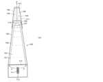
図1Aおよび1Bを参照すると吸引可能な媒体の発生装置に使用するためのタバコ組成物ポッドの一例が示されている。ポッドは2つのチェンバー13a、13bを含み、それぞれがタバコ組成物14a、14bを含む。最初に第1チェンバー13a内のタバコ組成物14aは、第2チェンバー13b内の第2タバコ組成物14bより大きな平均粒径を有する。その結果として、第1チェンバー13aの初期の吸引抵抗(RTD)は、第2チェンバー13bより小さく、従って、第1チェンバー13aを通る最初の流体流A1は、第2チェンバー内の流れA2より多く流れる。図1Bに示すように時間が経つにつれてタバコ組成物粒子は膨らみ、図1Bでは第1チェンバー13aのタバコ組成物14aが第1チェンバー13aのRTDが第2チェンバー13bより大きくなる程度に膨らんでおり、従って、流体は第2チェンバー13bを通って多く流れる(A2>A1)。1A and 1B, an example of a tobacco composition pod for use in an inhalable medium generator is shown. The pod includes two
図1Cを参照すると図1Aおよび1Bに示した型のタバコ組成物ポッドが組み込まれた吸引可能な媒体の発生装置1の例が示されている。大筋において、装置1は液体を揮発させ、蒸気またはエアロゾルを形成し、これは材料を通過してその材料から派生する1つ以上の成分を含有する吸引可能な媒体を製する。Referring now to FIG. 1C, an example of an inhalable medium generator 1 incorporating a tobacco composition pod of the type shown in FIGS. 1A and 1B is shown. In general, the device 1 volatilizes a liquid to form a vapor or aerosol that passes through a material to produce an inhalable medium containing one or more components derived from the material.
この点に関し、第1に注目すべきことは一般に蒸気はその臨界温度より低い温度で、気相の物質であり、これは例えば蒸気はその温度を下げずに圧力を上げることによって凝縮されて液体になり得ることを意味する。一方、一般にエアロゾルは、空気または別の気体中で微細固体粒子または液滴のコロイドである。「コロイド」は微視的に分散した不溶粒子が別の物質の全体に懸濁されている物質である。In this regard, the first thing to note is that a vapor is generally a substance in the gas phase below its critical temperature, meaning that, for example, a vapor can be condensed to a liquid by increasing its pressure without decreasing its temperature. An aerosol, on the other hand, is generally a colloid of fine solid particles or liquid droplets in air or another gas. A "colloid" is a substance in which microscopically dispersed insoluble particles are suspended throughout another substance.
再度図1を参照するとこの例の装置1は、ほぼ中空の円筒状の外方ハウジング2を有する。ハウジング2は開口端部3を有する。この例では管状のマウスピース4が開口端部3に設けられている。この例のマウスピース4は、ユーザーがハウジング2から取り外すことができる。O-リングまたは他のシール部材5がハウジング2内でのマウスピース4の封止の補助をしている。ハウジング2の他端6または他端の方にあるのは以下にさらに述べるように装置1の種々の部材に給電するためのバッテリー7である。バッテリー7は充電可能なバッテリーまたは使い捨てバッテリーであってもよい。またコントローラー8がハウジング2に以下にさらに述べるように装置1の種々の部材の稼働を制御するために設けられている。Referring again to FIG. 1, the device 1 in this example has a generally hollow cylindrical outer housing 2. The housing 2 has an open end 3. A
ハウジング2は液体10を保持するまたは含むための容器9を有する。種々の異なる形体を容器9に使用してもよい。図1の例では容器9は開口端部3と他端6の間でハウジング2に設けられた環状のチェンバー9の形体である。この特定の例ではハウジング2は2つの部分、即ち開口端部3の方にある第1部分2aと他端6の方にある第2端部2bからなる。ハウジング2の第1および第2部分2a、2bは、ねじ山、バイオネット嵌めなどによって互いに接続してもよい。使用の際、ユーザーはハウジング2の第1および第2部分2a、2bを離して、必要に応じて液体10を補充または交換できる。これとは別にマウスピース4を外して容器に触れられるようにすることも可能である。しかしながら、当然のことながら他の構成も可能である。例えば、液体10をハウジング2から全体的に取り外すことができる個別の環状のポット状容器に設けてもよい。このような個別の容器は、ユーザーが液体10を含む新しい容器をハウジング2に嵌めることで液体10を交換できるように使い捨てであってもよい。あるいはこのような容器を再使用可能にしてもよい。このような場合ユーザーは、容器がハウジング2から取り外されている間に容器内の液体10を補充または交換して、この補充された容器をハウジングに戻してもよい。当然のことながらハウジング2は、2つの部分から構成される必要はなく、ユーザーが触れることができるようにする他の構成、例えばその場で補充できるようにしてもよい。The housing 2 has a
ヒーター11はハウジング2のほぼ中央、即ちこの例ではハウジングの長さと幅に沿って中央に設けられている。この例ではヒーター11は、バッテリー7によって給電され、従ってバッテリー7に電気的に接続されている。ヒーター11は、例えばニクロム抵抗性ヒーター、セラミックヒーターなどを含む電気抵抗性ヒーターであってもよい。ヒーター11は、例えばコイル形状であってもよいワイヤ、プレート(2つ以上の異なる材料からなり、それの1つ以上が導電性であり、1つ以上が非導電性であってもよい多層プレートであってもよい)、メッシュ(織りまたは不織であってもよく、同様に多層構造であってもよい)、フィルムヒーターなどであってもよい。非電気的加熱装置などの他の加熱装置を使用してもよい。The
ヒーター11は液体10を揮発させるために設けられている。図示の例では環状の芯12がヒーター11を囲み、ヒーター11と(熱的に)接触している。環状の芯12の最外面は、液体容器9に含まれる液体10と接触する。芯12は一般的に吸収材であり、毛管作用により液体容器9から液体10を吸い込むように作用する。芯12は、好ましくは不織であり、例えばコットンまたはウール材料等または例えばポリエステル、ナイロン、ビスコース、ポリプロピレンなどの合成材料であってもよい。これとは別に芯はセラミックまたは金属材料であってもよい。これについては後でより詳しく説明するが、ここで注目すべきは使用の際、芯によって吸い込まれる液体10は、ヒーター11によって加熱されるということである。液体10は、揮発させて液滴のエアロゾルを製してもよく、充分に加熱して蒸気を製してもよい。そのように製せられたエアロゾルまたは蒸気は、芯12を出て、ユーザーのマウスピース4での吸引作用によって矢印Aに示すようにマウスピース4の方に移動する。ヒーター11と芯12は、単独の効果的に一体化された場合によっては「アトマイザー」と称されるアイテムとして供して加熱と吸い上げが単独のユニットで効果的に行われるようにしてもよい。The
ハウジング2は、装置1内にタバコ組成物14a、14bを保持するまたは含む2つのチェンバー13a、13bをさらに含む。使用時にはユーザーは、マウスピース4を取り外すおよび/またはハウジング2の2つの部分2a、2bを離すことによってハウジング2の開口端部3を介してタバコ組成物14a、14bを交換または補充するためにチェンバー13a、13bに触れることができる。種々の異なる形状をチェンバー13a、13bに使用してもよい。例えば、チェンバー13a、13bは、それぞれ両端が完全に開口し、タバコ組成物14a、14bを含む管であってもよい。別の例としてチェンバー13a、13bは、それぞれ蒸気またはエアロゾルが通過できる孔を有する1つ以上の端部壁を有する(図1Aおよび1Bに示すように)管であってもよい。チェンバー13a、13bは、ユーザーがタバコ組成物14a、14bを取り除き、交換する間、ハウジング2内のその位置に留まってもよい。これとは別にタバコ組成物14a、14bを含むチェンバー13a、13bは、使用時にはハウジング2にまとめて挿入され、ハウジングから取り外される別々の物であってもよい。この種の取り外し可能なチェンバー13a、13bは、ユーザーが新鮮なタバコ組成物を含む新しいチェンバー13a、13bをハウジング2に嵌めることによってタバコ組成物14a、14bを交換できるように使い捨てであってもよい。別例としてチェンバー13a、13bは、繰り返し使用してもよい。このような場合ユーザーはチェンバーをハウジング2から取り外している間にチェンバー13a、13bのタバコ組成物14a、14bを交換して、次にその充填されたチェンバー13をハウジング2に戻してもよい。さらに別の例ではチェンバー13a、13bはハウジング2の内部に設けられ、タバコ組成物を所定の位置に保持するクリップまたはそのようなものを含んでもよい。一部の例ではタバコ組成物は単にそれらの対応するチェンバー13a、13b内に滑り嵌めされる。さらに別の例として液体10を含む容器9は、それ自体がタバコ組成物14a、14bを支持または支えるために配置されてもよい。例えば、容器9はタバコ組成物14a、14bを所定の位置に収容および保持するための1つ以上のクリップまたは管を有してもよい。液体10を含むそしてタバコ組成物を収容するためのこのような2つの機能を有する容器9/チェンバーまたは受け部13a、13bは、カートリッジまたはそのようなものの形状であってもよく、使い捨ての物品であってもよく、繰り返し使用してもよく、液体10とタバコ組成物14a、14bは、ユーザーによって必要に応じて交換または継ぎ足される。場合によってはそれは充分な液体が数回の使用のために供されていて、ユーザーが時々タバコ組成物14a、14bを継ぎ足すまたは交換する必要があるということであってもよい。液体10が消費されると、ユーザーはその2つの機能を有する容器9/受け部13a、13bを廃棄し、新しい物を使用する。同様に充分なタバコ組成物が数回の使用のために供されていて、ユーザーが時々液体10を継ぎ足すまたは交換する必要があるということであってもよい。タバコ組成物が消費されると、ユーザーはその2つの機能を有する容器9/受け部13a、13bを廃棄し、新しい物を使用する。2つの機能を持った容器9/受け部の具体例については以下に述べる。The housing 2 further includes two
タバコ組成物14a、14bは、エアロゾルまたは蒸気が液体10から製せられる所の下流でかつハウジング2の開口端部3とマウスピース4の上流でハウジング2内に位置する。この特定の例ではタバコ組成物14a、14bはハウジング2の同じ部分またはチェンバーに効果的に設けられる。液体10から製せられるエアロゾルまたは蒸気は芯12を出て矢印Aで示すようにマウスピースでのユーザーの吸い込みの作用によってタバコ組成物14a、14bの方へと移動する。この特定の実施態様ではタバコ組成物は、エアロゾルまたは蒸気がタバコ組成物を通過し、次にハウジング2の開口端部3およびマウスピース4を通過するように多孔質である。エアロゾルまたは蒸気によって搬送される熱によってタバコ組成物からのニコチンおよび他の揮発性物質の揮発を増進させ、これらは通過するエアロゾル/蒸気に同伴される。タバコ組成物14a、14bを通る流れの相対流量は使用時に変化し、これは上記図1Aおよび1Bに関して説明し、例示したもののような本明細書中で説明したいずれかの機構によるものであってもよい。The
一部の実施態様ではタバコ組成物14a、14bおよび/またはそれらのチェンバー13a、13bは、エアロゾルまたは蒸気がタバコ組成物全体を通って流れるようにタバコ組成物/チェンバーとハウジング2の内部との間に空隙ができないように配置される。In some embodiments, the
好適には液体10は、装置1の電力消費を抑えるのに役立つように妥当な温度、好ましくは100~300℃の範囲、より好ましくは約150~250℃で揮発可能な液体である。好適な材料は電子タバコ装置に従来から使用されている、例えばプロピレングリコールおよびグリセロール(グリセリンとして知られている)などがある。The liquid 10 is preferably a liquid that is vaporizable at a reasonable temperature, preferably in the range of 100-300°C, more preferably about 150-250°C, to help reduce power consumption of the device 1. Suitable materials are conventionally used in e-cigarette devices, such as propylene glycol and glycerol (also known as glycerin).
タバコ組成物14a、14bは、液体10から製せられたエアロゾルまたは蒸気がそれら組成物を通過する際にエアロゾルまたは蒸気に風味を付与する。エアロゾルまたは蒸気がタバコ組成物14a、14b内および上を通過する際、熱くなったエアロゾルまたは蒸気はタバコにその感覚刺激特性を与える材料から有機物および他の化合物または成分を同伴し、よってエアロゾルまたは蒸気がマウスピース4へと移動する際にそれらに風味を付与する。The
装置1はユーザーにニコチンを提供する。ニコチンは液体で提供されてもよく、タバコ組成物から得られたものであってもよく、タバコ組成物のコーティングまたはそのようなものとして提供されてもよく、これらのあらゆる組み合わせとして提供されてもよい。同様に香味料をタバコ組成物および/または液体に添加してもよい。The device 1 provides nicotine to a user. The nicotine may be provided in a liquid, derived from a tobacco composition, provided as a coating on a tobacco composition or the like, or any combination thereof. Similarly, flavorings may be added to the tobacco composition and/or the liquid.
図1Cに示す例ではタバコ組成物から有機物および他の化合物または成分を発生させるために必要とされる装置1内のタバコ組成物14a、14bを加熱するための唯一の熱源は、液体10の加熱から製せられる熱いエアロゾルまたは蒸気である。In the example shown in FIG. 1C, the only heat source required to heat the
図2を参照すると 吸引可能な媒体の発生装置の別の例が示されている。次の説明およ
び図2では図1A~1Cを参照して説明した例の対応する部品および特徴と同じまたは類似する部品および特徴は、同じ符号を有するが200が足されている。簡潔にするためにこれら部品および特徴の説明は全体としてここでは繰り返さない。当然のことながら図1A~1Cの例に関して上述した構成および別例などは図2の例にも当てはまる。ここでも大筋において図2の装置201は液体を加熱して蒸気またはエアロゾルを形成し、これはタバコ組成物214a、214bを通過してタバコ組成物から派生する1つ以上の成分を含む吸引可能な媒体を製する。 Referring now to Figure 2, another example of an apparatus for generating inhalable medium is shown. In the following description and in Figure 2, parts and features that are the same or similar to corresponding parts and features of the example described with reference to Figures 1A-1C have the same reference numerals, but with the increment 200. For the sake of brevity, the description of these parts and features will not be repeated here in their entirety. It will be appreciated that the configurations and variations described above with respect to the example of Figures 1A-1C also apply to the example of Figure 2. Again, in broad terms, the
この例の装置201は、開口端部203と管状のマウスピース204を有するほぼ中空の円筒状の外方ハウジング202を有する。この例のマウスピース204はユーザーがハウジング202から取り外すことができ、O-リングまたは他のシール部材205がハウジング202内でのマウスピース204の封止の補助をしている。装置201の種々の部材に給電するためのバッテリー207とコントローラー208がハウジング202の他端206または他端の方に設けられている。この例のハウジング202は2つの部分からなり、第1部分202aは開口端部203の方であり、第2部分202bは他端206の方である。The
ハウジング202は液体210を保持するまたは含むための容器209を有する。容器209は図1Cの例に関して上述した型のいずれであってもよい。ヒーター211が液体210を揮発させるためにハウジング202のほぼ中央(長手方向および幅方向において)に設けられている。この例ではヒーター211はバッテリー207によって給電され、従って、バッテリー207に電気的に接続されている。ヒーター211は電気抵抗性ヒーター、セラミックヒーターなどであってもよい。ヒーター211は、例えばコイル状のワイヤ、プレート(2つ以上の異なる材料からなり、それの1つ以上が導電性であり、1つ以上が非導電性であってもよい多層プレートであってもよい)、メッシュ(織りまたは不織であってもよく、同様に多層構造であってもよい)、フィルムヒーターなどであってもよい。誘導加熱装置または非電気加熱装置などの他の加熱装置も使用してもよい。環状の芯212がヒーター211を囲み、ヒーター211と(熱)接触している。環状の芯212の最外面は液体容器209内の液体210と接触している。液体210は加熱され、液滴のエアロゾルを製するか、蒸気を製するために充分に加熱されてもよい。そのように製せられたエアロゾルまたは蒸気は、芯212を出て、ユーザーのマウスピース204での吸引作用によって矢印Aに示すようにマウスピース204の方に移動する。ヒーター211と芯212は、単独の効果的に一体化されたアイテムとして供して加熱と吸い上げが単独のユニットで効果的に行われるようにしてもよい。The
ハウジング202は、2つのチェンバー213a、213bをさらに含み、これらは装置201内でタバコ組成物214a、214bを保持するまたは含む。チェンバー213a、213bは、図1Cの例に関して上述した型のいずれであってもよい。タバコ組成物214a、214bは、エアロゾルまたは蒸気が液体210から製せられる所の下流でかつハウジング202の開口端部203とマウスピース204の上流でハウジング202内に位置する。この特定の例ではタバコ組成物214a、214bは、ハウジング202の同じ部分またはチェンバーに効果的に設けられる。液体210から製せられるエアロゾルまたは蒸気は芯212を出て矢印Aで示すようにマウスピース204でのユーザーの吸い込みの作用によってタバコ組成物の方へと移動する。特定の実施態様ではタバコ組成物214a、214bは、エアロゾルまたは蒸気がタバコ組成物を通過し、次にハウジング202の開口端部203およびマウスピース204を通過するように多孔質である。エアロゾルまたは蒸気によって搬送される熱によってタバコ組成物からのニコチンおよび他の揮発性物質を揮発させ、これらは通過するエアロゾル/蒸気に同伴される。タバコ組成物214a、214bを通る流れの相対流量は使用時に変化し、これは上記図1Aおよび1Bに関して説明し、例示したもののような本明細書中で説明したいずれかの機構によるものであってもよい。The
一部の実施態様ではタバコ組成物214a、214bおよび/またはそれらのチェンバー213a、213bは、エアロゾルまたは蒸気がタバコ組成物全体を通って流れるようにタバコ組成物/チェンバーとハウジング202の内部との間に空隙ができないように配置される。エアロゾルまたは蒸気がタバコ組成物214a、214b内および上を通過する際、熱くなったエアロゾルまたは蒸気はタバコにその感覚刺激特性を与える材料から有機物および他の化合物または成分を同伴し、よってエアロゾルまたは蒸気がマウスピース204へと移動する際にそれらに風味を付与する。In some embodiments, the
図2の例の装置201ではオーブンヒーターなどの第2ヒーター215がタバコ組成物214a、214bに熱接触した状態で設けられ、タバコ組成物を予備加熱するおよび/または装置201を使用している間タバコ組成物を付加的に加熱する。これは使用の際、蒸気またはエアロゾルがタバコ組成物を通過する際にタバコ組成物からの成分の放出を促進させる。タバコ組成物の望ましい加熱を達成するために加熱される液体の量は少なくなる。第2ヒーター215は、例えばバッテリー207によって給電される電気抵抗ヒーター、セラミックヒーターなどであってもよい。ヒーター215は、例えばコイル形状であってもよいワイヤ、プレート(2つ以上の異なる材料からなり、それの1つ以上が導電性であり、1つ以上が非導電性であってもよい多層プレートであってもよい)、メッシュ(織りまたは不織であってもよく、同様に多層構造であってもよい)、フィルムヒーターなどであってもよい。第2ヒーター215は、例えばバッテリー207によって給電される誘導ヒーターであってもよい。タバコ組成物214a、214bは、誘導加熱されやすい材料を含んでもよい。非電気的加熱装置などの他の加熱装置を第2ヒーター215に使用してもよい。In the
ヒーター215はタバコ組成物214a、214bからニコチンまたは他の揮発性物質を揮発させてもよい。The
図2の装置201の例ではタバコ組成物を加熱するためのヒーター215は、タバコ組成物の外部に設けられ、タバコ組成物をタバコ組成物の外部からの熱伝導によって加熱する。この例のヒーター215は、ほぼ円筒状である。ヒーター215は、実際には装置201の一体部品であり、ハウジング202の一部として設けてもよい。これとは別にヒーター215は、タバコ組成物214a、214bを保持するまたは含むチェンバー213a、213bと一体に設けてもよい。この別例ではチェンバー213a、213bが使い捨ての場合、ヒーター215は、新鮮なタバコを有する新しいチェンバーがユーザーによって装置201に装填される際に交換される。In the example of
ここで図3を参照すると吸引可能な媒体の発生装置の別の例が示されている。次の説明および図3では 図1Cを参照して説明した例の対応する部品および特徴と同じまたは類
似する部品および特徴は、同じ符号を有するが300が足されている。簡潔にするためにこれら部品および特徴の説明は全体としてここでは繰り返さない。当然のことながら図1Cおよび図2の例に関し上述した構成および代替えなどは図3の例にも適用可能である。ここでも大筋において図3の装置301は液体を加熱して蒸気またはエアロゾルを形成し、これはタバコ組成物314a、314bを通過してタバコ組成物から派生する1つ以上の成分を含む吸引可能な媒体を製する。 Referring now to Figure 3, another example of an apparatus for generating inhalable medium is shown. In the following description and in Figure 3, parts and features that are the same or similar to corresponding parts and features of the example described with reference to Figure 1C have the same reference numerals, but with the addition of 300. For the sake of brevity, the description of these parts and features will not be repeated here in their entirety. It will be appreciated that the configurations and alternatives, etc., discussed above with respect to the examples of Figures 1C and 2 are also applicable to the example of Figure 3. Again, in broad terms, the
この例の装置301も開口端部303と管状のマウスピース304を有するほぼ中空の円筒状の外方ハウジング302を有する。O-リングまたは他のシール部材305がハウジング302内でのマウスピース304の封止の補助をしている。装置301の種々の部材に給電するためのバッテリー307とコントローラー308がハウジング302の他端306または他端の方に設けられている。この例のハウジング302は2つの部分からなり、第1部分302aは開口端部303の方であり、第2部分302bは他端306の方である。The
ハウジング302は液体310を保持するまたは含むための容器309を有する。容器309は図1および2の例に関して上述した型のいずれであってもよい。ヒーター311が液体310を揮発させるためにハウジング302のほぼ中央に設けられている。ヒーター311は上述の型のいずれのものであってもよい。この例ではヒーター311は、バッテリー307によって給電され、従って、バッテリー307に電気的に接続されている。環状の芯312がヒーター311を囲み、ヒーター311と(熱)接触している。環状の芯312の最外面は液体容器309内の液体310と接触している。液体310は加熱され、液滴のエアロゾルを製するか、蒸気を製するために充分に加熱されてもよい。そのように製せられたエアロゾルまたは蒸気は、芯312を出て、ユーザーのマウスピース304での吸引作用によって矢印Aに示すようにマウスピース304の方に移動する。ヒーター311と芯312は、単独の効果的に一体化されたアイテムとして供して加熱と吸い上げが単独のユニットで効果的に行われるようにしてもよい。The
ハウジング302は2つのチェンバー313a、313bをさらに含み、これらは装置301内でタバコ組成物314a、314bを保持するまたは含む。チェンバーは図1Cおよび2の例に関して上述した型のいずれであってもよい。(図3に示す例ではチェンバー313a、313bは端壁316を有する管の形状であり、この端壁は貫通孔317を有し、そこを蒸気またはエアロゾルが通過することができ、これは上記で一選択肢として言及している。)タバコ組成物314a、314bは、エアロゾルまたは蒸気が液体310から製せられる所の下流でかつハウジング302の開口端部303とマウスピース304の上流でハウジング302内に位置する。この特定の例では再び、タバコ組成物はハウジング302の同じ部分またはチェンバーに効果的に設けられる。液体310から製せられるエアロゾルまたは蒸気は、芯312を出て矢印Aで示すようにマウスピース304でのユーザーの吸い込みの作用によってタバコ組成物の方へと移動する。特定の実施態様ではタバコ組成物314a、314bはエアロゾルまたは蒸気がタバコ組成物を通過し、次にハウジング302の開口端部303およびマウスピース304を通過するように多孔質である。エアロゾルまたは蒸気によって搬送される熱によってタバコ組成物からのニコチンおよび他の揮発性物質を揮発させ、これらは通過するエアロゾル/蒸気に同伴される。タバコ組成物314a、314bを通る流れの相対流量は使用時に変化し、これは上記図1Aおよび1Bに関して説明し、例示したもののような本明細書中で説明したいずれかの機構によるものであってもよい。The
一部の実施態様では タバコ組成物および/またはそれらのチェンバーは、エアロゾル
または蒸気がタバコ組成物全体を通って流れるようにタバコ組成物/チェンバーとハウジング302の内部との間に空隙ができないように配置される。エアロゾルまたは蒸気がタバコ組成物内および上を通過する際、熱くなったエアロゾルまたは蒸気はタバコにその感覚刺激特性を与える材料から有機物および他の化合物または成分を同伴し、よってエアロゾルまたは蒸気がマウスピース304へと移動する際にそれらに風味を付与する。液体310を含む容器309は、それ自体がタバコ組成物を支持または支えるために配置されてもよい。 In some embodiments, the tobacco compositions and/or their chambers are positioned such that there are no voids between the tobacco composition/chamber and the interior of the
図3の装置301の例では第2ヒーター318がタバコ組成物314a、314bを加熱するためにタバコ組成物に熱接触した状態で設けられ、使用の際に蒸気またはエアロゾルがタバコ組成物を通過する際にタバコ組成物から成分の放出を促進させる。第2ヒーター318は、例えばバッテリー307によって給電される電気抵抗ヒーター、セラミックヒーターなどであってもよい。非電気加熱装置などの他の加熱装置を第2ヒーター318に使用してもよい。In the
図3の例の装置301ではタバコ組成物314a、314bを加熱するためのヒーター318がタバコ組成物の内部に設けられており、タバコ組成物の内部からの熱伝導によってタバコ組成物を加熱する。この例のヒーター318は、一般にタバコ組成物の中央長手方向軸に沿って位置する円筒状ロッドの形体である。他の構成ではヒーター318は、コイル形状であってもよいワイヤ、プレート(2つ以上の異なる材料からなり、それの1つ以上が導電性であり、1つ以上が非導電性であってもよい多層プレートであってもよい)、メッシュ(織りまたは不織であってもよく、同様に多層構造であってもよい)、フィルムヒーターなどであってもよい。タバコ組成物は、ほぼ管状であり、そうでなければヒーター318を受けるための内部開口部を有する。ヒーター318は、実際には装置301の一体部品であり、ハウジング302の一部として設けてもよい。この場合タバコ組成物314a、314bが装置301内に充填される際(例えば、タバコ組成物を含むチェンバー313a、313bが装置301に装填される際)、タバコ組成物は第2ヒーター318を囲む。これとは別にヒーター318はチェンバー313a、313bと一体に設けてもよい。この別例ではチェンバーが使い捨ての場合、ヒーター318は、新鮮な材料を有する新しいチェンバーがユーザーによって装置301に装填される際に交換される。In the
別の例では複数の内部ヒーター318を設けてタバコ組成物をより効率的に加熱するようにしてもよい。別の例ではタバコ組成物は、1つ以上の外部ヒーター(図2の例の第2ヒーター215のような)と1つ以上の内部ヒーター(図3の例の第2ヒーター318のような)によって加熱してもよい。In another example, multiple
タバコ組成物を加熱するように構成された1つ以上のヒーター318は、タバコ組成物からニコチンまたは他の揮発性物質を揮発させてもよい。One or
ここで図4を参照すると液体602を含むための液体容器601とタバコ組成物604a、604b用の容器603a、603bを有するカートリッジ600の例の長手方向の断面が略式に示されている。この例では液体容器601とタバコ組成物容器603は、最初から一体に形成されるか、あるいは最初は2つまたは3つの部品で形成し、その後実質的に永久的に組み立てられるかのいずれかによって1つの一体部材として提供される。カートリッジ600は、液体602が液滴のエアロゾルを製するために揮発されるまたは蒸気を製するために充分に加熱されると、エアロゾルまたは蒸気の少なくとも一部、好ましくは全てまたはほぼ全てがタバコ組成物604a、604bを通過してこれらタバコ組成物から風味を捕捉するように構成されている。4, a longitudinal cross-section of an
図4の例では液体容器601はカートリッジ600のほぼ中央に設けられている。図示の例の液体容器601は円錐台形状であるが、円錐状、円筒状などの異なる形状であってもよい。液体容器601は外方シェル605に囲まれており、このシェルは液体容器601の長さ方向外側で環状の流路606を画定し、液体容器601の一端から他端へと延びている。外方シェル605は、液体容器601の第1端部壁607を越えて延び、液体容器601の第1端部壁607を越えてチェンバー608を画定する。環状の流路606およびチェンバー608は、凹部をタバコ組成物604a、604bを含む2つの容器603a、603bに分割するように仕切られている。他の例では、タバコ組成物は容器603a、603bから仕切られているチェンバー608のみに設けられてもよく、環状の流路606は空である。チェンバー608は液体容器601の端部壁607から離れて位置する端部壁609によって閉じられている。端部壁609は外方シェル605の一部であってもよく、あるいは別個のプラスチックまたはゴム製キャップなどであってもよい。さらに別の例では環状の流路606は容器603a、603bを形成するための仕切られてもよく、タバコ組成物は流路606に設けられ、チェンバー608に含まれる材料はなく、よって、チェンバー608は省略してもよく、流路606は端部壁609で効果的に終結する。流路606および/またはチェンバー608は完全にタバコ組成物で満たされてもよく、あるいは材料の一部または一塊だけを含んでもよい。端部壁609は、多孔性であるおよび/またはユーザーによって吸引されるようにカートリッジ600からエアロゾルまたは蒸気が出られるようにする1つ以上の貫通孔610を有する。液体容器601と固体チェンバー603a、603bは、それぞれ硬質、水密かつ気密の材料、例えば金属、好適なプラスチックなどで形成してもよい。In the example of FIG. 4, the
図4に示すカートリッジ600の例は、ヒーター611およびヒーター611と(熱)接触している芯612が設けられている。この例ではヒーター611と芯612は場合によっては「アトマイザー」と称される単独のユニットとして供される。この場合カートリッジ600がアトマイザーを含むと、そのようなカートリッジは「カトマイザー」と称される場合もある。ヒーター611の向きが略式に示されており、例えば、ヒーター611は、図4に示すようにカートリッジ600の長手方向軸に平行ではなく、直行する長手方向軸を有するコイルを有してもよい。The
芯612は液体602と接触している。これは例えば芯612が液体容器601の第2端部壁613の貫通穴(図示せず)に挿入されることによって行ってもよい。これとは別にまたはこれに加えて第2端部壁613は、液体が液体容器を通過できるようにする多孔質部材(図4に破線で略式に示すように)であってもよく、芯612は多孔性第2端部壁613と接触してもよい。第2端部壁613は、例えば多孔性セラミックディスクの形状であってもよい。この種の多孔性第2端部壁613は芯612への液体の流れを制御する役割を果たす。芯612は一般に吸収剤であり、毛管作用によって液体容器601から液体602を引き込む作用をする。芯612は好ましくは不織であり、例えばコットンまたはウールなどまたは例えばポリエステル、ナイロン、ビスコース、ポリプロピレンなどを含む合成材料であってもよい。The
使用時、カートリッジ600はユーザーによって装置(図示せず)のバッテリーセクションに連結され、ヒーター611が給電できるようになっている。アトマイザーのヒーター611が給電されると(例えば、装置全体のボタンを操作することによってまたはそれ自体は知られている装置全体のパフ検知器によって引き起こされてもよい)、芯612によって液体容器601から引き込まれる液体602はヒーター611によって加熱されて液体を揮発させるまたは気化させる。ユーザー全体装置のマウスピースで吸い込みを行うと、蒸気またはエアロゾルが矢印Aで示すように液体容器601の長さの外側周囲の環状流路606とチェンバー608内に移動する。蒸気またはエアロゾルはタバコ組成物604a、604bから風味を捕捉する。タバコ組成物604a、604bを通る流れの相対流量は使用時に変化し、これは上記図1Aおよび1Bに関して説明し、例示したもののような本明細書中で説明したいずれかの機構によるものであってもよい。In use, the
エアロゾルまたは蒸気によって搬送される熱によってタバコ組成物からのニコチンおよび他の揮発性物質を揮発させ、これらは通過するエアロゾル/蒸気に同伴される。蒸気またはエアロゾルは、次に矢印Bで示すように端部壁609を介してカートリッジ600から出ることができる。任意に一方向バルブ614を設けて、蒸気またはエアロゾルがカートリッジから出るだけしかできず、ヒーター611または装置全体としての電子部品にバックフローできないようにしてもよい。The heat carried by the aerosol or vapor volatilizes nicotine and other volatiles from the tobacco composition, which are entrained in the passing aerosol/vapor. The vapor or aerosol can then exit the
ここで図5を参照すると、カートリッジ700の別の例の略式長手方向断面図が示されており、これは液体702を含む液体容器701および仕切られたチェンバー708を画定する2つの容器703a、703bを有する。容器は、それぞれタバコ組成物704a、704bを保持する。次の説明および図5において、図4を参照して説明した例の対応する部品および特徴と同じまたは類似する部品および特徴は、同じ符号を有するが100が足されている。簡潔にするためにこれら部品および特徴の説明は全体としてここでは繰り返さない。Referring now to FIG. 5, there is shown a schematic longitudinal cross-sectional view of another example of a
この例ではカートリッジ700の液体容器701とタバコ組成物容器703a、703bは別個の部品として提供され、これらは使用時に取り外し自在に互いに接続される。液体容器701とタバコ組成物容器703a、703bは、例えばクリップ留めまたは互いに取り外し自在に固定されてもよく、または例えばタバコ組成物容器は液体容器701に単に載せるまたは密な摩擦嵌めしてもよい。カートリッジ700は、液体702が液滴のエアロゾルを製するために揮発されるまたは蒸気を製するために充分に加熱されると、エアロゾルまたは蒸気の少なくとも一部、好ましくは全てまたはほぼ全てがタバコ組成物704a、704bを通過してこれらタバコ組成物から風味を捕捉するように構成されている。タバコ組成物704a、704bを通る流れの相対流量は使用時に変化し、これは上記図1Aおよび1Bに関して説明し、例示したもののような本明細書中で説明したいずれかの機構によるものであってもよい。In this example, the
この例では液体容器701は外方シェル705に囲まれており、このシェルは液体容器701の長さ方向外側で環状の流路706を画定し、液体容器701の一端から他端へと延びている。外方シェル705は、液体容器701の第1端部壁707を越えて延び、端部壁709で終結する。端部壁709は別個のプラスチックまたはゴム製キャップなどであってもよい。端部壁709は多孔性でありおよび/または1つ以上の貫通孔710を有し、エアロゾルまたは蒸気が環状の流路706から出られるようになっている。一方向バルブ714を端部壁709の内側に設けて、蒸気またはエアロゾルがヒーター711および芯712から離れた端部で環状流路706から出るだけしかできず、ヒーター711または装置全体としての電子部品にバックフローできないようにしてもよい。タバコ組成物容器703a、703bは使用の際端部壁709に亘って配置され、端部壁709から出た蒸気またはエアロゾルがタバコ組成物容器内に移動するようになっている。タバコ組成物容器は出口開口部および/または多孔質端部壁715を有し、エアロゾルまたは蒸気がカートリッジ700を出て、ユーザーに吸引されるようになっている。In this example, the
使用時、カートリッジ700はユーザーによって装置(図示せず)のバッテリーセクションに連結され、ヒーター711が給電できるようになっている。アトマイザーのヒーター711が給電されると(例えば、装置全体のボタンを操作することによってまたはそれ自体は知られている装置全体のパフ検知器によって引き起こされてもよい)、芯712によって液体容器701から端部壁713を介して引き込まれる液体702がヒーター711によって加熱され、液体を揮発させるまたは蒸発させる。ユーザーが全体装置のマウスピースで吸い込みを行うと、蒸気またはエアロゾルが矢印Aで示すように液体容器701の長さの外側周囲の環状流路706内へ外方シェル705の端部壁709の方へと移動する。蒸気またはエアロゾルは、それから端部壁709を介して(一方向バルブがある場合それを介して)タバコ組成物容器703a、703bに移動し、そこでタバコ組成物704a、704bから風味を捕捉する。エアロゾルまたは蒸気によって搬送される熱によってタバコ組成物からのニコチンおよび他の揮発性物質を揮発させ、これらは通過するエアロゾル/蒸気に同伴される。蒸気またはエアロゾルは、次に矢印Bで示すようにタバコ組成物容器の端部壁715を介してカートリッジ700から出ることができる。In use, the
図4および5に示す例は、特にカトマイザーがバッテリーセクション(図示せず)に典型的にはねじ山、バイオネット嵌めなどによって嵌装されるいわゆるモジュラーまたは「電子作動(e-go)」製品に使用するのに適している。カトマイザーは、全体的に通常は使用後に廃棄され、新しい交換用のカトマイザーが使用される。別例として必要に応じて時々ユーザーが液体を補充し、および/または固形材料を交換することも可能である。The examples shown in Figures 4 and 5 are particularly suitable for use in so-called modular or "electronically actuated (e-go)" products where the cartomizer is fitted to a battery section (not shown), typically by a thread, bayonet fit, or the like. The cartomizer as a whole is typically discarded after use and a new replacement cartomizer is used. Alternatively, the liquid can be refilled and/or the solid material replaced by the user from time to time as needed.
図4および5に示した例は、それ自体は知られている他の型の電子タバコハイブリッド装置との使用に簡単に適合される。例えば、一般に小型で従来の紙巻きタバコに類似する形状および外観を有するいわゆる「類似電子タバコ」または「紙巻きタバコ似」なる装置がある。このような装置では液体容器は、通常液体を保持するための例えばコットンからなるなんらかの詰め物材を含む。このような従来の装置のカートリッジまたはカトマイザーは、通常全体的に使い捨てであるが、本発明の実施態様を使用する例において液体を補充するおよび/または固体材料を交換することが可能になる。別例として一般に比較的多量の液体を保持するための大きな液体容器を有し、装置の多くの点でユーザーが調整できる進んだ機能を供するいわゆるタンク装置またはパーソナル気化器なるものがある。4 and 5 are easily adapted for use with other types of e-cigarette hybrid devices known per se. For example, there are so-called "e-cigarette look-alike" or "cigarette-like" devices, which are generally small and have a shape and appearance similar to a conventional cigarette. In such devices, the liquid container usually includes some kind of filler material, for example cotton, to hold the liquid. The cartridges or cartomizers of such conventional devices are usually entirely disposable, but in examples using embodiments of the present invention, it becomes possible to refill the liquid and/or replace the solid material. Another example is the so-called tank devices or personal vaporizers, which generally have a large liquid container for holding a relatively large amount of liquid, and which offer advanced user-adjustable features in many respects of the device.
上述のカトマイザー装置のいずれかの別例として液体用のアトマイザー(即ち、ヒーターと芯)を液体および材料容器と別個に設けてもよい。アトマイザーは、例えばカートリッジが使用時ユーザーによって取り外し自在に嵌められる装置全体のバッテリーセクションの一部として供されてもよい。As an alternative to any of the cartomizer devices described above, an atomizer (i.e., heater and wick) for the liquid may be provided separate from the liquid and material container. The atomizer may be provided as part of the battery section of the overall device, for example a cartridge into which a user can removably fit during use.
図4および5に関して上述した例のいずれかにおいて、タバコ組成物を「予備加熱」するためのタバコ組成物用ヒーターを設けてもよい。このヒーターはカートリッジの一部またはカートリッジが使用の際に嵌められる装置のバッテリーセクションの一部として設けてもよい。このタバコ組成物用のヒーターは、タバコ組成物のニコチンおよび他の揮発性物質を揮発させ、次にこれらは通過する蒸気/エアロゾルに同伴される。In any of the examples described above with respect to Figures 4 and 5, a tobacco composition heater may be provided to "preheat" the tobacco composition. The heater may be provided as part of the cartridge or as part of the battery section of the device into which the cartridge is fitted during use. The tobacco composition heater volatilizes the nicotine and other volatiles of the tobacco composition which are then entrained in the passing vapor/aerosol.
本明細書中では「エアロゾル発生剤」は、エアロゾルの発生を促進させる化合物または混合物である。エアロゾル発生剤は、気体の初期の気化および/または吸引可能な固体および/または液体エアロゾルへの凝集を促進することによってエアロゾルの発生を促してもよい。As used herein, an "aerosol generating agent" is a compound or mixture that facilitates the generation of an aerosol. An aerosol generating agent may facilitate the generation of an aerosol by promoting the initial evaporation of a gas and/or condensation into an inhalable solid and/or liquid aerosol.
本明細書中では「吸引抵抗」は、22℃、101キロパスカル(760トール)で1秒当たり17.5ミリメートルの流量の試験のもと物体の全長に亘って空気を強制的に通過させるために必要とされる圧力を言う。吸引抵抗は、ISO 6565:201 1に従って測定される。As used herein, "resistance to draw" refers to the pressure required to force air through the length of an object under test at 22°C, 101 kilopascals (760 torr) and a flow rate of 17.5 millimeters per second. Resistance to draw is measured in accordance with ISO 6565:201 1.
本明細書中ではタバコチェンバーを通過する「流体」は、任意の液体および/または気体であってもよい。場合によっては流体はチェンバーを介して引き込まれ、次に揮発性液から発生したエアロゾルおよび/または蒸気と混ざる空気であってもよい。場合によっては流体は揮発性液から発生したエアロゾルおよび/または蒸気を含んでもよい。As used herein, the "fluid" passing through the tobacco chamber may be any liquid and/or gas. In some cases, the fluid may be air that is drawn through the chamber and then mixes with aerosols and/or vapors generated from the volatile liquid. In some cases, the fluid may include aerosols and/or vapors generated from the volatile liquid.
一般にあらゆる好適な1つ以上のエアロゾル発生剤を本発明のエアロゾル発生材に含有させてもよい。好適なエアロゾル発生剤としては、ソルビトール、グリセリンおよびプロピレングリコールまたはトリエチレングリコールのようなグリコール類などのポリオール、一価アルコールなどの非ポリオール、高沸点炭化水素、乳酸などの酸類、グリセリン誘導体、ジアセチン、トリアセチン、トリエチレングリコールジアセタート、クエン酸トリエチルまたはミリスチン酸エチルおよびミリスチン酸イソプロピルを含むミリスチン酸エステルなどのエステル類およびステアリン酸メチル、ドデカン二酸ジメチルおよびテト
ラデカン二酸ジメチルなどの脂肪族カルボン酸エステル類が挙げられるが、これらに限定されない。 Generally, any suitable aerosol generating agent or agents may be included in the aerosol generating materials of the present invention. Suitable aerosol generating agents include, but are not limited to, polyols, such as glycols, such as sorbitol, glycerin, and propylene glycol or triethylene glycol, non-polyols, such as monohydric alcohols, high boiling point hydrocarbons, acids, such as lactic acid, glycerin derivatives, esters, such as diacetin, triacetin, triethylene glycol diacetate, triethyl citrate or myristates, including ethyl myristate and isopropyl myristate, and aliphatic carboxylic acid esters, such as methyl stearate, dimethyl dodecanedioate, and dimethyl tetradecanedioate.
本明細書中では「風味」および「香味料」なる用語は、各地の条例で許可されており、成人消費者が望む味や香りを製品に加えるのに用いることができる材料を指す。このような材料としては、抽出物(例えば、カンゾウ、アジサイ、ホオノキの葉、カミツレ、フェヌグリーク、クローブ、メントール、ニホンハッカ、アニシード、シナモン、ハーブ、ヒメコウジ、サクランボ、ベリー、モモ、リンゴ、ドランブイ、バーボン、スコッチ、ウイスキー、スペアミント、ペパーミント、ラベンダー、カルダモン、セロリ、カスカリラ、ナツメグ、サンダルウッド、ベルガモット、ゼラニウム、ハチミツエキス、ローズ油、バニラ、レモン油、オレンジ油、カシア、キャラウェイ、コニャック、ジャスミン、イランイランノキ、セージ、ウイキョウ、ピメント、ショウガ、アニス、コリアンダー、コーヒー、ハッカ属のいずれかの種からのハッカ油など)、調味料、苦味受容体部位遮断剤、感覚受容器部位活性化剤または刺激剤、糖及び/または糖置換体(例えば、スクラロース、アセスルファムカリウム、アスパルテーム、サッカリン、サイクラミン酸塩、ラクトース、スクロース、グルコース、フルクトース、ソルビトール、マンニトールなど)や、木炭、クロロフィル、鉱物、植物息消臭剤などのその他の添加剤などが挙げられる。これら材料は模造品、合成または天然成分であってもよく、またはこれらのブレンドであってもよい。これら材料は、例えば油、液体、粉末などの任意の好適な形態であってもよい。As used herein, the terms "flavor" and "flavoring agent" refer to ingredients permitted by local regulations that may be used to impart a taste or aroma desired by adult consumers to a product. Such ingredients include extracts (e.g., licorice, hydrangea, magnolia leaf, chamomile, fenugreek, clove, menthol, mint, aniseed, cinnamon, herbs, wintergreen, cherry, berry, peach, apple, Drambuie, bourbon, Scotch, whiskey, spearmint, peppermint, lavender, cardamom, celery, cascarilla, nutmeg, sandalwood, bergamot, geranium, honey extract, rose oil, vanilla, lemon oil, orange oil, cassia, caraway, cognac, jasmine, etc.) , ylang-ylang, sage, fennel, pimento, ginger, anise, coriander, coffee, peppermint oil from any species of the genus Mentha, etc.), flavor enhancers, bitter receptor site blockers, sensory receptor site activators or stimulants, sugars and/or sugar substitutes (e.g., sucralose, acesulfame potassium, aspartame, saccharin, cyclamates, lactose, sucrose, glucose, fructose, sorbitol, mannitol, etc.), and other additives such as charcoal, chlorophyll, minerals, botanical breath fresheners, etc. These materials may be imitation, synthetic or natural ingredients, or may be blends thereof. These materials may be in any suitable form, for example, oils, liquids, powders, etc.
誤解を避けるために、本明細書で「含む(comprises)」が本発明または本発明の特徴
の定義に使用される場合、本発明または特徴が「含む(comprises)」の代わりに「から
実質的になる(consists essentially of)」または「からなる(consists of)」を使用して定義することができる実施態様も開示される。 For the avoidance of doubt, where "comprises" is used herein to define the invention or a feature of the invention, embodiments are also disclosed in which the invention or feature can be defined using "consists essentially of" or "consists of" instead of "comprises."
誤解を避けるために、本明細書で「第1」および「第2」なる用語が組成物/チェンバーに使用された場合、使用の順番の明確な開示はない。「第1」および「第2」は、単に異なる組成物またはチェンバーを表す手段として単に使用されている。1つのチェンバーまたは組成物に関して考察される特徴は、適宜各チェンバーまたは組成物に関して明確に開示されているものとする。For the avoidance of doubt, when the terms "first" and "second" are used herein to refer to compositions/chambers, there is no express disclosure of an order of use. "First" and "second" are merely used as a means of describing different compositions or chambers. Features discussed with respect to one chamber or composition shall be expressly disclosed with respect to each chamber or composition, as appropriate.
上記の実施態様は本発明の説明に役立つ実例として理解されたい。本発明のさらなる実施態様が想定される。当然のことながら任意の1つの実施態様について説明したあらゆる特徴は単独または説明された他の特徴と組み合わせて使用してもよく、他の実施態様のいずれかの1つ以上の特徴または他の実施態様のいずれかのあらゆる組み合わせと組み合わせて使用してもよい。さらに上記で説明されていない同等物および修飾物も添付の特許請求の範囲に規定されている本発明の範囲を逸脱することなく採用することも可能である。The above-described embodiments are to be understood as illustrative examples of the invention. Further embodiments of the invention are envisioned. It will be appreciated that any feature described with respect to any one embodiment may be used alone or in combination with the other features described, and may be used in combination with one or more features of any of the other embodiments or in any combination of any of the other embodiments. Moreover, equivalents and modifications not described above may also be employed without departing from the scope of the invention as defined in the appended claims.
ここで説明した種々の実施態様は、特許請求された特徴の理解と教示の単なる補助に提供されている。これらの実施態様は単なる代表的な具体例であり、包括的でも排他的でもない。当然だが、本開示の利点、実施形態、具体例、機能、特徴、構造、および/または他の側面は本開示を特許請求の範囲に規定されたとおりに限定するあるいは特許請求の範囲の均等物に限定すると考えるべきではなく、本開示の範囲および/または思想から乖離することなく他の実施形態を利用しても改変してもよいと考えるべきである。種々の実施形態は、開示された構成要素、成分、特徴、部品、工程、手段他の組合せを適切に備えても、これらで構成されても、基本的にこれらで構成されてもよい。また本開示は、現在は特許請求されていないが将来特許請求される可能性がある他の発明を含む。The various embodiments described herein are provided merely to aid in the understanding and teaching of the claimed features. These embodiments are merely representative examples and are not intended to be comprehensive or exclusive. It should be understood that the advantages, embodiments, examples, features, features, structures, and/or other aspects of the present disclosure should not be construed as limiting the present disclosure to the claims as set forth herein or to the equivalents of the claims, but that other embodiments may be utilized or modified without departing from the scope and/or spirit of the present disclosure. Various embodiments may suitably comprise, consist of, or consist essentially of the disclosed components, ingredients, features, parts, steps, means, or other combinations. The present disclosure also includes other inventions not currently claimed but which may be claimed in the future.
Claims (14)
Translated fromJapanese容器に保持された液体を揮発させるためのヒーターと、
第1および第2チェンバーと、
出口とを含む吸引可能な媒体の発生装置であって、
前記装置は、使用時に、蒸気および/またはエアロゾルの形態で揮発させた液体を含む吸引可能な媒体が、第1および/または第2チェンバーを通過しさらに出口を通過して出るように構成され、かつ、第1および第2チェンバーを流れる流体の相対流量が受動的手段を介して使用中に変化するように構成されており、第1チェンバーを流れる流れに対する抵抗が、蒸気および/またはエアロゾルに晒された結果として変化して、前記第1および第2チェンバーを流れる流体の相対流量が使用中に変化する、吸引可能な媒体の発生装置。 a container for holding a liquid;
a heater for volatilizing the liquid held in the container;
a first and a second chamber;
an outlet;
A device for generating inhalable medium, the device being configured such that in use, an inhalable medium comprising volatilized liquid in the form of vapour and/or aerosol passes through the first and/or second chambers and exits through an outlet, and the relative flow rates of fluid through the first and second chambers are varied in use via passive means, such that resistance to flow through the first chamber changes as a result of exposure to vapour and/or aerosol, causing the relative flow rates of fluid through the first and second chambers to vary in use .
請求項1乃至7いずれか1項記載の装置に使用するために構成されているポッド。 A pod comprising a first composition in a first chamber and a second composition in a second chamber,
A pod configured for use with an apparatus according to any preceding claim.
Applications Claiming Priority (4)
| Application Number | Priority Date | Filing Date | Title |
|---|---|---|---|
| GBGB1812373.7AGB201812373D0 (en) | 2018-07-30 | 2018-07-30 | Generation of an inhalable medium |
| GB1812373.7 | 2018-07-30 | ||
| JP2021504755AJP7291777B2 (en) | 2018-07-30 | 2019-07-25 | generation of aspirable media |
| PCT/EP2019/070017WO2020025434A1 (en) | 2018-07-30 | 2019-07-25 | Generation of an inhalable medium |
Related Parent Applications (1)
| Application Number | Title | Priority Date | Filing Date |
|---|---|---|---|
| JP2021504755ADivisionJP7291777B2 (en) | 2018-07-30 | 2019-07-25 | generation of aspirable media |
Publications (2)
| Publication Number | Publication Date |
|---|---|
| JP2023116589A JP2023116589A (en) | 2023-08-22 |
| JP7673123B2true JP7673123B2 (en) | 2025-05-08 |
Family
ID=63518260
Family Applications (2)
| Application Number | Title | Priority Date | Filing Date |
|---|---|---|---|
| JP2021504755AActiveJP7291777B2 (en) | 2018-07-30 | 2019-07-25 | generation of aspirable media |
| JP2023092633AActiveJP7673123B2 (en) | 2018-07-30 | 2023-06-05 | Generation of aspirable media |
Family Applications Before (1)
| Application Number | Title | Priority Date | Filing Date |
|---|---|---|---|
| JP2021504755AActiveJP7291777B2 (en) | 2018-07-30 | 2019-07-25 | generation of aspirable media |
Country Status (7)
| Country | Link |
|---|---|
| US (1) | US12144372B2 (en) |
| EP (1) | EP3829368A1 (en) |
| JP (2) | JP7291777B2 (en) |
| KR (2) | KR102677885B1 (en) |
| CA (1) | CA3106417A1 (en) |
| GB (1) | GB201812373D0 (en) |
| WO (1) | WO2020025434A1 (en) |
Families Citing this family (7)
| Publication number | Priority date | Publication date | Assignee | Title |
|---|---|---|---|---|
| GB202003675D0 (en)* | 2020-03-13 | 2020-04-29 | Nicoventures Holdings Ltd | Aerosol generating assembly |
| TW202145908A (en)* | 2020-04-22 | 2021-12-16 | 日商日本煙草產業股份有限公司 | Non-combustion heating type cigarette, electrically heating type cigarette and non-combustion heating type tobacco material |
| EP4164431A1 (en)* | 2020-06-12 | 2023-04-19 | JT International SA | Consumable container, aerosol generation device and refillable system thereof, and method using the system |
| GB202101606D0 (en)* | 2021-02-05 | 2021-03-24 | Nicoventures Trading Ltd | Aerosol-generating material and uses thereof |
| WO2023068789A1 (en)* | 2021-10-19 | 2023-04-27 | Kt&G Corporation | Aerosol-generating device |
| US20250009016A1 (en)* | 2021-10-19 | 2025-01-09 | Kt&G Corporation | Aerosol-generating device |
| KR102688838B1 (en)* | 2021-10-20 | 2024-07-26 | 주식회사 케이티앤지 | Aerosol generating device and method thereof |
Citations (4)
| Publication number | Priority date | Publication date | Assignee | Title |
|---|---|---|---|---|
| US20160106936A1 (en) | 2014-10-21 | 2016-04-21 | Breathe eCigs Corp. | Personal Vaporizer Having Controlled Usage |
| WO2017055584A1 (en) | 2015-10-02 | 2017-04-06 | British American Tobacco (Investments) Limited | Apparatus for generating an inhalable medium |
| WO2018020599A1 (en) | 2016-07-27 | 2018-02-01 | 日本たばこ産業株式会社 | Flavor inhaler |
| JP2018512118A (en) | 2015-02-27 | 2018-05-17 | ブリティッシュ アメリカン タバコ (インヴェストメンツ) リミテッドBritish American Tobacco (Investments) Limited | Device for generating a suckable medium |
Family Cites Families (190)
| Publication number | Priority date | Publication date | Assignee | Title |
|---|---|---|---|---|
| CA885796A (en) | 1971-11-16 | R. Johnson William | Smoking article having improved filter and method of making the same | |
| JPS4742449Y1 (en) | 1970-07-31 | 1972-12-22 | ||
| JPS488231U (en) | 1971-06-10 | 1973-01-30 | ||
| US4083372A (en) | 1976-05-24 | 1978-04-11 | Robert Boden | Cigarette-simulating inhaler |
| US4284089A (en) | 1978-10-02 | 1981-08-18 | Ray Jon P | Simulated smoking device |
| IT1119714B (en) | 1979-03-26 | 1986-03-10 | Montedison Spa | FILTERS FOR CIGARETTES AND PROCEDURE FOR THEIR PREPARATION |
| JPS60237982A (en) | 1984-05-12 | 1985-11-26 | 藤増 次郎 | Pipe used in prohibition of smoking and smoking |
| IE79075B1 (en) | 1984-09-14 | 1998-04-08 | Reynolds Tobacco Co R | A carbonaceous fuel element for a smoking article |
| SE8405479D0 (en) | 1984-11-01 | 1984-11-01 | Nilsson Sven Erik | WANT TO ADMINISTER VOCABULARY, PHYSIOLOGY, ACTIVE SUBJECTS AND DEVICE FOR THIS |
| CN1018329B (en) | 1984-12-21 | 1992-09-23 | 美国耳杰瑞诺兹烟草公司 | Carbon fuel element for smoking article and method of making same |
| US4756318A (en) | 1985-10-28 | 1988-07-12 | R. J. Reynolds Tobacco Company | Smoking article with tobacco jacket |
| GB8617831D0 (en) | 1986-07-22 | 1986-08-28 | British Petroleum Co Plc | Production of porous shaped articles |
| JPS63193499U (en) | 1987-06-02 | 1988-12-13 | ||
| US5019122A (en) | 1987-08-21 | 1991-05-28 | R. J. Reynolds Tobacco Company | Smoking article with an enclosed heat conductive capsule containing an aerosol forming substance |
| IL83826A (en) | 1987-09-08 | 1991-03-10 | Inventor S Funding Corp Ltd | Plastic mouthpiece for simulated smoking |
| US5159940A (en) | 1988-07-22 | 1992-11-03 | Philip Morris Incorporated | Smoking article |
| US5027839A (en) | 1988-10-17 | 1991-07-02 | Appell Kathleen M | Protective device for use in removing fingernail polish |
| US4913169A (en) | 1989-03-17 | 1990-04-03 | Brown & Williamson Tobacco Corporation | Smoking article |
| DE3910059C1 (en) | 1989-03-28 | 1990-11-15 | B.A.T. Cigarettenfabriken Gmbh, 2000 Hamburg, De | Smokable article |
| US5105834A (en) | 1989-12-18 | 1992-04-21 | R.J. Reynolds Tobacco Company | Cigarette and cigarette filter element therefor |
| EP0444553A3 (en) | 1990-02-27 | 1993-04-14 | R.J. Reynolds Tobacco Company | Cigarette |
| US5203355A (en) | 1991-02-14 | 1993-04-20 | R. J. Reynolds Tobacco Company | Cigarette with cellulosic substrate |
| CA2079495A1 (en) | 1991-10-03 | 1993-04-04 | John H. Kolts | Smoking article with co oxidation catalyst |
| JPH0664983A (en) | 1992-08-18 | 1994-03-08 | Tdk Corp | Cigarette filter and its production |
| GB9217914D0 (en) | 1992-08-22 | 1992-10-07 | British Petroleum Co | Phenolic resin & carbon products |
| US5613505A (en) | 1992-09-11 | 1997-03-25 | Philip Morris Incorporated | Inductive heating systems for smoking articles |
| US5327915A (en) | 1992-11-13 | 1994-07-12 | Brown & Williamson Tobacco Corp. | Smoking article |
| DE19505580A1 (en) | 1995-02-18 | 1996-08-22 | Dynamit Nobel Ag | Gas generator in sheet metal construction for a motor vehicle occupant protection device |
| TW377313B (en) | 1995-02-27 | 1999-12-21 | Corning Inc | The method of making extruded structures |
| ZA962078B (en) | 1995-03-14 | 1996-09-25 | Siemens Ag | Ultrasonic atomizer device with removable precision dosating unit |
| DE69724559T2 (en) | 1996-06-17 | 2004-07-15 | Japan Tobacco Inc. | FLAVORED ARTICLE |
| EP0845955A1 (en) | 1996-06-21 | 1998-06-10 | Cabot Safety Intermediate Corporation | Acoustical earmuff with incorporated snap-in foam cushion |
| US5944025A (en) | 1996-12-30 | 1999-08-31 | Brown & Williamson Tobacco Company | Smokeless method and article utilizing catalytic heat source for controlling products of combustion |
| DE19940713A1 (en) | 1999-02-23 | 2001-03-01 | Boehringer Ingelheim Int | Diffusion resistant cartridge for storing and dosing liquids, especially for producing drug-containing inhalable aerosols, has three-shell structure with collapsible bag, container and rigid housing |
| JP2001120250A (en) | 1999-10-22 | 2001-05-08 | Mitsubishi Rayon Co Ltd | Tobacco filter |
| CA2330782A1 (en) | 2001-01-05 | 2002-07-05 | Rupesh N. Pandey | An effective filtering device for removing hazardous chemicals in tobacco smoke |
| GB0117212D0 (en) | 2001-07-16 | 2001-09-05 | Mat & Separations Tech Int Ltd | Filter element |
| US6598607B2 (en) | 2001-10-24 | 2003-07-29 | Brown & Williamson Tobacco Corporation | Non-combustible smoking device and fuel element |
| AU2002357599A1 (en) | 2001-12-28 | 2003-07-24 | Japan Tobacco Inc. | Smoking implement |
| US7699052B2 (en) | 2002-09-05 | 2010-04-20 | Boehringer Ingelheim Pharma Gmbh & Co. Kg | Apparatus for the dispensing of liquids, container cartridge suitable for this, and system comprising the apparatus for the dispensing of liquids, and the container cartridge |
| US6814786B1 (en) | 2003-04-02 | 2004-11-09 | Philip Morris Usa Inc. | Filters including segmented monolithic sorbent for gas-phase filtration |
| US7370657B2 (en) | 2003-04-02 | 2008-05-13 | Philip Morris Usa Inc. | Activated carbon-containing sorbent |
| US8439047B2 (en) | 2003-12-22 | 2013-05-14 | Philip Morris Usa Inc. | Composite mesoporous/microporous materials and their use in smoking articles for removing certain gas phase constituents from tobacco smoke |
| US8381738B2 (en) | 2003-12-22 | 2013-02-26 | Philip Morris Usa Inc. | Composite materials and their use in smoking articles |
| US20060090769A1 (en) | 2004-11-02 | 2006-05-04 | Philip Morris Usa Inc. | Temperature sensitive powder for enhanced flavor delivery in smoking articles |
| US20060144410A1 (en) | 2004-12-30 | 2006-07-06 | Philip Morris Usa Inc. | Surface-modified activated carbon in smoking articles |
| US10285431B2 (en) | 2004-12-30 | 2019-05-14 | Philip Morris Usa Inc. | Encapsulated flavorant designed for thermal release and cigarette bearing the same |
| US20060260626A1 (en) | 2005-01-05 | 2006-11-23 | Philip Morris Usa Inc. | Activated carbons with molecular sieve membranes and their use as adsorbents in smoking articles |
| US8539957B2 (en) | 2005-01-14 | 2013-09-24 | Philip Morris Usa Inc. | Cigarettes and cigarette filters including activated carbon for removing nitric oxide |
| US20060225753A1 (en) | 2005-02-22 | 2006-10-12 | Rothmans, Benson & Hedges, Inc. | Tobacco smoke filter and tobacco blend for altering mainstream smoke |
| US7503960B2 (en) | 2005-03-15 | 2009-03-17 | Philip Morris Usa Inc. | Smoking articles and filters with carbon fiber composite molecular sieve sorbent |
| GB0506278D0 (en) | 2005-03-29 | 2005-05-04 | British American Tobacco Co | Porous carbon materials and smoking articles and smoke filters therefor incorporating such materials |
| US7878209B2 (en) | 2005-04-13 | 2011-02-01 | Philip Morris Usa Inc. | Thermally insulative smoking article filter components |
| US7767134B2 (en) | 2005-06-29 | 2010-08-03 | Philip Morris Usa Inc. | Templated carbon monolithic tubes with shaped micro-channels and method for making the same |
| US7647932B2 (en) | 2005-08-01 | 2010-01-19 | R.J. Reynolds Tobacco Company | Smoking article |
| AU2006296290A1 (en) | 2005-09-30 | 2007-04-05 | Philip Morris Products S.A. | Flavoured cigarette |
| DE102005054255A1 (en) | 2005-11-11 | 2007-05-24 | Hauni Maschinenbau Ag | Smoke-free cigarette |
| US9491971B2 (en) | 2005-12-13 | 2016-11-15 | Philip Morris Usa Inc. | Specifically-defined smoking article with activated carbon sorbent and sodium bicarbonate-treated fibers and method of treating mainstream smoke |
| US9220301B2 (en) | 2006-03-16 | 2015-12-29 | R.J. Reynolds Tobacco Company | Smoking article |
| CN201067079Y (en) | 2006-05-16 | 2008-06-04 | 韩力 | Simulated aerosol inhaler |
| US8393333B2 (en) | 2006-08-03 | 2013-03-12 | Philip Morris Usa Inc. | Immobilized diluents for smoking articles |
| IES20070633A2 (en) | 2006-09-05 | 2008-09-17 | Oglesby & Butler Res & Dev Ltd | A container comprising vaporisable matter for use in a vaporising device for vaporising a vaporisable constituent thereof |
| US7726320B2 (en) | 2006-10-18 | 2010-06-01 | R. J. Reynolds Tobacco Company | Tobacco-containing smoking article |
| CA2963423C (en) | 2007-03-30 | 2020-07-28 | Philip Morris Products S.A. | Device and method for delivery of a medicament |
| JP5089420B2 (en) | 2008-02-14 | 2012-12-05 | オルガノ株式会社 | Monolithic organic porous body, monolithic organic porous ion exchanger, production method thereof and chemical filter |
| AT507187B1 (en) | 2008-10-23 | 2010-03-15 | Helmut Dr Buchberger | INHALER |
| CN101433818A (en) | 2008-12-04 | 2009-05-20 | 南京大学 | Novel mesoporous material for absorbing granule phase substance, coke tar, phenol and amine nitrite in mainstream flue gas of tobacco |
| CN102395398B (en) | 2009-02-23 | 2016-03-16 | 日本烟草产业株式会社 | Non-power pattern of fever tobacco flavor extractor |
| BRPI1012702B1 (en) | 2009-03-17 | 2021-07-06 | Philip Morris Products S.A. | DEVICE FOR APPLYING NICOTINE TO A PATIENT, METHOD OF APPLYING NICOTINE TO A PATIENT BY INHALATION AND METHOD OF REPLACEMENT OF TOBACCO PRODUCT |
| EP2412396B2 (en) | 2009-03-23 | 2023-10-18 | Japan Tobacco, Inc. | Non-combustion article for flavor inhalation |
| GB2469842A (en) | 2009-04-29 | 2010-11-03 | British American Tobacco Co | Aerosol generating material for a smoking article |
| KR101530764B1 (en) | 2009-09-16 | 2015-06-22 | 필립모리스 프로덕츠 에스.에이. | Improved device and method for delivery of a medicament |
| US8528567B2 (en) | 2009-10-15 | 2013-09-10 | Philip Morris Usa Inc. | Smoking article having exothermal catalyst downstream of fuel element |
| GB0918129D0 (en) | 2009-10-16 | 2009-12-02 | British American Tobacco Co | Control of puff profile |
| EP2340729A1 (en) | 2009-12-30 | 2011-07-06 | Philip Morris Products S.A. | An improved heater for an electrically heated aerosol generating system |
| GB201004861D0 (en) | 2010-03-23 | 2010-05-05 | Kind Consumer Ltd | A simulated cigarette |
| US8671951B2 (en) | 2010-03-26 | 2014-03-18 | Philip Morris Usa Inc. | Methods of manufacturing cigarettes and filter subassemblies with squeezable flavor capsule |
| US10051884B2 (en) | 2010-03-26 | 2018-08-21 | Philip Morris Usa Inc. | Controlled release mentholated tobacco beads |
| CN101822420B (en) | 2010-04-22 | 2012-06-27 | 修运强 | Combined type multifunctional electronic simulated cigarette |
| US20120042885A1 (en) | 2010-08-19 | 2012-02-23 | James Richard Stone | Segmented smoking article with monolithic substrate |
| US9259035B2 (en) | 2010-05-15 | 2016-02-16 | R. J. Reynolds Tobacco Company | Solderless personal vaporizing inhaler |
| EP2399636A1 (en) | 2010-06-23 | 2011-12-28 | Philip Morris Products S.A. | An improved aerosol generator and liquid storage portion for use with the aerosol generator |
| EP2597976B1 (en) | 2010-07-30 | 2021-03-10 | Japan Tobacco, Inc. | Smokeless flavor inhalator |
| CA2807331C (en) | 2010-08-20 | 2015-05-19 | Japan Tobacco Inc. | Tobacco-flavor-releasing material and non-heating type tobacco flavor inhalator containing same |
| KR101389143B1 (en) | 2010-08-24 | 2014-04-24 | 니뽄 다바코 산교 가부시키가이샤 | Non-heating type apparatus for inhaling flavors and method for manufacturing flavor cartridge |
| US20140070465A1 (en) | 2010-10-15 | 2014-03-13 | Celanese Acetate Llc | Apparatuses, systems, and associated methods for forming porous masses for smoke filters |
| CN102160906B (en) | 2010-11-01 | 2012-08-08 | 常州市富艾发进出口有限公司 | Oral Suction Portable Nebulizer |
| EA019736B1 (en) | 2010-12-01 | 2014-05-30 | Евгений Иванович Евсюков | Inhaling device |
| EP2460423A1 (en) | 2010-12-03 | 2012-06-06 | Philip Morris Products S.A. | An electrically heated aerosol generating system having improved heater control |
| CN103491815B (en) | 2011-02-11 | 2016-01-20 | 巴特马克有限公司 | Inhalator assembly |
| SE535587C2 (en) | 2011-03-29 | 2012-10-02 | Chill Of Sweden Ab | Product containing a free nicotine salt and a non-water-soluble bag |
| GB201109419D0 (en) | 2011-06-06 | 2011-07-20 | British American Tobacco Co | Filter for a smoking article |
| US20120318882A1 (en) | 2011-06-16 | 2012-12-20 | Vapor Corp. | Vapor delivery devices |
| KR101791175B1 (en) | 2011-06-30 | 2017-10-27 | 엘지이노텍 주식회사 | Light emitting device and light emitting device package including the same |
| US9462830B2 (en) | 2011-07-12 | 2016-10-11 | Huizhou Kimree Technology Co., Ltd. | Electronic cigarette |
| GB201207054D0 (en) | 2011-09-06 | 2012-06-06 | British American Tobacco Co | Heating smokeable material |
| KR101600646B1 (en) | 2011-11-11 | 2016-03-07 | 주식회사 케이티앤지 | Flavor Delivery System for Inhalation |
| JP6189321B2 (en) | 2011-12-08 | 2017-08-30 | フィリップ・モーリス・プロダクツ・ソシエテ・アノニム | Aerosol generating device with air flow nozzle |
| GB2500957A (en) | 2011-12-23 | 2013-10-09 | Qiuming Liu | Electronic cigarette suction nozzle |
| EP2625974A1 (en) | 2012-02-13 | 2013-08-14 | Philip Morris Products S.A. | Aerosol-generating article having a flavour-generating component |
| AR089602A1 (en) | 2011-12-30 | 2014-09-03 | Philip Morris Products Sa | AEROSOL GENERATOR ARTICLE FOR USE WITH AN AEROSOL GENERATOR DEVICE |
| EP2797445B1 (en) | 2011-12-30 | 2016-05-04 | Philip Morris Products S.a.s. | Aerosol generating device with improved temperature distribution |
| EP2625975A1 (en) | 2012-02-13 | 2013-08-14 | Philip Morris Products S.A. | Aerosol-generating article having an aerosol-cooling element |
| WO2013101242A1 (en) | 2011-12-31 | 2013-07-04 | Intel Corporation | Bbul top side substrate layer enabling dual sided silicon interconnect and stacking flexibility |
| CA2862451C (en) | 2012-01-03 | 2020-02-18 | Philip Morris Products S.A. | An aerosol generating device and system with improved airflow |
| PL2801697T3 (en) | 2012-01-06 | 2020-06-15 | He, Manchao | Longwall working face, non-pillared mining method |
| GB201200558D0 (en) | 2012-01-13 | 2012-02-29 | British American Tobacco Co | Smoking article |
| US9854839B2 (en) | 2012-01-31 | 2018-01-02 | Altria Client Services Llc | Electronic vaping device and method |
| US9289014B2 (en) | 2012-02-22 | 2016-03-22 | Altria Client Services Llc | Electronic smoking article and improved heater element |
| WO2013138384A2 (en) | 2012-03-12 | 2013-09-19 | Uptoke Llc | Electronic vaporizing device and methods for use |
| US20140048085A1 (en) | 2012-03-28 | 2014-02-20 | Borealis Technical Limited | Cooling filter for cigarettes and smoking articles |
| RU2597540C2 (en) | 2012-04-18 | 2016-09-10 | Фонтем Холдингз 1 Б.В. | Electronic cigarette |
| US9820506B2 (en) | 2012-04-30 | 2017-11-21 | Philip Morris Products S.A. | Smoking article mouthpiece including aerogel |
| RU122254U1 (en) | 2012-08-28 | 2012-11-27 | Валентин Владимирович Ильин | DISPOSABLE ELECTRONIC CIGARETTE |
| CN204519356U (en) | 2012-09-27 | 2015-08-05 | 惠州市吉瑞科技有限公司 | Magnetic force connects electronic cigarette |
| US20140123989A1 (en) | 2012-11-05 | 2014-05-08 | The Safe Cig, Llc | Device and method for vaporizing a fluid |
| CN102894486A (en) | 2012-11-07 | 2013-01-30 | 修运强 | Spirally-driven slidably-punctured electronic smoking set |
| US9943107B2 (en) | 2012-12-17 | 2018-04-17 | Sis Resources, Ltd. | Cartomizer flavor enhancement |
| TWI608805B (en) | 2012-12-28 | 2017-12-21 | 菲利浦莫里斯製品股份有限公司 | Heated aerosol-generating device and method for generating aerosol with consistent properties |
| CN112353001B (en) | 2013-01-24 | 2025-02-25 | 富特姆投资有限公司 | Methods, compositions and devices for functionalization of aerosols for non-combustible smoking articles |
| MY189478A (en) | 2013-02-22 | 2022-02-16 | Altria Client Services Llc | Electronic smoking article |
| JP5882535B2 (en) | 2013-03-08 | 2016-03-09 | 日本たばこ産業株式会社 | Non-burning flavor inhaler |
| US20140261486A1 (en) | 2013-03-12 | 2014-09-18 | R.J. Reynolds Tobacco Company | Electronic smoking article having a vapor-enhancing apparatus and associated method |
| RU2672657C2 (en) | 2013-03-15 | 2018-11-16 | Филип Моррис Продактс С.А. | Smoking article with airflow directing element comprising aerosol-modifying agent |
| TW201446291A (en) | 2013-03-15 | 2014-12-16 | Philip Morris Products Sa | Aerosol-generating system with differential heating |
| SI2967135T1 (en) | 2013-03-15 | 2017-05-31 | Philip Morris Products S.A. | Aerosol-generating device comprising multiple solid-liquid phase-change materials |
| US10264819B2 (en) | 2013-03-15 | 2019-04-23 | Altria Client Services Llc | Electronic smoking article |
| WO2014155458A1 (en) | 2013-03-29 | 2014-10-02 | パナソニック液晶ディスプレイ株式会社 | Display device |
| ES2630715T3 (en) | 2013-05-21 | 2017-08-23 | Philip Morris Products S.A. | Spray comprising a distribution agent and a source of the drug |
| US9877511B2 (en) | 2013-07-24 | 2018-01-30 | Altria Client Services Llc | Electronic smoking article |
| GB201314917D0 (en) | 2013-08-21 | 2013-10-02 | British American Tobacco Co | Treated Tobacco and processes for preparing the same, Devices including the same and uses thereof |
| US10251423B2 (en) | 2013-09-13 | 2019-04-09 | Nicodart, Inc. | Programmable electronic vaporizing apparatus and smoking cessation system |
| CN203762287U (en) | 2013-09-24 | 2014-08-13 | 深圳市英德尔电子有限公司 | Electronic cigarette atomizer |
| WO2015046385A1 (en) | 2013-09-30 | 2015-04-02 | 日本たばこ産業株式会社 | Non-combustion type flavor aspirator and capsule unit |
| SG11201601985VA (en) | 2013-10-29 | 2016-04-28 | British American Tobacco Co | Apparatus for heating smokable material |
| CN203575655U (en) | 2013-11-12 | 2014-05-07 | 深圳市合元科技有限公司 | Oil plug for electronic cigarette and electronic cigarette |
| MX375053B (en) | 2013-12-19 | 2025-03-06 | Philip Morris Products Sa | Aerosol-generating system for generating and controlling the quantity of nicotine salt particles |
| CN105916397B (en) | 2014-01-14 | 2019-05-17 | 吉瑞高新科技股份有限公司 | Electronic smoke atomizer and electronic cigarette |
| KR20230167768A (en) | 2014-02-10 | 2023-12-11 | 필립모리스 프로덕츠 에스.에이. | Cartridge with a heater assembly for an aerosol-generating system |
| CA158309S (en) | 2014-02-25 | 2015-11-13 | Nicoventures Holdings Ltd | Electronic cigarette |
| DE202014001718U1 (en) | 2014-02-27 | 2015-05-28 | Xeo Holding GmbH | smoking device |
| US20150257447A1 (en) | 2014-03-11 | 2015-09-17 | Voodoo Science Llc | Electronic Cigarette Assembly |
| AU357877S (en) | 2014-03-13 | 2014-09-26 | Nicoventures Holdings Ltd | Electronic cigarette |
| CN103892467B (en) | 2014-04-02 | 2016-04-20 | 林光榕 | Oval electronic cigarette and manufacturing process thereof |
| GB201407642D0 (en) | 2014-04-30 | 2014-06-11 | British American Tobacco Co | Aerosol-cooling element and arrangements for apparatus for heating a smokable material |
| US20150335070A1 (en) | 2014-05-20 | 2015-11-26 | R.J. Reynolds Tobacco Company | Electrically-powered aerosol delivery system |
| CN104114050B (en) | 2014-05-30 | 2019-01-18 | 深圳麦克韦尔股份有限公司 | Electronic cigarette and its atomizer |
| WO2015188348A1 (en) | 2014-06-12 | 2015-12-17 | 吉瑞高新科技股份有限公司 | Atomizer and electronic cigarette comprising same |
| GB201410562D0 (en) | 2014-06-13 | 2014-07-30 | Nicoventures Holdings Ltd | Aerosol provision system |
| CN104068474B (en) | 2014-06-26 | 2017-01-04 | 深圳市康尔科技有限公司 | Squash type electronic cigarette |
| CN106659858B (en) | 2014-06-30 | 2020-11-24 | Syqe医药有限公司 | Medication dose box for inhaler device |
| RS57811B1 (en) | 2014-07-11 | 2018-12-31 | Philip Morris Products Sa | Aerosol-generating system comprising cartridge detection |
| GB2529201A (en) | 2014-08-13 | 2016-02-17 | Batmark Ltd | Device and method |
| PL2989912T3 (en) | 2014-09-01 | 2020-01-31 | Fontem Holdings 1 B.V. | Electronic smoking device |
| EP4088594B1 (en) | 2014-09-17 | 2023-09-06 | Fontem Ventures B.V. | Device for storing and vaporizing liquid media |
| PL3000339T3 (en) | 2014-09-23 | 2017-10-31 | Fontem Holdings 1 Bv | Electronic smoking device |
| US10251426B2 (en) | 2014-10-03 | 2019-04-09 | Fertin Pharma A/S | Electronic nicotine delivery system |
| GB201418817D0 (en) | 2014-10-22 | 2014-12-03 | British American Tobacco Co | Apparatus and method for generating an inhalable medium, and a cartridge for use therewith |
| WO2016069903A1 (en) | 2014-10-29 | 2016-05-06 | Altria Client Services Llc | E-vaping cartridge |
| GB2535427A (en) | 2014-11-07 | 2016-08-24 | Nicoventures Holdings Ltd | Solution |
| EA033136B1 (en) | 2014-11-10 | 2019-08-30 | Джапан Тобакко Инк. | Non-combusting flavor inhaler |
| CN204317492U (en) | 2014-11-14 | 2015-05-13 | 深圳市合元科技有限公司 | Be applicable to atomising device and the electronic cigarette of fluid matrix |
| US11013264B2 (en) | 2014-11-19 | 2021-05-25 | Fontem Holdings 4 B.V. | Method, composition and apparatus for functionalization of aerosols from non combustible smoking articles |
| WO2016079729A1 (en) | 2014-11-20 | 2016-05-26 | Ian Solomon | Compensating cigarette holder |
| CN204273243U (en) | 2014-12-02 | 2015-04-22 | 河南中烟工业有限责任公司 | A kind of electronic cigarette filter tip with the fragrant pearl of various tastes |
| EP3245885B1 (en) | 2015-01-26 | 2021-05-26 | Japan Tobacco Inc. | Non-combustion type flavor inhaler, flavor source unit, and method for manufacturing member used in a non-combustion type flavor inhaler |
| GB201501950D0 (en) | 2015-02-05 | 2015-03-25 | Jt Int Sa | Aerosol guiding device and aerosol generating system comprising said aerosol guiding device |
| GB201501951D0 (en) | 2015-02-05 | 2015-03-25 | Jt Int Sa | Aerosol guiding device and aerosol generating system comprising said aerosol guiding device |
| US20160227837A1 (en) | 2015-02-06 | 2016-08-11 | The Vapor Bar | Disposable electronic cigarette tank |
| EP3261467B1 (en) | 2015-02-27 | 2022-03-30 | Nicoventures Trading Limited | Cartridge, components and methods for generating an inhalable medium |
| CN104770876B (en) | 2015-03-23 | 2018-08-03 | 云南中烟工业有限责任公司 | A kind of electric heating type tobacco pipe with electronic cigarette pumping function |
| IL279264B (en) | 2015-05-06 | 2022-09-01 | Altria Client Services Llc | A non-flammable smoking device and its components |
| CN204653789U (en) | 2015-05-22 | 2015-09-23 | 陕西中烟工业有限责任公司 | Non-combustion-type three mould electrothermal atomized baking-type tobacco product aspirator |
| CN104957779B (en) | 2015-07-23 | 2017-11-14 | 云南中烟工业有限责任公司 | A kind of radial distribution formula multi-temperature zone electronic cigarette |
| USD816266S1 (en) | 2015-09-11 | 2018-04-24 | Nicoventures Holdings Limited | Electronic cigarette |
| USD815342S1 (en) | 2015-09-21 | 2018-04-10 | British American Tobacco (Investments) Limited | Cartridge for aerosol generating device |
| MX2018003327A (en) | 2015-09-25 | 2018-11-09 | Lubby Holdings Llc | Personal vaporizer having reversing air flow. |
| TW201714534A (en) | 2015-10-22 | 2017-05-01 | 菲利浦莫里斯製品股份有限公司 | Aerosol delivery system and method of operating the aerosol delivery system |
| CN205337599U (en) | 2015-10-22 | 2016-06-29 | 深圳麦克韦尔股份有限公司 | Electron cigarette and atomization component and atomizing component thereof |
| GB201520056D0 (en) | 2015-11-13 | 2015-12-30 | British American Tobacco Co | Tobacco blend |
| GB201522368D0 (en) | 2015-12-18 | 2016-02-03 | Jt Int Sa | An aerosol generating device |
| US20170280769A1 (en) | 2016-04-04 | 2017-10-05 | Altria Client Services Llc | Electronic vaping device and kit |
| CN105962423B (en) | 2016-07-14 | 2018-11-13 | 深圳瀚星翔科技有限公司 | Oil-leakage-prevention electronic atomizer |
| CA176097S (en) | 2016-08-02 | 2017-09-25 | Nicoventures Holdings Ltd | Electronic cigarette re-fill cartomizer |
| WO2018033649A1 (en) | 2016-08-19 | 2018-02-22 | Puresmoke Limited | Method for smoking e-liquids and device therefor |
| GB2556331A (en) | 2016-09-14 | 2018-05-30 | British American Tobacco Investments Ltd | A container |
| GB201615608D0 (en) | 2016-09-14 | 2016-10-26 | British American Tobacco Investments Ltd | A container |
| GB201618481D0 (en) | 2016-11-02 | 2016-12-14 | British American Tobacco Investments Ltd | Aerosol provision article |
| GB201700620D0 (en)* | 2017-01-13 | 2017-03-01 | British American Tobacco Investments Ltd | Aerosol generating device and article |
| US20180235276A1 (en) | 2017-02-22 | 2018-08-23 | Alexander Zuleta | System for vaporizing plant material |
- 2018
- 2018-07-30GBGBGB1812373.7Apatent/GB201812373D0/ennot_activeCeased
- 2019
- 2019-07-25CACA3106417Apatent/CA3106417A1/enactivePending
- 2019-07-25EPEP19755533.7Apatent/EP3829368A1/enactivePending
- 2019-07-25WOPCT/EP2019/070017patent/WO2020025434A1/ennot_activeCeased
- 2019-07-25JPJP2021504755Apatent/JP7291777B2/enactiveActive
- 2019-07-25KRKR1020217005666Apatent/KR102677885B1/enactiveActive
- 2019-07-25KRKR1020247020307Apatent/KR20240095485A/ennot_activeCeased
- 2019-07-25USUS17/250,528patent/US12144372B2/enactiveActive
- 2023
- 2023-06-05JPJP2023092633Apatent/JP7673123B2/enactiveActive
Patent Citations (4)
| Publication number | Priority date | Publication date | Assignee | Title |
|---|---|---|---|---|
| US20160106936A1 (en) | 2014-10-21 | 2016-04-21 | Breathe eCigs Corp. | Personal Vaporizer Having Controlled Usage |
| JP2018512118A (en) | 2015-02-27 | 2018-05-17 | ブリティッシュ アメリカン タバコ (インヴェストメンツ) リミテッドBritish American Tobacco (Investments) Limited | Device for generating a suckable medium |
| WO2017055584A1 (en) | 2015-10-02 | 2017-04-06 | British American Tobacco (Investments) Limited | Apparatus for generating an inhalable medium |
| WO2018020599A1 (en) | 2016-07-27 | 2018-02-01 | 日本たばこ産業株式会社 | Flavor inhaler |
Also Published As
| Publication number | Publication date |
|---|---|
| JP7291777B2 (en) | 2023-06-15 |
| US12144372B2 (en) | 2024-11-19 |
| KR20210031985A (en) | 2021-03-23 |
| KR20240095485A (en) | 2024-06-25 |
| WO2020025434A1 (en) | 2020-02-06 |
| JP2023116589A (en) | 2023-08-22 |
| GB201812373D0 (en) | 2018-09-12 |
| US20210307386A1 (en) | 2021-10-07 |
| KR102677885B1 (en) | 2024-06-21 |
| CA3106417A1 (en) | 2020-02-06 |
| EP3829368A1 (en) | 2021-06-09 |
| JP2021531803A (en) | 2021-11-25 |
Similar Documents
| Publication | Publication Date | Title |
|---|---|---|
| JP7673123B2 (en) | Generation of aspirable media | |
| JP7264987B2 (en) | Device for generating an inhalable medium, use of the device for sustained delivery of nicotine, cartridges and tobacco composition pods suitable for use in the generating device | |
| KR102730213B1 (en) | Aerosol generation | |
| JP7750911B2 (en) | Generation of inhalable media | |
| JP7273167B2 (en) | Container for aerosolizable material | |
| JP7542105B2 (en) | Aerosol generation | |
| RU2797877C2 (en) | Production of an inhaled medium | |
| RU2800012C2 (en) | Aerosol generation | |
| RU2772329C1 (en) | Aerosol production |
Legal Events
| Date | Code | Title | Description |
|---|---|---|---|
| A521 | Request for written amendment filed | Free format text:JAPANESE INTERMEDIATE CODE: A523 Effective date:20230630 | |
| A621 | Written request for application examination | Free format text:JAPANESE INTERMEDIATE CODE: A621 Effective date:20230630 | |
| A131 | Notification of reasons for refusal | Free format text:JAPANESE INTERMEDIATE CODE: A131 Effective date:20240820 | |
| A601 | Written request for extension of time | Free format text:JAPANESE INTERMEDIATE CODE: A601 Effective date:20241031 | |
| A521 | Request for written amendment filed | Free format text:JAPANESE INTERMEDIATE CODE: A523 Effective date:20250217 | |
| TRDD | Decision of grant or rejection written | ||
| A01 | Written decision to grant a patent or to grant a registration (utility model) | Free format text:JAPANESE INTERMEDIATE CODE: A01 Effective date:20250325 | |
| A61 | First payment of annual fees (during grant procedure) | Free format text:JAPANESE INTERMEDIATE CODE: A61 Effective date:20250423 | |
| R150 | Certificate of patent or registration of utility model | Ref document number:7673123 Country of ref document:JP Free format text:JAPANESE INTERMEDIATE CODE: R150 |