JP7672996B2 - SURGICAL STAPLE CARTRIDGE HAVING INTEGRATED AUTHENTICATION KEY - Patent application - Google Patents
SURGICAL STAPLE CARTRIDGE HAVING INTEGRATED AUTHENTICATION KEY - Patent applicationDownload PDFInfo
- Publication number
- JP7672996B2 JP7672996B2JP2021576978AJP2021576978AJP7672996B2JP 7672996 B2JP7672996 B2JP 7672996B2JP 2021576978 AJP2021576978 AJP 2021576978AJP 2021576978 AJP2021576978 AJP 2021576978AJP 7672996 B2JP7672996 B2JP 7672996B2
- Authority
- JP
- Japan
- Prior art keywords
- cartridge
- retainer
- staple cartridge
- surgical stapling
- lockout
- Prior art date
- Legal status (The legal status is an assumption and is not a legal conclusion. Google has not performed a legal analysis and makes no representation as to the accuracy of the status listed.)
- Active
Links
Images


Classifications
- A—HUMAN NECESSITIES
- A61—MEDICAL OR VETERINARY SCIENCE; HYGIENE
- A61B—DIAGNOSIS; SURGERY; IDENTIFICATION
- A61B17/00—Surgical instruments, devices or methods
- A61B17/068—Surgical staplers, e.g. containing multiple staples or clamps
- A61B17/072—Surgical staplers, e.g. containing multiple staples or clamps for applying a row of staples in a single action, e.g. the staples being applied simultaneously
- A61B17/07207—Surgical staplers, e.g. containing multiple staples or clamps for applying a row of staples in a single action, e.g. the staples being applied simultaneously the staples being applied sequentially
- A—HUMAN NECESSITIES
- A61—MEDICAL OR VETERINARY SCIENCE; HYGIENE
- A61B—DIAGNOSIS; SURGERY; IDENTIFICATION
- A61B17/00—Surgical instruments, devices or methods
- A61B17/068—Surgical staplers, e.g. containing multiple staples or clamps
- A—HUMAN NECESSITIES
- A61—MEDICAL OR VETERINARY SCIENCE; HYGIENE
- A61B—DIAGNOSIS; SURGERY; IDENTIFICATION
- A61B17/00—Surgical instruments, devices or methods
- A61B17/068—Surgical staplers, e.g. containing multiple staples or clamps
- A61B17/0682—Surgical staplers, e.g. containing multiple staples or clamps for applying U-shaped staples or clamps, e.g. without a forming anvil
- A61B17/0684—Surgical staplers, e.g. containing multiple staples or clamps for applying U-shaped staples or clamps, e.g. without a forming anvil having a forming anvil staying above the tissue during stapling
- A—HUMAN NECESSITIES
- A61—MEDICAL OR VETERINARY SCIENCE; HYGIENE
- A61B—DIAGNOSIS; SURGERY; IDENTIFICATION
- A61B17/00—Surgical instruments, devices or methods
- A61B17/068—Surgical staplers, e.g. containing multiple staples or clamps
- A61B17/072—Surgical staplers, e.g. containing multiple staples or clamps for applying a row of staples in a single action, e.g. the staples being applied simultaneously
- A—HUMAN NECESSITIES
- A61—MEDICAL OR VETERINARY SCIENCE; HYGIENE
- A61B—DIAGNOSIS; SURGERY; IDENTIFICATION
- A61B17/00—Surgical instruments, devices or methods
- A61B17/28—Surgical forceps
- A61B17/29—Forceps for use in minimally invasive surgery
- A—HUMAN NECESSITIES
- A61—MEDICAL OR VETERINARY SCIENCE; HYGIENE
- A61B—DIAGNOSIS; SURGERY; IDENTIFICATION
- A61B34/00—Computer-aided surgery; Manipulators or robots specially adapted for use in surgery
- A61B34/30—Surgical robots
- A—HUMAN NECESSITIES
- A61—MEDICAL OR VETERINARY SCIENCE; HYGIENE
- A61B—DIAGNOSIS; SURGERY; IDENTIFICATION
- A61B50/00—Containers, covers, furniture or holders specially adapted for surgical or diagnostic appliances or instruments, e.g. sterile covers
- A—HUMAN NECESSITIES
- A61—MEDICAL OR VETERINARY SCIENCE; HYGIENE
- A61B—DIAGNOSIS; SURGERY; IDENTIFICATION
- A61B50/00—Containers, covers, furniture or holders specially adapted for surgical or diagnostic appliances or instruments, e.g. sterile covers
- A61B50/20—Holders specially adapted for surgical or diagnostic appliances or instruments
- A—HUMAN NECESSITIES
- A61—MEDICAL OR VETERINARY SCIENCE; HYGIENE
- A61B—DIAGNOSIS; SURGERY; IDENTIFICATION
- A61B90/00—Instruments, implements or accessories specially adapted for surgery or diagnosis and not covered by any of the groups A61B1/00 - A61B50/00, e.g. for luxation treatment or for protecting wound edges
- A61B90/03—Automatic limiting or abutting means, e.g. for safety
- A—HUMAN NECESSITIES
- A61—MEDICAL OR VETERINARY SCIENCE; HYGIENE
- A61B—DIAGNOSIS; SURGERY; IDENTIFICATION
- A61B90/00—Instruments, implements or accessories specially adapted for surgery or diagnosis and not covered by any of the groups A61B1/00 - A61B50/00, e.g. for luxation treatment or for protecting wound edges
- A61B90/06—Measuring instruments not otherwise provided for
- A—HUMAN NECESSITIES
- A61—MEDICAL OR VETERINARY SCIENCE; HYGIENE
- A61B—DIAGNOSIS; SURGERY; IDENTIFICATION
- A61B90/00—Instruments, implements or accessories specially adapted for surgery or diagnosis and not covered by any of the groups A61B1/00 - A61B50/00, e.g. for luxation treatment or for protecting wound edges
- A61B90/08—Accessories or related features not otherwise provided for
- A—HUMAN NECESSITIES
- A61—MEDICAL OR VETERINARY SCIENCE; HYGIENE
- A61B—DIAGNOSIS; SURGERY; IDENTIFICATION
- A61B90/00—Instruments, implements or accessories specially adapted for surgery or diagnosis and not covered by any of the groups A61B1/00 - A61B50/00, e.g. for luxation treatment or for protecting wound edges
- A61B90/90—Identification means for patients or instruments, e.g. tags
- A—HUMAN NECESSITIES
- A61—MEDICAL OR VETERINARY SCIENCE; HYGIENE
- A61B—DIAGNOSIS; SURGERY; IDENTIFICATION
- A61B17/00—Surgical instruments, devices or methods
- A61B2017/00004—(bio)absorbable, (bio)resorbable or resorptive
- A—HUMAN NECESSITIES
- A61—MEDICAL OR VETERINARY SCIENCE; HYGIENE
- A61B—DIAGNOSIS; SURGERY; IDENTIFICATION
- A61B17/00—Surgical instruments, devices or methods
- A61B2017/00017—Electrical control of surgical instruments
- A—HUMAN NECESSITIES
- A61—MEDICAL OR VETERINARY SCIENCE; HYGIENE
- A61B—DIAGNOSIS; SURGERY; IDENTIFICATION
- A61B17/00—Surgical instruments, devices or methods
- A61B2017/00017—Electrical control of surgical instruments
- A61B2017/00022—Sensing or detecting at the treatment site
- A61B2017/00039—Electric or electromagnetic phenomena other than conductivity, e.g. capacity, inductivity, Hall effect
- A—HUMAN NECESSITIES
- A61—MEDICAL OR VETERINARY SCIENCE; HYGIENE
- A61B—DIAGNOSIS; SURGERY; IDENTIFICATION
- A61B17/00—Surgical instruments, devices or methods
- A61B2017/00367—Details of actuation of instruments, e.g. relations between pushing buttons, or the like, and activation of the tool, working tip, or the like
- A61B2017/00389—Button or wheel for performing multiple functions, e.g. rotation of shaft and end effector
- A—HUMAN NECESSITIES
- A61—MEDICAL OR VETERINARY SCIENCE; HYGIENE
- A61B—DIAGNOSIS; SURGERY; IDENTIFICATION
- A61B17/00—Surgical instruments, devices or methods
- A61B2017/00367—Details of actuation of instruments, e.g. relations between pushing buttons, or the like, and activation of the tool, working tip, or the like
- A61B2017/00398—Details of actuation of instruments, e.g. relations between pushing buttons, or the like, and activation of the tool, working tip, or the like using powered actuators, e.g. stepper motors, solenoids
- A—HUMAN NECESSITIES
- A61—MEDICAL OR VETERINARY SCIENCE; HYGIENE
- A61B—DIAGNOSIS; SURGERY; IDENTIFICATION
- A61B17/00—Surgical instruments, devices or methods
- A61B2017/0046—Surgical instruments, devices or methods with a releasable handle; with handle and operating part separable
- A—HUMAN NECESSITIES
- A61—MEDICAL OR VETERINARY SCIENCE; HYGIENE
- A61B—DIAGNOSIS; SURGERY; IDENTIFICATION
- A61B17/00—Surgical instruments, devices or methods
- A61B2017/0046—Surgical instruments, devices or methods with a releasable handle; with handle and operating part separable
- A61B2017/00473—Distal part, e.g. tip or head
- A—HUMAN NECESSITIES
- A61—MEDICAL OR VETERINARY SCIENCE; HYGIENE
- A61B—DIAGNOSIS; SURGERY; IDENTIFICATION
- A61B17/00—Surgical instruments, devices or methods
- A61B2017/00477—Coupling
- A—HUMAN NECESSITIES
- A61—MEDICAL OR VETERINARY SCIENCE; HYGIENE
- A61B—DIAGNOSIS; SURGERY; IDENTIFICATION
- A61B17/00—Surgical instruments, devices or methods
- A61B2017/00477—Coupling
- A61B2017/00482—Coupling with a code
- A—HUMAN NECESSITIES
- A61—MEDICAL OR VETERINARY SCIENCE; HYGIENE
- A61B—DIAGNOSIS; SURGERY; IDENTIFICATION
- A61B17/00—Surgical instruments, devices or methods
- A61B2017/00526—Methods of manufacturing
- A61B2017/0053—Loading magazines or sutures into applying tools
- A—HUMAN NECESSITIES
- A61—MEDICAL OR VETERINARY SCIENCE; HYGIENE
- A61B—DIAGNOSIS; SURGERY; IDENTIFICATION
- A61B17/00—Surgical instruments, devices or methods
- A61B2017/00681—Aspects not otherwise provided for
- A61B2017/00734—Aspects not otherwise provided for battery operated
- A—HUMAN NECESSITIES
- A61—MEDICAL OR VETERINARY SCIENCE; HYGIENE
- A61B—DIAGNOSIS; SURGERY; IDENTIFICATION
- A61B17/00—Surgical instruments, devices or methods
- A61B2017/00831—Material properties
- A61B2017/00876—Material properties magnetic
- A—HUMAN NECESSITIES
- A61—MEDICAL OR VETERINARY SCIENCE; HYGIENE
- A61B—DIAGNOSIS; SURGERY; IDENTIFICATION
- A61B17/00—Surgical instruments, devices or methods
- A61B2017/00982—General structural features
- A—HUMAN NECESSITIES
- A61—MEDICAL OR VETERINARY SCIENCE; HYGIENE
- A61B—DIAGNOSIS; SURGERY; IDENTIFICATION
- A61B17/00—Surgical instruments, devices or methods
- A61B17/068—Surgical staplers, e.g. containing multiple staples or clamps
- A61B17/072—Surgical staplers, e.g. containing multiple staples or clamps for applying a row of staples in a single action, e.g. the staples being applied simultaneously
- A61B2017/07214—Stapler heads
- A61B2017/07257—Stapler heads characterised by its anvil
- A61B2017/07264—Stapler heads characterised by its anvil characterised by its staple forming cavities, e.g. geometry or material
- A—HUMAN NECESSITIES
- A61—MEDICAL OR VETERINARY SCIENCE; HYGIENE
- A61B—DIAGNOSIS; SURGERY; IDENTIFICATION
- A61B17/00—Surgical instruments, devices or methods
- A61B17/068—Surgical staplers, e.g. containing multiple staples or clamps
- A61B17/072—Surgical staplers, e.g. containing multiple staples or clamps for applying a row of staples in a single action, e.g. the staples being applied simultaneously
- A61B2017/07214—Stapler heads
- A61B2017/07271—Stapler heads characterised by its cartridge
- A—HUMAN NECESSITIES
- A61—MEDICAL OR VETERINARY SCIENCE; HYGIENE
- A61B—DIAGNOSIS; SURGERY; IDENTIFICATION
- A61B17/00—Surgical instruments, devices or methods
- A61B17/068—Surgical staplers, e.g. containing multiple staples or clamps
- A61B17/072—Surgical staplers, e.g. containing multiple staples or clamps for applying a row of staples in a single action, e.g. the staples being applied simultaneously
- A61B2017/07214—Stapler heads
- A61B2017/07278—Stapler heads characterised by its sled or its staple holder
- A—HUMAN NECESSITIES
- A61—MEDICAL OR VETERINARY SCIENCE; HYGIENE
- A61B—DIAGNOSIS; SURGERY; IDENTIFICATION
- A61B17/00—Surgical instruments, devices or methods
- A61B17/068—Surgical staplers, e.g. containing multiple staples or clamps
- A61B17/072—Surgical staplers, e.g. containing multiple staples or clamps for applying a row of staples in a single action, e.g. the staples being applied simultaneously
- A61B2017/07214—Stapler heads
- A61B2017/07285—Stapler heads characterised by its cutter
- A—HUMAN NECESSITIES
- A61—MEDICAL OR VETERINARY SCIENCE; HYGIENE
- A61B—DIAGNOSIS; SURGERY; IDENTIFICATION
- A61B17/00—Surgical instruments, devices or methods
- A61B17/28—Surgical forceps
- A61B17/29—Forceps for use in minimally invasive surgery
- A61B2017/2926—Details of heads or jaws
- A—HUMAN NECESSITIES
- A61—MEDICAL OR VETERINARY SCIENCE; HYGIENE
- A61B—DIAGNOSIS; SURGERY; IDENTIFICATION
- A61B17/00—Surgical instruments, devices or methods
- A61B17/28—Surgical forceps
- A61B17/29—Forceps for use in minimally invasive surgery
- A61B2017/2926—Details of heads or jaws
- A61B2017/2932—Transmission of forces to jaw members
- A61B2017/2933—Transmission of forces to jaw members camming or guiding means
- A61B2017/2936—Pins in guiding slots
- A—HUMAN NECESSITIES
- A61—MEDICAL OR VETERINARY SCIENCE; HYGIENE
- A61B—DIAGNOSIS; SURGERY; IDENTIFICATION
- A61B17/00—Surgical instruments, devices or methods
- A61B17/28—Surgical forceps
- A61B17/29—Forceps for use in minimally invasive surgery
- A61B2017/2946—Locking means
- A—HUMAN NECESSITIES
- A61—MEDICAL OR VETERINARY SCIENCE; HYGIENE
- A61B—DIAGNOSIS; SURGERY; IDENTIFICATION
- A61B50/00—Containers, covers, furniture or holders specially adapted for surgical or diagnostic appliances or instruments, e.g. sterile covers
- A61B2050/005—Containers, covers, furniture or holders specially adapted for surgical or diagnostic appliances or instruments, e.g. sterile covers with a lid or cover
- A61B2050/0067—Types of closures or fasteners
- A61B2050/007—Locking clamps
- A—HUMAN NECESSITIES
- A61—MEDICAL OR VETERINARY SCIENCE; HYGIENE
- A61B—DIAGNOSIS; SURGERY; IDENTIFICATION
- A61B90/00—Instruments, implements or accessories specially adapted for surgery or diagnosis and not covered by any of the groups A61B1/00 - A61B50/00, e.g. for luxation treatment or for protecting wound edges
- A61B90/03—Automatic limiting or abutting means, e.g. for safety
- A61B2090/033—Abutting means, stops, e.g. abutting on tissue or skin
- A61B2090/034—Abutting means, stops, e.g. abutting on tissue or skin abutting on parts of the device itself
- A—HUMAN NECESSITIES
- A61—MEDICAL OR VETERINARY SCIENCE; HYGIENE
- A61B—DIAGNOSIS; SURGERY; IDENTIFICATION
- A61B90/00—Instruments, implements or accessories specially adapted for surgery or diagnosis and not covered by any of the groups A61B1/00 - A61B50/00, e.g. for luxation treatment or for protecting wound edges
- A61B90/03—Automatic limiting or abutting means, e.g. for safety
- A61B2090/037—Automatic limiting or abutting means, e.g. for safety with a frangible part, e.g. by reduced diameter
- A—HUMAN NECESSITIES
- A61—MEDICAL OR VETERINARY SCIENCE; HYGIENE
- A61B—DIAGNOSIS; SURGERY; IDENTIFICATION
- A61B90/00—Instruments, implements or accessories specially adapted for surgery or diagnosis and not covered by any of the groups A61B1/00 - A61B50/00, e.g. for luxation treatment or for protecting wound edges
- A61B90/03—Automatic limiting or abutting means, e.g. for safety
- A61B2090/038—Automatic limiting or abutting means, e.g. for safety during shipment
- A—HUMAN NECESSITIES
- A61—MEDICAL OR VETERINARY SCIENCE; HYGIENE
- A61B—DIAGNOSIS; SURGERY; IDENTIFICATION
- A61B90/00—Instruments, implements or accessories specially adapted for surgery or diagnosis and not covered by any of the groups A61B1/00 - A61B50/00, e.g. for luxation treatment or for protecting wound edges
- A61B90/06—Measuring instruments not otherwise provided for
- A61B2090/067—Measuring instruments not otherwise provided for for measuring angles
- A—HUMAN NECESSITIES
- A61—MEDICAL OR VETERINARY SCIENCE; HYGIENE
- A61B—DIAGNOSIS; SURGERY; IDENTIFICATION
- A61B90/00—Instruments, implements or accessories specially adapted for surgery or diagnosis and not covered by any of the groups A61B1/00 - A61B50/00, e.g. for luxation treatment or for protecting wound edges
- A61B90/08—Accessories or related features not otherwise provided for
- A61B2090/0803—Counting the number of times an instrument is used
- A—HUMAN NECESSITIES
- A61—MEDICAL OR VETERINARY SCIENCE; HYGIENE
- A61B—DIAGNOSIS; SURGERY; IDENTIFICATION
- A61B90/00—Instruments, implements or accessories specially adapted for surgery or diagnosis and not covered by any of the groups A61B1/00 - A61B50/00, e.g. for luxation treatment or for protecting wound edges
- A61B90/08—Accessories or related features not otherwise provided for
- A61B2090/0807—Indication means
- A61B2090/0808—Indication means for indicating correct assembly of components, e.g. of the surgical apparatus
- A—HUMAN NECESSITIES
- A61—MEDICAL OR VETERINARY SCIENCE; HYGIENE
- A61B—DIAGNOSIS; SURGERY; IDENTIFICATION
- A61B90/00—Instruments, implements or accessories specially adapted for surgery or diagnosis and not covered by any of the groups A61B1/00 - A61B50/00, e.g. for luxation treatment or for protecting wound edges
- A61B90/08—Accessories or related features not otherwise provided for
- A61B2090/0807—Indication means
- A61B2090/0811—Indication means for the position of a particular part of an instrument with respect to the rest of the instrument, e.g. position of the anvil of a stapling instrument
- A—HUMAN NECESSITIES
- A61—MEDICAL OR VETERINARY SCIENCE; HYGIENE
- A61B—DIAGNOSIS; SURGERY; IDENTIFICATION
- A61B90/00—Instruments, implements or accessories specially adapted for surgery or diagnosis and not covered by any of the groups A61B1/00 - A61B50/00, e.g. for luxation treatment or for protecting wound edges
- A61B90/08—Accessories or related features not otherwise provided for
- A61B2090/0814—Preventing re-use
- A—HUMAN NECESSITIES
- A61—MEDICAL OR VETERINARY SCIENCE; HYGIENE
- A61B—DIAGNOSIS; SURGERY; IDENTIFICATION
- A61B90/00—Instruments, implements or accessories specially adapted for surgery or diagnosis and not covered by any of the groups A61B1/00 - A61B50/00, e.g. for luxation treatment or for protecting wound edges
- A61B90/90—Identification means for patients or instruments, e.g. tags
- A61B90/92—Identification means for patients or instruments, e.g. tags coded with colour
- A—HUMAN NECESSITIES
- A61—MEDICAL OR VETERINARY SCIENCE; HYGIENE
- A61B—DIAGNOSIS; SURGERY; IDENTIFICATION
- A61B90/00—Instruments, implements or accessories specially adapted for surgery or diagnosis and not covered by any of the groups A61B1/00 - A61B50/00, e.g. for luxation treatment or for protecting wound edges
- A61B90/90—Identification means for patients or instruments, e.g. tags
- A61B90/94—Identification means for patients or instruments, e.g. tags coded with symbols, e.g. text
Landscapes
- Health & Medical Sciences (AREA)
- Surgery (AREA)
- Life Sciences & Earth Sciences (AREA)
- Engineering & Computer Science (AREA)
- Molecular Biology (AREA)
- Public Health (AREA)
- Heart & Thoracic Surgery (AREA)
- Medical Informatics (AREA)
- Nuclear Medicine, Radiotherapy & Molecular Imaging (AREA)
- Animal Behavior & Ethology (AREA)
- General Health & Medical Sciences (AREA)
- Biomedical Technology (AREA)
- Veterinary Medicine (AREA)
- Oral & Maxillofacial Surgery (AREA)
- Pathology (AREA)
- Robotics (AREA)
- Ophthalmology & Optometry (AREA)
- Surgical Instruments (AREA)
Description
Translated fromJapanese (関連出願の相互参照)
本出願は、2019年6月25日に出願された米国仮特許出願第62/866,208号、発明の名称「STAPLE CARTRIDGES WITH FEATURES FOR DEFEATING LOCKOUTS IN SURGICAL STAPLING DEVICES」、2019年2月19日に出願された米国仮特許出願第62/807,310号、発明の名称「METHODS FOR CONTROLLING A POWERED SURGICAL STAPLER THAT HAS SEPARATE ROTARY CLOSURE AND FIRING SYSTEMS」、2019年2月19日に出願された米国仮特許出願第62/807,319号、発明の名称「SURGICAL STAPLING DEVICES WITH IMPROVED LOCKOUT SYSTEMS」、及び2019年2月19日に出願された米国仮特許出願第62/807,309号、発明の名称「SURGICAL STAPLING DEVICES WITH IMPROVED ROTARY DRIVEN CLOSURE SYSTEMS」の利益を主張し、それらの全体が参照により本明細書に組み込まれる。 CROSS-REFERENCE TO RELATED APPLICATIONS
This application is a continuation of U.S. Provisional Patent Application No. 62/866,208, filed June 25, 2019, entitled "STAPLE CARTRIDGES WITH FEATURES FOR DEFEATING LOCKOUTS IN SURGICAL STAPLING DEVICES," and U.S. Provisional Patent Application No. 62/807,310, filed February 19, 2019, entitled "METHODS FOR CONTROLLING A POWERED SURGICAL STAPLER THAT HAS SEPARATE ROTARY CLOSURE AND FIRING No. 62/807,319, filed Feb. 19, 2019, entitled "SURGICAL STAPLING DEVICES WITH IMPROVED LOCKOUT SYSTEMS," and U.S. Provisional Patent Application No. 62/807,309, filed Feb. 19, 2019, entitled "SURGICAL STAPLING DEVICES WITH IMPROVED ROTARY DRIVEN CLOSURE SYSTEMS," each of which is incorporated by reference in its entirety.
本発明は、外科用器具に関し、様々な状況において組織をステープル留めし、切断するために設計された、外科用ステープル留め器具及び切断器具並びにそれらとともに使用するためのステープルカートリッジに関する。The present invention relates to surgical instruments, including surgical stapling and cutting instruments and staple cartridges for use therewith, designed for stapling and cutting tissue in a variety of situations.
本明細書に記載する実施形態の様々な特徴は、それらの利点とともに、以下の添付図面と併せて以下の説明によって理解することができる。
複数の図面を通して、対応する参照符号は対応する部分を示す。本明細書に記載される例示は、本発明の様々な実施形態を1つの形態で例示するものであり、かかる例示は、いかなる方法によっても本発明の範囲を限定するものとして解釈されるべきではない。Corresponding reference characters indicate corresponding parts throughout the several views. The examples described herein are illustrative of various embodiments of the present invention in one form only, and such examples should not be construed as limiting the scope of the present invention in any manner.
本願の出願人は、本願と同日に出願された以下の米国特許出願を所有しており、これらは各々、それらの全体が参照により本明細書に組み込まれる。
-米国特許出願、発明の名称「METHOD FOR PROVIDING AN AUTHENTICATION LOCKOUT IN A SURGICAL STAPLER WITH A REPLACEABLE CARTRIDGE」、代理人整理番号END9170USNP1/190162-1M号、
-米国特許出願、発明の名称「SURGICAL STAPLING ASSEMBLY WITH CARTRIDGE BASED RETAINER CONFIGURED TO UNLOCK A FIRING LOCKOUT」、代理人整理番号END9170USNP2/190162-2、
-米国特許出願、発明の名称「SURGICAL STAPLING ASSEMBLY WITH CARTRIDGE BASED RETAINER CONFIGURED TO UNLOCK A CLOSURE LOCKOUT」、代理人整理番号END9170USNP3/190162-3、
-米国特許出願、発明の名称「UNIVERSAL CARTRIDGE BASED KEY FEATURE THAT UNLOCKS MULTIPLE LOCKOUT ARRANGEMENTS IN DIFFERENT SURGICAL STAPLERS」、代理人整理番号END9170USNP4/190162-4号、
-米国特許出願、発明の名称「STABLE CARTRIDGE RETAINERS WITH FRANGIBLE RETENTION FEATURES AND METHODS OF USING SAME」、代理人整理番号END9170USNP5/190162-5、
-米国特許出願、発明の名称「STAPLE CARTRIDGE RETAINER WITH FRANGIBLE AUTHENTICATION KEY」、代理人整理番号END9170USNP6/190162-6号、
-米国特許出願、発明の名称「STAPLE CARTRIDGE RETAINER WITH RETRACTABLE AUTHENTICATION KEY」、代理人整理番号END9170USNP7/190162-7号、
-米国特許出願、発明の名称「STAPLE CARTRIDGE RETAINER SYSTEM WITH AUTHENTICATION KEYS」、代理人整理番号END9170USNP8/190162-8号、
-米国特許出願、発明の名称「INSERTABLE DEACTIVATOR ELEMENT FOR SURGICAL STAPLER LOCKOUTS」、代理人整理番号END9170USNP9/190162-9、
-米国特許出願、発明の名称「DUAL CAM CARTRIDGE BASED FEATURE FOR UNLOCKING A SURGICAL STAPLER LOCKOUT」、代理人整理番号END9170USNP10/190162-10号、
-米国特許出願、発明の名称「STAPLE CARTRIDGES WITH CAM SURFACES CONFIGURED TO ENGAGE PRIMARY AND SECONDARY PORTIONS OF A LOCKOUT OF A SURGICAL STAPLING DEVICE」、代理人整理番号END9170USNP11/190162-11号、
-米国特許出願、発明の名称「SURGICAL STAPLE CARTRIDGES WITH MOVABLE AUTHENTICATION KEY ARRANGEMENTS」、代理人整理番号END9170USNP12/190162-12号、及び、
-米国特許出願、発明の名称「DEACTIVATOR ELEMENT FOR DEFEATING SURGICAL STAPLING DEVICE LOCKOUTS」、代理人整理番号END9170USNP13/190162-13号。 The applicant of this application has owned the following U.S. patent applications, filed on even date herewith, each of which is incorporated herein by reference in its entirety:
- U.S. Patent Application, entitled "METHOD FOR PROVIDING AN AUTHENTICATION LOCKOUT IN A SURGICAL STAPLER WITH A REPLACEABLE CARTRIDGE," Attorney Docket No. END9170USNP1/190162-1M;
- U.S. Patent Application entitled "SURGICAL STAPLING ASSEMBLY WITH CARTRIDGE BASED RETAINER CONFIGURED TO UNLOCK A FIRING LOCKOUT", Attorney Docket No. END9170USNP2/190162-2;
- U.S. Patent Application entitled "SURGICAL STAPLING ASSEMBLY WITH CARTRIDGE BASED RETAINER CONFIGURED TO UNLOCK A CLOSURE LOCKOUT," Attorney Docket No. END9170USNP3/190162-3;
- U.S. Patent Application entitled "UNIVERSAL CARTRIDGE BASED KEY FEATURE THAT UNLOCKS MULTIPLE LOCKOUT ARRANGEMENTS IN DIFFERENT SURGICAL STAPLERS", Attorney Docket No. END9170USNP4/190162-4;
- U.S. Patent Application entitled "STABLE CARTRIDGE RETAINERS WITH FRANGIBLE RETENTION FEATURES AND METHODS OF USING SAME," Attorney Docket No. END9170USNP5/190162-5;
- U.S. Patent Application, entitled "STAPLE CARTRIDGE RETAINER WITH FRANGIBLE AUTHENTICATION KEY," Attorney Docket No. END9170USNP6/190162-6;
- U.S. Patent Application, entitled "STAPLE CARTRIDGE RETAINER WITH RETRACTABLE AUTHENTICATION KEY," Attorney Docket No. END9170USNP7/190162-7;
- U.S. Patent Application, entitled "STAPLE CARTRIDGE RETAINER SYSTEM WITH AUTHENTICATION KEYS," Attorney Docket No. END9170USNP8/190162-8;
- U.S. Patent Application, entitled "INSERTABLE DEACTIVATOR ELEMENT FOR SURGICAL STAPLER LOCKOUTS," Attorney Docket No. END9170USNP9/190162-9;
- U.S. Patent Application entitled "DUAL CAM CARTRIDGE BASED FEATURE FOR UNLOCKING A SURGICAL STAPLER LOCKOUT," Attorney Docket No. END9170USNP10/190162-10;
- U.S. Patent Application entitled "STAPLE CARTRIDGES WITH CAM SURFACES CONFIGURED TO ENGAGE PRIMARY AND SECONDARY PORTIONS OF A LOCKOUT OF A SURGICAL STAPLING DEVICE," Attorney Docket No. END9170USNP11/190162-11;
- U.S. Patent Application, entitled "SURGICAL STAPLE CARTRIDGES WITH MOVEABLE AUTHENTICATION KEY ARRANGEMENTS," Attorney Docket No. END9170USNP12/190162-12; and
- U.S. Patent Application entitled "DEACTIVATOR ELEMENT FOR DEFEATING SURGICAL STAPLING DEVICE LOCKOUTS," Attorney Docket No. END9170USNP13/190162-13.
本出願の出願人は、2019年6月25日に出願された以下の米国意匠特許出願を所有しており、これらはそれぞれの全体が参照により本明細書に組み込まれる。
-米国意匠特許出願第29/696,066号、発明の名称「SURGICAL STAPLE CARTRIDGE RETAINER WITH FIRING SYSTEM AUTHENTICATION KEY」、
-米国意匠特許出願第29/696,067号、発明の名称「SURGICAL STAPLE CARTRIDGE RETAINER WITH CLOSURE SYSTEM AUTHENTICATION KEY」、及び、
-米国意匠特許出願第29/696,072号、発明の名称「SURGICAL STAPLE CARTRIDGE」。 The applicant of this application owns the following U.S. design patent applications, filed on June 25, 2019, each of which is incorporated by reference in its entirety herein:
- U.S. Design Patent Application No. 29/696,066, entitled "SURGICAL STAPLE CARTRIDGE RETAINER WITH FIRING SYSTEM AUTHENTICATION KEY";
- U.S. Design Patent Application No. 29/696,067, entitled "SURGICAL STAPLE CARTRIDGE RETAINER WITH CLOSURE SYSTEM AUTHENTICATION KEY" and
- U.S. Design Patent Application Serial No. 29/696,072, entitled "SURGICAL STAPLE CARTRIDGE."
本願の出願人は、2019年2月21日に出願された以下の米国特許出願を所有しており、これらはそれぞれの全体が参照により本明細書に組み込まれる。
-米国仮特許出願第16/281,658号、発明の名称「METHODS FOR CONTROLLING A POWERED SURGICAL STAPLER THAT HAS SEPARATE ROTARY CLOSURE AND FIRING SYSTEMS」、
-米国特許出願第16/281,670号、発明の名称「STAPLE CARTRIDGE COMPRISING A LOCKOUT KEY CONFIGURED TO LIFT A FIRING MEMBER」、
-米国特許出願第16/281,675号、発明の名称「SURGICAL STAPLERS WITH ARRANGEMENTS FOR MAINTAINING A FIRING MEMBER THEREOF IN A LOCKED CONFIGURATION UNLESS A COMPATIBLE CARTRIDGE HAS BEEN INSTALLED THEREIN」、
-米国特許出願第16/281,685号、発明の名称「SURGICAL INSTRUMENT COMPRISING CO-OPERATING LOCKOUT FEATURES」、
-米国特許出願第16/281,693号、発明の名称「SURGICAL STAPLING ASSEMBLY COMPRISING A LOCKOUT AND AN EXTERIOR ACCESS ORIFICE TO PERMIT ARTIFICIAL UNLOCKING OF THE LOCKOUT」、
-米国特許出願第16/281,704号、発明の名称「SURGICAL STAPLING DEVICES WITH FEATURES FOR BLOCKING ADVANCEMENT OF A CAMMING ASSEMBLY OF AN INCOMPATIBLE CARTRIDGE INSTALLED THEREIN」、
-米国特許出願第16/281,707号、発明の名称「SURGICAL INSTRUMENT COMPRISING A DEACTIVATABLE LOCKOUT」、
-米国特許出願第16/281,741号、発明の名称「SURGICAL INSTRUMENT COMPRISING A JAW CLOSURE LOCKOUT」、
-米国特許出願第16/281,762号、発明の名称「SURGICAL STAPLING DEVICES WITH CARTRIDGE COMPATIBLE CLOSURE AND FIRING LOCKOUT ARRANGEMENTS」、
-米国特許出願第16/281,660号、発明の名称「SURGICAL STAPLE CARTRIDGE WITH FIRING MEMBER DRIVEN CAMMING ASSEMBLY THAT HAS AN ONBOARD TISSUE CUTTING FEATURE」、
-米国特許出願第16/281,666号、発明の名称「SURGICAL STAPLING DEVICES WITH IMPROVED ROTARY DRIVEN CLOSURE SYSTEMS」、
-米国特許出願第16/281,660号、発明の名称「SURGICAL STAPLING DEVICES WITH ASYMMETRIC CLOSURE FEATURES」、
-米国特許出願第16/281,678号、発明の名称「ROTARY DRIVEN FIRING MEMBERS WITH DIFFERENT ANVIL AND FRAME ENGAGEMENT FEATURES」、及び、
-米国特許出願第16/281,682号、発明の名称「SURGICAL STAPLING DEVICE WITH SEPARATE ROTARY DRIVEN CLOSURE AND FIRING SYSTEMS AND FIRING MEMBER THAT ENGAGES BOTH JAWS WHILE FIRING」。 The applicant of this application owns the following U.S. patent applications, filed on February 21, 2019, each of which is incorporated by reference in its entirety herein:
- U.S. Provisional Patent Application No. 16/281,658, entitled "METHODS FOR CONTROLLING A POWERED SURGICAL STAPLER THAT HAS SEPARATE ROTARY CLOSURE AND FIRING SYSTEMS";
- U.S. Patent Application No. 16/281,670, entitled "STAPLE CARTRIDGE COMPRESSING A LOCKOUT KEY CONFIGURED TO LIFT A FIRING MEMBER";
- U.S. Patent Application No. 16/281,675, entitled "SURGICAL STAPLES WITH ARRANGEMENTS FOR MAINTAINING A FIRING MEMBER THEREOF IN A LOCKED CONFIGURATION UNLESS A COMPATIBLE CARTRIDGE HAS BEEN INSTALLED THEREIN";
- U.S. Patent Application No. 16/281,685, entitled "SURGICAL INSTRUMENT COMPRESSING CO-OPERATION LOCKOUT FEATURES";
- U.S. Patent Application No. 16/281,693, entitled "SURGICAL STAPLING ASSEMBLY COMPRESSING A LOCKOUT AND AN EXTERIOR ACCESS ORIFICE TO PERMIT ARTIFICIAL UNLOCKING OF THE LOCKOUT";
- U.S. Patent Application No. 16/281,704, entitled "SURGICAL STAPLING DEVICES WITH FEATURES FOR BLOCKING ADVANCEMENT OF A CAMMING ASSEMBLY OF AN INCOMPATIBLE CARTRIDGE INSTALLED THEREIN";
- U.S. Patent Application No. 16/281,707, entitled "SURGICAL INSTRUMENT COMPRESSING A DEACTIVATABLE LOCKOUT";
- U.S. Patent Application No. 16/281,741, entitled "SURGICAL INSTRUMENT COMPRESSING A JAW CLOSURE LOCKOUT";
- U.S. Patent Application No. 16/281,762, entitled "SURGICAL STAPLING DEVICES WITH CARTRIDGE COMPATIBLE CLOSURE AND FIRING LOCKOUT ARRANGEMENTS";
- U.S. Patent Application No. 16/281,660, entitled "SURGICAL STAPLE CARTRIDGE WITH FIRING MEMBER DRIVEN CAMMING ASSEMBLY THAT HAS AN ONBOARD TISSUE CUTTING FEATURE";
- U.S. Patent Application No. 16/281,666, entitled "SURGICAL STAPLING DEVICES WITH IMPROVED ROTARY DRIVEN CLOSURE SYSTEMS";
- U.S. Patent Application No. 16/281,660, entitled "SURGICAL STAPLING DEVICES WITH ASYMMETRIC CLOSURE FEATURES";
- U.S. Patent Application No. 16/281,678, entitled "ROTARY DRIVEN FIRING MEMBERS WITH DIFFERENT ANVIL AND FRAME ENGAGEMENT FEATURES"; and
- U.S. Patent Application Serial No. 16/281,682, entitled "SURGICAL STAPLING DEVICE WITH SEPARATED ROTARY DRIVEN CLOSURE AND FIRING SYSTEMS AND FIRING MEMBERS THAT ENGAGES BOTH JAWS WHILE FIRING."
本明細書に記載され、添付の図面に示されるように、実施形態の全体的な構造、機能、製造、及び使用の完全な理解を提供するために、多数の具体的な詳細が説明される。周知の動作、構成要素、及び要素は、本明細書に記載される実施形態を不明瞭にしないようにするため、詳細に記載されていない。読者は、本明細書に説明及び図示された実施形態は、非限定的な例であり、したがって本明細書に開示された特定の構造的及び機能的詳細は、代表的及び例示的であり得ることを、理解するであろう。「特許請求の範囲」の範囲から逸脱することなく、それに対する変形及び変更を行うことができる。As described herein and illustrated in the accompanying drawings, numerous specific details are set forth to provide a thorough understanding of the overall structure, function, manufacture, and use of the embodiments. Well-known operations, components, and elements are not described in detail so as not to obscure the embodiments described herein. The reader will understand that the embodiments described and illustrated herein are non-limiting examples, and thus the specific structural and functional details disclosed herein may be representative and exemplary. Variations and modifications may be made thereto without departing from the scope of the "claims".
「備える、含む(comprise)」(並びに、「comprises」及び「comprising」などのcompriseの任意の語形)、「有する(have)」(並びに、「has」及び「having」などのhaveの任意の語形)、「含む(include)」(並びに、「includes」及び「including」などのincludeの任意の語形)、及び「含有する(contain)」(並びに、「contains」及び「containing」などのcontainの任意の語形)の用語は、オープンエンドの連結動詞である。結果として、1つ又は2つ以上の要素を「備える、含む(comprises)」、「有する(has)」、「含む(includes)」、若しくは「含有する(contains)」外科用システム、デバイス、又は器械は、それらの1つ又は2つ以上の要素を有するが、それらの1つ又は2つ以上の要素のみを有することに限定されない。同様に、1つ又は2つ以上の特徴を「備える、含む(comprises)」、「有する(has)」、「含む(includes)」、若しくは「含有する(contains)」システム、デバイス、又は器械の要素は、それらの1つ又は2つ以上の特徴を有するが、それらの1つ又は2つ以上の特徴のみを有することに限定されない。The terms "comprise" (and any form of comprise, such as "comprises" and "comprising"), "have" (and any form of have, such as "has" and "having"), "include" (and any form of include, such as "includes" and "including"), and "contain" (and any form of contain, such as "contains" and "containing") are open-ended linking verbs. As a result, a surgical system, device, or instrument that "comprises," "has," "includes," or "contains" one or more elements has one or more of those elements, but is not limited to having only one or more of those elements. Similarly, an element of a system, device, or apparatus that "comprises," "has," "includes," or "contains" one or more features means that the system, device, or apparatus has one or more of those features, but is not limited to having only one or more of those features.
「近位」及び「遠位」という用語は、本明細書では、外科用器具のハンドル部分を操作する臨床医を基準として使用される。「近位」という用語は、臨床医に最も近い部分を指し、「遠位」という用語は、臨床医から離れた位置にある部分を指す。便宜上及び明確性のために、「垂直」、「水平」、「上」、及び「下」などの空間的用語が、本明細書において図面に対して使用され得ることが更に理解されよう。しかしながら、外科用器具は、多くの配向及び位置で使用されるものであり、これらの用語は限定的及び/又は絶対的であることを意図したものではない。The terms "proximal" and "distal" are used herein with reference to a clinician manipulating a handle portion of a surgical instrument. The term "proximal" refers to the portion closest to the clinician and the term "distal" refers to the portion located away from the clinician. It will be further understood that for convenience and clarity, spatial terms such as "vertical," "horizontal," "upper," and "lower" may be used herein with respect to the drawings. However, surgical instruments are used in many orientations and positions, and these terms are not intended to be limiting and/or absolute.
腹腔鏡下及び低侵襲性の外科処置を行うための、様々な例示的なデバイス及び方法が提供される。しかしながら、本明細書に開示される様々な方法及びデバイスが、例えば切開外科処置と関連するものを含む、多くの外科処置及び用途で使用され得ることが、読者には容易に理解されよう。本明細書の「発明を実施するための形態」を読み進めるにつれて、読者は更に、本明細書に開示される様々な器具が、自然開口部を通じて、組織に形成される切開又は穿刺穴を通じてなど、任意の方法で体内に挿入され得ることを理解するであろう。これらの器具の作用部分すなわちエンドエフェクタ部分は、患者の体内に直接挿入することができる、又は、作用フレームを有するアクセスデバイスを通じて挿入することもでき、その作用フレームを通じて、外科用器具のエンドエフェクタ及び細長いシャフトを前進させることができる。Various exemplary devices and methods are provided for performing laparoscopic and minimally invasive surgical procedures. However, the reader will readily appreciate that the various methods and devices disclosed herein may be used in many surgical procedures and applications, including, for example, those associated with open surgical procedures. As the reader progresses through the "Description of the Invention" section of this specification, the reader will further appreciate that the various instruments disclosed herein may be inserted into the body in any manner, such as through a natural orifice, through an incision or puncture made in tissue, etc. The working or end effector portions of these instruments may be inserted directly into the patient's body, or may be inserted through an access device having a working frame through which the end effector and elongate shaft of the surgical instrument may be advanced.
外科用ステープル留めシステムは、シャフトと、シャフトから延在するエンドエフェクタと、を備えることができる。エンドエフェクタは、第1のジョー及び第2のジョーを備える。第1のジョーは、ステープルカートリッジを備える。ステープルカートリッジは、第1のジョー内に挿入可能であり、かつ第1のジョーから取り外し可能であるが、ステープルカートリッジが第1のジョーから取り外し可能でない、又は第1のジョーから少なくとも容易に交換可能ではない、他の実施形態が想定される。第2のジョーは、ステープルカートリッジから排出されたステープルを変形させるように構成されているアンビルを備える。第2のジョーは、閉鎖軸線を中心に第1のジョーに対して枢動可能であるが、第1のジョーが第2のジョーに対して枢動可能である、他の実施形態が想定される。外科用ステープル留めシステムは、エンドエフェクタをシャフトに対して回転させる、すなわち関節運動させることができるように構成されている関節継手を更に備える。エンドエフェクタは、関節継手を通って延在する関節運動軸線を中心にして回転可能である。関節継手を含まない他の実施形態も想定される。The surgical stapling system can include a shaft and an end effector extending from the shaft. The end effector includes a first jaw and a second jaw. The first jaw includes a staple cartridge. The staple cartridge is insertable into and removable from the first jaw, although other embodiments are envisioned in which the staple cartridge is not removable from the first jaw, or at least not easily replaceable from the first jaw. The second jaw includes an anvil configured to deform staples ejected from the staple cartridge. Other embodiments are envisioned in which the second jaw is pivotable relative to the first jaw about a closure axis, while the first jaw is pivotable relative to the second jaw. The surgical stapling system further includes an articulation joint configured to rotate, i.e., articulate, the end effector relative to the shaft. The end effector is rotatable about an articulation axis extending through the articulation joint. Other embodiments are envisioned that do not include an articulation joint.
ステープルカートリッジは、カートリッジ本体を備える。カートリッジ本体は、近位端部と、遠位端部と、近位端部と遠位端部との間に延在するデッキ部と、を含む。使用中、ステープルカートリッジは、ステープル留めされる組織の第1の側に位置付けられ、アンビルは、組織の第2の側に位置付けられる。アンビルは、ステープルカートリッジに向かって移動させられて、デッキ部に対して組織を押し付けてかつクランプする。続いて、カートリッジ本体内に取り外し可能に格納されているステープルを、組織内に展開することができる。カートリッジ本体は、内部に画定されたステープルキャビティを含み、ステープルは、ステープルキャビティ内に取り外し可能に格納される。ステープルキャビティは、6つの長手方向列に配置されている。3列のステープルキャビティが長手方向スロットの第1の側に位置付けられ、3列のステープルキャビティが長手方向スロットの第2の側に位置付けられている。ステープルキャビティ及びステープルの他の配置も可能であり得る。The staple cartridge comprises a cartridge body. The cartridge body includes a proximal end, a distal end, and a deck portion extending between the proximal and distal ends. In use, the staple cartridge is positioned on a first side of the tissue to be stapled and the anvil is positioned on a second side of the tissue. The anvil is moved toward the staple cartridge to press and clamp the tissue against the deck portion. Staples removably stored within the cartridge body can then be deployed into the tissue. The cartridge body includes staple cavities defined therein, and the staples are removably stored within the staple cavities. The staple cavities are arranged in six longitudinal rows. Three rows of staple cavities are positioned on a first side of the longitudinal slot and three rows of staple cavities are positioned on a second side of the longitudinal slot. Other arrangements of staple cavities and staples may be possible.
ステープルは、カートリッジ本体内のステープルドライバによって支持されている。ドライバは、第1の、すなわち未発射位置と、ステープルキャビティからステープルを排出する、第2の、すなわち発射済み位置との間で移動可能である。ドライバは、カートリッジ本体の底部周辺に延在するリテーナによってカートリッジ本体内に保持され、かつ、カートリッジ本体を把持し、リテーナをカートリッジ本体に対して保持するように構成されている、弾性部材を含む。ドライバは、スレッドによってそれらの未発射位置とそれらの発射済み位置との間で移動可能である。スレッドは、近位端部に隣接した近位位置と、遠位端部に隣接した遠位位置との間で移動可能である。スレッドは、ドライバの下を摺動し、ドライバを持ち上げるように構成されている複数の傾斜面を含み、ステープルがその上に支持され、アンビルに向かう。The staples are supported by staple drivers within the cartridge body. The drivers are movable between a first, or unfired, position and a second, or fired, position that ejects the staples from the staple cavities. The drivers are retained within the cartridge body by a retainer that extends around the bottom of the cartridge body and includes a resilient member configured to grip the cartridge body and hold the retainer against the cartridge body. The drivers are movable between their unfired and fired positions by a sled. The sled is movable between a proximal position adjacent a proximal end and a distal position adjacent a distal end. The sled includes a plurality of ramps configured to slide under the drivers and lift the drivers, on which the staples are supported, toward the anvil.
上記に加えて、スレッドは発射部材によって遠位側に移動される。発射部材は、スレッドに接触し、スレッドを遠位端部に向かって押すように構成されている。カートリッジ本体内に画定された長手方向スロットは、発射部材を受容するように構成されている。アンビルは、発射部材を受容するように構成されているスロットも含む。発射部材は、第1のジョーに係合する第1のカムと、第2のジョーに係合する第2のカムと、を更に備える。発射部材を遠位側に前進させる際、第1のカム及び第2のカムは、ステープルカートリッジのデッキ部とアンビルとの間の距離、すなわち組織隙間を制御することができる。発射部材はまた、ステープルカートリッジとアンビルとの中間に捕捉された組織を切除するように構成されているナイフも備える。ステープルがナイフよりも前方に排出されるように、ナイフが傾斜面に対して少なくとも部分的に近位に位置付けられることが望ましい。In addition to the above, the sled is moved distally by a firing member. The firing member is configured to contact the sled and push the sled toward the distal end. A longitudinal slot defined in the cartridge body is configured to receive the firing member. The anvil also includes a slot configured to receive the firing member. The firing member further includes a first cam engaging the first jaw and a second cam engaging the second jaw. When advancing the firing member distally, the first cam and the second cam can control the distance between the deck portion of the staple cartridge and the anvil, i.e., the tissue gap. The firing member also includes a knife configured to cut tissue captured intermediate the staple cartridge and the anvil. It is desirable for the knife to be positioned at least partially proximal to the ramp such that the staples are ejected forward of the knife.
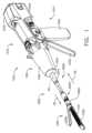
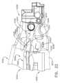
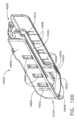
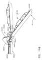
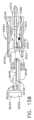
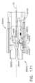
図1は、ハウジング1012に動作可能に連結された交換式シャフトアセンブリ1200を含む外科用器具1010を示している。図2は、ハウジング1012又はハンドル1014から取り外された交換式シャフトアセンブリ1200を図示している。図3に示すように、ハンドル1014は、ねじ、スナップ機構、接着剤などで相互連結され得る一対の相互連結可能なハンドルハウジングセグメント1016及び1018を備え得る。図示の配置では、ハンドルハウジングセグメント1016、1018は、ピストルグリップ部分1019を形成するように協働する。図1及び図3は、再使用されてもされなくてもよい、モータ駆動式の外科用切断及び締結器具1010を示している。図示された実施形態では、器具1010は、臨床医が把持し、操作し、作動させるように構成されたハンドル1014を備える前述のハウジング1012を備える。ハウジング1012は、1つ又は2つ以上の外科的タスク又は処置を行うように構成された外科用エンドエフェクタ1300は動作可能に連結された交換式シャフトアセンブリ1200に、動作可能に取り付けられるように構成されている。本発明を実施するための形態を読み進めるに従って、本明細書に開示される様々な形態の交換式シャフトアセンブリはまた、ロボット制御式の外科用システムと関連させて効果的に用いられ得ることが理解されよう。したがって、「ハウジング」という用語はまた、本明細書に開示する交換式シャフトアセンブリ及びそれらそれぞれの等価物を作動させるのに使用することができる、少なくとも1つの制御運動を生成し適用するように構成された、少なくとも1つの駆動システムを収容するか又は別の方法で動作可能に支持する、ロボットシステムのハウジング又は類似の部分を包含してもよい。加えて、様々な構成要素は、ハウジング内に「収容」されるか又は含まれてもよく、あるいは様々な構成要素は、ハウジングに「関連付け」られていてもよい。このような例では、構成要素は、ハウジング内に含まれていなくてもよく、又はハウジングによって直接支持されていなくてもよい。「フレーム(frame)」という用語は、手持ち式外科用器具の一部分を指し得る。また、「フレーム(frame)」という用語は、ロボット制御される外科用器具の一部分、及び/又は外科用器具を動作可能に制御するために使用され得るロボットシステムの一部分を表し得る。例えば、本明細書で開示される交換式シャフトアセンブリは、「SURGICAL STAPLING INSTRUMENTS WITH ROTATABLE STAPLE DEPLOYMENT ARRANGEMENTS」と題する米国特許第9,072,535号に開示される様々なロボットシステム、器具、構成要素及び方法とともに用いられ得、参照によりその全体が本明細書に組み込まれる。FIG. 1 illustrates a
図1に示される前述のハウジング1012は、その内部に外科用ステープルカートリッジ1350を動作可能に支持するように構成された外科用切断及び締結装置を備えるエンドエフェクタ1300を含む交換式シャフトアセンブリ1200(図2、図4、及び図5)と関連して示されている。ハウジング1012は、種々のサイズ及びタイプのステープルカートリッジを支持するように適合されたエンドエフェクタを含み、種々のシャフトの長さ、サイズ、及びタイプなどを有する交換式シャフトアセンブリと接続されて使用するように構成されてもよい。加えて、ハウジング1012はまた、例えば、運動、並びに高周波(radio frequency、RF)エネルギー、超音波エネルギー及び/又は運動などの他の形態のエネルギーを、様々な外科用途及び処置に関連して用いられるように適合されたエンドエフェクタ配置に印加するように構成されたアセンブリを含む様々な他の交換式シャフトアセンブリと接続されて効果的に用いられてもよい。更に、エンドエフェクタ、シャフトアセンブリ、ハンドル、外科用器具、及び/又は外科用器具システムは、臨床医によって把持及び操作され得る任意の好適な締結具を利用することができる。以下で更に詳細に記載されるように、ハンドル1014は、その内部に複数の駆動システムを動作可能に支持しており、これらの駆動システムは、それに動作可能に取り付けられる交換式シャフトアセンブリの対応する部分に対して様々な制御運動を生成及び適用するように構成されている。The
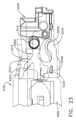
ここで図3を参照すると、ハンドル1014は、複数の駆動システムを動作可能に支持するフレーム1020を更に含み得る。例えば、フレーム1020は、全体的に1030として示される「第1の」すなわち閉鎖駆動システムを動作可能に支持することができ、この閉鎖駆動システムは、それに動作可能に取り付けられるか又は結合される交換式シャフトアセンブリ1200に対して閉鎖又は開放運動を適用するために用いられ得る。少なくとも1つの形態では、閉鎖駆動システム1030は、フレーム1020によって枢動可能に支持される閉鎖トリガ1032の形態のアクチュエータを含み得る。より具体的には、図3に示されるように、閉鎖トリガ1032は、ピン1033によってハウジング1014に枢動可能に結合されている。かかる配置によって、閉鎖トリガ1032を臨床医が操作することが可能になる。具体的には、臨床医がハンドル1014のピストルグリップ部分1019を把持すると、閉鎖トリガ1032を、開始位置又は「非作動」位置から、「作動」位置、より詳細には完全に握り込んだ位置又は完全作動位置へと容易に枢動させることができる。閉鎖トリガ1032は、ばね又は他の付勢配置(図示せず)によって、非作動位置へと付勢されてもよい。様々な形態において、閉鎖駆動システム1030は、閉鎖トリガ1032に枢動可能に結合された閉鎖リンケージアセンブリ1034を更に含む。図3に示すように、閉鎖リンケージアセンブリ1034は、ピン1035によって閉鎖トリガ1032に枢動可能に結合された第1の閉鎖リンク1036及び第2の閉鎖リンク1038を含んでもよい。第2の閉鎖リンク1038はまた、本明細書では「取り付け部材」と呼ばれることがあり、横向き取り付けピン1037を含む。3, the
引き続き図3を参照すると、第1の閉鎖リンク1036は、その上にロック壁又は端部1039を有し得、ロック壁又は端部は、フレーム1020に枢動可能に結合される閉鎖解除アセンブリ1060と協働するように構成されていることが分かる。少なくとも1つの形態では、閉鎖解除アセンブリ1060は、遠位方向に突出しているロック爪1064がその上に形成された解除ボタンアセンブリ1062を備えてもよい。解除ボタンアセンブリ1062は、解除ばね(図示せず)によって反時計方向に枢動させられてもよい。臨床医が閉鎖トリガ1032をそれの非作動位置からハンドル1014のピストルグリップ部分1019に向かって押下すると、第1の閉鎖リンク1036が、ロック爪1064が落下して第1の閉鎖リンク1036上でロック壁1039と保持係合し、それによって閉鎖トリガ1032が非作動位置に戻ることを防止する点まで上方に枢動する。したがって、閉鎖解除アセンブリ1060は、閉鎖トリガ1032を完全作動位置にロックする役割を果たす。臨床医が、閉鎖トリガ1032をロック解除して、それを非作動位置へ付勢することができるようにしたい場合、臨床医は単純に、解除ボタンアセンブリ1062を枢動させ、それによってロック爪1064を移動させて、第1の閉鎖リンク1036上のロック壁1039との係合から外す。ロック爪1064が第1の閉鎖リンク1036との係合から外れるように移動させられているとき、閉鎖トリガ1032は枢動して非作動構成に戻ってもよい。他の閉鎖トリガロック及び解除配置が用いられてもよい。Continuing to refer to FIG. 3, it can be seen that the
アーム1061が、解除ボタンアセンブリ1062から延在してもよい。例えば、永久磁石などの磁気要素1063をアーム1061に取り付けてもよい。解除ボタンアセンブリ1062をその第1の位置からその第2の位置へと回転させると、磁気要素1063は、回路基板1100に向かって移動することができる。回路基板1100は、磁気要素1063の移動を検出するように構成された、少なくとも1つのセンサを含むことができる。少なくとも1つの実施形態では、例えば、「ホール効果」センサ(図示せず)を、回路基板1100の底面に取り付けることができる。ホール効果センサは、磁気要素1063の移動によって生じる、ホール効果センサを取り巻く磁場における変化を検出するように構成され得る。ホール効果センサは、例えば、マイクロコントローラとの信号通信が可能であり、それによって、解除ボタンアセンブリ1062が、閉鎖トリガ1032の非作動位置とエンドエフェクタの開放構成とに関連付けられたその第1の位置にあるか、閉鎖トリガ1032の作動位置とエンドエフェクタの閉鎖構成とに関連付けられたその第2の位置にあるか、かつ/又は第1の位置と第2の位置との間の任意の位置にあるかを判断することができる。An
少なくとも1つの形態では、ハンドル1014及びフレーム1020は、本明細書で発射駆動システム1080と呼ばれる別の駆動システムを動作可能に支持し得、この発射駆動システムは、それに取り付けられた交換式シャフトアセンブリの対応する部分に対して発射運動を印加するように構成されている。発射駆動システム1080は、本明細書において「第2の駆動システム」とも呼ばれ得る。発射駆動システム1080は、ハンドル1014のピストルグリップ部分1019内に位置付けられている電気モータ1082を用いてもよい。様々な形態において、モータ1082は、例えば、約25,000RPMの最大回転数を有するブラシ付きDC駆動モータであってもよい。他の配置では、モータは、ブラシレスモータ、コードレスモータ、同期モータ、ステッパモータ、又は任意の他の好適な電気モータを含んでもよい。モータ1082は、電源1090によって給電されてもよく、一形態においては、取り外し可能なパワーパック1092を備え得る。例えば、図3で分かるように、パワーパック1092は、遠位ハウジング部分1096に取り付けるように構成された、近位ハウジング部分1094を備えてもよい。近位ハウジング部分1094及び遠位ハウジング部分1096は、その内部に複数の電池1098を動作可能に支持するように構成されている。電池1098はそれぞれ、例えば、リチウムイオン(Lithium Ion、「LI」)又は他の好適な電池を含んでもよい。遠位ハウジング部分1096は、モータ1082にやはり動作可能に結合されている回路基板1100に取り外し可能かつ動作可能に取り付けられるように構成されている。いくつかの電池1098が直列に接続され得、外科用器具1010の電源として使用され得る。加えて、電源1090は、交換可能及び/又は再充電可能であってもよい。In at least one form, the
他の様々な形態に関連して上記に概説したように、電気モータ1082は、回転可能なシャフト(図示せず)を含むことができ、そのシャフトは、長手方向に移動可能な駆動部材1120上の駆動歯1122の組又はラックと噛合係合して取り付けられたギヤ減速機アセンブリ1084と動作可能にインターフェース接続する。使用の際、電源1090によって提供される電圧極性によって電気モータ1082を時計方向に動作させることができるが、電池によって電気モータに印加される電圧極性は、電気モータ1082を反時計方向に動作させるために反転させることができる。電気モータ1082が一方向に回転されると、駆動部材1120は、遠位方向「DD」に軸方向に駆動されることになる。モータ82が反対の回転方向に駆動されると、駆動部材1120は、近位方向「PD」に軸線方向に駆動されることになる。ハンドル1014は、電源1090によって電気モータ1082に印加される極性を反転させるように構成することができるスイッチを含むことができる。本明細書に記載の他の形態と同様に、ハンドル1014はまた、駆動部材1120の位置、及び/又は駆動部材1120が移動させられている方向を検出するように構成されたセンサを含むことができる。As generally described above in connection with various other configurations, the
モータ1082の作動は、ハンドル1014上で枢動可能に支持される発射トリガ1130によって制御することができる。発射トリガ1130は、非作動位置と作動位置との間を枢動し得る。発射トリガ1130は、ばね1132又は他の付勢配置によって非作動位置へと付勢され得、それにより、臨床医が発射トリガ1130を解放すると、それがばね1132又は他の付勢配置によって非作動位置に枢動するか又は別様に戻され得る。少なくとも1つの形態では、発射トリガ1130は、上述したように、閉鎖トリガ1032の「外側」に配置することができる。少なくとも1つの形態では、発射トリガ安全ボタン1134が、ピン1035によって閉鎖トリガ1032に枢着されてもよい。安全ボタン1134は、発射トリガ1130と閉鎖トリガ1032との間に位置付けられ、そこから突出する枢動アーム1136を有してもよい。図3を参照されたい。閉鎖トリガ1032が非作動位置にあるとき、安全ボタン1134は、ハンドル1014に収容される。ここには臨床医が容易にアクセスすることができず、発射トリガ1130の作動を防止する安全位置と発射トリガ1130が発射されてもよい発射位置との間で移動させることもできない。臨床医が閉鎖トリガ1032を押下すると、安全ボタン1134及び発射トリガ1130が下方に枢動し、次いで、臨床医がそれらを操作することができる。The operation of the
上記に示されるように、少なくとも一形態において、長手方向に移動可能な駆動部材1120は、ギヤ減速機アセンブリ1084の対応する駆動ギヤ1086と噛合係合するために、その上に形成された歯1122のラックを有する。少なくとも1つの形態はまた、モータ1082が無効化された場合に、臨床医が長手方向に移動可能な駆動部材1120を手動で後退させることを可能にするように構成された、手動作動式の「緊急離脱」アセンブリ1140を含む。緊急離脱アセンブリ1140は、手動で枢動させて、駆動部材1120内にやはり設けられた歯1122とラチェット係合するように構成された、レバー又は緊急離脱ハンドルアセンブリ1142を含んでもよい。したがって、臨床医は、緊急離脱ハンドルアセンブリ1142を使用して駆動部材1120を近位方向「PD」にラチェットさせることによって、駆動部材1120を手動により後退させることができる。米国特許第8,608,045号、発明の名称「POWERED SURGICAL CUTTING AND STAPLING APPARATUS WITH MANUALLY RETRACTABLE FIRING SYSTEM」は、緊急離脱配置、並びに同じく本明細書に開示の様々な器具とともに用いられてもよい他の構成要素、配置、及びシステムを開示している。米国特許第8,608,045号は、その全体が参照により本明細書に組み込まれる。As noted above, in at least one form, the longitudinally
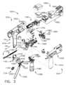
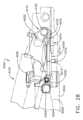
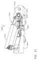
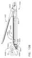
ここで図2及び図5を参照すると、交換式シャフトアセンブリ1200は、その中にステープルカートリッジ1350を動作可能に支持するように構成された細長いフレーム1310を備える外科用エンドエフェクタ1300を含む。エンドエフェクタ1300は、細長いフレーム1310に対して枢動可能に支持されたアンビル2000を更に含んでもよい。交換式シャフトアセンブリ1200は、エンドエフェクタ1300をシャフト軸線SAに対して所望の位置で解除可能に保持するように構成することができる、関節継手3020及び関節ロック2140を更に含んでもよい。エンドエフェクタ1300、関節継手3020、及び関節ロックの少なくとも1つの形態の実施例の様々な特徴は、2013年3月14日出願の米国特許出願第13/803,086号、発明の名称「ARTICULATABLE SURGICAL INSTRUMENT COMPRISING AN ARTICULATION LOCK」、現在の米国特許出願公開第2014/0263541号に説明されている。2013年3月14日出願の米国特許出願第13/803,086号、発明の名称「ARTICULATABLE SURGICAL INSTRUMENT COMPRISING AN ARTICULATION LOCK」、現在の米国特許出願公開第2014/0263541号の開示全体が参照により本明細書に組み込まれる。図4で分かるように、交換式シャフトアセンブリ1200は、ノズル部分1202及び1203から構成される近位ハウジング又はノズル1201を更に含むことができる。2 and 5, the
交換式シャフトアセンブリ1200は、エンドエフェクタ1300のアンビル2000を開閉するために利用することができる、閉鎖システム又は閉鎖部材アセンブリ3000を更に含むことができる。シャフトアセンブリ1200はスパイン1210を含み、スパイン1210は、(1)発射部材を内部で摺動可能に支持し、(2)スパイン1210の周りに延在する閉鎖部材アセンブリ3000を摺動可能に支持するように構成され得る。図5に示すように、スパイン1210の遠位端1212は、上部ラグ取り付け機構1270及び下部ラグ取り付け機構1280で終端する。上部ラグ取り付け機構1270の内部には、上部取り付けリンク1274を内部に固定支持可能なラグスロット1272が形成されている。同様に、下部ラグ取り付け機構1280の内部には、下部取り付けリンク1284を内部に固定支持可能なラグスロット1282が形成されている。上部取り付けリンク1274は、その内部に枢動ソケット1276を含み、その枢動ソケットは、フレームキャップ上に形成された枢動ピン1292、又は細長いフレーム1310の近位端部分1312に取り付けられたアンビルリテーナ1290を、その内部に回転可能に受容するように適合している。下部取り付けリンク1284は、細長いフレーム1310の近位端部分1312に形成された枢動穴1314内に受容されように適合する下部枢動ピン1286を含む。図5を参照されたい。下部枢動ピン1286は、枢動ソケット1276と垂直方向に位置合わせされて関節運動軸線AAを画定し、これを中心に外科用エンドエフェクタ1300がシャフト軸線SAに対して関節運動し得る。図2を参照されたい。The
図示される実施例において、外科用エンドエフェクタ1300は関節運動システム2100によって関節運動軸線AAを中心に選択的に関節運動可能である。一形態において、関節運動システム2100は、関節運動リンク2120に枢動可能に連結された近位関節運動駆動部2102を含む。図5に最も具体的に確認できるように、オフセット取り付けラグ2114が、近位関節運動駆動部2102の遠位端部2110に形成されている。枢動穴2116がオフセット取り付けラグ2114に形成され、関節運動リンク2120の近位端部2122に形成された近位リンクピン2124をその中に枢動可能に受容するように構成されている。関節運動リンク2120の遠位端部2126は、枢動穴2128を含み、枢動穴2128は、細長いフレーム1310の近位端部分1312に形成されたフレームピン1317をその中に枢動可能に受容するように構成されている。したがって、近位関節運動駆動部2102の軸方向移動は、それによって、関節運動の運動が細長いフレーム1310に印加され、それによって、外科用エンドエフェクタ1300がスパイン1210に対して関節運動軸線AAを中心として関節運動させる。関節運動システム2100の構成及び操作に関する更なる詳細は、その開示全体が参照により本明細書に組み込まれる、2017年6月28日出願の米国特許出願第15/635,631号、発明の名称「SURGICAL INSTRUMENT WITH AXIALLY MOVABLE CLOSURE MEMBER」、現在は米国特許出願公開第2019/0000464号などの、参照により本明細書に組み込まれる様々な参考文献に見出すことができる。様々な状況において、近位関節運動駆動部2102が近位方向又は遠位方向に移動していない場合、近位関節運動駆動部2102は関節ロック2140によって定位置に保持され得る。関節ロック2140の例に関する更なる詳細は、米国特許出願第15/635,631号、現在の米国特許出願公開第2019/0000464号、並びに本明細書に参照により組み込まれる他の参考文献に見出すことができる。In the illustrated embodiment, the
様々な状況において、スパイン1210は、シャーシ1240内で回転可能に支持される近位端1211を備えることができる。一配置では、例えば、スパイン1210の近位端1211には、シャーシ1240内で支持されるように構成されたスパイン軸受1216にねじ込みによって取り付けられるように、ねじ山1214が形成されている。図4を参照されたい。このような配置は、シャーシ1240へのスパイン1210の回転可能な取り付けを容易にし、それにより、スパイン1210は、シャーシ1240に対してシャフト軸線SAを中心に選択的に回転され得る。In various circumstances, the
主に図4を参照すると、交換式シャフトアセンブリ1200は、シャーシ1240に対して軸線方向に移動され得るようにその中で摺動可能に支持される、閉鎖シャトル1250を含む。閉鎖シャトル1250は、一対の近位側に突出するフック1252を含み、それらは、更に詳細に後述するように、第2の閉鎖リンク1038に取り付けられた取り付けピン1037(図3)に取り付けるように構成される。少なくとも1つの例では、閉鎖部材アセンブリ3000は、閉鎖シャトル1250に対して回転するように閉鎖シャトル1250に連結された近位端3012を有する近位閉鎖部材セグメント3010を備える。例えば、U字型コネクタ1263は、近位閉鎖部材セグメント3010の近位端3012にある環状スロット3014へと挿入され、閉鎖シャトル1250における垂直スロット1253内で保持される。このような配置により、近位閉鎖部材セグメント3010と閉鎖シャトル1250とが、一緒に軸方向移動するように取り付けられる一方で、近位閉鎖部材セグメント3010がシャフト軸線SAを中心として閉鎖シャトル1250に対して回転することが可能となる。閉鎖ばね1268が近位閉鎖部材3010上で軸止され、近位閉鎖部材3010を近位方向「PD」に付勢する役割を果たし、それによって、シャフトアセンブリがハンドル1014に動作可能に結合されると、閉鎖トリガ1032を非作動位置へと枢動する役割を果たすことができる。4, the
少なくとも1つの形態では、交換式シャフトアセンブリ1200は、関節継手3020を更に含んでもよい。しかしながら、他の交換式シャフトアセンブリが、関節屈曲可能でなくてもよい。図5に示すように、例えば、遠位閉鎖部材又は遠位側閉鎖管セグメント3030が、近位側閉鎖部材セグメント3010の遠位端に連結されている。関節継手3020は、二重枢動閉鎖スリーブアセンブリ3022を含む。様々な形態によれば、二重枢動閉鎖スリーブアセンブリ3022は、上部近位方向突出タング3052及び下部近位方向突出タング3054を有するエンドエフェクタ閉鎖管3050を含む。上部二重枢動リンク3056は、上方に突出する遠位枢動ピン及び近位枢動ピンを含み、これらは、遠位閉鎖管セグメント3030上において、上部近位方向突出タング3052の上部遠位ピンホール、及び上部遠位方向突出タング3031の上部近位ピンホール3032にそれぞれ係合する。下部二重枢動リンク3058は、上方に突出する遠位枢動ピン及び近位枢動ピンを含み、それらは、下部近位方向突出タング3054の下部遠位ピンホール、及び下部遠位方向突出タング3034の下部近位ピンホールにそれぞれ係合する。図4及び図5を参照されたい。以下により詳細に説明するように、閉鎖部材アセンブリ3000は、例えば閉鎖トリガ1032の作動に応答して、アンビル2000を閉鎖するように遠位(方向DD)に並進される。アンビル2000は、閉鎖部材アセンブリ3000を近位方向に並進させることによって開放され、これによってエンドエフェクタ閉鎖管3050がアンビル2000と相互作用し、アンビル2000を開放位置に枢動させる。In at least one embodiment, the
これも上述したように、交換式シャフトアセンブリ1200は、シャフトスパイン1210内で軸方向移動するように支持される発射部材1900を更に含む。発射部材1900は、遠位側切断部分又はナイフバー1910に取り付けられるように構成された中間発射シャフト部分1222を含む。中間発射シャフト部分1222は、その遠位端部に長手方向スロット1223を含み得、長手方向スロット1223は、遠位ナイフバー1910の近位端部上のタブ1912を受容するように構成され得る。長手方向スロット1223及び近位端部タブ1912は、それらの間の相対移動を可能にするようにサイズ決定及び構成され得、スリップ継手1914を備え得る。スリップ継手1914は、ナイフバー1910を移動させずに、又は少なくとも実質的に移動させずに、発射部材1900の中間発射シャフト部分1222を移動させて、エンドエフェクタ1300を関節運動させることを可能にし得る。エンドエフェクタ1300が好適に配向されると、ナイフバー1910を前進させ、フレーム1310内に位置決めされたステープルカートリッジ1350を発射するために、長手方向スロット1223の近位側壁がタブ1912と接触するまで中間発射シャフト部分1222を遠位方向に前進させ得る。ナイフバー1910は、ブレード又は組織切断縁部1922を含むナイフ部分1920を含み、上部アンビル係合タブ1924及び下部フレーム係合タブ1926を含む。様々な発射部材の構成及び動作は、参照により本明細書に組み込まれる様々な他の参考文献に開示されている。As also described above, the
図4で分かるように、シャフトアセンブリ1200は、近位閉鎖部材セグメント3010上に回転可能に受け入れられるスイッチドラム1500を更に含む。スイッチドラム1500は、外側に突出する作動ピンを受容するためのシャフトボスが内部に形成された中空のシャフトセグメント1502を備える。様々な状況下で、作動ピンは、スロットを通ってロックスリーブ内に設けられた長手方向スロット内へ延在することで、ロックスリーブが関節ドライバと係合されている場合にその軸運動を助ける。回転ねじりばね1420は、スイッチドラム1500上のボス及びノズルハウジング1201の一部分に係合して、スイッチドラム1500に付勢力を印加するように構成されている。スイッチドラム1500は、内部に画定された少なくとも部分的に円周方向の開口部1506を更に備えることができ、その開口部は、ノズル部分1202、1203から延在する円周方向のマウントを受容し、スイッチドラム1500とノズル1201との間の相対回転は許容するが並進は許容しないように構成することができる。マウントはまた、近位閉鎖部材セグメント3010の開口部3011を通って延在して、スパイン1210の陥凹部1219に収まる。スイッチドラム1500がシャフト軸線SAを中心として回転すると、最終的に、作動ピン及びロックスリーブが、その係合位置と係合解除位置との間で回転する。一配置では、スイッチドラム1500の回転は、閉鎖管又は閉鎖部材の軸方向前進に連結され得る。したがって、本質的に、閉鎖システムの作動は、それぞれの開示全体が本明細書に参照により組み込まれる米国特許出願第13/803,086号、発明の名称「ARTICULATABLE SURGICAL INSTRUMENT COMPRISING AN ARTICULATION LOCK」、現在は米国特許出願公開第2014/0263541号、及び米国特許第9,913,642号、発明の名称「SURGICAL INSTRUMENT COMPRISING A SENSOR SYSTEM」に更に詳細に記載される様々な方法で、発射駆動システムと関節駆動システムを動作可能に係合及び解除し得る。例えば、閉鎖部材セグメント3010が「ジョー開放」位置に対応するその最近位位置にあるとき、閉鎖部材セグメント3010は、関節運動システムを発射駆動システムと連結するように、スイッチドラム1500を位置決めする。閉鎖管が「ジョー閉鎖」位置に対応するその遠位位置に移動されると、閉鎖管は、関節運動システムが発射駆動システムから連結解除される位置までスイッチドラム1500を回転させている。As seen in FIG. 4, the
図4にも示されるように、シャフトアセンブリ1200は、例えば、エンドエフェクタ1300との間で電力を伝導し、かつ/又はエンドエフェクタ1300との間で信号を通信するように構成することができる、スリップリングアセンブリ1600を備えることができる。スリップリングアセンブリ1600は、シャーシ1240から延在するシャーシフランジ1242に取り付けられる近位コネクタフランジ1604と、シャフトハウジング内に画定されたスロット内に位置付けられる遠位コネクタフランジとを備えることができる。近位コネクタフランジ1604は第1の面を備えることができ、遠位コネクタフランジは、第1の面に隣接して位置付けられ、かつ第1の面に対して移動可能である第2の面を備えることができる。遠位コネクタフランジは、シャフト軸線SAを中心として、近位コネクタフランジ1604に対して回転することができる。近位コネクタフランジ1604は、その第1の面に画定される、複数の同心の、又は少なくとも実質的に同心の導体を備えることができる。コネクタは、コネクタフランジの近位側に取り付けられ得、複数の接点を有してもよく、それぞれの接点は、導体のうちの1つに対応し、かつそれと電気的に接触する。かかる配置により、近位コネクタフランジ1604と遠位コネクタフランジとが、それらの間の電気的接触を維持したまま相対回転することが可能になる。近位コネクタフランジ1604は、例えば、シャフトシャーシ1240に取り付けられたシャフト回路基板1610と信号連通するように導体を配置可能な、電気コネクタ1606を含むことができる。少なくとも1つの例では、複数の導体を備える配線ハーネスが、電気コネクタ1606とシャフト回路基板1610との間に延在することができる。電気コネクタ1606は、シャーシフランジ1242に画定されたコネクタ開口部1243を通って近位側に延在してもよい。図4を参照されたい。スリップリングアセンブリ1600に関する更なる詳細は、例えば、米国特許出願第13/803,086号、発明の名称「ARTICULATABLE SURGICAL INSTRUMENT COMPRISING AN ARTICULATION LOCK」、現在は米国特許出願公開第2014/0263541号、2013年3月13日出願の米国特許出願第13/800,067号、発明の名称「STAPLE CARTRIDGE TISSUE THICKNESS SENSOR SYSTEM」、現在は米国特許出願公開第2014/0263552号及び、米国特許第9,345,481号、発明の名称「STAPLE CARTRIDGE TISSUE THICKNESS SENSOR SYSTEM」に見出すことができる。米国特許出願第13/803,086号、現在は米国特許出願公開第2014/0263541号、米国特許出願第13/800,067号、現在は米国特許出願公開第2014/0263552号、及び米国特許第9,345,481号は、それぞれ、それぞれの全体が参照により本明細書に組み込まれる。4, the
上述したように、シャフトアセンブリ1200は、ハンドル1014に固定可能に取り付けられた近位部分と、長手方向軸を中心にして回転可能な遠位部分とを含むことができる。回転可能な遠位シャフト部分は、上述したように、スリップリングアセンブリ1600を中心にして近位部分に対して回転させることができる。スリップリングアセンブリ1600の遠位コネクタフランジは、回転可能な遠位シャフト部分内に位置付けることができる。また、上記に加えて、スイッチドラム1500も、回転可能な遠位シャフト部分内に位置付けることができる。回転可能な遠位シャフト部分を回転させると、遠位コネクタフランジ及びスイッチドラム1500を互いに同期させて回転させることができる。加えて、スイッチドラム1500を、遠位コネクタフランジに対して第1の位置と第2の位置との間で回転させることができる。スイッチドラム1500がその第1の位置にあると、関節駆動システムは、発射駆動システムから動作可能に係合解除され得、したがって、発射駆動システムの動作は、シャフトアセンブリ1200のエンドエフェクタ1300を関節運動させ得ない。スイッチドラム1500がその第2の位置にあると、関節駆動システムが発射駆動システムと動作可能に係合されてもよく、したがって、発射駆動システムの動作によってシャフトアセンブリ1200のエンドエフェクタ1300を関節運動させることができる。スイッチドラム1500をその第1の位置とその第2の位置との間で移動させると、スイッチドラム1500は、遠位コネクタフランジに対して移動させられる。様々な例において、シャフトアセンブリ1200は、スイッチドラム1500の位置を検出するように構成された少なくとも1つのセンサを備えることができる。As described above, the
再び図4を参照すると、シャーシ1240は、その上に形成された少なくとも1つ、好ましくは2つのテーパ付き取り付け部分1244を含み、その取り付け部分1244は、フレーム1020の遠位取り付けフランジ部分1700内に形成された対応するダブテールスロット1702内に受容されるように適合される。図3を参照されたい。各ダブテールスロット1702は、その中に取り付け部分1244を着座させて受容するようにテーパ付きであってもよく、又は言い換えれば、幾分V字形であってもよい。図4に更に示すように、シャフト取り付けラグ1226が、中間発射シャフト部分1222の近位端に形成されている。更に詳細に後述するように、交換式シャフトアセンブリ1200がハンドル1014に結合されると、シャフト取り付けラグ1226は、長手方向駆動部材1120の遠位端1125に形成された発射シャフト取り付けクレードル1126に受け入れられる。図3を参照されたい。Referring again to FIG. 4, the
様々なシャフトアセンブリの実施形態は、シャフトアセンブリ1200をハウジング1012に、より具体的には、フレーム1020に取り外し可能に結合するためにラッチシステム1710を用いる。図4で分かるように、例えば、少なくとも1つの形態では、ラッチシステム1710は、シャーシ1240に対して移動可能に連結されているロック部材又はロックヨーク1712を含む。図示される実施形態では、例えば、ロックヨーク1712は、2つの離間した下方に延びる脚部1714を有するU字形状を有している。脚部1714はそれぞれ、その上に形成される枢動ラグ1715を有し、枢動ラグ1715は、シャーシ1240内に形成される対応する穴1245に受容されるように適合される。かかる配置により、ロックヨーク1712をシャーシ1240に枢動可能に取り付けるのが容易になる。ロックヨーク1712は、フレーム1020の遠位取り付けフランジ部分1700の対応するロック戻り止め又は溝1704と解除可能に係合するように構成された、2つの近位側に突出するロックラグ1716を含んでもよい。図3を参照されたい。様々な形態では、ロックヨーク1712は、ばね又は付勢部材(図示せず)によって近位方向に付勢される。ロックヨーク1712の作動は、シャーシ1240に取り付けられたラッチアクチュエータアセンブリ1720上に摺動可能に取り付けられるラッチボタン1722によって遂行され得る。ラッチボタン1722を、ロックヨーク1712に対して近位方向に付勢することができる。更に詳細に後述するように、ラッチボタンを遠位方向に付勢することによってロックヨーク1712をロック解除位置へと移動させてもよく、これはまた、ロックヨーク1712を枢動させて、フレーム1020の遠位側取り付けフランジ1700との保持係合から外す。ロックヨーク1712がフレーム1020の遠位側取り付けフランジ1700と「保持係合」しているとき、ロックラグ1716は、遠位側取り付けフランジ1700の対応するロック戻り止め又は溝1704内に保定されるように収まっている。Various shaft assembly embodiments use a
組織を切断し締結するように適合された本明細書に記載されるタイプのエンドエフェクタ、並びに他のタイプのエンドエフェクタを含む、交換式シャフトアセンブリを用いる場合、エンドエフェクタの作動中に交換式シャフトアセンブリがハウジングから不用意に分離されることを防止することが望ましいことがある。例えば、使用の際に、臨床医が閉鎖トリガ1032を作動させて標的組織を把持し、所望の位置へと操作することがある。標的組織がエンドエフェクタ1300内に所望の配向で位置決めされると、臨床医は、次いで、閉鎖トリガ1032を完全に作動させてアンビル2000を閉鎖し、標的組織を切断及びステープル留めのために定位置にクランプし得る。その場合、第1の駆動システム1030は、完全に作動している。標的組織がエンドエフェクタ1300にクランプされた後、シャフトアセンブリ1200がハウジング1012から不用意に分離されることを防止することが望ましいことがある。ラッチシステム1710の1つの形態は、そのような不用意な分離を防止するように構成されている。When using interchangeable shaft assemblies, including end effectors of the type described herein adapted to cut and fasten tissue, as well as other types of end effectors, it may be desirable to prevent the interchangeable shaft assembly from being inadvertently separated from the housing during actuation of the end effector. For example, in use, a clinician may actuate the
図4で最も具体的に分かるように、ロックヨーク1712は、少なくとも1つの、好ましくは2つのロックフック1718を含み、そのロックフック1718は、閉鎖シャトル1250上に形成された対応するロックラグ部分1256に接触するように適合される。閉鎖シャトル1250が非作動位置にある(すなわち、第1の駆動システム1030が非作動であり、アンビル2000が開放されている)と、ロックヨーク1712は、遠位方向に枢動して、交換式シャフトアセンブリ1200をハウジング1012からロック解除し得る。その位置では、ロックフック1718は、閉鎖シャトル1250のロック突起部分1256と接触していない。しかしながら、閉鎖シャトル1250が作動位置に移動される(すなわち、第1の駆動システム1030が作動され、アンビル2000が閉鎖位置にある)と、ロックヨーク1712は、ロック解除位置に枢動することを防止される。別の言い方をすると、臨床医がロックヨーク1712をロック解除位置に枢動させようとした場合、又は例えばロックヨーク1712が、遠位方向に枢動するような形で不用意に押し出されるか又は接触された場合、ロックヨーク1712のロックフック1718が閉鎖シャトル1250のロック突起部分1256と接触して、ロックヨーク1712がロック解除位置に動くことを防止する。As seen most particularly in FIG. 4 , the
以下に、交換式シャフトアセンブリ1200のハンドル1014への取り付けについて記載する。連結プロセスを開始するために、臨床医は、シャーシ1240上に形成されたテーパ付き取り付け部分1244がフレーム1020のダブテールスロット1702と位置合わせされるように、交換式シャフトアセンブリ1200のシャーシ1240をフレーム1020の遠位側取り付けフランジ部分1700の上方に、又はそれに隣接して配置してもよい。次いで、臨床医は、シャフトアセンブリ1200をシャフト軸線SAに垂直な装着軸に沿って移動させて、取り付け部分1244を対応するダブテール受け入れスロット1702と「動作可能に係合」させて着座させ得る。そうすることで、中間発射シャフト部分1222上のシャフト取り付けラグ1226もまた、長手方向に移動可能な駆動部材1120のクレードル1126内に装着され、第2の閉鎖リンク1038上にあるピン1037の各部分が、閉鎖シャトル1250の対応するフック1252内に収められる。本明細書で使用するとき、2つの構成要素の文脈における「動作可能な係合」という用語は、それら2つの構成要素が互いに十分に係合され、それにより、作動運動をそれらに適用すると、構成要素が意図される行為、機能、及び/又は手順を実施し得ることを意味する。The following describes the attachment of the
交換式シャフトアセンブリ1200の少なくとも5つのシステムを、ハンドル1014の少なくとも5つの対応するシステムと動作可能に連結することができる。第1のシステムは、シャフトアセンブリ1200のフレーム又はスパインをハンドル1014のフレーム1020と連結及び/又は位置合わせするフレームシステムを備えることができる。別のシステムは、閉鎖駆動システム1030を備えることができ、閉鎖駆動システム1030は、ハンドル1014の閉鎖トリガ1032、及び閉鎖管3050、及びシャフトアセンブリ1200のアンビル2000を動作可能に接続することができる。上で概説したように、シャフトアセンブリ1200の閉鎖シャトル1250を、第2の閉鎖リンク1038のピン1037と係合させることができる。別のシステムは、ハンドル1014の発射トリガ1130をシャフトアセンブリ1200の中間発射シャフト部分1222と動作可能に接続することができる、発射駆動システム1080を備えることができる。上で概説したように、シャフト取り付けラグ1226は、長手方向駆動部材1120のクレードル1126と動作可能に接続されることができる。別のシステムは、例えばシャフトアセンブリ1200などのシャフトアセンブリが、ハンドル1014と動作可能に係合されていることを、例えばマイクロコントローラなど、ハンドル1014内のコントローラに信号伝達することができ、かつ/又は第2に、電力及び/若しくは通信信号をシャフトアセンブリ1200とハンドル1014との間で伝導することができる、電気システムを含むことができる。一例として、シャフトアセンブリ1200は、シャフト回路基板1610に動作可能に取り付けられる電気コネクタ1810を含むことができる。電気コネクタ1810は、制御回路基板1100上の対応する電気コネクタ1800と嵌合係合するように構成されている。回路類及び制御システムに関する更なる詳細は、米国特許出願第13/803,086号、現在は米国特許出願公開第2014/0263541号、及び米国特許出願第14/226,142号、現在は米国特許第9,913,642号に見出すことができ、それぞれの開示内容全体は、参照により本明細書に既に組み込まれている。第5のシステムは、シャフトアセンブリ1200をハンドル1014に解除可能にロックするためのラッチングシステムからなってもよい。At least five systems of the
図示される例におけるアンビル2000は、アンビル取り付け部分2010で終端するアンビル本体2002を含んでいる。アンビル取り付け部分2010は、細長いフレーム1310上に移動可能に又は枢動可能に支持されて、シャフト軸線SAを横断する固定アンビル枢軸線PAを中心に細長いフレーム1310に対して選択的に枢動移動する。図示される配置では、枢動部材又はアンビルトラニオン2012は、アンビル取り付け部分2010の各側方から横方向に延在して、細長いフレーム1310の近位端部分1312の直立壁1315に形成された対応するトラニオンクレードル1316内に受容されている。アンビルトラニオン2012は、フレームキャップ又はアンビルリテーナ1290によって、それらに対応するトラニオンクレードル1316内に枢動可能に保持される。フレームキャップ又はアンビルリテーナ1290は、一対の取り付けラグを有し、その一対の取り付けラグは、細長いフレーム1310の近位端部分1312の直立壁1315に形成された対応するラグ溝又はノッチ内に保持的に受容されるように構成されている。図5を参照されたい。The
引き続き図5を参照すると、少なくとも1つの配置では、遠位閉鎖部材又はエンドエフェクタ閉鎖管3050は、2つの軸方向にオフセットされた近位側及び遠位側の正の顎部開放機構3060及び3062を使用する。正のジョー開口部機構3060、3062は、その開示全体が参照により本明細書に組み込まれている、米国特許出願第15/635,631号、発明の名称「SURGICAL INSTRUMENT WITH AXIALLY MOVABLE CLOSURE MEMBER」、現在は米国特許出願公開第2019/0000464号で更に詳細に説明されるように、対応する解放領域及びアンビル取り付け部分2010上に形成された段差部分と相互作用するように構成されている。他の顎部開放配置を使用してもよい。Continuing to refer to FIG. 5, in at least one arrangement, the distal closure member or end
2003年5月20日に出願された米国特許出願第2004/0232200号、発明の名称「SURGICAL STAPLING INSTRUMENT HAVING A SPENT CARTRIDGE LOCKOUT」、米国特許出願第2004/0232199号、発明の名称「SURGICAL STAPLING INSTRUMENT HAVING A FIRING LOCKOUT FOR AN UNCLOSED ANVIL」、2003年5月20日に出願された米国特許出願第2004/0232197号、発明の名称「SURGICAL STAPLING INSTRUMENT INCORPORATING AN E-BEAM FIRING MECHANISM」、2003年5月20日に出願された米国特許出願第2004/0232196号、発明の名称「SURGICAL STAPLING INSTRUMENT HAVING SEPARATE DISTINCT CLOSING AND FIRING SYSTEMS」、3003年5月20日に出願された米国特許出願第2004/0232195号、発明の名称「SURGICAL STAPLING INSTRUMENT HAVING A SINGLE LOCKOUT MECHANISM FOR PREVENTION OF FIRING」、及び2017年8月17日に出願された米国特許出願第2018/0085123号、発明の名称「ARTICULATING SURGICAL STAPLING INSTRUMENT INCORPORATING A TWO-PIECE E-BEAM FIRING MECHANISM」の開示は、それらの全体が参照により本明細書に組み込まれる。U.S. Patent Application No. 2004/0232200, filed May 20, 2003, entitled "SURGICAL STAPLING INSTRUMENT HAVING A SPENT CARTRIDGE LOCKOUT"; U.S. Patent Application No. 2004/0232199, entitled "SURGICAL STAPLING INSTRUMENT HAVING A FIRING LOCKOUT FOR AN UNCLOSED ANVIIL"; U.S. Patent Application No. 2004/0232197, filed May 20, 2003, entitled "SURGICAL STAPLING INSTRUMENT INCORPORATING "AN E-BEAM FIRING MECHANISM"; U.S. Patent Application No. 2004/0232196, filed May 20, 2003, entitled "SURGICAL STAPLING INSTRUMENT HAVING SEPARATE DISTINCT CLOSING AND FIRING SYSTEMS"; U.S. Patent Application No. 2004/0232195, filed May 20, 3003, entitled "SURGICAL STAPLING INSTRUMENT HAVING A SINGLE LOCKOUT MECHANISM FOR PREVENTION OF The disclosures of "ARTICULATING SURGICAL STAPLING INSTRUMENT INCORPORATING A TWO-PIECE E-BEAM FIRING MECHANISM" and U.S. Patent Application No. 2018/0085123, filed August 17, 2017, entitled "ARTICULATING SURGICAL STAPLING INSTRUMENT INCORPORATING A TWO-PIECE E-BEAM FIRING MECHANISM" are incorporated herein by reference in their entireties.
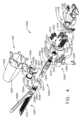
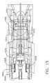
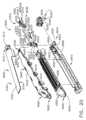
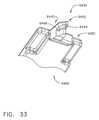
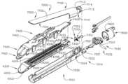
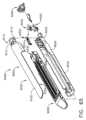
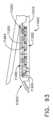
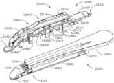
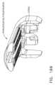
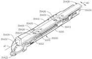
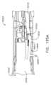
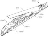
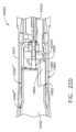
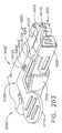
図6を参照すると、外科用ステープル留めアセンブリ4000の実施例が示されている。外科用ステープル留めアセンブリ4000は、上述の外科用器具1010に関連して、又は参照により本明細書に組み込まれている様々な開示に記載されている様々な他の外科用器具に関連して使用され得る。外科用ステープル留めアセンブリ4000は、例えば、前述の組み込まれた開示に開示される様々な形態の、電気的に制御された、電池駆動式の、手動式の、及び/又はロボット制御された外科用器具に関連して用いられ得る。図6で分かるように、外科用ステープル留めアセンブリ4000は、第1のジョーを備える全体的に4002として示される外科用ステープル留めデバイス、又は内部にステープルカートリッジ4200を動作可能に支持するように構成されたフレーム4010を備える。第1のジョー4010は、本明細書及び参照により本明細書に組み込まれる様々な開示に記載の様々な様式で、外科用器具又はロボットのシャフトアセンブリのスパインに取り付けられてもよい。図示される実施例では、第1のジョー4010は、ピン4032によってピン留めされるか、又は別様に第1のジョー4010の近位端部4014に取り付けられるシャフトマウントフランジ4030によって、シャフトアセンブリ(図6に図示せず)のスパイン部分に取り付けられている。特に、ピン4032は、第1のジョー4010の直立側壁4020内の位置合わせされた穴4021及びシャフトマウントフランジ4030内の穴4031を貫通するように構成されている。シャフトマウントフランジ4030は、様々な既知の構成でシャフトアセンブリに対する第1のジョー4010の関節運動を容易にするように構成された関節継手配置(図示せず)とインターフェース接続するように構成されている。外科用デバイス4002を外科用器具のシャフトに取り付け、動作可能にインターフェース接続する他の方法もまた、用いられ得る。例えば、ステープル留めデバイス4002は、ステープル留めデバイス(「エンドエフェクタ」とも呼ばれることもある)がシャフトアセンブリに対して関節運動することができないように、シャフトアセンブリに取り付けられ得る。6, an example of a
更に図6を参照すると、外科用ステープル留めデバイス4002は、ナイフ部材又は「発射部材」4050に取り付けられたナイフバー4042を備える発射部材アセンブリ4040を更に備える。ナイフバー4042はまた、外科用器具内の対応する構成要素及び発射システムとインターフェース接続して、開始位置から終了位置までナイフバー4042及び発射部材4050をステープル発射ストロークにわたって遠位方向に前進させ、またナイフバー4042及び発射部材4050を開始位置まで近位に後退させることができる発射運動を受容する。図示される配置では、発射部材4050は、切断縁部又はナイフ縁部4053を支持する発射部材本体4052を備える。発射部材4050は、発射部材本体4052の底部に形成され、発射部材本体4052の各側から横方向に延在する足部4054を更に備える。発射部材4050は、発射部材本体4052から横方向に延在する一対の上部ピン又は上部タブ4056を更に備え、これらは本明細書で更に考察されるように、アンビル上のレッジと係合するように適合される。更に、発射部材4050は、発射部材本体4052の各側から横方向に突出する一対の中央ピン又はタブ4058を備える。参照により本明細書に組み込まれる開示のうちのいくつかでは、発射部材4050は、「Eビーム」発射部材又は切断部材とも呼ばれ得る。6, the
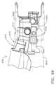
上記に加えて、外科用ステープル留めデバイス4002は、第1のジョー又はフレーム4010に対して移動可能な第2のジョー又はアンビル4100を備える。アンビル4100は、アンビル本体4102及びアンビル取り付け部分4110を含む。アンビル本体4102は、その中に形成された一連のステープル形成ポケット(図示せず)を有するステープル形成下面又は組織接触面4104を備え、これらのポケットは、駆動されて対応するステープルと形成接触するときにその対応するステープルを形成するように配置されている。アンビル取り付け部分4110は、第1のジョー4010の直立側壁4020内の対応するトラニオンスロット4022内に受容されるように構成された一対の横方向に延在するアンビルピン又はトラニオンピン4112を備える。図示される配置では、トラニオンスロット4022は、幾分「腎臓形状」であり、その中の対応するトラニオンピン4112の枢動及び軸方向移動を容易にする。アンビル4100のそのような枢動及び軸方向の移動は、アンビル閉鎖シーケンス中のアンビルの「並進」と呼ばれ得る。In addition to the above, the
上述のように、並びに参照により本明細書に組み込まれる開示のうちのいくつかでは、アンビル4100は、使用中又は使用済みの外科用ステープルカートリッジが第1のジョー又はフレーム4010から取り外され得るか又は未発射の外科用ステープルカートリッジがその中に動作可能に着座し得る開放位置から閉鎖位置に移動可能であり得る。アンビル4100は、軸方向に移動可能な閉鎖部材によって開放位置と閉鎖位置との間で移動可能であり得、この閉鎖部材は、外科用デバイス4002が動作可能に取り付けられる外科用器具のシャフトアセンブリの一部分であるエンドエフェクタ閉鎖管(図示せず)を備え得る。例えば、閉鎖部材が、外科器具内の閉鎖制御システムを作動させることによって近位位置から遠位方向に移動すると、閉鎖部材は、アンビル取り付け部分4110上のカム面を動作可能に係合し得る。閉鎖部材とアンビル取り付け部分4110との間のそのような相互作用により、アンビル取り付け部分4110及びアンビルトラニオンピン4112に、閉鎖部材がアンビル4100を完全に閉鎖した位置に移動させるまで、トラニオンスロット4022を枢動及び並進させる。完全閉鎖位置にあるとき、アンビル4100内のステープル形成ポケットは、第1のジョー又はフレーム4010に動作可能に着座している対応する適合性のある外科用ステープルカートリッジ内のステープルと適切に位置合わせされる。その後、軸方向に移動可能な閉鎖部材が近位方向に移動すると、閉鎖部材は、アンビル取り付け部分4110上の直立タブ4114とインターフェース接続して、アンビル4100を開放位置に戻す。As discussed above, and in some of the disclosures incorporated herein by reference, the
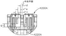
外科用ステープル留めデバイス4002と適合性があり得る外科用ステープルカートリッジ4200の一形態は、カートリッジデッキ表面又は組織接触面4204を画定するカートリッジ本体4202を備える。カートリッジ本体4202は、カートリッジデッキ表面4204を二分する長手方向スロット4206を更に備え、ステープル発射ストローク中に、カートリッジ本体4202内の発射部材の開始位置と終了位置との間で内部に発射部材4050の軸方向通路を収容するように構成されている。長手方向スロット4206は、カートリッジ4200の中心軸線CAに沿って存在する。外科用ステープルカートリッジ4200は、カートリッジ本体4202内に形成された一連のステープルポケット4208を更に備える。ステープルポケット4208は、長手方向スロット4206の各側に位置するオフセット「ライン」で形成され得る。各ステープルポケット4208は、それと関連付けられたステープルドライバ(図示せず)を有し得、ステープルドライバは、その上に外科用ステープル又は締結具(図示せず)を支持する。少なくとも1つの実施例では、カートリッジ本体4202は、その中に成形又は機械加工されたステープルポケット4208を有するポリマー材料から成形される。一配置では、ステープルポケット4208はまた、カートリッジ本体4202の底部を通って開口して、ドライバ及び締結具のそれぞれのステープルポケット4208内への装着を容易にする。ドライバ及び締結具がそれらのそれぞれのステープルポケット4208内に挿入されると、カートリッジパン4220がカートリッジ本体4202に取り付けられる。一形態では、カートリッジパン4220は、金属材料から製作され、カートリッジ本体4202の底部をわたって広がる底部4222を含む。カートリッジパン4220はまた、カートリッジ本体4202の各側に対応する2つの直立側壁4224を含む。カートリッジパン4220は、側壁4224上に形成され、カートリッジ本体4202の対応する部分にフック式に係合するように構成されたフック4226によってカートリッジ本体4202に取り外し可能に取り付けられ得る。加えて、カートリッジ本体4202はまた、そこから突出するラグ又は取り付け形成部を有し得、これらはカートリッジパン4220の対応する部分に保持係合するように構成されている。装着されると、カートリッジパン4220は、とりわけ、ドライバ及び締結具が、第1のジョー又はフレーム4010内へのステープルカートリッジの取り扱い及び装着中に、カートリッジ本体4202の底部から落下することを防止し得る。One form of
ステープルドライバのうちのいくつかは、その上に単一の外科用ステープルを動作可能に支持し、他のステープルドライバは、特定のカートリッジ設計に応じて、その上に2つ以上の外科用ステープルを支持する。各外科用ステープルは、ステープルクラウン及び2つの直立したステープル脚部を備える。ステープルクラウンは、典型的には、カートリッジがフレーム4010に動作可能に着座すると脚部がアンビルに向かって垂直に配向されるように、対応するステープルドライバ内に形成されたクレードル配置上に支持される。いくつかの配置では、外科用ステープルは、幾分V字形状を有し、脚部の端部は、わずかに外側に広がる。このような配置は、使用中にカートリッジが不用意に反転されるか又は逆さまに回転された場合に、ステープルポケットの脚部と側との間の摩擦係合によって、ステープルをその対応するステープルポケット内に保持する役割を果たし得る。他の外科用ステープルは、ほぼU字形状であり(脚部の端部は外側に広がっていない)、使用前にカートリッジを反転された場合、ステープルポケットから落下しやすくなり得る。Some of the staple drivers operably support a single surgical staple thereon, while others support two or more surgical staples thereon, depending on the particular cartridge design. Each surgical staple includes a staple crown and two upstanding staple legs. The staple crown is typically supported on a cradle arrangement formed within the corresponding staple driver such that the legs are oriented vertically toward the anvil when the cartridge is operably seated in the
外科用ステープルカートリッジ4200は、ステープル発射ストローク中にカートリッジ本体4202を通って軸方向に前進するように構成されたスレッド又はカム部材4230を更に備える。「新しい」、「未使用の」、又は「未発射の」外科用ステープルカートリッジでは、スレッド4230は、その最近位の「未発射」位置にある。スレッド4230は、カートリッジ本体内のステープルドライバの対応するラインに駆動可能に係合するように構成された複数のウェッジ又はカム部材4232を備える。ステープル発射ストローク中、発射部材4050は、スレッド4230に当接し、これを遠位方向に押してステープルドライバとカム接触させ、それによって、カートリッジ本体4202内でスレッド4230がその未発射位置からその最遠位の完全に発射される位置まで駆動されると、ステープルドライバをアンビル4100に向かって上方に順次駆動する。ステープルドライバが上方に駆動されると、ステープルは、ステープルカートリッジ4200のデッキ表面4204とアンビル4100との間にクランプされた組織を通って駆動され、アンビル4100のステープル形成下面4104と形成接触する。発射部材4050上の組織切断ナイフ4053は、発射部材4050が遠位方向に駆動されると、ステープル留めされた組織を切断する。ステープル発射ストロークが完了した後、及び/又は十分な長さのステープル発射ストロークが完了した後、発射部材4050は近位に後退される。しかしながら、スレッド4230は、発射部材4050とともに近位に後退されない。代わりに、スレッド4230は、それが発射部材4050によって押された最遠位位置に残される。The
ステープルカートリッジが発射された後、又は少なくとも部分的に発射された後、それはフレームから取り外され、次いで、所望であれば、別の交換可能なステープルカートリッジと交換される。このような時点で、ステープル留めデバイスを再使用して、患者の組織をステープル留め及び切開を継続することができる。しかしながら、場合によっては、以前に発射されたステープルカートリッジが、偶発的にフレームに装填され得る。発射部材がそのような以前に発射されたステープルカートリッジ内で遠位方向に前進されることになる場合、ステープル留め器具は、患者組織をステープル留めすることなくそれを切断する。ステープル留め器具は、ステープルカートリッジがカートリッジジョーに全く位置決めされていない状態で発射部材がステープル発射ストロークにわたって遠位方向に前進される場合、患者組織をステープル留めすることなく同様に切断する。加えて、様々な外科用ステープルカートリッジは、その内部にステープル/締結具の異なるアレイ及び/又は配向を有し得る。ステープル又は締結具のサイズ、並びに締結具の数は、特定の外科的手技又は用途に応じてカートリッジタイプごとに変化し得る。ステープルが適切に圧着又は形成されることを確実にするために、外科用ステープルカートリッジは、内部にステープル形成ポケットの適切なアレイを有する対応する適合性アンビル、並びに適切な切断及び発射構成要素と関連して使用されなければならない。「非適合性」カートリッジが、ステープルカートリッジに不適合であるアンビルを有する外科用ステープル留めデバイスに装填される場合、ステープルは、発射プロセス中に適切に形成されないことがあり、これは壊滅的な結果をもたらし得る。そのため、外科用ステープル留めアセンブリ4000は、以下でより詳細に論じられるように、これが偶然にも起こることを防止する1つ又は2つ以上のロックアウトを備える。After the staple cartridge has been fired, or at least partially fired, it is removed from the frame and then replaced, if desired, with another replaceable staple cartridge. At such a point, the stapling device can be reused to continue stapling and cutting the patient's tissue. However, in some cases, a previously fired staple cartridge may be accidentally loaded into the frame. If the firing member is to be advanced distally within such a previously fired staple cartridge, the stapling instrument will cut the patient tissue without stapling it. The stapling instrument will similarly cut the patient tissue without stapling it if the firing member is advanced distally through the staple firing stroke without any staple cartridge positioned in the cartridge jaws. In addition, various surgical staple cartridges may have different arrays and/or orientations of staples/fasteners therein. The size of the staples or fasteners, as well as the number of fasteners, may vary from cartridge type to cartridge type depending on the particular surgical procedure or application. To ensure that the staples are properly crimped or formed, the surgical staple cartridge must be used in conjunction with a corresponding compatible anvil having an appropriate array of staple forming pockets therein, as well as the appropriate cutting and firing components. If a "non-compatible" cartridge is loaded into a surgical stapling device having an anvil that is incompatible with the staple cartridge, the staples may not be properly formed during the firing process, which can have catastrophic consequences. Therefore, the
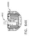
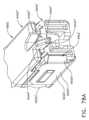
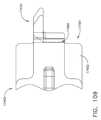
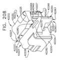
上記に加えて、外科用ステープル留めデバイス4002は、認可された又は適合性のあるステープルカートリッジが第1のジョー又はフレーム4010に動作可能に着座していない限り、発射部材4050がその最近位の開始位置から遠位方向に移動することを防止するように構成された第1のロックアウト4300を備える。第1のロックアウト4300は、本明細書において「認証」ロックアウトとも呼ばれ得る。図示される配置では、第1のロックアウト4300は、フレーム4010の近位端部4014に支持され、シャフトマウントフランジ4030に取り付けられる、単一の双方向の第1のロックアウトばね4310を備える。例えば、一配置では、第1のロックアウトばね4310は、カートリッジ軸線CAの一方の側に位置する第1のロックアウトアーム4312、及びカートリッジ軸線CAの反対側に位置する第2のロックアウトアーム4314を備える。第1のロックアウトアーム4312及び第2のロックアウトアーム4314は、中央本体部分4316に取り付けられている。図7を参照されたい。ばね4310は、第1のジョー又はフレーム4010に支持され、シャフトマウントフランジ4030内の穴4036、並びに第1のロックアウトアーム4312及び第2のロックアウトアーム4314の穴4318を通って延在するピン4034によって、シャフトマウントフランジ4030に固定されている。第1のロックアウトアーム4312及び第2のロックアウトアーム4314は各々、ロックアウト窓又は開口部4320を更に備える。ロックアウト窓4320は各々、発射部材4050がその最近位又は開始位置にあるときに、発射部材4050の隣接する第1の側又は第2の側から突出する対応する中央ピン4058をその中に受容するように適合されている。図8及び図9を参照されたい。In addition to the above, the
図8~図10は、ロック位置にある第1のロックアウト4300を図示し、このロック位置では、中央ピン4058は第1のロックアウトアーム4312及び第2のロックアウトアーム4314内のロックアウト窓4320内に受容されている。いくつかの配置では、外科用ステープル留めデバイス4002と適合性のあるステープルカートリッジ、又は別の言い方をすれば、適切な数、サイズ、及びステープルの配置を有するステープルカートリッジは、カートリッジ本体上及び/又はカートリッジパン上に直接形成された1つ又は2つ以上のロック解除又は「承認」鍵を有し得、これらのロック解除又は「承認」鍵は、適合するステープルカートリッジが第1のジョー又はフレームに動作可能に着座すると第1のロックアウトを無効化するように構成されている。内から突出するロック解除鍵を有する様々なステープルカートリッジが、以下に、並びに参照により本明細書に組み込まれる様々な開示に開示される。ただし、特定の実施例では、臨床医は、外科用ステープル留めデバイスと適合性があるが、別様にロック解除鍵を欠くステープルカートリッジを使用することを所望することがある。このような場合、臨床医は、これらの適合性のあるステープルカートリッジを外科用ステープル留めデバイスに別様に使用することができないであろう。外科用ステープル留めデバイス4002は、別様にロック解除鍵機構を欠くそのような適合性のあるステープルカートリッジの使用を容易にするように設計された機構を含む。8-10 illustrate the
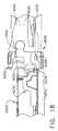
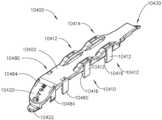
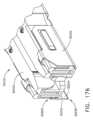
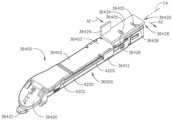
ここで図6及び図10を参照すると、ステープル留めアセンブリ4000は、外科用ステープル留めデバイス4002と別様に適合性のあるステープルカートリッジ4200に取り外し可能に結合されるように構成されたリテーナ4400を更に備える。図示される配置では、リテーナ4400は、カートリッジ本体4202のデッキ表面4204と同一の広がりを有し、その上に受容されるように構成された頂部4402を備える。したがって、少なくとも1つの構成では、リテーナ4400がカートリッジ本体4202に取り付けられると、リテーナ4400は、カートリッジ本体4202内のステープルポケット4208のすべてを覆う。このように、リテーナ4400がステープルカートリッジ4200に取り付けられると、リテーナ4400は、ステープルカートリッジ4200が使用前に反転又は逆さまになった場合に、ステープルポケット4208内に収容された外科用ステープルが落下することを防止し得る。リテーナ4400はまた、配送及び保管中にデッキ表面が汚染されることから保護する。6 and 10, the
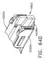
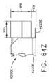
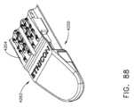
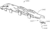
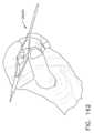
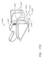
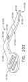
一配置では、リテーナ4400は、ポリマー材料から成形されてもよく、カートリッジ本体4202上に形成される外側に延在するデッキレッジ部分4205をラッチ係合するように構成された複数のリテーナラグ4410を含む。リテーナ4400は、傾斜ノーズ部分4420、及びカートリッジ本体4202の遠位ノーズ4203をラッチ係合するように構成された遠位ラッチタブ4422を更に備え得る。リテーナ4400は、遠位ラッチタブ4422を遠位ノーズ4203の端部を係合させ、頂部4402の下側がカートリッジデッキ表面4204に面し、リテーナラグ4410がカートリッジ本体4202の各側のデッキレッジ部分4205の上方に位置するようにリテーナ4400を位置合わせすることによって、外科用ステープルカートリッジ4200に取り外し可能に結合され得る。その後、リテーナ4400は、ステープルカートリッジ4200に向かって押圧され得、リテーナラグ4410を横方向外側に屈曲させ、対応するデッキレッジ部分4205とのラッチ係合にスナップ留めする。また、本明細書に開示される他のリテーナラッチ配置を使用して、リテーナ4400をステープルカートリッジ4200に取り外し可能に固定し得る。リテーナ4400は、リテーナラグ4410がデッキレッジ部分4205を係合解除するまで、こじ開け運動を遠位ラッチタブ4422に印加することによって、ステープルカートリッジ4200から取り外され得る。図示される実施例では、「持ち上げる(LIFT)」という用語は、ノーズ部分4420上に成形され、エンボス加工され、インプリントされ、又は別様に提供され、ユーザに取り外し指示を提供する。In one arrangement, the
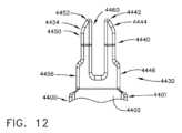
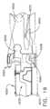
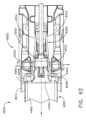
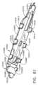
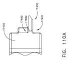
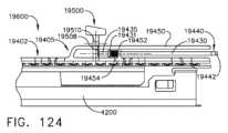
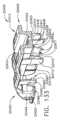
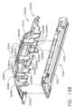
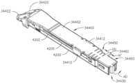
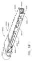
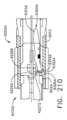
ここで図10~図13を参照すると、リテーナ4400は、リテーナ4400がステープルカートリッジ4200に取り付けられてカートリッジアセンブリ4500を形成し、カートリッジアセンブリ4500が第1のジョー又はフレーム4010に動作可能に着座すると、第1のロックアウト4300を無効化、非アクティブ化、又はラッチ解除するように構成された認証鍵4430を更に備える。図11で分かるように、認証鍵4430は、リテーナ4400の頂部4402の近位端部4401から近位に突出し、それらの間に発射部材本体4052を受容するようにサイズ決定される空間4460によって分離される右ランプ機構4440及び左ランプ機構4450を備える。図示される実施例では、右ランプ機構4440は、リテーナ4400の頂部4402から下方に角度を付け、近位右先端部4442を備える。近位右先端部4442は、先端部で内側に角度を付け、第2の右カム面4446まで遠位方向に延在する第1の右カム面4444を画定する。第2の右カム面4446は、第1の右カム面4444から頂部4402まで延在する。図12を参照されたい。同様に、左ランプ機構4450は、リテーナ4400の頂部4402から下方に角度を付け、近位左先端部4452を備える。近位左先端部4452は、先端部で内側に角度を付け、第2の左カム面4456まで遠位方向に延在する。第2の左カム面4456は、第1の左カム面4454から頂部4402まで延在する。リテーナ4400は、頂部4402の底面から突出し、外科用ステープルカートリッジ4200の長手方向スロット4206内に受容されるように配向されたリテーナキール4470を更に備える。リテーナキール4470は、リテーナ4400をステープルカートリッジ4200上に適切に配向する役割を果たし得、それにより、右ランプ機構4440及び左ランプ機構4450は発射部材4050の各側に延在する。加えて、リテーナキール4470は、ステープルカートリッジ4200内のスレッド4230を係合し、リテーナ4400がステープルカートリッジ4200に取り付けられている間、スレッド4230を未発射位置に保持するように構成され得る。リテーナキール4470は、長手方向スロット4206に対して、それとの摩擦嵌合を確立するようにサイズ決定され、リテーナ4400をステープルカートリッジ4200上に保持し得る。10-13, the
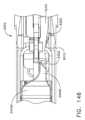
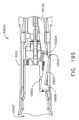
ここで図10、図14、及び図15を参照すると、リテーナ4400がステープルカートリッジ4200に取り付けられてカートリッジアセンブリ4500を形成した後、カートリッジアセンブリ4500は、認証鍵4430の右ランプ機構4440の右先端部4442を第1のロックアウトアーム4312上の直立したロック解除タブ4322と接触させ、左ランプ4450の左先端部4452を第1のロックアウトばね4310の第2のロックアウトアーム4314上の直立したロック解除タブ4324と接触するように、第1のジョー又はフレーム4010に長手方向に挿入され得る。組み立てられたカートリッジ配置4500のフレーム4010内近位方向への初期長手方向挿入中に、第1の右カム面4444は、第1のロックアウトばね4310の第1のロックアウトアーム4312を横方向外側(図14の矢印RL)に付勢し、第1の左カム面4454は、第2のロックアウトアーム4314を横方向外側(矢印LL)に付勢する。カートリッジアセンブリ4500の第1のジョー又はフレーム4010内近位方向への更なる前進により、第1のロックアウトアーム4312は、第1のロックアウトアーム4312が発射部材4050上の対応する中央ピン4058を係合解除する第1の中間位置に達し、また第2のロックアウトアーム4314は、第2のロックアウトアーム4314が発射部材4050上の対応する中央ピン4058を係合解除する第2の中間位置に達する。組み立てられたカートリッジ配置4500の第1のジョー又はフレーム4010内近位方向への継続的長手方向挿入により、第2の右カム面4446は、カートリッジアセンブリ4500が第1のジョー又はフレーム4010に完全に動作可能に着座するまで、第1のロックアウトアーム4312を横方向外側に更に付勢し、第2の左カム面4456は、第2のロックアウトアーム4314を横方向外側に更に付勢する。図15を参照されたい。カートリッジアセンブリ4500が第1のジョー又はフレーム4010に動作可能に着座すると、第1のロックアウトアーム4312上の遠位の第1の保持タブ4326は、ステープルカートリッジ4200の対応する側と係合して、第1のロックアウトアーム4312をそのロック解除位置に保持する。同様に、第2のロックアウトアーム4314上に形成された遠位の第2の保持タブ4328は、ステープルカートリッジ4200の別の対応する側に係合して、第2のロックアウトアーム4314をそのロック解除位置に保持する。その位置にあるとき、第1のロックアウト4300は、ロック解除位置にある、又は別の言い方をすれば、「無効化」される。ロック解除プロセス中、右ランプ4440及び左ランプ4450は、第1のばね4310から生成されるロック力が高い状態で印加されている発射部材4050によって補強され得る。10, 14, and 15, after the
次いで、ユーザは、リテーナラグ4410がカートリッジ本体4202上のデッキレッジ部分4205を係合解除するまで、遠位ラッチタブ4422をこじ開け、リテーナ4400を上方に持ち上げることによって、リテーナ4400をステープルカートリッジ4200から取り外し得る。第1のロックアウト4300が無効化又はロック解除された状態で、発射部材4050は、開始位置から遠位方向に前進され得、「準備完了状態」にある。ステープルカートリッジ4200が発射された後、発射部材4050は開始位置に後退して戻り、第2のジョー又はアンビル4100は開放位置まで枢動して戻る。次いで、使用済みステープルカートリッジは、第1のジョー又はフレーム4010から取り外され得る。使用済みステープルカートリッジ4200が第1のジョー又はフレーム4010から取り外されると、第1のロックアウトアーム4312及び第2のロックアウトアーム4314は、跳ね戻って発射部材4050上の対応する中央ピン4058と係合し、再び発射部材4050を開始位置に保持する。The user may then remove the
他の第1のロックアウトばね配置が企図される。例えば、第1のロックアウトばねは、1つの横方向ロックアウトアームのみを備え、発射部材の片側のみに係合し得る。このような配置では、ロックアウトアームをロック解除するために、1つのランプのみを備える認証鍵が必要とされ得る。Other first lockout spring arrangements are contemplated. For example, the first lockout spring may include only one lateral lockout arm and engage only one side of the firing member. In such an arrangement, an authentication key with only one lamp may be required to unlock the lockout arm.
上述のように、カートリッジアセンブリ4500がフレーム4010に動作可能に着座すると、第1のロックアウト4300は無効化又はロック解除されて、発射部材4050がステープル発射ストローク中にその準備完了状態から遠位方向に前進することを可能にする。ステープルカートリッジ4200に取り付けられると、リテーナ4400は、カートリッジデッキ表面4204を覆い、ステープルがステープルポケット4208から落下することを防止するとともに、任意の破片又は汚染物質が長手方向スロット4206又はステープルポケット4208に進入することを防止し、これは、ステープルカートリッジを損傷させる又はそれが適切に動作することを妨げることがある。カートリッジデッキ表面4204の一部分のみがリテーナによって覆われる、リテーナ4400の他の変形例が企図される。他の構成は、ステープルポケットのいずれか及び/又はデッキ表面のいずれかを覆わなくてもよい。As described above, when the
上述したように、ステープルカートリッジが発射された後、又は少なくとも部分的に発射された後、ステープルカートリッジは、第1のジョー又はフレームから取り外され、次いで、所望であれば、別の適合性のあるステープルカートリッジと交換される。このような時点で、ステープル留めデバイスを再使用して、患者組織をステープル留め及び切開を継続することができる。しかしながら、場合によっては、以前に発射されたステープルカートリッジが、偶発的にフレームに装填され得る。発射部材が、そのような以前に発射されたステープルカートリッジ(本明細書で「使用済み」カートリッジと呼ばれることもある)内で遠位方向に前進される場合、ステープル留め器具は、それをステープル留めすることなく患者組織を切断する。これは、リテーナ4400が使用済みカートリッジに不用意で偶発的に取り付けられ、結果として得られるカートリッジアセンブリが着座して第1のロックアウトを無効化する場合であっても発生し得ると考えられる。ステープルカートリッジが全くカートリッジジョーに位置決めされずに、発射部材がステープル発射ストロークにわたって遠位方向に前進された場合、外科用ステープル留めデバイスは、同様に、患者組織をステープル留めすることなくそれを切断する。これらの事象が起こるのを防ぐために、外科用ステープル留めデバイス4002は、使用済みステープルカートリッジが第1のジョー又はフレーム4010に着座すると、発射部材4050がステープル発射ストロークにわたって遠位方向に前進することを防止するように構成された第2のロックアウト4600を更に備える。As described above, after the staple cartridge has been fired, or at least partially fired, it is removed from the first jaw or frame and then replaced with another compatible staple cartridge, if desired. At such a point, the stapling device can be reused to continue stapling and cutting the patient tissue. However, in some cases, a previously fired staple cartridge may be accidentally loaded into the frame. If the firing member is advanced distally within such a previously fired staple cartridge (sometimes referred to herein as a "used" cartridge), the stapling instrument will cut the patient tissue without stapling it. It is believed that this may occur even if the
ここで図6、及び図16~図19を参照すると、中実構造又は積層構造を備え得るナイフバー4042は、第1のジョー又はフレーム4010の底部に取り付けられる又は接地されるばねプレート4070と動作可能にインターフェース接続するように構成されたばねタブ4044を備える。ばねプレート4070には穴4072が設けられており、発射部材4050がそれの最近位の「開始」位置にあるときに、その中にばねタブ4044を受容するように構成されている。その位置にあるとき、ばねタブ4044は、穴4072の中に延在し、オペレータによって所望されるまで、発射部材4050のあらゆる不用意な遠位移動を防止する役割を果たし得る。図示される実施例では、第2のロックアウト4600は、フレーム4010の底部に形成されたブロック機構又はレッジ4602を更に備える。カートリッジがフレーム4010に動作可能に着座する前に、ユーザが発射部材4050を遠位方向に前進させようとした場合、ばねプレート4070と協働するばねタブ4044は、発射部材4050を下方に降下させて、発射部材4050上の中央ピン4058をフレーム内のブロック機構4602と接触させ、それによって発射部材4050が遠位方向に前進することを防止する。6 and 16-19, the
図16及び図17は、使用済みステープルカートリッジ4200Sがフレーム4010に着座したときの第2のロックアウト4600の動作を示している。この文脈で使用される場合、「使用済み(spent)」ステープルカートリッジという用語は、以前に完全に発射されたか又は部分的に発射されたステープルカートリッジを指し得る。いずれの場合も、スレッド4230は、それの最近位の未発射位置から遠位方向に前進している。図16は、最近位の開始位置にある発射部材4050を示し、使用済みステープルカートリッジ4200Sがフレーム4010に着座している。図17は、発射部材4050が使用済みカートリッジ4200Sに遠位方向に前進することを防止する第2のロックアウト4600を示している。図17で分かるように、ばねプレート4070と協働するばねタブ4044は、発射部材4050を下方に降下させて、発射部材4050上の中央ピン4058をフレーム内のブロック機構4602と接触させ、それによって、発射部材4050が遠位方向に前進することを防止する。16 and 17 illustrate the operation of the
図18及び図19は、未発射ステープルカートリッジ4200が第1のジョー又はフレーム4010に着座したときの第2のロックアウト4600の動作を示している。図18及び図19で分かるように、スレッド4230はそれの最近位の未発射位置にある。スレッド4230は、発射部材本体4052上に形成されたロック解除機構4055によって係合するように構成されたロック解除レッジ4234を備える。図18は、最近位の開始位置にある発射部材4050を示し、未発射ステープルカートリッジ4200が第1のジョー又はフレーム4010に着座している。発射部材4050が遠位方向に前進すると、発射部材4050上のロック解除機構4055がスレッド4230上のロック解除レッジ4234と係合して発射部材4050が上方に持ち上げられ、それにより、発射部材4050の中央ピン4058が第1のジョー又はフレーム4010内のブロック機構4060を通過する。発射部材4050は、ここで自由になり、ステープルカートリッジ4200内への遠位前進を継続して、ステープル発射ストロークを完了する。発射部材4050が遠位方向に前進すると、足部4054は、第1のジョー又はフレーム4010の底部の対応する表面を係合し得、上部ピン4056は、外科用ステープル留めデバイス4002のアンビル4100上のカム面を係合し得、これらは、アンビル4100及びステープルカートリッジ4200を互いに対して位置決めするように協働する。とはいえ、足部4054及び上部ピン4056の一方又は両方を伴わない実施形態が想定される。18 and 19 illustrate the operation of the
上記から理解され得るように、第1のロックアウト5300は、第2のロックアウト4600の近位にある。第1のロックアウト5300は、第1のロックアウト5300が第1のジョー又はフレーム4010に着座している未発射ステープルカートリッジ4200のスレッド4230の近位にあるように、外科用ステープル留めデバイス4002内に位置決めされる。第1のロックアウト5300は、第1のロックが発射部材4050の開始位置からの遠位前進を防止する係合位置と、発射部材4050がそこから遠位方向に前進し得る係合解除位置との間で横方向に移動するように構成されている(本明細書では「準備完了状態」と呼ばれることもある)。例えば、第1のロックアウトアーム4312及び第2のロックアウトアーム4314は、係合位置と係合解除位置との間で第1の水平平面FP内で移動するように構成されている。図8を参照されたい。第2のロックアウト4600に関して、発射部材4050は、第2の平面SPに沿ってロック解除位置とロック位置との間で垂直に移動する。図9を参照されたい。図示される実施例では、第2の平面SPは、第1の平面FPに直交している。発射部材4050が準備完了状態にあるとき、発射運動が印加されると、発射部材4050は遠位方向に移動し得る。しかしながら、内部の未発射位置に位置するスレッドを有する適合性のあるステープルカートリッジが、第2のロックアウトをロック解除するためにフレームに着座しない限り、発射部材は、ステープル発射ストロークにわたって遠位方向に前進することが防止される。As can be seen from the above, the
図20~図23は、別の外科用ステープル留めアセンブリ5000を示し、これは、上述の外科用ステープル留めアセンブリ4000と多くの態様で同様である。外科用ステープル留めアセンブリ5000は、上述の外科手術器具1010に関連して、又は本明細書に参照により組み込まれる様々な開示に記載される様々な他の外科用器具に関連して使用され得る外科用ステープル留めデバイス5002を備える。図20で分かるように、外科用エンドエフェクタ5002は、第1のジョー又はフレーム5010を含み、これは、内部に適合性のあるステープルカートリッジ4200を動作可能に支持するように構成されている。第1のジョー又はフレーム5010は、本明細書に記載の及び/又は参照により本明細書に組み込まれる様々な開示に記載の様々な様式で、外科用器具又はロボットのシャフトアセンブリのスパインに取り付けられ得る。図示される実施例では、第1のジョー又はフレーム5010は、ピン5032によってピン留めされるか、又は別様に第1のジョー5010の近位端部5014に取り付けられるシャフトマウントフランジ5030によってシャフトアセンブリ(図20に図示せず)のスパインに取り付けられる。特に、ピン5032は、第1のジョー又はフレーム5010の直立側壁5020内の位置合わせされた穴5021、並びにシャフトマウントフランジ5030内の穴5031を通過するように構成されている。シャフトマウントフランジ5030は、様々な既知の構成でシャフトアセンブリに対する第1のジョー5010の関節運動を容易にするように構成された関節継手配置(図示せず)とインターフェース接続するように構成されている。外科用ステープル留めデバイス5002はまた、外科用ステープル留めデバイス5002の関節運動を容易にしないシャフトアセンブリと関連して使用され得る。20-23 show another
更に図20を参照すると、外科用ステープル留めデバイス5002は、ナイフ部材又は発射部材5050に取り付けられるナイフバー5042を備える発射部材アセンブリ5040を更に備える。ナイフバー5042はまた、外科用器具又はロボット内の対応する構成要素及び発射システムとインターフェース接続して、ナイフバー5042及び発射部材5050をステープル発射ストロークにわたって開始位置から終了位置に遠位方向に前進させ、またナイフバー5042及び発射部材5050を開始位置まで近位に後退させることができる発射運動を受容する。図示される配置では、発射部材5050は、切断縁部又はナイフ縁部5053を支持する発射部材本体5052を備える。発射部材5050は、発射部材本体5052の底部に形成され、その各側から横方向に延在する足部5054を更に備える。発射部材5050は、発射部材本体5052から横方向に延在する一対の頂部ピン又はタブ5056を更に備え、これらは、本明細書で更に考察されるように、第2のジョー又はアンビル上のレッジを係合するように適合される。加えて、発射部材5050は、発射部材本体5052の各側から横方向に突出する一対の中央ピン又はタブ5058を備える。参照により本明細書に組み込まれる開示のうちのいくつかでは、発射部材5050は、「Eビーム」発射部材又は切断部材とも呼ばれ得る。20, the
上記に加えて、外科用ステープル留めデバイス5002は、第1のジョー又はフレーム5010に対して移動可能な第2のジョー又はアンビル5100を更に備える。アンビル5100は、アンビル本体部5102及びアンビル取り付け部分5110を含む。アンビル本体5102は、その中に形成された一連のステープル形成ポケット(図示せず)を有するステープル形成下面又は組織接触面5104を備え、これらのポケットは、駆動され対応するステープルと形成接触するときにその対応するステープルを形成するように配置されている。アンビル取り付け部分5110は、第1のジョー又はフレーム5010の直立側壁5020に設けられる対応するトラニオン穴5022内に受容されるように構成された一対の横方向に延在するアンビルピン又はトラニオンピン5112を備える。上述のアンビル4100とは異なり、アンビル5100は、固定枢軸を中心にフレーム5010に対して枢動可能に移動するように、フレーム5010に枢動可能にピン留めされている。別の言い方をすれば、アンビル4100とは異なり、アンビル5100は、アンビル閉鎖プロセス中に実質的に軸方向に移動も並進もしない。様々な配置では、トラニオン穴5022は、トラニオンピンのそれへの装着及び自由枢動移動を容易にするようにトラニオンピン5112に対してサイズ決定され得、それにより、トラニオンピンは、その中にいくらかのわずかな軸方向移動を有し得るが、そのような軸方向運動のいずれかもアンビル4100の軸方向並進よりもはるかに小さい。In addition to the above, the
上述のように、並びに参照により本明細書に組み込まれる開示のうちのいくつかでは、アンビル5100は、使用中又は使用済みステープルカートリッジが第1のジョー又はフレーム5010から取り外され得るか、又は未発射ステープルカートリッジがその中に動作可能に着座し得る開放位置から、軸方向に移動可能な閉鎖部材又はエンドエフェクタ閉鎖管(図示せず)によって閉鎖位置まで移動可能であり得る。例えば、閉鎖部材が近位位置から遠位方向に移動すると、閉鎖管は、アンビル取り付け部分5110上のカム面を動作可能に係合し得る。閉鎖部材とアンビル取り付け部分5110との間のそのような相互作用により、閉鎖部材は、アンビル5100を完全閉鎖位置に移動させるまで、アンビル取り付け部分5110及びアンビルトラニオンピン5112を枢動させる。完全閉鎖位置にあるとき、アンビル5100内のステープル形成ポケットは、第1のジョー又はフレーム5010に動作可能に着座している対応する適合性のある外科用ステープルカートリッジ内のステープルと適切に位置合わせされる。その後、軸方向に移動可能な閉鎖部材が近位方向に移動すると、閉鎖部材は、アンビル5100を枢動させ開放位置に戻す。As discussed above, and in some of the disclosures incorporated herein by reference, the
上記に加えて、外科用ステープル留めデバイス5002は、認可された又は適合性のあるステープルカートリッジがフレーム5010に動作可能に着座していないときに、発射部材5050がその最近位の開始位置から遠位方向に移動することを防止するように構成された第1のロックアウト5300を備える。第1のロックアウト5300は、本明細書において「認証」ロックアウトとも呼ばれ得る。図示される配置では、第1のロックアウト5300は、第1のジョー又はフレーム5010の近位端部5014に支持され、シャフトマウントフランジ5030に取り付けられた単一の枢動可能な第1のばねアセンブリ5310を備える。例えば、一配置では、第1のばねアセンブリ5310は、中央本体部分5316に取り付けられた第1のロックアウトアーム5312及び第2のロックアウトアーム5314を備える。第1のばねアセンブリ5310は、シャフトマウントフランジ5030内の穴5036を通って、並びに第1のロックアウトアーム5312及び第2のロックアウトアーム5314内の穴5318を通って延在するピン5034によって、シャフトマウントフランジ5030に取り付けられている。第1のロックアウトアーム5312及び第2のロックアウトアーム5314は各々、ロックアウトラッチ機構5320を更に備える。各ロックアウトラッチ機構5320は、発射部材5050がその最近位又は開始位置にあるときに、発射部材5050上の対応する中央ピン5058をその中に解放可能に捕捉するように適合されている。図21を参照されたい。加えて、第1のロックアウトばねアセンブリ5310は、第1のばねアセンブリ5310をピン5034を中心に下方に付勢又は枢動させて、ラッチ機構5320を対応する中央ピン5058とラッチ係合又はロック係合する役割を果たす1つ又は複数の枢動ばね5330を更に備える。In addition to the above, the
外科用ステープル留めアセンブリ5000は、上述のリテーナ4400と同様のリテーナ5400を更に備え得る。リテーナ5400は、ステープルカートリッジ4200のデッキ表面4204と同一の広がりを有し、かつその上に受容されるように構成された頂部5402を備え、それにより、リテーナ5400がカートリッジ本体4202に取り付けられると、リテーナ5400がカートリッジ本体4202内のステープルポケット4208のすべてを覆う。したがって、リテーナ5400がステープルカートリッジ4200に取り付けられると、リテーナ5400は、使用前に外科用ステープルカートリッジ4200が反転又は逆さまになった場合に、ステープルポケット4208内に収容された外科用ステープルが落下することを防止し得る。リテーナ頂部がステープルポケットの全部又はいずれかを覆わない他のリテーナ構成が企図される。図示される配置では、リテーナ5400は、ポリマー材料から成形されてもよく、ステープルカートリッジ本体4202上の外側に延在するデッキレッジ部分4205を係合するように構成された複数のリテーナラグ5410を含む。リテーナ5400は、角度付きノーズ部分5420、及びカートリッジ本体4202の遠位ノーズ4203にラッチ係合するように構成された遠位ラッチタブ5422を更に備え得る。リテーナ5400は、遠位ラッチタブ5422をステープルカートリッジ遠位ノーズ4203の端部と係合させ、頂部5402の下側がカートリッジデッキ表面4204に面し、リテーナラグ5410がステープルカートリッジ本体4202の各側のデッキレッジ部分4205の上方に位置するようにリテーナ5400を位置合わせすることによって、ステープルカートリッジ4200に取り外し可能に結合され得る。その後、リテーナ5400は、ステープルカートリッジ4200に向かって押圧され得、リテーナラグ5410を横方向外側に屈曲させ、対応するデッキレッジ部分4205とのラッチ係合にスナップ留めする。また、本明細書に開示される他のリテーナラッチ配置を使用して、リテーナ5400をステープルカートリッジ4200に取り外し可能に固定し得る。The
リテーナ5400は、第1のロックアウトアーム5312及び第2のロックアウトアーム5314に形成された鍵ポケット5322を係合するように適合された認証鍵5430を更に備える。図20で分かるように、認証鍵5430は、リテーナ5400の頂部5402の近位端部5401から近位に突出し、それらの間に発射部材本体5052を受容するようにサイズ決定された空間によって分離される右ランプ機構5440及び左ランプ機構5450を備える。図示される実施例では、ランプ5440及び5450は、リテーナ5400の頂部5402から下方に角度を付け、第1のロックアウトアーム5312及び第2のロックアウトアーム5314の鍵ポケット5322に進入するように構成されている。The
使用中、リテーナ5400は、ステープルカートリッジ4200に取り外し可能に取り付けられて、カートリッジアセンブリ5500を形成する。その後、カートリッジアセンブリは、第1のジョー又はフレーム5010に初期挿入され、第1のロックアウトアーム5312及び第2のロックアウトアーム5314内の鍵ポケット5322に認証鍵5430のランプ5440及び5450を挿入する。図21を参照されたい。第1のジョー又はフレーム5010へのカートリッジアセンブリ5500内近位方向への更なる長手方向の前進により、ランプ5440及び5450は、ラッチ機構5320が対応する中央ピン5058を係合解除する係合解除位置又はロック解除位置へと上方に第1のばね5310を枢動させる。図22を参照されたい。カートリッジアセンブリ5500が第1のジョー又はフレーム5010に動作可能に着座すると、第1のロックアウトアーム5312及び第2のロックアウトアーム5314の各々に形成された遠位方向に面する戻り止め5326は、図22に示されるように、ステープルカートリッジ4200の近位端部に保持係合する。このような配置は、第1のばね5310を係合解除位置に保持する役割を果たす。その位置にあるとき、第1のロックアウト5300は、ロック解除位置にあり、又は別の言い方をすれば、「無効化」され、ロック解除され、又はラッチ解除される。次いで、ユーザは、リテーナラグ5410がデッキレッジ部分4205を係合解除するまで、遠位ラッチタブ5422をこじ開け、リテーナ5400を上方に持ち上げることによって、リテーナ5400をステープルカートリッジ4200から取り外し得る。図示される実施例では、「持ち上げる(LIFT)」という用語は、ノーズ部分5420上に成形され、エンボス加工され、インプリントされ、又は他の状態で提供され、ユーザに取り外し指示を提供する。フレーム5010内に残っている外科用ステープルカートリッジ5200は、発射される準備が完了している。図23を参照されたい。In use, the
外科用ステープル留めデバイス5002はまた、上述の第2のロックアウト4600と非常に類似する第2のロックアウト5600を含む。ここで図20及び図21を参照すると、中実構造又は積層構造を備え得るナイフバー5042は、第1のジョー5010の底部に取り付けられるばねプレート5070と動作可能にインターフェース接続するように構成されたばねタブ5044を備える。ばねプレート5070は、発射部材5050を下向きに枢動させる役割を果たし、それにより、発射部材5050上の中央ピン5038は、発射部材5050上のロック解除機構5055がスレッド4230上のロック解除レッジ4234と係合しない限り、フレーム5010の底部のフレームブロック機構又は当接機構(図示せず)に接触し、発射部材5050が上方に持ち上げられ、その結果、発射部材5050上の中央ピン5058が、上記で議論されたフレーム5010内のブロック機構を通過する。The
図24~図26は、上記の様式で第1のロックアウト5300を作動させるように構成された代替的な適合性のある外科用ステープルカートリッジ4200’を示している。しかしながら、この配置では、認証鍵5030’は、カートリッジパン4220’上に形成される。図24で分かるように、認証鍵5030’は、カートリッジパン4220’内に曲げられてそこから近位に突出する、右ランプ機構5440’及び左ランプ機構5450’を備える。補強リブ5441’は、ランプ5440’及び5450’は、ランプ5440’、5450’の各々に追加の支持及び剛性を提供するように形成され得る各継手にエンボス加工され得る。図示される実施例では、ランプ5440’は、角度付き近位先端部5442’を有し、ランプ5450’は、角度付き近位先端部5452を含む。先端部5442’、5452’は各々、第1のロックアウトアーム5312及び第2のロックアウトアーム5314内の鍵ポケット5322に進入し、上記の様式で第1のロックアウト5300を枢動させるように構成されている。第1のロックアウト5300は、別様に上記の様式で動作する。24-26 show an alternative compatible surgical staple cartridge 4200' configured to activate the
図27を参照すると、外科用ステープル留めアセンブリ6000の実施例が示されている。外科用ステープル留めアセンブリ6000は、上述の外科手術器具1010に関連して、又は本明細書に参照により組み込まれる様々な開示に記載される様々な他の外科用器具又はロボットに関連して使用され得る外科用ステープル留めデバイス6002を備える。図27で分かるように、外科用エンドエフェクタ6002は第1のジョー又はフレーム6010を備え、これらは、内部にステープルカートリッジ4200を動作可能に支持するように構成されている。第1のジョー又はフレーム6010は、本明細書に記載の様々な様式で、シャフトマウントフランジ4030(図6)によってシャフトアセンブリ(図示せず)のスパインに取り付けられる。外科用ステープル留めデバイス6002は、上記のようにナイフ部材又は発射部材4050に取り付けられるナイフバーを備える発射部材アセンブリを更に備える。27, an embodiment of a
上記に加えて、外科用ステープル留めデバイス6002は、第1のジョー又はフレーム6010に対して移動可能な第2のジョー又はアンビル6100を備える。アンビル6100は、上記のアンビル4100と同様であり、アンビル本体6102及びアンビル取り付け部分6110を備える。アンビル本体6102は、その中に形成された一連のステープル形成ポケット(図示せず)を有するステープル形成下面又は組織接触面6104を備え、これらのポケットは、駆動され対応するステープルと形成接触するときにその対応するステープルを形成するように配置されている。アンビル取り付け部分6110は、一対の横方向に延在するアンビルピン又はトラニオンアセンブリ6112を備える。各トラニオンアセンブリ6112は、そこから延在するトラニオンピン6122を有する外側にかつ下方に突出するロックラグ部分6120を備える。各トラニオンピン6122は、第1のジョー6010の直立側壁6020で対応するトラニオンスロット6022内に受容されるように構成されている。図示される配置では、トラニオンスロット6022は、幾分「腎臓形状」であり、その中の対応するトラニオンピン6122の枢動及び軸方向移動を容易にする。In addition to the above, the
上述のように、並びに参照により本明細書に組み込まれる開示のうちのいくつかでは、アンビル6100は、使用中又は使用済みの外科用ステープルカートリッジがフレーム6010から取り外されるか又は未使用の新しいステープルカートリッジがその中に動作可能に着座し得る開放位置から閉鎖位置まで、軸方向に移動可能な閉鎖部材又はエンドエフェクタ閉鎖管(図示せず)によって動作可能であり得る。例えば、閉鎖部材が近位位置から遠位方向に移動すると、閉鎖部材は、アンビル取り付け部分6110上のカム面を動作可能に係合し得る。閉鎖部材とアンビル取り付け部分6110との間のそのような相互作用により、アンビル取り付け部分6110及びアンビルトラニオンピン6122は、閉鎖部材がアンビル6100を閉鎖位置に移動させるまで、トラニオンスロット6022を枢動及び並進させる。完全閉鎖位置にあるとき、アンビル6100内のステープル形成ポケットは、フレーム6010内に動作可能に着座している対応する適合性のあるステープルカートリッジ内のステープルと適切に位置合わせされる。その後、軸方向に移動可能な閉鎖部材が近位方向に移動すると、閉鎖部材は、アンビル取り付け部分6110上の直立タブ6114とインターフェース接続して、アンビル6100を開放位置に戻す。As discussed above, and in some of the disclosures incorporated herein by reference, the
上記に加えて、外科用ステープル留めデバイス6002は、第1のロックアウト6300を備え、これは、第2のジョー又はアンビル6100が閉鎖部材によって開放位置から閉鎖位置に移動可能であることを防止するように構成されている。第1のロックアウト6300は、本明細書において「認証」ロックアウトとも呼ばれ得る。図示される配置では、第1のロックアウト6300は、それに取り付けられたロックアウトピン6312によってフレーム6010内に枢動可能に支持された第1のロックアウトアーム6310を備える。一実施例では、第1のロックアウトアーム6310は、ステンレス鋼などから製作され、ロックアウトピン6312は、それに溶接又は別様に取り付けられる。ロックアウトピン6312は、フレーム6010の枢動穴6013内に枢動可能に着座して、ロック位置とロック解除位置との間の第1のロックアウトアーム6310の枢動移動を容易にする。図28を参照されたい。図示される実施例では、ロックアウト機構6316は、第1のロックアウトアーム6310の近位端部6314上に形成され、第1のロックアウトアーム6310が係合位置にあるときに、対応するトラニオンアセンブリ6112上のロックラグ部分6120をブロック係合するように構成されている。ロックアウト機構6316がトラニオンアセンブリ6112上のロックラグ部分6120とブロック係合すると、ロックアウト機構6316は、トラニオンアセンブリ6112が第1のジョー又はフレーム6010内の対応するトラニオンスロット6022内で移動することを防止し、これにより、第2のジョー又はアンビル6100が、それに閉鎖運動が印加される場合に、開放位置から閉鎖位置に移動することを効果的に防止する。第1のロックアウトアーム6310のこの位置は、本明細書では「ジョーロック位置」と呼ばれ得る。ロックアウト機構6316、並びにロックラグ部分6120は、アンビル6100に印加される実質的な閉鎖運動に抵抗してアンビル6100の閉鎖を防止するように十分に堅牢であり得ることが理解されよう。In addition to the above, the
更に図28を参照すると、第1のロックアウトばね6330は、第1のジョー又はフレーム6010の対応する側壁6020に支持されて、第1のロックアウトアーム6310を係合位置、ロック位置、又は第1のロックアウトアーム6310がアンビル6100が開放位置から閉鎖位置に移動することを防止する「ジョーロック位置」までロック方向LDに付勢する。移動制限プレート又は取り付けプレート6070は、フレーム6010内に支持され、シャフト取り付けアセンブリに取り付けられている。移動制限プレート6070はまた、ジョーロック位置にあるときに、第1のロックアウトアーム6310に横方向支持を提供する。図29を参照されたい。図28及び図29で分かるように、第1のロックアウトアーム6310は、第1のロックアウトアーム6310の遠位端部6320上に形成された直立アクチュエータカムアーム6322を更に備える。アクチュエータカムアーム6322は、アクチュエータカム面6324を備える。第1のロックアウトアーム6310は、フレーム側壁6020に設けられた対応する開口部又はタブ窓6024内に受容されるように構成された保持タブ6326を更に備える。28, the
ここで図27を参照すると、ステープル留めアセンブリ6000は、外科用ステープルカートリッジ4200に取り外し可能に結合されるように構成されたリテーナ6400を更に備える。様々な実施形態では、リテーナ6400は、認証鍵6430を除いて、上記のリテーナ4400と実質的に同様である。図示される配置では、リテーナ6400は、デッキ表面4204と同一の広がりを有し、その上に受容されるように構成された頂部6402を備え、それにより、リテーナ6400がカートリッジ本体4202に取り付けられると、リテーナ6400はカートリッジ本体4202内のすべてのステープルポケット4208を覆う。代替の変形例では、リテーナ頂部は、ステープルポケットのうちのいくつかみを覆っても、又は全く覆わなくてもよい。リテーナ6400は、ポリマー材料から成形され得、ステープルカートリッジ本体4202上に形成された外側に延在するデッキレッジ部分4205を係合するように構成された複数のリテーナラグ6410を含み得る。リテーナ6400は、角度付きノーズ部分6420、及びステープルカートリッジ本体4202の遠位ノーズ4203を係合するように構成された遠位ラッチタブ6422を更に備え得る。リテーナ6400は、ラッチタブ6422を遠位ノーズ4203の端部と係合させ、リテーナ6400の頂部6402の下側がカートリッジデッキ表面4204に面し、リテーナラグ6410がカートリッジ本体4202の各側のデッキレッジ部分4205の上方に位置するようにリテーナ6400を位置合わせすることによって、外科用ステープルカートリッジ4200に取り外し可能に結合され得る。その後、リテーナ6400は、ステープルカートリッジ4200に向かって押圧され得、リテーナラグ6410を横方向外側に屈曲させ、対応するデッキレッジ部分4205とのラッチ係合にスナップ留めする。また、本明細書に開示される他のリテーナラッチ配置を使用して、リテーナ6400をステープルカートリッジ4200に取り外し可能に固定し得る。リテーナ6400は、こじ開け運動を遠位ラッチタブ6422に印加し、リテーナラグ6410がデッキレッジ部分4205を係合解除するまで上方に持ち上げることによって、ステープルカートリッジ4200から取り外され得る。図示される実施例では、「持ち上げる(LIFT)」という用語は、ノーズ部分6420に成形又はエンボス加工されて、ユーザに取り外し指示を提供する。27, the
ここで図32~図35を参照すると、リテーナ6400は、リテーナ6400が外科用ステープルカートリッジ4200に取り付けられ、外科用ステープルカートリッジ4200が第1のジョー又はフレーム6010内に動作可能に着座すると、第1のロックアウト6300を無効化、ロック解除、又はラッチ解除するように構成された認証鍵6430を更に備える。図32で分かるように、認証鍵6430は、リテーナ6400の頂部6402の近位端部6401から近位に突出し、リテーナ6400がステープルカートリッジ4200に取り付けられたときにカートリッジ軸線CAの一方の側に位置決めされた角度付きランプ機構6440を備える。図示される実施例では、ランプ6440は、リテーナ6400の頂部6402から下方に角度を付け、近位先端部6442を備え、この近位先端部は先端部で内方に角度を付ける第1のカム面又は近位カム面6444を画定する。第2のカム面又は遠位カム面6446は、第1のカム面6444の下に位置する。これらの二重連続カム面6444、6446は、アクチュエータカムアーム6322上のアクチュエータカム面6324とインターフェース接続して、第1のロックアウトアーム6310をロック位置又はジョーロック位置からロック解除位置又はジョー閉鎖位置に移動させるように構成されている。このような配置は、リテーナ6400を支持するステープルカートリッジが第1のジョー又はフレーム6010内に動作可能に着座すると、認証鍵6430がアクチュエータカムアーム6322をロック解除して作動させる余地をほとんど与えない。二重カム面配置は、第1のロックアウトアーム6310を係合解除位置又はジョー閉鎖位置に配置するのに必要とされる十分な枢動距離だけ、第1のロックアウトアーム6310の枢動作動を容易にする。この枢動移動量は、例えば、ランプ6440の幅の2倍超であってもよい。32-35, the
図29は、ロック位置又はジョーロック位置にある第1のロックアウト6300を示し、このロック位置又はジョーロック位置では、第1のロックアウトアーム6310は、ロックアウト機構6316がアンビル6100上のトラニオンアセンブリ6112上のロックラグ部分6120をブロック係合する位置に枢動される。ここで図36を参照すると、リテーナ6400が外科用ステープルカートリッジ4200に取り付けられてカートリッジアセンブリ6500を形成した後、カートリッジアセンブリ6500は、第1のカム面6444がアクチュエータカムアーム6322上のアクチュエータカム面6324を係合し、第1のロックアウトアーム6310をロック位置又はジョーロック位置から外れるように中間位置まで枢動させ始めるように、第1のジョー又はフレーム6010内に挿入され得る。組み立てられたカートリッジ配置6500のフレーム6010内近位方向への継続的な長手方向の挿入により、第1のカム面6444は、アクチュエータカム面6324を係合解除し、下部の第2のカム面6446は、アクチュエータカム面6324を係合して、第1のロックアウトアーム6310を中間位置からジョー閉鎖位置に移動させる。図37を参照されたい。第1のロックアウトアーム6310がロック位置又はジョーロック位置にあるとき、アクチュエータカムアーム6322は、発射部材6050の遠位方向に位置する。下部の第2のカム面6446は第1のロックアウトアーム6310の枢動移動を完了し、それにより、アクチュエータカムアーム6322は、アンビル6100が閉鎖位置に移動することを可能にしながら、発射部材6050の動作を妨げない。第1のロックアウトアーム6310がロック解除位置又はジョー閉鎖位置にあるとき、保持タブ6326は、フレーム側壁6020内のタブ窓6024内に受容され、ステープルカートリッジ4200によってその中に保持される。その位置にあるとき、第1のロックアウト6300は、ジョー閉鎖位置にあり、又は別の言い方をすれば、「無効化」され、ロック解除され、又はラッチ解除されている。次いで、ユーザは、遠位ラッチタブ6422をこじ開け、リテーナラグ6410がデッキレッジ部分4205を係合解除するまでリテーナ6400を上方に持ち上げることによって、リテーナ6400を外科用ステープルカートリッジ4200から取り外し得る。29 illustrates the
前述から理解され得るように、第1のロックアウト6300とインターフェース接続するために必要な空間は、アンビル6100が開いているときに利用可能であるが、アンビル6100が閉じているときには利用可能ではない。リテーナ6400は、カートリッジ挿入プロセス中にアンビル6100が開いているときのみ、カートリッジ4200上に存在する。その後、リテーナ6400は、ステープルカートリッジ4200から取り外される。アンビル6100は、リテーナ6400が所定の位置にあるときに閉じることができない。閉じたとき、アンビル6100は、リテーナ6400によって占有されていた空間を占有する。この配置は、デバイスの閉鎖及び発射中にステープル留めデバイス内に常駐したままであるカートリッジベースの認証鍵配置とは非常に異なる。二重連続ランプ/カム面がこの配置で使用されて、第1のロックアウトアーム6310を認証鍵6430の少なくとも約2倍の幅の距離だけ横方向に移動させる。これは、このデザインにとって重要な態様であり得る。As can be seen from the foregoing, the space required to interface with the
近位の高いランプ又はカム面は、ロック解除移動を始め、発射部材4050の遠位方向にあるステージングアクチュエータカムアーム6322を係合する。移動又は取り外しすることができない固定ロック機構は、ステープル発射ストロークにわたって発射部材4050を移動させる能力に影響を及ぼすことなく、この領域に到達することができないことが理解されよう。第2の下部ランプ/カム面は、第1のロック解除アーム6310のロック解除移動を完了し、それにより、アンビル6100が閉じることが完全に回避される。第2のランプ/カム面は、第1のランプ/カム面が第1のロックアウトアーム6310をその中間位置に枢動した後にのみ、その第1のロックアウトアーム6310の遠位端部に係合することができるように、第1のランプ/カム面の後方に順次離間される。The proximal high ramp or cam surface begins the unlocking movement and engages the staging
図38は、第1のロックアウト6300が無効化され、リテーナ6400がステープルカートリッジ4200から取り外された状態で、フレーム6010内に動作可能に着座したステープルカートリッジ4200を示している。アンビル6100は、ここで、開放位置と閉鎖位置との間で移動可能であり、外科用ステープルカートリッジ4200は、別様に発射され得る。少なくとも一形態では、外科用ステープル留めデバイス6002はまた、使用済みステープルカートリッジが上述の様々な様式で第1のジョー又はフレーム6010に着座すると、発射部材4050がステープル発射ストロークにわたって遠位方向に前進することを防止するように構成された第2のロックアウト4600を含み得る。ステープルカートリッジ4200が発射された後、発射部材4050は開始位置に後退して戻り、第2のジョー又はアンビル6100は開放位置まで枢動して戻る。次いで、使用済みステープルカートリッジは、第1のジョー又はフレーム6010から取り外され得る。使用済みステープルカートリッジ4200が第1のジョー又はフレーム6010から取り外されると、第1のロックアウトばねは、第1のロックアウトアーム6310をジョーロック位置に戻すように付勢し、このジョーロック位置では、第2のジョー又はアンビル6100が開放位置から閉鎖位置に移動することが防止される。FIG. 38 illustrates the
図38Aは、外科用ステープル留めデバイス6002の別の上面図であり、ステープルカートリッジ4200に取り付けられたリテーナ6400’を備え、内部にカートリッジアセンブリ6500’が着座している状態を示している。リテーナ6400’は、認証鍵6430’及びランプ6440’がリテーナ6400’の側壁6403’に組み込まれている点を除いて、上述のリテーナ6400と同様である。リテーナ6400’は、別様に、上述のリテーナ6400と同じ様式で動作し得る。38A is another top view of the
図39は、図示のように、認証鍵4228’’がカートリッジ本体4202’’に取り付けられたカートリッジパン4220’’に折り畳まれる点を除き、上記のステープルカートリッジ4200と同一である、ステープルカートリッジ4200’’の近位端部の斜視図である。図40~図42に示されるように、ステープルカートリッジ4200’’は、第1のロックアウト6300’を備える外科用ステープル留めデバイス6002’を備える外科用ステープル留めアセンブリ6000’と関連して使用されるように構成されている。外科用ステープル留めデバイス6002’は、第1のロックアウトアーム6310’に取り付けられたロックアウトピン6312’によってフレーム6010’に枢動可能に支持される第1のロックアウトアーム6310’の遠位端部6311’を除いて、外科用ステープル留めデバイス6002と実質的に同一である。第1のロックアウトアーム6310’の近位端部6314’は、第1のロックアウトアーム6310の近位端部6314と同一であり、上記に詳細に記載される様式で、アンビル6100’の対応するトラニオンアセンブリ6112’上のロックラグ部分にブロック係合するように構成されている。ロックアウトばね6330’は、上記の様式で、第1のロックアウトアーム6310’をロック位置に枢動させる役割を果たす。図40は、フレーム6010’へのステープルカートリッジ4200’’の挿入を示している。図40で分かるように、第1のロックアウトアーム6310’は、ロック位置又はジョーロック位置にあり、このロック位置又はジョーロック位置では、近位端部6314’(図41)はトラニオンアセンブリ6112’上のロックラグとブロック係合してアンビル6100’の閉鎖を防止する。図41及び図42は、フレーム6010’に完全に着座したステープルカートリッジ4200を示している。図41及び図42で分かるように、認証鍵4228’’は、第1のロックアウトアーム6310’をジョー閉鎖位置に枢動させ、第1のロックアウトアーム6310’をその位置に保持する。ジョー閉鎖位置にあるとき、アンビル6100は、図41に図示されるように、自由に枢動して閉鎖される。この配置では、認証鍵4228’’は、ステープルカートリッジの一部分を備え、取り外し可能なリテーナに取り付けられていない。認証鍵4228’’は、ジョー閉鎖位置に第1のロックアウトアーム6310’を保持する一方で、ステープルカートリッジはステープル留め手順全体にわたってフレーム6010’に着座したままである。FIG. 39 is a perspective view of the proximal end of the staple cartridge 4200'', which is identical to the
ステープルカートリッジ4200’が発射された後、ユーザは、外科用ステープル留めデバイス6002’の発射部材を開始位置に戻し、アンビル6100’は開放位置に枢動され、使用済みステープルカートリッジをフレーム6010’から取り外すことを可能にする。使用済みステープルカートリッジ4200’がフレーム6010’から取り外されると、ロックアウトばね6330’は、第1のロックアウトアーム6310’を枢動させてジョーロック位置に戻す。場合によっては、使用済みステープルカートリッジは、別のステープル留め手順及び/又は別のステープル留めデバイスでの再利用のために「再処理」されてもよい。これらの再処理事業者は、カートリッジを特定のステープル留めデバイスと適合させることが要求される再処理されたステープルカートリッジに、適切な外科用ステープル並びに適切な数の外科用ステープルを装着して、使用中の所望の結果を確保することが重要である。残念なことに、一部の再処理事業者は、使用済みカートリッジを適切に再処理することができない場合があるが、それでもなお、再処理された使用済みカートリッジを元の製造業者によって製造された新しいカートリッジとして提供する。エンドユーザは、欠陥のあるカートリッジを無意識に入手し、それを外科用ステープル留めデバイスで使用することがある。このような事例が発生することを防止するために、使用済みカートリッジが外科用ステープル留めデバイス6002’から取り外されると、認証鍵4228’’は、回復不能に平坦化され得る。例えば、図39で分かるように、認証鍵4228’’は、カートリッジパン4220’’に設けられたスロット4223’’内に摺動可能に受容される一対のラグ4229’’で形成される。平坦化力FFを認証鍵4228’’の先端部に印加することによって、鍵は、カートリッジパン4220’’の近位端部4225’’に対して平坦化され、認証鍵4228を将来の使用で動作不能にし得る。After the staple cartridge 4200' has been fired, the user returns the firing member of the surgical stapling device 6002' to the starting position and the anvil 6100' is pivoted to the open position, allowing the spent staple cartridge to be removed from the frame 6010'. Once the spent staple cartridge 4200' has been removed from the frame 6010', the lockout spring 6330' pivots the first lockout arm 6310' back to the jaw lock position. In some cases, the spent staple cartridge may be "reprocessed" for reuse in another stapling procedure and/or another stapling device. It is important that these reprocessing businesses load the reprocessed staple cartridge with the appropriate surgical staples as well as the appropriate number of surgical staples required to match the cartridge with a particular stapling device to ensure the desired results during use. Unfortunately, some reprocessing businesses may not be able to properly reprocess spent cartridges, but still provide the reprocessed spent cartridges as new cartridges manufactured by the original manufacturer. An end user may unknowingly obtain a defective cartridge and use it in a surgical stapling device. To prevent such an instance from occurring, the authentication key 4228'' may be irretrievably flattened when the used cartridge is removed from the surgical stapling device 6002'. For example, as seen in FIG. 39, the authentication key 4228'' is formed with a pair of lugs 4229'' that are slidably received within a slot 4223'' provided in the cartridge pan 4220''. By applying a flattening force FF to the tip of the authentication key 4228'', the key may be flattened against the proximal end 4225'' of the cartridge pan 4220'', rendering the
図43は、図示のように、認証鍵4228’’’がカートリッジ本体4202’’’に取り付けられたカートリッジパン4220’’’に折り畳まれる点を除き、上記のステープルカートリッジ4200と同一である、ステープルカートリッジ4200’’’の近位端部の斜視図である。この実施形態では、認証鍵4228’’’は、カートリッジデッキ4204’’’の一部分上に折り畳まれたカートリッジパン4220’’’の頂部フラップ4225’’’から突出し、これは、認証鍵4228’’’の強度を高める役割を果たし得る。認証鍵4228’’’は、折り畳まれた補強材壁部分4227’’’を更に備えてもよく、角度付き作動又はカム面4229A’’及びラッチ表面4229B’’’を有してもよい。図44~図46に示されるように、ステープルカートリッジ4200’’’は、第1のロックアウト6300’’を備える外科用ステープル留めデバイス6002’’を備える外科用ステープル留めアセンブリ6000’’と関連して使用されるように構成されている。43 is a perspective view of the proximal end of the staple cartridge 4200''', which is identical to the
多くの態様では、外科用ステープル留めデバイス6002’’は、外科用ステープル留めデバイス6002と実質的に同一であり、第1のロックアウトアーム6310’’に取り付けられたロックアウトピン6312’’によってフレーム6010’’に枢動可能に支持される第1のロックアウトアーム6310’’を含む。第1のロックアウトアーム6310’’の近位端部6314’’は、第1のロックアウトアーム6310の近位端部6314と同一であり得、上記で詳細に記載された様式で、アンビル6100’’の対応するトラニオンアセンブリ6112’’上のロックラグ部分にブロック係合するように構成されている。ロックアウトばね6330’’は、上述の様式で、第1のロックアウトアーム6310’’をロック位置又はジョーロック位置に枢動させる役割を果たす。第1のロックアウトアーム6310’’の遠位端部は、ステープルカートリッジ4200’’’上の認証鍵4228’’’によって係合されるように構成された直立アクチュエータカムアーム6322’’を備える。In many aspects, the surgical stapling device 6002'' is substantially identical to the
図46は、ステープルカートリッジ4200’’’のフレーム6010’’への挿入を示す。第1のロックアウトアーム6310’’は、ジョーロック位置にあり、このジョーロック位置では、近位端部6314’’は、トラニオンアセンブリ6112’上のロックラグとブロック係合状態にあり、アンビル6100’’の閉鎖を防止する。フレーム6010’’へのステープルカートリッジ4200’’’の初期挿入の間、角度付き作動又はカム面4229A’’’は、直立アクチュエータカムアーム6322’’と接触して、第1のロックアウトアーム6310’’をジョーロック位置から外れるように枢動させ始める。フレーム6010’’へのステープルカートリッジ4200’’’の継続的挿入により、認証鍵4228’’’は、第1のロックアウトアーム6310’’をロック解除位置又はジョー閉鎖位置まで枢動させ、アクチュエータカムアーム6322’’は角度付きカム面4229A’’を係合解除し、認証鍵4228’’’上のラッチ表面4229B’’’によってそのロック解除位置又はジョー閉鎖位置に保持される。図44及び図45を参照されたい。ロック解除位置又はジョー閉鎖位置にあるとき、アンビル6100’’は、自由に枢動して閉鎖される。この配置では、認証鍵4228’’’は、ステープルカートリッジの一部分を備え、取り外し可能なリテーナに取り付けられていない。認証鍵4228’’’は、ジョー閉鎖位置に第1のロックアウトアーム6310’’を保持する一方で、ステープル留め手技にわたってステープルカートリッジ4200’’’がフレーム6010’’に着座したままである。FIG. 46 illustrates the insertion of the staple cartridge 4200'' into the frame 6010''. The first lockout arm 6310'' is in a jaw-locked position in which the proximal end 6314'' is in blocking engagement with a locking lug on the trunnion assembly 6112' preventing closure of the anvil 6100''. During initial insertion of the staple cartridge 4200'' into the frame 6010'', the angled actuation or
図47は、図示のように、カートリッジ本体4702に取り付けられたカートリッジパン4720内に認証鍵4728が折り畳まれる点を除き、大部分が上述のステープルカートリッジ4200と同一である、ステープルカートリッジ4700の近位端部の斜視図である。この実施形態では、認証鍵4728は、カートリッジデッキ4704の一部の上に折り畳まれたカートリッジパン4720の頂部フラップ4725から突出し、これは認証鍵4728の強度を高める役割を果たし得る。認証鍵4728は、角度付き作動又はカム面4729A及びラッチ表面4729Bを備える。認証鍵4728は、カートリッジデッキ4704によって画定される平面の下方に延在するように折り畳まれ、例えば、上述の様式で外科用ステープル留めデバイス6002’’、又はわずかに短いアクチュエータカムアームを有する他の外科用ステープル留めデバイスで使用され得る。47 is a perspective view of the proximal end of the
図48~図51は、別の外科用ステープル留めアセンブリ7000を示し、これは、上述の外科用ステープル留めアセンブリ6000と多くの態様において同様である。外科用ステープル留めアセンブリ7000は、上述の外科手術器具1010に関連して、又は本明細書に参照により組み込まれる様々な開示に記載される様々な他の外科用器具又はロボットに関連して使用され得る外科用ステープル留めデバイス7002を備える。図48で分かるように、外科用エンドエフェクタ7002は第1のジョー又はフレーム7010を含み、これは、内部に外科用ステープルカートリッジ4200を動作可能に支持するように構成されている。第1のジョー又はフレーム7010は、本明細書に記載の様々な様式でシャフトアセンブリのスパインに取り付けられている。図示される実施例では、第1のジョー又はフレーム7010は、ピン7032によってピン留めされるか、又は別の方法で第1のジョー7010の近位端部7014に取り付けられるシャフトマウントフランジ7030によってシャフトアセンブリ(図48に図示せず)のスパインに取り付けられる。特に、ピン7032は、第1のジョー又はフレーム7010の直立側壁7020内の位置合わせされた穴7021、並びにシャフトマウントフランジ7030内の穴7031を通過するように構成されている。シャフトマウントフランジ7030は、様々な既知の構成でシャフトアセンブリに対する第1のジョー7010の関節運動を容易にするように構成された関節継手配置(図示せず)とインターフェース接続するように構成されている。外科用ステープル留めデバイス7002はまた、外科用ステープル留めデバイス7002の関節運動を容易にしないシャフトアセンブリと関連して使用され得る。48-51 show another
更に図48を参照すると、外科用ステープル留めデバイス7002は、ナイフ部材又は発射部材4050に取り付けられるナイフバー4042を備える発射部材アセンブリ4040を更に備える。発射部材4050及びナイフバー4042の動作は、上記で詳細に説明した。上記に加えて、外科用ステープル留めデバイス7002は、第1のジョー又はフレーム7010に対して移動可能な第2のジョー又はアンビル7100を更に備える。アンビル7100は、アンビル本体部7102及びアンビル取り付け部分7110を含む。アンビル本体7102は、その中に形成された一連のステープル形成ポケット(図示せず)を有するステープル形成下面又は組織接触面7104を備え、これらのポケットは、駆動されて対応するステープルと形成接触するときにその対応するステープルを形成するように配置されている。アンビル取り付け部分7110は、第1のジョー又はフレーム7010の直立側壁7020内の対応するトラニオン穴7022内に受容されるように構成される、一対の横方向に延在するアンビルピン又はトラニオンピン7112を備える。上述のアンビル6100とは異なり、アンビル7100は、固定枢動軸を中心にフレーム7010に対して枢動可能に移動するように、フレーム7010に枢動可能にピン留めされている。別の言い方をすれば、アンビル6100とは異なり、アンビル7100は、アンビル閉鎖プロセス中に実質的に軸方向に移動も並進もしない。48, the
上述のように、また参照により本明細書に組み込まれるいくつかの開示では、アンビル7100は、使用中又は使用済みステープルカートリッジが第1のジョー又はフレーム7010から取り外され得るか、又は未発射ステープルカートリッジがその中に動作可能に着座し得る開放位置から、軸方向に移動可能な閉鎖部材又はエンドエフェクタ閉鎖管7600によって閉鎖位置まで移動可能であり得る。例えば、閉鎖管7600が近位位置から遠位方向に移動すると、閉鎖管7600は、アンビル取り付け部分7110上のカム面7113と動作可能に係合し得る。閉鎖管7600とアンビル取り付け部分7110との間のそのような相互作用により、アンビル取り付け部分7110及びトラニオンピン7112は、閉鎖部材がアンビル7100を完全閉鎖位置に移動させるまで枢動する。完全閉鎖位置にあるとき、アンビル7100内のステープル形成ポケットは、第1のジョー又はフレーム7010に動作可能に着座している対応する適合性のあるステープルカートリッジ4200内のステープルと適切に位置合わせされる。その後、軸方向に移動可能な閉鎖管7600が近位方向に移動すると、閉鎖管7600上のタブ7602は、アンビル取り付け部分7110上のタブ7114と相互作用して、アンビル7100を枢動させて開放位置に戻す。As discussed above, and in some disclosures incorporated herein by reference, the
上記に加えて、外科用ステープル留めデバイス7002は、第1のロックアウト7300を備え、これは、第2のジョー又はアンビル7100が閉鎖部材7600によって開放位置から閉鎖位置に移動可能であることを防止するように構成されている。第1のロックアウト7300は、本明細書において「認証」ロックアウトとも呼ばれ得る。図示される配置では、第1のロックアウト7300は、それに取り付けられたロックアウトピン7312によって第1のジョー又はフレーム7010内に枢動可能に支持される第1のロックアウトアーム7310を備える。一実施例では、第1のロックアウトアーム7310は、ステンレス鋼などから製作され、ロックアウトピン7312は、その近位端部に機械加工されてもよい。ロックアウトピン7312は、フレーム7010内の枢動穴7013内に枢動可能に着座して、ジョーロック位置とジョー閉鎖位置との間のロック方向LDへの第1のロックアウトアーム7310の枢動移動を容易にする。図50を参照されたい。図示される実施例では、第1のロックアウトアーム7310は、第1のロックアウトアーム7310がジョーロック位置にあるときに、アンビル取り付け部分7110から下方に突出するロックラグ部分7120をブロック係合するように構成されている。第1のロックアウトアーム7310がそのロック位置又は係合位置にあるとき、ロックラグ部分7120が第1のロックアウトアーム7310に接触すると、アンビル7100の枢動移動が防止される。第1のロックアウトアーム7310、並びにロックラグ部分7120は、アンビル7100に印加される実質的な閉鎖運動に抵抗してアンビル7100の閉鎖を防止するように、各々十分に堅牢であることが理解されよう。In addition to the above, the
ここで図50を参照すると、第1のロックアウトばね7330は、第1のジョー又はフレーム7010の対応する側壁7020に支持されて、第1のロックアウトアーム7310をロック位置、又は第1のロックアウトアーム7310がアンビル7100が開放位置から閉鎖位置に移動することを防止するジョーロック位置までロック方向LDに付勢する。図50で分かるように、第1のロックアウトアーム7310は、第1のロックアウトアーム7310の遠位端部7320上に形成された直立アクチュエータカムアーム7322を更に備える。アクチュエータカムアーム7322は、その上にアクチュエータカム面7324を備える。第1のロックアウトアーム7310は、フレーム側壁7020に設けられた対応する開口部又はタブ窓7024内に受容されるように構成された保持タブ7326を更に備える。50, the
再び図48を参照すると、ステープル留めアセンブリ7000は、外科用ステープルカートリッジ4200に取り外し可能に結合されるように構成されたリテーナ7400を更に備える。多くの態様では、リテーナ7400は、上述のリテーナ4400と実質的に同様である。図示される配置では、リテーナ7400は、ステープルカートリッジ本体4202のデッキ表面4204と同一の広がり有し、その上に受容されるように構成された頂部7402を備える。リテーナ7400がカートリッジ本体4202に取り付けられると、リテーナ7400は、カートリッジ本体4202内のステープルポケット4208のすべてを覆う。他の変形例では、ステープルポケットの一部のみが覆われるか、又は全く覆われない。リテーナ7400は、ポリマー材料から成形されてもよく、外側に延在するデッキレッジ部分4205に係合するように構成された複数のリテーナラグ7410を含む。リテーナ7400は、角度付きノーズ部分7420、及びカートリッジ本体4202の遠位ノーズ4203を係合するように構成された遠位ラッチタブ7422を更に備え得る。48, the
リテーナ7400は、遠位ラッチタブ7422を遠位ノーズ4203の端部と係合させ、頂部7402の下側がカートリッジデッキ表面4204に面し、リテーナラグ7410がカートリッジ本体4202の各側のデッキレッジ部分4205の上方に位置するようにリテーナ7400を位置合わせすることによって、外科用ステープルカートリッジ4200に取り外し可能に結合され得る。その後、リテーナ7400は、ステープルカートリッジ4200に向かって押圧され得、リテーナラグ7410を横方向外側に屈曲させ、対応するデッキレッジ部分4205とのラッチ係合にスナップ留めする。また、本明細書に開示される他のリテーナラッチ配置を使用して、リテーナ7400をステープルカートリッジ4200に取り外し可能に固定し得る。リテーナ7400は、こじ開け運動を遠位ラッチタブ7422に印加し、リテーナラグ7410がデッキレッジ部分4205を係合解除するまで上方に持ち上げることによって、ステープルカートリッジ4200から取り外され得る。図示される実施例では、「持ち上げる(LIFT)」という用語は、ノーズ部分7420に成形又はエンボス加工されて、ユーザに取り外し指示を提供する。The
ここで図53~図56を参照すると、リテーナ7400は、リテーナ7400が外科用ステープルカートリッジ4200に取り付けられ、外科用ステープルカートリッジ4200が第1のジョー又はフレーム7010に動作可能に着座すると、第1のロックアウト7300を無効化するように構成された認証鍵7430を更に備える。図53で分かるように、認証鍵7430は、リテーナ7400の頂部7402の近位端部7401から近位に突出し、それらの間に発射部材本体4052を受容するようにサイズ決定されたる空間7460によって分離される右ランプ機構7440及び左ランプ機構7450を備える。図示される実施例では、右ランプ7440は、リテーナ7400の頂部7402から下方に角度を付け、先端部で内側に角度を付ける第1の右カム面又は近位右カム面7444を備える近位右先端部7442を備える。第2の右カム面又は遠位右カム面7446は、第1の右カム面7444の下方に位置する。これらの二重連続カム面7444、7446は、アクチュエータカムアーム7322上のアクチュエータカム面7324とインターフェース接続して、上述の様々な様式で、第1のロックアウトアーム7310をジョーロック位置から「ジョー閉鎖位置」に移動させるように構成されている。同様に、左ランプ7450は、リテーナ7400の頂部7402から下方に角度を付け、先端部で内側に角度を付ける第1の左カム面又は近位左カム面7454を備える近位左先端部7452を備える。第2の左カム面又は遠位左カム面7456は、第1の右カム面7444の下方に位置する。これらの二重連続カム面7454、7456は、フレーム軸線FAの左側又は反対側に取り付けられる第1のロックアウトアーム7310のアクチュエータカムアーム7322上のアクチュエータカム面7324とインターフェース接続するように構成されている。リテーナ7400は、頂部7402の底面から突出し、外科用ステープルカートリッジ4200の長手方向スロット4206内に受容されるように配向されたリテーナキール7470を更に備える。リテーナキール7470は、外科用ステープルカートリッジ4200上のリテーナ7400を適切に配向する役割を果たし得、それにより、右ランプ7440及び左ランプ7450は、発射部材4050の各側に延在する。リテーナキール7470はまた、長手方向スロット4206に対してサイズ決定されて、リテーナ7400がステープルカートリッジ4200に取り付けられるとそれとの摩擦保持係合を生成させ、またステープルカートリッジ4200を用いてスレッド4230を未発射位置に保持し得る。53-56, the
使用中、リテーナ7400は、本明細書に開示される様々な様式でステープルカートリッジ4200に取り付けられて、カートリッジアセンブリ7500を形成する。次いで、カートリッジアセンブリ7500は、認証鍵7430の右ランプ7440をアクチュエータカムアーム7322上のアクチュエータカム面7324と係合するように、第1のジョー又はフレーム7010に挿入され得る。カートリッジアセンブリ7500の初期近位挿入の間、第1の右カム面7444は、アクチュエータカムアーム7322を中間位置まで横方向外側に付勢する。第1のジョー又はフレーム7010へのカートリッジアセンブリ7500の近位方向への更なる長手方向の前進により、第1のカム面7444は、アクチュエータカム面7324を係合解除し、第2の右カム面7446は、アクチュエータカム面7324を係合して、第1のロックアウトアーム7310を中間位置から完全係合解除位置又はジョー閉鎖位置に移動させる。第1のロックアウトアーム7310がロック解除位置又はジョー閉鎖位置にあるとき、保持タブ7326は、フレーム側壁7020のタブ窓7024内に受容され、ステープルカートリッジ4200によってその中に保持される。その位置にあるとき、第1のロックアウト7300は、ロック解除位置又はジョー閉鎖位置にあり、又は別の言い方をすれば、「無効化」され、ロック解除され、又はラッチ解除される。次いで、ユーザは、遠位ラッチタブ7422をこじ開け、リテーナラグ7410がデッキレッジ部分4205を係合解除するまでリテーナ7400を上方に持ち上げることによって、リテーナ7400を外科用ステープルカートリッジ4200から取り外し得る。アンビル7100は、ここで、開放位置と閉鎖位置との間で移動可能であり、外科用ステープルカートリッジ4200は、別様に発射され得る。少なくとも一変形例では、外科用ステープル留めデバイス7002は、使用済みステープルカートリッジが上述の様々な様式で第1のジョー又はフレーム7010に着座すると、発射部材4050がステープル発射ストロークにわたって遠位方向に前進することを防止するように構成された第2のロックアウト4600を含み得る。ステープルカートリッジ4200が発射された後、発射部材4050は開始位置に後退して戻り、第2のジョー又はアンビル7100は開放位置まで枢動して戻る。次いで、使用済みステープルカートリッジは、第1のジョー又はフレーム7010から取り外され得る。使用済みステープルカートリッジ4200が第1のジョー又はフレーム7010から取り外されると、第1のロックアウトばねは、第1のロックアウトアーム7310を付勢して係合位置又はジョーロック位置に戻し、この係合位置又はジョーロック位置では、第2のジョー又はアンビルが開放位置から閉鎖位置に移動することを防止する。In use, the
図52で分かるように、外科用ステープル留めデバイス7002は、ステープルカートリッジがフレーム7010内に動作可能に着座すると、カートリッジ軸線CAと共通の平面上にあるフレーム軸線FAの第1の側7005上の第1のジョー又はフレーム7010内に位置決めされた第1のロックアウト7300を用いる。図56は、第1のロックアウト7300’が、中心フレーム軸線FAの第2の側又は反対側7007の第1のジョー又はフレーム7010’に位置決めされている点を除いて、外科用ステープル留めデバイス7002と同一である、第2の外科用ステープル留めデバイス7002’を示している。このような例では、認証鍵7430の左ランプ7450は、カートリッジアセンブリ7500’が外科用ステープル留めデバイス7002’のフレーム7010’の第1のジョーに着座すると、第1のロックアウトアーム7310’を係合位置又はロック位置から係合解除位置又はロック解除位置に移動させる役割を果たす。45mmの外科用ステープル留めデバイスは、カートリッジ軸の右側に第1のロックアウトを有してもよく、60mmの外科用ステープラは、カートリッジ軸の左側に第1のロックアウトを有してもよく、その逆もまた同様である。又は、血管ステープラ又は胸部ステープルなどの特定の特殊なステープル留めデバイスは、多目的ステープラとは異なる側にロックアウトを有してもよい。As seen in FIG. 52, the
図57を参照すると、外科用ステープル留めアセンブリ8000の実施例が示されている。外科用ステープル留めアセンブリ8000は、上述の外科手術器具1010に関連して、又は本明細書に参照により組み込まれている様々な開示に記載されている様々な他の外科用器具又はロボットに関連して使用され得る。外科用ステープル留めアセンブリ8000は、前述の組み込まれた開示に開示される様々な形態の、電気的に制御された、電池駆動式手動で駆動される、及び/又はロボット制御される外科用器具に関連して用いられ得る。図57で分かるように、外科用ステープル留めアセンブリ8000は、内部にステープルカートリッジ4200を動作可能に支持するように構成された第1のジョー又はフレーム8010を備える、全体的に8002として示される外科用ステープル留めデバイスを備える。第1のジョー8010は、本明細書に記載の様々な様式で、外科用器具又はロボットのシャフトアセンブリのスパインに取り付けられている。図示される実施例では、第1のジョー8010は、ピンによってピン留めされるか、又は別様に第1のジョー8010の近位端部8014に取り付けられるシャフトマウントフランジ8030によって、シャフトアセンブリ(図57には図示せず)のスパイン部分に取り付けられている。外科用デバイス8002を外科用器具のシャフトに取り付け、動作可能にインターフェース接続する他の方法もまた、用いられ得る。例えば、ステープル留めデバイス8002は、ステープル留めデバイス(「エンドエフェクタ」とも呼ばれることもある)がシャフトアセンブリに対して関節運動することができないように、シャフトアセンブリに取り付けられ得る。57, an example of a
更に図57を参照すると、外科用ステープル留めアセンブリ8000は、ナイフ部材5050又は「発射部材」に取り付けられたナイフバー5042を備える発射部材アセンブリ5040を更に備える。ナイフバー5042はまた、外科用器具又はロボット内の対応する構成要素及び発射システムとインターフェース接続して、開始位置から終了位置までステープル発射ストロークにわたって、ナイフバー5042及び発射部材5050を遠位方向に前進させ、また、ナイフバー5042及び発射部材5050を近位に後退させて発射部材5050を開始位置に戻すことができる、発射運動を受容する。図示される配置では、発射部材5050は、切断縁部又はナイフ縁部5053を支持する発射部材本体5052を備える。発射部材5050は、発射部材本体5052の底部に形成され、その各側から横方向に延在する足部5054を更に備える。発射部材5050は、発射部材本体5052から横方向に延在する一対の上部ピン又は上部タブ5056を更に備え、これらは本明細書で更に考察されるように、アンビル上のレッジと係合するように適合される。加えて、発射部材5050は、発射部材本体5052の各側から横方向に突出する一対の中央ピン又はタブ5058を備える。参照により本明細書に組み込まれる開示のうちのいくつかでは、発射部材5050は、「Eビーム」発射部材又は切断部材とも呼ばれ得る。57, the
上記に加えて、外科用ステープル留めデバイス8002は、第1のジョー又はフレーム8010に対して移動可能な第2のジョー又はアンビル8100を更に備える。アンビル8100は、アンビル本体部8102及びアンビル取り付け部分8110を含む。アンビル本体8102は、その中に形成された一連のステープル形成ポケット(図示せず)を有するステープル形成下面又は組織接触面8104を備え、これらのポケットは、駆動され対応するステープルと形成接触するときにその対応するステープルを形成するように配置されている。アンビル取り付け部分8110は、第1のジョー又はフレーム8010の直立側壁8020内の対応するトラニオン穴8022内に受容されるように構成される、一対の横方向に延在するアンビルピン又はトラニオンピン8112を備える。上述のアンビル4100とは異なり、アンビル8100は、固定枢動軸を中心にフレーム8010に対して枢動可能に移動するように、フレーム8010に枢動可能にピン留めされている。別の言い方をすれば、アンビル4100とは異なり、アンビル8100は、アンビル閉鎖プロセス中に実質的に軸方向に移動も並進もしない。In addition to the above, the
上述のように、並びに参照により本明細書に組み込まれる開示のうちのいくつかでは、アンビル8100は、使用中又は使用済みステープルカートリッジが第1のジョー又はフレーム8010から取り外され得るか、又は未発射ステープルカートリッジがその中に動作可能に着座し得る開放位置から、軸方向に移動可能な閉鎖部材又はエンドエフェクタ閉鎖管(図示せず)によって閉鎖位置まで移動可能であり得る。例えば、閉鎖部材が近位位置から遠位方向に移動すると、閉鎖管は、アンビル取り付け部分8110上のカム面を動作可能に係合し得る。閉鎖部材とアンビル取り付け部分8110との間のそのような相互作用により、アンビル取り付け部分8110及びトラニオンピン8112は、閉鎖部材がアンビル8100を完全閉鎖位置に移動させるまで枢動する。完全閉鎖位置にあるとき、アンビル8100内のステープル形成ポケットは、第1のジョー又はフレーム8010に動作可能に着座している対応する適合性のある外科用ステープルカートリッジ内のステープルと適切に位置合わせされる。その後、軸方向に移動可能な閉鎖部材が近位方向に移動すると、閉鎖部材は、アンビル8100を枢動させ開放位置に戻す。As discussed above, and in some of the disclosures incorporated herein by reference, the
上記に加えて、外科用ステープル留めアセンブリ8000は、認可された又は適合性のあるステープルカートリッジが第1のジョー又はフレーム8010に動作可能に着座していないときに、発射部材5050がその最近位の開始位置から遠位方向に移動することを防止するように構成された第1のロックアウト8300を更に備える。第1のロックアウト8300は、本明細書において「認証」ロックアウトとも呼ばれ得る。図示される配置では、第1のロックアウト8300は、フレーム8010の近位端部8014に支持され、シャフトマウントフランジ8030に取り付けられた単一の双方向の第1のばね8310を備える。例えば、一配置では、第1のばね8310は、カートリッジ軸線CAの一方の側に位置する第1のロックアウトアーム8312、及びカートリッジ軸線CAの第1のロックアウトアーム8312とは反対側に位置する第2のロックアウトアーム8314を備える。第1のロックアウトアーム8312及び第2のロックアウトアーム8314は、中央本体部分8316に取り付けられている。図58を参照されたい。ばね8310は、第1のジョー又はフレーム8010に取り付けられ、シャフトマウントフランジ8030内の穴8036、並びに第1のロックアウトアーム8312及び第2のロックアウトアーム8314の穴8318を通って延在するピン8034によって、シャフトマウントフランジ8030に取り付けられている。第1のロックアウトアーム8312及び第2のロックアウトアーム8314は各々、発射部材5050がその最近位又は開始位置にあるときに、発射部材5050の第1の側及び第2の側から突出する対応する中央ピン5058をその中に受容するように各々適合されたロックアウト窓又は開口部8320を更に備える。図59及び図61を参照されたい。In addition to the above, the
図59~図61は、ロック位置にある第1のロックアウト8300を図示し、このロック位置では、中央ピン5058は第1のロックアウトアーム8312及び第2のロックアウトアーム8314内のロックアウト窓8320内に受容されている。いくつかの配置では、外科用ステープル留めデバイス8002と適合性のあるステープルカートリッジ、又は別の言い方をすれば、適切な数、サイズ、及びステープルの配置を有するステープルカートリッジは、カートリッジ本体及び/又はカートリッジパン上に直接形成された1つ又は2つ以上のロック解除鍵を有し得、これらのロック解除鍵は、適合性のあるカートリッジが第1のジョー又はフレームに動作可能に着座すると、第1のロックアウトを無効化するように構成されている。内から突出する鍵をロック解除する様々なカートリッジは、参照により本明細書に組み込まれる様々な開示に開示されている。しかしながら、他の例では、臨床医は、外科用ステープル留めアセンブリと別様に適合性であるが、別様にロック解除鍵を欠くステープルカートリッジを使用することを所望し得る。このような場合、臨床医は、これらの適合性のあるステープルカートリッジを外科用ステープル留めデバイスに別様に使用することができないであろう。外科用ステープル留めアセンブリ8000は、別様に鍵機構のロック解除を欠く、そのような適合性のあるステープルカートリッジの使用を容易にするように設計された機構を含む。59-61 illustrate the
ここで図51及び図55を参照すると、ステープル留めアセンブリ8000は、ステープルカートリッジ4200に取り外し可能に結合されるように構成されたリテーナ4400を更に備える。リテーナ4400に関する具体的な詳細は上述されており、ここでは繰り返さない。上記のように、リテーナ4400は、リテーナ4400がステープルカートリッジ4200に取り付けられ、ステープルカートリッジ4200が第1のジョー又はフレーム8010に動作可能に着座すると、第1のロックアウト4300を無効化するように構成された認証鍵4430を更に備える。図11で分かるように、認証鍵4430は、リテーナ4400の頂部4402の近位端部4401から近位に突出し、それらの間に発射部材本体4052を受容するようにサイズ決定された空間4460によって離間される右ランプ機構4440及び左ランプ機構4450を備える。図示される実施例では、右ランプ4440は、リテーナ4400の頂部4402から下方に角度を付け、近位右先端部4442を備える。近位右先端部4442は、先端部で内側に角度を付け、第2の右カム面4446まで遠位方向に延在する第1の右カム面4444を画定する。第2の右カム面4446は、第1の右カム面4444から頂部4402まで延在する。図12を参照されたい。同様に、左ランプ4450は、リテーナ4400の頂部4402から下方に角度を付け、近位左先端部4452を備える。近位左先端部4452は、先端部で内側に角度を付け、第2の左カム面4456まで遠位方向に延在する。第2の左カム面は、第1の左カム面4454から頂部4402まで延在する。51 and 55, the
ここで図61及び図62を参照すると、使用中、リテーナ4400は、ステープルカートリッジ4200に取り外し可能に取り付けられて、カートリッジアセンブリ4500を形成する。次いで、カートリッジアセンブリ4500は、認証鍵の右先端部4442を第1のロックアウトアーム8312上の直立ロック解除タブ8322と接触させ、左先端部4452が第2のロックアウトアーム8314上の直立ロック解除タブ8324と接触するように、第1のジョー又はフレーム8010に挿入される。カートリッジアセンブリ4500の初期近位挿入中に、第1の右カム面4444は、第1のロックアウトアーム8312を横方向外側に付勢し(図62の矢印RL)、第1の左カム面4454は、第2のロックアウトアーム8314を横方向外側に付勢する(矢印LL)。カートリッジアセンブリ4500の第1のジョー又はフレーム8010内近位方向への更なる長手方向の前進により、第1のロックアウトアーム8312は、第1のロックアウトアーム8312が発射部材5050上の対応する中央ピン5058を係合解除する第1の中間位置に達し、また第2のロックアウトアーム8314は、第2のロックアウトアーム8314が発射部材5050の対応する中央ピン5058を係合解除する第2の中間位置に達する。カートリッジアセンブリ4500の第1のジョー又はフレーム8010内近位方向への継続的な長手方向の挿入のより、第2の右カム面4446は、第1のロックアウトアーム8312を横方向外側に更に付勢し、第2の左カム面4456は、カートリッジアセンブリ4500が第1のジョー又はフレーム8010に完全に動作可能に着座するまで、第2のロックアウトアーム8314を横方向外側に更に付勢する。図63を参照されたい。61 and 62, in use, the
カートリッジアセンブリ4500が第1のジョー又はフレーム5010に動作可能に着座すると、第1のロックアウトアーム8312上の遠位の第1の保持タブ8326は、ステープルカートリッジ4200の対応する側を係合して、第1のロックアウトアーム8312をそのロック解除位置に保持する。図62で分かるように、クリアランスポケット8021Rが側壁8020に設けられ、その位置に第1の保持タブ8326を収容している。同様に、第2のロックアウトアーム8314上に形成された遠位の第2の保持タブ8328は、ステープルカートリッジ4200の別の対応する側を係合して、第2のロックアウトアーム8314をそのロック解除位置に保持する。クリアランスポケット8021Lが側壁8020に設けられ、その位置に第2の保持タブ8328を収容している。その位置にあるとき、第1のロックアウト8300は、ロック解除位置にあり、又は別の言い方をすれば、「無効化」される。次いで、ユーザは、上述の様式で、ステープルカートリッジ4200からリテーナ4400を取り外し得る。第1のロックアウト8300が無効化又はロック解除された状態で、発射部材5050は、開始位置から遠位方向に前進され得、「準備完了状態」にある。When the
ステープルカートリッジ4200が発射された後、発射部材5050は開始位置に後退して戻され、第2のジョー又はアンビル8100は開放位置まで枢動して戻る。次いで、使用済みステープルカートリッジは、第1のジョー又はフレーム8010から取り外され得る。使用済みステープルカートリッジ4200が第1のジョー又はフレーム8010から取り外されると、第1のロックアウトアーム8312及び第2のロックアウトアーム8314は、跳ね戻って発射部材5050上の対応する中央ピン5058と係合し、再び発射部材5050を開始位置に保持する。また、少なくとも一変形では、外科用ステープル留めデバイス8002は、使用済みステープルカートリッジが第1のジョー又はフレーム8010に着座すると、発射部材5050がステープル発射ストロークにわたって遠位方向に前進することを防止するように構成された第2のロックアウト5600を含む。第2のロックアウトの動作に関する詳細は、上記で提供されており、ここでは繰り返さない。After the
上記に加えて、リテーナ4400の少なくとも1つの形態は、異なる形態の外科用ステープル留めデバイスとともに使用されるように適合された(適合性のある)様々なステープルカートリッジに取り付けられ得る。別の言い方をすれば、リテーナ4400は、異なるステープル留めデバイスに着座することができるステープルカートリッジ上に使用されて、それらのステープル留めデバイスの様々なロックアウト機構を無効化する。ステープルカートリッジ8200は、同様に、異なる形態のロックアウトを有する異なるステープル留めデバイスとともに使用され得る。例えば、図64は、第1のステープル留めデバイス4002及び少なくとも第2のステープル留めデバイス8002を備える、全体的に8600として示される外科用ステープル留めシステムを示している。リテーナ4400は、外科用ステープルカートリッジ4200に結合されて、外科用ステープル留めデバイス4002、8002の両方のうちの一方と適合性があるカートリッジアセンブリ4500を形成し得る。リテーナ4400が適合性のあるステープルカートリッジ4200に取り付けられて、組み立てられたカートリッジ配置4500を形成する場合、組み立てられたカートリッジ配置は、デバイス4002、8002のいずれかで使用され得る。同様に、ステープルカートリッジ4200はまた、ステープル留めデバイス4002、8002のいずれかで使用され得る。外科用ステープル留めデバイス4002は、並進アンビル4100を用いる。ステープル留めデバイス8002は、枢動アンビル8100を用いる。これらのデバイスは、各デバイスのアンビルが開放位置と閉鎖位置との間を移動するのに必要な空間の量が異なることに起因して、認証鍵配置が動作するための空間の量が非常に異なる。したがって、様々な用途において、認証ランプ機構は、両方のタイプのステープル留めデバイスのロックアウト構成を作動させるために、むしろ狭く、段階的かつ垂直に変位するカム面を用いる必要があり得る。In addition to the above, at least one form of the
別の一般的な態様に関連して、本明細書に開示される様々な認証鍵及び認証ランプは、本明細書に開示されるリテーナ本体構成と調整及び整合され得、それにより、1つのリテーナ/認証鍵/ランプ構成が、本明細書に開示される複数のステープル留めデバイスで使用され得るステープルカートリッジとともに使用され得る。このようなリテーナ認証鍵/ランプ構成を使用して、これらの様々なステープル留めデバイス内の複数のロックアウトシステムを無効化し得る。別の言い方をすれば、1つのリテーナ/認証鍵/認証ランプ構成を用いて、本明細書に開示されるステープル留めデバイスのいくつかのジョーブロックロックアウト及び/又は発射部材ロックアウトをロック解除し得る。In relation to another general aspect, the various authentication keys and authentication lights disclosed herein may be coordinated and aligned with the retainer body configurations disclosed herein, such that one retainer/authentication key/lamp configuration may be used with staple cartridges that may be used with multiple stapling devices disclosed herein. Such a retainer authentication key/lamp configuration may be used to override multiple lockout systems in these various stapling devices. Stated another way, one retainer/authentication key/authentication light configuration may be used to unlock the jaw block lockouts and/or firing member lockouts of several of the stapling devices disclosed herein.
本明細書で論じられるように、認証鍵配置は、取り外し可能なリテーナ上、カートリッジパン上、カートリッジ本体上、スレッド上、又は別の補助取り付け部品上に設けられてもよい。これらの認証鍵は、並進ジョー配置を用いる、本明細書に開示されるそれらの外科用ステープル留めデバイスの様々な第1のロックアウトシステム、並びに固定枢軸を中心に枢動可能なジョー配置を用いる、それらの外科用ステープル留めデバイスの第1のロックアウトシステムを無効化し得るように作り上げ得る。このような「汎用」認証鍵の設計は、移動可能なジョー又はアンビルが閉鎖位置にあるとき(ステープル留め発射動作にわたってデバイスに存在するように設計された鍵の場合)、並びに開放位置にあるとき、このようなデバイス内の利用可能な空間の量によって制限及び決定され得る。As discussed herein, authentication key arrangements may be provided on a removable retainer, cartridge pan, cartridge body, sled, or another auxiliary mounting component. These authentication keys may be crafted to defeat the various first lockout systems of those surgical stapling devices disclosed herein that use translating jaw arrangements, as well as those surgical stapling devices that use jaw arrangements that are pivotable about a fixed pivot. The design of such "universal" authentication keys may be limited and determined by the amount of space available within such devices when the movable jaws or anvil are in the closed position (for keys designed to be present in the device throughout the stapling firing motion) as well as in the open position.
並進ジョーを用いる外科用ステープル留めデバイス内のロックアウト、同様に、固定軸を中心に枢動する移動可能なジョーを用いる外科用ステープル留めデバイス内のロックアウトを無効化するために用いられ得る認証鍵構成を設計する場合、各外科用ステープル留めデバイスで利用可能な利用可能空間の量は、必然的に「汎用」認証鍵の特定の形状を決定する。これらのタイプの外科用ステープル留めデバイスでは、ジョーの形状及び移動経路が異なるため、ジョーが開放及び閉鎖するときに認証鍵のための利用可能な空間の量が異なる。When designing an authentication key configuration that can be used to defeat lockouts in surgical stapling devices that use translating jaws, as well as in surgical stapling devices that use movable jaws that pivot about a fixed axis, the amount of available space available in each surgical stapling device necessarily dictates the particular shape of the "universal" authentication key. In these types of surgical stapling devices, the jaw shapes and paths of travel are different, resulting in different amounts of space available for the authentication key when the jaws open and close.
図64A~図64Cは、ステープルカートリッジ4200Aの認証鍵4228Aを収容するために利用可能な空間の量の実施例を示しており、認証鍵機構4228Aが、カートリッジパン4220Aの底部に形成され、ステープルカートリッジ4200Aが、例えば、閉鎖位置にある並進アンビル4100を有する外科用ステープル留めデバイス4002内に着座しているときのものである。これらの図で分かるように、「閉鎖」空間エンベロープ4800は、垂直脚部4800V及び水平脚部4800Hを有し、1つの外科用ステープル留めデバイスに関連して使用される場合、例えば、aは約0.16インチであり、bは約0.14インチであり、cは約0.047インチであり、dは約0.025インチであり、eは約0.04インチであり、fは約0.035インチであり、gは約0.05インチである。図64D~図64Gは、外科用ステープル留めデバイスのジョーが開放しているときのステープルカートリッジ4200Aの「開放」空間エンベロープ4802を示しており、例えば、hは約0.14インチであり、iは約0.26インチであり、jは約0.17インチであり、kは約0.04インチ、Lは約0.0.07インチ、Mは約0.03インチである。64A-64C show an example of the amount of space available to accommodate the authentication key 4228A of the
図64H~図64Jは、別のステープルカートリッジ4200Bの認証鍵4228Bを収容するために利用可能な空間の量の実施例を示しており、認証鍵機構4228Bが、カートリッジパン4220Bの底部に形成され、ステープルカートリッジ4200Bが、例えば、閉鎖位置にある並進アンビル4100を有する外科用ステープル留めデバイス4002に着座しているときのものである。これらの図で分かるように、「閉鎖」空間エンベロープ4804は、垂直脚部4804V及び水平脚部4804Hを有し、1つの外科用ステープル留めデバイスに関連して使用される場合、例えば、nは約0.16インチであり、oは約0.16インチであり、pは約0.14インチであり、qは約0.025インチ、rは約0.04インチ、sは約0.095インチ、tは約0.05インチである。64H-64J show an example of the amount of space available to accommodate the authentication key 4228B of another
図64K~図64Mは、ステープルカートリッジ4200Cの認証鍵4228Cを収容するために利用可能な空間の量の例を示しており、認証鍵機構4228Cが、カートリッジパン4220Cの底部に形成され、ステープルカートリッジ4200Cが、例えば、閉鎖位置にある並進アンビル4100を有する外科用ステープル留めデバイス4002に着座しているときのものである。これらの図で分かるように、「閉鎖」空間エンベロープ4806は、垂直脚部4806V及び水平脚部4806Hを有し、1つの外科用ステープル留めデバイスに関連して使用される場合、例えば、uは約0.16インチ、vは約0.15インチであり、wは約0.037インチ、xは約0.025インチ、yは約0.04インチ、zは約0.095インチであり、aaは約0.06インチである。図64N~図64Qは、外科用ステープル留めデバイスのジョーが開放しているときのステープルカートリッジ4200Cの「開放」空間エンベロープ4808を示しており、例えば、bbは約0.26インチであり、ccは約0.23インチであり、ddは約0.12インチであり、eeは約0.12インチ、ffは約0.08インチ、ggは約0.04インチである。64K-64M show an example of the amount of space available to accommodate the authentication key 4228C of the
図64R~図64Tは、ステープルカートリッジ4200Dの認証鍵4228Dを収容するために利用可能な空間の量の実施例を示しており、認証鍵機構4228Dが、カートリッジパン4220Dの底部に形成され、ステープルカートリッジ4200Dが、例えば、固定枢軸を中心とした開放位置と閉鎖位置との間で移動可能なアンビル8100を有する外科用ステープル留めデバイス8002に着座しているときのものである。これらの図で分かるように、「閉鎖」空間エンベロープ4810は、垂直脚部4810V及び水平脚部4810Hを有し、1つの外科用ステープル留めデバイスに関連して使用される場合、例えば、hhは約0.16インチであり、iiは約0.20インチであり、jjは約0.047インチであり、kkは約0.025インチ、llは約0.05インチ、mmは約0.025インチ、nnは約0.09インチである。図64U~図64Xは、外科用ステープル留めデバイスのジョーが開放しているときのステープルカートリッジ4200Dの「開放」空間エンベロープ4812を示しており、例えば、ooは約0.09インチであり、ppは約0.08インチであり、qqは約0.05インチであり、rrは約0.06インチであり、ssは約0.10インチであり、ttは約0.03インチであり、uuは約0.09インチである。64R-64T show an example of the amount of space available to accommodate the authentication key 4228D of the
図64Y~64ZZは、ステープルカートリッジ4200Eの認証鍵4228Eを収容するために利用可能な空間の量の例を示し、ここで、カートリッジパン4220Eの底部分に形成され、ステープルカートリッジ4200Eが、例えば、固定枢軸を中心とした開放位置と閉鎖位置との間で移動可能なアンビル8100を有する外科用ステープル留めデバイス8002に着座すると、認証鍵機構4228Eが着座している。これらの図で分かるように、「閉鎖」空間エンベロープ4814は、垂直脚部4814V及び水平脚部4814Hを有し、1つの外科用ステープル留めデバイスに関連して使用される場合、例えば、vvは約0.16インチであり、wwは約0.20インチであり、xxは約0.047インチであり、yyは約0.025インチ、zzは約0.05インチ、aaaは約0.085インチであり、bbbは約0.09インチである。64Y-64ZZ show examples of the amount of space available to accommodate the authentication key 4228E of the
図65~図71は、別の外科用ステープル留めアセンブリ9000を示し、これは、上述の外科用ステープル留めアセンブリ7000と多くの態様において同様である。外科用ステープル留めアセンブリ9000は、上述の外科手術器具1010に関連して、又は本明細書に参照により組み込まれている様々な開示に記載されている様々な他の外科器具及びロボットに関連して使用され得る外科用ステープル留めデバイス9002を備える。図65で分かるように、外科用エンドエフェクタ9002は、第1のジョー又はフレーム9010を含み、これは、内部に外科用ステープルカートリッジ9200を動作可能に支持するように構成されている。第1のジョー又はフレーム9010は、本明細書に記載の様々な様式でシャフトアセンブリのスパインに取り付けられている。図示される実施例では、第1のジョー又はフレーム9010は、シャフトマウントフランジ9030によって、シャフトアセンブリ(図65には図示せず)のスパインに取り付けられている。外科用ステープル留めデバイス9002はまた、外科用ステープル留めデバイス9002の関節運動を容易にしないシャフトアセンブリと関連して使用され得る。65-71 show another
更に図65を参照すると、外科用ステープル留めデバイス9002は、ナイフ部材4050又は「発射部材」に取り付けられたナイフバー(図示せず)を備える発射部材アセンブリ4040を更に備える。発射部材4050及びナイフバーの動作は、上記で詳細に説明されており、ここでは繰り返さない。外科用ステープル留めデバイス9002は、第1のジョー又はフレーム9010に対して移動可能な第2のジョー又はアンビル9100を更に備える。アンビル9100は、アンビル本体部9102及びアンビル取り付け部分9110を備える。アンビル本体9102は、その中に形成された一連のステープル形成ポケット(図示せず)を有するステープル形成下面又は組織接触面9104を備え、これらのポケットは、駆動され対応するステープルと形成接触するときにその対応するステープルを形成するように配置されている。アンビル取り付け部分9110は、第1のジョー又はフレーム9010の直立側壁9020内の対応するトラニオン穴9022内に受容されるように構成される、一対の横方向に延在するアンビルピン又はトラニオンピン9112を備える。上述のアンビル6100とは異なり、アンビル9100は、固定枢軸を中心にフレーム9010に対して枢動可能に移動するように、フレーム9010に枢動可能にピン留めされている。別の言い方をすれば、アンビル6100とは異なり、アンビル9100は、アンビル閉鎖プロセス中に実質的に軸方向に移動も並進もしない。65, the
上述のように、また参照により本明細書に組み込まれるいくつかの開示では、アンビル9100は、使用中又は使用済みステープルカートリッジが第1のジョー又はフレーム9010から取り外され得るか、又は未発射ステープルカートリッジがその中に動作可能に着座し得る開放位置から、軸方向に移動可能な閉鎖部材又はエンドエフェクタ閉鎖管9600(図69)によって閉鎖位置まで移動可能であり得る。例えば、閉鎖管9600が近位位置から遠位方向に移動すると、閉鎖管9600は、アンビル取り付け部分9110上のカム面9113と動作可能に係合し得る。閉鎖管9600とアンビル取り付け部分9110との間のそのような相互作用により、アンビル取り付け部分9110及びアンビルトラニオンピン9112は、閉鎖部材がアンビル9100を完全に閉じた位置に移動するまで、枢動する。完全閉鎖位置にあるとき、アンビル9100内のステープル形成ポケットは、第1のジョー又はフレーム9010に動作可能に着座している対応する適合性のあるステープルカートリッジ9200内のステープルと適切に位置合わせされる。その後、軸方向に移動可能な閉鎖管9600が近位方向に移動すると、閉鎖管9600上の機構は、アンビル取り付け部分9110とインターフェースして、アンビル9100を枢動させて開放位置に戻す。As discussed above, and in some disclosures incorporated herein by reference, the
上記に加えて、外科用ステープル留めデバイス9002は、第1のロックアウト9300を備え、これは、閉鎖管9600によって第2のジョー又はアンビル9100が開放位置から閉鎖位置に移動可能であることを防止するように構成されている。第1のロックアウト9300は、本明細書において「認証」ロックアウトとも呼ばれ得る。図示される配置では、第1のロックアウト9300は、それに取り付けられたロックアウトピン9312によって第1のジョー又はフレーム9010内に枢動可能に支持される第1のロックアウトアーム9310を備える。図66を参照されたい。一実施例では、第1のロックアウトアーム9310は、ステンレス鋼などから製作され、ロックアウトピン9312は、その近位端部に機械加工されてもよい。ロックアウトピン9312は、フレーム9010内の枢動穴9013内に枢動可能に着座して、ジョーロック位置とジョー閉鎖位置との間の第1のロックアウトアーム9310の枢動移動を容易にする。図68を参照されたい。図示される実施例では、第1のロックアウトアーム9310は、第1のロックアウトアーム9310がロック位置又はジョーロック位置にあるときに、アンビル取り付け部分9110から下方に突出するロックラグ部分9120をブロック係合するように構成されている。図69を参照されたい。第1のロックアウトアーム9310がそのロック位置又は係合位置にあるとき、ロックラグ部分9120が第1のロックアウトアーム9310に接触すると、アンビル9100の枢動移動が防止される。第1のロックアウトアーム9310、並びにロックラグ部分9120は、アンビル9100に印加される実質的な閉鎖運動に抵抗してアンビル9100の閉鎖を防止するように、各々十分に堅牢であることが理解されよう。In addition to the above, the
ここで図66を参照すると、第1のロックアウトばね9330は、第1のジョー又はフレーム9010の対応する側壁9020に支持されて、横方向付勢力を第1のロックアウトアーム9310に印加し、第1のロックアウトアーム9310をロック方向LDにロック位置又はジョーロック位置まで付勢し(図68)、このロック位置又はジョーロック位置では、第1のロックアウトアーム9310がアンビル9100が開放位置から閉鎖位置に移動することを防止する。図66で分かるように、第1のロックアウトアーム9310は、第1のロックアウトアーム9310の遠位端部9320上に形成された直立カムアクチュエータタブ9322を更に備える。図71で分かるように、カムアクチュエータタブ9322は、上部アクチュエータカム面9324を備える。更に、下部アクチュエータカム部材9326は、第1のロックアウトアーム9310の遠位端部9320上に形成されている。66, the
少なくとも一実施例では、ステープル留めアセンブリ9000は、認証鍵9430がカートリッジパン9220に形成されている点を除き、上述のステープルカートリッジ4200と同一である、ステープルカートリッジ9200を備える。図72を参照されたい。認証鍵9430は、ステープルカートリッジ9200がフレーム9010に動作可能に着座すると、第1のロックアウト9300を無効化、ロック解除、又はラッチ解除するように構成されている。図72で分かるように、認証鍵9430は、カートリッジパン9220の近位端部9221から近位に突出し、上部ランプ機構9440、及び上部ランプ機構9440から垂直に変位する下部ランプ機構9450を備える。認証鍵9430は、カートリッジ本体9202の遠位端部の一部分にわたって延在するカートリッジパン9220の部分9223からほぼ直角に曲げられる。上部ランプ機構9440は、認証鍵9430内に曲げられる上部ランプタブ9441を備え、下部ランプ機構9450は、認証鍵9430内に曲げられる下部ランプタブ9451を備える。図72で分かるように、上部ランプ機構9440及び下部ランプ機構9450の両方は、カートリッジ本体9202によって画定されるカートリッジ軸線CAの同じ側に位置する。上部ランプ機構9440は、下部ランプ機構9450の近位にもあるように形成される。上記のように、上部ランプ機構9440及び下部ランプ機構9450は、カートリッジパン9220から外れるように屈曲される。別の言い方をすれば、上部ランプ機構9440及び下部ランプ機構9450は、カートリッジパン9220に一体的に形成されている。図示される実施例では、上部ランプ機構9440は、第1の上部カム面9442及び第2の上部カム面9444を備える。第1の上部カム面9442は、第2の上部カム面の近位にあり、また第2の上部カム面9444に対して角度が付けられている。下部ランプ機構9450は、第1の下部カム面9452及び第2の下部カム面9454を備える。第1の下部カム面9452は、第2の下部カム面9454の近位にあり、また第1の下部カム面9452に対して角度が付けられている。In at least one embodiment, the
図73~図77は、認証鍵9430の上ランプ機構9440部及び下部ランプ機構9450と、カムアクチュエータタブ9322及び下部アクチュエータカム部材9326上の上部アクチュエータカム面9324との間の相互作用を示している。図73は、ステープルカートリッジ9200がフレーム9010に長手方向(方向PD)に初期挿入されるときの、カムアクチュエータタブ9322に対する認証鍵9430の位置を示している。図73で分かるように、上部ランプ機構9440の第1の上部カム面9442は、カムアクチュエータタブ9322上の上部アクチュエータカム面9324をカム係合し、カムアクチュエータタブ9322、並びに第1のロックアウトアーム9310を横方向に付勢し始める。図73で更に分かるように、ロックアウトポケット9021は、フレーム9010の隣接する直立側壁9020に設けられ、第1のロックアウトアーム9310がロック位置又はジョーロック位置からロック解除位置又はジョー閉鎖位置に移動するときに、カムアクチュエータタブ9322を収容する。73-77 show the interaction between the
図74は、ステープルカートリッジ9200のフレーム9010内近位方向への継続的な長手方向の挿入を示している。図74で分かるように、ステープルカートリッジ9200は、第1の上部カム面9442が上部アクチュエータカム面9324を通過して進行し、カムアクチュエータタブ9322の先端部9325が認証鍵9430の上部ランプ機構9440上の第2の上部カム面9444を係合することを可能にする点まで挿入されている。このような連続的な相互作用は、カムアクチュエータタブ9322及び第1のロックアウトアーム9310を、ロック位置又はジョーロック位置とロック解除位置又はジョー閉鎖位置との間の中間位置まで横方向に移動させ続ける。74 illustrates continued longitudinal insertion of the
図75は、ステープルカートリッジ9200が近位方向PDにフレーム9010内長手方向に挿入され続けるときの、ステープルカートリッジ9200の位置を示している。図75で分かるように、カムアクチュエータタブ9322の先端部9325は、上部ランプ機構9440上の第2の上部カム面9444と係合したままであり、下部アクチュエータカム部材9326は、ここで、下部ランプ機構9450上の第1の下部カム面9452を係合している。この連続的な相互作用は、カムアクチュエータタブ9322並びに第1のロックアウトアーム9310を横方向に移動させ続ける。75 illustrates the position of the
図76は、ステープルカートリッジ9200がフレーム9010に動作可能に(完全に)着座した後のアクチュエータタブ9322の位置を示している。図76で分かるように、下部アクチュエータカム部材9326は、下部ランプ機構9450上の第2の下部カム面9454と係合したままであり、カムアクチュエータタブ9322を横方向に移動させて、フレーム9010の直立側壁9020内のロックアウトポケット9021に着座させる。第1のロックアウトアーム9310が図76に示されるロック解除位置又はジョー閉鎖位置にあるとき、アンビル9100は、第1のロックアウトアーム9310によってブロックされることなく、開放位置から閉鎖位置に枢動され得る。第1のロックアウトアーム9310がロック位置又はジョーロック位置にあるとき、下部アクチュエータカム部材9326は、発射部材本体4052の前に位置し、それにより、ジョーロック解除手順は、発射部材を遠位方向に前進させることによって開始することができない。下部アクチュエータカム部材9326は、発射部材4050の中央ピン4058の上に位置決めされ、ロック解除手順中にそれらの間に十分な隙間を提供する。図77及び図78は、アンビル9100が閉鎖位置に枢動された後の、アンビル9100の一部分に対する第1のロックアウトアーム6310の位置を示している。FIG. 76 illustrates the position of the
外科用ステープル留めデバイス9002は、使用済みステープルカートリッジがフレーム9010の第1のジョーに着座すると、発射部材4050が発射ストロークにわたって前進することを防止するための、第2のロックアウト4600と同様の第2のロックアウトを更に備えてもよい。第2のロックアウト4600は上記で詳細に説明されており、ここでは繰り返さない。The
図78Aは、上述の様式で、外科用ステープル留めデバイス9002に関連して使用され得る代替的なカートリッジアセンブリ9500を示している。図示される実施例では、カートリッジアセンブリ9500は、ステープルカートリッジ9200’を備え、それにはリテーナ6400’’が取り付けられている。リテーナ6400’’は、認証鍵6430’’及びランプ6440’’の形状及び構成を除いて、上述のリテーナ6400と同様である。リテーナ6400’’は、多くの態様において、上述のリテーナ6400と同一であり得る。78A illustrates an
更に図78Aを参照すると、カートリッジアセンブリ9500は、第2の認証ランプ9450’がカートリッジ本体9202’に取り付けられたカートリッジパン9220’に形成されている点を除き、上述のステープルカートリッジ4200と同様のステープルカートリッジ9200’を備える。図示のように、リテーナ6400’’がステープルカートリッジ9200’に取り付けられると、ランプ6440’’は、第1の上部カム面6442’’、及び第2の上部カム面6444’’を備える「第1の」ランプを備える。第1の上部カム面6442’’は、第2の上部カム面6444’’の近位にあり、また第2の上部カム面6444’’に対して角度が付けられている。カートリッジパン9220’上に位置する第2の認証ランプ9450’は、第1の下部カム面9452’及び第2の下部カム面9454’を備える。第2のランプ9450’は、リテーナ6400’’上の第1のランプ6440’’の下方に位置決めされ、第1の上部カム面6442’’の遠位方向に位置決めされる。カートリッジアセンブリ9500が外科用ステープル留めデバイス9002のフレーム9010に動作可能に着座すると、リテーナ6400’’上の第1のランプ6440’’及びカートリッジパン9220’上の第2のランプ9450’’の組み合わせは、カートリッジ9200上の上部ランプ機構9440及び第2のランプ機構9450と同じ様式で動作して、上記で詳細に記載された様式で第1のロックアウト9300を順次無効化、ロック解除、又はラッチ解除する。第1のロックアウトアーム9310がロック解除位置又は「ジョー閉鎖位置」に移動されると、第2のランプ9450’は、第1のロックアウトアーム9310をその位置に保持する。次いで、ユーザは、リテーナ6400’’をステープルカートリッジ9200’から取り外し得、アンビル9100が開放位置から閉鎖位置に枢動し得る。78A, the
図78B~図78Cは、第1の認証鍵9430’’がカートリッジ本体9202’’に形成又は成形される点を除き、上記のステープルカートリッジ9200と同様の代替的なステープルカートリッジ9200’’を示している。第1の認証鍵9430’’は、第1のランプ9440’’を備え、第1のランプ9440’’は、その上に形成された第1の上部カム面9442’’及び第2の上部カム面9444’’を有する。第1の上部カム面9442’’は、第2の上部カム面9444’’の近位にあり、また第2の上部カム面9444’’に対して角度が付けられている。カートリッジパン9220’’の一部分を備える第2の認証ランプ9450’’は、第1の下部カム面9452’’及び第2の下部カム面9454’’を備える。第2の認証ランプ9450’’は、第1のランプ9440’’の下方に位置し、第1の上部カム面9442’’の遠位方向に位置決めされる。カートリッジアセンブリ9200’’が外科用ステープル留めデバイス9002のフレーム9010に動作可能に着座すると、第1のランプ9440’’と第2のランプ9450との組み合わせは、カートリッジ9200上の上部ランプ機構9440及び下部ランプ機構9450と同じ様式で動作して、上記で詳細に記載された様式で第1のロックアウト9300を無効化する。78B-78C illustrate an
図79~図81は、例えば、図6に示されるタイプのステープルカートリッジ4200に取り外し可能に結合されるように構成されたリテーナ10400の一形態を示している。様々な実施形態では、リテーナ10400は、ステープルカートリッジ4200のデッキ表面4204と同一の広がりを有し、そのデッキ表面上に受容されるように構成された上部10402を備え、これにより、リテーナ10400がカートリッジ本体4202に取り付けられると、リテーナ10400はカートリッジ本体4202内のステープルポケット4208のすべてを覆う。リテーナ10400は、ポリマー材料から成形されてもよく、リテーナ10400の各側方から下方向に突出する複数の横方向保持機構を含んでもよい。図示の実施例では、2つの横方向リテーナラグアセンブリ10410は、リテーナ10400のほぼ中央部分に関連付けられている。各横方向保持ラグアセンブリ10410は、リテーナ10400の対応する側方部分に成形され、これにより、保持アーム10412は、リテーナ10400の底面10403の下に下方向に延在する。図示の実施例では、各保持アーム10412は、上面10402の上に延在する対応するサイドボス部分10414から延在する。このような配置は、リテーナラグアセンブリ10410に十分な強度を提供する一方で、保持アーム10412の各々に、ステープルカートリッジ4200へのリテーナ10400の取り付け及びそこからのリテーナ10400の取り外しの間に、わずかに外向きに屈曲する能力を与える役割を果たす。各保持アーム10412は、リテーナの底面10403内のノッチ10405に対応し、その端部に成形されるキャッチ機構10416を備える。キャッチ機構10416は、カートリッジ本体4202又はステープルカートリッジ4200の他の部分上に形成されたデッキレッジ部分4205の対応する部分にラッチ係合するように構成されている。79-81 illustrate one form of a
引き続き図79~図81を参照すると、リテーナ10400は、リテーナ10400の各側方から下方向に延在し、かつ横方向リテーナラグアセンブリ10410の遠位にある、横方向リテーナアーム10480及び10484の形態の追加の横方向保持機構を備えてもよい。各横方向リテーナアーム10480は、その端部に形成されたキャッチ機構10482を備える。各横方向リテーナアーム10484は、ステープルカートリッジ4200の対応する側を係合するように構成された角度付き端部分10486を含むタブを備える。リテーナ10400は、角度付きノーズ部分10420及び遠位ラッチタブ10422を更に備える。遠位ラッチタブ10422は、カートリッジ本体4202の遠位ノーズ4203をラッチ係合するように構成された内向きに延在するリップ10424を備える。79-81, the
図80及び図81で分かるように、リテーナ10400は、近位キール機構10470、中央キール機構10472、及び遠位キール機構10474を更に備え、これらは、互いに軸方向に位置合わせされ、リテーナ本体の底面10403から突出している。近位キール機構10470、中央キール機構10472、及び遠位キール機構10474は、ステープルカートリッジ4200内の長手方向スロット4206に挿入されるように構成されている。近位キール機構10470、中央キール機構10472、及び遠位キール機構10474は、リテーナがステープルカートリッジ4200上に適切に位置合わせされて、リテーナの取り付け及び取り外しを容易にすることを確実にし、更に、リテーナ認証鍵10430が、カートリッジ及びリテーナアセンブリが着座しているステープル留めデバイスのロック解除機構との係合のために適切に位置決めされることを確実にする役割を果たす。近位キール機構10470、中央キール機構10472、及び遠位キール機構10474は、カートリッジ本体42020の長手方向スロット4206に対してサイズ決定されて、それとの摩擦嵌合を生成し得る。加えて、近位キール機構10472は、ステープルカートリッジ内のスレッドを未発射位置に保持する役割を果たし得る。80 and 81, the
また、少なくとも一配置において、一連の易破壊性リテーナタブは、近位キール10470と中央キール10472との間、及び中央キール10472と遠位キール10474との間のリテーナ10400の底面上に成形される。より具体的には、図80を参照すると、4つの易破壊性保持タブが近位キール10470と中央キール10472との間に用いられ、4つの易破壊性保持タブが中央キール10472と遠位キール10474との間に用いられている。しかしながら、他の数の易破壊性保持タブを用いてもよい。図示の実施例では、各一連の易破壊性保持タブは、2つの右保持タブ10490R及び2つの左保持タブ10490Lを備える。各右保持タブ10490R及び各左保持タブ10490Lは、保持タブ10490R、10490Lのリテーナ10400からの選択的な取り外しを容易にする対応する易破壊性ジョイント10492によってリテーナ10400の底面10403に取り付けられている。各右保持タブ10490Rは、ステープルカートリッジ4200の長手方向スロット4206に挿入されるように配向され、長手方向スロット4206の左側壁に摩擦係合するように、左方向の角度付き付勢を有する。各左保持タブ10490Lは、ステープルカートリッジ4200の長手方向スロット4206に挿入されるように配向され、長手方向スロット4206の右側壁に摩擦係合するように、右方向の角度付き付勢を有する。したがって、右保持タブ10490R及び左保持タブ10490Lは、反対方向に下方向に角度を付けている。右保持タブ10490R及び左保持タブ10490Lが長手方向スロット4206に挿入されると、それらは、スロット4206の対向する側壁と摩擦係合して、リテーナ10400をステープルカートリッジ4200に更に保持的に固定する。Also, in at least one arrangement, a series of frangible retainer tabs are molded on the bottom surface of the
この文脈で使用される場合、「易破壊性ジョイント」という用語は、リテーナの本体からタブの取り外しを容易にするように構成されたジョイントを意味する。このようなジョイントは、それが取り付けられているタブ/本体部分の残りの断面と比較して、減少した断面の領域を含み得る。他の配置では、易破壊性ジョイントは、リテーナ本体材料の特性とは異なる特性を有する材料から製作されてもよい。このような特性は、ユーザによって容易に破壊されるジョイントをもたらし得る。このような場合のすべてにおいて、易破壊性ジョイントが破壊され、タブがリテーナ本体から取り外されると、タブは、ユーザによる再利用のために本体に再取り付けることができない。このような易破壊性ジョイント/取り付け機構の配置は、その再利用を容易にするためにリテーナに再取り付けされ得る取り外し可能なクリップ又は他の機構を用いる他のリテーナ配置と区別可能である。As used in this context, the term "frangible joint" refers to a joint configured to facilitate removal of the tab from the body of the retainer. Such a joint may include an area of reduced cross-section compared to the cross-section of the remainder of the tab/body portion to which it is attached. In other arrangements, the frangible joint may be fabricated from a material having properties different from those of the retainer body material. Such properties may result in a joint that is easily broken by a user. In all such cases, once the frangible joint is broken and the tab is removed from the retainer body, the tab cannot be reattached to the body for reuse by the user. Such frangible joint/attachment mechanism arrangements are distinguishable from other retainer arrangements that employ removable clips or other mechanisms that can be reattached to the retainer to facilitate its reuse.
リテーナ10400は、遠位ラッチタブ10422上の内向きに延在するリップ10424を遠位ノーズ4203の端部と係合させ、リテーナ10400を位置合わせすることによって、外科用ステープルカートリッジ4200に取り外し可能に結合され得、これにより、リテーナ頂部10402の下側はカートリッジデッキ表面4204に面し、近位キール機構10470、中央キール機構10472、遠位キール機構10474、及び易破壊性保持タブ10490R、10490Lは、ステープルカートリッジ4200内の長手方向スロット4206と位置合わせされる。その後、リテーナ10400は、ステープルカートリッジ4200に向かって押圧されて、リテーナアーム10412、10480、10484を横方向外側に屈曲させ、ステープルカートリッジ本体4202の対応する部分とのラッチ係合にスナップ留めし得る。リテーナ10400が下方向に押圧されると、角度付きの易破壊性保持タブ10490R、10490Lは、長手方向スロット4206の側壁に摩擦係合する。保持タブ10490R、10490L、並びにリテーナアーム10412、10480、10484は、リテーナ10400をステープルカートリッジ4200に固定する。The
リテーナ10400は、こじ開け運動を遠位ラッチタブ10422に印加し、保持タブ10490R、10490L及びリテーナアーム10412、10480、10484がカートリッジ4200から係合解除するまでリテーナ10400を上方向に持ち上げることによって、ステープルカートリッジ4200から取り外され得る。図示の実施例では、「持ち上げる(LIFT)」という用語は、ノーズ部分10420に成形又はエンボス加工されて、ユーザに取り外し指示を提供する。様々な例において、リテーナ10400は、リテーナ材料と適合性のある従来の洗浄及び滅菌方法を使用して洗浄及び再滅菌された後、別のステープルカートリッジ上に再利用されてもよい。リテーナの取り付け及び取り外し並びに再滅菌は、リテーナ10400が信頼性に欠けるようになり得る点までリテーナを経時的に劣化させる傾向があり得る。その時点で、リテーナ10400は、新しいリテーナのために廃棄され得る。このようなプロセスに合わせて、ユーザは、易破壊性保持タブ10490R、10490Lのうちの1つ又は2つ以上を、それぞれが、易破壊性保持タブ10490R、10490Lのすべてがリテーナ10400が廃棄されるべき時点で取り外されるまで使用した後に取り外し得る。図81を参照されたい。The
図示の実施例では、リテーナ10400は、認証鍵6430と構造及び動作が類似する認証鍵10430を備える。認証鍵6430の構造及び動作は、上記で詳細に説明されており、ここでは繰り返さない。しかしながら、代替の構成では、リテーナ10400は、本明細書に開示される様々な認証鍵/認証ランプ配置のうちのいずれか1つとともに形成されてもよい。In the illustrated embodiment, the
特定の状況では、いくつかのリテーナは、適合性のあるステープルカートリッジ上に容易に設置され、かつそこから容易に取り外されるように設計されている。多くのリテーナは、典型的には、カートリッジ製造業者によって設置され、製造業者は、リテーナが特定のステープル留めデバイスとの使用に適合する特定のステープルカートリッジと一致することを確実にすることができる。リテーナがステープルカートリッジから取り外され、ステープルカートリッジが使用されると、リテーナ並びに使用済みステープルカートリッジが廃棄され得る。しかしながら、いくつかの例では、ステープルカートリッジ並びにリテーナは、別のステープル留め手順及び/又は別のステープル留めデバイスで再利用するために「再処理」され得る。これらの再処理事業者が、適切な外科用ステープル並びに適切な数の外科用ステープルを再処理されたステープルカートリッジに設置し、再処理されたステープルカートリッジがそのカートリッジを特定のステープル留めデバイスと適合させて使用中に所望の結果を確実にすることが重要である。更に、再処理されたリテーナを使用する場合、リテーナが、特定のステープル留めデバイスと適合性のある又は一致するステープルカートリッジに取り付けられることが重要である。例えば、再処理されたリテーナが、特定のステープル留めデバイスと適合性のないステープルカートリッジに不注意に取り付けられ、そのカートリッジアセンブリがデバイスに着座してその中の様々なロックアウトを無効にする場合、ユーザは、不適切なカートリッジが設置された状態でデバイスを無意識に発射し得る。したがって、本明細書に開示されるリテーナのいくつかは、不適合又は不適切なステープルカートリッジでのそれらの再利用の機会を低減するために、1回又は限定された回数使用されるように設計されている。In certain circumstances, some retainers are designed to be easily installed on and removed from a compatible staple cartridge. Many retainers are typically installed by the cartridge manufacturer, who can ensure that the retainer is matched to a particular staple cartridge that is compatible for use with a particular stapling device. Once the retainer is removed from the staple cartridge and the staple cartridge is used, the retainer and the used staple cartridge may be discarded. However, in some instances, the staple cartridge and retainer may be "reprocessed" for reuse in another stapling procedure and/or another stapling device. It is important that these reprocessing entities install the appropriate surgical staples and the appropriate number of surgical staples into the reprocessed staple cartridge and match the reprocessed staple cartridge with the particular stapling device to ensure the desired results during use. Additionally, when using a reprocessed retainer, it is important that the retainer is attached to a staple cartridge that is compatible or matches the particular stapling device. For example, if a reprocessed retainer is inadvertently attached to a staple cartridge that is incompatible with a particular stapling device and the cartridge assembly is seated in the device, overriding various lockouts therein, a user may unintentionally fire the device with an improper cartridge installed. Accordingly, some of the retainers disclosed herein are designed to be used once or a limited number of times to reduce the chance of their reuse with an incompatible or inappropriate staple cartridge.
図82~図85は、例えば、図6に示されるタイプのステープルカートリッジ4200に取り外し可能に結合されるように構成されたリテーナ11400の一形態を示している。様々な実施形態では、リテーナ11400は、ステープルカートリッジ4200のデッキ表面4204と同一の広がりを有し、そのデッキ表面上に受容されるように構成された上部11402を備えており、これにより、リテーナ11400がカートリッジ本体4202に取り付けられると、リテーナ11400はカートリッジ本体4202内のすべてのステープルポケット4208を覆う。リテーナ11400は、ポリマー材料から成形されてもよく、リテーナ11400の各側方から下方向に突出する複数の横方向保持機構を含んでもよい。図示の実施例では、3つの横方向リテーナラグアセンブリ11410は、リテーナ11400の中央部分と関連付けられている。各横方向保持ラグアセンブリ11410は、リテーナ11400の対応する側方部分に成形され、これにより、保持アーム11412は、リテーナ11400の底面11403の下で下方向に延在する。図示の実施例では、各保持アーム11412は、対応するサイドボス部分11414から延在する。このような配置は、リテーナラグアセンブリ11410に十分な強度を提供する一方で、保持アーム11412の各々に、ステープルカートリッジ4200へのリテーナ11400の取り付け及びそこからのリテーナ11400の取り外しの間に、わずかに外向きに屈曲する能力を与える役割を果たす。各保持アーム11412は、底面11403のノッチに対応し、その端部に成形されたキャッチ機構11416を有する。キャッチ機構11416は、カートリッジ本体4202上に形成されたレッジ4205の対応する部分にラッチ係合するように構成されている。カートリッジ本体4202は、図84に示されるように、角度付き表面4011で形成され、レッジ4205の下のキャッチ機構のラッチングを容易にし得る。キャッチ機構11416はまた、カートリッジ本体4202の他の部分を係合するように構成されてもよい。82-85 illustrate one form of a
更に図82を参照すると、リテーナ11400は、互いに軸方向に位置合わせされ、リテーナ本体の底面11403から突出する、近位キール機構11470及び遠位キール機構11474を更に備える。近位キール機構11470及び遠位キール機構11474は、ステープルカートリッジ4200内の長手方向スロット4206内に挿入されるように構成されている。近位キール機構11470及び遠位キール機構11474は、リテーナ11400がステープルカートリッジ4200上に適切に位置合わせされてリテーナ11400の取り付け及び取り外しを容易にすることを確実にし、同様に、リテーナ認証鍵11430が、中にカートリッジアセンブリが着座するステープル留めデバイスのロック解除機構との係合のために適切に位置決めされることを確実にする役割を果たす。近位キール機構11470及び遠位キール機構11474は、カートリッジスロット4206に対して、それとの摩擦嵌合を確立するようにサイズ決定され得る。近位キール機構11470はまた、リテーナ11400がステープルカートリッジ4200に結合されている間に、ステープルカートリッジ内のスレッドを未発射位置に保持するように構成され得る。82, the
また、少なくとも一配置では、一連の解放可能な保持部材が、近位キール11470と遠位キール11474との間の底面上に成形される。図示の配置では、2対の右の解放可能な保持部材及び左の解放可能な保持部材が、近位キール11470と遠位キール11474との間に位置決めされている。各対は、右の解放可能な保持部材11480R及び左の解放可能保持部材11480Lを含む。各右の解放可能な保持部材11480Rは、(リテーナの遠位端から見たときに)左方向の角度付き付勢を伴って成形され、各左の解放可能な保持部材11480Lは、右方向の角度付き付勢を伴って成形される。図83を参照されたい。各右の解放可能な保持部材11480Rは、比較的鈍い尖った右端11483Rで終端する「右方向の」角度付き表面11482Rを有する右底部ラッチ機構11481Rとともに成形される。右中央ラグ11484Rは、各右底部ラッチ機構11481Rに対して成形され、それらの間にカートリッジパン4220の一部分を受容するようにサイズ決めされる空間11485Rをそれらの間に画定する。同様に、各左の解放可能な保持部材11480Lは、比較的鈍い尖った左端11483Lで終端する「左方向の」角度付き表面11482Lを有する左底部ラッチ機構11481Lとともに成形される。左中央ラグ11484Lは、各左底部ラッチ機構11481Lに対して成形され、それらの間にカートリッジパン4220の一部分を受容するようにサイズ決めされる空間11485Lをそれらの間に画定する。Also, in at least one arrangement, a series of releasable retaining members are molded on the bottom surface between the
図82でも分かるように、リテーナ11400は、右の解放可能な保持部材と左の解放可能な保持部材の対の間に配向される2対の保持タブを更に備える。各対は、右保持タブ11490R及び左保持タブ11490Lを含む。各右保持タブ11490Rは、ステープルカートリッジ4200の長手方向スロット4206に挿入されるように配向され、右保持タブ11490Rが長手方向スロット4206の左側壁に摩擦係合することを可能にするために、左方向の角度付き付勢を有する。各左保持タブ11490Lは、ステープルカートリッジ4200の長手方向スロット4206に挿入されるように配向され、左保持タブ11490Lが長手方向スロット4206の右側壁に摩擦係合することを可能にするように、右方向の角度付き付勢を有する。したがって、右の解放可能な保持部材及び左の解放可能な保持部材と同様に、右保持タブ11490R及び左保持タブ11490Lは反対方向に下方向に角度を付けている。右保持タブ11490R及び左保持タブ11490Lが長手方向スロット4206に挿入されると、それらは、カートリッジスロット4206の対向する側壁と摩擦係合して、リテーナ11400をステープルカートリッジ4200に更に保持的に固定する。82, the
ここで図82~図84を参照すると、リテーナ11400は、遠位ラッチタブ11422と関連付けられた内向きに延在するリップ(図示せず)を遠位ノーズ4203の端部と係合させ、リテーナ11400を位置合わせすることによって、ステープルカートリッジ4200に取り外し可能に結合され得、これにより、頂部11402の下側がカートリッジデッキ表面4204に面し、右の解放可能な保持部材11480R及び左の解放可能な保持部材11480Lの尖った端11483R、11483Lがステープルカートリッジ4200の長手方向スロット4206に挿入される。次いで、設置力「IF」をリテーナ11400に印加して、リテーナをステープルカートリッジ4200上に下方向に押圧する。右の解放可能な保持部材11480R及び左の解放可能な保持部材11480L、並びに右保持タブ11490R及び左保持タブ11490Lは、リテーナ11400がカートリッジ4200上に下方向に前進されると、スロット4206の対向する壁4207L、4207Rを摺動可能に係合する。図83に示すように、キャッチ機構11416の各々は、カートリッジ4200上のレッジ4205に接触し、キャッチ機構11416を横方向外向きに枢動させて、レッジ4205との係合にスナップ留めするように構成された角度付き表面11417を含む。リテーナ11400の継続的な下方向の前進により、右の解放可能な保持部材11480R及び左の解放可能な保持部材11480Lの尖った端部11483R、11483Lはそれぞれ、カートリッジパン4220内のスロット4221に進入し、それらとの係合にスナップ留めし、これにより、カートリッジパン4220が空間11485R、11485Lに受容される。リテーナ11400がステープルカートリッジ4200に取り付けられると、アセンブリは、「カートリッジアセンブリ」11500を備える。82-84, the
図84及び図85は、ステープル留めデバイス4002の第1のジョー又はフレーム4010内へのカートリッジアセンブリ11500の設置を図示している。図83及び図85で分かるように、カートリッジアセンブリ11500がフレーム4010内に挿入され、その中で下方向に押されると(矢印IF)、キャッチ機構11416上の角度付き表面11417がフレーム4010上の角度付き表面11417に摺動可能に接触し、キャッチ機構11416を横方向外向きに付勢して(図84の矢印L)、キャッチ機構11416をステープルカートリッジ4200上のレッジ4205から係合解除する。更に、右の解放可能な保持部材11480R及び左の解放可能な保持部材11480L上の角度付き面11482R、11482Lは、それぞれ、フレーム4010の底部のチャネルスロット4209の縁部に接触し、これにより、右の解放可能な保持部材11480R及び左の解放可能な保持部材11480Lがカートリッジパン4220を係合解除する。次いで、ユーザは、リテーナ11400の遠位端上の遠位ラッチタブ11422にこじ開け力を印加し、ここでチャネル4010内に着座するカートリッジ4200からリテーナ11400をこじり外すことができる。遠位ラッチタブ11422は、リテーナ11400の角度付きノーズ部分11420から遠位方向に延在する。様々な配置では、右の解放可能な保持部材11480R及び左の解放可能な保持部材11480Lは、比較的強い角度付き付勢を伴って成形され、これにより、リテーナ11400を別のステープルカートリッジ上に再設置することが困難になる。図示の実施例では、リテーナ11400は、外科用ステープル留めデバイス4002のロックアウトを無効にするように構成された認証鍵11430を備える。リテーナ11400はまた、本明細書に開示される外科用ステープルカートリッジのうちのいずれかと適合性のある他のステープルカートリッジ上で使用するように構成され得る。このような場合、リテーナ11400は、それが使用されることになる特定の外科用ステープル留めデバイスのロックアウトと適合性のある認証鍵11430を備えることになる。84 and 85 illustrate installation of the
様々な例において、ユーザが、特定の外科用ステープル留めデバイスにおいて用いられているステープルカートリッジが、真正である又は外科用ステープル留めデバイスと適合性のあることを確実にすることが望ましい。例えば、多くの場合、外科用ステープル留めデバイスの同じ製造業者によって製造されるそれらのカートリッジは、一般に、それらのステープル留めデバイスと適合性がある。例えば、ステープルカートリッジ4200の製造業者の識別情報をユーザに提供し、表示するために、製造業者のロゴ4260又は供給者表示マーキングが、例えば、カートリッジ4200のノーズ4203又は他の部分に設けられてもよい。このような供給者表示マーキングが、外科用ステープル留めデバイスの構成要素の各々、並びにステープルカートリッジ及びリテーナの構成要素の各々に適用され得る。図86に示される実施例では、ロゴ4260は、ノーズ4203上にエンボス加工されている。図87に示される実施例では、ロゴ4260は、遠位ノーズ4203の一部分に刻み目が付けられている。図88及び図89は、カートリッジデッキ4204の遠位部分に提供される別のロゴ又は供給者表示マーキング4262を示す。図88に示される実施例では、ロゴ4262は、デッキ4204上にエンボス加工されている。図89に示される実施例では、ロゴ4262はデッキ4204に刻み目が付けられている。図90は、上に供給者表示マーキングを有しないステープルカートリッジ4200のノーズ4203を示している。図91は、(製造業者又は特定のタイプのカートリッジと関連付けられ得る)固有の形状が提供され、またカートリッジデッキ4204上に提供されたロゴ/供給者表示4264を有する、ステープルカートリッジ4200のノーズ4203’を示している。図92は、ステープルカートリッジ4200の別のノーズ構成4203’’を示し、これは、固有の形状を設けてカートリッジの供給者に関する表示をユーザに提供する。In various instances, it is desirable for a user to ensure that a staple cartridge being used in a particular surgical stapling device is authentic or compatible with the surgical stapling device. For example, in many cases, those cartridges manufactured by the same manufacturer of the surgical stapling device are generally compatible with those stapling devices. For example, a manufacturer's
様々な例において、ステープルカートリッジに関連して使用されるリテーナが真正であるか、又はそのカートリッジ及び外科用ステープル留めデバイスと適合性のあることを確実することも望ましい。図91及び図92の実施例では、適合性のあるリテーナのノーズ部分の下側は、ノーズ構成4203’、4203’’と嵌合又は一致する機構を伴って形成され得、これにより、リテーナがそれらのカートリッジに取り付けられると、ユーザは、リテーナがそれらのステープルカートリッジと適合するか、又は別の言い方をすれば、それらのステープルカートリッジと適合性があるかどうかに関する表示が提供される。別の実施例が図93に示されており、外科用ステープル留めデバイス11002のフレーム11010は、上に印刷又はエンボス加工されたロゴ又は供給者マーキング11260の底部11262を有する。適合性のあるステープルカートリッジ11200は、カートリッジ11200のデッキレッジ11205の一方の側に印刷されたロゴ11260の中間部分11264を有する。適合性のあるリテーナ11400’は、上に印刷又は形成されたロゴ11260の頂部11266を有する。したがって、図93に示されるように、ともに組み立てられると、フレーム11010上のマーキング11262、ステープルカートリッジ11200上のマーキング11264、及びリテーナ11400’上のマーキング11266は協働して、完全なロゴ11260「ETHICON」又は他の名称若しくはロゴを形成し、3つの構成要素すべてが同じ供給者に由来し、互いに適合性があるという確認をユーザに提供する。図94は、互いに適合性がない可能性があり、ステープル留めデバイス11202と適合性のない、ステープルカートリッジ11200’及びリテーナ11400’’の使用を図示している。図94で分かるように、リテーナ11400’’及びステープルカートリッジ11200’は、上にマーキングを有せずに、完全なロゴ11260を形成する。上記の様々なマーキングは、(プラスチック)構成要素に成形され得るか、パッド印刷レーザエッチングされ得るか、化学的にマーキングされ得るか、又は構成要素/部品に機械的に機械加工され得る。マーキングは、それらが位置する表面に凹んでいてもよく、又は表面から突出していてもよい。このようなマーキングは、例えば、距離を増分させるか、又は長さを示すために用いられ得る。In various examples, it may also be desirable to ensure that a retainer used in conjunction with a staple cartridge is authentic or compatible with the cartridge and surgical stapling device. In the embodiment of FIGS. 91 and 92, the underside of the nose portion of a compatible retainer may be formed with features that mate or match with the
図95及び図96は、多くの態様において、上記のリテーナ4400と同一であるリテーナ12400を示している。リテーナ12400は、リテーナ本体12402に取り外し可能に結合された認証鍵アセンブリ12430を含む。認証鍵アセンブリ12430は、鍵本体部分12432、及び鍵本体部分12432から近位方向に突出する鍵ランプ12440を備える。認証鍵アセンブリ12430は、本明細書に開示される認証鍵/ランプ配置のうちのいずれかを備え得る。少なくとも一配置では、認証鍵アセンブリ12430は、使用後にユーザがリテーナ本体12402から認証鍵アセンブリ12430を取り外すことを可能にする易破壊性ジョイント12435によってリテーナ本体12402に取り付けられる。したがって、リテーナ12400が本明細書に開示される様々な方法で使用されると、リテーナ12400は、ステープルカートリッジから取り外され、次いで、ユーザは、リテーナ本体から認証鍵アセンブリ12430を取り外す、このようにして、リテーナ12400を「使い捨て」リテーナにする。少なくとも一配置では、テザー12437は、取り外された認証鍵アセンブリ12430をリテーナ本体12402に取り付けて、取り外した認証鍵アセンブリ12430が紛失するのを防止する。図87を参照されたい。本明細書に開示される様々なリテーナ本体構成のいずれも、リテーナを「使い捨て」リテーナにする易破壊性又は別の状態で取り外し可能なジョイントによってそれに取り外し可能に結合された認証鍵アセンブリを備えてもよい。このようなリテーナ配置は、リテーナをステープルカートリッジに取り付けるように構成され、その後、使用後にそこから取り外されるように構成された易破壊性保持部材/タブ/アームを用いてもよく、又は別の方法では用いなくてもよい。95 and 96 show a
図97は、多くの態様において、上記のリテーナ10400と非常に類似する別の使い捨てリテーナ13400を示している。リテーナ本体13402の中央断面に沿った1つ又は2つ以上の場所では、1つ又は2つ以上のスリット13405が、リテーナ本体13402の底面13403に提供される。図98は、例えば、スリット13405を示す、図97に示される場所でリテーナ13400(保持機構が省略されている)の一部分の断面図を示している。スリット13405は、リテーナ本体13402の中へ部分的に上方向に延在するのみであり、これにより、本明細書に開示される方法でステープルカートリッジにリテーナを設置して、カートリッジアセンブリを形成する間、リテーナ本体13402は、中にカートリッジアセンブリが着座するステープル留めデバイスのロックアウトを無効にするように認証鍵13430が適切に配向されることを確実にするのに十分に剛性である、断面構成を保持する。しかしながら、本明細書に開示される様々な方法でリテーナ13400を取り外す間、スリット13405は、リテーナ本体13402が、図99に示される非平面構成又は別のステープルカートリッジ上でのリテーナ13400の再利用を防止する類似の使用不可構成をとるように、リテーナ本体13402を十分に弱め得る。本明細書に開示される様々なリテーナ本体構成のいずれも、上記の方法で少なくとも1つのスリットを備え、リテーナを使い捨てリテーナにし得る。更に、本明細書に開示される認証鍵配置のいずれも、リテーナ13400上で用いられ得る。FIG. 97 illustrates another
図100~図104は、外科用ステープルカートリッジ4200又は他の好適なステープルカートリッジ配置と関連して使用され得る別のリテーナアセンブリ14400を図示している。図101で分かるように、リテーナアセンブリ14400は、リテーナカバー14600内に取り外し可能に取り付けられるように構成されたリテーナ基部14500を備える。リテーナ基部14500は、ステープルカートリッジ4200のノーズ4203上に挿入されるように構成された、リテーナノーズ機構14503から突出する2つの側壁14504を備える内部本体14502を備える。側壁14504は、カートリッジデッキ4204の近位部分に着座するように構成された近位ブリッジ14506によって接続されている。加えて、認証鍵14530は、近位ブリッジ14506の端部から近位方向に延在する。認証鍵14530は、それが用いられることになる特定の外科用ステープル留めデバイスに応じて、本明細書に開示される認証鍵配置のうちのいずれかを備え得る。100-104 illustrate another
リテーナカバー14600は、カバー頂部14602及び2つのカバー側壁14604を備え、これらは、その中に形成された一連のカバー取り付け機構又は取り付けラグ14606を有して、リテーナ基部14500の側壁14504を解放可能に係合する。遠位ラッチタブ14608は、リテーナカバー14600の取り外しを補助するために、リテーナカバー14600の遠位端上に形成される。使用中、リテーナカバー14600は、図100に示されるように、取り付けラグ14606が側壁14504の下側にラッチ係合するように、リテーナ基部14500上にスナップ留めされ得る。リテーナカバー14600及びリテーナ基部14500が互いに結合されると、アセンブリは、「リテーナアセンブリ」14700と呼ばれ得る。リテーナアセンブリ14700は、リテーナノーズ機構14503をステープルカートリッジ4200のノーズ4203上に挿入することによって、ステープルカートリッジ4200上に設置される。図100で分かるように、キール14610は、カバー頂部14602の下側に形成されている。キール14610は、組み立てられると、ステープルカートリッジ4200の長手方向スロット4206内に受容されるように配向及びサイズ決定される。キール14610は、長手方向スロット4206に対して、それとの摩擦係合を生成するようにサイズ決定され得る。加えて、キール14610は、リテーナアセンブリ14700がステープルカートリッジ4200に取り付けられると、スレッドを未発射位置に保持する役割を果たし得る。The
組み立てられると、リテーナカバー14600は、ステープルカートリッジ4200を完全に覆い、カートリッジアセンブリ14702を形成する。図104を参照されたい。場合によっては、ステープルカートリッジ4200のカートリッジ本体4202は、特定の色で成形されて、カートリッジのタイプ又はサイズを示す。少なくとも一配置では、1つ又は2つ以上の窓14505が、リテーナ基部14500内に設けられる。窓14505は、リテーナカバー14600内の協働窓14612と一致するように構成され、リテーナアセンブリ14700がステープルカートリッジ4200又は他の適合性のあるステープルカートリッジに取り付けられると、ユーザがステープルカートリッジ本体4202を目視することを可能にする。When assembled, the
リテーナアセンブリ14700がステープルカートリッジ4200に挿入されてカートリッジアセンブリ14702を形成すると、カートリッジアセンブリ14702は、次いで、外科用ステープル留めデバイスのチャネルに挿入され得、これにより、チャネルの側壁とカバー側壁14604内の取り付けラグ14606との間の接触により、カバー取り付け機構又は取り付けラグ14606はリテーナ基部14500から係合解除する。代替的に、リテーナカバー14600は、こじ開け運動を遠位ラッチタブ14608に印加することによって、外科用ステープル留めデバイスのチャネル内にカートリッジアセンブリ14702を設置する前に、リテーナアセンブリ14700から取り外され得る。いずれの場合も、リテーナカバー14600が取り外された後、リテーナカバー14600を除いたカートリッジアセンブリ14702は、認証鍵機構14530が外科用ステープル留めデバイスのロックアウトを無効にし、ロック解除し、又はラッチ解除し、カートリッジアセンブリ14702がチャネル内に着座するまで、本明細書に記載される様々な方法でチャネルに挿入され続ける。図101で分かるように、リテーナ基部14500の側壁14504は、ステープルカートリッジ4200の底部まで延在しておらず、カートリッジアセンブリ14702がチャネル内に着座すると、ステープルカートリッジ側部の一部分が露出され、ロックアウトのロックアウトアームの一部分を係合する。次いで、ユーザは、リテーナ基部14500を遠位方向に引っ張ることによってリテーナ基部14500をステープルカートリッジ4200から引き抜き、ステープルカートリッジ4200をフレーム内に動作可能に着座させたままにして、いずれの場合でも、ロックアウトをロック解除又はジョー閉止位置に保持し得る。Once the
図105~図107は、外科用ステープルカートリッジ4200又は他のステープルカートリッジ構成と関連して使用され得る別のリテーナアセンブリ15400を図示している。図106で分かるように、リテーナアセンブリ15400は、リテーナノーズ機構15414から突出する2つの底部側壁15412を備えるリテーナ基部15410を備える。リテーナノーズ機構15414は、ステープルカートリッジ4200のノーズ4203上に挿入されるように構成されている。底部側壁15412は、ステープルカートリッジデッキ4204の近位部分に着座するように構成された近位ブリッジ15416によって接続されている。加えて、認証鍵15530は、近位ブリッジ15416の端部から近位に延在する。認証鍵15530は、本明細書に開示される認証鍵配置のうちのいずれかを備え得る。リテーナ基部15410は、ステープルカートリッジ4200のノーズ4203上に挿入されるように構成されている。少なくとも一配置では、1つ又は2つ以上のラッチラグ15413が、各側壁15412上に形成されて、カートリッジ本体4202上のレッジ4205を係合し得る。105-107 illustrate another
リテーナアセンブリ15400は、リテーナカバー15600を更に備え、一連の易破壊性取り付けジョイント15604によってリテーナ基部15410に取り外し可能に結合されている。図示の配置では、リテーナカバー15600は、遠位ラッチタブ15602及び窓15606を備える。窓15606は、リテーナアセンブリ15400が取り付けられると、ユーザがカートリッジ本体4202を目視することを可能にするように構成されている。リテーナアセンブリ15400がステープルカートリッジ4200に取り付けられると、リテーナアセンブリ15400は、ステープルカートリッジ4200全体を覆い、カートリッジアセンブリ15700を形成する。次いで、カートリッジアセンブリ15700は、外科用ステープル留めデバイスのフレームに挿入されてもよく、これにより、リテーナカバー15600の近位端部分15608又は他の部分とチャネルの側壁又は他の部分との間の接触のより、易破壊性取り付けジョイント15604は破裂して、リテーナカバー15600がリテーナ基部15410から取り外されることを可能にする。代替的に、カートリッジアセンブリ15700が外科用ステープル留めデバイスのチャネル内に着座すると、ユーザは、こじ開け運動を遠位ラッチタブ15602に印加して、易破壊性取り付けジョイント15604が破裂してリテーナカバー15600がリテーナ基部15410から取り外されることを可能にし得る。図107を参照されたい。いずれの場合も、リテーナカバー15600が取り外された後、カートリッジ/リテーナ基部アセンブリは、例えば、認証鍵機構15530が外科用ステープル留めデバイス4002(又は他の外科用ステープル留めデバイス)のロックアウトを無効にし、カートリッジアセンブリ15700がフレーム4010に着座するまで、本明細書に記載される様々な方法でチャネルに挿入され続ける。次いで、ユーザは、いずれの場合であっても、ステープルカートリッジ4200をフレーム4010内に動作可能に着座させたままにしてリテーナ基部15410を遠位方向に引っ張ることによって、リテーナ基部15410をステープルカートリッジ4200から引き離して、ロックアウトをロックアウト又はジョー閉止位置に保持することができる。このようなリテーナアセンブリ15400は、「使い捨て」リテーナと呼ばれ得る。The
図108は、ステープルカートリッジ4200に取り付けられたリテーナ16400を備える別のカートリッジアセンブリ16500を図示している。図108で分かるように、リテーナ16400は、カートリッジデッキ4204上に延在し、カートリッジデッキ4204を覆うように構成されたリテーナ本体16402を備える。認証鍵16530は、リテーナ本体16402の近位端上に形成される。認証鍵16530は、用いられることになる特定の外科用ステープル留めデバイスに応じて、本明細書に開示される認証鍵配置のうちのいずれかを含み得る。図108で更に分かるように、取り外し部材16406は、リテーナ本体の遠位端16404上に形成されている。遠位端16404は、ステープルカートリッジ4200のノーズ4203を引っ掛けるノーズ取り付け部分16408を備える。108 illustrates another
少なくとも一配置では、ステープルが製造業者によってステープルカートリッジ4200に装填された後、リテーナ16400は、図108に示される方法でステープルカートリッジ4200上に挿入され、ノーズ取り付け部分16408上の下部取り付け機構16410は、カートリッジノーズ4203に一時的に取り付けられて、カートリッジアセンブリ16500を形成する。例えば、下部取り付け機構16410は、カートリッジノーズ4203に「熱かしめ」又はプラスチック溶接され得る。別の配置では、取り付け機構16410は、所望に応じてリテーナ16400の取り外しを可能にする適切な接着剤によってカートリッジノーズ又はカートリッジ本体4202に一時的に取り付けられ得る。使用中、カートリッジアセンブリ16500が外科用ステープル留めデバイス4002のフレーム4010に着座し、認証鍵16530がそのロックアウトを無効にした後、ユーザは、取り外し部材16406を把持し、長手方向遠位方向DDにリテーナ16400を引っ張り得、これにより、取り付け機構16410とノーズ4203との間のジョイントを向きを変えるか又は別の方法で破壊して、リテーナ16400がステープルカートリッジ4200から取り外されることを可能にする。In at least one arrangement, after staples are loaded into the
本明細書に開示される様々なリテーナのうちのいずれかが再処理/再利用されることを防止することが望ましいことがある様々な例では、本明細書に開示される様々な認証鍵はまた、認証鍵が、修復不能に破壊されるか、変形されるか、又は第1の作動位置又は適切な作動位置から認証鍵を使用不可にして外科用ステープル留めデバイス内のロックアウトを無効にする位置に再位置決めされることを可能するジョイント配置で、リテーナの残りの部分から認証鍵を完全に取り外すことなく、それぞれのリテーナ本体に取り付けられ得る。例えば、図109は、リテーナ本体部分17402、及び再構成可能なヒンジ又はジョイント配置17480によってリテーナ本体部分17402の近位端17401に取り付けられる認証鍵17430を含む、リテーナ17400を図示している。リテーナ本体17402は、本明細書に開示される様々なリテーナ本体部分のうちのいずれかと同一であり得、本明細書に開示される様々な配置のうちのいずれかによってステープルカートリッジ4200に取り外し可能に取り付け可能であり得る。認証鍵17430は、用いられることになる特定の外科用ステープル留めデバイスに応じて、本明細書に開示される認証鍵配置のうちのいずれかを備え得る。In various examples where it may be desirable to prevent any of the various retainers disclosed herein from being reprocessed/reused, the various authentication keys disclosed herein may also be attached to their respective retainer bodies in a joint arrangement that allows the authentication key to be irreparably destroyed, deformed, or repositioned to a position that disables the authentication key from the first or proper operating position and defeats the lockout in the surgical stapling device, without completely removing the authentication key from the remainder of the retainer. For example, FIG. 109 illustrates a
図110A~110Bは、認証鍵17430の底部に切り込まれたスリット17482を備える再構成可能なジョイント又はヒンジ配置17480を図示している。スリット17482は、リテーナ17400がリテーナ本体17402から完全に取り外されることなくステープルカートリッジ4200から取り外された後に、認証鍵17430を使用不可の位置に再構成されることを可能にするように、ジョイント配置17480を弱めるのに十分な深さである。110A-110B illustrate a reconfigurable joint or
図111は、急速に分解するポリマー材料から製作される再構成可能なヒンジ又はジョイント17480’を備える別の再構成可能なジョイント配置を示し、これは、ある期間後に、認証鍵17430が最初の使用後に使用不可の構成に再構成されることを可能にする。このような配置では、リテーナ本体17402は、第1のポリマー材料から製作され得る。再構成可能なジョイント17480’は、第1のポリマー材料からのファスナ速度で分解するポリグリコール酸などの加水分解性分解性材料などの第2のポリマー材料から製作され得る。他の配置では、第2の材料は、パッケージの開封及び使用中に水分に曝露されると、急速な分解を開始して認証鍵ジョイントを十分に弱めて再利用を防止する、カルボキシフェノキシ系ポリ無水物を含み得る。材料特性は、所望の最初の強度及び分解速度に基づいて「調整」することができる。更に、認証鍵の再処理事業者又は他のユーザがそれを再使用しようとする場合、分解性ポリマー材料の幾何学的形状及び量を変更して、認証鍵の分解効果(例えば、破損を可能にするが完全な破断は可能にしない分解性ポリマーは増加した領域)を増加させることができる。代替的な配置では、リテーナ全体は、このような第2のポリマー材料から製作され得る。このような材料組成物はまた、本明細書に開示される他の易破壊性ジョイント配置に関連して記載される様々な易破壊性ジョイント配置に関連して用いられ得る。FIG. 111 illustrates another reconfigurable joint arrangement with a reconfigurable hinge or joint 17480' fabricated from a rapidly degrading polymeric material, which allows the
図112は、鍵17430’の一部分17430Aが高濃度の分解性ポリマー材料から製作される認証鍵17430’を図示している。図113は、分解性ポリマー材料から製作され、分解中に認証鍵17430’’を弱めるのを援助する中空トラス要素17431’’を備える、認証鍵17430’’の断面を図示している。FIG. 112 illustrates an authentication key 17430' in which a
図114及び図115は、最初の使用後に使用不可状態に再構成され得る別のリテーナ15400及び認証鍵配置15430を概略的な形態で示している。図114で分かるように、リテーナ本体15402及び認証鍵15430は、より強いより厚い片15405によって両側に支持される軟調の中央隆起部15403を備える複合構造を備える。中央隆起部15403は、より強い材料の薄膜ウェブ15407が製造中に接続してリテーナ15400に構造的完全性を提供することを可能にする蛇行経路で構成されている。これらのウェブ15407は、低強度であり、最初の使用中にリテーナ15400をステープルカートリッジ上に保持し得るが、リテーナ15400の取り外し中に破裂し得る機構に接続されている。このような場合、例えば、ステープル留めデバイスジョーJA、JBの閉鎖を使用して、リテーナ15400の取り外しを補助し得る。図116を参照されたい。閉鎖ジョーは、リテーナ15400に十分な負荷/力を印加し、リテーナを破壊又は変形させ得る。リテーナ15400は、認証鍵15430をリテーナ本体15402に取り付ける役割を果たす埋め込まれたワイヤ15409を更に備え得、これにより、認証鍵15430がリテーナ本体15402から破断しても、ワイヤ15409によってそれに取り付けられたままである。図115を参照されたい。114 and 115 show in schematic form an
更に他の配置では、本明細書に開示されるリテーナ配置のうちのいずれかは、適切な接着剤によって未発射ステープルカートリッジに一時的に固定され得る。接着剤は、例えば、リテーナをカートリッジ本体に固着するが、破損し、ユーザによってリテーナをカートリッジ本体から取り外すことを可能にする。In yet other arrangements, any of the retainer arrangements disclosed herein may be temporarily secured to the unfired staple cartridge by a suitable adhesive. The adhesive, for example, secures the retainer to the cartridge body, but breaks, allowing the retainer to be removed from the cartridge body by a user.
次に図117~図121を参照すると、リテーナ18400が示されている。リテーナ18400は、ステープルカートリッジ18200又は他のステープルカートリッジに取り外し可能に結合されるように構成され、これは、リテーナ又はステープルカートリッジ上の認証鍵によって無効にし、ロック解除し、又はラッチ解除しない限り、ステープル留めデバイスが動作するのを防止する、本明細書に開示される様々なタイプのロックアウトを備える、特定の外科用ステープル留めデバイスに適合している。一配置では、例えば、リテーナ18400は、外科用ステープル留めデバイス6002と適合性のあるステープルカートリッジ18200とともに使用され得る。ステープルカートリッジ18200は、外科用ステープル留めデバイスの発射部材を収容するように構成された長手方向スロット18206を含むカートリッジ本体18204を備える。ステープルカートリッジ18200は、カートリッジ本体18202内に形成された一連のステープルポケット18208を更に備える。ステープルポケット18208は、長手方向スロット18206の各側に位置するオフセット「線」で形成され得る。各ステープルポケット18208は、上に外科用ステープル又はファスナ(図示せず)を支持する、ステープルポケットと関連付けられたステープルドライバ(図示せず)を有し得る。少なくとも一実施例では、カートリッジ本体18202は、その中に成形又は機械加工されたステープルポケット18208を有するポリマー材料から成形される。一配置では、ステープルポケット18208はまた、カートリッジ本体18202の底部を通って開口して、ドライバ及びファスナのそれぞれのステープルポケット18208内への設置を容易にする。ドライバ及びファスナがそれらのそれぞれのステープルポケット18208内に挿入されると、カートリッジパン18220がカートリッジ本体18202に取り付けられる。一形態では、カートリッジパン18220は、金属材料から製作され、カートリッジ本体18202の底部にわたって広がる底部18222を含む。カートリッジパン18220はまた、カートリッジ本体18202の各側に対応する2つの直立側壁18224を含む。カートリッジパン18220は、側壁18224上に形成され、カートリッジ本体18202の対応する部分にフック係合するように構成されたフック18226によってカートリッジ本体18202に取り外し可能に取り付けられ得る。117-121, a
リテーナ18400は、カートリッジ本体18202のデッキ表面18204と同一の広がりを有し、そのデッキ表面上に受容されるように構成された上部18403を備える。したがって、少なくとも一構成では、リテーナ18400がカートリッジ本体18202に取り付けられると、リテーナ18400は、カートリッジ本体4202内のステープルポケット18208のすべてを覆う。こうして、リテーナ18400がステープルカートリッジ18200に取り付けられると、リテーナ18400は、ステープルカートリッジ18200が使用前に反転又は上下逆さまになった場合、ステープルポケット18208内に格納された外科用ステープルが落下するのを防止し得る。リテーナ本体18402は、本明細書に開示されるリテーナ本体配置のうちのいずれかを備え得、これにより、リテーナ18400はステープルカートリッジ18200に取り外し可能に取り付け可能である。一配置では、リテーナ18400は、ポリマー材料から成形されてもよく、カートリッジ本体4202上に形成される外向きに延在するデッキレッジ部分18205をラッチ係合するように構成された複数のリテーナラグ18410を含み得る。図121を参照されたい。リテーナ18400は、リテーナ本体部分18402の底面から突出し、外科用ステープルカートリッジ18200の長手方向スロット18206内に受容されるように配向されたリテーナキール18470を更に備える。リテーナキール18470は、長手方向スロット18206に対して、それとの摩擦嵌合を確立するようにサイズ決定され得る。リテーナキール18470はまた、リテーナ18400がカートリッジ18200に取り付けられている間、スレッドを未発射位置に保持するように構成され得る。The
図示の実施例では、リテーナ本体18402上に移動可能に支持される認証鍵18430を備え、これにより、リテーナ18400は、第1の作動位置と後退位置との間で移動可能である。認証鍵18430はL字形状であり、リテーナ本体18402に枢動可能にピン留めされた一脚部18440、及びランプ機構18446を備える別の脚部18442を有する。認証鍵18430は、リテーナ本体18402の近位端18405に成形又は別の方法で取り付けられた鍵ハウジング18450内に支持される。認証鍵18430が作動位置にあるとき、脚部18442は、鍵ハウジング18450から近位方向に突出し、認証鍵18430が後退位置にあるとき、認証鍵18430は、鍵ハウジング18450内に完全に収容される。別の配置では、認証鍵18430が後退位置にあるとき、少なくとも脚部18442は、鍵ハウジング18450内で動作不能に受容される。図117及び図118で分かるように、ねじりバネ又は他の付勢部材18452は、鍵ハウジング18450内に取り付けられて、認証鍵18430を後退位置に付勢する。In the illustrated embodiment, the
図119は、元の製造業者によるステープルカートリッジ18200へのリテーナ18400の最初の設置を示している。設置中、認証鍵18430は作動位置に保持され、一方、リテーナはステープルカートリッジ18200に取り外し可能に取り付けられる。作動孔18448は、作動鍵18430の脚部18442を貫通して設けられ、デッキ表面18204から上方向に突出するリテーナペグ18209をその中に受容するように適合されている。新しい未使用のリテーナ18400が製造業者によって未発射カートリッジ18200上に着座すると、リテーナペグ18209は、脚部18442の孔18448内に受容されて、認証鍵18430を作動位置に保持する。図120を参照されたい。新しいリテーナ18400が未発射ステープルカートリッジ18400に取り付けられると、結果として得られるカートリッジアセンブリ18500は、本明細書に開示される様々な方法で外科用ステープル留めデバイス6002のフレーム6010に着座され得、これにより、認証鍵18430の脚部18442が、外科用ステープル留めデバイス6002のロックアウトを無効にし、ロック解除し、ラッチ解除する。カートリッジアセンブリ18500が外科用ステープル留めデバイス6002のフレーム6010に着座し、そのロックアウトが無効にされ、ロック解除され、ラッチ解除されると、ユーザは、本明細書に開示される様々な方法で、ステープルカートリッジ18200からリテーナ18400を取り外し得る。このような操作により、脚部18442が保持ペグ18209から係合解除される。脚部18442が保持ペグ18209から取り外されると、ねじりバネ18452は、認証鍵18430を鍵ハウジング18450内に後退位置まで跳ね込ませ、この後退位置では、認証鍵18430は作動位置に再作動され得ない。したがって、リテーナ18400は、使い捨てリテーナであり、別のステープルカートリッジ上に再び再使用することができない。FIG. 119 illustrates the initial installation of the
図122~図126は、本明細書に開示される様々なタイプのロックアウトを備える特定の外科用ステープル留めデバイスと適合性のあるステープルカートリッジ4200又は他のステープルカートリッジに取り外し可能に結合されるように構成された別のリテーナ19400を図示している。リテーナ19400は、カートリッジ本体4202のデッキ表面4204と同一の広がりを有し、その上に受容されるように構成された上部19403を備える。したがって、少なくとも一構成では、リテーナ19400がカートリッジ本体4202に取り付けられると、リテーナ19400は、カートリッジ本体4202内のステープルポケットのすべてを覆う。こうして、リテーナ19400がステープルカートリッジ4200に取り付けられると、リテーナ19400は、ステープルカートリッジ4200が使用前に反転又は上下逆さまになった場合に、ステープルポケット内に格納された外科用ステープルが落下するのを防止し得る。リテーナ本体19402は、本明細書に開示されるリテーナ本体配置のうちのいずれかを備え得、それにより、リテーナ19400はステープルカートリッジ4200に取り外し可能に取り付け可能である。一配置では、リテーナ19400は、ステープルカートリッジ4200を取り外し可能に係合するように構成された保持タブ又は保持機構19480を備える。122-126 illustrate another
図示の実施例では、リテーナ本体19402上に移動可能に支持される認証鍵19430を備え、それにより、リテーナ19400は、第1の作動位置と後退位置との間で移動可能である。認証鍵19430は、リテーナ本体19402の近位端19405に成形又は別の方法で取り付けられた鍵ハウジング19450内で軸方向移動するように支持される。認証鍵19400は、ハウジング壁19452を通って摺動可能に延在し、ハウジング壁の上に形成されたフランジ19431を有する。後退バネ19454は、ハウジング壁19452とフランジ19431との間で認証鍵19430上で軸支されて、認証鍵19430を遠位方向に(方向DD)付勢して後退位置にする。認証鍵19400が作動位置にあるとき、上に操作カム面19442を有し得る近位端部19440が鍵ハウジング19450から突出する。In the illustrated embodiment, the
図125及び図126で分かるように、リテーナ19400は、認証鍵19430とインターフェース接続するように構成されたプランジャアクチュエータ19500を更に備える。図示の配置では、プランジャアクチュエータ19500は、鍵ハウジング19450を通って横方向に延在し、設置位置と取り外し位置との間で軸方向に移動可能であるアクチュエータロッド19502を備える。プランジャパッド19504は、ステープルカートリッジ4200のデッキ表面4204を係合するように構成されたアクチュエータロッド19502の底部端に取り付けられている。プランジャボタン19506は、図示されるように、アクチュエータロッド19502の頂部端に取り付けられている。アクチュエータロッド19502は、認証鍵19430の遠位端19435に対応する垂直ノッチ19508を更に備える。垂直ノッチ19508は、アクチュエータロッド19502を通って延在する貫通孔19510と交差する。125 and 126, the
使用中、リテーナ19400は、ステープルカートリッジ4200上に設置されて、本明細書に開示される様々なタイプの外科用ステープル留めデバイスに着座することができるカートリッジアセンブリ19600を形成する。図123及び図124で分かるように、認証鍵19430の遠位端19435は、垂直ノッチ19508内に受容され、近位端19440は、鍵ハウジング19450から近位方向に突出している。認証鍵19430がその作動位置にあるとき、近位端部分19440は、カートリッジアセンブリ19600が着座する外科用ステープル留めデバイスのロックアウトのロックアウトアームと相互作用するように位置決めされている。カートリッジアセンブリ19600が外科用ステープル留めデバイスのフレームに着座し、認証鍵19430がロックアウトを無効にされ、ロック解除され、又はラッチ解除されると、ユーザは、プランジャアクチュエータ19500をステープルカートリッジ4200に向かって押し下げる。プランジャアクチュエータ19500を押し下げることにより、プランジャアクチュエータは、リテーナ19400をステープルカートリッジ4200から取り外し、認証鍵の遠位端19435遠位端19435をアクチュエータロッド19502内の貫通孔19510に進入するまで垂直スロット19508に乗り上げさせ、これにより、認証鍵19430が後退位置まで遠位方向に移動することを可能にする。図125を参照されたい。後退位置にあるとき、認証鍵14430、及びより具体的には、認証鍵19430の近位端19440は、外科用ステープル留めデバイスのロックアウトを無効にすることができない。少なくとも一配置では、リテーナ19400をステープルカートリッジ4200から取り外すのに必要な力の量は、リテーナ19400の再利用を防止し得るアクチュエータロッドの恒久的な変形をもたらすのに十分に大きい。In use, the
図127~図129は、別のリテーナ20400を示し、これは、本明細書に開示される様々なタイプのロックアウトを備える特定の外科用ステープル留めデバイスと適合性のあるステープルカートリッジ4200又は他のステープルカートリッジに取り外し可能に結合されるように構成されている。リテーナ20400は、カートリッジ本体4202のデッキ表面4204と同一の広がりを有し、そのデッキ表面上に受容されるように構成された上部20403を含むリテーナ本体20402を備える。したがって、少なくとも一構成では、リテーナ20400がカートリッジ本体4202に取り付けられると、リテーナ20400は、カートリッジ本体4202内のステープルポケットのすべてを覆う。こうして、リテーナ20400がステープルカートリッジ4200に取り付けられると、リテーナ20400は、ステープルカートリッジ4200が使用前に反転又は上下逆さまになった場合に、ステープルポケット内に格納された外科用ステープルが落下するのを防止し得る。リテーナ本体20402は、ステープルカートリッジ4200に取り外し可能に取り付け可能である。一配置では、リテーナ20400は、本明細書に記載される様々な方法でステープルカートリッジ4200を取り外し可能に係合するように構成された保持タブ又は保持機構20480を備える。127-129 illustrate another
上述のように、外科用ステープルカートリッジ4200は、ステープル発射ストローク中にカートリッジ本体4202を通って軸方向に前進するように構成されたスレッド又はカム部材4230を備える。「新しい」、「未使用の」、又は「未発射」外科用ステープルカートリッジでは、スレッド4230は、その最近位の「未発射」位置にある。スレッド4230は、カートリッジ本体4202内の長手方向スロット4206と一致する中央本体部分4231を備える。スレッド4230は、カートリッジ本体4202内のステープルドライバの対応するラインに駆動係合するように構成された複数のウェッジ又はカム部材4232を更に備える。ステープル発射ストローク中に、外科用ステープル留めデバイスの発射部材は、スレッド4230の中央本体部分4231に当接し、スレッド4230を遠位方向に押してステープルドライバとカム接触させ、それによって、スレッド4230がカートリッジ本体4202内でその未発射位置からその最遠位の完全に発射された位置まで駆動されると、ステープルドライバをアンビルに向かって上方向に連続的に駆動する。As described above, the
図127~図129で分かるように、リテーナ20400は、互いに対して軸方向に移動可能な第1の認証鍵部分20440及び第2の認証鍵部分20450を備える認証鍵アセンブリ20430を備える。第1の認証鍵部分20440及び第2の認証鍵部分20450は、リテーナ本体20402内に形成された長手方向ポケット20405内に摺動可能に支持されている。第1の認証鍵部分20440は、その近位端20442上に第1の認証ランプ部分20444を備える。同様に、第2の認証鍵部分20450は、その近位端20452上に形成される第2の認証ランプ部分20454を備える。As can be seen in Figs. 127-129, the
第1の認証鍵部分20440及び第2の認証鍵部分20450が作動位置で軸方向に位置合わせされると、第1の認証ランプ部分20444及び第2の認証ランプ部分20454は協働して、本明細書に記載される様々な方法で関連付けられた外科用ステープル留めデバイスのロックアウトを無効にするように構成された認証鍵ランプアセンブリ20700を形成する。少なくとも一配置では、第1の認証鍵部分20440は、リテーナ20400がステープルカートリッジ4200に取り付けられ、スレッド4230が未発射位置にあるときに、スレッド4230の中央本体部分4231を係合するように構成された第1のスレッド係合機構20446を更に備える。同様に、第2の認証鍵部分20450は、リテーナ20400がステープルカートリッジ4200に取り付けられ、スレッド4230が未発射位置にあるときに、スレッド4230の中央本体部分4231を係合するように構成された第2のスレッド係合機構20456を更に備える。一配置では、第1のスレッド係合機構20446及び第2のスレッド係合機構20456がリテーナ20400が取り付けられたステープルカートリッジ4200内の未発射スレッド4230の中央本体部分4231と係合しない限り、1つ又は2つ以上の付勢部材(図示せず)がリテーナ本体20402内に支持されて、第1の認証鍵部分20440及び第2の認証鍵部分20450を作動位置から外れるように付勢する。別の言い方をすれば、第1の認証鍵部分20440及び第2の認証鍵部分20450は、軸方向に位置ずれしており、第1のランプ部分20444及び第2のランプ部分20454が位置ずれして認証鍵ランプアセンブリ20700を形成しない。図127を参照されたい。他の配置は、付勢部材を用いない。図127及び図128でも分かるように、認証鍵部分20440は、リテーナ20400の頂部部分20403内のキャビティ20409内に受容される移動リミッタ20448を備える。同様に、認証鍵部分20450は、キャビティ20409内にも受容される移動リミッタ20458を備える。このような配置は、認証鍵部分20440、20450を制限された量の軸方向移動に制限する役割を果たす。When the first authentication
使用中、リテーナ20400は、未発射ステープルカートリッジ4200の上に位置合わせされ、それにより、第1のスレッド係合機構20446及び第2のスレッド係合機構20456がステープルカートリッジ4200内の長手方向スロット4206と位置合わせされる。その後、リテーナ20400は、本明細書に記載される方法でステープルカートリッジ4200上に押圧されて、カートリッジアセンブリ20800を形成する。リテーナ20400がステープルカートリッジ4200に取り付けられると、第1のスレッド係合機構20446及び第2のスレッド係合機構20456は、未発射スレッド4230の中央本体部分4231を係合し、第1の認証鍵部分20440及び第2の認証鍵部分20450を作動位置に移動させる。カートリッジアセンブリ20800が、リテーナ20400が関連付けられる外科用ステープルカートリッジのフレーム内に着座したとき、認証鍵ランプアセンブリ20700は、本明細書に開示される様々な方法で外科用ステープル留めデバイスのロックアウトを無効にする。リテーナ20400がステープルカートリッジ4200から取り外されると、第1のスレッド係合機構20446及び第2のスレッド係合機構20456は、スレッド4230の中央本体部分4231を係合解除し、第1の認証鍵部分20440及び第2の認証鍵部分20450は位置ずれした位置に移動する。In use, the
図130及び図131は、本明細書に開示される様々なタイプのロックアウトを備える特定の外科用ステープル留めデバイスと適合性のあるステープルカートリッジ4200又は他のステープルカートリッジに取り外し可能に結合されるように構成されたリテーナ本体21402を備える別のリテーナ21400を示している。リテーナ本体21402は、ステープルカートリッジ4200のカートリッジ本体4202のデッキ表面4204と同一の広がりを有し、そのデッキ表面上に受容されるように構成された頂部21403を備える。したがって、少なくとも一構成では、リテーナ21400がカートリッジ本体4202に取り付けられると、リテーナ21400は、カートリッジ本体4202内のステープルポケットのすべてを覆う。こうして、リテーナ21400がステープルカートリッジ4200に取り付けられると、リテーナ21400は、ステープルカートリッジ4200が使用前に反転又は上下逆さまになった場合に、ステープルポケット内に格納される外科用ステープルが落下するのを防止し得る。リテーナ本体21402は、ステープルカートリッジ4200に取り外し可能に取り付け可能であり、外科用ステープル留めデバイスのフレームに着座するように構成されたカートリッジアセンブリを形成する。一配置では、リテーナ21400は、本明細書に記載される様々な方法でステープルカートリッジ4200を取り外し可能に係合するように構成された保持タブ又は保持機構(図示せず)を備える。130 and 131 show another
図130~図131で分かるように、リテーナ21400は、リテーナ本体21402内に移動可能に支持される認証鍵アセンブリ21430を備え、これにより、作動位置と非作動位置すなわち後退位置との間で移動可能である。図示の配置では、認証鍵アセンブリ21430は、リテーナ本体21402内に摺動可能に支持された鍵本体21432を備える。近位端21440は、リテーナ本体21402から近位方向に突出している。近位端21440は、カートリッジアセンブリが着座する外科用ステープル留めデバイスのロックアウトのロックアウトアーム上の直立カムアクチュエータアーム又は作動タブとインターフェース接続するように構成されたカム面21442を備え得る。図130で分かるように、鍵本体21432は、リテーナ本体21402内に形成された被係合歯21405と係止的にインターフェース接続するように構成された一連のロック歯21434を更に備える。取り外し機構21436は、図示のように、鍵本体21432の遠位端上に形成されている。130-131, the
ステープルカートリッジ4200上に設置する前に、認証鍵アセンブリ21430は、作動位置へと軸方向に移動され、近位端部分21440は、カートリッジアセンブリが着座する外科用ステープル留めデバイスのロックアウトを無効にし、ロック解除し、又はラッチ解除するように位置している。これは、リテーナアセンブリ21400をステープルカートリッジ上に設置する製造業者によって行われ得る。次いで、リテーナアセンブリ21400は、本明細書に開示される様々な方法でステープルカートリッジ上に押圧されるか、又は別の方法で取り外し可能に取り付けられる。次いで、エンドユーザは、カートリッジアセンブリを外科用ステープル留めデバイスのフレームに着座させ、これにより、認証鍵アセンブリ21430の近位端21440が、本明細書に開示される様々な方法で、外科用ステープル留めデバイスのロックアウトを無効になり、ロック解除し、ラッチ解除する。その後、ユーザは、取り外し機構21436を引っ張り、リテーナアセンブリ21400を遠位方向に軸方向に引っ張ることによって、リテーナアセンブリ21400をステープルカートリッジから取り外し得る。リテーナアセンブリ21400をステープルカートリッジ4200から取り外すことに加えて、このような操作は、認証鍵アセンブリ21430を後退位置に後退させ、この後退位置では、リテーナ21400が別のステープルカートリッジに再取り付けされ、ステープル留めデバイス内に再着座した場合、認証鍵アセンブリ21430はロックアウトを無効にすることができない。Prior to installation on the
少なくとも一配置では、取り外し機構は、「ジッパタイ」と呼ばれることがある調整可能なワイヤタイが挿入され、その後に引っ張られ得る、孔21438を備える。加えて、又は代替的な配置では、ジッパタイが、保持タブのうちの1つと保持タブとカートリッジ本体との間に螺合されて、そこに引張力が印加されることを可能にし得る。また、少なくとも一実施例では、リテーナアセンブリ21400の製造業者は、最初に、認証鍵アセンブリ21430を作動位置に設定する。一連のロック歯21434及び被係合歯21405は「一方向」の歯であり、認証鍵アセンブリ21430が遠位方向に後退位置まで後退することのみを可能にする。歯21434、21405は、認証鍵アセンブリ21430が後退位置から作動位置まで近位方向に移動することを許容しない。一連の歯は、「一方向ラッチ」とも呼ばれ得る。認証鍵アセンブリ21430が後退位置にあると、これを使用して外科用ステープル留めデバイスのロックアウトを無効にすることはできない。したがって、リテーナアセンブリ21400は、1回のみ使用されるように構成されている。In at least one arrangement, the release mechanism includes a
図132~図136は、全体的に22000として設計されるステープルカートリッジリテーナシステムを示している。一形態では、システム22000は、本明細書に開示される様々な他のリテーナと設計において類似するリテーナ22400を備える。一実施例では、リテーナ22400は、ステープルカートリッジ4200のデッキ表面4204と同一の広がりを有し、そのデッキ表面上に受容されるように構成された頂部22403を備えるリテーナ本体22402を備え、これにより、リテーナ22400がカートリッジ本体4202に取り付けられると、リテーナ22400はカートリッジ本体4202内のステープルポケット4208のすべてを覆う。リテーナ22400は、ポリマー材料から成形され、リテーナ22400の各側方から下方向に突出する複数の横方向保持部材を含み得る。図示の実施例では、2つの横方向リテーナラグアセンブリ22410が、リテーナ22400のほぼ中央部分に関連付けられている。各横方向保持ラグアセンブリ22410は、保持部材22412がリテーナ22400の底面22405の下で下方向に延在するように、リテーナ22400の対応する側方部分に成形されている。図示の実施例では、各保持部材22412は、対応するサイドボス部分22414から延在している。このような配置は、リテーナラグアセンブリ22410に十分な強度を提供する一方で、保持アーム22412の各々に、ステープルカートリッジ4200へのリテーナ22400の取り付け及びそこからのリテーナ22400の取り外しの間に、わずかに外向きに屈曲する能力を与える役割を果たす。各保持部材22412は、その端部上に成形されるキャッチ機構22416を備える。キャッチ機構22416は、それぞれ、角度付き面22417を備え、ステープルカートリッジ4200のカートリッジ本体4202上に形成されるレッジ4205の対応する部分にラッチ係合するように構成されている。132-136 illustrate a staple cartridge retainer system generally designated 22000. In one form, the
リテーナ22400は、リテーナ22400の各側方から下方向に延在し、横方向リテーナラグアセンブリ22410の遠位にある、横方向保持部材22480及び22484の形態の追加の横方向保持機構を備えてもよい。各横方向保持部材22480は、ステープルカートリッジ4200の対応する部分を係合するように構成されたラッチ端22482を備える。各横方向保持部材22484は、ステープルカートリッジ4200の対応する側を係合するように構成された角度付き端部分22486を含む。リテーナ22400は、角度付きノーズ部分22420及び遠位ラッチタブ22422を更に備える。The
図135で分かるように、リテーナ22400は、近位キール機構22470及び遠位キール機構22474を追加的に備える。また、少なくとも一配置では、一連の中央保持タブが、近位キール22740と遠位キール22474との間でリテーナ22400の底面22405上に成形される。中央保持タブは、交互の右保持タブ22490R及び左保持タブ22490Lを備える。各右保持タブ22490Rは、ステープルカートリッジ4200に取り付けられ、カートリッジパン4220内のスロット4221内に延在し、それとの係合にスナップ留めするように構成された一対のキャッチ機構22492Rを備える。図134を参照されたい。設置前に、右保持タブ22490Rは、右保持タブ22490Rが長手方向スロット4206内に挿入可能であることを防止する、左方向の角度付き付勢を伴う「第1の状態」にある。各右保持タブ22490Rは、長手方向スロット4206に挿入可能であるように「第2の状態」に真っ直ぐにする必要がある。各左保持タブ22490Lは、カートリッジパン4220内のスロット4221を通って延在し、それとの係合にスナップ留めするように構成された一対のキャッチ機構22492Lを備える。設置前に、各左保持タブ22490Lは、左保持タブ22490Lがステープルカートリッジ4200の長手方向スロット4206に挿入されることを防止する右方向の角度付き付勢を伴う第1の状態に配向される。したがって、右保持タブ22490R及び左保持タブ22490Lは、それぞれの第1の状態にあるときに反対方向に下方向に角度を付ける。135, the
図示の実施例では、右保持タブ22490R及び左保持タブ22490Lは、組み立てプロセス中に第2の状態に十分に真っ直ぐにされない限り、ステープルカートリッジ4200の長手方向スロット4206へのそれらの挿入を防止する第1の状態に著しく強い角度付き付勢を伴って成形される。少なくとも一例では、リテーナシステム22000は、リテーナツール22800を備え、このリテーナツール22800は、ステープルカートリッジ4200へのリテーナ22400の取り付け中に、右保持タブ22490R及び左保持タブ22490Lを真っ直ぐにする(又は右保持タブ22490R及び左保持タブ22490Lを第1の状態から第2の状態に移動させる)ように使用されるように構成されている。一形態では、リテーナツール22800は、頂部22810及び2つの下方向に垂下する側壁22820を備える細長い本体22802を備える。側壁22820は、互いに離間されており、それらの間にステープルカートリッジデッキ4204を収容する。図134を参照されたい。頂部22810は、ツールスロット22814を有する隆起中央部分22812を備える。隆起中央部分22812は、リテーナ本体22402の底面22405と一致する。ツールスロット22814は、その中に右保持タブ22490R及び左保持タブ22490Lの端部を受容するようにサイズ決めされる、より広い頂部22816、及びステープルカートリッジ4200内の長手方向スロット4206の幅と類似又はわずかに小さい幅を有する狭い底部分22818を備える。リテーナツール22800がステープルカートリッジデッキ4204上に取り外し可能に支持されると、ツールスロット22814は、ステープルカートリッジ4200の長手方向スロット4206と一致する。一配置では、スロット22814の上部22816の一方の側に小さなレッジ機構22820が形成されて、設置プロセス中に右保持タブ22490R及び左保持タブ22490Lの最初の位置決めに適応する。図134を参照されたい。In the illustrated embodiment, the right and
ここで図132を参照すると、リテーナ22400は、図示にように、ステープルカートリッジ4200のデッキ4204上にリテーナツール22800を最初に配置することによってステープルカートリッジ4200上に設置され、これにより、ツールスロット22814がステープルカートリッジ4200内の長手方向スロット4206と位置合わせされる。次いで、リテーナ22400は、リテーナツール22800上に配置され、これにより、底面22405が隆起中央部分22812の上に配向され、右保持タブ22490R及び左保持タブ22490Lの端部が(それらのそれぞれの第1の状態である間に)ツールスロット22814の幅広部分22816内に受容される。その後、リテーナ22400は、ツール22800上に下方向に押圧される。リテーナ22400が下方向に押圧されると、各保持部材22412上の角度付き表面22417は、対応するツール側壁22820を係合し、外向きに屈曲され、これにより、キャッチ機構22416がカートリッジ本体4202上のレッジ4205を通過する。右保持タブ22490R及び左保持タブ22490Lの各々は、内側に屈曲されてツールスロット22814の底部分22818に進入し、最終的にはステープルカートリッジ4200の長手方向スロット4206に進入する(それらのそれぞれの第2の状態をとる)。リテーナ22400がその中間設置位置にあると、リテーナツール22800は、リテーナツール22800の近位端を把持し、ツールを近位長手方向PDに引っ張ることによって、リテーナ22400とステープルカートリッジ4200との間から長手方向に摺動して出され得る。図136を参照されたい。その後、リテーナ22400は、カートリッジ上の完全に着座した位置に下方向に押圧され続け得る。完全に着座した位置にあるとき、キャッチ機構22492R、22492Lは、カートリッジパン4220内のスロット4221内に延在し、それとの係合にスナップ留めする。各保持部材22412は、カートリッジ本体4202上のレッジ4205を係合し、横方向リテーナアーム22480及び22484の各々は、ステープルカートリッジ4200の対応する部分と保持係合している。132, the
リテーナ22400がステープルカートリッジ4200に取り付けられてカートリッジアセンブリ22500を形成すると、カートリッジアセンブリ22500は、本明細書に開示される様々な方法で外科用ステープル留めデバイスのフレームに挿入され得る。リテーナ22400は、カートリッジアセンブリ22500が着座する外科用ステープル留めデバイス内のロックアウトを無効にするように構成された認証鍵22430を更に備える。カートリッジアセンブリ22500がフレーム内に着座すると、保持アーム22412のキャッチ機構22416上の角度付き表面22417、並びにフレームの各横方向保持部材22482の側壁上の角度付き面22483は、キャッチ機構22416、22482を横方向外向きにカートリッジ本体4202上のレッジ4205との係合から外れるように付勢する役割を果たす。同様に、右持タブ22490R及び左保持タブ22490L上のキャッチ機構22492R、22492Lが、外科用ステープル留めデバイスのフレーム内のスロットの対応する側壁に接触すると、キャッチ機構22492R、22492Lは、カートリッジパン4220との係合から外れるように付勢される。次いで、リテーナ22400は、遠位ラッチタブ22422にこじ開け運動を印加し、リテーナ22400をステープルカートリッジ4200から上方向に引っ張ることによって、取り外され得る。少なくともいくつかの配置では、左右の保持タブ22490R、22490L、並びに保持アーム22412は十分に剛性であり、これにより、リテーナ22400がカートリッジに取り付けられていないと、リテーナツール22800を使用せずにリテーナ22400をステープルカートリッジ4200に設置することは、不可能ではないにしても非常に困難であり得る。このような場合、リテーナは、実際には使い捨てリテーナを備え得る。Once the
図137~図139は、全体的に、リテーナツール22800’を除いて、システム22000と類似の22000’として設計された別のステープルカートリッジリテーナシステムを図示している。この配置では、リテーナツール22800’は、左右の保持タブ22490R、22490Lの各々に対応する下方向に延在する矯正アームを有するツール本体22802’を備える。図示の配置では、リテーナ22400は、3つの右保持タブ22490R及び2つの左保持タブ22490Lを備える。したがって、リテーナツール22800’は、3つの右矯正アーム22810R’及び2つの左矯正アーム22810L’を備える。矯正アーム22810R’、22810L’の各々は、リテーナ22400の頂部22403の孔22407に対応している。図138を参照されたい。137-139 illustrate another staple cartridge retainer system, generally designated as 22000', similar to
リテーナ22400をステープルカートリッジ4200上に設置するために、矯正アーム22810R’、22810L’は、リテーナ22400の頂部22403の対応する孔22407に挿入され、対応する左右の保持タブ22490R、22490Lと係合する。矯正アーム22810R’は、対応する右保持タブ22490Rを係合し、それらを、ステープルカートリッジ4200のスロット4206内に挿入可能である比較的直線の挿入位置に付勢する。同様に、矯正アーム22810L’は、対応する左保持タブ22490Lを係合し、それらを、ステープルカートリッジ4200のスロット4206内に挿入可能である比較的直線の挿入位置に付勢する。リテーナツール22800’がリテーナ22400に挿入されると、リテーナは、ステープルカートリッジ4200上に押圧され得る。その後、ツール22800’は、リテーナ22400から上向き方向に引っ張り、それによって、左右の保持タブ22490L、22490Rのキャッチ機構がカートリッジパン4220内のスロット4221の縁部を係合することを可能にすることによって、リテーナから取り外すことができる。To install the
図140及び図141は、以下の違いを除いて、本明細書に開示されるリテーナのうちのいずれかと同一又は類似であり得る、別のリテーナ23400の一部分を示している。特に、リテーナ23400は、頂部23403を備えるリテーナ本体23402を備える。中央キールアセンブリ23470は、頂部分の下側23405から延在し、ステープルカートリッジのカートリッジ本体内の長手方向スロット内に受容されるように構成されている。図示の配置では、キールアセンブリ23470は、2つの軸方向に位置合わせされた一次キール部分23472、23474、及び、一次キール部分23472、23474と平面又は軸方向の位置合わせから外れるように付勢される2つの移動可能保持フラップ23476、23478を備える。一次キール部分23472、23474は、リテーナ軸RA上で軸方向に位置合わせされている。移動可能保持フラップ23476、23478は、それらがリテーナ軸RAの両側にある第1の状態に付勢される。図141を参照されたい。リテーナ23400をステープルカートリッジ4200上に設置するために、キールアセンブリ23470は、ステープルカートリッジ内のスロットと位置合わせされ、2つの移動可能保持フラップ23476、23478は、キールアセンブリ23470がステープルカートリッジ4200のスロット4206に押圧されると、平面(第2の状態)に付勢される。リテーナ23400はまた、本明細書に開示される様々な認証鍵配置のうちのいずれかを備え得る認証鍵アセンブリ23430を含む。140 and 141 show a portion of another
図142~図147は、外科用ステープル留めデバイス6002との使用と適合性のあるステープルカートリッジ4200に関連して用いられ得る別の使い捨てリテーナ24400を示している。外科用ステープル留めデバイス6002は、上記で詳細に記載された。図示の実施例では、リテーナ24400は、平面状の頂部24410を備えるリテーナ本体24402を備える。ノーズポケット24414は、頂部24410の遠位端24412上に形成される。ノーズポケット24414は、ステープルカートリッジ4200の遠位ノーズ4203に引っ掛けられるように構成されている。頂部24410は、ステープルカートリッジ4200に対してサイズ決めされ、これにより、上部24410がステープルカートリッジ4200又は他の好適なステープルカートリッジのデッキ表面4204と同一の広がりを有し、そのデッキ表面上に受容されるように構成され、その結果、リテーナ24400がカートリッジ本体4202に取り付けられると、リテーナ24400がカートリッジ本体4202内のステープルポケット4208のすべてを覆う。リテーナ24400は、ポリマー材料から成形されてもよく、リテーナ頂部24410の各側方から下方向に突出する横方向保持機構24420を含む。各横方向保持機構24420は、ステープルカートリッジ本体4202のレッジ部分4205を保持的に係合するように構成されている。図144を参照されたい。142-147 illustrate another
図示の配置では、リテーナ24400は、リビングヒンジ24432によって頂部24410の近位端22416に取り付けられたリテーナ取り外し部材24430を更に含む。認証鍵24440は、リテーナ取り外し部材24430上に形成され、外科用ステープル留めデバイス6002のロックアウト6300又は本明細書に開示される他の外科用ステープル留めデバイスの他のロックアウトを解除するように構成されている。リテーナ取り外し部材24430は、リテーナアクチュエータ24430の底面から突出する少なくとも1つのエジェクタ支柱又は一方向タブ機構24434を更に備える。少なくとも一配置では、エジェクタ支柱又は一方向タブ機構24434が、リテーナアクチュエータ24430の各側方に隣接して形成される。各エジェクタ支柱又は一方向タブ機構24434は、リテーナ頂部24410の孔24418に対応する。In the illustrated arrangement, the
リテーナ22400は、リテーナ取り外し部材24430が第1の非作動位置にある状態で、ステープルカートリッジ4200上に設置され得る。リテーナ24400は、ノーズポケット24414をステープルカートリッジ4200のノーズ4203上に引っ掛け、横方向保持機構24420がカートリッジ本体4202のレッジ4205を保持的に係合するまで、頂部24410をステープルカートリッジ4200のデッキ表面4204上に下方向に押圧することによって設置される。リテーナ24400及びステープルカートリッジ4200は、ここで、カートリッジアセンブリ24500を形成する。次いで、カートリッジアセンブリ24500は、外科用ステープル留めデバイス6002のフレーム6010に挿入され得、これにより、リテーナの認証鍵24440が外科用ステープル留めデバイス6002内の第1のロックアウトアーム6310のアクチュエータカムアーム6322を係合して、リテーナ取り外し部材24430が第1の非作動位置にある間にロックアウト6300を無効にする。図145は、第1の非作動位置にあるリテーナ取り外し部材24430(実線)を図示している。図145で分かるように、認証鍵24440は、アクチュエータカムアーム6322を係合している。図146はまた、フレーム6010へのカートリッジアセンブリ24500の最初の挿入中にアクチュエータカムアーム6322と係合する認証鍵24440を図示している。図147は、フレーム6010内に動作可能に着座しているカートリッジアセンブリ24500を図示しており、そこでは、認証鍵24440は、第1のロックアウトアーム6310をジョー閉止位置に枢動し、それによって、ステープル留めデバイス6002のロックアウト6300を無効にする。その後、ユーザは、リテーナ取り外し部材24430をリテーナ頂部24410に向かって第2の作動位置に押圧し得、この第2の作動位置では、一方向タブ機構24434がリテーナ頂部24410内の孔24418を通過する。一方向タブ機構24434が孔24418を通過すると、それらは、ステープルカートリッジ4200のデッキ表面4204を係合し、横方向保持機構24420をデッキレッジ部分4205から係合解除させる。リテーナ取り外し部材24430が第2の位置又は作動位置に枢動されると、認証鍵24440は、外科用ステープル留めデバイス6002の第1のロックアウトアーム6310のアクチュエータカムアーム6322から係合解除されるが、ステープルカートリッジ4200は、ロックアウト6300を無効位置又はロック解除位置に保持する。リテーナ24400は、ここで、フレーム6010内に着座するステープルカートリッジ4200から取り外され得る。図示の配置では、一方向タブ機構24434が頂部24410の対応する孔24418を通して押圧されると、それらは孔24418を通って戻ることができず、それによって、リテーナ取り外し部材24430を第2の位置又は作動位置に保持する。認証鍵24440は、リテーナ取り外し部材24430が第2の位置又は作動位置にあるとき(図145に破線で示される)、外科用ステープル留めデバイスのロックアウトを無効にすることができないため、かつ、リテーナ取り外し部材24430が一方向タブ機構24434によって第2の位置又は作動位置に保持されるため、リテーナ24400は、別のステープルカートリッジ上で再び使用することができない。リテーナ24400を更に再使用不能にするために、ユーザは、リテーナ24400の最初の使用後にリビングヒンジ24432を切断してもよい。The
図148は、ステープルカートリッジ4200とともに用いられ得る別のリテーナ25400を図示している。リテーナ24500は、本明細書に開示される様々なリテーナのうちのいずれかと類似であり得、その遠位端にカートリッジ取り外し機構25600を備える。別の言い方をすれば、本明細書に開示される様々なリテーナ配置のうちのいずれもが、カートリッジ取り外し機構25600を伴って追加的に形成され得る。一実施例では、カートリッジ取り外し機構25600は、リテーナ25400の頂部25403の遠位端上に一体的に形成された、プリーバー部分25602を備える。プリーバー部分25602は、リテーナの角度付きノーズ部分25420を越えて遠位方向に延在して、それらの間にノーズポケット25610を形成している。下方向に延在するプリーアーム25604は、プリーバー部分25602の遠位端に形成されている。148 illustrates another
リテーナ25400は、本明細書に開示される様々な方法でステープルカートリッジ4200に取り付けられて、カートリッジアセンブリを形成する。次いで、カートリッジアセンブリは、外科用ステープル留めデバイスのフレーム内に着座し、これにより、リテーナ25400の認証鍵25430が本明細書に開示される様々な方法のうちのいずれかでそのロックアウトを無効にする。次いで、リテーナ25400は、ステープルカートリッジ4200から取り外され、ステープル留めデバイスを使用して、ステープルカートリッジ4200内のステープルを発射する。ステープルカートリッジが発射されると、ユーザは、カートリッジ取り外し機構25600を用いて、使用済みステープルカートリッジ4200Sをステープル留めデバイスのフレーム25010から取り外し得る。図148で分かるように、使用済みステープルカートリッジ4200Sのノーズ4203は、フレーム25010から遠位方向に突出している。ユーザは、リテーナ25400を操作して、ノーズポケット25610内で使用済みステープルカートリッジのノーズ4203を係合し、プリーアーム25604が、使用済みステープルカートリッジ4200Sの長手方向スロットの遠位部分に挿入される。その後、ユーザは、リテーナ25400の近位端に取り外し力RFを印加して、カートリッジノーズ4203にこじ開け力を印加し、使用済みステープルカートリッジ4200Sをフレーム25010から飛び出させる。このような配置は、使用済みカートリッジを外科用ステープル留めデバイスから取り外すための改善された機械的利点を提供し、これを使用して、本明細書に開示される外科用ステープル留めデバイスのうちのいずれかから使用済みカートリッジを取り外し得る。The
図149~図156は、外科用ステープル留めデバイスのロックアウトを無効にするために使用され得る不活性化ツール26000を示す。不活性化器26000は、ジョーのうちの1つの閉止を防止するロックアウトであっても、外科用ステープル留めデバイス内の開始位置からの発射部材の遠位移動を防止するロックアウトであっても、本明細書に開示される様々な外科用ステープル留めデバイスのうちのいずれかとともに使用されて、その第1のロックアウトを無効にするように構成され得る。図150~図156は、上記で詳細に説明された外科用デバイス6002に関連する不活性化ツール26000の使用を示す。外科用ステープル留めデバイス6002の特定の構築及び動作に関する詳細は、上記に提供されており、不活性化ツール26000の使用を理解するために必要なこと以上に、ここで繰り返されることはない。図149に見られるように、一形態では、不活性化ツール26000は、外科用ステープル留めデバイス6002の第1のジョー及び第2のジョーのうちの1つと取り外し可能に嵌合するように設計されているツール本体26002を備える。図示の例では、ツール本体26002は、内部を通ってジョーのうちの1つを受容するようにサイズ決めされている通路26004を備える。図示された配置では、通路26004は、内部を通ってステープル留めデバイス6002のアンビル6100を摺動可能に受容するようにサイズ決め及び形状決めされている。ツール26000は、その近位端上に形成された認証キーランプ26020を有する近位方向に延在する認証キーアーム26010を更に備える。この配置では、認証キーランプ26020は、その上に形成されている単一の角度付きカム面26022を有する。他のツール配置は、他の外科用ステープル留めデバイスのロックアウト上の特徴部/カム面(複数可)を作動させるように特に構成されている異なるランプ配置及びカム面(複数可)を有し得る。また、図示された配置では、認証キーアーム26010は、ロックアウト6300のロックアウトアーム6310のアクチュエータカムアーム6322との認証キーランプ26020の整列を容易にする階段状部分26012を有する。他のバージョンのツール26000は、複数の段/オフセットを有し得、他のバージョンでは、段/オフセットがない場合がある。149-156 illustrate a
図150は、開放位置にあるアンビル6100上へのツール26000の初期設置であり、ユーザが未発射ステープルカートリッジをフレーム6010に着座させる前を示す。この状態にあるとき、ロックアウト6300は、ロック位置にある。この場合、ロックアウト6300は、アンビル6100が開放位置から閉鎖位置に移動するのを防止するように設計されており、ロック位置はまた、本明細書では「ジョーロック位置」と称され得る。使用中、ツール26000は、アンビル6100上で近位方向に移動して、キーランプ26020上のカム面26022を、デバイス6002の第1のロックアウトアーム6310上の直立アクチュエータカムアーム6322と接触させる。図151及び図152を参照されたい。図153は、カム面26022がアクチュエータカムアーム6322を越えて近位方向に進行し、アクチュエータカムアーム6322及び第1のロックアウトアーム6310が、ここでロック解除位置又はこの例では「ジョー閉止」位置に移動している、最近位の「不活性化」位置にあるツール26000の位置を示す。この時点で、ステープルカートリッジ4200は、フレーム6010に着座したときに、ステープルカートリッジ4200の近位端が、第1のロックアウトアーム6310をロック又はジョー閉止位置に保持するように、フレーム6010内に着座され得る。図154~図156を参照されたい。上述のように、第1のロックアウトアーム6310がロック解除又はジョー閉止位置にあるとき、第1のロックアウトアーム6310上の保持タブ6326は、フレーム側壁6020内に提供されているタブ窓6024内に受容される。ステープルカートリッジ4200がフレーム6010内に着座されると、不活性化ツール26000は、アンビル6100から取り外され得る。FIG. 150 shows the initial placement of the
図157は、外科用ステープル留めデバイスのロックアウトを無効にするために用いられ得る不活性化インサート26100の使用を示す。不活性化インサート26100は、ジョーのうちの1つの閉止を防止するロックアウトであっても、外科用ステープル留めデバイス内の開始位置からの発射部材の遠位移動を防止するロックアウトであっても、本明細書に開示される様々な外科用ステープル留めデバイスのうちのいずれかとともに使用されて、その第1のロックアウトを無効にするように構成され得る。図157は、上記で詳細に説明された外科用デバイス6002と実質的に同一である外科用デバイス6002Aに関連する不活性化インサート26100の使用を示す。ステープル留めデバイス6002Aと6002との間の唯一の著しい差は、ステープル留めデバイス6002Aが、ステープル留めデバイス6002に用いられる移動制限又は装着プレート6070の代わりに、上述の外科用ステープル留めデバイス4002に用いられるタイプのばねプレート4070を用いることである。加えて、第1のロックアウトアーム6310Aの遠位端6311Aは、外科用ステープル留めデバイス6002内の第1のロックアウトアーム6310の遠位端6311とわずかに異なる。例えば、図157に見られるように、遠位端6311A第1のロックアウトアーム6310Aは、第1のロックアウトアーム6310Aに取り付けられた角度付き部材6317Aを備える。アクチュエータカム部材6322Aは、角度部材6317Aから上方に延在する。1つの脚部6319Aは、アクチュエータカム部材6322Aを越えて内側に延在し、角度付き部材の別の脚部は、保持タブ6326Aを備える。そうでない場合、デバイス6002Aは、デバイス6002と同様の方法で動作する。外科用ステープル留めデバイス6002の特定の構築及び動作に関する詳細は、上記に提供されており、不活性化インサート26100の使用を理解するために必要なこと以上に、ここで繰り返されることはない。FIG. 157 illustrates the use of a
図157に示されるように、外科用ステープル留めデバイス6002Aは、ナイフバー4042に取り付けられた上記のタイプの発射部材4050を備える。固体又は積層構造を備え得るナイフバー4042は、第1のジョー又はフレーム6010の底部内に装着されたばねプレート4070と動作可能に連動するように構成されているばねタブ4044を備える。ばねプレート4070には、発射部材4050がその最近位の「開始」位置にあるときに、中にばねタブ4044を受容するように構成されている穴4072が設けられている。ばねタブ4044及びばねプレート4070は協働して、発射部材4050が未発射状態であるステープルカートリッジ内のスレッドと係合しない限り、発射部材4050をフレーム(図示せず)内のブロッキング特徴部と当接接触するように押し下げる。そのような配置は、上記で詳細に論じられ、使用済みカートリッジがデバイス6002Aに装填されたときに発射部材がステープル発射ストロークにわたって遠位方向に移動可能であることを防止するための第2のロックアウトを備える。As shown in FIG. 157, the
図157に見られるように、不活性化インサート26100は、図示されるように、ばねプレート4070内の穴4072の縁部にフック係合するように構成されている近位キャッチ26104が上に形成されているロックテール26102を備える。インサート26100は、金属から製作され、内部を通ってインサート通路26108が延在するようにインサート26100の遠位端内に曲げられているロックアウトアームブロッキング特徴部26106を備え得る。インサート26100が図157に示される不活性化位置に装着されると、ロックアウトアームブロッキング特徴部26106は、第1のロックアウトアーム6310Aをロック解除又はジョー閉止位置に付勢してロックアウト6300を無効にする。157, the
図158~図160は、アンビルが開放位置にあり、第1のロックアウトアーム6310Aがロック又はジョーロック位置にあるときに、インサート26100を不活性化位置内に設置するために使用され得る設置ツール26120の使用を示す。1つの配置では、設置ツール26120は、手に持って手動で操作され得るツール本体26122を備える。他の配置では、ツール26120は、外科用ステープル留めデバイスのジョーのうちの1つ又は他の部分と嵌合するように構成され得る。ツール26120は、本体26122から突出し、インサート26100のロックアウトアームブロッキング特徴部26106内の通路26108内に摺動可能に延在するように構成されている装着特徴部26124を更に含む。図示の例では、2つの装着特徴部26124が示されている。第2の装着特徴部26124は、外科用ステープル留めデバイスの第1のロックアウトアーム6310Aがフレーム軸の反対側に装着されたときに、フレーム軸FAの反対側にインサート26100を設置するために用いられ得る。158-160 illustrate the use of an
更に図158~図160を参照すると、設置ツール26120は、インサートロックテール26102上の近位キャッチ26104を解放可能に支持するように構成されているキャッチ特徴部26128を有する近位支持アーム26126を更に備える。図158は、設置ツール26120上に装着された不活性化インサート26100を示す。デバイス6002Aのジョーが開放位置にある状態で、ツール26120及び不活性化インサート26100は、ロックテール26102上の近位キャッチ26104がばねプレート4070内の穴4072と係合するように落下するまで、デバイス6002A内に近位方向に前進される。設置プロセス中、ツール及びインサートは、角度付き部材6317Aの脚部6139Aと発射部材4050との間を通過し、第1のロックアウトアーム6310Aをロック解除又はジョー閉止位置に付勢するように機能する。不活性化インサート26100が、キャッチ26104がばねプレート4070内の穴4072内にある不活性化位置にあると、ユーザは、次に、ツール26120を遠位方向に後退させ、インサートを所定の位置に残して、第1のロックアウトアーム6310を、アンビル又は第2のジョーが開放位置から閉鎖位置に移動し得るロック解除又はジョー閉止位置に保持することができる。他の不活性化インサートは、発射部材が開始位置から移動するのを防止する、本明細書に開示されているタイプのロックアウトを無効にするために同様の方法で用いられ得る。158-160, the
図161は、ロックアウトアーム6310をロック解除又はジョー閉止位置に保持するために使用され得る、別の形態の不活性化インサート26200を示す。1つの配置では、不活性化インサート26200は、フレーム6010の側壁6020内の開口部6024内に押圧されて、保持タブ6326及び又は第1のロックアウトアーム6310のアクチュエータカムアーム6322に摩擦係合して、ロックアウトアーム6310をロック解除又はジョー閉止位置に保持する。少なくともいくつかの用途では、開口部6024は、保持タブ6326と拡大開口部6024の縁部との間に不活性化インサート26200を収容するために、いくらか拡大される必要があり得る。図162は、ハンドヘルド設置ツール26220を描写しており、ハンドヘルド設置ツール26220は、手動で挿入してアクチュエータカムアーム6322と接触させて、ロックアウトアーム6310をロック解除又はジョー閉止位置に付勢することができ、その結果、不活性化インサート26200を所定の位置にくさび留めするか、又はそうでなければ設置することができる。図163も参照されたい。161 illustrates another form of
図164は、インサート26300がロックアウトアーム6310をロック解除又はジョー閉止位置に付勢する位置に、不活性化インサート26300を設置するための別の設置ツール26400を示す。図示された配置では、設置ツール26400は、マガジン脚部26410と、射出器脚部26420と、を備え、これらは、ともに枢動可能に結合されている。ツール26400は、その遠位端からフレーム6010内に挿入されて、マガジン脚部26410を、マガジン脚部26410の近位端26412がロックアウトアーム6310Aをロック解除又はジョー閉止位置に付勢した不活性化位置内に移動させるように構成されている。マガジン脚部26410は、中に複数の不活性化インサート26300を包含するばね式マガジン26414を備える。ユーザがマガジン脚部26410の近位端26412を所定の位置に操作すると、射出器脚部26420は、マガジン脚部26410に向かって枢動されて、最近位のインサート26300をフレーム内の不活性化位置に射出する。ばね式マガジン26414は、むしろ、別の外科用ステープル留めデバイスに設置するために、次のインサート26300を射出位置内へ並んだ状態で前進させる。不活性化インサート26300は、ロックアウトアーム6310Aの遠位端6311Aをロック解除位置又はジョー閉止位置に付勢し、フレームの一部分及び/又は発射部材の間のその位置に保持され得る。不活性化インサート26300が設置されると、次いで、ユーザは、設置ツール26400を引き抜き、ステープルカートリッジをフレーム6010内に設置することができる。代替的な配置では、ユーザは、設置ツール26400を使用して、第1のロックアウトアーム6310を上記の方法でロック解除又はジョー閉止位置に手動で付勢する。ロック解除又はジョー閉止位置にあるとき、第1のロックアウトアーム6310上の保持タブ6326は、フレーム6010の側壁6020内の開口部6024内に受容される。図165に描写された配置において、1つの粘着テープ26502の形態の不活性化部材26500は、保持タブ6326を開口部6024内に保持し、第1のロックアウトアーム6310をロック解除又はジョー閉止位置に保持するために、保持タブ6326上及び側壁6020の隣接部分上に配置される。別の配置では、不活性化部材26510は、保持タブ6326に磁気的に係合させ、かつ粘着テープ26512が側壁6020の隣接部分上に取り付けられたときに保持タブ6326を開口部6024内に保持するように構成されている磁石部材26514に取り付けられた1つの粘着テープ26512を備える。図166を参照されたい。両方の例において、不活性化部材26500、26510は、アンビル6100の閉鎖に干渉しない場合がある。FIG. 164 shows another
図167は、第1のロックアウトアーム6310をロック解除又はジョー閉止位置に一時的に付勢し、ステープルカートリッジがフレーム6010内に挿入されるまで第1のロックアウトアーム6310をその位置に保持してロックアウトアーム6310をロック解除又はジョー閉止位置に保持するために使用され得る、不活性化ツール26600を示す。図示の配置では、不活性化ツール26600は、示されるように、フレーム6010の一部分を間に受容するように構成されている2つの離間した脚部26604、26606を有するC字形の本体部分26602を備える。不活性化ツール26600は、脚部26606に動作可能に取り付けられ、ばね26612によって横方向位置L内に付勢されるばね付勢プランジャアセンブリ26610を更に備える。磁石26614は、ばね付勢プランジャアセンブリ26610に取り付けられ、保持タブ6326に磁気的に係合し、ステープルカートリッジがフレーム6010内に挿入されるまで、保持タブ6326をフレーム6010内の窓6024内に保持して、第1のロックアウトアーム6310をロック解除又はジョー閉止位置に保持するように適合されている。その後、ツール26600は、フレーム6010から取り外され得る。代替的な配置では、ばね付勢プランジャアセンブリ26610の端部は、接着剤、ワックス、表面張力、吸引などで保持タブ6326に取り付け可能であり得る。167 illustrates a
認証キーが上に一体的に形成されている本明細書に開示されるタイプのカートリッジ構成、並びに認証キー特徴部を上に含むリテーナが取り付けられているそれらのカートリッジアセンブリが、ステープル留めデバイス内の様々なロックアウト構成要素と適切に整列することを確実にするために、様々なステープル留めデバイスの実施形態は、カートリッジ又はカートリッジアセンブリをデバイスに適切に嵌合することを補助するための整列特徴部を備え得る。例えば、図168は、カートリッジ/カートリッジアセンブリ挿入範囲を制限し、かつカートリッジ/カートリッジアセンブリをフレーム内に適切に整列させるために、本明細書に開示されるデバイスの本明細書に開示される様々なフレーム4010、5010、6010、7010、8010、9010の両方の側壁に設けられ得るチャネルレッジ27000を描写している。これらのチャネルレッジ27000は、各フレーム側壁の上部分に設けられ、その中に形成若しくは機械加工されるか、又はそうでなければそれに取り付けられ得る。そのようなチャネルレッジ27000を収容するために、リリーフエリア27002を対応するアンビル4100、5100、6100、7100、8100、9100内に提供する必要があり得る。図169を参照されたい。To ensure that cartridge configurations of the type disclosed herein having an authentication key integrally formed thereon, as well as those cartridge assemblies having attached retainers including authentication key features thereon, are properly aligned with various lockout components within the stapling device, various stapling device embodiments may include alignment features to aid in properly mating the cartridge or cartridge assembly to the device. For example, FIG. 168 depicts
図170~図172は、上述した外科用ステープル留めデバイス6002Aの部分を描写している。図170及び図171に見られるように、デバイス6002Aは、デバイス6002Aのフレーム6010内に枢動可能に支持され、本明細書に開示される様々な方法でロック又はジョーロック位置(図170)とロック解除又はジョー閉止位置との間で移動可能である、第1のロックアウトアーム6310Aを備える。第1のロックアウトアーム6310Aがロック解除又はジョー閉止位置にあるとき、デバイス6002の第2のジョー又はアンビルは、開放位置から閉鎖位置に移動可能である。図172に見られるように、遠位端6311A第1のロックアウトアーム6310Aは、第1のロックアウトアーム6310Aに取り付けられた角度付き部材6317Aを備える。アクチュエータカム部材6322Aは、角度部材6317Aから上方に延在する。1つの脚部6319Aは、アクチュエータカム部材6322Aを越えて内側に延在し、角度付き部材の別の脚部は、保持タブ6326Aを備える。アクチュエータカム部材6322Aはまた、本明細書では一次ロックアウト特徴部6322Aと称され得、保持タブ6326Aはまた、本明細書では、第1のロックアウトアーム6310Aがロック解除又はジョー閉止位置にあるときに、フレーム側壁6020内の対応するタブ窓6024内に受容されるように構成されている二次ロックアウト特徴部6326Aと称され得る。一次ロックアウト特徴部6326Aはまた、第1のロックアウトアーム6310Aの「第1の部分」と称され得、二次ロックアウト特徴部6026Aはまた、本明細書では第1のロックアウトアーム6310Aの「第2の部分」と称され得る。170-172 depict portions of the
デバイス6002Aは、本明細書に開示される様々な方法で、ステープルカートリッジ28200とともに開始位置と終了位置との間でカートリッジ軸CAに沿って遠位方向に前進されるように構成されている発射部材4050を更に含む。図170で分かるように、第1のロックアウトアーム6310Aがロック又はジョーロック位置にあるとき、角度部材6317Aの脚部6319Aは、発射部材4050に非常に近接している。言い換えれば、一次ロックアウト特徴部6322Aの脚部6319A又は下部特徴部は、発射部材4050の経路4051内にある。したがって、ステープル留めデバイス6002Aに着座しているステープルカートリッジ上の作動キーは、ロック位置にあるときにアクチュエータカムアーム6322Aと最初に係合し、発射部材4050が作動するための十分なクリアランスを提供しながらアクチュエータカムアーム6322Aをロック解除位置まで枢動するように構成されなければならない。The
図170~図172は更に、アクチュエータカムアーム6322Aをロック又はジョーロック位置からロック解除又はジョー閉止位置に作動させ、カートリッジ28200がデバイス内に着座したままである間に発射部材4050が作動するのに十分なクリアランスを提供するように構成されている認証キー28230を備えるステープルカートリッジ28200の部分を描写している。図170~図172で分かるように、ステープルカートリッジ28200は、カートリッジ本体28202を備え、カートリッジ本体28202は、それと一体的に形成された認証キー28230を有する。認証キー28230は、カートリッジ軸に向かって内側に角度が付いているが、発射部材4050が開始位置にあるときには発射部材4050のちょうど手前で止まる、近位方向に延在する認証ランプ28232を備える。しかしながら、認証ランプ28232は十分に長く、それにより、カートリッジ28200が最初にフレーム6010内に長手方向に挿入され、アクチュエータカムアーム6322Aを横方向に移動させるときに、上に形成された第1のカム面28234は、アクチュエータカムアーム6322Aとカム係合することができる。この実施例では、カートリッジ28200がフレーム6010内に完全に着座(又は「動作可能に着座」)すると、カートリッジ本体282020の側面の第2のカム面28236は、二次ロックアウト特徴部6326Aに接触して、第1のロックアウトアーム6310Aをロック解除又はジョー閉鎖位置に横方向に枢動させることを終了する。図171を参照されたい。したがって、この配置では、認証ランプ28232は、カートリッジ本体28202の側壁部分28203のうちの1つから突出し、2つのカム面を利用して、第1のロックアウトアーム6310Aをロック解除又はジョー閉止位置に完全に枢動させる。170-172 further depict a portion of the
図173は、例えば、外科用ステープル留めデバイス6002’と互換性があるステープルカートリッジ29200に関連して使用され得るスレッド4230’を描写している。外科用ステープル留めデバイス6002’は、フレーム6010’に枢動可能に装着されているロックアウトアーム6310’を備え、ロック又はジョーロック位置とロック解除又はジョー閉止位置との間で移動可能である。外科用ステープル留めデバイス6002’の動作に関する具体的な詳細は、上記で提供されたので、ここでは繰り返さない。スレッド4230’は、上述のスレッド4230との構造において同様であるが、スレッド4230’は、そこから突出する認証キー4270’を更に備える。認証キー4270’は、第1の角度付きカム面4274’を備える比較的尖った認証ランプ4272’を備える。第1の角度付きカム面4274’は、スレッド4230’のウェッジ又はカム特徴部4232’とほぼ平行である長手方向の第2のカム面4276’と交差するように遠位方向に角度を付ける。スレッド4230と同様に、スレッド4230’は、フレーム6010’内に使用済みのステープルカートリッジが着座しているか、又はカートリッジが全く着座していないときに発射部材をロックアウトするように構成されている第2のロックアウトを無効にするために、スレッド4230’が最近位の未発射位置にあるときに発射部材本体4052上に形成されるロック解除特徴部4055によって係合するように構成されているロック解除レッジ4234’を備える。第2のロックアウトをロック解除するためのスレッドの使用に関する完全な詳細は、上記で論じられたので、ここでは繰り返さない。FIG. 173 depicts a sled 4230' that may be used in connection with a
図174は、スレッド4230’の認証キー4270’と第1のロックアウトアーム6310’の6311’の遠位端との間のロック解除相互作用を示す。図174は、ステープルカートリッジ29200内の未発射位置にあるスレッド4230’を示す。図174で分かるように、認証キー4270’は、ステープルカートリッジ29200から近位方向に突出している。したがって、カートリッジ29200がステープル留めデバイス6002’のフレーム内に最初に長手方向に着座すると、第1の角度付きカム面4276’は、第1のロックアウトアーム6310’の遠位端6311’上のカム面6313’と接触し、第1のロックアウトアーム6310’をロック又はジョーロック位置から横方向に枢動させる。カートリッジ29200が近位方向PDに長手方向に移動して、認証ランプ4272’を第1のロックアウトアーム6310’の遠位端上のカム面6313’に接触させると、認証ランプ4272’によって経験される結果として生じる抵抗力RFは、図174に示すように、カートリッジ軸CAに対してある角度を持って印加される。そのような抵抗力RFの向きは、スレッド4230’が未発射位置から遠位方向に押し出されるのを防止するために、スレッド4230’にわずかな角度のバイアスを印加するのに役立ち得る。FIG. 174 illustrates the unlocking interaction between the authentication key 4270' of the sled 4230' and the distal end 6311' of the first lockout arm 6310'. FIG. 174 illustrates the sled 4230' in an unfired position within the
図174は、デバイス内に完全に動作可能に着座する直前のカートリッジ29200の位置を示す。図174で分かるように、第1のロックアウトアーム6310’の遠位端6311’上のカム面6313’は、認証ランプ4272’上で第1の角度付きカム面4276’と係合解除する準備が整っている。近位方向のステープルカートリッジ29200の更なる長手方向の移動は、カム面6313’を認証ランプ4272’上の二次カム面4276’に接触させて、第1のロックアウトアーム6310’をロック解除位置に枢動させることを完了する。代替的な配置では、ステープルカートリッジ29200は、図174に示される位置に達したときに完全に着座され得る。いずれの場合でも、第1のロックアウトアーム6310’を反対のロック方向に促すばね6330’によって確立された付勢力BFは、スレッド4230’に横方向に印加される。この横方向付勢力BFはまた、発射部材によって遠位方向に前進するまで、スレッド4230’を未発射位置に保持することを支援し得る。第1のロックアウトアーム6310’がロック解除又はジョー閉止位置に移動された後、ユーザは、アンビルを閉鎖位置に枢動させることができる。次いで、発射部材は、ステープル発射ストロークにわたって遠位方向に前進され得る。代替的な配置では、ステープルカートリッジ29200がステープル留めデバイス内に着座している間、近位キール特徴部を有するリテーナをステープルカートリッジ29200に取り付けて、スレッド4230’を未発射位置に更に保持することができる。キール特徴部は、上記のロック解除手順中に、スレッド4230’が未発射位置から遠位方向に促されることを防止する。そのような場合、リテーナは、本明細書に開示される様々なリテーナのうちのいずれかと同様であり得るが、認証キーを欠く。そのような例では、カートリッジアセンブリ(リテーナ及びカートリッジ)がデバイス内に動作可能に着座され、それにより、第1及び第2のロックアウトが無効にされるか、ロック解除されるか、又はラッチ解除されると、ユーザは、リテーナを取り外すことができる。FIG. 174 illustrates the position of the
図175及び図176は、カートリッジ30200のカートリッジ本体部分30202に取り付けられたカートリッジパン30220内に形成された認証キー30230を有する別のステープルカートリッジ30200を示す。図175及び図176で分かるように、認証キー30230は、カートリッジ本体30202の角部30203からある角度で延在するカートリッジパン30220のフラップ部分30232を備える。フラップ部分30232は、カートリッジパン30220の底部延長部30234によって補強されている。一例では、ステープルカートリッジ30200は、第1のロックアウトアーム6310Bの遠位端6311Bの形状を除いて、外科用ステープル留めデバイス6002Aと同様の外科用ステープル留めデバイス6002Bとともに使用する(適合する)ように構成されている。外科用ステープル留めデバイス6002Aの構築及び動作に関する他の詳細は、上記で説明されたので、ここでは繰り返さない。175 and 176 show another
図177及び図178で分かるように、第1のロックアウトアーム6310Bの遠位端6311Bは、カム面6313Bを備え、ややくさび形状である。図177は、外科用ステープル留めデバイス6002Bのフレーム6010B内へのステープルカートリッジ30200の最初の長手方向の挿入を示す。図177で分かるように、認証キー30230のフラップ部分30232は、最初に、第1のロックアウトアーム6310Bの遠位端6311Bの頂部6315Bと接触している。図178に示される着座位置内へフレーム6010B内の近位方向にステープルカートリッジ30200を継続的に長手方向に挿入すると、認証キー30230は、第1のロックアウトアーム6310Bの遠位端6311Bをロック解除又はジョー閉止位置に枢動させる。認証キーのフラップ部分30232がカム面6313Bと相互作用すると、第1のロックアウトアーム6310Bは、ロック解除又はジョー閉止位置に枢動され、遠位端6311Bは、認証キー30230とフレーム6010Bの側壁6020Bとの間にくさび留めされる。図178でも分かるように、カートリッジ本体30202の近位端30207は、第1のロックアウトアーム6310Bの遠位端6311Bの遠位にある。図示の例では、認証キー30230は、ステープルカートリッジパン30220の右側に形成される。代替的な配置では、第1のロックアウトアームが外科用ステープル留めデバイスのその側に位置決めされている場合、認証キー30230は、カートリッジパン30220の左側に形成される。また、特定の外科用ステープル留めデバイスで利用可能な空間の量に応じて、ステープルカートリッジ30200の他の配置は、カートリッジパン30200の両側に形成された認証キー30230を備え、それにより、カートリッジは、外科用ステープル留めデバイスの両方の形態に対して機能的になる。As seen in FIGS. 177 and 178, the
図179及び図180は、上述した外科用ステープル留めデバイス6002Aとともに用いられ得るステープルカートリッジ31200を描写している。図179及び図180で分かるように、ステープルカートリッジ31200は、「変形可能な」、「屈曲可能な」、又は「回転可能な」タブ部分若しくはリビングヒンジ31272によって取り付けられた認証キー31270を有するカートリッジ本体31202を備える。タブ部分31272、並びに認証キー31270は、カートリッジ本体31202と一体的に形成され得る。他の配置では、タブ部分31272及び認証キー31270は、カートリッジ本体31202から別々に製作され、接着剤、溶接などによってそれに取り付けられ得る。そのような配置では、タブ部分31272及び認証キー31270は、カートリッジ本体31202又はタブ部分31272を含む同じ材料から製作され得、認証キー31270は、異なる材料から製作され得る。更に他の配置では、タブ部分31272及び認証キー31270は、異なる材料から製作される。179 and 180 depict a
図示の配置では、認証キー31270は、第1の角度付きカム面31276及び第2のカム面31278を備える認証ランプ31274を備える。図179は、ステープルカートリッジ31200が最初に外科用ステープル留めデバイス内に長手方向に挿入されたときに、認証ランプ31274の近位端又は先端31279が外科用ステープル留めデバイスの第1のロックアウトアームのアクチュエータカムアームに接触するように構成されている第1の状態の認証キー31270を示す。図180は、認証キー31270が、認証ランプ31274がカートリッジ本体31202の近位端31209に対して偏向された変形、屈曲又は回転状態にある、「第2の」状態における認証キー31270を示す。In the illustrated arrangement, the
図181は、外科用ステープル留めデバイス6002Aのフレーム6010内へのステープルカートリッジ31200の最初の長手方向の挿入を示す。図181で分かるように、認証キー31270の先端31279は、最初に、第1のロックアウトアーム6310Aの遠位端6311A上で角度付き部材6317Aの脚部6319Aに接触している。ステープルカートリッジ31200が近位方向にフレーム6010内に長手方向に挿入され続けると、先端部31279は脚部6319A上で回転し、一方、タブ部分31272は、第1のロックアウトアーム6310Aをロック解除位置又はジョー閉止位置に付勢しながら、図182に示す位置まで変形、屈曲又は回転する。図182で分かるように、先端31279は、角度付き部材6317Aの保持タブ6326Aと接触し、フレーム6010の側壁6020内の窓6024内に保持タブ6326Aを保持するように機能する。図181で分かるように、第1のロックアウトアーム6310Aがロック又はジョーロック位置にあるとき、角度部材6317Aの脚部6319Aは、発射部材4050に非常に近接している。したがって、ステープル留めデバイス6002Aに着座しているステープルカートリッジ上の作動キーは、ロック位置にあるときに第1のロックアウトアーム6310Aの遠位端6311Aと最初に係合し、発射部材4050が動作するのに十分なクリアランスを提供しながら、アクチュエータカムアーム6322Aをロック解除位置に枢動させるように構成されなければならない。181 illustrates the initial longitudinal insertion of the
1つの配置では、タブ部分31272は、第2の状態にあるとき、認証キー31270が動作可能又は機能的な第1の状態に戻されることを防止する材料から製作され、それにより、ステープルカートリッジ31200は、単回使用のカートリッジとなる。しかしながら、他の配置では、カートリッジがフレーム6010から発射及び取り外されると、タブ部分31272は、タブ部分が認証キー31270を機能的な第1の状態に戻すことを許容する弾性材料から製作され得る。他の配置では、タブ部分31272は、本明細書に開示される様々なタイプのリテーナ本体に成形されるか、又はそうでなければ取り付けられ得る。そのような配置では、タブ部分は、第2の状態に永続的に変形するように構成され得るか、又は使用後に機能的な第1の状態に戻るように構成され得る。更に他の配置では、発射部材4050の初期動作は、発射部材の作用により認証キーが第1の状態から第2の状態へ回転する点まで、第1のロックアウトアーム6310Aを横方向に枢動させ始めることができる。図示の例では、認証キー31270は、カートリッジ本体31202内の長手方向スロット31206の右側に形成される。代替的な配置では、第1のロックアウトアームが外科用ステープル留めデバイスのその側に位置決めされている場合、認証キー31270は、長手方向スロット31206の左側に形成される。また、特定の外科用ステープル留めデバイスで利用可能な空間の量に応じて、ステープルカートリッジ31200の他の配置は、スロット31206の両側に形成された認証キー31270を備え、それにより、カートリッジは、外科用ステープル留めデバイスの両方の形態に対して機能的になる。In one arrangement, the
図183及び図184は、本明細書に開示される様々な外科用ステープル留めデバイスとともに用いられ得るステープルカートリッジ32200を描写している。図183及び図184で分かるように、ステープルカートリッジ32200は、それに取り付けられたカートリッジパン32220を有するカートリッジ本体32202を備える。図示の例では、認証キー32270は、カートリッジパン32220の一部分を含み、ステープルカートリッジが最初にステープルデバイスのフレーム内に挿入されたときに、認証キーが、デバイスの第1のロックアウトアームを作動させる第1の状態(図183)に曲げられる。デバイスの第1のロックアウトアームの特定の設計に応じて、ステープルカートリッジがフレーム内に挿入され続けると、認証キー32270は、例えば、図184に示される第2の状態に押し込まれるときに、デバイスの第1のロックアウトアームをロック位置からロック解除位置に枢動させることができる。他の構成では、認証キー32270は、フレーム内へのステープルカートリッジ32200の完全な挿入中に第1の状態に留まり、第1のロックアウトアームをロック位置からロック解除位置に移動させ、認証キー32270がその第1の状態に留まっている間に第1のロックアウトアームをロック解除位置に保持する。カートリッジ32200がフレームから発射及び取り外されると、ユーザは、認証キー32270を第2の状態に移動させることができ、それにより、カートリッジ32200は単回使用のカートリッジとなる。183 and 184 depict a
図示の例では、認証キー32270は、カートリッジパン32220の右側に形成される。代替的な配置では、第1のロックアウトアームが外科用ステープル留めデバイスのその側に位置決めされている場合、認証キー32270は、カートリッジパン32220の左側に形成される。また、特定の外科用ステープル留めデバイスで利用可能な空間の量に応じて、ステープルカートリッジ32200の他の配置は、カートリッジパン32220の両側に形成された認証キー32270を備え、それにより、カートリッジは、外科用ステープル留めデバイスの両方の形態に対して機能的になる。In the illustrated example, the
図185は、カートリッジパン33220が取り付けられたカートリッジ本体33202を備えるステープルカートリッジ33200の近位端の斜視図である。図示の例では、右認証ランプ部分33272R及び左認証ランプ部分33272Lを含む認証キー33270は、カートリッジパン33220内に形成される。右及び左認証ランプ部分33272R、33272Lの各々は、図185に示される第1の状態内に曲げられ、カートリッジパン33220内に設けられたスロット33275内に摺動可能に受容されるラグ33273とともに形成される。各認証ランプ33272R、33272Lの先端に平坦化力FFを印加することにより、ランプ33272R、33272Lの各々は、将来の使用のために認証キー33270を動作不能にするカートリッジパン33220の近位端33225に対して平坦化され得る。ステープルカートリッジ33200は、例えば、上述の外科用ステープル留めデバイス4002及び8002、並びに他のものと関連して使用され得る。185 is a perspective view of a proximal end of a
図186は、ステープルカートリッジ4200に取り外し可能に結合して、本明細書に開示される様々な外科用ステープル留めデバイスに動作可能に着座し得るカートリッジアセンブリ34500を形成するように構成されているリテーナ34400を描写している。図示の例では、リテーナ34400は、リテーナ34400が取り付けられたときに、ステープルカートリッジ4200のカートリッジデッキ面を覆うように構成されている細長い遠位リテーナ本体34402を備える。一例では、リテーナ34400は、ステープルカートリッジ4200のノーズ上に延在し、本明細書に開示される様々な方法で遠位ラッチタブ34422によってそれにラッチされるように構成されている角度付きノーズ部分34420を更に備える。リテーナは、カートリッジ本体4202上に形成されたレッジ4205と解放可能に係合するように構成されている一対の保持アーム34412を更に備える。本明細書に開示される他の様々な形態の保持特徴部を用いて、リテーナ34400をステープルカートリッジ4200に結合することができる。186 depicts a
図186で分かるように、リテーナ34400は、弾性又はばねセクション34450によって遠位リテーナ本体34402に接続されている近位端部分34460を更に備える。認証キー34430は、近位端部分34460上に形成され、図186に第1の状態で示されている。認証キー34430は、認証キー34430が第2の状態内に移動されたときに、カートリッジアセンブリ34500がロック位置からロック解除位置に着座する外科用ステープル留めデバイスの第1のロックアウトアームを移動させるように構成されている、本明細書に開示される様々な認証キー配置のうちのいずれかを含み得る。使用中、リテーナ34400は、ステープルカートリッジ4200に結合されて、カートリッジアセンブリ34500を形成し、次いで、カートリッジアセンブリ34500は、第1の状態の認証キー34400とともにステープル留めデバイスに挿入される。この時点で、ステープル留めデバイスの第1のロックアウトアームは、依然としてロック位置にあり得る。次いで、ユーザは、近位部分34460上に形成されたアクチュエータタブ34462に、遠位方向DD(又はロックアウトの構成に応じて近位方向PD)に作動力AFを印加し得る。そのような作動力は、ばね部分34450が屈曲し、近位部分34460を移動させ、これによって、認証キー34430が作動方向ADに移動して、第1ロックアウトアームが認証キーによりロック解除位置に付勢される第2状態となる。この作動ステップは、カートリッジアセンブリがデバイス内に完全に動作可能に着座する前に行われ得るため、第1のロックアウトアームがロック解除位置に移動すると、カートリッジは、そのロック解除位置に第1のロックアウトアームを保持するように完全に着座し得る。次いで、ユーザは、着座したステープルカートリッジからリテーナを取り外し、外科用ステープル留めデバイスの動作を開始することができる。As seen in FIG. 186, the
図187は、ステープルカートリッジ4200に取り外し可能に結合して、本明細書に開示される様々な外科用ステープル留めデバイスに動作可能に着座し得るカートリッジアセンブリ35500を形成するように構成されているリテーナ35400を描写している。図示の例では、リテーナ35400は、リテーナ35400が取り付けられたときに、ステープルカートリッジ4200のカートリッジデッキ面を覆うように構成されている細長いリテーナ本体35402を備える。一例では、リテーナ35400は、ステープルカートリッジ4200のノーズ上に延在し、本明細書に開示される様々な方法で遠位ラッチタブ35422によってそれにラッチされるように構成されている角度付きノーズ部分35420を更に備える。リテーナ35400は、カートリッジ本体4202上に形成されたレッジ4205と解放可能に係合するように構成されている一対の保持アーム35412を更に備える。本明細書に開示される他の様々な形態の保持特徴部を用いて、リテーナ35400をステープルカートリッジ4200に結合することができる。187 depicts a
図187で分かるように、リテーナ35400は、リテーナ本体35402に移動可能に結合されているアクチュエータ部材35424を更に備える。図示の例では、アクチュエータ部材35424は、アクチュエータ部材35424内の角度付きスロット35426に受容される一対の直立取り付けピン35405によって、リテーナ本体35402の上部分35403に取り付けられている。認証キー35530は、アクチュエータ部材35424の近位端35428上に形成され、アクチュエータタブ35429は、その遠位端に形成される。認証キー34530は、図186に第1の状態で示されている。認証キー35430は、認証キー35430が第2の状態内に移動されたときに、カートリッジアセンブリ35500がロック位置からロック解除位置に着座する外科用ステープル留めデバイスの第1のロックアウトアームを移動させるように構成されている、本明細書に開示される様々な認証キー配置のうちのいずれかを含み得る。使用中、リテーナ35400は、ステープルカートリッジ4200に結合されて、カートリッジアセンブリ35500を形成し、次いで、カートリッジアセンブリ35500は、第1の状態の認証キー35400とともにステープル留めデバイスに挿入される。この時点で、ステープル留めデバイスの第1のロックアウトアームは、依然としてロック位置にあり得る。次いで、ユーザは、認証キー35430によって第1のロックアウトアームがロック解除位置に付勢される第2の状態に、認証キー35430を作動方向ADに移動させる作動力AFを作動タブ35429に印加することができる。この作動ステップは、カートリッジアセンブリ35500がデバイス内に完全に動作可能に着座する前に行われ得るため、第1のロックアウトアームがロック解除位置に移動すると、カートリッジは、そのロック解除位置に第1のロックアウトアームを保持するように完全に着座し得る。次いで、ユーザは、着座したステープルカートリッジ4200からリテーナ35400を取り外し、外科用ステープル留めデバイスの動作を開始することができる。187, the
図188は、ステープルカートリッジ4200に取り外し可能に結合して、本明細書に開示される様々な外科用ステープル留めデバイスに動作可能に着座し得るカートリッジアセンブリ36500を形成するように構成されているリテーナ36400を描写している。図示の例では、リテーナ36400は、リテーナ36400が取り付けられたときに、ステープルカートリッジ4200のカートリッジデッキ面を覆うように構成されている細長いリテーナ本体36402を備える。一例では、リテーナ36400は、ステープルカートリッジ4200のノーズ上に延在し、本明細書に開示される様々な方法で遠位ラッチタブ36422によってそれにラッチされるように構成されている角度付きノーズ部分36420を更に備える。リテーナ36400は、カートリッジ本体4202上に形成されたレッジ4205と解放可能に係合するように構成されている一対の保持アーム36412を更に備える。本明細書に開示される他の様々な形態の保持特徴部を用いて、リテーナ36400をステープルカートリッジ4200に結合することができる。188 depicts a
図188で分かるように、リテーナ36400は、リテーナ本体36402に移動可能に結合されているアクチュエータ部材36424を更に備える。図示の例では、アクチュエータ部材36424は、カートリッジ軸CAを横切るアクチュエータ部材36424内のスロット36426内に受容される一対の直立取り付けピン36405によって、リテーナ本体36402の上部分36403に取り付けられている。認証キー36530は、アクチュエータ部材36424の近位端36428上に形成され、アクチュエータタブ36429は、その側端に形成される。認証キー36530は、図188に第1の状態で示されている。認証キー36430は、認証キー36430が第2の状態内に移動されたときに、カートリッジアセンブリ36500がロック位置からロック解除位置に着座する外科用ステープル留めデバイスの第1のロックアウトアームを移動させるように構成されている、本明細書に開示される様々な認証キー配置のうちのいずれかを含み得る。使用中、リテーナ36400は、ステープルカートリッジ4200に結合されて、カートリッジアセンブリ36500を形成し、次いで、カートリッジアセンブリ36500は、第1の状態の認証キー36400とともにステープル留めデバイスに挿入される。この時点で、ステープル留めデバイスの第1のロックアウトアームは、依然としてロック位置にあり得る。次いで、ユーザは、認証キー36430によって第1のロックアウトアームがロック解除位置に付勢される第2の状態に、認証キー36430を作動方向ADに横方向に移動させる作動力AFを作動タブ36429に印加することができる。この作動ステップは、カートリッジアセンブリ36500がデバイス内に完全に動作可能に着座する前に行われ得るため、第1のロックアウトアームがロック解除位置に移動すると、カートリッジは、そのロック解除位置に第1のロックアウトアームを保持するように完全に着座し得る。次いで、ユーザは、着座したステープルカートリッジ4200からリテーナ36400を取り外し、外科用ステープル留めデバイスの動作を開始することができる。188, the
図189は、ステープルカートリッジ4200に取り外し可能に結合して、本明細書に開示される様々な外科用ステープル留めデバイスに動作可能に着座し得るカートリッジアセンブリ37500を形成するように構成されているリテーナ37400を描写している。図示の例では、リテーナ37400は、リテーナ37400が取り付けられたときに、ステープルカートリッジ4200のカートリッジデッキ面を覆うように構成されている細長いリテーナ本体37402を備える。一例では、リテーナ37400は、ステープルカートリッジ4200のノーズ上に延在し、本明細書に開示される様々な方法で遠位ラッチタブ37422によってそれにラッチされるように構成されている角度付きノーズ部分37420を更に備える。リテーナ37400は、カートリッジ本体4202上に形成されたレッジ4205と解放可能に係合するように構成されている一対の保持アーム37412を更に備える。本明細書に開示される他の様々な形態の保持特徴部を用いて、リテーナ37400をステープルカートリッジ4200に結合することができる。189 depicts a
図189で分かるように、リテーナ37400は、リテーナ本体37402に移動可能に結合されているアクチュエータ部材37424を更に備える。図示の例では、アクチュエータ部材37424は、取り付けピン37405によってリテーナ本体37402の上部分37403に枢動可能に取り付けられている。認証キー37430は、アクチュエータ部材37424の近位端37428上に形成され、アクチュエータタブ37429は、その側端に形成される。認証キー37430は、図189に第1の状態で示されている。認証キー37430は、認証キー37430が第2の状態内に移動されたときに、カートリッジアセンブリ37500がロック位置からロック解除位置に着座する外科用ステープル留めデバイスの第1のロックアウトアームを移動させるように構成されている、本明細書に開示される様々な認証キー配置のうちのいずれかを含み得る。使用中、リテーナ37400は、ステープルカートリッジ4200に結合されて、カートリッジアセンブリ37500を形成し、次いで、カートリッジアセンブリ37500は、第1の状態の認証キー37400とともにステープル留めデバイスに挿入される。この時点で、ステープル留めデバイスの第1のロックアウトアームは、依然としてロック位置にあり得る。次いで、ユーザは、認証キー37430によって第1のロックアウトアームがロック解除位置に付勢される第2の状態に、認証キー37430を作動方向ADに移動させる、作動力AFを作動タブ37429に印加することができる。この作動ステップは、カートリッジアセンブリ37500がデバイス内に完全に動作可能に着座する前に行われ得るため、第1のロックアウトアームがロック解除位置に移動すると、カートリッジは、そのロック解除位置に第1のロックアウトアームを保持するように完全に着座し得る。次いで、ユーザは、着座したステープルカートリッジ4200からリテーナ37400を取り外し、外科用ステープル留めデバイスの動作を開始することができる。As seen in FIG. 189 , the
図190は、ステープルカートリッジ4200に取り外し可能に結合して、本明細書に開示される様々な外科用ステープル留めデバイスに動作可能に着座し得るカートリッジアセンブリ38500を形成するように構成されているリテーナ38400を描写している。図示の例では、リテーナ38400は、リテーナ38400が取り付けられたときに、ステープルカートリッジ4200のカートリッジデッキ面を覆うように構成されている細長いリテーナ本体38402を備える。一例では、リテーナ38400は、ステープルカートリッジ4200のノーズ上に延在し、本明細書に開示される様々な方法で遠位ラッチタブ38422によってそれにラッチされるように構成されている角度付きノーズ部分38420を更に備える。リテーナ38400は、カートリッジ本体4202上に形成されたレッジ4205と解放可能に係合するように構成されている一対の保持アーム38412を更に備える。本明細書に開示される他の様々な形態の保持特徴部を用いて、リテーナ38400をステープルカートリッジ4200に結合することができる。FIG. 190 depicts a
図190で分かるように、リテーナ38400は、リテーナ本体38402に移動可能に結合されているアクチュエータ部材38424を更に備える。図示の例では、アクチュエータ部材38424は、一対のキャッチ38405によってリテーナ本体38402の上部分38403に回転可能に取り付けられている。認証キー38430は、アクチュエータ部材38424の近位端38428上に形成され、アクチュエータタブ38429は、それに取り付けられている。認証キー38430は、図189に第1の状態で示されている。認証キー38430は、図示するように製作され得るか、又は認証キー38430が第2の状態内に移動されたときに、カートリッジアセンブリ38500がロック位置からロック解除位置に着座する外科用ステープル留めデバイスの第1のロックアウトアームを移動させるように構成されている、本明細書に開示される様々な認証キー配置のうちのいずれかを含み得る。使用中、リテーナ38400は、ステープルカートリッジ4200に結合されて、カートリッジアセンブリ38500を形成し、次いで、カートリッジアセンブリ38500は、第1の状態の認証キー38400とともにステープル留めデバイスに挿入される。この時点で、ステープル留めデバイスの第1のロックアウトアームは、依然としてロック位置にあり得る。次いで、ユーザは、認証キー38430によって第1のロックアウトアームがロック解除位置に付勢される第2の状態に、認証キー38430を作動方向ADに回転させる作動力AFを作動タブ38429に印加することができる。この作動ステップは、カートリッジアセンブリ38500がデバイス内に完全に動作可能に着座する前に行われ得るため、第1のロックアウトアームがロック解除位置に移動すると、カートリッジは、そのロック解除位置に第1のロックアウトアームを保持するように完全に着座し得る。次いで、ユーザは、着座したステープルカートリッジ4200からリテーナ38400を取り外し、外科用ステープル留めデバイスの動作を開始することができる。As seen in FIG. 190, the
図191は、ステープルカートリッジ4200に取り外し可能に結合して、本明細書に開示される様々な外科用ステープル留めデバイスに動作可能に着座し得るカートリッジアセンブリ39500を形成するように構成されているリテーナ39400を描写している。図示の例では、リテーナ39400は、リテーナ39400が取り付けられたときに、ステープルカートリッジ4200のカートリッジデッキ面を覆うように構成されている細長いリテーナ本体39402を備える。一例では、リテーナ39400は、ステープルカートリッジ4200のノーズ上に延在し、本明細書に開示される様々な方法で遠位ラッチタブ38422によってそれにラッチされるように構成されている角度付きノーズ部分38420を更に備える。リテーナ39400は、カートリッジ本体4202上に形成されたレッジ4205と解放可能に係合するように構成されている一対の保持アーム38412を更に備える。本明細書に開示される他の様々な形態の保持特徴部を用いて、リテーナ39400をステープルカートリッジ4200に結合することができる。191 depicts a
図191で分かるように、認証キー4230は、カートリッジ本体4202に取り付けられたカートリッジパン4220内に形成されている。図示の例では、認証キー4230は、第1の状態から第2の状態に移動可能なばね部材を備える。この実施形態では、アクチュエータラグ39424は、リテーナ39400の近位端の底面上に形成されている。リテーナ39400が、図示するようにステープルカートリッジ4200に取り付けられると、アクチュエータラグ39424は、認証キーを第2の状態に保持する。リテーナ39400がステープルカートリッジ4200から切り離されると、認証キー4230は、第1の状態に戻る。使用中、リテーナ39400は、ステープルカートリッジ4200に結合されて、カートリッジアセンブリ39500を形成し、次いで、カートリッジアセンブリ39500は、第2の状態の認証キー39400とともにステープル留めデバイスに挿入される。カートリッジアセンブリ39500がステープル留めデバイスに着座すると、認証キー4230は、第1のロックアウトアームをロック解除位置内に付勢する。次いで、ユーザは、着座ステープルカートリッジ4200からリテーナ39400を取り外すことができる。リテーナ39400がステープルカートリッジ4200から取り外されると、認証キー4230は、ステープル留めデバイスの発射部材の道から外れている第1の状態になることが許可される。他の配置では、リテーナ39400が取り外されると、認証キー4230が第1の位置に戻るときに、認証キーは、第1のロックアウトアームをロック位置からロック解除位置に移動させる。191, the
図192は、ステープルカートリッジ4200に取り外し可能に結合して、本明細書に開示される様々な外科用ステープル留めデバイスに動作可能に着座し得るカートリッジアセンブリ40500を形成するように構成されているリテーナ40400を描写している。図示の例では、リテーナ40400は、リテーナ40400が取り付けられたときに、ステープルカートリッジ4200のカートリッジデッキ面を覆うように構成されている細長いリテーナ本体40402を備える。一例では、リテーナ40400は、ステープルカートリッジ4200のノーズ上に延在し、本明細書に開示される様々な方法で遠位ラッチタブ40422によってそれにラッチされるように構成されている角度付きノーズ部分40420を更に備える。リテーナ40400は、カートリッジ本体4202上に形成されたレッジ4205と解放可能に係合するように構成されている一対の保持アーム40412を更に備える。本明細書に開示される他の様々な形態の保持特徴部を用いて、リテーナ40400をステープルカートリッジ4200に結合することができる。192 depicts a
図192で分かるように、圧潰性の部材を備える認証キー40430は、リテーナ本体40402の近位端40460に位置する。1つの形態では、認証キー40430は、リテーナ本体40402に組み込まれる(成形される)か、又はそれに取り付けられてもよい。認証キー40430は、可撓性包装材料、ポリエチレンテレフタレート(PET)、ボール紙などから製作され、適切な接着剤によって本体部分40202に取り付けられ得る。図192は、第1の状態の認証キー40430を示す。使用中、リテーナ40400は、ステープルカートリッジ4200に結合されて、カートリッジアセンブリ40500を形成し、次いで、カートリッジアセンブリ40500は、第1の状態の認証キー40400とともにステープル留めデバイスに挿入される。カートリッジアセンブリ40500がステープル留めデバイスに着座すると、認証キー40430は、第1のロックアウトアームをロック解除位置に付勢しながら、第2の状態に圧潰される。次いで、ユーザは、着座したステープルカートリッジ4200からリテーナ40400を取り外し、外科用ステープル留めデバイスの動作を開始することができる。圧潰された認証キー40430は、リテーナ本体40402から取り外され得、新しい認証キー40430(第1の状態)は、リテーナ40400が再利用されることを可能にするように、リテーナ本体40402に取り付けられ得る。As seen in FIG. 192, the
図193~図195は、ステープルカートリッジ4200に取り外し可能に結合して、外科用ステープル留めデバイス6002Aなどの様々な外科用ステープル留めデバイスに動作可能に着座し得るカートリッジアセンブリ10500’を形成するように構成されているリテーナ10400’を描写している。図示の例では、リテーナ10400’は、以下の違いを除いて、上述のリテーナ10400と同様である。図193~図195で分かるように、リテーナ10400’は、リテーナ本体10402に移動可能に結合されているアクチュエータ部材10600を更に備える。図示の例では、アクチュエータ部材10600は、1つの構成では、リテーナ本体10402及びアクチュエータ部材10600と一体的に形成(成形)されているタブ10602によって、リテーナ本体10402に移動可能に結合されている。認証キー10630は、アクチュエータ部材10600の近位端10604上に形成され、アクチュエータタブ10608は、その遠位端10606端に形成される。認証キー10630は、図194に第1の状態で示されている。使用中、リテーナ10400’は、ステープルカートリッジ4200に結合されて、カートリッジアセンブリ10500’を形成し、次いで、カートリッジアセンブリ10500’は、第1の状態の認証キー10630とともにステープル留めデバイス6002Aに挿入される。この時点で、ステープル留めデバイスの第1のロックアウトアーム6310Aは、ロック位置に付勢される。図194は、カートリッジアセンブリ10500’がステープル留めデバイス6002Aのフレーム6010内に最初に挿入されるときの、アクチュエータ部材10600及び認証キー10630の位置を示す。193-195 depict a retainer 10400' configured to removably couple to a
図193及び図195は、フレーム6010内へのカートリッジアセンブリ10500’の、その中の最終着座位置への更なる挿入を示す。ユーザが、図194に描写されている初期挿入位置から近位方向にカートリッジアセンブリ10500’を移動させると、アクチュエータタブ10608は、外科用ステープル留めデバイス6002Aの一部分に接触し、第2の状態に移動される。図示の例では、アクチュエータタブ10608は、アンビル6100上に形成されている対応する下向きに延在する組織止め6109に接触する。そのような動きにより、認証キー10630は、第1のロックアウトアーム6310A上のアクチュエータカム部材6322Aに認証キー10630がカム係合し、第1のロックアウトアーム6310Aをロック位置からロック解除位置に枢動させる第2の状態に枢動する。次いで、ユーザは、着座したステープルカートリッジ4200からリテーナ10400’を取り外し、外科用ステープル留めデバイス6002Aの動作を開始することができる。図195Aは、そうでなければアクチュエータタブ10608と同じ方法で動作し得る異なるアクチュエータタブ10608’を有するリテーナ10400’を描写している。193 and 195 illustrate further insertion of the cartridge assembly 10500' into the
図196~図198は、ステープルカートリッジ4200に取り外し可能に結合して、外科用ステープル留めデバイス6002Aなどの様々な外科用ステープル留めデバイスに動作可能に着座し得るカートリッジアセンブリ10500’を形成するように構成されているリテーナ10400’を描写している。図示の例では、リテーナ10400’’は、アクチュエータ部材10700が、外科用ステープル留めデバイス6002Aの一部分との接触に応じて、それに対する軸方向及び枢動移動のために、リテーナ本体10402に移動可能に結合されていることを除いて、上述のリテーナ10400’と同様である。図示の例では、アクチュエータ部材10700は、リテーナ本体10402内に提供された長手方向スロット10605上に受容されるピン10702を備えるアクチュエータ本体部分10701を備える。認証キー配置10730は、アクチュエータ本体部分10700の近位端10704上に形成され、アクチュエータタブ10708は、その遠位端10706端に形成される。認証キー10730は、図197に第1の状態で示されている。使用中、リテーナ10400’’は、ステープルカートリッジ4200に結合されて、カートリッジアセンブリ10500’’を形成し、次いで、カートリッジアセンブリ10500’’は、第1の状態の認証キー10730とともにステープル留めデバイス6002A内に挿入される。この時点で、ステープル留めデバイス6002Aの第1のロックアウトアーム6310Aは、ロック位置に付勢される。図197は、カートリッジアセンブリ10500’’がステープル留めデバイス6002Aのフレーム6010内に最初に挿入されるときの、アクチュエータ部材10700及び認証キー10730の位置を示す。196-198 depict a retainer 10400' configured to removably couple to a
図196及び図198は、フレーム6010へのカートリッジアセンブリ10500’’の、その中の最終着座位置への更なる挿入を示す。ユーザが、図197に描写されている初期挿入位置から近位方向にカートリッジアセンブリ10500’’を移動させると、アクチュエータタブ10708は、外科用ステープル留めデバイス6002Aの一部分に接触し、第2の状態に移動される。図示の例では、アクチュエータタブ10708は、アンビル6100上に形成されている対応する下向きに延在する組織止め6109に接触する。そのような動きにより、認証キー10730は、第1のロックアウトアーム6310A上のアクチュエータカム部材6322Aに認証キー10730がカム係合し、第1のロックアウトアーム6310Aをロック位置からロック解除位置に枢動させる第2の状態に枢動する。次いで、ユーザは、着座したステープルカートリッジ4200からリテーナ10400’’を取り外し、外科用ステープル留めデバイス6002Aの動作を開始することができる。196 and 198 illustrate further insertion of the cartridge assembly 10500'' into the
図199~図201は、ステープルカートリッジ4200に取り外し可能に結合して、外科用ステープル留めデバイス6002Aなどの様々な外科用ステープル留めデバイスに動作可能に着座し得るカートリッジアセンブリ10500’’’を形成するように構成されているリテーナ10400’’’を描写している。図示の例では、リテーナ10400’’’は、アクチュエータ部材10800が、外科用ステープル留めデバイス6002Aの一部分との接触に応じて、それに対する枢動垂直移動のために、リテーナ本体10402に移動可能に結合されていることを除いて、上述のリテーナ10400’’’と同様である。図示の例では、アクチュエータ部材10800は、リビングヒンジ10802によってリテーナ本体10402に取り付けられたアクチュエータ本体部分10801を備える。認証キー配置10830は、アクチュエータ本体部分10801の近位端10804上に形成される。認証キー10830は、図200に第1の状態で示されている。使用中、リテーナ10400’’’は、ステープルカートリッジ4200に結合されて、カートリッジアセンブリ10500’’’を形成し、次いで、カートリッジアセンブリ10500’’’が、第1の状態の認証キー10830とともにステープル留めデバイス6002A内に挿入される。この時点で、ステープル留めデバイス6002Aの第1のロックアウトアーム6310Aは、ロック位置内に付勢される。図199及び図200は、カートリッジアセンブリ10500’’’がステープル留めデバイス6002Aのフレーム6010内に最初に挿入されるときの、アクチュエータ部材10800及び認証キー10830の位置を示す。199-201 depict a retainer 10400'''' configured to removably couple to a
図201は、フレーム6010へのカートリッジアセンブリ10500’’’の、その中の最終着座位置への更なる挿入を示す。ユーザが、図200に描写されている初期挿入位置から近位方向にカートリッジアセンブリ10500’’’を移動させると、アクチュエータ部材10800は、外科用ステープル留めデバイス6002Aの一部分に接触し、第2の状態に移動される。図示の例では、アクチュエータ部材10800は、カートリッジアセンブリ10500’’’が最終着座位置内に近位方向に移動されるとき、認証キー10830が第1のロックアウトアーム6310A上のアクチュエータカム部材6322Aとカム係合するように整列される第2の状態に、アクチュエータ部材10800を下方に枢動するアンビル6100の一部分に接触している。カートリッジアセンブリ10500’’’がその位置に移動すると、認証キー10830は、第1のロックアウトアーム6310Aをロック解除位置内に枢動させる。次いで、ユーザは、着座したステープルカートリッジ4200からリテーナ10400’’’を取り外し、外科用ステープル留めデバイス6002Aの動作を開始することができる。FIG. 201 illustrates further insertion of the cartridge assembly 10500''' into the
図202~図205は、本明細書に開示される様々な外科用ステープル留めデバイスの第1のロックアウトを無効にするために、本明細書に開示される様々なステープルカートリッジ及びリテーナ構成に関連して使用され得る不活性化要素41100を示す。図204で分かるように、一形態では、不活性化要素41100は、その近位端41104上に形成された認証キー特徴部41130を有する不活性化本体41102を備える。取り外しタブ41110はまた、本体41102に対して直角に遠位端41408から延在する。認証キー41130は、その上にカム面41134を有する認証ランプ41132を備える。202-205 show a
図203及び図204に示される配置では、不活性化インサート41100は、本明細書に開示される様々な外科用ステープル留めデバイスのうちのいずれかとともに使用されるように構成されているカートリッジアセンブリ5500’とともに使用されるように構成されている。図204は、外科用ステープル留めデバイス7002に着座したカートリッジアセンブリ5500’を示す。カートリッジアセンブリ5500’は、リテーナ5400’のリテーナ本体5402’が、それが取り付けられるステープルカートリッジ4200の近位端4201に至らず、リテーナ5400’に専用の認証キーがないことを除いて、上述のリテーナ5400と同様であるリテーナ5400’を備える。リテーナ5500’は、その中にステープルポケット(図示せず)を有するカートリッジデッキ面4204の一部分を覆うようにサイズ決めされている。図示された配置では、段41103が本体41102内に形成されて、図203に示されるように、リテーナ本体5402’を収容する。要素ロケータ又は戻り止め5409’は、リテーナ本体5402’から突出し、不活性化本体41102内のロケータキャビティ41105内に受容されて、不活性化要素をカートリッジアセンブリ5500’上に適切に位置させるように構成されている。不活性化要素41100が、図203に示されるように不活性化位置でリテーナ5400’内に設置されると、近位端部分41104はカートリッジデッキ面4204上に支持され、認証キー41130はステープルカートリッジ4200の近位端4201から近位方向に突出する。そのような配置は、ステープルカートリッジ4200と外科用ステープル留めデバイス7002のアンビル7100の下側との間に、リテーナ5400’並びに不活性化要素41100を収容するように機能する。In the arrangement shown in FIGS. 203 and 204, the deactivated
使用において、リテーナ5400’は、上述の方法で未発射ステープルカートリッジ4200に取り付けられ、カートリッジアセンブリ5500’を形成し得る。その後、不活性化要素41100は、上記のようにリテーナ5400’上に設置され得る。次いで、不活性化要素41100が取り付けられたカートリッジアセンブリ5500’が、フレーム7010内に挿入される。カートリッジアセンブリ5500’が最初にフレーム7010内に挿入されると、認証ランプ41132は最初に、第1のロックアウトアーム7310の遠位端7320上に形成された直立アクチュエータカムアーム7322に接触する。図48を参照されたい。フレーム7010内の近位方向へカートリッジアセンブリ5500’が継続的に移動すると、認証ランプ41132上のカム面41134による、ロック解除又はジョー閉止位置までのアクチュエータカムアーム7322及び第1のロックアウトアーム7310へのカム作用が引き起こされる。その位置にあるとき、不活性化要素41100の近位端部分41104は、アンビル7100の下側によって所定の位置に保持される。次いで、ユーザは、不活性化要素41100が所定の場所に留まる間、ステープルカートリッジ4200からリテーナ5400’を取り外すことができる。リテーナ5400’上の要素ロケータ又は戻り止め5409’は、不活性化器を位置から引っ張ることなく、リテーナ5400’が不活性化本体41102内のロケータキャビティ41105を長手方向に係合解除することを可能にするように構成されている。その位置にあるとき、除去タブ41110は、フレーム7010の側面を越えて横方向に突出しており、それにより、ユーザは、ステープル留めデバイスから不活性化要素41100を取り外すことが容易になる。不活性化器41100が外科用ステープル留めデバイス7002から取り外された後、ステープルカートリッジ4200の近位端4202は、上述の方法で、第1のロックアウトアーム7310をロック解除又はジョー閉止位置に保持する。ここで、外科用ステープル留めデバイス7002を作動させることができる。不活性化要素41100は、例えば、手術室内の慎重さを要求されるエリアに落下することなく、外科用ステープル留めデバイスから不活性化要素41100を除去することを許容する、ハンドル、タブ、ストリング、テザー、又は他のユーザアクセス可能な特徴部を有し得る。1つの配置では、不活性化要素41100は、テザー41150によってリテーナ5400’に取り付けられている。In use, the retainer 5400' may be attached to the
代替的な配置では、不活性化要素41100は、リテーナ5400’とは対照的に、ステープルカートリッジ4200に直接取り付けられ得る。そのような例では、不活性化要素41100は、その中に形成された段41103を有していなくてもよく、要素ロケータ又は戻り止め5409’は、カートリッジデッキ面4204上に形成されてもよい。しかしながら、他の配置では、不活性化要素41100は、長手方向スロット4206、カートリッジ本体4202、カートリッジパン4220などのステープルカートリッジ4200の他の部分と連動するロケータ特徴部/タブ、穴、戻り止めを有し得る。In an alternative arrangement, the
図206~図210は、本明細書に開示される様々な外科用ステープル留めデバイスに関連して使用されて、そのロックアウトを無効にすることができる代替のステープルカートリッジ42200を描写している。図206で分かるように、1つの形態では、ステープルカートリッジ42200は、近位端42204及び遠位端部分(図示せず)を備えるカートリッジ本体42202を備える。中央に配置された長手方向スロット42222は、近位端42204から遠位端部分まで延在し、カートリッジ軸CAを画定する。長手方向スロット4222は、そこを通るデバイスの発射部材の軸方向通路を収容するように構成されている。図208及び図209に示される例では、カートリッジ42200は、外科用ステープル留めデバイス6002Aに関連して示されている。したがって、この図示の例では、長手方向スロット42222は、ステープル発射ストローク中にカートリッジ本体42202内の開始位置から終了位置まで作動されるときに、発射部材4050の通路を収容するように構成されている。長手方向スロット42222は、カートリッジ本体42202を右本体部分42224及び左本体部分42230に分割する。右本体部分42224は、例えば、カートリッジ本体42202の右スロット壁42226と右側42228との間に延在する。左本体部分422230は、カートリッジ本体42202の左スロット壁42227と左側42232との間に延在する。206-210 depict an
右本体部分42224は、一対の右長手方向カムスロット42240を備え、左本体部分42230は、一対の左長手方向カムスロット42242を備える。右長手方向カムスロット42240は、近位端42204から遠位端部分まで延在し、ステープルカートリッジ42200内に摺動可能に支持されているスレッド42430上に形成された対応する右ウェッジ又はカム部材42440を収容するように構成されている。同様に、左長手方向カムスロット42242は、近位端42204から遠位端部分まで延在し、スレッド42430上の対応する左ウェッジ又はカム部材42442を収容するように構成されている。右カム部材42440及び左カム部材42442は、カートリッジ本体42202内のステープルドライバ(図示せず)の対応するラインに駆動的に係合するように構成されている。スレッド42430は、外科用ステープル留めデバイス6002Aの第2のロックアウトを無効にするために、上記の方法で発射部材4050上に形成されているロック解除特徴部によって係合するように構成されているロック解除レッジ(図示せず)を含み得る中央本体部分42432を更に備える。The
図示された配置では、長手方向スロット及び長手方向カムスロットの各々は、カートリッジ本体42202の底部分42221内で開放されて、スレッド42430が挿入され得るスレッド開口部42223を形成する。カートリッジパン42250は、カートリッジ本体42202内に形成されたステープルポケット内へのステープルドライバ及びステープル(図示せず)の設置を容易にし、その後、ステープル及びステープルドライバがカートリッジ本体42202の開放底部を通ってステープルポケットから落下するのを防ぐために、カートリッジ本体に取り付けられている。カートリッジパン42250は、ステープルカートリッジ42200の底部内へのスレッド42430の設置を容易にするために、その遠位端部分にノッチ42252を更に備える。図206及び図208で更に分かるように、長手方向スロット42222は、カートリッジ本体42204の近位端42204内の長手方向スロット開口42225から延在し、長手方向カムスロット42242の各々は、カートリッジ本体42204の近位端のカムスロット開口部42227から延在している。スレッド42430がカートリッジ42200内の未発射位置にあるとき、スレッド42430の近位端42433は、カートリッジ本体42202の近位端42204によって画定されるカートリッジ本体平面CP上に置かれている。代替的な構成では、右長手方向カムスロットのうちの1つは、認証キーアセンブリ42260によって架橋又は遮断される。In the illustrated arrangement, each of the longitudinal slots and the longitudinal cam slots are open in the bottom portion 42221 of the
認証キーアセンブリ42260は、カートリッジ本体42202の右本体部分42224から近位方向に突出している。図示の配置では、認証キーアセンブリ42260は、カートリッジ本体42202の近位端42204と一体的に形成されている。認証キーアセンブリ42260は、カートリッジ本体42202の近位端42204から近位方向にカンチレバー状に突き出ている上部分42280を備える。上部分は、カートリッジ本体42202上に画定されたカートリッジデッキ面42205と同一平面上にある上面42280を備える。加えて、上部分42280は、右スロット壁42226と同一平面上にある側面42284を有する。認証キー42260は、上部分42280から下方に延在して認証ランプ42262を画定する底部分42261を更に備える。図208で分かるように、認証ランプ42262は、第1のカム面42266を画定する丸みを帯びた近位先端42264に向かって先細になっている。認証ランプ42262は、角度付き第2の下カム面42272を画定するノッチ42270を更に備える。図209を参照すると、1つの配置では、ステープルカートリッジ42200は、カートリッジ幅Wを含み、認証ランプ42262は、カートリッジ本体42202の近位端42204又はスレッド42430の近位端42433とも一致する平面CPから測定されるランプ長Xを有する。ステープル留めプロセス全体を通して、認証キー42260がデバイスのフレーム6010内に存在するための非常に限られた利用可能な空間において、外科用ステーリングデバイス6002Aのロックアウト6310Aを適切に作動させることを容易にするための1つの配置では、ステープルカートリッジの幅に対する認証キー42260の寸法は、重要であり得る。少なくとも1つの例では、(.3)W<X<(.5)Wである。したがって、別の言い方をすると、認証ランプ42262は、スレッド42430の近位端42433を越えて、カートリッジ幅全体の30%~50%の間の距離だけ近位方向に突出している。上記に加えて、認証キー42260は、長手方向スロット42222の片側でカートリッジ本体42202に一体的に形成されている(成形されている)。認証ランプ42262は、カートリッジ軸CAを横切るランプ軸RAに沿って大まかに置かれているランプ面42263を画定する。認証ランプ42262は、右カムスロット42240のうちの1つと整列しているため、認証ランプ42262は、スレッド42430がカートリッジ本体42202の後部から落下するのを防止する。The authentication
図209は、外科用ステープル留めデバイス6002Aのフレーム6010とのステープルカートリッジ42200の初期整列を示す。その初期挿入位置にあるとき、認証ランプ42262上の第1のカム面42266は、外科用ステープル留めデバイス6002Aの第1のロックアウトアーム6310Aの遠位端6311A上に形成されている直立アクチュエータカム部材6322Aと整列される。ステープルカートリッジ42200をフレーム6010に挿入する間、認証ランプ42262上の第1のカム面42266は、第1のロックアウトアーム6310A上のアクチュエータカム部材6322Aに接触し、第1のロックアウトアーム6310Aをロック位置又はジョーロック位置から横方向に枢動させ始める。別の言い方をすれば、第1のカム面42266は、第1のロックアウトアーム6310Aをカートリッジ軸CAから離れる方向に移動させる。ステープルカートリッジ42200のフレーム6010内への更なる近位前進により、認証ランプ42262上の第2のカム面42272が、第1のロックアウトアーム6310の遠位端6311A上の脚部6319Aに係合し、第1のロックアウトアーム6310Aをロック解除又はジョー閉止位置に更に枢動させることが引き起こされる。第2のカム面42272は、ロック解除又はジョー閉止位置に第1のロックアウトアーム6310Aを保持する。したがって、ステープルカートリッジ42200の認証キー42260は、ステープルカートリッジ42200が外科用ステープル留めデバイス内に動作可能に着座しているときに、外科用ステープル留めデバイス6002Aの第1のロックアウト6300Aを無効にするように構成されている。FIG. 209 illustrates the initial alignment of the
本明細書で記載される主題の様々な態様を、以下の実施例において説明する。Various aspects of the subject matter described herein are illustrated in the following examples.
実施例1-外科用ステープル留めデバイスの動作を防止するためのロックアウトを備える外科用ステープル留めデバイスとともに使用するために構成されているステープルカートリッジ。ステープルカートリッジは、近位端と、遠位端部分と、を備えるステープル本体を備える。カートリッジ本体は、近位端から遠位端部分まで延在する中央に配置された長手方向スロットを更に備える。長手方向スロットは、カートリッジ軸を画定する。カートリッジ本体は、複数の長手方向カムスロットを更に備える。各カムスロットは、近位端から遠位端部分まで延在する。ステープルカートリッジは、スレッドと、認証ランプと、を更に備える。スレッドは、カートリッジ本体内に移動可能に支持されている。スレッドは、カートリッジ本体内の未発射位置と発射済み位置との間で移動可能である。スレッドは、複数のカム部材を備える。各カム部材は、長手方向カムスロットのうちの1つに摺動可能に受容されている。認証ランプは、カートリッジ本体の近位端から延在する。認証ランプは、カートリッジ軸を横切るランプ軸に沿ってカムスロットのうちの1つに対応する場所から延在するランプ面を備える。ランプ面は、ステープルカートリッジが外科用ステープル留めデバイス内に最初に着座したときに、外科用ステープル留めデバイスのロックアウトを、それとの接触によりカートリッジ軸から離れる方向に移動させるように構成されている第1のカム面を備える。Example 1 - A staple cartridge configured for use with a surgical stapling device comprising a lockout to prevent operation of the surgical stapling device. The staple cartridge comprises a staple body comprising a proximal end and a distal end portion. The cartridge body further comprises a centrally located longitudinal slot extending from the proximal end to the distal end portion. The longitudinal slot defines a cartridge axis. The cartridge body further comprises a plurality of longitudinal cam slots. Each cam slot extends from the proximal end to the distal end portion. The staple cartridge further comprises a sled and an authentication lamp. The sled is movably supported within the cartridge body. The sled is movable between an unfired position and a fired position within the cartridge body. The sled comprises a plurality of cam members. Each cam member is slidably received in one of the longitudinal cam slots. The authentication lamp extends from the proximal end of the cartridge body. The authentication ramp includes a ramp surface extending from a location corresponding to one of the cam slots along a ramp axis transverse to the cartridge axis. The ramp surface includes a first cam surface configured to move the lockout of the surgical stapling device away from the cartridge axis upon contact therewith when the staple cartridge is initially seated within the surgical stapling device.
実施例2-ランプ面が、ステープルカートリッジが外科用ステープル留めデバイス内に完全に着座したときに、外科用ステープル留めデバイスのロックアウトを、それとの接触によりロック解除位置内に移動させるように構成されている第2のカム面を備える、実施例1に記載のステープルカートリッジ。Example 2 - A staple cartridge as described in Example 1, wherein the ramp surface includes a second cam surface configured to move a lockout of the surgical stapling device into an unlocked position upon contact therewith when the staple cartridge is fully seated within the surgical stapling device.
実施例3-カートリッジ本体が、カートリッジ幅を含み、認証ランプが、カートリッジ本体の近位端からランプ距離だけ延在し、ランプ距離が、カートリッジ幅の30パーセント超、かつカートリッジ幅の50パーセント未満である、実施例1又は2に記載のステープルカートリッジ。Example 3 - A staple cartridge as described in Example 1 or 2, wherein the cartridge body includes a cartridge width, the authentication ramp extends a ramp distance from a proximal end of the cartridge body, and the ramp distance is greater than 30 percent of the cartridge width and less than 50 percent of the cartridge width.
実施例4-スレッドが、カートリッジ本体の底部のスレッド開口部を通してカートリッジ本体内に設置されている、実施例1、2、又は3に記載のステープルカートリッジ。Example 4 - A staple cartridge as described in Example 1, 2, or 3, wherein the thread is installed in the cartridge body through a thread opening in the bottom of the cartridge body.
実施例5-カートリッジ本体に取り付けられたカートリッジパンを更に備え、カートリッジパンが、スレッド開口部の一部分に及ぶ、実施例4に記載のステープルカートリッジ。Example 5 - The staple cartridge of Example 4, further comprising a cartridge pan attached to the cartridge body, the cartridge pan spanning a portion of the thread opening.
実施例6-各カムスロットが、カートリッジ本体の近位端の対応するカムスロット開口部から延在する、実施例1、2、3、4、又は5に記載のステープルカートリッジ。Example 6 - A staple cartridge as described in Examples 1, 2, 3, 4, or 5, wherein each cam slot extends from a corresponding cam slot opening in the proximal end of the cartridge body.
実施例7-カートリッジ本体の近位端が、カートリッジ平面を画定し、スレッドが未発射位置に位置決めされたときに、各カム部材がカートリッジ平面から延在する、実施例1、2、3、4、5、又は6に記載のステープルカートリッジ。Example 7 - A staple cartridge as described in Examples 1, 2, 3, 4, 5, or 6, wherein the proximal end of the cartridge body defines a cartridge plane and each cam member extends from the cartridge plane when the sled is positioned in the unfired position.
実施例8-カートリッジ本体がデッキ面を画定し、認証ランプが、デッキ面と同一平面上にある上部分を備える、実施例1、2、3、4、5、6、又は7に記載のステープルカートリッジ。Example 8 - A staple cartridge as described in Examples 1, 2, 3, 4, 5, 6, or 7, wherein the cartridge body defines a deck surface and the authentication lamp has an upper portion that is flush with the deck surface.
実施例9-認証ランプが、カートリッジ本体の近位端からのカンチレバー状である、実施例1、2、3、4、5、6、7、又は8に記載のステープルカートリッジ。Example 9 - A staple cartridge as described in Examples 1, 2, 3, 4, 5, 6, 7, or 8, wherein the authentication ramp is cantilevered from the proximal end of the cartridge body.
実施例10-外科用ステープル留めデバイスの動作を防止するためのロックアウトを備える外科用ステープル留めデバイスとともに使用するために構成されているステープルカートリッジ。ステープルカートリッジは、近位端、遠位端部分、デッキ面、及び底部を含むカートリッジ本体を備える。カートリッジ本体は、近位端から遠位端部分まで延在する中央に配置された長手方向スロットを更に備える。カートリッジ本体は、カートリッジ本体の底部を通るスレッド開口部を更に備える。スレッド開口部は、長手方向スロットの各側に複数の長手方向カムスロットを備える。各カムスロットは、近位端から遠位端部分まで延在する。ステープルカートリッジは、スレッドと、認証ランプと、を更に備える。スレッドは、カートリッジ本体のスレッド開口部内に移動可能に支持されている。スレッドは、カートリッジ本体内の未発射位置と発射済み位置との間で移動可能である。スレッドは、複数のカム部材を備える。各カム部材は、長手方向カムスロットのうちの1つに摺動可能に受容されている。認証ランプは、デッキ面と同一平面上にあり、そこから近位方向に延在する上部分を備える。認証ランプは、上部分から下方に延在し、上にランプ面を画定するランプ本体を更に備える。ランプ面は、ステープルカートリッジが最初に外科用ステープル留めデバイス内に着座したときに、外科用ステープル留めデバイスのロックアウトを、それとの接触により横方向に移動させるように構成されている第1のカム面を画定する。Example 10 - A staple cartridge configured for use with a surgical stapling device comprising a lockout to prevent operation of the surgical stapling device. The staple cartridge comprises a cartridge body including a proximal end, a distal end portion, a deck surface, and a bottom. The cartridge body further comprises a centrally located longitudinal slot extending from the proximal end to the distal end portion. The cartridge body further comprises a thread opening through the bottom of the cartridge body. The thread opening comprises a plurality of longitudinal cam slots on each side of the longitudinal slot. Each cam slot extends from the proximal end to the distal end portion. The staple cartridge further comprises a thread and an authentication ramp. The thread is movably supported within the thread opening of the cartridge body. The thread is movable between an unfired position and a fired position within the cartridge body. The thread comprises a plurality of cam members. Each cam member is slidably received in one of the longitudinal cam slots. The authentication ramp comprises an upper portion coplanar with the deck surface and extending proximally therefrom. The authentication ramp further includes a ramp body extending downwardly from the upper portion and defining a ramp surface thereon. The ramp surface defines a first cam surface configured to laterally displace the lockout of the surgical stapling device upon contact therewith when the staple cartridge is initially seated within the surgical stapling device.
実施例11-ランプ面が、ステープルカートリッジが外科用ステープル留めデバイス内に完全に着座したときに、外科用ステープル留めデバイスのロックアウトを、それとの接触によりロック解除位置内に移動させるように構成されている第2のカム面を更に備える、実施例10に記載のステープルカートリッジ。Example 11 - The staple cartridge of Example 10, wherein the ramp surface further comprises a second cam surface configured to move a lockout of the surgical stapling device into an unlocked position upon contact therewith when the staple cartridge is fully seated within the surgical stapling device.
実施例12-カートリッジ本体が、カートリッジ幅を含み、認証ランプが、カートリッジ本体の近位端からランプ距離だけ延在し、ランプ距離が、カートリッジ幅の30パーセント超、かつカートリッジ幅の50パーセント未満である、実施例10又は11に記載のステープルカートリッジ。Example 12 - A staple cartridge as described in Example 10 or 11, wherein the cartridge body includes a cartridge width, the authentication ramp extends from a proximal end of the cartridge body a ramp distance, and the ramp distance is greater than 30 percent of the cartridge width and less than 50 percent of the cartridge width.
実施例13-ランプ本体が、カートリッジ本体内の長手方向カムスロットのうちの1つと整列している、実施例10、11、又は12に記載のステープルカートリッジ。Example 13 - The staple cartridge of example 10, 11, or 12, wherein the ramp body is aligned with one of the longitudinal cam slots in the cartridge body.
実施例14-各カムスロットが、カートリッジ本体の近位端を通って開口している、実施例10、11、12、又は13に記載のステープルカートリッジ。Example 14 - A staple cartridge as described in Examples 10, 11, 12, or 13, wherein each cam slot opens through the proximal end of the cartridge body.
実施例15-カートリッジ本体の近位端が、カートリッジ平面を画定し、スレッドが未発射位置に位置決めされたときに、各カム部材がカートリッジ平面から延在する、実施例10、11、12、13、又は14に記載のステープルカートリッジ。Example 15 - A staple cartridge as described in Examples 10, 11, 12, 13, or 14, wherein the proximal end of the cartridge body defines a cartridge plane, and each cam member extends from the cartridge plane when the sled is positioned in the unfired position.
実施例16-スレッドが、カートリッジ本体の底部のスレッド開口部を通してカートリッジ本体内に設置されている、実施例10、11、12、13、14、又は15に記載のステープルカートリッジ。Example 16 - The staple cartridge of Examples 10, 11, 12, 13, 14, or 15, wherein the thread is installed in the cartridge body through a thread opening in the bottom of the cartridge body.
実施例17-カートリッジ本体に取り付けられたカートリッジパンを更に備え、カートリッジパンが、スレッド開口部の一部分に及ぶ、実施例10、11、12、13、14、15、又は16に記載のステープルカートリッジ。Example 17 - The staple cartridge of Examples 10, 11, 12, 13, 14, 15, or 16, further comprising a cartridge pan attached to the cartridge body, the cartridge pan spanning a portion of the thread opening.
実施例18-外科用ステープル留めデバイスが、第2のロックアウトを更に備え、スレッドが、スレッドが未発射位置にあり、かつステープルカートリッジが外科用ステープル留めデバイス内に完全に着座したときに、第2のロックアウトを無効にするように構成されている、実施例10、11、12、13、14、15、16、又は17に記載のステープルカートリッジ。Example 18 - The staple cartridge of any of Examples 10, 11, 12, 13, 14, 15, 16, or 17, wherein the surgical stapling device further comprises a second lockout, and the sled is configured to override the second lockout when the sled is in an unfired position and the staple cartridge is fully seated within the surgical stapling device.
実施例19-外科用ステープル留めデバイスの動作を防止するためのロックアウトを備える外科用ステープル留めデバイスとともに使用するために構成されているステープルカートリッジ。ステープルカートリッジは、近位端と、遠位端部分と、を備えるステープル本体を備える。カートリッジ本体は、近位端から遠位端部分まで延在する中央に配置された長手方向スロットを更に備える。カートリッジ本体は、長手方向スロットの各側に複数の長手方向カムスロットを更に備える。各カムスロットは、カートリッジ本体の近位端からカートリッジ本体の遠位端部分まで延在する。ステープルカートリッジは、スレッドと、カンチレバー状の認証ランプと、を更に備える。スレッドは、カートリッジ本体内に移動可能に支持されている。スレッドは、カートリッジ本体内の未発射位置と発射済み位置との間で移動可能である。スレッドは、複数のカム部材を備える。各カム部材は、長手方向カムスロットのうちの1つに摺動可能に受容されている。カンチレバー状の認証ランプは、カートリッジ本体の近位端から近位方向に突出し、カートリッジ本体の近位端から離間したランプ先端を画定する。認証ランプは、ランプ先端から延在し、カートリッジ本体内のカムスロットのうちの1つと整列しているランプ本体部分を更に備える。ランプ先端は、ステープルカートリッジが最初に外科用ステープル留めデバイス内に着座したときに、外科用ステープル留めデバイスのロックアウトを、それとの接触により横方向に移動させるように構成されている第1のカム面を画定する。ランプ本体部分は、ステープルカートリッジが外科用ステープル留めデバイス内に完全に着座したときに、外科用ステープル留めデバイスのロックアウトを、それとの接触によりロック解除位置内に移動させるように構成されている第2のカム面を画定する。Example 19 - A staple cartridge configured for use with a surgical stapling device comprising a lockout for preventing operation of the surgical stapling device. The staple cartridge comprises a staple body comprising a proximal end and a distal end portion. The cartridge body further comprises a centrally located longitudinal slot extending from the proximal end to the distal end portion. The cartridge body further comprises a plurality of longitudinal cam slots on each side of the longitudinal slot. Each cam slot extends from the proximal end of the cartridge body to the distal end portion of the cartridge body. The staple cartridge further comprises a sled and a cantilevered authentication ramp. The sled is movably supported within the cartridge body. The sled is movable between an unfired position and a fired position within the cartridge body. The sled comprises a plurality of cam members. Each cam member is slidably received in one of the longitudinal cam slots. The cantilevered authentication ramp projects proximally from the proximal end of the cartridge body and defines a ramp tip spaced from the proximal end of the cartridge body. The authentication ramp further includes a ramp body portion extending from the ramp tip and aligned with one of the cam slots in the cartridge body. The ramp tip defines a first cam surface configured to laterally move a lockout of the surgical stapling device upon contact therewith when the staple cartridge is initially seated within the surgical stapling device. The ramp body portion defines a second cam surface configured to laterally move a lockout of the surgical stapling device upon contact therewith into an unlocked position when the staple cartridge is fully seated within the surgical stapling device.
実施例20-カートリッジ本体が、カートリッジ幅を含み、ランプ先端が、カートリッジ本体の近位端からランプ距離だけ離間しており、ランプ距離が、カートリッジ幅の30パーセント超、かつカートリッジ幅の50パーセント未満である、実施例19に記載のステープルカートリッジ。Example 20 - A staple cartridge as described in Example 19, wherein the cartridge body includes a cartridge width, the ramp tip is spaced a ramp distance from the proximal end of the cartridge body, and the ramp distance is greater than 30 percent of the cartridge width and less than 50 percent of the cartridge width.
本明細書で説明する外科用器具システムの多くは、電動モータによって駆動されている。しかしながら、本明細書に記載された外科用器具システムは、任意の好適な様式で動作することができる。様々な事例において、本明細書で説明した外科用器具システムは、例えば、手動操作トリガにより動作することができる。特定の例では、本明細書に開示されるモータは、ロボット制御式システムの1つ又は複数の部分を備えることができる。更に、本明細書に開示されるエンドエフェクタ及び/又は工具アセンブリのいずれもロボット外科用器具システムとともに利用することができる。例えば、米国特許出願第13/118,241号、発明の名称「SURGICAL STAPLING INSTRUMENTS WITH ROTATABLE STAPLE DEPLOYMENT ARRANGEMENTS」(米国特許第9,072,535号)は、ロボット外科用器具システムのいくつかの例をより詳細に開示している。Many of the surgical tool systems described herein are driven by electric motors. However, the surgical tool systems described herein can be operated in any suitable manner. In various instances, the surgical tool systems described herein can be operated, for example, by a manually operated trigger. In certain examples, the motors disclosed herein can comprise one or more parts of a robotically controlled system. Additionally, any of the end effectors and/or tool assemblies disclosed herein can be utilized with a robotic surgical tool system. For example, U.S. Patent Application Serial No. 13/118,241, entitled "SURGICAL STAPLING INSTRUMENTS WITH ROTATABLE STAPLE DEPLOYMENT ARRANGEMENTS" (U.S. Patent No. 9,072,535) discloses several examples of robotic surgical tool systems in more detail.
本明細書に記載される外科用器具システムは、ステープルの展開及び変形に関連して説明されてきたが、しかしながら、本明細書に記載される実施形態は、これに限定されない。例えば、クランプ又はタックなど、ステープル以外の締結要素を展開する様々な実施形態が想定される。更に、組織を封止するための任意の好適な手段を利用する、様々な実施形態も想定される。例えば、様々な実施形態によるエンドエフェクタは、組織を加熱して封止するように構成されている電極を備え得る。また例えば、特定の実施形態によるエンドエフェクタは、組織を封止するために振動エネルギーを加えることができる。The surgical instrument systems described herein have been described in connection with deploying and deforming staples; however, the embodiments described herein are not so limited. Various embodiments are contemplated that deploy fastening elements other than staples, such as, for example, clamps or tacks. Additionally, various embodiments are contemplated that utilize any suitable means for sealing tissue. For example, end effectors according to various embodiments may include electrodes configured to heat and seal tissue. Also, for example, end effectors according to certain embodiments may apply vibrational energy to seal tissue.
以下の開示の内容全体が参照により本明細書に組み込まれる。
-1995年4月4日発行の米国特許第5,403,312号、発明の名称「ELECTROSURGICAL HEMOSTATIC DEVICE」、
-2006年2月21日発行の米国特許第7,000,818号、発明の名称「SURGICAL STAPLING INSTRUMENT HAVING SEPARATE DISTINCT CLOSING AND FIRING SYSTEMS」、
-2008年9月9日発行の米国特許第7,422,139号、発明の名称「MOTOR-DRIVEN SURGICAL CUTTING AND FASTENING INSTRUMENT WITH TACTILE POSITION FEEDBACK」、
-2008年12月16日発行の米国特許第7,464,849号、発明の名称「ELECTRO-MECHANICAL SURGICAL INSTRUMENT WITH CLOSURE SYSTEM AND ANVIL ALIGNMENT COMPONENTS」、
-2010年3月2日発行の米国特許第7,670,334号、発明の名称「SURGICAL INSTRUMENT HAVING AN ARTICULATING END EFFECTOR」、
-2010年7月13日発行の米国特許第7,753,245号、発明の名称「SURGICAL STAPLING INSTRUMENTS」、
-2013年3月12日発行の米国特許第8,393,514号、発明の名称「SELECTIVELY ORIENTABLE IMPLANTABLE FASTENER CARTRIDGE」、
-米国特許出願第11/343,803号、発明の名称「SURGICAL INSTRUMENT HAVING RECORDING CAPABILITIES」(現在は、米国特許第7,845,537号)、
-2008年2月14日出願の、米国特許出願第12/031,573号、発明の名称「SURGICAL CUTTING AND FASTENING INSTRUMENT HAVING RF ELECTRODES」、
-2008年2月15日出願の米国特許出願第12/031,873号、発明の名称「END EFFECTORS FOR A SURGICAL CUTTING AND STAPLING INSTRUMENT」(現在は、米国特許第7,980,443号)、
-米国特許出願第12/235,782号、発明の名称「MOTOR-DRIVEN SURGICAL CUTTING INSTRUMENT」(現在は、米国特許第8,210,411号)、
-米国特許出願第12/235,972号、発明の名称「MOTORIZED SURGICAL INSTRUMENT」(現在は、米国特許第9,050,083号)。
-米国特許出願第12/249,117号、発明の名称「POWERED SURGICAL CUTTING AND STAPLING APPARATUS WITH MANUALLY RETRACTABLE FIRING SYSTEM」(現在は、米国特許第8,608,045号)、
-2009年12月24日出願の米国特許出願第12/647,100号、発明の名称「MOTOR-DRIVEN SURGICAL CUTTING INSTRUMENT WITH ELECTRIC ACTUATOR DIRECTIONAL CONTROL ASSEMBLY」(現在は、米国特許第8,220,688号)、
-2012年9月29日出願の米国特許出願第12/893,461号、発明の名称「STAPLE CARTRIDGE」、(現在は、米国特許第8,733,613号)、
-2011年2月28日出願の米国特許出願第13/036,647号、発明の名称「SURGICAL STAPLING INSTRUMENT」、(現在は、米国特許第8,561,870号)、
-米国特許出願第13/118,241号、発明の名称「SURGICAL STAPLING INSTRUMENTS WITH ROTATABLE STAPLE DEPLOYMENT ARRANGEMENTS」(現在は、米国特許第9,072,535号)、
-2012年6月15日出願の米国特許出願第13/524049号、発明の名称「ARTICULATABLE SURGICAL INSTRUMENT COMPRISING A FIRING DRIVE」(現在は、米国特許第9,101,358号)、
-2013年3月13日出願の米国特許出願第13/800,025号、発明の名称「STAPLE CARTRIDGE TISSUE THICKNESS SENSOR SYSTEM」(現在は、米国特許第9,345,481号)、
-2013年3月13日出願の米国特許出願第13/800,067号、発明の名称「STAPLE CARTRIDGE TISSUE THICKNESS SENSOR SYSTEM」(現在は、米国特許出願公開第2014/0263552号)、
-2006年1月31日出願の米国特許出願公開第2007/0175955号、発明の名称「SURGICAL CUTTING AND FASTENING INSTRUMENT WITH CLOSURE TRIGGER LOCKING MECHANISM」、及び
-2010年4月22日出願の米国特許出願公開第2010/0264194号、発明の名称「SURGICAL STAPLING INSTRUMENT WITH AN ARTICULATABLE END EFFECTOR」(現在は、米国特許第8,308,040号)。 The entire contents of the following disclosures are incorporated herein by reference.
- U.S. Patent No. 5,403,312, issued April 4, 1995, entitled "ELECTROSURGICAL HEMOSTATIC DEVICE";
- U.S. Patent No. 7,000,818, issued on February 21, 2006, entitled "SURGICAL STAPLING INSTRUMENT HAVING SEPARATE DISTINCT CLOSING AND FIRING SYSTEMS";
- U.S. Patent No. 7,422,139, issued on September 9, 2008, entitled "MOTOR-DRIVEN SURGICAL CUTTING AND FASTENING INSTRUMENT WITH TACTILE POSITION FEEDBACK";
- U.S. Patent No. 7,464,849, issued December 16, 2008, entitled "ELECTRO-MECHANICAL SURGICAL INSTRUMENT WITH CLOSURE SYSTEM AND ANVIIL ALIGNMENT COMPONENTS";
- U.S. Patent No. 7,670,334, issued March 2, 2010, entitled "SURGICAL INSTRUMENT HAVING AN ARTICULATING END EFFECTOR";
- U.S. Patent No. 7,753,245, issued July 13, 2010, entitled "SURGICAL STAPLING INSTRUMENTS";
- U.S. Patent No. 8,393,514, issued on March 12, 2013, entitled "SELECTIVELY ORIENTABLE IMPLANTABLE FASTENER CARTRIDGE";
- U.S. Patent Application Serial No. 11/343,803, entitled "SURGICAL INSTRUMENT HAVING RECORDING CAPABILITIES" (now U.S. Patent No. 7,845,537);
- U.S. Patent Application No. 12/031,573, filed February 14, 2008, entitled "SURGICAL CUTTING AND FASTENING INSTRUMENT HAVING RF ELECTRODES";
- U.S. Patent Application No. 12/031,873, filed February 15, 2008, entitled "END EFFECTORS FOR A SURGICAL CUTTING AND STAPLING INSTRUMENT" (now U.S. Patent No. 7,980,443);
- U.S. Patent Application Serial No. 12/235,782, entitled "MOTOR-DRIVEN SURGICAL CUTTING INSTRUMENT" (now U.S. Patent No. 8,210,411);
- U.S. Patent Application Serial No. 12/235,972, entitled "MOTORIZED SURGICAL INSTRUMENT" (now U.S. Patent No. 9,050,083).
- U.S. Patent Application Serial No. 12/249,117, entitled "POWERED SURGICAL CUTTING AND STAPLING APPARATUS WITH MANUALLY RETRACTABLE FIRING SYSTEM" (now U.S. Patent No. 8,608,045);
No. 12/647,100, filed Dec. 24, 2009, entitled "MOTOR-DRIVEN SURGICAL CUTTING INSTRUMENT WITH ELECTRIC ACTUATOR DIRECTIONAL CONTROL ASSEMBLY" (now U.S. Pat. No. 8,220,688);
- U.S. Patent Application No. 12/893,461, filed Sep. 29, 2012, entitled "STAPLE CARTRIDGE" (now U.S. Patent No. 8,733,613);
- U.S. Patent Application No. 13/036,647, filed February 28, 2011, entitled "SURGICAL STAPLING INSTRUMENT," (now U.S. Patent No. 8,561,870);
- U.S. Patent Application Serial No. 13/118,241, entitled "SURGICAL STAPLING INSTRUMENTS WITH ROTATABLE STAPLE DEPLOYMENT ARRANGEMENTS" (now U.S. Patent No. 9,072,535);
- U.S. Patent Application No. 13/524,049, filed June 15, 2012, entitled "ARTICULATABLE SURGICAL INSTRUMENT COMPRESSING A FIRING DRIVE" (now U.S. Patent No. 9,101,358);
- U.S. Patent Application No. 13/800,025, filed March 13, 2013, entitled "STAPLE CARTRIDGE TISSUE THICKNESS SENSOR SYSTEM" (now U.S. Patent No. 9,345,481);
No. 13/800,067, filed March 13, 2013, entitled "STAPLE CARTRIDGE TISSUE THICKNESS SENSOR SYSTEM" (now U.S. Patent Application Publication No. 2014/0263552);
U.S. Patent Application Publication No. 2007/0175955, filed Jan. 31, 2006, entitled "SURGICAL CUTTING AND FASTENING INSTRUMENT WITH CLOSURE TRIGGER LOCKING MECHANISM" and U.S. Patent Application Publication No. 2010/0264194, filed Apr. 22, 2010, entitled "SURGICAL STAPLING INSTRUMENT WITH AN ARTICULATABLE END EFFECTOR" (now U.S. Patent No. 8,308,040).
特定の実施形態とともに本明細書で様々なデバイスについて説明したが、それらの実施形態に対して修正及び変更が実施されてもよい。特定の特徴、構造又は特性を、1つ又は2つ以上の実施形態で、任意の好適な様式で組み合わせてもよい。したがって、一実施形態に関して図示又は説明される特定の特徴、構造、又は特性は、無制限に、1つ以上の他の実施形態の特徴、構造、又は特性とすべて、あるいは、部分的に組み合わされてよい。また、材料が特定の構成要素に関して開示されているが、他の材料が使用されてもよい。更に、様々な実施形態に従って、所与の機能を実行するために、単一の構成要素を複数の構成要素に置き換えてもよく、また複数の構成要素を単一の構成要素に置き換えてもよい。以上の説明及び以下の特許請求の範囲は、そのような修正及び変形形態をすべて包含することが意図される。Although various devices have been described herein with specific embodiments, modifications and variations may be made to those embodiments. Particular features, structures, or characteristics may be combined in any suitable manner in one or more embodiments. Thus, a particular feature, structure, or characteristic illustrated or described with respect to one embodiment may be combined in whole or in part with the feature, structure, or characteristic of one or more other embodiments, without limitation. Also, although materials are disclosed with respect to particular components, other materials may be used. Moreover, multiple components may be substituted for a single component, and multiple components may be substituted for a single component, to perform a given function, according to various embodiments. It is intended that the foregoing description and the following claims cover all such modifications and variations.
本明細書に開示される装置は、1回の使用後に廃棄されるように設計することができ、又は複数回使用されるように設計することができる。しかしながら、いずれの場合も、デバイスは少なくとも1回の使用後に再利用のために再調整され得る。再調整には、デバイスの分解工程、それに続くデバイスの特定の部品の洗浄工程又は交換工程、及びその後のデバイスの再組み立て工程の任意の組み合わせを含むことができるが、これらに限定されない。具体的には、再調整の施設及び/又は外科チームは、デバイスを分解することができ、デバイスの特定の部品を洗浄及び/又は交換した後、デバイスをその後の使用のために再組み立てすることができる。当業者であれば、装置の再調整が、分解、洗浄/交換、及び再組み立てのための様々な技術を利用できることを理解するであろう。かかる技術の使用、及び結果として得られる再調整された装置は、すべて本出願の範囲内にある。The devices disclosed herein can be designed to be disposed of after a single use, or they can be designed to be used multiple times. In either case, however, the device can be reconditioned for reuse after at least one use. Reconditioning can include, but is not limited to, any combination of the steps of disassembly of the device, followed by cleaning or replacement of particular parts of the device, and then reassembly of the device. Specifically, a reconditioning facility and/or surgical team can disassemble the device, clean and/or replace particular parts of the device, and then reassemble the device for subsequent use. One of ordinary skill in the art will appreciate that reconditioning of a device can utilize a variety of techniques for disassembly, cleaning/replacement, and reassembly. Use of such techniques, and the resulting reconditioned devices, are all within the scope of the present application.
本明細書に開示のデバイスは、手術前に処理され得る。最初に、新品又は使用済みの器具が入手され、必要に応じて洗浄されてもよい。次いで器具を滅菌することができる。1つの滅菌技術では、器具は、プラスチックバッグ又はTYVEKバッグなど、閉鎖され密封された容器に入れられる。次いで、容器及び器具を、γ線、x線、及び/又は高エネルギー電子などの、容器を透過し得る放射線野に置くことができる。放射線は、器具上及び容器内の細菌を死滅させることができる。この後、滅菌済みの器具を滅菌容器内で保管することができる。密封容器は、医療施設で開封されるまで、器具を滅菌状態に保つことができる。デバイスはまた、β線、γ線、エチレンオキシド、過酸化水素プラズマ、及び/又は水蒸気が挙げられるが、これらに限定されない、当該技術分野で既知の任意の他の技術を用いて滅菌され得る。The devices disclosed herein may be processed prior to surgery. First, new or used instruments may be obtained and cleaned as necessary. The instruments may then be sterilized. In one sterilization technique, the instruments are placed in a closed and sealed container, such as a plastic bag or a TYVEK bag. The container and instruments may then be placed in a field of radiation that can penetrate the container, such as gamma radiation, x-rays, and/or high energy electrons. The radiation may kill bacteria on the instruments and in the container. The sterilized instruments may then be stored in the sterile container. The sealed container may keep the instruments sterile until they are opened in the medical facility. The devices may also be sterilized using any other technique known in the art, including, but not limited to, beta radiation, gamma radiation, ethylene oxide, hydrogen peroxide plasma, and/or water vapor.
代表的な設計を有するものとして本発明について記載してきたが、本発明は、本開示の趣旨及び範囲内で更に修正されてもよい。したがって、本出願は、その一般的原理を使用する本発明のあらゆる変形、使用、又は適合を包含するものとする。While the invention has been described as having an exemplary design, the invention may be further modified within the spirit and scope of this disclosure. This application is therefore intended to cover any variations, uses, or adaptations of the invention using its general principles.
〔実施の態様〕
(1) 外科用ステープル留めデバイスの動作を防止するためのロックアウトを備える前記外科用ステープル留めデバイスとともに使用するために構成されているステープルカートリッジであって、前記ステープルカートリッジが、
カートリッジ本体を備え、前記カートリッジ本体が、
近位端及び遠位端部分と、
前記近位端から前記遠位端部分まで延在する中央に配置された長手方向スロットであって、前記長手方向スロットがカートリッジ軸を画定する、長手方向スロットと、
複数の長手方向カムスロットであって、各前記カムスロットが、前記近位端から前記遠位端部分まで延在する、複数の長手方向カムスロットと、を備え、前記ステープルカートリッジが、
前記カートリッジ本体内で移動可能に支持されているスレッドであって、前記スレッドが、前記カートリッジ本体内の未発射位置と発射位置との間で移動可能であり、前記スレッドが、複数のカム部材を備え、各前記カム部材が、前記長手方向カムスロットのうちの1つに摺動可能に受容されている、スレッドと、
前記カートリッジ本体の前記近位端から延在する認証ランプであって、前記認証ランプが、前記カートリッジ軸を横切るランプ軸に沿って前記カムスロットのうちの1つに対応する場所から延在するランプ面を備え、前記ランプ面が、前記ステープルカートリッジが前記外科用ステープル留めデバイス内に最初に着座したときに、前記外科用ステープル留めデバイスの前記ロックアウトを、それとの接触により前記カートリッジ軸から離れる方向に移動させるように構成されている第1のカム面を備える、認証ランプと、を更に備える、ステープルカートリッジ。
(2) 前記ランプ面が、前記ステープルカートリッジが前記外科用ステープル留めデバイス内に完全に着座したときに、前記外科用ステープル留めデバイスの前記ロックアウトを、それとの接触によりロック解除位置内に移動させるように構成されている第2のカム面を備える、実施態様1に記載のステープルカートリッジ。
(3) 前記カートリッジ本体が、カートリッジ幅を含み、前記認証ランプが、前記カートリッジ本体の前記近位端からランプ距離だけ延在し、前記ランプ距離が、前記カートリッジ幅の30パーセント超、かつ前記カートリッジ幅の50パーセント未満である、実施態様1に記載のステープルカートリッジ。
(4) 前記スレッドが、前記カートリッジ本体の底部のスレッド開口部を通して前記カートリッジ本体内に設置されている、実施態様1に記載のステープルカートリッジ。
(5) 前記カートリッジ本体に取り付けられたカートリッジパンを更に備え、前記カートリッジパンが、前記スレッド開口部の一部分に及ぶ、実施態様4に記載のステープルカートリッジ。[Embodiment]
(1) A staple cartridge configured for use with a surgical stapling device comprising a lockout to prevent operation of the surgical stapling device, the staple cartridge comprising:
a cartridge body, the cartridge body comprising:
a proximal end portion and a distal end portion;
a centrally located longitudinal slot extending from the proximal end to the distal end portion, the longitudinal slot defining a cartridge axis;
a plurality of longitudinal cam slots, each said cam slot extending from said proximal end to said distal end portion, said staple cartridge comprising:
a sled movably supported within the cartridge body, the sled being movable between an unfired position and a fired position within the cartridge body, the sled including a plurality of cam members, each cam member being slidably received in one of the longitudinal cam slots;
and an authentication lamp extending from the proximal end of the cartridge body, the authentication lamp comprising a ramp surface extending from a location corresponding to one of the cam slots along a ramp axis transverse to the cartridge axis, the ramp surface comprising a first cam surface configured to move the lockout of the surgical stapling device away from the cartridge axis upon contact with the first cam surface when the staple cartridge is initially seated within the surgical stapling device.
(2) The staple cartridge of
(3) The staple cartridge of
(4) The staple cartridge of
(5) The staple cartridge of claim 4, further comprising a cartridge pan attached to the cartridge body, the cartridge pan spanning a portion of the thread opening.
(6) 各前記カムスロットが、前記カートリッジ本体の前記近位端の対応するカムスロット開口部から延在する、実施態様1に記載のステープルカートリッジ。
(7) 前記カートリッジ本体の前記近位端が、カートリッジ平面を画定し、前記スレッドが前記未発射位置に位置決めされたときに、各前記カム部材が前記カートリッジ平面から延在する、実施態様6に記載のステープルカートリッジ。
(8) 前記カートリッジ本体がデッキ面を画定し、前記認証ランプが、前記デッキ面と同一平面上にある上部分を備える、実施態様1に記載のステープルカートリッジ。
(9) 前記認証ランプが、前記カートリッジ本体の前記近位端からのカンチレバー状である、実施態様8に記載のステープルカートリッジ。
(10) 外科用ステープル留めデバイスの動作を防止するためのロックアウトを備える前記外科用ステープル留めデバイスとともに使用するために構成されているステープルカートリッジであって、前記ステープルカートリッジが、
カートリッジ本体を備え、前記カートリッジ本体が、
近位端、遠位端部分、デッキ面、及び底部と、
前記近位端から前記遠位端部分まで延在する中央に配置された長手方向スロットと、
前記カートリッジ本体の前記底部を通るスレッド開口部であって、前記スレッド開口部が、前記長手方向スロットの各側に複数の長手方向カムスロットを備え、各前記カムスロットが、前記近位端から前記遠位端部分まで延在している、スレッド開口部と、を備え、前記ステープルカートリッジが、
前記カートリッジ本体における前記スレッド開口部内で移動可能に支持されているスレッドであって、前記スレッドが、前記カートリッジ本体内の未発射位置と発射位置との間で移動可能であり、前記スレッドが、複数のカム部材を備え、各前記カム部材が、前記長手方向カムスロットのうちの1つに摺動可能に受容されている、スレッドと、
前記デッキ面と同一平面上にあり、そこから近位方向に延在する上部分を備える認証ランプと、を更に備え、前記認証ランプが、前記上部分から下方に延在し、上にランプ面を画定するランプ本体を更に備え、前記ランプ面が、前記ステープルカートリッジが最初に前記外科用ステープル留めデバイス内に着座したときに、前記外科用ステープル留めデバイスの前記ロックアウトを、それとの接触により横方向に移動させるように構成されている第1のカム面を画定する、ステープルカートリッジ。(6) The staple cartridge of
(7) The staple cartridge of claim 6, wherein the proximal end of the cartridge body defines a cartridge plane, and wherein each of the cam members extends from the cartridge plane when the sled is positioned in the unfired position.
(8) The staple cartridge of
9. The staple cartridge of claim 8, wherein the authentication lamp is cantilevered from the proximal end of the cartridge body.
10. A staple cartridge configured for use with a surgical stapling device comprising a lockout to prevent operation of the surgical stapling device, the staple cartridge comprising:
a cartridge body, the cartridge body comprising:
a proximal end, a distal end portion, a deck surface, and a bottom;
a centrally located longitudinal slot extending from said proximal end to said distal end portion;
a thread opening through the bottom of the cartridge body, the thread opening having a plurality of longitudinal cam slots on each side of the longitudinal slot, each cam slot extending from the proximal end to the distal end portion, wherein the staple cartridge comprises:
a sled movably supported within the sled opening in the cartridge body, the sled being movable between an unfired position and a fired position within the cartridge body, the sled including a plurality of cam members, each cam member being slidably received in one of the longitudinal cam slots;
and an authentication ramp having an upper portion coplanar with the deck surface and extending proximally therefrom, the authentication ramp further comprising a ramp body extending downwardly from the upper portion and defining a ramp surface thereon, the ramp surface defining a first cam surface configured to laterally move the lockout of the surgical stapling device upon contact therewith when the staple cartridge is initially seated within the surgical stapling device.
(11) 前記ランプ面が、前記ステープルカートリッジが前記外科用ステープル留めデバイス内に完全に着座したときに、前記外科用ステープル留めデバイスの前記ロックアウトを、それとの接触によりロック解除位置内に移動させるように構成されている第2のカム面を更に備える、実施態様10に記載のステープルカートリッジ。
(12) 前記カートリッジ本体が、カートリッジ幅を含み、前記認証ランプが、前記カートリッジ本体の前記近位端からランプ距離だけ延在し、前記ランプ距離が、前記カートリッジ幅の30パーセント超、かつ前記カートリッジ幅の50パーセント未満である、実施態様10に記載のステープルカートリッジ。
(13) 前記ランプ本体が、前記カートリッジ本体内の前記長手方向カムスロットのうちの1つと整列している、実施態様10に記載のステープルカートリッジ。
(14) 各前記カムスロットが、前記カートリッジ本体の前記近位端を通って開口する、実施態様13に記載のステープルカートリッジ。
(15) 前記カートリッジ本体の前記近位端が、カートリッジ平面を画定し、前記スレッドが前記未発射位置に位置決めされたときに、各前記カム部材が前記カートリッジ平面から延在する、実施態様10に記載のステープルカートリッジ。(11) The staple cartridge of claim 10, further comprising a second cam surface configured to contact the ramp surface to move the lockout of the surgical stapling device into an unlocked position when the staple cartridge is fully seated within the surgical stapling device.
(12) The staple cartridge of claim 10, wherein the cartridge body includes a cartridge width, the authentication ramp extends from the proximal end of the cartridge body a ramp distance, the ramp distance being greater than 30 percent of the cartridge width and less than 50 percent of the cartridge width.
13. The staple cartridge of claim 10, wherein the ramp body is aligned with one of the longitudinal cam slots in the cartridge body.
The staple cartridge of claim 13, wherein each cam slot opens through the proximal end of the cartridge body.
15. The staple cartridge of claim 10, wherein the proximal end of the cartridge body defines a cartridge plane, and wherein each of the cam members extends from the cartridge plane when the sled is positioned in the unfired position.
(16) 前記スレッドが、前記カートリッジ本体の前記底部の前記スレッド開口部を通して前記カートリッジ本体内に設置されている、実施態様10に記載のステープルカートリッジ。
(17) 前記カートリッジ本体に取り付けられたカートリッジパンを更に備え、前記カートリッジパンが、前記スレッド開口部の一部分に及ぶ、実施態様16に記載のステープルカートリッジ。
(18) 前記外科用ステープル留めデバイスが、第2のロックアウトを更に備え、前記スレッドが、前記スレッドが前記未発射位置にあり、かつ前記ステープルカートリッジが、前記外科用ステープル留めデバイス内に完全に着座したときに、前記第2のロックアウトを無効にするように構成されている、実施態様10に記載のステープルカートリッジ。
(19) 外科用ステープル留めデバイスの動作を防止するためのロックアウトを備える前記外科用ステープル留めデバイスとともに使用するために構成されているステープルカートリッジであって、前記ステープルカートリッジが、
カートリッジ本体を備え、前記カートリッジ本体が、
近位端及び遠位端部分と、
前記近位端から前記遠位端部分まで延在する中央に配置された長手方向スロットと、
前記長手方向スロットの各側上の複数の長手方向カムスロットであって、各前記カムスロットが、前記カートリッジ本体の前記近位端から前記カートリッジ本体の前記遠位端部分に延在している、複数の長手方向カムスロットと、を備え、前記ステープルカートリッジが、
前記カートリッジ本体内で移動可能に支持されているスレッドであって、前記スレッドが、前記カートリッジ本体内の未発射位置と発射位置との間で移動可能であり、前記スレッドが、複数のカム部材を備え、各前記カム部材が、前記長手方向カムスロットのうちの1つに摺動可能に受容されている、スレッドと、
前記カートリッジ本体の前記近位端から近位方向に突出し、前記カートリッジ本体の前記近位端から離間したランプ先端を画定するカンチレバー状の認証ランプと、を更に備え、前記認証ランプが、前記ランプ先端から延在し、前記カートリッジ本体内の前記カムスロットのうちの1つと整列したランプ本体部分を更に備え、前記ランプ先端が、前記ステープルカートリッジが最初に前記外科用ステープル留めデバイス内に着座したときに、前記外科用ステープル留めデバイスの前記ロックアウトを、それとの接触により横方向に移動させるように構成されている第1の面を画定し、前記ランプ本体部分が、前記ステープルカートリッジが前記外科用ステープル留めデバイス内に完全に着座したときに、前記外科用ステープル留めデバイスの前記ロックアウトを、それとの接触によりロック解除位置内に移動させるように構成されている第2のカム面を画定する、ステープルカートリッジ。
(20) 前記カートリッジ本体が、カートリッジ幅を含み、前記ランプ先端が、前記カートリッジ本体の前記近位端からランプ距離だけ離間しており、前記ランプ距離が、前記カートリッジ幅の30パーセント超、かつ前記カートリッジ幅の50パーセント未満である、実施態様19に記載のステープルカートリッジ。The staple cartridge of claim 10, wherein the thread is located within the cartridge body through the thread opening at the bottom of the cartridge body.
17. The staple cartridge of claim 16, further comprising a cartridge pan attached to the cartridge body, the cartridge pan spanning a portion of the thread opening.
18. The staple cartridge of claim 10, wherein the surgical stapling device further comprises a second lockout, and the sled is configured to override the second lockout when the sled is in the unfired position and the staple cartridge is fully seated within the surgical stapling device.
19. A staple cartridge configured for use with a surgical stapling device comprising a lockout to prevent operation of the surgical stapling device, the staple cartridge comprising:
a cartridge body, the cartridge body comprising:
a proximal end portion and a distal end portion;
a centrally located longitudinal slot extending from said proximal end to said distal end portion;
a plurality of longitudinal cam slots on each side of the longitudinal slot, each cam slot extending from the proximal end of the cartridge body to the distal end portion of the cartridge body, wherein the staple cartridge comprises:
a sled movably supported within the cartridge body, the sled being movable between an unfired position and a fired position within the cartridge body, the sled including a plurality of cam members, each cam member being slidably received in one of the longitudinal cam slots;
a cantilevered authentication ramp projecting proximally from the proximal end of the cartridge body and defining a ramp tip spaced from the proximal end of the cartridge body, the authentication ramp further comprising a ramp body portion extending from the ramp tip and aligned with one of the cam slots in the cartridge body, the ramp tip defining a first surface configured to laterally move the lockout of the surgical stapling device upon contact therewith when the staple cartridge is initially seated within the surgical stapling device, and the ramp body portion defining a second cam surface configured to laterally move the lockout of the surgical stapling device upon contact therewith into an unlocked position when the staple cartridge is fully seated within the surgical stapling device.
(20) The staple cartridge of claim 19, wherein the cartridge body includes a cartridge width, the ramp tip is spaced from the proximal end of the cartridge body by a ramp distance, the ramp distance being greater than 30 percent of the cartridge width and less than 50 percent of the cartridge width.
Claims (10)
Translated fromJapaneseカートリッジ本体を備え、前記カートリッジ本体が、
近位端及び遠位端部分と、
前記近位端から前記遠位端部分まで延在する中央に配置された長手方向スロットであって、前記長手方向スロットがカートリッジ軸を画定する、長手方向スロットと、
複数の長手方向カムスロットであって、前記複数の長手方向カムスロットの各々が、前記近位端から前記遠位端部分まで延在する、複数の長手方向カムスロットと、を備え、前記ステープルカートリッジが、
前記カートリッジ本体内で移動可能に支持されているスレッドであって、前記スレッドが、前記カートリッジ本体内の未発射位置と発射位置との間で移動可能であり、前記スレッドが、複数のカム部材を備え、各前記カム部材が、前記複数の長手方向カムスロットのうちの1つに摺動可能に受容されている、スレッドと、
前記カートリッジ本体の前記近位端から延在する、テーパ付き認証ランプであって、前記テーパ付き認証ランプが、ランプ先端と、前記カートリッジ軸と鋭角をなすランプ軸に沿って前記複数の長手方向カムスロットのうちの1つに対応する場所から前記ランプ先端に延在するランプ面とを備え、前記ランプ面が、前記ステープルカートリッジが前記外科用ステープル留めデバイス内に最初に着座したときに、前記外科用ステープル留めデバイスの前記ロックアウトを、それとの接触により前記カートリッジ軸から離れる方向に移動させるように構成されている第1のカム面を備える、テーパ付き認証ランプと、を更に備え、
前記テーパ付き認証ランプは、前記スレッドが前記カートリッジ本体の後部から落下するのを防止し、前記ランプ面は前記ランプ軸に沿って配置されている、ステープルカートリッジ。 1. A staple cartridge configured for use with a surgical stapling device comprising a lockout to prevent operation of the surgical stapling device, the staple cartridge comprising:
a cartridge body, the cartridge body comprising:
a proximal end portion and a distal end portion;
a centrally located longitudinal slot extending from the proximal end to the distal end portion, the longitudinal slot defining a cartridge axis;
a plurality of longitudinal cam slots, each of said plurality of longitudinal cam slots extending from said proximal end to said distal end portion, said staple cartridge comprising:
a sled movably supported within the cartridge body, the sled being movable between an unfired position and a fired position within the cartridge body, the sled including a plurality of cam members, each cam member being slidably received in one of the plurality of longitudinal cam slots;
a tapered authentication ramp extending from the proximal end of the cartridge body, the tapered authentication ramp comprising a ramp tip and a ramp face extending from a location corresponding to one of the plurality of longitudinal cam slots along a ramp axis that forms an acute angle with the cartridge axis to the ramp tip, the ramp face comprising a first cam surface configured to contact the lockout of the surgical stapling device away from the cartridge axis when the staple cartridge is initially seated within the surgical stapling device;
A staple cartridge, wherein the tapered authentication ramp prevents the sled from falling off a rear of the cartridge body, and the ramp surface is disposed along the ramp axis .
カートリッジ本体を備え、前記カートリッジ本体が、
近位端及び遠位端部分と、
前記近位端から前記遠位端部分まで延在する中央に配置された長手方向スロットであって、前記長手方向スロットがカートリッジ軸を画定する、長手方向スロットと、
複数の長手方向カムスロットであって、前記複数の長手方向カムスロットの各々が、前記近位端から前記遠位端部分まで延在する、複数の長手方向カムスロットと、を備え、前記ステープルカートリッジが、
前記カートリッジ本体内で移動可能に支持されているスレッドであって、前記スレッドが、前記カートリッジ本体内の未発射位置と発射位置との間で移動可能であり、前記スレッドが、複数のカム部材を備え、各前記カム部材が、前記複数の長手方向カムスロットのうちの1つに摺動可能に受容されている、スレッドと、
前記カートリッジ本体の前記近位端から延在する、テーパ付き認証ランプであって、前記テーパ付き認証ランプが、ランプ先端と、前記カートリッジ軸と鋭角をなすランプ軸に沿って前記複数の長手方向カムスロットのうちの1つに対応する場所から前記ランプ先端に延在するランプ面とを備え、前記ランプ面が、前記ステープルカートリッジが前記外科用ステープル留めデバイス内に最初に着座したときに、前記外科用ステープル留めデバイスの前記ロックアウトを、それとの接触により前記カートリッジ軸から離れる方向に移動させるように構成されている第1のカム面を備える、テーパ付き認証ランプと、を更に備え、
前記カートリッジ本体が、カートリッジ幅を含み、前記テーパ付き認証ランプが、前記カートリッジ本体の前記近位端からランプ距離だけ延在し、前記ランプ距離が、前記カートリッジ幅の30パーセント超、かつ前記カートリッジ幅の50パーセント未満であり、
前記テーパ付き認証ランプは、1つのスロットの境界に平行に延在する部分と、前記スレッドが落下しないように前記スレッドのさらなる近位移動を防止する角度付き部分とを有する、ステープルカートリッジ。1. A staple cartridge configured for use with a surgical stapling device comprising a lockout to prevent operation of the surgical stapling device, the staple cartridge comprising:
a cartridge body, the cartridge body comprising:
a proximal end portion and a distal end portion;
a centrally located longitudinal slot extending from the proximal end to the distal end portion, the longitudinal slot defining a cartridge axis;
a plurality of longitudinal cam slots, each of said plurality of longitudinal cam slots extending from said proximal end to said distal end portion, said staple cartridge comprising:
a sled movably supported within the cartridge body, the sled being movable between an unfired position and a fired position within the cartridge body, the sled including a plurality of cam members, each cam member being slidably received in one of the plurality of longitudinal cam slots;
a tapered authentication ramp extending from the proximal end of the cartridge body, the tapered authentication ramp comprising a ramp tip and a ramp face extending from a location corresponding to one of the plurality of longitudinal cam slots along a ramp axis that forms an acute angle with the cartridge axis to the ramp tip, the ramp face comprising a first cam surface configured to contact the lockout of the surgical stapling device away from the cartridge axis when the staple cartridge is initially seated within the surgical stapling device;
the cartridge body includes a cartridge width, the tapered authentication ramp extends a ramp distance from the proximal end of the cartridge body, the ramp distance being greater than 30 percent of the cartridge width and less than 50 percent of the cartridge width;
A staple cartridge, wherein the tapered authentication ramp has a portion that extends parallel to a boundary of one slot and an angled portion that prevents further proximal movement of the thread so that the thread does not fall.
Applications Claiming Priority (5)
| Application Number | Priority Date | Filing Date | Title |
|---|---|---|---|
| US201962866208P | 2019-06-25 | 2019-06-25 | |
| US62/866,208 | 2019-06-25 | ||
| US16/453,429 | 2019-06-26 | ||
| US16/453,429US11291445B2 (en) | 2019-02-19 | 2019-06-26 | Surgical staple cartridges with integral authentication keys |
| PCT/IB2020/055380WO2020261006A1 (en) | 2019-06-25 | 2020-06-08 | Surgical staple cartridges with integral authentication keys |
Publications (2)
| Publication Number | Publication Date |
|---|---|
| JP2022539084A JP2022539084A (en) | 2022-09-07 |
| JP7672996B2true JP7672996B2 (en) | 2025-05-08 |
Family
ID=71078557
Family Applications (11)
| Application Number | Title | Priority Date | Filing Date |
|---|---|---|---|
| JP2021576968APendingJP2022539531A (en) | 2019-06-25 | 2020-06-01 | Staple cartridge retainer with retractable authentication key |
| JP2021576963APendingJP2022539348A (en) | 2019-06-25 | 2020-06-01 | Surgical stapling assembly having cartridge-based retainer configured to unlock closure lockout |
| JP2021576969ACeasedJP2022539532A (en) | 2019-06-25 | 2020-06-01 | Staple cartridge retainer system with authentication key |
| JP2021576964APendingJP2022538144A (en) | 2019-06-25 | 2020-06-01 | Staple cartridge retainer with authentication key |
| JP2021576965ACeasedJP2022538145A (en) | 2019-06-25 | 2020-06-02 | Surgical stapling assembly having cartridge-based retainer configured to unlock firing lockout |
| JP2021576971APendingJP2022538149A (en) | 2019-06-25 | 2020-06-03 | Surgical stapler assembly with an insertable deactivating element for defeating stapler lockout |
| JP2021576973APendingJP2022538150A (en) | 2019-06-25 | 2020-06-03 | Dual-cam cartridge-based feature for unlocking surgical stapler lockouts |
| JP2021576975APendingJP2022539533A (en) | 2019-06-25 | 2020-06-03 | Staple cartridge having cam surfaces configured to engage primary and secondary lockout portions of a surgical stapling device |
| JP2021576974APendingJP2022538151A (en) | 2019-06-25 | 2020-06-08 | Surgical staple cartridge with movable authentication key arrangement |
| JP2021576976APendingJP2022539534A (en) | 2019-06-25 | 2020-06-08 | Deactivation element for defeating lockout of surgical stapling device |
| JP2021576978AActiveJP7672996B2 (en) | 2019-06-25 | 2020-06-08 | SURGICAL STAPLE CARTRIDGE HAVING INTEGRATED AUTHENTICATION KEY - Patent application |
Family Applications Before (10)
| Application Number | Title | Priority Date | Filing Date |
|---|---|---|---|
| JP2021576968APendingJP2022539531A (en) | 2019-06-25 | 2020-06-01 | Staple cartridge retainer with retractable authentication key |
| JP2021576963APendingJP2022539348A (en) | 2019-06-25 | 2020-06-01 | Surgical stapling assembly having cartridge-based retainer configured to unlock closure lockout |
| JP2021576969ACeasedJP2022539532A (en) | 2019-06-25 | 2020-06-01 | Staple cartridge retainer system with authentication key |
| JP2021576964APendingJP2022538144A (en) | 2019-06-25 | 2020-06-01 | Staple cartridge retainer with authentication key |
| JP2021576965ACeasedJP2022538145A (en) | 2019-06-25 | 2020-06-02 | Surgical stapling assembly having cartridge-based retainer configured to unlock firing lockout |
| JP2021576971APendingJP2022538149A (en) | 2019-06-25 | 2020-06-03 | Surgical stapler assembly with an insertable deactivating element for defeating stapler lockout |
| JP2021576973APendingJP2022538150A (en) | 2019-06-25 | 2020-06-03 | Dual-cam cartridge-based feature for unlocking surgical stapler lockouts |
| JP2021576975APendingJP2022539533A (en) | 2019-06-25 | 2020-06-03 | Staple cartridge having cam surfaces configured to engage primary and secondary lockout portions of a surgical stapling device |
| JP2021576974APendingJP2022538151A (en) | 2019-06-25 | 2020-06-08 | Surgical staple cartridge with movable authentication key arrangement |
| JP2021576976APendingJP2022539534A (en) | 2019-06-25 | 2020-06-08 | Deactivation element for defeating lockout of surgical stapling device |
Country Status (6)
| Country | Link |
|---|---|
| US (2) | US11464511B2 (en) |
| EP (14) | EP3756561A1 (en) |
| JP (11) | JP2022539531A (en) |
| CN (11) | CN114025687A (en) |
| BR (11) | BR112021026305A2 (en) |
| WO (11) | WO2020260990A1 (en) |
Families Citing this family (480)
| Publication number | Priority date | Publication date | Assignee | Title |
|---|---|---|---|---|
| US20070084897A1 (en) | 2003-05-20 | 2007-04-19 | Shelton Frederick E Iv | Articulating surgical stapling instrument incorporating a two-piece e-beam firing mechanism |
| US9060770B2 (en) | 2003-05-20 | 2015-06-23 | Ethicon Endo-Surgery, Inc. | Robotically-driven surgical instrument with E-beam driver |
| US11890012B2 (en) | 2004-07-28 | 2024-02-06 | Cilag Gmbh International | Staple cartridge comprising cartridge body and attached support |
| US9072535B2 (en) | 2011-05-27 | 2015-07-07 | Ethicon Endo-Surgery, Inc. | Surgical stapling instruments with rotatable staple deployment arrangements |
| US11998198B2 (en) | 2004-07-28 | 2024-06-04 | Cilag Gmbh International | Surgical stapling instrument incorporating a two-piece E-beam firing mechanism |
| US11246590B2 (en) | 2005-08-31 | 2022-02-15 | Cilag Gmbh International | Staple cartridge including staple drivers having different unfired heights |
| US7669746B2 (en) | 2005-08-31 | 2010-03-02 | Ethicon Endo-Surgery, Inc. | Staple cartridges for forming staples having differing formed staple heights |
| US11484312B2 (en) | 2005-08-31 | 2022-11-01 | Cilag Gmbh International | Staple cartridge comprising a staple driver arrangement |
| US10159482B2 (en) | 2005-08-31 | 2018-12-25 | Ethicon Llc | Fastener cartridge assembly comprising a fixed anvil and different staple heights |
| US7934630B2 (en) | 2005-08-31 | 2011-05-03 | Ethicon Endo-Surgery, Inc. | Staple cartridges for forming staples having differing formed staple heights |
| US20070106317A1 (en) | 2005-11-09 | 2007-05-10 | Shelton Frederick E Iv | Hydraulically and electrically actuated articulation joints for surgical instruments |
| US8186555B2 (en) | 2006-01-31 | 2012-05-29 | Ethicon Endo-Surgery, Inc. | Motor-driven surgical cutting and fastening instrument with mechanical closure system |
| US11278279B2 (en) | 2006-01-31 | 2022-03-22 | Cilag Gmbh International | Surgical instrument assembly |
| US7753904B2 (en) | 2006-01-31 | 2010-07-13 | Ethicon Endo-Surgery, Inc. | Endoscopic surgical instrument with a handle that can articulate with respect to the shaft |
| US11793518B2 (en) | 2006-01-31 | 2023-10-24 | Cilag Gmbh International | Powered surgical instruments with firing system lockout arrangements |
| US20110295295A1 (en) | 2006-01-31 | 2011-12-01 | Ethicon Endo-Surgery, Inc. | Robotically-controlled surgical instrument having recording capabilities |
| US20120292367A1 (en) | 2006-01-31 | 2012-11-22 | Ethicon Endo-Surgery, Inc. | Robotically-controlled end effector |
| US11224427B2 (en) | 2006-01-31 | 2022-01-18 | Cilag Gmbh International | Surgical stapling system including a console and retraction assembly |
| US8820603B2 (en) | 2006-01-31 | 2014-09-02 | Ethicon Endo-Surgery, Inc. | Accessing data stored in a memory of a surgical instrument |
| US7845537B2 (en) | 2006-01-31 | 2010-12-07 | Ethicon Endo-Surgery, Inc. | Surgical instrument having recording capabilities |
| US8708213B2 (en) | 2006-01-31 | 2014-04-29 | Ethicon Endo-Surgery, Inc. | Surgical instrument having a feedback system |
| US8992422B2 (en) | 2006-03-23 | 2015-03-31 | Ethicon Endo-Surgery, Inc. | Robotically-controlled endoscopic accessory channel |
| US8322455B2 (en) | 2006-06-27 | 2012-12-04 | Ethicon Endo-Surgery, Inc. | Manually driven surgical cutting and fastening instrument |
| US10568652B2 (en) | 2006-09-29 | 2020-02-25 | Ethicon Llc | Surgical staples having attached drivers of different heights and stapling instruments for deploying the same |
| US11980366B2 (en) | 2006-10-03 | 2024-05-14 | Cilag Gmbh International | Surgical instrument |
| US11291441B2 (en) | 2007-01-10 | 2022-04-05 | Cilag Gmbh International | Surgical instrument with wireless communication between control unit and remote sensor |
| US8632535B2 (en) | 2007-01-10 | 2014-01-21 | Ethicon Endo-Surgery, Inc. | Interlock and surgical instrument including same |
| US8684253B2 (en) | 2007-01-10 | 2014-04-01 | Ethicon Endo-Surgery, Inc. | Surgical instrument with wireless communication between a control unit of a robotic system and remote sensor |
| US20080169333A1 (en) | 2007-01-11 | 2008-07-17 | Shelton Frederick E | Surgical stapler end effector with tapered distal end |
| US7673782B2 (en) | 2007-03-15 | 2010-03-09 | Ethicon Endo-Surgery, Inc. | Surgical stapling instrument having a releasable buttress material |
| US8931682B2 (en) | 2007-06-04 | 2015-01-13 | Ethicon Endo-Surgery, Inc. | Robotically-controlled shaft based rotary drive systems for surgical instruments |
| US11564682B2 (en) | 2007-06-04 | 2023-01-31 | Cilag Gmbh International | Surgical stapler device |
| US7753245B2 (en) | 2007-06-22 | 2010-07-13 | Ethicon Endo-Surgery, Inc. | Surgical stapling instruments |
| US11849941B2 (en) | 2007-06-29 | 2023-12-26 | Cilag Gmbh International | Staple cartridge having staple cavities extending at a transverse angle relative to a longitudinal cartridge axis |
| US9179912B2 (en) | 2008-02-14 | 2015-11-10 | Ethicon Endo-Surgery, Inc. | Robotically-controlled motorized surgical cutting and fastening instrument |
| US11986183B2 (en) | 2008-02-14 | 2024-05-21 | Cilag Gmbh International | Surgical cutting and fastening instrument comprising a plurality of sensors to measure an electrical parameter |
| US7819298B2 (en) | 2008-02-14 | 2010-10-26 | Ethicon Endo-Surgery, Inc. | Surgical stapling apparatus with control features operable with one hand |
| JP5410110B2 (en) | 2008-02-14 | 2014-02-05 | エシコン・エンド−サージェリィ・インコーポレイテッド | Surgical cutting / fixing instrument with RF electrode |
| US8573465B2 (en) | 2008-02-14 | 2013-11-05 | Ethicon Endo-Surgery, Inc. | Robotically-controlled surgical end effector system with rotary actuated closure systems |
| US8636736B2 (en) | 2008-02-14 | 2014-01-28 | Ethicon Endo-Surgery, Inc. | Motorized surgical cutting and fastening instrument |
| US7866527B2 (en) | 2008-02-14 | 2011-01-11 | Ethicon Endo-Surgery, Inc. | Surgical stapling apparatus with interlockable firing system |
| US9585657B2 (en) | 2008-02-15 | 2017-03-07 | Ethicon Endo-Surgery, Llc | Actuator for releasing a layer of material from a surgical end effector |
| US9005230B2 (en) | 2008-09-23 | 2015-04-14 | Ethicon Endo-Surgery, Inc. | Motorized surgical instrument |
| US9386983B2 (en) | 2008-09-23 | 2016-07-12 | Ethicon Endo-Surgery, Llc | Robotically-controlled motorized surgical instrument |
| US11648005B2 (en) | 2008-09-23 | 2023-05-16 | Cilag Gmbh International | Robotically-controlled motorized surgical instrument with an end effector |
| US8210411B2 (en) | 2008-09-23 | 2012-07-03 | Ethicon Endo-Surgery, Inc. | Motor-driven surgical cutting instrument |
| US8608045B2 (en) | 2008-10-10 | 2013-12-17 | Ethicon Endo-Sugery, Inc. | Powered surgical cutting and stapling apparatus with manually retractable firing system |
| US8663220B2 (en) | 2009-07-15 | 2014-03-04 | Ethicon Endo-Surgery, Inc. | Ultrasonic surgical instruments |
| US11090104B2 (en) | 2009-10-09 | 2021-08-17 | Cilag Gmbh International | Surgical generator for ultrasonic and electrosurgical devices |
| US8220688B2 (en) | 2009-12-24 | 2012-07-17 | Ethicon Endo-Surgery, Inc. | Motor-driven surgical cutting instrument with electric actuator directional control assembly |
| US8851354B2 (en) | 2009-12-24 | 2014-10-07 | Ethicon Endo-Surgery, Inc. | Surgical cutting instrument that analyzes tissue thickness |
| US8783543B2 (en) | 2010-07-30 | 2014-07-22 | Ethicon Endo-Surgery, Inc. | Tissue acquisition arrangements and methods for surgical stapling devices |
| US11812965B2 (en) | 2010-09-30 | 2023-11-14 | Cilag Gmbh International | Layer of material for a surgical end effector |
| US9629814B2 (en) | 2010-09-30 | 2017-04-25 | Ethicon Endo-Surgery, Llc | Tissue thickness compensator configured to redistribute compressive forces |
| US9788834B2 (en) | 2010-09-30 | 2017-10-17 | Ethicon Llc | Layer comprising deployable attachment members |
| US11925354B2 (en) | 2010-09-30 | 2024-03-12 | Cilag Gmbh International | Staple cartridge comprising staples positioned within a compressible portion thereof |
| US10945731B2 (en) | 2010-09-30 | 2021-03-16 | Ethicon Llc | Tissue thickness compensator comprising controlled release and expansion |
| US11298125B2 (en) | 2010-09-30 | 2022-04-12 | Cilag Gmbh International | Tissue stapler having a thickness compensator |
| US9386988B2 (en) | 2010-09-30 | 2016-07-12 | Ethicon End-Surgery, LLC | Retainer assembly including a tissue thickness compensator |
| US9351730B2 (en) | 2011-04-29 | 2016-05-31 | Ethicon Endo-Surgery, Llc | Tissue thickness compensator comprising channels |
| US12213666B2 (en) | 2010-09-30 | 2025-02-04 | Cilag Gmbh International | Tissue thickness compensator comprising layers |
| US9016542B2 (en) | 2010-09-30 | 2015-04-28 | Ethicon Endo-Surgery, Inc. | Staple cartridge comprising compressible distortion resistant components |
| US8695866B2 (en) | 2010-10-01 | 2014-04-15 | Ethicon Endo-Surgery, Inc. | Surgical instrument having a power control circuit |
| AU2012250197B2 (en) | 2011-04-29 | 2017-08-10 | Ethicon Endo-Surgery, Inc. | Staple cartridge comprising staples positioned within a compressible portion thereof |
| US11207064B2 (en) | 2011-05-27 | 2021-12-28 | Cilag Gmbh International | Automated end effector component reloading system for use with a robotic system |
| BR112014024098B1 (en) | 2012-03-28 | 2021-05-25 | Ethicon Endo-Surgery, Inc. | staple cartridge |
| MX358135B (en) | 2012-03-28 | 2018-08-06 | Ethicon Endo Surgery Inc | Tissue thickness compensator comprising a plurality of layers. |
| US9439668B2 (en) | 2012-04-09 | 2016-09-13 | Ethicon Endo-Surgery, Llc | Switch arrangements for ultrasonic surgical instruments |
| US11871901B2 (en) | 2012-05-20 | 2024-01-16 | Cilag Gmbh International | Method for situational awareness for surgical network or surgical network connected device capable of adjusting function based on a sensed situation or usage |
| US9101358B2 (en) | 2012-06-15 | 2015-08-11 | Ethicon Endo-Surgery, Inc. | Articulatable surgical instrument comprising a firing drive |
| US9289256B2 (en) | 2012-06-28 | 2016-03-22 | Ethicon Endo-Surgery, Llc | Surgical end effectors having angled tissue-contacting surfaces |
| JP6290201B2 (en) | 2012-06-28 | 2018-03-07 | エシコン・エンド−サージェリィ・インコーポレイテッドEthicon Endo−Surgery,Inc. | Lockout for empty clip cartridge |
| US9408606B2 (en) | 2012-06-28 | 2016-08-09 | Ethicon Endo-Surgery, Llc | Robotically powered surgical device with manually-actuatable reversing system |
| BR112014032776B1 (en) | 2012-06-28 | 2021-09-08 | Ethicon Endo-Surgery, Inc | SURGICAL INSTRUMENT SYSTEM AND SURGICAL KIT FOR USE WITH A SURGICAL INSTRUMENT SYSTEM |
| US20140001231A1 (en) | 2012-06-28 | 2014-01-02 | Ethicon Endo-Surgery, Inc. | Firing system lockout arrangements for surgical instruments |
| US20140005705A1 (en) | 2012-06-29 | 2014-01-02 | Ethicon Endo-Surgery, Inc. | Surgical instruments with articulating shafts |
| US9282974B2 (en) | 2012-06-28 | 2016-03-15 | Ethicon Endo-Surgery, Llc | Empty clip cartridge lockout |
| US12383267B2 (en) | 2012-06-28 | 2025-08-12 | Cilag Gmbh International | Robotically powered surgical device with manually-actuatable reversing system |
| US11278284B2 (en) | 2012-06-28 | 2022-03-22 | Cilag Gmbh International | Rotary drive arrangements for surgical instruments |
| US9393037B2 (en) | 2012-06-29 | 2016-07-19 | Ethicon Endo-Surgery, Llc | Surgical instruments with articulating shafts |
| US9408622B2 (en) | 2012-06-29 | 2016-08-09 | Ethicon Endo-Surgery, Llc | Surgical instruments with articulating shafts |
| BR112015021082B1 (en) | 2013-03-01 | 2022-05-10 | Ethicon Endo-Surgery, Inc | surgical instrument |
| RU2672520C2 (en) | 2013-03-01 | 2018-11-15 | Этикон Эндо-Серджери, Инк. | Hingedly turnable surgical instruments with conducting ways for signal transfer |
| US9629629B2 (en) | 2013-03-14 | 2017-04-25 | Ethicon Endo-Surgey, LLC | Control systems for surgical instruments |
| BR112015026109B1 (en) | 2013-04-16 | 2022-02-22 | Ethicon Endo-Surgery, Inc | surgical instrument |
| US9826976B2 (en) | 2013-04-16 | 2017-11-28 | Ethicon Llc | Motor driven surgical instruments with lockable dual drive shafts |
| US9775609B2 (en) | 2013-08-23 | 2017-10-03 | Ethicon Llc | Tamper proof circuit for surgical instrument battery pack |
| MX369362B (en) | 2013-08-23 | 2019-11-06 | Ethicon Endo Surgery Llc | Firing member retraction devices for powered surgical instruments. |
| US20150272580A1 (en) | 2014-03-26 | 2015-10-01 | Ethicon Endo-Surgery, Inc. | Verification of number of battery exchanges/procedure count |
| US12232723B2 (en) | 2014-03-26 | 2025-02-25 | Cilag Gmbh International | Systems and methods for controlling a segmented circuit |
| BR112016021943B1 (en) | 2014-03-26 | 2022-06-14 | Ethicon Endo-Surgery, Llc | SURGICAL INSTRUMENT FOR USE BY AN OPERATOR IN A SURGICAL PROCEDURE |
| US10013049B2 (en) | 2014-03-26 | 2018-07-03 | Ethicon Llc | Power management through sleep options of segmented circuit and wake up control |
| US9737355B2 (en) | 2014-03-31 | 2017-08-22 | Ethicon Llc | Controlling impedance rise in electrosurgical medical devices |
| CN106456159B (en) | 2014-04-16 | 2019-03-08 | 伊西康内外科有限责任公司 | Fastener Cartridge Assembly and Nail Retainer Cover Arrangement |
| US20150297225A1 (en) | 2014-04-16 | 2015-10-22 | Ethicon Endo-Surgery, Inc. | Fastener cartridges including extensions having different configurations |
| US10327764B2 (en) | 2014-09-26 | 2019-06-25 | Ethicon Llc | Method for creating a flexible staple line |
| CN106456176B (en) | 2014-04-16 | 2019-06-28 | 伊西康内外科有限责任公司 | Fastener Cartridge Including Extensions With Different Configurations |
| BR112016023825B1 (en) | 2014-04-16 | 2022-08-02 | Ethicon Endo-Surgery, Llc | STAPLE CARTRIDGE FOR USE WITH A SURGICAL STAPLER AND STAPLE CARTRIDGE FOR USE WITH A SURGICAL INSTRUMENT |
| US10135242B2 (en) | 2014-09-05 | 2018-11-20 | Ethicon Llc | Smart cartridge wake up operation and data retention |
| US11311294B2 (en) | 2014-09-05 | 2022-04-26 | Cilag Gmbh International | Powered medical device including measurement of closure state of jaws |
| BR112017004361B1 (en) | 2014-09-05 | 2023-04-11 | Ethicon Llc | ELECTRONIC SYSTEM FOR A SURGICAL INSTRUMENT |
| US10105142B2 (en) | 2014-09-18 | 2018-10-23 | Ethicon Llc | Surgical stapler with plurality of cutting elements |
| US11523821B2 (en) | 2014-09-26 | 2022-12-13 | Cilag Gmbh International | Method for creating a flexible staple line |
| CN107427300B (en) | 2014-09-26 | 2020-12-04 | 伊西康有限责任公司 | Surgical suture buttresses and auxiliary materials |
| US9924944B2 (en) | 2014-10-16 | 2018-03-27 | Ethicon Llc | Staple cartridge comprising an adjunct material |
| US11141153B2 (en) | 2014-10-29 | 2021-10-12 | Cilag Gmbh International | Staple cartridges comprising driver arrangements |
| US10517594B2 (en) | 2014-10-29 | 2019-12-31 | Ethicon Llc | Cartridge assemblies for surgical staplers |
| US11504192B2 (en) | 2014-10-30 | 2022-11-22 | Cilag Gmbh International | Method of hub communication with surgical instrument systems |
| US9844376B2 (en) | 2014-11-06 | 2017-12-19 | Ethicon Llc | Staple cartridge comprising a releasable adjunct material |
| US10736636B2 (en) | 2014-12-10 | 2020-08-11 | Ethicon Llc | Articulatable surgical instrument system |
| US9844374B2 (en) | 2014-12-18 | 2017-12-19 | Ethicon Llc | Surgical instrument systems comprising an articulatable end effector and means for adjusting the firing stroke of a firing member |
| US9987000B2 (en) | 2014-12-18 | 2018-06-05 | Ethicon Llc | Surgical instrument assembly comprising a flexible articulation system |
| US9844375B2 (en) | 2014-12-18 | 2017-12-19 | Ethicon Llc | Drive arrangements for articulatable surgical instruments |
| US9943309B2 (en) | 2014-12-18 | 2018-04-17 | Ethicon Llc | Surgical instruments with articulatable end effectors and movable firing beam support arrangements |
| US10085748B2 (en) | 2014-12-18 | 2018-10-02 | Ethicon Llc | Locking arrangements for detachable shaft assemblies with articulatable surgical end effectors |
| MX389118B (en) | 2014-12-18 | 2025-03-20 | Ethicon Llc | SURGICAL INSTRUMENT WITH AN ANVIL THAT CAN BE SELECTIVELY MOVED ON A DISCRETE, NON-MOBILE AXIS RELATIVE TO A STAPLE CARTRIDGE. |
| US11154301B2 (en) | 2015-02-27 | 2021-10-26 | Cilag Gmbh International | Modular stapling assembly |
| US9993248B2 (en) | 2015-03-06 | 2018-06-12 | Ethicon Endo-Surgery, Llc | Smart sensors with local signal processing |
| US10548504B2 (en) | 2015-03-06 | 2020-02-04 | Ethicon Llc | Overlaid multi sensor radio frequency (RF) electrode system to measure tissue compression |
| JP2020121162A (en) | 2015-03-06 | 2020-08-13 | エシコン エルエルシーEthicon LLC | Time dependent evaluation of sensor data to determine stability element, creep element and viscoelastic element of measurement |
| US10441279B2 (en) | 2015-03-06 | 2019-10-15 | Ethicon Llc | Multiple level thresholds to modify operation of powered surgical instruments |
| US10433844B2 (en) | 2015-03-31 | 2019-10-08 | Ethicon Llc | Surgical instrument with selectively disengageable threaded drive systems |
| US10238386B2 (en) | 2015-09-23 | 2019-03-26 | Ethicon Llc | Surgical stapler having motor control based on an electrical parameter related to a motor current |
| US10105139B2 (en) | 2015-09-23 | 2018-10-23 | Ethicon Llc | Surgical stapler having downstream current-based motor control |
| US10299878B2 (en) | 2015-09-25 | 2019-05-28 | Ethicon Llc | Implantable adjunct systems for determining adjunct skew |
| US10433846B2 (en) | 2015-09-30 | 2019-10-08 | Ethicon Llc | Compressible adjunct with crossing spacer fibers |
| US10478188B2 (en) | 2015-09-30 | 2019-11-19 | Ethicon Llc | Implantable layer comprising a constricted configuration |
| US11890015B2 (en) | 2015-09-30 | 2024-02-06 | Cilag Gmbh International | Compressible adjunct with crossing spacer fibers |
| US10194973B2 (en) | 2015-09-30 | 2019-02-05 | Ethicon Llc | Generator for digitally generating electrical signal waveforms for electrosurgical and ultrasonic surgical instruments |
| US10595930B2 (en) | 2015-10-16 | 2020-03-24 | Ethicon Llc | Electrode wiping surgical device |
| US10265068B2 (en) | 2015-12-30 | 2019-04-23 | Ethicon Llc | Surgical instruments with separable motors and motor control circuits |
| US10292704B2 (en) | 2015-12-30 | 2019-05-21 | Ethicon Llc | Mechanisms for compensating for battery pack failure in powered surgical instruments |
| US11051840B2 (en) | 2016-01-15 | 2021-07-06 | Ethicon Llc | Modular battery powered handheld surgical instrument with reusable asymmetric handle housing |
| US11229471B2 (en) | 2016-01-15 | 2022-01-25 | Cilag Gmbh International | Modular battery powered handheld surgical instrument with selective application of energy based on tissue characterization |
| US12193698B2 (en) | 2016-01-15 | 2025-01-14 | Cilag Gmbh International | Method for self-diagnosing operation of a control switch in a surgical instrument system |
| US11129670B2 (en) | 2016-01-15 | 2021-09-28 | Cilag Gmbh International | Modular battery powered handheld surgical instrument with selective application of energy based on button displacement, intensity, or local tissue characterization |
| US11213293B2 (en) | 2016-02-09 | 2022-01-04 | Cilag Gmbh International | Articulatable surgical instruments with single articulation link arrangements |
| BR112018016098B1 (en) | 2016-02-09 | 2023-02-23 | Ethicon Llc | SURGICAL INSTRUMENT |
| US10448948B2 (en) | 2016-02-12 | 2019-10-22 | Ethicon Llc | Mechanisms for compensating for drivetrain failure in powered surgical instruments |
| US11224426B2 (en) | 2016-02-12 | 2022-01-18 | Cilag Gmbh International | Mechanisms for compensating for drivetrain failure in powered surgical instruments |
| US10426467B2 (en) | 2016-04-15 | 2019-10-01 | Ethicon Llc | Surgical instrument with detection sensors |
| US11179150B2 (en) | 2016-04-15 | 2021-11-23 | Cilag Gmbh International | Systems and methods for controlling a surgical stapling and cutting instrument |
| US10828028B2 (en) | 2016-04-15 | 2020-11-10 | Ethicon Llc | Surgical instrument with multiple program responses during a firing motion |
| US10456137B2 (en) | 2016-04-15 | 2019-10-29 | Ethicon Llc | Staple formation detection mechanisms |
| US10357247B2 (en) | 2016-04-15 | 2019-07-23 | Ethicon Llc | Surgical instrument with multiple program responses during a firing motion |
| US11607239B2 (en) | 2016-04-15 | 2023-03-21 | Cilag Gmbh International | Systems and methods for controlling a surgical stapling and cutting instrument |
| US10492783B2 (en) | 2016-04-15 | 2019-12-03 | Ethicon, Llc | Surgical instrument with improved stop/start control during a firing motion |
| US10363037B2 (en) | 2016-04-18 | 2019-07-30 | Ethicon Llc | Surgical instrument system comprising a magnetic lockout |
| US11317917B2 (en) | 2016-04-18 | 2022-05-03 | Cilag Gmbh International | Surgical stapling system comprising a lockable firing assembly |
| US20170296173A1 (en) | 2016-04-18 | 2017-10-19 | Ethicon Endo-Surgery, Llc | Method for operating a surgical instrument |
| US10456193B2 (en) | 2016-05-03 | 2019-10-29 | Ethicon Llc | Medical device with a bilateral jaw configuration for nerve stimulation |
| US10376305B2 (en) | 2016-08-05 | 2019-08-13 | Ethicon Llc | Methods and systems for advanced harmonic energy |
| US10500000B2 (en) | 2016-08-16 | 2019-12-10 | Ethicon Llc | Surgical tool with manual control of end effector jaws |
| US11266430B2 (en) | 2016-11-29 | 2022-03-08 | Cilag Gmbh International | End effector control and calibration |
| JP6983893B2 (en) | 2016-12-21 | 2021-12-17 | エシコン エルエルシーEthicon LLC | Lockout configuration for surgical end effectors and replaceable tool assemblies |
| CN110087565A (en) | 2016-12-21 | 2019-08-02 | 爱惜康有限责任公司 | Surgical stapling system |
| US20180168615A1 (en) | 2016-12-21 | 2018-06-21 | Ethicon Endo-Surgery, Llc | Method of deforming staples from two different types of staple cartridges with the same surgical stapling instrument |
| US11090048B2 (en) | 2016-12-21 | 2021-08-17 | Cilag Gmbh International | Method for resetting a fuse of a surgical instrument shaft |
| JP7010956B2 (en) | 2016-12-21 | 2022-01-26 | エシコン エルエルシー | How to staple tissue |
| US20180168625A1 (en) | 2016-12-21 | 2018-06-21 | Ethicon Endo-Surgery, Llc | Surgical stapling instruments with smart staple cartridges |
| MX2019007295A (en) | 2016-12-21 | 2019-10-15 | Ethicon Llc | Surgical instrument system comprising an end effector lockout and a firing assembly lockout. |
| US11419606B2 (en) | 2016-12-21 | 2022-08-23 | Cilag Gmbh International | Shaft assembly comprising a clutch configured to adapt the output of a rotary firing member to two different systems |
| US10973516B2 (en) | 2016-12-21 | 2021-04-13 | Ethicon Llc | Surgical end effectors and adaptable firing members therefor |
| US10582928B2 (en) | 2016-12-21 | 2020-03-10 | Ethicon Llc | Articulation lock arrangements for locking an end effector in an articulated position in response to actuation of a jaw closure system |
| US10980536B2 (en) | 2016-12-21 | 2021-04-20 | Ethicon Llc | No-cartridge and spent cartridge lockout arrangements for surgical staplers |
| JP2020501815A (en) | 2016-12-21 | 2020-01-23 | エシコン エルエルシーEthicon LLC | Surgical stapling system |
| US10813638B2 (en) | 2016-12-21 | 2020-10-27 | Ethicon Llc | Surgical end effectors with expandable tissue stop arrangements |
| US10542982B2 (en) | 2016-12-21 | 2020-01-28 | Ethicon Llc | Shaft assembly comprising first and second articulation lockouts |
| JP7010957B2 (en) | 2016-12-21 | 2022-01-26 | エシコン エルエルシー | Shaft assembly with lockout |
| US11517325B2 (en) | 2017-06-20 | 2022-12-06 | Cilag Gmbh International | Closed loop feedback control of motor velocity of a surgical stapling and cutting instrument based on measured displacement distance traveled over a specified time interval |
| US11382638B2 (en) | 2017-06-20 | 2022-07-12 | Cilag Gmbh International | Closed loop feedback control of motor velocity of a surgical stapling and cutting instrument based on measured time over a specified displacement distance |
| US10779820B2 (en) | 2017-06-20 | 2020-09-22 | Ethicon Llc | Systems and methods for controlling motor speed according to user input for a surgical instrument |
| US11653914B2 (en) | 2017-06-20 | 2023-05-23 | Cilag Gmbh International | Systems and methods for controlling motor velocity of a surgical stapling and cutting instrument according to articulation angle of end effector |
| US10881399B2 (en) | 2017-06-20 | 2021-01-05 | Ethicon Llc | Techniques for adaptive control of motor velocity of a surgical stapling and cutting instrument |
| US10307170B2 (en) | 2017-06-20 | 2019-06-04 | Ethicon Llc | Method for closed loop control of motor velocity of a surgical stapling and cutting instrument |
| US10993716B2 (en) | 2017-06-27 | 2021-05-04 | Ethicon Llc | Surgical anvil arrangements |
| US11324503B2 (en) | 2017-06-27 | 2022-05-10 | Cilag Gmbh International | Surgical firing member arrangements |
| US11266405B2 (en) | 2017-06-27 | 2022-03-08 | Cilag Gmbh International | Surgical anvil manufacturing methods |
| US11564686B2 (en) | 2017-06-28 | 2023-01-31 | Cilag Gmbh International | Surgical shaft assemblies with flexible interfaces |
| US11246592B2 (en) | 2017-06-28 | 2022-02-15 | Cilag Gmbh International | Surgical instrument comprising an articulation system lockable to a frame |
| US11484310B2 (en) | 2017-06-28 | 2022-11-01 | Cilag Gmbh International | Surgical instrument comprising a shaft including a closure tube profile |
| US10758232B2 (en) | 2017-06-28 | 2020-09-01 | Ethicon Llc | Surgical instrument with positive jaw opening features |
| US10765427B2 (en) | 2017-06-28 | 2020-09-08 | Ethicon Llc | Method for articulating a surgical instrument |
| USD906355S1 (en) | 2017-06-28 | 2020-12-29 | Ethicon Llc | Display screen or portion thereof with a graphical user interface for a surgical instrument |
| EP3420947B1 (en) | 2017-06-28 | 2022-05-25 | Cilag GmbH International | Surgical instrument comprising selectively actuatable rotatable couplers |
| US10932772B2 (en) | 2017-06-29 | 2021-03-02 | Ethicon Llc | Methods for closed loop velocity control for robotic surgical instrument |
| US11471155B2 (en) | 2017-08-03 | 2022-10-18 | Cilag Gmbh International | Surgical system bailout |
| US11304695B2 (en) | 2017-08-03 | 2022-04-19 | Cilag Gmbh International | Surgical system shaft interconnection |
| US11974742B2 (en) | 2017-08-03 | 2024-05-07 | Cilag Gmbh International | Surgical system comprising an articulation bailout |
| US11944300B2 (en) | 2017-08-03 | 2024-04-02 | Cilag Gmbh International | Method for operating a surgical system bailout |
| US10743872B2 (en) | 2017-09-29 | 2020-08-18 | Ethicon Llc | System and methods for controlling a display of a surgical instrument |
| US11399829B2 (en) | 2017-09-29 | 2022-08-02 | Cilag Gmbh International | Systems and methods of initiating a power shutdown mode for a surgical instrument |
| US11311342B2 (en) | 2017-10-30 | 2022-04-26 | Cilag Gmbh International | Method for communicating with surgical instrument systems |
| US11229436B2 (en) | 2017-10-30 | 2022-01-25 | Cilag Gmbh International | Surgical system comprising a surgical tool and a surgical hub |
| US11564756B2 (en) | 2017-10-30 | 2023-01-31 | Cilag Gmbh International | Method of hub communication with surgical instrument systems |
| US11317919B2 (en) | 2017-10-30 | 2022-05-03 | Cilag Gmbh International | Clip applier comprising a clip crimping system |
| US11026687B2 (en) | 2017-10-30 | 2021-06-08 | Cilag Gmbh International | Clip applier comprising clip advancing systems |
| US11510741B2 (en) | 2017-10-30 | 2022-11-29 | Cilag Gmbh International | Method for producing a surgical instrument comprising a smart electrical system |
| US11925373B2 (en) | 2017-10-30 | 2024-03-12 | Cilag Gmbh International | Surgical suturing instrument comprising a non-circular needle |
| US11911045B2 (en) | 2017-10-30 | 2024-02-27 | Cllag GmbH International | Method for operating a powered articulating multi-clip applier |
| US11291510B2 (en) | 2017-10-30 | 2022-04-05 | Cilag Gmbh International | Method of hub communication with surgical instrument systems |
| US11134944B2 (en) | 2017-10-30 | 2021-10-05 | Cilag Gmbh International | Surgical stapler knife motion controls |
| US11801098B2 (en) | 2017-10-30 | 2023-10-31 | Cilag Gmbh International | Method of hub communication with surgical instrument systems |
| US10842490B2 (en) | 2017-10-31 | 2020-11-24 | Ethicon Llc | Cartridge body design with force reduction based on firing completion |
| US10779826B2 (en) | 2017-12-15 | 2020-09-22 | Ethicon Llc | Methods of operating surgical end effectors |
| US10835330B2 (en) | 2017-12-19 | 2020-11-17 | Ethicon Llc | Method for determining the position of a rotatable jaw of a surgical instrument attachment assembly |
| US12336705B2 (en) | 2017-12-21 | 2025-06-24 | Cilag Gmbh International | Continuous use self-propelled stapling instrument |
| US11179151B2 (en) | 2017-12-21 | 2021-11-23 | Cilag Gmbh International | Surgical instrument comprising a display |
| US11311290B2 (en) | 2017-12-21 | 2022-04-26 | Cilag Gmbh International | Surgical instrument comprising an end effector dampener |
| US11969142B2 (en) | 2017-12-28 | 2024-04-30 | Cilag Gmbh International | Method of compressing tissue within a stapling device and simultaneously displaying the location of the tissue within the jaws |
| US11464535B2 (en) | 2017-12-28 | 2022-10-11 | Cilag Gmbh International | Detection of end effector emersion in liquid |
| US11109866B2 (en) | 2017-12-28 | 2021-09-07 | Cilag Gmbh International | Method for circular stapler control algorithm adjustment based on situational awareness |
| US11304720B2 (en) | 2017-12-28 | 2022-04-19 | Cilag Gmbh International | Activation of energy devices |
| US11832899B2 (en) | 2017-12-28 | 2023-12-05 | Cilag Gmbh International | Surgical systems with autonomously adjustable control programs |
| US11257589B2 (en) | 2017-12-28 | 2022-02-22 | Cilag Gmbh International | Real-time analysis of comprehensive cost of all instrumentation used in surgery utilizing data fluidity to track instruments through stocking and in-house processes |
| US11602393B2 (en) | 2017-12-28 | 2023-03-14 | Cilag Gmbh International | Surgical evacuation sensing and generator control |
| US11304763B2 (en) | 2017-12-28 | 2022-04-19 | Cilag Gmbh International | Image capturing of the areas outside the abdomen to improve placement and control of a surgical device in use |
| US11786245B2 (en) | 2017-12-28 | 2023-10-17 | Cilag Gmbh International | Surgical systems with prioritized data transmission capabilities |
| US11529187B2 (en) | 2017-12-28 | 2022-12-20 | Cilag Gmbh International | Surgical evacuation sensor arrangements |
| US20190201142A1 (en) | 2017-12-28 | 2019-07-04 | Ethicon Llc | Automatic tool adjustments for robot-assisted surgical platforms |
| US12127729B2 (en) | 2017-12-28 | 2024-10-29 | Cilag Gmbh International | Method for smoke evacuation for surgical hub |
| US12396806B2 (en) | 2017-12-28 | 2025-08-26 | Cilag Gmbh International | Adjustment of a surgical device function based on situational awareness |
| US11903601B2 (en) | 2017-12-28 | 2024-02-20 | Cilag Gmbh International | Surgical instrument comprising a plurality of drive systems |
| US11069012B2 (en) | 2017-12-28 | 2021-07-20 | Cilag Gmbh International | Interactive surgical systems with condition handling of devices and data capabilities |
| US11832840B2 (en) | 2017-12-28 | 2023-12-05 | Cilag Gmbh International | Surgical instrument having a flexible circuit |
| US11446052B2 (en) | 2017-12-28 | 2022-09-20 | Cilag Gmbh International | Variation of radio frequency and ultrasonic power level in cooperation with varying clamp arm pressure to achieve predefined heat flux or power applied to tissue |
| US10892995B2 (en) | 2017-12-28 | 2021-01-12 | Ethicon Llc | Surgical network determination of prioritization of communication, interaction, or processing based on system or device needs |
| US20190206569A1 (en) | 2017-12-28 | 2019-07-04 | Ethicon Llc | Method of cloud based data analytics for use with the hub |
| US11284936B2 (en) | 2017-12-28 | 2022-03-29 | Cilag Gmbh International | Surgical instrument having a flexible electrode |
| US11304745B2 (en) | 2017-12-28 | 2022-04-19 | Cilag Gmbh International | Surgical evacuation sensing and display |
| US11464559B2 (en) | 2017-12-28 | 2022-10-11 | Cilag Gmbh International | Estimating state of ultrasonic end effector and control system therefor |
| US11051876B2 (en) | 2017-12-28 | 2021-07-06 | Cilag Gmbh International | Surgical evacuation flow paths |
| US11432885B2 (en) | 2017-12-28 | 2022-09-06 | Cilag Gmbh International | Sensing arrangements for robot-assisted surgical platforms |
| US11376002B2 (en) | 2017-12-28 | 2022-07-05 | Cilag Gmbh International | Surgical instrument cartridge sensor assemblies |
| US11666331B2 (en) | 2017-12-28 | 2023-06-06 | Cilag Gmbh International | Systems for detecting proximity of surgical end effector to cancerous tissue |
| US11311306B2 (en) | 2017-12-28 | 2022-04-26 | Cilag Gmbh International | Surgical systems for detecting end effector tissue distribution irregularities |
| US11308075B2 (en) | 2017-12-28 | 2022-04-19 | Cilag Gmbh International | Surgical network, instrument, and cloud responses based on validation of received dataset and authentication of its source and integrity |
| US12376855B2 (en) | 2017-12-28 | 2025-08-05 | Cilag Gmbh International | Safety systems for smart powered surgical stapling |
| US11013563B2 (en) | 2017-12-28 | 2021-05-25 | Ethicon Llc | Drive arrangements for robot-assisted surgical platforms |
| US11786251B2 (en) | 2017-12-28 | 2023-10-17 | Cilag Gmbh International | Method for adaptive control schemes for surgical network control and interaction |
| US11291495B2 (en) | 2017-12-28 | 2022-04-05 | Cilag Gmbh International | Interruption of energy due to inadvertent capacitive coupling |
| US11179175B2 (en) | 2017-12-28 | 2021-11-23 | Cilag Gmbh International | Controlling an ultrasonic surgical instrument according to tissue location |
| US11896322B2 (en) | 2017-12-28 | 2024-02-13 | Cilag Gmbh International | Sensing the patient position and contact utilizing the mono-polar return pad electrode to provide situational awareness to the hub |
| US11304699B2 (en) | 2017-12-28 | 2022-04-19 | Cilag Gmbh International | Method for adaptive control schemes for surgical network control and interaction |
| US11132462B2 (en) | 2017-12-28 | 2021-09-28 | Cilag Gmbh International | Data stripping method to interrogate patient records and create anonymized record |
| US10898622B2 (en) | 2017-12-28 | 2021-01-26 | Ethicon Llc | Surgical evacuation system with a communication circuit for communication between a filter and a smoke evacuation device |
| US12062442B2 (en) | 2017-12-28 | 2024-08-13 | Cilag Gmbh International | Method for operating surgical instrument systems |
| US11696760B2 (en) | 2017-12-28 | 2023-07-11 | Cilag Gmbh International | Safety systems for smart powered surgical stapling |
| US11253315B2 (en) | 2017-12-28 | 2022-02-22 | Cilag Gmbh International | Increasing radio frequency to create pad-less monopolar loop |
| US11160605B2 (en) | 2017-12-28 | 2021-11-02 | Cilag Gmbh International | Surgical evacuation sensing and motor control |
| US11419630B2 (en) | 2017-12-28 | 2022-08-23 | Cilag Gmbh International | Surgical system distributed processing |
| US11026751B2 (en) | 2017-12-28 | 2021-06-08 | Cilag Gmbh International | Display of alignment of staple cartridge to prior linear staple line |
| US11612444B2 (en) | 2017-12-28 | 2023-03-28 | Cilag Gmbh International | Adjustment of a surgical device function based on situational awareness |
| US11266468B2 (en) | 2017-12-28 | 2022-03-08 | Cilag Gmbh International | Cooperative utilization of data derived from secondary sources by intelligent surgical hubs |
| US11278281B2 (en) | 2017-12-28 | 2022-03-22 | Cilag Gmbh International | Interactive surgical system |
| US11559308B2 (en) | 2017-12-28 | 2023-01-24 | Cilag Gmbh International | Method for smart energy device infrastructure |
| US11969216B2 (en) | 2017-12-28 | 2024-04-30 | Cilag Gmbh International | Surgical network recommendations from real time analysis of procedure variables against a baseline highlighting differences from the optimal solution |
| US11324557B2 (en) | 2017-12-28 | 2022-05-10 | Cilag Gmbh International | Surgical instrument with a sensing array |
| US10758310B2 (en) | 2017-12-28 | 2020-09-01 | Ethicon Llc | Wireless pairing of a surgical device with another device within a sterile surgical field based on the usage and situational awareness of devices |
| US11389164B2 (en) | 2017-12-28 | 2022-07-19 | Cilag Gmbh International | Method of using reinforced flexible circuits with multiple sensors to optimize performance of radio frequency devices |
| US11744604B2 (en) | 2017-12-28 | 2023-09-05 | Cilag Gmbh International | Surgical instrument with a hardware-only control circuit |
| US11571234B2 (en) | 2017-12-28 | 2023-02-07 | Cilag Gmbh International | Temperature control of ultrasonic end effector and control system therefor |
| US20190201112A1 (en) | 2017-12-28 | 2019-07-04 | Ethicon Llc | Computer implemented interactive surgical systems |
| US11864728B2 (en) | 2017-12-28 | 2024-01-09 | Cilag Gmbh International | Characterization of tissue irregularities through the use of mono-chromatic light refractivity |
| US10918310B2 (en) | 2018-01-03 | 2021-02-16 | Biosense Webster (Israel) Ltd. | Fast anatomical mapping (FAM) using volume filling |
| US12096916B2 (en) | 2017-12-28 | 2024-09-24 | Cilag Gmbh International | Method of sensing particulate from smoke evacuated from a patient, adjusting the pump speed based on the sensed information, and communicating the functional parameters of the system to the hub |
| US11424027B2 (en) | 2017-12-28 | 2022-08-23 | Cilag Gmbh International | Method for operating surgical instrument systems |
| US10987178B2 (en) | 2017-12-28 | 2021-04-27 | Ethicon Llc | Surgical hub control arrangements |
| US11937769B2 (en) | 2017-12-28 | 2024-03-26 | Cilag Gmbh International | Method of hub communication, processing, storage and display |
| US11633237B2 (en) | 2017-12-28 | 2023-04-25 | Cilag Gmbh International | Usage and technique analysis of surgeon / staff performance against a baseline to optimize device utilization and performance for both current and future procedures |
| US11273001B2 (en) | 2017-12-28 | 2022-03-15 | Cilag Gmbh International | Surgical hub and modular device response adjustment based on situational awareness |
| US11678881B2 (en) | 2017-12-28 | 2023-06-20 | Cilag Gmbh International | Spatial awareness of surgical hubs in operating rooms |
| WO2019133144A1 (en) | 2017-12-28 | 2019-07-04 | Ethicon Llc | Detection and escalation of security responses of surgical instruments to increasing severity threats |
| US11659023B2 (en) | 2017-12-28 | 2023-05-23 | Cilag Gmbh International | Method of hub communication |
| US11179208B2 (en) | 2017-12-28 | 2021-11-23 | Cilag Gmbh International | Cloud-based medical analytics for security and authentication trends and reactive measures |
| US11410259B2 (en) | 2017-12-28 | 2022-08-09 | Cilag Gmbh International | Adaptive control program updates for surgical devices |
| US11540855B2 (en) | 2017-12-28 | 2023-01-03 | Cilag Gmbh International | Controlling activation of an ultrasonic surgical instrument according to the presence of tissue |
| US10966791B2 (en) | 2017-12-28 | 2021-04-06 | Ethicon Llc | Cloud-based medical analytics for medical facility segmented individualization of instrument function |
| US11589888B2 (en) | 2017-12-28 | 2023-02-28 | Cilag Gmbh International | Method for controlling smart energy devices |
| US11998193B2 (en) | 2017-12-28 | 2024-06-04 | Cilag Gmbh International | Method for usage of the shroud as an aspect of sensing or controlling a powered surgical device, and a control algorithm to adjust its default operation |
| US11364075B2 (en) | 2017-12-28 | 2022-06-21 | Cilag Gmbh International | Radio frequency energy device for delivering combined electrical signals |
| US11818052B2 (en) | 2017-12-28 | 2023-11-14 | Cilag Gmbh International | Surgical network determination of prioritization of communication, interaction, or processing based on system or device needs |
| US11423007B2 (en) | 2017-12-28 | 2022-08-23 | Cilag Gmbh International | Adjustment of device control programs based on stratified contextual data in addition to the data |
| US11896443B2 (en) | 2017-12-28 | 2024-02-13 | Cilag Gmbh International | Control of a surgical system through a surgical barrier |
| US11076921B2 (en) | 2017-12-28 | 2021-08-03 | Cilag Gmbh International | Adaptive control program updates for surgical hubs |
| US11100631B2 (en) | 2017-12-28 | 2021-08-24 | Cilag Gmbh International | Use of laser light and red-green-blue coloration to determine properties of back scattered light |
| US11559307B2 (en) | 2017-12-28 | 2023-01-24 | Cilag Gmbh International | Method of robotic hub communication, detection, and control |
| US11147607B2 (en) | 2017-12-28 | 2021-10-19 | Cilag Gmbh International | Bipolar combination device that automatically adjusts pressure based on energy modality |
| US10944728B2 (en) | 2017-12-28 | 2021-03-09 | Ethicon Llc | Interactive surgical systems with encrypted communication capabilities |
| US11419667B2 (en) | 2017-12-28 | 2022-08-23 | Cilag Gmbh International | Ultrasonic energy device which varies pressure applied by clamp arm to provide threshold control pressure at a cut progression location |
| US11056244B2 (en) | 2017-12-28 | 2021-07-06 | Cilag Gmbh International | Automated data scaling, alignment, and organizing based on predefined parameters within surgical networks |
| US11166772B2 (en) | 2017-12-28 | 2021-11-09 | Cilag Gmbh International | Surgical hub coordination of control and communication of operating room devices |
| US20190201090A1 (en) | 2017-12-28 | 2019-07-04 | Ethicon Llc | Capacitive coupled return path pad with separable array elements |
| US11202570B2 (en) | 2017-12-28 | 2021-12-21 | Cilag Gmbh International | Communication hub and storage device for storing parameters and status of a surgical device to be shared with cloud based analytics systems |
| US20190201039A1 (en) | 2017-12-28 | 2019-07-04 | Ethicon Llc | Situational awareness of electrosurgical systems |
| US10943454B2 (en) | 2017-12-28 | 2021-03-09 | Ethicon Llc | Detection and escalation of security responses of surgical instruments to increasing severity threats |
| US11096693B2 (en) | 2017-12-28 | 2021-08-24 | Cilag Gmbh International | Adjustment of staple height of at least one row of staples based on the sensed tissue thickness or force in closing |
| US11317937B2 (en) | 2018-03-08 | 2022-05-03 | Cilag Gmbh International | Determining the state of an ultrasonic end effector |
| US11234756B2 (en) | 2017-12-28 | 2022-02-01 | Cilag Gmbh International | Powered surgical tool with predefined adjustable control algorithm for controlling end effector parameter |
| US11857152B2 (en) | 2017-12-28 | 2024-01-02 | Cilag Gmbh International | Surgical hub spatial awareness to determine devices in operating theater |
| US11576677B2 (en) | 2017-12-28 | 2023-02-14 | Cilag Gmbh International | Method of hub communication, processing, display, and cloud analytics |
| US10932872B2 (en) | 2017-12-28 | 2021-03-02 | Ethicon Llc | Cloud-based medical analytics for linking of local usage trends with the resource acquisition behaviors of larger data set |
| US11534196B2 (en) | 2018-03-08 | 2022-12-27 | Cilag Gmbh International | Using spectroscopy to determine device use state in combo instrument |
| US12303159B2 (en) | 2018-03-08 | 2025-05-20 | Cilag Gmbh International | Methods for estimating and controlling state of ultrasonic end effector |
| US11259830B2 (en) | 2018-03-08 | 2022-03-01 | Cilag Gmbh International | Methods for controlling temperature in ultrasonic device |
| US11986233B2 (en) | 2018-03-08 | 2024-05-21 | Cilag Gmbh International | Adjustment of complex impedance to compensate for lost power in an articulating ultrasonic device |
| US11207067B2 (en) | 2018-03-28 | 2021-12-28 | Cilag Gmbh International | Surgical stapling device with separate rotary driven closure and firing systems and firing member that engages both jaws while firing |
| US11278280B2 (en) | 2018-03-28 | 2022-03-22 | Cilag Gmbh International | Surgical instrument comprising a jaw closure lockout |
| US11096688B2 (en) | 2018-03-28 | 2021-08-24 | Cilag Gmbh International | Rotary driven firing members with different anvil and channel engagement features |
| US11589865B2 (en) | 2018-03-28 | 2023-02-28 | Cilag Gmbh International | Methods for controlling a powered surgical stapler that has separate rotary closure and firing systems |
| US11213294B2 (en) | 2018-03-28 | 2022-01-04 | Cilag Gmbh International | Surgical instrument comprising co-operating lockout features |
| US10973520B2 (en) | 2018-03-28 | 2021-04-13 | Ethicon Llc | Surgical staple cartridge with firing member driven camming assembly that has an onboard tissue cutting feature |
| US11219453B2 (en) | 2018-03-28 | 2022-01-11 | Cilag Gmbh International | Surgical stapling devices with cartridge compatible closure and firing lockout arrangements |
| US11090047B2 (en) | 2018-03-28 | 2021-08-17 | Cilag Gmbh International | Surgical instrument comprising an adaptive control system |
| US11471156B2 (en) | 2018-03-28 | 2022-10-18 | Cilag Gmbh International | Surgical stapling devices with improved rotary driven closure systems |
| US20200054321A1 (en) | 2018-08-20 | 2020-02-20 | Ethicon Llc | Surgical instruments with progressive jaw closure arrangements |
| US11324501B2 (en) | 2018-08-20 | 2022-05-10 | Cilag Gmbh International | Surgical stapling devices with improved closure members |
| US11291440B2 (en) | 2018-08-20 | 2022-04-05 | Cilag Gmbh International | Method for operating a powered articulatable surgical instrument |
| US11207065B2 (en) | 2018-08-20 | 2021-12-28 | Cilag Gmbh International | Method for fabricating surgical stapler anvils |
| US11317915B2 (en) | 2019-02-19 | 2022-05-03 | Cilag Gmbh International | Universal cartridge based key feature that unlocks multiple lockout arrangements in different surgical staplers |
| US11369377B2 (en) | 2019-02-19 | 2022-06-28 | Cilag Gmbh International | Surgical stapling assembly with cartridge based retainer configured to unlock a firing lockout |
| US11331100B2 (en) | 2019-02-19 | 2022-05-17 | Cilag Gmbh International | Staple cartridge retainer system with authentication keys |
| US11464511B2 (en) | 2019-02-19 | 2022-10-11 | Cilag Gmbh International | Surgical staple cartridges with movable authentication key arrangements |
| US11357503B2 (en) | 2019-02-19 | 2022-06-14 | Cilag Gmbh International | Staple cartridge retainers with frangible retention features and methods of using same |
| US11172929B2 (en) | 2019-03-25 | 2021-11-16 | Cilag Gmbh International | Articulation drive arrangements for surgical systems |
| US11696761B2 (en) | 2019-03-25 | 2023-07-11 | Cilag Gmbh International | Firing drive arrangements for surgical systems |
| US11648009B2 (en) | 2019-04-30 | 2023-05-16 | Cilag Gmbh International | Rotatable jaw tip for a surgical instrument |
| US11426251B2 (en) | 2019-04-30 | 2022-08-30 | Cilag Gmbh International | Articulation directional lights on a surgical instrument |
| US11253254B2 (en) | 2019-04-30 | 2022-02-22 | Cilag Gmbh International | Shaft rotation actuator on a surgical instrument |
| US11452528B2 (en) | 2019-04-30 | 2022-09-27 | Cilag Gmbh International | Articulation actuators for a surgical instrument |
| US11432816B2 (en) | 2019-04-30 | 2022-09-06 | Cilag Gmbh International | Articulation pin for a surgical instrument |
| US11471157B2 (en) | 2019-04-30 | 2022-10-18 | Cilag Gmbh International | Articulation control mapping for a surgical instrument |
| US11903581B2 (en) | 2019-04-30 | 2024-02-20 | Cilag Gmbh International | Methods for stapling tissue using a surgical instrument |
| USD952144S1 (en) | 2019-06-25 | 2022-05-17 | Cilag Gmbh International | Surgical staple cartridge retainer with firing system authentication key |
| USD950728S1 (en) | 2019-06-25 | 2022-05-03 | Cilag Gmbh International | Surgical staple cartridge |
| USD964564S1 (en)* | 2019-06-25 | 2022-09-20 | Cilag Gmbh International | Surgical staple cartridge retainer with a closure system authentication key |
| US11660163B2 (en) | 2019-06-28 | 2023-05-30 | Cilag Gmbh International | Surgical system with RFID tags for updating motor assembly parameters |
| US11426167B2 (en) | 2019-06-28 | 2022-08-30 | Cilag Gmbh International | Mechanisms for proper anvil attachment surgical stapling head assembly |
| US11627959B2 (en) | 2019-06-28 | 2023-04-18 | Cilag Gmbh International | Surgical instruments including manual and powered system lockouts |
| US11553971B2 (en) | 2019-06-28 | 2023-01-17 | Cilag Gmbh International | Surgical RFID assemblies for display and communication |
| US11241235B2 (en) | 2019-06-28 | 2022-02-08 | Cilag Gmbh International | Method of using multiple RFID chips with a surgical assembly |
| US11478241B2 (en) | 2019-06-28 | 2022-10-25 | Cilag Gmbh International | Staple cartridge including projections |
| US11376098B2 (en) | 2019-06-28 | 2022-07-05 | Cilag Gmbh International | Surgical instrument system comprising an RFID system |
| US11684434B2 (en) | 2019-06-28 | 2023-06-27 | Cilag Gmbh International | Surgical RFID assemblies for instrument operational setting control |
| US11298127B2 (en) | 2019-06-28 | 2022-04-12 | Cilag GmbH Interational | Surgical stapling system having a lockout mechanism for an incompatible cartridge |
| US11298132B2 (en) | 2019-06-28 | 2022-04-12 | Cilag GmbH Inlernational | Staple cartridge including a honeycomb extension |
| US11497492B2 (en) | 2019-06-28 | 2022-11-15 | Cilag Gmbh International | Surgical instrument including an articulation lock |
| US11638587B2 (en) | 2019-06-28 | 2023-05-02 | Cilag Gmbh International | RFID identification systems for surgical instruments |
| US11399837B2 (en) | 2019-06-28 | 2022-08-02 | Cilag Gmbh International | Mechanisms for motor control adjustments of a motorized surgical instrument |
| US11246678B2 (en) | 2019-06-28 | 2022-02-15 | Cilag Gmbh International | Surgical stapling system having a frangible RFID tag |
| US11464601B2 (en) | 2019-06-28 | 2022-10-11 | Cilag Gmbh International | Surgical instrument comprising an RFID system for tracking a movable component |
| US11771419B2 (en) | 2019-06-28 | 2023-10-03 | Cilag Gmbh International | Packaging for a replaceable component of a surgical stapling system |
| US11291451B2 (en) | 2019-06-28 | 2022-04-05 | Cilag Gmbh International | Surgical instrument with battery compatibility verification functionality |
| US11523822B2 (en) | 2019-06-28 | 2022-12-13 | Cilag Gmbh International | Battery pack including a circuit interrupter |
| US11853835B2 (en) | 2019-06-28 | 2023-12-26 | Cilag Gmbh International | RFID identification systems for surgical instruments |
| US11224497B2 (en) | 2019-06-28 | 2022-01-18 | Cilag Gmbh International | Surgical systems with multiple RFID tags |
| US12004740B2 (en) | 2019-06-28 | 2024-06-11 | Cilag Gmbh International | Surgical stapling system having an information decryption protocol |
| US11361176B2 (en) | 2019-06-28 | 2022-06-14 | Cilag Gmbh International | Surgical RFID assemblies for compatibility detection |
| US11259803B2 (en) | 2019-06-28 | 2022-03-01 | Cilag Gmbh International | Surgical stapling system having an information encryption protocol |
| US11844520B2 (en) | 2019-12-19 | 2023-12-19 | Cilag Gmbh International | Staple cartridge comprising driver retention members |
| US11931033B2 (en) | 2019-12-19 | 2024-03-19 | Cilag Gmbh International | Staple cartridge comprising a latch lockout |
| US12035913B2 (en) | 2019-12-19 | 2024-07-16 | Cilag Gmbh International | Staple cartridge comprising a deployable knife |
| US11504122B2 (en) | 2019-12-19 | 2022-11-22 | Cilag Gmbh International | Surgical instrument comprising a nested firing member |
| US11607219B2 (en) | 2019-12-19 | 2023-03-21 | Cilag Gmbh International | Staple cartridge comprising a detachable tissue cutting knife |
| US11304696B2 (en) | 2019-12-19 | 2022-04-19 | Cilag Gmbh International | Surgical instrument comprising a powered articulation system |
| US11234698B2 (en) | 2019-12-19 | 2022-02-01 | Cilag Gmbh International | Stapling system comprising a clamp lockout and a firing lockout |
| US11576672B2 (en) | 2019-12-19 | 2023-02-14 | Cilag Gmbh International | Surgical instrument comprising a closure system including a closure member and an opening member driven by a drive screw |
| US11529137B2 (en) | 2019-12-19 | 2022-12-20 | Cilag Gmbh International | Staple cartridge comprising driver retention members |
| US11291447B2 (en) | 2019-12-19 | 2022-04-05 | Cilag Gmbh International | Stapling instrument comprising independent jaw closing and staple firing systems |
| US11464512B2 (en) | 2019-12-19 | 2022-10-11 | Cilag Gmbh International | Staple cartridge comprising a curved deck surface |
| US11529139B2 (en) | 2019-12-19 | 2022-12-20 | Cilag Gmbh International | Motor driven surgical instrument |
| US11701111B2 (en) | 2019-12-19 | 2023-07-18 | Cilag Gmbh International | Method for operating a surgical stapling instrument |
| US11446029B2 (en) | 2019-12-19 | 2022-09-20 | Cilag Gmbh International | Staple cartridge comprising projections extending from a curved deck surface |
| US11559304B2 (en) | 2019-12-19 | 2023-01-24 | Cilag Gmbh International | Surgical instrument comprising a rapid closure mechanism |
| US11911032B2 (en) | 2019-12-19 | 2024-02-27 | Cilag Gmbh International | Staple cartridge comprising a seating cam |
| US20210196357A1 (en) | 2019-12-30 | 2021-07-01 | Ethicon Llc | Electrosurgical instrument with asynchronous energizing electrodes |
| US11660089B2 (en) | 2019-12-30 | 2023-05-30 | Cilag Gmbh International | Surgical instrument comprising a sensing system |
| US12053224B2 (en) | 2019-12-30 | 2024-08-06 | Cilag Gmbh International | Variation in electrode parameters and deflectable electrode to modify energy density and tissue interaction |
| US11950797B2 (en) | 2019-12-30 | 2024-04-09 | Cilag Gmbh International | Deflectable electrode with higher distal bias relative to proximal bias |
| US12076006B2 (en) | 2019-12-30 | 2024-09-03 | Cilag Gmbh International | Surgical instrument comprising an orientation detection system |
| US11937863B2 (en) | 2019-12-30 | 2024-03-26 | Cilag Gmbh International | Deflectable electrode with variable compression bias along the length of the deflectable electrode |
| US12262937B2 (en) | 2019-12-30 | 2025-04-01 | Cilag Gmbh International | User interface for surgical instrument with combination energy modality end-effector |
| US11696776B2 (en) | 2019-12-30 | 2023-07-11 | Cilag Gmbh International | Articulatable surgical instrument |
| US11944366B2 (en) | 2019-12-30 | 2024-04-02 | Cilag Gmbh International | Asymmetric segmented ultrasonic support pad for cooperative engagement with a movable RF electrode |
| US11986201B2 (en) | 2019-12-30 | 2024-05-21 | Cilag Gmbh International | Method for operating a surgical instrument |
| US11786294B2 (en) | 2019-12-30 | 2023-10-17 | Cilag Gmbh International | Control program for modular combination energy device |
| US11779387B2 (en) | 2019-12-30 | 2023-10-10 | Cilag Gmbh International | Clamp arm jaw to minimize tissue sticking and improve tissue control |
| US11786291B2 (en) | 2019-12-30 | 2023-10-17 | Cilag Gmbh International | Deflectable support of RF energy electrode with respect to opposing ultrasonic blade |
| US12336747B2 (en) | 2019-12-30 | 2025-06-24 | Cilag Gmbh International | Method of operating a combination ultrasonic / bipolar RF surgical device with a combination energy modality end-effector |
| US11911063B2 (en) | 2019-12-30 | 2024-02-27 | Cilag Gmbh International | Techniques for detecting ultrasonic blade to electrode contact and reducing power to ultrasonic blade |
| US11937866B2 (en) | 2019-12-30 | 2024-03-26 | Cilag Gmbh International | Method for an electrosurgical procedure |
| US12343063B2 (en) | 2019-12-30 | 2025-07-01 | Cilag Gmbh International | Multi-layer clamp arm pad for enhanced versatility and performance of a surgical device |
| US12082808B2 (en) | 2019-12-30 | 2024-09-10 | Cilag Gmbh International | Surgical instrument comprising a control system responsive to software configurations |
| US11812957B2 (en) | 2019-12-30 | 2023-11-14 | Cilag Gmbh International | Surgical instrument comprising a signal interference resolution system |
| US11779329B2 (en) | 2019-12-30 | 2023-10-10 | Cilag Gmbh International | Surgical instrument comprising a flex circuit including a sensor system |
| US11684412B2 (en) | 2019-12-30 | 2023-06-27 | Cilag Gmbh International | Surgical instrument with rotatable and articulatable surgical end effector |
| US11452525B2 (en) | 2019-12-30 | 2022-09-27 | Cilag Gmbh International | Surgical instrument comprising an adjustment system |
| US12064109B2 (en) | 2019-12-30 | 2024-08-20 | Cilag Gmbh International | Surgical instrument comprising a feedback control circuit |
| US12114912B2 (en) | 2019-12-30 | 2024-10-15 | Cilag Gmbh International | Non-biased deflectable electrode to minimize contact between ultrasonic blade and electrode |
| US20210196362A1 (en) | 2019-12-30 | 2021-07-01 | Ethicon Llc | Electrosurgical end effectors with thermally insulative and thermally conductive portions |
| US12023086B2 (en) | 2019-12-30 | 2024-07-02 | Cilag Gmbh International | Electrosurgical instrument for delivering blended energy modalities to tissue |
| USD975278S1 (en) | 2020-06-02 | 2023-01-10 | Cilag Gmbh International | Staple cartridge |
| USD966512S1 (en) | 2020-06-02 | 2022-10-11 | Cilag Gmbh International | Staple cartridge |
| USD974560S1 (en) | 2020-06-02 | 2023-01-03 | Cilag Gmbh International | Staple cartridge |
| USD975851S1 (en) | 2020-06-02 | 2023-01-17 | Cilag Gmbh International | Staple cartridge |
| USD967421S1 (en) | 2020-06-02 | 2022-10-18 | Cilag Gmbh International | Staple cartridge |
| USD976401S1 (en) | 2020-06-02 | 2023-01-24 | Cilag Gmbh International | Staple cartridge |
| USD975850S1 (en) | 2020-06-02 | 2023-01-17 | Cilag Gmbh International | Staple cartridge |
| US11497494B2 (en)* | 2020-06-30 | 2022-11-15 | Cilag Gmbh International | Surgical stapler cartridge retainer with ejector feature |
| US11871925B2 (en) | 2020-07-28 | 2024-01-16 | Cilag Gmbh International | Surgical instruments with dual spherical articulation joint arrangements |
| US11660093B2 (en)* | 2020-09-16 | 2023-05-30 | Cilag Gmbh International | Method of applying buttress to end effector of surgical stapler |
| US11517390B2 (en) | 2020-10-29 | 2022-12-06 | Cilag Gmbh International | Surgical instrument comprising a limited travel switch |
| US11617577B2 (en) | 2020-10-29 | 2023-04-04 | Cilag Gmbh International | Surgical instrument comprising a sensor configured to sense whether an articulation drive of the surgical instrument is actuatable |
| US11896217B2 (en) | 2020-10-29 | 2024-02-13 | Cilag Gmbh International | Surgical instrument comprising an articulation lock |
| US11844518B2 (en) | 2020-10-29 | 2023-12-19 | Cilag Gmbh International | Method for operating a surgical instrument |
| US11779330B2 (en) | 2020-10-29 | 2023-10-10 | Cilag Gmbh International | Surgical instrument comprising a jaw alignment system |
| US12053175B2 (en) | 2020-10-29 | 2024-08-06 | Cilag Gmbh International | Surgical instrument comprising a stowed closure actuator stop |
| US11717289B2 (en) | 2020-10-29 | 2023-08-08 | Cilag Gmbh International | Surgical instrument comprising an indicator which indicates that an articulation drive is actuatable |
| US11931025B2 (en) | 2020-10-29 | 2024-03-19 | Cilag Gmbh International | Surgical instrument comprising a releasable closure drive lock |
| US11452526B2 (en) | 2020-10-29 | 2022-09-27 | Cilag Gmbh International | Surgical instrument comprising a staged voltage regulation start-up system |
| USD980425S1 (en) | 2020-10-29 | 2023-03-07 | Cilag Gmbh International | Surgical instrument assembly |
| USD1013170S1 (en) | 2020-10-29 | 2024-01-30 | Cilag Gmbh International | Surgical instrument assembly |
| US11534259B2 (en) | 2020-10-29 | 2022-12-27 | Cilag Gmbh International | Surgical instrument comprising an articulation indicator |
| US11653920B2 (en) | 2020-12-02 | 2023-05-23 | Cilag Gmbh International | Powered surgical instruments with communication interfaces through sterile barrier |
| US11890010B2 (en) | 2020-12-02 | 2024-02-06 | Cllag GmbH International | Dual-sided reinforced reload for surgical instruments |
| US11627960B2 (en) | 2020-12-02 | 2023-04-18 | Cilag Gmbh International | Powered surgical instruments with smart reload with separately attachable exteriorly mounted wiring connections |
| WO2022118168A2 (en)* | 2020-12-02 | 2022-06-09 | Cilag Gmbh International | Surgical instrument with cartridge release mechanisms |
| US11849943B2 (en) | 2020-12-02 | 2023-12-26 | Cilag Gmbh International | Surgical instrument with cartridge release mechanisms |
| US11744581B2 (en) | 2020-12-02 | 2023-09-05 | Cilag Gmbh International | Powered surgical instruments with multi-phase tissue treatment |
| US11678882B2 (en) | 2020-12-02 | 2023-06-20 | Cilag Gmbh International | Surgical instruments with interactive features to remedy incidental sled movements |
| US11653915B2 (en) | 2020-12-02 | 2023-05-23 | Cilag Gmbh International | Surgical instruments with sled location detection and adjustment features |
| US11944296B2 (en) | 2020-12-02 | 2024-04-02 | Cilag Gmbh International | Powered surgical instruments with external connectors |
| US11737751B2 (en) | 2020-12-02 | 2023-08-29 | Cilag Gmbh International | Devices and methods of managing energy dissipated within sterile barriers of surgical instrument housings |
| US11980362B2 (en) | 2021-02-26 | 2024-05-14 | Cilag Gmbh International | Surgical instrument system comprising a power transfer coil |
| US11696757B2 (en) | 2021-02-26 | 2023-07-11 | Cilag Gmbh International | Monitoring of internal systems to detect and track cartridge motion status |
| US11751869B2 (en) | 2021-02-26 | 2023-09-12 | Cilag Gmbh International | Monitoring of multiple sensors over time to detect moving characteristics of tissue |
| US11744583B2 (en) | 2021-02-26 | 2023-09-05 | Cilag Gmbh International | Distal communication array to tune frequency of RF systems |
| US11950777B2 (en) | 2021-02-26 | 2024-04-09 | Cilag Gmbh International | Staple cartridge comprising an information access control system |
| US11950779B2 (en) | 2021-02-26 | 2024-04-09 | Cilag Gmbh International | Method of powering and communicating with a staple cartridge |
| US11730473B2 (en) | 2021-02-26 | 2023-08-22 | Cilag Gmbh International | Monitoring of manufacturing life-cycle |
| US11812964B2 (en) | 2021-02-26 | 2023-11-14 | Cilag Gmbh International | Staple cartridge comprising a power management circuit |
| US12324580B2 (en) | 2021-02-26 | 2025-06-10 | Cilag Gmbh International | Method of powering and communicating with a staple cartridge |
| US12108951B2 (en) | 2021-02-26 | 2024-10-08 | Cilag Gmbh International | Staple cartridge comprising a sensing array and a temperature control system |
| US11723657B2 (en) | 2021-02-26 | 2023-08-15 | Cilag Gmbh International | Adjustable communication based on available bandwidth and power capacity |
| US11925349B2 (en) | 2021-02-26 | 2024-03-12 | Cilag Gmbh International | Adjustment to transfer parameters to improve available power |
| US11749877B2 (en) | 2021-02-26 | 2023-09-05 | Cilag Gmbh International | Stapling instrument comprising a signal antenna |
| US11793514B2 (en) | 2021-02-26 | 2023-10-24 | Cilag Gmbh International | Staple cartridge comprising sensor array which may be embedded in cartridge body |
| US11701113B2 (en) | 2021-02-26 | 2023-07-18 | Cilag Gmbh International | Stapling instrument comprising a separate power antenna and a data transfer antenna |
| US11737749B2 (en) | 2021-03-22 | 2023-08-29 | Cilag Gmbh International | Surgical stapling instrument comprising a retraction system |
| US11759202B2 (en) | 2021-03-22 | 2023-09-19 | Cilag Gmbh International | Staple cartridge comprising an implantable layer |
| US11826012B2 (en) | 2021-03-22 | 2023-11-28 | Cilag Gmbh International | Stapling instrument comprising a pulsed motor-driven firing rack |
| US11826042B2 (en) | 2021-03-22 | 2023-11-28 | Cilag Gmbh International | Surgical instrument comprising a firing drive including a selectable leverage mechanism |
| US11717291B2 (en) | 2021-03-22 | 2023-08-08 | Cilag Gmbh International | Staple cartridge comprising staples configured to apply different tissue compression |
| US11723658B2 (en) | 2021-03-22 | 2023-08-15 | Cilag Gmbh International | Staple cartridge comprising a firing lockout |
| US11806011B2 (en) | 2021-03-22 | 2023-11-07 | Cilag Gmbh International | Stapling instrument comprising tissue compression systems |
| US11786243B2 (en) | 2021-03-24 | 2023-10-17 | Cilag Gmbh International | Firing members having flexible portions for adapting to a load during a surgical firing stroke |
| US11793516B2 (en) | 2021-03-24 | 2023-10-24 | Cilag Gmbh International | Surgical staple cartridge comprising longitudinal support beam |
| US11744603B2 (en) | 2021-03-24 | 2023-09-05 | Cilag Gmbh International | Multi-axis pivot joints for surgical instruments and methods for manufacturing same |
| US11896219B2 (en) | 2021-03-24 | 2024-02-13 | Cilag Gmbh International | Mating features between drivers and underside of a cartridge deck |
| US11786239B2 (en) | 2021-03-24 | 2023-10-17 | Cilag Gmbh International | Surgical instrument articulation joint arrangements comprising multiple moving linkage features |
| US11896218B2 (en) | 2021-03-24 | 2024-02-13 | Cilag Gmbh International | Method of using a powered stapling device |
| US11903582B2 (en) | 2021-03-24 | 2024-02-20 | Cilag Gmbh International | Leveraging surfaces for cartridge installation |
| US11857183B2 (en) | 2021-03-24 | 2024-01-02 | Cilag Gmbh International | Stapling assembly components having metal substrates and plastic bodies |
| US12102323B2 (en) | 2021-03-24 | 2024-10-01 | Cilag Gmbh International | Rotary-driven surgical stapling assembly comprising a floatable component |
| US11832816B2 (en) | 2021-03-24 | 2023-12-05 | Cilag Gmbh International | Surgical stapling assembly comprising nonplanar staples and planar staples |
| US11849945B2 (en) | 2021-03-24 | 2023-12-26 | Cilag Gmbh International | Rotary-driven surgical stapling assembly comprising eccentrically driven firing member |
| US11849944B2 (en) | 2021-03-24 | 2023-12-26 | Cilag Gmbh International | Drivers for fastener cartridge assemblies having rotary drive screws |
| US11944336B2 (en) | 2021-03-24 | 2024-04-02 | Cilag Gmbh International | Joint arrangements for multi-planar alignment and support of operational drive shafts in articulatable surgical instruments |
| US11826047B2 (en) | 2021-05-28 | 2023-11-28 | Cilag Gmbh International | Stapling instrument comprising jaw mounts |
| US11986182B2 (en)* | 2021-08-16 | 2024-05-21 | Cilag Gmbh International | Multi-position restraining member for sled movement |
| US11576671B1 (en)* | 2021-08-20 | 2023-02-14 | Covidien Lp | Small diameter linear surgical stapling apparatus |
| US11877745B2 (en) | 2021-10-18 | 2024-01-23 | Cilag Gmbh International | Surgical stapling assembly having longitudinally-repeating staple leg clusters |
| US11957337B2 (en) | 2021-10-18 | 2024-04-16 | Cilag Gmbh International | Surgical stapling assembly with offset ramped drive surfaces |
| US11980363B2 (en) | 2021-10-18 | 2024-05-14 | Cilag Gmbh International | Row-to-row staple array variations |
| US12239317B2 (en) | 2021-10-18 | 2025-03-04 | Cilag Gmbh International | Anvil comprising an arrangement of forming pockets proximal to tissue stop |
| US11937816B2 (en) | 2021-10-28 | 2024-03-26 | Cilag Gmbh International | Electrical lead arrangements for surgical instruments |
| US12089841B2 (en) | 2021-10-28 | 2024-09-17 | Cilag CmbH International | Staple cartridge identification systems |
| US12432790B2 (en) | 2021-10-28 | 2025-09-30 | Cilag Gmbh International | Method and device for transmitting UART communications over a security short range wireless communication |
| US12254977B2 (en)* | 2022-12-30 | 2025-03-18 | Cilag Gmbh International | Detection of knock-off or counterfeit surgical devices |
| US20250120714A1 (en)* | 2023-10-13 | 2025-04-17 | Cilag Gmbh International | Dual independent keyed locking members acting on the same drive member |
Citations (3)
| Publication number | Priority date | Publication date | Assignee | Title |
|---|---|---|---|---|
| JP2015512715A (en) | 2012-03-26 | 2015-04-30 | エシコン・エンド−サージェリィ・インコーポレイテッドEthicon Endo−Surgery,Inc. | Surgical stapling apparatus with a lockout system for preventing operation in the absence of a staple cartridge |
| US20150374363A1 (en) | 2014-06-25 | 2015-12-31 | Ethicon Endo-Surgery, Inc. | Lockout engagement features for surgical stapler |
| JP2017513592A (en) | 2014-04-16 | 2017-06-01 | エシコン・エンド−サージェリィ・エルエルシーEthicon Endo−Surgery, LLC | Fastener cartridge with tissue control feature |
Family Cites Families (2159)
| Publication number | Priority date | Publication date | Assignee | Title |
|---|---|---|---|---|
| US1853416A (en) | 1931-01-24 | 1932-04-12 | Ada P Hall | Tattoo marker |
| US2222125A (en) | 1940-03-19 | 1940-11-19 | Rudolph J Stehlik | Nail driver |
| US3082426A (en) | 1960-06-17 | 1963-03-26 | George Oliver Halsted | Surgical stapling device |
| US3187308A (en) | 1961-07-03 | 1965-06-01 | Gen Electric | Information storage system for microwave computer |
| US3157308A (en) | 1961-09-05 | 1964-11-17 | Clark Mfg Co J L | Canister type container and method of making the same |
| US3503396A (en) | 1967-09-21 | 1970-03-31 | American Hospital Supply Corp | Atraumatic surgical clamp |
| US3584628A (en) | 1968-10-11 | 1971-06-15 | United States Surgical Corp | Wire suture wrapping instrument |
| US3633584A (en) | 1969-06-10 | 1972-01-11 | Research Corp | Method and means for marking animals for identification |
| US4041362A (en) | 1970-01-23 | 1977-08-09 | Canon Kabushiki Kaisha | Motor control system |
| US3626457A (en) | 1970-03-05 | 1971-12-07 | Koppers Co Inc | Sentinel control for cutoff apparatus |
| US3759017A (en) | 1971-10-22 | 1973-09-18 | American Air Filter Co | Latch for a filter apparatus |
| US3863118A (en) | 1973-01-26 | 1975-01-28 | Warner Electric Brake & Clutch | Closed-loop speed control for step motors |
| US3898545A (en) | 1973-05-25 | 1975-08-05 | Mohawk Data Sciences Corp | Motor control circuit |
| US3932812A (en) | 1974-03-20 | 1976-01-13 | Peripheral Equipment Corporation | Motor speed indicator |
| US3912121A (en) | 1974-08-14 | 1975-10-14 | Dickey John Corp | Controlled population monitor |
| US3915271A (en) | 1974-09-25 | 1975-10-28 | Koppers Co Inc | Method and apparatus for electronically controlling the engagement of coacting propulsion systems |
| US4052649A (en) | 1975-06-18 | 1977-10-04 | Lear Motors Corporation | Hand held variable speed drill motor and control system therefor |
| AT340039B (en) | 1975-09-18 | 1977-11-25 | Viennatone Gmbh | MYOELECTRIC CONTROL CIRCUIT |
| US4096006A (en) | 1976-09-22 | 1978-06-20 | Spectra-Strip Corporation | Method and apparatus for making twisted pair multi-conductor ribbon cable with intermittent straight sections |
| US4412539A (en) | 1976-10-08 | 1983-11-01 | United States Surgical Corporation | Repeating hemostatic clip applying instruments and multi-clip cartridges therefor |
| US4171700A (en) | 1976-10-13 | 1979-10-23 | Erbe Elektromedizin Gmbh & Co. Kg | High-frequency surgical apparatus |
| JPS6056394B2 (en) | 1976-12-10 | 1985-12-10 | ソニー株式会社 | Motor control device |
| US4157859A (en) | 1977-05-26 | 1979-06-12 | Clifford Terry | Surgical microscope system |
| CA1124605A (en) | 1977-08-05 | 1982-06-01 | Charles H. Klieman | Surgical stapler |
| DE2944730A1 (en) | 1978-11-16 | 1980-05-29 | Corning Glass Works | SURGICAL INSTRUMENT |
| DE3016131A1 (en) | 1980-04-23 | 1981-10-29 | Siemens AG, 1000 Berlin und 8000 München | Telecommunications cable with humidity detector - comprising one bare conductor and one conductor insulated with water-soluble material |
| DE3204522A1 (en) | 1982-02-10 | 1983-08-25 | B. Braun Melsungen Ag, 3508 Melsungen | SURGICAL SKIN CLIP DEVICE |
| US4448193A (en) | 1982-02-26 | 1984-05-15 | Ethicon, Inc. | Surgical clip applier with circular clip magazine |
| US5385544A (en) | 1992-08-12 | 1995-01-31 | Vidamed, Inc. | BPH ablation method and apparatus |
| US4614366A (en) | 1983-11-18 | 1986-09-30 | Exactident, Inc. | Nail identification wafer |
| US4633874A (en) | 1984-10-19 | 1987-01-06 | Senmed, Inc. | Surgical stapling instrument with jaw latching mechanism and disposable staple cartridge |
| US4608160A (en) | 1984-11-05 | 1986-08-26 | Nelson Industries, Inc. | System for separating liquids |
| DE3523871C3 (en) | 1985-07-04 | 1994-07-28 | Erbe Elektromedizin | High frequency surgical device |
| US4701193A (en) | 1985-09-11 | 1987-10-20 | Xanar, Inc. | Smoke evacuator system for use in laser surgery |
| GB2180972A (en) | 1985-09-27 | 1987-04-08 | Philips Electronic Associated | Generating addresses for circuit units |
| US5047043A (en) | 1986-03-11 | 1991-09-10 | Olympus Optical Co., Ltd. | Resecting device for living organism tissue utilizing ultrasonic vibrations |
| US4735603A (en) | 1986-09-10 | 1988-04-05 | James H. Goodson | Laser smoke evacuation system and method |
| USD303787S (en) | 1986-10-31 | 1989-10-03 | Messenger Ronald L | Connector strain relieving back shell |
| GB8704265D0 (en) | 1987-02-24 | 1987-04-01 | Yang T H | Manual electric tools(1) |
| US5084057A (en) | 1989-07-18 | 1992-01-28 | United States Surgical Corporation | Apparatus and method for applying surgical clips in laparoscopic or endoscopic procedures |
| US5158585A (en) | 1988-04-13 | 1992-10-27 | Hitachi, Ltd. | Compressor unit and separator therefor |
| DE3824913A1 (en) | 1988-07-22 | 1990-02-01 | Thomas Hill | Device for monitoring high-frequency (radio-frequency) electric leakage currents |
| JPH071130Y2 (en) | 1988-10-25 | 1995-01-18 | オリンパス光学工業株式会社 | Ultrasonic treatment device |
| US4892244A (en) | 1988-11-07 | 1990-01-09 | Ethicon, Inc. | Surgical stapler cartridge lockout device |
| US4955959A (en) | 1989-05-26 | 1990-09-11 | United States Surgical Corporation | Locking mechanism for a surgical fastening apparatus |
| FR2647683B1 (en) | 1989-05-31 | 1993-02-12 | Kyocera Corp | BLOOD WATERPROOFING / COAGULATION DEVICE OUTSIDE BLOOD VESSELS |
| JPH0341943A (en) | 1989-07-10 | 1991-02-22 | Topcon Corp | Laser surgical operation device |
| US5010341A (en) | 1989-10-04 | 1991-04-23 | The United States Of America As Represented By The Secretary Of The Navy | High pulse repetition frequency radar early warning receiver |
| DE4002843C1 (en) | 1990-02-01 | 1991-04-18 | Gesellschaft Fuer Geraetebau Mbh, 4600 Dortmund, De | Protective breathing mask with filter - having gas sensors in-front and behind with difference in their signals providing signal for change of filter |
| US5035692A (en) | 1990-02-13 | 1991-07-30 | Nicholas Herbert | Hemostasis clip applicator |
| US5026387A (en) | 1990-03-12 | 1991-06-25 | Ultracision Inc. | Method and apparatus for ultrasonic surgical cutting and hemostatis |
| US5318516A (en) | 1990-05-23 | 1994-06-07 | Ioan Cosmescu | Radio frequency sensor for automatic smoke evacuator system for a surgical laser and/or electrical apparatus and method therefor |
| DE4026452C2 (en) | 1990-08-21 | 1993-12-02 | Schott Glaswerke | Device for recognizing and distinguishing medical disposable applicators that can be connected to a laser under a plug connection |
| US5204669A (en) | 1990-08-30 | 1993-04-20 | Datacard Corporation | Automatic station identification where function modules automatically initialize |
| US5156315A (en) | 1990-09-17 | 1992-10-20 | United States Surgical Corporation | Arcuate apparatus for applying two-part surgical fasteners |
| US5253793A (en) | 1990-09-17 | 1993-10-19 | United States Surgical Corporation | Apparatus for applying two-part surgical fasteners |
| US5100402A (en) | 1990-10-05 | 1992-03-31 | Megadyne Medical Products, Inc. | Electrosurgical laparoscopic cauterization electrode |
| US5129570A (en) | 1990-11-30 | 1992-07-14 | Ethicon, Inc. | Surgical stapler |
| BR9107241A (en) | 1990-12-18 | 1994-02-16 | Minnesota Mining & Mfg | CLAMP CARTRIDGE SET ADAPTED FOR USE IN A SURGICAL STAPLER |
| USD399561S (en) | 1991-01-24 | 1998-10-13 | Megadyne Medical Products, Inc. | Electrical surgical forceps handle |
| US5217003A (en) | 1991-03-18 | 1993-06-08 | Wilk Peter J | Automated surgical system and apparatus |
| US5423192A (en) | 1993-08-18 | 1995-06-13 | General Electric Company | Electronically commutated motor for driving a compressor |
| US5396900A (en) | 1991-04-04 | 1995-03-14 | Symbiosis Corporation | Endoscopic end effectors constructed from a combination of conductive and non-conductive materials and useful for selective endoscopic cautery |
| US5171247A (en) | 1991-04-04 | 1992-12-15 | Ethicon, Inc. | Endoscopic multiple ligating clip applier with rotating shaft |
| US5189277A (en) | 1991-04-08 | 1993-02-23 | Thermal Dynamics Corporation | Modular, stackable plasma cutting apparatus |
| US5413267A (en) | 1991-05-14 | 1995-05-09 | United States Surgical Corporation | Surgical stapler with spent cartridge sensing and lockout means |
| US5197962A (en) | 1991-06-05 | 1993-03-30 | Megadyne Medical Products, Inc. | Composite electrosurgical medical instrument |
| US5417210A (en) | 1992-05-27 | 1995-05-23 | International Business Machines Corporation | System and method for augmentation of endoscopic surgery |
| USD327061S (en) | 1991-07-29 | 1992-06-16 | Motorola, Inc. | Radio telephone controller or similar article |
| US5397046A (en) | 1991-10-18 | 1995-03-14 | United States Surgical Corporation | Lockout mechanism for surgical apparatus |
| US5307976A (en) | 1991-10-18 | 1994-05-03 | Ethicon, Inc. | Linear stapling mechanism with cutting means |
| US6250532B1 (en) | 1991-10-18 | 2001-06-26 | United States Surgical Corporation | Surgical stapling apparatus |
| EP0642376A4 (en) | 1991-11-01 | 1995-04-12 | Sorenson Laboratories, Inc. | Dual mode laser smoke evacuation system with sequential filter monitor and vacuum compensation. |
| US7497828B1 (en) | 1992-01-10 | 2009-03-03 | Wilk Ultrasound Of Canada, Inc. | Ultrasonic medical device and associated method |
| US5383880A (en) | 1992-01-17 | 1995-01-24 | Ethicon, Inc. | Endoscopic surgical system with sensing means |
| US5271543A (en) | 1992-02-07 | 1993-12-21 | Ethicon, Inc. | Surgical anastomosis stapling instrument with flexible support shaft and anvil adjusting mechanism |
| US5906625A (en) | 1992-06-04 | 1999-05-25 | Olympus Optical Co., Ltd. | Tissue-fixing surgical instrument, tissue-fixing device, and method of fixing tissue |
| US5318563A (en) | 1992-06-04 | 1994-06-07 | Valley Forge Scientific Corporation | Bipolar RF generator |
| US5762458A (en) | 1996-02-20 | 1998-06-09 | Computer Motion, Inc. | Method and apparatus for performing minimally invasive cardiac procedures |
| US5772597A (en) | 1992-09-14 | 1998-06-30 | Sextant Medical Corporation | Surgical tool end effector |
| FR2696089B1 (en) | 1992-09-25 | 1994-11-25 | Gen Electric Cgr | Device for handling a radiology device. |
| US5626587A (en) | 1992-10-09 | 1997-05-06 | Ethicon Endo-Surgery, Inc. | Method for operating a surgical instrument |
| DE4304353A1 (en) | 1992-10-24 | 1994-04-28 | Helmut Dipl Ing Wurster | Suturing device used in endoscopic surgical operations - has helical needle with fixed non-traumatic thread held and rotated by rollers attached to instrument head extended into patients body. |
| US5610811A (en) | 1992-11-09 | 1997-03-11 | Niti-On Medical Supply Co., Ltd. | Surgical instrument file system |
| US5417699A (en) | 1992-12-10 | 1995-05-23 | Perclose Incorporated | Device and method for the percutaneous suturing of a vascular puncture site |
| US5697926A (en) | 1992-12-17 | 1997-12-16 | Megadyne Medical Products, Inc. | Cautery medical instrument |
| US5403312A (en) | 1993-07-22 | 1995-04-04 | Ethicon, Inc. | Electrosurgical hemostatic device |
| US5403327A (en) | 1992-12-31 | 1995-04-04 | Pilling Weck Incorporated | Surgical clip applier |
| US5322055B1 (en) | 1993-01-27 | 1997-10-14 | Ultracision Inc | Clamp coagulator/cutting system for ultrasonic surgical instruments |
| US5987346A (en) | 1993-02-26 | 1999-11-16 | Benaron; David A. | Device and method for classification of tissue |
| US5467911A (en) | 1993-04-27 | 1995-11-21 | Olympus Optical Co., Ltd. | Surgical device for stapling and fastening body tissues |
| ES2122282T3 (en) | 1993-04-30 | 1998-12-16 | United States Surgical Corp | SURGICAL INSTRUMENT THAT HAS AN ARTICULATED JAW STRUCTURE. |
| GB9309142D0 (en) | 1993-05-04 | 1993-06-16 | Gyrus Medical Ltd | Laparoscopic instrument |
| US5364003A (en) | 1993-05-05 | 1994-11-15 | Ethicon Endo-Surgery | Staple cartridge for a surgical stapler |
| US5439468A (en) | 1993-05-07 | 1995-08-08 | Ethicon Endo-Surgery | Surgical clip applier |
| EP0706345B1 (en) | 1993-07-01 | 2003-02-19 | Boston Scientific Limited | Imaging, electrical potential sensing, and ablation catheters |
| US5817093A (en) | 1993-07-22 | 1998-10-06 | Ethicon Endo-Surgery, Inc. | Impedance feedback monitor with query electrode for electrosurgical instrument |
| GR940100335A (en) | 1993-07-22 | 1996-05-22 | Ethicon Inc. | Electrosurgical device for placing staples. |
| JPH07132122A (en) | 1993-11-09 | 1995-05-23 | Olympus Optical Co Ltd | Control system for medical treatment |
| US5342349A (en) | 1993-08-18 | 1994-08-30 | Sorenson Laboratories, Inc. | Apparatus and system for coordinating a surgical plume evacuator and power generator |
| US5503320A (en) | 1993-08-19 | 1996-04-02 | United States Surgical Corporation | Surgical apparatus with indicator |
| ZA948393B (en) | 1993-11-01 | 1995-06-26 | Polartechnics Ltd | Method and apparatus for tissue type recognition |
| US5462545A (en) | 1994-01-31 | 1995-10-31 | New England Medical Center Hospitals, Inc. | Catheter electrodes |
| US5560372A (en) | 1994-02-02 | 1996-10-01 | Cory; Philip C. | Non-invasive, peripheral nerve mapping device and method of use |
| US5465895A (en) | 1994-02-03 | 1995-11-14 | Ethicon Endo-Surgery, Inc. | Surgical stapler instrument |
| US5415335A (en) | 1994-04-07 | 1995-05-16 | Ethicon Endo-Surgery | Surgical stapler cartridge containing lockout mechanism |
| US5529235A (en) | 1994-04-28 | 1996-06-25 | Ethicon Endo-Surgery, Inc. | Identification device for surgical instrument |
| US5474566A (en) | 1994-05-05 | 1995-12-12 | United States Surgical Corporation | Self-contained powered surgical apparatus |
| DE69530642T2 (en) | 1994-07-29 | 2004-04-01 | Olympus Optical Co., Ltd. | Medical instrument for use in combination with endoscopes |
| US5496315A (en) | 1994-08-26 | 1996-03-05 | Megadyne Medical Products, Inc. | Medical electrode insulating system |
| US7053752B2 (en) | 1996-08-06 | 2006-05-30 | Intuitive Surgical | General purpose distributed operating room control system |
| US6646541B1 (en) | 1996-06-24 | 2003-11-11 | Computer Motion, Inc. | General purpose distributed operating room control system |
| DE4434864C2 (en) | 1994-09-29 | 1997-06-19 | United States Surgical Corp | Surgical staple applicator with interchangeable staple magazine |
| US6678552B2 (en) | 1994-10-24 | 2004-01-13 | Transscan Medical Ltd. | Tissue characterization based on impedance images and on impedance measurements |
| US5846237A (en) | 1994-11-18 | 1998-12-08 | Megadyne Medical Products, Inc. | Insulated implement |
| US5531743A (en) | 1994-11-18 | 1996-07-02 | Megadyne Medical Products, Inc. | Resposable electrode |
| JP3506809B2 (en) | 1995-06-08 | 2004-03-15 | オリンパス株式会社 | Body cavity observation device |
| US5836869A (en) | 1994-12-13 | 1998-11-17 | Olympus Optical Co., Ltd. | Image tracking endoscope system |
| JPH08164148A (en) | 1994-12-13 | 1996-06-25 | Olympus Optical Co Ltd | Surgical operation device under endoscope |
| US5632432A (en) | 1994-12-19 | 1997-05-27 | Ethicon Endo-Surgery, Inc. | Surgical instrument |
| US5613966A (en) | 1994-12-21 | 1997-03-25 | Valleylab Inc | System and method for accessory rate control |
| DE19503702B4 (en) | 1995-02-04 | 2005-10-27 | Nicolay Verwaltungs-Gmbh | Liquid and gas-tight encapsulated switch, in particular for electrosurgical instruments |
| US5654750A (en) | 1995-02-23 | 1997-08-05 | Videorec Technologies, Inc. | Automatic recording system |
| US5735445A (en) | 1995-03-07 | 1998-04-07 | United States Surgical Corporation | Surgical stapler |
| US5695505A (en) | 1995-03-09 | 1997-12-09 | Yoon; Inbae | Multifunctional spring clips and cartridges and applicators therefor |
| US5942333A (en) | 1995-03-27 | 1999-08-24 | Texas Research Institute | Non-conductive coatings for underwater connector backshells |
| US5624452A (en) | 1995-04-07 | 1997-04-29 | Ethicon Endo-Surgery, Inc. | Hemostatic surgical cutting or stapling instrument |
| US5775331A (en) | 1995-06-07 | 1998-07-07 | Uromed Corporation | Apparatus and method for locating a nerve |
| US5752644A (en) | 1995-07-11 | 1998-05-19 | United States Surgical Corporation | Disposable loading unit for surgical stapler |
| US5706998A (en) | 1995-07-17 | 1998-01-13 | United States Surgical Corporation | Surgical stapler with alignment pin locking mechanism |
| US5718359A (en) | 1995-08-14 | 1998-02-17 | United States Of America Surgical Corporation | Surgical stapler with lockout mechanism |
| US5693052A (en) | 1995-09-01 | 1997-12-02 | Megadyne Medical Products, Inc. | Coated bipolar electrocautery |
| USD379346S (en) | 1995-09-05 | 1997-05-20 | International Business Machines Corporation | Battery charger |
| US6283960B1 (en) | 1995-10-24 | 2001-09-04 | Oratec Interventions, Inc. | Apparatus for delivery of energy to a surgical site |
| GB9521772D0 (en) | 1995-10-24 | 1996-01-03 | Gyrus Medical Ltd | An electrosurgical instrument |
| DE19546707A1 (en) | 1995-12-14 | 1997-06-19 | Bayerische Motoren Werke Ag | Drive device for a motor vehicle |
| US5746209A (en) | 1996-01-26 | 1998-05-05 | The United States Of America As Represented By The Administrator Of The National Aeronautics And Space Administration | Method of and apparatus for histological human tissue characterizationusing ultrasound |
| US5762255A (en) | 1996-02-20 | 1998-06-09 | Richard-Allan Medical Industries, Inc. | Surgical instrument with improvement safety lockout mechanisms |
| US5820009A (en) | 1996-02-20 | 1998-10-13 | Richard-Allan Medical Industries, Inc. | Articulated surgical instrument with improved jaw closure mechanism |
| US6010054A (en) | 1996-02-20 | 2000-01-04 | Imagyn Medical Technologies | Linear stapling instrument with improved staple cartridge |
| US5725536A (en) | 1996-02-20 | 1998-03-10 | Richard-Allen Medical Industries, Inc. | Articulated surgical instrument with improved articulation control mechanism |
| US5797537A (en) | 1996-02-20 | 1998-08-25 | Richard-Allan Medical Industries, Inc. | Articulated surgical instrument with improved firing mechanism |
| US6099537A (en) | 1996-02-26 | 2000-08-08 | Olympus Optical Co., Ltd. | Medical treatment instrument |
| US5673842A (en) | 1996-03-05 | 1997-10-07 | Ethicon Endo-Surgery | Surgical stapler with locking mechanism |
| IL117607A0 (en) | 1996-03-21 | 1996-07-23 | Dev Of Advanced Medical Produc | Surgical stapler and method of surgical fastening |
| WO1997038634A1 (en) | 1996-04-18 | 1997-10-23 | Applied Medical Resources Corporation | Malleable clip applier and method |
| US6911916B1 (en) | 1996-06-24 | 2005-06-28 | The Cleveland Clinic Foundation | Method and apparatus for accessing medical data over a network |
| US6017354A (en) | 1996-08-15 | 2000-01-25 | Stryker Corporation | Integrated system for powered surgical tools |
| US5997528A (en) | 1996-08-29 | 1999-12-07 | Bausch & Lomb Surgical, Inc. | Surgical system providing automatic reconfiguration |
| DE69728793T2 (en) | 1996-08-29 | 2004-09-23 | Bausch & Lomb Surgical, Inc. | FREQUENCY AND POWER CONTROL ARRANGEMENT WITH DOUBLE CIRCLE |
| US5724468A (en) | 1996-09-09 | 1998-03-03 | Lucent Technologies Inc. | Electronic backplane device for a fiber distribution shelf in an optical fiber administration system |
| US7030146B2 (en) | 1996-09-10 | 2006-04-18 | University Of South Carolina | Methods for treating diabetic neuropathy |
| US5836909A (en) | 1996-09-13 | 1998-11-17 | Cosmescu; Ioan | Automatic fluid control system for use in open and laparoscopic laser surgery and electrosurgery and method therefor |
| US6109500A (en) | 1996-10-04 | 2000-08-29 | United States Surgical Corporation | Lockout mechanism for a surgical stapler |
| US5843080A (en) | 1996-10-16 | 1998-12-01 | Megadyne Medical Products, Inc. | Bipolar instrument with multi-coated electrodes |
| US6582424B2 (en) | 1996-10-30 | 2003-06-24 | Megadyne Medical Products, Inc. | Capacitive reusable electrosurgical return electrode |
| US6053910A (en) | 1996-10-30 | 2000-04-25 | Megadyne Medical Products, Inc. | Capacitive reusable electrosurgical return electrode |
| US7054674B2 (en) | 1996-11-19 | 2006-05-30 | Astron Clinica Limited | Method of and apparatus for investigating tissue histology |
| US5766186A (en) | 1996-12-03 | 1998-06-16 | Simon Fraser University | Suturing device |
| US6331181B1 (en) | 1998-12-08 | 2001-12-18 | Intuitive Surgical, Inc. | Surgical robotic tools, data architecture, and use |
| US9050119B2 (en) | 2005-12-20 | 2015-06-09 | Intuitive Surgical Operations, Inc. | Cable tensioning in a robotic surgical system |
| US8183998B2 (en) | 1996-12-16 | 2012-05-22 | Ip Holdings, Inc. | System for seamless and secure networking of implantable medical devices, electronic patch devices and wearable devices |
| EP0864348A1 (en) | 1997-03-11 | 1998-09-16 | Philips Electronics N.V. | Gas purifier |
| US6699187B2 (en) | 1997-03-27 | 2004-03-02 | Medtronic, Inc. | System and method for providing remote expert communications and video capabilities for use during a medical procedure |
| US7041941B2 (en) | 1997-04-07 | 2006-05-09 | Patented Medical Solutions, Llc | Medical item thermal treatment systems and method of monitoring medical items for compliance with prescribed requirements |
| US5947996A (en) | 1997-06-23 | 1999-09-07 | Medicor Corporation | Yoke for surgical instrument |
| DE19731894C1 (en) | 1997-07-24 | 1999-05-12 | Storz Karl Gmbh & Co | Endoscopic instrument for performing endoscopic interventions or examinations and endoscopic instruments containing such an endoscopic instrument |
| US5878938A (en) | 1997-08-11 | 1999-03-09 | Ethicon Endo-Surgery, Inc. | Surgical stapler with improved locking mechanism |
| US6102907A (en) | 1997-08-15 | 2000-08-15 | Somnus Medical Technologies, Inc. | Apparatus and device for use therein and method for ablation of tissue |
| US5865361A (en) | 1997-09-23 | 1999-02-02 | United States Surgical Corporation | Surgical stapling apparatus |
| US6039735A (en) | 1997-10-03 | 2000-03-21 | Megadyne Medical Products, Inc. | Electric field concentrated electrosurgical electrode |
| US5980510A (en) | 1997-10-10 | 1999-11-09 | Ethicon Endo-Surgery, Inc. | Ultrasonic clamp coagulator apparatus having improved clamp arm pivot mount |
| US5873873A (en) | 1997-10-10 | 1999-02-23 | Ethicon Endo-Surgery, Inc. | Ultrasonic clamp coagulator apparatus having improved clamp mechanism |
| US6068627A (en) | 1997-12-10 | 2000-05-30 | Valleylab, Inc. | Smart recognition apparatus and method |
| US6273887B1 (en) | 1998-01-23 | 2001-08-14 | Olympus Optical Co., Ltd. | High-frequency treatment tool |
| US6457625B1 (en) | 1998-02-17 | 2002-10-01 | Bionx Implants, Oy | Device for installing a tissue fastener |
| AU2769399A (en) | 1998-02-17 | 1999-08-30 | James A. Baker Jr. | Radiofrequency medical instrument for vessel welding |
| US6126658A (en) | 1998-02-19 | 2000-10-03 | Baker; James A. | Radiofrequency medical instrument and methods for vessel welding |
| JPH11267133A (en) | 1998-03-25 | 1999-10-05 | Olympus Optical Co Ltd | Therapeutic apparatus |
| US5968032A (en) | 1998-03-30 | 1999-10-19 | Sleister; Dennis R. | Smoke evacuator for a surgical laser or cautery plume |
| US8688188B2 (en) | 1998-04-30 | 2014-04-01 | Abbott Diabetes Care Inc. | Analyte monitoring device and methods of use |
| US6059799A (en) | 1998-06-25 | 2000-05-09 | United States Surgical Corporation | Apparatus for applying surgical clips |
| US6341164B1 (en) | 1998-07-22 | 2002-01-22 | Entrust Technologies Limited | Method and apparatus for correcting improper encryption and/or for reducing memory storage |
| US6126592A (en) | 1998-09-12 | 2000-10-03 | Smith & Nephew, Inc. | Endoscope cleaning and irrigation sheath |
| US6090107A (en) | 1998-10-20 | 2000-07-18 | Megadyne Medical Products, Inc. | Resposable electrosurgical instrument |
| US20100042093A9 (en) | 1998-10-23 | 2010-02-18 | Wham Robert H | System and method for terminating treatment in impedance feedback algorithm |
| US7137980B2 (en) | 1998-10-23 | 2006-11-21 | Sherwood Services Ag | Method and system for controlling output of RF medical generator |
| US7901400B2 (en) | 1998-10-23 | 2011-03-08 | Covidien Ag | Method and system for controlling output of RF medical generator |
| WO2000024322A1 (en) | 1998-10-23 | 2000-05-04 | Applied Medical Resources Corporation | Surgical grasper with inserts and method of using same |
| JP4101951B2 (en) | 1998-11-10 | 2008-06-18 | オリンパス株式会社 | Surgical microscope |
| US6451015B1 (en) | 1998-11-18 | 2002-09-17 | Sherwood Services Ag | Method and system for menu-driven two-dimensional display lesion generator |
| US6659939B2 (en) | 1998-11-20 | 2003-12-09 | Intuitive Surgical, Inc. | Cooperative minimally invasive telesurgical system |
| US6325808B1 (en) | 1998-12-08 | 2001-12-04 | Advanced Realtime Control Systems, Inc. | Robotic system, docking station, and surgical tool for collaborative control in minimally invasive surgery |
| US6522906B1 (en) | 1998-12-08 | 2003-02-18 | Intuitive Surgical, Inc. | Devices and methods for presenting and regulating auxiliary information on an image display of a telesurgical system to assist an operator in performing a surgical procedure |
| DE19860689C2 (en) | 1998-12-29 | 2001-07-05 | Erbe Elektromedizin | Method for controlling a device for removing smoke and device for carrying out the method |
| CA2358387C (en) | 1998-12-31 | 2007-11-13 | Jeffrey E. Yeung | Tissue fastening devices and delivery means |
| US6423057B1 (en) | 1999-01-25 | 2002-07-23 | The Arizona Board Of Regents On Behalf Of The University Of Arizona | Method and apparatus for monitoring and controlling tissue temperature and lesion formation in radio-frequency ablation procedures |
| GB2351884B (en) | 1999-04-10 | 2002-07-31 | Peter Strong | Data transmission method |
| US6308089B1 (en) | 1999-04-14 | 2001-10-23 | O.B. Scientific, Inc. | Limited use medical probe |
| US6301495B1 (en) | 1999-04-27 | 2001-10-09 | International Business Machines Corporation | System and method for intra-operative, image-based, interactive verification of a pre-operative surgical plan |
| US6461352B2 (en) | 1999-05-11 | 2002-10-08 | Stryker Corporation | Surgical handpiece with self-sealing switch assembly |
| US6454781B1 (en) | 1999-05-26 | 2002-09-24 | Ethicon Endo-Surgery, Inc. | Feedback control in an ultrasonic surgical instrument for improved tissue effects |
| US7032798B2 (en) | 1999-06-02 | 2006-04-25 | Power Medical Interventions, Inc. | Electro-mechanical surgical device |
| US8241322B2 (en) | 2005-07-27 | 2012-08-14 | Tyco Healthcare Group Lp | Surgical device |
| US6793652B1 (en) | 1999-06-02 | 2004-09-21 | Power Medical Interventions, Inc. | Electro-mechanical surgical device |
| US6264087B1 (en) | 1999-07-12 | 2001-07-24 | Powermed, Inc. | Expanding parallel jaw device for use with an electromechanical driver device |
| US6443973B1 (en) | 1999-06-02 | 2002-09-03 | Power Medical Interventions, Inc. | Electromechanical driver device for use with anastomosing, stapling, and resecting instruments |
| US8229549B2 (en) | 2004-07-09 | 2012-07-24 | Tyco Healthcare Group Lp | Surgical imaging device |
| US6716233B1 (en) | 1999-06-02 | 2004-04-06 | Power Medical Interventions, Inc. | Electromechanical driver and remote surgical instrument attachment having computer assisted control capabilities |
| US8025199B2 (en) | 2004-02-23 | 2011-09-27 | Tyco Healthcare Group Lp | Surgical cutting and stapling device |
| US6619406B1 (en) | 1999-07-14 | 2003-09-16 | Cyra Technologies, Inc. | Advanced applications for 3-D autoscanning LIDAR system |
| JP2001029353A (en) | 1999-07-21 | 2001-02-06 | Olympus Optical Co Ltd | Ultrasonic treating device |
| WO2001008578A1 (en) | 1999-07-30 | 2001-02-08 | Vivant Medical, Inc. | Device and method for safe location and marking of a cavity and sentinel lymph nodes |
| DE19935904C1 (en) | 1999-07-30 | 2001-07-12 | Karlsruhe Forschzent | Applicator tip of a surgical applicator for placing clips / clips for the connection of tissue |
| US6269411B1 (en) | 1999-08-12 | 2001-07-31 | Hewlett-Packard Company | System for enabling stacking of autochanger modules |
| AU7880600A (en) | 1999-08-12 | 2001-03-13 | Somnus Medical Technologies, Inc. | Nerve stimulation and tissue ablation apparatus and method |
| US6611793B1 (en) | 1999-09-07 | 2003-08-26 | Scimed Life Systems, Inc. | Systems and methods to identify and disable re-use single use devices based on detecting environmental changes |
| WO2001020892A2 (en) | 1999-09-13 | 2001-03-22 | Fernway Limited | A method for transmitting data between respective first and second modems in a telecommunications system, and a telecommunications system |
| US8004229B2 (en) | 2005-05-19 | 2011-08-23 | Intuitive Surgical Operations, Inc. | Software center and highly configurable robotic systems for surgery and other uses |
| US6325811B1 (en) | 1999-10-05 | 2001-12-04 | Ethicon Endo-Surgery, Inc. | Blades with functional balance asymmetries for use with ultrasonic surgical instruments |
| US20040078236A1 (en) | 1999-10-30 | 2004-04-22 | Medtamic Holdings | Storage and access of aggregate patient data for analysis |
| US6466817B1 (en) | 1999-11-24 | 2002-10-15 | Nuvasive, Inc. | Nerve proximity and status detection system and method |
| DK1246665T3 (en) | 2000-01-07 | 2006-01-09 | Biowave Corp | Electromagnetic Therapy Device |
| US6569109B2 (en) | 2000-02-04 | 2003-05-27 | Olympus Optical Co., Ltd. | Ultrasonic operation apparatus for performing follow-up control of resonance frequency drive of ultrasonic oscillator by digital PLL system using DDS (direct digital synthesizer) |
| US6911033B2 (en) | 2001-08-21 | 2005-06-28 | Microline Pentax Inc. | Medical clip applying device |
| US8016855B2 (en) | 2002-01-08 | 2011-09-13 | Tyco Healthcare Group Lp | Surgical device |
| US7770773B2 (en) | 2005-07-27 | 2010-08-10 | Power Medical Interventions, Llc | Surgical device |
| AUPQ600100A0 (en) | 2000-03-03 | 2000-03-23 | Macropace Products Pty. Ltd. | Animation technology |
| US6689131B2 (en) | 2001-03-08 | 2004-02-10 | Tissuelink Medical, Inc. | Electrosurgical device having a tissue reduction sensor |
| US6391102B1 (en) | 2000-03-21 | 2002-05-21 | Stackhouse, Inc. | Air filtration system with filter efficiency management |
| JP3875841B2 (en) | 2000-03-28 | 2007-01-31 | アロカ株式会社 | Medical system |
| US6778846B1 (en) | 2000-03-30 | 2004-08-17 | Medtronic, Inc. | Method of guiding a medical device and system regarding same |
| JP4723156B2 (en) | 2000-03-31 | 2011-07-13 | アンジオ ダイナミクス インコーポレイテッド | Tissue biopsy and treatment equipment |
| US6905498B2 (en) | 2000-04-27 | 2005-06-14 | Atricure Inc. | Transmural ablation device with EKG sensor and pacing electrode |
| US7252664B2 (en) | 2000-05-12 | 2007-08-07 | Cardima, Inc. | System and method for multi-channel RF energy delivery with coagulum reduction |
| EP1289415A4 (en) | 2000-05-18 | 2008-12-03 | Nuvasive Inc | Tissue discrimination and applications in medical procedures |
| DE10025285A1 (en) | 2000-05-22 | 2001-12-06 | Siemens Ag | Fully automatic, robot-assisted camera guidance using position sensors for laparoscopic interventions |
| US6742895B2 (en) | 2000-07-06 | 2004-06-01 | Alan L. Robin | Internet-based glaucoma diagnostic system |
| JP2004520865A (en) | 2000-07-25 | 2004-07-15 | リタ メディカル システムズ インコーポレイテッド | Apparatus for tumor detection and treatment using localized impedance measurements |
| ATE369800T1 (en) | 2000-09-24 | 2007-09-15 | Medtronic Inc | MOTOR CONTROL SYSTEM FOR A SURGICAL HANDPIECE |
| US7055730B2 (en) | 2000-10-13 | 2006-06-06 | Tyco Healthcare Group Lp | Surgical fastener applying apparatus |
| WO2003079909A2 (en) | 2002-03-19 | 2003-10-02 | Tyco Healthcare Group, Lp | Surgical fastener applying apparatus |
| US7334717B2 (en) | 2001-10-05 | 2008-02-26 | Tyco Healthcare Group Lp | Surgical fastener applying apparatus |
| US6679899B2 (en) | 2000-10-20 | 2004-01-20 | Ethicon Endo-Surgery, Inc. | Method for detecting transverse vibrations in an ultrasonic hand piece |
| US7077853B2 (en) | 2000-10-20 | 2006-07-18 | Ethicon Endo-Surgery, Inc. | Method for calculating transducer capacitance to determine transducer temperature |
| US6945981B2 (en) | 2000-10-20 | 2005-09-20 | Ethicon-Endo Surgery, Inc. | Finger operated switch for controlling a surgical handpiece |
| US6633234B2 (en) | 2000-10-20 | 2003-10-14 | Ethicon Endo-Surgery, Inc. | Method for detecting blade breakage using rate and/or impedance information |
| US6480796B2 (en) | 2000-10-20 | 2002-11-12 | Ethicon Endo-Surgery, Inc. | Method for improving the start up of an ultrasonic system under zero load conditions |
| CA2702198C (en) | 2000-10-20 | 2013-12-17 | Ethicon Endo-Surgery, Inc. | Detection circuitry for surgical handpiece system |
| US20020049551A1 (en) | 2000-10-20 | 2002-04-25 | Ethicon Endo-Surgery, Inc. | Method for differentiating between burdened and cracked ultrasonically tuned blades |
| ATE326802T1 (en) | 2000-11-28 | 2006-06-15 | Flash Networks Ltd | SYSTEM AND METHOD FOR TRANSMISSION RATE CONTROL |
| US7232445B2 (en) | 2000-12-06 | 2007-06-19 | Id, Llc | Apparatus for the endoluminal treatment of gastroesophageal reflux disease (GERD) |
| US6558380B2 (en) | 2000-12-08 | 2003-05-06 | Gfd Gesellschaft Fur Diamantprodukte Mbh | Instrument for surgical purposes and method of cleaning same |
| EP1216651A1 (en) | 2000-12-21 | 2002-06-26 | BrainLAB AG | Wireless medical acquisition and treatment system |
| US20050004559A1 (en) | 2003-06-03 | 2005-01-06 | Senorx, Inc. | Universal medical device control console |
| US6618626B2 (en) | 2001-01-16 | 2003-09-09 | Hs West Investments, Llc | Apparatus and methods for protecting the axillary nerve during thermal capsullorhaphy |
| US6551243B2 (en) | 2001-01-24 | 2003-04-22 | Siemens Medical Solutions Health Services Corporation | System and user interface for use in providing medical information and health care delivery support |
| WO2002067798A1 (en) | 2001-02-26 | 2002-09-06 | Ntero Surgical, Inc. | System and method for reducing post-surgical complications |
| DE60232315D1 (en) | 2001-02-27 | 2009-06-25 | Smith & Nephew Inc | SURGICAL NAVIGATION SYSTEM FOR PARTIAL KNEE JOINT CONSTRUCTION |
| EP1235471A1 (en) | 2001-02-27 | 2002-08-28 | STMicroelectronics Limited | A stackable module |
| EP1367958B1 (en) | 2001-03-14 | 2007-11-07 | Braun GmbH | Device for cleaning teeth |
| JP3660887B2 (en) | 2001-03-19 | 2005-06-15 | 株式会社日立製作所 | Surgery support device |
| JP2002288105A (en) | 2001-03-26 | 2002-10-04 | Hitachi Ltd | Storage area network system, operation method thereof, storage, data transfer amount monitoring device |
| US6783524B2 (en) | 2001-04-19 | 2004-08-31 | Intuitive Surgical, Inc. | Robotic surgical tool with ultrasound cauterizing and cutting instrument |
| ATE551955T1 (en) | 2001-04-20 | 2012-04-15 | Tyco Healthcare | SURGICAL DEVICE HAVING BIPOLAR OR ULTRASONIC FEATURES |
| JP4617059B2 (en) | 2001-04-20 | 2011-01-19 | パワー メディカル インターベンションズ, エルエルシー | Imaging device |
| US20020169584A1 (en) | 2001-05-14 | 2002-11-14 | Zhongsu Fu | Mobile monitoring system |
| US11229472B2 (en) | 2001-06-12 | 2022-01-25 | Cilag Gmbh International | Modular battery powered handheld surgical instrument with multiple magnetic position sensors |
| WO2002100247A2 (en) | 2001-06-13 | 2002-12-19 | Ckm Diagnostics, Inc. | Non-invasive method and apparatus for tissue detection |
| US7044911B2 (en) | 2001-06-29 | 2006-05-16 | Philometron, Inc. | Gateway platform for biological monitoring and delivery of therapeutic compounds |
| US20040243147A1 (en) | 2001-07-03 | 2004-12-02 | Lipow Kenneth I. | Surgical robot and robotic controller |
| WO2003013374A1 (en) | 2001-08-06 | 2003-02-20 | Penn State Research Foundation | Multifunctional tool and method for minimally invasive surgery |
| EP2314233B1 (en) | 2001-08-08 | 2013-06-12 | Stryker Corporation | A surgical tool system with an intermediate attachment located between the handpiece and an accessory or an implant, the attachment able to transmit energy from the handpiece to the accessory or the implant and the transmission of data signals from the accessory or implant to the handpiece |
| US7344532B2 (en) | 2001-08-27 | 2008-03-18 | Gyrus Medical Limited | Electrosurgical generator and system |
| US20030046109A1 (en) | 2001-08-30 | 2003-03-06 | Olympus Optical Co., Ltd. | Medical information system for improving efficiency of clinical record creating operations |
| US7104949B2 (en) | 2001-08-31 | 2006-09-12 | Ams Research Corporation | Surgical articles for placing an implant about a tubular tissue structure and methods |
| US20030093503A1 (en) | 2001-09-05 | 2003-05-15 | Olympus Optical Co., Ltd. | System for controling medical instruments |
| CN1561244A (en) | 2001-09-28 | 2005-01-05 | 密根医药公司 | Method and apparatus for securing and/or identifying a link to a percutaneous probe |
| JP4450622B2 (en) | 2001-09-28 | 2010-04-14 | アンジオ ダイナミクス インコーポレイテッド | Impedance-controlled tissue peeling device and method |
| US6524307B1 (en) | 2001-10-05 | 2003-02-25 | Medtek Devices, Inc. | Smoke evacuation apparatus |
| US6635056B2 (en) | 2001-10-09 | 2003-10-21 | Cardiac Pacemakers, Inc. | RF ablation apparatus and method using amplitude control |
| DE10151269B4 (en) | 2001-10-17 | 2005-08-25 | Sartorius Ag | Method for monitoring the integrity of filtration plants |
| US7464847B2 (en) | 2005-06-03 | 2008-12-16 | Tyco Healthcare Group Lp | Surgical stapler with timer and feedback display |
| US10285694B2 (en) | 2001-10-20 | 2019-05-14 | Covidien Lp | Surgical stapler with timer and feedback display |
| US6770072B1 (en) | 2001-10-22 | 2004-08-03 | Surgrx, Inc. | Electrosurgical jaw structure for controlled energy delivery |
| US8075558B2 (en) | 2002-04-30 | 2011-12-13 | Surgrx, Inc. | Electrosurgical instrument and method |
| WO2003038566A2 (en) | 2001-11-01 | 2003-05-08 | Scott Laboratories, Inc. | User interface for sedation and analgesia delivery systems and methods |
| US7383088B2 (en) | 2001-11-07 | 2008-06-03 | Cardiac Pacemakers, Inc. | Centralized management system for programmable medical devices |
| US7409354B2 (en) | 2001-11-29 | 2008-08-05 | Medison Online Inc. | Method and apparatus for operative event documentation and related data management |
| EP1453432B1 (en) | 2001-12-04 | 2012-08-01 | Tyco Healthcare Group LP | System and method for calibrating a surgical instrument |
| US6783525B2 (en) | 2001-12-12 | 2004-08-31 | Megadyne Medical Products, Inc. | Application and utilization of a water-soluble polymer on a surface |
| US20030114851A1 (en) | 2001-12-13 | 2003-06-19 | Csaba Truckai | Electrosurgical jaws for controlled application of clamping pressure |
| US6869435B2 (en) | 2002-01-17 | 2005-03-22 | Blake, Iii John W | Repeating multi-clip applier |
| US8775196B2 (en) | 2002-01-29 | 2014-07-08 | Baxter International Inc. | System and method for notification and escalation of medical data |
| US6585791B1 (en) | 2002-01-29 | 2003-07-01 | Jon C. Garito | Smoke plume evacuation filtration system |
| EP1334699A1 (en) | 2002-02-11 | 2003-08-13 | Led S.p.A. | Apparatus for electrosurgery |
| US6685704B2 (en) | 2002-02-26 | 2004-02-03 | Megadyne Medical Products, Inc. | Utilization of an active catalyst in a surface coating of an electrosurgical instrument |
| US20030210812A1 (en) | 2002-02-26 | 2003-11-13 | Ali Khamene | Apparatus and method for surgical navigation |
| US8010180B2 (en) | 2002-03-06 | 2011-08-30 | Mako Surgical Corp. | Haptic guidance system and method |
| US7527590B2 (en) | 2002-03-19 | 2009-05-05 | Olympus Corporation | Anastomosis system |
| US7343565B2 (en) | 2002-03-20 | 2008-03-11 | Mercurymd, Inc. | Handheld device graphical user interfaces for displaying patient medical records |
| US6641039B2 (en) | 2002-03-21 | 2003-11-04 | Alcon, Inc. | Surgical procedure identification system |
| FR2838234A1 (en) | 2002-04-03 | 2003-10-10 | Sylea | Flat electric cable, uses two layers with alternating wave layout for flattened conductors to provide electromagnetic cancellation |
| US7258688B1 (en) | 2002-04-16 | 2007-08-21 | Baylis Medical Company Inc. | Computerized electrical signal generator |
| WO2003090630A2 (en) | 2002-04-25 | 2003-11-06 | Tyco Healthcare Group, Lp | Surgical instruments including micro-electromechanical systems (mems) |
| EP2292151B1 (en) | 2002-05-10 | 2014-08-27 | Covidien LP | Surgical stapling apparatus having a wound closure material applicator assembly |
| US7457804B2 (en) | 2002-05-10 | 2008-11-25 | Medrad, Inc. | System and method for automated benchmarking for the recognition of best medical practices and products and for establishing standards for medical procedures |
| US20030223877A1 (en) | 2002-06-04 | 2003-12-04 | Ametek, Inc. | Blower assembly with closed-loop feedback |
| US7442198B2 (en) | 2002-06-12 | 2008-10-28 | Boston Scientific Scimed, Inc. | Suturing instrument with multi-load cartridge |
| CA2489727C (en) | 2002-06-14 | 2011-04-26 | Power Medical Interventions, Inc. | Surgical device |
| US6849074B2 (en) | 2002-06-17 | 2005-02-01 | Medconx, Inc. | Disposable surgical devices |
| US6951559B1 (en) | 2002-06-21 | 2005-10-04 | Megadyne Medical Products, Inc. | Utilization of a hybrid material in a surface coating of an electrosurgical instrument |
| WO2004001569A2 (en) | 2002-06-21 | 2003-12-31 | Cedara Software Corp. | Computer assisted system and method for minimal invasive hip, uni knee and total knee replacement |
| US7121460B1 (en) | 2002-07-16 | 2006-10-17 | Diebold Self-Service Systems Division Of Diebold, Incorporated | Automated banking machine component authentication system and method |
| US6852219B2 (en) | 2002-07-22 | 2005-02-08 | John M. Hammond | Fluid separation and delivery apparatus and method |
| US20060116908A1 (en) | 2002-07-30 | 2006-06-01 | Dew Douglas K | Web-based data entry system and method for generating medical records |
| US6824539B2 (en) | 2002-08-02 | 2004-11-30 | Storz Endoskop Produktions Gmbh | Touchscreen controlling medical equipment from multiple manufacturers |
| US9271753B2 (en) | 2002-08-08 | 2016-03-01 | Atropos Limited | Surgical device |
| AU2003257309A1 (en) | 2002-08-13 | 2004-02-25 | Microbotics Corporation | Microsurgical robot system |
| JP4217215B2 (en) | 2002-10-02 | 2009-01-28 | オリンパス株式会社 | Surgery system |
| ES2730694T3 (en) | 2002-10-04 | 2019-11-12 | Covidien Lp | Surgical stapler with universal joint and prior tissue support |
| EP1561299B1 (en) | 2002-10-28 | 2009-09-16 | Nokia Corporation | Device keys |
| US6913471B2 (en) | 2002-11-12 | 2005-07-05 | Gateway Inc. | Offset stackable pass-through signal connector |
| US7073765B2 (en) | 2002-11-13 | 2006-07-11 | Hill-Rom Services, Inc. | Apparatus for carrying medical equipment |
| KR100486596B1 (en) | 2002-12-06 | 2005-05-03 | 엘지전자 주식회사 | Apparatus and control method for driving of reciprocating compressor |
| US7009511B2 (en) | 2002-12-17 | 2006-03-07 | Cardiac Pacemakers, Inc. | Repeater device for communications with an implantable medical device |
| JP3769752B2 (en) | 2002-12-24 | 2006-04-26 | ソニー株式会社 | Information processing apparatus and information processing method, data communication system, and program |
| EP1590447B1 (en) | 2003-01-03 | 2012-03-14 | The Texas A & M University System | Stem-regulated, plant defense promoter and uses thereof in tissue-specific expression in monocots |
| US7081096B2 (en) | 2003-01-24 | 2006-07-25 | Medtronic Vascular, Inc. | Temperature mapping balloon |
| US7230529B2 (en) | 2003-02-07 | 2007-06-12 | Theradoc, Inc. | System, method, and computer program for interfacing an expert system to a clinical information system |
| US7104834B2 (en) | 2003-02-20 | 2006-09-12 | Sherwood Services Ag | System and method for connecting an electrosurgical instrument to a generator |
| US7182775B2 (en) | 2003-02-27 | 2007-02-27 | Microline Pentax, Inc. | Super atraumatic grasper apparatus |
| US20080114212A1 (en) | 2006-10-10 | 2008-05-15 | General Electric Company | Detecting surgical phases and/or interventions |
| JP2004267461A (en) | 2003-03-07 | 2004-09-30 | Olympus Corp | Endoscopic surgery system |
| US8882657B2 (en) | 2003-03-07 | 2014-11-11 | Intuitive Surgical Operations, Inc. | Instrument having radio frequency identification systems and methods for use |
| US20040206365A1 (en) | 2003-03-31 | 2004-10-21 | Knowlton Edward Wells | Method for treatment of tissue |
| US9149322B2 (en) | 2003-03-31 | 2015-10-06 | Edward Wells Knowlton | Method for treatment of tissue |
| US20040199180A1 (en) | 2003-04-02 | 2004-10-07 | Knodel Bryan D. | Method of using surgical device for anastomosis |
| WO2004091419A2 (en) | 2003-04-08 | 2004-10-28 | Wasielewski Ray C | Use of micro-and miniature position sensing devices for use in tka and tha |
| US20070192139A1 (en) | 2003-04-22 | 2007-08-16 | Ammon Cookson | Systems and methods for patient re-identification |
| CA2523675C (en) | 2003-05-01 | 2016-04-26 | Sherwood Services Ag | Electrosurgical instrument which reduces thermal damage to adjacent tissue |
| JP5137230B2 (en) | 2003-05-15 | 2013-02-06 | コヴィディエン・アクチェンゲゼルシャフト | Tissue sealer with non-conductive variable stop member and method for sealing tissue |
| US7044352B2 (en) | 2003-05-20 | 2006-05-16 | Ethicon Endo-Surgery, Inc. | Surgical stapling instrument having a single lockout mechanism for prevention of firing |
| US7380695B2 (en) | 2003-05-20 | 2008-06-03 | Ethicon Endo-Surgery, Inc. | Surgical stapling instrument having a single lockout mechanism for prevention of firing |
| US6978921B2 (en) | 2003-05-20 | 2005-12-27 | Ethicon Endo-Surgery, Inc. | Surgical stapling instrument incorporating an E-beam firing mechanism |
| US7140528B2 (en) | 2003-05-20 | 2006-11-28 | Ethicon Endo-Surgery, Inc. | Surgical stapling instrument having an electroactive polymer actuated single lockout mechanism for prevention of firing |
| US20070010838A1 (en) | 2003-05-20 | 2007-01-11 | Shelton Frederick E Iv | Surgical stapling instrument having a firing lockout for an unclosed anvil |
| US6988649B2 (en)* | 2003-05-20 | 2006-01-24 | Ethicon Endo-Surgery, Inc. | Surgical stapling instrument having a spent cartridge lockout |
| US7143923B2 (en)* | 2003-05-20 | 2006-12-05 | Ethicon Endo-Surgery, Inc. | Surgical stapling instrument having a firing lockout for an unclosed anvil |
| US20070084897A1 (en) | 2003-05-20 | 2007-04-19 | Shelton Frederick E Iv | Articulating surgical stapling instrument incorporating a two-piece e-beam firing mechanism |
| US9060770B2 (en) | 2003-05-20 | 2015-06-23 | Ethicon Endo-Surgery, Inc. | Robotically-driven surgical instrument with E-beam driver |
| US20040243435A1 (en) | 2003-05-29 | 2004-12-02 | Med-Sched, Inc. | Medical information management system |
| SE0301718L (en) | 2003-06-13 | 2005-02-11 | Atos Medical Ab | Method and device for determining body condition |
| US9035741B2 (en) | 2003-06-27 | 2015-05-19 | Stryker Corporation | Foot-operated control console for wirelessly controlling medical devices |
| US9002518B2 (en) | 2003-06-30 | 2015-04-07 | Intuitive Surgical Operations, Inc. | Maximum torque driving of robotic surgical tools in robotic surgical systems |
| US20050020909A1 (en) | 2003-07-10 | 2005-01-27 | Moctezuma De La Barrera Jose Luis | Display device for surgery and method for using the same |
| US8200775B2 (en) | 2005-02-01 | 2012-06-12 | Newsilike Media Group, Inc | Enhanced syndication |
| JP2005058616A (en) | 2003-08-19 | 2005-03-10 | Olympus Corp | Control device for medical system and method of control for medical system |
| KR100724837B1 (en) | 2003-08-25 | 2007-06-04 | 엘지전자 주식회사 | How to manage audio level information recording and adjust audio output level in digital audio equipment |
| US20050182655A1 (en) | 2003-09-02 | 2005-08-18 | Qcmetrix, Inc. | System and methods to collect, store, analyze, report, and present data |
| US20050065438A1 (en) | 2003-09-08 | 2005-03-24 | Miller Landon C.G. | System and method of capturing and managing information during a medical diagnostic imaging procedure |
| AU2004273890A1 (en) | 2003-09-15 | 2005-03-31 | Robert O. Dean | Operating room smoke evacuator with integrated vacuum motor and filter |
| EP1517117A1 (en) | 2003-09-22 | 2005-03-23 | Leica Geosystems AG | Method and system for the determination of the actual position of a positioning apparatus |
| US8147486B2 (en) | 2003-09-22 | 2012-04-03 | St. Jude Medical, Atrial Fibrillation Division, Inc. | Medical device with flexible printed circuit |
| US20050063575A1 (en) | 2003-09-22 | 2005-03-24 | Ge Medical Systems Global Technology, Llc | System and method for enabling a software developer to introduce informational attributes for selective inclusion within image headers for medical imaging apparatus applications |
| JP4129217B2 (en) | 2003-09-29 | 2008-08-06 | オリンパス株式会社 | Ultrasonic surgery system, abnormality detection method and abnormality detection program thereof |
| JP2005111085A (en) | 2003-10-09 | 2005-04-28 | Olympus Corp | Operation supporting system |
| US9113880B2 (en) | 2007-10-05 | 2015-08-25 | Covidien Lp | Internal backbone structural chassis for a surgical device |
| US10588629B2 (en) | 2009-11-20 | 2020-03-17 | Covidien Lp | Surgical console and hand-held surgical device |
| US9055943B2 (en) | 2007-09-21 | 2015-06-16 | Covidien Lp | Hand held surgical handle assembly, surgical adapters for use between surgical handle assembly and surgical end effectors, and methods of use |
| US10105140B2 (en) | 2009-11-20 | 2018-10-23 | Covidien Lp | Surgical console and hand-held surgical device |
| US8968276B2 (en) | 2007-09-21 | 2015-03-03 | Covidien Lp | Hand held surgical handle assembly, surgical adapters for use between surgical handle assembly and surgical end effectors, and methods of use |
| US10041822B2 (en) | 2007-10-05 | 2018-08-07 | Covidien Lp | Methods to shorten calibration times for powered devices |
| US20090090763A1 (en) | 2007-10-05 | 2009-04-09 | Tyco Healthcare Group Lp | Powered surgical stapling device |
| CA2543613A1 (en) | 2003-10-28 | 2005-05-12 | Uab Research Foundation | Electrosurgical control system |
| US7169145B2 (en) | 2003-11-21 | 2007-01-30 | Megadyne Medical Products, Inc. | Tuned return electrode with matching inductor |
| US7118564B2 (en) | 2003-11-26 | 2006-10-10 | Ethicon Endo-Surgery, Inc. | Medical treatment system with energy delivery device for limiting reuse |
| US7317955B2 (en) | 2003-12-12 | 2008-01-08 | Conmed Corporation | Virtual operating room integration |
| JP2005205184A (en) | 2003-12-22 | 2005-08-04 | Pentax Corp | Diagnosis support device |
| US7766207B2 (en) | 2003-12-30 | 2010-08-03 | Ethicon Endo-Surgery, Inc. | Articulating curved cutter stapler |
| US7207472B2 (en) | 2003-12-30 | 2007-04-24 | Ethicon Endo-Surgery, Inc. | Cartridge with locking knife for a curved cutter stapler |
| US20050143759A1 (en) | 2003-12-30 | 2005-06-30 | Kelly William D. | Curved cutter stapler shaped for male pelvis |
| US7147139B2 (en) | 2003-12-30 | 2006-12-12 | Ethicon Endo-Surgery, Inc | Closure plate lockout for a curved cutter stapler |
| US6988650B2 (en) | 2003-12-30 | 2006-01-24 | Ethicon Endo-Surgery, Inc. | Retaining pin lever advancement mechanism for a curved cutter stapler |
| US20050149356A1 (en) | 2004-01-02 | 2005-07-07 | Cyr Keneth K. | System and method for management of clinical supply operations |
| CN100490750C (en) | 2004-01-23 | 2009-05-27 | Ams研究公司 | Tissue Binding and Cutting Tools |
| US7766905B2 (en) | 2004-02-12 | 2010-08-03 | Covidien Ag | Method and system for continuity testing of medical electrodes |
| ES2285586T3 (en) | 2004-02-17 | 2007-11-16 | Tyco Healthcare Group Lp | SURGICAL ENGRAVING DEVICE WITH LOCKING MECHANISM. |
| US7774044B2 (en) | 2004-02-17 | 2010-08-10 | Siemens Medical Solutions Usa, Inc. | System and method for augmented reality navigation in a medical intervention procedure |
| US20050192610A1 (en) | 2004-02-27 | 2005-09-01 | Houser Kevin L. | Ultrasonic surgical shears and tissue pad for same |
| US7625388B2 (en) | 2004-03-22 | 2009-12-01 | Alcon, Inc. | Method of controlling a surgical system based on a load on the cutting tip of a handpiece |
| JP2007531124A (en) | 2004-03-26 | 2007-11-01 | コンヴァージェンス シーティー | System and method for controlling access and use of patient medical data records |
| US20050222631A1 (en) | 2004-04-06 | 2005-10-06 | Nirav Dalal | Hierarchical data storage and analysis system for implantable medical devices |
| US7248909B2 (en) | 2004-04-13 | 2007-07-24 | The Regents Of The University Of California | Method and apparatus for dynamically monitoring multiple in vivo tissue chromophores |
| US7379790B2 (en) | 2004-05-04 | 2008-05-27 | Intuitive Surgical, Inc. | Tool memory-based software upgrades for robotic surgery |
| US20050251233A1 (en) | 2004-05-07 | 2005-11-10 | John Kanzius | System and method for RF-induced hyperthermia |
| US7945065B2 (en) | 2004-05-07 | 2011-05-17 | Phonak Ag | Method for deploying hearing instrument fitting software, and hearing instrument adapted therefor |
| US20070179482A1 (en) | 2004-05-07 | 2007-08-02 | Anderson Robert S | Apparatuses and methods to treat biological external tissue |
| EP1753357B1 (en) | 2004-05-11 | 2014-11-26 | Wisconsin Alumni Research Foundation | Radiofrequency ablation with independently controllable ground pad conductors |
| US20050277913A1 (en) | 2004-06-09 | 2005-12-15 | Mccary Brian D | Heads-up display for displaying surgical parameters in a surgical microscope |
| US20050283148A1 (en) | 2004-06-17 | 2005-12-22 | Janssen William M | Ablation apparatus and system to limit nerve conduction |
| KR20070039065A (en) | 2004-06-24 | 2007-04-11 | 필립 엘. 길덴버그 | Anti-robot sealing device |
| US7818041B2 (en) | 2004-07-07 | 2010-10-19 | Young Kim | System and method for efficient diagnostic analysis of ophthalmic examinations |
| CA2513202C (en) | 2004-07-23 | 2015-03-31 | Mehran Anvari | Multi-purpose robotic operating system and method |
| US7879070B2 (en) | 2004-07-28 | 2011-02-01 | Ethicon Endo-Surgery, Inc. | Electroactive polymer-based actuation mechanism for grasper |
| US7147138B2 (en) | 2004-07-28 | 2006-12-12 | Ethicon Endo-Surgery, Inc. | Surgical stapling instrument having an electroactive polymer actuated buttress deployment mechanism |
| US7143925B2 (en) | 2004-07-28 | 2006-12-05 | Ethicon Endo-Surgery, Inc. | Surgical instrument incorporating EAP blocking lockout mechanism |
| US9072535B2 (en) | 2011-05-27 | 2015-07-07 | Ethicon Endo-Surgery, Inc. | Surgical stapling instruments with rotatable staple deployment arrangements |
| US7407074B2 (en) | 2004-07-28 | 2008-08-05 | Ethicon Endo-Surgery, Inc. | Electroactive polymer-based actuation mechanism for multi-fire surgical fastening instrument |
| US8905977B2 (en) | 2004-07-28 | 2014-12-09 | Ethicon Endo-Surgery, Inc. | Surgical stapling instrument having an electroactive polymer actuated medical substance dispenser |
| JP4873384B2 (en) | 2004-09-16 | 2012-02-08 | オリンパス株式会社 | Medical practice management method, management server and medical practice management system using the same |
| US8123764B2 (en) | 2004-09-20 | 2012-02-28 | Endoevolution, Llc | Apparatus and method for minimally invasive suturing |
| WO2008147555A2 (en) | 2007-05-24 | 2008-12-04 | Suturtek Incorporated | Apparatus and method for minimally invasive suturing |
| US7993354B1 (en) | 2010-10-01 | 2011-08-09 | Endoevolution, Llc | Devices and methods for minimally invasive suturing |
| US7782789B2 (en) | 2004-09-23 | 2010-08-24 | Harris Corporation | Adaptive bandwidth utilization for telemetered data |
| US20080015664A1 (en) | 2004-10-06 | 2008-01-17 | Podhajsky Ronald J | Systems and methods for thermally profiling radiofrequency electrodes |
| US20060079872A1 (en) | 2004-10-08 | 2006-04-13 | Eggleston Jeffrey L | Devices for detecting heating under a patient return electrode |
| US20060079879A1 (en) | 2004-10-08 | 2006-04-13 | Faller Craig N | Actuation mechanism for use with an ultrasonic surgical instrument |
| US7865236B2 (en) | 2004-10-20 | 2011-01-04 | Nervonix, Inc. | Active electrode, bio-impedance based, tissue discrimination system and methods of use |
| US8641738B1 (en) | 2004-10-28 | 2014-02-04 | James W. Ogilvie | Method of treating scoliosis using a biological implant |
| JP2006158525A (en) | 2004-12-03 | 2006-06-22 | Olympus Medical Systems Corp | Ultrasonic surgical apparatus and driving method of ultrasonic treatment instrument |
| US7371227B2 (en) | 2004-12-17 | 2008-05-13 | Ethicon Endo-Surgery, Inc. | Trocar seal assembly |
| US20060136622A1 (en) | 2004-12-21 | 2006-06-22 | Spx Corporation | Modular controller apparatus and method |
| US7294116B1 (en) | 2005-01-03 | 2007-11-13 | Ellman Alan G | Surgical smoke plume evacuation system |
| USD521936S1 (en) | 2005-01-07 | 2006-05-30 | Apple Computer, Inc. | Connector system |
| US8027710B1 (en) | 2005-01-28 | 2011-09-27 | Patrick Dannan | Imaging system for endoscopic surgery |
| US20070168461A1 (en) | 2005-02-01 | 2007-07-19 | Moore James F | Syndicating surgical data in a healthcare environment |
| US20080040151A1 (en) | 2005-02-01 | 2008-02-14 | Moore James F | Uses of managed health care data |
| EP1848332A4 (en) | 2005-02-03 | 2011-11-02 | Christopher Sakezles | Models and methods of using same for testing medical devices |
| US20060241399A1 (en) | 2005-02-10 | 2006-10-26 | Fabian Carl E | Multiplex system for the detection of surgical implements within the wound cavity |
| US7884735B2 (en) | 2005-02-11 | 2011-02-08 | Hill-Rom Services, Inc. | Transferable patient care equipment support |
| JP4681908B2 (en) | 2005-02-14 | 2011-05-11 | オリンパス株式会社 | Surgical device controller and surgical system using the same |
| JP2006223375A (en) | 2005-02-15 | 2006-08-31 | Olympus Corp | Surgery data recorder, surgery data display device and surgery data recording and displaying method |
| WO2006093807A2 (en) | 2005-02-28 | 2006-09-08 | Michael Rothman | A system and method for improving hospital patient care by providing a continual measurement of health |
| US8206345B2 (en) | 2005-03-07 | 2012-06-26 | Medtronic Cryocath Lp | Fluid control system for a medical device |
| US7784663B2 (en) | 2005-03-17 | 2010-08-31 | Ethicon Endo-Surgery, Inc. | Surgical stapling instrument having load sensing control circuitry |
| US8945095B2 (en) | 2005-03-30 | 2015-02-03 | Intuitive Surgical Operations, Inc. | Force and torque sensing for surgical instruments |
| US7699860B2 (en) | 2005-04-14 | 2010-04-20 | Ethicon Endo-Surgery, Inc. | Surgical clip |
| US7297149B2 (en) | 2005-04-14 | 2007-11-20 | Ethicon Endo-Surgery, Inc. | Surgical clip applier methods |
| US8038686B2 (en) | 2005-04-14 | 2011-10-18 | Ethicon Endo-Surgery, Inc. | Clip applier configured to prevent clip fallout |
| US9204830B2 (en) | 2005-04-15 | 2015-12-08 | Surgisense Corporation | Surgical instruments with sensors for detecting tissue properties, and system using such instruments |
| US7362228B2 (en) | 2005-04-28 | 2008-04-22 | Warsaw Orthepedic, Inc. | Smart instrument tray RFID reader |
| US7515961B2 (en) | 2005-04-29 | 2009-04-07 | Medtronic, Inc. | Method and apparatus for dynamically monitoring, detecting and diagnosing lead conditions |
| US9526587B2 (en) | 2008-12-31 | 2016-12-27 | Intuitive Surgical Operations, Inc. | Fiducial marker design and detection for locating surgical instrument in images |
| US7717312B2 (en) | 2005-06-03 | 2010-05-18 | Tyco Healthcare Group Lp | Surgical instruments employing sensors |
| US8398541B2 (en) | 2006-06-06 | 2013-03-19 | Intuitive Surgical Operations, Inc. | Interactive user interfaces for robotic minimally invasive surgical systems |
| US20060282097A1 (en) | 2005-06-13 | 2006-12-14 | Ortiz Mark S | Surgical suturing apparatus with a non-visible spectrum sensing member |
| US8468030B2 (en) | 2005-06-27 | 2013-06-18 | Children's Mercy Hospital | System and method for collecting, organizing, and presenting date-oriented medical information |
| US20160374747A9 (en) | 2005-07-15 | 2016-12-29 | Atricure, Inc. | Ablation Device with Sensor |
| US8603083B2 (en) | 2005-07-15 | 2013-12-10 | Atricure, Inc. | Matrix router for surgical ablation |
| US7554343B2 (en) | 2005-07-25 | 2009-06-30 | Piezoinnovations | Ultrasonic transducer control method and system |
| US8627993B2 (en) | 2007-02-12 | 2014-01-14 | Ethicon Endo-Surgery, Inc. | Active braking electrical surgical instrument and method for braking such an instrument |
| US8627995B2 (en) | 2006-05-19 | 2014-01-14 | Ethicon Endo-Sugery, Inc. | Electrically self-powered surgical instrument with cryptographic identification of interchangeable part |
| US9662116B2 (en) | 2006-05-19 | 2017-05-30 | Ethicon, Llc | Electrically self-powered surgical instrument with cryptographic identification of interchangeable part |
| US8573462B2 (en) | 2006-05-19 | 2013-11-05 | Ethicon Endo-Surgery, Inc. | Electrical surgical instrument with optimized power supply and drive |
| CN101495046B (en) | 2005-07-27 | 2012-12-12 | Tyco医疗健康集团 | e.g. shafts for electromechanical surgical equipment |
| US7621192B2 (en) | 2005-07-29 | 2009-11-24 | Dynatek Laboratories, Inc. | Medical device durability test apparatus having an integrated particle counter and method of use |
| KR20080045165A (en) | 2005-07-29 | 2008-05-22 | 알콘, 인코퍼레이티드 | Method and system for configuring a surgical device and entering data |
| US7641092B2 (en) | 2005-08-05 | 2010-01-05 | Ethicon Endo - Surgery, Inc. | Swing gate for device lockout in a curved cutter stapler |
| US7407075B2 (en) | 2005-08-15 | 2008-08-05 | Tyco Healthcare Group Lp | Staple cartridge having multiple staple sizes for a surgical stapling instrument |
| US20070049947A1 (en) | 2005-08-25 | 2007-03-01 | Microline Pentax Inc. | Cinch control device |
| US7720306B2 (en) | 2005-08-29 | 2010-05-18 | Photomed Technologies, Inc. | Systems and methods for displaying changes in biological responses to therapy |
| US8800838B2 (en) | 2005-08-31 | 2014-08-12 | Ethicon Endo-Surgery, Inc. | Robotically-controlled cable-based surgical end effectors |
| US9237891B2 (en) | 2005-08-31 | 2016-01-19 | Ethicon Endo-Surgery, Inc. | Robotically-controlled surgical stapling devices that produce formed staples having different lengths |
| US20070066970A1 (en) | 2005-09-16 | 2007-03-22 | Leonard Ineson | Integrated electrosurgical cart and surgical smoke evacuator unit |
| US20070078678A1 (en) | 2005-09-30 | 2007-04-05 | Disilvestro Mark R | System and method for performing a computer assisted orthopaedic surgical procedure |
| CA2625359A1 (en) | 2005-10-11 | 2007-04-19 | Blake Podaima | Smart medical compliance method and system |
| US8096459B2 (en) | 2005-10-11 | 2012-01-17 | Ethicon Endo-Surgery, Inc. | Surgical stapler with an end effector support |
| US20070191713A1 (en) | 2005-10-14 | 2007-08-16 | Eichmann Stephen E | Ultrasonic device for cutting and coagulating |
| US8000772B2 (en) | 2005-10-19 | 2011-08-16 | Biosense Webster, Inc. | Metal immunity in a reverse magnetic system |
| US7966269B2 (en) | 2005-10-20 | 2011-06-21 | Bauer James D | Intelligent human-machine interface |
| DE202005021068U1 (en) | 2005-10-25 | 2007-02-15 | Olympus Winter & Ibe Gmbh | Surgical gripping or cutting tool, comprises gripping or cutting elements and joint area separately made of different material |
| JP4676864B2 (en) | 2005-10-26 | 2011-04-27 | 株式会社フジクラ | Circuit structure using flexible wiring board |
| US7328828B2 (en) | 2005-11-04 | 2008-02-12 | Ethicon Endo-Surgery, Inc, | Lockout mechanisms and surgical instruments including same |
| CN1964187B (en) | 2005-11-11 | 2011-09-28 | 鸿富锦精密工业(深圳)有限公司 | A system, device and method to manage sound volume |
| US8411034B2 (en) | 2009-03-12 | 2013-04-02 | Marc Boillot | Sterile networked interface for medical systems |
| US7761164B2 (en) | 2005-11-30 | 2010-07-20 | Medtronic, Inc. | Communication system for medical devices |
| US7246734B2 (en) | 2005-12-05 | 2007-07-24 | Ethicon Endo-Surgery, Inc. | Rotary hydraulic pump actuated multi-stroke surgical instrument |
| JP2009519104A (en) | 2005-12-12 | 2009-05-14 | クック クリティカル ケア インコーポレーテッド | High intensity echo stimulation block needle |
| CA2867838C (en) | 2005-12-14 | 2016-08-02 | Stryker Corporation | Medical surgical waste collection and disposal system including a rover and a docker, the docker having features facilitating the alignment of the docker with the rover |
| US7757028B2 (en) | 2005-12-22 | 2010-07-13 | Intuitive Surgical Operations, Inc. | Multi-priority messaging |
| US8054752B2 (en) | 2005-12-22 | 2011-11-08 | Intuitive Surgical Operations, Inc. | Synchronous data communication |
| JP2007175231A (en) | 2005-12-27 | 2007-07-12 | Olympus Medical Systems Corp | Medical system |
| WO2007075091A2 (en) | 2005-12-29 | 2007-07-05 | Rikshospitalet - Radiumhospitalet Hf | Method and apparatus for determining local tissue impedance for positioning of a needle |
| US8628518B2 (en) | 2005-12-30 | 2014-01-14 | Intuitive Surgical Operations, Inc. | Wireless force sensor on a distal portion of a surgical instrument and method |
| US7907166B2 (en) | 2005-12-30 | 2011-03-15 | Intuitive Surgical Operations, Inc. | Stereo telestration for robotic surgery |
| US7930065B2 (en) | 2005-12-30 | 2011-04-19 | Intuitive Surgical Operations, Inc. | Robotic surgery system including position sensors using fiber bragg gratings |
| US20070167702A1 (en) | 2005-12-30 | 2007-07-19 | Intuitive Surgical Inc. | Medical robotic system providing three-dimensional telestration |
| US7670334B2 (en) | 2006-01-10 | 2010-03-02 | Ethicon Endo-Surgery, Inc. | Surgical instrument having an articulating end effector |
| CA2574935A1 (en) | 2006-01-24 | 2007-07-24 | Sherwood Services Ag | A method and system for controlling an output of a radio-frequency medical generator having an impedance based control algorithm |
| CA2854625C (en) | 2006-01-27 | 2017-01-24 | Suturtek Incorporated | Apparatus and method for tissue closure |
| US8161977B2 (en) | 2006-01-31 | 2012-04-24 | Ethicon Endo-Surgery, Inc. | Accessing data stored in a memory of a surgical instrument |
| US7568603B2 (en) | 2006-01-31 | 2009-08-04 | Ethicon Endo-Surgery, Inc. | Motor-driven surgical cutting and fastening instrument with articulatable end effector |
| US8820603B2 (en) | 2006-01-31 | 2014-09-02 | Ethicon Endo-Surgery, Inc. | Accessing data stored in a memory of a surgical instrument |
| US7845537B2 (en) | 2006-01-31 | 2010-12-07 | Ethicon Endo-Surgery, Inc. | Surgical instrument having recording capabilities |
| US20120292367A1 (en) | 2006-01-31 | 2012-11-22 | Ethicon Endo-Surgery, Inc. | Robotically-controlled end effector |
| US20070175955A1 (en)* | 2006-01-31 | 2007-08-02 | Shelton Frederick E Iv | Surgical cutting and fastening instrument with closure trigger locking mechanism |
| US9861359B2 (en) | 2006-01-31 | 2018-01-09 | Ethicon Llc | Powered surgical instruments with firing system lockout arrangements |
| US7644848B2 (en) | 2006-01-31 | 2010-01-12 | Ethicon Endo-Surgery, Inc. | Electronic lockouts and surgical instrument including same |
| US7422139B2 (en) | 2006-01-31 | 2008-09-09 | Ethicon Endo-Surgery, Inc. | Motor-driven surgical cutting fastening instrument with tactile position feedback |
| US7575144B2 (en) | 2006-01-31 | 2009-08-18 | Ethicon Endo-Surgery, Inc. | Surgical fastener and cutter with single cable actuator |
| US8763879B2 (en) | 2006-01-31 | 2014-07-01 | Ethicon Endo-Surgery, Inc. | Accessing data stored in a memory of surgical instrument |
| US7464849B2 (en) | 2006-01-31 | 2008-12-16 | Ethicon Endo-Surgery, Inc. | Electro-mechanical surgical instrument with closure system and anvil alignment components |
| US10357184B2 (en) | 2012-06-21 | 2019-07-23 | Globus Medical, Inc. | Surgical tool systems and method |
| US20070203744A1 (en) | 2006-02-28 | 2007-08-30 | Stefan Scholl | Clinical workflow simulation tool and method |
| CA2644983C (en) | 2006-03-16 | 2015-09-29 | Boston Scientific Limited | System and method for treating tissue wall prolapse |
| US20070225556A1 (en) | 2006-03-23 | 2007-09-27 | Ethicon Endo-Surgery, Inc. | Disposable endoscope devices |
| US8992422B2 (en) | 2006-03-23 | 2015-03-31 | Ethicon Endo-Surgery, Inc. | Robotically-controlled endoscopic accessory channel |
| US9636188B2 (en) | 2006-03-24 | 2017-05-02 | Stryker Corporation | System and method for 3-D tracking of surgical instrument in relation to patient body |
| US9675375B2 (en) | 2006-03-29 | 2017-06-13 | Ethicon Llc | Ultrasonic surgical system and method |
| US20070270660A1 (en) | 2006-03-29 | 2007-11-22 | Caylor Edward J Iii | System and method for determining a location of an orthopaedic medical device |
| US7667839B2 (en) | 2006-03-30 | 2010-02-23 | Particle Measuring Systems, Inc. | Aerosol particle sensor with axial fan |
| US20080015912A1 (en) | 2006-03-30 | 2008-01-17 | Meryl Rosenthal | Systems and methods for workforce management |
| FR2899932A1 (en) | 2006-04-14 | 2007-10-19 | Renault Sas | METHOD AND DEVICE FOR CONTROLLING THE REGENERATION OF A DEPOLLUTION SYSTEM |
| US20070244478A1 (en) | 2006-04-18 | 2007-10-18 | Sherwood Services Ag | System and method for reducing patient return electrode current concentrations |
| US20070249990A1 (en) | 2006-04-20 | 2007-10-25 | Ioan Cosmescu | Automatic smoke evacuator and insufflation system for surgical procedures |
| CN101060315B (en) | 2006-04-21 | 2010-09-29 | 鸿富锦精密工业(深圳)有限公司 | Volume management system and method |
| US7278563B1 (en) | 2006-04-25 | 2007-10-09 | Green David T | Surgical instrument for progressively stapling and incising tissue |
| US8007494B1 (en) | 2006-04-27 | 2011-08-30 | Encision, Inc. | Device and method to prevent surgical burns |
| US8574229B2 (en) | 2006-05-02 | 2013-11-05 | Aesculap Ag | Surgical tool |
| US7841980B2 (en) | 2006-05-11 | 2010-11-30 | Olympus Medical Systems Corp. | Treatment system, trocar, treatment method and calibration method |
| US7920162B2 (en) | 2006-05-16 | 2011-04-05 | Stryker Leibinger Gmbh & Co. Kg | Display method and system for surgical procedures |
| WO2007136769A2 (en) | 2006-05-19 | 2007-11-29 | Mako Surgical Corp. | Method and apparatus for controlling a haptic device |
| EP2486862B1 (en)* | 2006-05-19 | 2019-03-27 | Ethicon Endo-Surgery, Inc. | Electrical surgical instrument |
| US20070293218A1 (en) | 2006-05-22 | 2007-12-20 | Qualcomm Incorporated | Collision avoidance for traffic in a wireless network |
| US8366727B2 (en) | 2006-06-01 | 2013-02-05 | Ethicon Endo-Surgery, Inc. | Tissue pad ultrasonic surgical instrument |
| JP4504332B2 (en) | 2006-06-12 | 2010-07-14 | オリンパスメディカルシステムズ株式会社 | Surgical system and system operation information notification method |
| US9561045B2 (en) | 2006-06-13 | 2017-02-07 | Intuitive Surgical Operations, Inc. | Tool with rotation lock |
| US8560047B2 (en) | 2006-06-16 | 2013-10-15 | Board Of Regents Of The University Of Nebraska | Method and apparatus for computer aided surgery |
| WO2007149559A2 (en) | 2006-06-22 | 2007-12-27 | Board Of Regents Of The University Of Nebraska | Magnetically coupleable robotic devices and related methods |
| CN103222894B (en) | 2006-06-28 | 2015-07-01 | 美敦力Af卢森堡公司 | Methods and systems for thermally-induced renal neuromodulation |
| US10258425B2 (en) | 2008-06-27 | 2019-04-16 | Intuitive Surgical Operations, Inc. | Medical robotic system providing an auxiliary view of articulatable instruments extending out of a distal end of an entry guide |
| US20080059658A1 (en) | 2006-06-29 | 2008-03-06 | Nokia Corporation | Controlling the feeding of data from a feed buffer |
| US7391173B2 (en) | 2006-06-30 | 2008-06-24 | Intuitive Surgical, Inc | Mechanically decoupled capstan drive |
| JP2009543299A (en) | 2006-06-30 | 2009-12-03 | モレックス インコーポレイテド | Compliant pin control module and manufacturing method thereof |
| CA2692368C (en) | 2006-07-03 | 2016-09-20 | Beth Israel Deaconess Medical Center | Multi-channel medical imaging systems |
| US7776037B2 (en) | 2006-07-07 | 2010-08-17 | Covidien Ag | System and method for controlling electrode gap during tissue sealing |
| US20080013460A1 (en) | 2006-07-17 | 2008-01-17 | Geoffrey Benjamin Allen | Coordinated upload of content from multimedia capture devices based on a transmission rule |
| JP4643510B2 (en) | 2006-07-18 | 2011-03-02 | オリンパスメディカルシステムズ株式会社 | Surgical system control device and surgical device timeout value setting method |
| JP2008026051A (en) | 2006-07-19 | 2008-02-07 | Furuno Electric Co Ltd | Biochemical autoanalyzer |
| US7740159B2 (en) | 2006-08-02 | 2010-06-22 | Ethicon Endo-Surgery, Inc. | Pneumatically powered surgical cutting and fastening instrument with a variable control of the actuating rate of firing with mechanical power assist |
| US20080033404A1 (en) | 2006-08-03 | 2008-02-07 | Romoda Laszlo O | Surgical machine with removable display |
| US9757142B2 (en) | 2006-08-09 | 2017-09-12 | Olympus Corporation | Relay device and ultrasonic-surgical and electrosurgical system |
| EP2054852B1 (en) | 2006-08-21 | 2010-06-23 | STI Medical Systems, LLC | Computer aided analysis using video from endoscopes |
| US7771429B2 (en) | 2006-08-25 | 2010-08-10 | Warsaw Orthopedic, Inc. | Surgical tool for holding and inserting fasteners |
| ATE440549T1 (en) | 2006-09-08 | 2009-09-15 | Ethicon Endo Surgery Inc | SURGICAL INSTRUMENT AND ACTUATING DEVICE FOR TRANSMITTING MOTION THEREFOR |
| US8652086B2 (en) | 2006-09-08 | 2014-02-18 | Abbott Medical Optics Inc. | Systems and methods for power and flow rate control |
| US7637907B2 (en) | 2006-09-19 | 2009-12-29 | Covidien Ag | System and method for return electrode monitoring |
| USD584688S1 (en) | 2006-09-26 | 2009-01-13 | Hosiden Corporation | Photoelectric-transfer connector for optical fiber |
| US7506791B2 (en) | 2006-09-29 | 2009-03-24 | Ethicon Endo-Surgery, Inc. | Surgical stapling instrument with mechanical mechanism for limiting maximum tissue compression |
| US10130359B2 (en) | 2006-09-29 | 2018-11-20 | Ethicon Llc | Method for forming a staple |
| US8584921B2 (en) | 2006-10-06 | 2013-11-19 | Covidien Lp | Surgical instrument with articulating tool assembly |
| US8733614B2 (en) | 2006-10-06 | 2014-05-27 | Covidien Lp | End effector identification by mechanical features |
| EP1911391B1 (en) | 2006-10-11 | 2012-08-08 | Alka Kumar | System for evacuating detached tissue in continuous flow irrigation endoscopic procedures |
| CA2605135C (en) | 2006-10-17 | 2014-12-30 | Tyco Healthcare Group Lp | Apparatus for applying surgical clips |
| US8229767B2 (en) | 2006-10-18 | 2012-07-24 | Hartford Fire Insurance Company | System and method for salvage calculation, fraud prevention and insurance adjustment |
| EP2455036B1 (en) | 2006-10-18 | 2015-07-15 | Vessix Vascular, Inc. | Tuned RF energy and electrical tissue characterization for selective treatment of target tissues |
| US8126728B2 (en) | 2006-10-24 | 2012-02-28 | Medapps, Inc. | Systems and methods for processing and transmittal of medical data through an intermediary device |
| JP5085996B2 (en) | 2006-10-25 | 2012-11-28 | テルモ株式会社 | Manipulator system |
| US8214007B2 (en) | 2006-11-01 | 2012-07-03 | Welch Allyn, Inc. | Body worn physiological sensor device having a disposable electrode module |
| IL179051A0 (en) | 2006-11-05 | 2007-03-08 | Gyrus Group Plc | Modular surgical workstation |
| WO2008056618A2 (en) | 2006-11-06 | 2008-05-15 | Johnson & Johnson Kabushiki Kaisha | Stapling instrument |
| WO2008069816A1 (en) | 2006-12-06 | 2008-06-12 | Ryan Timothy J | Apparatus and methods for delivering sutures |
| US8062306B2 (en) | 2006-12-14 | 2011-11-22 | Ethicon Endo-Surgery, Inc. | Manually articulating devices |
| US8571598B2 (en) | 2006-12-18 | 2013-10-29 | Intel Corporation | Method and apparatus for location-based wireless connection and pairing |
| WO2008097407A2 (en) | 2006-12-18 | 2008-08-14 | Trillium Precision Surgical, Inc. | Intraoperative tissue mapping and dissection systems, devices, methods, and kits |
| US7617137B2 (en) | 2006-12-19 | 2009-11-10 | At&T Intellectual Property I, L.P. | Surgical suite radio frequency identification methods and systems |
| US7900805B2 (en) | 2007-01-10 | 2011-03-08 | Ethicon Endo-Surgery, Inc. | Surgical instrument with enhanced battery performance |
| US7954682B2 (en) | 2007-01-10 | 2011-06-07 | Ethicon Endo-Surgery, Inc. | Surgical instrument with elements to communicate between control unit and end effector |
| US8632535B2 (en) | 2007-01-10 | 2014-01-21 | Ethicon Endo-Surgery, Inc. | Interlock and surgical instrument including same |
| US11291441B2 (en) | 2007-01-10 | 2022-04-05 | Cilag Gmbh International | Surgical instrument with wireless communication between control unit and remote sensor |
| US8684253B2 (en) | 2007-01-10 | 2014-04-01 | Ethicon Endo-Surgery, Inc. | Surgical instrument with wireless communication between a control unit of a robotic system and remote sensor |
| US7721936B2 (en) | 2007-01-10 | 2010-05-25 | Ethicon Endo-Surgery, Inc. | Interlock and surgical instrument including same |
| JP5165696B2 (en) | 2007-01-16 | 2013-03-21 | エシコン・エンド−サージェリィ・インコーポレイテッド | Ultrasonic device for cutting and coagulation |
| US20080177362A1 (en) | 2007-01-18 | 2008-07-24 | Medtronic, Inc. | Screening device and lead delivery system |
| US20080177258A1 (en) | 2007-01-18 | 2008-07-24 | Assaf Govari | Catheter with microphone |
| US20090017910A1 (en) | 2007-06-22 | 2009-01-15 | Broadcom Corporation | Position and motion tracking of an object |
| US7836085B2 (en) | 2007-02-05 | 2010-11-16 | Google Inc. | Searching structured geographical data |
| US20110125149A1 (en) | 2007-02-06 | 2011-05-26 | Rizk El-Galley | Universal surgical function control system |
| US20080306759A1 (en) | 2007-02-09 | 2008-12-11 | Hakan Mehmel Ilkin | Patient workflow process messaging notification apparatus, system, and method |
| US8930203B2 (en) | 2007-02-18 | 2015-01-06 | Abbott Diabetes Care Inc. | Multi-function analyte test device and methods therefor |
| DK2117621T3 (en) | 2007-03-01 | 2013-12-09 | Buffalo Filter Llc | Weights and relief valve for laparoscopic disposable smoke evacuation system |
| EP3087929B1 (en) | 2007-03-06 | 2020-04-29 | Covidien LP | Surgical stapling apparatus |
| US8690864B2 (en) | 2007-03-09 | 2014-04-08 | Covidien Lp | System and method for controlling tissue treatment |
| US7422136B1 (en) | 2007-03-15 | 2008-09-09 | Tyco Healthcare Group Lp | Powered surgical stapling device |
| US7673782B2 (en) | 2007-03-15 | 2010-03-09 | Ethicon Endo-Surgery, Inc. | Surgical stapling instrument having a releasable buttress material |
| US20080235052A1 (en) | 2007-03-19 | 2008-09-25 | General Electric Company | System and method for sharing medical information between image-guided surgery systems |
| US8057498B2 (en) | 2007-11-30 | 2011-11-15 | Ethicon Endo-Surgery, Inc. | Ultrasonic surgical instrument blades |
| US8142461B2 (en) | 2007-03-22 | 2012-03-27 | Ethicon Endo-Surgery, Inc. | Surgical instruments |
| US7862560B2 (en) | 2007-03-23 | 2011-01-04 | Arthrocare Corporation | Ablation apparatus having reduced nerve stimulation and related methods |
| WO2008124079A1 (en) | 2007-04-03 | 2008-10-16 | Nuvasive, Inc. | Neurophysiologic monitoring system |
| EP2156718B1 (en) | 2007-04-03 | 2015-06-03 | Optis Wireless Technology, LLC | Backplane to mate boards with different widths |
| CN102327136B (en) | 2007-04-11 | 2014-04-23 | 柯惠Lp公司 | Surgical clip applier |
| US7995045B2 (en) | 2007-04-13 | 2011-08-09 | Ethicon Endo-Surgery, Inc. | Combined SBI and conventional image processor |
| US20080255413A1 (en) | 2007-04-13 | 2008-10-16 | Michael Zemlok | Powered surgical instrument |
| US7950560B2 (en) | 2007-04-13 | 2011-05-31 | Tyco Healthcare Group Lp | Powered surgical instrument |
| WO2009040677A2 (en) | 2007-04-16 | 2009-04-02 | The Governors Of The University Of Calgary | Methods, devices, and systems useful in registration |
| US8170396B2 (en) | 2007-04-16 | 2012-05-01 | Adobe Systems Incorporated | Changing video playback rate |
| US20080281301A1 (en) | 2007-04-20 | 2008-11-13 | Deboer Charles | Personal Surgical Center |
| US7823760B2 (en) | 2007-05-01 | 2010-11-02 | Tyco Healthcare Group Lp | Powered surgical stapling device platform |
| DE102007021185B4 (en) | 2007-05-05 | 2012-09-20 | Ziehm Imaging Gmbh | X-ray diagnostic device with a plurality of coded marks and a method for determining the position of device parts of the X-ray diagnostic device |
| US8083685B2 (en) | 2007-05-08 | 2011-12-27 | Propep, Llc | System and method for laparoscopic nerve detection |
| US20080281678A1 (en) | 2007-05-09 | 2008-11-13 | Mclagan Partners, Inc. | Practice management analysis tool for financial advisors |
| US9042978B2 (en) | 2007-05-11 | 2015-05-26 | Neurometrix, Inc. | Method and apparatus for quantitative nerve localization |
| US8768251B2 (en) | 2007-05-17 | 2014-07-01 | Abbott Medical Optics Inc. | Exclusive pairing technique for Bluetooth compliant medical devices |
| US7518502B2 (en) | 2007-05-24 | 2009-04-14 | Smith & Nephew, Inc. | System and method for tracking surgical assets |
| WO2008147567A1 (en) | 2007-05-25 | 2008-12-04 | The Charles Stark Draper Laboratory, Inc. | Integration and control of medical devices in a clinical environment |
| US8157145B2 (en) | 2007-05-31 | 2012-04-17 | Ethicon Endo-Surgery, Inc. | Pneumatically powered surgical cutting and fastening instrument with electrical feedback |
| US20080296346A1 (en) | 2007-05-31 | 2008-12-04 | Shelton Iv Frederick E | Pneumatically powered surgical cutting and fastening instrument with electrical control and recording mechanisms |
| US8931682B2 (en) | 2007-06-04 | 2015-01-13 | Ethicon Endo-Surgery, Inc. | Robotically-controlled shaft based rotary drive systems for surgical instruments |
| US8620473B2 (en) | 2007-06-13 | 2013-12-31 | Intuitive Surgical Operations, Inc. | Medical robotic system with coupled control modes |
| US9138129B2 (en) | 2007-06-13 | 2015-09-22 | Intuitive Surgical Operations, Inc. | Method and system for moving a plurality of articulated instruments in tandem back towards an entry guide |
| US20080312953A1 (en) | 2007-06-14 | 2008-12-18 | Advanced Medical Optics, Inc. | Database design for collection of medical instrument parameters |
| US8160690B2 (en) | 2007-06-14 | 2012-04-17 | Hansen Medical, Inc. | System and method for determining electrode-tissue contact based on amplitude modulation of sensed signal |
| US7753245B2 (en) | 2007-06-22 | 2010-07-13 | Ethicon Endo-Surgery, Inc. | Surgical stapling instruments |
| US8408439B2 (en)* | 2007-06-22 | 2013-04-02 | Ethicon Endo-Surgery, Inc. | Surgical stapling instrument with an articulatable end effector |
| US8062330B2 (en) | 2007-06-27 | 2011-11-22 | Tyco Healthcare Group Lp | Buttress and surgical stapling apparatus |
| GB0715211D0 (en) | 2007-08-06 | 2007-09-12 | Smith & Nephew | Apparatus |
| US9861354B2 (en) | 2011-05-06 | 2018-01-09 | Ceterix Orthopaedics, Inc. | Meniscus repair |
| US20160184054A1 (en) | 2007-07-05 | 2016-06-30 | Orthoaccel Technologies, Inc. | Pulsatile orthodontic device and methods |
| US7982776B2 (en) | 2007-07-13 | 2011-07-19 | Ethicon Endo-Surgery, Inc. | SBI motion artifact removal apparatus and method |
| JP5435532B2 (en) | 2007-07-17 | 2014-03-05 | 富士フイルム株式会社 | Image processing system |
| US8808319B2 (en) | 2007-07-27 | 2014-08-19 | Ethicon Endo-Surgery, Inc. | Surgical instruments |
| US8035685B2 (en) | 2007-07-30 | 2011-10-11 | General Electric Company | Systems and methods for communicating video data between a mobile imaging system and a fixed monitor system |
| US8604709B2 (en) | 2007-07-31 | 2013-12-10 | Lsi Industries, Inc. | Methods and systems for controlling electrical power to DC loads |
| US9044261B2 (en) | 2007-07-31 | 2015-06-02 | Ethicon Endo-Surgery, Inc. | Temperature controlled ultrasonic surgical instruments |
| US8512365B2 (en) | 2007-07-31 | 2013-08-20 | Ethicon Endo-Surgery, Inc. | Surgical instruments |
| US8801703B2 (en) | 2007-08-01 | 2014-08-12 | Covidien Lp | System and method for return electrode monitoring |
| US9020240B2 (en) | 2007-08-10 | 2015-04-28 | Leica Geosystems Ag | Method and surveying system for noncontact coordinate measurement on an object surface |
| WO2009023634A2 (en) | 2007-08-10 | 2009-02-19 | Smiths Medical Md, Inc. | System for controlling medical devices |
| US20090046146A1 (en) | 2007-08-13 | 2009-02-19 | Jonathan Hoyt | Surgical communication and control system |
| US20090048589A1 (en) | 2007-08-14 | 2009-02-19 | Tomoyuki Takashino | Treatment device and treatment method for living tissue |
| FR2920086A1 (en) | 2007-08-24 | 2009-02-27 | Univ Grenoble 1 | ANALYSIS SYSTEM AND METHOD FOR ENDOSCOPY SURGICAL OPERATION |
| US9848058B2 (en) | 2007-08-31 | 2017-12-19 | Cardiac Pacemakers, Inc. | Medical data transport over wireless life critical network employing dynamic communication link mapping |
| GB0718291D0 (en) | 2007-09-19 | 2007-10-31 | King S College London | Imaging apparatus and method |
| CN102793571B (en) | 2007-09-21 | 2014-12-17 | 柯惠Lp公司 | Surgical device |
| AU2008302043B2 (en) | 2007-09-21 | 2013-06-27 | Covidien Lp | Surgical device |
| US9050120B2 (en) | 2007-09-30 | 2015-06-09 | Intuitive Surgical Operations, Inc. | Apparatus and method of user interface with alternate tool mode for robotic surgical tools |
| US20090112618A1 (en) | 2007-10-01 | 2009-04-30 | Johnson Christopher D | Systems and methods for viewing biometrical information and dynamically adapting schedule and process interdependencies with clinical process decisioning |
| US10271844B2 (en) | 2009-04-27 | 2019-04-30 | Covidien Lp | Surgical stapling apparatus employing a predictive stapling algorithm |
| US10498269B2 (en)* | 2007-10-05 | 2019-12-03 | Covidien Lp | Powered surgical stapling device |
| US8967443B2 (en) | 2007-10-05 | 2015-03-03 | Covidien Lp | Method and apparatus for determining parameters of linear motion in a surgical instrument |
| US8960520B2 (en) | 2007-10-05 | 2015-02-24 | Covidien Lp | Method and apparatus for determining parameters of linear motion in a surgical instrument |
| US8012170B2 (en) | 2009-04-27 | 2011-09-06 | Tyco Healthcare Group Lp | Device and method for controlling compression of tissue |
| US20110022032A1 (en) | 2007-10-05 | 2011-01-27 | Tyco Healthcare Group Lp | Battery ejection design for a surgical device |
| EP2217157A2 (en) | 2007-10-05 | 2010-08-18 | Ethicon Endo-Surgery, Inc. | Ergonomic surgical instruments |
| US10779818B2 (en) | 2007-10-05 | 2020-09-22 | Covidien Lp | Powered surgical stapling device |
| US20130214025A1 (en) | 2007-10-05 | 2013-08-22 | Covidien Lp | Powered surgical stapling device |
| US8343065B2 (en) | 2007-10-18 | 2013-01-01 | Innovative Surgical Solutions, Llc | Neural event detection |
| US8321581B2 (en) | 2007-10-19 | 2012-11-27 | Voxer Ip Llc | Telecommunication and multimedia management method and apparatus |
| DE102007050232B4 (en) | 2007-10-20 | 2024-05-02 | Deutsches Zentrum für Luft- und Raumfahrt e.V. | Handling robot and method for controlling a handling robot |
| EP2053353A1 (en) | 2007-10-26 | 2009-04-29 | Leica Geosystems AG | Distance measuring method and corresponding device |
| US7954685B2 (en) | 2007-11-06 | 2011-06-07 | Tyco Healthcare Group Lp | Articulation and firing force mechanisms |
| US7954687B2 (en) | 2007-11-06 | 2011-06-07 | Tyco Healthcare Group Lp | Coated surgical staples and an illuminated staple cartridge for a surgical stapling instrument |
| EP2060986B1 (en) | 2007-11-13 | 2019-01-02 | Karl Storz SE & Co. KG | System and method for management of processes in a hospital and/or in an operating room |
| US8125168B2 (en) | 2007-11-19 | 2012-02-28 | Honeywell International Inc. | Motor having controllable torque |
| DE102007057033A1 (en) | 2007-11-27 | 2009-05-28 | Robert Bosch Gmbh | Electrically drivable hand tool machine |
| US9314261B2 (en) | 2007-12-03 | 2016-04-19 | Covidien Ag | Battery-powered hand-held ultrasonic surgical cautery cutting device |
| JP5278854B2 (en) | 2007-12-10 | 2013-09-04 | 富士フイルム株式会社 | Image processing system and program |
| DE102008061418A1 (en) | 2007-12-12 | 2009-06-18 | Erbe Elektromedizin Gmbh | Apparatus for contactless communication and use of a memory device |
| FR2924917B1 (en) | 2007-12-13 | 2011-02-11 | Microval | APPARATUS FOR INSTALLING SUTURE SPIERS RESULTING FROM A SHAPE MEMORY METAL WIRE. |
| EP2075096A1 (en) | 2007-12-27 | 2009-07-01 | Leica Geosystems AG | Method and system for extremely precise positioning of at least one object in the end position of a space |
| US20110264000A1 (en) | 2007-12-28 | 2011-10-27 | Saurav Paul | System and method for determining tissue type and mapping tissue morphology |
| US20090182577A1 (en) | 2008-01-15 | 2009-07-16 | Carestream Health, Inc. | Automated information management process |
| US8740840B2 (en) | 2008-01-16 | 2014-06-03 | Catheter Robotics Inc. | Remotely controlled catheter insertion system |
| JP5154961B2 (en) | 2008-01-29 | 2013-02-27 | テルモ株式会社 | Surgery system |
| US9336385B1 (en) | 2008-02-11 | 2016-05-10 | Adaptive Cyber Security Instruments, Inc. | System for real-time threat detection and management |
| US8561870B2 (en) | 2008-02-13 | 2013-10-22 | Ethicon Endo-Surgery, Inc. | Surgical stapling instrument |
| US9179912B2 (en) | 2008-02-14 | 2015-11-10 | Ethicon Endo-Surgery, Inc. | Robotically-controlled motorized surgical cutting and fastening instrument |
| US7810692B2 (en) | 2008-02-14 | 2010-10-12 | Ethicon Endo-Surgery, Inc. | Disposable loading unit with firing indicator |
| US7857185B2 (en) | 2008-02-14 | 2010-12-28 | Ethicon Endo-Surgery, Inc. | Disposable loading unit for surgical stapling apparatus |
| US7913891B2 (en)* | 2008-02-14 | 2011-03-29 | Ethicon Endo-Surgery, Inc. | Disposable loading unit with user feedback features and surgical instrument for use therewith |
| US8573465B2 (en) | 2008-02-14 | 2013-11-05 | Ethicon Endo-Surgery, Inc. | Robotically-controlled surgical end effector system with rotary actuated closure systems |
| US7819298B2 (en) | 2008-02-14 | 2010-10-26 | Ethicon Endo-Surgery, Inc. | Surgical stapling apparatus with control features operable with one hand |
| US8752749B2 (en) | 2008-02-14 | 2014-06-17 | Ethicon Endo-Surgery, Inc. | Robotically-controlled disposable motor-driven loading unit |
| US8636736B2 (en) | 2008-02-14 | 2014-01-28 | Ethicon Endo-Surgery, Inc. | Motorized surgical cutting and fastening instrument |
| US7980443B2 (en) | 2008-02-15 | 2011-07-19 | Ethicon Endo-Surgery, Inc. | End effectors for a surgical cutting and stapling instrument |
| US20090206131A1 (en) | 2008-02-15 | 2009-08-20 | Ethicon Endo-Surgery, Inc. | End effector coupling arrangements for a surgical cutting and stapling instrument |
| US9585657B2 (en) | 2008-02-15 | 2017-03-07 | Ethicon Endo-Surgery, Llc | Actuator for releasing a layer of material from a surgical end effector |
| US8608044B2 (en) | 2008-02-15 | 2013-12-17 | Ethicon Endo-Surgery, Inc. | Feedback and lockout mechanism for surgical instrument |
| US20090217932A1 (en) | 2008-03-03 | 2009-09-03 | Ethicon Endo-Surgery, Inc. | Intraluminal tissue markers |
| US8118206B2 (en) | 2008-03-15 | 2012-02-21 | Surgisense Corporation | Sensing adjunct for surgical staplers |
| US9987072B2 (en) | 2008-03-17 | 2018-06-05 | Covidien Lp | System and method for detecting a fault in a capacitive return electrode for use in electrosurgery |
| US20090234352A1 (en) | 2008-03-17 | 2009-09-17 | Tyco Healthcare Group Lp | Variable Capacitive Electrode Pad |
| US8343096B2 (en) | 2008-03-27 | 2013-01-01 | St. Jude Medical, Atrial Fibrillation Division, Inc. | Robotic catheter system |
| WO2009120953A2 (en) | 2008-03-27 | 2009-10-01 | Mayo Foundation For Medical Education And Research | Navigation and tissue capture systems and methods |
| US8155479B2 (en) | 2008-03-28 | 2012-04-10 | Intuitive Surgical Operations Inc. | Automated panning and digital zooming for robotic surgical systems |
| ES2442241T3 (en) | 2008-03-31 | 2014-02-10 | Applied Medical Resources Corporation | Electrosurgical system with a switching mechanism |
| USD583328S1 (en) | 2008-04-01 | 2008-12-23 | Cheng Uei Precision Industry Co., Ltd. | Receptacle connector |
| WO2009126553A2 (en) | 2008-04-08 | 2009-10-15 | The Quantum Group, Inc. | Dynamic integration of disparate health-related processes and data |
| US20090259221A1 (en) | 2008-04-15 | 2009-10-15 | Naoko Tahara | Power supply apparatus for operation |
| US20090259149A1 (en) | 2008-04-15 | 2009-10-15 | Naoko Tahara | Power supply apparatus for operation |
| US9526407B2 (en) | 2008-04-25 | 2016-12-27 | Karl Storz Imaging, Inc. | Wirelessly powered medical devices and instruments |
| WO2009140092A1 (en) | 2008-05-13 | 2009-11-19 | The Medicines Company | Maintenance of platelet inhibition during antiplatelet therapy |
| EP2793154B1 (en) | 2008-05-27 | 2021-03-31 | Stryker Corporation | Wireless medical room control arrangement for control of a plurality of medical devices |
| DE602009001103D1 (en) | 2008-06-04 | 2011-06-01 | Fujifilm Corp | Lighting device for use in endoscopes |
| EP2304555A2 (en) | 2008-06-05 | 2011-04-06 | Alcon Research, Ltd. | Wireless network and methods of wireless communication for ophthalmic surgical consoles |
| US7942303B2 (en) | 2008-06-06 | 2011-05-17 | Tyco Healthcare Group Lp | Knife lockout mechanisms for surgical instrument |
| US7789283B2 (en) | 2008-06-06 | 2010-09-07 | Tyco Healthcare Group Lp | Knife/firing rod connection for surgical instrument |
| US8622951B2 (en) | 2008-06-09 | 2014-01-07 | Abbott Medical Optics Inc. | Controlling a phacoemulsification system based on real-time analysis of image data |
| US8007513B2 (en) | 2008-06-12 | 2011-08-30 | Ethicon Endo-Surgery, Inc. | Partially reusable surgical stapler |
| US7932826B2 (en) | 2008-06-12 | 2011-04-26 | Abbott Laboratories Inc. | System for tracking the location of components, assemblies, and subassemblies in an automated diagnostic analyzer |
| JP5216429B2 (en) | 2008-06-13 | 2013-06-19 | 富士フイルム株式会社 | Light source device and endoscope device |
| US8628545B2 (en) | 2008-06-13 | 2014-01-14 | Covidien Lp | Endoscopic stitching devices |
| US20090326321A1 (en) | 2008-06-18 | 2009-12-31 | Jacobsen Stephen C | Miniaturized Imaging Device Including Multiple GRIN Lenses Optically Coupled to Multiple SSIDs |
| US9168104B2 (en) | 2008-06-23 | 2015-10-27 | John Richard Dein | Intra-operative system for identifying and tracking surgical sharp objects, instruments, and sponges |
| US20090326336A1 (en) | 2008-06-25 | 2009-12-31 | Heinz Ulrich Lemke | Process for comprehensive surgical assist system by means of a therapy imaging and model management system (TIMMS) |
| CN101617950A (en) | 2008-07-01 | 2010-01-06 | 王爱娣 | Repeating titanium clamp pincers |
| US8771270B2 (en) | 2008-07-16 | 2014-07-08 | Intuitive Surgical Operations, Inc. | Bipolar cautery instrument |
| US8054184B2 (en) | 2008-07-31 | 2011-11-08 | Intuitive Surgical Operations, Inc. | Identification of surgical instrument attached to surgical robot |
| US8058771B2 (en) | 2008-08-06 | 2011-11-15 | Ethicon Endo-Surgery, Inc. | Ultrasonic device for cutting and coagulating with stepped output |
| US9089360B2 (en) | 2008-08-06 | 2015-07-28 | Ethicon Endo-Surgery, Inc. | Devices and techniques for cutting and coagulating tissue |
| US8406859B2 (en) | 2008-08-10 | 2013-03-26 | Board Of Regents, The University Of Texas System | Digital light processing hyperspectral imaging apparatus |
| US8172836B2 (en) | 2008-08-11 | 2012-05-08 | Tyco Healthcare Group Lp | Electrosurgical system having a sensor for monitoring smoke or aerosols |
| US20100217991A1 (en) | 2008-08-14 | 2010-08-26 | Seung Wook Choi | Surgery robot system of server and client type |
| US8257387B2 (en) | 2008-08-15 | 2012-09-04 | Tyco Healthcare Group Lp | Method of transferring pressure in an articulating surgical instrument |
| US8500728B2 (en) | 2008-08-18 | 2013-08-06 | Encision, Inc. | Enhanced control systems including flexible shielding and support systems for electrosurgical applications |
| US8409223B2 (en) | 2008-08-29 | 2013-04-02 | Covidien Lp | Endoscopic surgical clip applier with clip retention |
| JP5231902B2 (en) | 2008-09-02 | 2013-07-10 | 株式会社ニデック | Vitreous surgery device |
| US8208707B2 (en) | 2008-09-02 | 2012-06-26 | General Electric Company | Tissue classification in medical images |
| CN101672648A (en) | 2008-09-12 | 2010-03-17 | 富士通天株式会社 | Information processing device and image processing device |
| US9107688B2 (en) | 2008-09-12 | 2015-08-18 | Ethicon Endo-Surgery, Inc. | Activation feature for surgical instrument with pencil grip |
| WO2010030850A2 (en) | 2008-09-12 | 2010-03-18 | Ethicon Endo-Surgery, Inc. | Ultrasonic device for fingertip control |
| US20100070417A1 (en) | 2008-09-12 | 2010-03-18 | At&T Mobility Ii Llc | Network registration for content transactions |
| EP2163209A1 (en) | 2008-09-15 | 2010-03-17 | Zhiqiang Weng | Lockout mechanism for a surgical stapler |
| US20100069939A1 (en) | 2008-09-15 | 2010-03-18 | Olympus Medical Systems Corp. | Operation system |
| US20100069942A1 (en) | 2008-09-18 | 2010-03-18 | Ethicon Endo-Surgery, Inc. | Surgical instrument with apparatus for measuring elapsed time between actions |
| US7954686B2 (en) | 2008-09-19 | 2011-06-07 | Ethicon Endo-Surgery, Inc. | Surgical stapler with apparatus for adjusting staple height |
| US8005947B2 (en) | 2008-09-22 | 2011-08-23 | Abbott Medical Optics Inc. | Systems and methods for providing remote diagnostics and support for surgical systems |
| US9050083B2 (en) | 2008-09-23 | 2015-06-09 | Ethicon Endo-Surgery, Inc. | Motorized surgical instrument |
| US9005230B2 (en) | 2008-09-23 | 2015-04-14 | Ethicon Endo-Surgery, Inc. | Motorized surgical instrument |
| US8210411B2 (en) | 2008-09-23 | 2012-07-03 | Ethicon Endo-Surgery, Inc. | Motor-driven surgical cutting instrument |
| US9386983B2 (en) | 2008-09-23 | 2016-07-12 | Ethicon Endo-Surgery, Llc | Robotically-controlled motorized surgical instrument |
| US7988028B2 (en) | 2008-09-23 | 2011-08-02 | Tyco Healthcare Group Lp | Surgical instrument having an asymmetric dynamic clamping member |
| CN102216430B (en) | 2008-10-01 | 2014-07-09 | 雪佛龙美国公司 | A process to manufacture a base stock and a base oil manufacturing plant |
| US8608045B2 (en) | 2008-10-10 | 2013-12-17 | Ethicon Endo-Sugery, Inc. | Powered surgical cutting and stapling apparatus with manually retractable firing system |
| US8808308B2 (en) | 2008-10-13 | 2014-08-19 | Alcon Research, Ltd. | Automated intraocular lens injector device |
| US7918377B2 (en) | 2008-10-16 | 2011-04-05 | Ethicon Endo-Surgery, Inc. | Surgical stapling instrument with apparatus for providing anvil position feedback |
| US8239066B2 (en) | 2008-10-27 | 2012-08-07 | Lennox Industries Inc. | System and method of use for a user interface dashboard of a heating, ventilation and air conditioning network |
| US8021890B2 (en) | 2008-11-03 | 2011-09-20 | Petty Jon A | Colorimetric test for brake system corrosion |
| US8231042B2 (en)* | 2008-11-06 | 2012-07-31 | Tyco Healthcare Group Lp | Surgical stapler |
| US8295902B2 (en) | 2008-11-11 | 2012-10-23 | Shifamed Holdings, Llc | Low profile electrode assembly |
| US20100137845A1 (en) | 2008-12-03 | 2010-06-03 | Immersion Corporation | Tool Having Multiple Feedback Devices |
| JP5282343B2 (en) | 2008-12-05 | 2013-09-04 | 富士フイルム株式会社 | Imaging apparatus and program |
| US8515520B2 (en) | 2008-12-08 | 2013-08-20 | Medtronic Xomed, Inc. | Nerve electrode |
| US10080578B2 (en) | 2008-12-16 | 2018-09-25 | Nico Corporation | Tissue removal device with adjustable delivery sleeve for neurosurgical and spinal surgery applications |
| US8627483B2 (en) | 2008-12-18 | 2014-01-07 | Accenture Global Services Limited | Data anonymization based on guessing anonymity |
| US8335590B2 (en) | 2008-12-23 | 2012-12-18 | Intuitive Surgical Operations, Inc. | System and method for adjusting an image capturing device attribute using an unused degree-of-freedom of a master control device |
| US8160098B1 (en) | 2009-01-14 | 2012-04-17 | Cisco Technology, Inc. | Dynamically allocating channel bandwidth between interfaces |
| US11075754B2 (en) | 2009-01-15 | 2021-07-27 | International Business Machines Corporation | Universal personal medical database access control |
| US20100191100A1 (en) | 2009-01-23 | 2010-07-29 | Warsaw Orthopedic, Inc. | Methods and systems for diagnosing, treating, or tracking spinal disorders |
| US20110278343A1 (en) | 2009-01-29 | 2011-11-17 | Cardica, Inc. | Clamping of Hybrid Surgical Instrument |
| BRPI1007522A2 (en) | 2009-01-30 | 2016-02-16 | Univ Columbia | controllable magnetic source for intracorporeal device fixation |
| US20100198200A1 (en) | 2009-01-30 | 2010-08-05 | Christopher Horvath | Smart Illumination for Surgical Devices |
| CN102300516B (en) | 2009-01-30 | 2014-07-23 | 皇家飞利浦电子股份有限公司 | Check device |
| US20100198248A1 (en) | 2009-02-02 | 2010-08-05 | Ethicon Endo-Surgery, Inc. | Surgical dissector |
| US8799009B2 (en) | 2009-02-02 | 2014-08-05 | Mckesson Financial Holdings | Systems, methods and apparatuses for predicting capacity of resources in an institution |
| EP2215980B1 (en) | 2009-02-04 | 2012-12-19 | Stryker Leibinger GmbH & Co. KG | Surgical electric tool and actuation components for same |
| US8517239B2 (en) | 2009-02-05 | 2013-08-27 | Ethicon Endo-Surgery, Inc. | Surgical stapling instrument comprising a magnetic element driver |
| US20100204717A1 (en) | 2009-02-12 | 2010-08-12 | Cardica, Inc. | Surgical Device for Multiple Clip Application |
| US8641621B2 (en) | 2009-02-17 | 2014-02-04 | Inneroptic Technology, Inc. | Systems, methods, apparatuses, and computer-readable media for image management in image-guided medical procedures |
| US8858547B2 (en) | 2009-03-05 | 2014-10-14 | Intuitive Surgical Operations, Inc. | Cut and seal instrument |
| TW201129129A (en) | 2009-03-06 | 2011-08-16 | Interdigital Patent Holdings | Platform validation and management of wireless devices |
| US9848904B2 (en) | 2009-03-06 | 2017-12-26 | Procept Biorobotics Corporation | Tissue resection and treatment with shedding pulses |
| US8892191B2 (en) | 2009-03-08 | 2014-11-18 | Oprobe, Llc | Methods of determining motion and distance during medical and veterinary procedures |
| US8918207B2 (en) | 2009-03-09 | 2014-12-23 | Intuitive Surgical Operations, Inc. | Operator input device for a robotic surgical system |
| US8418073B2 (en) | 2009-03-09 | 2013-04-09 | Intuitive Surgical Operations, Inc. | User interfaces for electrosurgical tools in robotic surgical systems |
| US8120301B2 (en) | 2009-03-09 | 2012-02-21 | Intuitive Surgical Operations, Inc. | Ergonomic surgeon control console in robotic surgical systems |
| US8423182B2 (en) | 2009-03-09 | 2013-04-16 | Intuitive Surgical Operations, Inc. | Adaptable integrated energy control system for electrosurgical tools in robotic surgical systems |
| US9226689B2 (en) | 2009-03-10 | 2016-01-05 | Medtronic Xomed, Inc. | Flexible circuit sheet |
| US20100235689A1 (en) | 2009-03-16 | 2010-09-16 | Qualcomm Incorporated | Apparatus and method for employing codes for telecommunications |
| US20100250276A1 (en) | 2009-03-26 | 2010-09-30 | Jay Pierce | System and method for an orthopedic dynamic data repository and registry for clinical |
| CN102422552B (en) | 2009-03-26 | 2016-05-04 | Xped控股股份有限公司 | Arrangement for managing wireless communication between devices |
| US8945163B2 (en) | 2009-04-01 | 2015-02-03 | Ethicon Endo-Surgery, Inc. | Methods and devices for cutting and fastening tissue |
| US9277969B2 (en) | 2009-04-01 | 2016-03-08 | Covidien Lp | Microwave ablation system with user-controlled ablation size and method of use |
| US8277446B2 (en) | 2009-04-24 | 2012-10-02 | Tyco Healthcare Group Lp | Electrosurgical tissue sealer and cutter |
| US8365975B1 (en) | 2009-05-05 | 2013-02-05 | Cardica, Inc. | Cam-controlled knife for surgical instrument |
| AU2010245667B2 (en) | 2009-05-08 | 2015-03-12 | Johnson & Johnson Surgical Vision, Inc. | Self-learning engine for the refinement and optimization of surgical settings |
| GB2470189B (en) | 2009-05-11 | 2013-10-16 | Gyrus Medical Ltd | Electrosurgical generator |
| US9656092B2 (en) | 2009-05-12 | 2017-05-23 | Chronicmobile, Inc. | Methods and systems for managing, controlling and monitoring medical devices via one or more software applications functioning in a secure environment |
| GB0908368D0 (en) | 2009-05-15 | 2009-06-24 | Univ Leuven Kath | Adjustable remote center of motion positioner |
| US20100292684A1 (en) | 2009-05-15 | 2010-11-18 | Cybulski James S | Tissue modification devices and methods of the same |
| US20100292535A1 (en) | 2009-05-18 | 2010-11-18 | Larry Paskar | Endoscope with multiple fields of view |
| WO2010141922A1 (en) | 2009-06-04 | 2010-12-09 | Abbott Diabetes Care Inc. | Method and system for updating a medical device |
| US9226791B2 (en) | 2012-03-12 | 2016-01-05 | Advanced Cardiac Therapeutics, Inc. | Systems for temperature-controlled ablation using radiometric feedback |
| US9277961B2 (en) | 2009-06-12 | 2016-03-08 | Advanced Cardiac Therapeutics, Inc. | Systems and methods of radiometrically determining a hot-spot temperature of tissue being treated |
| US20110077512A1 (en) | 2009-06-16 | 2011-03-31 | Dept. Of Veterans Affairs | Biopsy marker composition and method of use |
| US9532827B2 (en) | 2009-06-17 | 2017-01-03 | Nuortho Surgical Inc. | Connection of a bipolar electrosurgical hand piece to a monopolar output of an electrosurgical generator |
| WO2010146587A1 (en) | 2009-06-18 | 2010-12-23 | Peer Medical Ltd. | Multi-camera endoscope |
| US9872609B2 (en) | 2009-06-18 | 2018-01-23 | Endochoice Innovation Center Ltd. | Multi-camera endoscope |
| US8827134B2 (en) | 2009-06-19 | 2014-09-09 | Covidien Lp | Flexible surgical stapler with motor in the head |
| US8473066B2 (en) | 2009-07-06 | 2013-06-25 | Boston Scientific Neuromodulation Company | External charger for a medical implantable device using field sensing coils to improve coupling |
| US8461744B2 (en) | 2009-07-15 | 2013-06-11 | Ethicon Endo-Surgery, Inc. | Rotating transducer mount for ultrasonic surgical instruments |
| WO2011007271A1 (en) | 2009-07-15 | 2011-01-20 | Koninklijke Philips Electronics N.V. | Method for automatic setting time varying parameter alert and alarm limits |
| US8663220B2 (en) | 2009-07-15 | 2014-03-04 | Ethicon Endo-Surgery, Inc. | Ultrasonic surgical instruments |
| US9017326B2 (en) | 2009-07-15 | 2015-04-28 | Ethicon Endo-Surgery, Inc. | Impedance monitoring apparatus, system, and method for ultrasonic surgical instruments |
| US9439736B2 (en) | 2009-07-22 | 2016-09-13 | St. Jude Medical, Atrial Fibrillation Division, Inc. | System and method for controlling a remote medical device guidance system in three-dimensions using gestures |
| US8934684B2 (en) | 2009-07-31 | 2015-01-13 | Siemens Aktiengesellschaft | Method and system for facilitating an image guided medical procedure |
| FR2948594B1 (en) | 2009-07-31 | 2012-07-20 | Dexterite Surgical | ERGONOMIC AND SEMI-AUTOMATIC MANIPULATOR AND INSTRUMENT APPLICATIONS FOR MINI-INVASIVE SURGERY |
| US20110046618A1 (en) | 2009-08-04 | 2011-02-24 | Minar Christopher D | Methods and systems for treating occluded blood vessels and other body cannula |
| US8968358B2 (en) | 2009-08-05 | 2015-03-03 | Covidien Lp | Blunt tissue dissection surgical instrument jaw designs |
| GB0913930D0 (en) | 2009-08-07 | 2009-09-16 | Ucl Business Plc | Apparatus and method for registering two medical images |
| US8360299B2 (en) | 2009-08-11 | 2013-01-29 | Covidien Lp | Surgical stapling apparatus |
| US8955732B2 (en) | 2009-08-11 | 2015-02-17 | Covidien Lp | Surgical stapling apparatus |
| US7956620B2 (en) | 2009-08-12 | 2011-06-07 | Tyco Healthcare Group Lp | System and method for augmented impedance sensing |
| US8733612B2 (en) | 2009-08-17 | 2014-05-27 | Covidien Lp | Safety method for powered surgical instruments |
| US20140148729A1 (en) | 2012-11-29 | 2014-05-29 | Gregory P. Schmitz | Micro-mechanical devices and methods for brain tumor removal |
| US8886790B2 (en) | 2009-08-19 | 2014-11-11 | Opanga Networks, Inc. | Systems and methods for optimizing channel resources by coordinating data transfers based on data type and traffic |
| US9636239B2 (en) | 2009-08-20 | 2017-05-02 | Case Western Reserve University | System and method for mapping activity in peripheral nerves |
| US20110166883A1 (en) | 2009-09-01 | 2011-07-07 | Palmer Robert D | Systems and Methods for Modeling Healthcare Costs, Predicting Same, and Targeting Improved Healthcare Quality and Profitability |
| SE0901166A1 (en) | 2009-09-10 | 2011-03-11 | Cathprint Ab | Flexible catheter lead carrier provided with such lead carrier |
| US9265429B2 (en) | 2009-09-18 | 2016-02-23 | Welch Allyn, Inc. | Physiological parameter measuring platform device supporting multiple workflows |
| US10386990B2 (en) | 2009-09-22 | 2019-08-20 | Mederi Rf, Llc | Systems and methods for treating tissue with radiofrequency energy |
| US9750563B2 (en) | 2009-09-22 | 2017-09-05 | Mederi Therapeutics, Inc. | Systems and methods for treating tissue with radiofrequency energy |
| US9474565B2 (en) | 2009-09-22 | 2016-10-25 | Mederi Therapeutics, Inc. | Systems and methods for treating tissue with radiofrequency energy |
| WO2011035816A1 (en) | 2009-09-28 | 2011-03-31 | Johnson & Johnson Medical S.P.A. | Method and system for monitoring the flow and usage of medical devices |
| WO2011035817A1 (en) | 2009-09-28 | 2011-03-31 | Johnson & Johnson Medical S.P.A. | Method and system for monitoring the flow and usage of medical devices |
| EP2329786A2 (en) | 2009-10-01 | 2011-06-08 | Navotek Medical Ltd. | Guided surgery |
| US20110125519A1 (en) | 2009-10-02 | 2011-05-26 | Rabin Chandra Kemp Dhoble | Apparatuses, methods and systems for a mobile healthcare manager-based patient feedback driven prescription optimizer |
| US9050093B2 (en) | 2009-10-09 | 2015-06-09 | Ethicon Endo-Surgery, Inc. | Surgical generator for ultrasonic and electrosurgical devices |
| US10441345B2 (en) | 2009-10-09 | 2019-10-15 | Ethicon Llc | Surgical generator for ultrasonic and electrosurgical devices |
| US9168054B2 (en) | 2009-10-09 | 2015-10-27 | Ethicon Endo-Surgery, Inc. | Surgical generator for ultrasonic and electrosurgical devices |
| US20140074076A1 (en) | 2009-10-12 | 2014-03-13 | Kona Medical, Inc. | Non-invasive autonomic nervous system modulation |
| US8635088B2 (en) | 2009-10-14 | 2014-01-21 | Cincinnati Children's Hospital Medical Center | Medical facility bed availability |
| US8157151B2 (en) | 2009-10-15 | 2012-04-17 | Tyco Healthcare Group Lp | Staple line reinforcement for anvil and cartridge |
| AU2010306622A1 (en) | 2009-10-16 | 2012-05-24 | Nanomedapps Llc | Item and user tracking |
| US8038693B2 (en) | 2009-10-21 | 2011-10-18 | Tyco Healthcare Group Ip | Methods for ultrasonic tissue sensing and feedback |
| US8322590B2 (en)* | 2009-10-28 | 2012-12-04 | Covidien Lp | Surgical stapling instrument |
| WO2011052390A1 (en) | 2009-10-28 | 2011-05-05 | オリンパスメディカルシステムズ株式会社 | Medical device |
| US8398633B2 (en) | 2009-10-30 | 2013-03-19 | Covidien Lp | Jaw roll joint |
| US8225979B2 (en) | 2009-10-30 | 2012-07-24 | Tyco Healthcare Group Lp | Locking shipping wedge |
| WO2011053921A2 (en) | 2009-10-30 | 2011-05-05 | The Johns Hopkins University | Visual tracking and annotation of clinically important anatomical landmarks for surgical interventions |
| DK2320621T3 (en) | 2009-11-06 | 2016-12-19 | Hoffmann La Roche | A method of establishing a cryptographic communication between a remote device and a medical device and system for carrying out this method |
| US8521331B2 (en) | 2009-11-13 | 2013-08-27 | Intuitive Surgical Operations, Inc. | Patient-side surgeon interface for a minimally invasive, teleoperated surgical instrument |
| US20110118708A1 (en) | 2009-11-13 | 2011-05-19 | Intuitive Surgical Operations, Inc. | Double universal joint |
| EP2467065B1 (en) | 2009-11-13 | 2020-01-08 | Intuitive Surgical Operations, Inc. | End effector with redundant closing mechanisms |
| KR102152042B1 (en) | 2009-11-13 | 2020-09-04 | 인튜어티브 서지컬 오퍼레이션즈 인코포레이티드 | Surgical tool with a compact wrist |
| US8682489B2 (en) | 2009-11-13 | 2014-03-25 | Intuitive Sugical Operations, Inc. | Method and system for hand control of a teleoperated minimally invasive slave surgical instrument |
| US20110114697A1 (en)* | 2009-11-19 | 2011-05-19 | Ethicon Endo-Surgery, Inc. | Circular stapler introducer with multi-lumen sheath |
| US9241730B2 (en) | 2009-11-25 | 2016-01-26 | Eliaz Babaev | Ultrasound surgical saw |
| US8540709B2 (en) | 2009-12-07 | 2013-09-24 | Covidien Lp | Removable ink for surgical instrument |
| US8136712B2 (en) | 2009-12-10 | 2012-03-20 | Ethicon Endo-Surgery, Inc. | Surgical stapler with discrete staple height adjustment and tactile feedback |
| US20110152712A1 (en) | 2009-12-21 | 2011-06-23 | Hong Cao | Impedance Measurement Tissue Identification in Blood Vessels |
| US8220688B2 (en) | 2009-12-24 | 2012-07-17 | Ethicon Endo-Surgery, Inc. | Motor-driven surgical cutting instrument with electric actuator directional control assembly |
| US8851354B2 (en) | 2009-12-24 | 2014-10-07 | Ethicon Endo-Surgery, Inc. | Surgical cutting instrument that analyzes tissue thickness |
| US20110162048A1 (en) | 2009-12-31 | 2011-06-30 | Apple Inc. | Local device awareness |
| USD657368S1 (en) | 2009-12-31 | 2012-04-10 | Welch Allyn, Inc. | Patient monitoring device with graphical user interface |
| US8608046B2 (en)* | 2010-01-07 | 2013-12-17 | Ethicon Endo-Surgery, Inc. | Test device for a surgical tool |
| WO2011089606A1 (en) | 2010-01-20 | 2011-07-28 | Creative Team Instruments Ltd. | Orientation dector for use with a hand-held surgical or dental tool |
| US11881307B2 (en) | 2012-05-24 | 2024-01-23 | Deka Products Limited Partnership | System, method, and apparatus for electronic patient care |
| US8439910B2 (en) | 2010-01-22 | 2013-05-14 | Megadyne Medical Products Inc. | Electrosurgical electrode with electric field concentrating flash edge |
| US8476227B2 (en) | 2010-01-22 | 2013-07-02 | Ethicon Endo-Surgery, Inc. | Methods of activating a melanocortin-4 receptor pathway in obese subjects |
| WO2011089718A1 (en) | 2010-01-22 | 2011-07-28 | オリンパスメディカルシステムズ株式会社 | Treatment tool, treatment device, and treatment method |
| US8556929B2 (en) | 2010-01-29 | 2013-10-15 | Covidien Lp | Surgical forceps capable of adjusting seal plate width based on vessel size |
| GB2477515B (en) | 2010-02-03 | 2012-09-26 | Orbital Multi Media Holdings Corp | Data flow control method and apparatus |
| ES2436516T3 (en) | 2010-02-04 | 2014-01-02 | Aesculap Ag | Laparoscopic radiofrequency surgical device |
| US8951272B2 (en) | 2010-02-11 | 2015-02-10 | Ethicon Endo-Surgery, Inc. | Seal arrangements for ultrasonically powered surgical instruments |
| US8486096B2 (en) | 2010-02-11 | 2013-07-16 | Ethicon Endo-Surgery, Inc. | Dual purpose surgical instrument for cutting and coagulating tissue |
| US8403945B2 (en) | 2010-02-25 | 2013-03-26 | Covidien Lp | Articulating endoscopic surgical clip applier |
| US8512325B2 (en) | 2010-02-26 | 2013-08-20 | Covidien Lp | Frequency shifting multi mode ultrasonic dissector |
| US9610412B2 (en) | 2010-03-02 | 2017-04-04 | Covidien Lp | Internally pressurized medical devices |
| US9107684B2 (en) | 2010-03-05 | 2015-08-18 | Covidien Lp | System and method for transferring power to intrabody instruments |
| USD673117S1 (en) | 2010-03-09 | 2012-12-25 | Wago Verwaltungsgesellschaft Mbh | Electrical connectors |
| US8864761B2 (en) | 2010-03-10 | 2014-10-21 | Covidien Lp | System and method for determining proximity relative to a critical structure |
| WO2011112931A1 (en) | 2010-03-12 | 2011-09-15 | The Board Of Trustees Of The University Of Illinois | Waterproof stretchable optoelectronics |
| US9888864B2 (en) | 2010-03-12 | 2018-02-13 | Inspire Medical Systems, Inc. | Method and system for identifying a location for nerve stimulation |
| WO2011119840A1 (en) | 2010-03-25 | 2011-09-29 | The Research Foundation Of State University Of New York | Method and system for guided, efficient treatment |
| US9023032B2 (en) | 2010-03-25 | 2015-05-05 | Covidien Lp | Shaped circuit boards suitable for use in electrosurgical devices and rotatable assemblies including same |
| JP5405373B2 (en) | 2010-03-26 | 2014-02-05 | 富士フイルム株式会社 | Electronic endoscope system |
| JP5606120B2 (en) | 2010-03-29 | 2014-10-15 | 富士フイルム株式会社 | Endoscope device |
| USD678304S1 (en) | 2010-03-31 | 2013-03-19 | Spintso International Ab | Display screen or portion thereof with graphical user interface |
| US8834518B2 (en) | 2010-04-12 | 2014-09-16 | Ethicon Endo-Surgery, Inc. | Electrosurgical cutting and sealing instruments with cam-actuated jaws |
| WO2011128766A2 (en) | 2010-04-13 | 2011-10-20 | Picard Frederic | Methods and systems for object tracking |
| WO2011128796A1 (en) | 2010-04-13 | 2011-10-20 | Koninklijke Philips Electronics N.V. | Medical body area network (mban) with key-based control of spectrum usage |
| US9498298B2 (en) | 2010-04-23 | 2016-11-22 | Kenneth I. Lipow | Ring form surgical effector |
| US10631912B2 (en) | 2010-04-30 | 2020-04-28 | Medtronic Xomed, Inc. | Interface module for use with nerve monitoring and electrosurgery |
| USD631252S1 (en) | 2010-05-26 | 2011-01-25 | Leslie Henry E | Glove holder for engaging a garment |
| US9052809B2 (en) | 2010-05-26 | 2015-06-09 | General Electric Company | Systems and methods for situational application development and deployment with patient event monitoring |
| US9091588B2 (en) | 2010-05-28 | 2015-07-28 | Prognost Systems Gmbh | System and method of mechanical fault detection based on signature detection |
| AU2015201140B2 (en) | 2010-06-11 | 2017-02-09 | Ethicon, Llc | Suture delivery tools for endoscopic and robot-assisted surgery and methods |
| US20120130217A1 (en) | 2010-11-23 | 2012-05-24 | Kauphusman James V | Medical devices having electrodes mounted thereon and methods of manufacturing therefor |
| US8596515B2 (en) | 2010-06-18 | 2013-12-03 | Covidien Lp | Staple position sensor system |
| RU2579737C2 (en) | 2010-06-24 | 2016-04-10 | Конинклейке Филипс Электроникс Н.В. | Real-time hifu therapy monitoring and control in set of measurements |
| US8429153B2 (en) | 2010-06-25 | 2013-04-23 | The United States Of America As Represented By The Secretary Of The Army | Method and apparatus for classifying known specimens and media using spectral properties and identifying unknown specimens and media |
| US8453906B2 (en) | 2010-07-14 | 2013-06-04 | Ethicon Endo-Surgery, Inc. | Surgical instruments with electrodes |
| FR2963148A1 (en) | 2010-07-20 | 2012-01-27 | Maquet S A | EQUIPMENT MANAGEMENT SYSTEM OF AN OPERATIVE BLOCK AND USE THEREOF |
| US20120022519A1 (en) | 2010-07-22 | 2012-01-26 | Ethicon Endo-Surgery, Inc. | Surgical cutting and sealing instrument with controlled energy delivery |
| US8968337B2 (en) | 2010-07-28 | 2015-03-03 | Covidien Lp | Articulating clip applier |
| US8403946B2 (en) | 2010-07-28 | 2013-03-26 | Covidien Lp | Articulating clip applier cartridge |
| US8827136B2 (en) | 2010-08-11 | 2014-09-09 | Covidien Lp | Endoscopic purse string surgical device |
| US10137245B2 (en) | 2010-08-17 | 2018-11-27 | University Of Florida Research Foundation, Inc. | Central site photoplethysmography, medication administration, and safety |
| US8814864B2 (en) | 2010-08-23 | 2014-08-26 | Covidien Lp | Method of manufacturing tissue sealing electrodes |
| US11544652B2 (en) | 2010-09-01 | 2023-01-03 | Apixio, Inc. | Systems and methods for enhancing workflow efficiency in a healthcare management system |
| US20120059684A1 (en) | 2010-09-02 | 2012-03-08 | International Business Machines Corporation | Spatial-Temporal Optimization of Physical Asset Maintenance |
| US8360296B2 (en) | 2010-09-09 | 2013-01-29 | Ethicon Endo-Surgery, Inc. | Surgical stapling head assembly with firing lockout for a surgical stapler |
| US8632525B2 (en) | 2010-09-17 | 2014-01-21 | Ethicon Endo-Surgery, Inc. | Power control arrangements for surgical instruments and batteries |
| US9289212B2 (en) | 2010-09-17 | 2016-03-22 | Ethicon Endo-Surgery, Inc. | Surgical instruments and batteries for surgical instruments |
| WO2012044410A2 (en) | 2010-09-20 | 2012-04-05 | Surgiquest, Inc. | Multi-flow filtration system |
| JP2012065698A (en) | 2010-09-21 | 2012-04-05 | Fujifilm Corp | Operation support system, and operation support method using the same |
| US9220559B2 (en) | 2010-09-24 | 2015-12-29 | Ethicon Endo-Surgery, Inc. | Articulation joint features for articulating surgical device |
| US8733613B2 (en) | 2010-09-29 | 2014-05-27 | Ethicon Endo-Surgery, Inc. | Staple cartridge |
| US8893949B2 (en) | 2010-09-30 | 2014-11-25 | Ethicon Endo-Surgery, Inc. | Surgical stapler with floating anvil |
| US9314246B2 (en) | 2010-09-30 | 2016-04-19 | Ethicon Endo-Surgery, Llc | Tissue stapler having a thickness compensator incorporating an anti-inflammatory agent |
| EP3120781B1 (en) | 2010-09-30 | 2018-03-21 | Ethicon LLC | Surgical stapling instrument with interchangeable staple cartridge arrangements |
| US9351730B2 (en) | 2011-04-29 | 2016-05-31 | Ethicon Endo-Surgery, Llc | Tissue thickness compensator comprising channels |
| US9301753B2 (en) | 2010-09-30 | 2016-04-05 | Ethicon Endo-Surgery, Llc | Expandable tissue thickness compensator |
| JP5902179B2 (en)* | 2010-09-30 | 2016-04-13 | エシコン・エンド−サージェリィ・インコーポレイテッドEthicon Endo−Surgery,Inc. | Surgical stapling instrument having a releasable support structure and a surgical stapling instrument having a system that prevents actuation movement when no cartridge is present |
| US9113862B2 (en) | 2010-09-30 | 2015-08-25 | Ethicon Endo-Surgery, Inc. | Surgical stapling instrument with a variable staple forming system |
| US20120100517A1 (en) | 2010-09-30 | 2012-04-26 | Andrew Bowditch | Real-time, interactive, three-dimensional virtual surgery system and method thereof |
| RU2013119928A (en) | 2010-09-30 | 2014-11-10 | Этикон Эндо-Серджери, Инк. | A STAPLING SYSTEM CONTAINING A RETAINING MATRIX AND A LEVELING MATRIX |
| US9016542B2 (en) | 2010-09-30 | 2015-04-28 | Ethicon Endo-Surgery, Inc. | Staple cartridge comprising compressible distortion resistant components |
| US9788834B2 (en)* | 2010-09-30 | 2017-10-17 | Ethicon Llc | Layer comprising deployable attachment members |
| US9386988B2 (en) | 2010-09-30 | 2016-07-12 | Ethicon End-Surgery, LLC | Retainer assembly including a tissue thickness compensator |
| AU2011308509B8 (en) | 2010-10-01 | 2015-04-02 | Applied Medical Resources Corporation | Electrosurgical instrument |
| US8979890B2 (en) | 2010-10-01 | 2015-03-17 | Ethicon Endo-Surgery, Inc. | Surgical instrument with jaw member |
| US9655672B2 (en) | 2010-10-04 | 2017-05-23 | Covidien Lp | Vessel sealing instrument |
| BR112013008763B1 (en) | 2010-10-11 | 2021-02-17 | Cook Medical Technologies LLC. | medical device for engaging a tissue |
| TWI513451B (en) | 2010-10-25 | 2015-12-21 | Medtronic Ardian Luxembourg | Devices, systems and methods for evaluation and feedback of neuromodulation treatment |
| US8628529B2 (en) | 2010-10-26 | 2014-01-14 | Ethicon Endo-Surgery, Inc. | Surgical instrument with magnetic clamping force |
| US9155503B2 (en) | 2010-10-27 | 2015-10-13 | Cadwell Labs | Apparatus, system, and method for mapping the location of a nerve |
| US20140287393A1 (en) | 2010-11-04 | 2014-09-25 | The Johns Hopkins University | System and method for the evaluation of or improvement of minimally invasive surgery skills |
| US10959769B2 (en) | 2010-11-05 | 2021-03-30 | Ethicon Llc | Surgical instrument with slip ring assembly to power ultrasonic transducer |
| US9381058B2 (en) | 2010-11-05 | 2016-07-05 | Ethicon Endo-Surgery, Llc | Recharge system for medical devices |
| US9782214B2 (en) | 2010-11-05 | 2017-10-10 | Ethicon Llc | Surgical instrument with sensor and powered control |
| US9072523B2 (en) | 2010-11-05 | 2015-07-07 | Ethicon Endo-Surgery, Inc. | Medical device with feature for sterile acceptance of non-sterile reusable component |
| US9011471B2 (en) | 2010-11-05 | 2015-04-21 | Ethicon Endo-Surgery, Inc. | Surgical instrument with pivoting coupling to modular shaft and end effector |
| US20120116265A1 (en) | 2010-11-05 | 2012-05-10 | Houser Kevin L | Surgical instrument with charging devices |
| US20120116381A1 (en) | 2010-11-05 | 2012-05-10 | Houser Kevin L | Surgical instrument with charging station and wireless communication |
| US9161803B2 (en) | 2010-11-05 | 2015-10-20 | Ethicon Endo-Surgery, Inc. | Motor driven electrosurgical device with mechanical and electrical feedback |
| CA140107S (en) | 2010-11-11 | 2011-11-30 | Hosiden Corp | Electrical connector |
| EP2640301B1 (en) | 2010-11-15 | 2016-03-30 | Intuitive Surgical Operations, Inc. | Decoupling instrument shaft roll and end effector actuation in a surgical instrument |
| EP2458328B1 (en) | 2010-11-24 | 2016-01-27 | Leica Geosystems AG | Construction measuring device with an automatic plumbing point finding function |
| US8814996B2 (en) | 2010-12-01 | 2014-08-26 | University Of South Carolina | Methods and sensors for the detection of active carbon filters degradation with EMIS-ECIS PWAS |
| US8523043B2 (en) | 2010-12-07 | 2013-09-03 | Immersion Corporation | Surgical stapler having haptic feedback |
| US8714352B2 (en) | 2010-12-10 | 2014-05-06 | Covidien Lp | Cartridge shipping aid |
| US9044244B2 (en) | 2010-12-10 | 2015-06-02 | Biosense Webster (Israel), Ltd. | System and method for detection of metal disturbance based on mutual inductance measurement |
| US9364171B2 (en) | 2010-12-22 | 2016-06-14 | Veebot Systems, Inc. | Systems and methods for autonomous intravenous needle insertion |
| DE112011104539T5 (en) | 2010-12-22 | 2013-09-26 | Cooper Technologies Company | Pre-filtering and maintenance detection for explosion-proof enclosures |
| US9119655B2 (en) | 2012-08-03 | 2015-09-01 | Stryker Corporation | Surgical manipulator capable of controlling a surgical instrument in multiple modes |
| US8936614B2 (en) | 2010-12-30 | 2015-01-20 | Covidien Lp | Combined unilateral/bilateral jaws on a surgical instrument |
| USD678196S1 (en) | 2011-01-07 | 2013-03-19 | Seiko Epson Corporation | Input signal selector for projector |
| EP3113692B1 (en) | 2011-01-11 | 2025-09-10 | Amsel Medical Corporation | Apparatus for occluding a blood vessel and/or other tubular structures |
| US8818556B2 (en) | 2011-01-13 | 2014-08-26 | Microsoft Corporation | Multi-state model for robot and user interaction |
| US8798527B2 (en) | 2011-01-14 | 2014-08-05 | Covidien Lp | Wireless relay module for remote monitoring systems |
| US20120191162A1 (en) | 2011-01-20 | 2012-07-26 | Cristiano Villa | System of Remote Controlling a Medical Laser Generator Unit with a Portable Computing Device |
| US20120191091A1 (en) | 2011-01-24 | 2012-07-26 | Tyco Healthcare Group Lp | Reusable Medical Device with Advanced Counting Capability |
| US9875339B2 (en) | 2011-01-27 | 2018-01-23 | Simbionix Ltd. | System and method for generating a patient-specific digital image-based model of an anatomical structure |
| WO2012106310A1 (en) | 2011-02-04 | 2012-08-09 | The Penn State Research Foundation | Method and device for determining the location of an endoscope |
| US9990856B2 (en) | 2011-02-08 | 2018-06-05 | The Trustees Of The University Of Pennsylvania | Systems and methods for providing vibration feedback in robotic systems |
| CA2827044A1 (en) | 2011-02-10 | 2012-08-16 | Actuated Medical, Inc. | Medical tool with electromechanical control and feedback |
| WO2012112251A1 (en) | 2011-02-15 | 2012-08-23 | Intuitive Surgical Operations, Inc. | Systems for indicating a clamping prediction |
| KR102359695B1 (en) | 2011-02-15 | 2022-02-09 | 인튜어티브 서지컬 오퍼레이션즈 인코포레이티드 | Systems for detecting clamping or firing failure |
| US9393017B2 (en) | 2011-02-15 | 2016-07-19 | Intuitive Surgical Operations, Inc. | Methods and systems for detecting staple cartridge misfire or failure |
| US9216062B2 (en) | 2011-02-15 | 2015-12-22 | Intuitive Surgical Operations, Inc. | Seals and sealing methods for a surgical instrument having an articulated end effector actuated by a drive shaft |
| US20120211542A1 (en) | 2011-02-23 | 2012-08-23 | Tyco Healthcare Group I.P | Controlled tissue compression systems and methods |
| USD687146S1 (en) | 2011-03-02 | 2013-07-30 | Baylis Medical Company Inc. | Electrosurgical generator |
| AU2012225668A1 (en) | 2011-03-07 | 2013-10-10 | Passer Stitch, Llc | Suture passing devices and methods |
| US8397972B2 (en) | 2011-03-18 | 2013-03-19 | Covidien Lp | Shipping wedge with lockout |
| US20120245958A1 (en) | 2011-03-25 | 2012-09-27 | Surgichart, Llc | Case-Centric Medical Records System with Social Networking |
| US10729458B2 (en) | 2011-03-30 | 2020-08-04 | Covidien Lp | Ultrasonic surgical instruments |
| US20120253847A1 (en) | 2011-03-31 | 2012-10-04 | General Electric Company | Health information telecommunications system and method |
| EP2509276B1 (en) | 2011-04-05 | 2013-11-20 | F. Hoffmann-La Roche AG | Method for secure transmission of electronic data over a data communication connection between one device and another |
| BR112013026603A8 (en) | 2011-04-15 | 2018-03-06 | Infobionic Inc | multi-layer analysis remote data collection and monitoring system |
| US20150051452A1 (en) | 2011-04-26 | 2015-02-19 | The Trustees Of Columbia University In The City Of New York | Apparatus, method and computer-accessible medium for transform analysis of biomedical data |
| US9649113B2 (en) | 2011-04-27 | 2017-05-16 | Covidien Lp | Device for monitoring physiological parameters in vivo |
| AU2012250197B2 (en) | 2011-04-29 | 2017-08-10 | Ethicon Endo-Surgery, Inc. | Staple cartridge comprising staples positioned within a compressible portion thereof |
| US9561316B2 (en) | 2011-04-29 | 2017-02-07 | Medtronic, Inc. | Intersession monitoring for blood fluid removal therapy |
| AU2012201645B2 (en)* | 2011-04-29 | 2015-04-16 | Covidien Lp | Surgical stapling apparatus |
| JP5816457B2 (en) | 2011-05-12 | 2015-11-18 | オリンパス株式会社 | Surgical device |
| US9820741B2 (en) | 2011-05-12 | 2017-11-21 | Covidien Lp | Replaceable staple cartridge |
| JP5865606B2 (en) | 2011-05-27 | 2016-02-17 | オリンパス株式会社 | Endoscope apparatus and method for operating endoscope apparatus |
| US9202078B2 (en) | 2011-05-27 | 2015-12-01 | International Business Machines Corporation | Data perturbation and anonymization using one way hash |
| US10542978B2 (en) | 2011-05-27 | 2020-01-28 | Covidien Lp | Method of internally potting or sealing a handheld medical device |
| KR102109615B1 (en) | 2011-05-31 | 2020-05-12 | 인튜어티브 서지컬 오퍼레이션즈 인코포레이티드 | Positive control of robotic surgical instrument end effector |
| US9615877B2 (en) | 2011-06-17 | 2017-04-11 | Covidien Lp | Tissue sealing forceps |
| WO2012174539A1 (en) | 2011-06-17 | 2012-12-20 | Parallax Enterprises | Consolidated healthcare and resource management system |
| US9498231B2 (en) | 2011-06-27 | 2016-11-22 | Board Of Regents Of The University Of Nebraska | On-board tool tracking system and methods of computer assisted surgery |
| JP6093761B2 (en) | 2011-06-28 | 2017-03-08 | コーニンクレッカ フィリップス エヌ ヴェKoninklijke Philips N.V. | Apparatus for optical analysis of relevant tissue samples |
| US20130001121A1 (en) | 2011-07-01 | 2013-01-03 | Biomet Manufacturing Corp. | Backup kit for a patient-specific arthroplasty kit assembly |
| JP5623348B2 (en) | 2011-07-06 | 2014-11-12 | 富士フイルム株式会社 | Endoscope system, processor device for endoscope system, and method for operating endoscope system |
| US20130008677A1 (en) | 2011-07-08 | 2013-01-10 | Chen Huifu | Multi-head power tool |
| US9652655B2 (en) | 2011-07-09 | 2017-05-16 | Gauss Surgical, Inc. | System and method for estimating extracorporeal blood volume in a physical sample |
| JP5502812B2 (en) | 2011-07-14 | 2014-05-28 | 富士フイルム株式会社 | Biological information acquisition system and method of operating biological information acquisition system |
| JP5936914B2 (en) | 2011-08-04 | 2016-06-22 | オリンパス株式会社 | Operation input device and manipulator system including the same |
| JP6021353B2 (en) | 2011-08-04 | 2016-11-09 | オリンパス株式会社 | Surgery support device |
| US9724095B2 (en) | 2011-08-08 | 2017-08-08 | Covidien Lp | Surgical fastener applying apparatus |
| US9539007B2 (en) | 2011-08-08 | 2017-01-10 | Covidien Lp | Surgical fastener applying aparatus |
| US20130112618A1 (en) | 2011-08-08 | 2013-05-09 | Mamadou S. Diallo | Filtration membranes, related nano and/or micro fibers, composites methods and systems |
| US9312618B2 (en) | 2011-08-08 | 2016-04-12 | Molex, Llc | Connector with tuned channel |
| US9123155B2 (en) | 2011-08-09 | 2015-09-01 | Covidien Lp | Apparatus and method for using augmented reality vision system in surgical procedures |
| US9125644B2 (en) | 2011-08-14 | 2015-09-08 | SafePath Medical, Inc. | Apparatus and method for suturing tissue |
| US20130046279A1 (en) | 2011-08-16 | 2013-02-21 | Paul J. Niklewski | User interface feature for drug delivery system |
| US20130046182A1 (en) | 2011-08-16 | 2013-02-21 | Elwha LLC, a limited liability company of the State of Delaware | Devices and Methods for Recording Information on a Subject's Body |
| US9028492B2 (en) | 2011-08-18 | 2015-05-12 | Covidien Lp | Surgical instruments with removable components |
| US8685056B2 (en) | 2011-08-18 | 2014-04-01 | Covidien Lp | Surgical forceps |
| WO2013027202A2 (en) | 2011-08-21 | 2013-02-28 | M.S.T. Medical Surgery Technologies Ltd. | Device and method for asissting laparoscopic surgery - rule based approach |
| US9099863B2 (en) | 2011-09-09 | 2015-08-04 | Covidien Lp | Surgical generator and related method for mitigating overcurrent conditions |
| WO2013036496A1 (en) | 2011-09-09 | 2013-03-14 | Depuy Spine, Inc. | Systems and methods for surgical support and management |
| US9101359B2 (en) | 2011-09-13 | 2015-08-11 | Ethicon Endo-Surgery, Inc. | Surgical staple cartridge with self-dispensing staple buttress |
| US9414940B2 (en) | 2011-09-23 | 2016-08-16 | Orthosensor Inc. | Sensored head for a measurement tool for the muscular-skeletal system |
| WO2013049386A1 (en) | 2011-09-27 | 2013-04-04 | Allied Minds Devices Llc | Instruct-or |
| US11154559B2 (en) | 2011-09-29 | 2021-10-26 | Ethicon Endo-Surgery, Inc. | Methods and compositions of bile acids |
| US9579503B2 (en) | 2011-10-05 | 2017-02-28 | Medtronic Xomed, Inc. | Interface module allowing delivery of tissue stimulation and electrosurgery through a common surgical instrument |
| US9463646B2 (en) | 2011-10-07 | 2016-10-11 | Transact Technologies Incorporated | Tilting touch screen for printer and printer with tilting touch screen |
| US8856936B2 (en) | 2011-10-14 | 2014-10-07 | Albeado Inc. | Pervasive, domain and situational-aware, adaptive, automated, and coordinated analysis and control of enterprise-wide computers, networks, and applications for mitigation of business and operational risks and enhancement of cyber security |
| US8931679B2 (en) | 2011-10-17 | 2015-01-13 | Covidien Lp | Surgical stapling apparatus |
| US8585631B2 (en) | 2011-10-18 | 2013-11-19 | Alcon Research, Ltd. | Active bimodal valve system for real-time IOP control |
| EP2768418B1 (en) | 2011-10-19 | 2017-07-19 | Ethicon Endo-Surgery, Inc. | Clip applier adapted for use with a surgical robot |
| US9492146B2 (en) | 2011-10-25 | 2016-11-15 | Covidien Lp | Apparatus for endoscopic procedures |
| US9016539B2 (en) | 2011-10-25 | 2015-04-28 | Covidien Lp | Multi-use loading unit |
| US9480492B2 (en) | 2011-10-25 | 2016-11-01 | Covidien Lp | Apparatus for endoscopic procedures |
| US8657177B2 (en) | 2011-10-25 | 2014-02-25 | Covidien Lp | Surgical apparatus and method for endoscopic surgery |
| KR102019754B1 (en) | 2011-10-26 | 2019-09-10 | 인튜어티브 서지컬 오퍼레이션즈 인코포레이티드 | Surgical instrument with integral knife blade |
| US8912746B2 (en) | 2011-10-26 | 2014-12-16 | Intuitive Surgical Operations, Inc. | Surgical instrument motor pack latch |
| EP2770937B1 (en) | 2011-10-26 | 2016-10-05 | Intuitive Surgical Operations, Inc. | Cartridge status and presence detection |
| US9364231B2 (en) | 2011-10-27 | 2016-06-14 | Covidien Lp | System and method of using simulation reload to optimize staple formation |
| US10404801B2 (en) | 2011-11-08 | 2019-09-03 | DISH Technologies L.L.C. | Reconfiguring remote controls for different devices in a network |
| US9277956B2 (en) | 2011-11-09 | 2016-03-08 | Siemens Medical Solutions Usa, Inc. | System for automatic medical ablation control |
| US8968309B2 (en) | 2011-11-10 | 2015-03-03 | Covidien Lp | Surgical forceps |
| CN111281457B (en) | 2011-11-15 | 2023-10-20 | 直观外科手术操作公司 | Surgical instrument with retracting blade |
| EP2781195B1 (en) | 2011-11-16 | 2016-10-26 | Olympus Corporation | Medical instrument |
| US8968312B2 (en) | 2011-11-16 | 2015-03-03 | Covidien Lp | Surgical device with powered articulation wrist rotation |
| WO2013076714A1 (en) | 2011-11-24 | 2013-05-30 | Synerom Medical Ltd | A safe skin treatment apparatus for personal use and method for its use |
| WO2013086036A1 (en) | 2011-12-05 | 2013-06-13 | Qualcomm Incorporated | Telehealth wireless communication hub device and service platform system |
| US9259268B2 (en) | 2011-12-06 | 2016-02-16 | Covidien Lp | Vessel sealing using microwave energy |
| US8968336B2 (en) | 2011-12-07 | 2015-03-03 | Edwards Lifesciences Corporation | Self-cinching surgical clips and delivery system |
| US9010608B2 (en)* | 2011-12-14 | 2015-04-21 | Covidien Lp | Releasable buttress retention on a surgical stapler |
| US9237892B2 (en)* | 2011-12-14 | 2016-01-19 | Covidien Lp | Buttress attachment to the cartridge surface |
| US20130165776A1 (en) | 2011-12-22 | 2013-06-27 | Andreas Blomqvist | Contraction status assessment |
| JP5859849B2 (en) | 2011-12-28 | 2016-02-16 | タイコエレクトロニクスジャパン合同会社 | Electrical connector |
| US9220502B2 (en) | 2011-12-28 | 2015-12-29 | Covidien Lp | Staple formation recognition for a surgical device |
| US20130178853A1 (en) | 2012-01-05 | 2013-07-11 | International Business Machines Corporation | Surgical tool management |
| US9867914B2 (en) | 2012-01-10 | 2018-01-16 | Buffalo Filter Llc | Fluid filtration device and system |
| US8962062B2 (en) | 2012-01-10 | 2015-02-24 | Covidien Lp | Methods of manufacturing end effectors for energy-based surgical instruments |
| CN103841910B (en) | 2012-01-19 | 2017-02-15 | 奥林巴斯株式会社 | Medical system |
| US20130191154A1 (en) | 2012-01-22 | 2013-07-25 | Dobkin William R. | Medical data system generating automated surgical reports |
| US20130191647A1 (en) | 2012-01-23 | 2013-07-25 | Michael N. Ferrara, JR. | Secure Wireless Access to Medical Data |
| JP5815426B2 (en) | 2012-01-25 | 2015-11-17 | 富士フイルム株式会社 | Endoscope system, processor device for endoscope system, and image processing method |
| WO2013111244A1 (en) | 2012-01-25 | 2013-08-01 | パナソニック株式会社 | Consumer electronic appliance information management device, consumer electronic appliance information sharing method and consumer electronic appliance information sharing system |
| US9649064B2 (en) | 2012-01-26 | 2017-05-16 | Autonomix Medical, Inc. | Controlled sympathectomy and micro-ablation systems and methods |
| US9183723B2 (en) | 2012-01-31 | 2015-11-10 | Cleanalert, Llc | Filter clog detection and notification system |
| US9710644B2 (en) | 2012-02-01 | 2017-07-18 | Servicenow, Inc. | Techniques for sharing network security event information |
| US9038882B2 (en) | 2012-02-03 | 2015-05-26 | Covidien Lp | Circular stapling instrument |
| US20140066700A1 (en) | 2012-02-06 | 2014-03-06 | Vantage Surgical Systems Inc. | Stereoscopic System for Minimally Invasive Surgery Visualization |
| US8682049B2 (en) | 2012-02-14 | 2014-03-25 | Terarecon, Inc. | Cloud-based medical image processing system with access control |
| US20130206813A1 (en) | 2012-02-14 | 2013-08-15 | Ethicon Endo-Surgery, Inc. | Linear stapler |
| US9192375B2 (en) | 2012-02-29 | 2015-11-24 | Marker Medical, Llc | Surgical apparatus and method |
| US9486271B2 (en) | 2012-03-05 | 2016-11-08 | Covidien Lp | Method and apparatus for identification using capacitive elements |
| US11399898B2 (en) | 2012-03-06 | 2022-08-02 | Briteseed, Llc | User interface for a system used to determine tissue or artifact characteristics |
| US20150066000A1 (en) | 2012-03-06 | 2015-03-05 | Briteseed Llc | Surgical Tool With Integrated Sensor |
| US9864839B2 (en) | 2012-03-14 | 2018-01-09 | El Wha Llc. | Systems, devices, and method for determining treatment compliance including tracking, registering, etc. of medical staff, patients, instrumentation, events, etc. according to a treatment staging plan |
| US9119617B2 (en) | 2012-03-16 | 2015-09-01 | Ethicon, Inc. | Clamping devices for dispensing surgical fasteners into soft media |
| US9364249B2 (en) | 2012-03-22 | 2016-06-14 | Ethicon Endo-Surgery, Llc | Method and apparatus for programming modular surgical instrument |
| US20130253480A1 (en) | 2012-03-22 | 2013-09-26 | Cory G. Kimball | Surgical instrument usage data management |
| US9198711B2 (en) | 2012-03-22 | 2015-12-01 | Covidien Lp | Electrosurgical system for communicating information embedded in an audio tone |
| US9381003B2 (en) | 2012-03-23 | 2016-07-05 | Integrated Medical Systems International, Inc. | Digital controller for surgical handpiece |
| US9375282B2 (en) | 2012-03-26 | 2016-06-28 | Covidien Lp | Light energy sealing, cutting and sensing surgical device |
| WO2013143573A1 (en) | 2012-03-26 | 2013-10-03 | Brainlab Ag | Pairing medical devices within a working environment |
| US20130256373A1 (en) | 2012-03-28 | 2013-10-03 | Ethicon Endo-Surgery, Inc. | Devices and methods for attaching tissue thickness compensating materials to surgical stapling instruments |
| MX358135B (en) | 2012-03-28 | 2018-08-06 | Ethicon Endo Surgery Inc | Tissue thickness compensator comprising a plurality of layers. |
| JP2013202313A (en) | 2012-03-29 | 2013-10-07 | Panasonic Corp | Surgery support device and surgery support program |
| CN103619233B (en) | 2012-03-30 | 2016-08-17 | 奥林巴斯株式会社 | endoscopic device |
| US9050063B2 (en) | 2012-03-30 | 2015-06-09 | Sandance Technology Llc | Systems and methods for determining suitability of a mechanical implant for a medical procedure |
| KR101365357B1 (en) | 2012-04-02 | 2014-02-20 | 주식회사 모바수 | Instrument for Minimally Invasive Surgery Having Articulation Fixing Structure |
| US9055870B2 (en) | 2012-04-05 | 2015-06-16 | Welch Allyn, Inc. | Physiological parameter measuring platform device supporting multiple workflows |
| USD772252S1 (en) | 2012-04-05 | 2016-11-22 | Welch Allyn, Inc. | Patient monitoring device with a graphical user interface |
| US20130268283A1 (en) | 2012-04-05 | 2013-10-10 | Welch Allyn, Inc. | Process to Streamline Workflow for Continuous Monitoring of a Patient |
| US9724118B2 (en) | 2012-04-09 | 2017-08-08 | Ethicon Endo-Surgery, Llc | Techniques for cutting and coagulating tissue for ultrasonic surgical instruments |
| US9439668B2 (en) | 2012-04-09 | 2016-09-13 | Ethicon Endo-Surgery, Llc | Switch arrangements for ultrasonic surgical instruments |
| US9226766B2 (en) | 2012-04-09 | 2016-01-05 | Ethicon Endo-Surgery, Inc. | Serial communication protocol for medical device |
| US9237921B2 (en) | 2012-04-09 | 2016-01-19 | Ethicon Endo-Surgery, Inc. | Devices and techniques for cutting and coagulating tissue |
| US20130267874A1 (en) | 2012-04-09 | 2013-10-10 | Amy L. Marcotte | Surgical instrument with nerve detection feature |
| US9241731B2 (en) | 2012-04-09 | 2016-01-26 | Ethicon Endo-Surgery, Inc. | Rotatable electrical connection for ultrasonic surgical instruments |
| US9814457B2 (en) | 2012-04-10 | 2017-11-14 | Ethicon Llc | Control interface for laparoscopic suturing instrument |
| US9186141B2 (en) | 2012-04-12 | 2015-11-17 | Covidien Lp | Circular anastomosis stapling apparatus utilizing a two stroke firing sequence |
| JP5940864B2 (en) | 2012-04-12 | 2016-06-29 | カール シュトルツ ゲゼルシャフト ミット ベシュレンクテル ハフツング ウント コンパニー コマンディートゲゼルシャフト | Medical manipulator |
| JP5997365B2 (en) | 2012-04-18 | 2016-09-28 | カーディカ インコーポレイテッド | Safety lockout for surgical staplers |
| US10357304B2 (en) | 2012-04-18 | 2019-07-23 | CardioSonic Ltd. | Tissue treatment |
| US9788851B2 (en) | 2012-04-18 | 2017-10-17 | Ethicon Llc | Surgical instrument with tissue density sensing |
| US20150133945A1 (en) | 2012-05-02 | 2015-05-14 | Stryker Global Technology Center | Handheld tracking system and devices for aligning implant systems during surgery |
| US11871901B2 (en) | 2012-05-20 | 2024-01-16 | Cilag Gmbh International | Method for situational awareness for surgical network or surgical network connected device capable of adjusting function based on a sensed situation or usage |
| US9439622B2 (en) | 2012-05-22 | 2016-09-13 | Covidien Lp | Surgical navigation system |
| US9498182B2 (en) | 2012-05-22 | 2016-11-22 | Covidien Lp | Systems and methods for planning and navigation |
| US9493807B2 (en) | 2012-05-25 | 2016-11-15 | Medtronic Minimed, Inc. | Foldover sensors and methods for making and using them |
| US9572592B2 (en) | 2012-05-31 | 2017-02-21 | Ethicon Endo-Surgery, Llc | Surgical instrument with orientation sensing |
| US9084606B2 (en) | 2012-06-01 | 2015-07-21 | Megadyne Medical Products, Inc. | Electrosurgical scissors |
| KR20130136184A (en) | 2012-06-04 | 2013-12-12 | 삼성전자주식회사 | Method for contents backup and an electronic device thereof |
| US10453573B2 (en) | 2012-06-05 | 2019-10-22 | Dexcom, Inc. | Dynamic report building |
| US11076880B2 (en) | 2012-06-11 | 2021-08-03 | Covidien Lp | Temperature estimation and tissue detection of an ultrasonic dissector from frequency response monitoring |
| US10677764B2 (en) | 2012-06-11 | 2020-06-09 | Covidien Lp | Temperature estimation and tissue detection of an ultrasonic dissector from frequency response monitoring |
| US20130331875A1 (en) | 2012-06-11 | 2013-12-12 | Covidien Lp | Temperature estimation and tissue detection of an ultrasonic dissector from frequency response monitoring |
| US9101358B2 (en) | 2012-06-15 | 2015-08-11 | Ethicon Endo-Surgery, Inc. | Articulatable surgical instrument comprising a firing drive |
| US20190000569A1 (en) | 2012-06-21 | 2019-01-03 | Globus Medical, Inc. | Controlling a surgical robot to avoid robotic arm collision |
| US10136954B2 (en) | 2012-06-21 | 2018-11-27 | Globus Medical, Inc. | Surgical tool systems and method |
| US10799298B2 (en) | 2012-06-21 | 2020-10-13 | Globus Medical Inc. | Robotic fluoroscopic navigation |
| US9483618B2 (en) | 2012-06-22 | 2016-11-01 | Exco Intouch Limited | Systems, methods and computer program products for providing disease and/or condition specific adaptive mobile health content, applications and/or solutions |
| US20140107697A1 (en) | 2012-06-25 | 2014-04-17 | Castle Surgical, Inc. | Clamping Forceps and Associated Methods |
| US8968296B2 (en) | 2012-06-26 | 2015-03-03 | Covidien Lp | Energy-harvesting system, apparatus and methods |
| US9615728B2 (en) | 2012-06-27 | 2017-04-11 | Camplex, Inc. | Surgical visualization system with camera tracking |
| US9642606B2 (en) | 2012-06-27 | 2017-05-09 | Camplex, Inc. | Surgical visualization system |
| US20140001231A1 (en) | 2012-06-28 | 2014-01-02 | Ethicon Endo-Surgery, Inc. | Firing system lockout arrangements for surgical instruments |
| US9408606B2 (en) | 2012-06-28 | 2016-08-09 | Ethicon Endo-Surgery, Llc | Robotically powered surgical device with manually-actuatable reversing system |
| US20140006132A1 (en) | 2012-06-28 | 2014-01-02 | Jason W. Barker | Systems and methods for managing promotional offers |
| US9119657B2 (en) | 2012-06-28 | 2015-09-01 | Ethicon Endo-Surgery, Inc. | Rotary actuatable closure arrangement for surgical end effector |
| US9028494B2 (en) | 2012-06-28 | 2015-05-12 | Ethicon Endo-Surgery, Inc. | Interchangeable end effector coupling arrangement |
| US8747238B2 (en) | 2012-06-28 | 2014-06-10 | Ethicon Endo-Surgery, Inc. | Rotary drive shaft assemblies for surgical instruments with articulatable end effectors |
| US10930400B2 (en) | 2012-06-28 | 2021-02-23 | LiveData, Inc. | Operating room checklist system |
| JP6290201B2 (en) | 2012-06-28 | 2018-03-07 | エシコン・エンド−サージェリィ・インコーポレイテッドEthicon Endo−Surgery,Inc. | Lockout for empty clip cartridge |
| US9282974B2 (en) | 2012-06-28 | 2016-03-15 | Ethicon Endo-Surgery, Llc | Empty clip cartridge lockout |
| US9561038B2 (en) | 2012-06-28 | 2017-02-07 | Ethicon Endo-Surgery, Llc | Interchangeable clip applier |
| BR112014032776B1 (en) | 2012-06-28 | 2021-09-08 | Ethicon Endo-Surgery, Inc | SURGICAL INSTRUMENT SYSTEM AND SURGICAL KIT FOR USE WITH A SURGICAL INSTRUMENT SYSTEM |
| US9072536B2 (en) | 2012-06-28 | 2015-07-07 | Ethicon Endo-Surgery, Inc. | Differential locking arrangements for rotary powered surgical instruments |
| US20140005718A1 (en) | 2012-06-28 | 2014-01-02 | Ethicon Endo-Surgery, Inc. | Multi-functional powered surgical device with external dissection features |
| US20140005640A1 (en) | 2012-06-28 | 2014-01-02 | Ethicon Endo-Surgery, Inc. | Surgical end effector jaw and electrode configurations |
| US9820768B2 (en) | 2012-06-29 | 2017-11-21 | Ethicon Llc | Ultrasonic surgical instruments with control mechanisms |
| DE102012220116A1 (en) | 2012-06-29 | 2014-01-02 | Fraunhofer-Gesellschaft zur Förderung der angewandten Forschung e.V. | Mobile device, in particular for processing or observation of a body, and method for handling, in particular calibration, of a device |
| US9283045B2 (en) | 2012-06-29 | 2016-03-15 | Ethicon Endo-Surgery, Llc | Surgical instruments with fluid management system |
| US9226767B2 (en) | 2012-06-29 | 2016-01-05 | Ethicon Endo-Surgery, Inc. | Closed feedback control for electrosurgical device |
| US9393037B2 (en) | 2012-06-29 | 2016-07-19 | Ethicon Endo-Surgery, Llc | Surgical instruments with articulating shafts |
| TWM444669U (en) | 2012-07-03 | 2013-01-01 | Sercomm Corp | Multi-module combination communication device |
| CN104755010A (en) | 2012-07-04 | 2015-07-01 | 西比姆公司 | Devices and systems for carotid body ablation |
| KR101806195B1 (en) | 2012-07-10 | 2018-01-11 | 큐렉소 주식회사 | Surgical Robot System and Method for Controlling Surgical Robot |
| US20140013565A1 (en) | 2012-07-10 | 2014-01-16 | Eileen B. MacDonald | Customized process for facilitating successful total knee arthroplasty with outcomes analysis |
| US10194907B2 (en) | 2012-07-18 | 2019-02-05 | Covidien Lp | Multi-fire stapler with electronic counter, lockout, and visual indicator |
| MX346174B (en) | 2012-07-26 | 2017-03-10 | Depuy Synthes Products Inc | YCBCR PULSED LIGHTING SCHEME IN A DEFICIENT LIGHT ENVIRONMENT. |
| US20140029411A1 (en) | 2012-07-27 | 2014-01-30 | Samsung Electronics Co., Ltd. | Method and system to provide seamless data transmission |
| US8917513B1 (en) | 2012-07-30 | 2014-12-23 | Methode Electronics, Inc. | Data center equipment cabinet information center and updateable asset tracking system |
| US20140033926A1 (en) | 2012-08-03 | 2014-02-06 | Robert Scott Fassel | Filtration System |
| CA2880277A1 (en) | 2012-08-03 | 2014-02-06 | Applied Medical Resources Corporation | Simulated stapling and energy based ligation for surgical training |
| EP2883510B1 (en) | 2012-08-07 | 2017-09-27 | Olympus Corporation | Medical control system |
| US8761717B1 (en) | 2012-08-07 | 2014-06-24 | Brian K. Buchheit | Safety feature to disable an electronic device when a wireless implantable medical device (IMD) is proximate |
| JP6257930B2 (en) | 2012-08-07 | 2018-01-10 | 東芝メディカルシステムズ株式会社 | Ultrasonic diagnostic apparatus and ultrasonic probe |
| US9101374B1 (en) | 2012-08-07 | 2015-08-11 | David Harris Hoch | Method for guiding an ablation catheter based on real time intracardiac electrical signals and apparatus for performing the method |
| EP4218647A1 (en) | 2012-08-08 | 2023-08-02 | Ortoma AB | System for computer assisted surgery |
| US8795001B1 (en) | 2012-08-10 | 2014-08-05 | Cisco Technology, Inc. | Connector for providing pass-through power |
| EP2698602A1 (en) | 2012-08-16 | 2014-02-19 | Leica Geosystems AG | Hand-held distance measuring device with angle calculation unit |
| WO2014031800A1 (en) | 2012-08-22 | 2014-02-27 | Energize Medical Llc | Therapeutic energy systems |
| AU2012388657B2 (en) | 2012-08-28 | 2017-09-07 | Covidien Lp | Adjustable electrosurgical pencil |
| USD729267S1 (en) | 2012-08-28 | 2015-05-12 | Samsung Electronics Co., Ltd. | Oven display screen with a graphical user interface |
| US20140073893A1 (en) | 2012-09-12 | 2014-03-13 | Boston Scientific Scimed Inc. | Open irrigated-mapping linear ablation catheter |
| US10496788B2 (en) | 2012-09-13 | 2019-12-03 | Parkland Center For Clinical Innovation | Holistic hospital patient care and management system and method for automated patient monitoring |
| CN202875416U (en) | 2012-09-14 | 2013-04-17 | 苏州天臣国际医疗科技有限公司 | Staple chamber of linear stitching and cutting device |
| US20140081659A1 (en) | 2012-09-17 | 2014-03-20 | Depuy Orthopaedics, Inc. | Systems and methods for surgical and interventional planning, support, post-operative follow-up, and functional recovery tracking |
| US9250172B2 (en) | 2012-09-21 | 2016-02-02 | Ethicon Endo-Surgery, Inc. | Systems and methods for predicting metabolic and bariatric surgery outcomes |
| US20140087999A1 (en) | 2012-09-21 | 2014-03-27 | The General Hospital Corporation D/B/A Massachusetts General Hospital | Clinical predictors of weight loss |
| US20140084949A1 (en) | 2012-09-24 | 2014-03-27 | Access Business Group International Llc | Surface impedance systems and methods |
| JP5719819B2 (en) | 2012-09-28 | 2015-05-20 | 日本光電工業株式会社 | Surgery support system |
| US9106270B2 (en) | 2012-10-02 | 2015-08-11 | Covidien Lp | Transmitting data across a patient isolation barrier using an electric-field capacitive coupler module |
| DE102012109459A1 (en) | 2012-10-04 | 2014-04-10 | Aesculap Ag | Adjustable blade for transapical aortic valve resection |
| US20140108035A1 (en) | 2012-10-11 | 2014-04-17 | Kunter Seref Akbay | System and method to automatically assign resources in a network of healthcare enterprises |
| US9107573B2 (en) | 2012-10-17 | 2015-08-18 | Karl Storz Endovision, Inc. | Detachable shaft flexible endoscope |
| US9421014B2 (en) | 2012-10-18 | 2016-08-23 | Covidien Lp | Loading unit velocity and position feedback |
| US10201365B2 (en) | 2012-10-22 | 2019-02-12 | Ethicon Llc | Surgeon feedback sensing and display methods |
| US9095367B2 (en) | 2012-10-22 | 2015-08-04 | Ethicon Endo-Surgery, Inc. | Flexible harmonic waveguides/blades for surgical instruments |
| US9265585B2 (en) | 2012-10-23 | 2016-02-23 | Covidien Lp | Surgical instrument with rapid post event detection |
| EP4257159A3 (en) | 2012-10-24 | 2023-10-25 | Stryker Corporation | Mobile cart of a waste collection system |
| US9918788B2 (en) | 2012-10-31 | 2018-03-20 | St. Jude Medical, Atrial Fibrillation Division, Inc. | Electrogram-based ablation control |
| US9572529B2 (en) | 2012-10-31 | 2017-02-21 | Covidien Lp | Surgical devices and methods utilizing optical coherence tomography (OCT) to monitor and control tissue sealing |
| US9686306B2 (en) | 2012-11-02 | 2017-06-20 | University Of Washington Through Its Center For Commercialization | Using supplemental encrypted signals to mitigate man-in-the-middle attacks on teleoperated systems |
| KR102359702B1 (en) | 2012-11-02 | 2022-02-09 | 인튜어티브 서지컬 오퍼레이션즈 인코포레이티드 | Flux transmission connectors and systems, flux disambiguation, and systems and methods for mapping flux supply paths |
| US10631939B2 (en) | 2012-11-02 | 2020-04-28 | Intuitive Surgical Operations, Inc. | Systems and methods for mapping flux supply paths |
| CN104902836B (en) | 2012-11-05 | 2017-08-08 | 毕达哥拉斯医疗有限公司 | controlled tissue ablation |
| CA2795323C (en) | 2012-11-09 | 2019-09-24 | Covidien Lp | Multi-use loading unit |
| ES2736004T3 (en) | 2012-11-14 | 2019-12-23 | Covidien Lp | Multipurpose Charging Unit |
| WO2014081783A1 (en) | 2012-11-20 | 2014-05-30 | Surgiquest, Inc. | Systems and methods for conducting smoke evacuation during laparoscopic surgical procedures |
| US9546662B2 (en) | 2012-11-20 | 2017-01-17 | Smith & Nephew, Inc. | Medical pump |
| US20140148803A1 (en) | 2012-11-28 | 2014-05-29 | Covidien Lp | External actuator for an electrosurgical instrument |
| US9724100B2 (en)* | 2012-12-04 | 2017-08-08 | Ethicon Llc | Circular anvil introduction system with alignment feature |
| US9743016B2 (en) | 2012-12-10 | 2017-08-22 | Intel Corporation | Techniques for improved focusing of camera arrays |
| US9398905B2 (en) | 2012-12-13 | 2016-07-26 | Ethicon Endo-Surgery, Llc | Circular needle applier with offset needle and carrier tracks |
| FR2999757A1 (en) | 2012-12-13 | 2014-06-20 | Patrick Coudert | METHOD FOR SECURE ACCESS TO CONFIDENTIAL MEDICAL DATA, AND STORAGE MEDIUM FOR SAID METHOD |
| US9320534B2 (en) | 2012-12-13 | 2016-04-26 | Alcon Research, Ltd. | Fine membrane forceps with integral scraping feature |
| JP2014134530A (en) | 2012-12-14 | 2014-07-24 | Panasonic Corp | Force measurement device, force measurement method, force measurement program, force measurement integrated electronic circuit and master-slave device |
| US10722222B2 (en) | 2012-12-14 | 2020-07-28 | Covidien Lp | Surgical system including a plurality of handle assemblies |
| CN202953237U (en) | 2012-12-14 | 2013-05-29 | 纬创资通股份有限公司 | carton structure |
| US9463022B2 (en) | 2012-12-17 | 2016-10-11 | Ethicon Endo-Surgery, Llc | Motor driven rotary input circular stapler with lockable flexible shaft |
| US9597081B2 (en) | 2012-12-17 | 2017-03-21 | Ethicon Endo-Surgery, Llc | Motor driven rotary input circular stapler with modular end effector |
| AU2013266989A1 (en)* | 2012-12-19 | 2014-07-03 | Covidien Lp | Buttress attachment to the cartridge surface |
| DE102012025102A1 (en) | 2012-12-20 | 2014-06-26 | avateramedical GmBH | Endoscope with a multi-camera system for minimally invasive surgery |
| MX365363B (en) | 2012-12-21 | 2019-05-30 | Deka Products Lp | System, method, and apparatus for communicating data. |
| US20140187856A1 (en) | 2012-12-31 | 2014-07-03 | Lee D. Holoien | Control System For Modular Imaging Device |
| JP6297060B2 (en) | 2012-12-31 | 2018-03-20 | インテュイティブ サージカル オペレーションズ, インコーポレイテッド | Surgical staple cartridge with enhanced knife clearance |
| US10588597B2 (en) | 2012-12-31 | 2020-03-17 | Intuitive Surgical Operations, Inc. | Systems and methods for interventional procedure planning |
| US10028788B2 (en) | 2012-12-31 | 2018-07-24 | Mako Surgical Corp. | System for image-based robotic surgery |
| US9717141B1 (en) | 2013-01-03 | 2017-07-25 | St. Jude Medical, Atrial Fibrillation Division, Inc. | Flexible printed circuit with removable testing portion |
| WO2014107548A1 (en) | 2013-01-05 | 2014-07-10 | Foundation Medicine, Inc. | System and method for outcome tracking and analysis |
| GB2509523A (en) | 2013-01-07 | 2014-07-09 | Anish Kumar Mampetta | Surgical instrument with flexible members and a motor |
| JP6112300B2 (en) | 2013-01-10 | 2017-04-12 | パナソニックIpマネジメント株式会社 | Master-slave robot control device and control method, master-slave robot, and control program |
| US9675354B2 (en) | 2013-01-14 | 2017-06-13 | Intuitive Surgical Operations, Inc. | Torque compensation |
| US9522003B2 (en) | 2013-01-14 | 2016-12-20 | Intuitive Surgical Operations, Inc. | Clamping instrument |
| US10265090B2 (en) | 2013-01-16 | 2019-04-23 | Covidien Lp | Hand held electromechanical surgical system including battery compartment diagnostic display |
| US9750500B2 (en) | 2013-01-18 | 2017-09-05 | Covidien Lp | Surgical clip applier |
| USD716333S1 (en) | 2013-01-24 | 2014-10-28 | Broadbandtv, Corp. | Display screen or portion thereof with a graphical user interface |
| US9610114B2 (en) | 2013-01-29 | 2017-04-04 | Ethicon Endo-Surgery, Llc | Bipolar electrosurgical hand shears |
| US9370248B2 (en) | 2013-01-31 | 2016-06-21 | Enrique Ramirez Magaña | Theater seating system with reclining seats and comfort divider |
| CN105358070B (en) | 2013-02-08 | 2018-03-23 | 阿库图森医疗有限公司 | Expandable catheter assembly with flexible printed circuit board |
| BR112015018762B1 (en)* | 2013-02-08 | 2021-11-09 | Ethicon Endo-Surgery, Inc | SURGICAL STAPLER |
| MX360430B (en)* | 2013-02-08 | 2018-10-31 | Ethicon Endo Surgery Inc | Staple cartridge comprising a releasable cover. |
| US9386984B2 (en) | 2013-02-08 | 2016-07-12 | Ethicon Endo-Surgery, Llc | Staple cartridge comprising a releasable cover |
| JP6306058B2 (en)* | 2013-02-08 | 2018-04-04 | エシコン・エンド−サージェリィ・インコーポレイテッドEthicon Endo−Surgery,Inc. | Releasable tissue thickness compensator and fastener cartridge having the same |
| US20140226572A1 (en) | 2013-02-13 | 2014-08-14 | Qualcomm Incorporated | Smart WiFi Access Point That Selects The Best Channel For WiFi Clients Having Multi-Radio Co-Existence Problems |
| JP6299067B2 (en) | 2013-02-14 | 2018-03-28 | セイコーエプソン株式会社 | Head-mounted display device and method for controlling head-mounted display device |
| KR101451970B1 (en) | 2013-02-19 | 2014-10-23 | 주식회사 루트로닉 | An ophthalmic surgical apparatus and an method for controlling that |
| US20140243809A1 (en) | 2013-02-22 | 2014-08-28 | Mark Gelfand | Endovascular catheters for trans-superficial temporal artery transmural carotid body modulation |
| WO2014134196A1 (en) | 2013-02-26 | 2014-09-04 | Eastern Virginia Medical School | Augmented shared situational awareness system |
| US9375262B2 (en) | 2013-02-27 | 2016-06-28 | Covidien Lp | Limited use medical devices |
| US10098527B2 (en) | 2013-02-27 | 2018-10-16 | Ethidcon Endo-Surgery, Inc. | System for performing a minimally invasive surgical procedure |
| US20140243799A1 (en) | 2013-02-27 | 2014-08-28 | Ethicon Endo-Surgery, Inc. | Percutaneous Instrument with Tapered Shaft |
| US9808248B2 (en) | 2013-02-28 | 2017-11-07 | Ethicon Llc | Installation features for surgical instrument end effector cartridge |
| US9717497B2 (en) | 2013-02-28 | 2017-08-01 | Ethicon Llc | Lockout feature for movable cutting member of surgical instrument |
| BR112015021082B1 (en) | 2013-03-01 | 2022-05-10 | Ethicon Endo-Surgery, Inc | surgical instrument |
| RU2672520C2 (en) | 2013-03-01 | 2018-11-15 | Этикон Эндо-Серджери, Инк. | Hingedly turnable surgical instruments with conducting ways for signal transfer |
| US9468438B2 (en) | 2013-03-01 | 2016-10-18 | Eticon Endo-Surgery, LLC | Sensor straightened end effector during removal through trocar |
| US20140252064A1 (en) | 2013-03-05 | 2014-09-11 | Covidien Lp | Surgical stapling device including adjustable fastener crimping |
| KR102117270B1 (en) | 2013-03-06 | 2020-06-01 | 삼성전자주식회사 | Surgical robot system and method for controlling the same |
| US9414776B2 (en) | 2013-03-06 | 2016-08-16 | Navigated Technologies, LLC | Patient permission-based mobile health-linked information collection and exchange systems and methods |
| US9706993B2 (en) | 2013-03-08 | 2017-07-18 | Covidien Lp | Staple cartridge with shipping wedge |
| WO2014164819A1 (en) | 2013-03-12 | 2014-10-09 | Dmitri Boutoussov | Dental laser unit with communication link to assistance center |
| US9204995B2 (en) | 2013-03-12 | 2015-12-08 | Katalyst Surgical, Llc | Membrane removing forceps |
| US9717498B2 (en) | 2013-03-13 | 2017-08-01 | Covidien Lp | Surgical stapling apparatus |
| US9314308B2 (en) | 2013-03-13 | 2016-04-19 | Ethicon Endo-Surgery, Llc | Robotic ultrasonic surgical device with articulating end effector |
| US9814463B2 (en)* | 2013-03-13 | 2017-11-14 | Covidien Lp | Surgical stapling apparatus |
| EP3135225B1 (en) | 2013-03-13 | 2019-08-14 | Covidien LP | Surgical stapling apparatus |
| US9345481B2 (en) | 2013-03-13 | 2016-05-24 | Ethicon Endo-Surgery, Llc | Staple cartridge tissue thickness sensor system |
| US9668729B2 (en) | 2013-03-13 | 2017-06-06 | Covidien Lp | Surgical stapling apparatus |
| US9629628B2 (en) | 2013-03-13 | 2017-04-25 | Covidien Lp | Surgical stapling apparatus |
| KR20140112207A (en) | 2013-03-13 | 2014-09-23 | 삼성전자주식회사 | Augmented reality imaging display system and surgical robot system comprising the same |
| US9114494B1 (en) | 2013-03-14 | 2015-08-25 | Kenneth Jack Mah | Electronic drill guide |
| US9629629B2 (en) | 2013-03-14 | 2017-04-25 | Ethicon Endo-Surgey, LLC | Control systems for surgical instruments |
| US9808244B2 (en) | 2013-03-14 | 2017-11-07 | Ethicon Llc | Sensor arrangements for absolute positioning system for surgical instruments |
| WO2014142925A1 (en) | 2013-03-14 | 2014-09-18 | Empire Technology Development Llc | Identification of surgical smoke |
| WO2014142926A1 (en) | 2013-03-14 | 2014-09-18 | Empire Technology Development Llc | Identification of surgical smoke |
| EP2967564B1 (en) | 2013-03-14 | 2018-09-12 | Applied Medical Resources Corporation | Surgical stapler with partial pockets |
| US9668765B2 (en) | 2013-03-15 | 2017-06-06 | The Spectranetics Corporation | Retractable blade for lead removal device |
| US9241728B2 (en) | 2013-03-15 | 2016-01-26 | Ethicon Endo-Surgery, Inc. | Surgical instrument with multiple clamping mechanisms |
| WO2014144946A2 (en) | 2013-03-15 | 2014-09-18 | John Alberti | Force responsive power tool |
| WO2014145249A1 (en) | 2013-03-15 | 2014-09-18 | Olive Medical Corporation | Controlling the integral light energy of a laser pulse |
| US9788906B2 (en) | 2013-03-15 | 2017-10-17 | Synaptive Medical (Barbados) Inc. | Context aware surgical systems for intraoperatively configuring imaging devices |
| JP6396987B2 (en) | 2013-03-15 | 2018-09-26 | エスアールアイ インターナショナルSRI International | Super elaborate surgical system |
| US9283028B2 (en) | 2013-03-15 | 2016-03-15 | Covidien Lp | Crest-factor control of phase-shifted inverter |
| KR102526549B1 (en) | 2013-03-15 | 2023-04-27 | 어플라이드 메디컬 리소시스 코포레이션 | Surgical stapler having actuation mechanism with rotatable shaft |
| EP2967347B1 (en) | 2013-03-15 | 2023-09-06 | Synaptive Medical Inc. | Intramodal synchronization of surgical data |
| WO2014145661A1 (en) | 2013-03-15 | 2014-09-18 | Pentair Water Pool And Spa, Inc. | Dissolved oxygen control system for aquaculture |
| MY177299A (en) | 2013-03-15 | 2020-09-11 | Synaptive Medical Inc | Surgical imaging systems |
| US10105149B2 (en) | 2013-03-15 | 2018-10-23 | Board Of Regents Of The University Of Nebraska | On-board tool tracking system and methods of computer assisted surgery |
| US9485475B2 (en) | 2013-03-15 | 2016-11-01 | Arthrex, Inc. | Surgical imaging system and method for processing surgical images |
| US11278353B2 (en) | 2016-03-16 | 2022-03-22 | Synaptive Medical Inc. | Trajectory alignment system and methods |
| WO2014145695A1 (en) | 2013-03-15 | 2014-09-18 | Peerbridge Health, Inc. | System and method for monitoring and diagnosing patient condition based on wireless sensor monitoring data |
| CN105050527B (en) | 2013-03-15 | 2018-03-27 | 圣纳普医疗(巴巴多斯)公司 | Intelligent positioning system and method therefor |
| US10929939B2 (en) | 2013-03-15 | 2021-02-23 | Breg, Inc. | Business intelligence portal |
| WO2014144947A1 (en) | 2013-03-15 | 2014-09-18 | Olive Medical Corporation | Super resolution and color motion artifact correction in a pulsed color imaging system |
| US9116597B1 (en) | 2013-03-15 | 2015-08-25 | Ca, Inc. | Information management software |
| US9600138B2 (en) | 2013-03-15 | 2017-03-21 | Synaptive Medical (Barbados) Inc. | Planning, navigation and simulation systems and methods for minimally invasive therapy |
| US20160038253A1 (en) | 2013-03-15 | 2016-02-11 | Cameron Anthony Piron | Method, system and apparatus for controlling a surgical navigation system |
| US9420967B2 (en) | 2013-03-19 | 2016-08-23 | Surgisense Corporation | Apparatus, systems and methods for determining tissue oxygenation |
| US20140364691A1 (en) | 2013-03-28 | 2014-12-11 | Endochoice, Inc. | Circuit Board Assembly of A Multiple Viewing Elements Endoscope |
| US20140296694A1 (en) | 2013-04-02 | 2014-10-02 | General Electric Company | Method and system for ultrasound needle guidance |
| US20140303660A1 (en) | 2013-04-04 | 2014-10-09 | Elwha Llc | Active tremor control in surgical instruments |
| US20140303990A1 (en) | 2013-04-05 | 2014-10-09 | Biomet Manufacturing Corp. | Integrated orthopedic planning and management process |
| US10349824B2 (en) | 2013-04-08 | 2019-07-16 | Apama Medical, Inc. | Tissue mapping and visualization systems |
| US9826976B2 (en) | 2013-04-16 | 2017-11-28 | Ethicon Llc | Motor driven surgical instruments with lockable dual drive shafts |
| US9561982B2 (en) | 2013-04-30 | 2017-02-07 | Corning Incorporated | Method of cleaning glass substrates |
| US9592095B2 (en) | 2013-05-16 | 2017-03-14 | Intuitive Surgical Operations, Inc. | Systems and methods for robotic medical system integration with external imaging |
| US9111548B2 (en) | 2013-05-23 | 2015-08-18 | Knowles Electronics, Llc | Synchronization of buffered data in multiple microphones |
| US10722292B2 (en) | 2013-05-31 | 2020-07-28 | Covidien Lp | Surgical device with an end-effector assembly and system for monitoring of tissue during a surgical procedure |
| JP6599317B2 (en) | 2013-06-05 | 2019-10-30 | ザ アリゾナ ボード オブ リージェンツ オン ビハーフ オブ ザ ユニバーシティー オブ アリゾナ | Imaging probe |
| AU2014288938B2 (en) | 2013-06-17 | 2019-03-14 | Nyxoah SA | Dynamic modification of modulation throughout a therapy period |
| US9820699B2 (en) | 2013-06-18 | 2017-11-21 | Koninklijke Philips N.V. | Processing status information of a medical device |
| EP2639580B1 (en) | 2013-06-20 | 2017-08-16 | Siemens Schweiz AG | Monitoring the function of an electrolytic gas sensor with three electrodes and a hazard warning device and gas measuring device |
| US9797486B2 (en) | 2013-06-20 | 2017-10-24 | Covidien Lp | Adapter direct drive with manual retraction, lockout and connection mechanisms |
| WO2014205254A2 (en) | 2013-06-21 | 2014-12-24 | Virtual Radiologic Corporation | Radiology data processing and standardization techniques |
| US11195598B2 (en) | 2013-06-28 | 2021-12-07 | Carefusion 303, Inc. | System for providing aggregated patient data |
| US9910963B2 (en) | 2013-07-02 | 2018-03-06 | Quintiles Ims Incorporated | Market measures and outcomes for app prescribing |
| US9750503B2 (en) | 2013-07-11 | 2017-09-05 | Covidien Lp | Methods and devices for performing a surgical anastomosis |
| EP2827099A1 (en) | 2013-07-16 | 2015-01-21 | Leica Geosystems AG | Laser tracker with target searching functionality |
| US10097578B2 (en) | 2013-07-23 | 2018-10-09 | Oasis Technology, Inc. | Anti-cyber hacking defense system |
| CN105431093B (en) | 2013-08-06 | 2019-03-29 | 奥林巴斯株式会社 | Pneumoperitoneum device |
| WO2015021333A1 (en) | 2013-08-07 | 2015-02-12 | Cornell Universty | Semiconductor tweezers and instrumentation for tissue detection and characterization |
| AU2014304991B2 (en) | 2013-08-08 | 2019-03-21 | Bloom Technologies NV | Wireless pregnancy monitor |
| US9439717B2 (en) | 2013-08-13 | 2016-09-13 | Covidien Lp | Surgical forceps including thermal spread control |
| US9750522B2 (en) | 2013-08-15 | 2017-09-05 | Ethicon Llc | Surgical instrument with clips having transecting blades |
| US9636112B2 (en)* | 2013-08-16 | 2017-05-02 | Covidien Lp | Chip assembly for reusable surgical instruments |
| KR102299245B1 (en) | 2013-08-16 | 2021-09-08 | 인튜어티브 서지컬 오퍼레이션즈 인코포레이티드 | System and method for coordinated motion among heterogeneous devices |
| GB201314774D0 (en) | 2013-08-19 | 2013-10-02 | Fish Engineering Ltd | Distributor apparatus |
| US9675419B2 (en) | 2013-08-21 | 2017-06-13 | Brachium, Inc. | System and method for automating medical procedures |
| US9775609B2 (en) | 2013-08-23 | 2017-10-03 | Ethicon Llc | Tamper proof circuit for surgical instrument battery pack |
| US9539006B2 (en) | 2013-08-27 | 2017-01-10 | Covidien Lp | Hand held electromechanical surgical handle assembly for use with surgical end effectors, and methods of use |
| US9326816B2 (en) | 2013-08-30 | 2016-05-03 | Medtronic Ardian Luxembourg S.A.R.L. | Neuromodulation systems having nerve monitoring assemblies and associated devices, systems, and methods |
| US9295514B2 (en) | 2013-08-30 | 2016-03-29 | Ethicon Endo-Surgery, Llc | Surgical devices with close quarter articulation features |
| EP3041427B1 (en) | 2013-09-06 | 2024-11-06 | Brigham and Women's Hospital, Inc. | System for a tissue resection margin measurement device |
| US9916942B2 (en) | 2013-09-10 | 2018-03-13 | Apple Inc. | Sealed button for an electronic device |
| US9861428B2 (en) | 2013-09-16 | 2018-01-09 | Ethicon Llc | Integrated systems for electrosurgical steam or smoke control |
| US9830424B2 (en) | 2013-09-18 | 2017-11-28 | Hill-Rom Services, Inc. | Bed/room/patient association systems and methods |
| US9962157B2 (en) | 2013-09-18 | 2018-05-08 | Covidien Lp | Apparatus and method for differentiating between tissue and mechanical obstruction in a surgical instrument |
| US10073515B2 (en) | 2013-09-18 | 2018-09-11 | Nanophthalmos, Llc | Surgical navigation system and method |
| US9622684B2 (en) | 2013-09-20 | 2017-04-18 | Innovative Surgical Solutions, Llc | Neural locating system |
| US10478189B2 (en) | 2015-06-26 | 2019-11-19 | Ethicon Llc | Method of applying an annular array of staples to tissue |
| US9907552B2 (en) | 2013-09-23 | 2018-03-06 | Ethicon Llc | Control features for motorized surgical stapling instrument |
| US9513861B2 (en) | 2013-09-24 | 2016-12-06 | Intel Corporation | Systems and methods for discovering wireless display devices using inaudible audio signals |
| US9717548B2 (en) | 2013-09-24 | 2017-08-01 | Covidien Lp | Electrode for use in a bipolar electrosurgical instrument |
| US9867651B2 (en) | 2013-09-26 | 2018-01-16 | Covidien Lp | Systems and methods for estimating tissue parameters using surgical devices |
| US9936942B2 (en) | 2013-09-26 | 2018-04-10 | Surgimatix, Inc. | Laparoscopic suture device with release mechanism |
| DE102013016063A1 (en) | 2013-09-27 | 2015-04-02 | W. O. M. World of Medicine GmbH | Pressure-retaining smoke evacuation in an insufflator |
| US20140035762A1 (en) | 2013-10-01 | 2014-02-06 | Ethicon Endo-Surgery, Inc. | Providing Near Real Time Feedback To A User Of A Surgical Instrument |
| US20160235303A1 (en) | 2013-10-11 | 2016-08-18 | The Trustees Of Columbia University In The City Of New York | System, method and computer-accessible medium for characterization of tissue |
| US10037715B2 (en) | 2013-10-16 | 2018-07-31 | Simulab Corporation | Detecting insertion of needle into simulated vessel using a conductive fluid |
| US10463365B2 (en) | 2013-10-17 | 2019-11-05 | Covidien Lp | Chip assembly for surgical instruments |
| US20150108198A1 (en) | 2013-10-17 | 2015-04-23 | Covidien Lp | Surgical instrument, loading unit and fasteners for use therewith |
| US10022090B2 (en) | 2013-10-18 | 2018-07-17 | Atlantic Health System, Inc. | Nerve protecting dissection device |
| EP3060157B1 (en) | 2013-10-24 | 2019-12-11 | Auris Health, Inc. | System for robotic-assisted endolumenal surgery |
| WO2015066565A1 (en) | 2013-10-31 | 2015-05-07 | Health Research, Inc. | System and method for a situation and awareness-based intelligent surgical system |
| EP3063684B1 (en) | 2013-11-01 | 2019-08-28 | Koninklijke Philips N.V. | Patient feedback for use of therapeutic device |
| CN105682568B (en)* | 2013-11-04 | 2018-10-23 | 柯惠Lp公司 | Surgical fasteners bringing device |
| EP3065824A4 (en) | 2013-11-04 | 2017-07-05 | Guided Interventions, Inc. | Method and apparatus for performance of thermal bronchiplasty with unfocused ultrasound |
| US9922304B2 (en) | 2013-11-05 | 2018-03-20 | Deroyal Industries, Inc. | System for sensing and recording consumption of medical items during medical procedure |
| US9544744B2 (en) | 2013-11-15 | 2017-01-10 | Richard Postrel | Method and system for pre and post processing of beacon ID signals |
| USD783675S1 (en) | 2013-11-18 | 2017-04-11 | Mitsubishi Electric Corporation | Information display for an automotive vehicle with a computer generated icon |
| US9949785B2 (en) | 2013-11-21 | 2018-04-24 | Ethicon Llc | Ultrasonic surgical instrument with electrosurgical feature |
| EP2876885A1 (en) | 2013-11-21 | 2015-05-27 | Axis AB | Method and apparatus in a motion video capturing system |
| US10368892B2 (en) | 2013-11-22 | 2019-08-06 | Ethicon Llc | Features for coupling surgical instrument shaft assembly with instrument body |
| US10552574B2 (en) | 2013-11-22 | 2020-02-04 | Spinal Generations, Llc | System and method for identifying a medical device |
| US9105174B2 (en) | 2013-11-25 | 2015-08-11 | Mark Matthew Harris | System and methods for nonverbally communicating patient comfort data |
| WO2015081038A1 (en) | 2013-11-26 | 2015-06-04 | Ethicon Endo-Surgery, Inc. | Features to apply fluid to an ultrasonic blade of a surgical instrument |
| US9943325B2 (en) | 2013-11-26 | 2018-04-17 | Ethicon Llc | Handpiece and blade configurations for ultrasonic surgical instrument |
| WO2015081086A1 (en) | 2013-11-27 | 2015-06-04 | The Johns Hopkins University | System and method for medical data analysis and sharing |
| US9713503B2 (en) | 2013-12-04 | 2017-07-25 | Novartis Ag | Surgical utility connector |
| FR3014636A1 (en) | 2013-12-05 | 2015-06-12 | Sagemcom Broadband Sas | ELECTRIC MODULE |
| US10159044B2 (en) | 2013-12-09 | 2018-12-18 | GM Global Technology Operations LLC | Method and apparatus for controlling operating states of bluetooth interfaces of a bluetooth module |
| KR101527176B1 (en) | 2013-12-09 | 2015-06-09 | (주)미래컴퍼니 | Surgical Robot Apparatus and Method for Controlling Surgical Robot Apparatus |
| CN105813582B (en) | 2013-12-11 | 2019-05-28 | 柯惠Lp公司 | Wrist and jaw assemblies for robotic surgical systems |
| CN110448377A (en) | 2013-12-12 | 2019-11-15 | 柯惠Lp公司 | Gear train for robotic surgical system |
| US9808245B2 (en) | 2013-12-13 | 2017-11-07 | Covidien Lp | Coupling assembly for interconnecting an adapter assembly and a surgical device, and surgical systems thereof |
| GB2521228A (en) | 2013-12-16 | 2015-06-17 | Ethicon Endo Surgery Inc | Medical device |
| US9743946B2 (en) | 2013-12-17 | 2017-08-29 | Ethicon Llc | Rotation features for ultrasonic surgical instrument |
| WO2015095715A1 (en) | 2013-12-20 | 2015-06-25 | Intuitive Surgical Operations, Inc. | Simulator system for medical procedure training |
| US9839428B2 (en) | 2013-12-23 | 2017-12-12 | Ethicon Llc | Surgical cutting and stapling instruments with independent jaw control features |
| US20150297311A1 (en) | 2013-12-23 | 2015-10-22 | Camplex, Inc. | Surgical visualization systems |
| US20150173756A1 (en) | 2013-12-23 | 2015-06-25 | Ethicon Endo-Surgery, Inc. | Surgical cutting and stapling methods |
| US9681870B2 (en) | 2013-12-23 | 2017-06-20 | Ethicon Llc | Articulatable surgical instruments with separate and distinct closing and firing systems |
| US9642620B2 (en) | 2013-12-23 | 2017-05-09 | Ethicon Endo-Surgery, Llc | Surgical cutting and stapling instruments with articulatable end effectors |
| US10039546B2 (en)* | 2013-12-23 | 2018-08-07 | Covidien Lp | Loading unit including shipping member |
| US9539020B2 (en) | 2013-12-27 | 2017-01-10 | Ethicon Endo-Surgery, Llc | Coupling features for ultrasonic surgical instrument |
| TWI548388B (en) | 2013-12-30 | 2016-09-11 | 國立臺灣大學 | A handheld robot for orthopedic surgery and a control method thereof |
| US9795436B2 (en) | 2014-01-07 | 2017-10-24 | Ethicon Llc | Harvesting energy from a surgical generator |
| US9579099B2 (en) | 2014-01-07 | 2017-02-28 | Covidien Lp | Shipping member for loading unit |
| KR20150085251A (en) | 2014-01-15 | 2015-07-23 | 엘지전자 주식회사 | Display device and method for controlling the same |
| US9839424B2 (en) | 2014-01-17 | 2017-12-12 | Covidien Lp | Electromechanical surgical assembly |
| US9655616B2 (en) | 2014-01-22 | 2017-05-23 | Covidien Lp | Apparatus for endoscopic procedures |
| US20150208934A1 (en) | 2014-01-24 | 2015-07-30 | Genevieve Sztrubel | Method And Apparatus For The Detection Of Neural Tissue |
| US9907550B2 (en) | 2014-01-27 | 2018-03-06 | Covidien Lp | Stitching device with long needle delivery |
| WO2015116687A1 (en) | 2014-01-28 | 2015-08-06 | St. Jude Medical, Cardiology Division, Inc. | Elongate medical devices incorporating a flexible substrate, a sensor, and electrically-conductive traces |
| US9700312B2 (en) | 2014-01-28 | 2017-07-11 | Covidien Lp | Surgical apparatus |
| US9468454B2 (en) | 2014-01-28 | 2016-10-18 | Ethicon Endo-Surgery, Inc. | Motor control and feedback in powered surgical devices |
| US9802033B2 (en) | 2014-01-28 | 2017-10-31 | Ethicon Llc | Surgical devices having controlled tissue cutting and sealing |
| US9801679B2 (en) | 2014-01-28 | 2017-10-31 | Ethicon Llc | Methods and devices for controlling motorized surgical devices |
| US9358685B2 (en) | 2014-02-03 | 2016-06-07 | Brain Corporation | Apparatus and methods for control of robot actions based on corrective user inputs |
| US9706674B2 (en) | 2014-02-04 | 2017-07-11 | Covidien Lp | Authentication system for reusable surgical instruments |
| US10213266B2 (en) | 2014-02-07 | 2019-02-26 | Covidien Lp | Robotic surgical assemblies and adapter assemblies thereof |
| US11090109B2 (en) | 2014-02-11 | 2021-08-17 | Covidien Lp | Temperature-sensing electrically-conductive tissue-contacting plate configured for use in an electrosurgical jaw member, electrosurgical system including same, and methods of controlling vessel sealing using same |
| JP5942045B2 (en) | 2014-02-17 | 2016-06-29 | オリンパス株式会社 | Ultrasonic treatment device |
| US9301691B2 (en) | 2014-02-21 | 2016-04-05 | Covidien Lp | Instrument for optically detecting tissue attributes |
| JP6462004B2 (en) | 2014-02-24 | 2019-01-30 | エシコン エルエルシー | Fastening system with launcher lockout |
| US10973682B2 (en) | 2014-02-24 | 2021-04-13 | Alcon Inc. | Surgical instrument with adhesion optimized edge condition |
| US20140166724A1 (en) | 2014-02-24 | 2014-06-19 | Ethicon Endo-Surgery, Inc. | Staple cartridge including a barbed staple |
| US10499994B2 (en) | 2014-02-27 | 2019-12-10 | University Surgical Associates, Inc. | Interactive display for surgery with mother and daughter video feeds |
| JP2015163172A (en) | 2014-02-28 | 2015-09-10 | オリンパス株式会社 | Exclusion device and robot system |
| US9603277B2 (en) | 2014-03-06 | 2017-03-21 | Adtran, Inc. | Field-reconfigurable backplane system |
| WO2015134749A2 (en) | 2014-03-06 | 2015-09-11 | Stryker Corporation | Medical/surgical waste collection unit with a light assembly separate from the primary display, the light assembly presenting informatin about the operation of the system by selectively outputting light |
| GB2523831B (en) | 2014-03-07 | 2020-09-30 | Cmr Surgical Ltd | Surgical arm |
| US10342623B2 (en) | 2014-03-12 | 2019-07-09 | Proximed, Llc | Surgical guidance systems, devices, and methods |
| US20160374710A1 (en) | 2014-03-12 | 2016-12-29 | Yegor D. Sinelnikov | Carotid body ablation with a transvenous ultrasound imaging and ablation catheter |
| KR20170035831A (en) | 2014-03-14 | 2017-03-31 | 시냅티브 메디컬 (바베이도스) 아이엔씨. | Intelligent positioning system and methods therefore |
| KR102395425B1 (en) | 2014-03-17 | 2022-05-09 | 인튜어티브 서지컬 오퍼레이션즈 인코포레이티드 | Alignment and engagement for teleoperated actuated surgical instruments |
| WO2015142953A1 (en) | 2014-03-17 | 2015-09-24 | Intuitive Surgical Operations, Inc. | System and method for recentering imaging devices and input controls |
| KR102553082B1 (en) | 2014-03-17 | 2023-07-10 | 인튜어티브 서지컬 오퍼레이션즈 인코포레이티드 | Surgical cannula mounts and related systems and methods |
| US10166061B2 (en) | 2014-03-17 | 2019-01-01 | Intuitive Surgical Operations, Inc. | Teleoperated surgical system equipment with user interface |
| KR102360482B1 (en) | 2014-03-17 | 2022-02-10 | 인튜어티브 서지컬 오퍼레이션즈 인코포레이티드 | Methods and devices for tele-surgical table registration |
| KR102536576B1 (en) | 2014-03-17 | 2023-05-26 | 인튜어티브 서지컬 오퍼레이션즈 인코포레이티드 | Surgical cannulas and related systems and methods of identifying surgical cannulas |
| US9554854B2 (en) | 2014-03-18 | 2017-01-31 | Ethicon Endo-Surgery, Llc | Detecting short circuits in electrosurgical medical devices |
| JP2017508590A (en) | 2014-03-20 | 2017-03-30 | ステップワイズ エルティーディーStepwise Ltd | Convertible surgical tissue stapler and application method thereof |
| US20150272580A1 (en) | 2014-03-26 | 2015-10-01 | Ethicon Endo-Surgery, Inc. | Verification of number of battery exchanges/procedure count |
| US10004497B2 (en) | 2014-03-26 | 2018-06-26 | Ethicon Llc | Interface systems for use with surgical instruments |
| US10013049B2 (en) | 2014-03-26 | 2018-07-03 | Ethicon Llc | Power management through sleep options of segmented circuit and wake up control |
| US9913642B2 (en) | 2014-03-26 | 2018-03-13 | Ethicon Llc | Surgical instrument comprising a sensor system |
| US10159140B2 (en) | 2014-03-27 | 2018-12-18 | Fagerhults Belysning Ab | Lighting system for providing light in a room |
| US10197803B2 (en) | 2014-03-28 | 2019-02-05 | Alma Mater Studiorum—Universita' di Bologna | Augmented reality glasses for medical applications and corresponding augmented reality system |
| CN106163445B (en) | 2014-03-31 | 2019-11-29 | 直观外科手术操作公司 | Surgical instruments with switchable drives |
| US9737355B2 (en) | 2014-03-31 | 2017-08-22 | Ethicon Llc | Controlling impedance rise in electrosurgical medical devices |
| US9757126B2 (en) | 2014-03-31 | 2017-09-12 | Covidien Lp | Surgical stapling apparatus with firing lockout mechanism |
| CN106163444B (en) | 2014-04-01 | 2019-06-28 | 直观外科手术操作公司 | Control Input Accuracy of Teleoperated Surgical Instruments |
| US9987068B2 (en) | 2014-04-04 | 2018-06-05 | Covidien Lp | Systems and methods for optimizing emissions from simultaneous activation of electrosurgery generators |
| US9974595B2 (en) | 2014-04-04 | 2018-05-22 | Covidien Lp | Systems and methods for optimizing emissions from simultaneous activation of electrosurgery generators |
| US20170027603A1 (en) | 2014-04-08 | 2017-02-02 | Ams Research Corporation | Flexible devices for blunt dissection and related methods |
| US9980769B2 (en) | 2014-04-08 | 2018-05-29 | Ethicon Llc | Methods and devices for controlling motorized surgical devices |
| US9433427B2 (en) | 2014-04-08 | 2016-09-06 | Incuvate, Llc | Systems and methods for management of thrombosis |
| US9918730B2 (en) | 2014-04-08 | 2018-03-20 | Ethicon Llc | Methods and devices for controlling motorized surgical devices |
| EP3128941B1 (en) | 2014-04-09 | 2020-11-18 | Gyrus ACMI, Inc. (D.B.A. Olympus Surgical Technologies America) | Enforcement device for limited usage product |
| US10765376B2 (en) | 2014-04-09 | 2020-09-08 | University Of Rochester | Method and apparatus to diagnose the metastatic or progressive potential of cancer, fibrosis and other diseases |
| US20150297225A1 (en) | 2014-04-16 | 2015-10-22 | Ethicon Endo-Surgery, Inc. | Fastener cartridges including extensions having different configurations |
| BR112016023825B1 (en) | 2014-04-16 | 2022-08-02 | Ethicon Endo-Surgery, Llc | STAPLE CARTRIDGE FOR USE WITH A SURGICAL STAPLER AND STAPLE CARTRIDGE FOR USE WITH A SURGICAL INSTRUMENT |
| US10470768B2 (en)* | 2014-04-16 | 2019-11-12 | Ethicon Llc | Fastener cartridge including a layer attached thereto |
| US10327764B2 (en) | 2014-09-26 | 2019-06-25 | Ethicon Llc | Method for creating a flexible staple line |
| US20150297200A1 (en) | 2014-04-17 | 2015-10-22 | Covidien Lp | End of life transmission system for surgical instruments |
| US10164466B2 (en) | 2014-04-17 | 2018-12-25 | Covidien Lp | Non-contact surgical adapter electrical interface |
| US20150302157A1 (en) | 2014-04-17 | 2015-10-22 | Ryan Mitchell Collar | Apparatus, Method, and System for Counting Packaged, Consumable, Medical Items Such as Surgical Suture Cartridges |
| US10258363B2 (en) | 2014-04-22 | 2019-04-16 | Ethicon Llc | Method of operating an articulating ultrasonic surgical instrument |
| EP3134038A4 (en) | 2014-04-25 | 2017-11-29 | The Trustees of Columbia University in the City of New York | Spinal treatment devices, methods, and systems |
| AU2015249277B2 (en) | 2014-04-25 | 2020-01-30 | Sharp Fluidics Inc. | Systems and methods for increased operating room efficiency |
| US10133248B2 (en) | 2014-04-28 | 2018-11-20 | Covidien Lp | Systems and methods for determining an end of life state for surgical devices |
| US20150317899A1 (en) | 2014-05-01 | 2015-11-05 | Covidien Lp | System and method for using rfid tags to determine sterilization of devices |
| US10175127B2 (en) | 2014-05-05 | 2019-01-08 | Covidien Lp | End-effector force measurement drive circuit |
| US10342606B2 (en) | 2014-05-06 | 2019-07-09 | Cosman Instruments, Llc | Electrosurgical generator |
| US20150324114A1 (en) | 2014-05-06 | 2015-11-12 | Conceptualiz Inc. | System and method for interactive 3d surgical planning and modelling of surgical implants |
| US9861366B2 (en) | 2014-05-06 | 2018-01-09 | Covidien Lp | Ejecting assembly for a surgical stapler |
| WO2015175570A1 (en) | 2014-05-12 | 2015-11-19 | Virginia Tech Intellectual Properties, Inc. | Selective modulation of intracellular effects of cells using pulsed electric fields |
| CN106456257B (en) | 2014-05-13 | 2019-11-05 | 柯惠Lp公司 | Robot arm for operation support system and application method |
| US9770541B2 (en) | 2014-05-15 | 2017-09-26 | Thermedx, Llc | Fluid management system with pass-through fluid volume measurement |
| US9753568B2 (en) | 2014-05-15 | 2017-09-05 | Bebop Sensors, Inc. | Flexible sensors and applications |
| US11977998B2 (en) | 2014-05-15 | 2024-05-07 | Storz Endoskop Produktions Gmbh | Surgical workflow support system |
| EP3142569B1 (en) | 2014-05-15 | 2023-12-27 | Covidien LP | Surgical fastener applying apparatus |
| US9943918B2 (en) | 2014-05-16 | 2018-04-17 | Powdermet, Inc. | Heterogeneous composite bodies with isolated cermet regions formed by high temperature, rapid consolidation |
| US20150332003A1 (en) | 2014-05-19 | 2015-11-19 | Unitedhealth Group Incorporated | Computer readable storage media for utilizing derived medical records and methods and systems for same |
| SG10201912585TA (en) | 2014-05-30 | 2020-02-27 | Semiconductor Energy Lab | Semiconductor device and method for manufacturing the same |
| JP6735272B2 (en) | 2014-05-30 | 2020-08-05 | アプライド メディカル リソーシーズ コーポレイション | Electrosurgical sealing and incision system |
| US9549781B2 (en) | 2014-05-30 | 2017-01-24 | The Johns Hopkins University | Multi-force sensing surgical instrument and method of use for robotic surgical systems |
| WO2015184146A1 (en) | 2014-05-30 | 2015-12-03 | Sameh Mesallum | Systems for automated biomechanical computerized surgery |
| US9325732B1 (en) | 2014-06-02 | 2016-04-26 | Amazon Technologies, Inc. | Computer security threat sharing |
| WO2015191562A1 (en) | 2014-06-09 | 2015-12-17 | Revon Systems, Llc | Systems and methods for health tracking and management |
| US10251725B2 (en) | 2014-06-09 | 2019-04-09 | Covidien Lp | Authentication and information system for reusable surgical instruments |
| US9331422B2 (en) | 2014-06-09 | 2016-05-03 | Apple Inc. | Electronic device with hidden connector |
| WO2015191718A1 (en) | 2014-06-11 | 2015-12-17 | University Of Houston | Systems and methods for medical procedure monitoring |
| ES2861258T3 (en) | 2014-06-11 | 2021-10-06 | Applied Med Resources | Circumferential Shot Surgical Stapler |
| US10045781B2 (en)* | 2014-06-13 | 2018-08-14 | Ethicon Llc | Closure lockout systems for surgical instruments |
| US11437125B2 (en) | 2014-06-13 | 2022-09-06 | University Hospitals Cleveland Medical Center | Artificial-intelligence-based facilitation of healthcare delivery |
| KR101587721B1 (en) | 2014-06-17 | 2016-01-22 | 에스엔유 프리시젼 주식회사 | Apparatus and method for controlling surgical burr cutter |
| US10335147B2 (en) | 2014-06-25 | 2019-07-02 | Ethicon Llc | Method of using lockout features for surgical stapler cartridge |
| US9636825B2 (en) | 2014-06-26 | 2017-05-02 | Robotex Inc. | Robotic logistics system |
| CN112862775A (en) | 2014-07-25 | 2021-05-28 | 柯惠Lp公司 | Augmenting surgical reality environment |
| US20160034648A1 (en) | 2014-07-30 | 2016-02-04 | Verras Healthcare International, LLC | System and method for reducing clinical variation |
| US10748115B2 (en) | 2014-08-01 | 2020-08-18 | Smith & Nephew, Inc. | Providing implants for surgical procedures |
| US10422727B2 (en) | 2014-08-10 | 2019-09-24 | Harry Leon Pliskin | Contaminant monitoring and air filtration system |
| US10478243B2 (en) | 2014-08-11 | 2019-11-19 | Covidien Lp | Surgical instruments and methods for performing tonsillectomy and adenoidectomy procedures |
| EP3179952B1 (en) | 2014-08-13 | 2019-03-20 | Covidien LP | Robotically controlled mechanical advantage gripper |
| CN105449719B (en) | 2014-08-26 | 2019-01-04 | 珠海格力电器股份有限公司 | distributed energy power supply control method, device and system |
| KR20170045286A (en) | 2014-08-26 | 2017-04-26 | 아벤트, 인크. | Method and system for identification of source of chronic pain and treatment |
| US10194972B2 (en) | 2014-08-26 | 2019-02-05 | Ethicon Llc | Managing tissue treatment |
| US9943312B2 (en)* | 2014-09-02 | 2018-04-17 | Ethicon Llc | Methods and devices for locking a surgical device based on loading of a fastener cartridge in the surgical device |
| US9795380B2 (en) | 2014-09-02 | 2017-10-24 | Ethicon Llc | Devices and methods for facilitating closing and clamping of an end effector of a surgical device |
| US10004500B2 (en) | 2014-09-02 | 2018-06-26 | Ethicon Llc | Devices and methods for manually retracting a drive shaft, drive beam, and associated components of a surgical fastening device |
| US9788835B2 (en) | 2014-09-02 | 2017-10-17 | Ethicon Llc | Devices and methods for facilitating ejection of surgical fasteners from cartridges |
| US9700320B2 (en)* | 2014-09-02 | 2017-07-11 | Ethicon Llc | Devices and methods for removably coupling a cartridge to an end effector of a surgical device |
| US9848877B2 (en) | 2014-09-02 | 2017-12-26 | Ethicon Llc | Methods and devices for adjusting a tissue gap of an end effector of a surgical device |
| US9280884B1 (en) | 2014-09-03 | 2016-03-08 | Oberon, Inc. | Environmental sensor device with alarms |
| BR112017004282A2 (en) | 2014-09-05 | 2017-12-05 | Ethicon Llc | adjunct with integrated sensors to quantify tissue compression |
| US10135242B2 (en) | 2014-09-05 | 2018-11-20 | Ethicon Llc | Smart cartridge wake up operation and data retention |
| US11311294B2 (en) | 2014-09-05 | 2022-04-26 | Cilag Gmbh International | Powered medical device including measurement of closure state of jaws |
| CA2957091C (en) | 2014-09-15 | 2021-08-10 | Synaptive Medical (Barbados) Inc. | System and method for collection, storage and management of medical data |
| KR102773368B1 (en)* | 2014-09-15 | 2025-02-27 | 어플라이드 메디컬 리소시스 코포레이션 | Surgical stapler with self-adjusting staple height |
| EP3193767B1 (en) | 2014-09-15 | 2022-04-20 | Covidien LP | Robotically controlling surgical assemblies |
| US10105142B2 (en) | 2014-09-18 | 2018-10-23 | Ethicon Llc | Surgical stapler with plurality of cutting elements |
| WO2016149794A1 (en) | 2015-03-26 | 2016-09-29 | Surgical Safety Technologies Inc. | Operating room black-box device, system, method and computer readable medium |
| US12114986B2 (en) | 2014-09-23 | 2024-10-15 | SST Canada Inc. | System and method for biometric data capture for event prediction |
| WO2016044920A1 (en) | 2014-09-23 | 2016-03-31 | Surgical Safety Technologies Inc. | Operating room black-box device, system, method and computer readable medium |
| EP3626279A1 (en) | 2014-09-25 | 2020-03-25 | NxStage Medical Inc. | Medicament preparation and treatment devices, methods, and systems |
| US9936961B2 (en) | 2014-09-26 | 2018-04-10 | DePuy Synthes Products, Inc. | Surgical tool with feedback |
| CN106714722A (en) | 2014-09-29 | 2017-05-24 | 柯惠Lp公司 | Dynamic Input Scaling for Controlling Robotic Surgical Systems |
| US10039564B2 (en) | 2014-09-30 | 2018-08-07 | Ethicon Llc | Surgical devices having power-assisted jaw closure and methods for compressing and sensing tissue |
| US9901406B2 (en) | 2014-10-02 | 2018-02-27 | Inneroptic Technology, Inc. | Affected region display associated with a medical device |
| US9630318B2 (en) | 2014-10-02 | 2017-04-25 | Brain Corporation | Feature detection apparatus and methods for training of robotic navigation |
| US9833254B1 (en) | 2014-10-03 | 2017-12-05 | Verily Life Sciences Llc | Controlled dissection of biological tissue |
| US10603128B2 (en) | 2014-10-07 | 2020-03-31 | Covidien Lp | Handheld electromechanical surgical system |
| US10292758B2 (en) | 2014-10-10 | 2019-05-21 | Ethicon Llc | Methods and devices for articulating laparoscopic energy device |
| GB201417963D0 (en) | 2014-10-10 | 2014-11-26 | Univ Oslo Hf | Measurement of impedance of body tissue |
| US10076325B2 (en)* | 2014-10-13 | 2018-09-18 | Ethicon Llc | Surgical stapling apparatus comprising a tissue stop |
| US10102926B1 (en) | 2014-10-14 | 2018-10-16 | Sentry Data Systems, Inc. | Detecting, analyzing and impacting improvement opportunities related to total cost of care, clinical quality and revenue integrity |
| US9924944B2 (en) | 2014-10-16 | 2018-03-27 | Ethicon Llc | Staple cartridge comprising an adjunct material |
| US10226254B2 (en) | 2014-10-21 | 2019-03-12 | Covidien Lp | Adapter, extension, and connector assemblies for surgical devices |
| WO2016064632A1 (en) | 2014-10-24 | 2016-04-28 | Covidien Lp | Sensorizing robotic surgical system access ports |
| CN110236853B (en) | 2014-10-27 | 2021-06-04 | 直观外科手术操作公司 | System and method for registration to an operating table |
| US9717417B2 (en) | 2014-10-29 | 2017-08-01 | Spectral Md, Inc. | Reflective mode multi-spectral time-resolved optical imaging methods and apparatuses for tissue classification |
| US11504192B2 (en) | 2014-10-30 | 2022-11-22 | Cilag Gmbh International | Method of hub communication with surgical instrument systems |
| DE112014006992T5 (en) | 2014-10-31 | 2017-06-14 | Olympus Corporation | Medical treatment device |
| CN104436911A (en) | 2014-11-03 | 2015-03-25 | 佛山市顺德区阿波罗环保器材有限公司 | Air purifier capable of preventing faking based on filter element recognition |
| US9844376B2 (en) | 2014-11-06 | 2017-12-19 | Ethicon Llc | Staple cartridge comprising a releasable adjunct material |
| JP2016087248A (en) | 2014-11-07 | 2016-05-23 | ソニー株式会社 | Observation device and observation system |
| US10792422B2 (en) | 2014-11-10 | 2020-10-06 | White Bear Medical LLC | Dynamically controlled treatment protocols for autonomous treatment systems |
| JP6614456B2 (en) | 2014-11-19 | 2019-12-04 | 国立大学法人九州大学 | High frequency forceps |
| US10092355B1 (en) | 2014-11-21 | 2018-10-09 | Verily Life Sciences Llc | Biophotonic surgical probe |
| US9782212B2 (en) | 2014-12-02 | 2017-10-10 | Covidien Lp | High level algorithms |
| CA2969129A1 (en) | 2014-12-03 | 2016-06-09 | Metavention, Inc. | Systems and methods for modulating nerves or other tissue |
| US9247996B1 (en) | 2014-12-10 | 2016-02-02 | F21, Llc | System, method, and apparatus for refurbishment of robotic surgical arms |
| US10736636B2 (en)* | 2014-12-10 | 2020-08-11 | Ethicon Llc | Articulatable surgical instrument system |
| US10188467B2 (en) | 2014-12-12 | 2019-01-29 | Inneroptic Technology, Inc. | Surgical guidance intersection display |
| US10095942B2 (en) | 2014-12-15 | 2018-10-09 | Reflex Robotics, Inc | Vision based real-time object tracking system for robotic gimbal control |
| WO2016100214A1 (en) | 2014-12-16 | 2016-06-23 | Intuitive Surgical Operations, Inc. | Ureter detection using waveband-selective imaging |
| US9160853B1 (en) | 2014-12-17 | 2015-10-13 | Noble Systems Corporation | Dynamic display of real time speech analytics agent alert indications in a contact center |
| WO2016100719A1 (en) | 2014-12-17 | 2016-06-23 | Maquet Cardiovascular Llc | Surgical device |
| CN104490448B (en) | 2014-12-17 | 2017-03-15 | 徐保利 | Surgical ligation clip applier |
| US10010366B2 (en) | 2014-12-17 | 2018-07-03 | Ethicon Llc | Surgical devices and methods for tissue cutting and sealing |
| US10117649B2 (en) | 2014-12-18 | 2018-11-06 | Ethicon Llc | Surgical instrument assembly comprising a lockable articulation system |
| US9844374B2 (en) | 2014-12-18 | 2017-12-19 | Ethicon Llc | Surgical instrument systems comprising an articulatable end effector and means for adjusting the firing stroke of a firing member |
| US9943309B2 (en) | 2014-12-18 | 2018-04-17 | Ethicon Llc | Surgical instruments with articulatable end effectors and movable firing beam support arrangements |
| US10188385B2 (en) | 2014-12-18 | 2019-01-29 | Ethicon Llc | Surgical instrument system comprising lockable systems |
| US10085748B2 (en) | 2014-12-18 | 2018-10-02 | Ethicon Llc | Locking arrangements for detachable shaft assemblies with articulatable surgical end effectors |
| US9844375B2 (en) | 2014-12-18 | 2017-12-19 | Ethicon Llc | Drive arrangements for articulatable surgical instruments |
| US9987000B2 (en) | 2014-12-18 | 2018-06-05 | Ethicon Llc | Surgical instrument assembly comprising a flexible articulation system |
| US20160180045A1 (en) | 2014-12-19 | 2016-06-23 | Ebay Inc. | Wireless beacon devices used to track medical information at a hospital |
| US20160224760A1 (en) | 2014-12-24 | 2016-08-04 | Oncompass Gmbh | System and method for adaptive medical decision support |
| ES2971142T3 (en) | 2014-12-30 | 2024-06-03 | Touchstone International Medical Science Co Ltd | Stapling head and suturing and cutting apparatus set for endoscopic surgery |
| EP3241166A4 (en) | 2014-12-31 | 2018-10-03 | Vector Medical, LLC | Process and apparatus for managing medical device selection and implantation |
| US9775611B2 (en)* | 2015-01-06 | 2017-10-03 | Covidien Lp | Clam shell surgical stapling loading unit |
| US9931124B2 (en) | 2015-01-07 | 2018-04-03 | Covidien Lp | Reposable clip applier |
| US10362179B2 (en) | 2015-01-09 | 2019-07-23 | Tracfone Wireless, Inc. | Peel and stick activation code for activating service for a wireless device |
| WO2016115409A1 (en) | 2015-01-14 | 2016-07-21 | Datto, Inc. | Remotely configurable routers with failover features, and methods and apparatus for reliable web-based administration of same |
| GB2535627B (en) | 2015-01-14 | 2017-06-28 | Gyrus Medical Ltd | Electrosurgical system |
| US9931040B2 (en) | 2015-01-14 | 2018-04-03 | Verily Life Sciences Llc | Applications of hyperspectral laser speckle imaging |
| CN107205747B (en) | 2015-01-15 | 2020-09-08 | 柯惠有限合伙公司 | Reusable endoscopic surgical clip applier |
| US10656720B1 (en) | 2015-01-16 | 2020-05-19 | Ultrahaptics IP Two Limited | Mode switching for integrated gestural interaction and multi-user collaboration in immersive virtual reality environments |
| AU2016200084B2 (en) | 2015-01-16 | 2020-01-16 | Covidien Lp | Powered surgical stapling device |
| GB2534558B (en) | 2015-01-21 | 2020-12-30 | Cmr Surgical Ltd | Robot tool retraction |
| US20160206362A1 (en) | 2015-01-21 | 2016-07-21 | Serene Medical, Inc. | Systems and devices to identify and limit nerve conduction |
| EP3247298A4 (en) | 2015-01-21 | 2018-12-26 | Serene Medical, Inc. | Systems and devices to identify and limit nerve conduction |
| US10159809B2 (en) | 2015-01-30 | 2018-12-25 | Surgiquest, Inc. | Multipath filter assembly with integrated gaseous seal for multimodal surgical gas delivery system |
| US9387295B1 (en) | 2015-01-30 | 2016-07-12 | SurgiQues, Inc. | Filter cartridge with internal gaseous seal for multimodal surgical gas delivery system having a smoke evacuation mode |
| CN107209805A (en) | 2015-02-02 | 2017-09-26 | 思想外科有限公司 | Method and system for managed care data |
| EP3254640A4 (en) | 2015-02-05 | 2018-08-08 | Olympus Corporation | Manipulator |
| US9713424B2 (en) | 2015-02-06 | 2017-07-25 | Richard F. Spaide | Volume analysis and display of information in optical coherence tomography angiography |
| JP6389774B2 (en) | 2015-02-10 | 2018-09-12 | 東芝テック株式会社 | Product sales data processing device |
| US20160228061A1 (en) | 2015-02-10 | 2016-08-11 | Cathprint Ab | Low profile medical device with integrated flexible circuit and methods of making the same |
| US10111658B2 (en) | 2015-02-12 | 2018-10-30 | Covidien Lp | Display screens for medical devices |
| EP3872525A1 (en) | 2015-02-13 | 2021-09-01 | Zoller & Fröhlich GmbH | Scanning assembly and method for scanning an object |
| US9805472B2 (en) | 2015-02-18 | 2017-10-31 | Sony Corporation | System and method for smoke detection during anatomical surgery |
| US10111665B2 (en) | 2015-02-19 | 2018-10-30 | Covidien Lp | Electromechanical surgical systems |
| US9905000B2 (en) | 2015-02-19 | 2018-02-27 | Sony Corporation | Method and system for surgical tool localization during anatomical surgery |
| US20160242836A1 (en) | 2015-02-23 | 2016-08-25 | Hemostatix Medical Technologies, LLC | Apparatus, System and Method for Excision of Soft Tissue |
| US10085749B2 (en) | 2015-02-26 | 2018-10-02 | Covidien Lp | Surgical apparatus with conductor strain relief |
| US10285698B2 (en)* | 2015-02-26 | 2019-05-14 | Covidien Lp | Surgical apparatus |
| JP6440816B2 (en) | 2015-02-27 | 2018-12-19 | オリンパス株式会社 | MEDICAL TREATMENT DEVICE AND METHOD OF OPERATING MEDICAL TREATMENT DEVICE |
| US10733267B2 (en) | 2015-02-27 | 2020-08-04 | Surgical Black Box Llc | Surgical data control system |
| US9993258B2 (en) | 2015-02-27 | 2018-06-12 | Ethicon Llc | Adaptable surgical instrument handle |
| US10180463B2 (en) | 2015-02-27 | 2019-01-15 | Ethicon Llc | Surgical apparatus configured to assess whether a performance parameter of the surgical apparatus is within an acceptable performance band |
| US10159483B2 (en) | 2015-02-27 | 2018-12-25 | Ethicon Llc | Surgical apparatus configured to track an end-of-life parameter |
| US10687806B2 (en)* | 2015-03-06 | 2020-06-23 | Ethicon Llc | Adaptive tissue compression techniques to adjust closure rates for multiple tissue types |
| US9993248B2 (en) | 2015-03-06 | 2018-06-12 | Ethicon Endo-Surgery, Llc | Smart sensors with local signal processing |
| US9808246B2 (en) | 2015-03-06 | 2017-11-07 | Ethicon Endo-Surgery, Llc | Method of operating a powered surgical instrument |
| KR101956496B1 (en) | 2015-03-06 | 2019-03-08 | 마이크로매스 유케이 리미티드 | Liquid trap or separator for electrosurgical applications |
| US10441279B2 (en) | 2015-03-06 | 2019-10-15 | Ethicon Llc | Multiple level thresholds to modify operation of powered surgical instruments |
| US9924961B2 (en) | 2015-03-06 | 2018-03-27 | Ethicon Endo-Surgery, Llc | Interactive feedback system for powered surgical instruments |
| US9901342B2 (en) | 2015-03-06 | 2018-02-27 | Ethicon Endo-Surgery, Llc | Signal and power communication system positioned on a rotatable shaft |
| US10617412B2 (en) | 2015-03-06 | 2020-04-14 | Ethicon Llc | System for detecting the mis-insertion of a staple cartridge into a surgical stapler |
| US10245033B2 (en) | 2015-03-06 | 2019-04-02 | Ethicon Llc | Surgical instrument comprising a lockable battery housing |
| US9895148B2 (en) | 2015-03-06 | 2018-02-20 | Ethicon Endo-Surgery, Llc | Monitoring speed control and precision incrementing of motor for powered surgical instruments |
| US10045776B2 (en) | 2015-03-06 | 2018-08-14 | Ethicon Llc | Control techniques and sub-processor contained within modular shaft with select control processing from handle |
| US10548504B2 (en) | 2015-03-06 | 2020-02-04 | Ethicon Llc | Overlaid multi sensor radio frequency (RF) electrode system to measure tissue compression |
| JP6360803B2 (en) | 2015-03-10 | 2018-07-18 | 富士フイルム株式会社 | Medical data management apparatus, its operating method and operating program |
| ES2779523T3 (en) | 2015-03-10 | 2020-08-18 | Covidien Lp | Robotic Surgical Systems, Instrument Drive Units, and Drive Assemblies |
| WO2016144937A1 (en) | 2015-03-10 | 2016-09-15 | Covidien Lp | Measuring health of a connector member of a robotic surgical system |
| US10190888B2 (en) | 2015-03-11 | 2019-01-29 | Covidien Lp | Surgical stapling instruments with linear position assembly |
| US10653476B2 (en) | 2015-03-12 | 2020-05-19 | Covidien Lp | Mapping vessels for resecting body tissue |
| US10342602B2 (en) | 2015-03-17 | 2019-07-09 | Ethicon Llc | Managing tissue treatment |
| US9717525B2 (en) | 2015-03-17 | 2017-08-01 | Prabhat Kumar Ahluwalia | Uterine manipulator |
| JP6285383B2 (en) | 2015-03-20 | 2018-02-28 | 富士フイルム株式会社 | Image processing apparatus, endoscope system, operation method of image processing apparatus, and operation method of endoscope system |
| US10390718B2 (en) | 2015-03-20 | 2019-08-27 | East Carolina University | Multi-spectral physiologic visualization (MSPV) using laser imaging methods and systems for blood flow and perfusion imaging and quantification in an endoscopic design |
| US10568621B2 (en) | 2015-03-25 | 2020-02-25 | Ethicon Llc | Surgical staple buttress with integral adhesive for releasably attaching to a surgical stapler |
| US10349939B2 (en) | 2015-03-25 | 2019-07-16 | Ethicon Llc | Method of applying a buttress to a surgical stapler |
| US10172618B2 (en)* | 2015-03-25 | 2019-01-08 | Ethicon Llc | Low glass transition temperature bioabsorbable polymer adhesive for releasably attaching a staple buttress to a surgical stapler |
| US9636164B2 (en) | 2015-03-25 | 2017-05-02 | Advanced Cardiac Therapeutics, Inc. | Contact sensing systems and methods |
| US10136891B2 (en)* | 2015-03-25 | 2018-11-27 | Ethicon Llc | Naturally derived bioabsorbable polymer gel adhesive for releasably attaching a staple buttress to a surgical stapler |
| US10863984B2 (en) | 2015-03-25 | 2020-12-15 | Ethicon Llc | Low inherent viscosity bioabsorbable polymer adhesive for releasably attaching a staple buttress to a surgical stapler |
| JP6485694B2 (en) | 2015-03-26 | 2019-03-20 | ソニー株式会社 | Information processing apparatus and method |
| US10813684B2 (en) | 2015-03-30 | 2020-10-27 | Ethicon Llc | Control of cutting and sealing based on tissue mapped by segmented electrode |
| EP3278256A4 (en) | 2015-03-30 | 2018-11-21 | Zoll Medical Corporation | Clinical data handoff in device management and data sharing |
| EP3777745B1 (en) | 2015-03-31 | 2024-06-05 | St. Jude Medical, Cardiology Division, Inc. | Device for delivering pulsed rf energy during catheter ablation |
| US10433844B2 (en) | 2015-03-31 | 2019-10-08 | Ethicon Llc | Surgical instrument with selectively disengageable threaded drive systems |
| US10383518B2 (en) | 2015-03-31 | 2019-08-20 | Midmark Corporation | Electronic ecosystem for medical examination room |
| US20160292456A1 (en) | 2015-04-01 | 2016-10-06 | Abbvie Inc. | Systems and methods for generating longitudinal data profiles from multiple data sources |
| EP3280315B1 (en) | 2015-04-06 | 2020-11-18 | Thomas Jefferson University | Implantable vital sign sensor |
| US10327779B2 (en)* | 2015-04-10 | 2019-06-25 | Covidien Lp | Adapter, extension, and connector assemblies for surgical devices |
| EP3280345B1 (en) | 2015-04-10 | 2024-08-07 | MAKO Surgical Corp. | System of controlling a surgical tool during autonomous movement of the surgical tool |
| US10117702B2 (en) | 2015-04-10 | 2018-11-06 | Ethicon Llc | Surgical generator systems and related methods |
| US20160299213A1 (en) | 2015-04-10 | 2016-10-13 | Enovate Medical, Llc | Asset tags |
| US20160296246A1 (en) | 2015-04-13 | 2016-10-13 | Novartis Ag | Forceps with metal and polymeric arms |
| JP2018512967A (en) | 2015-04-20 | 2018-05-24 | メドロボティクス コーポレイション | Articulated robotic probe, system and method for incorporating a probe, and method for performing a surgical procedure |
| US10806506B2 (en) | 2015-04-21 | 2020-10-20 | Smith & Nephew, Inc. | Vessel sealing algorithm and modes |
| EP3202315A4 (en) | 2015-04-21 | 2018-06-20 | Olympus Corporation | Medical device and operating method for medical device |
| EP3741309A1 (en) | 2015-04-22 | 2020-11-25 | Covidien LP | Handheld electromechanical surgical system |
| CN107708595B (en) | 2015-04-23 | 2020-08-04 | Sri国际公司 | Ultra-dexterous surgical system user interface device |
| US10617463B2 (en) | 2015-04-23 | 2020-04-14 | Covidien Lp | Systems and methods for controlling power in an electrosurgical generator |
| US20160342753A1 (en) | 2015-04-24 | 2016-11-24 | Starslide | Method and apparatus for healthcare predictive decision technology platform |
| US20160314712A1 (en) | 2015-04-27 | 2016-10-27 | KindHeart, Inc. | Telerobotic surgery system for remote surgeon training using robotic surgery station and remote surgeon station and associated methods |
| US20160314717A1 (en) | 2015-04-27 | 2016-10-27 | KindHeart, Inc. | Telerobotic surgery system for remote surgeon training using robotic surgery station coupled to remote surgeon trainee and instructor stations and associated methods |
| US20160323283A1 (en) | 2015-04-30 | 2016-11-03 | Samsung Electronics Co., Ltd. | Semiconductor device for controlling access right to resource based on pairing technique and method thereof |
| JP6501915B2 (en) | 2015-05-07 | 2019-04-17 | ノバダック テクノロジーズ ユーエルシー | Method and system for laser speckle imaging of tissue using color image sensor |
| US10235737B2 (en) | 2015-05-11 | 2019-03-19 | Elwha Llc | Interactive surgical drape, system, and related methods |
| CN107735044B (en) | 2015-05-11 | 2021-02-05 | 柯惠Lp公司 | Coupling instrument drive unit and robotic surgical instrument |
| JP6930062B2 (en) | 2015-05-12 | 2021-09-01 | レビー、エイブラハム | Dynamic field endoscope |
| US9566708B2 (en) | 2015-05-14 | 2017-02-14 | Daniel Kurnianto | Control mechanism for end-effector maneuver |
| GB2538497B (en) | 2015-05-14 | 2020-10-28 | Cmr Surgical Ltd | Torque sensing in a surgical robotic wrist |
| US10555675B2 (en) | 2015-05-15 | 2020-02-11 | Gauss Surgical, Inc. | Method for projecting blood loss of a patient during a surgery |
| EP4434690A3 (en) | 2015-05-15 | 2024-12-18 | Mako Surgical Corp. | Systems for providing guidance for a robotic medical procedure |
| US20160342916A1 (en) | 2015-05-20 | 2016-11-24 | Schlumberger Technology Corporation | Downhole tool management system |
| CA3029355A1 (en) | 2015-05-22 | 2016-11-22 | Covidien Lp | Surgical instruments and methods for performing tonsillectomy, adenoidectomy, and other surgical procedures |
| US9519753B1 (en) | 2015-05-26 | 2016-12-13 | Virtual Radiologic Corporation | Radiology workflow coordination techniques |
| US10022120B2 (en) | 2015-05-26 | 2018-07-17 | Ethicon Llc | Surgical needle with recessed features |
| US10349941B2 (en) | 2015-05-27 | 2019-07-16 | Covidien Lp | Multi-fire lead screw stapling device |
| US9918326B2 (en) | 2015-05-27 | 2018-03-13 | Comcast Cable Communications, Llc | Optimizing resources in data transmission |
| US20160354162A1 (en) | 2015-06-02 | 2016-12-08 | National Taiwan University | Drilling control system and drilling control method |
| US10426555B2 (en) | 2015-06-03 | 2019-10-01 | Covidien Lp | Medical instrument with sensor for use in a system and method for electromagnetic navigation |
| US10959788B2 (en) | 2015-06-03 | 2021-03-30 | Covidien Lp | Offset instrument drive unit |
| CN107666859A (en) | 2015-06-03 | 2018-02-06 | 圣犹达医疗用品国际控股有限公司 | Active magnetic position sensor |
| EP4179997A3 (en) | 2015-06-08 | 2023-08-30 | Covidien LP | Mounting device for surgical systems and method of use |
| US10118119B2 (en) | 2015-06-08 | 2018-11-06 | Cts Corporation | Radio frequency process sensing, control, and diagnostics network and system |
| CN114376733B (en) | 2015-06-09 | 2025-01-10 | 直观外科手术操作公司 | Configuring surgical systems using surgical procedure atlases |
| EP3307197B1 (en) | 2015-06-10 | 2024-06-26 | Intuitive Surgical Operations, Inc. | System for patient-side instrument control |
| US20160361070A1 (en) | 2015-06-10 | 2016-12-15 | OrthoDrill Medical Ltd. | Sensor technologies with alignment to body movements |
| US10004491B2 (en) | 2015-06-15 | 2018-06-26 | Ethicon Llc | Suturing instrument with needle motion indicator |
| CN107921618B (en) | 2015-06-15 | 2022-10-28 | 米沃奇电动工具公司 | Electric tool communication system |
| US9782164B2 (en) | 2015-06-16 | 2017-10-10 | Ethicon Endo-Surgery, Llc | Suturing instrument with multi-mode cartridges |
| US9888914B2 (en) | 2015-06-16 | 2018-02-13 | Ethicon Endo-Surgery, Llc | Suturing instrument with motorized needle drive |
| CA2987637C (en) | 2015-06-16 | 2023-10-03 | Covidien Lp | Robotic surgical system torque transduction sensing |
| US9839419B2 (en) | 2015-06-16 | 2017-12-12 | Ethicon Endo-Surgery, Llc | Suturing instrument with jaw having integral cartridge component |
| US9861422B2 (en) | 2015-06-17 | 2018-01-09 | Medtronic, Inc. | Catheter breach loop feedback fault detection with active and inactive driver system |
| JP6808655B2 (en)* | 2015-06-18 | 2021-01-06 | エシコン エルエルシーEthicon LLC | Surgical end effector with double cam actuated jaw closure mechanism |
| US10154841B2 (en) | 2015-06-18 | 2018-12-18 | Ethicon Llc | Surgical stapling instruments with lockout arrangements for preventing firing system actuation when a cartridge is spent or missing |
| US10512499B2 (en) | 2015-06-19 | 2019-12-24 | Covidien Lp | Systems and methods for detecting opening of the jaws of a vessel sealer mid-seal |
| JP6771494B2 (en) | 2015-06-19 | 2020-10-21 | コヴィディエン リミテッド パートナーシップ | Control method for robotic surgical instruments with bidirectional connections |
| JP6697487B2 (en) | 2015-06-19 | 2020-05-20 | コヴィディエン リミテッド パートナーシップ | Robotic surgery assembly |
| US10792118B2 (en) | 2015-06-23 | 2020-10-06 | Matrix It Medical Tracking Systems, Inc. | Sterile implant tracking device, system and method of use |
| EP3313315B1 (en) | 2015-06-23 | 2024-04-10 | Covidien LP | Robotic surgical assemblies |
| WO2016206015A1 (en) | 2015-06-24 | 2016-12-29 | Covidien Lp | Surgical clip applier with multiple clip feeding mechanism |
| US10528840B2 (en) | 2015-06-24 | 2020-01-07 | Stryker Corporation | Method and system for surgical instrumentation setup and user preferences |
| US10905415B2 (en) | 2015-06-26 | 2021-02-02 | Ethicon Llc | Surgical stapler with electromechanical lockout |
| US10265066B2 (en)* | 2015-06-26 | 2019-04-23 | Ethicon Llc | Surgical stapler with incomplete firing indicator |
| US10034704B2 (en) | 2015-06-30 | 2018-07-31 | Ethicon Llc | Surgical instrument with user adaptable algorithms |
| US11051873B2 (en) | 2015-06-30 | 2021-07-06 | Cilag Gmbh International | Surgical system with user adaptable techniques employing multiple energy modalities based on tissue parameters |
| US11141213B2 (en) | 2015-06-30 | 2021-10-12 | Cilag Gmbh International | Surgical instrument with user adaptable techniques |
| US11129669B2 (en) | 2015-06-30 | 2021-09-28 | Cilag Gmbh International | Surgical system with user adaptable techniques based on tissue type |
| US9839470B2 (en) | 2015-06-30 | 2017-12-12 | Covidien Lp | Electrosurgical generator for minimizing neuromuscular stimulation |
| US10898256B2 (en) | 2015-06-30 | 2021-01-26 | Ethicon Llc | Surgical system with user adaptable techniques based on tissue impedance |
| KR101726054B1 (en) | 2015-07-08 | 2017-04-12 | 성균관대학교산학협력단 | Apparatus and method for discriminating biological tissue, surgical apparatus using the apparatus |
| WO2017011382A1 (en) | 2015-07-13 | 2017-01-19 | Surgimatix, Inc. | Laparoscopic suture device with release mechanism |
| WO2017011576A2 (en) | 2015-07-13 | 2017-01-19 | Mako Surgical Corp. | Lower extremities leg length calculation method |
| WO2017011646A1 (en) | 2015-07-14 | 2017-01-19 | Smith & Nephew, Inc. | Instrumentation identification and re-ordering system |
| GB2540756B (en) | 2015-07-22 | 2021-03-31 | Cmr Surgical Ltd | Gear packaging for robot arms |
| GB2541369B (en) | 2015-07-22 | 2021-03-31 | Cmr Surgical Ltd | Drive mechanisms for robot arms |
| US10194913B2 (en) | 2015-07-30 | 2019-02-05 | Ethicon Llc | Surgical instrument comprising systems for assuring the proper sequential operation of the surgical instrument |
| US10045782B2 (en) | 2015-07-30 | 2018-08-14 | Covidien Lp | Surgical stapling loading unit with stroke counter and lockout |
| CN107920853A (en) | 2015-08-05 | 2018-04-17 | 奥林巴斯株式会社 | Treatment apparatus |
| US10679758B2 (en) | 2015-08-07 | 2020-06-09 | Abbott Cardiovascular Systems Inc. | System and method for supporting decisions during a catheterization procedure |
| US9532845B1 (en) | 2015-08-11 | 2017-01-03 | ITKR Software LLC | Methods for facilitating individualized kinematically aligned total knee replacements and devices thereof |
| EP3334510B1 (en) | 2015-08-14 | 2020-02-12 | 3M Innovative Properties Company | Identification of filter media within a filtration system |
| US10136949B2 (en) | 2015-08-17 | 2018-11-27 | Ethicon Llc | Gathering and analyzing data for robotic surgical systems |
| US11351001B2 (en) | 2015-08-17 | 2022-06-07 | Intuitive Surgical Operations, Inc. | Ungrounded master control devices and methods of use |
| US10205708B1 (en) | 2015-08-21 | 2019-02-12 | Teletracking Technologies, Inc. | Systems and methods for digital content protection and security in multi-computer networks |
| US10639039B2 (en) | 2015-08-24 | 2020-05-05 | Ethicon Llc | Surgical stapler buttress applicator with multi-zone platform for pressure focused release |
| WO2017033365A1 (en) | 2015-08-25 | 2017-03-02 | 川崎重工業株式会社 | Remote control robot system |
| US10980538B2 (en) | 2015-08-26 | 2021-04-20 | Ethicon Llc | Surgical stapling configurations for curved and circular stapling instruments |
| MX2018002387A (en)* | 2015-08-26 | 2018-08-01 | Ethicon Llc | Staple cartridge assembly without a bottom cover. |
| WO2017037705A1 (en) | 2015-08-30 | 2017-03-09 | M.S.T. Medical Surgery Technologies Ltd | An intelligent surgical tool control system for laparoscopic surgeries |
| JP6894431B2 (en) | 2015-08-31 | 2021-06-30 | ケービー メディカル エスアー | Robotic surgical system and method |
| US10238390B2 (en)* | 2015-09-02 | 2019-03-26 | Ethicon Llc | Surgical staple cartridges with driver arrangements for establishing herringbone staple patterns |
| JP5989877B1 (en) | 2015-09-03 | 2016-09-07 | 株式会社メディカルプラットフォーム | Information processing apparatus, information processing method, and information processing program |
| US20170068792A1 (en) | 2015-09-03 | 2017-03-09 | Bruce Reiner | System and method for medical device security, data tracking and outcomes analysis |
| JP7041052B6 (en) | 2015-09-09 | 2022-05-30 | コーニンクレッカ フィリップス エヌ ヴェ | Systems and methods for planning and executing repetitive intervention procedures |
| EP3141181B1 (en) | 2015-09-11 | 2018-06-20 | Bernard Boon Chye Lim | Ablation catheter apparatus with a basket comprising electrodes, an optical emitting element and an optical receiving element |
| EP3346940B1 (en) | 2015-09-11 | 2021-08-18 | Covidien LP | Robotic surgical system control scheme for manipulating robotic end effctors |
| DE102015115559A1 (en) | 2015-09-15 | 2017-03-16 | Karl Storz Gmbh & Co. Kg | Manipulation system and handling device for surgical instruments |
| US10076326B2 (en) | 2015-09-23 | 2018-09-18 | Ethicon Llc | Surgical stapler having current mirror-based motor control |
| CN108289713B (en) | 2015-09-25 | 2021-07-27 | 柯惠Lp公司 | Robotic surgical components and their electromechanical instruments |
| US10639111B2 (en) | 2015-09-25 | 2020-05-05 | Covidien Lp | Surgical robotic assemblies and instrument adapters thereof |
| CN108024834A (en) | 2015-09-25 | 2018-05-11 | 柯惠Lp公司 | Elastic Surgical Interfaces for Robotic Surgical Systems |
| US10130432B2 (en) | 2015-09-25 | 2018-11-20 | Ethicon Llc | Hybrid robotic surgery with locking mode |
| US11076909B2 (en) | 2015-09-25 | 2021-08-03 | Gyrus Acmi, Inc. | Multifunctional medical device |
| AU2016326371B2 (en) | 2015-09-25 | 2020-07-23 | Covidien Lp | Robotic surgical assemblies and instrument drive connectors thereof |
| US10194973B2 (en) | 2015-09-30 | 2019-02-05 | Ethicon Llc | Generator for digitally generating electrical signal waveforms for electrosurgical and ultrasonic surgical instruments |
| US9900787B2 (en) | 2015-09-30 | 2018-02-20 | George Ou | Multicomputer data transferring system with a base station |
| JP7123791B2 (en) | 2015-09-30 | 2022-08-23 | エシコン エルエルシー | Circuit topology for compound generator |
| EP3355816B1 (en) | 2015-09-30 | 2022-06-15 | Ethicon LLC | Generator for digitally generating combined electrical signal waveforms for ultrasonic surgical instruments |
| US10433846B2 (en) | 2015-09-30 | 2019-10-08 | Ethicon Llc | Compressible adjunct with crossing spacer fibers |
| US11083399B2 (en) | 2015-10-05 | 2021-08-10 | Infobionic, Inc. | Electrode patch for health monitoring |
| CN107613897B (en) | 2015-10-14 | 2021-12-17 | 外科手术室公司 | Augmented reality surgical navigation |
| US10595930B2 (en) | 2015-10-16 | 2020-03-24 | Ethicon Llc | Electrode wiping surgical device |
| US11020200B2 (en) | 2015-10-19 | 2021-06-01 | Ethicon Llc | Surgical instrument with dual mode end effector and compound lever with detents |
| US10058393B2 (en) | 2015-10-21 | 2018-08-28 | P Tech, Llc | Systems and methods for navigation and visualization |
| EP3364904A4 (en) | 2015-10-22 | 2019-06-19 | Covidien LP | VARIABLE SCAN FOR INPUT DEVICES |
| US20170116873A1 (en) | 2015-10-26 | 2017-04-27 | C-SATS, Inc. | Crowd-sourced assessment of performance of an activity |
| US10639027B2 (en) | 2015-10-27 | 2020-05-05 | Ethicon Llc | Suturing instrument cartridge with torque limiting features |
| WO2017075541A1 (en) | 2015-10-29 | 2017-05-04 | Sharp Fluidics Llc | Systems and methods for data capture in an operating room |
| CN108348303B (en) | 2015-10-30 | 2021-03-05 | 柯惠Lp公司 | Input handle for robotic surgical system with visual feedback |
| EP3367948B1 (en) | 2015-10-30 | 2024-04-24 | Covidien LP | Haptic fedback controls for a robotic surgical system interface |
| US10818383B2 (en) | 2015-10-30 | 2020-10-27 | Koninklijke Philips N.V. | Hospital matching of de-identified healthcare databases without obvious quasi-identifiers |
| WO2017075176A1 (en) | 2015-10-30 | 2017-05-04 | Cedars-Sinai Medical Center | Methods and systems for performing tissue classification using multi-channel tr-lifs and multivariate analysis |
| WO2017079044A1 (en) | 2015-11-06 | 2017-05-11 | Intuitive Surgical Operations, Inc. | Knife with mechanical fuse |
| US10084833B2 (en) | 2015-11-09 | 2018-09-25 | Cisco Technology, Inc. | Initiating a collaboration session between devices using an audible message |
| US20170132785A1 (en) | 2015-11-09 | 2017-05-11 | Xerox Corporation | Method and system for evaluating the quality of a surgical procedure from in-vivo video |
| EP3373811A4 (en) | 2015-11-10 | 2019-09-04 | Novanta Inc. | Cordless and wireless surgical display system |
| US10390831B2 (en) | 2015-11-10 | 2019-08-27 | Covidien Lp | Endoscopic reposable surgical clip applier |
| US20170132374A1 (en) | 2015-11-11 | 2017-05-11 | Zyno Medical, Llc | System for Collecting Medical Data Using Proxy Inputs |
| AU2016354489A1 (en) | 2015-11-11 | 2018-06-07 | Johnson & Johnson Surgical Vision, Inc. | Systems and methods for providing virtual access to a surgical console |
| EP3373834A4 (en) | 2015-11-12 | 2019-07-31 | Intuitive Surgical Operations Inc. | Surgical system with training or assist functions |
| EP3373831B1 (en) | 2015-11-13 | 2024-01-03 | Intuitive Surgical Operations, Inc. | Push-pull stapler with two degree of freedom wrist |
| US10772630B2 (en) | 2015-11-13 | 2020-09-15 | Intuitive Surgical Operations, Inc. | Staple pusher with lost motion between ramps |
| US10973517B2 (en) | 2015-11-13 | 2021-04-13 | Intuitive Surgical Operations, Inc. | Stapler with composite cardan and screw drive |
| US20170143284A1 (en) | 2015-11-25 | 2017-05-25 | Carestream Health, Inc. | Method to detect a retained surgical object |
| WO2017091704A1 (en) | 2015-11-25 | 2017-06-01 | Camplex, Inc. | Surgical visualization systems and displays |
| KR102374677B1 (en) | 2015-11-27 | 2022-03-15 | 삼성전자 주식회사 | Method and apparatus for managing terminal using wireless communication |
| US10143526B2 (en) | 2015-11-30 | 2018-12-04 | Auris Health, Inc. | Robot-assisted driving systems and methods |
| US9888975B2 (en) | 2015-12-04 | 2018-02-13 | Ethicon Endo-Surgery, Llc | Methods, systems, and devices for control of surgical tools in a robotic surgical system |
| KR102535081B1 (en) | 2015-12-09 | 2023-05-22 | 삼성전자주식회사 | Watch-type wearable device |
| US10311036B1 (en) | 2015-12-09 | 2019-06-04 | Universal Research Solutions, Llc | Database management for a logical registry |
| US20170164997A1 (en) | 2015-12-10 | 2017-06-15 | Ethicon Endo-Surgery, Llc | Method of treating tissue using end effector with ultrasonic and electrosurgical features |
| GB201521805D0 (en) | 2015-12-10 | 2016-01-27 | Cambridge Medical Robotics Ltd | Guiding engagement of a robot arm and surgical instrument |
| GB201521804D0 (en) | 2015-12-10 | 2016-01-27 | Cambridge Medical Robotics Ltd | Pulley arrangement for articulating a surgical instrument |
| US10265130B2 (en) | 2015-12-11 | 2019-04-23 | Ethicon Llc | Systems, devices, and methods for coupling end effectors to surgical devices and loading devices |
| US11045223B2 (en) | 2015-12-11 | 2021-06-29 | Reach Surgical, Inc. | Modular signal interface system and powered trocar |
| AU2016367922B2 (en) | 2015-12-11 | 2019-08-08 | Servicenow, Inc. | Computer network threat assessment |
| JP6876065B2 (en) | 2015-12-14 | 2021-05-26 | ニューヴェイジヴ,インコーポレイテッド | 3D visualization during surgery with reduced radiation |
| CA3005094C (en) | 2015-12-14 | 2021-05-25 | Buffalo Filter Llc | Method and apparatus for attachment and evacuation |
| US10238413B2 (en) | 2015-12-16 | 2019-03-26 | Ethicon Llc | Surgical instrument with multi-function button |
| US20170172614A1 (en) | 2015-12-17 | 2017-06-22 | Ethicon Endo-Surgery, Llc | Surgical instrument with multi-functioning trigger |
| US10624616B2 (en) | 2015-12-18 | 2020-04-21 | Covidien Lp | Surgical instruments including sensors |
| US10368894B2 (en) | 2015-12-21 | 2019-08-06 | Ethicon Llc | Surgical instrument with variable clamping force |
| US20170177806A1 (en) | 2015-12-21 | 2017-06-22 | Gavin Fabian | System and method for optimizing surgical team composition and surgical team procedure resource management |
| WO2017111890A1 (en) | 2015-12-21 | 2017-06-29 | GYRUS ACMI, INC. (d/b/a OLYMPUS SURGICAL TECHNOLOGIES AMERICA) | High surface energy portion on a medical instrument |
| JP6657933B2 (en) | 2015-12-25 | 2020-03-04 | ソニー株式会社 | Medical imaging device and surgical navigation system |
| US10779900B2 (en) | 2015-12-29 | 2020-09-22 | Covidien Lp | Robotic surgical systems and instrument drive assemblies |
| US10470791B2 (en) | 2015-12-30 | 2019-11-12 | Ethicon Llc | Surgical instrument with staged application of electrosurgical and ultrasonic energy |
| US10292704B2 (en) | 2015-12-30 | 2019-05-21 | Ethicon Llc | Mechanisms for compensating for battery pack failure in powered surgical instruments |
| US10265068B2 (en) | 2015-12-30 | 2019-04-23 | Ethicon Llc | Surgical instruments with separable motors and motor control circuits |
| US10368865B2 (en) | 2015-12-30 | 2019-08-06 | Ethicon Llc | Mechanisms for compensating for drivetrain failure in powered surgical instruments |
| US20210275129A1 (en) | 2016-01-11 | 2021-09-09 | Kambiz Behzadi | In situ system and method for sensing or monitoring |
| US11129670B2 (en) | 2016-01-15 | 2021-09-28 | Cilag Gmbh International | Modular battery powered handheld surgical instrument with selective application of energy based on button displacement, intensity, or local tissue characterization |
| US20170202595A1 (en) | 2016-01-15 | 2017-07-20 | Ethicon Endo-Surgery, Llc | Modular battery powered handheld surgical instrument with a plurality of control programs |
| US10716615B2 (en) | 2016-01-15 | 2020-07-21 | Ethicon Llc | Modular battery powered handheld surgical instrument with curved end effectors having asymmetric engagement between jaw and blade |
| US11051840B2 (en) | 2016-01-15 | 2021-07-06 | Ethicon Llc | Modular battery powered handheld surgical instrument with reusable asymmetric handle housing |
| US11229471B2 (en) | 2016-01-15 | 2022-01-25 | Cilag Gmbh International | Modular battery powered handheld surgical instrument with selective application of energy based on tissue characterization |
| US11022421B2 (en) | 2016-01-20 | 2021-06-01 | Lucent Medical Systems, Inc. | Low-frequency electromagnetic tracking |
| CN108601623B (en) | 2016-01-29 | 2021-11-02 | 波士顿科学医学有限公司 | Medical User Interface |
| KR102760033B1 (en) | 2016-01-29 | 2025-02-03 | 인튜어티브 서지컬 오퍼레이션즈 인코포레이티드 | Systems and methods for variable speed surgical devices |
| US20170215944A1 (en) | 2016-01-29 | 2017-08-03 | Covidien Lp | Jaw aperture position sensor for electrosurgical forceps |
| US11273006B2 (en) | 2016-01-29 | 2022-03-15 | Millennium Healthcare Technologies, Inc. | Laser-assisted periodontics |
| JP6864011B2 (en) | 2016-02-02 | 2021-04-21 | インテュイティブ サージカル オペレーションズ, インコーポレイテッド | Instrument force sensor using strain gauge on Faraday cage |
| USD784270S1 (en) | 2016-02-08 | 2017-04-18 | Vivint, Inc. | Control panel |
| US11213293B2 (en) | 2016-02-09 | 2022-01-04 | Cilag Gmbh International | Articulatable surgical instruments with single articulation link arrangements |
| US10413291B2 (en) | 2016-02-09 | 2019-09-17 | Ethicon Llc | Surgical instrument articulation mechanism with slotted secondary constraint |
| US10420559B2 (en) | 2016-02-11 | 2019-09-24 | Covidien Lp | Surgical stapler with small diameter endoscopic portion |
| US9980140B1 (en) | 2016-02-11 | 2018-05-22 | Bigfoot Biomedical, Inc. | Secure communication architecture for medical devices |
| US10448948B2 (en) | 2016-02-12 | 2019-10-22 | Ethicon Llc | Mechanisms for compensating for drivetrain failure in powered surgical instruments |
| US10258331B2 (en) | 2016-02-12 | 2019-04-16 | Ethicon Llc | Mechanisms for compensating for drivetrain failure in powered surgical instruments |
| US20170231628A1 (en) | 2016-02-12 | 2017-08-17 | Ethicon Endo-Surgery, Llc | Mechanisms for compensating for drivetrain failure in powered surgical instruments |
| US11224426B2 (en) | 2016-02-12 | 2022-01-18 | Cilag Gmbh International | Mechanisms for compensating for drivetrain failure in powered surgical instruments |
| US10555769B2 (en) | 2016-02-22 | 2020-02-11 | Ethicon Llc | Flexible circuits for electrosurgical instrument |
| CA2958160A1 (en) | 2016-02-24 | 2017-08-24 | Covidien Lp | Endoscopic reposable surgical clip applier |
| US10717194B2 (en) | 2016-02-26 | 2020-07-21 | Intuitive Surgical Operations, Inc. | System and method for collision avoidance using virtual boundaries |
| AU2017224228B2 (en) | 2016-02-26 | 2022-03-24 | Think Surgical, Inc. | Method and system for guiding user positioning of a robot |
| CN108697468B (en) | 2016-02-26 | 2021-06-08 | 柯惠Lp公司 | Robotic surgical system and its robotic arm |
| US10786298B2 (en) | 2016-03-01 | 2020-09-29 | Covidien Lp | Surgical instruments and systems incorporating machine learning based tissue identification and methods thereof |
| US10561753B2 (en) | 2016-03-02 | 2020-02-18 | Asp Global Manufacturing Gmbh | Method of sterilizing medical devices, analyzing biological indicators, and linking medical device sterilization equipment |
| EP3422990A4 (en) | 2016-03-04 | 2019-11-13 | Covidien LP | REVERSE KINEMATIC CONTROL SYSTEMS FOR SURGICAL ROBOTIC SYSTEM |
| AU2017225996B2 (en) | 2016-03-04 | 2021-05-20 | Covidien Lp | Electromechanical surgical systems and robotic surgical instruments thereof |
| EP3422983B1 (en) | 2016-03-04 | 2021-09-22 | Covidien LP | Ultrasonic instruments for robotic surgical systems |
| WO2017155999A1 (en) | 2016-03-07 | 2017-09-14 | Hansa Medical Products, Inc. | Apparatus and method for forming an opening in patient's tissue |
| JP6488249B2 (en) | 2016-03-08 | 2019-03-20 | 富士フイルム株式会社 | Blood vessel information acquisition apparatus, endoscope system, and blood vessel information acquisition method |
| CA2960535C (en) | 2016-03-11 | 2019-08-20 | The Toronto-Dominion Bank | Application platform security enforcement in cross device and ownership structures |
| WO2017160808A1 (en) | 2016-03-15 | 2017-09-21 | Advanced Cardiac Therapeutics, Inc. | Improved devices, systems and methods for irrigated ablation |
| US10350016B2 (en) | 2016-03-17 | 2019-07-16 | Intuitive Surgical Operations, Inc. | Stapler with cable-driven advanceable clamping element and dual distal pulleys |
| US10631858B2 (en) | 2016-03-17 | 2020-04-28 | Intuitive Surgical Operations, Inc. | Stapler with cable-driven advanceable clamping element and distal pulley |
| CN108601670B (en) | 2016-03-30 | 2021-03-23 | 索尼公司 | Image processing device and method, surgical system, and surgical member |
| JP2017176611A (en) | 2016-03-31 | 2017-10-05 | ソニー株式会社 | Tool holding device and medical observation device |
| US10413297B2 (en) | 2016-04-01 | 2019-09-17 | Ethicon Llc | Surgical stapling system configured to apply annular rows of staples having different heights |
| US11284890B2 (en) | 2016-04-01 | 2022-03-29 | Cilag Gmbh International | Circular stapling system comprising an incisable tissue support |
| US10420552B2 (en) | 2016-04-01 | 2019-09-24 | Ethicon Llc | Surgical stapling system configured to provide selective cutting of tissue |
| US10175096B2 (en) | 2016-04-01 | 2019-01-08 | Ethicon Llc | System and method to enable re-use of surgical instrument |
| CN109414267B (en)* | 2016-04-01 | 2021-07-09 | 伊西康有限责任公司 | Surgical suturing system including jaw closure latch |
| JP7010839B2 (en)* | 2016-04-01 | 2022-01-26 | エシコン エルエルシー | Staple cartridge with non-invasive features |
| US10531874B2 (en) | 2016-04-01 | 2020-01-14 | Ethicon Llc | Surgical cutting and stapling end effector with anvil concentric drive member |
| BR112018070087B1 (en)* | 2016-04-01 | 2023-01-24 | Ethicon Llc | SURGICAL STAPPING INSTRUMENT COMPRISING MULTIPLE LOCKS |
| US10722233B2 (en) | 2016-04-07 | 2020-07-28 | Intuitive Surgical Operations, Inc. | Stapling cartridge |
| KR102388183B1 (en) | 2016-04-12 | 2022-04-19 | 어플라이드 메디컬 리소시스 코포레이션 | Reload Shaft Assembly for Surgical Stapler |
| US10828028B2 (en) | 2016-04-15 | 2020-11-10 | Ethicon Llc | Surgical instrument with multiple program responses during a firing motion |
| US11179150B2 (en) | 2016-04-15 | 2021-11-23 | Cilag Gmbh International | Systems and methods for controlling a surgical stapling and cutting instrument |
| US10492783B2 (en) | 2016-04-15 | 2019-12-03 | Ethicon, Llc | Surgical instrument with improved stop/start control during a firing motion |
| US11607239B2 (en) | 2016-04-15 | 2023-03-21 | Cilag Gmbh International | Systems and methods for controlling a surgical stapling and cutting instrument |
| US10456137B2 (en) | 2016-04-15 | 2019-10-29 | Ethicon Llc | Staple formation detection mechanisms |
| US10357247B2 (en) | 2016-04-15 | 2019-07-23 | Ethicon Llc | Surgical instrument with multiple program responses during a firing motion |
| US10426467B2 (en) | 2016-04-15 | 2019-10-01 | Ethicon Llc | Surgical instrument with detection sensors |
| US10363037B2 (en) | 2016-04-18 | 2019-07-30 | Ethicon Llc | Surgical instrument system comprising a magnetic lockout |
| EP4104775A1 (en)* | 2016-04-18 | 2022-12-21 | Ethicon LLC | Surgical instrument comprising a lockout |
| US20170296173A1 (en)* | 2016-04-18 | 2017-10-19 | Ethicon Endo-Surgery, Llc | Method for operating a surgical instrument |
| EP3445978B1 (en) | 2016-04-19 | 2021-03-10 | Clearmotion, Inc. | Active hydraulec ripple cancellation methods and systems |
| JP6355875B2 (en) | 2016-04-19 | 2018-07-11 | オリンパス株式会社 | Endoscope system |
| US20170304020A1 (en) | 2016-04-20 | 2017-10-26 | Samson Ng | Navigation arm system and methods |
| US10363032B2 (en) | 2016-04-20 | 2019-07-30 | Ethicon Llc | Surgical stapler with hydraulic deck control |
| US10285700B2 (en) | 2016-04-20 | 2019-05-14 | Ethicon Llc | Surgical staple cartridge with hydraulic staple deployment |
| WO2017189317A1 (en) | 2016-04-26 | 2017-11-02 | KindHeart, Inc. | Telerobotic surgery system for remote surgeon training using robotic surgery station and remote surgeon station and an animating device |
| US20170312456A1 (en) | 2016-04-27 | 2017-11-02 | David Bruce PHILLIPS | Skin Desensitizing Device |
| US10772673B2 (en) | 2016-05-02 | 2020-09-15 | Covidien Lp | Surgical energy system with universal connection features |
| DE102016207666B4 (en) | 2016-05-03 | 2023-03-02 | Olympus Winter & Ibe Gmbh | Medical smoke evacuation apparatus and method of operating the same |
| US10456193B2 (en) | 2016-05-03 | 2019-10-29 | Ethicon Llc | Medical device with a bilateral jaw configuration for nerve stimulation |
| CN105785611A (en) | 2016-05-04 | 2016-07-20 | 深圳市华星光电技术有限公司 | Backboard and mould used for manufacturing backboard brackets |
| US10505756B2 (en) | 2017-02-10 | 2019-12-10 | Johnson Controls Technology Company | Building management system with space graphs |
| US20200348662A1 (en) | 2016-05-09 | 2020-11-05 | Strong Force Iot Portfolio 2016, Llc | Platform for facilitating development of intelligence in an industrial internet of things system |
| US20170325878A1 (en) | 2016-05-11 | 2017-11-16 | Ethicon Llc | Suction and irrigation sealing grasper |
| CA3024623A1 (en) | 2016-05-18 | 2017-11-23 | Virtual Incision Corporation | Robotic surgical devices, systems and related methods |
| US10624667B2 (en) | 2016-05-20 | 2020-04-21 | Ethicon Llc | System and method to track usage of surgical instrument |
| US10555748B2 (en) | 2016-05-25 | 2020-02-11 | Ethicon Llc | Features and methods to control delivery of cooling fluid to end effector of ultrasonic surgical instrument |
| WO2017205481A1 (en) | 2016-05-26 | 2017-11-30 | Covidien Lp | Robotic surgical assemblies and instrument drive units thereof |
| EP3463143A4 (en) | 2016-05-26 | 2020-01-22 | Covidien LP | ROBOTIC SURGICAL ARRANGEMENTS |
| EP3463159B1 (en) | 2016-05-26 | 2024-01-03 | Covidien LP | Instrument drive units |
| EP3463158B1 (en) | 2016-05-26 | 2023-08-30 | Covidien LP | Cannula assemblies for use with robotic surgical systems |
| GB201609467D0 (en) | 2016-05-30 | 2016-07-13 | Givaudan Sa | Improvements in or relating to organic compounds |
| DE102016209576B4 (en) | 2016-06-01 | 2024-06-13 | Siemens Healthineers Ag | Motion control for a mobile medical device |
| US11090125B2 (en) | 2016-06-03 | 2021-08-17 | Covidien Lp | Passive axis system for robotic surgical systems |
| CN107735040B (en) | 2016-06-03 | 2021-06-18 | 柯惠Lp公司 | Control Arms for Robotic Surgical Systems |
| US11272992B2 (en) | 2016-06-03 | 2022-03-15 | Covidien Lp | Robotic surgical assemblies and instrument drive units thereof |
| CA3023266A1 (en) | 2016-06-03 | 2017-12-07 | Covidien Lp | Systems, methods, and computer-readable storage media for controlling aspects of a robotic surgical device and viewer adaptive stereoscopic display |
| CN107708594B (en) | 2016-06-03 | 2021-03-05 | 柯惠Lp公司 | Control arm assembly for robotic surgical system |
| US11056219B2 (en) | 2016-06-08 | 2021-07-06 | Health Value Analytics, Inc. | System and method for determining and indicating value of healthcare |
| US10561360B2 (en) | 2016-06-15 | 2020-02-18 | Biomet Manufacturing, Llc | Implants, systems and methods for surgical planning and assessment |
| US11617611B2 (en) | 2016-06-17 | 2023-04-04 | Megadayne Medical Products, Inc. | Hand-held instrument with dual zone fluid removal |
| US11515030B2 (en) | 2016-06-23 | 2022-11-29 | Siemens Healthcare Gmbh | System and method for artificial agent based cognitive operating rooms |
| USD826405S1 (en) | 2016-06-24 | 2018-08-21 | Ethicon Llc | Surgical fastener |
| US11125553B2 (en) | 2016-06-24 | 2021-09-21 | Syracuse University | Motion sensor assisted room shape reconstruction and self-localization using first-order acoustic echoes |
| USD822206S1 (en) | 2016-06-24 | 2018-07-03 | Ethicon Llc | Surgical fastener |
| USD847989S1 (en) | 2016-06-24 | 2019-05-07 | Ethicon Llc | Surgical fastener cartridge |
| US10893863B2 (en) | 2016-06-24 | 2021-01-19 | Ethicon Llc | Staple cartridge comprising offset longitudinal staple rows |
| USD850617S1 (en) | 2016-06-24 | 2019-06-04 | Ethicon Llc | Surgical fastener cartridge |
| CN113425344A (en) | 2016-06-30 | 2021-09-24 | 直观外科手术操作公司 | System and method for fault reaction mechanism for medical robotic system |
| US10313137B2 (en) | 2016-07-05 | 2019-06-04 | General Electric Company | Method for authenticating devices in a medical network |
| CN206097107U (en) | 2016-07-08 | 2017-04-12 | 山东威瑞外科医用制品有限公司 | Ultrasonic knife frequency tracking device |
| US10258362B2 (en) | 2016-07-12 | 2019-04-16 | Ethicon Llc | Ultrasonic surgical instrument with AD HOC formed blade |
| US10842522B2 (en) | 2016-07-15 | 2020-11-24 | Ethicon Llc | Ultrasonic surgical instruments having offset blades |
| WO2018020553A1 (en) | 2016-07-25 | 2018-02-01 | オリンパス株式会社 | Energy control device and treatment system |
| JP6665299B2 (en) | 2016-07-26 | 2020-03-13 | オリンパス株式会社 | Energy control device, treatment system, and method of operating energy control device |
| US10378893B2 (en) | 2016-07-29 | 2019-08-13 | Ca, Inc. | Location detection sensors for physical devices |
| US9844321B1 (en) | 2016-08-04 | 2017-12-19 | Novartis Ag | Enhanced ophthalmic surgical experience using a virtual reality head-mounted display |
| US10376305B2 (en) | 2016-08-05 | 2019-08-13 | Ethicon Llc | Methods and systems for advanced harmonic energy |
| US11006997B2 (en) | 2016-08-09 | 2021-05-18 | Covidien Lp | Ultrasonic and radiofrequency energy production and control from a single power converter |
| US10037641B2 (en) | 2016-08-10 | 2018-07-31 | Elwha Llc | Systems and methods for individual identification and authorization utilizing conformable electronics |
| EP3497544B1 (en) | 2016-08-12 | 2021-09-22 | Boston Scientific Scimed, Inc. | Distributed interactive medical visualization system with primary/secondary interaction features |
| US10231775B2 (en) | 2016-08-16 | 2019-03-19 | Ethicon Llc | Robotic surgical system with tool lift control |
| US9943377B2 (en) | 2016-08-16 | 2018-04-17 | Ethicon Endo-Surgery, Llc | Methods, systems, and devices for causing end effector motion with a robotic surgical system |
| US10500000B2 (en) | 2016-08-16 | 2019-12-10 | Ethicon Llc | Surgical tool with manual control of end effector jaws |
| US10398517B2 (en) | 2016-08-16 | 2019-09-03 | Ethicon Llc | Surgical tool positioning based on sensed parameters |
| US10813703B2 (en) | 2016-08-16 | 2020-10-27 | Ethicon Llc | Robotic surgical system with energy application controls |
| US10531929B2 (en) | 2016-08-16 | 2020-01-14 | Ethicon Llc | Control of robotic arm motion based on sensed load on cutting tool |
| US10390895B2 (en) | 2016-08-16 | 2019-08-27 | Ethicon Llc | Control of advancement rate and application force based on measured forces |
| US11285314B2 (en) | 2016-08-19 | 2022-03-29 | Cochlear Limited | Advanced electrode array insertion |
| US10861605B2 (en) | 2016-08-22 | 2020-12-08 | Aic Innovations Group, Inc. | Method and apparatus for determining health status |
| US10695134B2 (en) | 2016-08-25 | 2020-06-30 | Verily Life Sciences Llc | Motion execution of a robotic system |
| US10736649B2 (en) | 2016-08-25 | 2020-08-11 | Ethicon Llc | Electrical and thermal connections for ultrasonic transducer |
| US10555750B2 (en) | 2016-08-25 | 2020-02-11 | Ethicon Llc | Ultrasonic surgical instrument with replaceable blade having identification feature |
| KR102299132B1 (en) | 2016-08-30 | 2021-09-08 | 마코 서지컬 코포레이션 | Intraoperative pelvic registration systems and methods |
| US11370113B2 (en) | 2016-09-06 | 2022-06-28 | Verily Life Sciences Llc | Systems and methods for prevention of surgical mistakes |
| US11291384B2 (en) | 2016-09-09 | 2022-04-05 | Sunnybrook Research Institute | System and method for magnetic occult lesion localization and imaging |
| US10568703B2 (en) | 2016-09-21 | 2020-02-25 | Verb Surgical Inc. | User arm support for use in a robotic surgical system |
| US10069633B2 (en) | 2016-09-30 | 2018-09-04 | Data I/O Corporation | Unified programming environment for programmable devices |
| KR102265060B1 (en) | 2016-10-03 | 2021-06-16 | 버브 서지컬 인크. | Immersive 3D display for robotic surgery |
| US20180098816A1 (en) | 2016-10-06 | 2018-04-12 | Biosense Webster (Israel) Ltd. | Pre-Operative Registration of Anatomical Images with a Position-Tracking System Using Ultrasound |
| US10278778B2 (en) | 2016-10-27 | 2019-05-07 | Inneroptic Technology, Inc. | Medical device navigation using a virtual 3D space |
| EP3534817A4 (en) | 2016-11-04 | 2020-07-29 | Intuitive Surgical Operations Inc. | RECONFIGURABLE DISPLAY IN COMPUTER-BASED REMOTE-CONTROLLED SURGERY |
| US10492784B2 (en) | 2016-11-08 | 2019-12-03 | Covidien Lp | Surgical tool assembly with compact firing assembly |
| WO2018089812A1 (en) | 2016-11-11 | 2018-05-17 | Intuitive Surgical Operations, Inc. | Teleoperated surgical system with patient health records based instrument control |
| WO2018089986A2 (en) | 2016-11-14 | 2018-05-17 | Conmed Corporation | Multimodal surgical gas delivery system having continuous pressure monitoring of a continuous flow of gas to a body cavity |
| US11147935B2 (en) | 2016-11-14 | 2021-10-19 | Conmed Corporation | Smoke evacuation system for continuously removing gas from a body cavity |
| US11003988B2 (en) | 2016-11-23 | 2021-05-11 | General Electric Company | Hardware system design improvement using deep learning algorithms |
| US10463371B2 (en) | 2016-11-29 | 2019-11-05 | Covidien Lp | Reload assembly with spent reload indicator |
| DE112017006128T5 (en) | 2016-12-01 | 2019-08-14 | Kinze Manufacturing, Inc. | A system, method and / or apparatus for providing a display unit and an interface for use with an agricultural implement |
| WO2018106809A2 (en) | 2016-12-06 | 2018-06-14 | Fellowes, Inc. | Air purifier with intelligent sensors and airflow |
| US10881446B2 (en) | 2016-12-19 | 2021-01-05 | Ethicon Llc | Visual displays of electrical pathways |
| US10318763B2 (en) | 2016-12-20 | 2019-06-11 | Privacy Analytics Inc. | Smart de-identification using date jittering |
| BR112019010623B1 (en) | 2016-12-20 | 2023-01-24 | Verb Surgical Inc | SYSTEM FOR USE IN A ROBOTIC SURGICAL SYSTEM AND METHOD OF OPERATING A ROBOTIC SURGICAL SYSTEM |
| US10782114B2 (en) | 2016-12-20 | 2020-09-22 | Boston Scientific Scimed Inc. | Hybrid navigation sensor |
| US11134942B2 (en) | 2016-12-21 | 2021-10-05 | Cilag Gmbh International | Surgical stapling instruments and staple-forming anvils |
| US20180168648A1 (en)* | 2016-12-21 | 2018-06-21 | Ethicon Endo-Surgery, Llc | Durability features for end effectors and firing assemblies of surgical stapling instruments |
| US10973516B2 (en) | 2016-12-21 | 2021-04-13 | Ethicon Llc | Surgical end effectors and adaptable firing members therefor |
| US10485543B2 (en) | 2016-12-21 | 2019-11-26 | Ethicon Llc | Anvil having a knife slot width |
| US10993715B2 (en) | 2016-12-21 | 2021-05-04 | Ethicon Llc | Staple cartridge comprising staples with different clamping breadths |
| US20180168625A1 (en) | 2016-12-21 | 2018-06-21 | Ethicon Endo-Surgery, Llc | Surgical stapling instruments with smart staple cartridges |
| US10542982B2 (en) | 2016-12-21 | 2020-01-28 | Ethicon Llc | Shaft assembly comprising first and second articulation lockouts |
| US10582928B2 (en) | 2016-12-21 | 2020-03-10 | Ethicon Llc | Articulation lock arrangements for locking an end effector in an articulated position in response to actuation of a jaw closure system |
| US10687810B2 (en)* | 2016-12-21 | 2020-06-23 | Ethicon Llc | Stepped staple cartridge with tissue retention and gap setting features |
| US10980536B2 (en) | 2016-12-21 | 2021-04-20 | Ethicon Llc | No-cartridge and spent cartridge lockout arrangements for surgical staplers |
| US11419606B2 (en) | 2016-12-21 | 2022-08-23 | Cilag Gmbh International | Shaft assembly comprising a clutch configured to adapt the output of a rotary firing member to two different systems |
| US10945727B2 (en) | 2016-12-21 | 2021-03-16 | Ethicon Llc | Staple cartridge with deformable driver retention features |
| US10695055B2 (en) | 2016-12-21 | 2020-06-30 | Ethicon Llc | Firing assembly comprising a lockout |
| US10568625B2 (en) | 2016-12-21 | 2020-02-25 | Ethicon Llc | Staple cartridges and arrangements of staples and staple cavities therein |
| US10813638B2 (en)* | 2016-12-21 | 2020-10-27 | Ethicon Llc | Surgical end effectors with expandable tissue stop arrangements |
| US11090048B2 (en) | 2016-12-21 | 2021-08-17 | Cilag Gmbh International | Method for resetting a fuse of a surgical instrument shaft |
| US10758229B2 (en) | 2016-12-21 | 2020-09-01 | Ethicon Llc | Surgical instrument comprising improved jaw control |
| US10426471B2 (en) | 2016-12-21 | 2019-10-01 | Ethicon Llc | Surgical instrument with multiple failure response modes |
| US10898186B2 (en) | 2016-12-21 | 2021-01-26 | Ethicon Llc | Staple forming pocket arrangements comprising primary sidewalls and pocket sidewalls |
| US20180168615A1 (en) | 2016-12-21 | 2018-06-21 | Ethicon Endo-Surgery, Llc | Method of deforming staples from two different types of staple cartridges with the same surgical stapling instrument |
| US11523857B2 (en) | 2016-12-22 | 2022-12-13 | Medtronic, Inc. | Multiplexing algorithm with power allocation |
| US10244926B2 (en) | 2016-12-28 | 2019-04-02 | Auris Health, Inc. | Detecting endolumenal buckling of flexible instruments |
| US10610654B2 (en) | 2017-01-10 | 2020-04-07 | General Electric Company | Lung protective ventilation control |
| US10842897B2 (en) | 2017-01-20 | 2020-11-24 | Éclair Medical Systems, Inc. | Disinfecting articles with ozone |
| US20180211013A1 (en) | 2017-01-25 | 2018-07-26 | International Business Machines Corporation | Patient Communication Priority By Compliance Dates, Risk Scores, and Organizational Goals |
| CN110139619A (en) | 2017-02-15 | 2019-08-16 | 柯惠Lp公司 | Anti-Crush Systems and Devices for Medical Robotics Applications |
| US11158415B2 (en) | 2017-02-16 | 2021-10-26 | Mako Surgical Corporation | Surgical procedure planning system with multiple feedback loops |
| KR102471422B1 (en) | 2017-02-17 | 2022-11-30 | 엔제트 테크놀러지스 인크. | Method and system for non-contact control in surgical environment |
| US20180242967A1 (en) | 2017-02-26 | 2018-08-30 | Endoevolution, Llc | Apparatus and method for minimally invasive suturing |
| WO2018156928A1 (en) | 2017-02-27 | 2018-08-30 | Applied Logic, Inc. | System and method for managing the use of surgical instruments |
| US9922172B1 (en) | 2017-02-28 | 2018-03-20 | Digital Surgery Limited | Surgical guidance system based on a pre-coded surgical procedural map |
| US20170173262A1 (en) | 2017-03-01 | 2017-06-22 | François Paul VELTZ | Medical systems, devices and methods |
| US10813710B2 (en) | 2017-03-02 | 2020-10-27 | KindHeart, Inc. | Telerobotic surgery system using minimally invasive surgical tool with variable force scaling and feedback and relayed communications between remote surgeon and surgery station |
| US10675100B2 (en) | 2017-03-06 | 2020-06-09 | Covidien Lp | Systems and methods for improving medical instruments and devices |
| US10497472B1 (en) | 2017-03-08 | 2019-12-03 | Deborah T. Bullington | Directional signal fencing for medical appointment progress tracking |
| EP4252697A3 (en) | 2017-03-14 | 2024-03-27 | Stephen B. Murphy | Systems and methods for determining leg length change during hip surgery |
| WO2018167878A1 (en) | 2017-03-15 | 2018-09-20 | オリンパス株式会社 | Energy source device |
| CN110402111A (en)* | 2017-03-17 | 2019-11-01 | 柯惠有限合伙公司 | Cutting boards for surgical stapling instruments |
| US11017906B2 (en) | 2017-03-20 | 2021-05-25 | Amino, Inc. | Machine learning models in location based episode prediction |
| US10028402B1 (en) | 2017-03-22 | 2018-07-17 | Seagate Technology Llc | Planar expansion card assembly |
| CN108652695B (en) | 2017-03-31 | 2020-02-14 | 江苏风和医疗器材股份有限公司 | Surgical instrument |
| WO2018176414A1 (en) | 2017-03-31 | 2018-10-04 | Fengh Medical Co., Ltd. | Staple cartridge assembly and surgical instrument with the same |
| US20180294060A1 (en) | 2017-04-10 | 2018-10-11 | Ghassan S. Kassab | Technological devices and systems and methods to use the same to obtain biological information |
| EP3609424A1 (en) | 2017-04-14 | 2020-02-19 | Stryker Corporation | Surgical systems and methods for facilitating ad-hoc intraoperative planning of surgical procedures |
| JP2018176387A (en) | 2017-04-19 | 2018-11-15 | 富士ゼロックス株式会社 | Robot device and program |
| EP3612122B1 (en) | 2017-04-21 | 2023-12-20 | Medicrea International | A system for developing one or more patient-specific spinal implants |
| US20180315492A1 (en) | 2017-04-26 | 2018-11-01 | Darroch Medical Solutions, Inc. | Communication devices and systems and methods of analyzing, authenticating, and transmitting medical information |
| CN117373636A (en) | 2017-05-08 | 2024-01-09 | 梅西莫股份有限公司 | System for pairing a medical system with a network controller using an adapter |
| US11065062B2 (en) | 2017-05-17 | 2021-07-20 | Covidien Lp | Systems and methods of tracking and analyzing use of medical instruments |
| USD834541S1 (en) | 2017-05-19 | 2018-11-27 | Universal Remote Control, Inc. | Remote control |
| CN110650675B (en) | 2017-05-22 | 2022-12-06 | 贝克顿·迪金森公司 | System, apparatus and method for secure wireless pairing between two devices using embedded out-of-band key generation |
| US11266455B2 (en) | 2017-05-22 | 2022-03-08 | Cilag Gmbh International | Combination ultrasonic and electrosurgical instrument with a production clamp force based ultrasonic seal process and related methods |
| US10806532B2 (en) | 2017-05-24 | 2020-10-20 | KindHeart, Inc. | Surgical simulation system using force sensing and optical tracking and robotic surgery system |
| US10478185B2 (en) | 2017-06-02 | 2019-11-19 | Covidien Lp | Tool assembly with minimal dead space |
| US10992698B2 (en) | 2017-06-05 | 2021-04-27 | Meditechsafe, Inc. | Device vulnerability management |
| US20180357383A1 (en) | 2017-06-07 | 2018-12-13 | International Business Machines Corporation | Sorting Medical Concepts According to Priority |
| US10932784B2 (en) | 2017-06-09 | 2021-03-02 | Covidien Lp | Handheld electromechanical surgical system |
| CA3064576A1 (en) | 2017-06-09 | 2018-12-13 | Stryker Corporation | Surgical systems with twist-lock battery connection |
| US11596400B2 (en) | 2017-06-09 | 2023-03-07 | Covidien Lp | Handheld electromechanical surgical system |
| US11045199B2 (en) | 2017-06-09 | 2021-06-29 | Covidien Lp | Handheld electromechanical surgical system |
| US20180360456A1 (en) | 2017-06-20 | 2018-12-20 | Ethicon Llc | Surgical instrument having controllable articulation velocity |
| US10307170B2 (en) | 2017-06-20 | 2019-06-04 | Ethicon Llc | Method for closed loop control of motor velocity of a surgical stapling and cutting instrument |
| US10980537B2 (en) | 2017-06-20 | 2021-04-20 | Ethicon Llc | Closed loop feedback control of motor velocity of a surgical stapling and cutting instrument based on measured time over a specified number of shaft rotations |
| US10888321B2 (en) | 2017-06-20 | 2021-01-12 | Ethicon Llc | Systems and methods for controlling velocity of a displacement member of a surgical stapling and cutting instrument |
| US10881399B2 (en) | 2017-06-20 | 2021-01-05 | Ethicon Llc | Techniques for adaptive control of motor velocity of a surgical stapling and cutting instrument |
| US11229496B2 (en) | 2017-06-22 | 2022-01-25 | Navlab Holdings Ii, Llc | Systems and methods of providing assistance to a surgeon for minimizing errors during a surgical procedure |
| USD893717S1 (en) | 2017-06-28 | 2020-08-18 | Ethicon Llc | Staple cartridge for surgical instrument |
| US10765427B2 (en) | 2017-06-28 | 2020-09-08 | Ethicon Llc | Method for articulating a surgical instrument |
| US10903685B2 (en) | 2017-06-28 | 2021-01-26 | Ethicon Llc | Surgical shaft assemblies with slip ring assemblies forming capacitive channels |
| US10758232B2 (en)* | 2017-06-28 | 2020-09-01 | Ethicon Llc | Surgical instrument with positive jaw opening features |
| US10299870B2 (en) | 2017-06-28 | 2019-05-28 | Auris Health, Inc. | Instrument insertion compensation |
| US11298128B2 (en) | 2017-06-28 | 2022-04-12 | Cilag Gmbh International | Surgical system couplable with staple cartridge and radio frequency cartridge, and method of using same |
| US11007022B2 (en) | 2017-06-29 | 2021-05-18 | Ethicon Llc | Closed loop velocity control techniques based on sensed tissue parameters for robotic surgical instrument |
| US10932772B2 (en) | 2017-06-29 | 2021-03-02 | Ethicon Llc | Methods for closed loop velocity control for robotic surgical instrument |
| US10258418B2 (en) | 2017-06-29 | 2019-04-16 | Ethicon Llc | System for controlling articulation forces |
| US10398434B2 (en) | 2017-06-29 | 2019-09-03 | Ethicon Llc | Closed loop velocity control of closure member for robotic surgical instrument |
| US10898183B2 (en) | 2017-06-29 | 2021-01-26 | Ethicon Llc | Robotic surgical instrument with closed loop feedback techniques for advancement of closure member during firing |
| US11153076B2 (en) | 2017-07-17 | 2021-10-19 | Thirdwayv, Inc. | Secure communication for medical devices |
| JP6901342B2 (en) | 2017-07-21 | 2021-07-14 | 東芝テック株式会社 | Information processing device |
| US10959732B2 (en) | 2017-08-10 | 2021-03-30 | Ethicon Llc | Jaw for clip applier |
| US10751052B2 (en) | 2017-08-10 | 2020-08-25 | Ethicon Llc | Surgical device with overload mechanism |
| US10912567B2 (en) | 2017-08-29 | 2021-02-09 | Ethicon Llc | Circular stapler |
| US20190059986A1 (en) | 2017-08-29 | 2019-02-28 | Ethicon Llc | Methods, systems, and devices for controlling electrosurgical tools |
| EP3662810A4 (en) | 2017-08-31 | 2020-07-08 | Sony Corporation | DEVICE FOR PROCESSING MEDICAL IMAGES, SYSTEM FOR PROCESSING MEDICAL IMAGES AND CONTROL METHOD OF A DEVICE FOR PROCESSING MEDICAL IMAGES |
| US11027432B2 (en) | 2017-09-06 | 2021-06-08 | Stryker Corporation | Techniques for controlling position of an end effector of a robotic device relative to a virtual constraint |
| USD831209S1 (en) | 2017-09-14 | 2018-10-16 | Ethicon Llc | Surgical stapler cartridge |
| US10624707B2 (en) | 2017-09-18 | 2020-04-21 | Verb Surgical Inc. | Robotic surgical system and method for communicating synchronous and asynchronous information to and from nodes of a robotic arm |
| US20190087544A1 (en) | 2017-09-21 | 2019-03-21 | General Electric Company | Surgery Digital Twin |
| US10743872B2 (en) | 2017-09-29 | 2020-08-18 | Ethicon Llc | System and methods for controlling a display of a surgical instrument |
| US10874460B2 (en) | 2017-09-29 | 2020-12-29 | K2M, Inc. | Systems and methods for modeling spines and treating spines based on spine models |
| JP6861604B2 (en) | 2017-10-02 | 2021-04-21 | 株式会社オカムラ | Management system and control method |
| WO2019074722A2 (en) | 2017-10-10 | 2019-04-18 | Miki Roberto Augusto | Universal orthopedic clamp |
| WO2019079179A1 (en) | 2017-10-16 | 2019-04-25 | Cryterion Medical, Inc. | Fluid detection assembly for a medical device |
| EP3697356B1 (en) | 2017-10-17 | 2023-02-15 | Alcon Inc. | Customized ophthalmic surgical profiles |
| WO2019079126A1 (en) | 2017-10-17 | 2019-04-25 | Verily Life Sciences Llc | Display of preoperative and intraoperative images |
| US10398348B2 (en) | 2017-10-19 | 2019-09-03 | Biosense Webster (Israel) Ltd. | Baseline impedance maps for tissue proximity indications |
| US11090075B2 (en) | 2017-10-30 | 2021-08-17 | Cilag Gmbh International | Articulation features for surgical end effector |
| US11026687B2 (en) | 2017-10-30 | 2021-06-08 | Cilag Gmbh International | Clip applier comprising clip advancing systems |
| US11564756B2 (en) | 2017-10-30 | 2023-01-31 | Cilag Gmbh International | Method of hub communication with surgical instrument systems |
| US11801098B2 (en) | 2017-10-30 | 2023-10-31 | Cilag Gmbh International | Method of hub communication with surgical instrument systems |
| US10932804B2 (en) | 2017-10-30 | 2021-03-02 | Ethicon Llc | Surgical instrument with sensor and/or control systems |
| US11925373B2 (en) | 2017-10-30 | 2024-03-12 | Cilag Gmbh International | Surgical suturing instrument comprising a non-circular needle |
| US11311342B2 (en) | 2017-10-30 | 2022-04-26 | Cilag Gmbh International | Method for communicating with surgical instrument systems |
| US10736616B2 (en) | 2017-10-30 | 2020-08-11 | Ethicon Llc | Surgical instrument with remote release |
| US11229436B2 (en) | 2017-10-30 | 2022-01-25 | Cilag Gmbh International | Surgical system comprising a surgical tool and a surgical hub |
| US11291510B2 (en) | 2017-10-30 | 2022-04-05 | Cilag Gmbh International | Method of hub communication with surgical instrument systems |
| US11911045B2 (en) | 2017-10-30 | 2024-02-27 | Cllag GmbH International | Method for operating a powered articulating multi-clip applier |
| US11510741B2 (en) | 2017-10-30 | 2022-11-29 | Cilag Gmbh International | Method for producing a surgical instrument comprising a smart electrical system |
| US11317919B2 (en) | 2017-10-30 | 2022-05-03 | Cilag Gmbh International | Clip applier comprising a clip crimping system |
| US11129634B2 (en) | 2017-10-30 | 2021-09-28 | Cilag Gmbh International | Surgical instrument with rotary drive selectively actuating multiple end effector functions |
| US10842490B2 (en) | 2017-10-31 | 2020-11-24 | Ethicon Llc | Cartridge body design with force reduction based on firing completion |
| US10783634B2 (en) | 2017-11-22 | 2020-09-22 | General Electric Company | Systems and methods to deliver point of care alerts for radiological findings |
| US10937551B2 (en) | 2017-11-27 | 2021-03-02 | International Business Machines Corporation | Medical concept sorting based on machine learning of attribute value differentiation |
| US10631916B2 (en) | 2017-11-29 | 2020-04-28 | Megadyne Medical Products, Inc. | Filter connection for a smoke evacuation device |
| US10786317B2 (en) | 2017-12-11 | 2020-09-29 | Verb Surgical Inc. | Active backdriving for a robotic arm |
| US11071595B2 (en) | 2017-12-14 | 2021-07-27 | Verb Surgical Inc. | Multi-panel graphical user interface for a robotic surgical system |
| US10966718B2 (en)* | 2017-12-15 | 2021-04-06 | Ethicon Llc | Dynamic clamping assemblies with improved wear characteristics for use in connection with electromechanical surgical instruments |
| US10729509B2 (en) | 2017-12-19 | 2020-08-04 | Ethicon Llc | Surgical instrument comprising closure and firing locking mechanism |
| US11179151B2 (en) | 2017-12-21 | 2021-11-23 | Cilag Gmbh International | Surgical instrument comprising a display |
| US12127729B2 (en) | 2017-12-28 | 2024-10-29 | Cilag Gmbh International | Method for smoke evacuation for surgical hub |
| US10987178B2 (en) | 2017-12-28 | 2021-04-27 | Ethicon Llc | Surgical hub control arrangements |
| US11273001B2 (en) | 2017-12-28 | 2022-03-15 | Cilag Gmbh International | Surgical hub and modular device response adjustment based on situational awareness |
| US11202570B2 (en) | 2017-12-28 | 2021-12-21 | Cilag Gmbh International | Communication hub and storage device for storing parameters and status of a surgical device to be shared with cloud based analytics systems |
| US11364075B2 (en) | 2017-12-28 | 2022-06-21 | Cilag Gmbh International | Radio frequency energy device for delivering combined electrical signals |
| US11266468B2 (en) | 2017-12-28 | 2022-03-08 | Cilag Gmbh International | Cooperative utilization of data derived from secondary sources by intelligent surgical hubs |
| US11308075B2 (en) | 2017-12-28 | 2022-04-19 | Cilag Gmbh International | Surgical network, instrument, and cloud responses based on validation of received dataset and authentication of its source and integrity |
| US11013563B2 (en) | 2017-12-28 | 2021-05-25 | Ethicon Llc | Drive arrangements for robot-assisted surgical platforms |
| US11540855B2 (en) | 2017-12-28 | 2023-01-03 | Cilag Gmbh International | Controlling activation of an ultrasonic surgical instrument according to the presence of tissue |
| US11166772B2 (en) | 2017-12-28 | 2021-11-09 | Cilag Gmbh International | Surgical hub coordination of control and communication of operating room devices |
| US20190200980A1 (en) | 2017-12-28 | 2019-07-04 | Ethicon Llc | Surgical system for presenting information interpreted from external data |
| US20190200906A1 (en) | 2017-12-28 | 2019-07-04 | Ethicon Llc | Dual cmos array imaging |
| US20190200997A1 (en) | 2017-12-28 | 2019-07-04 | Ethicon Llc | Stapling device with both compulsory and discretionary lockouts based on sensed parameters |
| US11998193B2 (en) | 2017-12-28 | 2024-06-04 | Cilag Gmbh International | Method for usage of the shroud as an aspect of sensing or controlling a powered surgical device, and a control algorithm to adjust its default operation |
| US11304699B2 (en) | 2017-12-28 | 2022-04-19 | Cilag Gmbh International | Method for adaptive control schemes for surgical network control and interaction |
| US11559307B2 (en) | 2017-12-28 | 2023-01-24 | Cilag Gmbh International | Method of robotic hub communication, detection, and control |
| US11969216B2 (en) | 2017-12-28 | 2024-04-30 | Cilag Gmbh International | Surgical network recommendations from real time analysis of procedure variables against a baseline highlighting differences from the optimal solution |
| US20190200987A1 (en) | 2017-12-28 | 2019-07-04 | Ethicon Llc | Variable output cartridge sensor assembly |
| US20190201039A1 (en) | 2017-12-28 | 2019-07-04 | Ethicon Llc | Situational awareness of electrosurgical systems |
| US11419630B2 (en) | 2017-12-28 | 2022-08-23 | Cilag Gmbh International | Surgical system distributed processing |
| US10695081B2 (en) | 2017-12-28 | 2020-06-30 | Ethicon Llc | Controlling a surgical instrument according to sensed closure parameters |
| US20190201140A1 (en) | 2017-12-28 | 2019-07-04 | Ethicon Llc | Surgical hub situational awareness |
| US11026751B2 (en) | 2017-12-28 | 2021-06-08 | Cilag Gmbh International | Display of alignment of staple cartridge to prior linear staple line |
| US20190206555A1 (en) | 2017-12-28 | 2019-07-04 | Ethicon Llc | Cloud-based medical analytics for customization and recommendations to a user |
| US11147607B2 (en) | 2017-12-28 | 2021-10-19 | Cilag Gmbh International | Bipolar combination device that automatically adjusts pressure based on energy modality |
| US11311306B2 (en) | 2017-12-28 | 2022-04-26 | Cilag Gmbh International | Surgical systems for detecting end effector tissue distribution irregularities |
| US11234756B2 (en) | 2017-12-28 | 2022-02-01 | Cilag Gmbh International | Powered surgical tool with predefined adjustable control algorithm for controlling end effector parameter |
| US11832899B2 (en) | 2017-12-28 | 2023-12-05 | Cilag Gmbh International | Surgical systems with autonomously adjustable control programs |
| US11317937B2 (en) | 2018-03-08 | 2022-05-03 | Cilag Gmbh International | Determining the state of an ultrasonic end effector |
| US11432885B2 (en) | 2017-12-28 | 2022-09-06 | Cilag Gmbh International | Sensing arrangements for robot-assisted surgical platforms |
| US10758310B2 (en) | 2017-12-28 | 2020-09-01 | Ethicon Llc | Wireless pairing of a surgical device with another device within a sterile surgical field based on the usage and situational awareness of devices |
| US11969142B2 (en) | 2017-12-28 | 2024-04-30 | Cilag Gmbh International | Method of compressing tissue within a stapling device and simultaneously displaying the location of the tissue within the jaws |
| US11291495B2 (en) | 2017-12-28 | 2022-04-05 | Cilag Gmbh International | Interruption of energy due to inadvertent capacitive coupling |
| US11857152B2 (en) | 2017-12-28 | 2024-01-02 | Cilag Gmbh International | Surgical hub spatial awareness to determine devices in operating theater |
| US11304763B2 (en) | 2017-12-28 | 2022-04-19 | Cilag Gmbh International | Image capturing of the areas outside the abdomen to improve placement and control of a surgical device in use |
| US11786245B2 (en) | 2017-12-28 | 2023-10-17 | Cilag Gmbh International | Surgical systems with prioritized data transmission capabilities |
| US11160605B2 (en) | 2017-12-28 | 2021-11-02 | Cilag Gmbh International | Surgical evacuation sensing and motor control |
| US11109866B2 (en) | 2017-12-28 | 2021-09-07 | Cilag Gmbh International | Method for circular stapler control algorithm adjustment based on situational awareness |
| US20190201142A1 (en) | 2017-12-28 | 2019-07-04 | Ethicon Llc | Automatic tool adjustments for robot-assisted surgical platforms |
| US11571234B2 (en) | 2017-12-28 | 2023-02-07 | Cilag Gmbh International | Temperature control of ultrasonic end effector and control system therefor |
| US11132462B2 (en) | 2017-12-28 | 2021-09-28 | Cilag Gmbh International | Data stripping method to interrogate patient records and create anonymized record |
| US11056244B2 (en) | 2017-12-28 | 2021-07-06 | Cilag Gmbh International | Automated data scaling, alignment, and organizing based on predefined parameters within surgical networks |
| US20190201034A1 (en) | 2017-12-28 | 2019-07-04 | Ethicon Llc | Powered stapling device configured to adjust force, advancement speed, and overall stroke of cutting member based on sensed parameter of firing or clamping |
| US11253315B2 (en) | 2017-12-28 | 2022-02-22 | Cilag Gmbh International | Increasing radio frequency to create pad-less monopolar loop |
| US10932872B2 (en) | 2017-12-28 | 2021-03-02 | Ethicon Llc | Cloud-based medical analytics for linking of local usage trends with the resource acquisition behaviors of larger data set |
| US11602393B2 (en) | 2017-12-28 | 2023-03-14 | Cilag Gmbh International | Surgical evacuation sensing and generator control |
| US11076921B2 (en) | 2017-12-28 | 2021-08-03 | Cilag Gmbh International | Adaptive control program updates for surgical hubs |
| US11179175B2 (en) | 2017-12-28 | 2021-11-23 | Cilag Gmbh International | Controlling an ultrasonic surgical instrument according to tissue location |
| US11896322B2 (en) | 2017-12-28 | 2024-02-13 | Cilag Gmbh International | Sensing the patient position and contact utilizing the mono-polar return pad electrode to provide situational awareness to the hub |
| US11559308B2 (en) | 2017-12-28 | 2023-01-24 | Cilag Gmbh International | Method for smart energy device infrastructure |
| US20190206564A1 (en) | 2017-12-28 | 2019-07-04 | Ethicon Llc | Method for facility data collection and interpretation |
| US10966791B2 (en) | 2017-12-28 | 2021-04-06 | Ethicon Llc | Cloud-based medical analytics for medical facility segmented individualization of instrument function |
| US11389164B2 (en) | 2017-12-28 | 2022-07-19 | Cilag Gmbh International | Method of using reinforced flexible circuits with multiple sensors to optimize performance of radio frequency devices |
| US11576677B2 (en) | 2017-12-28 | 2023-02-14 | Cilag Gmbh International | Method of hub communication, processing, display, and cloud analytics |
| US20190201090A1 (en) | 2017-12-28 | 2019-07-04 | Ethicon Llc | Capacitive coupled return path pad with separable array elements |
| US11096693B2 (en) | 2017-12-28 | 2021-08-24 | Cilag Gmbh International | Adjustment of staple height of at least one row of staples based on the sensed tissue thickness or force in closing |
| US11419667B2 (en) | 2017-12-28 | 2022-08-23 | Cilag Gmbh International | Ultrasonic energy device which varies pressure applied by clamp arm to provide threshold control pressure at a cut progression location |
| US11100631B2 (en) | 2017-12-28 | 2021-08-24 | Cilag Gmbh International | Use of laser light and red-green-blue coloration to determine properties of back scattered light |
| US10943454B2 (en) | 2017-12-28 | 2021-03-09 | Ethicon Llc | Detection and escalation of security responses of surgical instruments to increasing severity threats |
| US11896443B2 (en) | 2017-12-28 | 2024-02-13 | Cilag Gmbh International | Control of a surgical system through a surgical barrier |
| US20190205567A1 (en) | 2017-12-28 | 2019-07-04 | Ethicon Llc | Data pairing to interconnect a device measured parameter with an outcome |
| US11304720B2 (en) | 2017-12-28 | 2022-04-19 | Cilag Gmbh International | Activation of energy devices |
| US12096916B2 (en) | 2017-12-28 | 2024-09-24 | Cilag Gmbh International | Method of sensing particulate from smoke evacuated from a patient, adjusting the pump speed based on the sensed information, and communicating the functional parameters of the system to the hub |
| US11257589B2 (en) | 2017-12-28 | 2022-02-22 | Cilag Gmbh International | Real-time analysis of comprehensive cost of all instrumentation used in surgery utilizing data fluidity to track instruments through stocking and in-house processes |
| US20190201027A1 (en) | 2017-12-28 | 2019-07-04 | Ethicon Llc | Surgical instrument with acoustic-based motor control |
| US11423007B2 (en) | 2017-12-28 | 2022-08-23 | Cilag Gmbh International | Adjustment of device control programs based on stratified contextual data in addition to the data |
| US11424027B2 (en) | 2017-12-28 | 2022-08-23 | Cilag Gmbh International | Method for operating surgical instrument systems |
| US11446052B2 (en) | 2017-12-28 | 2022-09-20 | Cilag Gmbh International | Variation of radio frequency and ultrasonic power level in cooperation with varying clamp arm pressure to achieve predefined heat flux or power applied to tissue |
| US10944728B2 (en) | 2017-12-28 | 2021-03-09 | Ethicon Llc | Interactive surgical systems with encrypted communication capabilities |
| US11324557B2 (en) | 2017-12-28 | 2022-05-10 | Cilag Gmbh International | Surgical instrument with a sensing array |
| WO2019133144A1 (en) | 2017-12-28 | 2019-07-04 | Ethicon Llc | Detection and escalation of security responses of surgical instruments to increasing severity threats |
| US11589888B2 (en) | 2017-12-28 | 2023-02-28 | Cilag Gmbh International | Method for controlling smart energy devices |
| US11832840B2 (en) | 2017-12-28 | 2023-12-05 | Cilag Gmbh International | Surgical instrument having a flexible circuit |
| US11696760B2 (en) | 2017-12-28 | 2023-07-11 | Cilag Gmbh International | Safety systems for smart powered surgical stapling |
| US11633237B2 (en) | 2017-12-28 | 2023-04-25 | Cilag Gmbh International | Usage and technique analysis of surgeon / staff performance against a baseline to optimize device utilization and performance for both current and future procedures |
| US11051876B2 (en) | 2017-12-28 | 2021-07-06 | Cilag Gmbh International | Surgical evacuation flow paths |
| US10849697B2 (en) | 2017-12-28 | 2020-12-01 | Ethicon Llc | Cloud interface for coupled surgical devices |
| US11744604B2 (en) | 2017-12-28 | 2023-09-05 | Cilag Gmbh International | Surgical instrument with a hardware-only control circuit |
| US11678881B2 (en) | 2017-12-28 | 2023-06-20 | Cilag Gmbh International | Spatial awareness of surgical hubs in operating rooms |
| US11864728B2 (en) | 2017-12-28 | 2024-01-09 | Cilag Gmbh International | Characterization of tissue irregularities through the use of mono-chromatic light refractivity |
| US11376002B2 (en) | 2017-12-28 | 2022-07-05 | Cilag Gmbh International | Surgical instrument cartridge sensor assemblies |
| US10898622B2 (en) | 2017-12-28 | 2021-01-26 | Ethicon Llc | Surgical evacuation system with a communication circuit for communication between a filter and a smoke evacuation device |
| US11529187B2 (en) | 2017-12-28 | 2022-12-20 | Cilag Gmbh International | Surgical evacuation sensor arrangements |
| US10892995B2 (en) | 2017-12-28 | 2021-01-12 | Ethicon Llc | Surgical network determination of prioritization of communication, interaction, or processing based on system or device needs |
| US11464535B2 (en) | 2017-12-28 | 2022-10-11 | Cilag Gmbh International | Detection of end effector emersion in liquid |
| US20190201130A1 (en) | 2017-12-28 | 2019-07-04 | Ethicon Llc | Communication of data where a surgical network is using context of the data and requirements of a receiving system / user to influence inclusion or linkage of data and metadata to establish continuity |
| US10892899B2 (en) | 2017-12-28 | 2021-01-12 | Ethicon Llc | Self describing data packets generated at an issuing instrument |
| US20190201115A1 (en) | 2017-12-28 | 2019-07-04 | Ethicon Llc | Aggregation and reporting of surgical hub data |
| US11612444B2 (en) | 2017-12-28 | 2023-03-28 | Cilag Gmbh International | Adjustment of a surgical device function based on situational awareness |
| US11284936B2 (en) | 2017-12-28 | 2022-03-29 | Cilag Gmbh International | Surgical instrument having a flexible electrode |
| US11410259B2 (en) | 2017-12-28 | 2022-08-09 | Cilag Gmbh International | Adaptive control program updates for surgical devices |
| US11179208B2 (en) | 2017-12-28 | 2021-11-23 | Cilag Gmbh International | Cloud-based medical analytics for security and authentication trends and reactive measures |
| US11464559B2 (en) | 2017-12-28 | 2022-10-11 | Cilag Gmbh International | Estimating state of ultrasonic end effector and control system therefor |
| US11659023B2 (en) | 2017-12-28 | 2023-05-23 | Cilag Gmbh International | Method of hub communication |
| US20190206569A1 (en) | 2017-12-28 | 2019-07-04 | Ethicon Llc | Method of cloud based data analytics for use with the hub |
| US11666331B2 (en) | 2017-12-28 | 2023-06-06 | Cilag Gmbh International | Systems for detecting proximity of surgical end effector to cancerous tissue |
| US10755813B2 (en) | 2017-12-28 | 2020-08-25 | Ethicon Llc | Communication of smoke evacuation system parameters to hub or cloud in smoke evacuation module for interactive surgical platform |
| US11278281B2 (en) | 2017-12-28 | 2022-03-22 | Cilag Gmbh International | Interactive surgical system |
| US11937769B2 (en) | 2017-12-28 | 2024-03-26 | Cilag Gmbh International | Method of hub communication, processing, storage and display |
| US11304745B2 (en) | 2017-12-28 | 2022-04-19 | Cilag Gmbh International | Surgical evacuation sensing and display |
| US11903601B2 (en) | 2017-12-28 | 2024-02-20 | Cilag Gmbh International | Surgical instrument comprising a plurality of drive systems |
| US11069012B2 (en) | 2017-12-28 | 2021-07-20 | Cilag Gmbh International | Interactive surgical systems with condition handling of devices and data capabilities |
| US20190206561A1 (en) | 2017-12-28 | 2019-07-04 | Ethicon Llc | Data handling and prioritization in a cloud analytics network |
| US20190201112A1 (en) | 2017-12-28 | 2019-07-04 | Ethicon Llc | Computer implemented interactive surgical systems |
| WO2019143856A2 (en) | 2018-01-17 | 2019-07-25 | Zoll Medical Corporation | Systems and methods for assisting patient airway management |
| US10856768B2 (en) | 2018-01-25 | 2020-12-08 | Biosense Webster (Israel) Ltd. | Intra-cardiac scar tissue identification using impedance sensing and contact measurement |
| WO2019152898A1 (en) | 2018-02-03 | 2019-08-08 | Caze Technologies | Surgical systems with sensing and machine learning capabilities and methods thereof |
| US10682139B2 (en) | 2018-02-11 | 2020-06-16 | Chul Hi Park | Device and method for assisting selection of surgical staple height |
| KR20250038836A (en) | 2018-02-27 | 2025-03-19 | 어플라이드 메디컬 리소시스 코포레이션 | Surgical stapler having a powered handle |
| US11967422B2 (en) | 2018-03-05 | 2024-04-23 | Medtech S.A. | Robotically-assisted surgical procedure feedback techniques |
| US11986233B2 (en) | 2018-03-08 | 2024-05-21 | Cilag Gmbh International | Adjustment of complex impedance to compensate for lost power in an articulating ultrasonic device |
| US11259830B2 (en) | 2018-03-08 | 2022-03-01 | Cilag Gmbh International | Methods for controlling temperature in ultrasonic device |
| US11534196B2 (en) | 2018-03-08 | 2022-12-27 | Cilag Gmbh International | Using spectroscopy to determine device use state in combo instrument |
| US11278280B2 (en) | 2018-03-28 | 2022-03-22 | Cilag Gmbh International | Surgical instrument comprising a jaw closure lockout |
| US11213294B2 (en) | 2018-03-28 | 2022-01-04 | Cilag Gmbh International | Surgical instrument comprising co-operating lockout features |
| US11096688B2 (en) | 2018-03-28 | 2021-08-24 | Cilag Gmbh International | Rotary driven firing members with different anvil and channel engagement features |
| US11207067B2 (en) | 2018-03-28 | 2021-12-28 | Cilag Gmbh International | Surgical stapling device with separate rotary driven closure and firing systems and firing member that engages both jaws while firing |
| US11219453B2 (en) | 2018-03-28 | 2022-01-11 | Cilag Gmbh International | Surgical stapling devices with cartridge compatible closure and firing lockout arrangements |
| US11090047B2 (en) | 2018-03-28 | 2021-08-17 | Cilag Gmbh International | Surgical instrument comprising an adaptive control system |
| US11471156B2 (en) | 2018-03-28 | 2022-10-18 | Cilag Gmbh International | Surgical stapling devices with improved rotary driven closure systems |
| US11589865B2 (en) | 2018-03-28 | 2023-02-28 | Cilag Gmbh International | Methods for controlling a powered surgical stapler that has separate rotary closure and firing systems |
| US10973520B2 (en) | 2018-03-28 | 2021-04-13 | Ethicon Llc | Surgical staple cartridge with firing member driven camming assembly that has an onboard tissue cutting feature |
| US20190298353A1 (en) | 2018-03-28 | 2019-10-03 | Ethicon Llc | Surgical stapling devices with asymmetric closure features |
| USD876466S1 (en) | 2018-03-29 | 2020-02-25 | Mitsubishi Electric Corporation | Display screen with graphical user interface |
| US11141232B2 (en) | 2018-03-29 | 2021-10-12 | Intuitive Surgical Operations, Inc. | Teleoperated surgical instruments |
| JP7108449B2 (en) | 2018-04-10 | 2022-07-28 | Dgshape株式会社 | Surgical instrument management system |
| US11278274B2 (en) | 2018-05-04 | 2022-03-22 | Arch Day Design, Llc | Suture passing device |
| US11642183B2 (en) | 2018-06-06 | 2023-05-09 | Verily Life Sciences Llc | Systems and methods for fleet management of robotic surgical systems |
| US12119110B2 (en) | 2018-06-06 | 2024-10-15 | Verily Life Sciences Llc | Robotic surgery using multi-user authentication without credentials |
| WO2019236847A1 (en) | 2018-06-08 | 2019-12-12 | East Carolina University | Determining peripheral oxygen saturation (spo2) and hemoglobin concentration using multi-spectral laser imaging (msli) methods and systems |
| US10292769B1 (en) | 2018-08-07 | 2019-05-21 | Sony Corporation | Surgical assistive device and method for providing assistance in surgery of anatomical portions of internal organ affected by intraoperative shift |
| US11278285B2 (en) | 2018-08-13 | 2022-03-22 | Cilag GbmH International | Clamping assembly for linear surgical stapler |
| USD904612S1 (en) | 2018-08-13 | 2020-12-08 | Ethicon Llc | Cartridge for linear surgical stapler |
| US11207065B2 (en) | 2018-08-20 | 2021-12-28 | Cilag Gmbh International | Method for fabricating surgical stapler anvils |
| US10856870B2 (en) | 2018-08-20 | 2020-12-08 | Ethicon Llc | Switching arrangements for motor powered articulatable surgical instruments |
| USD914878S1 (en) | 2018-08-20 | 2021-03-30 | Ethicon Llc | Surgical instrument anvil |
| US10912559B2 (en) | 2018-08-20 | 2021-02-09 | Ethicon Llc | Reinforced deformable anvil tip for surgical stapler anvil |
| US11253256B2 (en) | 2018-08-20 | 2022-02-22 | Cilag Gmbh International | Articulatable motor powered surgical instruments with dedicated articulation motor arrangements |
| US11045192B2 (en) | 2018-08-20 | 2021-06-29 | Cilag Gmbh International | Fabricating techniques for surgical stapler anvils |
| US11291440B2 (en) | 2018-08-20 | 2022-04-05 | Cilag Gmbh International | Method for operating a powered articulatable surgical instrument |
| US20200054321A1 (en) | 2018-08-20 | 2020-02-20 | Ethicon Llc | Surgical instruments with progressive jaw closure arrangements |
| US10779821B2 (en) | 2018-08-20 | 2020-09-22 | Ethicon Llc | Surgical stapler anvils with tissue stop features configured to avoid tissue pinch |
| US11083458B2 (en) | 2018-08-20 | 2021-08-10 | Cilag Gmbh International | Powered surgical instruments with clutching arrangements to convert linear drive motions to rotary drive motions |
| US11039834B2 (en) | 2018-08-20 | 2021-06-22 | Cilag Gmbh International | Surgical stapler anvils with staple directing protrusions and tissue stability features |
| US10842492B2 (en) | 2018-08-20 | 2020-11-24 | Ethicon Llc | Powered articulatable surgical instruments with clutching and locking arrangements for linking an articulation drive system to a firing drive system |
| US12144136B2 (en) | 2018-09-07 | 2024-11-12 | Cilag Gmbh International | Modular surgical energy system with module positional awareness with digital logic |
| US11804679B2 (en) | 2018-09-07 | 2023-10-31 | Cilag Gmbh International | Flexible hand-switch circuit |
| US20200078113A1 (en) | 2018-09-07 | 2020-03-12 | Ethicon Llc | Port presence detection system for modular energy system |
| US11923084B2 (en) | 2018-09-07 | 2024-03-05 | Cilag Gmbh International | First and second communication protocol arrangement for driving primary and secondary devices through a single port |
| US11510720B2 (en) | 2018-09-07 | 2022-11-29 | Cilag Gmbh International | Managing simultaneous monopolar outputs using duty cycle and synchronization |
| US11514576B2 (en) | 2018-12-14 | 2022-11-29 | Acclarent, Inc. | Surgical system with combination of sensor-based navigation and endoscopy |
| US11605455B2 (en) | 2018-12-22 | 2023-03-14 | GE Precision Healthcare LLC | Systems and methods for predicting outcomes using raw data |
| US11605161B2 (en) | 2019-01-10 | 2023-03-14 | Verily Life Sciences Llc | Surgical workflow and activity detection based on surgical videos |
| US11331100B2 (en) | 2019-02-19 | 2022-05-17 | Cilag Gmbh International | Staple cartridge retainer system with authentication keys |
| US11357503B2 (en) | 2019-02-19 | 2022-06-14 | Cilag Gmbh International | Staple cartridge retainers with frangible retention features and methods of using same |
| US11464511B2 (en) | 2019-02-19 | 2022-10-11 | Cilag Gmbh International | Surgical staple cartridges with movable authentication key arrangements |
| US11369377B2 (en) | 2019-02-19 | 2022-06-28 | Cilag Gmbh International | Surgical stapling assembly with cartridge based retainer configured to unlock a firing lockout |
| US11317915B2 (en) | 2019-02-19 | 2022-05-03 | Cilag Gmbh International | Universal cartridge based key feature that unlocks multiple lockout arrangements in different surgical staplers |
| US11218822B2 (en) | 2019-03-29 | 2022-01-04 | Cilag Gmbh International | Audio tone construction for an energy module of a modular energy system |
| US20200305924A1 (en) | 2019-03-29 | 2020-10-01 | Ethicon Llc | Automatic ultrasonic energy activation circuit design for modular surgical systems |
| USD952144S1 (en) | 2019-06-25 | 2022-05-17 | Cilag Gmbh International | Surgical staple cartridge retainer with firing system authentication key |
| USD964564S1 (en) | 2019-06-25 | 2022-09-20 | Cilag Gmbh International | Surgical staple cartridge retainer with a closure system authentication key |
| USD950728S1 (en) | 2019-06-25 | 2022-05-03 | Cilag Gmbh International | Surgical staple cartridge |
| US11547468B2 (en) | 2019-06-27 | 2023-01-10 | Cilag Gmbh International | Robotic surgical system with safety and cooperative sensing control |
| US11253255B2 (en) | 2019-07-26 | 2022-02-22 | Covidien Lp | Knife lockout wedge |
| US20210128149A1 (en) | 2019-11-01 | 2021-05-06 | Covidien Lp | Surgical staple cartridge |
| US10902944B1 (en) | 2020-01-06 | 2021-01-26 | Carlsmed, Inc. | Patient-specific medical procedures and devices, and associated systems and methods |
- 2019
- 2019-06-26USUS16/453,413patent/US11464511B2/enactiveActive
- 2019-06-26USUS16/453,355patent/US11751872B2/enactiveActive
- 2020
- 2020-06-01BRBR112021026305Apatent/BR112021026305A2/ennot_activeIP Right Cessation
- 2020-06-01WOPCT/IB2020/055180patent/WO2020260990A1/ennot_activeCeased
- 2020-06-01WOPCT/IB2020/055173patent/WO2020260988A1/ennot_activeCeased
- 2020-06-01JPJP2021576968Apatent/JP2022539531A/enactivePending
- 2020-06-01CNCN202080047405.4Apatent/CN114025687A/enactivePending
- 2020-06-01CNCN202080047297.0Apatent/CN114072075A/enactivePending
- 2020-06-01JPJP2021576963Apatent/JP2022539348A/enactivePending
- 2020-06-01BRBR112021026396Apatent/BR112021026396A2/ennot_activeIP Right Cessation
- 2020-06-01CNCN202080046788.3Apatent/CN114025678A/enactivePending
- 2020-06-01BRBR112021026321Apatent/BR112021026321A2/ennot_activeIP Right Cessation
- 2020-06-01CNCN202080047403.5Apatent/CN114025686A/enactivePending
- 2020-06-01WOPCT/IB2020/055170patent/WO2020260985A1/ennot_activeCeased
- 2020-06-01BRBR112021026347Apatent/BR112021026347A2/ennot_activeIP Right Cessation
- 2020-06-01JPJP2021576969Apatent/JP2022539532A/ennot_activeCeased
- 2020-06-01WOPCT/IB2020/055175patent/WO2020260989A1/ennot_activeCeased
- 2020-06-01JPJP2021576964Apatent/JP2022538144A/enactivePending
- 2020-06-02WOPCT/IB2020/055209patent/WO2020260994A1/ennot_activeCeased
- 2020-06-02JPJP2021576965Apatent/JP2022538145A/ennot_activeCeased
- 2020-06-02CNCN202080046758.2Apatent/CN114007522A/enactivePending
- 2020-06-02BRBR112021026210Apatent/BR112021026210A2/ennot_activeIP Right Cessation
- 2020-06-03CNCN202080047326.3Apatent/CN114025682A/enactivePending
- 2020-06-03WOPCT/IB2020/055238patent/WO2020260995A1/ennot_activeCeased
- 2020-06-03BRBR112021026158Apatent/BR112021026158A2/ennot_activeIP Right Cessation
- 2020-06-03JPJP2021576971Apatent/JP2022538149A/enactivePending
- 2020-06-03JPJP2021576973Apatent/JP2022538150A/enactivePending
- 2020-06-03BRBR112021026287Apatent/BR112021026287A2/ennot_activeIP Right Cessation
- 2020-06-03CNCN202080047429.XApatent/CN114025688A/enactivePending
- 2020-06-03WOPCT/IB2020/055246patent/WO2020260997A1/ennot_activeCeased
- 2020-06-03WOPCT/IB2020/055243patent/WO2020260996A1/ennot_activeCeased
- 2020-06-03CNCN202080047226.0Apatent/CN114051393A/enactivePending
- 2020-06-03BRBR112021026301Apatent/BR112021026301A2/ennot_activeIP Right Cessation
- 2020-06-03JPJP2021576975Apatent/JP2022539533A/enactivePending
- 2020-06-08WOPCT/IB2020/055379patent/WO2020261005A1/ennot_activeCeased
- 2020-06-08WOPCT/IB2020/055378patent/WO2020261004A1/ennot_activeCeased
- 2020-06-08CNCN202080047424.7Apatent/CN114072077B/enactiveActive
- 2020-06-08WOPCT/IB2020/055380patent/WO2020261006A1/ennot_activeCeased
- 2020-06-08BRBR112021026328Apatent/BR112021026328A2/enunknown
- 2020-06-08BRBR112021026200Apatent/BR112021026200A2/ennot_activeIP Right Cessation
- 2020-06-08JPJP2021576974Apatent/JP2022538151A/enactivePending
- 2020-06-08BRBR112021026354Apatent/BR112021026354A2/ennot_activeIP Right Cessation
- 2020-06-08JPJP2021576976Apatent/JP2022539534A/enactivePending
- 2020-06-08CNCN202080046874.4Apatent/CN114144124A/enactivePending
- 2020-06-08JPJP2021576978Apatent/JP7672996B2/enactiveActive
- 2020-06-08CNCN202080046846.2Apatent/CN114096203A/enactivePending
- 2020-06-24EPEP20181937.2Apatent/EP3756561A1/ennot_activeWithdrawn
- 2020-06-24EPEP20181957.0Apatent/EP3756563A1/ennot_activeWithdrawn
- 2020-06-24EPEP20181881.2Apatent/EP3756557A1/ennot_activeWithdrawn
- 2020-06-24EPEP20182075.0Apatent/EP3756568A3/ennot_activeWithdrawn
- 2020-06-24EPEP20182018.0Apatent/EP3756564A3/ennot_activeWithdrawn
- 2020-06-24EPEP21193515.0Apatent/EP3973890A3/ennot_activeWithdrawn
- 2020-06-24EPEP21193523.4Apatent/EP3988033A3/ennot_activeWithdrawn
- 2020-06-24EPEP20182100.6Apatent/EP3756569B1/enactiveActive
- 2020-06-24EPEP20182050.3Apatent/EP3756566A3/ennot_activeWithdrawn
- 2020-06-24EPEP20181956.2Apatent/EP3756562B1/enactiveActive
- 2020-06-24EPEP21193524.2Apatent/EP3988034A3/ennot_activeWithdrawn
- 2020-06-24EPEP20181903.4Apatent/EP3756558A3/ennot_activeWithdrawn
- 2020-06-24EPEP20181904.2Apatent/EP3756559A1/ennot_activeWithdrawn
- 2020-06-24EPEP20182049.5Apatent/EP3756565A1/ennot_activeWithdrawn
Patent Citations (3)
| Publication number | Priority date | Publication date | Assignee | Title |
|---|---|---|---|---|
| JP2015512715A (en) | 2012-03-26 | 2015-04-30 | エシコン・エンド−サージェリィ・インコーポレイテッドEthicon Endo−Surgery,Inc. | Surgical stapling apparatus with a lockout system for preventing operation in the absence of a staple cartridge |
| JP2017513592A (en) | 2014-04-16 | 2017-06-01 | エシコン・エンド−サージェリィ・エルエルシーEthicon Endo−Surgery, LLC | Fastener cartridge with tissue control feature |
| US20150374363A1 (en) | 2014-06-25 | 2015-12-31 | Ethicon Endo-Surgery, Inc. | Lockout engagement features for surgical stapler |
Also Published As
Similar Documents
| Publication | Publication Date | Title |
|---|---|---|
| JP7672996B2 (en) | SURGICAL STAPLE CARTRIDGE HAVING INTEGRATED AUTHENTICATION KEY - Patent application | |
| US11259807B2 (en) | Staple cartridges with cam surfaces configured to engage primary and secondary portions of a lockout of a surgical stapling device | |
| US11357503B2 (en) | Staple cartridge retainers with frangible retention features and methods of using same |
Legal Events
| Date | Code | Title | Description |
|---|---|---|---|
| A621 | Written request for application examination | Free format text:JAPANESE INTERMEDIATE CODE: A621 Effective date:20230522 | |
| A977 | Report on retrieval | Free format text:JAPANESE INTERMEDIATE CODE: A971007 Effective date:20240131 | |
| A131 | Notification of reasons for refusal | Free format text:JAPANESE INTERMEDIATE CODE: A131 Effective date:20240206 | |
| A521 | Request for written amendment filed | Free format text:JAPANESE INTERMEDIATE CODE: A523 Effective date:20240502 | |
| A02 | Decision of refusal | Free format text:JAPANESE INTERMEDIATE CODE: A02 Effective date:20240806 | |
| A521 | Request for written amendment filed | Free format text:JAPANESE INTERMEDIATE CODE: A523 Effective date:20241206 | |
| A911 | Transfer to examiner for re-examination before appeal (zenchi) | Free format text:JAPANESE INTERMEDIATE CODE: A911 Effective date:20241213 | |
| TRDD | Decision of grant or rejection written | ||
| A01 | Written decision to grant a patent or to grant a registration (utility model) | Free format text:JAPANESE INTERMEDIATE CODE: A01 Effective date:20250325 | |
| A61 | First payment of annual fees (during grant procedure) | Free format text:JAPANESE INTERMEDIATE CODE: A61 Effective date:20250423 | |
| R150 | Certificate of patent or registration of utility model | Ref document number:7672996 Country of ref document:JP Free format text:JAPANESE INTERMEDIATE CODE: R150 |