JP7672035B2 - Light-emitting unit and light-irradiating beauty device - Google Patents
Light-emitting unit and light-irradiating beauty deviceDownload PDFInfo
- Publication number
- JP7672035B2 JP7672035B2JP2020177498AJP2020177498AJP7672035B2JP 7672035 B2JP7672035 B2JP 7672035B2JP 2020177498 AJP2020177498 AJP 2020177498AJP 2020177498 AJP2020177498 AJP 2020177498AJP 7672035 B2JP7672035 B2JP 7672035B2
- Authority
- JP
- Japan
- Prior art keywords
- light
- light source
- source unit
- unit
- electromagnetic waves
- Prior art date
- Legal status (The legal status is an assumption and is not a legal conclusion. Google has not performed a legal analysis and makes no representation as to the accuracy of the status listed.)
- Active
Links
Images


Classifications
- A—HUMAN NECESSITIES
- A61—MEDICAL OR VETERINARY SCIENCE; HYGIENE
- A61N—ELECTROTHERAPY; MAGNETOTHERAPY; RADIATION THERAPY; ULTRASOUND THERAPY
- A61N5/00—Radiation therapy
- A61N5/06—Radiation therapy using light
- A61N5/0613—Apparatus adapted for a specific treatment
- A61N5/0616—Skin treatment other than tanning
- A—HUMAN NECESSITIES
- A61—MEDICAL OR VETERINARY SCIENCE; HYGIENE
- A61B—DIAGNOSIS; SURGERY; IDENTIFICATION
- A61B18/00—Surgical instruments, devices or methods for transferring non-mechanical forms of energy to or from the body
- A61B18/18—Surgical instruments, devices or methods for transferring non-mechanical forms of energy to or from the body by applying electromagnetic radiation, e.g. microwaves
- A61B18/20—Surgical instruments, devices or methods for transferring non-mechanical forms of energy to or from the body by applying electromagnetic radiation, e.g. microwaves using laser
- A61B18/203—Surgical instruments, devices or methods for transferring non-mechanical forms of energy to or from the body by applying electromagnetic radiation, e.g. microwaves using laser applying laser energy to the outside of the body
- A—HUMAN NECESSITIES
- A61—MEDICAL OR VETERINARY SCIENCE; HYGIENE
- A61B—DIAGNOSIS; SURGERY; IDENTIFICATION
- A61B18/00—Surgical instruments, devices or methods for transferring non-mechanical forms of energy to or from the body
- A61B2018/00315—Surgical instruments, devices or methods for transferring non-mechanical forms of energy to or from the body for treatment of particular body parts
- A61B2018/00452—Skin
- A61B2018/0047—Upper parts of the skin, e.g. skin peeling or treatment of wrinkles
- A—HUMAN NECESSITIES
- A61—MEDICAL OR VETERINARY SCIENCE; HYGIENE
- A61B—DIAGNOSIS; SURGERY; IDENTIFICATION
- A61B18/00—Surgical instruments, devices or methods for transferring non-mechanical forms of energy to or from the body
- A61B2018/00315—Surgical instruments, devices or methods for transferring non-mechanical forms of energy to or from the body for treatment of particular body parts
- A61B2018/00452—Skin
- A61B2018/00476—Hair follicles
- A—HUMAN NECESSITIES
- A61—MEDICAL OR VETERINARY SCIENCE; HYGIENE
- A61B—DIAGNOSIS; SURGERY; IDENTIFICATION
- A61B18/00—Surgical instruments, devices or methods for transferring non-mechanical forms of energy to or from the body
- A61B18/18—Surgical instruments, devices or methods for transferring non-mechanical forms of energy to or from the body by applying electromagnetic radiation, e.g. microwaves
- A61B2018/1807—Surgical instruments, devices or methods for transferring non-mechanical forms of energy to or from the body by applying electromagnetic radiation, e.g. microwaves using light other than laser radiation
- A—HUMAN NECESSITIES
- A61—MEDICAL OR VETERINARY SCIENCE; HYGIENE
- A61N—ELECTROTHERAPY; MAGNETOTHERAPY; RADIATION THERAPY; ULTRASOUND THERAPY
- A61N5/00—Radiation therapy
- A61N5/06—Radiation therapy using light
- A61N2005/0635—Radiation therapy using light characterised by the body area to be irradiated
- A61N2005/0643—Applicators, probes irradiating specific body areas in close proximity
- A61N2005/0644—Handheld applicators
- A—HUMAN NECESSITIES
- A61—MEDICAL OR VETERINARY SCIENCE; HYGIENE
- A61N—ELECTROTHERAPY; MAGNETOTHERAPY; RADIATION THERAPY; ULTRASOUND THERAPY
- A61N5/00—Radiation therapy
- A61N5/06—Radiation therapy using light
- A61N2005/065—Light sources therefor
- A61N2005/0651—Diodes
- A61N2005/0652—Arrays of diodes
- A—HUMAN NECESSITIES
- A61—MEDICAL OR VETERINARY SCIENCE; HYGIENE
- A61N—ELECTROTHERAPY; MAGNETOTHERAPY; RADIATION THERAPY; ULTRASOUND THERAPY
- A61N5/00—Radiation therapy
- A61N5/06—Radiation therapy using light
- A61N2005/065—Light sources therefor
- A61N2005/0654—Lamps
- A—HUMAN NECESSITIES
- A61—MEDICAL OR VETERINARY SCIENCE; HYGIENE
- A61N—ELECTROTHERAPY; MAGNETOTHERAPY; RADIATION THERAPY; ULTRASOUND THERAPY
- A61N5/00—Radiation therapy
- A61N5/06—Radiation therapy using light
- A61N2005/0658—Radiation therapy using light characterised by the wavelength of light used
- A61N2005/0659—Radiation therapy using light characterised by the wavelength of light used infrared
- A—HUMAN NECESSITIES
- A61—MEDICAL OR VETERINARY SCIENCE; HYGIENE
- A61N—ELECTROTHERAPY; MAGNETOTHERAPY; RADIATION THERAPY; ULTRASOUND THERAPY
- A61N5/00—Radiation therapy
- A61N5/06—Radiation therapy using light
- A61N2005/0658—Radiation therapy using light characterised by the wavelength of light used
- A61N2005/0662—Visible light
- A—HUMAN NECESSITIES
- A61—MEDICAL OR VETERINARY SCIENCE; HYGIENE
- A61N—ELECTROTHERAPY; MAGNETOTHERAPY; RADIATION THERAPY; ULTRASOUND THERAPY
- A61N5/00—Radiation therapy
- A61N5/06—Radiation therapy using light
- A61N2005/0664—Details
- A61N2005/0665—Reflectors
Landscapes
- Health & Medical Sciences (AREA)
- Life Sciences & Earth Sciences (AREA)
- Physics & Mathematics (AREA)
- Engineering & Computer Science (AREA)
- Biomedical Technology (AREA)
- Surgery (AREA)
- Nuclear Medicine, Radiotherapy & Molecular Imaging (AREA)
- Optics & Photonics (AREA)
- Animal Behavior & Ethology (AREA)
- General Health & Medical Sciences (AREA)
- Public Health (AREA)
- Veterinary Medicine (AREA)
- Pathology (AREA)
- Radiology & Medical Imaging (AREA)
- Electromagnetism (AREA)
- Otolaryngology (AREA)
- Biophysics (AREA)
- Heart & Thoracic Surgery (AREA)
- Medical Informatics (AREA)
- Molecular Biology (AREA)
- Radiation-Therapy Devices (AREA)
Description
Translated fromJapanese本開示は、発光ユニットおよび光照射型美容装置に関する。This disclosure relates to a light-emitting unit and a light-irradiating cosmetic device.
美肌・抑毛等の美容効果を得る手段として、施術者の皮膚表面に光を照射する方法が知られており、施術者の皮膚表面に光を照射することで美容効果を得るための装置として、光照射型美容装置が知られている。As a means of achieving beauty effects such as beautiful skin and hair suppression, a method of irradiating light onto the practitioner's skin surface is known, and a light-irradiating beauty device is known as a device for achieving beauty effects by irradiating light onto the practitioner's skin surface.
この光照射型美容装置は光源を有する発光ユニットを備えている。また、光照射型美容装置の光源としては、LED(Light Emitting Diode)やレーザーのようなナローバンドな波長スペクトルを持つ光源やフラッシュランプのようにブロードバンドな波長スペクトルを持つ光源が用いられるのが一般的である。This light-irradiating cosmetic device is equipped with a light-emitting unit having a light source. In addition, the light source used for a light-irradiating cosmetic device is generally a light source with a narrowband wavelength spectrum such as an LED (Light Emitting Diode) or a laser, or a light source with a broadband wavelength spectrum such as a flash lamp.
ところで、光源から放射される光が皮膚に照射された際に得られる美容効果は波長スペクトルによって異なっていることが知られている。そのため、近年では、異なる種類の波長スペクトルを持つ光源から放射される光を同時に皮膚に照射して、様々な美容効果を得られるようにしたいというニーズがある。Incidentally, it is known that the cosmetic effects obtained when light emitted from a light source is irradiated onto the skin vary depending on the wavelength spectrum. For this reason, in recent years, there has been a need to simultaneously irradiate the skin with light emitted from light sources with different types of wavelength spectrum in order to obtain a variety of cosmetic effects.
なお、上述の光とは、可視光のみでなく紫外や赤外の波長を含む広義の光(電磁波)のことである。The light mentioned above refers to light (electromagnetic waves) in a broad sense, including not only visible light but also ultraviolet and infrared wavelengths.
そして、様々な美容効果を得られるようにした光照射型美容装置としては、以下の特許文献1,2に示すような光照射型美容装置が提案されている。As light-irradiating beauty devices that can achieve a variety of beauty effects, the following light-irradiating beauty devices have been proposed:Patent Documents 1 and 2.
上記特許文献1では、同一平面上に異なる種類の光源を配置することで、複数の波長スペクトルの光美容効果を同時に得られるようにしている。In the above-mentioned patent document 1, by arranging different types of light sources on the same plane, it is possible to obtain the photocosmetic effects of multiple wavelength spectra simultaneously.
また、上記特許文献2では、フラッシュランプの出射口を中心とし、その出射口の周囲にLED等の別の光源を配置することで同一平面上において複数の波長スペクトルを照射できるようになっている。In addition, in the above-mentioned Patent Document 2, the flash lamp's emission port is placed at the center, and other light sources such as LEDs are arranged around the emission port, making it possible to irradiate multiple wavelength spectra on the same plane.
しかしながら、上記特許文献1,2に開示の構成では、皮膚接地面が大きくならざるを得ず、小鼻や目尻等の細かな所に照射する際には、周囲に配置された光源の光しか当てることができなかった。However, with the configurations disclosed in Patent Documents 1 and 2, the contact area with the skin is inevitably large, and when irradiating small areas such as the nostrils or corners of the eyes, only the light from the light sources located around the area can be applied.
このように、上記従来の技術では、複数の光源から出射される光を同一の場所に当てることができない部位が多々存在し、美容効果を高めることが難しいという問題があった。As such, the conventional technology described above has the problem that there are many areas where light emitted from multiple light sources cannot be directed at the same location, making it difficult to enhance the cosmetic effect.
そこで、本開示は、美容効果をより高めることが可能な発光ユニットおよび光照射型美容装置を得ることを目的とする。Therefore, the present disclosure aims to provide a light-emitting unit and a light-irradiating cosmetic device that can further enhance the cosmetic effect.
本開示の一態様にかかる発光ユニットは、所定の波長スペクトルを持つ第1の光源部と、前記第1の光源部とは異なる波長スペクトルを持つ第2の光源部と、前記第1の光源部および前記第2の光源部から電磁波をそれぞれ放射させた場合に、前記第1の光源部から放射される電磁波の少なくとも一部および前記第2の光源部から放射される電磁波の少なくとも一部が出射される出射口と、を備えている。そして、前記第1の光源部は、前記第2の光源部から放射される電磁波との干渉が抑制される位置に配置されており、前記第2の光源部は、前記第1の光源部から放射される電磁波との干渉が抑制される位置に配置されている。A light-emitting unit according to one aspect of the present disclosure includes a first light source unit having a predetermined wavelength spectrum, a second light source unit having a wavelength spectrum different from that of the first light source unit, and an emission port through which at least a portion of the electromagnetic waves emitted from the first light source unit and at least a portion of the electromagnetic waves emitted from the second light source unit are emitted when electromagnetic waves are emitted from the first light source unit and the second light source unit, respectively. The first light source unit is disposed at a position where interference with the electromagnetic waves emitted from the second light source unit is suppressed, and the second light source unit is disposed at a position where interference with the electromagnetic waves emitted from the first light source unit is suppressed.
また、本開示の一態様にかかる光照射型美容装置は、前記発光ユニットを備える装置である。In addition, a light-irradiating cosmetic device according to one aspect of the present disclosure is a device equipped with the light-emitting unit.
本開示によれば、美容効果をより高めることが可能な発光ユニットおよび光照射型美容装置を得ることができる。The present disclosure provides a light-emitting unit and a light-irradiating cosmetic device that can further enhance the cosmetic effect.
以下、図面を参照しながら実施の形態を詳細に説明する。但し、必要以上に詳細な説明は省略する場合がある。たとえば、既によく知られた事項の詳細説明、または、実質的に同一の構成に対する重複説明を省略する場合がある。Below, the embodiments will be described in detail with reference to the drawings. However, more detailed explanations than necessary may be omitted. For example, detailed explanations of matters that are already well known or duplicate explanations of substantially identical configurations may be omitted.
なお、添付図面および以下の説明は、当業者が本開示を十分に理解するために提供されるのであって、これらにより特許請求の範囲に記載の主題を限定することを意図していない。The accompanying drawings and the following description are provided to enable those skilled in the art to fully understand the present disclosure, and are not intended to limit the subject matter described in the claims.
また、以下では、可視光のみでなく紫外や赤外等の波長を含む広義の光のことを電磁波として説明する。In the following, electromagnetic waves will be used to refer to light in a broad sense, including not only visible light but also ultraviolet and infrared wavelengths.
また、以下の実施の形態では、出射口を上方に向けた状態で光照射型美容装置の上下方向Zを規定し、光照射型美容装置の水平方向における長手方向を幅方向Yと規定し、光照射型美容装置の水平方向における短手方向(上下方向Zおよび幅方向Yに直交する方向)を前後方向Xと規定して説明する。In the following embodiments, the light-irradiating cosmetic device is described with the up-down direction Z when the light outlet faces upward, the long direction of the light-irradiating cosmetic device in the horizontal direction is defined as the width direction Y, and the short direction of the light-irradiating cosmetic device in the horizontal direction (the direction perpendicular to the up-down direction Z and the width direction Y) is defined as the front-rear direction X.
また、本実施の形態では、本体部におけるスイッチ部が設けられている側を前後方向の前方と規定して説明する。In addition, in this embodiment, the side of the main body where the switch unit is provided is defined as the front in the front-to-rear direction.
(実施の形態)
[光照射型美容装置の構成の一例]
まず、光照射型美容装置の構成の一例を図1および図8を用いて説明する。 (Embodiment)
[Example of the configuration of a light-irradiating beauty device]
First, an example of the configuration of a light-irradiating cosmetic device will be described with reference to FIGS. 1 and 8. FIG.
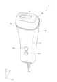
本実施の形態にかかる光照射型美容装置1は、図1に示すように、本体部10と、本体部10に着脱可能に装着されるアタッチメント20と、を備えている。As shown in FIG. 1, the light-irradiating cosmetic device 1 according to this embodiment includes a
本体部10は、上下方向Zに細長い形状をしており、使用者が片手で把持することができる程度の大きさに形成されている。このように、本実施の形態では、本体部10を手で把持することが可能なグリップ部として機能させている。そして、本体部10の上端には、光を施術者の皮膚に照射するための発光ユニット30を有するアタッチメント(光照射用アタッチメント)20が装着されている。The
この光照射用アタッチメント(アタッチメント20)が装着された光照射型美容装置1は、例えば、施術者の顔や手足の皮膚に所定の波長スペクトルの電磁波を照射することで、施術者の皮膚の美容効果を高めるための装置である。The light-irradiating cosmetic device 1 equipped with this light-irradiating attachment (attachment 20) is a device for enhancing the cosmetic effect of the practitioner's skin, for example by irradiating the skin of the practitioner's face, hands, and feet with electromagnetic waves of a specific wavelength spectrum.
なお、アタッチメント20は、例えば、ボディ用のアタッチメントやフェイス用のアタッチメント等、複数の光照射用アタッチメントの1つとすることができる。こうすれば、用途に応じて複数のアタッチメントを使い分けることができ、より効率よく美容効果を得ることができるようになる。また、脱毛用のアタッチメント等、光照射以外の機能を有するアタッチメントも有するようにしてもよい。The
本体部10は、本実施の形態では、合成樹脂製のハウジング11を備えており、このハウジング11は、例えば、複数の分割体を継ぎ合わせることで形成することができる。そして、ハウジング11の内部には空洞が形成されており、この空洞内に、各種電気部品が収容されている。In this embodiment, the
本実施の形態では、ハウジング11の内部に形成される空洞内には、図8に示すように、後述するフラッシュランプ(第1光源)321を駆動させるフラッシュランプ駆動部13と、後述するLED(第2光源)331を駆動させるLED駆動部14と、フラッシュランプ駆動部13およびLED駆動部14に電力を供給する電源部12等が収容されている。In this embodiment, as shown in FIG. 8, a cavity formed inside the
また、本実施の形態では、ハウジング11には、光照射型美容装置1を動作させる(電源をオン・オフさせる)押圧式の操作スイッチ11aが形成されている。なお、本実施の形態ではスイッチとして押圧式の操作スイッチ11aを例示したが、電源をオン・オフできるスイッチであればスライド式やその他のスイッチであってもよい。In addition, in this embodiment, the
また、ハウジング11には、フラッシュランプ駆動部13およびLED駆動部14のいずれか一方の駆動、または、両方の駆動を選択することが可能な押圧式の選択スイッチ11bが形成されている。この選択スイッチ11bも、スライド式やその他のスイッチとすることが可能である。The
[発光ユニットの構成の一例]
次に、発光ユニットの構成の一例を図2~図8を用いて説明する。 [Example of the configuration of the light-emitting unit]
Next, an example of the configuration of the light emitting unit will be described with reference to FIGS.
本実施の形態にかかる発光ユニット30は、上述したアタッチメント20に内蔵されている(備えられている)。The light-emitting
具体的には、アタッチメント20は、アタッチメント20の外郭を構成するハウジング21を備えており、このハウジング21の内部に発光ユニット30が内蔵されている。Specifically, the
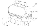
ハウジング21は、上下に分割された上側ハウジング211および下側ハウジング212を継ぎ合わせることで形成されており、このハウジング21の内部には、上下に貫通する空洞が形成されている(図4および図5参照)。なお、本実施の形態では、ハウジング21の内部に形成される空洞の上下開口のうち上方に開口する開口部が後述する出射口31の開口部311になっており、この開口部に導光板312を挿入することで、出射口31が形成されている。The
発光ユニット30は、フラッシュランプユニット(第1の光源部)32と、LEDユニット(第2の光源部)33と、フラッシュランプユニット32およびLEDユニット33よりも上方に位置する出射口31と、を備えている。そして、フラッシュランプユニット32が持つ波長スペクトルと、LEDユニット33が持つ波長スペクトルが異なるようにしている。The light-
本実施の形態では、フラッシュランプユニット32では、第1光源としてのフラッシュランプ321が用いられており、LEDユニット33では、第2光源としてのLED331が用いられている。こうすることで、フラッシュランプユニット32から放射される電磁波が所定の波長スペクトルを持つようにしている。そして、LEDユニット33から放射される電磁波が、フラッシュランプユニット32から放射される電磁波とは異なる所定の波長スペクトルを持つようにしている。In this embodiment, the
なお、本実施の形態のように、美容効果を出すための第1光源としてフラッシュランプ321を用いると、400nm~1200nmのブロードバンド光が放射されるため、幅広い美容効果を施術者の肌に与えることができる上、脱毛効果を与えることができる。When the
ここで、本実施の形態では、略円筒状のフラッシュランプ(円筒管のフラッシュランプ)321が用いられており、この円筒管のフラッシュランプ321は、軸方向を幅方向Yに沿わせた状態で配置されている(図4および図5参照)。In this embodiment, a substantially cylindrical flash lamp (cylindrical tube flash lamp) 321 is used, and this cylindrical
このように、円筒管のフラッシュランプ321を用いると、円筒管のラジアル方向に電磁波(光)を放射するため、出射口31に効率よく電磁波(光)を導くことができず、比較的多くの電磁波(光)が無駄になってしまう。In this way, when using a
そこで、本実施の形態では、フラッシュランプユニット32が、フラッシュランプ321から放射されて出射口31から外れた方向に向かう電磁波の少なくとも一部を出射口31に導くための反射鏡322を備えるようにした。Therefore, in this embodiment, the
反射鏡322は、略矩形板状の部材を側面視で上方に開口するU字状に折り曲げたような形状をしており、反射鏡322の内面が鏡面322aになっている。そして、円筒管のフラッシュランプ321を、側面視で略U字状の反射鏡322内の下側で、鏡面322aと対向するように配置させている。このとき、側面視で略U字状の反射鏡322を近似する放物線の焦点部分に円筒管のフラッシュランプ321が配置されるようにするのが好ましい。こうすれば、円筒管のフラッシュランプ321から放射された電磁波をより確実に上方に向けて反射させることができるようになる。
さらに、本実施の形態では、円筒管のフラッシュランプ321および側面視で略U字状の反射鏡322の上方、かつ、上下方向Zにおいて出射口31よりも下方(第1光源側)に、フラッシュランプ用フィルター323が配置されている。そして、円筒管のフラッシュランプ321から放射された電磁波および反射鏡322の鏡面322aで反射した電磁波が、このフラッシュランプ用フィルター323を通過してから出射口31に向かうようにしている。このように、本実施の形態では、フラッシュランプ用フィルター323がフラッシュランプユニット32の出射口となっている。Furthermore, in this embodiment, a
フラッシュランプ用フィルター323は、少なくともフラッシュランプ321から放射される電磁波の少なくとも一部を透過させやすい材質で形成することができる。また、ガラスやアクリル等の本体の表面にフィルターを貼り付けることで形成することも可能である。このとき、すべての波長が透過しやすい材質を選ぶこともでき、すべての波長が透過しやすい材質を選んだ場合には、より高いエネルギーを取り出すことができるようになる。また、フラッシュランプ用フィルター323を特定の波長がカットされる波長カットフィルターとして機能させることも可能である。例えば、肌にフラッシュランプ321から電磁波(光)を照射した際に痛みに繋がりやすい400nm~550nmの光をカットすれば、より痛みを感じにくい照射を実現することができる。また、バンドパスフィルターを構成し、特定の波長の光を取り出せるようにすることで、与えたい美容効果が得られる光のみを肌に当てるようにすることも可能である。The
これらの円筒管のフラッシュランプ321、反射鏡322およびフラッシュランプ用フィルター323は、本実施の形態では、保持ケース324に保持されている(図4、図5および図7参照)。In this embodiment, the
上述したように、本実施の形態では、美容効果を出すための第1光源としては、1つのフラッシュランプ321が用いられているが、美容効果を出すための第2光源としては、複数個のLED331が用いられている。As described above, in this embodiment, one
複数個のLED331としては、表面実装型のLEDが用いられており、複数個のLED331がLED実装基板332上に実装されている。本実施の形態では、LED実装基板332は、フラッシュランプユニット32の上面(フラッシュランプ用フィルター323)の周囲を囲むように配置されており、このLED実装基板332上に複数個のLED331が全周に亘って略等間隔に離間配置された状態で実装されている。したがって、本実施の形態では、複数個のLED331は、フラッシュランプユニット32の上面(フラッシュランプ用フィルター323)の全周を囲むように配置されている。Surface-mounted LEDs are used as the
なお、表面実装型以外のLEDをLED331として用いることも可能である。Note that LEDs other than surface mount type can also be used as
本実施の形態のように、美容効果を出すための第2光源としてLED331を用いると、与えたい美容効果に合わせて波長を選択することができるため、所望の美容効果を与えることができる上、脱毛効果を与えることができる。As in this embodiment, when
例えば、下記波長帯のLED331を選択すれば、下記に示す美容効果を得ることができる。なお、下記に示す波長はピーク波長を示しており、LED331から発する電磁波(光)の一部に範囲外の波長が含まれていてもよい。For example, by selecting an
(1)400nm~550nm:小じわ改善、にきび改善、赤ら顔改善、保湿、毛穴改善、抗炎症作用、皮脂低減、創傷治癒
(2)550nm~620nm:小じわ改善、ほうれい線改善、ターンオーバー促進、シミ改善
(3)620nm~750nm:創傷治癒、免疫力活性、シワ改善、シミ改善、ターンオーバー促進、コラーゲン産生
(4)750nm~2000nm:創傷治癒、免疫力活性、ターンオーバー促進
なお、550nm~1000nmの波長スペクトルを持つLEDを用いれば、肌の明るさ改善の効果を得ることが可能である。 (1) 400nm to 550nm: Improvement of fine lines, acne, redness, moisturizing, pore improvement, anti-inflammatory effect, sebum reduction, wound healing (2) 550nm to 620nm: Improvement of fine lines, nasolabial folds, cell turnover promotion, age spot improvement (3) 620nm to 750nm: Wound healing, immune system activation, wrinkle improvement, age spot improvement, cell turnover promotion, collagen production (4) 750nm to 2000nm: Wound healing, immune system activation, cell turnover promotion. In addition, by using an LED with a wavelength spectrum of 550nm to 1000nm, it is possible to obtain the effect of improving skin brightness.
また、複数のLED331として同一の波長スペクトルを持つLEDとする必要はなく、異なる波長スペクトルを持つLEDを組合せて使用してもよい。例えば450nmのLEDと630nmのLEDを使用すれば、にきび改善とコラーゲン産生効果を狙うこともできる。In addition, the
また、LED331から放射される電磁波の波長スペクトルが温度依存性を持っていてもよい。このようなLEDとしては、例えば、赤色系の光を放射するLEDを用いることができる。このように、温度依存性を持つLEDを用いれば、使用時の温度変化に応じて様々な効果を肌に与えることができるようになる。すなわち、1つのLEDで複数の効果を肌に与えることができるようになる。The wavelength spectrum of the electromagnetic waves emitted from the
複数個のLED331は、本実施の形態では、LED実装基板332を介してヒートシンク333に熱的に接続されており、LED331の熱がヒートシンク333から放熱されるようになっている。In this embodiment, the
このように、本実施の形態では、LEDユニット33は、第2光源としての複数個のLED331と、複数個のLED331が実装されるLED実装基板332と、LED331の熱を放熱させるヒートシンク333と、を備えている。As described above, in this embodiment, the
さらに、フラッシュランプユニット32およびLEDユニット33は、図7に示すように、一体化させた状態でハウジング21の空間内に収容されている。Furthermore, the
具体的には、平面視で略ロの字状(矩形の環状)をしたLED実装基板332の中央開口にフラッシュランプユニット32のフラッシュランプ用フィルター323を挿入固定することで、円筒管のフラッシュランプ321、反射鏡322およびフラッシュランプ用フィルター323を保持した保持ケース324をLEDユニット33と一体化させている。Specifically, the
また、図7に示すように、LED実装基板332の幅方向Yの両側には、取付孔332aが形成されており、この取付孔332aにネジ35を挿入して上側ハウジング211に固定することで、フラッシュランプユニット32およびLEDユニット33をハウジング21に固定している。As shown in FIG. 7, mounting
ところで、フラッシュランプユニット32からは、電磁波(光)が上下方向Zの上方(+Z方向)に向けて放射されることになる。また、複数個のLED331は、電磁波(光)が上下方向Zの上方(+Z方向)に向けて放射されるTop Emitting型のLEDであるため、上下方向Zの下方(-Z方向)へ放射される電磁波(光)は考慮する必要がない。Incidentally, electromagnetic waves (light) are emitted from the
ただし、LED331は配光分布を持っているため、XY方向へは広がりを持っている。そのため、このまま特に配慮しなければ、LED331から放射された電磁波(光)のうち出射口31から放出される電磁波(光)はごく一部となってしまう。However, since the
そこで、本実施の形態では、発光ユニット30が、フラッシュランプユニット32およびLEDユニット33と出射口31との間に配置され、フラッシュランプユニット32およびLEDユニット33のうち少なくともいずれか一方の光源部から放射される電磁波(光)の少なくとも一部を出射口31に導くための光学系を備えるようにした。このように、発光ユニット30が、LED331から放射された電磁波(光)を出射口31へ導く手段としての光学系を備えるようにすることで、より多くの電磁波(光)を肌に当てることができるようにしている。In this embodiment, the light-emitting
また、電磁波(光)を肌に当てる際には、肌への必要以上のダメージを防ぐためや一定の美容効果を得るためにも、出射口31における電磁波(光)の分布が均一であることが望ましい。In addition, when electromagnetic waves (light) are applied to the skin, it is desirable that the distribution of the electromagnetic waves (light) at the
そこで、本実施の形態では、光学系として、電磁波(光)を混合させて明るさのむらを少なくすることが可能なインテグレータ光学系34を用いるようにしている。このようなインテグレータ光学系34としては、従来公知のものを用いることができる。Therefore, in this embodiment, an integrator
本実施の形態では、フラッシュランプユニット32およびLEDユニット33から放射される波長スペクトルの電磁波(光)を反射しうる鏡面341aで囲われたライトパイプ341をインテグレータ光学系34としたものを例示している。In this embodiment, the integrator
さらに、本実施の形態では、入射側(LED331側:上下方向Zの下側)が複数個のLED331をすべて収容することが可能な開口であり、出射方向(上下方向Zの上側)に向かうにつれて開口面積が小さくなるように4枚の鏡を組み合わせて構成したテーパ状のライトパイプ341を用いてインテグレータ光学系34を形成している。したがって、本実施の形態では、テーパ状のライトパイプ341の内部には上下に貫通する略四角錐台状の空間部が形成されている。Furthermore, in this embodiment, the entrance side (
このようなテーパ状のライトパイプ341を用いれば、より安価にインテグレータ光学系34を得ることができる上、より効率的にLED331からの電磁波(光)を出射口31へ導き、出射口31において電磁波(光)を略均一化することができるようになる。By using such a
このように、本実施の形態では、ライトパイプ341の鏡面341aが、ライトパイプ341の中心軸に対して傾斜する4つの鏡面を有している。Thus, in this embodiment, the
なお、4つの鏡面のうち少なくとも1つの鏡面がライトパイプ341の中心軸と平行に延在する鏡面となるようにしてもよい。At least one of the four mirror surfaces may extend parallel to the central axis of the
ただし、インテグレータ光学系34を用いたとしても、フラッシュランプユニット32やLED331(LEDユニット33)の配置状況によっては、電磁波(光)の出射口31に向けての放射が相手側の光源部に邪魔されてしまい、出射口31から放出される電磁波(光)が少なくなってしまう場合がある。However, even if the integrator
そこで、本実施の形態では、フラッシュランプユニット32が、LEDユニット33から放射される電磁波との干渉が抑制される位置に配置されるようにし、LEDユニット33が、フラッシュランプユニット32から放射される電磁波との干渉が抑制される位置に配置されるようにした。このように、本実施の形態では、電磁波(光)の出射口31に向けての放射が邪魔されてしまうことをより確実に抑制できるようにすることで、十分な光量を出射口31から取り出すことが可能となるようにしている。Therefore, in this embodiment, the
具体的には、本実施の形態では、フラッシュランプユニット32は、LEDユニット33から主方向に向けて放射される電磁波(光)が出射口31に到達するまでの間に、LEDユニット33から主方向に向けて放射される電磁波(光)と重ならないようにした状態で配置されている。さらに、LEDユニット33は、フラッシュランプユニット32から主方向に向けて放射される電磁波(光)が出射口31に到達するまでの間に、フラッシュランプユニット32から主方向に向けて放射される電磁波(光)と重ならないようにした状態で配置されている。ここで、フラッシュランプユニット32から放射される電磁波(光)の主方向は、上下方向Zの上方であり、LEDユニット33から放射される電磁波(光)の主方向は、上下方向Zの上方である。Specifically, in this embodiment, the
さらに、本実施の形態では、LEDユニット33が、平面視(出射口31から視た状態)でフラッシュランプユニット32と重ならない位置に配置されており、フラッシュランプユニット32およびLEDユニット33は、フラッシュランプユニット32の出射面32aとLEDユニット33の出射面33aとが略同一平面上に位置するように配置されている。Furthermore, in this embodiment, the
このとき、フラッシュランプユニット32が、LEDユニット33から放射される電磁波の半値角以内の電磁波と干渉しない位置に配置され、LEDユニット33が、フラッシュランプユニット32から放射される電磁波の半値角以内の電磁波と干渉しない位置に配置されることになる。At this time, the
こうすれば、フラッシュランプユニット32およびLEDユニット33の各々から放射される電磁波(光)を、相手側の光源部に干渉することなく出射口31へ導くことが可能になる。In this way, it becomes possible to guide the electromagnetic waves (light) emitted from each of the
なお、現実的には完全な同一面にできない場合も想定されるが、この場合には、各々の光源部から放射される電磁波(光)の半値角以内の光を遮らない位置へ相手側の光源部を配置するのが好ましい。こうすることでも、十分な光量を取り出すことが可能になる。In reality, it may not be possible to make the surfaces completely flush. In this case, it is preferable to place the light source unit on the other side in a position that does not block the light within the half-value angle of the electromagnetic waves (light) emitted from each light source unit. This also makes it possible to extract a sufficient amount of light.
[光照射型美容装置の動作の一例]
以上のように構成された発光ユニット30を備えた光照射型美容装置1について、その動作を説明する。 [Example of operation of light-irradiating beauty device]
The operation of the light-irradiating cosmetic device 1 equipped with the light-emitting
まず、発光ユニット30が内蔵されたアタッチメント20を本体部10に装着することで光照射型美容装置1を使用できる状態にする。First, the
そして、使用可能な状態とした光照射型美容装置1の操作スイッチ11aを操作することで、電源をオンにする。Then, the power is turned on by operating the
このとき、選択スイッチ11bによって、フラッシュランプ駆動部13およびLED駆動部14の両方の駆動が選択されている場合には、電源部12よりフラッシュランプ駆動部13へ電力が供給され、フラッシュランプ駆動部13によってフラッシュランプ321が発光されることになる。また、電源部12よりLED駆動部14へ電力が供給され、LED駆動部14によってLED331が発光されることになる。At this time, if the
そして、フラッシュランプ321から放射される電磁波(光)およびLED331から放射される電磁波(光)がインテグレータ光学系34内に導入されて、2種類の電磁波(光)は、より均等に混合した状態で、出射口31から外部に出射されることになる。The electromagnetic waves (light) emitted from the
この状態で、出射口31が肌で覆われるようにした状態で、光照射型美容装置1を肌に沿って摺動させる。こうすることで、施術者の皮膚表面に光を照射させ、施術者の皮膚に所望の美容効果を与えるようにしている。In this state, with the
このように、本実施の形態では、フラッシュランプユニット32およびLEDユニット33から電磁波(光)をそれぞれ放射させた場合に、同一の領域(1つの出射口31)から2種類の電磁波(光)の少なくとも一部が出射されるようになっている。なお、本実施の形態では、2種類の電磁波(光)は、フラッシュランプユニット32から放射される電磁波およびLEDユニット33から放射される電磁波となっている。In this manner, in this embodiment, when electromagnetic waves (light) are emitted from the
また、電源をオンにしたときに、選択スイッチ11bによって、フラッシュランプ駆動部13およびLED駆動部14のうちの一方の駆動が選択されている場合には、一方の光源部から放射される電磁波(光)が出射口31から出射されることになる。When the power is turned on, if the
[作用・効果]
以下では、上記実施の形態で示した発光ユニットおよび光照射型美容装置の特徴的構成およびそれにより得られる効果を説明する。 [Action and Effects]
The characteristic configurations of the light-emitting unit and the light-irradiating cosmetic device described in the above embodiment and the effects obtained thereby will be described below.
上記実施の形態で示した発光ユニット30は、所定の波長スペクトルを持つ第1の光源部32と、第1の光源部32とは異なる波長スペクトルを持つ第2の光源部33と、第1の光源部32および第2の光源部33から電磁波をそれぞれ放射させた場合に、第1の光源部32から放射される電磁波の少なくとも一部および第2の光源部33から放射される電磁波の少なくとも一部が出射される出射口31と、を備えている。また、第1の光源部32は、第2の光源部33から放射される電磁波との干渉が抑制される位置に配置されており、第2の光源部33は、第1の光源部32から放射される電磁波との干渉が抑制される位置に配置されている。The light-emitting
こうすれば、夫々異なる波長スペクトルを持つ光源からの光(電磁波)を同一の領域(1つの出射口)から出射させることができるようになる。そのため、異なる波長スペクトルを持つ光源のうちの1つの光(電磁波)しか当てることができない部位が肌に存在してしまうことを抑制することができる。したがって、皮膚のより多くの部位に異なる波長スペクトルの光(電磁波)を同時に照射することができるようになって、施術者の美容効果をより高めることが可能になる。In this way, it becomes possible to emit light (electromagnetic waves) from light sources with different wavelength spectra from the same area (one emission port). This makes it possible to prevent the existence of areas on the skin that can only be hit by one light (electromagnetic wave) from one of the light sources with different wavelength spectra. This makes it possible to simultaneously irradiate more areas of the skin with light (electromagnetic waves) of different wavelength spectra, thereby further enhancing the cosmetic effect achieved by the practitioner.
また、出射口の面積を小さくしたとしても、複数の光源から出射される光(電磁波)を同時に出射口から出射させることが可能になるため、小鼻や目尻の細かな所にも複数の光源から出射される光(電磁波)を同時に当てることができる。その結果、美容効果をより一層高めることができるようになる。In addition, even if the area of the exit is small, it is possible for light (electromagnetic waves) emitted from multiple light sources to be emitted from the exit simultaneously, so light (electromagnetic waves) emitted from multiple light sources can be directed simultaneously at small areas such as the nostrils and corners of the eyes. As a result, the beauty effects can be further enhanced.
このように、本実施の形態にかかる発光ユニット30は、所定の波長スペクトルを持つ第1の光源部32と、第1の光源部32とは異なる波長スペクトルを持つ第2の光源部33と、第1の光源部32および第2の光源部33から電磁波をそれぞれ放射させた場合に、第1の光源部32から放射される電磁波の少なくとも一部および第2の光源部33から放射される電磁波の少なくとも一部が出射される出射口31と、を備え、第1の光源部32から放射される電磁波と第2の光源部33から放射される電磁波とを同一出射口(出射口31)から取り出せるようにしたことにより、いかなる皮膚の部位であっても異なる波長スペクトルの光(電磁波)を同時に照射することができ複数の美容効果の光(電磁波)を同時に施術することができるものである。In this way, the light-emitting
また、第1の光源部32および第2の光源部33と出射口31との間に配置され、第1の光源部32および第2の光源部33のうち少なくともいずれか一方の光源部から放射される電磁波の少なくとも一部を出射口31に導くための光学系をさらに備えていてもよい。The device may further include an optical system disposed between the first
こうすれば、第1の光源部32および第2の光源部33のうち少なくともいずれか一方の光源部から放射される光(電磁波)をより効率的に出射口に導くことができ、美容効果をより一層高めることができるようになる。In this way, the light (electromagnetic waves) emitted from at least one of the first
また、光学系がインテグレータ光学系34であってもよい。The optical system may also be an integrator
こうすれば、異なる波長スペクトルを持つ光源からの光(電磁波)を、より均一となるように混合させた状態で出射口から出射させることが可能になる。その結果、夫々異なる波長スペクトルを持つ光源からの光(電磁波)をより均一に皮膚に当てることができ、より効率的に皮膚の美容効果を高めることができるようになる。In this way, it becomes possible to emit light (electromagnetic waves) from light sources with different wavelength spectra in a more uniformly mixed state from the emission port. As a result, the light (electromagnetic waves) from the light sources, each with a different wavelength spectrum, can be applied to the skin more uniformly, and the cosmetic effects on the skin can be enhanced more efficiently.
また、インテグレータ光学系34が、第1の光源部32と第2の光源部33から放射される波長スペクトルの電磁波を反射しうる鏡面341aで囲われたライトパイプ341であってもよい。The integrator
こうすれば、より簡素な構成でインテグレータ光学系34を形成することができるようになる。This makes it possible to form the integrator
また、ライトパイプ341の鏡面341aが、ライトパイプ341の中心軸に対して傾斜する鏡面を有していてもよい。The
こうすれば、第1の光源部32および第2の光源部33のうち少なくともいずれか一方の光源部から放射される光(電磁波)をより効率的に出射口に導くことができ、美容効果をより一層高めることができるようになる。In this way, the light (electromagnetic waves) emitted from at least one of the first
特に、本実施の形態で示したようなテーパ状のライトパイプ341を用いれば、より効率良く、より均一な光(電磁波)を出射口31へ届けることができるようになる。In particular, by using a tapered
また、ライトパイプ341の鏡面341aが、ライトパイプ341の中心軸と平行に延在する鏡面を有していてもよい。The
こうすれば、より容易にライトパイプ341の鏡面341aを形成することができるようになる。This makes it easier to form the
また、第1の光源部32は、第1光源としてのフラッシュランプ321を有しており、第1光源321から放射されて出射口31から外れた方向に向かう電磁波の少なくとも一部を出射口31に導くための反射鏡322を備えていてもよい。The first
こうすれば、フラッシュランプ321から放射される光(電磁波)をより無駄なく出射口に導くことができるようになる。This allows the light (electromagnetic waves) emitted from the
また、第2の光源部33は、第2光源としてのLED331を有していてもよい。The second
こうすれば、より容易に様々な美容効果を奏する構成とすることができるようになる。This makes it easier to create a configuration that provides a variety of beauty effects.
また、LED331から放射される電磁波の波長スペクトルが温度依存性を持っていてもよい。In addition, the wavelength spectrum of the electromagnetic waves emitted from
こうすれば、1つのLEDを用いるだけで複数の美容効果を得ることができるようになる。This way, multiple beauty effects can be achieved using just one LED.
また、第1の光源部32は、第2の光源部33から主方向に向けて放射される電磁波が出射口31に到達するまでの間に、第2の光源部33から主方向に向けて放射される電磁波と重ならないようにした状態で配置されており、第2の光源部33は、第1の光源部32から主方向に向けて放射される電磁波が出射口31に到達するまでの間に、第1の光源部32から主方向に向けて放射される電磁波と重ならないようにした状態で配置されていてもよい。The first
こうすれば、各々の光源部から放射される光(電磁波)をより無駄なく出射口に導くことができるようになる。This allows the light (electromagnetic waves) emitted from each light source to be guided to the exit port with less waste.
また、第2の光源部33が、出射口31から視た状態で第1の光源部32と重ならない位置に配置されていてもよい。The second
こうすることでも、各々の光源部から放射される光(電磁波)をより無駄なく出射口に導くことができるようになる。This also makes it possible to guide the light (electromagnetic waves) emitted from each light source to the exit port with less waste.
また、第1の光源部32の出射面32aと第2の光源部33の出射面33aとが略同一平面上に位置していてもよい。In addition, the
こうすることでも、各々の光源部から放射される光(電磁波)をより無駄なく出射口に導くことができるようになる。This also makes it possible to guide the light (electromagnetic waves) emitted from each light source to the exit port with less waste.
また、第1の光源部32が、第2の光源部33から放射される電磁波の半値角以内の電磁波と干渉しない位置に配置されており、第2の光源部33が、第1の光源部32から放射される電磁波の半値角以内の電磁波と干渉しない位置に配置されていてもよい。The first
こうすることでも、各々の光源部から放射される光(電磁波)をより無駄なく出射口に導くことができるようになる。This also makes it possible to guide the light (electromagnetic waves) emitted from each light source to the exit port with less waste.
また、上記実施の形態で示した光照射型美容装置1は、上記発光ユニット30を備えている。The light-irradiating cosmetic device 1 shown in the above embodiment is also equipped with the light-emitting
こうすれば、美容効果をより一層高めることが可能な発光ユニットを備える光照射型美容装置を得ることができる。In this way, a light-emitting cosmetic device equipped with a light-emitting unit can be obtained that can further enhance the cosmetic effect.
また、光照射型美容装置1が、発光ユニット30を備えるアタッチメント20と、アタッチメント20を着脱可能に装着する本体部10と、を備えていてもよい。The light-irradiating cosmetic device 1 may also include an
こうすれば、発光ユニットを備えるアタッチメントを、様々な機能を有するアタッチメントの1つとして選択することができるようになるため、より汎用性を持たせた光照射型美容装置を得ることができる。また、発光ユニットの交換がより容易になる。In this way, an attachment equipped with a light-emitting unit can be selected as one of a variety of attachments with various functions, resulting in a more versatile light-irradiating cosmetic device. In addition, it becomes easier to replace the light-emitting unit.
このように、本実施の形態によれば、美容効果をより高めることが可能な発光ユニットおよび光照射型美容装置を得ることができる。In this way, according to this embodiment, it is possible to obtain a light-emitting unit and a light-irradiating cosmetic device that can further enhance the cosmetic effect.
[その他]
以上、本開示にかかる発光ユニットおよび光照射型美容装置の内容を説明したが、これらの記載に限定されるものではなく、種々の変形および改良が可能であることは、当業者には自明である。 [others]
The light-emitting unit and light-irradiating cosmetic device according to the present disclosure have been described above, but the present disclosure is not limited to these descriptions, and it will be obvious to those skilled in the art that various modifications and improvements are possible.
例えば、上記実施の形態では、フラッシュランプユニット32およびLEDユニット33が、フラッシュランプユニット32の出射面32aとLEDユニット33の出射面33aとが略同一平面上に位置するように配置されているものを例示しているが、これに限らず、フラッシュランプユニット32およびLEDユニット33は、相手側の光源部から放射される電磁波との干渉が抑制される位置に配置されていればよい。例えば、フラッシュランプユニット32の出射面32aとLEDユニット33の出射面33aとの高さが異なっていてもよいし、フラッシュランプユニット32から放射される電磁波(光)の主方向と、LEDユニット33から放射される電磁波(光)の主方向とが異なる方向であってもよい。For example, in the above embodiment, the
また、位置関係による干渉防止以外の方法、例えば、鏡やレンズのような光学系を配置することで光の挙動をコントールし干渉を抑制することも可能である。In addition to preventing interference through positional relationships, it is also possible to control the behavior of light and suppress interference by using optical systems such as mirrors and lenses.
また、上記実施の形態では、テーパ状のライトパイプ341をインテグレータ光学系34として用いたものを例示したが、ライトパイプ341は何も配置しない場合よりも光を効率よく出射口31へ導けるものであればよい。例えば、直線状のライトパイプ、フライアレイレンズなどのインテグレータ光学系を用いることが可能である。こうすることでも、より効率的に電磁波(光)を出射口31へ導くことができ、出射口31における照度分布を略均一にすることができる。In addition, in the above embodiment, a tapered
また、上記実施の形態では、第1光源の一例としてフラッシュランプ32を、第2光源としてLED331を例示したが、第1光源および第2光源は、電磁波を発することができるものであればよく、例えば、LD(Laser Diode)、有機EL等を用いることができる。こうすることでも、与えたい美容効果に合わせて波長を選択し所望の美容効果、脱毛効果を与えることができる。In addition, in the above embodiment, the
また、上記実施の形態では、本体部10に着脱可能に装着されるアタッチメント20を備えるものを例示したが、一体型の光照射型美容装置(発光ユニットの着脱ができない光照射型美容装置)とすることも可能である。In addition, in the above embodiment, an example was given of a device equipped with an
また、本体部やアタッチメント、その他細部のスペック(形状、大きさ、レイアウト等)も適宜に変更可能である。In addition, the specifications of the main body, attachments, and other details (shape, size, layout, etc.) can be changed as appropriate.
以上のように、本開示にかかる発光ユニットおよび光照射型美容装置は、美容効果をより高めることが可能であるので、光を肌に照射して生体作用を得る装置、具体的には、美顔器、脱毛器、理学療法装置、医療装置などに適用することが可能である。As described above, the light-emitting unit and light-irradiating cosmetic device disclosed herein can enhance the cosmetic effect, and can therefore be used in devices that irradiate light onto the skin to obtain a biological effect, specifically, facial beautifying devices, hair removal devices, physical therapy devices, medical devices, and the like.
1 光照射型美容装置
10 本体部
20 アタッチメント
30 発光ユニット
31 出射口
32 フラッシュランプユニット(第1の光源部)
32a 出射面
321 フラッシュランプ(第1光源)
322 反射鏡
33 LEDユニット(第2の光源部)
33a 出射面
331 LED(第2光源)
34 インテグレータ光学系(光学系)
341 ライトパイプ
341a 鏡面
Reference Signs List 1 Light-irradiating
32a: Emission surface 321: Flash lamp (first light source)
322
34 Integrator optical system (optical system)
341
Claims (8)
Translated fromJapanese前記第1の光源部とは異なる波長スペクトルを持つ第2の光源部と、
前記第1の光源部および前記第2の光源部から電磁波をそれぞれ放射させた場合に、前記第1の光源部から放射される電磁波の少なくとも一部および前記第2の光源部から放射される電磁波の少なくとも一部が混合された状態で射される出射口と、
前記第1の光源部および前記第2の光源部と前記出射口との間に配置され、前記第1の光源部および前記第2の光源部のうち少なくともいずれか一方の光源部から放射される電磁波の少なくとも一部を前記出射口に導くための光学系と、
を備え、
前記第1の光源部から放射される電磁波の主方向と前記第2の光源部から放射される電磁波の主方向とが略一致しており、
前記光学系がインテグレータ光学系であり、
前記インテグレータ光学系が、前記第1の光源部と前記第2の光源部から放射される波長スペクトルの電磁波を反射しうる鏡面で囲われたライトパイプであり、
前記第1の光源部は、第1光源としてのフラッシュランプを有しており、
前記第1光源から放射されて前記出射口から外れた方向に向かう電磁波の少なくとも一部を前記出射口に導くための反射鏡を備えており、
前記第2の光源部は、第2光源としてのLEDを複数有しており、
前記第2の光源部が、前記出射口から視た状態で前記第1の光源部と重ならない位置に配置されており、
前記第1の光源部の出射面と前記第2の光源部の出射面とが略同一平面上に位置しており、
複数の前記LEDが、前記フラッシュランプおよび前記反射鏡を有するフラッシュランプユニットの上面の全周を囲むように配置されている、
発光ユニット。 a first light source unit having a predetermined wavelength spectrum;
a second light source unit having a wavelength spectrum different from that of the first light source unit;
an emission port through which at least a portion of the electromagnetic waves radiated from the first light source unit and at least a portion of the electromagnetic waves radiated from the second light source unit are emitted in a mixed state when electromagnetic waves are radiated from the first light source unit and the second light source unit, respectively;
an optical system disposed between the first light source unit and the second light source unit and the light exit, for guiding at least a part of an electromagnetic wave emitted from at least one of the first light source unit and the second light source unit to the light exit;
Equippedwith
a main direction of the electromagnetic wave radiated from thefirst light source unit and a main direction of the electromagnetic wave radiated from the second light source unit are substantially the same,
the optical system is an integrator optical system,
the integrator optical system is a light pipe surrounded by a mirror surface capable of reflecting electromagnetic waves of wavelength spectrums emitted from the first light source unit and the second light source unit,
the first light source unit has a flash lamp as a first light source,
a reflector for guiding, to the exit port, at least a portion of the electromagnetic wave emitted from the first light source and traveling in a direction away from the exit port,
The second light source unit has a plurality of LEDs as second light sources,
the second light source unit is disposed at a position not overlapping with the first light source unit when viewed from the light exit port,
an exit surface of the first light source unit and an exit surface of the second light source unit are located on substantially the same plane,
A plurality of the LEDs are arranged so as to surround the entire periphery of the upper surface of a flash lamp unit having the flash lamp and the reflecting mirror.
Light emitting unit.
請求項1に記載の発光ユニット。 The mirror surface of the light pipe has a mirror surface that is inclined with respect to a central axis of the light pipe.
The light-emitting unit according to claim1 .
請求項1または請求項2に記載の発光ユニット。 the mirror surface of the light pipe has a mirror surface extending parallel to a central axis of the light pipe;
The light-emitting unit according to claim1 .
請求項1~3のうちいずれか1項に記載の発光ユニット。 The wavelength spectrum of the electromagnetic wave emitted from the LED has temperature dependence.
The light-emitting unitaccording to any one of claims 1 to 3 .
前記第2の光源部は、前記光学系が配置されていない場合には、前記第1の光源部から主方向に向けて放射される電磁波が前記出射口に到達するまでの間に、前記第1の光源部から主方向に向けて放射される電磁波と重ならないようにした状態で配置されている、
請求項1~4のうちいずれか1項に記載の発光ユニット。 the first light source unit is arranged in a state where,when the optical system is not arranged, the first light source unit does not overlap with the electromagnetic wave radiated from the second light source unit in the main direction until the electromagnetic wave radiated from the second light source unit in the main direction reaches the light outlet,
When the optical system is not disposed , the second light source unit is disposed in a state in which the second light source unit does not overlap with the electromagnetic wave emitted from the first light source unit in the main direction until the electromagnetic wave emitted from the first light source unit in the main direction reaches the light outlet.
The light-emitting unit according to any one of claims 1 to4 .
前記第2の光源部が、前記第1の光源部から放射される電磁波の半値角以内の電磁波と干渉しない位置に配置されている、
請求項1~5のうちいずれか1項に記載の発光ユニット。 the first light source unit is disposed at a position where it does not interfere with electromagnetic waves within a half-value angle of the electromagnetic waves radiated from the second light source unit,
the second light source unit is disposed at a position where it does not interfere with electromagnetic waves within a half-value angle of the electromagnetic waves radiated from the first light source unit;
The light-emitting unit according to any one of claims 1 to5 .
光照射型美容装置。 The light-emitting unit according to any one of claims 1 to6 is provided.
A light-emitting beauty device.
前記アタッチメントを着脱可能に装着する本体部と、
を備える、
請求項7に記載の光照射型美容装置。 an attachment including the light emitting unit;
A main body to which the attachment is detachably attached;
Equipped with
The light-irradiating cosmetic device according to claim7 .
Priority Applications (4)
| Application Number | Priority Date | Filing Date | Title |
|---|---|---|---|
| JP2020177498AJP7672035B2 (en) | 2020-10-22 | 2020-10-22 | Light-emitting unit and light-irradiating beauty device |
| CN202180071595.8ACN116367889A (en) | 2020-10-22 | 2021-09-30 | Light emitting unit and light irradiation type cosmetic device |
| EP21882531.3AEP4234008A4 (en) | 2020-10-22 | 2021-09-30 | Light emission unit and light emission type cosmetic device |
| PCT/JP2021/036121WO2022085390A1 (en) | 2020-10-22 | 2021-09-30 | Light emission unit and light emission type cosmetic device |
Applications Claiming Priority (1)
| Application Number | Priority Date | Filing Date | Title |
|---|---|---|---|
| JP2020177498AJP7672035B2 (en) | 2020-10-22 | 2020-10-22 | Light-emitting unit and light-irradiating beauty device |
Publications (2)
| Publication Number | Publication Date |
|---|---|
| JP2022068686A JP2022068686A (en) | 2022-05-10 |
| JP7672035B2true JP7672035B2 (en) | 2025-05-07 |
Family
ID=81289587
Family Applications (1)
| Application Number | Title | Priority Date | Filing Date |
|---|---|---|---|
| JP2020177498AActiveJP7672035B2 (en) | 2020-10-22 | 2020-10-22 | Light-emitting unit and light-irradiating beauty device |
Country Status (4)
| Country | Link |
|---|---|
| EP (1) | EP4234008A4 (en) |
| JP (1) | JP7672035B2 (en) |
| CN (1) | CN116367889A (en) |
| WO (1) | WO2022085390A1 (en) |
Families Citing this family (3)
| Publication number | Priority date | Publication date | Assignee | Title |
|---|---|---|---|---|
| JP2024008036A (en)* | 2022-07-07 | 2024-01-19 | リアラン株式会社 | Beauty appliance |
| JP7556418B2 (en)* | 2023-02-21 | 2024-09-26 | ウシオ電機株式会社 | Ultraviolet Therapy Device |
| WO2025190345A1 (en)* | 2024-03-15 | 2025-09-18 | Shenzhen Ulike Smart Electronics Co., Ltd. | Skin treatment device |
Citations (3)
| Publication number | Priority date | Publication date | Assignee | Title |
|---|---|---|---|---|
| JP2006511275A (en) | 2002-12-20 | 2006-04-06 | パロマー・メディカル・テクノロジーズ・インコーポレイテッド | Phototherapy device for acne and other hair follicle disorders |
| JP2015073744A (en) | 2013-10-09 | 2015-04-20 | ヤーマン株式会社 | Light irradiation type beauty equipment |
| US20150250543A1 (en) | 2014-03-07 | 2015-09-10 | Syneron Medical Ltd. | Multi-wavelength laser device for skin treatment |
Family Cites Families (5)
| Publication number | Priority date | Publication date | Assignee | Title |
|---|---|---|---|---|
| WO2000002491A1 (en)* | 1998-07-09 | 2000-01-20 | Curelight Ltd. | Apparatus and method for efficient high energy photodynamic therapy of acne vulgaris and seborrhea |
| IL148257A0 (en)* | 2001-12-06 | 2002-09-12 | Curelight Ltd | Phototherapy for psoriasis and other skin disorders |
| US20070239142A1 (en) | 2006-03-10 | 2007-10-11 | Palomar Medical Technologies, Inc. | Photocosmetic device |
| WO2006092776A1 (en)* | 2005-03-03 | 2006-09-08 | Leortec Ltd. | Aesthetic treatment device |
| EP3610818A1 (en)* | 2018-08-13 | 2020-02-19 | Koninklijke Philips N.V. | Hand-held device for performing a treatment operation |
- 2020
- 2020-10-22JPJP2020177498Apatent/JP7672035B2/enactiveActive
- 2021
- 2021-09-30CNCN202180071595.8Apatent/CN116367889A/enactivePending
- 2021-09-30EPEP21882531.3Apatent/EP4234008A4/enactivePending
- 2021-09-30WOPCT/JP2021/036121patent/WO2022085390A1/ennot_activeCeased
Patent Citations (3)
| Publication number | Priority date | Publication date | Assignee | Title |
|---|---|---|---|---|
| JP2006511275A (en) | 2002-12-20 | 2006-04-06 | パロマー・メディカル・テクノロジーズ・インコーポレイテッド | Phototherapy device for acne and other hair follicle disorders |
| JP2015073744A (en) | 2013-10-09 | 2015-04-20 | ヤーマン株式会社 | Light irradiation type beauty equipment |
| US20150250543A1 (en) | 2014-03-07 | 2015-09-10 | Syneron Medical Ltd. | Multi-wavelength laser device for skin treatment |
Also Published As
| Publication number | Publication date |
|---|---|
| EP4234008A1 (en) | 2023-08-30 |
| EP4234008A4 (en) | 2024-03-20 |
| WO2022085390A1 (en) | 2022-04-28 |
| JP2022068686A (en) | 2022-05-10 |
| CN116367889A (en) | 2023-06-30 |
Similar Documents
| Publication | Publication Date | Title |
|---|---|---|
| JP7672035B2 (en) | Light-emitting unit and light-irradiating beauty device | |
| KR101807533B1 (en) | LED Mask | |
| US9415237B2 (en) | Light treatment system | |
| US9533170B2 (en) | Multicolor light emitting diode treatment system with uniform illumination | |
| US8961578B2 (en) | Dermatological treatment device with one or more vertical cavity surface emitting lasers (VCSEL) | |
| JP6333833B2 (en) | Device, apparatus and assembly for light beauty treatment | |
| US20080119913A1 (en) | Light therapy personal care device | |
| KR101616002B1 (en) | Mask device for facial skin clinic | |
| US20100069898A1 (en) | Acne Treatment Method, System and Device | |
| US20080103563A1 (en) | Light therapy personal care device | |
| US20070032843A1 (en) | Phototherapy apparatus | |
| CN112135665A (en) | Light delivery device with optical comb | |
| CN107921275A (en) | Phototherapy device | |
| HUP0400131A2 (en) | Photodynamic therapy lamp | |
| EP2376194A1 (en) | Phototherapeutic apparatus and method | |
| KR101220132B1 (en) | Portable uv curing apparatus | |
| KR102325386B1 (en) | Skin care device | |
| JP7689282B2 (en) | Light-emitting unit and light-irradiating beauty device | |
| KR102108677B1 (en) | Complex therapeutic apparatus using LED | |
| KR200488956Y1 (en) | Light emitter for skin having xenon lamp | |
| JP2024543581A (en) | Body irradiation device for applying directed actinic light to living organisms | |
| KR20220139335A (en) | body irradiation device | |
| JP2013252413A (en) | Flat panel narrow band monochromatic light emitting device and shell type led narrow band monochromatic light emitting device | |
| JP2011238748A (en) | Ultraviolet light emitting diode solidification device | |
| JP7364660B2 (en) | Facial massager |
Legal Events
| Date | Code | Title | Description |
|---|---|---|---|
| RD04 | Notification of resignation of power of attorney | Free format text:JAPANESE INTERMEDIATE CODE: A7424 Effective date:20230524 | |
| A621 | Written request for application examination | Free format text:JAPANESE INTERMEDIATE CODE: A621 Effective date:20230602 | |
| A131 | Notification of reasons for refusal | Free format text:JAPANESE INTERMEDIATE CODE: A131 Effective date:20240402 | |
| A521 | Request for written amendment filed | Free format text:JAPANESE INTERMEDIATE CODE: A523 Effective date:20240529 | |
| A131 | Notification of reasons for refusal | Free format text:JAPANESE INTERMEDIATE CODE: A131 Effective date:20240730 | |
| A521 | Request for written amendment filed | Free format text:JAPANESE INTERMEDIATE CODE: A523 Effective date:20240927 | |
| A131 | Notification of reasons for refusal | Free format text:JAPANESE INTERMEDIATE CODE: A131 Effective date:20241210 | |
| A521 | Request for written amendment filed | Free format text:JAPANESE INTERMEDIATE CODE: A523 Effective date:20250129 | |
| TRDD | Decision of grant or rejection written | ||
| A01 | Written decision to grant a patent or to grant a registration (utility model) | Free format text:JAPANESE INTERMEDIATE CODE: A01 Effective date:20250318 | |
| A61 | First payment of annual fees (during grant procedure) | Free format text:JAPANESE INTERMEDIATE CODE: A61 Effective date:20250407 | |
| R150 | Certificate of patent or registration of utility model | Ref document number:7672035 Country of ref document:JP Free format text:JAPANESE INTERMEDIATE CODE: R150 |