JP7671848B2 - Reagent Layer and Sensor - Google Patents
Reagent Layer and SensorDownload PDFInfo
- Publication number
- JP7671848B2 JP7671848B2JP2023531831AJP2023531831AJP7671848B2JP 7671848 B2JP7671848 B2JP 7671848B2JP 2023531831 AJP2023531831 AJP 2023531831AJP 2023531831 AJP2023531831 AJP 2023531831AJP 7671848 B2JP7671848 B2JP 7671848B2
- Authority
- JP
- Japan
- Prior art keywords
- binding site
- polymer
- reagent layer
- protein
- sensor
- Prior art date
- Legal status (The legal status is an assumption and is not a legal conclusion. Google has not performed a legal analysis and makes no representation as to the accuracy of the status listed.)
- Active
Links
Images


Classifications
- C—CHEMISTRY; METALLURGY
- C12—BIOCHEMISTRY; BEER; SPIRITS; WINE; VINEGAR; MICROBIOLOGY; ENZYMOLOGY; MUTATION OR GENETIC ENGINEERING
- C12Q—MEASURING OR TESTING PROCESSES INVOLVING ENZYMES, NUCLEIC ACIDS OR MICROORGANISMS; COMPOSITIONS OR TEST PAPERS THEREFOR; PROCESSES OF PREPARING SUCH COMPOSITIONS; CONDITION-RESPONSIVE CONTROL IN MICROBIOLOGICAL OR ENZYMOLOGICAL PROCESSES
- C12Q1/00—Measuring or testing processes involving enzymes, nucleic acids or microorganisms; Compositions therefor; Processes of preparing such compositions
- C12Q1/001—Enzyme electrodes
- C12Q1/004—Enzyme electrodes mediator-assisted
- C—CHEMISTRY; METALLURGY
- C08—ORGANIC MACROMOLECULAR COMPOUNDS; THEIR PREPARATION OR CHEMICAL WORKING-UP; COMPOSITIONS BASED THEREON
- C08F—MACROMOLECULAR COMPOUNDS OBTAINED BY REACTIONS ONLY INVOLVING CARBON-TO-CARBON UNSATURATED BONDS
- C08F220/00—Copolymers of compounds having one or more unsaturated aliphatic radicals, each having only one carbon-to-carbon double bond, and only one being terminated by only one carboxyl radical or a salt, anhydride ester, amide, imide or nitrile thereof
- C08F220/02—Monocarboxylic acids having less than ten carbon atoms; Derivatives thereof
- C08F220/10—Esters
- C08F220/34—Esters containing nitrogen, e.g. N,N-dimethylaminoethyl (meth)acrylate
- C—CHEMISTRY; METALLURGY
- C08—ORGANIC MACROMOLECULAR COMPOUNDS; THEIR PREPARATION OR CHEMICAL WORKING-UP; COMPOSITIONS BASED THEREON
- C08F—MACROMOLECULAR COMPOUNDS OBTAINED BY REACTIONS ONLY INVOLVING CARBON-TO-CARBON UNSATURATED BONDS
- C08F226/00—Copolymers of compounds having one or more unsaturated aliphatic radicals, each having only one carbon-to-carbon double bond, and at least one being terminated by a single or double bond to nitrogen or by a heterocyclic ring containing nitrogen
- C08F226/02—Copolymers of compounds having one or more unsaturated aliphatic radicals, each having only one carbon-to-carbon double bond, and at least one being terminated by a single or double bond to nitrogen or by a heterocyclic ring containing nitrogen by a single or double bond to nitrogen
- C—CHEMISTRY; METALLURGY
- C12—BIOCHEMISTRY; BEER; SPIRITS; WINE; VINEGAR; MICROBIOLOGY; ENZYMOLOGY; MUTATION OR GENETIC ENGINEERING
- C12Q—MEASURING OR TESTING PROCESSES INVOLVING ENZYMES, NUCLEIC ACIDS OR MICROORGANISMS; COMPOSITIONS OR TEST PAPERS THEREFOR; PROCESSES OF PREPARING SUCH COMPOSITIONS; CONDITION-RESPONSIVE CONTROL IN MICROBIOLOGICAL OR ENZYMOLOGICAL PROCESSES
- C12Q1/00—Measuring or testing processes involving enzymes, nucleic acids or microorganisms; Compositions therefor; Processes of preparing such compositions
- C12Q1/001—Enzyme electrodes
- C12Q1/005—Enzyme electrodes involving specific analytes or enzymes
- C12Q1/006—Enzyme electrodes involving specific analytes or enzymes for glucose
- G—PHYSICS
- G01—MEASURING; TESTING
- G01N—INVESTIGATING OR ANALYSING MATERIALS BY DETERMINING THEIR CHEMICAL OR PHYSICAL PROPERTIES
- G01N27/00—Investigating or analysing materials by the use of electric, electrochemical, or magnetic means
- G01N27/26—Investigating or analysing materials by the use of electric, electrochemical, or magnetic means by investigating electrochemical variables; by using electrolysis or electrophoresis
- G01N27/28—Electrolytic cell components
- G01N27/30—Electrodes, e.g. test electrodes; Half-cells
- G01N27/327—Biochemical electrodes, e.g. electrical or mechanical details for in vitro measurements
Landscapes
- Chemical & Material Sciences (AREA)
- Organic Chemistry (AREA)
- Life Sciences & Earth Sciences (AREA)
- Health & Medical Sciences (AREA)
- Proteomics, Peptides & Aminoacids (AREA)
- Zoology (AREA)
- Wood Science & Technology (AREA)
- Engineering & Computer Science (AREA)
- Molecular Biology (AREA)
- Immunology (AREA)
- Analytical Chemistry (AREA)
- Biochemistry (AREA)
- General Health & Medical Sciences (AREA)
- Physics & Mathematics (AREA)
- Biotechnology (AREA)
- Biophysics (AREA)
- Genetics & Genomics (AREA)
- General Engineering & Computer Science (AREA)
- Microbiology (AREA)
- Bioinformatics & Cheminformatics (AREA)
- Chemical Kinetics & Catalysis (AREA)
- Emergency Medicine (AREA)
- Polymers & Plastics (AREA)
- Medicinal Chemistry (AREA)
- General Physics & Mathematics (AREA)
- Pathology (AREA)
- Electrochemistry (AREA)
- Apparatus Associated With Microorganisms And Enzymes (AREA)
- Measuring Or Testing Involving Enzymes Or Micro-Organisms (AREA)
Description
Translated fromJapanese本開示は、ポリマー、試薬層およびセンサに関する。The present disclosure relates to polymers, reagent layers and sensors.
従来、試料中のアナライトにタンパク質を作用させてアナライトを測定するセンサが知られている。このようなセンサとしては、酵素を用いた電気化学センサがある。酵素を用いた電気化学センサの代表例としては、自己血糖測定に用いられる電気化学グルコースバイオセンサが挙げられる。電気化学グルコースバイオセンサには、グルコース酸化還元酵素が用いられている。Conventionally, sensors are known that measure analytes in a sample by reacting the analytes with proteins. One such sensor is an electrochemical sensor that uses an enzyme. A representative example of an electrochemical sensor that uses an enzyme is the electrochemical glucose biosensor used for self-measurement of blood glucose. The electrochemical glucose biosensor uses glucose oxidoreductase.
近年、生体内のアナライトを連続的に測定する、埋め込み型の電気化学センサが開発されている。このような埋め込み型の電気化学センサは、一般的には数日~数週間といった長時間、生体内に埋め込まれる。したがって、酸化還元酵素がセンサ外部に流出することを抑制する必要がある。これに対し、酸化還元酵素を含有する試薬層を保護膜で被覆することで、酸化還元酵素がセンサの外部に流出することを抑制する技術が知られている(例えば、特許文献1参照)。In recent years, implantable electrochemical sensors have been developed that continuously measure analytes in the body. Such implantable electrochemical sensors are generally implanted in the body for long periods of time, such as several days to several weeks. Therefore, it is necessary to prevent the oxidoreductase from leaking out of the sensor. In response to this, a technology is known that covers the reagent layer containing the oxidoreductase with a protective film to prevent the oxidoreductase from leaking out of the sensor (see, for example, Patent Document 1).
保護膜によって酸化還元酵素の流出を抑制することで、電気化学センサの耐久性や測定感度が低下したり、生体等が負の影響を受けたりすることを抑制できる。一方で、電気化学センサの耐久性や測定感度の低下をより抑制したいという要求や、生体等が受ける負の影響をより抑制したいという要求は常にある。また、埋め込み型でないセンサや、酸化還元酵素以外のタンパク質を用いるセンサにおいても、耐久性や測定感度の維持は当然に求められる。したがって、タンパク質のセンサ外部への流出をより抑制することが望まれる。By suppressing the outflow of oxidoreductases using a protective film, it is possible to suppress a decrease in the durability and measurement sensitivity of the electrochemical sensor, and to suppress negative effects on living organisms, etc. On the other hand, there is always a demand to further suppress the decrease in durability and measurement sensitivity of electrochemical sensors, and to further suppress the negative effects on living organisms, etc. Furthermore, it is natural that durability and measurement sensitivity must be maintained even in sensors that are not implanted or that use proteins other than oxidoreductases. Therefore, it is desirable to further suppress the outflow of proteins outside the sensor.
本開示はこうした状況に鑑みてなされたものであり、その目的の1つは、タンパク質のセンサ外部への流出を抑制する技術を提供することにある。This disclosure has been made in light of these circumstances, and one of its objectives is to provide a technology that suppresses the leakage of proteins outside the sensor.
上記課題を解決するために、本開示のある態様は、試料中のアナライトを測定するセンサの試薬層に含まれるポリマーである。このポリマーは、アナライトに作用するタンパク質と共有結合する第1結合部位と、タンパク質と静電相互作用により結合する第2結合部位と、を備える。In order to solve the above problems, one aspect of the present disclosure is a polymer contained in a reagent layer of a sensor that measures an analyte in a sample. The polymer has a first binding site that covalently bonds to a protein that acts on the analyte, and a second binding site that binds to the protein through electrostatic interaction.
また、本開示の他の態様は、試料中のアナライトを測定するセンサの試薬層である。この試薬層は、上記態様のポリマーと、ポリマーに結合するとともにアナライトに作用するタンパク質と、を備える。Another aspect of the present disclosure is a reagent layer of a sensor for measuring an analyte in a sample. The reagent layer comprises the polymer of the above aspect and a protein that binds to the polymer and acts on the analyte.
また、本開示の他の態様は、センサである。このセンサは、作用極および対極を含む電極部と、作用極に接するように配置される上記態様の試薬層と、を備える。Another aspect of the present disclosure is a sensor. The sensor includes an electrode portion including a working electrode and a counter electrode, and a reagent layer of the above aspect that is disposed in contact with the working electrode.
以上説明した構成要素の任意の組合せ、本開示の表現を方法、装置、システム等の間で変換したものもまた、本開示の態様として有効である。Any combination of the components described above, and conversions of the expressions of this disclosure between methods, devices, systems, etc., are also valid aspects of the present disclosure.
本開示によれば、タンパク質のセンサ外部への流出を抑制することができる。According to the present disclosure, it is possible to suppress the leakage of proteins outside the sensor.
以下、本開示を好適な実施の形態をもとに図面を参照しながら説明する。実施の形態は、本開示を限定するものではなく例示であって、実施の形態に記述されるすべての特徴やその組み合わせは、必ずしも本開示の本質的なものであるとは限らない。各図面に示される同一または同等の構成要素、部材、処理には、同一の符号を付するものとし、適宜重複した説明は省略する。また、各図に示す各部の縮尺や形状は、説明を容易にするために便宜的に設定されており、特に言及がない限り限定的に解釈されるものではない。また、本明細書または請求項中に「第1」、「第2」等の用語が用いられる場合には、特に言及がない限りこの用語はいかなる順序や重要度を表すものでもなく、ある構成と他の構成とを区別するためのものである。また、各図面において実施の形態を説明する上で重要ではない部材の一部は省略して表示する。The present disclosure will be described below with reference to the drawings based on preferred embodiments. The embodiments are illustrative and do not limit the present disclosure, and all features and combinations thereof described in the embodiments are not necessarily essential to the present disclosure. The same or equivalent components, members, and processes shown in each drawing are given the same reference numerals, and duplicated descriptions are omitted as appropriate. In addition, the scale and shape of each part shown in each drawing are set for convenience to facilitate explanation, and are not to be interpreted as being limiting unless otherwise specified. In addition, when terms such as "first" and "second" are used in this specification or claims, unless otherwise specified, these terms do not represent any order or importance, but are intended to distinguish one configuration from another. In addition, some of the members that are not important in explaining the embodiment in each drawing are omitted.
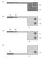
図1(A)は、実施の形態に係るセンサ1の表面側を示す図である。図1(B)は、実施の形態に係るセンサ1の裏面側を示す図である。本実施の形態において、センサ1の表面とは、作用極26および参照極28が配置される側の面である。センサ1の裏面とは、対極30が配置される側の面である。なお、センサ1の表裏は特に限定されない。Figure 1 (A) is a diagram showing the front side of a
本実施の形態に係るセンサ1は、試料中のアナライトを測定するためのセンサであり、例えばバイオセンサである。一例としてのセンサ1は、電気化学センサであり、センシング部2と、端子部4とを有する。センシング部2は、生体(例えば人体)に挿入される。端子部4は、生体の表面に装着される図示しない回路部と、センシング部2とを電気的に接続する。センシング部2は、端子部4を介して回路部に電気信号を送信する。The
センシング部2が生体に挿入された状態が維持されることで、試料としての血液等におけるアナライトとしてのグルコース等の存在や濃度を連続的に測定することができる。なお、本実施の形態では、埋め込み型の電気化学センサをセンサ1の例に挙げて説明するが、センサ1は非埋め込み型であってもよいし、電気化学式以外の測定様式であってもよい。また、試料やアナライトの種類は特に限定されない。試料は、例えば培地等であってもよい。また、アナライトとしては、ヘモグロビン;糖化ヘモグロビン;グルタミン、グルタミン酸などのアミノ酸;フルクトシルリジン、フルクトシルバリンなどの糖化アミノ酸;フルクトシルバリルヒスチジンなどの糖化ペプチド;糖化アルブミン;グルコースなどの糖類;ビタミンCなどのビタミン類;アルコール類;コレステロール;乳酸;ピルビン酸;ケトン体(3-ヒドロキシ酪酸)等が例示される。By maintaining the state in which the
センシング部2は、保護膜6で覆われる。保護膜6は、少なくとも後述する試薬層を被覆する。保護膜6は、試薬層に含まれる物質(例えば酸化還元酵素やレドックスメディエータ)の保護膜6外への漏出を抑制する。また、保護膜6は、保護膜6外に存在するアナライトが保護膜6内に透過可能な孔を有する。埋め込み型のバイオセンサでは、センシング部2が生体内に挿入される。このため、保護膜6は、タンパク質や細胞が吸着し難いことが好ましく、一般的にはそのような性質を有するポリマーで構成される。保護膜6を構成可能なポリマーとしては、例えば、メタクリル酸メチルとヒドロキシエチルメタクリレートとのコポリマー、ブチルメタクリレートとヒドロキシエチルメタクリレートとのコポリマー、ポリ(2-メタクリロイルオキシエチルホスホリルコリン-コ-n-ブチルメタクリレート)等が挙げられる。なお、これらの例示されたポリマーと同様の主鎖を有する(メタ)アクリレート系化合物も使用可能である。The
端子部4の表面には、参照極接続端子8と、作用極接続端子10とが設けられる。端子部4の裏面には、対極接続端子12が設けられる。端子部4における参照極接続端子8、作用極接続端子10および対極接続端子12を除く部分は、絶縁性のレジスト膜14で覆われる。A reference
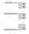
図2(A)~図2(D)、図3(A)~図3(D)および図4(A)~図4(C)は、センサ1の製造工程を示す図である。まず、図2(A)および図2(C)に示すように、絶縁基板16が形成される。絶縁基板16は、例えばポリエチレンテレフタレート、ポリエーテルケトン、ポリカーボネート、ポリイミド、ポリエチレン、ポリプロピレン、ポリスチレン、ポリ塩化ビニル、ポリオキシメチレン、モノマーキャストナイロン、ポリブチレンテレフタレート、メタクリル樹脂、ABS樹脂等の樹脂材料、あるいはガラス材料で構成される。好ましくは、絶縁基板16はポリエチレンテレフタレートで構成される。Figures 2(A) to 2(D), 3(A) to 3(D), and 4(A) to 4(C) are diagrams showing the manufacturing process of
そして、図2(B)に示すように、絶縁基板16の表面に導電性薄膜18が形成される。また、図2(D)に示すように、絶縁基板16の裏面に導電性薄膜18が形成される。導電性薄膜18は、スパッタ法、蒸着法、イオンプレーティング法、スクリーン印刷法等を用いて、金(Au)、白金(Pt)、パラジウム(Pd)、イリジウム(Ir)、カーボン(C)等の導電性材料を絶縁基板16の両面に成膜することで形成できる。Then, as shown in Fig. 2(B), a conductive
次いで、図3(A)に示すように、表面側の導電性薄膜18がレーザ描画により分割され、参照極導体20と、作用極導体22とが形成される。そして、図3(B)に示すように、スクリーン印刷法等によって、表側の導電性薄膜18の上にレジスト膜14が形成される。参照極導体20のうちセンシング部2に含まれる一部分と、端子部4に含まれる一部分とは、レジスト膜14が積層されずに露出する。これにより、参照極形成領域24および参照極接続端子8が形成される。また、作用極導体22のうちセンシング部2に含まれる一部分と、端子部4に含まれる一部分とは、レジスト膜14が積層されずに露出する。これにより、作用極26および作用極接続端子10が形成される。続いて、図3(C)に示すように、スクリーン印刷法やインクジェット印刷法等によって、参照極形成領域24に銀/塩化銀(Ag/AgCl)等が成膜されて、参照極28が形成される。Next, as shown in FIG. 3(A), the conductive
また、図3(D)に示すように、スクリーン印刷法等によって、裏面側の導電性薄膜18の上にレジスト膜14が形成される。裏側の導電性薄膜18のうちセンシング部2に含まれる一部分と、端子部4に含まれる一部分とは、レジスト膜14が積層されずに露出する。これにより、対極30および対極接続端子12が形成される。3(D), a resist
次いで、図4(A)に示すように、作用極26の上に試薬液が塗布され、乾燥されて試薬層32が形成される。したがって、試薬層32は、作用極26に接するように配置される。試薬層32の組成については、後に詳細に説明する。その後、図4(B)および図4(C)に示すように、センシング部2に当たる部分が保護膜用ポリマー溶液に浸漬され、乾燥されて保護膜6が形成される。これにより、試薬層32が保護膜6で被覆される。本実施の形態の保護膜6は、センシング部2の全体を被覆している。Next, as shown in FIG. 4(A), a reagent solution is applied onto the working
以上の工程により、保護膜6で覆われたセンシング部2と、保護膜6で覆われずに参照極接続端子8、作用極接続端子10および対極接続端子12が露出した端子部4とを有するセンサ1が得られる。Through the above steps, a
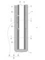
図5は、図1(A)に示すA-A線に沿った断面図である。なお、図5では、センシング部2のみを図示している。図6(A)は、図5に示すB-B線に沿った断面図である。図6(B)は、図5に示すC-C線に沿った断面図である。Figure 5 is a cross-sectional view taken along line A-A shown in Figure 1(A). Note that Figure 5 only shows the
図5および図6(A)に示すように、センシング部2の先端領域には、中央に絶縁基板16が配置される。そして、絶縁基板16の表面側には、作用極26および試薬層32がこの順に積層される。また、絶縁基板16の裏面側には、対極30が積層される。そして、絶縁基板16、作用極26、試薬層32および対極30は、保護膜6で覆われる。As shown in Figures 5 and 6 (A), an insulating
図5および図6(B)に示すように、センシング部2の先端領域よりも端子部4側の領域には、中央に絶縁基板16が配置される。そして、絶縁基板16の表面側には、参照極導体20および作用極導体22が積層され、その上にレジスト膜14が積層される。また、参照極導体20の表面側には、参照極28が積層される。また、絶縁基板16の裏面側には、導電性薄膜18およびレジスト膜14がこの順に積層される。そして、絶縁基板16、参照極導体20、作用極導体22、表面側のレジスト膜14、参照極28、導電性薄膜18および裏面側のレジスト膜14は、保護膜6で覆われる。As shown in Figures 5 and 6 (B), an insulating
作用極26、参照極28および対極30は、電極部34を構成する。したがって、本実施の形態の電極部34は、3電極式の電極構造を有する。なお、電極部34は、作用極26および対極30を含んでいればよく、作用極26および対極30のみの2電極式であってもよい。The working
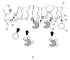
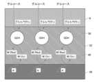
続いて、試薬層32について詳細に説明する。図7は、試薬層32内におけるポリマー36、タンパク質38およびレドックスメディエータ40の様子を示す模式図である。図7に示すように、試薬層32は、ポリマー36と、タンパク質38とを備える。タンパク質38としては、酸化還元酵素や抗体(免疫グロブリン)等が例示される。本実施の形態では、タンパク質38は酸化還元酵素である。そして、本実施の形態の試薬層32は、電子伝達能を有するレドックスメディエータ40を備える。さらに、試薬層32は、第1架橋剤42と、第2架橋剤44と、第3架橋剤54とを備える。なお、試薬層32は、カーボン粒子等の導電性粒子、緩衝液成分等の他の成分も含んでいてもよい。Next, the
ポリマー36は、タンパク質38と共有結合する第1結合部位46と、タンパク質38と静電相互作用により結合する第2結合部位48とを備える。ポリマー36とタンパク質38とが共有結合および静電相互作用によって互いに結合することで、ポリマー36とタンパク質38とが強固に結合した高分子量の複合体を形成することができる。これにより、タンパク質38が保護膜6を透過してセンサ1の外部に流出することを抑制できる。なお、図7では、第2結合部位48が正の電荷を有し、タンパク質38が負の電荷を有しているが、逆であってもよい。The
また、本実施の形態では、第1架橋剤42がタンパク質38および第1結合部位46の間に介在し、両者を結合している。これにより、複合体をより高分子量化することができるため、タンパク質38の流出をより抑制することができる。なお、タンパク質38および第1結合部位46は、第1架橋剤42を介さずに直に共有結合してもよい。In this embodiment, the
また、ポリマー36は、レドックスメディエータ40と共有結合する第3結合部位50を備える。ポリマー36とレドックスメディエータ40とが共有結合によって互いに結合することで、ポリマー36とレドックスメディエータ40とが結合した高分子量の複合体を形成することができる。これにより、レドックスメディエータ40が保護膜6を透過してセンサ1の外部に流出することを抑制できる。The
また、本実施の形態では、第2架橋剤44がレドックスメディエータ40および第3結合部位50の間に介在し、両者を結合している。これにより、複合体をより高分子量化することができるため、レドックスメディエータ40の流出をより抑制することができる。なお、レドックスメディエータ40および第3結合部位50は、第2架橋剤44を介さずに直に共有結合してもよい。In this embodiment, the
また、ポリマー36にタンパク質38としての酸化還元酵素と、レドックスメディエータ40とが結合することで、酸化還元酵素とレドックスメディエータ40との距離を近づけることができる。これにより、試薬層32の応答性を高めることができる。また、ポリマー36がタンパク質38およびレドックスメディエータ40の一方のみを結合する場合に比べて、複合体をより高分子量化することができる。これにより、タンパク質38およびレドックスメディエータ40の流出をより抑制することができる。In addition, by binding the oxidoreductase as the
また、試薬層32には、複数のポリマー36が含まれている。試薬層32に含まれる複数のポリマー36は、1種類のみであってもよいし、複数種類の組み合わせであってもよい。そして、各ポリマー36は、他のポリマー36と共有結合する第4結合部位52を有する。各ポリマー36は、第4結合部位52どうしが共有結合することで、互いに結合することができる。また、本実施の形態では、第3架橋剤54が2つの第4結合部位52の間に介在し、両者を結合している。ポリマー36どうしが互いに結合することで、複合体をさらに高分子量化することができる。また、第3架橋剤54がポリマー36どうしの間に介在して両者を結合することで、複合体をさらに高分子量化することができる。これにより、タンパク質38およびレドックスメディエータ40の流出をより抑制することができる。なお、第4結合部位52どうしは、第3架橋剤54を介さずに直に共有結合してもよい。The
以下、試薬層32に含まれる各成分について詳細に説明する。Below, each component contained in the
(ポリマー36)
本実施の形態のポリマー36は、下記式(1)で表される第1モノマー、および下記式(2)で表される第2モノマーを構成単位として含む。(Polymer 36)
The
A1およびA2が主鎖に含み得るヘテロ原子は、それぞれ独立に例えば酸素(O)、窒素(N)、ケイ素(Si)である。またA1としては、-CH2-CHR1-、-CH2-C(CH3)R1-等が例示される。A2としては、-CH2-CHR2-、-CH2-C(CH3)R2-等が例示される。R1およびR2としては、それぞれ独立に-CH2-、-C(=O)O-CH2-CH2-、-C6H5-CH2-等が例示される。-C6H5-は、ベンゼン環である。 Heteroatoms thatA1 andA2 may contain in the main chain are each independently, for example, oxygen (O), nitrogen (N) or silicon (Si). Examples ofA1 include-CH2-CHR1- and-CH2 -C(CH3 )R1- . Examples ofA2 include-CH2-CHR2- and -CH2- C(CH3 )R2- . Examples ofR1 andR2 are each independently, for example,-CH2- , -C(=O)O-CH2-CH2- and-C6H5 -CH2- .-C6H5- isa benzene ring.
官能基Xは、アミン、アルコール、フェノール、チオール、カルボン酸、ヒドラジン、アルコキシアミン、ヒドロキシアミン、イミダゾール、ピリジン、アシルアジド、アシルハライド、アルキルハライド、酸無水物、アルデヒド、ケトン、アルキルスルホネート、マレイミド、エポキシド、アジリジン、イソシアネート、イソチオシアネート、イミドエステル、スルホニルハライドおよび活性化エステルからなる群から選択される少なくとも1種から誘導される基であることが好ましい。活性化エステルとしては、スルホ基、ニトロ基もしくはハロ基を含む電子吸引基で置換された、スクシニミジルエステル、ベンゾトリアゾルエステルもしくはアリールエステル、またはカルボジイミド基を有するカルボン酸エステルが例示される。The functional group X is preferably a group derived from at least one selected from the group consisting of amines, alcohols, phenols, thiols, carboxylic acids, hydrazines, alkoxyamines, hydroxyamines, imidazoles, pyridines, acyl azides, acyl halides, alkyl halides, acid anhydrides, aldehydes, ketones, alkyl sulfonates, maleimides, epoxides, aziridines, isocyanates, isothiocyanates, imide esters, sulfonyl halides, and activated esters. Examples of activated esters include succinimidyl esters, benzotriazole esters, or aryl esters substituted with electron-withdrawing groups including sulfo groups, nitro groups, or halo groups, or carboxylic acid esters having a carbodiimide group.
少なくとも一部の官能基Xは、第1結合部位46を構成する。この場合、官能基Xの種類は、結合相手であるタンパク質38の種類に応じて、適宜選択することができる。図8は、共有結合可能な反応基の組み合わせを示す図である。第1結合部位46とタンパク質38とは、いずれか一方が図8に示す第1反応基を有し、他方が図8に示す第2反応基を有すれば、互いに共有結合することができる。また、第1架橋剤42が第1結合部位46およびタンパク質38の間に介在する場合は、第1架橋剤42および第1結合部位46の一方が第1反応基を有し、他方が第2反応基を有するとともに、第1架橋剤42およびタンパク質38の一方が第1反応基を有し、他方が第2反応基を有すればよい。At least a part of the functional group X constitutes the first
好ましくは、官能基Xは、アミン、チオール、カルボン酸、イミダゾールおよびピリジンからなる群から選択される少なくとも1種から誘導される基である。これにより、より入手しやすい架橋剤を第1架橋剤42として選択可能になるため、第1架橋剤42を介したポリマー36とタンパク質38との共有結合をより簡便に実現することができる。また、第1架橋剤42を介した、あるいは介しないポリマー36とタンパク質38との架橋反応において、温度やpH等の反応条件を比較的温和な条件にすることができる。これにより、タンパク質38の失活を抑制することができる。Preferably, the functional group X is a group derived from at least one selected from the group consisting of amine, thiol, carboxylic acid, imidazole, and pyridine. This allows a more readily available crosslinking agent to be selected as the
また、少なくとも一部の官能基Xは、第3結合部位50を構成する。この場合、官能基Xの種類は、結合相手であるレドックスメディエータ40の種類に応じて、適宜選択することができる。つまり、第3結合部位50とレドックスメディエータ40とは、いずれか一方が第1反応基を有し、他方が第2反応基を有すれば、互いに共有結合することができる。また、第2架橋剤44が第3結合部位50およびレドックスメディエータ40の間に介在する場合は、第2架橋剤44および第3結合部位50の一方が第1反応基を有し、他方が第2反応基を有するとともに、第2架橋剤44およびレドックスメディエータ40の一方が第1反応基を有し、他方が第2反応基を有すればよい。At least a part of the functional group X constitutes the third
第1結合部位46および第3結合部位50は、同じ官能基を有することが好ましい。つまり、同じ種類の官能基Xが第1結合部位46および第3結合部位50の両方を構成することが好ましい。これにより、1種類の第1モノマーでタンパク質38との共有結合とレドックスメディエータ40との共有結合とを実現できる。よって、ポリマー36を構成するモノマーの種類を削減でき、ポリマー36の合成方法の簡略化を図ることができる。It is preferable that the first
また、少なくとも一部の官能基Xは、第4結合部位52を構成する。この場合、官能基Xの種類は、結合相手である他のポリマー36の第4結合部位52の種類に応じて、適宜選択することができる。つまり、2つのポリマー36の第4結合部位52において、いずれか一方が第1反応基を有し、他方が第2反応基を有すれば、互いに共有結合することができる。また、第3架橋剤54が2つの第4結合部位52の間に介在する場合は、第3架橋剤54と各第4結合部位52との間で、第1反応基と第2反応基の組み合わせ条件を満たせばよい。At least some of the functional groups X constitute the fourth
第1結合部位46、第3結合部位50および第4結合部位52は、少なくとも2つが同じ官能基を有することが好ましく、3つが同じ官能基を有することがより好ましい。つまり、同じ種類の官能基Xが第1結合部位46、第3結合部位50および第4結合部位52のうち少なくとも2つを構成することが好ましい。これにより、より少ない種類の第1モノマーでタンパク質38との共有結合、レドックスメディエータ40との共有結合、および他のポリマー36との共有結合を実現できる。よって、ポリマー36を構成するモノマーの種類を削減でき、ポリマー36の合成方法の簡略化を図ることができる。It is preferable that at least two of the first
官能基Yは、四級アンモニウム、四級ホスホニウム、三級スルホニウムおよび芳香族カチオンからなる群から選択される少なくとも1種から誘導されるカチオン基、またはカルボン酸、ホスホン酸およびスルホン酸からなる群から選択される少なくとも1種から誘導されるアニオン基であることが好ましい。The functional group Y is preferably a cationic group derived from at least one selected from the group consisting of quaternary ammonium, quaternary phosphonium, tertiary sulfonium and aromatic cations, or an anionic group derived from at least one selected from the group consisting of carboxylic acid, phosphonic acid and sulfonic acid.
四級アンモニウムは、窒素原子に4つの有機置換基R2、R3、R4、R5が結合した構造を有する。四級ホスホニウムは、リン原子に4つの有機置換基R2、R3、R4、R5が結合した構造を有する。三級スルホニウムは、硫黄原子に3つの有機置換基R2、R3、R4が結合した構造を有する。R2は上述のとおりである。R3~R5は、例えば、置換基を有してもよいC1-6の直鎖もしくは分岐鎖の飽和もしくは不飽和の炭化水素基、置換基を有してもよいアシル基、置換基を有してもよいアルコキシ基、置換基を有してもよいフェニル基であり、R3~R5は同一でも異なってもよい。 A quaternary ammonium has a structure in which four organic substituents R2 , R3 , R4 , and R5 are bonded to a nitrogen atom. A quaternary phosphonium has a structure in which four organic substituents R2 , R3 , R4 , and R5 are bonded to a phosphorus atom. A tertiary sulfonium has a structure in which three organic substituents R2 , R3 , and R4 are bonded to a sulfur atom. R2 is as described above. R3 to R5 are, for example, a C1-6 linear or branched, saturated or unsaturated hydrocarbon group which may have a substituent, an acyl group which may have a substituent, an alkoxy group which may have a substituent, or a phenyl group which may have a substituent, and R3 to R5 may be the same or different.
芳香族カチオンとしては、イミダゾリウム、オキサゾリウム、ピラジニウム、ピラゾリウム、ピリダジニウム、ピロリジニウム、ピリジニウム、ピペリジニウム、チアゾリウムおよびトリアゾリウムが例示される。Examples of aromatic cations include imidazolium, oxazolium, pyrazinium, pyrazolium, pyridazinium, pyrrolidinium, pyridinium, piperidinium, thiazolium and triazolium.
官能基Yは、第2結合部位48を構成する。官能基Yの種類は、結合相手であるタンパク質38の種類に応じて、適宜選択することができる。第2結合部位48とタンパク質38とは、互いに逆の電荷を有すれば、互いに静電相互作用により結合することができる。一例としての官能基Yは、官能基Xと異なる基である。また好ましくは、官能基Yはカチオン基である。タンパク質38が酸化還元酵素である場合、センサ1が主に用いられる中性付近の条件下では、一般的な酸化還元酵素は負の電荷を有するものが多い。このため、官能基Yをカチオン基とすることで、ポリマー36とタンパク質38との静電相互作用による結合をより簡便に実現することができる。The functional group Y constitutes the second
ポリマー36の具体例としては、下記式(3)~式(7)に示すものが例示される。式(3)~式(6)におけるmおよびnと、式(7)におけるl、mおよびnとは、各モノマーのモル比を示す。各モノマーのモル比は、適宜設定することができる。また、式(3)~式(7)では、カウンターイオンの一例としてCl-を示している。 Specific examples of
(タンパク質38)
タンパク質38は、ポリマー36の第1結合部位46および第2結合部位48に結合するとともにアナライトに作用する。上述のとおり、タンパク質38としては酸化還元酵素や抗体(免疫グロブリン)等が例示される。本実施の形態における酸化還元酵素とは、アナライトを酸化または脱水素化することができる酵素を指す。酸化還元酵素としては、グルコースオキシダーゼ、ラクテートオキシダーゼ、ピルビン酸オキシダーゼ、コレステロールオキシダーゼ、アミノ酸オキシダーゼ、グルタミン酸オキシダーゼ、フルクトシルアミノ酸オキシダーゼ、アルコールオキシダーゼ、アスコルビン酸オキシダーゼ、フルクトシルペプチドオキシダーゼ、グルコースデヒドロゲナーゼ、ラクテートデヒドロゲナーゼ、ピルビン酸デヒドロゲナーゼ、アミノ酸デヒドロゲナーゼ、グルタミン酸デヒドロゲナーゼ、3-ヒドロキシ酪酸デヒドロゲナーゼ、アルコールデヒドロゲナーゼ等が例示される。酸化還元酵素は、必要に応じて複数種を組み合わせてもよい。(Protein 38)
The
タンパク質38が酸化還元酵素である場合、典型的には、酸化還元酵素が有するアミノ基が第1結合部位46または第1架橋剤42と共有結合する。また、酸化還元酵素が有するチオール基やカルボキシル基等が第1結合部位46または第1架橋剤42と共有結合することもあり得る。酸化還元酵素の配合量は、例えばセンサ1個当り、または1回の測定当り、好ましくは0.01~100U(ユニット)であり、より好ましくは0.05~50Uであり、さらに好ましくは0.1~10Uである。When the
また、タンパク質38は、第2結合部位48との結合部位が正の電荷を有する場合、等電点が使用環境のpH以下であることが好ましい。また、タンパク質38は、第2結合部位48との結合部位が負の電荷を有する場合、等電点が使用環境のpH以上であることが好ましい。タンパク質38の使用環境とは、少なくとも試薬液中を指す。好ましくは、タンパク質38の使用環境とは、試薬液中と、測定対象試料中との両方を指す。一例として、第2結合部位48との結合部位が正の電荷を有する場合、タンパク質38の等電点は好ましくはpH9以下であり、より好ましくはpH7.4以下であり、さらに好ましくはpH5.5以下である。また、第2結合部位48との結合部位が負の電荷を有する場合、タンパク質38の等電点は好ましくはpH5.5以上であり、より好ましくはpH7.4以上であり、さらに好ましくはpH9以上である。In addition, when the binding site with the second
タンパク質38としての酸化還元酵素は、好ましくは補酵素結合型酵素である。補酵素としては、ピロロキノリンキノン(PQQ)、ニコチンアミドアデニンジヌクレオチド(NAD)、ニコチンアミドアデニンジヌクレオチドリン酸(NADP)、フラビンアデニンジヌクレオチド(FAD)、フラビンモノヌクレオチド(FMN)、チアミンピロリン酸(TPP)、コエンザイムA(CoA)等が例示される。The oxidoreductase as
例えば、アナライトがグルコースである場合、酸化還元酵素は、グルコースオキシダーゼまたはグルコースデヒドロゲナーゼ(GDH)となる。補酵素結合型のグルコースデヒドロゲナーゼとしては、ピロロキノリンキノン(PQQ)結合型GDHやフラビンアデニンヌクレオチド(FAD)結合型GDHが例示される。また、生体内のマルトースの影響を考慮すると、GDHは、グルコースに対する酵素活性を100%とした場合のマルトースに対する酵素活性が5%以下であることが好ましく、3%以下であることがより好ましい。このような酵素活性を有する酵素としては、FAD結合型GDHが例示される。また、このようなFAD結合型GDHとしては、アスペルギルス属(オリゼやテレウス)由来、ムコール属由来のものが例示される。For example, when the analyte is glucose, the oxidoreductase is glucose oxidase or glucose dehydrogenase (GDH). Examples of coenzyme-bound glucose dehydrogenase include pyrroloquinoline quinone (PQQ)-bound GDH and flavin adenine nucleotide (FAD)-bound GDH. Considering the effect of maltose in the body, it is preferable that the enzyme activity of GDH on maltose is 5% or less, and more preferably 3% or less, when the enzyme activity on glucose is 100%. An example of an enzyme having such enzyme activity is FAD-bound GDH. Examples of such FAD-bound GDH include those derived from the genus Aspergillus (oryzae and Terreus) and the genus Mucor.
(レドックスメディエータ40)
レドックスメディエータ40は、ポリマー36の第3結合部位50に結合するとともに、可逆的に酸化体および還元体となることができ、物質間における電子の移動を媒介する。レドックスメディエータ40としては、オスミウム錯体、ルテニウム錯体、鉄錯体等の金属錯体類;ベンゾキノン、ナフトキノン、フェナントレンキノン、フェナントロリンキノン、アントラキノン、およびこれらの誘導体等のキノン化合物;フェナジン化合物;ビオロゲン化合物;フェノチアジン化合物;フェノール化合物等が例示される。レドックスメディエータ40は、必要に応じて複数種を組み合わせてもよい。(Redox Mediator 40)
The
レドックスメディエータ40の具体例としては、フェリシアン化カリウム;ヘキサアンミンルテニウム;フェロセン;ヒドロキノン;2-メチル-1,4-ベンゾキノン;1,2-ナフトキノン-4-スルホン酸塩;9,10-フェナントレンキノン-2-スルホン酸塩;9,10-フェナントレンキノン-2,7-ジスルホン酸塩;1,10-フェナントロリン-5,6-ジオン;アントラキノン-2-スルホン酸塩;1-メトキシ-5-メチルフェナジニウムメチルサルフェートや1-メトキシ-5-エチルフェナジニウムエチルサルフェート等のフェナジン誘導体;メチルビオロゲン;ベンジルビオロゲン;メチレングリーン;2-アミノフェノール;2-アミノ-4-メチルフェノール;および2,4-ジアミノフェノールからなる群から選ばれる1種以上の化合物の誘導体であって、ポリマー36に結合可能な官能基(図8に示す第1反応基または第2反応基)を有する誘導体が挙げられる。上記の塩(スルホン酸塩、ジスルホン酸塩)としては、ナトリウム塩、カリウム塩、カルシウム塩、マグネシウム塩、リチウム塩等が例示される。 Specific examples of
レドックスメディエータ40の配合量は、例えばセンサ1個当り、または1回の測定当り、好ましくは0.1pmol~1000μmolであり、より好ましくは5pmol~250μmolであり、さらに好ましくは100pmol~50μmolである。The amount of
レドックスメディエータ40は、第3結合部位50または第2架橋剤44との結合部位を有する。上述のとおり、レドックスメディエータ40の結合部位は、第1反応基および第2反応基のうち、第3結合部位50または第2架橋剤44が有する反応基の結合対象となる反応基を有する。The
(第1架橋剤42、第2架橋剤44および第3架橋剤54)
第1架橋剤42、第2架橋剤44および第3架橋剤54としては、グルタルアルデヒド;こはく酸ジスクシンイミジル(Disuccinimidyl Succinate)、スベリン酸ビス(3-スルホ-N-スクシンイミジル)二ナトリウム(Bis(3-sulfo-N-succinimidyl) Suberate Disodium Salt)、4,7,10,13,16-ペンタオキサノナデカン二酸ジ(N-スクシンイミジル)(Bis(NHS)PEG5)等の、両末端にNHSエステルを有する化合物;ポリエチレングリコールジグリシジルエーテル(Poly(ethylene glycol) diglycidyl ether)、ポリプロピレングリコールジグリシジルエーテル(Poly(propylene glycol) diglycidyl ether)、1-4-ブタンジオールジグリシジルエーテル(1,4-Butanediol diglycidyl ether)等の、両末端にエポキシ基を有する化合物;1,2-ビス(マレイミド)エタン(1,2-Bis(maleimido)ethane)、1,11-ビスマレイミドトリエチレングリコール(1,11-bismaleimido-triethyleneglycol)等の、両末端にマレイミド基を有する化合物;1,2-ビス(2-アミノエトキシ)エタン(1,2-Bis(2-aminoethoxy)ethane)等の、両末端にアミノ基を有する化合物;マレイミド-PEG2-スクシンイミジル(Maleimide-PEG2-NHS Ester)、アミノ-PEG6-カルボン酸(Amino-PEG6-carboxylic Acid)の、両末端が異なる官能基の化合物;4アーム-PEG10K-スクシンイミジル グルタレート(4arm-PEG10K-Succinimidyl Glutarate)、4アーム-PEG10K-マレイミド(4arm-PEG10K-Maleimide)、8アーム-PEG10K-スクシンイミジル スクシネート(8arm-PEG10K-Succinimidyl Succinate)等の、分岐鎖を有する化合物からなる群から選択される1種以上が例示される。(
Examples of the
試薬層32に第1架橋剤42および第2架橋剤44の2つが含有される場合、第1架橋剤42および第2架橋剤44は、同じ種類の架橋剤であることが好ましい。また、試薬層32に第1架橋剤42および第3架橋剤54の2つが含有される場合、第1架橋剤42および第3架橋剤54は、同じ種類の架橋剤であることが好ましい。また、試薬層32に第2架橋剤44および第3架橋剤54の2つが含有される場合、第2架橋剤44および第3架橋剤54は、同じ種類の架橋剤であることが好ましい。また、試薬層32に第1架橋剤42、第2架橋剤44および第3架橋剤54の3つが含有される場合、第1架橋剤42、第2架橋剤44および第3架橋剤54は、少なくとも2つが同じ架橋剤であることが好ましく、3つが同じ架橋剤であることがより好ましい。これらにより、架橋剤の種類を削減できるため、試薬層32の調製方法の簡略化を図ることができる。When the
一例としての試薬層32は、第1結合部位46、第2結合部位48、第3結合部位50および第4結合部位52を有するポリマー36と、タンパク質38と、レドックスメディエータ40と、第1架橋剤42と、第3架橋剤54とを備える。第1結合部位46、第3結合部位50および第4結合部位52は、少なくとも2つが同じ官能基を有する。タンパク質38は、第1架橋剤42を介して第1結合部位46に結合する。また、タンパク質38は第2結合部位48に結合する。レドックスメディエータ40は、第2架橋剤44を介さずに直に第3結合部位50に結合する。2つのポリマー36の第4結合部位52どうしは、第3架橋剤54を介して結合する。そして、第1架橋剤42と第3架橋剤54とは、同じ架橋剤である。The
続いて、センサ1によるアナライトの測定原理について説明する。図9は、センサ1の測定原理を説明するための模式図である。ここでは一例として、センサ1が電気化学センサであり、アナライトがグルコースであり、タンパク質38がグルコースデヒドロゲナーゼ(GDH)である場合を説明する。Next, the measurement principle of the analyte by the
まず、血液中や皮下間質液中のグルコースが、保護膜6を透過して試薬層32に到達する。次に、グルコースがグルコースデヒドロゲナーゼにより酸化され、グルコノラクトンが生成される。また、これと同時にレドックスメディエータ40が還元されて、酸化体(M(Ox))が還元体(M(Red))となる。そして、レドックスメディエータ40の還元体が作用極26の表面で酸化されて、還元体(M(Red))が酸化体(M(Ox))となり、同時に電子が発生する。この電子が作用極26に受け渡され、電流値として測定される。First, glucose in the blood or subcutaneous interstitial fluid permeates the
以上説明したように、本実施の形態に係るポリマー36は、第1結合部位46による共有結合と、第2結合部位48による静電的相互作用とによって、タンパク質38を結合している。これにより、タンパク質38のセンサ外部への流出を抑制することができる。よって、センサ1の耐久性や測定感度の低下をより抑制することができる。また、生体等が受ける負の影響をより抑制することができる。また、ポリマー36は、第3結合部位50による共有結合によってレドックスメディエータ40を結合する。これにより、レドックスメディエータ40のセンサ外部への流出を抑制することができる。よって、センサ1の耐久性や測定感度の低下をより抑制でき、また生体等が受ける負の影響をより抑制することができる。また、ポリマー36は、第4結合部位52による共有結合によって他のポリマー36と結合する。これにより、センサ1の耐久性や測定感度の低下をさらに抑制でき、また生体等が受ける負の影響をさらに抑制することができる。As described above, the
さらに、タンパク質38と第1結合部位46との間に第1架橋剤42が介在している。また、レドックスメディエータ40と第3結合部位50との間に第2架橋剤44が介在している。また、2つの第4結合部位52の間に第3架橋剤54が介在している。これらにより、ポリマー36、タンパク質38およびレドックスメディエータ40の複合体をより高分子量化することができる。よって、タンパク質38およびレドックスメディエータ40のセンサ外部への流出をより抑制することができる。Furthermore, a
以上、本開示の実施の形態について詳細に説明した。前述した実施の形態は、本開示を実施するにあたっての具体例を示したものにすぎない。実施の形態の内容は、本開示の技術的範囲を限定するものではなく、請求の範囲に規定された発明の思想を逸脱しない範囲において、構成要素の変更、追加、削除等の多くの設計変更が可能である。設計変更が加えられた新たな実施の形態は、組み合わされる実施の形態および変形それぞれの効果をあわせもつ。前述の実施の形態では、このような設計変更が可能な内容に関して、「本実施の形態の」、「本実施の形態では」等の表記を付して強調しているが、そのような表記のない内容でも設計変更が許容される。以上の構成要素の任意の組み合わせも、本開示の態様として有効である。図面の断面に付したハッチングは、ハッチングを付した対象の材質を限定するものではない。Above, the embodiments of the present disclosure have been described in detail. The above-mentioned embodiments merely show specific examples of implementing the present disclosure. The contents of the embodiments do not limit the technical scope of the present disclosure, and many design changes such as changes, additions, and deletions of components are possible within the scope of the invention defined in the claims. A new embodiment with design changes has the effects of each of the combined embodiments and modifications. In the above-mentioned embodiments, the contents in which such design changes are possible are emphasized by adding notations such as "in this embodiment" and "in this embodiment", but design changes are permitted even in contents without such notations. Any combination of the above components is also valid as an aspect of the present disclosure. The hatching on the cross section of the drawing does not limit the material of the object to which the hatching is added.
なお、実施の形態は、以下に記載する項目によって特定されてもよい。
(項目1)
試料中のアナライトを測定するセンサ(1)の試薬層(32)に含まれるポリマー(36)であって、
アナライトに作用するタンパク質(38)と共有結合する第1結合部位(46)と、
タンパク質(38)と静電相互作用により結合する第2結合部位(48)と、を備える、
ポリマー(36)。
(項目2)
上記式(1)で表される第1モノマー、および
上記式(2)で表される第2モノマーを構成単位として含む、
項目1に記載のポリマー(36)。
(項目3)
官能基Xは、アミン、アルコール、フェノール、チオール、カルボン酸、ヒドラジン、アルコキシアミン、ヒドロキシアミン、イミダゾール、ピリジン、アシルアジド、アシルハライド、アルキルハライド、酸無水物、アルデヒド、ケトン、アルキルスルホネート、マレイミド、エポキシド、アジリジン、イソシアネート、イソチオシアネート、イミドエステル、スルホニルハライドおよび活性化エステルからなる群から選択される少なくとも1種から誘導される基であり、
官能基Yは、四級アンモニウム、四級ホスホニウム、三級スルホニウムおよび芳香族カチオンからなる群から選択される少なくとも1種から誘導されるカチオン基、またはカルボン酸、ホスホン酸およびスルホン酸からなる群から選択される少なくとも1種から誘導されるアニオン基である、
項目2に記載のポリマー(36)。
(項目4)
タンパク質(38)は、酸化還元酵素である、
項目1ないし3のいずれかに記載のポリマー(36)。
(項目5)
ポリマー(36)は、電子伝達能を有するレドックスメディエータ(40)と共有結合する第3結合部位(50)を備える、
項目4に記載のポリマー(36)。
(項目6)
第1結合部位(46)および第3結合部位(50)は、同じ官能基を有する、
項目5に記載のポリマー(36)。
(項目7)
試料中のアナライトを測定するセンサ(1)の試薬層(32)であって、
項目1乃至6のいずれかに記載のポリマー(36)と、
ポリマー(36)に結合するとともにアナライトに作用するタンパク質(38)と、を備える、
試薬層(32)。
(項目8)
タンパク質(38)および第1結合部位(46)を結合する第1架橋剤(42)を備える、
項目7に記載の試薬層(32)。
(項目9)
タンパク質(38)は、酸化還元酵素であり、
ポリマー(36)は、電子伝達能を有するレドックスメディエータ(40)と共有結合する第3結合部位(50)を備え、
試薬層(32)は、ポリマー(36)に結合するレドックスメディエータ(40)を備える、
項目7または8に記載の試薬層(32)。
(項目10)
レドックスメディエータ(40)および第3結合部位(50)を結合する第2架橋剤(44)を備える、
項目9に記載の試薬層(32)。
(項目11)
酸化還元酵素(38)および第1結合部位(46)を結合する第1架橋剤(42)を備え、
第1架橋剤(42)および第2架橋剤(44)は、同じ架橋剤である、
項目10に記載の試薬層(32)。
(項目12)
試薬層(32)は、複数のポリマー(36)を備え、
各ポリマー(36)は、他のポリマー(36)と共有結合する第4結合部位(52)を有し、
試薬層(32)は、第4結合部位(52)どうしを結合する第3架橋剤(54)を備える、
項目7乃至11のいずれかに記載の試薬層(32)。
(項目13)
タンパク質(38)は、酸化還元酵素であり、
ポリマー(36)は、電子伝達能を有するレドックスメディエータ(40)と共有結合する第3結合部位(50)を備え、
第1結合部位(46)、第3結合部位(50)および第4結合部位(52)は、少なくとも2つが同じ官能基を有する、
項目12に記載の試薬層(32)。
(項目14)
タンパク質(38)は、酸化還元酵素であり、
ポリマー(36)は、電子伝達能を有するレドックスメディエータ(40)と共有結合する第3結合部位(50)を備え、
試薬層(32)は、酸化還元酵素(38)および第1結合部位(46)を結合する第1架橋剤(42)と、レドックスメディエータ(40)および第3結合部位(50)を結合する第2架橋剤(44)と、を備え、
第1架橋剤(42)、第2架橋剤(44)および第3架橋剤(54)は、少なくとも2つが同じ架橋剤である、
項目12または13に記載の試薬層(32)。
(項目15)
作用極(26)および対極(30)を含む電極部(34)と、
作用極(26)に接するように配置される項目7乃至14のいずれかに記載の試薬層(32)と、を備える、
センサ(1)。
(項目16)
試薬層(32)を被覆する保護膜(6)を備える、
項目15に記載のセンサ(1)。 The embodiment may be specified by the items described below.
(Item 1)
A polymer (36) contained in a reagent layer (32) of a sensor (1) for measuring an analyte in a sample, comprising:
a first binding site (46) which is covalently linked to a protein (38) which acts on the analyte;
and a second binding site (48) that binds to the protein (38) by electrostatic interaction.
Polymer (36).
(Item 2)
The composition includes, as structural units, a first monomer represented by the above formula (1) and a second monomer represented by the above formula (2).
(Item 3)
the functional group X is a group derived from at least one selected from the group consisting of amines, alcohols, phenols, thiols, carboxylic acids, hydrazines, alkoxyamines, hydroxyamines, imidazoles, pyridines, acyl azides, acyl halides, alkyl halides, acid anhydrides, aldehydes, ketones, alkyl sulfonates, maleimides, epoxides, aziridines, isocyanates, isothiocyanates, imido esters, sulfonyl halides, and activated esters;
The functional group Y is a cationic group derived from at least one selected from the group consisting of quaternary ammonium, quaternary phosphonium, tertiary sulfonium and aromatic cations, or an anionic group derived from at least one selected from the group consisting of carboxylic acid, phosphonic acid and sulfonic acid.
The polymer (36) according to
(Item 4)
Protein (38) is an oxidoreductase.
4. A polymer (36) according to any one of
(Item 5)
The polymer (36) has a third binding site (50) that is covalently bonded to a redox mediator (40) capable of transferring electrons.
(Item 6)
the first binding site (46) and the third binding site (50) have the same functional group;
(Item 7)
A reagent layer (32) of a sensor (1) for measuring an analyte in a sample, comprising:
A polymer (36) according to any one of
a protein (38) that binds to the polymer (36) and acts on the analyte;
A reagent layer (32).
(Item 8)
a first cross-linker (42) that binds a protein (38) and a first binding site (46);
(Item 9)
Protein (38) is an oxidoreductase;
the polymer (36) has a third binding site (50) that is covalently bonded to a redox mediator (40) capable of transferring electrons;
The reagent layer (32) comprises a redox mediator (40) bound to a polymer (36);
Item 9. The reagent layer (32) according to
(Item 10)
a second cross-linker (44) that links the redox mediator (40) and the third binding site (50);
(Item 11)
a first cross-linker (42) that links an oxidoreductase (38) and a first binding site (46);
The first crosslinker (42) and the second crosslinker (44) are the same crosslinker;
Item 11. The reagent layer (32) according to
(Item 12)
The reagent layer (32) comprises a plurality of polymers (36);
Each polymer (36) has a fourth binding site (52) that is covalently bonded to another polymer (36);
The reagent layer (32) includes a third cross-linking agent (54) that bonds the fourth binding sites (52) together.
12. The reagent layer (32) according to any one of items 7 to 11.
(Item 13)
Protein (38) is an oxidoreductase;
the polymer (36) has a third binding site (50) that is covalently bonded to a redox mediator (40) capable of transferring electrons;
At least two of the first binding site (46), the third binding site (50) and the fourth binding site (52) have the same functional group;
Item 13. The reagent layer (32) according to
(Item 14)
Protein (38) is an oxidoreductase;
the polymer (36) has a third binding site (50) that is covalently bonded to a redox mediator (40) capable of transferring electrons;
The reagent layer (32) comprises a first cross-linker (42) that bonds the oxidoreductase (38) and the first binding site (46), and a second cross-linker (44) that bonds the redox mediator (40) and the third binding site (50);
At least two of the first crosslinker (42), the second crosslinker (44) and the third crosslinker (54) are the same crosslinker;
(Item 15)
An electrode portion (34) including a working electrode (26) and a counter electrode (30);
and a reagent layer (32) according to any one of items 7 to 14, which is arranged so as to contact the working electrode (26).
Sensor (1).
(Item 16)
A protective film (6) is provided to cover the reagent layer (32).
以下、本発明の実施例を説明するが、これら実施例は、本発明を好適に説明するための例示に過ぎず、なんら本発明を限定するものではない。Below, examples of the present invention are described. However, these examples are merely illustrative to better explain the present invention and are not intended to limit the present invention in any way.
(ポリマーAの合成)
図10は、ポリマーAの重合反応を示す図である。まず、2-アミノエチルメタクリレート塩酸塩(モノマーa)と、(4-ビニルフェニル)メタンアミン(モノマーb)と、メタクロイルコリンクロリド(モノマーc)とを用意した。そして、4つ口フラスコにモノマーaを0.97mmol、モノマーbを0.97mmol、モノマーcを11.97mmol、2,2’-アゾビス(2-メチルプロピオンアミジン)二塩酸塩(以下V-50と称する)を0.08mmol、エタノールを227mmol投入した。(Synthesis of Polymer A)
10 is a diagram showing the polymerization reaction of polymer A. First, 2-aminoethyl methacrylate hydrochloride (monomer a), (4-vinylphenyl)methanamine (monomer b), and methacryloylcholine chloride (monomer c) were prepared. Then, 0.97 mmol of monomer a, 0.97 mmol of monomer b, 11.97 mmol of monomer c, 0.08 mmol of 2,2'-azobis(2-methylpropionamidine) dihydrochloride (hereinafter referred to as V-50), and 227 mmol of ethanol were charged into a four-neck flask.
続いて、スターラーチップ、温度計、減圧/Arガスラインを4つ口フラスコにセットした。室温で攪拌しながら、減圧/Arガスラインを用いて4つ口フラスコ内の減圧とArガスの供給とを10回繰り返してフラスコ内の試料を脱気した。脱気処理の後に4つ口フラスコを密閉し、反応温度60℃で24時間、図10に示す重合反応を行った。重合の進行および終了は、1H-NMRでモノマーの消失を計測することで確認した。反応終了後、反応液を透析膜(MWCO:3500)に入れ、3日間透析した。その際、1日に2回液を交換した。透析終了後、得られた反応物を凍結乾燥してポリマーAを得た。ポリマーAは、上記式(7)において、n:m:l=21.2:8.1:70.7であるポリマーに相当する。なお、各モノマーのモル比は、NMRスペクトルのシグナルの積分比から算出した。以下のポリマーB,C,E,Fについても同様である。また、ゲル浸透クロマトグラフィー(GPC)で測定した結果、ポリマーAは、数平均分子量Mnが89642であり、重量平均分子量Mwが502171であった。 Next, a stirrer tip, a thermometer, and a vacuum/Ar gas line were set in the four-neck flask. While stirring at room temperature, the sample in the flask was degassed by repeatedly decompressing the four-neck flask and supplying
(ポリマーBの合成)
図11は、ポリマーBの重合反応を示す図である。まず、モノマーaと、(ビニルベンジル)トリメチルアンモニウムクロリド(モノマーd)とを用意した。そして、4つ口フラスコにモノマーaを7.36mmol、モノマーdを7.36mmol、V-50を0.07mmol、イオン交換水を616mmol投入した。以降はポリマーAの場合と同様の処理を施し、図11に示す重合反応を行ってポリマーBを得た。ポリマーBは、上記式(4)において、n:m=48.5:51.5であるポリマーに相当する。(Synthesis of Polymer B)
Fig. 11 is a diagram showing the polymerization reaction of polymer B. First, monomer a and (vinylbenzyl)trimethylammonium chloride (monomer d) were prepared. Then, 7.36 mmol of monomer a, 7.36 mmol of monomer d, 0.07 mmol of V-50, and 616 mmol of ion-exchanged water were charged into a four-neck flask. Thereafter, the same treatment as in the case of polymer A was carried out, and polymer B was obtained by carrying out the polymerization reaction shown in Fig. 11. Polymer B corresponds to the polymer in which n:m = 48.5:51.5 in the above formula (4).
(ポリマーCの合成)
図12は、ポリマーCの重合反応を示す図である。まず、モノマーaと、モノマーcとを用意した。そして、4つ口フラスコにモノマーaを1.14mmol、モノマーcを10.22mmol、V-50を0.06mmol、イオン交換水を投入した。以降はポリマーAの場合と同様の処理を施し、図12に示す重合反応を行ってポリマーCを得た(必要に応じて反応時間は適宜調整した)。ポリマーCは、上記式(6)において、n:m=13.3:86.7であるポリマーに相当する。(Synthesis of Polymer C)
Fig. 12 is a diagram showing the polymerization reaction of polymer C. First, monomer a and monomer c were prepared. Then, 1.14 mmol of monomer a, 10.22 mmol of monomer c, 0.06 mmol of V-50, and ion-exchanged water were charged into a four-neck flask. Thereafter, the same treatment as in the case of polymer A was carried out, and the polymerization reaction shown in Fig. 12 was carried out to obtain polymer C (the reaction time was appropriately adjusted as necessary). Polymer C corresponds to the polymer in the above formula (6) where n:m = 13.3:86.7.
(比較例としてのメディエータ結合ポリマーDの作製)
メディエータとしてフェナジン、具体的には5-{[(2,5-ジオキソピリジン-1-イル)オキシ]-5-オキソペンチル}-1-メトキシフェナジニウム硝酸塩(東京化成工業株式会社製)を用意した。このメディエータを0.47mg計り取り、47μLのMiliQ水に溶解させた。また、比較例のポリマーDとしてポリ(L-リジン)塩酸塩(PLKC800:アラマンダポリマーズ社製)を用意した。このポリマーDは、後述の試薬調製で用いたグルコースデヒドロゲナーゼに対する第2結合部位48を有しないポリマーに相当する。ポリマーDを0.513mg計り取り、51.3μLのMiliQ水に溶解させた。また、縮合剤(WSC W001:同仁化学社製)を9.59mg計り取り、479.3μLのMiliQに溶解させた。(Preparation of Mediator-Bound Polymer D as Comparative Example)
Phenazine was used as a mediator, specifically, 5-{[(2,5-dioxopyridin-1-yl)oxy]-5-oxopentyl}-1-methoxyphenazinium nitrate (Tokyo Chemical Industry Co., Ltd.). 0.47 mg of this mediator was weighed out and dissolved in 47 μL of MiliQ water. Poly(L-lysine) hydrochloride (PLKC800: Allamanda Polymers) was also prepared as polymer D of the comparative example. This polymer D corresponds to the polymer not having the second
これら3つの溶液と、250mM 2-モルホリノエタンスルホン酸(MES)緩衝液(pH6.0)96μLとを混合するとともに、MiliQ水で合計体積が1200μLになるように調整した。その後、約20時間、室温にて混合液を撹拌しながら反応を進行させた。反応終了後、遠心式限外ろ過フィルター(アミコンウルトラ-4 50k:メルクミリポア社製)を用いて、反応液の限外ろ過を数回行い、低分子を除いた液をメディエータ結合ポリマーD(ポリ(L-リジン)結合フェナジン)の溶液として回収した。These three solutions were mixed with 96 μL of 250 mM 2-morpholinoethanesulfonic acid (MES) buffer (pH 6.0) and the total volume was adjusted to 1200 μL with MilliQ water. The mixture was then stirred at room temperature for about 20 hours to allow the reaction to proceed. After the reaction was completed, the reaction solution was ultrafiltered several times using a centrifugal ultrafiltration filter (Amicon Ultra-4 50k: Merck Millipore), and the solution from which low molecular weight compounds had been removed was collected as a solution of mediator-bound polymer D (poly(L-lysine)-bound phenazine).
(メディエータ結合ポリマーAの作製)
ポリマ-Dに代えてポリマーAを2.63mg計り取り、175.4μLのMiliQ水に溶解させた点を除いて、メディエータ結合ポリマーDの作製と同様の方法でメディエータ結合ポリマーAの溶液を作製した。(Preparation of mediator-bound polymer A)
A solution of mediator-bound polymer A was prepared in the same manner as for the preparation of mediator-bound polymer D, except that 2.63 mg of polymer A was weighed out instead of polymer D and dissolved in 175.4 μL of MilliQ water.
(メディエータ結合ポリマーBの作製)
ポリマーDに代えてポリマーBを1.56mg計り取り、104.1μLのMiliQ水に溶解させた点を除いて、メディエータ結合ポリマーDの作製と同様の方法でメディエータ結合ポリマーBの溶液を作製した。(Preparation of Mediator-bound Polymer B)
A solution of mediator-bound polymer B was prepared in the same manner as in the preparation of mediator-bound polymer D, except that 1.56 mg of polymer B was weighed out instead of polymer D and dissolved in 104.1 μL of MilliQ water.
(メディエータ結合ポリマーCの作製)
ポリマーDに代えてポリマーCを6.08mg計り取り、405.2μLのMiliQ水に溶解させた点を除いて、メディエータ結合ポリマーDの作製と同様の方法でメディエータ結合ポリマーCの溶液を作製した。(Preparation of Mediator-bound Polymer C)
A solution of mediator-bound polymer C was prepared in the same manner as for the preparation of mediator-bound polymer D, except that 6.08 mg of polymer C was weighed out instead of polymer D and dissolved in 405.2 μL of MilliQ water.
各メディエータ結合ポリマーの溶液を25倍希釈し、それぞれをマイクロプレートに100μL投入した。そして、プレートリーダーを用いて各溶液の吸収スペクトルを測定した。結果を図13に示す。なお、マイクロプレートには、UV-Star(登録商標)96Well F-Boden(グライナー・バイオ・ワン社製)を用いた。また、プレートリーダーには、infinite(登録商標)M200 Pro(テカン社製)を用いた。Each mediator-bound polymer solution was diluted 25-fold, and 100 μL of each was added to a microplate. The absorption spectrum of each solution was then measured using a plate reader. The results are shown in Figure 13. The microplate used was a UV-Star (registered trademark) 96 Well F-Boden (manufactured by Greiner Bio One). The plate reader used was an infinite (registered trademark) M200 Pro (manufactured by Tecan).
図13は、各メディエータ結合ポリマーの吸収スペクトルを示す図である。図13に示すように、いずれのメディエータ結合ポリマーにおいても、波長230nm~330nmの間と330nm~430nmの間とのそれぞれにピークが見られた。この2つのピークは、フェナジン由来のピークである。このことから、各ポリマーにフェナジンが結合していることが確認された。Figure 13 shows the absorption spectrum of each mediator-bound polymer. As shown in Figure 13, in each mediator-bound polymer, peaks were observed at wavelengths between 230 nm and 330 nm and between 330 nm and 430 nm. These two peaks are derived from phenazine. This confirmed that phenazine was bound to each polymer.
(試薬液の調製)
以下に示す各試薬を以下の終濃度となるように混合し、約1時間反応させて試薬液を調製した。なお、カーボン分散液は、使用前に超音波バスで約10分処理した後に用いた。
・リン酸ナトリウム緩衝液(pH6.5) 終濃度8mM
・FAD依存性グルコースデヒドロゲナーゼ(GDH GLD1:BBIインターナショナル社製) 終濃度2000U/mL
・グルタルアルデヒド25%溶液(和光純薬工業社製) 終濃度0.005%(wt/v)
・各メディエータ結合ポリマー 終濃度1(386nmの吸光度が1相当)
・カーボン分散液 終濃度4mg/mL(Preparation of Reagent Solution)
The following reagents were mixed to the following final concentrations and reacted for about 1 hour to prepare a reagent solution. The carbon dispersion was treated in an ultrasonic bath for about 10 minutes before use.
Sodium phosphate buffer (pH 6.5)
FAD-dependent glucose dehydrogenase (GDH GLD1: manufactured by BBI International) final concentration 2000 U/mL
Glutaraldehyde 25% solution (Wako Pure Chemical Industries, Ltd.) Final concentration 0.005% (wt/v)
Each mediator-bound polymer: final concentration 1 (absorbance at 386 nm corresponds to 1)
Carbon dispersion
なお、リン酸ナトリウム緩衝液は、リン酸水素二ナトリウム(和光純薬工業社製)と、リン酸二水素ナトリウム(和光純薬工業社製)とで調製した。カーボン分散液は、ケッチェンブラック(EC300J:ライオン・スペシャリティ・ケミカルズ株式会社製)を5mg/mLのヒドロキシプロピルセルロース(NISSO HPCL 日本曹達株式会社製)溶液にカーボン濃度16mg/mLとなるように混合し、超音波ホモジナイザーで3分以上処理することで得た。各メディエータ結合ポリマーの濃度は、各ポリマーの溶液を25倍希釈してマイクロプレートに100μL投入し、プレートリーダーで吸収スペクトルを測定することで溶液における各ポリマーの濃度を確認し、その値を基に調整した。The sodium phosphate buffer was prepared with disodium hydrogen phosphate (Wako Pure Chemical Industries, Ltd.) and sodium dihydrogen phosphate (Wako Pure Chemical Industries, Ltd.). The carbon dispersion was prepared by mixing Ketjen Black (EC300J: Lion Specialty Chemicals Co., Ltd.) with a 5 mg/mL solution of hydroxypropyl cellulose (NISSO HPCL Nippon Soda Co., Ltd.) to a carbon concentration of 16 mg/mL, and treating with an ultrasonic homogenizer for 3 minutes or more. The concentration of each mediator-bound polymer was adjusted based on the concentration of each polymer in the solution, which was confirmed by diluting the solution by 25 times and adding 100 μL to a microplate and measuring the absorption spectrum with a plate reader.
(保護膜用ポリマー溶液の調製)
以下に示す各試薬を以下の終濃度となるように混合し、保護膜用ポリマー溶液を調製した。
・ ポリ(ter.ブチルメタクリレート-b-4-ビニルピリジン)(ポリマーソース社製、以下tBuMA4VPと称する) 終濃度7.11%
・ ポリプロピレングリコールメチルエーテル-スチレン-4-ビニルピリジンのランダムコポリマー(ポリマーソース社製、以下PGMAS4VPと称する) 終濃度0.89%
・ ポリ(エチレングルコール)ジメチルエーテル(シグマアルドリッチ社製、以下PEGDGEと称する) 終濃度0.98%
・ HEPES緩衝液(pH8.0) 終濃度5mM(Preparation of polymer solution for protective film)
The following reagents were mixed to the following final concentrations to prepare a polymer solution for the protective film.
Poly(tert.butyl methacrylate-b-4-vinylpyridine) (manufactured by Polymer Source, hereinafter referred to as tBuMA4VP) final concentration 7.11%
Random copolymer of polypropylene glycol methyl ether-styrene-4-vinylpyridine (manufactured by Polymer Source, hereinafter referred to as PGMAS4VP) final concentration: 0.89%
Poly(ethylene glycol) dimethyl ether (Sigma-Aldrich, hereinafter referred to as PEGDGE) final concentration: 0.98%
・HEPES buffer (pH 8.0) final concentration 5mM
なお、tBuMA4VP、PGMAS4VPおよびPEGDGEは、エタノールに溶解して用いた。tBuMA4VPの数平均分子量Mnは、ポリ(ter.ブチルメタクリレート)が80,000、ポリ(4-ビニルピリジン)が77,000である。tBuMA4VPのMw/Mnは1.15である。PGMAS4VPは、ポリプロピレングリコールメチルエーテル:スチレン:4-ビニルピリジン=24:16:60であり、数平均分子量Mnが52,000であり、重量平均分子量Mwが94,000であり、Mw/Mnが1.8である。PEGDGEの数平均分子量Mnは~1,000である。HEPES緩衝液は、2-[4-(2-ヒドロキシエチル)-1-ピペラジニル]エタンスルホン酸(同仁化学社製)を用いて調製した。tBuMA4VP, PGMAS4VP and PEGDGE were dissolved in ethanol before use. The number average molecular weight Mn of tBuMA4VP is 80,000 for poly(tert-butyl methacrylate) and 77,000 for poly(4-vinylpyridine). The Mw/Mn of tBuMA4VP is 1.15. PGMAS4VP has a polypropylene glycol methyl ether:styrene:4-vinylpyridine ratio of 24:16:60, a number average molecular weight Mn of 52,000, a weight average molecular weight Mw of 94,000 and a Mw/Mn of 1.8. The number average molecular weight Mn of PEGDGE is 1,000. The HEPES buffer solution was prepared using 2-[4-(2-hydroxyethyl)-1-piperazinyl]ethanesulfonic acid (manufactured by Dojindo Chemical Industries, Ltd.).
(センサ用電極の作製)
スパッタリングにより絶縁基板上に金電極を形成した。各メディエータ結合ポリマーを含有する試薬液を別々の金電極に0.4μL塗布し、約15分乾燥させた。各金電極に再び試薬液を0.4μL塗布した後、オーバーナイトで乾燥させた。これにより、各金電極上に試薬層を形成した。試薬層を形成した各金電極を保護膜用ポリマー溶液に浸漬し、引き上げ、乾燥させる作業を複数回繰り返した。この作業の完了後に1日乾燥させて、各金電極上に保護膜を形成した。以上の工程により、各メディエータ結合ポリマーを含有する試薬層と、試薬層を被覆する保護膜とを備えるセンサ用電極を得た。(Preparation of Sensor Electrodes)
A gold electrode was formed on an insulating substrate by sputtering. 0.4 μL of the reagent solution containing each mediator-bound polymer was applied to a separate gold electrode and dried for about 15 minutes. 0.4 μL of the reagent solution was again applied to each gold electrode, and then dried overnight. This formed a reagent layer on each gold electrode. Each gold electrode on which the reagent layer was formed was immersed in a polymer solution for a protective film, pulled out, and dried multiple times. After this operation was completed, the electrodes were dried for one day to form a protective film on each gold electrode. Through the above steps, a sensor electrode was obtained that had a reagent layer containing each mediator-bound polymer and a protective film covering the reagent layer.
(センサの耐久性評価)
作製したセンサ用電極を作用極とし、対極としての金電極と、参照極としてのAg/AgCl電極(飽和KCl)(ビー・エー・エス社製)とを組み合わせて3電極式の電極部を作製した。そして、ポテンショスタット(ビー・エー・エス社製)を用い、アンペロメトリック法によって、リン酸緩衝生理食塩水中での電流の時間変化を測定した。(Sensor durability evaluation)
A three-electrode electrode was prepared by combining the prepared sensor electrode as a working electrode, a gold electrode as a counter electrode, and an Ag/AgCl electrode (saturated KCl) (manufactured by BAS) as a reference electrode. Then, the time change of the current in phosphate buffered saline was measured by the amperometric method using a potentiostat (manufactured by BAS).
具体的には、測定開始1000秒後から500秒毎に、理論値50mg/dL、150mg/dL、300mg/dL、500mg/dLになるようにグルコースを添加し、継続的に電流応答値を測定した。測定後は電極を37℃のリン酸緩衝生理食塩水中に保存した。1日間保存した後、同様の測定を行った。なお、グルコース濃度50mg/dL、150mg/dL、300mg/dLにおける電流値は、測定対象となるグルコースを添加した後から、次のグルコース添加直前の5秒前、10秒前、15秒前、20秒前および25秒前の5点の測定値から算出した平均値とした。Specifically, glucose was added every 500 seconds from 1000 seconds after the start of measurement to reach theoretical values of 50 mg/dL, 150 mg/dL, 300 mg/dL, and 500 mg/dL, and the current response value was continuously measured. After the measurement, the electrode was stored in phosphate buffered saline at 37°C. After storing for one day, the same measurement was performed. The current values at glucose concentrations of 50 mg/dL, 150 mg/dL, and 300 mg/dL were calculated as the average value calculated from the five measured
また、最終濃度の電流値は、グルコース濃度が500mg/dLになるようにグルコース溶液を添加した後、480秒後、485秒後、490秒後、495秒後および500秒後の5点の測定値から算出した平均値とした。なお、各グルコース濃度における電流値は、グルコース濃度0mg/dLにおける電流値を減じるバックグラウンド補正処理を施した後の電流値である。結果を図14に示す。The current value of the final concentration was the average value calculated from the five measured values 480 seconds, 485 seconds, 490 seconds, 495 seconds, and 500 seconds after adding glucose solution so that the glucose concentration was 500 mg/dL. The current value at each glucose concentration was the current value after background correction processing was performed to subtract the current value at a glucose concentration of 0 mg/dL. The results are shown in Figure 14.
図14は、センサの耐久性評価の結果を示す図である。図14に示すように、メディエータ結合ポリマーD(比較例)に比べて、メディエータ結合ポリマーA~Cでは、初日と1日保存後とで電流値の変化が小さかった。特に、300~500mg/dLの高濃度域において、電流値の減少が顕著に抑えられていた。このことから、メディエータ結合ポリマーA~Cによれば、酸化還元酵素(タンパク質)およびレドックスメディエータの流出を抑制でき、よってセンサの耐久性等を向上させられることが確認された。Figure 14 shows the results of the durability evaluation of the sensor. As shown in Figure 14, compared to mediator-bound polymer D (comparison example), mediator-bound polymers A to C showed a smaller change in current value between the first day and after one day of storage. In particular, in the high concentration range of 300 to 500 mg/dL, the decrease in current value was significantly suppressed. This confirmed that mediator-bound polymers A to C can suppress the outflow of oxidoreductase (protein) and redox mediator, thereby improving the durability, etc. of the sensor.
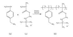
なお、発明者らは、ポリマーEおよびポリマーFについても実際に合成した。以下に各ポリマーの合成手順を説明する。The inventors also actually synthesized polymer E and polymer F. The synthesis procedures for each polymer are described below.
(ポリマーEの合成)
図15は、ポリマーEの重合反応を示す図である。まず、モノマーbと、モノマーcとを用意した。そして、4つ口フラスコにモノマーbを0.85mmol、モノマーcを7.61mmol、2,2’-アゾビス(4-メトキシ-2,4-ジメチルバレロニトリル)(以下V-70と称する)を0.25mmol投入した。以降はポリマーAの場合と同様の処理を施し、図15に示す重合反応を行ってポリマーEを得た(必要に応じて反応温度、反応時間は適宜調整した)。ポリマーEは、上記式(5)において、n:m=15.0:85.0であるポリマーに相当する。(Synthesis of Polymer E)
FIG. 15 is a diagram showing the polymerization reaction of polymer E. First, monomer b and monomer c were prepared. Then, 0.85 mmol of monomer b, 7.61 mmol of monomer c, and 0.25 mmol of 2,2'-azobis(4-methoxy-2,4-dimethylvaleronitrile) (hereinafter referred to as V-70) were charged into a four-neck flask. Thereafter, the same treatment as in the case of polymer A was carried out, and the polymerization reaction shown in FIG. 15 was carried out to obtain polymer E (the reaction temperature and reaction time were appropriately adjusted as necessary). Polymer E corresponds to the polymer in the above formula (5) where n:m=15.0:85.0.
(ポリマーFの合成)
図16は、ポリマーFの重合反応を示す図である。まず、アリルアミン塩酸塩(モノマーe)と、モノマーcとを用意した。そして、4つ口フラスコにモノマーeを92.22mmol、モノマーcを9.22mmol、V-50を66.1mmol、イオン交換水を590mmol投入した。以降はポリマーAの場合と同様の処理を施し、図16に示す重合反応を行ってポリマーFを得た。ポリマーFは、上記式(3)において、n:m=5.8:94.2であるポリマーに相当する。(Synthesis of Polymer F)
Fig. 16 is a diagram showing the polymerization reaction of polymer F. First, allylamine hydrochloride (monomer e) and monomer c were prepared. Then, 92.22 mmol of monomer e, 9.22 mmol of monomer c, 66.1 mmol of V-50, and 590 mmol of ion-exchanged water were charged into a four-neck flask. Thereafter, the same treatment as in the case of polymer A was carried out, and polymer F was obtained by carrying out the polymerization reaction shown in Fig. 16. Polymer F corresponds to the polymer in which n:m = 5.8:94.2 in the above formula (3).
本開示は、ポリマー、試薬層およびセンサに利用することができる。The present disclosure can be used in polymers, reagent layers and sensors.
1 センサ、 6 保護膜、 26 作用極、 30 対極、 32 試薬層、 34 電極部、 36 ポリマー、 38 タンパク質、 40 レドックスメディエータ、 42 第1架橋剤、 44 第2架橋剤、 46 第1結合部位、 48 第2結合部位、 50 第3結合部位、 52 第4結合部位、 54 第3架橋剤。1 sensor, 6 protective film, 26 working electrode, 30 counter electrode, 32 reagent layer, 34 electrode portion, 36 polymer, 38 protein, 40 redox mediator, 42 first crosslinker, 44 second crosslinker, 46 first binding site, 48 second binding site, 50 third binding site, 52 fourth binding site, 54 third crosslinker.
Claims (10)
Translated fromJapaneseポリマーと、
前記ポリマーに結合するとともに前記アナライトに作用するタンパク質と、を備え、
前記ポリマーは、
前記タンパク質と共有結合する第1結合部位と、
前記タンパク質と静電相互作用により結合する第2結合部位と、を備え、
式(1):
式(2):
前記タンパク質は、酸化還元酵素である、
試薬層。 A reagent layer of a sensor for measuring an analyte in a sample, comprising:
A polymer ;
a protein that binds to the polymer and acts on the analyte;
The polymer is
a first binding site that is covalently attached to the protein;
a second binding site that binds to the protein through electrostatic interaction;
Formula (1):
Formula (2):
The protein is an oxidoreductase.
Reagent layer.
請求項1に記載の試薬層。 a first cross-linker linkingthe oxidoreductase and the first binding site;
The reagent layer of claim1 .
前記試薬層は、前記ポリマーに結合する前記レドックスメディエータを備える、
請求項1に記載の試薬層。the polymer comprises a third binding site that is covalently bonded to a redox mediator capable of transferring electrons;
the reagent layer comprises the redox mediator bound to the polymer;
The reagent layer of claim1 .
請求項3に記載の試薬層。 a second cross-linker that links the redox mediator and the third binding site;
The reagent layer of claim3 .
前記第1架橋剤および前記第2架橋剤は、同じ架橋剤である、
請求項4に記載の試薬層。 a first cross-linking agent that links the oxidoreductase and the first binding site;
The first crosslinker and the second crosslinker are the same crosslinker.
The reagent layer of claim4 .
各ポリマーは、他の前記ポリマーと共有結合する第4結合部位を有し、
前記試薬層は、前記第4結合部位どうしを結合する第3架橋剤を備える、
請求項1に記載の試薬層。 the reagent layer comprises a plurality of the polymers;
each polymer has a fourth binding site covalently bonded to another said polymer;
the reagent layer includes a third cross-linking agent that bonds the fourth binding sites together;
The reagent layer of claim1 .
前記第1結合部位、前記第3結合部位および前記第4結合部位は、少なくとも2つが同じ官能基を有する、
請求項6に記載の試薬層。the polymer comprises a third binding site that is covalently bonded to a redox mediator capable of transferring electrons;
At least two of the first binding site, the third binding site and the fourth binding site have the same functional group;
The reagent layer of claim6 .
前記試薬層は、前記酸化還元酵素および前記第1結合部位を結合する第1架橋剤と、前記レドックスメディエータおよび前記第3結合部位を結合する第2架橋剤と、を備え、
前記第1架橋剤、前記第2架橋剤および前記第3架橋剤は、少なくとも2つが同じ架橋剤である、
請求項6に記載の試薬層。the polymer comprises a third binding site that is covalently bonded to a redox mediator capable of transferring electrons;
the reagent layer comprises a first crosslinker that bonds the oxidoreductase and the first binding site, and a second crosslinker that bonds the redox mediator and the third binding site;
At least two of the first crosslinking agent, the second crosslinking agent, and the third crosslinking agent are the same crosslinking agent.
The reagent layer of claim6 .
前記作用極に接するように配置される請求項1乃至8のいずれかに記載の試薬層と、を備える、
センサ。 An electrode portion including a working electrode and a counter electrode;
The reagent layer according toany one of claims 1 to 8 , which is disposed so as to be in contact with the working electrode.
Sensor.
請求項9に記載のセンサ。 A protective film is provided to cover the reagent layer.
The sensor of claim9 .
Applications Claiming Priority (3)
| Application Number | Priority Date | Filing Date | Title |
|---|---|---|---|
| JP2021107307 | 2021-06-29 | ||
| JP2021107307 | 2021-06-29 | ||
| PCT/JP2022/024652WO2023276772A1 (en) | 2021-06-29 | 2022-06-21 | Polymer, reagent layer, and sensor |
Publications (3)
| Publication Number | Publication Date |
|---|---|
| JPWO2023276772A1 JPWO2023276772A1 (en) | 2023-01-05 |
| JPWO2023276772A5 JPWO2023276772A5 (en) | 2023-10-27 |
| JP7671848B2true JP7671848B2 (en) | 2025-05-02 |
Family
ID=84691773
Family Applications (1)
| Application Number | Title | Priority Date | Filing Date |
|---|---|---|---|
| JP2023531831AActiveJP7671848B2 (en) | 2021-06-29 | 2022-06-21 | Reagent Layer and Sensor |
Country Status (5)
| Country | Link |
|---|---|
| US (1) | US20240141404A1 (en) |
| EP (1) | EP4365213A4 (en) |
| JP (1) | JP7671848B2 (en) |
| CN (1) | CN117616056A (en) |
| WO (1) | WO2023276772A1 (en) |
Citations (6)
| Publication number | Priority date | Publication date | Assignee | Title |
|---|---|---|---|---|
| JP2006321829A (en) | 2005-05-17 | 2006-11-30 | Kazuhiko Ishihara | Copolymer and method for producing the same |
| WO2007126051A1 (en) | 2006-04-28 | 2007-11-08 | Fujirebio Inc. | Reagent for assaying antiphospholipid antibody |
| JP2012502689A (en) | 2008-09-15 | 2012-02-02 | アボット ダイアベティス ケア インコーポレイテッド | Cationic polymer-based wired enzyme composition used for analyte sensor |
| JP2019038869A (en) | 2017-08-22 | 2019-03-14 | 東洋インキScホールディングス株式会社 | Aqueous conductive dispersion, biosensor and method for producing biosensor |
| WO2019146788A1 (en) | 2018-01-29 | 2019-08-01 | Phcホールディングス株式会社 | Protective film material for biosensor probe |
| JP2019523787A (en) | 2016-06-06 | 2019-08-29 | ソニー株式会社 | Ionic polymers containing fluorescent or colored reporter groups |
Family Cites Families (4)
| Publication number | Priority date | Publication date | Assignee | Title |
|---|---|---|---|---|
| JPS58223739A (en)* | 1982-06-23 | 1983-12-26 | Hitachi Ltd | Humidity-sensitive material for sensor |
| KR20180084685A (en)* | 2018-01-31 | 2018-07-25 | 주식회사 엔게인 | Hydro gel and glucose sensor including the same |
| EP3777683A1 (en)* | 2018-03-30 | 2021-02-17 | PHC Holdings Corporation | Sensor using phenazine derivative or high molecular weight redox polymer containing phenazine derivative |
| EP4070870A4 (en)* | 2019-12-06 | 2023-01-25 | Kurita Water Industries Ltd. | SLUDGE DEWATERING AGENT AND SLUDGE DEWATERING PROCESS |
- 2022
- 2022-06-21WOPCT/JP2022/024652patent/WO2023276772A1/ennot_activeCeased
- 2022-06-21JPJP2023531831Apatent/JP7671848B2/enactiveActive
- 2022-06-21EPEP22832920.7Apatent/EP4365213A4/enactivePending
- 2022-06-21CNCN202280045978.2Apatent/CN117616056A/enactivePending
- 2023
- 2023-12-22USUS18/394,118patent/US20240141404A1/enactivePending
Patent Citations (6)
| Publication number | Priority date | Publication date | Assignee | Title |
|---|---|---|---|---|
| JP2006321829A (en) | 2005-05-17 | 2006-11-30 | Kazuhiko Ishihara | Copolymer and method for producing the same |
| WO2007126051A1 (en) | 2006-04-28 | 2007-11-08 | Fujirebio Inc. | Reagent for assaying antiphospholipid antibody |
| JP2012502689A (en) | 2008-09-15 | 2012-02-02 | アボット ダイアベティス ケア インコーポレイテッド | Cationic polymer-based wired enzyme composition used for analyte sensor |
| JP2019523787A (en) | 2016-06-06 | 2019-08-29 | ソニー株式会社 | Ionic polymers containing fluorescent or colored reporter groups |
| JP2019038869A (en) | 2017-08-22 | 2019-03-14 | 東洋インキScホールディングス株式会社 | Aqueous conductive dispersion, biosensor and method for producing biosensor |
| WO2019146788A1 (en) | 2018-01-29 | 2019-08-01 | Phcホールディングス株式会社 | Protective film material for biosensor probe |
Non-Patent Citations (1)
| Title |
|---|
| JOSE,Ramos,Amino‐functionalized latex particles obtained by a multistep method: Development of a new immunoreagent,Journal of Polymer Science Part A: Polymer Chemistry,2003,Vol.41(15),p.2404-2411,DOI:10.1002/pola.10782 |
Also Published As
| Publication number | Publication date |
|---|---|
| EP4365213A1 (en) | 2024-05-08 |
| JPWO2023276772A1 (en) | 2023-01-05 |
| WO2023276772A1 (en) | 2023-01-05 |
| CN117616056A (en) | 2024-02-27 |
| US20240141404A1 (en) | 2024-05-02 |
| EP4365213A4 (en) | 2024-10-23 |
Similar Documents
| Publication | Publication Date | Title |
|---|---|---|
| Heller et al. | Electrochemical glucose sensors and their applications in diabetes management | |
| US7563588B2 (en) | Electrically non-conductive, nanoparticulate membrane | |
| US8005188B2 (en) | Test-sensor production monitoring using XRF spectrometry | |
| Cardosi et al. | Amperometric glucose sensors for whole blood measurement based on dehydrogenase enzymes | |
| Bu et al. | NAD (P) H sensors based on enzyme entrapment in ferrocene-containing polyacrylamide-based redox gels | |
| EP3777683A1 (en) | Sensor using phenazine derivative or high molecular weight redox polymer containing phenazine derivative | |
| US20210347926A1 (en) | Oxidation-reduction polymer including transition metal complex, and electrochemical biosensor using same | |
| US20190170739A1 (en) | Electrochemical detection systems and components thereof | |
| KR102352758B1 (en) | Novel redox polymer comprising transition metal complex and Electrochemical biosensor using the same | |
| US8226814B2 (en) | Transition metal complexes with pyridyl-imidazole ligands | |
| JP7625098B2 (en) | Electrochemical biosensor or sensing film for electrochemical biosensor containing transition metal complex or redox polymer | |
| Wang et al. | Shield, anchor, and adhesive roles of methylene blue in tyrosinase adsorbed on carbon felt for a flow injection amperometric enzyme biosensor for phenolic substrates and inhibitors | |
| JP7671848B2 (en) | Reagent Layer and Sensor | |
| US20250179039A1 (en) | Electron acceptor, and reagent layer and sensor each using same | |
| Komkova et al. | Anchoring PQQ-Glucose Dehydrogenase with Electropolymerized Azines for the Most Efficient Bioelectrocatalysis | |
| JP7285332B2 (en) | High molecular weight redox polymer and biosensor using the same | |
| JP4879441B2 (en) | Glycated protein measurement kit | |
| EP4596563A2 (en) | Electrochemical biosensor comprising transition metal complex or oxidation-reduction polymer | |
| EP4549921A1 (en) | Sensor and method for manufacturing same | |
| Karan | Enzyme biosensors containing polymeric electron transfer systems | |
| Weckström | Enzyme-mediator coupling for non-invasive glucose monitoring | |
| JP2023172531A (en) | Cation exchange membrane and sensor | |
| WO2024019017A1 (en) | Reagent layer and biosensor comprising reagent layer | |
| Cardosi et al. | Based on Dehydrogenase Enzymes |
Legal Events
| Date | Code | Title | Description |
|---|---|---|---|
| A521 | Request for written amendment filed | Free format text:JAPANESE INTERMEDIATE CODE: A523 Effective date:20230731 | |
| A621 | Written request for application examination | Free format text:JAPANESE INTERMEDIATE CODE: A621 Effective date:20230731 | |
| A131 | Notification of reasons for refusal | Free format text:JAPANESE INTERMEDIATE CODE: A131 Effective date:20240709 | |
| A521 | Request for written amendment filed | Free format text:JAPANESE INTERMEDIATE CODE: A523 Effective date:20240822 | |
| A131 | Notification of reasons for refusal | Free format text:JAPANESE INTERMEDIATE CODE: A131 Effective date:20241210 | |
| A521 | Request for written amendment filed | Free format text:JAPANESE INTERMEDIATE CODE: A523 Effective date:20250127 | |
| TRDD | Decision of grant or rejection written | ||
| A01 | Written decision to grant a patent or to grant a registration (utility model) | Free format text:JAPANESE INTERMEDIATE CODE: A01 Effective date:20250415 | |
| A61 | First payment of annual fees (during grant procedure) | Free format text:JAPANESE INTERMEDIATE CODE: A61 Effective date:20250421 | |
| R150 | Certificate of patent or registration of utility model | Ref document number:7671848 Country of ref document:JP Free format text:JAPANESE INTERMEDIATE CODE: R150 |