JP7669816B2 - Power conversion device, diagnostic device, and diagnostic method - Google Patents
Power conversion device, diagnostic device, and diagnostic methodDownload PDFInfo
- Publication number
- JP7669816B2 JP7669816B2JP2021097085AJP2021097085AJP7669816B2JP 7669816 B2JP7669816 B2JP 7669816B2JP 2021097085 AJP2021097085 AJP 2021097085AJP 2021097085 AJP2021097085 AJP 2021097085AJP 7669816 B2JP7669816 B2JP 7669816B2
- Authority
- JP
- Japan
- Prior art keywords
- motor
- power
- diagnosis
- unit
- deterioration
- Prior art date
- Legal status (The legal status is an assumption and is not a legal conclusion. Google has not performed a legal analysis and makes no representation as to the accuracy of the status listed.)
- Active
Links
Images


Classifications
- H—ELECTRICITY
- H02—GENERATION; CONVERSION OR DISTRIBUTION OF ELECTRIC POWER
- H02P—CONTROL OR REGULATION OF ELECTRIC MOTORS, ELECTRIC GENERATORS OR DYNAMO-ELECTRIC CONVERTERS; CONTROLLING TRANSFORMERS, REACTORS OR CHOKE COILS
- H02P27/00—Arrangements or methods for the control of AC motors characterised by the kind of supply voltage
- H02P27/04—Arrangements or methods for the control of AC motors characterised by the kind of supply voltage using variable-frequency supply voltage, e.g. inverter or converter supply voltage
- H02P27/06—Arrangements or methods for the control of AC motors characterised by the kind of supply voltage using variable-frequency supply voltage, e.g. inverter or converter supply voltage using DC to AC converters or inverters
- G—PHYSICS
- G01—MEASURING; TESTING
- G01R—MEASURING ELECTRIC VARIABLES; MEASURING MAGNETIC VARIABLES
- G01R19/00—Arrangements for measuring currents or voltages or for indicating presence or sign thereof
- G—PHYSICS
- G01—MEASURING; TESTING
- G01R—MEASURING ELECTRIC VARIABLES; MEASURING MAGNETIC VARIABLES
- G01R31/00—Arrangements for testing electric properties; Arrangements for locating electric faults; Arrangements for electrical testing characterised by what is being tested not provided for elsewhere
- G01R31/34—Testing dynamo-electric machines
- G01R31/343—Testing dynamo-electric machines in operation
- G—PHYSICS
- G01—MEASURING; TESTING
- G01R—MEASURING ELECTRIC VARIABLES; MEASURING MAGNETIC VARIABLES
- G01R31/00—Arrangements for testing electric properties; Arrangements for locating electric faults; Arrangements for electrical testing characterised by what is being tested not provided for elsewhere
- G01R31/34—Testing dynamo-electric machines
- G01R31/346—Testing of armature or field windings
- H—ELECTRICITY
- H02—GENERATION; CONVERSION OR DISTRIBUTION OF ELECTRIC POWER
- H02P—CONTROL OR REGULATION OF ELECTRIC MOTORS, ELECTRIC GENERATORS OR DYNAMO-ELECTRIC CONVERTERS; CONTROLLING TRANSFORMERS, REACTORS OR CHOKE COILS
- H02P21/00—Arrangements or methods for the control of electric machines by vector control, e.g. by control of field orientation
- H02P21/14—Estimation or adaptation of machine parameters, e.g. flux, current or voltage
- H—ELECTRICITY
- H02—GENERATION; CONVERSION OR DISTRIBUTION OF ELECTRIC POWER
- H02P—CONTROL OR REGULATION OF ELECTRIC MOTORS, ELECTRIC GENERATORS OR DYNAMO-ELECTRIC CONVERTERS; CONTROLLING TRANSFORMERS, REACTORS OR CHOKE COILS
- H02P29/00—Arrangements for regulating or controlling electric motors, appropriate for both AC and DC motors
- H02P29/02—Providing protection against overload without automatic interruption of supply
- H02P29/024—Detecting a fault condition, e.g. short circuit, locked rotor, open circuit or loss of load
- H02P29/027—Detecting a fault condition, e.g. short circuit, locked rotor, open circuit or loss of load the fault being an over-current
- H—ELECTRICITY
- H02—GENERATION; CONVERSION OR DISTRIBUTION OF ELECTRIC POWER
- H02P—CONTROL OR REGULATION OF ELECTRIC MOTORS, ELECTRIC GENERATORS OR DYNAMO-ELECTRIC CONVERTERS; CONTROLLING TRANSFORMERS, REACTORS OR CHOKE COILS
- H02P29/00—Arrangements for regulating or controlling electric motors, appropriate for both AC and DC motors
- H02P29/02—Providing protection against overload without automatic interruption of supply
- H02P29/024—Detecting a fault condition, e.g. short circuit, locked rotor, open circuit or loss of load
- H02P29/028—Detecting a fault condition, e.g. short circuit, locked rotor, open circuit or loss of load the motor continuing operation despite the fault condition, e.g. eliminating, compensating for or remedying the fault
- H—ELECTRICITY
- H02—GENERATION; CONVERSION OR DISTRIBUTION OF ELECTRIC POWER
- H02M—APPARATUS FOR CONVERSION BETWEEN AC AND AC, BETWEEN AC AND DC, OR BETWEEN DC AND DC, AND FOR USE WITH MAINS OR SIMILAR POWER SUPPLY SYSTEMS; CONVERSION OF DC OR AC INPUT POWER INTO SURGE OUTPUT POWER; CONTROL OR REGULATION THEREOF
- H02M1/00—Details of apparatus for conversion
- H02M1/0003—Details of control, feedback or regulation circuits
- H02M1/0009—Devices or circuits for detecting current in a converter
Landscapes
- Engineering & Computer Science (AREA)
- Power Engineering (AREA)
- Physics & Mathematics (AREA)
- General Physics & Mathematics (AREA)
- Control Of Ac Motors In General (AREA)
- Inverter Devices (AREA)
Description
Translated fromJapanese本開示は、電力変換装置等に関する。This disclosure relates to power conversion devices, etc.
例えば、交流電動機の有効電力や無効電力に基づき、交流電動機の劣化異常に関する診断を行う技術が知られている(特許文献1,2参照)。For example, there is known technology for diagnosing deterioration and abnormalities in AC motors based on the active and reactive power of the AC motors (see
しかしながら、上記の文献では、交流電動機の有効電力や無効電力の大きさに着目して交流電動機の劣化異常の診断を行っている。そのため、例えば、交流電動機の有効電力や無効電力の瞬間的な大きさの変化を捉えて、劣化異常の可能性があると誤った診断が行われる可能性がある。また、交流電動機の有効電力や無効電力の大きさに表れない劣化異常に関する診断を行うことができない可能性がある。その結果、交流電動機の劣化異常に関する診断を適切に行うことができない可能性がある。However, in the above-mentioned literature, deterioration abnormalities in an AC motor are diagnosed by focusing on the magnitude of the active power and reactive power of the AC motor. Therefore, for example, a momentary change in the magnitude of the active power or reactive power of the AC motor may be captured and a mistaken diagnosis may be made that there is a possibility of a deterioration abnormality. In addition, it may not be possible to diagnose deterioration abnormalities that are not reflected in the magnitude of the active power or reactive power of the AC motor. As a result, it may not be possible to properly diagnose deterioration abnormalities in the AC motor.
そこで、上記課題に鑑み、交流電動機の劣化異常に関する診断をより適切に行うことが可能な技術を提供することを目的とする。In view of the above problems, the objective is to provide a technology that can more appropriately diagnose deterioration abnormalities in AC motors.
上記目的を達成するため、本開示の一実施形態では、
外部から入力される電力を用いて交流電動機を駆動する駆動部と、
前記交流電動機の相電流を検出する電流検出部と、
前記電流検出部の出力に基づき、前記交流電動機の有効電力及び無効電力の少なくとも一方を演算する演算部と、
前記有効電力及び前記無効電力の前記少なくとも一方の周波数成分に基づき、前記交流電動機の劣化異常に関する診断を行う診断部と、を備え、
前記診断部は、前記有効電力及び前記無効電力の前記少なくとも一方について、周波数分析により得られる周波数成分、及び波形計数法により得られる振動の振幅に基づき、前記診断を行う、
電力変換装置が提供される。 In order to achieve the above object, in one embodiment of the present disclosure,
A drive unit that drives an AC motor using power input from an external source;
A current detection unit that detects a phase current of the AC motor;
a calculation unit that calculates at least one of an active power and a reactive power of the AC motor based on an output of the current detection unit;
a diagnosis unit that performs a diagnosis regarding deterioration or abnormality of the AC motor based on the frequency component of at least one of the active power and the reactive power,
The diagnosing unit performs the diagnosis on at least one of the active power and the reactive power based on a frequency component obtained by a frequency analysis and an amplitude of vibration obtained by a waveform counting method.
A power converter is provided.
また、本開示の他の実施形態では、
交流電動機の相電流を検出する電流検出部の出力を取得し、前記交流電動機の有効電力及び無効電力の少なくとも一方を演算する演算部と、
前記有効電力及び前記無効電力の前記少なくとも一方の周波数成分に基づき、前記交流電動機の劣化異常に関する診断を行う診断部と、を備え、
前記診断部は、前記有効電力及び前記無効電力の前記少なくとも一方について、周波数分析により得られる周波数成分、及び波形計数法により得られる振動の振幅に基づき、前記診断を行う、
診断装置が提供される。 In another embodiment of the present disclosure,
a calculation unit that obtains an output of a current detection unit that detects a phase current of an AC motor and calculates at least one of an active power and a reactive power of the AC motor;
a diagnosis unit that performs a diagnosis regarding deterioration or abnormality of the AC motor based on the frequency component of at least one of the active power and the reactive power,
The diagnosing unit performs the diagnosis on at least one of the active power and the reactive power based on a frequency component obtained by a frequency analysis and an amplitude of vibration obtained by a waveform counting method.
A diagnostic device is provided.
また、本開示の更に他の実施形態では、
診断装置が、交流電動機の相電流を検出する電流検出部の出力を取得し、前記電流検出部の出力に基づき、前記交流電動機の有効電力及び無効電力の少なくとも一方を演算する演算ステップと、
前記診断装置が、前記有効電力及び前記無効電力の前記少なくとも一方の周波数成分に基づき、前記交流電動機の劣化異常に関する診断を行う診断ステップと、を含み、
前記診断ステップでは、前記有効電力及び前記無効電力の前記少なくとも一方について、周波数分析により得られる周波数成分、及び波形計数法により得られる振動の振幅に基づき、前記診断を行う、
診断方法が提供される。
In still another embodiment of the present disclosure,
a calculation step in which a diagnostic device acquires an output of a current detection unit that detects a phase current of an AC motor, and calculates at least one of an active power and a reactive power of the AC motor based on the output of the current detection unit;
a diagnosis stepof diagnosing deterioration or abnormality of the AC motor based on the frequency component of at least one of the active power and the reactive power by the diagnosis device,
In the diagnosis step, the diagnosis is performed on at least one of the active power and the reactive power based on a frequency component obtained by a frequency analysis and an amplitude of vibration obtained by a waveform counting method.
A diagnostic method is provided.
上述の実施形態によれば、交流電動機の劣化異常に関する診断をより適切に行うことができる。The above-described embodiment allows for more appropriate diagnosis of deterioration abnormalities in AC motors.
以下、図面を参照して実施形態について説明する。The following describes the embodiment with reference to the drawings.
[劣化異常診断システムの概要]
まず、図1を参照して、本実施形態に係る劣化異常診断システム1の概要について説明する。 [Outline of the Deterioration and Anomaly Diagnostic System]
First, an overview of a degradation and
図1は、本実施形態に係る劣化異常診断システム1の構成の第1例を示す図である。Figure 1 is a diagram showing a first example of the configuration of a degradation and
劣化異常診断システム1は、電動機Mの劣化異常に関する診断を行う。The deterioration
電動機Mの劣化異常に関する診断には、例えば、電動機Mの劣化異常の有無の診断や電動機Mの劣化異常の進行度合いの診断(推定)等が含まれる。電動機Mの劣化異常の進行度合いは、例えば、複数の段階(レベル)で表されてもよいし、連続的に変化する数値等で表されてもよい。Diagnosis of the deterioration abnormality of the motor M includes, for example, diagnosis of the presence or absence of deterioration abnormality of the motor M and diagnosis (estimation) of the degree of progression of the deterioration abnormality of the motor M. The degree of progression of the deterioration abnormality of the motor M may be expressed, for example, in multiple stages (levels), or may be expressed by a continuously changing numerical value, etc.
電動機Mの劣化異常には、例えば、巻線(コイル)の絶縁劣化が含まれる。絶縁劣化は、熱的要因、電気的要因、機械的要因、及び環境的要因等の少なくとも一つによって、電動機Mの巻線の絶縁部分に生じる劣化を意味する。絶縁劣化が進行すると、例えば、絶縁劣化が進行した部分での巻線の抵抗値が変化して、巻線の不平衡が生じ、電流バランスが崩れてしまう。そして、最終的には、巻線の相短絡が生じ電動機Mの機械的故障に繋がる。Deterioration of the motor M includes, for example, insulation deterioration of the windings (coils). Insulation deterioration refers to deterioration that occurs in the insulating parts of the windings of the motor M due to at least one of thermal, electrical, mechanical, and environmental factors. As insulation deterioration progresses, for example, the resistance value of the windings in the part where insulation deterioration has progressed changes, causing an imbalance in the windings and disrupting the current balance. Ultimately, a phase short circuit occurs in the windings, leading to a mechanical failure of the motor M.
これに対して、劣化異常診断システム1は、電動機Mの絶縁劣化を含む劣化異常に関する診断を行うことによって、電動機Mの劣化異常の有無や進行度合いをユーザに把握させることができる。そのため、例えば、ユーザは、電動機Mの機械的故障の兆候を前もって把握することができる。よって、劣化異常診断システム1は、電動機Mを含む設備のメンテナンスの頻度を抑制し、電動機Mの状態に合わせてメンテナンスを行うことができると共に、電動機Mを含む設備の突発的な停止やその復旧作業に伴う設備の長期停止等のリスクを低減することができる。In response to this, the degradation
図1に示すように、劣化異常診断システム1は、電力変換装置100と、センサ200と、管理装置300と、端末装置400とを含む。As shown in FIG. 1, the degradation and
劣化異常診断システム1に含まれる電力変換装置100、管理装置300、端末装置400は、それぞれ、一つであってもよいし、複数であってもよい。The
電力変換装置100は、商用電源PSから入力される三相交流電力(例えば、R相、S相、及びT相)を所定の電圧や所定の周波数を有する三相交流電力(例えば、U相、V相、及びW相)に変換し、電動機Mを駆動する。The
尚、電力変換装置100は、商用電源PSと異なる他の電源から入力される三相交流電力に基づき、電動機Mを駆動する三相交流電力を生成してもよい。また、電力変換装置100は、三相交流の電源から入力される電力に代えて、或いは、加えて、直流電源から入力される電力に基づき、電動機Mを駆動する三相交流電力を生成してもよい。この場合、直流電力は、整流回路110とインバータ回路130との間の直流リンク部(正ラインPL及び負ラインNL)に入力される。The
商用電源PSと電力変換装置100との間の交流伝達経路(R相、S相、及びT相の電線)には、交流伝達経路の接続状態及び遮断状態を切り換え可能な遮断器BKが設置される。遮断器BKは、例えば、MCCB(Molded Case Circuit Breaker)である。A circuit breaker BK capable of switching between a connected state and a disconnected state of the AC transmission path is installed in the AC transmission path (R-phase, S-phase, and T-phase electric wires) between the commercial power source PS and the
電動機M(交流電動機の一例)は、電力変換装置100から出力される三相交流電力に基づき、所定の機械や工場や建物に設置される所定の設備等を電気駆動する。所定の機械には、例えば、圧縮機、ファン、ブロア等が含まれる。また、所定の設備には、例えば、エレベータやベルトコンベア等の搬送装置が含まれる。The electric motor M (an example of an AC motor) electrically drives a specific machine or specific equipment installed in a factory or building based on the three-phase AC power output from the
図1に示すように、電力変換装置100は、整流回路110と、平滑回路120と、インバータ回路130と、制御装置140と、センサ150と、表示装置160と、通信装置170とを含む。As shown in FIG. 1, the
整流回路110は、商用電源PSから入力されるR相、S相、及びT相の三相交流電力を整流し、直流電力を出力可能に構成される。整流回路110は、正側及び負側の出力端のそれぞれが正ラインPL及び負ラインNLの一端に接続され、正ラインPL及び負ラインNLを通じて、直流電力を平滑回路120に出力することができる。整流回路110は、例えば、6つの半導体ダイオードを含み、上下アームを構成する2つの半導体ダイオードの直列接続体が3組並列接続されるブリッジ型全波整流回路である。The
平滑回路120は、整流回路110から出力される直流電力やインバータ回路130から回生される直流電力の脈動を抑制し、平滑化する。The smoothing
平滑回路120は、例えば、平滑コンデンサを含む。The smoothing
平滑コンデンサは、整流回路110やインバータ回路130と並列に、正ラインPL及び負ラインNLを繋ぐ経路に設けられてよい。The smoothing capacitor may be provided in parallel with the
平滑コンデンサは、適宜、充放電を繰り返しながら、整流回路110から出力される直流電力やインバータ回路130から出力(回生)される直流電力を平滑化する。The smoothing capacitor smoothes the DC power output from the
平滑コンデンサは、一つであってよい。また、平滑コンデンサは、複数配置されてもよく、複数の平滑コンデンサが正ラインPL及び負ラインNLの間に並列接続されてもよいし、直列接続されてもよい。また、複数の平滑コンデンサは、2以上の平滑コンデンサの直列接続体が正ラインPL及び負ラインNLの間に複数並列接続される形で構成されてもよい。There may be one smoothing capacitor. Alternatively, multiple smoothing capacitors may be arranged, and the multiple smoothing capacitors may be connected in parallel or in series between the positive line PL and the negative line NL. Alternatively, the multiple smoothing capacitors may be configured in such a way that two or more series-connected smoothing capacitors are connected in parallel between the positive line PL and the negative line NL.
また、平滑回路120は、例えば、リアクトルを含む。The smoothing
リアクトルは、整流回路110と平滑コンデンサ(具体的には、平滑コンデンサが配置される経路との分岐点)との間の正ラインPLに設けられてよい。The reactor may be provided on the positive line PL between the
リアクトルは、適宜、電流の変化を妨げるように電圧を発生させながら、整流回路110から出力される直流電力やインバータ回路130から出力(回生)される直流電力を平滑化する。The reactor generates a voltage to appropriately prevent changes in the current, smoothing the DC power output from the
インバータ回路130(駆動部の一例)は、その正側及び負側の入力端が正ラインPL及び負ラインNLの他端に接続される。インバータ回路130は、平滑回路120から供給される直流電力を半導体スイッチのスイッチ動作により、所定の周波数や所定の電圧を有する三相交流電力(例えば、U相、V相、及びW相)に変換し電動機Mに出力し、電動機Mを駆動する。半導体スイッチは、例えば、シリコン(Si)製のIGBT(Insulated Gate Bipolar Transistor)やMOSFET(Metal-Oxide-Semiconductor Field-Effect Transistor)であってよい。また、半導体スイッチは、例えば、シリコンカーバイド(SiC)や窒化ガリウム(GaN)等のワイドバンドギャップ半導体を用いた半導体素子であってもよい。The inverter circuit 130 (an example of a drive unit) has its positive and negative input terminals connected to the other ends of the positive line PL and the negative line NL. The
インバータ回路130は、例えば、6つの半導体スイッチを含み、上下アームを構成する2つの半導体スイッチの直列接続体(スイッチレグ)が正ラインPL及び負ラインNLの間に3組並列接続されるブリッジ回路を含む形で構成される。そして、インバータ回路130は、3組の上下アームの接続点から引き出されるU相線、V相線、及びW相線を通じて、三相交流電力を出力してよい。また、6つの半導体スイッチには、それぞれ、環流ダイオードが並列接続されてよい。The
制御装置140(診断装置の一例)は、電力変換装置100に関する制御を行う。The control device 140 (an example of a diagnostic device) controls the
制御装置140の機能は、任意のハードウェア或いは任意のハードウェア及びソフトウェアの組み合わせ等により実現されてよい。例えば、制御装置140は、CPU(Central Processing Unit)、RAM(Random Access Memory)等のメモリ装置、ROM(Read Only Memory)等の不揮発性の補助記憶装置、及び外部との入出力用のインタフェース装置を含むコンピュータを中心に構成される。制御装置140は、例えば、補助記憶装置にインストールされるプログラムをメモリ装置にロードしCPUに実行させることにより、各種機能を実現する。また、制御装置140は、インタフェース装置を通じて、外部の信号を受信したり、外部に信号を出力(送信)したりする。The functions of the
制御装置140は、例えば、インバータ回路130(具体的には、それぞれの半導体スイッチのゲート)に駆動信号を出力し、インバータ回路130を用いて、電動機Mが所定の運転条件を満足するように駆動する。換言すれば、制御装置140は、所定の運転条件に沿って電動機Mを駆動するための制御信号を生成し、インバータ回路130に出力する。The
また、制御装置140は、例えば、電動機Mの劣化異常に関する診断を行う。詳細は、後述する。The
尚、制御装置140の機能は、複数の制御装置(制御回路)に分散される形で実現されてもよい。例えば、インバータ回路130を介して電動機Mを駆動する機能と、電動機Mの劣化異常に関する診断を行う機能とは、電力変換装置100の異なる制御装置により実現されてもよい。また、制御装置140の機能の一部又は全部は、例えば、管理装置300や端末装置400(共に、診断装置の一例)等の電力変換装置100の外部装置に移管されてもよい。例えば、電動機Mの劣化異常に関する診断機能の一部又は全部は、管理装置300や端末装置400等に移管されてもよい。The functions of the
センサ150は、電力変換装置100の状態に関する検出データを取得する。センサ150は、例えば、一対一の通信線等を通じて制御装置140と接続され、検出データに対応する信号(以下、「検出信号」)は、制御装置140に取り込まれる。これにより、制御装置140は、センサ150の検出信号に基づき、電力変換装置100に関する制御を行うことができる。The
センサ150は、例えば、正ラインPL及び負ラインNLの間のリンク電圧を検出する電圧センサを含む。また、センサ150(電流検出部の一例)は、例えば、インバータ回路130と電動機Mとの間のU相線、V相線、及びW相線の電流、即ち、電動機MのU相、V相、及びW相の相電流(以下、それぞれ、「U相電流」、「V相電流」、及び「W相電流」)を検出する電流センサを含む。電流センサは、例えば、ホールセンサ、シャント抵抗、フラックスゲート等を用いて、電動機Mの相電流を検出し、AD(Analog-Digital)コンバータを用いて、相電流の検出値(デジタル値)を出力する。また、センサ150は、インバータ回路130と電動機Mとの間の回路、即ち、U相線、V相線、及びW相線の相電圧(以下、「U相電圧」、「V相電圧」、及び「W相電圧」)を検出する電圧センサを含んでもよい。The
表示装置160は、例えば、電力変換装置100の筐体の外側の表面に設けられる。表示装置160は、制御装置140の制御下で、電力変換装置100に関する情報を表示する。The
尚、表示装置160は、電力変換装置100の筐体の外部、例えば、電動機Mにより電気駆動される、生産設備や機械設備等の筐体の表面(外面)に設けられてもよい。The
通信装置170は、所定の通信回線を通じて、管理装置300や端末装置400等の電力変換装置100の外部の機器と通信を行う。The
所定の通信回線は、例えば、一対一の通信線であってよい。また、所定の通信回線には、例えば、電動機Mにより電機駆動される生産設備や機械設備等が設置される施設(工場)内に構築されるフィールドネットワーク等のローカルネットワーク(LAN:Local Area Network)が含まれてよい。ローカルネットワークは、有線で構築されていてもよいし、無線で構築されていてもよいし、その双方を含んでいてもよい。また、所定の通信回線には、例えば、電動機Mにより電気駆動される生産設備や機械設備等が設置される施設(工場)の外部の広域ネットワーク(WAN:Wide Area Network)が含まれてもよい。広域ネットワークには、例えば、基地局を末端とする移動体通信網、通信衛星を利用する衛星通信網、インターネット網等が含まれてよい。また、所定の通信回線には、例えば、ブルートゥース(登録商標)やWiFi等の所定の無線通信規格による近距離通信回線が含まれてもよい。The predetermined communication line may be, for example, a one-to-one communication line. The predetermined communication line may include, for example, a local network (LAN: Local Area Network) such as a field network constructed in a facility (factory) where production equipment, machinery, etc. electrically driven by the electric motor M are installed. The local network may be constructed as a wired network, may be constructed as a wireless network, or may include both. The predetermined communication line may also include, for example, a wide area network (WAN: Wide Area Network) outside the facility (factory) where production equipment, machinery, etc. electrically driven by the electric motor M are installed. The wide area network may include, for example, a mobile communication network with a base station as its terminal, a satellite communication network using a communication satellite, an Internet network, etc. The predetermined communication line may also include, for example, a short-distance communication line according to a predetermined wireless communication standard such as Bluetooth (registered trademark) or WiFi.
尚、通信装置170の機能は、外部の機器との間のインタフェースとして、制御装置140に内蔵されてもよい。The functions of the
センサ200は、電力変換装置100の外部に設けられ、電動機Mの状態に関する検出データを出力する。センサ200は、例えば、電動機Mの回転位置や回転速度の状態を検出可能な回転位置センサである。回転位置センサは、例えば、エンコーダであってよい。エンコーダは、例えば、光学式や磁気式等、任意の方式で電動機Mの回転位置や回転速度を検出してよい。センサ200の出力(検出データ)は、一対一の通信線等を通じて、電力変換装置100(制御装置140)に取り込まれる。The
尚、センサ200の検出データは、所定の通信回線を通じて制御装置140に直接取り込まれる代わりに、通信装置170を介して制御装置140に取り込まれてもよい。In addition, the detection data of the
管理装置300は、電力変換装置100の外部に設けられ、電力変換装置100の上位装置として、電力変換装置100及び電動機Mを管理(監視)する。管理装置300は、例えば、電力変換装置100から電力変換装置100や電動機Mの状態に関するデータを取得し、電力変換装置100や電動機Mの状態を監視する。また、管理装置300は、例えば、電力変換装置100に制御信号を出力し、電力変換装置100や電動機Mの制御を行う。また、管理装置300は、例えば、表示部310を通じて、作業者や管理者等のユーザに電力変換装置100や電動機Mに関する情報を提供したり、ユーザからの入力を受け付け、電力変換装置100に送信したりする。The
管理装置300は、例えば、電動機Mを含む所定の機械や設備が設置される工場等において、電力変換装置100を含むフィールドデバイスを管理するPLC(Programmable Logic Controller)等のエッジコントローラである。また、管理装置300は、例えば管理用の端末装置である。管理用の端末装置は、例えば、工場等の事務所に設置されるデスクトップ型のPC(Personal Computer)等の定置型のコンピュータ端末であってよい。また、管理用の端末装置は、例えば、タブレット端末、スマートフォン、ラップトップ型のPC等の工場等の管理者や作業者等が携帯可能な可搬型の端末装置(携帯端末)であってもよい。また、管理装置300は、例えば、サーバ装置である。サーバ装置は、例えば、電動機Mを含む所定の機械や設備が設置される工場等の遠隔に設置されるオンプレミスサーバやクラウドサーバであってよい。また、サーバ装置は、電動機Mを含む所定の機械や設備が設置される工場等の敷地内やその近隣の施設に設置されるエッジサーバであってもよい。The
端末装置400は、電力変換装置100の外部に設けられ、電力変換装置100(劣化異常診断システム1)のユーザに利用されるユーザ端末である。端末装置400は、例えば、表示部410を通じて、ユーザに電力変換装置100や電動機Mに関する各種情報を提供したり、ユーザから各種入力を受け付け、電力変換装置100に送信したりする。The
端末装置400は、例えば、デスクトップ型のPC等の定置型の端末装置であってよい。また、端末装置400は、例えば、スマートフォン、タブレット端末、ラップトップ型のPC等の可搬型の端末装置(携帯端末)であってもよい。The
[電力変換装置の機能構成の一例]
次に、図2、図3を参照して、電力変換装置100の機能構成の一例について説明する。 [Example of functional configuration of power conversion device]
Next, an example of the functional configuration of the
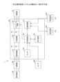
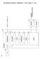
図2は、本実施形態に係る電力変換装置100(制御装置140)の機能構成の一例を示す機能ブロック図である。図3は、電力演算部1402による瞬時有効電力P及び瞬時無効電力Qの演算処理の一例を示す機能ブロック図である。Figure 2 is a functional block diagram showing an example of the functional configuration of the power conversion device 100 (control device 140) according to this embodiment. Figure 3 is a functional block diagram showing an example of the calculation process of the instantaneous active power P and the instantaneous reactive power Q by the
図2に示すように、制御装置140は、電動機制御部1401と、電力演算部1402と、分析部1403と、特徴量取得部1404と、診断部1405と、通知部1406とを含む。電動機制御部1401、電力演算部1402、分析部1403、特徴量取得部1404、診断部1405、及び通知部1406のそれぞれの機能の一部又は全部は、例えば、補助記憶装置にインストールされるプログラムがメモリ装置にロードされCPUで実行されることにより実現される。2, the
電動機制御部1401は、インバータ回路130を用いて、電動機Mの駆動制御を行う。電動機制御部1401は、例えば、V/f制御やベクトル制御等の任意の制御方式で電動機Mの駆動制御を行ってよい。The
具体的には、電動機制御部1401は、センサ150の検出データ(例えば、U相電流、V相電流、及びW相電流の検出値)に基づき、電動機Mを所定の運転条件で駆動するための制御信号(駆動指令)を生成し、インバータ回路130に出力する。Specifically, the
例えば、電動機制御部1401は、センサ150の検出データ、及び電動機Mの運転条件に基づき、U相電圧、V相電圧、及びW相電圧の指令値(以下、「電圧指令値」)を生成し、電圧指令値に応じた制御信号をインバータ回路130に出力する。For example, the
電力演算部1402(演算部の一例)は、センサ150の検出データに基づき、電動機Mの瞬時有効電力P及び瞬時無効電力Qを演算する。The power calculation unit 1402 (an example of a calculation unit) calculates the instantaneous active power P and instantaneous reactive power Q of the motor M based on the detection data of the
例えば、図3に示すように、電動機制御部1401がベクトル制御を採用する場合、ベクトル制御に関する処理過程での演算結果を用いて、電動機Mの瞬時有効電力P及び瞬時無効電力Qを演算する。For example, as shown in FIG. 3, when the
この場合、電動機制御部1401は、三相二相変換部1401Aと、回転座標変換部1401Bと、速度調節部1401Cと、電流指令生成部1401Dと、電流調節部1401Eと、変換部1401Fと、駆動指令出力部1401Gとを含む。In this case, the
三相二相変換部1401Aは、センサ150(電流センサ)により検出されるU相電流Iu、V相電流Iv、及びW相電流Iwを、例えば、クラーク変換等の既知の方法によって、二相の固定座標系(α軸、β軸)のα軸電流Iα及びβ軸電流Iβに変換する。The three-phase to two-
尚、U相電流Iu、V相電流Iv、及びW相電流Iwは、全て、センサ150(電流センサ)により検出されてもよいし、任意の二相の電流のみがセンサ150により検出され、残りの一相の電流が他の2つの検出値に基づき推定されてもよい。The U-phase current Iu, the V-phase current Iv, and the W-phase current Iw may all be detected by the sensor 150 (current sensor), or only the currents of any two phases may be detected by the
回転座標変換部1401Bは、センサ150の出力に基づくα軸電流Iα及びβ軸電流Iβを、例えば、パーク変換等の既知の方法によって、電動機M上の二相の回転座標系(d軸、q軸)のd軸電流Id及びq軸電流Iqに変換する。The rotating coordinate
速度調節部1401Cは、電動機Mの運転条件に基づく電動機Mの角速度の指令値(以下、「速度指令」)ω*と、センサ200(回転位置センサ)により検出される電動機Mの角速度ωとに基づき、電動機Mの回転速度を調節する。例えば、速度調節部1401Cは、実際の電動機の角速度ωと速度指令ω*との偏差をゼロに近づけるための電動機Mのトルクの指令値(以下、「トルク指令」)τ*を生成し出力する。速度調節部1401Cは、任意の制御方式によって、トルク指令τ*を生成してよい。例えば、速度調節部1401Cは、P(Proportional)制御、PI(Proportional-Integral)制御、PID(Proportional-Integral-Differential)制御等を用いて、トルク指令τ*を生成する。The speed adjustment unit 1401C adjusts the rotation speed of the motor M based on a command value (hereinafter, "speed command") ω* of the angular velocity of the motor M based on the operating conditions of the motor M and the angular velocity ω of the motor M detected by the sensor 200 (rotational position sensor). For example, the speed adjustment unit 1401C generates and outputs a command value (hereinafter, "torque command") τ* of the torque of the motor M for bringing the deviation between the actual angular velocity ω of the motor and the speed command ω* closer to zero. The speed adjustment unit 1401C may generate the torque command τ* by any control method. For example, the speed adjustment unit 1401C generates the torque command τ* by using P (Proportional) control, PI (Proportional-Integral) control, PID (Proportional-Integral-Differential) control, or the like.
尚、角速度ωは、センサ200(回転位置センサ)の出力に依らず、電動機Mの相電流や相電圧に基づき推定されてもよい。この場合、センサ200(回転位置センサ)は省略される。The angular velocity ω may be estimated based on the phase current and phase voltage of the motor M, without relying on the output of the sensor 200 (rotational position sensor). In this case, the sensor 200 (rotational position sensor) is omitted.
電流指令生成部1401Dは、トルク指令τ*に基づき、トルク指令τ*を実現するための電動機Mのd軸電流の指令値(以下、「d軸電流指令」)Id*及びq軸電流の指令値(以下、「q軸電流指令」)Iq*を生成し出力する。Based on the torque command τ*, the current
電流調節部1401Eは、d軸電流指令Id*及びq軸電流指令Iq*と、電動機Mの実際の検出値に相当するd軸電流Id及びq軸電流Iqとに基づき、電動機Mの電流を調節する。例えば、電流調節部1401Eは、d軸電流指令Id*とd軸電流Idとの偏差、及びq軸電流指令Iq*とq軸電流Iqとの偏差をゼロに近づけるための電動機Mのd軸電圧の指令値(以下、「d軸電圧指令」)Vd*及びq軸電圧の指令値(以下、「q軸電圧指令」)Vq*を生成し出力する。電流調節部1401Eは、任意の制御方式によって、d軸電圧指令Vd*及びq軸電圧指令Vq*を生成してよい。例えば、速度調節部1401Cは、P制御、PI制御、PID制御等を用いて、d軸電圧指令Vd*及びq軸電圧指令Vq*を生成する。The
変換部1401Fは、d軸電圧指令Vd*及びq軸電圧指令Vq*を、U相電圧の指令値(以下、「U相電圧指令」)Vu*、V相電圧の指令値(以下、「V相電圧指令」)Vv*、及びW相電圧の指令値(以下、「W相電圧指令」)Vw*に変換する。The
駆動指令出力部1401Gは、電動機MのU相電圧指令Vu*、V相電圧指令Vv*、及びW相電圧指令Vw*に基づき、インバータ回路130の駆動指令を生成し、インバータ回路130に出力する。具体的には、駆動指令出力部1401Gは、インバータ回路130の半導体スイッチのゲート駆動指令を生成し、インバータ回路130の半導体スイッチのゲート端子に印加する。これにより、電動機制御部1401は、インバータ回路130を用いて、所定の運転条件に沿うように電動機Mを適切に駆動制御することができる。The drive
電力演算部1402は、回転座標変換部1401Bの出力(d軸電流Id、q軸電流Iq)及び電流調節部1401Eの出力(d軸電圧指令Vd*、q軸電圧指令Vq*)に基づき、以下の式(1)、(2)から電動機Mの瞬時有効電力P及び瞬時無効電力Qを演算してよい。The

尚、V/f制御等が採用される場合、電動機制御部1401で生成されるU相電圧指令Vu*、V相電圧指令Vv*、及びW相電圧指令Vw*が電動機Mの回転に応じて座標変換されることで、d軸電圧指令Vd*及びq軸電圧指令Vq*が生成されてよい。また、電力演算部1402は、回転座標系(d軸、q軸)の電流や電圧に代えて、固定座標系(α軸、β軸)の電流や電圧を用いて、電動機Mの瞬時有効電力P及び瞬時無効電力Qを演算してもよい。When V/f control or the like is adopted, the U-phase voltage command Vu*, V-phase voltage command Vv*, and W-phase voltage command Vw* generated by the
分析部1403は、電動機Mの劣化異常の進行を表す、瞬時有効電力P及び瞬時無効電力Qの変化に関する分析を行う。詳細は、後述する(図6参照)。The
特徴量取得部1404(取得部の一例)は、分析部1403の分析結果に基づき、電動機Mの劣化異常に関する特徴量を取得する。詳細は、後述する(図8参照)。The feature acquisition unit 1404 (an example of an acquisition unit) acquires feature amounts related to deterioration abnormalities of the electric motor M based on the analysis results of the
診断部1405は、特徴量取得部1404により取得される特徴量に基づき、電動機Mの劣化異常に関する診断を行う。詳細は、後述する(図8参照)。The
通知部1406は、診断部1405による診断結果をユーザに通知する。通知部1406は、例えば、表示装置160に診断結果に関する情報を表示してよい。また、通知部1406は、例えば、通信装置170を通じて、診断結果に関する情報を含む信号を管理装置300や端末装置400に送信してもよい。これにより、通知部1406は、管理装置300の表示部310や端末装置400の表示部410に診断結果に関する情報を表示させ、ユーザに診断結果を通知することができる。The
尚、管理装置300は、例えば、管理対象の複数の電動機Mの劣化異常に関する診断結果を集約して、表示部310を通じてユーザに通知してもよい。また、管理装置300は、例えば、管理対象の複数の電動機Mの劣化異常に関する診断結果に基づき、メンテナンスの計画を立案してもよい。端末装置400についても同様であってよい。The
[電動機の劣化異常に関する診断方法の一例]
次に、図4~図8を参照して、電動機Mの劣化異常に関する診断方法の一例について説明する。 [An example of a diagnosis method for deterioration and abnormality of an electric motor]
Next, an example of a method for diagnosing deterioration or abnormality of the electric motor M will be described with reference to FIGS.
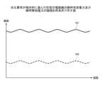
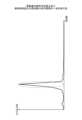
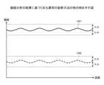
図4は、正常な状態の電動機Mの瞬時有効電力P及び瞬時無効電力Qの振幅を時系列で示す図である。具体的には、図4は、正常な状態の電動機Mの瞬時有効電力Pでのグラフ401、及び瞬時無効電力Qの時系列でのグラフ402を含む。図5は、劣化異常が相対的に進んだ状態の電動機Mの瞬時有効電力P及び瞬時無効電力Qの振幅を時系列で示す図である。具体的には、図5は、劣化異常が相対的に進んだ状態の電動機Mの瞬時有効電力Pの時系列でのグラフ501、及び瞬時無効電力Qの時系列でのグラフ502を含む。図6は、電動機Mの瞬時有効電力P及び瞬時無効電力Qの周波数分析の結果の一例を表す図である。図7は、分析部1403の構成の一例を示す図である。図8は、周波数分析の結果に基づく劣化異常の診断方法の一例を示す図である。Figure 4 is a diagram showing the amplitude of the instantaneous active power P and the instantaneous reactive power Q of the motor M in a normal state in a time series. Specifically, Figure 4 includes a
図4に示すように、電動機Mが劣化異常の進行していない正常な状態では、電動機Mの瞬時有効電力P及び瞬時無効電力Qの振幅は、略一定である。As shown in FIG. 4, when the motor M is in a normal state where no deterioration abnormality has progressed, the amplitudes of the instantaneous active power P and instantaneous reactive power Q of the motor M are approximately constant.
一方、図5に示すように、電動機Mが劣化異常のある程度進行した状態では、電動機Mの瞬時有効電力P及び瞬時無効電力Qの振幅に振動成分が生じる場合がある。電動機Mに劣化異常が生じると、瞬時有効電力P及び瞬時無効電力Qの波形に、基本周波数よりも大きい周波数成分(典型的には、高調波成分)が重畳する場合があるからである。On the other hand, as shown in FIG. 5, when the motor M is in a state where the deterioration abnormality has progressed to a certain extent, vibration components may occur in the amplitude of the instantaneous active power P and instantaneous reactive power Q of the motor M. This is because when the motor M is deteriorated abnormally, frequency components (typically harmonic components) greater than the fundamental frequency may be superimposed on the waveforms of the instantaneous active power P and instantaneous reactive power Q.
そこで、本例では、制御装置140は、瞬時有効電力P及び瞬時無効電力Qの周波数成分に着目して、電動機Mの劣化異常に関する診断を行う。Therefore, in this example, the
具体的には、分析部1403は、瞬時有効電力P及び瞬時無効電力Qの周波数成分に関する分析(以下、便宜的に「周波数分析」)を行う。Specifically, the
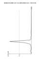
例えば、図6に示すように、分析部1403は、FFT(Fast Fourier Transform)等を用いて瞬時有効電力P及び瞬時無効電力Qのスペクトル分析を行ってよい。For example, as shown in FIG. 6, the
本例(図6)では、基本周波数よりも大きい所定の周波数成分(図中の破線の囲み部分)において、瞬時有効電力Pや瞬時無効電力Qの振幅の振動成分に相当する、非常な大きなスペクトル値が現れている。In this example (Figure 6), very large spectral values appear at certain frequency components (areas enclosed by dashed lines in the figure) that are greater than the fundamental frequency, which correspond to the vibration components of the amplitudes of the instantaneous active power P and the instantaneous reactive power Q.
また、例えば、瞬時有効電力P及び瞬時無効電力Qの振幅に生じる振動成分の周波数が予め分かっている場合、分析部1403は、その周波数を含む周波数帯に対応する狭帯域のバンドパスフィルタを含んでもよい。そして、分析部1403は、狭帯域のバンドパスフィルタを用いて、瞬時有効電力P及び瞬時無効電力Qから所定の周波数成分を取り出してもよい。For example, when the frequency of the vibration component occurring in the amplitude of the instantaneous active power P and the instantaneous reactive power Q is known in advance, the
所定の周波数成分は、例えば、高調波成分、即ち、基本周波数の整数倍の周波数成分である。また、所定の周波数成分は、複数であってもよい。The predetermined frequency component is, for example, a harmonic component, i.e., a frequency component that is an integer multiple of the fundamental frequency. Also, there may be multiple predetermined frequency components.
また、例えば、図7に示すように、瞬時有効電力P及び瞬時無効電力Qの振幅に生じる振動成分の周波数が電動機Mの回転速度(角速度ω)に依存して変化する場合、追跡フィルタTFを含んでもよい。そして、分析部1403は、追跡フィルタTFを用いて、瞬時有効電力P及び瞬時無効電力Qから電動機Mの回転周波数に関係する所定の周波数成分を取り出してもよい。For example, as shown in FIG. 7, if the frequency of the vibration components occurring in the amplitude of the instantaneous active power P and the instantaneous reactive power Q varies depending on the rotation speed (angular velocity ω) of the electric motor M, a tracking filter TF may be included. Then, the
具体的には、追跡フィルタTFは、回転座標変換部TF1及びローパスフィルタ部TF2によって、瞬時有効電力P及び瞬時無効電力Qから電動機Mの回転周波数成分を抽出することができる。電動機Mの角速度ωで回転する座標系上では、瞬時有効電力P及び瞬時無効電力Qが直流成分に相当するからである。そして、追跡フィルタTFは、固定座標変換部TF3によって、瞬時有効電力P及び瞬時無効電力Qにおける回転周波数に関係する所定の周波数成分を出力することができる。Specifically, the tracking filter TF can extract the rotational frequency components of the motor M from the instantaneous active power P and the instantaneous reactive power Q by using the rotating coordinate transformation section TF1 and the low-pass filter section TF2. This is because in a coordinate system rotating at the angular velocity ω of the motor M, the instantaneous active power P and the instantaneous reactive power Q correspond to DC components. The tracking filter TF can then output a predetermined frequency component related to the rotational frequency in the instantaneous active power P and the instantaneous reactive power Q by using the fixed coordinate transformation section TF3.
特徴量取得部1404は、分析部1403の周波数分析の結果から、瞬時有効電力P及び瞬時無効電力Qの周波数成分に着目した特徴量(以下、便宜的に「周波数特徴量」)を取得する。The
例えば、特徴量取得部1404は、周波数特徴量として、瞬時有効電力P及び瞬時無効電力Qの所定の周波数成分の大きさ(例えば、スペクトル値)を取得してよい。所定の周波数成分の大きさが相対的に大きくなるほど、瞬時有効電力P及び瞬時無効電力Qの振幅の振動成分がより顕著になり、劣化異常が相対的に進んでいると考えられるからである。For example, the
診断部1405は、周波数特徴量に基づき、電動機Mの劣化異常に関する診断を行う。The
例えば、図8に示すように、診断部1405は、周波数特徴量としての瞬時有効電力Pや瞬時無効電力Qの所定の周波数成分の大きさ(スペクトル値)が所定基準(閾値Sp_th)を超えた場合に、電動機Mの劣化異常の可能性があると診断する。For example, as shown in FIG. 8, when the magnitude (spectrum value) of a predetermined frequency component of the instantaneous active power P or the instantaneous reactive power Q as a frequency characteristic quantity exceeds a predetermined criterion (threshold value Sp_th), the
所定基準(閾値Sp_th)は、固定値であってもよいし、例えば、電動機Mの運転状態等に応じて可変される可変値であってもよい。また、所定基準(閾値Sp_th)は、瞬時有効電力Pの場合と瞬時無効電力Qの場合とで、同じであってもよいし、異なっていてもよい。The predetermined standard (threshold Sp_th) may be a fixed value or may be a variable value that is changed depending on, for example, the operating state of the electric motor M. Furthermore, the predetermined standard (threshold Sp_th) may be the same or different in the case of the instantaneous active power P and the case of the instantaneous reactive power Q.
また、例えば、所定の周波数成分が複数ある場合、複数の所定の周波数成分の大きさの合計が所定の閾値を超えた場合に、電動機Mの劣化異常の可能性があると診断してもよい。Also, for example, if there are multiple predetermined frequency components, and the sum of the magnitudes of the multiple predetermined frequency components exceeds a predetermined threshold, it may be diagnosed that there is a possibility of deterioration or abnormality in the motor M.
また、例えば、診断部1405は、所定の周波数成分の大きさに基づき、電動機Mの劣化異常の進行度合いを診断してもよい。具体的には、診断部1405は、所定の周波数成分の大きさが大きくなるほど、電動機Mの劣化異常の進行度合いが大きく(高く)なるように、電動機Mの劣化異常の進行度合いを診断する。電動機Mの劣化異常の進行度合いを決定するための基準は、固定されていてもよいし、例えば、電動機Mの運転状態等に応じて可変されてもよい。For example, the
このように、本例では、制御装置140は、瞬時有効電力P及び瞬時無効電力Qの周波数成分に基づき、電動機Mの劣化異常に関する診断を行う。In this way, in this example, the
これにより、制御装置140は、電動機Mが故障し、電動機Mを含む設備等の突発的な停止等が発生する前に、電動機Mの機械的故障に繋がる劣化異常の可能性をユーザに通知することができる。そのため、制御装置140は、電動機Mを含む設備のメンテナンスの頻度を抑制し、電動機Mの状態に合わせてメンテナンスを行うことができると共に、電動機Mを含む設備の突発的な停止やその復旧作業に伴う設備の長期停止等のリスクを低減することができる。As a result, the
また、例えば、瞬時有効電力P及び瞬時無効電力Qの大きさに着目することも考えられるものの、瞬間的な大きさの変化を捉えて、電動機Mの劣化異常の可能性があると誤った診断が行われる可能性がある。また、この場合、電動機Mの瞬時有効電力Pや瞬時無効電力Qの大きさに表れない電動機Mの劣化異常に関する診断を行うことができない可能性がある。In addition, for example, it is possible to focus on the magnitude of the instantaneous active power P and the instantaneous reactive power Q, but there is a possibility that an erroneous diagnosis will be made that there is a possibility of a deterioration abnormality in the motor M due to capturing an instantaneous change in magnitude. In this case, it may not be possible to diagnose deterioration abnormalities in the motor M that are not reflected in the magnitude of the instantaneous active power P and the instantaneous reactive power Q of the motor M.
これに対して、本例では、制御装置140は、瞬時有効電力P及び瞬時無効電力Qの周波数成分に着目することによって、電動機Mの劣化異常に関する診断をより適切に行うことができる。In contrast, in this example, the
また、例えば、電動機Mの劣化異常の診断のために専用のセンサ等を設置することも考えられるものの、電動機Mの劣化異常の診断機能の実現のためのコストの増加を避けられない。In addition, for example, it is possible to install a dedicated sensor or the like to diagnose deterioration abnormalities in the electric motor M, but this would inevitably increase costs in order to realize a diagnostic function for deterioration abnormalities in the electric motor M.
これに対して、本例では、制御装置140は、電動機Mの制御に必要なセンサ150やセンサ200の出力のみを利用し、電動機Mの劣化異常に関する診断を行うことができる。そのため、制御装置140は、コストの増加を抑制しつつ、電動機Mの劣化異常に関する診断を行うことができる。In contrast, in this example, the
尚、制御装置140は、瞬時有効電力P及び瞬時無効電力Qの何れか一方だけを用いて、周波数成分に基づく電動機Mの劣化異常に関する診断を行ってもよい。The
[劣化異常診断処理の一例]
次に、図9を参照して、制御装置140による電動機Mの劣化異常診断処理の一例について説明する。 [An example of deterioration abnormality diagnosis processing]
Next, an example of a deterioration/abnormality diagnosis process for the electric motor M performed by the
図9は、電動機Mの劣化異常診断処理の一例を概略的に示すフローチャートである。Figure 9 is a flowchart showing an example of a deterioration abnormality diagnosis process for the electric motor M.
本フローチャートは、所定のタイミングで実行される。所定のタイミングは、例えば、電力変換装置100の電源オンのタイミングである。これにより、制御装置140は、電力変換装置100の電源オンに合わせて、電動機Mの劣化異常に関する診断を行うができる。また、所定のタイミングは、例えば、電力変換装置100に設けられる入力部を通じてユーザからの診断要求が入力されるタイミングであってもよい。また、所定のタイミングは、例えば、通信装置170を通じて、管理装置300や端末装置400からユーザからの診断要求が入力されるタイミングであってもよい。以下、後述の図14のフローチャートについても同様であってよい。また、所定のタイミングは、例えば、電動機Mの稼働中(運転中)であってもよい。具体的には、所定のタイミングは、電動機制御部1401による電動機Mの制御のタイミング(制御周期)に同期されたタイミングであってもよい。This flowchart is executed at a predetermined timing. The predetermined timing is, for example, the timing of turning on the
図9に示すように、ステップS102にて、電力演算部1402は、最新の瞬時有効電力P及び瞬時無効電力Qを算出するための最新データを取得する。最新のデータは、例えば、最新のd軸電流Id、q軸電流Iq、d軸電圧指令Vd*、及びq軸電圧指令Vq*のデータである。As shown in FIG. 9, in step S102, the
制御装置140は、ステップS102の処理が完了すると、ステップS104に進む。When the
ステップS104にて、電力演算部1402は、ステップS102で取得したデータに基づき、瞬時有効電力P及び瞬時無効電力Qを算出する。In step S104, the
制御装置140は、ステップS104の処理が完了すると、ステップS106に進む。When the processing of step S104 is completed, the
ステップS106にて、分析部1403は、ステップS104で算出された瞬時有効電力P及び瞬時無効電力Qについて、周波数分析を行う。In step S106, the
制御装置140は、ステップS106の処理が完了すると、ステップS108に進む。When the
ステップS108にて、特徴量取得部1404は、ステップS106の周波数分析の結果に基づき、電動機Mの劣化異常に関する特徴量(周波数特徴量)を取得する。In step S108, the
制御装置140は、ステップS108の処理が完了すると、ステップS110に進む。When the
ステップS110にて、診断部1405は、ステップS108で取得された特徴量(周波数特徴量)に基づき、電動機Mの劣化異常に関する診断を行う。In step S110, the
診断部1405は、ステップS110の処理が完了すると、ステップS112に進む。When the processing of step S110 is completed, the
ステップS112にて、診断部1405は、電動機Mの劣化異常の可能性があるか否かを判定する。診断部1405は、電動機Mの劣化異常の可能性がある場合、ステップS114に進み、電動機Mの劣化異常の可能性がない場合、ステップS116に進む。In step S112, the
尚、診断部1405によって、電動機Mの劣化異常の進行度合いが診断される場合、ステップS112では、その進行度合いが所定基準を超えているか否かが判定されてよい。所定基準は、例えば、実験やコンピュータシミュレーション等を通じて、電動機Mのメンテナンスが施されるべきと考えられる、電動機Mの劣化異常の進行度合いの下限として予め規定される。この場合、後述のステップS114では、電動機Mの劣化異常の進行度合いが所定基準を超えている旨が通知されてよい。また、診断部1405によって、電動機Mの劣化異常の進行度合いが診断される場合、ステップS112、及び後述のステップS114,S116に代えて、診断結果としての電動機Mの劣化異常の進行度合いをユーザに通知する処理が行われてもよい。また、例えば、電力変換装置100の電源オン時に実行される場合等、ユーザからの診断要求に依らず、劣化異常診断処理が実施される場合、後述のステップS116の処理は省略されてもよい。When the
ステップS114にて、通知部1406は、表示装置160や通信装置170を通じて、電動機Mの劣化異常の可能性がある旨の診断結果をユーザに通知する。In step S114, the
尚、通知部1406は、併せて、電動機Mのメンテナンスをユーザに促す通知を行ってもよい。The
制御装置140は、ステップS114の処理が完了すると、今回のフローチャートの処理を終了する。When the processing of step S114 is completed, the
一方、ステップS116にて、通知部1406は、表示装置160や通信装置170を通じて、電動機Mが正常である旨の診断結果をユーザに通知する。On the other hand, in step S116, the
制御装置140は、ステップS116の処理が完了すると、今回のフローチャートの処理を終了する。When the
[電力変換装置の機能構成の他の例]
次に、図10を参照して、電力変換装置100の機能構成の他の例について説明する。以下、上述の一例(図2)と異なる部分を中心に説明を行う。 [Another example of the functional configuration of the power conversion device]
Next, another example of the functional configuration of the
図10は、本実施形態に係る電力変換装置100(制御装置140)の機能構成の他の例を示す機能ブロック図である。Figure 10 is a functional block diagram showing another example of the functional configuration of the power conversion device 100 (control device 140) according to this embodiment.
図10に示すように、制御装置140は、上述の一例の場合と同様、電動機制御部1401と、電力演算部1402と、分析部1403と、特徴量取得部1404と、診断部1405と、通知部1406とを含む。電動機制御部1401、電力演算部1402、分析部1403、特徴量取得部1404、診断部1405、及び通知部1406のそれぞれの機能の一部又は全部は、例えば、補助記憶装置にインストールされるプログラムがメモリ装置にロードされCPUで実行されることにより実現される。As shown in FIG. 10, the
分析部1403は、上述の一例の場合と同様、電動機Mの劣化異常の進行を表す、瞬時有効電力P及び瞬時無効電力Qの変化に関する分析を行う。具体的には、分析部1403は、上述の一例の場合と異なり、周波数分析部1403Aと、振幅分析部1403Bとを含む。As in the above example, the
周波数分析部1403Aは、上述の一例の分析部1403の場合と同様、瞬時有効電力P及び瞬時無効電力Qについての周波数分析を行う。The
尚、上述の一例の分析部1403は、周波数分析部1403A及び振幅分析部1403Bのうちの周波数分析部1403Aのみを含む形態に相当する。The above-mentioned example of the
振幅分析部1403Bは、後述の如く、瞬時有効電力P及び瞬時無効電力Qに生じる、基本波よりも波長が短い振動成分の振幅(以下、単に「振動成分の振幅」)に関する分析(以下、便宜的に「振幅分析」)を行う。詳細は、後述する(図11参照)。As described below, the
特徴量取得部1404は、上述の一例の場合と同様、分析部1403の分析結果に基づき、電動機Mの劣化異常に関する特徴量を取得する。具体的には、特徴量取得部1404は、上述の一例の場合と異なり、特徴量取得部1404A,1404Bを含む。As in the above example, the
特徴量取得部1404Aは、上述の一例の特徴量取得部1404の場合と同様、分析部1403(周波数分析部1403A)による周波数分析の結果に基づき、周波数特徴量を取得する。The
尚、上述の一例の分析部1403は、特徴量取得部1404A,1404Bのうちの特徴量取得部1404Aのみを含む形態に相当する。The
特徴量取得部1404Bは、振幅分析部1403Bによる振幅分析の結果に基づき、瞬時有効電力P及び瞬時無効電力Qの振動成分の振幅に着目した特徴量(以下、便宜的に「振幅特徴量」)を取得する。詳細は、後述する(図12、図13参照)。The
診断部1405は、上述の一例の場合と同様、特徴量取得部1404(特徴量取得部1404A)により取得される周波数特徴量に基づき、電動機Mの劣化異常に関する診断を行う。As in the above example, the
また、診断部1405は、上述の一例の場合と同様、特徴量取得部1404(特徴量取得部1404B)により取得される振幅特徴量に基づき、電動機Mの劣化異常に関する診断を行う。詳細は、後述する(図12、図13参照)。As in the above example, the
[電動機の劣化異常に関する診断方法の他の例]
次に、上述の図4、図5に加えて、図11~図13を参照して、電動機Mの劣化異常に関する診断方法の他の例について説明する。 [Another example of a diagnosis method for deterioration and abnormality of an electric motor]
Next, another example of the diagnosis method for determining whether or not the motor M is deteriorated will be described with reference to FIGS. 11 to 13 in addition to the above-mentioned FIGS.
図11は、電動機Mの瞬時有効電力P及び瞬時無効電力Qの振幅分析の結果の一例を表す図である。図12は、振幅分析の結果に基づく劣化異常の診断方法の一例を示す図である。図13は、振幅分析の結果に基づく劣化異常の診断方法の他の例を示す図である。Figure 11 shows an example of the results of an amplitude analysis of the instantaneous active power P and instantaneous reactive power Q of the motor M. Figure 12 shows an example of a method for diagnosing a deterioration abnormality based on the results of the amplitude analysis. Figure 13 shows another example of a method for diagnosing a deterioration abnormality based on the results of the amplitude analysis.
図4、図5に示すように、上述の如く、電動機Mが劣化異常のある程度進行した状態では、電動機Mの瞬時有効電力P及び瞬時無効電力Qの振幅に振動成分が生じる場合がある。そして、電動機Mの劣化異常が進行するにつれて、その振動成分はより顕著になる。As shown in Figures 4 and 5, as described above, when the motor M is in a state where the deterioration abnormality has progressed to a certain extent, vibration components may occur in the amplitude of the instantaneous active power P and instantaneous reactive power Q of the motor M. As the deterioration abnormality of the motor M progresses, the vibration components become more pronounced.
そこで、本例では、制御装置140は、電動機Mの瞬時有効電力P及び瞬時無効電力Qに生じる、基本波よりも波長が短い振動成分の振幅に着目して、電動機Mの劣化異常に関する診断を行う。Therefore, in this example, the
具体的には、振幅分析部1403Bは、上述の如く、瞬時有効電力P及び瞬時無効電力Qの振動分析を行う。Specifically, the
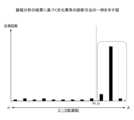
例えば、図11に示すように、振幅分析部1403Bは、波形計数法によって、瞬時有効電力Pや瞬時無効電力Qの振幅のピーク値を取得する。ピーク値は、対象となる振幅のピークと前回の振幅のピークとの間の差分に相当する。そして、振幅分析部1403Bは、取得したピーク値を所定範囲ごとに振り分けて、所定範囲ごとのピーク値の計測回数を取得してよい。この際、例えば、極大極小法、最大値最小値法、振幅法、レベルクロッシング法、レンジベア法、レインフロー法等の既知の方法が任意に適用されてよい。For example, as shown in FIG. 11, the
また、例えば、図5に示すように、振幅分析部1403Bは、瞬時有効電力Pや瞬時無効電力Qの振幅に生じる振動成分に相当する時系列の波形データを取得してもよい。Also, for example, as shown in FIG. 5, the
特徴量取得部1404Bは、上述の如く、振幅分析部1403Bの分析結果から、瞬時有効電力P及び瞬時無効電力Qの振動成分の振幅に着目した特徴量(振幅特徴量)を取得する。As described above, the
例えば、特徴量取得部1404Bは、振幅特徴量として、振幅分析部1403Bにより取得されたピーク値のうちの所定基準(閾値Pk_th)を超えるピーク値の測定回数、或いは、全体の測定回数に対する比率(以下、「測定率」)を取得する。瞬時有効電力Pや瞬時無効電力Qの振幅のピーク値は、振動成分の振幅に相当し、そのピーク値が大きくなるほど、電動機Mの劣化異常が相対的に進んでいると考えられるからである。For example, the
所定基準(閾値Pk_th)は、固定値であってもよいし、例えば、電動機Mの運転状態等に基づき可変される可変値であってもよい。また、所定基準(閾値Pk_th)は、瞬時有効電力Pの場合と瞬時無効電力Qの場合とで、同じであってもよいし、異なっていてもよい。The predetermined standard (threshold Pk_th) may be a fixed value or may be a variable value that is changed based on, for example, the operating state of the electric motor M. Furthermore, the predetermined standard (threshold Pk_th) may be the same or different in the case of the instantaneous active power P and the case of the instantaneous reactive power Q.
また、例えば、特徴量取得部1404Bは、振幅分析部1403Bにより取得された瞬時有効電力Pや瞬時無効電力Qの振幅の振動成分の時系列の波形データから、振幅特徴量として、振動成分の振幅値を取得してもよい。振動成分の振幅値が大きくなるほど、劣化異常の進行が相対的に進んでいると考えられるからである。For example, the
診断部1405は、上述の如く、振幅特徴量に基づき、電動機Mの劣化異常に関する診断を行う。As described above, the
例えば、図12に示すように、診断部1405は、振幅特徴量としての閾値Pk_thを超えるピーク値(図中の破線の囲み部分)の測定回数或いは測定率が所定基準(閾値N_th)を超えた場合に、電動機Mの劣化異常の可能性があると診断する。For example, as shown in FIG. 12, when the number of measurements or the measurement rate of a peak value (part enclosed by a dashed line in the figure) exceeding a threshold value Pk_th as an amplitude feature exceeds a predetermined standard (threshold value N_th), the
所定基準(閾値N_th)は、固定値であってもよいし、例えば、電動機Mの運転状態等に応じて可変される可変値であってもよい。また、所定基準(閾値N_th)は、瞬時有効電力Pの場合と瞬時無効電力Qの場合とで、同じであってもよいし、異なっていてもよい。The predetermined standard (threshold N_th) may be a fixed value or may be a variable value that is changed depending on, for example, the operating state of the electric motor M. Furthermore, the predetermined standard (threshold N_th) may be the same or different in the case of the instantaneous active power P and the case of the instantaneous reactive power Q.
また、例えば、診断部1405は、振幅特徴量としての閾値Pk_thを超えるピーク値の測定回数或いは測定率に基づき、電動機Mの劣化異常の進行度合いを診断してもよい。具体的には、診断部1405は、閾値Pk_thを超えるピーク値の測定回数或いは測定率が大きくなるほど、電動機Mの劣化異常の進行度合いが大きく(高く)なるように、電動機Mの劣化異常の進行度合いを診断する。電動機Mの劣化異常の進行度合いを決定するための基準は、固定されていてもよいし、例えば、電動機Mの運転状態等に応じて可変されてもよい。For example, the
また、例えば、図13に示すように、診断部1405は、振幅特徴量としての振動成分の振幅値が所定基準(閾値A_th)を超えた場合に、電動機Mの劣化異常の可能性があると診断する。Also, for example, as shown in FIG. 13, when the amplitude value of the vibration component as the amplitude feature exceeds a predetermined standard (threshold A_th), the
所定基準(閾値A_th)は、固定値であってもよいし、例えば、電動機Mの運転状態等に応じて可変される可変値であってもよい。また、所定基準(閾値A_th)は、瞬時有効電力Pの場合と瞬時無効電力Qの場合とで、同じであってもよいし、異なっていてもよい。The predetermined standard (threshold A_th) may be a fixed value or may be a variable value that is changed depending on, for example, the operating state of the electric motor M. Furthermore, the predetermined standard (threshold A_th) may be the same or different in the case of the instantaneous active power P and the case of the instantaneous reactive power Q.
また、例えば、診断部1405は、振幅特徴量としての振動成分の振幅値に基づき、電動機Mの劣化異常の進行度合いを診断してもよい。具体的には、診断部1405は、瞬時有効電力Pや瞬時無効電力Qの振幅の振動成分の振幅値が大きくなるほど、電動機Mの劣化異常の進行度合いが大きく(高く)なるように、電動機Mの劣化異常の進行度合いを診断する。電動機Mの劣化異常の進行度合いを決定するための基準は、上述の場合と同様、固定されていてもよいし、例えば、電動機Mの運転状態等に応じて可変されてもよい。For example, the
このように、本例では、制御装置140は、瞬時有効電力P及び瞬時無効電力Qの振動成分、具体的には、基本波よりも波長が短い振動成分の振幅に基づき、電動機Mの劣化異常に関する診断を行う。In this way, in this example, the
これにより、制御装置140は、上述の一例の場合と同様、電動機Mを含む設備のメンテナンスの頻度を抑制し、電動機Mの状態に合わせてメンテナンスを行うことができると共に、電動機Mを含む設備の突発的な停止やその復旧作業に伴う設備の長期停止等のリスクを低減することができる。As a result, as in the example described above, the
また、制御装置140は、瞬時有効電力P及び瞬時無効電力Qにおける基本波より波長が短い振動成分の振幅に着目することによって、上述の一例の場合と同様、電動機Mの劣化異常に関する診断をより適切に行うことができる。In addition, by focusing on the amplitude of vibration components in the instantaneous active power P and the instantaneous reactive power Q that have a shorter wavelength than the fundamental wave, the
また、本例では、制御装置140は、瞬時有効電力P及び瞬時無効電力Qの周波数成分に加えて、基本波よりも波長が短い振動成分の振幅に基づき、電動機Mの劣化異常に関する診断を行う。In addition, in this example, the
これにより、制御装置140は、二つの観点から電動機Mの劣化異常に関する診断を行うことができる。そのため、制御装置140は、例えば、一方の観点で電動機Mの故障の兆候(劣化異常の可能性)を捉えることができない場合でも、他方の観点で電動機Mの故障の兆候を捉えることができる場合がある。よって、制御装置140は、電動機Mの劣化異常の可能性をより早期に診断することができる。This allows the
尚、制御装置140は、瞬時有効電力P及び瞬時無効電力Qの何れか一方だけを用いて、基本波よりも波長が短い振動成分の振幅に基づく電動機Mの劣化異常に関する診断を行ってもよい。また、制御装置140は、瞬時有効電力Pや瞬時無効電力Qの周波数成分に基づく電動機Mの劣化異常に関する診断、及び瞬時有効電力Pや瞬時無効電力Qの振動成分の振幅に基づく電動機Mの劣化異常に関する診断のうちの後者の診断のみを実施してもよい。The
[劣化異常診断処理の他の例]
次に、図14を参照して、制御装置140による電動機Mの劣化異常診断処理の他の例について説明する。 [Another example of deterioration abnormality diagnosis processing]
Next, another example of the deterioration/abnormality diagnosis process for the electric motor M performed by the
図14は、電動機Mの劣化異常診断処理の他の例を概略的に示すフローチャートである。Figure 14 is a flowchart that shows another example of the deterioration abnormality diagnosis process for the electric motor M.
図14に示すように、ステップS202,S204は、図9のステップS102,S104の処理と同じであるため、説明を省略する。As shown in FIG. 14, steps S202 and S204 are the same as steps S102 and S104 in FIG. 9, so their explanation is omitted.
制御装置140は、ステップS204の処理が完了すると、ステップS206に進む。When the
ステップS206にて、分析部1403(周波数分析部1403A及び振幅分析部1403B)は、ステップS204で算出された瞬時有効電力P及び瞬時無効電力Qについて、周波数分析及び振幅分析を行う。In step S206, the analysis unit 1403 (
制御装置140は、ステップS206の処理が完了すると、ステップS208に進む。When the
ステップS208にて、特徴量取得部1404(特徴量取得部1404A及び特徴量取得部1404B)は、ステップS206の周波数分析及び振幅分析の結果に基づき、電動機Mの劣化異常に関する特徴量(周波数特徴量及び振幅特徴量)を取得する。In step S208, the feature acquisition unit 1404 (
制御装置140は、ステップS208の処理が完了すると、ステップS210に進む。When the
ステップS210にて、診断部1405は、ステップS208で取得された特徴量(周波数特徴量及び振幅特徴量)に基づき、電動機Mの劣化異常に関する診断を行う。In step S210, the
具体的には、診断部1405は、周波数特徴量に基づき、電動機Mの劣化異常に関する診断を行うと共に、振幅特徴量に基づき、電動機Mの劣化異常に関する診断を行う。Specifically, the
また、診断部1405は、周波数特徴量に基づく個別の診断結果、及び振幅特徴量に基づく個別の診断結果に基づき、総合的な診断を行ってもよい。The
制御装置140は、ステップS210の処理が完了すると、ステップS212に進む。When the
ステップS212にて、診断部1405は、電動機Mの劣化異常の可能性があるか否かを判定する。例えば、診断部1405は、周波数特徴量に基づく個別の診断結果、及び振幅特徴量に基づく個別の診断結果の何れか一方が、電動機Mの劣化異常の可能性があることを表している場合、電動機Mの劣化異常の可能性があると判定する。また、診断部1405は、総合的な診断結果として、電動機Mの劣化異常の可能性があるか否かを判定してもよい。診断部1405は、電動機Mの劣化異常の可能性がある場合、ステップS214に進み、電動機Mの劣化異常の可能性がない場合、ステップS216に進む。In step S212, the
尚、診断部1405によって、電動機Mの劣化異常の進行度合いが診断される場合、ステップS212では、その進行度合いが所定基準を超えているか否かが判定されてよい。所定基準は、上述の一例(図9)の場合と同様であってよい。例えば、周波数特徴量に基づく個別の診断結果、及び振幅特徴量に基づく個別の診断結果の何れか一方で、電動機Mの劣化異常の進行度合いが所定基準を超えている場合、電動機Mの劣化異常の進行度合いが所定基準を超えていると判定される。また、総合的な診断結果として、電動機Mの劣化異常の進行度合いが所定基準を超えているか否かが判定されてもよい。この場合、ステップS214では、図9のステップS114の場合と同様、電動機Mの劣化異常の進行度合いが所定基準を超えている旨が通知されてよい。また、診断部1405によって、電動機Mの劣化異常の進行度合いが診断される場合、ステップS212~S216に代えて、診断結果としての電動機Mの劣化異常の進行度合いをユーザに通知する処理が行われてもよい。また、例えば、電力変換装置100の電源オン時に実行される場合等、ユーザからの診断要求に依らず、劣化異常診断処理が実施される場合、ステップS216の処理は省略されてもよい。In addition, when the degree of progression of the deterioration abnormality of the motor M is diagnosed by the
ステップS214,S216は、図9のステップS114,S116の処理と同じであるため、説明を省略する。Steps S214 and S216 are the same as steps S114 and S116 in FIG. 9, so the explanation is omitted.
制御装置140は、ステップS214,S216の処理が完了すると、今回のフローチャートの処理を終了する。When the
尚、瞬時有効電力Pや瞬時無効電力Qの周波数成分に基づく電動機Mの劣化異常診断処理、及び瞬時有効電力Pや瞬時無効電力Qの振動成分の振幅に基づく電動機Mの劣化異常診断処理は、別個の独立した処理として実施されてもよい。The deterioration abnormality diagnosis process for the electric motor M based on the frequency components of the instantaneous active power P and the instantaneous reactive power Q, and the deterioration abnormality diagnosis process for the electric motor M based on the amplitude of the vibration components of the instantaneous active power P and the instantaneous reactive power Q may be performed as separate independent processes.
[作用]
次に、本実施形態に係る劣化異常診断システム1の作用について説明する。 [Action]
Next, the operation of the deterioration and
本実施形態では、電力変換装置100は、インバータ回路130と、センサ150と、電力演算部1402と、診断部1405と、を備える。具体的には、インバータ回路130と、外部から入力される電力を用いて電動機Mを駆動する。また、センサ150は、電動機Mの相電流を検出する。また、電力演算部1402は、センサ150の出力に基づき、電動機Mの有効電力及び無効電力の少なくとも一方を演算する。そして、診断部1405は、電動機Mの有効電力及び無効電力の少なくとも一方の周波数成分に基づき、電動機Mの劣化異常に関する診断を行う。In this embodiment, the
これにより、電力変換装置100は、例えば、電動機Mの有効電力や無効電力の大きさに着目して電動機Mの劣化異常に関する診断を行う場合等に比して、電動機Mの劣化異常に関する診断をより適切に行うことができる。As a result, the
また、本実施形態では、診断部1405は、電動機Mの有効電力及び無効電力の少なくとも一方の所定の周波数成分の変化に基づき、電動機Mの劣化異常に関する診断を行ってもよい。In addition, in this embodiment, the
これにより、電力変換装置100は、例えば、電動機Mの有効電力や無効電力の所定の周波数成分が相対的に大きくなる変化を捉えて、電動機Mの劣化異常の進行状態を診断することができる。As a result, the
また、本実施形態では、電力変換装置100は、追跡フィルタTFを備えてもよい。具体的には、追跡フィルタTFは、電動機Mの回転速度に応じて変化する、電動機Mの有効電力及び無効電力の少なくとも一方の所定の周波数成分を出力してもよい。そして、診断部1405は、追跡フィルタTFの出力に基づき、電動機Mの劣化異常に関する診断を行ってもよい。In addition, in this embodiment, the
これにより、電力変換装置100は、電動機Mの劣化異常の進行状態を表す、電動機Mの有効電力や無効電力の所定の周波数成分が電動機Mの回転速度に依存して変化する場合であっても、電動機Mの劣化異常に関する診断を適切に行うことができる。As a result, the
また、本実施形態では、電力変換装置100は、特徴量取得部1404を備えてもよい。具体的には、特徴量取得部1404は、電動機Mの有効電力及び無効電力の少なくとも一方の所定の周波数成分に関する特徴量(周波数特徴量)を取得してよい。そして、診断部1405は、周波数特徴量が第1の所定基準(例えば、閾値Sp_th)を超えた場合に、電動機Mの劣化異常の可能性がある旨の診断を行ってもよい。In addition, in this embodiment, the
これにより、電力変換装置100は、第1の所定基準を適宜設定することで、具体的に、電動機Mの劣化異常の可能性の有無を診断することができる。As a result, the
また、本実施形態では、第1の所定基準は、電動機Mの状態に応じて可変されてもよい。In addition, in this embodiment, the first predetermined standard may be variable depending on the state of the electric motor M.
これにより、電力変換装置100は、電動機Mの状態に合わせて、電動機Mの劣化異常に関する診断を適切に行うことができる。This allows the
また、本実施形態では、周波数特徴量は、電動機Mの有効電力及び無効電力の少なくとも一方の所定の周波数成分の大きさ、或いは、電動機Mの有効電力及び無効電力の少なくとも一方の複数の所定の周波数成分の大きさの合計であってもよい。In addition, in this embodiment, the frequency characteristic may be the magnitude of a predetermined frequency component of at least one of the active power and reactive power of the electric motor M, or the sum of the magnitudes of multiple predetermined frequency components of at least one of the active power and reactive power of the electric motor M.
これにより、電力変換装置100は、具体的に、電動機Mの有効電力や無効電力の所定の周波数成分が相対的に大きくなる変化を捉えて、電動機Mの劣化異常の可能性の有無を診断することができる。As a result, the
また、本実施形態では、診断部1405は、電動機Mの有効電力及び無効電力の少なくとも一方の周波数成分、及び振動成分の振幅に基づき、電動機Mの劣化異常に関する診断を行ってもよい。In addition, in this embodiment, the
これにより、電力変換装置100は、複数の観点から電動機Mの劣化異常に関する診断を行うことができる。そのため、電力変換装置100は、電動機Mの故障の兆候(劣化異常の可能性)をより早期に診断することができる。This allows the
また、本実施形態では、診断部1405は、電動機Mの有効電力及び無効電力の少なくとも一方の振動成分の振幅が第2の所定基準(例えば、閾値A_th)を超えた場合に、電動機Mの劣化異常の可能性がある旨の診断を行ってもよい。In addition, in this embodiment, the
これにより、電力変換装置100は、第2の所定基準を適宜設定することで、具体的に、電動機Mの有効電力や無効電力の振動成分の振幅が相対的に大きくなる変化を捉えて、電動機Mの劣化異常の可能性の有無を診断することができる。As a result, by appropriately setting the second predetermined standard, the
また、本実施形態では、電力変換装置100は、通知部1406を備えてもよい。具体的には、通知部1406は、診断部1405の診断結果をユーザに通知してもよい。In addition, in this embodiment, the
これにより、電力変換装置100は、電動機Mの劣化異常に関する状況をユーザに認識させることができる。This allows the
また、本実施形態では、制御装置140における電動機Mの劣化異常に関する診断機能が管理装置300や端末装置400に移管されてもよい。具体的には、管理装置300や端末装置400は、電力変換装置100のセンサ150やこれと同様のセンサ等の出力を取得可能に構成され、電力演算部1402及び診断部1405等と同様の構成を備えてもよい。In addition, in this embodiment, the diagnostic function for deterioration abnormalities of the electric motor M in the
これにより、管理装置300や端末装置400は、上述の電力変換装置100等と同様、電動機Mの劣化異常に関する診断をより適切に行うことができる。This allows the
以上、実施形態について詳述したが、本開示はかかる特定の実施形態に限定されるものではなく、特許請求の範囲に記載された要旨の範囲内において、種々の変形・変更が可能である。Although the embodiments have been described in detail above, the present disclosure is not limited to such specific embodiments, and various modifications and variations are possible within the scope of the gist of the invention as described in the claims.
1 劣化異常診断システム
100 電力変換装置
110 整流回路
120 平滑回路
130 インバータ回路(駆動部)
140 制御装置(診断装置)
150 センサ(電流検出部)
160 表示装置
170 通信装置
200 センサ
300 管理装置(診断装置)
310 表示部
400 端末装置(診断装置)
410 表示部
1401 電動機制御部
1402 電力演算部(演算部)
1403 分析部
1403A 周波数分析部
1403B 振幅分析部
1404,1404A,1404B 特徴量取得部(取得部)
1405 診断部
1406 通知部
BK 遮断器
M 電動機(交流電動機)
NL 負ライン
PL 正ライン
PS 商用電源(電源) REFERENCE SIGNS
140 Control device (diagnosis device)
150 Sensor (current detection unit)
160
310
410
1403
1405
NL Negative line PL Positive line PS Commercial power supply (power supply)
Claims (10)
Translated fromJapanese前記交流電動機の相電流を検出する電流検出部と、
前記電流検出部の出力に基づき、前記交流電動機の有効電力及び無効電力の少なくとも一方を演算する演算部と、
前記有効電力及び前記無効電力の前記少なくとも一方の周波数成分に基づき、前記交流電動機の劣化異常に関する診断を行う診断部と、を備え、
前記診断部は、前記有効電力及び前記無効電力の前記少なくとも一方について、周波数分析により得られる周波数成分、及び波形計数法により得られる振動の振幅に基づき、前記診断を行う、
電力変換装置。 A drive unit that drives an AC motor using power input from an external source;
A current detection unit that detects a phase current of the AC motor;
a calculation unit that calculates at least one of an active power and a reactive power of the AC motor based on an output of the current detection unit;
a diagnosis unit that performs a diagnosis regarding deterioration or abnormality of the AC motor based on the frequency component of at least one of the active power and the reactive power,
The diagnosing unit performs the diagnosis on at least one of the active power and the reactive power based on a frequency component obtained by a frequency analysis and an amplitude of vibration obtained by a waveform counting method.
Power conversion equipment.
請求項1に記載の電力変換装置。 The diagnosing unit performs the diagnosis based on a change in a predetermined frequency component of the at least one of the active power and the reactive power.
The power conversion device according to claim 1 .
前記診断部は、前記追跡フィルタの出力に基づき、前記診断を行う、
請求項2に記載の電力変換装置。 a tracking filter that outputs the predetermined frequency component of the at least one of the active power and the reactive power, the tracking filter changing according to a rotation speed of the AC motor;
The diagnosis unit performs the diagnosis based on an output of the tracking filter.
The power conversion device according to claim 2 .
前記診断部は、前記特徴量が第1の所定基準を超えた場合に、前記交流電動機の劣化異常の可能性がある旨の前記診断を行う、
請求項2又は3に記載の電力変換装置。 an acquisition unit that acquires a feature amount related to the predetermined frequency component of the at least one of the active power and the reactive power,
the diagnosing unit performs the diagnosis that there is a possibility of deterioration or abnormality in the AC motor when the feature amount exceeds a first predetermined criterion.
The power conversion device according to claim 2 or 3.
請求項4に記載の電力変換装置。 The first predetermined criterion is varied depending on a state of the AC motor.
The power conversion device according to claim 4.
請求項4又は5に記載の電力変換装置。 The feature amount is a magnitude of the predetermined frequency component of the at least one of the active power and the reactive power, or a sum of magnitudes of a plurality of the predetermined frequency components of the at least one of the active power and the reactive power.
The power conversion device according to claim 4 or 5.
請求項1乃至6の何れか一項に記載の電力変換装置。 the diagnosing unit performs the diagnosis that there is a possibility of deterioration or abnormality in the AC motor when an amplitude of the vibration of at least one of the active power and the reactive power exceeds a second predetermined standard.
The power conversion device according toany one of claims 1 to 6 .
請求項1乃至7の何れか一項に記載の電力変換装置。 a notification unit that notifies a user of a diagnosis result of the diagnosis unit;
A power conversion device according to any one of claims 1 to7 .
前記有効電力及び前記無効電力の前記少なくとも一方の周波数成分に基づき、前記交流電動機の劣化異常に関する診断を行う診断部と、を備え、
前記診断部は、前記有効電力及び前記無効電力の前記少なくとも一方について、周波数分析により得られる周波数成分、及び波形計数法により得られる振動の振幅に基づき、前記診断を行う、
診断装置。 a calculation unit that obtains an output of a current detection unit that detects a phase current of an AC motor and calculates at least one of an active power and a reactive power of the AC motor;
a diagnosis unit that performs a diagnosis regarding deterioration or abnormality of the AC motor based on the frequency component of at least one of the active power and the reactive power,
The diagnosing unit performs the diagnosis on at least one of the active power and the reactive power based on a frequency component obtained by a frequency analysis and an amplitude of vibration obtained by a waveform counting method.
Diagnostic equipment.
前記診断装置が、前記有効電力及び前記無効電力の前記少なくとも一方の周波数成分に基づき、前記交流電動機の劣化異常に関する診断を行う診断ステップと、を含み、
前記診断ステップでは、前記有効電力及び前記無効電力の前記少なくとも一方について、周波数分析により得られる周波数成分、及び波形計数法により得られる振動の振幅に基づき、前記診断を行う、
診断方法。 a calculation step in which a diagnostic device acquires an output of a current detection unit that detects a phase current of an AC motor, and acquires at least one of an active power and a reactive power of the AC motor based on the output of the current detection unit;
a diagnosis stepof diagnosing deterioration or abnormality of the AC motor based on the frequency component of at least one of the active power and the reactive power by the diagnosis device,
In the diagnosis step, the diagnosis is performed on at least one of the active power and the reactive power based on a frequency component obtained by a frequency analysis and an amplitude of vibration obtained by a waveform counting method.
Diagnostic methods.
Priority Applications (3)
| Application Number | Priority Date | Filing Date | Title |
|---|---|---|---|
| JP2021097085AJP7669816B2 (en) | 2021-06-10 | 2021-06-10 | Power conversion device, diagnostic device, and diagnostic method |
| CN202210574990.4ACN115473473A (en) | 2021-06-10 | 2022-05-24 | Power conversion device, diagnostic device, and diagnostic method |
| DE102022113190.4ADE102022113190B4 (en) | 2021-06-10 | 2022-05-25 | POWER CONVERTER DEVICE, DIAGNOSTIC DEVICE AND DIAGNOSTIC METHOD |
Applications Claiming Priority (1)
| Application Number | Priority Date | Filing Date | Title |
|---|---|---|---|
| JP2021097085AJP7669816B2 (en) | 2021-06-10 | 2021-06-10 | Power conversion device, diagnostic device, and diagnostic method |
Publications (2)
| Publication Number | Publication Date |
|---|---|
| JP2022188847A JP2022188847A (en) | 2022-12-22 |
| JP7669816B2true JP7669816B2 (en) | 2025-04-30 |
Family
ID=84192573
Family Applications (1)
| Application Number | Title | Priority Date | Filing Date |
|---|---|---|---|
| JP2021097085AActiveJP7669816B2 (en) | 2021-06-10 | 2021-06-10 | Power conversion device, diagnostic device, and diagnostic method |
Country Status (3)
| Country | Link |
|---|---|
| JP (1) | JP7669816B2 (en) |
| CN (1) | CN115473473A (en) |
| DE (1) | DE102022113190B4 (en) |
Citations (2)
| Publication number | Priority date | Publication date | Assignee | Title |
|---|---|---|---|---|
| JP2013505430A (en) | 2009-09-18 | 2013-02-14 | シュレーダー・エレクトロニクス・リミテッド | Tracking filter device for wheel monitoring system |
| JP2020153965A (en) | 2019-03-15 | 2020-09-24 | オムロン株式会社 | Abnormality diagnosis device and abnormality diagnosis method |
Family Cites Families (7)
| Publication number | Priority date | Publication date | Assignee | Title |
|---|---|---|---|---|
| JP3525736B2 (en)* | 1998-04-28 | 2004-05-10 | 日産自動車株式会社 | Diagnostic device for machine driven by motor |
| US6822839B2 (en) | 2002-12-05 | 2004-11-23 | Eaton Corporation | Method and apparatus of detecting internal motor faults in an induction machine |
| CA2934860C (en)* | 2011-02-28 | 2018-07-31 | Emerson Electric Co. | Residential solutions hvac monitoring and diagnosis |
| KR101699034B1 (en)* | 2016-06-16 | 2017-01-23 | (주)그린정보시스템 | Apparatus for intelligent automatic control and method for controlling the same |
| CN106646223B (en)* | 2016-09-22 | 2019-02-01 | 华北电力大学 | A kind of three-phase cage asynchronous motor rotor broken splits the diagnostic method of conducting bar number |
| EP3681035A4 (en) | 2017-09-05 | 2021-04-14 | Hitachi, Ltd. | AC ELECTRIC MOTOR MONITORING DEVICE AND MONITORING METHOD AND ELECTRIC MOTOR CONTROL SYSTEM MONITORING DEVICE AND MONITORING METHOD |
| JP6777251B1 (en) | 2019-12-03 | 2020-10-28 | 株式会社安川電機 | Power conversion device, diagnostic device and diagnostic method |
- 2021
- 2021-06-10JPJP2021097085Apatent/JP7669816B2/enactiveActive
- 2022
- 2022-05-24CNCN202210574990.4Apatent/CN115473473A/enactivePending
- 2022-05-25DEDE102022113190.4Apatent/DE102022113190B4/enactiveActive
Patent Citations (2)
| Publication number | Priority date | Publication date | Assignee | Title |
|---|---|---|---|---|
| JP2013505430A (en) | 2009-09-18 | 2013-02-14 | シュレーダー・エレクトロニクス・リミテッド | Tracking filter device for wheel monitoring system |
| JP2020153965A (en) | 2019-03-15 | 2020-09-24 | オムロン株式会社 | Abnormality diagnosis device and abnormality diagnosis method |
Also Published As
| Publication number | Publication date |
|---|---|
| DE102022113190B4 (en) | 2023-11-23 |
| JP2022188847A (en) | 2022-12-22 |
| DE102022113190A1 (en) | 2022-12-15 |
| CN115473473A (en) | 2022-12-13 |
Similar Documents
| Publication | Publication Date | Title |
|---|---|---|
| RU2562968C1 (en) | Method and system for detecting faulty rectifier in ac-to-dc converter | |
| EP2905630B1 (en) | Fault detection in brushless exciters | |
| EP2682769B1 (en) | Apparatus for diagnosing DC link capacitor of inverter | |
| WO2013187207A1 (en) | Apparatus for detecting deterioration of power module | |
| US20200341063A1 (en) | Systems and methods for analyzing operation of motors | |
| WO2020026755A1 (en) | Power conversion device and ground fault location diagnosis method | |
| CN110546881B (en) | Segmented estimation of negative sequence voltage for fault detection in electrical systems | |
| CN111727557B (en) | Motor driving device and refrigeration loop application equipment | |
| CN110095660B (en) | Frequency converter output open-phase detection method | |
| JP7669816B2 (en) | Power conversion device, diagnostic device, and diagnostic method | |
| US20250007443A1 (en) | State determination device, motor drive system, freezing system, fan system, and state determination method | |
| JP7596780B2 (en) | Power conversion device, power transmission device, information processing device, and degradation/abnormality diagnosis method | |
| US11952997B2 (en) | Operating method of a compressor of a refrigerating machine and compressor of a refrigerating machine | |
| JP2018128270A (en) | Insulation monitoring device and insulation monitoring system | |
| KR20200090005A (en) | Apparatus for controlling compressor and method for controlling compressor | |
| US20230143105A1 (en) | Motor drive device that calculates insulation resistance value of motor | |
| JP2023130934A (en) | Diagnostic device, diagnostic system, and diagnostic method | |
| JP2024082587A (en) | Diagnostic systems, electric drive units | |
| JP2023177596A (en) | Diagnosis device and method for diagnosis | |
| WO2021262833A1 (en) | Systems and methods for analyzing operation of motors | |
| JP2024083207A (en) | Diagnosis device, control device, power conversion device, diagnosis method, and program | |
| KR101193957B1 (en) | Method and System for Calculating Torque of Induction Motors Using Current Spectrum and Method and System For Fault Diagnosis of Induction Motors Using the same | |
| JP2023023861A (en) | Diagnostic device, power conversion device, diagnostic method, and program | |
| JP2016019439A (en) | Fault detection device for semiconductor power converter | |
| Zdiri et al. | Open-circuit fault diagnosis in four-switch three-phase inverter fed induction motor drive |
Legal Events
| Date | Code | Title | Description |
|---|---|---|---|
| A621 | Written request for application examination | Free format text:JAPANESE INTERMEDIATE CODE: A621 Effective date:20240514 | |
| A131 | Notification of reasons for refusal | Free format text:JAPANESE INTERMEDIATE CODE: A131 Effective date:20250121 | |
| A977 | Report on retrieval | Free format text:JAPANESE INTERMEDIATE CODE: A971007 Effective date:20250122 | |
| A521 | Request for written amendment filed | Free format text:JAPANESE INTERMEDIATE CODE: A523 Effective date:20250304 | |
| TRDD | Decision of grant or rejection written | ||
| A01 | Written decision to grant a patent or to grant a registration (utility model) | Free format text:JAPANESE INTERMEDIATE CODE: A01 Effective date:20250318 | |
| A61 | First payment of annual fees (during grant procedure) | Free format text:JAPANESE INTERMEDIATE CODE: A61 Effective date:20250331 | |
| R150 | Certificate of patent or registration of utility model | Ref document number:7669816 Country of ref document:JP Free format text:JAPANESE INTERMEDIATE CODE: R150 |