JP7669504B2 - Aircraft Propulsion Unit - Google Patents
Aircraft Propulsion UnitDownload PDFInfo
- Publication number
- JP7669504B2 JP7669504B2JP2023547872AJP2023547872AJP7669504B2JP 7669504 B2JP7669504 B2JP 7669504B2JP 2023547872 AJP2023547872 AJP 2023547872AJP 2023547872 AJP2023547872 AJP 2023547872AJP 7669504 B2JP7669504 B2JP 7669504B2
- Authority
- JP
- Japan
- Prior art keywords
- inverter module
- coolant
- inverter
- aircraft
- propulsion unit
- Prior art date
- Legal status (The legal status is an assumption and is not a legal conclusion. Google has not performed a legal analysis and makes no representation as to the accuracy of the status listed.)
- Active
Links
- 239000002826coolantSubstances0.000claimsdescription83
- 238000001816coolingMethods0.000claimsdescription47
- 230000007246mechanismEffects0.000claimsdescription30
- 238000000034methodMethods0.000claimsdescription14
- 238000007664blowingMethods0.000claims1
- 230000006870functionEffects0.000description25
- 239000003990capacitorSubstances0.000description14
- 239000012530fluidSubstances0.000description14
- 230000000712assemblyEffects0.000description8
- 238000000429assemblyMethods0.000description8
- 238000004806packaging method and processMethods0.000description5
- 238000004804windingMethods0.000description5
- 239000003570airSubstances0.000description4
- 230000020169heat generationEffects0.000description4
- 239000000463materialSubstances0.000description4
- 230000008569processEffects0.000description4
- 238000012545processingMethods0.000description4
- 239000000758substrateSubstances0.000description4
- 229910052782aluminiumInorganic materials0.000description3
- XAGFODPZIPBFFR-UHFFFAOYSA-NaluminiumChemical compound[Al]XAGFODPZIPBFFR-UHFFFAOYSA-N0.000description3
- 239000004020conductorSubstances0.000description3
- 230000009977dual effectEffects0.000description3
- 238000010292electrical insulationMethods0.000description3
- 239000007788liquidSubstances0.000description3
- 238000012546transferMethods0.000description3
- RYGMFSIKBFXOCR-UHFFFAOYSA-NCopperChemical compound[Cu]RYGMFSIKBFXOCR-UHFFFAOYSA-N0.000description2
- LYCAIKOWRPUZTN-UHFFFAOYSA-NEthylene glycolChemical compoundOCCOLYCAIKOWRPUZTN-UHFFFAOYSA-N0.000description2
- XEEYBQQBJWHFJM-UHFFFAOYSA-NIronChemical compound[Fe]XEEYBQQBJWHFJM-UHFFFAOYSA-N0.000description2
- 229910000831SteelInorganic materials0.000description2
- 239000012080ambient airSubstances0.000description2
- 239000000919ceramicSubstances0.000description2
- 229910052802copperInorganic materials0.000description2
- 239000010949copperSubstances0.000description2
- 238000010586diagramMethods0.000description2
- 239000000446fuelSubstances0.000description2
- 238000007726management methodMethods0.000description2
- 229910052751metalInorganic materials0.000description2
- 239000002184metalSubstances0.000description2
- 239000000203mixtureSubstances0.000description2
- 230000001105regulatory effectEffects0.000description2
- IHQKEDIOMGYHEB-UHFFFAOYSA-Msodium dimethylarsinateChemical class[Na+].C[As](C)([O-])=OIHQKEDIOMGYHEB-UHFFFAOYSA-M0.000description2
- 239000010959steelSubstances0.000description2
- 239000004593EpoxySubstances0.000description1
- CWYNVVGOOAEACU-UHFFFAOYSA-NFe2+Chemical compound[Fe+2]CWYNVVGOOAEACU-UHFFFAOYSA-N0.000description1
- 230000005355Hall effectEffects0.000description1
- HBBGRARXTFLTSG-UHFFFAOYSA-NLithium ionChemical compound[Li+]HBBGRARXTFLTSG-UHFFFAOYSA-N0.000description1
- 238000009825accumulationMethods0.000description1
- -1batteriesSubstances0.000description1
- 230000008901benefitEffects0.000description1
- 230000000903blocking effectEffects0.000description1
- 239000011449brickSubstances0.000description1
- OJIJEKBXJYRIBZ-UHFFFAOYSA-Ncadmium nickelChemical compound[Ni].[Cd]OJIJEKBXJYRIBZ-UHFFFAOYSA-N0.000description1
- 239000003985ceramic capacitorSubstances0.000description1
- 239000011248coating agentSubstances0.000description1
- 238000000576coating methodMethods0.000description1
- 239000002131composite materialSubstances0.000description1
- 230000001276controlling effectEffects0.000description1
- 230000008878couplingEffects0.000description1
- 238000010168coupling processMethods0.000description1
- 238000005859coupling reactionMethods0.000description1
- 238000006073displacement reactionMethods0.000description1
- 238000004146energy storageMethods0.000description1
- 238000005516engineering processMethods0.000description1
- 239000002828fuel tankSubstances0.000description1
- 230000005484gravityEffects0.000description1
- WGCNASOHLSPBMP-UHFFFAOYSA-NhydroxyacetaldehydeNatural productsOCC=OWGCNASOHLSPBMP-UHFFFAOYSA-N0.000description1
- 238000009413insulationMethods0.000description1
- 230000010354integrationEffects0.000description1
- 229910052742ironInorganic materials0.000description1
- 229910001416lithium ionInorganic materials0.000description1
- 239000012528membraneSubstances0.000description1
- 238000012986modificationMethods0.000description1
- 230000004048modificationEffects0.000description1
- 239000000615nonconductorSubstances0.000description1
- 230000003287optical effectEffects0.000description1
- 238000012354overpressurizationMethods0.000description1
- 238000012856packingMethods0.000description1
- 239000004033plasticSubstances0.000description1
- 238000005057refrigerationMethods0.000description1
- 230000009466transformationEffects0.000description1
- 230000007704transitionEffects0.000description1
- 238000009423ventilationMethods0.000description1
- 238000013022ventingMethods0.000description1
- XLYOFNOQVPJJNP-UHFFFAOYSA-NwaterSubstancesOXLYOFNOQVPJJNP-UHFFFAOYSA-N0.000description1
Images


Classifications
- B—PERFORMING OPERATIONS; TRANSPORTING
- B64—AIRCRAFT; AVIATION; COSMONAUTICS
- B64D—EQUIPMENT FOR FITTING IN OR TO AIRCRAFT; FLIGHT SUITS; PARACHUTES; ARRANGEMENT OR MOUNTING OF POWER PLANTS OR PROPULSION TRANSMISSIONS IN AIRCRAFT
- B64D27/00—Arrangement or mounting of power plants in aircraft; Aircraft characterised by the type or position of power plants
- B64D27/02—Aircraft characterised by the type or position of power plants
- B64D27/30—Aircraft characterised by electric power plants
- B—PERFORMING OPERATIONS; TRANSPORTING
- B60—VEHICLES IN GENERAL
- B60L—PROPULSION OF ELECTRICALLY-PROPELLED VEHICLES; SUPPLYING ELECTRIC POWER FOR AUXILIARY EQUIPMENT OF ELECTRICALLY-PROPELLED VEHICLES; ELECTRODYNAMIC BRAKE SYSTEMS FOR VEHICLES IN GENERAL; MAGNETIC SUSPENSION OR LEVITATION FOR VEHICLES; MONITORING OPERATING VARIABLES OF ELECTRICALLY-PROPELLED VEHICLES; ELECTRIC SAFETY DEVICES FOR ELECTRICALLY-PROPELLED VEHICLES
- B60L15/00—Methods, circuits, or devices for controlling the traction-motor speed of electrically-propelled vehicles
- B60L15/007—Physical arrangements or structures of drive train converters specially adapted for the propulsion motors of electric vehicles
- B—PERFORMING OPERATIONS; TRANSPORTING
- B64—AIRCRAFT; AVIATION; COSMONAUTICS
- B64D—EQUIPMENT FOR FITTING IN OR TO AIRCRAFT; FLIGHT SUITS; PARACHUTES; ARRANGEMENT OR MOUNTING OF POWER PLANTS OR PROPULSION TRANSMISSIONS IN AIRCRAFT
- B64D27/00—Arrangement or mounting of power plants in aircraft; Aircraft characterised by the type or position of power plants
- B64D27/02—Aircraft characterised by the type or position of power plants
- B64D27/24—Aircraft characterised by the type or position of power plants using steam or spring force
- B—PERFORMING OPERATIONS; TRANSPORTING
- B64—AIRCRAFT; AVIATION; COSMONAUTICS
- B64D—EQUIPMENT FOR FITTING IN OR TO AIRCRAFT; FLIGHT SUITS; PARACHUTES; ARRANGEMENT OR MOUNTING OF POWER PLANTS OR PROPULSION TRANSMISSIONS IN AIRCRAFT
- B64D27/00—Arrangement or mounting of power plants in aircraft; Aircraft characterised by the type or position of power plants
- B64D27/02—Aircraft characterised by the type or position of power plants
- B64D27/30—Aircraft characterised by electric power plants
- B64D27/31—Aircraft characterised by electric power plants within, or attached to, wings
- B—PERFORMING OPERATIONS; TRANSPORTING
- B64—AIRCRAFT; AVIATION; COSMONAUTICS
- B64D—EQUIPMENT FOR FITTING IN OR TO AIRCRAFT; FLIGHT SUITS; PARACHUTES; ARRANGEMENT OR MOUNTING OF POWER PLANTS OR PROPULSION TRANSMISSIONS IN AIRCRAFT
- B64D27/00—Arrangement or mounting of power plants in aircraft; Aircraft characterised by the type or position of power plants
- B64D27/02—Aircraft characterised by the type or position of power plants
- B64D27/30—Aircraft characterised by electric power plants
- B64D27/34—All-electric aircraft
- B—PERFORMING OPERATIONS; TRANSPORTING
- B64—AIRCRAFT; AVIATION; COSMONAUTICS
- B64D—EQUIPMENT FOR FITTING IN OR TO AIRCRAFT; FLIGHT SUITS; PARACHUTES; ARRANGEMENT OR MOUNTING OF POWER PLANTS OR PROPULSION TRANSMISSIONS IN AIRCRAFT
- B64D27/00—Arrangement or mounting of power plants in aircraft; Aircraft characterised by the type or position of power plants
- B64D27/02—Aircraft characterised by the type or position of power plants
- B64D27/30—Aircraft characterised by electric power plants
- B64D27/35—Arrangements for on-board electric energy production, distribution, recovery or storage
- B64D27/357—Arrangements for on-board electric energy production, distribution, recovery or storage using batteries
- B—PERFORMING OPERATIONS; TRANSPORTING
- B64—AIRCRAFT; AVIATION; COSMONAUTICS
- B64D—EQUIPMENT FOR FITTING IN OR TO AIRCRAFT; FLIGHT SUITS; PARACHUTES; ARRANGEMENT OR MOUNTING OF POWER PLANTS OR PROPULSION TRANSMISSIONS IN AIRCRAFT
- B64D33/00—Arrangement in aircraft of power plant parts or auxiliaries not otherwise provided for
- B64D33/08—Arrangement in aircraft of power plant parts or auxiliaries not otherwise provided for of power plant cooling systems
- H—ELECTRICITY
- H02—GENERATION; CONVERSION OR DISTRIBUTION OF ELECTRIC POWER
- H02K—DYNAMO-ELECTRIC MACHINES
- H02K11/00—Structural association of dynamo-electric machines with electric components or with devices for shielding, monitoring or protection
- H02K11/30—Structural association with control circuits or drive circuits
- H02K11/33—Drive circuits, e.g. power electronics
- H—ELECTRICITY
- H02—GENERATION; CONVERSION OR DISTRIBUTION OF ELECTRIC POWER
- H02K—DYNAMO-ELECTRIC MACHINES
- H02K9/00—Arrangements for cooling or ventilating
- H02K9/02—Arrangements for cooling or ventilating by ambient air flowing through the machine
- H02K9/04—Arrangements for cooling or ventilating by ambient air flowing through the machine having means for generating a flow of cooling medium
- H02K9/06—Arrangements for cooling or ventilating by ambient air flowing through the machine having means for generating a flow of cooling medium with fans or impellers driven by the machine shaft
- H—ELECTRICITY
- H02—GENERATION; CONVERSION OR DISTRIBUTION OF ELECTRIC POWER
- H02K—DYNAMO-ELECTRIC MACHINES
- H02K9/00—Arrangements for cooling or ventilating
- H02K9/19—Arrangements for cooling or ventilating for machines with closed casing and closed-circuit cooling using a liquid cooling medium, e.g. oil
- B—PERFORMING OPERATIONS; TRANSPORTING
- B60—VEHICLES IN GENERAL
- B60L—PROPULSION OF ELECTRICALLY-PROPELLED VEHICLES; SUPPLYING ELECTRIC POWER FOR AUXILIARY EQUIPMENT OF ELECTRICALLY-PROPELLED VEHICLES; ELECTRODYNAMIC BRAKE SYSTEMS FOR VEHICLES IN GENERAL; MAGNETIC SUSPENSION OR LEVITATION FOR VEHICLES; MONITORING OPERATING VARIABLES OF ELECTRICALLY-PROPELLED VEHICLES; ELECTRIC SAFETY DEVICES FOR ELECTRICALLY-PROPELLED VEHICLES
- B60L2200/00—Type of vehicles
- B60L2200/10—Air crafts
- B—PERFORMING OPERATIONS; TRANSPORTING
- B60—VEHICLES IN GENERAL
- B60L—PROPULSION OF ELECTRICALLY-PROPELLED VEHICLES; SUPPLYING ELECTRIC POWER FOR AUXILIARY EQUIPMENT OF ELECTRICALLY-PROPELLED VEHICLES; ELECTRODYNAMIC BRAKE SYSTEMS FOR VEHICLES IN GENERAL; MAGNETIC SUSPENSION OR LEVITATION FOR VEHICLES; MONITORING OPERATING VARIABLES OF ELECTRICALLY-PROPELLED VEHICLES; ELECTRIC SAFETY DEVICES FOR ELECTRICALLY-PROPELLED VEHICLES
- B60L2210/00—Converter types
- B60L2210/40—DC to AC converters
- B—PERFORMING OPERATIONS; TRANSPORTING
- B60—VEHICLES IN GENERAL
- B60L—PROPULSION OF ELECTRICALLY-PROPELLED VEHICLES; SUPPLYING ELECTRIC POWER FOR AUXILIARY EQUIPMENT OF ELECTRICALLY-PROPELLED VEHICLES; ELECTRODYNAMIC BRAKE SYSTEMS FOR VEHICLES IN GENERAL; MAGNETIC SUSPENSION OR LEVITATION FOR VEHICLES; MONITORING OPERATING VARIABLES OF ELECTRICALLY-PROPELLED VEHICLES; ELECTRIC SAFETY DEVICES FOR ELECTRICALLY-PROPELLED VEHICLES
- B60L2240/00—Control parameters of input or output; Target parameters
- B60L2240/40—Drive Train control parameters
- B60L2240/42—Drive Train control parameters related to electric machines
- B60L2240/425—Temperature
- B—PERFORMING OPERATIONS; TRANSPORTING
- B60—VEHICLES IN GENERAL
- B60L—PROPULSION OF ELECTRICALLY-PROPELLED VEHICLES; SUPPLYING ELECTRIC POWER FOR AUXILIARY EQUIPMENT OF ELECTRICALLY-PROPELLED VEHICLES; ELECTRODYNAMIC BRAKE SYSTEMS FOR VEHICLES IN GENERAL; MAGNETIC SUSPENSION OR LEVITATION FOR VEHICLES; MONITORING OPERATING VARIABLES OF ELECTRICALLY-PROPELLED VEHICLES; ELECTRIC SAFETY DEVICES FOR ELECTRICALLY-PROPELLED VEHICLES
- B60L2240/00—Control parameters of input or output; Target parameters
- B60L2240/40—Drive Train control parameters
- B60L2240/52—Drive Train control parameters related to converters
- B60L2240/525—Temperature of converter or components thereof
- Y—GENERAL TAGGING OF NEW TECHNOLOGICAL DEVELOPMENTS; GENERAL TAGGING OF CROSS-SECTIONAL TECHNOLOGIES SPANNING OVER SEVERAL SECTIONS OF THE IPC; TECHNICAL SUBJECTS COVERED BY FORMER USPC CROSS-REFERENCE ART COLLECTIONS [XRACs] AND DIGESTS
- Y02—TECHNOLOGIES OR APPLICATIONS FOR MITIGATION OR ADAPTATION AGAINST CLIMATE CHANGE
- Y02T—CLIMATE CHANGE MITIGATION TECHNOLOGIES RELATED TO TRANSPORTATION
- Y02T50/00—Aeronautics or air transport
- Y02T50/60—Efficient propulsion technologies, e.g. for aircraft
Landscapes
- Engineering & Computer Science (AREA)
- Aviation & Aerospace Engineering (AREA)
- Power Engineering (AREA)
- Mechanical Engineering (AREA)
- Chemical & Material Sciences (AREA)
- Combustion & Propulsion (AREA)
- Transportation (AREA)
- Microelectronics & Electronic Packaging (AREA)
- Electric Propulsion And Braking For Vehicles (AREA)
Description
Translated fromJapanese 関連出願の相互参照
本出願は、2021年2月9日に出願された米国特許出願第63/147,560号の利益を主張し、その内容は、明示的に記載されているかのように参照により本明細書に組み込まれる。 CROSS-REFERENCE TO RELATED APPLICATIONS This application claims the benefit of U.S. Patent Application No. 63/147,560, filed February 9, 2021, the contents of which are incorporated by reference herein as if expressly set forth herein.
本発明は、概して、航空分野に関し、より詳細には、航空機推進システムのパッケージングまたは冷却に関する。The present invention relates generally to the aviation field, and more particularly to packaging or cooling aircraft propulsion systems.
任意の特定の要素または動作の説明を容易に識別するために、参照番号における最上位桁は、その要素が最初に導入される図番号を指す。
本発明のいくつかの実施例の以下の説明は、本発明をこれらの実施例に限定することを意図するものではなく、当業者が本発明を製造および使用することを可能にすることを意図するものである。The following description of some embodiments of the invention is not intended to limit the invention to these embodiments, but is intended to enable one of ordinary skill in the art to make and use the invention.
図1は、航空機100の平面図である。航空機100は、胴体114と、2つの翼112と、尾翼110と、複数のナセル(nacelles)118内に配置された傾動可能な複数のロータアセンブリ116として具体化された推進システム108とを含む。航空機100は、複数のナセルバッテリパック104及び複数の翼バッテリパック106として図1に具体化された1つ以上の電源を含む。図示の実施例では、複数のナセルバッテリパック104は、複数のインボードナセル(inboard nacelles)102内に配置されているが、当然ながら、複数のナセルバッテリパック104は航空機100の一部を形成する他のナセル118内に配置可能であることが理解されよう。バッテリパックは、図2を参照して説明されるエネルギーシステム200の一部を構成する。航空機100は、典型的には、電子インフラストラクチャ、制御面、冷却システム、着陸装置などの関連機器を含む。1 is a plan view of an
翼112は、前進飛行中に航空機100を支持するための揚力を発生させるように機能する。翼112は、追加的または代替的に、様々な構造的応力(例えば、空気力、重力、推進力、外部点荷重、分散荷重、および/または物体力など)の影響下で、バッテリパック202、バッテリモジュール204、および/または推進システム108を構造的に支持するように機能することができる。翼112は、航空機上で任意の適切な幾何形状および/または配置を有することができる。The
図2は、いくつかの実施例による図1の航空機100で使用する航空機エネルギーシステム200の概略図である。示されるように、エネルギーシステム200は、1つ以上のバッテリパック202を含む。各バッテリパック202は、1つ以上のバッテリモジュール204を含んでもよく、そのバッテリモジュール204は、いくつかのセル206を備えてもよい。2 is a schematic diagram of an aircraft energy system 200 for use with the
典型的には、バッテリパック202に関連付けられるのは、1つ以上の電気推進システム108と、それをエネルギーシステム200の他のコンポーネントに接続するためのバッテリメイト(battery mate)208と、通気システムの一部としてのバースト膜210と、冷却のための流体循環システム212と、(動作中のバッテリから充電中のバッテリへの)電力の送達を規制し、バッテリパック202とエネルギーシステム200の電子インフラストラクチャとの統合を提供するパワーエレクトロニクス214とである。図1に示すように、推進システム108は、複数のロータアセンブリを備え得る。Typically associated with the battery pack 202 are one or more
電子インフラストラクチャおよびパワーエレクトロニクス214は、追加的または代替的には、バッテリパック202を航空機のエネルギーシステムに統合するように機能することができる。電子インフラストラクチャは、バッテリ管理システム(BMS : Battery Management System)、パワーエレクトロニクス(HVアーキテクチャ、パワーコンポーネント等)、LVアーキテクチャ(例えば、車両ワイヤハーネス、データ接続など)、および/または任意の他の適切なコンポーネントを含むことができる。電子インフラストラクチャは、バッテリパックおよび/またはモジュール間で電力および/またはデータを伝送することができるモジュール間電気接続を含むことができる。モジュール間は、バルクヘッド接続、バスバー、ワイヤハーネス、および/または任意の他の好適なコンポーネントを含むことができる。The electronic infrastructure and power electronics 214 may additionally or alternatively function to integrate the battery packs 202 into the energy system of the aircraft. The electronic infrastructure may include a Battery Management System (BMS), power electronics (HV architecture, power components, etc.), LV architecture (e.g., vehicle wire harness, data connections, etc.), and/or any other suitable components. The electronic infrastructure may include inter-module electrical connections that may transmit power and/or data between the battery packs and/or modules. The inter-module may include bulkhead connections, bus bars, wire harnesses, and/or any other suitable components.
バッテリパック202は、推進システム108に供給するための電気化学エネルギーを再充電可能な方法で蓄積するように機能する。バッテリパック202は、任意の適切な方法で航空機の周りに配置および/または分散され得る。バッテリパックは、翼内(例えば、翼の空洞の内側)、ナセルの内側、および/または航空機上の任意の他の適切な位置に配置されることができる。特定の実施例では、システムは、左翼のインボード部分内の第1のバッテリパックと、右翼のインボード部分内の第2のバッテリパックとを含む。第2の特定の実施例では、システムは、左翼のインボードナセル内の第1のバッテリパックと、右翼のインボードナセル内の第2のバッテリパックとを含む。バッテリパック202は、複数のバッテリモジュール204を含み得る。The battery packs 202 function to rechargeably store electrochemical energy for supplying the
エネルギーシステム200は、動作中または充電中にバッテリパック202によって生成された熱を除去するためにバッテリパック202内で作動流体を循環させるように機能する冷却システム(例えば、流体循環システム212)を含む。バッテリセル206、バッテリモジュール204、および/またはバッテリパック202は、任意の適切な方法で冷却システムによって直列および/または並列に流体接続され得る。The energy system 200 includes a cooling system (e.g., fluid circulation system 212) that functions to circulate a working fluid within the battery pack 202 to remove heat generated by the battery pack 202 during operation or charging. The battery cells 206, battery modules 204, and/or battery pack 202 may be fluidly connected in series and/or parallel by the cooling system in any suitable manner.
図3は、いくつかの例による図1の航空機100で使用する航空機推進システム300の一部を示す。航空機推進システム300は、モーター302と、航空機推進システム300の動作のためにモーター302と併せて使用される1つまたは複数のアクセサリユニットと、を含み、そのアクセサリユニットは、例えば、ブレードピッチング(blade pitching)機構304、ティルト(tilt)機構306、およびインバータシステム308を含み得る。より具体的には、図3は、インバータシステム308の半体を通る断面を示しており、インバータシステム308の両半体を通る断面については、さらなる図4を参照されたい。3 illustrates a portion of an aircraft propulsion system 300 for use with the
航空機推進システム300の動作に関連して使用されるアクセサリユニット又はシステムはまた、ラジエータ310、ファン312、ポンプ314、及びアキュムレータ(accumulator)316を含み得、これらは共に航空機推進システム300の冷却システムを構成する。複数の冷却システム構成要素は、互いに接続され、冷却剤通路320を介していくつかの冷却板322に結合される。Accessory units or systems used in connection with the operation of the aircraft propulsion system 300 may also include a
インバータシステム308は、インバータハウジング318内に取り付けられたインバータ基板324、制御基板326、およびモーターインバータ基板340を含む。モーターインバータ基板340は、モーター302に電力を供給するインバータ350を含む。インバータ基板324は、複数のインバータ、例えば、電気接続348によってブレードピッチング機構304に結合されたインバータ334と、電気接続342によってティルト機構306に結合されたインバータ336と、電気接続344によって一体型ポンプ314およびファン312に結合されたインバータ338とを含む。モーター302は、電気接続346によってインバータ350に結合される。The
インバータシステム308は、モーター302、ブレードピッチング機構304、ティルト機構306、ファン312、ポンプ314に供給される電力を調整して、それらの動作を制御するように機能する。より具体的には、インバータシステム308は、いくつかの例では、各アクセサリユニット内の複数の交流(AC : alternating current)モーターに供給される電力の周波数及び/又は電圧を制御して、特定のアクセサリユニットの回転速度、変位及び/又はトルクを制御するように機能する。The
いくつかの例では、モーター302は、航空機100のロータ120に接続されるか、またはロータ120のハブに組み込まれる。モーター302は、インランナーモーター(in-runner motor)、アウトランナーモーター(outrunner motor)、および/または他の任意の適切なタイプのモーターであり得る。好ましくは、モーター302は、大径モーター、および/またはプロペラに高トルクおよび低速を提供するように設計および構成された(歯車装置などを有する)モーターである。モーター302は、任意の適切な電力能力および/または電力要求値を有することができる。好ましくは、モーター302は3相モーターであり、より好ましくは、冗長性および性能のために2つの独立した3相モーターとして巻かれる。モーター302は、80kW未満、500kW、500kW超、それらの値によって境界付けられる任意の範囲、および/または他の任意の好適な電力特性の電力閾値(例えば、ピーク電力、最大連続電力、公称電力、二重巻線モーターの巻線の個々のセットの最大電力等)を有することができる。特定の例では、モーター302は、100RPM未満、100RPM、5000RPM未満、5000RPM、5000RPM超、それらの値によって境界付けられる任意の範囲、および/または任意の適切な速度の最高速度でロータ120を回転させることができ、10N-m未満、50N-m、5000N-m、5000N-m超、それらの値によって境界付けられる任意の範囲、および/または任意の適切な最大トルクの最大トルクで動作することができる。In some examples, the
インバータ336は、調整された電力をティルト機構306に供給するように構成されており、ティルト機構306は、いくつかの例では、前進配置とホバリングまたは垂直飛行配置との間でモーター302を枢動および/または平行移動させるように機能する。ティルト機構306は、図9A~図9C及び図10A~図10Cにより詳細に示すように、モーター302(及び/又はそれに取り付けられたインバータ)の後方/インボード部分又はモーター302の前方/インボード部分に結合することができ、モーター302を航空機の機体に結合する。The inverter 336 is configured to provide regulated power to the tilt mechanism 306, which in some examples functions to pivot and/or translate the
インバータハウジング318は、制御基板326、インバータ基板324、及びインバータ基板340を囲む及び/又は構造的に支持するように機能する。インバータハウジング318は、追加的に又は代替的には、冷却システムの一部を構成するように機能することができ、冷却サブシステムのポンプ314及び/又はファン312を取り付けることができ、EMIシールドとして機能することができ、及び/又は他の機能を実行することができる。インバータハウジング318は、好ましくは、モーター302の一部分(例えば、前進配置における後方部分)内に入れ子構造になる(nest)ように、および/またはそれに取り付けられるように構成されるが、他の方法で構成されることもできる。The inverter housing 318 functions to enclose and/or structurally support the control board 326, the inverter board 324, and the inverter board 340. The inverter housing 318 may additionally or alternatively function to form part of a cooling system, mount the pump 314 and/or
インバータハウジング318は、冷却サブシステムの一部として機能し、及び/又はインバータハウジング318から作動流体(空気または液体冷却剤など)に熱エネルギーを伝達するように機能する複数の一体型要素を含むことができる。インバータハウジング318は、インバータハウジング318の基部および/または幅広面を閉鎖する一体型冷却板322を含み得る。インバータハウジング318はまた、インバータハウジング318の周囲から延びる複数の熱冷却フィン332を含み得る。図3および図4に示すようないくつかの例では、インバータハウジング318のベースプレートは、一組の内部冷却チャネルを有する冷却板322と、インバータハウジング318外部の後方部分にある(例えば、航空機推進システム300が前進配置にあるときに後方に面する)複数の冷却フィン332と、を含む。The inverter housing 318 may include multiple integral elements that function as part of a cooling subsystem and/or transfer thermal energy from the inverter housing 318 to a working fluid (such as air or liquid coolant). The inverter housing 318 may include an
制御基板326は、(例えば、飛行プロセッサまたはFMSから)複数のコマンドを受信し、受信した複数のコマンドに基づいて複数のインバータ基板の動作を制御するように機能する。制御基板326は、加えて、種々のセンサを監視し、および/またはセンサーフィードバックに基づいて種々のアクセサリユニットもしくはアクチュエータを制御し、機上の飛行管理システム(FMS : flight management system)とインタフェース接続するように機能することができる。制御基板326は、フィールド指向制御(FOC : field-oriented control)またはベクトル制御を提供するように構成され得るが、追加的又は代替的には、直接トルク制御(DTC : direct torque control)、(例えば、ファン等の低電力アクチュエータのためのパルス幅変調による)スカラー制御を提供するように構成され得、および/または任意の好適な複数のアクチュエータのための任意の好適な制御を提供するように構成され得る。好ましくは、インバータハウジング318の各々の個別の冷却剤体積及び/又は小領域(subregion)内に配置された特定の制御基板326があり、この制御基板326は、インバータハウジング318のそれぞれの冷却剤体積(小領域)内の各インバータに電気的に接続され、及び/又は各インバータを制御する。しかしながら、追加的又は代替的には、インバータハウジング内の全てのインバータに接続され、及び/又は全てのインバータを制御する単一の制御基板326、又は各冷却剤体積内の2つ以上の制御基板があってもよい。制御基板326は、プリント回路基板(PCB : printed circuit board)であることが好ましいが、他の方法で適切に実装されることもできる。制御基板は、プロセッサカード及びゲート駆動回路を含むことができるが、制御基板は、追加的に又は代替的には、他の任意の適切な構成要素を含むことができる。The control board 326 functions to receive commands (e.g., from a flight processor or FMS) and control the operation of the inverter boards based on the received commands. The control board 326 may additionally function to monitor various sensors and/or control various accessory units or actuators based on sensor feedback and interface with an on-board flight management system (FMS). The control board 326 may be configured to provide field-oriented control (FOC) or vector control, but may additionally or alternatively be configured to provide direct torque control (DTC), scalar control (e.g., via pulse width modulation for low power actuators such as fans), and/or any suitable control for any suitable actuators. Preferably, there is a specific control board 326 located within each individual coolant volume and/or subregion of the inverter housing 318, which is electrically connected to and/or controls each inverter within the respective coolant volume (subregion) of the inverter housing 318. However, additionally or alternatively, there may be a single control board 326 connected to and/or controlling all inverters in the inverter housing, or two or more control boards in each coolant volume. The control board 326 is preferably a printed circuit board (PCB), but may be suitably implemented in other manners. The control board may include a processor card and gate drive circuitry, but the control board may additionally or alternatively include any other suitable components.
インバータ基板324およびインバータ基板340は、モーター302、ブレードピッチング機構304、ティルト機構306、ファン312、ポンプ314などの複数のアクチュエータに供給される電力を調整して、制御基板326からの複数の信号に従ってそれらの作動を制御するように機能する。より具体的には、複数のインバータ基板は、(例えば、バッテリパック202などのオンボード(onboard)電源からの)DC電力を、(例えば、回転速度および/またはトルクを制御するために複数のACアクチュエータに供給される)特定の周波数および/または電圧の位相出力に変換する。各インバータ基板は、その組のそれぞれのアクチュエータの一組の巻線に関連付けられた1つまたは複数のインバータ回路(以下、「インバータ」)を含む。複数のインバータは、変圧器、抵抗器、トランジスタ(例えば、MOSFET)、コンデンサ(例えば、デカップリングDCリンクコンデンサ)、および/またはそれぞれのアクチュエータの複数の電力要求値に従って指定される電気回路を構成するように相互接続された他の任意の適切な複数の電気構成要素の任意の適切な配置、組合せ、および/または順列を含む。The inverter board 324 and the inverter board 340 function to regulate the power supplied to the actuators, such as the
一組のインバータ基板は、好ましくは、アクチュエータセットの最高電力アクチュエータ(例えば、モーター302)用のインバータ回路を含む一次(例えば、高電力)インバータ基板340と、アクチュエータセットの残りのアクチュエータ用のインバータを含む二次(例えば、低電力)インバータ基板324と、を含む。高電力インバータ基板340(及び関連する最高電力アクチュエータ)の電力要求値は、(例えば、0.5未満、3、5、5超、それらの間の任意の比率、及び/又は任意の他の適切な値だけ)一次インバータ基板340の最大電力出力が二次インバータ基板324の最大電力出力よりも大きくなるように、アクチュエータセットの残りのアクチュエータの集合電力要求値を超えることができる。しかしながら、複数のインバータ基板は、追加的に又は代替的には、全てのインバータを収容する単一の基板、複数の二次(低電力)基板を含むこと、及び/又は複数のインバータは、任意の適切な組のインバータ基板に別様に分散されることができる。The set of inverter boards preferably includes a primary (e.g., high power) inverter board 340 that includes an inverter circuit for the highest power actuator (e.g., motor 302) of the actuator set, and a secondary (e.g., low power) inverter board 324 that includes inverters for the remaining actuators of the actuator set. The power requirements of the high power inverter board 340 (and associated highest power actuator) may exceed the collective power requirements of the remaining actuators of the actuator set such that the maximum power output of the primary inverter board 340 is greater than the maximum power output of the secondary inverter board 324 (e.g., by less than 0.5, 3, 5, more than 5, any ratio therebetween, and/or any other suitable value). However, the multiple inverter boards may additionally or alternatively include a single board housing all inverters, multiple secondary (low power) boards, and/or the multiple inverters may be otherwise distributed across any suitable set of inverter boards.
インバータ基板324、インバータ基板340、および制御基板326は、好ましくは、「積層」構成で配置されるが、他の方法で、インバータハウジングの1つ又は複数の幅広面/ベースプレートに平行に、モーターの回転軸408に垂直に、ファイアウォール(firewall)410に垂直に、および/または他の方法で適切に配置され得る。制御基板326は、好ましくは、一次インバータ基板340と二次インバータ基板324との間に配置されるが、追加的に又は代替的には、二次インバータ基板324の厚さ方向において一次インバータ基板340の反対側に配置されてもよく、及び/又は他の方法で適切に配置されてもよい。一組のインバータ基板および/または制御基板は、任意の適切な方法で分散され得る。センサや制御信号などの低電圧電力やデータは、フレキシブルプリント回路を使用して制御基板とインバータ基板との間でルーティングされることができる。逆に、インバータとアクチュエータとの間の電力接続は、好ましくは、バスバー接続及び/又は(例えば、積層基板の幅広面に直交する)強固な電気接続によって形成される。しかしながら、電力および/またはデータ接続は、他の方法で、インバータおよび/または制御基板の間で適切にルーティングされることができる。The inverter board 324, inverter board 340, and control board 326 are preferably arranged in a "stacked" configuration, but may be arranged parallel to one or more broad faces/base plates of the inverter housing, perpendicular to the motor's axis of rotation 408, perpendicular to the firewall 410, and/or otherwise suitably arranged. The control board 326 is preferably arranged between the primary inverter board 340 and the secondary inverter board 324, but may additionally or alternatively be arranged on the opposite side of the thickness of the secondary inverter board 324 from the primary inverter board 340, and/or may be otherwise suitably arranged. The set of inverter boards and/or control boards may be distributed in any suitable manner. Low voltage power and data, such as sensors and control signals, may be routed between the control board and the inverter board using flexible printed circuits. Conversely, the power connection between the inverter and the actuators is preferably formed by busbar connections and/or rigid electrical connections (e.g., perpendicular to the broad faces of the laminate boards). However, the power and/or data connections may be suitably routed between the inverter and/or control boards in other manners.
インバータ基板340には、複数のDCリンクコンデンサ(DC link capacitors)328が結合されている。複数のDCリンクコンデンサ328は、負荷平衡エネルギー蓄積デバイスを構成し、これは、瞬間的な電圧スパイク、サージ、およびEMIからインバータネットワークを保護するのに役立つ。DCリンクコンデンサ328は、セラミック、フィルム、および/またはそれらの混合物であり得る。複数のDCリンクコンデンサ328は、インバータ基板340の後側に沿って、および/またはインバータハウジング318のベースプレートに隣接して配置されることができる。第2の例では、複数のDCリンクコンデンサ328は、ファイアウォールの遠位におよび/またはインバータの周囲に沿って配置されることができる。複数のDCリンクコンデンサ328は、複数のDCリンクコンデンサ328から複数の冷却フィン332および冷却板322に熱を伝達する働きをする熱伝導性エポキシ330内に囲まれることができる。Coupled to the inverter board 340 are a number of DC link capacitors 328. The DC link capacitors 328 constitute a load balancing energy storage device that helps protect the inverter network from momentary voltage spikes, surges, and EMI. The DC link capacitors 328 can be ceramic, film, and/or a mixture thereof. The DC link capacitors 328 can be positioned along the rear side of the inverter board 340 and/or adjacent to the base plate of the inverter housing 318. In a second example, the DC link capacitors 328 can be positioned distal to the firewall and/or along the perimeter of the inverter. The DC link capacitors 328 can be enclosed in a thermally conductive epoxy 330 that serves to transfer heat from the DC link capacitors 328 to the cooling fins 332 and the
冷却板322および冷却板352は、制御基板326および/またはインバータ基板324およびインバータ基板340の複数の発熱部品、ならびに複数のDCリンクコンデンサ328から熱エネルギーを除去するように機能する。航空機推進システム300は、ハウジングのそれぞれの個別の冷却剤体積内に配置され(例えば、図4に示すようにファイアウォール410の各側に1つ)、単一のマルチインバータ(multi-inverter)とペアにされた(それに熱的に結合された)複数の個別の冷却板、および/または複数のマルチインバータに熱的に結合された複数の冷却板を含むことができる。マルチインバータは、複数のアクチュエータ用の電力を調整する単一のインバータである。各マルチインバータ内に熱的に単一の冷却板、各マルチインバータ内に複数の冷却板、複数のマルチインバータに熱的に結合された単一の冷却板、および/またはシステム内の任意の適切な数の冷却板が存在し得る。The
いくつかの例では、一組の冷却板は、一次インバータ基板340の熱発生領域に熱的に結合された一次冷却板322と、制御基板326および/または二次インバータ基板324に熱的に結合された1つまたは複数の二次冷却板352と、を含む。第1の例において、一次冷却板322は、一次インバータ基板340とインバータハウジング318との間に配置される(および/またはインバータハウジング318に一体化される)。第2の例では、1つ以上の二次冷却板352は、二次インバータ基板324と制御基板326(例えば、プロセッサカード)との間に配置され、それらに熱的に結合される。第2の例では、(二次インバータ基板324および制御基板326からの)1つまたは複数の二次冷却板352の幅広面への各熱発生領域の投影面積は、重なり合わないかまたは重なり合うことができる。しかしながら、1つ以上の二次冷却板352は、制御基板326及び/又は処理基板(及びその上の熱発生領域)に対して他の方法で配置され得る。いくつかの例では、複数の冷却板は、インバータハウジング318の本体に一体化されることができ、および/または複数の個別の冷却剤体積を(例えば、後端で)閉鎖するインバータハウジング318のベースプレートを形成することができる。そのような例では、単一の冷却板は、複数のマルチインバータのインバータ基板(および/または制御基板)の熱発生領域および/または幅広面にわたって延在し、両方のマルチインバータに熱的に接続された内部体積を含むことができる。そのような例では、冷却板は、並列の複数の冷媒流路を介して冗長な複数のマルチインバータを冷却することができるが、追加的にまたは代替的には、直列および並列の複数の冷媒の流れの任意の適切な組み合わせ/順列で複数のマルチインバータを冷却することができる。代替的には、単一の冷却板は、複数の流体チャネルを有する複数のマルチインバータに熱的に接続され得る(例えば、機械的に分離され、並列の冷媒流路を形成する)。In some examples, the set of cold plates includes a primary
冷却剤通路320を形成する複数の冷却剤ルーティング構成要素は、冷却剤(例えば、水/グリコール混合物、変圧器油など)の循環を、冷却板322および冷却板352を通って、またはそれに隣接して、またはその周りに方向付け、それら冷却板を冷却システムの残りの部分に結合する(すなわち、冷却ループを形成する)ように機能する。複数の冷却剤ルーティング構成要素は、任意の流体マニホールド、ホース、チューブ、パイプ、インバータのハウジング内のチャネル、モーターの本体内のチャネル、および/または他の任意の好適な冷却剤ルーティング構成要素を含むことができる。好ましくは、冷却剤通路320は、一次冷却板322を二次冷却板352に直列に(例えば、マルチインバータ内/小領域内で)流体接続する。冷却剤通路320は、単一の流体ループ(例えば、直列の全ての構成要素、ループのセクションを通過するように全て収束する並列流体流の複数のセクションなど)または複数の並列流体ループを形成することができる。しかしながら、冷却剤通路320は、直列/並列の冷却剤流の任意の好適な組み合わせおよび/または順列で、冷却システムの種々の冷却構成要素を相互接続することができる。複数の冷却剤ルーティング構成要素は、(例えば、流体マニホールドまたは他の流体ルーティングを介して)インバータ基板の厚さ内の複数のオリフィス(orifices)を通過することができ、および/または基板の周囲にルーティングされることができる。複数の冷却剤ルーティング構成要素は、インバータハウジング318の後方端部(例えば、取り付け側の近位、ポンプ/ラジエータの近位、冷却剤入口)における第1の冷却剤ルーティング終端と、インバータハウジング318の前方端部における第2の冷却剤ルーティング終端(例えば、出口)とを含むことができる。第2の冷却剤ルーティング終端は、好ましくは、モーター302に結合され、第1の冷却剤ルーティング終端は、好ましくは、ポンプ314に接合されるが、冷却剤通路320は、別様に、冷却システムの種々の構成要素を相互接続することができる。The multiple coolant routing components forming the
冷却剤通路320の複数の構成要素は、任意選択的には、熱を冷却剤から周囲環境に排出するように機能するラジエータ310を通して冷却剤流を方向付けることができる。いくつかの例では、ラジエータ310は、ティルト機構306の1つまたは複数の配置において、ラジエータ310を通る外部空気流(例えば、ファン312によるダクト流(ducted flow))が部分的および/または完全に(例えば、流れの方向、モーターの回転軸408に沿った長さ方向などにおいて)遮られるように、ティルト機構306に接するおよび/またはティルト機構306と隣接して入れ子構造にすることができる。特に、ラジエータ310およびティルト機構306を密接に入れ子構造にすること、および/またはラジエータ310を通る空気流を直接的に遮ることは、前進飛行中の実装密度および空気力学的効率を増加させることができ、モーター302およびインバータ基板340の電力要求値が低減される(ひいては、航空機推進システム300からの必要な熱が排除される)。同様に、移行中および/またはホバリング配置においてティルト機構306の変形中にラジエータ310をモーター302およびインバータハウジング318とともに変位させることは、電力および/または排熱要求値が最大である結果として熱負荷が最大であるときにラジエータ310によって達成される空気流および/または排熱を増加させることができる。さらに図9A~図9Cおよび図10A~図10Cを参照されたい。そのような事例では、モーター302と共に移動するラジエータ310によって、ホバリングまたは垂直飛行中の排熱を効果的に倍増させて、ラジエータ310を通る空気流を増加させることができる。しかしながら、システムは、任意の他の適切なラジエータ310を含むことができ、および/またはラジエータ310を通して冷却剤を適切に送ることができる。代替的には、システムは、冷凍システム(refrigeration system)および/または他の準周囲冷却アーキテクチャによって熱を排出することができる。The components of the
いくつかの実施例では、複数の冷却剤ルーティング構成要素は、環境との圧力交換を伴わずに、冷却剤を完全に流動的に封入および含有することができる。そのような例では、複数の冷却剤ルーティング構成要素は、冷却剤をアキュムレータ316を通して方向付けることができ、それにより、流体圧力を調節し、過加圧を防止することができる。代替的には、冷却剤通路320は、冷却サブシステム内のガス蓄積を防止するために、周囲環境への受動的冷却剤通気(passive coolant venting)および/または他の任意の適切な圧力平衡機構を含むことができる。In some examples, the coolant routing components can fully fluidly enclose and contain the coolant without pressure exchange with the environment. In such examples, the coolant routing components can direct the coolant through the accumulator 316, thereby regulating the fluid pressure and preventing over-pressurization. Alternatively, the
ポンプ314は、冷却剤通路320に沿って、冷却剤ルーティング構成要素、冷却板、および/またはアクチュエータを通して、冷却剤を循環させるように機能する。ポンプ314は、追加的または代替的には、モーター302および/または冷却板322からラジエータ310に冷却剤を輸送するように機能することができる。The pump 314 functions to circulate the coolant along the
ファン312は、インバータハウジング318の複数の冷却フィン332を横切って及び/又はラジエータ310を通って周囲空気を循環させるように機能する。いくつかの例では、ファン312は、ポンプ314の回転シャフトに機械的に接続することができ、および/または他の方法でポンプ314と機械的に一体化されることができる。ファン312は、ポンプ314に直接的に連結され、ポンプシャフトの角速度に比例する角速度(例えば、ギアが外されたときの等価角速度)で回転するように構成されることができる。ファン312は、ダクト付き、および/またはダクトなし、および/または他の方法で適切に実装されることができる。追加的または代替的には、ファン312は、ポンプ314とは別個であってもよく(例えば、ラジエータアセンブリなどに一体化されていてもよく)、および/または別で電力供給されてもよい。The
航空機推進システム300は、任意選択的には、システムの動作を監視するように機能する複数のセンサを含むことができる。複数のセンサは、温度センサ(例えば、サーミスタ、熱電対等)、慣性センサ(例えば、加速度計、ジャイロスコープ、IMU等)、インピーダンスセンサ、ホール効果センサ、流量センサ(例えば、流量センサ、流体圧力センサ等)、および/または他の任意の好適なセンサを含むことができる。いくつかの例では、複数の温度センサを使用して、モーター巻線、軸受、冷却剤、および/または任意の他の適切な構成要素の温度を監視することができる。いくつかの例では、複数の流量センサは、冷却剤サブシステム内の冷却剤圧力および/または流量を監視することができる。しかしながら、システムは、任意の他の適切なセンサを含むことができる。複数のセンサは、好ましくは、制御基板326に通信可能に接続され、種々の作動制御スキーム(例えば、フィードフォワード、フィードバック等)と併せて採用されることができる。しかしながら、いくつかの例では、複数のセンサ入力が、オンボードインバータ基板(例えば、前進配置におけるスタックの先頭となるインバータ基板324、二次/トリプルインバータ基板(secondary/triple-inverter board))において受信されることが有利であり得る。そのようないくつかの例では、複数のセンサ入力は、複数のインバータから電気的に絶縁され、制御基板326(またはFMS)に中継されるインバータ基板324のセクションにおいて受信されることができる。したがって、制御基板326は、航空機推進システム300の様々なセンサに「間接的に」接続され、かつ/またはインバータ基板324を介して間接的に接続されると考えることができる。The aircraft propulsion system 300 may optionally include multiple sensors that function to monitor the operation of the system. The multiple sensors may include temperature sensors (e.g., thermistors, thermocouples, etc.), inertial sensors (e.g., accelerometers, gyroscopes, IMUs, etc.), impedance sensors, Hall effect sensors, flow sensors (e.g., flow sensors, fluid pressure sensors, etc.), and/or any other suitable sensors. In some examples, multiple temperature sensors may be used to monitor the temperature of the motor windings, bearings, coolant, and/or any other suitable components. In some examples, multiple flow sensors may monitor the coolant pressure and/or flow rate in the coolant subsystem. However, the system may include any other suitable sensors. The multiple sensors are preferably communicatively connected to the control board 326 and may be employed in conjunction with various operational control schemes (e.g., feedforward, feedback, etc.). However, in some examples, it may be advantageous for multiple sensor inputs to be received on an on-board inverter board (e.g., inverter board 324, the top of the stack in a forward configuration, secondary/triple-inverter board). In some such examples, the sensor inputs may be received at a section of the inverter board 324 that is electrically isolated from the inverters and relayed to the control board 326 (or FMS). Thus, the control board 326 may be considered to be "indirectly" connected to the various sensors of the aircraft propulsion system 300 and/or indirectly connected via the inverter board 324.
冷却剤のルーティングは、好ましくは、冷却剤流路の様々な部分にわたって実質的に均一に(例えば、10%未満、20%未満、50%未満だけ変化する、または正確に均一等)かつ/または一定の断面積で供給される。冷却剤は、好ましくは、(例えば、冷却剤温度が、モーターを通って5℃未満上昇する等、モーター302および/またはインバータハウジング318を通る冷却剤温度上昇が、いくつかの例において無視され得るように)複数の冷却剤ルーティング構成要素を通して高流量で循環される。The routing of the coolant is preferably substantially uniform (e.g., varies by less than 10%, less than 20%, less than 50%, or is precisely uniform, etc.) and/or constant cross-sectional area across various portions of the coolant flow path. The coolant is preferably circulated at high flow rates through multiple coolant routing components (such that the coolant temperature rise through the
いくつかの例では、ラジエータ310からの冷却剤通路320内の冷却剤は、ステータ404においてモーター302に入り、ステータ404内の複数の界磁コイルを通過するかまたは複数の界磁コイルの間を通過し、次いで電気バス(electrical bussing)406を通過する。次いで、冷却剤通路320内の冷却剤は、インバータハウジング318内に進み、冷却板352および冷却板322を通ってからポンプ314に戻り、そこからラジエータ310に戻る。従って、冷却剤通路は、モーター302を冷却するだけでなく、航空機100に関連付けられた複数のアクチュエータのインバータも冷却する統合冷却システムを提供する。冷却通路における流れの方向および構成要素の順序は、当然ながら、変更または逆にすることができる。In some examples, the coolant in the
作動機構(例えば、ティルト機構906)の外側にインバータをパッケージングすることによって、作動機構(例えば、ポンプ/ファン、モーター、ブレードピッチ機構など)の外側の複数のアクチュエータへのケーブルルーティングの複雑さを低減することができる。By packaging the inverter outside the actuation mechanism (e.g., tilt mechanism 906), the complexity of cable routing to multiple actuators outside the actuation mechanism (e.g., pump/fan, motor, blade pitch mechanism, etc.) can be reduced.
図4は、いくつかの例による図3の航空機推進システム300の一部をさらに示す。より詳細には、図4に示されているのは、図3に示されているインバータシステム308の両半体を通る断面図である。いくつかの例では、インバータハウジング318は、モーター302の径方向内側に延在するように構成され、モーター302のステータ404および/またはロータ402は、インバータハウジング318の一部分の(モーターの回転軸408に対して)径方向外側に配置される。そのような例では、インバータハウジング318は、モーター302の複数の永久磁石またはステータ404の径方向内側に延びることができる。インバータハウジング318の外周は、モーター302の径方向内周と同一平面に配置されてもよく、および/またはモーター302の径方向外周から挿入されてもよいが、他の方法で適切に構成されてもよい。より好ましくは、インバータハウジング318は、モーター302の電気バス406(例えば、複数のバスリング(bus rings))から径方向に挿入されることができ、かつ/またはステータ404のハウジングによって囲まれることができる。しかしながら、インバータハウジング318は、他の方法でモーターに対して適切に配置されることができる。インバータハウジング318は、電気バス端子、冷却剤チャネル/オリフィス、サーマル(熱)フィン、および/または任意の他の適切な特徴を任意の適切な配置で含むことができる。インバータハウジング318は、好ましくは、高い熱伝導率を有する金属(例えば、アルミニウム)から形成されるが、追加的に又は代替的には、断熱、電気絶縁、プラスチック、複合材料、鉄系金属(例えば、鉄)、鋼、銅、及び/又は任意の他の適切な材料を含むことができる。4 further illustrates a portion of the aircraft propulsion system 300 of FIG. 3 according to some examples. More specifically, shown in FIG. 4 is a cross-sectional view through both halves of the
インバータハウジング318は、ファイアウォール410を含むことができ、このファイアウォール410は、インバータハウジングの内部を複数(例えば、2つ)の別個の冷却剤体積(例えば、流体的に隔離された第1の体積412および第2の体積414)に細分化するように、および/またはインバータハウジング318の内部の対向する部分間(例えば、ハウジング内の冗長または二次的な隔離された体積間)の熱事象の伝播を防止するように機能する。ファイアウォール410は、好ましくは、(例えば、図4に示すインバータハウジング318の上面および下面に対して垂直である)幅広の上面と下面との間でインバータハウジング318の内部を通って延在するが、他の方法で適切に配置されることもできる)。ファイアウォール410は、モーターの回転軸408に対して矢状面(sagittal plane)に沿って配置されることができ、および/または回転軸408に対して軸方向および径方向に延在することができるが、追加的または代替的には、他の方法で適切に配置されることができる。インバータハウジング318内のファイアウォール410によって画定された複数の冷却剤体積は、好ましくは対称であり、および/または実質的に等しい体積であるが、ファイアウォール410は、インバータハウジングを別様に適切に分割することができる。ファイアウォール410は、ハウジング外部と同じ材料(例えば、アルミニウム、鋼など)および/または任意の他の適切な材料から形成されることができる。The inverter housing 318 may include a firewall 410 that functions to subdivide the interior of the inverter housing into multiple (e.g., two) separate coolant volumes (e.g., a first volume 412 and a second volume 414 that are fluidly isolated) and/or to prevent propagation of a thermal event between opposing portions of the interior of the inverter housing 318 (e.g., between redundant or secondary isolated volumes within the housing). The firewall 410 preferably extends through the interior of the inverter housing 318 between broad upper and lower surfaces (e.g., perpendicular to the upper and lower surfaces of the inverter housing 318 shown in FIG. 4), but may be suitably positioned in other ways. The firewall 410 may be positioned along a sagittal plane relative to the motor's axis of rotation 408 and/or may extend axially and radially relative to the axis of rotation 408, but may additionally or alternatively be suitably positioned in other ways. The multiple coolant volumes defined by the firewall 410 within the inverter housing 318 are preferably symmetrical and/or of substantially equal volume, although the firewall 410 may suitably divide the inverter housing otherwise. The firewall 410 may be formed from the same material as the housing exterior (e.g., aluminum, steel, etc.) and/or any other suitable material.
インバータシステム308は、制御基板326および/またはインバータ基板324およびインバータ基板340の冗長なインスタンス(instance)(複数可)を含むことができ、各々は、別個の冷却剤体積に関連付けられる。しかしながら、複数の電子機器は、インバータハウジング318の別個の複数の冷却剤体積に共有されることもできる。共通の別個の冷却剤体積内の複数の電子機器は、好ましくは、一緒に接続され、協働して単一のインバータ(例えば、複数のアクチュエータのための電力を調整するマルチインバータ)を構成するが、代替として、遮断されるか、または別様に構成され得る。したがって、一組のインバータ基板を、各組のアクチュエータを別々に作動させることができる「マルチインバータ」(例えば、クワッドインバータ(quad inverter))とみなすことができる場合、ハウジングは、ファイアウォール410の両側で熱的に、機械的に、および/または電気的に絶縁することができる複数の上記マルチインバータを含むことができる。特定の例では、ファイアウォールは、インバータハウジングを、第1の体積412および第2の体積414などの2つの別個の部分に細分化することができ、各体積は、制御基板326と、協働してクワッドインバータを構成する2つのインバータ基板、インバータ基板324およびインバータ基板340とを含む。いくつかの例では、2つのクワッドインバータは、4つのアクチュエータのセットを協調的におよび/または独立して作動させることができる。したがって、インバータハウジング318は、インバータハウジング318内に共通にパッケージングされた(および/またはそれによって冷却された)合計8個のインバータに対して、(冗長な)2つのクワッドインバータを含むことができる。The
したがって、この技術の例は、単一の電気推進システム内で互いに機械的に結合された2つの独立した3相モーターと結合されたときに、単一のインバータシステム内および/または単一のインバータハウジング318内に二重冗長性(dual redundancy)を提供することができる。そのような例は、二重巻線アクチュエータ、二重インバータおよび/もしくは制御基板、別個の冷却構成要素を利用することができ、ならびに/または任意の他の好適な冗長性を提供することができる。そのような例は、同様に、冗長な複数のインバータ間の任意の熱事象の伝播を緩和するために、(例えば、ファイアウォール410を使用して)インバータハウジング318を別個の複数の冷却剤体積に細分化することができる。Thus, examples of this technology, when combined with two independent three-phase motors mechanically coupled to each other in a single electric propulsion system, can provide dual redundancy within a single inverter system and/or within a single inverter housing 318. Such examples can utilize dual winding actuators, dual inverters and/or control boards, separate cooling components, and/or provide any other suitable redundancy. Such examples can similarly subdivide the inverter housing 318 into separate coolant volumes (e.g., using firewalls 410) to mitigate the propagation of any thermal events between the redundant inverters.
図5は、いくつかの例による図3および図4の航空機推進システム300の部分断面図を示す。特に、図4を参照して上述したように、インバータハウジング318は、モーター302の径方向内側で入れ子構造にされ、モーター302のステータ404および/またはロータ402は、インバータハウジング318の一部分の(モーターの回転軸408に対して)径方向外側に配置される。また、図5には、DCリンクコンデンサ328用の複数の冷却フィン332、一体化されたポンプ/ファン502、ラジエータ310、および冷却剤通路320を形成する複数の導管のいくつかが示されている。5 illustrates a partial cross-sectional view of the aircraft propulsion system 300 of FIGS. 3 and 4 according to some examples. In particular, as described above with reference to FIG. 4, the inverter housing 318 is nested radially inside the
この構成は、インバータ/制御基板を通って電力および/または冷却を効率的にルーティングすることによって、高電力密度インバータパッケージング(high power-density inverter packaging)を提供する。いくつかの例では、システムは、ステータおよび/またはロータの内部に1つまたは複数のインバータ基板をパッケージングすることによって、ブラシレスDCモーター(例えば、モーター内にパッケージングされたインバータ)のパッケージング効率を向上させる。同様に、この構成は、モーター302及び/又はインバータハウジング318内に又は部分的に冷却サブシステムを密接に一体化することによって電力密度を向上させることができる。This configuration provides high power-density inverter packaging by efficiently routing power and/or cooling through the inverter/control boards. In some examples, the system improves packaging efficiency of brushless DC motors (e.g., inverters packaged within the motor) by packaging one or more inverter boards inside the stator and/or rotor. Similarly, this configuration can improve power density by tightly integrating cooling subsystems within or partially within the
図6は、いくつかの例による航空機推進システム300で使用されるインバータ基板604を示す。インバータ基板604は、複数の発熱部品602を有する。いくつかの例では、これらは、インバータ基板324上にインバータ334、インバータ336、およびインバータ338を備えるSiCスイッチである。インバータ基板604の複数の発熱部品602は、インバータ基板604の厚さ方向で1つ又は複数の冷却板に対向して配置されることができる。そのような事例では、インバータ基板604は、インバータ基板604を通って延在し、1つまたは複数の発熱部品602を冷却板322などの1つまたは複数の冷却板に熱的に接続する、1つまたは複数の発熱部品602の基部に配置された(および/または発熱領域の周りに分散された)高伝導性材料の複数のサーマルコイン(thermal coins)606を含む熱伝達経路を含むことができる。6 illustrates an
複数のサーマルコイン606は、基板の厚さを通る熱抵抗を減少させるように機能する。複数のサーマルコイン606は、銅、アルミニウム、および/または他の高熱伝導性材料などの高熱伝導性材料から形成されることが好ましく、基板の短絡を回避するためにインバータ基板604の回路から電気的に絶縁されることが好ましい。一例では、複数のサーマルコイン606は、セラミック層または(例えば、材料の残りの部分よりも低い熱伝導率、基板よりも低い熱伝導率などを有する)他の電気絶縁層などの一体化された複数の電気絶縁層を含むことができ、その一例が図7に示されている。第2の例では、複数のサーマルコイン606は、周囲(例えば、電気部品とサーマルコインの露出部分との間、冷却板とサーマルコインとの間など)で電気絶縁コーティングまたはシール(seal)によって電気的に絶縁されることができる。The
いくつかの例では、インバータ基板604は、(例えば、同じインバータ基板の異なる発熱領域に熱的に結合された)冷却板からインバータ基板の構成要素/領域を熱的に遮断するように構成された遮断層を含むことができる。一例では、複数のフィルムコンデンサは、冷却板から熱的に遮断され、周囲空気に冷却されるが、複数のセラミックコンデンサは、液体冷却剤を使用して冷却される。これにより、MOSFETなどの(周囲温度をはるかに上回る高温に耐えることができる)大きな冷却要求値を有する発熱部品を、液体冷却剤を使用して別個に冷却することができる。DCリンクフィルムコンデンサとハウジングの冷却板/ベースプレートとの間の断熱は、(同等の厚さの)エアギャップの熱伝導率よりも小さい熱伝導率を有する、エアギャップの熱伝導率よりも大きい熱伝導率を有する、および/または任意の他の適切な熱特性を有することができる。In some examples, the
図7は、いくつかの例による図6のインバータ基板の複数のサーマルコイン606と冷却板322との間の熱界面を示す。冷却板322に隣接して流体チャネル702が設けられており、この流体チャネルには、冷却剤通路320を介して冷却剤が供給される。熱伝導層706は、複数のサーマルコイン606と冷却する冷却板322との間に設けられる。電気絶縁層704は、複数のサーマルコイン606を冷却板322から及び互いから電気的に絶縁するために設けられる。他の例では、複数のサーマルコイン606は、電気絶縁体704に取り付けることができ、この電気絶縁体704は冷却板322aに取り付けられる。7 illustrates the thermal interface between the
図8は、いくつかの例による図3および図4の航空機推進システム300の斜視図を示す。図8は、モーター302と、ファン312と、ラジエータ310と、冷却剤通路320の一部を形成する配管の一部との相対的な配置を示す。FIG. 8 illustrates a perspective view of the aircraft propulsion system 300 of FIGS. 3 and 4 according to some examples. FIG. 8 illustrates the relative arrangement of the
図9A、図9Bおよび図9Cは、いくつかの例による航空機推進システム300と、プロペラ902およびナセル904などの関連する複数の構成要素との傾動を示す。航空機は、図示されるようなeVTOL航空機(例えば、マルチモーダル(multi-modal)航空機)であることが好ましいが、追加的に又は代替的には、任意の適切な航空機を含むことができる。航空機100は、好ましくは、前進配置(図9Aおよび図10A)と、ホバリングまたは垂直飛行配置(図9Cおよび図10C)との間で動作可能な複数の航空機推進システムを有するティルトローター(tiltrotor)航空機である。しかしながら、航空機は、代替的には、1つ以上のロータアセンブリまたは推進システムを有する固定翼航空機、1つ以上のロータアセンブリを有するヘリコプター(例えば、少なくとも1つのロータアセンブリまたは航空機推進システムが、水平推力を提供するように実質的に軸線方向に配向される)、ティルトウィング(tiltwing)航空機、無翼航空機(例えば、ヘリコプター、マルチコプター(multi-copter)、クアッドコプター(quadcopter))、および/または複数のプロペラまたは複数のロータによって推進される任意の他の適切な回転翼機または車両であり得る。9A, 9B, and 9C illustrate the tilting of an aircraft propulsion system 300 and associated components such as a
図9A~図9Cに示すように、一例では、(モーター302、インバータシステム308、およびラジエータ310と識別される)航空機推進システム300と、ブレードピッチング機構908を有するプロペラ902とを含むナセル904は、ナセル904の後部寄りに配置されたティルト機構906によって航空機100の残りの部分に対して傾動可能である。As shown in Figures 9A-9C, in one example, a
前進配置とホバリング配置との間で設定可能な航空機の推進ティルト機構に組み込まれた場合、複数の冷却サブシステムは、以下で説明するように、ホバリング配置において利用可能な空気流の増加を有利に用いることができる。When incorporated into an aircraft propulsion tilt mechanism that can be configured between forward and hover configurations, the multiple cooling subsystems can advantageously utilize the increased airflow available in the hover configuration, as described below.
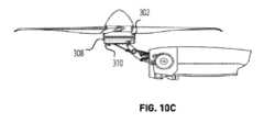
図10A、図10B、および図10Cは、いくつかの例によるナセル1004に対する航空機推進システム300およびプロペラ902などの複数の関連構成要素の傾動を示す。図10Bおよび図10Cに見られるように、この例では、(モーター302、インバータシステム308、およびラジエータ310と識別される)航空機推進システム300およびブレードピッチング機構1008を有するプロペラ1002は、ナセル1004の前部寄りに配置されたティルト機構1006によってナセル1004に対して傾動可能である。10A, 10B, and 10C show the tilting of the aircraft propulsion system 300 and several related components, such as the
ホバリング配置である図10Cに見られるように、ラジエータ310は、垂直配置におけるようにナセル1004内に収容される場合とは対照的に、外気に曝される。これにより、ファン312から、およびプロペラ902からの隣接する空気流の結果として、ラジエータ310を通るより多くの空気流が生じる。ホバリングは水平飛行よりも高い電力要求値を有するので、ラジエータ310を通る増加した空気流によって提供される追加の冷却は有利であり得る。As seen in FIG. 10C, the hovering configuration, the
システムおよび/または方法の実施形態は、様々なシステムコンポーネントおよび様々な方法プロセスのあらゆる組合せおよび順列を含み得、本明細書で説明される方法および/またはプロセスの1つまたは複数の例は、本明細書で説明されるシステム、要素、および/またはエンティティの1つまたは複数の例によって、および/またはそれら1つまたは複数を使用して、非同期に(例えば、順次に)、同時に(例えば、並行して)、または他の任意の適切な順序で実行されることができる。Embodiments of the systems and/or methods may include any combination and permutation of the various system components and various method processes, and one or more examples of the methods and/or processes described herein may be performed asynchronously (e.g., sequentially), simultaneously (e.g., in parallel), or in any other suitable order by and/or using one or more of the example systems, elements, and/or entities described herein.
推力発生要素を指すときに本明細書で利用される「ロータ」という用語は、ロータ、プロペラ、および/または他の任意の適切な回転式空力アクチュエータを指し得る。ロータは、関節型または半剛性ハブ(例えば、ブレードとハブとの接続は、関節型である、可撓性である、剛性である及び/又は別の方法で接続することができる)を利用する回転式空力アクチュエータを指し得、プロペラは、剛性ハブ(例えば、ブレードとハブとの接続は、関節型である、可撓性である、剛性である及び/又は別の方法で接続することができる)を利用する回転式空力アクチュエータを指し得るが、本明細書で使用される際、そのような区別は、明示的または黙示的でもなく、「ロータ」の使用は、どちらの構成も指し得、また、関節型もしくは剛性ブレードの他の任意の適切な構成及び/又は中心部材もしくはハブへのブレード接続の他の任意の適切な構成も指し得る。同様に、「プロペラ」の使用は、どちらの構成も指し得、関節型もしくは剛性ブレードの他の任意の適切な構成及び/又は中心部材もしくはハブへのブレード接続の他の任意の適切な構成も指し得る。従って、ティルトロータ航空機は、ティルトプロペラ航空機、ティルトプロップ航空機と呼ぶこと、および/または別の方法で適切に言及するもしくは説明することができる。The term "rotor" as used herein when referring to a thrust-producing element may refer to a rotor, a propeller, and/or any other suitable rotary aerodynamic actuator. A rotor may refer to a rotary aerodynamic actuator utilizing an articulated or semi-rigid hub (e.g., the blade-to-hub connection may be articulated, flexible, rigid, and/or otherwise connected), and a propeller may refer to a rotary aerodynamic actuator utilizing a rigid hub (e.g., the blade-to-hub connection may be articulated, flexible, rigid, and/or otherwise connected), but as used herein, no such distinction is made, express or implied, and use of "rotor" may refer to either configuration, as well as any other suitable configuration of articulated or rigid blades and/or any other suitable configuration of blade connections to a central member or hub. Similarly, use of "propeller" may refer to either configuration, as well as any other suitable configuration of articulated or rigid blades and/or any other suitable configuration of blade connections to a central member or hub. Thus, a tiltrotor aircraft may be referred to as a tiltpropeller aircraft, a tiltprop aircraft, and/or otherwise appropriately referred to or described.
制御基板、インバータ基板などに関連して本明細書で使用される「基板(board)」という用語は、好ましくは回路基板を指す。より好ましくは、「基板」は、集合的にプリント回路基板アセンブリ(PCBA : printed circuit board assembly)を形成することができる、プリント回路基板(PCB : printed circuit board)および/またはその上に組み立てられた複数の電子部品を指す。第1の例では、制御基板はPCBAである。第2の例では、インバータ基板はPCBAである。しかしながら、「基板」は、追加的に又は代替的には、片面PCB、両面PCB、多層PCB、リジッド(rigid)PCB、フレキシブルPCBを指すこと、及び/又は他の任意の適切な意味を有することができる。The term "board" as used herein in connection with a control board, inverter board, etc., preferably refers to a circuit board. More preferably, "board" refers to a printed circuit board (PCB) and/or a plurality of electronic components assembled thereon, which may collectively form a printed circuit board assembly (PCBA). In a first example, the control board is a PCBA. In a second example, the inverter board is a PCBA. However, "board" may additionally or alternatively refer to a single-sided PCB, a double-sided PCB, a multi-layer PCB, a rigid PCB, a flexible PCB, and/or have any other suitable meaning.
航空機は、1つ又は複数のアクチュエータ(例えば、ロータ/プロペラ、ティルト機構、ブレードピッチ機構、冷却システムなど)に電力を供給する任意の適切な形態の電力貯蔵または電力貯蔵ユニット(バッテリ、フライホイール、ウルトラキャパシタ(ultra-capacitor)、バッテリ、燃料タンクなど)を含むことができる。好ましい電力/燃料源はバッテリであるが、システムは、任意の適切な電力/燃料源とともに合理的に使用され得る。航空機は、補助電源及び/又は冗長な電源(例えば、バックアップバッテリ、複数のバッテリ)を含むこと、又は冗長な電源を除外することができる。航空機は、(例えば、複数のパック、ブリック(bricks)、モジュール、セル等であり、且つ直列及び/又は並列のアーキテクチャの任意の組み合わせの)任意の適切な電気的アーキテクチャ又は構成において、任意の適切なセルケミストリ(cell chemistries)(例えば、リチウムイオン、ニッケルカドミウム等)を有するバッテリを用いることができる。The aircraft may include any suitable form of power storage or power storage unit (e.g., batteries, flywheels, ultra-capacitors, batteries, fuel tanks, etc.) that powers one or more actuators (e.g., rotors/propellers, tilt mechanisms, blade pitch mechanisms, cooling systems, etc.). Although the preferred power/fuel source is a battery, the system may be reasonably used with any suitable power/fuel source. The aircraft may include auxiliary and/or redundant power sources (e.g., backup batteries, multiple batteries) or may exclude redundant power sources. The aircraft may use batteries having any suitable cell chemistries (e.g., lithium ion, nickel cadmium, etc.) in any suitable electrical architecture or configuration (e.g., multiple packs, bricks, modules, cells, etc., and in any combination of series and/or parallel architectures).
特定の例では、システムは、複数の傾動可能ロータアセンブリ(例えば、6つの傾動可能ロータアセンブリ)を含む電気ティルトローター航空機に統合される。電気ティルトローター航空機は、固定翼航空機、回転翼航空機として、及び固定翼状態と回転翼状態との間の任意の境界配置(liminal configuration)(例えば、複数のティルトロータアセンブリのうちの1つ又は複数が部分的に回転した状態となる)で動作することができる。この例における電気ティルトローター航空機の制御システムは、固定翼配置の、回転翼配置の、および/または固定翼配置と回転翼配置との間の複数の傾動可能ロータアセンブリに命令し、制御するように機能することができる。In a particular example, the system is integrated into an electric tiltrotor aircraft that includes multiple tiltable rotor assemblies (e.g., six tiltable rotor assemblies). The electric tiltrotor aircraft can operate as a fixed-wing aircraft, a rotary-wing aircraft, and in any liminal configuration between fixed-wing and rotary-wing conditions (e.g., one or more of the multiple tiltrotor assemblies are partially rotated). The control system of the electric tiltrotor aircraft in this example can function to command and control the multiple tiltable rotor assemblies in a fixed-wing configuration, a rotary-wing configuration, and/or between the fixed-wing and rotary-wing configurations.
本明細書で使用される「実質的に」という用語は、正確に、おおよそ、所定の閾値または許容範囲内にあることを意味すること、および/または他の任意の適切な意味を有することができる。As used herein, the term "substantially" can mean exactly, approximately, within a given threshold or tolerance, and/or have any other suitable meaning.
代替実施形態は、コンピュータ可読命令を記憶する非一時的コンピュータ可読媒体において、上記の方法および/または処理モジュールを実装する。命令は、コンピュータ可読媒体および/または処理システムと統合された複数のコンピュータ実行可能コンポーネントによって実行されることができる。コンピュータ可読媒体は、RAM、ROM、フラッシュメモリ、EEPROM、光デバイス(CDまたはDVD)、ハードドライブ、フロッピー(登録商標)ドライブ、非一時的コンピュータ可読媒体、または任意の適切なデバイスなどの任意の適切なコンピュータ可読媒体を含み得る。コンピュータ実行可能コンポーネントは、CPU、GPU、TPUS、マイクロプロセッサ、またはASICなど、非一時的コンピュータ可読媒体に接続されたコンピューティングシステムおよび/または処理システム(例えば、1つまたは複数の並設または分散されたリモートまたはローカルプロセッサを含む)を含むことができるが、命令は、代替的または追加的には、任意の適切な専用ハードウェアデバイスによって実行されることができる。Alternative embodiments implement the above methods and/or processing modules in a non-transitory computer-readable medium that stores computer-readable instructions. The instructions can be executed by multiple computer-executable components integrated with the computer-readable medium and/or processing system. The computer-readable medium may include any suitable computer-readable medium, such as RAM, ROM, flash memory, EEPROM, optical devices (CD or DVD), hard drives, floppy drives, non-transitory computer-readable media, or any suitable device. The computer-executable components may include a computing system and/or processing system (e.g., including one or more collocated or distributed remote or local processors) connected to the non-transitory computer-readable medium, such as a CPU, GPU, TPUS, microprocessor, or ASIC, although the instructions may alternatively or additionally be executed by any suitable dedicated hardware device.
システムおよび/または方法の実施形態は、様々なシステムコンポーネントおよび様々な方法プロセスのあらゆる組合せおよび順列を含み得、本明細書で説明される方法および/またはプロセスの1つ又は複数の例は、本明細書で説明されるシステム、要素、および/またはエンティティの1つまたは複数の例によって、および/またはそれらの1つ又は複数を使用して、非同期に(例えば、順次に)、同時に(例えば、並行して)、または他の任意の適切な順番で実行されることができる。Embodiments of the systems and/or methods may include any combination and permutation of the various system components and various method processes, and one or more examples of the methods and/or processes described herein may be performed asynchronously (e.g., sequentially), simultaneously (e.g., in parallel), or in any other suitable order by and/or using one or more examples of the systems, elements, and/or entities described herein.
当業者であれば、前述の詳細な説明ならびに図面および特許請求の範囲から認識されるように、以下の特許請求の範囲において定義される本発明の範囲から逸脱することなく、本発明の実施例に対して修正および変更を行うことができる。As will be appreciated from the foregoing detailed description and drawings and claims, those skilled in the art may make modifications and variations to the embodiments of the present invention without departing from the scope of the invention as defined in the following claims.
Claims (17)
Translated fromJapanese電気モーターと、
前記電気モーターを動作させるために使用される少なくとも1つのアクセサリユニットであって、前記航空機推進ユニットを垂直飛行配置と水平飛行配置との間で傾動させるティルト機構を含む前記少なくとも1つのアクセサリユニットと、
前記電気モーターおよび前記少なくとも1つのアクセサリユニットに電力を供給する複数のインバータを含むインバータモジュールと、
前記電気モーターおよび前記インバータモジュールに結合された冷却システムであって、前記電気モーターおよび前記インバータモジュールを通ってまたはそれらに隣接して冷却剤を循環させるための冷却剤通路を含む前記冷却システムと、を備える航空機推進ユニット。 1. An aircraft propulsion unit, comprising:
An electric motor;
at least one accessory unit used to operate the electric motor, the at least one accessory unit including a tilt mechanism for tilting the aircraft propulsion unit between a vertical flight configuration and a horizontal flight configuration;
an inverter module including a plurality of inverters for powering the electric motor and the at least one accessory unit;
a cooling system coupled to the electric motor and the inverter module, the cooling system including a coolant passage for circulating a coolant through or adjacent to the electric motor and the inverter module.
胴体と
1つ又は複数の推力発生ユニットと、
前記推力発生ユニットを駆動する1つ又は複数の推進ユニットと、を備え、
各推進ユニットは、
電気モーターと、
前記電気モーターを動作させるために使用される少なくとも1つのアクセサリユニットであって、前記航空機推進ユニットを垂直飛行配置と水平飛行配置との間で傾動させるティルト機構を含む前記少なくとも1つのアクセサリユニットと、
前記電気モーターおよび前記少なくとも1つのアクセサリユニットに電力を供給する複数のインバータを含むインバータモジュールと、
前記電気モーターおよび前記インバータモジュールに結合された冷却システムであって、前記電気モーターおよび前記インバータモジュールを通ってまたはそれらに隣接して冷却剤を循環させるための冷却剤通路を含む前記冷却システムと、を含み、
前記冷却システムは、ラジエータをさらに含み、前記航空機推進ユニットが前記垂直飛行配置にある場合の使用時の前記ラジエータを通る空気流は、前記航空機推進ユニットが前記水平飛行配置にある場合よりも大きい、航空機。 1. An aircraft,
a fuselage; and one or more thrust producing units;
one or more propulsion units that drive the thrust producing units;
Each propulsion unit is
An electric motor;
at least one accessory unit used to operate the electric motor, the at least one accessory unit including a tilt mechanism for tilting the aircraft propulsion unit between a vertical flight configuration and a horizontal flight configuration;
an inverter module including a plurality of inverters for powering the electric motor and the at least one accessory unit;
a cooling system coupled to the electric motor and the inverter module, the cooling systemincluding coolant passages for circulating a coolant through or adjacent to the electric motor and the inverter module;
The cooling system further includes a radiator, and wherein airflow through the radiator, in use, when the aircraft propulsion unit is in the vertical flight configuration, is greater than when the aircraft propulsion unit is in the horizontal flight configuration .
前記電気モーター内に形成された冷却剤通路に冷却剤を循環させること、
前記インバータモジュールの前記ハウジングを通って前記冷却剤を循環させること、
熱交換器を通って前記冷却剤を循環させること、
垂直飛行配置において前記熱交換器を通る空気流が増加するように、前記航空機推進ユニットを水平飛行配置と前記垂直飛行配置との間で傾動させること、を備える、方法。 1. A method for cooling an aircraft propulsion unit comprising an electric motor, at least one accessory unit used to operate the electric motor, and an inverter module, the inverter module including a housing and a plurality of inverters that provide power to the electric motor and the at least one accessory unit, the method comprising:
circulating a coolant through coolant passages formed within said electric motor;
circulating the coolant through the housing of the inverter module;
circulating the coolant through a heat exchanger;
tilting the aircraft propulsion unit between a horizontal flight configuration and a vertical flight configuration such that airflow through the heat exchanger is increased in the vertical flight configuration .
前記1つまたは複数の冷却板を通過して前記冷却剤を循環させることをさらに備える請求項16に記載の方法。 the inverter module includes one or more cold plates for transferring heat from the plurality of inverters to the coolant in the coolant passages;
The method of claim16 , further comprising circulating the coolant through the one or more cold plates.
Priority Applications (1)
| Application Number | Priority Date | Filing Date | Title |
|---|---|---|---|
| JP2025067207AJP7728996B2 (en) | 2021-02-09 | 2025-04-16 | Aircraft Propulsion Unit |
Applications Claiming Priority (3)
| Application Number | Priority Date | Filing Date | Title |
|---|---|---|---|
| US202163147560P | 2021-02-09 | 2021-02-09 | |
| US63/147,560 | 2021-02-09 | ||
| PCT/US2022/070585WO2022174229A1 (en) | 2021-02-09 | 2022-02-09 | Aircraft propulsion unit |
Related Child Applications (1)
| Application Number | Title | Priority Date | Filing Date |
|---|---|---|---|
| JP2025067207ADivisionJP7728996B2 (en) | 2021-02-09 | 2025-04-16 | Aircraft Propulsion Unit |
Publications (3)
| Publication Number | Publication Date |
|---|---|
| JP2024506334A JP2024506334A (en) | 2024-02-13 |
| JPWO2022174229A5 JPWO2022174229A5 (en) | 2025-02-06 |
| JP7669504B2true JP7669504B2 (en) | 2025-04-28 |
Family
ID=80685544
Family Applications (2)
| Application Number | Title | Priority Date | Filing Date |
|---|---|---|---|
| JP2023547872AActiveJP7669504B2 (en) | 2021-02-09 | 2022-02-09 | Aircraft Propulsion Unit |
| JP2025067207AActiveJP7728996B2 (en) | 2021-02-09 | 2025-04-16 | Aircraft Propulsion Unit |
Family Applications After (1)
| Application Number | Title | Priority Date | Filing Date |
|---|---|---|---|
| JP2025067207AActiveJP7728996B2 (en) | 2021-02-09 | 2025-04-16 | Aircraft Propulsion Unit |
Country Status (6)
| Country | Link |
|---|---|
| US (3) | US11560235B2 (en) |
| EP (1) | EP4291489A1 (en) |
| JP (2) | JP7669504B2 (en) |
| KR (1) | KR20230142777A (en) |
| CN (2) | CN116981621B (en) |
| WO (1) | WO2022174229A1 (en) |
Families Citing this family (28)
| Publication number | Priority date | Publication date | Assignee | Title |
|---|---|---|---|---|
| KR102627083B1 (en)* | 2017-05-22 | 2024-01-18 | 오버에어, 인코퍼레이티드 | Evtol aircraft using large, variable speed tilt rotors |
| EP4291489A1 (en) | 2021-02-09 | 2023-12-20 | Joby Aero, Inc. | Aircraft propulsion unit |
| FR3121126B1 (en)* | 2021-03-26 | 2023-03-24 | Safran Helicopter Engines | COMBAT AIRCRAFT WITH ELECTRICAL ARMING SYSTEM WITH ENERGY MANAGEMENT |
| JP7692719B2 (en)* | 2021-03-31 | 2025-06-16 | 本田技研工業株式会社 | aircraft |
| US12096606B2 (en)* | 2022-03-25 | 2024-09-17 | Toyota Motor Engineering & Manufacturing North America, Inc. | Hybrid cooling systems for electric machines |
| US20240270393A1 (en) | 2022-10-06 | 2024-08-15 | Archer Aviation Inc. | SYSTEMS AND METHODS FOR OIL MAINTENANCE IN GEARBOXES FOR eVTOL AIRCRAFT |
| US11787551B1 (en) | 2022-10-06 | 2023-10-17 | Archer Aviation, Inc. | Vertical takeoff and landing aircraft electric engine configuration |
| KR20250107177A (en) | 2022-10-06 | 2025-07-11 | 아처 에비에이션 인크. | Systems, methods and mechanical design for inverters for EVTOL aircraft |
| US12312091B2 (en) | 2022-10-06 | 2025-05-27 | Archer Aviation Inc. | Systems and methods for improved gearboxes for evtol aircraft |
| WO2024077280A1 (en)* | 2022-10-06 | 2024-04-11 | Archer Aviation Inc. | Systems and methods for improved aircraft electric engines |
| US11613350B1 (en) | 2022-10-07 | 2023-03-28 | Archer Aviation, Inc. | Systems and methods for lifter motor cooling in eVTOL aircraft |
| WO2024077308A1 (en)* | 2022-10-07 | 2024-04-11 | Archer Aviation Inc. | Systems and methods for motor cooling in vtol aircraft |
| EP4536552A1 (en) | 2022-10-07 | 2025-04-16 | Archer Aviation, Inc. | Systems and methods for motor cooling in vtol aircraft |
| KR102827094B1 (en)* | 2022-12-08 | 2025-07-01 | 한국항공우주연구원 | Tilt rotor aircraft with bi-directional cooling passage |
| US11679872B1 (en) | 2022-12-12 | 2023-06-20 | Archer Aviation Inc. | Tilter motor cooling apparatus for vertical takeoff and landing aircraft and operating method of the same |
| US20250042544A1 (en)* | 2023-05-26 | 2025-02-06 | Archer Aviation Inc. | Systems and methods for retracting lift propeller in evtol aircraft |
| US11827349B1 (en)* | 2023-05-26 | 2023-11-28 | Archer Aviation, Inc. | Systems and methods for retracting lift propeller in eVTOL aircraft |
| GB2636842A (en) | 2023-12-22 | 2025-07-02 | Evolito Ltd | Aeronautical propulsion system |
| US20250242937A1 (en)* | 2024-01-31 | 2025-07-31 | Heart Aerospace AB | Aerospace electric propulsion thermal management system |
| WO2025184696A1 (en)* | 2024-03-06 | 2025-09-12 | AMSL Innovations Pty Ltd | Aircraft and electric power systems for aircraft |
| CN119218430B (en)* | 2024-11-29 | 2025-03-21 | 四川沃飞长空科技发展有限公司 | Electric engine, electric propulsion device and aircraft |
| CN119190378B (en)* | 2024-11-29 | 2025-02-28 | 四川沃飞长空科技发展有限公司 | Cooling control method and related device of electric engine |
| CN119218431B (en)* | 2024-11-29 | 2025-02-28 | 四川沃飞长空科技发展有限公司 | Electric engine, electric propulsion device and aircraft |
| CN119190372B (en)* | 2024-11-29 | 2025-02-21 | 四川沃飞长空科技发展有限公司 | Electric engine, electric propulsion device and aircraft |
| CN119218433B (en)* | 2024-11-29 | 2025-03-21 | 四川沃飞长空科技发展有限公司 | Electric engine, electric propulsion device and aircraft |
| CN119218432B (en)* | 2024-11-29 | 2025-03-21 | 四川沃飞长空科技发展有限公司 | Electric engine, electric propulsion device and aircraft |
| CN119231836A (en)* | 2024-12-05 | 2024-12-31 | 浙江吉利控股集团有限公司 | Motor assembly, thrust assembly and aircraft |
| CN119231837B (en)* | 2024-12-05 | 2025-04-22 | 浙江吉利控股集团有限公司 | Motor assembly, thrust component and aircraft |
Citations (2)
| Publication number | Priority date | Publication date | Assignee | Title |
|---|---|---|---|---|
| JP2019501830A (en) | 2016-01-15 | 2019-01-24 | オーロラ フライト サイエンシズ コーポレーション | Hybrid propelled vertical take-off and landing aircraft |
| WO2020025884A1 (en) | 2018-07-31 | 2020-02-06 | Safran | Polyphased electrical machine with integrated power electronics and an integrated coolant circuit |
Family Cites Families (131)
| Publication number | Priority date | Publication date | Assignee | Title |
|---|---|---|---|---|
| US3128964A (en)* | 1964-04-14 | figures | ||
| US4927329A (en)* | 1988-10-21 | 1990-05-22 | General Electric Company | Aircraft engine unducted fan blade pitch control system |
| US5535967A (en)* | 1993-12-20 | 1996-07-16 | Alliedsignal Inc. | Floating speed electrically driven suction system |
| DE19543284A1 (en)* | 1995-11-21 | 1997-05-22 | Robbe Modellsport Gmbh & Co Kg | Drive unit for model aircraft |
| US6390418B1 (en)* | 1999-02-25 | 2002-05-21 | United Technologies Corporation | Tangentially directed acoustic jet controlling boundary layer |
| JP2004048823A (en)* | 2002-07-08 | 2004-02-12 | Hitachi Unisia Automotive Ltd | Electric machine with inverter |
| JP4310683B2 (en)* | 2003-05-13 | 2009-08-12 | アイシン・エィ・ダブリュ株式会社 | Drive unit with built-in electric motor |
| US10443139B2 (en)* | 2003-09-05 | 2019-10-15 | Brilliant Light Power, Inc. | Electrical power generation systems and methods regarding same |
| JP4614688B2 (en)* | 2004-05-20 | 2011-01-19 | トヨタ自動車株式会社 | A cooling system and a hybrid vehicle equipped with it. |
| US8720814B2 (en)* | 2005-10-18 | 2014-05-13 | Frick A. Smith | Aircraft with freewheeling engine |
| US8152096B2 (en)* | 2005-10-18 | 2012-04-10 | Smith Frick A | Apparatus and method for vertical take-off and landing aircraft |
| JP5090802B2 (en) | 2006-06-28 | 2012-12-05 | ソウル セミコンダクター カンパニー リミテッド | Phosphor, manufacturing method thereof, and light emitting diode |
| US8016226B1 (en)* | 2007-07-10 | 2011-09-13 | Wood Victor A | Vertical take off and landing aircraft system with energy recapture technology |
| EP2143943A1 (en)* | 2008-07-09 | 2010-01-13 | Greenergy India Private Limited | Wind turbine |
| US9102401B2 (en)* | 2009-03-12 | 2015-08-11 | Textron Innovations Inc. | Wing extension control surface |
| WO2010134923A1 (en)* | 2009-05-22 | 2010-11-25 | Bell Helicopter Textron Inc. | Rotor blade spacing for vibration attenuation |
| IL199009A (en)* | 2009-05-27 | 2013-11-28 | Israel Aerospace Ind Ltd | Air vehicle |
| US8708273B2 (en)* | 2009-10-09 | 2014-04-29 | Oliver Vtol, Llc | Three-wing, six tilt-propulsion unit, VTOL aircraft |
| US20110147533A1 (en)* | 2009-12-21 | 2011-06-23 | Honeywell International Inc. | Morphing ducted fan for vertical take-off and landing vehicle |
| CA2802389C (en)* | 2010-06-15 | 2015-11-24 | Bell Helicopter Textron Inc. | Method and apparatus for in-flight blade folding |
| GB2482333A (en)* | 2010-07-30 | 2012-02-01 | Ge Aviat Systems Ltd | Aircraft propeller |
| GB201016742D0 (en)* | 2010-10-05 | 2010-11-17 | Health Prot Agency | Clostridium difficile antigens |
| GB201017597D0 (en)* | 2010-10-19 | 2010-12-01 | Randox Lab | Drug detection |
| US9227719B2 (en)* | 2011-03-11 | 2016-01-05 | The United States Of America As Represented By The Administrator Of The National Aeronautics And Space Administration | Reactive orthotropic lattice diffuser for noise reduction |
| WO2013106009A1 (en)* | 2011-03-28 | 2013-07-18 | Rolls-Royce North American Technologies Inc. | Aircraft and airborne electrical power and thermal management system |
| TWI538852B (en)* | 2011-07-19 | 2016-06-21 | 季航空股份有限公司 | Personal aircraft |
| CN202334270U (en)* | 2011-11-28 | 2012-07-11 | 株洲南车时代电气股份有限公司 | Current transformer |
| GB201202441D0 (en)* | 2012-02-13 | 2012-03-28 | Reiter Johannes | Wing adjustment mechanism |
| DK201270179A (en)* | 2012-04-11 | 2013-10-11 | Envision Energy Denmark Aps | Wind turbine with improved cooling |
| DE102012104783B4 (en)* | 2012-06-01 | 2019-12-24 | Quantum-Systems Gmbh | Aircraft, preferably UAV, drone and / or UAS |
| US9128109B1 (en)* | 2012-08-20 | 2015-09-08 | The Boeing Company | Method and system for detecting errors in indicated air speed |
| US10780786B2 (en)* | 2012-09-24 | 2020-09-22 | Robert Del Core | Adaptive thermal management of an electric energy storage method and system apparatus |
| US9561857B2 (en)* | 2013-02-06 | 2017-02-07 | Raytheon Company | Aircraft thermal management system for cooling using expendable coolants |
| EP2774853A1 (en) | 2013-03-07 | 2014-09-10 | Siemens Aktiengesellschaft | Drive nacelle for an airplane |
| US9248908B1 (en)* | 2013-06-12 | 2016-02-02 | The Boeing Company | Hybrid electric power helicopter |
| FR3006996B1 (en)* | 2013-06-14 | 2016-12-09 | European Aeronautic Defence & Space Co Eads France | ELECTRICAL PROPULSION ASSEMBLY FOR AIRCRAFT |
| JP5942943B2 (en)* | 2013-08-20 | 2016-06-29 | トヨタ自動車株式会社 | Battery temperature control device |
| US9561867B2 (en)* | 2013-10-11 | 2017-02-07 | The Boeing Company | Modular equipment center lightning threat reduction architecture |
| US9325224B2 (en)* | 2013-12-28 | 2016-04-26 | Google Inc. | Electrically-isolated and liquid-cooled rotor and stator assemblies |
| US9623967B2 (en)* | 2014-02-01 | 2017-04-18 | Aero Machining, LLC | Tiltrotor unmanned aerial vehicle |
| US10315760B2 (en)* | 2014-03-18 | 2019-06-11 | Joby Aero, Inc. | Articulated electric propulsion system with fully stowing blades and lightweight vertical take-off and landing aircraft using same |
| US10625852B2 (en)* | 2014-03-18 | 2020-04-21 | Joby Aero, Inc. | Aerodynamically efficient lightweight vertical take-off and landing aircraft with pivoting rotors and stowing rotor blades |
| US10046855B2 (en)* | 2014-03-18 | 2018-08-14 | Joby Aero, Inc. | Impact resistant propeller system, fast response electric propulsion system and lightweight vertical take-off and landing aircraft using same |
| US9694911B2 (en)* | 2014-03-18 | 2017-07-04 | Joby Aviation, Inc. | Aerodynamically efficient lightweight vertical take-off and landing aircraft with pivoting rotors and stowing rotor blades |
| FR3020799B1 (en)* | 2014-05-12 | 2016-06-03 | Airbus Helicopters | GIRAVION EQUIPPED WITH ANEMOMETER PLACED AT THE TOP OF A REAR DRIFT OF THE GIRAVION |
| EA201692463A1 (en)* | 2014-05-29 | 2017-10-31 | Бриллиант Лайт Пауэр, Инк. | SYSTEMS AND METHODS FOR ELECTRIC POWER GENERATION |
| US10815890B2 (en)* | 2014-07-03 | 2020-10-27 | General Electric Company | Jet engine cold air cooling system |
| CN115946858A (en)* | 2014-08-29 | 2023-04-11 | 峰鸟航空科技公司 | Systems and methods for implementing a regional air transportation network using hybrid electric aircraft |
| JP6294195B2 (en)* | 2014-09-09 | 2018-03-14 | 日立オートモティブシステムズ株式会社 | Power converter |
| WO2016054068A1 (en)* | 2014-10-03 | 2016-04-07 | Lightening Energy | Electric vehicle battery thermal management system and method |
| US9435661B2 (en)* | 2014-10-08 | 2016-09-06 | Honeywell International Inc. | Systems and methods for attitude fault detection based on air data and aircraft control settings |
| JP6279449B2 (en) | 2014-10-27 | 2018-02-14 | 株式会社神戸製鋼所 | Outer rotor type axial gap type brushless motor |
| US9994313B2 (en)* | 2014-11-26 | 2018-06-12 | XCraft Enterprises, LLC | High speed multi-rotor vertical takeoff and landing aircraft |
| US10526091B2 (en)* | 2014-12-03 | 2020-01-07 | The Boeing Company | Mobile platform thermal management systems and methods |
| WO2016189421A1 (en)* | 2015-05-22 | 2016-12-01 | Bombardier Inc. | Airflow management in cabin of aircraft |
| US10766627B2 (en)* | 2015-05-29 | 2020-09-08 | Verity Studios Ag | Aerial vehicle |
| US10589854B2 (en)* | 2015-10-07 | 2020-03-17 | Sikorsky Aircraft Corporation | Aircraft with overlapped rotors |
| US20170104385A1 (en)* | 2015-10-08 | 2017-04-13 | Adam C. Salamon | Reduced Complexity Ring Motor Design for Propeller Driven Vehicles |
| US10011361B2 (en)* | 2015-11-16 | 2018-07-03 | Textron Innovations Inc. | Aircraft environmental control system providing improved performance and backup temperature control |
| US10246184B2 (en)* | 2015-12-02 | 2019-04-02 | Jon M. Ragland | Aircraft with internally housed propellor units |
| US10830097B2 (en)* | 2016-02-04 | 2020-11-10 | General Electric Company | Engine casing with internal coolant flow patterns |
| US10029808B2 (en)* | 2016-02-29 | 2018-07-24 | The Boeing Company | Structurally integrated thermal management system for aerospace vehicles |
| US10399666B2 (en)* | 2016-03-23 | 2019-09-03 | Amazon Technologies, Inc. | Aerial vehicle propulsion mechanism with coaxially aligned and independently rotatable propellers |
| US10208676B2 (en)* | 2016-03-29 | 2019-02-19 | General Electric Company | Gas turbine engine dual sealing cylindrical variable bleed valve |
| US10245961B2 (en)* | 2016-06-01 | 2019-04-02 | Current Ways, Inc. | Inverter-charger combination |
| JPWO2017217487A1 (en)* | 2016-06-16 | 2019-04-11 | 株式会社フジクラ | Oxide superconducting wire and method for producing the same |
| US10183746B2 (en)* | 2016-07-01 | 2019-01-22 | Bell Helicopter Textron Inc. | Aircraft with independently controllable propulsion assemblies |
| US10800539B2 (en)* | 2016-08-19 | 2020-10-13 | General Electric Company | Propulsion engine for an aircraft |
| US9944386B1 (en)* | 2017-07-13 | 2018-04-17 | Kitty Hawk Corporation | Multicopter with wide span rotor configuration and protective fuselage |
| AT520904A5 (en)* | 2016-09-22 | 2021-07-15 | Qingdao Austech Solar Tech Co Ltd | System and device for generating electricity with integrated circulation |
| US10364036B2 (en)* | 2016-10-18 | 2019-07-30 | Kitty Hawk Corporation | Multicopter with boom-mounted rotors |
| CN106921003B (en)* | 2016-10-25 | 2019-09-06 | 蔚来汽车有限公司 | Intelligent control system and method for electric vehicle battery pack temperature |
| US10407164B2 (en)* | 2016-10-28 | 2019-09-10 | Honeywell International Inc. | Air distribution system with drag reducing inlet |
| CN110546068B (en)* | 2016-11-02 | 2023-05-26 | 杰欧比航空有限公司 | VTOL aircraft using rotors to simulate rigid wing aerodynamics |
| EP3321186A1 (en)* | 2016-11-14 | 2018-05-16 | Airbus Operations GmbH | Aircraft |
| US10826343B2 (en)* | 2016-11-17 | 2020-11-03 | General Electric Company | High speed electric machine with radially supported rotor magnets |
| US10218232B2 (en)* | 2016-11-17 | 2019-02-26 | General Electric Company | High speed electric machine |
| US10326643B2 (en)* | 2016-12-27 | 2019-06-18 | The Charles Stark Draper Laboratory, Inc. | Self-configuring fault-tolerant operational group |
| US20180215475A1 (en)* | 2017-02-01 | 2018-08-02 | General Electric Company | Systems and Methods for Integrated Power and Thermal Management in a Turbine-Powered Aircraft |
| US20180244370A1 (en)* | 2017-02-18 | 2018-08-30 | Jean-Eloi William Lombard | Passive flow control mechanism for suppressing tollmien-schlichting waves, delaying transition to turbulence and reducing drag |
| US11731772B2 (en)* | 2017-03-02 | 2023-08-22 | Textron Innovations Inc. | Hybrid propulsion drive train system for tiltrotor aircraft |
| US20180287234A1 (en)* | 2017-03-28 | 2018-10-04 | Kitty Hawk Corporation | Integrated cooling and venting system |
| US20200007007A1 (en)* | 2017-03-31 | 2020-01-02 | The Board Of Trustees Of The University Of Illinois | High frequency electric motor, control system, and method of manufacture |
| US20180358664A1 (en)* | 2017-06-08 | 2018-12-13 | Mtd Products Inc | Rechargeable battery pack with active or passive cooling |
| US10507928B2 (en)* | 2017-06-16 | 2019-12-17 | Honeywell International Inc. | High efficiency electrically driven environmental control system |
| DE102017211561A1 (en)* | 2017-07-06 | 2019-01-10 | Siemens Aktiengesellschaft | Airplane with a power electronic component |
| KR102281226B1 (en)* | 2017-07-18 | 2021-07-22 | 엘지디스플레이 주식회사 | Display device |
| DE102017212798A1 (en)* | 2017-07-26 | 2019-01-31 | Siemens Aktiengesellschaft | Electric motor with cooling device |
| US10493820B2 (en)* | 2017-09-08 | 2019-12-03 | Honeywell International Inc. | Coating of the ECS primary heat exchanger (PHX) with low temperature catalyst for ozone and/or volatile organic compounds (VOC) and/or carbon monoxide conversion |
| US20190315476A1 (en)* | 2017-10-18 | 2019-10-17 | Carl Eugene Lawrence | Electric Aircraft Propulsion System |
| CN111278755B (en)* | 2017-10-27 | 2022-04-08 | 伯克希尔格雷营业股份有限公司 | System and method for processing objects, including feeding and removing of magazines of a mobile matrix carrier system |
| JP6863875B2 (en)* | 2017-10-27 | 2021-04-21 | 日立Astemo株式会社 | Electric drive device and electric power steering device |
| CN108054935A (en)* | 2017-12-25 | 2018-05-18 | 苍南县新源电子科技有限公司 | Easy heat radiation inverter mounting shell |
| US11696895B2 (en)* | 2017-12-28 | 2023-07-11 | Sumitomo Pharma Co., Ltd. | Fine particle coating (drug-containing hollow particle and method for manufacturing same) |
| US10822109B2 (en)* | 2018-01-05 | 2020-11-03 | The Boeing Company | Methods and systems for determining airspeed of an aircraft |
| US11660970B2 (en)* | 2018-01-05 | 2023-05-30 | Byton Limited | On-board liquid-cooled or gas-cooled charging cable for electric vehicles |
| US10608505B1 (en)* | 2018-02-09 | 2020-03-31 | Wisk Aero Llc | Cooling motor controller with a motor with duct |
| US10144503B1 (en)* | 2018-02-22 | 2018-12-04 | Kitty Hawk Corporation | Fixed wing aircraft with trailing rotors |
| US11312471B2 (en)* | 2018-03-16 | 2022-04-26 | Joby Aero, Inc. | Aircraft drag reduction system and internally cooled motor system and aircraft using same |
| JP2019170065A (en)* | 2018-03-23 | 2019-10-03 | 日本電産トーソク株式会社 | Inverter device |
| US10272767B1 (en)* | 2018-03-23 | 2019-04-30 | Sf Motors, Inc. | Dual loop liquid cooling of integrated electric drivetrain |
| US11121557B2 (en)* | 2018-04-06 | 2021-09-14 | Aurora Flight Sciences Corporation | Power distribution system for aircraft |
| US20190316849A1 (en)* | 2018-04-11 | 2019-10-17 | Nio Usa, Inc. | Thermal management, heat transfer improvement of radiator and condenser using ac system evaporator's condensation |
| JP6800546B2 (en)* | 2018-04-23 | 2020-12-16 | 森村Sofcテクノロジー株式会社 | Complex and electrochemical reaction cell stack |
| US11024894B2 (en)* | 2018-05-04 | 2021-06-01 | Raytheon Technologies Corporation | Cooling architecture for a vehicle |
| US20190351740A1 (en)* | 2018-05-18 | 2019-11-21 | Nio Usa, Inc. | Use of an inside condenser to maximize total thermal system performance |
| CN112368208A (en)* | 2018-05-31 | 2021-02-12 | 杰欧比飞行有限公司 | Electric power system architecture and fault-tolerant VTOL (virtual volume on-board) aircraft using same |
| DE102019103541A1 (en)* | 2018-07-06 | 2020-01-09 | Hanon Systems | Cooling module with axial fan for vehicles, especially for electric vehicles |
| JP7038621B2 (en)* | 2018-07-20 | 2022-03-18 | 東京エレクトロン株式会社 | Position measuring device and position measuring method |
| CN108897367B (en) | 2018-07-27 | 2020-11-27 | 京东方科技集团股份有限公司 | Voltage control circuit, method, device and storage medium |
| US11746701B2 (en)* | 2018-08-09 | 2023-09-05 | Rolls-Royce North American Technologies, Inc. | Bleed expander cooling with turbine |
| GB201814255D0 (en)* | 2018-09-03 | 2018-10-17 | Rolls Royce Plc | Aircraft propulsion system |
| JP7083298B2 (en)* | 2018-09-28 | 2022-06-10 | 本田技研工業株式会社 | Motor structure and vehicle |
| US10807723B2 (en)* | 2018-11-02 | 2020-10-20 | The Boeing Company | Integrated liquid heat exchanger and outflow valve systems and methods |
| DE102018129226A1 (en) | 2018-11-20 | 2020-05-20 | Dynamic E Flow Gmbh | Electrical machine with several rigid winding pieces designed as waveguides - electrical connection concept |
| US20200331602A1 (en)* | 2018-12-07 | 2020-10-22 | Joby Aero, Inc. | Rotary airfoil and design method therefor |
| US10497996B1 (en)* | 2018-12-12 | 2019-12-03 | Cora Aero Llc | Battery with liquid temperature controlling system |
| US10807730B2 (en)* | 2018-12-21 | 2020-10-20 | General Electric Company | Motor driven propulsor of an aircraft |
| US20200385127A1 (en)* | 2019-02-21 | 2020-12-10 | Gabriel Devault | Advanced FuelCell Integration Into Aircraft |
| US12166384B2 (en) | 2019-03-19 | 2024-12-10 | Magna powertrain gmbh & co kg | High performance electromagnetic machine and cooling system |
| EP3719919A1 (en)* | 2019-03-20 | 2020-10-07 | Hamilton Sundstrand Corporation | Thermal regulation of batteries |
| CN116646641B (en)* | 2019-04-23 | 2024-09-13 | 杰欧比飞行有限公司 | Battery thermal management system and method |
| US11711003B2 (en)* | 2019-05-31 | 2023-07-25 | MagniX USA, Inc. | High voltage converter for use as electric power supply |
| US20200376927A1 (en)* | 2019-05-31 | 2020-12-03 | Nio Usa, Inc. | Artificial intelligence in conditioning or thermal management of electrified powertrain |
| US11679891B2 (en)* | 2019-06-06 | 2023-06-20 | Beta Air, Llc | Integrated electric propulsion assembly |
| US11247583B2 (en)* | 2019-08-15 | 2022-02-15 | Ford Global Technologies, Llc | Battery thermal management systems for providing improved battery cooling as a function of vehicle speed |
| US11632052B2 (en)* | 2020-05-07 | 2023-04-18 | Current Ways, Inc. | Dual active bridge with distributed inductance |
| US20220011782A1 (en)* | 2020-06-30 | 2022-01-13 | Joby Aero, Inc. | Method And System For Safely Landing A Battery Powered Electric VTOL Aircraft In A Low Charge Condition |
| US20220181940A1 (en)* | 2020-12-03 | 2022-06-09 | Joby Aero, Inc. | Redundant resolver |
| JP7528376B2 (en)* | 2020-12-18 | 2024-08-05 | ジョビー エアロ,インコーポレイテッド | Electric motor with liquid cooling of the winding stator |
| EP4291489A1 (en) | 2021-02-09 | 2023-12-20 | Joby Aero, Inc. | Aircraft propulsion unit |
- 2022
- 2022-02-09EPEP22709530.4Apatent/EP4291489A1/enactivePending
- 2022-02-09KRKR1020237030380Apatent/KR20230142777A/enactivePending
- 2022-02-09WOPCT/US2022/070585patent/WO2022174229A1/ennot_activeCeased
- 2022-02-09CNCN202280019915.XApatent/CN116981621B/enactiveActive
- 2022-02-09JPJP2023547872Apatent/JP7669504B2/enactiveActive
- 2022-02-09CNCN202410738635.5Apatent/CN118545247B/enactiveActive
- 2022-02-09USUS17/650,458patent/US11560235B2/enactiveActive
- 2022-12-09USUS18/064,160patent/US11691746B2/enactiveActive
- 2023
- 2023-05-16USUS18/318,200patent/US11912425B2/enactiveActive
- 2025
- 2025-04-16JPJP2025067207Apatent/JP7728996B2/enactiveActive
Patent Citations (2)
| Publication number | Priority date | Publication date | Assignee | Title |
|---|---|---|---|---|
| JP2019501830A (en) | 2016-01-15 | 2019-01-24 | オーロラ フライト サイエンシズ コーポレーション | Hybrid propelled vertical take-off and landing aircraft |
| WO2020025884A1 (en) | 2018-07-31 | 2020-02-06 | Safran | Polyphased electrical machine with integrated power electronics and an integrated coolant circuit |
Also Published As
| Publication number | Publication date |
|---|---|
| US11560235B2 (en) | 2023-01-24 |
| US11912425B2 (en) | 2024-02-27 |
| WO2022174229A1 (en) | 2022-08-18 |
| JP2025105633A (en) | 2025-07-10 |
| EP4291489A1 (en) | 2023-12-20 |
| CN116981621A (en) | 2023-10-31 |
| US20230107180A1 (en) | 2023-04-06 |
| US20230278716A1 (en) | 2023-09-07 |
| US11691746B2 (en) | 2023-07-04 |
| US20220250756A1 (en) | 2022-08-11 |
| CN118545247A (en) | 2024-08-27 |
| CN116981621B (en) | 2024-07-02 |
| KR20230142777A (en) | 2023-10-11 |
| JP2024506334A (en) | 2024-02-13 |
| JP7728996B2 (en) | 2025-08-25 |
| CN118545247B (en) | 2025-04-18 |
Similar Documents
| Publication | Publication Date | Title |
|---|---|---|
| JP7669504B2 (en) | Aircraft Propulsion Unit | |
| JP7580007B2 (en) | Battery thermal management system and method | |
| US12068707B2 (en) | Inverter circuits and electrical propulsion systems for eVTOL aircraft | |
| US11794913B2 (en) | Integrated electric propulsion unit | |
| US11679872B1 (en) | Tilter motor cooling apparatus for vertical takeoff and landing aircraft and operating method of the same | |
| US12240599B2 (en) | Systems and methods for lifter motor cooling in EVTOL aircraft | |
| JP7692719B2 (en) | aircraft | |
| US11613368B2 (en) | Aircraft with electrical energy storage in nacelles | |
| US20240405633A1 (en) | Driving device and driving device unit | |
| WO2024107698A1 (en) | Heat exchanger assemblies and cooling systems for evtol aircraft | |
| US12134481B2 (en) | Aircraft thermal management system | |
| US12434832B2 (en) | Systems and methods for lifter motor cooling in evtol aircraft | |
| WO2025120995A1 (en) | Battery module and battery cooling system | |
| EP4619308A1 (en) | Heat exchanger assemblies and cooling systems for evtol aircraft | |
| JP2025148334A (en) | Devices for aircraft propulsion | |
| JP2025148333A (en) | Devices for aircraft propulsion |
Legal Events
| Date | Code | Title | Description |
|---|---|---|---|
| A521 | Request for written amendment filed | Free format text:JAPANESE INTERMEDIATE CODE: A523 Effective date:20250129 | |
| A621 | Written request for application examination | Free format text:JAPANESE INTERMEDIATE CODE: A621 Effective date:20250129 | |
| A871 | Explanation of circumstances concerning accelerated examination | Free format text:JAPANESE INTERMEDIATE CODE: A871 Effective date:20250129 | |
| TRDD | Decision of grant or rejection written | ||
| A01 | Written decision to grant a patent or to grant a registration (utility model) | Free format text:JAPANESE INTERMEDIATE CODE: A01 Effective date:20250318 | |
| A61 | First payment of annual fees (during grant procedure) | Free format text:JAPANESE INTERMEDIATE CODE: A61 Effective date:20250416 | |
| R150 | Certificate of patent or registration of utility model | Ref document number:7669504 Country of ref document:JP Free format text:JAPANESE INTERMEDIATE CODE: R150 |