JP7669088B1 - Ferrules - Google Patents
FerrulesDownload PDFInfo
- Publication number
- JP7669088B1 JP7669088B1JP2025020887AJP2025020887AJP7669088B1JP 7669088 B1JP7669088 B1JP 7669088B1JP 2025020887 AJP2025020887 AJP 2025020887AJP 2025020887 AJP2025020887 AJP 2025020887AJP 7669088 B1JP7669088 B1JP 7669088B1
- Authority
- JP
- Japan
- Prior art keywords
- recess
- optical fiber
- fiber insertion
- ferrule
- insertion hole
- Prior art date
- Legal status (The legal status is an assumption and is not a legal conclusion. Google has not performed a legal analysis and makes no representation as to the accuracy of the status listed.)
- Active
Links
Images


Landscapes
- Mechanical Coupling Of Light Guides (AREA)
Abstract
Translated fromJapanese
Description
Translated fromJapanese本発明はフェルールに関し、特に、複数の光ファイバを接続するための光ファイバコネクタのフェルールに関する。The present invention relates to a ferrule, and more particularly to a ferrule for an optical fiber connector for connecting multiple optical fibers.
光ファイバ同士、または光ファイバと光ファイバ部品などとを接続および切り離すための部品として、光ファイバコネクタが用いられている。フェルールは、スリーブまたはガイドピンによって整列し、光ファイバを保持固定する部材である。Optical fiber connectors are used as components for connecting and disconnecting optical fibers to each other or between optical fibers and optical fiber components. A ferrule is a component that aligns the optical fiber with a sleeve or guide pin and holds it in place.
また、光コネクタ用フェルールの接着剤注入窓が形成されるのとは逆側の外面に、凹部を形成することも提案されている(例えば、特許文献1参照)。さらに、光コネクタ用フェルールの左右方向の反りを無くして、ガイドピン穴の中心を基準とする光ファイバ挿入穴の位置の狂いを無くし、低損失の接続を可能にするため、フェルール本体の下面に、窓とほぼ同じ大きさの凹部を設けることも提案されている(例えば、特許文献2参照)。It has also been proposed to form a recess on the outer surface of the optical connector ferrule opposite the adhesive injection window (see, for example, Patent Document 1). Furthermore, it has also been proposed to provide a recess of approximately the same size as the window on the underside of the ferrule body in order to eliminate left-right warping of the optical connector ferrule and eliminate misalignment of the optical fiber insertion hole relative to the center of the guide pin hole, thereby enabling a low-loss connection (see, for example, Patent Document 2).
しかしながら、射出成形やトランスファ成形により光ファイバコネクタのフェルールを成形しようとすると、光ファイバを通すための光ファイバ挿入穴に曲がりが生じてしまう。光ファイバ挿入穴が開口している面を研磨すると、光ファイバ挿入穴の開口の位置にずれが生じてしまう。これにより、フェルールを嵌合させた場合、光ファイバの光軸がずれてしまい、接続損失が大きくなってしまう。However, when trying to mold the ferrules of optical fiber connectors by injection molding or transfer molding, the optical fiber insertion hole through which the optical fiber passes becomes bent. When the surface on which the optical fiber insertion hole is open is polished, the position of the opening of the optical fiber insertion hole becomes misaligned. As a result, when the ferrule is mated, the optical axis of the optical fiber becomes misaligned, resulting in high connection loss.
本発明は、このような状況に鑑みてなされたものであり、光ファイバ挿入穴の曲がりをより小さくして、光ファイバ挿入穴の開口の位置をより精度良く配置できるようにするものである。The present invention was made in consideration of these circumstances, and aims to reduce the bending of the optical fiber insertion hole, thereby enabling the position of the opening of the optical fiber insertion hole to be positioned with greater precision.
本発明の一側面のフェルールは、複数の光ファイバを接続するための光ファイバコネクタのフェルールであって、樹脂から成形されるフェルールであり、互いに平行に配列されている、複数の光ファイバのそれぞれを通すための光ファイバ挿入穴と、光ファイバ挿入穴に平行に、光ファイバ挿入穴を挟むように配列されている2つのガイドピン穴と、光ファイバ挿入穴およびガイドピン穴が開口している面である接続端面に隣接する面のうちの、所定の面である第1の面に開口している、光ファイバを固定するための接着剤を注入するための穴である接着剤注入穴と、接続端面に隣接する面のうちの、第1の面に対向する面である第2の面において、接着剤注入穴に対向する位置に設けられている第1の凹部と、第2の面のうち、光ファイバ挿入穴が内部に形成されている部分の第2の面の部分に設けられていて、第2の面のうち、2つのガイドピン穴のそれぞれが内部に形成されている部分の第2の面の部分まで延びている第2の凹部とが形成されていて、第1の凹部は、光ファイバ挿入穴、ガイドピン穴および接着剤注入穴とは連通せず、第2の凹部は、光ファイバ挿入穴、ガイドピン穴、接着剤注入穴および第1の凹部とは連通せず、互いに平行に配列されている光ファイバ挿入穴の複数の中心線を面内に含む第1の仮想面に直交する第2の仮想面であって、接続端面の中央部と交差する第2の仮想面に対して、面対称に形成されている。 A ferrule according to one aspect of the present invention is a ferrule for an optical fiber connector for connecting a plurality of optical fibers, the ferrule being molded from resin, and comprising : an optical fiber insertion hole for passing each of a plurality of optical fibers arranged parallel to each other; two guide pin holes arranged parallel to the optical fiber insertion hole and sandwiching the optical fiber insertion hole; an adhesiveinjection hole for injecting an adhesive for fixing the optical fiber, which opens on a first face, which is a predetermined face among faces adjacent to a connection end face, which is a face in which the optical fiber insertion hole and the guide pin holes open; and a ferrule facing the adhesive injection hole on a second face, which is a face opposite the first face among faces adjacent to the connection end face. a first recess provided at a position where the optical fiber insertion hole is formed, and a second recess provided on a portion of the second surface where the optical fiber insertion hole is formedtherein and extending to a portion of the second surface where the two guide pin holes are formed therein, the first recess not communicating with the optical fiber insertion hole, the guide pin hole, and the adhesive injection hole, the second recess not communicating with the optical fiber insertion hole, the guide pin hole, the adhesive injection hole, and the first recess, andbeing formed symmetrically with respect to a second imaginary plane that is perpendicular to a first imaginary plane including within its plane a plurality of center lines of the optical fiber insertion holes that are arranged parallel to one another, and that intersects with the center of the connection end face .
第1の面のうちの、光ファイバ挿入穴が内部に形成されている部分の第1の面の部分に第3の凹部をさらに形成し、第3の凹部は、光ファイバ挿入穴、ガイドピン穴、接着剤注入穴、第1の凹部および第2の凹部とは連通しないようにすることができる。A third recess can be further formed in the portion of the first surface where the optical fiber insertion hole is formed, and the third recess can be configured not to communicate with the optical fiber insertion hole, the guide pin hole, the adhesive injection hole, the first recess, and the second recess.
第3の凹部を、第1の面のうち、2つのガイドピン穴のそれぞれが内部に形成されている部分の第1の面の部分まで延ばすことができる。 The third recess canextend to a portion of the first surface where each of the two guide pin holes is formed therein.
第3の凹部を、第2の仮想面に対して、面対称に形成することができる。 The third recess can be formed symmetrically with respect tothe second imaginary plane .
第3の凹部を、第1の面と第2の面とに挟まれている、第1の面および第2の面に平行な仮想的な面に対して、第2の凹部と面対称に形成することができる。The third recess can be formed symmetrically to the second recess with respect to an imaginary plane that is sandwiched between the first and second surfaces and is parallel to the first and second surfaces.
第1の凹部を、他の部分の肉厚よりも薄い肉厚の薄肉部により接着剤注入穴と遮断することができる。The first recess can be blocked off from the adhesive injection hole by a thin-walled portion that is thinner than the other portions.
第1の凹部を、第2の面から所定の深さの第1の窪み部と、第1の窪み部の深さに比較して、第2の面からの深さがより深く、接続端面側に配置されている第2の窪み部とからなるようにすることができる。The first recess can be made to consist of a first recess portion having a predetermined depth from the second surface, and a second recess portion having a greater depth from the second surface than the depth of the first recess portion and disposed on the connection end surface side.
第1の凹部の底側の隅を、曲面状に形成することができる。The bottom corner of the first recess can be formed into a curved shape.
以上のように、本発明によれば、光ファイバ挿入穴の曲がりをより小さくして、光ファイバ挿入穴の開口の位置をより精度良く配置できる。As described above, according to the present invention, the bending of the optical fiber insertion hole can be reduced, and the position of the opening of the optical fiber insertion hole can be positioned with greater precision.
以下に本発明の実施の形態を説明するが、本発明の構成要件と、発明の詳細な説明に記載の実施の形態との対応関係を例示すると、次のようになる。この記載は、本発明をサポートする実施の形態が、発明の詳細な説明に記載されていることを確認するためのものである。従って、発明の詳細な説明中には記載されているが、本発明の構成要件に対応する実施の形態として、ここには記載されていない実施の形態があったとしても、そのことは、その実施の形態が、その構成要件に対応するものではないことを意味するものではない。逆に、実施の形態が構成要件に対応するものとしてここに記載されていたとしても、そのことは、その実施の形態が、その構成要件以外の構成要件には対応しないものであることを意味するものでもない。The following describes an embodiment of the present invention, but the correspondence between the constituent elements of the present invention and the embodiments described in the detailed description of the invention is exemplified as follows. This description is for the purpose of confirming that the embodiments supporting the present invention are described in the detailed description of the invention. Therefore, even if there is an embodiment that is described in the detailed description of the invention but is not described here as an embodiment that corresponds to a constituent element of the present invention, this does not mean that the embodiment does not correspond to that constituent element. Conversely, even if an embodiment is described here as corresponding to a constituent element, this does not mean that the embodiment does not correspond to constituent elements other than that constituent element.
本発明の一側面のフェルールは、複数の光ファイバを接続するための光ファイバコネクタのフェルールであって、樹脂から成形されるフェルールであり、互いに平行に配列されている、複数の光ファイバのそれぞれを通すための光ファイバ挿入穴(例えば、図6の光ファイバ挿入穴161)と、光ファイバ挿入穴に平行に、光ファイバ挿入穴を挟むように配列されている2つのガイドピン穴(例えば、図6のガイドピン穴162)と、光ファイバ挿入穴およびガイドピン穴が開口している面である接続端面に隣接する面のうちの、所定の面である第1の面に開口している、光ファイバを固定するための接着剤を注入するための穴である接着剤注入穴(例えば、図6の接着剤注入穴141)と、接続端面に隣接する面のうちの、第1の面に対向する面である第2の面において、接着剤注入穴に対向する位置に設けられている第1の凹部(例えば、図7の凹部142)と、第2の面のうち、光ファイバ挿入穴が内部に形成されている部分の第2の面の部分に設けられていて、第2の面のうち、2つのガイドピン穴のそれぞれが内部に形成されている部分の第2の面の部分まで延びている第2の凹部(例えば、図7の凹部144)とが形成されていて、第1の凹部は、光ファイバ挿入穴、ガイドピン穴および接着剤注入穴とは連通せず、第2の凹部は、光ファイバ挿入穴、ガイドピン穴、接着剤注入穴および第1の凹部とは連通せず、互いに平行に配列されている光ファイバ挿入穴の複数の中心線を面内に含む第1の仮想面に直交する第2の仮想面であって、接続端面の中央部と交差する第2の仮想面に対して、面対称に形成されている。 A ferrule according to one aspect of the present invention is a ferrule for an optical fiber connector for connecting a plurality of optical fibers, the ferrule being molded from resin, and comprising : optical fiber insertion holes (e.g., optical
以下、図1乃至図11を参照して、本発明の実施の形態のフェルールについて説明する。The following describes a ferrule according to an embodiment of the present invention with reference to Figures 1 to 11.
まず、本発明の一実施の形態のフェルール11の構成を説明する。図1および図2は、本発明の実施の形態のフェルール11の構成の概要を説明する斜視図である。図3は、フェルール11の構成を示す6面図である。図4は、フェルール11の構成を示す、図3(A)に示されるAA’線における切断部端面図である。図5は、フェルール11の構成を示す、図3(F)に示されるBB’線、CC’線、DD’線またはEE’線における切断部端面図である。図5(A)は、図3(F)に示されるBB’線における切断部端面図である。図5(B)は、図3(F)に示されるCC’線における切断部端面図である。図5(C)は、図3(F)に示されるDD’線における切断部端面図である。図5(D)は、図3(F)に示されるEE’線における切断部端面図である。First, the configuration of the
なお、以下、説明において、嵌合されたとき、他のデバイスと接する側の面である接続端面を前側として、前後の方向をY軸で図示し、左右方向をX軸で図示し、上下の方向をZ軸で図示する。また、以下、Y軸方向のうち、図1中の右下側を単に前側と称し、Y軸方向のうち、図1中の左上側を単に後側(奥側)と称する。さらに、以下、X軸方向のうち、図1中の左下側を単に左側と称し、X軸方向のうち、図1中の右上側を単に右側と称する。さらにまた、以下、Z軸方向のうち、図1中の上側を単に上側と称し、Z軸方向のうち、図1中の下側を単に下側と称する。なお、後側(奥側)がY軸の正の方向であり、右側がX軸の正の方向であり、上側がZ軸の正の方向である。また、Z軸方向を、単に上下方向とも称し、X軸方向を、単に左右方向とも称し、Y軸方向を単に前後方向とも称する。さらに、X軸およびY軸に平行な面に沿う方向を単に水平方向とも称する。さらにまた、水平方向に対して比較的小さい角度を挟む方向および水平方向を横方向とも称し、上下方向に対して比較的小さい角度を挟む方向および上下方向を縦方向とも称する。以下の図においても同様である。In the following description, the connection end surface that contacts another device when mated is the front side, the front-rear direction is illustrated by the Y axis, the left-right direction is illustrated by the X axis, and the up-down direction is illustrated by the Z axis. In the following, the lower right side in the Y axis direction in FIG. 1 is simply referred to as the front side, and the upper left side in the Y axis direction in FIG. 1 is simply referred to as the rear side (rear side). In the following, the lower left side in the X axis direction in FIG. 1 is simply referred to as the left side, and the upper right side in the X axis direction in FIG. 1 is simply referred to as the right side. In the following, the upper side in the Z axis direction in FIG. 1 is simply referred to as the upper side, and the lower side in the Z axis direction in FIG. 1 is simply referred to as the lower side. In the following, the rear side (rear side) is the positive direction of the Y axis, the right side is the positive direction of the X axis, and the upper side is the positive direction of the Z axis. The Z-axis direction is also referred to simply as the up-down direction, the X-axis direction is also referred to simply as the left-right direction, and the Y-axis direction is also referred to simply as the front-back direction. Furthermore, the direction along a plane parallel to the X-axis and the Y-axis is also referred to simply as the horizontal direction. Furthermore, the horizontal direction and directions that form a relatively small angle with the horizontal direction are also referred to as the lateral direction, and the up-down direction and directions that form a relatively small angle with the up-down direction are also referred to as the vertical direction. The same applies to the following figures.
フェルール11は、スリーブまたはガイドピンによって整列し、光ファイバを保持固定する部材である。例えば、フェルール11は、MT(Mechanically Transferable)コネクタフェルールである。ここで、スリーブは、二つのフェルールを自身の内径によって、整列する管状の部材である。ガイドピンは、二つのフェルールを自身の外径によって、整列する棒状の部材である。フェルール11は、MPO(Multi-fiber Push On)コネクタまたはMTコネクタなどの光ファイバコネクタに用いられる。光ファイバコネクタは、光ファイバ同士、または光ファイバと光ファイバ部品などとを接続および切り離すための部品である。例えば、フェルール11は、ハウジングと共に、光ファイバに取り付ける光コネクタである光ファイバコネクタプラグを構成する。例えば、フェルール11は、光ファイバコードの端部に装着される。光ファイバコードは、シースが被せられて保護された光ファイバを複数まとめたものである。例えば、テープ形光ファイバコードと称される光ファイバコードは、シースが被せられて保護された光ファイバがテープ状に並べられて構成されている。The
フェルール11は、樹脂から成形されている。例えば、フェルール11は、PPS(Poly Phenylene Sulfide)またはPEEK(Poly Ether Ether Ketone)などの熱可塑性樹脂を射出成形することにより製造される。また、例えば、フェルール11は、エポキシ樹脂等の熱硬化性樹脂を用いたトランスファ成形により製造される。すなわち、フェルール11は、複数の光ファイバを接続するための光ファイバコネクタのフェルールであって、樹脂から成形されるフェルールである。The
フェルール11には、接続部21およびブーツ装着部22が設けられている。接続部21は、光ファイバを保持し、嵌合されたとき、他のデバイスと接する。ブーツ装着部22は、接続部21に対して上下左右方向に張り出した形状とされ、光ファイバとフェルール11との接触による挫屈(座屈)を防止するブーツが装着される。The
フェルール11の接続部21の外形は、概ね直方体状に形成されている。フェルール11の接続部21の前側の面は、フェルール11が他のデバイスに嵌合されたとき、他のデバイスと接する側の面である接続端面31である。上面32、左側面33、右側面34および底面35は、接続端面31に隣接している。上面32は、左側面33および右側面34のそれぞれに対して、より広い面積の平面である。左側面33は、接続端面31が前側に配置され、上面32が上側に配置された場合、左側に配置される側面である。右側面34は、左側面33に対向する面である。右側面34は、接続端面31が前側に配置され、上面32が上側に配置された場合、右側に配置される側面である。底面35は、上面32に対向する面である。底面35は、左側面33および右側面34のそれぞれに対して、より広い面積の平面である。The external shape of the
フェルール11には、複数の光ファイバ挿入穴61および2つのガイドピン穴62が形成されている。光ファイバ挿入穴61は、接続部21に形成されている。光ファイバ挿入穴61には、それぞれ、光ファイバが挿入される。より具体的には、光ファイバ挿入穴61には、それぞれ、シースが取り除かれて末端処理された光ファイバの心線が挿入される。複数の光ファイバ挿入穴61は、互いに平行に配列されている。光ファイバ挿入穴61の一方の端部は、接続端面31に開口している。光ファイバ挿入穴61の他方の端部は、接着剤注入穴41に開口している。ガイドピン穴62は、他のデバイスと嵌合するとき、位置決めのためのガイドピンが挿入される。2つのガイドピン穴62は、光ファイバ挿入穴61を挟むように配列されている。また、2つのガイドピン穴62は、光ファイバ挿入穴61に平行に配列されている。ガイドピン穴62の一方の端部は、接続端面31に開口している。ガイドピン穴62の他方の端部は、ブーツ装着部22の後方の端面に開口している。The
このように、光ファイバ挿入穴61は、複数の前記光ファイバのそれぞれを通すための穴であって、互いに平行に配列されている。ガイドピン穴62は、光ファイバ挿入穴61に平行に、光ファイバ挿入穴61を挟むように配列されている。In this way, the optical fiber insertion holes 61 are holes for passing each of the multiple optical fibers, and are arranged parallel to each other. The guide pin holes 62 are arranged parallel to the optical fiber insertion holes 61, sandwiching the optical fiber insertion holes 61.
ブーツ装着部22の後方の端面には、光ファイバコード挿入口45が形成されている。光ファイバコード挿入口45には、末端処理された光ファイバコードの端部が挿入される。An optical fiber
また、上面32には、接着剤注入穴41が形成されている。接着剤注入穴41は、上面32に開口している。接着剤注入穴41は、フェルール11に光ファイバが挿入された後、光ファイバを固定するための接着剤が注入される。また、接着剤注入穴41は、複数の光ファイバ挿入穴61および光ファイバコード挿入口45に連通している。接着剤注入穴41の内部には、光ファイバ溝63が形成されている。光ファイバ溝63は、末端処理された光ファイバの心線のそれぞれを光ファイバ挿入穴61のそれぞれに案内する溝から構成されている。光ファイバ溝63は、接着剤注入穴41の底面側であって、光ファイバ挿入穴61の他方の端部が開口している位置に形成されている。光ファイバ溝63は、末端処理された光ファイバの心線をそれぞれ保持できるように、上側が開いた溝状に形成されている。Also, an
このように、接着剤注入穴41は、嵌合されたとき、他のデバイスと接する側の面であって、光ファイバ挿入穴61およびガイドピン穴62が開口している面である接続端面31に隣接する上面32に開口している、光ファイバを固定するための接着剤を注入するための穴である。In this way, the
底面35には、凹部42が形成されている。凹部42は、接着剤注入穴41に対向する位置に形成されている。凹部42は、光ファイバ挿入穴61、ガイドピン穴62および接着剤注入穴41とは連通しない。凹部42は、光ファイバコード挿入口45とも連通しない。A
図4および図5に示されるように、凹部42は、窪み部71および窪み部72からなる。窪み部72は、底面35から所定の深さの窪み状に形成されている。窪み部71は、窪み部72と連通し、窪み部72の深さに比較して、底面35からの深さがより深く、接続端面31側に配置されている。このようにすることで、フェルール11を成形するとき、樹脂の流れの速度を抑制し、光ファイバ挿入穴61の曲がりをより小さくして、光ファイバ挿入穴61の開口の位置をより精度良く配置できる。凹部42に窪み部71および窪み部72を設けたので、フェルール11を成形するときの、樹脂の流れを制御するための長さを十分に取ることができ、樹脂の流れの速度を調整することができる。As shown in Figs. 4 and 5, the
また、凹部42の底側の隅(内側の角部)は、曲面状に形成されている。例えば、凹部42の底側の隅は、球冠状に形成されている。凹部42の底側の隅が曲面状に形成されているので、フェルール11を成形するとき、樹脂の流れに乱れが生じにくい。これにより、光ファイバ挿入穴61の開口の位置をより精度良く配置できる。仮に、凹部42の底側の隅を、角状に形成すると、フェルール11を成形するとき、樹脂に乱流が生じて、光ファイバ挿入穴61の周囲に残留応力が生じて、歪が生じてしまう。In addition, the bottom corner of the recess 42 (inner corner) is formed in a curved shape. For example, the bottom corner of the
図4に示されるように、接着剤注入穴41の底面と凹部42の底面との間には、薄肉部81が形成されている。薄肉部81の肉厚は、フェルール11における他の部分の肉厚よりも薄く形成されている。より具体的には、接着剤注入穴41の底面に形成されている光ファイバ溝63と窪み部71の底面との間に、薄肉部81が形成されている。As shown in FIG. 4, a thin-
薄肉部81が形成されていることで、フェルール11を成形するとき、樹脂の流れの速度を抑制し、光ファイバ挿入穴61の曲がりをより小さくして、光ファイバ挿入穴61の開口の位置をより精度良く配置できる。また、薄肉部81が形成されていることで、光ファイバ挿入穴61の他方の端部が開口している位置において、光ファイバ挿入穴61の周囲に加わる残留応力のバランスを取ることができるので、光ファイバ挿入穴61の周囲に加わる引っ張りや押圧の力がより小さくなり、光ファイバ挿入穴61の曲がりをより小さくして、光ファイバ挿入穴61の開口の位置をより精度良く配置できる。By forming the thin-
凹部42に、窪み部71および窪み部72を設け、凹部42の底側の隅を、曲面状に形成し、薄肉部81を形成することで、光ファイバ挿入穴61の開口の位置のばらつきを0.1μm以下とすることができる。これにより、従来、極めて困難であった、シングルモード光ファイバの接続に適したフェルール11を歩留まり良く製造することができる。By providing recessed
このように、凹部42は、接続端面31に隣接する上面32に対向する底面35において、接着剤注入穴41に対向する位置に設けられていて、光ファイバ挿入穴61、ガイドピン穴62および接着剤注入穴41とは連通しない。In this way, the
以上のように、光ファイバ挿入穴61の曲がりをより小さくして、光ファイバ挿入穴61の開口の位置をより精度良く配置できる。As described above, the curvature of the optical
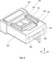
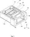
次に、本発明の一実施の形態のフェルール101の構成を説明する。図6および図7は、本発明の実施の形態のフェルール101の構成の概要を説明する斜視図である。図8は、フェルール101の構成を示す6面図である。図9は、フェルール101の構成を示す、図8(A)に示されるAA’線またはBB’線における切断部端面図である。図9(A)は、図8(A)に示されるAA’線における切断部端面図である。図9(B)は、図8(A)に示されるBB’線における切断部端面図である。Next, the configuration of the
図10は、フェルール101の構成を示す、図8(F)に示されるCC’線、DD’線、EE’線またはFF’線における切断部端面図である。図10(A)は、図8(F)に示されるCC’線における切断部端面図である。図10(B)は、図8(F)に示されるDD’線における切断部端面図である。図10(C)は、図8(F)に示されるEE’線における切断部端面図である。図10(D)は、図8(F)に示されるFF’線における切断部端面図である。Figure 10 shows the configuration of the
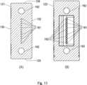
図11は、フェルール101の構成を示す、図8(F)に示されるGG’線またはHH’線における切断部端面図である。図11(A)は、図8(F)に示されるGG’線における切断部端面図である。図11(B)は、図8(F)に示されるHH’線における切断部端面図である。Figure 11 shows the configuration of the
フェルール101は、スリーブまたはガイドピンによって整列し、光ファイバを保持固定する部材である。例えば、フェルール101は、MTコネクタフェルールである。フェルール101は、MPOコネクタまたはMTコネクタなどの光ファイバコネクタに用いられる。例えば、フェルール101は、ハウジングと共に、光ファイバに取り付ける光コネクタである光ファイバコネクタプラグを構成する。例えば、フェルール101は、光ファイバコードの端部に装着される。The
フェルール101は、樹脂から成形されている。例えば、フェルール101は、PPSまたはPEEKなどの熱可塑性樹脂を射出成形することにより製造される。また、例えば、フェルール101は、エポキシ樹脂等の熱硬化性樹脂を用いたトランスファ成形により製造される。すなわち、フェルール101は、複数の光ファイバを接続するための光ファイバコネクタのフェルールであって、樹脂から成形されるフェルールである。The
フェルール101には、接続部121、ブーツ装着部122、接続端面131、上面132、左側面133、右側面134、底面135、接着剤注入穴141、凹部142、凹部143、凹部144、光ファイバコード挿入口145、光ファイバ挿入穴161、ガイドピン穴162、光ファイバ溝163、窪み部171、窪み部172および薄肉部181が形成されている。The
接続部121、ブーツ装着部122、接続端面131、上面132、左側面133、右側面134、底面135、接着剤注入穴141、凹部142、光ファイバコード挿入口145、光ファイバ挿入穴161、ガイドピン穴162、光ファイバ溝163、窪み部171、窪み部172および薄肉部181は、それぞれ、図1乃至図5を参照して説明した接続部21、ブーツ装着部22、接続端面31、上面32、左側面33、右側面34、底面35、接着剤注入穴41、凹部42、光ファイバコード挿入口45、光ファイバ挿入穴61、ガイドピン穴62、光ファイバ溝63、窪み部71、窪み部72および薄肉部81のそれぞれと同様なので、その説明は適宜省略する。The
また、上面132には、接着剤注入穴141および凹部143が形成されている。接着剤注入穴141は、上面132に開口している。接着剤注入穴141は、フェルール101に光ファイバが挿入された後、光ファイバを固定するための接着剤が注入される。また、接着剤注入穴141は、複数の光ファイバ挿入穴161および光ファイバコード挿入口145に連通している。The
凹部143は、上面132に形成されている。図9(A)、図10(C)および図10(D)に示されるように、凹部143は、光ファイバ挿入穴161の一部分の上側に形成されている。すなわち、凹部143は、上面132のうち、光ファイバ挿入穴161が内部に形成されている部分の上面132の部分に設けられている。より具体的には、凹部143は、光ファイバ挿入穴161の部分のうち、光ファイバ挿入穴161の他方の端部が開口している接着剤注入穴141側の部分の上側に形成されている。The
また、図9(B)、図10(A)、図10(B)および図10(C)に示されるように、凹部143は、2つのガイドピン穴162のそれぞれの一部分の上側に形成されている。すなわち、凹部143は、上面132のうち、2つのガイドピン穴162のそれぞれが内部に形成されている部分の上面132の部分に設けられている。より具体的には、図9(B)に示されるように、凹部143は、2つのガイドピン穴162のそれぞれの部分のうち、前後方向の中央部分の上側に形成されている。凹部143は、光ファイバ挿入穴161、ガイドピン穴162、接着剤注入穴141、後述する凹部142および後述する凹部144とは連通しない。As shown in Figs. 9(B), 10(A), 10(B) and 10(C), the
凹部143は、上面132のうちの、接着剤注入穴141の開口の周囲に形成されている。凹部143は、接着剤注入穴141の矩形状の開口の前側、右側および左側を囲うように、上側から見てコの字状(U字形状)に形成されている。すなわち、凹部143は、接着剤注入穴141の矩形状の開口に対して、接続端面131側、左側面133側および右側面134側に形成されている。言い換えれば、凹部143は、ファイバ挿入穴161およびガイドピン穴162の上側に形成されている。The
図9および図10に示されるように、凹部143の底側の隅(内側の角部)は、曲面状に形成されている。例えば、凹部143の底側の隅は、球冠状に形成されている。また、凹部143の部分のうち、接続端面131に近接する部分であって、光ファイバ挿入穴161の開口に近接する部分は、接続端面131側に張り出している。As shown in Figures 9 and 10, the bottom corner (inner corner) of the
また、凹部143は、Z軸とY軸とで規定される仮想的な平面であって、X軸方向における接続端面131の中心位置を通る仮想的な平面に対して、面対称に形成されている。すなわち、凹部143は、互いに平行に配列されている光ファイバ挿入穴161の中心を通る仮想的な第1の面に直交する仮想的な第2の面であって、接続端面131の中央部と交差する仮想的な第2の面に対して、面対称に形成されている。The
このように、凹部143は、上面132のうち、光ファイバ挿入穴161が内部に形成されている部分の上面132の部分に設けられている。また、凹部143は、上面132のうち、2つのガイドピン穴162のそれぞれが内部に形成されている部分の上面132の一部分に設けられている。In this way, the
凹部143は、上面132における接着剤注入穴141の矩形状の開口部の3つの辺であって、接続端面131側の辺および接続端面131側の辺に隣接する辺の3つの辺を囲うように形成されている。The
なお、凹部143は、光ファイバ挿入穴161の部分の上側にのみ形成するようにしてもよい。また、凹部143は、2つのガイドピン穴162のそれぞれの部分の上側にのみ形成するようにしてもよい。The
凹部143を設けたので、フェルール11を成形するときに生じる、樹脂の残留応力による歪を抑制し、光ファイバ挿入穴61の曲がりをより小さくして、光ファイバ挿入穴61の開口の位置をより精度良く配置できる。また、ガイドピン穴162の曲がりをより小さくして、ガイドピン穴162の開口の位置をより精度良く配置できる。By providing the
底面135には、凹部142および凹部144が形成されている。凹部142は、接着剤注入穴141に対向する位置に形成されている。凹部142は、光ファイバ挿入穴161、ガイドピン穴162および接着剤注入穴141とは連通しない。凹部142は、光ファイバコード挿入口145とも連通しない。The
凹部142は、窪み部171および窪み部172からなる。薄肉部181は、フェルール101における他の部分の肉厚よりも薄く形成されている。The
凹部144は、底面135に形成されている。図9(A)、図10(C)および図10(D)に示されるように、凹部144は、光ファイバ挿入穴161の一部分の下側に形成されている。すなわち、凹部144は、底面135のうち、光ファイバ挿入穴161が内部に形成されている部分の底面135の部分に設けられている。より具体的には、凹部144は、光ファイバ挿入穴161の部分のうち、光ファイバ挿入穴161の他方の端部が開口している接着剤注入穴141側の部分の下側に形成されている。The
また、図9(B)、図10(A)、図10(B)および図10(C)に示されるように、凹部144は、2つのガイドピン穴162のそれぞれの一部分の下側に形成されている。すなわち、凹部144は、底面135のうち、2つのガイドピン穴162のそれぞれが内部に形成されている部分の底面135の部分に設けられている。より具体的には、図9(B)に示されるように、凹部144は、2つのガイドピン穴162のそれぞれの部分のうち、前後方向の中央部分の下側に形成されている。凹部144は、光ファイバ挿入穴161、ガイドピン穴162、接着剤注入穴141、凹部142および凹部143とは連通しない。As shown in Figs. 9(B), 10(A), 10(B) and 10(C), the
凹部144は、底面135のうちの、凹部142の開口の周囲に形成されている。凹部144は、凹部142の矩形状の開口の前側、右側および左側を囲うように、下側から見てコの字状(U字形状)に形成されている。すなわち、凹部144は、凹部142の矩形状の開口に対して、接続端面131側、左側面133側および右側面134側に形成されている。言い換えれば、凹部144は、ファイバ挿入穴161およびガイドピン穴162の下側に形成されている。The
図9および図10に示されるように、凹部144の底側の隅(内側の角部)は、曲面状に形成されている。例えば、凹部144の底側の隅は、球冠状に形成されている。また、凹部144の部分のうち、接続端面131に近接する部分であって、光ファイバ挿入穴161の開口に近接する部分は、接続端面131側に張り出している。As shown in Figures 9 and 10, the bottom corner (inner corner) of the
また、凹部144は、Z軸とY軸とで規定される仮想的な平面であって、X軸方向における接続端面131の中心位置を通る仮想的な平面に対して、面対称に形成されている。すなわち、凹部144は、互いに平行に配列されている光ファイバ挿入穴161の中心を通る仮想的な第1の面に直交する仮想的な第2の面であって、接続端面131の中央部と交差する仮想的な第2の面に対して、面対称に形成されている。The
このように、凹部144は、底面135のうち、光ファイバ挿入穴161が内部に形成されている部分の底面135の部分に設けられている。また、凹部144は、底面135のうち、2つのガイドピン穴162のそれぞれが内部に形成されている部分の底面135の部分に設けられている。In this way, the
さらに、凹部143は、X軸とY軸とで規定される仮想的な平面であって、Y軸方向における接続端面131の中心位置を通る仮想的な平面に対して、凹部144と面対称に形成されている。すなわち、凹部143は、上面132と底面135とに挟まれている、上面132および底面135に平行な仮想的な面に対して、凹部144と面対称に形成されている。Furthermore,
このように、凹部144は、底面135における凹部142の矩形状の開口部の3つの辺であって、接続端面131面側の辺および接続端面131側の辺に隣接する辺の3つの辺を囲うように形成されている。In this way, the
なお、凹部144は、光ファイバ挿入穴161の部分の下側にのみ形成するようにしてもよい。また、凹部144は、2つのガイドピン穴162のそれぞれの部分の下側にのみ形成するようにしてもよい。The
凹部144を設けたので、フェルール11を成形するときに生じる、樹脂の残留応力による歪を抑制し、光ファイバ挿入穴61の曲がりをより小さくして、光ファイバ挿入穴61の開口の位置をより精度良く配置できる。また、ガイドピン穴162の曲がりをより小さくして、ガイドピン穴162の開口の位置をより精度良く配置できる。By providing the
凹部143若しくは凹部144のいずれか一方または両方を設けることで、光ファイバ挿入穴161の開口の位置のばらつきを0.1μmより小さくすることができる。これにより、従来、極めて困難であった、シングルモード光ファイバの接続に適したフェルール11を歩留まり良く製造することができる。By providing either or both of the
以上のように、本発明によれば、光ファイバ挿入穴の曲がりをより小さくして、光ファイバ挿入穴の開口の位置をより精度良く配置できる。As described above, according to the present invention, the bending of the optical fiber insertion hole can be reduced, and the position of the opening of the optical fiber insertion hole can be positioned with greater precision.
このように、フェルール101は、複数の光ファイバを接続するための光ファイバコネクタのフェルールであり、樹脂から成形される。フェルール101には、互いに平行に配列されている、複数の光ファイバのそれぞれを通すための光ファイバ挿入穴161と、光ファイバ挿入穴161に平行に、光ファイバ挿入穴161を挟むように配列されている2つのガイドピン穴162と、嵌合されたとき、他のデバイスと接する側の面であって、光ファイバ挿入穴161およびガイドピン穴162が開口している面である接続端面131に隣接する面のうちの、所定の面である上面132に開口している、光ファイバを固定するための接着剤を注入するための穴である接着剤注入穴141と、接続端面131に隣接する面のうちの、上面132に対向する面である底面135において、接着剤注入穴141に対向する位置に設けられている凹部142と、底面135のうち、光ファイバ挿入穴161が内部に形成されている部分の底面135の部分に設けられている凹部144とが形成されている。凹部142は、光ファイバ挿入穴161、ガイドピン穴162および接着剤注入穴141とは連通しない。凹部144は、光ファイバ挿入穴161、ガイドピン穴162、接着剤注入穴141および凹部142とは連通しない。In this way, the
凹部144を、底面135のうち、2つのガイドピン穴162のそれぞれが内部に形成されている部分の底面135の部分に形成することができる。The
凹部144を、互いに平行に配列されている光ファイバ挿入穴161の中心を通る仮想的な上面132に直交する仮想的な底面135であって、接続端面131の中央部と交差する仮想的な底面135に対して、面対称に形成することができる。The
上面132のうちの、光ファイバ挿入穴161が内部に形成されている部分の上面132の部分に凹部143をさらに形成することができる。凹部143は、光ファイバ挿入穴161、ガイドピン穴162、接着剤注入穴141、凹部142および凹部144とは連通しない。A
凹部143を、上面132のうち、2つのガイドピン穴162のそれぞれが内部に形成されている部分の上面132の部分に形成することができる。The
凹部143を、互いに平行に配列されている光ファイバ挿入穴161の中心を通る仮想的な上面132に直交する仮想的な底面135であって、接続端面131の中央部と交差する仮想的な底面135に対して、面対称に形成することができる。The
凹部143を、上面132と底面135とに挟まれている、上面132および底面135に平行な仮想的な面に対して、凹部144と面対称に形成することができる。The
凹部142を、他の部分の肉厚よりも薄い肉厚の薄肉部181により接着剤注入穴141と遮断することができる。The
凹部142を、底面135から所定の深さの窪み部172と、窪み部172の深さに比較して、底面135からの深さがより深く、接続端面131側に配置されている窪み部171とからなるようにすることができる。The
凹部142の底側の隅を、曲面状に形成することができる。The bottom corners of the
また、本発明の実施の形態は、上述した実施の形態に限定されるものではなく、本発明の要旨を逸脱しない範囲において種々の変更が可能である。Furthermore, the embodiments of the present invention are not limited to the above-mentioned embodiments, and various modifications are possible without departing from the spirit of the present invention.
11 フェルール, 21 接続部, 22 ブーツ装着部, 31 接続端面, 32 上面, 33 左側面, 34 右側面, 35 底面, 41 接着剤注入穴, 42 凹部, 45 光ファイバコード挿入口, 61 光ファイバ挿入穴, 62 ガイドピン穴, 63 光ファイバ溝, 71および72 窪み部, 81 薄肉部81, 101 フェルール1, 121 接続部, 122 ブーツ装着部, 131 接続端面, 132 上面, 133 左側面, 134 右側面, 135 底面, 141 接着剤注入穴, 142乃至144 凹部, 145 光ファイバコード挿入口, 161 光ファイバ挿入穴, 162 ガイドピン穴, 163 光ファイバ溝, 171および172 窪み部, 181 薄肉部11 ferrule, 21 connection portion, 22 boot mounting portion, 31 connection end face, 32 top face, 33 left side face, 34 right side face, 35 bottom face, 41 adhesive injection hole, 42 recess, 45 optical fiber cord insertion port, 61 optical fiber insertion hole, 62 guide pin hole, 63 optical fiber groove, 71 and 72 recessed portion, 81
Claims (8)
Translated fromJapanese互いに平行に配列されている、複数の前記光ファイバのそれぞれを通すための光ファイバ挿入穴と、
前記光ファイバ挿入穴に平行に、前記光ファイバ挿入穴を挟むように配列されている2つのガイドピン穴と、
前記光ファイバ挿入穴および前記ガイドピン穴が開口している面である接続端面に隣接する面のうちの、所定の面である第1の面に開口している、前記光ファイバを固定するための接着剤を注入するための穴である接着剤注入穴と、
前記接続端面に隣接する面のうちの、前記第1の面に対向する面である第2の面において、前記接着剤注入穴に対向する位置に設けられている第1の凹部と、
前記第2の面のうち、前記光ファイバ挿入穴が内部に形成されている部分の前記第2の面の部分に設けられていて、前記第2の面のうち、2つのガイドピン穴のそれぞれが内部に形成されている部分の前記第2の面の部分まで延びている第2の凹部と
が形成されていて、
前記第1の凹部は、前記光ファイバ挿入穴、前記ガイドピン穴および前記接着剤注入穴とは連通せず、
前記第2の凹部は、前記光ファイバ挿入穴、前記ガイドピン穴、前記接着剤注入穴および前記第1の凹部とは連通せず、互いに平行に配列されている前記光ファイバ挿入穴の複数の中心線を面内に含む第1の仮想面に直交する第2の仮想面であって、前記接続端面の中央部と交差する第2の仮想面に対して、面対称に形成されている
フェルール。 A ferrule for an optical fiber connector for connecting a plurality of optical fibers, the ferrule being molded from resin,
an optical fiber insertion hole for passing each of the optical fibers, the optical fibers being arranged in parallel to each other;
two guide pin holes arranged parallel to the optical fiber insertion hole so as to sandwich the optical fiber insertion hole;
an adhesive injection hole for injecting an adhesive for fixing the optical fiber, the adhesive injection hole being opened in a first face, which is a predetermined face among faces adjacent to the connection end face, which is a face in which the optical fiber insertion hole and the guide pin hole are opened;
a first recess provided in a second surface, which is a surface facing the first surface among surfaces adjacent to the connection end surface, at a position facing the adhesive injection hole;
a second recess provided on a portion of the second surfacewhere the optical fiber insertion hole is formed, and extending to a portion of the second surface where each of the two guide pin holes is formed ,
the first recess does not communicate with the optical fiber insertion hole, the guide pin hole, and the adhesive injection hole;
The second recess is not in communication with the optical fiber insertion hole, the guide pin hole, the adhesive injection hole and the first recess, and is formed symmetrically with respect to a second imaginary plane that is perpendicular to a first imaginary plane including a plurality of center lines of the optical fiber insertion holes that are arranged parallel to one another and that intersects with a center portion of the connection end face.
Ferrule.
前記第1の面のうちの、前記光ファイバ挿入穴が内部に形成されている部分の前記第1の面の部分に第3の凹部がさらに形成されていて、
前記第3の凹部は、前記光ファイバ挿入穴、前記ガイドピン穴、前記接着剤注入穴、前記第1の凹部および前記第2の凹部とは連通しない
フェルール。 2. The ferrule according to claim 1,
a third recess is further formed in a portion of the first surface where the optical fiber insertion hole is formed,
The third recess does not communicate with the optical fiber insertion hole, the guide pin hole, the adhesive injection hole, the first recess, and the second recess.
前記第3の凹部は、前記第1の面のうち、2つのガイドピン穴のそれぞれが内部に形成されている部分の前記第1の面の部分まで延びているフェルール。The ferrule according toclaim 2 ,
The third recessextends to a portion of the first surface where two guide pin holes are formed inside.
前記第3の凹部は、前記第2の仮想面に対して、面対称に形成されているフェルール。The ferrule according toclaim 3 ,
The third recess is formed symmetrically with respect tothe second imaginary plane .
前記第3の凹部は、前記第1の面と前記第2の面とに挟まれている、前記第1の面および前記第2の面に平行な仮想的な面に対して、前記第2の凹部と面対称に形成されている
フェルール。The ferrule according toclaim 2 ,
The third recess is formed symmetrically to the second recess with respect to a virtual plane that is sandwiched between the first surface and the second surface and is parallel to the first surface and the second surface.
前記第1の凹部は、他の部分の肉厚よりも薄い肉厚の薄肉部により前記接着剤注入穴と遮断されている
フェルール。 2. The ferrule according to claim 1,
The first recess is blocked from the adhesive injection hole by a thin-walled portion having a thickness thinner than that of other portions of the ferrule.
前記第1の凹部は、前記第2の面から所定の深さの第1の窪み部と、前記第1の窪み部の深さに比較して、前記第2の面からの深さがより深く、前記接続端面側に配置されている第2の窪み部とからなるフェルール。 2. The ferrule according to claim 1,
The first recess of the ferrule comprises a first recess portion having a predetermined depth from the second surface, and a second recess portion having a depth from the second surface deeper than the depth of the first recess portion and disposed on the connection end surface side.
前記第1の凹部の底側の隅は、曲面状に形成されているフェルール。 2. The ferrule according to claim 1,
A corner of the bottom side of the first recess is formed into a curved shape.
Priority Applications (2)
| Application Number | Priority Date | Filing Date | Title |
|---|---|---|---|
| JP2025020887AJP7669088B1 (en) | 2025-02-12 | 2025-02-12 | Ferrules |
| JP2025063750AJP7710781B1 (en) | 2025-02-12 | 2025-04-08 | Ferrules |
Applications Claiming Priority (1)
| Application Number | Priority Date | Filing Date | Title |
|---|---|---|---|
| JP2025020887AJP7669088B1 (en) | 2025-02-12 | 2025-02-12 | Ferrules |
Related Child Applications (1)
| Application Number | Title | Priority Date | Filing Date |
|---|---|---|---|
| JP2025063750ADivisionJP7710781B1 (en) | 2025-02-12 | 2025-04-08 | Ferrules |
Publications (1)
| Publication Number | Publication Date |
|---|---|
| JP7669088B1true JP7669088B1 (en) | 2025-04-28 |
Family
ID=95513975
Family Applications (2)
| Application Number | Title | Priority Date | Filing Date |
|---|---|---|---|
| JP2025020887AActiveJP7669088B1 (en) | 2025-02-12 | 2025-02-12 | Ferrules |
| JP2025063750AActiveJP7710781B1 (en) | 2025-02-12 | 2025-04-08 | Ferrules |
Family Applications After (1)
| Application Number | Title | Priority Date | Filing Date |
|---|---|---|---|
| JP2025063750AActiveJP7710781B1 (en) | 2025-02-12 | 2025-04-08 | Ferrules |
Country Status (1)
| Country | Link |
|---|---|
| JP (2) | JP7669088B1 (en) |
Citations (7)
| Publication number | Priority date | Publication date | Assignee | Title |
|---|---|---|---|---|
| JP2004069880A (en)* | 2002-08-05 | 2004-03-04 | Alps Electric Co Ltd | Ferrule for multi-core optical fiber connector, and apparatus for manufacturing it |
| JP2005189616A (en)* | 2003-12-26 | 2005-07-14 | Fujikura Ltd | Optical ferrule molding method, optical ferrule molding die, and optical ferrule |
| WO2010074032A1 (en)* | 2008-12-24 | 2010-07-01 | 株式会社フジクラ | Optical ferrule, die for molding optical ferrule, process for producing optical ferrule, and ferrule with optical fiber |
| WO2022158018A1 (en)* | 2021-01-22 | 2022-07-28 | 株式会社フジクラ | Ferrule and ferrule structure |
| US20220381998A1 (en)* | 2021-05-25 | 2022-12-01 | Commscope Technologies Llc | Windowless ferrule |
| WO2024024348A1 (en)* | 2022-07-28 | 2024-02-01 | 古河電気工業株式会社 | Ferrule, method for manufacturing ferrule, ferrule-equipped fiber ribbon, and method for manufacturing ferrule-equipped fiber ribbon |
| WO2025013575A1 (en)* | 2023-07-12 | 2025-01-16 | 株式会社フジクラ | Optical connector and ferrule |
Family Cites Families (3)
| Publication number | Priority date | Publication date | Assignee | Title |
|---|---|---|---|---|
| JP4165849B2 (en)* | 1999-10-01 | 2008-10-15 | 株式会社フジクラ | Ferrule for multi-fiber optical connector |
| JPWO2019064773A1 (en)* | 2017-09-26 | 2020-09-03 | 住友電気工業株式会社 | Spacer, optical connector and optical connection structure |
| JP2020030242A (en)* | 2018-08-20 | 2020-02-27 | 住友電気工業株式会社 | Optical connection parts and optical connectors |
- 2025
- 2025-02-12JPJP2025020887Apatent/JP7669088B1/enactiveActive
- 2025-04-08JPJP2025063750Apatent/JP7710781B1/enactiveActive
Patent Citations (7)
| Publication number | Priority date | Publication date | Assignee | Title |
|---|---|---|---|---|
| JP2004069880A (en)* | 2002-08-05 | 2004-03-04 | Alps Electric Co Ltd | Ferrule for multi-core optical fiber connector, and apparatus for manufacturing it |
| JP2005189616A (en)* | 2003-12-26 | 2005-07-14 | Fujikura Ltd | Optical ferrule molding method, optical ferrule molding die, and optical ferrule |
| WO2010074032A1 (en)* | 2008-12-24 | 2010-07-01 | 株式会社フジクラ | Optical ferrule, die for molding optical ferrule, process for producing optical ferrule, and ferrule with optical fiber |
| WO2022158018A1 (en)* | 2021-01-22 | 2022-07-28 | 株式会社フジクラ | Ferrule and ferrule structure |
| US20220381998A1 (en)* | 2021-05-25 | 2022-12-01 | Commscope Technologies Llc | Windowless ferrule |
| WO2024024348A1 (en)* | 2022-07-28 | 2024-02-01 | 古河電気工業株式会社 | Ferrule, method for manufacturing ferrule, ferrule-equipped fiber ribbon, and method for manufacturing ferrule-equipped fiber ribbon |
| WO2025013575A1 (en)* | 2023-07-12 | 2025-01-16 | 株式会社フジクラ | Optical connector and ferrule |
Also Published As
| Publication number | Publication date |
|---|---|
| JP7710781B1 (en) | 2025-07-22 |
Similar Documents
| Publication | Publication Date | Title |
|---|---|---|
| KR100937284B1 (en) | Optical Connectors Ferrules, Optical Connectors, Optical Components, and Optical Wiring Systems | |
| US7850372B2 (en) | Optical connector with optical fiber | |
| JP5165872B2 (en) | Ferrule, optical waveguide connector manufacturing method using the ferrule, and optical waveguide connector | |
| US9606300B2 (en) | Adapter and optical connector coupling system | |
| CN110178063B (en) | Optical fiber holding member, optical connector, and optical coupling structure | |
| US20120033920A1 (en) | Optical fiber ferrule | |
| JPWO2020149262A1 (en) | Optical connector and optical connection structure | |
| JPWO2016170782A1 (en) | Multi-core optical connector | |
| JP7669088B1 (en) | Ferrules | |
| US11150418B2 (en) | Optical connector ferrule and optical connector | |
| JP7723109B2 (en) | Optical Connectors and Plugs | |
| JP7737887B2 (en) | Ferrule, optical connector, and method of manufacturing the optical connector | |
| JP5398409B2 (en) | Optical connector | |
| JP2021081477A (en) | Optical connector ferrule, optical connector, and manufacturing method of spacer | |
| CN220961923U (en) | Multicore optical fiber ferrule | |
| US20250147243A1 (en) | Optical connection structure, first connection body, first optical connector, second connection body, second optical connector, and method for manufacturing optical connection structure | |
| EP4625013A1 (en) | Ferrule, optical connector, and method for manufacturing optical connector | |
| JP2023178776A (en) | Ferrule, optical connector, metal mold for ferrule molding, and ferrule manufacturing method | |
| JP2009053365A (en) | Optical connector | |
| JP2023084257A (en) | Optical connector and optical connection structure | |
| JP3218262B2 (en) | Optical waveguide components | |
| JPH0588046A (en) | Optical connector | |
| JP2024112097A (en) | Ferrules and Optical Connectors | |
| CN119604793A (en) | Optical connector, ferrule and optical coupling structure | |
| KR20210043350A (en) | Optical Adapter |
Legal Events
| Date | Code | Title | Description |
|---|---|---|---|
| A621 | Written request for application examination | Free format text:JAPANESE INTERMEDIATE CODE: A621 Effective date:20250218 | |
| A871 | Explanation of circumstances concerning accelerated examination | Free format text:JAPANESE INTERMEDIATE CODE: A871 Effective date:20250218 | |
| A131 | Notification of reasons for refusal | Free format text:JAPANESE INTERMEDIATE CODE: A131 Effective date:20250310 | |
| A521 | Request for written amendment filed | Free format text:JAPANESE INTERMEDIATE CODE: A523 Effective date:20250324 | |
| TRDD | Decision of grant or rejection written | ||
| A01 | Written decision to grant a patent or to grant a registration (utility model) | Free format text:JAPANESE INTERMEDIATE CODE: A01 Effective date:20250404 | |
| A61 | First payment of annual fees (during grant procedure) | Free format text:JAPANESE INTERMEDIATE CODE: A61 Effective date:20250409 | |
| R150 | Certificate of patent or registration of utility model | Ref document number:7669088 Country of ref document:JP Free format text:JAPANESE INTERMEDIATE CODE: R150 |