JP7667401B2 - Dynamically stiffening medical composite structures - Google Patents
Dynamically stiffening medical composite structuresDownload PDFInfo
- Publication number
- JP7667401B2 JP7667401B2JP2021502825AJP2021502825AJP7667401B2JP 7667401 B2JP7667401 B2JP 7667401B2JP 2021502825 AJP2021502825 AJP 2021502825AJP 2021502825 AJP2021502825 AJP 2021502825AJP 7667401 B2JP7667401 B2JP 7667401B2
- Authority
- JP
- Japan
- Prior art keywords
- layer
- stiffening
- braided
- vacuum
- pressure
- Prior art date
- Legal status (The legal status is an assumption and is not a legal conclusion. Google has not performed a legal analysis and makes no representation as to the accuracy of the status listed.)
- Active
Links
- 239000002131composite materialSubstances0.000titledescription9
- 239000010410layerSubstances0.000claimsdescription802
- 230000003014reinforcing effectEffects0.000claimsdescription86
- 239000012791sliding layerSubstances0.000claimsdescription60
- 238000005452bendingMethods0.000claimsdescription54
- 238000003860storageMethods0.000claimsdescription20
- -1polyethylene terephthalatePolymers0.000claimsdescription16
- 229910001220stainless steelInorganic materials0.000claimsdescription16
- 229920000139polyethylene terephthalatePolymers0.000claimsdescription15
- 239000005020polyethylene terephthalateSubstances0.000claimsdescription15
- 239000010935stainless steelSubstances0.000claimsdescription14
- 230000008859changeEffects0.000claimsdescription12
- 239000000843powderSubstances0.000claimsdescription11
- 238000000034methodMethods0.000description151
- 210000003484anatomyAnatomy0.000description45
- 230000007704transitionEffects0.000description42
- 210000004115mitral valveAnatomy0.000description36
- 239000012530fluidSubstances0.000description33
- 239000011248coating agentSubstances0.000description32
- 238000000576coating methodMethods0.000description32
- 230000033001locomotionEffects0.000description32
- 238000011282treatmentMethods0.000description29
- 239000000835fiberSubstances0.000description27
- 210000002216heartAnatomy0.000description21
- 210000004379membraneAnatomy0.000description21
- 239000012528membraneSubstances0.000description21
- 239000000758substrateSubstances0.000description20
- 210000001035gastrointestinal tractAnatomy0.000description19
- JOYRKODLDBILNP-UHFFFAOYSA-NEthyl urethaneChemical compoundCCOC(N)=OJOYRKODLDBILNP-UHFFFAOYSA-N0.000description17
- 238000007459endoscopic retrograde cholangiopancreatographyMethods0.000description17
- 230000008439repair processEffects0.000description16
- 230000000747cardiac effectEffects0.000description15
- 239000000463materialSubstances0.000description15
- 210000001519tissueAnatomy0.000description15
- 210000000013bile ductAnatomy0.000description14
- 208000027418Wounds and injuryDiseases0.000description12
- 238000002052colonoscopyMethods0.000description12
- 229920001971elastomerPolymers0.000description12
- 210000005246left atriumAnatomy0.000description12
- 210000003734kidneyAnatomy0.000description11
- 210000004072lungAnatomy0.000description11
- 210000000277pancreatic ductAnatomy0.000description10
- 210000004556brainAnatomy0.000description9
- 230000006835compressionEffects0.000description9
- 238000007906compressionMethods0.000description9
- 238000003384imaging methodMethods0.000description9
- 229910052751metalInorganic materials0.000description9
- 239000002184metalSubstances0.000description9
- 210000003157atrial septumAnatomy0.000description8
- 230000008901benefitEffects0.000description8
- 230000002496gastric effectEffects0.000description8
- 230000007246mechanismEffects0.000description8
- 230000002787reinforcementEffects0.000description8
- 210000000813small intestineAnatomy0.000description8
- XLYOFNOQVPJJNP-UHFFFAOYSA-NwaterSubstancesOXLYOFNOQVPJJNP-UHFFFAOYSA-N0.000description8
- 238000012323Endoscopic submucosal dissectionMethods0.000description7
- 230000015572biosynthetic processEffects0.000description7
- 210000004204blood vesselAnatomy0.000description7
- 210000001072colonAnatomy0.000description7
- 238000013461designMethods0.000description7
- 230000001965increasing effectEffects0.000description7
- 238000005096rolling processMethods0.000description7
- 238000007789sealingMethods0.000description7
- 210000005166vasculatureAnatomy0.000description7
- 239000000853adhesiveSubstances0.000description6
- 230000001070adhesive effectEffects0.000description6
- 238000004873anchoringMethods0.000description6
- 210000001765aortic valveAnatomy0.000description6
- 238000004891communicationMethods0.000description6
- 239000000806elastomerSubstances0.000description6
- 229920001296polysiloxanePolymers0.000description6
- 210000005245right atriumAnatomy0.000description6
- 239000005060rubberSubstances0.000description6
- 230000006641stabilisationEffects0.000description6
- 238000011105stabilizationMethods0.000description6
- 229920002725thermoplastic elastomerPolymers0.000description6
- 239000004696Poly ether ether ketoneSubstances0.000description5
- JUPQTSLXMOCDHR-UHFFFAOYSA-Nbenzene-1,4-diol;bis(4-fluorophenyl)methanoneChemical compoundOC1=CC=C(O)C=C1.C1=CC(F)=CC=C1C(=O)C1=CC=C(F)C=C1JUPQTSLXMOCDHR-UHFFFAOYSA-N0.000description5
- 210000004351coronary vesselAnatomy0.000description5
- 210000001198duodenumAnatomy0.000description5
- 238000003780insertionMethods0.000description5
- 230000037431insertionEffects0.000description5
- 239000000314lubricantSubstances0.000description5
- 229920002530polyetherether ketonePolymers0.000description5
- 230000005855radiationEffects0.000description5
- 238000002271resectionMethods0.000description5
- 229920002803thermoplastic polyurethanePolymers0.000description5
- 238000012546transferMethods0.000description5
- 239000004677NylonSubstances0.000description4
- FAPWRFPIFSIZLT-UHFFFAOYSA-MSodium chlorideChemical compound[Na+].[Cl-]FAPWRFPIFSIZLT-UHFFFAOYSA-M0.000description4
- 229910052782aluminiumInorganic materials0.000description4
- XAGFODPZIPBFFR-UHFFFAOYSA-NaluminiumChemical compound[Al]XAGFODPZIPBFFR-UHFFFAOYSA-N0.000description4
- 230000005540biological transmissionEffects0.000description4
- 230000009977dual effectEffects0.000description4
- 238000002181esophagogastroduodenoscopyMethods0.000description4
- 238000002594fluoroscopyMethods0.000description4
- 230000006870functionEffects0.000description4
- 210000005240left ventricleAnatomy0.000description4
- 230000003902lesionEffects0.000description4
- 238000004519manufacturing processMethods0.000description4
- 238000002844meltingMethods0.000description4
- 230000008018meltingEffects0.000description4
- HLXZNVUGXRDIFK-UHFFFAOYSA-Nnickel titaniumChemical compound[Ti].[Ti].[Ti].[Ti].[Ti].[Ti].[Ti].[Ti].[Ti].[Ti].[Ti].[Ni].[Ni].[Ni].[Ni].[Ni].[Ni].[Ni].[Ni].[Ni].[Ni].[Ni].[Ni].[Ni].[Ni]HLXZNVUGXRDIFK-UHFFFAOYSA-N0.000description4
- 229910001000nickel titaniumInorganic materials0.000description4
- 229920001778nylonPolymers0.000description4
- 229920003023plasticPolymers0.000description4
- 239000004033plasticSubstances0.000description4
- 229920001343polytetrafluoroethylenePolymers0.000description4
- 239000004810polytetrafluoroethyleneSubstances0.000description4
- 230000002829reductive effectEffects0.000description4
- 210000002784stomachAnatomy0.000description4
- 238000001356surgical procedureMethods0.000description4
- 229920000785ultra high molecular weight polyethylenePolymers0.000description4
- 210000001631vena cava inferiorAnatomy0.000description4
- 238000012800visualizationMethods0.000description4
- 241001631457CannulaSpecies0.000description3
- 229920000271Kevlar®Polymers0.000description3
- 229920000508VectranPolymers0.000description3
- 239000004979VectranSubstances0.000description3
- 230000005856abnormalityEffects0.000description3
- 230000009471actionEffects0.000description3
- 210000000709aortaAnatomy0.000description3
- 210000002376aorta thoracicAnatomy0.000description3
- 210000001715carotid arteryAnatomy0.000description3
- 230000001684chronic effectEffects0.000description3
- 238000005520cutting processMethods0.000description3
- 230000006378damageEffects0.000description3
- 238000007598dipping methodMethods0.000description3
- 230000002183duodenal effectEffects0.000description3
- 230000000694effectsEffects0.000description3
- 229920001746electroactive polymerPolymers0.000description3
- 238000012326endoscopic mucosal resectionMethods0.000description3
- 238000002674endoscopic surgeryMethods0.000description3
- 239000004811fluoropolymerSubstances0.000description3
- 229920002313fluoropolymerPolymers0.000description3
- 230000002209hydrophobic effectEffects0.000description3
- 238000005286illuminationMethods0.000description3
- 208000014674injuryDiseases0.000description3
- 230000002262irrigationEffects0.000description3
- 238000003973irrigationMethods0.000description3
- 239000004761kevlarSubstances0.000description3
- 229920001684low density polyethylenePolymers0.000description3
- 239000004702low-density polyethyleneSubstances0.000description3
- 230000008569processEffects0.000description3
- 238000002432robotic surgeryMethods0.000description3
- 239000011780sodium chlorideSubstances0.000description3
- 238000005507sprayingMethods0.000description3
- 230000008733traumaEffects0.000description3
- WFKWXMTUELFFGS-UHFFFAOYSA-NtungstenChemical compound[W]WFKWXMTUELFFGS-UHFFFAOYSA-N0.000description3
- 229910052721tungstenInorganic materials0.000description3
- 239000010937tungstenSubstances0.000description3
- 210000002438upper gastrointestinal tractAnatomy0.000description3
- 238000004804windingMethods0.000description3
- 229920002799BoPETPolymers0.000description2
- 229920000049Carbon (fiber)Polymers0.000description2
- RYGMFSIKBFXOCR-UHFFFAOYSA-NCopperChemical compound[Cu]RYGMFSIKBFXOCR-UHFFFAOYSA-N0.000description2
- PEDCQBHIVMGVHV-UHFFFAOYSA-NGlycerineChemical compoundOCC(O)COPEDCQBHIVMGVHV-UHFFFAOYSA-N0.000description2
- 239000005041Mylar™Substances0.000description2
- 206010039897SedationDiseases0.000description2
- 229920001494TechnoraPolymers0.000description2
- 239000004760aramidSubstances0.000description2
- 229920003235aromatic polyamidePolymers0.000description2
- 239000004917carbon fiberSubstances0.000description2
- 210000000038chestAnatomy0.000description2
- 238000004140cleaningMethods0.000description2
- 238000010276constructionMethods0.000description2
- 229910052802copperInorganic materials0.000description2
- 239000010949copperSubstances0.000description2
- 230000008878couplingEffects0.000description2
- 238000010168coupling processMethods0.000description2
- 238000005859coupling reactionMethods0.000description2
- 238000002788crimpingMethods0.000description2
- 230000007423decreaseEffects0.000description2
- 229910003460diamondInorganic materials0.000description2
- 239000010432diamondSubstances0.000description2
- FPAFDBFIGPHWGO-UHFFFAOYSA-Ndioxosilane;oxomagnesium;hydrateChemical compoundO.[Mg]=O.[Mg]=O.[Mg]=O.O=[Si]=O.O=[Si]=O.O=[Si]=O.O=[Si]=OFPAFDBFIGPHWGO-UHFFFAOYSA-N0.000description2
- 201000010099diseaseDiseases0.000description2
- 208000037265diseases, disorders, signs and symptomsDiseases0.000description2
- 238000001839endoscopyMethods0.000description2
- 230000002708enhancing effectEffects0.000description2
- 238000001125extrusionMethods0.000description2
- 239000004744fabricSubstances0.000description2
- PCHJSUWPFVWCPO-UHFFFAOYSA-NgoldChemical compound[Au]PCHJSUWPFVWCPO-UHFFFAOYSA-N0.000description2
- 229910052737goldInorganic materials0.000description2
- 239000010931goldSubstances0.000description2
- 230000002439hemostatic effectEffects0.000description2
- 238000013152interventional procedureMethods0.000description2
- 229920000126latexPolymers0.000description2
- 239000004816latexSubstances0.000description2
- 238000011068loading methodMethods0.000description2
- 210000003750lower gastrointestinal tractAnatomy0.000description2
- 230000001050lubricating effectEffects0.000description2
- 239000003550markerSubstances0.000description2
- VNWKTOKETHGBQD-UHFFFAOYSA-NmethaneChemical compoundCVNWKTOKETHGBQD-UHFFFAOYSA-N0.000description2
- 230000000926neurological effectEffects0.000description2
- 210000002445nippleAnatomy0.000description2
- 238000010422paintingMethods0.000description2
- 230000036961partial effectEffects0.000description2
- 230000037361pathwayEffects0.000description2
- 239000002985plastic filmSubstances0.000description2
- 230000011514reflexEffects0.000description2
- 230000036280sedationEffects0.000description2
- 229910052709silverInorganic materials0.000description2
- 239000004332silverSubstances0.000description2
- 239000004950technoraSubstances0.000description2
- 238000002560therapeutic procedureMethods0.000description2
- 210000003708urethraAnatomy0.000description2
- 230000000007visual effectEffects0.000description2
- 229920002261Corn starchPolymers0.000description1
- 229920001651CyanoacrylatePolymers0.000description1
- CWYNVVGOOAEACU-UHFFFAOYSA-NFe2+Chemical compound[Fe+2]CWYNVVGOOAEACU-UHFFFAOYSA-N0.000description1
- 206010018001Gastrointestinal perforationDiseases0.000description1
- 229920000106Liquid crystal polymerPolymers0.000description1
- 239000004977Liquid-crystal polymers (LCPs)Substances0.000description1
- MWCLLHOVUTZFKS-UHFFFAOYSA-NMethyl cyanoacrylateChemical compoundCOC(=O)C(=C)C#NMWCLLHOVUTZFKS-UHFFFAOYSA-N0.000description1
- 239000004697PolyetherimideSubstances0.000description1
- 239000004698PolyethyleneSubstances0.000description1
- 241000256247Spodoptera exiguaSpecies0.000description1
- PPBRXRYQALVLMV-UHFFFAOYSA-NStyreneNatural productsC=CC1=CC=CC=C1PPBRXRYQALVLMV-UHFFFAOYSA-N0.000description1
- 208000007536ThrombosisDiseases0.000description1
- RTAQQCXQSZGOHL-UHFFFAOYSA-NTitaniumChemical compound[Ti]RTAQQCXQSZGOHL-UHFFFAOYSA-N0.000description1
- 101150044878US18 geneProteins0.000description1
- 230000003187abdominal effectEffects0.000description1
- NIXOWILDQLNWCW-UHFFFAOYSA-Nacrylic acid groupChemical groupC(C=C)(=O)ONIXOWILDQLNWCW-UHFFFAOYSA-N0.000description1
- 230000002411adverseEffects0.000description1
- 208000007474aortic aneurysmDiseases0.000description1
- 238000013459approachMethods0.000description1
- 210000001367arteryAnatomy0.000description1
- 230000001746atrial effectEffects0.000description1
- 238000012550auditMethods0.000description1
- 238000010009beatingMethods0.000description1
- 230000009286beneficial effectEffects0.000description1
- 210000000941bileAnatomy0.000description1
- 230000000903blocking effectEffects0.000description1
- 238000009954braidingMethods0.000description1
- 210000000621bronchiAnatomy0.000description1
- 230000009172burstingEffects0.000description1
- 238000007675cardiac surgeryMethods0.000description1
- 239000003086colorantSubstances0.000description1
- 210000002808connective tissueAnatomy0.000description1
- 238000007596consolidation processMethods0.000description1
- 239000000356contaminantSubstances0.000description1
- 238000011109contaminationMethods0.000description1
- 230000008602contractionEffects0.000description1
- 229920001577copolymerPolymers0.000description1
- 239000008120corn starchSubstances0.000description1
- 229940099112cornstarchDrugs0.000description1
- 125000004122cyclic groupChemical group0.000description1
- 230000003247decreasing effectEffects0.000description1
- 230000007547defectEffects0.000description1
- 230000010339dilationEffects0.000description1
- 238000002224dissectionMethods0.000description1
- 239000012153distilled waterSubstances0.000description1
- 230000002526effect on cardiovascular systemEffects0.000description1
- 239000013536elastomeric materialSubstances0.000description1
- 230000003073embolic effectEffects0.000description1
- 230000010102embolizationEffects0.000description1
- 238000005538encapsulationMethods0.000description1
- 230000001747exhibiting effectEffects0.000description1
- 229920000295expanded polytetrafluoroethylenePolymers0.000description1
- 210000001105femoral arteryAnatomy0.000description1
- 210000003191femoral veinAnatomy0.000description1
- 239000011152fibreglassSubstances0.000description1
- 238000011049fillingMethods0.000description1
- 238000007667floatingMethods0.000description1
- 239000006260foamSubstances0.000description1
- 239000002783friction materialSubstances0.000description1
- 231100001014gastrointestinal tract lesionToxicity0.000description1
- 235000011187glycerolNutrition0.000description1
- 239000008187granular materialSubstances0.000description1
- 239000004519greaseSubstances0.000description1
- 210000004013groinAnatomy0.000description1
- 231100001261hazardousToxicity0.000description1
- 230000035876healingEffects0.000description1
- 210000003709heart valveAnatomy0.000description1
- 230000023597hemostasisEffects0.000description1
- 230000002706hydrostatic effectEffects0.000description1
- 210000003767ileocecal valveAnatomy0.000description1
- 210000003111iliac veinAnatomy0.000description1
- 239000007943implantSubstances0.000description1
- 238000002513implantationMethods0.000description1
- 238000011065in-situ storageMethods0.000description1
- 208000015181infectious diseaseDiseases0.000description1
- 230000003993interactionEffects0.000description1
- 230000002452interceptive effectEffects0.000description1
- 210000000936intestineAnatomy0.000description1
- 238000005304joiningMethods0.000description1
- 238000003475laminationMethods0.000description1
- 210000002429large intestineAnatomy0.000description1
- 230000000670limiting effectEffects0.000description1
- 239000007788liquidSubstances0.000description1
- 239000011159matrix materialSubstances0.000description1
- 210000000713mesenteryAnatomy0.000description1
- 230000001537neural effectEffects0.000description1
- 210000000056organAnatomy0.000description1
- 239000002245particleSubstances0.000description1
- 239000011295pitchSubstances0.000description1
- 229920006255plastic filmPolymers0.000description1
- 229920003223poly(pyromellitimide-1,4-diphenyl ether)Polymers0.000description1
- 239000004417polycarbonateSubstances0.000description1
- 229920000515polycarbonatePolymers0.000description1
- 229920001601polyetherimidePolymers0.000description1
- 229920000573polyethylenePolymers0.000description1
- 229920000098polyolefinPolymers0.000description1
- 229920000915polyvinyl chloridePolymers0.000description1
- 239000004800polyvinyl chlorideSubstances0.000description1
- 229940071643prefilled syringeDrugs0.000description1
- 238000004321preservationMethods0.000description1
- 238000003825pressingMethods0.000description1
- 210000001187pylorusAnatomy0.000description1
- 210000002321radial arteryAnatomy0.000description1
- 230000009467reductionEffects0.000description1
- 230000002040relaxant effectEffects0.000description1
- 230000000284resting effectEffects0.000description1
- 230000002441reversible effectEffects0.000description1
- 238000006748scratchingMethods0.000description1
- 230000002393scratching effectEffects0.000description1
- 238000000926separation methodMethods0.000description1
- 229910001285shape-memory alloyInorganic materials0.000description1
- 238000004904shorteningMethods0.000description1
- 238000002579sigmoidoscopyMethods0.000description1
- 239000002356single layerSubstances0.000description1
- 239000002689soilSubstances0.000description1
- 239000002904solventSubstances0.000description1
- 238000010561standard procedureMethods0.000description1
- 239000000454talcSubstances0.000description1
- 229910052623talcInorganic materials0.000description1
- 230000001225therapeutic effectEffects0.000description1
- 210000001042thoracic arteryAnatomy0.000description1
- 229910052719titaniumInorganic materials0.000description1
- 239000010936titaniumSubstances0.000description1
- 230000000699topical effectEffects0.000description1
- 210000003437tracheaAnatomy0.000description1
- 238000002604ultrasonographyMethods0.000description1
- 210000003462veinAnatomy0.000description1
- 238000013022ventingMethods0.000description1
- 230000002747voluntary effectEffects0.000description1
Images


Classifications
- A—HUMAN NECESSITIES
- A61—MEDICAL OR VETERINARY SCIENCE; HYGIENE
- A61M—DEVICES FOR INTRODUCING MEDIA INTO, OR ONTO, THE BODY; DEVICES FOR TRANSDUCING BODY MEDIA OR FOR TAKING MEDIA FROM THE BODY; DEVICES FOR PRODUCING OR ENDING SLEEP OR STUPOR
- A61M25/00—Catheters; Hollow probes
- A61M25/0043—Catheters; Hollow probes characterised by structural features
- A61M25/005—Catheters; Hollow probes characterised by structural features with embedded materials for reinforcement, e.g. wires, coils, braids
- A—HUMAN NECESSITIES
- A61—MEDICAL OR VETERINARY SCIENCE; HYGIENE
- A61M—DEVICES FOR INTRODUCING MEDIA INTO, OR ONTO, THE BODY; DEVICES FOR TRANSDUCING BODY MEDIA OR FOR TAKING MEDIA FROM THE BODY; DEVICES FOR PRODUCING OR ENDING SLEEP OR STUPOR
- A61M25/00—Catheters; Hollow probes
- A61M25/0097—Catheters; Hollow probes characterised by the hub
- A—HUMAN NECESSITIES
- A61—MEDICAL OR VETERINARY SCIENCE; HYGIENE
- A61M—DEVICES FOR INTRODUCING MEDIA INTO, OR ONTO, THE BODY; DEVICES FOR TRANSDUCING BODY MEDIA OR FOR TAKING MEDIA FROM THE BODY; DEVICES FOR PRODUCING OR ENDING SLEEP OR STUPOR
- A61M25/00—Catheters; Hollow probes
- A61M25/01—Introducing, guiding, advancing, emplacing or holding catheters
- A61M25/0102—Insertion or introduction using an inner stiffening member, e.g. stylet or push-rod
- A—HUMAN NECESSITIES
- A61—MEDICAL OR VETERINARY SCIENCE; HYGIENE
- A61M—DEVICES FOR INTRODUCING MEDIA INTO, OR ONTO, THE BODY; DEVICES FOR TRANSDUCING BODY MEDIA OR FOR TAKING MEDIA FROM THE BODY; DEVICES FOR PRODUCING OR ENDING SLEEP OR STUPOR
- A61M25/00—Catheters; Hollow probes
- A61M25/01—Introducing, guiding, advancing, emplacing or holding catheters
- A61M25/0105—Steering means as part of the catheter or advancing means; Markers for positioning
- A61M25/0133—Tip steering devices
- A61M25/0147—Tip steering devices with movable mechanical means, e.g. pull wires
- A—HUMAN NECESSITIES
- A61—MEDICAL OR VETERINARY SCIENCE; HYGIENE
- A61B—DIAGNOSIS; SURGERY; IDENTIFICATION
- A61B1/00—Instruments for performing medical examinations of the interior of cavities or tubes of the body by visual or photographical inspection, e.g. endoscopes; Illuminating arrangements therefor
- A61B1/00064—Constructional details of the endoscope body
- A61B1/00071—Insertion part of the endoscope body
- A61B1/00078—Insertion part of the endoscope body with stiffening means
- A—HUMAN NECESSITIES
- A61—MEDICAL OR VETERINARY SCIENCE; HYGIENE
- A61B—DIAGNOSIS; SURGERY; IDENTIFICATION
- A61B1/00—Instruments for performing medical examinations of the interior of cavities or tubes of the body by visual or photographical inspection, e.g. endoscopes; Illuminating arrangements therefor
- A61B1/00131—Accessories for endoscopes
- A61B1/00135—Oversleeves mounted on the endoscope prior to insertion
- A—HUMAN NECESSITIES
- A61—MEDICAL OR VETERINARY SCIENCE; HYGIENE
- A61M—DEVICES FOR INTRODUCING MEDIA INTO, OR ONTO, THE BODY; DEVICES FOR TRANSDUCING BODY MEDIA OR FOR TAKING MEDIA FROM THE BODY; DEVICES FOR PRODUCING OR ENDING SLEEP OR STUPOR
- A61M25/00—Catheters; Hollow probes
- A61M25/0043—Catheters; Hollow probes characterised by structural features
- A61M2025/0063—Catheters; Hollow probes characterised by structural features having means, e.g. stylets, mandrils, rods or wires to reinforce or adjust temporarily the stiffness, column strength or pushability of catheters which are already inserted into the human body
- A—HUMAN NECESSITIES
- A61—MEDICAL OR VETERINARY SCIENCE; HYGIENE
- A61M—DEVICES FOR INTRODUCING MEDIA INTO, OR ONTO, THE BODY; DEVICES FOR TRANSDUCING BODY MEDIA OR FOR TAKING MEDIA FROM THE BODY; DEVICES FOR PRODUCING OR ENDING SLEEP OR STUPOR
- A61M25/00—Catheters; Hollow probes
- A61M25/01—Introducing, guiding, advancing, emplacing or holding catheters
- A61M25/0105—Steering means as part of the catheter or advancing means; Markers for positioning
- A61M25/0133—Tip steering devices
- A61M25/0147—Tip steering devices with movable mechanical means, e.g. pull wires
- A61M2025/015—Details of the distal fixation of the movable mechanical means
- A—HUMAN NECESSITIES
- A61—MEDICAL OR VETERINARY SCIENCE; HYGIENE
- A61M—DEVICES FOR INTRODUCING MEDIA INTO, OR ONTO, THE BODY; DEVICES FOR TRANSDUCING BODY MEDIA OR FOR TAKING MEDIA FROM THE BODY; DEVICES FOR PRODUCING OR ENDING SLEEP OR STUPOR
- A61M25/00—Catheters; Hollow probes
- A61M25/01—Introducing, guiding, advancing, emplacing or holding catheters
- A61M25/09—Guide wires
- A61M2025/0915—Guide wires having features for changing the stiffness
- A—HUMAN NECESSITIES
- A61—MEDICAL OR VETERINARY SCIENCE; HYGIENE
- A61M—DEVICES FOR INTRODUCING MEDIA INTO, OR ONTO, THE BODY; DEVICES FOR TRANSDUCING BODY MEDIA OR FOR TAKING MEDIA FROM THE BODY; DEVICES FOR PRODUCING OR ENDING SLEEP OR STUPOR
- A61M25/00—Catheters; Hollow probes
- A61M25/0043—Catheters; Hollow probes characterised by structural features
- A61M25/0045—Catheters; Hollow probes characterised by structural features multi-layered, e.g. coated
- A—HUMAN NECESSITIES
- A61—MEDICAL OR VETERINARY SCIENCE; HYGIENE
- A61M—DEVICES FOR INTRODUCING MEDIA INTO, OR ONTO, THE BODY; DEVICES FOR TRANSDUCING BODY MEDIA OR FOR TAKING MEDIA FROM THE BODY; DEVICES FOR PRODUCING OR ENDING SLEEP OR STUPOR
- A61M25/00—Catheters; Hollow probes
- A61M25/0043—Catheters; Hollow probes characterised by structural features
- A61M25/005—Catheters; Hollow probes characterised by structural features with embedded materials for reinforcement, e.g. wires, coils, braids
- A61M25/0051—Catheters; Hollow probes characterised by structural features with embedded materials for reinforcement, e.g. wires, coils, braids made from fenestrated or weakened tubing layer
- A—HUMAN NECESSITIES
- A61—MEDICAL OR VETERINARY SCIENCE; HYGIENE
- A61M—DEVICES FOR INTRODUCING MEDIA INTO, OR ONTO, THE BODY; DEVICES FOR TRANSDUCING BODY MEDIA OR FOR TAKING MEDIA FROM THE BODY; DEVICES FOR PRODUCING OR ENDING SLEEP OR STUPOR
- A61M25/00—Catheters; Hollow probes
- A61M25/01—Introducing, guiding, advancing, emplacing or holding catheters
- A61M25/06—Body-piercing guide needles or the like
- A61M25/0662—Guide tubes
Landscapes
- Health & Medical Sciences (AREA)
- Life Sciences & Earth Sciences (AREA)
- Engineering & Computer Science (AREA)
- Veterinary Medicine (AREA)
- Biomedical Technology (AREA)
- Heart & Thoracic Surgery (AREA)
- Animal Behavior & Ethology (AREA)
- General Health & Medical Sciences (AREA)
- Public Health (AREA)
- Biophysics (AREA)
- Anesthesiology (AREA)
- Hematology (AREA)
- Pulmonology (AREA)
- Mechanical Engineering (AREA)
- Media Introduction/Drainage Providing Device (AREA)
- Surgery (AREA)
- Endoscopes (AREA)
- Nuclear Medicine, Radiotherapy & Molecular Imaging (AREA)
- Optics & Photonics (AREA)
- Pathology (AREA)
- Radiology & Medical Imaging (AREA)
- Physics & Mathematics (AREA)
- Medical Informatics (AREA)
- Molecular Biology (AREA)
Description
Translated fromJapanese(関連出願の相互参照)
本出願は、「動的硬化医療用複合構造(DYNAMICALLY RIGIDIZING COMPOSITE MEDICAL STRUCTURES)」の名称で2019年4月17日に出願された米国仮特許出願第62/835,101号と、「動的硬化医療用複合構造 (DYNAMICALLY RIGIDIZING COMPOSITE MEDICAL STRUCTURES)」の名称で2019年5月29日に出願された米国仮特許出願第62/854,199号と、「動的硬化医療用複合構造 (DYNAMICALLY RIGIDIZING COMPOSITE MEDICAL STRUCTURES)」の名称で2018年12月17日に出願された米国仮特許出願第62/780,820号と、「動的硬化編組オーバーチューブ(BRAIDED DYNAMICALLY RIGIDIZING OVERTUBE)」の名称で2018年7月19日に出願された米国仮特許出願第62/700,760号の優先権を主張し、これらの全体が参照により本明細書に援用される。CROSS-REFERENCE TO RELATED APPLICATIONS
This application is a continuation of U.S. Provisional Patent Application No. 62/835,101, filed April 17, 2019, entitled "DYNAMICALLY RIGIDIZING COMPOSITE MEDICAL STRUCTURES," U.S. Provisional Patent Application No. 62/854,199, filed May 29, 2019, entitled "DYNAMICALLY RIGIDIZING COMPOSITE MEDICAL STRUCTURES," U.S. Provisional Patent Application No. 62/780,820, filed December 17, 2018, entitled "DYNAMICALLY RIGIDIZING COMPOSITE MEDICAL STRUCTURES," and U.S. Provisional Patent Application No. 62/780,820, filed December 17, 2018, entitled "BRAIDED DYNAMICALLY RIGIDIZING COMPOSITE MEDICAL STRUCTURES," all of which are hereby incorporated by reference in their entirety. This application claims priority to U.S. Provisional Patent Application No. 62/700,760, filed July 19, 2018, entitled "METHOD FOR USE IN A HIGH-SPEED PHOTO-PROPYLENE SURFACE TUBE," which is incorporated herein by reference in its entirety.
本出願はまた、「動的硬化オーバーチューブ(DYNAMICALLY RIGIDIZING OVERTUBE)」の名称で2018年5月16日に出願された米国仮特許出願第62/672,444号の優先権を主張して、「動的硬化オーバーチューブ(DYNAMICALLY RIGIDIZING OVERTUBE)」の名称で2018年7月19日に出願された国際特許出願第PCT/US2018/042946号と、「動的硬化オーバーチューブ(DYNAMICALLY RIGIDIZING OVERTUBE)」の名称で2017年7月20日に出願された米国仮特許出願第62/535,134号にも関連しており、その全体が参照により本明細書に援用される。This application also claims priority to U.S. Provisional Patent Application No. PCT/US2018/042946, filed July 19, 2018, entitled "DYNAMICALLY RIGIDIZING OVERTUBE," which claims priority to U.S. Provisional Patent Application No. 62/672,444, filed May 16, 2018, entitled "DYNAMICALLY RIGIDIZING OVERTUBE," and U.S. Provisional Patent Application No. 62/535,134, filed July 20, 2017, entitled "DYNAMICALLY RIGIDIZING OVERTUBE," which are incorporated herein by reference in their entireties.
本出願はまた、「小腸内での内視鏡前進の為のデバイス(DEVICE FOR ENDOSCOPIS ADVANCEMENT THROUGH THE SMALL INTESTINE)」の名称で2016年5月20日に出願された米国仮特許出願第62,339,593号の優先権を主張する現在の国際公開第2017/041052号である、「小腸内での内視鏡前進の為のデバイス(DEVICE FOR ENDOCSOPIS ADVANCEMENT THROUGH THE SMALL INTESTINE)」の名称で2016年9月2日に出願された国際特許出願第PCT/US2016/050290号の米国特許法第371条に基づく国内段階出願である、現在の米国特許出願公開第2018/0271354号である「小腸内での内視鏡前進の為のデバイス(DEVICE FOR ENDOCSOPIS ADVANCEMENT THROUGH THE SMALL INTESTINE)」の名称で2018年3月2日に出願された米国特許出願第15/757,230号と、「小腸内での内視鏡前進の為のデバイス(DEVICE FOR ENDOCSOPIS ADVANCEMENT THROUGH THE SMALL INTESTINE)」の名称で2015年9月3日に出願された米国仮特許出願第62/213,908号とに関連しており、その全体が参照により本明細書に援用される。This application also relates to a device for endoscopy advancement through the small intestine, now U.S. Patent Application Publication No. 2018/0271354, which is a national stage application under 35 U.S.C. 371 of International Patent Application No. PCT/US2016/050290, filed September 2, 2016, entitled "DEVICE FOR ENDOSCOPIS ADVANCEMENT THROUGH THE SMALL INTESTINE," now WO 2017/041052, which claims priority to U.S. Provisional Patent Application No. 62,339,593, filed May 20, 2016, entitled "DEVICE FOR ENDOSCOPIS ADVANCEMENT THROUGH THE SMALL INTESTINE." No. 15/757,230, filed March 2, 2018, entitled "DEVICE FOR ENDOCSOPIS ADVANCEMENT THROUGH THE SMALL INTESTINE," and U.S. Provisional Patent Application No. 62/213,908, filed September 3, 2015, entitled "DEVICE FOR ENDOCSOPIS ADVANCEMENT THROUGH THE SMALL INTESTINE," both of which are incorporated herein by reference in their entireties.
(参照による援用)
本明細書に言及される全ての公報及び特許出願は、個々の公報又は特許出願の各々が参照により援用されることが明確かつ個別的に指摘された場合と同じ程度に、参照により本明細書に援用される。(Incorporated by reference)
All publications and patent applications mentioned in this specification are herein incorporated by reference to the same extent as if each individual publication or patent application was specifically and individually indicated to be incorporated by reference.
本発明は、動的硬化医療用複合構造に関する。The present invention relates to dynamically hardening medical composite structures.
医療処置中には、介入性医療デバイスが解剖学的構造内で湾曲するか輪状になって医療デバイスの進入を困難にすることがある。During medical procedures, interventional medical devices may bend or loop within the anatomical structures, making it difficult to advance the medical device.
消化管の過度のカーブ又はループにより内視鏡がそれ以上は前進できない時に起こる消化管ループ形成は、内視鏡について特に周知の臨床的課題である。実際に、大腸内視鏡検査を受けた100人の患者のうち91人にループ形成が発生したことが、或る研究から判明した。(非特許文献1)。消化管ループ形成は、血管壁及び腸間膜を伸張させるので処置を長引かせて患者に痛みを与え得る。更に、消化管ループ形成は穿孔の発生率の上昇につながる。消化管ループ形成という深刻なケースでは、ループ形成が大腸の長さを伸張させて大腸内視鏡は端部に達するのに充分なほど長くないので、完全な大腸内視鏡検査は不可能である。消化管ループ形成は精密な先端制御にとっての障害であって、ハンドルと内視鏡先端の間の所望の1対1動作関係をユーザから奪う。このような問題は一般に、大腸内視鏡検査、食道十二指腸鏡検査(EGD)、小腸鏡検査、内視鏡的逆行性胆道膵管造影(ERCP)、(ESD(内視鏡的粘膜下層剥離術)とEMR(内視鏡的粘膜切除術)とを含む)介入性内視鏡処置、ロボット可撓性内視鏡検査、経口ロボット外科手術(TORS)、(ルーワイ法(Roux-en-Y)を含む)解剖学的構造異常のケース、そして広範囲の内視鏡処置にわたって、またNOTES(自然孔経管腔的内視鏡手術)処置の間に発生する。従って、消化管ループ形成の防止を助けて消化管へのより良好なアクセスを提供するデバイスの必要性がある。Gastrointestinal looping, which occurs when an endoscope cannot be advanced any further due to excessive curvature or looping of the gastrointestinal tract, is a particularly well-known clinical challenge for endoscopes. In fact, one study found that looping occurred in 91 of 100 patients undergoing colonoscopy (Non-Patent Document 1). Gastrointestinal looping can prolong the procedure and cause pain to the patient because it stretches the blood vessel walls and mesentery. Furthermore, gastrointestinal looping leads to an increased incidence of perforation. In severe cases of gastrointestinal looping, complete colonoscopy is not possible because the looping extends the length of the colon and the colonoscope is not long enough to reach the end. Gastrointestinal looping is an obstacle to precise tip control, depriving the user of the desired one-to-one operating relationship between the handle and the endoscope tip. Such problems commonly occur during colonoscopy, esophagoduodenoscopy (EGD), enteroscopy, endoscopic retrograde cholangiopancreatography (ERCP), interventional endoscopic procedures (including ESD (endoscopic submucosal dissection) and EMR (endoscopic mucosal resection)), robotic flexible endoscopy, transoral robotic surgery (TORS), cases of anatomical abnormalities (including Roux-en-Y), and across a wide range of endoscopic procedures, and during NOTES (natural orifice transluminal endoscopic surgery) procedures. Thus, there is a need for a device that helps prevent gastrointestinal loop formation and provides better access to the gastrointestinal tract.
医療機器を前進させる際の同様の難題は、例えば、肺、腎臓、脳、心窩部、そして他の解剖学的箇所での介入性処置の間に起こり得る。従って、さもなければ到達が困難な解剖学的箇所に到達する為の安全、効率的、そして精密なアクセスを提供するデバイスが必要である。Similar challenges in advancing medical devices can arise during interventional procedures, for example, in the lungs, kidneys, brain, epigastric region, and other anatomical locations. Thus, devices that provide safe, efficient, and precise access to reach otherwise difficult-to-reach anatomical locations are needed.
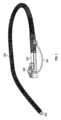
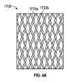
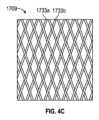
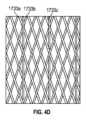
概して、一実施形態において、硬化デバイスは、長形可撓性チューブと、長形可撓性チューブの上に配置される編組層と、可撓性チューブ及び編組層の上の外側層と、真空又は圧力源に装着されるように構成される長形可撓性チューブと外側層との間の入口とを含む。編組層は、長形可撓性チューブが直線状である時に長形可撓性チューブの長手軸線に対して5~40度の編組角度で共に編組される複数の撚糸を有する。硬化デバイスは、真空又は圧力が入口から印加される時の硬化構成と、真空又は圧力が入口から印加されない時の可撓構成とを有するように構成される。編組角度は、硬化デバイスが可撓構成である時に硬化デバイスが屈曲すると変化するように構成される。Generally, in one embodiment, the stiffening device includes an elongated flexible tube, a braided layer disposed over the elongated flexible tube, an outer layer over the flexible tube and the braided layer, and an inlet between the elongated flexible tube and the outer layer configured to be attached to a vacuum or pressure source. The braided layer has a plurality of strands braided together at a braid angle of 5 to 40 degrees relative to a longitudinal axis of the elongated flexible tube when the elongated flexible tube is straight. The stiffening device is configured to have a stiffening configuration when vacuum or pressure is applied through the inlet and a flexible configuration when vacuum or pressure is not applied through the inlet. The braid angle is configured to change as the stiffening device flexes when the stiffening device is in the flexible configuration.
上記及び他の実施形態は以下の特徴のうち一つ以上を含み得る。編組角度は10と35度の間であり得る。編組角度は15と25度の間であり得る。硬化構成での硬化デバイスは、可撓構成での硬化デバイスより少なくとも2倍は剛性であり得る。硬化構成での硬化デバイスは、可撓構成での硬化デバイスより少なくとも5倍は剛性である。硬化は更に、編組層に近接して編組層より低い摩擦係数を有する滑動層を含み得る。長形可撓性チューブは、中に延在する補強要素を含み得る。補強要素は、コイル又は複数の輪状要素を含み得る。複数の撚糸は4~60のインチ当たりピック数で共に編組され得る。撚糸は、ポリエチレンテレフタレート又はステンレス鋼を含み得る。編組層は、長形可撓性チューブに対して30~70%の被覆率を提供し得る。複数の撚糸は96本以上の撚糸を含み得る。入口は圧力源に装着されるように構成され、硬化デバイスは更に貯気層を中に含み得る。貯気層は、入口から圧力が印加される時に編組層へ押圧されるように構成され得る。外側層は更に、複数の補強要素を中に含み得る。入口は真空源に装着されるように構成され、外側層は薄い可撓性シースであり得る。硬化デバイスは更に、編組層と外側層との間に径方向間隙を含み得る。間隙は0.00002”~0.04”の厚さを有し得る。硬化デバイスは更に操向性遠位端部を含み得る。硬化デバイスは更に、長形可撓性チューブと外側層との間に密閉チャネルを含み得る。密閉チャネルは、ワーキングチャネル、ケーブルガイド、又は膨張内腔を含み得る。These and other embodiments may include one or more of the following features. The braid angle may be between 10 and 35 degrees. The braid angle may be between 15 and 25 degrees. The stiffened device in the stiffened configuration may be at least two times stiffer than the stiffened device in the flexible configuration. The stiffened device in the stiffened configuration is at least five times stiffer than the stiffened device in the flexible configuration. The stiffening may further include a sliding layer proximate the braided layer and having a lower coefficient of friction than the braided layer. The elongated flexible tube may include a reinforcing element extending therethrough. The reinforcing element may include a coil or a plurality of hoop elements. The plurality of strands may be braided together at a picks per inch count of 4 to 60. The strands may include polyethylene terephthalate or stainless steel. The braided layer may provide a coverage of 30 to 70% for the elongated flexible tube. The plurality of strands may include 96 or more strands. The inlet is configured to be attached to a pressure source, and the stiffening device may further include an air reservoir therein. The reservoir layer may be configured to be pressed against the braided layer when pressure is applied from the inlet. The outer layer may further include a plurality of reinforcing elements therein. The inlet is configured to be attached to a vacuum source, and the outer layer may be a thin flexible sheath. The stiffening device may further include a radial gap between the braided layer and the outer layer. The gap may have a thickness of 0.00002" to 0.04". The stiffening device may further include a steerable distal end. The stiffening device may further include a sealed channel between the elongated flexible tube and the outer layer. The sealed channel may include a working channel, a cable guide, or an inflation lumen.
概して、一実施形態において、体内腔で硬化デバイスを前進させる方法は、(1)硬化デバイスが可撓構成である間に硬化デバイスを体内腔へ挿入することであって、硬化デバイスが、長形可撓性チューブと、硬化デバイスが直線状である時に5~40度の編組角度で共に編組される複数の撚糸を有する編組層と、外側層とを含み、可撓性チューブが可撓構成であると編組角度が変化することと、(2)硬化デバイスが体内腔の所望の箇所に達した時に、可撓性チューブと外側層の間の真空又は圧力を操作して、可撓構成より剛性である硬化構成へ硬化デバイスを移行させることとを含む。Generally, in one embodiment, a method of advancing a stiffening device through a body lumen includes (1) inserting the stiffening device into the body lumen while the stiffening device is in a flexible configuration, the stiffening device including an elongated flexible tube, a braided layer having multiple strands braided together at a braid angle of 5-40 degrees when the stiffening device is straight, and an outer layer, the braid angle changing when the flexible tube is in the flexible configuration, and (2) manipulating a vacuum or pressure between the flexible tube and the outer layer when the stiffening device reaches a desired location in the body lumen to transition the stiffening device to a stiffening configuration that is more rigid than the flexible configuration.
上記及び他の実施形態は以下の特徴のうち一つ以上を含み得る。この方法は更に、真空又は圧力を操作した後に真空又は圧力を解放して硬化デバイスを再び可撓構成へ移行させることを含み得る。編組角度は10と35度の間であり得る。編組角度は15と25度の間であり得る。この方法は更に、硬化デバイスが硬化構成である間に硬化デバイスにスコープを通過させることを含み得る。この方法は、硬化デバイスの操向性遠位端部を体内腔で操向することを含み得る。体内腔は消化管にあり得る。体内腔は心臓にあり得る。体内腔は腎臓にあり得る。体内腔は肺にあり得る。体内腔は脳にあり得る。These and other embodiments may include one or more of the following features. The method may further include releasing the vacuum or pressure after manipulating the vacuum or pressure to transition the stiffening device back to the flexible configuration. The braid angle may be between 10 and 35 degrees. The braid angle may be between 15 and 25 degrees. The method may further include passing a scope through the stiffening device while the stiffening device is in the stiffening configuration. The method may include steering the steerable distal end of the stiffening device through the body lumen. The body lumen may be in the digestive tract. The body lumen may be in the heart. The body lumen may be in the kidney. The body lumen may be in the lung. The body lumen may be in the brain.
概して、一実施形態において、硬化デバイスは、長形可撓性チューブと、長形可撓性チューブの上に配置される編組層と、可撓性チューブ及び編組層の上の外側層と、真空又は圧力源に装着されるように構成される長形可撓性チューブと外側層の間の入口とを含む。硬化デバイスは、真空又は圧力が入口から印加される時の硬化構成と、真空又は圧力が入口から印加されない時の可撓構成とを有するように構成される。硬化構成での硬化デバイスと可撓構成での硬化デバイスとの剛性比は5より大きい。Generally, in one embodiment, the stiffening device includes an elongated flexible tube, a braided layer disposed over the elongated flexible tube, an outer layer over the flexible tube and the braided layer, and an inlet between the elongated flexible tube and the outer layer configured to be attached to a vacuum or pressure source. The stiffening device is configured to have a stiffening configuration when vacuum or pressure is applied from the inlet and a flexible configuration when vacuum or pressure is not applied from the inlet. A stiffness ratio between the stiffening device in the stiffening configuration and the stiffening device in the flexible configuration is greater than 5.
上記及び他の実施形態は、以下の特徴のうち一つ以上を含み得る。比は6より大きい。比は10より大きい。編組層は、長形可撓性チューブが直線状である時に長形可撓性チューブの長手軸線に対して5~40度の編組角度で共に編組される複数の撚糸を有しる。編組角度は10と35度の間であり得る。硬化デバイスは更に、編組層に近接して編組層より低い摩擦係数を有する滑動層を含み得る。長形可撓性チューブは、中に延在する補強要素を含み得る。補強要素はコイル又は複数の輪状要素を含み得る。編組層は4~60のインチ当たりピック数で共に編組される複数の撚糸を含み得る。編組層は共に編組される複数の撚糸を含み、撚糸はポリエチレンテレフタレート又はステンレス鋼を含み得る。編組層は長形可撓性チューブに対して30~70%の被覆率を提供し得る。編組層は、共に編組される96本以上の撚糸を含み得る。入口は圧力源に装着されるように構成され得る。硬化デバイスは更に貯気層を中に含み、貯気層は、入口から圧力が供給される時に編組層に押圧されるように構成され得る。外側層は更に、複数の補強要素を中に含み得る。入口は真空源に装着されるように構成され得る。外側層は薄い可撓性シースであり得る。硬化デバイスは更に、編組層と外側層の間の径方向間隙を含み得る。間隙は0.00002”~0.04”の厚さを有し得る。硬化デバイスは更に操向性遠位端部を含み得る。硬化デバイスは更に、長形可撓性チューブと外側層との間の密閉チャネルを含み得る。密閉チャネルは、ワーキングチャネル、ケーブルガイド、又は膨張内腔を含み得る。These and other embodiments may include one or more of the following features: The ratio is greater than 6. The ratio is greater than 10. The braided layer has a plurality of strands braided together at a braid angle of 5 to 40 degrees relative to a longitudinal axis of the elongated flexible tube when the elongated flexible tube is straight. The braid angle may be between 10 and 35 degrees. The stiffening device may further include a sliding layer proximate the braided layer having a lower coefficient of friction than the braided layer. The elongated flexible tube may include a reinforcing element extending therethrough. The reinforcing element may include a coil or a plurality of hoop elements. The braided layer may include a plurality of strands braided together at a picks per inch of 4 to 60. The braided layer includes a plurality of strands braided together, and the strands may include polyethylene terephthalate or stainless steel. The braided layer may provide a coverage of 30 to 70% for the elongated flexible tube. The braided layer may include 96 or more strands braided together. The inlet may be configured to be attached to a pressure source. The stiffening device may further include a reservoir layer therein, the reservoir layer configured to be pressed against the braided layer when pressure is applied from the inlet. The outer layer may further include a plurality of reinforcing elements therein. The inlet may be configured to be attached to a vacuum source. The outer layer may be a thin flexible sheath. The stiffening device may further include a radial gap between the braided layer and the outer layer. The gap may have a thickness of 0.00002" to 0.04". The stiffening device may further include a steerable distal end. The stiffening device may further include a sealed channel between the elongated flexible tube and the outer layer. The sealed channel may include a working channel, a cable guide, or an inflation lumen.
概して、一実施形態において、体内腔で硬化デバイスを前進させる方法は、(1)硬化デバイスが可撓構成である間に硬化デバイスを体内腔へ挿入することであって、硬化デバイスが長形可撓性チューブと編組層と外側層とを含むことと、(2)硬化デバイスが体内腔の所望の箇所に達した時に、可撓性チューブと外側層との間の真空又は圧力を操作して、可撓構成よりも剛性である硬化構成へ硬化デバイスを移行させることとを含む。硬化構成での剛性と可撓構成での剛性の比は5より大きい。Generally, in one embodiment, a method of advancing a stiffening device through a body lumen includes (1) inserting the stiffening device into the body lumen while the stiffening device is in a flexible configuration, the stiffening device including an elongated flexible tube, a braided layer, and an outer layer, and (2) when the stiffening device reaches a desired location in the body lumen, manipulating a vacuum or pressure between the flexible tube and the outer layer to transition the stiffening device to a stiffened configuration that is stiffer than the flexible configuration. The ratio of stiffness in the stiffened configuration to stiffness in the flexible configuration is greater than 5.
上記及び他の実施形態は以下の特徴のうち一つ以上を含み得る。この方法は更に、真空又は圧力を操作した後に真空又は圧力を解放して硬化デバイスを再び可撓構成に移行させることを含み得る。比は6より大きくてもよい。比は10より大きくてもよい。この方法は更に、硬化デバイスが硬化構成である間に硬化デバイスにスコープを通過させることを含み得る。この方法は更に、硬化デバイスの操向性遠位端部を体内腔で操向することを含み得る。体内腔は消化管にあり得る。体内腔は心臓にあり得る。体内腔は腎臓にあり得る。体内腔は肺にあり得る。体内腔は脳にあり得る。These and other embodiments may include one or more of the following features. The method may further include releasing the vacuum or pressure after manipulating the vacuum or pressure to transition the stiffening device back to the flexible configuration. The ratio may be greater than 6. The ratio may be greater than 10. The method may further include passing a scope through the stiffening device while the stiffening device is in the stiffening configuration. The method may further include steering the steerable distal end of the stiffening device through the body lumen. The body lumen may be in the digestive tract. The body lumen may be in the heart. The body lumen may be in the kidney. The body lumen may be in the lung. The body lumen may be in the brain.
概して、一実施形態において、硬化デバイスは、長形可撓性チューブと、長形可撓性チューブの径方向外側に配置される編組層と、編組層に近接する滑動層と、外側層と、長形可撓性チューブと外側層の間の真空又は圧力入口とを含む。外側層は、可撓性チューブと編組層と滑動層との上にある。入口は、真空又は圧力源に装着されるように構成される。硬化デバイスは、真空又は圧力が入口から印加される時の硬化構成と、真空又は圧力が入口から印加されない時の可撓構成とを有するように構成される。滑動層は、硬化デバイスが可撓構成である時に編組層と長形可撓性チューブ又は外側層との間の摩擦を低減させるように構成される。Generally, in one embodiment, the stiffening device includes an elongated flexible tube, a braided layer disposed radially outward of the elongated flexible tube, a sliding layer adjacent the braided layer, an outer layer, and a vacuum or pressure inlet between the elongated flexible tube and the outer layer. The outer layer overlies the flexible tube, the braided layer, and the sliding layer. The inlet is configured to be attached to a vacuum or pressure source. The stiffening device is configured to have a stiffening configuration when vacuum or pressure is applied from the inlet and a flexible configuration when vacuum or pressure is not applied from the inlet. The sliding layer is configured to reduce friction between the braided layer and the elongated flexible tube or the outer layer when the stiffening device is in the flexible configuration.
上記及び他の実施形態は、以下の特徴のうち一つ以上を含み得る。滑動層は、編組層よりも低い摩擦係数を有し得る。滑動層は粉末を含み得る。硬化構成での硬化デバイスは、可撓構成での硬化デバイスより少なくとも2倍は剛性であり得る。硬化構成での硬化デバイスは、可撓構成での硬化デバイスより少なくとも5倍は剛性であり得る。編組層は、長形可撓性チューブが直線状である時に長形可撓性チューブの長手軸線に対して5~40度の編組角度で共に編組される複数の撚糸を有し得る。編組角度は10と35度の間であり得る。長形可撓性チューブは、中に延在する補強要素を含み得る。補強要素はコイル又は複数の輪状要素を含み得る。編組層は、4~60のインチ当たりピック数で共に編組される複数の撚糸を含み得る。編組層は、共に編組される複数の撚糸を含み、撚糸はポリエチレンテレフタレート又はステンレス鋼を含み得る。編組層は、長形可撓性チューブに対して30~70%の被覆率を提供し得る。編組層は、共に編組される96本の撚糸かより多くの撚糸を含み得る。入口は圧力源に装着されるように構成され得る。硬化デバイスは更に貯気層を中に含み得る。貯気層は、入口から圧力が供給される時に編組層へ押圧されるように構成され得る。外側層は更に、複数の補強要素を中に含み得る。入口は真空源に装着されるように構成され得る。外側層は薄い可撓性シースであり得る。硬化デバイスは更に、編組層と外側層との間に径方向間隙を含み得る。間隙は0.00002”~0.04”の厚さを有し得る。硬化デバイスは更に操向性遠位端部を含み得る。硬化デバイスは更に、長形可撓性チューブと外側層との間に密閉チャネルを含み得る。密閉チャネルは、ワーキングチャネル、ケーブルガイド、又は膨張内腔を含み得る。These and other embodiments may include one or more of the following features. The sliding layer may have a lower coefficient of friction than the braided layer. The sliding layer may include a powder. The cured device in the cured configuration may be at least two times stiffer than the cured device in the flexible configuration. The cured device in the cured configuration may be at least five times stiffer than the cured device in the flexible configuration. The braided layer may have a plurality of strands braided together at a braid angle of 5 to 40 degrees relative to a longitudinal axis of the elongated flexible tube when the elongated flexible tube is straight. The braid angle may be between 10 and 35 degrees. The elongated flexible tube may include a reinforcing element extending therethrough. The reinforcing element may include a coil or a plurality of hoop elements. The braided layer may include a plurality of strands braided together at a picks per inch of 4 to 60. The braided layer may include a plurality of strands braided together, the strands may include polyethylene terephthalate or stainless steel. The braided layer may provide 30-70% coverage for the elongated flexible tube. The braided layer may include 96 or more strands braided together. The inlet may be configured to be attached to a pressure source. The stiffening device may further include a reservoir layer therein. The reservoir layer may be configured to be pressed against the braided layer when pressure is provided from the inlet. The outer layer may further include a plurality of reinforcing elements therein. The inlet may be configured to be attached to a vacuum source. The outer layer may be a thin flexible sheath. The stiffening device may further include a radial gap between the braided layer and the outer layer. The gap may have a thickness of 0.00002" to 0.04". The stiffening device may further include a steerable distal end. The stiffening device may further include a sealing channel between the elongated flexible tube and the outer layer. The sealing channel may include a working channel, a cable guide, or an inflation lumen.
概して、一実施形態において、体内腔で硬化デバイスを前進させる方法は、(1)硬化デバイスが可撓構成である間に硬化デバイスを体内腔へ挿入することであって、硬化デバイスが、長形可撓性チューブと、編組層と、編組層に近接する滑動層と、外側層とを含み、滑動層は、硬化デバイスが可撓構成である間に編組層と長形可撓性チューブ又は外側層との間の摩擦を低減させることと、(2)硬化デバイスが体内腔の所望の箇所に達した時に、可撓性チューブとシースとの間の真空又は圧力を操作して、可撓構成より剛性である硬化構成へ硬化デバイスを移行させることとを含む。Generally, in one embodiment, a method of advancing a stiffening device through a body lumen includes (1) inserting the stiffening device into the body lumen while the stiffening device is in a flexible configuration, the stiffening device including an elongated flexible tube, a braided layer, a sliding layer adjacent the braided layer, and an outer layer, the sliding layer reducing friction between the braided layer and the elongated flexible tube or the outer layer while the stiffening device is in the flexible configuration, and (2) manipulating a vacuum or pressure between the flexible tube and a sheath to transition the stiffening device to a stiffening configuration that is more rigid than the flexible configuration when the stiffening device reaches a desired location in the body lumen.
上記及び他の実施形態は、以下の特徴のうち一つ以上を含み得る。この方法は更に、真空又は圧力を操作した後に真空又は圧力を解放して硬化デバイスを再び可撓構成へ移行させることを含み得る。滑動層は、編組層より低い摩擦係数を有し得る。滑動層は粉末を含み得る。この方法は更に、硬化デバイスが硬化構成である間に硬化デバイスにスコープを通過させることを含み得る。この方法は更に、硬化デバイスの操向性遠位端部を体内腔で操向することを含み得る。体内腔は消化管にあり得る。体内腔は心臓にあり得る。体内腔は腎臓にあり得る。体内腔は肺にあり得る。体内腔は脳にあり得る。These and other embodiments may include one or more of the following features. The method may further include releasing the vacuum or pressure after operating the vacuum or pressure to transition the stiffening device back to the flexible configuration. The sliding layer may have a lower coefficient of friction than the braided layer. The sliding layer may include a powder. The method may further include passing a scope through the stiffening device while the stiffening device is in the stiffening configuration. The method may further include steering the steerable distal end of the stiffening device through the body lumen. The body lumen may be in the digestive tract. The body lumen may be in the heart. The body lumen may be in the kidney. The body lumen may be in the lung. The body lumen may be in the brain.
概して、一実施形態において、硬化デバイスは、補強要素と基材とを含む内側長形可撓性チューブと、長形可撓性チューブの径方向外側に配置される編組層と、編組層の上の外側層と、真空又は圧力源に装着されるように構成される長形可撓性チューブと外側層との間の真空又は圧力入口とを含む。補強要素は5:1を超える幅と厚さのアスペクト比を有する。硬化デバイスは、真空又は圧力が真空入口から印加される時の硬化構成と、真空又は圧力が真空入口から印加されない時の可撓構成とを有するように構成される。Generally, in one embodiment, the stiffening device includes an inner elongated flexible tube including a reinforcing element and a substrate, a braided layer disposed radially outward of the elongated flexible tube, an outer layer over the braided layer, and a vacuum or pressure inlet between the elongated flexible tube and the outer layer configured to be attached to a vacuum or pressure source. The reinforcing element has an aspect ratio of width to thickness greater than 5:1. The stiffening device is configured to have a stiffened configuration when vacuum or pressure is applied from the vacuum inlet and a flexible configuration when vacuum or pressure is not applied from the vacuum inlet.
上記及び他の実施形態は、以下の特徴のうち一つ以上を含み得る。補強要素はコイルであり得る。補強要素は複数の閉リングを含み得る。閉リングは複数のポケット及びノッチを含み得る。補強要素は波状ワイヤを含み得る。補強要素は繊維又は金属ワイヤであり得る。アスペクト比は10:1を超え得る。アスペクト比は11:1を超え得る。長形可撓性チューブには複数の補強要素が設けられ得る。各補強要素の間の間隔は0.0006”インチ以下であり得る。長形可撓性チューブは更に、補強要素が埋設される基材を含み得る。基材はTPU又はTPEを含み得る。These and other embodiments may include one or more of the following features: The reinforcing element may be a coil. The reinforcing element may include a plurality of closed rings. The closed rings may include a plurality of pockets and notches. The reinforcing element may include a corrugated wire. The reinforcing element may be a fabric or a metal wire. The aspect ratio may be greater than 10:1. The aspect ratio may be greater than 11:1. The elongated flexible tube may include a plurality of reinforcing elements. The spacing between each reinforcing element may be 0.0006" or less. The elongated flexible tube may further include a substrate in which the reinforcing elements are embedded. The substrate may include TPU or TPE.
概して、一実施形態において、体内腔で硬化デバイスを前進させる方法は、(1)硬化デバイスが可撓構成である間に硬化デバイスを体内腔へ挿入することであって、硬化デバイスが、補強要素と基材とを有する長形可撓性チューブと、編組層と、外側層とを含み、補強要素が10:1を超える幅と厚さのアスペクト比を有することと、(2)硬化デバイスが体内腔の所望の箇所に達した時に、可撓性チューブと外側層との間の真空又は圧力を操作して、可撓構成より剛性である硬化構成に硬化装置を移行させることとを含む。Generally, in one embodiment, a method of advancing a stiffening device through a body lumen includes (1) inserting the stiffening device into the body lumen while the stiffening device is in a flexible configuration, the stiffening device including an elongated flexible tube having a reinforcing element and a substrate, a braided layer, and an outer layer, the reinforcing element having an aspect ratio of width to thickness greater than 10:1, and (2) manipulating a vacuum or pressure between the flexible tube and the outer layer when the stiffening device reaches a desired location in the body lumen to transition the stiffening device to a stiffening configuration that is more rigid than the flexible configuration.
上記及び他の実施形態は、以下の特徴のうち一つ以上を含み得る。長形可撓性チューブは、真空又は圧力が印加される時に圧縮に抵抗できる。These and other embodiments may include one or more of the following features: The elongated flexible tube is capable of resisting compression when a vacuum or pressure is applied.
概して、一実施形態において、硬化デバイスは、長形可撓性チューブと、長形可撓性チューブの上に配置される編組層と、可撓性チューブ及び編組層の上の外側層と、真空又は圧力源に装着されるように構成される長形可撓性チューブと外側層との間の入口とを含む。編組層は、共に編組される複数の撚糸を有する。硬化デバイスは、真空又は圧力が入口から印加される時の硬化構成と、真空又は圧力が入口から印加されない時の可撓構成とを有するように構成される。硬化デバイスが可撓構成である時に撚糸の端部の相対移動を可能にする環状リングに各端部が埋設又は囲繞される。Generally, in one embodiment, the stiffening device includes an elongated flexible tube, a braided layer disposed over the elongated flexible tube, an outer layer over the flexible tube and the braided layer, and an inlet between the elongated flexible tube and the outer layer configured to be attached to a vacuum or pressure source. The braided layer has a plurality of strands braided together. The stiffening device is configured to have a stiffened configuration when vacuum or pressure is applied through the inlet and a flexible configuration when vacuum or pressure is not applied through the inlet. Each end is embedded or surrounded by an annular ring that allows relative movement of the ends of the strands when the stiffening device is in the flexible configuration.
上記及び他の実施形態は、以下の特徴のうち一つ以上を含み得る。環状リングは材料コーティングを含み得る。環状リングはシリコーン又はウレタンを含み得る。環状リングはおよそ0.005~0.250インチの厚さであり得る。These and other embodiments may include one or more of the following features: The annular ring may include a material coating. The annular ring may include silicone or urethane. The annular ring may be approximately 0.005 to 0.250 inches thick.
概して、一実施形態において、体内腔で硬化デバイスを前進させる方法は、(1)硬化デバイスが可撓構成である間に硬化デバイスを体内腔へ挿入することであって、硬化デバイスが、長形可撓性チューブと、共に編組される複数の撚糸を有する編組層と、外側層とを含むことと、(2)硬化デバイスが体内腔の所望の箇所に達した時に、可撓性チューブとシースとの間の真空又は圧力を操作して、可撓構成より剛性である硬化構成へ硬化デバイスを移行させることとを含む。硬化デバイスが可撓構成である間に撚糸の端部が互いに対して移動するように、各端部が環状リングに埋設又は囲繞される。硬化デバイスが硬化構成である間には、端部は互いに対して実質的に固定される。Generally, in one embodiment, a method of advancing a stiffening device in a body lumen includes (1) inserting the stiffening device into the body lumen while the stiffening device is in a flexible configuration, the stiffening device including an elongated flexible tube, a braided layer having a plurality of strands braided together, and an outer layer, and (2) manipulating a vacuum or pressure between the flexible tube and a sheath to transition the stiffening device to a stiffened configuration that is more rigid than the flexible configuration when the stiffening device reaches a desired location in the body lumen. Each end of the strands is embedded or surrounded by an annular ring such that the ends move relative to each other while the stiffening device is in the flexible configuration. The ends are substantially fixed relative to each other while the stiffening device is in the stiffened configuration.
概して、一実施形態において、硬化デバイスは、長形可撓性チューブと、長形可撓性チューブの上に配置される編組層と、可撓性チューブ及び編組層の上で密閉される外側層と、真空源に装着されるように構成される長形可撓性チューブと外側層との間の入口とを含む。編組層は、共に編組される複数の撚糸と、編組体に織り込まれる複数の輪状繊維とを有する。硬化デバイスは、真空が入口から印加される時の硬化構成と、真空が入口から印加されない時の可撓構成とを有するように構成される。Generally, in one embodiment, the stiffening device includes an elongated flexible tube, a braided layer disposed over the elongated flexible tube, an outer layer sealed over the flexible tube and the braided layer, and an inlet between the elongated flexible tube and the outer layer configured to be attached to a vacuum source. The braided layer has a plurality of strands braided together and a plurality of looped fibers woven into the braid. The stiffening device is configured to have a stiffening configuration when a vacuum is applied from the inlet and a flexible configuration when a vacuum is not applied from the inlet.
概して、一実施形態において、体内腔で硬化デバイスを前進させる方法は、(1)硬化デバイスが可撓構成である間に硬化デバイスを体内腔へ挿入することであって、硬化デバイスが、長形可撓性チューブと編組層と外側層とを含むことと、(2)硬化デバイスが体内腔の所望の箇所に達した時に、可撓性チューブと外側層との間の真空を操作して、可撓構成より剛性である硬化構成へ硬化デバイスを移行させることとを含む。編組層は、共に編組される複数の撚糸と、編組体に織り込まれる複数の輪状繊維とを有する。Generally, in one embodiment, a method of advancing a stiffening device through a body lumen includes (1) inserting the stiffening device into the body lumen while the stiffening device is in a flexible configuration, the stiffening device including an elongated flexible tube, a braided layer, and an outer layer, and (2) when the stiffening device reaches a desired location in the body lumen, operating a vacuum between the flexible tube and the outer layer to transition the stiffening device to a stiffening configuration that is more rigid than the flexible configuration. The braided layer has a number of strands that are braided together and a number of hooped fibers woven into the braid.
概して、一実施形態において、硬化デバイスは、長形可撓性チューブと、長形可撓性チューブの上に配置される貯気層と、貯気層の上に配置される編組層と、可撓性チューブ及び編組層の上に配置される外側層と、貯気層と長形可撓性チューブとの間の圧力入口と、貯気層と外側層との間の通気出口とを含む。圧力入口は、圧力源に装着されるように構成される。編組層は、共に編組される複数の撚糸を含む。硬化デバイスは、圧力入口から圧力が供給される時の硬化構成と、圧力入口から圧力が供給されない時の可撓構成とを達成するように構成される。硬化デバイスが可撓構成から硬化構成へ移行する際には、撚糸を囲繞する流体又は気体が通気出口から出る。Generally, in one embodiment, the stiffening device includes an elongated flexible tube, an air storage layer disposed over the elongated flexible tube, a braided layer disposed over the air storage layer, an outer layer disposed over the flexible tube and the braided layer, a pressure inlet between the air storage layer and the elongated flexible tube, and a vent outlet between the air storage layer and the outer layer. The pressure inlet is configured to be attached to a pressure source. The braided layer includes a plurality of strands braided together. The stiffening device is configured to achieve a stiffened configuration when pressure is applied from the pressure inlet and a flexible configuration when pressure is not applied from the pressure inlet. When the stiffening device transitions from the flexible configuration to the stiffened configuration, fluid or gas surrounding the strands exits through the vent outlet.
上記及び他の実施形態は、以下の特徴のうち一つ以上を含み得る。硬化デバイスは更に、長形可撓性チューブに装着されるハンドルを含み得る。ハンドルは、通気出口との連通状態にある通気ポートを含み得る。These and other embodiments may include one or more of the following features: The curing device may further include a handle attached to the elongated flexible tube. The handle may include a vent port in communication with the vent outlet.
概して、一実施形態において、体内腔で硬化デバイスを前進させる方法は、(1)硬化デバイスが可撓構成である間に硬化デバイスを体内腔へ挿入することであって、硬化デバイスが、長形可撓性チューブと、貯気層と、共に編組される複数の撚糸を有する編組層と、外側層とを含むことと、(2)硬化デバイスが体内腔の所望の箇所に達した時に長形可撓性チューブと貯気層との間の入口から圧力を提供すると共に、撚糸を囲繞する気体又は流体を通気出口から排出して、可撓構成より剛性である硬化構成へ硬化デバイスを移行させることとを含む。Generally, in one embodiment, a method of advancing a stiffening device through a body lumen includes (1) inserting the stiffening device into the body lumen while the stiffening device is in a flexible configuration, the stiffening device including an elongated flexible tube, an air reservoir, a braided layer having a plurality of strands braided together, and an outer layer; and (2) applying pressure through an inlet between the elongated flexible tube and the air reservoir when the stiffening device reaches a desired location in the body lumen and venting gas or fluid surrounding the strands through a vent outlet to transition the stiffening device to a stiffened configuration that is more rigid than the flexible configuration.
概して、一実施形態において、硬化デバイスは、長形可撓性チューブと、長形可撓性チューブの上に配置される編組層と、可撓性チューブ及び編組層の上の外側層と、外側層と長形可撓性チューブとの間に延在するチャネルと、入口とを含む。入口は長形可撓性チューブと外側層との間にあって、真空又は圧力源に装着されるように構成される。チャネルは、ワーキングチャネル、操向性ケーブルチャネル、又は膨張内腔を含む。硬化デバイスは、真空又は圧力が入口から印加される時の硬化構成と、真空又は圧力が入口から印加されない時の可撓構成とを有するように構成される。Generally, in one embodiment, the stiffening device includes an elongated flexible tube, a braided layer disposed over the elongated flexible tube, an outer layer over the flexible tube and the braided layer, a channel extending between the outer layer and the elongated flexible tube, and an inlet. The inlet is between the elongated flexible tube and the outer layer and is configured to be attached to a vacuum or pressure source. The channel includes a working channel, a steering cable channel, or an inflation lumen. The stiffening device is configured to have a stiffening configuration when vacuum or pressure is applied from the inlet and a flexible configuration when vacuum or pressure is not applied from the inlet.
概して、一実施形態において、体内腔で医療用ツールを前進させる方法は、(1)硬化デバイスが可撓構成である間に硬化デバイスを体内腔へ挿入することであって、硬化デバイスは、長形可撓性チューブと編組層と外側層とを含むことと、(2)硬化デバイスが体内腔の所望の箇所に達した時に可撓性チューブと外側層との間の真空又は圧力を操作して、可撓構成より剛性である硬化構成へ硬化デバイスを移行させることと、(3)長形可撓性チューブと外側層との間に配置される密閉ワーキングチャネルに医療用ツールを通過させることとを含む。Generally, in one embodiment, a method of advancing a medical tool through a body lumen includes (1) inserting a stiffening device into the body lumen while the stiffening device is in a flexible configuration, the stiffening device including an elongated flexible tube, a braided layer, and an outer layer; (2) manipulating a vacuum or pressure between the flexible tube and the outer layer when the stiffening device reaches a desired location in the body lumen to transition the stiffening device to a stiffened configuration that is more rigid than the flexible configuration; and (3) passing the medical tool through a sealed working channel disposed between the elongated flexible tube and the outer layer.
概して、一実施形態において、体内腔で医療用ツールを前進させる方法は、(1)硬化デバイスが可撓構成である間に硬化デバイスを体内腔へ挿入することであって、硬化デバイスが、長形可撓性チューブと編組層と外側層とを包含することと、(2)硬化デバイスが体内腔の所望の箇所に達した時に、可撓性チューブと外側層との間の真空又は圧力を操作して、可撓構成より剛性である硬化構成へ硬化デバイスを移行させることと、(3)長形可撓性チューブと外側層との間に配置される少なくとも一つのケーブルを操作して硬化デバイスの遠位端部を配向することとを含む。Generally, in one embodiment, a method of advancing a medical tool through a body lumen includes (1) inserting a stiffening device into the body lumen while the stiffening device is in a flexible configuration, the stiffening device including an elongated flexible tube, a braided layer, and an outer layer; (2) manipulating a vacuum or pressure between the flexible tube and the outer layer when the stiffening device reaches a desired location in the body lumen to transition the stiffening device to a stiffened configuration that is more rigid than the flexible configuration; and (3) manipulating at least one cable disposed between the elongated flexible tube and the outer layer to orient a distal end of the stiffening device.
概して、一実施形態において、体内腔で医療用ツールを前進させる方法は、(1)硬化デバイスが可撓構成である間に硬化デバイスを体内腔へ挿入することであって、硬化デバイスが長形可撓性チューブと編組層と外側層を含むことと、(2)硬化デバイスが体内腔の所望の箇所に達した時に、可撓性チューブと外側層との間の真空又は圧力を操作して、可撓構成より剛性である硬化構成へ硬化デバイスを移行させることと、(3)長形可撓性チューブと外側層との間に配置される密閉膨張内腔に膨張媒体を通過させることにより硬化デバイスでバルーンを膨張させることとを含む。Generally, in one embodiment, a method of advancing a medical tool through a body lumen includes (1) inserting a stiffening device into the body lumen while the stiffening device is in a flexible configuration, the stiffening device including an elongated flexible tube, a braided layer, and an outer layer; (2) manipulating a vacuum or pressure between the flexible tube and the outer layer to transition the stiffening device to a stiffened configuration that is more rigid than the flexible configuration when the stiffening device reaches a desired location in the body lumen; and (3) inflating a balloon with the stiffening device by passing an inflation medium through an enclosed inflation lumen disposed between the elongated flexible tube and the outer layer.
概して、一実施形態において、硬化デバイスは、中央内腔を有する長形可撓性チューブと、長形可撓性チューブの上に配置される編組層と、可撓性チューブ及び編組層の上の外側層と、中央内腔内に延在する複数の密閉ワーキングチャネルと、真空又は圧力源に装着されるように構成される長形可撓性チューブと外側層との間の入口とを含む。硬化デバイスは、真空又は圧力が入口から印加される時の硬化構成と、真空又は圧力が入口から印加されない時の可撓構成とを有するように構成される。Generally, in one embodiment, the stiffening device includes an elongated flexible tube having a central lumen, a braided layer disposed over the elongated flexible tube, an outer layer over the flexible tube and the braided layer, a plurality of enclosed working channels extending into the central lumen, and an inlet between the elongated flexible tube and the outer layer configured to be attached to a vacuum or pressure source. The stiffening device is configured to have a stiffening configuration when vacuum or pressure is applied through the inlet and a flexible configuration when vacuum or pressure is not applied through the inlet.
概して、一実施形態において、体内腔で複数の医療用ツールを前進させる方法は、(1)硬化デバイスが可撓構成である間に硬化デバイスを体内腔へ挿入することであって、硬化デバイスが長形可撓性チューブと編組層と外側層とを含むことと、(2)硬化デバイスが体内腔の所望の箇所に達した時に、可撓性チューブと外側層との間の真空又は圧力を操作して、可撓構成より剛性である硬化構成へ硬化デバイスを移行させることと、(3)硬化デバイスの第1密閉ワーキングチャネルに第1医療用ツールを通過させることと、(4)硬化デバイスの第2密閉ワーキングチャネルに第2医療用ツールを通過させることとを含む。Generally, in one embodiment, a method of advancing multiple medical tools through a body lumen includes (1) inserting a stiffening device into the body lumen while the stiffening device is in a flexible configuration, the stiffening device including an elongated flexible tube, a braided layer, and an outer layer; (2) manipulating a vacuum or pressure between the flexible tube and the outer layer when the stiffening device reaches a desired location in the body lumen to transition the stiffening device to a stiffened configuration that is more rigid than the flexible configuration; (3) passing a first medical tool through a first sealed working channel of the stiffening device; and (4) passing a second medical tool through a second sealed working channel of the stiffening device.
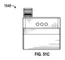
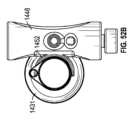
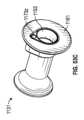
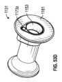
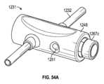
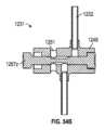
概して、一実施形態において、オーバーチューブは、長形チューブと、長形チューブに装着される遠位先端とを含む。遠位先端は、一つ以上の真空孔が中に延在する環状遠位面を有する。一つ以上の真空孔は、真空の印加時に環状遠位面へ組織を引き寄せるように構成される。Generally, in one embodiment, the overtube includes an elongate tube and a distal tip attached to the elongate tube. The distal tip has an annular distal surface with one or more vacuum holes extending therethrough. The one or more vacuum holes are configured to draw tissue toward the annular distal surface upon application of vacuum.
本実施形態及び他の実施形態は、以下の特徴のうち一つ以上を含み得る。長形チューブは硬化デバイスであって、硬化デバイスは、真空又は圧力が壁に印加される時の硬化構成と、真空又は圧力が壁に印加されない時の可撓構成とを有するように構成され得る。長形チューブは編組層とその上の外側層とを含み得る。環状遠位面は、長形チューブの長手軸線に対して傾斜し得る。This and other embodiments may include one or more of the following features: The elongate tube may be a stiffening device that may be configured to have a stiffened configuration when a vacuum or pressure is applied to the wall and a flexible configuration when no vacuum or pressure is applied to the wall. The elongate tube may include a braided layer and an outer layer thereon. The annular distal surface may be angled relative to a longitudinal axis of the elongate tube.
概して、一実施形態において、硬化デバイスは、長形可撓性チューブと、長形可撓性チューブの上に配置される編組層と、可撓性チューブ及び編組層の上の外側層と、長形可撓性チューブに装着される遠位先端とを含む。編組層は、長形可撓性チューブが直線状である時に長形可撓性チューブの長手軸線に対する第1編組角度で共に編組される複数の撚糸を有する。遠位先端は、第1編組角度と異なる第2編組角度で共に編組される複数の撚糸を有する第2編組層を含む。長形可撓性チューブと外側層との間の入口は、真空又は圧力源に装着されるように構成される。硬化デバイスは、真空又は圧力が入口から印加される時の硬化構成と、真空又は圧力が入口から印加されない時の可撓構成とを有するように構成される。Generally, in one embodiment, the stiffening device includes an elongated flexible tube, a braided layer disposed over the elongated flexible tube, an outer layer over the flexible tube and the braided layer, and a distal tip attached to the elongated flexible tube. The braided layer has a plurality of strands braided together at a first braid angle relative to a longitudinal axis of the elongated flexible tube when the elongated flexible tube is straight. The distal tip includes a second braided layer having a plurality of strands braided together at a second braid angle different than the first braid angle. An inlet between the elongated flexible tube and the outer layer is configured to be attached to a vacuum or pressure source. The stiffening device is configured to have a stiffening configuration when vacuum or pressure is applied from the inlet and a flexible configuration when vacuum or pressure is not applied from the inlet.
上記及び他の実施形態は、以下の特徴のうち一つ以上を含み得る。第2編組角度は第1編組角度より大きい。第1及び第2編組層は互いに接合され得る。These and other embodiments may include one or more of the following features: The second braid angle is greater than the first braid angle. The first and second braided layers may be joined to one another.
概して、一実施形態において、硬化デバイスは、複数の補強要素を中に含む長形可撓性チューブを含む。長形可撓性チューブは、近位セクションと遠位セクションとを含む。編組層は遠位セクションではなく近位セクションの上に配置される。編組層は、長形可撓性チューブが直線状である時に長形可撓性チューブの長手軸線に対する第1編組角度で共に編組される複数の撚糸を有する。外側層は、編組層の上に配置される。複数の操向性リンケージは近位セクションではなく遠位セクションの上に延在する。入口は長形可撓性チューブと外側層との間にあり、真空又は圧力源に装着されるように構成される。硬化デバイスは、真空又は圧力が入口から印加される時の硬化構成と、真空又は圧力が入口から印加されない時の可撓構成とを有するように構成される。In general, in one embodiment, the stiffening device includes an elongated flexible tube having a plurality of reinforcing elements therein. The elongated flexible tube includes a proximal section and a distal section. A braided layer is disposed over the proximal section but not the distal section. The braided layer has a plurality of strands braided together at a first braid angle relative to a longitudinal axis of the elongated flexible tube when the elongated flexible tube is straight. An outer layer is disposed over the braided layer. A plurality of steering linkages extend over the distal section but not the proximal section. An inlet is between the elongated flexible tube and the outer layer and is configured to be attached to a vacuum or pressure source. The stiffening device is configured to have a stiffened configuration when vacuum or pressure is applied from the inlet and a flexible configuration when vacuum or pressure is not applied from the inlet.
上記及び他の実施形態は、以下の特徴のうち一つ以上を含み得る。硬化デバイスは更に、操向性リンケージに装着される複数のケーブルを含み得る。ケーブルは長形可撓性チューブと外側層との間に延在し得る。These and other embodiments may include one or more of the following features: The stiffening device may further include a plurality of cables attached to the steerable linkage. The cables may extend between the elongated flexible tube and the outer layer.
概して、一実施形態において、硬化デバイスは、硬化アセンブリと複数のリンケージとを含む。硬化アセンブリは、長形可撓性チューブと、長形可撓性チューブの上に配置される編組層と、可撓性チューブ及び編組層の上の外側層と、入口とを含む。入口は長形可撓性チューブと外側層との間にあって、真空又は圧力源に装着されるように構成される。複数の操向性リンケージは硬化アセンブリの遠位部分の上に取り付けられる。硬化アセンブリは、真空又は圧力が入口から印加される時の硬化構成と、真空又は圧力が入口から印加されない時の可撓構成とを有するように構成される。In general, in one embodiment, the stiffening device includes a stiffening assembly and a plurality of linkages. The stiffening assembly includes an elongated flexible tube, a braided layer disposed over the elongated flexible tube, an outer layer over the flexible tube and the braided layer, and an inlet. The inlet is between the elongated flexible tube and the outer layer and is configured to be attached to a vacuum or pressure source. The plurality of steerable linkages are mounted on a distal portion of the stiffening assembly. The stiffening assembly is configured to have a stiffened configuration when vacuum or pressure is applied from the inlet and a flexible configuration when vacuum or pressure is not applied from the inlet.
上記及び他の実施形態は、以下の特徴のうち一つ以上を含み得る。硬化デバイスは更に、操向性リンケージに装着される複数のケーブルを含み得る。ケーブルは、長形可撓性チューブと外側層との間に延在し得る。These and other embodiments may include one or more of the following features: The stiffening device may further include a plurality of cables attached to the steerable linkage. The cables may extend between the elongated flexible tube and the outer layer.
概して、一実施形態において、硬化デバイスは、長形可撓性チューブと複数の操向性リンケージと出口とを含む。長形可撓性チューブは、近位セクションと遠位セクションとを含む。長形可撓性チューブは、中の複数の補強要素と、近位セクション及び遠位セクションの上に配置される編組層と、複数の補強要素を含む外側層とを含む。複数の操向性リンケージは、近位セクションではなく遠位セクションの上に延在する。入口は長形可撓性チューブと外側層との間にあって、真空又は圧力源に装着されるように構成される。編組層は、長形可撓性チューブが直線状である時に長形可撓性チューブの長手軸線に対する第1編組角度で共に編組される複数の撚糸を有する。外側層は遠位セクションではなく近位セクションの上に配置される。硬化デバイスは、真空又は圧力が入口から印加される時の硬化構成と、真空又は圧力が入口から印加されない時の可撓構成とを有するように構成される。In general, in one embodiment, the stiffening device includes an elongated flexible tube, a plurality of steerable linkages, and an outlet. The elongated flexible tube includes a proximal section and a distal section. The elongated flexible tube includes a plurality of reinforcing elements therein, a braided layer disposed over the proximal and distal sections, and an outer layer including the plurality of reinforcing elements. The plurality of steerable linkages extend over the distal section but not the proximal section. The inlet is between the elongated flexible tube and the outer layer and is configured to be attached to a vacuum or pressure source. The braided layer has a plurality of strands braided together at a first braid angle relative to a longitudinal axis of the elongated flexible tube when the elongated flexible tube is straight. The outer layer is disposed over the proximal section but not the distal section. The stiffening device is configured to have a stiffened configuration when a vacuum or pressure is applied from the inlet and a flexible configuration when a vacuum or pressure is not applied from the inlet.
上記及び他の実施形態は、以下の特徴のうち一つ以上を含み得る。硬化デバイスは更に、操向性リンケージに装着される複数のケーブルを含み得る。ケーブルは、長形可撓性チューブと外側層との間に延在される。These and other embodiments may include one or more of the following features: The stiffening device may further include a plurality of cables attached to the steerable linkage. The cables extend between the elongated flexible tube and the outer layer.
概して、一実施形態において、硬化デバイスは硬化アセンブリと複数のリンケージとを含む。硬化アセンブリは、長形可撓性チューブと、長形可撓性チューブの上に配置される編組層と、可撓性チューブ及び編組層の上の外側層と、真空又は圧力源に装着されるように構成される長形可撓性チューブと外側層との間の入口とを含む。硬化アセンブリの遠位セクションには背部が延在する。背部は、設定方向での硬化アセンブリの屈曲を行うように構成される。複数の操向性リンケージは硬化アセンブリの遠位にある。硬化アセンブリは、真空又は圧力が入口から印加される時の硬化構成と、真空又は圧力が入口から印加されない時の可撓構成とを有するように構成される。Generally, in one embodiment, the stiffening device includes a stiffening assembly and a plurality of linkages. The stiffening assembly includes an elongated flexible tube, a braided layer disposed over the elongated flexible tube, an outer layer over the flexible tube and the braided layer, and an inlet between the elongated flexible tube and the outer layer configured to be attached to a vacuum or pressure source. A back portion extends from a distal section of the stiffening assembly. The back portion is configured to effect bending of the stiffening assembly in a set orientation. A plurality of steering linkages are distal to the stiffening assembly. The stiffening assembly is configured to have a stiffening configuration when vacuum or pressure is applied from the inlet and a flexible configuration when vacuum or pressure is not applied from the inlet.
上記及び他の実施形態は、以下の特徴のうち一つ以上を含み得る。硬化デバイスは更に、操作時に背部でデバイスを屈曲させるように構成されるプルワイヤを含み得る。硬化デバイスは更に、操向性リンケージに装着される複数のケーブルを含み得る。ケーブルは、長形可撓性チューブと外側層との間に延在し得る。These and other embodiments may include one or more of the following features. The stiffening device may further include a pull wire configured to bend the device at its back when actuated. The stiffening device may further include a plurality of cables attached to the steerable linkage. The cables may extend between the elongated flexible tube and the outer layer.
概して、一実施形態において、硬化デバイスは、硬化アセンブリと遠位先端とを含む。硬化アセンブリは、長形可撓性チューブと、長形可撓性チューブの上に配置される編組層と、可撓性チューブ及び編組層の上の外側層と、真空又は圧力源に装着されるように構成される長形可撓性チューブと外側層との間の入口とを含む。遠位先端は長形可撓性チューブに装着される。遠位先端は、旋回点で共に接続される複数のリンケージを含む。硬化アセンブリと遠位先端とは、真空又は圧力が入口から印加される時の硬化構成と、真空又は圧力が入口から印加されない時の可撓構成とを取るように構成される。In general, in one embodiment, the stiffening device includes a stiffening assembly and a distal tip. The stiffening assembly includes an elongated flexible tube, a braided layer disposed over the elongated flexible tube, an outer layer over the flexible tube and the braided layer, and an inlet between the elongated flexible tube and the outer layer configured to be attached to a vacuum or pressure source. The distal tip is attached to the elongated flexible tube. The distal tip includes a plurality of linkages connected together at pivot points. The stiffening assembly and distal tip are configured to assume a stiffened configuration when vacuum or pressure is applied from the inlet and a flexible configuration when vacuum or pressure is not applied from the inlet.
概して、一実施形態において、硬化デバイスとの使用の為のハンドルは、硬化デバイスに装着されるように構成されるハンドル本体と、ハンドル本体に装着され、真空源に接続されるように構成される真空給送管路と、硬化デバイスの壁との連通状態にある真空ポートと、ハンドル本体の操作要素とを含む。操作要素は、第1位置と第2位置との間で移動するように構成される。第1位置の操作要素は真空給送管路を真空ポートに接続して、硬化デバイスの壁に真空を提供し、第2位置の操作要素は、真空給送管路を真空ポートから切断して硬化デバイスの壁から排出を行う。Generally, in one embodiment, a handle for use with a curing device includes a handle body configured to be attached to the curing device, a vacuum delivery line attached to the handle body and configured to be connected to a vacuum source, a vacuum port in communication with a wall of the curing device, and an operating element on the handle body. The operating element is configured to move between a first position and a second position. The operating element in the first position connects the vacuum delivery line to the vacuum port to provide a vacuum to the wall of the curing device, and the operating element in the second position disconnects the vacuum delivery line from the vacuum port to evacuate the wall of the curing device.
上記及び他の実施形態は、以下の特徴のうち一つ以上を含み得る。操作要素は磁気要素を含み得る。磁気要素は、操作要素を第1位置又は第2位置に保持するように構成され得る。真空給送管路はハンドル内でコイル状であり得る。These and other embodiments may include one or more of the following features: The operating element may include a magnetic element. The magnetic element may be configured to hold the operating element in the first position or the second position. The vacuum delivery line may be coiled within the handle.
概して、一実施形態において、体内腔で硬化デバイスを前進させる方法は、(1)硬化デバイスのハンドルを保持することと、(2)硬化デバイスが可撓構成である間に硬化デバイスの長形本体を体内腔へ挿入することと、(3)硬化デバイスが体内腔の所望の箇所に達した時に、真空が長形本体の壁へ流入して長形本体を硬化構成へ移行させるように、操作要素を第1方向に移動させてハンドルの真空給送管路を長形本体の壁への真空ポートと接続することと、(4)長形本体から排出を行って長形本体を可撓構成へ移行させるように、操作要素を第2方向に移動させて真空給送管路を真空ポートから切断することとを含む。Generally, in one embodiment, a method of advancing a stiffening device through a body lumen includes (1) holding a handle of the stiffening device; (2) inserting an elongated body of the stiffening device into the body lumen while the stiffening device is in a flexible configuration; (3) moving a control element in a first direction to connect a vacuum delivery line of the handle to a vacuum port in a wall of the elongated body when the stiffening device reaches a desired location in the body lumen, such that vacuum flows into the wall of the elongated body to transition the elongated body to the stiffened configuration; and (4) moving the control element in a second direction to disconnect the vacuum delivery line from the vacuum port to vent the elongated body to transition the elongated body to the flexible configuration.
概して、一実施形態において、硬化デバイスとの使用の為のハンドルは、硬化デバイスに装着するように構成されるハンドル本体と、ハンドル本体内の流体室と、流体室及び硬化デバイスの壁との流体連通状態にある出口と、第1位置と第2位置との間で移動するように構成される操作要素とを含む。操作要素は、第1位置から第2位置への移動時に流体室から硬化デバイスの壁へ流体を移送すると共に、第2位置から第1位置への移動時に流体を流体室へ再び移送するように構成される。Generally, in one embodiment, a handle for use with a curing device includes a handle body configured to attach to the curing device, a fluid chamber within the handle body, an outlet in fluid communication with the fluid chamber and a wall of the curing device, and an operating element configured to move between a first position and a second position. The operating element is configured to transfer fluid from the fluid chamber to the wall of the curing device when moving from the first position to the second position, and to transfer fluid back to the fluid chamber when moving from the second position to the first position.
上記及び他の実施形態は、以下の特徴のうち一つ以上を含み得る。ハンドルは更に、ハンドル本体内の溢流室と、流体室と溢流室との間の圧力解放バルブとを含み得る。圧力解放バルブは、流体室の圧力が所定の最大圧力に達した時に開いて流体を溢流室へ流入させるように構成され得る。ハンドルは更に、ハンドル本体内のピストン及び転動型ダイヤフラムを含み得る。ピストンは、操作要素が第1位置と第2位置との間で移動する際に転動型ダイヤフラムを押圧するように構成され得る。These and other embodiments may include one or more of the following features. The handle may further include an overflow chamber in the handle body and a pressure relief valve between the fluid chamber and the overflow chamber. The pressure relief valve may be configured to open to allow fluid to flow into the overflow chamber when pressure in the fluid chamber reaches a predetermined maximum pressure. The handle may further include a piston and a rolling diaphragm in the handle body. The piston may be configured to press against the rolling diaphragm as the operating element moves between the first and second positions.
概して、一実施形態において、体内腔で硬化デバイスを前進させる方法は、(1)硬化デバイスのハンドルを保持することと、(2)硬化デバイスが可撓構成である間に硬化デバイスの長形本体を体内腔へ挿入することと、(3)硬化デバイスが体内腔の所望の箇所に達した時に、操作要素を第1方向に移動させてハンドルの流体室から硬化要素の壁へ流体を移動させ、硬化デバイスを硬化構成に移行させることと、(4)操作を第2方向に移動させて硬化要素の壁からハンドルへ流体を再び移動させ、硬化デバイスを可撓構成に移行させることとを含む。Generally, in one embodiment, a method of advancing a stiffening device through a body lumen includes (1) holding a handle of the stiffening device; (2) inserting an elongated body of the stiffening device into the body lumen while the stiffening device is in a flexible configuration; (3) when the stiffening device reaches a desired location in the body lumen, moving the operating element in a first direction to transfer fluid from a fluid chamber in the handle to a wall of the stiffening element and transition the stiffening device to the stiffening configuration; and (4) moving the operating element in a second direction to again transfer fluid from the wall of the stiffening element to the handle and transition the stiffening device to the flexible configuration.
概して、一実施形態において、入れ子システムは、第1硬化デバイスと、第1硬化デバイス内に径方向に配置される第2硬化デバイスとを含む。第2硬化デバイスは第1硬化デバイスに対して軸方向に摺動可能である。第1及び第2硬化デバイスは真空又は圧力により交互に硬化されるように構成される。Generally, in one embodiment, the nesting system includes a first curing device and a second curing device radially disposed within the first curing device. The second curing device is axially slidable relative to the first curing device. The first and second curing devices are configured to be alternately cured by vacuum or pressure.
上記及び他の実施形態は、以下の特徴のうち一つ以上を含み得る。圧力は1atmより大きい。第1硬化デバイスは真空により硬化されるように構成され、第2硬化デバイスは1atmより大きい圧力により硬化されるように構成され得る。第1及び第2硬化デバイスの各々は複数の層を含み得る。真空又は圧力は複数の層の間に供給されるように構成される。複数の層の少なくとも一つは編組層であり得る。These and other embodiments may include one or more of the following features: The pressure is greater than 1 atm. The first stiffening device may be configured to be cured by a vacuum and the second stiffening device may be configured to be cured by a pressure greater than 1 atm. Each of the first and second stiffening devices may include multiple layers. The vacuum or pressure may be configured to be applied between the multiple layers. At least one of the multiple layers may be a braided layer.
概して、一実施形態において、体内腔で前進させる方法は、(1)第1硬化デバイスが可撓構成である間に第1硬化デバイスを体内腔へ挿入することと、(2)真空又は圧力を第1硬化デバイスへ供給して、可撓構成より剛性である硬化構成へ第1硬化デバイスを移行させることと、(3)第2硬化デバイスが硬化構成での第1硬化デバイスの形状を取るように、第1硬化デバイスが硬化構成である間に可撓構成の第2硬化デバイスを第1硬化デバイスへ挿入することと、(4)真空又は圧力を第2硬化デバイスへ供給して第2硬化デバイスを可撓構成から硬化構成へ移行させることとを含む。Generally, in one embodiment, a method of advancing in a body lumen includes: (1) inserting a first stiffening device into the body lumen while the first stiffening device is in a flexible configuration; (2) applying a vacuum or pressure to the first stiffening device to transition the first stiffening device to a stiffening configuration that is more rigid than the flexible configuration; (3) inserting a second stiffening device in a flexible configuration into the first stiffening device while the first stiffening device is in the stiffening configuration such that the second stiffening device assumes the shape of the first stiffening device in the stiffening configuration; and (4) applying a vacuum or pressure to the second stiffening device to transition the second stiffening device from the flexible configuration to the stiffening configuration.
上記及び他の実施形態は、以下の特徴のうち一つ以上を含み得る。各硬化デバイスは長形可撓性チューブと編組層とを含み得る。真空又は圧力の供給は、編組層を圧縮して硬化デバイスを硬化構成へ移行させ得る。These and other embodiments may include one or more of the following features: Each stiffening device may include an elongated flexible tube and a braided layer. Application of vacuum or pressure may compress the braided layer to transition the stiffening device into the stiffening configuration.
概して、一実施形態において、体内腔で前進させる方法は、(1)第1硬化デバイスが所望の箇所に達するまで可撓構成の第1硬化デバイスを移動させることと、(2)第1硬化デバイスが所望の箇所に達した後に、真空又は圧力を第1硬化デバイスへ供給することにより第1硬化デバイスを硬化構成へ移行させることと、(3)第1硬化デバイスが硬化した後に、可撓構成の第2硬化デバイスを硬化構成の第1硬化デバイスの上で移動させることと、(4)真空又は圧力を第2硬化デバイスへ供給することにより、第2硬化要素を硬化構成へ移行させることと、(5)真空又は圧力を除去することにより第1硬化デバイスを可撓構成へ移行させることと、(6)第1硬化デバイスが所望の箇所に達するまで可撓構成の第1硬化デバイスに第2長形硬化デバイスの中を移動させることとを含む。Generally, in one embodiment, a method of advancing in a body lumen includes (1) moving a first stiffening device in a flexible configuration until the first stiffening device reaches a desired location; (2) transitioning the first stiffening device to a stiffening configuration by applying a vacuum or pressure to the first stiffening device after the first stiffening device reaches the desired location; (3) moving a second stiffening device in a flexible configuration over the first stiffening device in the stiffening configuration after the first stiffening device has hardened; (4) transitioning the second stiffening element to the stiffening configuration by applying a vacuum or pressure to the second stiffening device; (5) transitioning the first stiffening device to the flexible configuration by removing the vacuum or pressure; and (6) moving the first stiffening device in the flexible configuration through the second elongated stiffening device until the first stiffening device reaches the desired location.
上記及び他の実施形態は、以下の特徴のうち一つ以上を含み得る。この方法は、第1及び第2の両方の硬化デバイスを可撓構成へ周期的に移動させ、周囲の解剖学的構造と一致するように第1及び第2硬化デバイスの曲率を増大させることとを含み得る。These and other embodiments may include one or more of the following features: The method may include periodically moving both the first and second stiffening devices to a flexible configuration to increase the curvature of the first and second stiffening devices to conform to the surrounding anatomical structure.
概して、一実施形態において、硬化ロッドは、内側貯気層と、内側貯気層の上に配置される編組層と、内側貯気層及び編組層の上で密閉される外側シースと、真空源に装着されるように構成される外側シースと内側貯気層との間の入口とを含む。硬化ロッドは、真空が入口から印加される時の硬化構成と、真空又は圧力が入口から供給されない時の可撓構成とを有するように構成される。硬化ロッドは、中に延在する貫通内腔を有していない。Generally, in one embodiment, the stiffening rod includes an inner reservoir layer, a braided layer disposed over the inner reservoir layer, an outer sheath sealed over the inner reservoir layer and the braided layer, and an inlet between the outer sheath and the inner reservoir layer configured to be attached to a vacuum source. The stiffening rod is configured to have a stiffened configuration when vacuum is applied through the inlet and a flexible configuration when no vacuum or pressure is provided through the inlet. The stiffening rod does not have a through lumen extending therethrough.
概して、一実施形態において、体内腔で硬化デバイスを前進させる方法は、(1)体内腔で硬化デバイスを前進させることと、(2)長形可撓性チューブと編組層と貯気部とを有するロッドが可撓構成である間に硬化デバイスの内腔へロッドを挿入することと、(3)硬化デバイスの内腔の所望の箇所にロッドが達した時に、1atmより大きい圧力をロッドの中央密閉内腔へ供給して編組層を長形可撓性チューブに押圧し、可撓構成より剛性である硬化構成へ硬化デバイスを移行させることと、(4)ロッドが硬化構成である間に硬化デバイスをロッド上で更に前進させることとを含む。Generally, in one embodiment, a method of advancing a stiffening device through a body lumen includes (1) advancing the stiffening device through a body lumen; (2) inserting a rod having an elongated flexible tube, a braided layer, and an air reservoir into a lumen of the stiffening device while the rod is in a flexible configuration; (3) when the rod reaches a desired location in the lumen of the stiffening device, delivering a pressure greater than 1 atm to a central sealed lumen of the rod to press the braided layer against the elongated flexible tube and transition the stiffening device to a stiffened configuration that is more rigid than the flexible configuration; and (4) advancing the stiffening device further over the rod while the rod is in the stiffened configuration.
概して、一実施形態において、胆道鏡検査を実施する方法は、(1)オーバーチューブが可撓構成である間にオーバーチューブを結腸へ挿入することであって、オーバーチューブが、長形可撓性チューブと、共に編組される複数の撚糸を有する編組層と、外側層とを含むことと、(2)オーバーチューブの遠位端部を乳頭の方へ操向することと、(3)可撓性チューブと外側層との間の真空又は圧力を操作して、可撓構成より剛性である硬化構成へオーバーチューブを移行させることと、(4)オーバーチューブが硬化構成である間に、オーバーチューブを通って胆管又は膵管へガイドワイヤを前進させることと、(5)ガイドワイヤの上でスコープを胆管又は膵管へ前進させることとを含む。Generally, in one embodiment, a method of performing a cholangioscopy includes (1) inserting an overtube into the colon while the overtube is in a flexible configuration, the overtube including an elongated flexible tube, a braided layer having multiple strands braided together, and an outer layer; (2) steering a distal end of the overtube toward the papilla; (3) manipulating a vacuum or pressure between the flexible tube and the outer layer to transition the overtube to a stiffened configuration that is more rigid than the flexible configuration; (4) advancing a guidewire through the overtube while the overtube is in the stiffened configuration, and (5) advancing a scope over the guidewire into the bile or pancreatic duct.
概して、一実施形態において、心臓解剖学的構造にアクセスする方法は、(1)シースが可撓構成である間に心臓解剖学的構造へシースを挿入することであって、シースが、長形可撓性チューブと、共に編組される複数の撚糸を有する編組層と、外側層とを含むことと、(2)シースの遠位端部を所望の最終箇所へ操向することと、(3)可撓性チューブと外側層との間の真空又は圧力を操作して、可撓構成より剛性である硬化構成へオーバーチューブを移行させることと、(4)心臓デバイスに硬化シースを通過させることとを含む。Generally, in one embodiment, a method of accessing a cardiac anatomy includes (1) inserting a sheath into the cardiac anatomy while the sheath is in a flexible configuration, the sheath including an elongated flexible tube, a braided layer having multiple strands braided together, and an outer layer; (2) steering a distal end of the sheath to a desired final location; (3) manipulating a vacuum or pressure between the flexible tube and the outer layer to transition the overtube to a stiffened configuration that is more rigid than the flexible configuration; and (4) passing a cardiac device through the stiffening sheath.
上記及び他の実施形態は、以下の特徴のうち一つ以上を含み得る。所望の最終箇所は大動脈弁であり得る。心臓デバイスは、経カテーテル大動脈弁置換であり得る。所望の最終箇所は僧帽弁であり得る。心臓デバイスは僧帽弁置換又は僧帽弁修復要素であり得る。These and other embodiments may include one or more of the following features: The desired end location may be the aortic valve. The cardiac device may be a transcatheter aortic valve replacement. The desired end location may be the mitral valve. The cardiac device may be a mitral valve replacement or mitral valve repair element.
本明細書に記載のデバイスのいずれも、以下のうち一つ以上を含み得る。硬化デバイスは更に、編組層に近接する滑動層を含み得る。滑動層は編組層より低い摩擦係数を有し得る。硬化構成の硬化デバイスは、可撓構成の硬化デバイスより少なくとも2倍は剛性であり得る。硬化構成の硬化デバイスは、可撓構成の硬化デバイスより少なくとも5倍は剛性であり得る。編組層は、長形可撓性チューブが直線状である時に長形可撓性チューブの長手軸線に対して5~40度の編組角度で共に編組される複数の撚糸を有し得る。編組角度は10と35度の間であり得る。長形可撓性チューブは、中に延在する補強要素を含み得る。補強要素はコイル又は複数の輪状要素を含み得る。編組層は、4~60のインチ当たりピック数で共に編組される複数の撚糸を含み得る。編組層は、共に編組される複数の撚糸を含み得る。撚糸はポリエチレンテレフタレート又はステンレス鋼を含み得る。編組層は、長形可撓性チューブに対して30~70%の被覆率を提供し得る。編組層は、共に編組される96本の撚糸又はそれ以上の撚糸を含み得る。入口は圧力源に装着されるように構成され得る。硬化デバイスは更に貯気層を中に含み得る。貯気層は、圧力が入口から供給される時に編組層に押圧されるように構成され得る。外側層は更に、複数の補強要素を中に含み得る。入口は真空源に装着されるように構成され得る。外側層は薄い可撓性シースであり得る。硬化デバイスは更に、編組層と外側層との間に径方向間隙を含み得る。間隙は0.00002”~0.04”の厚さを有し得る。硬化デバイスは更に操向性遠位端部を含み得る。硬化デバイスは更に、長形可撓性チューブと外側層との間に密閉チャネルを含み得る。密閉チャネルは、ワーキングチャネル、ケーブルガイド、又は膨張内腔を含み得る。Any of the devices described herein may include one or more of the following: The stiffened device may further include a sliding layer adjacent to the braided layer. The sliding layer may have a lower coefficient of friction than the braided layer. The stiffened device in the stiffened configuration may be at least two times stiffer than the stiffened device in the flexible configuration. The stiffened device in the stiffened configuration may be at least five times stiffer than the stiffened device in the flexible configuration. The braided layer may have a plurality of strands braided together at a braid angle of 5 to 40 degrees relative to a longitudinal axis of the elongated flexible tube when the elongated flexible tube is straight. The braid angle may be between 10 and 35 degrees. The elongated flexible tube may include a reinforcing element extending therethrough. The reinforcing element may include a coil or a plurality of hoop elements. The braided layer may include a plurality of strands braided together at a picks per inch of 4 to 60. The braided layer may include a plurality of strands braided together. The strands may include polyethylene terephthalate or stainless steel. The braided layer may provide 30-70% coverage for the elongated flexible tube. The braided layer may include 96 or more strands braided together. The inlet may be configured to be attached to a pressure source. The stiffening device may further include a reservoir layer therein. The reservoir layer may be configured to be pressed against the braided layer when pressure is provided from the inlet. The outer layer may further include a plurality of reinforcing elements therein. The inlet may be configured to be attached to a vacuum source. The outer layer may be a thin flexible sheath. The stiffening device may further include a radial gap between the braided layer and the outer layer. The gap may have a thickness of 0.00002" to 0.04". The stiffening device may further include a steerable distal end. The stiffening device may further include a sealing channel between the elongated flexible tube and the outer layer. The sealing channel may include a working channel, a cable guide, or an inflation lumen.
本明細書に記載の方法のいずれも以下のうち一つ以上を含み得る。方法は更に、真空又は圧力を操作した後に真空又は圧力を解放して硬化デバイスを再び可撓構成に移行させることを含み得る。方法は消化管で実施され得る。方法は心臓で実施され得る。方法は腎臓で実施され得る。方法は肺で実施され得る。方法は脳で実施され得る。Any of the methods described herein may include one or more of the following. The method may further include releasing the vacuum or pressure after manipulating the vacuum or pressure to transition the stiffening device back to the flexible configuration. The method may be performed in the gastrointestinal tract. The method may be performed in the heart. The method may be performed in the kidney. The method may be performed in the lung. The method may be performed in the brain.
本発明の新規の特徴は以下に続く請求項に詳しく提示される。発明の原理が利用されている例示的実施形態を提示する以下の詳細な説明と添付図面とを参照することにより、本発明の特徴及び利点のより良い理解が得られるだろう。
概して、本明細書に記載されるのは、身体のカーブ状又はループ状部分(例えば血管)でのスコープ(例えば内視鏡)又は他の医療機器の輸送を補助するように構成される硬化デバイス(例えばオーバーチューブ)である。硬化デバイスは長く、薄く、中空であり、可撓構成(つまり弛緩、柔軟、又は軟質の構成)から硬化構成(つまり剛性である、及び/又は、硬化時に取る形状を保つ)へ急速に移行できる。複数の層(例えばコイル状又は補強層、滑動層、編組層、貯気層、及び/又は、密閉シース)は、硬化デバイスの壁を共に形成できる。例えば硬化デバイスの壁へ、又は硬化デバイスの壁内へ真空又は圧力を印加することにより、硬化デバイスは可撓構成から硬化構成へ移行できる。真空又は圧力が除去されると、層は容易にねじり変形するか互いに対して移動し得る。真空又は圧力が印加されると、ねじり変形、移動、屈曲、座屈に抵抗する能力が実質的に高められた状態へ層が移行することにより、システムの硬化が行われる。Generally described herein is a stiffening device (e.g., an overtube) configured to aid in the transport of a scope (e.g., an endoscope) or other medical device through a curved or looped portion of the body (e.g., a blood vessel). The stiffening device is long, thin, hollow, and can be rapidly transitioned from a flexible configuration (i.e., flaccid, pliable, or soft) to a stiffened configuration (i.e., rigid and/or retains the shape it assumes upon stiffening). Multiple layers (e.g., a coiled or reinforcement layer, a sliding layer, a braided layer, an air reservoir layer, and/or a sealing sheath) can together form the walls of the stiffening device. The stiffening device can transition from the flexible configuration to the stiffened configuration, for example, by applying a vacuum or pressure to or within the walls of the stiffening device. When the vacuum or pressure is removed, the layers can easily twist or move relative to one another. When the vacuum or pressure is applied, the layers transition to a state that substantially enhances their ability to resist twisting, movement, bending, or buckling, thereby stiffening the system.
本明細書に記載の硬化デバイスは、カテーテル、シース、スコープ(例えば内視鏡)、ワイヤ、又は腹腔鏡検査機器を含む多様な医療用途の為に硬化を行い得る。硬化デバイスは独立した付加デバイスとして機能し、カテーテル、シース、スコープ、ワイヤ、又は腹腔鏡検査機器の本体に組み込まれ得る。本明細書に記載のデバイスは、非医療用構造の硬化も行い得る。The stiffening devices described herein may provide stiffening for a variety of medical applications, including catheters, sheaths, scopes (e.g., endoscopes), wires, or laparoscopic instruments. The stiffening devices may function as stand-alone add-on devices and may be incorporated into the body of a catheter, sheath, scope, wire, or laparoscopic instrument. The devices described herein may also provide stiffening for non-medical structures.
例示的な硬化デバイスシステムが図1に示されている。システムは、編組層と外側層(下の編組体を示すように一部が切除されている)と内側層とを含む複数の層を備える壁を有する硬化デバイス300を含む。システムは更に、硬化デバイス300へ真空又は圧力を供給する真空又は圧力入口344を有するハンドル342を含む。操作要素346は、真空又は圧力をオン及びオフにして可撓及び硬化構成の間で硬化デバイス300を移行させるのに使用され得る。硬化デバイス300の遠位先端339は、身体内での硬化デバイス300の遠位移動を促進するように滑らか、可撓性、そして非外傷性であり得る。更に、先端339は遠位端部から近位端部までテーパ状であって、身体内での硬化デバイス300の遠位移動を更に促進する。An exemplary stiffening device system is shown in FIG. 1. The system includes a
デバイス300に類似した硬化デバイスの為の例示的な編組層209の一部分が図2A~2Bに示されている。編組層209は編組された撚糸233を含み得る。編組層209は例えばチューブ状編組体であり得る。A portion of an
硬化デバイス(例えばデバイス300)が直線(非屈曲)構成である時の硬化デバイスの長手軸線235に対する撚糸233の編組角度αは、40度以下、35度以下、25度以下のように45度未満であり得る。図3を参照すると、(硬化デバイスが直線状又は非屈曲状である時の)編組角度αが増加すると、硬化デバイスの屈曲強度が低下する。すなわち、45度の編組角度(トルク又はねじり編組体に一般的な最小角度)を持つ硬化デバイスの真空状態での屈曲強度である。一般に真空状態でのカテーテルシャフト補強に使用される更に大きい角度は、25度の編組角度を持つ硬化デバイスの真空状態での屈曲強度の27%である。従って、より低い編組角度(例えば、40度以下又は35度以下のように45度未満)を有すると、真空状態(また同様に圧力状態)で硬化デバイス(例えばデバイス300)が屈曲時に剛性のままである(構成変化に抵抗する)ことを保証するので有利である。付加的に、硬化デバイスが直線(非屈曲)構成である時の編組角度αは、8度より大きい、10度より大きい、15度以上のように、5度より大きい。この範囲内の編組角度αを有すると、可撓構成である時(つまり真空又は圧力状態で硬化されない時)に編組体が屈曲に充分なほど可撓性のままであることを保証する。故に、硬化デバイスが直線構成である時の硬化デバイスの長手軸線235に対する撚糸233の編組角度αは、10から35度、15から25度、およそ5,10,15,20,25,30,35,40度のように、5から40度であり得る。硬化デバイスが5から40度の直線(非屈曲)構成である時の硬化デバイスの長手軸線235に対する撚糸233の編組角度αは、硬化構成である時(つまり真空又は圧力状態に置かれた時)にまだ剛性の可撓構成の(例えば真空/圧力状態でない時の)硬化デバイスが屈曲するのに充分なほど可撓性であることを保証する。付加的に、撚糸233が互いに摺動するように構成され、故に編組角度αが変化して硬化デバイスが撓曲又は屈曲することが理解されるべきである。5と40度の間である角度αを有すると、繊維が互いに衝突してさらなる角度変化を防止することなく撚糸233が互いに対して自由に移動できることも保証するので有利である。The braid angle α of the
更に、編組層209の為の編組体は、8,10,12,14,16,18,20,25のインチ当たりピック数など、4~60のインチ当たりピック数であり得る。一実施形態において、層209により形成されるチューブは0.578”の直径を有し、編組体は12~14のインチ当たりピック数である。Furthermore, the braid for
幾つかの実施形態において、編組層209(又は本明細書に記載のいずれかの編組層)は、本明細書に記載の硬化デバイスが高い剛性比(つまり真空又は圧力が印加される時などの硬化構成の剛性と、真空又は圧力が印加されない時などの可撓構成での剛性との比)を有するように構成され得る。例えば、剛性比は、6より大きい、9より大きい、9より大きい、10より大きいなど、5より大きい。下記の表1を参照すると、6個の真空硬化デバイス(サンプルA~F)が構築され、大気圧(可撓構成)と真空状態(硬化構成)での片持ち梁屈曲剛性について4”の長さと1/2”での撓曲で検査された。図示のように、編組角度が低下すると硬化デバイスの剛性が上昇する。サンプルE及びFは、特に、一般的なトルク角度での編組体(サンプルE,47.7度と0.529lbfの硬化時剛性)と、低角度の編組体(サンプルF,27.2度と1.455lbfの硬化時剛性)の間の剛性差を示す。やはり表1に示されているように、低角度(例えばサンプルA~D及びFのように、45度又は35度未満の角度)の硬化デバイスは、5未満の剛性比を有する高角度(例えばサンプルFのように45度以上の角度)の硬化デバイスよりもはるかに高い剛性比(例えば5より大きい、6より大きい、9より大きい、又は10より大きい比)を有し得る。サンプルA及びBの両方が5を超える剛性比を有することが表1からも確認され得る。サンプルBの撚糸が長手軸線に近い配向を持つので、14.9度の編組角度のサンプルBは、サンプルよりも低い剛性比を有するが、絶対剛性は高い(それ故サンプルBは可撓構成で高い剛性を有する)。In some embodiments, the braided layer 209 (or any braided layer described herein) may be configured such that the stiffening devices described herein have a high stiffness ratio (i.e., the ratio of stiffness in a stiffened configuration, such as when a vacuum or pressure is applied, to stiffness in a flexible configuration, such as when no vacuum or pressure is applied). For example, the stiffness ratio is greater than 5, such as greater than 6, greater than 9, greater than 9, greater than 10, etc. Referring to Table 1 below, six vacuum-cured devices (Samples A-F) were constructed and tested for cantilever bending stiffness at atmospheric pressure (flexible configuration) and vacuum (cured configuration) at a length of 4" and a deflection at 1/2". As shown, as the braid angle decreases, the stiffness of the stiffening device increases. Samples E and F in particular show the stiffness difference between a braid at a typical torque angle (Sample E, 47.7 degrees and 0.529 lbf stiffness at curing) and a braid at a low angle (Sample F, 27.2 degrees and 1.455 lbf stiffness at curing). As also shown in Table 1, a stiffening device with a low angle (e.g., angles less than 45 degrees or 35 degrees, such as Samples A-D and F) can have a much higher stiffness ratio (e.g., ratios greater than 5, 6, 9, or 10) than a stiffening device with a high angle (e.g., angles greater than 45 degrees, such as Sample F), which has a stiffness ratio less than 5. It can also be seen from Table 1 that both Samples A and B have stiffness ratios greater than 5. Sample B with a braid angle of 14.9 degrees has a lower stiffness ratio than Sample B because the twisted yarns of Sample B have an orientation closer to the longitudinal axis, but the absolute stiffness is higher (hence Sample B has a higher stiffness in the flexible configuration).

下記の表2を参照すると、三つの圧力硬化デバイス(サンプルG‐I)が構築され、大気圧大気圧(可撓構成)で、また4atm圧力状態(硬化構成)での片持ち梁屈曲剛性について4”の長さと1/2”での撓曲が検査された。サンプルは全て、35~45%の被覆率と、96本の撚糸と撚糸1本当たり1本の単繊維とを備える編組体とを含む。示されているように、編組角度を低下させると硬化デバイスの剛性が高くなる。やはり表2に示されているように、低角度の硬化デバイスは高角度の硬化デバイスより高い剛性比を有し得る。幾つかの実施形態において、本明細書に記載の圧力硬化デバイスは、15より大きい、20より大きいなど、10より大きい剛性比を有する。With reference to Table 2 below, three pressure-stiffened devices (samples G-I) were constructed and tested for cantilever bending stiffness at atmospheric pressure (flexible configuration) and at 4 atm pressure (stiffened configuration) at 4" length and 1/2" flexure. All samples included 35-45% coverage and a braid with 96 strands and 1 monofilament per strand. As shown, decreasing the braid angle increases stiffness of the stiffened device. As also shown in Table 2, low angle stiffened devices can have a higher stiffness ratio than high angle stiffened devices. In some embodiments, the pressure-stiffened devices described herein have a stiffness ratio greater than 10, such as greater than 15, greater than 20, etc.

更に、幾つかの実施形態において、編組層209の編組体は、40%~60%など30%~70%、例えば30%、40%、50%、60%、又は70%の被覆率を有し、被覆エリアは、編組体により被覆又は遮蔽される下の表面の百分率である。Furthermore, in some embodiments, the braid of the
幾つかの実施形態では、撚糸233が互いに交絡されるように、内側チューブ又は硬化デバイス及び/又は独立マンドレルの周りに各個別撚糸を螺旋状に巻くことにより、編組層209が形成され得る。一実施形態において、編組層209は0.50”~0.60”、例えば0.56”のマンドレル上で熱形成され得る。更に、幾つかの実施形態では、編組層が製造中に、コア直径より小さい(つまり編組体が最初に製造された際の直径より小さい)直径になるようにチューブ又はマンドレルに取り付けられ得る。このように編組体を径方向に圧縮すると、高い硬化倍数を提供する範囲で編組角度を減少させ得る(と共に、PPIを減少させ、チューブ状編組層の全長を増大させ、編組体被覆百分率を上昇させる)。In some embodiments, the
撚糸233は、矩形/平坦(例えば、長辺が0.005”,0.007”,0.010”,0.012”など0.001”~0.060”、短辺が0.001”,0.002”,0.003”など0.0003”~0.030”)、円形(例えば直径が0.005”,0.01”,0.012”など0.001”~0.020”)、又は楕円形である。幾つかの実施形態において、撚糸233の幾つかは平坦であって撚糸233の幾つかは円形でもよい。The
幾つかの実施形態において、撚糸233は、金属単繊維(例えばステンレス鋼、アルミニウム、ニチノール、タングステン、チタン)、プラスチック(ナイロン、ポリエチレンテレフタレート、PEEK、ポリエーテルイミド)、又は高強度繊維(例えばアラミド、超高分子重量UHMWポリエチレン、又はベクトランなどの液晶ポリマー)で製作され得る。幾つかの実施形態において、薄いエラストマコーティングを含む金属コアなど、多層複合体で撚糸233が製作され得る。一つの特定例において、撚糸233は、0.002”×0.002”の断面寸法を持つアルミ被覆PETが織り込まれた直径0.010”の円形ナイロン(又は直径0.003”の金属単繊維)を含み得る。幾つかの実施形態において、編組体の撚糸233の材料は、周知の高摩擦係数材料でもよい。例えば、撚糸233は一体構造であるか、撚糸がアルミニウムの上にアルミニウム、銅の上に銅、銀の上に銀、又は金の上に金を含むようにコーティングを有し得る。別の例として、撚糸233はエラストマ材料でコーティングされ得る(例えば低デュロメータエラストマが高弾性率基材の上にコーティングされ得る)。別の例として、撚糸233はスチレンコポリマー、ポリカーボネート、又はアクリルで製作され得る。In some embodiments, the
編組層209内に延在する24,48,96,120,144本又はより多数の撚糸233など、12~800本の撚糸233が設けられ得る。幾つかの実施形態では、96本以上の撚糸、120本以上の撚糸、200本以上の撚糸、又は240本以上の撚糸が設けられ得る。撚糸間の相互作用の増加により、多数の撚糸は編組体の硬化を助けるので有利である。There may be between 12 and 800
図4A~4Dを参照すると、本明細書に記載の硬化デバイスのいずれかの編組体は、様々な異なる編組パターンであり得る。例えば、図4Aを参照すると、層1709の編組体は、2本の近接撚糸1733a,bが2本の撚糸の上、それから2本の撚糸の下に延在するダイヤモンドフルロードパターンであり得る。図4Bを参照すると、層1709の編組体は、近接の撚糸1733bと反対になるように、各撚糸1733aが2本の撚糸の上、それから2本の撚糸の下に延在するフルロードパターンであり得る。図4Cを参照すると、層1709の編組体は、各撚糸1733aが近接の撚糸1733bと反対に1本の撚糸の上と1本の撚糸の下に延在するダイヤモンドハーフロードパターンであり得る。図4Dを参照すると、層1709の編組体は、交差した撚糸1733a,1733b内に延びる1本以上の長手撚糸1733cを含み得る。4A-4D, the braid of any of the cured devices described herein may be in a variety of different braid patterns. For example, with reference to FIG. 4A, the braid of
図5A~5Bを参照すると、各撚糸1833は1本の単繊維1818(図5A)又は多数の単繊維1818a~cを含み得る(図5Bでは各撚糸1833に3本の単繊維1818a~cが示されている)。単繊維1818は、捲縮(単繊維のうねり又は屈曲)を低減させるように選択され得る(つまり、直径、間隔、弾性率が明確に調整され得る)。捲縮の低減は、システムが圧縮座屈抵抗を強化するのに役立ち、これはシステム剛性の強化につながる。Referring to Figures 5A-5B, each
具体的な編組層実施形態の例J~Nが表3に示されている。Specific braided layer embodiment examples J to N are shown in Table 3.

使用時に、本明細書に記載の硬化デバイスの壁の間に真空又は圧力が供給されて、編組層及び近隣層を収縮及び/又は分離させ、可撓及び硬化構成の間で移行させる。故に本明細書に記載の硬化デバイスは、ユーザによる操作時に高柔軟性から高剛性まで移行できるので有利である。真空又は圧力が印加されると、編組体又は撚糸が径方向に収縮又は膨張し、定位置で互いに対して機械的に固定又は係止され得る。その結果、真空又は圧力が印加される時に、硬化デバイスは可撓構成から硬化構成に移る(これにより真空又は圧力の印加の直前に硬化デバイスが取っていた形状に硬化デバイスを固定する)。In use, a vacuum or pressure is applied between the walls of the stiffening devices described herein to cause the braided layer and adjacent layers to contract and/or separate, transitioning between the flexible and stiffened configurations. The stiffening devices described herein are thus advantageously capable of transitioning from highly flexible to highly stiff upon manipulation by a user. When vacuum or pressure is applied, the braids or strands may contract or expand radially and become mechanically fixed or locked in place relative to one another. As a result, when vacuum or pressure is applied, the stiffening device transitions from a flexible configuration to a stiffened configuration (thereby fixing the stiffening device in the shape it was in immediately prior to application of the vacuum or pressure).
図6A~6Dを参照すると、幾つかの実施形態において、本明細書に記載の硬化デバイス5600の編組層5609の一端部又は両端部がデバイス5600の別の層に接合されて、編組体の撚糸5633がほつれるのを防止できる。更に、可撓構成である時の硬化デバイス5600の撓曲中に撚糸5633の相対移動を可能にするように(つまり撚糸5633が拘束された場合に起こり得る、先端5629での牽引を招き得るデバイス5600の硬化又は座屈を防止するように)、撚糸5633の端部が接合される。6A-6D, in some embodiments, one or both ends of the
例えば、図6Aに示されているように、編組層5609の先端5629は、伸張性及び/又は可撓性である、シリコーン又はウレタンなどの低デュロメータ材料のコーティング5634を含み得る。その結果、撚糸5633の端部はコーティング5634に被包される(故にほつれが防止される)が、それでも伸張及び/又は撓曲する際にコーティング5634と共に移動する。コーティング5634は、0.005~0.250の間の厚さ(例えばおよそ1/32”厚さ)など、薄い。For example, as shown in FIG. 6A, the
別の例として、図6Bに示されているように、編組層5609の先端5629は環状リング5601zを周りに含み得る。幾つかの実施形態において、リング5601zは撚糸5633の先端を溶融することにより形成され得る。他の実施形態において、リング5601zは撚糸5633に接合される(例えば、撚糸5633の20%未満、10%未満、又は5%未満に接合される)独立要素であってもよい。幾つかの実施形態において、二つの接合位置は互いにおよそ180度離れている。リング5601zは、撚糸5633がほつれずにリング5601zの下で互いに対して実質的に移動できることを保証するので有利である。リング5601zは、例えば、ゴム、カプトン、PTFE、シリコーン、ウレタン、ラテックス、又はePTFEで製作され得る。6B, the
別の例として、図6Cに示されているように、編組層5609の先端5629は先端5629に沿って変化するピック数を有し、先端のピック数は高く、中心に向かってピック数が低くなる。その結果、撚糸5633は、層5609の他の部分よりも先端5629において、長手軸線に対して大きい角度を有し得る。例えば、デバイス5600の中央部分での撚糸5633は、デバイス5600の長手軸線に対して45度以下の角度(例えば、40度以下、35度以下、25度以下、20度以下)を有するが、先端5629での撚糸5633は、長手軸線に対して45°と60°の間など、45°より大きい角度(例えば35度、45度、又は55度)を有し得る。編組角度の変化は先端5629での連続的な変化である、及び/又は、二つの独立した編組体を共に結合することにより生じる。角度の大きな撚糸5633は先端5629で最内層まで接着される。大きな角度の編組体を先端5629に設けることにより、撚糸5633が内側層5615に固定された時でも先端5629は湾曲又は屈曲の際に可撓性を維持し得る。幾つかの実施形態において、先端5629での編組角度の増加は、製造中にチューブ状編組体の内側のコアを引っ張る速度を変化させることにより生じる。As another example, as shown in FIG. 6C, the
別の例として、図6Dに示されているように、編組層5609の先端5629が裏返されて最内層5615(及び/又は、編組層5609の径方向内側の他の層)に接合され得る。先端5629は、撚糸5633の移動を可能にする余分な(反転)長さを含むので、裏返されていない先端5629よりも可撓性であり得る。As another example, as shown in FIG. 6D, the
幾つかの実施形態において、編組層5609の近位及び遠位端部が異なる処置を受けてもよい(例えば遠位端部は図6A~6Dに記載の第1処置を受けるのに対して、近位端部は図6A~6Dに記載の第2処置を受けてもよい)。In some embodiments, the proximal and distal ends of the
幾つかの実施形態において、本明細書に記載の硬化デバイス(例えば硬化デバイス300)は、編組層(例えば編組層209)に隣接する一つ以上の滑動層を含み得る。滑動層は、編組及び隣接層の間の摩擦を低減させて、真空又は圧力が硬化デバイスに印加されない時には特に、隣接層(特に編組層)を互いに容易にねじり変形又は移動させて、可撓構成での可撓性を最大化するように構成され得る。滑動層は、硬化デバイスの基本的可撓性を高めて層を互いに対して移動させ得るので有利である。一実施形態において、滑動層はタルカン又はコーンスターチなどの粉末を含み得る。特に、粉末滑動層は、デバイスにかなりの厚みを付加せずに摩擦を低減させることにより、硬化構成での硬化デバイスの可撓性を高め得るので有利である。滑動層は、薄膜フルオロポリマー(厚さ2~50ミクロンのFEP、ケミフィルム、PTFE)など、低摩擦係数の材料で製作され得る。一実施形態において、滑動層はコーティングであり得る。一実施形態において、滑動層は、エラストマに付加される滑剤であり得る。一実施形態において、滑動層は、低密度ポリエチレン(LDPE)など固有の滑性を持つ薄いプラスチック膜のシースであり得る。一実施形態において、.0005”のFEP又は、.00025”のケミフィルム(サンゴバン(St.Gobain))など、薄い螺旋巻きの膜で滑動層が製作され得る。一実施形態において、滑動層はグリース、オイル、又は他の液体で製作され得る。In some embodiments, the curing devices described herein (e.g., curing device 300) may include one or more sliding layers adjacent to the braided layer (e.g., braided layer 209). The sliding layer may be configured to reduce friction between the braid and adjacent layers to allow adjacent layers (especially braided layers) to easily twist or move relative to one another to maximize flexibility in the flexible configuration, especially when no vacuum or pressure is applied to the curing device. The sliding layer is advantageous because it increases the basic flexibility of the cured device to allow the layers to move relative to one another. In one embodiment, the sliding layer may include a powder, such as talc or cornstarch. In particular, a powder sliding layer is advantageous because it increases the flexibility of the cured device in the cured configuration by reducing friction without adding significant thickness to the device. The sliding layer may be made of a material with a low coefficient of friction, such as a thin fluoropolymer (FEP, Chemifilm, PTFE, 2-50 microns thick). In one embodiment, the sliding layer may be a coating. In one embodiment, the sliding layer can be a lubricant added to the elastomer. In one embodiment, the sliding layer can be a sheath of a thin plastic film with inherent lubricity, such as low density polyethylene (LDPE). In one embodiment, the sliding layer can be made of a thin spiral wound film, such as .0005" FEP or .00025" Chemifilm (St. Gobain). In one embodiment, the sliding layer can be made of grease, oil, or other liquid.
本明細書に記載の硬化デバイスは、例えば硬化デバイスの壁内に真空又は圧力が印加される時に、付加層(例えば編組層)が統合されうる内側表面となるように構成される最内層を含み得る。この層は更に、壁のシールとなり(つまり防漏性であり)、硬化デバイスの屈曲及び/又は、硬化中の硬化デバイスの圧縮の間でも径方向圧壊に抵抗するのに充分な強度を持ち得る。図7を参照すると、幾つかの実施形態において、最内層8815は、補強要素8850z又はコイルを基材8851z内に含み得る。補強要素8850zは、間に間隙を含む(螺旋コイルよりも圧壊に対する高い抵抗を示す)連続螺旋コイル又は閉リングであり得る。付加的に、内側層8801は内側膜8852z及び外側膜8853zをその片側又は両側に含み得る。幾つかの実施形態において、要素8853z,8852z,8850z/8851zの各々は0.0002”~0.015”の厚さを有し得る。The curing devices described herein may include an innermost layer configured to provide an inner surface to which additional layers (e.g., braided layers) may be integrated, for example, when a vacuum or pressure is applied within the walls of the curing device. This layer may further provide a seal (i.e., leak-proof) to the walls and may be strong enough to resist radial collapse during flexing of the curing device and/or compression of the curing device during curing. With reference to FIG. 7, in some embodiments, the
補強要素8850zは、例えば、ステンレス鋼、ニチノール、又はタングステン製の金属ワイヤのような金属ワイヤであり得る。補強要素8850zは例えば、高強度繊維(例えばケブラーKevlar)、ダイニーマ(Dyneema)、ベクトラン(Vectran)、テクノーラ(Technora)、又はカーボン繊維)であり得る。補強要素8850zは例えば、ステント、チューブから切断された構造、又は編組体であり得る。幾つかの実施形態において、補強要素8850zは円形ワイヤ(例えば0.001”,0.003”,0.005”,0.007”,0.009”の直径など、0.0005”~0.030”の直径)であり得る。幾つかの実施形態において、補強要素8850zは矩形ワイヤであり得る(例えば、0.001”から0.100”インチ、例えば0.010”,0.020”,0.030”,0.040”,0.050”,0.060”,0.070”,0.080”,0.090”,0.100”の幅を有する、及び/又は、矩形ワイヤは0.0003”から0.020”、例えば0.001”,0.003”,0.005”,0.007”,0.010”の厚さを有し得る)。他の実施形態において、補強要素8850zは楕円形断面を有し得る、及び/又は、複数の個別撚糸を有する、及び/又は、四つの尖った角が丸くなった矩形断面を有し得る。幾つかの実施形態において、補強要素8850zは、例えば間隙を設けるレーザを使用して単一のチューブから切断されてもよい。幾つかの実施形態では補強要素が使用されない。The reinforcing
幾つかの実施形態において、補強要素8850zはアスペクト比の高い要素であり得る(例えば5:1を超える、10:1を超える、11:1を超える、およそ12:1などのアスペクト比のような、RE高さに対して高いRE幅を有する)。図7では、RE幅は補強要素8850zの幅であり、RE高さは補強要素8850zの高さ又は厚さであり、RE間隙は補強要素8850zの間の距離であることに注意していただきたい。補強要素8850zの幅と高さの高い比は、最内層8815内での補強要素8850zの平行四辺形タイプの圧壊を外圧が引き起こすのを防止するのに役立つので有利である。コイルの螺旋がコイルの中心軸線に対してほぼ垂直からコイルの中心軸線に対して平行まで移動する(螺旋が本質的に「ひっくり返る」)時に、平行四辺形タイプの圧壊が発生する。更に、補強要素8850zの間のRE間隙は、RE高さの2倍以下、RE高さの1.5倍以下など、RE高さの3倍以下である場合に、平行四辺形化を防止するので有利である。付加的に、最内層8815を備える中空チューブの内径と、4.5未満、およそ4.3など、5未満の最内層8815での補強要素8850zの幅との比も同様に、平行四辺形タイプの圧壊を防止するのに役立つ。In some embodiments, the reinforcing
基材8851zは非常に低デュロメータのもの、例えばTPU又はTPEであって、デュロメータは60A,50A,40A,30A,20A,10A以下である。幾つかの実施形態において、基材8851zはTPU、TPE、PET、PEEK、マイラ(Mylar)、ウレタン、又はシリコーンであり得る。内側及び外側膜8852z,8853zも同様に、TPU、TPE、PET、PEEK、マイラ、ウレタン、シリコーンを含み得る。幾つかの実施形態において、内側及び外側膜8852z,8853zは、噴霧、浸漬、シート又はチューブとしての巻き付け、溶剤槽での引っ張り、溶融、及び/又は圧密により形成され得る。幾つかの実施形態において、層8815は、内側及び/又は外側膜8852z,8853zを含まない、及び/又は、付加的な膜が含まれ得る。内側及び/又は外側膜8852z,8853zは、滑らかな内側表面及び外側表面を設け得る。The
圧力システムの為の最内層8815の特定例において、層は、RE幅が0.050”、RE高さが0.008”、RE間隙が0.010”の中空チューブとして、内径0.260”で製作される。膜8853zは両側で省略される。膜8852z(基材8851z及び補強要素8850zの両側)は全て、ウレタン(600psiから100%歪み)で製作される。基材8851zと各膜8852zの両方の厚さは約0.006”であって、壁の総厚さは0.018”となる。この構造は、10atmを超える外圧での圧壊に抵抗できる。In the specific example of the
圧力システムの為の最内層8815の第二の特定例では、膜8853zは両側で省略される。RE幅は0.050”であり、RE高さは0.008”であり、RE間隙は0.010”である。膜8852zは高デュロメータのエラストマ、例えば2000psi@100%歪みの応力を有すると共に約0.001”厚さの厚さを有するエラストマである。基材8851zは50Aウレタンであり得る。基材8851zは、例えば.008”の矩形断面又は.010”の円形断面を持つ熱可塑性エラストマの紐原料として付着され得る。この紐原料は、ワイヤ(例えば、直径が.001”)又は繊維をコアに含む原料を同時押出成型することにより、高い軸方向弾性率(だが横方向弾性率は高くない)で付着され得る。In a second specific example of the
圧力システムの為の最内層8815の第三の特定例において、補強要素8850zは高いアスペクト比を持つワイヤであり得る。例えば、層8815は、方形のステンレス鋼ワイヤで0.005”のRE高さと0.060”のRE幅と0.006”のRE間隙とを有する。最内層8815と共に形成されるチューブの内径は0.26”である。要素8852z及び8851zは80Aウレタンであって、厚さはおよそ0.002”であり得る。更に、層8851zは50Aウレタンであり得る(例えば、溶融ウレタンと、圧力を介した精密な吐出の為のオリフィスとを備える加熱タンクから付着される)。この例示的な最内層8815の構造は、12atmを超える圧力、13atmを超える圧力など、10atmを超える外圧での圧壊に抵抗できる。In a third specific example of an
真空システムの為の最内層8815の特定例において、片側(例えば外側又は上側)の外側膜8853zが省略され、補強部/基材の上(外側)の膜8852zは0.005”の50Aウレタンを含み、基材8851zは0.005”厚さの50Aウレタンで製作され、補強要素8850zはステンレス鋼ワイヤであり、補強部/基材の下(内側)の膜8852zは厚さ0.0025”の50Aウレタンであり、底の外側膜8853zは厚さ0.004”の80Aウレタンである。RE幅は0.020”であり、RE高さは0.005”であり、RE間隙は0.010”である。底の外側膜8853zには親水性コーティングが施されている。層8815により形成されるチューブの内径は0.551”である。In a specific example of an
図7には対称的なものとして示されているが、最内層8815は膜8852z,8853zの対称配置を有する必要はないことが理解されるべきである。例えば、いずれの層も底部(基材/補強部の内側)になく、両方の層が上部に存在しうる。付加的に、両方の最内膜8852zの材料が同じである必要はなく、両方の最外膜8853zの材料も同じである必要はないことが理解されるべきである。Although shown as symmetrical in FIG. 7, it should be understood that the
最内層の補強要素は様々な構成であり得る。図8D~8Fに示されているように、補強要素9205zは多始点コイル巻線(例えば、図8Fに示されているように始点が2個、図8Eに示されているように始点が3個、又は図8Dに示されているように始点が4個)であり得る。多始点コイル巻線が使用される時に、長手軸線上での補強要素間の間隙は単一コイルの際と同じであり得るが、始点の数は2,3,4,5,6,7,8,9又はそれ以上であり得る。単一始点であるとほぼ垂直である(例えば垂線から2度離れた)ワイヤ角度が得られるが、多始点アプローチでは、コイルを付勢して垂線よりも更に(例えば4,6,10,15、又は20度)離れて一方向に傾斜させるワイヤ角度が得られる。大きいピッチを含むコイルは安定性の為に互いを支える傾向があるので、この大きな角度は圧力下で最内層を傾斜させて構造的に圧壊させる可能性が低い。図8A~8Cは、多始点補強要素9205zのうちの個々の始点(コイル)を示す。図8Cは図8Fからの一つのコイルを示し、図8Bは図8Eからの一つのコイルを示し、図8Aは図8Dからの一つのコイルを示す。The reinforcing elements of the innermost layer can be in various configurations. As shown in Figures 8D-8F, the reinforcing elements 9205z can be multi-start coil windings (e.g., two starts as shown in Figure 8F, three starts as shown in Figure 8E, or four starts as shown in Figure 8D). When multi-start coil windings are used, the spacing between the reinforcing elements on the longitudinal axis can be the same as with a single coil, but the number of starts can be 2, 3, 4, 5, 6, 7, 8, 9, or more. A single start results in a wire angle that is nearly perpendicular (e.g., 2 degrees away from perpendicular), whereas a multi-start approach results in a wire angle that biases the coil to tilt in one direction further away from perpendicular (e.g., 4, 6, 10, 15, or 20 degrees). This larger angle is less likely to tilt the innermost layer and structurally collapse under pressure, since coils with larger pitches tend to support each other for stability. 8A-8C show individual start points (coils) of the multi-start reinforcing element 9205z. FIG. 8C shows one coil from FIG. 8F, FIG. 8B shows one coil from FIG. 8E, and FIG. 8A shows one coil from FIG. 8D.
幾つかの実施形態では、図9A~9Bを参照すると、補強要素8950zは一連の波形又は波状のワイヤ(又は本明細書で記載のようにコイル状である波状ワイヤ)であり得る。図9Bに示されているように、デバイスが装填されると、波状の補強要素8950zがそれ自体と衝突するように移動してワイヤの間に基材8851zを圧縮すると共に平行四辺形タイプの圧壊に抵抗する。特定の一実施形態において、このような波状ワイヤを含む最内層は0.005”のRE高さと0.060”のRE幅とちょうど0.006”のRE間隙とを有し得る。波状の波は中心線から+/-0.03”変化し得る(すなわち、0.060”の波振幅を有する)。波は0.3”毎に反復し得る(すなわち0.3”の波長を有する)。9A-9B, in some embodiments, the reinforcing element 8950z can be a series of wavy or corrugated wires (or wavy wires that are coiled as described herein). As shown in FIG. 9B, when the device is loaded, the corrugated reinforcing element 8950z moves to impinge on itself to compress the
幾つかの実施形態において、図10A~10Cを参照すると、補強要素9050zは交互的なポケットワイヤ9052zとノッチワイヤ9053とを含み得る。取り出し時に、それぞれの要素のポケット及びノッチは(図10Dに示されているように)離れている。しかしながら、装填時に、ワイヤ9053zのノッチは(図10Eに示されているように)移動してワイヤ9052zのポケットと衝突し、ワイヤの間で基材8851zを圧縮して平行四辺形タイプの圧壊に抵抗する。In some embodiments, referring to FIGS. 10A-10C, the reinforcing
幾つかの実施形態では、図11A~11Bを参照すると、補強要素9150zは撓曲設計で、例えばレーザチューブから切断され得る。In some embodiments, referring to Figures 11A-11B, the reinforcing
幾つかの実例で、補強要素は内側層から分離されている。例えば、補強要素は内側層の径方向内側又は外側に配置され得る。最内層は例えば30Aから80Aの硬度を有し得る。更に、最内層は0.0005”と0.060”の間の壁厚を有し得る。幾つかの実施形態において、最内層は、潤滑剤又はコーティング(例えば親水性コーティング)をその内側表面に含んで内視鏡又は他の機器の摺動を向上させ得る。コーティングは親水性(例えばハイドロマー(Hydromer登録商標)コーティング又はサーモディクス(Surmodics登録商標)コーティング)あるいは疎水性(例えばフルオロポリマー)であり得る。例えばコーティングを浸漬、塗着、又は噴霧することにより、コーティングが塗布され得る。最内層は低摩擦係数の積層であり得る。In some instances, the reinforcing element is separate from the inner layer. For example, the reinforcing element may be disposed radially inward or outward of the inner layer. The innermost layer may have a hardness of, for example, 30A to 80A. Additionally, the innermost layer may have a wall thickness between 0.0005" and 0.060". In some embodiments, the innermost layer may include a lubricant or coating (e.g., a hydrophilic coating) on its inner surface to enhance sliding of the endoscope or other device. The coating may be hydrophilic (e.g., a Hydromer® coating or a Surmodics® coating) or hydrophobic (e.g., a fluoropolymer). The coating may be applied, for example, by dipping, painting, or spraying the coating. The innermost layer may be a low coefficient of friction laminate.
硬化構成での例示的な硬化デバイスが図12A及び12Bに示されている。硬化デバイスが硬化すると、真空又は圧力が印加される前に取っていた形状で硬化が行われる、つまり直線化せず、屈曲し、さもなければその形状を実質的に変更する(例えば図12Aに示されているようにループ状構成で、又は図12Bに示されているように蛇状の形状で固まる)。これは、(例えばコイル巻きチューブによる)内側層又は外側層への空気補剛作用が屈曲時の硬化デバイスの最大負荷能力のわずかな割合(例えば5%)であることにより硬化デバイスが直線化に抵抗するからである。真空又は圧力の解放時に、編組体又は撚糸が互いに係止解除されて、硬化デバイスの屈曲を可能にするように再び移動する。やはり、硬化デバイスは真空又は圧力の解放を通してより可撓性になるので、真空又は圧力が解放される前に取っていた形状で可撓性となる、つまり直線化せず、屈曲するか、さもなければ実質的に形状を変える。故に、本明細書に記載の硬化デバイスは、編組体の撚糸の動きを制約することにより(例えば真空又は圧力を印加することにより)、可撓性の非剛性構成から高剛性の硬化構成に移行できる。An exemplary stiffening device in a stiffening configuration is shown in Figures 12A and 12B. As the stiffening device stiffens, it does so in the shape it had before the vacuum or pressure was applied, i.e., it does not straighten, bend, or otherwise substantially change its shape (e.g., it sets in a looped configuration as shown in Figure 12A, or in a serpentine configuration as shown in Figure 12B). This is because the stiffening device resists straightening due to the air stiffening action on the inner or outer layers (e.g., by coiled tubing) being a small percentage (e.g., 5%) of the stiffening device's maximum load capacity when bent. Upon release of the vacuum or pressure, the braids or strands disengage from each other and move again to allow bending of the stiffening device. Again, as the stiffening device becomes more flexible through the release of the vacuum or pressure, it becomes flexible in the shape it had before the vacuum or pressure was released, i.e., it does not straighten, bend, or otherwise substantially change its shape. Thus, the stiffening devices described herein can be transitioned from a flexible, non-rigid configuration to a stiff, stiffened configuration by constraining the movement of the strands of the braid (e.g., by applying a vacuum or pressure).
本明細書に記載の硬化デバイスは硬化及び可撓構成の間で急速に切り替わり、幾つかの実施形態では移行サイクルの数は無限である。介入性の医療デバイスは長くて人体の奥深くに挿入されるので、またより正確な治療処置を行うと予想されるので、精度と制御の必要性が高い。本明細書に記載の選択的硬化デバイス(例えばオーバーチューブ)は、(必要時に)可撓性の利点と(必要時に)剛性の利点の両方を提供できる。更に、本明細書に記載の硬化デバイスは、例えば、「小腸での内視鏡前進の為のデバイス(DEVICE FOR ENDOSCOPIC ADVANCEMENT THROUGH THE SMALL INTESTINE)」の名称で2016年9月2日に出願された国際特許出願第PCT/US2016/050290号に記載されているような旧来の内視鏡、大腸内視鏡、ロボットシステム、及び/又は、誘導システムと共に使用され、同出願の全体が参照により援用される。The stiffening devices described herein rapidly switch between stiffening and flexible configurations, with an infinite number of transition cycles in some embodiments. Because interventional medical devices are long and inserted deep into the body, and because they are expected to perform more precise therapeutic procedures, the need for precision and control is high. The selective stiffening devices (e.g., overtubes) described herein can provide both the benefits of flexibility (when needed) and rigidity (when needed). Furthermore, the stiffening devices described herein can be used with traditional endoscopes, colonoscopes, robotic systems, and/or guidance systems, such as those described in International Patent Application No. PCT/US2016/050290, filed September 2, 2016, entitled "DEVICE FOR ENDOSCOPIC ADVANCEMENT THROUGH THE SMALL INTESTINE," which is incorporated by reference in its entirety.
本明細書に記載の硬化デバイスは、異なる長さ及び直径を含む多数の構成で用意され得る。幾つかの実施形態において、硬化デバイスは、(例えば、硬化デバイスの本体内での一般的な内視鏡ツールの通過を可能にする為の)ワーキングチャネル、バルーン、入れ子要素、及び/又は、側面装填特徴を含み得る。The stiffening devices described herein may be provided in a number of configurations, including different lengths and diameters. In some embodiments, the stiffening devices may include a working channel (e.g., to allow passage of common endoscopic tools through the body of the stiffening device), a balloon, a nesting element, and/or a side-loading feature.
図13A~13Dを参照すると、一実施形態において、チューブ状硬化デバイス100は、(例えば機器又は内視鏡を中に載置する為の)内腔120の周りに配置される複数の層を有する壁を含む。真空が層の間へ供給されると硬化デバイス100を硬化させ得る。Referring to Figures 13A-13D, in one embodiment, the
例えば硬化デバイス100の壁内に真空が印加された時に、残りの層と一体化される内側表面を設けるように最内層115が構成され得る。この構造は、非真空状態で屈曲力を最小化する/可撓性を最大化するように構成され得る。幾つかの実施形態において、最内層115は、上記のように補強要素150z又はコイルを基材内に含み得る。For example, the
最内層115の上(つまり径方向外側)の層113は、滑動層であり得る。The
層111は径方向間隙(つまり空間)であり得る。間隙層111は、(真空が印加されない時に)その上の編組層が中で移動する為の空間となると共に、(真空の印加時に)編組又は織物層が径方向内側に移動できる空間となり得る。
層109は、本明細書の他の箇所で記載されるものと同様の編組撚糸133を含む第1編組層であり得る。編組層は、例えば、0.001”から0.040”の厚さであり得る。例えば、編組層は、0.001”,0.003”,0.005”,0.010”,0.015”,0.020”,0.025”,0.030”の厚さであり得る。
幾つかの実施形態では、図13Bに示されているように、編組体は引張又は輪状繊維137を有し得る。輪状繊維137は螺旋状である、及び/又は、編組層に織り込まれる。更に輪状繊維137はインチ当たり2~50、例えば20~40個の輪として配置され得る。輪状繊維137は(座屈又は破裂に抵抗する)径方向の高圧縮剛性を付与するので有利であるが、硬化デバイス100の長手軸線の方向には柔軟なままである。すなわち、硬化デバイス100に圧縮が印加された場合に、編組層109は圧縮の際に直径を膨張させようとする。輪状繊維137はこの径方向膨張に抵抗することで圧縮に抵抗し得る。従って、輪状繊維137は、屈曲時に可撓性であるがそれでも引っ張りと圧縮の両方に抵抗するシステムを提供できる。In some embodiments, as shown in FIG. 13B, the braid may have tensile or
層107は、層111に類似した別の径方向間隙層であり得る。
幾つかの実施形態において、本明細書に記載の硬化デバイスは二つ以上の編組層を有し得る。例えば、硬化デバイスは2,3、または4個の編組層を含み得る。図13Cを参照すると、層105は第2編組層105であり得る。第2編組層105は、第1編組層109に関して記載した特性のいずれかを有し得る。幾つかの実施形態において、第2編組層105の編組体は第1編組層109の編組体と同一であり得る。他の実施形態において、第2編組層105の編組体は第1編組層109の編組体と異なり得る。例えば、第2編組層105の編組体の方が少ない撚糸を含み、第1編組層109の編組体より大きい編組角度αを有する。撚糸の数が少ないと、(同等又は多数の撚糸を含む第2撚糸を有するものに対して)硬化デバイス100の可撓性を高めるのに役立ち、編組角度αが大きいと、(例えば、第1編組層が圧縮される場合に)第1編組層109の直径を収縮させるのに役立ち得る一方で、硬化デバイス100の可撓性を上昇/維持する。別の例として、第2編組層105の編組体が第1編組層109の編組体より多くの撚糸を含み、より大きい編組角度αを有してもよい。撚糸の数が多いと、比較的頑丈で滑らかな層となる一方で、編組角度αが大きいと、第1編組層109の直径を収縮させるのに役立つ。In some embodiments, the stiffening devices described herein may have more than one braided layer. For example, the stiffening devices may include two, three, or four braided layers. With reference to FIG. 13C,
層103は、層111に類似した別の径方向間隙層であり得る。間隙層103は、およそ0.03”など、0.0002~0.04”の厚さを有し得る。この範囲内の厚さは、編組層の撚糸133が互いに対して滑動及び/又は膨隆して硬化デバイス100の屈曲中の可撓性を保証することを確実にする。
最外層101は、真空が印加される時に径方向内側に移動して編組層105,109の方に引き寄せられ、その表面と適合するように構成され得る。最外層101は軟質で非外傷性であり、両端部で密閉されて層115と共に真空密閉室を形成する。最外層101は弾性で、例えばウレタン製であり得る。最外層101の硬度は例えば30Aから80Aであり得る。更に、最外層101は、およそ0.001”,0.002”,0.003”,0.004”など、0.0001~0.01”の厚さを有し得る。代替的に、最外層は、例えばLDPE、ナイロン、又はPEEKを含む可塑性であり得る。The
幾つかの実施形態において、最外層101は例えば、中に延在する引張又は輪状繊維137を有し得る。輪状繊維137は例えば、アラミド(例えばテクノーラ、ナイロン、ケブラー)、ベクトラン、ダイニーマ、カーボンファイバ、ファイバグラス、又はプラスチックで製作され得る。更に、輪状繊維137は、インチ当たり2~50、例えば20~40輪状で配置され得る。幾つかの実施形態において、輪状繊維137は、エラストマシース内に積層され得る。輪状繊維は別の繊維と比較して高い剛性を一方向に付与し得る(例えば、輪状方向には非常に剛性であるが、硬化デバイスの長手軸線の方向には非常に柔軟性である)ので有利である。付加的に、輪状繊維は、繊維が引張負荷状態に置かれるまで低い輪状剛性を提供し得るので有利であり、その時点で輪状繊維は突然高い輪状剛性を示し得る。In some embodiments, the
幾つかの実施形態において、最外層101は、潤滑剤、コーティング、及び/又は粉末(例えばタルカン粉末)をその外側表面に含んで、解剖学的構造での硬化デバイスの摺動を向上させる。コーティングは親水性(例えばハイドロマー(Hydromer登録商標)コーティング又はサーモディクス(Surmodics登録商標)コーティング)であるか、疎水性(例えばフルオロポリマー)であり得る。コーティングは、例えば、コーティングの浸漬、塗着、又は噴霧により形成され得る。In some embodiments, the
最内層115も同様に、硬化デバイス100に真空が印加されない時には特に隣接層が互いに対して容易にねじり変形することで可撓性を最大化するように構成される内側表面に、潤滑剤、コーティング(例えば親水性又は疎水性コーティング)及び/又は粉末(例えばタルカン粉末)を含み得る。The
幾つかの実施形態において、最外層101は径方向内側の層の上で遊離し得る。例えば、(チューブを構成すると仮定すると)層101の内径は、径方向内側の次の層と(例えば編組層と)の0”~0.200”の径方向間隙を有し得る。これは、真空状態ではない時に真空硬化システムにより可撓性を付与するが、それでも高い硬化倍数を維持する。他の実施形態において、最外層101は次の層(例えば編組層)の上で径方向内側に若干伸張し得る。例えば、層101を構成するチューブのゼロ歪み直径は、径方向内側の次の層よりも直径で0~0.200”小さく、それからこの層の上で伸張する。真空状態にない時に、このシステムは、外側層101が更に遊離しているものより低い可撓性を有し得る。しかしながら、より滑らかな外観を有して使用中には断裂の可能性が低い。In some embodiments, the
幾つかの実施形態において、最外層101は径方向内側の層の上で遊離し得る。層101を静かに膨張させて硬化デバイスを可撓構成でより自由に屈曲させる為に、わずかな正圧が層101の下に印加され得る。この実施形態において、最外層101は弾性であり、編組体への圧縮力を維持することにより剛性を付与できる。(名目上は編組体から離すようにシースを拡張させるのに充分で、例えば2psiの)正圧が供給されると、最外層101はもはや剛性に寄与せず、基本的可撓性を高め得る。硬化が望ましいと、正圧が負圧(真空)で置換され、剛性を付与する。In some embodiments, the
真空は、硬化デバイス100内で最低から最高の周囲真空状態(例えばおよそ14.7psi)で運ばれる。幾つかの実施形態において、真空が何らかの中間レベルまで低下して可変の剛性性能を提供するように、ブリードバルブ、レギュレータ、又はポンプコントロールが設けられ得る。編組スリーブの層を近接の層に圧縮することにより硬化デバイス構造を硬化するように真空圧が使用され得るので有利である。編組体は屈曲時に(つまり長手軸線に対して垂直に屈曲する時に)自然な可撓性を持ち、編組体が内側層に当接しながら屈曲形状と適合する為にスリーブが屈曲するので、交絡撚糸により形成される格子構造が歪曲する。この結果、編組スリーブが屈曲する際に各格子要素の角部の角度が変化する格子幾何学形状となる。本明細書に記載の層など、相似材料の間で圧縮される時に、格子要素はその現在角度で係止され、真空の印加時に変形に抵抗する高い性能を有することにより、真空が印加される屈曲時に全体構造を硬化させる。更に、幾つかの実施形態において、編組体の中又は上の輪状繊維は、高い屈曲負荷が印加されると編組体の局所的座屈を防止するのに役立つ引張負荷を伝え得る。Vacuum is delivered within the
可撓構成から硬化構成への移行時に、硬化デバイス100の剛性は2倍から30倍以上、例えば10倍、15倍、20倍まで上昇し得る。一つの特定例において、硬化デバイス100に類似した硬化デバイスの剛性が検査された。検査された硬化デバイスの壁厚は1.0mm、外径は17mmであり、硬化デバイスが10度撓曲するまで、硬化デバイスの9.5cm長さの長持ち梁部分の端部に力が印加された。可撓モードでこのように撓曲するのに必要な力はわずか30グラムであったのに対して、硬化(真空)モードでこのように撓曲するのに必要とされる力は350グラムであった。When transitioning from the flexible to the hardened configuration, the stiffness of the hardening
真空硬化デバイス100の幾つかの実施形態では、編組層が一つのみ設けられてもよい。真空硬化デバイス100の他の実施形態では、2,3又はそれ以上の編組層が設けられ得る。幾つかの実施形態において、硬化デバイス100の径方向間隙層又は滑動層のうち一つ以上は除去されてもよい。幾つかの実施形態では、硬化デバイス100の滑動層の幾つか又は全てが除去されてもよい。In some embodiments of the
本明細書に記載の編組層は、剛性可変の層として作用し得る。剛性可変層は、操作時に(例えば真空が印加された時に)屈曲剛性及び/又はねじり変形抵抗が上昇して結果的に高い硬度が得られる一つ以上の剛性可変要素又は構造を含み得る。編組層に加えて、又は編組層の代わりに、他の剛性可変要素が使用され得る。幾つかの実施形態では、「動的硬化オーバーチューブ(DYNAMICALLY RIGIDIZING OVERTUBE)」の名称で2018年7月19日に出願された国際特許出願第PCT/US2018/042946号に記載のように、剛性可変要素として嵌合部が使用され、同出願の全体が参照により援用される。代替的又は付加的に、剛性可変要素は粒子又は小粒、妨害層、薄片、硬化軸方向部材、硬化装置、長手方向部材、又は実質的に長手方向の部材を含み得る。The braided layer described herein may act as a variable stiffness layer. The variable stiffness layer may include one or more variable stiffness elements or structures that increase bending stiffness and/or torsional deformation resistance during operation (e.g., when a vacuum is applied), resulting in high stiffness. Other variable stiffness elements may be used in addition to or instead of the braided layer. In some embodiments, a fitting is used as a variable stiffness element, as described in International Patent Application No. PCT/US2018/042946, filed July 19, 2018, entitled "DYNAMICALLY RIGIDIZING OVERTUBE," which is incorporated by reference in its entirety. Alternatively or additionally, the variable stiffness element may include a particle or granule, a blocking layer, a flake, a stiffening axial member, a stiffening device, a longitudinal member, or a substantially longitudinal member.
幾つかの実施形態において、本明細書に記載の硬化デバイスは、真空ではなく圧力の印加を通して硬化し得る。例えば、図14A~14Bを参照すると、硬化デバイス2100は、硬化の為に真空ではなく(例えば1atmより高い)圧力を保持するように構成され得ることを除いて、硬化デバイス100に類似し得る。故に硬化デバイス2100は、(例えば機器又は内視鏡の載置の為に)内腔2120の周りに配置される複数の層を含み得る。硬化デバイス2100は、最内層2115(最内層115に類似)と、滑動層2113(滑動層113に類似)と、圧力間隙2112と、貯気層2121と、間隙層2111(間隙層111に類似)と、編組層2109(編組層109に類似)又は本明細書に記載の他の剛性可変層と、間隙層2107(層107に類似)と、最外封入層2101とを含み得る。In some embodiments, the curing devices described herein may be cured through the application of pressure rather than a vacuum. For example, referring to FIGS. 14A-14B, the
圧力間隙2112は、硬化デバイス2100の層への圧力の印加の為の間隙を提供する密閉室であり得る。流体又は気体の膨張/圧力媒体を使用して圧力間隙2112へ圧力が供給され得る。膨張/圧力媒体は水又は生理的食塩水、あるいは例えばソイル又はグリセリンなどの潤滑流体であり得る。潤滑流体は、例えば、硬化デバイス2100の層が可撓構成で互いの上を流動するのを助ける。膨張/圧力媒体は硬化デバイス2100の硬化の間に間隙2112へ供給され、硬化デバイス2100を再び可撓構成に変形させるように部分的又は完全に排出され得る。幾つかの実施形態において、硬化デバイス2100の圧力間隙2112は、プレフィルド注射器又はプレフィルド注入器などプレフィルド圧力源に接続されることにより、医師に必要な設定時間を短縮し得る。The
貯気層2121は、例えば、(例えばショア20Aから70Aの)低デュロメータエラストマ又は薄いプラスチックシートで製作され得る。貯気層2121は、長さ方向に密閉されてチューブを形成するプラスチック又はゴムの薄いシートから形成され得る。長さ方向シールは例えば、バット又はラップジョイントであり得る。例えば、ラップジョイントは、ラップジョイントのゴムを溶融することにより、あるいは接着剤を使用することにより、ゴムシートに長さ方向に形成され得る。幾つかの実施形態において、貯気層2121は、およそ0.005”厚さなど、0.0002~0.020”厚さであり得る。貯気層2121は軟質、高摩擦、伸縮性、及び/又は、ひだ形成容易であり得る。幾つかの実施形態において、貯気層2121はポリオレフィン又はPETである。例えば、ベース材料の押出成形とその後の熱、圧力、及び/又は放射による薄壁化など、熱収縮チューブ材を形成するのに使用される方法を使用することにより、貯気部2121が形成され得る。圧力間隙2112を通して圧力が供給される時に、貯気層2121は間隙層2111を通して拡張して編組層2109を最外封入層2101へ押圧するので、編組撚糸の相対移動が抑制され得る。The
最外封入層2101は、押出成形チューブなどのチューブであり得る。代替的に、最外封入層2101は、本明細書に記載の他の実施形態の為の最内層に関して記載したのと同様の、補強要素(例えば、円形又は矩形断面を含む金属ワイヤ)がエラストマ基材に被包されるチューブであり得る。幾つかの実施形態において、最外封入層2101は、(例えば円形又は平坦ワイヤ製の)螺旋ばね、及び/又は(円形又は平坦金属ワイヤ製などの)チューブ状編組体と、層の他の要素に接合されない薄いエラストマシートを含み得る。最外封入層2101は、連続した滑らかな表面を持つチューブ状構造であり得る。これは、外側部材が近接状態で局所的に高い接触負荷を伴って摺動することを容易にし得る(例えば本明細書で更に記載される入れ子構成)。更に外側層2101は、挟持などの圧縮負荷を支持するように構成され得る。付加的に、(例えば補強要素を備える)外側層2101は、圧力が印加された時でも硬化デバイス2100が直径を変えるのを防止するように構成され得る。The
外側層2101と内側層2115の両方が補強要素を中に含むので、編組層2109では(引張負荷状態の)直径収縮と(圧縮負荷状態の)直径増加の両方が妥当に抑制され得る。Because both the
真空ではなく圧力を使用して可撓状態から硬化状態へ移行させることにより、硬化デバイス2100の硬度が上昇し得る。例えば、幾つかの実施形態において、圧力間隙2112へ供給される圧力は、2と40気圧の間、4と20気圧の間、5と10気圧の間など、1と40気圧の間であり得る。幾つかの実施形態において、およそ2atm、およそ4気圧、およそ5気圧、およそ10気圧、およそ20気圧で圧力が供給される。幾つかの実施形態において、10~80倍など、20~50倍など、2~100倍である、可撓構成から硬化構成への(単純な片持ち梁構成で測定された)相対的屈曲剛性の変化が硬化デバイス2100に見られる。例えば、硬化デバイス2100は、およそ10,15,20、又は25,30,40,50、又は100倍以上である、可撓構成から硬化構成への相対的屈曲剛性の変化を有し得る。図15は、本明細書に記載の硬化デバイスについての屈曲強度と圧力のグラフを示す。示されているように、壁に供給される圧力が上昇するにつれて硬化デバイスの屈曲強度が上昇する。By using pressure rather than vacuum to transition from the flexible to the rigid state, the
硬化デバイス2100に類似した様々な加圧硬化デバイスの壁の単純形態が図16A~16Oに示されている。例えば、図16Aの硬化デバイス2200aは、最内層2215aと、圧力間隙2212aと、最外層2201aに密閉される貯気層2221aと、編組層2209aと、(硬化デバイス2100に関して記載されたものに類似の)外側封入層2201aとを含む。硬化デバイス2200aは更に、中に圧力を密閉するエンドキャップ2292aを近位及び遠位端部に含む。入口2293aを介して圧力間隙2212aへ圧力が供給される時に、貯気層2221aが編組層2209aに押圧され、そして編組層は最外層2201aに押圧されて、編組体の撚糸が互いに対して移動するのを防止する。Simple configurations of the walls of various pressure curing devices similar to
図16Jを参照すると、硬化デバイス2200jは、滑動層2213j及び剛性層2298jが追加されていることを除いて硬化デバイス2200aに類似している。層2213jは、例えばコーティング膜又は粉末を包含する、本明細書に記載の滑動層でありうる。層2298jは、層2201j及び2215jに類似した剛性層であり、本明細書の他の箇所で記載される補強要素2250zを含み得る。付加的な剛性層2298jは内側層2215jと共に機能し得る。例えば、二つの層2215j及び2298jは可撓構成で(滑動層2213jを介して)互いに容易に滑動し、硬化構成では(つまり圧力印加時には)互いに固着して剛性複合構造を形成する。層2298jは高デュロメータのエラストマゴム、例えば60A,70A,80A,または90Aより高いか等しいデュロメータを持つTPU又はTPEであり得る。チューブが可撓状態である時には、層2215j及び2298jは(例えば滑動層2213jにより)互いに対して容易にねじれ変形又は移動し得るので、システムの可撓性は層が共に接合されている場合の可撓性よりも低い。チューブが硬化状態にある時(例えば圧力が印加される時)に、層2215j,2298j,2213jは、硬化デバイス2200jの壁の圧壊に抵抗する為に互いに係止されて単一の接合層のように作用し得る。他の実施形態と同様に、圧力が間隙2212jに供給されてデバイス2200jを硬化させる時に編組層2205jは外側層2201jに押圧され得る。16J, the cured
図16Bを参照すると、硬化デバイス2200bは、圧力間隙2212bが反転貯気層2221b(又は二重層貯気部)により囲繞される、つまり編組層2205bに隣接する片側と最内層2215bに隣接する片側とを貯気層2221bが含むことを除いて、硬化デバイス2200aに類似している。(貯気層2221bの両側の内側の)圧力間隙2212bに圧力が供給されると、貯気層2221bは最内層2215bと編組体2209bの両方へ拡張する(そして編組体は最外層2201bへ押圧される)。16B,
図16Cを参照すると、硬化デバイス2200cは、貯気層2221cが最外層2201cではなく最内層2215cに密閉されることを除いて、硬化デバイス2200aに類似している。入口2293cを介して圧力間隙2212cへ圧力が供給されると、貯気層2221cは編組層2209cに押圧され、編組層は最外層2201cに押圧される。Referring to FIG. 16C,
図16Dを参照すると、硬化デバイス2200dは、最内層2215dがコイル巻きチューブではなくばね要素であることを除いて硬化デバイス2200bに類似している。反転貯気層2221dに圧力が存在するので、内側層2215dがそれ自体に密閉される必要はない。Referring to FIG. 16D,
図16Eを参照すると、最内層2215aが、近位及び遠位端部の両方で密閉される内側ペイロード2294eと置換されて複数の内腔(例えばワーキングチャネル2291e、圧力チャネル2292e、洗浄チャネル2293e)を含み得ることを除いて、硬化デバイス2200eは硬化デバイス2200aに類似している。Referring to FIG. 16E, curing
図16Fを参照すると、圧力間隙2212fへ供給される圧力が貯気層2221を編組層2209fへ内側に押圧して編組層が最内層2215fに押圧されるように編組層2209fが圧力間隙2212f及び貯気層2221fの内側にあることを除いて、硬化デバイス2200fは硬化デバイス2200aに類似している。Referring to FIG. 16F,
幾つかの実施形態において、圧力硬化デバイスは、(例えば、同じか異なる編組特性の)二つの編組層を含み得る。例えば、二つの編組層2209m及び2205mを備える例示的な硬化デバイス2200mが、図16Mに示されている。二つの編組層2209m及び2205mは二つの貯気部2221m及び2217m(及び/又は単一の環状貯気部)を間に挟む。二つの貯気部の間の圧力間隙2212mへ圧力が供給される時に、外側編組層2205mは外側層2201mへ径方向外側に押圧されるのに対して、内側編組層2209mは内側編組層2215mへ径方向内側に押圧されて、デバイス2200mを硬化させる。In some embodiments, the pressure stiffening device may include two braided layers (e.g., of the same or different braiding characteristics). For example, an
二つの編組層2209n,2205nを備える別の例示的な硬化デバイス2200nが図16Nに示されている。二つの編組層2209n,2205nは、貯気層2221n(不図示)と外側チューブ2201nとの間で互いに近接して配置される。圧力間隙2212nへ圧力が供給される時に、貯気部2221nは二つの編組層2209n,2205nを共に外側チューブ2201nへ押圧する。編組層2209n,2205nは加圧時に互いに噛み合うことにより、デバイス2200nの硬度を強化する。Another
図16Kを参照すると、例えば繊維と接着剤とを含む環状リング2219kが編組層2209k及び貯気層2221kの端部の各々の周りに配置されて貯気層2221kを最内層2215kに装着する(ことにより、入口2293kから圧力が供給される時に圧力間隙2212k内の圧力を保持する)ことを除いて、硬化デバイス2200kは硬化デバイス2200aに類似している。環状リング2219kは例えば、ケブラー又はダイニーマなどの高強度繊維を含み得る。更に、接着剤は例えばシアノアクリレートであり得る。幾つかの実施形態において、接着剤は最内層2215kと貯気層2221kとの間の端部にも塗着され、入口チューブも包囲する。16K, the
図16Gは、間隙入口2293gと通気入口2223gとを備える硬化デバイス2200gを示す。入口2293gは(圧力管路2294gを介して)圧力間隙2212gに接続される。入口2223gは、(貯気部2221gと最外層2201gとの間の)編組層2209gの周りの間隙2206gに接続される。デバイス2200gは一つ以上の異なる構成で硬化し得る。第1硬化構成では、通気入口2223gが開口するか大気圧まで排出される間に、入口2293gへ圧力が印加される。こうして入口2293gから圧力間隙2212gへ供給される圧力が編組体2209gを最外層2201gへ押圧し、そして最外層が間隙2206gの空気を通気入口2223gから押し出す。通気入口2223gから空気を放出させると、編組層2209gと外側層2201gとの間により密着した機械嵌めが可能であり、これによりデバイス2200gの硬化を強める。第2硬化構成では、圧力が入口2293gに印加されて真空が通気入口2223gに印加され得る。こうして、外側層2201gへの編組層2209gの移動を真空が補助するので、硬化デバイス2200gが第1構成よりも更に剛性になる。デバイス2200gは一つ以上の異なる構成で同様に可撓性になり得る。第1可撓構成では、入口2293gと通気入口2223gの両方が大気圧に開口し得る。これは外側層2201gに対して編組層2209gを遊離させ、編組層2209gが外側層2201gに対して自由に移動し得るので硬化デバイス2200gを可撓性にし得る。第2可撓構成では、入口2293gと通気入口2223gの両方に低圧(例えば大気圧より5~10%高い)が提供され得る。こうして最外層2201g及び最内層2215gが若干分離して、編組層2209gが自由に移動する為の付加的なエリアが設けられ得る。その結果、これにより硬化デバイス2200gが第1硬化構成よりも更に可撓性になり得る。付加的に、可撓構成で大気圧より高い低圧を提供すると、(例えば圧力間隙2212gが本質的にゼロになるように)非常に小さい直径の本体へ硬化デバイス2200gが導入されてから、入口2293gと通気入口2223gの両方に低圧が提供されて圧力間隙2212gを若干拡張させ、編組層2209gが自由に移動する為の更なる余裕が生じる。16G shows a
図16Hは、圧力管路2294hに接続されるベローズ2243hを備える硬化デバイス2200hを示す。圧力間隙2212hと圧力管路2294hとベローズ2243hは全て、蒸留水又は生理的食塩水溶液又はオイルなどの密閉圧力伝達媒体が充填されるように構成され得る。圧力伝達媒体は、蛍光透視法を使用する処置中に硬化デバイスをより明瞭に示すので有利であるX線不透過性流体であり得る。圧力伝達媒体は、使用の直前、及び/又は、デバイスが製造される時に、硬化デバイスに付加され得る。使用時に、アクチュエータ2288hを操作するとベローズ2243hを圧縮することでベローズ2243h内の圧力媒体の体積を減少させ、この媒体は圧力管路2294hを圧力間隙2212hまで流れて、圧力間隙2212hの圧力上昇と外側層2201hへの編組層2209hの移動とを起こす。通気入口2223hは大気に開口して、編組層2209hの周りの空間2206hから気体を放出させる。更に、アクチュエータ2288hの動作を逆転させると、圧力媒体がベローズ2243hへ戻るので圧力間隙2212hの圧力が降下する。アクチュエータ2288hは、例えば、ソレノイド、ボイスコイル、リードスクリュ、バルブ、又はロータリーカムであり得る。幾つかの実施形態では、圧力管路2294hが挟持または平坦化されて、ベローズ2243hを使用せずに圧力間隙2212hの圧力を上昇させる。16H shows the
図16Iは、サンプ2230i及び2228iをそれぞれ含む硬化デバイス2200iを示す。サンプ2230i及び2228iは、水と空気のような気体状媒体など、流体媒体を包含し得る。圧力又は真空、あるいはその組み合わせが入口2293i,2223iへ印加され得る。示されているサンプ構成の使用は、各間隙2206i又は2212iの加圧状態(圧力、真空、又は大気圧の上昇)に関係なく硬化デバイスに空気又は気体が設けられないことを意味する。処置中に間隙から漏出する際に、これは、流体媒体のみが患者へ流入することを意味し得る。こうして気体(例えば空気)塞栓形成からの患者保護が得られる。16I shows the hardening
幾つかの実施形態において、本明細書に記載の硬化デバイスは、デバイスの長さにわたって長手方向に延びる複数の個別の貯気部を含み得る。例えば、図16Oを参照すると、デバイス2200oは、圧力間隙2212oを囲繞する四つの異なる周方向貯気部2221oを含む。この実施形態において、編組層は同様に四つの長手方向平坦編組体2209oに分割され、編組体の各々は貯気部2221oの径方向外側に配置される。他の実施形態において、編組層は、(以下で図67に関して記載されるものと同様の)貯気部2221oの周りに巻かれるチューブ状編組体を含み得る。更に、外側及び内側層2201o,2215oは分割部2236oにより接続される。幾つかの実施形態において、分割部2236oは外側又は内側層2201o,2215oの要素により形成され得る(例えば層2201o,2215oの一方又は両方の連続要素であり得る)。幾つかの実施形態において、分割部2230oは壁の厚さの維持に役立つように構成され得る。圧力間隙2212oに圧力が供給されると、貯気部2221oは平坦な編組層2209oを外側層2201oに押圧するように拡張する。In some embodiments, the stiffening devices described herein may include multiple separate reservoirs that extend longitudinally across the length of the device. For example, referring to FIG. 16O, device 2200o includes four distinct circumferential reservoirs 2221o that surround pressure gap 2212o. In this embodiment, the braided layer is similarly divided into four longitudinal flat braids 2209o, each of which is disposed radially outward of reservoir 2221o. In other embodiments, the braided layer may include a tubular braid wrapped around reservoir 2221o (similar to that described with respect to FIG. 67 below). Additionally, outer and inner layers 2201o, 2215o are connected by a split 2236o. In some embodiments, split 2236o may be formed by an element of outer or inner layer 2201o, 2215o (e.g., may be a continuous element of one or both layers 2201o, 2215o). In some embodiments, the split section 2230o can be configured to help maintain the wall thickness. When pressure is applied to the pressure gap 2212o, the air reservoir 2221o expands to press the flat braided layer 2209o against the outer layer 2201o.
幾つかの実施形態において、図16Lを参照すると、本明細書に記載の圧力硬化デバイスは最内層を含まない(例えば補強要素を中に備える最内層を含まない)。むしろ、硬化デバイス2200lは、外側層2201lと間隙層2206lと編組層2209lと反転又はチューブ状貯気部2221l(圧力間隙2212lを中に備える)とを含み得る。チューブ状貯気部2221lは、(スコープ229lなど)内側デバイスの周りに配置されるように構成され得る。圧力間隙2212lに加圧媒体が充填されると、貯気部2221lはスコープ229l及び編組層2209lへ拡張し得る。真空硬化デバイスに関して本明細書に記載される特徴のいずれかは、圧力硬化デバイスに関して記載された特徴のいずれかと交替又は置換され得ることが理解されるべきである。16L, in some embodiments, the pressure stiffening devices described herein do not include an innermost layer (e.g., do not include an innermost layer with a reinforcing element therein). Rather, the stiffening device 2200l may include an outer layer 2201l, a gap layer 2206l, a braided layer 2209l, and an inverted or tubular reservoir 2221l (with a pressure gap 2212l therein). The tubular reservoir 2221l may be configured to be disposed around an inner device (such as a scope 229l). When the pressure gap 2212l is filled with a pressurized medium, the reservoir 2221l may extend into the scope 229l and the braided layer 2209l. It should be understood that any of the features described herein with respect to the vacuum stiffening device may be alternated or substituted for any of the features described with respect to the pressure stiffening device.
幾つかの実施形態において、本明細書に記載の硬化デバイスにはツールまたはワーキングチャネルが組み込まれている。ワーキングチャネルは、硬化デバイスの屈曲剛性を大きくは付加しないように設計され得る。図17A~17Cを参照すると、一実施形態において、硬化デバイス500は、中に延在するワーキングチャネル555を含み得る。ワーキングチャネル555は、大径端部569zから小径端部570zまで局所的にネック状又はテーパ状である交互伸縮性チューブ状セクションにより形成される(例えばワーキング要素の通過の為の)中央内腔571zを含み得る。セクションの各々は、離散箇所又は係留点568zで壁の下層(例えば最内層515の上の滑動層513)に接続され、さもなければ自由な移動が可能である。硬化デバイス500が屈曲する際には、ワーキングチャネル555の屈曲を可能にするように小径端部570zが近隣セクションの大径端部559zの中で移動できる。ワーキングチャネル555は、滑動層513と第1編組層509との間の径方向間隙511など、硬化デバイス500の壁内に配置される(それ故、径方向間隙層507と第2編組層505と径方向間隙層503と最外層501との下にも配置され得る)。故にワーキングチャネル555は、硬化デバイス500の密閉真空(又は圧力室)内に配置され得る。幾つかの実施形態において、ワーキングチャネル555自体は、真空又は圧力漏出経路がないことを保証するように、密閉バッグ又は層572z内に配置され得る。他の実施形態において、これらのセクションはその間に摺動シールを含み、真空又は圧力漏出経路が設けられないことを保証する。幾つかの実施形態では、図17Dに示されているように、テーパ状セクションを有するのではなく、大径セクション525aと小径セクション525bとが交互に設けられ得る。硬化デバイス500での屈曲中に、小径セクション525bは大径セクション525a内で移動できる。ワーキングチャネルは層501,515により形成される密閉空間内に置かれ得るか、層501の上など、この密閉空間の外側に置かれ得る。In some embodiments, the stiffening devices described herein incorporate a tool or working channel. The working channel may be designed so as not to significantly add to the bending stiffness of the stiffening device. With reference to FIGS. 17A-17C, in one embodiment, the
図18A~18Bを参照すると、幾つかの実施形態において、硬化デバイス7800は硬化デバイス7800の長形本体7803zの一部分の周りに螺旋状に設けられるワーキングチャネル7855を含み得る。例えば、ワーキングチャネル7855は、デバイス7800の長手軸線に対して、およそ45度の角度など、40~50度の角度で螺旋状に設けられ得る。螺旋状ワーキングチャネル7855は、屈曲に抵抗することなく、及び/又は、長さに沿った経路長調節を必要とすることなく、硬化デバイス7800が屈曲する際に湾曲経路へと変形できるので有利である。ワーキングチャネル7855は、ハンドル7831と一体化される近位ポート7840zと、硬化デバイス7800の先端7833zの端部に成形される(ワーキングツールの出口である)遠位ポート7841zとを含み得る。螺旋状ワーキングチャネル7855は、最外層7801の上に、(明瞭化の為に外側層7801が除去されている図18A~18Bに示されているように)外側層7801の上に、又は更に壁の層の中に(つまり編組層の下に)配置され得る。18A-18B, in some embodiments, the
図19A~19Bを参照すると、幾つかの実施形態において、硬化デバイス4500は、外側に螺旋状に設けられる複数のワーキングチャネル4555を含み得る。図19A~19Bに示されているように、ワーキングチャネル4555は、例えば、硬化デバイス4500の周りに螺旋シールドを形成し得る。幾つかの実施形態において、ワーキングチャネル4555は、内側硬化デバイス4500とは別に硬化され得る第2硬化要素を共に形成するように構成され得る。第2硬化要素は、個々の螺旋状ワーキングチャネル4555の相対移動により高い可撓性を持ち得るので有利である。幾つかの実施形態において、ワーキングチャネル4555は、ワーキングチャネル4555を円形断面に収容する薄い可撓リング及び/又は薄い可撓性シースを含み得る。幾つかの実施形態において、デバイス4500は更に、例えばワーキングチャネル4555内に延在するツールの載置を助ける操向性遠位先端4547を含み得る。19A-19B, in some embodiments, the
図20A~20Bを参照すると、幾つかの実施形態において、硬化デバイス8000は、中央内腔8020から先端8033zまで延在する(1~10,3~5,4~5本のワーキングチャネルなど)複数のワーキングチャネル8055a~dを備える硬化長形本体8003zを含み得る。ワーキングチャネル8055a~dは、処置全体で複数の異なるツールに使用され得る。例えば、ワーキングチャネル8055a~dの一つはカメラ及び照明を備えるカテーテルに使用され、別のワーキングチャネルは牽引に使用され、別のワーキングチャネルは切断に使用され、別のワーキングチャネルは吸引に使用される等である。ワーキングチャネル8055a~dに延在する要素は、処置全体で交換され得る。幾つかの実施形態において、硬化長形本体8003zは使い捨てであるが、ツールは洗浄及び/又は殺菌可能である。幾つかの実施形態において、硬化デバイス8000は更に、受動又は能動リンケージ8004zを含み得る。20A-20B, in some embodiments, the
図21を参照すると、幾つかの実施形態において、硬化デバイス8100は第1ワーキングチャネル8155aと第2ワーキングチャネル8155bとを含み得る。第1ワーキングチャネル8155bは、遠位端部8133zまで中央内腔8120に(又は長形本体8103zの壁内に)延在し得る。第2ワーキングチャネルは同様に中央内腔8120で、又は長形本体8103zの壁内に延在するが、(例えばリンケージ8104zの前の)遠位セクション8102zの近位にある長形本体8103zの側から出る。ツールチャネル8155bが遠位セクションの近位から出ると、リンケージ8104zの操向又は屈曲との干渉を制限するので有利である。21, in some embodiments, the
図22を参照すると、幾つかの実施形態において、ツール7942zは、本明細書に記載の硬化デバイスのワーキングチャネルとの使用の為に特に設計され得る。ツール7942zは、可撓シャフト7943zと、拡張性の非外傷性先端7944zとを含み得る。非外傷性先端7944zは、拡張性バルーン、又は周りにフォームを備えるニチノールケージであり得る。幾つかの実施形態において、拡張性先端7944zは、ワーキングチャネルでの送達の為に圧壊される(例えばシース状になる)と共に、ワーキングチャネルを通したシースの引き抜き及び載置の後には自己拡張するように構成され得る。非外傷性先端7944zは、例えば、消化管の内腔を満たさないように、それ故消化管の壁と接触しないようなサイズであり得る。ツール7942zは更に、先端7944z又はシャフト7943zに装着される可撓ループ7945zを有し得る。幾つかの実施形態において、ループ7945zは(大抵は消化管の様々な欠損部を閉じるのに使用される)内視鏡クリップに装着されて、ESD処置中に牽引を行い得る。シャフト7943zを長手方向に摺動させることにより、ユーザはクリップに牽引力を提供できる。外傷を生じるか消化管に詰まることを懸念せずに拡張性の非外傷性クリップ7944zにより、ツール7942zは硬化デバイスの前方へ自由に前進できるので有利である。可撓ループ7945zをクリップに掛けることにより、ツール7942zは可撓シャフト7943zの単純な前後動作を伴う良好な牽引力が得られる。22, in some embodiments, the
本明細書に記載の硬化デバイスのいずれかは、硬化デバイスのメイン長形本体と異なる設計を持つ単数又は複数の遠位端部セクションを有し得る。図23に示されているように、例えば、硬化デバイス5500はメイン長形本体5503zと遠位端部セクション5502zとを有し得る。遠位端部セクション5502zのみ、メイン長形本体5503zのみ、又は遠位端部セクション5502zとメイン長形本体5503zの両方が、(例えば真空及び/又は圧力により)本明細書に記載のように硬化され得る。幾つかの実施形態では、一方のセクション5502z,5503zが圧力により操作されて、他方のセクション5502z,5503zが真空により操作される。他の実施形態では、両方のセクション5502z,5503zがそれぞれ圧力又は真空により操作される。Any of the curing devices described herein may have one or more distal end sections with a different design than the main elongate body of the curing device. As shown in FIG. 23, for example, the
図24を参照すると、幾つかの実施形態において、遠位セクション5702zは、メイン長形セクション5703zの編組体と異なる硬化編組体を含み得る。例えば、一実施形態において、遠位端部セクション5702zの長手軸線に対する編組角度はメイン長形本体5703zの編組角度よりも大きい。例えば、遠位セクションでの編組角度は40度であるのに対して、メイン長形本体での編組角度は20度であり得る。編組体はいくらか重複して可撓性の接着剤と結合され得る。これらの設計は、非硬化状態でメイン長形セクション5703zよりも高い屈曲可撓性を遠位端部セクション5702zに付与する。可撓性の高い遠位先端を設けると、例えば、(編組体端部の固着により生じる)先端での座屈及び牽引を防止し得るので有利である、及び/又は、体内腔での誘導中に可撓性を付与して解剖学的構造への外傷を防止し得るので有利である。別の実施形態において、遠位端部セクション5702zの長手軸線に対する編組角度はメイン長形本体5703zの編組角度より小さい。これは、メイン長形本体5703zより高い剛性を硬化状態で遠位端部セクション5702zに付与する。遠位端部セクション5702zの剛性が高いと、例えば、硬化デバイス5700の遠位端部から中央内腔を通った医療デバイスの移動又は送達の為の安定的なプラットフォームを提供し得るので有利である。24, in some embodiments, the
図25を参照すると、幾つかの実施形態において、遠位端部セクション5802zは受動的に操作される複数のリンケージ5804zを含み得る。リンケージ5804zは一つ以上の旋回点で共に接続され、決定的な屈曲(つまり特定及び所定の方向での屈曲)を提供し得るので有利である。付加的に、リンケージ5804zは遠位端部セクション5802zへねじり剛性を提供する一方で、屈曲のための高い可撓性を提供し得るので有利である。デバイス5800が解剖学的構造内で移動する際に、リンケージ5804zは受動的に、例えば撓曲を介して操作され得る。遠位端部セクション5802zは、例えば、1,2,4,6,8,10,16,20,30,40個のリンク5504zなど、1~100個のリンケージ5804zを含み得る。幾つかの実施形態において、リンケージ5804zは、レーザ切断によるチューブ又はステントなど、受動的な切断撓曲部により形成され得る。25, in some embodiments, the
図26を参照すると、他の実施形態において、遠位セクション7602zは、硬化デバイス7600の操向の為にケーブル7624などを介して能動的に制御される複数のリンケージ7604zを含み得る。デバイス7600は、デバイスの移動を制御するように構成されるケーブル7624を含むことを除いてデバイス5800に類似している。硬化長形本体7603z(つまり外壁7601、編組層7609、内側層7615を含む)でのケーブル7624の通過は図26に示されていないが、ケーブル7624は本明細書の他の箇所で記載されているいかなる手法で延在してもよい。幾つかの実施形態において、硬化長形本体7603zの一つ以上の層は、遠位セクション7602zまで持続し得る。例えば、図26に示されているように、内側層7615は遠位セクション7602zまで持続する、例えばリンケージ7604zの径方向内側に載置され得る。同様に、硬化近位セクションからの付加的な層のいずれ(例えば編組層7609又は外側層7601が遠位セクション7602zまで持続する、及び/又は、リンケージ7604zの径方向内側に配置され得る)。他の実施形態において、硬化長形本体7603の層のいずれも遠位セクション2702zまで持続しない。リンケージ7604z(と本明細書に記載のいずれかのリンケージ)は、その上に被膜7627zを含み得る。被膜7627zは、遠位セクション7602zを非外傷性及び/又は滑らかにし得るので有利である。被膜7627zは延伸PTFEなど、膜であり得る。屈曲抵抗が低いが座屈抵抗は高い滑らかな低摩擦の表面が設けられ得るので、延伸PTFEは有利である。26, in other embodiments, the
図27A~Eは、硬化デバイスの操向の為にケーブル4324などを介して能動的に制御される複数のリンケージ4304zを含む別の例示的な遠位端部セクション4302zを示す。幾つかの実施形態において、リンケージ4304zの為の旋回点は、図27A~Eに示されているように、歯車の歯に類似した渦巻き状であって、局所的な接触抗力を低減させ得る。ケーブル4324は、硬化デバイスの長さに延在するケーブルガイド(例えばジャケット又はコイルパイプ)内に配置され得る。幾つかの実施形態において、ケーブル4324(及びケーブルガイド)は硬化デバイスの壁内に延在し得る。ケーブルガイドは、硬化デバイスの壁を通してではなくケーブルガイドを通して引張負荷が伝えられるので、リンケージ4304zに負荷が印加される際に壁の構造が逆に撓曲しないことを保証し得るので有利である。幾つかの実施形態において、ケーブルガイド及びケーブル4324は、硬化デバイスの屈曲を相殺する余剰長さを有し得る。この余剰長さは、例えば、硬化デバイスの壁内に織り込まれるか巻かれ得る。更に、ケーブル4324はリンケージ4304z(例えば図27C参照)の孔及び/又は溝部に延びるが、それ以外は壁内で自由浮動状態のままとなる(及びこのことにより硬化デバイスの屈曲を相殺する)。ケーブル4324が操作されると、リンケージ4304zが互いに対して旋回することにより、硬化デバイスの遠位端部セクションの操向が行われる。操向の為のリンケージ4304zとケーブル4324との連接は、アクチュエータ(例えば、局所モータ、電流活性化(熱)ニチノールワイヤ、近位アクチュエータ(一般的にステンレス鋼、タングステン、又は複合材)、油圧装置、及び/又はEAP(電気活性ポリマー)により達成され得る。このような操向機構は、高い臨床的有用性を提供し得るので有利である。更に、このような操向は、中央内腔に配置されるデバイス(例えば、内視鏡又はガイドワイヤ)が所望の解剖学的構造の箇所へ操向されて、より容易にこれに達することを可能にする。27A-E show another exemplary
遠位端部セクションを操向するのにケーブルが使用されると、(ケーブルガイド内にあってもなくても)ケーブルは、幾つかの異なる手法で本明細書に記載の硬化デバイスの壁内を通され得る。図28~39Bは、ケーブルガイドを備える硬化デバイスの例示的な構成を示す(明瞭化の為に図28~39Bでは幾つかの壁層が省略されている)。例えば、図28は、外側径方向間隙層6207内のケーブルガイド6299に(故に編組層6209と外側層6201との間に)延在するケーブル6224を有する硬化デバイス6200を示す。幾つかの実施形態において、ケーブル6224及びケーブルガイド6299の各々は周囲にほぼ等距離で(つまり4本のケーブルが使用される時に近隣のケーブルからおよそ90度離れて)配置され得る。他の実施形態では、ケーブル6224とケーブルガイド6299のうち一つ以上は、離間するのではなく近くで(例えば同じ四分円の中で)グループ化され得る。更に、幾つかの実施形態において、ケーブル6224及び/又はガイド6299は硬化デバイス6200の周囲に非対称的に配置され得る。When cables are used to steer the distal end section, the cables (whether in cable guides or not) may be routed within the walls of the stiffening devices described herein in several different ways. FIGS. 28-39B show example configurations of stiffening devices with cable guides (several wall layers have been omitted from FIGS. 28-39B for clarity). For example, FIG. 28 shows a
図29は、ケーブル6324とケーブルガイド6399とが内側径方向間隙層6311に(故に編組層6309と貯気部6321など硬化デバイスの内側層との間に)配置されている硬化デバイス6300を示す。例えば、圧力間隙6312に圧力が供給されると、貯気部6321は編組層6309を押圧し、編組層はこれに応じて外側層6301を押圧して、編組層6309がねじれるか他の形でケーブル6234に影響することはない。やはり、ケーブル6324とケーブルガイドとは、硬化デバイス6300の周囲に等距離又は非対称で配置され得る。29 shows a
図30を参照すると、幾つかの実施形態において、硬化デバイス6400は、加圧又は真空ゾーンから少なくとも部分的に分離されたケーブル6424及びケーブルガイド6499を有し得る。例えば、図30に示されているように、チューブ状貯気層6421は圧力間隙6412を囲繞し得る。ケーブル6424及びケーブルガイド6499の幾つか又は全ては、内側層6415と編組層6409との間の間隙6407に、そしてチューブ状貯気層6421に近接して配置され得る。この構成では、ケーブル6424とケーブルガイド6499の両方が貯気層6421の加圧による影響が最小となり、積み重ね高さ又は厚さが壁に追加されることが実質的にない。30, in some embodiments, the
図31を参照すると、幾つかの実施形態において、硬化デバイス6500は、ケーブル6524及びケーブルガイド6599の各々が近接のチューブ状貯気部6521の間の間隙6507に嵌着するように周方向に離間する複数のチューブ状貯気部6521を含み得る。Referring to FIG. 31, in some embodiments, the
図32を参照すると、ケーブル6624とガイド6699とがペアでグループ化されて必要なチューブ状貯気部6621の数を減少させる(例えば、二つのチューブ状貯気部6621とその間に配置されている二対のケーブル6624及びガイド6699が設けられる)ことを除いて、硬化デバイス6600はデバイス6500に類似している。Referring to FIG. 32, the
図33を参照すると、各チューブ状貯気部6721がチューブ状編組層6709を周りに含む(つまりデバイス6500のように単一の編組層6509を有するのではない)ことを除いて、硬化デバイス6700はデバイス6500と類似している。加圧媒体が圧力間隙6712へ提供されると、貯気部6721が拡張して各個別チューブ状編組体6709を押圧し、編組体は拡張して内側及び外側層6715,6701を押圧する。代替的に、デバイスが周囲の一部でのみ剛性になるように、貯気部の全てが同時に加圧されなくてもよい(例えば1か2個のみ)。こうしてデバイスの一部分にのみ剛性が生じる一方で、他の部分の間ではまだ可撓性が残り、デバイスが撓曲負荷を受けたとすると卓越運動が生じ得る。33,
図34を参照すると、幾つかの実施形態において、硬化デバイス6800は編組層6809のストリップ(つまりチューブ状編組体ではなく平坦な編組体)を含み得る。編組層6809の各ストリップと各ケーブル6824及びケーブルガイドは径方向間隙6807に配置され得る。更に、硬化デバイス6800の壁の厚さを最小化するように、編組層6809のストリップはケーブル6824/6899と交互に設けられ得る。貯気部6821は、編組層6809のストリップとケーブル6824/ガイド6899の径方向外側に配置され得る。圧力間隙6812に圧力媒体が供給されると、貯気部6821は編組層6809のストリップを最内層6815へと径方向内側に押圧してデバイス6800を硬化させる。他の実施形態において、貯気部6821は、編組層6809のストリップ(及びケーブル6824/ガイド6899)の径方向内側にあって、編組層6809のストリップを外側層6801へ押圧するように構成され得る。34, in some embodiments, the
幾つかの実施形態において、図35を参照すると、ケーブル6924とケーブルガイド6999とは、硬化デバイス6900の中央内腔6920に延在するように配置され得る。In some embodiments, referring to FIG. 35, the
幾つかの実施形態において、図36を参照すると、ケーブル7024及びケーブルガイド7099は外側層7001の径方向外側に配置され得る。ケーブル7024及びガイド7099は、例えば、ケーブル7024のみに延在し得るか外側層7001を完全に包囲し得るシース7009zに配置され得る。デバイス7000の移動中に自由に屈曲するように(例えば、ガイド7099が屈曲の際に硬化デバイス7000の治癒の内側に配置されるか外側に配置されるかに応じて、カールするか全長に延在するように)、シース7009z内でのガイド7099の拘束は最小に過ぎない。36, in some embodiments, the
図37を参照すると、幾つかの実施形態において、ケーブルガイド7199(およびその中の1本以上のケーブル)は、硬化デバイス7100の外側層7101の外側に螺旋状に巻かれ得る。付加的なケーブルガイドも同様に周りに螺旋状に巻かれ得る。幾つかの実施形態において、ケーブルガイド7199は、内側層の周りなど、硬化デバイス7100の他の層に螺旋状に巻かれてもよい。Referring to FIG. 37, in some embodiments, the cable guide 7199 (and one or more cables therein) may be spirally wound around the outside of the
図38A~38Bを参照すると、幾つかの実施形態において、ケーブルガイド7299(及びその中の1本以上のケーブル)とチューブ状要素7210zとは、内側層7215の周りに(つまりケーブルガイド7299とチューブ状要素7210zとが硬化デバイス7200の長さに沿ってほぼ単一の層を形成するように)交互に螺旋状に巻かれ得る。チューブ状要素7210zは、内側チューブ状貯気部7221を備える外側チューブ状編組体7209を含み得る。加圧媒体が圧力間隙7212へ提供されると、貯気部7221はチューブ状編組体7209へ外向きに拡張し、編組体は外側層(明瞭化の為に不図示)を外向きに押圧できる。38A-38B, in some embodiments, the cable guide 7299 (and one or more cables therein) and the
図39A~39Bを参照すると、ケーブルガイド7399とチューブ状貯気部7321のみが間隙7311内の内側層7315の周りに螺旋状に巻かれることを除いて、硬化デバイス7300はデバイス7200に類似している(ケーブルガイド7399とチューブ状貯気部7321とが明瞭化の為に図39Bに示されていないことに注意していただきたい)。そして編組層7309は間隙7311の周りに径方向に巻かれ得る。圧力媒体がチューブ状貯気部7321に供給されると、貯気部7321は拡張して編組層7309を外側層7301(明瞭化の為に図39Aには示されていない)へ押圧する。39A-39B,
図28~39Bに関して記載されたケーブル構成は(1,2,3,4,5,6,8,12,16本のケーブルなど)いかなる数のケーブルと共に使用されてもよい。更に、ケーブルは、何らかの先端又は硬化デバイスを操向する、及び/又は、遠位端部セクション(例えば編組角度の異なるリンケージを備えるセクション)を操向するのに使用され得る。更に、本明細書に記載のケーブルガイドは、円形ケーブルを備える円形、平坦、平坦リボン引張要素を備える矩形、又はその組み合わせであり得る。更に、幾つかの実施形態では、ケーブルに加えて、又はケーブルの代わりに、他の操向要素(例えば、空気圧装置、油圧装置、形状記憶合金、EAP(電気活性ポリマー)、又はモータ)が使用され得る。操向に利用可能な力が入れ子システムの硬化に必要な力より明らかに低い場合でも、操向に必要な要素と硬化に必要な要素とを意図的に分離することにより、長さに応じて連続的に高い硬化性能を示す構造とすることができる。28-39B may be used with any number of cables (e.g., 1, 2, 3, 4, 5, 6, 8, 12, 16 cables, etc.). Additionally, the cables may be used to steer any tip or stiffening device and/or steer a distal end section (e.g., a section with a linkage with a different braid angle). Additionally, the cable guides described herein may be round with a round cable, flat, rectangular with a flat ribbon tension element, or combinations thereof. Additionally, in some embodiments, other steering elements (e.g., pneumatic devices, hydraulic devices, shape memory alloys, EAPs (electroactive polymers), or motors) may be used in addition to or in place of the cables. Even if the forces available for steering are significantly lower than the forces required for stiffening the nested system, the intentional separation of the elements required for steering and the elements required for stiffening may result in a structure that exhibits continuous high stiffening performance over length.
付加的に、図28~39Bに関して記載されたケーブルの構成及び載置がワーキングチャネル又は他の内腔(例えばバルーンの為の膨張内腔)の硬化デバイス内での載置に同様に使用され得ることが理解されるべきである。Additionally, it should be understood that the cable configurations and placements described with respect to Figures 28-39B may similarly be used for placement within the stiffening device in the working channel or other lumen (e.g., inflation lumen for a balloon).
図40A~40Dを参照すると、幾つかの実施形態において、遠位端部セクション5902zは、圧力又は真空の印加を介して硬化するように特に設計された一連の(能動的又は受動的)リンケージ5904zを含み得る。例えば、リンケージ5904zは(例えばワイヤ旋回点であり得る)旋回点5928zを通して互いに接続され得る。各旋回点5928zは、リンケージの間において一つの自由度での屈曲を可能にする。更に、リンケージ5904zは、前のリンケージから90度離れて配置されて旋回点5928zと接続される他のあらゆるリンケージと交互方式で配設され得る。各リンケージ5904zは、互いに対するリンケージ5904zの屈曲を可能にするように旋回点5928zから延出する切除部5975zを近位及び遠位端部に有する。更に、各リンケージ5904zは、それぞれの引張部材5930zにより近隣のリンケージ5904zに接続され得る。引張部材5930zは一つのリンケージに対して固着されて、近隣のリンケージの軌道5931z内(例えばリンケージ3203bの軌道5931z内)で少なくとも部分的に移動可能であり得る。リンケージ5904zの移動により、引張部材5930zは、硬化デバイスの屈曲中に、カーブの外側にある時に伸びて、湾曲の内側にある時には短くなる。更に、近位端部セクション5902zは、反対軸線上で(つまり互いに90度離れて)引張部材5930zに装着される二つの摺動クランプ5932zを含み得る。二つの引張部材5930zは、摺動クランプ5932zの各々から遠位セクション5902zの最遠位端部まで延在する。遠位端部セクション5902zが屈曲される際に、各摺動クランプ5932zの一つのケーブル要素が短くなって各摺動クランプ5932zの一つのケーブル要素が長くなり、結果的に摺動クランプ5932zの周方向移動が生じる。真空又は圧力が印加されると、外側スリーブは摺動クランプ5932zを軌道5931zの表面に圧縮できる。摺動クランプ5932zと軌道5931zの表面は滑らかであるか、凹凸があるか、歯を有し得る。この圧縮力は摺動クランプ5932zをリンク5904zに関して定位置に係止させることにより、引張部材5930zの位置を固着させて遠位端部セクションをその現在形状で剛性化する。付加的な硬化リンケージ及び/又は嵌合部は、「動的硬化オーバーチューブ(DYNAMICALLY RIGIDIZING OVERTUBE)」の名称で2018年7月19日に出願されて現在はPCT公開第WO2019/018682号である国際特許出願第PCT/US2018/042946号に記載されており、その全体が参照により本願に援用される。40A-40D, in some embodiments, the
図41A~41Bを参照すると、幾つかの実施形態において、遠位端部セクション6002zは、本明細書の他の箇所に記載のように真空又は圧力を介して硬化するセクション6007zの上に(つまり内側層6015、圧力間隙6012、貯気部6021、編組層6009、外側層6001を含む硬化壁の上に)載置される(能動的又は受動的な)リンケージ6004zを含み得る。リンケージ6004zを硬化セクションの上に載置すると、残りの構造が硬化された時に硬化され得る操向性又は決定的な屈曲先端と共に、リンクによるシステムの利点(例えば屈曲可撓性及びねじり剛性)が得られる。代替的に、リンケージは硬化セクションの径方向内側に配置され得る。図41Bに示されているように、ケーブルガイド6099内のケーブル6024はリンケージ6004zに延在して、リンケージ6004zの任意の能動的操向を行う。41A-41B, in some embodiments, the
図42Aを参照すると、幾つかの実施形態において、遠位端部セクション6102zは、(例えばエラストマ、PVC、又はPEEK製の)薄い材料層6108zに密閉される(能動的又は受動的な)一連のリンケージ6104zを含み得る。リンケージ6104zと薄い材料層6108zとは、例えば、編組層6109の上(つまり径方向外側)に配置され、メイン長形本体6103zのコイル巻きチューブ6101と連続的であり得る。この実施形態では、圧力又は真空が間隙6112に供給される時に、編組層6109が貯気部6121により、メイン長形本体6103zのコイル巻きチューブ6101と、遠位端部セクション6102zのリンケージシース6108zとに圧縮されて硬化する。リンケージシース6108zは、編組体の拡張圧力に抵抗できるようにリンケージ6104zにより支持される。この設計は、硬化とリンケージの両方を提供すると共に小さい壁厚及び/又は直径を維持するので有利である。遠位端部セクション6102zは、例えば、ケーブルガイド内に延在してリンケージ6104zを操作するケーブル6124を含み得る。42A, in some embodiments, the
幾つかの実施形態において、硬化構造は、硬化構造の壁の中から、そして任意でリンクを伴わずに操向され得る。図42Bは、ケーブルガイド2599が圧力間隙2512に載置されて内側層2515に装着される圧力硬化構造2500の断面図を示す。ケーブル2524はケーブルガイド2499から遠位端部セクション2502zへ延出して、係留点2568で内側層2515に係留される。ケーブル2524を引っ張ると、(ケーブルガイド2599の端部から遠位にある)遠位端部セクション2502zが撓曲する。幾つかの実施形態では、ケーブルガイド2599が省略されてもよく、ケーブル2524が引っ張られると硬化デバイス2500がその全長にわたって屈曲する。幾つかの実施形態では、遠位端部セクション2502zが本体2503zよりも屈曲するように(本明細書に記載のように、例えば編組角度を変えること、又はより可撓性の高い補強要素を内側層と外側層のいずれかに使用することにより)近位長形本体2503zよりも低い屈曲剛性を有する遠位端部セクション2502zを備えるデバイス2500が構築され得る。ケーブルガイド2599及びケーブル2524は、貯気部2521と編組体2509との間、又は編組体2509と外側層2501との間に載置され得る。ケーブルガイド2599及び/又はケーブル2524は外壁2501に装着され得る。代替的に、真空硬化構造では、ケーブルガイド2599及びケーブル2524が内側層と編組体との間、又は編組体と外側層との間に載置され得る。幾つかの実施形態において、貯気部2521と編組層2509の編組体とは、ケーブル2524がケーブルガイド2599の内側にないセクションでは省略されて、内側及び外側層2515,2501のみ、又は外側層のみ、又は内側層のみが残る。In some embodiments, the stiffening structure may be steered from within the walls of the stiffening structure, and optionally without links. FIG. 42B shows a cross-sectional view of
図43A~43Cを参照すると、幾つかの実施形態において、遠位端部セクション4602zは能動的撓曲セグメント4646を含み得る。撓曲セグメント4646は、その中に延在して操作時に一つ以上の所定方向のみの屈曲を行うリボン又は背部を含み得る。能動的撓曲セグメント4646は、例えば、一つ以上のケーブル、貯気部、プルワイヤ、及び/又は、ガイドワイヤの導入を使用して、所定の形状まで撓曲し得る。故に能動的撓曲セグメント4646は、固定箇所および固定方向での硬化デバイス4600の屈曲を行い得る。幾つかの実施形態において、マーカ(例えばX線不透過性マーカ)が能動的撓曲セグメント4646の中又はその近位に配置されて、屈曲がどこで起こるか、及び/又は、能動的撓曲セグメント4646が屈曲するのはどの方向かを指示する。能動的撓曲セグメント4646を使用した硬化デバイス4600の屈曲は、例えば、解剖学的構造からの補助なしで屈曲が必要とされると(つまり硬化デバイス4600の為の解剖学的経路が解剖学的構造により予規定または拘束されない)場合には有利であり得る。例えば、このような屈曲は、僧帽弁での経中隔処置の間に下大静脈(IVC)と心房中隔との間の開放的か比較的制約のない空間に屈曲部を設けるのに有用であり得る。能動的屈曲セグメント4646は、本明細書に記載のように(つまり圧力又は真空を介して)硬化して能動的撓曲セグメント4646を屈曲構成に固定又は係止するように構成され得る。更に、硬化デバイス4600は、能動的撓曲セグメント4646に加えて(例えばリンケージを備える)操向性遠位セクションを含み得る。本明細書の他の箇所に記載されるように、操向性遠位セクション4647は硬化デバイス4646の遠位端部を(例えばケーブルを介して、及び/又は、4本の軸上で)所望の方向に向けるか配向するのに使用され得る。43A-43C, in some embodiments, the
本明細書に記載の硬化デバイスのいずれかは、別々に硬化する一つ以上のセクションを含み得る。例えば、図44A~44Cを参照すると、幾つかの実施形態において、硬化デバイス900は別々の真空/圧力室975a~d(例えば4個の真空又は圧力室)をその長さに沿って有し得る。各室975a,b,c,dは、室975a,b,c,dの個別硬化の為に延在する独自の真空/圧力管路927a~dを有し得る。圧力シール929は、各室の間に、及び/又は、遠位端部に延在し得る。別々の硬化室975a,b,c,dを備える硬化デバイス900は、幾つかの実施形態において、(例えば本明細書に他の形で記載されているようなリンケージを備える)操向性遠位セクション902zを含む。操向性遠位セクション902zを制御するケーブル924a~dは、ケーブルガイド999を使用して管理され得る(例えば、各真空室975で1~4個のケーブルガイド999など少なくとも一つが設けられ得る)。幾つかの実施形態では、図44Bに示されているように、ケーブル924a~d、ケーブルガイド999a~d、及び/又は、真空/圧力管路927a~dは、最内層915と編組層909との間の径方向間隙911の中に(故に最外層901の下にも)延在し得る。他の実施形態では、図44Cに示されているように、ケーブル924a~d、ケーブルガイド999a~d、及び/又は、真空/圧力管路927a~dは、硬化デバイス900の中央内腔920内に延在し得る。硬化デバイス900の使用時に、可撓状態にある室975a~dのいずれかは、ケーブル引張方向に操向又は撓曲される一方で、硬化した室975a~dはその位置に維持されて撓曲しない。この設計により、真空/圧力状態、及び/又は、操向方向にある室975a~dが様々な複雑な形状を取って最小のループ形成で解剖学的構造内で誘導が行われ得るので、有利である。Any of the curing devices described herein may include one or more sections that are cured separately. For example, with reference to FIGS. 44A-44C, in some embodiments, the
幾つかの実施形態において、本明細書に記載の硬化デバイスの遠位端部セクションは、吸引部、バルーン、又はケージ要素など、局所的な組織安定化の為の要素を含み得る。例えば、図45A~45Dを参照すると、一実施形態において、硬化デバイス600はバルーン666と、バルーンまで延在するバルーン膨張内腔又はチューブ667を含み得る。図45B~45D(明瞭化の為、6B~6Cでは外側層が除去されている)に示されているように、バルーン膨張チューブ667はワーキングチャネル655に沿って(故に滑動層613と第1編組層609との間の径方向間隙内に)延在し得る。図45B~45Cに示されているように、膨張チューブ667は、長さを変えて(つまり図45Bのように直線化するか、45Cのように大きな屈曲部が設けられて)硬化デバイス600の屈曲に対応できるサービスループ668を含むように構成され得る。幾つかの実施形態において、バルーン膨張チューブは、屈曲に対応するように軸線を中心に螺旋状であり得る。幾つかの実施形態において、真空硬化デバイスは、最内層と編組体との間、編組体と外側層との間、内側層の径方向内側、又は外側層の径方向外側に、バルーン膨張チューブを含み得る。幾つかの実施形態において、圧力硬化デバイスは、貯気部と編組体との間、編組体と外側層との間、内側層であれば径方向内側、又は外側層の径方向外側の圧力間隙に、膨張内腔を含み得る。例えば、膨張内腔は、ワーキングチャネル及び/又はケーブルに関して本明細書に記載されたのと同様に配置され得る。In some embodiments, the distal end section of the stiffening device described herein may include elements for localized tissue stabilization, such as suction, balloon, or cage elements. For example, referring to FIGS. 45A-45D, in one embodiment, the
別の例として、図46Aから46Bは硬化デバイスと使用する為の例示的な真空先端5354を示す。真空先端5354は、真空孔5358の周方向アレイを最遠位面5359に含み得る。更に、真空孔5358のアレイは、硬化デバイスに(つまり硬化デバイスの層状壁の中、又はこれに沿って)延びる真空管路5356に接続され得る。操作時に(例えば環状入口5319zから)真空管路5356を通ってアレイの孔5358の各々に真空が提供されるように、真空管路5356が真空源に接続され得る。その結果、先端5354の最遠位面5359(故に硬化デバイスの最遠位面)で吸引が行われ得る。このような吸引は、例えば組織を吸引するのに(例えば乳頭のカニューレ処置などの介入性処置中の安定化、例えば膵管又は胆管へのアクセスに)有用であり得る。吸引は、例えば、内視鏡的粘膜下層剥離術(ESD)又は内視鏡的粘膜全厚切除術(EFTR)にも有用であり得る。46A-46B show an
幾つかの実施形態において、真空先端5354は硬化デバイスの操向性セクションのすぐ遠位に配置され、これは所望の方向に真空先端5354を配向するのに使用され得るので有利である。更に、幾つかの実施形態において、ツール(例えばガイドワイヤ又はスコープ)は、先端5354の中央内腔5320zを通って真空孔5358のアレイの間を通過して、吸引が行われる間の処置の実施を可能にする。In some embodiments, the
図47A~47Bを参照すると、幾つかの実施形態において、真空先端5254は、孔の周方向アレイではなく最遠位面5259に半環状の孔アレイ5238を含み得る。Referring to Figures 47A-47B, in some embodiments, the
図48A~48Bを参照すると、幾つかの実施形態において、真空先端5454は(例えば30,45,60,70,80度など、先端5454の長手軸線に対して30~80度傾斜した)傾斜遠位面5459を有し得る。傾斜遠位面は傾斜した解剖学的構造に接近してより容易に局所的表面に付着するのに役立ち得るので有利である。Referring to FIGS. 48A-48B, in some embodiments, the
本明細書に記載の真空先端は、吸引がスコープのレンズではなく局所的に(例えば孔5358で)発生するので、内視鏡レンズの「レッドアウト」を起こさずに吸引を行い得るので有利である。従って、吸引が行われる時でもスコープは組織の可視化を可能にする。The vacuum tips described herein are advantageous because suction can be applied without "red-out" of the endoscope lens because suction occurs locally (e.g., at hole 5358) and not at the lens of the scope. Thus, the scope allows visualization of tissue even as suction is being applied.
幾つかの実施形態において、本明細書に記載の真空先端が電流を伝えることができるように、真空先端は金属被覆部分を含む、及び/又は、共結合ワイヤを有し得る。このような電流は、例えば、吸引される組織を切断又は凝固するのに使用され得る。In some embodiments, the vacuum tips described herein may include metallized portions and/or have covalent wires such that the vacuum tips can conduct electrical current. Such electrical current may be used, for example, to cut or coagulate the tissue being aspirated.
幾つかの実施形態において、本明細書に記載の真空先端は、標準的な内視鏡、又は硬化を含まない内視鏡タイプのデバイスと共に使用され得る。In some embodiments, the vacuum tips described herein can be used with standard endoscopes or endoscopic type devices that do not include stiffening.
本明細書に記載の硬化デバイスのいずれも、デバイスの手動取り扱い及び/又は操作を可能にするように構成されるハンドルと共に使用され得る。Any of the curing devices described herein may be used with a handle configured to allow for manual handling and/or manipulation of the device.
例示的なハンドル1031が図49A~49Dに示されている。ハンドル1031は、真空又は圧力を操作するように構成されるボタンの形の操作要素1048を含む(ボタンは図49A及び49Cではオフで、図49B及び49Dではオンで示されている)。更に、ハンドル1031の中の流路は、真空又は圧力源に装着されるように構成される真空又は圧力入口ポート1049と、出口1073zを介して硬化デバイスに接続される硬化デバイスポート1050と、大気に接続される通気ポート1051とを含み得る。図49Aに示されているように、(つまり硬化デバイスへの硬化の為の真空又は圧力がオフであるように)操作要素1048は遠位「オフ」位置にある時に、通気ポート1051と硬化デバイスポート1050とは互いに連通状態にあって、硬化圧力又は真空を空気に排出して硬化デバイスを可撓構成にする。図49Bに示されているように、(つまり硬化デバイスへの真空又は圧力がオンであるように)操作要素1048が近位の「オン」位置にある時に、硬化デバイスポート1050と真空又は圧力入口ポート1049は互いに連通状態にあることにより、圧力又は真空を硬化デバイスに供給してデバイスの硬化を可能にする。幾つかの実施形態において、ハンドル1031は接合領域1053で硬化デバイスに(例えば硬化デバイス上の内側コイル巻きチューブに)接合されるように構成され得る。図49C~Dに示されているように、ハンドルは、硬化デバイスが可撓又は硬化構成であるかどうかを示す状態インジケータ要素1067zを含む。この実施形態において、状態インジケータ1067zは、ボタンが「オン」位置に置かれている時を「オン」の語が示して、ボタンが「オフ」位置に置かれている時を「オフ」の語が示すようなものである。他の実施形態において、状態インジケータは記号、カラー、ライト、又は移動インジケータであり得る。An
本明細書に記載の硬化デバイスハンドルの為の操作要素は、ボタン、スイッチ、トグルスイッチ、スライダ、ねじ接続、スクイーズハンドル、コック栓であり得る。更に、操作要素は平面状、扇形、又は全方位形であり得る。インジケータ要素は、単語、ライト、あるいは真空又は圧力の流れで回転する要素を含み得る。例えば、図50A~50Bを参照すると、幾つかの実施形態において、操作要素1548はスライダ要素であり得る。操作要素1548は、ハンドル上を摺動するように構成される接続要素1574z(例えば中空チューブ又はスナップ嵌め要素)を含み得る。インジケータ要素1567zはスライダに組み込まれ得る(例えばスライダが一つの位置にある時に「硬化」を、スライダが別の位置にある時に「可撓」を示す)。類似のスライダ操作要素1648(これは直交形)が図51A~51Cに見られる。The operating elements for the stiffening device handles described herein can be buttons, switches, toggle switches, sliders, screw connections, squeeze handles, and stopcocks. Additionally, the operating elements can be planar, sector-shaped, or omni-directional. The indicator elements can include words, lights, or elements that rotate with the flow of vacuum or pressure. For example, referring to FIGS. 50A-50B, in some embodiments, the
幾つかの実施形態において、操作要素とインジケータ要素とをハンドルに含めること以外に、一方又は両方が別々の要素にあってもよい。例えば、操作要素は、ハンドルと真空又は圧力ポンプとの間で真空又は圧力管路に配置され得る、フットペダルにより操作され得る、スコープアンビリカル、スコープシャフトに設けられる、あるいは患者のベッドにクリップ留めされる。幾つかの実施形態において、操作要素はハンドルから独立しているが、処置の一部でハンドルにクリップ留めされる。例えば、図52A~52Cは、ハンドル1431に着脱可能に結合する為の装着機構1452(例えばc形状クリップ)を含む操作要素1448を示す。ハンドルから独立したインジケータ要素及び/又は操作要素を設けると、アクチュエータ及びインジケータがより明白に見られる(つまり人の解剖学的構造により遮蔽されない)、及び/又は、追加の人(例えば処置の助手)によりアクチュエータ又はインジケータがより容易に制御/使用されることが可能であるので有利である。In some embodiments, rather than including the operating element and indicator element in the handle, one or both may be separate elements. For example, the operating element may be located in a vacuum or pressure line between the handle and a vacuum or pressure pump, may be operated by a foot pedal, may be located on a scope umbilical, a scope shaft, or may be clipped to a patient bed. In some embodiments, the operating element is separate from the handle, but is clipped to the handle for part of the procedure. For example, FIGS. 52A-52C show an
図53A~Dは、硬化デバイスの操作を可能にするように設計されるが操作要素又はインジケータ要素を含まないハンドル1131を示す。ハンドル1131は、ハンドル1131の為の挿入阻止部として作用し得る(つまりハンドル1131が解剖学的構造へ移動しないように止める)と共に使用中にオペレータが押す面として作用する大型ストッパ又はフランジ1161を遠位端部に含む。硬化デバイスは接合領域1153で接続され得る。更に、ハンドル1131は、出力1173zに接続される遠隔操作要素から硬化デバイスへの入力1165を含み得る。FIGS. 53A-D show a
幾つかの実施形態において、真空硬化デバイスと共に使用する為のハンドルは、真空が供給されない時(つまり硬化デバイスが可撓構成である時)に硬化デバイスの通気を行う通気ポートを含み得る。例えば、図54A~54Bは、一方向に動かされると硬化デバイス内の真空を操作すると共に反対方向に動かされると真空又は圧力の操作を停止するスプールバルブ操作要素1248を有するハンドル1231を示す。真空又は圧力による硬化デバイスの操作を停止する時に、操作要素1248は通気ポート1251を介して通気を行い得る。操作要素1248は、4”~8”、例えば6”などハンドルから離れて、ハンドルに通じる真空又は圧力管路1232に配置され得る。図54Aに示されているように、端部ボタンインジケータ要素1267zを備えるスプールバルブは、硬化デバイスが(図の)硬化構成又は(反対方向に押された時の)硬化構成であることを示す。In some embodiments, a handle for use with a vacuum curing device may include a vent port to vent the curing device when vacuum is not applied (i.e., when the curing device is in a flexible configuration). For example, FIGS. 54A-54B show a
図55A~55Cを参照すると、操作要素1348は回転バルブであり(例えば本明細書に記載のようにハンドル又は他の箇所に接続され)、回転バルブ操作要素1348の摺動インジケータ1367zは、真空又は圧力が(図55A及び55Cに示されているように)オンであるか、(図55Bに示されているように)オフであって排出されるかを示す。Referring to FIGS. 55A-55C, the
幾つかの実施形態において、真空硬化デバイスとの使用の為のハンドルは、真空又は通気構成にハンドルを自動的に係止するように構成される機構を含み得る。例えば、真空硬化デバイス7500との使用の為のハンドル7531が図56A~56Gに示されている。ハンドル7531は、硬化デバイス7500に装着されるように構成されるハンドル本体7515zを含む。ハンドル7531は更に、硬化デバイス7500へ真空を供給する為のスイッチリングの形の操作要素7548を含む。スイッチリング操作要素7548は、(図56Dに示されている)近位磁石7523zと(図56Eに示されている)遠位磁石7524zのいずれかと係合するように構成される磁石7522zを含み得る。スイッチリング磁石7522zが近位磁石7523zと係合すると、ハンドル7531の真空給送管路7532が硬化デバイスへの真空ポート7550から切断され、硬化デバイスと真空の両方が排出されるか(図56Fに示されているように)大気に開放される。スイッチリング磁石7522zが遠位磁石7523zと係合すると、(図56Gに示されているように)真空を供給するように、ハンドル7531の真空給送管路7532が硬化デバイスへの真空ポート7550に接続される。磁石7522z,7523z,7524zはスイッチリング7548を真空または通気構成に係止し、これにより想定外の構成(例えば解剖学的構造を損傷し得る硬化構成である時に解剖学的構造でのデバイス7500の移動が試みられる)の場合に生じ得る患者への害を防止するので、有利である。幾つかの実施形態では、磁石7522zが鉄材料であるのに対して磁石7523z,7524zは磁石であるか、その逆でもよい。図56A~56Bに示されているように、ハンドル7531は更に、ハンドル7531の真空給送チューブ管路7532を被覆するように構成されるグリップカバー7525zを備える、ユーザの手の為のユーザグリップ7521zを含み得る。更に、真空給送チューブ管路7532はスイッチリング操作要素7548に直接接続され得る。真空給送管路7532はグリップカバー7525zの下に螺旋状又は巻き形状を有して、真空給送管路7532により生じる動作制約を伴わずにスイッチリング操作要素7548が近位及び遠位に移動することを可能にする。真空給送管路7532の螺旋は30から約1440度までである。例えば、(明瞭化の為にグリップカバーが除去されている図56Cに示されているように)90度、180,360,720度であり得る。グリップカバー7525zは、ハンドル7531の周りすべてで螺旋を描く時でも真空給送管路7532全体を被覆するように設計され得る。ハンドル7531は更に、解剖学的構造へのハンドル7531の移動を防止するストッパフランジ7561(例えばストッパフランジは、肛門又はオーラルバイトガードをデバイスが通過するのを防止し得る)、スコープ又は他のワーキングツールの挿入の為の近位ハンドルポート7526z、及び/又は、インジケータ要素7567zを含み得る。インジケータ要素7567zは、スイッチリング操作要素7548が遠位位置にある時にのみ可視であるバンドである。インジケータ要素7567zは、ハンドルの他の部分と異なる色又は値を有し、好ましくは明確な対照を成して低照明構成でも可視である色である。例えば、ハンドル7531が白色でインジケータ要素7567zが中程度又は暗めの青色である。インジケータ要素7567zバンドはハンドル7531の他の部分と異なるテクスチャを有してもよい。例えば、隆起突部又はクロスハッチングを有し得る。こうして医師はハンドル7531の状態を容易に感知できる。In some embodiments, a handle for use with a vacuum curing device may include a mechanism configured to automatically lock the handle in a vacuum or vent configuration. For example, a
幾つかの実施形態において、圧力硬化デバイスとの使用の為のハンドルは、圧力間隙入口と通気間隙入口とを含み得る。圧力硬化デバイス6200に装着される例示的なハンドル6231が図57A~57Cに示されている。ハンドルは間隙入口6293と通気間隙入口6223とを含む。圧力間隙入口6293は(圧力管路6294を介して)圧力間隙6212に接続される。(ハンドル全体に延在してその両側を出口とする)通気間隙入口6223は、(貯気部6221と最外層6201との間の)編組層2209の周りの間隙6206に接続される。通気入口6223は大気に開口し、一方で間隙入口6293は圧力源に接続され得る(例えば操作要素で操作される)。ハンドル6231は、例えば、図16Gに関して記載されたようにデバイス2200gを作動させるのに使用され得る。幾つかの実施形態では、図16Iに関して記載されたように、デバイス2200iを作動させるのにハンドル6231が使用され得るように間隙入口6293に接手が追加され得る。In some embodiments, a handle for use with a pressure stiffening device may include a pressure gap inlet and a vent gap inlet. An
幾つかの実施形態において、圧力硬化デバイスと共に使用する為のハンドルは、予充填圧力媒体を含み得る。例えば、圧力硬化デバイス7400に装着される例示的ハンドル7431が図58A~58Eに示されている。ハンドル7431は、ハンドル7431の流体室7412zに予充填又は貯蔵される圧力媒体などの圧力媒体を硬化デバイス7400に提供するように操作され得るハンドル本体7415z及びグリップ/レバー7411zを含む。室7412zは、例えば、転動型ダイヤフラム7416zに隣接とする。グリップ/レバー7411zは、ピストン7413zのラック7414zと係合する歯7476zを含み得る。グリップ/レバー7411zがハンドル本体7415zの方へ移動すると、ピストン7413zは流体室7412zの転動型ダイヤフラム7416zへ遠位方向に移動できる。転動型ダイヤフラム7416zは、遠位方向に押圧される際に、剛性化の為に室7412zから間隙入口7493を通って貯気部7421の外側の圧力間隙7412へ圧力媒体を流入させる(そして空気又は他の流体が同様に通気部7423を介して編組層7409の周りから流出する)。幾つかの実施形態において、ハンドル7431は(例えばボールペンに見られるようなクリックオン/クリックオフ機構を介した)係止機構を含み、ばね7477z及びフィーラ7778zは硬化構成で硬化デバイス7400を係止するようにグリップ/レバー7411zを本体7415zに係止するように構成される。同様に、グリップ/レバー7411zが再び本体に押圧されると、グリップ/レバー7411が解放され、流体は入口7493を介して流体室7412zへ戻る。In some embodiments, a handle for use with a pressure stiffening device may include a pre-filled pressure medium. For example, an
幾つかの実施形態において、ハンドル7431は更に、室7412zと溢流室7418zとの間に圧力解放バルブ7417zを含み得る。流体室7412zの圧力が所定の最大圧力(例えば5atm)に達する時に、圧力解放バルブ7417zが開いて流体が溢流室7418zへ運ばれる。グリップ/レバー7411zの初回操作時にバルブ7417が常に開くように、流体室7412zでは製造中に溢流が生じ、こうして所望の圧力へのハンドル7431の校正が保証され得る。流体室7412zを充填する一つの例示的な方法は、(1)圧力システムに通じるチューブに装着される充填接手にハンドル7431を装着することと、(2)ハンドルを真空にして充填接手から空気を除去することと、(3)真空を維持しながら、水、DI、生理的食塩水、オイル、又は別の非圧縮性流体を充填接手からシステムへ導入することと、(4)圧力接手の遠位で(機械的圧着を介して、チューブの溶融を介して等)チューブを圧着及び密閉してから、圧力接手を除去し、圧着/密閉チューブをハンドルに残すこととを含み得る。In some embodiments, the
本明細書に記載のハンドルのいずれかには、圧力指示特徴が組み込まれ得る。例えば、ハンドルは圧力ゲージを有し得る。ハンドルは、デバイスが加圧されていることの視覚的指示を示すように変位するピストンなどの特徴を含み得る。ハンドルは、異なる色を表示するように裏返されるか回される特徴を有し、例えば大気圧では緑色の点を表示して硬化時には赤色の点を表示し得る。幾つかの実施形態において、視覚的表示が蛍光透視法で見られる。Any of the handles described herein may incorporate pressure indicating features. For example, the handle may have a pressure gauge. The handle may include features such as a piston that displaces to provide a visual indication that the device is pressurized. The handle may have features that can be flipped or turned to display different colors, for example, a green dot at atmospheric pressure and a red dot when set. In some embodiments, the visual indication is viewed under fluoroscopy.
記載の圧力硬化ハンドルのいずれかは、何らかの理由でハンドル通路が詰まった場合の緊急通気特徴を有し得る。緊急通気特徴は、例えば、デバイスの切開を可能にすることで圧力空洞を破壊し得る。緊急通気特徴は、例えば、ハンドルの遠位にあるバルブ(例えば拭き取りバルブ)であって、バルブが操作されると、デバイスは圧力を排出し、それ故に硬化が終了する。Any of the pressure cure handles described may have an emergency vent feature in case the handle passage becomes clogged for any reason. The emergency vent feature may, for example, allow the device to be cut open, thereby breaking the pressure cavity. The emergency vent feature may, for example, be a valve (e.g., a wipe valve) distal to the handle that, when operated, allows the device to vent pressure, thus ending cure.
本明細書に記載の硬化デバイスのいずれかは、装置内撮像を行う為の内蔵カメラ、照明等を含み得る。(以下で図63に示されているような)幾つかの実施形態において、カメラ及び照明はデバイスの遠位先端に配置され得る。他の実施形態では、図59に示されているように、硬化デバイス8200は、デバイスの遠位端部8202zの近位にある(例えば操向性リンケージ7204zの近位にある)長形本体8203zに取り付けられるカメラ8234z及び照明8235zを含み得る。Any of the curing devices described herein may include an integrated camera, light, etc. for in-situ imaging. In some embodiments (such as shown in FIG. 63 below), the camera and light may be located at the distal tip of the device. In other embodiments, as shown in FIG. 59, the
幾つかの実施形態において、本明細書に記載の硬化デバイスは、導入針(つまり介入性心臓病処置の為の誘導針シースなど、可撓デバイスの誘導の為の機器)として構成され得る。例えば、図60を参照すると、硬化デバイス8700はテーパ状先端8733zを備える硬化長形本体8703zを含み得る。デバイス8700は更に、止血バルブ8749zと流出管路8748zとを含み得る。In some embodiments, the stiffening devices described herein can be configured as introducer needles (i.e., instruments for introducing a flexible device, such as an introducer sheath for an interventional cardiology procedure). For example, referring to FIG. 60,
本明細書に記載の編組体は、メッシュ、製織材料、リボン、又は布を含むか、これらに置き換えられ得る。幾つかの実施形態で、編組体は不織布である(つまり異なる角度の繊維が互いの上下を通らずに、互いに交差しない別々の層の上にある)。同様に、編組体はステント又は皮下チューブから切断された構造(例えば金属構造)により置き換えられ得る。The braids described herein may include or be replaced by mesh, woven material, ribbon, or fabric. In some embodiments, the braid is non-woven (i.e., fibers at different angles do not pass over or under each other, but are on separate layers that do not cross each other). Similarly, the braid may be replaced by a structure (e.g., a metal structure) cut from a stent or hypodermic tube.
幾つかの実施形態において、本明細書に記載の硬化デバイスは、(例えば硬化デバイスの近位端部へのスコープ/機器の挿入を必要とするのでなく)スコープ又は他の機器の側面に搭載されるように構成され得る。例えば、図61A~61Bに示されているように、硬化デバイス400はその長さに沿って分割され(つまり近位端部から遠位端部まで壁内で長手方向に分割され)得る。更に、接続特徴444が分割された壁を共に接続し得る。幾つかの実施形態において、接続特徴444は再利用可能である。例えば、接続特徴444は、嵌合する(図61A)と硬化デバイス400を共に保持すると共に、解離する(図61B)とスコープ/機器の為の側面アクセスが設けられる一連の磁石であり得る。他の例示的な再利用可能接続特徴は、ジッパー、インタロックジップロックの雄及び雌構成、または再利用可能なテープを含む。幾つかの実施形態において、接続特徴444は、永久テープ又は接着剤など、永久的で再利用可能ではない。In some embodiments, the curing devices described herein may be configured to mount to the side of a scope or other instrument (e.g., rather than requiring insertion of the scope/instrument into the proximal end of the curing device). For example, as shown in FIGS. 61A-61B, the
幾つかの実施形態において、本明細書に記載の真空及び圧力多層システムは、非円筒形又は非チューブ状の構造について剛性を生じるのに使用され得る。例えば、本明細書に記載のシステムは、加圧及び/又は硬化時に所望の形状を取るバルーンを用意するのに使用され得る。このような構造は、(引張又は圧縮)ワイヤあるいは薄い(引張)繊維撚糸など、高い輪状剛性を示す要素をそれにもかかわらず含有する可撓構造であり得る。In some embodiments, the vacuum and pressure multi-layer systems described herein can be used to create stiffness for non-cylindrical or non-tubular structures. For example, the systems described herein can be used to prepare a balloon that assumes a desired shape upon pressurization and/or curing. Such structures can be flexible structures that nevertheless contain elements that exhibit high hoop stiffness, such as wires (in tension or compression) or thin (in tension) fiber strands.
幾つかの実施形態において、本明細書に記載の硬化デバイスは、スコープ又は機器と最内層との間に空間を設けて潤滑剤を保持する、最内層の中の近位及び遠位シールを含み得る。In some embodiments, the cured devices described herein may include proximal and distal seals in the innermost layer that provide a space between the scope or instrument and the innermost layer to retain the lubricant.
幾つかの実施形態において、本明細書に記載の硬化デバイスは、他の形態の製品と共に使用され得る。例えば、内視鏡は本明細書に記載の硬化機構を含み、硬化デバイスは本明細書に記載の硬化機構を含み得る。共に使用されると、一つずつ前進して要素の一方が常に剛性状態にあるのでループ形成が減少又は解消される入れ子システムを形成できる(つまり順次前進入れ子システムを形成する)。In some embodiments, the stiffening devices described herein may be used with other forms of products. For example, an endoscope may include a stiffening mechanism described herein, and a stiffening device may include a stiffening mechanism described herein. When used together, they may advance one at a time to form a nested system in which one element is always in a rigid state, reducing or eliminating loop formation (i.e., forming a sequentially advanced nested system).
例示的な入れ子システム2300zが図62に示されている。システム2300zは、同心状と非同心状のいずれかで互いに対して軸方向に移動可能である外側硬化デバイス2300と内側硬化デバイス2310(ここでは硬化スコープとして構成)とを含み得る。外側硬化デバイス2300と内側硬化デバイス2310とは、本明細書に記載の硬化特徴のいずれかを含み得る。例えば、外側硬化デバイス2300は、最外層2301aと、編組層2309aと、コイルが巻かれた内側層2315aとを含み得る。外側硬化デバイス2300は、例えば、最外層2301aと内側層2315aとの間に真空を受容して硬化を行うように構成され得る。同様に、内側スコープ2310は、(例えばコイルが巻かれた)外側層2301bと、編組層2309bと、貯気層2321bと、(例えばコイルが巻かれた)内側層2315bとを含み得る。内側スコープ2310は、例えば、貯気部2321bと内側層2315bとの間で圧力を受容して硬化を行うように構成され得る。更に、空気/水チャネル2336zとワーキングチャネル2355とが内側硬化デバイス2310内に延在し得る。付加的に、内側硬化スコープ2310は、カメラ2334zとライト2335zと操向性リンケージ2304zとを備える遠位セクション2302zを含み得る。カバー2327zが遠位セクション2302zに延在し得る。別の実施形態において、カメラ及び/又は照明は別のアセンブリで送達され得る(例えば、カメラと照明がカテーテルに共にまとめられてワーキングチャネル2355及び/又は付加的ワーキングチャネル内を最遠位端部2333zまで送達され得る)。An
内側硬化デバイス2310と外側硬化デバイス2300との間にインタフェース2337zが配置され得る。インタフェース2327zは、例えば0.0020”,0.005”,又は0.020”の厚さなど0.001”~0.050”の寸法d(図62参照)を有する間隙であり得る。幾つかの実施形態において、インタフェース2337zは低摩擦であって、例えば、摩擦を低下させる粉末、コーティング、又は積層を含み得る。幾つかの実施形態では、内側硬化デバイス2310と外側硬化デバイス2300との間にシールが設けられて、介在空間が例えば流体又は水で加圧されて静圧軸受が設けられる。他の実施形態では、内側硬化デバイス2310と外側硬化デバイス2300との間にシールが設けられ、介在空間に小球体が充填されて摩擦を低減する。An
内側硬化デバイス2310と外側硬化デバイス2300とは互いに対して移動して、入れ子システム2300zの長さにわたって屈曲又は形状を伝えるように交互に硬化する。例えば、内側デバイス2310が内腔へ挿入されて所望の形状に屈曲又は操向され得る。圧力が内側硬化デバイス2310に印加されて、内側硬化デバイス2310とその構成で編組要素を嵌合及び係止させ得る。そして(例えば可撓状態の)硬化デバイス2300が剛性内側デバイス2310の上を前進し得る。外側硬化デバイス2300が内側デバイス2310の先端に達すると、真空が硬化デバイス2300へ印加されて層を嵌合及び係止させて硬化デバイスの形状を固定する。内側デバイス2310は可撓状態に移行して前進し、プロセスが反復される。システム2300zは、硬化デバイスと、スコープとして構成される内側デバイスとを含むものとして記載されているが、他の構成が可能であることが理解されるべきである。例えば、システムは2本のオーバーチューブ、2本のカテーテル、又はオーバーチューブとカテーテルとスコープとの組み合わせを含み得る。The
図63は、別の例示的入れ子システム2700zを示す。内側及び外側硬化デバイス2710,2700の両方に装着されるカバー2738zを含むことを除いて、システム2700zはシステム2300zと類似している。カバー2738zは例えば低デュロメータの薄壁状であって、弾性及び伸張性を可能にする。カバー2728zは、ウレタン、ラテックス、シリコーンなどのゴムであり得る。カバー2728zは、内側及び外側デバイス2710,2700の間のインタフェース/径方向間隙2337zを保護し得る。カバー2738zは、内側及び外側チューブの間の空間に汚染物が進入するのを防止し得る。カバー2738zは更に、内側及び外側チューブの間の空間に組織又は他の物質が捕捉されるのを防止し得る。カバー2738zは伸張して内側デバイス2710と外側デバイス2700とが材料の弾性範囲内で互いから独立して移動することを可能にする。カバー2738zが常に最小の若干の伸張状態であるように、カバー2738zは硬化デバイス2710,2700に接合又は装着され得る。この実施形態は清掃の為に外側から拭き取られ得る。幾つかの実施形態において、カバー2738zは米国特許第6447491号に開示されているように「転動型」」シールとして構成されてもよく、その開示全体が参照により援用される。FIG. 63 illustrates another exemplary nesting system 2700z. System 2700z is similar to
図64A~64Bは、別の例示的入れ子システム9400zを示す。このシステム9400zにおいて、外側硬化デバイス9400は(例えばスコープに類似の)操向撮像を含むのに対して、内側デバイスは(本明細書の他の箇所で記載の付加的な操向要素を含み得るが)硬化のみを含む。故に、外側デバイス9400は、本明細書に開示のリンケージ又は他の操向手段9404zと、カメラ9434zと、照明9435zとを含む。外側デバイス9400は更に、内側デバイス9410へのアクセスの為の中央通路9439z(例えばワーキングチャネルのような内腔)を含み得る。幾つかの実施形態において、ベローズ又はチューブ材料のループは、通路9439zを内側デバイス9410の内腔に接続できる。他の入れ子システムと同様に、デバイス9410,9400の少なくとも一方は一度に硬化するのに対して、他方は硬化に適合する、及び/又は、解剖学的構造内を移動できる。ここで、外側デバイス9400は内側デバイス9410に通じている(内側デバイス9410は図64Aでは外側デバイス9400に対する後退状態で示され、図64Bでは外側デバイス9400と実質的に平らに延在する)。システム9400zは、解剖学的構造の挟持及び/又は内側及び外側デバイス9410,9400の間への流体の進入を回避する滑らかな外側表面を備えるので有利である。外側デバイス9400で操向を行うと、先端を操向するという付加的な効果も得られる。また、外側デバイス9400の直径が大きく大型カメラを収納する能力を持つことから、外側デバイスは良好な撮像性能を促進できる。64A-64B show another
図65A~65Hは、本明細書に記載の入れ子システム2400zの例示的な使用を示す。図65Aでは、内側硬化デバイス2410の遠位端部が外側硬化デバイス2400の外側に延在するように内側硬化デバイス2410は外側硬化デバイス2400の中に配置される。図65Bでは、内側硬化デバイス2410の遠位端部は所望の方向/配向に屈曲されてから(例えば本明細書に記載の真空又は圧力を使用して)硬化される。図65Cでは、(可撓構成の)外側硬化デバイス2400が(屈曲遠位セクションの上を含めて)硬化状態の内側硬化デバイス2410の上を前進する。外側硬化デバイス2400の遠位端部が内側硬化デバイス2410の遠位端部の上で充分に前進すると、(例えば本明細書に記載の真空又は圧力を使用して)外側硬化デバイス2400が硬化され得る。図65Dでは、内側硬化デバイス2410が、(例えば本明細書に記載のように真空又は圧力を除去することと、先端が容易に動くように操向性ケーブルを弛緩させることにより)可撓状態に移行し、前進して所望のように誘導/配向/操向され得る。交互に、図65Dでは、硬化した外側チューブへの負荷を最小にするように、出現する際に内側硬化デバイス2410が(手動により、又はコンピュータ制御を介して)能動的に操向され得る。外側硬化デバイス2400への負荷を最小にすると、このチューブを硬化形状に保持することが容易になる。内側硬化デバイス2410が硬化すると、外側硬化デバイス2400は可撓状態に移行し、(図65Eに示されているように)その上を前進する。そして図65F~Hに示されているようにプロセスが反復され得る。65A-65H illustrate an exemplary use of the
幾つかの実施形態において、図65A~Hに示されている手順の完了時に、第3硬化デバイスが最初の二つの硬化デバイス(2400,2410)の上に摺動されて硬化されてもよい。それから硬化デバイス2400,2410が引き抜かれる。最後に、第4硬化デバイスが第3チューブの内腔へ挿入され得る。この第4硬化デバイスは硬化デバイス2410よりも大きな直径とより多くの特徴とを有する。例えば、より大きなワーキングチャネル、より多数のワーキングチャネル、より良好なカメラ、又はこれらの組み合わせを有し得る。この技術により、より可撓性でより操作可能な傾向にある2本の小型チューブが身体の奥深くに達することが可能となる一方で、最終的には大きなチューブが治療目的で送達される。交互に、上の例では、第4硬化デバイスは当該技術で周知の標準的な内視鏡であり得る。In some embodiments, upon completion of the procedure shown in Figures 65A-H, a third stiffening device may be slid over and stiffened onto the first two stiffening devices (2400, 2410). The
幾つかの実施形態において、図65A~Hに示されている手順が完了すると、外側硬化デバイス2400が硬化し、それから内側硬化デバイス2410が除去され得る。例えば、硬化デバイス2410は、カメラと照明と遠位操向セクションとを包含する「誘導」デバイスであり得る。「誘導」デバイス2410は、手順の間の清掃を容易にするように充分に密閉され得る。そして第2内側デバイスが硬化した外側デバイス2400の内側に載置され、外側デバイス2400の遠位端部を越えて前進する。第2内側デバイスは、カメラ、ライト、水、吸引部及び様々なツールなどを包含する「治療用」チューブであり得る。「治療用」デバイスは操向セクション又は硬化能力を有さず、他の特徴、例えば治療を実施する為のツールを含める為の付加的なスペースが治療用チューブの本体に設けられ得る。定位置に置かれると、「治療用」チューブのツールが、例えば人の消化管での粘膜切除又は切開など、身体での治療を実施するのに使用され得る。In some embodiments, once the procedure shown in Figs. 65A-H is complete, the
別の実施形態では、図65A~Hに示されている手順の完了後またはその間に、第3デバイスが内方の内側チューブ2410へ挿入され得る。第3デバイスは硬化及び/又は内視鏡であり得る。In another embodiment, a third device may be inserted into the inner
本明細書に記載の入れ子システムの為の外側硬化デバイスは真空を介した硬化、内側スコープ硬化デバイスは圧力を介した硬化と呼ばれることが多いが、逆も当てはまる(つまり外側硬化デバイスが圧力を介して、内側硬化デバイスが真空を介して硬化する)、及び/又は、両方が同じ硬化源(圧力及び/又は真空)を有し得る。The outer curing device for the nested systems described herein is often referred to as curing via vacuum and the inner scope curing device as curing via pressure, although the reverse is also true (i.e., the outer curing device cures via pressure and the inner curing device cures via vacuum) and/or both may have the same curing source (pressure and/or vacuum).
入れ子システムの内側及び外側要素が一体化硬化要素を含むものとして概ね記載されているが、(撮像スコープ要素と硬化要素との間の相対的摺動が可能であるように)硬化要素は独立していてもよい。Although the inner and outer elements of the nesting system have been generally described as including integral stiffening elements, the stiffening elements may be separate (such that relative sliding between the imaging scope element and the stiffening elements is possible).
本明細書に記載の入れ子システムの硬化デバイスは、組み立てられる時に、実質的に外側硬化デバイスの中で内側硬化デバイスが回転できないように設計され得る。例えば、内側硬化デバイスの外側表面は、スプラインを形成する長手方向の隆起部及び溝部を有し得る。外側硬化デバイスの内側表面は、外側硬化デバイスの同じ特徴と係合する対応の隆起部及び溝部を有し得る。The stiffening devices of the nesting systems described herein can be designed such that when assembled, the inner stiffening device cannot substantially rotate within the outer stiffening device. For example, the outer surface of the inner stiffening device can have longitudinal ridges and grooves that form splines. The inner surface of the outer stiffening device can have corresponding ridges and grooves that engage with the same features of the outer stiffening device.
本明細書に記載の入れ子システムの硬化デバイスのいずれか又は両方は、操向性であり得る。両方の硬化デバイスが操向性である場合には、可撓性で長手方向に移動するどちらかの硬化デバイスを操向するアルゴリズムが具現され得る。アルゴリズムは可撓性硬化デバイスを操向して硬化デバイスの形状を予想することで、可撓硬化デバイスを動かして硬化デバイスを直線状にする傾向が最小となる。Either or both of the stiffening devices of the nesting systems described herein may be steerable. If both stiffening devices are steerable, an algorithm may be implemented to steer either stiffening device that is flexible and moves longitudinally. The algorithm steers the flexible stiffening device to anticipate the shape of the stiffening device, minimizing the tendency to move the flexible stiffening device to straighten the stiffening device.
本明細書に記載の入れ子システムの一つの硬化デバイスが真空を必要として他方の硬化デバイスが圧力を必要とする場合に、一方と他方(外側及び内側)の移動がスイッチの操作を伴うユーザ制御が構築され、例えば、他方が可撓性の為に排気された時に一方が剛性の為に加圧される第1条件と、一方が可撓性の為に排気されて他方が剛性のために真空化される第2条件との間でスイッチが切り替わる。これは例えば、フットペダル又はハンドスイッチであり得る。In the case where one curing device of the nesting system described herein requires a vacuum and the other requires pressure, user control can be established whereby movement from one to the other (outside and in) involves the operation of a switch, for example, between a first condition where one is pressurized for rigidity while the other is evacuated for flexibility, and a second condition where one is evacuated for flexibility and the other is evacuated for rigidity. This can be, for example, a foot pedal or hand switch.
幾つかの実施形態では、本明細書に記載の入れ子システムの交互移動が手動で制御され得る。他の実施形態において、交互移動は、コンピュータを介して、及び/又は、電動の動作制御システムにより、自動的に制御され得る。In some embodiments, the alternating motion of the nesting systems described herein may be controlled manually. In other embodiments, the alternating motion may be controlled automatically via a computer and/or by an electronic motion control system.
本明細書に記載の入れ子システムは同様の剛性を備え得るので有利である。これは、入れ子システムの総剛性が比較的連続的であることを保証できる。本明細書に記載の入れ子システムは多種多様な解剖学的構造に適合するように小型であり得る。例えば、神経の用途では、システムの外径がおよそ0.1”など0.05”~0.15”の間であり得る。心臓の用途では、システムの外径はおよそ0.2”など0.1”~0.3”の間であり得る。消化器官の用途では、システムの外径は0.8”など0.3”~1.0”の間であり得る。更に、本明細書に記載の入れ子システムは小さい輪郭でも高い剛性を維持できる。例えば、可撓構成から硬化構成への相対的剛性の変化は、10倍、20倍、30倍、又はそれ以上であり得る。付加的に、本明細書に記載の入れ子システムは互いに対してより滑らかに移動するので有利である。Advantageously, the nesting systems described herein may have similar stiffness. This can ensure that the total stiffness of the nesting system is relatively continuous. The nesting systems described herein may be compact to fit a wide variety of anatomical structures. For example, in neurological applications, the outer diameter of the system may be between 0.05" and 0.15", such as approximately 0.1". In cardiac applications, the outer diameter of the system may be between 0.1" and 0.3", such as approximately 0.2". In gastrointestinal applications, the outer diameter of the system may be between 0.3" and 1.0", such as 0.8". Furthermore, the nesting systems described herein may maintain high stiffness even in small profiles. For example, the change in relative stiffness from a flexible configuration to a rigid configuration may be 10x, 20x, 30x, or more. Additionally, the nesting systems described herein may advantageously move more smoothly relative to one another.
本明細書に記載の入れ子システムは、任意の経路、あるいは開放、複雑、又は曲がった空間を誘導して自立型の複雑な形状範囲が設けられるので有利である。入れ子システムは更に形状伝搬を行って一つの要素から別の要素へ形状記憶が付与されることを可能にするので有利である。幾つかの実施形態では、周期的に、両方のチューブが部分的または完全な可撓状態に置かれるので、例えば、システムの半径又は曲率が増加すると、周囲の解剖学的構造がシステムを支持する。チューブを硬化するのに使用される圧力又は真空が減少又は停止すると、チューブを部分的又は完全な可撓状態に置く。この一時的弛緩(例えば1~10秒)により、システムが移動する解剖学的形状により近似する形状をシステムが発見することが可能になる。例えば、大腸では、この弛緩により解剖学的構造の急旋回部が静かに開く。The nesting system described herein is advantageous because it can be guided through any path or open, complex, or curved space to provide a freestanding range of complex shapes. The nesting system is also advantageous because it allows shape propagation to be performed to impart shape memory from one element to another. In some embodiments, periodically, both tubes are placed in a partial or complete flexible state so that, for example, the radius or curvature of the system increases, and the surrounding anatomical structure supports the system. When the pressure or vacuum used to stiffen the tubes is reduced or stopped, the tubes are placed in a partial or complete flexible state. This temporary relaxation (e.g., 1-10 seconds) allows the system to find a shape that more closely resembles the anatomical shape it will travel through. For example, in the large intestine, this relaxation gently opens up tight turns in the anatomical structure.
幾つかの実施形態において、内側及び外側硬化デバイスの剛性性能は、外側硬化デバイスに複製された時に内側硬化デバイスにより先端で形成される急カーブが、形状が外側チューブの近位に進むにつれて徐々に開く(大きな半径を持つ)ように設計され得る。例えば、外側硬化デバイスは硬化時に大きな最小曲率半径を有するように設計され得る。In some embodiments, the stiffening performance of the inner and outer stiffening devices can be designed such that the sharp curve formed at the tip by the inner stiffening device when replicated in the outer stiffening device gradually opens up (has a larger radius) as the shape progresses proximally to the outer tube. For example, the outer stiffening device can be designed to have a large minimum radius of curvature when stiffened.
入れ子システムは連続的であり(つまり細分化されず)、そのため身体(例えば腸)でのスムーズで連続的な移動が得られる。入れ子システムは、使い捨てで低コストである。The nesting system is continuous (i.e. not fragmented), which allows for smooth, continuous movement through the body (e.g. the intestine). The nesting system is disposable and low cost.
幾つかの実施形態において、外側硬化デバイスは、(例えば、参照により全体が援用される国際特許第PCT/US18/42946号に記載のように)動的硬化オーバーチューブであり得る。幾つかの実施形態において、内側硬化デバイスは硬化システム、あるいは商用のスコープ、例えば直径5mmの鼻腔内視鏡であり得る。硬化入れ子システムの利用により、十二指腸内視鏡と比較して、所望であればより高い可撓性と、所望であればより高い剛性と、操作性向上と、はるかに小さい曲率半径での連接能力を提供する小型スコープの利用が可能になる。In some embodiments, the outer stiffening device can be a dynamic stiffening overtube (e.g., as described in International Patent Application No. PCT/US18/42946, which is incorporated by reference in its entirety). In some embodiments, the inner stiffening device can be a stiffening system or a commercial scope, such as a 5 mm diameter nasal endoscope. The use of a stiffening nesting system allows for the use of a smaller scope that provides greater flexibility, if desired, greater stiffness, improved maneuverability, and the ability to articulate at a much smaller radius of curvature, as compared to a duodenoscope.
幾つかの実施形態において、目的地に達すると、入れ子システムの内側硬化デバイスが引き出される。外側硬化デバイスは硬化したままであり、内側要素の空間を通って蛍光透視法画像にコントラストが導入され得る。In some embodiments, once the destination is reached, the inner stiffening device of the nesting system is withdrawn. The outer stiffening device remains stiffened and contrast can be introduced into the fluoroscopy image through the space of the inner element.
RFコイルが本明細書に記載の入れ子システムのいずれかに使用されて、入れ子システムがいかなる形状を取ってもこれについての3D表現が得られる。この表現は、(例えば自動化大腸内視鏡検査の後での医師による再診察の為に)形状を再形成するか所与の点に戻るのに使用され得る。An RF coil may be used with any of the nested systems described herein to obtain a 3D representation of whatever shape the nested system may assume. This representation may be used to reshape or return to a given point (e.g., for follow-up by a physician after an automated colonoscopy).
幾つかの実施形態において、本明細書に記載の入れ子システムは完成内視鏡として使用可能であり、ワーキングチャネル、加圧管路、真空管路、先端洗浄、照明及び撮像の為の電子機器(ビジョンシステム、超音波、X線、MRI)のペイロードを内部構造が支承する。In some embodiments, the nesting systems described herein can be used as complete endoscopes, with internal structures supporting a payload of working channels, pressurized lines, vacuum lines, tip irrigation, and electronics for illumination and imaging (vision systems, ultrasound, x-ray, MRI).
本明細書に記載の入れ子システムは、例えば大腸内視鏡検査に使用され得る。このような大腸内視鏡検査入れ子システムはループ形成を低減又は解消できる。内視鏡縮小の必要性を解消し得る。ループ形成がないので、この処置ではS状結腸鏡検査の速度及び低コストを大腸検査の効率と組み合わせることができる。付加的に、大腸内視鏡検査入れ子システムは、意識下鎮静法とその関連コスト、時間、リスク、設備要件を解消できる。更に、本明細書に記載の入れ子システムを使用することにより、このような大腸内視鏡処置の為の処置技術が著しく削減され得る。更に、幾つかの実施形態では、本明細書に記載の入れ子システムは自動化大腸内視鏡検査を提供し、ビジョンシステムは、ポリープを探しながら大腸の中心へ入れ子システムを自動的に進める。このような自動化システムであれば、基本的な診察に鎮静も医師も必要とせず、必要であれば次の診察の為の医師のフォローアップを可能にするので、有利である。The nesting systems described herein may be used, for example, in colonoscopy. Such colonoscopy nesting systems may reduce or eliminate loop formation. They may eliminate the need for endoscope reduction. Without loop formation, the procedure may combine the speed and low cost of sigmoidoscopy with the efficiency of colonoscopy. Additionally, the colonoscopy nesting systems may eliminate conscious sedation and its associated costs, time, risks, and equipment requirements. Furthermore, by using the nesting systems described herein, the procedural techniques for such colonoscopy procedures may be significantly reduced. Furthermore, in some embodiments, the nesting systems described herein provide automated colonoscopy, where a vision system automatically advances the nesting system into the center of the colon while searching for polyps. Such an automated system would be advantageous since it would require neither sedation nor a physician for the basic examination, and would allow for follow-up by the physician for subsequent examinations, if necessary.
幾つかの実施形態において、本明細書に記載の硬化デバイスは硬化ロッドとして構成され得る。図66を参照すると、ロッド4900は、外側層4901と編組層4909と内側貯気層4921とを含み得る。更に、貯気層内の間隙4912は、例えば空気又は水で密閉及び充填され(例えば、貯気層4921を径方向外側に押圧し)得る。外側層4901は、コイル補強ウレタンチューブなど、ワイヤ補強層であり得る。編組層4901は編組撚糸4933を含み、本明細書に記載の他の編組層の特徴のいずれかを含み得る。内側編組層4921は低デュロメータエラストマで製作され得る。ロッド4900は更に、軟質及び/又はテーパ状である非外傷性先端を含み得る。In some embodiments, the stiffening devices described herein may be configured as stiffening rods. With reference to FIG. 66,
幾つかの実施形態において、内側貯気層4921の遠位端部は外側層4901に密閉され、ロッド4900は、硬化の為の真空を提供する入口を外側層4901と内側貯気層4921との間に含み得る。他の実施形態において、内側貯気層4921の遠位端部は、それ自体又は非外傷性遠位先端に密閉されて、近位端部は、圧力硬化を行う内側貯気層4921の内側(つまり内側貯気層4921の径方向内側)への入口を有するように構成され得る。圧力硬化が使用される時には、ロッド4900は更に、内側貯気層4921から外側層4901への空気の排出を可能にする(ことにより貯気層4921が編組層4909を外側層4901へ充分に押圧できる)遠位及び/又は近位端部の通気口を含み得る。In some embodiments, the distal end of the
幾つかの実施形態では、外側層4901の外側表面がコーティングされて親水性コーティングを含む低摩擦面となる。幾つかの実施形態において、ロッド4900の外径は5mm未満、4mm未満、又は3mm未満であり得る。例えば、外径は2.5mmと3mmの間やおよそ2.8mmなど、2mmと5mmの間であり得る。幾つかの実施形態において、編組層4909の編組体の角度は、およそ5~15度など、チューブの長手軸線に対して25度未満であり得る。幾つかの実施形態において、編組層4909内に延在する20~40本の撚糸など、10本と50本の間の撚糸が設けられ得る。In some embodiments, the outer surface of the
図67を参照すると、ロッド4900は例えば大腸内視鏡検査の為の剛性ワイヤとして使用され得る。このような使用時に、大腸内視鏡5091は患者の大腸へ挿入され得る。ループ形成が発生する(ことにより大腸内視鏡の前進を妨げる)場合には、スコープ5091が定位置に残されてスコープ5091のワーキングチャネル5055が洗浄され、水がロッド4900の外側表面に散布されて親水性コーティングを活性化し、ロッド4900が可撓状態(つまり非硬化状態)でワーキングチャネル5055へ挿入される。ロッド4900が内視鏡へ充分に挿入されてロッド4900の遠位端部が大腸内視鏡5091の遠位端部と同一平面になると、(例えば圧力入口及び/又はコネクタ5063zを介して)真空又は圧力がロッド4900に印加されることにより、ロッドを硬化する。幾つかの実施形態において、圧力又は真空は注射器又は係止注入器を通してロッド4900へ供給され得る。大腸内視鏡5091は、ロッド4900を患者に対する静止状態にしたままで患者に対してロッド4900上で前進する。真空又は圧力が除去されると硬化ロッド4900を前進させるか除去する。67, the
こうしてロッド4900は、標準的な剛性ワイヤに対して(つまり一定の硬度を持つ剛性ワイヤに対して)カーブで容易に誘導するように可撓構成でスコープ5091へ挿入されるので有利である。更に、ロッド4900は可撓構成でループ状の大腸の形状に適合する一方で、硬化構成ではスコープが辿る硬質の軌道を設ける。可撓及び剛性構成の間でのロッド4900の動的移行は、(さもなければ標準的な剛性ワイヤでは発生し得る)スコープ5091の不要な直線化を防止できる。更に、ロッド4900の非外傷性先端はワーキングチャネル5055の損傷を防止できる。硬化ロッド4900は更に比較的長く(例えばスコープより長く)、スコープが硬化ロッド4900の上を又は硬化ロッドに沿って移動するのでスコープの誘導を阻害することがなく、故にロッド4900はスコープの長さに関係なく様々なスコープと共に機能できる。同様に、ロッド4900は3.2mm以下の直径を有し、故に(大部分の内視鏡は3.2mm以上のワーキングチャネルを有するので)直径に関係なく様々な内視鏡と共に機能できる。Thus, the
本明細書に記載の硬化システム及びデバイスは、幾つかの異なる解剖学的箇所への処置又はアクセスに使用され得る。The sclerosing systems and devices described herein can be used to treat or access several different anatomical locations.
一つの使用方法において、外科処置の間に、本明細書に記載の硬化デバイスは可撓構成で患者へ導入され得る。硬化デバイスの遠位端部が困難な解剖学的構造(例えばループ形成を起こし得るかさもなければ標準的な機器では通過が困難な解剖学的構造の一部分)を越えた位置になると、硬化デバイスが硬化構成に移行する。そして機器(例えばスコープ)が硬化デバイスの上又は中を通される。In one method of use, during a surgical procedure, the stiffening device described herein may be introduced into a patient in a flexible configuration. Once the distal end of the stiffening device is positioned beyond a difficult anatomy (e.g., a portion of the anatomy that may cause looping or is otherwise difficult to traverse with standard instruments), the stiffening device transitions to the stiffening configuration. An instrument (e.g., a scope) is then passed over or through the stiffening device.
例えば、本明細書に記載のデバイスは消化管を誘導するのに、さもなければ他の臓器で遮蔽される解剖学的箇所への腹部アクセスの為、(ESD(内視鏡的粘膜下層剥離術)及びEMR(内視鏡的粘膜切開術)を含む)介入性内視鏡処置の為、直接胆道鏡検査の為、内視鏡的逆行胆道膵管撮像法の為、心臓用途の為、消化管の病変の切除又はスネア処置の為、小腸鏡検査の為、肺にアクセスするか腎臓にアクセスするEUSの為、神経の用途の為、慢性的完全閉塞の為、腹腔鏡検査の手動ツールの為、反対脚部へのアクセスの為、耳鼻咽喉の用途の為、食道十二指腸鏡検査中に、経口ロボット手術の為、可撓ロボット内視鏡の為、自然孔経内腔内視鏡手術の為、又は解剖学的異常のケースの為に、使用され得る。特定例が以下で更に記載される。For example, the devices described herein may be used to navigate the gastrointestinal tract, for abdominal access to anatomical locations that would otherwise be blocked by other organs, for interventional endoscopic procedures (including ESD (endoscopic submucosal dissection) and EMR (endoscopic mucosal dissection)), for direct cholangioscopy, for endoscopic retrograde cholangiopancreatic imaging, for cardiac applications, for resection or snare of gastrointestinal lesions, for enteroscopy, for EUS to access the lungs or kidneys, for neurological applications, for chronic total obstruction, for laparoscopic manual tools, for contralateral leg access, for ENT applications, during esophagoduodenoscopy, for transoral robotic surgery, for flexible robotic endoscopes, for natural orifice transluminal endoscopic surgery, or for cases of anatomical abnormalities. Specific examples are further described below.
更に、本明細書に記載の硬化デバイスは所望の用途に応じて異なる寸法を有し得る。例えば、消化管での使用の為に設計される時に、硬化デバイスはおよそ0.3”~0.8”(例えば0.5”)の内径と、0.4”~1.0”(例えば0.6”)の外径と、75~150cmなど50~200cmの長さを有し得る。例えば心臓血管での使用の為に設計される時に、硬化デバイスは、例えば0.04”~0.3”(例えば0.2”)の内径と、0.06”~0.4”の外径と、30~130cmの長さとを有し得る。Additionally, the stiffening devices described herein may have different dimensions depending on the desired application. For example, when designed for gastrointestinal use, the stiffening device may have an inner diameter of approximately 0.3" to 0.8" (e.g., 0.5"), an outer diameter of 0.4" to 1.0" (e.g., 0.6"), and a length of 50 to 200 cm, such as 75 to 150 cm. For example, when designed for cardiovascular use, the stiffening device may have an inner diameter of approximately 0.04" to 0.3" (e.g., 0.2"), an outer diameter of 0.06" to 0.4", and a length of 30 to 130 cm.
本明細書に記載の硬化デバイスは、(I)スコープが目的地に達した後にオーバーチューブを載置する、(II)オーバーチューブがスコープに密接して後続するが、スコープが目的地に達するまではスコープの先端の近位にある、(III)ポイントアンドシュート方法の、少なくとも三つの異なる手法でスコープの為のオーバーチューブとして使用され得る。例示的な硬化デバイス2000及びスコープ2091が図68A~68Bに示されている。The stiffening devices described herein can be used as an overtube for a scope in at least three different ways: (I) placing the overtube after the scope has reached its destination, (II) the overtube closely trails the scope but is proximal to the tip of the scope until the scope has reached its destination, and (III) a point-and-shoot method. An
方法Iでは、標準的な技術を使用して所望の箇所でスコープ2091が身体に載置されてから、硬化デバイス2000がスコープ2091を充分に支持するまで硬化デバイス2000が近位端部から前進される。例えば、大腸の切除を実施する為に、医師は大腸内視鏡を目標部位まで前進させてからほぼ又は完全に内視鏡の先端まで硬化デバイスを前進させる。そして硬化デバイス2000が硬化する。硬化デバイス2000は、例えば、安定的な外科用プラットフォームを設けることにより大腸の切除中の制御を向上させるので有利である。硬化デバイス2000は、患者の外部での医師の手によるスコープ2091のシャフトの動作とスコープ2091の先端の動作との間の良好な接続(いわゆる「1対1」動作)も促進し得るので有利である。In Method I, the
方法IIについて、スコープ2091は硬化デバイス2000に通じており(例えばスコープ2091の遠位端部と硬化デバイス2000の遠位端部とがほぼ整列することは決してなく)、硬化デバイスは可撓と硬化の状態が反復的に切り替えられてスコープの前進を補助する。例えば、スコープ2091を前進させる時に、硬化デバイス2000は硬化状態であって、スコープのループ形成の防止を助けると共にスコープの力の伝達を補助し得る。スコープ2091が前進してしまうと、硬化デバイスは再び可撓性となり、スコープの遠位に前進する。プロセスが反復され得る。For Method II, the
方法IIIは以下のステップを含み得る。(1)硬化デバイス200の遠位端部がスコープ2091の遠位端部とほぼ整列された可撓状態に硬化デバイス2000が置かれる。(2)スコープ2091が、その上に配置された硬化デバイス2000の遠位端部と共に操向され、それ故スコープ2091により操向される。(3)スコープ2091の操向位置の鏡像である硬化状態に硬化デバイス2000が置かれる。(4)スコープ2091の遠位端部が前進する。このポイントアンドシュート方法により、スコープ2091の先端が向いている方向にスコープ2091が前進し得るので有利である。幾つかの実施形態では、ステップが反復されて、身体の空洞又は内腔の中で硬化デバイス2000及びスコープ2091を前進させ得る。Method III may include the following steps: (1) The
方法I~IIIが互いとの組み合わせで使用され得ることが理解されるべきである。更に、幾つかの実施形態では、硬化デバイスは操向性であってスコープの方向を更に提供し得る。It should be understood that Methods I-III may be used in combination with each other. Additionally, in some embodiments, the curing device may be steerable to further provide direction for the scope.
三つの異なる制御手法が消化管で使用され得る。例えば、図69Aに示されているように、これらの技術は内視鏡2691aが硬化デバイス2600aと共に上部消化管2646zに配置され得る。別の例として、図69Bに示されているように硬化デバイス2600bは下部消化管2647zに内視鏡2691bを配置するのに使用され得る。記載された制御手法は、図69A及び69Bに示された配置の達成を容易または急速にする一方で、(消化管穿孔など)合併症のリスクを最小にして、内視鏡ループ形成による患者の不快感を軽減又は解消する。Three different control techniques may be used in the GI tract. For example, as shown in FIG. 69A, these techniques may involve placing an
本明細書に記載の硬化デバイス及びシステムは、内視鏡的逆行性胆道膵管造影(ERCP)及び/又は直接胆道鏡検査法(DC)に使用され得る。内視鏡逆行性胆道膵管造影の目標は、胆管及び膵管の疾病を診断及び治療することである。これは、ガイドワイヤを胆管及び膵管へ誘導し、管へコントラストを導入し、蛍光透視法で視認し、ワイヤで管へ様々なツールを通過させることにより、側視十二指腸内視鏡で実施されるのが最も一般的である。放射線及びコントラスト導入を使用するのではなくカメラで管を直接視認することが望ましい。胆管へ小型内視鏡を通過させることにより、放射線を伴わずに管を直接視認できる。しかしながら、スコープはループを形成する傾向があるので、胃を通って胆管へこのような小型内視鏡を誘導するのは非常に困難である。The hardening devices and systems described herein may be used for endoscopic retrograde cholangiopancreatography (ERCP) and/or direct cholangioscopy (DC). The goal of endoscopic retrograde cholangiopancreatography is to diagnose and treat diseases of the bile and pancreatic ducts. This is most commonly performed with a side-viewing duodenoscope by guiding a guidewire into the bile and pancreatic ducts, introducing contrast into the ducts, viewing with fluoroscopy, and passing various tools into the ducts with a wire. It is desirable to directly view the ducts with a camera rather than using radiation and contrast introduction. By passing a miniature endoscope into the bile duct, the ducts can be viewed directly without radiation. However, it is very difficult to navigate such a miniature endoscope through the stomach and into the bile duct as the scope has a tendency to form loops.
胆管及び膵管のカニューレ処置は二つの理由で困難である。第一に、小さい管の内側にフィットするように内視鏡は小型でなければならず、これは、非常に可撓性であって胃から出ようとする時に胃の内側で座屈することを意味する。第二に、管の入口(乳頭)が十二指腸壁の側面にあって、これは内視鏡の長軸に対して角度を成して内視鏡が屈曲及び前進しなければならないことを意味し、これは表面の撓曲なしでは行われない。本明細書に記載の硬化デバイスは、乳頭のカニューレ処理という運動力学的及び臨床的に難題の多いタスクを含むERCP及びDC中に、より最適なアクセス及び安定化を生じるのに使用され得る。例えば、本明細書に記載のデバイスは、(一般的には十二指腸内視鏡で実施される)乳頭への接近と、樹状の胆管及び膵管のカニューレ処理の両方に使用され得る。Cannulation of the bile and pancreatic ducts is difficult for two reasons. First, the endoscope must be small to fit inside the small ducts, which means that it must be very flexible and buckle inside the stomach as it exits. Second, the entrances to the ducts (papillae) are on the sides of the duodenal wall, which means that the endoscope must bend and advance at an angle to its long axis, which cannot be done without surface flexion. The stiffening devices described herein can be used to create more optimal access and stabilization during ERCP and DC, which includes the kinematically and clinically challenging task of cannulating the papilla. For example, the devices described herein can be used both to access the papilla (typically performed with a duodenoscope) and to cannulate the bile and pancreatic tree ducts.
図70A~72Dを参照すると、本明細書に記載の硬化デバイスは、膵管及び胆管のERCP及び直接可視化(胆道鏡検査)に様々な手法で使用され得る。例えば、図70A~70Bに示されているように、操向性遠位端部8302zを備える(図25の硬化デバイスと類似している)硬化デバイス8300は、胆道鏡8391の上で使用され得る。胆道鏡8391は、カメラと、照明と、任意で、胆管への誘導に必要な屈曲半径及び直径を達成するように設計されるツールチャネルとを備える可撓性内視鏡であり得る。胆道鏡8391の屈曲半径は、0.5”であって、遠位先端の挿入チューブの直径は2mm~6mmである。胆道鏡8391は硬化デバイス8300の内側に載置され、硬化デバイス8300は可撓状態で始動する。二つのデバイス8300,8391は上部消化管を通って十二指腸8354zまで共に誘導され得る(あるいは、オペレータにより必要と見なされた時には、胆道鏡8391は硬化デバイス8300の前方を前進して硬化デバイス8300がこれに続く)。十二指腸8354zに入ると、硬化デバイス8300が硬化して、管の入口(乳頭8355z)に向かって胆道鏡8391の角度に操向される。硬化デバイス8300の操向は定位置で固定され、胆道鏡8391は乳頭8355zまで前進する。ガイドワイヤ8385が胆道鏡8391内で押されて乳頭8355zの入口に向かい、胆管8357z又は膵管8356z内で押される(胆管8355zの配置は図70Aに示されている)。図70Bに示されているように、胆道鏡8391はワイヤ8385上で胆管8357zへ前進されて直接カニューレ処置を達成する。この方法におけるこの硬化デバイス8300は小型の胆道鏡8391を支持して胃の中で座屈しないように保つので有利であり、硬化デバイス8300の操向セクション8302zは胆道鏡8391を撓曲させてこれを乳頭へ向けるので有利である。その結果、直接的な視認が達成され、ERCP中に必要とされる放射線の量を減少させる。70A-72D, the stiffening devices described herein may be used in a variety of ways for ERCP and direct visualization (cholangioscopy) of the pancreatic and bile ducts. For example, as shown in FIGS. 70A-70B, stiffening device 8300 (similar to the stiffening device of FIG. 25) with steerable
別の例示的ERCP方法が図71A~71Bに示されている。この実施形態では、操向性遠位端部を含まない硬化デバイス8400が使用され得る。胆道鏡8491は硬化デバイス8400を操向するのに、一方で可撓構成では乳頭8455zの方へ硬化デバイス8400を向けるのに使用され得る。正しい方向に向けられると、硬化デバイス8400は硬化され得る。そして図70A~70Bに関して上に記載したのと同じように、胆道鏡8491が前進する。この方法は、直接胆道鏡検査の「ポイントアンドシュート」方法と呼ばれ得る。Another exemplary ERCP method is shown in FIGS. 71A-71B. In this embodiment, a
別の例示的ERCP方法が図72A~72Dに示されている。この実施形態において、硬化デバイス8500は、(例えば図20A~20B及び21A~21Bのデバイスと同様の)少なくとも二つのワーキングチャネルを含む。胆道鏡8591は、最初に誘導と乳頭8555zのカニューレ処置の為に第1ツールチャネルに置かれる。ガイドワイヤ8585が(図72Bに示されているような)胆道管8557zまたは膵管(8556z)を横切ると、胆道鏡8591が第1ツールチャネルから除去されて、(図72Cに示されているように)ワイヤ8585は管8557zの内側の定位置に残る。そして、(図72Dに示されているように)乳頭8555zの十二指腸側が見えるように、胆道鏡8591が(例えば図81に示されているようにデバイス8500の壁から横に延出する)第2ツールチャネルに置かれ得る。管8557zに置かれるステント8558zなど大型の機器を載置するのに第1ツールチャネルが使用され得る。幾つかの実施形態では、ステント8558zが管8557zの直径の大部分を占めてステント8558zの一部分が十二指腸8554zの内側に残るので、ステント載置中に乳頭8555zの外部(十二指腸)視認を行うことが有用であり得る。Another exemplary ERCP method is shown in FIGS. 72A-72D. In this embodiment, the hardening
別の例示的ERCP方法において、図59のデバイスに類似した硬化デバイスは、デバイスの全長に延びる単一のツールチャネルを含む。硬化デバイスは、操向セクションのすぐ近位にある硬化デバイスの外側に装着されるカメラを含む。カニューレ処置、ERCP、そして直接胆道管検査は、上に記載した方法と同様に実施され得る。ステント又は大型ツールが使用される時に、胆道鏡がツールチャネルから除去されて、大型機器又はステントが使用される間に乳頭の外部を視認するのに硬化デバイスカメラが使用され得る。In another exemplary ERCP method, a stiffening device similar to the device of FIG. 59 includes a single tool channel that runs the entire length of the device. The stiffening device includes a camera mounted on the exterior of the stiffening device just proximal to the steering section. Cannulation, ERCP, and direct cholangioscopic examination can be performed similar to the methods described above. When a stent or large tool is used, the cholangioscope can be removed from the tool channel and the stiffening device camera can be used to view the exterior of the papilla while the large instrument or stent is being used.
別の例示的なERCP方法において、硬化デバイスは図46A~46Bに記されているように遠位端部の吸引先端を含む。吸引先端は乳頭を囲繞し、先端で吸引が行われ得る。この動作は乳頭を安定させ、ワイヤを横切る適切な箇所に胆道鏡を向けることが容易になる。乳頭の周囲組織の保持は、ワイヤ又は胆道鏡により乳頭を押圧する時に幾らかの逆張力も提供できる。胆道鏡又は他のツールの圧縮力への逆張力を提供すると、必要とされる括約筋切開(乳頭の切開)の数を減少させ得る。In another exemplary ERCP method, the sclerosing device includes an aspiration tip at its distal end, as depicted in FIGS. 46A-46B. The aspiration tip surrounds the papilla, and suction can be applied at the tip. This action stabilizes the papilla and makes it easier to orient the cholangioscope at the proper location to cross the wire. Holding the tissue around the papilla can also provide some counter tension when the wire or cholangioscope presses against the papilla. Providing counter tension to the compressive force of the cholangioscope or other tool can reduce the number of sphincterotomes (cutting of the papilla) required.
本明細書に記載のERCPに使用される硬化デバイスは使い捨てで殺菌されており、感染又は患者間汚染のリスクを低減させるので有利である。この方法は更に、硬化デバイス及び/又はスコープでの操向性能による乳頭への放射の減少と誘導の容易化という結果を生じる。Advantageously, the sclerosing devices used in the ERCP described herein are disposable and sterile, reducing the risk of infection or patient-to-patient contamination. This method further results in reduced radiation to the nipple and easier navigation due to steering capabilities of the sclerosing device and/or scope.
本明細書に記載の硬化デバイス及びシステムは、大動脈弁及び僧帽弁を含む心臓病学及び心臓手術に使用され得る。The curettage devices and systems described herein may be used in cardiology and cardiac surgery, including aortic and mitral valve surgery.
一般的に、経カテーテル、経皮的処置では、処置部位までカテーテルを前進させるのに妥当な剛性を有するが解剖学的構造に適合するのに充分なほどの可撓性を持つある種の可撓ロッド又はシャフトを使用して、アクセス部位(例えば鼠径部、腕等の動脈又は静脈)からの動作に臨床医が影響を与える。これは、全ての力又はてこ作用が遠隔アクセス部位で発生し、より局所的な解剖学的構造から反射して、(a)処置部位への誘導の為に可撓性ロッド又はシャフトを屈曲させると共に(b)処置部位に局所的な力(線形及びトルク)を提供することを意味する。対照的に、本明細書に記載の動的硬化デバイスは、解剖学的反射と無関係に、曲がりくねった解剖学的構造から処置部位までの誘導と処置部位での硬化及び安定的なポートの形成との両方の手段を提供することにより、アクセス部位を処置部位へ効果的に移動させる。Typically, in transcatheter, percutaneous procedures, the clinician influences movement from an access site (e.g., an artery or vein in the groin, arm, etc.) using some type of flexible rod or shaft that is reasonably stiff to advance the catheter to the treatment site, but flexible enough to conform to the anatomy. This means that all of the force or leverage occurs at the remote access site and is reflected from the more local anatomy to (a) bend the flexible rod or shaft for guidance to the treatment site, and (b) provide local forces (linear and torque) at the treatment site. In contrast, the dynamic stiffening device described herein effectively moves the access site to the treatment site by providing a means of both guiding the flexible rod or shaft through tortuous anatomy to the treatment site and stiffening and creating a stable port at the treatment site, independent of anatomical reflections.
本明細書に記載の硬化デバイスの利点の一つは、周囲の解剖学的構造(例えば血管)に適合する能力である。ガイドカテーテルなどのデバイスは、解剖学的構造(例えば血管)内を前進して必要な機能を実施するのにある量の剛性を付与する必要がある。しかしながら、剛性システムは、少なくとも一部では非常に曲がりくねった経路によりターゲットの解剖学的構造へデバイスが前進して、解剖学的構造をデバイスに適合させることを防止し、これは周囲の組織及び血管への外傷を招く。対照的に、本明細書に記載の硬化デバイスは、血管構造内を移動するのに充分なほど可撓性であって、血管構造を再形成するのではなく血管構造に適合する。本明細書に記載の硬化デバイス又は入れ子システムにより可能となるインチワームは、この可撓性前方移動を可能にする。デバイスがターゲット部位まで前進すると、硬化は、血管構造に形成される経路の保存及び利用を可能にする。本明細書に記載の硬化デバイスは、例えば、可撓状態では一般的なガイドカテーテルの1/10の剛性で、硬化状態では一般的なガイドカテーテルの5倍の剛性であり得る。One advantage of the stiffening devices described herein is their ability to conform to the surrounding anatomy (e.g., blood vessels). Devices such as guide catheters need to provide a certain amount of stiffness to advance through the anatomy (e.g., blood vessels) and perform a required function. However, stiffening systems prevent the device from advancing, at least in part, to the target anatomy through a very tortuous path to allow the anatomy to conform to the device, which can lead to trauma to the surrounding tissue and blood vessels. In contrast, the stiffening devices described herein are flexible enough to move through the vasculature and conform to the vasculature rather than reshaping it. The inchworm enabled by the stiffening devices or nesting systems described herein allows for this flexible forward movement. Once the device is advanced to the target site, stiffening allows for the preservation and utilization of the pathway formed in the vasculature. The stiffening devices described herein can be, for example, 1/10 as stiff as a typical guide catheter in a flexible state and 5 times as stiff as a typical guide catheter in a stiffened state.
幾つかの実施形態において、本明細書に記載の硬化デバイスは、心臓又は血管構造での経皮的処置中に使用され得る。硬化デバイスは心臓の解剖学的構造に適合すると共に機器操作の為の局所的遠位支点となり得る。現在、経皮的処置を実施する時に、機械的な固定及び安定化がアクセス部位(例えば大腿静脈、橈骨動脈、腸骨静脈等)で発生する。上に記載したように、この固定点は、アクセス部位から処置部位まで延在する長いモーメントアームを形成する。更に、以下でより詳しく記載するように、アクセス部位とターゲットの解剖学的構造との間で一般的な剛性カテーテルシステムにより形成される機械的リンケージは、解剖学的反射に依存し、使用されるツールへカテーテル先端を向けて力を伝達する。剛性カテーテルシステムは、解剖学的構造に適合するように屈曲される時にアクセスルートに沿って潜在エネルギーを発生させる。このエネルギーは、自発的若しくは非自発的な患者移動又はアクセス部位でのオペレータによる非意図的な移動が生じると、開放される。対照的に、本明細書に記載の硬化デバイスは、硬化の前に解剖学的経路に適合し、剛性カテーテルシステムと関連して蓄積されたエネルギーを除外する。いったん硬化すると、解剖学的反射と無関係に機械的な固定が達成され、モーメントアームを大幅に短縮して処置ツールに対する医師の制御を高め、結果が更に予測可能となる。幾つかの実施形態において、硬化デバイスは一体化止血弁を包含し、独立したアクセスシースの必要性を回避する。In some embodiments, the stiffening devices described herein may be used during percutaneous procedures in the heart or vasculature. The stiffening devices conform to the cardiac anatomy and can provide a local distal fulcrum for instrument manipulation. Currently, when performing percutaneous procedures, mechanical fixation and stabilization occurs at the access site (e.g., femoral vein, radial artery, iliac vein, etc.). As described above, this fixation point creates a long moment arm that extends from the access site to the treatment site. Furthermore, as described in more detail below, the mechanical linkage created by a typical rigid catheter system between the access site and the target anatomy relies on anatomical reflexes to direct and transmit forces to the catheter tip to the tool being used. Rigid catheter systems generate latent energy along the access route as they are bent to conform to the anatomy. This energy is released when voluntary or involuntary patient movement or unintentional movement by the operator at the access site occurs. In contrast, the stiffening devices described herein conform to the anatomical pathway prior to stiffening, eliminating the stored energy associated with rigid catheter systems. Once cured, mechanical fixation is achieved independent of anatomical reflexes, significantly shortening the moment arm and increasing the physician's control over the procedural tool, resulting in more predictable outcomes. In some embodiments, the curing device includes an integrated hemostatic valve, obviating the need for a separate access sheath.
幾つかの実施形態において、本明細書に記載の硬化デバイスは、介入性心臓病学又は構造的な心臓ケースにおいてガイドシースに剛性を付与するのに使用され得る。例えば、硬化デバイスは、経カテーテル大動脈弁置換(TAVR)デバイスの為の「レール」を設けるのに使用され、これにより、血栓負荷の多い大動脈弓の上部を引っ掻くか裂くことにないように、TAVRカテーテルの先端を守る(現行システムは弓の外側に乗って斑点をこすり、塞栓デブリを形成する)。硬化デバイスは、優れた整合及び載置と共に、低い弁傍漏出とペーシングノードに対する最適な載置とを可能にするのに役立つ。In some embodiments, the stiffening devices described herein can be used to provide stiffness to guide sheaths in interventional cardiology or structural heart cases. For example, stiffening devices can be used to provide "rails" for transcatheter aortic valve replacement (TAVR) devices, protecting the tip of the TAVR catheter from scratching or tearing the upper part of the aortic arch, which is highly thrombus laden (current systems ride on the outside of the arch and scrape against spots, creating embolic debris). The stiffening devices help enable low paravalvular leakage and optimal placement relative to the pacing node, along with excellent alignment and placement.
幾つかの実施形態において、本明細書に記載の硬化デバイスは、静脈循環から右心房及び心房中隔を通って左心房へ、そして僧帽弁を通って順方向に左心房流出管及び大動脈弁へ通過する送達システムとして使用され得る。このようにして、経カテーテル大動脈弁移植(TAVI)は、大動脈弓との接触の回避と、逆方向展開には一般的な大動脈の上昇とを促進し得る。In some embodiments, the stiffening devices described herein may be used as a delivery system passing from the venous circulation through the right atrium and atrial septum to the left atrium and antegrade through the mitral valve to the left atrial outflow tract and aortic valve. In this way, transcatheter aortic valve implantation (TAVI) may facilitate avoidance of contact with the aortic arch and aortic ascent that is common with retrograde deployment.
幾つかの実施形態において、本明細書に記載の硬化デバイスは僧帽弁置換の送達に使用され得る。すなわち、僧帽弁置換中に隔壁を横切ることは、多数のカーブ、鼓動心臓、そしてインプラントの送達前の正確に整列された挿入及び安定化の必要性を伴うので、特に困難であり得る。現行のバルブ送達プラットフォームはかなり剛性であり、(高度に石灰化して脆弱になり得る大腿動脈など)直線状になる解剖学的構造には危険である。本明細書に記載の硬化デバイスは、可撓性で進行し、特定の人の解剖学的構造をどのような形状でも硬化させる導管を形成して、硬化デバイスが解剖学的軌道全体に適合させ得るので有利である。その結果、本明細書に記載の硬化デバイスでは、臨床医が、解剖学的構造に直接通じる安定した機械的内腔を形成して大きな局所的な解剖学的負荷を伴わずにこれを載置し、そしてデバイスが送達される際にその形状で硬度を伴って安定化させることが可能である。In some embodiments, the stiffening devices described herein may be used in the delivery of mitral valve replacement. That is, crossing the septum during mitral valve replacement can be particularly challenging with multiple curves, a beating heart, and the need for precisely aligned insertion and stabilization prior to delivery of the implant. Current valve delivery platforms are fairly rigid and hazardous to straight anatomical structures (such as the femoral artery, which can be highly calcified and weak). The stiffening devices described herein are advantageous because they can flexibly advance and form a conduit to stiffen a particular person's anatomy in any shape, allowing the stiffening device to conform to the entire anatomical trajectory. As a result, the stiffening devices described herein allow the clinician to form a stable mechanical lumen directly into the anatomy to place it without significant local anatomical loads, and then to be stabilized with stiffness in that shape as the device is delivered.
図73Aには、心臓の右心房RAから左心房を通って前進する硬化デバイス3700の実施形態が描かれている。ガイドワイヤ又は他の穿孔部材と拡張器とが心房中隔3704に穿孔して左心房LAへのアクセスを設けるのに使用され得る。硬化デバイス3700は、本明細書に記載の方法を使用して治療部位まで前進し得る。(硬化性であってもなくても)心臓用ツール3787は硬化デバイス3700内を前進し得る。例えば、心臓用ツール3787と硬化デバイス3700とは、図65A~Hのように本明細書で示された入れ子システムに関して記載されたように前進する。硬化が動的な性質であることにより、デバイス3700とツール3787とがねじれた解剖学的構造を通って前進できる。硬化デバイス3700が処置部位で一度硬化すると、治療のための安定した土台となり得る。任意であるが、硬化デバイス3700は、硬化デバイス37000を心臓の室に、例えば心房中隔3704に係止してチューブ3700の先端を左心房LAに維持する、遠位先端の近くの係止バルーン3778を包含し得る。図73Bの詳細図はバルーン3778を示す。バルーン3778は、チューブ3700の周囲のいずれかの箇所に配置され得る。幾つかの実施形態において、バルーンは環状であってチューブ3700の周囲を囲繞する。硬化デバイス3700はエコー発生先端を含み得る。リアルタイムの視認を可能にする他の先端も可能である(例えば、X線検査先端、生理的食塩水が充填されたバッグ内のスコープ等)。FIG. 73A depicts an embodiment of a
図74A~74Bは、冠状動脈など細い分岐血管での治療の実施に動的硬化デバイスを使用するための例示的方法を示す。これらの細い血管への誘導時には、これらのエリアに力を印加するとガイドカテーテル又は他の前進デバイスがこのエリアへ押圧されることが多い。時には、わずかな機械的利点を提供する為にこのような状況ではアクセスシースが使用される。やはり、このようなアクセスシースを使用して、例えば閉塞部を押圧する力を印加すると、デバイス全体がこのエリアから押し出される。図74A~74Bは、標準的なガイドカテーテルの使用を本明細書に記載の硬化デバイスと比較したものである。図74Aでは、主要な冠状動脈3842の一つの小孔3845へ誘導するのに標準的なガイドカテーテル3886が使用される。ガイドワイヤ3885はガイドカテーテル3886の先端から延出して、処置(例えばステントの載置)を実施するのに使用され得る。ガイドカテーテル3886は、幾つかの実施形態において、近接の解剖学的構造3873から反射して、機械的利点を達成する、カテーテルの押し戻しを防止する、及び/又は、より局所的な力を提供し得る。対照的に、図74Bは、小孔3845を通って冠状動脈3842へ前進した本明細書に記載の硬化デバイス3800を示す。デバイス3800の硬化性能の為、局所的解剖学的構造から反射して、代わりに治療部位での固有の安定化を提供する必要がない。付加的に、硬化デバイスの動的硬化性能の為、小孔3845を越えて冠状動脈3842まで前進し得る。74A-74B show an exemplary method for using a dynamic stiffening device to perform treatments in small branching vessels such as coronary arteries. When navigating these small vessels, applying force to these areas often pushes the guide catheter or other advancement device into the area. Sometimes an access sheath is used in these situations to provide a slight mechanical advantage. Again, using such an access sheath, applying force, for example to push against an occlusion, pushes the entire device out of the area. FIGS. 74A-74B compare the use of a standard guide catheter to the stiffening device described herein. In FIG. 74A, a
図75Aは、僧帽弁修復を実施する為の動的硬化オーバーチューブシステムを使用する例示的な方法を示す。この方法は、治療部位、この例では僧帽弁との軸方向整合状態を単独で維持するように硬化デバイス3900がどのように左心房LAに配置されるかを図示している。図75Aに示されているように、硬化デバイス3900は血管構造を通って右心房RAへ、心房中隔を通って左心室LAへ前進する。チューブの端部3969に延在する長手軸線3983が所望の治療部位エリア(例えばバルブの部分)と整列されるように、硬化デバイスの端部が操向され得る。操向、動的硬化、そして先端視認の性能により、硬化デバイスの精密な配置が可能である。例えば、軸線3983は僧帽弁MVから左心室LVに延在する。硬化デバイス3900の別の位置3964は破線で示され、その軸線は僧帽弁MVの小葉に延在する。現行の僧帽弁修復方法は、左心房LAへ誘導するガイドカテーテルを利用し、たいていは確実な軸方向整列は可能でない。硬化デバイス3900を使用して硬化の前の可撓状態で軸方向整列を達成するという今回開示の方法は、僧帽弁修復などの処置中に配置する為の現在使用されている方法に対して、大きな長所を提供する。この種の精密な整列は、開胸手術で通常維持されるのと同等の精度で縫合糸、クリップ、他のデバイスを心臓内に載置する能力を含めて、解剖学的構造の他のエリア(例えば、他の弁、経中隔アクセス部位、血管内腔)でも有益である。FIG. 75A shows an exemplary method of using the dynamic stiffening overtube system to perform mitral valve repair. The method illustrates how the
図75Bを参照すると、図75Aに示されているような処置に使用される硬化デバイス3900は、様々な構成を包含し得る。幾つかの実施形態において、硬化デバイス3900はガイドワイヤ3985を使用して操向及び配置され得る。幾つかの実施形態において、硬化デバイス3900は、内側硬化デバイス3910を包含する入れ子システムを包含し得る。With reference to FIG. 75B, the
図75Cに示されているように、一実施形態において、ニードル先端カテーテル3958zが硬化デバイス3900内を前進して、僧帽弁小葉の上方など心臓の幾何学的構造内に配置される。幾つかの実施形態において、ニードル先端カテーテル3958zは、組織内を通る一定長の縫合糸3959zに装着されて縫合糸の係留部となる係留デバイス3962z(プレジット、ステンレス鋼プレジット等)を収容し得る。硬化デバイス内で送達される縫合糸及び係留部は、僧帽弁修復の為の小葉縫縮術など、組織構造を共に縫合するのに使用され得る。As shown in FIG. 75C, in one embodiment, a
本明細書に記載の一つ以上の硬化デバイスを包含するシステムが僧帽弁修復以外の心臓処置に使用されることが認識されるだろう。例えば、同じ処置中に小葉修復及び僧帽弁形成術を行うことが目標である複雑な僧帽弁処置にシステムが使用され得る。大動脈形成(例えばTAVI)の経中隔送達を実施するのにシステムが使用され得る。幾つかの実施形態では、経中隔アクセスを介して僧帽弁修復を実施するのにシステムが使用される。心臓の一つの室から別の室への縫合糸又は他の機器を通過させるのに動的硬化オーバーチューブの組み合わせが協調的に使用され得る。これらの処置のいずれかにおいて、本明細書に記載の動的硬化システムでは、心臓の様々な室への汎用的なアクセスを提供するカニューレ又はアクセスシースが設けられ得る。It will be appreciated that a system incorporating one or more of the stiffening devices described herein may be used in cardiac procedures other than mitral valve repair. For example, the system may be used in complex mitral valve procedures where the goal is to perform leaflet repair and mitral valve repair during the same procedure. The system may be used to perform transseptal delivery of aortoplasty (e.g., TAVI). In some embodiments, the system may be used to perform mitral valve repair via transseptal access. A combination of dynamic stiffening overtubes may be used in concert to pass sutures or other instruments from one chamber of the heart to another. In any of these procedures, the dynamic stiffening systems described herein may be provided with a cannula or access sheath that provides universal access to the various chambers of the heart.
図76Aは、心臓の多数の室に同時に載置され得る例示的な二重硬化カニューレシステムを示す。二つの硬化カニューレ4000a,4000bは軸方向に整列され、一つのカニューレから別のカニューレへ臨床医が機器を通す為の性能を提供する。使用時に、第1硬化カニューレ4000aは右心房RAから左心房LAへ誘導されて、カニューレの先端4004は僧帽弁4081に面している。硬化カニューレ4000aはこの位置で硬化され得る。カニューレ4004aは、先端を適切に配置してデバイスを操向する先端4004近くの屈曲セクションを包含し得る。第2カニューレ4000bは、大動脈4066zから左心室LVへ逆方向に誘導され得る。先端4039が僧帽弁の下に配置されて第1カニューレ4000aの先端40004に面するように、カニューレ4000bは操向及び配置され得る。カニューレ4000bはこの位置で硬化され得る。第1カニューレの先端4004と第2カニューレの先端4039との間に延在する軸線4014は、治療対象のエリアと整列され得る。この二重アクセスにより、例えば、縫合糸は、一つのカニューレから他のカニューレへ通過する、及び/又は、ツールが間を通過することを可能にする。二つのカニューレを使用すると、より高い精度及び正確性で処置が実施され得る(例えば、治療部位は上、下、又は両方からアプローチされ得る)。このような二つの硬化カニューレ4000a,400bで実施され得る処置の例は、標準的な縫合技術による小葉縫縮術と、従来のリングによる弁輪形成術とを含む。各カニューレ4000a,4000bは多数のワーキングチャネルを含み、心臓内に固定アクセス部位を設ける。これらの二重固定部位を設けると、侵襲性のはるかに低い経皮的アクセスを通した標準的な開胸手術の反復を可能にする。76A shows an exemplary dual stiffening cannula system that may be placed simultaneously in multiple chambers of the heart. The two
図76Bは、組織に縫合糸を通過させるのに使用される図76Aの二重硬化カニューレシステムを示す。第1硬化デバイス4000aは、縫合される組織4061zの第1側に配置される。第2硬化デバイス4000bは組織4061zの反対側に配置される。第1デバイス4000aにより配置されるニードルカテーテル4058zは、第2チューブ4026により配置されて組織4061zに縫合糸を通過させる把持器、スネア、又は同様のものなどのツール4065zとの組み合わせで使用され得る。FIG. 76B shows the dual stiffening cannula system of FIG. 76A being used to pass a suture through tissue. A
図77を参照すると、幾つかの実施形態において、本明細書に記載の硬化デバイスは、内視鏡処置中にトロカールとして使用され得る。図77は、動的硬化トロカール4141と標準的なトロカール4138とを示す。一般的に、標準的なトロカール4138の使用時に、トロカール4138の最初の載置は不正確であり、除去及び再配置を必要とする。対照的に、動的硬化トロカール4141は、トロカールの載置中又は載置後に細かい調節を可能にする。本明細書に開示の他の動的硬化デバイスに関して記載したように、動的硬化トロカール4141は操向性能を有し得る。この性能を使用して、トロカール4141は所望の方向に屈曲又は撓曲されてから硬化し、標準的トロカールよりもはるかに大きな制御を可能にする。動的硬化トロカール4141は、心臓用途及び/又は身体の他の箇所で使用され得る。付加的に、トロカール4141は用途に応じて異なるサイズ又は形状で設けられ得る。77, in some embodiments, the stiffening devices described herein may be used as trocars during endoscopic procedures. FIG. 77 shows a dynamically stiffening
図78を参照すると、動的硬化デバイス4200は大動脈分岐部4297に使用され得る。この血管構造のエリアはよく病気になり、この部位の極度にねじれた解剖学的構造に基づく複雑な修復を必要とする。現在、このエリアの治療に使用される多くのカテーテル又は他の送達デバイスは分岐部の頂点まで移動して、そこからツールを配備する。図78に示されているように、動的硬化デバイス4200は、操向と動的(例えば周期的)硬化の組み合わせを使用して、分岐部4297の周りを誘導してエリアのいずれかの治療部位に到達することが可能である。例えば、図78に示されているシステムは、他の脚部での経皮的アクセスを行うことにより一方の脚部でのCTO(慢性的完全閉塞)を治療するのに使用され得る。With reference to FIG. 78, the
図79を参照すると、能動的撓曲セグメント4746と操向性遠位セクション4747とを備える硬化デバイス4700が、僧帽弁修復を実施するのに心臓で使用され得る。硬化デバイス4700は、治療部位、この例では僧帽弁MVとの軸方向整列を単独で維持するように左心房LAに配置され得る。こうして硬化デバイス4700は血管構造を通って右心房RAへ、心房中隔を通って左心房LAへ前進する。チューブの端部4769に延在する長手軸線4783が所望の治療エリア(例えば弁の部分)と整列ように、硬化デバイスの端部が操向され得る。所望の配置を達成する為、能動的撓曲セグメント4746はIVCと心房中隔との間の比較的制約のない空間で屈曲されるのに対して、遠位操向性セクション4747は左心房LAに配置されて僧帽弁MVの方へ操向又は配向され得る。このような位置で、硬化デバイス4700は、90度以上の角度で、5cmなどおよそ4~6cmの円弧半径を持つ屈曲部を有し得る。79, a
図80を参照すると、僧帽弁修復での使用の為の(能動的撓曲セグメント4846と操向性遠位セクション4847とを備える)硬化デバイス4800は、装着された遠位ペイロード4848(例えば、僧帽弁クリップ、僧帽弁置換、又は弁輪形成術リング)を含み得る。遠位ペイロード4848が装着される一方で、能動的撓曲セグメント4846と操向性遠位セクション4847とをやはり取り入れることにより、このような処置中に外側大型ボアガイドカテーテルの必要性が低減または解消され得るので有利である。僧帽弁処置に使用する為のカテーテル4800(又は4700)は、例えば、14~40Frであって80~120cmの長さを持つ。80, a stiffening device 4800 (with
硬化デバイス4700又は4800を使用する方法は、(1)遠位循環部へデバイスを導入することと、(2)ターゲットの解剖学的構造(例えば心臓弁)へデバイスを前進させることと、(3)能動的撓曲セグメントにより第1屈曲部を設けること(例えば、およそ90°であるIVCと隔壁との間の屈曲部を通過させること)と、(4)圧力又は真空を使用して能動的撓曲セグメントを屈曲構成で係止することと、(5)操向性遠位セクションを使用して僧帽弁平面及び僧帽弁に到達することと、(6)治療又はペイロードを送達することとを含み得る。A method of using the
本明細書に記載の能動的撓曲セクションと操向性遠位セクションとを備える硬化デバイスは、例えば、胸部動脈の為の有窓グラフトの載置の為と、治療を必要とする重要な分岐血管を含む腹部動脈瘤の修復にも使用され得る。The stiffening devices with active bending sections and steerable distal sections described herein may also be used, for example, for placement of fenestrated grafts for thoracic arteries and for repair of abdominal aneurysms that contain critical branch vessels requiring treatment.
本明細書に記載の硬化デバイス及びシステムは、消化管の病変の切除又はスネア処置に使用され得る。The sclerosing devices and systems described herein may be used to resect or snare lesions in the gastrointestinal tract.
図81A~81Fを参照すると、幾つかの実施形態において、硬化デバイス700は、ワーキングチャネル755内に延在するワーキングツール777の方向性を制御するように構成され得る。例えば、硬化デバイス700は、近位に延在する(本明細書に記載の硬化特徴を含み得る)近位硬化長形本体703zよりも高い可撓性を持つ可撓性遠位セクション702zを含み得る。図81Aを参照すると、スコープ操向セクション776を備える内視鏡791が血管760zの硬化デバイス700内に載置され得る。図81Bを参照すると、硬化デバイス700は、内視鏡791の操向セクション776の上に可撓性遠位セクション702zが配置されるように遠位方向に移動し得る。図81Cに示されているように、操向性セクション776が屈曲すると、可撓性遠位セクション702zと接続されたワーキングチャネル755とがこれと共に屈曲することにより、(血管736中の病変779への)ワーキングチャネル755内のツール777の操向を行う。図81Dに示されているように、それからツール777がワーキングチャネル755から所望の箇所(例えば病変779)まで前進する。図81Eを参照すると、硬化デバイス700が近位に引っ張られて可撓性遠位部分702zを操向性セクション776から移動させると共に、ワーキングチャネル755を更に近位にも移動させる。図81Fに示されているように、こうして、スコープ791は、ワーキングツール777の載置又は方向を妨害することなく(操向性セクション776により)操向され得る。81A-81F, in some embodiments, the
本明細書に記載の硬化デバイス及びシステムは、疾病を診断及び/又は治療する為に小腸のほぼ全てで誘導が行われる小腸鏡検査に使用され得る。The sclerosing devices and systems described herein may be used in enteroscopy, where navigation is performed throughout substantially all of the small intestine to diagnose and/or treat disease.
小腸鏡検査は、スコープの直径が比較的小さい(9mm)、非常に長い(2メートル)、そして小腸(それぞれ幽門又は回盲弁)の始点又は終点に到達するように消化管を誘導する際に頻繁にループが形成されることを含む幾つかの理由から、運動学的に難題である。Enteroscopy is kinematically challenging for several reasons, including the relatively small diameter (9 mm), very long (2 meters) scope, and frequent loops that are formed when guiding the digestive tract to reach the beginning or end of the small intestine (pylorus or ileocecal valve, respectively).
本明細書に記載の硬化デバイス及びシステムはIEUSに使用され得る。The curing devices and systems described herein may be used in IEUS.
本明細書に記載の硬化デバイス及びシステムは肺へのアクセスに使用され得る。例えば、硬化デバイス2100とスコープ2191とは同心状態で(硬化デバイスの内側にスコープ)組み立てられ、口から気管そして気管分岐部に置かれる。本明細書で詳述したように、「ポイントアンドシュート」方法が気管分岐部で採用されて、左右の主気管支へスコープを前進させる。「ポイントアンドシュート」方法は、肺の付加的な深部の分岐部を選択するのに反復的に使用され得る。The sclerosing devices and systems described herein may be used to access the lungs. For example, the
本明細書に記載の硬化デバイス及びシステムは、腎臓へのアクセスに使用され得る。例えば、硬化デバイス2100とスコープ2191とが同心状態で(硬化デバイスの内側にスコープ)組み立てられてから、尿道を通って膀胱に置かれる。本明細書で詳述したように、「ポイントアンドシュート」方法が膀胱で採用されて左右の尿道へスコープを前進させる。「ポイントアンドシュート」方法は、スコープが腎臓に達するのを助ける為に反復的に使用され得る。The sclerosing devices and systems described herein may be used to access the kidney. For example, the
本明細書に記載の硬化デバイス及びシステムは、神経の解剖学的構造内を誘導するのに使用され得る。The sclerosing devices and systems described herein can be used to navigate within the neural anatomy.
本明細書に記載のシステムは、頸動脈又は脳に通じるか脳内の遠位血管へのアクセスに使用され得る。The systems described herein can be used to access the carotid artery or distal blood vessels leading to or within the brain.
例えば、ガイドワイヤは頸動脈に載置され得る。硬化デバイス又はシースはガイドワイヤの上に載置されて頸動脈へ向けられる。オーバーチューブ又はシースがターゲット部位に載置されると、処置中にカテーテル又はガイドワイヤが大動脈弓へ脱出する可能性を低下させる。For example, a guidewire can be placed into the carotid artery. A stiffening device or sheath is placed over the guidewire and directed into the carotid artery. Once the overtube or sheath is placed at the target site, it reduces the chance of the catheter or guidewire slipping out into the aortic arch during the procedure.
本明細書に記載の硬化デバイス及びシステムは、慢性的完全閉塞(CTO)のアクセス及び/又は治療の為に使用され得る。The curing devices and systems described herein can be used to access and/or treat chronic total occlusions (CTOs).
故に、幾つかの実施形態において、硬化デバイスは介入性心臓病学の為にカテーテルに組み込まれ得るので、非常に容易に(可撓性により)進み、例えばCTOの処置時など、例えば局所的な解剖学的構造内を押されるのにデバイスが使用される時に硬化され得る。Thus, in some embodiments, the stiffening device can be incorporated into a catheter for interventional cardiology so that it can be advanced very easily (due to its flexibility) and stiffened when the device is used, for example, to be pushed through the local anatomy, for example, when treating a CTO.
本明細書に記載の硬化デバイス及びシステムは、腹腔鏡検査用手動ツールと共に使用され得る。The sclerosing devices and systems described herein can be used with laparoscopic manual tools.
本明細書に記載の硬化デバイス及びシステムは反対脚部へのアクセスに使用され得る。The curing devices and systems described herein can be used to access the opposite leg.
本明細書に記載の硬化デバイス及びシステムは、耳鼻咽喉(ENT)用途に使用され得る。The curing devices and systems described herein may be used in ear, nose and throat (ENT) applications.
本明細書に記載の硬化デバイス及びシステムは、例えば胃の屋根での食道十二指腸検査(EGD)中に治療を実施するのに使用され得る。The sclerosing devices and systems described herein can be used to perform treatments, for example, during an esophagoduodenal dilation (EGD) at the roof of the stomach.
本明細書に記載の硬化デバイス及びシステムは、TORS(経口ロボット手術)に使用され得る。The curing devices and systems described herein can be used in transoral robotic surgery (TORS).
本明細書に記載の硬化デバイス及びシステムは、NOTES(自然孔経腔内視鏡手術)に使用され得る。The curing devices and systems described herein can be used in NOTES (natural orifice transluminal endoscopic surgery).
本明細書に記載の硬化デバイス及びシステムは、ルーワイを含む解剖学的構造異常のケースに使用され得る。The sclerosing devices and systems described herein may be used in cases of anatomical abnormalities, including Roux-en-Y.
一実施形態に関して本明細書に記載されたいずれかの特徴が別の実施形態に関して本明細書に記載されたいずれかの特徴と組み合わされるか置き換えられ得ることが理解されるべきである。例えば、本明細書に記載の硬化デバイスの様々な層及び/又は特徴が他の層に対して組み合わせ、置き換え、及び/又は再配置され得る。It should be understood that any feature described herein with respect to one embodiment may be combined with or substituted for any feature described herein with respect to another embodiment. For example, various layers and/or features of the curing devices described herein may be combined, substituted, and/or rearranged with respect to other layers.
材料及び製造技術を含めた本発明に関連する付加的な詳細は、関連技術の当業者のレベル内で採用され得る。一般的又は論理的に採用される付加的な動作に関する本発明の方法ベースの態様についても同じことが当てはまる。また、記載された進歩的な変形の任意の特徴が、単独で、又は本明細書に記載の特徴のうち一つ以上との組み合わせで記載及び請求され得ることが考えられる。同様に、単数の物品への言及は、存在する同じ物品が複数あるという可能性を含む。より具体的に記すと、本明細書と添付の請求項で使用される際に、単数形の“a”,“and”,“said”,“the”はそれ以外であることが文脈で明記されない限り複数の指示物を含む。更に、請求項は任意の要素を除外するように作成され得ることに注意していただきたい。そのため、この記載は、請求項の要素の記載又は「ネガティブ」な限定の使用に関係した「単独で(solely)」、「のみ(only)」、その他のような排他的用語の使用の先行的根拠として機能することが意図されている。本明細書の他の箇所で定義されない限り、本明細書で使用される全ての技術的及び科学的な語は、本発明が属する技術の当業者により一般に理解されるものと同じ意味を有する。本発明の範囲はこの明細書によってではなく、採用される請求項の語の平易な意味のみにより限定されるものとする。Additional details related to the present invention, including materials and manufacturing techniques, may be adopted within the level of one of ordinary skill in the relevant art. The same is true for method-based aspects of the present invention with respect to additional operations generally or logically adopted. It is also contemplated that any feature of the described inventive variation may be described and claimed alone or in combination with one or more of the features described herein. Similarly, reference to a singular item includes the possibility that there are multiple of the same items present. More specifically, as used in this specification and the appended claims, the singular forms "a," "and," "said," and "the" include plural referents unless the context clearly dictates otherwise. Furthermore, it should be noted that the claims may be drafted to exclude any element. As such, this description is intended to serve as a predicate for the use of exclusive terminology such as "solely," "only," and the like in connection with the description of claim elements or the use of "negative" limitations. Unless defined elsewhere in this specification, all technical and scientific terms used herein have the same meaning as commonly understood by one of ordinary skill in the art to which this invention pertains. The scope of the invention is not intended to be limited by this specification, but only by the plain meaning of the claim terms employed.
特徴又は要素が別の特徴又は要素の「上に(on)」あるものとして言及される時には、他の特徴又は要素の直接上にあるか、介在の特徴及び/又は要素も存在し得る。対照的に、ある特徴又は要素が別の特徴又は要素の「直接上に(directly on)」あるものとして言及される時には、介在の特徴又は要素は存在しない。ある特徴又は要素が別の特徴又は要素に「接続される(connected)」、「装着される(attached)」、「結合される(coupled)」ものとして言及される時には、他の特徴又は要素に直接接続、装着、結合されうるか、介在の特徴又は要素が存在しうることが理解されるだろう。対照的に、ある特徴又は要素が別の特徴又は要素に「直接接続される(directly connected)」、「直接装着される(directly attached)」、「直接結合される(directly coupled)」ものとして言及される時には、介在の特徴又は要素は存在しない。一実施形態に関して記載又は図示されたが、このように記載又は図示された特徴及び要素は他の実施形態にも当てはまり得る。別の特徴に「近接して(adjacent)」配設される構造又は特徴への言及は近接特徴の上又は下にある部分を有し得ることも、当業者には認識されるだろう。When a feature or element is referred to as being "on" another feature or element, it is either directly on the other feature or element, or intervening features and/or elements may also be present. In contrast, when a feature or element is referred to as being "directly on" another feature or element, there are no intervening features or elements present. When a feature or element is referred to as being "connected," "attached," or "coupled" to another feature or element, it will be understood that it may be directly connected, attached, or coupled to the other feature or element, or intervening features or elements may be present. In contrast, when a feature or element is referred to as being "directly connected," "directly attached," or "directly coupled" to another feature or element, there are no intervening features or elements present. Although described or illustrated with respect to one embodiment, the features and elements so described or illustrated may apply to other embodiments. Those skilled in the art will also recognize that a reference to a structure or feature being disposed "adjacent" to another feature may have portions that are above or below the adjacent feature.
本明細書で使用される用語は、特定の実施形態のみを説明することを目的としており、発明を限定することは意図されていない。例えば、本明細書で使用される際に、単数形の“a”,“an”,“the”は、それ以外であることが文脈で明記されない限り複数形も同じく含むことが意図されている。「包含する(comprises)」及び/又は「包含する(comprising)」の語は、本明細書で使用された時に、記載の特徴、ステップ、動作、要素、及び/又はコンポーネントの存在を明記するものであるが、一つ以上の他の特徴、ステップ、動作、要素、コンポーネント、及び/又はこれらのグループの存在又は追加を除外するものではないことが更に理解されるだろう。本明細書に使用される際に、「及び/又は(and/or)」の語は関連して挙げられた物品のうち一つ以上の組み合わせのいずれか及び全てを含み、「/」として省略され得る。The terms used herein are for the purpose of describing particular embodiments only and are not intended to be limiting of the invention. For example, as used herein, the singular forms "a", "an" and "the" are intended to include the plural forms as well, unless the context clearly dictates otherwise. It will be further understood that the terms "comprises" and/or "comprising", as used herein, specify the presence of the stated features, steps, operations, elements, and/or components, but do not exclude the presence or addition of one or more other features, steps, operations, elements, components, and/or groups thereof. As used herein, the term "and/or" includes any and all combinations of one or more of the associated listed items and may be abbreviated as "/".
「下に(under)」、「下方に(below)」、「下方の(lower)」、「上に(over)」、「上方の(upper)」その他などの空間的相対語は、図に示されている別の要素又は特徴に対する一つの要素又は特徴の関係を記す説明を容易にする為に使用され得る。空間的相対語は、図に描かれている配向に加えて使用又は動作時のデバイスの多様な配向を内含することが意図されていることが理解されるだろう。例えば、図のデバイスが逆転された場合に、他の要素または特徴の「下に(under)」又は「真下に(beneath)」と記載される要素は他の要素又は特徴の「上に(over)」配向される。故に、例示的な語である「下に(under)」は上と下の両方の配向を内含し得る。デバイスはその他の配向でもよく(90度回転されるか他の配向である)、本明細書で使用される空間的相対記述子は適宜解釈される。同様に、「上向きに(upwardly)」、「下向きに(downwardly)」、「垂直の(vertical)」、「水平の(horizontal)」その他の語は、それ以外が明記されない限り、説明のみを目的として本明細書で使用される。Spatially relative terms such as "under," "below," "lower," "over," "upper," and the like, may be used to facilitate the description of the relationship of one element or feature to another element or feature depicted in the figures. It will be understood that the spatially relative terms are intended to include various orientations of the device in use or operation in addition to the orientation depicted in the figures. For example, if the device in the figures is inverted, an element described as "under" or "beneath" the other element or feature would be oriented "over" the other element or feature. Thus, the exemplary term "under" can include both an above and below orientation. The device may be otherwise oriented (rotated 90 degrees or at other orientations) and the spatially relative descriptors used herein interpreted accordingly. Similarly, terms such as "upwardly," "downwardly," "vertical," "horizontal," and the like are used herein for descriptive purposes only, unless otherwise specified.
「第1(first)」及び「第2(second)」の語は、様々な特徴/要素を説明するために本明細書で使用され得るが、これらの特徴/要素は、それ以外が文脈に記されていない限り、これらの語により限定されるべきではない。これらの語は、一つの特徴/要素を別の特徴/要素から区別するのに使用され得る。故に、本発明の教示を逸脱することなく、以下に記す第1特徴/要素は第2特徴/要素と呼ばれてもよく、同様に以下に記される第2特徴/要素は第1特徴/要素と呼ばれてもよい。The terms "first" and "second" may be used herein to describe various features/elements, but these features/elements should not be limited by these terms unless the context dictates otherwise. These terms may be used to distinguish one feature/element from another. Thus, a first feature/element described below may be referred to as a second feature/element, and similarly, a second feature/element described below may be referred to as a first feature/element, without departing from the teachings of the present invention.
例での使用を含めて明細書及び請求項で使用される際に、そしてそれ以外が明記されない限り、全ての数字は、「約(about)」又は「およそ(approximately)」の語が明示されない場合でも、これらの語が前に置かれたかのように解釈され得る。「約(about)」又は「およそ(approximately)」の語が大きさ及び/又は位置を説明する時に使用されると、記載の値及び/又は位置が値及び/又は位置の妥当な予想範囲内にあることを表す。例えば、ある数値は、記載の値(又は値の範囲)の+/-0.1%、記載の値(又は値の範囲)の+/-1%、記載の値(又は値の範囲)の+/-2%、記載の値(又は値の範囲)の+/-5%、記載の値(又は値の範囲)の+/-10%等である値を有する。本明細書に記載の数値範囲はこれに包摂される全ての部分範囲を含むことが意図される。
〔付記1〕
硬化デバイスであって、
長形可撓性チューブと、
前記長形可撓性チューブの上に配置される編組層であって、前記長形可撓性チューブが直線状である時に前記長形可撓性チューブの長手軸線に対して5~40度の編組角度で共に編組される複数の撚糸を有する編組層と、
前記可撓性チューブ及び前記編組層の上の外側層と、
真空又は圧力源に装着されるように構成される、前記長形可撓性チューブと前記外側層との間の入口と、
を包含して、
真空又は圧力が前記入口から印加される時の硬化構成と、真空又は圧力が前記入口から印加されない時の可撓構成とを有するように構成される硬化デバイスであり、
硬化デバイスが前記可撓構成である時に硬化デバイスが屈曲すると前記編組角度が変化するように構成される、
硬化デバイス。
〔付記2〕
前記編組角度が10と35度の間である、付記1の硬化デバイス。
〔付記3〕
前記編組角度が15と25度の間である、付記1の硬化デバイス。
〔付記4〕
前記硬化構成の硬化デバイスが、前記可撓構成の硬化デバイスより少なくとも2倍は剛性である、付記1の硬化デバイス。
〔付記5〕
前記硬化構成の硬化デバイスが、前記可撓構成の硬化デバイスより少なくとも5倍は剛性である、付記1の硬化デバイス。
〔付記6〕
前記編組層に隣接して前記編組層より低い摩擦係数を有する滑動層を更に包含する、付記1の硬化デバイス。
〔付記7〕
前記長形可撓性チューブが、中に延在する補強要素を包含する、付記1の硬化デバイス。
〔付記8〕
前記補強要素がコイル又は複数の輪状要素を包含する、付記1の硬化デバイス。
〔付記9〕
前記複数の撚糸が4~60のインチ当たりピック数で共に編組される、付記1の硬化デバイス。
〔付記10〕
前記撚糸がポリエチレンテレフタレートまたはステンレス鋼である、付記1の硬化デバイス。
〔付記11〕
前記編組層が前記長形可撓性チューブに対して30~70%の被覆率を提供する、付記1の硬化デバイス。
〔付記12〕
前記複数の撚糸が96本以上の撚糸を包含する、付記1の硬化デバイス。
〔付記13〕
前記入口が圧力源に装着されるように構成され、硬化デバイスが更に貯気層を中に包含し、前記貯気層が、前記入口から圧力が供給される時に前記編組層に押圧されるように構成される、付記1の硬化デバイス。
〔付記14〕
前記外側層が更に、複数の補強要素を中に包含する、付記13の硬化デバイス。
〔付記15〕
前記入口が真空源に装着されるように構成され、前記外側層が薄い可撓性シースである、付記1の硬化デバイス。
〔付記16〕
前記編組層と前記外側層との間の径方向間隙を更に包含し、前記間隙が0.00002”~0.04”の厚さを有する、付記1の硬化デバイス。
〔付記17〕
操向性遠位端部を更に包含する、付記1の硬化デバイス。
〔付記18〕
前記長形可撓性チューブと前記外側層との間の密閉チャネルを更に包含し、前記密閉チャネルが、ワーキングチャネル、ケーブルガイド、又は膨張内腔を包含する、付記1の硬化デバイス。
〔付記19〕
硬化デバイスを体内腔で前進させる方法であって、
硬化デバイスが可撓構成である間に硬化デバイスを前記体内腔へ挿入することであって、前記硬化デバイスが、長形可撓性チューブと、前記硬化デバイスが直線状である時に5~40度の編組角度で共に編組される複数の撚糸を有する編組層と、外側層とを包含し、前記可撓性チューブが前記可撓構成で屈曲する際に前記編組角度が変化することと、
前記硬化デバイスが前記体内腔の所望の箇所に達した時に、前記可撓性チューブと前記外側層との間の真空又は圧力を操作して、前記可撓構成よりも剛性である硬化構成に前記硬化デバイスを移行させることと、
を包含する方法。
〔付記20〕
真空又は圧力を操作して前記硬化デバイスを前記可撓構成へ再び移行させた後に真空又は圧力を解放することを更に包含する、付記19の方法。
〔付記21〕
前記編組角度が10と35度の間である、付記19の方法。
〔付記22〕
前記編組角度が15と25度の間である、付記19の方法。
〔付記23〕
前記硬化デバイスが前記硬化構成である間に前記硬化デバイスにスコープを通過させることを更に包含する、付記19の方法。
〔付記24〕
前記硬化デバイスの操向性遠位端部を前記体内腔で操向することを更に包含する、付記19の方法。
〔付記25〕
前記体内腔が消化管にある、付記19の方法。
〔付記26〕
前記体内腔が心臓にある、付記19の方法。
〔付記27〕
前記体内腔が腎臓にある、付記19の方法。
〔付記28〕
前記体内腔が肺にある、付記19の方法。
〔付記29〕
前記体内腔が脳にある、付記19の方法。
〔付記30〕
硬化デバイスであって、
長形可撓性チューブと、
前記長形可撓性チューブの上に配置される編組層と、
前記可撓性チューブ及び前記編組層の上の外側層と、
真空または圧力源に装着されるように構成される、前記長形可撓性チューブと前記外側層との間の入口と、
を包含し、
真空又は圧力が前記入口から印加される時の硬化構成と、真空又は圧力が前記入口から印加されない時の可撓構成とを有するように前記硬化デバイスが構成され、前記硬化構成での前記硬化デバイスの剛性と前記可撓構成での前記硬化デバイスの剛性との比が5より大きい、
硬化デバイス。
〔付記31〕
前記比が6より大きい、付記30の硬化デバイス。
〔付記32〕
前記比が10より大きい、付記30の硬化デバイス。
〔付記33〕
前記長形可撓性チューブが直線状である時に前記長形可撓性チューブの長手軸線に対して5~40度の編組角度で共に編組される複数の撚糸を前記編組層が有する、付記30の硬化デバイス。
〔付記34〕
前記編組角度が10と35度の間である、付記33の硬化デバイス。
〔付記35〕
前記編組層に隣接して前記編組層より低い摩擦係数を有する滑動層を更に包含する、付記30の硬化デバイス。
〔付記36〕
前記長形可撓性チューブが、中に延在する補強要素を包含する、付記30の硬化デバイス。
〔付記37〕
前記補強要素がコイル又は複数の輪状要素を包含する、付記36の硬化デバイス。
〔付記38〕
4~60のインチ当たりピック数で共に編組される複数の撚糸を前記編組層が包含する、付記30の硬化デバイス。
〔付記39〕
共に編組される複数の撚糸を前記編組層が包含し、前記撚糸がポリエチレンテレフタレートまたはステンレス鋼を包含する、付記30の硬化デバイス。
〔付記40〕
前記編組層が前記長形可撓性チューブに対して30~70%の被覆率を提供する、付記30の硬化デバイス。
〔付記41〕
共に編組される96本以上の撚糸を前記編組層が包含する、付記30の硬化デバイス。
〔付記42〕
前記入口が圧力源に装着されるように構成され、前記硬化デバイスが貯気層を中に包含し、前記入口から圧力が供給される時に前記編組層に押圧されるように前記貯気層が構成される、付記30の硬化デバイス。
〔付記43〕
前記外側層が更に複数の補強要素を中に包含する、付記42の硬化デバイス。
〔付記44〕
前記入口が真空源に装着されるように構成され、前記外側層が薄い可撓性シースである、付記30の硬化デバイス。
〔付記45〕
前記編組層と前記外側層との間の径方向間隙を更に包含し、前記間隙が0.00002”~0.04”の厚さを有する、付記30の硬化デバイス。
〔付記46〕
操向性遠位端部を更に包含する、付記30の硬化デバイス。
〔付記47〕
前記長形可撓性チューブと前記外側層との間の密閉チャネルを更に包含し、前記密閉チャネルがワーキングチャネル、ケーブルガイド、又は膨張内腔を包含する、付記30の硬化デバイス。
〔付記48〕
体内腔で硬化デバイスを前進させる方法であって、
前記硬化デバイスが可撓構成である間に前記体内腔へ硬化デバイスを挿入することであって、前記硬化デバイスが長形可撓性チューブと編組層と外側層とを包含することと、
前記硬化デバイスが前記体内腔の所望の箇所に達した時に、前記可撓性チューブと前記外側層との間の真空又は圧力を操作して、前記可撓構成より剛性である硬化構成に前記硬化デバイスを移行させることであって、前記硬化構成での剛性と前記可撓構成での剛性との比が5より大きいことと、
を包含する方法。
〔付記49〕
真空又は圧力を操作して前記硬化デバイスを再び前記可撓構成へ移行させた後に真空又は圧力を解放することを更に包含する、付記48の方法。
〔付記50〕
前記比が6より大きい、付記48の方法。
〔付記51〕
前記比が10より大きい、付記48の方法。
〔付記52〕
前記硬化デバイスが前記硬化構成である間に前記硬化デバイスにスコープを通過させることを更に包含する、付記48の方法。
〔付記53〕
前記体内腔で前記硬化デバイスの操向性遠位端部を操向することを更に包含する、付記48の方法。
〔付記54〕
前記体内腔が消化管にある、付記48の方法。
〔付記55〕
前記体内腔が心臓にある、付記48の方法。
〔付記56〕
前記体内腔が腎臓にある、付記48の方法。
〔付記57〕
前記体内腔が肺にある、付記48の方法。
〔付記58〕
前記体内腔が脳にある、付記48の方法。
〔付記59〕
硬化デバイスであって、
長形可撓性チューブと、
前記長形可撓性チューブの径方向外側に配置される編組層と、
前記編組層に隣接する滑動層と、
前記可撓性チューブと前記編組層と前記滑動層との上の外側層と、
真空又は圧力源に装着されるように構成される、前記長形可撓性チューブと前記外側層との間の真空又は圧力入口と、
を包含し、
前記入口から真空又は圧力が印加される時の硬化構成と、前記入口から真空又は圧力が印加されない時の可撓構成とを有するように構成される硬化デバイスであり、
硬化デバイスが前記可撓構成である時に前記編組層と前記長形可撓性チューブ又は前記外側層との間の摩擦を低減させるように前記滑動層が構成される、
硬化デバイス。
〔付記60〕
前記滑動層が前記編組層より低い摩擦係数を有する、付記59の硬化デバイス。
〔付記61〕
前記滑動層が粉末を包含する、付記59の硬化デバイス。
〔付記62〕
前記硬化構成での硬化デバイスが前記可撓構成での硬化デバイスより少なくとも2倍は剛性である、付記59の硬化デバイス。
〔付記63〕
前記剛性構成での硬化デバイスが前記可撓構成での硬化デバイスより少なくとも5倍は剛性である、付記59の硬化デバイス。
〔付記64〕
前記長形可撓性チューブが直線状である時に前記長形可撓性チューブの長手軸線に対して5~40度の編組角度で共に編組される複数の撚糸を前記編組層が有する、付記59の硬化デバイス。
〔付記65〕
前記編組角度が10と35度の間である、付記64の硬化デバイス。
〔付記66〕
前記長形可撓性チューブが、中に延在する補強要素を包含する、付記59の硬化デバイス。
〔付記67〕
前記補強要素がコイル又は複数の輪状要素を包含する、付記66の硬化デバイス。
〔付記68〕
4~60のインチ当たりピック数で共に編組される複数の撚糸を前記編組層が包含する、付記59の硬化デバイス。
〔付記69〕
共に編組される複数の撚糸を前記編組層が包含し、前記撚糸がポリエチレンテレフタレートまたはステンレス鋼を包含する、付記59の硬化デバイス。
〔付記70〕
前記編組層が前記長形可撓性チューブに対して30~70%の被覆率を提供する、付記59の硬化デバイス。
〔付記71〕
共に編組される96本以上の撚糸を前記編組層が包含する、付記59の硬化デバイス。
〔付記72〕
圧力源に装着するように前記入口が構成され、更に貯気層を中に包含する硬化デバイスであり、前記入口から圧力が供給される時に前記編組層に押圧されるように前記貯気層が構成される、付記59の硬化デバイス。
〔付記73〕
前記外側層が更に複数の補強要素を中に包含する、付記71の硬化デバイス。
〔付記74〕
真空源に装着されるように前記入口が構成され、前記外側層が薄い可撓性シースである、付記59の硬化デバイス。
〔付記75〕
前記編組層と前記外側層との間の径方向間隙を更に包含し、前記間隙が0.00002”~0.04”の厚さを有する、付記59の硬化デバイス。
〔付記76〕
操向性遠位端部を更に包含する、付記59の硬化デバイス。
〔付記77〕
前記長形可撓性チューブと前記外側層との間の密閉チャネルを更に包含し、前記密閉チャネルがワーキングチャネル、ケーブルガイド、又は膨張内腔を包含する、付記59の硬化デバイス。
〔付記78〕
体内腔で硬化デバイスを前進させる方法であって、
前記硬化デバイスが可撓構成である間に前記体内腔へ前記硬化デバイスを挿入することであって、前記硬化デバイスが、長形可撓性チューブと、編組層と、前記編組層に隣接する滑動層と、外側層とを包含し、前記硬化デバイスが前記可撓構成である間に前記編組層と前記長形可撓性チューブ又は前記外側層との間の摩擦を前記滑動層が低減させることと、
前記硬化デバイスが前記体内腔の所望の箇所に達した時に、前記可撓性チューブと前記シースとの間の真空又は圧力を操作して、前記可撓構成より剛性である硬化構成へ前記硬化デバイスを移行させることと、
を包含する方法。
〔付記79〕
真空又は圧力を操作して前記硬化デバイスを再び前記可撓構成に移行させた後に真空又は圧力を解放することを更に包含する、付記78の方法。
〔付記80〕
前記滑動層が前記編組層より低い摩擦係数を有する、付記78の方法。
〔付記81〕
前記滑動層が粉末を包含する、付記78の方法。
〔付記82〕
前記硬化デバイスが前記硬化構成である間に前記硬化デバイスにスコープを通過させることを更に包含する、付記78の方法。
〔付記83〕
前記硬化デバイスの操向性遠位端部を前記体内腔で操向することを更に包含する、付記78の方法。
〔付記84〕
前記体内腔が消化管にある、付記78の方法。
〔付記85〕
前記体内腔が心臓にある、付記78の方法。
〔付記86〕
前記体内腔が腎臓にある、付記78の方法。
〔付記87〕
前記体内腔が肺にある、付記78の方法。
〔付記88〕
前記体内腔が脳にある、付記78の方法。 As used in the specification and claims, including in the examples, and unless otherwise specified, all numbers may be construed as if preceded by the words "about" or "approximately," even if these words are not explicitly stated. When the words "about" or "approximately" are used in describing a size and/or location, it indicates that the stated value and/or location is within a reasonable expected range of values and/or locations. For example, a numerical value may have a value that is +/- 0.1% of the stated value (or range of values), +/- 1% of the stated value (or range of values), +/- 2% of the stated value (or range of values), +/- 5% of the stated value (or range of values), +/- 10% of the stated value (or range of values), etc. Numerical ranges stated herein are intended to include all subranges subsumed therein.
[Appendix 1]
1. A curing device comprising:
A long flexible tube;
a braided layer disposed over the elongated flexible tube, the braided layer having a plurality of strands braided together at a braid angle of 5 to 40 degrees relative to a longitudinal axis of the elongated flexible tube when the elongated flexible tube is straight;
an outer layer over the flexible tube and the braided layer;
an inlet between the elongated flexible tube and the outer layer configured to be attached to a vacuum or pressure source;
Including,
a curing device configured to have a curing configuration when a vacuum or pressure is applied through the inlet and a flexible configuration when a vacuum or pressure is not applied through the inlet;
wherein the braid angle is configured to change upon bending of the stiffening device when the stiffening device is in the flexible configuration.
Hardening device.
[Appendix 2]
2. The stiffening device of
[Appendix 3]
2. The stiffening device of
[Appendix 4]
2. The curing device of
[Appendix 5]
2. The curing device of
[Appendix 6]
2. The cured device of
[Appendix 7]
2. The stiffening device of
[Appendix 8]
2. The stiffening device of
[Appendix 9]
2. The stiffening device of
[Appendix 10]
2. The curing device of
[Appendix 11]
2. The stiffening device of
[Appendix 12]
2. The stiffening device of
[Appendix 13]
2. The stiffening device of
[Appendix 14]
14. The curing device of claim 13, wherein the outer layer further comprises a plurality of reinforcing elements therein.
[Appendix 15]
2. The curing device of
[Appendix 16]
2. The stiffening device of
[Appendix 17]
2. The hardening device of
[Appendix 18]
2. The stiffening device of
[Appendix 19]
1. A method of advancing a stiffening device through a body lumen, comprising:
inserting a stiffening device into the body lumen while the stiffening device is in a flexible configuration, the stiffening device including an elongated flexible tube, a braided layer having a plurality of strands braided together at a braid angle of 5-40 degrees when the stiffening device is straight, and an outer layer, the braid angle changing as the flexible tube bends in the flexible configuration;
when the stiffening device reaches a desired location in the body lumen, manipulating a vacuum or pressure between the flexible tube and the outer layer to transition the stiffening device to a stiffened configuration that is more rigid than the flexible configuration;
The method includes:
[Appendix 20]
20. The method of claim 19, further comprising manipulating a vacuum or pressure to transition the curing device back to the flexible configuration, followed by releasing the vacuum or pressure.
[Appendix 21]
20. The method of claim 19, wherein the braid angle is between 10 and 35 degrees.
[Appendix 22]
20. The method of claim 19, wherein the braid angle is between 15 and 25 degrees.
[Appendix 23]
20. The method of claim 19, further comprising passing a scope through the curing device while the curing device is in the curing configuration.
[Appendix 24]
20. The method of claim 19, further comprising steering a steerable distal end of the hardening device through the body lumen.
[Appendix 25]
20. The method of claim 19, wherein the body cavity is in the digestive tract.
[Appendix 26]
20. The method of claim 19, wherein the body cavity is a heart.
[Appendix 27]
20. The method of claim 19, wherein the body cavity is a kidney.
[Appendix 28]
20. The method of claim 19, wherein the body cavity is a lung.
[Appendix 29]
20. The method of claim 19, wherein the body cavity is a brain.
[Appendix 30]
1. A curing device comprising:
A long flexible tube;
a braided layer disposed over the elongated flexible tube;
an outer layer over the flexible tube and the braided layer;
an inlet between the elongated flexible tube and the outer layer configured to be attached to a vacuum or pressure source;
Inclusive of
the curing device is configured to have a hardened configuration when a vacuum or pressure is applied through the inlet and a flexible configuration when a vacuum or pressure is not applied through the inlet, and a ratio of a stiffness of the curing device in the hardened configuration to a stiffness of the curing device in the flexible configuration is greater than 5;
Hardening device.
[Appendix 31]
31. The curing device of
[Appendix 32]
31. The curing device of
[Appendix 33]
31. The stiffening device of
[Appendix 34]
34. The stiffening device of claim 33, wherein the braid angle is between 10 and 35 degrees.
[Appendix 35]
31. The cured device of
[Appendix 36]
31. The stiffening device of
[Appendix 37]
37. The stiffening device of claim 36, wherein the reinforcing element comprises a coil or a plurality of hoop-shaped elements.
[Appendix 38]
31. The stiffening device of
[Appendix 39]
31. The curing device of
[Appendix 40]
31. The stiffening device of
[Appendix 41]
31. The stiffening device of
[Appendix 42]
31. The stiffening device of
[Appendix 43]
43. The stiffening device of claim 42, wherein the outer layer further comprises a plurality of reinforcing elements therein.
[Appendix 44]
31. The curing device of
[Appendix 45]
31. The stiffening device of
[Appendix 46]
31. The stiffening device of
[Appendix 47]
31. The stiffening device of
[Appendix 48]
1. A method of advancing a stiffening device in a body lumen, comprising:
inserting the stiffening device into the body lumen while the stiffening device is in a flexible configuration, the stiffening device including an elongated flexible tube, a braided layer, and an outer layer;
when the stiffening device reaches a desired location in the body lumen, manipulating a vacuum or pressure between the flexible tube and the outer layer to transition the stiffening device to a stiffened configuration that is stiffer than the flexible configuration, the ratio of stiffness in the stiffened configuration to stiffness in the flexible configuration being greater than 5;
The method includes:
[Appendix 49]
49. The method of claim 48, further comprising manipulating the vacuum or pressure to transition the curing device back to the flexible configuration, followed by releasing the vacuum or pressure.
[Appendix 50]
49. The method of claim 48, wherein the ratio is greater than 6.
[Appendix 51]
49. The method of claim 48, wherein the ratio is greater than 10.
[Appendix 52]
49. The method of claim 48, further comprising passing a scope through the curing device while the curing device is in the curing configuration.
[Appendix 53]
49. The method of claim 48, further comprising steering a steerable distal end of the stiffening device through the body lumen.
[Appendix 54]
49. The method of claim 48, wherein the body cavity is in the digestive tract.
[Appendix 55]
49. The method of claim 48, wherein the body cavity is a heart.
[Appendix 56]
49. The method of claim 48, wherein the body cavity is a kidney.
[Appendix 57]
49. The method of claim 48, wherein the body cavity is a lung.
[Appendix 58]
49. The method of claim 48, wherein the body cavity is a brain.
[Appendix 59]
1. A curing device comprising:
A long flexible tube;
a braided layer disposed radially outward of the elongated flexible tube;
a sliding layer adjacent to the braided layer;
an outer layer over the flexible tube, the braided layer, and the sliding layer;
a vacuum or pressure inlet between the elongated flexible tube and the outer layer configured to be attached to a vacuum or pressure source;
Inclusive of
a curing device configured to have a curing configuration when a vacuum or pressure is applied through the inlet and a flexible configuration when no vacuum or pressure is applied through the inlet;
the sliding layer is configured to reduce friction between the braided layer and the elongated flexible tube or the outer layer when the stiffening device is in the flexible configuration.
Hardening device.
[Appendix 60]
60. The cured device of claim 59, wherein the sliding layer has a lower coefficient of friction than the braided layer.
[Appendix 61]
60. The curing device of claim 59, wherein the sliding layer comprises a powder.
[Appendix 62]
60. The stiffening device of claim 59, wherein the stiffening device in the stiffened configuration is at least two times more rigid than the stiffening device in the flexible configuration.
[Appendix 63]
60. The stiffening device of claim 59, wherein the stiffening device in the rigid configuration is at least 5 times stiffer than the stiffening device in the flexible configuration.
[Appendix 64]
60. The stiffening device of claim 59, wherein the braided layer comprises a plurality of strands braided together at a braid angle of 5 to 40 degrees relative to a longitudinal axis of the elongated flexible tube when the elongated flexible tube is straight.
[Appendix 65]
65. The stiffening device of claim 64, wherein the braid angle is between 10 and 35 degrees.
[Appendix 66]
60. The stiffening device of claim 59, wherein the elongated flexible tube includes a reinforcing element extending therethrough.
[Appendix 67]
70. The stiffening device of claim 66, wherein the reinforcing element comprises a coil or a plurality of hoop-shaped elements.
[Appendix 68]
60. The stiffening device of claim 59, wherein the braided layer comprises a plurality of strands braided together at between 4 and 60 picks per inch.
[Appendix 69]
60. The stiffening device of claim 59, wherein the braided layer comprises a plurality of threads braided together, the threads comprising polyethylene terephthalate or stainless steel.
[Appendix 70]
60. The stiffening device of claim 59, wherein the braided layer provides 30-70% coverage for the elongated flexible tube.
[Appendix 71]
60. The stiffening device of claim 59, wherein the braided layer comprises 96 or more strands braided together.
[Appendix 72]
60. The stiffening device of claim 59, wherein the inlet is configured to attach to a pressure source and further contains an air reservoir therein, the air reservoir configured to be pressed against the braided layer when pressure is supplied from the inlet.
[Appendix 73]
72. The stiffening device of claim 71, wherein the outer layer further comprises a plurality of reinforcing elements therein.
[Appendix 74]
60. The curing device of claim 59, wherein the inlet is configured to be attached to a vacuum source and the outer layer is a thin, flexible sheath.
[Appendix 75]
60. The stiffening device of claim 59, further comprising a radial gap between the braided layer and the outer layer, the gap having a thickness of 0.00002" to 0.04".
[Appendix 76]
60. The stiffening device of claim 59, further comprising a steerable distal end.
[Appendix 77]
60. The stiffening device of claim 59, further comprising a sealed channel between the elongated flexible tube and the outer layer, the sealed channel comprising a working channel, a cable guide, or an inflation lumen.
[Appendix 78]
1. A method of advancing a stiffening device in a body lumen, comprising:
inserting the stiffening device into the body lumen while the stiffening device is in a flexible configuration, the stiffening device including an elongated flexible tube, a braided layer, a sliding layer adjacent to the braided layer, and an outer layer, the sliding layer reducing friction between the braided layer and the elongated flexible tube or the outer layer while the stiffening device is in the flexible configuration;
when the stiffening device reaches a desired location in the body lumen, manipulating a vacuum or pressure between the flexible tube and the sheath to transition the stiffening device to a stiffening configuration that is more rigid than the flexible configuration;
The method includes:
[Appendix 79]
80. The method of claim 78, further comprising manipulating the vacuum or pressure to transition the curing device back to the flexible configuration, followed by releasing the vacuum or pressure.
[Appendix 80]
80. The method of claim 78, wherein the sliding layer has a lower coefficient of friction than the braided layer.
[Appendix 81]
80. The method of claim 78, wherein the sliding layer comprises a powder.
[Appendix 82]
80. The method of claim 78, further comprising passing a scope through the curing device while the curing device is in the curing configuration.
[Appendix 83]
80. The method of claim 78, further comprising steering a steerable distal end of the hardening device through the body lumen.
[Appendix 84]
80. The method of claim 78, wherein the body cavity is in the digestive tract.
[Appendix 85]
80. The method of claim 78, wherein the body cavity is a heart.
[Appendix 86]
80. The method of claim 78, wherein the body cavity is a kidney.
[Appendix 87]
80. The method of claim 78, wherein the body cavity is a lung.
[Appendix 88]
80. The method of claim 78, wherein the body cavity is a brain.
100 硬化デバイス
101 最外層
103 間隙層
105 第2編組層
107 間隙層
109 第1編組層
111 間隙層
113 滑動層
115 最内層
120 内腔
133 編組撚糸
137 輪状繊維
150z 補強要素
209 編組層
233 編組撚糸
235 長手軸線
300 硬化デバイス
339 先端
342 ハンドル
344 真空又は圧力入口
346 操作要素
400 硬化デバイス
444 接続特徴
500 硬化デバイス
501 最外層
503 径方向間隙層
505 第2編組層
507 径方向間隙層
509 第1編組層
511 径方向間隙
513 滑動層
515 最内層
525a 大径部
525b 小径部
555 ワーキングチャネル
568z 係留点
569z 大径端部
570z 小径端部
571z 中央内腔
572z 密閉層
600 硬化デバイス
609 第1編組層
611 径方向間隙
613 滑動層
655 ワーキングチャネル
666 バルーン
667 膨張チューブ
668 サービスループ
700 硬化デバイス
702z 可撓遠位セクション
703z 近位硬化長形本体
755 ワーキングチャネル
760z 血管
776 スコープ操向セクション
777 ワーキングツール
779 病変
791 スコープ
900 硬化デバイス
901 最外層
902z 操向性遠位セクション
909 編組層
911 径方向間隙
915 最内層
920 中央内腔
924a,b,c,d ケーブル
927a,b,c,d 真空/圧力管路
929 圧力シール
975a,b,c,d 真空/圧力室
999a,b,c,d ケーブルガイド
1031 ハンドル
1048 操作要素
1049 真空圧入口ポート
1050 硬化デバイスポート
1051 通気ポート
1053 接合領域
1067z 状態インジケータ要素
1073z 出力
1131 ハンドル
1153 接合領域
1161 大型ストッパ/フランジ
1165 入力
1173z 出力
1231 ハンドル
1232 真空又は圧力管路
1248 操作要素
1251 通気ポート
1267z 端部ボタンインジケータ要素
1348 操作要素
1367z 摺動インジケータ
1431 ハンドル
1448 操作要素
1452 装着機構
1548 操作要素
1567z インジケータ要素
1574z 接続要素
1648 スライダ操作要素
1709 層
1733a,b 撚糸
1733c 長手撚糸
1818 単繊維
1818a,b,c 単繊維
1833 撚糸
2000 硬化デバイス
2100 硬化デバイス
2101 最外封入層
2107 間隙層
2109 編組層
2111 間隙層
2112 圧力間隙
2113 滑動層
2115 最内層
2120 内腔
2121 貯気層
2200a,b,c,d,e,f,g,h,i,j,k,l,m,n,o 硬化デバイス
2201a,b,c,e,f,g,h,i,j,k,l,m,n,o 最外層
2205b,d,i,j,m,n, 編組層
2206g,h,i,l 間隙
2209a,b,c,e,d,f,g,h,k,l,m,n,o 編組層
2212a,b,c,d,e,f,g,h,i,j,k,l,m,n,o 圧力間隙
2213j 滑動層
2215a,b,c,d,f,g,j,k,m,n,o 最内層
2217m 貯気部
2219k 環状リング
2221a,b,c,e,f,g,h,i,j,k,l,m,n,o 貯気層
2223g,h,i 入口
2228i,2230i サンプ
2236o 分割部
2243h ベローズ
2250z 補強要素
2288h アクチュエータ
2291e,l ワーキングチャネル
2292a,b,d,e,g,h,i,j,k エンドキャップ
2293a,c,e,g,i,j,k 入口
2294e,g,h 内側ペイロード
2298j 剛性層
2300 外側硬化デバイス
2300z システム
2301a 最外層
2301b 外側層
2302z 遠位セクション
2304z 操向性リンケージ
2309a,b 編組層
2310 内側硬化デバイス
2315a,b 内側層
2321b 貯気層
2327z 境界面
2333z 最遠位端部
2334z カメラ
2335z 照明
2336z 空気/水チャネル
2337z カバー
2355 ワーキングチャネル
2400 外側硬化デバイス
2400z 入れ子システム
2410 内側硬化デバイス
2500 圧力硬化構造
2501 外壁
2502z 遠位端部セクション
2503z 近位長形本体
2509 編組体
2512 圧力間隙
2515 内側層
2521 貯気部
2524 ケーブル
2568 係留点
2599 ケーブルガイド
2600a,b 硬化デバイス
2646z 上部消化管
2647z 下部消化管
2691a,b 内視鏡
2700 外側デバイス
2700z 入れ子式システム
2710 内側デバイス
2738z カバー
3700 硬化デバイス
3704 心房中隔
3778 バルーン
3787 心臓用ツール
3800 硬化デバイス
3842 冠状動脈
3845 心門
3873 解剖学的構造
3885 ガイドワイヤ
3886 ガイドカテーテル
3900 硬化デバイス
3910 内側硬化デバイス
3958z ニードル先端カテーテル
3959z 縫合糸
3962z 係留デバイス
3964 別の位置
3969 チューブ端部
3983 長手軸線
3985 ガイドワイヤ
4000a,b 硬化カニューレ
4004 先端
4014 軸線
4039 リップ
4058z ニードルカテーテル
4061z 組織
4065z ツール
4066z 大動脈
4081 僧帽弁
4138 標準トロカール
4141 動的硬化トロカール
4200 動的硬化デバイス
4297 分岐点
4302z 遠位端部セクション
4304z リンケージ
4324 ケーブル
4500 硬化デバイス
4547 操向性遠位先端
4555 ワーキングチャネル
4600 硬化デバイス
4602z 遠位端部セクション
4646 撓曲セグメント
4647 操向性遠位セクション
4700 硬化デバイス
4746 能動的撓曲セグメント
4747 遠位操向性セクション
4769 チューブ端部
4783 長手軸線
4800 硬化デバイス
4846 能動的撓曲セグメント
4847 操向性遠位セクション
4848 遠位ペイロード
4900 ロッド
4901 外側層
4909 編組層
4912 間隙
4933 編組撚糸
5055 ワーキングチャネル
5063z 圧力入口及び/又はコネクタ
5091 大腸内視鏡
5238 孔
5254 真空先端
5319z 環状入口
5320z 中央内腔
5354 真空先端
5356 真空管路
5358 真空孔
5359 最遠位面
5454 真空先端
5459 傾斜遠位面
5500 硬化デバイス
5502z 遠位端部セクション
5503z メイン長形本体
5600 デバイス
5601z リング
5609 編組層
5615 最内層
5629 先端
5633 撚糸
5634 コーティング
5700 硬化デバイス
5702z 遠位セクション
5703z メイン長形セクション
5800 デバイス
5802z 遠位端部セクション
5804z リンケージ
5902z 遠位端部セクション
5904z リンケージ
5928z 旋回点
5929z 遠位端部セクション
5930z 引張部材
5931z 軌道
5932z 摺動クランプ
5975z 切除部
6001 外側層
6002z 遠位端部セクション
6004z リンケージ
6007z セクション
6009 編組層
6012 圧力間隙
6015 内側層
6021 貯気部
6024 ケーブル
6099 ケーブルガイド
6101 コイル巻きチューブ
6102z 遠位端部セクション
6103z メイン長形本体
6104z リンケージ
6108z シース
6109 編組層
6112 間隙
6121 貯気部
6124 ケーブル
6200 硬化デバイス
6201 最外層
6206 間隙
6207 外側径方向間隙層
6209 編組層
6212 圧力間隙
6221 貯気部
6223 通気間隙入口
6224 ケーブル
6231 ハンドル
6293 圧力間隙入口
6294 圧力管路
6299 ケーブルガイド
6300 硬化デバイス
6301 外側層
6309 編組層
6311 内側径方向間隙層
6312 圧力間隙
6324 ケーブル
6321 貯気部
6399 ケーブルガイド
6400 硬化デバイス
6407 間隙
6409 編組層
6412 圧力間隙
6415 内側層
6421 管形貯気層
6424 ケーブル
6499 ケーブルガイド
6500 硬化デバイス
6507 間隙
6521 管形貯気部
6524 ケーブル
6599 ケーブルガイド
6600 硬化デバイス
6621 管形貯気部
6624 ケーブル
6699 ガイド
6700 硬化デバイス
6701 外側層
6709 管形編組層
6712 圧力間隙
6715 内側層
6721 チューブ状貯気部
6800 硬化デバイス
6801 外側層
6807 径方向間隙
6809 編組層
6812 圧力間隙
6815 最内層
6821 貯気部
6824 ケーブル
6899 ケーブルガイド
6900 中央内腔
6920 中央内腔
6924 ケーブル
6999 ケーブルガイド
7000 デバイス
7001 外側層
7009z シース
7024 ケーブル
7099 ケーブルガイド
7100 硬化デバイス
7101 外側層
7199 ケーブルガイド
7200 硬化デバイス
7209 チューブ状編組体
7210z 管形要素
7212 圧力間隙
7215 内側層
7221 内側管形貯気部
7210z 管形要素
7212 圧力間隙
7299 ケーブルガイド
7300 硬化デバイス
7301 外側層
7309 編組層
7311 間隙
7315 内側層
7321 チューブ状貯気部
7399 ケーブルガイド
7400 圧力硬化デバイス
7411z グリップ/レバー
7412z 室
7413z ピストン
7414z ラック
7415z ハンドル本体
7416z 転動型ダイヤフラム
7417z 圧力解放バルブ
7418z 溢流室
7421 貯気部
7423 通気部
7431 ハンドル
7476z 歯
7493 入口
7500 真空硬化デバイス
7515z ハンドル本体
7521z ユーザグリップ
7522z 磁石
7523z 近位磁石
7524z 遠位磁石
7525z グリップカバー
7526z 近位ハンドルポート
7531 ハンドル
7532 真空給送管路
7548 切換操作要素
7550 真空ポート
7561 ストッパフランジ
7567z インジケータ要素
7600 デバイス
7601 外壁
7602z 遠位セクション
7604z リンケージ
7609 編組層
7615 内側層
7624 ケーブル
7627z 被膜
7778z フィーラ
7800 硬化デバイス
7801 最外層
7803z 長形本体
7831 ハンドル
7833z 先端
7840z 近位ポート
7855 ワーキングチャネル
7841z 遠位ポート
7942 ツール
7943z シャフト
7944z 非外傷性先端
7945z 可撓ループ
8000 硬化デバイス
8003z 硬化長形本体
8004z リンケージ
8020 中央内腔
8033z 先端
8055a,b,c,d ワーキングチャネル
8100 硬化デバイス
8102z 遠位セクション
8103z 長形本体
8104z リンケージ
8120 中央内腔
8155a 第1ワーキングチャネル
8155b 第2ワーキングチャネル
8200 硬化デバイス
8202z 遠位端部
8203z 長形本体
8204z 操向性リンケージ
8234z カメラ
8235z 照明
8300 硬化デバイス
8302z 操向性遠位端部
8354z 十二指腸
8355z 乳頭
8356z 膵管
8357z 胆管
8385 ガイドワイヤ
8391 胆道鏡
8400 硬化デバイス
8455z 乳頭
8491 胆道鏡
8500 硬化デバイス
8554z 十二指腸
8555z 乳頭突起
8556z 膵管
8557z 胆管
8558z ステント
8585 ガイドワイヤ
8591 胆道鏡
8700 硬化デバイス
8733z テーパ状遠位先端
8748z 洗浄管路
8749z 止血バルブ
8815 最内層
8850z 補強要素
8055a,b,c,d ワーキングチャネル
8851z マトリックス
8852z 内膜
8853z 外膜
9050z 補強要素
9052z ポケットワイヤ
9053z ノッチワイヤ
9150z 補強要素
9400 外側硬化デバイス
9400z 入れ子システム
9404z 操向性要素
9410 内側デバイス
9434z カメラ
9435z 照明
9439z 中央通路
IVC 下大動脈
LA 左心房
LV 左心室
MV 僧帽弁
RA 右心房
α 編組角度 100 Stiffening device 101 Outermost layer 103 Gap layer 105 Second braided layer 107 Gap layer 109 First braided layer 111 Gap layer 113 Sliding layer 115 Innermost layer 120 Lumen 133 Braided strand 137 Hoop fiber 150z Reinforcing element 209 Braided layer 233 Braided strand 235 Longitudinal axis 300 Stiffening device 339 Tip 342 Handle 344 Vacuum or pressure inlet 346 Manipulation element 400 Stiffening device 444 Connecting feature 500 Stiffening device 501 Outermost layer 503 Radial gap layer 505 Second braided layer 507 Radial gap layer 509 First braided layer 511 Radial gap 513 Sliding layer 515 Innermost layer 525a Large diameter section 525b Small diameter section 555 Working channel 568z Anchoring point 569z Large diameter end 570z Small diameter end 571z Central lumen 572z Sealing layer 600 Stiffening device 609 First braided layer 611 Radial gap 613 Sliding layer 655 Working channel 666 Balloon 667 Inflation tube 668 Service loop 700 Stiffening device 702z Flexible distal section 703z Proximal stiffening elongated body 755 Working channel 760z Vessel 776 Scope steering section 777 Working tool 779 Lesion 791 Scope 900 Stiffening device 901 Outermost layer 902z Steerable distal section 909 Braided layer 911 radial gap 915 innermost layer 920 central lumen 924a,b,c,d cable 927a,b,c,d vacuum/pressure line 929 pressure seal 975a,b,c,d vacuum/pressure chamber 999a,b,c,d cable guide 1031 handle 1048 operating element 1049 vacuum pressure inlet port 1050 stiffening device port 1051 vent port 1053 bonding area 1067z status indicator element 1073z output 1131 handle 1153 bonding area 1161 large stopper/flange 1165 input 1173z output 1231 handle 1232 vacuum or pressure line 1248 operating element 1251 vent port 1267z End button indicator element 1348 Operating element 1367z Slide indicator 1431 Handle 1448 Operating element 1452 Attachment mechanism 1548 Operating element 1567z Indicator element 1574z Connection element 1648 Slider operating element 1709 Layer 1733a,b Twisted yarn 1733c Longitudinal twisted yarn 1818 Monofilament 1818a,b,c Monofilament 1833 Twisted yarn 2000 Stiffening device 2100 Stiffening device 2101 Outermost encapsulating layer 2107 Gap layer 2109 Braided layer 2111 Gap layer 2112 Pressure gap 2113 Sliding layer 2115 Innermost layer 2120 Lumen 2121 Air reservoir layer 2200a, b, c, d, e, f, g, h, i, j, k, l, m, n, o Curing device 2201a, b, c, e, f, g, h, i, j, k, l, m, n, o Outermost layer 2205b, d, i, j, m, n, Braided layer 2206 g, h, i, l Gap 2209a, b, c, e, d, f, g, h, k, l, m, n, o Braided layer 2212a, b, c, d, e, f, g, h, i, j, k, l, m, n, o Pressure gap 2213j Sliding layer 2215a, b, c, d, f, g, j, k, m, n, o Innermost layer 2217m Air storage section 2219k Annular ring 2221a,b,c,e,f,g,h,i,j,k,l,m,n,o reservoir 2223g,h,i inlet 2228i,2230i sump 2236o divider 2243h bellows 2250z stiffening element 2288h actuator 2291e,l working channel 2292a,b,d,e,g,h,i,j,k end cap 2293a,c,e,g,i,j,k inlet 2294e,g,h inner payload 2298j stiffening layer 2300 outer stiffening device 2300z system 2301a outermost layer 2301b outer layer 2302z distal section 2304z steerable linkage 2309a,b braided layer 2310 Inner stiffening device 2315a,b Inner layer 2321b Air reservoir 2327z Interface 2333z Distal most end 2334z Camera 2335z Lighting 2336z Air/water channel 2337z Cover 2355 Working channel 2400 Outer stiffening device 2400z Nesting system 2410 Inner stiffening device 2500 Pressure stiffening structure 2501 Outer wall 2502z Distal end section 2503z Proximal elongated body 2509 Braid 2512 Pressure gap 2515 Inner layer 2521 Air reservoir 2524 Cable 2568 Anchoring point 2599 Cable guide 2600a,b Stiffening device 2646z Upper GI tract 2647z Lower GI tract 2691a,b Endoscope 2700 Outer device 2700z Nested system 2710 Inner device 2738z Cover 3700 Stiffening device 3704 Atrial septum 3778 Balloon 3787 Cardiac tool 3800 Stiffening device 3842 Coronary artery 3845 Ostium 3873 Anatomy 3885 Guidewire 3886 Guide catheter 3900 Stiffening device 3910 Inner stiffening device 3958z Needle tip catheter 3959z Suture 3962z Anchoring device 3964 Alternate location 3969 Tube end 3983 Longitudinal axis 3985 Guidewire 4000a,b Stiffening cannula 4004 Tip 4014 Axis 4039 Lip 4058z Needle catheter 4061z Tissue 4065z Tool 4066z Aorta 4081 Mitral valve 4138 Standard trocar 4141 Dynamic stiffening trocar 4200 Dynamic stiffening device 4297 Branch point 4302z Distal end section 4304z Linkage 4324 Cable 4500 Stiffening device 4547 Steerable distal tip 4555 Working channel 4600 Stiffening device 4602z Distal end section 4646 Flexure segment 4647 Steerable distal section 4700 Stiffening device 4746 Active flexure segment 4747 Distal steerable section 4769 Tube end 4783 Longitudinal axis 4800 Stiffening device 4846 Active flexing segment 4847 Steerable distal section 4848 Distal payload 4900 Rod 4901 Outer layer 4909 Braided layer 4912 Interstitial space 4933 Braided strands 5055 Working channel 5063z Pressure inlet and/or connector 5091 Colonoscope 5238 Hole 5254 Vacuum tip 5319z Annular inlet 5320z Central lumen 5354 Vacuum tip 5356 Vacuum line 5358 Vacuum hole 5359 Distal most surface 5454 Vacuum tip 5459 Sloped distal surface 5500 Stiffening device 5502z Distal end section 5503z Main elongate body 5600 Device 5601z Ring 5609 Braided layer 5615 Innermost layer 5629 Tip 5633 Yarn 5634 Coating 5700 Stiffening device 5702z Distal section 5703z Main elongate section 5800 Device 5802z Distal end section 5804z Linkage 5902z Distal end section 5904z Linkage 5928z Pivot point 5929z Distal end section 5930z Tension member 5931z Track 5932z Sliding clamp 5975z Cutout 6001 Outer layer 6002z Distal end section 6004z Linkage 6007z Section 6009 Braided layer 6012 Pressure gap 6015 Inner layer 6021 Air reservoir 6024 Cable 6099 Cable guide 6101 coiled tube 6102z distal end section 6103z main elongate body 6104z linkage 6108z sheath 6109 braided layer 6112 gap 6121 air reservoir 6124 cable 6200 stiffening device 6201 outermost layer 6206 gap 6207 outer radial gap layer 6209 braided layer 6212 pressure gap 6221 air reservoir 6223 vent gap inlet 6224 cable 6231 handle 6293 pressure gap inlet 6294 pressure line 6299 cable guide 6300 stiffening device 6301 outer layer 6309 braided layer 6311 inner radial gap layer 6312 pressure gap 6324 cable 6321 air reservoir 6399 cable guide 6400 stiffening device 6407 gap 6409 braided layer 6412 pressure gap 6415 inner layer 6421 tubular air reservoir 6424 cable 6499 cable guide 6500 stiffening device 6507 gap 6521 tubular air reservoir 6524 cable 6599 cable guide 6600 stiffening device 6621 tubular air reservoir 6624 cable 6699 guide 6700 stiffening device 6701 outer layer 6709 tubular braided layer 6712 pressure gap 6715 inner layer 6721 tubular air reservoir 6800 stiffening device 6801 outer layer 6807 Radial gap 6809 Braided layer 6812 Pressure gap 6815 Innermost layer 6821 Air reservoir 6824 Cable 6899 Cable guide 6900 Central lumen 6920 Central lumen 6924 Cable 6999 Cable guide 7000 Device 7001 Outer layer 7009z Sheath 7024 Cable 7099 Cable guide 7100 Stiffening device 7101 Outer layer 7199 Cable guide 7200 Stiffening device 7209 Tubular braid 7210z Tubular element 7212 Pressure gap 7215 Inner layer 7221 Inner tubular air reservoir 7210z Tubular element 7212 Pressure gap 7299 Cable guide 7300 Stiffening device 7301 Outer layer 7309 Braided layer 7311 Gap 7315 Inner layer 7321 Tubular air reservoir 7399 Cable guide 7400 Pressure stiffening device 7411z Grip/lever 7412z Chamber 7413z Piston 7414z Rack 7415z Handle body 7416z Rolling diaphragm 7417z Pressure relief valve 7418z Overflow chamber 7421 Air reservoir 7423 Vent 7431 Handle 7476z Teeth 7493 Inlet 7500 Vacuum stiffening device 7515z Handle body 7521z User grip 7522z Magnet 7523z Proximal magnet 7524z Distal magnet 7525z Grip cover 7526z Proximal Handle Port 7531 Handle 7532 Vacuum Delivery Line 7548 Switching Operating Element 7550 Vacuum Port 7561 Stopper Flange 7567z Indicator Element 7600 Device 7601 Outer Wall 7602z Distal Section 7604z Linkage 7609 Braided Layer 7615 Inner Layer 7624 Cable 7627z Cover 7778z Feeler 7800 Stiffening Device 7801 Outermost Layer 7803z Elongated Body 7831 Handle 7833z Tip 7840z Proximal Port 7855 Working Channel 7841z Distal Port 7942 Tool 7943z Shaft 7944z Atraumatic Tip 7945z Flexible Loop 8000 Stiffening device 8003z Stiffening elongate body 8004z Linkage 8020 Central lumen 8033z Tip 8055a,b,c,d Working channel 8100 Stiffening device 8102z Distal section 8103z Elongate body 8104z Linkage 8120 Central lumen 8155a First working channel 8155b Second working channel 8200 Stiffening device 8202z Distal end 8203z Elongate body 8204z Steerable linkage 8234z Camera 8235z Illumination 8300 Stiffening device 8302z Steerable distal end 8354z Duodenum 8355z Papilla 8356z Pancreatic duct 8357z Bile duct 8385 Guidewire 8391 Cholangioscope 8400 Sclerosing device 8455z Papilla 8491 Cholangioscope 8500 Sclerosing device 8554z Duodenum 8555z Papilla 8556z Pancreatic duct 8557z Bile duct 8558z Stent 8585 Guidewire 8591 Cholangioscope 8700 Sclerosing device 8733z Tapered distal tip 8748z Irrigation line 8749z Hemostatic valve 8815 Innermost layer 8850z Reinforcing element 8055a,b,c,d Working channel 8851z Matrix 8852z Intima 8853z Adventitia 9050z Reinforcing element 9052z Pocket wire 9053z Notch wire 9150z Reinforcing Element 9400 Outer Stiffening Device 9400z Nesting System 9404z Steerable Element 9410 Inner Device 9434z Camera 9435z Illumination 9439z Central Passage IVC Inferior Aorta LA Left Atrium LV Left Ventricle MV Mitral Valve RA Right Atrium α Braid Angle
Claims (49)
Translated fromJapanese中に延在する補強要素を包含する長形可撓性チューブと、
前記長形可撓性チューブの上に配置される編組層であって、前記長形可撓性チューブが直線状である時に前記長形可撓性チューブの長手軸線に対して5~40度の編組角度で共に編組される複数の撚糸を有する編組層と、
前記編組層に近接して配置される貯気層と、
前記可撓性チューブ及び前記編組層の上の外側層と、
真空又は圧力源に装着されるように構成される、前記長形可撓性チューブと前記外側層との間の入口と、
を包含して、
真空又は圧力が前記入口から印加される時の硬化構成と、真空又は圧力が前記入口から印加されない時の可撓構成とを有するように構成される硬化デバイスであり、前記貯気層が、前記真空又は前記圧力が前記入口から印加される時に前記長形可撓性チューブ及び前記編組層に押圧するように構成され、
硬化デバイスが前記可撓構成である時に硬化デバイスが屈曲すると前記編組角度が変化するように構成される、
硬化デバイス。 1. A curing device comprising:
an elongated flexible tubeincluding a reinforcing element extending therethrough ;
a braided layer disposed over the elongated flexible tube, the braided layer having a plurality of strands braided together at a braid angle of 5 to 40 degrees relative to a longitudinal axis of the elongated flexible tube when the elongated flexible tube is straight;
an air storage layer disposed adjacent to the braided layer;
an outer layer over the flexible tube and the braided layer;
an inlet between the elongated flexible tube and the outer layer configured to be attached to a vacuum or pressure source;
Including,
a stiffening device configured to have a stiffened configuration when a vacuum or pressure is applied through the inlet and a flexible configuration when a vacuum orpressure is not applied through the inlet, the air reservoir configured to press against the elongated flexible tube and the braided layer when the vacuum or pressure is applied through the inlet;
wherein the braid angle is configured to change upon bending of the stiffening device when the stiffening device is in the flexible configuration.
Hardening device.
中に延在する補強要素を包含する長形可撓性チューブと、
前記長形可撓性チューブの上に配置される編組層と、
前記可撓性チューブ及び前記編組層の上の外側層と、
前記編組層に近接して配置される貯気層と、
真空または圧力源に装着されるように構成される、前記長形可撓性チューブと前記外側層との間の入口と、
を包含し、
真空又は圧力が前記入口から印加される時の硬化構成と、真空又は圧力が前記入口から印加されない時の可撓構成とを有するように前記硬化デバイスが構成され、前記硬化構成での前記硬化デバイスの剛性と前記可撓構成での前記硬化デバイスの剛性との比が5より大きく、
前記貯気層が、前記真空又は前記圧力が前記入口から印加される時に前記長形可撓性チューブ及び前記編組層に押圧するように構成され、
前記長形可撓性チューブが直線状である時に前記長形可撓性チューブの長手軸線に対して25度未満の編組角度で共に編組される複数の撚糸を前記編組層が有する、
硬化デバイス。1. A curing device comprising:
an elongated flexible tube including a reinforcing element extending therethrough;
a braided layer disposed over the elongated flexible tube;
an outer layer over the flexible tube and the braided layer;
an air storage layer disposed adjacent to the braided layer;
an inlet between the elongated flexible tube and the outer layer configured to be attached to a vacuum or pressure source;
Inclusive of
the curing device is configured to have a hardened configuration when vacuum or pressure is applied through the inlet and a flexible configuration when vacuum or pressure is not applied through the inlet, a ratio of stiffness of the curing device in the hardened configuration to stiffness of the curing device in the flexible configuration being greater than 5;
the air reservoir is configured to press against the elongated flexible tube and the braided layer when the vacuum or pressure is applied through the inlet;
the braided layer having a plurality of strands braided together at a braid angle of less than 25 degrees relative to a longitudinal axis of the elongated flexible tube when the elongated flexible tube is straight;
Hardening device.
中に延在する補強要素を包含する長形可撓性チューブと、
前記長形可撓性チューブの径方向外側に配置される編組層と、
前記編組層に隣接する滑動層と、
前記可撓性チューブと前記編組層と前記滑動層との上の外側層と、
前記編組層に近接して配置される貯気層と、
真空又は圧力源に装着されるように構成される、前記長形可撓性チューブと前記外側層との間の真空又は圧力入口と、
を包含し、
前記入口から真空又は圧力が印加される時の硬化構成と、前記入口から真空又は圧力が印加されない時の可撓構成とを有するように構成される硬化デバイスであり、
前記貯気層が、前記真空又は前記圧力が前記入口から印加される時に前記長形可撓性チューブ及び前記編組層に押圧するように構成され、
硬化デバイスが前記可撓構成である時に前記編組層と前記長形可撓性チューブ又は前記外側層との間の摩擦を低減させるように前記滑動層が構成され、
前記長形可撓性チューブが直線状である時に前記長形可撓性チューブの長手軸線に対して5~40度の編組角度で共に編組される複数の撚糸を前記編組層が有する、
硬化デバイス。1. A curing device comprising:
an elongated flexible tube including a reinforcing element extending therethrough;
a braided layer disposed radially outward of the elongated flexible tube;
a sliding layer adjacent to the braided layer;
an outer layer over the flexible tube, the braided layer, and the sliding layer;
an air storage layer disposed adjacent to the braided layer;
a vacuum or pressure inlet between the elongated flexible tube and the outer layer configured to be attached to a vacuum or pressure source;
Inclusive of
a curing device configured to have a curing configuration when a vacuum or pressure is applied through the inlet and a flexible configuration when no vacuum or pressure is applied through the inlet;
the air reservoir is configured to press against the elongated flexible tube and the braided layer when the vacuum or pressure is applied through the inlet;
the sliding layer is configured to reduce friction between the braided layer and the elongated flexible tube or the outer layer when the stiffening device is in the flexible configuration;
the braided layer having a plurality of strands braided together at a braid angle of 5 to 40 degrees relative to a longitudinal axis of the elongated flexible tube when the elongated flexible tube is straight;
Hardening device.
Priority Applications (1)
| Application Number | Priority Date | Filing Date | Title |
|---|---|---|---|
| JP2025003148AJP2025063130A (en) | 2018-07-19 | 2025-01-09 | Dynamically stiffening medical composite structures |
Applications Claiming Priority (9)
| Application Number | Priority Date | Filing Date | Title |
|---|---|---|---|
| US201862700760P | 2018-07-19 | 2018-07-19 | |
| US62/700,760 | 2018-07-19 | ||
| US201862780820P | 2018-12-17 | 2018-12-17 | |
| US62/780,820 | 2018-12-17 | ||
| US201962835101P | 2019-04-17 | 2019-04-17 | |
| US62/835,101 | 2019-04-17 | ||
| US201962854199P | 2019-05-29 | 2019-05-29 | |
| US62/854,199 | 2019-05-29 | ||
| PCT/US2019/042650WO2020018934A1 (en) | 2018-07-19 | 2019-07-19 | Dynamically rigidizing composite medical structures |
Related Child Applications (1)
| Application Number | Title | Priority Date | Filing Date |
|---|---|---|---|
| JP2025003148ADivisionJP2025063130A (en) | 2018-07-19 | 2025-01-09 | Dynamically stiffening medical composite structures |
Publications (3)
| Publication Number | Publication Date |
|---|---|
| JP2021531111A JP2021531111A (en) | 2021-11-18 |
| JPWO2020018934A5 JPWO2020018934A5 (en) | 2022-07-26 |
| JP7667401B2true JP7667401B2 (en) | 2025-04-23 |
Family
ID=69164712
Family Applications (2)
| Application Number | Title | Priority Date | Filing Date |
|---|---|---|---|
| JP2021502825AActiveJP7667401B2 (en) | 2018-07-19 | 2019-07-19 | Dynamically stiffening medical composite structures |
| JP2025003148APendingJP2025063130A (en) | 2018-07-19 | 2025-01-09 | Dynamically stiffening medical composite structures |
Family Applications After (1)
| Application Number | Title | Priority Date | Filing Date |
|---|---|---|---|
| JP2025003148APendingJP2025063130A (en) | 2018-07-19 | 2025-01-09 | Dynamically stiffening medical composite structures |
Country Status (7)
| Country | Link |
|---|---|
| US (10) | US11135398B2 (en) |
| EP (1) | EP3823711A4 (en) |
| JP (2) | JP7667401B2 (en) |
| CN (1) | CN112714658A (en) |
| AU (2) | AU2019307743B2 (en) |
| CA (1) | CA3106275A1 (en) |
| WO (1) | WO2020018934A1 (en) |
Families Citing this family (46)
| Publication number | Priority date | Publication date | Assignee | Title |
|---|---|---|---|---|
| US12220538B2 (en) | 2008-12-08 | 2025-02-11 | Scientia Vascular, Inc. | Micro-fabricated intravascular devices having varying diameters |
| CA2980018C (en) | 2015-03-19 | 2018-02-20 | Prytime Medical Devices, Inc. | System and method for low-profile occlusion balloon catheter |
| JP7082052B2 (en) | 2015-09-03 | 2022-06-07 | ネプチューン メディカル インク. | A device for advancing the endoscope in the small intestine |
| US11207502B2 (en) | 2016-07-18 | 2021-12-28 | Scientia Vascular, Llc | Guidewire devices having shapeable tips and bypass cuts |
| EP3500151A4 (en) | 2016-08-18 | 2020-03-25 | Neptune Medical Inc. | DEVICE AND METHOD FOR IMPROVED VISUALIZATION OF THE SMALL BOWEL |
| ES2966345T3 (en) | 2017-05-26 | 2024-04-22 | Scientia Vascular Inc | Microfabricated medical device with a non-helical cutting arrangement |
| JP7379321B2 (en) | 2017-07-20 | 2023-11-14 | ネプチューン メディカル インク. | Dynamically rigid overtube |
| US12059128B2 (en) | 2018-05-31 | 2024-08-13 | Neptune Medical Inc. | Device and method for enhanced visualization of the small intestine |
| CN112714658A (en) | 2018-07-19 | 2021-04-27 | 海王星医疗公司 | Dynamic rigidized composite medical structure |
| EP3833273A4 (en) | 2018-08-06 | 2022-06-29 | Prytime Medical Devices, Inc. | System and method for low profile occlusion balloon catheter |
| US11793392B2 (en) | 2019-04-17 | 2023-10-24 | Neptune Medical Inc. | External working channels |
| WO2021242884A1 (en) | 2020-05-26 | 2021-12-02 | Neptune Medical Inc. | Rigidizing devices |
| WO2020214221A1 (en) | 2019-04-17 | 2020-10-22 | Neptune Medical Inc. | Dynamically rigidizing composite medical structures |
| WO2021076765A1 (en) | 2019-10-17 | 2021-04-22 | Intuitive Surgical Operations, Inc. | Surgical tool with nested shaft tubes |
| US11396035B2 (en)* | 2019-11-25 | 2022-07-26 | Resonance Technology, Inc. | MRI magnet room cleaning system |
| US12343485B2 (en) | 2020-01-23 | 2025-07-01 | Scientia Vascular, Inc. | High torque guidewire device |
| US12178975B2 (en) | 2020-01-23 | 2024-12-31 | Scientia Vascular, Inc. | Guidewire having enlarged, micro-fabricated distal section |
| JP2023511957A (en)* | 2020-01-24 | 2023-03-23 | ワシントン・ユニバーシティ | Variable stiffness catheter and method |
| CA3178444A1 (en)* | 2020-03-30 | 2021-10-07 | Neptune Medical Inc. | Layered walls for rigidizing devices |
| JP2023537006A (en)* | 2020-08-06 | 2023-08-30 | キヤノン ユーエスエイ,インコーポレイテッド | Catheter shaft with tapered inner diameter for improved flow |
| US11717322B2 (en) | 2020-08-17 | 2023-08-08 | Covidien Lp | Flexible cannula having selective rigidity |
| JP2023540342A (en)* | 2020-09-03 | 2023-09-22 | ネプチューン メディカル インク. | Dynamic stiffening guide rail and how to use it |
| US12296112B2 (en) | 2020-10-05 | 2025-05-13 | Scientia Vascular, Inc. | Microfabricated catheter devices with high axial strength |
| WO2022132766A1 (en)* | 2020-12-18 | 2022-06-23 | Gyrus Acmi, Inc. D/B/A Olympus Surgical Technologies America | Direct peroral cholangioscope system with guide sheath |
| JP2024505186A (en)* | 2021-01-25 | 2024-02-05 | ネプチューン メディカル インク. | Large diameter hemostasis valve |
| KR20230133374A (en) | 2021-01-29 | 2023-09-19 | 넵튠 메디컬 인코포레이티드 | Device and method for preventing inadvertent movement of a dynamic stiffening device |
| JP7546912B2 (en)* | 2021-02-12 | 2024-09-09 | 国立大学法人東北大学 | Variable stiffness deformation body and variable stiffness mechanism |
| EP4056222A1 (en)* | 2021-03-09 | 2022-09-14 | SoftRail Medical AG | Wire device and method for selectively stiffening of a wire device |
| EP4056221A1 (en)* | 2021-03-09 | 2022-09-14 | SoftRail Medical AG | Tubular device and method for selectively stiffening a tubular device |
| AU2022233165A1 (en)* | 2021-03-10 | 2023-09-28 | Neptune Medical Inc. | Control of robotic dynamically rigidizing composite medical structures |
| WO2022197895A1 (en)* | 2021-03-18 | 2022-09-22 | Prytime Medical Devices, Inc. | Vascular occlusion catheter |
| JP2023041290A (en)* | 2021-09-13 | 2023-03-24 | オリンパスメディカルシステムズ株式会社 | Manufacturing method for flexible tube for endoscope, endoscope including flexible tube for endoscope manufactured using manufacturing method for flexible tube for endoscope, and core material used in manufacturing flexible tube for endoscope |
| KR20240124993A (en)* | 2021-12-22 | 2024-08-19 | 넵튠 메디컬 인코포레이티드 | Method and device for conquering curvature of the colon |
| US20250135159A1 (en)* | 2022-02-08 | 2025-05-01 | Neptune Medical Inc. | Dynamically rigidizing composite medical structures |
| US20230277807A1 (en)* | 2022-03-07 | 2023-09-07 | Boston Scientific Medical Device Limited | Microcatheter with multistrand braid design |
| CN119255741A (en)* | 2022-03-25 | 2025-01-03 | 海王星医疗公司 | Method and apparatus for navigation using a pair of rigidified devices |
| KR20250003955A (en)* | 2022-04-27 | 2025-01-07 | 넵튠 메디컬 인코포레이티드 | Sanitary outer covering for endoscope |
| WO2023212641A2 (en)* | 2022-04-27 | 2023-11-02 | Neptune Medical Inc. | Hygienic sheath for endoscopy |
| US20250194904A1 (en)* | 2022-05-16 | 2025-06-19 | Neptune Medical Inc. | External working channels for endoscopic devices |
| CN116099112B (en)* | 2022-06-24 | 2025-01-21 | 苏州浩微生物医疗科技有限公司 | An adjustable curved catheter structure and corresponding interventional medical equipment |
| JP2024098165A (en) | 2023-01-10 | 2024-07-23 | 富士フイルム株式会社 | Medical instrument guide device |
| WO2024249708A1 (en)* | 2023-05-30 | 2024-12-05 | Neptune Medical Inc. | Rigidizing aspiration systems and methods |
| WO2025019816A1 (en)* | 2023-07-19 | 2025-01-23 | Aspero Medical, Inc. | Overtube devices and assemblies for elongate surgical tools |
| US12330292B2 (en) | 2023-09-28 | 2025-06-17 | Neptune Medical Inc. | Telescoping robot |
| WO2025129198A1 (en)* | 2023-12-15 | 2025-06-19 | Neptune Medical Inc. | Tendon-rigidizing apparatuses |
| WO2025171405A1 (en)* | 2024-02-08 | 2025-08-14 | Neptune Medical Inc. | Methods and apparatuses for navigating using a pair of rigidizing devices |
Citations (3)
| Publication number | Priority date | Publication date | Assignee | Title |
|---|---|---|---|---|
| JP2009061173A (en) | 2007-09-07 | 2009-03-26 | Olympus Corp | Endoscope apparatus |
| US20120277729A1 (en) | 2011-04-29 | 2012-11-01 | Melsheimer Jeffry S | Catheter having a selectively variable degree of flexibility |
| WO2016034598A1 (en) | 2014-09-02 | 2016-03-10 | Koninklijke Philips N.V. | Guidewire for optical shape sensing |
Family Cites Families (529)
| Publication number | Priority date | Publication date | Assignee | Title |
|---|---|---|---|---|
| US2268321A (en)* | 1940-11-20 | 1941-12-30 | Wardlyn Corp | Catheter |
| US2767705A (en) | 1954-10-08 | 1956-10-23 | Technical Oil Tool Corp | Sigmoidoscope with suction attachment for immobilizing adjacent tissue |
| US3859986A (en) | 1973-06-20 | 1975-01-14 | Jiro Okada | Surgical device |
| JPS5061890A (en) | 1973-10-04 | 1975-05-27 | ||
| US4066071A (en) | 1975-08-15 | 1978-01-03 | Nagel John G | Extension pull through device to allow for easier passage of flexible fiber endoscope |
| US4141364A (en) | 1977-03-18 | 1979-02-27 | Jorge Schultze | Expandable endotracheal or urethral tube |
| US4151800A (en) | 1977-04-15 | 1979-05-01 | The United States Of America As Represented By The Administrator Of The National Aeronautics And Space Administration | Thermal insulation protection means |
| US4176662A (en) | 1977-06-17 | 1979-12-04 | The United States Of America As Represented By The Administrator Of The National Aeronautics And Space Administration | Apparatus for endoscopic examination |
| US4425919A (en)* | 1981-07-27 | 1984-01-17 | Raychem Corporation | Torque transmitting catheter apparatus |
| JPS58173558A (en) | 1982-04-01 | 1983-10-12 | テルモ株式会社 | Tube for medical device |
| SE442377B (en) | 1984-06-29 | 1985-12-23 | Mediplast Ab | CATS, HEALTH OR SIMILAR DEVICE |
| US4690131A (en) | 1985-05-31 | 1987-09-01 | The United States Of America As Represented By The Department Of Health And Human Services | Medical apparatus |
| US4696544A (en) | 1985-11-18 | 1987-09-29 | Olympus Corporation | Fiberscopic device for inspection of internal sections of construction, and method for using same |
| US4676229A (en) | 1986-04-09 | 1987-06-30 | Welch Allyn, Inc. | Biopsy channel for an endoscope |
| US4961738A (en) | 1987-01-28 | 1990-10-09 | Mackin Robert A | Angioplasty catheter with illumination and visualization within angioplasty balloon |
| US4817613A (en) | 1987-07-13 | 1989-04-04 | Devices For Vascular Intervention, Inc. | Guiding catheter |
| US4794912A (en) | 1987-08-17 | 1989-01-03 | Welch Allyn, Inc. | Borescope or endoscope with fluid dynamic muscle |
| US4890602A (en) | 1987-11-25 | 1990-01-02 | Hake Lawrence W | Endoscope construction with means for controlling rigidity and curvature of flexible endoscope tube |
| US4893613A (en) | 1987-11-25 | 1990-01-16 | Hake Lawrence W | Endoscope construction with means for controlling rigidity and curvature of flexible endoscope tube |
| US4815450A (en) | 1988-02-01 | 1989-03-28 | Patel Jayendra I | Endoscope having variable flexibility |
| JPH01244732A (en) | 1988-03-28 | 1989-09-29 | Asahi Optical Co Ltd | Endoscope with sheath |
| US4794412A (en) | 1988-05-16 | 1988-12-27 | Xerox Corporation | Vertical line width control ionographic system |
| DE3829603A1 (en) | 1988-09-01 | 1990-03-15 | Kontron Holding Ag | ULTRASONIC DOSCOPE DEVICE |
| US5037404A (en)* | 1988-11-14 | 1991-08-06 | Cordis Corporation | Catheter having sections of variable torsion characteristics |
| GB2226245A (en) | 1988-11-18 | 1990-06-27 | Alan Crockard | Endoscope, remote actuator and aneurysm clip applicator. |
| US4959058A (en) | 1989-03-17 | 1990-09-25 | Michelson Gary K | Cannula having side opening |
| JPH0724086Y2 (en) | 1989-05-01 | 1995-06-05 | 株式会社町田製作所 | Channel tube for endoscope |
| US4962751A (en) | 1989-05-30 | 1990-10-16 | Welch Allyn, Inc. | Hydraulic muscle pump |
| US4913369A (en) | 1989-06-02 | 1990-04-03 | Welch Allyn, Inc. | Reel for borescope insertion tube |
| JP2756706B2 (en) | 1989-07-19 | 1998-05-25 | 旭光学工業株式会社 | Method and fixture for fixing outer tube of curved tube section of endoscope |
| DE3935256C1 (en) | 1989-10-23 | 1991-01-03 | Bauerfeind, Peter, Dr., 8264 Waldkraiburg, De | |
| US5037386A (en) | 1989-11-17 | 1991-08-06 | Minnesota Mining And Manufacturing Company | Pressure sensing scope cannula |
| US5025778A (en) | 1990-03-26 | 1991-06-25 | Opielab, Inc. | Endoscope with potential channels and method of using the same |
| US5019121A (en) | 1990-05-25 | 1991-05-28 | Welch Allyn, Inc. | Helical fluid-actuated torsional motor |
| US5018436A (en) | 1990-07-31 | 1991-05-28 | Welch Allyn, Inc. | Folded bladder for fluid dynamic muscle |
| US5193525A (en) | 1990-11-30 | 1993-03-16 | Vision Sciences | Antiglare tip in a sheath for an endoscope |
| US5123421A (en) | 1991-01-16 | 1992-06-23 | C. R. Bard, Inc. | Liquid activated steerable catheter guidewire |
| US5244619A (en) | 1991-05-03 | 1993-09-14 | Burnham Warren R | Method of making catheter with irregular inner and/or outer surfaces to reduce travelling friction |
| US5251611A (en) | 1991-05-07 | 1993-10-12 | Zehel Wendell E | Method and apparatus for conducting exploratory procedures |
| US5503616A (en) | 1991-06-10 | 1996-04-02 | Endomedical Technologies, Inc. | Collapsible access channel system |
| US5201908A (en) | 1991-06-10 | 1993-04-13 | Endomedical Technologies, Inc. | Sheath for protecting endoscope from contamination |
| US5188595A (en) | 1991-06-28 | 1993-02-23 | Laserscope | Method for enhanced retention of balloon catheter in body cavity |
| US5217001A (en) | 1991-12-09 | 1993-06-08 | Nakao Naomi L | Endoscope sheath and related method |
| US5360440A (en) | 1992-03-09 | 1994-11-01 | Boston Scientific Corporation | In situ apparatus for generating an electrical current in a biological environment |
| JPH05293077A (en) | 1992-04-20 | 1993-11-09 | Olympus Optical Co Ltd | Intraluminal inserting apparatus |
| US6449006B1 (en) | 1992-06-26 | 2002-09-10 | Apollo Camera, Llc | LED illumination system for endoscopic cameras |
| US5662587A (en) | 1992-09-16 | 1997-09-02 | Cedars Sinai Medical Center | Robotic endoscopy |
| US5431676A (en) | 1993-03-05 | 1995-07-11 | Innerdyne Medical, Inc. | Trocar system having expandable port |
| US5823961A (en) | 1993-05-12 | 1998-10-20 | Hdc Corporation | Catheter guidewire and flushing apparatus and method of insertion |
| US5531685A (en) | 1993-06-11 | 1996-07-02 | Catheter Research, Inc. | Steerable variable stiffness device |
| JP3383009B2 (en) | 1993-06-29 | 2003-03-04 | テルモ株式会社 | Vascular catheter |
| US5447148A (en) | 1993-07-08 | 1995-09-05 | Vision Sciences, Inc. | Endoscopic contamination protection system to facilitate cleaning of endoscopes |
| US5577992A (en) | 1993-10-05 | 1996-11-26 | Asahi Kogaku Kogyo Kabushiki Kaisha | Bendable portion of endoscope |
| US5483951A (en) | 1994-02-25 | 1996-01-16 | Vision-Sciences, Inc. | Working channels for a disposable sheath for an endoscope |
| US5746692A (en) | 1994-05-05 | 1998-05-05 | Imagen Medical, Inc. | Catheter and endoscope system with distal protruding ball tip and method |
| US5607435A (en) | 1994-05-23 | 1997-03-04 | Memory Medical Systems, Inc. | Instrument for endoscopic-type procedures |
| US5624381A (en) | 1994-08-09 | 1997-04-29 | Kieturakis; Maciej J. | Surgical instrument and method for retraction of an anatomic structure defining an interior lumen |
| JP3614943B2 (en) | 1994-09-29 | 2005-01-26 | オリンパス株式会社 | Endoscopic puncture needle |
| US5891112A (en)* | 1995-04-28 | 1999-04-06 | Target Therapeutics, Inc. | High performance superelastic alloy braid reinforced catheter |
| US5759151A (en) | 1995-06-07 | 1998-06-02 | Carnegie Mellon University | Flexible steerable device for conducting exploratory procedures |
| US5662621A (en) | 1995-07-06 | 1997-09-02 | Scimed Life Systems, Inc. | Guide catheter with shape memory retention |
| US5632734A (en) | 1995-10-10 | 1997-05-27 | Guided Medical Systems, Inc. | Catheter shape control by collapsible inner tubular member |
| US5810715A (en) | 1995-09-29 | 1998-09-22 | Olympus Optical Co., Ltd. | Endoscope provided with function of being locked to flexibility of insertion part which is set by flexibility modifying operation member |
| US5603991A (en) | 1995-09-29 | 1997-02-18 | Target Therapeutics, Inc. | Method for coating catheter lumens |
| US6726677B1 (en) | 1995-10-13 | 2004-04-27 | Transvascular, Inc. | Stabilized tissue penetrating catheters |
| US5749828A (en) | 1995-12-22 | 1998-05-12 | Hewlett-Packard Company | Bending neck for use with invasive medical devices |
| US5749889A (en) | 1996-02-13 | 1998-05-12 | Imagyn Medical, Inc. | Method and apparatus for performing biopsy |
| US5746694A (en) | 1996-05-16 | 1998-05-05 | Wilk; Peter J. | Endoscope biopsy channel liner and associated method |
| US5882345A (en) | 1996-05-22 | 1999-03-16 | Yoon; Inbae | Expandable endoscopic portal |
| GB9610765D0 (en) | 1996-05-23 | 1996-07-31 | Axon Anthony T R | Improvements in or relating to endoscopes |
| US6090099A (en)* | 1996-05-24 | 2000-07-18 | Target Therapeutics, Inc. | Multi-layer distal catheter section |
| US5782811A (en)* | 1996-05-30 | 1998-07-21 | Target Therapeutics, Inc. | Kink-resistant braided catheter with distal side holes |
| NL1003984C2 (en) | 1996-09-09 | 1998-03-10 | Cordis Europ | Catheter with internal stiffening bridges. |
| IT1285533B1 (en) | 1996-10-22 | 1998-06-08 | Scuola Superiore Di Studi Universitari E Di Perfezionamento Sant Anna | ENDOSCOPIC ROBOT |
| US6599316B2 (en) | 1996-11-04 | 2003-07-29 | Advanced Stent Technologies, Inc. | Extendible stent apparatus |
| US5779624A (en) | 1996-12-05 | 1998-07-14 | Boston Scientific Corporation | Sigmoid splint device for endoscopy |
| US6159187A (en) | 1996-12-06 | 2000-12-12 | Target Therapeutics, Inc. | Reinforced catheter with a formable distal tip |
| US6723063B1 (en) | 1998-06-29 | 2004-04-20 | Ekos Corporation | Sheath for use with an ultrasound element |
| US5951539A (en) | 1997-06-10 | 1999-09-14 | Target Therpeutics, Inc. | Optimized high performance multiple coil spiral-wound vascular catheter |
| US6616623B1 (en) | 1997-07-02 | 2003-09-09 | Idializa Ltd. | System for correction of a biological fluid |
| AU9207398A (en) | 1997-08-27 | 1999-03-16 | Pinotage, Llc | Controllable multi-directional surgical positioning device |
| US5916147A (en) | 1997-09-22 | 1999-06-29 | Boury; Harb N. | Selectively manipulable catheter |
| US5891114A (en) | 1997-09-30 | 1999-04-06 | Target Therapeutics, Inc. | Soft-tip high performance braided catheter |
| EP1042029B1 (en) | 1997-12-22 | 2015-09-16 | Celgard, LLC | Device for removal of gas bubbles and dissolved gasses in liquid |
| US20020095175A1 (en) | 1998-02-24 | 2002-07-18 | Brock David L. | Flexible instrument |
| US5989240A (en) | 1998-02-27 | 1999-11-23 | Becton, Dickson And Company | Adaptor for mounting a fluid handling device on a catheter tubing |
| US6190357B1 (en) | 1998-04-21 | 2001-02-20 | Cardiothoracic Systems, Inc. | Expandable cannula for performing cardiopulmonary bypass and method for using same |
| GB9808426D0 (en) | 1998-04-21 | 1998-06-17 | Univ London | Device with means for propelling it along a passage |
| EP1096965B1 (en)* | 1998-07-16 | 2007-12-05 | Mark Cohen | Reinforced variable stiffness tubing |
| US6352503B1 (en) | 1998-07-17 | 2002-03-05 | Olympus Optical Co., Ltd. | Endoscopic surgery apparatus |
| US5916145A (en) | 1998-08-07 | 1999-06-29 | Scimed Life Systems, Inc. | Device and method of using a surgical assembly with mesh sheath |
| US6296644B1 (en) | 1998-08-26 | 2001-10-02 | Jean Saurat | Spinal instrumentation system with articulated modules |
| US6162171A (en) | 1998-12-07 | 2000-12-19 | Wan Sing Ng | Robotic endoscope and an autonomous pipe robot for performing endoscopic procedures |
| IL128286A (en) | 1999-01-29 | 2004-01-04 | Sightline Techn Ltd | Propulsion of a probe in the colon using a flexible sleeve |
| US6179776B1 (en) | 1999-03-12 | 2001-01-30 | Scimed Life Systems, Inc. | Controllable endoscopic sheath apparatus and related method of use |
| US20040044350A1 (en) | 1999-04-09 | 2004-03-04 | Evalve, Inc. | Steerable access sheath and methods of use |
| US6685632B1 (en) | 1999-05-04 | 2004-02-03 | Cardiothoracic Systems, Inc. | Surgical instruments for accessing and stabilizing a localized portion of a beating heart |
| WO2000071016A1 (en) | 1999-05-26 | 2000-11-30 | Scimed Life Systems, Inc. | A suction device for an endoscope |
| JP3793368B2 (en) | 1999-06-07 | 2006-07-05 | ペンタックス株式会社 | Swallowing endoscope device |
| US6398791B1 (en) | 1999-06-11 | 2002-06-04 | Scimed Life Systems Inc | Variable composite sheath with interrupted sections |
| US6368315B1 (en)* | 1999-06-23 | 2002-04-09 | Durect Corporation | Composite drug delivery catheter |
| US7637905B2 (en) | 2003-01-15 | 2009-12-29 | Usgi Medical, Inc. | Endoluminal tool deployment system |
| US6364878B1 (en) | 1999-07-07 | 2002-04-02 | Cardiac Pacemakers, Inc. | Percutaneous transluminal ablation catheter manipulation tool |
| US6508804B2 (en) | 1999-07-28 | 2003-01-21 | Scimed Life Systems, Inc. | Catheter having continuous lattice and coil reinforcement |
| WO2001015768A1 (en) | 1999-08-27 | 2001-03-08 | Wollschlaeger Helmut | Device for handling a catheter |
| US6506149B2 (en) | 1999-09-07 | 2003-01-14 | Origin Medsystems, Inc. | Organ manipulator having suction member supported with freedom to move relative to its support |
| AU7381900A (en) | 1999-09-24 | 2001-04-30 | Omnisonics Medical Technologies, Inc. | Variable stiffness medical device |
| US6780151B2 (en) | 1999-10-26 | 2004-08-24 | Acmi Corporation | Flexible ureteropyeloscope |
| US6533752B1 (en) | 2000-01-05 | 2003-03-18 | Thomas C Waram | Variable shape guide apparatus |
| US6517477B1 (en) | 2000-01-27 | 2003-02-11 | Scimed Life Systems, Inc. | Catheter introducer system for exploration of body cavities |
| US6699179B2 (en) | 2000-01-27 | 2004-03-02 | Scimed Life Systems, Inc. | Catheter introducer system for exploration of body cavities |
| EP1265522A1 (en) | 2000-03-23 | 2002-12-18 | Atropos Limited | An insertion device for an endoscope |
| US6800056B2 (en) | 2000-04-03 | 2004-10-05 | Neoguide Systems, Inc. | Endoscope with guiding apparatus |
| US6837846B2 (en) | 2000-04-03 | 2005-01-04 | Neo Guide Systems, Inc. | Endoscope having a guide tube |
| WO2005018428A2 (en) | 2000-04-03 | 2005-03-03 | Neoguide Systems, Inc. | Activated polymer articulated instruments and methods of insertion |
| US6974411B2 (en) | 2000-04-03 | 2005-12-13 | Neoguide Systems, Inc. | Endoscope with single step guiding apparatus |
| US8517923B2 (en) | 2000-04-03 | 2013-08-27 | Intuitive Surgical Operations, Inc. | Apparatus and methods for facilitating treatment of tissue via improved delivery of energy based and non-energy based modalities |
| US6858005B2 (en) | 2000-04-03 | 2005-02-22 | Neo Guide Systems, Inc. | Tendon-driven endoscope and methods of insertion |
| US8888688B2 (en) | 2000-04-03 | 2014-11-18 | Intuitive Surgical Operations, Inc. | Connector device for a controllable instrument |
| US6984203B2 (en) | 2000-04-03 | 2006-01-10 | Neoguide Systems, Inc. | Endoscope with adjacently positioned guiding apparatus |
| US6468203B2 (en) | 2000-04-03 | 2002-10-22 | Neoguide Systems, Inc. | Steerable endoscope and improved method of insertion |
| US6610007B2 (en) | 2000-04-03 | 2003-08-26 | Neoguide Systems, Inc. | Steerable segmented endoscope and method of insertion |
| WO2001087399A2 (en) | 2000-05-18 | 2001-11-22 | Wilson-Cook Medical Inc. | Medical device with improved wire guide access |
| US6309346B1 (en) | 2000-06-29 | 2001-10-30 | Ashkan Farhadi | Creeping colonoscope |
| US6572590B1 (en) | 2000-07-13 | 2003-06-03 | Merit Medical Systems, Inc. | Adjustable quick-release valve with toggle capability |
| JP4429495B2 (en) | 2000-07-28 | 2010-03-10 | オリンパス株式会社 | Endoscope |
| JP3927764B2 (en) | 2000-09-01 | 2007-06-13 | ペンタックス株式会社 | Endoscope flexible tube |
| DE10049175A1 (en) | 2000-09-22 | 2002-04-25 | Tea Gmbh | Biodegradable functional fluid for mechanical drives |
| JP3600194B2 (en) | 2000-10-02 | 2004-12-08 | オリンパス株式会社 | Endoscope |
| JP2002125921A (en) | 2000-10-20 | 2002-05-08 | Norikazu Hattori | Attachment of endoscope and endoscope |
| US6793661B2 (en) | 2000-10-30 | 2004-09-21 | Vision Sciences, Inc. | Endoscopic sheath assemblies having longitudinal expansion inhibiting mechanisms |
| US6684433B2 (en) | 2001-03-07 | 2004-02-03 | Gualtiero G. Giori | Pressure adjustable foam support apparatus |
| US6793621B2 (en) | 2001-03-08 | 2004-09-21 | Atropos Limited | Colonic overtube |
| US6558400B2 (en) | 2001-05-30 | 2003-05-06 | Satiety, Inc. | Obesity treatment tools and methods |
| US6817974B2 (en) | 2001-06-29 | 2004-11-16 | Intuitive Surgical, Inc. | Surgical tool having positively positionable tendon-actuated multi-disk wrist joint |
| US20060199999A1 (en) | 2001-06-29 | 2006-09-07 | Intuitive Surgical Inc. | Cardiac tissue ablation instrument with flexible wrist |
| JP4744026B2 (en) | 2001-07-30 | 2011-08-10 | オリンパス株式会社 | Capsule endoscope and capsule endoscope system |
| WO2003013348A1 (en) | 2001-08-02 | 2003-02-20 | Tadanori Munemoto | Endoscope device |
| US6712832B2 (en) | 2001-10-15 | 2004-03-30 | Tilak M. Shah | Low-pressure medical balloons and method of making same |
| US20030083546A1 (en) | 2001-10-18 | 2003-05-01 | John Butler | Device |
| US20030153866A1 (en) | 2001-11-09 | 2003-08-14 | Long Gary L. | Self-propelled, intraluminal device with hollow, cylindrical head and method of use |
| US6616628B2 (en) | 2001-11-16 | 2003-09-09 | Cardiac Pacemakers, Inc. | Steerable catheter with a longitudinally adjustable curved core |
| US6860516B2 (en) | 2001-12-07 | 2005-03-01 | Pentax Corporation | Channel tube coupling structure for anti-pollution type endoscope |
| US6740030B2 (en) | 2002-01-04 | 2004-05-25 | Vision Sciences, Inc. | Endoscope assemblies having working channels with reduced bending and stretching resistance |
| US7493156B2 (en) | 2002-01-07 | 2009-02-17 | Cardiac Pacemakers, Inc. | Steerable guide catheter with pre-shaped rotatable shaft |
| CA2472207A1 (en) | 2002-01-09 | 2003-07-24 | Neoguide Systems, Inc. | Apparatus and method for endoscopic colectomy |
| US7717899B2 (en) | 2002-01-28 | 2010-05-18 | Cardiac Pacemakers, Inc. | Inner and outer telescoping catheter delivery system |
| WO2003070313A1 (en) | 2002-02-19 | 2003-08-28 | Medamicus, Inc. | Composite stasis valve |
| WO2003073921A1 (en) | 2002-03-06 | 2003-09-12 | Atropos Limited | A steerable colonoscope probe with variable stiffness |
| US7261688B2 (en) | 2002-04-05 | 2007-08-28 | Warsaw Orthopedic, Inc. | Devices and methods for percutaneous tissue retraction and surgery |
| US7141055B2 (en) | 2002-04-24 | 2006-11-28 | Surgical Connections, Inc. | Resection and anastomosis devices and methods |
| US20030216622A1 (en) | 2002-04-25 | 2003-11-20 | Gavriel Meron | Device and method for orienting a device in vivo |
| US7384422B2 (en) | 2002-05-06 | 2008-06-10 | Pressure Products Medical Supplies, Inc. | Telescopic, separable introducer and method of using the same |
| US20030216691A1 (en) | 2002-05-17 | 2003-11-20 | Endo-Aid, Inc. | Laproscopic pump |
| US20050085829A1 (en) | 2002-05-17 | 2005-04-21 | Esophyx, Inc. | Transoral endoscopic gastroesophageal flap valve restoration device, assembly, system and method |
| US20040243227A1 (en) | 2002-06-13 | 2004-12-02 | Guided Delivery Systems, Inc. | Delivery devices and methods for heart valve repair |
| US20050107811A1 (en) | 2002-06-13 | 2005-05-19 | Guided Delivery Systems, Inc. | Delivery devices and methods for heart valve repair |
| US6790173B2 (en) | 2002-06-13 | 2004-09-14 | Usgi Medical, Inc. | Shape lockable apparatus and method for advancing an instrument through unsupported anatomy |
| US20060058582A1 (en) | 2002-06-13 | 2006-03-16 | Usgi Medical Inc. | Disposable shapelocking system |
| US7591781B2 (en) | 2002-07-15 | 2009-09-22 | Olympus Corporation | Endoscope system with insertion direction changing guides |
| KR100482275B1 (en) | 2002-08-09 | 2005-04-13 | 한국과학기술연구원 | Micro capsule robot |
| US9808597B2 (en) | 2002-09-12 | 2017-11-07 | Intuitive Surgical Operations, Inc. | Shape-transferring cannula system and method of use |
| US8298161B2 (en) | 2002-09-12 | 2012-10-30 | Intuitive Surgical Operations, Inc. | Shape-transferring cannula system and method of use |
| US7947000B2 (en) | 2003-09-12 | 2011-05-24 | Intuitive Surgical Operations, Inc. | Cannula system for free-space navigation and method of use |
| CH696424A5 (en) | 2002-10-15 | 2007-06-15 | Alexander Von Weymarn Schaerli | Guide device, in particular for positioning catheters in a body passage. |
| US6936003B2 (en) | 2002-10-29 | 2005-08-30 | Given Imaging Ltd | In-vivo extendable element device and system, and method of use |
| US6923754B2 (en) | 2002-11-06 | 2005-08-02 | Senorx, Inc. | Vacuum device and method for treating tissue adjacent a body cavity |
| WO2004045672A2 (en) | 2002-11-15 | 2004-06-03 | The Government Of The United States As Represented By The Secretary Of The Department Of Health And Human Services | Variable curve catheter |
| US20050165366A1 (en) | 2004-01-28 | 2005-07-28 | Brustad John R. | Medical tubing having variable characteristics and method of making same |
| JP3965108B2 (en) | 2002-11-29 | 2007-08-29 | オリンパス株式会社 | Endoscope flexible tube |
| US20040186349A1 (en) | 2002-12-24 | 2004-09-23 | Usgi Medical Corp. | Apparatus and methods for achieving endoluminal access |
| US20040186350A1 (en) | 2003-01-13 | 2004-09-23 | Usgi Medical Corp. | Apparatus and methods for guiding an endoscope via a rigidizable wire guide |
| JP2004258629A (en) | 2003-02-05 | 2004-09-16 | Olympus Corp | Endoscopic device |
| US7438712B2 (en)* | 2003-03-05 | 2008-10-21 | Scimed Life Systems, Inc. | Multi-braid exterior tube |
| US20060041188A1 (en) | 2003-03-25 | 2006-02-23 | Dirusso Carlo A | Flexible endoscope |
| CN2613655Y (en) | 2003-03-27 | 2004-04-28 | 刘堂贵 | Quickly disassembled pressure regulating valve group |
| US8100824B2 (en) | 2003-05-23 | 2012-01-24 | Intuitive Surgical Operations, Inc. | Tool with articulation lock |
| US20050010237A1 (en) | 2003-06-09 | 2005-01-13 | Niazi Imran K. | Catheter to cannulate coronary sinus branches |
| EP1670534B1 (en) | 2003-07-02 | 2010-01-27 | Cook Incorporated | Coaxial Catheters |
| US7291127B2 (en) | 2003-07-28 | 2007-11-06 | Boston Scientific Scimed, Inc. | Variable manipulative strength catheter |
| EP2258322A3 (en) | 2003-09-02 | 2011-05-18 | Aesculap Implant Systems, Inc. | Artificial intervertebral disc |
| US20080234546A1 (en) | 2003-10-01 | 2008-09-25 | Olympus Corporation | In vivo observation device |
| US20050124875A1 (en) | 2003-10-01 | 2005-06-09 | Olympus Corporation | Vivo observation device |
| US20050245899A1 (en) | 2003-10-28 | 2005-11-03 | Swisher David R | Dual purpose adapter |
| US20070088367A1 (en) | 2004-10-22 | 2007-04-19 | Alexander Von Weymarn-Scharli | Device, especially tube or catheter, for at least partially introducing into a body passage |
| JP4217587B2 (en) | 2003-11-26 | 2009-02-04 | オリンパス株式会社 | Endoscope cap |
| US7780692B2 (en) | 2003-12-05 | 2010-08-24 | Onset Medical Corporation | Expandable percutaneous sheath |
| JP3791011B2 (en) | 2003-12-08 | 2006-06-28 | 有限会社エスアールジェイ | Balloon mounting jig |
| US7273469B1 (en) | 2003-12-31 | 2007-09-25 | Advanced Cardiovascular Systems, Inc. | Modified needle catheter for directional orientation delivery |
| DE102004001461A1 (en) | 2004-01-08 | 2005-08-11 | Wollschläger, Helmut, Prof. Dr.med. | Device for handling a catheter |
| DE102004003166B4 (en) | 2004-01-21 | 2011-09-15 | Siemens Ag | catheter |
| US20050165275A1 (en) | 2004-01-22 | 2005-07-28 | Kenneth Von Felten | Inspection device insertion tube |
| JP3877075B2 (en) | 2004-01-28 | 2007-02-07 | 有限会社エスアールジェイ | Endoscope device |
| AU2013207571B2 (en) | 2004-01-28 | 2015-08-27 | Applied Medical Resources Corporation | Medical tubing |
| DE602005027627D1 (en) | 2004-01-30 | 2011-06-09 | Fujifilm Corp | Endoscope applicator and endoscope |
| CN101095277A (en) | 2004-03-12 | 2007-12-26 | 斯里国际 | Mechanical meta-materials |
| US7699864B2 (en) | 2004-03-18 | 2010-04-20 | Onset Medical Corporation | Expandable medical access device |
| JP3981364B2 (en) | 2004-03-19 | 2007-09-26 | オリンパス株式会社 | Double balloon endoscope system |
| JP4756851B2 (en) | 2004-03-19 | 2011-08-24 | オリンパス株式会社 | Endoscope balloon control device |
| US7727228B2 (en) | 2004-03-23 | 2010-06-01 | Medtronic Cryocath Lp | Method and apparatus for inflating and deflating balloon catheters |
| JP3962999B2 (en) | 2004-03-29 | 2007-08-22 | 有限会社エスアールジェイ | Endoscope device |
| US7321986B2 (en) | 2004-03-31 | 2008-01-22 | International Business Machines Corporation | Configuring cache memory from a storage controller |
| US8512219B2 (en) | 2004-04-19 | 2013-08-20 | The Invention Science Fund I, Llc | Bioelectromagnetic interface system |
| US20060063973A1 (en) | 2004-04-21 | 2006-03-23 | Acclarent, Inc. | Methods and apparatus for treating disorders of the ear, nose and throat |
| US7837615B2 (en) | 2004-05-10 | 2010-11-23 | Usgi Medical, Inc. | Shape lockable apparatus and method for advancing an instrument through unsupported anatomy |
| RU2006137465A (en) | 2004-05-13 | 2008-06-20 | Сайтлайн Текнолоджиз Лтд. (Il) | METHOD OF CUTTING AND SEALING OF REPLACEABLE MULTI-LIGHT TUBE |
| JP2005323778A (en) | 2004-05-13 | 2005-11-24 | Olympus Corp | Endoscope apparatus |
| EP1755438A1 (en) | 2004-05-13 | 2007-02-28 | Stryker Gi Ltd | Connector for use with multilumen tubing |
| WO2005112895A2 (en) | 2004-05-20 | 2005-12-01 | Spectrum Dynamics Llc | Ingestible device platform for the colon |
| US7708751B2 (en) | 2004-05-21 | 2010-05-04 | Ethicon Endo-Surgery, Inc. | MRI biopsy device |
| US7736379B2 (en) | 2004-06-09 | 2010-06-15 | Usgi Medical, Inc. | Compressible tissue anchor assemblies |
| US7931661B2 (en) | 2004-06-14 | 2011-04-26 | Usgi Medical, Inc. | Apparatus and methods for performing transluminal gastrointestinal procedures |
| EP3123922B1 (en) | 2004-06-25 | 2019-11-27 | Carnegie Mellon University | Steerable, follow the leader device |
| US8075476B2 (en) | 2004-07-27 | 2011-12-13 | Intuitive Surgical Operations, Inc. | Cannula system and method of use |
| US7143925B2 (en) | 2004-07-28 | 2006-12-05 | Ethicon Endo-Surgery, Inc. | Surgical instrument incorporating EAP blocking lockout mechanism |
| US20060047183A1 (en) | 2004-09-01 | 2006-03-02 | Chul Hi Park | Inflatable guide device |
| KR101048916B1 (en) | 2004-09-08 | 2011-07-12 | 올림푸스 가부시키가이샤 | Capsule Type Medical Device |
| US7771411B2 (en) | 2004-09-24 | 2010-08-10 | Syntheon, Llc | Methods for operating a selective stiffening catheter |
| US7559916B2 (en) | 2004-09-24 | 2009-07-14 | Syntheon, Llc | Catheter with controllable stiffness and method for operating a selective stiffening catheter |
| US7938307B2 (en) | 2004-10-18 | 2011-05-10 | Tyco Healthcare Group Lp | Support structures and methods of using the same |
| US7594888B2 (en) | 2004-10-29 | 2009-09-29 | Depuy Spine, Inc. | Expandable ports and methods for minimally invasive surgery |
| JP3834820B2 (en) | 2004-11-04 | 2006-10-18 | フジノン株式会社 | Balloon control device for endoscope apparatus |
| JP3874298B2 (en) | 2004-11-05 | 2007-01-31 | フジノン株式会社 | Balloon control device for endoscope apparatus |
| US20060129130A1 (en) | 2004-11-18 | 2006-06-15 | Tal Michael G | Sheath/catheter system with controlled hardness and flexibility |
| WO2006058079A2 (en) | 2004-11-22 | 2006-06-01 | Endius, Inc. | Expandable device for providing access to the spine |
| US8409111B2 (en) | 2004-11-22 | 2013-04-02 | Bard Peripheral Vascular, Inc. | Removable localizing wire |
| US7399291B2 (en) | 2004-12-02 | 2008-07-15 | Syntheon, Llc. | Catheter for treatment of total occlusions and methods for manufacture and use of the catheter |
| WO2006063491A1 (en) | 2004-12-14 | 2006-06-22 | Kerang Jiang | Endoscope system with a disposable sheath and method of use thereof |
| US8206287B2 (en) | 2005-02-14 | 2012-06-26 | Olympus Corporation | Endoscope having flexible tube |
| JP4000485B2 (en) | 2005-02-28 | 2007-10-31 | フジノン株式会社 | Endoscope device |
| US20060200023A1 (en) | 2005-03-04 | 2006-09-07 | Sdgi Holdings, Inc. | Instruments and methods for nerve monitoring in spinal surgical procedures |
| US20070255101A1 (en) | 2005-03-04 | 2007-11-01 | Sightline Technologies Ltd. | Endoscope with Protective Sleeve |
| US20060235457A1 (en) | 2005-04-15 | 2006-10-19 | Amir Belson | Instruments having a rigidizable external working channel |
| KR100702155B1 (en) | 2005-05-12 | 2007-04-02 | 한국과학기술연구원 | Encapsulated Micro Robot Drive System |
| US7857754B2 (en) | 2005-05-13 | 2010-12-28 | Ethicon Endo-Surgery, Inc. | Apparatus useful for positioning a device on an endoscope |
| EP1881781A2 (en) | 2005-05-16 | 2008-01-30 | Kenneth Binmoeller | Systems and methods to facilitate endoscopic interventions |
| US20060264707A1 (en) | 2005-05-20 | 2006-11-23 | Kinney Timothy P | Endoscope sheath |
| US20060287666A1 (en) | 2005-06-15 | 2006-12-21 | Usgi Medical Inc. | Apparatus and methods for endoluminal advancement |
| WO2007002526A1 (en) | 2005-06-24 | 2007-01-04 | Everest Vit, Inc. | Insertion tube storage carousel |
| US20070015965A1 (en) | 2005-07-13 | 2007-01-18 | Usgi Medical Inc. | Methods and apparatus for colonic cleaning |
| US20100010308A1 (en) | 2005-08-17 | 2010-01-14 | Michael Braun | Hygiene protector for endoscopes, endoscope with hygiene protector, and method for fitting a hygiene protector onto an endoscope |
| DE102005039601A1 (en) | 2005-08-19 | 2007-02-22 | Karl Storz Gmbh & Co. Kg | Endoscope, especially duodenoscope for mother-baby cholangioscopy |
| JP2007054125A (en) | 2005-08-22 | 2007-03-08 | Olympus Medical Systems Corp | Endoscope |
| US7998132B2 (en) | 2005-09-02 | 2011-08-16 | Boston Scientific Scimed, Inc. | Adjustable stiffness catheter |
| JP2009507617A (en) | 2005-09-14 | 2009-02-26 | ネオガイド システムズ, インコーポレイテッド | Method and apparatus for performing transluminal and other operations |
| US20080188928A1 (en) | 2005-09-16 | 2008-08-07 | Amr Salahieh | Medical device delivery sheath |
| US20070100414A1 (en) | 2005-11-02 | 2007-05-03 | Cardiomind, Inc. | Indirect-release electrolytic implant delivery systems |
| US7798992B2 (en) | 2005-11-04 | 2010-09-21 | Ethicon Endo-Surgery, Inc. | Lumen traversing device |
| DE102005057479A1 (en) | 2005-11-30 | 2007-05-31 | Philipps-Universität Marburg | Arrangement for guidance of instrument within hollow chamber, has fixing means, at distance from each other, which can be activated in form that each fixing means is implemented independent from other |
| US8480576B2 (en) | 2005-12-07 | 2013-07-09 | Faheem A. Sandhu | Access system for minimally invasive spinal surgery |
| US7758501B2 (en) | 2006-01-04 | 2010-07-20 | Depuy Spine, Inc. | Surgical reactors and methods of minimally invasive surgery |
| US20070219411A1 (en) | 2006-01-13 | 2007-09-20 | Olympus Medical Systems Corp. | Overtube and endoscopic treatment system |
| DE102006018489A1 (en) | 2006-02-15 | 2007-10-25 | Epflex Feinwerktechnik Gmbh | Controlled stiffenable hose |
| US7988621B2 (en) | 2006-08-10 | 2011-08-02 | Syntheon, Llc | Torque-transmitting, variably-flexible, corrugated insertion device and method for transmitting torque and variably flexing a corrugated insertion device |
| US9814372B2 (en) | 2007-06-27 | 2017-11-14 | Syntheon, Llc | Torque-transmitting, variably-flexible, locking insertion device and method for operating the insertion device |
| US9155451B2 (en) | 2006-03-02 | 2015-10-13 | Syntheon, Llc | Variably flexible insertion device and method for variably flexing an insertion device |
| US8092374B2 (en) | 2006-03-02 | 2012-01-10 | Kevin Smith | Variably flexible insertion device and method for variably flexing an insertion device |
| US8556804B2 (en)* | 2006-05-22 | 2013-10-15 | Syntheon, Llc | Torque-transmitting, variably flexible insertion device and method for transmitting torque and variably flexing an insertion device |
| US20070239252A1 (en) | 2006-04-10 | 2007-10-11 | Medtronic Vascular, Inc. | A Mechanism to Ensure Placement of Ostial Renal Stents |
| US20120035540A1 (en) | 2006-04-12 | 2012-02-09 | Searete Llc, A Limited Liability Corporation Of The State Of Delaware | Event-based control of a lumen traveling device |
| JP4981344B2 (en) | 2006-04-13 | 2012-07-18 | 富士フイルム株式会社 | Endoscope balloon unit |
| US20070250149A1 (en) | 2006-04-21 | 2007-10-25 | Abbott Laboratories | Stiffening Support Catheters and Methods for Using the Same |
| US7993303B2 (en) | 2006-04-21 | 2011-08-09 | Abbott Laboratories | Stiffening support catheter and methods for using the same |
| US20070260121A1 (en) | 2006-05-08 | 2007-11-08 | Ethicon Endo-Surgery, Inc. | Endoscopic Translumenal Surgical Systems |
| US7905877B1 (en) | 2006-05-12 | 2011-03-15 | Micrus Design Technology, Inc. | Double helix reinforced catheter |
| DE102006024094A1 (en) | 2006-05-17 | 2007-11-22 | Epflex Feinwerktechnik Gmbh | Controlled stiffenable guidewire unit |
| EP2018205A1 (en) | 2006-05-19 | 2009-01-28 | Conmed Endoscopic Technologies, Inc. | Steerable medical instrument |
| JP4716922B2 (en) | 2006-05-23 | 2011-07-06 | オリンパスメディカルシステムズ株式会社 | Capsule type medical device and drug introduction system using the same |
| KR101477133B1 (en) | 2006-06-13 | 2014-12-29 | 인튜어티브 서지컬 인코포레이티드 | Minimally invasive surgical system |
| US20080058595A1 (en) | 2006-06-14 | 2008-03-06 | Snoke Phillip J | Medical device introduction systems and methods |
| US20100063358A1 (en) | 2006-07-07 | 2010-03-11 | Fred Kessler | Channeled flexible sleeve for medical articles |
| US8109953B1 (en) | 2006-08-14 | 2012-02-07 | Volcano Corporation | Catheter device, hub assembly and method for traversing total occlusions |
| BRPI0714489B8 (en) | 2006-08-14 | 2021-06-22 | Cardiorobotics Inc | airship multi-articulated device |
| JP5006596B2 (en) | 2006-08-21 | 2012-08-22 | オリンパスメディカルシステムズ株式会社 | Capsule endoscope |
| EP2062609B1 (en) | 2006-09-13 | 2011-06-29 | Kawasumi Laboratories, Inc. | Microcatheter |
| AU2007297702B2 (en) | 2006-09-19 | 2013-04-04 | The Trustees Of Columbia University In The City Of New York | Systems, devices, and methods for surgery on a hollow anatomically suspended organ |
| WO2008041809A1 (en) | 2006-10-02 | 2008-04-10 | University Industry Cooperation Foundation Korea Aerospace University | Capsule type endoscope device |
| US20080091073A1 (en) | 2006-10-16 | 2008-04-17 | Chul Hi Park | Inflatable actuation device |
| US20080103360A1 (en) | 2006-11-01 | 2008-05-01 | Boris Shtul | Endoscopic device insertable into a body cavity and movable in a predetermined direction, and method of moving the endoscopic device in the body cavity |
| US20080172037A1 (en) | 2006-11-01 | 2008-07-17 | Percutaneous Systems, Inc. | Catheter with adjustable column stability and methods for its use |
| US20080139887A1 (en) | 2006-12-07 | 2008-06-12 | International Polymer Engineering, Inc. | Endoscopic working channel and method of making same |
| US10278682B2 (en) | 2007-01-30 | 2019-05-07 | Loma Vista Medical, Inc. | Sheaths for medical devices |
| SE0700313L (en) | 2007-02-09 | 2008-07-29 | Danielsson Innovation Ab | fishing reel |
| US8425602B2 (en) | 2007-02-09 | 2013-04-23 | Alphatec Spine, Inc. | Curvilinear spinal access method and device |
| US20080200762A1 (en) | 2007-02-16 | 2008-08-21 | Stokes Michael J | Flexible endoscope shapelock |
| US20100113874A1 (en) | 2007-04-04 | 2010-05-06 | Marco Quirini | Teleoperated endoscopic capsule |
| WO2008122969A1 (en) | 2007-04-10 | 2008-10-16 | Stryker Gi Ltd. | Versatile control system for supplying fluid medium to endoscope |
| US20080262300A1 (en) | 2007-04-20 | 2008-10-23 | Usgi Medical, Inc. | Endoscopic system with disposable sheath |
| US20080275299A1 (en) | 2007-05-01 | 2008-11-06 | Chul Hi Park | Actuation device |
| EP2150167B1 (en) | 2007-05-10 | 2014-08-27 | Technion Research & Development Foundation Ltd. | Semi disposable endoscope |
| US8870755B2 (en) | 2007-05-18 | 2014-10-28 | Olympus Endo Technology America Inc. | Rotate-to-advance catheterization system |
| US8226548B2 (en) | 2007-07-07 | 2012-07-24 | Cannuflow, Inc. | Rigid arthroscope system |
| US8157727B2 (en) | 2007-07-16 | 2012-04-17 | Ethicon Endo-Surgery, Inc. | Surgical methods and devices with movement assistance |
| JP2009022443A (en) | 2007-07-18 | 2009-02-05 | Fujinon Corp | Insertion assisting device |
| US8125755B2 (en) | 2007-07-26 | 2012-02-28 | Sri International | Selectively rigidizable and actively steerable articulatable device |
| JP2009045141A (en) | 2007-08-16 | 2009-03-05 | Fujifilm Corp | Endoscope insertion aid and endoscope |
| WO2009029639A1 (en) | 2007-08-27 | 2009-03-05 | Spine View, Inc. | Balloon cannula system for accessing and visualizing spine and related methods |
| US8287447B2 (en) | 2007-08-29 | 2012-10-16 | Minos Medical | Outer tube for natural orifice surgery |
| JP2009055955A (en) | 2007-08-29 | 2009-03-19 | Olympus Medical Systems Corp | Endoscope device |
| US8382785B2 (en) | 2007-09-27 | 2013-02-26 | Swan Valley Medical Incorporated | Apparatus and method for performing cystotomy procedures |
| JP5273980B2 (en) | 2007-10-01 | 2013-08-28 | オリンパスメディカルシステムズ株式会社 | Endoscope ligation tool and endoscope ligation system |
| US20090157068A1 (en) | 2007-10-01 | 2009-06-18 | Faouzi Kallel | Intraoperative electrical conduction mapping system |
| US9220398B2 (en) | 2007-10-11 | 2015-12-29 | Intuitive Surgical Operations, Inc. | System for managing Bowden cables in articulating instruments |
| JP2011501682A (en) | 2007-10-16 | 2011-01-13 | インモーション メディカル リミテッド | Lumen probe device and method for using the same |
| AU2008313280A1 (en) | 2007-10-17 | 2009-04-23 | Tel Hashomer Medical Research Infrastructure And Services Ltd | System and method for guiding of gastrointestinal device through the gastrointestinal tract |
| US20090112063A1 (en) | 2007-10-31 | 2009-04-30 | Bakos Gregory J | Endoscopic overtubes |
| US20100268025A1 (en) | 2007-11-09 | 2010-10-21 | Amir Belson | Apparatus and methods for capsule endoscopy of the esophagus |
| US8663096B2 (en) | 2007-11-13 | 2014-03-04 | Covidien Lp | System and method for rigidizing flexible medical implements |
| US20090131752A1 (en) | 2007-11-19 | 2009-05-21 | Chul Hi Park | Inflatable artificial muscle for elongated instrument |
| US9066655B2 (en) | 2007-12-07 | 2015-06-30 | Ethicon Endo-Surgery, Inc. | Selective stiffening devices and methods |
| WO2009094434A2 (en) | 2008-01-22 | 2009-07-30 | University Of South Florida | Endoscopic overtube |
| ES2334303A1 (en) | 2008-02-04 | 2010-03-08 | Universidad Politecnica De Valencia | Method and device for automated translational movement of an endoscope through the digestive tract |
| US8246575B2 (en) | 2008-02-26 | 2012-08-21 | Tyco Healthcare Group Lp | Flexible hollow spine with locking feature and manipulation structure |
| US8550989B2 (en) | 2008-02-29 | 2013-10-08 | The University Of Tokyo | Flexibility/rigidity adjustable apparatus |
| WO2009131612A1 (en) | 2008-03-21 | 2009-10-29 | William Joseph Drasler | Expandable introducer sheath |
| US10368838B2 (en) | 2008-03-31 | 2019-08-06 | Intuitive Surgical Operations, Inc. | Surgical tools for laser marking and laser cutting |
| US9333287B2 (en) | 2008-04-08 | 2016-05-10 | Jet Prep Ltd. | Body passage cleansing device |
| US7938809B2 (en) | 2008-04-14 | 2011-05-10 | Merit Medical Systems, Inc. | Quick release hemostasis valve |
| US20090287049A1 (en) | 2008-05-15 | 2009-11-19 | Jones Donald K | Access Systems Including Collapsible Port Body For Intra-Abdominal Surgery |
| WO2009151926A2 (en) | 2008-05-23 | 2009-12-17 | Spine View, Inc. | Method and devices for treating spinal stenosis |
| US8496648B2 (en) | 2008-05-27 | 2013-07-30 | Intuitive Surgical Operations, Inc. | Stiffening assembly |
| ES2658968T3 (en) | 2008-06-05 | 2018-03-13 | Carnegie Mellon University | Extendable articulated probe device |
| WO2009154192A1 (en) | 2008-06-19 | 2009-12-23 | 国立大学法人大阪大学 | Lumenal wall puncturing overtube |
| US20100010437A1 (en)* | 2008-07-11 | 2010-01-14 | Miles Robin R | Steerable catheter with distending lumen-actuated curling catheter tip |
| US8771170B2 (en) | 2008-08-01 | 2014-07-08 | Microaccess, Inc. | Methods and apparatus for transesophageal microaccess surgery |
| US8123739B2 (en) | 2008-08-19 | 2012-02-28 | Cook Medical Technologies Llc | Drainage catheter and method for catheterizing a patient |
| KR20110058781A (en) | 2008-08-28 | 2011-06-01 | 신세스 게엠바하 | Osteoinduced spinal cord spacing |
| US20100069716A1 (en) | 2008-09-12 | 2010-03-18 | Yem Chin | Flexible guide conduit |
| JP5297732B2 (en) | 2008-09-12 | 2013-09-25 | オリンパスメディカルシステムズ株式会社 | Parent-child endoscope |
| US8047236B2 (en) | 2008-09-12 | 2011-11-01 | Boston Scientific Scimed, Inc. | Flexible conduit with locking element |
| US20100076451A1 (en) | 2008-09-19 | 2010-03-25 | Ethicon Endo-Surgery, Inc. | Rigidizable surgical instrument |
| US8663196B2 (en) | 2008-09-23 | 2014-03-04 | Kassab Kughn Endovascular Devices Llc | Endovascular sheath with gradable stiffness device and method |
| US20100087711A1 (en) | 2008-10-06 | 2010-04-08 | Gyrus Ent, L.L.C. | Repeatably flexible surgical instrument |
| US8894643B2 (en) | 2008-10-10 | 2014-11-25 | Intuitive Surgical Operations, Inc. | Integral electrode placement and connection systems |
| JP2010136834A (en) | 2008-12-10 | 2010-06-24 | Fujifilm Corp | Endoscope soft portion and endoscope |
| US8348834B2 (en) | 2008-12-18 | 2013-01-08 | Ethicon Endo-Surgery, Inc. | Steerable surgical access devices and methods |
| EP2389218A4 (en)* | 2009-01-20 | 2012-06-13 | Guided Delivery Systems Inc | Diagnostic catheters, guide catheters, visualization devices and chord manipulation devices, and related kits and methods |
| US8468637B2 (en) | 2009-02-06 | 2013-06-25 | Endoclear Llc | Mechanically-actuated endotracheal tube cleaning device |
| WO2010111461A1 (en) | 2009-03-25 | 2010-09-30 | The Cleveland Clinic Foundation | Medical device sheath |
| WO2010114972A2 (en) | 2009-04-01 | 2010-10-07 | University Of Florida Research Foundation, Inc. | Apparatuses for advancing an endoscope through a passage |
| US9254123B2 (en) | 2009-04-29 | 2016-02-09 | Hansen Medical, Inc. | Flexible and steerable elongate instruments with shape control and support elements |
| EP2429427B1 (en) | 2009-05-14 | 2017-10-11 | Cook Medical Technologies LLC | Access sheath with active deflection |
| DE102009042490A1 (en) | 2009-05-29 | 2010-12-09 | Aesculap Ag | control device |
| US8920369B2 (en) | 2009-06-24 | 2014-12-30 | Shifamed Holdings, Llc | Steerable delivery sheaths |
| US10080482B2 (en) | 2009-06-30 | 2018-09-25 | Intuitive Surgical Operations, Inc. | Compliant surgical device |
| US8439970B2 (en) | 2009-07-14 | 2013-05-14 | Edwards Lifesciences Corporation | Transapical delivery system for heart valves |
| WO2011013147A1 (en) | 2009-07-27 | 2011-02-03 | Kemiplast S.R.L. | Method and apparatus for making a composite tape for packaging foodstuffs |
| US20110306950A1 (en) | 2010-06-10 | 2011-12-15 | Cucin Robert L | Coaxially-Driven Tissue Aspiration Instruments |
| DE102009037046A1 (en) | 2009-08-13 | 2011-02-17 | Olympus Winter & Ibe Gmbh | Tubular shaft of a surgical instrument and surgical instrument |
| DE102009037047A1 (en) | 2009-08-13 | 2011-02-17 | Olympus Winter & Ibe Gmbh | Tubular shaft of a surgical instrument |
| JP5448637B2 (en) | 2009-08-18 | 2014-03-19 | 富士フイルム株式会社 | Insertion path securing device |
| DE102009041510A1 (en) | 2009-09-14 | 2011-03-31 | Richard Wolf Gmbh | Endoscopic instrument |
| DE102009049143B3 (en) | 2009-10-12 | 2010-12-30 | Sopro-Comeg Gmbh | Rigid, rod shaped endoscope for examining inner organ of patient, has magnet within inner space, where movement of inner hollow tubes against innermost hollow tube takes place by forces produced by magnet |
| WO2011047339A2 (en) | 2009-10-15 | 2011-04-21 | Inventio Llc | Disposable and reusable complex shaped see-through endoscope |
| US8241299B2 (en) | 2009-10-22 | 2012-08-14 | Devicor Medical Products, Inc. | Biopsy marker delivery configured to retain marker prior to intended deployment |
| CN102711585B (en)* | 2009-11-02 | 2016-04-20 | 波士顿科学国际医疗贸易公司 | There is the soft endoscope that can change rigidity |
| CN101732082B (en) | 2009-11-06 | 2011-06-22 | 广州宝胆医疗器械科技有限公司 | Soft and hard gallbladder and cholangioscopic system |
| EP2531127A4 (en) | 2009-11-11 | 2015-04-29 | Alphatec Spine Inc | METHODS AND DEVICES FOR FIXING A PENETRATION POINT ON THE VERTEBRAL COLUMN |
| ES2874194T3 (en) | 2009-12-16 | 2021-11-04 | Boston Scient Scimed Inc | Arrangements for making an endoluminal anatomical structure |
| US9186131B2 (en) | 2009-12-16 | 2015-11-17 | Macroplata, Inc. | Multi-lumen-catheter retractor system for a minimally-invasive, operative gastrointestinal treatment |
| US10595711B2 (en) | 2009-12-16 | 2020-03-24 | Boston Scientific Scimed, Inc. | System for a minimally-invasive, operative gastrointestinal treatment |
| US9565998B2 (en) | 2009-12-16 | 2017-02-14 | Boston Scientific Scimed, Inc. | Multi-lumen-catheter retractor system for a minimally-invasive, operative gastrointestinal treatment |
| CN101797147B (en) | 2010-01-21 | 2011-09-14 | 广州宝胆医疗器械科技有限公司 | Soft-hard son-mother hysteroscope and oviductlens systems |
| US8969639B2 (en) | 2010-02-05 | 2015-03-03 | Exxonmobil Chemical Patents Inc. | Dehydrogenation process |
| JP5563852B2 (en) | 2010-03-12 | 2014-07-30 | 富士フイルム株式会社 | Overtube with balloon and endoscope system |
| JP2011194126A (en) | 2010-03-23 | 2011-10-06 | Fujifilm Corp | Guide tube for endoscope or treatment tool |
| JP2011200358A (en) | 2010-03-25 | 2011-10-13 | Fujifilm Corp | Endoscope insertion aid |
| JP2011200356A (en) | 2010-03-25 | 2011-10-13 | Fujifilm Corp | Endoscope insertion auxiliary tool |
| WO2011120047A1 (en) | 2010-03-26 | 2011-09-29 | IBIS Medical, Inc. | Intragastric implant devices |
| US20110245611A1 (en) | 2010-03-30 | 2011-10-06 | Chuen-Tai Yeh | Expandable capsule endoscope and expandable capsule endoscopy system |
| CN102858227B (en) | 2010-04-26 | 2013-12-18 | 奥林巴斯医疗株式会社 | Endoscope |
| HRP20160090T4 (en) | 2010-05-25 | 2019-06-28 | Arc Medical Design Limited | SCOPE MEDICAL DEVICE COVER |
| US20110301414A1 (en) | 2010-06-04 | 2011-12-08 | Robert Hotto | Intelligent endoscopy systems and methods |
| US10582834B2 (en) | 2010-06-15 | 2020-03-10 | Covidien Lp | Locatable expandable working channel and method |
| US8672837B2 (en) | 2010-06-24 | 2014-03-18 | Hansen Medical, Inc. | Methods and devices for controlling a shapeable medical device |
| GB2477587A (en) | 2010-07-28 | 2011-08-10 | Architectural Facades And Soffit Systems Ltd | Cladding panels made to resemble tiling |
| US20120029296A1 (en) | 2010-07-29 | 2012-02-02 | KYPHON SARL. A Limited Liability Company | Expandable cannula assemblies for use in percutaneous surgical procedures |
| US20120071752A1 (en) | 2010-09-17 | 2012-03-22 | Sewell Christopher M | User interface and method for operating a robotic medical system |
| EP3120781B1 (en) | 2010-09-30 | 2018-03-21 | Ethicon LLC | Surgical stapling instrument with interchangeable staple cartridge arrangements |
| WO2012047939A2 (en) | 2010-10-04 | 2012-04-12 | Ind Platforms Llc | Expandable devices, rail systems, and motorized devices |
| EP2629810A1 (en) | 2010-10-18 | 2013-08-28 | Boston Scientific Scimed, Inc. | Medical implant including a magnesium-based tie layer |
| EP2629676B1 (en) | 2010-10-19 | 2016-07-13 | United States Endoscopy Group, Inc. | Cytology brush apparatus with improvements |
| US9795771B2 (en) | 2010-10-19 | 2017-10-24 | Warsaw Orthopedic, Inc. | Expandable spinal access instruments and methods of use |
| JP5711380B2 (en) | 2010-10-22 | 2015-04-30 | メドロボティクス コーポレイション | Articulated robotic probe |
| CN201899767U (en) | 2010-11-23 | 2011-07-20 | 天津捷希医疗设备有限公司 | Lighting type anorectal internal expanding device |
| US9211140B2 (en) | 2010-11-24 | 2015-12-15 | Kyphon Sarl | Dynamically expandable cannulae and systems and methods for performing percutaneous surgical procedures employing same |
| TW201223493A (en) | 2010-12-02 | 2012-06-16 | Chung Shan Inst Of Science | Expandable capsule endoscope |
| IT1402844B1 (en) | 2010-12-13 | 2013-09-27 | Scuola Superiore Di Studi Universitari E Di Perfez | ROBOTIC DEVICE FOR MAGNETIC DRIVING FOR ENDOSCOPY PROCEDURES |
| US20120165792A1 (en) | 2010-12-22 | 2012-06-28 | Ethicon Endo-Surgery, Inc. | Pill Catchers |
| JP5174140B2 (en) | 2010-12-24 | 2013-04-03 | 富士フイルム株式会社 | Endoscope insertion aid |
| US9283402B2 (en) | 2011-01-03 | 2016-03-15 | Best Medical International, Inc. | Apparatus and method for providing a double balloon breast brachytherapy device |
| US20120179097A1 (en) | 2011-01-06 | 2012-07-12 | Cully Edward H | Methods and apparatus for an adjustable stiffness catheter |
| US10092291B2 (en) | 2011-01-25 | 2018-10-09 | Ethicon Endo-Surgery, Inc. | Surgical instrument with selectively rigidizable features |
| WO2012112967A1 (en) | 2011-02-18 | 2012-08-23 | Guided Delivery Systems Inc. | Systems and methods for variable stiffness tethers |
| JP5638425B2 (en) | 2011-03-07 | 2014-12-10 | 富士フイルム株式会社 | Endoscopic flexible tube and manufacturing method thereof |
| WO2012122288A2 (en) | 2011-03-08 | 2012-09-13 | The Johns Hopkins University | Visualization balloon and method of use thereof |
| WO2012138815A1 (en) | 2011-04-05 | 2012-10-11 | United States Endoscopy Group, Inc. | Balloon access device for endoscope |
| US9833126B2 (en) | 2011-04-05 | 2017-12-05 | Visualization Balloons, Llc | Balloon access device with features for engaging an endoscope |
| US20120259177A1 (en) | 2011-04-05 | 2012-10-11 | Warsaw Orthopedic, Inc. | Overlapping Retractor Blade Assemblies |
| US20150094656A1 (en) | 2011-05-03 | 2015-04-02 | Amr Salahieh | Steerable medical devices, systems, and methods of use |
| JP5788239B2 (en) | 2011-06-23 | 2015-09-30 | オリンパス株式会社 | Orbit forming device |
| WO2013003757A2 (en) | 2011-06-30 | 2013-01-03 | The Spectranetics Corporation | Reentry catheter and method thereof |
| US20130018306A1 (en) | 2011-07-13 | 2013-01-17 | Doron Moshe Ludwin | System for indicating catheter deflection |
| CN104010773B (en) | 2011-09-13 | 2017-01-18 | 美的洛博迪克斯公司 | Highly Articulated Probes With Anti-Twist Link Arrangement, Methods Of Formation Thereof, And Methods Of Performing Medical Procedures |
| CN103042777B (en) | 2011-10-14 | 2016-09-14 | 杜邦公司 | Composite bed compound of impact strength with improvement and its production and use |
| US9585546B2 (en) | 2011-11-21 | 2017-03-07 | Cook Medical Technologies Llc | Endoscope stabilization system |
| CA2798716A1 (en) | 2011-12-13 | 2013-06-13 | Peermedical Ltd. | Removable tip endoscope |
| GB2497544A (en) | 2011-12-13 | 2013-06-19 | Staffordshire University Entpr And Commercial Dev | Travelling capsule with two drive mechanisms |
| US9386916B2 (en) | 2011-12-20 | 2016-07-12 | Life Spine, Inc. | Three-blade spinal retractor |
| WO2013096610A1 (en) | 2011-12-21 | 2013-06-27 | Oyola Arnold E | Stabilizing apparatus for highly articulated probes with link arrangement, methods of formation thereof, and methods of use thereof |
| WO2013109883A1 (en) | 2012-01-20 | 2013-07-25 | The General Hospital Corporation | System, method and apparatus for optical imaging of luminal organs |
| US20140074170A1 (en) | 2012-02-10 | 2014-03-13 | Herbert H. Mertens | Delivery Device With Interior Dilation Element Channel |
| JP6034573B2 (en) | 2012-02-28 | 2016-11-30 | テルモ株式会社 | Flexible tube for medical device and medical device |
| JP2015109887A (en) | 2012-03-28 | 2015-06-18 | テルモ株式会社 | Medical treatment implement |
| KR101941569B1 (en) | 2012-03-30 | 2019-04-15 | 삼성전자주식회사 | Pipe having variable flexibility and manipulator having the same |
| US9192284B2 (en) | 2012-04-03 | 2015-11-24 | Easynotes Ltd. | Endoscopic accessory for endoscopic device |
| US8777844B1 (en) | 2012-05-08 | 2014-07-15 | Siddharth Sadanand | Modifiable endoscope device |
| US9011513B2 (en)* | 2012-05-09 | 2015-04-21 | Abbott Cardiovascular Systems Inc. | Catheter having hydraulic actuator |
| US9198714B2 (en) | 2012-06-29 | 2015-12-01 | Ethicon Endo-Surgery, Inc. | Haptic feedback devices for surgical robot |
| US9386910B2 (en) | 2012-07-18 | 2016-07-12 | Apollo Endosurgery, Inc. | Endoscope overtube for insertion through a natural body orifice |
| US9125653B2 (en) | 2012-08-02 | 2015-09-08 | St. Jude Medical, Cardiology Division, Inc. | Flexible nosecone for percutaneous device |
| US9610068B2 (en) | 2012-08-29 | 2017-04-04 | Boston Scientific Scimed, Inc. | Articulation joint with bending member |
| US9198835B2 (en) | 2012-09-07 | 2015-12-01 | Covidien Lp | Catheter with imaging assembly with placement aid and related methods therefor |
| US20140081169A1 (en) | 2012-09-17 | 2014-03-20 | Vanderbilt University | System and method of tetherless insufflation in colon capsule endoscopy |
| US9604339B2 (en)* | 2012-10-29 | 2017-03-28 | Wayne O. Duescher | Vacuum-grooved membrane wafer polishing workholder |
| EP2934347B1 (en) | 2012-12-21 | 2023-02-22 | Ircad | Applicators for modular magnetic anastomosis device |
| US9526862B2 (en) | 2012-12-27 | 2016-12-27 | Samsung Electronics Co., Ltd | Medical tube and flexibility-variable mechanism with the same |
| JP6133594B2 (en) | 2012-12-27 | 2017-05-24 | 三星電子株式会社Samsung Electronics Co.,Ltd. | Medical tube and flexible variable mechanism |
| US20170055813A1 (en) | 2013-01-16 | 2017-03-02 | Uvision 360, Inc. | Medical device introduction and imaging system, and associated method |
| US10299662B2 (en) | 2013-02-07 | 2019-05-28 | Endoaid Ltd. | Endoscopic sleeve |
| WO2014130563A1 (en) | 2013-02-19 | 2014-08-28 | Beth Israel Deaconess Medical Center | Adjustable stiffness catheter |
| US9474882B2 (en) | 2013-02-26 | 2016-10-25 | Prytime Medical Devices, Inc. | Fluoroscopy-independent balloon guided occlusion catheter and methods |
| US20140276601A1 (en) | 2013-03-13 | 2014-09-18 | DePuy Synthes Products, LLC | Catheter stiffness adjustment system and method |
| US10206588B2 (en) | 2013-03-15 | 2019-02-19 | Given Imaging Ltd. | Device and system for sensing within in-vivo fluids |
| CN104302254B (en) | 2013-03-15 | 2018-01-23 | 泰克斯提亚创新方案有限公司 | Elements with variable stiffness controlled by negative pressure |
| US11006975B1 (en) | 2013-03-15 | 2021-05-18 | Southern Methodist University | Steerable extendable devices |
| US9993142B2 (en) | 2013-03-28 | 2018-06-12 | Endochoice, Inc. | Fluid distribution device for a multiple viewing elements endoscope |
| EP2994035A4 (en) | 2013-05-07 | 2017-06-07 | Jet Prep Ltd. | Rigid head for a body passage device |
| EP2996540A4 (en) | 2013-05-17 | 2018-01-24 | Avantis Medical Systems, Inc. | Secondary imaging endoscopic device |
| WO2014200764A1 (en) | 2013-06-12 | 2014-12-18 | The United States Of America, As Represented By The Secretary, Department Of Health & Human Services | Encircling implant delivery systems and methods |
| WO2014203641A1 (en) | 2013-06-19 | 2014-12-24 | オリンパスメディカルシステムズ株式会社 | Endoscope |
| US9675792B2 (en) | 2013-08-05 | 2017-06-13 | Cook Medical Technologies Llc | Hemostasis mechanism and method |
| WO2015035354A1 (en) | 2013-09-09 | 2015-03-12 | The Cleveland Clinic Foundation | Endoscope for tissue dissection and visualization |
| JP2016533864A (en) | 2013-10-22 | 2016-11-04 | キャプソ・ヴィジョン・インコーポレーテッド | System and method for use in a capsule device having a multi-density phase |
| US11007026B2 (en) | 2013-10-25 | 2021-05-18 | Intuitive Surgical Operations, Inc. | Flexible instrument with embedded actuation conduits |
| KR101523598B1 (en) | 2013-11-04 | 2015-05-29 | 최재홍 | The device and method of fixing and shortening of intestine during endoscopy |
| US9949618B2 (en) | 2013-11-21 | 2018-04-24 | Motus Gi Medical Technologies Ltd. | Apparatus and method for coupling between a colonoscope and add-on tubes |
| WO2015077584A2 (en) | 2013-11-22 | 2015-05-28 | Massachusetts Institute Of Technology | Steering techniques for surgical instruments |
| US20150164314A1 (en) | 2013-12-16 | 2015-06-18 | Medical Instrument Development Laboratories, Inc. | Steerable laser probe |
| US9730755B2 (en)* | 2014-01-31 | 2017-08-15 | Medtronic Cryocath Lp | Medical device with adjustable flexibility |
| US9320508B2 (en) | 2014-02-27 | 2016-04-26 | Gyrus Acmi, Inc. | Expandable medical access sheath |
| US9788856B2 (en) | 2014-03-11 | 2017-10-17 | Stryker European Holdings I, Llc | Endoscopic surgical systems and methods |
| KR101584542B1 (en) | 2014-05-15 | 2016-01-13 | 주식회사 인트로메딕 | capsule endoscope |
| CN106999248B (en) | 2014-06-19 | 2021-04-06 | Kb医疗公司 | Systems and methods for performing minimally invasive surgery |
| US20160270865A1 (en) | 2014-07-01 | 2016-09-22 | Auris Surgical Robotics, Inc. | Reusable catheter with disposable balloon attachment and tapered tip |
| WO2016006516A1 (en) | 2014-07-07 | 2016-01-14 | オリンパス株式会社 | Connection structure for wire protective sheath, linking member, wire protective sheath structural body, and connection method for wire protective sheath |
| US11540875B2 (en)* | 2014-07-16 | 2023-01-03 | Microcube, Llc | Minimally invasive access channels into bodily regions |
| CN106488744B (en) | 2014-07-28 | 2019-09-24 | 株式会社日立制作所 | X-ray imaging device and image reconstruction method |
| US10542877B2 (en)* | 2014-08-29 | 2020-01-28 | Endochoice, Inc. | Systems and methods for varying stiffness of an endoscopic insertion tube |
| CN106659367B (en) | 2014-09-17 | 2018-09-07 | 奥林巴斯株式会社 | Curved tube and endoscopic device with curved tube |
| EP3200718A4 (en) | 2014-09-30 | 2018-04-25 | Auris Surgical Robotics, Inc | Configurable robotic surgical system with virtual rail and flexible endoscope |
| US10363398B2 (en) | 2014-10-06 | 2019-07-30 | Sanovas Intellectual Property, Llc | Steerable catheter with flexing tip member |
| CN104287684B (en) | 2014-10-08 | 2016-03-02 | 南京航空航天大学 | Parked and the pose adjusting device of ratchet pawl reset formula capsule Inner mirror robot and method |
| CN105759418B (en) | 2014-12-19 | 2019-06-28 | 深圳市锐丽视科技有限公司 | Flexible number endoscope |
| WO2016100072A1 (en) | 2014-12-19 | 2016-06-23 | University Hospitals Health System, Inc. | Accessory medical device introduction apparatus for endoscopes |
| JP7044552B2 (en) | 2015-01-20 | 2022-03-30 | キューアペル メディカル, エルエルシー | Tubular structure with variable support |
| WO2016131903A1 (en) | 2015-02-18 | 2016-08-25 | KB Medical SA | Systems and methods for performing minimally invasive spinal surgery with a robotic surgical system using a percutaneous technique |
| CN107835704B (en) | 2015-03-27 | 2020-12-15 | 项目莫里股份有限公司 | Fluid drive system for catheter articulation and other uses |
| US9931026B2 (en) | 2015-03-30 | 2018-04-03 | Acclarent, Inc. | Balloon catheter with image capture and light emission features |
| US9498108B1 (en) | 2015-04-28 | 2016-11-22 | Opportunity/Discovery Llc | Disposable sheath device |
| US10307042B2 (en) | 2015-04-28 | 2019-06-04 | Opportunity/Discovery Llc | Disposable sheath device |
| CN107427190B (en) | 2015-05-25 | 2019-07-05 | 奥林巴斯株式会社 | Medical pipe and medical system |
| EP3878350A1 (en) | 2015-06-29 | 2021-09-15 | Gyrus ACMI, Inc. d/b/a Olympus Surgical Technologies America | Sheath for an endoscope |
| US9913570B2 (en) | 2015-08-07 | 2018-03-13 | Enlightenvue Llc | Endoscope with variable profile tip |
| JP7082052B2 (en) | 2015-09-03 | 2022-06-07 | ネプチューン メディカル インク. | A device for advancing the endoscope in the small intestine |
| US10765304B2 (en) | 2015-09-28 | 2020-09-08 | Bio-Medical Engineering (HK) Limited | Endoscopic systems, devices, and methods for performing in vivo procedures |
| US10448805B2 (en) | 2015-09-28 | 2019-10-22 | Bio-Medical Engineering (HK) Limited | Endoscopic systems, devices and methods |
| CN108366710B (en) | 2015-11-20 | 2020-08-11 | 奥林巴斯株式会社 | Endoscope system |
| WO2017096362A1 (en) | 2015-12-04 | 2017-06-08 | Barrish Mark D | Lateral articulation anchors for catheters and other uses |
| CN115300748A (en) | 2015-12-18 | 2022-11-08 | 伊纳里医疗有限公司 | Catheter shaft and related devices, systems and methods |
| US10702305B2 (en) | 2016-03-23 | 2020-07-07 | Coopersurgical, Inc. | Operative cannulas and related methods |
| JP6605127B2 (en) | 2016-04-22 | 2019-11-13 | オリンパス株式会社 | Flexible tube insertion device |
| US12022994B2 (en) | 2016-05-16 | 2024-07-02 | President And Fellows Of Harvard College | Soft actuators for pop-up laminate structures |
| US10758709B2 (en) | 2016-05-26 | 2020-09-01 | Boston Scientific Scimed, Inc. | Articulating devices and methods |
| EP3500151A4 (en) | 2016-08-18 | 2020-03-25 | Neptune Medical Inc. | DEVICE AND METHOD FOR IMPROVED VISUALIZATION OF THE SMALL BOWEL |
| US10271764B2 (en) | 2016-09-02 | 2019-04-30 | Elwha Llc | Intraluminal devices with deployable elements |
| CN109996490B (en) | 2016-09-28 | 2023-01-10 | 项目莫里股份有限公司 | Base station, charging station and/or server for robotic catheter systems and other uses, and improved articulation apparatus and systems |
| KR101886217B1 (en) | 2016-11-14 | 2018-08-07 | 전남대학교산학협력단 | Active Drug Delivery System with Patch in Gastrointestinal Tract |
| CN211883715U (en) | 2016-12-05 | 2020-11-10 | 沙爱尔泽德克科技有限公司 | Endoscope cuff and endoscope assembly |
| US20180160893A1 (en) | 2016-12-12 | 2018-06-14 | Meditrina, Inc. | Endoscope and method of use |
| CN106823102A (en) | 2017-03-09 | 2017-06-13 | 珠海德瑞医疗器械有限公司 | A kind of mariages braided blood vessel angiography catheter |
| CN110913773B (en) | 2017-03-18 | 2023-03-28 | 波士顿科学国际有限公司 | System for minimally invasive treatment of a body cavity |
| US10751507B2 (en) | 2017-04-10 | 2020-08-25 | Syn Variflex, Llc | Thermally controlled variable-flexibility catheters and methods of manufacturing same |
| CN106943114B (en) | 2017-04-27 | 2019-01-08 | 泗洪县正心医疗技术有限公司 | A kind of expandable endoscope in end |
| US10926076B2 (en) | 2017-05-09 | 2021-02-23 | Merit Medical Systems, Inc. | Hemostasis torque assembly |
| US20180326144A1 (en) | 2017-05-12 | 2018-11-15 | Meditrina, Inc. | Endoscope system and method of use |
| KR102576296B1 (en) | 2017-05-17 | 2023-09-08 | 아우리스 헬스, 인코포레이티드 | Interchangeable working channels |
| WO2018216142A1 (en) | 2017-05-24 | 2018-11-29 | オリンパス株式会社 | Flexible tube insertion device and insertion control device |
| US20180338673A1 (en) | 2017-05-26 | 2018-11-29 | Covidien Lp | Surgical sheath and surgical apparatus including the same |
| CN110650767B (en) | 2017-05-26 | 2023-02-28 | 住友电木株式会社 | Catheter tube |
| WO2018237086A1 (en) | 2017-06-21 | 2018-12-27 | Acs Industries, Inc. | ENHANCED ELECTRICALLY CONTINUOUS CABLE ENHANCED GRIDING TUBULAR TUBULAR SHEATH |
| CN107296584B (en) | 2017-07-07 | 2023-05-09 | 温州市人民医院 | Controllable novel capsule endoscope |
| JP7379321B2 (en) | 2017-07-20 | 2023-11-14 | ネプチューン メディカル インク. | Dynamically rigid overtube |
| NL2019545B1 (en) | 2017-09-14 | 2019-03-27 | Univ Delft Tech | Instrument for minimal invasive surgical operations, comprising a rod or catheter and a tip mounted on the rod or catheter with an elastically deformable element |
| CN107697631A (en) | 2017-09-28 | 2018-02-16 | 东莞三润田智能科技股份有限公司 | Telescoping mechanism |
| EP3694390B1 (en) | 2017-10-11 | 2023-12-20 | Meditrina, Inc. | Endoscope |
| GB2569177B (en) | 2017-12-08 | 2019-12-04 | Surgerytech Aps | Endoscope system |
| DK3517772T3 (en) | 2018-01-24 | 2021-07-05 | Siemens Gamesa Renewable Energy As | Flexible balsa wood panel, rotor blade, wind turbine and method |
| KR20240118200A (en) | 2018-02-13 | 2024-08-02 | 아우리스 헬스, 인코포레이티드 | System and method for driving medical instrument |
| US11589736B2 (en) | 2018-03-13 | 2023-02-28 | Meditrina, Inc. | Deflectable endoscope and method of use |
| DE102018110624A1 (en) | 2018-05-03 | 2019-11-07 | Konstantin Bob | Endoscope with extendable working channel |
| US12059128B2 (en) | 2018-05-31 | 2024-08-13 | Neptune Medical Inc. | Device and method for enhanced visualization of the small intestine |
| CN216365146U (en) | 2018-06-05 | 2022-04-26 | 沙爱尔泽德克科技有限公司 | Endoscope assistance device and endoscope assistance kit |
| CN112714658A (en) | 2018-07-19 | 2021-04-27 | 海王星医疗公司 | Dynamic rigidized composite medical structure |
| US11678788B2 (en) | 2018-07-25 | 2023-06-20 | Intuitive Surgical Operations, Inc. | Systems and methods for use of a variable stiffness flexible elongate device |
| US10687698B2 (en) | 2018-09-12 | 2020-06-23 | Enlightenvue Llc | Direct endoluminal- and/or endovascular-illumination systems and methods of use thereof |
| WO2020097361A1 (en) | 2018-11-07 | 2020-05-14 | Meditrina, Inc. | Endoscope and method of use |
| DE102018133368A1 (en) | 2018-12-21 | 2020-06-25 | Konstantin Bob | Endoscope with an expandable working channel |
| WO2020214221A1 (en) | 2019-04-17 | 2020-10-22 | Neptune Medical Inc. | Dynamically rigidizing composite medical structures |
| WO2021242884A1 (en) | 2020-05-26 | 2021-12-02 | Neptune Medical Inc. | Rigidizing devices |
| US11793392B2 (en) | 2019-04-17 | 2023-10-24 | Neptune Medical Inc. | External working channels |
| WO2020214556A1 (en) | 2019-04-18 | 2020-10-22 | Meditrina, Inc. | Endoscope and method of use |
| JP7376612B2 (en) | 2019-05-24 | 2023-11-08 | ベクトン・ディキンソン・アンド・カンパニー | Articulating reinforcement cannulas, access sets, and methods |
| CA3178444A1 (en) | 2020-03-30 | 2021-10-07 | Neptune Medical Inc. | Layered walls for rigidizing devices |
| JP2023540342A (en) | 2020-09-03 | 2023-09-22 | ネプチューン メディカル インク. | Dynamic stiffening guide rail and how to use it |
| JP2024505186A (en) | 2021-01-25 | 2024-02-05 | ネプチューン メディカル インク. | Large diameter hemostasis valve |
| KR20230133374A (en) | 2021-01-29 | 2023-09-19 | 넵튠 메디컬 인코포레이티드 | Device and method for preventing inadvertent movement of a dynamic stiffening device |
| AU2022233165A1 (en) | 2021-03-10 | 2023-09-28 | Neptune Medical Inc. | Control of robotic dynamically rigidizing composite medical structures |
| KR20250003955A (en) | 2022-04-27 | 2025-01-07 | 넵튠 메디컬 인코포레이티드 | Sanitary outer covering for endoscope |
- 2019
- 2019-07-19CNCN201980061388.7Apatent/CN112714658A/enactivePending
- 2019-07-19WOPCT/US2019/042650patent/WO2020018934A1/ennot_activeCeased
- 2019-07-19AUAU2019307743Apatent/AU2019307743B2/enactiveActive
- 2019-07-19EPEP19838653.4Apatent/EP3823711A4/enactivePending
- 2019-07-19JPJP2021502825Apatent/JP7667401B2/enactiveActive
- 2019-07-19CACA3106275Apatent/CA3106275A1/enactivePending
- 2021
- 2021-01-19USUS17/152,706patent/US11135398B2/enactiveActive
- 2021-10-04USUS17/493,785patent/US11478608B2/enactiveActive
- 2022
- 2022-09-02USUS17/902,770patent/US11724065B2/enactiveActive
- 2022-09-06USUS17/903,879patent/US11554248B1/enactiveActive
- 2023
- 2023-06-28USUS18/343,561patent/US20230338702A1/enactivePending
- 2024
- 2024-06-21USUS18/751,188patent/US20240350768A1/enactivePending
- 2024-08-19USUS18/809,322patent/US12285571B2/enactiveActive
- 2024-08-20USUS18/810,458patent/US12311122B2/enactiveActive
- 2025
- 2025-01-09JPJP2025003148Apatent/JP2025063130A/enactivePending
- 2025-04-28USUS19/192,242patent/US20250262407A1/enactivePending
- 2025-05-23USUS19/218,177patent/US20250281718A1/enactivePending
- 2025-07-04AUAU2025205139Apatent/AU2025205139A1/enactivePending
Patent Citations (3)
| Publication number | Priority date | Publication date | Assignee | Title |
|---|---|---|---|---|
| JP2009061173A (en) | 2007-09-07 | 2009-03-26 | Olympus Corp | Endoscope apparatus |
| US20120277729A1 (en) | 2011-04-29 | 2012-11-01 | Melsheimer Jeffry S | Catheter having a selectively variable degree of flexibility |
| WO2016034598A1 (en) | 2014-09-02 | 2016-03-10 | Koninklijke Philips N.V. | Guidewire for optical shape sensing |
Also Published As
| Publication number | Publication date |
|---|---|
| US11724065B2 (en) | 2023-08-15 |
| US11554248B1 (en) | 2023-01-17 |
| AU2019307743A1 (en) | 2021-01-28 |
| US20240350768A1 (en) | 2024-10-24 |
| WO2020018934A1 (en) | 2020-01-23 |
| US20240408351A1 (en) | 2024-12-12 |
| US20250281718A1 (en) | 2025-09-11 |
| JP2021531111A (en) | 2021-11-18 |
| JP2025063130A (en) | 2025-04-15 |
| US20250262407A1 (en) | 2025-08-21 |
| EP3823711A1 (en) | 2021-05-26 |
| WO2020018934A8 (en) | 2020-03-26 |
| US11135398B2 (en) | 2021-10-05 |
| US12311122B2 (en) | 2025-05-27 |
| US12285571B2 (en) | 2025-04-29 |
| US20230001134A1 (en) | 2023-01-05 |
| US20230338702A1 (en) | 2023-10-26 |
| AU2025205139A1 (en) | 2025-07-24 |
| EP3823711A4 (en) | 2022-05-18 |
| US20220023586A1 (en) | 2022-01-27 |
| US20230001135A1 (en) | 2023-01-05 |
| AU2019307743B2 (en) | 2025-04-10 |
| CN112714658A (en) | 2021-04-27 |
| CA3106275A1 (en) | 2020-01-23 |
| US20240408352A1 (en) | 2024-12-12 |
| US20210138187A1 (en) | 2021-05-13 |
| US11478608B2 (en) | 2022-10-25 |
Similar Documents
| Publication | Publication Date | Title |
|---|---|---|
| JP7667401B2 (en) | Dynamically stiffening medical composite structures | |
| EP3955982B1 (en) | Dynamically rigidizing composite medical structures | |
| US20240024640A1 (en) | Dynamically rigidizing guiderail and methods of use | |
| KR20230027067A (en) | hardening device | |
| WO2014130563A1 (en) | Adjustable stiffness catheter | |
| CA3133556A1 (en) | Dynamically rigidizing composite medical structures | |
| US20230338709A1 (en) | Steerable member and system and methods of making and using same |
Legal Events
| Date | Code | Title | Description |
|---|---|---|---|
| A521 | Request for written amendment filed | Free format text:JAPANESE INTERMEDIATE CODE: A523 Effective date:20220715 | |
| A621 | Written request for application examination | Free format text:JAPANESE INTERMEDIATE CODE: A621 Effective date:20220715 | |
| A977 | Report on retrieval | Free format text:JAPANESE INTERMEDIATE CODE: A971007 Effective date:20230320 | |
| A131 | Notification of reasons for refusal | Free format text:JAPANESE INTERMEDIATE CODE: A131 Effective date:20230411 | |
| A601 | Written request for extension of time | Free format text:JAPANESE INTERMEDIATE CODE: A601 Effective date:20230706 | |
| A601 | Written request for extension of time | Free format text:JAPANESE INTERMEDIATE CODE: A601 Effective date:20230904 | |
| A521 | Request for written amendment filed | Free format text:JAPANESE INTERMEDIATE CODE: A523 Effective date:20231006 | |
| A131 | Notification of reasons for refusal | Free format text:JAPANESE INTERMEDIATE CODE: A131 Effective date:20231212 | |
| A601 | Written request for extension of time | Free format text:JAPANESE INTERMEDIATE CODE: A601 Effective date:20240307 | |
| A601 | Written request for extension of time | Free format text:JAPANESE INTERMEDIATE CODE: A601 Effective date:20240502 | |
| A521 | Request for written amendment filed | Free format text:JAPANESE INTERMEDIATE CODE: A523 Effective date:20240612 | |
| A02 | Decision of refusal | Free format text:JAPANESE INTERMEDIATE CODE: A02 Effective date:20240910 | |
| A521 | Request for written amendment filed | Free format text:JAPANESE INTERMEDIATE CODE: A523 Effective date:20250109 | |
| A521 | Request for written amendment filed | Free format text:JAPANESE INTERMEDIATE CODE: A821 Effective date:20250109 | |
| TRDD | Decision of grant or rejection written | ||
| A01 | Written decision to grant a patent or to grant a registration (utility model) | Free format text:JAPANESE INTERMEDIATE CODE: A01 Effective date:20250218 | |
| A61 | First payment of annual fees (during grant procedure) | Free format text:JAPANESE INTERMEDIATE CODE: A61 Effective date:20250311 | |
| R150 | Certificate of patent or registration of utility model | Ref document number:7667401 Country of ref document:JP Free format text:JAPANESE INTERMEDIATE CODE: R150 |