JP7666815B2 - Actuated expandable oral thrombectomy catheter - Google Patents
Actuated expandable oral thrombectomy catheterDownload PDFInfo
- Publication number
- JP7666815B2 JP7666815B2JP2020195771AJP2020195771AJP7666815B2JP 7666815 B2JP7666815 B2JP 7666815B2JP 2020195771 AJP2020195771 AJP 2020195771AJP 2020195771 AJP2020195771 AJP 2020195771AJP 7666815 B2JP7666815 B2JP 7666815B2
- Authority
- JP
- Japan
- Prior art keywords
- catheter
- lobes
- expandable tip
- catheter shaft
- tension
- Prior art date
- Legal status (The legal status is an assumption and is not a legal conclusion. Google has not performed a legal analysis and makes no representation as to the accuracy of the status listed.)
- Active
Links
Images


Classifications
- A—HUMAN NECESSITIES
- A61—MEDICAL OR VETERINARY SCIENCE; HYGIENE
- A61B—DIAGNOSIS; SURGERY; IDENTIFICATION
- A61B17/00—Surgical instruments, devices or methods
- A61B17/22—Implements for squeezing-off ulcers or the like on inner organs of the body; Implements for scraping-out cavities of body organs, e.g. bones; for invasive removal or destruction of calculus using mechanical vibrations; for removing obstructions in blood vessels, not otherwise provided for
- A61B17/221—Gripping devices in the form of loops or baskets for gripping calculi or similar types of obstructions
- A—HUMAN NECESSITIES
- A61—MEDICAL OR VETERINARY SCIENCE; HYGIENE
- A61B—DIAGNOSIS; SURGERY; IDENTIFICATION
- A61B17/00—Surgical instruments, devices or methods
- A61B17/22—Implements for squeezing-off ulcers or the like on inner organs of the body; Implements for scraping-out cavities of body organs, e.g. bones; for invasive removal or destruction of calculus using mechanical vibrations; for removing obstructions in blood vessels, not otherwise provided for
- A61B17/22031—Gripping instruments, e.g. forceps, for removing or smashing calculi
- A—HUMAN NECESSITIES
- A61—MEDICAL OR VETERINARY SCIENCE; HYGIENE
- A61B—DIAGNOSIS; SURGERY; IDENTIFICATION
- A61B17/00—Surgical instruments, devices or methods
- A61B17/32—Surgical cutting instruments
- A61B17/3205—Excision instruments
- A61B17/3207—Atherectomy devices working by cutting or abrading; Similar devices specially adapted for non-vascular obstructions
- A61B17/320725—Atherectomy devices working by cutting or abrading; Similar devices specially adapted for non-vascular obstructions with radially expandable cutting or abrading elements
- A—HUMAN NECESSITIES
- A61—MEDICAL OR VETERINARY SCIENCE; HYGIENE
- A61M—DEVICES FOR INTRODUCING MEDIA INTO, OR ONTO, THE BODY; DEVICES FOR TRANSDUCING BODY MEDIA OR FOR TAKING MEDIA FROM THE BODY; DEVICES FOR PRODUCING OR ENDING SLEEP OR STUPOR
- A61M25/00—Catheters; Hollow probes
- A61M25/01—Introducing, guiding, advancing, emplacing or holding catheters
- A61M25/0105—Steering means as part of the catheter or advancing means; Markers for positioning
- A61M25/0133—Tip steering devices
- A61M25/0147—Tip steering devices with movable mechanical means, e.g. pull wires
- A—HUMAN NECESSITIES
- A61—MEDICAL OR VETERINARY SCIENCE; HYGIENE
- A61B—DIAGNOSIS; SURGERY; IDENTIFICATION
- A61B17/00—Surgical instruments, devices or methods
- A61B17/00234—Surgical instruments, devices or methods for minimally invasive surgery
- A61B2017/00292—Surgical instruments, devices or methods for minimally invasive surgery mounted on or guided by flexible, e.g. catheter-like, means
- A61B2017/003—Steerable
- A61B2017/00318—Steering mechanisms
- A61B2017/00323—Cables or rods
- A—HUMAN NECESSITIES
- A61—MEDICAL OR VETERINARY SCIENCE; HYGIENE
- A61B—DIAGNOSIS; SURGERY; IDENTIFICATION
- A61B17/00—Surgical instruments, devices or methods
- A61B17/22—Implements for squeezing-off ulcers or the like on inner organs of the body; Implements for scraping-out cavities of body organs, e.g. bones; for invasive removal or destruction of calculus using mechanical vibrations; for removing obstructions in blood vessels, not otherwise provided for
- A61B2017/22038—Implements for squeezing-off ulcers or the like on inner organs of the body; Implements for scraping-out cavities of body organs, e.g. bones; for invasive removal or destruction of calculus using mechanical vibrations; for removing obstructions in blood vessels, not otherwise provided for with a guide wire
- A61B2017/22045—Implements for squeezing-off ulcers or the like on inner organs of the body; Implements for scraping-out cavities of body organs, e.g. bones; for invasive removal or destruction of calculus using mechanical vibrations; for removing obstructions in blood vessels, not otherwise provided for with a guide wire fixed to the catheter; guiding tip
- A—HUMAN NECESSITIES
- A61—MEDICAL OR VETERINARY SCIENCE; HYGIENE
- A61B—DIAGNOSIS; SURGERY; IDENTIFICATION
- A61B17/00—Surgical instruments, devices or methods
- A61B17/22—Implements for squeezing-off ulcers or the like on inner organs of the body; Implements for scraping-out cavities of body organs, e.g. bones; for invasive removal or destruction of calculus using mechanical vibrations; for removing obstructions in blood vessels, not otherwise provided for
- A61B2017/22072—Implements for squeezing-off ulcers or the like on inner organs of the body; Implements for scraping-out cavities of body organs, e.g. bones; for invasive removal or destruction of calculus using mechanical vibrations; for removing obstructions in blood vessels, not otherwise provided for with an instrument channel, e.g. for replacing one instrument by the other
- A—HUMAN NECESSITIES
- A61—MEDICAL OR VETERINARY SCIENCE; HYGIENE
- A61B—DIAGNOSIS; SURGERY; IDENTIFICATION
- A61B17/00—Surgical instruments, devices or methods
- A61B17/22—Implements for squeezing-off ulcers or the like on inner organs of the body; Implements for scraping-out cavities of body organs, e.g. bones; for invasive removal or destruction of calculus using mechanical vibrations; for removing obstructions in blood vessels, not otherwise provided for
- A61B2017/22079—Implements for squeezing-off ulcers or the like on inner organs of the body; Implements for scraping-out cavities of body organs, e.g. bones; for invasive removal or destruction of calculus using mechanical vibrations; for removing obstructions in blood vessels, not otherwise provided for with suction of debris
- A—HUMAN NECESSITIES
- A61—MEDICAL OR VETERINARY SCIENCE; HYGIENE
- A61B—DIAGNOSIS; SURGERY; IDENTIFICATION
- A61B17/00—Surgical instruments, devices or methods
- A61B17/22—Implements for squeezing-off ulcers or the like on inner organs of the body; Implements for scraping-out cavities of body organs, e.g. bones; for invasive removal or destruction of calculus using mechanical vibrations; for removing obstructions in blood vessels, not otherwise provided for
- A61B2017/22082—Implements for squeezing-off ulcers or the like on inner organs of the body; Implements for scraping-out cavities of body organs, e.g. bones; for invasive removal or destruction of calculus using mechanical vibrations; for removing obstructions in blood vessels, not otherwise provided for after introduction of a substance
- A61B2017/22084—Implements for squeezing-off ulcers or the like on inner organs of the body; Implements for scraping-out cavities of body organs, e.g. bones; for invasive removal or destruction of calculus using mechanical vibrations; for removing obstructions in blood vessels, not otherwise provided for after introduction of a substance stone- or thrombus-dissolving
- A—HUMAN NECESSITIES
- A61—MEDICAL OR VETERINARY SCIENCE; HYGIENE
- A61B—DIAGNOSIS; SURGERY; IDENTIFICATION
- A61B17/00—Surgical instruments, devices or methods
- A61B17/22—Implements for squeezing-off ulcers or the like on inner organs of the body; Implements for scraping-out cavities of body organs, e.g. bones; for invasive removal or destruction of calculus using mechanical vibrations; for removing obstructions in blood vessels, not otherwise provided for
- A61B17/221—Gripping devices in the form of loops or baskets for gripping calculi or similar types of obstructions
- A61B2017/2212—Gripping devices in the form of loops or baskets for gripping calculi or similar types of obstructions having a closed distal end, e.g. a loop
- A—HUMAN NECESSITIES
- A61—MEDICAL OR VETERINARY SCIENCE; HYGIENE
- A61B—DIAGNOSIS; SURGERY; IDENTIFICATION
- A61B17/00—Surgical instruments, devices or methods
- A61B17/22—Implements for squeezing-off ulcers or the like on inner organs of the body; Implements for scraping-out cavities of body organs, e.g. bones; for invasive removal or destruction of calculus using mechanical vibrations; for removing obstructions in blood vessels, not otherwise provided for
- A61B17/221—Gripping devices in the form of loops or baskets for gripping calculi or similar types of obstructions
- A61B2017/2215—Gripping devices in the form of loops or baskets for gripping calculi or similar types of obstructions having an open distal end
- A—HUMAN NECESSITIES
- A61—MEDICAL OR VETERINARY SCIENCE; HYGIENE
- A61B—DIAGNOSIS; SURGERY; IDENTIFICATION
- A61B17/00—Surgical instruments, devices or methods
- A61B17/32—Surgical cutting instruments
- A61B17/3205—Excision instruments
- A61B17/3207—Atherectomy devices working by cutting or abrading; Similar devices specially adapted for non-vascular obstructions
- A61B2017/320716—Atherectomy devices working by cutting or abrading; Similar devices specially adapted for non-vascular obstructions comprising means for preventing embolism by dislodged material
Landscapes
- Health & Medical Sciences (AREA)
- Life Sciences & Earth Sciences (AREA)
- Surgery (AREA)
- Engineering & Computer Science (AREA)
- Veterinary Medicine (AREA)
- Public Health (AREA)
- General Health & Medical Sciences (AREA)
- Biomedical Technology (AREA)
- Heart & Thoracic Surgery (AREA)
- Animal Behavior & Ethology (AREA)
- Molecular Biology (AREA)
- Medical Informatics (AREA)
- Nuclear Medicine, Radiotherapy & Molecular Imaging (AREA)
- Vascular Medicine (AREA)
- Orthopedic Medicine & Surgery (AREA)
- Mechanical Engineering (AREA)
- Biophysics (AREA)
- Pulmonology (AREA)
- Anesthesiology (AREA)
- Hematology (AREA)
- Media Introduction/Drainage Providing Device (AREA)
- Surgical Instruments (AREA)
Description
Translated fromJapanese (関連出願の相互参照)
本出願は、2019年11月27日に出願され、参照によりその全体が本明細書に組み込まれる、米国特許仮出願第62/941,585号の優先権の利益を主張するものである。 CROSS-REFERENCE TO RELATED APPLICATIONS
This application claims the benefit of priority to U.S. Provisional Patent Application No. 62/941,585, filed November 27, 2019, and incorporated herein by reference in its entirety.
(発明の分野)
本発明は、概して、脈管内医療処置中に血管から急性閉塞を除去するための装置及び方法に関する。より具体的には、本発明は、物体を回収することができる拡張可能な先端部を有する回収カテーテルに関する。 FIELD OF THEINVENTION
The present invention relates generally to devices and methods for removing an acute occlusion from a blood vessel during an intravascular medical procedure, and more particularly, to a retrieval catheter having an expandable tip capable of retrieving an object.
血塊回収カテーテル及び装置は、多くの場合、患者が急性虚血性脳卒中(AIS)、心筋梗塞(MI)、及び肺塞栓症(PE)などの状態に罹患している場合に、脈管内介入のための機械的血栓除去に使用される。従来の技術では特に神経脈管床へのアクセスは能力が試されるが、これは標的血管が細径であり、挿入部位に対して遠隔であり、かつ非常に曲がりくねっているためである。従来の装置は、多くの場合、プロファイルが大きすぎて、曲がりくねった血管をナビゲートするために必要な送達性及び可撓性に欠けるか、又は標的部位に送達されたときに血塊を除去するのに有効ではないかのいずれかである。Clot retrieval catheters and devices are often used for mechanical thrombectomy for endovascular interventions when patients suffer from conditions such as acute ischemic stroke (AIS), myocardial infarction (MI), and pulmonary embolism (PE). Access to the neurovascular bed is particularly challenging with conventional techniques because the target vessels are small in diameter, remote to the insertion site, and highly tortuous. Conventional devices are often either too large in profile and lack the deliverability and flexibility necessary to navigate tortuous vessels, or are ineffective at removing clots when delivered to the target site.
血塊自体は、血管の形状をとる単純な管状構造から、一度に多数の血管にまたがり得る長いストランド状の配置にまで及ぶ、多数の複雑な形態及び堅さをとることにより、処置を複雑化し得る。血塊が古いか新しいか(age of a clot)もまた、その伸展性に影響を及ぼし得、より古い血塊が、新鮮な血塊よりも圧縮性が低い傾向にある。経験的にも、血塊回収装置との相互作用の性質に応じて、血塊の機械的特性が有意な方式で影響され得ることも実証されている。更に、いくつかの機構は、血塊を血管壁に強く付着させる役割を果たす。壊れやすい血管を損傷することなく、これらの結合を破壊することは、重大な課題である。The clot itself can complicate treatment by assuming a number of complex morphologies and consistencies, ranging from simple tubular structures taking the shape of a blood vessel to long strand-like arrangements that can span multiple blood vessels at once. The age of a clot can also affect its extensibility, with older clots tending to be less compressible than fresh clots. Experience has also demonstrated that the mechanical properties of the clot can be influenced in significant ways, depending on the nature of the interaction with the clot retrieval device. Furthermore, several mechanisms serve to strongly attach the clot to the vessel wall. Breaking these bonds without damaging the fragile blood vessels is a significant challenge.
小さく、高度に分岐した脳動脈系への有効な装置の送達は依然として困難であり、従来の血塊回収カテーテルは、多数の欠点を抱えている。最初に、カテーテル自体の直径は、患者に著しい不快感を引き起こすのを避けるために十分に小さくなければならない。回収カテーテルはまた、経路に沿って滑らかな前進を提供するために軸方向の剛性も有する一方で、脈管構造をナビゲートして高いひずみに耐えるために十分に可撓性でなければならない。標的部位に達すると、身体から回収される典型的な物体は、カテーテルの先端直径よりも実質的に大きいサイズであり、先端部内への物体の回収をより困難にする。例えば、フィブリンに富む堅固な血塊は、従来の固定口カテーテルの先端部に詰まってしまうことがあるため、多くの場合に摘出することが困難であり得る。加えて、この詰まりにより、血塊の他の軟質部分が堅い領域から剪断されることがある。Effective device delivery into the small, highly branched cerebral arterial system remains challenging, and conventional clot retrieval catheters suffer from a number of shortcomings. First, the diameter of the catheter itself must be small enough to avoid causing significant discomfort to the patient. The retrieval catheter must also be flexible enough to navigate the vasculature and withstand high strains while also possessing axial stiffness to provide smooth advancement along the pathway. Once at the target site, typical objects retrieved from the body are substantially larger in size than the catheter tip diameter, making retrieval of the object into the tip more difficult. For example, tough clots rich in fibrin can often be difficult to extract because they can become lodged in the tip of a conventional fixed port catheter. In addition, this lodging can cause otherwise soft portions of the clot to be sheared off from the tough region.
径が細く、先端部サイズが固定されていることはまた、処置中に血液及び血栓物質の除去に必要な吸引を誘導する際にも効率が悪い。吸入は、吸引又は機械的血栓除去装置の使用の結果として生じ得るいかなる断片も、移動して遠位血管を閉塞することができないように、十分強くなければならない。しかしながら、固定口カテーテルで吸引するときに、吸引流のかなりの部分は、血塊が存在しないカテーテルの先端部の近位の血管流体から来ることになる。これは、吸引効率を著しく低下させ、血塊除去の成功率を低下させる。The small diameter and fixed tip size are also inefficient in inducing the suction required for the removal of blood and thrombus material during the procedure. The suction must be strong enough so that any fragments that may result from the use of suction or mechanical thrombus removal devices are unable to dislodge and occlude the distal vessel. However, when aspirating with a fixed port catheter, a significant portion of the aspirate flow will come from the vascular fluid proximal to the tip of the catheter where no clot is present. This significantly reduces the efficiency of aspiration and reduces the success rate of clot removal.
したがって、多くのカテーテル設計は、標的部位で拡張することができる口を有する。血塊が捕捉され、漏斗形状を有する先端部内に近位に引き込まれると、血塊は、回収中に徐々に圧縮されることができ、カテーテルを通して吸引シリンジ又はキャニスター内に充填されるように吸引され得る。加えて、血塊が先端部の漏斗形状内に詰まった場合、拡張された口は血塊を保護し、吸引吸入が維持され、カテーテルがガイドカテーテル又は外部シース内に後退する際に血塊が外れるのを防ぐことができる。Thus, many catheter designs have a port that can be expanded at the target site. Once the clot is captured and drawn proximally into the funnel-shaped tip, it can be gradually compressed during retrieval and aspirated through the catheter into an aspiration syringe or canister. In addition, if the clot becomes lodged within the funnel-shaped tip, the expanded port can protect the clot and maintain aspiration to prevent it from becoming dislodged as the catheter is retracted into the guide catheter or outer sheath.
しかしながら、拡張する遠位先端部又は漏斗構造を用いて上述の設計上の課題を克服しようとするカテーテル設計はいずれも、血塊を把持して、拡張状態で安定した半径方向の力を加えるための強度を有する必要があるであろう。同構造はまた、折り畳まれた状態にあるときに、曲がりくねった脈管構造をナビゲートするときに与えられる重度の機械的ひずみに耐える可撓性及び弾力性を有する必要もあるであろう。先端部はまた、アクセス若しくは中間カテーテル、バルーンガイドカテーテル、又は他のそのようなシースから展開されたときに、使用者が一貫した繰り返し可能な様式で拡張を作動させるための手段も必要とする。However, any catheter design that attempts to overcome the above design challenges with an expanding distal tip or funnel structure would need to have the strength to grip the clot and apply a consistent radial force in the expanded state. The structure would also need to be flexible and resilient when in the collapsed state to withstand the severe mechanical strains imposed when navigating tortuous vasculature. The tip would also need a means for the user to actuate the expansion in a consistent and repeatable manner when deployed from an access or intermediate catheter, balloon guide catheter, or other such sheath.
本設計は、上記の欠陥に対処するためにこれらの特徴を組み込む拡張性先端部を有する改良された回収カテーテルを提供することを目的とする。The present design aims to provide an improved retrieval catheter with an expandable tip that incorporates these features to address the deficiencies noted above.
本明細書の設計は、標的血管内に局所的な流れの制限/停止を提供することが可能である一方で、血塊に面する大きい口も有する、血塊回収カテーテルであり得る。カテーテルは、閉塞性血塊に到達するために、神経脈管などの解剖学的構造の非常に曲がりくねった領域をナビゲートすることを可能にするように、十分に可撓性であり得る。カテーテルはまた、意図的な利点のために、比較的低プロファイルのアクセスシース及びカテーテルと互換性があってもよい。The design herein may be a clot retrieval catheter capable of providing localized flow restriction/stoppage within the target vessel while also having a large mouth facing the clot. The catheter may be sufficiently flexible to allow for navigating highly tortuous areas of the anatomy, such as the neurovasculature, to reach the occlusive clot. The catheter may also be compatible with relatively low profile access sheaths and catheters for deliberate advantage.
血塊回収カテーテルは、内部を通って延びる1つ又は2つ以上の内部管腔を有する実質的に管状の本体を有してもよい。大きい中央カテーテル管腔は、ガイドワイヤ、マイクロカテーテル、ステント回収装置、及び他のこのような内部を通る装置の経路のために構成され得る。管腔はまた、カテーテルの遠位端における拡張性先端部への吸引を誘導することもできる。管状本体は、遠位端において終端することができ、この遠位端では、拡張性先端部は一体的に形成され得るか、又は固定的に接続され得る。先端部は、閉塞性血栓の部位においてアクセスカテーテル又は中間カテーテルから延ばされたときに、折り畳まれた送達構成から拡張された展開構成へと拡張するように構成され得る。拡張は、カテーテルの近位ハンドル上の制御部を用いて、使用者によって起動され得る。The clot retrieval catheter may have a substantially tubular body with one or more internal lumens extending therethrough. A large central catheter lumen may be configured for passage of guidewires, microcatheters, stent retrieval devices, and other such devices through the interior. The lumens may also direct suction to an expandable tip at the distal end of the catheter. The tubular body may terminate at a distal end where the expandable tip may be integrally formed or fixedly connected. The tip may be configured to expand from a collapsed delivery configuration to an expanded deployed configuration when extended from an access catheter or intermediate catheter at the site of an occlusive thrombus. Expansion may be activated by the user with a control on the proximal handle of the catheter.
いくつかの例では、管状本体は、1つ又は2つ以上の軸方向に延びる長手方向スパインから、様々な長さで横方向に延びる一連のループリブを有することができる。リブ及びスパインは、ポリマー管のレーザ加工又は押出によってモノリシックに形成され得る。別の例では、管状本体は、ポリマージャケットで被覆された又はポリマージャケット内に内包された、金属製の編組体又はコイル状のワイヤ構造体であり得る。スパインは、拡張性先端部の一部に固定的に接続されるか、又はそれと一体的に形成され得る。In some examples, the tubular body can have a series of looped ribs extending laterally at various lengths from one or more axially extending longitudinal spines. The ribs and spines can be monolithically formed by laser machining or extrusion of a polymer tube. In another example, the tubular body can be a metallic braided or coiled wire structure coated with or contained within a polymer jacket. The spines can be fixedly connected to or integrally formed with a portion of the expandable tip.
カテーテル本体の遠位端において配設された拡張性先端部は、半径方向に拡張された展開構成をとるように使用者によって作動され得る。先端部は、引張ケーブルなどの制御部材によって作動され得、これは使用者によって張力付与されるか又は押されてもよく、拡張性先端部の1つ又は2つ以上の部材に遠位に接続され得る。引張ワイヤは、ワイヤの張力付与及び押し込みの両方が先端部の機能を作動させるように、十分な軸方向剛性を有する鋼又は高弾性ポリマーで構築され得る。1つ又は2つ以上の引張ケーブルガイド管は、カテーテル本体の周囲の周りに配設され得、カテーテル軸の長さで延びていることができる。各ガイド管は、引張ケーブルの阻害されない相対運動を可能にするようにサイズ決めされた内部管状管腔を有することができる。引張ワイヤガイド管は、支持管の内壁又は外壁のいずれかに当接することができるか、又は引張ワイヤガイド管は中間壁を形成することができる。The expandable tip disposed at the distal end of the catheter body can be actuated by a user to assume a radially expanded deployed configuration. The tip can be actuated by a control member, such as a tension cable, which may be tensioned or pushed by the user and can be distally connected to one or more members of the expandable tip. The tension wire can be constructed of steel or a highly elastic polymer with sufficient axial stiffness so that both tensioning and pushing of the wire actuates the function of the tip. One or more tension cable guide tubes can be disposed around the circumference of the catheter body and can extend the length of the catheter shaft. Each guide tube can have an internal tubular lumen sized to allow unhindered relative movement of the tension cable. The tension wire guide tube can abut either the inner or outer wall of the support tube, or the tension wire guide tube can form an intermediate wall.
いくつかの例では、ガイド管は、管状カテーテルシャフトの遠位端の近位の点において終端することができ、シャフトの遠位端と同一平面であるか、又は遠位端シャフトに対して遠位の距離を更に延びていることができる。遠位切り欠きもまた、カテーテルシャフト及び/又はガイド管の遠位端に近接して機械加工又は形成されて、長手方向軸に対して引張ケーブルのより緩やかな浅い拡張角度を可能にすることができる。近位制御ハンドル又はルアーは、引張ケーブルが一緒に張力付与されることを可能にすることができ、それにより、均一かつ一貫した半径方向の拡張が拡張性先端部の周囲の周りに与えられ得る。In some examples, the guide tube can terminate at a point proximal to the distal end of the tubular catheter shaft and can be flush with the distal end of the shaft or extend a further distance distal to the distal shaft. A distal notch can also be machined or formed proximal to the distal end of the catheter shaft and/or guide tube to allow for a more gradual, shallower expansion angle of the tensioning cable relative to the longitudinal axis. A proximal control handle or luer can allow the tensioning cables to be tensioned together, so that a uniform and consistent radial expansion can be imparted around the circumference of the expandable tip.
拡張された展開構成では、先端部は、支柱が長手方向軸の周りに複数の葉状部又は遠位フープを形成する実質的に円錐形状又は漏斗形状をとることができ、これにより、閉塞物の回収のための遠位に面する開いた口を画定することができる。葉状部は、拡張時に血管の壁と非外傷性接触のために、緩やかに傾斜するループ又は花弁形状を有する遠位ピークを有することができる。葉状部はまた、隣接する葉状部が互いに対して相対的な摺動運動が可能であるように、周方向に互いに重なり合うことができる。この構成は、脈管構造の曲がりくねった領域における撚り又は曲げ運動を可能にすることによって、先端部に強化された可撓性を与えることができる。重なり合う葉状部はまた、先端部が、低プロファイルの送達能力のために、及び先端部が外側シース又はカテーテルの中に折り畳まれて戻されたときに、先端部がそれ自体上で折り重ねられることも可能とし得る。葉状部は、カテーテルの長手方向軸と軸対称であってもよく、又は軸対称でなくてもよい。葉状部を形成する支柱は、管状本体の遠位端において接続することができ、支柱は、支持管の1つ又は2つ以上の軸方向スパインのうちの1つと整列されてもよい。In the expanded deployed configuration, the tip can assume a substantially conical or funnel shape with the struts forming multiple lobes or distal hoops about the longitudinal axis, thereby defining a distally facing open mouth for retrieval of occlusion material. The lobes can have distal peaks with gently sloping loops or petal shapes for atraumatic contact with the vessel wall upon expansion. The lobes can also overlap each other circumferentially such that adjacent lobes are capable of relative sliding motion relative to each other. This configuration can provide enhanced flexibility to the tip by allowing twisting or bending motion in tortuous regions of the vasculature. The overlapping lobes can also allow the tip to fold over on itself for low profile delivery capabilities and when the tip is folded back into the outer sheath or catheter. The lobes may or may not be axially symmetric with the longitudinal axis of the catheter. The struts forming the lobes can be connected at the distal end of the tubular body, and the struts can be aligned with one of one or more axial spines of the support tube.
いくつかの例では、複数の葉状部は、1つ又は2つ以上の作動葉状部及び1つ又は2つ以上の受動葉状部を有することができる。作動葉状部及び受動葉状部は、遠位ピークと、カテーテルシャフトに接続された1つ又は2つ以上の近位接合部とを有することができる。1つ又は2つ以上の作動葉状部の各々は、拡張性先端部を作動及び拡張させるための引張ケーブルに接続され得る。In some examples, the multiple lobes can have one or more actuating lobes and one or more passive lobes. The actuating and passive lobes can have distal peaks and one or more proximal junctions connected to the catheter shaft. Each of the one or more actuating lobes can be connected to a tension cable for actuating and expanding the expandable tip.
引張ワイヤと葉状部との間の接続は、先端部が接合部においていくらかの横方向の可撓性を維持するように、様々な構成を有することができる。引張ワイヤは、多数の手段を通じて葉状部に接続され得る。1つの構成では、1つ又は2つ以上の張力付与部材は、作動葉状部の遠位ピークから近位に延び、小穴内で終端する。カテーテル本体のガイド管から遠位に延びる引張ケーブルは、引張ケーブル及び葉状部の支柱が連結されるが堅く接続されないように、小穴を通って延びる最遠位端において、拡大された球状部内で終端することができる。曲げられたとき、又は血塊の回収中に先端部が圧縮荷重下に置かれると、より少ない剛性の接続部は、捕捉された血塊上のより緊密な把持のために、先端部に更なる可撓性及び局所的に偏向する能力を与えることができる。The connection between the pull wire and the lobes can have a variety of configurations so that the tip maintains some lateral flexibility at the junction. The pull wire can be connected to the lobes through a number of means. In one configuration, one or more tensioning members extend proximally from the distal peak of the actuation lobe and terminate within the eyelet. The pull cable extending distally from the guide tube of the catheter body can terminate in an enlarged bulb at its distal-most end that extends through the eyelet so that the pull cable and the lobe struts are linked but not rigidly connected. When bent or when the tip is placed under a compressive load during clot retrieval, the less rigid connection can give the tip more flexibility and the ability to deflect locally for a tighter grip on the captured clot.
他の例では、球状部は、拡張性先端部とカテーテル本体との間の界面の曲げ剛性を調整する他の設計が予想され得るように、多角形又は非球形の形状を有することができる。更なる設計は、葉状部支柱と、カテーテル本体のガイド管から遠位に延びる引張ケーブルとの間のピン接続などの、可撓性ヒンジ式接合部を有することができる。ヒンジ式接合部は、送達されている間にカテーテルの特定の曲げ面を画定するか、又は付勢することができる。In other examples, the bulb can have a polygonal or non-spherical shape, as other designs can be envisioned that tailor the bending stiffness of the interface between the expandable tip and the catheter body. Further designs can have flexible hinged joints, such as pin connections between the leaflet struts and tension cables that extend distally from the guide tube of the catheter body. The hinged joints can define or bias a particular bending plane of the catheter during delivery.
いくつかの例では、葉状部の少なくとも一部分は、起伏又は拡張可能なセルなどの可撓性を増加させるパターンを含むことができる。一例では、葉状部支柱は、全体的な可撓性先端部構造を改良するために波形形状を有するか、又は狭窄化されたセクションを有することができる。In some examples, at least a portion of the lobes can include patterns that increase flexibility, such as undulations or expandable cells. In one example, the lobe struts can have a wavy shape or have narrowed sections to improve the overall flexible tip structure.
葉状部の近位接合部はまた、応力を低減し、先端部の可撓性を増加させるために、多数の方式で設計することができる。カテーテルシャフトはハイポチューブからカットされ、葉状部はシャフトの遠位端に一体的に形成され得る。別の例では、追加の横方向の可撓性は、葉状部の近位接合部を形成する葉状部係留部を軸方向に拘束するように構成された、カテーテルシャフトの遠位端に近接した係留スロットを切り込むことによって得ることができる。葉状部は、係留スロット内に長手方向に係留され得る。スロットは、カテーテル本体の壁を通って機械加工されて、葉状部の係留のための拘束構造を形成することができる。葉状部は遠位方向に延びることができ、各葉状部は、1つ又は2つ以上の隣接する葉状部と重なり合って、可撓性の花弁状の配置を形成することができる。隣接する葉状部の支柱は、交差することができ、拡張された展開構成に展開するときに、又は拡張された展開構成から折り畳まれるときに先端部が拘束されないように相対運動が可能であり得る。この構成では、カテーテル本体を通って延びる引張ケーブルは、葉状部が重なり合う交差点において、隣接する葉状部の周りにループを形成することができる。引張ケーブルループは、引張ケーブルの張力付与により先端部の円滑かつ均一な展開をもたらすことができるように、180度離間した交差点と係合することができる。The proximal joints of the lobes can also be designed in a number of ways to reduce stress and increase tip flexibility. The catheter shaft can be cut from a hypotube and the lobes can be integrally formed at the distal end of the shaft. In another example, additional lateral flexibility can be obtained by cutting anchoring slots proximal to the distal end of the catheter shaft configured to axially constrain the lobe anchors that form the proximal joints of the lobes. The lobes can be anchored longitudinally within the anchoring slots. The slots can be machined through the wall of the catheter body to form a constraining structure for anchoring the lobes. The lobes can extend distally and each lobe can overlap with one or more adjacent lobes to form a flexible petal-like arrangement. The struts of adjacent lobes can cross and can be capable of relative movement such that the tip is unconstrained when deployed to or collapsed from the expanded deployed configuration. In this configuration, the tension cable extending through the catheter body can form loops around adjacent lobes at the intersections where the lobes overlap. The tension cable loops can engage intersections spaced 180 degrees apart such that tensioning of the tension cable can provide smooth and uniform deployment of the tip.
可撓性カバーは、支持管の少なくとも一部及び拡張性先端部の支柱フレームワークの少なくとも一部の周りにスリーブを形成するように配設され得る。カバーは、延性エラストマーから形成された膜であってもよく、これは、高い破損ひずみに起因して、引き裂き及び穿孔に対する耐性を有する、軟性及び可撓性であるという利点を有する。代替として、カバーは、先端部の少なくとも一部を封入するために一緒に融着され、接着されるか、リフローされるか、又は縫製され得る1つ又は2つ以上のポリマージャケットであり得る。膜は更に、血管内及び他のカテーテル内でのナビゲーションを円滑にする低摩擦表面を提供するために、エラストマー又は同様の材料で更にコーティングされるか、又はそれから作製され得る。The flexible covering may be disposed to form a sleeve around at least a portion of the support tube and at least a portion of the strut framework of the expandable tip. The covering may be a membrane formed from a ductile elastomer, which has the advantage of being soft and flexible with resistance to tearing and puncture due to high failure strain. Alternatively, the covering may be one or more polymer jackets that may be fused, glued, reflowed, or sewn together to encapsulate at least a portion of the tip. The membrane may be further coated with or made from an elastomer or similar material to provide a low friction surface that facilitates navigation within blood vessels and other catheters.
別の例では、血栓除去カテーテルは、管状カテーテルシャフトと、カテーテルシャフトの遠位端に一体的に形成された拡張性先端部と、を有することができる。カテーテルシャフトは、遠位端と、内部を通って意図する長手方向軸を有するカテーテル管腔と、を有することができる。いくつかの例では、カテーテルシャフトは、カテーテル管腔の周囲の周りに配設された1つ又は2つ以上の引張ケーブルガイド管を有することができる。ガイド管は、1つ又は2つ以上の引張ケーブルを収容することができ、引張ケーブルはガイド管内の引張ケーブル管腔内に配設され、近位ハンドルを使用してカテーテルの使用者によって動作可能に張力付与されることが可能である。ある場合には、2つの引張ケーブルは、カテーテルシャフトの周囲の周りに180度離間され得る。In another example, the thrombus removal catheter can have a tubular catheter shaft and an expandable tip integrally formed at the distal end of the catheter shaft. The catheter shaft can have a distal end and a catheter lumen having a longitudinal axis intended therethrough. In some examples, the catheter shaft can have one or more tensioning cable guide tubes disposed around the circumference of the catheter lumen. The guide tube can house one or more tensioning cables, which are disposed within a tensioning cable lumen within the guide tube and can be operably tensioned by a user of the catheter using a proximal handle. In some cases, the two tensioning cables can be spaced 180 degrees apart around the circumference of the catheter shaft.
拡張性先端部は、カテーテルシャフトの遠位端に一体的に形成され得る。先端部及びシャフトは、単一のポリマー押出物又は金属管から形成され得る。押出物は、例えば、ポリエーテルエーテルケトン(PEEK)又は別の頑丈な熱可塑性ポリマーから製造され得る。押出物はまた、管の可撓性を高めるために、横断方向及び/又は軸方向のスロットを伴ってレーザカットされ得る。一例では、拡張性先端部は、1つ又は2つ以上の引張ケーブルが張力付与されたときに、折り畳まれた送達構成から拡張展開構成へと半径方向に拡張するように構成された複数の葉状部を有することができる。拡張性先端部は、1つ又は2つ以上の外側ジャケットによって少なくとも部分的に封入され得る。The expandable tip may be integrally formed at the distal end of the catheter shaft. The tip and shaft may be formed from a single polymer extrusion or metal tube. The extrusion may be manufactured, for example, from polyetheretherketone (PEEK) or another robust thermoplastic polymer. The extrusion may also be laser cut with transverse and/or axial slots to enhance the flexibility of the tube. In one example, the expandable tip may have multiple lobes configured to radially expand from a collapsed delivery configuration to an expanded deployed configuration when one or more tensioning cables are tensioned. The expandable tip may be at least partially encapsulated by one or more outer jackets.
1つのより具体的な実施例では、複数の葉状部は、引張ケーブルに接続された2つの作動葉状部、及び作動葉状部に周方向に接合された2つの受動葉状部であり得る。作動葉状部は、引張ケーブルが張力付与されたときに、折り畳まれた送達構成と拡張された展開構成との間で拡張性先端部を作動させるように構成され得る。In one more specific example, the multiple lobes can be two actuating lobes connected to a tensioning cable and two passive lobes circumferentially joined to the actuating lobes. The actuating lobes can be configured to actuate the expandable tip between a collapsed delivery configuration and an expanded deployed configuration when the tensioning cable is tensioned.
受動及び作動葉状部のサイズ及び形状は、拡張性先端部の折り重ね及び拡張をガイドするように設計され得る。受動葉状部は、実質的に蹄鉄形状のプロファイルを有することができる。作動及び受動葉状部は、同様のサイズであり得る。代替的に、作動葉状部は、拡張性先端部の実質的により大きい部分を構成するように、受動葉状部よりも著しく大きくすることができる。いくつかの例では、作動葉状部は、先端部の周囲の大部分を構成することができ、引張ケーブルが後退したときに先端部が外側に張り出し、短くなり、広がるような形状にされ得る。作動葉状部のこの動きは、作動葉状部の間でのみ伸張するのではなく、受動葉状部が外側に広がるのを助けることができる。The size and shape of the passive and actuating lobes can be designed to guide the folding and expansion of the expandable tip. The passive lobes can have a substantially horseshoe-shaped profile. The actuating and passive lobes can be of similar size. Alternatively, the actuating lobes can be significantly larger than the passive lobes so as to constitute a substantially larger portion of the expandable tip. In some examples, the actuating lobes can constitute a majority of the circumference of the tip and can be shaped such that the tip flares outward, shortens, and spreads when the tension cable is retracted. This movement of the actuating lobes can help the passive lobes spread outward, rather than stretching only between the actuating lobes.
更なる例では、血栓除去カテーテルは、遠位端を有する管状カテーテルシャフトと、内部を通って意図する長手方向軸を有するカテーテル管腔と、を有することができる。摺動カラーは、カテーテルシャフトの周りに配設され、長手方向軸に沿って入れ子式に摺動するように構成され得る。いくつかの例では、1つ又は2つ以上の引張ケーブルは、摺動カラーに固定的に接続され、カテーテル管腔の周囲の周りに配設され得る。引張ケーブルは、カテーテルの使用者によって動作可能に張力付与されることが可能であり、摺動カラーをカテーテルシャフトに沿って摺動させることができる。In a further example, the thrombus removal catheter can have a tubular catheter shaft having a distal end and a catheter lumen having a longitudinal axis intended therethrough. A sliding collar can be disposed about the catheter shaft and configured to telescopically slide along the longitudinal axis. In some examples, one or more tensioning cables can be fixedly connected to the sliding collar and disposed about the circumference of the catheter lumen. The tensioning cables can be operably tensioned by a user of the catheter to cause the sliding collar to slide along the catheter shaft.
血栓除去カテーテルはまた、カテーテルシャフトの遠位端に近接した拡張性先端部を有することができる。先端部は、折り畳まれた送達構成及び半径方向に拡張された展開構成を有することができる。いくつかの例では、先端部は、長手方向軸の周りに周方向に重なり合う複数の遠位フープを有することができる。フープは、拡張性先端部が拡張された展開構成にあるときに、漏斗プロファイルを形成するように構成され得る。他の例では、1つ又は2つ以上の外側ジャケットは、拡張性先端部を少なくとも部分的に封入することができる。The thrombus removal catheter can also have an expandable tip proximate the distal end of the catheter shaft. The tip can have a folded delivery configuration and a radially expanded deployed configuration. In some examples, the tip can have multiple distal hoops that overlap circumferentially about the longitudinal axis. The hoops can be configured to form a funnel profile when the expandable tip is in the expanded deployed configuration. In other examples, one or more outer jackets can at least partially encapsulate the expandable tip.
いくつかの場合には、フープは、カテーテル本体と先端部との間に急激な剛性移行がないように、カテーテルシャフトの編組ワイヤ支持構造体からの延長部であり得る。別の例では、葉状部は、隣接する葉状部が先端部の遠位端のある程度離れた近位で織られるか、又は絡み合っている編組構成で形成され得る。同様の例では、拡張性先端部のワイヤ葉状部は、先端部及びカテーテルシャフトが別個のセクションであるように、カテーテル本体の補強ワイヤ編組体とは独立して形成され得る。この構成では、葉状部の近位端は、カテーテル本体の周りに配設された周方向摺動カラー内に係留され得る。In some cases, the hoops may be extensions from the braided wire support structure of the catheter shaft so that there is no abrupt transition in stiffness between the catheter body and the tip. In another example, the lobes may be formed in a braided configuration where adjacent lobes are woven or intertwined some distance proximal to the distal end of the tip. In a similar example, the wire lobes of the expandable tip may be formed independently of the reinforcing wire braid of the catheter body such that the tip and catheter shaft are separate sections. In this configuration, the proximal ends of the lobes may be anchored within a circumferential sliding collar disposed about the catheter body.
遠位フープは、拡張性先端部を多数の方式で拡張させることができるように作動され得る。一例では、引張ケーブルは、フープの遠位ピークに直接接続され得る。ケーブルが張力付与されたときに、重なり合うフープは、ファンと似たように、半径方向外側に一緒に張り出すことができる。別の例では、遠位フープは、引張ケーブルが張力付与され、カラーがカテーテルシャフトに沿って入れ子式に摺動するにつれて半径方向に拡張するように、遠位フープの近位端において摺動カラーに接続することができる。更なる例では、先端部のフープを封入する1つ又は2つ以上の外側ジャケットは近位で摺動カラーに接続されることができ、引張ケーブルが張力付与されたときに、ジャケット及びフープが半径方向に拡張する。The distal hoop can be actuated to allow the expandable tip to expand in a number of ways. In one example, a tensioning cable can be connected directly to the distal peak of the hoop. When the cable is tensioned, the overlapping hoops can flare outward radially together, similar to a fan. In another example, the distal hoop can be connected to a sliding collar at its proximal end such that the tensioning cable is tensioned and the collar expands radially as it slides telescopically along the catheter shaft. In a further example, one or more outer jackets encapsulating the tip hoop can be connected proximally to a sliding collar, and when the tensioning cable is tensioned, the jacket and hoop expand radially.
開示される設計では、カテーテルシャフトは、PTFEなどの低摩擦ライナを有する内側層と、低摩擦ライナに結合された厚い裏当て層と、を含むことができる、複合構造を有することができる。この層は、1つ又は2つ以上の長手方向溝を有するマンドレルの上にスリーブとして組み立てられ、マンドレルの外面の形状に適合することができる。内側層は、マンドレルの長手方向溝の形状をとることができ、ガイド管が溝内に挿入されるときに、1つ又は2つ以上の引張ワイヤガイド管腔のための周方向支持体を形成することができる。次いで、コイル又は編組補強層を内側層の外径の周りに配設され得る。コイル又は編組体の軸方向の間隔を変化させることによって、カテーテルシャフトの異なる軸方向長さに可変剛性特性を与えることができる。膜カバーが適用され、構造体に積層されるか、又は融着され得る。結合されると、マンドレルは、内側カテーテル管腔を開けるために除去され得る。In the disclosed design, the catheter shaft can have a composite structure that can include an inner layer with a low friction liner such as PTFE and a thick backing layer bonded to the low friction liner. This layer can be assembled as a sleeve over a mandrel with one or more longitudinal grooves and can conform to the shape of the outer surface of the mandrel. The inner layer can take the shape of the longitudinal grooves of the mandrel and can form circumferential support for one or more pull wire guide lumens when the guide tube is inserted into the groove. A coil or braid reinforcement layer can then be disposed around the outer diameter of the inner layer. By varying the axial spacing of the coil or braid, variable stiffness characteristics can be imparted to different axial lengths of the catheter shaft. A membrane cover can be applied and laminated or fused to the structure. Once bonded, the mandrel can be removed to open the inner catheter lumen.
本開示の他の態様及び特徴は、以下の詳細な説明を添付の図と併せて考察することで明らかになるであろう。追加の特徴又は製造工程は、当業者によって認識され理解されるように含めることができる。Other aspects and features of the present disclosure will become apparent from the following detailed description considered in conjunction with the accompanying figures. Additional features or manufacturing steps may be included as would be recognized and understood by one of ordinary skill in the art.
本発明の上記及び更なる態様は、
添付の図面と併せて以下の説明を参照して更に考察され、様々な図面において、同様の数字は、同様の構造要素及び特徴を示す。図面は、必ずしも縮尺どおりではなく、代わりに、本発明の原理を例示することが重視されている。図は、限定としてではなく単なる例示として、本発明の装置の1つ又は2つ以上の実装形態を描写している。
Consider further with reference to the following description in conjunction with the accompanying drawings, in which like numerals indicate like structural elements and features in the various drawings. The drawings are not necessarily to scale, emphasis instead being placed upon illustrating the principles of the invention. The figures depict one or more implementations of the apparatus of the present invention, by way of example only and not by way of limitation.
ここで、本発明の具体的な実施例を図面を参照して詳細に説明するが、同一の参照番号は、機能的に類似又は同一の要素を示す。図は、拡張性遠位先端部を有する血栓除去カテーテルを示す。先端部の口は、部材の遠位リングから形成され得る。1つ又は2つ以上の引張ケーブルを後退させて、部材の遠位リングを作動させ、展開状態に拡張させることができる。先端部は、半径方向に拡張して血管の壁と封止を形成することができ、流れを制限し、先端部の近位の流体を阻止することにより、より効率的な吸引を遠位方向に誘導して血塊を取り、捕捉することができる。カテーテルシャフトは、補助装置を通過させ、吸引を誘導するための中央カテーテル管腔と、引張ケーブルを拡張性先端部に送ることができる1つ又は2つ以上のガイド管腔とを有するマルチ管腔構成を有することができる。可撓性の低弾性率膜は、拡張性先端部及びカテーテルシャフトの少なくとも一部分の周りに配設され得る。Specific embodiments of the present invention will now be described in detail with reference to the drawings, in which like reference numbers indicate functionally similar or identical elements. The figures show a thrombus removal catheter having an expandable distal tip. The tip port may be formed from a distal ring of material. One or more tensioning cables may be retracted to actuate the distal ring of material and expand it to a deployed state. The tip may expand radially to form a seal with the vessel wall, restricting flow and blocking fluid proximal to the tip, thereby directing more efficient suction distally to retrieve and capture clots. The catheter shaft may have a multi-lumen configuration with a central catheter lumen for passing auxiliary devices and directing suction, and one or more guide lumens through which the tensioning cables may be routed to the expandable tip. A flexible low modulus membrane may be disposed around the expandable tip and at least a portion of the catheter shaft.
開示される設計の目的は、局所的な流れの制限/停止と、血塊に面する大きい口との両方を提供することが可能な血塊回収カテーテルを作製することである。このカテーテルは、曲がりくねった神経脈管をナビゲートして閉塞性血塊に到達することが可能であってよく、したがって、高度に可撓性であり得る。カテーテルはまた、比較的低プロファイルのアクセスシース及びカテーテルと適合可能であり得、そのため患者の鼠径部(大腿骨アクセスの場合)の刺創が、容易かつ確実に閉鎖され得る。血塊回収カテーテルは、0.110インチ未満、好ましくは0.090インチ未満、いくつかの場合には0.087インチ未満、最も好ましくは0.085インチ未満の内径を有するシース又はガイドを通過させることができる。したがって、カテーテル及び拡張性先端部は、約0.084インチ又は2mmの低送達プロファイルが可能であり得、更に、その遠位口を、血塊が位置する血管のサイズに拡張させることができ、これは5mmの大きさともなり得る。引張ケーブルは、操作者が処置中に別個の時間に先端部の直径を制御することを可能にする。開示される設計はまた、処置中又は処置後に、使用者が先端部を折り畳むことを可能にすることができる。The objective of the disclosed design is to create a clot retrieval catheter that can provide both localized flow restriction/stop and a large mouth facing the clot. The catheter may be capable of navigating the tortuous neurovasculature to reach the occlusive clot and therefore may be highly flexible. The catheter may also be compatible with relatively low profile access sheaths and catheters so that the puncture wound in the patient's groin (in the case of femoral access) may be easily and reliably closed. The clot retrieval catheter may be passed through a sheath or guide having an inner diameter of less than 0.110 inches, preferably less than 0.090 inches, in some cases less than 0.087 inches, and most preferably less than 0.085 inches. Thus, the catheter and expandable tip may be capable of a low delivery profile of about 0.084 inches or 2 mm, and furthermore, its distal mouth may be expanded to the size of the vessel in which the clot is located, which may be as large as 5 mm. The tension cable allows the operator to control the diameter of the tip at separate times during the procedure. The disclosed designs can also allow the user to fold the tip during or after the procedure.
冠血管、肺血管、又は脳血管に関わらず、脈管内の様々な血管にアクセスすることは、周知の手順工程及び多数の従来の市販アクセサリ製品の使用を伴う。血管造影材料、回転止血弁、機械的血栓除去装置、及びガイドワイヤなどのこれらの製品は、研究室及び医療処置において広く使用されている。これらの製品が、以下の説明において本発明のシステム及び方法と共に使用される場合、それらの機能及び正確な構成は、詳細には記載されない。これらの説明は、多くの場合、血栓除去治療に関連しているが、システム及び方法は、他の処置及び他の身体通路にも同様に適応させることができる。Accessing the various blood vessels in the vasculature, whether coronary, pulmonary, or cerebral, involves well-known procedural steps and the use of numerous conventional, commercially available accessory products. These products, such as angiographic materials, rotating hemostatic valves, mechanical thrombectomy devices, and guidewires, are widely used in laboratory and medical procedures. When these products are used with the systems and methods of the present invention in the following descriptions, their function and exact configuration will not be described in detail. Although these descriptions are often related to thrombectomy treatments, the systems and methods can be adapted to other procedures and other body passages as well.
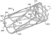
図を参照すると、図1は、近位カテーテルシャフト220及び遠位拡張性先端部110を有する血塊回収カテーテル100の遠位部分を示す。カテーテル100は、標準的な介入技術、並びにアクセスカテーテル、バルーンガイドカテーテル、及び/又はガイドワイヤなどの市販の補助装置を使用して、脈管内の標的部位にナビゲートすることができる。カテーテルシャフト本体220は、長手方向軸111の周りに配設された略管状の構造を有することができる。Referring to the figures, FIG. 1 shows a distal portion of a
1つの構成では、先端部110は、折り畳まれた送達構成から広げられたときに拡張可能な花弁形状を形成する、多数の葉状部112、113を有することができる。葉状部は、ループ又はフープの形状に構成された支柱又はワイヤであり得る。図1に示される例は、2つの作動葉状部112と、カテーテルシャフト220の遠位端225に堅く接続された2つの受動葉状部113とを含む。2つの作動葉状部112は、180度離間して位置決めされ、2つの受動葉状部113の支柱と周方向に重なり合うことができる。In one configuration, the
作動及び受動葉状部の数は、装置の必要性に基づいて変動し得る。例えば、葉状部の数を多くすることにより、膜の支持及び血管壁との封止を形成するための半径方向の力を増加させることができるが、所与の支柱の厚さ及び幅に対する先端部の横方向剛性も増加することになる。The number of active and passive leaflets can be varied based on the needs of the device. For example, a larger number of leaflets can increase the radial force to support the membrane and form a seal with the vessel wall, but also increase the lateral stiffness of the tip for a given strut thickness and width.
いくつかの場合には、葉状部112、113は、起伏、狭窄セクション、又は拡張可能なセルなどの可撓性を増加させるであろうパターンを含むことができる。葉状部の起伏は、曲がりくねった血管を通して標的部位へと前進させられるときに、折り畳まれた送達構成において先端部が反対側で短くなったり長くなったりすることを支援することができる。更に、起伏は、先端部110が拡張している間にカテーテル100が遠位に押される場合に、1つ又は2つ以上の葉状部又は先端部の一部分が過剰に拡張するのを防ぐのに役立ち得る。他の例では、葉状部112、113は、拡張されたときに遠位端において半径方向内側に低いテーパ角及び曲線を有することができ、その結果、支柱は血管壁に押し込まれない。In some cases, the
拡張性先端部110は、近位接合部114においてカテーテルシャフト220の遠位端225に固定的に又は柔軟に連結され、外側シース又はカテーテル内の折り畳まれた送達構成から半径方向に拡張された展開構成へと半径方向に拡張するように構成され得る。図1は、固定葉状部の近位接合部114を示す。葉状部はまた、小穴などのより可撓性のリンク機構を介して接続され得ることが理解され得る。葉状部はまた、先端部110の均一で一貫した拡張及び折り重ねのためのヒンジ点として機能することができる狭窄セクション又はノッチなどの特徴部を有することができる。The
カテーテルシャフト220は、主要カテーテル管腔212と、ガイド管腔222を画定する1つ又は2つ以上のガイド管221とを有するマルチ管腔システムであり得る。カテーテル管腔212は、マイクロカテーテル及びステントリーバなどの補助装置の送達に使用することができ、拡張性先端部110を通して遠位方向に吸引を誘導するために使用することもできる。シャフト220の構造は、例えば、内部低摩擦ライナと、製造中に編組構造にリフローされ得る外側ポリマージャケットと、を有する、ポリマー及び/又は金属編組支持構造体であり得る。The
ガイド管221は、使用者によって操作される近位ルアー又は制御ハンドル(図示せず)から長手方向軸111に対して軸方向に平行に延び得る。ガイド管は、カテーテルシャフト220の遠位端225に近接して遠位に、又は遠位端の近位若しくは遠位に終端することができる。ガイド管221は、拡張性先端部110を拡張する及び/又は折り畳むように構成された制御部材又は引張ワイヤケーブル120のための導管として機能することができる。The
カテーテルシャフト220及び拡張性先端部110の外面は、膜又は外側ジャケット(図示せず)によって少なくとも部分的に被覆され得る。膜又はジャケットは、血塊の吸引及び回収中に近位流体が先端部に進入するのを阻止することができ、処置中に他の破片の血塊断片の遠位移動を防ぎながら、吸引力のより効率的な方向付けを可能にする。一例では、ジャケットは、拡張された展開構成にあるときに、拡張性先端部を拡張させることによって及ぼされる半径方向の力が先端部の漏斗又は円錐形状輪郭に膜を伸張させるのに十分であるように、高弾性材料から形成され得る。代替的に、ジャケットは、葉状部が自由に動くことができるように、葉状部の上に袋状に緩く折り重ねられたものであり得る。先端部110の内径から外径まで折り重ねられた袋状のジャケットは、ジャケットを拡張させるのに必要なひずみを低減し、膜の内側部分が吸引下で折り畳まれることからの抵抗を強化するために、葉状部支柱間で一緒に接着されているか、又は熱溶接されている内面及び外面を有することができる。The outer surface of the
図2a~図2cは、拡張性先端部110の作動葉状部112と引張ケーブル120との間の可撓性取り付け接合部の様々な方法を示す。引張ケーブル120は、使用者によって作動されたときに先端部110の拡張偏向を引き起こすのに十分な引張強度を有する、鋼又は高分子量ポリマーで構築され得る。引張ケーブル120は、拡張性先端部の拡張又は後退中に円滑な移行を提供するのを助け、カテーテルシャフト220の支持管に直接連結されていなくてもよい受動葉状部113のバランスをとるために周方向に離間され得る。例えば、図1の構成などの、180度離間された2つの作動葉状部112を有することにより、先端部110は、標的まで前進させられるか又は標的から引き出されるときに、2つのケーブル120の曲げ平面の周りで曲がることができる。2a-c show various methods of flexible attachment joints between the
引張ケーブル120部材は、図2a及び図2bに示されるように、それらの最遠位端において、拡大された球状部端部118を用いて定位置に固設され得る。球状部端部118は、引張ケーブル120が拡張性先端部上に形成された関連する小穴116を通って供給された後、製造中に形成され得る。小穴は、作動先端葉状部112の近位に延びる張力付与部材115の近位端に配置されることができる。球状部118は、結び目を形成する方法、熱を適用する方法、レーザカットする方法、成形する方法、又は機械的塑性変形を使用する方法など、いくつかの方法のいずれかによって形成され得る。別の例では、小穴116は、隣接する葉状部112同士の接合部において形成されたループであってもよい。The
別の例では、球状部は、全ての自由度において堅く構成された接合部を伴わずに葉状部112、113に曲げモーメントを伝達しながら、依然として小穴116によって保持され得るような多角形又は非球形の形状を有することができる。拡張性先端部とカテーテル本体との間の界面の曲げ剛性を調整する他の設計が予想され得る。図2cは、ヒンジリンク117が、引張ケーブル120と作動葉状部112の張力付与部材115との間の重なり合う界面において形成する、可撓性ヒンジ式接合部を有することができる更なる設計を示す。ヒンジリンク117は、拡張性先端部110の1つ又は2つ以上の曲げ平面を画定する単一又は二重ピン接続であり得る。周方向に整列された二重ピン接続は、例えば、全ての葉状部からの先端部の支持を維持しながら、互いに垂直な2つの平面に可撓性を有する先端部を提供するであろう。ヒンジ式接合部はまた、先端部110が屈曲するための、より大きな自由度で開放する自在接合部であってもよい。In another example, the bulb can have a polygonal or non-spherical shape that can transmit bending moments to the
図3に示されるように、引張ケーブル120は、カテーテルシャフト220の遠位端225においてガイド管腔222を出ることができ、又はシャフト及びガイド管221は、シャフトの外面に遠位切り欠き224を形成するフィレット又はスカラップを有することができる。遠位切り欠き224は、ケーブル管腔222からのより浅い出口角度を可能にすることによって、張力付与部材115上の引張ケーブル120によって及ぼされる引張角度を変更することができる。切り欠き224は、示されるように出口角度を固定するために、カテーテルシャフト220の遠位端225の近位の特定の距離に位置することができる。別の例では、切り欠きは、遠位端225の近位に延びるスロットであってもよい。更なる例では、個々の引張ケーブル120は、単一の引張ケーブル120を使用して、作動葉状部112のうちの2つ以上を周囲の周りで拡張性先端部110に引っ張るように、カテーテルシャフト220内の2つ以上の遠位切り欠き224を出るように分割され得る。As shown in FIG. 3, the
引張ケーブル120は、カテーテルシャフト220の軸111に沿ってガイド管腔222内で非常に自由に移動することができるべきである。低摩擦システムは、ガイド管腔222及び/又は引張ケーブル120の外面のライニングのためのPTFE又はFEPなどの材料を使用して利用され得る。代替的に、潤滑剤(シリコーンオイル又は二硫化モリブデンなど)を使用してもよく、親水性コーティングなどのコーティングを使用することもできる。引張ケーブル自体は、非常に高弾性の材料で作製することができ、それにより使用時に張力下で最小の伸張又は伸長を呈する、薄い低プロファイルケーブルが使用され得る。引張ケーブルがワイヤ又はマルチフィラメントケーブル形態にあるときに、ステンレス鋼、Nitinol、又はMP35Nのような金属も使用され得る。UHMWPE、LCP、Vectran、又はKevlarなどの工学的ポリマー又は複合体もまた、好適な材料として想定され得る。加えて、ワイヤ及びケーブル及び/又は金属及びポリマーの両方の組み合わせも使用され得る。例えば、PTFEコーティングを有する固体Nitinolワイヤは、引張ケーブルの大部分に使用することができ、遠位端近くのUHMWPEの短いセグメントは、引張ケーブルを拡張性先端部110の作動葉状部112に接続するのを助けるために使用され得る。近位の固体モノフィラメントはまた、必要に応じてフレームを折り畳むために前進させることができるように、引張ケーブル内に良好な押し込み性及びカラム剛性を提供するためにも使用され得る。The
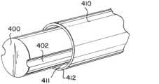
図4に示される別の構成では、カテーテル100は、長手方向軸111の周りに構成された管状カテーテルシャフト220を有することができる。カテーテルシャフト220は、カテーテル100の可撓性がその長さに沿って調整され得るように、規則的又は可変の間隔で表面に機械加工された長手方向及び/又は横断方向の切り込み228を有することができる。例えば、スロットは、カテーテルの近位部分がより高い押し込み性及び追跡性特性を与えるようなサイズ又は間隔を有することができる。シャフト220のより遠位の長さに沿った異なるスロット間隔は、閉塞性血塊の近くの狭く曲がりくねった血管に対してより高い可撓性を可能にすることができる。In another configuration shown in FIG. 4, the
図示されるカテーテルシャフト220は、シャフト周囲の両側に180度離間した2つのガイド管221を有することができる。ガイド管221は、遠位拡張性先端部110の拡張及び折り畳みを作動させるための引張ケーブル120を送るために使用することができる。ガイド管221は、カテーテルシャフトの全長に延び、シャフト内の横断方向の切込み又はスロット228を周方向に分断して、長手方向に延びるスパイン230を形成することができる。軸方向スパイン230は、一定の厚さを有することができ、又はカテーテルシャフト220の近位部分と遠位部分との間に滑らかな剛性移行を提供するよう先細であることができる。The illustrated
図4~図6に示される例では、拡張性先端部110は、6つの遠位ピーク119を有する葉状部124を形成する6つの支柱セグメントを有する。葉状部124は、ポリマーカテーテルシャフト220と一体的にレーザカットされ得るか、別個の部材として機械加工され得る(図4~図6に示されるように)か、又は一体的な部材と独立した部材との組み合わせであり得る。隣接する葉状部124は、交差点126において周方向に重なり合うことができる。葉状部は、交差点において固定的に連結されている必要はなく、その結果、それらは交互に配置されており、先端部110が拡張又は収縮するときに、互いに対して摺動して折り重ねられてもよい。葉状部を6個より多く有する設計は、追加の葉状部支柱が、ジャケット又は膜(図示せず)の折り畳みを防ぐための半径方向の追加の力及び支持を提供しながら、先端部の可撓性をいくらか犠牲にすることが理解され得る。同様に、より大きい剛性又は厚さの膜がより少ない支持を必要とする状況では、より少ない葉状部が利用され得る。In the example shown in FIGS. 4-6, the
1つ又は2つ以上の引張ケーブル120は、ガイド管221のガイド管腔222内のシャフト220の長さに沿って延び得る。引張ケーブル120は、2つの隣接する葉状部122が重なり合う交差点126を取り囲むように構成された遠位ループ122を有するように形成され得る。張力付与されたときに、引張ケーブル120は、交差点126を外側に引っ張って、半径方向のサイズを増大させ、拡張性先端部110を展開することができる。いくつかの場合には、シャフト220のガイド管221は、シャフトの遠位端225を越えて遠位延長部227を有することができる。One or
図5は、図4のカテーテル100のカテーテルシャフト220を示す。係留スロット226は、シャフトと遠位先端部110の葉状部124との間の近位接合部114に剛性及び保持を提供するように、シャフト220の遠位端225に近位に配置され得る。図6に示される例などの独立した隣接する葉状部124は、遠位ピーク119及び近位足部又は係留部128を有するフープ形状を有することができる。葉状部124は、交互に配置され、それらの近位葉状部係留部128は、シャフト220の係留スロット226内で一緒にレーザ溶接又は結合され得る。別の例では、葉状部のいくつかはシャフトと一体的に形成され得る一方で、他の葉状部は、シャフト上に溶接又は接着された係留部128を有する。別の代替として、シャフト220の遠位端225を取り囲むカラーは、葉状部係留部128の軸方向運動を制御するための保持リングとして機能することができる(その例が図9aに示される)。FIG. 5 shows the
本発明の態様による血栓除去カテーテルの別の例の遠位部分が図7に示される。管状カテーテルシャフト220は、ポリマー押出物から形成され得る。押出物は、例えば、ポリエーテルエーテルケトン(PEEK)又は別の頑丈な熱可塑性ポリマーから製造され得る。押出物は、管状シャフト220に追加の横方向の可撓性を与えるために、外面に切り込まされた軸方向及び/又は横断方向スロット228を有するように構成され得る。切り込みは、シャフト220の異なる軸方向セクションに対する剛性特性を調整するために、長手方向に整列又はオフセットされ得る。スロット228は、シャフト220の長さに沿って1つ又は2つ以上の長手方向スパイン230を形成するように、周方向に不連続であり得る。The distal portion of another example of a thrombus removal catheter according to an aspect of the invention is shown in FIG. 7. The
1つ又は2つ以上の引張ケーブルガイド管221は、カテーテル本体220の周囲の周りに配設され得、カテーテル軸の長さを延びることができる。管221は、カテーテル管の外面と当接して面一であってもよく、又は中間壁若しくはいくつかの他の配置であってもよい。示されるように、いくつかの実施例は、カテーテルシャフトの周囲の周りに180度離間された2つの引張ケーブルを有することができるが、より多くのケーブルが利用されるときに、他の離間配置が予想され得る。ガイド管221は、必要に応じて管が追加の補剛機構として機能することができるように、1つ又は2つ以上の長手方向スパイン230と半径方向に整列されていても、されていなくてもよい。各ガイド管は、引張ケーブル120の自由な相対的な軸方向運動を可能にするようにサイズ決めされた内側管状管腔212を有し得る。他の設計と同様に、遠位切り欠き224は、張力が適用されるときに引張ケーブル120の半径方向の屈曲を可能にするために提供され得る。ガイド管は、ポリイミド管などの良好なカラム剛性及び耐キンク性を提供する、頑丈なポリマー管であり得る。One or more tension
この例の拡張性先端部110の漏斗設計は、カテーテルシャフト220と直接レーザカットされた葉状部240、241の一体格子であり得る。代替的に、拡張性先端部110格子は、単一の部品として射出成形され、熱溶接、接着剤、又は同様の手段によってシャフト220に取り付けられ得る。作動葉状部240は、結び目、ループ、又は小穴など、前述したものと同様の構成で、引張ケーブル120と動作可能に連結され得る。葉状部240、241は、拡張されたときに血管の壁との非外傷性接触のために、穏やかに傾斜するループ又は花弁形状を伴って遠位に丸みを帯び得る。葉状部240、241は、引張ケーブル120が後退する際に先端部110が外側に張り出したときに、葉状部240、241が可能であるか又は短くなったり広くなったりすることができるような曲げ部を含むことができる。他の実施例と同様に、ポリマージャケット又は膜は、先端部110及びカテーテルシャフト220の少なくとも一部分を被覆又は封入することができる。The funnel design of the
図7は、折り畳まれた送達構成における拡張性先端部110を示す。先端部110は、2つの作動葉状部240と、カテーテルシャフト220の遠位端225に堅く接続された2つの受動葉状部241と、を含むことができる。2つの受動葉状部241は、周方向接合部229において作動葉状部240に周方向に接合され得、作動葉状部は、引張ケーブルのうちの1つに固定的に接続され得る。Figure 7 shows the
作動葉状部240は、拡張性先端部110の周囲の、受動葉状部241よりも実質的に大きい部分を占めることができる。図7に見られるように、受動葉状部241は、実質的に蹄鉄形状のプロファイルを有することができ、ここで、先端部110が折り畳まれた送達構成にあるときに、馬蹄の脚部は、一緒に周方向に圧縮される。作動葉状部240の形状は、引張ケーブル120が後退させられるときに、それらが短くなり、広がるように(並びに外側に張り出すように)調節され得る。この形状は、周方向接合部229において引っ張られたときに、隣接する受動葉状部241が張り出すのを助けることになり、したがって、卵形漏斗形状へと単に伸ばされるのとは対照的に、より丸みのある漏斗を作る。The
図7は、図8の拡張された展開構成で示されている。受動葉状部241は、より短く、作動葉状部240の長さに沿って周方向接合部229で交差することができ、それにより、受動葉状部はより大きい半径方向サイズに張り出す。全ての葉状部の組み合わされた張り出しは、血管と封止を形成するようにより良好に形成された、より丸みを帯びた均一な漏斗に寄与し、血塊が取れると、捕捉された血塊を受け入れて圧縮する。図示される実施例では、膜又はジャケット430は、先端部110の拡張された口の輪郭に追従するようにトリミングされ得る。他の例では、ジャケット430は、正方形又は非外傷性の凹状プロファイルに従うことができる。7 is shown in the expanded deployed configuration of FIG. 8. The
図9a及び図9bは、葉状部が編組又はコイル織成構造体310から形成される漏斗形状のカテーテル先端部300の別の構成を示す。葉状部のワイヤは、カテーテルの軸111に沿って入れ子式に摺動することができる摺動カラー320内に交互に配置され、固定されることができる、重なり合う遠位フープ312を形成することができる。カテーテル本体220はまた、長手方向軸111の周りに管状形状を形成することができる、織成又は編組支持構造体を有することができる。織成メッシュの密度は、カテーテルシャフト220の軸方向セクションに対する局所的な剛性特性を調整するように構成され得る。遠位フープ312は、カテーテルのワイヤ編組体310と一体であってもよく、ワイヤ長さ及び/又は編組角度は、図9bに示されるように、拡張されると、フープが拡張した先端部300のための緩やかな漏斗プロファイルを形成するように調整され得る。9a and 9b show another configuration of a funnel-shaped
一例では、拡張性先端部110及びカテーテルシャフト220の編組構造体310を一体的に形成することができる例では、引張ワイヤ(図示せず)は、先端部110の展開構成への拡張のために、織り交差点314の周りにループ状にされ得る。別の例では、遠位フープのワイヤは、カテーテル本体220に直接固定されるか、又は外側ポリマージャケット430内に埋め込まれた近位接合部114を有するように、近位に延びることができる。遠位フープ312の織り交差点314は、可能な限り遠位に維持され得る。遠位フープ312は、互いに対して自由に移動し、摺動することができる。In one example, the
編組メッシュは、金属ワイヤ構造体を有することができ、Nitinolなどの形状記憶特性を有する合金を利用することができる。編組メッシュを形成するために、一体型ワイヤを、先細の弾丸形状の鼻部で形成ツールの周りに巻き付けて、血管内で非外傷性交差のために先端部を遠位に減少する外径にヒートセットすることができる。エラストマー膜を開くのを支援するようにワイヤに増加した剛性を与えるために、ワイヤ外径は比較的大きくなり得る。一例では、ワイヤの外径は、0.004インチ~0.008インチの範囲であり得る。血塊を受け入れるよう流量及び先端部の近位断面を最大化するために、ワイヤのセグメントはプレスツールで平坦化され得る。作動時に開く拡張性先端部を形成するワイヤの遠位セクションもまた平坦化され得るが、このセクションはまた、拡張された展開状態の先端部の直径の増加が断面に影響を与えないので、丸みを帯びたままであってもよい。The braided mesh can have a metal wire construction and can utilize alloys with shape memory properties such as Nitinol. To form the braided mesh, a unitary wire can be wrapped around a forming tool with a tapered bullet-shaped nose and heat set to a distally decreasing outer diameter for atraumatic crossing within the vessel. The wire outer diameter can be relatively large to give the wire increased stiffness to aid in opening the elastomeric membrane. In one example, the wire outer diameter can range from 0.004 inches to 0.008 inches. A segment of the wire can be flattened with a press tool to maximize flow rate and the proximal cross section of the tip to accommodate the clot. The distal section of the wire that forms the expandable tip that opens upon actuation can also be flattened, but this section can also remain rounded since the increase in diameter of the tip in the expanded deployed state does not affect the cross section.
図9aに示される先端部の例の展開構成への作動機構の例が図10に示される。カラー320は、カテーテルシャフト220の少なくとも一部分の周りに摺動可能に配設され、1つ又は2つ以上の引張ケーブル120の張力付与又は押し込みを通じてカテーテルの長手方向軸111に沿って並進するように構成され得る。遠位フープ312は、摺動カラー320に接続されたフープ張力付与部材322を有することができる。張力付与装置部材322は、ワイヤ又はストリップであってもよく、拡張性先端部300の編組構造体310のフープ312のいくつか又は全部に接続され得る。次いで、張力付与部材322は、カラー320が引張ケーブル120と共に近位に引っ張られるときに、先端部を張り出させ、拡張することができる。遠位フープ312のストランドは、カラーが引っ張り、近位に並進されるときに半径方向に拡張するように、シャフト220に埋め込まれるか、又は別の方法でシャフト220に接続され得る。引張力は、180度離間した2つの引張ケーブル120を通じてフープ312に均等に分配され得る。An example of an actuation mechanism for the example tip shown in FIG. 9a to a deployed configuration is shown in FIG. 10. A
代替として、外側ジャケット又は膜430の少なくとも一部分は、拡張性先端部110の上で反転され、摺動可能なカラー320に結合され得る。膜430は、シャフト220の内径に結合されるフープ312の半径方向内側に延びることができる。次いで、膜430は、カラー320が引張ケーブル120と共に近位に引っ張られるときに、フープ312を半径方向に拡張することができる。Alternatively, at least a portion of the outer jacket or
本明細書に開示されるカテーテル設計のいずれもまた、1つ又は2つ以上のステントリーバと共に使用され得ることに留意されたい。ステントリーバの後退と拡張された展開構成における拡大された先端セクションを通じた効率的な吸引の組み合わせは、血塊を除去する際の最初の通過成功の可能性を増加させるために一緒に作用することができる。カテーテルはまた、吸引真空を血塊面に誘導することもでき、一方、ステントリーバは、複合血塊(脆砕性領域及びフィブリンに富む領域から構成される)をまとめて保持して塞栓を防ぎ、血塊を血管壁から取るのを支援することができる。先端セクションの漏斗状形状はまた、カテーテルへの進入時の血塊の剪断を減少させ、流れを停止させて、新たな領域の塞栓から遠位の血管を保護することもできる。It should be noted that any of the catheter designs disclosed herein may also be used with one or more stentreaver. The combination of retraction of the stentriever and efficient aspiration through the enlarged tip section in the expanded deployed configuration can work together to increase the chances of first pass success in removing the clot. The catheter can also direct an aspiration vacuum to the clot surface, while the stentriever can hold the composite clot (composed of friable and fibrin-rich regions) together to prevent embolization and assist in dislodging the clot from the vessel wall. The funnel shape of the tip section can also reduce shearing of the clot upon entry into the catheter, halting flow and protecting the distal vessel from embolization of new areas.
図11a及び図11bは、葉状部が編組又はコイル織成構造体310から形成される漏斗形状のカテーテル先端部300の追加の構成を示す。先端部300の編組構造体310は、カテーテルシャフト220の編組構造体と一体であってもよい。編組体310のパターンは、2つの引張ワイヤ120からの先端部の作動を可能にして、直径方向に反対側の作動葉状部340から隣接する受動葉状部341へと力を伝達することができ、それにより、全ての葉状部が、図示されるような実質的に管状の折り畳まれた送達状態から吸引及び/又は装置の送達のために開いた展開構成に移動する。一例では、引張ワイヤ120は、作動葉状部340の遠位端325において編組ループ又は小穴316に取り付けられ得る。別の例では、引張ワイヤ120は、作動葉状部340の遠位端325の中央に単純に溶接されてもよく、又は織り交差点314において取り付けられてもよい。11a and 11b show additional configurations of a funnel-shaped
図11aに示されるように、作動葉状部340は、隣接する受動葉状部341の各々の下(半径方向内側)に位置決めされてよく、それにより引張ワイヤ(図示せず)に張力を付与することにより、バランスの取れた方式で全ての葉状部を開くことができる。近位に、葉状部340、341の支柱は、各々、交差葉状部撚り点342において単一の撚りを有することができ、これは、葉状部を互いに対して係留するのを助けることができ、先端部300の半径方向の拡張のための枢動として機能することができる。代替的に、撚り点342における葉状部間のスポット溶接は、位置を固設することができる。この構成の利点は、拡張可能な先端部が開いたときに、葉状部340、341が交差点314において互いに対して摺動することができるため、引張ワイヤと作動葉状部との間の接続は摺動可能である必要がないことである。As shown in FIG. 11a, the
別の構成では、先端部300の引張ワイヤ120は、図4に見られる拡張性先端部と同様の遠位葉状部交差点314の上にループ状にすることができる。この構成は、引張ワイヤの張力を拡張する葉状部により均等に並進させる(translated to)ことを可能にする。この構成では、作動葉状部340は、隣接する受動葉状部341の上(半径方向外側)又は下(半径方向内側)に位置決めされ得る。しかしながら、交差点314における引張ワイヤ取り付けは、摺動可能でなければならないが、交差点が、葉状部が半径方向に拡張されるときに、より近位の位置まで摺動することを可能にする。In another configuration, the
編組織成体310は、図11bに示されるように、膜又は外側ジャケット430で被覆され得る。ジャケット430は、カテーテルの内径から先端部300の葉状部340、341の下で遠位に延び、遠位端325において反転して、葉状部の上を近位方向に延びることができる。反転したジャケット430がこの設計で先端部に接着される必要はないので、葉状部は、反転したジャケットソックス内で互いに対して自由に移動する。The
前の例と同様に、引張ケーブルガイド管221は、カテーテルシャフト220と共に長手方向に延び得る。いくつかの例では、引張ケーブル120は、編組葉状部340、341の下でガイド管から遠位に延びることができる。この配向により、先端部が拡張されるときに、撚り点342が引張ケーブル120の半径方向の移動を制限することができるので、先端部300の作動のための張力のあるてこの作用を低減する代償として、カテーテルの組み立てを容易にするであろう。他の例では、引張ケーブルがガイド管221から出るときに制限がないように、引張ケーブル120を葉状部340、341の上に通すことによって、先端部の作動拡張のてこの作用が保持され得る。この構成は、より大きい開く力を生成することを可能にすることができるが、引張ケーブルが葉状部の下にねじ込まれた場合よりも、カテーテルの組み立てがより困難になり得る。As in the previous example, the tension
様々な製造方法を用いて、本明細書に開示される実施例のカテーテルを製造することができる。図12a~図12bは、血塊回収カテーテルのカテーテルシャフト220のための可能な構造方法の横断方向端面図を示す。図12aでは、シャフトは、可撓性を加えるためにレーザカットされる一体型マルチ管腔押出物であってもよい。例えば、シャフト220は、近位端と遠位端との間に螺旋状の切り込みセクションを有することができる。切り込みは、長手方向に整列された一連の狭い横断方向スロットが、押出物においてガイド管221に平行な1つ又は2つ以上の軸方向スパイン230を形成することができるように、切り込み幅の変化を含むことができる。軸方向スパインは、シャフトの可撓性を維持しながら、シャフトの良好な押し込み性を与えることができる。マルチ管腔シャフト220は、180度離間した引張ケーブル管腔222を有する対の(twin)ガイド管221を有することができる。対の引張ケーブル管腔222のうちの少なくとも1つはまた、張力下でのシャフトの過剰な伸長を防ぐために、内部を通って延びる内部テザー(図示せず)を有することができる。一例では、テザーは、伸張に対する耐性を与えるフルオロポリマー又は他の材料で作製され得る。限定された伸張により、シャフト220が脈管内の狭い半径にあるときに、押出物の切り込みを開くことができる。テザーはまた、硬く、フィブリンに富む血塊が先端部に詰まっているときに、拡張性先端部を外側シース又は中間カテーテル内に後退させる必要がある場合など、より大きい張力を受けて切り込みが実質的に引き離されることに抵抗することができる。A variety of manufacturing methods can be used to manufacture the catheters of the embodiments disclosed herein. Figures 12a-b show transverse end views of possible construction methods for the
一例では、カテーテルは、内面及び外面を有するシャフトを有することができ、内面の外周は外面の外周よりも大きい。押出物の内壁に当接して横断するように図示されているが、引張ケーブルガイド管221及び管腔222はまた、押出物の中間壁又は外壁の外側に位置し得ることが理解され得る。In one example, the catheter can have a shaft with an inner surface and an outer surface, where the outer circumference of the inner surface is greater than the outer circumference of the outer surface. Although shown abutting and transverse to the inner wall of the extrusion, it can be understood that the tension
押出物は、PEEK、ポリアミド(Pa)、又はTR 55などのナイロンなどの高弾性熱可塑性ポリマーであり、シャフトに優れた押し込み性能を与えることができる。加えて、押出材料は、マイクロカテーテル、ステントリーバ、及びガイドワイヤなどの、処置のための他の装置の通過を支援するための高弾性かつ低摩擦のポリマーであり得る。熱収縮した外側ジャケット又は膜430(図示せず)は、シャフトの外径に融着されたときに、シャフト220の押出物を封止することができる。The extrusion can be a highly elastic thermoplastic polymer such as PEEK, polyamide (Pa), or nylon such as TR 55, giving the shaft excellent pushability. Additionally, the extrusion material can be a highly elastic, low friction polymer to aid in the passage of other devices for procedures, such as microcatheters, stentreaver, and guidewires. A heat shrunk outer jacket or membrane 430 (not shown) can seal the extrusion of the
別の例では、低摩擦層又はフィルムは、押出物の内部に位置決めされ得る結合のための外側裏当て層を有する、小型のPTFE又は他の低摩擦ライナの使用を通じてシャフト220の内径に適用され得る。次いで、拡大された端部を有する加熱されたマンドレルを、ライナを通して引き込み、ライナを拡張し、レーザカットされた押出物の内面に接着することができる。ライナが融着するために、必要に応じて、追加の熱を押出物に適用することができる。In another example, a low friction layer or film can be applied to the inner diameter of the
図12bは、層状の複合構造体の代替のシャフト220を示す。層は、低摩擦の内側スリーブ又はライナ410と、外側ジャケット又は膜430が適用され得る管状コア420と、を含むことができる。コアは、カテーテルシャフト220の構造及び補強を提供するために、押出物、レーザカットハイポチューブ、又はコイル状若しくは編組メッシュであってもよい。12b shows an
複合層状カテーテルシャフト220は、図13a~図13dに示されるような構造のための方法を通じて説明され得る。図13aでは、カテーテルシャフト220の所望の内径とほぼ同じ外径を有することができる、実質的に円筒形のマンドレル400を製作することができる。マンドレル400は、引張ワイヤガイド管221のための金型として機能する、長手方向軸111に平行な外面に機械加工された1つ又は2つ以上の長手方向管腔溝402を有することができる。The composite
図13bでは、複合構造体は、PTFE又はPETなどの低摩擦ライナ411と、低摩擦ライナに結合された厚い裏当て層412と、を有する、可撓性内側層410を含むことができる。可撓性内側層410は、円筒形マンドレル400の上にスリーブとして組み立てられ得る。図13cでは、管腔ガイド管221を形成するポリアミド又は同様の管は、内側層410を溝内に押し込むためにマンドレル400の管腔溝402に挿入され得る。次いで、コイル又は編組補強層420は、内側層410及びガイド管221の外径の周りに巻き付けられるか、又は配設され得る。前述したように、コイル又は編組補強材420のピッチ又は軸方向の間隔は、カテーテルシャフト220の異なる軸方向長さに対する剛性特性を調整するために変化させることができる。補強コイル420は、ガイド管221を内側層410にしっかりと結びつけることができる。他の例では、レーザカットされた管をコイル又は編組体の代わりに使用し、組立体の上で摺動させてマンドレル400、内側層410、及びガイド管221を一緒に保持することができる。In FIG. 13b, the composite structure can include a flexible
本明細書で使用するとき、用語「ジャケット」、「膜」、及び「カバー」は互換的に使用される。外側ジャケット又は膜430は、複合構造体の上部の上に適用され、熱収縮又は積層を使用してリフローされて、組立体を一緒に保持することができる。いくつかの場合には、ジャケットは、様々な材料特性を有するいくつかのセクションを有することができる。図13dでは、ジャケット又は膜430が固設されると、溝付きマンドレル400は除去されることができる。As used herein, the terms "jacket," "membrane," and "cover" are used interchangeably. An outer jacket or
図14は、図13a~図13dの方法から得ることができる複合カテーテルシャフト220の構成の断面図である。外側ジャケットは、膜カバー430であってもよく、更に記載されるように、様々な異なる形態又は構成をとることができる。膜又はカバーは、拡張性先端部の拡張が、拘束されていないときにカバーを伸張させるのに十分な半径方向の力を与えるように、高弾性材料を有する管状プロファイルで形成され得る。カバー430はまた、プリーツ又は折り目432を有する先細の漏斗形状に予め形成することもでき、これにより、送達のためにより低いプロファイルに折り重ねることができる。Figure 14 is a cross-sectional view of a
好適なジャケット材料としては、40A以下のショア硬度を有することができるChronopreneなどの弾性ポリウレタン、又はシリコーンエラストマーを挙げることができる。カテーテルシャフト220及び先端フレームワークがポリマー押出物から形成される場合、空間、スロット、又はパターンが外面にレーザカットされ得、ジャケットは、製造中に空間内にリフロー又は射出成形され得る。代替的に、ジャケットは、構造体に積層され得る。Suitable jacket materials may include elastomeric polyurethanes such as Chronoprene, which may have a Shore hardness of 40A or less, or silicone elastomers. If the
外側カテーテルを通じた血塊回収カテーテル100の滑らかな送達を可能にするために、膜430の外面は、PTFEなどの低摩擦若しくは潤滑性材料、又はSurmodics、Harland、Biocoat、又はCovalonによって提供されるような市販の潤滑性コーティングでコーティングされ得る。同様に、カテーテルシャフト220の内面はまた、補助装置を通過させるために同じ又は同様の低摩擦材料でコーティングすることもでき、捕捉された血塊が吸引及び/又は機械的血栓除去装置を使用してカテーテル100を通って近位方向に引き寄せられることを支援することもできる。To allow smooth delivery of the
他の例では、ジャケット又は膜は、真っ直ぐな押出物であってもよく、押出成形され、拡張性先端部及びカテーテル本体上に後形成されてもよい。代替として、カテーテルシャフト及び拡張性先端部がレーザカットされた支柱、コイル、又は編組構造体を有する場合、構造体は、浸漬コーティング又はプラズマ堆積プロセスの一部として膜内に封入され得る。In other examples, the jacket or membrane may be a straight extrusion and may be extruded and post-formed onto the expandable tip and catheter body. Alternatively, if the catheter shaft and expandable tip have laser cut struts, coils, or braided structures, the structures may be encapsulated within the membrane as part of a dip coating or plasma deposition process.
カバーは、口の外周に沿って拡張性先端部の口の輪郭に追従するようにトリミングされ得るか、又は平面の面で完成され得る。別の例では、カバー膜は、葉状部の遠位ピークの半径方向内側に及び近位に折り重ねられ、内側層と外側層との間に溶接され得る。カバーの厚さは、先端部の葉状部の間及びその上に維持され得るか、又は均一な厚さで完成され得る。The cover may be trimmed to follow the contour of the expandable tip's mouth along the periphery of the mouth, or may be completed with a flat surface. In another example, the cover membrane may be folded radially inward and proximal to the distal peaks of the lobes and welded between the inner and outer layers. The thickness of the cover may be maintained between and over the tip lobes, or may be completed with a uniform thickness.
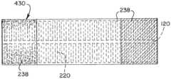
代替として、ジャケット又は膜430はまた、図15a及び図15bに示されるように、ポリマージャケット238の一連の層から形成され得る。例えば、カバーのポリマージャケット238は、図15aに示されるように、厚さを通して材料特性を調整するために、カテーテルシャフト220の周りに配設された半径方向列にあり得る。代替的に、異なるデュロメータジャケット又はジャケット238のセットは、図15bに示されるように、カテーテルの異なるセクションに別個の押し込み性及び可撓性特性を与えるために、軸に沿って別個の長さにおいてカテーテルシャフト220の周りに配設され得る。ジャケットを軸方向列に構成することによって、カテーテルの全体的な剛性を近位端でより硬いものから遠位端で極めて可撓性のものへと移行させることが可能である。Alternatively, the jacket or
一連のポリマージャケット238を一緒に突き合わせ、カテーテルシャフト220に融着することができる。拡張性先端部は、浸漬コーティングされ得る同じ又は別個のジャケットを有することができ、カテーテルシャフトのジャケットに当接するか、又はその下に位置するか、若しくはその上に位置することができる。先端部のジャケットがシャフトのジャケットの下にある場合、それは支持管のジャケットがリフローされるときに発生する熱に耐えることが可能な材料から製造することができる。更なる例では、可変剛性及び弾性特性で予め形成された外側ジャケットを一連のポリマージャケットと置き換えることができる。A series of
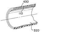
図16a~図16dは、ジャケット430が、カテーテルシャフト220の遠位端に向かって拡張されていない先端部110の周りに配設され得る方法のいくつかの例を簡単に示す。図16a~図16bは、ジャケット430が折り目又はプリーツ432を伴って適用されて、大型又は袋状のジャケットが使用される状況における低プロファイル送達状態の折り重ねを可能にする例を示す。次に、プリーツ432は、先端部110が展開構成に拡張されたときに展開され得る。ジャケット430は、先端部の拡張された花弁部又は葉状部と重なり合って、周囲に延び、先端部が拡張するときにジャケット上に与えられる歪みを最小化することができる。同様の実施例では、ジャケット430は、拡張性先端部のためにわずかに大きくすることができ、拡張された先端部の輪郭にジャケットを適合させるために、ジャケットの展開プリーツ432と弾性膨張との組み合わせが使用される。16a-16d briefly illustrate some examples of how the
図16cは、拡張性先端部110の上に適用された被覆膜430を有するカテーテル100の遠位部分のプロファイル断面図を示す。膜430は、プラズマプロセスで浸漬又は堆積され、続いてフレームに積層され得る。膜縁部は、先端部110の遠位縁部に追従するようにトリミングされてもよく、又は平面の面として残されてもよい。図16dに示される別個の実施例では、膜430は、軟性の非外傷性リップ434が作製されるように、先端部110のフレームの周りに折り重ねるか又は反転させることができる。膜430は先端部110に融着されてもよく、又は先端構造体は、リップ434内で自由に摺動するように構成され得る。16c shows a profile cross-section of the distal portion of the
本発明は、構成及び詳細において変化し得る、記載された例に必ずしも限定されない。「遠位」及び「近位」という用語は、前述の説明を通して使用され、処置している医師に対する位置及び方向を指すことを意味する。したがって、「遠位」又は「遠位に」は、医師に対して離れた位置又は医師から離れる方向を指す。同様に、「近位」又は「近位に」は、医師に対して近い位置又は医師に向かう方向を指す。更に、文脈が明らかに既定しない限り、「a」、「an」、及び「the」という単数形は、複数の指示対象を含む。The present invention is not necessarily limited to the described examples, which may vary in configuration and details. The terms "distal" and "proximal" are used throughout the foregoing description and are meant to refer to a position and direction relative to the treating physician. Thus, "distal" or "distally" refers to a position away from the physician or a direction away from the physician. Similarly, "proximal" or "proximally" refers to a position closer to the physician or a direction toward the physician. Additionally, the singular forms "a," "an," and "the" include plural referents unless the context clearly dictates.
本明細書で任意の数値又は数値の範囲について用いる「約」又は「およそ」という用語は、構成要素の部分又は構成要素の集合が、本明細書において説明されるその意図された目的に沿って機能することを可能とする、好適な寸法の許容誤差を示すものである。より具体的には、「約」又は「およそ」とは、列挙された値の±20%の値の範囲を指すことがあり、例えば「約90%」は、71%~99%の値の範囲を指し得る。The term "about" or "approximately" as used herein with respect to any numerical value or range of numerical values indicates a suitable dimensional tolerance that allows a portion of a component or a collection of components to function in accordance with its intended purpose as described herein. More specifically, "about" or "approximately" may refer to a range of values of ±20% of the recited value, e.g., "about 90%" may refer to a range of values from 71% to 99%.
例示的な実施形態について説明する際、明確にするために、専門用語が利用されている。各用語は、当業者によって理解されるその最も広い意味を有することが企図されており、本開示の範囲及び趣旨を逸脱することなく、類似の目的を実現するために同様に作用する全ての技術的な均等物を含むことが意図される。方法の1つ又は2つ以上の工程への言及は、追加の方法工程又は明示的に識別されたそれらの工程間に介在する方法工程の存在を排除しないことも理解されたい。方法のいくつかの工程は、開示される技術の範囲から逸脱することなく、本明細書に述べられる順序とは異なる順序で実施することができる。同様に、装置又はシステムにおける1つ又は2つ以上の構成要素への言及は、追加の構成要素又は明示的に識別されたそれらの構成要素間に介在する構成要素の存在を排除しないことも理解されたい。明確さ及び簡潔さのために、全ての可能な組み合わせが列挙されているわけではなく、かかる修正例は、多くの場合、当業者には明らかであり、以下の特許請求の範囲内にあることが意図される。In describing the exemplary embodiments, technical terms are utilized for clarity. Each term is intended to have its broadest meaning as understood by one of ordinary skill in the art, and is intended to include all technical equivalents that operate in a similar manner to achieve similar purposes without departing from the scope and spirit of the present disclosure. It should also be understood that a reference to one or more steps of a method does not preclude the presence of additional method steps or intervening method steps between those steps that are explicitly identified. Some steps of a method can be performed in a different order than the order set forth herein without departing from the scope of the disclosed technology. Similarly, it should also be understood that a reference to one or more components in an apparatus or system does not preclude the presence of additional components or intervening components between those components that are explicitly identified. For clarity and conciseness, not all possible combinations have been listed, and such modifications will often be apparent to those of ordinary skill in the art and are intended to be within the scope of the following claims.
〔実施の態様〕
(1) 血栓除去カテーテルであって、前記カテーテルが、
管状カテーテルシャフトであって、
遠位端と、内部を通って延びる長手方向軸を有するカテーテル管腔と、
前記カテーテル管腔の周囲の周りに配設され、前記カテーテルシャフトの長手方向長さを延びる引張ケーブル管腔を含む、1つ又は2つ以上の引張ケーブルガイド管と、
前記引張ケーブル管腔内に配設され、前記カテーテルの使用者によって動作可能に張力付与されることが可能である1つ又は2つ以上の引張ケーブルと、を含む、管状カテーテルシャフトと、
折り畳まれた送達構成及び半径方向に拡張された展開構成を有する拡張性先端部であって、前記先端部が、前記長手方向軸の周りに1つ又は2つ以上の葉状部を含み、前記拡張性先端部が前記拡張された展開構成にあるときに、漏斗プロファイルをとるように構成されている、拡張性先端部と、を備え、
前記1つ又は2つ以上の引張ケーブルは、張力が前記引張ケーブルに適用されたときに、前記折り畳まれた送達構成と前記拡張された展開構成との間で前記拡張性先端部を作動させるように構成されている、血栓除去カテーテル。
(2) 複数の前記葉状部が、1つ又は2つ以上の作動葉状部及び1つ又は2つ以上の受動葉状部を含み、
前記1つ又は2つ以上の作動葉状部及び前記1つ又は2つ以上の受動葉状部が、遠位ピークと、前記カテーテルシャフトに接続された1つ又は2つ以上の近位接合部と、を含む、ループ状の支柱を含む、実施態様1に記載のカテーテル。
(3) 前記作動葉状部及び前記受動葉状部は、前記拡張性先端部が、前記折り畳まれた送達構成と前記半径方向に拡張された展開構成との間で移行するときに、互いの上を摺動するように構成されている、実施態様2に記載のカテーテル。
(4) 前記カテーテルシャフトが、前記遠位端に近接した前記引張ケーブルガイド管からの1つ又は2つ以上の遠位切り欠きを更に含み、前記遠位切り欠きは、前記引張ケーブルが前記長手方向軸に対して浅い角度で前記引張ケーブル管腔を出ることを可能にするように構成されている、実施態様2に記載のカテーテル。
(5) 前記1つ又は2つ以上の作動葉状部の各々が、前記葉状部の前記遠位ピークから遠位に延び、引張ケーブルに固定的に接続された張力付与部材を更に含む、実施態様2に記載のカテーテル。[Embodiment]
(1) A thrombus removal catheter, comprising:
1. A tubular catheter shaft comprising:
a catheter lumen having a distal end and a longitudinal axis extending therethrough;
one or more tension cable guide tubes including a tension cable lumen disposed about the circumference of the catheter lumen and extending a longitudinal length of the catheter shaft;
a tubular catheter shaft including one or more tension cables disposed within the tension cable lumen and operable to be tensioned by a user of the catheter;
an expandable tip having a collapsed delivery configuration and a radially expanded deployed configuration, the tip including one or more lobes about the longitudinal axis and configured to assume a funnel profile when the expandable tip is in the expanded deployed configuration;
the one or more tensioning cables are configured to actuate the expandable tip between the collapsed delivery configuration and the expanded deployed configuration when tension is applied to the tensioning cables.
(2) the plurality of lobes includes one or more actuating lobes and one or more passive lobes;
A catheter as described in embodiment 1, wherein the one or more working lobes and the one or more passive lobes comprise looped struts including a distal peak and one or more proximal junctions connected to the catheter shaft.
3. The catheter of claim 2, wherein the actuating lobes and the passive lobes are configured to slide over one another as the expandable tip transitions between the collapsed delivery configuration and the radially expanded deployed configuration.
4. The catheter of claim 2, wherein the catheter shaft further comprises one or more distal notches from the tension cable guide tube proximate the distal end, the distal notches configured to allow the tension cable to exit the tension cable lumen at a shallow angle relative to the longitudinal axis.
5. The catheter of claim 2, wherein each of the one or more actuation lobes further comprises a tensioning member extending distally from the distal peak of the lobe and fixedly connected to a tensioning cable.
(6) 前記引張ケーブルが、ヒンジリンクを通じて前記張力付与部材に接続されている、実施態様5に記載のカテーテル。
(7) 前記引張ケーブルが、前記張力付与部材の小穴に接続された球状部を含む、実施態様5に記載のカテーテル。
(8) 前記引張ケーブルが、前記1つ又は2つ以上の作動葉状部の前記ループ状支柱の周りに構成された遠位ループを備える、実施態様2に記載のカテーテル。
(9) 前記葉状部の前記近位接合部が、前記カテーテルシャフトの前記遠位端に近接した複数の係留スロットと係合するように構成された葉状部係留部を含む、実施態様2に記載のカテーテル。
(10) 前記引張ケーブルガイド管が、前記カテーテルシャフトの前記遠位端に対して遠位の距離を更に延びる、実施態様2に記載のカテーテル。6. The catheter of claim 5, wherein the tension cable is connected to the tensioning member through a hinge link.
7. The catheter of claim 5, wherein the tension cable includes a bulb connected to an eyelet in the tensioning member.
8. The catheter of claim 2, wherein the tension cable comprises a distal loop configured around the looped strut of the one or more actuation lobes.
9. The catheter of claim 2, wherein the proximal joint of the lobes includes lobe anchors configured to engage with a plurality of anchor slots proximate the distal end of the catheter shaft.
10. The catheter of claim 2, wherein the tension cable guide tube extends a distal distance further relative to the distal end of the catheter shaft.
(11) 前記拡張性先端部が、1つ又は2つ以上の外側ジャケットによって少なくとも部分的に封入されている、実施態様2に記載のカテーテル。
(12) 血栓除去カテーテルであって、前記カテーテルが、
管状カテーテルシャフトであって、
遠位端と、内部を通って延びる長手方向軸を有するカテーテル管腔と、
前記カテーテル管腔の周囲の周りに配設された1つ又は2つ以上の引張ケーブルガイド管であって、前記ガイド管が、引張ケーブル管腔内に配設され、前記カテーテルの使用者によって動作可能に張力付与されることが可能である、1つ又は2つ以上の引張ケーブルを有する、1つ又は2つ以上の引張ケーブルガイド管と、を含む、管状カテーテルシャフトと、
前記カテーテルシャフトの前記遠位端において一体的に形成された拡張性先端部であって、前記1つ又は2つ以上の引張ケーブルが張力付与されたときに、折り畳まれた送達構成から拡張された展開構成へと半径方向に拡張するように構成された複数の葉状部を含む、拡張性先端部と、を備える、血栓除去カテーテル。
(13) 前記拡張性先端部が、1つ又は2つ以上の外側ジャケットによって少なくとも部分的に封入されている、実施態様12に記載のカテーテル。
(14) 前記1つ又は2つ以上の引張ケーブルが、前記カテーテルシャフトの周囲の周りに180度離間された2つの引張ケーブルを含む、実施態様12に記載のカテーテル。
(15) 前記複数の葉状部が、2つの作動葉状部と、前記作動葉状部に周方向に接合された2つの受動葉状部と、を含み、前記作動葉状部の各々が、前記2つの引張ケーブルのうちの1つに固定的に接続されており、
前記作動葉状部は、前記引張ケーブルが張力付与されたときに、前記折り畳まれた送達構成と前記拡張された展開構成との間で前記拡張性先端部を作動させるように構成されている、実施態様14に記載のカテーテル。11. The catheter of claim 2, wherein the expandable tip is at least partially encapsulated by one or more outer jackets.
(12) A thrombus removal catheter, comprising:
1. A tubular catheter shaft comprising:
a catheter lumen having a distal end and a longitudinal axis extending therethrough;
a tubular catheter shaft including one or more tension cable guide tubes disposed about a circumference of the catheter lumen, the guide tubes having one or more tension cables disposed within the tension cable lumen and operable to be tensioned by a user of the catheter;
an expandable tip integrally formed at the distal end of the catheter shaft, the expandable tip including a plurality of lobes configured to radially expand from a collapsed delivery configuration to an expanded deployed configuration when the one or more tensioning cables are tensioned.
13. The catheter of claim 12, wherein the expandable tip is at least partially encapsulated by one or more outer jackets.
14. The catheter of claim 12, wherein the one or more tension cables include two tension cables spaced 180 degrees apart around a circumference of the catheter shaft.
(15) The plurality of lobes includes two actuating lobes and two passive lobes circumferentially joined to the actuating lobes, each of the actuating lobes being fixedly connected to one of the two tension cables;
15. The catheter of claim 14, wherein the actuation leaflets are configured to actuate the expandable tip between the collapsed delivery configuration and the expanded deployed configuration when the tensioning cable is tensioned.
(16) 前記受動葉状部が、実質的に馬蹄形状のプロファイルを有する、実施態様15に記載のカテーテル。
(17) 前記作動葉状部が、前記拡張性先端部の周囲の、前記受動葉状部よりも実質的に大きい部分を含む、実施態様15に記載のカテーテル。
(18) 血栓除去カテーテルであって、前記カテーテルが、
管状カテーテルシャフトであって、
遠位端と、内部を通って意図する長手方向軸を有するカテーテル管腔と、
前記カテーテルシャフトの周りに配設され、前記長手方向軸に沿って入れ子式に摺動するように構成された摺動カラーと、
前記摺動カラーに固定的に接続され、前記カテーテル管腔の周囲の周りに配設された1つ又は2つ以上の引張ケーブルであって、前記摺動カラーを摺動させるために、前記カテーテルの使用者によって動作可能に張力付与されることが可能である、1つ又は2つ以上の引張ケーブルと、を含む、管状カテーテルシャフトと、
折り畳まれた送達構成及び半径方向に拡張された展開構成を有する前記遠位端に近接した拡張性先端部であって、前記先端部が、前記長手方向軸の周りに周方向に重なり合う複数の遠位フープを含み、前記拡張性先端部が前記拡張された展開構成にあるときに漏斗プロファイルを形成するように構成されている、拡張性先端部と、
前記拡張性先端部を少なくとも部分的に封入する、1つ又は2つ以上の外側ジャケットと、を備える、血栓除去カテーテル。
(19) 前記遠位フープが、それらの近位端において前記摺動カラーに接続されており、前記遠位フープは、前記引張ケーブルが張力付与されたときに、半径方向に拡張するように構成されている、実施態様18に記載のカテーテル。
(20) 前記1つ又は2つ以上の外側ジャケットが近位で前記摺動カラーに接続されており、前記ジャケットは、前記引張ケーブルが張力付与されたときに、前記遠位フープを半径方向に拡張させるように構成されている、実施態様18に記載のカテーテル。16. The catheter of claim 15, wherein the passive lobes have a substantially horseshoe-shaped profile.
17. The catheter of claim 15, wherein the actuating lobes comprise a substantially larger portion of the circumference of the expandable tip than the passive lobes.
(18) A thrombus removal catheter, comprising:
1. A tubular catheter shaft comprising:
a catheter lumen having a distal end and a longitudinal axis extending therethrough;
a sliding collar disposed about the catheter shaft and configured to telescopically slide along the longitudinal axis;
a tubular catheter shaft including one or more tensioning cables fixedly connected to the sliding collar and disposed about a circumference of the catheter lumen, the one or more tensioning cables being operatively tensionable by a user of the catheter to slide the sliding collar;
an expandable tip proximate the distal end having a collapsed delivery configuration and a radially expanded deployed configuration, the tip including a plurality of distal hoops circumferentially overlapping about the longitudinal axis and configured to form a funnel profile when the expandable tip is in the expanded deployed configuration;
and one or more outer jackets at least partially encapsulating the expandable tip.
19. The catheter of claim 18, wherein the distal hoops are connected at their proximal ends to the sliding collar, the distal hoops being configured to radially expand when the tensioning cable is tensioned.
20. The catheter of claim 18, wherein the one or more outer jackets are proximally connected to the sliding collar, the jackets being configured to radially expand the distal hoop when the tensioning cable is tensioned.
Claims (9)
Translated fromJapanese管状カテーテルシャフトであって、
遠位端と、内部を通って延びる長手方向軸を有するカテーテル管腔と、
前記カテーテル管腔の周囲に配設され、前記カテーテルシャフトの長手方向長さを延びる引張ケーブル管腔を含む、1つ又は2つ以上の引張ケーブルガイド管と、
前記引張ケーブル管腔内に配設され、前記カテーテルの使用者によって動作可能に張力付与されることが可能である1つ又は2つ以上の引張ケーブルと、を含む、管状カテーテルシャフトと、
折り畳まれた送達構成及び半径方向に拡張された展開構成を有する拡張性先端部であって、前記拡張性先端部が、前記長手方向軸の周りに2つ以上の葉状部を含み、前記拡張性先端部が前記拡張された展開構成にあるときに、漏斗プロファイルをとるように構成されている、拡張性先端部と、を備え、
前記引張ケーブルは、張力が前記引張ケーブルに適用されたときに、前記折り畳まれた送達構成と前記拡張された展開構成との間で前記拡張性先端部を作動させるように構成されており、
前記2つ以上の葉状部の内の第1の葉状部および第2の葉状部の各々が、遠位ピークと、前記カテーテルシャフトに接続された1つ又は2つ以上の近位接合部と、を含む、ループ状の支柱を含み、
前記カテーテルシャフトが、前記遠位端に近接した前記引張ケーブルガイド管からの1つ又は2つ以上の遠位切り欠きを更に含み、前記遠位切り欠きは、前記引張ケーブルが前記長手方向軸に対して浅い角度で前記引張ケーブル管腔を出ることを可能にするように構成されている、血栓除去カテーテル。 1. A thrombus removal catheter, comprising:
1. A tubular catheter shaft comprising:
a catheter lumen having a distal end and a longitudinal axis extending therethrough;
one or more tension cable guide tubes including a tension cable lumendisposed about the catheter lumen and extending a longitudinal length of the catheter shaft;
a tubular catheter shaft including one or more tension cables disposed within the tension cable lumen and operable to be tensioned by a user of the catheter;
an expandable tip having a collapsed delivery configuration and a radially expanded deployed configuration, theexpandable tip includingtwo or more lobes about the longitudinal axis and configured to assume a funnel profile when the expandable tip is in the expanded deployed configuration;
the tensioning cable is configured to actuate the expandable tip between the collapsed delivery configuration and the expanded deployed configuration when tension is applied to the tensioning cable;
each of the first and second lobes of the two or more lobes includes a looped strut including a distal peak and one or more proximal junctions connected to the catheter shaft;
a catheter shaft extending from the distal end of the catheter to the distal end of the catheter, the catheter shaft further comprising one or more distal notches extending from the distal end of the catheter shaft to the distal end of the catheter, the distal notches being configured to allow the tension cable to exit the tension cable lumen at a shallow angle relative to the longitudinal axis .
管状カテーテルシャフトであって、
遠位端と、内部を通って延びる長手方向軸を有するカテーテル管腔と、
前記カテーテル管腔の周囲に配設され、前記カテーテルシャフトの長手方向長さを延びる引張ケーブル管腔を含む、1つ又は2つ以上の引張ケーブルガイド管と、
前記引張ケーブル管腔内に配設され、前記カテーテルの使用者によって動作可能に張力付与されることが可能である1つ又は2つ以上の引張ケーブルと、を含む、管状カテーテルシャフトと、
折り畳まれた送達構成及び半径方向に拡張された展開構成を有する拡張性先端部であって、前記拡張性先端部が、前記長手方向軸の周りに2つ以上の葉状部を含み、前記拡張性先端部が前記拡張された展開構成にあるときに、漏斗プロファイルをとるように構成されている、拡張性先端部と、を備え、
前記引張ケーブルは、張力が前記引張ケーブルに適用されたときに、前記折り畳まれた送達構成と前記拡張された展開構成との間で前記拡張性先端部を作動させるように構成されており、
前記2つ以上の葉状部の内の第1の葉状部および第2の葉状部の各々が、遠位ピークと、前記カテーテルシャフトに接続された1つ又は2つ以上の近位接合部と、を含む、ループ状の支柱を含み、
前記第1の葉状部が、前記第1の葉状部の前記遠位ピークから近位に延び、前記引張ケーブルに固定的に接続された張力付与部材を更に含み、
前記引張ケーブルが引っ張られた場合に、前記第1の葉状部が変形し、前記第1の葉状部から前記第2の葉状部に力が伝達されて前記第2の葉状部が変形し、前記拡張性先端部が前記折り畳まれた送達構成から前記拡張された展開構成に作動させられる、血栓除去カテーテル。 1. A thrombus removal catheter, comprising:
1. A tubular catheter shaft comprising:
a catheter lumen having a distal end and a longitudinal axis extending therethrough;
one or more tension cable guide tubes including a tension cable lumendisposed about the catheter lumen and extending a longitudinal length of the catheter shaft;
a tubular catheter shaft including one or more tension cables disposed within the tension cable lumen and operable to be tensioned by a user of the catheter;
an expandable tip having a collapsed delivery configuration and a radially expanded deployed configuration, theexpandable tip includingtwo or more lobes about the longitudinal axis and configured to assume a funnel profile when the expandable tip is in the expanded deployed configuration;
the tensioning cable is configured to actuate the expandable tip between the collapsed delivery configuration and the expanded deployed configuration when tension is applied to the tensioning cable;
each of the first and second lobes of the two or more lobes includes a looped strut including a distal peak and one or more proximal junctions connected to the catheter shaft;
the first lobe further comprising a tensioning member extendingproximally from the distal peak ofthefirst lobe and fixedly connected to the tension cable;
when the tension cable is pulled, the first lobe deforms, a force is transmitted from the first lobe to the second lobe causing the second lobe to deform, and the expandable tip is actuated from the collapsed delivery configuration to the expanded deployed configuration .
管状カテーテルシャフトであって、
遠位端と、内部を通って延びる長手方向軸を有するカテーテル管腔と、
前記カテーテル管腔の周囲に配設され、前記カテーテルシャフトの長手方向長さを延びる引張ケーブル管腔を含む、1つ又は2つ以上の引張ケーブルガイド管と、
前記引張ケーブル管腔内に配設され、前記カテーテルの使用者によって動作可能に張力付与されることが可能である1つ又は2つ以上の引張ケーブルと、を含む、管状カテーテルシャフトと、
折り畳まれた送達構成及び半径方向に拡張された展開構成を有する拡張性先端部であって、前記拡張性先端部が、前記長手方向軸の周りに2つ以上の葉状部を含み、前記拡張性先端部が前記拡張された展開構成にあるときに、漏斗プロファイルをとるように構成されている、拡張性先端部と、を備え、
前記引張ケーブルは、張力が前記引張ケーブルに適用されたときに、前記折り畳まれた送達構成と前記拡張された展開構成との間で前記拡張性先端部を作動させるように構成されており、
前記2つ以上の葉状部の内の第1の葉状部および第2の葉状部の各々が、遠位ピークと、前記カテーテルシャフトに接続された1つ又は2つ以上の近位接合部と、を含む、ループ状の支柱を含み、
前記引張ケーブルが、前記第1の葉状部の前記ループ状の支柱の周りに構成された遠位ループを備え、
前記引張ケーブルが引っ張られた場合に、前記第1の葉状部が変形し、前記第1の葉状部から前記第2の葉状部に力が伝達されて前記第2の葉状部が変形し、前記拡張性先端部が前記折り畳まれた送達構成から前記拡張された展開構成に作動させられる、血栓除去カテーテル。 1. A thrombus removal catheter, comprising:
1. A tubular catheter shaft comprising:
a catheter lumen having a distal end and a longitudinal axis extending therethrough;
one or more tension cable guide tubes including a tension cable lumendisposed about the catheter lumen and extending a longitudinal length of the catheter shaft;
a tubular catheter shaft including one or more tension cables disposed within the tension cable lumen and operable to be tensioned by a user of the catheter;
an expandable tip having a collapsed delivery configuration and a radially expanded deployed configuration, theexpandable tip includingtwo or more lobes about the longitudinal axis and configured to assume a funnel profile when the expandable tip is in the expanded deployed configuration;
the tensioning cable is configured to actuate the expandable tip between the collapsed delivery configuration and the expanded deployed configuration when tension is applied to the tensioning cable;
each of the first and second lobes of the two or more lobes includes a looped strut including a distal peak and one or more proximal junctions connected to the catheter shaft;
the tension cable includes a distal loop configured around thelooped post ofthe first lobe;
when the tension cable is pulled, the first lobe deforms, a force is transmitted from the first lobe to the second lobe causing the second lobe to deform, and the expandable tip is actuated from the collapsed delivery configuration to the expanded deployed configuration .
管状カテーテルシャフトであって、
遠位端と、内部を通って延びる長手方向軸を有するカテーテル管腔と、
前記カテーテル管腔の周囲に配設され、前記カテーテルシャフトの長手方向長さを延びる引張ケーブル管腔を含む、1つ又は2つ以上の引張ケーブルガイド管と、
前記引張ケーブル管腔内に配設され、前記カテーテルの使用者によって動作可能に張力付与されることが可能である1つ又は2つ以上の引張ケーブルと、を含む、管状カテーテルシャフトと、
折り畳まれた送達構成及び半径方向に拡張された展開構成を有する拡張性先端部であって、前記拡張性先端部が、前記長手方向軸の周りに2つ以上の葉状部を含み、前記拡張性先端部が前記拡張された展開構成にあるときに、漏斗プロファイルをとるように構成されている、拡張性先端部と、を備え、
前記引張ケーブルは、張力が前記引張ケーブルに適用されたときに、前記折り畳まれた送達構成と前記拡張された展開構成との間で前記拡張性先端部を作動させるように構成されており、
前記2つ以上の葉状部の内の第1の葉状部および第2の葉状部の各々が、遠位ピークと、前記カテーテルシャフトに接続された1つ又は2つ以上の近位接合部と、を含む、ループ状の支柱を含み、
前記第1の葉状部および前記第2の葉状部の各々の前記近位接合部が、前記カテーテルシャフトの前記遠位端に近接した係留スロットと係合するように構成された葉状部係留部を含む、血栓除去カテーテル。 1. A thrombus removal catheter, comprising:
1. A tubular catheter shaft comprising:
a catheter lumen having a distal end and a longitudinal axis extending therethrough;
one or more tension cable guide tubes including a tension cable lumendisposed about the catheter lumen and extending a longitudinal length of the catheter shaft;
a tubular catheter shaft including one or more tension cables disposed within the tension cable lumen and operable to be tensioned by a user of the catheter;
an expandable tip having a collapsed delivery configuration and a radially expanded deployed configuration, theexpandable tip includingtwo or more lobes about the longitudinal axis and configured to assume a funnel profile when the expandable tip is in the expanded deployed configuration;
the tensioning cable is configured to actuate the expandable tip between the collapsed delivery configuration and the expanded deployed configuration when tension is applied to the tensioning cable;
each of the first and second lobes of the two or more lobes includes a looped strut including a distal peak and one or more proximal junctions connected to the catheter shaft;
the proximal junction of each ofthe firstand second lobes includes a lobe anchor configured to engagean anchoring slot proximate the distal end of the cathetershaft .
管状カテーテルシャフトであって、
遠位端と、内部を通って延びる長手方向軸を有するカテーテル管腔と、
前記カテーテル管腔の周囲に配設され、前記カテーテルシャフトの長手方向長さを延びる引張ケーブル管腔を含む、1つ又は2つ以上の引張ケーブルガイド管と、
前記引張ケーブル管腔内に配設され、前記カテーテルの使用者によって動作可能に張力付与されることが可能である1つ又は2つ以上の引張ケーブルと、を含む、管状カテーテルシャフトと、
折り畳まれた送達構成及び半径方向に拡張された展開構成を有する拡張性先端部であって、前記拡張性先端部が、前記長手方向軸の周りに2つ以上の葉状部を含み、前記拡張性先端部が前記拡張された展開構成にあるときに、漏斗プロファイルをとるように構成されている、拡張性先端部と、を備え、
前記引張ケーブルは、張力が前記引張ケーブルに適用されたときに、前記折り畳まれた送達構成と前記拡張された展開構成との間で前記拡張性先端部を作動させるように構成されており、
前記2つ以上の葉状部の内の第1の葉状部および第2の葉状部の各々が、遠位ピークと、前記カテーテルシャフトに接続された1つ又は2つ以上の近位接合部と、を含む、ループ状の支柱を含み、
前記引張ケーブルガイド管が、前記カテーテルシャフトの前記遠位端に対して遠位の距離を更に延びる、血栓除去カテーテル。 1. A thrombus removal catheter, comprising:
1. A tubular catheter shaft comprising:
a catheter lumen having a distal end and a longitudinal axis extending therethrough;
one or more tension cable guide tubes including a tension cable lumendisposed about the catheter lumen and extending a longitudinal length of the catheter shaft;
a tubular catheter shaft including one or more tension cables disposed within the tension cable lumen and operable to be tensioned by a user of the catheter;
an expandable tip having a collapsed delivery configuration and a radially expanded deployed configuration, theexpandable tip includingtwo or more lobes about the longitudinal axis and configured to assume a funnel profile when the expandable tip is in the expanded deployed configuration;
the tensioning cable is configured to actuate the expandable tip between the collapsed delivery configuration and the expanded deployed configuration when tension is applied to the tensioning cable;
each of the first and second lobes of the two or more lobes includes a looped strut including a distal peak and one or more proximal junctions connected to the catheter shaft;
The tension cable guide tube furtherextends a distal distance relative to the distal end of the catheter shaft.
Applications Claiming Priority (2)
| Application Number | Priority Date | Filing Date | Title |
|---|---|---|---|
| US201962941585P | 2019-11-27 | 2019-11-27 | |
| US62/941,585 | 2019-11-27 |
Publications (2)
| Publication Number | Publication Date |
|---|---|
| JP2021084035A JP2021084035A (en) | 2021-06-03 |
| JP7666815B2true JP7666815B2 (en) | 2025-04-22 |
Family
ID=73598766
Family Applications (1)
| Application Number | Title | Priority Date | Filing Date |
|---|---|---|---|
| JP2020195771AActiveJP7666815B2 (en) | 2019-11-27 | 2020-11-26 | Actuated expandable oral thrombectomy catheter |
Country Status (6)
| Country | Link |
|---|---|
| US (2) | US11779364B2 (en) |
| EP (2) | EP3827764B1 (en) |
| JP (1) | JP7666815B2 (en) |
| KR (1) | KR20210066742A (en) |
| CN (1) | CN112842464A (en) |
| ES (1) | ES2999643T3 (en) |
Families Citing this family (33)
| Publication number | Priority date | Publication date | Assignee | Title |
|---|---|---|---|---|
| US10265086B2 (en) | 2014-06-30 | 2019-04-23 | Neuravi Limited | System for removing a clot from a blood vessel |
| US12194251B2 (en)* | 2018-05-01 | 2025-01-14 | Magellan Biomedical Inc. | System and method for device steering, tracking, and navigation of devices for interventional procedures |
| US12285182B2 (en) | 2018-10-10 | 2025-04-29 | Innova Vascular, Inc. | Devices and methods for removing an embolus |
| ES2910600T3 (en) | 2019-03-04 | 2022-05-12 | Neuravi Ltd | Powered Clot Recovery Catheter |
| EP3791815B1 (en) | 2019-09-11 | 2024-06-26 | Neuravi Limited | Expandable mouth catheter |
| US11839725B2 (en) | 2019-11-27 | 2023-12-12 | Neuravi Limited | Clot retrieval device with outer sheath and inner catheter |
| US11779364B2 (en) | 2019-11-27 | 2023-10-10 | Neuravi Limited | Actuated expandable mouth thrombectomy catheter |
| US11944327B2 (en) | 2020-03-05 | 2024-04-02 | Neuravi Limited | Expandable mouth aspirating clot retrieval catheter |
| US11883043B2 (en) | 2020-03-31 | 2024-01-30 | DePuy Synthes Products, Inc. | Catheter funnel extension |
| US11759217B2 (en) | 2020-04-07 | 2023-09-19 | Neuravi Limited | Catheter tubular support |
| US11883610B2 (en)* | 2020-08-31 | 2024-01-30 | Covidien Lp | Aspiration systems and methods, and expanding-mouth catheters |
| US20220061870A1 (en)* | 2020-08-31 | 2022-03-03 | Covidien Lp | Aspiration systems and methods, and expanding-mouth catheters |
| US11896250B2 (en) | 2020-08-31 | 2024-02-13 | Covidien Lp | Aspiration systems and methods, and expanding-mouth catheters |
| US11872354B2 (en) | 2021-02-24 | 2024-01-16 | Neuravi Limited | Flexible catheter shaft frame with seam |
| JP2024518961A (en) | 2021-06-07 | 2024-05-08 | アバンテック バスキュラー コーポレイション | Hybrid Atherectomy Device |
| JP2022190691A (en)* | 2021-06-14 | 2022-12-26 | ニューラヴィ・リミテッド | Expandable polymeric flare tip catheter and method for fabricating same |
| CN113509238A (en)* | 2021-07-19 | 2021-10-19 | 江苏迈得诺医疗集团有限公司 | Thrombus-taking catheter |
| US20230095102A1 (en)* | 2021-07-29 | 2023-03-30 | Neuravi Limited | Collapsible super-bore catheter |
| IL311621A (en) | 2021-09-22 | 2024-05-01 | Qapel Medical Inc | Methods and apparatus for catheters, adaptable tips for catheters, including for aspiration catheters, and aspiration catheters with adjustable tips |
| US11937839B2 (en) | 2021-09-28 | 2024-03-26 | Neuravi Limited | Catheter with electrically actuated expandable mouth |
| US12011186B2 (en) | 2021-10-28 | 2024-06-18 | Neuravi Limited | Bevel tip expandable mouth catheter with reinforcing ring |
| US20230137418A1 (en)* | 2021-11-03 | 2023-05-04 | Neuravi Limited | Super-bore catheter with braid supported flared tip |
| WO2023147460A1 (en) | 2022-01-27 | 2023-08-03 | Contego Medical, Inc. | Thrombectomy and aspiration system and methods of use |
| WO2022257543A1 (en)* | 2022-03-21 | 2022-12-15 | 宁波新跃医疗科技股份有限公司 | One-piece gripping element and manufacturing method |
| US12336726B2 (en) | 2022-04-18 | 2025-06-24 | Boston Scientific Medical Device Limited | Device and method for mechanical thrombectomy |
| JP2025515801A (en)* | 2022-05-12 | 2025-05-20 | ニューラヴィ・リミテッド | Funnel-shaped catheter tip with angled folded hoop |
| WO2023222881A1 (en)* | 2022-05-20 | 2023-11-23 | Neuravi Limited | Wire supported expandable catheter tip |
| CN114916993B (en)* | 2022-07-19 | 2022-12-16 | 深圳佰特微医疗科技有限公司 | Thrombus taking device and thrombus taking system |
| WO2024092123A1 (en)* | 2022-10-26 | 2024-05-02 | Shifamed Holdings, Llc | Thrombus removal systems and associated methods |
| AU2023204304B1 (en)* | 2023-05-09 | 2023-11-09 | Venus Medtech (Hangzhou) Inc. | Sheath for loading and retracting prosthetic implant and delivery system |
| AU2023204303B1 (en)* | 2023-05-09 | 2023-11-09 | Venus Medtech (Hangzhou) Inc. | Expandable sheath for transcatheter delivery system and delivery system |
| US12220140B1 (en) | 2023-08-16 | 2025-02-11 | Avantec Vascular Corporation | Thrombectomy devices with lateral and vertical bias |
| US12414785B1 (en) | 2025-03-17 | 2025-09-16 | Avantec Vascular Corporation | Cutters with pulsating vacuum control |
Citations (4)
| Publication number | Priority date | Publication date | Assignee | Title |
|---|---|---|---|---|
| US20160346002A1 (en) | 2015-05-27 | 2016-12-01 | Angioworks Medical, B.V. | Devices and methods for minimally invasive tissue removal |
| JP2017500156A (en) | 2013-12-24 | 2017-01-05 | ボストン サイエンティフィック サイムド,インコーポレイテッドBoston Scientific Scimed,Inc. | Medical recovery apparatus and method |
| JP2018519912A (en) | 2015-06-30 | 2018-07-26 | ボストン サイエンティフィック サイムド,インコーポレイテッドBoston Scientific Scimed,Inc. | Recovery device and method of use related thereto |
| WO2019178543A1 (en) | 2018-03-15 | 2019-09-19 | Becton, Dickinson And Company | Anatomical extraction device |
Family Cites Families (701)
| Publication number | Priority date | Publication date | Assignee | Title |
|---|---|---|---|---|
| US4324262A (en) | 1979-01-02 | 1982-04-13 | University Of Virginia Alumni Patents Foundation | Aspirating culture catheter and method of use |
| US4243040A (en) | 1979-09-17 | 1981-01-06 | Beecher William H | Extracting device for removing objects from human body passages |
| SE433445B (en) | 1981-04-16 | 1984-05-28 | Erik Gustav Percy Nordqvist | urinary catheter |
| US4351342A (en) | 1981-06-10 | 1982-09-28 | Wiita Bruce E | Balloon catheter |
| US4592356A (en) | 1984-09-28 | 1986-06-03 | Pedro Gutierrez | Localizing device |
| US4738666A (en) | 1985-06-11 | 1988-04-19 | Genus Catheter Technologies, Inc. | Variable diameter catheter |
| US4767404A (en) | 1986-07-14 | 1988-08-30 | R & S Associates Co. | Surgical suction device having a perforated sleeve |
| US4719924A (en) | 1986-09-09 | 1988-01-19 | C. R. Bard, Inc. | Small diameter steerable guidewire with adjustable tip |
| US4793348A (en) | 1986-11-15 | 1988-12-27 | Palmaz Julio C | Balloon expandable vena cava filter to prevent migration of lower extremity venous clots into the pulmonary circulation |
| US4873978A (en) | 1987-12-04 | 1989-10-17 | Robert Ginsburg | Device and method for emboli retrieval |
| US5011488A (en) | 1988-12-07 | 1991-04-30 | Robert Ginsburg | Thrombus extraction system |
| DE8910603U1 (en) | 1989-09-06 | 1989-12-07 | Günther, Rolf W., Prof. Dr. | Device for removing blood clots from arteries and veins |
| US5092839A (en) | 1989-09-29 | 1992-03-03 | Kipperman Robert M | Coronary thrombectomy |
| US5256144A (en) | 1989-11-02 | 1993-10-26 | Danforth Biomedical, Inc. | Low profile, high performance interventional catheters |
| US5122136A (en) | 1990-03-13 | 1992-06-16 | The Regents Of The University Of California | Endovascular electrolytically detachable guidewire tip for the electroformation of thrombus in arteries, veins, aneurysms, vascular malformations and arteriovenous fistulas |
| US5171233A (en) | 1990-04-25 | 1992-12-15 | Microvena Corporation | Snare-type probe |
| AU646666B2 (en) | 1990-05-14 | 1994-03-03 | Colin Nates | Surgical apparatus |
| US5449372A (en) | 1990-10-09 | 1995-09-12 | Scimed Lifesystems, Inc. | Temporary stent and methods for use and manufacture |
| WO1992007606A1 (en) | 1990-10-29 | 1992-05-14 | Scimed Life Systems, Inc. | Guide catheter system for angioplasty balloon catheter |
| JPH05208014A (en) | 1991-04-10 | 1993-08-20 | Olympus Optical Co Ltd | Treating tool |
| US6309379B1 (en) | 1991-05-23 | 2001-10-30 | Lloyd K. Willard | Sheath for selective delivery of multiple intravascular devices and methods of use thereof |
| DE69226539T2 (en) | 1991-09-05 | 1999-04-29 | Mayo Foundation For Medical Education And Research, Rochester, Minn. | BENDING TUBULAR DEVICE FOR MEDICAL APPLICATIONS |
| US5261916A (en) | 1991-12-12 | 1993-11-16 | Target Therapeutics | Detachable pusher-vasoocclusive coil assembly with interlocking ball and keyway coupling |
| US5234437A (en) | 1991-12-12 | 1993-08-10 | Target Therapeutics, Inc. | Detachable pusher-vasoocclusion coil assembly with threaded coupling |
| EP0661949A4 (en) | 1992-09-23 | 1995-09-20 | Target Therapeutics Inc | Medical retrieval device. |
| US5396902A (en) | 1993-02-03 | 1995-03-14 | Medtronic, Inc. | Steerable stylet and manipulative handle assembly |
| US5538512A (en) | 1993-02-25 | 1996-07-23 | Zenzon; Wendy J. | Lubricious flow directed catheter |
| GB9308893D0 (en) | 1993-04-29 | 1993-06-16 | Special Trustees For The Unite | Apparatus for collecting data |
| US5897567A (en) | 1993-04-29 | 1999-04-27 | Scimed Life Systems, Inc. | Expandable intravascular occlusion material removal devices and methods of use |
| CA2172129A1 (en) | 1993-09-20 | 1995-04-06 | Bruce H. Diamond | Multiple biopsy sampling device |
| US5855598A (en) | 1993-10-21 | 1999-01-05 | Corvita Corporation | Expandable supportive branched endoluminal grafts |
| US5387226A (en) | 1994-01-14 | 1995-02-07 | Baxter International Inc. | Rapid exchange catheter |
| US5609627A (en) | 1994-02-09 | 1997-03-11 | Boston Scientific Technology, Inc. | Method for delivering a bifurcated endoluminal prosthesis |
| ES2340142T3 (en) | 1994-07-08 | 2010-05-31 | Ev3 Inc. | SYSTEM TO CARRY OUT AN INTRAVASCULAR PROCEDURE. |
| US5520651A (en) | 1994-10-03 | 1996-05-28 | Conmed Corporation | Self releasing suction and irrigation apparatus and method of attachment |
| US5558652A (en) | 1994-10-06 | 1996-09-24 | B. Braun Medical, Inc. | Introducer with radiopaque marked tip and method of manufacture therefor |
| US5658296A (en) | 1994-11-21 | 1997-08-19 | Boston Scientific Corporation | Method for making surgical retrieval baskets |
| US5709704A (en) | 1994-11-30 | 1998-01-20 | Boston Scientific Corporation | Blood clot filtering |
| US5549626A (en) | 1994-12-23 | 1996-08-27 | New York Society For The Ruptured And Crippled Maintaining The Hospital For Special Surgery | Vena caval filter |
| CA2212084C (en) | 1995-02-02 | 2008-11-18 | Boston Scientific Corporation | Surgical wire basket extractor |
| US6348056B1 (en) | 1999-08-06 | 2002-02-19 | Scimed Life Systems, Inc. | Medical retrieval device with releasable retrieval basket |
| US5645558A (en) | 1995-04-20 | 1997-07-08 | Medical University Of South Carolina | Anatomically shaped vasoocclusive device and method of making the same |
| US5639277A (en) | 1995-04-28 | 1997-06-17 | Target Therapeutics, Inc. | Embolic coils with offset helical and twisted helical shapes |
| US5938645A (en) | 1995-05-24 | 1999-08-17 | Boston Scientific Corporation Northwest Technology Center Inc. | Percutaneous aspiration catheter system |
| US5624461A (en) | 1995-06-06 | 1997-04-29 | Target Therapeutics, Inc. | Three dimensional in-filling vaso-occlusive coils |
| US5713853A (en) | 1995-06-07 | 1998-02-03 | Interventional Innovations Corporation | Methods for treating thrombosis |
| RU2157146C2 (en) | 1995-06-13 | 2000-10-10 | ВИЛЬЯМ КУК Европа, A/S | Device for performing implantation in blood vessels and hollow organs |
| JPH0919438A (en) | 1995-07-04 | 1997-01-21 | Asahi Optical Co Ltd | Basket-type grasping tool for endoscope |
| US5601600A (en) | 1995-09-08 | 1997-02-11 | Conceptus, Inc. | Endoluminal coil delivery system having a mechanical release mechanism |
| US6264663B1 (en) | 1995-10-06 | 2001-07-24 | Metamorphic Surgical Devices, Llc | Device for removing solid objects from body canals, cavities and organs including an invertable basket |
| US5779716A (en) | 1995-10-06 | 1998-07-14 | Metamorphic Surgical Devices, Inc. | Device for removing solid objects from body canals, cavities and organs |
| US6168604B1 (en) | 1995-10-06 | 2001-01-02 | Metamorphic Surgical Devices, Llc | Guide wire device for removing solid objects from body canals |
| US5827304A (en) | 1995-11-16 | 1998-10-27 | Applied Medical Resources Corporation | Intraluminal extraction catheter |
| US5769871A (en) | 1995-11-17 | 1998-06-23 | Louisville Laboratories, Inc. | Embolectomy catheter |
| US5695519A (en) | 1995-11-30 | 1997-12-09 | American Biomed, Inc. | Percutaneous filter for carotid angioplasty |
| US6168622B1 (en) | 1996-01-24 | 2001-01-02 | Microvena Corporation | Method and apparatus for occluding aneurysms |
| US5895398A (en) | 1996-02-02 | 1999-04-20 | The Regents Of The University Of California | Method of using a clot capture coil |
| CN1216929A (en) | 1996-02-02 | 1999-05-19 | 血管转换公司 | Method and apparatus for blocking flow through blood vessels |
| NL1002423C2 (en) | 1996-02-22 | 1997-08-25 | Cordis Europ | Temporary filter catheter. |
| US5728078A (en) | 1996-03-19 | 1998-03-17 | Powers Dental & Medical Technologies Inc. | Medical suctioning bacteria valve and related method |
| US5846251A (en) | 1996-07-22 | 1998-12-08 | Hart; Charles C. | Access device with expandable containment member |
| US5971938A (en) | 1996-04-02 | 1999-10-26 | Hart; Charles C. | Access device with expandable containment member |
| US6254571B1 (en) | 1996-04-18 | 2001-07-03 | Applied Medical Resources Corporation | Remote clot management |
| US5935139A (en) | 1996-05-03 | 1999-08-10 | Boston Scientific Corporation | System for immobilizing or manipulating an object in a tract |
| US6096053A (en) | 1996-05-03 | 2000-08-01 | Scimed Life Systems, Inc. | Medical retrieval basket |
| US6022336A (en) | 1996-05-20 | 2000-02-08 | Percusurge, Inc. | Catheter system for emboli containment |
| US5662671A (en) | 1996-07-17 | 1997-09-02 | Embol-X, Inc. | Atherectomy device having trapping and excising means for removal of plaque from the aorta and other arteries |
| US6066158A (en) | 1996-07-25 | 2000-05-23 | Target Therapeutics, Inc. | Mechanical clot encasing and removal wire |
| US6325819B1 (en) | 1996-08-19 | 2001-12-04 | Cook Incorporated | Endovascular prosthetic device, an endovascular graft prothesis with such a device, and a method for repairing an abdominal aortic aneurysm |
| US6520951B1 (en) | 1996-09-13 | 2003-02-18 | Scimed Life Systems, Inc. | Rapid exchange catheter with detachable hood |
| US5827321A (en) | 1997-02-07 | 1998-10-27 | Cornerstone Devices, Inc. | Non-Foreshortening intraluminal prosthesis |
| US5893869A (en) | 1997-02-19 | 1999-04-13 | University Of Iowa Research Foundation | Retrievable inferior vena cava filter system and method for use thereof |
| EP0934092A4 (en) | 1997-03-06 | 2008-03-26 | Boston Scient Scimed Inc | DEVICE AND METHOD FOR DISTAL PROTECTION |
| US5814064A (en) | 1997-03-06 | 1998-09-29 | Scimed Life Systems, Inc. | Distal protection device |
| WO1998038929A1 (en) | 1997-03-06 | 1998-09-11 | Percusurge, Inc. | Intravascular aspiration system |
| US5947995A (en) | 1997-06-06 | 1999-09-07 | Samuels; Shaun Lawrence Wilkie | Method and apparatus for removing blood clots and other objects |
| US5904698A (en) | 1997-06-10 | 1999-05-18 | Applied Medical Resources Corporation | Surgical shaving device for use within body conduits |
| US5968057A (en) | 1997-06-18 | 1999-10-19 | Taheri; Syde A. | Apparatus for removing a blood clot from a vessel |
| US5911725A (en) | 1997-08-22 | 1999-06-15 | Boury; Harb N. | Intraluminal retrieval catheter |
| US6395014B1 (en) | 1997-09-26 | 2002-05-28 | John A. Macoviak | Cerebral embolic protection assembly and associated methods |
| US6361545B1 (en) | 1997-09-26 | 2002-03-26 | Cardeon Corporation | Perfusion filter catheter |
| US6066149A (en) | 1997-09-30 | 2000-05-23 | Target Therapeutics, Inc. | Mechanical clot treatment device with distal filter |
| US6174318B1 (en) | 1998-04-23 | 2001-01-16 | Scimed Life Systems, Inc. | Basket with one or more moveable legs |
| US6099534A (en) | 1997-10-01 | 2000-08-08 | Scimed Life Systems, Inc. | Releasable basket |
| US5908435A (en) | 1997-10-23 | 1999-06-01 | Samuels; Shaun L. W. | Expandable lumen device and method of use |
| EP1028670B1 (en) | 1997-11-07 | 2008-01-02 | Salviac Limited | An embolic protection device |
| US7491216B2 (en) | 1997-11-07 | 2009-02-17 | Salviac Limited | Filter element with retractable guidewire tip |
| US20040260333A1 (en) | 1997-11-12 | 2004-12-23 | Dubrul William R. | Medical device and method |
| US20040199202A1 (en) | 1997-11-12 | 2004-10-07 | Genesis Technologies Llc | Biological passageway occlusion removal |
| US9498604B2 (en) | 1997-11-12 | 2016-11-22 | Genesis Technologies Llc | Medical device and method |
| DE69839888D1 (en) | 1997-11-12 | 2008-09-25 | Genesis Technologies Llc | DEVICE FOR REMOVING OCCLUSIONS IN BIOLOGICAL PASSES |
| US20100030256A1 (en) | 1997-11-12 | 2010-02-04 | Genesis Technologies Llc | Medical Devices and Methods |
| JP3075355B2 (en) | 1998-02-05 | 2000-08-14 | オリンパス光学工業株式会社 | Basket type grasping forceps |
| US6602265B2 (en) | 1998-02-10 | 2003-08-05 | Artemis Medical, Inc. | Tissue separation medical device and method |
| WO1999039648A1 (en) | 1998-02-10 | 1999-08-12 | Dubrul William R | Entrapping apparatus and method for use |
| US6423032B2 (en) | 1998-03-13 | 2002-07-23 | Arteria Medical Science, Inc. | Apparatus and methods for reducing embolization during treatment of carotid artery disease |
| US6960222B2 (en) | 1998-03-13 | 2005-11-01 | Gore Enterprise Holdins, Inc. | Catheter having a funnel-shaped occlusion balloon of uniform thickness and methods of manufacture |
| AU746955B2 (en) | 1998-03-27 | 2002-05-09 | Cook Urological Inc. | Minimally-invasive medical retrieval device |
| JP2002503140A (en) | 1998-04-23 | 2002-01-29 | サイムド ライフ システムズ,インコーポレイテッド | Non-traumatic medical recovery device |
| US6511492B1 (en) | 1998-05-01 | 2003-01-28 | Microvention, Inc. | Embolectomy catheters and methods for treating stroke and other small vessel thromboembolic disorders |
| IL124958A0 (en) | 1998-06-16 | 1999-01-26 | Yodfat Ofer | Implantable blood filtering device |
| US6165194A (en) | 1998-07-24 | 2000-12-26 | Micrus Corporation | Intravascular flow modifier and reinforcement device |
| US6656218B1 (en) | 1998-07-24 | 2003-12-02 | Micrus Corporation | Intravascular flow modifier and reinforcement device |
| US6306163B1 (en) | 1998-08-04 | 2001-10-23 | Advanced Cardiovascular Systems, Inc. | Assembly for collecting emboli and method of use |
| US6093199A (en) | 1998-08-05 | 2000-07-25 | Endovascular Technologies, Inc. | Intra-luminal device for treatment of body cavities and lumens and method of use |
| US6022343A (en) | 1998-09-03 | 2000-02-08 | Intratherapeutics, Inc. | Bridged coil catheter support structure |
| US6409683B1 (en) | 1998-09-30 | 2002-06-25 | Cordis Corporation | Medical guidewire with improved coil attachment |
| US6371963B1 (en) | 1998-11-17 | 2002-04-16 | Scimed Life Systems, Inc. | Device for controlled endoscopic penetration of injection needle |
| US5997939A (en) | 1998-11-24 | 1999-12-07 | Archer-Daniels-Midland Company | Weather-resistant protein supplement feeds, and methods of making same |
| US6102932A (en) | 1998-12-15 | 2000-08-15 | Micrus Corporation | Intravascular device push wire delivery system |
| US6165199A (en) | 1999-01-12 | 2000-12-26 | Coaxia, Inc. | Medical device for removing thromboembolic material from cerebral arteries and methods of use |
| US6161547A (en) | 1999-01-15 | 2000-12-19 | Coaxia, Inc. | Medical device for flow augmentation in patients with occlusive cerebrovascular disease and methods of use |
| US7018401B1 (en) | 1999-02-01 | 2006-03-28 | Board Of Regents, The University Of Texas System | Woven intravascular devices and methods for making the same and apparatus for delivery of the same |
| US20020138094A1 (en) | 1999-02-12 | 2002-09-26 | Thomas Borillo | Vascular filter system |
| US6146396A (en) | 1999-03-05 | 2000-11-14 | Board Of Regents, The University Of Texas System | Declotting method and apparatus |
| US20020169474A1 (en) | 1999-03-08 | 2002-11-14 | Microvena Corporation | Minimally invasive medical device deployment and retrieval system |
| US6673089B1 (en) | 1999-03-11 | 2004-01-06 | Mindguard Ltd. | Implantable stroke treating device |
| US6632236B2 (en) | 1999-03-12 | 2003-10-14 | Arteria Medical Science, Inc. | Catheter having radially expandable main body |
| US6893450B2 (en) | 1999-03-26 | 2005-05-17 | Cook Urological Incorporated | Minimally-invasive medical retrieval device |
| US6964672B2 (en) | 1999-05-07 | 2005-11-15 | Salviac Limited | Support frame for an embolic protection device |
| WO2000067666A1 (en) | 1999-05-07 | 2000-11-16 | Salviac Limited | Improved filter element for embolic protection device |
| GB2365356A (en) | 1999-05-07 | 2002-02-20 | Salviac Ltd | An embolic protection device |
| US7014647B2 (en) | 1999-05-07 | 2006-03-21 | Salviac Limited | Support frame for an embolic protection device |
| US6585756B1 (en) | 1999-05-14 | 2003-07-01 | Ernst P. Strecker | Implantable lumen prosthesis |
| US6350271B1 (en) | 1999-05-17 | 2002-02-26 | Micrus Corporation | Clot retrieval device |
| US6375668B1 (en) | 1999-06-02 | 2002-04-23 | Hanson S. Gifford | Devices and methods for treating vascular malformations |
| US6458139B1 (en) | 1999-06-21 | 2002-10-01 | Endovascular Technologies, Inc. | Filter/emboli extractor for use in variable sized blood vessels |
| US6214026B1 (en) | 1999-07-30 | 2001-04-10 | Incept Llc | Delivery system for a vascular device with articulation region |
| US6203561B1 (en) | 1999-07-30 | 2001-03-20 | Incept Llc | Integrated vascular device having thrombectomy element and vascular filter and methods of use |
| US6616679B1 (en) | 1999-07-30 | 2003-09-09 | Incept, Llc | Rapid exchange vascular device for emboli and thrombus removal and methods of use |
| US6530939B1 (en) | 1999-07-30 | 2003-03-11 | Incept, Llc | Vascular device having articulation region and methods of use |
| US7306618B2 (en) | 1999-07-30 | 2007-12-11 | Incept Llc | Vascular device for emboli and thrombi removal and methods of use |
| US6544279B1 (en) | 2000-08-09 | 2003-04-08 | Incept, Llc | Vascular device for emboli, thrombus and foreign body removal and methods of use |
| US6179861B1 (en) | 1999-07-30 | 2001-01-30 | Incept Llc | Vascular device having one or more articulation regions and methods of use |
| US20020026211A1 (en) | 1999-12-23 | 2002-02-28 | Farhad Khosravi | Vascular device having emboli and thrombus removal element and methods of use |
| US6245087B1 (en) | 1999-08-03 | 2001-06-12 | Embol-X, Inc. | Variable expansion frame system for deploying medical devices and methods of use |
| US6346116B1 (en) | 1999-08-03 | 2002-02-12 | Medtronic Ave, Inc. | Distal protection device |
| US6251122B1 (en) | 1999-09-02 | 2001-06-26 | Scimed Life Systems, Inc. | Intravascular filter retrieval device and method |
| US6146404A (en) | 1999-09-03 | 2000-11-14 | Scimed Life Systems, Inc. | Removable thrombus filter |
| US6315778B1 (en) | 1999-09-10 | 2001-11-13 | C. R. Bard, Inc. | Apparatus for creating a continuous annular lesion |
| US6454775B1 (en) | 1999-12-06 | 2002-09-24 | Bacchus Vascular Inc. | Systems and methods for clot disruption and retrieval |
| US6660013B2 (en) | 1999-10-05 | 2003-12-09 | Omnisonics Medical Technologies, Inc. | Apparatus for removing plaque from blood vessels using ultrasonic energy |
| US6652555B1 (en) | 1999-10-27 | 2003-11-25 | Atritech, Inc. | Barrier device for covering the ostium of left atrial appendage |
| US6425909B1 (en) | 1999-11-04 | 2002-07-30 | Concentric Medical, Inc. | Methods and devices for filtering fluid flow through a body structure |
| US9113936B2 (en) | 1999-12-23 | 2015-08-25 | Abbott Laboratories | Snare |
| US6660021B1 (en) | 1999-12-23 | 2003-12-09 | Advanced Cardiovascular Systems, Inc. | Intravascular device and system |
| US6402771B1 (en) | 1999-12-23 | 2002-06-11 | Guidant Endovascular Solutions | Snare |
| US6575997B1 (en) | 1999-12-23 | 2003-06-10 | Endovascular Technologies, Inc. | Embolic basket |
| US6520934B1 (en) | 1999-12-29 | 2003-02-18 | Advanced Cardiovascular Systems, Inc. | Catheter assemblies with flexible radiopaque marker |
| US6383206B1 (en) | 1999-12-30 | 2002-05-07 | Advanced Cardiovascular Systems, Inc. | Embolic protection system and method including filtering elements |
| US6663613B1 (en) | 2000-01-25 | 2003-12-16 | Bacchus Vascular, Inc. | System and methods for clot dissolution |
| US6540768B1 (en) | 2000-02-09 | 2003-04-01 | Cordis Corporation | Vascular filter system |
| US6391037B1 (en) | 2000-03-02 | 2002-05-21 | Prodesco, Inc. | Bag for use in the intravascular treatment of saccular aneurysms |
| US6485502B2 (en) | 2000-03-10 | 2002-11-26 | T. Anthony Don Michael | Vascular embolism prevention device employing filters |
| US6695865B2 (en) | 2000-03-20 | 2004-02-24 | Advanced Bio Prosthetic Surfaces, Ltd. | Embolic protection device |
| US6514273B1 (en) | 2000-03-22 | 2003-02-04 | Endovascular Technologies, Inc. | Device for removal of thrombus through physiological adhesion |
| US6632241B1 (en) | 2000-03-22 | 2003-10-14 | Endovascular Technologies, Inc. | Self-expanding, pseudo-braided intravascular device |
| GB2369575A (en) | 2000-04-20 | 2002-06-05 | Salviac Ltd | An embolic protection system |
| US6592616B1 (en) | 2000-04-28 | 2003-07-15 | Advanced Cardiovascular Systems, Inc. | System and device for minimizing embolic risk during an interventional procedure |
| US6334864B1 (en) | 2000-05-17 | 2002-01-01 | Aga Medical Corp. | Alignment member for delivering a non-symmetric device with a predefined orientation |
| US6602271B2 (en) | 2000-05-24 | 2003-08-05 | Medtronic Ave, Inc. | Collapsible blood filter with optimal braid geometry |
| AUPQ831500A0 (en) | 2000-06-22 | 2000-07-13 | White, Geoffrey H. | Method and apparatus for performing percutaneous thromboembolectomies |
| DE10191982T1 (en) | 2000-06-23 | 2003-11-06 | Salviac Ltd | Filter element for embolic protection device |
| US6565591B2 (en) | 2000-06-23 | 2003-05-20 | Salviac Limited | Medical device |
| US20040073243A1 (en) | 2000-06-29 | 2004-04-15 | Concentric Medical, Inc., A Delaware Corporation | Systems, methods and devices for removing obstructions from a blood vessel |
| US7766921B2 (en) | 2000-06-29 | 2010-08-03 | Concentric Medical, Inc. | Systems, methods and devices for removing obstructions from a blood vessel |
| US8298257B2 (en) | 2000-06-29 | 2012-10-30 | Concentric Medical, Inc. | Systems, methods and devices for removing obstructions from a blood vessel |
| US7727243B2 (en) | 2000-06-29 | 2010-06-01 | Concentric Medical., Inc. | Systems, methods and devices for removing obstructions from a blood vessel |
| US7285126B2 (en) | 2000-06-29 | 2007-10-23 | Concentric Medical, Inc. | Systems, methods and devices for removing obstructions from a blood vessel |
| US20070208371A1 (en) | 2000-06-29 | 2007-09-06 | Concentric Medical, Inc. | Devices and methods for removing obstructions from a patient and methods for making obstruction removing devices |
| US6824545B2 (en) | 2000-06-29 | 2004-11-30 | Concentric Medical, Inc. | Systems, methods and devices for removing obstructions from a blood vessel |
| US6663650B2 (en) | 2000-06-29 | 2003-12-16 | Concentric Medical, Inc. | Systems, methods and devices for removing obstructions from a blood vessel |
| CA2411699A1 (en) | 2000-06-29 | 2002-01-10 | Ivan Sepetka | Systems, methods and devices for removing obstructions from a blood vessel |
| US7727242B2 (en) | 2000-06-29 | 2010-06-01 | Concentric Medical, Inc. | Systems, methods and devices for removing obstructions from a blood vessel |
| US20050288686A1 (en) | 2000-06-29 | 2005-12-29 | Concentric Medical, Inc., A Delaware Corporation | Systems, methods and devices for removing obstructions from a blood vessel |
| US6730104B1 (en) | 2000-06-29 | 2004-05-04 | Concentric Medical, Inc. | Methods and devices for removing an obstruction from a blood vessel |
| AU2001273088A1 (en) | 2000-06-30 | 2002-01-30 | Viacor Incorporated | Intravascular filter with debris entrapment mechanism |
| US6485501B1 (en) | 2000-08-11 | 2002-11-26 | Cordis Corporation | Vascular filter system with guidewire and capture mechanism |
| US7381198B2 (en) | 2000-08-23 | 2008-06-03 | Revascular Therapeutics, Inc. | Steerable distal support system |
| SE517247C2 (en) | 2000-09-13 | 2002-05-14 | Dan Lundgren | Strainer for suction tubes for surgical or dental use |
| US6589265B1 (en) | 2000-10-31 | 2003-07-08 | Endovascular Technologies, Inc. | Intrasaccular embolic device |
| US6602272B2 (en) | 2000-11-02 | 2003-08-05 | Advanced Cardiovascular Systems, Inc. | Devices configured from heat shaped, strain hardened nickel-titanium |
| US6740094B2 (en) | 2000-11-06 | 2004-05-25 | The Regents Of The University Of California | Shape memory polymer actuator and catheter |
| US7229472B2 (en) | 2000-11-16 | 2007-06-12 | Cordis Corporation | Thoracic aneurysm repair prosthesis and system |
| US6517551B1 (en) | 2000-11-22 | 2003-02-11 | George Mark Driskill | Intravascular foreign object retrieval catheter |
| US6726703B2 (en) | 2000-11-27 | 2004-04-27 | Scimed Life Systems, Inc. | Distal protection device and method |
| US6579308B1 (en) | 2000-11-28 | 2003-06-17 | Scimed Life Systems, Inc. | Stent devices with detachable distal or proximal wires |
| US7927784B2 (en) | 2000-12-20 | 2011-04-19 | Ev3 | Vascular lumen debulking catheters and methods |
| US6582448B1 (en) | 2000-12-21 | 2003-06-24 | Advanced Cardiovascular Systems, Inc. | Vessel occlusion device for embolic protection system |
| US6951569B2 (en) | 2000-12-27 | 2005-10-04 | Ethicon, Inc. | Surgical balloon having varying wall thickness |
| US6936059B2 (en) | 2001-01-16 | 2005-08-30 | Scimed Life Systems, Inc. | Endovascular guidewire filter and methods of use |
| WO2002094111A2 (en) | 2001-01-16 | 2002-11-28 | Incept Llc | Vascular device for emboli and thrombi removal |
| US6610077B1 (en) | 2001-01-23 | 2003-08-26 | Endovascular Technologies, Inc. | Expandable emboli filter and thrombectomy device |
| US7226464B2 (en) | 2001-03-01 | 2007-06-05 | Scimed Life Systems, Inc. | Intravascular filter retrieval device having an actuatable dilator tip |
| US6562066B1 (en) | 2001-03-02 | 2003-05-13 | Eric C. Martin | Stent for arterialization of the coronary sinus and retrograde perfusion of the myocardium |
| US6579302B2 (en) | 2001-03-06 | 2003-06-17 | Cordis Corporation | Total occlusion guidewire device |
| US7214237B2 (en) | 2001-03-12 | 2007-05-08 | Don Michael T Anthony | Vascular filter with improved strength and flexibility |
| US20020177800A1 (en) | 2001-04-16 | 2002-11-28 | Bagaoisan Celso J. | Aspiration catheters and method of use |
| US6814739B2 (en) | 2001-05-18 | 2004-11-09 | U.S. Endoscopy Group, Inc. | Retrieval device |
| US6635070B2 (en) | 2001-05-21 | 2003-10-21 | Bacchus Vascular, Inc. | Apparatus and methods for capturing particulate material within blood vessels |
| US6551341B2 (en) | 2001-06-14 | 2003-04-22 | Advanced Cardiovascular Systems, Inc. | Devices configured from strain hardened Ni Ti tubing |
| US6638245B2 (en) | 2001-06-26 | 2003-10-28 | Concentric Medical, Inc. | Balloon catheter |
| US6702782B2 (en) | 2001-06-26 | 2004-03-09 | Concentric Medical, Inc. | Large lumen balloon catheter |
| ATE372729T1 (en) | 2001-06-28 | 2007-09-15 | Lithotech Medical Ltd | DEVICE FOR CATCHING FOREIGN BODY |
| US7338510B2 (en) | 2001-06-29 | 2008-03-04 | Advanced Cardiovascular Systems, Inc. | Variable thickness embolic filtering devices and method of manufacturing the same |
| JP4567918B2 (en) | 2001-07-02 | 2010-10-27 | テルモ株式会社 | Intravascular foreign matter removal wire and medical device |
| US6997939B2 (en) | 2001-07-02 | 2006-02-14 | Rubicon Medical, Inc. | Methods, systems, and devices for deploying an embolic protection filter |
| US8715312B2 (en) | 2001-07-20 | 2014-05-06 | Microvention, Inc. | Aneurysm treatment device and method of use |
| US8252040B2 (en) | 2001-07-20 | 2012-08-28 | Microvention, Inc. | Aneurysm treatment device and method of use |
| US6533800B1 (en) | 2001-07-25 | 2003-03-18 | Coaxia, Inc. | Devices and methods for preventing distal embolization using flow reversal in arteries having collateral blood flow |
| JP4313197B2 (en) | 2001-08-22 | 2009-08-12 | ゴア エンタープライズ ホールディングス,インコーポレイティド | Apparatus and method for treating a stroke and controlling blood flow characteristics of the brain |
| US6730107B2 (en) | 2001-08-23 | 2004-05-04 | Scimed Life Systems, Inc. | Single lumen rapid-exchange catheter |
| US6551342B1 (en) | 2001-08-24 | 2003-04-22 | Endovascular Technologies, Inc. | Embolic filter |
| US7175655B1 (en) | 2001-09-17 | 2007-02-13 | Endovascular Technologies, Inc. | Avoiding stress-induced martensitic transformation in nickel titanium alloys used in medical devices |
| US7749243B2 (en) | 2001-10-19 | 2010-07-06 | Boston Scientific Scimed, Inc. | Embolus extractor |
| US20040138692A1 (en) | 2003-01-13 | 2004-07-15 | Scimed Life Systems, Inc. | Embolus extractor |
| US7594926B2 (en) | 2001-11-09 | 2009-09-29 | Boston Scientific Scimed, Inc. | Methods, systems and devices for delivering stents |
| EP1441666B1 (en) | 2001-11-09 | 2008-01-23 | Rubicon Medical, Inc. | Stent delivery device with embolic protection |
| US6890340B2 (en) | 2001-11-29 | 2005-05-10 | Medtronic Vascular, Inc. | Apparatus for temporary intraluminal protection |
| US6837898B2 (en) | 2001-11-30 | 2005-01-04 | Advanced Cardiovascular Systems, Inc. | Intraluminal delivery system for an attachable treatment device |
| US7153320B2 (en) | 2001-12-13 | 2006-12-26 | Scimed Life Systems, Inc. | Hydraulic controlled retractable tip filter retrieval catheter |
| US6790196B2 (en) | 2001-12-18 | 2004-09-14 | Scimed Life Systems, Inc. | Aspirating devices for removal of thrombus/lipid from a body lumen |
| EP1455686A2 (en) | 2001-12-21 | 2004-09-15 | Salviac Limited | A support frame for an embolic protection device |
| US8647359B2 (en) | 2002-01-10 | 2014-02-11 | Boston Scientific Scimed, Inc. | Distal protection filter |
| US7118539B2 (en) | 2002-02-26 | 2006-10-10 | Scimed Life Systems, Inc. | Articulating guide wire for embolic protection and methods of use |
| US7063707B2 (en) | 2002-03-06 | 2006-06-20 | Scimed Life Systems, Inc. | Medical retrieval device |
| US20030176884A1 (en) | 2002-03-12 | 2003-09-18 | Marwane Berrada | Everted filter device |
| US20030187495A1 (en) | 2002-04-01 | 2003-10-02 | Cully Edward H. | Endoluminal devices, embolic filters, methods of manufacture and use |
| US20030191493A1 (en) | 2002-04-05 | 2003-10-09 | Epstein Gordon H. | Device for clot retrieval and distal protection |
| US20030199917A1 (en) | 2002-04-22 | 2003-10-23 | Knudson Mark B. | Thrombus treatment with emboli management |
| US6685628B2 (en) | 2002-05-15 | 2004-02-03 | Dinh Q. Vu | Endoscopic balloon for spill-proof laparoscopic ovarian cystectomy |
| US20030236533A1 (en) | 2002-06-20 | 2003-12-25 | The Regents Of The University Of California | Shape memory polymer actuator and catheter |
| US7166120B2 (en) | 2002-07-12 | 2007-01-23 | Ev3 Inc. | Catheter with occluding cuff |
| US7232452B2 (en) | 2002-07-12 | 2007-06-19 | Ev3 Inc. | Device to create proximal stasis |
| US8425549B2 (en) | 2002-07-23 | 2013-04-23 | Reverse Medical Corporation | Systems and methods for removing obstructive matter from body lumens and treating vascular defects |
| US7058456B2 (en) | 2002-08-09 | 2006-06-06 | Concentric Medical, Inc. | Methods and devices for changing the shape of a medical device |
| DE10242444A1 (en) | 2002-09-11 | 2004-04-01 | pfm Produkte für die Medizin AG | extractor |
| FR2844492B1 (en) | 2002-09-12 | 2005-06-10 | Valeo Systemes Dessuyage | ARRANGEMENT FOR FASTENING A WIPER BLADE ON AN ARM |
| US20060100695A1 (en) | 2002-09-27 | 2006-05-11 | Peacock James C Iii | Implantable stent with modified ends |
| CA2501147A1 (en) | 2002-10-10 | 2004-04-22 | Micro Therapeutics, Inc. | Wire braid-reinforced microcatheter |
| US6989021B2 (en) | 2002-10-31 | 2006-01-24 | Cordis Corporation | Retrievable medical filter |
| US8282678B2 (en) | 2002-11-13 | 2012-10-09 | Allium Medical Solutions Ltd. | Endoluminal lining |
| US7766973B2 (en) | 2005-01-19 | 2010-08-03 | Gi Dynamics, Inc. | Eversion resistant sleeves |
| WO2004056275A1 (en) | 2002-12-23 | 2004-07-08 | Lithotech Medical Ltd. | Surgical device for extracting a foreign object and method for manufacturing thereof |
| US7220271B2 (en) | 2003-01-30 | 2007-05-22 | Ev3 Inc. | Embolic filters having multiple layers and controlled pore size |
| US7323001B2 (en) | 2003-01-30 | 2008-01-29 | Ev3 Inc. | Embolic filters with controlled pore size |
| DE602004003266D1 (en) | 2003-02-07 | 2007-01-04 | Pierpont Family Ltd Partnershi | Catheter system for angioplasty |
| US20040199201A1 (en) | 2003-04-02 | 2004-10-07 | Scimed Life Systems, Inc. | Embolectomy devices |
| US7604649B2 (en) | 2003-04-29 | 2009-10-20 | Rex Medical, L.P. | Distal protection device |
| US7331976B2 (en) | 2003-04-29 | 2008-02-19 | Rex Medical, L.P. | Distal protection device |
| WO2004100772A2 (en) | 2003-05-12 | 2004-11-25 | University Of Florida | Devices and methods for disruption and removal of luninal occlusions |
| US7122043B2 (en) | 2003-05-19 | 2006-10-17 | Stout Medical Group, L.P. | Tissue distention device and related methods for therapeutic intervention |
| WO2005000130A1 (en) | 2003-06-11 | 2005-01-06 | Concentric Medical, Inc. | Systems, methods and devices for removing obstructions from a blood vessel |
| US7722634B2 (en) | 2003-07-03 | 2010-05-25 | Regents Of The University Of Minnesota | Medical device and method of intravenous filtration |
| US7220252B2 (en) | 2003-07-18 | 2007-05-22 | Polyzen, Inc. | Inflatable dual balloon catheter |
| US7316692B2 (en) | 2003-08-12 | 2008-01-08 | Boston Scientific Scimed, Inc. | Laser-cut clot puller |
| US20050049670A1 (en) | 2003-08-29 | 2005-03-03 | Jones Donald K. | Self-expanding stent and stent delivery system for treatment of vascular disease |
| US20050049669A1 (en) | 2003-08-29 | 2005-03-03 | Jones Donald K. | Self-expanding stent and stent delivery system with distal protection |
| JP2007503918A (en) | 2003-09-04 | 2007-03-01 | セカント メディカル エルエルシー | Intravascular snare for capturing and removing arterial emboli |
| US8535344B2 (en) | 2003-09-12 | 2013-09-17 | Rubicon Medical, Inc. | Methods, systems, and devices for providing embolic protection and removing embolic material |
| US20050059993A1 (en) | 2003-09-17 | 2005-03-17 | Kamal Ramzipoor | Embolectomy device |
| US8388630B2 (en) | 2003-09-18 | 2013-03-05 | Boston Scientific Scimed, Inc. | Medical retrieval devices and methods |
| US7371228B2 (en) | 2003-09-19 | 2008-05-13 | Medtronic Vascular, Inc. | Delivery of therapeutics to treat aneurysms |
| JP3660931B2 (en) | 2003-09-22 | 2005-06-15 | 新 石丸 | Thrombus embolus capture device |
| US7344550B2 (en) | 2003-10-21 | 2008-03-18 | Boston Scientific Scimed, Inc. | Clot removal device |
| US6994718B2 (en) | 2003-10-29 | 2006-02-07 | Medtronic Vascular, Inc. | Distal protection device for filtering and occlusion |
| US7220269B1 (en) | 2003-11-06 | 2007-05-22 | Possis Medical, Inc. | Thrombectomy catheter system with occluder and method of using same |
| US7744604B2 (en) | 2003-11-13 | 2010-06-29 | Lawrence Livermore National Security, Llc | Shape memory polymer medical device |
| JP2005160648A (en) | 2003-12-01 | 2005-06-23 | Terumo Corp | Wire and medical instrument for removing foreign body in blood vessel |
| JP4301935B2 (en) | 2003-12-26 | 2009-07-22 | テルモ株式会社 | Device for retaining embolus member |
| US8002822B2 (en) | 2004-01-22 | 2011-08-23 | Isoflux, Inc. | Radiopaque coating for biomedical devices |
| CA2556935A1 (en) | 2004-02-19 | 2005-09-01 | Applied Medical Resources Corporation | Embolectomy capture sheath |
| US20050209673A1 (en) | 2004-03-04 | 2005-09-22 | Y Med Inc. | Bifurcation stent delivery devices |
| US20070118165A1 (en) | 2004-03-08 | 2007-05-24 | Demello Jonathan R | System and method for removal of material from a blood vessel using a small diameter catheter |
| US20080228209A1 (en) | 2004-03-08 | 2008-09-18 | Demello Richard M | System and method for removal of material from a blood vessel using a small diameter catheter |
| US20080045881A1 (en) | 2004-03-26 | 2008-02-21 | University Of Southern California | Devices and methods for removing a matter from a body cavity of a patient |
| US20050228417A1 (en) | 2004-03-26 | 2005-10-13 | Teitelbaum George P | Devices and methods for removing a matter from a body cavity of a patient |
| US7232462B2 (en) | 2004-03-31 | 2007-06-19 | Cook Incorporated | Self centering delivery catheter |
| US7654997B2 (en) | 2004-04-21 | 2010-02-02 | Acclarent, Inc. | Devices, systems and methods for diagnosing and treating sinusitus and other disorders of the ears, nose and/or throat |
| US9308382B2 (en) | 2004-06-10 | 2016-04-12 | Medtronic Urinary Solutions, Inc. | Implantable pulse generator systems and methods for providing functional and/or therapeutic stimulation of muscles and/or nerves and/or central nervous system tissue |
| US20060184175A1 (en) | 2004-07-29 | 2006-08-17 | X-Sten, Inc. | Spinal ligament modification devices |
| US7582109B2 (en) | 2004-08-04 | 2009-09-01 | Delegge Rebecca | Thermal transition methods and devices |
| DE102004040868A1 (en) | 2004-08-23 | 2006-03-09 | Miloslavski, Elina | Device for removing thrombi |
| US9655633B2 (en) | 2004-09-10 | 2017-05-23 | Penumbra, Inc. | System and method for treating ischemic stroke |
| US20060058837A1 (en) | 2004-09-10 | 2006-03-16 | Arani Bose | System and method for treating ischemic stroke |
| US7931659B2 (en) | 2004-09-10 | 2011-04-26 | Penumbra, Inc. | System and method for treating ischemic stroke |
| EP2468348B1 (en) | 2004-09-17 | 2016-10-26 | Codman & Shurtleff, Inc. | Thin film metallic devices for plugging aneurysms or vessels |
| WO2006052322A2 (en) | 2004-09-22 | 2006-05-18 | Guterman Lee R | Cranial aneurysm treatment arrangement |
| US20060089637A1 (en) | 2004-10-14 | 2006-04-27 | Werneth Randell L | Ablation catheter |
| US8562672B2 (en) | 2004-11-19 | 2013-10-22 | Medtronic, Inc. | Apparatus for treatment of cardiac valves and method of its manufacture |
| US20060149313A1 (en) | 2004-12-30 | 2006-07-06 | Edward Arguello | Distal protection apparatus with improved wall apposition |
| US7527637B2 (en) | 2005-01-07 | 2009-05-05 | Medtronic Vascular Inc. | Distal protection device for filtering and occlusion |
| US8057543B2 (en) | 2005-01-28 | 2011-11-15 | Greatbatch Ltd. | Stent coating for eluting medication |
| US8109941B2 (en) | 2005-02-28 | 2012-02-07 | Boston Scientific Scimed, Inc. | Distal release retrieval assembly and related methods of use |
| EP1863402B1 (en) | 2005-03-24 | 2010-01-13 | Cook Incorporated | Exchangeable delivery system with distal protection |
| US20060229638A1 (en) | 2005-03-29 | 2006-10-12 | Abrams Robert M | Articulating retrieval device |
| US7955344B2 (en) | 2005-04-01 | 2011-06-07 | Nexgen Medical Systems, Inc. | Thrombus removal system and process |
| US8603122B2 (en) | 2005-04-01 | 2013-12-10 | Nexgen Medical Systems, Incorporated | Thrombus removal system and process |
| US7955345B2 (en) | 2005-04-01 | 2011-06-07 | Nexgen Medical Systems, Inc. | Thrombus removal system and process |
| US20060282111A1 (en) | 2005-06-09 | 2006-12-14 | Baylor College Of Medicine | Segmented Embolectomy Catheter |
| US9636115B2 (en) | 2005-06-14 | 2017-05-02 | Stryker Corporation | Vaso-occlusive delivery device with kink resistant, flexible distal end |
| US8109962B2 (en) | 2005-06-20 | 2012-02-07 | Cook Medical Technologies Llc | Retrievable device having a reticulation portion with staggered struts |
| US7850708B2 (en) | 2005-06-20 | 2010-12-14 | Cook Incorporated | Embolic protection device having a reticulated body with staggered struts |
| EP2759276A1 (en) | 2005-06-20 | 2014-07-30 | Medtronic Ablation Frontiers LLC | Ablation catheter |
| US7771452B2 (en) | 2005-07-12 | 2010-08-10 | Cook Incorporated | Embolic protection device with a filter bag that disengages from a basket |
| US7766934B2 (en) | 2005-07-12 | 2010-08-03 | Cook Incorporated | Embolic protection device with an integral basket and bag |
| US8187298B2 (en) | 2005-08-04 | 2012-05-29 | Cook Medical Technologies Llc | Embolic protection device having inflatable frame |
| US8123769B2 (en) | 2005-08-12 | 2012-02-28 | Cook Medical Technologies Llc | Thrombus removal device |
| US8702777B2 (en) | 2005-08-22 | 2014-04-22 | Incept, Llc | Steep-taper flared stents and apparatus and methods for delivering them |
| US20080188928A1 (en) | 2005-09-16 | 2008-08-07 | Amr Salahieh | Medical device delivery sheath |
| US8632562B2 (en) | 2005-10-03 | 2014-01-21 | Cook Medical Technologies Llc | Embolic protection device |
| US8182508B2 (en) | 2005-10-04 | 2012-05-22 | Cook Medical Technologies Llc | Embolic protection device |
| US8252017B2 (en) | 2005-10-18 | 2012-08-28 | Cook Medical Technologies Llc | Invertible filter for embolic protection |
| US20090221967A1 (en) | 2005-10-28 | 2009-09-03 | Carag Ag | Intravascular Device |
| JP2009514630A (en) | 2005-11-09 | 2009-04-09 | フェノックス ゲーエムベーハー | Thrombus removal device |
| US8066036B2 (en) | 2005-11-17 | 2011-11-29 | Microvention, Inc. | Three-dimensional complex coil |
| DE102005059670A1 (en) | 2005-12-12 | 2007-06-14 | Phenox Gmbh | Device for removing thrombi from blood vessels |
| US7837702B2 (en) | 2005-12-21 | 2010-11-23 | Nexeon Medsystems, Inc. | Interventional catheter for retrograde use having embolic protection capability and methods of use |
| WO2007076480A2 (en) | 2005-12-23 | 2007-07-05 | Levy Elad I | Bifurcated aneurysm treatment arrangement |
| JP5301080B2 (en) | 2005-12-26 | 2013-09-25 | 株式会社ジャパンディスプレイ | Liquid crystal display |
| US20070149996A1 (en) | 2005-12-28 | 2007-06-28 | Medtronic Vascular, Inc. | Low profile filter |
| US7691124B2 (en) | 2006-01-31 | 2010-04-06 | Codman & Shurtleff, Inc. | Delivery of therapeutic devices |
| BRPI0707681A2 (en) | 2006-02-01 | 2011-05-10 | Cleveland Clinic Foudation | Method and apparatus for increasing blood flow through a blocked artery |
| EP1986568B1 (en) | 2006-02-03 | 2017-04-05 | Covidien LP | Methods and devices for restoring blood flow within blocked vasculature |
| US9757260B2 (en) | 2006-03-30 | 2017-09-12 | Medtronic Vascular, Inc. | Prosthesis with guide lumen |
| US7846175B2 (en) | 2006-04-03 | 2010-12-07 | Medrad, Inc. | Guidewire and collapsable filter system |
| US20120150147A1 (en) | 2010-12-08 | 2012-06-14 | Penumbra, Inc. | System and method for treating ischemic stroke |
| US20070239254A1 (en) | 2006-04-07 | 2007-10-11 | Chris Chia | System for percutaneous delivery and removal of a prosthetic valve |
| US9615832B2 (en) | 2006-04-07 | 2017-04-11 | Penumbra, Inc. | Aneurysm occlusion system and method |
| GB0700560D0 (en) | 2007-01-11 | 2007-02-21 | Emcision Ltd | Device and method for the treatment of diseased tissue such as tumours |
| US20100016957A1 (en) | 2006-05-26 | 2010-01-21 | Edwin Jager | Device and method for controlled delivery of chemical substances |
| US20070288038A1 (en) | 2006-06-13 | 2007-12-13 | Frank Bimbo | Medical Retrieval Devices and Methods |
| CA2655026C (en) | 2006-06-15 | 2016-08-02 | Microvention, Inc. | Embolization device constructed from expansible polymer |
| JP5065710B2 (en) | 2006-06-20 | 2012-11-07 | テルモ株式会社 | Catheter assembly |
| US20100004607A1 (en) | 2006-07-21 | 2010-01-07 | Scott Wilson | Devices and methods for accessing a cerebral vessel |
| US20080082107A1 (en) | 2006-07-21 | 2008-04-03 | John Miller | Devices and methods for removing obstructions from a cerebral vessel |
| US7708704B2 (en) | 2006-07-31 | 2010-05-04 | Codman & Shurtleff, Pc | Interventional medical device component having an interrupted spiral section and method of making the same |
| CA2660851A1 (en) | 2006-08-17 | 2008-02-21 | Nfocus Neuromedical, Inc. | Isolation devices for the treatment of aneurysms |
| US8834554B2 (en) | 2006-08-22 | 2014-09-16 | Abbott Cardiovascular Systems Inc. | Intravascular stent |
| DE102006044831A1 (en) | 2006-09-20 | 2008-04-03 | Phenox Gmbh | Device for removing thrombi from blood vessels |
| US9149609B2 (en) | 2006-10-16 | 2015-10-06 | Embolitech, Llc | Catheter for removal of an organized embolic thrombus |
| WO2008057554A1 (en) | 2006-11-08 | 2008-05-15 | Cook Incorporated | Thrombus removal device |
| EP2263605A1 (en) | 2006-11-20 | 2010-12-22 | SeptRx, Inc. | Device and method for preventing the undesired passage of emboli from a venous blood pool to an arterial blood pool |
| US20080281350A1 (en) | 2006-12-13 | 2008-11-13 | Biomerix Corporation | Aneurysm Occlusion Devices |
| US7914549B2 (en) | 2007-01-05 | 2011-03-29 | Hesham Morsi | Mechanical embolectomy and suction catheter |
| EP3689274A1 (en) | 2007-02-05 | 2020-08-05 | Boston Scientific Limited | Thrombectomy system |
| US8333783B2 (en) | 2007-02-16 | 2012-12-18 | Reverse Medical Corporation | Occlusion device and method of use |
| CA2673213A1 (en) | 2007-03-20 | 2008-09-25 | Minvasys | Apparatus and methods for stent delivery with embolic protection |
| US20080243170A1 (en) | 2007-03-30 | 2008-10-02 | Boston Scientific Scimed, Inc. | Embolic capturing devices and methods |
| US8535334B2 (en) | 2007-04-17 | 2013-09-17 | Lazarus Effect, Inc. | Complex wire formed devices |
| US10064635B2 (en) | 2007-04-17 | 2018-09-04 | Covidien Lp | Articulating retrieval devices |
| US20080275488A1 (en) | 2007-05-01 | 2008-11-06 | Fleming James A | Extended duration removable medical filter |
| US20080275493A1 (en) | 2007-05-01 | 2008-11-06 | Victor Farmiga | Extended duration medical filter system with caged filter |
| US20110022149A1 (en) | 2007-06-04 | 2011-01-27 | Cox Brian J | Methods and devices for treatment of vascular defects |
| WO2008157256A1 (en) | 2007-06-13 | 2008-12-24 | Catharos Medical Systems, Inc. | Methods and devices for removal of a medical agent from a physiological efferent fluid collection site |
| US20090024157A1 (en) | 2007-07-18 | 2009-01-22 | Abbott Laboratories | Embolic protection device with open cell design |
| EP2180839A4 (en) | 2007-08-06 | 2013-08-28 | Michael R Henson | Thrombectomy system and method |
| WO2009019664A2 (en) | 2007-08-07 | 2009-02-12 | Itgi Medical Ltd. | Method and devices useful for the treatment of aneurysms |
| JP2010268818A (en) | 2007-09-06 | 2010-12-02 | Will Fine:Kk | Intravascular clot recovering device |
| US8252018B2 (en) | 2007-09-14 | 2012-08-28 | Cook Medical Technologies Llc | Helical embolic protection device |
| US9138307B2 (en) | 2007-09-14 | 2015-09-22 | Cook Medical Technologies Llc | Expandable device for treatment of a stricture in a body vessel |
| US8419748B2 (en) | 2007-09-14 | 2013-04-16 | Cook Medical Technologies Llc | Helical thrombus removal device |
| US9198687B2 (en) | 2007-10-17 | 2015-12-01 | Covidien Lp | Acute stroke revascularization/recanalization systems processes and products thereby |
| US8088140B2 (en) | 2008-05-19 | 2012-01-03 | Mindframe, Inc. | Blood flow restorative and embolus removal methods |
| US8066757B2 (en) | 2007-10-17 | 2011-11-29 | Mindframe, Inc. | Blood flow restoration and thrombus management methods |
| US9220522B2 (en) | 2007-10-17 | 2015-12-29 | Covidien Lp | Embolus removal systems with baskets |
| US8585713B2 (en) | 2007-10-17 | 2013-11-19 | Covidien Lp | Expandable tip assembly for thrombus management |
| US10123803B2 (en) | 2007-10-17 | 2018-11-13 | Covidien Lp | Methods of managing neurovascular obstructions |
| US9827084B2 (en) | 2007-10-26 | 2017-11-28 | Embolitech, Llc | Intravascular guidewire filter system for pulmonary embolism protection and embolism removal or maceration |
| US8221358B2 (en) | 2007-11-20 | 2012-07-17 | Warsaw Orthopedic, Inc. | Devices and methods for delivering drug depots to a site beneath the skin |
| DE102007056946A1 (en) | 2007-11-27 | 2009-05-28 | Gunnar Pah | Device for filtering blood |
| WO2009073619A2 (en) | 2007-11-30 | 2009-06-11 | New England Association Of Gynecologic Laparoscopists, Llp | Transcervical excision and removal of tissue |
| WO2009076482A1 (en) | 2007-12-10 | 2009-06-18 | Incept, Llc | Retrieval apparatus and methods for use |
| US8506512B2 (en) | 2007-12-20 | 2013-08-13 | Angio Dynamics | Systems and methods for removing undesirable material within a circulatory system utilizing a balloon catheter |
| US10517617B2 (en) | 2007-12-20 | 2019-12-31 | Angiodynamics, Inc. | Systems and methods for removing undesirable material within a circulatory system utilizing a balloon catheter |
| US8734374B2 (en) | 2007-12-20 | 2014-05-27 | Angiodynamics, Inc. | Systems and methods for removing undesirable material within a circulatory system during a surgical procedure |
| US8075510B2 (en) | 2007-12-20 | 2011-12-13 | Vortex Medical, Inc. | Systems and methods for removing undesirable material within a circulatory system |
| US20110213290A1 (en) | 2007-12-20 | 2011-09-01 | Vortex Medical | Systems and Methods for Removing Undesirable Material Within a Circulatory System |
| US20170136158A1 (en)* | 2015-10-16 | 2017-05-18 | Angiodynamics, Inc. | Systems and Methods for Removing Undesirable Material Within a Circulatory System |
| WO2009086208A2 (en) | 2007-12-21 | 2009-07-09 | Microvention, Inc. | Hydrogel filaments for biomedical uses |
| US8545526B2 (en) | 2007-12-26 | 2013-10-01 | Lazarus Effect, Inc. | Retrieval systems and methods for use thereof |
| US8246672B2 (en) | 2007-12-27 | 2012-08-21 | Cook Medical Technologies Llc | Endovascular graft with separately positionable and removable frame units |
| US20090177206A1 (en) | 2008-01-08 | 2009-07-09 | Zimmer Spine, Inc. | Instruments, implants, and methods for fixation of vertebral compression fractures |
| US8021379B2 (en) | 2008-01-11 | 2011-09-20 | Medtronic Vascular, Inc. | Obstruction removal system |
| US8021380B2 (en) | 2008-01-11 | 2011-09-20 | Dustin Thompson | Obstruction removal system |
| CA2781407A1 (en) | 2008-01-14 | 2009-07-23 | Michael P. Brenzel | Apparatus and methods for fracture repair |
| US20110046716A1 (en) | 2008-02-20 | 2011-02-24 | Murray Vascular Pty Limited | Stent |
| JP5457373B2 (en) | 2008-02-22 | 2014-04-02 | コヴィディエン リミテッド パートナーシップ | Device for blood flow recovery |
| US8974518B2 (en) | 2008-03-25 | 2015-03-10 | Medtronic Vascular, Inc. | Eversible branch stent-graft and deployment method |
| WO2009124288A1 (en) | 2008-04-04 | 2009-10-08 | Reverse Medical Corporation | Multi-utilitarian microcatheter system and method of use |
| US20090270815A1 (en) | 2008-04-29 | 2009-10-29 | Infraredx, Inc. | Catheter Priming System |
| EP2192947A1 (en) | 2008-04-30 | 2010-06-09 | Medtronic, Inc. | Techniques for placing medical leads for electrical stimulation of nerve tissue |
| US8992591B2 (en) | 2008-05-07 | 2015-03-31 | Cook Medical Technologies Llc | Delivery system with low longitudinal compressibility |
| US20090292307A1 (en) | 2008-05-22 | 2009-11-26 | Nasser Razack | Mechanical embolectomy device and method |
| US20090299374A1 (en) | 2008-06-02 | 2009-12-03 | Loma Vista Medical, Inc. | Inflatable medical devices |
| US8939991B2 (en) | 2008-06-08 | 2015-01-27 | Hotspur Technologies, Inc. | Apparatus and methods for removing obstructive material from body lumens |
| US8070694B2 (en) | 2008-07-14 | 2011-12-06 | Medtronic Vascular, Inc. | Fiber based medical devices and aspiration catheters |
| US8333796B2 (en) | 2008-07-15 | 2012-12-18 | Penumbra, Inc. | Embolic coil implant system and implantation method |
| US9402707B2 (en) | 2008-07-22 | 2016-08-02 | Neuravi Limited | Clot capture systems and associated methods |
| EP2341845B1 (en) | 2008-07-22 | 2016-01-06 | Neuravi Limited | Clot capture systems |
| US9232992B2 (en) | 2008-07-24 | 2016-01-12 | Aga Medical Corporation | Multi-layered medical device for treating a target site and associated method |
| US8465456B2 (en) | 2008-07-31 | 2013-06-18 | Boston Scientific Scimed, Inc. | Extendable aspiration catheter |
| WO2010017537A2 (en) | 2008-08-08 | 2010-02-11 | Incept, Llc | Apparatus and methods for accessing and removing material from body lumens |
| DE102008038195A1 (en) | 2008-08-19 | 2010-02-25 | Phenox Gmbh | Device for opening occluded blood vessels |
| US9034008B2 (en) | 2008-08-29 | 2015-05-19 | Rapid Medical Ltd. | Device and method involving stabilization during clot removal |
| US8758364B2 (en) | 2008-08-29 | 2014-06-24 | Rapid Medical Ltd. | Device and method for clot engagement and capture |
| US8864792B2 (en) | 2008-08-29 | 2014-10-21 | Rapid Medical, Ltd. | Device and method for clot engagement |
| ATE534336T1 (en) | 2008-08-29 | 2011-12-15 | Rapid Medical Ltd | EMBOLECTOMY DEVICE |
| US9005237B2 (en) | 2008-08-29 | 2015-04-14 | Rapid Medical Ltd. | Device and method for clot capture |
| US8721714B2 (en) | 2008-09-17 | 2014-05-13 | Medtronic Corevalve Llc | Delivery system for deployment of medical devices |
| DE202009001951U1 (en) | 2008-10-02 | 2010-03-04 | M T W - Endoskopie Inhaber Wolfgang Haag E.K. | Medical instrument |
| US7951111B2 (en) | 2008-10-10 | 2011-05-31 | Intervalve, Inc. | Valvuloplasty catheter and methods |
| WO2010046897A1 (en) | 2008-10-24 | 2010-04-29 | Rapid Medical Ltd. | Embolectomy device containing a distal and proximal effecter |
| US20100125326A1 (en) | 2008-11-20 | 2010-05-20 | Medtronic Vascular, Inc. | Braided Stent With a Shortenable Tether |
| US20110152920A1 (en) | 2008-12-02 | 2011-06-23 | Rapid Medical Ltd. | Embolectomy device |
| US20100191272A1 (en) | 2009-01-23 | 2010-07-29 | Salviac Limited | Distal access embolic protection system and methods of using the same |
| US8361095B2 (en) | 2009-02-17 | 2013-01-29 | Cook Medical Technologies Llc | Loop thrombectomy device |
| US20100211094A1 (en) | 2009-02-18 | 2010-08-19 | Cook Incorporated | Umbrella distal embolic protection device |
| US9011511B2 (en) | 2009-02-20 | 2015-04-21 | Boston Scientific Scimed, Inc. | Balloon catheter |
| EP2403583B1 (en) | 2009-03-06 | 2016-10-19 | Lazarus Effect, Inc. | Retrieval systems |
| US20100249815A1 (en) | 2009-03-25 | 2010-09-30 | Cook Incorporated | Everted sheath thrombectomy device |
| US9717500B2 (en) | 2009-04-15 | 2017-08-01 | Microvention, Inc. | Implant delivery system |
| GB2470716B (en) | 2009-05-18 | 2013-10-23 | Cook Medical Technologies Llc | Thrombus retrieval device |
| DE202009012796U1 (en) | 2009-05-29 | 2009-11-26 | Aesculap Ag | Surgical instrument |
| TR201907891T4 (en) | 2009-06-15 | 2019-06-21 | Perflow Medical Ltd | Apparatus for maintaining blood flow through a blocked vein. |
| US8758423B2 (en) | 2009-06-18 | 2014-06-24 | Graftcraft I Goteborg Ab | Device and method for treating ruptured aneurysms |
| US8795317B2 (en) | 2009-07-08 | 2014-08-05 | Concentric Medical, Inc. | Embolic obstruction retrieval devices and methods |
| US8357178B2 (en) | 2009-07-08 | 2013-01-22 | Concentric Medical, Inc. | Vascular and bodily duct treatment devices and methods |
| US8529596B2 (en) | 2009-07-08 | 2013-09-10 | Concentric Medical, Inc. | Vascular and bodily duct treatment devices and methods |
| US8357179B2 (en) | 2009-07-08 | 2013-01-22 | Concentric Medical, Inc. | Vascular and bodily duct treatment devices and methods |
| US8795345B2 (en) | 2009-07-08 | 2014-08-05 | Concentric Medical, Inc. | Vascular and bodily duct treatment devices and methods |
| JP5537081B2 (en) | 2009-07-28 | 2014-07-02 | 浜松ホトニクス株式会社 | Processing object cutting method |
| US8057497B1 (en) | 2009-07-28 | 2011-11-15 | Seshadri Raju | Thrombectomy removal device kit |
| US9452040B2 (en) | 2009-08-27 | 2016-09-27 | Boston Scientific Scimed Inc. | Embolic protection devices with an improved filter membrane |
| US20110054504A1 (en) | 2009-08-31 | 2011-03-03 | Boston Scientific Scimed, Inc. | Recanalization device with expandable cage |
| US8911487B2 (en) | 2009-09-22 | 2014-12-16 | Penumbra, Inc. | Manual actuation system for deployment of implant |
| US8357893B2 (en) | 2009-09-23 | 2013-01-22 | Ut-Battelle, Llc | Ion mobility sensor system |
| US20110071432A1 (en) | 2009-09-24 | 2011-03-24 | Carrillo Jr Oscar R | Fine Needle Aspiration Device with Distal Anchor |
| US20110077620A1 (en) | 2009-09-30 | 2011-03-31 | Debeer Nicholas C | Guide Catheters |
| US8372133B2 (en) | 2009-10-05 | 2013-02-12 | 480 Biomedical, Inc. | Polymeric implant delivery system |
| US8636724B2 (en) | 2009-10-26 | 2014-01-28 | Poiesis Medical, Llc | Balloon encapsulated catheter tip |
| DE102009056450A1 (en) | 2009-12-01 | 2011-06-09 | Acandis Gmbh & Co. Kg | Medical device for introduction into a hollow organ and method for producing such a device |
| DE102009056448B4 (en) | 2009-12-01 | 2011-11-10 | Acandis Gmbh & Co. Kg | Delivery system for a medical functional element |
| US20110130756A1 (en) | 2009-12-01 | 2011-06-02 | Everson Jr David C | Vasculature device |
| US9539081B2 (en) | 2009-12-02 | 2017-01-10 | Surefire Medical, Inc. | Method of operating a microvalve protection device |
| DE102010025661A1 (en) | 2010-02-05 | 2011-08-11 | Acandis GmbH & Co. KG, 76327 | Medical device for the release of concrements, method for producing such a device, treatment system with such a device and method for producing a treatment system |
| CN102821704A (en) | 2010-02-05 | 2012-12-12 | 斯瑞克运营有限公司 | Multimode occlusion and stenosis treatment apparatus and method of use |
| CA2804254C (en) | 2010-02-23 | 2016-11-01 | Medina Medical, Inc. | Devices and methods for vascular recanalization |
| DE102010010849B4 (en) | 2010-03-10 | 2024-10-02 | Acandis Gmbh | Medical device for removing concretions from hollow body organs and method for producing such a device |
| DE102010010848A1 (en) | 2010-03-10 | 2011-09-15 | Acandis Gmbh & Co. Kg | Medical device for removing concretions from hollow organs of the body |
| GB2478592B (en) | 2010-03-12 | 2012-02-29 | Cook Medical Technologies Llc | Obstruction removal assembly and method |
| DE102010014778A1 (en) | 2010-04-13 | 2011-10-13 | Acandis Gmbh & Co. Kg | Medical device for e.g. removing thrombus from curved blood vessel, has suction opening turnable towards calculus such that calculus is connected with suction element over low pressure laterally transferable from line and suction element |
| EP2558005B1 (en) | 2010-04-13 | 2022-03-30 | MIVI Neuroscience, Inc | Embolectomy devices for treatment of acute ischemic stroke condition |
| AU2011240927B2 (en) | 2010-04-14 | 2015-07-16 | Microvention, Inc. | Implant delivery device |
| US8764811B2 (en) | 2010-04-20 | 2014-07-01 | Medtronic Vascular, Inc. | Controlled tip release stent graft delivery system and method |
| US10220134B2 (en) | 2010-04-23 | 2019-03-05 | Mark D. Wieczorek | Transseptal access device and method of use |
| US20130184739A1 (en) | 2010-04-28 | 2013-07-18 | Eamon Brady | Clot engagement and removal systems |
| DE102010024085B4 (en) | 2010-06-17 | 2012-10-18 | Acandis Gmbh & Co. Kg | Delivery system for a medical functional element |
| US8876878B2 (en) | 2010-07-23 | 2014-11-04 | Medtronic, Inc. | Attachment mechanism for stent release |
| US8858497B2 (en) | 2010-09-07 | 2014-10-14 | Angio Dynamics, Inc. | Device and method for removing material from a hollow anatomical structure |
| US8616040B2 (en) | 2010-09-17 | 2013-12-31 | Medtronic Vascular, Inc. | Method of forming a drug-eluting medical device |
| US9039749B2 (en) | 2010-10-01 | 2015-05-26 | Covidien Lp | Methods and apparatuses for flow restoration and implanting members in the human body |
| ES2683943T3 (en) | 2010-10-22 | 2018-09-28 | Neuravi Limited | Clot capture and removal system |
| WO2012064726A1 (en) | 2010-11-12 | 2012-05-18 | Stryker Corporation | Axially variable radial pressure cages for clot capture |
| EP2646102A4 (en) | 2010-12-03 | 2017-12-06 | AngioDynamics, Inc. | Devices and methods for removing clots |
| US8915950B2 (en) | 2010-12-06 | 2014-12-23 | Covidien Lp | Vascular remodeling device |
| WO2012081020A1 (en) | 2010-12-12 | 2012-06-21 | Perflow Medical Ltd. | Method and apparatus for occlusion retrieval |
| WO2012088162A1 (en) | 2010-12-20 | 2012-06-28 | Microvention, Inc. | Polymer stents and methods of manufacture |
| WO2012106657A2 (en) | 2011-02-04 | 2012-08-09 | Concentric Medical, Inc. | Vascular and bodily duct treatment devices and methods |
| DE102011011510B4 (en) | 2011-02-17 | 2022-12-29 | Acandis Gmbh | Medical device for removing calculus and system with such a medical device |
| ES2807348T3 (en) | 2011-03-07 | 2021-02-22 | Stryker Corp | Balloon catheter and support shaft for it |
| US11259824B2 (en) | 2011-03-09 | 2022-03-01 | Neuravi Limited | Clot retrieval device for removing occlusive clot from a blood vessel |
| EP4566553A3 (en) | 2011-03-09 | 2025-08-06 | Neuravi Limited | A clot retrieval device for removing occlusive clot from a blood vessel |
| DE102011014586B3 (en) | 2011-03-21 | 2012-09-13 | Acandis Gmbh & Co. Kg | Medical device for treatment of hollow organs of the body, system with such a device and method for producing such a device |
| US20120283768A1 (en) | 2011-05-05 | 2012-11-08 | Sequent Medical Inc. | Method and apparatus for the treatment of large and giant vascular defects |
| US9486604B2 (en) | 2011-05-12 | 2016-11-08 | Medtronic, Inc. | Packaging and preparation tray for a delivery system |
| WO2012156924A1 (en) | 2011-05-17 | 2012-11-22 | Cardioflow Ltd. | Vascular occlusion and aspiration device |
| WO2012158668A1 (en) | 2011-05-17 | 2012-11-22 | Stryker Corporation | Method of fabricating an implantable medical device that includes one or more thin film polymer support layers |
| US20120296362A1 (en) | 2011-05-19 | 2012-11-22 | Tyco Healthcare Group Lp | Vascular remodeling device |
| ES2683178T3 (en) | 2011-05-23 | 2018-09-25 | Covidien Lp | Extraction systems |
| WO2012166467A1 (en) | 2011-05-27 | 2012-12-06 | Stryker Corporation | Assembly for percutaneously inserting an implantable medical device, steering the device to a target location and deploying the device |
| US11026708B2 (en) | 2011-07-26 | 2021-06-08 | Thrombx Medical, Inc. | Intravascular thromboembolectomy device and method using the same |
| US10779855B2 (en) | 2011-08-05 | 2020-09-22 | Route 92 Medical, Inc. | Methods and systems for treatment of acute ischemic stroke |
| US8617200B2 (en) | 2011-08-17 | 2013-12-31 | Cook Medical Technologies Llc | Multi-layer filtration device |
| US20130046333A1 (en) | 2011-08-19 | 2013-02-21 | Donald K. Jones | Intralumenal retrieval system |
| US20130046334A1 (en) | 2011-08-19 | 2013-02-21 | Donald K. Jones | Intralumenal retrieval system |
| WO2013037805A1 (en) | 2011-09-12 | 2013-03-21 | Highlife Sas | Treatment catheter system |
| JP5998147B2 (en) | 2011-09-27 | 2016-09-28 | 寛治 井上 | Vascular free substance capture device |
| US9750565B2 (en) | 2011-09-30 | 2017-09-05 | Medtronic Advanced Energy Llc | Electrosurgical balloons |
| US20130085439A1 (en) | 2011-09-30 | 2013-04-04 | Tyco Healthcare Group Lp | Device to encourage blood circulation between dialysis |
| US12096951B2 (en) | 2011-10-05 | 2024-09-24 | Penumbra, Inc. | System and method for treating ischemic stroke |
| CN104159525A (en) | 2011-10-24 | 2014-11-19 | 急速医疗有限公司 | Clot removal devices and methods |
| US8771341B2 (en) | 2011-11-04 | 2014-07-08 | Reverse Medical Corporation | Protuberant aneurysm bridging device and method of use |
| US20140309673A1 (en) | 2011-11-11 | 2014-10-16 | Nathan John Dacuycuy | Devices for removing vessel occlusions |
| US20130144328A1 (en) | 2011-12-06 | 2013-06-06 | Boston Scientific Scimed, Inc. | Expanding distal sheath with combined embolic protection |
| US9439750B2 (en) | 2011-12-16 | 2016-09-13 | Stryker Corporation | Embolectomy cage |
| GB2498349B (en) | 2012-01-10 | 2013-12-11 | Cook Medical Technologies Llc | Object capture device |
| ES2671045T3 (en) | 2012-01-15 | 2018-06-04 | Triticum Ltd. | Device to remove occlusions of a biological vessel |
| CN104159535A (en) | 2012-01-17 | 2014-11-19 | 波士顿科学西美德公司 | Renal nerve modulation devices and methods for making and using the same |
| CN104168845B (en) | 2012-01-17 | 2017-10-20 | 珀弗娄医疗有限公司 | Method and apparatus for removing blockages |
| DE102012101284A1 (en) | 2012-02-17 | 2013-09-05 | Acandis Gmbh & Co. Kg | Medical device with a grid structure and treatment system with such a medical device |
| US9522258B2 (en) | 2012-02-24 | 2016-12-20 | Cook Medical Technologies Llc | Clot removal system and method |
| CA2863672C (en) | 2012-03-06 | 2017-02-14 | Georg Bortlein | Treatment catheter member with encircling function |
| CA2867181C (en) | 2012-03-16 | 2020-08-11 | Microvention, Inc. | Stent and stent delivery device |
| US9833625B2 (en) | 2012-03-26 | 2017-12-05 | Medtronic, Inc. | Implantable medical device delivery with inner and outer sheaths |
| US9717421B2 (en) | 2012-03-26 | 2017-08-01 | Medtronic, Inc. | Implantable medical device delivery catheter with tether |
| US9242290B2 (en) | 2012-04-03 | 2016-01-26 | Medtronic Vascular, Inc. | Method and apparatus for creating formed elements used to make wound stents |
| US9549832B2 (en) | 2012-04-26 | 2017-01-24 | Medtronic Vascular, Inc. | Apparatus and methods for filling a drug eluting medical device via capillary action |
| US9622892B2 (en) | 2012-04-26 | 2017-04-18 | Cook Medical Technologies Llc | Longitudinally reinforced sheath |
| US9700399B2 (en) | 2012-04-26 | 2017-07-11 | Medtronic Vascular, Inc. | Stopper to prevent graft material slippage in a closed web stent-graft |
| WO2013179217A1 (en) | 2012-05-29 | 2013-12-05 | Alvimedica Tibbi̇ Ürünler San. Ve Diş Ti̇c. A.Ş. | A balloon dilatation catheter for treatment of paranasal sinus diseases |
| JP5238088B1 (en) | 2012-06-29 | 2013-07-17 | ハリマ化成株式会社 | Solder alloy, solder paste and electronic circuit board |
| US9445828B2 (en) | 2012-07-05 | 2016-09-20 | Cognition Medical Corp. | Methods, devices, and systems for postconditioning with clot removal |
| US20140012281A1 (en) | 2012-07-09 | 2014-01-09 | Boston Scientific Scimed, Inc. | Expandable guide extension catheter |
| US9149190B2 (en) | 2012-07-17 | 2015-10-06 | Stryker Corporation | Notification system of deviation from predefined conditions |
| EP2882350B1 (en) | 2012-08-13 | 2019-09-25 | MicroVention, Inc. | Shaped removal device |
| US9204887B2 (en) | 2012-08-14 | 2015-12-08 | W. L. Gore & Associates, Inc. | Devices and systems for thrombus treatment |
| CN104812420B (en) | 2012-08-17 | 2017-09-22 | 波士顿科学西美德公司 | Guiding extension conduit |
| EP2895227B1 (en) | 2012-09-17 | 2018-06-20 | Boston Scientific Scimed, Inc. | Collarless guide extension catheter |
| US9504476B2 (en) | 2012-10-01 | 2016-11-29 | Microvention, Inc. | Catheter markers |
| US11419620B2 (en) | 2012-10-03 | 2022-08-23 | The University Of Toledo | Minimally invasive thrombectomy |
| EP2906254B1 (en) | 2012-10-15 | 2020-01-08 | Microvention, Inc. | Polymeric treatment compositions |
| US9456834B2 (en) | 2012-10-31 | 2016-10-04 | Covidien Lp | Thrombectomy device with distal protection |
| US9314248B2 (en) | 2012-11-06 | 2016-04-19 | Covidien Lp | Multi-pivot thrombectomy device |
| US10327781B2 (en) | 2012-11-13 | 2019-06-25 | Covidien Lp | Occlusive devices |
| US8784434B2 (en) | 2012-11-20 | 2014-07-22 | Inceptus Medical, Inc. | Methods and apparatus for treating embolism |
| US9539022B2 (en) | 2012-11-28 | 2017-01-10 | Microvention, Inc. | Matter conveyance system |
| WO2014089392A1 (en) | 2012-12-07 | 2014-06-12 | Medtronic, Inc. | Minimally invasive implantable neurostimulation system |
| US20140180377A1 (en) | 2012-12-20 | 2014-06-26 | Penumbra, Inc. | Aneurysm occlusion system and method |
| US9358021B2 (en) | 2013-01-09 | 2016-06-07 | Covidien Lp | Connection of an endovascular intervention device to a manipulation member |
| US10342546B2 (en) | 2013-01-14 | 2019-07-09 | Microvention, Inc. | Occlusive device |
| WO2014113257A2 (en) | 2013-01-15 | 2014-07-24 | A.V. Medical Technologies, Ltd. | Infusion catheter with guidewire valving |
| US20140257362A1 (en) | 2013-03-07 | 2014-09-11 | St. Jude Medical, Cardiology Division, Inc. | Filtering and removing particulates from bloodstream |
| US10688230B2 (en) | 2013-03-07 | 2020-06-23 | Circulite, Inc. | Malleable cannula |
| US9539382B2 (en) | 2013-03-12 | 2017-01-10 | Medtronic, Inc. | Stepped catheters with flow restrictors and infusion systems using the same |
| US9642635B2 (en) | 2013-03-13 | 2017-05-09 | Neuravi Limited | Clot removal device |
| US20140277003A1 (en) | 2013-03-13 | 2014-09-18 | The Spectranetics Corporation | Material Capturing Guidewire |
| US9433429B2 (en) | 2013-03-14 | 2016-09-06 | Neuravi Limited | Clot retrieval devices |
| WO2014150824A1 (en) | 2013-03-14 | 2014-09-25 | Stryker Corporation | Vaso-occlusive device delivery system |
| WO2014140092A2 (en) | 2013-03-14 | 2014-09-18 | Neuravi Limited | Devices and methods for removal of acute blockages from blood vessels |
| CN105228534B (en) | 2013-03-14 | 2018-03-30 | 斯瑞克公司 | Vaso-Occlusive Device Delivery System |
| ES2708786T3 (en) | 2013-03-14 | 2019-04-11 | Neuravi Ltd | Clot recovery device to remove occlusive clots from a blood vessel |
| EP2967573B1 (en) | 2013-03-14 | 2021-04-21 | Stryker Corporation | Vaso-occlusive device delivery system |
| JP6182660B2 (en) | 2013-03-14 | 2017-08-16 | ボストン サイエンティフィック サイムド,インコーポレイテッドBoston Scientific Scimed,Inc. | Subintimal reentry catheter with shape-controlled balloon |
| US9398966B2 (en) | 2013-03-15 | 2016-07-26 | Medtronic Vascular, Inc. | Welded stent and stent delivery system |
| WO2014151123A1 (en) | 2013-03-15 | 2014-09-25 | Microvention, Inc. | Multi-component obstruction removal system and method |
| US9545301B2 (en) | 2013-03-15 | 2017-01-17 | Covidien Lp | Coated medical devices and methods of making and using same |
| US9724112B2 (en) | 2013-03-15 | 2017-08-08 | Cook Medical Technologies Llc | Shape memory metal emboli trap |
| BR112015023602A2 (en) | 2013-03-15 | 2017-07-18 | Microvention Inc | embolic protection device |
| US9393035B2 (en) | 2013-04-12 | 2016-07-19 | Yongyi Alan Yu | Systems and methods for restoring blood flow to a vessel |
| US8974472B2 (en) | 2013-04-16 | 2015-03-10 | Calcula Technologies, Inc. | Method for removing kidney stones |
| US9662425B2 (en) | 2013-04-22 | 2017-05-30 | Stryker European Holdings I, Llc | Method for drug loading hydroxyapatite coated implant surfaces |
| US10111676B2 (en) | 2013-05-01 | 2018-10-30 | Cook Medical Technologies Llc | Looped clot retriever wire |
| WO2014178198A1 (en) | 2013-05-02 | 2014-11-06 | テルモ株式会社 | Blood clot removal device |
| ITMI20130816A1 (en) | 2013-05-20 | 2014-11-21 | Fabio Melchiorre | DEVICE TO INTRODUCE WITH EXPANDABLE ENDS |
| US9445928B2 (en) | 2013-05-30 | 2016-09-20 | Medtronic Vascular, Inc. | Delivery system having a single handed deployment handle for a retractable outer sheath |
| US20140364896A1 (en) | 2013-06-07 | 2014-12-11 | Abott Cardiovascular Systems, Inc. | Device, system, and method for thrombus retrieval |
| US9737306B2 (en) | 2013-06-14 | 2017-08-22 | Artventive Medical Group, Inc. | Implantable luminal devices |
| US9259237B2 (en) | 2013-07-12 | 2016-02-16 | Inceptus Medical, Llc | Methods and apparatus for treating pulmonary embolism |
| US10076399B2 (en) | 2013-09-13 | 2018-09-18 | Covidien Lp | Endovascular device engagement |
| US9675782B2 (en) | 2013-10-10 | 2017-06-13 | Medtronic Vascular, Inc. | Catheter pull wire actuation mechanism |
| US10383644B2 (en) | 2013-10-17 | 2019-08-20 | Covidien Lp | Mechanical thrombectomy with proximal occlusion |
| US10238406B2 (en) | 2013-10-21 | 2019-03-26 | Inari Medical, Inc. | Methods and apparatus for treating embolism |
| US9955978B2 (en) | 2013-10-25 | 2018-05-01 | Medtronic Vascular, Inc. | Tissue compression device with multi-chamber bladder |
| WO2015073704A1 (en) | 2013-11-13 | 2015-05-21 | Covidien Lp | Galvanically assisted attachment of medical devices to thrombus |
| GB2520482B (en) | 2013-11-15 | 2015-12-23 | Cook Medical Technologies Llc | Aneurysm closure device |
| KR102211335B1 (en) | 2013-12-20 | 2021-02-03 | 마이크로벤션, 인코포레이티드 | Device delivery system |
| EP3082939B1 (en) | 2013-12-20 | 2020-12-02 | MicroVention, Inc. | Delivery adapter |
| US9265512B2 (en) | 2013-12-23 | 2016-02-23 | Silk Road Medical, Inc. | Transcarotid neurovascular catheter |
| US9155552B2 (en) | 2014-01-03 | 2015-10-13 | Legacy Ventures LLC | Clot retrieval system |
| US8900265B1 (en) | 2014-01-03 | 2014-12-02 | Legacy Ventures LLC | Clot retrieval system |
| WO2015179324A2 (en) | 2014-05-18 | 2015-11-26 | Legacy Ventures LLC | Clot retrieval system |
| US9962177B2 (en) | 2014-01-03 | 2018-05-08 | Legacy Ventures LLC | Clot retrieval system |
| US20160066921A1 (en) | 2014-02-21 | 2016-03-10 | Neuravi Limited | DEVICE AND METHOD FOR ENDOVASCULAR TREATMENT OF ANEURYSMS USING EMBOLIC ePTFE |
| US10271863B2 (en) | 2014-03-04 | 2019-04-30 | Thrombx Medical, Inc. | Intravascular thromboembolectomy device comprising a plurality of clot engaging elements and method using the same |
| US20150374391A1 (en) | 2014-03-07 | 2015-12-31 | Inceptus Medical, Llc | Methods and apparatus for treating small vessel thromboembolisms |
| JP6959003B2 (en) | 2014-03-10 | 2021-11-02 | トリバスキュラー インコーポレイテッド | Inflatable occlusion wire balloon for aortic applications |
| US10285720B2 (en) | 2014-03-11 | 2019-05-14 | Neuravi Limited | Clot retrieval system for removing occlusive clot from a blood vessel |
| US9968740B2 (en) | 2014-03-25 | 2018-05-15 | Surefire Medical, Inc. | Closed tip dynamic microvalve protection device |
| WO2015157181A1 (en) | 2014-04-08 | 2015-10-15 | Stryker Corporation | Implant delivery system |
| WO2015167997A1 (en) | 2014-04-30 | 2015-11-05 | Stryker Corporation | Implant delivery system and method of use |
| WO2015179377A1 (en) | 2014-05-20 | 2015-11-26 | Muffin Incorporated | Aneurysm stop pressure system |
| US9060777B1 (en) | 2014-05-28 | 2015-06-23 | Tw Medical Technologies, Llc | Vaso-occlusive devices and methods of use |
| EP3151904A4 (en) | 2014-06-04 | 2018-02-14 | Nfinium Vascular Technologies, LLC | Low radial force vascular device and method of occlusion |
| CN106470728A (en) | 2014-06-09 | 2017-03-01 | 因赛普特斯医学有限责任公司 | Retraction and suction device and related systems and methods for treating embolism |
| US10792056B2 (en) | 2014-06-13 | 2020-10-06 | Neuravi Limited | Devices and methods for removal of acute blockages from blood vessels |
| JP6595513B2 (en) | 2014-06-13 | 2019-10-23 | ニューラヴィ・リミテッド | Device for removal of acute occlusions from blood vessels |
| US10265086B2 (en) | 2014-06-30 | 2019-04-23 | Neuravi Limited | System for removing a clot from a blood vessel |
| WO2016010995A1 (en) | 2014-07-15 | 2016-01-21 | Boston Scientific Scimed, Inc. | Medical retrieval devices |
| US9668898B2 (en) | 2014-07-24 | 2017-06-06 | Medtronic Vascular, Inc. | Stent delivery system having dynamic deployment and methods of manufacturing same |
| US9801657B2 (en) | 2014-09-12 | 2017-10-31 | Freudenberg Medical, Llc | Expandable introducer sheath |
| US9770577B2 (en) | 2014-09-15 | 2017-09-26 | Medtronic Xomed, Inc. | Pressure relief for a catheter balloon device |
| US9579484B2 (en) | 2014-09-19 | 2017-02-28 | Medtronic Vascular, Inc. | Sterile molded dispenser |
| CN106455910B (en) | 2014-10-01 | 2018-07-24 | 奥林巴斯株式会社 | Endoscope-use swan-neck and endoscope with the endoscope-use swan-neck |
| EP4008389B1 (en) | 2014-11-04 | 2025-07-02 | OrbusNeich Medical Pte. Ltd. | Progressive flexibility catheter support frame |
| US20160135829A1 (en) | 2014-11-13 | 2016-05-19 | Angiodynamics, Inc. | Systems and methods for en bloc removal of undesirable material from passageways |
| EP3682821B1 (en) | 2014-11-26 | 2022-05-11 | Neuravi Limited | A clot retrieval device for removing an occlusive clot from a blood vessel |
| US10617435B2 (en) | 2014-11-26 | 2020-04-14 | Neuravi Limited | Clot retrieval device for removing clot from a blood vessel |
| CN205729569U (en) | 2014-12-31 | 2016-11-30 | 科迪斯公司 | Ink vessel transfusing implant |
| US11771446B2 (en) | 2020-10-19 | 2023-10-03 | Anaconda Biomed, S.L. | Thrombectomy system and method of use |
| US9692557B2 (en) | 2015-02-04 | 2017-06-27 | Stryker European Holdings I, Llc | Apparatus and methods for administering treatment within a bodily duct of a patient |
| US10314699B2 (en) | 2015-03-13 | 2019-06-11 | St. Jude Medical, Cardiology Division, Inc. | Recapturable valve-graft combination and related methods |
| US10327896B2 (en) | 2015-04-10 | 2019-06-25 | Edwards Lifesciences Corporation | Expandable sheath with elastomeric cross sectional portions |
| US10603195B1 (en) | 2015-05-20 | 2020-03-31 | Paul Sherburne | Radial expansion and contraction features of medical devices |
| CN104905873B (en) | 2015-07-09 | 2018-05-04 | 宁波胜杰康生物科技有限公司 | A kind of new intracavitary neoplasm cryoablation conduit and its operating method |
| US9999493B2 (en) | 2015-08-06 | 2018-06-19 | Kp Medcure, Inc. | Axial lengthening thrombus capture system |
| US10307168B2 (en) | 2015-08-07 | 2019-06-04 | Terumo Corporation | Complex coil and manufacturing techniques |
| US10154905B2 (en) | 2015-08-07 | 2018-12-18 | Medtronic Vascular, Inc. | System and method for deflecting a delivery catheter |
| US10492938B2 (en) | 2015-08-11 | 2019-12-03 | Terumo Corporation | System and method for implant delivery |
| CN113952095B (en) | 2015-09-18 | 2025-06-06 | 微仙美国有限公司 | Implant retention, detachment and delivery systems |
| JP6816126B2 (en) | 2015-09-18 | 2021-01-20 | マイクロベンション インコーポレイテッドMicrovention, Inc. | Releasable delivery system |
| EP3349669B1 (en) | 2015-09-18 | 2020-10-21 | Terumo Corporation | Vessel prosthesis |
| JP6854282B2 (en) | 2015-09-18 | 2021-04-07 | テルモ株式会社 | Pressable implant delivery system |
| CN108024821B (en) | 2015-09-21 | 2020-10-30 | 斯瑞克公司 | Embolectomy device |
| JP6591664B2 (en) | 2015-09-21 | 2019-10-16 | ストライカー コーポレイションStryker Corporation | Embolization removal device |
| US10172632B2 (en) | 2015-09-22 | 2019-01-08 | Medtronic Vascular, Inc. | Occlusion bypassing apparatus with a re-entry needle and a stabilization tube |
| CN108348319B (en) | 2015-09-28 | 2020-03-10 | 斯瑞克公司 | Mechanical embolectomy device and method |
| US10327791B2 (en) | 2015-10-07 | 2019-06-25 | Medtronic Vascular, Inc. | Occlusion bypassing apparatus with a re-entry needle and a distal stabilization balloon |
| WO2017062383A1 (en) | 2015-10-07 | 2017-04-13 | Stryker Corporation | Multiple barrel clot removal devices |
| US10786302B2 (en) | 2015-10-09 | 2020-09-29 | Medtronic, Inc. | Method for closure and ablation of atrial appendage |
| US10271873B2 (en) | 2015-10-26 | 2019-04-30 | Medtronic Vascular, Inc. | Sheathless guide catheter assembly |
| JP6878422B2 (en) | 2015-10-31 | 2021-05-26 | ニューロヴァスク・テクノロジーズ・インコーポレイテッド | Embolectomy devices and methods with blood flow restriction |
| WO2017087816A1 (en) | 2015-11-19 | 2017-05-26 | Penumbra, Inc. | Systems and methods for treatment of stroke |
| US10716915B2 (en) | 2015-11-23 | 2020-07-21 | Mivi Neuroscience, Inc. | Catheter systems for applying effective suction in remote vessels and thrombectomy procedures facilitated by catheter systems |
| US10631946B2 (en) | 2015-11-30 | 2020-04-28 | Penumbra, Inc. | System for endoscopic intracranial procedures |
| EP3386580B1 (en) | 2015-12-09 | 2023-11-01 | Medtronic Vascular Inc. | Catheter with a lumen shaped as an identification symbol |
| WO2017097616A1 (en) | 2015-12-11 | 2017-06-15 | Neuravi Limited | Devices and methods for removal of acute blockages from blood vessels |
| US10159568B2 (en) | 2015-12-14 | 2018-12-25 | Medtronic, Inc. | Delivery system having retractable wires as a coupling mechanism and a deployment mechanism for a self-expanding prosthesis |
| US10500046B2 (en) | 2015-12-14 | 2019-12-10 | Medtronic, Inc. | Delivery system having retractable wires as a coupling mechanism and a deployment mechanism for a self-expanding prosthesis |
| WO2017117284A1 (en) | 2015-12-30 | 2017-07-06 | Stryker Corporation | Embolic devices and methods of manufacturing same |
| US20170189033A1 (en) | 2016-01-06 | 2017-07-06 | Microvention, Inc. | Occlusive Embolic Coil |
| US10070950B2 (en) | 2016-02-09 | 2018-09-11 | Medtronic Vascular, Inc. | Endoluminal prosthetic assemblies, and associated systems and methods for percutaneous repair of a vascular tissue defect |
| KR102837372B1 (en) | 2016-02-10 | 2025-07-24 | 마이크로벤션, 인코포레이티드 | Intravascular treatment site access |
| AU2017218115B2 (en) | 2016-02-10 | 2020-03-05 | Microvention, Inc. | Devices for vascular occlusion |
| US10188500B2 (en) | 2016-02-12 | 2019-01-29 | Medtronic Vascular, Inc. | Stent graft with external scaffolding and method |
| CN105662647B (en)* | 2016-02-19 | 2017-11-17 | 杭州启明医疗器械有限公司 | Thrombus filter |
| WO2017147493A1 (en) | 2016-02-24 | 2017-08-31 | Incept, Llc | Enhanced flexibility neurovascular catheter |
| WO2017151988A1 (en) | 2016-03-03 | 2017-09-08 | Boston Scientific Scimed, Inc. | Guide extension catheter with expandable balloon |
| CN114432008A (en) | 2016-03-31 | 2022-05-06 | 美敦力瓦斯科尔勒公司 | Expandable introducer sheath with steering mechanism |
| US20170281331A1 (en) | 2016-03-31 | 2017-10-05 | Medtronic Vascular, Inc. | Endoluminal prosthetic devices having fluid-absorbable compositions for repair of a vascular tissue defect |
| US10695542B2 (en) | 2016-04-04 | 2020-06-30 | Medtronic Vascular, Inc. | Drug coated balloon |
| US10252024B2 (en) | 2016-04-05 | 2019-04-09 | Stryker Corporation | Medical devices and methods of manufacturing same |
| US10441407B2 (en) | 2016-04-12 | 2019-10-15 | Medtronic Vascular, Inc. | Gutter filling stent-graft and method |
| US9987122B2 (en) | 2016-04-13 | 2018-06-05 | Medtronic Vascular, Inc. | Iliac branch device and method |
| US10010403B2 (en) | 2016-04-18 | 2018-07-03 | Medtronic Vascular, Inc. | Stent-graft prosthesis and method of manufacture |
| US20170304097A1 (en) | 2016-04-21 | 2017-10-26 | Medtronic Vascular, Inc. | Stent-graft delivery system having an inner shaft component with a loading pad or covering on a distal segment thereof for stent retention |
| US10940294B2 (en) | 2016-04-25 | 2021-03-09 | Medtronic Vascular, Inc. | Balloon catheter including a drug delivery sheath |
| US10517711B2 (en) | 2016-04-25 | 2019-12-31 | Medtronic Vascular, Inc. | Dissection prosthesis system and method |
| WO2017189591A1 (en) | 2016-04-25 | 2017-11-02 | Stryker Corporation | Inverting mechanical thrombectomy apparatuses and methods of use in the vasculature |
| EP3448276B1 (en) | 2016-04-25 | 2020-03-04 | Stryker Corporation | Clot-engulfing mechanical thrombectomy apparatuses |
| EP3590446B1 (en) | 2016-04-25 | 2021-01-06 | Stryker Corporation | Anti-jamming and macerating thrombectomy apparatuses |
| US10406011B2 (en) | 2016-04-28 | 2019-09-10 | Medtronic Vascular, Inc. | Implantable medical device delivery system |
| US11147952B2 (en) | 2016-04-28 | 2021-10-19 | Medtronic Vascular, Inc. | Drug coated inflatable balloon having a thermal dependent release layer |
| US10191615B2 (en) | 2016-04-28 | 2019-01-29 | Medtronic Navigation, Inc. | Method and apparatus for image-based navigation |
| US10292844B2 (en) | 2016-05-17 | 2019-05-21 | Medtronic Vascular, Inc. | Method for compressing a stented prosthesis |
| US10786659B2 (en) | 2016-06-01 | 2020-09-29 | Microvention, Inc. | Reinforced balloon catheter |
| CN109561903B (en) | 2016-06-03 | 2021-07-27 | 斯瑞克公司 | Flip thrombectomy device |
| WO2018006041A1 (en) | 2016-06-30 | 2018-01-04 | Avinger, Inc. | Atherectomy catheter with shapeable distal tip |
| US10856981B2 (en) | 2016-07-08 | 2020-12-08 | Edwards Lifesciences Corporation | Expandable sheath and methods of using the same |
| US20180042623A1 (en) | 2016-08-11 | 2018-02-15 | Stanley Batiste | Blood Clot Aspiration Catheter |
| WO2018033401A1 (en)* | 2016-08-17 | 2018-02-22 | Neuravi Limited | A clot retrieval system for removing occlusive clot from a blood vessel |
| EP3500191B1 (en)* | 2016-08-17 | 2020-09-23 | Neuravi Limited | A clot retrieval system for removing occlusive clot from a blood vessel |
| JP2019187458A (en) | 2016-08-29 | 2019-10-31 | テルモ株式会社 | Suction catheter, suction system, and treatment method |
| US10610668B2 (en) | 2016-10-05 | 2020-04-07 | Becton, Dickinson And Company | Catheter with an asymmetric tip |
| FI3528717T3 (en) | 2016-10-24 | 2024-08-09 | Inari Medical Inc | Devices for treating vascular occlusion |
| AU2017254847A1 (en) | 2016-11-28 | 2018-06-14 | Neuravi Limited | Devices and methods for removal of acute blockages from blood vessels |
| US10806893B2 (en) | 2017-01-10 | 2020-10-20 | Surefire Medical, Inc. | Guiding catheter having shape-retentive distal end |
| US20180193050A1 (en) | 2017-01-10 | 2018-07-12 | Empire Technology Development Llc | Diverticulum inverting device |
| US10864350B2 (en) | 2017-01-20 | 2020-12-15 | Route 92 Medical, Inc. | Single operator intracranial medical device delivery systems and methods of use |
| EP3585305B1 (en) | 2017-02-23 | 2025-07-30 | Boston Scientific Scimed, Inc. | Medical drain device |
| EP3600079A1 (en) | 2017-03-27 | 2020-02-05 | Append Medical Ltd. | Left atrial appendage closure |
| CN110520187B (en) | 2017-04-20 | 2021-11-02 | 朝日英达科株式会社 | catheter |
| US10499895B2 (en) | 2017-04-24 | 2019-12-10 | Medtronic Vascular, Inc. | Elastic introducer sheath |
| US11076879B2 (en) | 2017-04-26 | 2021-08-03 | Zeltiq Aesthetics, Inc. | Shallow surface cryotherapy applicators and related technology |
| AU2018204059A1 (en) | 2017-06-28 | 2019-01-17 | Neuravi Limited | Clot retrieval system for removing occlusive clot from a blood vessel |
| EP4085853B1 (en) | 2017-07-31 | 2024-07-24 | Boston Scientific Scimed, Inc. | Introducer system with expandable capabilities |
| CN111511296A (en) | 2017-09-30 | 2020-08-07 | 赛瑞特锐弗有限公司 | Extraction system |
| US20200297364A1 (en) | 2017-10-16 | 2020-09-24 | Shanghai Wallaby Medical Technologies Co., Inc. | Devices and methods for treating blocked blood vessels |
| CN117599322A (en) | 2018-02-15 | 2024-02-27 | 阿比奥梅德公司 | Expandable introducer sheath for medical devices |
| US11305095B2 (en) | 2018-02-22 | 2022-04-19 | Scientia Vascular, Llc | Microfabricated catheter having an intermediate preferred bending section |
| US11191556B2 (en) | 2018-03-01 | 2021-12-07 | Covidien Lp | Catheter including an expandable member |
| SG11202008410YA (en) | 2018-03-07 | 2020-09-29 | Innovative Cardiovascular Solutions Llc | Embolic protection device |
| EP3764922A4 (en) | 2018-03-12 | 2022-01-12 | Xtract Medical, Inc. | Devices and methods for removing material from a patient |
| CN111867495A (en) | 2018-03-12 | 2020-10-30 | 纽瓦斯克医疗科技有限公司 | Blood flow protection device for ischemic stroke treatment |
| WO2019236737A1 (en) | 2018-06-05 | 2019-12-12 | Medtronic Vascular, Inc. | Catheter including slidable push grip |
| WO2020139979A1 (en) | 2018-12-27 | 2020-07-02 | C. R. Bard, Inc. | Extraction basket |
| ES2910600T3 (en) | 2019-03-04 | 2022-05-12 | Neuravi Ltd | Powered Clot Recovery Catheter |
| CN110141303B (en) | 2019-06-06 | 2022-09-02 | 赛诺神畅医疗科技有限公司 | Apparatus for breaking thrombus and sucking thrombus |
| EP3982882A4 (en) | 2019-06-17 | 2023-07-05 | The Foundry, LLC | Hybrid expandable device |
| JP2022540692A (en) | 2019-07-19 | 2022-09-16 | エリクシアー メディカル コーポレイション | Devices and methods for thrombus aspiration |
| JP7648607B2 (en) | 2019-09-09 | 2025-03-18 | シファメド・ホールディングス・エルエルシー | ADJUSTABLE SHUNTS AND ASSOCIATED SYSTEMS AND METHODS - Patent application |
| US20210153883A1 (en) | 2019-11-27 | 2021-05-27 | Neuravi Limited | Aspiration catheter, systems, and methods thereof |
| US11779364B2 (en) | 2019-11-27 | 2023-10-10 | Neuravi Limited | Actuated expandable mouth thrombectomy catheter |
| US11839725B2 (en) | 2019-11-27 | 2023-12-12 | Neuravi Limited | Clot retrieval device with outer sheath and inner catheter |
| US20210196292A1 (en) | 2019-12-26 | 2021-07-01 | Neuravi Limited | Intravascular Catheter |
| EP4090222A1 (en) | 2020-01-16 | 2022-11-23 | Entellect Medical Holdings | A steerable shaft for interventional devices |
| AU2020429461A1 (en) | 2020-02-18 | 2022-09-22 | Vantis Vascular, Inc. | Intravascular delivery system and method for percutaneous coronary intervention |
| KR20230009271A (en) | 2020-05-13 | 2023-01-17 | 에드워즈 라이프사이언시스 코포레이션 | Kink-resistant inflatable sheath |
| CN116348047A (en) | 2020-07-20 | 2023-06-27 | 万能医药公司 | Device and method for aspiration of thrombus |
| DE202020107013U1 (en) | 2020-12-04 | 2021-01-07 | Biotronik Ag | Expandable insertion element, especially for catheter-supported aortic valve implantation |
| US11872354B2 (en) | 2021-02-24 | 2024-01-16 | Neuravi Limited | Flexible catheter shaft frame with seam |
- 2020
- 2020-11-25USUS17/104,097patent/US11779364B2/enactiveActive
- 2020-11-26KRKR1020200161562Apatent/KR20210066742A/enactivePending
- 2020-11-26ESES20210069Tpatent/ES2999643T3/enactiveActive
- 2020-11-26JPJP2020195771Apatent/JP7666815B2/enactiveActive
- 2020-11-26EPEP20210069.9Apatent/EP3827764B1/enactiveActive
- 2020-11-26EPEP24206480.6Apatent/EP4467087A3/enactivePending
- 2020-11-27CNCN202011357276.7Apatent/CN112842464A/enactivePending
- 2023
- 2023-08-30USUS18/239,808patent/US20230414235A1/enactivePending
Patent Citations (4)
| Publication number | Priority date | Publication date | Assignee | Title |
|---|---|---|---|---|
| JP2017500156A (en) | 2013-12-24 | 2017-01-05 | ボストン サイエンティフィック サイムド,インコーポレイテッドBoston Scientific Scimed,Inc. | Medical recovery apparatus and method |
| US20160346002A1 (en) | 2015-05-27 | 2016-12-01 | Angioworks Medical, B.V. | Devices and methods for minimally invasive tissue removal |
| JP2018519912A (en) | 2015-06-30 | 2018-07-26 | ボストン サイエンティフィック サイムド,インコーポレイテッドBoston Scientific Scimed,Inc. | Recovery device and method of use related thereto |
| WO2019178543A1 (en) | 2018-03-15 | 2019-09-19 | Becton, Dickinson And Company | Anatomical extraction device |
Also Published As
| Publication number | Publication date |
|---|---|
| US11779364B2 (en) | 2023-10-10 |
| EP3827764B1 (en) | 2024-10-30 |
| EP3827764C0 (en) | 2024-10-30 |
| EP3827764A2 (en) | 2021-06-02 |
| ES2999643T3 (en) | 2025-02-26 |
| EP3827764A3 (en) | 2021-08-25 |
| KR20210066742A (en) | 2021-06-07 |
| US20210153884A1 (en) | 2021-05-27 |
| EP4467087A3 (en) | 2025-01-29 |
| CN112842464A (en) | 2021-05-28 |
| EP4467087A2 (en) | 2024-11-27 |
| JP2021084035A (en) | 2021-06-03 |
| US20230414235A1 (en) | 2023-12-28 |
Similar Documents
| Publication | Publication Date | Title |
|---|---|---|
| JP7666815B2 (en) | Actuated expandable oral thrombectomy catheter | |
| US11446045B2 (en) | Devices and methods for removal of acute blockages from blood vessels | |
| KR102537017B1 (en) | Devices and methods for removal of acute blockages from blood vessels | |
| US20230149035A1 (en) | Devices and methods for aspiration of thrombus | |
| US20240188972A1 (en) | Expandable mouth aspirating clot retrieval catheter | |
| US20210077134A1 (en) | Devices and methods for removal of acute blockages from blood vessels | |
| CN113813489A (en) | Catheter port design | |
| EP4115935A2 (en) | Expandable polymeric flare tip catheter and methods of fabricating same | |
| EP4176829A1 (en) | Super-bore catheter with braid supported flared tip | |
| KR20230065171A (en) | Catheter with low-shear tip | |
| CN119907649A (en) | Catheter with ridge reinforcement | |
| KR20250010052A (en) | Funnel catheter tip with beveled folding hoop |
Legal Events
| Date | Code | Title | Description |
|---|---|---|---|
| A621 | Written request for application examination | Free format text:JAPANESE INTERMEDIATE CODE: A621 Effective date:20230928 | |
| A977 | Report on retrieval | Free format text:JAPANESE INTERMEDIATE CODE: A971007 Effective date:20240905 | |
| A131 | Notification of reasons for refusal | Free format text:JAPANESE INTERMEDIATE CODE: A131 Effective date:20240917 | |
| A521 | Request for written amendment filed | Free format text:JAPANESE INTERMEDIATE CODE: A523 Effective date:20241211 | |
| RD04 | Notification of resignation of power of attorney | Free format text:JAPANESE INTERMEDIATE CODE: A7424 Effective date:20250117 | |
| TRDD | Decision of grant or rejection written | ||
| A01 | Written decision to grant a patent or to grant a registration (utility model) | Free format text:JAPANESE INTERMEDIATE CODE: A01 Effective date:20250311 | |
| A61 | First payment of annual fees (during grant procedure) | Free format text:JAPANESE INTERMEDIATE CODE: A61 Effective date:20250403 | |
| R150 | Certificate of patent or registration of utility model | Ref document number:7666815 Country of ref document:JP Free format text:JAPANESE INTERMEDIATE CODE: R150 |