JP7664153B2 - Energy Supply System - Google Patents
Energy Supply SystemDownload PDFInfo
- Publication number
- JP7664153B2 JP7664153B2JP2021201117AJP2021201117AJP7664153B2JP 7664153 B2JP7664153 B2JP 7664153B2JP 2021201117 AJP2021201117 AJP 2021201117AJP 2021201117 AJP2021201117 AJP 2021201117AJP 7664153 B2JP7664153 B2JP 7664153B2
- Authority
- JP
- Japan
- Prior art keywords
- supply system
- energy supply
- hydrogen
- fuel
- supplied
- Prior art date
- Legal status (The legal status is an assumption and is not a legal conclusion. Google has not performed a legal analysis and makes no representation as to the accuracy of the status listed.)
- Active
Links
Images


Classifications
- Y—GENERAL TAGGING OF NEW TECHNOLOGICAL DEVELOPMENTS; GENERAL TAGGING OF CROSS-SECTIONAL TECHNOLOGIES SPANNING OVER SEVERAL SECTIONS OF THE IPC; TECHNICAL SUBJECTS COVERED BY FORMER USPC CROSS-REFERENCE ART COLLECTIONS [XRACs] AND DIGESTS
- Y02—TECHNOLOGIES OR APPLICATIONS FOR MITIGATION OR ADAPTATION AGAINST CLIMATE CHANGE
- Y02E—REDUCTION OF GREENHOUSE GAS [GHG] EMISSIONS, RELATED TO ENERGY GENERATION, TRANSMISSION OR DISTRIBUTION
- Y02E60/00—Enabling technologies; Technologies with a potential or indirect contribution to GHG emissions mitigation
- Y02E60/30—Hydrogen technology
- Y02E60/50—Fuel cells
Landscapes
- Fuel Cell (AREA)
Description
Translated fromJapanese本発明はエネルギー供給システムに関し、たとえば、エンジンと燃料電池とを組み合わせたハイブリッドシステムにおいて、熱と電力と水素を外部供給可能にする技術に関する。The present invention relates to an energy supply system, for example, a technology that enables heat, electricity, and hydrogen to be supplied to an external source in a hybrid system that combines an engine and a fuel cell.
脱炭素にむけて、分散電源の利用が増大する傾向にある。分散電源は、たとえばSOFC(固体酸化物形燃料電池)およびエンジン(内燃機関)を備える。As part of efforts to decarbonize, there is a trend toward increased use of distributed power sources. Distributed power sources include, for example, SOFCs (solid oxide fuel cells) and engines (internal combustion engines).
SOFC(固体酸化物形燃料電池)は、高い発電効率がメリットである。さらに、高温で駆動することから、その排熱を燃料改質に用いることができる。一方で、設備コストが高価であることや、未利用燃料を含むオフガスが排出されることがデメリットである。The advantage of SOFCs (solid oxide fuel cells) is their high power generation efficiency. In addition, because they operate at high temperatures, the waste heat can be used to reform fuel. On the other hand, their disadvantages include the high equipment costs and the emission of off-gas containing unused fuel.
エンジン発電機は、安価な設備コストがメリットであるが、発電効率がSOFCに比べて低いことがデメリットである。The advantage of engine generators is low equipment costs, but the disadvantage is that the power generation efficiency is lower than that of SOFCs.
これらの背景から、SOFCとエンジンのハイブリッドシステムが提案されている。たとえば特許文献1の排気利用システムは、SOFCのオフガスをエンジンの燃料として再利用する。In light of these circumstances, hybrid systems of SOFCs and engines have been proposed. For example, the exhaust utilization system described in
しかしながら、従来のエネルギー供給システムでは、システムの外部に水素を供給することができないという課題があった。However, conventional energy supply systems had the problem that hydrogen could not be supplied outside the system.
本発明はこのような課題を解決するためになされたものであり、外部に水素を供給することができるエネルギー供給システムを提供することを目的とする。The present invention has been made to solve these problems, and aims to provide an energy supply system that can supply hydrogen to the outside.
本発明に係るエネルギー供給システムの一例は、
酸化物イオン伝導型の燃料電池と、内燃機関とを備える、エネルギー供給システムにおいて、
前記内燃機関の排気または前記燃料電池の排気の少なくとも一方と、前記燃料電池への供給燃料または空気とを熱交換する、熱交換器と、
前記エネルギー供給システムの外部に水素を供給するために、前記燃料電池から排出されたアノードオフガスを前記熱交換器に分配する、第一分配装置と、
を備え、
前記熱交換器は前記アノードオフガスを冷却し、
前記エネルギー供給システムは、さらに、前記熱交換器によって冷却された前記アノードオフガスを、前記外部への水素供給と、前記内燃機関への燃料利用とに分配する、第二分配装置を備える、
ことを特徴とする。 An example of the energy supply system according to the present invention is
An energy supply system comprising an oxide ion conductive fuel cell and an internal combustion engine,
a heat exchanger that exchanges heat between at least one of the exhaust gas from the internal combustion engine and the exhaust gas from the fuel cell and the fuel or air supplied to the fuel cell;
a first distributor that distributes an anode off-gas discharged from the fuel cell to the heat exchanger in order to supply hydrogen to the outside of the energy supply system;
Equipped with
The heat exchanger cools the anode off-gas;
The energy supply system further includes a second distribution device that distributes the anode off gas cooled by the heat exchanger between hydrogen supply to the outside and fuel use for the internal combustion engine.
It is characterized by:
本発明に係るエネルギー供給システムは、外部に水素を供給することができる。The energy supply system of the present invention can supply hydrogen to the outside.
たとえば、SOFCとエンジンを組み合わせたハイブリッド方式により、熱、電気、水素の3形態で外部にエネルギーを供給でき、需要に合わせて高い効率と高い稼働率での運用が可能となる。For example, a hybrid system that combines an SOFC with an engine can supply energy to the outside in three forms: heat, electricity, and hydrogen, enabling highly efficient operation with high operating rates in line with demand.
また、たとえば、熱電比を調整可能なコージェネレーションシステムを提供することができる。In addition, for example, it is possible to provide a cogeneration system that allows for adjustment of the heat/power ratio.
以下、本発明の実施形態を添付図面に基づいて説明する。
[第一実施形態]
以下、本発明の第一実施形態に関わるエネルギー供給システムの構成及び運転方法について説明する。第一実施形態に関わるエネルギー供給システムは、SOFC-エンジンハイブリッドシステムである。 Hereinafter, an embodiment of the present invention will be described with reference to the accompanying drawings.
[First embodiment]
A configuration and an operation method of an energy supply system according to a first embodiment of the present invention will be described below. The energy supply system according to the first embodiment is an SOFC-engine hybrid system.
<エネルギー供給システムの構成>
図1は、第一実施形態に関わるエネルギー供給システム10の基本構成例を示す概略図である。エネルギー供給システム10は、エンジン11(内燃機関)と、SOFC12(固体酸化物形燃料電池)と、バーナー13と、改質器14と、分離器15と、制御器16と、熱交換器21~28を含む熱交換器群と、第一分配装置31と、第二分配装置32とを備える。なお図中「HEX」は「熱交換器」を表す。<Energy supply system configuration>
1 is a schematic diagram showing an example of a basic configuration of an
エンジン11は、いわゆるエンジン発電機であり、ベース燃料を燃焼させて発電を行う。SOFC12は酸化物イオン伝導型の燃料電池であり、燃料を空気中の酸素と反応させて発電を行う。SOFC12のアノードオフガスは、たとえば水素、二酸化炭素、水、一酸化炭素、を含む。SOFC12はたとえば700℃において最適に動作する。The
図1において、太実線矢印は高温の空気(たとえばエンジン11の排気およびSOFC12のカソードからの未利用空気を含む排気)の流れを表し、細実線矢印は燃料(未利用の燃料を含むアノードオフガスを含む)の流れを表し、一点鎖線矢印は常温または高温の空気(たとえば吸気)の流れを表し、ハッチング付き太線矢印は排水の流れを表し、ハッチング付き細線矢印は熱媒体(本実施形態では水)の流れを表し、破線矢印はエンジン11の冷媒の流れを表し、二重線矢印は制御信号の流れを表す。In FIG. 1, the thick solid arrows represent the flow of high-temperature air (e.g., exhaust from
バーナー13は、SOFC12のアノードオフガスと、カソードの未利用空気とを混合し燃焼させる。改質器14は、SOFC12への供給燃料を、水素を含むガス(改質ガス)に変換することにより改質する。改質器14の動作温度は適宜設計可能であるが、たとえばSOFC12の最適な稼働温度に応じて決定することができ、本実施形態では700℃である。The
熱交換器21~28は、エンジン11の排気およびSOFC12の排気と、SOFC12への供給燃料、空気および水とを熱交換する。本実施形態では、それぞれ具体的に下記の熱交換を行う。
‐熱交換器21は、エンジン11の排気とSOFC12への供給燃料とを熱交換する。これによって燃料が適切な温度に加熱される。
‐熱交換器22は、エンジン11の排気とSOFC12への空気とを熱交換する。これによって空気が適切な温度に加熱される。
‐熱交換器23は、SOFC12のアノードオフガスとSOFC12への供給燃料とを熱交換する。これによってアノードオフガスが冷却されるとともに、燃料が適切な温度に加熱される。
‐熱交換器24は、SOFC12の排気とSOFC12への空気とを熱交換する。これによって空気が適切な温度に加熱される。
‐熱交換器25は、SOFC12のアノードオフガスと水とを熱交換し、これによってアノードオフガスを冷却する。冷却によって凝縮しアノードオフガスから分離された液体の水は、外部に排出される。
‐熱交換器26は、SOFC12の排気と水を熱交換する。
‐熱交換器27は、エンジン11の排気と水とを熱交換する。
‐熱交換器28は、エンジン11の冷媒と水とを熱交換する。
熱交換器25~28によって加熱された水は、熱交換器28から外部へと供給され、これによって外部に熱が供給される。 The
- The
- The heat exchanger 22 exchanges heat between the exhaust of the
The
- The heat exchanger 24 exchanges heat between the exhaust of the SOFC 12 and the air to the SOFC 12. This heats the air to an appropriate temperature.
The heat exchanger 25 exchanges heat between the anode off-gas of the SOFC 12 and water, thereby cooling the anode off-gas. Liquid water that is condensed by the cooling and separated from the anode off-gas is discharged to the outside.
- The
The heat exchanger 27 exchanges heat between the exhaust gas of the
The heat exchanger 28 exchanges heat between the coolant of the
The water heated by the heat exchangers 25 to 28 is supplied to the outside from the heat exchanger 28, thereby supplying heat to the outside.
熱交換器21~28の配置は、次のようになっている。
‐エンジン11の排気は、上流から順に、熱交換器21、22、27を通過する。
‐SOFC12の排気は、上流から順に、バーナー13、改質器14、熱交換器24、26を通過する。
‐SOFC12への供給燃料は、上流から順に、熱交換器21、23、改質器14を通過する。
‐SOFC12への供給空気は、上流から順に、熱交換器22、24を通過する。
‐SOFC12のアノードオフガスは、まず第一分配装置31によって分配される。第一分配装置31によって分配された一方はバーナー13に供給される。他方は、上流から順に熱交換器23、25、第二分配装置32を通過する。
‐水は、上流から順に、熱交換器25、26、27、28を通過する。 The
The exhaust gas from the
The exhaust gas from the
The fuel supplied to the
The air supplied to the
The anode off-gas of the
The water passes through
本実施形態に係る熱交換器群は8個の熱交換器を含むが、熱交換器群は少なくとも1個の熱交換器を含んでいればよく(すなわち単一の熱交換器であってもよく)、とくに、エンジン11の排気またはSOFC12の排気の少なくとも一方と、SOFC12への供給燃料または空気とを熱交換する熱交換器が少なくとも1個あればよい。また、熱交換器21~28のうち2個以上の機能を、1個の熱交換器に備えてもよい。The heat exchanger group according to this embodiment includes eight heat exchangers, but it is sufficient that the heat exchanger group includes at least one heat exchanger (i.e., it may be a single heat exchanger), and in particular, it is sufficient that there is at least one heat exchanger that exchanges heat between at least one of the exhaust gas from the
なお、熱交換器の具体的な構成はこれに限らず任意に変更可能であり、たとえば後述の第二実施形態および第三実施形態のような構成とすることも可能である。The specific configuration of the heat exchanger is not limited to this and can be changed as desired, for example, it can be configured as in the second and third embodiments described below.
第一分配装置31は、SOFC12から排出されたアノードオフガスの一部を熱交換器23に分配し、別の一部をバーナー13に分配する。動作の具体例は、図3を参照して後述する。熱交換器23に分配されたアノードオフガスの一部は、エネルギー供給システム10の外部に水素を供給するために用いられる。The
第二分配装置32は、熱交換器23および25によって冷却されたアノードオフガスを、外部への水素供給と、エンジン11への燃料利用とに分配する。The
分離器15は、アノードオフガスから水素を分離し、分離された水素をエネルギー供給システム10の外部に供給する。これによって、外部に供給される水素の純度を向上させることができる。なお分離器15の具体的な構成は、公知技術等に基づいて当業者が適宜設計することができる。The
本実施形態では、分離器15は第二分配装置32の下流に配置されるが、変形例として、分離器15を第二分配装置32の上流に配置することも可能であり、たとえば熱交換器25と第二分配装置32との間に配置することができる。In this embodiment, the
制御器16は、エネルギー供給システム10の全体の動作を制御する。たとえば、上述の第一分配装置31の動作、第二分配装置32の動作、SOFC12への供給燃料の供給量、等を制御する。制御器16は公知のコンピュータとしてのハードウェア構成を有し、たとえば演算手段および記憶手段を備える。演算手段はたとえばプロセッサを含み、記憶手段はたとえば半導体メモリ装置および磁気ディスク装置等の記憶媒体を含む。記憶手段はプログラムを記憶してもよい。プロセッサがこのプログラムを実行することにより、コンピュータは制御器16としての機能を実現してもよい。The
<水素の外部供給制御>
以下、エネルギー供給システム10が水素を外部に供給する際の動作について説明する。水素の外部供給有無は様々な判断材料がある。例えば、水素の外部需要量がある場合は、余剰水素を外部に供給してよい。その際に、水素の外部供給があった場合でも、水素の外部販売価格が所定の基準価格以下である場合は、外部供給をやめてもよい。さらに、外部需要量に合わせてエンジン11への供給と外部への供給との流量調整を実施するために、第二分配装置32を制御することが望ましい。<External hydrogen supply control>
The operation of the
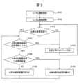
図2は、エネルギー供給システム10が水素を外部に供給する際の動作例を示すフローチャートである。このフローチャートの処理の実行は、たとえば制御器16によって制御される。Figure 2 is a flowchart showing an example of the operation of the
水素の外部供給に先立って、エネルギー供給システム10は、システムの運転を開始し(ステップS001)、システムの暖機運転を行う(ステップS002)。暖機運転は所定時間行われる。あるいは、暖機運転は、エネルギー供給システム10の所定箇所の温度が任意の基準温度以上になるまで、または、経過時間に応じて事前に決定されたパターンで行われる。暖機運転の方法は、システムのサイズ、構成、等に応じて設計することができる。Prior to supplying hydrogen to the outside, the
次に、エネルギー供給システム10は、外部における水素の需要を表す情報を取得する(ステップS101)。この情報は、たとえば外部における水素の需要があるか否かを表す情報と、需要量を表す情報とを含む。需要量は、たとえば流量(時間あたりの量、以下同じ)で表される。また、この情報は、たとえば外部のコンピュータ等から受信することによって取得することができる。Next, the
ステップS101において水素の需要がある場合には、エネルギー供給システム10は、水素の販売価格を表す情報を取得し、販売価格が基準価格以上であるか否かを判定する(ステップS102)。販売価格を表す情報は、たとえば外部のコンピュータ等から受信することによって取得することができる。If there is a demand for hydrogen in step S101, the
基準価格は、エネルギー供給システム10へ供給する燃料の価格、設備費、季節、時刻によるエネルギーの価値、等を考慮し、設計者が任意の値を事前に決定することができる。このような制御とすることで、経済的に成立する範囲で、需要量に合わせて、水素を外部に供給できる。The base price can be determined in advance by the designer, taking into consideration the price of the fuel supplied to the
ステップS101において水素の需要がない場合、または、ステップS102において販売価格が所定価格未満である場合には、エネルギー供給システム10は、水素(余剰水素)をエンジン11に供給する(ステップS103)。たとえば、第二分配装置32が水素の全量をエンジン11に分配する。ステップS103の後、処理はステップS101に戻る。If there is no demand for hydrogen in step S101, or if the selling price is less than the predetermined price in step S102, the
ステップS102において販売価格が所定価格以上である場合には、エネルギー供給システム10は、現在の水素の供給量(エネルギー供給システム10から外部に供給されている水素の量)を取得し、需要量が供給量より大きいか否かを判定する(ステップS104)。需要量および供給量は、たとえば流量で表される。If the selling price is equal to or higher than the predetermined price in step S102, the
ステップS104において需要量が供給量より大きい場合には、エネルギー供給システム10は、供給量(すなわち外部に供給する水素の量)を増やす(ステップS105)。ここで増やす量(増分)は、任意に指定または変更可能である。ステップS105の後、処理はステップS102に戻る。なお、変形例としてステップS101に戻してもよい。If the demand is greater than the supply in step S104, the
ステップS104において需要量が供給量以下である場合には、エネルギー供給システム10は、供給量を減らす(ステップS106)。ここで減らす量も、任意に指定または変更可能である。ステップS106の後、処理はステップS102に戻る。なお、変形例としてステップS101に戻してもよい。If the demand amount is equal to or less than the supply amount in step S104, the
ステップS102~S106のループは、停止指示が与えられるまで連続して実行することができる。このループにより、常に最適な水素量を外部へ供給することができる。The loop of steps S102 to S106 can be executed continuously until a stop command is given. This loop ensures that the optimal amount of hydrogen is always supplied to the outside.
このようにして、本実施形態に係るエネルギー供給システム10は、外部に水素を供給することができる。In this way, the
また、エネルギー供給システム10では、第二分配装置32が、外部に供給する水素の量を、水素の需要に応じて制御するので、需要に応じた適切な水素供給を行うことができる。また、とくに本実施形態では、第二分配装置32が、外部に供給する水素の量を、さらに水素の販売価格に応じて制御するので、エネルギー供給システム10の外部および内部における水素の価値を比較して、適切な水素供給を行うことができる。In addition, in the
なお、エネルギー供給システム10は、熱交換器28から高温の水を排出するので、熱を外部に供給することができる。また、エンジン11およびSOFC12の発電動作により、電力を外部に供給することができる。このように、熱、電力、水素の3形態でエネルギーを供給することができる。とくに、エネルギー供給システム10は、熱電比を調整可能なコージェネレーションシステムとして機能する。The
<アノードオフガスの分配制御>
図3は、第一分配装置31に係る動作例を示すフローチャートである。このフローチャートの処理の実行は、たとえば制御器16によって制御される。ステップS001およびS002は、図2の処理と同様である。ステップS002の後、エネルギー供給システム10は、SOFC12の入口の供給燃料および空気の温度が、所定の基準温度以上になるように分配装置を制御する。<Anode off-gas distribution control>
Fig. 3 is a flowchart showing an example of the operation of the
まず、エネルギー供給システム10は、SOFC12の入口におけるガス温度が、所定の基準温度以上であるか否かを判定する(ステップS201)。ここで、「ガス温度」とは、供給燃料(燃料ガス)の温度であってもよく、空気の温度であってもよく、双方に基づいて算出される温度であってもよい。また、基準温度はSOFC12の最適な稼働温度に基づいて適宜決定することができ、たとえば700℃である。First, the
ステップS201において、温度が基準温度以上である場合には、エネルギー供給システム10は、バーナー13に供給するアノードオフガスの量を減らす(ステップS202)。この量は、たとえば流量である。一方、温度が基準温度未満である場合には、エネルギー供給システム10は、バーナー13に供給するアノードオフガスの量を増やす(ステップS203)。ステップS202またはS203の後、処理はステップS201に戻る。In step S201, if the temperature is equal to or higher than the reference temperature, the
このような制御により、SOFC12の温度を稼働に適した温度に維持しながら、外部に供給可能な水素の量を自由に変化させることができる。This type of control makes it possible to freely change the amount of hydrogen that can be supplied to the outside while maintaining the temperature of the SOFC12 at a temperature suitable for operation.
<SOFCへの燃料供給制御>
図4は、SOFC12への供給燃料の制御例を示すフローチャートである。このフローチャートの処理の実行は、たとえば制御器16によって制御される。とくに、この処理の実行は、図示しない燃料供給装置(たとえば熱交換器21に燃料を供給する)を介して実現することができる。<Fuel supply control to SOFC>
4 is a flowchart showing an example of control of the fuel supply to the
ステップS001およびS002は、図2の処理と同様である。ステップS002の後、エネルギー供給システム10は、改質器14の温度が所定の基準温度以上であるか否かを判定する(ステップS301)。基準温度は、たとえば上述のように700℃である。Steps S001 and S002 are the same as the process in FIG. 2. After step S002, the
ステップS301において改質器14の温度が基準温度以上である場合には、エネルギー供給システム10は、第二分配装置32が外部に水素を供給しているか否かを判定する(ステップS302)。If the temperature of the
ステップS302において外部に水素が供給されている場合には、エネルギー供給システム10は、外部における水素の需要量を表す情報を取得し、需要量が供給量より大きいか否かを判定する(ステップS303)。If hydrogen is being supplied to the outside in step S302, the
ステップS302において外部に水素が供給されていない場合、および、ステップS303において需要量が供給量以下である場合には、エネルギー供給システム10は、エンジン11にベース燃料が供給されているか否かを判定する(ステップS304)。If hydrogen is not being supplied to the outside in step S302, and if the demand amount is less than or equal to the supply amount in step S303, the
ステップS303において需要量が供給量より大きい場合、および、ステップS304においてエンジン11にベース燃料が供給されている場合には、エネルギー供給システム10は、SOFC12への燃料の供給量を増やす(ステップS305)。ここで増やす量(増分)は、任意に指定または変更可能である。ステップS305の後、処理はステップS301に戻る。If the demand amount is greater than the supply amount in step S303, and if base fuel is being supplied to the
ステップS301において改質器14の温度が基準温度未満である場合、および、ステップS304においてエンジン11にベース燃料が供給されていない場合には、エネルギー供給システム10は、SOFC12への燃料の供給量を減らす(ステップS306)。ここで減らす量(増分)も、任意に指定または変更可能である。ステップS306の後、処理はステップS301に戻る。If the temperature of the
以上のように、ステップS301の判定結果に応じてステップS305またはS306が実行されるので、改質器14が適切な稼働温度でない場合にはSOFC12に供給される燃料が減少し、非効率な動作を抑制することができる。As described above, step S305 or S306 is executed depending on the result of the determination in step S301, so that if the
また、ステップS302の判定結果に応じてステップS305またはS306が実行されるので、水素を外部に供給している場合にはSOFC12に供給される燃料が増加し、より多くの水素を生成することができる。In addition, step S305 or S306 is executed depending on the result of the determination in step S302, so that when hydrogen is being supplied to the outside, the fuel supplied to SOFC12 increases, and more hydrogen can be produced.
また、ステップS303の判定結果に応じてステップS305またはS306が実行されるので、水素の需要量が大きい場合にはSOFC12に供給される燃料が増加し、より多くの水素を生成することができる。In addition, step S305 or S306 is executed depending on the result of the determination in step S303, so that when the demand for hydrogen is large, the fuel supplied to SOFC12 increases, and more hydrogen can be produced.
また、ステップS304の判定結果に応じてステップS305またはS306が実行されるので、エンジン11にベース燃料が供給されておらず、すなわちエンジン11が第二分配装置32からの水素のみで動作している場合には、不要な水素の生成を抑制することができる。In addition, step S305 or S306 is executed depending on the result of the determination in step S304, so that when base fuel is not supplied to the
このように、図4の処理によれば、エネルギー供給システム10は、
‐改質器14の温度、
‐第二分配装置32が外部に水素を供給しているか否か、
‐外部における水素の需要量と、第二分配装置32から外部への水素の供給量との関係、および
‐エンジン11に燃料が供給されているか否か、
に基づいて、SOFC12への燃料の供給量を制御するので、SOFC12が生成する水素の量を最適に制御することができ、動作効率が向上する。 In this way, according to the process of FIG. 4, the energy supply system 10:
the temperature of the
- whether the
the relationship between the external demand for hydrogen and the supply of hydrogen from the
Since the amount of fuel supplied to the
なお、ステップS301~S304の判定処理は、いずれかを省略することも可能であり、ステップS301~S304のうち少なくとも1つが実行されればよい。たとえば、ステップS301~S304のうち1つのみを実行し、結果がYESであればステップS305を、NOであればステップS306を、それぞれ実行するよう構成することも可能である。Note that any of the determination processes in steps S301 to S304 may be omitted, and it is sufficient that at least one of steps S301 to S304 is executed. For example, it is also possible to configure the system to execute only one of steps S301 to S304, and execute step S305 if the result is YES, and execute step S306 if the result is NO.
ステップS301~S306のループは、停止指示が与えられるまで連続して実行することができる。このループにより、常に最適な量の燃料をSOFC12に供給することができる。The loop of steps S301 to S306 can be executed continuously until a stop command is given. This loop ensures that the optimal amount of fuel is always supplied to the
<全体制御>
エネルギー供給システム10は、上記の制御以外に、エンジン11およびSOFC12の発電電力を電力需要に合わせるために、燃料の供給量を制御する。具体例として、システム全体での発電電力が、外部から要求される電力量の指示値(需要電力値等)に適合するように、各燃料の流量が増減する。<Overall control>
In addition to the above controls, the
<燃料供給装置>
SOFC12およびエンジン11へ供給する燃料の量に関する制御は、当業者が公知技術等に基づいて適宜設計することができ、特に制限はない。たとえば、燃料噴射弁の開閉周期および/または開閉時間の制御により流量を調整するものを用いてもよいし、マスフローコントローラのようなバルブ制御やポンプ制御による流量制御が可能なものを用いてもよい。また、必要に応じて加圧ポンプを用いて所定圧力まで加圧してもよい。<Fuel supply device>
The control of the amount of fuel supplied to the
<燃料の組成>
エンジン11へ供給するベース燃料の組成について、特に制限はない。一般的なエンジン燃料を用いることができ、たとえば、ガソリン、軽油、天然ガス、メタン、エタノール、水素などが考えられる。また、バイオエタノールまたはバイオガスを用いることも可能である。<Fuel composition>
There is no particular limitation on the composition of the base fuel supplied to the
SOFC12へ供給する燃料の組成についても制限はなく、メタン、エタノール、メタノール、天然ガス、ガソリン、などの炭化水素燃料を用いることができる。また、改質器14内で水蒸気改質を行うために水も供給するが、水と燃料との比率はそれぞれの燃料に対して事前に適切な値を決定することにより制御することができる。特に、改質ガス中の水素量を多くする場合は、燃料中の水蒸気と炭素数のモル数の比率であるS/Cが高いことが望ましく5以上にすることが好ましい。There are no restrictions on the composition of the fuel supplied to the
燃料と水とは、それぞれを別々に供給してもよいし、エタノールのような水と混合が可能なものであれば、事前に混合したものを一つの供給装置で供給してもよい。水と燃料とを別々に供給する場合は、水の全量または一部として熱交換器25,26,27,28により昇温されたものを用いることも考えられる。これにより、改質器やSOFCを任意の温度に維持したまま、供給燃料量を増量させることができ、水素発生量を増やすことができる。これは、外部へ供給する熱量を減らし、水素生産量を増大することなる。すなわち、外部へ供給する熱と水素の供給量のバランスを制御することが可能となる。このように水を外部の熱利用装置と燃料供給装置へと分配する場合は図示しない水分配装置を設けてもよい。The fuel and water may be supplied separately, or if it is a fuel that can be mixed with water, such as ethanol, it may be pre-mixed and supplied by one supply device. When supplying water and fuel separately, it is possible to use water that has been heated by
<エンジンの構成>
エンジン11は、公知の構成を備えたものとすることができ、ディーゼルエンジン、火花点火エンジン、等を用いることができる。<Engine configuration>
The
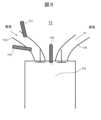
図5に、エンジン11の概略構成例を示す。この例は予混合火花エンジンのものである。エンジン11において、ベース燃料を供給する燃料供給装置111が吸気管112または燃焼室113に備えられている。ベース燃料としてはガソリンや軽油等の石油系燃料だけでなく、エタノール混合ガソリン、バイオエタノールおよびメタンなど公知のものを用いることができる。さらに、エンジン11は、第二分配装置32からの改質ガスを供給する改質ガス供給装置114を吸気管112に備えており、これによって改質ガスが吸気管112に供給される。燃焼室113には点火プラグ116が配置され、エンジン11は燃料と改質ガスの双方もしくは少なくとも片方を用いて発電する構成となっている。Figure 5 shows an example of the schematic configuration of the
エンジン11の台数に特に制限はなく、エネルギー供給システム10はエンジン11を複数台搭載しても良い。エンジン11の排気の全量または一部は、排気管115に結合された熱交換器21へ供給される。排気管115に結合される熱交換器21の台数に制限はなく、熱交換器21を複数台搭載する場合には、配置(並列や直列など)に制限はない。There is no particular limit to the number of
改質ガス中に含まれる水素は、燃焼速度がエンジン燃料として一般的に使われている炭化水素系燃料に比べ大きいこと、燃焼範囲が炭化水素系燃料に比べて大きいことから、急速燃焼および希薄燃焼が可能となる。更に、水素は炭化水素燃料に比べて燃焼性が高いことから、燃焼効率の向上が可能となる。これにより、エンジン11の熱効率が向上し、同一出力を出すための燃料の消費量削減が可能となる。The hydrogen contained in the reformed gas has a higher combustion speed and a larger combustion range than hydrocarbon fuels that are commonly used as engine fuels, making rapid combustion and lean combustion possible. Furthermore, hydrogen has higher combustibility than hydrocarbon fuels, making it possible to improve combustion efficiency. This improves the thermal efficiency of the
また、図には示されていないが、吸気管112には吸入する空気量の調整バルブ(たとえばスロットル)を備えてもよく、燃料および改質ガスの量に対して量論空気量以上の空気が吸入されるよう制御されてもよい。さらに、水素を含む改質ガスの割合が高いときは、吸入空気量を増大し希薄燃焼を行うように制御されてもよい。Although not shown in the figure, the
<SOFCの構成>
SOFC12は酸化物イオン伝導型の燃料電池であり、一般的なSOFCを用いることができる。アノードには水素および一酸化炭素を含む燃料ガスが供給され、カソードには空気または酸素が供給される。SOFCの材料、稼働温度、サイズ、等については、特に制限はない。<Configuration of SOFC>
The
<熱交換器>
熱交換器21~28は、公知の構成を有する熱交換器を用いることができる。発電装置(エンジン11およびSOFC12)のサイズおよび仕様に合わせて適切な熱交換器を用いる。一般的なシェルアンドチューブ型、プレート型、フィンチューブ型、等の公知の熱交換器であってもよい。たとえば排熱ボイラーなどにより発電装置の排熱を用いて蒸気を生成するものであってもよい。<Heat exchanger>
The
熱交換器の構造および個数に制限はなく、複数台搭載した場合でも、配置(並列、直列など)に関して制限はない。熱交換器は放熱による大気への熱損失を低減するために、断熱材を取り付けるなど断熱を行うことが好ましい。熱交換器の出口には図に記載していない圧力調整弁を搭載してもよい。これにより、熱交換内の流路の圧力を上昇させることから、密度を増加させるため、熱交換能力が増大する。そのため、熱交換器の小型化が可能となる。また、熱利用装置の熱源として0.78MPa以上の高圧蒸気が必要な場合にも対応できる。There are no restrictions on the structure or number of heat exchangers, and even if multiple units are installed, there are no restrictions on the arrangement (parallel, series, etc.). It is preferable to insulate the heat exchanger by installing insulating material, etc., to reduce heat loss to the atmosphere due to heat radiation. A pressure regulating valve (not shown in the figure) may be installed at the outlet of the heat exchanger. This increases the pressure in the flow path within the heat exchanger, thereby increasing the density and therefore the heat exchange capacity. This makes it possible to reduce the size of the heat exchanger. It can also be used in cases where high-pressure steam of 0.78 MPa or more is required as a heat source for heat utilization equipment.
<分配装置>
第一分配装置31および第二分配装置32には、公知の分配装置を用いることができる。単一の配管から二つの配管へ、それぞれ任意の流量を供給できる分配装置であってもよく、分配した配管それぞれにバルブを設置し、それぞれの流量を制御する分配装置であってもよい。例えば高温のガス制御装置においては、自動車用部品であるウエストゲートバルブやそれと同等なものを用いることができる。<Distribution device>
A known distributor can be used for the
<改質器>
図6に、改質器14の概略構成例を示す。改質器14は反応器を備える。図6(a)は2流体型の反応器の例を示し、図6(b)は1流体型の反応器の例を示す。<Reformer>
6 shows an example of a schematic configuration of the
改質器14は燃料を改質ガスに変換する。改質器14は、燃料改質を行うための触媒141を内部に搭載している。改質器14は、高温水蒸気と燃料が供給可能な供給口142と、改質ガスの排出が可能な排出口143とを備える。The
改質器14のサイズおよび外形に制限は無い。サイズは、エンジン11またはSOFC12の出力に対応して、適宜調整することができる。There are no restrictions on the size and shape of the
改質器14の内部に搭載する触媒141の組成に制限はなく、たとえば公知のものが用いられる。たとえば金属またはセラミックを材料とした母材に、触媒材料を担持したものを用いる。母材の形状に制限はなく、ペレット状、ハニカム構造、シート状、等とすることができる。担持される触媒材料は、たとえばニッケル、白金、パラジウム、ロジウム、イリジウム、ルテニウム、モリブデン、レニウム、タングステン、バナジウム、オスミウム、クロム、コバルト、鉄、ニオブ、銅、亜鉛等から選択された少なくとも1種で構成される。There is no restriction on the composition of the
<熱利用装置>
エネルギー供給システム10から供給される熱を利用する装置は、たとえば施設ごとに必要な装置とすることができ、制限はない。乾燥機、暖房装置、吸収式冷凍機、給湯器、等の熱源として用いることができる。他の公知の熱利用装置を用いてもよい。<Heat utilization equipment>
The device that utilizes the heat supplied from the
<分離器>
分離器15の構成について制限はない。設置場所に関しては、上述のように第二分配装置32の前後どちらに配置してもよい。<Separator>
There is no limitation on the configuration of the
<CO変成器>
アノードオフガス中には水素、二酸化炭素、一酸化炭素、水蒸気などが含まれる。外部へ水素を供給する場合は、改質ガス中の水素量を増やすことが好ましい。改質ガス中の一酸化炭素と水蒸気との以下のような反応を進めることで水素量を増量することができる。
CO+H2O⇒CO2+H2
このために、図示していないCO変成器を設けてもよい。設置する場所に制限はないが、第一分配装置31と熱交換器23との間、熱交換器23と熱交換器25との間、熱交換器25の出口などが考えられる。CO変成器の具体的な構成は、公知技術等に基づいて当業者が適宜設計することができる。<CO transformer>
The anode off-gas contains hydrogen, carbon dioxide, carbon monoxide, water vapor, etc. When hydrogen is supplied to the outside, it is preferable to increase the amount of hydrogen in the reformed gas. The amount of hydrogen can be increased by promoting the following reaction between carbon monoxide and water vapor in the reformed gas.
CO +H2O⇒CO2 +H2
For this purpose, a CO transformer (not shown) may be provided. There is no limitation on the location where it may be installed, but possible locations include between the
[第二実施形態]
以下、本発明の第二実施形態に関わるエネルギー供給システムの構成及び運転方法について説明する。第一実施形態と共通する部分については、説明を省略する場合がある。[Second embodiment]
Hereinafter, a configuration and an operation method of an energy supply system according to a second embodiment of the present invention will be described. Descriptions of parts common to the first embodiment may be omitted.
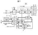
図7は、第二実施形態に関わるエネルギー供給システム10の基本構成例を示す概略図である。なおこの図では制御器16の図示を省略している。Figure 7 is a schematic diagram showing an example of the basic configuration of an
本実施形態では、第一実施形態(図1)の熱交換器群において、熱交換器23が省略されている。すなわち、SOFC12への供給燃料は、熱交換器21から直接改質器14へと流れ、SOFC12のアノードオフガスは、第一分配装置31から直接熱交換器25へと流れる。このように、熱交換器の一部を省略することも可能である。In this embodiment, the
[第三実施形態]
以下、本発明の第三実施形態に関わるエネルギー供給システムの構成及び運転方法について説明する。第一または第二実施形態と共通する部分については、説明を省略する場合がある。[Third embodiment]
Hereinafter, a configuration and an operation method of an energy supply system according to a third embodiment of the present invention will be described. Descriptions of parts common to the first and second embodiments may be omitted.
図8は、第三実施形態に関わるエネルギー供給システム10の基本構成例を示す概略図である。なおこの図でも制御器16の図示を省略している。Figure 8 is a schematic diagram showing an example of the basic configuration of an
本実施形態では、第二実施形態(図7)において、SOFC12への供給燃料に含まれるメタンがエタノールに置き換えられ、改質器14の位置が変更されている(すなわち、熱交換器21があった位置に改質器14が配置されている)。また、改質器14があった位置には新たな熱交換器29が配置されている。このように、第三実施形態の熱交換器群は熱交換器21を含まず、熱交換器29を含む。In this embodiment, the methane contained in the fuel supplied to the
熱交換器29は、SOFC12の排気(バーナー13を経由して供給される)と、改質器14からSOFC12への供給燃料とを熱交換する。これによってSOFC12への供給燃料がさらに加熱され、SOFC12の最適な稼働温度(たとえば700℃)に達する。The
エタノールやメタノール、ジエチルエーテル、ジメチルエーテルなどは比較的低温(たとえば400℃以上)で改質が可能なので、熱交換器による加熱を省略して改質器14に導入することができる。また、本実施形態ではSOFC12の最適な稼働温度が750℃であるため、SOFC12への供給燃料をさらに熱交換器29によって加熱する必要があるが、SOFC12の最適な稼働温度がより低い場合には、熱交換器29を省略することも可能である。Ethanol, methanol, diethyl ether, dimethyl ether, etc. can be reformed at a relatively low temperature (e.g., 400°C or higher), so they can be introduced into the
[その他の実施形態]
第一、第二および第三実施形態において、当業者は公知技術等に基づいて適宜変形を施すことが可能である。具体例を以下に示す。[Other embodiments]
In the first, second and third embodiments, a person skilled in the art can appropriately modify the embodiments based on known techniques, etc. Specific examples are shown below.
図9に、エンジン11の変形例を示す。この例は直噴火花エンジンのものである。この変形例に係るエンジン11では、改質ガス供給装置114が吸気管112でなく燃焼室113に設けられており、これによって改質ガスは燃焼室113に供給される。このようなエンジン11で発電を行うことも可能である。Figure 9 shows a modified version of the
図10に、エンジン11の別の変形例を示す。この例はディーゼルエンジンのものである。この変形例に係るエンジン11でも、改質ガス供給装置114が燃焼室113に設けられている。また、ディーゼルエンジンであるため燃料の発火点が低く、点火プラグ116は不要である。Figure 10 shows another modified example of the
10…エネルギー供給システム
11…エンジン(内燃機関)
12…SOFC(燃料電池)
13…バーナー
14…改質器
15…分離器
16…制御器
21~29…熱交換器
31…第一分配装置
32…第二分配装置
111…燃料供給装置
112…吸気管
113…燃焼室
114…改質ガス供給装置
115…排気管
116…点火プラグ
141…触媒
142…供給口
143…排出口 10...
12...SOFC (fuel cell)
Claims (10)
Translated fromJapanese前記内燃機関の排気または前記燃料電池の排気の少なくとも一方と、前記燃料電池への供給燃料または空気とを熱交換する、熱交換器と、
前記エネルギー供給システムの外部に水素を供給するために、前記燃料電池から排出されたアノードオフガスを前記熱交換器に分配する、第一分配装置と、
を備え、
前記熱交換器は前記アノードオフガスを冷却し、
前記エネルギー供給システムは、さらに、前記熱交換器によって冷却された前記アノードオフガスを、前記外部への水素供給と、前記内燃機関への燃料利用とに分配する、第二分配装置を備える、
ことを特徴とする、エネルギー供給システム。 An energy supply system comprising an oxide ion conductive fuel cell and an internal combustion engine,
a heat exchanger that exchanges heat between at least one of the exhaust gas from the internal combustion engine and the exhaust gas from the fuel cell and the fuel or air supplied to the fuel cell;
a first distributor that distributes an anode off-gas discharged from the fuel cell to the heat exchanger in order to supply hydrogen to the outside of the energy supply system;
Equipped with
The heat exchanger cools the anode off-gas;
The energy supply system further includes a second distribution device that distributes the anode off gas cooled by the heat exchanger between hydrogen supply to the outside and fuel use for the internal combustion engine.
An energy supply system comprising:
前記第一分配装置は、前記燃料電池の入口におけるガス温度が所定の基準温度以上である場合に、バーナーに供給するアノードオフガスの量を減らし、入口におけるガス温度が前記基準温度未満である場合に、前記バーナーに供給するアノードオフガスの量を増やす、
ことを特徴とする、エネルギー供給システム。 2. The energy supply system according to claim 1,
the first distributor reduces an amount of anode off-gas supplied to the burner when the gas temperature at the inlet of the fuel cell is equal to or higher than a predetermined reference temperature, and increases an amount of anode off-gas supplied to the burner when the gas temperature at the inlet is lower than the reference temperature;
An energy supply system comprising:
前記エネルギー供給システムは、前記外部における水素の需要を表す情報を取得し、
前記第二分配装置は、前記需要に応じて、前記外部に供給する水素の量を制御する、
ことを特徴とする、エネルギー供給システム。 2. The energy supply system according to claim 1,
The energy supply system acquires information representing the external demand for hydrogen,
The second distribution device controls the amount of hydrogen supplied to the outside in accordance with the demand.
An energy supply system comprising:
前記エネルギー供給システムは、水素の販売価格を表す情報を取得し、
前記第二分配装置は、前記需要と、前記販売価格とに応じて、前記外部に供給する水素の量を制御する、
ことを特徴とする、エネルギー供給システム。 The energy supply system according to claim 3,
The energy supply system acquires information representing a selling price of hydrogen,
The second distribution device controls the amount of hydrogen to be supplied to the outside in accordance with the demand and the selling price.
An energy supply system comprising:
前記熱交換器は、前記アノードオフガスと、前記燃料電池への供給燃料とを熱交換する、
ことを特徴とする、エネルギー供給システム。 2. The energy supply system according to claim 1,
The heat exchanger exchanges heat between the anode off-gas and a fuel supplied to the fuel cell.
An energy supply system comprising:
前記エネルギー供給システムは、前記燃料電池への供給燃料を改質する改質器を備える、
ことを特徴とする、エネルギー供給システム。 2. The energy supply system according to claim 1,
the energy supply system includes a reformer that reforms fuel to be supplied to the fuel cell;
An energy supply system comprising:
前記エネルギー供給システムは、
‐改質器の温度、
‐前記第二分配装置が前記外部に水素を供給しているか否か、
‐前記外部における水素の需要量と、前記第二分配装置から前記外部への水素の供給量との関係、および
‐前記内燃機関に燃料が供給されているか否か、
のうち少なくとも1つに基づいて、前記燃料電池への燃料の供給量を制御する、
ことを特徴とする、エネルギー供給システム。 In the energy supply system according to claim 1 or 6,
The energy supply system includes:
- reformer temperature,
- whether said second distributor supplies hydrogen to said outside;
the relationship between the demand for hydrogen in the external environment and the supply of hydrogen from the second distributor to the external environment, and whether or not fuel is being supplied to the internal combustion engine.
and controlling the amount of fuel supplied to the fuel cell based on at least one of the following:
An energy supply system comprising:
前記熱交換器は、前記内燃機関の排気と、前記改質器への供給燃料とを熱交換する、
ことを特徴とする、エネルギー供給システム。 The energy supply system according to claim 6,
The heat exchanger exchanges heat between the exhaust gas from the internal combustion engine and the fuel supplied to the reformer.
An energy supply system comprising:
前記熱交換器は、前記燃料電池の排気と、前記改質器から前記燃料電池への供給燃料とを熱交換する、
ことを特徴とする、エネルギー供給システム。 The energy supply system according to claim 6,
the heat exchanger exchanges heat between exhaust gas from the fuel cell and fuel supplied from the reformer to the fuel cell;
An energy supply system comprising:
前記エネルギー供給システムは、前記アノードオフガスから水素を分離する分離器を備える、
ことを特徴とする、エネルギー供給システム。
2. The energy supply system according to claim 1,
The energy supply system includes a separator that separates hydrogen from the anode off-gas.
An energy supply system comprising:
Priority Applications (1)
| Application Number | Priority Date | Filing Date | Title |
|---|---|---|---|
| JP2021201117AJP7664153B2 (en) | 2021-12-10 | 2021-12-10 | Energy Supply System |
Applications Claiming Priority (1)
| Application Number | Priority Date | Filing Date | Title |
|---|---|---|---|
| JP2021201117AJP7664153B2 (en) | 2021-12-10 | 2021-12-10 | Energy Supply System |
Publications (2)
| Publication Number | Publication Date |
|---|---|
| JP2023086536A JP2023086536A (en) | 2023-06-22 |
| JP7664153B2true JP7664153B2 (en) | 2025-04-17 |
Family
ID=86850558
Family Applications (1)
| Application Number | Title | Priority Date | Filing Date |
|---|---|---|---|
| JP2021201117AActiveJP7664153B2 (en) | 2021-12-10 | 2021-12-10 | Energy Supply System |
Country Status (1)
| Country | Link |
|---|---|
| JP (1) | JP7664153B2 (en) |
Citations (8)
| Publication number | Priority date | Publication date | Assignee | Title |
|---|---|---|---|---|
| JP2004517442A (en) | 2000-12-16 | 2004-06-10 | バイエリッシェ モートーレン ウエルケ アクチエンゲゼルシャフト | Fuel cell system in vehicle with internal combustion engine and method of operating the same |
| JP2009032596A (en) | 2007-07-27 | 2009-02-12 | Tokyo Gas Co Ltd | Operating temperature control method for solid oxide fuel cell system |
| JP2013089455A (en) | 2011-10-18 | 2013-05-13 | Mazda Motor Corp | Fuel cell system |
| JP2013189880A (en) | 2012-03-12 | 2013-09-26 | Toyota Motor Corp | Exhaust utilization system for internal combustion engine |
| JP2014105627A (en) | 2012-11-27 | 2014-06-09 | Toyota Motor Corp | Internal combustion engine |
| JP2015130337A (en) | 2013-12-31 | 2015-07-16 | ゼネラル・エレクトリック・カンパニイ | Solid oxide fuel cell system |
| JP2016213085A (en) | 2015-05-11 | 2016-12-15 | 三菱日立パワーシステムズ株式会社 | Solid oxide type fuel battery system |
| JP2019216501A (en) | 2018-06-11 | 2019-12-19 | Jfeエンジニアリング株式会社 | Device for storing and supplying energy obtained by waste incineration |
- 2021
- 2021-12-10JPJP2021201117Apatent/JP7664153B2/enactiveActive
Patent Citations (8)
| Publication number | Priority date | Publication date | Assignee | Title |
|---|---|---|---|---|
| JP2004517442A (en) | 2000-12-16 | 2004-06-10 | バイエリッシェ モートーレン ウエルケ アクチエンゲゼルシャフト | Fuel cell system in vehicle with internal combustion engine and method of operating the same |
| JP2009032596A (en) | 2007-07-27 | 2009-02-12 | Tokyo Gas Co Ltd | Operating temperature control method for solid oxide fuel cell system |
| JP2013089455A (en) | 2011-10-18 | 2013-05-13 | Mazda Motor Corp | Fuel cell system |
| JP2013189880A (en) | 2012-03-12 | 2013-09-26 | Toyota Motor Corp | Exhaust utilization system for internal combustion engine |
| JP2014105627A (en) | 2012-11-27 | 2014-06-09 | Toyota Motor Corp | Internal combustion engine |
| JP2015130337A (en) | 2013-12-31 | 2015-07-16 | ゼネラル・エレクトリック・カンパニイ | Solid oxide fuel cell system |
| JP2016213085A (en) | 2015-05-11 | 2016-12-15 | 三菱日立パワーシステムズ株式会社 | Solid oxide type fuel battery system |
| JP2019216501A (en) | 2018-06-11 | 2019-12-19 | Jfeエンジニアリング株式会社 | Device for storing and supplying energy obtained by waste incineration |
Also Published As
| Publication number | Publication date |
|---|---|
| JP2023086536A (en) | 2023-06-22 |
Similar Documents
| Publication | Publication Date | Title |
|---|---|---|
| JP4515253B2 (en) | Fuel cell system | |
| JP6513810B2 (en) | High efficiency molten carbonate fuel cell system and method | |
| US6932958B2 (en) | Simplified three-stage fuel processor | |
| JP2009137778A (en) | Starting method of fuel cell system | |
| JP5000412B2 (en) | Operating temperature control method for solid oxide fuel cell system | |
| JP5519357B2 (en) | Solid oxide fuel cell system and cogeneration system equipped with the same | |
| JP2013527555A (en) | How to operate a cogeneration facility | |
| US6833209B2 (en) | Fuel-cell co-generation system, of electrical energy and hot water | |
| KR101897500B1 (en) | Fuel cell system with heat exchager using reformed gas or anode off gas | |
| JP5078698B2 (en) | Load following operation method of fuel cell system | |
| JP2009037814A (en) | Method for reducing temperature in high temperature region of solid oxide fuel cell and apparatus therefor | |
| EP2858158A1 (en) | Fuel cell system | |
| JP3924407B2 (en) | Fuel reformer and fuel cell system | |
| JP7664153B2 (en) | Energy Supply System | |
| JP2007179884A (en) | Indirect internal reforming type solid oxide fuel cell | |
| KR101205538B1 (en) | A solid oxide fuel cell system | |
| US20040038094A1 (en) | Fuel cell system | |
| JP3897149B2 (en) | Solid oxide fuel cell and Stirling engine combined system | |
| JP5122028B2 (en) | Power generation system and operation method thereof | |
| KR101295237B1 (en) | Fuel cell system | |
| JP7033094B2 (en) | Cogeneration system | |
| JP7575643B1 (en) | Ammonia-based solid oxide fuel cell (SOFC) system with heating element heating and method of operation thereof - Patents.com | |
| JP2012219008A (en) | Thermal treatment system | |
| JP2010225284A (en) | Operation method of indirect internal reforming type solid oxide fuel cell system | |
| JPH08339815A (en) | Fuel cell generator |
Legal Events
| Date | Code | Title | Description |
|---|---|---|---|
| A621 | Written request for application examination | Free format text:JAPANESE INTERMEDIATE CODE: A621 Effective date:20240620 | |
| A977 | Report on retrieval | Free format text:JAPANESE INTERMEDIATE CODE: A971007 Effective date:20250310 | |
| TRDD | Decision of grant or rejection written | ||
| A01 | Written decision to grant a patent or to grant a registration (utility model) | Free format text:JAPANESE INTERMEDIATE CODE: A01 Effective date:20250401 | |
| A61 | First payment of annual fees (during grant procedure) | Free format text:JAPANESE INTERMEDIATE CODE: A61 Effective date:20250407 | |
| R150 | Certificate of patent or registration of utility model | Ref document number:7664153 Country of ref document:JP Free format text:JAPANESE INTERMEDIATE CODE: R150 |