JP7663795B2 - Tubular retention device - Google Patents
Tubular retention deviceDownload PDFInfo
- Publication number
- JP7663795B2 JP7663795B2JP2020571167AJP2020571167AJP7663795B2JP 7663795 B2JP7663795 B2JP 7663795B2JP 2020571167 AJP2020571167 AJP 2020571167AJP 2020571167 AJP2020571167 AJP 2020571167AJP 7663795 B2JP7663795 B2JP 7663795B2
- Authority
- JP
- Japan
- Prior art keywords
- tubular
- outlet
- tip
- valve portion
- valve
- Prior art date
- Legal status (The legal status is an assumption and is not a legal conclusion. Google has not performed a legal analysis and makes no representation as to the accuracy of the status listed.)
- Active
Links
- 230000014759maintenance of locationEffects0.000titleclaimsdescription4
- 239000012528membraneSubstances0.000claimsdescription18
- 239000012530fluidSubstances0.000claimsdescription12
- 238000003780insertionMethods0.000claimsdescription12
- 230000037431insertionEffects0.000claimsdescription12
- 239000000463materialSubstances0.000claimsdescription7
- 210000000013bile ductAnatomy0.000description17
- 210000000941bileAnatomy0.000description12
- 239000011248coating agentSubstances0.000description8
- 238000000576coating methodMethods0.000description8
- 210000001198duodenumAnatomy0.000description7
- 239000002184metalSubstances0.000description7
- 229910052751metalInorganic materials0.000description7
- 230000002093peripheral effectEffects0.000description6
- 230000003902lesionEffects0.000description4
- 239000007788liquidSubstances0.000description4
- 210000000232gallbladderAnatomy0.000description3
- 238000010992refluxMethods0.000description3
- 230000000717retained effectEffects0.000description3
- 239000000956alloySubstances0.000description2
- 230000007423decreaseEffects0.000description2
- 238000007598dipping methodMethods0.000description2
- 238000000034methodMethods0.000description2
- 229910001000nickel titaniumInorganic materials0.000description2
- -1polytetrafluoroethylenePolymers0.000description2
- 229920001343polytetrafluoroethylenePolymers0.000description2
- 239000004810polytetrafluoroethyleneSubstances0.000description2
- 229920005989resinPolymers0.000description2
- 239000011347resinSubstances0.000description2
- 230000001629suppressionEffects0.000description2
- 238000011144upstream manufacturingMethods0.000description2
- YCKRFDGAMUMZLT-UHFFFAOYSA-NFluorine atomChemical compound[F]YCKRFDGAMUMZLT-UHFFFAOYSA-N0.000description1
- 208000031481Pathologic ConstrictionDiseases0.000description1
- 229910001069Ti alloyInorganic materials0.000description1
- 229910045601alloyInorganic materials0.000description1
- 210000004204blood vesselAnatomy0.000description1
- 239000000919ceramicSubstances0.000description1
- 239000000470constituentSubstances0.000description1
- 229910052731fluorineInorganic materials0.000description1
- 239000011737fluorineSubstances0.000description1
- 210000001035gastrointestinal tractAnatomy0.000description1
- 230000012447hatchingEffects0.000description1
- KHYBPSFKEHXSLX-UHFFFAOYSA-NiminotitaniumChemical compound[Ti]=NKHYBPSFKEHXSLX-UHFFFAOYSA-N0.000description1
- 229910001092metal group alloyInorganic materials0.000description1
- 239000007769metal materialSubstances0.000description1
- 150000002739metalsChemical class0.000description1
- 238000012986modificationMethods0.000description1
- 230000004048modificationEffects0.000description1
- HLXZNVUGXRDIFK-UHFFFAOYSA-Nnickel titaniumChemical compound[Ti].[Ti].[Ti].[Ti].[Ti].[Ti].[Ti].[Ti].[Ti].[Ti].[Ti].[Ni].[Ni].[Ni].[Ni].[Ni].[Ni].[Ni].[Ni].[Ni].[Ni].[Ni].[Ni].[Ni].[Ni]HLXZNVUGXRDIFK-UHFFFAOYSA-N0.000description1
- 229920013716polyethylene resinPolymers0.000description1
- 229920000139polyethylene terephthalatePolymers0.000description1
- 239000005020polyethylene terephthalateSubstances0.000description1
- 238000009958sewingMethods0.000description1
- 229920002050silicone resinPolymers0.000description1
- 239000010935stainless steelSubstances0.000description1
- 229910001220stainless steelInorganic materials0.000description1
Images


Classifications
- A—HUMAN NECESSITIES
- A61—MEDICAL OR VETERINARY SCIENCE; HYGIENE
- A61F—FILTERS IMPLANTABLE INTO BLOOD VESSELS; PROSTHESES; DEVICES PROVIDING PATENCY TO, OR PREVENTING COLLAPSING OF, TUBULAR STRUCTURES OF THE BODY, e.g. STENTS; ORTHOPAEDIC, NURSING OR CONTRACEPTIVE DEVICES; FOMENTATION; TREATMENT OR PROTECTION OF EYES OR EARS; BANDAGES, DRESSINGS OR ABSORBENT PADS; FIRST-AID KITS
- A61F2/00—Filters implantable into blood vessels; Prostheses, i.e. artificial substitutes or replacements for parts of the body; Appliances for connecting them with the body; Devices providing patency to, or preventing collapsing of, tubular structures of the body, e.g. stents
- A61F2/02—Prostheses implantable into the body
- A61F2/04—Hollow or tubular parts of organs, e.g. bladders, tracheae, bronchi or bile ducts
- A—HUMAN NECESSITIES
- A61—MEDICAL OR VETERINARY SCIENCE; HYGIENE
- A61F—FILTERS IMPLANTABLE INTO BLOOD VESSELS; PROSTHESES; DEVICES PROVIDING PATENCY TO, OR PREVENTING COLLAPSING OF, TUBULAR STRUCTURES OF THE BODY, e.g. STENTS; ORTHOPAEDIC, NURSING OR CONTRACEPTIVE DEVICES; FOMENTATION; TREATMENT OR PROTECTION OF EYES OR EARS; BANDAGES, DRESSINGS OR ABSORBENT PADS; FIRST-AID KITS
- A61F2/00—Filters implantable into blood vessels; Prostheses, i.e. artificial substitutes or replacements for parts of the body; Appliances for connecting them with the body; Devices providing patency to, or preventing collapsing of, tubular structures of the body, e.g. stents
- A61F2/02—Prostheses implantable into the body
- A61F2/24—Heart valves ; Vascular valves, e.g. venous valves; Heart implants, e.g. passive devices for improving the function of the native valve or the heart muscle; Transmyocardial revascularisation [TMR] devices; Valves implantable in the body
- A61F2/2476—Valves implantable in the body not otherwise provided for
- A—HUMAN NECESSITIES
- A61—MEDICAL OR VETERINARY SCIENCE; HYGIENE
- A61F—FILTERS IMPLANTABLE INTO BLOOD VESSELS; PROSTHESES; DEVICES PROVIDING PATENCY TO, OR PREVENTING COLLAPSING OF, TUBULAR STRUCTURES OF THE BODY, e.g. STENTS; ORTHOPAEDIC, NURSING OR CONTRACEPTIVE DEVICES; FOMENTATION; TREATMENT OR PROTECTION OF EYES OR EARS; BANDAGES, DRESSINGS OR ABSORBENT PADS; FIRST-AID KITS
- A61F2/00—Filters implantable into blood vessels; Prostheses, i.e. artificial substitutes or replacements for parts of the body; Appliances for connecting them with the body; Devices providing patency to, or preventing collapsing of, tubular structures of the body, e.g. stents
- A61F2/02—Prostheses implantable into the body
- A61F2/04—Hollow or tubular parts of organs, e.g. bladders, tracheae, bronchi or bile ducts
- A61F2002/041—Bile ducts
Landscapes
- Health & Medical Sciences (AREA)
- Cardiology (AREA)
- Oral & Maxillofacial Surgery (AREA)
- Transplantation (AREA)
- Engineering & Computer Science (AREA)
- Biomedical Technology (AREA)
- Heart & Thoracic Surgery (AREA)
- Vascular Medicine (AREA)
- Life Sciences & Earth Sciences (AREA)
- Animal Behavior & Ethology (AREA)
- General Health & Medical Sciences (AREA)
- Public Health (AREA)
- Veterinary Medicine (AREA)
- Gastroenterology & Hepatology (AREA)
- Pulmonology (AREA)
- Prostheses (AREA)
- Media Introduction/Drainage Providing Device (AREA)
- Infusion, Injection, And Reservoir Apparatuses (AREA)
Description
Translated fromJapanese本発明は、管状留置具に関する。The present invention relates to a tubular indwelling device.
従来、血管や消化管などの生体管腔内に留置される管状留置具が知られている。この種の管状留置具は、一般に、管状の形状を有し、径方向において拡縮可能な骨格部と、骨格部に沿って設けられる皮膜部と、を備える。また、例えば、胆管の狭窄や閉塞の治療に用いられる管状留置具では、本体部の一端から筒状に突出する筒状突起部が膜体から形成されているものもある(例えば、特許文献1参照)。Tubular retaining devices that are placed in living lumens such as blood vessels and the digestive tract are known. This type of tubular retaining device generally has a tubular shape and includes a skeleton that can expand and contract in the radial direction, and a membrane that is provided along the skeleton. For example, some tubular retaining devices used to treat strictures and obstructions in the bile duct have a tubular protrusion that protrudes cylindrically from one end of the main body, formed from a membrane (see, for example, Patent Document 1).
ところで、生体管腔内に留置された管状留置具の状態、生体管腔における管状留置具よりも奥側の管腔内面の状態などを確認するために内視鏡を用いたり、生体管腔における管状留置具よりも奥側部分を処置するための処置具を用いたりする場合がある。
しかしながら、筒状突起部の膜体が密着して開口部が閉塞された状態では、管状留置具の内側に内視鏡や処置具を挿入し難く、観察や処置を容易に行うことができないといった問題がある。一方、十二指腸から胆管への異物の逆流の抑制を適正に行う上では、胆汁が胆のうから放出されないときに筒状突起部の開口部を閉塞させることが望ましい。
上記した問題は、胆管用の管状留置具に限らず、逆止弁状の機能(以下、「弁機能」という。)を有する管状留置具で同様に生じるおそれがある。 Incidentally, there are cases where an endoscope is used to check the condition of a tubular indwelling device placed in a biological lumen, or the condition of the inner surface of the biological lumen on the side deeper than the tubular indwelling device, or where a treatment instrument is used to treat the portion of the biological lumen on the side deeper than the tubular indwelling device.
However, when the membrane of the cylindrical projection is tightly attached and the opening is blocked, it is difficult to insert an endoscope or treatment tool into the inside of the tubular retaining device, and observation or treatment cannot be easily performed. On the other hand, in order to appropriately suppress the reflux of foreign bodies from the duodenum to the bile duct, it is desirable to block the opening of the cylindrical projection when bile is not being released from the gallbladder.
The above-mentioned problems are not limited to tubular indwelling devices for use in the bile duct, but may occur in any tubular indwelling device having a check valve-like function (hereinafter referred to as a "valve function").
本発明の目的は、弁部を有する管状留置具の内側への冶具の挿入を容易に行うことができる管状留置具を提供することである。The object of the present invention is to provide a tubular indwelling device having a valve portion that allows easy insertion of a tool into the inside of the tubular indwelling device.
一の態様の管状留置具は、
生体管腔内に留置されて管状の流路を画成する管状留置具であって、
管状の本体部と、
前記本体部における前記生体管腔内を流れる流体の流れ方向の下流側端部に設けられ、前記流体が流出する流出口を有する弁部と、を備え、
前記流出口は、膜体により形成され、
前記弁部は、前記本体部の軸方向中央側より離れる方向に先細り形状に形成され、その先端部に前記流出口が設けられ、前記流出口が閉塞した状態のときに下流側から前記流出口内への冶具の挿入を案内可能な案内部を更に有し、
前記弁部は、前記膜体における前記先端部を構成する第1及び第2板状部の内面を密着させるようにして扁平状に形成され、
前記案内部は、前記第1及び第2板状部のいずれか一方の板状部の先端部に形成されて先端側から軸方向中央側に切り欠かれた形状をなし、前記第1及び第2板状部のいずれか他方の板状部の先端部が前記軸方向と直交する方向に対向しない部位を有することを特徴とする。
また、他の態様の管状留置具は、
生体管腔内に留置されて管状の流路を画成する管状留置具であって、
管状の本体部と、
前記本体部における前記生体管腔内を流れる流体の流れ方向の下流側端部に設けられ、前記流体が流出する流出口を有する弁部と、を備え、
前記流出口は、膜体により形成され、
前記弁部は、前記本体部の軸方向中央側より離れる方向に先細り形状に形成され、その先端部に前記流出口が設けられ、前記流出口が閉塞した状態のときに下流側から前記流出口内への冶具の挿入を案内可能な案内部を更に有し、
前記弁部は、前記膜体における前記先端部を構成する第1及び第2板状部の内面を密着させるようにして扁平状に形成され、
前記案内部は、前記第1及び第2板状部の素材、伸縮性、柔軟性、硬度の少なくともいずれかを互いに異ならせて形成されていることを特徴とする。
The tubular indwelling device according to one embodiment includes:
A tubular indwelling device that is placed in a living body lumen to define a tubular flow path,
A tubular body portion;
a valve portion provided at a downstream end of the main body portion in a flow direction of a fluid flowing through the biological lumen, the valve portion having an outlet through which the fluid flows out,
The outlet is formed by a membrane,
the valve portion is formed in a tapered shape in a direction away from the axial center of the main body portion, the outlet is provided at a tip portion of the valve portion, and the valve portion further has a guide portion capable of guiding insertion of a tool into the outlet from a downstream side when the outlet is in a closed state,
the valve portion is formed in a flat shape by closely contacting inner surfaces of first and second plate-shaped portions constituting the tip portion of the membrane body,
The guide portion is formed at the tip portion of one of the first and second plate-shaped portions,has a shape cut out from the tip side toward the center in the axial direction, and is characterized in that the tip portion of the other of the first and second plate-shaped portions has a portion that does not face each other in a direction perpendicular to the axial direction.
In addition, a tubular indwelling device according to another embodiment is
A tubular indwelling device that is placed in a living body lumen to define a tubular flow path,
A tubular body portion;
a valve portion provided at a downstream end of the main body portion in a flow direction of a fluid flowing through the biological lumen, the valve portion having an outlet through which the fluid flows out,
The outlet is formed by a membrane,
the valve portion is formed in a tapered shape in a direction away from the axial center of the main body portion, the outlet is provided at a tip portion of the valve portion, and the valve portion further has a guide portion capable of guiding insertion of a tool into the outlet from a downstream side when the outlet is in a closed state,
the valve portion is formed in a flat shape by closely contacting inner surfaces of first and second plate-shaped portions constituting the tip portion of the membrane body,
The guide portion is characterized in that the first and second plate-shaped portions are formed with at least one of a material, elasticity, flexibility, and hardness being different from each other.
本発明によれば、弁部を有する管状留置具の内側への冶具の挿入を容易に行うことができる。According to the present invention, it is possible to easily insert a tool into the inside of a tubular indwelling device having a valve portion.
以下、本発明の実施形態を、図面を参照して詳細に説明する。Below, an embodiment of the present invention is described in detail with reference to the drawings.
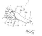
図1は、本発明の実施形態に係る管状留置具1の下流側端部2aを示す斜視図であり、図2は、管状留置具1の下流側端部2aの平面図である。
なお、以下の説明では、管状留置具1の長手方向を「管軸方向」とし、「管軸方向」に直交する一方向を「幅方向」とし、「管軸方向」及び「幅方向」に直交する一方向を「上下方向」とする。また、管状留置具1が留置された状態での「管軸方向」の一端側(胆のう側)を「基端側」とし、他端側(十二指腸側)を「先端側」とする。 FIG. 1 is a perspective view showing a
In the following description, the longitudinal direction of the
管状留置具1は、例えば、胆管(生体管腔)内に留置され、胆管の閉塞部又は狭窄部などの病変部を径方向外側に押し拡げて病変部の治療を行うもの(一般的に、胆管ステントと称呼される。)である。このとき、管状留置具1は、基端側及び先端側がそれぞれ胆のう側及び十二指腸側を向くように留置され、胆汁の流れ方向において、基端側が上流側となり、先端側が下流側となる。The
図1及び図2に示すように、管状留置具1は、例えば、管状の本体部2における胆管内を流れる胆汁(流体)の流れ方向の下流側端部2aに、流出口23(後述)を有する弁部3が設けられている。具体的には、管状留置具1は、骨格部10と、皮膜部20と、を備えて構成されている。1 and 2, the
<骨格部>
骨格部10は、自己拡張可能に構成され、本例では、胆汁などの流体を導通させるための流路を画成するための管状構造を有する骨格本体部11と、骨格本体部11の管端部11aから延びるように設けられる一対の延出部12と、を有している。管端部11aは、図中に破線で示されるように、骨格本体部11と一対の延出部12,12とを区分けする境界にも相当する。<Skeleton>
The
骨格本体部11には、金属線材が管軸方向にジグザグ状に往復しながら周方向に環状に延びて構成される複数のジグザグ環状部が管軸方向に並ぶように配置されている。また、骨格本体部11は、隣接するジグザグ環状部同士が周方向における複数の箇所にて金属線材で管軸方向に連結されるように構成されている。骨格本体部11は、全体として筒状の形状を有している。In the
一対の延出部12,12は、金属線材から構成され、骨格本体部11の幅方向両側にて管軸方向先端側に延びるように構成されている。すなわち、一対の延出部12,12は、管状留置具1の管軸を挟んで向かい合うように配置されている。一対の延出部12,12は、例えば、連結部12aにより骨格本体部11の所定箇所に連結され、骨格本体部11から離れるにつれて上下方向の幅が徐々に小さくなるように構成されている。また、一対の延出部12,12の各々は、最も管軸方向先端側に位置する頂点12bから管軸方向基端側に向けて斜め上方及び斜め下方に延びるV字状部分12cを有するように形成されている。
一対の延出部12,12は、後述するように、皮膜部20の突出部22(後述)を支持する支持部材としての機能を果たす。なお、一対の延出部12,12は、互いに離れる向きに広がることで突出部22を幅方向に開くような力を突出部22に及ぼしてもよいし、そのような力を突出部22に及ぼしてもいなくてもよい。 The pair of
As described below, the pair of
骨格部10は、径方向内側に収縮した縮径状態から径方向外側に拡張して拡径状態へと拡縮可能に構成されている。骨格部10が拡径状態にあるとき、管状留置具1は、その内部に筒状の流路を画成する。骨格部10は、例えば、管軸方向に引っ張られることで径方向内側に収縮しながら管軸方向に伸長し、縮径状態から解放されることで径方向外側に拡張しながら管軸方向に短縮するように構成される。骨格部10は、このように構成されることで、胆管留置時、骨格部10の外周面、特に骨格本体部11の外周面によって胆管の病変部の内面を径方向外側に押圧し、胆管の病変部を径方向外側に押し拡げることができる。The
骨格部10を構成する材料としては、例えば、ステンレス鋼、Ni-Ti合金(すなわち、ニチノール)、チタン合金などに代表される公知の金属又は金属合金が挙げられる。また、骨格部10の位置を体外から確認できるように、骨格部10の一部または全部をX線造影性を有する合金材料から構成してもよい。骨格部10は、セラミックや樹脂などの金属材料以外の材料で構成されてもよい。Examples of materials that constitute the
骨格部10を構成する金属線材の材料、線種(例えば、ワイヤ等の円形線材、又は、レーザーカットによる角状線材)、線径(断面積)、周方向におけるジグザグの往復回数及びジグザグ形状、並びに、管軸方向における線材間隔(単位長さ当たりの骨格量)等は、留置する生体管腔などに応じて適宜選択可能となっている。The material of the metal wire constituting the
<皮膜部>
皮膜部20は、膜体をなし、骨格部10の骨格本体部11に沿って設けられる筒状部21と、この筒状部21の端部から突出する突出部22と、が一体的に繋がった構成を有する。<Coating part>
The
筒状部21は、骨格本体部11に沿って設けられ、胆管留置時に骨格本体部11が拡張状態にあるとき、胆汁を突出部22に向けて案内する流路を画成する。すなわち、筒状部21は、骨格本体部11とともに、管状の本体部2を構成している。
ここで、筒状部21は、骨格本体部11を挟み込むように骨格本体部11の外周面と内周面とに配置されてもよい。あるいは、筒状部21は、骨格本体部11の外周面のみに配置されてもよいし、骨格本体部11の内周面のみに配置されてもよい。筒状部21は、例えば、縫い付けやディッピング等の公知の手法を用いて骨格本体部11に固定され得る。 The
Here, the
突出部22は、皮膜部20における、筒状部21の先端側端部から連続して管軸方向先端側に突出する。突出部22は、胆管留置時に胆汁を十二指腸に向けて放出する部分である。突出部22は、全体として、筒状部21に繋がる基端側の流路断面積よりも筒状部21から離れる先端側の流路断面積が小さい先細り形状を有する。より具体的には、本例では、突出部22は、第1部分22aと、第2部分(先端部構成部)22bと、を有している。第1部分22aは、骨格部10の一対の延出部12,12に沿って基端側から先端側に向かうにつれて流路断面積が徐々に小さくなっている。第2部分22bは、第1部分22aから先端側に向けて流路断面積が実質的に同一である状態で延びている。第2部分22bでは、突出部22を構成する膜体を上下方向において実質的に密着させるようにして扁平状に形成されている。
また、第2部分22bには、骨格部10が設けられておらず、このような形状の皮膜部20は、例えば、ディッピング等の公知の手法を用いて形成される。 The protruding
Further, the
突出部22の管軸方向先端側端部(胆汁の流れ方向下流側)の開口は、筒状部21から突出部22内に流れ込んだ胆汁などの液体を十二指腸に流出させる流出口23として機能する。
流出口23は、管状留置具1内を液体が流れないときには、幅方向に直線状に延びて閉塞した状態に維持される。一方で、流出口23は、管状留置具1内を液体が流れるときには、その液体自身の圧力によって上下に開口するようになっている。この結果、突出部22は、胆管留置時に胆管から十二指腸への胆汁の流出および十二指腸から胆管への異物の逆流の抑制を行う逆止弁状の機能を果たすことになる。
すなわち、本体部2(骨格本体部11、筒状部21)における胆汁の流れ方向の下流側端部2aに弁部3が設けられている。そして、弁部3は、本体部2の軸方向中央側より離れる方向に先細り形状に形成され、その先端部に流出口23が設けられている。 The opening at the tip end of the
That is, the
ここで、流出口23が「閉塞」するとは、流出口23の開口面積が減少するように突出部22が変形することを表す。具体的には、突出部22は、流出口23の開口面積が実質的にゼロになる程度まで変形されてもよい。あるいは、突出部22は、流出口23から胆汁が流出するときの開口面積よりも小さく且つゼロよりも大きい所定の開口面積となるまで変形されてもよい。Here, the
また、弁部3は、例えば、内視鏡や処置具等の冶具200(図3(a)等参照)の流出口23内への挿入を案内する案内部30を備えている。
案内部30は、皮膜部20における流出口23の開口縁部に形成され、例えば、突出部22の第2部分22bにより形成されている。具体的には、案内部30は、第2部分22bを構成する第1及び第2板状部b1、b2のうち、第2板状部b2に形成されている。また、案内部30は、第2板状部b2の先端側から軸方向中央側(流れ方向上流側)に所定形状(例えば、「V」字状等)に切り欠かれた形状をなしている。
なお、案内部30の形状は、一例であってこれに限られるものではなく、案内部30の切欠形状を構成する斜辺の長さ、深さ等は適宜任意に変更可能である。また、切欠形状も「V」字状に限られるものではなく、例えば、円弧状など適宜任意に変更可能である。 The
The
The shape of the
なお、皮膜部20を構成する材料としては、例えば、シリコーン樹脂、PTFE(ポリテトラフルオロエチレン)等のフッ素系樹脂、及びポリエチレンテレフタレート等のポリエチレン樹脂などが挙げられる。Examples of materials constituting the
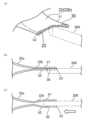
次に、管状留置具1の弁部3への冶具200の挿入について、図3(a)~図3(c)を参照して説明する。
図3(a)は、弁部3への冶具200の挿入前の状態を示す斜視図であり、図3(b)は、同様に、弁部3への冶具200の挿入前の状態を模式的に示す断面図である。図3(c)は、弁部3へ冶具200を挿入した状態を模式的に示す断面図である。図3(b)、(c)においては、ハッチングの図示はいずれも省略されている。 Next, the insertion of the
Fig. 3(a) is a perspective view showing a state before the
図3(a)及び図3(b)に示すように、先ず、第2板状部b2の切欠が形成された案内部30の内側に、冶具200の先端部分を配置する。ここで、冶具200の先端部分を案内部30の直下に配置し、下側(第2板状部b2側)から上側(第1板状部b1側)に変位させる。これにより、案内部30の内側への配置が容易となる。
続けて、図3(c)に示すように、冶具200の先端部分を第1板状部b1の下面に対して上側に押し当てつつ弁部3の奥側(白抜きの矢印の方向)に変位させることで、弁部3に対して冶具200が挿入される。そして、図示は省略するが、冶具200の先端部分を白抜きの矢印の方向にさらに変位させていくことで、管状留置具1の内側へと挿入されていく。 As shown in Figures 3(a) and 3(b), first, the tip portion of the
3(c), the tip portion of the
以上のように、本実施形態に係る管状留置具1は、生体管腔(胆管)内に留置されて管状の流路を画成する管状留置具1であって、管状の本体部2と、本体部2における生体管腔内を流れる流体(胆汁)の流れ方向の下流側端部2aに設けられ、流体が流出する流出口23を有する弁部3と、を備える。弁部3は、流出口23内への冶具200の挿入を案内する案内部30を更に有している。
したがって、逆流抑制効果を有する弁機能を具備する管状留置具1における流出口23が閉塞した状態であっても、弁部3に設けられている案内部30により、流出口23内への冶具200の挿入を案内することができ、弁部3を有する管状留置具1の内側への冶具200の挿入を容易に行うことができる。 As described above, the tubular
Therefore, even if
また、案内部30は、膜体における流出口23の開口縁部に形成されている。そのため、案内部30に冶具200を配置するだけで、流出口23内への冶具200の挿入を容易に案内することができる。具体的には、弁部3は、本体部2の軸方向中央側より離れる方向に先細り形状に形成され、その先端部に流出口23が設けられる。案内部30は、膜体における先端部を構成する先端部構成部(第2板状部b2)により形成されている。そのため、先細り形状の弁部3の先端部構成部に形成されている案内部30に冶具200を配置するだけで、流出口23内への冶具200の挿入を容易に案内することができる。
また、案内部30は、第2板状部b2の先端側から軸方向中央側に切り欠かれた形状をなす。そのため、第2板状部b2の切欠が形成された案内部30の内側に冶具200の先端部分を容易に配置することができ、当該案内部30により案内されながら流出口23内への冶具200の挿入を容易に行うことができる。 In addition, the
In addition, the
以上、本発明を実施形態に基づいて具体的に説明したが、本発明は上記実施形態に限定されるものではなく、その要旨を逸脱しない範囲で変更可能である。
例えば、上記実施形態では、骨格部10の骨格本体部11が、複数のジグザグ環状部が管軸方向に並ぶように配置される構造を例示した。しかし、上記実施形態は一例であってこれに限られるものではなく、適宜任意に変更可能である。具体的には、例えば、図4に示すように、管状留置具1Aの骨格本体部11Aは、金属線材が管軸方向にジグザグ状に往復しながら螺旋状に旋回するように構成されてもよい。また、この場合、一対の延出部12A,12Aは、そのように旋回する金属線材の一部が流出口23に向けて延びるように構成され得る。なお、この場合においても、一対の延出部12A,12Aは、互いに離れる向きに広がることで突出部22を幅方向に開くような力を突出部22に及ぼしてもよいし、そのような力を突出部22に及ぼしてもいなくてもよい。 Although the present invention has been specifically described based on the embodiment, the present invention is not limited to the above embodiment and can be modified without departing from the gist of the present invention.
For example, in the above embodiment, the
なお、管状留置具1Aは、留置後に抜去する際に使用される抜去補助部40を具備している。これにより、例えば、内視鏡を用いて管状留置具1Aの留置状態や生体管腔における管状留置具1Aよりも奥側部分を確認後、当該管状留置具1Aを抜去する必要が生じても、抜去補助部40の先端の係着部41に回収用カテーテルの先端の回収用引掛け具(図示略)を係着させて当該管状留置具1Aの抜去を適正に行うことができる。The tubular retaining device 1A is equipped with a
また、上記実施形態では、案内部30として、第2部分22bを構成する第2板状部b2に切欠形状が形成されたものを例示した。しかし、上記実施形態は一例であってこれに限られるものではない。例えば、第2部分22bを構成する第1板状部b1に切欠形状が形成されていてもよい。すなわち、案内部30は、第2部分(先端部構成部)22bを構成する第1及び第2板状部b1、b2のうち、少なくとも何れか一方に形成されていればよい。
さらに、案内部30として、所定形状(例えば、「V」字状等)に切り欠かれた形状に形成されたものを例示したが、必ずしも切欠形状に形成されている必要はない。例えば、第2部分22bを構成する第1及び第2板状部b1、b2の素材、伸縮性、柔軟性、硬度などを互いに異ならせることで、流出口23内へ冶具を挿入し易いような構成としてもよい。
また、案内部30の形状は、一例であってこれに限られるものではなく、適宜任意に変更可能である。例えば、第2部分22bを構成する第1及び第2板状部b1、b2のうち、少なくとも何れか一方の先端部分を他方に対して離間するように所定形状(例えば、山型(逆「V」字状)等)に突出させた形状としてもよい。 In the above embodiment, the
Furthermore, although the
The shape of the
また、上記実施形態では、管状留置具1は、胆管に留置されて用いられるものを例示したが、一例であってこれに限られるものではない。管状留置具1は、逆流抑制効果を有する弁機能をより適正に発揮させることが求められる他の生体管腔に対して用いられてもよいし、そのような弁機能が求められない他の生体管腔に対して用いられてもよい。In the above embodiment, the
なお、今回開示された実施の形態はすべての点で例示であって制限的なものではないと考えられるべきである。本発明の範囲は上記した説明ではなくて特許請求の範囲によって示され、特許請求の範囲と均等の意味および範囲内でのすべての変更が含まれることが意図される。It should be noted that the embodiments disclosed herein are illustrative in all respects and are not restrictive. The scope of the present invention is indicated by the claims rather than the above description, and is intended to include all modifications within the meaning and scope of the claims.
1、1A 管状留置具
2 本体部
2a 下流側端部
3 弁部
10 骨格部
11、11A 骨格本体部
12、12A 延出部
20 皮膜部
21 筒状部
22 突出部
22b 第2部分
b2 第2板状部(先端部構成部)
23 流出口
30 案内部
200 冶具
23
Claims (3)
Translated fromJapanese管状の本体部と、
前記本体部における前記生体管腔内を流れる流体の流れ方向の下流側端部に設けられ、前記流体が流出する流出口を有する弁部と、を備え、
前記流出口は、膜体により形成され、
前記弁部は、前記本体部の軸方向中央側より離れる方向に先細り形状に形成され、その先端部に前記流出口が設けられ、前記流出口が閉塞した状態のときに下流側から前記流出口内への冶具の挿入を案内可能な案内部を更に有し、
前記弁部は、前記膜体における前記先端部を構成する第1及び第2板状部の内面を密着させるようにして扁平状に形成され、
前記案内部は、前記第1及び第2板状部のいずれか一方の板状部の先端部に形成されて先端側から軸方向中央側に切り欠かれた形状をなし、前記第1及び第2板状部のいずれか他方の板状部の先端部が前記軸方向と直交する方向に対向しない部位を有する
管状留置具。 A tubular indwelling device that is placed in a living body lumen to define a tubular flow path,
A tubular body portion;
a valve portion provided at a downstream end of the main body portion in a flow direction of a fluid flowing through the biological lumen, the valve portion having an outlet through which the fluid flows out,
The outlet is formed by a membrane,
the valve portion is formed in a tapered shape in a direction away from the axial center of the main body portion, the outlet is provided at a tip portion of the valve portion, and the valve portion further has a guide portion capable of guiding insertion of a tool into the outlet from a downstream side when the outlet is in a closed state,
the valve portion is formed in a flat shape by closely contacting inner surfaces of first and second plate-shaped portions constituting the tip portion of the membrane body,
The guide portion is a tubular retention device formed at the tip of one of the first and second plate-shaped portionsand cut out from the tip side toward the center in the axial direction, and the tip of the other of the first and second plate-shaped portions has a portion that does not face each other in a direction perpendicular to the axial direction.
管状の本体部と、
前記本体部における前記生体管腔内を流れる流体の流れ方向の下流側端部に設けられ、前記流体が流出する流出口を有する弁部と、を備え、
前記流出口は、膜体により形成され、
前記弁部は、前記本体部の軸方向中央側より離れる方向に先細り形状に形成され、その先端部に前記流出口が設けられ、前記流出口が閉塞した状態のときに下流側から前記流出口内への冶具の挿入を案内可能な案内部を更に有し、
前記弁部は、前記膜体における前記先端部を構成する第1及び第2板状部の内面を密着させるようにして扁平状に形成され、
前記案内部は、前記第1及び第2板状部の素材、伸縮性、柔軟性、硬度の少なくともいずれかを互いに異ならせて形成されている
管状留置具。 A tubular indwelling device that is placed in a living body lumen to define a tubular flow path,
A tubular body portion;
a valve portion provided at a downstream end of the main body portion in a flow direction of a fluid flowing through the biological lumen, the valve portion having an outlet through which the fluid flows out,
The outlet is formed by a membrane,
the valve portion is formed in a tapered shape in a direction away from the axial center of the main body portion, the outlet is provided at a tip portion of the valve portion, and the valve portion further has a guide portion capable of guiding insertion of a tool into the outlet from a downstream side when the outlet is in a closed state,
the valve portion is formed in a flat shape by closely contacting inner surfaces of first and second plate-shaped portions constituting the tip portion of the membrane body,
The guide portion is a tubular indwelling device formed by making at least one of the material, stretchability, flexibility, and hardness of the first and second plate-shaped portions different from each other.
3. The tubular indwelling device according toclaim 1 , wherein the guide portion is formed on an opening edge portion of the outlet port in the membrane body.
Applications Claiming Priority (3)
| Application Number | Priority Date | Filing Date | Title |
|---|---|---|---|
| JP2019017969 | 2019-02-04 | ||
| JP2019017969 | 2019-02-04 | ||
| PCT/JP2020/003689WO2020162359A1 (en) | 2019-02-04 | 2020-01-31 | Tubular indwelling device |
Publications (2)
| Publication Number | Publication Date |
|---|---|
| JPWO2020162359A1 JPWO2020162359A1 (en) | 2021-12-09 |
| JP7663795B2true JP7663795B2 (en) | 2025-04-17 |
Family
ID=71947662
Family Applications (1)
| Application Number | Title | Priority Date | Filing Date |
|---|---|---|---|
| JP2020571167AActiveJP7663795B2 (en) | 2019-02-04 | 2020-01-31 | Tubular retention device |
Country Status (3)
| Country | Link |
|---|---|
| US (1) | US20220168090A1 (en) |
| JP (1) | JP7663795B2 (en) |
| WO (1) | WO2020162359A1 (en) |
Families Citing this family (1)
| Publication number | Priority date | Publication date | Assignee | Title |
|---|---|---|---|---|
| US12088029B2 (en)* | 2021-07-20 | 2024-09-10 | Dell Products L.P. | Cable termination for information handling systems |
Citations (4)
| Publication number | Priority date | Publication date | Assignee | Title |
|---|---|---|---|---|
| US20050228505A1 (en) | 2004-03-29 | 2005-10-13 | Cornet Douglas A | Device and method for treating gastroesophageal reflux disease |
| US20080091261A1 (en) | 2006-10-13 | 2008-04-17 | Creighton University | Implantable valve prosthesis |
| WO2015146612A1 (en) | 2014-03-28 | 2015-10-01 | 社会医療法人蘇西厚生会 まつなみリサーチパーク | Medical instrument |
| JP2017185299A (en) | 2012-01-30 | 2017-10-12 | 川澄化学工業株式会社 | Biliary duct stent |
- 2020
- 2020-01-31JPJP2020571167Apatent/JP7663795B2/enactiveActive
- 2020-01-31USUS17/422,656patent/US20220168090A1/ennot_activeAbandoned
- 2020-01-31WOPCT/JP2020/003689patent/WO2020162359A1/ennot_activeCeased
Patent Citations (4)
| Publication number | Priority date | Publication date | Assignee | Title |
|---|---|---|---|---|
| US20050228505A1 (en) | 2004-03-29 | 2005-10-13 | Cornet Douglas A | Device and method for treating gastroesophageal reflux disease |
| US20080091261A1 (en) | 2006-10-13 | 2008-04-17 | Creighton University | Implantable valve prosthesis |
| JP2017185299A (en) | 2012-01-30 | 2017-10-12 | 川澄化学工業株式会社 | Biliary duct stent |
| WO2015146612A1 (en) | 2014-03-28 | 2015-10-01 | 社会医療法人蘇西厚生会 まつなみリサーチパーク | Medical instrument |
Also Published As
| Publication number | Publication date |
|---|---|
| JPWO2020162359A1 (en) | 2021-12-09 |
| WO2020162359A1 (en) | 2020-08-13 |
| US20220168090A1 (en) | 2022-06-02 |
Similar Documents
| Publication | Publication Date | Title |
|---|---|---|
| JP6861281B2 (en) | Introducer | |
| CN103547238B (en) | bracket | |
| JP6832111B2 (en) | Stent graft, stent graft set, and stent graft indwelling device | |
| JP2019088872A (en) | Biliary stent | |
| CN112236186B (en) | Push Sheath Style | |
| JP7267245B2 (en) | stent | |
| JP7631632B2 (en) | Stents | |
| JP6158616B2 (en) | Foreign body capture device in body cavity | |
| JP7663795B2 (en) | Tubular retention device | |
| JP5960910B2 (en) | In-vivo indwelling delivery system | |
| JP7258765B2 (en) | Tubular therapeutic device, tubular therapeutic device set and tubular therapeutic device placement device | |
| US20160022446A1 (en) | Stent | |
| JP7512561B2 (en) | Tubular retention device | |
| JP7487439B2 (en) | Tubular retention device | |
| JP6199181B2 (en) | Stent | |
| JP7435980B2 (en) | tubular indwelling device | |
| JP2011101674A (en) | Thrombus capturing catheter and thrombus capturing device | |
| JP2007252895A (en) | Intravascular foreign body removal catheter | |
| US10327931B2 (en) | Pusher-assembly for an insertion system for a self-expandable vascular implant | |
| JP2011072441A (en) | Biological organ dilator implement | |
| JP2018033872A (en) | Medical tube | |
| JP2022153326A (en) | tubular retainer | |
| JP2014069034A (en) | Balloon catheter | |
| WO2020179293A1 (en) | Stent delivery system |
Legal Events
| Date | Code | Title | Description |
|---|---|---|---|
| A625 | Written request for application examination (by other person) | Free format text:JAPANESE INTERMEDIATE CODE: A625 Effective date:20230105 | |
| A131 | Notification of reasons for refusal | Free format text:JAPANESE INTERMEDIATE CODE: A131 Effective date:20231107 | |
| A521 | Request for written amendment filed | Free format text:JAPANESE INTERMEDIATE CODE: A523 Effective date:20231222 | |
| A131 | Notification of reasons for refusal | Free format text:JAPANESE INTERMEDIATE CODE: A131 Effective date:20240326 | |
| A521 | Request for written amendment filed | Free format text:JAPANESE INTERMEDIATE CODE: A523 Effective date:20240521 | |
| A02 | Decision of refusal | Free format text:JAPANESE INTERMEDIATE CODE: A02 Effective date:20240903 | |
| A521 | Request for written amendment filed | Free format text:JAPANESE INTERMEDIATE CODE: A523 Effective date:20241030 | |
| A911 | Transfer to examiner for re-examination before appeal (zenchi) | Free format text:JAPANESE INTERMEDIATE CODE: A911 Effective date:20241113 | |
| TRDD | Decision of grant or rejection written | ||
| A01 | Written decision to grant a patent or to grant a registration (utility model) | Free format text:JAPANESE INTERMEDIATE CODE: A01 Effective date:20250306 | |
| A61 | First payment of annual fees (during grant procedure) | Free format text:JAPANESE INTERMEDIATE CODE: A61 Effective date:20250310 | |
| R150 | Certificate of patent or registration of utility model | Ref document number:7663795 Country of ref document:JP Free format text:JAPANESE INTERMEDIATE CODE: R150 |