JP7663159B2 - Electrosurgical instrument having flexible wiring assembly - Patents.com - Google Patents
Electrosurgical instrument having flexible wiring assembly - Patents.comDownload PDFInfo
- Publication number
- JP7663159B2 JP7663159B2JP2022540370AJP2022540370AJP7663159B2JP 7663159 B2JP7663159 B2JP 7663159B2JP 2022540370 AJP2022540370 AJP 2022540370AJP 2022540370 AJP2022540370 AJP 2022540370AJP 7663159 B2JP7663159 B2JP 7663159B2
- Authority
- JP
- Japan
- Prior art keywords
- end effector
- jaw
- shaft
- electrosurgical instrument
- electrode
- Prior art date
- Legal status (The legal status is an assumption and is not a legal conclusion. Google has not performed a legal analysis and makes no representation as to the accuracy of the status listed.)
- Active
Links
Images


Landscapes
- Surgical Instruments (AREA)
Description
Translated fromJapanese (関連出願の相互参照)
本非仮出願は、2019年12月30日出願の米国特許仮出願第62/955,299号、発明の名称「DEVICES AND SYSTEMS FOR ELECTROSURGERY」の米国特許法第119条(e)の下の利益を主張するものであり、この開示の全内容は、参照により本明細書に組み込まれる。 CROSS-REFERENCE TO RELATED APPLICATIONS
This non-provisional application claims the benefit under 35 U.S.C. §119(e) of U.S. Provisional Application No. 62/955,299, filed December 30, 2019, entitled "DEVICES AND SYSTEMS FOR ELECTROSURGERY," the entire disclosure of which is incorporated herein by reference.
本発明は、組織を切断及び締結するように構成された外科用器具を非限定的に含む、組織を治療するように設計された外科用器具に関する。外科用器具は、外科手術中に組織の解剖、切断、及び/又は凝固をもたらすために発生器によって給電される電気外科用器具を含み得る。外科用器具は、外科用ステープル及び/又は締結具を使用して組織を切断及びステープル留めするように構成された器具を含み得る。外科用器具は、観血的外科手術で使用するために構成され得るが、腹腔鏡、内視鏡、及びロボット支援手順などの他のタイプの手術における用途を有し、患者内の正確な位置決めを容易にするために器具のシャフト部分に対して関節運動可能なエンドエフェクタを含み得る。The present invention relates to surgical instruments designed to treat tissue, including, but not limited to, surgical instruments configured to cut and fasten tissue. The surgical instruments may include electrosurgical instruments powered by a generator to effect dissection, cutting, and/or coagulation of tissue during surgery. The surgical instruments may include instruments configured to cut and staple tissue using surgical staples and/or fasteners. The surgical instruments may be configured for use in open surgery, but have applications in other types of surgery, such as laparoscopic, endoscopic, and robotic-assisted procedures, and may include an end effector that is articulatable relative to a shaft portion of the instrument to facilitate precise positioning within a patient.
様々な実施形態では、ハウジングと、ハウジングから延在するシャフトと、シャフトから延在するエンドエフェクタと、エンドエフェクタをシャフトに回転可能に接続する関節継手と、配線回路と、を備える、電気外科用器具が開示される。ハウジングは、プリント制御基板を含む。配線回路は、プリント制御基板からシャフトを通ってエンドエフェクタ内に延在する。配線回路は、エンドエフェクタの機能を監視し、監視された機能をプリント制御基板に通信するように構成されている。配線回路は、シャフトに固定された近位剛性部分と、エンドエフェクタに固定された遠位剛性部分と、近位剛性部分から遠位剛性部分まで延在する中間部分と、を含む。中間部分は、弾力的部分及び伸縮性部分を含む。In various embodiments, an electrosurgical instrument is disclosed that includes a housing, a shaft extending from the housing, an end effector extending from the shaft, an articulation joint rotatably connecting the end effector to the shaft, and wiring circuitry. The housing includes a printed control board. The wiring circuitry extends from the printed control board through the shaft and into the end effector. The wiring circuitry is configured to monitor functions of the end effector and communicate the monitored functions to the printed control board. The wiring circuitry includes a proximal rigid portion secured to the shaft, a distal rigid portion secured to the end effector, and an intermediate portion extending from the proximal rigid portion to the distal rigid portion. The intermediate portion includes a resilient portion and a stretchable portion.
様々な実施形態では、ハウジングと、ハウジングから延在するシャフトと、シャフトから延在するエンドエフェクタと、エンドエフェクタをシャフトに回転可能に接続する関節継手と、配線回路と、を備える、電気外科用器具が開示される。ハウジングは、プリント制御基板を含む。配線回路は、プリント制御基板からシャフトを通ってエンドエフェクタ内に延在する。配線回路は、エンドエフェクタの機能を監視し、監視された機能をプリント制御基板に通信するように構成されている。配線回路は、剛性部分と、弛緩構成と非弛緩構成との間で移行可能な弾力的部分と、弾力的部分を通って延在する導電性ワイヤと、を含む。導電性ワイヤは、伸縮性部分を含む。導電性ワイヤは、弾力的部分が弛緩構成から非弛緩構成に移行するときに伸長するように構成されている。In various embodiments, an electrosurgical instrument is disclosed that includes a housing, a shaft extending from the housing, an end effector extending from the shaft, an articulation joint rotatably connecting the end effector to the shaft, and wiring circuitry. The housing includes a printed control board. The wiring circuitry extends from the printed control board through the shaft into the end effector. The wiring circuitry is configured to monitor a function of the end effector and communicate the monitored function to the printed control board. The wiring circuitry includes a rigid portion, a resilient portion transitionable between a relaxed configuration and a non-relaxed configuration, and a conductive wire extending through the resilient portion. The conductive wire includes a stretchable portion. The conductive wire is configured to elongate when the resilient portion transitions from the relaxed configuration to the non-relaxed configuration.
様々な実施形態では、ハウジングと、ハウジングから延在するシャフトと、シャフトから延在するエンドエフェクタと、シャフトに対して並進してエンドエフェクタ機能を実行するように構成されている並進部材と、配線ハーネスと、を備える、電気外科用器具が開示される。ハウジングは、プリント制御基板を含む。配線ハーネスは、プリント制御基板からシャフト内に延在する。配線ハーネスは、シャフトに固定された剛性本体部分と、剛性本体部分から延在する弾力的部分と、剛性本体部分及び弾力的部分を通って延在する導電性ワイヤと、を含む。弾力的部分の端部は、並進部材に取り付けられている。並進部材に取り付けられた弾力的部分の端部は、並進部材の属性を測定するように構成されているセンサを備える。In various embodiments, an electrosurgical instrument is disclosed that includes a housing, a shaft extending from the housing, an end effector extending from the shaft, a translation member configured to translate relative to the shaft to perform an end effector function, and a wiring harness. The housing includes a printed control board. The wiring harness extends from the printed control board into the shaft. The wiring harness includes a rigid body portion secured to the shaft, a resilient portion extending from the rigid body portion, and conductive wires extending through the rigid body portion and the resilient portion. An end of the resilient portion is attached to the translation member. An end of the resilient portion attached to the translation member includes a sensor configured to measure an attribute of the translation member.
様々な態様の新規特徴は、添付の「特許請求の範囲」に具体的に記載される。しかしながら、記載される形態は、構成及び操作の方法のいずれに関しても、以下の記載を添付の図面と共に参照することにより最良に理解され得る。
本願の出願人は、本願と同日に出願された以下の米国特許出願を所有しており、これらは各々、それらの全体が参照により本明細書に組み込まれる。
・代理人整理番号END9234USNP1/190717-1M、発明の名称「METHOD FOR AN ELECTROSURGICAL PROCEDURE」、
・代理人整理番号END9234USNP2/190717-2、発明の名称「ARTICULATABLE SURGICAL INSTRUMENT」、
・代理人整理番号END9234USNP3/190717-3、発明の名称「SURGICAL INSTRUMENT WITH JAW ALIGNMENT FEATURES」、
・代理人整理番号END9234USNP4/190717-4、発明の名称「SURGICAL INSTRUMENT WITH ROTATABLE AND ARTICULATABLE SURGICAL END EFFECTOR」、
・代理人整理番号END9234USNP5/190717-5、発明の名称「ELECTROSURGICAL INSTRUMENT WITH ASYNCHRONOUS ENERGIZING ELECTRODES」、
・代理人整理番号END9234USNP6/190717-6、発明の名称「ELECTROSURGICAL INSTRUMENT WITH ELECTRODES BIASING SUPPORT」、
・代理人整理番号END9234USNP8/190717-8、発明の名称「ELECTROSURGICAL INSTRUMENT WITH VARIABLE CONTROL MECHANISMS」、
・代理人整理番号END9234USNP9/190717-9、発明の名称「ELECTROSURGICAL SYSTEMS WITH INTEGRATED AND EXTERNAL POWER SOURCES」、
・代理人整理番号END9234USNP10/190717-10、発明の名称「ELECTROSURGICAL INSTRUMENTS WITH ELECTRODES HAVING ENERGY FOCUSING FEATURES」、
・代理人整理番号END9234USNP11/190717-11、発明の名称「ELECTROSURGICAL INSTRUMENTS WITH ELECTRODES HAVING VARIABLE ENERGY DENSITIES」、
・代理人整理番号END9234USNP12/190717-12、発明の名称「ELECTROSURGICAL INSTRUMENT WITH MONOPOLAR AND BIPOLAR ENERGY CAPABILITIES」、
・代理人整理番号END9234USNP13/190717-13、発明の名称「ELECTROSURGICAL END EFFECTORS WITH THERMALLY INSULATIVE AND THERMALLY CONDUCTIVE PORTIONS」、
・代理人整理番号END9234USNP14/190717-14、発明の名称「ELECTROSURGICAL INSTRUMENT WITH ELECTRODES OPERABLE IN BIPOLAR AND MONOPOLAR MODES」、
・代理人整理番号END9234USNP15/190717-15、発明の名称「ELECTROSURGICAL INSTRUMENT FOR DELIVERING BLENDED ENERGY MODALITIES TO TISSUE」、
・代理人整理番号END9234USNP16/190717-16、発明の名称「CONTROL PROGRAM ADAPTATION BASED ON DEVICE STATUS AND USER INPUT」、
・代理人整理番号END9234USNP17/190717-17、発明の名称「CONTROL PROGRAM FOR MODULAR COMBINATION ENERGY DEVICE」、及び
・代理人整理番号END9234USNP18/190717-18、発明の名称「SURGICAL SYSTEM COMMUNICATION PATHWAYS」。 The applicant of this application has owned the following U.S. patent applications, filed on even date herewith, each of which is incorporated herein by reference in its entirety:
- Attorney Docket No. END9234USNP1/190717-1M, Title of invention: "METHOD FOR AN ELECTROSURGICAL PROCEDURE";
- Attorney Docket No. END9234USNP2/190717-2, Title of invention "ARTICULATABLE SURGICAL INSTRUMENT",
- Agent Reference Number END9234USNP3/190717-3, Title of Invention "SURGICAL INSTRUMENT WITH JAW ALIGNMENT FEATURES",
- Attorney Docket No. END9234USNP4/190717-4, Title of invention: "SURGICAL INSTRUMENT WITH ROTATABLE AND ARTICULATABLE SURGICAL END EFFECTOR";
- Attorney Docket No. END9234USNP5/190717-5, Title of invention: "ELECTROSURGICAL INSTRUMENT WITH ASYNCHRONOUS ENERGIZING ELECTRODES",
- Attorney Docket No. END9234USNP6/190717-6, Title of invention: "ELECTROSURGICAL INSTRUMENT WITH ELECTRODES BIASING SUPPORT";
- Attorney Docket No. END9234USNP8/190717-8, Title of Invention "ELECTROSURGICAL INSTRUMENT WITH VARIABLE CONTROL MECHANISMS",
- Attorney Docket No. END9234USNP9/190717-9, Title of invention: "ELECTROSURGICAL SYSTEMS WITH INTEGRATION AND EXTERNAL POWER SOURCES";
- Attorney Docket No. END9234USNP10/190717-10, Title of invention: "ELECTROSURGICAL INSTRUMENTS WITH ELECTRODES HAVING ENERGY FOCUSING FEATURES";
- Attorney Docket No. END9234USNP11/190717-11, Title of invention: "ELECTROSURGICAL INSTRUMENTS WITH ELECTRODES HAVING VARIABLE ENERGY DENSITIES";
- Attorney Docket No. END9234USNP12/190717-12, Title of invention: "ELECTROSURGICAL INSTRUMENT WITH MONOPOLAR AND BIPOLAR ENERGY CAPABILITIES";
- Attorney Docket No. END9234USNP13/190717-13, Title of invention: "ELECTROSURGICAL END EFFECTORS WITH THERMALLY INSULATIVE AND THERMALLY CONDUCTIVE PORTIONS";
- Attorney Docket No. END9234USNP14/190717-14, Title of invention: "ELECTROSURGICAL INSTRUMENT WITH ELECTRODES OPERABLE IN BIPOLAR AND MONOPOLAR MODES";
- Attorney Docket No. END9234USNP15/190717-15, Title of Invention "ELECTROSURGICAL INSTRUMENT FOR DELIVERING BLENDED ENERGY MODALITIES TO TISSUE",
- Attorney Docket No. END9234USNP16/190717-16, Title of invention: "CONTROL PROGRAM ADAPTATION BASED ON DEVICE STATUS AND USER INPUT";
- Attorney Docket No. END9234USNP17/190717-17, titled "CONTROL PROGRAM FOR MODULAR COMBINATION ENERGY DEVICE", and - Attorney Docket No. END9234USNP18/190717-18, titled "SURGICAL SYSTEM COMMUNICATION PATHWAYS".
本出願の出願人は、各開示の全体が参照により本明細書に組み込まれる、2019年12月30日出願の以下の米国特許仮出願を所有する。
・米国特許仮出願第62/955,294号、発明の名称「USER INTERFACE FOR SURGICAL INSTRUMENT WITH COMBINATION ENERGY MODALITY END-EFFECTOR」、
・米国特許仮出願第62/955,292号、発明の名称「COMBINATION ENERGY MODALITY END-EFFECTOR」、及び
・米国特許仮出願第62/955,306号、発明の名称「SURGICAL INSTRUMENT SYSTEMS」。 The applicant of this application owns the following U.S. provisional patent applications, filed December 30, 2019, the disclosures of each of which are incorporated by reference in their entirety herein:
- U.S. Provisional Patent Application No. 62/955,294, entitled "USER INTERFACE FOR SURGICAL INSTRUMENT WITH COMBINATION ENERGY MODALITY END-EFFECTOR";
- U.S. Provisional Patent Application No. 62/955,292, entitled "COMBINATION ENERGY MODALITY END-EFFECTOR," and - U.S. Provisional Patent Application No. 62/955,306, entitled "SURGICAL INSTRUMENT SYSTEMS."
本出願の出願人は、各開示の全体が参照により本明細書に組み込まれる、以下の米国特許出願を所有する。
・米国特許出願第16/209,395号、発明の名称「METHOD OF HUB COMMUNICATION」(現在は、米国特許出願公開第2019/0201136号)、
・米国特許出願第16/209,403号、発明の名称「METHOD OF CLOUD BASED DATA ANALYTICS FOR USE WITH THE HUB」(現在は、米国特許出願公開第2019/0206569号)、
・米国特許出願第16/209,407号、発明の名称「METHOD OF ROBOTIC HUB COMMUNICATION, DETECTION, AND CONTROL」(現在は、米国特許出願公開第2019/0201137号)、
・米国特許出願第16/209,416号、発明の名称「METHOD OF HUB COMMUNICATION, PROCESSING, DISPLAY, AND CLOUD ANALYTICS」(現在は、米国特許出願公開第2019/0206562号)、
・米国特許出願第16/209,423号、発明の名称「METHOD OF COMPRESSING TISSUE WITHIN A STAPLING DEVICE AND SIMULTANEOUSLY DISPLAYING THE LOCATION OF THE TISSUE WITHIN THE JAWS」(現在は、米国特許出願公開第2019/0200981号)、
・米国特許出願第16/209,427号、発明の名称「METHOD OF USING REINFORCED FLEXIBLE CIRCUITS WITH MULTIPLE SENSORS TO OPTIMIZE PERFORMANCE OF RADIO FREQUENCY DEVICES」(現在は、米国特許出願公開第2019/0208641号)、
・米国特許出願第16/209,433号、発明の名称「METHOD OF SENSING PARTICULATE FROM SMOKE EVACUATED FROM A PATIENT,ADJUSTING THE PUMP SPEED BASED ON THE SENSED INFORMATION, AND COMMUNICATING THE FUNCTIONAL PARAMETERS OF THE SYSTEM TO THE HUB」(現在は、米国特許出願公開第2019/0201594号)、
・米国特許出願第16/209,447号、発明の名称「METHOD FOR SMOKE EVACUATION FOR SURGICAL HUB」(現在は、米国特許出願公開第2019/0201045号)、
・米国特許出願第16/209,453号、発明の名称「METHOD FOR CONTROLLING SMART ENERGY DEVICES」(現在は、米国特許出願公開第2019/0201046号)、
・米国特許出願第16/209,458号、発明の名称「METHOD FOR SMART ENERGY DEVICE INFRASTRUCTURE」(現在は、米国特許出願公開第2019/0201047号)、
・米国特許出願第16/209,465号、発明の名称「METHOD FOR ADAPTIVE CONTROL SCHEMES FOR SURGICAL NETWORK CONTROL AND INTERACTION」(現在は、米国特許出願公開第2019/0206563号)、
・米国特許出願第16/209,478号、発明の名称「METHOD FOR SITUATIONAL AWARENESS FOR SURGICAL NETWORK OR SURGICAL NETWORK CONNECTED DEVICE CAPABLE OF ADJUSTING FUNCTION BASED ON A SENSED SITUATION OR USAGE」(現在は、米国特許出願公開第2019/0104919号)、
・米国特許出願第16/209,490号、発明の名称「METHOD FOR FACILITY DATA COLLECTION AND INTERPRETATION」(現在は、米国特許出願公開第2019/0206564号)、
・米国特許出願第16/209,491号、発明の名称「METHOD FOR CIRCULAR STAPLER CONTROL ALGORITHM ADJUSTMENT BASED ON SITUATIONAL AWARENESS」(現在は、米国特許出願公開第2019/0200998号)、
・米国特許出願第16/562,123号、発明の名称「METHOD FOR CONSTRUCTING AND USING A MODULAR SURGICAL ENERGY SYSTEM WITH MULTIPLE DEVICES」、
・米国特許出願第16/562,135号、発明の名称「METHOD FOR CONTROLLING AN ENERGY MODULE OUTPUT」、
・米国特許出願第16/562,144号、発明の名称「METHOD FOR CONTROLLING A MODULAR ENERGY SYSTEM USER INTERFACE」、及び
・米国特許出願第16/562,125号、発明の名称「METHOD FOR COMMUNICATING BETWEEN MODULES AND DEVICES IN A MODULAR SURGICAL SYSTEM」。 The applicant of the present application owns the following U.S. patent applications, the disclosures of each of which are incorporated herein by reference in their entirety:
U.S. Patent Application No. 16/209,395, entitled "METHOD OF HUB COMMUNICATION" (now U.S. Patent Application Publication No. 2019/0201136);
U.S. Patent Application No. 16/209,403, entitled "METHOD OF CLOUD BASED DATA ANALYTICS FOR USE WITH THE HUB" (now U.S. Patent Application Publication No. 2019/0206569);
U.S. Patent Application No. 16/209,407 entitled "METHOD OF ROBOTIC HUB COMMUNITION, DETECTION, AND CONTROL" (now U.S. Patent Application Publication No. 2019/0201137);
U.S. Patent Application No. 16/209,416, entitled "METHOD OF HUB COMMUNICATION, PROCESSING, DISPLAY, AND CLOUD ANALYTICS" (currently U.S. Patent Application Publication No. 2019/0206562);
- U.S. Patent Application No. 16/209,423, entitled "METHOD OF COMPRESSING TISSUE WITHIN A STAPLING DEVICE AND SIMULTANEOUSLY DISPLAYING THE LOCATION OF THE TISSUE WITHIN THE JAWS" (currently U.S. Patent Application Publication No. 2019/0200981);
U.S. Patent Application No. 16/209,427, entitled "METHOD OF USING REINFORCED FLEXIBLE CIRCUITS WITH MULTIPLE SENSORS TO OPTIMISE PERFORMANCE OF RADIO FREQUENCY DEVICES" (now U.S. Patent Application Publication No. 2019/0208641);
- U.S. Patent Application No. 16/209,433, entitled "METHOD OF SENSING PARTICULATE FROM SMOKE EVACUATED FROM A PATIENT, ADJUSTING THE PUMP SPEED BASED ON THE SENSED INFORMATION, AND COMMUNICATING THE FUNCTIONAL PARAMETERS OF THE SYSTEM TO THE HUB" (now U.S. Patent Application Publication No. 2019/0201594);
No. 16/209,447, entitled "METHOD FOR SMOKE EVACUATION FOR SURGICAL HUB" (now U.S. Patent Application Publication No. 2019/0201045);
U.S. Patent Application No. 16/209,453, entitled "METHOD FOR CONTROLLING SMART ENERGY DEVICES" (now U.S. Patent Application Publication No. 2019/0201046);
U.S. Patent Application No. 16/209,458, entitled "METHOD FOR SMART ENERGY DEVICE INFRASTRUCTURE" (now U.S. Patent Application Publication No. 2019/0201047);
U.S. Patent Application No. 16/209,465, entitled "METHOD FOR ADAPTIVE CONTROL SCHEMES FOR SURGICAL NETWORK CONTROL AND INTERACTION" (now U.S. Patent Application Publication No. 2019/0206563);
- U.S. Patent Application No. 16/209,478, entitled "METHOD FOR SITUSATIONAL AWARENESS FOR SURGICAL NETWORK OR SURGICAL NETWORK CONNECTED DEVICE CAPABLE OF ADJUSTING FUNCTION BASED ON A SENSED SITUS OR USAGE" (now U.S. Patent Application Publication No. 2019/0104919);
U.S. Patent Application No. 16/209,490, entitled "METHOD FOR FACILITY DATA COLLECTION AND INTERPRETERATION" (now U.S. Patent Application Publication No. 2019/0206564);
U.S. Patent Application No. 16/209,491, entitled "METHOD FOR CIRCULAR STAPLER CONTROL ALGORITHM ADJUSTMENT BASED ON SITUATIONAL AWARENESS" (now U.S. Patent Application Publication No. 2019/0200998);
- U.S. Patent Application No. 16/562,123, entitled "METHOD FOR CONSTRUCTING AND USING A MODULAR SURGICAL ENERGY SYSTEM WITH MULTIPLE DEVICES";
- U.S. Patent Application No. 16/562,135, entitled "METHOD FOR CONTROLLING AN ENERGY MODULE OUTPUT";
- U.S. Patent Application No. 16/562,144, entitled "METHOD FOR CONTROLLING A MODULAR ENERGY SYSTEM USER INTERFACE", and - U.S. Patent Application No. 16/562,125, entitled "METHOD FOR COMMUNICATING BETWEEN MODULES AND DEVICES IN A MODULAR SURGICAL SYSTEM".
外科用可視化プラットフォームの様々な態様を詳細に説明する前に、例示の実施例が、適用又は使用において、添付の図面及び明細書で例示される部品の構造及び配置の詳細に限定されないことに留意されたい。例示の実施例は、他の態様、変形形態、及び修正形態で実施されるか、又はそれらに組み込まれてもよく、様々な方法で実施又は実行されてもよい。更に、特に明記しない限り、本明細書で用いられる用語及び表現は、読者の便宜のために例示の実施例を説明する目的で選択されたものであり、それらを限定するためのものではない。更に、以下に記述される態様、態様の表現、及び/又は実施例のうち1つ以上を、以下に記述される他の態様、態様の表現、及び/又は実施例のうち任意の1つ以上と組み合わせることができるものと理解されたい。Before describing the various aspects of the surgical visualization platform in detail, it should be noted that the exemplary embodiments are not limited in application or use to the details of construction and arrangement of parts illustrated in the accompanying drawings and specification. The exemplary embodiments may be embodied in or incorporated into other aspects, variations, and modifications and may be practiced or carried out in various ways. Moreover, unless otherwise indicated, the terms and expressions used herein have been selected for the convenience of the reader for the purpose of describing the exemplary embodiments and not for the purpose of limiting them. Furthermore, it should be understood that one or more of the aspects, aspect expressions, and/or examples described below can be combined with any one or more of the other aspects, aspect expressions, and/or examples described below.
様々な態様は、外科手術中に組織の解剖、切断、及び/又は凝固をもたらすために発生器によって給電される電気外科用器具を含む、電気外科用システムを目的とする。電気外科用器具は、観血的外科処置における使用のために構成され得るが、腹腔鏡、内視鏡、及びロボット支援処置などの他のタイプの外科における用途も有する。Various aspects are directed to electrosurgical systems that include electrosurgical instruments powered by a generator to effect dissection, cutting, and/or coagulation of tissue during a surgical procedure. The electrosurgical instruments may be configured for use in open surgical procedures, but also have applications in other types of surgery, such as laparoscopic, endoscopic, and robotic-assisted procedures.
以下でより詳細に説明するように、電気外科用器具は、一般に、遠位に取り付けられたエンドエフェクタ(例えば、1つ以上の電極)を有するシャフトを備える。エンドエフェクタは、電流が組織内に導入されるように、組織に対して位置決めすることができる。電気外科用器具は、双極又は単極動作用に構成することができる。双極動作中、電流はそれぞれ、エンドエフェクタの活性電極によって組織に導入され、エンドエフェクタの戻り電極によって組織から戻される。単極動作中、電流は、エンドエフェクタの活性電極によって組織に導入され、患者の体に別個に位置する戻り電極(例えば、接地パッド)を介して戻される。組織を流れる電流によって生成される熱は、組織内及び/又は組織間の止血封止を形成してもよく、したがって、例えば、血管を封止するために特に有用であってもよい。As described in more detail below, electrosurgical instruments generally include a shaft having a distally attached end effector (e.g., one or more electrodes). The end effector can be positioned relative to the tissue such that electrical current is introduced into the tissue. Electrosurgical instruments can be configured for bipolar or monopolar operation. During bipolar operation, electrical current is introduced into the tissue by an active electrode of the end effector and returned from the tissue by a return electrode of the end effector, respectively. During monopolar operation, electrical current is introduced into the tissue by an active electrode of the end effector and returned via a return electrode (e.g., a ground pad) separately located on the patient's body. Heat generated by electrical current flowing through the tissue may form a hemostatic seal within and/or between the tissues and may thus be particularly useful, for example, for sealing blood vessels.
図1は、複数のエネルギーモダリティを外科用器具に送達するように構成されている発生器900の例を示す。発生器900は、エネルギーを外科用器具に送達するためのRF信号及び/又は超音波信号を提供する。発生器900は、単一のポートを通して複数のエネルギーモダリティ(例えば、とりわけ超音波、双極若しくは単極RF、不可逆及び/若しくは可逆電気穿孔法並びに/又はマイクロ波エネルギー)を送達することができる少なくとも1つの発生器出力部を備え、これらの信号は、組織を治療するために個別に又は同時にエンドエフェクタに送達することができる。発生器900は、波形発生器904に連結されたプロセッサ902を備える。プロセッサ902及び波形発生器904は、開示を明瞭にするために示されていない、プロセッサ902に連結されたメモリに記憶された情報に基づいて、様々な信号波形を発生するように構成されている。波形に関連するデジタル情報は、デジタル入力をアナログ出力に変換するために1つ又は2つ以上のDAC回路を含む波形発生器904に提供される。アナログ出力は、信号調節及び増幅のために、増幅器906に供給される。増幅器906の、調節され増幅された出力は、電力変圧器908に連結されている。信号は、電力変圧器908を横断して患者絶縁側にある二次側に連結されている。第1のエネルギーモダリティの第1の信号は、外科用器具のENERGY1及びRETURNとラベルされた端子間に提供される。第2のエネルギーモダリティの第2の信号は、コンデンサ910を横断して連結され、外科用器具のENERGY2及びRETURNとラベルされた端子間に提供される。2つを超えるエネルギーモダリティが出力されてもよく、したがって添え字「n」は、最大n個のENERGYn端子が提供され得ることを示すために使用することができ、ここでnは、1超の正の整数であることが理解されよう。最大「n」個のリターンパス(RETURNn)が、本開示の範囲から逸脱することなく提供されてもよいことも理解されよう。 FIG. 1 shows an example of a
第1の電圧感知回路912は、ENERGY1及びRETURNパスとラベルされた端子にわたって連結され、それらの間の出力電圧を測定する。第2の電圧感知回路924は、ENERGY2及びRETURNパスとラベルされた端子にわたって連結され、それらの間の出力電圧を測定する。電流感知回路914は、いずれかのエネルギーモダリティの出力電流を測定するために、示される電力変圧器908の二次側のRETURN区間と直列に配設される。異なるリターンパスが各エネルギーモダリティに対して提供される場合、別個の電流感知回路は各リターン区間で提供されねばならない。第1の電圧感知回路912及び第2の電圧感知回路924の出力が対応の絶縁変圧器928、922に提供され、電流感知回路914の出力は、別の絶縁変圧器916に提供される。電力変圧器908の一次側(非患者絶縁側)における絶縁変圧器916、928、922の出力は、1つ以上のADC回路926に提供される。ADC回路926のデジタル化された出力は、更なる処理及び計算のためにプロセッサ902に提供される。出力電圧及び出力電流のフィードバック情報は、外科用器具に提供される出力電圧及び電流を調整するために、出力インピーダンスなどのパラメータを計算するために使用することができる。プロセッサ902と患者絶縁回路との間の入力/出力通信は、インターフェース回路920を介して提供される。センサもまた、インターフェース回路920を介してプロセッサ902と電気通信してもよい。 A first
一態様では、インピーダンスは、ENERGY1/RETURNとラベルされた端子にわたって連結された第1の電圧感知回路912又はENERGY2/RETURNとラベルされた端子にわたって連結された第2の電圧感知回路924のいずれかの出力を、電力変圧器908の二次側のRETURN区間と直列に配置された電流感知回路914の出力で割ることによって、プロセッサ902により判定され得る。第1の電圧感知回路912及び第2の電圧感知回路924の出力は、個別の絶縁変圧器928、922に提供され、電流感知回路914の出力は、別の絶縁変圧器916に提供される。ADC回路926からのデジタル化された電圧及び電流感知測定値は、インピーダンスを計算するためにプロセッサ902に提供される。一例として、第1のエネルギーモダリティENERGY1はRF単極エネルギーであってもよく、第2のエネルギーモダリティENERGY2はRF双極エネルギーであってもよい。それでも、双極及び単極RFエネルギーモダリティに加えて、他のエネルギーモダリティには、数ある中でも超音波エネルギー、不可逆並びに/又は可逆電気穿孔法及び/若しくはマイクロ波エネルギーが挙げられる。また、図1に例示された例は、単一のリターンパス(RETURN)が2つ以上のエネルギーモダリティに提供され得ることを示しているが、他の態様では、複数のリターンパスRETURNnが、各エネルギーモダリティENERGYnに提供されてもよい。 In one aspect, the impedance may be determined by the
図1に示すように、少なくとも1つの出力ポートを備える発生器900は、実施される組織の治療のタイプに応じて、電力を、例えば、とりわけ超音波、双極若しくは単極RF、不可逆及び/若しくは可逆電気穿孔法、並びに/又はマイクロ波エネルギーなどの1つ以上のエネルギーモダリティの形態でエンドエフェクタに提供するために、単一の出力部を有し、かつ複数のタップを有する電力変圧器908を含むことができる。例えば、発生器900は、超音波トランスデューサを駆動するために高電圧かつ低電流のエネルギーを送達し、RF電極を駆動して組織を封止するために低電圧かつ高電流のエネルギーを送達し、又は単極又は双極RF電気外科用電極のいずれかを使用したスポット凝固のために凝固波形を有するエネルギーを送達することができる。発生器900からの出力波形は、周波数を外科用器具のエンドエフェクタに提供するために、誘導、切り替え又はフィルタリングされ得る。一例では、RF双極電極の、発生器900の出力部への接続部は、好ましくは、ENERGY2とラベルされた出力部とRETURNとの間に位置するであろう。単極出力の場合、ENERGY2出力部へ活性電極(例えば、ペンシル型又は他のプローブ)を接続し、RETURN出力部に好適なリターンパッドを接続することが好ましいであろう。 As shown in FIG. 1 , the
追加の詳細は、その全体が参照により本明細書に組み込まれる、「TECHNIQUES FOR OPERATING GENERATOR FOR DIGITALLY GENERATING ELECTRICAL SIGNAL WAVEFORMS AND SURGICAL INSTRUMENTS」と題する2017年3月30日公開の米国特許出願公開第2017/0086914号に開示されている。Additional details are disclosed in U.S. Patent Application Publication No. 2017/0086914, published March 30, 2017, entitled "TECHNIQUES FOR OPERATING GENERATOR FOR DIGITALLY GENERATING ELECTRICAL SIGNAL WAVEFORMS AND SURGICAL INSTRUMENTS," which is incorporated herein by reference in its entirety.
図2は、発生器1100と、これと共に使用可能な様々な外科用器具1104、1106、1108と、を備える外科用システム1000の一形態を示し、外科用器具1104は超音波外科用器具であり、外科用器具1106はRF電気外科用器具であり、多機能型外科用器具1108は組み合わせ超音波/RF電気外科用器具である。発生器1100は、様々な外科用器具と共に使用するように構成可能である。様々な形態によれば、発生器1100は、例えば、超音波外科用器具1104、RF電気外科用器具1106、並びに発生器1100から同時に送達されるRFエネルギー及び超音波エネルギーを統合する多機能型外科用器具1108を含む異なるタイプの様々な外科用装置と共に使用するように構成可能であり得る。図2の形態では、発生器1100は、外科用器具1104、1106、1108とは別個に示されているが、一形態では、発生器1100は、外科用器具1104、1106、1108のうちのいずれかと一体的に形成されて、一体型外科用システムを形成してもよい。発生器1100は、発生器1100のコンソールの前側パネル上に位置する入力装置1110を含む。入力装置1110は、発生器1100の動作をプログラムするのに好適な信号を生成する任意の好適な装置を含むことができる。発生器1100は、有線又は無線通信用に構成されてもよい。2 illustrates one form of a
発生器1100は、複数の外科用器具1104、1106、1108を駆動するように構成される。第1の外科用器具は超音波外科用器具1104であり、ハンドピース1105(handpiece、HP)、超音波トランスデューサ1120、シャフト1126、及びエンドエフェクタ1122を備える。エンドエフェクタ1122は、超音波トランスデューサ1120と音響的に連結された超音波ブレード1128及びクランプアーム1140を備える。ハンドピース1105は、クランプアーム1140を動作させるトリガ1143と、超音波ブレード1128又は他の機能にエネルギーを供給し、駆動するためのトグルボタン1137、1134b、1134cの組み合わせと、を備える。トグルボタン1137、1134b、1134cは、発生器1100を用いて超音波トランスデューサ1120にエネルギーを供給するように構成することができる。The
発生器1100はまた、第2の外科用器具1106を駆動するようにも構成される。第2の外科用器具1106は、RF電気外科用器具であり、ハンドピース1107(HP)、シャフト1127、及びエンドエフェクタ1124を備える。エンドエフェクタ1124は、クランプアーム1145、1142b内に電極を備え、シャフト1127の電気導体部分を通って戻る。電極は、発生器1100内の双極エネルギー源に連結され、双極エネルギー源によってエネルギーを供給される。ハンドピース1107は、クランプアーム1145、1142bを動作させるためのトリガ1145と、エンドエフェクタ1124内の電極にエネルギーを供給するためのエネルギースイッチを作動するためのエネルギーボタン1135と、を備える。第2の外科用器具1106はまた、単極エネルギーを組織に送達するためにリターンパッドと共に使用され得る。The
発生器1100はまた、多機能型外科用器具1108を駆動するようにも構成される。多機能型外科用器具1108は、ハンドピース1109(HP)、シャフト1129、及びエンドエフェクタ1125を備える。エンドエフェクタ1125は、超音波ブレード1149及びクランプアーム1146を備える。超音波ブレード1149は、超音波トランスデューサ1120と音響的に連結される。ハンドピース1109は、クランプアーム1146を動作させるトリガ1147と、超音波ブレード1149又は他の機能にエネルギーを供給し、駆動するためのトグルボタン11310、1137b、1137cの組み合わせと、を備える。トグルボタン11310、1137b、1137cは、発生器1100を用いて超音波トランスデューサ1120にエネルギーを供給し、かつ同様に発生器1100内に収容された双極エネルギー源を用いて超音波ブレード1149にエネルギーを供給するように構成することができる。単極エネルギーは、双極エネルギーと組み合わせて、又は双極エネルギーとは別に組織に送達され得る。The
発生器1100は、様々な外科用器具と共に使用するように構成可能である。様々な形態によれば、発生器1100は、例えば、超音波外科用器具1104、RF電気外科用器具1106、並びに発生器1100から同時に送達されるRFエネルギー及び超音波エネルギーを統合する多機能型外科用器具1108を含む異なるタイプの異なる外科用器具と共に使用するように構成可能であり得る。図2の形態では、発生器1100は、外科用器具1104、1106、1108とは別個に示されているが、別の形態では、発生器1100は、外科用器具1104、1106、1108のうちのいずれか1つと一体的に形成されて、一体型外科用システムを形成してもよい。上で考察されるように、発生器1100は、発生器1100のコンソールの前側パネル上に位置する入力装置1110を含む。入力装置1110は、発生器1100の動作をプログラムするのに好適な信号を生成する任意の好適な装置を含むことができる。発生器1100はまた、1つ又は2つ以上の出力装置1112を含んでもよい。電気信号波形をデジタル的に発生させるための発生器、及び外科用器具の更なる態様は、その全体が参照により本明細書に組み込まれる米国特許出願公開第2017-0086914(A1)号に記載されている。The
図3は、様々な機能を実行するために起動され得る複数のモータアセンブリを備える外科用器具又はツール600の概略図を示す。図示される例では、閉鎖モータアセンブリ610は、開放構成と閉鎖構成との間でエンドエフェクタを移行させるように動作可能であり、関節運動モータアセンブリ620は、シャフトアセンブリに対してエンドエフェクタを関節運動させるように動作可能である。特定の例では、複数のモータアセンブリは個々に起動されて、エンドエフェクタにおいて発射運動、閉鎖運動、及び/又は関節運動を生じさせることができる。発射運動、閉鎖運動、及び/又は関節運動は、例えばシャフトアセンブリを介してエンドエフェクタに伝達することができる。FIG. 3 shows a schematic diagram of a surgical instrument or
特定の例では、閉鎖モータアセンブリ610は、閉鎖モータを含む。閉鎖603は、具体的には閉鎖部材を閉鎖するように変位させ、エンドエフェクタを閉鎖構成に移行するために、モータによって生成された閉鎖運動をエンドエフェクタに伝達するように構成され得る、閉鎖モータ駆動アセンブリ612と動作可能に連結されてもよい。閉鎖運動によって、例えば、エンドエフェクタが開放構成から閉鎖構成へと移行して組織を捕捉することができる。エンドエフェクタは、モータの方向を逆転させることによって開放位置に移行され得る。In certain examples, the
特定の例では、関節運動モータアセンブリ620は、モータによって生成された関節運動をエンドエフェクタに伝達するように構成することができる、関節駆動アセンブリ622に動作可能に連結される、関節運動モータを含む。特定の例では、関節運動によって、例えば、エンドエフェクタがシャフトに対して関節運動することができる。In certain examples, the
外科用器具600のモータの1つ以上は、モータのシャフト上の出力トルクを測定するためのトルクセンサを備えてもよい。エンドエフェクタ上の力は、ジョーの外側の力センサによって、又はジョーを作動させるモータのトルクセンサなどによって、任意の従来の様式で感知されてもよい。One or more of the motors of the
様々な例において、モータアセンブリ610、620は、1つ以上のHブリッジFETを含み得る1つ以上のモータドライバを備える。モータドライバは、例えば、制御回路601のマイクロコントローラ640(「コントローラ」)からの入力に基づいて、電源630からモータへと伝達された電力を変調してもよい。特定の例では、マイクロコントローラ640を用いて、例えばモータによる電流の引き込みを測定することができる。In various examples, the
特定の例では、マイクロコントローラ640は、マイクロプロセッサ642(「プロセッサ」)と、1つ以上の非一時的コンピュータ可読媒体又はメモリユニット644(「メモリ」)と、を含んでもよい。特定の例では、メモリ644は、様々なプログラム命令を記憶することができ、それが実行されると、プロセッサ642に、本明細書に記載される複数の機能及び/又は計算を実施させることができる。特定の例では、メモリユニット644のうちの1つ以上が、例えば、プロセッサ642に連結されてもよい。様々な態様では、マイクロコントローラ640は、有線若しくは無線チャネル、又はこれらの組み合わせを介して通信してもよい。In certain examples, the microcontroller 640 may include a microprocessor 642 ("processor") and one or more non-transitory computer-readable media or memory units 644 ("memory"). In certain examples, the memory 644 may store various program instructions that, when executed, may cause the
特定の例では、電源630を用いて、例えばマイクロコントローラ640に電力を供給してもよい。特定の例では、電源630は、例えばリチウムイオン電池などの電池(又は「電池パック」若しくは「電源パック」)を含んでもよい。特定の例では、電池パックは、外科用器具600に電力を供給するため、ハンドルに解除可能に装着されるように構成されてもよい。直列で接続された多数の電池セルを、電源630として使用してもよい。特定の例では、電源630は、例えば、交換可能及び/又は再充電可能であってもよい。In certain examples, the
様々な例では、プロセッサ642は、モータドライバを制御して、アセンブリ610、620のモータの位置、回転方向、及び/又は速度を制御してもよい。特定の例では、プロセッサ642は、モータを停止及び/又は無効化するように、モータドライバに信号伝達することができる。「プロセッサ」という用語は、本明細書で使用されるとき、任意の好適なマイクロプロセッサ、マイクロコントローラ、又は、コンピュータの中央処理装置(central processing unit、CPU)の機能を1つの集積回路又は最大で数個の集積回路上で統合した他の基本コンピューティング装置を含むと理解されるべきである。プロセッサ642は、デジタルデータを入力として受理し、メモリに記憶された命令に従ってそのデータを処理し、結果を出力として提供する、多目的のプログラム可能装置である。これは、内部メモリを有するので、逐次的デジタル論理の一例である。プロセッサは、二進数法で表される数字及び記号で動作する。In various examples, the
一例では、プロセッサ642は、Texas Instruments製のARM Cortexの商品名で知られているものなど、任意のシングルコア又はマルチコアプロセッサであってもよい。特定の例では、マイクロコントローラ620は、例えばTexas Instrumentsから入手可能なLM 4F230H5QRであってもよい。少なくとも1つの実施例では、Texas InstrumentsのLM4F230H5QRは、製品データシートで容易に利用可能な機能の中でもとりわけ、最大40MHzの256KBのシングルサイクルフラッシュメモリ若しくは他の不揮発性メモリのオンチップメモリ、性能を40MHz超に改善するためのプリフェッチバッファ、32KBのシングルサイクルSRAM、StellarisWare(登録商標)ソフトウェアを搭載した内部ROM、2KBのEEPROM、1つ又は2つ以上のPWMモジュール、1つ又は2つ以上のQEIアナログ、12個のアナログ入力チャネルを備える1つ又は2つ以上の12ビットADCを含むARM Cortex-M4Fプロセッサコアである。他のマイクロコントローラが、外科用器具600と共に使用するのに容易に代用されてもよい。したがって、本開示は、この文脈に限定されるべきではない。In one example, the
特定の例では、メモリ644は、外科用器具600のモータそれぞれを制御する、プログラム命令を含んでもよい。例えば、メモリ644は、閉鎖モータ、及び関節運動モータを制御するためのプログラム命令を含んでもよい。このようなプログラム命令は、プロセッサ642に、外科用器具600のアルゴリズム又は制御プログラムからの入力に従って、閉鎖機能及び関節運動機能を制御させることができる。In certain examples, the memory 644 may include program instructions that control each of the motors of the
特定の例では、例えば、センサ645などの1つ以上の機構及び/又はセンサを用いて、特定の設定で使用すべきプログラム命令をプロセッサ642に警告することができる。例えば、センサ645は、エンドエフェクタの閉鎖、及び関節運動に関連するプログラム命令を使用するようにプロセッサ642に警告することができる。特定の例では、センサ645は、例えば、閉鎖アクチュエータの位置を感知するために用いることができる位置センサを備えてもよい。したがって、プロセッサ642は、プロセッサ642が閉鎖アクチュエータの作動を示すセンサ630からの信号を受信する場合、エンドエフェクタを閉じることに関連付けられたプログラム命令を使用して、閉鎖駆動アセンブリ620のモータを作動させることができる。In certain examples, one or more mechanisms and/or sensors, such as, for example, sensor 645, can be used to alert
いくつかの例では、モータはブラシレスDC電動モータであってもよく、それぞれのモータ駆動信号は、モータの1つ以上の固定子巻線に提供されるPWM信号を含んでもよい。また、いくつかの例では、モータドライバは省略されてもよく、制御回路601がモータ駆動信号を直接生成してもよい。In some examples, the motors may be brushless DC electric motors and each motor drive signal may include a PWM signal provided to one or more stator windings of the motor. Also, in some examples, the motor driver may be omitted and the
様々な腹腔鏡手術中においては、患者の腹壁に設置されたトロカールを通して外科用器具の外科用エンドエフェクタ部分を挿入して、患者の腹部内に位置する手術部位にアクセスすることは一般的な手法である。その最も単純な形態では、トロカールは、カニューレ又はスリーブとして知られる中空チューブ内で典型的に使用される一方に鋭い三角形の先端を有するペン形状の器具であり、体部に開口部を作り、そこを通して外科用エンドエフェクタが導入され得る。そのような構成は、体腔内に、外科用エンドエフェクタが挿入され得るアクセスポートを形成する。トロカールのカニューレの内径は、トロカールを通して挿入され得る外科用器具のエンドエフェクタ及び駆動支持シャフトのサイズを必然的に制限する。During various laparoscopic procedures, it is common practice to insert a surgical end effector portion of a surgical instrument through a trocar placed in the patient's abdominal wall to access a surgical site located within the patient's abdomen. In its simplest form, a trocar is a pen-shaped instrument with a sharp triangular tip on one side that is typically used within a hollow tube known as a cannula or sleeve to create an opening in a body through which a surgical end effector may be introduced. Such a configuration creates an access port within a body cavity through which a surgical end effector may be inserted. The inner diameter of the trocar's cannula necessarily limits the size of the end effector and drive support shaft of a surgical instrument that may be inserted through the trocar.
実施される外科的処置の特定のタイプに関係なく、外科用エンドエフェクタがトロカールカニューレを通して患者に挿入されると、治療される組織又は器官に対して外科用エンドエフェクタを適切に位置決めするために、トロカールカニューレ内に位置付けられたシャフトアセンブリに対して外科用エンドエフェクタを移動させる必要があることが多い。このトロカールカニューレ内に留まるシャフトの部分に対する外科用エンドエフェクタの移動又は位置決めは、多くの場合、外科用エンドエフェクタの「関節運動」と呼ばれる。外科用エンドエフェクタのそのような関節運動を容易にするために、外科用エンドエフェクタを関連付けられたシャフトに取り付けるための様々な関節継手が開発されている。多くの外科的処置において予想されるように、可能な限り大きな関節運動範囲を有する外科用エンドエフェクタを使用することが望ましい。Regardless of the particular type of surgical procedure being performed, once a surgical end effector is inserted into a patient through a trocar cannula, it is often necessary to move the surgical end effector relative to a shaft assembly positioned within the trocar cannula in order to properly position the surgical end effector relative to the tissue or organ being treated. This movement or positioning of the surgical end effector relative to the portion of the shaft that remains within the trocar cannula is often referred to as "articulation" of the surgical end effector. To facilitate such articulation of the surgical end effector, various articulation joints have been developed for attaching the surgical end effector to an associated shaft. As anticipated in many surgical procedures, it is desirable to use a surgical end effector that has as large a range of articulation as possible.
トロカールカニューレのサイズによって課されるサイズの制約により、関節継手の構成要素は、トロカールカニューレを通して自由に挿入可能であるようにサイズ決定されなければならない。これらのサイズの制約はまた、手持ち式であるか、又はより大きな自動システムの一部分を備え得る、ハウジング内に支持されるモータ及び/又は他の制御システムと動作可能にインターフェース接続する様々な駆動部材及び構成要素のサイズ及び構成も制限する。多くの場合、これらの駆動部材は、外科用エンドエフェクタに動作可能に結合されるか、又は動作可能にインターフェース接続されるように、関節継手を動作可能に通過しなければならない。例えば、1つのそのような駆動部材は、外科用エンドエフェクタに関節運動制御運動を加えるために一般的に用いられる。使用中、関節運動駆動部材は、外科用エンドエフェクタのトロカールを通した挿入を容易にするため、外科用エンドエフェクタを非関節運動位置に位置付けるように非作動であり、その後、外科用エンドエフェクタが患者に入ったときに外科用エンドエフェクタを所望の位置に関節運動させるように作動させることができる。Due to size constraints imposed by the size of the trocar cannula, the components of the articulation joint must be sized to be freely insertable through the trocar cannula. These size constraints also limit the size and configuration of the various drive members and components that operably interface with a motor and/or other control system supported within a housing that may be handheld or comprise a portion of a larger automated system. In many cases, these drive members must operably pass through the articulation joint to be operably coupled to or operably interfaced with a surgical end effector. For example, one such drive member is commonly used to apply an articulation control motion to a surgical end effector. In use, the articulation drive member is inactivated to position the surgical end effector in a non-articulated position to facilitate insertion of the surgical end effector through the trocar, and can then be activated to articulate the surgical end effector to a desired position when the surgical end effector enters the patient.
したがって、前述のサイズ制約は、所望の関節運動の範囲を達成し、更に、外科用エンドエフェクタの様々な特徴部を動作させるのに必要な様々な異なる駆動システムを収容できる、関節システムの開発の多くの課題である。更に、外科用エンドエフェクタが所望の関節運動位置に位置付けられると、関節運動システム及び関節継手は、エンドエフェクタの作動及び外科的処置の遂行中に、外科用エンドエフェクタをその位置に保持できなければならない。そのような関節継手の構成はまた、使用中にエンドエフェクタが受ける外力に耐えることが可能でなければならない。The aforementioned size constraints therefore pose many challenges in the development of an articulation system that can achieve the desired range of articulation motion and also accommodate the variety of different drive systems required to operate the various features of the surgical end effector. Furthermore, once the surgical end effector is positioned in a desired articulation position, the articulation system and articulation joint must be capable of holding the surgical end effector in that position during actuation of the end effector and performance of the surgical procedure. Such an articulation joint configuration must also be capable of withstanding the external forces to which the end effector is subjected during use.
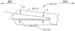
図4~図7は、第1のジョー30110、第2のジョー30120、及び単極楔形電極30130を備える、電気外科用器具30100を示す。第1のジョー30110及び第2のジョー30120は、開放位置と閉鎖位置との間で移動可能であり、それらの間に組織Tを把持するように構成されている。第1のジョー30110及び第2のジョー30120の各々は、発電機に電気的に結合される電極を備える。例示的な好適な発電機900、1100は、図1及び図2に関連して上述されている。発電機は、電力を供給し、第1及び第2のジョー30110、30120の電極に、双極組織処置サイクルにおいて組織を封止、凝固、及び/又は焼灼するための双極エネルギーを協働的に送達させるように構成されている。4-7 show an
使用中、第1のジョー30110及び第2のジョー30120は、組織Tがそれらの間に把持されるとき、それらの遠位端において互いから離れる方向に偏向し得る。組織Tが把持されると、組織Tは、第1のジョー30110及び第2のジョー30120に力を及ぼし、ジョーを互いから離れる方向に偏向させる。より具体的には、組織Tが第1のジョー30110と第2のジョー30120との間に把持されるとき、ジョーの遠位端方向の第1のジョー30110と第2のジョー30120との間の間隙Bは、ジョーの近位端方向の第1のジョー30110と第2のジョー30120との間の間隙Aよりも大きくなり得る。In use, the
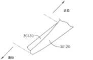
上記に加えて、電気外科用器具30100のエンドエフェクタ30100は、発電機(例えば、発電機900、1100)に電気的に接続され、発電機によって通電されるときに第1のジョー30110と第2のジョー30120との間に位置付けられた組織Tを切断するように構成されている、単極楔形電極30130を更に備える。図示される実施形態では、単極楔形電極30130は、第2のジョー30120に固定されているが、単極楔形電極30130が第1のジョー30110に固定される他の実施形態が想定される。単極楔形電極30130は、その近位端でより薄く、その遠位端でより厚く(図7参照)、第1のジョー30110と第2のジョー30120との間に画定される可変間隙を相殺する。言い換えれば、単極楔形電極30130は、楔形状を備える。前述のように、ジョー30110、30120の間に画定される可変間隙は、組織がそれらの間に把持されるときのジョー30110、30120の偏向に少なくとも部分的に起因する。少なくとも1つの実施形態では、単極楔形電極30130は、柔軟なフレックス回路基板30132を含む。柔軟なフレックス回路基板30132は、組織が第1のジョー30110と第2のジョー30120との間で把持されるときに、第1のジョー30110及び第2のジョー30120の偏向を相殺するため、長手方向に曲がる及び/又は屈曲するように構成されている。In addition to the above, the
様々な例では、単極楔形電極30130は、柔軟なフレックス回路基板30132の長さに沿って中央に配置された導電性部材30134を含む。図示される例では、導電性部材30134は、柔軟なフレックス回路基板30132上に配置され、そこでその少なくとも一部分は、柔軟なフレックス回路基板30132の上面を通して露出される。特定の例では、導電性部材30134の部分は露出しているが、他の部分は、柔軟なフレックス回路基板30132によって覆われている。In various examples, the
ジョー30110、30120が湾曲形状を備える例では、単極楔形電極30130は、同様の湾曲プロファイルで長手方向に延在する。更に、単極楔形電極30130は、長手方向に延在するにつれて、より大きい幅からより小さい幅に徐々に変化する。したがって、その近位端の近くの単極楔形電極30130の第1の幅は、図6に示されるように、その遠位端の近くの第2の幅よりも大きい。他の例では、その近位端の近くの単極楔形電極の第1の幅は、その遠位端の近くの第2の幅よりも小さくてもよい。In examples where the
図示される例では、導電性部材30134の遠位端は、柔軟なフレックス回路基板30132の遠位端の近位にあり、柔軟なフレックス回路基板30132の遠位端は、ジョー30130の遠位端の近位にある。しかしながら、他の例では、ジョー30130の遠位端、導電性部材30134、及び柔軟なフレックス回路基板30132は、1つの位置で一体化されている。In the illustrated example, the distal end of the
図8~図10は、第1のジョー30210、第2のジョー30220、及び単極電極30230を備える電気外科用器具30200を示す。第1のジョー30210及び第2のジョー30220は、開放位置と閉鎖位置との間で移動可能であり、組織は、それらの間に位置付けられるように構成されている。第1のジョー30210及び第2のジョー30220は、金属から構成され、誘電材料でコーティングされ得る。少なくとも1つの実施形態では、第1のジョー30210及び第2のジョー30220は、ステンレス鋼で構成され、収縮チューブでコーティングされている。様々な態様では、ジョー30210、30220は、単極電極30230から電気的に絶縁された双極電極を画定する。8-10 show an
第1のジョー30210は、第1のジョー30210の周りに位置付けられた第1の柔軟な部材30240を備え、第2のジョー30220は、第2のジョー30220の周りに位置付けられた第2の柔軟な部材30250を備える。柔軟な部材30240、30250は、組織が第1のジョー30210と第2のジョー30220との間に位置付けられたときに組織との接触を強化するために圧縮可能である、変形可能な誘電材料を含む。少なくとも1つの実施形態では、柔軟な部材30240、30250は、シリコーン及び/又はゴムを含む。The
上記に加えて、単極電極30230が発電機(例えば、発電機1100、900)によって通電されるときに、単極電極30230は、第1のジョー30210と第2のジョー30220との間に位置付けられた組織を切断するために利用される。単極電極30230は、第1のジョー30210に沿って、かつ第1の柔軟な部材30240内に延在するワイヤを備える。単極電極30230は、第1の柔軟な部材30240の近位開口30242を通って第1の柔軟な部材20140を出て、第1の柔軟な部材30240の外部に沿って延在し、次いで第1の柔軟な部材30240の遠位開口30244を通って第1の柔軟な部材20140に再度入る。この配置は、組織が第1のジョー30210と第2のジョー30220との間で把持されるときに、単極電極30230の中央部分30232が曲がる及び/又は屈曲することを可能にする。更に、単極電極30230の中央部分30232は、その長さに沿って第1の柔軟な部材30240によって補強される。言い換えれば、第1の柔軟な部材30240は、単極電極30230の中央部分30232に第2のジョー30220に向かう付勢力を加える。第1の柔軟な部材30240は、第1のジョー30210及び第2のジョー30220がそれらの間に組織を把持するときに、単極電極30230によって組織上で加えられる圧力を増加させ、単極電極30230の切断能力を改善する。Further to the above, when the
様々な態様では、単極電極30230は、例えば、ステンレス鋼、チタン、又は任意の他の好適な金属などの金属から構成され得る。単極電極30230の露出表面は、露出金属仕上げを有することができ、又は例えばPTFEなどの薄い誘電材料でコーティングすることができる。様々な態様では、コーティングは、導電性表面を画定する薄い金属ストリップを露出するためにスカイブされ得る。In various aspects, the
図11は、第1のジョー30310、第2のジョー30320、及び単極電極30330を備える外科用器具30300を示す。第1のジョー30310及び第2のジョー30320は、開放位置と閉鎖位置との間で移動可能であり、それらの間に組織Tを把持する。第1のジョー30310は、第1の双極電極を備え、第2のジョー30320は、第2の双極電極を備える。第1及び第2の双極電極は協働して、双極組織処置サイクルにおいて、第1のジョー30310と第2のジョー30320の間に把持された組織を焼灼及び/又は封止するための双極エネルギーを送達する。11 illustrates a
上記に加えて、第1のジョー30310は、第1の組織接触面30314を備え、第2のジョー30320は、第2の組織接触面30324を備える。第1のジョー30310は、その中に第1の柔軟な又は付勢部材30340を受容するように構成された第1の凹部30312を備える。第1の付勢部材30340は、組織Tが第1のジョー30310と第2のジョー30320との間に把持されるときに、組織Tを第2のジョー30320に向かって付勢するように構成されている。第2のジョーは、その中に第2の柔軟な又は付勢部材30350及び単極電極30330を受容するように構成された第2の凹部30322を備える。第2の付勢部材30350は、組織Tが第1のジョー30310と第2のジョー30320との間に把持されるときに、単極電極30330及び組織Tを第1のジョー30310に向かって付勢するように構成されている。Further to the above, the
上記に加えて、第1の凹部30312及び第2の凹部30322は、第1のジョー30310及び第2のジョー30320を完全に閉鎖することができるように、第1の付勢部材30340、第2の付勢部材30350、及び単極電極30330を受容するようにサイズ決定及び成形される。言い換えれば、第1のジョー30310及び第2のジョー30320が閉鎖位置にあるとき、それらの間に位置付けられている組織Tがない場合、第1の組織接触面30314及び第2の組織接触面30324は互いに接触する。しかしながら、第1のジョー30310及び第2のジョー30320が閉鎖位置にあるとき、組織Tがそれらの間に位置付けられている場合、及び/又は、組織Tがそれらの間に位置付けられていない場合、第1の組織接触面30314と第2の組織接触面30324との間に間隙が画定される他の実施形態が想定される。いずれにせよ、第1の凹部30312及び第2の凹部30322は、単極電極30330が第2の組織接触面30324の上を、第1のジョー30310の第1の凹部30312内に延在して、第1のジョー30310及び第2のジョー30320が完全に閉鎖する能力を高めるようにサイズ決定及び/又は成形される。第1及び第2の凹部30312、30322は、第1及び第2のジョー30310、30320から単極電極30330を電気的に絶縁するための電気的絶縁材料を含む。しかしながら、第1及び第2の凹部30312、30322が、第1及び第2のジョー30310、30320から単極電極30330を電気的に絶縁しない他の実施形態が想定される。単極電極30330は、外科用器具30300の制御ハウジングへの独立した配線接続を含む。独立した配線接続により、単極電極30330は、第1及び第2のジョー30310、30320の第1及び第2の電極とは無関係に通電されて、互いに独立して切断及び/又は封止操作を行うことを可能にする。少なくとも1つの実施形態では、外科用器具30300の制御ハウジングは、第1及び第2のジョー30310、30320の第1及び第2の電極が通電されて焼灼及び/又は封止されていない組織Tの切断を阻止するまで、単極電極30330が通電されるのを阻止する。In addition to the above, the
図12は、電気外科用器具と共に使用するための外科用エンドエフェクタ30400を示す。エンドエフェクタ30400は、第1の双極電極30410を含む第1のジョー、第2の双極電極30420を含む第2のジョー、及び単極電極30430を備える。第1の双極電極30410及び第2の双極電極30420は、柔軟な部材及び/又は柔軟な絶縁体30440によって少なくとも部分的に囲まれている。柔軟な絶縁体30440は、ゴム、シリコーン、ポリテトラフルオロエチレン(PTFE)チューブ、及び/又はそれらの組み合わせを含むことができる。単極電極30430は、第1の双極電極30410の柔軟な絶縁体30440に取り付けられている。したがって、単極電極30430は、第1の双極電極30410から電気的に絶縁されている。少なくとも1つの実施形態では、第1の電極30410を取り囲む適合絶縁体30440は、剛性、又は少なくとも実質的に剛性のPTFEチューブを備え、第2の電極30420を取り囲む第2の柔軟な絶縁体30440は、シリコーン及び/又はゴム材料を含む。例えば、第1の双極電極30410及び第2の双極電極30420の周囲に少なくとも部分的に位置付けられた、PTFEチューブ、ゴム、及び/又はシリコーンの異なる組み合わせを有する、他の実施形態が想定される。12 illustrates a
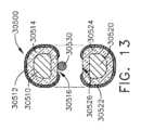
図13は、電気外科用器具と共に使用するための外科用エンドエフェクタ30500を示す。外科用エンドエフェクタは、第1のジョー30510と、開放位置と閉鎖位置との間で移動可能な第2のジョー30520とを備え、それらの間に組織を把持する。第1のジョー30510は、第1の柔軟な部材30514によって少なくとも部分的に囲まれ、第2のジョー30520は、第2の柔軟な部材30524によって少なくとも部分的に囲まれている。第1の柔軟な部材30514は、第1の双極電極30512によってほぼ完全に囲まれており、第2の柔軟な部材30524は、第2の双極電極30522によってほぼ完全に囲まれている。より具体的には、第1の双極電極30512は、単極電極30530が第1の柔軟な部材30514に固定されている間隙部分30516を除いて、第1の柔軟な部材30514を取り囲む。更に、第2の双極電極30522は、第1のジョー30510に面する間隙部分30526を除いて、第2の柔軟な部材30524を取り囲む。第2のジョー30520の間隙部分30526は、第1のジョー30510及び第2のジョー30520が閉鎖位置において組織を把持するときに、第1の柔軟な部材30514から延在する単極電極30530が、第1の柔軟な部材30514及び第2の柔軟な部材30524の両方からの付勢力を受けることを可能にする。第1の柔軟な部材30514及び第2の柔軟な部材30524は、電気的絶縁材料を含み、単極電極30530を第1の双極電極30512及び第2の双極電極30522から電気的に絶縁する。第1及び第2の柔軟な部材30514、30524は、ゴム、シリコーン、PTFEチューブ、及び/又はそれらの組み合わせを含むことができる。13 illustrates a
図14は、電気外科用器具と共に使用するための外科用エンドエフェクタ30600を示す。外科用エンドエフェクタ30600は、第1のジョー30610と、開放位置と閉鎖位置との間で移動可能な第2のジョー30620とを備え、それらの間に組織を把持する。第1のジョー30610は、第1の柔軟な部材30614によって少なくとも部分的に囲まれ、第2のジョー30620は、第2の柔軟な部材30624によって少なくとも部分的に囲まれている。第1の柔軟な部材30614は、第1の双極電極30612によってほぼ完全に囲まれており、第2の柔軟な部材30624は、第2の双極電極30622によってほぼ完全に囲まれている。言い換えれば、第1の双極電極30612は、単極電極30630が第1の柔軟な部材30614に固定されている間隙部分30616を除いて、第1の柔軟な部材30614を取り囲む。更に、第2の双極電極30622は、間隙部分30626を除いて、第2の柔軟な部材30624を取り囲む。14 illustrates a
上記に加えて、第1及び第2の双極電極30612、30622の間隙部分30616、30626は、第1のジョー30610及び第2のジョー30620が閉鎖位置にあるときに、第1の柔軟な部材30614から延在する単極電極30630を第2の柔軟な部材30624に接触させる。更に、間隙部分30616、30626はオフセットされており、ジョー30610、30620が閉じられており、それらの間に組織が位置付けられていないときに、第1の双極電極30612が第2の柔軟な部材30624及び第2の双極電極30622に接触して、第1の柔軟な部材30614に接触することを可能にする。電極30512、30533とは異なり、電極30612、30622は、互いに鏡像ではない。代わりに、電極30612は、電極30622とはオフセットされており、間隙部分30616、30610も互いにオフセットされる。この配置は、回路短絡を阻止する。In addition to the above, the
いずれにせよ、第1のジョー30610及び第2のジョー30620が閉じられると、単極電極30630は、第1の柔軟な部材30614と第2の柔軟な部材30624との間に位置付けられて、組織がジョー30610、30620の間で把持されるときに、単極電極30630にばね付勢又は付勢力を提供する。言い換えれば、単極電極30630は、第1のジョー30610及び第2のジョー30620が組織の周りで閉じられているときに、第1の柔軟な部材30614及び第2の柔軟な部材30624の両方から付勢力を受ける。柔軟な部材30614、30624からの付勢力は、単極電極30630が通電されるときに組織の切断を容易にする。In any case, when the
上記に加えて、少なくとも1つの実施形態では、第1の柔軟な部材30614及び第2の柔軟な部材30624は、電気的絶縁材料を含み、単極電極30630を第1の双極電極30612及び第2の双極電極30622から電気的に絶縁する。少なくとも1つの実施形態では、第1及び第2の柔軟な部材30614、30624は、ゴム、シリコン、PTFEチューブ、及び/又はそれらの組み合わせを含むことができる。Further to the above, in at least one embodiment, the first
図15は、電気外科用器具と共に使用するための外科用エンドエフェクタ30700を示す。エンドエフェクタ30700は、第1のジョー30710と、開放位置と閉鎖位置との間で移動可能な第2のジョー30720とを備え、それらの間に組織を把持する。第1のジョー30710は第1の双曲電極を画定し、第2のジョー30720は第2の双極電極を画定し、協働して、第1のジョー30710と第2のジョー30720との間に把持された組織を焼灼及び/又は封止するための双極エネルギーを送達するように構成されている。更に、第1のジョー30710は、その中に取り付けられた第1の柔軟な部材30714を備える第1の長手方向凹部30712を備える。第2のジョー30720は、その中に取り付けられた第2の柔軟な部材30724を備える第2の長手方向凹部30722を備える。外科用エンドエフェクタ30700は、第1の柔軟な部材30714に固定された単極電極30730を更に備える。第1の柔軟な部材30714及び第2の柔軟な部材30724は、第1のジョー30710及び第2のジョー30720が閉鎖位置において組織を把持するときに、第1の柔軟な部材30714から延在する単極電極30730が、第1の柔軟な部材30714及び第2の柔軟な部材30724の両方からの付勢力を受けることを可能にする。第1の柔軟な部材30714及び第2の柔軟な部材30724は、電気的絶縁材料を含み、単極電極30730を第1のジョー30710の第1の電極及び第2のジョー30720の第2の電極から電気的に絶縁する。第1及び第2の柔軟な部材30714、30724は、ゴム、シリコーン、PTFEチューブ、及び/又はそれらの組み合わせを含むことができる。15 illustrates a
図16は、電気外科用器具と共に使用するための外科用エンドエフェクタを示す。エンドエフェクタ30800は、第1のジョー30810と、開放位置と閉鎖位置との間で移動可能な第2のジョー30820とを備え、それらの間に組織を把持する。第1のジョー30810は、第1の双極電極を画定し、第2のジョー30820は、第2の双極電極を画定する。上述のように、第1及び第2の双極電極は、第1のジョー30810と第2のジョー30820の間に位置付けられた組織を焼灼及び/又は封止するための双極エネルギーを送達するために協働するように構成されている。更に、第1のジョー30810は、その中に取り付けられた柔軟な部材30814を備える長手方向凹部30812を備える。少なくとも1つの実施形態では、第2のジョー30820は、PTFE収縮チューブでコーティングされたステンレス鋼を含む。外科用エンドエフェクタ30800は、第1のジョー30810の柔軟な部材30814に固定された単極電極30830を更に備える。柔軟な部材30814は、第1のジョー30810及び第2のジョー30820がそれらの間に組織を把持するときに、単極電極30830に付勢力を提供する。柔軟な部材30814の付勢力は、切断動作中に単極電極30830と組織との間の接触を強化する。この柔軟な部材30814は、電気的絶縁材料を含み、単極電極30830を第1のジョー30810の第1の電極から電気的に絶縁する。柔軟な部材30814は、ゴム、シリコーン、PTFEチューブ、及び/又はそれらの組み合わせを含むことができる。16 illustrates a surgical end effector for use with an electrosurgical instrument. The
図17は、外科用エンドエフェクタ30800に対する別の外科用エンドエフェクタ30800’を示す。エンドエフェクタ30800’は、エンドエフェクタ30800に類似しているが、単極電極30830は、第2のジョー30820に固定されている。組織が第1のジョー30810と第2のジョー30820との間に位置付けられると、柔軟な部材30814は、組織を通して、第2のジョー30820に取り付けられた単極電極30830に付勢力を加える。Figure 17 shows an alternative surgical end effector 30800' to the
図18は、電気外科用器具と共に使用するための外科用エンドエフェクタ30900を示す。外科用エンドエフェクタ30900は、エンドエフェクタ30900の長さに沿って長手方向に延在するエンドエフェクタ軸EAを画定する。外科用エンドエフェクタ30900は、第1のジョー30910と、開放位置と閉鎖位置との間で移動可能な第2のジョー30920とを備え、それらの間に組織を把持する。第1のジョー30910は、第1のダイヤモンド様コーティング30914によって囲まれた第1のハニカム格子構造30912を備える。第2のジョー30920は、第2のダイヤモンド様コーティング30924によって囲まれた第2のハニカム格子構造30922を備える。ダイヤモンド様コーティング30914、30924は、例えば、本明細書に記載のダイヤモンド様コーティングのいずれかであり得る。第1のハニカム格子構造30912及び第2のハニカム格子構造30922は、同じ幾何学的アレイ及び材料を含む。しかしながら、第1のハニカム格子構造30912及び第2のハニカム格子構造30922が、本明細書に記載されるように、より多くの又はより少ない空気ポケットを含む異なる幾何学的アレイ及び材料を含む、他の実施形態が想定される。第1のダイヤモンド様コーティング30914及び第2のダイヤモンド様コーティング30924は、同じ材料を含む。しかしながら、第1のダイヤモンド様コーティング30914及び第2のダイヤモンド様コーティング30924が異なる材料を含む、他の実施形態が想定される。18 illustrates a
上記に加えて、エンドエフェクタ30900は、エンドエフェクタ軸EAの第1の側面の第1のジョー30910の第1のダイヤモンド様コーティング30914に固定された、第1の双極電極30940を更に備える。第1の双極電極30940は、エンドエフェクタ30900の長さに沿って長手方向に延在する。第2のジョー30920は、第2のジョー30920に画定された切り欠き部分30926内に取り付けられた柔軟な部材30960を備える。エンドエフェクタ30900は、エンドエフェクタ軸EAの第2の側面の柔軟な部材30960に取り付けられた第2の双極電極30950を更に備える。第2の双極電極30950は、エンドエフェクタ30900の長さに沿って長手方向に延在する。電極30940、30950は協働して、ジョー30910とジョー30920との間に把持された組織に双極エネルギーを送達する。更に、電極30940、30950は、互いにオフセットされて、短絡を形成し得る閉鎖位置におけるそれらの間の偶発的な接触を阻止する。In addition to the above, the
更に、エンドエフェクタ30900は、柔軟な部材30960に取り付けられ、第1の双極電極30940と第2の双極電極30950との中間に位置付けられた単極電極30930を備える。単極電極30930は、エンドエフェクタ30900の長さに沿って長手方向に延在し、少なくとも1つの実施形態では、エンドエフェクタ軸EAと位置合わせされる。Additionally, the
本明細書で論じられるように、第1の双極電極30940及び第2の双極電極30950は、双極エネルギーサイクルにおいて組織に双極エネルギーを送達することによって、組織が第1のジョー30910と第2のジョー30920との間に位置付けられたときに組織を焼灼及び/又は封止するように構成されている。更に、単極電極30930は、単極エネルギーサイクルにおいて組織に単極エネルギーを送達することによって組織を切断するように構成されている。As discussed herein, the first
上記に加えて、柔軟な部材30960は圧縮可能であり、第1のジョー30910と第2のジョー30920との間に位置付けられた組織に圧力をかける。より具体的には、柔軟な部材30960の直接上方の領域にある組織上のジョー30910、30920によって加えられる圧力は、柔軟な部材30960に隣接する領域内(すなわち、柔軟な部材30960が存在しない領域)の組織に加えられる圧力よりも大きい。少なくとも1つの実施形態では、柔軟な部材30960は、第2のダイヤモンド様コーティング30924及び第2のジョー30920のハニカム格子構造30922から第2の双極電極30950及び単極電極30930を絶縁する、エラストマー及び/又はプラスチックハニカム構造を備える。柔軟な部材30960は、第2の双極電極30950及び単極電極30930を定位置に保持し、組織が第1のジョー30910と第2のジョー30920との間で把持されるときに、単極電極30930及び第2の双極電極30950に、第1のジョー30910に向かう付勢力をもたらす。Further to the above, the flexible member 30960 is compressible and applies pressure to tissue positioned between the
上記に加えて、第1及び第2のダイヤモンド様コーティング30914、30924は、導電性かつ断熱性である。しかしながら、第1及び第2のダイヤモンド様コーティング30914、30924が電気的に絶縁性かつ/又は断熱性である他の実施形態が想定される。第1及び第2のハニカム格子構造30912、30922は、第1及び第2のジョー30910、30920に断熱性をもたらす空気ポケットを備える。第1及び第2のハニカム格子構造30912、30922は、組織が第1のジョー30910と第2のジョー30920との間に位置付けられたときに、組織に追加のバネ付勢を提供する。少なくとも1つの実施形態では、第1及び第2のハニカム格子構造30912、30922は、組織がそれらの間に把持されるときに、第1及び第2のジョー30910、30920の屈曲及び/又は曲げを可能にする。いずれにせよ、第1及び第2のハニカム格子構造30912、30922及び柔軟な部材30960のばね力は、組織が第1のジョー30910と第2のジョー30920との間で把持されるときに組織に一貫した圧力を提供する。In addition to the above, the first and second diamond-
様々な態様では、ダイヤモンド様コーティング(DLC)30914、30924のうちの1つ以上は、炭素原子間のグラファイト及びダイヤモンド結合を有する非晶質炭素-水素ネットワークから構成される。DLCコーティング30914、30924は、第1及び第2のハニカム格子構造30912、30922の周囲に、低摩擦かつ高硬度特性を有するフィルムを形成することができる。DLCコーティング30914、30924は、ドープされていても、又はドープされていなくてもよく、一般に、sp3結合の大部分を含有する、非晶質炭素(a-C)又は水素化非晶質炭素(a-C:H)の形態である。Oerlikon Balzersによって開発された表面コーティング技術などの様々な表面コーティング技術を利用して、DLCコーティング30914、30924を形成することができる。少なくとも1つの例では、DLCコーティング30914、30924は、プラズマ支援化学蒸着法(PACVD)を使用して生成される。In various aspects, one or more of the diamond-like coatings (DLC) 30914, 30924 are composed of an amorphous carbon-hydrogen network with graphite and diamond bonds between the carbon atoms. The
様々な態様において、DLCコーティングの一方又は両方は、窒化チタン、窒化クロム、Graphit iC(商標)、又は任意の他の好適なコーティングを含むコーティングで置換され得る。In various embodiments, one or both of the DLC coatings may be replaced with a coating including titanium nitride, chromium nitride, Graphit iC™, or any other suitable coating.
更に図18を参照すると、電極30940、30950は、軸EAに沿って延在し、単極電極30930を横切る平面が、電極30940、30950の間に延在するようにオフセットされている。更に、図示される例では、電極30930、30940、30950は、ジョー30910、30920の外面から突出する。しかしながら、他の例では、電極30930、30940、30950のうちの1つ以上は、それらの外面がジョー30910、30920の外面と同一平面になるように、ジョー30910、30920に埋め込むことができる。18, the
図4~図18に関連して説明されるいくつかのエンドエフェクタは、組織への双極エネルギー及び/又は単極エネルギーの送達を含む組織処置サイクルにおいて、エンドエフェクタによって把持された組織を凝固、焼灼、封止、及び/又は切断するように構成されている。双極エネルギー及び単極エネルギーは、組織に別々に、又は組み合わせて送達され得る。一例では、単極エネルギーは、組織への双極エネルギー送達が終了した後に組織に送達される。Some end effectors described in connection with FIGS. 4-18 are configured to coagulate, cauterize, seal, and/or cut tissue grasped by the end effector in a tissue treatment cycle that includes delivery of bipolar and/or monopolar energy to the tissue. Bipolar and monopolar energy may be delivered to the tissue separately or in combination. In one example, monopolar energy is delivered to the tissue after bipolar energy delivery to the tissue has terminated.
図19は、双極エネルギーサイクルにおいて双極エネルギーを、単極エネルギーサイクルにおいて単極エネルギーを組織に送達する、組織処置サイクル31000の代替例を示すグラフである。組織処置サイクル31000は、双極のみの相31002、ブレンドエネルギー相31004、及び単極のみの相31006を含む。組織処置サイクル31000は、例えば、エンドエフェクタ(例えば、図4~図18のエンドエフェクタ)を含む電気外科用器具に結合された発生器(例えば、発電機1100、900)を含む電気外科用システムによって実施することができる。19 is a graph illustrating an alternative example of a
図19のグラフは、y軸上に電力(W)、x軸上に時間を示す。グラフ及び以下のその説明で提供される電力値は、組織処置サイクル31000で利用され得る電力レベルの非限定的な例である。他の好適な電力レベルも本開示によって企図される。グラフは、双極電力曲線31010及び単極電力曲線31014を示す。更に、ブレンド電力曲線31012は、組織への単極及び双極エネルギーの同時適用を表す。The graph of FIG. 19 shows power (W) on the y-axis and time on the x-axis. The power values provided on the graph and its description below are non-limiting examples of power levels that may be utilized in a
更に図19を参照すると、最初の組織接触段階は、t0とt1との間に示され、組織に任意のエネルギーを適用する前に起こる。エンドエフェクタのジョーは、治療される組織の両側に位置付けられる。その後、双極エネルギーは、t1で始まり、t4で終了する組織凝固段階を通して組織に適用される。フェザリングセグメントの間(t1~t2)、双極エネルギーの印加は、所定の電力値(例えば、100W)まで増加し、フェザリングセグメントの残りの間(t1~t2)及び組織加温セグメント(t2~t3)は所定の電力値に維持される。封止セグメントの間(t3~t4)、双極エネルギー印加は徐々に減少する。双極エネルギー印加は、封止セグメント(t3~t4)の終わり、かつ、切断/切除段階の開始前に終了する。 19, an initial tissue contact phase is shown betweent0 andt1 and occurs prior to the application of any energy to the tissue. The jaws of the end effector are positioned on either side of the tissue to be treated. Bipolar energy is then applied to the tissue throughout the tissue coagulation phase beginning att1 and ending att4 . During the feathering segment (t1 -t2 ), the application of bipolar energy is increased to a predetermined power value (e.g., 100 W) and maintained at the predetermined power value for the remainder of the feathering segment (t1 -t2 ) and the tissue heating segment (t2 -t3 ). During the sealing segment (t3 -t4 ), the bipolar energy application is gradually decreased. Bipolar energy application is terminated at the end of the sealing segment (t3 -t4 ) and prior to the beginning of the cutting/ablation phase.
上記に加えて、組織への単極エネルギー印加は、組織凝固段階中に起動される。図19に示される例では、単極エネルギーの起動は、時間t2において、フェザリングセグメントの終了時及び組織加温セグメントの開始時に開始する。双極エネルギーと同様に、組織への単極エネルギー印加は、所定の電力レベル(例えば、75W)まで徐々に増加し、組織加温セグメントの残りの間及び封止セグメントの初期部分において維持される。 In addition to the above, monopolar energy application to the tissue is activated during the tissue coagulation phase. In the example shown in Figure 19, activation of monopolar energy begins at timet2 , at the end of the feathering segment and the beginning of the tissue heating segment. As with the bipolar energy, monopolar energy application to the tissue is gradually increased to a predetermined power level (e.g., 75W) and maintained for the remainder of the tissue heating segment and the initial portion of the sealing segment.
組織凝固段階の封止セグメントの間(t3~t4)、組織への単極エネルギー印加の電力は、組織への双極エネルギー印加の電力が徐々に減少するにつれて、徐々に増加する。図示される例では、組織への双極エネルギー印加は、組織凝固サイクルの終了時(t4)に停止される。組織の切除段階の開始は、封止セグメントの間(t3~t4)に受けていた単極エネルギーがここまで徐々に増加しているt4における、単極電力曲線31014の変曲点によって始まり、続いて、凝固した組織を切除するのに十分な所定の最大閾値電力レベル(例えば、150W)までの工程が続く。最大電力閾値は、所定の期間維持され、単極電力レベルをゼロに戻して終了する。 During the sealing segment of the tissue coagulation phase (t-t ), the power of monopolar energy application to the tissue is gradually increased as the power of bipolar energy application to the tissue is gradually decreased. In the illustrated example, the bipolar energy application to the tissue is stopped at the end of the tissue coagulation cycle (t) . The start of the tissue ablation phase begins with an inflection point in the
したがって、組織処置サイクル31000は、3つの連続した時間において、3つの異なるエネルギーモダリティを組織処置領域に送達するように構成されている。双極エネルギーを含むが単極エネルギーを含まない第1のエネルギーモダリティは、t1~t2のフェザリングセグメントの間、組織処置領域に適用される。単極エネルギーと双極エネルギーとの組み合わせを含むブレンドエネルギーモダリティである第2のエネルギーモダリティは、t2~t4の組織加温セグメント及び組織封止セグメントの間、組織処置領域に適用される。最後に、単極エネルギーが含まれるが双極エネルギーを含まない第3のエネルギーモダリティは、t4~t5の切断セグメントの間、組織に印加される。更に、第2のエネルギーモダリティは、単極エネルギー及び双極エネルギーの電力レベルの合計である電力レベルを含む。少なくとも1つの例では、第2のエネルギーモダリティの電力レベルは、最大閾値(例えば、120W)を含む。様々な態様では、単極エネルギー及び双極エネルギーは、2つの異なる発電機からエンドエフェクタに送達され得る。 Thus, the
ブレンドエネルギー相31004中に適用されるブレンド電力曲線31012は、組織への双極エネルギー及び単極エネルギーの組み合わせの印加を表す。組織加温セグメントの間(t2~t3)、ブレンド電力曲線31012は、t2において、単極電力が起動されると上昇し、組織加温セグメント(t2、t3)の残りと、組織封止セグメントの開始時(t3~t4)の間、双極電力は一定の、又は少なくとも実質的に一定のレベルで維持される。封止セグメントの間(t3~t4)、ブレンド電力曲線31012は、単極電力レベルが増加するにつれて双極電力レベルを徐々に減少させることによって、一定の、又は少なくとも実質的に一定のレベルで維持される。 The blended
様々な態様では、組織処置サイクル31000の双極及び/又は単極電力レベルは、組織インピーダンス、ジョーモータ速度、ジョーモータ力、エンドエフェクタのジョー開口部、及び/又はエンドエフェクタ閉鎖をもたらすモータの電流引き込みなどの1つ以上の測定されたパラメータに基づいて調整することができる。In various aspects, the bipolar and/or monopolar power levels of the
少なくとも1つの実施形態によれば、患者組織を切断するための単極電極は、単極カムローブ電極及びそれに取り付けられたワイヤを含む。単極カムローブ電極は、最初に電気外科用器具のエンドエフェクタの遠位端に位置する。臨床医が患者組織の切断を望む場合、単極カムローブ電極は、通電され(すなわち、本明細書で論じられるように、発電機を介して)、それに取り付けられたワイヤによって引っ張られる。ワイヤは、最初にカムローブ電極を誘導して、エンドエフェクタの中心線に沿って組織間隙内に上方に回転し、次いで遠位端から近位端まで引っ張られて、患者組織を切断する。言い換えれば、枢動切断ブレードが遠位端に位置し、次いで近位に引っ張られた場合、カムローブ電極は外科用器具の枢動切断ブレードのように作用する。更に、少なくとも1つの実施形態では、カムローブ電極に取り付けられたワイヤは、カムローブ電極の回転中心からオフセットされているため、ワイヤが近位に引っ張られると、カムローブ電極は最初に直立位置に回転される。カムローブ電極は、カムローブ電極が位置付けられている場所から、エンドエフェクタジョーの反対側に対して垂直に力を及ぼす。そのような構成では、カムローブ電極は最初に、ワイヤがカムローブ電極を最初に引っ張ってカムローブ電極をその直立位置に回転させるまで、エンドエフェクタのジョー間の組織間隙から隠され得る。カムローブ電極は最初に隠されているため、カムローブがエンドエフェクタの他のジョーに対してかけている負荷は、組織間隙とは無関係である。言い換えれば、カムローブ電極は、近位運動から遠位に始まる前に実質的に直立しているか、又はカムローブ電極は、近位運動から遠位に始まる前に部分的に立ち上がっているかのいずれかである。カムローブ電極がその直立位置に向かって回転する量は、エンドエフェクタのジョー間に位置付けられた組織の量と組織の剛性に依存する。例えば、カムローブ電極が遠位端から近位端に向かって移動し始める前に、より硬い組織は、より軟質の組織よりも、カムローブ電極をより直立位置に回転させることに抵抗する。According to at least one embodiment, a monopolar electrode for cutting patient tissue includes a monopolar cam lobe electrode and a wire attached thereto. The monopolar cam lobe electrode is initially located at the distal end of the end effector of the electrosurgical instrument. When a clinician desires to cut patient tissue, the monopolar cam lobe electrode is energized (i.e., via a generator, as discussed herein) and pulled by a wire attached thereto. The wire first induces the cam lobe electrode to rotate upward along the centerline of the end effector into the tissue gap and then is pulled from the distal end to the proximal end to cut the patient tissue. In other words, if the pivoting cutting blade is located at the distal end and then pulled proximally, the cam lobe electrode acts like a pivoting cutting blade of a surgical instrument. Furthermore, in at least one embodiment, the wire attached to the cam lobe electrode is offset from the center of rotation of the cam lobe electrode, so that when the wire is pulled proximally, the cam lobe electrode is initially rotated to an upright position. The cam lobe electrode exerts a force perpendicular to the opposite side of the end effector jaw from where the cam lobe electrode is positioned. In such a configuration, the cam lobe electrode may initially be hidden from the tissue gap between the jaws of the end effector until the wire first pulls on the cam lobe electrode, rotating the cam lobe electrode to its upright position. Because the cam lobe electrode is initially hidden, the load the cam lobe is exerting on the other jaw of the end effector is independent of the tissue gap. In other words, the cam lobe electrode is either substantially upright before beginning distally from the proximal movement, or the cam lobe electrode is partially upright before beginning distally from the proximal movement. The amount that the cam lobe electrode rotates toward its upright position depends on the amount of tissue positioned between the jaws of the end effector and the stiffness of the tissue. For example, stiffer tissue will resist rotating the cam lobe electrode to a more upright position than softer tissue before the cam lobe electrode begins to move from the distal end toward the proximal end.
図20は、ハウジングと、ハウジングから延在するシャフト40110と、シャフト40110から延在するエンドエフェクタ40120と、を備える。電気外科用器具40100を示す。関節継手40130は、シャフト40110及びエンドエフェクタ40120を回転可能に接続して、シャフト40110に対するエンドエフェクタ40120の関節運動を容易にする。回路基板40140は、器具40100のハウジング内に位置する。しかしながら、任意の好適な場所に位置付けられた回路基板40140がある、他の実施形態が想定される。少なくとも1つの例では、回路基板40140は、プリント回路基板である。プリント回路基板40140は、プリント回路基板40140を配線アセンブリ40150に接続するための接続プラグ40142を含む。配線アセンブリ40150は、プリント回路基板40140からシャフト40110を通ってエンドエフェクタ40120内に延在する。配線アセンブリ40150は、エンドエフェクタ40120の少なくとも1つの機能を監視し、監視された情報をプリント回路基板40140にリレーするように構成されている。配線アセンブリ40150は、例えば、エンドエフェクタ40120のジョーの圧縮速度及び/又はエンドエフェクタ40120の熱サイクルを含むエンドエフェクタの機能を監視することができる。図示される例では、配線アセンブリ40150は、エンドエフェクタ40120内に位置付けられたセンサ40122を備える。センサ40122は、エンドエフェクタ40120の少なくとも1つの機能を監視する。20 illustrates an
様々な態様では、センサ40122は、例えば、ホール効果センサなどの磁気センサ、ひずみゲージ、圧力センサ、渦電流センサなどの誘導センサ、抵抗センサ、容量センサ、光センサ、及び/又は他の任意の好適なセンサなど、任意の好適なセンサを備えてもよい。様々な態様では、回路基板40140は、プロセッサ及びメモリユニットを有するマイクロコントローラを含む制御回路を備える。メモリユニットは、センサ40122によって提供される測定値に基づいて、エンドエフェクタ40120の特定のパラメータ及び/又はエンドエフェクタ40120によって把持された組織を認識するための1つ以上のアルゴリズム及び/又はルックアップテーブルを格納し得る。In various aspects, the
上記に加えて、配線アセンブリ40150は、配線アセンブリ40150が外科用器具40100の様々な部品境界部及び/又は接合部にわたって屈曲、曲げ、及び/又は延伸することを可能にするために、可撓性回路の一部としていくつかの可撓性、剛性、及び/又は伸縮性部分を備え得る。例えば、配線アセンブリ40150が部品境界部又は接合部を横切ると、非伸張性の可撓性プラスチック基材(すなわち、ポリイミド、ピーク、透明導電性ポリエステルフィルム)は、可撓性シリコーン又はエラストマー基材に移行し、次いで、接合部の他方の側の非伸張性可撓性基材に戻る。配線アセンブリ40150内の金属導体は、連続的なままであるが、部品境界部及び/又は接合部にわたって伸張可能である。少なくとも2つの平面で可撓性である局所部分を備えるこの配置により、回路全体が可撓性であることを可能にする。したがって、部品境界部及び/又は関節にわたる配線アセンブリ40150の部分は、配線アセンブリ40150を引き離すこと、又はその連続性を失うことなく、局所的な相対運動を可能にする。配線アセンブリ40150は、局所的運動ゾーンの周りに固定されて、配線アセンブリ40150が過度にひずむ及び/又は歪むことから保護する。In addition to the above, the
上記に加えて、本実施形態では、配線アセンブリ40150は、第1の弾性部分40152、近位剛性部分40154、第2の弾性部分40156、及び遠位剛性部分40158を備える。近位剛性部分40154は、細長いシャフト40110内に位置付けられ、遠位剛性部分40158は、エンドエフェクタ40120内に位置付けられている。第1の弾性部分40152は、プリント回路基板40140と近位剛性部分40154との間に位置付けられている。第2の弾性部分40156は、近位剛性部分40154と遠位剛性部分40158との間に位置付けられている。配線アセンブリ40150が2つ超又は2つ未満の弾性部分を含む他の実施形態が想定される。剛性部分40154、40158は、例えば、接着剤40105でそれぞれシャフト40110及びエンドエフェクタ40120に固定され得る。しかしながら、任意の好適な付着手段を利用してもよい。弾性部分40152、40156は、弾力的部分(すなわち、曲げ及び/又は屈曲のため)及び伸縮性部分(すなわち、延伸のため)を更に備える。少なくとも1つの実施形態では、弾力的部分は、第1の基材又は層を備え、伸縮性部分は、第2の基材又は層を含む。第1及び第2の基材は、異なる材料を含む。しかしながら、第1及び第2の基材が異なる構成で同じ材料を含む他の実施形態が想定される。Further to the above, in this embodiment, the
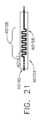
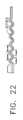
上記に加えて、配線アセンブリ40150は、配線アセンブリ40150の全長にわたって、プリント回路基板40140とエンドエフェクタ40120との間に電気エネルギーを運ぶように構成された電気トレース又は導体40160を更に備える。主に図21及び図22を参照すると、導体40160は、弾性部分40152、40156にまたがる伸縮性部分40162を備える。伸縮性部分40162は、弾性部分40152、40156が図22に例示されるように伸ばされるときに伸縮性部分40162が伸張することを可能にする、蛇行、振動、及び/又はジグザグパターンを備える。弾性部分40152、40156がそれらの弛緩状態及び/又は自然状態に戻るとき、伸縮性部分40162は、図21に示されるように、その蛇行、振動、及び/又はジグザグパターンに戻される。In addition to the above, the
上記に加えて、少なくとも1つの実施形態では、導体40160は、導体40160が、蛇行、振動、及び/又はジグザグパターンで配線アセンブリ40150に印刷された銅導体を含むRF処理エネルギーなどの高電流用途で使用され得る。弾性部分40152、40156にわたる導体40160の伸縮性部分40162が、伸縮性部分40162が関節を横切って延伸することを可能にするように結合する導電性リンクを含む他の実施形態が想定される。In addition to the above, in at least one embodiment, the
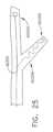
図23は、シャフト40210、並進部材40220、及びフレックス回路及び/又は配線ハーネス40230を備える、電気外科用器具40200を示す。配線ハーネス40230は、配線アセンブリ40150と類似し得る。並進部材40220は、例えば、患者組織を切開するためのナイフ駆動ロッド、器具40200の、関節ケーブル、及び/又は剛性関節部材であり得る。しかしながら、並進部材40220は、本明細書に記載されるような任意の並進部材であり得る。いずれにせよ、並進部材40220は、シャフト40210に対して並進するように構成され、並進部材40220と共に並進する鉄要素40222を備える。鉄要素40222は、例えば、並進部材40220に取り付けられるか、又はその中に収容され得る。配線ハーネス40230は、シャフト40210内に固定され、鉄要素40222の直線位置、したがって並進部材40220の直線位置を検出するように構成された線形誘導センサ40232を備える。より具体的には、線形誘導センサ40232は、鉄要素40222が破壊する電場を生成するように構成されている。線形誘導センサ40232は、配線ハーネス40230に統合されて、外部要素及び流体からの堅牢な保護を提供する。23 shows an
様々な態様では、センサ40232は、ホール効果センサなどの磁気センサ、歪みゲージ、圧力センサ、渦電流センサなどの誘導センサ、抵抗センサ、容量センサ、光センサ、及び/又は任意の他の好適なセンサであってよい。様々な態様では、制御回路aは、プロセッサを有するマイクロコントローラと、センサ40232によって提供される測定に基づいて外科用器具40200の特定のパラメータ及び/又は外科用器具40200によって処理される組織を認識するための1つ以上のアルゴリズム及び/又はルックアップテーブルを記憶するメモリユニットとを含む。In various aspects, the
図24及び図25は、シャフト40310、並進部材40320、及びフレックス回路又は配線ハーネス40330を備える、電気外科用器具40300を示す。並進部材40320は、シャフト40310に対して並進して、エンドエフェクタ機能を実行するように構成されている。並進部材40320は、例えば、患者組織を切開するためのナイフ駆動ロッド、器具40300の、関節ケーブル、及び/又は剛性関節部材であり得る。しかしながら、並進部材は、例えば、本明細書に記載の任意の並進部材であり得る。いずれにせよ、配線ハーネス40330は、導体40331、本体部分40332、及び本体部分40332から延在する弾性部分40334を備える。本体部分40332は、シャフト40310に固定され、外科用器具40300のエンドエフェクタの機能を測定するように構成された第1のセンサ40340を備える。弾性部分40334は、並進部材40320に取り付けられ、第2のセンサ40350を備える。第2のセンサ40350は、弾性部分40334が並進部材40320に取り付けられる弾性部分40334の端部に位置付けられている。したがって、第2のセンサ40350は、並進部材40320と共に並進する。第2のセンサ40350は、並進部材40320内の応力及び/又は歪みを測定するように構成されている。しかしながら、第2のセンサが並進部材40320の位置、速度、及び/又は加速度を測定するように構成されている他の実施形態が想定される。24 and 25 show an
様々な態様では、制御回路aは、プロセッサを有するマイクロコントローラと、センサ40340、40350によって提供される測定に基づいて外科用器具40300の特定のパラメータ及び/又は外科用器具40300によって処理される組織を認識するための1つ以上のアルゴリズム及び/又はルックアップテーブルを記憶するメモリユニットとを含む。In various aspects, the control circuit a includes a microcontroller having a processor and a memory unit that stores one or more algorithms and/or look-up tables for recognizing certain parameters of the
上記に加えて、弾性部分40334は、図20~図22に関して本明細書で論じられる弾性部分40152、40156と同様である。より具体的には、弾性部分40334は、弾性部分40334が配線ハーネス40330の本体部分40332に対して曲がる、屈曲する、及び/又は延伸することを可能にする弾力的部分及び/又は伸縮性部分を備える。そのような配置により、第2のセンサ40350の検出された測定値が、配線ハーネス40330に対する並進部材40320の移動によって影響を受けることなく、第2のセンサ40350が配線ハーネス40330に一体化されることが可能になる。In addition to the above, the
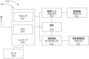
図26~図33は、ハンドル40410と、ハンドル40410から延在するシャフト40420と、シャフト40420から延在する遠位ヘッド又はエンドエフェクタ40430と、を備える、電気外科用器具40400を示す。ハンドル40410は、トリガ40412と、制御回路40413からの入力ごとに、かつトリガ40412の作動運動に応答して、モータ40411aを駆動するように構成されたモータドライバ/コントローラ40422bによって駆動されるモータ40411aを含む、電動モータアセンブリ40411と、を備える。様々な態様では、制御回路40413は、プロセッサ40415及びメモリユニット40417を有するマイクロコントローラ40414を含む。電源40418は、モータに電力を供給するためにモータコントローラ40411bと、マイクロコントローラ40414とに結合される。26-33 show an
シャフト40420は、シャフト軸SAを画定し、エンドエフェクタ駆動部材40419などのエンドエフェクタ駆動部材を備える。エンドエフェクタ駆動部材40419は、ハンドル40410内の電動モータ40411aに動作可能に応答し、少なくとも2つのエンドエフェクタ機能を実行するように構成されている。本明細書で論じられるように、エンドエフェクタ40430は、シャフト40420から選択的にロック及びロック解除されるように構成されている。より具体的には、エンドエフェクタ40430がシャフト40420にロックされると、エンドエフェクタ40430は、シャフト40420に対して回転及び/又は関節運動することができず、エンドエフェクタ駆動部材40419は、エンドエフェクタ40430のジョーを開閉するように構成されている。更に、エンドエフェクタ40430がシャフト40420からロック解除されるとき、エンドエフェクタは、シャフト40420に対して回転及び/又は関節運動することができ、エンドエフェクタ駆動部材40419が電動モータによって作動されるときに、エンドエフェクタ駆動部材40419はエンドエフェクタ40430をシャフト軸SAの周りで回転させる。The
器具40400は、手動トグル部材又はロッカー部材40440、細長いシャフト40450、及び引張ケーブル40460を更に備える。細長いシャフト40450は、細長いシャフト40450及び引張ケーブル40460がシャフト軸SAに沿って一緒に移動するように、引張ケーブル40460に圧着される。ロッカー部材40440は、細長いシャフト40450を受容するように構成された、内部に画定されたスロット40442を備える。ロッカー部材40440及び細長いシャフト40450は、ハンドル40410内に取り付けられ、ロッカー部材40440の部分がハンドル40410の各側を越えて横方向に延在して、ロッカー部材40440が臨床医によって手動で作動されることを可能にする。ロッカー部材40440は、スロット40442内に延在するピン40444を更に備える。ピン40444は、細長いシャフト40450の外径に画定されたV字形溝40452内に延在する。細長いシャフト40450は、ばねなどによって、ロッカー部材40440から離れるように付勢される(すなわち、遠位に付勢される)。The
使用中、ロッカー部材40440が時計方向CWに回転すると、ピン40444は、V字形溝40452の第1の側部内で摺動し、細長いシャフト40450をロッカー部材40440に向かって後退させる(すなわち、近位に)。ロッカー部材40440が反時計方向CCWに回転すると、ピン40444は、V字形溝40452の第1の側部の反対側の第2の側部内で摺動し、細長いシャフト40450をロッカー部材40440に向かって後退させる(すなわち、近位に)。図31を参照すると、ロッカー部材40440が中心にあるとき、細長いシャフト40450は、その最遠位位置にある(すなわち、ロッカー部材40440から最も遠い)。図32及び図33を参照すると、ロッカー部材40440が時計方向CW又は反時計方向CCWのいずれかに回転するとき、細長いシャフト40450は、ロッカー部材40440に向かって後退する(すなわち、近位に)。In use, when the
上述のように、細長いシャフト40450は、引張ケーブル40460に圧着される。したがって、引張ケーブル40460は、ロッカー部材40440が時計方向CW又は反時計方向CCWのいずれかに回転されるとき、後退する。引張ケーブル40460は、米国特許出願代理人整理番号END9234USNP2/190717-2の図54に示されるロック解除ケーブル11342と同様であり得る。より具体的には、引張ケーブル40460は、後退する(すなわち、近位に動かされる)と、エンドエフェクタ40430をロック解除して、エンドエフェクタ40430がシャフト40420に対して回転及び/又は関節運動することを可能にする。したがって、ロッカー部材40440が時計方向CW又は反時計方向CCWのいずれかに回転すると、エンドエフェクタ40430は、エンドエフェクタ40430の回転及び/又は関節運動を可能にするようにロック解除される。As described above, the
上記に加えて、ロッカー部材40440は、下向きに延在するポスト40446の両側に位置付けられた第1のスイッチ40447及び第2のスイッチ40448と係合するように構成された、下向きに延在するポスト40446を更に備える。第1のスイッチ40447及び第2のスイッチ40448は、ハンドル40410内に位置付けられた関節運動モータを作動させるように構成されている。より具体的には、ロッカー部材40440が時計方向CWに回転すると、引張ケーブル40460は、エンドエフェクタ40430をロック解除するように後退し、ポスト40446が第1のスイッチ40447を係合する結果、第1の方向にモータ40411aの回転をもたらし、これにより、関節運動駆動アセンブリ40417がエンドエフェクタ40430を、例えば右に関節運動させる。ロッカー部材40440が反時計方向CCWに回転すると、引張ケーブル40460が後退して、エンドエフェクタ40430をロック解除する。ポスト40446は、第2のスイッチ40448と係合し、これにより、第1の方向と反対の第2の方向にモータ40411aの回転がもたらされ、それによって、関節駆動アセンブリ40417がエンドエフェクタ40430を左に関節運動させる。In addition to the above, the
上記に加えて、図28に示すように、ロッカー部材40440が中心にあるとき、第1のスイッチ40447も第2のスイッチ40448も起動されない。引張ケーブル40460は、上述のように、エンドエフェクタ40430がロックされていることに対応するその最遠位位置にある。様々な態様では、任意の好適なシフタ又はクラッチ機構は、関節駆動アセンブリ40417との動作可能な係合と、閉鎖/発射アセンブリ40421との動作可能な係合との間で駆動部材40419をシフトするように構成され得る。シフタ機構は、ロッカー部材40440が中心にあるときに駆動部材40419が閉鎖/発射駆動アセンブリ40421に動作可能に結合され、ロッカー部材40440が時計方向CW又は反時計方向CCWのいずれかに中心位置から回転するときに関節駆動アセンブリ40417に動作可能に結合されるように、ロッカー部材40440によって動作させることができる。In addition to the above, as shown in FIG. 28, when the
エンドエフェクタ40430がロックされると、ハンドル40410内の電動モータの回転は、エンドエフェクタ駆動部材40419の回転をもたらし、閉鎖/発射駆動アセンブリ40421によって、開放位置と閉鎖位置との間でエンドエフェクタ40430の一対のジョーを移動させる。しかしながら、エンドエフェクタ40430がロックされているときに、エンドエフェクタ駆動部材40419の回転がエンドエフェクタ40430を通って発射部材を並進させる他の実施形態が想定される。いずれにせよ、ロッカー部材40440が時計方向CW又は反時計方向CCWのいずれかに回転すると、エンドエフェクタ40430はロック解除され、シャフト軸SAを中心としたエンドエフェクタ40430の回転を可能にする。より具体的には、エンドエフェクタ40430がロック解除されると、エンドエフェクタ駆動部材40419が、ハンドル40410内の電動モータ40411aによって作動され、エンドエフェクタ40430は、シャフト40420に対してシャフト軸SAを中心に回転する。When the
上記に加えて、関節運動モータが第1のスイッチ40447及び第2のスイッチ40448に動作可能に応答する、2つ以上の関節運動モータを備える他の実施形態が想定される。そのような構成は、例えば、エンドエフェクタ40430とシャフト40420との間に二重関節継手が用いられる場合、複数の軸に対するエンドエフェクタ40430の関節運動を容易にする。また、閉鎖、発射、及び/又は関節運動専用の別個のモータを備える他の実施形態も想定される。In addition to the above, other embodiments are envisioned that include two or more articulation motors, where the articulation motors are operatively responsive to the
様々な態様では、モータドライバ40411bは、プロセッサ40416からの入力に基づいて、複数の動作状態で電動モータ40411aを動作させるように構成されている。例えば、エンドエフェクタ駆動部材40419がエンドエフェクタ40430のジョーを開閉する(すなわち、遠位ヘッド又はエンドエフェクタ40430がロックされている)とき、電動モータは、第1の動作モードにある。電動モータ40411aが第1の動作モードにあるとき、エンドエフェクタ駆動部材40419は、エンドエフェクタ40430のジョーを開閉するため、第1の速度、第1の変化量、第1のトルク量、及び/又は第1の加速量で動作される。エンドエフェクタ駆動部材40419がシャフト軸SAを中心にエンドエフェクタ40430を回転させる(すなわち、遠位ヘッド又はエンドエフェクタ40430がロック解除されている)とき、電動モータ40411aは、第2の動作モードにある。電動モータ40411aが第2の動作モードにあるとき、エンドエフェクタ駆動部材40419は、エンドエフェクタ40430を回転させるため、第2の速度、第2の変化量、第2のトルク量、及び/又は第2の加速量で動作される。In various aspects, the
少なくとも1つの実施形態では、第1の動作モード及び第2の動作モードは異なり、例えば、異なる速度、トルク、及び/又は加速度でエンドエフェクタ駆動部材40419を駆動するための制御パラメータの異なる組み合わせを含む。少なくとも1つの実施形態では、第2の動作モード(すなわち、遠位ヘッド回転)は、第1の動作モードよりも、例えば、低い最大トルク限界、正確な調整を可能にするための段階的な加速、及び/又は低い最大トルク速度を含む。対照的に、エンドエフェクタ駆動部材40419は、例えば、より高いトルク制限を含み、段階的な加速を含まないか、若しくは限定されており、及び/又は第1の動作モードでより速い速度で回転する。In at least one embodiment, the first and second operating modes are different, e.g., include different combinations of control parameters for driving the end
様々な態様では、メモリ40415は、プロセッサ40416によって実行されると、プロセッサ40416に第1の動作モード又は第2の動作モードのうちの1つを選択させるプログラム命令を記憶する。例えば、異なる速度、トルク、及び/又は加速度でエンドエフェクタ駆動部材40419を駆動するための制御パラメータの様々な組み合わせは、メモリ40415に記憶されたルックアップテーブル、アルゴリズム、及び/又は方程式からプロセッサ40416によって選択することができる。In various aspects, the
上記に加えて、図29を参照すると、制御回路40413は、関節運動モータの速度、トルク、及び/又は加速度を制御する。関節運動モータは、上述のように、第1のスイッチ40447及び第2のスイッチ40448によって作動されて、シャフト軸SAに対してエンドエフェクタ40430を関節運動させる。少なくとも1つの実施形態では、第1のスイッチ40447と第2のスイッチ40448は、適応制御される。マイクロコントローラ40414は、第1のスイッチ40447及び第2のスイッチ40448と信号通信して、ロッカー部材40440の手動の動きに基づいてエンドエフェクタ40430を関節運動させるため、モータ40411aの速度の比例制御を提供することができる。より具体的には、第1のスイッチ40447又は第2のスイッチ40448が押下される距離及び/又は力は、エンドエフェクタ40430が関節運動する速度、トルク、及び/又は加速度に正比例する。あるいは、特定の例では、スイッチ40447及び40448は、モータドライバ40411bと直接通信している。29, in addition to the above, the
図29に示されるように、外科用器具40400が、伝達機構、シフト可能モータ駆動装置、及び/又はシフタ40427を備え、エンドエフェクタ駆動シャフト40419及び、例えばエンドエフェクタ40430の関節運動を駆動する、関節駆動アセンブリ40417などの2つの駆動機構を一緒にロックする、又は、エンドエフェクタ駆動シャフト40419及び閉鎖/発射駆動アセンブリ40421をロックする、様々な実施形態が想定される。そのような構成では、外科用器具40400は、エンドエフェクタ40430の関節運動を駆動し、エンドエフェクタ40430をシャフト軸SAの周りで回転させ、エンドエフェクタ40430のジョーを開閉するための単一の電動モータ40411aを備える。より具体的には、シフタ40427は、関節駆動アセンブリ40417と閉鎖/発射駆動アセンブリ40421との係合間で、単一の電動モータを切り替える。29, various embodiments are envisioned in which the
少なくとも1つの実施形態によれば、外科用器具のモータのハンドルユーザ制御及び/又はエンドエフェクタの運動は、外科用器具の制御システムと信号通信する。制御システムは、ハンドル内に収容され、ユーザトリガフィードバックをエンドエフェクタのモータ駆動フィードバックに連結して、エンドエフェクタの比例的であるが直接的ではない制御を提供する。少なくとも1つの実施形態では、制御システムは、ユーザにクランプレベルフィードバックを提供するための代替手段を備えたエンドエフェクタの間接的開ループ制御を提供する。外科用器具は、触覚フィードバック及びトリガ掃引相関を含む。更に、外科用器具は、触覚フィードバックの除去を相殺するために、ジョー内の代替圧縮又は圧力を監視するための制御システムに対するフィードバックシステムを備える。そのような構成では、手動ユーザ入力は、トリガのストロークとは無関係にジョーを駆動する。少なくとも1つの実施形態では、ばね戻りを備える指のサイズのより小さいトリガが利用されて、手動制御及びハンドルの操縦性を改善する。更に、少なくとも1つの実施形態では、新しい単回使用シャフトが導入されたときに、外科用器具への電気バックボーンのモジュール式取り付けが用いられる。According to at least one embodiment, the handle user control of the motor of the surgical instrument and/or the movement of the end effector are in signal communication with the control system of the surgical instrument. The control system is housed in the handle and couples the user trigger feedback to the motor drive feedback of the end effector to provide proportional but not direct control of the end effector. In at least one embodiment, the control system provides indirect open loop control of the end effector with an alternative means for providing clamp level feedback to the user. The surgical instrument includes tactile feedback and trigger sweep correlation. Additionally, the surgical instrument includes a feedback system to the control system for monitoring alternative compression or pressure in the jaws to counteract the removal of tactile feedback. In such a configuration, manual user input drives the jaws independent of the stroke of the trigger. In at least one embodiment, a smaller finger sized trigger with spring return is utilized to improve manual control and maneuverability of the handle. Additionally, in at least one embodiment, modular attachment of the electrical backbone to the surgical instrument is used when new single use shafts are introduced.
図35は、電気外科用器具40551に電力を供給するように構成された、電気外科用器具40551及び電源(例えば、発電機)40552を備える外科用システム40550(図34)の電力概略図のグラフ40500を示す。電気外科用器具40551は、別個の発電機40552と協働して電気外科用器具40551の電力モータ及び他の構成要素に給電するように機能する、一体型の、又は自給型の電源を含む。一体型電源は、例えば、充電式の取り外し不可能な電池40553などの蓄電装置を備える。電池40553は、電池40553が発生器40552の出力部に取り付けられるとすぐに再充電を開始するように構成されている。一体型電源は、例えば、処置中の使用において再充電を開始することができる。一体型電源、又は再充電可能電池は、再充電可能電池40553が所定の最大レベルに充電されるまで、モータ、コントローラ、及び/又はセンサによって消費される電力に関係なく、電力出力発生器40552から一定の電力レベルを消費する。電池40553は、同時に、放電して電気外科用器具40551の制御部又はモータを動作させ、電力出力発生器40552を介して充電することができる。電池40553は、発生器初期化中又は使用中の待機状態で、ユーザが要求された動作の間に所定のレベルに到達するまで充電し続ける。電池40553が所定の最低レベルまで使われた場合、電気外科用器具40551が再び使用できる前に、電池40553が最低閾値レベルを超えて充電されるまでの時間、待つ必要があることをユーザに通知する。FIG. 35 shows a
上記に加えて、図35のグラフ40500は、X軸上の時間tに対してプロットされた外科用システム40550の様々なパラメータを表すY軸を含む、グラフ40502、40504、40506、40508を含む。グラフ40502は、電気外科用器具の電源への発生器40552(例えば、再充電可能電池40553などの内部蓄電池)によって供給される電力(ワット(W))をY軸上に示す。グラフ40504は、最大充電レベル閾値のパーセンテージとしての電池40553の充電レベルをY軸上に示す。グラフ40506は、例えば、モータ40554などの外科用器具40551の構成要素によって電池40553から消費された電力(ワット(W))をY軸上に示す。グラフ40508は、最大モータ速度閾値のパーセンテージとして設定されたモータ速度限界をY軸上に示す。In addition to the above,
図示された例では、電気外科用器具40551は、発生器40552に時間t0において接続される。発生器40552は、電池40553の充電レベルが100%の最大閾値に達するまで(t1に達成される)、一定の再充電速度(S1)で再充電可能電池40553を充電する。発生器40552による電力供給は、外科用器具40551を発生器40552に接続すると自動的に開始され、充電レベルが最大閾値に達すると自動的に停止される。様々な例では、外科用システム40550は、電池40553の充電レベルを検出するための充電メータ40556、及び充電レベルが最大閾値に達したときに、外科用器具40551への電力供給を停止するためのスイッチング機構を含む、制御回路40555を含む。少なくとも1つの例では、電池は15Wの一定速度で充電することができる。発生器は、電池充電レベルが100%に達したときに、電池40553の充電を自動的に停止する。 In the illustrated example, the
更に、時間t2において、モータ40554は、外科用器具40551のエンドエフェクタ40557に1つ以上の機能を実行させるように起動される。モータ40554は、電池40553から電力を引き出し、電池40553を速度S2で放電させる。電池40553は、モータ40554に電力を放電しながら充電し続ける。したがって、放電速度S2は、モータが電池から電力を引き出すことによる電池40553の放電速度と、発生器40552によって電池40553に供給される電力による電池40553の充電速度の組み合わせから導き出され、これは、モータ40554が停止されるまで、並行して又は同時に発生する。モータ40554による電力消費が停止されると、電池40553は、一定速度S1での再充電に戻る。 Additionally, at timet2 , the motor 40554 is activated to cause the
図示される例では、モータ40553は、グラフ40506に示されるように、第1及び第2のインスタンス40501、40503で作動され、例えば、組織を把持するためにエンドエフェクタ40557のジョーを開閉する。臨床医は、組織の良好な把持を達成するために、ジョーを何回か開閉することができる。モータ作動の第2のインスタンス40503の終わりに、電池40553は、一定速度S1でのt3で達成する100%充電レベルまで再充電するように戻り、その時点で、発生器40552によって電池40553に供給される電力が停止される。更に、エンドエフェクタ40557を関節運動させるためのモータ作動の第3のインスタンス40505は、時間t4から時間t5まで速度S3で電池40553を放電させる。エンドエフェクタ閉鎖/開放及び関節運動は、電池40553の電力を引き出す、同じ又は異なるモータによって駆動され得る。 In the illustrated example, the
更に、グラフ40504、40506に示されるように、モータ作動の第4、第5、第6、及び第7のインスタンス40507、40509、40511、40513により、電池40553の充電レベルは、第1の所定の最低閾値(例えば、40%)及び第2の所定の最低閾値(例えば、20%)に到達し、超える。発生器40552及び電池40553と信号通信する電気外科用器具40551のモータドライバ/コントローラ40558は、電池充電レベルが第1の所定の閾値レベルに減少するまで、モータ速度限界を100%に維持する。電池40553の充電レベルが第1の所定のレベル、例えば、時間t6における40%まで低下するとき、モータコントローラ40558は、モータ速度限界を低下させて(例えば、50%)、電池の電力を節約する。したがって、電池充電レベルが40%であり、かつエンドエフェクタ40557のジョーが作動されているとき、器具は、第1の低減速度でエンドエフェクタ40557のジョーを閉じ、モータ作動インスタンス40509の時間tbを、モータ作動インスタンス40507の時間taよりも長くする。更に、充電レベルが第2の所定のレベル、例えば、時間t7における20%まで低下するとき、モータコントローラ40558は、モータの速度限界を25%まで低下させて、電池の電力を更に節約する。電池充電レベルが20%であり、かつエンドエフェクタ40557のジョーが作動されているとき、器具は、第1の低減速度より低い第2の低減速度でエンドエフェクタ40557のジョーをクランプさせ、モータ作動インスタンス40513の時間tcを、モータ作動インスタンス40509の時間tbよりも長くする。したがって、モータコントローラ40558は、モータ40554に電力を供給する電池40553の対応する充電レベルに基づいて、異なる速度で同様の機能をモータに実行させる。 Further, as shown in
更に、電池40553の充電レベルが所定の最小レベル、例えば、時間t8における10%まで低下したとき、モータ速度限界はゼロまで低下し、外科用器具は、電池40553が所定の最小レベル、例えば、時間t9における40%よりも高く充電されるまで待つように、臨床医に警告する。電池40553が10%から40%へと再充填され、エンドエフェクタ40557のジョーがモータ作動インスタンス40515において作動されるとき、外科用器具40551は、時間taより短い時間tdにおいて、第1の低減速度でエンドエフェクタ40557のジョーを動かす。時間tdの終了時に作動インスタンス40515が完了すると、電池40553は、発生器40552から電池40553への電源が停止されるt10において最大充電レベルに到達するまで、一定の再充電速度S1での再充電を開始する。 Additionally, when the charge level of the
図34は、プロセッサ40561及びプログラム命令を格納するメモリ40562を含むマイクロコントローラ40560を有する制御回路40550を含む、外科用システム40550の簡略化された概略図である。プログラム命令が実行されると、プログラム命令は、プロセッサ40561に電池40553の充電レベルを検出させる。少なくとも1つの例では、プロセッサ40561は、電池40553の充電レベルを測定するように構成された充電メータ40556と通信している。更に、モータ40554が動作している間に、電池40553の充電レベルが第1の最小充電レベル閾値(例えば、40%)以下であることを検出することにより、プロセッサにモータ40554の最大速度限界を第1の最大閾値に低下させる。少なくとも1つの例では、プロセッサ4056は、モータ40554の速度を制御するように構成されたモータドライバ40558と通信している。そのような例では、プロセッサ40561は、モータドライバ40558に信号を送り、モータ40554のモータ速度限界を第1の最大閾値に低下させる。あるいは、他の例では、プロセッサ40561は、最大モータ速度限界を直接制御することができる。34 is a simplified schematic diagram of a
更に、モータ40554が動作している間に、電池40561の充電レベルが第2の最小充電レベル閾値(例えば、20%)以下であることを検出することにより、プロセッサにモータ40554の最大速度限界を第1の最大閾値より小さい第2の最大閾値に低下させる。更に、モータ40554が動作している間に、電池40553の充電レベルが第3の最小充電レベル閾値(例えば、10%)以下であることを検出することにより、プロセッサにモータ40554の最大速度限界をゼロまで低下させるか、モータ40554を停止させる。プロセッサ40561は、最小充電レベルが、例えば、第2の最小充電レベル閾値(例えば、20%)などの所定の閾値以上になるまで、モータ40554の再起動を阻止することができる。Further, detecting that the charge level of the
特定の例では、プロセッサ40561は、1つ以上のフィードバックシステム40563を更に使用して、臨床医に警告を出すことができる。ある特定の事例では、フィードバックシステム40563は、例えば表示画面、バックライト、及び/又はLEDなど、1つ以上の視覚フィードバックシステムを備えてもよい。ある特定の事例では、フィードバックシステム40563は、例えばスピーカ及び/又はブザーなど、1つ以上の音声フィードバックシステムを備えてもよい。ある特定の事例では、フィードバックシステム40563は、例えば、1つ以上の触覚フィードバックシステムを備えてもよい。特定の事例では、フィードバックシステム40563は、例えば、視覚、音声、及び/又は触覚フィードバックシステムの組み合わせを備えてもよい。In certain examples, the
上記に加えて、少なくとも1つの実施形態では、内部電池は、外科的処置の間に及び/又は外科的処置中に、外部蓄電装置によって、又は外科用器具に取り付けられた外部電池によって充電される。少なくとも1つの実施形態では、外部電池は、例えば、無菌包装で滅菌野に導入され、外科用器具に取り付けられて、例えば、内部電池を補足し、及び/又は内部電池の代替となる使い捨て電池を含む。少なくとも1つの実施形態では、外部電池は、例えば、組織の治療的処置のための無線周波数(RF)電力が発電機によって供給される間、機械的動作システムを制御するための唯一の動作電源である。そのような構成では、内部電池がデバイスに電力を供給するのに不十分であるとき、外部電池は外科用器具に接続される。より具体的には、外部電池は、内部電池を置き換えるのではなく、それと協働的に使用される。更に、少なくとも1つの実施形態では、外部電池は、内部電池を充電するため、外科用器具が外科的処置を実施していないときに外科用器具の内部電池に接続された使い捨て電池を含む。次に、外部電池は、補助電力が必要な場合、臨床医によって後に使用するために外科用器具から取り外される。In addition to the above, in at least one embodiment, the internal battery is charged during and/or after the surgical procedure by an external power storage device or by an external battery attached to the surgical instrument. In at least one embodiment, the external battery includes a disposable battery that is introduced to the sterile field, for example, in a sterile package, and attached to the surgical instrument to, for example, supplement and/or replace the internal battery. In at least one embodiment, the external battery is the only operating power source for controlling the mechanical motion system, for example, while radio frequency (RF) power for therapeutic treatment of tissue is provided by the generator. In such a configuration, the external battery is connected to the surgical instrument when the internal battery is insufficient to power the device. More specifically, the external battery is used in cooperation with, rather than replacing, the internal battery. Furthermore, in at least one embodiment, the external battery includes a disposable battery that is connected to the internal battery of the surgical instrument when the surgical instrument is not performing a surgical procedure to charge the internal battery. The external battery is then removed from the surgical instrument for later use by the clinician when supplemental power is needed.
図36は、外科用器具40610と、単極発電機40620と、双極発電機40630と、を備える外科用システム40600を示す。図示される実施形態では、単極発電機40620は、外科用器具40610のモータ40650に電気的に直接結合され、双極発電機40630は、電池40640に電気的に直接結合されている。双極発電機40630は、電池40640を充電し、これにより、モータ40650に電力を供給するように構成されている。単極発電機40620は、モータ40650に直接電力を供給し、電池40640を充電するように構成されている。より具体的には、追加の電気接続40660は、単極発電機40620と電池との間に提供されて、単極発電機40620がモータ40650に電力を供給しながら、電池40640にも電力を供給して電池40640を充電することを可能にする。単極発電機40620及び双極発電機40630は、電池40640及びモータ40650にDC電力を出力するように構成されている。36 shows a surgical system 40600 comprising a
様々な態様では、外科用器具40610はエンドエフェクタ40611を含む。モータ40650は、エンドエフェクタ40611に動作可能に結合され、エンドエフェクタ40611を、例えば、エンドエフェクタ40611のジョー40613、40614のうちの少なくとも1つを、図36に示すような開放構成と、それらの間に組織を把持するための閉鎖構成との間でエンドエフェクタ40611移行させるように動かすなど、複数の機能を実施するように作動させることができる。更に、エンドエフェクタ40611は、シャフト40615から遠位に延在し、モータ40650によって生成された作動運動によってシャフト40615を通って中央に延在する長手方向軸を中心にシャフト40611に対して関節運動可能である。In various aspects, the
更に、外科用器具40610は、発生器40620及び40630からモータ40650及び/又は電池40640に電力を伝達する電源アセンブリ40616を更に備える。少なくとも1つの例では、電源アセンブリ40616は、発生器40620から第1の電力及び発生器40630からの第2の電力を別々に受信する。電源アセンブリ40616は、第2の電力を電池40640に送って、所定の最大充電レベルまで一定速度(S1)で電池を充電するように構成されている。電源アセンブリ40616は、第1の電力を電動モータ40650及び電池40650に送るように更に構成されている。図示される例では、モータ40650は、電池40640及び発生器40620によって並行して又は同時に電力供給される。Additionally, the
図37は、外科用システム40600の電池充電率及びモータトルクのグラフ40700を示す。ライン40710は、双極発電機40630のみが外科用器具40610と共に利用される場合の、電池40640の電池充電率を表す。ライン40720は、単極発電機40620及び双極発電機40630の両方が外科用器具40610と共に利用されるときの、組み合わせた電池充電率を表す。単極発電機40620及び双極発電機40630の両方が電池40640の充電に使用されるとき、電池40640は、単極発電機40620及び双極発電機40630のうちの1つのみが電池40640の充電に使用された場合よりも高速で充電される。更に、ライン40730は、双極発電機40630のみが外科用器具40610と共に利用される場合の、モータ40650のモータトルクを表す。ライン40740は、単極発電機40620及び双極発電機40630の両方が外科用器具40610と共に利用されるときの、モータ40650のモータトルクを表す。単極発電機40620及び双極発電機40630の両方がモータ40650に電力を供給するために使用されるとき、モータ40650は、単極発電機40620及び双極発電機40630のうちの1つのみがモータ40650に電力を供給するために使用された場合と比較して、より多くのトルクを生成することができる。FIG. 37 shows a
上記に加えて、単極発電機40620がモータ40650にのみ電力を供給するように構成され、双極発電機40630が電池40640を充電し、次にモータ40650に追加の電力を供給するように構成されている(すなわち、単極発電機40620は電池40640を充電しない)、他の実施形態が想定される。更に、例えば、単極発電機40620及び双極発電機40630の両方が、電池40640を単に充電し、次にモータ40650に電力を供給するために使用される他の実施形態が想定される。そのような構成では、単極発電機40620及び双極発電機40630の両方を同期させて、電池40640を一斉に充電し、次にモータ40650を動作させるために使用される。少なくとも1つの実施形態では、外科用器具40610のエンドエフェクタ40611を駆動するために、2つ以上のモータが利用され得る。そのような構成では、単極発電機40620は、モータのうちの1つに電力を供給することができ、双極発電機40630は、別のモータに電力を供給することができる。更に、単極発電機40620及び双極発電機40630の両方を用いて、電池40640を充電し、次にモータに電力を供給するために使用することができる。しかしながら、単極発電機40620及び双極発電機40630のうちの1つのみが電池40640を充電するために使用される他の実施形態が想定される。In addition to the above, other embodiments are envisioned in which the
本明細書に記載される主題の様々な態様を、以下の実施例セットにおいて説明する。Various aspects of the subject matter described herein are illustrated in the following set of examples.
実施例セット1
実施例1-エンドエフェクタを備える外科用器具。エンドエフェクタは、近位端、遠位端、第1のジョー、及び第2のジョーを含む。第1のジョーは、第1の電極を含む。第1のジョー及び第2のジョーのうちの1つは、第1のジョーと第2のジョーの他方に対して開放位置から閉鎖位置に移動可能であり、第1のジョーと第2のジョーとの間に組織を把持する。第2のジョーは、第2の電極と、エンドエフェクタの長さの下方で中央に配置されている単極電極と、を含む。第1の電極及び第2の電極は、双極サイクルで組織に双極エネルギーを送達するように協働する。単極電極は、楔形状を含む。楔形状は、エンドエフェクタの長さに沿って幅が徐々に変化する。単極電極は、第1の電極及び第2の電極から電気的に絶縁される。単極電極は、単極サイクルで組織を切断するために単極エネルギーを使用するように構成されている。
Example 1 - A surgical instrument comprising an end effector. The end effector includes a proximal end, a distal end, a first jaw, and a second jaw. The first jaw includes a first electrode. One of the first jaw and the second jaw is movable from an open position to a closed position relative to the other of the first jaw and the second jaw to grasp tissue between the first jaw and the second jaw. The second jaw includes a second electrode and a monopolar electrode centrally disposed down a length of the end effector. The first electrode and the second electrode cooperate to deliver bipolar energy to the tissue in a bipolar cycle. The monopolar electrode includes a wedge shape. The wedge shape varies in width gradually along the length of the end effector. The monopolar electrode is electrically insulated from the first electrode and the second electrode. The monopolar electrode is configured to use monopolar energy to cut tissue in a monopolar cycle.
実施例2-第1のジョー及び第2のジョーが、横方向に湾曲している、実施例1に記載の外科用器具。Example 2 - A surgical instrument as described in Example 1, in which the first jaw and the second jaw are laterally curved.
実施例3-単極サイクルが、双極サイクルの後に実行される、実施例1又は2に記載の外科用器具。Example 3 - A surgical instrument as described in Example 1 or 2, in which a monopolar cycle is performed after a bipolar cycle.
実施例4-単極サイクルが、双極サイクルとは独立して実行される、実施例1、2、又は3に記載の外科用器具。Example 4 - A surgical instrument as described in Example 1, 2, or 3, in which the monopolar cycle is performed independently of the bipolar cycle.
実施例5-単極サイクル及び双極サイクルが、組織処置サイクルで非同期的に作動される、実施例1又は2に記載の外科用器具。Example 5 - A surgical instrument as described in Example 1 or 2, in which the monopolar and bipolar cycles are operated asynchronously with the tissue treatment cycle.
実施例6-単極サイクルが、組織処置サイクルにおける双極サイクルの開始後及び双極サイクルの終了前に開始される、実施例1、2、3、又は4に記載の外科用器具。Example 6 - A surgical instrument as described in Examples 1, 2, 3, or 4, in which a monopolar cycle is initiated after the start of a bipolar cycle in a tissue treatment cycle and before the end of the bipolar cycle.
実施例7-エンドエフェクタを備える外科用器具。エンドエフェクタは、近位端、遠位端、第1のジョー、及び第2のジョーを含む。第1のジョーは、第1の電極を含む。第1のジョー及び第2のジョーのうちの1つは、第1のジョーと第2のジョーの他方に対して開放位置から閉鎖位置に移動可能であり、第1のジョーと第2のジョーとの間に組織を把持する。第2のジョーは、第2の電極と、第1の電極及び第2の電極から電気的に絶縁された単極電極と、を含む。第1の電極及び第2の電極は、双極サイクルで組織に双極エネルギーを送達するように協働する。単極電極は、エンドエフェクタの長さの下方で中央に配置された柔軟なフレックス回路基板と、柔軟なフレックス回路基板上に配置された導電性部材と、を含む。単極電極は、単極サイクルで組織を切断するために単極エネルギーを使用するように構成されている。Example 7 - A surgical instrument comprising an end effector. The end effector includes a proximal end, a distal end, a first jaw, and a second jaw. The first jaw includes a first electrode. One of the first jaw and the second jaw is movable from an open position to a closed position relative to the other of the first jaw and the second jaw to grasp tissue between the first jaw and the second jaw. The second jaw includes a second electrode and a monopolar electrode electrically isolated from the first electrode and the second electrode. The first electrode and the second electrode cooperate to deliver bipolar energy to the tissue in a bipolar cycle. The monopolar electrode includes a flexible flex circuit board centrally disposed down a length of the end effector and a conductive member disposed on the flexible flex circuit board. The monopolar electrode is configured to use monopolar energy to cut tissue in a monopolar cycle.
実施例8-第7のジョー及び第2のジョーが、横方向に湾曲している、実施例1に記載の外科用器具。Example 8 - A surgical instrument as described in Example 1, in which the seventh jaw and the second jaw are laterally curved.
実施例9-単極サイクルが、双極サイクルの後に実行される、実施例7又は8に記載の外科用器具。Example 9 - A surgical instrument as described in Example 7 or 8, in which a monopolar cycle is performed after a bipolar cycle.
実施例10-単極サイクルが、双極サイクルとは独立して実行される、実施例7、8、又は9に記載の外科用器具。Example 10 - A surgical instrument as described in Examples 7, 8, or 9, in which the monopolar cycle is performed independently of the bipolar cycle.
実施例11-単極サイクル及び双極サイクルが、非同期的に作動される、実施例7又は8に記載の外科用器具。Example 11 - A surgical instrument as described in Example 7 or 8, in which the monopolar and bipolar cycles are operated asynchronously.
実施例12-単極サイクルが、組織処置サイクルにおける双極サイクルの開始後及び双極サイクルの終了前に開始される、実施例7、8、9、又は10に記載の外科用器具。Example 12 - A surgical instrument as described in Examples 7, 8, 9, or 10, in which a monopolar cycle is initiated after the start of a bipolar cycle in a tissue treatment cycle and before the end of the bipolar cycle.
実施例13-エンドエフェクタを備える外科用器具。エンドエフェクタは、近位端、遠位端、第1のジョー、及び第2のジョーを含む。第1のジョーは、第1の電極を含む。第1のジョー及び第2のジョーのうちの1つは、第1のジョーと第2のジョーの他方に対して開放位置から閉鎖位置に移動可能であり、第1のジョーと第2のジョーとの間に組織を把持する。第2のジョーは、第2の電極と、エンドエフェクタの長さの下方で中央に配置されている単極電極と、を含む。第1の電極及び第2の電極は、双極サイクルで組織に双極エネルギーを送達するように協働する。単極電極は、第1の電極及び第2の電極から電気的に絶縁された導電性ワイヤを含む。単極電極は、単極サイクルで組織を切断するために単極エネルギーを使用するように構成されている。Example 13 - A surgical instrument comprising an end effector. The end effector includes a proximal end, a distal end, a first jaw, and a second jaw. The first jaw includes a first electrode. One of the first jaw and the second jaw is movable from an open position to a closed position relative to the other of the first jaw and the second jaw to grasp tissue between the first jaw and the second jaw. The second jaw includes a second electrode and a monopolar electrode centrally disposed down a length of the end effector. The first electrode and the second electrode cooperate to deliver bipolar energy to the tissue in a bipolar cycle. The monopolar electrode includes a conductive wire electrically insulated from the first electrode and the second electrode. The monopolar electrode is configured to use monopolar energy to cut tissue in a monopolar cycle.
実施例14-単極サイクルが、双極サイクルの後に実行される、実施例13に記載の外科用器具。Example 14 - A surgical instrument as described in Example 13, in which a monopolar cycle is performed after a bipolar cycle.
実施例15-単極サイクルが、双極サイクルとは独立して実行される、実施例13又は14に記載の外科用器具。Example 15 - A surgical instrument as described in Example 13 or 14, in which the monopolar cycle is performed independently of the bipolar cycle.
実施例16-導電性ワイヤが、可撓性中央部分を含む、実施例13、14、又は15に記載の外科用器具。Example 16 - A surgical instrument as described in Examples 13, 14, or 15, wherein the conductive wire includes a flexible central portion.
実施例17-柔軟な部材を更に備え、導電性ワイヤは、柔軟な部材によって第2のジョーから電気的に絶縁されている、実施例13、14、15、又は16に記載の外科用器具。Example 17 - The surgical instrument of Examples 13, 14, 15, or 16, further comprising a flexible member, the conductive wire being electrically insulated from the second jaw by the flexible member.
実施例18-柔軟な部材が、変形可能な誘電材料を含む、実施例17の外科用器具。Example 18 - The surgical instrument of Example 17, wherein the flexible member comprises a deformable dielectric material.
実施例19-柔軟な部材が圧縮可能である、実施例17又は18に記載の外科用器具。Example 19 - A surgical instrument as described in Example 17 or 18, wherein the flexible member is compressible.
実施例20-柔軟な部材が、第1の柔軟な部材を含み、第1のジョーが、第2の柔軟な部材を含み、第1の柔軟な部材及び第2の柔軟な部材は、導電性ワイヤを第1のジョー及び第2のジョーから電気的に絶縁する、実施例17、18、又は19に記載の外科用器具。Example 20 - The surgical instrument of example 17, 18, or 19, wherein the flexible member comprises a first flexible member, the first jaw comprises a second flexible member, and the first flexible member and the second flexible member electrically insulate the conductive wire from the first jaw and the second jaw.
実施例セット2
実施例1-電気外科用器具と共に使用するための外科用エンドエフェクタ。エンドエフェクタは、近位端、遠位端、第1のジョー、及び第2のジョーを含む。外科用エンドエフェクタの中心平面は、近位端及び遠位端を通って延在する。第1のジョーは、中心平面によって長手方向に二分される。第1のジョーは、第1のジョーの一部分に沿って延在する第1の電極を含む。第1の電極は、中心平面の第1の側に位置付けられている。第2のジョーは、中心平面によって長手方向に二分される。第1のジョー及び第2のジョーのうちの少なくとも1つは、エンドエフェクタを開放構成から閉鎖構成に移行させるように移動可能であり、第1のジョーと第2のジョーとの間で組織を把持する。第2のジョーは、第2の電極及び柔軟な基材を含む。第2の電極は、第2のジョーの一部分に沿って延在する。第2の電極は、中心平面の第2の側に位置付けられている。第1の電極及び第2の電極は、協働して、双極エネルギーを組織に送達するように構成されている。柔軟な基材は、第2のジョーの長さに沿って延在する。柔軟な基材は、中心平面の第1の側の第1の柔軟部分、中心平面の第2の側の第2の柔軟部分、及び中心平面に沿って延在する単極電極を含む。第2の電極は、第2の柔軟部分上に取り付けられている。単極電極は、柔軟な基材上に取り付けられている。単極電極は、単極エネルギーを組織に送達するように構成されている。柔軟な基材は、閉鎖構成において、第1のジョーに向かって第2の電極及び単極電極に付勢力を加えるように構成されている。 Example Set 2
Example 1 - A surgical end effector for use with an electrosurgical instrument. The end effector includes a proximal end, a distal end, a first jaw, and a second jaw. A central plane of the surgical end effector extends through the proximal end and the distal end. The first jaw is bisected longitudinally by the central plane. The first jaw includes a first electrode extending along a portion of the first jaw. The first electrode is positioned on a first side of the central plane. The second jaw is bisected longitudinally by the central plane. At least one of the first jaw and the second jaw is movable to transition the end effector from an open configuration to a closed configuration to grasp tissue between the first jaw and the second jaw. The second jaw includes a second electrode and a flexible substrate. The second electrode extends along a portion of the second jaw. The second electrode is positioned on a second side of the central plane. The first electrode and the second electrode are configured to cooperate to deliver bipolar energy to tissue. The flexible substrate extends along a length of the second jaw. The flexible substrate includes a first flexible portion on a first side of a central plane, a second flexible portion on a second side of the central plane, and a monopolar electrode extending along the central plane. The second electrode is mounted on the second flexible portion. The monopolar electrode is mounted on the flexible substrate. The monopolar electrode is configured to deliver monopolar energy to tissue. The flexible substrate is configured to apply a biasing force to the second electrode and the monopolar electrode toward the first jaw in a closed configuration.
実施例2-第1の柔軟部分が、第2の柔軟部分よりも小さい、実施例1に記載の外科用エンドエフェクタ。Example 2 - A surgical end effector as described in Example 1, in which the first flexible portion is smaller than the second flexible portion.
実施例3-第2のジョーが、誘電体コーティングを含む、実施例1又は2に記載の外科用エンドエフェクタ。Example 3 - A surgical end effector as described in Example 1 or 2, wherein the second jaw includes a dielectric coating.
実施例4-柔軟な基材及び誘電体コーティングが、同一平面上の組織接触表面を画定する、実施例3に記載の外科用エンドエフェクタ。Example 4 - A surgical end effector as described in Example 3, wherein the flexible substrate and the dielectric coating define a coplanar tissue contacting surface.
実施例5-柔軟な基材が、誘電体コーティングを単極電極及び第2の電極から分離する、実施例3又は4に記載の外科用エンドエフェクタ。Example 5 - A surgical end effector as described in Example 3 or 4, wherein a flexible substrate separates the dielectric coating from the monopolar electrode and the second electrode.
実施例6-柔軟な基材が、多孔質構造を含む、実施例1、2、3、4、又は5に記載の外科用エンドエフェクタ。Example 6 - A surgical end effector as described in Examples 1, 2, 3, 4, or 5, wherein the flexible substrate comprises a porous structure.
実施例7-柔軟な基材が、弾性ハニカム構造を含む、実施例1、2、3、4、5、又は6に記載の外科用エンドエフェクタ。Example 7 - A surgical end effector as described in Examples 1, 2, 3, 4, 5, or 6, wherein the flexible substrate comprises an elastic honeycomb structure.
実施例8-第1のジョーが、第1の多孔性骨格と、第1の多孔性骨格を少なくとも部分的に覆う第1のダイヤモンド様コーティングと、を更に含み、第1の電極が、第1のダイヤモンド様コーティング上に配置されている、実施例1、2、3、4、5、6、又は7に記載の外科用エンドエフェクタ。Example 8 - The surgical end effector of Example 1, 2, 3, 4, 5, 6, or 7, wherein the first jaw further comprises a first porous scaffold and a first diamond-like coating at least partially covering the first porous scaffold, and the first electrode is disposed on the first diamond-like coating.
実施例9-第2のジョーが、第2の多孔性骨格と、第2の多孔性骨格を少なくとも部分的に覆う第2のダイヤモンド様コーティングと、を更に含み、柔軟な基材が、第2のダイヤモンド様コーティング上に配置されている、実施例1、2、3、4、5、6、7、又は8に記載の外科用エンドエフェクタ。Example 9 - The surgical end effector of Example 1, 2, 3, 4, 5, 6, 7, or 8, wherein the second jaw further comprises a second porous scaffold and a second diamond-like coating at least partially covering the second porous scaffold, and the flexible substrate is disposed on the second diamond-like coating.
実施例10-シャフトと、シャフトから延在するエンドエフェクタと、を備える、外科用器具。エンドエフェクタは、近位端、遠位端、第1のジョー、及び第2のジョーを含む。エンドエフェクタの中心平面は、近位端及び遠位端を通って延在する。第1のジョーは、中心平面によって長手方向に二分される。第1のジョーは、第1のジョーの一部分に沿って延在する第1の電極を含む。第1の電極は、中心平面の第1の側に位置付けられている。第2のジョーは、中心平面によって長手方向に二分される。第1のジョー及び第2のジョーのうちの少なくとも1つは、エンドエフェクタを開放構成から閉鎖構成に移行させるように移動可能であり、第1のジョーと第2のジョーとの間で組織を把持する。第2のジョーは、第2の電極及び圧縮可能な支持体を含む。第2の電極は、第2のジョーの一部分に沿って延在する。第2の電極は、中心平面の第2の側に位置付けられている。第1の電極及び第2の電極は、協働して、双極エネルギーを組織に送達するように構成されている。圧縮可能な支持体は、第2のジョーの長さに沿って延在する。圧縮可能な支持体は、中心平面の第1の側の第1の圧縮可能部分、中心平面の第2の側の第2の圧縮可能部分、及び中心平面に沿って延在する単極電極を含む。第2の電極は、第2の圧縮可能部分上に取り付けられている。単極電極は、圧縮可能な支持体上に取り付けられている。単極電極は、単極エネルギーを組織に送達するように構成されている。圧縮可能な支持体は、閉鎖構成において、第1のジョーに対して第2の電極及び単極電極にばね付勢を加えるように構成されている。Example 10 - A surgical instrument comprising a shaft and an end effector extending from the shaft. The end effector includes a proximal end, a distal end, a first jaw, and a second jaw. A central plane of the end effector extends through the proximal end and the distal end. The first jaw is bisected longitudinally by the central plane. The first jaw includes a first electrode extending along a portion of the first jaw. The first electrode is positioned on a first side of the central plane. The second jaw is bisected longitudinally by the central plane. At least one of the first jaw and the second jaw is movable to transition the end effector from an open configuration to a closed configuration to grasp tissue between the first jaw and the second jaw. The second jaw includes a second electrode and a compressible support. The second electrode extends along a portion of the second jaw. The second electrode is positioned on a second side of the central plane. The first electrode and the second electrode are configured to cooperate to deliver bipolar energy to tissue. The compressible support extends along a length of the second jaw. The compressible support includes a first compressible portion on a first side of a central plane, a second compressible portion on a second side of the central plane, and a monopolar electrode extending along the central plane. The second electrode is mounted on the second compressible portion. The monopolar electrode is mounted on the compressible support. The monopolar electrode is configured to deliver monopolar energy to tissue. The compressible support is configured to apply a spring bias to the second electrode and the monopolar electrode relative to the first jaw in a closed configuration.
実施例11-第1の圧縮可能部分が、第2の圧縮可能部分よりも小さい、実施例10に記載の外科用器具。Example 11 - The surgical instrument of example 10, wherein the first compressible portion is smaller than the second compressible portion.
実施例12-第2のジョーが、誘電体コーティングを含む、実施例10又は11に記載の外科用器具。Example 12 - A surgical instrument as described in Example 10 or 11, wherein the second jaw includes a dielectric coating.
実施例13-圧縮可能な支持体及び誘電体コーティングが、同一平面上の組織接触表面を画定する、実施例12に記載の外科用器具。Example 13 - A surgical instrument as described in Example 12, wherein the compressible support and the dielectric coating define a coplanar tissue contacting surface.
実施例14-圧縮可能な支持体が、誘電体コーティングを単極電極及び第2の電極から分離する、実施例12又は13に記載の外科用器具。Example 14 - A surgical instrument as described in Example 12 or 13, wherein a compressible support separates the dielectric coating from the monopolar electrode and the second electrode.
実施例15-圧縮可能な支持体が、多孔質構造を含む、実施例10、11、12、13、又は14に記載の外科用器具。Example 15 - A surgical instrument as described in Example 10, 11, 12, 13, or 14, wherein the compressible support comprises a porous structure.
実施例16-圧縮可能な支持体が、弾性ハニカム構造を含む、実施例10、11、12、13、14、又は15に記載の外科用器具。Example 16 - The surgical instrument of example 10, 11, 12, 13, 14, or 15, wherein the compressible support comprises a resilient honeycomb structure.
実施例17-第1のジョーが、第1の多孔性骨格と、第1の多孔性骨格を少なくとも部分的に覆う第1のダイヤモンド様コーティングと、を更に含み、第1の電極が、第1のダイヤモンド様コーティング上に配置されている、実施例10、11、12、13、14、15、又は16に記載の外科用器具。Example 17 - The surgical instrument of Example 10, 11, 12, 13, 14, 15, or 16, wherein the first jaw further comprises a first porous scaffold and a first diamond-like coating at least partially covering the first porous scaffold, and the first electrode is disposed on the first diamond-like coating.
実施例18-第2のジョーが、第2の多孔性骨格と、第2の多孔性骨格を少なくとも部分的に覆う第2のダイヤモンド様コーティングと、を更に含み、圧縮可能な支持体が、第2のダイヤモンド様コーティング上に配置されている、実施例10、11、12、13、14、15、16、又は17に記載の外科用器具。Example 18 - The surgical instrument of Example 10, 11, 12, 13, 14, 15, 16, or 17, wherein the second jaw further comprises a second porous scaffold and a second diamond-like coating at least partially covering the second porous scaffold, and the compressible support is disposed on the second diamond-like coating.
実施例19-電気外科用器具と共に使用するための外科用エンドエフェクタ。エンドエフェクタは、近位端、遠位端、第1のジョー、及び第2のジョーを含む。第1のジョーは、近位端と遠位端との間を長手方向に延在する。第1のジョーは、第1のジョーの一部分に沿って長手方向に延在する第1の電極を含む。第2のジョーは、近位端と遠位端との間を長手方向に延在する。第1のジョー及び第2のジョーのうちの少なくとも1つは、エンドエフェクタを開放構成から閉鎖構成に移行させるように移動可能であり、第1のジョーと第2のジョーとの間で組織を把持する。第2のジョーは、第2の電極、単極電極、及び柔軟な基材を含む。第2の電極は、第2のジョーの一部分に沿って長手方向に延在する。第2の電極は、第1の電極から横方向にオフセットされている。第1の電極及び第2の電極は、協働して、双極エネルギーを組織に送達するように構成されている。単極電極は、第2の電極に並行して長手方向に延在する。単極電極は、単極エネルギーを組織に送達するように構成されている。単極電極及び第2の電極は、離間した配置で柔軟な基材上に固定的に取り付けられている。柔軟な基材は、閉鎖構成において、第1のジョーに向かって第2の電極及び単極電極に付勢力を加えるように構成されている。Example 19 - A surgical end effector for use with an electrosurgical instrument. The end effector includes a proximal end, a distal end, a first jaw, and a second jaw. The first jaw extends longitudinally between the proximal end and the distal end. The first jaw includes a first electrode extending longitudinally along a portion of the first jaw. The second jaw extends longitudinally between the proximal end and the distal end. At least one of the first jaw and the second jaw is movable to transition the end effector from an open configuration to a closed configuration to grasp tissue between the first jaw and the second jaw. The second jaw includes a second electrode, a monopolar electrode, and a flexible substrate. The second electrode extends longitudinally along a portion of the second jaw. The second electrode is laterally offset from the first electrode. The first electrode and the second electrode are configured to cooperate to deliver bipolar energy to tissue. The monopolar electrode extends longitudinally parallel to the second electrode. The monopolar electrode is configured to deliver monopolar energy to tissue. The monopolar electrode and the second electrode are fixedly mounted on a flexible substrate in a spaced apart arrangement. The flexible substrate is configured to apply a biasing force to the second electrode and the monopolar electrode toward the first jaw in the closed configuration.
実施例20-第1のジョー及び第2のジョーのうちの少なくとも1つが、誘電体コーティングを含む、実施例19に記載の外科用エンドエフェクタ。Example 20 - A surgical end effector as described in Example 19, wherein at least one of the first jaw and the second jaw includes a dielectric coating.
実施例セット3
実施例1-ハウジングと、ハウジングから延在するシャフトと、シャフトから延在するエンドエフェクタと、エンドエフェクタをシャフトに回転可能に接続する関節継手と、配線回路と、を備える、電気外科用器具。ハウジングは、プリント制御基板を含む。配線回路は、プリント制御基板からシャフトを通ってエンドエフェクタ内に延在する。配線回路は、エンドエフェクタの機能を監視し、監視した機能をプリント制御基板に通信するように構成されている。配線回路は、シャフトに固定された近位剛性部分と、エンドエフェクタに固定された遠位剛性部分と、近位剛性部分から遠位剛性部分まで延在する中間部分と、を含む。中間部分は、弾力的部分及び伸縮性部分を含む。
Example 1 - An electrosurgical instrument comprising a housing, a shaft extending from the housing, an end effector extending from the shaft, an articulation joint rotatably connecting the end effector to the shaft, and wiring circuitry. The housing includes a printed control board. The wiring circuitry extends from the printed control board through the shaft and into the end effector. The wiring circuitry is configured to monitor functionality of the end effector and communicate the monitored functionality to the printed control board. The wiring circuitry includes a proximal rigid portion secured to the shaft, a distal rigid portion secured to the end effector, and an intermediate portion extending from the proximal rigid portion to the distal rigid portion. The intermediate portion includes a resilient portion and a stretchable portion.
実施例2-弾力的部分が第1の基材を含み、伸縮性部分が第2の基材を含み、第1の基材及び第2の基材が異なっている、実施例1に記載の電気外科用器具。Example 2 - The electrosurgical instrument of Example 1, wherein the resilient portion comprises a first substrate and the stretchable portion comprises a second substrate, and the first substrate and the second substrate are different.
実施例3-伸縮性部分が、ジグザグ構成の導体を含み、導体は、非伸縮性金属材料で作製されている、実施例1又は2に記載の電気外科用器具。Example 3 - An electrosurgical instrument as described in Example 1 or 2, wherein the stretchable portion includes a conductor in a zigzag configuration, and the conductor is made of a non-stretchable metallic material.
実施例4-伸縮性部分が、蛇腹形状の導体を含み、導体は、非伸縮性金属材料で作製されている、実施例1、2、又は3に記載の電気外科用器具。Example 4 - An electrosurgical instrument as described in Examples 1, 2, or 3, in which the stretchable portion includes a bellows-shaped conductor, the conductor being made of a non-stretchable metallic material.
実施例5-弾力的部分が、基材を含む積層部分を含む、実施例1、2、3、又は4に記載の電気外科用器具。Example 5 - An electrosurgical instrument as described in Examples 1, 2, 3, or 4, wherein the resilient portion includes a laminate portion that includes a substrate.
実施例6-ハウジングと、ハウジングから延在するシャフトと、シャフトから延在するエンドエフェクタと、エンドエフェクタをシャフトに回転可能に接続する関節継手と、配線回路と、を備える、電気外科用器具。ハウジングは、プリント制御基板を含む。配線回路は、プリント制御基板からシャフトを通ってエンドエフェクタ内に延在する。配線回路は、エンドエフェクタの機能を監視し、監視した機能をプリント制御基板に通信するように構成されている。配線回路は、剛性部分と、弛緩構成と非弛緩構成との間で移行可能な弾力的部分と、弾力的部分を通って延在する導電性ワイヤと、を含む。導電性ワイヤは、伸縮性部分を含む。導電性ワイヤは、弾力的部分が弛緩構成から非弛緩構成に移行するときに伸長するように構成されている。Example 6 - An electrosurgical instrument comprising a housing, a shaft extending from the housing, an end effector extending from the shaft, an articulation joint rotatably connecting the end effector to the shaft, and wiring circuitry. The housing includes a printed control board. The wiring circuitry extends from the printed control board through the shaft into the end effector. The wiring circuitry is configured to monitor a function of the end effector and communicate the monitored function to the printed control board. The wiring circuitry includes a rigid portion, a resilient portion transitionable between a relaxed configuration and a non-relaxed configuration, and a conductive wire extending through the resilient portion. The conductive wire includes a stretchable portion. The conductive wire is configured to elongate when the resilient portion transitions from the relaxed configuration to the non-relaxed configuration.
実施例7-伸縮性部分がジグザグパターンを含む、実施例6に記載の電気外科用器具。Example 7 - An electrosurgical instrument as described in Example 6, wherein the elastic portion includes a zigzag pattern.
実施例8-伸縮性部分が振動パターンを含む、実施例6又は7に記載の電気外科用器具。Example 8 - An electrosurgical instrument as described in Example 6 or 7, wherein the stretchable portion includes a vibration pattern.
実施例9-伸縮性部分が蛇腹形状を含む、実施例6、7、又は8に記載の電気外科用器具。Example 9 - An electrosurgical instrument as described in Examples 6, 7, or 8, wherein the stretchable portion includes a bellows shape.
実施例10-弾力的部分が、基材を含む積層部分を含む、実施例6、7、8、又は9に記載の電気外科用器具。Example 10 - An electrosurgical instrument as described in Examples 6, 7, 8, or 9, wherein the resilient portion includes a laminate portion that includes a substrate.
実施例11-ハウジングと、ハウジングから延在するシャフトと、シャフトから延在するエンドエフェクタと、シャフトに対して並進してエンドエフェクタ機能を実行するように構成されている並進部材と、配線ハーネスと、を備える、電気外科用器具。ハウジングは、プリント制御基板を含む。配線ハーネスは、プリント制御基板からシャフト内に延在する。配線ハーネスは、シャフトに固定された剛性本体部分と、剛性本体部分から延在する弾力的部分と、剛性本体部分及び弾力的部分を通って延在する導電性ワイヤと、を含む。弾力的部分の端部は、並進部材に取り付けられている。並進部材に取り付けられた弾力的部分の端部は、並進部材の属性を測定するように構成されているセンサを備える。Example 11 - An electrosurgical instrument comprising a housing, a shaft extending from the housing, an end effector extending from the shaft, a translation member configured to translate relative to the shaft to perform an end effector function, and a wiring harness. The housing includes a printed control board. The wiring harness extends from the printed control board into the shaft. The wiring harness includes a rigid body portion secured to the shaft, a resilient portion extending from the rigid body portion, and conductive wires extending through the rigid body portion and the resilient portion. An end of the resilient portion is attached to the translation member. An end of the resilient portion attached to the translation member includes a sensor configured to measure an attribute of the translation member.
実施例12-並進部材の属性が、並進部材内の応力を含む、実施例11に記載の電気外科用器具。Example 12 - The electrosurgical instrument of example 11, wherein the attribute of the translation member includes a stress within the translation member.
実施例13-並進部材の属性が、並進部材内の歪みを含む、実施例11に記載の電気外科用器具。Example 13 - The electrosurgical instrument of example 11, wherein the attribute of the translation member includes a strain within the translation member.
実施例14-並進部材の属性が、並進部材内の応力及び歪みを含む、実施例11に記載の電気外科用器具。Example 14 - The electrosurgical instrument of example 11, wherein the attributes of the translation member include stress and strain within the translation member.
実施例15-並進部材の属性が、並進部材の位置、並進部材の速度、及び並進部材の加速度からなる群のうちの1つを含む、実施例11、12、13、又は14に記載の電気外科用器具。Example 15 - The electrosurgical instrument of Examples 11, 12, 13, or 14, wherein the attribute of the translation member includes one of the group consisting of a position of the translation member, a velocity of the translation member, and an acceleration of the translation member.
実施例16-配線ハーネスの弾力的部分内に位置付けられた導電性ワイヤの一部が、伸縮性部分を含む、実施例11、12、13、14、又は15に記載の電気外科用器具。Example 16 - An electrosurgical instrument as described in Examples 11, 12, 13, 14, or 15, wherein a portion of the conductive wire positioned within the elastic portion of the wiring harness includes a stretchable portion.
実施例17-伸縮性部分がジグザグパターンを含む、実施例16に記載の電気外科用器具。Example 17 - An electrosurgical instrument as described in Example 16, wherein the elastic portion includes a zigzag pattern.
実施例18-伸縮性部分が振動パターンを含む、実施例16又は17に記載の電気外科用器具。Example 18 - An electrosurgical instrument as described in Example 16 or 17, wherein the stretchable portion includes a vibration pattern.
実施例19-伸縮性部分が蛇腹形状を含む、実施例16、17、又は18に記載の電気外科用器具。Example 19 - An electrosurgical instrument as described in Example 16, 17, or 18, wherein the stretchable portion includes a bellows shape.
実施例20-配線ハーネスが、エンドエフェクタ内に延在し、エンドエフェクタ機能を測定するように構成されている第2のセンサを含む、実施例11、12、13、14、15、16、17、18、又は19に記載の電気外科用器具。Example 20 - The electrosurgical instrument of Examples 11, 12, 13, 14, 15, 16, 17, 18, or 19, wherein the wiring harness extends into the end effector and includes a second sensor configured to measure end effector function.
実施例セット4
実施例1-モータアセンブリと、シャフト軸を画定するシャフトと、シャフトから延在する遠位ヘッドと、回転駆動部材と、遠位ヘッドロック部材と、を備える、外科用器具。遠位ヘッドは、シャフト軸を中心に回転可能である。モータアセンブリは、モータと、モータコントローラと、を含む。モータコントローラは、第1の動作モード及び第2の動作モードでモータを動作させるように構成されている。遠位ヘッドは、開放構成と閉鎖構成との間で移動可能なエンドエフェクタを含む。回転駆動部材は、モータに動作可能に応答する。回転駆動部材は、遠位ヘッドと動作可能に係合される。遠位ヘッドロック部材は、遠位ヘッドがシャフトからロック解除されている第1の位置と、遠位ヘッドがシャフトにロックされている第2の位置との間で手動で移動可能である。遠位ヘッドロック部材が第1の位置にあり、回転駆動部材が作動されているとき、遠位ヘッドは、シャフトに対してシャフト軸を中心に回転する。遠位ヘッドロック部材が第2の位置にあり、回転駆動部材が作動されているとき、エンドエフェクタは、開放構成から閉鎖構成に向かって移動する。 Example Set 4
Example 1 - A surgical instrument comprising a motor assembly, a shaft defining a shaft axis, a distal head extending from the shaft, a rotational drive member, and a distal head locking member. The distal head is rotatable about the shaft axis. The motor assembly includes a motor and a motor controller. The motor controller is configured to operate the motor in a first mode of operation and a second mode of operation. The distal head includes an end effector movable between an open configuration and a closed configuration. The rotational drive member is operatively responsive to the motor. The rotational drive member is operatively engaged with the distal head. The distal head locking member is manually movable between a first position in which the distal head is unlocked from the shaft and a second position in which the distal head is locked to the shaft. When the distal head locking member is in the first position and the rotational drive member is actuated, the distal head rotates about the shaft axis relative to the shaft. When the distal head locking member is in the second position and the rotational drive member is actuated, the end effector moves from the open configuration toward the closed configuration.
実施例2-遠位ヘッドロック部材が第1の位置にあるとき、モータアセンブリは第1の動作モードで動作するように構成されており、遠位ヘッドロック部材が第2の位置にあるとき、モータは第2の動作モードで動作するように構成されている、実施例1に記載の外科用器具。Example 2 - A surgical instrument as described in Example 1, wherein the motor assembly is configured to operate in a first operating mode when the distal head locking member is in a first position, and the motor is configured to operate in a second operating mode when the distal head locking member is in a second position.
実施例3-モータが第1の動作モードにあるとき、モータは回転駆動部材を第1の速度で回転させるように構成されており、モータが第2の動作モードにあるとき、モータは回転駆動部材を第2の速度で回転させるように構成されており、第1の速度及び第2の速度が異なる、実施例1又は2に記載の外科用器具。Example 3 - A surgical instrument as described in Example 1 or 2, wherein when the motor is in a first operating mode, the motor is configured to rotate the rotary drive member at a first speed, and when the motor is in a second operating mode, the motor is configured to rotate the rotary drive member at a second speed, the first speed and the second speed being different.
実施例4-モータが第1の動作モードにあるとき、モータは第1のトルク量を生成するように構成されており、モータが第2の動作モードにあるとき、モータは第2のトルク量を生成するように構成されており、第1のトルク量及び第2のトルク量が異なる、実施例1、2、又は3に記載の外科用器具。Example 4 - A surgical instrument as described in Examples 1, 2, or 3, wherein the motor is configured to generate a first amount of torque when the motor is in a first operating mode and the motor is configured to generate a second amount of torque when the motor is in a second operating mode, the first amount of torque and the second amount of torque being different.
実施例5-モータが第1の動作モードにあるとき、回転駆動部材は第1の速度で加速し、モータが第2の動作モードにあるとき、回転駆動部材は第2の速度で加速し、第1の速度及び第2の速度が異なる、実施例1、2、3、又は4に記載の外科用器具。Example 5 - A surgical instrument as described in Examples 1, 2, 3, or 4, wherein when the motor is in a first mode of operation, the rotary drive member accelerates at a first speed, and when the motor is in a second mode of operation, the rotary drive member accelerates at a second speed, the first speed and the second speed being different.
実施例6-遠位ヘッドロック部材と動作可能に係合された引張ケーブルを更に備え、引張ケーブルは、遠位ヘッドがシャフトからロック解除されている第1の構成と、遠位ヘッドがシャフトにロックされている第2の構成との間で遠位ヘッドを移行させるように、遠位ヘッドと動作可能に係合されている、実施例1、2、3、4、又は5に記載の外科用器具。Example 6 - The surgical instrument of Examples 1, 2, 3, 4, or 5, further comprising a tensioning cable operably engaged with the distal head locking member, the tensioning cable operably engaged with the distal head to transition the distal head between a first configuration in which the distal head is unlocked from the shaft and a second configuration in which the distal head is locked to the shaft.
実施例7-モータアセンブリと、シャフト軸を画定するシャフトと、シャフトから延在するエンドエフェクタと、回転駆動部材と、モードセレクタ部材と、を備える、外科用器具。モータアセンブリは、モータと、モータコントローラと、を含む。モータコントローラは、第1の動作モード及び第2の動作モードでモータを動作させるように構成されている。エンドエフェクタは、第1のエンドエフェクタ機能、及び第1のエンドエフェクタ機能とは異なる第2のエンドエフェクタ機能を実行するように構成されている。回転駆動部材は、モータに動作可能に応答する。回転駆動部材は、エンドエフェクタと動作可能に係合し、第1のエンドエフェクタ機能及び第2のエンドエフェクタ機能を選択的に実行するように構成されている。モードセレクタ部材は、エンドエフェクタ及び回転駆動部材と動作可能に係合される。モードセレクタ部材は、回転駆動部材がモータによって作動されるとき、エンドエフェクタが第1のエンドエフェクタ機能を実行する第1の位置と、回転駆動部材がモータによって作動されるとき、エンドエフェクタが第2のエンドエフェクタ機能を実行する第2の位置との間で手動で移動可能である。モータは、モードセレクタ部材が第1の位置にあるとき、第1の動作モードで動作するように構成されている。モータは、モードセレクタ部材が第2の位置にあるとき、第2の動作モードで動作するように構成されている。Example 7 - A surgical instrument comprising a motor assembly, a shaft defining a shaft axis, an end effector extending from the shaft, a rotational drive member, and a mode selector member. The motor assembly includes a motor and a motor controller. The motor controller is configured to operate the motor in a first mode of operation and a second mode of operation. The end effector is configured to perform a first end effector function and a second end effector function different from the first end effector function. The rotational drive member is operatively responsive to the motor. The rotational drive member is operatively engaged with the end effector and configured to selectively perform the first end effector function and the second end effector function. The mode selector member is operatively engaged with the end effector and the rotational drive member. The mode selector member is manually movable between a first position in which the end effector performs a first end effector function when the rotary drive member is actuated by the motor, and a second position in which the end effector performs a second end effector function when the rotary drive member is actuated by the motor. The motor is configured to operate in a first mode of operation when the mode selector member is in the first position. The motor is configured to operate in a second mode of operation when the mode selector member is in the second position.
実施例8-モータが第1の動作モードにあるとき、モータは回転駆動部材を第1の速度で回転させるように構成されており、モータが第2の動作モードにあるとき、モータは回転駆動部材を第2の速度で回転させるように構成されており、第1の速度及び第2の速度が異なる、実施例7に記載の外科用器具。Example 8 - A surgical instrument as described in Example 7, wherein when the motor is in a first operating mode, the motor is configured to rotate the rotary drive member at a first speed, and when the motor is in a second operating mode, the motor is configured to rotate the rotary drive member at a second speed, the first speed and the second speed being different.
実施例9-モータが第1の動作モードにあるとき、モータは第1のトルク量を生成するように構成されており、モータが第2の動作モードにあるとき、モータは第2のトルク量を生成するように構成されており、第1のトルク量及び第2のトルク量が異なる、実施例7又は8に記載の外科用器具。Example 9 - A surgical instrument as described in Example 7 or 8, wherein the motor is configured to generate a first amount of torque when the motor is in a first operating mode and the motor is configured to generate a second amount of torque when the motor is in a second operating mode, the first amount of torque and the second amount of torque being different.
実施例10-モータが第1の動作モードにあるとき、回転駆動部材は第1の速度で加速し、モータが第2の動作モードにあるとき、回転駆動部材は第2の速度で加速し、第1の速度及び第2の速度が異なる、実施例7、8、又は9に記載の外科用器具。Example 10 - A surgical instrument as described in Examples 7, 8, or 9, wherein when the motor is in a first mode of operation, the rotary drive member accelerates at a first speed, and when the motor is in a second mode of operation, the rotary drive member accelerates at a second speed, the first speed and the second speed being different.
実施例11-モータと、シャフト軸を画定するシャフトと、シャフトから延在するエンドエフェクタと、モータに動作可能に応答する回転駆動部材と、回転駆動部材と動作可能に係合されたロック部材と、ロック部材と動作可能に係合されたトグル部材と、を備える、外科用器具。回転駆動部材は、エンドエフェクタと動作可能に係合し、第1のエンドエフェクタ機能、及び第1のエンドエフェクタ機能とは異なる第2のエンドエフェクタ機能を選択的に実行するように構成されている。ロック部材は、エンドエフェクタがシャフトにロックされている第1の位置と、エンドエフェクタがシャフトからロック解除されている第2の位置との間で移動可能である。トグル部材は、シャフト軸を中心に回転可能であり、ロック部材を第1の位置と第2の位置との間で移動させる。回転駆動部材は、ロック部材が第1の位置にあるとき、第1のエンドエフェクタ機能を実行するように構成されている。回転駆動部材は、ロック部材が第2の位置にあるとき、第2のエンドエフェクタ機能を実行するように構成されている。Example 11 - A surgical instrument comprising a motor, a shaft defining a shaft axis, an end effector extending from the shaft, a rotational drive member operably responsive to the motor, a locking member operably engaged with the rotational drive member, and a toggle member operably engaged with the locking member. The rotational drive member operably engages with the end effector and is configured to selectively perform a first end effector function and a second end effector function different from the first end effector function. The locking member is movable between a first position in which the end effector is locked to the shaft and a second position in which the end effector is unlocked from the shaft. The toggle member is rotatable about the shaft axis to move the locking member between the first and second positions. The rotational drive member is configured to perform the first end effector function when the locking member is in the first position. The rotational drive member is configured to perform the second end effector function when the locking member is in the second position.
実施例12-第1のエンドエフェクタ機能が、シャフト軸を中心としたエンドエフェクタの回転を含み、第2のエンドエフェクタ機能が、エンドエフェクタの一対のジョーを作動させることを含む、実施例11に記載の外科用器具。Example 12 - A surgical instrument as described in Example 11, in which the first end effector function includes rotating the end effector about a shaft axis and the second end effector function includes actuating a pair of jaws of the end effector.
実施例13-第1のエンドエフェクタ機能が、エンドエフェクタを通して発射部材を並進させることを含み、第2のエンドエフェクタ機能が、エンドエフェクタの一対のジョーを作動させることを含む、実施例11に記載の外科用器具。Example 13 - A surgical instrument as described in Example 11, wherein the first end effector function includes translating a firing member through the end effector and the second end effector function includes actuating a pair of jaws of the end effector.
実施例14-関節継手を更に備え、第2のエンドエフェクタ機能が、関節運動軸を中心としたシャフトに対するエンドエフェクタの関節運動を含む、実施例11に記載の外科用器具。Example 14 - The surgical instrument of Example 11, further comprising an articulation joint, and the second end effector function includes articulation of the end effector relative to the shaft about an articulation axis.
実施例15-第1の動作モード、及び第1の動作モードとは異なる第2の動作モードでモータを動作させるように構成されているモータコントローラを更に備える、実施例11、12、13、又は14に記載の外科用器具。Example 15 - The surgical instrument of Examples 11, 12, 13, or 14, further comprising a motor controller configured to operate the motor in a first operating mode and a second operating mode different from the first operating mode.
実施例16-モータコントローラは、ロック部材が第1の位置にあるとき、第1の動作モードでモータを動作させ、ロック部材が第2の位置にあるとき、第2の動作モードでモータを動作させるように構成されている、実施例15に記載の外科用器具。Example 16 - A surgical instrument as described in Example 15, wherein the motor controller is configured to operate the motor in a first operating mode when the locking member is in a first position and to operate the motor in a second operating mode when the locking member is in a second position.
実施例17-モータが第1の動作モードにあるとき、モータは回転駆動部材を第1の速度で回転させるように構成されており、モータが第2の動作モードにあるとき、モータは回転駆動部材を第2の速度で回転させるように構成されており、第1の速度及び第2の速度が異なる、実施例16に記載の外科用器具。Example 17 - The surgical instrument of Example 16, wherein when the motor is in a first operating mode, the motor is configured to rotate the rotary drive member at a first speed, and when the motor is in a second operating mode, the motor is configured to rotate the rotary drive member at a second speed, the first speed and the second speed being different.
実施例18-モータが第1の動作モードにあるとき、モータは第1のトルク量を生成するように構成されており、モータが第2の動作モードにあるとき、モータは第2のトルク量を生成するように構成されており、第1のトルク量及び第2のトルク量が異なる、実施例16又は17に記載の外科用器具。Example 18 - A surgical instrument as described in Example 16 or 17, wherein the motor is configured to generate a first amount of torque when the motor is in a first operating mode and the motor is configured to generate a second amount of torque when the motor is in a second operating mode, the first amount of torque and the second amount of torque being different.
実施例19-モータが第1の動作モードにあるとき、回転駆動部材は第1の速度で加速し、モータが第2の動作モードにあるとき、回転駆動部材は第2の速度で加速し、第1の速度及び第2の速度が異なる、実施例16、17、又は18に記載の外科用器具。Example 19 - A surgical instrument as described in Examples 16, 17, or 18, wherein when the motor is in a first operating mode, the rotary drive member accelerates at a first speed, and when the motor is in a second operating mode, the rotary drive member accelerates at a second speed, the first speed and the second speed being different.
実施例20-ロック部材及びエンドエフェクタと動作可能に係合する引張ケーブルを更に備え、引張ケーブルは、エンドエフェクタがシャフトからロック解除されている第1の構成と、エンドエフェクタがシャフトにロックされている第2の構成との間でエンドエフェクタを移行するように構成されている、実施例11、12、13、14、15、16、17、18、又は19に記載の外科用器具。Example 20 - The surgical instrument of any of Examples 11, 12, 13, 14, 15, 16, 17, 18, or 19, further comprising a tensioning cable operatively engaged with the locking member and the end effector, the tensioning cable configured to transition the end effector between a first configuration in which the end effector is unlocked from the shaft and a second configuration in which the end effector is locked to the shaft.
実施例セット5
実施例1-発生器と、発生器から電力を受信するように構成された外科用器具と、を備える、外科用システム。外科用器具は、ハウジングと、ハウジングから延在するシャフトと、シャフトから延在するエンドエフェクタと、発生器と電気通信する内部蓄電池と、を備える。ハウジングは、電動モータを含む。シャフトは、長手方向シャフト軸を画定する。エンドエフェクタは、電動モータからの作動に動作可能に応答する。エンドエフェクタは、開放構成と閉鎖構成との間で移行可能である。エンドエフェクタは、長手方向シャフト軸を横切る関節運動軸を中心に長手方向シャフト軸に対して回転可能である。発生器は、電動モータに十分な電力を直接供給して、電動モータを作動させることができない。内部蓄電池は、電動モータに電力を供給するように構成されている。内部蓄電池は、内部蓄電池の充電レベルに依存する充電速度で、発生器によって閾値まで充電可能である。充電速度は、外科用器具による充電消費に依存しない。
Example 1 - A surgical system comprising a generator and a surgical instrument configured to receive power from the generator. The surgical instrument comprises a housing, a shaft extending from the housing, an end effector extending from the shaft, and an internal battery in electrical communication with the generator. The housing includes an electric motor. The shaft defines a longitudinal shaft axis. The end effector is operatively responsive to actuation from the electric motor. The end effector is transitionable between an open configuration and a closed configuration. The end effector is rotatable relative to the longitudinal shaft axis about an articulation axis transverse to the longitudinal shaft axis. The generator is unable to directly provide sufficient power to the electric motor to operate the electric motor. The internal battery is configured to provide power to the electric motor. The internal battery is chargeable by the generator to a threshold value at a charge rate that is dependent on a charge level of the internal battery. The charge rate is independent of charge consumption by the surgical instrument.
実施例2-発生器が、充電消費中に内部蓄電池を充電するように構成されている、実施例1に記載の外科用システム。Example 2 - A surgical system as described in Example 1, in which the generator is configured to charge the internal battery during charge consumption.
実施例3-電動モータが内部蓄電池から電力を引き出している間に、内部蓄電池の充電レベルが閾値未満であるとき、発生器が、内部蓄電池に電力を一定速度で供給する、実施例1又は2に記載の外科用システム。Example 3 - A surgical system as described in Example 1 or 2, in which the generator supplies power to the internal battery at a constant rate when the charge level of the internal battery is below a threshold while the electric motor is drawing power from the internal battery.
実施例4-内部蓄電池の充電レベルが所定の最小レベルを超えるとき、電動モータの速度が最大速度に到達することが可能である、実施例1、2、又は3に記載の外科用システム。Example 4 - A surgical system as described in Examples 1, 2, or 3, in which the speed of the electric motor is capable of reaching a maximum speed when the charge level of the internal battery exceeds a predetermined minimum level.
実施例5-内部蓄電池の充電レベルが所定の最小レベルを下回るとき、電動モータの速度が低減速度に制限される、実施例4に記載の外科用システム。Example 5 - A surgical system as described in Example 4, in which the speed of the electric motor is limited to a reduced speed when the charge level of the internal battery falls below a predetermined minimum level.
実施例6-エンドエフェクタが、電極を含む第1のジョーと、第2のジョーと、を含み、発生器が、外科用器具に第1の電力を供給して、電極に、第1のジョーと第2のジョーとの間に捕捉された組織を焼灼させると共に、外科用器具に第2の電力を供給して内部蓄電池を充電するように構成されている、実施例1、2、3、4、又は5に記載の外科用器具。Example 6 - A surgical instrument as described in Example 1, 2, 3, 4, or 5, wherein the end effector includes a first jaw including an electrode and a second jaw, and the generator is configured to provide a first power to the surgical instrument to cause the electrode to cauterize tissue captured between the first and second jaws and a second power to the surgical instrument to charge an internal battery.
実施例7-内部蓄電池が、再充電可能電池を含む、実施例1、2、3、4、5、又は6に記載の外科用器具。Example 7 - A surgical instrument as described in Examples 1, 2, 3, 4, 5, or 6, wherein the internal battery comprises a rechargeable battery.
実施例8-再充電可能電池が、ハウジングと一体化されている、実施例7に記載の外科用器具。Example 8 - A surgical instrument as described in Example 7, in which a rechargeable battery is integrated into the housing.
実施例9-電源と、電源から電力を受信するように構成された外科用器具と、を備える、外科用システム。外科用器具は、ハウジングと、ハウジングから延在するシャフトと、シャフトから延在するエンドエフェクタと、内部蓄電池と、を備える。ハウジングは、電動モータを含む。エンドエフェクタは、電動モータに動作可能に連結される。電動モータは、エンドエフェクタを駆動してエンドエフェクタ機能を実行するように構成されている。内部蓄電池は、電源と電気通信する。内部蓄電池は、電動モータに電力を供給するように構成されている。内部蓄電池は、内部蓄電池の充電レベルに依存する充電速度で、電源によって閾値まで充電可能である。内部蓄電池は、電動モータがエンドエフェクタを駆動してエンドエフェクタ機能を実行する間、電源によって充電可能である。Example 9 - A surgical system comprising a power source and a surgical instrument configured to receive power from the power source. The surgical instrument comprises a housing, a shaft extending from the housing, an end effector extending from the shaft, and an internal battery. The housing includes an electric motor. The end effector is operably coupled to the electric motor. The electric motor is configured to drive the end effector to perform an end effector function. The internal battery is in electrical communication with the power source. The internal battery is configured to provide power to the electric motor. The internal battery is rechargeable by the power source to a threshold value at a charge rate that depends on a charge level of the internal battery. The internal battery is rechargeable by the power source while the electric motor drives the end effector to perform an end effector function.
実施例10-内部蓄電池の充電レベルを検出するように構成された制御回路を更に備え、第1の最小充電レベルまでの又はそれを下回る充電レベルの低下を検出することにより、制御回路が、電動モータの最大速度限界を第1の最小速度限界閾値に低減させる、実施例9に記載の外科用システム。Example 10 - The surgical system of Example 9, further comprising a control circuit configured to detect a charge level of the internal battery, and upon detecting a drop in the charge level to or below a first minimum charge level, the control circuit reduces the maximum speed limit of the electric motor to a first minimum speed limit threshold.
実施例11-第1の最小充電レベルよりも低い第2の最小充電レベルまでの又はそれを下回る充電レベルの低下を検出することにより、制御回路が、電動モータの最大速度限界を第1の最小速度限界閾値よりも低い第2の最小速度限界閾値に低減させる、実施例10に記載の外科用システム。Example 11 - A surgical system as described in Example 10, in which upon detecting a drop in the charge level to or below a second minimum charge level that is lower than the first minimum charge level, the control circuit reduces the maximum speed limit of the electric motor to a second minimum speed limit threshold that is lower than the first minimum speed limit threshold.
実施例12-第2の最小充電レベルよりも低い第3の最小充電レベルまでの又はそれを下回る充電レベルの低下を検出することにより、制御回路が、電動モータを停止させる、実施例11に記載の外科用システム。Example 12 - A surgical system as described in Example 11, in which the control circuit stops the electric motor upon detecting a drop in the charge level to or below a third minimum charge level that is lower than the second minimum charge level.
実施例13-制御回路は、内部蓄電池の充電レベルが第3の最小充電レベル以上になるまで電動モータの再作動を阻止するように構成されている、実施例12に記載の外科用システム。Example 13 - A surgical system as described in Example 12, wherein the control circuit is configured to prevent reactivation of the electric motor until the charge level of the internal battery is equal to or greater than a third minimum charge level.
実施例14-電動モータが内部蓄電池から電力を引き出している間に、内部蓄電池の充電レベルが閾値未満であるとき、電源が、内部蓄電池に電力を一定速度で供給する、実施例9、10、11、12、又は13に記載の外科用システム。Example 14 - A surgical system as described in Examples 9, 10, 11, 12, or 13, in which the power source provides power to the internal battery at a constant rate when the charge level of the internal battery is below a threshold while the electric motor is drawing power from the internal battery.
実施例15-エンドエフェクタが、電極を含む第1のジョーと、第2のジョーと、を含み、外科用器具に第1の電力を供給して、電極に、第1のジョーと第2のジョーとの間に捕捉された組織を焼灼させると共に、外科用器具に第2の電力を供給して内部蓄電池を充電するように構成されている、実施例9、10、11、12、13、又は14に記載の外科用器具。Example 15 - The surgical instrument of Example 9, 10, 11, 12, 13, or 14, wherein the end effector includes a first jaw including an electrode, a second jaw, and is configured to provide a first power to the surgical instrument to cause the electrode to cauterize tissue captured between the first jaw and the second jaw, and to provide a second power to the surgical instrument to charge an internal battery.
実施例16-内部蓄電池が、再充電可能電池を含む、実施例9、10、11、12、13、14、又は15に記載の外科用器具。Example 16 - A surgical instrument as described in Examples 9, 10, 11, 12, 13, 14, or 15, wherein the internal battery comprises a rechargeable battery.
実施例17-電源が、使い捨て電池を含む、実施例9、10、11、12、13、14、15、又は16に記載の外科用器具。Example 17 - A surgical instrument as described in Examples 9, 10, 11, 12, 13, 14, 15, or 16, wherein the power source comprises a disposable battery.
実施例18-ハウジングと、ハウジングから延在するシャフトと、シャフトから延在するエンドエフェクタと、電源と、を備える、外科用器具。ハウジングは、電動モータと、電動モータに接続された内部蓄電池と、を含む。電動モータは、エンドエフェクタにエンドエフェクタ機能を実行させるように構成されている。電源アセンブリは、2つの別個の電源に接続可能である。電源アセンブリは、電源から第1の電力及び第2の電力を別々に受信するように構成されている。電源アセンブリは、第2の電力を内部蓄電池に送るように構成されている。電源アセンブリは、第1の電力を電動モータ及び内部蓄電池に送るように構成されている。電源アセンブリは、電動モータが、内部蓄電池及び第1の電力によって同時に電力供給されるように構成されている。Example 18 - A surgical instrument comprising a housing, a shaft extending from the housing, an end effector extending from the shaft, and a power source. The housing includes an electric motor and an internal battery connected to the electric motor. The electric motor is configured to cause the end effector to perform an end effector function. The power supply assembly is connectable to two separate power sources. The power supply assembly is configured to separately receive a first power and a second power from the power sources. The power supply assembly is configured to send the second power to the internal battery. The power supply assembly is configured to send the first power to the electric motor and the internal battery. The power supply assembly is configured such that the electric motor is simultaneously powered by the internal battery and the first power.
実施例19-内部蓄電池及び第1の電力が、電動モータに、内部蓄電池及び第1の電力のうちのいずれか1つのみによって引き起こされる第2のモータトルクよりも大きい第1のモータトルクを生成させるように構成されている、実施例18に記載の外科用器具。Example 19 - A surgical instrument as described in Example 18, in which the internal battery and the first power are configured to cause the electric motor to generate a first motor torque that is greater than a second motor torque caused by only one of the internal battery and the first power.
実施例20-内部蓄電池が、再充電可能電池を含む、実施例18又は19に記載の外科用器具。Example 20 - A surgical instrument as described in Example 18 or 19, wherein the internal battery comprises a rechargeable battery.
いくつかの形態が示され説明されてきたが、添付の特許請求の範囲をそのような詳細に制限又は限定することは、本出願人が意図するところではない。多くの修正、変形、変更、置換、組み合わせ及びこれらの形態の等価物を実施することができ、本開示の範囲から逸脱することなく当業者により想到されるであろう。更に、記述する形態に関連した各要素の構造は、その要素によって実施される機能を提供するための手段として代替的に説明することができる。また、材料が特定の構成要素に関して開示されているが、他の材料が使用されてもよい。したがって、上記の説明文及び添付の特許請求の範囲は、全てのそのような修正、組み合わせ、及び変形を、開示される形態の範囲に含まれるものとして網羅することを意図としたものである点を理解されたい。添付の特許請求の範囲は、全てのそのような修正、変形、変更、置換、修正、及び等価物を網羅することを意図する。While several embodiments have been shown and described, it is not the intention of the applicant to restrict or limit the scope of the appended claims to such details. Numerous modifications, variations, changes, substitutions, combinations, and equivalents of these embodiments can be made and will occur to those skilled in the art without departing from the scope of the present disclosure. Moreover, the structure of each element associated with the described embodiments can alternatively be described as a means for providing the function performed by that element. Also, although materials are disclosed with respect to specific components, other materials may be used. It is therefore to be understood that the above description and the appended claims are intended to cover all such modifications, combinations, and variations as falling within the scope of the disclosed embodiments. The appended claims are intended to cover all such modifications, variations, changes, substitutions, modifications, and equivalents.
上記の詳細な説明は、ブロック図、フロー図及び/又は実施例を用いて、装置及び/又はプロセスの様々な形態について記載してきた。そのようなブロック図、フロー図及び/又は実施例が1つ若しくは2つ以上の機能及び/又は動作を含む限り、当業者に理解されたいこととして、そのようなブロック図、フロー図及び/又は実施例に含まれる各機能及び/又は動作は、多様なハードウェア、ソフトウェア、ファームウェア又はこれらの事実上の任意の組み合わせによって、個々にかつ/又は集合的に実施することができる。当業者には、本明細書で開示される形態のうちのいくつかの態様の全部又は一部が、1台若しくは2台以上のコンピュータ上で稼働する1つ若しくは2つ以上のコンピュータプログラムとして(例えば、1台若しくは2台以上のコンピュータシステム上で稼働する1つ若しくは2つ以上のプログラムとして)、1つ若しくは2つ以上のプロセッサ上で稼働する1つ若しくは2つ以上のプログラムとして(例えば、1つ若しくは2つ以上のマイクロプロセッサ上で稼働する1つ若しくは2つ以上のプログラムとして)、ファームウェアとして、又はこれらの実質的に任意の組み合わせとして集積回路上で等価に実施することができ、回路を設計すること、並びに/又はソフトウェア及び/若しくはファームウェアのコードを記述することは、本開示を鑑みれば当業者の技能の範囲内に含まれることが理解されよう。加えて、当業者には理解されることとして、本明細書に記載した主題の機構は、多様な形態で1つ又は2つ以上のプログラム製品として配布されることが可能であり、本明細書に記載した主題の具体的な形態は、配布を実際に実行するために使用される信号搬送媒体の特定のタイプにかかわらず適用される。The above detailed description has set forth various aspects of the apparatus and/or processes using block diagrams, flow diagrams, and/or examples. To the extent that such block diagrams, flow diagrams, and/or examples include one or more functions and/or operations, it will be understood by those skilled in the art that each function and/or operation included in such block diagrams, flow diagrams, and/or examples can be implemented individually and/or collectively by various hardware, software, firmware, or virtually any combination thereof. Those skilled in the art will understand that some aspects of the embodiments disclosed herein may be equivalently implemented in whole or in part on an integrated circuit as one or more computer programs running on one or more computers (e.g., one or more programs running on one or more computer systems), as one or more programs running on one or more processors (e.g., one or more programs running on one or more microprocessors), as firmware, or as substantially any combination thereof, and that designing circuitry and/or writing software and/or firmware code is within the skill of those skilled in the art in view of this disclosure. In addition, those skilled in the art will understand that the subject mechanisms described herein may be distributed as one or more program products in a variety of forms, and that the specific forms of the subject matter described herein apply regardless of the particular type of signal-bearing medium used to actually effect the distribution.
様々な開示された態様を実施するように論理をプログラムするために使用される命令は、ダイナミックランダムアクセスメモリ(DRAM)、キャッシュ、フラッシュメモリ又は他のストレージなどのシステム内メモリに記憶され得る。更に、命令は、ネットワークを介して、又は他のコンピュータ可読媒体によって配布され得る。したがって、機械可読媒体としては、機械(例えば、コンピュータ)によって読み出し可能な形態で情報を記憶又は送信するための任意の機構が挙げられ得るが、フロッピーディスケット、光ディスク、コンパクトディスク、読み出し専用メモリ(CD-ROM)、並びに磁気光学ディスク、読み出し専用メモリ(ROM)、ランダムアクセスメモリ(RAM)、消去可能プログラマブル読み出し専用メモリ(EPROM)、電気的消去可能プログラマブル読み出し専用メモリ(EEPROM)、磁気若しくは光カード、フラッシュメモリ又は、電気的、光学的、音響的、若しくは他の形態の伝播信号(例えば、搬送波、赤外線信号、デジタル信号など)を介してインターネットを介した情報の送信に使用される有形機械可読ストレージに限定されない。したがって、非一時的コンピュータ可読媒体としては、機械(例えば、コンピュータ)によって読み出し可能な形態で電子命令又は情報を記憶又は送信するのに好適な任意のタイプの有形機械可読媒体が挙げられる。The instructions used to program the logic to implement the various disclosed aspects may be stored in a system memory such as dynamic random access memory (DRAM), cache, flash memory, or other storage. Additionally, the instructions may be distributed over a network or by other computer-readable media. Thus, a machine-readable medium may include any mechanism for storing or transmitting information in a form readable by a machine (e.g., a computer), but is not limited to floppy diskettes, optical disks, compact disks, read-only memories (CD-ROMs), as well as magneto-optical disks, read-only memories (ROMs), random access memories (RAMs), erasable programmable read-only memories (EPROMs), electrically erasable programmable read-only memories (EEPROMs), magnetic or optical cards, flash memories, or tangible machine-readable storage used to transmit information over the Internet via electrical, optical, acoustic, or other forms of propagated signals (e.g., carrier waves, infrared signals, digital signals, etc.). Thus, non-transitory computer-readable media includes any type of tangible machine-readable medium suitable for storing or transmitting electronic instructions or information in a form readable by a machine (e.g., a computer).
本明細書の任意の態様で使用されるとき、「制御回路」という用語は、例えば、ハードワイヤード回路、プログラマブル回路(例えば、1つ又は2つ以上の個々の命令処理コアを含むコンピュータプロセッサ、処理ユニット、プロセッサ、マイクロコントローラ、マイクロコントローラユニット、コントローラ、デジタル信号プロセッサ(digital signal processor、DSP)、プログラマブル論理装置(programmable logic device、PLD)、プログラマブル論理アレイ(programmable logic array、PLA)、又はフィールドプログラマブルゲートアレイ(field programmable gate array、FPGA))、状態機械回路、プログラマブル回路によって実行される命令を記憶するファームウェア、及びこれらの任意の組み合わせを指すことができる。制御回路は、集合的に又は個別に、例えば、集積回路(IC)、特定用途向け集積回路(ASIC)、システムオンチップ(SoC)、デスクトップコンピュータ、ラップトップコンピュータ、タブレットコンピュータ、サーバ、スマートフォンなどの、より大きなシステムの一部を形成する回路として具現化され得る。したがって、本明細書で使用されるとき、「制御回路」は、少なくとも1つの個別の電気回路を有する電気回路、少なくとも1つの集積回路を有する電気回路、少なくとも1つの特定用途向け集積回路を有する電気回路、コンピュータプログラムによって構成された汎用コンピューティング装置(例えば、本明細書で説明したプロセス及び/若しくは装置を少なくとも部分的に実行するコンピュータプログラムによって構成された汎用コンピュータ、又は本明細書で説明したプロセス及び/若しくは装置を少なくとも部分的に実行するコンピュータプログラムによって構成されたマイクロプロセッサ)を形成する電気回路、メモリ装置(例えば、ランダムアクセスメモリの形態)を形成する電気回路及び/又は通信装置(例えばモデム、通信スイッチ、又は光-電気設備)を形成する電気回路を含むが、これらに限定されない。当業者は、本明細書で述べた主題が、アナログ形式若しくはデジタル形式、又はこれらのいくつかの組み合わせで実施されてもよいことを認識するであろう。As used in any aspect of this specification, the term "control circuitry" may refer to, for example, hardwired circuitry, programmable circuitry (e.g., a computer processor, processing unit, processor, microcontroller, microcontroller unit, controller, digital signal processor (DSP), programmable logic device (PLD), programmable logic array (PLA), or field programmable gate array (FPGA) including one or more individual instruction processing cores), state machine circuitry, firmware that stores instructions executed by the programmable circuitry, and any combination thereof. The control circuitry may be embodied, collectively or individually, as circuits that form part of a larger system, such as, for example, an integrated circuit (IC), an application specific integrated circuit (ASIC), a system on a chip (SoC), a desktop computer, a laptop computer, a tablet computer, a server, a smartphone, etc. Thus, as used herein, "control circuitry" includes, but is not limited to, electrical circuits having at least one discrete electrical circuit, electrical circuits having at least one integrated circuit, electrical circuits having at least one application specific integrated circuit, electrical circuits forming a general purpose computing device configured by a computer program (e.g., a general purpose computer configured by a computer program to at least partially execute the processes and/or devices described herein, or a microprocessor configured by a computer program to at least partially execute the processes and/or devices described herein), electrical circuits forming a memory device (e.g., a form of random access memory) and/or electrical circuits forming a communication device (e.g., a modem, a communication switch, or an optical-electrical facility). Those skilled in the art will recognize that the subject matter described herein may be implemented in analog or digital form, or some combination thereof.
本明細書の任意の態様で使用されるとき、「論理」という用語は、前述の動作のいずれかを実施するように構成されたアプリケーション、ソフトウェア、ファームウェア、及び/又は回路を指し得る。ソフトウェアは、非一時的コンピュータ可読記憶媒体上に記録されたソフトウェアパッケージ、コード、命令、命令セット、及び/又はデータとして具現化されてもよい。ファームウェアは、メモリ装置内のコード、命令、若しくは命令セット、及び/又はハードコードされた(例えば、不揮発性の)データとして具現化されてもよい。As used in any aspect of this specification, the term "logic" may refer to an application, software, firmware, and/or circuitry configured to perform any of the operations described above. Software may be embodied as a software package, code, instructions, instruction sets, and/or data recorded on a non-transitory computer-readable storage medium. Firmware may be embodied as code, instructions, or instruction sets in a memory device, and/or hard-coded (e.g., non-volatile) data.
本明細書の任意の態様で使用されるとき、「構成要素」、「システム」、「モジュール」などという用語は、ハードウェア、ハードウェアとソフトウェアとの組み合わせ、ソフトウェア、又は実行中のソフトウェアのいずれかであるコンピュータ関連エンティティを指すことができる。When used in any aspect of this specification, the terms "component," "system," "module," etc. may refer to a computer-related entity that is either hardware, a combination of hardware and software, software, or software in execution.
本明細書の任意の態様で使用されるとき、「アルゴリズム」とは、所望の結果につながるステップの自己無撞着シーケンスを指し、「ステップ」とは、必ずしも必要ではないが、記憶、転送、組み合わせ、比較、及び別様に操作されることが可能な電気信号又は磁気信号の形態をとることができる物理量及び/又は論理状態の操作を指す。これらの信号を、ビット、値、要素、記号、文字、用語、番号などとして言及することが一般的な扱い方である。これらの及び類似の用語は、適切な物理量と関連付けられてもよく、また単に、これらの量及び/又は状態に適用される便利な標識である。As used in any aspect of this specification, an "algorithm" refers to a self-consistent sequence of steps leading to a desired result, and the "steps" refer to manipulations of physical quantities and/or logical states, which may, but need not, take the form of electrical or magnetic signals capable of being stored, transferred, combined, compared, and otherwise manipulated. It is common practice to refer to these signals as bits, values, elements, symbols, characters, terms, numbers, or the like. These and similar terms may be associated with the appropriate physical quantities or are merely convenient labels applied to these quantities and/or states.
ネットワークとしては、パケット交換ネットワークが挙げられ得る。通信装置は、選択されたパケット交換ネットワーク通信プロトコルを使用して、互いに通信することができる。1つの例示的な通信プロトコルとしては、伝送制御プロトコル/インターネットプロトコル(TCP/IP)を使用して通信を可能にすることができるイーサネット通信プロトコルを挙げることができる。イーサネットプロトコルは、Institute of Electrical and Electronics Engineers(IEEE)によって発行された2008年12月発行の表題「IEEE802.3 Standard」、及び/又は本規格の後のバージョンのイーサネット規格に準拠するか、又は互換性があり得る。代替的に又は追加的に、通信装置は、X.25通信プロトコルを使用して互いに通信することができる。X.25通信プロトコルは、International Telecommunication Union-Telecommunication Standardization Sector(ITU-T)によって公布された規格に準拠するか、又は互換性があり得る。代替的に又は追加的に、通信装置は、フレームリレー通信プロトコルを使用して互いに通信することができる。フレームリレー通信プロトコルは、Consultative Committee for International Telegraph and Telephone(CCITT)及び/又はthe American National Standards Institute(ANSI)によって公布された規格に準拠するか、又は互換性があり得る。代替的に又は追加的に、送受信機は、非同期転送モード(ATM)通信プロトコルを使用して互いに通信することが可能であり得る。ATM通信プロトコルは、ATM Forumによって「ATM-MPLS Network Interworking 2.0」という題で2001年8月に公開されたATM規格及び/又は本規格の後のバージョンに準拠するか、又は互換性があり得る。当然のことながら、異なる及び/又は後に開発されたコネクション型ネットワーク通信プロトコルは、本明細書で等しく企図される。The network may include a packet-switched network. The communication devices may communicate with each other using a selected packet-switched network communication protocol. One exemplary communication protocol may include an Ethernet communication protocol that may enable communication using Transmission Control Protocol/Internet Protocol (TCP/IP). The Ethernet protocol may conform to or be compatible with the Ethernet standard entitled "IEEE 802.3 Standard" issued December 2008 by the Institute of Electrical and Electronics Engineers (IEEE), and/or later versions of this standard. Alternatively or additionally, the communication devices may communicate with each other using the X.25 communication protocol. The T.25 communication protocol may conform to or be compatible with standards promulgated by the International Telecommunications Union-Telecommunications Standardization Sector (ITU-T). Alternatively or additionally, the communication devices may communicate with each other using a frame relay communication protocol. The frame relay communication protocol may conform to or be compatible with standards promulgated by the Consultative Committee for International Telegraph and Telephone (CCITT) and/or the American National Standards Institute (ANSI). Alternatively or additionally, the transceivers may be capable of communicating with each other using an asynchronous transfer mode (ATM) communication protocol. The ATM communications protocol may conform to or be compatible with the ATM standard published by the ATM Forum in August 2001, entitled "ATM-MPLS Network Interworking 2.0," and/or any later version of this standard. Of course, different and/or later developed connection-oriented network communications protocols are equally contemplated herein.
別段の明確な定めがない限り、前述の開示から明らかなように、前述の開示全体を通じて、「処理すること(processing)」、「計算すること(computing)」、「算出すること(calculating)」、「判定すること(determining)」、「表示すること(displaying)」などの用語を使用する考察は、コンピュータシステムのレジスタ及びメモリ内で物理(電子的)量として表現されるデータを、コンピュータシステムのメモリ若しくはレジスタ又は他のそのような情報記憶、伝送、若しくは表示装置内で物理量として同様に表現される他のデータへと操作し変換する、コンピュータシステム又は類似の電子計算装置のアクション及び処理を指していることが理解されよう。Unless expressly specified otherwise, as will be apparent from the foregoing disclosure, discussions throughout the foregoing disclosure using terms such as "processing," "computing," "calculating," "determining," "displaying," and the like will be understood to refer to the actions and processing of a computer system or similar electronic computing device that manipulates and transforms data represented as physical (electronic) quantities in the registers and memory of the computer system into other data similarly represented as physical quantities in the memory or registers of the computer system or other such information storage, transmission, or display devices.
1つ又は2つ以上の構成要素が、本明細書中で、「ように構成される(configured to)」、「ように構成可能である(configurable to)」、「動作可能である/ように動作する(operable/operative to)」、「適合される/適合可能である(adapted/adaptable)」、「ことが可能である(able to)」、「準拠可能である/準拠する(conformable/conformed to)」などと言及され得る。当業者は、「ように構成される」は、一般に、文脈上他の意味に解釈すべき場合を除き、アクティブ状態の構成要素及び/又は非アクティブ状態の構成要素及び/又はスタンバイ状態の構成要素を包含し得ることを理解するであろう。One or more components may be referred to herein as being "configured to," "configurable to," "operable/operative to," "adapted/adaptable," "able to," "conformable/conformed to," and the like. Those skilled in the art will understand that "configured to" may generally encompass active and/or inactive and/or standby components, unless the context requires otherwise.
「近位」及び「遠位」という用語は、本明細書では、外科用器具のハンドル部分を操作する臨床医を基準として使用される。「近位」という用語は、臨床医に最も近い部分を指し、「遠位」という用語は、臨床医から離れた位置にある部分を指す。便宜上及び明確性のために、「垂直」、「水平」、「上」、及び「下」などの空間的用語が、本明細書において図面に対して使用され得ることが更に理解されよう。しかしながら、外科用器具は、多くの向き及び位置で使用されるものであり、これらの用語は限定的及び/又は絶対的であることを意図したものではない。The terms "proximal" and "distal" are used herein with reference to a clinician manipulating a handle portion of a surgical instrument. The term "proximal" refers to the portion closest to the clinician and the term "distal" refers to the portion located away from the clinician. It will be further understood that for convenience and clarity, spatial terms such as "vertical," "horizontal," "upper," and "lower" may be used herein with respect to the drawings. However, surgical instruments are used in many orientations and positions, and these terms are not intended to be limiting and/or absolute.
当業者は、一般に、本明細書で使用され、かつ特に添付の特許請求の範囲(例えば、添付の特許請求の範囲の本文)で使用される用語は、概して「オープンな」用語として意図されるものである(例えば、「含む(including)」という用語は、「~を含むが、それらに限定されない(including but not limited to)」と解釈されるべきであり、「有する(having)」という用語は「~を少なくとも有する(having at least)」と解釈されるべきであり、「含む(includes)」という用語は「~を含むが、それらに限定されない(includes but is not limited to)」と解釈されるべきであるなど)ことを理解するであろう。更に、導入された請求項記載(introduced claim recitation)において特定の数が意図される場合、かかる意図は当該請求項中に明確に記載され、またかかる記載がない場合は、かかる意図は存在しないことが、当業者には理解されるであろう。例えば、理解を助けるものとして、後続の添付の特許請求の範囲は、「少なくとも1つの(at least one)」及び「1つ又は2つ以上の(one or more)」という導入句を、請求項記載を導入するために含むことがある。しかしながら、かかる句の使用は、「a」又は「an」という不定冠詞によって請求項記載を導入した場合に、たとえ同一の請求項内に「1つ又は2つ以上の」又は「少なくとも1つの」といった導入句及び「a」又は「an」という不定冠詞が含まれる場合であっても、かかる導入された請求項記載を含むいかなる特定の請求項も、かかる記載事項を1つのみ含む請求項に限定されると示唆されるものと解釈されるべきではない(例えば、「a」及び/又は「an」は通常、「少なくとも1つの」又は「1つ又は2つ以上の」を意味するものと解釈されるべきである)。定冠詞を使用して請求項記載を導入する場合にも、同様のことが当てはまる。Those skilled in the art will understand that the terms used herein generally, and in the appended claims in particular (e.g., the body of the appended claims), are generally intended as "open" terms (e.g., the term "including" should be interpreted as "including but not limited to," the term "having" should be interpreted as "having at least," the term "includes" should be interpreted as "includes but is not limited to," etc.). Furthermore, those skilled in the art will understand that where a specific number is intended in an introduced claim recitation, such intent is clearly set forth in the claim, and in the absence of such a recitation, no such intent exists. For example, as an aid to understanding, the appended claims may include the introductory phrases "at least one" and "one or more" to introduce the claim recitation. However, the use of such phrases should not be construed as implying that when a claim recitation is introduced by the indefinite article "a" or "an," any particular claim containing such an introduced claim recitation is limited to claims containing only one such recitation, even if the same claim contains an introductory phrase such as "one or more" or "at least one" and the indefinite article "a" or "an" (e.g., "a" and/or "an" should generally be construed to mean "at least one" or "one or more"). The same applies when a definite article is used to introduce a claim recitation.
加えて、導入された請求項記載において特定の数が明示されている場合であっても、かかる記載は、典型的には、少なくとも記載された数を意味するものと解釈されるべきであることが、当業者には認識されるであろう(例えば、他に修飾語のない、単なる「2つの記載事項」という記載がある場合、一般的に、少なくとも2つの記載事項、又は2つ又は3つ以上の記載事項を意味する)。更に、「A、B及びCなどのうちの少なくとも1つ」に類する表記が使用される場合、一般に、かかる構文は、当業者がその表記を理解するであろう意味で意図されている(例えば、「A、B及びCのうちの少なくとも1つを有するシステム」は、限定するものではないが、Aのみ、Bのみ、Cのみ、AとBの両方、AとCの両方、BとCの両方及び/又はAとBとCの全てなどを有するシステムを含む)。「A、B又はCなどのうちの少なくとも1つ」に類する表記が用いられる場合、一般に、かかる構文は、当業者がその表記を理解するであろう意味で意図されている(例えば、「A、B、又はCのうちの少なくとも1つを有するシステム」は、限定するものではないが、Aのみ、Bのみ、Cのみ、AとBの両方、AとCの両方、BとCの両方及び/又はAとBとCの全てなどを有するシステムを含む)。更に、典型的には、2つ以上の選択的な用語を表すあらゆる選言的な語及び/又は句は、文脈上他の意味に解釈すべき場合を除いて、明細書内であろうと、請求の範囲内であろうと、あるいは図面内であろうと、それら用語のうちの1つ、それらの用語のうちのいずれか、又はそれらの用語の両方を含む可能性を意図すると理解されるべきであることが、当業者には理解されよう。例えば、「A又はB」という句は、典型的には、「A」又は「B」又は「A及びB」の可能性を含むものと理解されよう。In addition, those skilled in the art will recognize that even if a specific number is specified in an introduced claim description, such a description should typically be interpreted to mean at least the number recited (e.g., a description of just "two items" without other qualifiers generally means at least two items, or two or more items). Furthermore, when a notation similar to "at least one of A, B, and C, etc." is used, such syntax is generally intended in the sense that a person skilled in the art would understand the notation (e.g., "a system having at least one of A, B, and C" includes, but is not limited to, systems having only A, only B, only C, both A and B, both A and C, both B and C, and/or all of A, B, and C, etc.). When a notation similar to "at least one of A, B, or C, etc." is used, such syntax is generally intended in the sense that one of ordinary skill in the art would understand the notation (e.g., "a system having at least one of A, B, or C" includes, but is not limited to, systems having only A, only B, only C, both A and B, both A and C, both B and C, and/or all of A, B, and C, etc.). Furthermore, one of ordinary skill in the art will understand that any disjunctive word and/or phrase expressing two or more alternative terms should typically be understood to contemplate the possibility of including one of those terms, either of those terms, or both of those terms, unless the context requires otherwise, whether in the specification, claims, or drawings. For example, the phrase "A or B" will typically be understood to include the possibility of "A" or "B" or "A and B."
添付の特許請求の範囲に関して、当業者は、本明細書における引用した動作は一般に、任意の順序で実施され得ることを理解するであろう。また、様々な動作のフロー図がシーケンスで示されているが、様々な動作は、示されたもの以外の順序で実施されてもよく、又は同時に実施されてもよいことが理解されるべきである。かかる代替の順序付けの例は、文脈上他の意味に解釈すべき場合を除いて、重複、交互配置、割り込み、再順序付け、増加的、予備的、追加的、同時、逆又は他の異なる順序付けを含んでもよい。更に、「~に応答する」、「~に関連する」といった用語、又は他の過去時制の形容詞は、一般に、文脈上他の意味に解釈すべき場合を除き、かかる変化形を除外することが意図されるものではない。With respect to the appended claims, one of ordinary skill in the art will appreciate that the recited operations herein may generally be performed in any order. Also, while flow diagrams of various operations are shown in a sequence, it should be understood that the various operations may be performed in orders other than those shown, or may be performed simultaneously. Examples of such alternative orderings may include overlapping, interleaving, interrupting, reordering, incremental, preliminary, additional, simultaneous, reverse, or other different orderings, unless the context requires otherwise. Moreover, terms such as "responsive to," "related to," or other past tense adjectives are generally not intended to exclude such variations, unless the context requires otherwise.
「一態様」、「態様」、「例示」、「一例示」などへの任意の参照は、その態様に関連して記載される特定の機構、構造又は特性が少なくとも1つの態様に含まれると意味することは特記に値する。したがって、本明細書の全体を通じて様々な場所に見られる語句「一態様では」、「態様では」、「例示では」及び「一例示では」は、必ずしも全てが同じ態様を指すものではない。更に、特定の特徴、構造、又は特性は、1つ又は2つ以上の態様において任意の好適な様態で組み合わせることができる。It is worth noting that any reference to "one embodiment," "an embodiment," "an example," "an example," or the like means that a particular feature, structure, or characteristic described in connection with that embodiment is included in at least one embodiment. Thus, the appearances of the phrases "in one embodiment," "in an embodiment," "in an example," and "in one example" in various places throughout this specification do not necessarily all refer to the same embodiment. Furthermore, particular features, structures, or characteristics may be combined in any suitable manner in one or more embodiments.
本明細書では、特に指示がない限り、本開示で使用される「約」又は「およそ」という用語は、特に指定されない限り、当業者によって決定される特定の値に対する許容誤差を意味し、これは、値が測定又は決定される方法に部分的に依存する。特定の実施形態では、「約」又は「およそ」という用語は、標準偏差の1、2、3、又は4倍以内を意味する。特定の実施形態では、「約」又は「およそ」という用語は、所与の値又は範囲の50%、20%、15%、10%、9%、8%、7%、6%、5%、4%、3%、2%、1%、0.5%、又は0.05%以内を意味する。As used herein, unless otherwise indicated, the term "about" or "approximately" as used in this disclosure refers to an acceptable error for a particular value as determined by one of ordinary skill in the art, which depends in part on how the value is measured or determined. In certain embodiments, the term "about" or "approximately" means within 1, 2, 3, or 4 standard deviations. In certain embodiments, the term "about" or "approximately" means within 50%, 20%, 15%, 10%, 9%, 8%, 7%, 6%, 5%, 4%, 3%, 2%, 1%, 0.5%, or 0.05% of a given value or range.
本明細書においては、別途示されない限り、全ての数値パラメータは、全ての場合において、「約」なる語により先行及び修飾されているものとして理解すべきであり、かかる数値パラメータは、パラメータの数値を求めるために用いられる基礎となる測定法に固有の変動特性を有するものである。最低でも、特許請求の範囲の範囲に対して均等論の適用を制限することを試みてはならず、本明細書に記載される各数値パラメータは、報告された有効桁の数字を考慮し、通常の四捨五入の手法を適用することにより、少なくとも解釈されるべきである。In this specification, unless otherwise indicated, all numerical parameters should be understood in all instances to be preceded and modified by the word "about," and such numerical parameters have the inherent variability characteristic of the underlying measurement method used to determine the numerical value of the parameter. At the very least, no attempt should be made to limit the application of the doctrine of equivalents to the scope of the claims, and each numerical parameter set forth herein should at least be construed in light of the number of reported significant digits and by applying ordinary rounding techniques.
本明細書に記載される任意の数値範囲は、記載された範囲内に包含される全ての部分範囲を含む。例えば、「1~10」の範囲には、記載された最小値である1と記載された最大値である10との間(かつ最小値と最大値を含む)の全ての部分範囲、すなわち、1以上の最小値及び10以下の最大値を有する全ての部分範囲が含まれる。また、本明細書に列挙される全ての範囲は、列挙された範囲の終点を含む。例えば、「1~10」の範囲は、終点1及び10を含む。本明細書に記載されるあらゆる最大の数値限界は、これに包含される全てのより小さい数値限界を含むことを意図し、本明細書に記載されるあらゆる最小の数値限界は、これに包含される全てのより大きい数値限界を含むことを意図している。したがって、出願人は、明示的に記載された範囲内に包含されるあらゆる明示的に記載された部分範囲を含むように、請求項を含む本明細書を補正する権利を有するものである。全てのそのような範囲は、本明細書中に本質的に記載されている。Any numerical range described herein includes all subranges subsumed within the described range. For example, the range "1 to 10" includes all subranges between (and including) the stated minimum of 1 and the stated maximum of 10, i.e., all subranges having a minimum of 1 or more and a maximum of 10 or less. Also, all ranges recited herein include the recited range endpoints. For example, the range "1 to 10" includes the
本明細書で参照され、かつ/又は任意の出願データシートに列挙される任意の特許出願、特許、非特許刊行物、又は他の開示資料は、組み込まれる資料が本明細書と矛盾しない範囲で、参照により本明細書に組み込まれる。それ自体、また必要な範囲で、本明細書に明瞭に記載される開示内容は、参照により本明細書に組み込まれるあらゆる矛盾する記載に優先するものとする。参照により本明細書に組み込まれると言及されているが、現行の定義、見解、又は本明細書に記載される他の開示内容と矛盾する任意の内容、又はそれらの部分は、組み込まれた内容と現行の開示内容との間に矛盾が生じない範囲においてのみ、組み込まれるものとする。Any patent application, patent, non-patent publication, or other disclosure material referenced herein and/or listed in any Application Data Sheet is incorporated herein by reference to the extent that the incorporated material is not inconsistent with this specification. As such, and to the extent necessary, the disclosure material explicitly set forth in this specification shall take precedence over any conflicting statements incorporated herein by reference. Any material, or portions thereof, that is referred to as being incorporated herein by reference but that conflicts with current definitions, views, or other disclosure material set forth herein shall be incorporated only to the extent that no conflict arises between the incorporated material and the current disclosure material.
要約すると、本明細書に記載した構想を用いる結果として得られる多くの利益が記載されてきた。1つ又は2つ以上の形態の上述の記載は、例示及び説明を目的として提示されているものである。包括的であることも、開示された厳密な形態に限定することも意図されていない。上記の教示を鑑みて、修正又は変形が可能である。1つ又は2つ以上の形態は、原理及び実際の応用について例示し、それによって、様々な形態を様々な修正例と共に、想到される特定の用途に適するものとして当業者が利用することを可能にするようにするために、選択及び記載されたものである。本明細書と共に提示される特許請求の範囲が全体的な範囲を定義することが意図される。In summary, many benefits have been described that result from using the concepts described herein. The foregoing description of one or more embodiments has been presented for purposes of illustration and description. It is not intended to be exhaustive or to be limited to the precise forms disclosed. Modifications or variations are possible in light of the above teachings. The one or more embodiments have been selected and described to illustrate the principles and practical applications, thereby enabling those skilled in the art to utilize the various embodiments, with various modifications, as appropriate for the particular use contemplated. It is intended that the claims presented herewith define the overall scope.
〔実施の態様〕
(1) 電気外科用器具であって、
プリント制御基板を含むハウジングと、
前記ハウジングから延在するシャフトと、
前記シャフトから延在するエンドエフェクタと、
前記エンドエフェクタを前記シャフトに回転可能に接続する関節継手と、
前記プリント制御基板から前記シャフトを通って前記エンドエフェクタ内に延在する配線回路であって、前記エンドエフェクタの機能を監視し、監視した前記機能を前記プリント制御基板に通信するように構成されている、配線回路と、を備え、前記配線回路は、
前記シャフトに固定された近位剛性部分と、
前記エンドエフェクタに固定された遠位剛性部分と、
前記近位剛性部分から前記遠位剛性部分まで延在する中間部分と、を含み、前記中間部分は、
弾力的部分と、
伸縮性部分と、を含む、電気外科用器具。
(2) 前記弾力的部分が第1の基材を含み、前記伸縮性部分が第2の基材を含み、前記第1の基材及び前記第2の基材が異なっている、実施態様1に記載の電気外科用器具。
(3) 前記伸縮性部分が、ジグザグ構成の導体を含み、前記導体は、非伸縮性金属材料で作製されている、実施態様1に記載の電気外科用器具。
(4) 前記伸縮性部分が、蛇腹形状の導体を含み、前記導体は、非伸縮性金属材料で作製されている、実施態様1に記載の電気外科用器具。
(5) 前記弾力的部分が、基材を含む積層部分を含む、実施態様1に記載の電気外科用器具。[Embodiment]
(1) An electrosurgical instrument comprising:
a housing containing a printed control board;
a shaft extending from the housing;
an end effector extending from the shaft;
an articulation joint rotatably connecting the end effector to the shaft;
and wiring circuitry extending from the printed control board through the shaft and into the end effector, the wiring circuitry being configured to monitor functions of the end effector and communicate the monitored functions to the printed control board, the wiring circuitry comprising:
a proximal rigid portion secured to the shaft;
a distal rigid portion secured to the end effector;
an intermediate portion extending from the proximal rigid portion to the distal rigid portion, the intermediate portion comprising:
The elastic part and
and a stretchable portion.
2. The electrosurgical instrument of
3. The electrosurgical instrument of
4. The electrosurgical instrument of
5. The electrosurgical instrument of
(6) 電気外科用器具であって、
プリント制御基板を含むハウジングと、
前記ハウジングから延在するシャフトと、
前記シャフトから延在するエンドエフェクタと、
前記エンドエフェクタを前記シャフトに回転可能に接続する関節継手と、
前記プリント制御基板から前記シャフトを通って前記エンドエフェクタ内に延在する配線回路であって、前記エンドエフェクタの機能を監視し、監視した前記機能を前記プリント制御基板に通信するように構成されている、配線回路と、を備え、前記配線回路は、
剛性部分と、
弛緩構成と非弛緩構成との間で移行可能な弾力的部分と、
前記弾力的部分を通って延在する導電性ワイヤであって、前記導電性ワイヤは伸縮性部分を含み、前記弾力的部分が前記弛緩構成から前記非弛緩構成に移行するときに伸長するように構成されている、導電性ワイヤと、を含む、電気外科用器具。
(7) 前記伸縮性部分がジグザグパターンを含む、実施態様6に記載の電気外科用器具。
(8) 前記伸縮性部分が振動パターンを含む、実施態様6に記載の電気外科用器具。
(9) 前記伸縮性部分が蛇腹形状を含む、実施態様6に記載の電気外科用器具。
(10) 前記弾力的部分が、基材を含む積層部分を含む、実施態様6に記載の電気外科用器具。(6) An electrosurgical instrument comprising:
a housing containing a printed control board;
a shaft extending from the housing;
an end effector extending from the shaft;
an articulation joint rotatably connecting the end effector to the shaft;
and wiring circuitry extending from the printed control board through the shaft and into the end effector, the wiring circuitry being configured to monitor functions of the end effector and communicate the monitored functions to the printed control board, the wiring circuitry comprising:
A rigid portion;
a resilient portion transitionable between a relaxed configuration and an unrelaxed configuration;
and a conductive wire extending through the resilient portion, the conductive wire including a stretchable portion and configured to elongate when the resilient portion transitions from the relaxed configuration to the unrelaxed configuration.
7. The electrosurgical instrument of claim 6, wherein the elastic portion comprises a zigzag pattern.
8. The electrosurgical instrument of claim 6, wherein the elastic portion includes a vibration pattern.
9. The electrosurgical instrument of claim 6, wherein the elastic portion comprises a bellows shape.
10. The electrosurgical instrument of claim 6, wherein the resilient portion comprises a laminate portion including a substrate.
(11) 電気外科用器具であって、
プリント制御基板を含むハウジングと、
前記ハウジングから延在するシャフトと、
前記シャフトから延在するエンドエフェクタと、
前記シャフトに対して並進して、エンドエフェクタ機能を実行するように構成されている、並進部材と、
前記プリント制御基板から前記シャフト内に延在する配線ハーネスと、を備え、前記配線ハーネスは、
前記シャフトに固定された剛性本体部分と、
前記剛性本体部分から延在する弾力的部分であって、前記弾力的部分の端部は、前記並進部材に取り付けられており、前記弾力的部分の前記端部はセンサを含み、前記センサは、前記並進部材の属性を測定するように構成されている、弾力的部分と、
前記剛性本体部分及び前記弾力的部分を通って延在する導電性ワイヤと、を含む、電気外科用器具。
(12) 前記並進部材の前記属性が、前記並進部材内の応力を含む、実施態様11に記載の電気外科用器具。
(13) 前記並進部材の前記属性が、前記並進部材内の歪みを含む、実施態様11に記載の電気外科用器具。
(14) 前記並進部材の前記属性が、前記並進部材内の応力及び歪みを含む、実施態様11に記載の電気外科用器具。
(15) 前記並進部材の前記属性が、前記並進部材の位置、前記並進部材の速度、及び前記並進部材の加速度からなる群のうちの1つを含む、実施態様11に記載の電気外科用器具。(11) An electrosurgical instrument comprising:
a housing containing a printed control board;
a shaft extending from the housing;
an end effector extending from the shaft;
a translation member configured to translate relative to the shaft to perform an end effector function;
a wiring harness extending from the printed control board into the shaft, the wiring harness comprising:
a rigid body portion secured to the shaft;
a resilient portion extending from the rigid body portion, an end of the resilient portion attached to the translation member, the end of the resilient portion including a sensor, the sensor configured to measure a property of the translation member;
and a conductive wire extending through the rigid body portion and the resilient portion.
The electrosurgical instrument of claim 11, wherein the attribute of the translation member includes a stress within the translation member.
The electrosurgical instrument of claim 11, wherein the attribute of the translation member includes a strain in the translation member.
14. The electrosurgical instrument of claim 11, wherein the attribute of the translation member comprises stress and strain within the translation member.
15. The electrosurgical instrument according to claim 11, wherein the attribute of the translational member includes one of the group consisting of a position of the translational member, a velocity of the translational member, and an acceleration of the translational member.
(16) 前記配線ハーネスの前記弾力的部分内に位置付けられた前記導電性ワイヤの一部が、伸縮性部分を含む、実施態様11に記載の電気外科用器具。
(17) 前記伸縮性部分がジグザグパターンを含む、実施態様16に記載の電気外科用器具。
(18) 前記伸縮性部分が振動パターンを含む、実施態様16に記載の電気外科用器具。
(19) 前記伸縮性部分が蛇腹形状を含む、実施態様16に記載の電気外科用器具。
(20) 前記配線ハーネスが、前記エンドエフェクタ内に延在し、エンドエフェクタ機能を測定するように構成されている第2のセンサを含む、実施態様11に記載の電気外科用器具。16. The electrosurgical instrument of claim 11, wherein a portion of the conductive wires positioned within the resilient portion of the wiring harness includes a stretchable portion.
17. The electrosurgical instrument of claim 16, wherein the elastic portion comprises a zigzag pattern.
18. The electrosurgical instrument of claim 16, wherein the elastic portion includes a vibration pattern.
19. The electrosurgical instrument of claim 16, wherein the elastic portion comprises a bellows shape.
20. The electrosurgical instrument of claim 11, wherein the wiring harness extends into the end effector and includes a second sensor configured to measure an end effector function.
Claims (20)
Translated fromJapaneseプリント制御基板を含むハウジングと、
前記ハウジングから延在するシャフトと、
前記シャフトから延在するエンドエフェクタと、
前記エンドエフェクタを前記シャフトに回転可能に接続する関節継手と、
前記プリント制御基板から前記シャフトを通って前記エンドエフェクタ内に延在する配線回路であって、前記エンドエフェクタの機能を監視し、監視した前記機能を前記プリント制御基板に通信するように構成されている、配線回路と、を備え、
前記配線回路は、
前記シャフトに固定された近位剛性部分と、
前記エンドエフェクタに固定された遠位剛性部分と、
前記近位剛性部分から前記遠位剛性部分まで延在する中間部分と、を含み、
前記中間部分は、
弾力的部分と、
伸縮性部分と、を含み、
前記中間部分の少なくとも一部は、少なくとも部分的に前記関節継手を横切っている、電気外科用器具。 1. An electrosurgical instrument comprising:
a housing containing a printed control board;
a shaft extending from the housing;
an end effector extending from the shaft;
an articulation joint rotatably connecting the end effector to the shaft;
wiring circuitry extending from the printed control board through the shaft and into the end effector, the wiring circuitry being configured to monitor functions of the end effector and to communicate the monitored functions to the printed control board;
The wiring circuit includes:
a proximal rigid portion secured to the shaft;
a distal rigid portion secured to the end effector;
an intermediate portion extending from the proximal rigid portion to the distal rigid portion;
The intermediate portion is
The elastic part and
andan elastic portion,
At least a portion of the intermediate portion at least partially traverses the articulation joint.
プリント制御基板を含むハウジングと、
前記ハウジングから延在するシャフトと、
前記シャフトから延在するエンドエフェクタと、
前記エンドエフェクタを前記シャフトに回転可能に接続する関節継手と、
前記プリント制御基板から前記シャフトを通って前記エンドエフェクタ内に延在する配線回路であって、前記エンドエフェクタの機能を監視し、監視した前記機能を前記プリント制御基板に通信するように構成されている、配線回路と、を備え、
前記配線回路は、
剛性部分と、
弛緩構成と非弛緩構成との間で移行可能な弾力的部分と、
前記弾力的部分を通って延在する導電性ワイヤであって、前記導電性ワイヤは伸縮性部分を含み、前記弾力的部分が前記弛緩構成から前記非弛緩構成に移行するときに伸長するように構成されている、導電性ワイヤと、を含み、
前記導電性ワイヤの少なくとも一部は、少なくとも部分的に前記関節継手を横切っている、電気外科用器具。 1. An electrosurgical instrument comprising:
a housing containing a printed control board;
a shaft extending from the housing;
an end effector extending from the shaft;
an articulation joint rotatably connecting the end effector to the shaft;
wiring circuitry extending from the printed control board through the shaft and into the end effector, the wiring circuitry being configured to monitor functions of the end effector and to communicate the monitored functions to the printed control board;
The wiring circuit includes:
A rigid portion;
a resilient portion transitionable between a relaxed configuration and an unrelaxed configuration;
a conductive wire extending through the resilient portion, the conductive wire including a stretchable portion and configured to elongate when the resilient portion transitions from the relaxed configuration to the unrelaxed configuration;
At least a portion of the conductive wire at least partially traverses the articulation joint.
プリント制御基板を含むハウジングと、
前記ハウジングから延在するシャフトと、
前記シャフトから延在するエンドエフェクタと、
前記シャフトに対して並進して、エンドエフェクタ機能を実行するように構成されている、並進部材と、
前記プリント制御基板から前記シャフト内に延在する配線ハーネスと、を備え、前記配線ハーネスは、
前記シャフトに固定された剛性本体部分と、
前記剛性本体部分から延在する弾力的部分であって、前記弾力的部分の端部は、前記並進部材に取り付けられており、前記弾力的部分の前記端部はセンサを含み、前記センサは、前記並進部材の属性を測定するように構成されている、弾力的部分と、
前記剛性本体部分及び前記弾力的部分を通って延在する導電性ワイヤと、を含む、電気外科用器具。 1. An electrosurgical instrument comprising:
a housing containing a printed control board;
a shaft extending from the housing;
an end effector extending from the shaft;
a translation member configured to translate relative to the shaft to perform an end effector function;
a wiring harness extending from the printed control board into the shaft, the wiring harness comprising:
a rigid body portion secured to the shaft;
a resilient portion extending from the rigid body portion, an end of the resilient portion attached to the translation member, the end of the resilient portion including a sensor, the sensor configured to measure a property of the translation member;
and a conductive wire extending through the rigid body portion and the resilient portion.
Applications Claiming Priority (5)
| Application Number | Priority Date | Filing Date | Title |
|---|---|---|---|
| US201962955299P | 2019-12-30 | 2019-12-30 | |
| US62/955,299 | 2019-12-30 | ||
| US16/885,860US11974801B2 (en) | 2019-12-30 | 2020-05-28 | Electrosurgical instrument with flexible wiring assemblies |
| US16/885,860 | 2020-05-28 | ||
| PCT/IB2020/060768WO2021137020A1 (en) | 2019-12-30 | 2020-11-16 | Electrosurgical instrument with flexible wiring assemblies |
Publications (2)
| Publication Number | Publication Date |
|---|---|
| JP2023510182A JP2023510182A (en) | 2023-03-13 |
| JP7663159B2true JP7663159B2 (en) | 2025-04-16 |
Family
ID=82906211
Family Applications (1)
| Application Number | Title | Priority Date | Filing Date |
|---|---|---|---|
| JP2022540370AActiveJP7663159B2 (en) | 2019-12-30 | 2020-11-16 | Electrosurgical instrument having flexible wiring assembly - Patents.com |
Country Status (3)
| Country | Link |
|---|---|
| JP (1) | JP7663159B2 (en) |
| CN (1) | CN114945333A (en) |
| BR (1) | BR112022013025A2 (en) |
Citations (2)
| Publication number | Priority date | Publication date | Assignee | Title |
|---|---|---|---|---|
| JP2016159152A (en) | 2015-02-26 | 2016-09-05 | コヴィディエン リミテッド パートナーシップ | Surgical apparatus |
| JP2018512909A (en) | 2015-03-06 | 2018-05-24 | エシコン エルエルシーEthicon LLC | Smart sensor with local signal processing |
Family Cites Families (4)
| Publication number | Priority date | Publication date | Assignee | Title |
|---|---|---|---|---|
| US9055943B2 (en)* | 2007-09-21 | 2015-06-16 | Covidien Lp | Hand held surgical handle assembly, surgical adapters for use between surgical handle assembly and surgical end effectors, and methods of use |
| ES2442241T3 (en)* | 2008-03-31 | 2014-02-10 | Applied Medical Resources Corporation | Electrosurgical system with a switching mechanism |
| US20100193566A1 (en)* | 2009-02-05 | 2010-08-05 | Ethicon Endo-Surgery, Inc. | Surgical stapling instrument |
| US9468438B2 (en)* | 2013-03-01 | 2016-10-18 | Eticon Endo-Surgery, LLC | Sensor straightened end effector during removal through trocar |
- 2020
- 2020-11-16JPJP2022540370Apatent/JP7663159B2/enactiveActive
- 2020-11-16BRBR112022013025Apatent/BR112022013025A2/enunknown
- 2020-11-16CNCN202080091356.4Apatent/CN114945333A/enactivePending
Patent Citations (2)
| Publication number | Priority date | Publication date | Assignee | Title |
|---|---|---|---|---|
| JP2016159152A (en) | 2015-02-26 | 2016-09-05 | コヴィディエン リミテッド パートナーシップ | Surgical apparatus |
| JP2018512909A (en) | 2015-03-06 | 2018-05-24 | エシコン エルエルシーEthicon LLC | Smart sensor with local signal processing |
Also Published As
| Publication number | Publication date |
|---|---|
| JP2023510182A (en) | 2023-03-13 |
| CN114945333A (en) | 2022-08-26 |
| BR112022013025A2 (en) | 2022-11-22 |
Similar Documents
| Publication | Publication Date | Title |
|---|---|---|
| EP3845159B1 (en) | Electrosugical systems with integrated and external power sources | |
| JP7646674B2 (en) | Electrosurgical instrument having electrodes operable in bipolar and monopolar modes - Patents.com | |
| JP7622067B2 (en) | ELECTROSURGICAL INSTRUMENT FOR DELIVERING MIXED ENERGY MODALITIES TO TISS | |
| EP3492028A1 (en) | Actuation mechanisms and load adjustment assemblies for surgical instruments | |
| JP7676710B2 (en) | Electrosurgical instrument with support for energizing electrodes - Patents.com | |
| JP7725792B2 (en) | Electrosurgical system with integrated and external power source | |
| JP7743680B2 (en) | Electrosurgical instrument with asynchronously energized electrodes | |
| JP7663159B2 (en) | Electrosurgical instrument having flexible wiring assembly - Patents.com | |
| JP7753216B2 (en) | Electrosurgical instrument having variable control mechanism | |
| JP7639003B2 (en) | Electrosurgical instrument having electrodes with variable energy density - Patents.com | |
| JP7589421B2 (en) | Electrosurgical Instrument Having Monopolar and Bipolar Energy Capability - Patent application | |
| JP2023508554A (en) | Electrosurgical instrument with variable control mechanism | |
| JP7639000B2 (en) | Electrosurgical end effector having thermally insulating and thermally conductive portions - Patents.com |
Legal Events
| Date | Code | Title | Description |
|---|---|---|---|
| A621 | Written request for application examination | Free format text:JAPANESE INTERMEDIATE CODE: A621 Effective date:20231114 | |
| A131 | Notification of reasons for refusal | Free format text:JAPANESE INTERMEDIATE CODE: A131 Effective date:20240611 | |
| A977 | Report on retrieval | Free format text:JAPANESE INTERMEDIATE CODE: A971007 Effective date:20240612 | |
| A601 | Written request for extension of time | Free format text:JAPANESE INTERMEDIATE CODE: A601 Effective date:20240911 | |
| A521 | Request for written amendment filed | Free format text:JAPANESE INTERMEDIATE CODE: A523 Effective date:20241108 | |
| RD04 | Notification of resignation of power of attorney | Free format text:JAPANESE INTERMEDIATE CODE: A7424 Effective date:20250117 | |
| TRDD | Decision of grant or rejection written | ||
| A01 | Written decision to grant a patent or to grant a registration (utility model) | Free format text:JAPANESE INTERMEDIATE CODE: A01 Effective date:20250305 | |
| A61 | First payment of annual fees (during grant procedure) | Free format text:JAPANESE INTERMEDIATE CODE: A61 Effective date:20250319 | |
| R150 | Certificate of patent or registration of utility model | Ref document number:7663159 Country of ref document:JP Free format text:JAPANESE INTERMEDIATE CODE: R150 |