JP7663124B2 - Optical Monitor Device - Google Patents
Optical Monitor DeviceDownload PDFInfo
- Publication number
- JP7663124B2 JP7663124B2JP2023523913AJP2023523913AJP7663124B2JP 7663124 B2JP7663124 B2JP 7663124B2JP 2023523913 AJP2023523913 AJP 2023523913AJP 2023523913 AJP2023523913 AJP 2023523913AJP 7663124 B2JP7663124 B2JP 7663124B2
- Authority
- JP
- Japan
- Prior art keywords
- optical
- refractive index
- side member
- light
- incident
- Prior art date
- Legal status (The legal status is an assumption and is not a legal conclusion. Google has not performed a legal analysis and makes no representation as to the accuracy of the status listed.)
- Active
Links
Images


Classifications
- G—PHYSICS
- G01—MEASURING; TESTING
- G01M—TESTING STATIC OR DYNAMIC BALANCE OF MACHINES OR STRUCTURES; TESTING OF STRUCTURES OR APPARATUS, NOT OTHERWISE PROVIDED FOR
- G01M11/00—Testing of optical apparatus; Testing structures by optical methods not otherwise provided for
- G01M11/30—Testing of optical devices, constituted by fibre optics or optical waveguides
- G01M11/37—Testing of optical devices, constituted by fibre optics or optical waveguides in which light is projected perpendicularly to the axis of the fibre or waveguide for monitoring a section thereof
- G—PHYSICS
- G01—MEASURING; TESTING
- G01M—TESTING STATIC OR DYNAMIC BALANCE OF MACHINES OR STRUCTURES; TESTING OF STRUCTURES OR APPARATUS, NOT OTHERWISE PROVIDED FOR
- G01M11/00—Testing of optical apparatus; Testing structures by optical methods not otherwise provided for
- G01M11/02—Testing optical properties
- G01M11/0207—Details of measuring devices
- G—PHYSICS
- G02—OPTICS
- G02B—OPTICAL ELEMENTS, SYSTEMS OR APPARATUS
- G02B6/00—Light guides; Structural details of arrangements comprising light guides and other optical elements, e.g. couplings
- G02B6/24—Coupling light guides
- G02B6/26—Optical coupling means
- G—PHYSICS
- G02—OPTICS
- G02B—OPTICAL ELEMENTS, SYSTEMS OR APPARATUS
- G02B6/00—Light guides; Structural details of arrangements comprising light guides and other optical elements, e.g. couplings
- G02B6/24—Coupling light guides
- G02B6/26—Optical coupling means
- G02B6/32—Optical coupling means having lens focusing means positioned between opposed fibre ends
Landscapes
- Physics & Mathematics (AREA)
- General Physics & Mathematics (AREA)
- Chemical & Material Sciences (AREA)
- Analytical Chemistry (AREA)
- Optics & Photonics (AREA)
- Optical Couplings Of Light Guides (AREA)
Description
Translated fromJapanese本開示は、光モニタデバイスに関し、特に光伝送装置などにあって光の強度を検出しその検出結果を他の部品にフィードバックするための光モニタデバイスに関する。The present disclosure relates to an optical monitoring device, and more particularly to an optical monitoring device for detecting the intensity of light in an optical transmission device or the like and feeding back the detection result to other components.
近年、インターネットトラフィックの増大に伴い、通信システムにおいては通信容量を増大することが強く求められている。これを実現するため、通信局舎とユーザ宅間のアクセスネットワークや通信局舎同士を結ぶコアネットワークでは光ファイバを用いた通信システムが使われている。光ファイバ通信では通信の制御や設備の健全性の確認のために光ファイバを伝搬する光強度の検出がしばしば用いられる。例えば、アクセスネットワークでは、光ファイバに試験光を伝搬させ、その光強度検出から光ファイバの損失や健全性、心線対象や繋がりの確認などを行なっている。また、コアネットワークで用いられるWDM(Wavelength Division Multiplexing )伝送ではフィードバック制御のため光強度のモニタリングが必要である。In recent years, with the increase in Internet traffic, there is a strong demand for increasing communication capacity in communication systems. To achieve this, communication systems using optical fibers are used in access networks between communication offices and user homes and in core networks connecting communication offices. In optical fiber communication, detection of the light intensity propagating through optical fibers is often used to control communication and check the soundness of facilities. For example, in access networks, test light is propagated through optical fibers, and the loss and soundness of optical fibers, the target and connection of core wires, etc. are confirmed by detecting the light intensity. In addition, WDM (Wavelength Division Multiplexing) transmission used in core networks requires monitoring of light intensity for feedback control.
アクセスネットワークの光強度モニタリングでは、例えば特許文献1に記載のような技術が使われている。特許文献1には2本の平行導波路によって光を一定の分岐比で分岐する技術が記載されており、これによりアクセスネットワークにおける光信号の強度や伝搬損失の測定などが行なえる。For example, technology such as that described in
WMD伝送での光強度モニタリングでは、例えば特許文献2の技術が使われている。特許文献2には1次元に配列された光ファイバと誘電体多層膜との組み合わせにより複数の光ファイバの光信号の強度を同時にモニタリングする技術が記載されている。For example, the technology of
しかし、従来のような配置構成とした光モニタデバイスにおいては、まだ以下に示すような課題がある。However, the conventional optical monitor device still has the following problems.
光通信が普及し、光設備/ケーブルの光ファイバ心数が多心化していく中で、まず、光ファイバ1心毎に光カプラを用いる光モニタデバイスの場合は多心化に応じてコストとサイズが増大する。光ファイバと光強度センサを1次元のアレイ状に配置した光モニタデバイスの場合も、光ファイバのアレイ配置には限界があり、それよりも光ファイバの心数が増大すれば、心数に応じてコストとサイズが増大する。As optical communications become more widespread and the number of optical fiber cores in optical facilities/cables increases, firstly, in the case of optical monitoring devices that use an optical coupler for each optical fiber core, the cost and size increase in proportion to the number of cores.Even in the case of optical monitoring devices in which optical fibers and optical intensity sensors are arranged in a one-dimensional array, there is a limit to the array arrangement of optical fibers, and if the number of optical fiber cores increases beyond that, the cost and size increase in proportion to the number of cores.
このような光モニタデバイスを構成するための空間光学系として、例えば特許文献2では光分岐に誘電体多層膜を用いている。しかしながら、誘電体多層膜は一般に光の反射率が高いため光モニタデバイスを透過する信号の損失が大きくなるという課題がある。また、誘電体多層膜は一般に特定の波長帯しか反射しないため、WDM伝送のような広い波長帯を使う通信のモニタリングには適さないという課題がある。As a spatial optical system for constructing such an optical monitor device, for example,
本開示は、多心数の光ファイバ用の光モニタデバイスにおいて、広い波長域の光信号をモニタ可能にすることを目的とする。An object of the present disclosure is to enable monitoring of optical signals in a wide wavelength range in an optical monitoring device for a multi-core optical fiber.
上記目的を達成するために、本開示の光モニタデバイスは、
複数の光ファイバを伝搬する光の強度を検出する光モニタデバイスにおいて、
入射光の一部を第1の方向へ、残りを第2の方向へ特定の分岐比で分岐し、出射する光学部品を備え、
前記光学部品が、
一様な厚さを有する単層膜と、
前記単層膜の入射側に設けられ、前記単層膜と異なる屈折率を有する入射側部材と、
前記単層膜の出射側に設けられ、前記入射側部材と同じ屈折率を有する出射側部材と、
を備え、
前記単層膜と前記入射側部材との第1の屈折率界面及び前記単層膜と前記出射側部材との第2の屈折率界面が、それぞれ入射光の光軸と特定の角度をもって設けられ、
前記第1の方向が前記第1の屈折率界面及び前記第2の屈折率界面を透過する方向であり、
前記第2の方向が前記第1の屈折率界面及び前記第2の屈折率界面で反射する方向である。 In order to achieve the above object, the optical monitor device of the present disclosure comprises:
An optical monitor device for detecting the intensity of light propagating through a plurality of optical fibers, comprising:
an optical component that splits a part of incident light into a first direction and the rest into a second direction at a specific splitting ratio and outputs the split light;
The optical component is
A monolayer film having a uniform thickness;
an incident side member provided on an incident side of the monolayer film and having a refractive index different from that of the monolayer film;
an exit side member provided on the exit side of the single layer film and having the same refractive index as the entrance side member;
Equipped with
a first refractive index interface between the monolayer film and the incident-side member and a second refractive index interface between the monolayer film and the output-side member are provided at specific angles with respect to an optical axis of the incident light,
the first direction is a direction passing through the first refractive index interface and the second refractive index interface,
The second direction is a direction in which light is reflected at the first refractive index interface and the second refractive index interface.
本開示の光モニタデバイスは、複数の光ファイバを伝搬する光の強度を検出する光モニタデバイスにおいて、一様な厚さを有する単層膜を用いて入射光を分岐する。本開示の光モニタデバイスは、単層膜を用いて入射光を分岐するため、広い波長域の光信号がモニタ可能である。したがって、本開示によれば、多心数の光ファイバ用の光モニタデバイスにおいて、広い波長域の光信号をモニタ可能にすることができる。The optical monitoring device of the present disclosure is an optical monitoring device that detects the intensity of light propagating through multiple optical fibers, and splits incident light using a single-layer film having a uniform thickness. Since the optical monitoring device of the present disclosure splits incident light using a single-layer film, optical signals in a wide wavelength range can be monitored. Therefore, according to the present disclosure, an optical monitoring device for optical fibers with a large number of cores can monitor optical signals in a wide wavelength range.
以下、本開示の実施形態について、図面を参照しながら詳細に説明する。なお、本開示は、以下に示す実施形態に限定されるものではない。これらの実施の例は例示に過ぎず、本開示は当業者の知識に基づいて種々の変更、改良を施した形態で実施することができる。なお、本明細書及び図面において符号が同じ構成要素は、相互に同一のものを示すものとする。Hereinafter, the embodiments of the present disclosure will be described in detail with reference to the drawings. Note that the present disclosure is not limited to the embodiments shown below. These implementation examples are merely illustrative, and the present disclosure can be implemented in various forms with various modifications and improvements based on the knowledge of those skilled in the art. Note that components with the same reference numerals in this specification and drawings are assumed to indicate the same components.
(第1の実施形態)
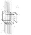
本実施形態の光モニタデバイスは、図1に例示する構成を備える。
本実施形態の光モニタデバイスは、複数の入射側光ファイバ11を伝搬する光の強度を検出する光モニタデバイスにおいて、
入射側光ファイバ11からの各入射光に対し、入射光41の大部分を特定の第1の方向へ、残りを別の特定の第2の方向へと一定の分岐比で分岐し、各分岐光を出射する空間光学系30と、
前記空間光学系30に光を入射するように2次元配列状に配置された、複数の光を伝搬する入射側光ファイバ11と、
前記空間光学系30から第1の方向へ出射される大部分の出射光42を受光するように配置された、複数の光を伝搬する出射側光ファイバ12と、
前記空間光学系30から第2の方向へ出射される一部の出射光43を受光するように配置された受光部5と、
前記空間光学系30と前記入射側光ファイバ11の間に配置され、入射側光ファイバ11から空間光学系30への各入射光を平行光とする入射側光学レンズ21と、
前記空間光学系30と前記出射側光ファイバ12の間に配置され、空間光学系30からの各出射光を、効率よく入射側光ファイバ11に対応する出射側光ファイバ12に結合する出射側光学レンズ22と、
を有する。(First embodiment)
The optical monitoring device of this embodiment has a configuration exemplified in FIG.
The optical monitoring device of this embodiment is an optical monitoring device that detects the intensity of light propagating through a plurality of incident side
a spatial optical system (30) for splitting a majority of each incident light (41) from an incident-side optical fiber (11) in a specific first direction and the remainder in another specific second direction at a constant splitting ratio, and emitting each split light;
an input
an output side
a light receiving
an incident-side
an output
has.
さらに、本実施形態の光モニタデバイスでは、図2に例示するように、空間光学系30が、一様な屈折率の材料で構成される入射側部材30Aと出射側部材30Bとの間に設けられた別の一様な屈折率を持つ単層膜33を備え、その単層膜33が入射光41の光軸と特定の角度(図では45度)をもって設けられている。これにより、単層膜33と入射側部材30Aとの第1の屈折率界面33A及び単層膜33と出射側部材30Bとの第2の屈折率界面33Bが、それぞれ入射光の光軸と特定の角度をもって設けられている。2, the spatial
図1では、特定の角度が45度であり、反射光の方向が90度である例を示すが、反射光の方向は90度固定ではなく、必要に応じて変えることが可能である。又、空間光学系30は、空間系に限らず、方向の異なる2つの光に分岐可能な分岐面を備える任意の光学部品を用いることができる。1 shows an example in which the specific angle is 45 degrees and the direction of the reflected light is 90 degrees, but the direction of the reflected light is not fixed at 90 degrees and can be changed as necessary. In addition, the spatial
図1、図2に例示する光モニタデバイスによれば、入射側光ファイバ11からの入射光41は入射側光学レンズ21で平行光となるため、拡散による損失を防ぐことができる。さらに空間光学系30によって大部分の出射光42が出射側光学レンズ22に導かれる。出射側光学レンズ22は空間光学系30を通過した光を集光し、出射側光ファイバ12に結合する。このように、入射側光ファイバ11から出た大部分の出射光42を損失が少ない状態で出射側光ファイバ12に導くことができる。1 and 2, the
一方、空間光学系30によって分岐された一部の出射光43は前記大部分の出射光42とは別の方向に配置された受光部5に導かれる。これにより、本実施形態の光モニタデバイスは、入射側光ファイバ11から出射側光ファイバ12に伝搬する光の一部の強度を測定できる。空間光学系30での出射光42と出射光43との分岐比が一定で予め分かっており、例えばそれがN:1であるとして、受光部5で測定された光の強度がL(単位は例えばmW)であるとすると、入射側光ファイバ11から入射した光強度は(N+1)×L、出射側光ファイバ12に伝搬した光強度はN×Lであると知ることができる。On the other hand, a part of the emitted
受光部5は、入射側光ファイバ11の2次元配列形状に整合するように配置された複数の受光素子で構成されていてもよいが、エリアイメージセンサなどの各入射側光ファイバ11からの入射位置ごとに光強度を検出可能な1つの受光素子で構成されていてもよい。この場合、受光部5で検出された各出射光43の強度は、入射側光ファイバ11ごとに出力される。これにより、部品点数を減らすことができるとともに、任意の2次元配列の入射側光ファイバ11に用いることができる。The light
図1、図2に例示する光モニタデバイスによれば、屈折率界面33A及び33Bでのフレネル反射により入射光は分岐される。フレネル反射は波長に依存せず、屈折率界面33A及び33Bでの屈折率に依存するため広い波長域において光が分岐される。1 and 2, incident light is branched by Fresnel reflection at the refractive index interfaces 33 A and 33 B. Since Fresnel reflection does not depend on wavelength but on the refractive index at the refractive index interfaces 33 A and 33 B, light is branched in a wide wavelength range.
図2は入射側部材30Aと出射側部材30Bが同じ屈折率の場合の入射光の波長による光路の違いを例示している。入射側部材30Aと出射側部材30Bが同じ屈折率の場合、単層膜33では波長が異なると異なる方向に進む。このため、屈折率界面33Bへの入射位置が波長によって異なる。一方で、屈折率界面33Bから入射した光は、単層膜33と出射側部材30Bの間の屈折により、入射側部材30Aと同じ方向に進む。このため、各出射側光ファイバ12の入射端面での光軸を平行に配置しても、波長に依らず透過光を出射側光ファイバ12に結合させることができる。2 illustrates the difference in optical path depending on the wavelength of incident light when the
このように、本開示では、単層膜33において波長に応じた屈折率界面33Bへの入射位置の違いが生じる。そのため、本開示では、出射側光学レンズ22の位置は、入射光41の中心波長、屈折角及び単層膜33の厚みSに応じて定められている。In this manner, in the present disclosure, a difference occurs in the incident position on the
また、出射側光学レンズ22に到達する光の幅は、入射光41の波長幅と単層膜33の厚みSに主に依存する。出射側光学レンズ22の径に対して出射側光学レンズ22に到達する光の幅が小さいと光損失が小さく、一方でこの幅が大きいと光損失が大きくなる。そのため、出射側光学レンズ22の径を、入射光41の波長幅と単層膜33の厚みSに応じて定める値以上とすることで、光損失を小さくすることができる。一方、出射側光学レンズ22の径が前記入射側ファイバの設置間隔以上となると隣のレンズとぶつかるため、出射側光学レンズ22の径は前記入射側ファイバの設置間隔以下であることが必要である。The width of the light reaching the output
(本開示の効果)
図1に例示する光モニタデバイスによれば、入射側光ファイバ11と出射側光ファイバ12は2次元に配列されており、空間光学系30によって2次元配列の光束を分岐する。これにより単心の光ファイバ毎の光モニタデバイスや光ファイバが1次元に配列された光モニタデバイスを用いるよりも小型化が可能という効果がある。また、構成する部品が少ないことから、低コスト化が容易という効果がある。加えて、広い波長域で光が分岐されるので、誘電体多層膜を用いた光モニタデバイスよりも広い波長域の光信号をモニタすることができる。したがって、本開示の光モニタデバイスは、広い波長域の光信号がモニタ可能であり、かつ数十心といった多心数の光ファイバ用の光モニタデバイスを小型かつ低コストに実現可能にすることができる。(Effects of the present disclosure)
According to the optical monitoring device illustrated in FIG. 1, the input
なお、図1では、入射側光ファイバ11、出射側光ファイバ12、入射側光学レンズ21及び出射側光学レンズ22が3×3の2次元配列状に配置されている例を示すが、2×2以上の任意の数の組み合わせでありうる。Note that, although Figure 1 shows an example in which the incident side
(第2の実施形態)
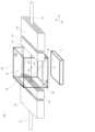
図3に、本実施形態に係る光モニタデバイスの構成例を示す。入射側部材30A、出射側部材30Bは例えば石英ガラスなどの透明な材料で作ることができる。単層膜33は、入射側部材30A及び出射側部材30Bの間に所定の厚さのスペーサ34を配置し、隙間を開けることで空気層を利用することができる。入射側光学レンズ21及び出射側光学レンズ22は、光コネクタなどで使用される角形フェルールにGRIN(GRaded INdex)ファイバを内蔵したコリーメータで実現することができる。入射側光ファイバ11及び出射側光ファイバ12も、入射側光学レンズ21及び出射側光学レンズ22と同様に、角形のフェルール23及び24に内蔵し、光コネクタと同様ガイドピン25とガイド穴を用いて入射側光ファイバ11、入射側光学レンズ21、出射側光ファイバ12、出射側光学レンズ22の光軸を調心することができる。受光部5は市販の光イメージセンサで実現できる。単層膜33以外の接続部に屈折率整合材を充填することで、余計なフレネル反射を抑制できる。Second Embodiment
FIG. 3 shows an example of the configuration of the optical monitor device according to this embodiment. The
また、余計なフレネル反射を抑制するには、入射側部材30A及び出射側部材30Bの屈折率は、入射側光ファイバ11及び出射側光ファイバ12の光ファイバコアと同等であることが望ましい。例えば、入射側光ファイバ11及び出射側光ファイバ12が、通信用光ファイバに用いられる石英ガラスのファイバコアの場合、屈折率1.47の屈折率整合材を用いるのが望ましい。単層膜33には空気層(屈折率1)を用いるのが安価な構造と言える。単層膜33への入射角を30度とすると、フレネル反射率(p偏光)は8.5%となる。In order to suppress unnecessary Fresnel reflection, it is desirable that the refractive index of the
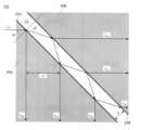
図4に単層膜33での詳細な透過光と反射光の様子を例示する。入射側光ファイバ11から空間光学系30に入射してくる入射光41の強度をL0とすると、1次反射光、2次反射光、3次反射光の強度LR1、LR2、LR3はそれぞれ以下の式で表される。
ここで、r1は屈折率界面33Aでのフレネル反射率であり、r2は屈折率界面33Bでのフレネル反射率である。またδは、単層膜33中で進んだ光の位相であり、4πnScosθ/λである。ここで、nは単層膜33の屈折率、Sは単層膜33の厚み、θは屈折角、λは光の波長である。本実施形態では、単層膜33は空気層であるため、屈折率n=1である。また図4では、1次透過光、2次透過光、3次透過光の強度LT1、LT2、LT3を示す。 Here,r1 is the Fresnel reflectance at the
また、入射側光学レンズ21で入射光41が光束半径Rの平行光束になるとすると、i次反射光とj次反射光との重なり積分は以下の式で表される。

4次以上の反射光は微小なので無視すると、この空間光学系30で反射し受光部5で受光される光の強度Lは以下の式で表される。
図5に最小分岐比と単層膜33の厚さSと光束半径Rの比との関係を示す。光通信装置の最小光信号強度は、例えばIEC 61753-1で国際標準化されており、-20~-25dB程度である。一方、光センサの最小受光感度は一般に-40dBであるので、幅広い装置で使用可能であるためには-15dB以上の分岐比が必要である。そのためには図5からS/Rが0.5以上となる単層膜33の厚さSが必要であることが分かる。Figure 5 shows the relationship between the minimum branching ratio and the ratio of the thickness S of the
図6に単層膜33の厚さSと光束半径Rの比を変えた時の空間光学系30での分岐比を示す。S/R=0.5、2.0、4.0のいずれの場合も広い波長帯において光を分岐できることが分かる。しかしながら、SとRの比が0.5の場合、空間光学系30内での干渉により分岐比が小さい波長帯が現れる。このように、単層膜33の厚さSと光束半径Rの組み合わせによっては空間光学系30内での干渉が生じる。そのため、SとRの比が0.5以上となる単層膜33の厚さSを有しかつ単層膜33での干渉を避けられる光束半径Rに設定することが好ましい。6 shows the branching ratio in the spatial
以上、実施例だが、これに制限されるものではない。例えば、本開示では単層膜33が空気層である例を示したが、単層膜33は入射側部材30A及び出射側部材30Bよりも屈折率の低いガラスであってもよい。また、空間光学系30は立方形状に限らず、直方体などの任意の形状でありうる。また受光部5の配置についても、空間光学系30で分岐された光を受光可能な任意の位置に配置することができる。例えば、受光部5は空間光学系30の内部に埋設されていてもよい。The above are examples, but the present disclosure is not limited to these. For example, the
また本開示の光モニタデバイスは、光伝送システムにおいて伝送される任意の光のモニタリングに用いることが可能である。例えば、送信装置、受信装置又は中継装置などの光伝送システムに用いられる任意の装置に本開示の光モニタデバイスを搭載し、受光部5での測定結果を装置内又は装置外での任意の部品へのフィードバック又はフィードフォワードに用いることができる。また、光伝送システムにおける伝送線路の途中に本開示の光モニタデバイスを挿入し、伝送線路における光信号の強度や伝搬損失の測定を行うことができる。The optical monitoring device of the present disclosure can be used to monitor any light transmitted in an optical transmission system. For example, the optical monitoring device of the present disclosure can be mounted in any device used in an optical transmission system, such as a transmitting device, a receiving device, or a repeater, and the measurement result at the
本開示は情報通信産業に適用することができる。The present disclosure can be applied to the information and communications industry.
5:受光部
11:入射側光ファイバ
12:出射側光ファイバ
21:入射側光学レンズ
22:出射側光学レンズ
23、24:フェルール
25:ガイドピン
30:空間光学系
30A:入射側部材
30B:出射側部材
33:単層膜
34:スペーサ
41:入射光
42:大部分の出射光
43:一部の出射光5: Light receiving unit 11: Incident side optical fiber 12: Emitting side optical fiber 21: Incident side optical lens 22: Emitting side
Claims (5)
Translated fromJapanese前記光信号の一部を第1の方向へ、残りを第2の方向へ特定の分岐比で分岐し、出射する光学部品と、
前記光学部品に前記光信号を入射するように2次元配列状に配置されている複数の入射側光ファイバと、
前記光学部品からの前記第1の方向への各出射光をそれぞれ受光するように2次元配列状に配置されている複数の出射側光ファイバと、
前記光学部品からの前記第2の方向への出射光をそれぞれ受光するように配置されている受光部と、
前記光学部品と前記入射側光ファイバの間に配置され、前記複数の入射側光ファイバからの前記光信号を平行光とする入射側光学レンズと、
前記光学部品と前記出射側光ファイバの間に配置され、前記光学部品からの各出射光を前記出射側光ファイバに結合させる出射側光学レンズと、
を備え、
前記光信号は、波長多重されており、
前記光学部品が、
14%未満の一定の値で前記第2の方向へ分岐する、一様な厚さを有する単層膜と、
前記単層膜の入射側に設けられ、前記単層膜と異なる屈折率を有する入射側部材と、
前記単層膜の出射側に設けられ、前記入射側部材と同じ屈折率を有する出射側部材と、
を備え、
前記単層膜と前記入射側部材との第1の屈折率界面及び前記単層膜と前記出射側部材との第2の屈折率界面が、それぞれ前記光信号の光軸と特定の角度をもって設けられ、
前記第1の方向が前記第1の屈折率界面及び前記第2の屈折率界面を透過する方向であり、
前記第2の方向が前記第1の屈折率界面及び前記第2の屈折率界面で反射する方向であり、
前記単層膜の厚さSと前記入射側光学レンズから出射される平行光の光束半径Rの比が0.5以上となる前記単層膜の厚さSを有し、
前記単層膜での干渉を避けられる前記光束半径を有する、
光モニタデバイス。 1. An optical monitor device for detecting the intensity of optical signals propagating through a plurality of optical fibers, comprising:
an optical component that splits a part of the optical signal in a first direction and the rest in a second direction at a specific splitting ratio and outputs the split signal;
a plurality of incident side optical fibers arranged in a two-dimensional array so as to input the optical signal to the optical component;
a plurality of output side optical fibers arranged in a two-dimensional array so as to receive each output light from the optical component in the first direction;
a light receiving unit arranged to receive each of the light beams emitted from the optical component in the second direction;
an incident-side optical lens disposed between the optical component and the incident-side optical fiber, and converting the optical signals from the plurality of incident-side optical fibers into parallel light;
an output optical lens disposed between the optical component and the output optical fiber, for coupling each output light from the optical component to the output optical fiber;
Equipped with
the optical signal is wavelength multiplexed;
The optical component is
a monolayer having a uniform thickness that branches in the second direction by a constant value of less than 14%;
an incident side member provided on an incident side of the monolayer film and having a refractive index different from that of the monolayer film;
an exit side member provided on the exit side of the single layer film and having the same refractive index as the entrance side member;
Equipped with
a first refractive index interface between the single layer film and the incident side member and a second refractive index interface between the single layer film and the exit side member are provided at specific angles with respect to an optical axis of the optical signal,
the first direction is a direction passing through the first refractive index interface and the second refractive index interface,
the second directionis a direction of reflection at the first refractive index interface and the second refractive index interface,
the monolayer film has a thickness S such that a ratio of the thickness S of the monolayer film to a light beam radius R of the parallel light emitted from the incident side optical lens is 0.5 or more;
The light beam radius is such that interference in the single layer film can be avoided.
Optical monitor device.
ことを特徴とする請求項1に記載の光モニタデバイス。 The incident side member and the exit side member are transparent bodies having the same refractive index.
2. The optical monitor device according to claim 1 .
前記光信号の一部を第1の方向へ、残りを第2の方向へ特定の分岐比で分岐し、出射する光学部品と、
前記光学部品から前記第2の方向へ分岐された前記光信号を受光する受光部と、
を備え、
前記光信号は、波長多重されており、
前記光学部品が、
14%未満の一定の値で前記第2の方向へ分岐する、一様な厚さを有する単層膜と、
前記単層膜の入射側に設けられ、前記単層膜と異なる屈折率を有する入射側部材と、
前記単層膜の出射側に設けられ、前記入射側部材と同じ屈折率を有する出射側部材と、
を備え、
前記単層膜と前記入射側部材との第1の屈折率界面及び前記単層膜と前記出射側部材との第2の屈折率界面が、それぞれ前記光信号の光軸と特定の角度をもって設けられ、
前記第1の方向が前記第1の屈折率界面及び前記第2の屈折率界面を透過する方向であり、
前記第2の方向が前記第1の屈折率界面及び前記第2の屈折率界面で反射する方向であり、
前記入射側部材及び前記出射側部材が同じ屈折率の石英ガラスであり、
前記単層膜が、空気層、又は前記入射側部材及び前記出射側部材よりも屈折率の低い透明なガラスである、
光モニタデバイス。1. An optical monitor device for detecting the intensity of optical signals propagating through a plurality of optical fibers, comprising:
an optical component that splits a part of the optical signal in a first direction and the rest in a second direction at a specific splitting ratio and outputs the split signal;
a light receiving unit that receives the optical signal branched in the second direction from the optical component;
Equipped with
the optical signal is wavelength multiplexed;
The optical component is
a monolayer having a uniform thickness that branches in the second direction by a constant value of less than 14%;
an incident side member provided on an incident side of the monolayer film and having a refractive index different from that of the monolayer film;
an exit side member provided on the exit side of the single layer film and having the same refractive index as the entrance side member;
Equipped with
a first refractive index interface between the single layer film and the incident side member and a second refractive index interface between the single layer film and the exit side member are provided at specific angles with respect to an optical axis of the optical signal,
the first direction is a direction passing through the first refractive index interface and the second refractive index interface,
the second direction is a direction of reflection at the first refractive index interface and the second refractive index interface,
the incident side member and the exit side member are made of quartz glass having the same refractive index,
The single layer film is an air layer or a transparent glass having a lower refractive index than the incident side member and the exit side member.
Optical monitor device.
ことを特徴とする請求項1に記載の光モニタデバイス。 The position of the output optical lens is determined according to the central wavelength of the optical signal.
2. The optical monitor device according to claim1 .
ことを特徴とする請求項1に記載の光モニタデバイス。 a diameter of the output optical lens is equal to or larger than a value determined according to a wavelength width of the optical signal and is equal to or smaller than an installation interval of the input optical fibers;
2. The optical monitor device according to claim1 .
Applications Claiming Priority (1)
| Application Number | Priority Date | Filing Date | Title |
|---|---|---|---|
| PCT/JP2021/020450WO2022249454A1 (en) | 2021-05-28 | 2021-05-28 | Optical monitor device |
Publications (2)
| Publication Number | Publication Date |
|---|---|
| JPWO2022249454A1 JPWO2022249454A1 (en) | 2022-12-01 |
| JP7663124B2true JP7663124B2 (en) | 2025-04-16 |
Family
ID=84228499
Family Applications (1)
| Application Number | Title | Priority Date | Filing Date |
|---|---|---|---|
| JP2023523913AActiveJP7663124B2 (en) | 2021-05-28 | 2021-05-28 | Optical Monitor Device |
Country Status (3)
| Country | Link |
|---|---|
| US (1) | US20240230464A1 (en) |
| JP (1) | JP7663124B2 (en) |
| WO (1) | WO2022249454A1 (en) |
Citations (10)
| Publication number | Priority date | Publication date | Assignee | Title |
|---|---|---|---|---|
| JP2004219523A (en) | 2003-01-10 | 2004-08-05 | Fujitsu Ltd | Optical monitor device |
| JP2004226501A (en) | 2003-01-20 | 2004-08-12 | Fujitsu Ltd | Variable optical attenuator |
| US6873760B2 (en) | 2002-03-19 | 2005-03-29 | Opti Work, Inc. | Integrated optical fiber collimator |
| WO2007026510A1 (en) | 2005-08-29 | 2007-03-08 | Matsushita Electric Industrial Co., Ltd. | Fiber laser and optical device |
| JP2007214189A (en) | 2006-02-07 | 2007-08-23 | Komatsu Ltd | Apparatus and method for determining window deterioration of laser chamber |
| JP2010050299A (en) | 2008-08-22 | 2010-03-04 | Gigaphoton Inc | Polarization purity control device and gas laser device with same |
| JP2011064540A (en) | 2009-09-16 | 2011-03-31 | Nikon Corp | Tunable filter and light source device |
| JP2012255932A (en) | 2011-06-09 | 2012-12-27 | Enplas Corp | Lens array and optical module provided therewith |
| CN104092493A (en) | 2014-07-30 | 2014-10-08 | 四川飞阳科技有限公司 | One-way luminous power monitor |
| CN208569113U (en) | 2018-08-03 | 2019-03-01 | 武汉华工正源光子技术有限公司 | A kind of backlight monitoring optical assembly and device with the air gap |
Family Cites Families (5)
| Publication number | Priority date | Publication date | Assignee | Title |
|---|---|---|---|---|
| US6668108B1 (en)* | 2000-06-02 | 2003-12-23 | Calient Networks, Inc. | Optical cross-connect switch with integrated optical signal tap |
| US8639069B1 (en)* | 2003-06-30 | 2014-01-28 | Calient Technologies, Inc. | Wavelength dependent optical switch |
| US8441732B2 (en)* | 2008-03-28 | 2013-05-14 | Michael D. Tocci | Whole beam image splitting system |
| US8355638B2 (en)* | 2009-06-26 | 2013-01-15 | Alcatel Lucent | Receiver for optical transverse-mode-multiplexed signals |
| CN107505773B (en)* | 2017-09-26 | 2021-01-26 | 京东方科技集团股份有限公司 | Backlight module and display device |
- 2021
- 2021-05-28USUS18/288,988patent/US20240230464A1/enactivePending
- 2021-05-28WOPCT/JP2021/020450patent/WO2022249454A1/ennot_activeCeased
- 2021-05-28JPJP2023523913Apatent/JP7663124B2/enactiveActive
Patent Citations (10)
| Publication number | Priority date | Publication date | Assignee | Title |
|---|---|---|---|---|
| US6873760B2 (en) | 2002-03-19 | 2005-03-29 | Opti Work, Inc. | Integrated optical fiber collimator |
| JP2004219523A (en) | 2003-01-10 | 2004-08-05 | Fujitsu Ltd | Optical monitor device |
| JP2004226501A (en) | 2003-01-20 | 2004-08-12 | Fujitsu Ltd | Variable optical attenuator |
| WO2007026510A1 (en) | 2005-08-29 | 2007-03-08 | Matsushita Electric Industrial Co., Ltd. | Fiber laser and optical device |
| JP2007214189A (en) | 2006-02-07 | 2007-08-23 | Komatsu Ltd | Apparatus and method for determining window deterioration of laser chamber |
| JP2010050299A (en) | 2008-08-22 | 2010-03-04 | Gigaphoton Inc | Polarization purity control device and gas laser device with same |
| JP2011064540A (en) | 2009-09-16 | 2011-03-31 | Nikon Corp | Tunable filter and light source device |
| JP2012255932A (en) | 2011-06-09 | 2012-12-27 | Enplas Corp | Lens array and optical module provided therewith |
| CN104092493A (en) | 2014-07-30 | 2014-10-08 | 四川飞阳科技有限公司 | One-way luminous power monitor |
| CN208569113U (en) | 2018-08-03 | 2019-03-01 | 武汉华工正源光子技术有限公司 | A kind of backlight monitoring optical assembly and device with the air gap |
Also Published As
| Publication number | Publication date |
|---|---|
| JPWO2022249454A1 (en) | 2022-12-01 |
| WO2022249454A1 (en) | 2022-12-01 |
| US20240230464A1 (en) | 2024-07-11 |
Similar Documents
| Publication | Publication Date | Title |
|---|---|---|
| US4213677A (en) | Light coupling and branching device using light focusing transmission body | |
| US5757994A (en) | Three-part optical coupler | |
| US6031952A (en) | Broadband coupler | |
| JP6366602B2 (en) | Multichannel optical connector with coupling lens | |
| GB2038017A (en) | Optical fibre directional coupler | |
| US20190113682A1 (en) | Method for axial alignment of coupled multicore optical fiber | |
| US5666448A (en) | Variable splitting optical coupler | |
| US4739501A (en) | Optical multiplexer/demultiplexer | |
| US11898928B2 (en) | Large core apparatus for measuring optical power in multifiber cables | |
| CN105531612A (en) | optical coupler | |
| CA1141216A (en) | Self-aligning optical fibre coupler | |
| US7577328B2 (en) | Optical reflector, optical system and optical multiplexer/demultiplexer device | |
| US6507680B1 (en) | Planar lightwave circuit module | |
| US12199665B2 (en) | Optical monitor device | |
| US7313293B2 (en) | Optical power monitoring apparatus, optical power monitoring method, and light receiving device | |
| JP7663124B2 (en) | Optical Monitor Device | |
| JP7371900B2 (en) | Bulk monitor and monitoring method for multi-core fiber | |
| JP7609267B2 (en) | Optical Monitor Device | |
| JP7609268B2 (en) | Optical monitor device and optical intensity measuring method | |
| KR100361441B1 (en) | tap coupler | |
| JP2019169780A (en) | Optical communication system | |
| CN113625391A (en) | Optical structure, optical coupling method and photonic integrated circuit chip | |
| WO2024024024A1 (en) | Optical monitoring device and light intensity measurement method | |
| EP1085354A2 (en) | Planar lightwave circuit module | |
| WO2024024038A1 (en) | Optical monitoring device and light intensity wavelength measurement method |
Legal Events
| Date | Code | Title | Description |
|---|---|---|---|
| A621 | Written request for application examination | Free format text:JAPANESE INTERMEDIATE CODE: A621 Effective date:20230901 | |
| A131 | Notification of reasons for refusal | Free format text:JAPANESE INTERMEDIATE CODE: A131 Effective date:20240528 | |
| A521 | Request for written amendment filed | Free format text:JAPANESE INTERMEDIATE CODE: A523 Effective date:20240722 | |
| A131 | Notification of reasons for refusal | Free format text:JAPANESE INTERMEDIATE CODE: A131 Effective date:20240806 | |
| A521 | Request for written amendment filed | Free format text:JAPANESE INTERMEDIATE CODE: A523 Effective date:20241001 | |
| A02 | Decision of refusal | Free format text:JAPANESE INTERMEDIATE CODE: A02 Effective date:20241022 | |
| A521 | Request for written amendment filed | Free format text:JAPANESE INTERMEDIATE CODE: A523 Effective date:20250120 | |
| A521 | Request for written amendment filed | Free format text:JAPANESE INTERMEDIATE CODE: A821 Effective date:20250120 | |
| TRDD | Decision of grant or rejection written | ||
| A01 | Written decision to grant a patent or to grant a registration (utility model) | Free format text:JAPANESE INTERMEDIATE CODE: A01 Effective date:20250305 | |
| A61 | First payment of annual fees (during grant procedure) | Free format text:JAPANESE INTERMEDIATE CODE: A61 Effective date:20250318 | |
| R150 | Certificate of patent or registration of utility model | Ref document number:7663124 Country of ref document:JP Free format text:JAPANESE INTERMEDIATE CODE: R150 | |
| S533 | Written request for registration of change of name | Free format text:JAPANESE INTERMEDIATE CODE: R313533 |