JP7662627B2 - ENT PROCEDURE VISUALIZATION SYSTEM AND METHOD - Google Patents
ENT PROCEDURE VISUALIZATION SYSTEM AND METHODDownload PDFInfo
- Publication number
- JP7662627B2 JP7662627B2JP2022523933AJP2022523933AJP7662627B2JP 7662627 B2JP7662627 B2JP 7662627B2JP 2022523933 AJP2022523933 AJP 2022523933AJP 2022523933 AJP2022523933 AJP 2022523933AJP 7662627 B2JP7662627 B2JP 7662627B2
- Authority
- JP
- Japan
- Prior art keywords
- patient
- image
- anatomy
- orientation
- coordinate system
- Prior art date
- Legal status (The legal status is an assumption and is not a legal conclusion. Google has not performed a legal analysis and makes no representation as to the accuracy of the status listed.)
- Active
Links
- 238000012800visualizationMethods0.000titleclaimsdescription28
- 238000000034methodMethods0.000titledescription61
- 210000003484anatomyAnatomy0.000claimsdescription98
- 230000003287optical effectEffects0.000claimsdescription84
- 230000002596correlated effectEffects0.000claimsdescription38
- 230000007935neutral effectEffects0.000claimsdescription35
- 230000000875corresponding effectEffects0.000claimsdescription17
- 238000009877renderingMethods0.000claimsdescription15
- 230000009466transformationEffects0.000claimsdescription15
- 230000000007visual effectEffects0.000claimsdescription13
- 230000001131transforming effectEffects0.000claimsdescription12
- 238000002675image-guided surgeryMethods0.000claimsdescription11
- 230000003190augmentative effectEffects0.000claimsdescription10
- 230000003068static effectEffects0.000claimsdescription5
- 230000004044responseEffects0.000claimsdescription3
- 210000003128headAnatomy0.000description68
- 238000002591computed tomographyMethods0.000description40
- ICMWWNHDUZJFDW-DHODBPELSA-NoxymetholoneChemical compoundC([C@@H]1CC2)C(=O)\C(=C/O)C[C@]1(C)[C@@H]1[C@@H]2[C@@H]2CC[C@](C)(O)[C@@]2(C)CC1ICMWWNHDUZJFDW-DHODBPELSA-N0.000description22
- 238000004891communicationMethods0.000description11
- 230000008878couplingEffects0.000description7
- 238000010168coupling processMethods0.000description7
- 238000005859coupling reactionMethods0.000description7
- 238000000844transformationMethods0.000description7
- 238000010191image analysisMethods0.000description6
- 239000003550markerSubstances0.000description6
- 230000015654memoryEffects0.000description6
- 238000001356surgical procedureMethods0.000description6
- 238000012545processingMethods0.000description5
- 238000010586diagramMethods0.000description4
- 230000006870functionEffects0.000description4
- 238000012986modificationMethods0.000description4
- 230000004048modificationEffects0.000description4
- 230000008569processEffects0.000description4
- 230000005855radiationEffects0.000description4
- 238000004140cleaningMethods0.000description3
- 239000012636effectorSubstances0.000description3
- 230000005672electromagnetic fieldEffects0.000description3
- 230000014509gene expressionEffects0.000description3
- 238000004458analytical methodMethods0.000description2
- 230000008859changeEffects0.000description2
- 238000005520cutting processMethods0.000description2
- 238000002595magnetic resonance imagingMethods0.000description2
- 210000001331noseAnatomy0.000description2
- 210000003695paranasal sinusAnatomy0.000description2
- 210000003800pharynxAnatomy0.000description2
- 239000000523sampleSubstances0.000description2
- 238000002604ultrasonographyMethods0.000description2
- 241000894006BacteriaSpecies0.000description1
- IAYPIBMASNFSPL-UHFFFAOYSA-NEthylene oxideChemical compoundC1CO1IAYPIBMASNFSPL-UHFFFAOYSA-N0.000description1
- 239000004775TyvekSubstances0.000description1
- 229920000690TyvekPolymers0.000description1
- 230000006978adaptationEffects0.000description1
- 239000000853adhesiveSubstances0.000description1
- 230000001070adhesive effectEffects0.000description1
- 238000013459approachMethods0.000description1
- 230000009286beneficial effectEffects0.000description1
- 230000007423decreaseEffects0.000description1
- 230000000916dilatatory effectEffects0.000description1
- 230000010339dilationEffects0.000description1
- 238000010894electron beam technologyMethods0.000description1
- 238000003384imaging methodMethods0.000description1
- 238000004519manufacturing processMethods0.000description1
- 239000000463materialSubstances0.000description1
- 238000012544monitoring processMethods0.000description1
- 210000003928nasal cavityAnatomy0.000description1
- 210000004279orbitAnatomy0.000description1
- 230000008447perceptionEffects0.000description1
- 210000001747pupilAnatomy0.000description1
- 238000002310reflectometryMethods0.000description1
- 230000001954sterilising effectEffects0.000description1
- 238000004659sterilization and disinfectionMethods0.000description1
Images


Classifications
- A—HUMAN NECESSITIES
- A61—MEDICAL OR VETERINARY SCIENCE; HYGIENE
- A61B—DIAGNOSIS; SURGERY; IDENTIFICATION
- A61B34/00—Computer-aided surgery; Manipulators or robots specially adapted for use in surgery
- A61B34/20—Surgical navigation systems; Devices for tracking or guiding surgical instruments, e.g. for frameless stereotaxis
- A—HUMAN NECESSITIES
- A61—MEDICAL OR VETERINARY SCIENCE; HYGIENE
- A61B—DIAGNOSIS; SURGERY; IDENTIFICATION
- A61B90/00—Instruments, implements or accessories specially adapted for surgery or diagnosis and not covered by any of the groups A61B1/00 - A61B50/00, e.g. for luxation treatment or for protecting wound edges
- A61B90/36—Image-producing devices or illumination devices not otherwise provided for
- A61B90/37—Surgical systems with images on a monitor during operation
- A—HUMAN NECESSITIES
- A61—MEDICAL OR VETERINARY SCIENCE; HYGIENE
- A61B—DIAGNOSIS; SURGERY; IDENTIFICATION
- A61B17/00—Surgical instruments, devices or methods
- A61B17/24—Surgical instruments, devices or methods for use in the oral cavity, larynx, bronchial passages or nose; Tongue scrapers
- A—HUMAN NECESSITIES
- A61—MEDICAL OR VETERINARY SCIENCE; HYGIENE
- A61B—DIAGNOSIS; SURGERY; IDENTIFICATION
- A61B34/00—Computer-aided surgery; Manipulators or robots specially adapted for use in surgery
- A61B34/10—Computer-aided planning, simulation or modelling of surgical operations
- A61B2034/101—Computer-aided simulation of surgical operations
- A61B2034/105—Modelling of the patient, e.g. for ligaments or bones
- A—HUMAN NECESSITIES
- A61—MEDICAL OR VETERINARY SCIENCE; HYGIENE
- A61B—DIAGNOSIS; SURGERY; IDENTIFICATION
- A61B34/00—Computer-aided surgery; Manipulators or robots specially adapted for use in surgery
- A61B34/10—Computer-aided planning, simulation or modelling of surgical operations
- A61B2034/107—Visualisation of planned trajectories or target regions
- A—HUMAN NECESSITIES
- A61—MEDICAL OR VETERINARY SCIENCE; HYGIENE
- A61B—DIAGNOSIS; SURGERY; IDENTIFICATION
- A61B34/00—Computer-aided surgery; Manipulators or robots specially adapted for use in surgery
- A61B34/20—Surgical navigation systems; Devices for tracking or guiding surgical instruments, e.g. for frameless stereotaxis
- A61B2034/2046—Tracking techniques
- A61B2034/2048—Tracking techniques using an accelerometer or inertia sensor
- A—HUMAN NECESSITIES
- A61—MEDICAL OR VETERINARY SCIENCE; HYGIENE
- A61B—DIAGNOSIS; SURGERY; IDENTIFICATION
- A61B34/00—Computer-aided surgery; Manipulators or robots specially adapted for use in surgery
- A61B34/20—Surgical navigation systems; Devices for tracking or guiding surgical instruments, e.g. for frameless stereotaxis
- A61B2034/2046—Tracking techniques
- A61B2034/2051—Electromagnetic tracking systems
- A—HUMAN NECESSITIES
- A61—MEDICAL OR VETERINARY SCIENCE; HYGIENE
- A61B—DIAGNOSIS; SURGERY; IDENTIFICATION
- A61B34/00—Computer-aided surgery; Manipulators or robots specially adapted for use in surgery
- A61B34/20—Surgical navigation systems; Devices for tracking or guiding surgical instruments, e.g. for frameless stereotaxis
- A61B2034/2046—Tracking techniques
- A61B2034/2055—Optical tracking systems
- A—HUMAN NECESSITIES
- A61—MEDICAL OR VETERINARY SCIENCE; HYGIENE
- A61B—DIAGNOSIS; SURGERY; IDENTIFICATION
- A61B34/00—Computer-aided surgery; Manipulators or robots specially adapted for use in surgery
- A61B34/20—Surgical navigation systems; Devices for tracking or guiding surgical instruments, e.g. for frameless stereotaxis
- A61B2034/2072—Reference field transducer attached to an instrument or patient
- A—HUMAN NECESSITIES
- A61—MEDICAL OR VETERINARY SCIENCE; HYGIENE
- A61B—DIAGNOSIS; SURGERY; IDENTIFICATION
- A61B34/00—Computer-aided surgery; Manipulators or robots specially adapted for use in surgery
- A61B34/25—User interfaces for surgical systems
- A61B2034/256—User interfaces for surgical systems having a database of accessory information, e.g. including context sensitive help or scientific articles
- A—HUMAN NECESSITIES
- A61—MEDICAL OR VETERINARY SCIENCE; HYGIENE
- A61B—DIAGNOSIS; SURGERY; IDENTIFICATION
- A61B90/00—Instruments, implements or accessories specially adapted for surgery or diagnosis and not covered by any of the groups A61B1/00 - A61B50/00, e.g. for luxation treatment or for protecting wound edges
- A61B90/36—Image-producing devices or illumination devices not otherwise provided for
- A61B2090/364—Correlation of different images or relation of image positions in respect to the body
- A61B2090/365—Correlation of different images or relation of image positions in respect to the body augmented reality, i.e. correlating a live optical image with another image
- A—HUMAN NECESSITIES
- A61—MEDICAL OR VETERINARY SCIENCE; HYGIENE
- A61B—DIAGNOSIS; SURGERY; IDENTIFICATION
- A61B90/00—Instruments, implements or accessories specially adapted for surgery or diagnosis and not covered by any of the groups A61B1/00 - A61B50/00, e.g. for luxation treatment or for protecting wound edges
- A61B90/36—Image-producing devices or illumination devices not otherwise provided for
- A61B90/37—Surgical systems with images on a monitor during operation
- A61B2090/372—Details of monitor hardware
- A—HUMAN NECESSITIES
- A61—MEDICAL OR VETERINARY SCIENCE; HYGIENE
- A61B—DIAGNOSIS; SURGERY; IDENTIFICATION
- A61B90/00—Instruments, implements or accessories specially adapted for surgery or diagnosis and not covered by any of the groups A61B1/00 - A61B50/00, e.g. for luxation treatment or for protecting wound edges
- A61B90/36—Image-producing devices or illumination devices not otherwise provided for
- A61B90/37—Surgical systems with images on a monitor during operation
- A61B2090/373—Surgical systems with images on a monitor during operation using light, e.g. by using optical scanners
- A—HUMAN NECESSITIES
- A61—MEDICAL OR VETERINARY SCIENCE; HYGIENE
- A61B—DIAGNOSIS; SURGERY; IDENTIFICATION
- A61B90/00—Instruments, implements or accessories specially adapted for surgery or diagnosis and not covered by any of the groups A61B1/00 - A61B50/00, e.g. for luxation treatment or for protecting wound edges
- A61B90/36—Image-producing devices or illumination devices not otherwise provided for
- A61B90/37—Surgical systems with images on a monitor during operation
- A61B2090/374—NMR or MRI
- A—HUMAN NECESSITIES
- A61—MEDICAL OR VETERINARY SCIENCE; HYGIENE
- A61B—DIAGNOSIS; SURGERY; IDENTIFICATION
- A61B90/00—Instruments, implements or accessories specially adapted for surgery or diagnosis and not covered by any of the groups A61B1/00 - A61B50/00, e.g. for luxation treatment or for protecting wound edges
- A61B90/36—Image-producing devices or illumination devices not otherwise provided for
- A61B90/37—Surgical systems with images on a monitor during operation
- A61B2090/376—Surgical systems with images on a monitor during operation using X-rays, e.g. fluoroscopy
- A61B2090/3762—Surgical systems with images on a monitor during operation using X-rays, e.g. fluoroscopy using computed tomography systems [CT]
- A—HUMAN NECESSITIES
- A61—MEDICAL OR VETERINARY SCIENCE; HYGIENE
- A61B—DIAGNOSIS; SURGERY; IDENTIFICATION
- A61B90/00—Instruments, implements or accessories specially adapted for surgery or diagnosis and not covered by any of the groups A61B1/00 - A61B50/00, e.g. for luxation treatment or for protecting wound edges
- A61B90/36—Image-producing devices or illumination devices not otherwise provided for
- A61B90/37—Surgical systems with images on a monitor during operation
- A61B2090/378—Surgical systems with images on a monitor during operation using ultrasound
- A—HUMAN NECESSITIES
- A61—MEDICAL OR VETERINARY SCIENCE; HYGIENE
- A61B—DIAGNOSIS; SURGERY; IDENTIFICATION
- A61B90/00—Instruments, implements or accessories specially adapted for surgery or diagnosis and not covered by any of the groups A61B1/00 - A61B50/00, e.g. for luxation treatment or for protecting wound edges
- A61B90/39—Markers, e.g. radio-opaque or breast lesions markers
- A61B2090/3937—Visible markers
- A—HUMAN NECESSITIES
- A61—MEDICAL OR VETERINARY SCIENCE; HYGIENE
- A61B—DIAGNOSIS; SURGERY; IDENTIFICATION
- A61B90/00—Instruments, implements or accessories specially adapted for surgery or diagnosis and not covered by any of the groups A61B1/00 - A61B50/00, e.g. for luxation treatment or for protecting wound edges
- A61B90/39—Markers, e.g. radio-opaque or breast lesions markers
- A61B2090/3983—Reference marker arrangements for use with image guided surgery
- A—HUMAN NECESSITIES
- A61—MEDICAL OR VETERINARY SCIENCE; HYGIENE
- A61B—DIAGNOSIS; SURGERY; IDENTIFICATION
- A61B90/00—Instruments, implements or accessories specially adapted for surgery or diagnosis and not covered by any of the groups A61B1/00 - A61B50/00, e.g. for luxation treatment or for protecting wound edges
- A61B90/50—Supports for surgical instruments, e.g. articulated arms
- A61B2090/502—Headgear, e.g. helmet, spectacles
Landscapes
- Health & Medical Sciences (AREA)
- Surgery (AREA)
- Life Sciences & Earth Sciences (AREA)
- Engineering & Computer Science (AREA)
- Nuclear Medicine, Radiotherapy & Molecular Imaging (AREA)
- Molecular Biology (AREA)
- Veterinary Medicine (AREA)
- Public Health (AREA)
- General Health & Medical Sciences (AREA)
- Biomedical Technology (AREA)
- Heart & Thoracic Surgery (AREA)
- Medical Informatics (AREA)
- Animal Behavior & Ethology (AREA)
- Oral & Maxillofacial Surgery (AREA)
- Robotics (AREA)
- Gynecology & Obstetrics (AREA)
- Radiology & Medical Imaging (AREA)
- Pathology (AREA)
- Otolaryngology (AREA)
- Dentistry (AREA)
- Pulmonology (AREA)
- Apparatus For Radiation Diagnosis (AREA)
- Processing Or Creating Images (AREA)
- Image Processing (AREA)
- Analysing Materials By The Use Of Radiation (AREA)
- Investigating Or Analyzing Materials By The Use Of Ultrasonic Waves (AREA)
- Diaphragms For Electromechanical Transducers (AREA)
Description
Translated fromJapanese (優先権)
本出願は、2019年10月24日に出願された「Visualization System and Method for ENT Procedures」と題される米国特許仮出願第62/925,441号に対する優先権を主張するものである。 (Priority)
This application claims priority to U.S. Provisional Patent Application No. 62/925,441, filed October 24, 2019, entitled “Visualization System and Method for ENT Procedures.”
画像誘導手術ナビゲーションシステムは、手術部位又は他の患者の解剖学的構造の追加情報及び視覚的視点を提供するために、外科処置中に使用される。これは、手術部位の術前画像(例えば、CT画像)を様々な視点から表示することを含み得、また、処置中に外科用器具が通る計画された経路などの静的情報、並びに外科用器具の遠位先端の現在の場所などの動的情報を示すために、そのような表示された画像上にマーカをオーバーレイすることを含み得る。そのような情報は、外科用器具が患者の体内の特定の場所にナビゲートされる精度及び安全性を改善するために使用され得る。Image-guided surgical navigation systems are used during surgical procedures to provide additional information and visual perspectives of the surgical site or other patient anatomy. This may include displaying pre-operative images (e.g., CT images) of the surgical site from various perspectives, and may also include overlaying markers on such displayed images to indicate static information, such as the planned path that the surgical instruments will follow during the procedure, as well as dynamic information, such as the current location of the distal tip of the surgical instruments. Such information may be used to improve the accuracy and safety with which surgical instruments are navigated to specific locations within the patient's body.
画像誘導手術中に利用可能な追加情報の幅広さを考えると、外科医又は他の施術者は、手術部位のビューの間を切り替えるうちに、又は患者の解剖学的構造の直視と患者の解剖学的構造のシミュレートされた画像の観察との間を切り替えるうちに、ときどき空間的に混乱する場合がある。例えば、いくつかのケースでは、外科医は、画像誘導手術ナビゲーションシステムのディスプレイで患者の頭部の軸方向ビューのCTスライスを見ながら、時折、患者の頭部を直視することもあり得る。そのような場合、外科医は、それらの直接知覚と軸方向ビューとの間で方向感覚を失い、空間的かつ方向的な対応を決定することが不可能になり得、患者の頭部内での外科用器具の誤った動きをもたらし得る。Given the breadth of additional information available during image-guided surgery, a surgeon or other practitioner may sometimes become spatially disoriented while switching between views of a surgical site or between viewing a direct view of the patient's anatomy and observing a simulated image of the patient's anatomy. For example, in some cases, a surgeon may occasionally view the patient's head directly while viewing a CT slice of an axial view of the patient's head on the display of an image-guided surgical navigation system. In such cases, the surgeon may become disoriented between their direct perception and the axial view and be unable to determine spatial and directional correspondence, resulting in erroneous movement of surgical instruments within the patient's head.
ENT処置のために、いくつかのシステム及び方法が作られ、使用されてきたが、本発明の発明者ら以前に、添付の特許請求の範囲に述べた発明を作り、又は使用した者はいないと考えられる。Although several systems and methods have been made and used for ENT procedures, it is believed that no one prior to the inventors of the present invention has made or used the invention set forth in the accompanying claims.
本明細書に組み込まれ、かつその一部をなす添付の図面は、本発明の実施形態を例示するものであり、上記の本発明の一般的な説明、及び以下の実施形態の詳細な説明とともに、本発明の原理を説明する役割を果たすものである。
図面は、いかなる方式でも限定することを意図しておらず、本発明の様々な実施形態は、図面に必ずしも描写されていないものを含め、他の様々な方式で実施し得ることが企図される。本明細書に組み込まれ、かつその一部をなす添付図面は、本発明のいくつかの態様を例示するものであり、説明共に本発明の原理を説明する役割を果たすものである。しかしながら、本発明が、示される正確な配置に限定されない点は理解される。The drawings are not intended to be limiting in any manner, and it is contemplated that various embodiments of the invention may be embodied in other various ways, including those not necessarily depicted in the drawings. The accompanying drawings, which are incorporated in and form a part of this specification, illustrate several aspects of the invention and, together with the description, serve to explain the principles of the invention. It will be understood, however, that the invention is not limited to the precise arrangements shown.
本発明の特定の実施例の以下の説明は、本発明の範囲を限定するために使用されるべきではない。本発明の他の実施例、特徴、態様、実施形態、及び利点は、本発明を実施するために想到される最良の形態の1つを実例として示す以下の説明文より、当業者には明らかとなろう。理解されるように、本発明は、いずれも本発明から逸脱することなく、他の異なるかつ明白な態様が可能である。したがって、図面及び説明は、限定的なものではなく、本質的に例示的なものと見なされるべきである。The following description of specific examples of the present invention should not be used to limit the scope of the present invention. Other examples, features, aspects, embodiments, and advantages of the present invention will become apparent to those skilled in the art from the following description, which illustrates, by way of example, one of the best modes contemplated for carrying out the present invention. As will be understood, the present invention is capable of other different and obvious aspects, all without departing from the present invention. Thus, the drawings and description should be regarded as illustrative in nature, and not as restrictive.
本開示を明確にするために、本明細書において、「近位」及び「遠位」という用語は、遠位外科用エンドエフェクタを有する外科用器具を握持する外科医又は他の操作者に対して定義される。「近位」という用語は、外科医のより近くに配置された要素の位置を指し、「遠位」という用語は、外科用器具の外科用エンドエフェクタのより近くにかつ外科医からより遠くに配置された要素の位置を指す。また、図面を参照して「上部」、「下部」、「垂直」、「水平」などの空間的用語が本明細書で使用される限り、このような用語は例示的な記述目的にのみ使用されて、限定も絶対も意図していないことが理解されるであろう。その点において、本明細書に開示されるものなどの外科用器具を、本明細書で図示及び記載するものに限定されない様々な向き及び位置で使用してもよいことが理解されよう。For clarity of this disclosure, the terms "proximal" and "distal" are defined herein relative to a surgeon or other operator gripping a surgical instrument having a distal surgical end effector. The term "proximal" refers to the location of an element disposed closer to the surgeon, and the term "distal" refers to the location of an element disposed closer to the surgical end effector of the surgical instrument and farther from the surgeon. Also, to the extent that spatial terms such as "upper," "lower," "vertical," "horizontal," and the like are used herein with reference to the drawings, it will be understood that such terms are used for illustrative descriptive purposes only and are not intended to be limiting or absolute. In that regard, it will be understood that surgical instruments such as those disclosed herein may be used in a variety of orientations and positions that are not limited to those shown and described herein.
本明細書で使用される場合、任意の数値又は範囲の「約」又は「およそ」という用語は、構成要素の部分又は集合が、本明細書で記載されているその本来の目的のために機能することを可能とするような好適な寸法の許容範囲を示すものである。As used herein, the term "about" or "approximately" of any numerical value or range is intended to indicate a suitable tolerance of dimensions that allows a portion or collection of components to function for its intended purpose as described herein.
I.例示的な画像誘導手術ナビゲーションシステム
患者(P)の頭部(H)内で医療処置を実施するとき、特に器具が患者(P)の頭部(H)内の器具の作業要素の内視鏡視野を得ることが困難又は不可能である場所にある場合に、患者(P)の頭部(H)内の器具の位置に関する情報を有することが望ましい場合がある。図1は、画像誘導を用いてENT処置を実行することを可能にする例示的なIGSナビゲーションシステム(10)を示す。本明細書に記載されている構成要素及び動作性を有することに加えて、あるいはそれに代えて、IGSナビゲーションシステム(10)は、以下の文献の教示の少なくとも一部に従って構成され、動作可能であり得る。すなわち、米国特許第7,720,521号、発明の名称「Methods and Devices for Performing Procedures within the Ear,Nose,Throat and Paranasal Sinuses」(2010年5月18日発行)(開示内容は参照により本明細書に組み込まれている)、米国特許出願公開第2014/0364725号、発明の名称「Systems and Methods for Performing Image Guided Procedures within the Ear,Nose,Throat and Paranasal Sinuses」(2014年12月11日公開)(開示内容は参照により本明細書に組み込まれている)。 I. Exemplary Image-Guided Surgical Navigation System When performing a medical procedure within the head (H) of a patient (P), it may be desirable to have information regarding the location of an instrument within the head (H) of the patient (P), especially when the instrument is in a location within the head (H) of the patient (P) where it is difficult or impossible to obtain an endoscopic view of the working element of the instrument. Figure 1 illustrates an exemplary IGS navigation system (10) that allows for performing an ENT procedure using image guidance. In addition to or instead of having the components and operability described herein, the IGS navigation system (10) may be configured and operable in accordance with at least a portion of the teachings of the following documents: No. 7,720,521, entitled "Methods and Devices for Performing Procedures within the Ear, Nose, Throat and Paranasal Sinuses," issued May 18, 2010 (the disclosure of which is incorporated herein by reference); U.S. Patent Application Publication No. 2014/0364725, entitled "Systems and Methods for Performing Image Guided Procedures within the Ear, Nose, Throat and Paranasal Sinuses" (published May 18, 2010), the disclosure of which is incorporated herein by reference; Sinuses" (published December 11, 2014), the disclosure of which is incorporated herein by reference.
本実施例のIGSナビゲーションシステム(10)は、磁界発生器アセンブリ(20)を含み、磁界発生器アセンブリ(20)は、馬蹄形フレーム(22)に組み込まれた磁界発生器(24)のセットを含む。磁界発生器(24)は、患者(patient、P)の頭部(head、H)の周りに異なる周波数の交流磁場を発生して、IGSナビゲーションシステム(10)が座標系を関連付ける被追跡エリアを生成するように動作可能である。この実施例では、ナビゲーションガイドワイヤ(40)が患者(P)の頭部(H)に挿入される。ナビゲーションガイドワイヤ(40)は、独立型装置であってもよく、又は外科用切断器具若しくは拡張器具などの医療器具のエンドエフェクタ又は他の箇所に位置付けられてもよい。本実施例では、フレーム(22)が椅子(30)に装着され、フレーム(22)が患者(P)の頭部(H)に隣接して位置するように患者(P)は椅子(30)に着座する。単に一例として、椅子(30)及び/又は磁界発生器アセンブリ(20)は、米国特許第10,561,370号、発明の名称「Apparatus to Secure Field Generating Device to Chair」(2020年2月18日発行)(開示内容は参照により本明細書に組み込まれている)の教示の少なくとも一部に従って構成され、動作可能であり得る。The IGS navigation system (10) of this embodiment includes a magnetic field generator assembly (20), which includes a set of magnetic field generators (24) assembled to a horseshoe-shaped frame (22). The magnetic field generators (24) are operable to generate alternating magnetic fields of different frequencies around the head (H) of a patient (P) to generate a tracked area to which the IGS navigation system (10) associates a coordinate system. In this embodiment, a navigation guide wire (40) is inserted into the head (H) of the patient (P). The navigation guide wire (40) may be a standalone device or may be positioned at the end effector or other location of a medical instrument, such as a surgical cutting or dilating instrument. In this embodiment, the frame (22) is attached to a chair (30), and the patient (P) is seated in the chair (30) such that the frame (22) is positioned adjacent to the head (H) of the patient (P). By way of example only, the chair (30) and/or the magnetic field generator assembly (20) may be configured and operable in accordance with at least a portion of the teachings of U.S. Pat. No. 10,561,370, entitled "Apparatus to Secure Field Generating Device to Chair," issued Feb. 18, 2020, the disclosure of which is incorporated herein by reference.
本実施例のIGSナビゲーションシステム(10)は、更に、プロセッサ(12)を含み、プロセッサ(12)は、IGSナビゲーションシステム(10)の磁界発生器(24)及び他の要素を制御する。例えば、プロセッサ(12)は、磁界発生器(24)を駆動して交流電磁界を生成し、ナビゲーションガイドワイヤ(40)からの信号を処理して患者(P)の頭部(H)内におけるナビゲーションガイドワイヤ(40)内のセンサの場所を判定するように動作可能である。プロセッサ(12)は、1つ又は2つ以上のメモリと通信する処理ユニット(例えば、組み合わせ論理回路又は他の類似の回路を使用してソフトウェア命令を評価及び実行するように構成された1組の電子回路)を備える。本実施例のプロセッサ(12)は、キーパッド及び/又はマウス若しくはトラックボールなどのポインティングデバイスを含む動作制御部(14)を含むコンソール(18)内に装着されている。医師は、外科処置を実行しながら、プロセッサ(12)と相互作用する動作制御部(14)を使用する。The IGS navigation system (10) of this embodiment further includes a processor (12) that controls the magnetic field generator (24) and other elements of the IGS navigation system (10). For example, the processor (12) is operable to drive the magnetic field generator (24) to generate an alternating electromagnetic field and to process signals from the navigation guide wire (40) to determine the location of a sensor in the navigation guide wire (40) within the head (H) of the patient (P). The processor (12) includes a processing unit (e.g., a set of electronic circuits configured to evaluate and execute software instructions using combinational logic or other similar circuits) in communication with one or more memories. The processor (12) of this embodiment is mounted in a console (18) that includes a motion control (14) that includes a keypad and/or a pointing device such as a mouse or trackball. A surgeon uses the motion control (14) to interact with the processor (12) while performing a surgical procedure.
ナビゲーションガイドワイヤ(40)は、磁界発生器(24)によって生成された交流電磁界内の測位に反応するセンサ(図示せず)を含む。連結ユニット(42)はナビゲーションガイドワイヤ(40)の近位端に固定され、コンソール(18)とナビゲーションガイドワイヤ(40)との間のデータ及び他の信号の通信を提供するように構成されている。連結ユニット(42)は、データ及び他の信号の有線又は無線通信を提供することができる。The navigation guidewire (40) includes a sensor (not shown) that responds to positioning in the alternating electromagnetic field generated by the magnetic field generator (24). A coupling unit (42) is secured to the proximal end of the navigation guidewire (40) and is configured to provide communication of data and other signals between the console (18) and the navigation guidewire (40). The coupling unit (42) can provide wired or wireless communication of data and other signals.
本例では、ナビゲーションガイドワイヤ(40)のセンサは、ナビゲーションガイドワイヤ(40)の遠位端に少なくとも1つのコイルを含む。かかるコイルが磁界発生器(24)によって生成された交流電磁界の中に置かれると、交流磁界がコイルの中に電流を生成し得、この電流は、ナビゲーションガイドワイヤ(40)内の導電路(単数又は複数)に沿って、連結ユニット(42)を介してプロセッサ(12)に更に伝送され得る。この現象により、IGSナビゲーションシステム(10)は、三次元空間内(すなわち、患者(P)の頭部(H)内など)におけるナビゲーションガイドワイヤ(40)又は他の医療器具(拡張器具、外科用切断器具など)の遠位端の場所を判定することができる。これを実現するため、プロセッサ(12)は、ナビゲーションガイドワイヤ(40)の遠位端の位置座標を、ナビゲーションガイドワイヤ(40)内のコイル(複数可)の位置関連信号から計算するアルゴリズムを実行する。この例では、位置センサが、ガイドワイヤ(40)内に位置しているが、そのような位置センサは、以下でより詳細に説明するものを含む、拡張カテーテル、ガイドカテーテル、ガイドレール、吸入器具、ポインタ器具、位置合わせプローブ、キューレット、患者追跡装置、及び他の器具などの、様々な他の種類の器具に統合することができる。In this example, the sensor of the navigation guidewire (40) includes at least one coil at the distal end of the navigation guidewire (40). When such a coil is placed in an alternating electromagnetic field generated by the magnetic field generator (24), the alternating magnetic field can generate an electric current in the coil, which can be further transmitted along the conductive path(s) in the navigation guidewire (40) via the coupling unit (42) to the processor (12). This phenomenon allows the IGS navigation system (10) to determine the location of the distal end of the navigation guidewire (40) or other medical instrument (e.g., dilation instrument, surgical cutting instrument, etc.) in three-dimensional space (i.e., in the head (H) of the patient (P)). To achieve this, the processor (12) executes an algorithm to calculate the position coordinates of the distal end of the navigation guidewire (40) from the position-related signals of the coil(s) in the navigation guidewire (40). In this example, the position sensor is located in the guidewire (40), but such position sensors can be integrated into a variety of other types of instruments, such as dilatation catheters, guide catheters, guide rails, suction instruments, pointer instruments, alignment probes, curettes, patient tracking devices, and other instruments, including those described in more detail below.
プロセッサ(12)は、プロセッサ(12)のメモリに記憶されたソフトウェアを用いて、IGSナビゲーションシステム(10)を較正し及び動作させる。このような動作は、磁界発生器(24)を駆動することと、ナビゲーションガイドワイヤ(40)からのデータを処理することと、動作制御部(14)からのデータを処理することと、ディスプレイスクリーン(16)を駆動することと、を含む。いくつかの実装形態では、動作はまた、IGSナビゲーションシステム(10)の1つ以上の安全機構又は機能の監視及び施行も含み得る。プロセッサ(12)は、患者の頭部(H)のビデオカメラ画像、患者の頭部(H)のCTスキャン画像、及び/又は患者の鼻腔内及び患者の鼻腔に隣接する解剖学的構造のコンピュータ生成三次元モデル、に関してナビゲーションガイドワイヤ(40)の遠位端の位置を示すディスプレイスクリーン(16)を介して、リアルタイムで動画を提供するように更に動作可能である。ディスプレイスクリーン(16)は、外科処置中にこのような画像を同時に及び/又は互いに重ね合わせて表示し得る。そのようなディスプレイ画像は、また、操作者がリアルタイムでその実際の場所にある器具の仮想レンダリングを見ることができるように、ナビゲーションガイドワイヤ(40)などの、患者の頭部(H)に挿入された器具のグラフィカル表現を含み得る。単に一例として、ディスプレイスクリーン(16)は、米国特許第10,463,242号、発明の名称「Guidewire Navigation for Sinuplasty」(2019年11月5日発行)(開示内容は参照により本明細書に組み込まれている)の教示の少なくとも一部に従って画像を提供してもよい。操作者が内視鏡も使用している場合には、内視鏡画像もディスプレイスクリーン(16)に表示することができる。The processor (12) calibrates and operates the IGS navigation system (10) using software stored in the memory of the processor (12). Such operations include driving the magnetic field generator (24), processing data from the navigation guidewire (40), processing data from the motion control (14), and driving the display screen (16). In some implementations, the operations may also include monitoring and enforcement of one or more safety features or functions of the IGS navigation system (10). The processor (12) is further operable to provide a real-time video via the display screen (16) showing the position of the distal end of the navigation guidewire (40) with respect to a video camera image of the patient's head (H), a CT scan image of the patient's head (H), and/or a computer-generated three-dimensional model of the anatomical structures within and adjacent to the patient's nasal cavity. The display screen (16) may display such images simultaneously and/or overlaid on one another during a surgical procedure. Such display images may also include graphical representations of instruments inserted into the patient's head (H), such as a navigation guidewire (40), so that the operator can see a virtual rendering of the instrument in its actual location in real time. By way of example only, the display screen (16) may provide images in accordance with at least some of the teachings of U.S. Pat. No. 10,463,242, entitled "Guidewire Navigation for Sinuplasty," issued Nov. 5, 2019, the disclosure of which is incorporated herein by reference. If the operator is also using an endoscope, endoscopic images may also be displayed on the display screen (16).
ディスプレイスクリーン(16)によって提供される画像は、器具がナビゲーションワイヤ(40)を組み込んでいる場合、患者の頭部(H)内の器具を操縦する、及びその他の方法で操作を行う際に操作者を誘導するのに役立ち得る。また、以下に記載するように、手術用器具の他の構成要素及び他の種類の手術用器具は、ナビゲーションガイドワイヤ(40)のセンサのようなセンサを組み込んでもよいことを理解されたい。The images provided by the display screen (16) may help guide the operator in steering and otherwise maneuvering the instrument within the patient's head (H) if the instrument incorporates a navigation guidewire (40). It should also be understood that other components of the surgical instrument and other types of surgical instruments may incorporate sensors, such as sensors in the navigation guidewire (40), as described below.
いくつかの実装態様では、IGSナビゲーションシステム(10)は、図2Aに示されるように患者の頭部(H)又は患者(P)の別の適切な部分に配置され得る、患者追跡アセンブリ(50)を含み得る。頭部(H)をガイドワイヤ(40)とは別に、ただし同じ座標系内で追跡することによって、ガイドワイヤ(40)及び頭部(H)の互いに対する位置及び配向が処置中に決定され得る。これは、頭部(H)が、座標系内のその初期位置を決定するために位置合わせされるが、その後、処置中に移動する場合に有利であり得る。頭部(H)を独立して追跡することにより、回転又は他の動きが検出され得、初期位置合わせは、頭部(H)の新しい位置を考慮して更新され得る。このようにして、オーバーレイされたマーカで頭部(H)内のガイドワイヤ(40)の位置を示すCT画像スライスのディスプレイなど、処置中に使用される任意の画像誘導ナビゲーションの特徴は、そのような動きに応答して自動的に更新され得る。患者追跡アセンブリ(50)の実装態様は、開示内容が参照により本明細書に組み込まれる、2017年12月14日に出願された米国特許出願公開第2019/0183582号、発明の名称「Mounted Patient Tracking Component for Surgical Navigation System」の教示のいずれかに従って、IGSナビゲーションシステム(10)と共に構成され、動作可能であり得る。In some implementations, the IGS navigation system (10) may include a patient tracking assembly (50), which may be located on the patient's head (H) or another suitable portion of the patient (P) as shown in FIG. 2A. By tracking the head (H) separately from the guidewire (40), but within the same coordinate system, the position and orientation of the guidewire (40) and head (H) relative to each other may be determined during the procedure. This may be advantageous when the head (H) is registered to determine its initial position in the coordinate system, but then moves during the procedure. By tracking the head (H) independently, rotation or other motion may be detected, and the initial registration may be updated to account for the new position of the head (H). In this manner, any image-guided navigation features used during the procedure, such as the display of CT image slices showing the position of the guidewire (40) within the head (H) with overlaid markers, may be automatically updated in response to such motion. Implementations of the patient tracking assembly (50) may be configured and operable with the IGS navigation system (10) in accordance with any of the teachings of U.S. Patent Application Publication No. 2019/0183582, filed Dec. 14, 2017, entitled "Mounted Patient Tracking Component for Surgical Navigation System," the disclosure of which is incorporated herein by reference.
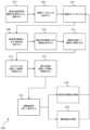
患者追跡アセンブリ(50)の一例として、図2Bは、IGSナビゲーションシステム(10)に容易に組み込まれ得る患者追跡アセンブリ(200)を示す。患者追跡アセンブリ(200)は、使い捨て部分(210)及び再利用可能部分(250)を含む。使い捨て部分(210)は、患者の頭部(H)又は患者の別の好適な部分に(例えば、可撓性接着パッドを使用して)装着するように構成され、例示的な使用中に再利用可能部分(250)が患者(P)の頭部又は別の部分に対して固定されるように、再利用可能部分(250)の連結ブロック(220)と選択的に連結するように構成され、再利用可能部分(250)は、患者(P)の頭部(H)の部分を追跡するために、プロセッサ(12)と通信するように構成されている。As an example of a patient tracking assembly (50), FIG. 2B shows a patient tracking assembly (200) that can be easily incorporated into the IGS navigation system (10). The patient tracking assembly (200) includes a disposable portion (210) and a reusable portion (250). The disposable portion (210) is configured to be attached to the patient's head (H) or another suitable portion of the patient (e.g., using a flexible adhesive pad) and selectively coupled to the coupling block (220) of the reusable portion (250) such that the reusable portion (250) is secured to the head or another portion of the patient (P) during exemplary use, and the reusable portion (250) is configured to communicate with the processor (12) to track a portion of the patient's head (H).
再利用可能部分(250)は、連結アセンブリ(254)から近位に延在するケーブル(252)とセンサ(255)とを含む。連結アセンブリ(254)は、使用中に再利用可能部分(250)を使い捨て部分(210)と連結するように適合されている。使い捨て部分(210)と適切に連結されると、センサ(255)は、追跡される解剖学的構造の場所を決定するために、プロセッサ(12)と共に利用され得、それにより、プロセッサ(12)は、例示的な使用中に患者(P)の解剖学的構造に対するナビゲーションガイドワイヤ(40)(又は任意の他の好適な器具)の場所を正確に表示し得る。ケーブル(252)は、例示的な使用中にセンサ(255)とプロセッサ(12)との間の通信用の導管を提供するように構成されている。したがって、ケーブル(252)は、センサ(255)が、ケーブル(252)を介してプロセッサ(110)と有線通信するように直接接続し得る。あるいは、ケーブル(252)は、連結ユニット(42)が、ナビゲーションガイドワイヤ(40)とプロセッサ(12)との間の無線通信を確立する方法と同様に、センサ(255)を、プロセッサ(12)と無線通信する無線通信装置に接続し得る。The reusable portion (250) includes a cable (252) and a sensor (255) extending proximally from a coupling assembly (254). The coupling assembly (254) is adapted to couple the reusable portion (250) with the disposable portion (210) during use. When properly coupled with the disposable portion (210), the sensor (255) can be utilized with the processor (12) to determine the location of the tracked anatomical structure, so that the processor (12) can accurately indicate the location of the navigation guidewire (40) (or any other suitable instrument) relative to the anatomical structure of the patient (P) during exemplary use. The cable (252) is configured to provide a conduit for communication between the sensor (255) and the processor (12) during exemplary use. Thus, the cable (252) can directly connect the sensor (255) to be in wired communication with the processor (110) via the cable (252). Alternatively, the cable (252) may connect the sensor (255) to a wireless communication device that communicates wirelessly with the processor (12), similar to how the coupling unit (42) establishes wireless communication between the navigation guidewire (40) and the processor (12).
II.ENT処置のための例示的な可視化システム
図3は、外科処置中に追加情報及び画像ナビゲーションビューを提供するため、IGSナビゲーションシステム(10)と共に実装され得る可視化システム(60)を示す。特に、可視化システム(60)は、ほぼリアルタイムで処置中にキャプチャされた患者の画像上にオーバーレイされる、拡張現実ビューに情報を表示するナビゲーションビューを提供し得る。これは、有利には、外科医が処置中に患者を見る代わりにディスプレイスクリーン(16)又は別のディスプレイを見る頻度及び必要性を低減し得、また、外科医が、物理的世界と、IGSナビゲーションシステム(10)によって提供される画像ナビゲーションビューとの間で自分自身を空間的に配向するのに役立ち得る。 II. Exemplary Visualization System for ENT Procedures Figure 3 illustrates a
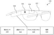
可視化システム(60)は、以下により詳細に説明されるように、ヘッドマウントディスプレイ(「HMD」)(100)、ハンドヘルドディスプレイ(「HHD」)(101)、又は別の同様の装置のうちの1つ以上を、画像誘導外科処置中にIGSナビゲーションシステム(10)と通信するように構成することによって、IGSナビゲーションシステム(10)と共に実装され得る。図4は、外科医、又は画像誘導外科処置にかかわる他のユーザの顔に装着され得るフレーム(102)を含む、HMD(100)の斜視図を示す。フレーム(102)に取り付けられたケース(108)が示されているが、ケース(108)は、他の場所に装着されるか又は取り付けられ、フレーム(102)に取り付けられた装置との有線又は無線接続を介して、それらの装置と連結されてもよい。ケース(108)は、HMD(100)の視点、場所、又はその両方を示す空間的情報を提供するように動作可能な視点センサ(110)を含む。視点センサ(110)は、例えば、ジャイロスコープ、加速度計、又は位置センサ(例えば、ガイドワイヤ(40)のセンサなど)のうちの1つ以上を含み得る。視点センサ(108)からの情報は、フレーム(102)に取り付けられたカメラ(106)の視覚的視点の1つ以上の態様を決定するために使用可能であり得、これは、以下により詳細に説明されるように、カメラ(106)の光軸の配向(例えば、1つ以上の軸に対する回転座標)、IGSナビゲーションシステム(10)の座標系に対するカメラ(106)の場所(例えば、1つ以上の軸の位置座標)、又はその両方を決定することを含み得る。The visualization system (60) may be implemented in conjunction with the IGS navigation system (10) by configuring one or more of a head mounted display ("HMD") (100), a handheld display ("HHD") (101), or another similar device to communicate with the IGS navigation system (10) during an image-guided surgical procedure, as described in more detail below. FIG. 4 shows a perspective view of the HMD (100) including a frame (102) that may be worn on the face of a surgeon or other user involved in an image-guided surgical procedure. Although the case (108) is shown attached to the frame (102), the case (108) may be worn or attached elsewhere and coupled to devices attached to the frame (102) via a wired or wireless connection to those devices. The case (108) includes a viewpoint sensor (110) operable to provide spatial information indicative of a viewpoint, location, or both of the HMD (100). The viewpoint sensor (110) may include, for example, one or more of a gyroscope, an accelerometer, or a position sensor (such as a sensor on the guidewire (40)). Information from the viewpoint sensor (108) may be used to determine one or more aspects of the visual viewpoint of a camera (106) mounted on the frame (102), which may include determining the orientation of the optical axis of the camera (106) (e.g., rotational coordinates about one or more axes), the location of the camera (106) relative to the coordinate system of the IGS navigation system (10) (e.g., positional coordinates about one or more axes), or both, as described in more detail below.
ケース(108)は、また、プロセッサ(12)又は他の装置と通信することができる有線又は無線トランシーバであり得る通信装置(112)と、HMD(100)の機能に関連するデータを処理及び記憶し、機能を実行するように構成されたプロセッサ及びメモリ(114)と、を含む。電源(116)も含まれ、電源(116)は、電池又は外部電源への接続であってもよく、プロセッサ及びメモリ(114)、通信装置(112)、カメラ(106)、ディスプレイ(104)、並びにHMD(100)の他の構成要素に電力を提供するように構成されている。The case (108) also includes a communication device (112), which may be a wired or wireless transceiver capable of communicating with the processor (12) or other devices, and a processor and memory (114) configured to process and store data related to the functionality of the HMD (100) and to perform functions. A power source (116), which may be a battery or a connection to an external power source, is also included and is configured to provide power to the processor and memory (114), the communication device (112), the camera (106), the display (104), and other components of the HMD (100).
装着時に、フレーム(102)は、フレーム(102)及び/又はケース(108)に取り付けられたカメラ(106)を、装着者が真っ直ぐ前を見たときにカメラの光軸が装着者の目の光軸と実質的に平行になるように位置付ける。本明細書で使用される場合、「中立光軸」という用語は、HMD(100)の装着者が実質的に真っ直ぐ前を見たときに(例えば、目の瞳孔が、眼窩内で垂直及び水平の両方で実質的に中心にある場合)、装着者の目の光軸を指し得る。このようにして、カメラ(106)は、HMD(100)の装着者の視界と同様の視界を有する画像をキャプチャする。一例として、カメラ(106)は、装着者の右目の視界の一部又は全てを含む画像をキャプチャし得、カメラ(106)は、装着者が真っ直ぐ前を見ているときに最も近接して位置付けられる。カメラ(106)は、本開示に照らして当業者には明らかであるように、画像、ビデオ、及びオーディオをキャプチャすることが可能であり得、それらの画像、ビデオ、及びオーディオは、プロセッサ及びメモリ(114)によって記憶され、通信装置(112)を介してプロセッサ(12)に送信されるか、又は別の装置に送信されて、表示又は提示され得る。カメラ(106)によってキャプチャされた画像データは、例えば、キャプチャされた画像の物体又は他の視覚的特性を識別することを含み得るコンピュータビジョン及び他の分析にも使用され得る。そのような分析は、プロセッサ(114)、プロセッサ(12)、若しくはその両方によって実行されてもよく、又は本開示に照らして当業者には明らかであるように、様々なクラウドコンピューティング若しくはエッジ処理技術を使用して実行されてもよい。When worn, the frame (102) positions the camera (106) mounted on the frame (102) and/or the case (108) such that the optical axis of the camera is substantially parallel to the optical axis of the wearer's eye when the wearer looks straight ahead. As used herein, the term "neutral optical axis" may refer to the optical axis of the wearer's eye when the wearer of the HMD (100) looks substantially straight ahead (e.g., when the pupil of the eye is substantially centered both vertically and horizontally within the eye socket). In this way, the camera (106) captures an image having a field of view similar to the field of view of the wearer of the HMD (100). As an example, the camera (106) may capture an image that includes some or all of the field of view of the wearer's right eye, with the camera (106) positioned closest when the wearer looks straight ahead. The camera (106) may be capable of capturing images, video, and audio that may be stored by the processor and memory (114) and transmitted to the processor (12) via the communication device (112) or transmitted to another device for display or presentation, as would be apparent to one of ordinary skill in the art in light of this disclosure. Image data captured by the camera (106) may also be used for computer vision and other analysis, which may include, for example, identifying objects or other visual characteristics in the captured image. Such analysis may be performed by the processor (114), the processor (12), or both, or may be performed using various cloud computing or edge processing techniques, as would be apparent to one of ordinary skill in the art in light of this disclosure.
ディスプレイ(104)はまた、フレーム(102)及び/又はケース(108)に取り付けられ、HMD(100)の装着者の視界内にあるように位置付けられる。いくつかの実装態様では、ディスプレイ(104)は、透明でない場合は少なくとも部分的に半透明であり、装着者の視界上にオーバーレイされたように見える画像をレンダリングするために、プロセッサ(114)によって動作可能である。一例として、ディスプレイ(104)は、カメラ(106)によってキャプチャされた画像を表示し得、これは、近接した目からの装着者の視界の一部又は全てを遮る場合があるが、それ以外では、その目に対する装着者の通常の視界と同様に見える。別の例として、画像分析は、その画像内の目的の物体(例えば、外科的ナビゲーションの文脈で、人間の顔、又は人間の解剖学的構造の別の部分)を識別するために、キャプチャされた画像に対して実行されてもよく、ディスプレイ(104)は、装着者にとって、識別された物体の直接ビュー上にオーバーレイされている(例えば、ディスプレイ(104)の透明部分を通して見える)ように見える視覚的マーカをレンダリングするように動作され得る。上記のいくつかの実装形態では、光学マーカ又は他の基準マーカは、人間の顔自体ではなく、人間の顔に配置された光学マーカが識別され得るように、それらの反射性、形状、又は他の視覚的特性により、容易に識別可能な物体を有する画像データを提供するために、目的の物体上に配置され得る。The display (104) is also attached to the frame (102) and/or the case (108) and positioned to be within the field of view of the wearer of the HMD (100). In some implementations, the display (104) is at least partially translucent, if not transparent, and operable by the processor (114) to render an image that appears to be overlaid on the wearer's field of view. As one example, the display (104) may display an image captured by the camera (106), which may block some or all of the wearer's view from the proximal eye, but otherwise appears similar to the wearer's normal view for that eye. As another example, image analysis may be performed on the captured image to identify an object of interest in that image (e.g., in the context of surgical navigation, a human face, or another part of the human anatomy), and the display (104) may be operated to render a visual marker that appears to the wearer to be overlaid (e.g., seen through a transparent portion of the display (104)) on the direct view of the identified object. In some implementations described above, optical markers or other fiducial markers may be placed on the object of interest to provide image data having objects that are easily identifiable by their reflectivity, shape, or other visual characteristics such that the optical markers placed on the human face may be identified, rather than the human face itself.
更に別の例として、ディスプレイ(104)は、画像分析若しくはマシンビジョンの代わりに、又はそれに加えて、他の入力に基づいて、装着者の視界の直接ビューにオーバーレイする視覚的マーキングをレンダリングするように動作され得る。これは、例えば、視点センサ(110)、プロセッサ(12)、患者追跡装置(50)(例えば、プロセッサ(12)との通信を介する)、及び他の装置からの情報に基づいて、視覚的マーキングをレンダリングすることを含み得る。これは、HMD(100)の回転視点に関連付けられた情報(例えば、視点センサ(100)のジャイロスコープ特徴に基づく)を提供する視覚的マーキングをレンダリングすることを含み得る。別の例として、これは、外科用器具及びHMD(100)に関連付けられた追跡情報に基づいて、外科用器具(例えば、ガイドワイヤ(40))をオーバーレイする視覚的マーキングをレンダリングすることを含み得る。言い換えれば、プロセッサ(12)が、外科用器具及びHMD(100)の相対位置を追跡及び決定することができ、HMD(100)の配向が(例えば、視点センサ(110)を使用して)決定され得る場合、追跡された物体の互いに対する位置及びスケールが決定され、ディスプレイ(104)を介してレンダリングされたマーキングとして生成され得る。As yet another example, the display (104) may be operated to render visual markings that overlay a direct view of the wearer's field of view instead of or in addition to image analysis or machine vision, based on other inputs. This may include, for example, rendering visual markings based on information from the viewpoint sensor (110), the processor (12), the patient tracking device (50) (e.g., via communication with the processor (12)), and other devices. This may include rendering visual markings that provide information associated with the rotational viewpoint of the HMD (100) (e.g., based on the gyroscopic characteristics of the viewpoint sensor (100)). As another example, this may include rendering visual markings that overlay a surgical instrument (e.g., a guidewire (40)) based on tracking information associated with the surgical instrument and the HMD (100). In other words, if the processor (12) can track and determine the relative positions of the surgical instrument and the HMD (100), and the orientation of the HMD (100) can be determined (e.g., using the eye gaze sensor (110)), the position and scale of the tracked objects relative to one another can be determined and generated as markings rendered via the display (104).
本開示に照らして当業者には明らかであるように、上記の特徴の一部又は全ては、ディスプレイ(104)以外の他のディスプレイを用いて実行されてもよい。例えば、いくつかの実装態様では、別個のディスプレイ(例えば、ディスプレイスクリーン(16)又は部屋全体から見える壁取り付けディスプレイ)は、カメラ(106)からキャプチャされた画像、及び追加され得る任意のマーキング、レンダリング、又は他のオーバーレイデータを受信し、表示するように構成され得る。そのような実装態様では、ディスプレイ(104)は、オーバーレイ画像のみをレンダリングし得るが、別個のディスプレイは、カメラ(106)によってキャプチャされた画像及び任意の対応するオーバーレイ画像の組み合わせをレンダリングし得る。これにより、HMD(100)の装着者に加えて、処置の他の参加者が、追加のナビゲーションビューを見ることが可能になり得る。いくつかのそのような実装態様では、HMD(100)は、ディスプレイ(104)を含まなくてもよく、キャプチャされた画像とレンダリングされたオーバーレイとの組み合わせは、ディスプレイスクリーン(16)又は患者の近くに位置付けられた別のディスプレイで見ることが可能であり得る。As will be apparent to one of ordinary skill in the art in light of this disclosure, some or all of the above features may be implemented using other displays besides the display (104). For example, in some implementations, a separate display (e.g., the display screen (16) or a wall-mounted display visible from across the room) may be configured to receive and display the captured images from the camera (106) and any markings, renderings, or other overlay data that may be added. In such implementations, the display (104) may render only the overlay images, but the separate display may render a combination of the images captured by the camera (106) and any corresponding overlay images. This may allow other participants in the procedure to view additional navigation views in addition to the wearer of the HMD (100). In some such implementations, the HMD (100) may not include a display (104), and the combination of the captured images and the rendered overlays may be viewable on the display screen (16) or another display positioned near the patient.
HHD(101)は、HMD(100)の能力の一部又は全てを共有し得、例えば、スマートフォン、タブレット、独自の装置、又はデータを処理及び記憶する、機能を実行する、データを送受信する、画像をキャプチャする、空間情報(例えば、配向、場所、又はその両方)を提供するなどの能力を有する他のハンドヘルドコンピューティング装置であり得る。HHD(101)のディスプレイは、一般に、LED又はLCDディスプレイであり得、したがって、ディスプレイ(104)で可能であるように、物体が直接見える透明な表面上にレンダリングされたマーキングをオーバーレイすることはできない場合がある。いくつかの実装態様では、HMD(100)又はHHD(101)は、追加の能力を含むように修正されてもよい。例えば、HMD(100)のいくつかの実装態様は、IGSナビゲーションシステム(10)の座標系に対して自己位置を決定する能力を含まない場合がある。そのような場合、センサがHMD(100)上に(例えば、外部又は内部に)取り付けられてもよく、HMD(100)が、ガイドワイヤ(40)及び患者追跡アセンブリ(50)と同様に、IGSナビゲーションシステム(10)と相互作用し、IGSナビゲーションシステム(10)によって追跡されることを可能にする。したがって、視点センサ(110)の能力は、デフォルトでHMD(100)に存在する能力、並びに後で追加され得る能力の両方を、それらがケース(108)内にあるか又はHMD(100)の外側に取り付けられているかにかかわらず含み得る。The HHD (101) may share some or all of the capabilities of the HMD (100) and may be, for example, a smartphone, tablet, proprietary device, or other handheld computing device with the ability to process and store data, perform functions, send and receive data, capture images, provide spatial information (e.g., orientation, location, or both), etc. The display of the HHD (101) may generally be an LED or LCD display, and therefore may not be able to overlay rendered markings on transparent surfaces where objects are directly viewed, as is possible with the display (104). In some implementations, the HMD (100) or the HHD (101) may be modified to include additional capabilities. For example, some implementations of the HMD (100) may not include the ability to determine self-location relative to the coordinate system of the IGS navigation system (10). In such cases, the sensor may be mounted (e.g., externally or internally) on the HMD (100) to enable the HMD (100) to interact with and be tracked by the IGS navigation system (10), as well as the guidewire (40) and patient tracking assembly (50). Thus, the capabilities of the gaze sensor (110) may include both capabilities that are present in the HMD (100) by default, as well as capabilities that may be added later, whether they are within the case (108) or mounted on the outside of the HMD (100).
いくつかの実装態様では、HMD(100)の配向及び場所を示す情報は、複数のソースから入手可能であり得る。一例として、視点センサ(110)は、回転配向を決定することができるジャイロスコープ特徴を含んでもよく、回転配向を決定するためにIGSナビゲーションシステム(10)による追跡が可能な三軸センサを含むか又は組み込んでもよく、カメラ(106)によってキャプチャされた画像内に存在する光学基準を識別するように構成されてもよい。そのような例では、処理構成要素(例えば、プロセッサ(114)、プロセッサ(12)、又は他のプロセッサ)は、本開示に照らして当業者には明らかであるように、性能及び精度を均衡させることによって、様々な方法で配向又は場所を決定するように構成され得る。例えば、いくつかの実装態様は、性能を重視するために、HMD(100)自体からのジャイロスコープ情報又はIGSナビゲーションシステム(10)からの追跡情報のみに基づいて配向又は場所を決定してもよく、他の実装態様は、いくつかの性能の潜在コスト(例えば、あるとすれば、HMD(100)の配向又は場所が変わることと、新しい配向又は場所の決定が完了することとの間の遅延)でより高い精度を達成する目的で、ジャイロスコープ、磁気追跡、及び画像分析情報の組み合わせを使用してもよい。In some implementations, information indicative of the orientation and location of the HMD (100) may be available from multiple sources. As an example, the gaze sensor (110) may include a gyroscope feature capable of determining a rotational orientation, may include or incorporate a three-axis sensor capable of being tracked by the IGS navigation system (10) to determine a rotational orientation, and may be configured to identify optical fiducials present in the image captured by the camera (106). In such examples, the processing components (e.g., the processor (114), the processor (12), or other processors) may be configured to determine the orientation or location in various ways by balancing performance and accuracy, as would be apparent to one of ordinary skill in the art in light of this disclosure. For example, some implementations may determine the orientation or location based solely on gyroscope information from the HMD (100) itself or tracking information from the IGS navigation system (10) in order to emphasize performance, while other implementations may use a combination of gyroscope, magnetic tracking, and image analysis information in order to achieve greater accuracy at some potential cost of performance (e.g., delay, if any, between the orientation or location of the HMD (100) changing and the determination of the new orientation or location being completed).
可視化システム(60)は、HMD(100)又はHHD(101)のユーザ、又はカメラ(106)からの画像及び任意の対応するオーバーレイレンダリングを表示するように構成されている他のディスプレイの観察者に、追加のナビゲーションビュー及び他のフィードバックを提供するために、外科的ナビゲーション中に追加の入力及び情報が収集され、使用されることを可能にする。可視化システム(60)がない場合、IGSナビゲーションシステム(10)で利用可能な有用な情報は幅広く存在するが、その大部分は、術前画像(例えば、術前撮像、CT、MRI、又は超音波画像セットから生成された3D患者モデル)に関連して使用又は表示されることに限定される。The visualization system (60) allows additional input and information to be collected and used during surgical navigation to provide additional navigation views and other feedback to a user of the HMD (100) or HHD (101), or an observer of another display configured to display the images from the camera (106) and any corresponding overlay renderings. Without the visualization system (60), there is a wide range of useful information available to the IGS navigation system (10), but most of it is limited to being used or displayed in conjunction with preoperative images (e.g., 3D patient models generated from preoperative imaging, CT, MRI, or ultrasound image sets).
一例として、IGSナビゲーションシステム(10)は、外科医が、処置の前に患者のCT画像のセットを見て、外科医が処置中に1つ以上の外科用器具をナビゲートする手術計画又は手術経路の構想を練ることを可能にし得る。その後、処置中に、手術経路は、CT画像セット上にオーバーレイされ、ディスプレイスクリーン(16)を介して表示され、外科医が、必要に応じて、限られた数のビュー(例えば、軸方向、冠状、矢状)とスライスとの間を切り替えることを可能にする。別の例として、処置中に、外科用器具(例えば、ガイドワイヤ(40))も追跡され、同様にCT画像セット上に表示され得る。一緒に表示されると、外科医は、外科用器具の追跡された位置と、互いに対する計画された手術経路とを相互に関連付けて示すCT画像を見ることが有益であると感じる可能性ある。As one example, the IGS navigation system (10) may allow a surgeon to view a set of CT images of a patient prior to a procedure and envision a surgical plan or path along which the surgeon will navigate one or more surgical instruments during the procedure. Then, during the procedure, the surgical path is overlaid on the CT image set and displayed via the display screen (16), allowing the surgeon to switch between a limited number of views (e.g., axial, coronal, sagittal) and slices as needed. As another example, during the procedure, a surgical instrument (e.g., a guidewire (40)) may also be tracked and similarly displayed on the CT image set. When displayed together, the surgeon may find it beneficial to view CT images that correlate the tracked position of the surgical instrument and the planned surgical path relative to each other.
有用であるが、外科医は、近くのディスプレイ装置を見るために患者から目を離す必要がある場合があるため、上記の特徴は、外科医の注意を患者からそらし得る。また、患者に対する外科医の実際の場所が変わっていないため、軸方向ビュー、冠状ビュー、矢状ビューの間で切り替えたときに方向感覚を失い得る。例えば、外科医は、患者の頭部の軸方向平面CT画像を見ている可能性があり、視線を患者に戻したときは、患者の頭部の矢状面を見ている可能性がある。外科用器具、手術経路、並びに近くの解剖学的空洞及び構造の場所及び配向など、CT画像に表示される情報を使用するために、外科医は、外科用器具をナビゲートする方向を知るために、最初に頭の中で軸方向面から矢状面に変換するか、又は軸方向面の空間的理解を矢状面に関係付ける必要がある。このプロセスは、精神的に負担がかかる可能性があり、処置中に貴重な時間を消費する場合があり、また、外科用器具の誤ったナビゲーションをもたらし得る。While useful, the above features may distract the surgeon from the patient, as the surgeon may need to look away from the patient to view a nearby display device. Also, switching between axial, coronal, and sagittal views may be disorienting, as the surgeon's actual location relative to the patient has not changed. For example, the surgeon may be looking at an axial plane CT image of the patient's head, and when he or she turns his or her gaze back to the patient, he or she may be looking at the sagittal plane of the patient's head. In order to use the information displayed in the CT image, such as the location and orientation of the surgical instruments, the surgical path, and nearby anatomical cavities and structures, the surgeon must first mentally convert from the axial plane to the sagittal plane, or relate the spatial understanding of the axial plane to the sagittal plane, in order to know the direction to navigate the surgical instruments. This process may be mentally taxing, may consume valuable time during the procedure, and may result in incorrect navigation of the surgical instruments.
これに対処するために、可視化システム(60)は、座標系及び関連付けられた情報を、HMD(100)の装着者によって知覚される物理的世界に関係付けるためのフレームワークを提供する。そのような関連情報としては、例えば、CT画像、構成された手術経路、リアルタイムの外科用器具追跡、リアルタイムの患者追跡、調査若しくは回避されるべき領域を示す構成された目的点、及び本明細書では相関データセットと総称され得る、IGSナビゲーションの座標系に相関され得る他の同様の情報が挙げられ得る。To address this, the visualization system (60) provides a framework for relating coordinate systems and associated information to the physical world perceived by the wearer of the HMD (100). Such relevant information may include, for example, CT images, configured surgical paths, real-time surgical instrument tracking, real-time patient tracking, configured objectives indicating areas to be investigated or avoided, and other similar information that may be correlated to the IGS navigation coordinate system, which may be collectively referred to herein as correlated data sets.
関係付けられると、これらの相関データセットは次いで、ディスプレイスクリーン(16)又は別の近くのディスプレイのみに表示される代わりに、患者を直接見ているときに利用可能であるように、ディスプレイ(104)を介して表示され得る。外部ディスプレイを参照する必要性を低減することに加えて、そのような実装態様は、HMD(100)の装着者が、マウス又はキーボードを使用して画像スライスを順に進めていくか、観察可能な平面間を切り替えるか、又は3Dモデルを回転させる代わりに、患者に対する視点を変えることにより、相関データセットをブラウズ又はナビゲートすることを可能にする。例えば、追跡された外科器具の場所及び手術経路の場合、外科医は、マウス又はキーボードインターフェースを使用して、CT画像スライスを順に進めていき、CT画像平面間を移動することに制限されるのではなく、異なる角度からの移動及び観察によって異なる視点から患者の頭部内の器具の場所及び手術経路のレンダリングされたオーバーレイを見ることができ得る。Once correlated, these correlated data sets can then be displayed via the display (104) so that they are available when viewing the patient directly, instead of being displayed only on the display screen (16) or another nearby display. In addition to reducing the need to refer to an external display, such implementations allow the wearer of the HMD (100) to browse or navigate the correlated data sets by changing the viewpoint on the patient, instead of using a mouse or keyboard to step through image slices, switch between viewable planes, or rotate the 3D model. For example, in the case of tracked surgical instrument locations and surgical paths, the surgeon may be able to use a mouse or keyboard interface to step through CT image slices and see rendered overlays of the instrument locations and surgical paths within the patient's head from different perspectives by moving and viewing from different angles, rather than being limited to moving between CT image planes.
上記の例示的な実装態様として、図5は、HMD(100)又は別の観察装置を介して相関データセットをレンダリングし表示するために、可視化システム(60)を用いて実行され得る1組の工程(300)を示し、図6A~図6C及び図7A~図7Cは、可視化システム(60)を用いて表示又は観察され得る例示的なインターフェースを示す。患者を処置のために位置付けた後、患者は位置合わせされ(ブロック302)、患者追跡アセンブリ(50)を含む実装態様では、IGSナビゲーション座標系内で追跡され得る。患者の位置合わせは、位置合わせプローブ又は他の装置を使用して、患者の解剖学的構造に対応する複数の場所を有する座標系を提供することを含み得るか、患者追跡アセンブリ(50)を配置、較正、及び使用することを含み得るか、若しくはその両方を含み得るか、又は他の位置合わせ技術を含み得る。位置合わせ(ブロック302)はまた、ガイドワイヤ(40)及び他の追跡可能な外科用器具などの他の装置及び器具を位置合わせ及び追跡することも含み得る。位置合わせ(ブロック302)は、HMD(100)を位置合わせ及び追跡することも含み得、HMD(100)は、IGSナビゲーションシステム(10)によって位置的に追跡されることができる。As an example implementation of the above, FIG. 5 shows a set of steps (300) that may be performed using a visualization system (60) to render and display the correlation data set via an HMD (100) or another viewing device, and FIGS. 6A-6C and 7A-7C show example interfaces that may be displayed or viewed using the visualization system (60). After positioning the patient for the procedure, the patient may be aligned (block 302) and, in an implementation that includes a patient tracking assembly (50), tracked within the IGS navigation coordinate system. Aligning the patient may include using an alignment probe or other device to provide a coordinate system with multiple locations that correspond to the patient's anatomy, may include positioning, calibrating, and using the patient tracking assembly (50), or both, or may include other alignment techniques. Alignment (block 302) may also include aligning and tracking other devices and instruments, such as guidewires (40) and other trackable surgical instruments. Alignment (block 302) may also include aligning and tracking the HMD (100), which can be positionally tracked by the IGS navigation system (10).
IGSナビゲーションシステム(10)はまた、患者及び処置に関連付けられた1つ以上の相関データセットを受信し得(ブロック304)、相関データセットは、患者の解剖学的構造の術前画像(例えば、CT、MRI、及び超音波画像セット)、事前構成された手術計画及び手術経路、並びにIGSナビゲーション座標系に関連付けられ得る他の事前構成された又は術前にキャプチャ若しくは生成されたデータセットを含み得る。受信された(ブロック304)相関データセットはまた、ガイドワイヤ(40)及び他の追跡される外科用器具の場所を示す位置追跡データ、並びにHMD(100)の場所を示す位置追跡データなど、処置中にリアルタイムでキャプチャされ、次いで、座標系に関連付けられるデータを含み得る。The IGS navigation system (10) may also receive one or more correlated datasets associated with the patient and procedure (block 304), which may include preoperative images of the patient's anatomy (e.g., CT, MRI, and ultrasound image sets), preconfigured surgical plans and surgical paths, and other preconfigured or preoperatively captured or generated datasets that may be associated with the IGS navigation coordinate system. The received (block 304) correlated datasets may also include data captured in real time during the procedure and then associated with the coordinate system, such as position tracking data indicating the location of the guidewire (40) and other tracked surgical instruments, and position tracking data indicating the location of the HMD (100).
HMD(100)又は別の装置(例えば、HHD(102))が可視化システム(60)と共に使用される場合、記載されているように、画像は、カメラ(106)によってキャプチャされ得る(ブロック306)。いくつかの実装態様では、画像は、常にカメラ(106)の構成されたフレームレートに基づいてキャプチャされ(ブロック306)、そのため、それぞれの後続の画像は、HMD(100)の装着者の動きに基づいて、前の画像からわずかに変化し得る。キャプチャされた(ブロック306)画像は、プロセッサ及びメモリ(114)によって格納され得、プロセッサ(12)又は別の装置に送信され得る。If an HMD (100) or another device (e.g., HHD (102)) is used with the visualization system (60), images may be captured by the camera (106) (block 306) as described. In some implementations, images are always captured based on the configured frame rate of the camera (106) (block 306), so that each subsequent image may vary slightly from the previous image based on the movement of the wearer of the HMD (100). The captured (block 306) images may be stored by the processor and memory (114) and may be transmitted to the processor (12) or another device.
画像がキャプチャされると(ブロック306)、可視化システム(60)は、解剖学的構造に対するHMD(100)の配向を繰り返し決定し(ブロック308)、解剖学的構造に対するHMD(100)の距離を繰り返し決定し得る(ブロック310)。これらの決定(ブロック308、ブロック310)は、本開示に照らして当業者には明らかであるように、連続的に、かつ独立して行われてもよく、又はキャプチャされた(ブロック306)画像ごとに1対1の基準で(例えば、カメラ(106)は、1秒ごとに30枚の画像又はフレームをキャプチャする場合、可視化システム(60)は、それぞれの画像に対して1回ずつ、1秒ごとに30回配向(ブロック308)及び距離(ブロック310)を決定することになる)若しくは何らかの他の対応で(例えば、可視化システムは、キャプチャされた(ブロック306)画像3枚ごとに1回、配向(ブロック308)及び距離(ブロック310)を決定するように構成され得る)行われてもよい。As images are captured (block 306), the visualization system (60) may repeatedly determine the orientation of the HMD (100) relative to the anatomical structures (block 308) and may repeatedly determine the distance of the HMD (100) relative to the anatomical structures (block 310). These determinations (
配向(308)及び距離(310)は、すでに説明されているように、様々な方法で決定され得る。例えば、いくつかの実装態様では、HMD(100)及び患者の頭部(H)のそれぞれは、IGSナビゲーションシステム(10)によって位置的及び配向的に追跡され得、距離及び配向は、IGSナビゲーション座標系を使用して決定され得る。いくつかの実装態様では、配向及び/又は距離は、HMD(100)の視点センサ(110)を使用して決定され得る。The orientation (308) and distance (310) may be determined in various ways, as previously described. For example, in some implementations, the HMD (100) and the patient's head (H) may each be positionally and orientationally tracked by an IGS navigation system (10), and the distance and orientation may be determined using the IGS navigation coordinate system. In some implementations, the orientation and/or distance may be determined using a gaze sensor (110) in the HMD (100).
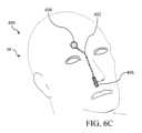
いくつかの実装態様では、配向及び/又は距離は、特定の物体(例えば、光学基準)又は患者の解剖学的構造(例えば、目)を識別するために、キャプチャされた(ブロック306)画像の画像分析を使用して決定され得る。例えば、特に予測可能なサイズ、形状、及び他の特性を有する光学基準の場合、光学基準を含む画像の画像分析は、光学基準が見られる距離及び視点を示し得る。図6Aを参照すると、患者の頭部(H)に配置されている患者追跡アセンブリ(200)が見て取れる。1つ以上の光学基準(230、232)は、所望に応じて、患者追跡アセンブリ(200)上か、又は他の場所に配置されてもよい。In some implementations, the orientation and/or distance may be determined using image analysis of the captured (block 306) image to identify particular objects (e.g., optical fiducials) or patient anatomical structures (e.g., eyes). For example, image analysis of the image including the optical fiducials may indicate the distance and viewpoint from which the optical fiducials are viewed, particularly for optical fiducials having predictable sizes, shapes, and other characteristics. With reference to FIG. 6A, a patient tracking assembly (200) can be seen positioned on the patient's head (H). One or more optical fiducials (230, 232) may be positioned on the patient tracking assembly (200) or elsewhere, as desired.
画像内の光学基準(230)の外観は、画像がキャプチャされた視点(例えば、光学基準(230)は、図6Aに示されるように見たときに円として現れるが、観察者が左又は右に移動すると、楕円形として現れ得る)、並びに距離(例えば、光学基準は2cmの直径を有し得る)の指標を提供する。光学基準(230)が、十分な複雑さの非対称形状を有する場合、又は光学基準(230)の表面が、十分な複雑さのパターン又は他の可視特性を有する場合、単一の基準は、配向及び距離を完全に決定するのに十分な情報を提供し得る。The appearance of the optical fiducial (230) in the image provides an indication of the viewpoint from which the image was captured (e.g., the optical fiducial (230) may appear as a circle when viewed as shown in FIG. 6A, but may appear as an oval as the observer moves left or right) as well as distance (e.g., the optical fiducial may have a diameter of 2 cm). If the optical fiducial (230) has an asymmetric shape of sufficient complexity, or if the surface of the optical fiducial (230) has a pattern or other visible characteristic of sufficient complexity, a single fiducial may provide enough information to completely determine orientation and distance.
加えて、図6Aに示されるように、いくつかの光学基準(230、232)が使用される場合、他の基準に対するそれぞれの基準の見かけの位置が、配向の指標として使用され得る。したがって、追跡アセンブリ(200)又は頭部(H)上に2つ以上の光学基準を配置することが有利であり得る。いくつかの実装態様では、製造時に1つ以上の基準が追跡アセンブリ(200)の表面に統合され得、これは有利には、その後の基準ベースの配向及び距離の決定を支援するために使用され得る、互いからの静的な既知の位置付け及び距離を示し得る。In addition, as shown in FIG. 6A, when several optical fiducials (230, 232) are used, the apparent position of each fiducial relative to the other fiducials can be used as an indication of orientation. Therefore, it can be advantageous to place two or more optical fiducials on the tracking assembly (200) or head (H). In some implementations, one or more fiducials can be integrated into the surface of the tracking assembly (200) at the time of manufacture, which can advantageously indicate a static, known positioning and distance from each other that can be used to assist in subsequent fiducial-based orientation and distance determinations.
説明されているように、実装態様は、配向(ブロック308)及び距離(ブロック310)を決定するために取られ特定のアプローチで異なる場合があり、いくつかの実装態様は、IGSナビゲーション座標系内でそれぞれの目的の物体を追跡することに完全に依存してもよいが、他の実装態様は、その結果の精度、性能、又は他の特性を改善するために、そのような追跡と、光学基準の画像分析又は他の技術とを組み合わせてもよい。したがって、開示された方法及び他の方法の様々な組み合わせが存在し、配向(ブロック308)及び距離(ブロック310)を決定するための様々な利点を提供することになり、そのような組み合わせは、本開示に基づいて当業者には明らかであることを理解されたい。As described, implementations may vary in the particular approach taken to determine orientation (block 308) and distance (block 310), with some implementations relying entirely on tracking each object of interest within the IGS navigation coordinate system, while other implementations may combine such tracking with optically based image analysis or other techniques to improve the resulting accuracy, performance, or other characteristics. Thus, it should be understood that various combinations of the disclosed and other methods exist and will provide various advantages for determining orientation (block 308) and distance (block 310), and such combinations will be apparent to one of ordinary skill in the art based on this disclosure.
観察された解剖学的構造に対する距離及び配向が決定された後は、その距離及び配向を使用して、相関データセットが、観察された解剖学的構造のレンダリングされたオーバーレイとしてディスプレイ(104)を介して表示され得るように、又はキャプチャされた画像のレンダリングされたオーバーレイとして別の装置を介して表示され得るように変換され得る。相関データセット変換としては、例えば、キャプチャされた(ブロック306)画像のスケール及び視点に一致するように手術経路を変換すること(ブロック312)、キャプチャされた(ブロック306)画像のスケール及び視点に一致するようにCT画像又は他の画像タイプを変換すること(ブロック314)、キャプチャされた(ブロック306)画像のスケール及び視点に一致するように外科用器具の遠位先端の追跡位置を変換すること(ブロック315)、及び他の変換が挙げられ得る。図5の文脈内で論じられているが、手術経路、CT画像、及び追跡される外科用ツールは、受信された(ブロック304)相関データセット内に存在する必要がないことを理解されたい。Once the distance and orientation relative to the observed anatomical structure is determined, the distance and orientation may be used to transform the correlated dataset so that it may be displayed via the display (104) as a rendered overlay of the observed anatomical structure or via another device as a rendered overlay of the captured image. Correlated dataset transformations may include, for example, transforming the surgical path (block 312) to match the scale and viewpoint of the captured (block 306) image, transforming the CT image or other image type (block 314) to match the scale and viewpoint of the captured (block 306) image, transforming the tracked position of the distal tip of the surgical instrument (block 315) to match the scale and viewpoint of the captured (block 306) image, and other transformations. Although discussed within the context of FIG. 5, it should be understood that the surgical path, CT image, and tracked surgical tool do not need to be present in the correlated dataset received (block 304).
相関データセットの変換は、相関データセットに表される特定のデータに応じて様々になる。例えば、図8を参照すると、システムが、患者の頭部(H)上のCT画像スライスの一部又は全てをオーバーレイするように構成されている場合、視点(502)(例えば、カメラ(106)のレンズ)と観察点(504)(例えば、カメラ(106)の光軸と交差する座標系内の最初の点、ボクセル、又は他の物体)との間の距離(506)を使用して、CT画像スライスがディスプレイ(104)を介して表示されるスケールを変換し、制御するためのスケーリング係数が決定され、適用され得る。HMD(100)の装着者が頭部(H)に向かって移動すると、距離(506)は減少し、表示されるCT画像スライスのスケールは増大する。同様に、頭部(H)から離れる動きによって、距離(506)が増加し、表示されるCT画像スライスのスケールは縮小される。このようにして、スケーリング係数は、距離(506)に基づいて、その距離での頭部(H)の知覚されるサイズに対応するCT画像の適切なサイズのレンダリングを提供するように構成され得る。Transformations of the correlated data set will vary depending on the particular data represented in the correlated data set. For example, referring to FIG. 8, if the system is configured to overlay some or all of the CT image slices on the patient's head (H), the distance (506) between the viewpoint (502) (e.g., the lens of the camera (106)) and the observation point (504) (e.g., the first point, voxel, or other object in the coordinate system that intersects the optical axis of the camera (106)) can be used to determine and apply a scaling factor to transform and control the scale at which the CT image slices are displayed via the display (104). As the wearer of the HMD (100) moves towards the head (H), the distance (506) decreases and the scale of the displayed CT image slices increases. Similarly, movement away from the head (H) increases the distance (506) and reduces the scale of the displayed CT image slices. In this manner, the scaling factor can be configured based on the distance (506) to provide an appropriately sized rendering of the CT image corresponding to the perceived size of the head (H) at that distance.
上記の例を続けると、観察点(504)に対する視点(502)の位置は、三次元座標系(501)内で、レンダリングするのに適切なCT画像スライスを決定するために使用されてもよく、適切なCT画像スライスを、頭部(H)上にオーバーレイされ得るように変換するのに使用されてもよい。一例として、いくつかの実装態様では、頭部(H)のCT画像スライスは、頭部(H)の上方の視点が軸方向ビューを示し得、頭部の正面からの視点が冠状ビューを示し得、頭部の側部からの視点が矢状ビューを示し得るように、頭部(H)が見られる視点に応じてオーバーレイとして選択され、レンダリングされてもよく、ビューは、HMD(100)の装着者が視点間を移動すると、自動的に切り替えられ得る。Continuing with the above example, the position of the viewpoint (502) relative to the observation point (504) may be used to determine, within the three-dimensional coordinate system (501), the appropriate CT image slice to render, and may be used to transform the appropriate CT image slice so that it can be overlaid on the head (H). As an example, in some implementations, the CT image slices of the head (H) may be selected and rendered as an overlay depending on the viewpoint from which the head (H) is viewed, such that a viewpoint above the head (H) may indicate an axial view, a viewpoint from the front of the head may indicate a coronal view, and a viewpoint from the side of the head may indicate a sagittal view, and the views may be switched automatically as the wearer of the HMD (100) moves between viewpoints.
別の例として、いくつかの実装態様では、CT画像スライスは、それが定位置に固定され、異なる視点から見られているかのような、CT画像スライスの二次元入力画像の外観を有する新しい画像を作成するために変換され得る(例えば、二次元画像視点変換)。このようにして、頭部(H)に表示される二次元CT画像スライスは、HMD(100)の装着者が視点間を移動するにつれて視点変換され得る。As another example, in some implementations, the CT image slices may be transformed to create a new image that has the appearance of the two-dimensional input image of the CT image slice as if it were fixed in place and viewed from a different viewpoint (e.g., two-dimensional image viewpoint transformation). In this way, the two-dimensional CT image slices displayed on the head (H) may be viewpoint transformed as the wearer of the HMD (100) moves between viewpoints.
更に別の変換例として、手術経路を含む相関データセットの場合、手術経路の座標は、1組の点、線、又は点線としてレンダリングされ、頭部(H)にオーバーレイされ得る。距離(506)は、頭部(H)にオーバーレイされたときに、手術経路のそれぞれの座標が頭部(H)に対して適切に位置付けられるように、手術経路のスケールを変換するために使用され得る。座標系(501)内の観察点(504)に対する視点(502)の位置は、(HMD)の装着者が視点間を移動するときに、手術経路を変換するために使用され得る。そのような変換は、上述のように、視点変換として実行されてもよく、又は本明細書の開示に基づいて当業者には明らかであるように、他の三次元回転及び深さ変換を使用して実行されてもよい。As yet another example transformation, for a correlation data set including a surgical path, the coordinates of the surgical path may be rendered as a set of points, lines, or dashed lines and overlaid on the head (H). Distance (506) may be used to transform the scale of the surgical path so that when overlaid on the head (H), each coordinate of the surgical path is properly positioned relative to the head (H). The position of the viewpoint (502) relative to the observation point (504) in the coordinate system (501) may be used to transform the surgical path as the wearer of the (HMD) moves between viewpoints. Such transformations may be performed as viewpoint transformations, as described above, or may be performed using other three-dimensional rotation and depth transformations, as would be apparent to one of ordinary skill in the art based on the disclosure herein.
それぞれの相関データセットが(例えば、スケーリング、視点変換、ないしは別の方法で)変換された後、それらは1つ以上の観察装置上でレンダリング又は表示(ブロック316)されてもよく、これは、ディスプレイ(104)を介してレンダリングされたマーカをオーバーレイとして表示すること、HHD(101)又は別のディスプレイを介してレンダリングされたマーカをキャプチャされた画像上にオーバーレイとして表示すること、又はその両方を含み得る。HMD(100)を装着するユーザにとって、レンダリングされたマーカは、透明ディスプレイ(104)を通して見られる、その視界内の物体(例えば、患者の頭部又は他の解剖学的構造)をオーバーレイするように見え得る。HHD(101)のユーザ又は壁取り付けディスプレイ若しくは他の装置の観察者にとって、キャプチャされた画像は、レンダリングされたマーキングがオーバーレイされた状態で表示され得る。説明されているように、画像をキャプチャする工程、視点を決定する工程、及び相関データセットを変換する工程は、ユーザが、オーバーレイされた情報の連続的な更新を受信しながら、通常どおりに処置領域を動き回り、見回すことができるように、画像がキャプチャされると連続的に繰り返され得る。After each correlated data set has been transformed (e.g., scaled, viewpoint transformed, or otherwise), they may be rendered or displayed (block 316) on one or more viewing devices, which may include displaying the rendered markers as an overlay via the display (104), displaying the rendered markers as an overlay on the captured image via the HMD (101) or another display, or both. To a user wearing the HMD (100), the rendered markers may appear to overlay objects in their field of view (e.g., the patient's head or other anatomical structures) as seen through the transparent display (104). To a user of the HHD (101) or an observer on a wall-mounted display or other device, the captured image may be displayed with the rendered markings overlaid. As described, the steps of capturing images, determining the viewpoint, and transforming the correlated data set may be repeated continuously as images are captured so that the user can move and look around the treatment area as normal while receiving continuous updates of the overlaid information.
例えば、観察される解剖学的構造の動き(ブロック318)又はHMD(100)、HHD(101)、若しくは他の観察装置の動きのいずれかが生じた(ブロック320)場合、次にキャプチャされた(ブロック306)画像が受信され、配向(ブロック308)及び距離(ブロック310)が再決定される。次いで、新たに決定された配向及び距離は、1つ以上の変換に使用され、新たに生成されるオーバーレイには、以前の画像以降に発生したあらゆる動き又は変化が考慮されることになる。For example, if either movement of the observed anatomical structure (block 318) or movement of the HMD (100), HHD (101), or other observation device occurs (block 320), the next captured (block 306) image is received and the orientation (block 308) and distance (block 310) are redetermined. The newly determined orientation and distance are then used in one or more transformations such that the newly generated overlay takes into account any movement or changes that have occurred since the previous image.
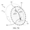
図6A~図6Cは、ディスプレイ(104)を介して表示され、直視される患者の頭部(H)上にオーバーレイされ得るような、又は頭部(H)のキャプチャされた画像上にオーバーレイされ、表示され得るような、レンダリング及び変換された手術経路を含むインターフェース(400)の例を示す。図6Aでは、頭部(H)は、正面から見られており(例えば、冠状面のビュー)、レンダリングされたマーカは、ディスプレイ(104)を介して又は直接、キャプチャされた画像上にオーバーレイされている。レンダリングされたマーカは、外科用ツールが追うべき経路を示す手術経路(402)、処置に関与する解剖学的構造の目的地又は部分を示す標的マーカ(404)、及び追跡される外科用器具の現在の場所を示すツールマーカ(406)を含む。マーカのスケールは、手術経路(402)が、患者の頭部(H)を正確にオーバーレイし、ディスプレイ(104)又は別の装置を介してレンダリングされたオーバーレイとしてではなく、冠状面のCT画像スライス上で直視するのと同じように見えるように、決定された距離(310)に基づいて決定されている。マーカの位置及び配向も、決定された配向(308)に基づいて決定されている。6A-6C show an example of an interface (400) including a rendered and transformed surgical path as it may be displayed via the display (104) and overlaid on a patient's head (H) viewed directly, or as it may be overlaid and displayed on a captured image of the head (H). In FIG. 6A, the head (H) is viewed from the front (e.g., a coronal view) and the rendered markers are overlaid on the captured image via the display (104) or directly. The rendered markers include a surgical path (402) indicating the path the surgical tool should follow, a target marker (404) indicating the destination or portion of the anatomical structure involved in the procedure, and a tool marker (406) indicating the current location of the tracked surgical instrument. The scale of the markers is determined based on the determined distance (310) so that the surgical path (402) accurately overlays the patient's head (H) and appears as if viewed directly on a coronal CT image slice, rather than as an overlay rendered via the display (104) or another device. The location and orientation of the markers are also determined based on the determined orientation (308).
図6Bは、側面から見た頭部(H)(例えば、矢状面のビュー)を示す。それぞれのマーカは、視点の変化に基づいて、新しい位置及び配向でレンダリングされている。例えば、図6Aでは、手術経路(402)は、頭部(H)の冠状面に沿って横断しているように見える。冠状面は、図6Bでは見られず、代わりに、矢状面に沿って横断する手術経路(402)が見て取れる。同様に、標的マーカ(404)及びツールマーカ(406)の位置及び配向はそれぞれ、図6Aから変更され、頭部(H)内の、それらのマーカが位置付けられている深さが決定され得る。図6Cは、観察者が図6Aのビューと図6Bのビューとの間を移動するときに見られるような、第3の視点から見た頭部(H)を示す。観察者が図6Aのビューと図6Bのビューとの間で移動するか、又は頭部(H)が見られ得る他の視点に移動すると、マーカのそれぞれは、追加情報及びコンテキストを提供するために更新され、新たにレンダリングされ得、CT画像セットによって提供される視点のみに限定されることもなく、また、説明されているように、頭部(H)からディスプレイスクリーン(16)又は別のディスプレイへと目を離すことで、気が散って方向感覚を失うこともない。FIG. 6B shows the head (H) from a side view (e.g., a sagittal view). Each marker is rendered in a new position and orientation based on the change in viewpoint. For example, in FIG. 6A, the surgical path (402) appears to traverse along the coronal plane of the head (H). The coronal plane is not seen in FIG. 6B, and instead, the surgical path (402) is seen traversing along the sagittal plane. Similarly, the positions and orientations of the target marker (404) and tool marker (406), respectively, are changed from FIG. 6A, and the depth at which they are positioned within the head (H) can be determined. FIG. 6C shows the head (H) from a third viewpoint, as seen when an observer moves between the views of FIG. 6A and FIG. 6B. As the observer moves between the views of FIG. 6A and FIG. 6B, or to other viewpoints from which the head (H) may be seen, each of the markers may be updated and newly rendered to provide additional information and context, without being limited to only the viewpoints provided by the CT image set, and without the distraction and disorientation of looking away from the head (H) to the display screen (16) or another display, as described.
可視化システム(60)によって提供され得るインターフェースの別の例として、図7Aは、CT画像セットから選択された画像(430)を示し、図7B~図7Dは、ディスプレイ(104)を介して表示され、直視される患者の頭部(H)上にオーバーレイされ得るような、又は頭部(H)のキャプチャされた画像上にオーバーレイされ、表示され得るような、画像(430)及び手術経路(402)のレンダリングされたオーバーレイを含むインターフェース(440)の例を示す。画像(430)、手術経路(402)、及び標的マーカ(404)は、処置の前に相関データセットとして受信(304)され得る。As another example of an interface that may be provided by the visualization system (60), FIG. 7A shows a selected image (430) from a CT image set, and FIGS. 7B-7D show an example of an interface (440) including a rendered overlay of the image (430) and the surgical path (402) as may be displayed via the display (104) and overlaid on a directly viewed patient's head (H), or as may be overlaid and displayed on a captured image of the head (H). The image (430), surgical path (402), and target markers (404) may be received (304) as a correlated data set prior to the procedure.
図7Bでは、頭部(H)は、図6Aの視点と同じ視点から見られている。画像(430)はまた、画像(430)のスケールが頭部(H)の知覚されるサイズに対応するように変換された後(例えば、画像(430)が大きすぎて、頭部(H)を越えて延在してしまうのとは対照的に)、頭部(H)上にオーバーレイされている。ツールマーカ(406)、手術経路(402)、及び標的マーカ(404)も、CT画像(430)と共にオーバーレイされ、可視であり得、それぞれ、レンダリングを介して頭部(H)の直接的な見え方を完全に不明瞭にするか、又はいくらかの透明度を可能にするかのいずれかにするように、様々な透明度でレンダリングされ得る。可視化システム(60)の様々な実装態様は、図6A~図6C又は図7B~図7Dに示されるようなインターフェースを提供し得るが、いくつかの実装態様は、その両方を提供し得、例えば、ある特定の層を、所望に応じて有効又は無効にすることを可能にし得る。例えば、これは、所望され得るように、頭部(H)への画像(430)のオーバーレイを有効又は無効にすることを含み得る。In FIG. 7B, the head (H) is viewed from the same perspective as in FIG. 6A. The image (430) is also overlaid on the head (H) after the scale of the image (430) has been transformed to correspond to the perceived size of the head (H) (e.g., as opposed to the image (430) being too large and extending beyond the head (H)). The tool markers (406), surgical path (402), and target markers (404) are also overlaid with the CT image (430) and may be visible, each of which may be rendered with various degrees of transparency to either completely obscure the direct view of the head (H) through the rendering or allow some transparency. Various implementations of the visualization system (60) may provide interfaces as shown in FIGS. 6A-6C or 7B-7D, while some implementations may provide both, for example allowing certain layers to be enabled or disabled as desired. For example, this may include enabling or disabling the overlay of image (430) on the head (H), as may be desired.
図7C及び図7Dはそれぞれ、図6B及び図6Cに示されるものと一致する、異なる視点からの頭部(H)を示す。画像(430)は、影付き領域としてシミュレートされ、他のレンダリングされたマーキングはそれぞれ、変更された視点を考慮して変換される。記載されているように、図7Bは、冠状面の実質的に変更されていないCT画像を画像(430)として示し得るが、図7Cは、矢状面の実質的に変更されていないCT画像を画像(430)として示し得る。いくつかの実装態様では、図7Dは、観察者の視点が冠状面に近いか、又は矢状面に近いかどうかに応じて、冠状面又は矢状面から変換されたCT画像を示し得る。7C and 7D show the head (H) from different viewpoints, consistent with those shown in FIGS. 6B and 6C, respectively. The image (430) is simulated as a shaded region, and other rendered markings are transformed to account for the altered viewpoint, respectively. As described, FIG. 7B may show a substantially unaltered CT image in the coronal plane as image (430), while FIG. 7C may show a substantially unaltered CT image in the sagittal plane as image (430). In some implementations, FIG. 7D may show a CT image transformed from the coronal or sagittal plane, depending on whether the observer's viewpoint is closer to the coronal or sagittal plane.
図6A~図7Cのインターフェースは、相関データセットがレンダリングされ、ディスプレイ(104)の透明部分を通して見える物体上にオーバーレイされたときに表示され得るインターフェースを表すことを理解されたい。例えば、図6Aを参照すると、頭部(H)は、ディスプレイ(104)を介してレンダリングされていないが、ディスプレイ(104)の透明部分を通して見られているため、拡張現実インターフェースの可視部分となる。図6A~図7Cのインターフェースはまた、相関データセットが、ディスプレイスクリーン(16)を介して表示され得るか、又はHHD(101)を介して表示され得るような、レンダリングされ、カメラ(106)を介してキャプチャされた画像上にオーバーレイされたときに表示され得るインターフェースを表す。そのようなインターフェースでは、キャプチャされた画像に基づいて、頭部(H)もディスプレイ上にレンダリングされる。It should be understood that the interfaces of FIGS. 6A-7C represent interfaces that may be displayed when the correlated data set is rendered and overlaid on an object seen through a transparent portion of the display (104). For example, referring to FIG. 6A, the head (H) is not rendered through the display (104), but is seen through a transparent portion of the display (104) and is therefore a visible part of the augmented reality interface. The interfaces of FIGS. 6A-7C also represent interfaces that may be displayed when the correlated data set is rendered and overlaid on an image captured through the camera (106), such as may be displayed through the display screen (16) or may be displayed through the HHD (101). In such an interface, the head (H) is also rendered on the display based on the captured image.
III.例示的な組み合わせ
以下の実施例は、本明細書の教示を組み合わせるか又は適用することができる、種々の非網羅的な方法に関する。以下の実施例は、本出願における又は本出願の後の書類提出における任意の時点で提示され得るいずれの特許請求の適用範囲をも限定することを意図したものではないことを理解されたい。一切の権利放棄を意図するものではない。以下の実施例は、あくまでも例示的な目的で与えられるものに過ぎない。本明細書の種々の教示は、その他の多くの方式で構成及び適用が可能であると考えられる。また、いくつかの変形形態では、以下の実施例において言及される特定の特徴を省略してよいことも考えられる。したがって、本発明者らによって又は本発明者らの利益の承継者によって、後日そうである旨が明示的に示されない限り、以下に言及される態様又は特徴のいずれも重要なものとしてみなされるべきではない。いずれの特許請求が、本出願において、又は以下に言及される特徴以外の更なる特徴を含む本出願に関連する後の書類提出において示される場合、それらの更なる特徴は、特許性に関連するいかなる理由によっても追加されたものとして仮定されるべきではない。 III. EXEMPLARY COMBINATIONS The following examples relate to various non-exhaustive methods in which the teachings herein may be combined or applied. It should be understood that the following examples are not intended to limit the scope of any claims that may be presented at any time in this application or in a later filing of this application. No disclaimer is intended. The following examples are provided for illustrative purposes only. It is contemplated that the various teachings herein may be configured and applied in many other ways. It is also contemplated that certain features mentioned in the following examples may be omitted in some variations. Thus, none of the aspects or features mentioned below should be considered as critical unless expressly indicated to be so at a later date by the inventors or by the inventors' successors in interest. If any claim is presented in this application or in a later filing related to this application that includes additional features other than those mentioned below, those additional features should not be presumed to have been added for any reason related to patentability.
ENT可視化のためのシステムであって、(a)画像誘導手術(「IGS」)ナビゲーションシステムであって、(i)追跡された領域に対応する座標系を維持し、(ii)座標系を用いて1つ以上の位置センサを追跡し、(iii)患者の解剖学的構造の場所を座標系と位置合わせするように動作可能な、画像誘導手術(「IGS」)ナビゲーションシステムと、(b)ウェアラブルフレーム及びディスプレイを含むヘッドマウントディスプレイ(「HMD」)であって、ディスプレイは、装着者の中立光軸と交差するように、ウェアラブルフレーム上に位置付けられている、ヘッドマウントディスプレイ(「HMD」)と、(c)患者の解剖学的構造に対するHMDの視点を示す視点データのセットを生成するように動作可能なセンサと、(d)プロセッサと、を備え、プロセッサは、(i)1つ以上の相関データセットを受信することであって、1つ以上の相関データセットのそれぞれは、座標系に関連付けられたデータを含む、ことと、(ii)患者の解剖学的構造が、現在の視点から見られている間に、視点データのセットに基づいて、患者の解剖学的構造上の観察点に対する中立光軸の配向を決定することと、(iii)視点データのセットに基づいて、中立光軸の原点と観察点との間の距離を決定することと、(iv)配向及び距離に基づいて、1つ以上の相関データセットを変換して、現在の視点で患者の解剖学的構造に対応するオーバーレイ画像を生成することと、(v)ディスプレイを介してオーバーレイ画像をレンダリングすることと、を行うように構成されている、システム。A system for ENT visualization, comprising: (a) an image-guided surgery ("IGS") navigation system operable to (i) maintain a coordinate system corresponding to a tracked region, (ii) track one or more position sensors with the coordinate system, and (iii) align a location of a patient's anatomy with the coordinate system; (b) a head-mounted display ("HMD") including a wearable frame and a display, the display being positioned on the wearable frame such that it intersects with a neutral optical axis of the wearer; (c) a sensor operable to generate a set of viewpoint data indicative of a viewpoint of the HMD relative to the patient's anatomy; and (d) a display sensor operable to generate a set of viewpoint data indicative of a viewpoint of the HMD relative to the patient's anatomy. and a processor configured to: (i) receive one or more correlation data sets, each of the one or more correlation data sets including data associated with a coordinate system; (ii) determine an orientation of a neutral optical axis relative to an observation point on the patient's anatomy based on the set of viewpoint data while the patient's anatomy is viewed from a current viewpoint; (iii) determine a distance between an origin of the neutral optical axis and the observation point based on the set of viewpoint data; (iv) transform the one or more correlation data sets based on the orientation and distance to generate an overlay image corresponding to the patient's anatomy at the current viewpoint; and (v) render the overlay image via a display.
1つ以上の相関データセットは、(i)患者の解剖学的構造内の外科用器具の計画された経路を示す手術経路、及び(ii)1つ以上の位置センサのうちの1つの位置センサに関連付けられた遠位先端の現在の場所を示す遠位先端場所を含む、実施例1に記載のシステム。The system of Example 1, wherein the one or more correlation data sets include (i) a surgical path indicating a planned path of the surgical instrument within the patient's anatomy, and (ii) a distal tip location indicating a current location of the distal tip associated with one of the one or more position sensors.
1つ以上の相関データセットは、患者の解剖学的構造の術前画像のセットから選択された画像スライスを更に含む、実施例2に記載のシステム。The system of Example 2, wherein the one or more correlation data sets further include image slices selected from a set of preoperative images of the patient's anatomy.
患者の解剖学的構造上に位置付けられた患者追跡アセンブリを更に備え、(i)患者追跡アセンブリは、1つ以上の位置センサのうちの1つの位置センサを含み、(ii)IGSナビゲーションシステムは、位置センサの動きに基づいて、座標系で患者の解剖学的構造の場所を更新するように構成されている、実施例1~2のいずれか1つ以上に記載のシステム。The system of any one or more of Examples 1-2, further comprising a patient tracking assembly positioned on the patient's anatomy, (i) the patient tracking assembly including one of the one or more position sensors, and (ii) the IGS navigation system configured to update the location of the patient's anatomy in the coordinate system based on movement of the position sensor.
センサは、HMDに取り付けられており、1つ以上の位置センサのうちの1つであり、プロセッサは、観察点に対する中立光軸の配向を決定するときに、(i)座標系に基づいて、中立光軸の配向を決定し、(ii)座標系に基づいて、患者の解剖学的構造の配向を決定し、(iii)座標系に基づいて、中立光軸の配向と患者の解剖学的構造の配向とを相関させるように更に構成されている、実施例4に記載のシステム。The system of Example 4, wherein the sensor is attached to the HMD and is one of one or more position sensors, and the processor is further configured to, when determining the orientation of the neutral optical axis relative to the observation point, (i) determine the orientation of the neutral optical axis based on a coordinate system, (ii) determine the orientation of the patient's anatomical structures based on the coordinate system, and (iii) correlate the orientation of the neutral optical axis with the orientation of the patient's anatomical structures based on the coordinate system.
センサは、HMDに取り付けられており、1つ以上の位置センサのうちの1つであり、プロセッサは、原点と観察点との間の距離を決定するときに、(i)座標系に基づいて、原点の場所を決定し、(ii)座標系に基づいて、患者の解剖学的構造の場所を決定し、(iii)座標系に基づいて、原点の場所と患者の解剖学的構造の場所との間の距離を決定するように更に構成されている、実施例4~5のいずれか1つ以上に記載のシステム。The system according to any one or more of Examples 4-5, wherein the sensor is attached to the HMD and is one of one or more position sensors, and the processor is further configured to, when determining the distance between the origin and the observation point, (i) determine a location of the origin based on the coordinate system, (ii) determine a location of the patient's anatomical structure based on the coordinate system, and (iii) determine the distance between the location of the origin and the location of the patient's anatomical structure based on the coordinate system.
プロセッサは、1つ以上の相関データセットを変換するときに、(i)原点と観察点との間の距離に基づいて、スケーリング係数を決定し、(ii)観察点に対する中立光軸の配向に基づいて、視点変換を決定し、(iii)スケーリング係数によって決定されたスケール及び視点変換によって決定された視点を含むオーバーレイ画像を生成するように更に構成されている、実施例1~6のいずれか1つ以上に記載のシステム。The system of any one or more of Examples 1 to 6, wherein the processor is further configured to: (i) determine a scaling factor based on a distance between the origin and the observation point; (ii) determine a viewpoint transformation based on an orientation of the neutral optical axis relative to the observation point; and (iii) generate an overlay image including a scale determined by the scaling factor and a viewpoint determined by the viewpoint transformation when transforming one or more of the correlation data sets.
ディスプレイは透明スクリーンを含み、プロセッサは、オーバーレイ画像が患者の解剖学的構造の直視される部分上に現れるように、オーバーレイ画像を透明スクリーン上にレンダリングするように更に構成されている、実施例7に記載のシステム。The system of Example 7, wherein the display includes a transparent screen, and the processor is further configured to render the overlay image on the transparent screen such that the overlay image appears on a directly viewed portion of the patient's anatomy.
プロセッサは、(i)距離及び配向を繰り返し再決定し、(ii)距離及び配向が変化するにつれて、ディスプレイを介してオーバーレイ画像を更新及びレンダリングするように更に構成されている、実施例1~8のいずれか1つ以上に記載のシステム。The system of any one or more of Examples 1-8, wherein the processor is further configured to (i) repeatedly redetermine the distance and orientation, and (ii) update and render the overlay image via the display as the distance and orientation change.
センサは、ウェアラブルフレーム上に位置付けられ、中立光軸に平行な、かつ中立光軸から静的にオフセットされた光軸を有するカメラを含み、プロセッサは、配向及び距離を決定するときに、(i)物体の1つ以上の可視特性を示し、座標系内の物体と観察点との間の関係を示す、物体データセットを記憶し、(ii)カメラから物体を含む画像を受信し、(iii)物体データセット及び画像に基づいて、配向及び距離を決定するように更に構成されている、実施例1~9のいずれか1つ以上に記載のシステム。The system of any one or more of Examples 1 to 9, wherein the sensor includes a camera positioned on the wearable frame and having an optical axis parallel to and statically offset from the neutral optical axis, and the processor is further configured to, when determining the orientation and distance, (i) store an object dataset indicative of one or more visible characteristics of the object and indicative of a relationship between the object and an observation point in a coordinate system, (ii) receive an image including the object from the camera, and (iii) determine the orientation and distance based on the object dataset and the image.
患者の解剖学的構造に近接して位置付けられた1つ以上の光学基準を更に備え、物体データセットによって説明される物体が、その1つ以上の光学基準である、実施例10に記載のシステム。The system of Example 10 further comprises one or more optical fiducials positioned proximate to the patient's anatomical structure, and the object described by the object dataset is the one or more optical fiducials.
患者の解剖学的構造上に位置付けられた患者追跡アセンブリを更に備え、(i)患者追跡アセンブリは、1つ以上の位置センサのうちの1つの位置センサを含み、(ii)IGSナビゲーションシステムは、位置センサの動きに基づいて、座標系で患者の解剖学的構造の場所を更新するように構成されており、(iii)1つ以上の光学基準は、患者追跡アセンブリの表面上に位置付けられている、実施例11に記載のシステム。The system of Example 11 further comprises a patient tracking assembly positioned on the patient's anatomy, (i) the patient tracking assembly includes one of the one or more position sensors, (ii) the IGS navigation system is configured to update the location of the patient's anatomy in the coordinate system based on movement of the position sensor, and (iii) the one or more optical fiducials are positioned on a surface of the patient tracking assembly.
センサは、ウェアラブルフレーム上に位置付けられ、中立光軸に平行な、かつ中立光軸から静的にオフセットされた光軸を有するカメラを含み、プロセッサは、ディスプレイを介してオーバーレイ画像をレンダリングすることに加えて、(i)カメラから画像を受信し、画像を、既知の静的オフセット値に基づいてオーバーレイ画像に相関させ、(ii)画像にオーバーレイ画像を追加して、拡張画像を生成し、(iii)該ディスプレイ以外の1つ以上のディスプレイ上に拡張画像を表示するように更に構成されている、実施例1~12のいずれか1つ以上に記載のシステム。The system of any one or more of Examples 1 to 12, wherein the sensor includes a camera positioned on the wearable frame and having an optical axis parallel to and statically offset from the neutral optical axis, and the processor, in addition to rendering the overlay image via the display, is further configured to: (i) receive an image from the camera and correlate the image to the overlay image based on a known static offset value; (ii) add the overlay image to the image to generate an augmented image; and (iii) display the augmented image on one or more displays other than the display.
(i)プロセッサは、IGSナビゲーションシステムの第1のプロセッサ及びHMDの第2のプロセッサのうちの1つ以上を含み、(ii)センサは、HMDに連結されたジャイロスコープセンサのうちの1つ以上と、HMDに取り付けられたカメラと、HMDに取り付けられた1つ以上の位置センサのうちの1つの位置センサと、を含み、(iii)視点データのセットは、ジャイロスコープ配向データのセット、座標系に関連付けられた位置座標のセット、座標系に関連付けられた配向座標のセット、及びカメラによってキャプチャされた画像のうちの1つ以上を含む、実施例1~13のいずれか1つ以上に記載のシステム。A system according to any one or more of Examples 1 to 13, in which (i) the processor includes one or more of a first processor of an IGS navigation system and a second processor of the HMD, (ii) the sensor includes one or more of a gyroscope sensor coupled to the HMD, a camera attached to the HMD, and one position sensor of the one or more position sensors attached to the HMD, and (iii) the set of viewpoint data includes one or more of a set of gyroscope orientation data, a set of position coordinates associated with a coordinate system, a set of orientation coordinates associated with a coordinate system, and an image captured by the camera.
方法であって、(a)画像誘導手術(「IGS」)ナビゲーションシステムを構成することであって、(i)追跡された領域に対応する座標系を維持し、(ii)座標系を用いて1つ以上の位置センサを追跡するように、構成することと、(b)患者の解剖学的構造の場所を座標系と位置合わせすることと、(c)1つ以上の相関データセットを受信することであって、1つ以上の相関データセットのそれぞれは、座標系に関連付けられたデータを含む、ことと、(d)ウェアラブルフレーム及びディスプレイを含むヘッドマウントディスプレイ(「HMD」)を装着しながら、現在の視点から患者の解剖学的構造を見ることであって、ディスプレイは、装着者の中立光軸と交差するように、ウェアラブルフレーム上に位置付けられる、ことと、(e)HMDのセンサから受信した視点データのセットに基づいて、患者の解剖学的構造上の観察点に対する中立光軸の配向を決定することと、(f)視点データのセットに基づいて、中立光軸の原点と観察点との間の距離を決定することと、(g)配向及び距離に基づいて、1つ以上の相関データセットを変換して、現在の視点で患者の解剖学的構造に対応するオーバーレイ画像を生成することと、(h)ディスプレイを介してオーバーレイ画像をレンダリングすることと、を含む、方法。A method comprising: (a) configuring an image-guided surgery ("IGS") navigation system to (i) maintain a coordinate system corresponding to a tracked region and (ii) track one or more position sensors with the coordinate system; (b) aligning a location of a patient's anatomy with the coordinate system; (c) receiving one or more correlation data sets, each of the one or more correlation data sets including data associated with the coordinate system; and (d) viewing the patient's anatomy from a current viewpoint while wearing a head-mounted display ("HMD") including a wearable frame and a display. (e) determining an orientation of the neutral optical axis relative to an observation point on the patient's anatomy based on a set of viewpoint data received from a sensor of the HMD; (f) determining a distance between an origin of the neutral optical axis and the observation point based on the set of viewpoint data; (g) transforming one or more correlation data sets based on the orientation and distance to generate an overlay image corresponding to the patient's anatomy at the current viewpoint; and (h) rendering the overlay image via the display.
1つ以上の相関データセットを受信することは、(i)患者の解剖学的構造内の外科用器具の計画された経路を示す手術経路を受信することと、(ii)1つ以上の位置センサのうちの1つの位置センサに関連付けられた遠位先端の現在の場所を示す遠位先端場所を受信することと、(iii)患者の解剖学的構造の術前画像のセットから選択された画像スライスを受信することと、を含む、実施例15に記載の方法。The method of example 15, wherein receiving one or more correlated data sets includes: (i) receiving a surgical path indicating a planned path of the surgical instrument within the patient's anatomy; (ii) receiving a distal tip location indicating a current location of a distal tip associated with one of the one or more position sensors; and (iii) receiving a selected image slice from a set of preoperative images of the patient's anatomy.
センサは、ウェアラブルフレーム上に位置付けられ、中立光軸に平行な、かつ中立光軸から静的にオフセットされた光軸を有するカメラを含み、方法は、(a)患者追跡アセンブリを患者の解剖学的構造上に配置することであって、患者追跡アセンブリは、(i)1つ以上の位置センサのうちの1つの位置センサと、(ii)1つ以上の光学基準と、を含む、ことと、(b)1つ以上の光学基準の1つ以上の可視特性を示し、座標系内の1つ以上の光学基準と観察点との間の関係を示す、物体データセットを記憶することと、(c)1つ以上の光学基準を含む画像をカメラから受信することと、(d)物体データセット及び画像に基づいて配向及び距離を決定することと、を更に含む、実施例15~16のいずれか1つ以上に記載の方法。The method of any one or more of Examples 15-16, wherein the sensor is positioned on the wearable frame and includes a camera having an optical axis parallel to and statically offset from the neutral optical axis, and the method further includes: (a) positioning a patient tracking assembly on the patient's anatomy, the patient tracking assembly including (i) one of the one or more position sensors and (ii) one or more optical fiducials; (b) storing an object dataset indicative of one or more visual characteristics of the one or more optical fiducials and indicative of a relationship between the one or more optical fiducials and an observation point in a coordinate system; (c) receiving an image from the camera including the one or more optical fiducials; and (d) determining an orientation and distance based on the object dataset and the image.
センサは、1つ以上の位置センサのうちの第2の位置センサを含み、物体データセット、画像、及び座標系に基づいて配向及び距離を決定することを更に含む、実施例17に記載の方法。The method of example 17, wherein the sensor includes a second position sensor of the one or more position sensors, and further includes determining the orientation and distance based on the object data set, the image, and the coordinate system.
ENT可視化のためのシステムであって、(a)画像誘導手術(「IGS」)ナビゲーションシステムであって、(i)追跡された領域に対応する座標系を維持し、(ii)座標系を用いて1つ以上の位置センサを追跡し、(iii)患者の解剖学的構造の場所を座標系と位置合わせするように動作可能な、画像誘導手術(「IGS」)ナビゲーションシステムと、(b)カメラ及びディスプレイを含むハンドヘルドディスプレイ(「HHD」)と、(c)患者の解剖学的構造に対するHHDの視点を示す視点データのセットを生成するように動作可能なセンサと、(d)プロセッサと、を備え、プロセッサは、(i)1つ以上の相関データセットを受信することであって、1つ以上の相関データセットのそれぞれは、座標系に関連付けられたデータを含む、ことと、(ii)HHDが現在の視点から患者の解剖学的構造に向けられている間に、カメラから画像を受信することと、(iii)視点データのセットに基づいて、患者の解剖学的構造上の観察点に対するカメラの光軸の配向を決定することと、(iv)視点データのセットに基づいて、光軸の原点と観察点との間の距離を決定することと、(v)配向及び距離に基づいて、1つ以上の相関データセットを変換して、画像内の患者の解剖学的構造に対応するオーバーレイ画像を生成することと、(vi)オーバーレイ画像及び画像に基づいて、ディスプレイを介して拡張画像を表示することと、を行うように構成されている、システム。A system for ENT visualization, comprising: (a) an image-guided surgery ("IGS") navigation system operable to (i) maintain a coordinate system corresponding to a tracked region, (ii) track one or more position sensors with the coordinate system, and (iii) align a location of a patient's anatomy with the coordinate system; (b) a handheld display ("HHD") including a camera and a display; (c) a sensor operable to generate a set of viewpoint data indicative of a viewpoint of the HHD relative to the patient's anatomy; and (d) a processor, the processor operable to (i) receive one or more correlated data sets, the one or more correlated data sets being operable to generate a set of viewpoint data indicative of a viewpoint of the HHD relative to the patient's anatomy. Each of the sets includes data associated with a coordinate system; (ii) receive images from the camera while the HHD is pointed at the patient's anatomy from a current viewpoint; (iii) determine an orientation of an optical axis of the camera relative to an observation point on the patient's anatomy based on the set of viewpoint data; (iv) determine a distance between an origin of the optical axis and the observation point based on the set of viewpoint data; (v) transform one or more correlation data sets based on the orientation and distance to generate an overlay image corresponding to the patient's anatomy in the image; and (vi) display an augmented image via the display based on the overlay image and the image.
(i)センサは、1つ以上の位置センサのうちの1つの位置センサであり、(ii)1つ以上の位置センサのうちの第2の位置センサは、患者の解剖学的構造上に位置付けられ、(iii)1つ以上の相関データセットは、(A)患者の解剖学的構造内の外科用器具の計画された経路を示す手術経路と、(B)1つ以上の位置センサのうちの第3の位置センサに関連付けられた遠位先端の現在の場所を示す遠位先端場所と、を含む、実施例19に記載のシステム。The system of Example 19, wherein (i) the sensor is one position sensor of the one or more position sensors, (ii) a second position sensor of the one or more position sensors is positioned on the patient's anatomy, and (iii) the one or more correlated data sets include (A) a surgical path indicating a planned path of the surgical instrument within the patient's anatomy, and (B) a distal tip location indicating a current location of the distal tip associated with a third position sensor of the one or more position sensors.
IV.その他
本明細書に記載の教示、表現、実施形態、実施例などのうちのいずれか1つ以上を、本明細書に記載の他の教示、表現、実施形態、実施例などのうちのいずれか1つ以上と組み合わせることができる点が理解されるべきである。したがって、上記の教示、表現、実施形態、実施例などは、互いに対して独立して考慮されるべきではない。本明細書の教示を組み合わせることができる様々な好適な方法は、本明細書の教示に鑑みて当業者には容易に明らかであろう。このような修正例及び変形例は、特許請求の範囲に含まれることが意図される。 IV. Other It should be understood that any one or more of the teachings, expressions, embodiments, examples, etc. described herein can be combined with any one or more of the other teachings, expressions, embodiments, examples, etc. described herein. Thus, the above teachings, expressions, embodiments, examples, etc. should not be considered independently of each other. Various suitable ways in which the teachings of this specification can be combined will be readily apparent to those skilled in the art in light of the teachings of this specification. Such modifications and variations are intended to be included within the scope of the claims.
本明細書に参照により組み込まれると言及されるあらゆる特許、公報、又はその他の開示内容は、全体的に又は部分的に、組み込まれる内容が現行の定義、見解、又は本開示に記載されるその他の開示内容とあくまで矛盾しない範囲でのみ本明細書に組み込まれることを理解されたい。それ自体、また必要な範囲で、本明細書に明瞭に記載される開示内容は、参照により本明細書に組み込まれるあらゆる矛盾する記載に優先するものとする。参照により本明細書に組み込まれると言及されているが、現行の定義、見解、又は本明細書に記載される他の開示内容と矛盾する任意の内容、又はそれらの部分は、組み込まれた内容と現行の開示内容との間に矛盾が生じない範囲においてのみ、組み込まれるものとする。Any patent, publication, or other disclosure referred to as being incorporated by reference herein, in whole or in part, is to be understood as being incorporated herein only to the extent that the incorporated content does not conflict with current definitions, views, or other disclosures set forth in this disclosure. As such, and to the extent necessary, the disclosures expressly set forth herein shall take precedence over any conflicting statements incorporated herein by reference. Any content, or portions thereof, referred to as being incorporated by reference herein but which conflicts with current definitions, views, or other disclosures set forth herein shall be incorporated only to the extent that no conflict arises between the incorporated content and the current disclosures.
上述の装置の変形例は、1回の使用後に処分するように設計することができ、又はそれらは、複数回使用するように設計することができる。変形形態は、いずれか又は両方の場合においても、少なくとも1回の使用後に再利用のために再調整することができる。再調整は、装置の分解工程、それに続く特定の部品の洗浄又は交換工程、及びその後の再組立工程の任意の組み合わせを含み得る。特に、装置のいくつかの変形形態は分解することができ、また、装置の任意の数の特定の部分又は部品を、任意の組み合わせで選択的に交換又は除去することができる。特定の部品の洗浄及び/又は交換の際、装置のいくつかの変形形態を、再調整施設において、又は処置の直前にユーザによって、その後の使用のために再組み立てすることができる。当業者であれば、装置の再調整において、分解、洗浄/交換、及び再組立のための様々な技術を利用することができることを理解するであろう。かかる技術の使用、及び結果として得られる再調整された装置は、全て本出願の範囲内にある。The device variations described above may be designed to be disposed of after a single use, or they may be designed to be used multiple times. The variations, in either or both cases, may be reconditioned for reuse after at least one use. Reconditioning may include any combination of the steps of disassembly of the device, followed by cleaning or replacement of particular parts, and subsequent reassembly. In particular, some variations of the device may be disassembled, and any number of particular portions or parts of the device may be selectively replaced or removed in any combination. Upon cleaning and/or replacement of particular parts, some variations of the device may be reassembled for subsequent use at a reconditioning facility, or by a user immediately prior to a procedure. Those skilled in the art will appreciate that reconditioning of a device may utilize a variety of techniques for disassembly, cleaning/replacement, and reassembly. The use of such techniques, and the resulting reconditioned device, are all within the scope of the present application.
単に例として、本明細書に記載される変形形態は、処置の前及び/又は後に滅菌されてもよい。1つの滅菌技術では、装置をプラスチック製又はTYVEK製のバックなど、閉鎖及び封止された容器に入れる。次に、容器及び装置を、γ線、X線、又は高エネルギー電子線などの、容器を透過し得る放射線場に置いてもよい。放射線は、装置上及び容器内の細菌を死滅させ得る。次に、滅菌された装置を、後の使用のために、滅菌容器内に保管してもよい。装置はまた、ベータ線若しくはガンマ線、エチレンオキシド、又は蒸気を含むがこれらに限定されない、当該技術分野で周知の任意の他の技術を用いて滅菌することができる。By way of example only, the variations described herein may be sterilized before and/or after treatment. In one sterilization technique, the device is placed in a closed and sealed container, such as a plastic or TYVEK bag. The container and device may then be placed in a field of radiation that can penetrate the container, such as gamma radiation, x-rays, or a high-energy electron beam. The radiation may kill bacteria on the device and in the container. The sterilized device may then be stored in the sterile container for later use. The device may also be sterilized using any other technique known in the art, including but not limited to beta or gamma radiation, ethylene oxide, or steam.
本発明の様々な実施形態を示し記載したが、当業者による適切な修正により、本発明の範囲から逸脱することなく、本明細書に記載の方法及びシステムの更なる適合化を実現することができる。このような可能な修正のうちのいくつかについて述べたが、その他の修正が当業者には明らかとなるであろう。例えば、上記の実施例、実施形態、幾何学的形状、材料、寸法、比率、工程などは例示的なものであり、必須のものではない。したがって、本発明の範囲は、以下の特許請求の範囲の観点から考慮されるべきものであり、本明細書及び図面に示され記載された構造及び動作の細部に限定されないものとして理解される。Although various embodiments of the present invention have been shown and described, further adaptations of the methods and systems described herein may be achieved by those skilled in the art through appropriate modifications without departing from the scope of the present invention. Although some of such possible modifications have been described, other modifications will be apparent to those skilled in the art. For example, the above examples, embodiments, geometries, materials, dimensions, ratios, steps, etc. are illustrative and not required. Accordingly, the scope of the present invention should be considered in light of the following claims and should not be understood to be limited to the details of structure and operation shown and described in the specification and drawings.
〔実施の態様〕
(1) ENT可視化のためのシステムであって、
(a)画像誘導手術(「IGS」)ナビゲーションシステムであって、
(i)追跡された領域に対応する座標系を維持し、
(ii)前記座標系を用いて1つ以上の位置センサを追跡し、
(iii)患者の解剖学的構造の場所を前記座標系と位置合わせするように動作可能である、画像誘導手術(「IGS」)ナビゲーションシステムと、
(b)ウェアラブルフレーム及びディスプレイを含むヘッドマウントディスプレイ(「HMD」)であって、前記ディスプレイは、装着者の中立光軸と交差するように、前記ウェアラブルフレーム上に位置付けられている、ヘッドマウントディスプレイ(「HMD」)と、
(c)前記患者の解剖学的構造に対する前記HMDの視点を示す視点データのセットを生成するように動作可能なセンサと、
(d)プロセッサと、を備え、
前記プロセッサが、
(i)1つ以上の相関データセットを受信することであって、前記1つ以上の相関データセットのそれぞれは、前記座標系に関連付けられたデータを含む、ことと、
(ii)前記患者の解剖学的構造が、現在の視点から見られている間に、前記視点データのセットに基づいて、前記患者の解剖学的構造上の観察点に対する前記中立光軸の配向を決定することと、
(iii)前記視点データのセットに基づいて、前記中立光軸の原点と前記観察点との間の距離を決定することと、
(iv)前記配向及び前記距離に基づいて、前記1つ以上の相関データセットを変換して、前記現在の視点で前記患者の解剖学的構造に対応するオーバーレイ画像を生成することと、
(v)前記ディスプレイを介して前記オーバーレイ画像をレンダリングすることと、を行うように構成されている、システム。
(2) 前記1つ以上の相関データセットは、
(i)前記患者の解剖学的構造内の外科用器具の計画された経路を示す手術経路と、
(ii)前記1つ以上の位置センサのうちの1つの位置センサに関連付けられた遠位先端の現在の場所を示す遠位先端場所と、を含む、実施態様1に記載のシステム。
(3) 前記1つ以上の相関データセットは、前記患者の解剖学的構造の術前画像のセットから選択された画像スライスを更に含む、実施態様2に記載のシステム。
(4) 前記患者の解剖学的構造上に位置付けられた患者追跡アセンブリを更に備え、
(i)前記患者追跡アセンブリは、前記1つ以上の位置センサのうちの1つの位置センサを含み、
(ii)前記IGSナビゲーションシステムは、前記位置センサの動きに基づいて、前記座標系で前記患者の解剖学的構造の前記場所を更新するように構成されている、実施態様1に記載のシステム。
(5) 前記センサは、前記HMDに取り付けられており、前記1つ以上の位置センサのうちの1つであり、前記プロセッサは、前記観察点に対する前記中立光軸の前記配向を決定するときに、
(i)前記座標系に基づいて、前記中立光軸の配向を決定し、
(ii)前記座標系に基づいて、前記患者の解剖学的構造の配向を決定し、
(iii)前記座標系に基づいて、前記中立光軸の前記配向と前記患者の解剖学的構造の前記配向とを相関させるように更に構成されている、実施態様4に記載のシステム。[Embodiment]
(1) A system for visualizing ENT, comprising:
(a) an image-guided surgery ("IGS") navigation system, comprising:
(i) maintaining a coordinate system corresponding to the tracked region;
(ii) tracking one or more position sensors with the coordinate system;
(iii) an image-guided surgery ("IGS") navigation system operable to register a location of a patient's anatomy with said coordinate system; and
(b) a head mounted display ("HMD") including a wearable frame and a display, the display being positioned on the wearable frame such that it intersects a neutral optical axis of a wearer; and
(c) a sensor operable to generate a set of viewpoint data indicative of a viewpoint of the HMD relative to the patient's anatomy; and
(d) a processor;
The processor,
(i) receiving one or more correlated data sets, each of the one or more correlated data sets including data associated with the coordinate system;
(ii) determining an orientation of the neutral optical axis relative to a viewing point on the patient's anatomy based on the set of viewpoint data while the patient's anatomy is viewed from a current viewpoint; and
(iii) determining a distance between an origin of the neutral optical axis and the observation point based on the set of viewpoint data; and
(iv) transforming the one or more correlated data sets based on the orientation and the distance to generate an overlay image corresponding to the patient's anatomy at the current viewpoint;
(v) rendering the overlay image via the display.
(2) the one or more correlated data sets include
(i) a surgical path indicating a planned path of a surgical instrument within the patient's anatomy;
(ii) a distal tip location indicating a current location of a distal tip associated with one of the one or more position sensors.
3. The system of claim 2, wherein the one or more correlated data sets further include image slices selected from a set of pre-operative images of the patient's anatomy.
(4) further comprising a patient tracking assembly positioned over the patient's anatomy;
(i) the patient tracking assembly includes a position sensor of the one or more position sensors;
(ii) The system of claim 1, wherein the IGS navigation system is configured to update the location of the patient's anatomical structure in the coordinate system based on movement of the position sensor.
(5) the sensor is attached to the HMD and is one of the one or more position sensors, and the processor, when determining the orientation of the neutral optical axis with respect to the observation point,
(i) determining an orientation of the neutral optical axis based on the coordinate system;
(ii) determining an orientation of the patient's anatomy based on the coordinate system;
(iii) correlating the orientation of the neutral optical axis with the orientation of the patient's anatomical structure based on the coordinate system.
(6) 前記センサは、前記HMDに取り付けられており、前記1つ以上の位置センサのうちの1つであり、前記プロセッサは、前記原点と前記観察点との間の前記距離を決定するときに、
(i)前記座標系に基づいて、前記原点の場所を決定し、
(ii)前記座標系に基づいて、前記患者の解剖学的構造の場所を決定し、
(iii)前記座標系に基づいて、前記原点の前記場所と前記患者の解剖学的構造の前記場所との間の前記距離を決定するように更に構成されている、実施態様4に記載のシステム。
(7) 前記プロセッサは、前記1つ以上の相関データセットを変換するときに、
(i)前記原点と前記観察点との間の前記距離に基づいて、スケーリング係数を決定し、
(ii)前記観察点に対する前記中立光軸の前記配向に基づいて、視点変換を決定し、
(iii)前記スケーリング係数によって決定されたスケール及び前記視点変換によって決定された視点を含む前記オーバーレイ画像を生成するように更に構成されている、実施態様1に記載のシステム。
(8) 前記ディスプレイは透明スクリーンを含み、前記プロセッサは、前記オーバーレイ画像が前記患者の解剖学的構造の直視される部分上に現れるように、前記オーバーレイ画像を前記透明スクリーン上にレンダリングするように更に構成されている、実施態様7に記載のシステム。
(9) 前記プロセッサは、
(i)前記距離及び前記配向を繰り返し再決定し、
(ii)前記距離及び前記配向の変化に応じて、前記ディスプレイを介して前記オーバーレイ画像を更新及びレンダリングするように更に構成されている、実施態様1に記載のシステム。
(10) 前記センサは、前記ウェアラブルフレーム上に位置付けられ、前記中立光軸に平行な、かつ前記中立光軸から静的にオフセットされた光軸を有するカメラを含み、前記プロセッサは、前記配向及び前記距離を決定するときに、
(i)物体の1つ以上の可視特性を示し、前記座標系内の前記物体と前記観察点との間の関係を示す、物体データセットを記憶し、
(ii)前記物体を含む画像を前記カメラから受信し、
(iii)前記物体データセット及び前記画像に基づいて、前記配向及び前記距離を決定するように更に構成されている、実施態様1に記載のシステム。(6) The sensor is attached to the HMD and is one of the one or more position sensors, and when the processor determines the distance between the origin and the observation point,
(i) determining a location of the origin based on the coordinate system;
(ii) determining a location of the patient's anatomical structure based on the coordinate system;
(iii) determining the distance between the location of the origin and the location of the patient's anatomical structure based on the coordinate system.
(7) When transforming the one or more correlation data sets, the processor:
(i) determining a scaling factor based on the distance between the origin and the observation point;
(ii) determining a viewpoint transformation based on the orientation of the neutral optical axis relative to the observation point;
(iii) generating the overlay image having a scale determined by the scaling factor and a viewpoint determined by the viewpoint transformation.
8. The system of claim 7, wherein the display includes a transparent screen, and the processor is further configured to render the overlay image on the transparent screen such that the overlay image appears on a directly viewed portion of the patient's anatomy.
(9) The processor:
(i) iteratively redetermining said distance and said orientation;
(ii) updating and rendering the overlay image via the display in response to changes in the distance and the orientation.
(10) The sensor includes a camera positioned on the wearable frame and having an optical axis parallel to and statically offset from the neutral optical axis, and the processor, when determining the orientation and the distance, further comprises:
(i) storing an object data set indicating one or more visual characteristics of an object and indicating a relationship between said object and said observation point in said coordinate system;
(ii) receiving an image from the camera that includes the object;
(iii) determining the orientation and the distance based on the object dataset and the image.
(11) 前記患者の解剖学的構造に近接して位置付けられた1つ以上の光学基準を更に備え、前記物体データセットによって説明される前記物体が、前記1つ以上の光学基準である、実施態様10に記載のシステム。
(12) 前記患者の解剖学的構造上に位置付けられた患者追跡アセンブリを更に備え、
(i)前記患者追跡アセンブリは、前記1つ以上の位置センサのうちの1つの位置センサを含み、
(ii)前記IGSナビゲーションシステムは、前記位置センサの動きに基づいて、前記座標系で前記患者の解剖学的構造の前記場所を更新するように構成されており、
(iii)前記1つ以上の光学基準は、前記患者追跡アセンブリの表面上に位置付けられている、実施態様11に記載のシステム。
(13) 前記センサは、前記ウェアラブルフレーム上に位置付けられ、前記中立光軸に平行な、かつ前記中立光軸から静的にオフセットされた光軸を有するカメラを含み、前記プロセッサは、前記ディスプレイを介して前記オーバーレイ画像をレンダリングすることに加えて、
(i)前記カメラから画像を受信し、既知の静的オフセット値に基づいて前記画像を前記オーバーレイ画像に相関させ、
(ii)前記オーバーレイ画像を前記画像に追加して、拡張画像を生成し、
(iii)前記拡張画像を、前記ディスプレイ以外の1つ以上のディスプレイ上に表示するように更に構成されている、実施態様1に記載のシステム。
(14) (i)前記プロセッサは、前記IGSナビゲーションシステムの第1のプロセッサ及び前記HMDの第2のプロセッサのうちの1つ以上を含み、
(ii)前記センサは、前記HMDと連結されたジャイロスコープセンサ、前記HMDに取り付けられたカメラ、及び前記HMDに取り付けられた前記1つ以上の位置センサのうちの1つの位置センサのうちの1つ以上を含み、
(iii)前記視点データのセットは、ジャイロスコープ配向データのセット、前記座標系に関連付けられた位置座標のセット、前記座標系に関連付けられた配向座標のセット、及び前記カメラによってキャプチャされた画像のうちの1つ以上を含む、実施態様1に記載のシステム。
(15) 方法であって、
(a)画像誘導手術(「IGS」)ナビゲーションシステムを構成することであって、
(i)追跡された領域に対応する座標系を維持し、
(ii)前記座標系を用いて1つ以上の位置センサを追跡するように、構成することと、
(b)患者の解剖学的構造の場所を前記座標系と位置合わせすることと、
(c)1つ以上の相関データセットを受信することであって、前記1つ以上の相関データセットのそれぞれは、前記座標系に関連付けられたデータを含む、ことと、
(d)ウェアラブルフレーム及びディスプレイを含むヘッドマウントディスプレイ(「HMD」)を装着しながら、現在の視点から前記患者の解剖学的構造を見ることであって、前記ディスプレイは、装着者の中立光軸と交差するように、前記ウェアラブルフレーム上に位置付けられる、ことと、
(e)前記HMDのセンサから受信した視点データのセットに基づいて、前記患者の解剖学的構造上の観察点に対する前記中立光軸の配向を決定することと、
(f)前記視点データのセットに基づいて、前記中立光軸の原点と前記観察点との間の距離を決定することと、
(g)前記配向及び前記距離に基づいて、前記1つ以上の相関データセットを変換して、前記現在の視点で前記患者の解剖学的構造に対応するオーバーレイ画像を生成することと、
(h)前記ディスプレイを介して前記オーバーレイ画像をレンダリングすることと、を含む、方法。11. The system of
(12) further comprising a patient tracking assembly positioned over the patient's anatomy;
(i) the patient tracking assembly includes a position sensor of the one or more position sensors;
(ii) the IGS navigation system is configured to update the location of the patient's anatomy in the coordinate system based on movement of the position sensor;
(iii) the one or more optical fiducials are positioned on a surface of the patient tracking assembly.
(13) The sensor includes a camera positioned on the wearable frame and having an optical axis parallel to and statically offset from the neutral optical axis, and the processor, in addition to rendering the overlay image via the display, further comprises:
(i) receiving an image from the camera and correlating the image to the overlay image based on a known static offset value;
(ii) adding the overlay image to the image to generate an augmented image;
(iii) displaying the augmented image on one or more displays other than the display.
(14) (i) the processor includes one or more of a first processor of the IGS navigation system and a second processor of the HMD;
(ii) the sensors include one or more of a gyroscope sensor coupled to the HMD, a camera attached to the HMD, and a position sensor of the one or more position sensors attached to the HMD;
(iii) the set of viewpoint data includes one or more of a set of gyroscope orientation data, a set of position coordinates associated with the coordinate system, a set of orientation coordinates associated with the coordinate system, and an image captured by the camera.
(15) A method comprising the steps of:
(a) configuring an image-guided surgery ("IGS") navigation system, comprising:
(i) maintaining a coordinate system corresponding to the tracked region;
(ii) configuring one or more position sensors to track using said coordinate system; and
(b) registering a location of a patient's anatomy with said coordinate system;
(c) receiving one or more correlated data sets, each of the one or more correlated data sets including data associated with the coordinate system; and
(d) viewing the patient's anatomy from a current viewpoint while wearing a head mounted display ("HMD") including a wearable frame and a display, the display positioned on the wearable frame such that it intersects with a neutral optical axis of the wearer;
(e) determining an orientation of the neutral optical axis relative to a viewing point on the patient's anatomy based on a set of viewpoint data received from a sensor of the HMD;
(f) determining a distance between an origin of the neutral optical axis and the observation point based on the set of viewpoint data; and
(g) transforming the one or more correlated data sets based on the orientation and the distance to generate an overlay image corresponding to the patient's anatomy at the current viewpoint;
(h) rendering the overlay image through the display.
(16) 前記1つ以上の相関データセットを受信することは、
(i)前記患者の解剖学的構造内の外科用器具の計画された経路を示す手術経路を受信することと、
(ii)前記1つ以上の位置センサのうちの1つの位置センサに関連付けられた遠位先端の現在の場所を示す遠位先端場所を受信することと、
(iii)前記患者の解剖学的構造の術前画像のセットから選択された画像スライスを受信することと、を含む、実施態様15に記載の方法。
(17) 前記センサは、前記ウェアラブルフレーム上に位置付けられ、前記中立光軸に平行な、かつ前記中立光軸から静的にオフセットされた光軸を有するカメラを含み、前記方法は、
(a)患者追跡アセンブリを前記患者の解剖学的構造上に配置することであって、前記患者追跡アセンブリは、
(i)前記1つ以上の位置センサのうちの1つの位置センサと、
(ii)1つ以上の光学基準と、を含む、ことと、
(b)前記1つ以上の光学基準の1つ以上の可視特性を示し、前記座標系内の前記1つ以上の光学基準と前記観察点との間の関係を示す、物体データセットを記憶することと、
(c)前記1つ以上の光学基準を含む画像を前記カメラから受信することと、
(d)前記物体データセット及び前記画像に基づいて、前記配向及び前記距離を決定することと、を更に含む、実施態様15に記載の方法。
(18) 前記センサは、前記1つ以上の位置センサのうちの第2の位置センサを含み、前記物体データセット、前記画像、及び前記座標系に基づいて前記配向及び前記距離を決定することを更に含む、実施態様17に記載の方法。
(19) ENT可視化のためのシステムであって、
(a)画像誘導手術(「IGS」)ナビゲーションシステムであって、
(i)追跡された領域に対応する座標系を維持し、
(ii)前記座標系を用いて1つ以上の位置センサを追跡し、
(iii)患者の解剖学的構造の場所を前記座標系と位置合わせするように動作可能である、画像誘導手術(「IGS」)ナビゲーションシステムと、
(b)カメラ及びディスプレイを含むハンドヘルドディスプレイ(「HHD」)と、
(c)前記患者の解剖学的構造に対する前記HHDの視点を示す視点データのセットを生成するように動作可能なセンサと、
(d)プロセッサと、を備え、
前記プロセッサが、
(i)1つ以上の相関データセットを受信することであって、前記1つ以上の相関データセットのそれぞれは、前記座標系に関連付けられたデータを含む、ことと、
(ii)前記HHDが、現在の視点から前記患者の解剖学的構造に向けられている間に、前記カメラから画像を受信することと、
(iii)前記視点データのセットに基づいて、前記患者の解剖学的構造上の観察点に対する前記カメラの光軸の配向を決定することと、
(iv)前記視点データのセットに基づいて、前記光軸の原点と前記観察点との間の距離を決定することと、
(v)前記配向及び前記距離に基づいて、前記1つ以上の相関データセットを変換して、前記画像内の前記患者の解剖学的構造に対応するオーバーレイ画像を生成することと、
(vi)前記オーバーレイ画像及び前記画像に基づいて、前記ディスプレイを介して拡張画像を表示することと、を行うように構成されている、システム。
(20) (i)前記センサは、前記1つ以上の位置センサのうちの1つの位置センサであり、
(ii)前記1つ以上の位置センサのうちの第2の位置センサは、前記患者の解剖学的構造上に位置付けられており、
(iii)前記1つ以上の相関データセットは、
(A)前記患者の解剖学的構造内の外科用器具の計画された経路を示す手術経路と、
(B)前記1つ以上の位置センサのうちの第3の位置センサに関連付けられた遠位先端の現在の場所を示す遠位先端場所と、を含む、実施態様19に記載のシステム。(16) Receiving the one or more correlated data sets comprises:
(i) receiving a surgical path indicating a planned path of a surgical instrument within the patient's anatomy;
(ii) receiving a distal tip location indicating a current location of a distal tip associated with a position sensor of the one or more position sensors;
(iii) receiving a selected image slice from a set of pre-operative images of the patient's anatomy.
(17) The sensor includes a camera positioned on the wearable frame and having an optical axis parallel to and statically offset from the neutral optical axis, and the method further comprises:
(a) positioning a patient tracking assembly over the patient anatomy, the patient tracking assembly comprising:
(i) a position sensor of the one or more position sensors; and
(ii) one or more optical fiducials; and
(b) storing an object data set indicative of one or more visual characteristics of the one or more optical fiducials and indicative of a relationship between the one or more optical fiducials and the observation point in the coordinate system;
(c) receiving an image from the camera including the one or more optical fiducials; and
(d) determining the orientation and the distance based on the object dataset and the image.
18. The method of claim 17, wherein the sensor includes a second position sensor of the one or more position sensors, and further comprising determining the orientation and the distance based on the object dataset, the image, and the coordinate system.
(19) A system for ENT visualization, comprising:
(a) an image-guided surgery ("IGS") navigation system, comprising:
(i) maintaining a coordinate system corresponding to the tracked region;
(ii) tracking one or more position sensors with the coordinate system;
(iii) an image-guided surgery ("IGS") navigation system operable to register a location of a patient's anatomy with said coordinate system; and
(b) a handheld display ("HHD") including a camera and a display; and
(c) a sensor operable to generate a set of viewpoint data indicative of a viewpoint of the HHD relative to the patient's anatomy;
(d) a processor;
The processor,
(i) receiving one or more correlated data sets, each of the one or more correlated data sets including data associated with the coordinate system;
(ii) receiving an image from the camera while the HHD is pointed at the patient's anatomy from a current viewpoint;
(iii) determining an orientation of an optical axis of the camera relative to a viewpoint on the patient's anatomy based on the set of viewpoint data; and
(iv) determining a distance between an origin of the optical axis and the observation point based on the set of viewpoint data; and
(v) transforming the one or more correlation data sets based on the orientation and the distance to generate an overlay image corresponding to the patient's anatomy in the image;
(vi) displaying an augmented image through the display based on the overlay image and the image.
(20) (i) the sensor is one of the one or more position sensors;
(ii) a second position sensor of the one or more position sensors is positioned on the patient's anatomy; and
(iii) the one or more correlated data sets include
(A) a surgical path illustrating a planned path of a surgical instrument within the patient's anatomy;
(B) a distal tip location indicating a current location of a distal tip associated with a third position sensor of the one or more position sensors.
Claims (13)
Translated fromJapanese(a)画像誘導手術(「IGS」)ナビゲーションシステムであって、
(i)追跡された領域に対応する座標系を維持し、
(ii)前記座標系を用いて複数の位置センサを追跡し、
(iii)患者の解剖学的構造の場所を前記座標系と位置合わせするように動作可能である、画像誘導手術(「IGS」)ナビゲーションシステムと、
(b)ウェアラブルフレーム及びディスプレイを含むヘッドマウントディスプレイ(「HMD」)であって、前記ディスプレイは、装着者の中立光軸と交差するように、前記ウェアラブルフレーム上に位置付けられている、ヘッドマウントディスプレイ(「HMD」)と、
(c)前記患者の解剖学的構造に対する前記HMDの視点を示す視点データのセットを生成するように動作可能なセンサと、
(d)プロセッサと、を備え、
前記プロセッサが、
(i)1つ以上の相関データセットを受信することであって、前記1つ以上の相関データセットのそれぞれは、外科用器具の遠位先端の現在位置を示す遠位先端場所を含む前記座標系に関連付けられたデータを含み、遠位先端場所のデータは、前記複数の位置センサのうちの器具位置センサから取得され、前記器具位置センサは、前記外科用器具の前記遠位先端に配置されている、1つ以上の相関データセットを受信することと、
(ii)前記患者の解剖学的構造が、現在の視点から見られている間に、前記視点データのセットに基づいて、前記患者の解剖学的構造上の観察点に対する前記中立光軸の配向を決定することと、
(iii)前記視点データのセットに基づいて、前記中立光軸の原点と前記観察点との間の距離を決定することと、
(iv)前記配向及び前記距離に基づいて、前記1つ以上の相関データセットを変換して、前記現在の視点で前記患者の解剖学的構造に対応するオーバーレイ画像を生成することと、
(v)前記ディスプレイを介して、前記器具位置センサを有する前記遠位先端の前記現在位置のビューを含む前記オーバーレイ画像をレンダリングすることと、を行うように構成されており、
前記システムは前記患者の解剖学的構造上に位置付けられた患者追跡アセンブリを更に備え、
(i)前記患者追跡アセンブリは、前記複数の位置センサのうちの患者解剖学的構造位置センサを含み、
(ii)前記IGSナビゲーションシステムは、前記患者解剖学的構造位置センサからの信号に基づいて、前記座標系で前記患者の解剖学的構造の前記場所を更新するように構成されている、システム。 1. A system for ENT visualization, comprising:
(a) an image-guided surgery ("IGS") navigation system, comprising:
(i) maintaining a coordinate system corresponding to the tracked region;
(ii) trackinga plurality of position sensors using the coordinate system;
(iii) an image-guided surgery ("IGS") navigation system operable to register a location of a patient's anatomy with said coordinate system; and
(b) a head mounted display ("HMD") including a wearable frame and a display, the display being positioned on the wearable frame such that it intersects a neutral optical axis of a wearer; and
(c) a sensor operable to generate a set of viewpoint data indicative of a viewpoint of the HMD relative to the patient's anatomy; and
(d) a processor;
The processor,
(i) receiving one or more correlated data sets, each of the one or more correlated data sets including data associated with the coordinate systemincluding a distal tip location indicative of a current position of a distal tip of a surgical instrument, distal tip location data being obtained from an instrument position sensor of the plurality of position sensors, the instrument position sensor being disposed at the distal tip of the surgical instrument;
(ii) determining an orientation of the neutral optical axis relative to a viewing point on the patient's anatomy based on the set of viewpoint data while the patient's anatomy is viewed from a current viewpoint; and
(iii) determining a distance between an origin of the neutral optical axis and the observation point based on the set of viewpoint data; and
(iv) transforming the one or more correlated data sets based on the orientation and the distance to generate an overlay image corresponding to the patient's anatomy at the current viewpoint;
(v) rendering via the display the overlay imageincluding a view of the current position of the distal tip having the instrument position sensor ;
The system further comprises a patient tracking assembly positioned over the patient's anatomy;
(i) the patient tracking assembly includesa patient anatomy position sensor amongthe plurality of position sensors;
(ii) the IGS navigation system is configured to update the location of the patient's anatomy in the coordinate system based onsignals from thepatient anatomy position sensor.
(i)前記患者の解剖学的構造内の前記外科用器具の計画された経路を示す手術経路を含む、請求項1に記載のシステム。 The one or more correlated data sets include:
The system of claim 1 , further comprising: (i) a surgicalpathindicating aplanned path of the surgical instrument within the patient's anatomy.
(i)前記座標系に基づいて、前記中立光軸の配向を決定し、
(ii)前記座標系に基づいて、前記患者の解剖学的構造の配向を決定し、
(iii)前記座標系に基づいて、前記中立光軸の前記配向と前記患者の解剖学的構造の前記配向とを相関させるように更に構成されている、請求項1に記載のシステム。 The sensor is attached to the HMD and is one ofthe plurality of position sensors, and the processor, when determining the orientation of the neutral optical axis relative to the observation point, further comprises:
(i) determining an orientation of the neutral optical axis based on the coordinate system;
(ii) determining an orientation of the patient's anatomy based on the coordinate system;
2. The system of claim 1, further configured to: (iii) correlate the orientation of the neutral optical axis with the orientation of the patient's anatomy based on the coordinate system.
(i)前記座標系に基づいて、前記原点の場所を決定し、
(ii)前記座標系に基づいて、前記患者の解剖学的構造の場所を決定し、
(iii)前記座標系に基づいて、前記原点の前記場所と前記患者の解剖学的構造の前記場所との間の前記距離を決定するように更に構成されている、請求項1に記載のシステム。 The sensor is attached to the HMD and is one ofthe plurality of position sensors, and the processor, when determining the distance between the origin and the observation point,
(i) determining a location of the origin based on the coordinate system;
(ii) determining a location of the patient's anatomical structure based on the coordinate system;
2. The system of claim 1, further configured to: (iii) determine the distance between the location of the origin and the location of the patient's anatomy based on the coordinate system.
(i)前記原点と前記観察点との間の前記距離に基づいて、スケーリング係数を決定し、
(ii)前記観察点に対する前記中立光軸の前記配向に基づいて、視点変換を決定し、
(iii)前記スケーリング係数によって決定されたスケール及び前記視点変換によって決定された視点を含む前記オーバーレイ画像を生成するように更に構成されている、請求項1に記載のシステム。 The processor, when transforming the one or more correlated data sets,
(i) determining a scaling factor based on the distance between the origin and the observation point;
(ii) determining a viewpoint transformation based on the orientation of the neutral optical axis relative to the observation point;
The system of claim 1 , further configured to: (iii) generate the overlay image having a scale determined by the scaling factor and a viewpoint determined by the viewpoint transformation.
(i)前記距離及び前記配向を繰り返し再決定し、
(ii)前記距離及び前記配向の変化に応じて、前記ディスプレイを介して前記オーバーレイ画像を更新及びレンダリングするように更に構成されている、請求項1に記載のシステム。 The processor,
(i) iteratively redetermining said distance and said orientation;
The system of claim 1 , further configured to: (ii) update and render the overlay image via the display in response to changes in the distance and the orientation.
(i)物体の1つ以上の可視特性を示し、前記座標系内の前記物体と前記観察点との間の関係を示す、物体データセットを記憶し、
(ii)前記物体を含む画像を前記カメラから受信し、
(iii)前記物体データセット及び前記画像に基づいて、前記配向及び前記距離を決定するように更に構成されている、請求項1に記載のシステム。 The sensor includes a camera positioned on the wearable frame and having an optical axis parallel to and statically offset from the neutral optical axis, and the processor, when determining the orientation and the distance, further comprises:
(i) storing an object data set indicating one or more visual characteristics of an object and indicating a relationship between said object and said observation point in said coordinate system;
(ii) receiving an image from the camera that includes the object;
The system of claim 1 , further configured to: (iii) determine the orientation and the distance based on the object dataset and the image.
(i)前記カメラから画像を受信し、既知の静的オフセット値に基づいて前記画像を前記オーバーレイ画像に相関させ、
(ii)前記オーバーレイ画像を前記画像に追加して、拡張画像を生成し、
(iii)前記拡張画像を、前記ディスプレイ以外の1つ以上のディスプレイ上に表示するように更に構成されている、請求項1に記載のシステム。 The sensor includes a camera positioned on the wearable frame and having an optical axis parallel to and statically offset from the neutral optical axis, and the processor, in addition to rendering the overlay image via the display, further comprises:
(i) receiving an image from the camera and correlating the image to the overlay image based on a known static offset value;
(ii) adding the overlay image to the image to generate an augmented image;
The system of claim 1 , further configured to: (iii) display the augmented image on one or more displays other than the display.
(ii)前記センサは、前記HMDと連結されたジャイロスコープセンサ、前記HMDに取り付けられたカメラ、及び前記HMDに取り付けられた前記複数の位置センサのうちの1つの位置センサのうちの1つ以上を含み、
(iii)前記視点データのセットは、ジャイロスコープ配向データのセット、前記座標系に関連付けられた位置座標のセット、前記座標系に関連付けられた配向座標のセット、及び前記カメラによってキャプチャされた画像のうちの1つ以上を含む、請求項1に記載のシステム。 (i) the processor includes one or more of a first processor of the IGS navigation system and a second processor of the HMD;
(ii) the sensor includes one or more of a gyroscope sensor coupled to the HMD, a camera attached to the HMD, and a position sensor of theplurality of position sensors attached to the HMD;
2. The system of claim 1 , wherein (iii) the set of viewpoint data includes one or more of a set of gyroscope orientation data, a set of position coordinates associated with the coordinate system, a set of orientation coordinates associated with the coordinate system, and an image captured by the camera.
Applications Claiming Priority (5)
| Application Number | Priority Date | Filing Date | Title |
|---|---|---|---|
| US201962925441P | 2019-10-24 | 2019-10-24 | |
| US62/925,441 | 2019-10-24 | ||
| US17/037,809 | 2020-09-30 | ||
| US17/037,809US20210121238A1 (en) | 2019-10-24 | 2020-09-30 | Visualization system and method for ent procedures |
| PCT/IB2020/059863WO2021079271A1 (en) | 2019-10-24 | 2020-10-20 | Visualization system and method for ent procedures |
Publications (2)
| Publication Number | Publication Date |
|---|---|
| JP2022553385A JP2022553385A (en) | 2022-12-22 |
| JP7662627B2true JP7662627B2 (en) | 2025-04-15 |
Family
ID=75585296
Family Applications (1)
| Application Number | Title | Priority Date | Filing Date |
|---|---|---|---|
| JP2022523933AActiveJP7662627B2 (en) | 2019-10-24 | 2020-10-20 | ENT PROCEDURE VISUALIZATION SYSTEM AND METHOD |
Country Status (6)
| Country | Link |
|---|---|
| US (1) | US20210121238A1 (en) |
| EP (1) | EP4048173B1 (en) |
| JP (1) | JP7662627B2 (en) |
| CN (1) | CN114727848A (en) |
| IL (1) | IL292344A (en) |
| WO (1) | WO2021079271A1 (en) |
Families Citing this family (14)
| Publication number | Priority date | Publication date | Assignee | Title |
|---|---|---|---|---|
| GB2536650A (en) | 2015-03-24 | 2016-09-28 | Augmedics Ltd | Method and system for combining video-based and optic-based augmented reality in a near eye display |
| US11980507B2 (en) | 2018-05-02 | 2024-05-14 | Augmedics Ltd. | Registration of a fiducial marker for an augmented reality system |
| US11766296B2 (en) | 2018-11-26 | 2023-09-26 | Augmedics Ltd. | Tracking system for image-guided surgery |
| US11980506B2 (en) | 2019-07-29 | 2024-05-14 | Augmedics Ltd. | Fiducial marker |
| US12178666B2 (en) | 2019-07-29 | 2024-12-31 | Augmedics Ltd. | Fiducial marker |
| EP4072426B1 (en)* | 2019-12-13 | 2025-04-16 | Smith&Nephew, Inc. | Anatomical feature extraction and presentation using augmented reality |
| US11382712B2 (en) | 2019-12-22 | 2022-07-12 | Augmedics Ltd. | Mirroring in image guided surgery |
| US11389252B2 (en) | 2020-06-15 | 2022-07-19 | Augmedics Ltd. | Rotating marker for image guided surgery |
| US12239385B2 (en) | 2020-09-09 | 2025-03-04 | Augmedics Ltd. | Universal tool adapter |
| US11896445B2 (en) | 2021-07-07 | 2024-02-13 | Augmedics Ltd. | Iliac pin and adapter |
| US12150821B2 (en) | 2021-07-29 | 2024-11-26 | Augmedics Ltd. | Rotating marker and adapter for image-guided surgery |
| WO2023021448A1 (en) | 2021-08-18 | 2023-02-23 | Augmedics Ltd. | Augmented-reality surgical system using depth sensing |
| EP4511809A1 (en) | 2022-04-21 | 2025-02-26 | Augmedics Ltd. | Systems and methods for medical image visualization |
| IL319523A (en) | 2022-09-13 | 2025-05-01 | Augmedics Ltd | Augmented reality eyewear for image-guided medical intervention |
Citations (4)
| Publication number | Priority date | Publication date | Assignee | Title |
|---|---|---|---|---|
| US20020156363A1 (en) | 1999-10-28 | 2002-10-24 | Hunter Mark W. | Registration of human anatomy integrated for electromagnetic localization |
| US20170042631A1 (en) | 2014-04-22 | 2017-02-16 | Surgerati, Llc | Intra-operative medical image viewing system and method |
| US20180185113A1 (en) | 2016-09-09 | 2018-07-05 | GYS Tech, LLC d/b/a Cardan Robotics | Methods and Systems for Display of Patient Data in Computer-Assisted Surgery |
| WO2018203304A1 (en) | 2017-05-05 | 2018-11-08 | Scopis Gmbh | Surgical navigation system |
Family Cites Families (15)
| Publication number | Priority date | Publication date | Assignee | Title |
|---|---|---|---|---|
| US7720521B2 (en) | 2004-04-21 | 2010-05-18 | Acclarent, Inc. | Methods and devices for performing procedures within the ear, nose, throat and paranasal sinuses |
| US20070208252A1 (en) | 2004-04-21 | 2007-09-06 | Acclarent, Inc. | Systems and methods for performing image guided procedures within the ear, nose, throat and paranasal sinuses |
| US8648897B2 (en)* | 2006-10-10 | 2014-02-11 | Exelis, Inc. | System and method for dynamically enhancing depth perception in head borne video systems |
| US20140276004A1 (en)* | 2013-03-15 | 2014-09-18 | Medtronic Navigation, Inc. | Navigated Surgical Instrument |
| CN106029000A (en)* | 2014-02-21 | 2016-10-12 | 阿克伦大学 | Imaging and display systems for guiding medical interventions |
| US10463242B2 (en) | 2014-07-09 | 2019-11-05 | Acclarent, Inc. | Guidewire navigation for sinuplasty |
| US10025093B2 (en)* | 2016-04-13 | 2018-07-17 | Microsoft Technology Licensing, Llc | Waveguide-based displays with exit pupil expander |
| US11534243B2 (en)* | 2016-11-23 | 2022-12-27 | Clear Guide Medical, Inc. | System and methods for navigating interventional instrumentation |
| US10561370B2 (en) | 2017-04-26 | 2020-02-18 | Accalrent, Inc. | Apparatus to secure field generating device to chair |
| US10888382B2 (en)* | 2017-12-14 | 2021-01-12 | Acclarent, Inc. | Mounted patient tracking component for surgical navigation system |
| US11058497B2 (en)* | 2017-12-26 | 2021-07-13 | Biosense Webster (Israel) Ltd. | Use of augmented reality to assist navigation during medical procedures |
| US11484365B2 (en)* | 2018-01-23 | 2022-11-01 | Inneroptic Technology, Inc. | Medical image guidance |
| US20190282305A1 (en)* | 2018-03-16 | 2019-09-19 | Acclarent, Inc. | Navigation sleeve for medical instrument |
| KR102274982B1 (en)* | 2018-05-28 | 2021-07-09 | 전남대학교산학협력단 | A Guide-Wired Helical Microrobot for Mechanical Thrombectomy |
| US20190388157A1 (en)* | 2018-06-21 | 2019-12-26 | Acclarent, Inc. | Surgical navigation system with pattern recognition for fail-safe tissue removal |
- 2020
- 2020-09-30USUS17/037,809patent/US20210121238A1/enactivePending
- 2020-10-20EPEP20807868.3Apatent/EP4048173B1/enactiveActive
- 2020-10-20CNCN202080074110.6Apatent/CN114727848A/enactivePending
- 2020-10-20ILIL292344Apatent/IL292344A/enunknown
- 2020-10-20WOPCT/IB2020/059863patent/WO2021079271A1/ennot_activeCeased
- 2020-10-20JPJP2022523933Apatent/JP7662627B2/enactiveActive
Patent Citations (4)
| Publication number | Priority date | Publication date | Assignee | Title |
|---|---|---|---|---|
| US20020156363A1 (en) | 1999-10-28 | 2002-10-24 | Hunter Mark W. | Registration of human anatomy integrated for electromagnetic localization |
| US20170042631A1 (en) | 2014-04-22 | 2017-02-16 | Surgerati, Llc | Intra-operative medical image viewing system and method |
| US20180185113A1 (en) | 2016-09-09 | 2018-07-05 | GYS Tech, LLC d/b/a Cardan Robotics | Methods and Systems for Display of Patient Data in Computer-Assisted Surgery |
| WO2018203304A1 (en) | 2017-05-05 | 2018-11-08 | Scopis Gmbh | Surgical navigation system |
Also Published As
| Publication number | Publication date |
|---|---|
| EP4048173A1 (en) | 2022-08-31 |
| IL292344A (en) | 2022-06-01 |
| WO2021079271A1 (en) | 2021-04-29 |
| EP4048173C0 (en) | 2025-03-19 |
| EP4048173B1 (en) | 2025-03-19 |
| US20210121238A1 (en) | 2021-04-29 |
| JP2022553385A (en) | 2022-12-22 |
| CN114727848A (en) | 2022-07-08 |
Similar Documents
| Publication | Publication Date | Title |
|---|---|---|
| JP7662627B2 (en) | ENT PROCEDURE VISUALIZATION SYSTEM AND METHOD | |
| US12336771B2 (en) | Augmented reality navigation systems for use with robotic surgical systems and methods of their use | |
| JP7561221B2 (en) | Live 3D holographic guidance and navigation for performing interventional procedures | |
| US11800970B2 (en) | Computerized tomography (CT) image correction using position and direction (P and D) tracking assisted optical visualization | |
| US11754971B2 (en) | Method and system for displaying holographic images within a real object | |
| JP7460631B2 (en) | ENDOSCOPY HAVING DUAL IMAGE SENSORS - Patent application | |
| EP3395282B1 (en) | Endoscopic view of invasive procedures in narrow passages | |
| US20250228624A1 (en) | Extended reality systems with three-dimensional visualizations of medical image scan slices | |
| US7774044B2 (en) | System and method for augmented reality navigation in a medical intervention procedure | |
| JP2020511239A (en) | System and method for augmented reality display in navigation surgery | |
| US11656735B2 (en) | Method for real time update of fly-through camera placement | |
| WO2025037267A1 (en) | Augmented reality navigation based on medical implants |
Legal Events
| Date | Code | Title | Description |
|---|---|---|---|
| A621 | Written request for application examination | Free format text:JAPANESE INTERMEDIATE CODE: A621 Effective date:20230830 | |
| A977 | Report on retrieval | Free format text:JAPANESE INTERMEDIATE CODE: A971007 Effective date:20240319 | |
| A131 | Notification of reasons for refusal | Free format text:JAPANESE INTERMEDIATE CODE: A131 Effective date:20240326 | |
| A521 | Request for written amendment filed | Free format text:JAPANESE INTERMEDIATE CODE: A523 Effective date:20240625 | |
| A131 | Notification of reasons for refusal | Free format text:JAPANESE INTERMEDIATE CODE: A131 Effective date:20240917 | |
| A521 | Request for written amendment filed | Free format text:JAPANESE INTERMEDIATE CODE: A523 Effective date:20241217 | |
| RD04 | Notification of resignation of power of attorney | Free format text:JAPANESE INTERMEDIATE CODE: A7424 Effective date:20250130 | |
| TRDD | Decision of grant or rejection written | ||
| A01 | Written decision to grant a patent or to grant a registration (utility model) | Free format text:JAPANESE INTERMEDIATE CODE: A01 Effective date:20250305 | |
| A61 | First payment of annual fees (during grant procedure) | Free format text:JAPANESE INTERMEDIATE CODE: A61 Effective date:20250403 | |
| R150 | Certificate of patent or registration of utility model | Ref document number:7662627 Country of ref document:JP Free format text:JAPANESE INTERMEDIATE CODE: R150 |