JP7661307B2 - Adaptive power-based SRAM allocation - Patents.com - Google Patents
Adaptive power-based SRAM allocation - Patents.comDownload PDFInfo
- Publication number
- JP7661307B2 JP7661307B2JP2022510106AJP2022510106AJP7661307B2JP 7661307 B2JP7661307 B2JP 7661307B2JP 2022510106 AJP2022510106 AJP 2022510106AJP 2022510106 AJP2022510106 AJP 2022510106AJP 7661307 B2JP7661307 B2JP 7661307B2
- Authority
- JP
- Japan
- Prior art keywords
- instruction
- row
- powered
- state memory
- data
- Prior art date
- Legal status (The legal status is an assumption and is not a legal conclusion. Google has not performed a legal analysis and makes no representation as to the accuracy of the status listed.)
- Active
Links
Images


Classifications
- G—PHYSICS
- G06—COMPUTING OR CALCULATING; COUNTING
- G06F—ELECTRIC DIGITAL DATA PROCESSING
- G06F3/00—Input arrangements for transferring data to be processed into a form capable of being handled by the computer; Output arrangements for transferring data from processing unit to output unit, e.g. interface arrangements
- G06F3/06—Digital input from, or digital output to, record carriers, e.g. RAID, emulated record carriers or networked record carriers
- G06F3/0601—Interfaces specially adapted for storage systems
- G06F3/0602—Interfaces specially adapted for storage systems specifically adapted to achieve a particular effect
- G06F3/0625—Power saving in storage systems
- G—PHYSICS
- G06—COMPUTING OR CALCULATING; COUNTING
- G06F—ELECTRIC DIGITAL DATA PROCESSING
- G06F1/00—Details not covered by groups G06F3/00 - G06F13/00 and G06F21/00
- G06F1/26—Power supply means, e.g. regulation thereof
- G06F1/32—Means for saving power
- G06F1/3203—Power management, i.e. event-based initiation of a power-saving mode
- G06F1/3206—Monitoring of events, devices or parameters that trigger a change in power modality
- G06F1/3215—Monitoring of peripheral devices
- G06F1/3225—Monitoring of peripheral devices of memory devices
- G—PHYSICS
- G06—COMPUTING OR CALCULATING; COUNTING
- G06F—ELECTRIC DIGITAL DATA PROCESSING
- G06F1/00—Details not covered by groups G06F3/00 - G06F13/00 and G06F21/00
- G06F1/26—Power supply means, e.g. regulation thereof
- G06F1/32—Means for saving power
- G06F1/3203—Power management, i.e. event-based initiation of a power-saving mode
- G06F1/3234—Power saving characterised by the action undertaken
- G06F1/325—Power saving in peripheral device
- G06F1/3275—Power saving in memory, e.g. RAM, cache
- G—PHYSICS
- G06—COMPUTING OR CALCULATING; COUNTING
- G06F—ELECTRIC DIGITAL DATA PROCESSING
- G06F12/00—Accessing, addressing or allocating within memory systems or architectures
- G06F12/02—Addressing or allocation; Relocation
- G06F12/0223—User address space allocation, e.g. contiguous or non contiguous base addressing
- G06F12/023—Free address space management
- G06F12/0238—Memory management in non-volatile memory, e.g. resistive RAM or ferroelectric memory
- G06F12/0246—Memory management in non-volatile memory, e.g. resistive RAM or ferroelectric memory in block erasable memory, e.g. flash memory
- G—PHYSICS
- G06—COMPUTING OR CALCULATING; COUNTING
- G06F—ELECTRIC DIGITAL DATA PROCESSING
- G06F3/00—Input arrangements for transferring data to be processed into a form capable of being handled by the computer; Output arrangements for transferring data from processing unit to output unit, e.g. interface arrangements
- G06F3/06—Digital input from, or digital output to, record carriers, e.g. RAID, emulated record carriers or networked record carriers
- G06F3/0601—Interfaces specially adapted for storage systems
- G06F3/0628—Interfaces specially adapted for storage systems making use of a particular technique
- G06F3/0638—Organizing or formatting or addressing of data
- G—PHYSICS
- G06—COMPUTING OR CALCULATING; COUNTING
- G06F—ELECTRIC DIGITAL DATA PROCESSING
- G06F3/00—Input arrangements for transferring data to be processed into a form capable of being handled by the computer; Output arrangements for transferring data from processing unit to output unit, e.g. interface arrangements
- G06F3/06—Digital input from, or digital output to, record carriers, e.g. RAID, emulated record carriers or networked record carriers
- G06F3/0601—Interfaces specially adapted for storage systems
- G06F3/0668—Interfaces specially adapted for storage systems adopting a particular infrastructure
- G06F3/0671—In-line storage system
- G06F3/0673—Single storage device
- G06F3/0679—Non-volatile semiconductor memory device, e.g. flash memory, one time programmable memory [OTP]
- G—PHYSICS
- G06—COMPUTING OR CALCULATING; COUNTING
- G06F—ELECTRIC DIGITAL DATA PROCESSING
- G06F9/00—Arrangements for program control, e.g. control units
- G06F9/06—Arrangements for program control, e.g. control units using stored programs, i.e. using an internal store of processing equipment to receive or retain programs
- G06F9/30—Arrangements for executing machine instructions, e.g. instruction decode
- G06F9/30145—Instruction analysis, e.g. decoding, instruction word fields
- G—PHYSICS
- G06—COMPUTING OR CALCULATING; COUNTING
- G06F—ELECTRIC DIGITAL DATA PROCESSING
- G06F9/00—Arrangements for program control, e.g. control units
- G06F9/06—Arrangements for program control, e.g. control units using stored programs, i.e. using an internal store of processing equipment to receive or retain programs
- G06F9/30—Arrangements for executing machine instructions, e.g. instruction decode
- G06F9/38—Concurrent instruction execution, e.g. pipeline or look ahead
- G06F9/3802—Instruction prefetching
- G06F9/3804—Instruction prefetching for branches, e.g. hedging, branch folding
- G—PHYSICS
- G06—COMPUTING OR CALCULATING; COUNTING
- G06F—ELECTRIC DIGITAL DATA PROCESSING
- G06F9/00—Arrangements for program control, e.g. control units
- G06F9/06—Arrangements for program control, e.g. control units using stored programs, i.e. using an internal store of processing equipment to receive or retain programs
- G06F9/30—Arrangements for executing machine instructions, e.g. instruction decode
- G06F9/38—Concurrent instruction execution, e.g. pipeline or look ahead
- G06F9/3824—Operand accessing
- G—PHYSICS
- G06—COMPUTING OR CALCULATING; COUNTING
- G06F—ELECTRIC DIGITAL DATA PROCESSING
- G06F9/00—Arrangements for program control, e.g. control units
- G06F9/06—Arrangements for program control, e.g. control units using stored programs, i.e. using an internal store of processing equipment to receive or retain programs
- G06F9/30—Arrangements for executing machine instructions, e.g. instruction decode
- G06F9/38—Concurrent instruction execution, e.g. pipeline or look ahead
- G06F9/3836—Instruction issuing, e.g. dynamic instruction scheduling or out of order instruction execution
- G—PHYSICS
- G06—COMPUTING OR CALCULATING; COUNTING
- G06F—ELECTRIC DIGITAL DATA PROCESSING
- G06F9/00—Arrangements for program control, e.g. control units
- G06F9/06—Arrangements for program control, e.g. control units using stored programs, i.e. using an internal store of processing equipment to receive or retain programs
- G06F9/30—Arrangements for executing machine instructions, e.g. instruction decode
- G06F9/38—Concurrent instruction execution, e.g. pipeline or look ahead
- G06F9/3885—Concurrent instruction execution, e.g. pipeline or look ahead using a plurality of independent parallel functional units
- G06F9/3887—Concurrent instruction execution, e.g. pipeline or look ahead using a plurality of independent parallel functional units controlled by a single instruction for multiple data lanes [SIMD]
- G—PHYSICS
- G06—COMPUTING OR CALCULATING; COUNTING
- G06F—ELECTRIC DIGITAL DATA PROCESSING
- G06F9/00—Arrangements for program control, e.g. control units
- G06F9/06—Arrangements for program control, e.g. control units using stored programs, i.e. using an internal store of processing equipment to receive or retain programs
- G06F9/30—Arrangements for executing machine instructions, e.g. instruction decode
- G06F9/38—Concurrent instruction execution, e.g. pipeline or look ahead
- G06F9/3885—Concurrent instruction execution, e.g. pipeline or look ahead using a plurality of independent parallel functional units
- G06F9/3888—Concurrent instruction execution, e.g. pipeline or look ahead using a plurality of independent parallel functional units controlled by a single instruction for multiple threads [SIMT] in parallel
- G—PHYSICS
- G11—INFORMATION STORAGE
- G11C—STATIC STORES
- G11C11/00—Digital stores characterised by the use of particular electric or magnetic storage elements; Storage elements therefor
- G11C11/21—Digital stores characterised by the use of particular electric or magnetic storage elements; Storage elements therefor using electric elements
- G11C11/34—Digital stores characterised by the use of particular electric or magnetic storage elements; Storage elements therefor using electric elements using semiconductor devices
- G11C11/40—Digital stores characterised by the use of particular electric or magnetic storage elements; Storage elements therefor using electric elements using semiconductor devices using transistors
- G11C11/401—Digital stores characterised by the use of particular electric or magnetic storage elements; Storage elements therefor using electric elements using semiconductor devices using transistors forming cells needing refreshing or charge regeneration, i.e. dynamic cells
- G11C11/4063—Auxiliary circuits, e.g. for addressing, decoding, driving, writing, sensing or timing
- G11C11/407—Auxiliary circuits, e.g. for addressing, decoding, driving, writing, sensing or timing for memory cells of the field-effect type
- G11C11/4074—Power supply or voltage generation circuits, e.g. bias voltage generators, substrate voltage generators, back-up power, power control circuits
- G—PHYSICS
- G11—INFORMATION STORAGE
- G11C—STATIC STORES
- G11C11/00—Digital stores characterised by the use of particular electric or magnetic storage elements; Storage elements therefor
- G11C11/21—Digital stores characterised by the use of particular electric or magnetic storage elements; Storage elements therefor using electric elements
- G11C11/34—Digital stores characterised by the use of particular electric or magnetic storage elements; Storage elements therefor using electric elements using semiconductor devices
- G11C11/40—Digital stores characterised by the use of particular electric or magnetic storage elements; Storage elements therefor using electric elements using semiconductor devices using transistors
- G11C11/41—Digital stores characterised by the use of particular electric or magnetic storage elements; Storage elements therefor using electric elements using semiconductor devices using transistors forming static cells with positive feedback, i.e. cells not needing refreshing or charge regeneration, e.g. bistable multivibrator or Schmitt trigger
- G11C11/413—Auxiliary circuits, e.g. for addressing, decoding, driving, writing, sensing, timing or power reduction
- G11C11/417—Auxiliary circuits, e.g. for addressing, decoding, driving, writing, sensing, timing or power reduction for memory cells of the field-effect type
- G11C11/418—Address circuits
- G—PHYSICS
- G11—INFORMATION STORAGE
- G11C—STATIC STORES
- G11C8/00—Arrangements for selecting an address in a digital store
- G11C8/12—Group selection circuits, e.g. for memory block selection, chip selection, array selection
- G—PHYSICS
- G06—COMPUTING OR CALCULATING; COUNTING
- G06F—ELECTRIC DIGITAL DATA PROCESSING
- G06F2212/00—Indexing scheme relating to accessing, addressing or allocation within memory systems or architectures
- G06F2212/10—Providing a specific technical effect
- G06F2212/1028—Power efficiency
- Y—GENERAL TAGGING OF NEW TECHNOLOGICAL DEVELOPMENTS; GENERAL TAGGING OF CROSS-SECTIONAL TECHNOLOGIES SPANNING OVER SEVERAL SECTIONS OF THE IPC; TECHNICAL SUBJECTS COVERED BY FORMER USPC CROSS-REFERENCE ART COLLECTIONS [XRACs] AND DIGESTS
- Y02—TECHNOLOGIES OR APPLICATIONS FOR MITIGATION OR ADAPTATION AGAINST CLIMATE CHANGE
- Y02D—CLIMATE CHANGE MITIGATION TECHNOLOGIES IN INFORMATION AND COMMUNICATION TECHNOLOGIES [ICT], I.E. INFORMATION AND COMMUNICATION TECHNOLOGIES AIMING AT THE REDUCTION OF THEIR OWN ENERGY USE
- Y02D10/00—Energy efficient computing, e.g. low power processors, power management or thermal management
Landscapes
- Engineering & Computer Science (AREA)
- Theoretical Computer Science (AREA)
- Software Systems (AREA)
- Physics & Mathematics (AREA)
- General Engineering & Computer Science (AREA)
- General Physics & Mathematics (AREA)
- Microelectronics & Electronic Packaging (AREA)
- Computer Hardware Design (AREA)
- Human Computer Interaction (AREA)
- Power Sources (AREA)
- Executing Machine-Instructions (AREA)
- Advance Control (AREA)
Description
Translated fromJapanese(関連出願への相互参照)
本願は、2019年8月29日に出願された「ADAPTABLE ALLOCATION OF SRAM BASED POWER」と題する米国特許出願第16/556,139号の利益を主張するものであり、その全ての内容は、言及することによって本明細書に組み込まれる。CROSS-REFERENCE TO RELATED APPLICATIONS
This application claims the benefit of U.S. patent application Ser. No. 16/556,139, filed Aug. 29, 2019, entitled “ADAPTABLE ALLOCATION OF SRAM BASED POWER,” the entire contents of which are incorporated herein by reference.
コンピュータシステムにおいて、スタティックランダムアクセスメモリ等の揮発性メモリは、パワーオンされると電力を消費する。揮発性メモリの電力消費を改善するための技術が常に開発されている。In computer systems, volatile memory, such as static random access memory, consumes power when the system is powered on. Technologies are constantly being developed to improve the power consumption of volatile memory.
添付図面と共に例として与えられる以下の説明から、より詳細な理解を得ることができる。A more detailed understanding can be had from the following description, given by way of example in conjunction with the accompanying drawings, in which:
コンピュータ命令を処理する技術が提供される。技術は、命令のための命令状態メモリエントリについての情報を取得することと、クラスタリング基準に基づいて、命令状態メモリエントリに対して、選択可能に電力供給される行及びブロックを有する命令状態メモリ内のスロットを識別することと、識別されたスロットに命令状態メモリエントリを配置することと、を含む。Techniques are provided for processing computer instructions. The techniques include obtaining information about an instruction state memory entry for an instruction, identifying a slot in the instruction state memory having a selectably powered row and block for the instruction state memory entry based on a clustering criterion, and placing the instruction state memory entry in the identified slot.
図1は、開示の1つ以上の特徴を実装することができる例示的なデバイス100のブロック図である。デバイス100は、限定されないが、例えば、コンピュータ、ゲーミングデバイス、ハンドヘルドデバイス、セットトップボックス、テレビ、携帯電話、タブレットコンピュータ、又は、他のコンピューティングデバイスのうち何れかであってもよい。デバイス100は、プロセッサ102と、メモリ104と、記憶装置106と、1つ以上の入力デバイス108と、1つ以上の出力デバイス110と、を含む。また、デバイス100は、1つ以上の入力ドライバ112及び1つ以上の出力ドライバ114を含む。何れかの入力ドライバ112は、ハードウェア、ハードウェア及びソフトウェアの組み合わせ、又は、ソフトウェアとして具体化され、入力デバイス108を制御する(例えば、動作を制御すること、入力ドライバ112から入力を受信すること、及び、入力ドライバ112に入力を提供すること)目的を果たす。同様に、何れかの出力ドライバ114は、ハードウェア、ハードウェア及びソフトウェアの組み合わせ、又は、ソフトウェアとして具体化され、出力デバイス110を制御する(例えば、動作を制御すること、出力ドライバ114から入力を受信すること、及び、出力ドライバ114に入力を提供すること)目的を果たす。デバイス100が、図1に示されていない追加のコンポーネントを含んでもよいことが理解されよう。FIG. 1 is a block diagram of an
様々な代替例では、プロセッサ102は、セントラルプロセシングユニット(CPU)、グラフィックプロセシングユニット(GPU)、同一のダイ上に配置されたCPU及びGPU、又は、1つ以上のプロセッサコアを含み、各々のプロセッサコアは、CPU又はGPUであってもよい。様々な代替例では、メモリ104は、プロセッサ102と同一のダイ上に位置し、又は、プロセッサ102とは別に位置する。メモリ104は、揮発性メモリ又は不揮発性メモリ(例えば、ランダムアクセスメモリ(RAM)、動的RAM、キャッシュ)を含む。In various alternatives, the
記憶装置106は、固定記憶装置又は着脱可能記憶装置、例えば、限定されないが、ハードディスクドライブ、ソリッドステートドライブ、光学ディスク、又は、フラッシュドライブを含む。入力デバイス108は、限定されないが、キーボード、キーパッド、タッチスクリーン、タッチパッド、検出器、マイクロフォン、加速度計、ジャイロスコープ、生体スキャナ、又は、ネットワーク接続(例えば、無線IEEE802信号の送信及び/若しくは受信のための無線ローカルエリアネットワークカード)を含む。出力デバイス110は、限定されないが、ディスプレイ、スピーカ、プリンタ、触覚フィードバックデバイス、1つ以上のライト、アンテナ、又は、ネットワーク接続(例えば、無線IEEE802信号の送信及び/若しくは受信のための無線ローカルエリアネットワークカード)を含む。
入力ドライバ112及び出力ドライバ114は、入力デバイス108及び出力デバイス110の各々とインタフェースし、入力デバイス108及び出力デバイス110の各々を駆動するように構成された1つ以上のハードウェアコンポーネント、ソフトウェアコンポーネント、及び/又は、ファームウェアコンポーネントを含む。入力ドライバ112は、プロセッサ102及び入力デバイス108と通信し、プロセッサ102が入力デバイス108から入力を受信することを可能にする。出力ドライバ114は、プロセッサ102及び出力デバイス110と通信し、プロセッサ102が出力デバイス110に出力を送信することを可能にする。出力ドライバ114は、ディスプレイデバイスに結合されたアクセラレーテッドプロセシングデバイス(APD)116を含み、ディスプレイデバイス118は、いくつかの例では、出力を示すためにリモートディスプレイプロトコルを使用する物理ディスプレイデバイス又はシミュレートされたデバイスである。APD116は、計算コマンド及びグラフィックレンダリングコマンドを処理するために、プロセッサ102からそれらの計算コマンド及びグラフィックレンダリングコマンドを受け付け、表示のためにディスプレイデバイス118に画素出力を提供するように構成されている。以下に更に詳細に説明するように、APD116は、単一命令複数データ(SIMD)パラダイムに従って計算を実行するように構成された1つ以上の並列プロセシングユニットを含む。よって、APD116によって実行され、又は、APD116と共に実行されるものとして様々な機能が本明細書で説明されているが、様々な例では、APD116によって実行されるものとして説明する機能は、加えて又は代わりに、ホストプロセッサ(例えば、プロセッサ102)によって駆動されない類似の機能を有し、ディスプレイデバイス118にグラフィカル出力を提供するように構成された他のコンピューティングデバイスによって実行される。例えば、SIMDパラダイムに従ってプロセシングタスクを実行する任意のプロセシングシステムが、本明細書で説明する機能を実行するように構成されてもよいことが企図される。代わりに、SIMDパラダイムに従ってプロセシングタスクを実行しないコンピューティングシステムが、本明細書で説明する機能を実行することが企図される。The
図2は、一例による、デバイス100及びAPD116の詳細を示す図である。プロセッサ102(図1)は、オペレーティングシステム120、ドライバ122及びアプリケーション126を実行し、代わりに又は加えて、他のソフトウェアも実行してもよい。オペレーティングシステム120は、ハードウェアリソースを管理すること、サービス要求を処理すること、処理の実行をスケジューリング及び制御すること、並びに、他の演算を実行すること等のように、デバイス100の様々な態様を制御する。APDドライバ122は、APD116の演算を制御し、処理のためにAPD116にグラフィックレンダリングタスク等のタスク又は他のワークを送信する。いくつかの実施形態では、APDドライバ122は、APD116のプロセシングコンポーネント(以下に更に詳細に説明するSIMDユニット138等)による実行のためにプログラムをコンパイルするジャストインタイムコンパイラを含む。FIG. 2 illustrates details of
APD116は、並列処理に適切であることができるグラフィック演算及び非グラフィック演算等のように、選択された機能についてのコマンド及びプログラムを実行する。APD116は、プロセッサ102から受信したコマンドに基づいて、画素演算、幾何学計算、及び、ディスプレイデバイスに画像をレンダリングすること等のようなグラフィックパイプライン演算を実行するために使用されてもよい。また、APD116は、プロセッサ102から受信したコマンドに基づいて、ビデオに関連する演算、物理シミュレーション、数値流体力学、又は、他のタスク等のように、グラフィック演算に直接関連しない計算処理演算を実行する。APD 116 executes commands and programs for selected functions, such as graphic and non-graphic operations that may be suitable for parallel processing. APD 116 may be used to perform graphic pipeline operations, such as pixel operations, geometry calculations, and rendering images to a display device, based on commands received from
APD116は、SIMDパラダイムに従って並列方式でプロセッサ102の要求において演算を実行するように構成された1つ以上のSIMDユニット138(又は、別のユニット)を含む計算ユニット132を含む。SIMDパラダイムは、複数のプロセシング要素が単一のプログラム制御フローユニット及びプログラムカウンタを共有し、よって、異なるデータによりそのプログラムを実行することが可能であることを除いて、同一のプログラムを実行する。一例では、各々のSIMDユニット138は、16個のレーンを含み、各々のレーンは、異なるデータによりその命令を実行することができることを除いて、SIMDユニット138内の他のレーンと同時に同一の命令を実行する。全てのレーンが所定の命令を実行する必要がない場合、レーンは、プレディケーションによりスイッチオフされてもよい。また、プレディケーションは、分岐制御フローによりプログラムを実行するために使用されてもよい。より詳細には、条件付き分岐又は個々のレーンによって実行される計算に制御フローが基づいている他の命令によるプログラムについて、制御フローパスに対応するレーンのプレディケーションが現在実行されておらず、異なる制御フローパスの直列実行は、任意の制御フローを可能にする。The APD 116 includes a
APD116は、計算ユニット132にアクセス可能な1つ以上のキャッシュ142を含む。キャッシュ142は、個々のキャッシュ142の何れかに記憶されたデータが計算ユニット132の何れかにアクセス可能であることを可能にするように、キャッシュコヒーレントプロトコルを実装する。The APD 116 includes one or
計算ユニット132によって与えられる並列性は、画素値計算、頂点変換、及び、他のグラフィック演算等のグラフィック関連演算に適切である。よって、いくつかのインスタンスでは、プロセッサ102(又は、別のエンティティ)からグラフィックプロセシングコマンドを受け付けるグラフィックパイプライン134は、並列に実行するために計算ユニット132に計算タスクを提供する。The parallelism provided by the
また、計算ユニット132は、グラフィックに関連しない計算タスク、又は、グラフィックパイプライン134の「通常(normal)」演算(例えば、グラフィックパイプライン134の演算のために実行される処理を補足するように実行されるカスタム演算)の一部として実行されない計算タスクを実行するために使用される。プロセッサ102上で実行されるアプリケーション126又は他のソフトウェアは、実行のために、そのような計算タスクを定義したプログラム(カーネル)をAPD116に送信する。The
計算ユニット132における実行の基本単位は、ワークアイテムである。各々のワークアイテムは、特定のレーン内で並列に実行されることになるプログラムの単一のインスタンス化(「カーネル」とも呼ばれることがある)を表す。ワークアイテムは、単一のSIMDプロセシングユニット138上の「ウェーブフロント」として同時に(又は、部分的に同時に、及び、部分的に直列に)実行されてもよい。1つ以上のウェーブフロントは、同一のプログラムを実行するように設計されたワークアイテムの集合を含む「ワークグループ」に含まれる。ワークグループは、ワークグループを構成するウェーブフロントの各々を実行することによって実行されてもよい。代替例では、ウェーブフロントは、単一のSIMDユニット138又は異なるSIMDユニット138上で実行される。APDスケジューラ136は、計算ユニット132及びSIMDユニット138上で様々なワークグループ及びウェーブフロントをスケジューリングすることに関連する演算を実行するように構成されている。使用例では、アプリケーション126は、カーネルの実行の「サイズ」に関してカーネルを実行するための方式をAPD116に示し、「サイズ」は、ワークアイテムの数を示す。演算のいくつかのモードでは、アプリケーション126は、ワークアイテムがワークグループにどのように分割されるかを決定する。演算の他のモードでは、APD116及び/又はドライバ122は、ワークアイテムをワークグループにどのように分割するかを決定する。カーネルの実行のサイズ、及び、ワークグループ毎に実行されることになるワークアイテムの数は、何個のワークグループが所定のカーネル実行のために実行されることになるかを決定する。それらのワークグループは、APD116によって実行される。APDスケジューラ136は、コンピューティングリソースの可用性に基づいて(例えば、何個のワークグループが特定の計算ユニット132に割り当てられるか、メモリ、レジスタ又は他のリソース等の他のリソースが利用可能であるかどうか)、実行のために計算ユニット132にワークグループを割り当てる。The basic unit of execution in the
図3は、一例による、命令ディスパッチユニット300のブロック図である。命令ディスパッチユニット300は、SIMDユニット138、プロセッサ102、又は、ここで説明されない別のプロセッサ等のプロセッサに含まれている。3 is a block diagram of an example
命令ディスパッチユニット300は、命令フェッチブロック302と、復号ブロック(デコーダ)304と、命令状態メモリ310と、を含む。また、命令ディスパッチユニット300は、低待ち時間(レイテンシ)ブロック306及び高待ち時間(レイテンシ)ブロック308を含む。低待ち時間ブロックは、復号ユニット304の要求において命令状態メモリ310に低待ち時間データを提供する。低待ち時間データは、フェッチされることになるその待ち時間が、高待ち時間データのフェッチされることになる待ち時間よりも低い、命令の実行のために必要なデータである。高待ち時間ブロックは、復号ユニット304の要求において命令状態メモリ310に高待ち時間データを提供する。概して、低待ち時間データは、信号伝播待ち時間に関して復号ユニット304に近い構造から取り出すことができるデータである。そのような構造の1つの例は、復号ユニット304から特定の値を計算する演算を受信し、それらの値を計算し、命令状態メモリ310にそれらの値を提供するカスタム計算回路を含む。低待ち時間構造の別の例は、復号ユニット304及び命令状態メモリ310に「近い」メモリを含み、その結果、それらのメモリへのアクセス待ち時間は、高待ち時間データユニット308の何れかのメモリについての最速のアクセス待ち時間よりも短い。低待ち時間データブロック306は、そのような低待ち時間データを提供するプロセシング回路又は低待ち時間メモリ等を含む任意の構造の集合を含む。高待ち時間データは、低待ち時間データユニット306の最長待ち時間よりも長い待ち時間を有する、構造から取り出されるデータである。高待ち時間データ構造の例は、キャッシュ(レベル0キャッシュ等の最低レベルのキャッシュを含む)、システムメモリ、不揮発性記憶装置、又は、他の構造を含む。高待ち時間データブロック308は、全てのそのような構造を含み、又は、そのような構造が命令ディスパッチユニット300に対して物理的に外側にある場合、そのような構造への命令ディスパッチユニット300内のインタフェース(すなわち、高待ち時間データについての要求を送信し、それに応じて高待ち時間データを受信するハードウェア回路)を含む。The
動作中、命令フェッチユニット302は、実行されることになる命令をフェッチし、復号ユニット304にそれらの命令を提供する。復号ユニット304は、詳細に示されていない機能ユニットによる実行のためのマイクロ演算を生成するように、命令を分析する。機能ユニットは、算術論理ユニット(ALU)、メモリから読み込み若しくはメモリに書き込むロード/ストアユニット、又は、他のユニット等のように、命令についての処理を実行する様々なユニットのうち何れかである。事実上、命令セットアーキテクチャから選択された命令から構成されたプログラムを実行する全てのプロセッサは、復号ユニット及び機能ユニットを有する。During operation, the instruction fetch unit 302 fetches instructions to be executed and provides them to the decode unit 304. The decode unit 304 analyzes the instructions to generate micro-ops for execution by functional units not shown in detail. The functional units may be any of a variety of units that perform operations on the instructions, such as an arithmetic logic unit (ALU), a load/store unit that reads from or writes to memory, or other units. Virtually all processors that execute programs composed of instructions selected from an instruction set architecture have a decode unit and functional units.
実行されることになる命令は、低待ち時間データ及び高待ち時間データの何れか又は両方を消費する。様々なプロセッサは、低待ち時間データを消費するが高待ち時間データを消費しないいくつかの命令、高待ち時間データを消費するが低待ち時間データを消費しないいくつかの命令、高待ち時間データ及び低待ち時間データを消費するいくつかの命令、及び、高待ち時間データも低待ち時間データも消費しないいくつかの命令を含む命令セットを有する。The instructions to be executed consume either low latency data, high latency data, or both. Various processors have instruction sets that include some instructions that consume low latency data but not high latency data, some instructions that consume high latency data but not low latency data, some instructions that consume both high latency and low latency data, and some instructions that consume neither high latency data nor low latency data.
復号ユニット304が命令を復号した後に、命令が低待ち時間データを必要とする場合、復号ユニット304は、低待ち時間データブロック306から低待ち時間データをフェッチする。低待ち時間データが取得されると、復号ユニット304は、命令についてのマイクロ演算及び低待ち時間データを含むエントリを、命令状態メモリ310に配置する。また、復号ユニット304は、高待ち時間データブロック308から高待ち時間データをフェッチすることをトリガする。高待ち時間データが高待ち時間データブロック308から取り出されると、命令は、実行の準備ができており、命令状態メモリ310は、機能ユニットに命令を送信する。単一の命令セットアーキテクチャ命令が命令状態メモリ310内での複数のエントリを結果としてもたらすことが可能である。言い換えると、復号ユニット304が各々の命令セットアーキテクチャ命令についての複数のマイクロ演算を生成し、命令状態メモリ310内で各々のマイクロ演算についてのエントリを生成することが可能である。After the decode unit 304 decodes an instruction, if the instruction requires low latency data, the decode unit 304 fetches the low latency data from the low latency data block 306. Once the low latency data is obtained, the decode unit 304 places an entry in the
マイクロ演算及び低待ち時間データを命令状態メモリ310に送信する場合、これに加えて、復号ユニット304は、電力制御についての情報を命令状態メモリ310に送信する。命令状態メモリ310は、命令状態メモリ310のコンテンツに応じて、及び、復号ユニット304から受信した電力制御情報に応じてパワーオン及びパワーオフする、個々に電力供給可能な複数のブロックを含む。In addition to sending micro-ops and low latency data to the
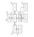
図4は、一例による、命令状態メモリ310の詳細なブロック図である。命令状態メモリ310は、複数の行(rows)404内に編成された複数のブロック402を含む。各々の行404は、1つ以上のエントリを含む。行404内で、各々のブロック402は、他のブロック402とは異なるタイプのデータを記憶する。特に、ブロック402は、エントリが対象とするマイクロ演算を識別するデータである「コア命令状態」、又は、特定のタイプの低待ち時間データを記憶する。各々のブロック402は、各々の他のブロックとは別にパワーオン又はパワーオフされてもよい。「パワーオン又はパワーオフ」という用語は、クロックゲーティング(メモリ素子内のデータを保持するようにクロックを中断若しくは再開するが、読み込み若しくは書き込みを防止する)又は電力ゲーティング(ブロック402に電力をスイッチオン若しくはスイッチオフする)の何れかを実行することを集合的に差す。各々の行404も、個々にパワーオン又はパワーオフされてもよい。コントローラ401は、エントリが特定の行404に配置され、又は、特定の行404から除去されるかに関わらず、メモリ400のコンテンツに応じて、及び、復号ユニット204から受信した電力制御についての情報に応じて、行をパワーオン及びパワーオフする。FIG. 4 is a detailed block diagram of an example
図4では、各々の行内の同一の位置にあるブロック402は、同一のタイプのデータを記憶する。一例では、状態1についてのブロック402は、同一のタイプのデータを記憶し、状態2についてのブロック402の全ては、同一のタイプのデータを記憶する、等である。特定の命令は、行404に記憶することができるタイプのデータの何れかのサブセットを必要とすることがある。より具体的には、1つのタイプの命令は、状態1についてのブロックに記憶されるデータ、及び、状態3についてのブロックに記憶されるデータを必要とすることがあるが、状態2についてのブロック等の他のブロックに記憶されるデータを必要としないことがある。よって、その命令についての命令状態メモリ310内のエントリは、状態1についてのブロック及び状態2についてのブロックにデータを記憶するが、他のブロックに記憶しない。In FIG. 4, blocks 402 in the same position in each row store the same type of data. In one example, the blocks 402 for
いくつかの状況では、コントローラ401は、行404内のエントリがブロック402のタイプのデータを記憶しない場合、その行内のそのブロックをパワーオフする。特定のブロック402についてのデータを使用する行404内の最後のエントリが行404から削除されたことを検出した後に、コントローラは、そのブロック402を即時にパワーダウンする。いくつかの実施形態では、特定のブロック402についてのデータを使用する行404内の最後のエントリが行404から削除されたことを検出した後に、コントローラは、待機期間に移行する。待機期間の間、ブロック402と関連付けられたデータを使用する行404に別のエントリが配置されることになるとコントローラ401が判別した場合、コントローラ401は、ブロック402をパワーダウンしない。待機期間の間、ブロック402と関連付けられたデータを使用する行404にエントリが配置されないことになるとコントローラ401が判別した場合、コントローラ401は、ブロック402をパワーダウンする。In some circumstances, the controller 401 powers off a block in a row if no entry in the row stores data of the type of block 402. After detecting that the last entry in the
ブロック402のパワーダウンについての待機期間は、任意の技術的に実現可能な方法で判別されてもよい。待機期間は、命令状態メモリ310の状態に関わらず一定であってもよいし、命令状態メモリ310の状態及び/又は復号ユニット304によって復号される命令の状態に応じて可変であってもよい。いくつかの実施形態では、ブロック402のパワーダウンについての待機期間は、アイドル期間の間にブロック402をパワーオンしたままにすることによって消費される電力と、ブロック402をターンオフし、次いで、アイドル期間の間に再度ターンオンすることによって保存される電力と、の間の比較に基づいている。アイドル期間は、ブロック402がエンプティになるときと、新たなエントリがブロック402に配置されるときと、の間のサイクルの回数である。いくつかの例では、アイドル期間は、命令ディスパッチユニット300の状態から既知である。特に、ブロック402がエンプティになるとき、それに対してブロック402を使用したエントリが命令状態メモリ310において未だ生成されていない(例えば、低待ち時間データがフェッチされている)命令ディスパッチユニット300において処理される命令が存在するが、ブロック402がエンプティになった後に特定の回数のサイクル内にブロック402内のエントリを命令が必要とすることが既知である場合、特定の回数のサイクルは、アイドル期間の持続時間である。命令ディスパッチユニット300において命令が存在しない場合、アイドル期間は、デフォルトのアイドル期間であり、デフォルトのアイドル期間は、いくつかの実施形態では、ブロック402内で空間を必要とする命令を命令ディスパッチユニット受信するときから、命令が実際にそのブロック402を占有することになるときまでの最小回数のサイクルである。いくつかの実施形態では、ブロック402をパワーオフし、次いで、アイドル期間の間にパワーオンすることによって消費される電力量に対する、アイドル期間内にブロック402をパワーオンしたままにすることによって消費される電力量は、設計者によって予め定められている。その状況では、命令状態メモリ310は、パワーオフされ、アイドル期間が閾値を上回る場合に再度パワーオンされるように構成され、アイドル期間が閾値以下である場合、パワーオンされたままであるように構成され、閾値は、クロスオーバポイントであり、クロスオーバポイントでは、ブロック402をパワーオフし、次いで、ブロック402をパワーオンする代わりに、それがブロック402をパワーオンしたままにするために、電力コストがより高くなる。いくつかの例では、閾値は、例えば、構成レジスタを介してプログラム可能である。The wait period for powering down block 402 may be determined in any technically feasible manner. The wait period may be constant regardless of the state of
いくつかの状況では、行がエントリを記憶しない場合、コントローラ401は、行404をパワーオフする。いくつかの実施形態では、行404内の最後のエントリが行404から削除されたことを検出した後に、コントローラは、その行404を即時にパワーダウンする。いくつかの実施形態では、行404内の最後のエントリが行404から削除されたことを検出した後に、コントローラは、待機期間に移行する。待機期間の間、別のエントリが行404に配置されることになるとコントローラ401が判別した場合、コントローラ401は、行404をパワーダウンしない。待機期間の間、他のエントリが行404に配置されないことになるとコントローラが判別した場合、コントローラ401は、行404をパワーダウンする。In some circumstances, if the row does not store an entry, the controller 401 powers off the
行404のパワーダウンについての待機期間は、任意の技術的に実現可能な方法において判別されてもよい。待機期間は、命令状態メモリ310の状態に関わらず一定であってもよいし、命令状態メモリ310の状態及び/又は復号ユニット304によって復号される命令の状態に応じて可変であってもよい。いくつかの実施形態では、行404のパワーダウンについての待機期間は、パワーオンされる行404の数に基づいている。特に、パワーオンされる行が多いと、遅延404が短くなる。いくつかの実施形態では、行404のパワーダウンについての待機期間は、パワーオンされる他の行404内の解放されたエントリの数に基づいている。パワーオンされる他の行404に存在する解放されたエントリが多いと、遅延が短くなる。いくつかの実施形態では、待機期間は、何個のエントリがインフライト命令に対して必要とされるかに基づいている。いくつかの実施形態では、命令状態メモリ310は、ブロック402をパワーダウンするかどうかに関わらず、上述した説明と同様の方法で行404をどのようにパワーダウンするかを判別し、「行404」は、「ブロック402」と置き換えられる。The wait period for powering down a
図5は、一例による、命令状態メモリ310に新たなエントリを配置する演算を示す図である。コントローラ401は、ターンオフすることができる行404の数を最大にするために、行404内でエントリを共にクラスタすることを試みる。特に、コントローラ401が命令状態メモリ310に配置する新たなエントリを受信するとき、コントローラ401は、最小のエンプティエントリスロットを有すると共に、少なくとも1つのエンプティエントリスロットをなおも有する行404を判別し、識別された行404内でエンプティエントリスロットの1つに新たなエントリを配置する。一例では、2つの行404が同一の数のエンプティエントリを有する場合、コントローラ401は、最新のエントリを有する行404を選択する。新たなエントリを受信するためにエンプティエントリスロットの数が最小の行404を選択することは、アクティブな行404の総数が少なくなり、より多くの数の行404がパワーダウンされることを可能にする。5 illustrates an operation for placing a new entry in the
いくつかの状況では、新たなエントリが特定のタイプの低待ち時間データを必要とし、よって、エントリが配置される行404内で特定のブロック402がパワーオンされる必要があることを必要とすると判別すると、コントローラ401は、パワーオフされたそのブロック402を有する行404の代わりに、既にパワーオンされたブロック402を有する行404を選択する。いくつかの実施形態では、2つの行404が同一の数のエンプティエントリを有するが、1つがパワーオンされた新たなエントリによって必要なブロック402を有し、1つがパワーオンされたそのブロック402を有さない場合、コントローラ401は、パワーオンされた必要なブロック402を有する行404を選択する。いくつかの実施形態では、選択された行404が、パワーオンされた必要なブロック402を有する最小数のエンプティエントリを有する行404である限り、その行404が別の行404よりも多いエンプティエントリを有する場合でさえ、コントローラ401は、パワーオンされた必要なブロック402を有する行404を選択する。いくつかの実施形態では、選択されることになる行404内のエンプティエントリの数が、パワーオフされた必要なブロック402を有する行404内のエンプティエントリの数の閾値数内又は閾値割合内にある限り、パワーオフされた必要なブロック402を有する別の行404よりもその行が多くのエンプティエントリを有する場合、コントローラ401は、パワーオンされた必要なブロック402を有する行404を選択する。In some situations, upon determining that a new entry requires a particular type of low latency data and therefore requires that a particular block 402 needs to be powered on within the
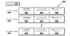
図6は、命令状態メモリ310、SIMDユニット命令状態メモリ600の例示的な実施形態のブロック図である。SIMDユニット命令状態メモリ600は、コア命令状態についてのブロック602と、フィルタリング重みについてのブロック604と、参照データについてのブロック606と、を含む。Figure 6 is a block diagram of an exemplary embodiment of the
上述したように、SIMDユニット138は、一連の命令を含むシェーダプログラムを実行する。命令状態メモリ310を含む命令ディスパッチユニット300は、命令をフェッチ及び復号し、復号した命令及び状態データを命令状態メモリ310に配置する。As described above, the
コア命令状態は、実行されることになる命令に対して実行される必要がある演算を識別する情報である。一例では、命令は、加算命令であり、コア命令状態は、加算演算が実行される必要があることを示す。フィルタリング重みについてのブロック604は、テキスチャ命令についてのフィルタリング重みを記憶する。より具体的には、いくつかの命令は、フィルタの適用による、テキスチャデータの操作を必要とする。フィルタは、命令識別子に基づいて決定された重みを含んでもよく、それらの重みは、テクセル等のオペランドに適用されてもよい。この例では、フィルタ重みは、低待ち時間データであり、テクセルは、高待ち時間データである。フィルタ重みは、低待ち時間データブロック306から取り出されたことに応じて、フィルタリング重み604についてのブロックに配置される。The core instruction state is information that identifies the operation that needs to be performed for the instruction to be executed. In one example, the instruction is an add instruction and the core instruction state indicates that an add operation needs to be performed. The block for filtering weights 604 stores filtering weights for texture instructions. More specifically, some instructions require manipulation of texture data by application of a filter. The filters may include weights determined based on the instruction identifier, and those weights may be applied to operands such as texels. In this example, the filter weights are low latency data and the texels are high latency data. The filter weights are placed in the block for filtering weights 604 in response to being retrieved from the low latency data block 306.
参照データ606についてのブロック606は、命令によって使用されることになる参照データを記憶する。参照データは、高待ち時間データのアイテム等のように、別の値と比較されることになるデータである。一例では、参照データについてのブロック606は、Zテスト(深度テストとも呼ばれることがある)のために使用される画素についての深度値を記憶する。いくつかの例では、画素シェーダプログラムは、深度バッファに記憶された値に対して深度テストを実行する。特に、画素シェーダは、処理される画素の深度値を深度バッファ内の値と比較し、画素を破棄してもよいし、及び/又は、結果として深度バッファを修正してもよい。参照データは、画素についての深度値であり、オペランドは、深度バッファから取り出された値である。The
命令は、典型的には、コア命令状態についてのブロック602を使用する。よって、いくつかの実施形態では、行404がパワーオンされるとき、コア命令状態についてのブロック602はパワーオフされない。命令は、命令の識別子に応じて、フィルタリング重みについてのブロック604又は参照データについてのブロック606の何れか又は両方を使用してもよい。よって、命令が特定の行404内にあるとき、その命令によって使用される低待ち時間データについてのブロックは、スイッチオンされる。様々な実施形態では、フィルタリング重み又は参照データの何れか又は両方を使用する命令がパワーオフされたそれらのブロックと共に行404に配置されることになるとコントローラ401が判別した場合、コントローラ401は、それらのブロックをパワーオンさせる。An instruction typically uses the
図7は、一例による、命令状態メモリ310にエントリを配置する方法700のフローチャートである。図1~図6のシステムに関して説明するが、当業者は、任意の技術的に実現可能な順序で方法700のステップを実行するように構成された任意のシステムが本開示の範囲内に含まれることを理解するであろう。Figure 7 is a flow chart of a
方法700は、ステップ702において開始し、ステップ702では、命令状態メモリ310のコントローラ401は、命令のための命令状態メモリエントリについての情報を受信する。この情報は、デコーダ304から受信され、何れのタイプの低待ち時間データが命令状態メモリエントリと関連付けられた命令によって使用されるかを示す。フェッチされることになる低待ち時間データを命令が必要とする場合、デコーダ304は、低待ち時間データブロック306からその情報を要求する。また、デコーダ304は、高待ち時間データブロック308から高待ち時間データを要求する。デコーダ304が複数のマイクロ演算に命令を拡大してもよいこと、及び、各々のマイクロ演算が命令状態メモリエントリを必要とすることがあることに留意されたい。このケースでは、方法700の態様(ステップ704及び706等)、又は、方法700の全ては、命令から生成されたマイクロ演算毎に繰り返される。いくつかの実施形態では、クラスタリング基準は、1つのみのスロットの代わりに、命令について必要な総数のスロットを考慮する。
ステップ704において、コントローラ401は、クラスタリング基準に基づいて、命令状態メモリ310内のスロットを識別する。クラスタリング基準は、より少ない行404内でより多くのエントリをクラスタリングさせて、より多くの行404がパワーオフされることを可能にするために存在する。いくつかの実施形態では、クラスタリング基準は、パワーオンされた同一のブロック402及びパワーオフされた同一のブロック402を有する行404内でエントリをクラスタリングさせる。In
いくつかの実施形態では、クラスタリング基準は以下の通りである。コントローラ401は、最小の、非ゼロの数のエンプティエントリを有する行404に新たなエントリを配置することを試みる。このアクションは、行404内のエントリの集中を結果としてもたらす。In some embodiments, the clustering criterion is as follows: The controller 401 attempts to place new entries in the
いくつかの実施形態では、クラスタリング基準は、使用される行404内でパワーオンされたブロック402を考慮に入れる。一例では、最小数のエントリを有する複数の行404が存在する場合(すなわち、2つ以上の行404が最小数のエンプティエントリでもある同一の数のエンプティエントリを有する場合)、コントローラ401は、パワーオンされる最小数のブロック402を結果としてもたらす行404を選択する。例えば、命令についての新たなエントリがブロック2についての低待ち時間データを必要とする場合、及び、最小数のエントリを有する1つの行404がパワーオンされたブロック2を有し、最小数のエントリを有する1つの行404がパワーオフされたブロックを有する場合、コントローラ401は、新たなエントリを配置するためにパワーオンされたブロック2を有する行404を選択する。いくつかの実施形態では、行404は、同一の数のエンプティエントリを有する必要がなく、行404が行404内での最小数のエンプティエントリの閾値数内又は閾値割合内の数のエンプティエントリを有し、その行404がパワーオンされた必要とされるブロックを有するが、より小数のエンプティエントリを有する行404がパワーオンされた必要とされるブロックを有さない場合、コントローラ401は、より小数のエンプティエントリを有する行404の代わりに、パワーオンされた必要とされるブロックを有する行404を選択する。いくつかの実施形態では、コントローラ401は、パワーオンすることができるブロック402の考えられる組み合わせ毎に、又は、パワーオンすることができるブロック402の組み合わせのサブセットについて、1つの行404をパワーオンしたままにする。この実施形態では、新たなエントリについて、コントローラ401は、その上で必要とされるブロック402をも有し、又は、それに対して最小数のブロック402がパワーオンされる必要がある最小数のエントリを有する行404を選択する。エンプティエントリを有する行404が存在しない場合、コントローラ401は、行404をパワーオンする。同様に、エントリについて必要とされるパワーオンされたブロック402を行404が有さない場合、コントローラ401は、少なくとも1つのブロック402をパワーオンする。ステップ706において、コントローラ401は、識別されたスロットに命令状態メモリエントリを配置する。In some embodiments, the clustering criteria takes into account the powered-on blocks 402 within the
命令についての全ての高待ち時間データが命令状態メモリ310内に入る場合、命令状態メモリ310は、機能ユニットに命令を送信する。さらに、命令が行404内で最後の命令であった場合、又は、行404内で特定のブロック402を使用する最後の命令であった場合、コントローラ401は、行404又はブロック402をパワーダウンする。パワーダウンは、本明細書で他に説明したように遅延の後に行われてもよい。また、遅延の間、行404又はブロック402を必要とする新たな命令が入る場合、パワーダウンが行われない。さらに、いくつかの実施形態では、命令についての情報が実行のために機能ユニットに送信される場合、命令について実際にパワーオンされたブロック402のみが読み込まれ、よって、電力供給されていないブロックから読み込むための電力が消費されない。When all high latency data for an instruction is in the
本明細書における開示に基づいて、多くの変形が可能であることを理解されたい。特徴及び要素を特定の組み合わせで上述したが、各々の特徴又は要素は、他の特徴及び要素なしに単独で使用されてもよいし、他の特徴及び要素との様々な組み合わせ又は他の特徴及び要素なしの様々な組み合わせで使用されてもよい。It should be understood that many variations are possible based on the disclosure herein. Although features and elements have been described above in particular combinations, each feature or element may be used alone without the other features and elements, or in various combinations with or without the other features and elements.
図に示され、及び/又は、本明細書で説明した様々な機能ユニット(限定されないが、プロセッサ102、入力ドライバ112、入力デバイス108、出力ドライバ114、出力デバイス110、アクセラレーテッドプロセシングデバイス116、スケジューラ136、グラフィックプロセシングパイプライン134、計算ユニット132、SIMDユニット138、命令ディスパッチユニット300、命令フェッチユニット302、復号ユニット304、低待ち時間データユニット306、高待ち時間データユニット308、命令状態メモリ310、又は、コントローラ401を含む)は、汎用コンピュータ、プロセッサ又はプロセッサコアとして実装されてもよいし、汎用コンピュータ、プロセッサ又はプロセッサコアによって実行可能な非一時的なコンピュータ可読記憶媒体や別の媒体に記憶されたプログラム、ソフトウェア又はファームウェアとして実装されてもよい。提供される方法は、汎用コンピュータ、プロセッサ又はプロセッサコアにおいて実施されてもよい。適切なプロセッサは、例として、汎用プロセッサ、特殊目的プロセッサ、従来型のプロセッサ、デジタルシグナルプロセッサ(DSP)、複数のマイクロプロセッサ、DSPコアと関連した1つ以上のマイクロプロセッサ、コントローラ、マイクロコントローラ、特定用途向け集積回路(ASIC)、フィールドプログラマブルゲートアレイ(FPGA)回路、の他のタイプの集積回路(IC)、及び/又は、状態機械を含む。このようなプロセッサは、ネットリストを含む処理されたハードウェア記述言語(HDL)命令及び他の中間データ(コンピュータ可読媒体に記憶されることが可能な命令)の結果を使用して製造工程を構成することによって、製造されてもよい。このような処理の結果は、マスクワークであってもよく、マスクワークは、開示した特徴を実装するプロセッサを製造する半導体製造工程において使用される。The various functional units shown in the figures and/or described herein (including, but not limited to, the
本明細書で提供される方法又はフローチャートは、汎用コンピュータ又はプロセッサによる実行のために非一時的なコンピュータ可読記憶媒体に組み込まれたコンピュータプログラム、ソフトウェア又はファームウェアにおいて実装されてもよい。非一時的なコンピュータ可読記憶媒体の例は、リードオンリメモリ(ROM)、ランダムアクセスメモリ(RAM)、レジスタ、キャッシュメモリ、半導体メモリデバイス、内蔵ハードディスク及び着脱可能ディスク等の磁気媒体、磁気光学媒体、並びに、CD-ROMディスク及びデジタル多用途ディスク(DVD)等の光学媒体を含む。The methods or flow charts provided herein may be implemented in a computer program, software, or firmware embodied in a non-transitory computer-readable storage medium for execution by a general purpose computer or processor. Examples of non-transitory computer-readable storage media include read-only memory (ROM), random access memory (RAM), registers, cache memory, semiconductor memory devices, magnetic media such as internal hard disks and removable disks, magneto-optical media, and optical media such as CD-ROM disks and digital versatile disks (DVDs).
Claims (20)
Translated fromJapanese命令に関する命令状態メモリエントリの情報を取得することと、
クラスタリング基準に基づいて、前記命令状態メモリエントリについて、選択可能に電力供給される行及びブロックを有する命令状態メモリ内のスロットを識別することと、
前記命令状態メモリエントリを、識別されたスロットに配置することと、を含む、
方法。 1. A method for processing computer instructions, comprising:
Obtaining information in an instruction status memory entry relating to an instruction;
identifying a slot in an instruction state memory having a selectably powered row and block for said instruction state memory entry based on a clustering criterion;
placing the instruction status memory entry in the identified slot.
method.
請求項1の方法。 the information in the instruction status memory entry includes one or more operations related to the instruction;
2. The method of claim 1.
前記高待ち時間データは、前記命令状態メモリエントリに記憶された低待ち時間データよりも高いアクセス待ち時間を有する、
請求項1の方法。 and upon receiving the high latency data of the instruction status memory entry, transmitting the data in the instruction status memory entry and the high latency data to one or more functional units for execution;
the high latency data having a higher access latency than the low latency data stored in the instruction state memory entry.
2. The method of claim 1.
前記行をパワーダウンすることと、をさらに含む、
請求項3の方法。 determining that after transmitting the data in the instruction status memory entry to the one or more functional units for execution, there are no occupied slots in the row to which the data was transmitted;
powering down the row.
The method of claim 3.
請求項4の方法。 The power down occurs after a waiting period.
The method of claim 4.
前記命令状態メモリ内の行のうち、最小の、非ゼロの数の空きスロットを有する行を識別することと、
識別された行の空きスロットを、前記命令状態メモリエントリ用のスロットとして識別することと、を含む、
請求項1の方法。 Identifying slots in the instruction state memory based on the clustering criteria includes:
identifying a row in said instruction status memory having a minimum non-zero number of free slots;
identifying a free slot in the identified row as a slot for said instruction status memory entry;
2. The method of claim 1.
前記命令状態メモリにおいて、第1のパワーオンされた行は、前記第1のタイプのデータについての第1のブロックを含み、前記第1のブロックはパワーオンされており、第2のパワーオンされた行は、前記第1のタイプのデータについての第2のブロックを含み、前記第2のブロックはパワーオフされており、
前記スロットを識別することは、前記第1のパワーオンされた行内のスロットを識別することを含む、
請求項1の方法。 the instruction state memory entry includes an item of a first type of data;
in the instruction state memory, a first powered-on row includes a first block of data of the first type, the first block being powered on, and a second powered-on row includes a second block of data of the first type, the second block being powered off;
identifying the slot includes identifying a slot in the first powered-on row.
2. The method of claim 1.
請求項7の方法。 the second powered-on row includes more free slots than the first powered-on row.
The method of claim 7.
パワーオンされた行が空きスロットを有していないと判別することと、
パワーオフされた行をパワーオンすることと、を含む、
請求項1の方法。 Identifying the slot comprises:
determining that a powered on row has no free slots;
powering on the powered off rows.
2. The method of claim 1.
複数の選択可能に電力供給される行であって、各々の行は、複数の選択可能に電力供給されるブロックを有する、複数の選択可能に電力供給される行と、
コントローラと、を備え、
前記コントローラは、
命令に関する命令状態メモリエントリの情報を取得することと、
クラスタリング基準に基づいて、前記命令状態メモリエントリについて、選択可能に電力供給される行及びブロックを有する命令状態メモリ内のスロットを識別することと、
前記命令状態メモリエントリを、識別されたスロットに配置することと、
を行うように構成されている、
命令状態メモリ。 an instruction state memory,
a plurality of selectably powered rows, each row having a plurality of selectably powered blocks;
A controller,
The controller:
Obtaining information in an instruction status memory entry relating to an instruction;
identifying a slot in an instruction state memory having a selectably powered row and block for said instruction state memory entry based on a clustering criterion;
placing said instruction status memory entry in the identified slot;
[0023]
Instruction state memory.
請求項10の命令状態メモリ。 the information in the instruction status memory entry includes one or more operations related to the instruction;
The instruction state memory of claim 10.
前記命令状態メモリエントリの高待ち時間データを受信すると、前記命令状態メモリエントリ内のデータ及び前記高待ち時間データを、実行のために1つ以上の機能ユニットに送信するように構成されており、
前記高待ち時間データは、前記命令状態メモリエントリに記憶された低待ち時間データよりも高いアクセス待ち時間を有する、
請求項10の命令状態メモリ。 The controller:
configured, upon receiving the high latency data of the instruction status memory entry, to transmit the data in the instruction status memory entry and the high latency data to one or more functional units for execution;
the high latency data having a higher access latency than the low latency data stored in the instruction state memory entry.
The instruction state memory of claim 10.
前記命令状態メモリエントリ内の前記データを、実行のために前記1つ以上の機能ユニットに送信した後に、前記データが送信された行に占有されたスロットがないと判別することと、
前記行をパワーダウンすることと、
を行うように構成されている、
請求項12の命令状態メモリ。 The controller:
determining that after transmitting the data in the instruction status memory entry to the one or more functional units for execution, there are no occupied slots in the row to which the data was transmitted;
powering down said row;
[0023]
13. The instruction state memory of claim 12.
請求項13の命令状態メモリ。 The power down occurs after a waiting period.
14. The instruction state memory of claim 13.
前記命令状態メモリ内の行のうち、最小の、非ゼロの数の空きスロットを有する行を識別することと、
識別された行の空きスロットを、前記命令状態メモリエントリ用のスロットとして識別することと、を含む、
請求項10の命令状態メモリ。 Identifying slots in the instruction state memory based on the clustering criteria includes:
identifying a row in said instruction status memory having a minimum non-zero number of free slots;
identifying a free slot in the identified row as a slot for said instruction status memory entry;
The instruction state memory of claim 10.
前記命令状態メモリにおいて、第1のパワーオンされた行は、前記第1のタイプのデータについての第1のブロックを含み、前記第1のブロックはパワーオンされており、第2のパワーオンされた行は、前記第1のタイプのデータについての第2のブロックを含み、前記第2のブロックはパワーオフされており、
前記スロットを識別することは、前記第1のパワーオンされた行内のスロットを識別することを含む、
請求項10の命令状態メモリ。 the instruction state memory entry includes an item of a first type of data;
in the instruction state memory, a first powered-on row includes a first block of data of the first type, the first block being powered on, and a second powered-on row includes a second block of data of the first type, the second block being powered off;
identifying the slot includes identifying a slot in the first powered-on row.
The instruction state memory of claim 10.
請求項16の命令状態メモリ。 the second powered-on row includes more free slots than the first powered-on row.
17. The instruction state memory of claim 16.
パワーオンされた行が空きスロットを有していないと判別することと、
パワーオフされた行をパワーオンすることと、を含む、
請求項10の命令状態メモリ。 Identifying the slot comprises:
determining that a powered on row has no free slots;
powering on the powered off rows.
The instruction state memory of claim 10.
機能ユニットと、
を備えるプロセッサであって、
前記命令状態メモリは、
複数の選択可能に電力供給される行であって、各々の行は、複数の選択可能に電力供給されるブロックを有する、複数の選択可能に電力供給される行と、
コントローラと、を備え、
前記コントローラは、
命令に関する命令状態メモリエントリの情報を取得することと、
クラスタリング基準に基づいて、前記命令状態メモリエントリについて、選択可能に電力供給される行及びブロックを有する命令状態メモリ内のスロットを識別することと、
前記命令状態メモリエントリを、識別されたスロットに配置することと、
を行うように構成されており、
前記機能ユニットは、
前記命令を実行するように構成されている、
プロセッサ。 an instruction state memory;
A functional unit;
A processor comprising:
The instruction state memory includes:
a plurality of selectably powered rows, each row having a plurality of selectably powered blocks;
A controller,
The controller:
Obtaining information in an instruction status memory entry relating to an instruction;
identifying a slot in an instruction state memory having a selectably powered row and block for said instruction state memory entry based on a clustering criterion;
placing said instruction status memory entry in the identified slot;
The device is configured to:
The functional unit comprises:
configured to execute the instructions;
Processor.
前記命令状態メモリエントリの高待ち時間データを受信した後に、前記命令状態メモリエントリ内のデータ及び前記高待ち時間データを、実行のために前記機能ユニットに送信するように構成されており、
前記高待ち時間データは、前記命令状態メモリエントリに記憶された低待ち時間データよりも高いアクセス待ち時間を有する、
請求項19のプロセッサ。 The controller:
configured, after receiving the high latency data of the instruction status memory entry, to transmit the data in the instruction status memory entry and the high latency data to the functional unit for execution;
the high latency data having a higher access latency than the low latency data stored in the instruction state memory entry.
20. The processor of claim 19.
Applications Claiming Priority (3)
| Application Number | Priority Date | Filing Date | Title |
|---|---|---|---|
| US16/556,139US11996166B2 (en) | 2019-08-29 | 2019-08-29 | Adaptable allocation of SRAM based on power |
| US16/556,139 | 2019-08-29 | ||
| PCT/US2020/047672WO2021041334A1 (en) | 2019-08-29 | 2020-08-24 | Adaptable allocation of sram based on power |
Publications (2)
| Publication Number | Publication Date |
|---|---|
| JP2022546250A JP2022546250A (en) | 2022-11-04 |
| JP7661307B2true JP7661307B2 (en) | 2025-04-14 |
Family
ID=74680458
Family Applications (1)
| Application Number | Title | Priority Date | Filing Date |
|---|---|---|---|
| JP2022510106AActiveJP7661307B2 (en) | 2019-08-29 | 2020-08-24 | Adaptive power-based SRAM allocation - Patents.com |
Country Status (6)
| Country | Link |
|---|---|
| US (1) | US11996166B2 (en) |
| EP (1) | EP4022417A4 (en) |
| JP (1) | JP7661307B2 (en) |
| KR (1) | KR20220051358A (en) |
| CN (1) | CN114258522A (en) |
| WO (1) | WO2021041334A1 (en) |
Families Citing this family (3)
| Publication number | Priority date | Publication date | Assignee | Title |
|---|---|---|---|---|
| US11996166B2 (en)* | 2019-08-29 | 2024-05-28 | Advanced Micro Devices, Inc. | Adaptable allocation of SRAM based on power |
| US20230214270A1 (en)* | 2021-12-31 | 2023-07-06 | Western Digital Technologies, Inc. | Readiness states for partitioned internal resources of a memory controller |
| US12360765B2 (en)* | 2023-10-20 | 2025-07-15 | Qualcomm Incorporated | Processing unit employing micro-operations (micro-ops) random access memory (RAM) as main program memory |
Citations (10)
| Publication number | Priority date | Publication date | Assignee | Title |
|---|---|---|---|---|
| US5819308A (en) | 1997-02-27 | 1998-10-06 | Industrial Technology Research Institute | Method for buffering and issuing instructions for use in high-performance superscalar microprocessors |
| US20020053038A1 (en) | 2000-10-31 | 2002-05-02 | International Business Machines Corporation | Adaptive issue queue for reduced power at high performance |
| US20060059314A1 (en) | 2004-09-10 | 2006-03-16 | Cavium Networks | Direct access to low-latency memory |
| JP2007200213A (en) | 2006-01-30 | 2007-08-09 | Nec Corp | Information processing device, entry configuration control method and program |
| US20090031120A1 (en) | 2007-07-23 | 2009-01-29 | Ibm Corporation | Method and Apparatus for Dynamically Fusing Instructions at Execution Time in a Processor of an Information Handling System |
| US20100070695A1 (en) | 2008-09-15 | 2010-03-18 | Texas Instruments Incorporated | Power-efficient memory management for embedded systems |
| JP2010073124A (en) | 2008-09-22 | 2010-04-02 | Nec Corp | Command control circuit, command control method, and information processor |
| US20140136873A1 (en) | 2012-11-14 | 2014-05-15 | Advanced Micro Devices, Inc. | Tracking memory bank utility and cost for intelligent power up decisions |
| US20140189328A1 (en) | 2012-12-27 | 2014-07-03 | Tomer WEINER | Power reduction by using on-demand reservation station size |
| US20190163394A1 (en) | 2017-11-28 | 2019-05-30 | Advanced Micro Devices, Inc. | Expandable buffer for memory transactions |
Family Cites Families (29)
| Publication number | Priority date | Publication date | Assignee | Title |
|---|---|---|---|---|
| US7284117B1 (en)* | 2003-11-04 | 2007-10-16 | Advanced Micro Devices, Inc. | Processor that predicts floating point instruction latency based on predicted precision |
| GB2426360A (en)* | 2005-05-18 | 2006-11-22 | Symbian Software Ltd | Reorganisation of memory for conserving power in a computing device |
| US8601234B2 (en)* | 2007-11-07 | 2013-12-03 | Qualcomm Incorporated | Configurable translation lookaside buffer |
| KR101297563B1 (en)* | 2007-11-15 | 2013-08-19 | 삼성전자주식회사 | Storage management method and storage management system |
| US9477587B2 (en)* | 2008-04-11 | 2016-10-25 | Micron Technology, Inc. | Method and apparatus for a volume management system in a non-volatile memory device |
| US8347037B2 (en)* | 2008-10-22 | 2013-01-01 | International Business Machines Corporation | Victim cache replacement |
| US8127167B2 (en)* | 2009-03-30 | 2012-02-28 | Mediatek Inc. | Methods for reducing power consumption and devices using the same |
| US9038073B2 (en)* | 2009-08-13 | 2015-05-19 | Qualcomm Incorporated | Data mover moving data to accelerator for processing and returning result data based on instruction received from a processor utilizing software and hardware interrupts |
| US20110194606A1 (en)* | 2010-02-09 | 2011-08-11 | Cheng-Yu Hsieh | Memory management method and related memory apparatus |
| US20120089781A1 (en)* | 2010-10-11 | 2012-04-12 | Sandeep Ranade | Mechanism for retrieving compressed data from a storage cloud |
| US8473679B2 (en)* | 2011-03-31 | 2013-06-25 | Ceva D.S.P. Ltd. | System, data structure, and method for collapsing multi-dimensional data |
| US8724389B2 (en)* | 2012-07-26 | 2014-05-13 | Ocz Storage Solutions, Inc. | Non-volatile solid state memory-based mass storage device and methods thereof |
| US9311243B2 (en)* | 2012-11-30 | 2016-04-12 | Intel Corporation | Emulated message signaled interrupts in multiprocessor systems |
| US9830164B2 (en)* | 2013-01-29 | 2017-11-28 | Advanced Micro Devices, Inc. | Hardware and software solutions to divergent branches in a parallel pipeline |
| US9996354B2 (en)* | 2015-01-09 | 2018-06-12 | International Business Machines Corporation | Instruction stream tracing of multi-threaded processors |
| US9916252B2 (en)* | 2015-05-19 | 2018-03-13 | Linear Algebra Technologies Limited | Systems and methods for addressing a cache with split-indexes |
| US11755484B2 (en)* | 2015-06-26 | 2023-09-12 | Microsoft Technology Licensing, Llc | Instruction block allocation |
| US9576637B1 (en)* | 2016-05-25 | 2017-02-21 | Advanced Micro Devices, Inc. | Fine granularity refresh |
| US10034407B2 (en)* | 2016-07-22 | 2018-07-24 | Intel Corporation | Storage sled for a data center |
| US10354716B2 (en)* | 2016-09-16 | 2019-07-16 | Aspiring Sky Co. Limited | SRAM based memory structures and methods thereof |
| US9819258B1 (en)* | 2016-09-30 | 2017-11-14 | Intel Corporation | Systems and methods for latch-up detection and mitigation |
| US20180260014A1 (en)* | 2017-03-07 | 2018-09-13 | Nxp Usa, Inc. | Systems and methods for controlling memory array power consumption |
| US10446198B2 (en)* | 2017-10-02 | 2019-10-15 | Micron Technology, Inc. | Multiple concurrent modulation schemes in a memory system |
| US10572168B2 (en)* | 2017-11-16 | 2020-02-25 | International Business Machines Corporation | DRAM bank activation management |
| US10762931B2 (en)* | 2018-07-16 | 2020-09-01 | Taiwan Semiconductor Manufacturing Company, Ltd. | Memory power management |
| US10846363B2 (en)* | 2018-11-19 | 2020-11-24 | Microsoft Technology Licensing, Llc | Compression-encoding scheduled inputs for matrix computations |
| US11023379B2 (en)* | 2019-02-13 | 2021-06-01 | Google Llc | Low-power cached ambient computing |
| US11354326B2 (en)* | 2019-07-29 | 2022-06-07 | Thoughtspot, Inc. | Object indexing |
| US11996166B2 (en)* | 2019-08-29 | 2024-05-28 | Advanced Micro Devices, Inc. | Adaptable allocation of SRAM based on power |
- 2019
- 2019-08-29USUS16/556,139patent/US11996166B2/enactiveActive
- 2020
- 2020-08-24CNCN202080058029.9Apatent/CN114258522A/enactivePending
- 2020-08-24KRKR1020227008481Apatent/KR20220051358A/enactivePending
- 2020-08-24WOPCT/US2020/047672patent/WO2021041334A1/ennot_activeCeased
- 2020-08-24EPEP20858116.5Apatent/EP4022417A4/enactivePending
- 2020-08-24JPJP2022510106Apatent/JP7661307B2/enactiveActive
Patent Citations (10)
| Publication number | Priority date | Publication date | Assignee | Title |
|---|---|---|---|---|
| US5819308A (en) | 1997-02-27 | 1998-10-06 | Industrial Technology Research Institute | Method for buffering and issuing instructions for use in high-performance superscalar microprocessors |
| US20020053038A1 (en) | 2000-10-31 | 2002-05-02 | International Business Machines Corporation | Adaptive issue queue for reduced power at high performance |
| US20060059314A1 (en) | 2004-09-10 | 2006-03-16 | Cavium Networks | Direct access to low-latency memory |
| JP2007200213A (en) | 2006-01-30 | 2007-08-09 | Nec Corp | Information processing device, entry configuration control method and program |
| US20090031120A1 (en) | 2007-07-23 | 2009-01-29 | Ibm Corporation | Method and Apparatus for Dynamically Fusing Instructions at Execution Time in a Processor of an Information Handling System |
| US20100070695A1 (en) | 2008-09-15 | 2010-03-18 | Texas Instruments Incorporated | Power-efficient memory management for embedded systems |
| JP2010073124A (en) | 2008-09-22 | 2010-04-02 | Nec Corp | Command control circuit, command control method, and information processor |
| US20140136873A1 (en) | 2012-11-14 | 2014-05-15 | Advanced Micro Devices, Inc. | Tracking memory bank utility and cost for intelligent power up decisions |
| US20140189328A1 (en) | 2012-12-27 | 2014-07-03 | Tomer WEINER | Power reduction by using on-demand reservation station size |
| US20190163394A1 (en) | 2017-11-28 | 2019-05-30 | Advanced Micro Devices, Inc. | Expandable buffer for memory transactions |
Also Published As
| Publication number | Publication date |
|---|---|
| CN114258522A (en) | 2022-03-29 |
| US20210065758A1 (en) | 2021-03-04 |
| EP4022417A4 (en) | 2023-09-13 |
| KR20220051358A (en) | 2022-04-26 |
| EP4022417A1 (en) | 2022-07-06 |
| WO2021041334A1 (en) | 2021-03-04 |
| JP2022546250A (en) | 2022-11-04 |
| US11996166B2 (en) | 2024-05-28 |
Similar Documents
| Publication | Publication Date | Title |
|---|---|---|
| US11703931B2 (en) | Application profiling for power-performance management | |
| JP7661307B2 (en) | Adaptive power-based SRAM allocation - Patents.com | |
| US12242384B2 (en) | Compression aware prefetch | |
| US10558418B2 (en) | Monitor support on accelerated processing device | |
| TW201342030A (en) | Instruction that specifies an application thread performance state | |
| JP7603051B2 (en) | Chiplet-integrated machine learning accelerator | |
| CN117859114A (en) | Processing apparatus and method for sharing storage among cache memory, local data storage, and register file | |
| US20220100543A1 (en) | Feedback mechanism for improved bandwidth and performance in virtual environment usecases | |
| US20230185623A1 (en) | Method of task transition between heterogenous processors | |
| US20230205680A1 (en) | Emulating performance of prior generation platforms | |
| US20210173650A1 (en) | Techniques for improving operand caching | |
| US11947487B2 (en) | Enabling accelerated processing units to perform dataflow execution | |
| US20220206851A1 (en) | Regenerative work-groups | |
| US20250278292A1 (en) | Pipelined compute dispatch processing | |
| US12222797B2 (en) | Dynamic configuration of processor sub-components | |
| KR20250025675A (en) | Live Profile Driven Cache Aging Policy | |
| JP2025500185A (en) | Adaptive Power Management |
Legal Events
| Date | Code | Title | Description |
|---|---|---|---|
| A621 | Written request for application examination | Free format text:JAPANESE INTERMEDIATE CODE: A621 Effective date:20230816 | |
| A977 | Report on retrieval | Free format text:JAPANESE INTERMEDIATE CODE: A971007 Effective date:20240710 | |
| A131 | Notification of reasons for refusal | Free format text:JAPANESE INTERMEDIATE CODE: A131 Effective date:20240903 | |
| TRDD | Decision of grant or rejection written | ||
| A01 | Written decision to grant a patent or to grant a registration (utility model) | Free format text:JAPANESE INTERMEDIATE CODE: A01 Effective date:20250311 | |
| A61 | First payment of annual fees (during grant procedure) | Free format text:JAPANESE INTERMEDIATE CODE: A61 Effective date:20250402 | |
| R150 | Certificate of patent or registration of utility model | Ref document number:7661307 Country of ref document:JP Free format text:JAPANESE INTERMEDIATE CODE: R150 |