JP7658140B2 - SOUND OUTPUT DEVICE, SOUND OUTPUT SYSTEM, AND CONTROL METHOD - Google Patents
SOUND OUTPUT DEVICE, SOUND OUTPUT SYSTEM, AND CONTROL METHODDownload PDFInfo
- Publication number
- JP7658140B2 JP7658140B2JP2021059779AJP2021059779AJP7658140B2JP 7658140 B2JP7658140 B2JP 7658140B2JP 2021059779 AJP2021059779 AJP 2021059779AJP 2021059779 AJP2021059779 AJP 2021059779AJP 7658140 B2JP7658140 B2JP 7658140B2
- Authority
- JP
- Japan
- Prior art keywords
- sound
- sound output
- unit
- output unit
- output
- Prior art date
- Legal status (The legal status is an assumption and is not a legal conclusion. Google has not performed a legal analysis and makes no representation as to the accuracy of the status listed.)
- Active
Links
Images


Classifications
- H—ELECTRICITY
- H04—ELECTRIC COMMUNICATION TECHNIQUE
- H04R—LOUDSPEAKERS, MICROPHONES, GRAMOPHONE PICK-UPS OR LIKE ACOUSTIC ELECTROMECHANICAL TRANSDUCERS; DEAF-AID SETS; PUBLIC ADDRESS SYSTEMS
- H04R3/00—Circuits for transducers, loudspeakers or microphones
- H04R3/12—Circuits for transducers, loudspeakers or microphones for distributing signals to two or more loudspeakers
- H—ELECTRICITY
- H04—ELECTRIC COMMUNICATION TECHNIQUE
- H04R—LOUDSPEAKERS, MICROPHONES, GRAMOPHONE PICK-UPS OR LIKE ACOUSTIC ELECTROMECHANICAL TRANSDUCERS; DEAF-AID SETS; PUBLIC ADDRESS SYSTEMS
- H04R5/00—Stereophonic arrangements
- H04R5/04—Circuit arrangements, e.g. for selective connection of amplifier inputs/outputs to loudspeakers, for loudspeaker detection, or for adaptation of settings to personal preferences or hearing impairments
- G—PHYSICS
- G02—OPTICS
- G02B—OPTICAL ELEMENTS, SYSTEMS OR APPARATUS
- G02B27/00—Optical systems or apparatus not provided for by any of the groups G02B1/00 - G02B26/00, G02B30/00
- G02B27/01—Head-up displays
- G02B27/017—Head mounted
- G—PHYSICS
- G06—COMPUTING OR CALCULATING; COUNTING
- G06F—ELECTRIC DIGITAL DATA PROCESSING
- G06F3/00—Input arrangements for transferring data to be processed into a form capable of being handled by the computer; Output arrangements for transferring data from processing unit to output unit, e.g. interface arrangements
- G06F3/16—Sound input; Sound output
- G06F3/165—Management of the audio stream, e.g. setting of volume, audio stream path
- H—ELECTRICITY
- H04—ELECTRIC COMMUNICATION TECHNIQUE
- H04M—TELEPHONIC COMMUNICATION
- H04M1/00—Substation equipment, e.g. for use by subscribers
- H04M1/72—Mobile telephones; Cordless telephones, i.e. devices for establishing wireless links to base stations without route selection
- H04M1/724—User interfaces specially adapted for cordless or mobile telephones
- H04M1/72403—User interfaces specially adapted for cordless or mobile telephones with means for local support of applications that increase the functionality
- H04M1/72409—User interfaces specially adapted for cordless or mobile telephones with means for local support of applications that increase the functionality by interfacing with external accessories
- H04M1/72412—User interfaces specially adapted for cordless or mobile telephones with means for local support of applications that increase the functionality by interfacing with external accessories using two-way short-range wireless interfaces
- H—ELECTRICITY
- H04—ELECTRIC COMMUNICATION TECHNIQUE
- H04M—TELEPHONIC COMMUNICATION
- H04M1/00—Substation equipment, e.g. for use by subscribers
- H04M1/72—Mobile telephones; Cordless telephones, i.e. devices for establishing wireless links to base stations without route selection
- H04M1/724—User interfaces specially adapted for cordless or mobile telephones
- H04M1/72403—User interfaces specially adapted for cordless or mobile telephones with means for local support of applications that increase the functionality
- H04M1/72409—User interfaces specially adapted for cordless or mobile telephones with means for local support of applications that increase the functionality by interfacing with external accessories
- H04M1/72415—User interfaces specially adapted for cordless or mobile telephones with means for local support of applications that increase the functionality by interfacing with external accessories for remote control of appliances
- H—ELECTRICITY
- H04—ELECTRIC COMMUNICATION TECHNIQUE
- H04M—TELEPHONIC COMMUNICATION
- H04M1/00—Substation equipment, e.g. for use by subscribers
- H04M1/72—Mobile telephones; Cordless telephones, i.e. devices for establishing wireless links to base stations without route selection
- H04M1/724—User interfaces specially adapted for cordless or mobile telephones
- H04M1/72469—User interfaces specially adapted for cordless or mobile telephones for operating the device by selecting functions from two or more displayed items, e.g. menus or icons
- H—ELECTRICITY
- H04—ELECTRIC COMMUNICATION TECHNIQUE
- H04R—LOUDSPEAKERS, MICROPHONES, GRAMOPHONE PICK-UPS OR LIKE ACOUSTIC ELECTROMECHANICAL TRANSDUCERS; DEAF-AID SETS; PUBLIC ADDRESS SYSTEMS
- H04R1/00—Details of transducers, loudspeakers or microphones
- H04R1/10—Earpieces; Attachments therefor ; Earphones; Monophonic headphones
- H04R1/1041—Mechanical or electronic switches, or control elements
- H—ELECTRICITY
- H04—ELECTRIC COMMUNICATION TECHNIQUE
- H04R—LOUDSPEAKERS, MICROPHONES, GRAMOPHONE PICK-UPS OR LIKE ACOUSTIC ELECTROMECHANICAL TRANSDUCERS; DEAF-AID SETS; PUBLIC ADDRESS SYSTEMS
- H04R1/00—Details of transducers, loudspeakers or microphones
- H04R1/10—Earpieces; Attachments therefor ; Earphones; Monophonic headphones
- H04R1/105—Earpiece supports, e.g. ear hooks
- H—ELECTRICITY
- H04—ELECTRIC COMMUNICATION TECHNIQUE
- H04R—LOUDSPEAKERS, MICROPHONES, GRAMOPHONE PICK-UPS OR LIKE ACOUSTIC ELECTROMECHANICAL TRANSDUCERS; DEAF-AID SETS; PUBLIC ADDRESS SYSTEMS
- H04R1/00—Details of transducers, loudspeakers or microphones
- H04R1/10—Earpieces; Attachments therefor ; Earphones; Monophonic headphones
- H04R1/1058—Manufacture or assembly
- H04R1/1075—Mountings of transducers in earphones or headphones
- H—ELECTRICITY
- H04—ELECTRIC COMMUNICATION TECHNIQUE
- H04R—LOUDSPEAKERS, MICROPHONES, GRAMOPHONE PICK-UPS OR LIKE ACOUSTIC ELECTROMECHANICAL TRANSDUCERS; DEAF-AID SETS; PUBLIC ADDRESS SYSTEMS
- H04R1/00—Details of transducers, loudspeakers or microphones
- H04R1/10—Earpieces; Attachments therefor ; Earphones; Monophonic headphones
- H04R1/1091—Details not provided for in groups H04R1/1008 - H04R1/1083
- H—ELECTRICITY
- H04—ELECTRIC COMMUNICATION TECHNIQUE
- H04R—LOUDSPEAKERS, MICROPHONES, GRAMOPHONE PICK-UPS OR LIKE ACOUSTIC ELECTROMECHANICAL TRANSDUCERS; DEAF-AID SETS; PUBLIC ADDRESS SYSTEMS
- H04R2420/00—Details of connection covered by H04R, not provided for in its groups
- H04R2420/03—Connection circuits to selectively connect loudspeakers or headphones to amplifiers
- H—ELECTRICITY
- H04—ELECTRIC COMMUNICATION TECHNIQUE
- H04R—LOUDSPEAKERS, MICROPHONES, GRAMOPHONE PICK-UPS OR LIKE ACOUSTIC ELECTROMECHANICAL TRANSDUCERS; DEAF-AID SETS; PUBLIC ADDRESS SYSTEMS
- H04R2420/00—Details of connection covered by H04R, not provided for in its groups
- H04R2420/09—Applications of special connectors, e.g. USB, XLR, in loudspeakers, microphones or headphones
- H—ELECTRICITY
- H04—ELECTRIC COMMUNICATION TECHNIQUE
- H04R—LOUDSPEAKERS, MICROPHONES, GRAMOPHONE PICK-UPS OR LIKE ACOUSTIC ELECTROMECHANICAL TRANSDUCERS; DEAF-AID SETS; PUBLIC ADDRESS SYSTEMS
- H04R2430/00—Signal processing covered by H04R, not provided for in its groups
- H04R2430/01—Aspects of volume control, not necessarily automatic, in sound systems
Landscapes
- Engineering & Computer Science (AREA)
- Physics & Mathematics (AREA)
- Signal Processing (AREA)
- Acoustics & Sound (AREA)
- Human Computer Interaction (AREA)
- Computer Networks & Wireless Communication (AREA)
- Health & Medical Sciences (AREA)
- Otolaryngology (AREA)
- General Physics & Mathematics (AREA)
- General Health & Medical Sciences (AREA)
- Theoretical Computer Science (AREA)
- Optics & Photonics (AREA)
- Multimedia (AREA)
- General Engineering & Computer Science (AREA)
- Audiology, Speech & Language Pathology (AREA)
- Manufacturing & Machinery (AREA)
- Circuit For Audible Band Transducer (AREA)
Description
Translated fromJapaneseこの発明は、音出力装置、音出力システム、及び制御方法に関する。This invention relates to a sound output device, a sound output system, and a control method.
音を出力する装置についての研究、開発が行われている。Research and development is underway on devices that output sound.
これに関し、複数の表示デバイスに対して画像の表示と音声の出力とを行う情報処理装置であって、画像の表示先と音声の出力先とを対応付けた情報を記憶し、画像の表示先の切り替えが行われた場合、当該情報に基づいて、画像の表示先が切り替えられた後の画像の表示先に対応付けられた音声の出力先を、画像の表示先が切り替えられた後の音声の出力先として設定する情報処理装置が知られている(特許文献1参照)。In this regard, there is known an information processing device that displays images and outputs audio on multiple display devices, stores information associating the image display destination with the audio output destination, and when the image display destination is switched, sets the audio output destination associated with the image display destination after the image display destination has been switched as the audio output destination after the image display destination has been switched based on the information (see Patent Document 1).
ここで、特許文献1に記載されたような情報処理装置は、音声の出力先として選択された表示デバイスが、音声の出力先となる音声出力デバイスを複数備えている場合、いずれの音声出力デバイスを音声の出力先として選択すべきかの判定を行うことができず、意図しない音声出力デバイスから音声を出力させてしまうことがあった。換言すると、当該情報処理装置と接続される表示デバイスは、複数の音声出力デバイスを備える場合、当該情報処理装置と接続されると、意図しない音声出力デバイスから音声を出力させてしまうことがあった。Here, when a display device selected as an audio output destination has multiple audio output devices to which the audio is to be output, an information processing device such as that described in
上記課題を解決するために本発明の一態様は、人の身体に装着される装着部と、前記身体に装着されている場合に画像を視認可能なように表示する表示部と、音を出力するスピーカーを含む第1音出力部と、を設ける本体と、情報処理装置と通信可能に接続される通信部と、ジャックを有し、前記ジャックにプラグが差し込まれた場合において、音を示す情報を前記プラグに出力する動作を行う第2音出力部と、を設ける中継装置と、を備え、前記本体は、前記第1音出力部の動作が有効であるかどうかと、前記第2音出力部の動作が有効であるかどうかと、を判定する制御部と、を設け、前記制御部は、前記通信部に前記情報処理装置が接続され、且つ、前記第1音出力部と前記第2音出力部との動作が有効である場合、前記第2音出力部の動作を無効にし、前記第1音出力部に音を出力させる、音出力装置である。
In order to solve the above problem, one aspect of the present invention is a sound output device comprising: a main body having a mounting unit to be attached to a person's body,a display unit that displays an image so that it can be seen when attached to the body, and a first sound output unit including a speaker that outputs sound; a communication unit that is communicatively connected to an information processing device, and a second sound output unit that has a jack and, when a plug is inserted into the jack, outputs information indicating a sound to the plug, wherein the main body has a control unit that determines whether the operation of the first sound output unit is enabled and whether the operation of the second sound output unit is enabled, and when the information processing deviceis connected to the communication unitand the operation of the first sound output unit and the second sound output unit are enabled, the control unit disables the operation of the second sound output unit and causes the first sound output unit to output sound .
また、上記課題を解決するために本発明の一態様は、上記に記載の音出力装置と、前記情報処理装置と、を備える音出力システである。In order to solve the above problem, one aspect of the present invention is a sound output system including the sound output device described above and the information processing device.
また、上記課題を解決するために本発明の一態様は、人の身体に装着される装着部と、前記身体に装着されている場合に画像を視認可能なように表示する表示部と、音を出力するスピーカーを含む第1音出力部とを設ける本体と、情報処理装置と通信可能に接続される通信部と、ジャックを有し、前記ジャックにプラグが差し込まれた場合において音を示す情報を前記プラグに出力する動作を行う第2音出力部と、設ける中継装置と、を備える音出力装置の制御方法であって、前記第1音出力部の動作が有効であるかどうかを判定するステップと、前記第2音出力部の動作が有効であるかどうかを判定するステップと、前記通信部に前記情報処理装置が接続されているかどうかを判定するステップと、前記通信部に前記情報処理装置が接続され、且つ、前記第1音出力部と前記第2音出力部との動作が有効である第1ケースの場合、前記第2音出力部の動作を無効にするステップと、前記第1ケースの場合、前記第1音出力部に音を出力させるステップと、を有する制御方法である。In addition, in order to solve the above problem, one aspect of the present invention isa control method for a sound output device comprising: a main body having an attachment unit to be attached to a human body, a display unit that displays an image so that it can be seen when attached to the body, and a first sound output unit including a speaker that outputs sound; a communication unit that is communicatively connected to an information processing device; a second sound output unit that has a jack and outputs information indicating a sound to the plug when a plug is inserted into the jack; and a relay device, the control method comprising the steps of: determining whether the operation of the first sound output unit is enabled; determining whether the operation of the second sound output unit is enabled; determining whether the information processing device is connected to the communication unit; in a first case in which the information processing device is connected to the communication unit and the operation of the first sound output unit and the second sound output unitis enabled, disabling the operation of the second sound output unit; and in the first case, causing the first sound output unit to output sound .
<実施形態>
以下、本発明の実施形態について、図面を参照して説明する。 <Embodiment>
Hereinafter, an embodiment of the present invention will be described with reference to the drawings.
<音出力システムの概要>
まず、実施形態に係る音出力システムの概要について説明する。 <Outline of the sound output system>
First, an overview of a sound output system according to an embodiment will be described.
実施形態に係る音出力システムは、音出力装置と、情報処理装置を備える。ここで、音出力装置は、情報処理装置と通信可能に接続される。また、音出力装置は、装着部と、複数の音出力部と、制御部を備える。装着部は、音出力装置を人の身体に装着させる。複数の音出力部のそれぞれは、音を示す情報又は音を出力する動作を行う。そして、制御部は、音出力装置が情報処理装置と接続された場合、複数の音出力部のうち予め決められた1つ以上の第1音出力部の動作を有効にするとともに、複数の音出力部のうち当該1つ以上の第1音出力部以外の1つ以上の音出力部の動作を無効にする。これにより、音出力装置及び音出力システムは、情報処理装置と接続された場合において、意図しない音出力部から音を出力させてしまうことを抑制することができる。The sound output system according to the embodiment includes a sound output device and an information processing device. Here, the sound output device is connected to the information processing device so as to be able to communicate with the information processing device. The sound output device also includes a wearing unit, multiple sound output units, and a control unit. The wearing unit causes the sound output device to be worn on a person's body. Each of the multiple sound output units performs an operation of outputting information indicating a sound or a sound. Then, when the sound output device is connected to the information processing device, the control unit enables the operation of one or more predetermined first sound output units among the multiple sound output units, and disables the operation of one or more sound output units other than the one or more first sound output units among the multiple sound output units. In this way, the sound output device and the sound output system can prevent sound from being output from an unintended sound output unit when connected to the information processing device.
以下では、実施形態に係る音出力システムの構成と、音出力装置が情報処理装置と接続された場合において音出力システムが行う処理とについて詳しく説明する。The following provides a detailed description of the configuration of the sound output system according to the embodiment and the processing performed by the sound output system when the sound output device is connected to an information processing device.
<音出力システムの構成>
まず、音出力システム1を例に挙げて、実施形態に係る音出力システムの構成について説明する。なお、以下では、説明の便宜上、音出力システム1のユーザーを、単にユーザーと称して説明する。 <Configuration of sound output system>
First, the configuration of a sound output system according to an embodiment will be described by taking as an example the
図1は、音出力システム1の構成の一例を示す概略図である。また、図2は、音出力システム1が備える音出力装置10の構成の一例を示す図である。また、図3は、音出力システム1が備える情報処理装置20の構成の一例を示す図である。FIG. 1 is a schematic diagram showing an example of the configuration of a
音出力システム1は、音出力装置10と、情報処理装置20を備える。ここで、音出力装置10と情報処理装置20とは、有線又は無線により互いに通信可能に接続される。The
音出力システム1は、音を示す音情報を情報処理装置20に出力させ、情報処理装置20から出力された音情報が示す音を音出力装置10に出力させる。これにより、音出力システム1は、ユーザーが所望する音をユーザーに聴かせることができる。ここで、本実施形態では、音には、音声、音響、音楽等のことであるが、これらに限られるわけではない。すなわち、本実施形態では、音は、生物が鳴らす音であってもよく、無生物が鳴らす音であってもよい。また、本実施形態では、音情報は、音を示す信号であってもよく、音を示す他の形式の情報であってもよい。The
音出力装置10は、前述の音出力装置の一例である。音出力装置10は、情報処理装置20から出力される音情報を取得する。音出力装置10は、取得した音情報に応じた処理を行う。例えば、音出力装置10は、取得した音情報が示す音を出力する処理を行う。これにより、音出力装置10は、当該音をユーザーに聴かせることができる。また、例えば、音出力装置10は、取得した音情報を、当該音情報が示す音を出力可能な他の装置へ出力する処理を行う。当該他の装置は、イヤフォン、ヘッドフォン等のことであるが、これらに限られるわけではない。これにより、音出力装置10は、情報処理装置20から出力された音情報が示す音を、当該他の装置に出力させることができる。The
また、音出力装置10は、ユーザーが装着可能な装置である。図1に示した例では、音出力装置10は、ヘッドマウントディスプレイである。ヘッドマウントディスプレイは、装着型表示装置の一例である。なお、音出力装置10は、ヘッドマウントディスプレイに代えて、ユーザーが装着可能な他の種類の装着型表示装置であってもよい。また、音出力装置10は、ヘッドマウントディスプレイに代えて、画像を表示不可能であり、且つ、音を出力することが可能な装着型の装置であってもよい。当該装置としては、例えば、ヘッドフォン等が挙げられる。The
また、音出力装置10は、音情報又は音を出力する動作を行う複数の音出力部を備える。このため、音出力装置10は、情報処理装置20から取得した音情報が示す音又は当該音情報そのものを、これら複数の音出力部のうちのいずれかに出力させることができる。これら複数の音出力部のそれぞれは、例えば、コーン型のスピーカー、ホーン型のスピーカー、リボン型のスピーカー、ドーム型のスピーカー、骨伝導スピーカー、音情報が出力されるジャックを有する装置、音情報が出力されるプラグを有する装置、無線により音情報の出力を行う通信装置等であるが、これらに限られるわけではない。なお、音出力装置10が備える複数の音出力部の一部又は全部は、音情報が入力される音入力部と一体に構成された音入出力部であってもよい。この場合、音入出力部は、例えば、各種のスピーカーのいずれかとマイクロフォンとが一体に構成された装置、無線により音情報の入出力を行う通信装置等であるが、これらに限られるわけではない。以下では、一例として、音出力装置10が、2つの音出力部を備える場合について説明する。また、以下では、一例として、これら2つの音出力部のそれぞれが、音入出力部である場合について説明する。また、以下では、一例として、これら2つの音入出力部が、音入出力部16Aと音入出力部16Bとの2つの音入出力部である場合について説明する。なお、音出力装置10は、3つ以上の音出力部を備える構成であってもよい。この場合、これら3つ以上の音出力部のうちの一部又は全部は、音入出力部であってもよい。The
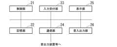
ここで、音出力装置10は、図2に示した通り、制御部11と、記憶部12と、操作部13と、通信部14と、表示部15と、音入出力部16Aと、音入出力部16Bと、装着部17を備える。なお、図1では、図が煩雑になるのを防ぐため、制御部11と、記憶部12と、通信部14を省略している。As shown in Fig. 2, the
制御部11は、音出力装置10の全体を制御する。制御部11は、プロセッサーであり、例えば、マイコン、CPU(Central Processing Unit)、DSP(Digital Signal Processor)等である。制御部11は、記憶部12に格納された各種のプログラムを実行する。なお、制御部11は、複数のハードウェアにより構成されてもよく、単一のプロセッサーで構成されてもよい。また、制御部11は、音出力装置10の各機能を実現するようにプログラムされたハードウェアであってもよい。すなわち、制御部11は、記憶部12に記憶された各種のプログラムをハードウェア回路として搭載した構成であってもよい。この場合、例えば、制御部11は、ASIC(Application Specific Integrated Circuit)、FPGA(Field Programmable Gate Array)等によって構成される。The
記憶部12は、例えば、SSD(Solid State Drive)、EEPROM(Electrically Erasable Programmable Read-Only Memory)、ROM(Read-Only Memory)、RAM(Random Access Memory)等を含む。なお、記憶部12は、音出力装置10に内蔵されるものに代えて、USB(Universal Serial Bus)等のデジタル入出力ポート等によって接続された外付け型の記憶装置であってもよい。記憶部12は、音出力装置10が処理する各種の情報、各種のプログラム等を格納する。なお、記憶部12は、1つの記憶装置によって構成されてもよく、複数の記憶装置によって構成されてもよい。The
操作部13は、各種の操作を受け付ける1以上のハードウェアキーを有する。操作部13は、音出力装置10から出力される音の大きさ、すなわち、音量の調整を行う操作を受け付けるハードウェアキー、音出力装置10の電源のオンとオフとを切り替える操作を受け付けるハードウェアキー等を有する。なお、操作部13は、これらのハードウェアキーに代えて、又は、これらのハードウェアキーに加えて、他のハードウェアキーを備える構成であってもよい。また、音出力装置10は、操作部13を備えない構成であってもよい。この場合、音出力装置10は、音出力装置10と通信可能に接続された情報処理装置から操作を受け付ける。ここで、情報処理装置20は、このような情報処理装置の一例である。なお、音出力装置10は、操作部13を備える場合であっても、音出力装置10と通信可能に接続された情報処理装置から操作を受け付ける。The
通信部14は、例えば、USB等のデジタル入出力ポート、イーサネット(登録商標)ポート等を含んで構成される。The
表示部15は、透過型の液晶ディスプレイを含む表示装置である。なお、表示部15は、透過型の液晶ディスプレイに代えて、他の透過型のディスプレイ、透過型の導光光学系と導光光学系とに画像光を射出する液晶ディスプレイパネル、有機EL(ElectroLuminescence)ディスプレイパネル等の表示素子を含む構成であってもよい。また、表示部15は、外光を透過する透過型に限定されるものではなく、外光を透過せずに遮光して映像のみをユーザーに視認させる構成であってもよく、カメラで撮像した外界像と映像とを重畳してユーザーに視認させる構成であってもよい。The
音入出力部16Aは、音情報が入力される音入力部と、音情報又は音を出力する動作を行う音出力部とが一体に構成された音入出力部の一例である。音入出力部16Aは、例えば、音出力装置10と一体に構成されたビルトイン型のマイクロフォン及びスピーカーである。この場合、マイクロフォンは、音情報が入力される音入力部の一例である。また、この場合、スピーカーは、音を出力する動作を行う音出力部の一例である。なお、このスピーカーは、如何なる種類のスピーカーであってもよい。また、音出力装置10は、音出力装置10と一体に構成されたビルトイン型のスピーカーを、音入出力部16Aの代わりの音出力部として備える構成であってもよい。The sound input/
音入出力部16Bは、音情報が入力される音入力部と、音情報又は音を出力する動作を行う音出力部とが一体に構成された音入出力部の一例である。音入出力部16Bは、例えば、ジャックを有し、ジャックにプラグが差し込まれた場合において、ジャックとプラグとを介した音情報の入出力を行う装置である。当該プラグは、例えば、イヤフォン、ヘッドフォン等へ音情報を入力するプラグ、CDプレイヤー等の音楽再生装置から音情報が出力されるプラグ等のことであるが、これらに限られるわけではない。なお、音出力装置10は、当該場合において音情報をプラグに出力する動作を行う装置を、音入出力部16Bの代わりの音出力部として備える構成であってもよい。イヤフォン、ヘッドフォン等は、当該装置の一例である。The sound input/
装着部17は、音出力装置10をユーザーの身体に装着させるために用いられる部材である。図1に示した例では、音出力装置10は、前述した通り、ヘッドマウントディスプレイである。この場合、装着部17は、表示部15の表示面をユーザーが視認することが可能なように、音出力装置10をユーザーの頭部に装着させる。当該例では、装着部17は、テンプルである。なお、装着部17は、テンプルに加えて、パッド、モダン等を有する構成であってもよい。また、装着部17は、テンプルに代えて、表示部15の表示面をユーザーが視認することが可能なように、音出力装置10をユーザーの頭部に装着させることが可能な部材であれば、他の部材であってもよい。The mounting
ここで、図1に示した例では、音出力装置10は、音出力装置本体10Aと、中継装置10Bとの2つの装置により構成されている。この場合、音出力装置本体10Aと中継装置10Bとは、有線又は無線により互いに通信可能に接続される。当該例では、音出力装置本体10Aと中継装置10Bとは、ケーブルにより通信可能に接続されている。また、中継装置10Bは、音出力装置本体10Aと情報処理装置20との間における各種の情報の送受信を中継する。すなわち、当該例では、中継装置10Bと情報処理装置20とは、有線又は無線により互いに通信可能に接続される。これにより、図1に示した例において、音出力装置10と情報処理装置20とは、前述した通り、通信可能に接続される。In the example shown in FIG. 1, the
また、図1に示した例では、音出力装置本体10Aは、制御部11と、記憶部12と、表示部15と、音入出力部16Aと、音入出力部16Bと、装着部17を備える。また、当該例では、中継装置10Bは、操作部13と、通信部14を備える。なお、音出力装置本体10Aは、操作部13と通信部14との少なくとも一方を更に備える構成であってもよい。また、中継装置10Bは、制御部11と、記憶部12と、音入出力部16Aと、音入出力部16Bとのうちの一部又は全部を更に備える構成であってもよい。また、音出力装置10は、音出力装置本体10Aと中継装置10Bとが一体に構成された装置であってもよい。1, the sound output device
情報処理装置20は、例えば、多機能携帯電話端末(スマートフォン)である。なお、情報処理装置20は、多機能携帯電話端末に代えて、携帯電話端末、タブレットPC(Personal Computer)、ノートPC、PDA(Personal Digital Assistant)、デスクトップPC、ワークステーション等の他の情報処理装置であってもよい。The
情報処理装置20は、受け付けた操作に応じて、音出力装置10を制御する各種の指令を音出力装置10に出力する。情報処理装置20から音出力装置10に出力される指令は、コマンドであってもよく、他の形式の指令であってもよい。これにより、ユーザーは、情報処理装置20を介して、音出力装置10の操作を行うことができる。換言すると、音出力装置10は、情報処理装置20からの操作を受け付けることができる。The
また、情報処理装置20は、受け付けた操作に応じて、各種の音情報を音出力装置10に出力することにより、ユーザーが所望する音を音出力装置10に出力させることができる。これら各種の音情報は、例えば、情報処理装置20において再生される動画像に付随する音楽、音声等を示す情報、情報処理装置20を用いて行われる音声通話の音声を示す情報等であるが、これらに限られるわけではない。In addition, the
また、情報処理装置20は、受け付けた操作に応じて、情報処理装置20が備えるスピーカーから、各種の音情報が示す音を出力することもできる。In addition, the
情報処理装置20は、制御部21と、記憶部22と、入力受付部23と、通信部24と、表示部25と、音入出力部26を備える。The
制御部21は、情報処理装置20の全体を制御する。制御部21は、プロセッサーであり、例えば、CPUである。制御部21は、記憶部22に格納された各種のプログラムを実行する。なお、制御部21は、複数のハードウェアにより構成されてもよく、単一のプロセッサーで構成されてもよい。また、制御部21は、情報処理装置20の各機能を実現するようプログラムされたハードウェアであってもよい。すなわち、制御部21は、記憶部22に記憶された各種のプログラムをハードウェア回路として搭載した構成であってもよい。この場合、例えば、制御部21は、ASIC、FPGA等によって構成される。The
記憶部22は、例えば、SSD、EEPROM、ROM、RAM等を含む。なお、記憶部22は、情報処理装置20に内蔵されるものに代えて、USB等のデジタル入出力ポート等によって接続された外付け型の記憶装置であってもよい。記憶部22は、情報処理装置20が処理する各種の情報、各種のプログラム等を格納する。なお、記憶部22は、1つの記憶装置によって構成されてもよく、複数の記憶装置によって構成されてもよい。The
入力受付部23は、例えば、表示部25と一体に構成されたタッチパネルである。なお、入力受付部23は、これに代えて、キーボード、マウス等の表示部25と別体の他の入力装置であってもよい。The
通信部24は、例えば、USB等のデジタル入出力ポート、イーサネット(登録商標)ポート等を含んで構成される。The
表示部25は、例えば、液晶ディスプレイパネル、有機ELディスプレイパネル等を含む表示装置である。The
音入出力部26は、音情報が入力される音入力部と、音を出力する動作を行う音出力部とが一体に構成された機能部である。例えば、音入出力部26は、情報処理装置20と一体に構成されたビルトイン型のマイクロフォン及びスピーカーである。この場合、マイクロフォンは、当該音入力部の一例である。また、この場合、スピーカーは、音を出力する動作を行う音出力部の一例である。なお、このスピーカーは、如何なる種類のスピーカーであってもよい。また、情報処理装置20は、情報処理装置20と一体に構成されたビルトイン型のスピーカーを、音入出力部26の代わりの音出力部として備える構成であってもよい。The sound input/
ここで、音出力システム1において、音出力装置10は、情報処理装置20と接続された場合、複数の音出力部のうち予め決められた1つ以上の第1音出力部の動作を有効にするとともに、複数の音出力部のうち当該1つ以上の第1音出力部以外の1つ以上の音出力部の動作を無効にする。この一例において、音出力装置10は、前述した通り、これら複数の音出力部として、音入出力部16Aと、音入出力部16Bとの2つの音入出力部を備えている。このため、この一例では、音出力装置10は、情報処理装置20と接続された場合、音入出力部16Aと音入出力部16Bとのうちの一方の動作を、予め決められた第1音出力部の動作として有効にするとともに、音入出力部16Aと音入出力部16Bとのうちの他方の動作を無効にする。これにより、音出力装置10は、情報処理装置20と接続された場合において、意図しない音入出力部から音を出力させてしまうことを抑制することができる。以下では、一例として、音入出力部16Aが、予め決められた第1音出力部である場合について説明する。なお、音出力装置10は、3つ以上の音出力部を備える場合において、情報処理装置20と接続された場合、3つ以上の音出力部のうち予め決められた1つ以上の音出力部の動作を1つ以上の第1音出力部の動作として有効にするとともに、3つ以上の音出力部のうち当該1つ以上の第1音出力部以外の1つ以上の音出力部の動作を無効にする構成であってもよい。ただし、この場合、これら1つ以上の第1音出力部のそれぞれは、動作中において互いの動作を阻害しない。Here, in the
<音出力システムにおける音の出力>
以下、図4を参照し、音出力システム1における音の出力について説明する。ここで、図4についての説明では、説明の便宜上、音情報又は音の出力を区別する必要がない限り、まとめて音の出力と称して説明する。また、以下では、説明の便宜上、音出力装置10と情報処理装置20とが通信可能に接続されている状態を、接続状態と称して説明する。また、以下では、説明の便宜上、音出力装置10と情報処理装置20とが通信可能に接続されていない状態を、非接続状態と称して説明する。 <Sound output in sound output system>
Hereinafter, the output of sound in the
図4は、音入出力部16A及び音入出力部16Bそれぞれの動作の有効又は無効と、音出力システム1において音の出力を行う音入出力部との関係の一例を示す図である。Figure 4 is a diagram showing an example of the relationship between the enabled/disabled operation of sound input/
図4に示したように、音出力システム1では、音入出力部16A及び音入出力部16Bそれぞれの動作の有効又は無効に応じて、音の出力を行う音入出力部が切り替わる。As shown in FIG. 4, in the
ここで、図4に示したケース1は、音入出力部16A及び音入出力部16Bの両方の動作が有効であり、イヤフォン等のプラグが音入出力部16Bに差し込まれている状況を示す。なお、図4では、動作が有効であることを、「Enable」によって示している。また、図4では、動作が無効であることを、「Disable」によって示している。ケース1の音出力システム1では、音の出力は、音入出力部16Aと音入出力部16Bとのいずれにより行われるか定まらない。すなわち、ケース1の音出力システム1では、音の出力を行う音入出力部は、不定である。この場合、音の出力は、音入出力部16Aと音入出力部16Bとのいずれか一方又は両方により行われる。このため、ケース1の音出力システム1では、音の出力は、意図しない音入出力部により行われることがある。これは、音出力システム1のユーザーにとって望ましいことではない。なお、図4では、音入出力部16Bへプラグが差し込まれていることを、「CONNECT」によって示している。また、図4では、音入出力部16Bへプラグが差し込まれていないことを、「DISCONNECT」によって示している。Here,
また、図4に示したケース2は、音入出力部16A及び音入出力部16Bの両方の動作が有効であり、且つ、イヤフォン等のプラグが音入出力部16Bに差し込まれていない状況を示す。ケース2の音出力システム1では、音の出力は、音入出力部16Aにより行われる。これは、イヤフォン等のプラグが音入出力部16Bに差し込まれていないためである。Case 2 shown in FIG. 4 shows a situation in which both sound input/
また、図4に示したケース3は、音入出力部16Aの動作が有効であり、音入出力部16Bの動作が無効であり、イヤフォン等のプラグが音入出力部16Bに差し込まれている状況を示す。ケース3の音出力システム1では、音の出力は、音入出力部16Aにより行われる。Case 3 shown in FIG. 4 shows a situation in which the operation of sound input/
また、図4に示したケース4は、音入出力部16Aの動作が有効であり、音入出力部16Bの動作が無効であり、イヤフォン等のプラグが音入出力部16Bに差し込まれていない状況を示す。ケース4の音出力システム1でも、音の出力は、音入出力部16Aにより行われる。Case 4 shown in FIG. 4 shows a situation in which the operation of sound input/
また、図4に示したケース5は、音入出力部16Aの動作が無効であり、音入出力部16Bの動作が有効であり、イヤフォン等のプラグが音入出力部16Bに差し込まれている状況を示す。ケース5の音出力システム1では、音の出力は、音入出力部16Bにより行われる。Case 5 shown in FIG. 4 shows a situation in which the operation of sound input/
また、図4に示したケース6は、音入出力部16Aの動作が無効であり、音入出力部16Bの動作が有効であり、イヤフォン等のプラグが音入出力部16Bに差し込まれていない状況を示す。ケース6の音出力システム1では、音の出力は、情報処理装置20の音入出力部26により行われる。これは、イヤフォンのプラグが音入出力部16Bに差し込まれていないためである。Case 6 shown in FIG. 4 shows a situation in which the operation of sound input/
また、図4に示したケース7は、音入出力部16A及び音入出力部16Bの両方の動作が無効であり、イヤフォンのプラグが音入出力部16Bに差し込まれている状況を示す。ケース7の音出力システム1でも、音の出力は、情報処理装置20の音入出力部26により行われる。Case 7 shown in FIG. 4 shows a situation in which the operation of both sound input/
また、図4に示したケース8は、音入出力部16A及び音入出力部16Bの両方の動作が無効であり、イヤフォン等のプラグが音入出力部16Bに差し込まれていない状況を示す。ケース8の音出力システム1でも、音の出力は、情報処理装置20の音入出力部26により行われる。Case 8 shown in FIG. 4 shows a situation in which the operation of both sound input/
以上のように、音出力システム1では、音入出力部16A及び音入出力部16Bそれぞれの動作の有効又は無効に応じて、音の出力を行う音入出力部が切り替わる。そして、音出力システム1は、図4に示したケース1が実現してしまうと、非接続状態から接続状態へと遷移した場合、意図しない音入出力部から音を出力させてしまうことがある。例えば、音出力システム1は、ケース1が実現してしまうと、非接続状態から接続状態へと遷移した場合、音入出力部16Aと音入出力部16Bとの両方から音を出力させてしまうことがある。As described above, in
そこで、音出力システム1では、音出力装置10は、ケース1が実現しない構成になっている。具体的には、前述した通り、音出力装置10は、情報処理装置20と接続された場合、音入出力部16Aの動作を、予め決められた第1音出力部の動作として有効にするとともに、音入出力部16Bの動作を無効にする。これにより、音出力装置10は、情報処理装置20と接続された場合、ケース1が実現してしまうことを抑制することができ、その結果、意図しない音入出力部から音を出力させてしまうことを抑制することができる。Therefore, in the
<情報処理装置と接続された場合において音出力装置が行う有効無効切替処理>
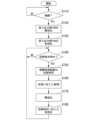
以下、図5を参照し、情報処理装置20と接続された場合において音出力装置10が行う有効無効切替処理について説明する。ここで、有効無効切替処理は、音出力装置10が行う処理のうち、音入出力部16A及び音入出力部16Bそれぞれの動作の有効と無効とを切り替える処理のことである。図5は、情報処理装置20と接続された場合において音出力装置10が行う有効無効切替処理の流れの一例を示す図である。以下では、一例として、図5に示したステップS110の処理が行われるよりも前のタイミングにおいて、音出力装置10及び情報処理装置20それぞれの電源がオンに切り替えられている場合について説明する。また、以下では、一例として、当該タイミングにおいて、音出力装置本体10Aと中継装置10Bとが通信可能に接続されている場合について説明する。 <Enable/disable switching process performed by sound output device when connected to information processing device>
Hereinafter, with reference to FIG. 5, the enable/disable switching process performed by the
制御部11は、音出力装置10が情報処理装置20と接続されるまで待機する(ステップS110)。なお、図5では、ステップS110の処理を、「接続?」によって示している。制御部11は、例えば、中継装置10Bを介した音出力装置本体10Aと情報処理装置20との間の有線又は無線による通信が確立した場合、音出力装置10が情報処理装置20と接続されたと判定する。換言すると、制御部11は、音出力装置10と情報処理装置20との間の通信が確立した場合、音出力装置10が情報処理装置20と接続されたと判定する。一方、制御部11は、例えば、この通信が確立していない場合、音出力装置10が情報処理装置20と接続されていないと判定する。ここで、制御部11は、中継装置10Bを介した音出力装置本体10Aと情報処理装置20との間の有線又は無線による通信が確立したことを、既知の方法で特定する構成であってもよく、これから開発される方法で特定する構成であってもよい。なお、制御部11は、他の方法により、音出力装置10が情報処理装置20と接続されたと判定する構成であってもよい。例えば、制御部11は、情報処理装置20から出力された接続完了を示す情報を取得した場合、音出力装置10が情報処理装置20と接続されたと判定する構成であってもよい。当該情報は、第2指令の一例である。また、制御部11は、音出力装置10が情報処理装置20と接続されたことを音出力装置10が検出した場合、音出力装置10が情報処理装置20と接続されたと判定する構成であってもよい。この場合、音出力装置10は、音出力装置10が情報処理装置20と接続されたことを検出する検出部を備える。The
制御部11は、音出力装置10が情報処理装置20と接続されたと判定した場合(ステップS110-YES)、音入出力部16Bの動作を無効にする(ステップS120)。すなわち、制御部11は、ステップS120において、音入出力部16Bからの音の出力を禁止する。図5では、ステップS120の処理を、「音入出力部16Bの無効化」によって示している。なお、制御部11は、ステップS120の処理を、スイッチング素子による音入出力部16Bへの電力供給の停止等のようにハードウェアによって行ってもよく、音情報の音入出力部16Bへの出力の停止等のようにソフトウェアによって行ってもよい。When the
次に、制御部11は、予め決められた第1音入出力部の動作として、音入出力部16Aの動作を有効にする(ステップS130)。すなわち、制御部11は、ステップS130において、音入出力部16Aからの音の出力を許可する。図5では、ステップS130の処理を、「音入出力部16Bの有効化」によって示している。なお、制御部11は、ステップS130の処理を、スイッチング素子による音入出力部16Aへの電力供給の開始等のようにハードウェアによって行ってもよく、音情報の音入出力部16Aへの出力の開始等のようにソフトウェアによって行ってもよい。また、制御部11は、ステップS120の処理と、ステップS130の処理とを、並列に行う構成であってもよい。Next, the
次に、制御部11は、情報処理装置20から切替指令を受け付けるまで待機する(ステップS140)。ここで、切替指令は、音出力装置10が備える音入出力部16Aと音入出力部16Bとのいずれか一方を指定する指令である。そして、切替指令は、切替指令によって指定される音入出力部の動作を有効にする指令である。例えば、切替指令は、切替指令によって指定される音入出力部が音入出力部16Bであった場合、音入出力部16Bの動作を有効にする指令である。また、例えば、切替指令は、切替指令によって指定される音入出力部が音入出力部16Aであった場合、音入出力部16Aの動作を有効にする指令である。なお、音出力装置10が3つ以上の音入出力部を備える場合、切替指令は、これら3つ以上の音入出力部のうちのいずれか1つを指定する指令であり、且つ、切替指令により指定される音入出力部の動作を有効にする指令である。Next, the
制御部11は、情報処理装置20から切替指令を受け付けたと判定した場合(ステップS140-YES)、情報処理装置20の状態が、音声通話状態と、音入出力状態と、非音入出力状態とのいずれであるかを特定する(ステップS150)。図5では、ステップS150の処理を、「情報処理装置の状態特定」によって示している。ここで、音声通話状態は、情報処理装置20の状態のうち音声通話が行われている状態のことである。音入出力状態は、情報処理装置20の状態のうちの音声通話状態と異なる状態であり、音声通話以外の音の入出力を情報処理装置20が行っている状態のことである。なお、この音の入出力には、音情報の入出力も含まれている。例えば、音入出力状態は、音声の出力を伴う動画像の再生、音楽の再生、録音等のうちの一部又は全部を情報処理装置20が行っている状態のことである。非音入出力状態は、音声通話状態及び音入出力状態の両方と異なる状態である。すなわち、非音入出力状態は、情報処理装置20の状態のうち、音声通話が行われていない状態であり、且つ、音声通話以外の音の入出力も行われていない状態のことである。When the
次に、制御部11は、ステップS150において特定した情報処理装置20の状態に応じた処理を行う(ステップS160)。図5では、ステップS160の処理を、「状態に応じた処理」によって示している。ここで、ステップS160の処理について説明する。Next, the
例えば、制御部11は、ステップS150において特定した情報処理装置20の状態が音声通話状態であった場合、音声通話状態に応じた処理として、音入出力部16A及び音入出力部16Bのそれぞれから出力される音の音量をミュートにする処理を行う。これは、情報処理装置20において音声通話が行われている場合において音出力装置10と情報処理装置20とが接続されると、音入出力部16A及び音入出力部16Bのそれぞれから出力される音の音量がミュートにされていない限り、情報処理装置20における音声通話の音が、意図せずして音入出力部16A及び音入出力部16Bのいずれかから出力されてしまう可能性があるためである。これを防ぐため、制御部11は、ステップS150において特定した情報処理装置20の状態が音声通話状態であった場合、音入出力部16A及び音入出力部16Bのそれぞれから出力される音の音量をミュートにする処理を行う。For example, when the state of the
また、例えば、制御部11は、ステップS150において特定した情報処理装置20の状態が音入出力状態であった場合、音入出力状態に応じた処理として、情報処理装置20による音の入出力を停止する処理を行う。具体的には、制御部11は、情報処理装置20によって音楽、動画像等の再生が行われている場合、ステップS160において、当該再生を停止する処理を行う。また、制御部11は、情報処理装置20による録音が行われている場合、ステップS160において、当該録音を停止する処理を行う。これらは、ユーザーが音出力装置10における所望の音入出力部の動作を有効にする前に、意図しない音入出力部から音が出力されてしまうことがあるためである。For example, when the state of the
また、例えば、制御部11は、ステップS150において特定した情報処理装置20の状態が非音入出力状態であった場合、ステップS160において、非音入出力状態に応じた処理を行わない。Also, for example, if the state of the
ステップS160の処理が行われた後、制御部11は、音入出力部16A及び音入出力部16Bの両方の動作を無効にする(ステップS170)。図5では、ステップS170の処理を、「無効化」によって示している。なお、制御部11は、音出力装置10が3つ以上の音入出力部を備える場合、ステップS170において、これら3つ以上の音入出力部の全部の動作を無効にする。ステップS170の処理は、音入出力部16A及び音入出力部16Bそれぞれの動作の有効と無効とを切り替える場合において、意図せずして前述のケース1が実現してしまうことを、より確実に抑制するための処理である。After the processing of step S160 is performed, the
例えば、ステップS170の処理を制御部11が行うことにより、制御部11は、ケース3からケース5へ状態を遷移させる場合、図6に示すように、ケース3からケース7へ状態を遷移させてから、ケース7からケース5へ状態を遷移させる。図6は、ステップS170の処理を介して遷移する状態のイメージの一例を示す図である。ここで、図6に示したケース3は、図4に示したケース3を示す。また、図6に示したケース5は、図4に示したケース5を示す。また、図6に示したケース7は、図4に示したケース7を示す。すなわち、制御部11は、音の出力を行う音入出力部が音入出力部16Aである状態から、音の出力を行う音入出力部が音入出力部16Bである状態へ遷移させる場合、ステップS170の処理により、音の出力を行う音入出力部が音入出力部16Aである状態から、音の出力を行う音入出力部が音入出力部26である状態へ遷移させ、その後、音の出力を行う音入出力部が音入出力部26である状態から、音の出力を行う音入出力部が音入出力部16Bである状態へ遷移させる。これにより、音出力装置10は、意図せずしてケース1が実現してしまうことを、より確実に抑制することができる。For example, when the
次に、制御部11は、ステップS140において受け付けた切替指令により指定された音入出力部の動作を有効にする(ステップS180)。図5では、ステップS180の処理を、「切替指令に応じた有効化」によって示している。例えば、制御部11は、ステップS140において受け付けた切替指令により指定された音入出力部が音入出力部16Bであった場合、音入出力部16Bの動作を有効にする。また、例えば、制御部11は、当該切替指令により指定された音入出力部が音入出力部16Aであった場合、音入出力部16Aの動作を有効にする。これにより、音出力装置10のユーザーは、音出力装置10を情報処理装置20に接続した後において、情報処理装置20を介して、所望の音入出力部の動作を有効にすることができる。ステップS180の処理が行われた後、制御部11は、ステップS140に遷移し、情報処理装置20から切替指令を受け付けるまで再び待機する。Next, the
以上のように、音出力装置10は、音出力装置10が情報処理装置20と接続された場合、2つの音入出力部のうち音入出力部16Aの動作を、予め決められた第1音入出力部の動作として有効にするとともに、音入出力部16Bの動作を無効にする。これにより、音出力装置10は、情報処理装置20と接続された場合において、意図しない音入出力部から音を出力させてしまうことを抑制することができる。As described above, when the
また、音出力装置10は、情報処理装置20と接続された場合において、音入出力部16Aの動作を有効にし、且つ、音入出力部16Bの動作を無効にした後、受け付けた切替指令に応じて、切替指令により指定される音入出力部の動作を有効にする。これにより、音出力装置10は、情報処理装置20に接続された後において、ユーザーから受け付けた操作に応じて、音を出力させる音入出力部をユーザーが所望する音入出力部に切り替えることができる。Furthermore, when the
また、音出力装置10は、切替指令に応じて音入出力部16Aと音入出力部16Bとのいずれかの音入出力部の動作を有効にする場合、当該音出力部の動作を有効にする前に、音入出力部16A及び音入出力部16Bの両方の動作を無効にし、その後、当該音入出力部の動作を有効にする。例えば、音出力装置10は、図6に示したように、切替指令に応じてケース3からケース5に切り替わる場合、ケース3からケース7に切り替えた後、ケース7からケース5に切り替える。このケース7を実現する処理の一例が、図5に示したステップS170の処理である。これにより、音出力装置10は、2つの音入出力部それぞれの動作の有効と無効とを切り替える場合において、意図せずしてケース1が実現してしまうことを、より確実に抑制することができる。Furthermore, when the
また、音出力装置10は、切替指令に応じて音入出力部16Aと音入出力部16Bとのいずれかの音入出力部の動作を有効にする場合、当該音出力部の動作を有効にする前に、情報処理装置20の状態に応じた処理を行ってから音入出力部16A及び音入出力部16Bの両方の動作を無効にし、その後、当該音入出力部の動作を有効にする。これにより、音出力装置10は、音入出力部16A及び音入出力部16Bの両方に、意図しない音を出力させてしまうことを、より確実に抑制することができる。In addition, when the
<切替操作を受け付けた場合において情報処理装置が行う処理>
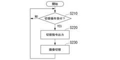
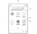
以下、図7を参照し、切替操作を受け付けた場合において情報処理装置20が行う処理について説明する。ここで、切替操作は、音入出力部16Aと音入出力部16Bとのうちの一方の動作を有効にするとともに、音入出力部16Aと音入出力部16Bとのうちの他方の動作を無効にする操作のことである。図7は、切替操作を受け付けた場合において情報処理装置20が行う処理の流れの一例を示す図である。以下では、一例として、図7に示したステップS210の処理が行われるよりも前のタイミングにおいて、図5に示したステップS130の処理が行われている場合について説明する。また、以下では、一例として、当該タイミングにおいて、音出力装置10への操作を受け付ける画像が表示される領域RAを含む操作画像P1が、情報処理装置20の表示部25に表示されている場合について説明する。 <Processing performed by information processing device when switching operation is accepted>
Hereinafter, with reference to FIG. 7, a process performed by the
制御部21は、切替操作を受け付けるまで待機する(ステップS210)。ここで、ステップS210の処理について説明する。The
図8は、操作画像P1の一例を示す図である。操作画像P1には、領域RAが含まれている。領域RAには、現在の音出力装置10において、動作が有効にされている音入出力部を示す画像が、音出力装置10への操作を受け付ける画像の一例として表示される。すなわち、図5に示したステップS130の処理が行われた直後では、領域RAには、この一例における第1音入出力部である音入出力部16Aを示す画像P11が表示されている。制御部21は、画像P11を選択する操作が行われた場合、当該操作を、音入出力部16Bの動作を有効にするとともに、音入出力部16Aの動作を無効にする切替操作として受け付ける。そして、制御部21は、画像P11を、図9に示したように、音入出力部16Bを示す画像P12に切り替える。すなわち、この場合、領域RAには、図9に示したように、画像P12が表示される。図9は、画像P12が表示されている場合の操作画像P1の一例を示す図である。一方、制御部21は、画像P12を選択する操作が行われた場合、当該操作を、音入出力部16Aの動作を有効にするとともに、音入出力部16Bの動作を無効にする切替操作として受け付ける。そして、制御部21は、画像P12を、図8に示したように、音入出力部16Aを示す画像P11に切り替える。なお、画像P11、画像P12のそれぞれを選択する操作は、例えば、タップ等のタッチ操作、クリック等であるが、これらに限られるわけではない。8 is a diagram showing an example of the operation image P1. The operation image P1 includes an area RA. In the area RA, an image showing the sound input/output unit whose operation is enabled in the current
制御部21は、切替操作を受け付けたと判定した場合(ステップS210-YES)、切替指令を音出力装置10に出力する(ステップS220)。ここで、制御部21が受け付けた切替操作が、音入出力部16Bの動作を有効にする切替操作である場合、制御部21は、ステップS220において、音入出力部16Bを指定し、且つ、音入出力部16Bの動作を有効にする切替指令を音出力装置10に出力する。一方、制御部21が受け付けた切替操作が、音入出力部16Aの動作を有効にする切替操作である場合、制御部21は、ステップS220において、音入出力部16Aを指定し、且つ、音入出力部16Aの動作を有効にする切替指令を音出力装置10に出力する。When the
次に、制御部21は、領域RAに表示されている画像の切替を行う(ステップS230)。ここで、ステップS210において受け付けた切替操作が、画像P11を選択する操作であった場合、制御部21は、ステップS230において、領域RAに表示されている画像P11を画像P12へ切り替える。一方、ステップS210において受け付けた切替操作が、画像P12を選択する操作であった場合、制御部21は、ステップS230において、領域RAに表示されている画像P12を画像P11へ切り替える。ステップS230の処理が行われた後、制御部21は、ステップS210に遷移し、切替操作を受け付けるまで再び待機する。Next, the
以上のように、情報処理装置20は、音出力装置10への切替操作を受け付けることができる。より具体的には、情報処理装置20は、切替操作を受け付け、受け付けた切替操作に応じて、音出力装置10が備える音入出力部のいずれかの動作を有効にすることができる。これにより、情報処理装置20は、音出力装置10が備える音入出力部のうち、ユーザーが所望する音入出力部の動作を有効にすることができる。As described above, the
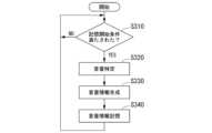
<所定の記憶開始条件が満たされた場合に音出力装置が行う処理>
以下、図10を参照し、所定の記憶開始条件が満たされた場合に音出力装置10が行う処理について説明する。ここで、記憶開始条件は、音の音量を示す音量情報の記憶を音出力装置10に開始させる条件のことである。記憶開始条件には、例えば、以下に示した条件A1~条件A5の5つの条件が含まれている。 <Processing performed by the sound output device when a predetermined storage start condition is satisfied>
Hereinafter, a process performed by the
(条件A1):音出力装置10と情報処理装置20との間の通信接続が切断されたこと
(条件A2):音出力装置10と接続された状態の情報処理装置20の電源がオフに切り替わったこと
(条件A3):音入出力部16Bの動作が有効である場合において音入出力部16Bのジャックからプラグが抜去されたこと
(条件A4):音入出力部16Aの動作が有効から無効に切り替えられたこと
(条件A5):音入出力部16Bの動作が有効から無効に切り替えられたこと(Condition A1): The communication connection between the
なお、記憶開始条件には、条件A1~条件A5の5つの条件のうちの一部又は全部に代えて、又は、当該5つの条件のうちの一部又は全部に加えて、他の条件が含まれる構成であってもよい。制御部11は、例えば、記憶開始条件に含まれる5つの条件のうちの少なくとも1つが満たされた場合、記憶開始条件が満たされたと判定する。一方、制御部11は、例えば、当該場合、記憶開始条件に含まれる5つの条件のうちの全部が満たされていない場合、記憶開始条件が満たされていないと判定する。The storage start condition may include other conditions instead of some or all of the five conditions A1 to A5, or in addition to some or all of the five conditions. For example, the
図10は、所定の記憶開始条件が満たされた場合に音出力装置10が行う処理の流れの一例を示す図である。Figure 10 shows an example of the flow of processing performed by the
制御部11は、記憶開始条件が満たされるまで待機する(ステップS310)。The
制御部11は、記憶開始条件が満たされたと判定した場合(ステップS310-YES)、音入出力部16Aと音入出力部16Bとのうち動作が有効になっている方の音入出力部を特定する。そして、制御部11は、特定した音入出力部から出力される音の音量を特定する(ステップS320)。例えば、制御部11は、ステップS320において、音入出力部16Aの動作が有効になっていることを特定した場合、音入出力部16Aから出力される音の音量を特定する。また、例えば、制御部11は、ステップS320において、音入出力部16Bの動作が有効になっていることを特定した場合、音入出力部16Bに差し込まれたプラグを有する装置から出力される音の音量を特定する。When the
次に、制御部11は、音量情報を生成する(ステップS330)。ここで、制御部11は、例えば、ステップS320において特定した音入出力部が音入出力部16Aであった場合、ステップS320において特定した音量を示す情報と、音入出力部16Aを識別する情報とを含む情報を、当該音量を示す音量情報として生成する。また、制御部11は、例えば、ステップS320において特定した音入出力部が音入出力部16Bであった場合、ステップS320において特定した音量を示す情報と、音入出力部16Bを識別する情報とを含む情報を、当該音量を示す音量情報として生成する。Next, the
次に、制御部11は、ステップS330において生成した音量情報を、記憶部12に記憶させる(ステップS340)。なお、制御部11は、音入出力部16Aを識別する情報を含む音量情報を記憶部12に記憶させる場合において、当該音量情報が記憶部12に予め記憶されている場合、当該音量情報を新しい音量情報に更新する。また、制御部11は、音入出力部16Bを識別する情報を含む音量情報を記憶部12に記憶させる場合において、当該音量情報が記憶部12に予め記憶されている場合、当該音量情報を新しい音量情報に更新する。ステップS340の処理が行われた後、制御部11は、ステップS310に遷移し、記憶開始条件が満たされるまで再び待機する。Next, the
以上のように、音出力装置10は、所定の記憶開始条件が満たされる毎に、音量情報を記憶することができる。これにより、音出力装置10は、図11に示すフローチャートの処理によって、後述する読出開始条件が満たされる毎に、音入出力部16Aと音入出力部16Bとのそれぞれから出力される音の音量を、ユーザーからの操作を受け付けることなく、ユーザーが以前に設定していた音量と同じ音量に設定することができる。As described above, the
<所定の読出開始条件が満たされた場合に音出力装置が行う処理>
以下、図11を参照し、所定の読出開始条件が満たされた場合に音出力装置10が行う処理について説明する。ここで、読出開始条件は、記憶部12に予め記憶された音量情報の記憶部12からの読み出しを音出力装置10に開始させる条件のことである。読出開始条件には、例えば、以下に示した条件B1~条件B5の5つの条件が含まれている。 <Processing performed by the sound output device when a specific readout start condition is satisfied>
11, a process performed by the
(条件B1):音出力装置10が情報処理装置20と接続されたこと
(条件B2):音出力装置10と接続された状態の情報処理装置20の電源がオンに切り替わったこと
(条件B3):音入出力部16Bの動作が有効である場合において音入出力部16Bのジャックにプラグが差し込まれたこと
(条件B4):音入出力部16Aの動作が無効から有効に切り替えられたこと
(条件B5):音入出力部16Bの動作が無効から有効に切り替えられたこと(Condition B1): The
なお、読出開始条件には、条件B1~条件B5の5つの条件のうちの一部又は全部に代えて、又は、当該5つの条件のうちの一部又は全部に加えて、他の条件が含まれる構成であってもよい。制御部11は、例えば、読出開始条件に含まれる5つの条件のうちの少なくとも1つが満たされた場合、読出開始条件が満たされたと判定する。一方、制御部11は、例えば、当該場合、読出開始条件に含まれる5つの条件のうちの全部が満たされていない場合、読出開始条件が満たされていないと判定する。The read start condition may include other conditions instead of some or all of the five conditions B1 to B5, or in addition to some or all of the five conditions. The
図11は、所定の読出開始条件が満たされた場合に音出力装置10が行う処理の流れの一例を示す図である。Figure 11 shows an example of the flow of processing performed by the
制御部11は、読出開始条件が満たされるまで待機する(ステップS410)。The
制御部11は、読出開始条件が満たされたと判定した場合(ステップS410-YES)、音入出力部16Aと音入出力部16Bとのうち動作が有効になっている方の音入出力部を特定する。そして、制御部11は、特定した音入出力部を識別する情報を含む音量情報を、記憶部12から読み出す(ステップS420)。例えば、制御部11は、ステップS420において、音入出力部16Aの動作が有効になっていることを特定した場合、音入出力部16Aを識別する情報を含む音量情報を記憶部12から読み出す。また、例えば、制御部11は、ステップS320において、音入出力部16Bの動作が有効になっていることを特定した場合、音入出力部16Bを識別する情報を含む音量情報を記憶部12から読み出す。なお、図10に示したフローチャートの処理が行われる前の記憶部12には、音入出力部16Aを識別する情報とともに、音入出力部16Aから出力される音の音量として、デフォルトの音量を示す情報を含む音量情報が記憶されていてもよく、当該音量情報が記憶されていなくてもよい。また、図10に示したフローチャートの処理が行われる前の記憶部12には、音入出力部16Bを識別する情報とともに、音入出力部16Bから出力される音の音量として、デフォルトの音量を示す情報を含む音量情報が記憶されていてもよく、当該音量情報が記憶されていなくてもよい。When the
次に、制御部11は、ステップS420において読み出した音量情報が示す音量を特定する(ステップS430)。Next, the
次に、制御部11は、ステップS420において読み出した音量情報に含まれる情報が示す音入出力部から出力される音の音量を、当該音量情報に含まれる情報が示す音量に設定する(ステップS440)。ここで、制御部11は、例えば、ステップS420において読み出した音量情報に含まれる情報が識別する音入出力部が音入出力部16Aであった場合、音入出力部16Aから出力される音の音量を、ステップS430において特定した音量に設定する。また、制御部11は、例えば、ステップS420において読み出した音量情報に含まれる情報が識別する音入出力部が音入出力部16Bであった場合、音入出力部16Bから出力される音の音量を、ステップS430において特定した音量に設定する。ステップS440の処理が行われた後、制御部11は、ステップS410に遷移し、読出開始条件が満たされるまで再び待機する。Next, the
以上のように、音出力装置10は、所定の読出開始条件が満たされる毎に、音入出力部16Aと音入出力部16Bとのそれぞれから出力される音の音量を、ユーザーからの操作を受け付けることなく、ユーザーが以前に設定していた音量と同じ音量に設定することができる。As described above, each time a predetermined readout start condition is satisfied, the
以上説明したように、実施形態に係る音出力装置は、情報処理装置と通信可能に接続される音出力装置であって、音出力装置を人の身体に装着させる装着部と、音を示す情報又は音を出力する動作を行う複数の音出力部と、音出力装置が情報処理装置と接続された場合、複数の音出力部のうち予め決められた1つ以上の第1音出力部の動作を有効にするとともに、複数の音出力部のうち1つ以上の第1音出力部以外の1つ以上の音出力部の動作を無効にする制御部と、を備える。これにより、音出力装置は、情報処理装置と接続された場合において、意図しない音出力部から音を出力させてしまうことを抑制することができる。ここで、上記において説明した例では、音出力装置10は、当該音出力装置の一例である。また、上記において説明した例では、情報処理装置20は、当該情報処理装置の一例である。また、上記において説明した例では、装着部17は、当該装着部の一例である。また、上記において説明した例では、音入出力部16A、音入出力部16Bのそれぞれは、音出力部の一例である。また、上記において説明した例では、音入出力部16Aは、第1音出力部の一例である。また、上記において説明した例では、制御部11は、当該制御部の一例である。As described above, the sound output device according to the embodiment is a sound output device that is communicatively connected to an information processing device, and includes a mounting unit that mounts the sound output device on a person's body, a plurality of sound output units that perform an operation of outputting information or sound indicating a sound, and a control unit that enables the operation of one or more first sound output units among the plurality of sound output units when the sound output device is connected to the information processing device, and disables the operation of one or more sound output units other than the one or more first sound output units among the plurality of sound output units. This allows the sound output device to suppress sound output from an unintended sound output unit when connected to an information processing device. Here, in the example described above, the
また、音出力装置では、制御部は、情報処理装置と接続された場合において、1つ以上の第1音出力部の動作を有効にし、且つ、1つ以上の音出力部の動作を無効にした後、受け付けた第1指令に応じて、複数の音出力部のうちの第1指令により指定される第2音出力部の動作を有効にする、構成が用いられてもよい。ここで、上記において説明した例では、切替指令は、第1指令の一例である。また、上記において説明した例では、音入出力部16A、音入出力部16Bのそれぞれは、第2音出力部の一例である。In addition, in the sound output device, the control unit may be configured to enable the operation of one or more first sound output units when connected to the information processing device, disable the operation of one or more sound output units, and then enable the operation of a second sound output unit specified by the first command among the multiple sound output units in response to the received first command. Here, in the example described above, the switching command is an example of a first command. Also, in the example described above, each of sound input/
また、音出力装置では、制御部は、第1指令に応じて第2音出力部の動作を有効にする場合、第2音出力部の動作を有効にする前に、複数の音出力部の全部の動作を無効にし、その後、第2音出力部の動作を有効にする、構成が用いられてもよい。In addition, in the sound output device, when the control unit enables the operation of the second sound output unit in response to the first command, the control unit may be configured to disable the operation of all of the multiple sound output units before enabling the operation of the second sound output unit, and then enable the operation of the second sound output unit.
また、音出力装置では、制御部は、第1指令に応じて第2音出力部の動作を有効にする場合、第2音出力部の動作を有効にする前に、情報処理装置の状態に応じた処理を行ってから複数の音出力部の全部の動作を無効にし、その後、第2音出力部の動作を有効にする、構成が用いられてもよい。In addition, in the sound output device, when the control unit enables the operation of the second sound output unit in response to the first command, the control unit may perform processing according to the state of the information processing device before enabling the operation of the second sound output unit, and then disable the operation of all of the multiple sound output units, and then enable the operation of the second sound output unit.
また、音出力装置では、複数の音出力部のうちの一部又は全部は、音を示す情報が入力される音入力部と一体に構成された音入出力部である、構成が用いられてもよい。The sound output device may also be configured such that some or all of the multiple sound output units are sound input/output units that are integrated with a sound input unit to which information indicating sound is input.
また、音出力装置では、制御部は、情報処理装置と接続された場合、情報処理装置から受け付けた第2指令に応じて、1つ以上の第1音出力部の動作を有効にするとともに、1つ以上の音出力部の動作を無効にする、構成が用いられてもよい。In addition, the sound output device may be configured such that, when connected to an information processing device, the control unit enables the operation of one or more first sound output units and disables the operation of one or more sound output units in response to a second command received from the information processing device.
また、音出力装置では、情報処理装置が接続されたことを検出する検出部を備え、制御部は、情報処理装置と接続されたことを検出部が検出した場合、1つ以上の第1音出力部の動作を有効にするとともに、1つ以上の音出力部の動作を無効にする、構成が用いられてもよい。The sound output device may also be configured to include a detection unit that detects that an information processing device has been connected, and the control unit may enable the operation of one or more first sound output units and disable the operation of one or more sound output units when the detection unit detects that the information processing device has been connected.
また、音出力装置では、複数の音出力部には、ジャックを有し、ジャックにプラグが差し込まれた場合において、音を示す情報をプラグに出力する動作を行う装置と、音を出力するスピーカーと、が含まれている、構成が用いられてもよい。The sound output device may also be configured such that the multiple sound output units have a jack and, when a plug is inserted into the jack, include a device that outputs information indicating a sound to the plug, and a speaker that outputs the sound.
また、音出力装置は、画像を表示する表示部を更に備えた装着型表示装置である、構成が用いられてもよい。ここで、上記において説明した例では、装着型表示装置は、ヘッドマウントディスプレイである。The sound output device may also be a wearable display device further including a display unit that displays an image. In the example described above, the wearable display device is a head-mounted display.
以上、この発明の実施形態を、図面を参照して詳述してきたが、具体的な構成はこの実施形態に限られるものではなく、この発明の要旨を逸脱しない限り、変更、置換、削除等されてもよい。The embodiment of the present invention has been described above in detail with reference to the drawings, but the specific configuration is not limited to this embodiment, and may be changed, replaced, deleted, etc., without departing from the spirit of the present invention.
また、以上に説明した装置における任意の構成部の機能を実現するためのプログラムを、コンピューター読み取り可能な記録媒体に記録し、そのプログラムをコンピューターシステムに読み込ませて実行するようにしてもよい。当該装置は、例えば、音出力装置10、音出力装置本体10A、中継装置10B、情報処理装置20等のことである。なお、ここでいう「コンピューターシステム」とは、OS(Operating System)や周辺機器等のハードウェアを含むものとする。また、「コンピューター読み取り可能な記録媒体」とは、フレキシブルディスク、光磁気ディスク、ROM、CD(Compact Disk)-ROM等の可搬媒体、コンピューターシステムに内蔵されるハードディスク等の記憶装置のことをいう。さらに「コンピューター読み取り可能な記録媒体」とは、インターネット等のネットワークや電話回線等の通信回線を介してプログラムが送信された場合のサーバーやクライアントとなるコンピューターシステム内部の揮発性メモリー(RAM)のように、一定時間プログラムを保持しているものも含むものとする。In addition, a program for implementing the functions of any of the components of the device described above may be recorded on a computer-readable recording medium, and the program may be read and executed by a computer system. Such devices include, for example, the
また、上記のプログラムは、このプログラムを記憶装置等に格納したコンピューターシステムから、伝送媒体を介して、あるいは、伝送媒体中の伝送波により他のコンピューターシステムに伝送されてもよい。ここで、プログラムを伝送する「伝送媒体」は、インターネット等のネットワーク(通信網)や電話回線等の通信回線(通信線)のように情報を伝送する機能を有する媒体のことをいう。
また、上記のプログラムは、前述した機能の一部を実現するためのものであってもよい。さらに、上記のプログラムは、前述した機能をコンピューターシステムにすでに記録されているプログラムとの組み合わせで実現できるもの、いわゆる差分ファイル(差分プログラム)であってもよい。 The above program may be transmitted from a computer system in which the program is stored in a storage device or the like to another computer system via a transmission medium, or by transmission waves in the transmission medium. Here, the "transmission medium" that transmits the program refers to a medium that has a function of transmitting information, such as a network (communication network) such as the Internet or a communication line (communication line) such as a telephone line.
The above program may be for implementing some of the above functions. Furthermore, the above program may be a so-called differential file (differential program) that can implement the above functions in combination with a program already recorded in the computer system.
1…音出力システム、10…音出力装置、10A…音出力装置本体、10B…中継装置、11、21…制御部、12、22…記憶部、13…操作部、14、24…通信部、15、25…表示部、16A、16B、26…音入出力部、17…装着部、20…情報処理装置、23…入力受付部1...sound output system, 10...sound output device, 10A...sound output device main body, 10B...relay device, 11, 21...control unit, 12, 22...storage unit, 13...operation unit, 14, 24...communication unit, 15, 25...display unit, 16A, 16B, 26...sound input/output unit, 17...mounting unit, 20...information processing device, 23...input reception unit
Claims (9)
Translated fromJapanese情報処理装置と通信可能に接続される通信部と、ジャックを有し、前記ジャックにプラグが差し込まれた場合において、音を示す情報を前記プラグに出力する動作を行う第2音出力部と、を設ける中継装置と、
を備え、
前記本体は、前記第1音出力部の動作が有効であるかどうかと、前記第2音出力部の動作が有効であるかどうかと、を判定する制御部と、を設け、
前記制御部は、前記通信部に前記情報処理装置が接続され、且つ、前記第1音出力部と前記第2音出力部との動作が有効である場合、前記第2音出力部の動作を無効にし、前記第1音出力部に音を出力させる、音出力装置。 a main body including a mounting unit to be mounted on a person's body,a display unit to display an image so as to be visibly recognized when the device is mounted on the body, and a first sound output unit including a speaker to output sound;
a relay device including a communication unit communicably connected to an information processing device, and a second sound output unit having a jack and outputting information indicating a sound to the plug when a plug is inserted into the jack;
Equipped with
the main body includes a control unit that determines whether an operation of the first sound output unit is valid and whether an operation of the second sound output unit is valid;
The control unit, when the information processing deviceis connected to the communication unitand operation of the first sound output unit and the second sound output unit is enabled, disables operation of the second sound output unit and causes the first sound output unit to output sound .
請求項1に記載の音出力装置。 When the information processing deviceis connectedto the communication unitand operations of the first sound output unit and the second sound output unit are enabled, the control unit disables the operationof the second sound output unit , and thenenables the operation of the second sound output unit in response to the received first command, and causes the second sound output unit to output information indicating a sound to the plug.
The sound output device according to claim 1 .
請求項2に記載の音出力装置。 When enabling the operation of the second sound output unit in response to the first command, the control unitdisables the operation of the first sound output unit before enabling the operation of the second sound output unit, and then enables the operation of the second sound output unit.
The sound output device according to claim 2 .
請求項3に記載の音出力装置。 When enabling the operation of the second sound output unit in response to the first command, the control unit performs processing according to a state of the information processing device before enabling the operation of the second sound output unit, and then disables the operation ofthe first sound output unit , and then enables the operation of the second sound output unit.
The sound output device according to claim 3 .
請求項1から4のうちいずれか一項に記載の音出力装置。The first sound output unitincludes a microphone to which information indicating a sound is input.
The sound output device according to claim 1 .
請求項1から5のうちいずれか一項に記載の音出力装置。 When the information processing deviceis connectedto the communication unitand operations of the first sound output unit and the second sound output unit are enabled, the control unitdisables the operation of the second sound output unit and causes the first sound output unit to output a sound in response to a second command received from the information processing device.
The sound output device according to claim 1 .
前記制御部は、前記通信部に前記情報処理装置が接続されたことを前記検出部が検出し、且つ、前記第1音出力部と前記第2音出力部との動作が有効である場合、前記第2音出力部の動作を無効にし、前記第1音出力部に音を出力させる、
請求項1から5のうちいずれか一項に記載の音出力装置。a detection unit that detects that the information processing deviceis connectedto the communication unit ;
When the detection unit detects that the information processing deviceis connectedto the communication unitand operations of the first sound output unit and the second sound output unit are enabled,the control unit disables the operation of the second sound output unit and causes the first sound output unit to output sound.
The sound output device according to claim 1 .
前記情報処理装置と、
を備える音出力システム。A sound output device according to any one ofclaims 1 to 7 ;
The information processing device;
A sound output system comprising:
前記第1音出力部の動作が有効であるかどうかを判定するステップと、
前記第2音出力部の動作が有効であるかどうかを判定するステップと、
前記通信部に前記情報処理装置が接続されているかどうかを判定するステップと、
前記通信部に前記情報処理装置が接続され、且つ、前記第1音出力部と前記第2音出力部との動作が有効である第1ケースの場合、前記第2音出力部の動作を無効にするステップと、
前記第1ケースの場合、前記第1音出力部に音を出力させるステップと、
を有する制御方法。 A control method for a sound output device including: a main body including a mounting unit to be mounted on a human body;a display unit that displays an image so as to be visibly recognized when mounted on the body; and a first sound output unit including a speaker that outputs sound; a communication unit that is communicatively connected to an information processing device; and a second sound output unit that has a jack and outputs information indicating a sound to the plug when a plug is inserted into the jack,
determining whether an operation of the first sound output unit is enabled;
determining whether the operation of the second sound output unit is enabled;
determining whether the information processing device is connected to the communication unit;
In a first case in which the information processing device is connected to the communication unit and operations of the first sound output unit and the second sound output unit are enabled, disabling operation of the second sound output unit;
In the first case, causing the first sound output unit to output a sound;
The control method includes:
Priority Applications (3)
| Application Number | Priority Date | Filing Date | Title |
|---|---|---|---|
| JP2021059779AJP7658140B2 (en) | 2021-03-31 | 2021-03-31 | SOUND OUTPUT DEVICE, SOUND OUTPUT SYSTEM, AND CONTROL METHOD |
| CN202210318137.6ACN115150702B (en) | 2021-03-31 | 2022-03-29 | Sound output device, sound output system, and control method |
| US17/709,344US12052553B2 (en) | 2021-03-31 | 2022-03-30 | Sound output device, sound output system, and control method |
Applications Claiming Priority (1)
| Application Number | Priority Date | Filing Date | Title |
|---|---|---|---|
| JP2021059779AJP7658140B2 (en) | 2021-03-31 | 2021-03-31 | SOUND OUTPUT DEVICE, SOUND OUTPUT SYSTEM, AND CONTROL METHOD |
Publications (2)
| Publication Number | Publication Date |
|---|---|
| JP2022156199A JP2022156199A (en) | 2022-10-14 |
| JP7658140B2true JP7658140B2 (en) | 2025-04-08 |
Family
ID=83406172
Family Applications (1)
| Application Number | Title | Priority Date | Filing Date |
|---|---|---|---|
| JP2021059779AActiveJP7658140B2 (en) | 2021-03-31 | 2021-03-31 | SOUND OUTPUT DEVICE, SOUND OUTPUT SYSTEM, AND CONTROL METHOD |
Country Status (3)
| Country | Link |
|---|---|
| US (1) | US12052553B2 (en) |
| JP (1) | JP7658140B2 (en) |
| CN (1) | CN115150702B (en) |
Citations (2)
| Publication number | Priority date | Publication date | Assignee | Title |
|---|---|---|---|---|
| JP2014107658A (en) | 2012-11-27 | 2014-06-09 | Yamaha Corp | Headphone |
| JP2015037246A (en) | 2013-08-13 | 2015-02-23 | ソニー株式会社 | Headphone type acoustic device and control method therefor |
Family Cites Families (14)
| Publication number | Priority date | Publication date | Assignee | Title |
|---|---|---|---|---|
| TWI232362B (en)* | 2002-09-20 | 2005-05-11 | Quanta Comp Inc | Audio processing method of notebook computer |
| US20060165244A1 (en)* | 2004-12-14 | 2006-07-27 | Chao-Hung Wu | Computer system for switching audio outputs and method thereof |
| JP2009009321A (en) | 2007-06-27 | 2009-01-15 | Toshiba Corp | Information processing device |
| WO2011161496A1 (en)* | 2010-06-22 | 2011-12-29 | Nokia Corporation | Arranging an audio signal based on the number of loudspeakers |
| CN102547502B (en)* | 2010-12-17 | 2014-12-24 | 索尼爱立信移动通讯有限公司 | Headset, headset use control method and terminal |
| US8971546B2 (en)* | 2011-10-14 | 2015-03-03 | Sonos, Inc. | Systems, methods, apparatus, and articles of manufacture to control audio playback devices |
| JP2013239767A (en)* | 2012-05-11 | 2013-11-28 | Nikon Corp | Head-mounted type information input/output device |
| JP6028491B2 (en)* | 2012-09-26 | 2016-11-16 | セイコーエプソン株式会社 | Head-mounted display device and method for controlling head-mounted display device |
| CN103945310B (en)* | 2014-04-29 | 2017-01-11 | 华为终端有限公司 | Transmission method, mobile terminal, multi-channel earphones and audio playing system |
| JP2015225276A (en)* | 2014-05-29 | 2015-12-14 | セイコーエプソン株式会社 | Display system, display device, display control device, display method and program |
| US9924270B2 (en)* | 2015-01-09 | 2018-03-20 | Intel Corporation | Techniques for channelization of stereo audio in headphones |
| KR102429394B1 (en)* | 2015-11-24 | 2022-08-04 | 삼성전자주식회사 | Audio accessory and audio output method |
| CN107484424A (en)* | 2016-06-23 | 2017-12-15 | 深圳市柔宇科技有限公司 | A kind of wear-type playback equipment |
| KR102716426B1 (en)* | 2018-12-19 | 2024-10-11 | 한국전자통신연구원 | Method for providing virtual augmented reality, apparatus and scent projector using the method |
- 2021
- 2021-03-31JPJP2021059779Apatent/JP7658140B2/enactiveActive
- 2022
- 2022-03-29CNCN202210318137.6Apatent/CN115150702B/enactiveActive
- 2022-03-30USUS17/709,344patent/US12052553B2/enactiveActive
Patent Citations (2)
| Publication number | Priority date | Publication date | Assignee | Title |
|---|---|---|---|---|
| JP2014107658A (en) | 2012-11-27 | 2014-06-09 | Yamaha Corp | Headphone |
| JP2015037246A (en) | 2013-08-13 | 2015-02-23 | ソニー株式会社 | Headphone type acoustic device and control method therefor |
Also Published As
| Publication number | Publication date |
|---|---|
| JP2022156199A (en) | 2022-10-14 |
| CN115150702A (en) | 2022-10-04 |
| US20220322007A1 (en) | 2022-10-06 |
| US12052553B2 (en) | 2024-07-30 |
| CN115150702B (en) | 2025-07-18 |
Similar Documents
| Publication | Publication Date | Title |
|---|---|---|
| US11630636B2 (en) | Changing companion communication device behavior based on status of wearable device | |
| CN111181816B (en) | Audio data routing between multiple wirelessly connected devices | |
| KR102203510B1 (en) | Method, device and electronic device for controlling application program | |
| US11006202B2 (en) | Automatic user interface switching | |
| TW200922269A (en) | Portable hands-free device with sensor | |
| JP6563138B2 (en) | Head mounted display device and head mounted display system | |
| CN113760219B (en) | Information processing method and device | |
| JP7658140B2 (en) | SOUND OUTPUT DEVICE, SOUND OUTPUT SYSTEM, AND CONTROL METHOD | |
| CN113672191B (en) | Audio playback method and device | |
| US10776297B2 (en) | Method and device for operating trigger between electronic devices and jack accessory supporting the same | |
| JP6341047B2 (en) | Audio equipment | |
| KR101267059B1 (en) | Apparatus and method for hearing ability protection in portable communication system | |
| KR100688176B1 (en) | Mobile communication terminal with external input / output function and its operation method | |
| JP2005151067A (en) | COMMUNICATION TERMINAL DEVICE AND REPRODUCTION METHOD | |
| WO2024244635A1 (en) | Management method for hearing aid device, and electronic device | |
| CN119072928A (en) | Listening device, and control method and program of listening device | |
| JP5857984B2 (en) | Sound data processing device | |
| JP2005032106A (en) | Information output device and method | |
| JP5002548B2 (en) | Telephone and telephone setting method |
Legal Events
| Date | Code | Title | Description |
|---|---|---|---|
| RD04 | Notification of resignation of power of attorney | Free format text:JAPANESE INTERMEDIATE CODE: A7424 Effective date:20210917 | |
| RD03 | Notification of appointment of power of attorney | Free format text:JAPANESE INTERMEDIATE CODE: A7423 Effective date:20211104 | |
| A621 | Written request for application examination | Free format text:JAPANESE INTERMEDIATE CODE: A621 Effective date:20240112 | |
| A977 | Report on retrieval | Free format text:JAPANESE INTERMEDIATE CODE: A971007 Effective date:20240927 | |
| A131 | Notification of reasons for refusal | Free format text:JAPANESE INTERMEDIATE CODE: A131 Effective date:20241105 | |
| A521 | Request for written amendment filed | Free format text:JAPANESE INTERMEDIATE CODE: A523 Effective date:20241224 | |
| TRDD | Decision of grant or rejection written | ||
| A01 | Written decision to grant a patent or to grant a registration (utility model) | Free format text:JAPANESE INTERMEDIATE CODE: A01 Effective date:20250225 | |
| A61 | First payment of annual fees (during grant procedure) | Free format text:JAPANESE INTERMEDIATE CODE: A61 Effective date:20250310 | |
| R150 | Certificate of patent or registration of utility model | Ref document number:7658140 Country of ref document:JP Free format text:JAPANESE INTERMEDIATE CODE: R150 |