JP7656959B2 - Warehouse cell, multi-storey warehouse and cargo storage method therefor - Google Patents
Warehouse cell, multi-storey warehouse and cargo storage method thereforDownload PDFInfo
- Publication number
- JP7656959B2 JP7656959B2JP2023509370AJP2023509370AJP7656959B2JP 7656959 B2JP7656959 B2JP 7656959B2JP 2023509370 AJP2023509370 AJP 2023509370AJP 2023509370 AJP2023509370 AJP 2023509370AJP 7656959 B2JP7656959 B2JP 7656959B2
- Authority
- JP
- Japan
- Prior art keywords
- warehouse
- cargo
- box
- transport
- parent
- Prior art date
- Legal status (The legal status is an assumption and is not a legal conclusion. Google has not performed a legal analysis and makes no representation as to the accuracy of the status listed.)
- Active
Links
- 238000003860storageMethods0.000titleclaimsdescription228
- 238000000034methodMethods0.000titledescription184
- 210000004027cellAnatomy0.000claimsdescription477
- 230000007246mechanismEffects0.000claimsdescription204
- 230000033001locomotionEffects0.000claimsdescription71
- 210000000352storage cellAnatomy0.000claimsdescription16
- 230000003287optical effectEffects0.000claimsdescription6
- 230000008093supporting effectEffects0.000claimsdescription3
- 230000032258transportEffects0.000description991
- 238000012384transportation and deliveryMethods0.000description373
- 238000003032molecular dockingMethods0.000description333
- 238000010586diagramMethods0.000description128
- 230000008569processEffects0.000description87
- 238000012546transferMethods0.000description72
- 230000027455bindingEffects0.000description69
- 238000009739bindingMethods0.000description69
- 238000007726management methodMethods0.000description61
- 238000009826distributionMethods0.000description47
- 210000000078clawAnatomy0.000description46
- 230000005540biological transmissionEffects0.000description41
- 230000008859changeEffects0.000description34
- 230000006854communicationEffects0.000description28
- 238000004891communicationMethods0.000description27
- 230000003993interactionEffects0.000description23
- 238000013439planningMethods0.000description22
- 230000000712assemblyEffects0.000description14
- 238000000429assemblyMethods0.000description14
- 230000000007visual effectEffects0.000description14
- 238000013016dampingMethods0.000description13
- 238000012544monitoring processMethods0.000description13
- 230000006870functionEffects0.000description12
- 239000000725suspensionSubstances0.000description12
- 238000004806packaging method and processMethods0.000description11
- 238000005516engineering processMethods0.000description10
- 230000001976improved effectEffects0.000description9
- 238000012545processingMethods0.000description8
- 238000001179sorption measurementMethods0.000description8
- 238000005192partitionMethods0.000description7
- 230000004044responseEffects0.000description7
- 238000004804windingMethods0.000description7
- 238000004364calculation methodMethods0.000description6
- 230000002452interceptive effectEffects0.000description6
- 238000012790confirmationMethods0.000description5
- 230000006378damageEffects0.000description5
- 238000004904shorteningMethods0.000description5
- 230000001960triggered effectEffects0.000description5
- 239000000463materialSubstances0.000description4
- 239000000919ceramicSubstances0.000description3
- 239000000945fillerSubstances0.000description3
- 239000006260foamSubstances0.000description3
- 238000012986modificationMethods0.000description3
- 230000004048modificationEffects0.000description3
- 239000005022packaging materialSubstances0.000description3
- 238000005303weighingMethods0.000description3
- 230000008901benefitEffects0.000description2
- 238000012937correctionMethods0.000description2
- 238000002716delivery methodMethods0.000description2
- 238000013461designMethods0.000description2
- 238000011161developmentMethods0.000description2
- 238000005339levitationMethods0.000description2
- 230000004807localizationEffects0.000description2
- 230000014759maintenance of locationEffects0.000description2
- 238000013507mappingMethods0.000description2
- 239000004033plasticSubstances0.000description2
- 230000002265preventionEffects0.000description2
- 230000000630rising effectEffects0.000description2
- 238000005096rolling processMethods0.000description2
- 230000001360synchronised effectEffects0.000description2
- 101150047061tag-72 geneProteins0.000description2
- 206010029216NervousnessDiseases0.000description1
- 206010039203Road traffic accidentDiseases0.000description1
- 230000002159abnormal effectEffects0.000description1
- 230000005856abnormalityEffects0.000description1
- 238000010521absorption reactionMethods0.000description1
- 230000001133accelerationEffects0.000description1
- 230000003213activating effectEffects0.000description1
- 238000004458analytical methodMethods0.000description1
- 239000003638chemical reducing agentSubstances0.000description1
- 230000008602contractionEffects0.000description1
- 230000008878couplingEffects0.000description1
- 238000010168coupling processMethods0.000description1
- 238000005859coupling reactionMethods0.000description1
- 230000007423decreaseEffects0.000description1
- 230000009977dual effectEffects0.000description1
- 230000007613environmental effectEffects0.000description1
- -1etc.Substances0.000description1
- 239000011521glassSubstances0.000description1
- 239000003292glueSubstances0.000description1
- 230000005484gravityEffects0.000description1
- 239000012943hotmeltSubstances0.000description1
- 230000009191jumpingEffects0.000description1
- 238000012423maintenanceMethods0.000description1
- 238000004519manufacturing processMethods0.000description1
- 238000005259measurementMethods0.000description1
- 238000010297mechanical methods and processMethods0.000description1
- 229920006327polystyrene foamPolymers0.000description1
- 229910052573porcelainInorganic materials0.000description1
- 238000007790scrapingMethods0.000description1
- 230000035939shockEffects0.000description1
- 239000004575stoneSubstances0.000description1
- 230000001131transforming effectEffects0.000description1
- 230000007723transport mechanismEffects0.000description1
Images


Classifications
- B—PERFORMING OPERATIONS; TRANSPORTING
- B65—CONVEYING; PACKING; STORING; HANDLING THIN OR FILAMENTARY MATERIAL
- B65G—TRANSPORT OR STORAGE DEVICES, e.g. CONVEYORS FOR LOADING OR TIPPING, SHOP CONVEYOR SYSTEMS OR PNEUMATIC TUBE CONVEYORS
- B65G1/00—Storing articles, individually or in orderly arrangement, in warehouses or magazines
- B65G1/02—Storage devices
- B65G1/04—Storage devices mechanical
- B65G1/137—Storage devices mechanical with arrangements or automatic control means for selecting which articles are to be removed
Landscapes
- Engineering & Computer Science (AREA)
- Mechanical Engineering (AREA)
- Warehouses Or Storage Devices (AREA)
Description
Translated fromJapanese本発明は物流関連の技術分野に関するものであり、特に倉庫セル、立体倉庫及其貨物貯蔵方法に関するものである。The present invention relates to the technical field related to logistics, and in particular to warehouse cells, multi-story warehouses, and cargo storage methods therefor.
科学技術と経済の二重推進により、物流産業は従来の物流から現代の物流へと急速に変化している。原産地から消費地への貨物の移動過程において、輸送、貯蔵、流通など複数の部分に関する物流チェーンが自動化、情報化、インテリジェント化、無人化の方向に進化している。物流チェーンでは、貨物を収める倉庫が重要な部分である。それは伝統的な倉庫でも現代のスマート倉庫でも、基本的に棚に貨物を並べる。棚と棚の間には貨物の入庫や出庫などの貨物を移動操作するための通路が設置されている。一部の大型倉庫では、入出庫エリア、仕分けエリアなど、さまざまな貨物エリアがある。Driven by the dual thrust of science and technology and the economy, the logistics industry is rapidly transforming from traditional logistics to modern logistics. In the process of moving goods from the place of origin to the place of consumption, the logistics chain in multiple parts such as transportation, storage, and distribution is evolving in the direction of automation, informationization, intelligence, and unmanned. In the logistics chain, the warehouse that stores the goods is an important part. Whether it is a traditional warehouse or a modern smart warehouse, the goods are basically lined up on shelves. Between the shelves, aisles are installed for moving the goods, such as entering and leaving the warehouse. Some large warehouses have various cargo areas, such as entering and leaving areas and sorting areas.
従来の倉庫では、貨物の入庫、出庫、移動は基本的にフォークリフトなどの手動または手動補助搬送装置によって実現される。公開番号CN107577215A、「棚とスケジューリング方法、および運営方法、センターとシステム」という名称の中国特許出願では、倉庫内の異なるエリアを移動することができ、したがって、貨物の流通効率を向上させる可動棚が公開されている。従来の倉庫と比較して、前述のスマート倉庫は、貨物移動の自動化と作業効率を大幅に改善したが、従来の倉庫でも現代のスマート倉庫でも、倉庫内の貨物移動を円滑に完了するのに十分な空間を確保する必要があり、倉庫全体の空間の半分以下の倉庫空間に貯蔵するので、倉庫の空間利用率は高くない。In traditional warehouses, the entry, exit and movement of cargo is basically realized by manual or manual-assisted conveying devices such as forklifts. A Chinese patent application with publication number CN107577215A, entitled "Shelf and Scheduling Method, and Operation Method, Center and System", discloses a movable shelf that can be moved between different areas in a warehouse, thus improving the distribution efficiency of cargo. Compared with traditional warehouses, the aforementioned smart warehouses have greatly improved the automation and work efficiency of cargo movement, but whether in traditional warehouses or modern smart warehouses, sufficient space must be secured to smoothly complete the movement of cargo in the warehouse, and the cargo is stored in less than half of the warehouse space, so the space utilization rate of the warehouse is not high.
本発明は、従来技術に存在する技術的課題に鑑みてなされたものであり、倉庫の空間利用率を向上させるための倉庫セル、立体倉庫及びその貨物入庫方法を提案する。The present invention was made in consideration of the technical problems existing in the prior art, and proposes a warehouse cell, a multi-story warehouse, and a method for storing cargo therein to improve the space utilization rate of a warehouse.
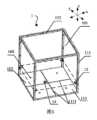
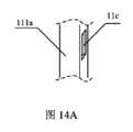
上記課題を解決するために、本発明は、貯蔵装置を収めるように配置された貯蔵空間と移動空間を含む立体倉庫の倉庫セルを提供する。前記貯蔵空間には貯蔵装置を収める。前記移動空間には前記貯蔵装置を移動させるための移動装置を収める。前記移動空間は前記貯蔵空間の上方または下方にある。貯蔵空間と移動空間の体積比率は、≧4:1,又は≧5:1,又は≧6:1,又は≧7:1,又は≧8:1,又は≧9:1,又は≧10:1である。In order to solve the above problems, the present invention provides a warehouse cell of a multi-level warehouse including a storage space and a moving space arranged to accommodate a storage device. The storage space accommodates the storage device. The moving space accommodates a moving device for moving the storage device. The moving space is located above or below the storage space. The volume ratio of the storage space to the moving space is ≧4:1, or ≧5:1, or ≧6:1, or ≧7:1, or ≧8:1, or ≧9:1, or ≧10:1.
本発明のもう一つの角度により、本発明は2つ以上の水平連結および/または積み重ねられた前記倉庫セル、移動装置および制御システムを含む立体倉庫を提供する。前記倉庫セルには貯蔵装置を収める。前記移動装置は前記倉庫セルの間で前記貯蔵装置を移動させる。前記制御システムは、前記移動装置による前記倉庫セル間の移動を制御するように構成されている。According to another aspect of the invention, the invention provides a multi-level warehouse comprising two or more horizontally connected and/or stacked warehouse cells, a moving device and a control system. The warehouse cells house storage devices. The moving device moves the storage devices between the warehouse cells. The control system is configured to control the movement between the warehouse cells by the moving device.
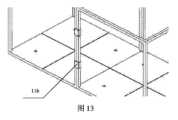
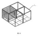
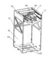
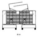
本発明のもう一つの角度により、本発明はまたフレーム、複数のスタンド機構及び底板を含む立体倉庫を提供する。前記フレームは、複数の倉庫セルを定義するように配置する。前記倉庫セルは、水平及び垂直方向に配列される。前記倉庫セルには貯蔵装置を収める。前記複数のスタンド機構は前記フレーム上に設ける。各倉庫セルにおいて前記貯蔵装置を支持するように配置されている。前記底板は前記複数のスタンド機構の下方に設けられ、このうち前記スタンド機構と前記底板との間は移動空間と定義され、移動装置を収める。前記移動装置は、異なる倉庫セルの間で前記貯蔵装置を移動するように配置されている。According to another aspect of the present invention, the present invention also provides a multi-level warehouse including a frame, a plurality of stand mechanisms, and a base plate. The frame is arranged to define a plurality of warehouse cells. The warehouse cells are arranged in horizontal and vertical directions. A storage device is housed in the warehouse cells. The plurality of stand mechanisms are provided on the frame. The stand mechanisms are arranged to support the storage device in each warehouse cell. The base plate is provided below the plurality of stand mechanisms, and a moving space is defined between the stand mechanisms and the base plate, and houses a moving device. The moving device is arranged to move the storage device between different warehouse cells.
本発明の別の側面において、本発明はまた複数の異なる高さの貯蔵階層、複数の異なる高さの移動階層と昇降システムを含む立体倉庫を提供する。このうち、前記貯蔵階層は、複数の貯蔵空間を含み、前記貯蔵空間には貯蔵装置が配置される。前記移動階層は前記貯蔵階層の上方または下方に設置される移動装置のための移動空間を提供するように配置されている。前記昇降システムは、異なる移動階層間で前記貯蔵装置および/または前記移動装置を移動させるように配置する。このうち、前記貯蔵階層と前記移動階層の高さ比率は、≧4:1、又は≧5:1、又は≧6:1、又は≧7:1、又は≧8:1、又は≧9:1、又は≧10:1である。In another aspect of the present invention, the present invention also provides a multi-level warehouse including a plurality of storage levels of different heights, a plurality of movable levels of different heights, and a lifting system. The storage level includes a plurality of storage spaces, and a storage device is disposed in the storage space. The movable levels are disposed to provide a moving space for the movable devices disposed above or below the storage level. The lifting system is disposed to move the storage devices and/or the movable devices between the different movable levels. The height ratio of the storage level to the movable level is ≧4:1, or ≧5:1, or ≧6:1, or ≧7:1, or ≧8:1, or ≧9:1, or ≧10:1.
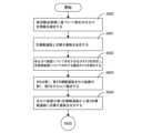
本発明の別の態様において、本発明はまた前記立体倉庫が複数の水平連結および/または積み重ね倉庫セルを含む立体倉庫貨物入庫方法を提供する。前記方法は、以下のステップを含む。貯蔵装置内に貨物を配置し、第1倉庫セル内に位置する。移動装置により前記貯蔵装置を前記第1倉庫セルのスタンド機構から離脱させる。前記移動装置により前記貯蔵装置を第2倉庫セルに移動する。また、前記移動装置により前記貯蔵装置を前記第2倉庫セルのスタンド機構にセットする。In another aspect of the present invention, the present invention also provides a cargo entry method for a multi-level warehouse, the multi-level warehouse including a plurality of horizontally linked and/or stacked warehouse cells. The method includes the following steps: Placing cargo in a storage device and positioning the storage device in a first warehouse cell; Using a moving device to detach the storage device from a stand mechanism of the first warehouse cell; Using the moving device to move the storage device to a second warehouse cell; Also, Using the moving device to set the storage device on the stand mechanism of the second warehouse cell.
本発明が提供する立体倉庫は倉庫セルからなり、倉庫セル内の空間の大部分が貯蔵空間である。貯蔵装置の大きさ及び積載重量と移動装置の内部部品が占める空間及びその積載重量から、移動装置の厚さと倉庫セル高さとの比が1/11-1/5であることを算出できる。すなわち、1つの倉庫セルの空間体積1に対する利用率は80〜90%に達することができる。移動装置が磁気浮上など他の方式を採用する場合、空間利用率は95%に達することができる。また、貨物は倉庫セル内の貯蔵装置内にあるため、貨物の積み重ねによる貨物損傷の可能性も低減される。The multi-story warehouse provided by the present invention is composed of warehouse cells, and most of the space within the warehouse cells is storage space. From the size and load weight of the storage device and the space occupied by the internal parts of the moving device and their load weight, it can be calculated that the ratio of the thickness of the moving device to the height of the warehouse cell is 1/11-1/5. In other words, the utilization rate of one space volume of one warehouse cell can reach 80-90%. If the moving device adopts other methods such as magnetic levitation, the space utilization rate can reach 95%. In addition, since the cargo is inside the storage device within the warehouse cell, the possibility of cargo damage due to cargo being piled up is also reduced.
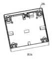
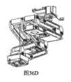
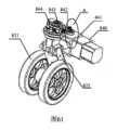
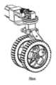
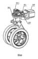
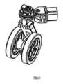
本発明は本体、リフト機構、走行機構、案内機構を備えるAGV(自動案内搬送装置)にも関連する。前記本体の内部は駆動アセンブリ、操舵アセンブリ、リフトアセンブリおよび電気部品を含む。前記リフト機構は前記リフトアセンブリと協働し、前記本体の上面からリフトロッドを突き出し又は引っ込める。前記走行機構は本体の下に設けられ、前記駆動アセンブリと操舵アセンブリとに協働するように配置されている。The present invention also relates to an AGV (automated guided vehicle) that includes a body, a lift mechanism, a traveling mechanism, and a guide mechanism. The interior of the body includes a drive assembly, a steering assembly, a lift assembly, and electrical components. The lift mechanism cooperates with the lift assembly to extend or retract a lift rod from the top surface of the body. The traveling mechanism is provided below the body and is arranged to cooperate with the drive assembly and the steering assembly.
前記ガイド機構は本体の下に設けられ、走行機構の走行方向を案内するように配置されている。前記走行機構は1つ又は複数の車輪アセンブリを含む。The guide mechanism is provided under the body and is arranged to guide the running direction of the running mechanism. The running mechanism includes one or more wheel assemblies.
1つの実施例では、車輪アセンブリは少なくとも1つまたは複数のガイド輪本体と、ガイド輪本体の中心に固定されたガイド輪シャフトを含む。In one embodiment, the wheel assembly includes at least one or more guide wheel bodies and a guide wheel shaft fixed to the center of the guide wheel body.
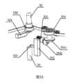
1つの実施例では、前記駆動アセンブリは駆動モータと動力伝達機構を含む。前記駆動モータは走行駆動力を出力する。In one embodiment, the drive assembly includes a drive motor and a power transmission mechanism. The drive motor outputs a driving force for traveling.
前記動力伝達機構は、先端の駆動輪、駆動従動輪及び末端の車輪軸を含む。The power transmission mechanism includes a driving wheel at the front end, a driving driven wheel, and a wheel axle at the rear end.
駆動モータの出力軸は、駆動輪で駆動従動輪に動力を伝達し、駆動従動輪から前記車輪軸に動力を伝達し、車輪本体を径方向に回転させる。The output shaft of the drive motor transmits power to the drive driven wheel via the drive wheel, and then transmits power from the drive driven wheel to the wheel shaft, causing the wheel body to rotate radially.
1つの実施例では、前記操舵アセンブリは操舵モータと操舵機構を含む。前記操舵モータから操舵動力が出力される。前記操舵機構は、操舵駆動輪、操舵従動輪及びこれと一体に連結する操舵フレームを備え、前記操舵従動輪は操舵フレーム、駆動従動輪と同軸に固定する。前記操舵フレームは車輪軸と固定する。前記操舵モータ出力軸は操舵駆動輪を介して操舵従動輪に動力を伝達し、操舵従動輪は操舵フレームに固定連結された駆動従動輪軸と車輪軸を一緒に回転させ、車輪本体の走行方向を変える。1つの実施例では、前記駆動モータの出力軸の端部と駆動輪軸との間に、動力伝達方向を変化させる転向機構をさらに備える。In one embodiment, the steering assembly includes a steering motor and a steering mechanism. Steering power is output from the steering motor. The steering mechanism includes a steering drive wheel, a steering driven wheel, and a steering frame integrally connected thereto, and the steering driven wheel is fixed coaxially with the steering frame and the driving driven wheel. The steering frame is fixed to the wheel axle. The steering motor output shaft transmits power to the steering driven wheel via the steering drive wheel, and the steering driven wheel rotates the driving driven wheel axle and the wheel axle fixedly connected to the steering frame together to change the running direction of the wheel body. In one embodiment, a turning mechanism for changing the power transmission direction is further provided between the end of the output shaft of the drive motor and the driving wheel axle.
1つの実施例では、前記操舵モータの出力軸の端部と操舵駆動輪軸との間に、動力伝達方向を変化させる転向機構をさらに備える。1つの実施例では、前記動力伝達機構は車輪従動輪をさらに備える。前記車輪従動輪の軸は転向機構を介して駆動用従動輪の軸と連結する。駆動従動輪は前記車輪従動輪に動力を伝達し、その後、車輪従動輪から車輪軸に伝達する。1つの実施例では、前記転向機構は互いに係合する傘歯車である。1つの実施例では前記リフトアセンブリは、リフトモータ、動力伝達機構と転向機構を含む。前記リフトモータはリフト動力を出力する。前記動力伝達機構はリフト駆動輪とリフト従動輪を含む。前記転向機構はリフト従動輪軸の末端とリフト動力の方向を変更するリフト機構の始端に接続されている。1つの実施例では前記リフト機構は、リフト機構の先端にあるギア、動力伝達ラック、リフトロッド、ロック機構を含む。前記リフト機構の始端にある前記ギアは前記転向機構と連結する。前記動力伝達ラックはラック側面にクロスバーが設けられる。前記動力伝達ラックは前記ギアに噛合する。前記ギアの回転に伴ってクロスバーを上下移動させる。前記リフトロッドの下端はクロスバーに対向し、クロスバーが前記ギアの回転に伴って上方に移動する時にリフトロッドを押し出す。前記ロック機構は前記リフトロッドに連結され、前記リフトロッドがプリセット位置に到達した時に前記リフトロッドをロックする。1つの実施例では、前記AGVは位置決めレバーをさらに備え、前記クロスバーの先端が前記クロスバーに対向する。前記ギアの回転に伴ってクロスバーが下方に移動する際に、位置決めレバーを前記本体の下面から突出させる。1つの実施例では、前記位置決めレバーは前記クロスバーと一体に設けられる。あるいは、位置決めレバー復帰構造をさらに備える。前記ギアの回転に伴って前記クロスバーが上方に移動して前記位置決めレバーから離間した時に、前記位置決めレバーを復帰させる。1つの実施例では、前記ガイド機構はガイド輪及びそのキャリヤと、ガイド輪電磁ソレノイドからなる少なくとも2組の互い方向に垂直な車輪アセンブリを含む。前記ガイド輪とそのキャリヤは、本体底部の溝に配置されている。前記ガイド輪電磁ソレノイドは溝内に配置され、ガイドフレームに固定され、ガイド輪が溝内から排出または収納されるのを制御する。1つの実施例では、前記AGVはさらに本体の底部の溝内に設けた位置決めセンサを含む。ガイド輪が走行面のガイド溝に正しく降ろされた後に信号を送信する。In one embodiment, the steering motor further includes a steering mechanism between the end of the output shaft of the steering motor and the steering drive wheel shaft, which changes the power transmission direction. In one embodiment, the power transmission mechanism further includes a wheel driven wheel. The axis of the wheel driven wheel is connected to the axis of the drive driven wheel via a steering mechanism. The drive driven wheel transmits power to the wheel driven wheel, and then transmits it from the wheel driven wheel to the wheel shaft. In one embodiment, the steering mechanism is a bevel gear that engages with each other. In one embodiment, the lift assembly includes a lift motor, a power transmission mechanism, and a steering mechanism. The lift motor outputs lift power. The power transmission mechanism includes a lift drive wheel and a lift driven wheel. The steering mechanism is connected to the end of the lift driven wheel shaft and the start of the lift mechanism that changes the direction of the lift power. In one embodiment, the lift mechanism includes a gear at the tip of the lift mechanism, a power transmission rack, a lift rod, and a lock mechanism. The gear at the start of the lift mechanism is connected to the steering mechanism. The power transmission rack is provided with a crossbar on a side of the rack. The power transmission rack meshes with the gear. The crossbar is moved up and down as the gear rotates. The lower end of the lift rod faces the crossbar, and pushes out the lift rod when the crossbar moves upward as the gear rotates. The lock mechanism is connected to the lift rod and locks the lift rod when the lift rod reaches a preset position. In one embodiment, the AGV further includes a positioning lever, and a tip of the crossbar faces the crossbar. When the crossbar moves downward as the gear rotates, the positioning lever is caused to protrude from the lower surface of the main body. In one embodiment, the positioning lever is provided integrally with the crossbar. Alternatively, a positioning lever return structure is further provided. When the crossbar moves upward as the gear rotates and is separated from the positioning lever, the positioning lever is returned. In one embodiment, the guide mechanism includes at least two sets of wheel assemblies perpendicular to each other, each set consisting of a guide wheel and its carrier, and a guide wheel electromagnetic solenoid. The guide wheel and its carrier are disposed in a groove at the bottom of the main body. The guide wheel electromagnetic solenoid is disposed in the groove and fixed to the guide frame, and controls the guide wheel to be ejected or retracted from the groove. In one embodiment, the AGV further includes a positioning sensor disposed in the groove at the bottom of the main body. It transmits a signal after the guide wheel is properly lowered into the guide groove of the running surface.
1つの実施例では、前記AGVはさらにタスク管理モジュール、移動制御モジュール、搬送制御モジュールを備える本体の内部にある制御装置を含む。前記タスク管理モジュールは、目標貨物および目標位置を含む搬送タスクを受信する。前記移動制御モジュールは、受信した走行経路または目標位置と現在位置から算出された走行経路に基づいて、駆動アセンブリ、操舵アセンブリを制御する。前記移動制御モジュールは、指示された走行経路または目標位置と現在の自車位置から算出される走行経路に基づいて、駆動アセンブリおよび操舵アセンブリを制御する。走行機構を予定された経路に従って走行及び/または操舵させること。前記搬送制御モジュールは目標貨物を確定した後、リフト機構が貨物の持ち上げを制御し、目的地の目標位置に到達した後、貨物を降ろすためにリフト機構の引き戻しを制御する。1つの実施例では、前記制御装置は、前記本体の上面外側および下面外側に配置された電子タグリーダ/ライタをさらに備え、前記目標貨物の位置を識別する。1つの実施例では、前記制御装置は、強制位置決めモジュールをさらに含む。走行が不安定であり、かつ目標位置に到達した後、その位置を確認または正確に修正する必要がある場合に、制御位置決めレバーが本体の下面から突出して位置決めする。1つの実施例では、前記制御装置は、移動制御モジュールおよび搬送制御モジュールを補助するための一種以上のセンサおよび/またはレーザSLAMまたは視覚VSLAMシステムをさらに含む。1つの実施例では、移動制御モジュールは走行経路に応じて操舵が必要な場合に、走行機構が90度回転するように操舵アセンブリを制御する。In one embodiment, the AGV further includes a control device inside the main body including a task management module, a movement control module, and a transport control module. The task management module receives a transport task including a target cargo and a target position. The movement control module controls a drive assembly and a steering assembly based on the received travel path or a travel path calculated from the target position and the current position. The movement control module controls the drive assembly and the steering assembly based on the instructed travel path or a travel path calculated from the target position and the current vehicle position. The travel mechanism is made to travel and/or steer according to a planned path. After the transport control module determines the target cargo, the lift mechanism controls the lifting of the cargo, and after reaching the target position at the destination, the lift mechanism controls the retraction to unload the cargo. In one embodiment, the control device further includes an electronic tag reader/writer arranged on the outer upper surface and the outer lower surface of the main body to identify the position of the target cargo. In one embodiment, the control device further includes a forced positioning module. A control positioning lever protrudes from the underside of the body for positioning when the travel is unstable and the position needs to be confirmed or precisely corrected after reaching the target position. In one embodiment, the control device further includes one or more sensors and/or a laser SLAM or visual VSLAM system to assist the movement control module and the transport control module. In one embodiment, the movement control module controls the steering assembly to rotate the
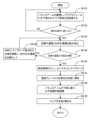
1つの実施例では、前記自動案内搬送装置の作業方法は走行経路を確定することを含む。前記走行経路は1以上の直線区間を含む。隣接する2つの直線区間が互いに直交する。自動案内搬送装置は走行経路に従って搬送目標位置に到達した後、リフト機構を突き出して目標貨物を持ち上げる。走行経路に従って目標貨物が目的地の目標位置に到達した後、リフト機構を引き戻して目標貨物を降ろす。1つの実施例では、前記作業方法はさらに、走行経路に従って搬送目標位置および目的地目標位置に到達した後、現在位置が搬送目標位置および目的地目標位置であるか否かを識別することを含む。1つの実施例では、前記作業方法はさらに搬送目標位置を確定した後、搬送目標位置における貨物が目標貨物であるか否かを識別することを含む。1つの実施例では、前記作業方法は前記目標貨物が倉庫セルの貯蔵空間の親通箱に位置し、前記親通箱の底部にID電子タグが設けられていることを含む。前記自動案内搬送装置は倉庫セルの移動空間を走行し、倉庫セル移動空間の底板にはID電子タグが設けられており、前記自動案内搬送装置はID電子タグを読み取って識別する。1つの実施例では、前記作業方法は搬送環境が不安定な場合に、前記自動案内搬送装置が目標位置に到達した時に、正確な位置決め後に位置決めレバーを用いて強制的に位置決めすることを含む。In one embodiment, the working method of the automatic guided transport device includes determining a travel path. The travel path includes one or more straight sections. Two adjacent straight sections are perpendicular to each other. After the automatic guided transport device reaches the transport target position according to the travel path, it protrudes the lift mechanism to lift the target cargo. After the target cargo reaches the destination target position according to the travel path, it retracts the lift mechanism to unload the target cargo. In one embodiment, the working method further includes identifying whether the current position is the transport target position and the destination target position after reaching the transport target position and the destination target position according to the travel path. In one embodiment, the working method further includes identifying whether the cargo at the transport target position is the target cargo after determining the transport target position. In one embodiment, the working method includes that the target cargo is located in a parent container in a storage space of a warehouse cell, and an ID electronic tag is provided on the bottom of the parent container. The automatic guided transport device travels in a moving space of a warehouse cell, and an ID electronic tag is provided on the bottom plate of the warehouse cell moving space, and the automatic guided transport device reads and identifies the ID electronic tag. In one embodiment, the method includes forcibly positioning the automatic guide and transport device using a positioning lever after accurate positioning when the transport environment is unstable and the automatic guide and transport device reaches the target position.
本発明において提供したAGV(自動誘導搬送装置)は厚みが薄く、占有スペースが小さく、しかも正確に運転できて、立体倉庫内部の移動空間と通路空間を節約できる。したがって、これを利用した立体倉庫の空間利用率を向上させることができる。The AGV (automated guided vehicle) provided in this invention is thin, occupies a small space, and can be operated accurately, saving movement space and aisle space inside a multi-story warehouse. Therefore, the space utilization rate of a multi-story warehouse using this can be improved.
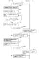
本発明に基づく立体倉庫は以下の貨物入庫方法も提供され、以下の手順になる。輸送機器における貯蔵空間に立体倉庫をドッキングさせる。前記貯蔵空間と立体倉庫は1つまたは複数の倉庫セルを有する。移動装置で貯蔵空間における第1倉庫セルから入庫貯蔵装置を搬出し、かつ前記入庫貯蔵装置と第1倉庫セルのIDバインドを解除する。この時、前記貯蔵装置には貨物を有する。そして、移動装置で入庫貯蔵装置を立体倉庫中の第2倉庫セルに搬送し、入庫貯蔵装置と第2倉庫セルのIDをバインドする。1つの実施例では、前記の入庫方法はさらに、立体倉庫の1つまたは複数の倉庫セルと、輸送機器における貯蔵空間の1つまたは複数の倉庫セルとが直接ドッキングすることを含む。1つの実施例では、前記入庫方法はさらに、1つまたは複数の倉庫セルと輸送機器における貯蔵空間の1つまたは複数の倉庫セルを、ドッキングプレートまたはドッキングパイプを用いてドッキングすることを含む。1つの実施例では、前記ドッキングプレートまたはドッキングパイプは、移動装置のガイド構造を有する。1つの実施例では、前記ドッキングプレートまたはドッキングパイプ上のガイド構造が、前記倉庫セルにおけるガイド構造と同じである。1つの実施例では、ドッキングされた輸送機器における貯蔵空間の第1倉庫セルと立体倉庫の第2倉庫セルとは、同一または異なる倉庫階層に位置する。1つの実施例では、前記入庫方法は前記輸送機器がドローンである場合に、ドローンが前記立体倉庫のドローン接続口の上方でホバリングし、グラブハンドまたはリフトを介して立体倉庫にドッキングすることを含む。1つの実施例では、前記入庫方法はさらに、少なくとも入庫貯蔵装置の数、ドッキング面の倉庫セルの数、および現在利用可能な移動装置の数に基づいて、1回の最大搬送量を確定することを含む。1つの実施例では、前記入庫方法はさらに立体倉庫および輸送機器の貯蔵空間における現在のタスク量に基づいて、利用可能な移動装置を確定することを含む。1つの実施例では、前記貯蔵方法ではさらに、利用可能な移動装置は立体倉庫または輸送機器に属する。または前記移動装置は予備移動装置である。1つの実施例では、前記入庫方法は使用可能な移動装置の数が1つまたは複数である場合に、複数の移動装置が協調して入庫貯蔵装置を搬送することを含む。1つの実施例では、前記入庫方法はさらに、利用可能な前記移動装置に入庫貯蔵装置リストを送信し、かつ前記入庫貯蔵装置リストをリアルタイムに更新することを含む。1つの実施例では、前記入庫方法は、前記移動装置が貯蔵空間に入る時、前記入庫貯蔵装置リストに基づいて搬出される入庫貯蔵装置を識別することを含む。1つの実施例では、前記入庫方法はさらに、入庫貯蔵装置の数、立体倉庫における空き倉庫セルの位置および数に基づいて複数の第2倉庫セルを確定することを含む。1つの実施例では、前記入庫方法はさらに、入庫前に入庫貯蔵装置の数を取得し、及び入庫貯蔵装置数に応じて、立体倉庫出入口付近において入庫貯蔵装置数以上の複数の第2倉庫セルが空くように準備することを含む。1つの実施例では、前記入庫方法はさらに、入庫前に入庫貯蔵装置を輸送機器内の貯蔵空間出入口付近に搬送することを含む。1つの実施例では、前記入庫方法はさらに、前記入庫貯蔵装置はID電子タグを有する。前記移動装置は電子タグリーダ/ライタを有する。前記入庫貯蔵装置と第1倉庫セルのIDバインドを解除するステップは、入庫貯蔵装置のID電子タグを読み取り、タグ情報にある倉庫セルのID情報を修正することを含む。1つの実施例では、前記入庫方法はさらに、前記入庫貯蔵装置を輸送機器貯蔵空間における第1倉庫セルから搬出する際に、入庫貯蔵装置の電子タグ情報における倉庫セルのID情報を移動状態に変更し、前記入庫貯蔵装置を立体倉庫における第2倉庫セルに搬送した後,入庫貯蔵装置の電子タグ情報中の倉庫セルのID情報を第2倉庫セルの識別情報に修正することを含む。The present invention also provides a cargo storage method for a multi-story warehouse, which includes the following steps: Dock the multi-story warehouse to a storage space in a transport device. The storage space and the multi-story warehouse have one or more storage cells. The moving device removes an input storage device from a first storage cell in the storage space, and releases the ID binding between the input storage device and the first storage cell. At this time, the storage device has cargo. Then, the moving device transports the input storage device to a second storage cell in the multi-story warehouse, and binds the IDs of the input storage device and the second storage cell. In one embodiment, the input method further includes directly docking one or more storage cells in the multi-story warehouse with one or more storage cells in the storage space in the transport device. In one embodiment, the input method further includes docking one or more storage cells with one or more storage cells in the storage space in the transport device using a docking plate or a docking pipe. In one embodiment, the docking plate or the docking pipe has a guide structure of the moving device. In one embodiment, the guide structure on the docking plate or docking pipe is the same as the guide structure in the warehouse cell. In one embodiment, the first warehouse cell of the storage space in the docked transportation device and the second warehouse cell of the multi-level warehouse are located on the same or different warehouse levels. In one embodiment, the warehousing method includes, when the transportation device is a drone, hovering above the drone connection port of the multi-level warehouse and docking to the multi-level warehouse via a grab hand or a lift. In one embodiment, the warehousing method further includes determining a maximum amount of transport at one time based on at least the number of warehousing storage devices, the number of warehouse cells on the docking surface, and the number of currently available mobile devices. In one embodiment, the warehousing method further includes determining an available mobile device based on the current task amount in the storage space of the multi-level warehouse and the transportation device. In one embodiment, the storage method further includes the available mobile device belonging to the multi-level warehouse or the transportation device. Or the mobile device is a reserve mobile device. In one embodiment, the method of entering the warehouse includes, when the number of available mobile devices is one or more, a plurality of mobile devices transporting the incoming storage devices in cooperation with each other. In one embodiment, the method of entering the warehouse further includes transmitting a list of incoming storage devices to the available mobile devices and updating the list of incoming storage devices in real time. In one embodiment, the method of entering the warehouse further includes, when the mobile device enters the storage space, identifying an incoming storage device to be removed based on the list of incoming storage devices. In one embodiment, the method of entering the warehouse further includes determining a plurality of second warehouse cells based on the number of incoming storage devices and the positions and number of vacant warehouse cells in the multi-story warehouse. In one embodiment, the method of entering the warehouse further includes obtaining the number of incoming storage devices before entering the warehouse, and preparing a plurality of second warehouse cells equal to or greater than the number of incoming storage devices to be vacant near an entrance/exit of the multi-story warehouse according to the number of incoming storage devices. In one embodiment, the method of entering the warehouse further includes transporting the incoming storage devices to a vicinity of an entrance/exit of the storage space in the transport device before entering the warehouse. In one embodiment, the receiving method further includes the receiving storage device having an ID electronic tag, and the moving device having an electronic tag reader/writer. The step of releasing the ID binding between the receiving storage device and the first warehouse cell includes reading the ID electronic tag of the receiving storage device and correcting the ID information of the warehouse cell in the tag information. In one embodiment, the receiving method further includes changing the ID information of the warehouse cell in the electronic tag information of the receiving storage device to a moving state when the receiving storage device is removed from the first warehouse cell in the transport equipment storage space, and after transporting the receiving storage device to a second warehouse cell in a multi-story warehouse, correcting the ID information of the warehouse cell in the electronic tag information of the receiving storage device to the identification information of the second warehouse cell.
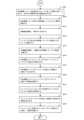
本発明の立体倉庫に基づいて、立体倉庫の貨物出庫方法を提供する。下記手順に従う。立体倉庫と輸送機器の貯蔵空間とをドッキングさせる。前記貯蔵空間と立体倉庫が1つまたは複数の倉庫セルを有することを特徴とする。移動装置で立体倉庫の第3倉庫セルから出庫貯蔵装置を搬出し、かつ前記入庫貯蔵装置と第3倉庫セルとのIDバインドを解除する。前記貯蔵装置は出庫貨物を有する。そして、移動装置で出庫貯蔵装置を輸送機器貯蔵空間における第4倉庫セルに搬送し、かつ出庫貯蔵装置と第4倉庫セルのIDをバインドする。Based on the multi-story warehouse of the present invention, a cargo retrieval method for a multi-story warehouse is provided. The method follows the steps below. The multi-story warehouse is docked with a storage space for transport equipment. The storage space and the multi-story warehouse are characterized in having one or more warehouse cells. A moving device removes an outgoing storage device from a third warehouse cell of the multi-story warehouse, and releases the ID binding between the incoming storage device and the third warehouse cell. The storage device has outgoing cargo. Then, the moving device transports the outgoing storage device to a fourth warehouse cell in the transport equipment storage space, and binds the ID of the outgoing storage device to the fourth warehouse cell.
本発明の立体倉庫に基づいて、第1立体倉庫間の貨物交換方法も提供される。下記手順に従う。第1立体倉庫と第2立体倉庫とをドッキングさせる、前記第1立体倉庫と前記第2立体倉庫がそれぞれ複数のセルを含む。移動装置で第1立体倉庫の第1倉庫セルから第1貯蔵装置を搬出し、かつ前記第1貯蔵装置と第1倉庫セルとのIDバインドを解除する。第1移動装置で第1貯蔵装置を第2立体倉庫の第2倉庫セルに搬送し、第1貯蔵装置と第2倉庫セルのIDをバインドする。第1移動装置で第2立体倉庫の第3の倉庫セルから第2貯蔵装置を搬出し、前記第2貯蔵装置と第2倉庫セルとのIDバインドを解除する。第1移動装置で第2貯蔵装置を第1立体倉庫の第4倉庫セルに搬送する。第2貯蔵装置と第4倉庫セルのIDをバインドする。Based on the multi-story warehouse of the present invention, a cargo exchange method between a first multi-story warehouse is also provided. The method follows the steps below. A first multi-story warehouse and a second multi-story warehouse are docked, and the first multi-story warehouse and the second multi-story warehouse each include a plurality of cells. A mobile device is used to remove a first storage device from a first warehouse cell of the first multi-story warehouse, and the ID binding between the first storage device and the first warehouse cell is released. The first mobile device is used to transport the first storage device to a second warehouse cell of the second multi-story warehouse, and the ID binding between the first storage device and the second warehouse cell is released. The first mobile device is used to remove a second storage device from a third warehouse cell of the second multi-story warehouse, and the ID binding between the second storage device and the second warehouse cell is released. The first mobile device is used to transport the second storage device to a fourth warehouse cell of the first multi-story warehouse. The ID binding between the second storage device and the fourth warehouse cell is released.
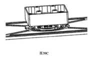
本発明は、空間利用率の高い立体倉庫に関し、貨物の入出庫時に2つの立体倉庫を直接ドア対ドアに、層間の全体または一部をドッキングして、異なる層で同時に貨物を搬送することができ、従来の倉庫の貨物出庫と入庫と比較して、効率が非常に高く、短時間で大量の貨物の運搬作業を完了することができる。The present invention relates to a multi-story warehouse with high space utilization rate. When cargo is being loaded or unloaded, two multi-story warehouses can be directly docked door-to-door, with the entire or partial inter-floor docking, allowing cargo to be transported simultaneously on different floors. Compared with the loading and unloading of cargo in conventional warehouses, this is highly efficient and can complete the transportation of large amounts of cargo in a short period of time.
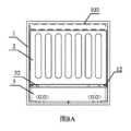
本発明はまた第1本体、仕分リング爪と第1ID電子タグを含む子通箱にも関する。前記第1本体に開口部と対応の箱蓋が設けられ、箱蓋は1つまたは複数の鎖によって第1本体と閉合しロックされ、かつ第1本体と貨物を貯蔵する貯蔵空間を定義する。前記仕分リング爪は第1本体または箱蓋に設けられる。前記第1ID電子タグは、少なくとも子通箱のID情報および内蔵貨物の物流情報を記録するように構成されている。1つの実施例では、前記子通箱内の物流情報は少なくとも、内蔵貨物情報および貨物流通における位置変化情報を含む。一実施形態では、第1本体と箱蓋の材料は硬質材料である。1つの実施例では、前記ロックは荷受人の身元確認に応じて開く構成である。1つの実施例では、前記貯蔵空間は取り出すことができない緩衝構造を含む。1つの実施例では、前記貯蔵空間内の貨物は追加の包装が必要ない。The present invention also relates to a sub-transport box including a first body, a sorting ring claw, and a first ID electronic tag. The first body is provided with an opening and a corresponding box cover, and the box cover is closed and locked to the first body by one or more chains, and defines a storage space for storing the first body and cargo. The sorting ring claw is provided on the first body or the box cover. The first ID electronic tag is configured to record at least ID information of the sub-transport box and logistics information of the cargo contained therein. In one embodiment, the logistics information in the sub-transport box includes at least the cargo contained therein and position change information in cargo distribution. In one embodiment, the material of the first body and the box cover is a hard material. In one embodiment, the lock is configured to open in response to identification of the consignee. In one embodiment, the storage space includes a buffer structure that cannot be removed. In one embodiment, the cargo in the storage space does not require additional packaging.
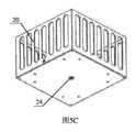
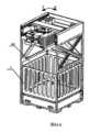
本発明はまた、子通箱と親通箱を含む物流用親子通箱に関し、子通箱の第1ID電子タグは少なくとも、それと親通箱のIDバインド情報を記録するように構成される。前記親通箱は第2本体、搬送構造及び第2ID電子タグを含む。前記第2本体は1つまたは複数の子通箱を収める。前記搬送構造は第2本体に設けられ、移動装置と協働するように配置されている。前記第2ID電子タグは少なくとも、親通箱とその位置に関する関連情報を記録する。1つの実施例では、前記第2本体の上部には子通箱を上面から取り出ために開放される。1つの実施例では、前記第2本体の側面には子通箱を側面から取り出すための開閉可能なサイドドアが設けられる。1つの実施例では、前記搬送構造は移動装置との位置決めのための第2本体底部に配置された位置決め溝である。1つの実施例では、前記搬送構造は第2本体上部に配置された取手であり、第2搬送構造としての移動装置内のロボットと協働する。1つの実施例では、前記搬送構造は第2本体の上部に設けられた吸着装置であり、第2搬送構造としての移動装置における吸着機構と協働する。1つの実施例では、親通箱の位置は倉庫セルであり、その位置に関する情報は、親通箱とその位置の識別バインディング情報である。1つの実施例では、複数の子通箱は複数の仕様を含み、親通箱のサイズは同じかまたは異なる仕様の複数の子通箱の組み合わせとフィットするように設計されており、親通箱の容積をフルに活用することができる。The present invention also relates to a parent-child transport box for logistics, including a child transport box and a parent transport box, and the first ID electronic tag of the child transport box is configured to record at least ID binding information of the child transport box and the parent transport box. The parent transport box includes a second body, a conveying structure, and a second ID electronic tag. The second body accommodates one or more child transport boxes. The conveying structure is provided on the second body and arranged to cooperate with a moving device. The second ID electronic tag records at least relevant information about the parent transport box and its position. In one embodiment, the upper part of the second body is opened to remove the child transport box from the top surface. In one embodiment, the side of the second body is provided with an openable side door to remove the child transport box from the side. In one embodiment, the conveying structure is a positioning groove arranged on the bottom of the second body for positioning with the moving device. In one embodiment, the conveying structure is a handle arranged on the upper part of the second body, and cooperates with a robot in the moving device as the second conveying structure. In one embodiment, the transport structure is a suction device provided on the upper part of the second body, and cooperates with a suction mechanism in the moving device as the second transport structure. In one embodiment, the location of the parent transport box is a warehouse cell, and the information about the location is identification binding information of the parent transport box and its location. In one embodiment, the multiple child transport boxes include multiple specifications, and the size of the parent transport box is designed to fit a combination of multiple child transport boxes of the same or different specifications, so that the volume of the parent transport box can be fully utilized.
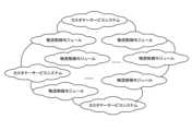
本発明はまた、子親通箱ベースの物流システムにも関する。1つまたは複数の移動倉庫および/または固定倉庫、複数の前記物流子親通箱を含む。前記移動倉庫および/または固定倉庫が1つまたは複数の倉庫セルを含む。このうち、入荷後の貨物は子通箱内に配置され、子通箱は親通箱内に配置され、親通箱は一つの倉庫セルに収容される。ここで、前記倉庫セル、親通箱、子通箱および貨物は互いに関連している。移動倉庫または輸送機器を介して、貨物を内蔵した子通箱を荷受人に届ける。1つの実施例では、前記固定倉庫は複数の倉庫セルを有する立体倉庫を含む。1つの実施例では、移動倉庫は輸送機器と前記輸送機器上に配置された1つまたは複数の倉庫セルを有する立体倉庫を含む。1つの実施例では、前記物流システムはさらに、移動倉庫または固定倉庫内に配置され、次の出庫の物流先に応じて子通箱を仕分けする仕分装置を含む。1つの実施例では、前記物流システムはさらに宅配ロボットを含み、前記宅配ロボットは親通箱を収容するための1つまたは複数の倉庫セルを含む。1つの実施例では、前記固定倉庫は宅配便ロッカーを含み、それは親子通箱を収容するための1つまたは複数の倉庫セルを含む。The present invention also relates to a child/parent transit box-based logistics system. The system includes one or more mobile warehouses and/or fixed warehouses, and a plurality of the child/parent transit boxes. The mobile warehouse and/or fixed warehouse includes one or more warehouse cells. Among these, the cargo after arrival is placed in the child transit box, the child transit box is placed in the parent transit box, and the parent transit box is stored in one warehouse cell. Here, the warehouse cell, the parent transit box, the child transit box, and the cargo are related to each other. The child transit box containing the cargo is delivered to the consignee via the mobile warehouse or a transport device. In one embodiment, the fixed warehouse includes a multi-level warehouse having a plurality of warehouse cells. In one embodiment, the mobile warehouse includes a multi-level warehouse having a transport device and one or more warehouse cells arranged on the transport device. In one embodiment, the logistics system further includes a sorting device arranged in the mobile warehouse or fixed warehouse, which sorts the child transit boxes according to the logistics destination of the next outgoing shipment. In one embodiment, the logistics system further includes a home delivery robot, and the home delivery robot includes one or more warehouse cells for storing the parent transit boxes. In one embodiment, the fixed warehouse includes a parcel locker, which includes one or more warehouse cells for housing parent and child parcels.
本発明はまた、親子通箱の貨物情報の記録方法にも関する。下記手順を含む。子通箱に貨物を配置し、少なくとも子通箱の第1ID電子タグに貨物情報を記録する。子通箱を親通箱内に配置し、子通箱の第1ID電子タグに子通箱と親通箱のID情報を記録する。親通箱を倉庫セルに配置し、親通箱の第2ID電子タグに親通箱と前記倉庫セルのIDバインド情報を記録する。そして、前記倉庫セル、親通箱とサブ通箱の前記バインド情報を関連付ける。1つの実施例では、貨物関連方法はさらに親通箱が位置する倉庫セルを変更する際に、前記親通箱と倉庫セルとのバインドを変更することを含む。1つの実施例では、貨物関連方法はさらに、子通箱が位置する親通箱を変更する際に、子通箱と親通箱とのバインドを変更することを含む。The present invention also relates to a method for recording cargo information of a parent and child transport box. The method includes the following steps: Placing cargo in the child transport box and recording cargo information in at least a first ID electronic tag of the child transport box; Placing the child transport box in a parent transport box and recording ID information of the child transport box and the parent transport box in the first ID electronic tag of the child transport box; Placing the parent transport box in a warehouse cell and recording ID binding information of the parent transport box and the warehouse cell in the second ID electronic tag of the parent transport box; and associating the binding information of the warehouse cell, the parent transport box and the sub transport box. In one embodiment, the cargo-related method further includes changing the binding between the parent transport box and the warehouse cell when changing the warehouse cell in which the parent transport box is located. In one embodiment, the cargo-related method further includes changing the binding between the child transport box and the parent transport box when changing the parent transport box in which the child transport box is located.
本発明では、貨物は常に子通箱内にあり、子通箱は異なる物流機器内を流通し、かつ流通中の親通箱、倉庫セルとの相関関係の変化をリアルタイムに記録し、物流システムにおける貨物の位置をリアルタイムに得ることができ、システム内の貨物を管理監視するためのデータサポートを提供する。親通箱は立体倉庫の倉庫セルに貯蔵されているため、貨物がバックログ、プッシュバックになることはない。子通箱はいろんな形状やサイズの貨物に適合する様々な仕様がある。したがって、本発明の貨物は既存物流システムにおける様々な包装テープ、親通箱、発泡スチロール箱、充填材などを節約し、かつ親子通箱は再利用することができるため、より環境に優しい。貨物輸送装置はすべて同じ仕様の立体倉庫であり、子通箱を収める親通箱は各貨物輸送装置で共通であるため、貨物の受け渡し時に、現在の貨物輸送装置から別の貨物輸送装置に直接親通箱を運ぶだけで、貨物の輸送が迅速化され、物流効率が向上する。In the present invention, the cargo is always in the child transport box, which circulates through different logistics equipment, and the changes in the correlation between the parent transport box and the warehouse cell during circulation are recorded in real time, so that the position of the cargo in the logistics system can be obtained in real time, providing data support for managing and monitoring the cargo in the system. Since the parent transport box is stored in the warehouse cell of the multi-level warehouse, the cargo will not be backlogged or pushed back. The child transport box has various specifications that are suitable for cargo of various shapes and sizes. Therefore, the cargo of the present invention saves various packaging tapes, parent transport boxes, polystyrene foam boxes, fillers, etc. in the existing logistics system, and the parent and child transport boxes can be reused, making it more environmentally friendly. Since all the cargo transport devices are multi-level warehouses with the same specifications and the parent transport boxes that contain the child transport boxes are common to each cargo transport device, when the cargo is delivered, the parent transport box can be directly transported from the current cargo transport device to another cargo transport device, which speeds up the transportation of the cargo and improves logistics efficiency.
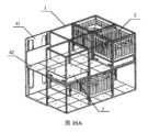
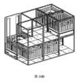
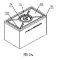
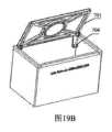
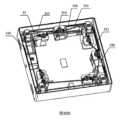
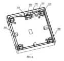
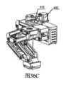
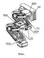
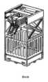
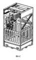
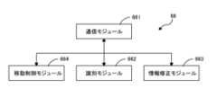
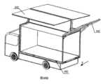
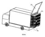
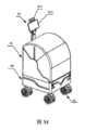
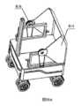
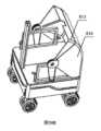
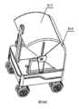
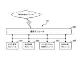
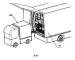
本発明はまた、立体倉庫、貯蔵装置、移動装置、仕分装置および輸送機器を含む移動倉庫に関する。ここで、前記立体倉庫は複数の倉庫セルを含み、前記倉庫セルは積み重ねられた貯蔵空間と移動空間を含む。前記貯蔵装置は倉庫セル中の貯蔵空間に収容される。前記移動装置は前記貯蔵装置の搬送のために、複数の倉庫セルの移動空間からなる空間で移動するように配置される。前記仕分装置は貯蔵装置中の貨物を仕分するために、複数の隣接する倉庫セルを占有するように配置される。前記輸送機器は前記立体倉庫を運ぶために使用され、移動機能を提供する。1つの実施例では、前記輸送機器は筐体フレームと筐体カバー、前記筐体フレームは前記筐体カバーと連結し、内部空間を有する筐体本体を構成する。前記立体倉庫は前記筐体本体の内部空間に設けられている。1つの実施例では、前記囲い構造は1つまたは複数の筐体ドアを含み、前記筐体ドアの面積は立体倉庫における倉庫セルの整数倍である。1つの実施例では、前記筐体ドアは筐体フレームの側面および/または背面に設けられた第1筐体ドアまたは筐体の上面にドローンとドッキングする第2筐体ドアを含む。1つの実施例では、前記移動倉庫は、前記筐体ドアと前記筐体フレームにそれぞれ両端が連結された複数の支持棒をさらに備え、前記筐体ドアが開いた時に支持固定される。1つの実施例では、前記移動倉庫は昇降レール、昇降スタンド及びドッキングプレートを備える昇降ドッキング装置を含む。昇降レールは前記筐体ドア内の筐体フレームに固定される。前記昇降スタンドは前記昇降レール機構に協働するように設けられ、前記レールに沿って上昇または下降可能である。前記ドッキングプレートの一端は前記昇降スタンドの先端に可動連結される。上面は移動装置スタンド機構である。前記ドッキングプレートは筐体ドアが開いた時に箱の空間外に開き、筐体ドアが閉じられた時に収納することができる。1つの実施例では、前記ドッキングプレートの長さは1つ倉庫セルの幅に適合する。または筐体ドアの幅に適合する。1つの実施例では、前記移動倉庫は筐体フレームの底部に配置されたX-Y駆動テーブルをさらに含み、前記立体倉庫は前記X-Y駆動テーブルに固定される。1つの実施例では、前記筐体ドアは前記X-Y駆動テーブルの長さ又は幅に適合する。1つの実施例では、前記移動倉庫は筐体フレームと車体との間に配置されたエアサスペンションをさらに含む。1つの実施例では、前記移動倉庫はさらに、通信モジュール、ナビゲーションモジュール及びドッキング制御モジュールを含む制御システムを備える。前記通信モジュールはクラウドシステムと情報を通信するように構成される。前記ナビゲーションモジュールは計画されたルートに基づいて、車両の走行ルートを確定するために使用される。前記ドッキング制御モジュールは、前記第2移動倉庫に応じて前記ドッキングモードを確定するように構成され、前記確定されたドッキングモードに従って関連部品の動作を制御する。1つの実施例では、前記制御システムはリアルタイムの地理的位置を取得し、通信モジュールを介してクラウドシステムに送信する地理的位置測位装置をさらに含む。1つの実施例では、前記ドッキング制御モジュールは昇降ドッキング装置制御ユニットと筐体ドア制御ユニットを備える。前記筐体ドア制御ユニットは前記筐体ドアの開閉を制御する。前記昇降ドッキング装置制御ユニットはドッキングプレートの昇降、開閉を制御する。1つの実施例では、前記昇降ドッキング装置の制御ユニットは、下記センサの1つまたは複数を含む。ドッキングプレート位置決めセンサは、ドッキングプレートが立体倉庫の倉庫セルと正確にドッキングする際に、ドッキング完了信号を発する。リフティング位置決めセンサは、ドッキングプレートが予定している第2移動倉庫の底部の位置に到達し、第2移動倉庫を安全に持ち上げることができる時に、位置決め信号を発する。また、倉庫セル位置決めセンサは、第2移動倉庫の倉庫セルが立体倉庫内の倉庫セルと正確にドッキングした場合に、ドッキング完了信号を発する。1つの実施例では、前記ドッキング制御モジュールはX-Y駆動テーブル制御ユニットをさらに備え、X-Y駆動テーブルをX方向またはY方向に移動するように構成され、前記立体倉庫を筐体外へ予定距離だけ移動させる。1つの実施例では、前記移動倉庫はさらに、エアサスペンション制御モジュールを備え、ドッキング時にエアサスペンションの空気圧を調整するように構成され、立体倉庫のレベルを調整する。1つの実施例では、移動倉庫内の前記移動装置はAGVを含む。1つの実施例では、前記AGVは本体、リフト機構、走行機構とガイド機構を備える、前記本体の内部は駆動アセンブリ、操舵アセンブリ、リフトアセンブリ及び電気部品を含む。前記リフト機構は前記リフトアセンブリに係合する。前記本体の上面から突出または引き込むように配置する。前記走行機構は本体の下に設けられ、前記駆動アセンブリと操舵アセンブリとが係合する。前記ガイド機構は本体の下に設けられ、走行機構の走行を案内する。1つの実施例では、前記仕分装置は支持ユニット、移動ユニット及び仕分ロボットを含む。前記支持ユニットは、少なくとも1つの仕分セルと接続する。前記仕分セルが貨物を収める親通箱を載置する。前記仕分セルは倉庫セルに接続する。前記移動ユニットは前記支持ユニットに可動連結しており、前記支持ユニットに沿って複数の仕分セル間を移動可能である。前記仕分ロボットは前記移動ユニットに接続され、仕分けタスクに従って貨物を掴み取る。前記移動ユニットの移動に伴って、第1親通箱から第2親通箱に貨物を仕分する。1つの実施例では、前記移動倉庫中の前記貯蔵装置は親子通箱を含む。子通箱は貨物を内蔵し、親通箱は1つまたは複数の子通箱を内蔵し、倉庫セル内の貯蔵空間に配置される。親通箱は内蔵の子通箱とその所在的倉庫セルのIDに関連付けられている。The present invention also relates to a mobile warehouse including a multi-level warehouse, a storage device, a moving device, a sorting device, and a transport device. Here, the multi-level warehouse includes a plurality of warehouse cells, and the warehouse cells include stacked storage spaces and a moving space. The storage device is accommodated in the storage space in the warehouse cells. The moving device is arranged to move in a space consisting of the moving spaces of the plurality of warehouse cells for transporting the storage device. The sorting device is arranged to occupy a plurality of adjacent warehouse cells for sorting cargo in the storage device. The transport device is used to transport the multi-level warehouse and provides a moving function. In one embodiment, the transport device is a housing frame and a housing cover, and the housing frame is connected to the housing cover to form a housing body having an internal space. The multi-level warehouse is provided in the internal space of the housing body. In one embodiment, the enclosure structure includes one or more housing doors, and the area of the housing door is an integer multiple of the warehouse cell in the multi-level warehouse. In one embodiment, the housing door includes a first housing door provided on the side and/or back of the housing frame or a second housing door that docks with a drone on the top surface of the housing. In one embodiment, the mobile warehouse further includes a plurality of support rods each connected at both ends to the housing door and the housing frame, and supported and fixed when the housing door is opened. In one embodiment, the mobile warehouse includes a lifting and docking device including a lifting rail, a lifting stand, and a docking plate. The lifting rail is fixed to the housing frame in the housing door. The lifting stand is provided to cooperate with the lifting rail mechanism and can rise or fall along the rail. One end of the docking plate is movably connected to the tip of the lifting stand. The upper surface is a mobile device stand mechanism. The docking plate opens outside the space of the box when the housing door is opened, and can be stored when the housing door is closed. In one embodiment, the length of the docking plate fits the width of one warehouse cell. Or fits the width of the housing door. In one embodiment, the mobile warehouse further includes an X-Y driving table arranged at the bottom of the housing frame, and the multi-level warehouse is fixed to the X-Y driving table. In one embodiment, the housing door fits the length or width of the X-Y driving table. In one embodiment, the mobile warehouse further includes an air suspension disposed between the housing frame and the vehicle body. In one embodiment, the mobile warehouse further includes a control system including a communication module, a navigation module, and a docking control module. The communication module is configured to communicate information with a cloud system. The navigation module is used to determine a driving route of the vehicle based on a planned route. The docking control module is configured to determine the docking mode according to the second mobile warehouse, and controls the operation of related parts according to the determined docking mode. In one embodiment, the control system further includes a geographic positioning device that obtains a real-time geographic position and transmits it to a cloud system via the communication module. In one embodiment, the docking control module includes a lifting docking device control unit and a housing door control unit. The housing door control unit controls the opening and closing of the housing door. The lifting docking device control unit controls the lifting, opening and closing of a docking plate. In one embodiment, the control unit of the lifting docking device includes one or more of the following sensors: The docking plate positioning sensor issues a docking completion signal when the docking plate accurately docks with the warehouse cell of the multi-level warehouse. The lifting positioning sensor issues a positioning signal when the docking plate reaches the planned position of the bottom of the second mobile warehouse and the second mobile warehouse can be safely lifted. The warehouse cell positioning sensor also issues a docking completion signal when the warehouse cell of the second mobile warehouse accurately docks with the warehouse cell in the multi-level warehouse. In one embodiment, the docking control module further includes an X-Y drive table control unit configured to move the X-Y drive table in the X direction or the Y direction to move the multi-level warehouse a planned distance outside the housing. In one embodiment, the mobile warehouse further includes an air suspension control module configured to adjust the air pressure of the air suspension during docking to adjust the level of the multi-level warehouse. In one embodiment, the moving device in the mobile warehouse includes an AGV. In one embodiment, the AGV includes a main body, a lift mechanism, a traveling mechanism and a guide mechanism, and the inside of the main body includes a drive assembly, a steering assembly, a lift assembly and an electrical component. The lift mechanism engages with the lift assembly. The lift mechanism is arranged to protrude or retract from the upper surface of the main body. The travel mechanism is provided under the main body, and the drive assembly and the steering assembly engage with each other. The guide mechanism is provided under the main body and guides the travel of the travel mechanism. In one embodiment, the sorting device includes a support unit, a moving unit, and a sorting robot. The support unit is connected to at least one sorting cell. The sorting cell places a parent transit box containing cargo. The sorting cell is connected to a warehouse cell. The moving unit is movably connected to the support unit and can move between a plurality of sorting cells along the support unit. The sorting robot is connected to the moving unit and grabs the cargo according to a sorting task. As the moving unit moves, the sorting robot sorts the cargo from a first parent transit box to a second parent transit box. In one embodiment, the storage device in the mobile warehouse includes a parent-child transit box. The child transit box contains cargo, and the parent transit box contains one or more child transit boxes and is arranged in a storage space in a warehouse cell. A parent shipping box is associated with the ID of the built-in child shipping box and the warehouse cell in which it is located.
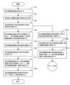
また、1つの実施例では、本発明はさらに移動倉庫の貨物輸送方法を提供する。下記手順を含む。その輸送距離内の貨物受渡タスクを取得する。前記貨物受渡タスクはドッキング地点とドッキングされた第2移動倉庫または固定倉庫を含む。ドッキング地点へ移動中に受け渡す予定の貨物を仕分すること。また、ドッキング地点で第2移動倉庫と固定倉庫との間で貨物を受け渡す。1つの実施例では、前記移動倉庫の貨物輸送方法はクラウドシステムと情報通信し、クラウドから送信された貨物受渡タスクを受信することを含む。1つの実施例では、貨物受渡タスクの受信と同時に、計画された走行経路を受信する。または、現在の位置とドッキング地点に基づいて走行ルートを計算する。1つの実施例では、前記移動倉庫の貨物輸送方法はさらに、貨物受渡タスクに応じて貨物仕分けリストを取得する。前記貨物仕分けリストに従って貨物を仕分する。1つの実施例では、貨物の仕分けリストは貨物の受渡タスクを受信と同時に、クラウドから受信される。または、立体倉庫内の貨物情報とドッキング地点から貨物仕分けリストを確定する。In one embodiment, the present invention further provides a method for transporting cargo from a mobile warehouse, which includes the following steps: Obtain a cargo delivery task within the transport distance. The cargo delivery task includes a docking point and a docked second mobile warehouse or a fixed warehouse. Sort the cargo to be delivered during the transport to the docking point. Also, deliver the cargo between the second mobile warehouse and the fixed warehouse at the docking point. In one embodiment, the cargo transport method for the mobile warehouse includes communicating with a cloud system and receiving a cargo delivery task sent from the cloud. In one embodiment, a planned driving route is received simultaneously with receiving the cargo delivery task. Or, a driving route is calculated based on the current position and the docking point. In one embodiment, the cargo transport method for the mobile warehouse further includes obtaining a cargo sorting list according to the cargo delivery task. Sort the cargo according to the cargo sorting list. In one embodiment, the cargo sorting list is received from the cloud simultaneously with receiving the cargo delivery task. Or, the cargo sorting list is determined from the cargo information in the multi-level warehouse and the docking point.
本発明が提供する移動倉庫は貨物を輸送する時、ともに、貨物貯蔵機能も兼ね備えている。貨物を受渡す前に移動中に貨物の物流方向に従って仕分を完了する。移動倉庫に貯蔵される貨物の規模は大小柔軟で、多様なドッキングモード、ビッグデータに基づく貨物仕分けアルゴリズム、貨物交換アルゴリズム、走行経路アルゴリズムなどにより、輸送効率とドッキング時の貨物交換効率を向上させることができ、全体として貨物の滞留時間を短縮した。したがって、本発明における物流システムの貨物輸送は柔軟かつ効率的である。The mobile warehouse provided by the present invention has a cargo storage function while transporting cargo. Sorting is completed according to the logistics direction of the cargo while in motion before it is handed over. The size of the cargo stored in the mobile warehouse can be flexible, large or small, and by using various docking modes, cargo sorting algorithms based on big data, cargo exchange algorithms, driving route algorithms, etc., the transportation efficiency and cargo exchange efficiency during docking can be improved, and the overall cargo dwell time is shortened. Therefore, the cargo transportation of the logistics system in the present invention is flexible and efficient.
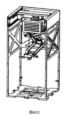
本発明はまた、バランスアーム、グラブモジュール及び運動駆動部を備える立体倉庫に適用される仕分ロボットに関する。前記バランスアームは移動過程を円滑に保つ。貨物をグラブするための前記グラブモジュールは、前記バランスアームの末端に取り付けられている。前記運動駆動部は前記バランスアームに連結され、バランスアームの伸縮と移動、及びグラブモジュールで貨物を掴み取ると降ろす。1つの実施例では、前記バランスアームは、第1関節によって連結された少なくとも2つのアームを含む。1つの実施例では、前記アームは少なくとも第2関節によって連結された上アームと下アームとを含み、一方のアームの上アームと他方のアームの下アームとは第1関節を介して連結されている。1つの実施例では、第1関節が連結された2つのアームは収縮状態で並列に隣接している。1つの実施例では、第2関節可動は収縮状態で上腕と下腕とが互いに協働して連結される。1つの実施例では、前記グラブモジュールは、グラブ本体と前記グラブ本体の端部に固定されたグラブを備える。前記グラブ本体はバランスアームの下アームの先端に固定される。前記グラブは前記グラブ本体の先端に可動接続されている。1つの実施例では、前記グラブモジュールは前記グラブ本体に連結され、仕分ける貨物を識別する識別部をさらに備える。1つの実施例では、前記グラブは複数のグラブ爪を含み、各グラブ爪は、前記グラブ本体に個別に可動連結され、前記貨物との接触部の全体形状、大きさ、位置の片方または両方を変更する。1つの実施例では、前記グラブ爪は吸着式および/または機械式を採用する。1つの実施例では、前記機械式グラブ爪は貨物の取手にセットされるリング爪を有する。1つの実施例では、前記グラブ本体は各グラブ爪に対応するガイドレールを備え、グラブ爪はレールスライダに固定されている。1つの実施例では、前記グラブモジュールは前記グラブ本体に可動連結された減衰プレートをさらに備え、グラブが貨物を掴み取る際に、グラブと貨物の間の空間にフィットし、貨物の揺れを抑制する。1つの実施例では、前記識別ユニットは貨物ID電子タグリーダ/ライタである。1つの実施例では、前記ID電子タグリーダ/ライタは、RFIDリーダ/ライタまたは2次元コードリーダ/ライタである。1つの実施例では、前記認識部は前記貨物の画像を取得して前記貨物を識別する画像識別ユニットである。1つの実施例では、前記画像識別ユニットはカメラと画像識別サブユニットとを含み、前記カメラは貨物または貨物ID電子タグ画像を取得し、前記画像識別サブユニットは取得した画像に基づいて貨物を識別する。1つの実施例では、前記駆動ユニットはバランスアームの展開および引き戻しを制御する関節アクチュエータを含む。1つの実施例では、前記関節アクチュエータは駆動動力を供給する駆動モータ、ワイヤリール及びワイヤロープを備える。前記駆動モータは駆動力を提供する。前記ワイヤロープはリールから突出し、ガイド輪を介してバランスアームの端部に固定され、前記ワイヤリールを連結する駆動モータの出力軸は、ワイヤリールのワイヤロープの伸縮を制御することで、バランスアームの展開及び引き戻しを制御する。1つの実施例では、前記駆動ユニットはさらに、グラブの掴み取る動作を制御するグラブアクチュエータを含む。1つの実施例では、前記仕分ロボットは、それぞれ前記移動駆動部および前記グラブモジュール信号に接続された制御ユニットをさらに備え、仕分けタスクに従って前記移動駆動部と前記グラブモジュールに協調し、貨物の仕分を完了する。1つの実施例では、貨物は子通箱に収められる。1つの実施例では、前記仕分ロボットは上位機と通信する通信ユニットをさらに備える。1つの実施例では、前記仕分ロボットは1つまたは複数の位置決めセンサ、衝突防止センサ、レーザSLAMおよび視覚VSLAMの中の1つまたは複数を含むセンサユニットをさらに含む。The present invention also relates to a sorting robot applied to a multi-level warehouse, comprising a balance arm, a grab module, and a motion drive unit. The balance arm keeps the movement process smooth. The grab module for grabbing cargo is attached to the end of the balance arm. The motion drive unit is connected to the balance arm and controls the extension and movement of the balance arm, and the grab module to grab and lower the cargo. In one embodiment, the balance arm includes at least two arms connected by a first joint. In one embodiment, the arm includes an upper arm and a lower arm connected by at least a second joint, and the upper arm of one arm and the lower arm of the other arm are connected via the first joint. In one embodiment, the two arms connected by the first joint are adjacent to each other in parallel in a contracted state. In one embodiment, the second movable joint is contracted, and the upper arm and the lower arm are connected to each other in cooperation with each other. In one embodiment, the grab module includes a grab body and a grab fixed to an end of the grab body. The grab body is fixed to the tip of the lower arm of the balance arm. The grab is movably connected to the tip of the grab body. In one embodiment, the grab module is further provided with an identification unit connected to the grab body and identifying the cargo to be sorted. In one embodiment, the grab includes a plurality of grab claws, each of which is individually movably connected to the grab body to change one or both of the overall shape, size, and position of the contact portion with the cargo. In one embodiment, the grab claw adopts an adsorption type and/or a mechanical type. In one embodiment, the mechanical grab claw has a ring claw that is set on the handle of the cargo. In one embodiment, the grab body includes a guide rail corresponding to each grab claw, and the grab claw is fixed to a rail slider. In one embodiment, the grab module further includes a damping plate movably connected to the grab body, which fits into the space between the grab and the cargo when the grab grabs the cargo, and suppresses the swinging of the cargo. In one embodiment, the identification unit is a cargo ID electronic tag reader/writer. In one embodiment, the ID electronic tag reader/writer is an RFID reader/writer or a two-dimensional code reader/writer. In one embodiment, the recognition unit is an image identification unit that acquires an image of the cargo and identifies the cargo. In one embodiment, the image identification unit includes a camera and an image identification subunit, the camera acquires an image of the cargo or a cargo ID electronic tag, and the image identification subunit identifies the cargo based on the acquired image. In one embodiment, the drive unit includes a joint actuator that controls the deployment and retraction of the balance arm. In one embodiment, the joint actuator includes a drive motor that supplies driving power, a wire reel, and a wire rope. The drive motor provides driving force. The wire rope protrudes from the reel and is fixed to the end of the balance arm via a guide wheel, and the output shaft of the drive motor that connects the wire reel controls the extension and retraction of the wire rope of the wire reel, thereby controlling the deployment and retraction of the balance arm. In one embodiment, the drive unit further includes a grab actuator that controls the grabbing operation of the grab. In one embodiment, the sorting robot further includes a control unit connected to the mobile drive and the grab module signals, respectively, and cooperates with the mobile drive and the grab module according to a sorting task to complete sorting of the cargo. In one embodiment, the cargo is placed in a child transport box. In one embodiment, the sorting robot further includes a communication unit for communicating with a host machine. In one embodiment, the sorting robot further includes a sensor unit including one or more of a positioning sensor, a collision prevention sensor, a laser SLAM, and a visual VSLAM.
本発明はまた、支持ユニット、移動ユニット及び仕分けロボットを含む立体倉庫に適用される仕分け装置に関する。前記支持ユニットは少なくとも1つの仕分セルに接続され、前記仕分セルは第1親通箱を配置し、前記第1親通箱は仕分け待ちの商品を収める。前記移動ユニットは前記支持ユニットと可動連結しており、前記支持ユニットに沿って1以上の仕分セル間で移動可能である。前記仕分ロボットは前記移動ユニットに固定され、仕分け作業に応じて貨物を掴み取り、前記移動ユニットの移動に伴って第1親通箱から第2親通箱に貨物を仕分する。1つの実施例では、前記支持ユニットは1つの仕分セルの上方または側面に連結されている。1つの実施例では、前記移動ユニットは支持ユニットに固定されたガイドレールと、ガイドレールスライダーを介して前記ガイドレールに連結された前記ビームを含む。前記仕分ロボットは前記ビームと連結している。1つの実施例では、前記仕分セルは倉庫セルと同じ仕様または適合する。1つの実施例では、貨物は子通箱に収める。仕分装置は通信モジュール、識別モジュール、情報変更モジュールを含む仕分サブシステムをさらに備える。前記通信モジュールは仕分タスクを受信する。前記仕分タスクは少なくとも目標子通箱リストを含む。前記目標子通箱リストは少なくとも目標子通箱リストのID情報を含む。元のバインドされた第1親通箱のID情報、および目標子通箱を収めるための第2親通箱のID情報を含む。前記識別モジュールは仕分セルの中の親通箱及びその中の子通箱が、目標親通箱であるか目標子通箱であるか否かを識別する。前記情報修正モジュールは前記目標子通箱を第1親通箱から引き離す際に、前記目標子通箱と前記第1親通箱のIDバインドを解除する。目標子通箱を第2親通箱に配置する時、目標子通箱と第2親通箱のIDバインドが確立される。1つの実施例では、前記仕分けサブシステムは仕分ロボットの伸縮、移動、および目標子通箱の掴み取りを制御するように構成された移動制御モジュールを含む。The present invention also relates to a sorting device applied to a multi-level warehouse, comprising a support unit, a moving unit, and a sorting robot. The support unit is connected to at least one sorting cell, the sorting cell places a first parent box, and the first parent box contains goods waiting to be sorted. The moving unit is movably connected to the support unit and can move between one or more sorting cells along the support unit. The sorting robot is fixed to the moving unit and grabs cargo according to a sorting operation, and sorts the cargo from the first parent box to a second parent box as the moving unit moves. In one embodiment, the support unit is connected to the upper or side of one sorting cell. In one embodiment, the moving unit includes a guide rail fixed to the support unit and the beam connected to the guide rail via a guide rail slider. The sorting robot is connected to the beam. In one embodiment, the sorting cell has the same specifications as or conforms to a warehouse cell. In one embodiment, the cargo is placed in a child box. The sorting device further comprises a sorting subsystem including a communication module, an identification module, and an information modification module. The communication module receives a sorting task. The sorting task includes at least a target child shipping box list. The target child shipping box list includes at least ID information of the target child shipping box list. The ID information of the originally bound first parent shipping box and the ID information of the second parent shipping box for containing the target child shipping box are included. The identification module identifies whether the parent shipping box in the sorting cell and the child shipping box therein are a target parent shipping box or a target child shipping box. The information modification module releases the ID binding between the target child shipping box and the first parent shipping box when the target child shipping box is separated from the first parent shipping box. When the target child shipping box is placed on the second parent shipping box, the ID binding between the target child shipping box and the second parent shipping box is established. In one embodiment, the sorting subsystem includes a movement control module configured to control the extension, movement, and picking up of the target child shipping box of the sorting robot.
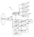
本発明はまた、立体倉庫仕分システムに関する。前記仕分装置、移動装置及び制御システムを備える。前記仕分装置が立体倉庫に分散して倉庫セルに連通し、仕分タスクに応じて目標親通箱内の目標子通箱を仕分する。前記移動装置は庫内の倉庫セルの移動空間に分布する。搬送タスクに応じて親通箱を搬送する。前記制御システムは前記仕分け装置及び移動装置と通信するように配置され、仕分け作業及び搬送作業の割り当て及び仕分け情報の維持保守に用いられる。1つの実施例では、前記制御システムはタスク決定モジュール、貨物統計モジュール及びタスク計画モジュールを備える。前記タスク決定モジュールは物流情報に基づいて現在の仕分け物流場所を確定する。前記貨物統計モジュールは仕分け物流地、貨物スケジューリング情報に基づいて、各親通箱とその内部子通箱内の貨物の住所情報を分析し、目標親通箱および目標子通箱を確定するように構成されている。前記タスク計画モジュールは、少なくとも庫内の目標親通箱分布情報、仕分装置分布情報と移動装置の数および位置情報に基づいて、各仕分装置および各移動装置に対応するタスクを確定するように構成されている。1つの実施例では、前記タスク計画モジュールは仕分タスクユニットと搬送タスクユニットを備える。前記仕分タスクユニットは、各仕分装置によって仕分した目標子通箱リストを識別しかつ維持保守する。前記目標子通箱リストは、少なくとも目標子通箱ID情報、元のバインドされた第1親通箱ID情報および仕分された目標子通箱を収めた第2親通箱ID情報を含む。前記搬送タスクユニットは移動装置、第1親通箱、第2親通箱及び仕分け装置の分布位置情報に基づいて、移動装置毎にリアルタイムに搬送タスクを割り当てるように配置されている。1つの実施例では、前記分布位置情報は倉庫セルID情報である。1つの実施例では、制御システムは、倉庫内の子通箱、親通箱のバインド関係、および親通箱と倉庫セルのバインド関係を維持保守するように構成された貨物情報メンテナンスモジュールをさらに含む。1つの実施例では、前記制御システムはクラウド上に位置し、前記立体倉庫はローカルモジュールを含み、制御システムはローカルモジュールを介して仕分装置および移動装置と通信する。The present invention also relates to a multi-level warehouse sorting system. The system includes a sorting device, a moving device, and a control system. The sorting device is distributed in a multi-level warehouse and communicates with warehouse cells to sort target child transport boxes in a target parent transport box according to a sorting task. The moving devices are distributed in the moving space of the warehouse cells in the warehouse. The parent transport boxes are transported according to a transport task. The control system is arranged to communicate with the sorting device and the moving device, and is used for allocating sorting and transporting tasks and maintaining sorting information. In one embodiment, the control system includes a task determination module, a cargo statistics module, and a task planning module. The task determination module determines a current sorting logistics location based on logistics information. The cargo statistics module is configured to analyze address information of each parent transport box and its internal child transport box based on the sorting logistics location and cargo scheduling information, and determine a target parent transport box and a target child transport box. The task planning module is configured to determine a task corresponding to each sorting device and each moving device based on at least target parent transport box distribution information in the warehouse, sorting device distribution information, and the number and position information of moving devices. In one embodiment, the task planning module includes a sorting task unit and a transport task unit. The sorting task unit identifies and maintains a list of target child transport boxes sorted by each sorting device. The target child transport box list includes at least target child transport box ID information, originally bound first parent transport box ID information, and second parent transport box ID information containing the sorted target child transport box. The transport task unit is configured to assign a transport task to each moving device in real time based on distribution location information of the moving device, the first parent transport box, the second parent transport box, and the sorting device. In one embodiment, the distribution location information is warehouse cell ID information. In one embodiment, the control system further includes a cargo information maintenance module configured to maintain a binding relationship between the child transport box and the parent transport box in the warehouse, and a binding relationship between the parent transport box and the warehouse cell. In one embodiment, the control system is located on a cloud, the multi-level warehouse includes a local module, and the control system communicates with the sorting device and the moving device through the local module.
本発明はまた、立体倉庫貨物仕分方法に関する。下記手順を含む。移動装置により第1親通箱と第2親通箱を仕分セルに搬送する。仕分セルの仕分ロボットは、第1親通箱から第2親通箱に貨物をキャッチする。そして、移動装置を介して前記第1親通箱と第2親通箱を仕分セルから搬出する。1つの実施例では、前記仕分け方法はさらに物流輸送情報に基づいて仕分け物流場所を確定することを含む。1つの実施例において、前記仕分方法はさらに、立体倉庫内の貨物のスケジューリング情報と、それが位置する第1親通箱に基づいて、第2親通箱を確定することを含む。1つの実施例では、前記仕分方法はさらに、庫内の第1および第2親通箱分布情報、仕分装置分布情報と移動装置の数および位置情報に基づいて、仕分装置に対応する仕分タスクを決定し、移動装置に対応する搬送タスクを確定することを含む。1つの実施例では、前記仕分方法はさらに、前記第2親通箱にターゲット子通箱の位置がなく、かつ、非目標子通箱がないことに対して、前記第2親通箱を倉庫セルに搬送することを含む。1つの実施例において、前記仕分方法はさらに、庫内の空き倉庫セルの分布に基づいて仕分を完了した第2親通箱を格納する倉庫セルを確定することを含む。1つの実施例では、前記仕分方法はさらに、出庫エリアの空き倉庫セルを仕分け完了した第2親通箱を、優先的に格納するように確定することを含む。 The present invention alsorelates to a cargo sorting method for a multi-level warehouse, the method comprising the steps of: transporting a first parent pass box and a second parent pass box to a sorting cell by a moving device; a sorting robot in the sorting cell catches cargo from the first parent pass box to the second parent pass box; and carrying the first parent pass box and the second parent pass box out of the sorting cell via a moving device. In one embodiment, the sorting method further includes determining a sorting logistics location based on logistics transport information. In one embodiment, the sorting method further includes determining a second parent pass box based on scheduling information of the cargo in the multi-level warehouse and the first parent pass box where it is located. In one embodiment, the sorting method further includes determining a sorting task corresponding to the sorting device based on distribution information of the first and second parent pass boxes in the warehouse, sorting device distribution information, and the number and position information of the moving devices, and determining a transport task corresponding to the moving device. In one embodiment, the sorting method further includes transporting the second parent transit box to a warehouse cell when the second parent transit box has no target child transit box position and no non-target child transit box. In one embodiment, the sorting method further includes determining a warehouse cell to store the second parent transit box that has completed sorting based on a distribution of vacant warehouse cells in the warehouse. In one embodiment, the sorting method further includes determining an vacant warehouse cell in an output area to preferentially store the second parent transit box that has completed sorting.
本発明が提供する仕分システムは、空間位置を過大にする必要なく、移動装置の組み合わせにより、仕分けロボットを用いて時間や空間に制約なく迅速かつ正確に貨物を仕分けることができ、仕分効率が高い。The sorting system provided by the present invention can use a sorting robot to quickly and accurately sort cargo without time or space constraints, without the need for excessive spatial positioning, and can achieve high sorting efficiency by combining moving devices.
以下、本発明の選ばれた実施例について図面を参照しながらさらに詳細に説明する。
本発明の実施例の目的、技術提案およびアドバンテージをより明確にするために、以下、本発明の実施例における図面と併せて、本発明の実施例における技術提案を明確かつ完全に説明する。説明された実施例は明らかに本発明の一部の実施例であり、全ての実施例ではない。本発明の実施例に基づいて、当分野のエンジニアが創造的な労働を行ってないことを前提に得られた他のすべての実施例は、本発明の保護の範囲内に属する。In order to make the purpose, technical proposal and advantages of the embodiments of the present invention clearer, the technical proposal in the embodiments of the present invention will be described clearly and completely below in conjunction with the drawings in the embodiments of the present invention. The described embodiments are obviously only some of the embodiments of the present invention, but not all of the embodiments. All other embodiments obtained based on the embodiments of the present invention on the premise that engineers in the field have not performed creative labor, fall within the scope of protection of the present invention.
以下の詳細な説明では、本願の一部として本願の実施形態を説明するために、各明細書の添付図面を参照することができる。添付図面において、類似の符号は異なる図面において、概ね類似した構成要素を説明する。In the following detailed description, reference may be made to the accompanying drawings, each of which is incorporated herein by reference, to illustrate embodiments of the present application. In the accompanying drawings, like reference numerals refer to generally similar components in different drawings.
本願の各実施形態は、当該技術分野に関する知識及び技術を有する当業者が、本願の技術提案を実施できるように、以下で十分詳細に説明する。また、構造的、論理的または電気的な変更も、本願の他の実施形態を用いて行うことがきることを理解されたい。Each embodiment of the present application is described below in sufficient detail to enable a person skilled in the art with knowledge and skill in the relevant technical field to implement the technical proposals of the present application. It should also be understood that structural, logical, or electrical changes may be made with other embodiments of the present application.
既存の技術では、物流チェーンの各部分は、以下の特徴のいくつかを共有している。With existing technology, each part of the logistics chain shares some of the following characteristics:
第1に、物流チェーンでは貨物を貯蔵する倉庫が重要な部分である。それは伝統的な倉庫や現代のスマート倉庫であるかどうか、基本的に棚に貨物を配置する。棚と棚の間には貨物の入庫や出庫などの貨物移動操作のための通路が残っている。一部の大型倉庫では、入出庫エリア、仕分けエリアなど、さまざまな貨物エリアがある。従来の倉庫では貨物の入庫、出庫、移動はフォークリフトなどの手動または手動補助搬送装置によって実現される。特許公開番号CN107577215A、発明の名称「棚とスケジューリング方法、および操作の高さ方法、センターとシステム」は、倉庫内の異なるエリアを移動することができ、貨物の流通効率を向上させる可動棚が開示されている。従来の倉庫と比較して、前述のスマート倉庫は貨物移動の自動化と作業効率を大幅に改善したが、従来の倉庫でも現代のスマート倉庫でも、倉庫内の貨物移動を順調に行うのに十分な空間を確保する必要がある。貨物を貯蔵する倉庫空間は倉庫全体空間の半分以下であり、倉庫の空間利用率は高くない。First, the warehouse where the cargo is stored is an important part in the logistics chain. Whether it is a traditional warehouse or a modern smart warehouse, the cargo is basically placed on the shelves. Between the shelves, aisles remain for cargo movement operations such as storing and unloading the cargo. In some large warehouses, there are various cargo areas, such as storage and unloading areas and sorting areas. In traditional warehouses, the storing, unloading and movement of cargo is realized by manual or manual assisted conveying devices such as forklifts. Patent publication number CN107577215A, invention title "Shelf and Scheduling Method, and Operation Height Method, Center and System" discloses a movable shelf that can move between different areas in the warehouse and improve the distribution efficiency of cargo. Compared with the traditional warehouse, the aforementioned smart warehouse has greatly improved the automation and work efficiency of cargo movement, but whether it is a traditional warehouse or a modern smart warehouse, it is necessary to ensure sufficient space for the smooth movement of cargo in the warehouse. The warehouse space for storing cargo is less than half of the total space of the warehouse, and the space utilization rate of the warehouse is not high.
第2に、物流システムにおける貨物の輸送には貨物の荷揚げ、荷降ろしドックと倉庫の間および倉庫内の運搬が含まれ、通常では手動、半手動、および完全に自動化された機器のいくつかの方法が含まれる。科学技術の発展に伴い、現在、ほとんどの物流システムは半自動、すなわち作業者が貨物を運ぶために機器を使用している。作業者がフォークリフトを運転し、リフトと連動して貨物を出し入れする。現在登場しているスマート倉庫は、主にAGV(Automated Guided Vehicle)を使用して貨物を運ぶ。倉庫のサイズ、貨物の体積、サイズに応じてAGVは多くの形態を持っている。例えば、「AGVミニカー」と題された特許番号CN203715182Uは、昇降棚を有するAGVが提供されている。特許公開番号CN104317289A、発明の名称「新型フォークリフト式AGV」は、その場で回転でき、転向時に転向半径を減少させるフォークリフト式AGVを提供している。また、背負い型AGV、牽引型AGVなど他のタイプのAGVもある。Secondly, the transportation of cargo in the logistics system includes the unloading of cargo, transportation between the loading dock and the warehouse and within the warehouse, which usually includes several methods of manual, semi-manual, and fully automated equipment. With the development of science and technology, currently most logistics systems are semi-automatic, that is, the equipment is used by workers to transport the cargo. The worker drives the forklift and works with the lift to load and unload the cargo. The smart warehouses that have emerged now mainly use AGVs (Automated Guided Vehicles) to transport the cargo. Depending on the size of the warehouse, the volume and size of the cargo, AGVs have many forms. For example, patent number CN203715182U, entitled "AGV Minicar", provides an AGV with a lifting shelf. Patent publication number CN104317289A, named as the invention "New type forklift type AGV", provides a forklift type AGV that can turn on the spot and reduce the turning radius when turning. There are also other types of AGVs such as backpack type AGVs and tow type AGVs.
前述の各種AGVの構造と作業方法は現在の物流モードに適応し、主に様々な大型倉庫に適用され、棚間の通路で運行する。または仕分エリアや出庫エリアなどの異なるエリアで貨物を運ぶ。The structure and working methods of the various AGVs mentioned above are adapted to the current logistics mode and are mainly used in various large warehouses to operate in the aisles between shelves or to transport cargo in different areas such as sorting areas and delivery areas.
第3に、貨物を原産地から消費地に移動する過程で、貨物は流通のあらゆる段階で様々な搬送に耐える。輸送中の貨物の損傷を避けるために貨物の性質に応じて、異なる梱包手段を使用して貨物を梱包する必要がある。例えば、一般的な小物貨物は、段ボール箱、ビニール袋、テープ、ホットメルト接着剤などの包装を使用し、段ボール箱内の貨物の揺れを防ぐために充填物が充填される。ガラス製品、セラミック製品など壊れやすい貨物については、カスタム形状の発泡ケースなどの特殊なパッケージも追加する必要がある。したがって、通常では小さな貨物を安全に目的地に到達させるために、大量の梱包材を必要とする。この過剰包装方法は大量の貯蔵、輸送空間を占有するだけでなく、包装材料の多くを無駄にし、プラスチックや発泡体などの包装材料のほとんどは、リサイクル不可能な材料であり、環境に大きな負荷と害をもたらす。Third, in the process of moving cargo from the place of origin to the place of consumption, the cargo endures various conveyances at every stage of distribution. In order to avoid damage to the cargo during transportation, different packaging means need to be used to package the cargo according to the nature of the cargo. For example, general small cargo uses packaging such as cardboard boxes, plastic bags, tape, hot melt glue, etc., and fillers are filled to prevent the cargo from shaking inside the cardboard box. For fragile cargo such as glass products and ceramic products, special packages such as custom-shaped foam cases also need to be added. Therefore, a large amount of packaging material is required to safely reach the destination of small cargo that is usually small. This overpackaging method not only occupies a large amount of storage and transportation space, but also wastes a lot of packaging materials, and most of the packaging materials such as plastic and foam are non-recyclable materials, which brings great burden and harm to the environment.
第4に、仕分けは物流チェーンのもう1つ重要な部分である。輸送と流通の効率を向上させるために、物流システムは通常マルチレベル仕分センターを設置する。例えば、顧客から集荷された貨物は、仕分けセンターを通じて仕分、輸送され、次の仕分センターによって仕分され、再輸送される。配送ステーションに到着するまで、配送ステーションから目的地まで配送する。仕分けセンターには少なくとも一時的に貯蔵されている倉庫が含まれている。倉庫内の貨物は、手動または機器によって相応レベルに仕分され、そして収集、指定されたエリアに輸送され、貯蔵される。輸送車両が到着して荷揚げされ、仕分センターから次の仕分センターまたは配送ステーションに輸送される。Fourth, sorting is another important part of the logistics chain. In order to improve the efficiency of transportation and distribution, logistics systems usually set up multi-level sorting centers. For example, cargo collected from customers is sorted and transported through a sorting center, then sorted and re-transported by the next sorting center. Until it arrives at the distribution station, it is delivered from the distribution station to its destination. The sorting center includes a warehouse where it is stored at least temporarily. The cargo in the warehouse is sorted into the corresponding levels by hand or by equipment, and then collected, transported to a designated area and stored. The transport vehicle arrives and unloads the cargo, and the cargo is transported from the sorting center to the next sorting center or distribution station.
技術の発展に伴い、仕分け技術も徐々に向上している。原始的な手動仕分けから、さまざまな自動化装置による自動仕分けへと進化した。例えば、特許番号CN102218404B、発明の名称「無線周波数、ビデオおよび赤外線識別追跡に基づく物流仕分けシステムおよび方法」には、貨物投入コンベア、貨物搬送ガイド、複数の仕分けコンベア、貨物識別装置を含む仕分装置が開示されている。貨物投入コンベアは貨物を貨物搬送ガイドに投入し、貨物識別装置によって識別され、対応する仕分けコンベアに供給される。また、例えば特許番号CN103949408B、発明の名称「高速貨物仕分車及び仕分けシステム」は、仕分けセンターの倉庫にライン式仕分けシステムを設置し、ライン式搬送路に複数の仕分け口を設け、仕分け車を用いて仕分け対象貨物を積載している。仕分車は、搬送路の移動中に貨物を識別し、識別された貨物を対応する仕分け口を通過する時に仕分け口に押し込む。他のタイプの仕分装置または仕分ロボットもある。With the development of technology, sorting technology has also gradually improved. It has evolved from primitive manual sorting to automatic sorting by various automation devices. For example, Patent No. CN102218404B, titled "Logistics sorting system and method based on radio frequency, video and infrared identification tracking", discloses a sorting device including a cargo input conveyor, a cargo conveying guide, multiple sorting conveyors, and a cargo identification device. The cargo input conveyor inputs cargo into the cargo conveying guide, which is identified by the cargo identification device and supplied to the corresponding sorting conveyor. Also, for example, Patent No. CN103949408B, titled "High-speed cargo sorting car and sorting system", installs a line-type sorting system in the warehouse of a sorting center, provides multiple sorting ports on the line-type conveying path, and uses a sorting car to load the cargo to be sorted. The sorting car identifies the cargo while it is moving on the conveying path, and pushes the identified cargo into the sorting port when it passes through the corresponding sorting port. There are also other types of sorting devices or sorting robots.
前述の各種仕分け技術では、仕分け装置や仕分けロボット、仕分け予定貨物、仕分け済み貨物を収めるのに十分な大きさのエリアを確保する必要があり、かつ仕分け後も、フォークリフトなどの輸送設備が仕分された貨物を収集するのに、十分な大きさのエリアを確保する必要がある。輸送通路を通って貨物貯蔵エリアに輸送、貯蔵し、出庫を待つ。したがって、倉庫は仕分けや輸送に十分な空間を確保する必要がある。また、仕分けセンターの倉庫では貨物が入庫から出庫まで、倉庫管理技術、仕分け技術、出庫輸送頻度などの要因により、仕分けセンターに一定期間滞在し、出庫を待つ必要がある。The various sorting technologies mentioned above require an area large enough to accommodate the sorting equipment, sorting robots, cargo to be sorted, and cargo that has already been sorted. After sorting, an area large enough for transport equipment such as forklifts to collect the sorted cargo must also be secured. The cargo is then transported through transport corridors to a cargo storage area, where it is stored and awaits removal from the warehouse. Therefore, warehouses must have sufficient space for sorting and transportation. Furthermore, at the sorting center warehouse, cargo must stay at the sorting center for a certain period of time from when it enters the warehouse until when it is removed from the warehouse, depending on factors such as warehouse management technology, sorting technology, and frequency of transportation for removal from the warehouse.
最後に、物流の末端の集荷、配送についてまた人力で行う必要がある。例えば、宅配業者が顧客の所まで集荷または配達のために車両を運転する必要がある。いくつかの宅配ロボットが出現しているが、これらの宅配ロボットは作業者と協調し、配達センターの作業者が宅配ロボットの貨物を出し入れする。それ自体は独自に貨物の出し入れすることはできない。Finally, collection and delivery at the end of the logistics chain still need to be done by human labor. For example, a delivery company needs to drive a vehicle to the customer's location to collect or deliver the goods. Some delivery robots have appeared, but these work in cooperation with workers at the delivery center, who take the robot's cargo in and out; the robot itself cannot take in or out cargo on its own.
本発明(本特許出願に既に関連している複数の特許出願を含む)は、画期的な新しい物流システムを提供する。物流チェーンのすべての部分に対して、既存の物流システムとは異なる複数の画期的なソリューションを提案し、貨物の滞留時間を短縮し、貨物の輸送効率を向上させ、固定位置倉庫の使用を削減し、倉庫の空間利用率を高め、貨物の完全な管理監視を確保し、過剰包装による環境負荷を低減することができる。The present invention (including multiple patent applications already related to this patent application) provides a groundbreaking new logistics system. It proposes multiple groundbreaking solutions for all parts of the logistics chain that are different from existing logistics systems, shortening cargo dwell time, improving cargo transportation efficiency, reducing the use of fixed-location warehouses, increasing warehouse space utilization, ensuring complete management and monitoring of cargo, and reducing the environmental burden caused by excessive packaging.
本発明の1つまたは複数の実施例によれば、本発明の物流システムは、顧客サービスシステム、多段中間輸送物流装置、および複数の物流制御モジュールを含む。ここで、システム全体の説明を分かりやすくするために、以下の説明において、より理解しやすくするために各種物流機器に対して命名を行う。According to one or more embodiments of the present invention, the logistics system of the present invention includes a customer service system, a multi-stage intermediate transport logistics device, and a plurality of logistics control modules. Here, in order to facilitate the explanation of the entire system, the various logistics devices are named in the following description for easier understanding.
図1は、本発明の1つの実施例に係る多段物流設備の輸送イメージ図である。本実施例では、端末物流装置は宅配ロボット8、固定位置倉庫(例えば、宅配ロッカー10)、ドローンM1(小型および大型ドローンを含む。図に示す小型ドローン)、およびミニトラック9a等を備えている。一点鎖線は末端物流チェーンであり、顧客は末端物流機器と対話し、貨物が顧客の所から物流システムに入り、または物流システムから顧客の所に戻る。細線は2次物流チェーンであり、末端物流機器の間で発生し、貨物輸送の小さなエリアで行われる。太い実線は3次物流チェーンであり、末端物流機器とやや長い輸送距離を持つ3次物流機器の間で貨物を受け渡し、小さなエリアで集荷した貨物をやや長い輸送距離を持つ3次物流機器で輸送する。太い点線は、3組の物流機器と都市間物流機器の間で貨物を受け渡す4次物流チェーンである。このレベルの物流チェーンでは、貨物は3次物流機器によって都市間物流機器に渡され、都市間物流機器はある都市または国から別の都市または別の国に貨物を輸送する。Figure 1 is a transportation image diagram of a multi-stage logistics facility according to one embodiment of the present invention. In this embodiment, the terminal logistics facility is equipped with a
いくつかの実施例では、物流機器は、図中のミニトラック9aと比較的大型の都市循環トラック9bおよび国際都市間物流機器などの都市間貨物輸送装置を含み、距離に応じて貨物機、都市間鉄道、長距離および短距離トラック、海上貨物船などを含むことができる。In some embodiments, the logistics equipment includes intercity cargo transport equipment such as
いくつかの実施例では、末端物流チェーンの例として宅配ロボットが記載されている。当業者は、宅配ロボットの作業も宅配員に置き換えることができることを理解しているはずである。これについて本文では説明しない。In some embodiments, a delivery robot is described as an example of a terminal logistics chain. Those skilled in the art should understand that the work of the delivery robot can also be replaced by a delivery person. This will not be described in the present text.
いくつかの実施例では、物流機器は固定倉庫と移動可能な貨物輸送装置を含む。各物流機器は唯一のID電子タグを有し、貨物輸送装置は対応する輸送距離範囲を有し、輸送距離範囲の大きさに応じて全体の貨物輸送装置を複数のレベルに分割し、例えば全体として、全国間、都市間および市内の3つのレベルに分けられる。In some embodiments, the logistics equipment includes a fixed warehouse and a mobile cargo transport device. Each logistics equipment has a unique ID electronic tag, and the cargo transport device has a corresponding transport distance range. The entire cargo transport device is divided into multiple levels according to the size of the transport distance range, for example, into three levels overall: national, intercity, and intracity.
このうち、都市レベルの貨物機器は、都市のサイズと貨物輸送装置の輸送距離に応じて、複数の異なるレベルに分けることができる。図2は都市レベルの多段階貨物輸送装置の輸送距離のイメージ図である。本実施例では、物流端末の宅配ロボット8の搬送距離S1が最短であり、その数が最も多いため、全体として宅配ロボット8の搬送範囲は市内のすべての利用者エリアをカバーすることができる。ミニトラック9aは宅配ロボット8の輸送距離S1よりも輸送距離S2が大きい2次貨物輸送装置である。都市循環トラックは3次貨物輸送装置であり、その輸送距離S3は市内最大である。輸送距離が長くなるにつれて、必要な数量は少なくなる。もちろん、数量は貨物の量にも関係している。貨物の流れが大きい場合、貨物輸送装置は多くなり、貨物輸送装置が多いほど貨物の流れが速くなる。本発明の物流システムは貨物の流れが大きいほど、そのアドバンテージが明らかになり、効率が逆に高くなる。Among them, city-level cargo equipment can be divided into several different levels according to the size of the city and the transport distance of the cargo transport device. Figure 2 is an image diagram of the transport distance of a city-level multi-stage cargo transport device. In this embodiment, the transport distance S1 of the logistics terminal's
いくつかの実施例では、各レベルの貨物輸送装置の輸送エリアは、その移動に応じて変化する。したがって、スケジューリングでより柔軟になる。貨物の受け渡しでは、貨物輸送の方向、貨物輸送装置の分布および輸送方向のみを使用して、貨物輸送装置のドッキング地点とドッキングする貨物輸送装置を計算で確定する。したがって、貨物の受け渡しとドッキングはより柔軟で迅速になり、貨物の滞留時間が短縮され、物流効率が向上する。In some embodiments, the transportation area of each level of cargo transport device changes according to its movement, thus making scheduling more flexible. In cargo delivery, only the cargo transport direction, the distribution of cargo transport devices and the transportation direction are used to calculate and determine the docking point of the cargo transport device and the cargo transport device to be docked. Therefore, cargo delivery and docking become more flexible and faster, the cargo dwell time is shortened, and logistics efficiency is improved.
当業者が理解しているように、各レベルの貨物輸送装置は、そのレベルの輸送に適応する輸送機器を含む。ただし、本発明はこれに限定されるものではない。例えば、通常では2次物流チェーンとして使用される貨物輸送装置の大型トラックは、末端物流チェーンの機器として顧客から直接貨物を集荷することもできる。また、例えば、末端物流チェーンとしてのミニトラックは、通常では3次物流チェーンの貨物輸送装置として使用される航空機に直接貨物を受け渡すことができ、他のレベルの貨物輸送装置を介する必要がない。As will be understood by those skilled in the art, each level of cargo transport equipment includes transport equipment suitable for that level of transport. However, the present invention is not limited thereto. For example, a large truck, which is a cargo transport equipment normally used as a secondary logistics chain, can also collect cargo directly from a customer as equipment in a terminal logistics chain. Also, for example, a mini truck, which is a terminal logistics chain, can deliver cargo directly to an aircraft, which is normally used as a cargo transport equipment in a tertiary logistics chain, without the need to go through cargo transport equipment of other levels.
いくつかの実施例では、本発明の物流チェーンは固定倉庫を含まないことができる。物流チェーンの各レベルの貨物輸送装置間で貨物を受け渡すことができ、固定倉庫(または仕分センター)に貨物を渡した後、別の貨物輸送装置によって固定倉庫から貨物を取り出す必要がない。これにより、貨物の滞留時間が大幅に短縮され、物流効率が向上し、物流コストが削減される。いくつかの実施例では、固定倉庫(宅配便ロッカーを含む)は、本発明の物流チェーンに補助設備として追加されうることができる。例えば、集荷および配送部分では、末端物流チェーンの貨物輸送装置と時間的に合わない場合、顧客の満足度が低下する。宅配ロッカーを導入すれば、時間の違いを補うことができ、顧客の満足度を向上させることができる。いくつかの実施例では、固定倉庫(郊外の大型倉庫を含む)は、物流チェーンの重要な部分として機能し、物流チェーンの重要な部分となる。このような固定倉庫は、貨物輸送装置のスケジューリングを容易にするため、大量の貨物が都市に出入りするバッファ倉庫として機能することができる。本発明のいくつかの実施例では、貨物輸送装置における貨物数と固定位置倉庫における貨物数量の比は、50%以上、80%以上、90%以上、95%以上または99%以上である。 In some embodiments, the logistics chain of the present invention may not include a fixed warehouse. The cargo may be handed over between the cargo transport devices at each level of the logistics chain, and after the cargo is handed over to the fixed warehouse (or sorting center), there is no need to retrieve the cargo from the fixed warehouse by another cargo transport device. This significantly reduces the cargo dwell time, improves logistics efficiency, and reduces logistics costs. In some embodiments, a fixed warehouse (including a parcel locker) may be added to the logistics chain of the present invention as an auxiliary facility. For example, in the collection and delivery part, if there is a time mismatch with the cargo transport device of the terminal logistics chain, customersatisfaction decreases . The introduction of a parcel locker can make up for the time difference and improve customer satisfaction. In some embodiments, a fixed warehouse (including a large warehouse in the suburbs) serves as an important part of the logistics chain and becomes an important part of the logistics chain. Such a fixed warehouse may serve as a buffer warehouse where a large amount of cargo enters and leaves the city to facilitate the scheduling of the cargo transport device. In some embodiments of the present invention, the ratio of the number of cargoes in the cargo transport device to the number of cargoes in the fixed location warehouse is 50% or more, 80% or more, 90% or more, 95% or more, or 99% or more.
いくつかの実施例では、貨物輸送装置は貨物輸送の役割を果たすだけでなく、貨物貯蔵の目的も達成できる立体倉庫を含む。いくつかの実施例では、貨物輸送装置は立体倉庫、貯蔵装置、移動装置、仕分け装置および輸送機器を含む。立体倉庫は輸送機器に積載される。輸送機器の種類と積載能力に応じて、立体倉庫の仕様はさまざまである。例えば、輸送機器が小型車両、航空機、船舶である場合、小規模の立体倉庫を運ぶことができ、大型トラック、列車、貨物機、海上貨物船の輸送は大規模な立体倉庫を運ぶことができる。立体倉庫内部の貯蔵装置に貨物を内蔵する。いくつかの実施例では、貯蔵装置は親子通箱を含む。貨物は子通箱に内蔵され、親通箱は複数の子通箱を収める。親通箱は立体倉庫の倉庫セル中的の貯蔵空間に収められる。いくつかの実施例では、移動装置について、例えば小型、超薄型AGVであり、倉庫セルの移動空間に位置し、前記親通箱を搬送する。いくつかの実施例では、立体倉庫の規模に応じて、多数の仕分装置が立体倉庫に分散され、隣接する倉庫セルと連結され、倉庫セルに統合される。In some embodiments, the cargo transport device includes a multi-level warehouse that can not only fulfill the role of cargo transport, but also achieve the purpose of cargo storage. In some embodiments, the cargo transport device includes a multi-level warehouse, a storage device, a moving device, a sorting device, and a transport device. The multi-level warehouse is loaded onto the transport device. Depending on the type and loading capacity of the transport device, the specifications of the multi-level warehouse vary. For example, if the transport device is a small vehicle, an aircraft, or a ship, it can carry a small multi-level warehouse, and the transport of a large truck, a train, a cargo plane, or an ocean freighter can carry a large multi-level warehouse. The cargo is stored in the storage device inside the multi-level warehouse. In some embodiments, the storage device includes a parent-child transport box. The cargo is stored in the child transport box, and the parent transport box stores multiple child transport boxes. The parent transport box is stored in a storage space in a warehouse cell of the multi-level warehouse. In some embodiments, the transport device is, for example, a small, ultra-thin AGV, which is located in the moving space of the warehouse cell and transports the parent transport box. In some embodiments, depending on the size of the multi-storey warehouse, multiple sorting devices are distributed throughout the multi-storey warehouse, connected to adjacent warehouse cells, or integrated into the warehouse cells.
いくつかの実施例では、貨物は子通箱内に配置され、子通箱は立体倉庫の倉庫セルに格納された親通箱に配置される。これにより、貨物が積み重なって押し合うことがない。子通箱は様々な仕様を有し、様々な形状、サイズの貨物に適応することができる。いくつかの壊れやすい貨物のために、子通箱は輸送中の衝突や損傷から子通箱内の貨物を保護することができる衝突防止などの構造で設計されている。いくつかの実施例では、貨物の運搬は、例えば立体倉庫内および立体倉庫がドッキングしている時、AGVなどの本発明で提供される移動装置で親通箱を円滑に運搬し、既存の物流システムのような乱暴な取り扱い、雑な仕分けがなくなる。従って、本発明における貨物は、従来の物流システムに必要な各種包装テープ、包装箱、発泡箱、充填材等を不要とし、既存の物流システムにおける過剰包装の問題を回避することができ、より環境に配慮したものである。 In some embodiments, the cargo is placed in a child transport box, and the child transport box is placed in a parent transport box stored in a warehouse cell of a multi-storey warehouse. This prevents the cargo from being stacked and pushed against each other. The child transport box has various specifications and can accommodate cargo of various shapes and sizes. For some fragile cargo, the child transport box is designed with a structure such as a collision prevention structure that can protect the cargo in the child transport box from collisions and damage during transportation. In some embodiments, the transportation of the cargo is smooth by a moving device provided by the present invention, such as an AGV, when the multi-storey warehouse and the multi-storey warehouse are docked, andrough handling andrough sorting as in the existing logistics system are eliminated. Therefore, the cargo in the present invention does not require various packaging tapes, packaging boxes, foam boxes, fillers, etc. required in the conventional logistics system, and the problem of overpackaging in the existing logistics system can be avoided, which is more environmentally friendly.
いくつかの実施例では、各貨物輸送装置の中は同じ仕様の倉庫セルからなる立体倉庫であり、子通箱を収める親通箱は各貨物輸送装置で共通に使用することができる。貨物の受け渡し時に、AGVは現在の貨物輸送装置から直接仕分された親通箱を、別の貨物輸送装置に運ぶ。既存の物流システムにおける荷降ろしや積荷などの部分が不要になるため、貨物の積み降ろし時間を節約できる。しかも、各ドッキング部分は人の介入を必要とせず、高効率であるだけでなく、貨物と人との接触を避けることもできる。In some embodiments, the interior of each cargo transport device is a multi-level warehouse consisting of warehouse cells with the same specifications, and the parent transport boxes that house the child transport boxes can be used commonly by each cargo transport device. When transferring cargo, the AGV transports the parent transport boxes sorted directly from the current cargo transport device to another cargo transport device. This eliminates the need for unloading and loading parts of the existing logistics system, thereby saving time in loading and unloading cargo. Moreover, each docking section does not require human intervention, which is not only highly efficient but also avoids contact between cargo and people.
いくつかの実施例では、貨物が輸送中に物流方向に従って、ある貨物輸送装置から別の貨物輸送装置に渡される。異なるレベルの貨物輸送装置は、複数の物流チェーンレベルを形成する。貨物は発送から目的地に到着まで、異なる輸送距離を持つ複数の貨物輸送装置に渡され、固定倉庫を通過または通過せず、最終的に受取顧客に配送される。In some embodiments, cargo is handed over from one cargo transport device to another cargo transport device during transportation according to a logistics direction. The cargo transport devices at different levels form multiple logistics chain levels. From dispatch to arrival at the destination, the cargo may be handed over to multiple cargo transport devices with different transportation distances, passing or not passing through a fixed warehouse, and finally delivered to the receiving customer.
以下、具体的な実施例により本発明を詳細に説明する。The present invention will be explained in detail below with specific examples.
いくつかの実施例では、立体倉庫は高い空間利用率を有する。庫内の空間のほとんどは貯蔵装置を収める貯蔵空間として使用される。前記貯蔵装置は例えば貯蔵箱または貯蔵トレイである。1つの実施例では、貯蔵装置は親子通箱を含む。貨物を収める子通箱は密閉装置であり、親通箱内に配置される。貯蔵空間の上方または貯蔵空間の下方に移動装置を収める移動空間を設ける。前記移動装置は例えば超薄型のAGVである。移動装置で貯蔵空間の貯蔵装置を移動させ、貨物の入出庫、庫内移動などの操作を完了する。貯蔵空間と移動空間の具体的な構造設計により、前記貯蔵空間と前記移動空間の体積比は、≧4:1,又は≧5:1,又は≧6:1,又は≧7:1,又は≧8:1,又は≧9:1,又は≧10:1とすることができる。したがって、本発明が提供する立体倉庫の空間利用率は、従来の倉庫または現代のスマート倉庫よりもはるかに高い。In some embodiments, the multi-level warehouse has a high space utilization rate. Most of the space inside the warehouse is used as a storage space to accommodate the storage device. The storage device is, for example, a storage box or a storage tray. In one embodiment, the storage device includes a parent-child transport box. The child transport box that accommodates the cargo is a sealed device and is disposed inside the parent transport box. A transport space to accommodate the transport device is provided above or below the storage space. The transport device is, for example, an ultra-thin AGV. The transport device moves the storage device in the storage space to complete operations such as loading and unloading the cargo and transporting within the warehouse. According to the specific structural design of the storage space and the transport space, the volume ratio of the storage space to the transport space can be ≧4:1, or ≧5:1, or ≧6:1, or ≧7:1, or ≧8:1, or ≧9:1, or ≧10:1. Therefore, the space utilization rate of the multi-level warehouse provided by the present invention is much higher than that of traditional warehouses or modern smart warehouses.
倉庫セル実施例1
1つの実施例において、本発明は、標準化、モジュール化された倉庫セルを提供し、複数の倉庫セルが積み重ねられ高い空間利用率を持つ立体倉庫を形成することができる。Warehouse Cell Example 1
In one embodiment, the present invention provides a standardized, modular warehouse cell, where multiple warehouse cells can be stacked to form a multi-level warehouse with high space utilization.
図3は、本発明の1つの実施例に係る標準化、モジュール化された倉庫セルの立体構成図である。前記倉庫セル1は少なくとも1つの立方体フレームを含み、4本の柱111、上部に4本のフレーム112と底板113を備えている。この立方体フレームの4本の柱111はスタンド機構と連結し、このスタンド機構により貯蔵装置を支持する。本実施例では、前記スタンド機構は支持ブロックとして、内部に向かう2つの支持ブロック12が各柱に連結されている。他の実施例では、前記スタンド機構は前記柱に連結された扇状構造であってもよく、前記扇形構造体のラジアン角度は≦90度である。Figure 3 is a three-dimensional diagram of a standardized, modularized warehouse cell according to one embodiment of the present invention. The
セルの立体フレーム底面は、一枚の底板113である。他の実施例では、底板113は必要に応じて軽量化された切り板または網状に設定することができ、コストを節約する。立体空間における貨物の分布を把握できるように、各倉庫セルにはID電子タグ14が設けられている。図3に示すように、ID電子タグ14は底板113の適切な位置に取り付けられ、庫内の番号などの倉庫セルのID情報が記録されている。The bottom surface of the three-dimensional frame of the cell is a
倉庫セル1の立方体フレーム内部の空間は、前記支持ブロック12から立方体フレームの上部まで貯蔵装置を収める貯蔵空間101を含む。例えば本実施例における貯蔵装置は親通箱2である。図4は、親通箱2が倉庫セル1内に配置された状態を示すイメージ図である。親通箱2を設置する目的は、倉庫セルの貯蔵空間をできるだけ利用することである。収められた貨物は仕様、体積形状など様々な可能性があるため、親通箱2で異なる仕様、異なる体積の貨物を整然と集合させることができる。立方体フレームの4つの支持ブロック12は親通箱2の底部を支持し、貯蔵空間101に安定して収めることができる。The space inside the cubic frame of the
1つの実施例では、貨物は子通箱内(図示せず)内に配置される。子通箱は親通箱2に配置される。いくつかの実施例では、親通箱2は本実施例における倉庫セル1の貯蔵空間101の仕様に一致する寸法を持つ第1本体20を含む。図5Aに示すように、親通箱2の第1本体20の高さは貯蔵空間101と一致し、第1本体20の上部は開放していて、子通箱の出し入れができる。他のいくつかの実施例では、図5Bに示すように、親通箱2の第1本体20の高さは貯蔵空間101の高さよりも低い。他のいくつかの実施例では、図6A-6Bに示すように、親通箱2の第1本体20は貯蔵トレイのような形状、かつ縁22aを含む。第1本体20には、異なる仕様、異なる体積の貨物を収めるための複数の仕様の位置決め溝23aが順序良く設けられている。In one embodiment, the cargo is placed in a child box (not shown). The child box is placed in a
上述した3つの実施例では、親通箱2の第1本体20の底部は搬送構造を有している。同図に示すように、搬送構造は移動装置のリフト機構に協働する位置決め構造21とすることができ、移動装置を親通箱2の第1本体20の底部から親通箱2に押し上げることができる。いくつかの実施例では、各親通箱2は図5Cに示すようにID電子タグ24を備えている。1つの実施例では、ID電子タグはその親通箱2のID情報を記録する電子タグであり、例えば、親通箱2の番号である。In the three embodiments described above, the bottom of the
いくつかの実施例では、前記支持ブロック12から立方体フレームの底部までは移動空間102である。移動装置としての歩行空間である。1つの実施例では、前記移動装置としてAGV3が用いられる。AGV3は移動空間102内を移動する。倉庫セル1の底板113はAGV3の走行面であり、図7A-7Bは、AGV3が前記倉庫セル1に停止した状態のイメージ図である。いくつかの実施例では、図3と組み合わせて、底板113には直交になるガイド溝1131が設けられている。底板113は長方形であるため、AGV3が底板11a上を邪魔なく移動できるように、直交して設けられたガイド溝1131は、それぞれ対応する底辺と平行である。ガイド溝1131に対応し、図7Bに示すようにAGV3の底部に2つのガイド輪31が配設され、走行中にAGV3が走行経路から外れるのを防止する。本実施例では、底板113には直交関係にあるガイド溝1131が1組設けられている。2組または3組設けてもよく、AGV3の底部の対応する位置には、対応するガイド輪31も設けられている。In some embodiments, the area from the
ガイド溝とガイド輪は、AGVが走行中に常にそのルートから逸脱しないようにするために使用される。同様の考え方によれば、フレーム底面113に凸条を設け、AGV底面にフィットする溝を設けることができ、同様にガイドとして機能することができる。機械式の方法は低コスト、高い安定性および制御しやすい。Guide grooves and guide wheels are used to ensure that the AGV does not deviate from its route while traveling. According to a similar idea, a convex rib can be provided on the
これら2つの機械式構造以外にも、AGV3ガイドは電磁式、レーザ式、赤外線式、超音波式、UWB式または光学式などの構造を採用することができる。当業者は、実際のニーズに応じて任意のガイド構造を選択することができるが、ここでは説明を省略する。In addition to these two mechanical structures, the AGV3 guide can also adopt electromagnetic, laser, infrared, ultrasonic, UWB or optical structures. Those skilled in the art can choose any guide structure according to actual needs, but the description is omitted here.
いくつかの実施例では、親通箱2を移動させるために、AGV3の上面にはリフト機構32が設けられている。貨物を移動させない場合に、リフト機構32はAGV3の上部に収められる。貨物を移動する必要がある場合、リフト機構32がAGV3の上面から突出し、親通箱2の底部の位置決め構造21に係合する。リフト機構32の上昇に伴って、支持ブロックから持ち上げることができる。In some embodiments, a
いくつかの実施例では、AGV3のベース下面の外側には電子タグリーダ/ライタ(図示せず)が設けられ、倉庫セル1のID電子タグを読み取る。ベース上面の外側には電子タグリーダ/ライタ(図示せず)が設けられ、親通箱2のID電子タグを読み取る。In some embodiments, an electronic tag reader/writer (not shown) is provided on the outside of the underside of the base of the
図8A-図8Bは、1つの倉庫セル1の中に親通箱2を収め、かつ1台のAGV3は停止した状態を示す。親通箱2を移動させるために、AGV3は親通箱2の下方に停止する。まずリフト機構32で前記親通箱2を持ち上げ、親通箱2を支持ブロック12から離脱させ、そしてAGV3が親通箱2を移動させる。倉庫セル1には、AGV3が支持ブロック12から親通箱2を押し上げて支持ブロック12から離脱させることで、移動を容易にするリフト空間103が残されている。前記リフト空間103の高さは、AGV3のリフト機構が持ち上げる距離に合わせて、AGV3のリフト機構32が前記親通箱2を持ち上げた後、妨げることなく移動することができれば良い。したがって、前記リフト空間103は大きすぎる必要はなく、例えば、リフト空間103の高さは、5cm未満、または3cm未満、または1cm未満であってもよい。Figures 8A-8B show a state in which a
本実施例では、移動貨物用AGV3の厚さは移動空間102の大きさを確定する。一方、AGV3の厚さは倉庫セル1の高さのごく一部を占めている。したがって、倉庫セル1内の空間の大部分は貯蔵空間である。親通箱2の大きさ及び積載重量とAGV3の内部部品が占める大きさ及び積載重量に基づいて、AGV3の厚さと倉庫セル1の高さの比は1/8-1/4、すなわち、1つの倉庫セル1の空間利用率は、75%-90%に達することが計算で分かる。移動装置が磁気浮上など他の方法を採用する場合、空間利用率は95%に達することができる。In this embodiment, the thickness of the
倉庫セル実施例2
図9は、本発明の別の実施例に係る倉庫セルのイメージ図である。本実施例では、倉庫セル1bは少なくとも1つの立方体フレームを含み、立方体フレームは4本の柱111b、天板112b、底板113bを含む。このうち、天板112bにはガイドレール1121bが設けられており、移動装置はガイドレール1121bに吊り機構31bを介して連結された伸縮可能なロボットグラブ3bである。吊下げ機構31bはロボットグラブ3bの方向に360度回転させられ、かつロボットグラブ3bを昇降させるために上下に伸縮させられる。Warehouse Cell Example 2
9 is an image diagram of a warehouse cell according to another embodiment of the present invention. In this embodiment, the warehouse cell 1b includes at least one cubicframe ,which includes four
倉庫セル1b、親通箱2bに対して、前記実施例と違って、その搬送構造は、第1本体の4つの頂辺に設けられた取手21bであり、その上方移動装置の読み取りを容易にするために、前記第1本体の4つの頂辺のいずれかにIDタグが設けられていてもよい。For the warehouse cell 1b and the
親通箱2bは底板113b上に置かれ、吊下げ機構31bはガイドレール1121bに沿って親通箱2bの上方にロボットグラブ3bを移動させ、前記ロボットグラブ3bを取手21bの位置に対応するように拡張し、親通箱2bの取手21bを掴み取り、親通箱2bを底板113bから離し、ガイドレールを介してx方向またはy方向に移動することにより、貨物の水平交差移動を実現する。本実施例では、移動装置を収める移動空間102bが貯蔵空間101bの上方に位置する。ロボットグラブ3b等の移動装置の構成を設けることにより、その占める空間を小さくすることができる。したがって、本実施例における貯蔵空間101bと移動空間102bとの割合は、少なくとも2/1より大きくすることができる。The
倉庫セル実施例3
図10は、本発明の別の実施例に係る倉庫セルのイメージ図である。本実施例では、倉庫セル1cは少なくとも1つの立方体フレームを含み、立方体フレームは4本の柱111c、仕切板112c及び底板1113cを含む。このうち、仕切板112cは支柱111cの上半分に連結され、支柱の先端が位置する平面と移動空間102cを形成する。仕切板112cには、仕切板112c上の移動装置3cの走行を案内するためのガイドレール又はガイド溝が設けられている。親通箱2は底板113c上に配置されている。親通箱2と移動装置3cとは接触しない接続構造を有している。移動装置3cは、例えば、親通箱2を移動する必要がある時に吸引力を発生させ、前記吸引力は真空を抜く際に発生する吸引力、または電磁吸着力であってもよい。対応している親通箱2の第1本体には吸着装置が設けられており、移動装置3cに対応する真空吸着装置または電磁吸着装置であり、移動装置3cに吸引されて底板113cから離れ、移動装置3cの移動に追従して水平方向に貨物のクロス移動が完了する。本実施例では、仕切板112cと底板113cとの間にリフト空間103cと貯蔵空間101cを構成し、仕切板112c以上を移動空間102cとしている。リフト空間103cの高さは、親通箱2が吸着された時に底板113cから離れた高さであるため、この空間の高さはセンチメートルまたはミリメートルレベルで小さくすることができる。一方、移動装置3cの体積は大きくする必要がないので、移動空間102cの高さは貯蔵空間101cに対して高さが小さく、倉庫セル1c内の空間の大部分が貯蔵空間101cであり、貯蔵空間101cは全体の空間の75%以上に達することができる。 Warehouse Cell Example 3
FIG. 10 is an image diagram of a warehouse cell according to another embodiment of the present invention. In this embodiment, the
なお、実施例における倉庫セルに対応して、親通箱は図11に示す構成としてもよい。第1本体20cの側面に開閉可能なサイドドア201cを設け、2つのリンクバーに設けてもよく、開いた時にそれぞれ上部及び底部に向かってスライドさせ、側面から子通箱を出し入れできる。本実施例では、サイドドア201cはロールカーテンドアであり、他のフレキシブルな材料で作られたスライド可能なドアであってもよい。貯蔵状態では、サイドドア201cが閉じた状態であり、そこに子通箱を出し入れする時、サイドドア201cが開く。例えば、入庫、配送、仕分け時にサイドドア201cは開状態となる。このうち第1本体20cの上面には、移動装置の吸着構造に合わせた吸着装置21cも設けられている。In addition, the parent shipping box may have the configuration shown in FIG. 11 in correspondence with the warehouse cell in the embodiment. An
本発明で提供する倉庫セルはモジュール化、標準化された貯蔵セルであり、そのようなユニットが複数積層され、連結されると、立体的な倉庫システムを得ることができる。いくつかの実施例では、隣接する倉庫セルは、柱を共有することができる。すなわち、立体倉庫の柱は、左右または上下に隣接する倉庫セルで共有することができる。立体倉庫の製造においても、複数の倉庫セルを同時に形成される。The warehouse cells provided by the present invention are modularized, standardized storage cells, and when multiple such units are stacked and connected, a three-dimensional warehouse system can be obtained. In some embodiments, adjacent warehouse cells can share columns. That is, columns in a multi-story warehouse can be shared by adjacent warehouse cells to the left and right or above and below. In the manufacture of a multi-story warehouse, multiple warehouse cells are formed simultaneously.
他のいくつかの実施例では、立体倉庫の柔軟性を高めるために、立体倉庫の全部または一部に隣接する倉庫セルは、それぞれ独自の柱を有することができる。これらのセルを連結するために、本発明が提供する倉庫セルの立体フレームは、異なる倉庫セルを連結するための3次元連結構造をそれぞれ備えている。In some other embodiments, to increase the flexibility of the multi-storey warehouse, adjacent warehouse cells in all or part of the multi-storey warehouse may each have their own columns. To connect these cells, the multi-storey frame of the warehouse cells provided by the present invention each has a three-dimensional connecting structure for connecting different warehouse cells.
倉庫セル接続構造 実施例1
図12は、倉庫セル接続イメージ図である。本実施例では、倉庫セルの立体フレームに連結穴11aが設けられており、2つの倉庫セル1が連結されると、それぞれの連結穴11aが連通し、このとき、ボルトとナット(図12には図示せず)により2つの倉庫セル1を連結することができる。Warehouse cell connection structure Example 1
Fig. 12 is an image diagram of warehouse cell connection. In this embodiment, the three-dimensional frame of the warehouse cell is provided with
倉庫セル接続構造 実施例2
図13は、別種類の倉庫セル接続イメージ図である。本実施例では、立体フレーム上の1つの柱または縁に1つまたは複数の溝が設けられており、2つのセルが並ぶと、2つの凹部が対応し、リング爪11bが凹部内に係合し、2つのセルが連結される。1つの倉庫セルのx,y,z三方に複数の溝を設けることにより、3次元で他の倉庫セルを接続でき、必要に応じて任意の数の倉庫セルを接続することができる。Warehouse cell connection structure Example 2
Figure 13 is an image diagram of another type of warehouse cell connection. In this embodiment, one or more grooves are provided on one pillar or edge on the three-dimensional frame, and when two cells are lined up, two recesses correspond to each other, and the
倉庫セル接続構造 実施例3
図14A-14Cは、別種類の倉庫セル接続イメージ図である。図14Aに示すように、立体フレーム上の各柱または縁に1つまたは複数の溝11cが設けられ、図14Bに示すように、他方の倉庫セルに凸状または凸ブロック11dが設けられる。同じ仕様の2つの倉庫セルが並列に配置されると、一方の倉庫セルの凸状または凸ブロック11dが他方の倉庫セルの溝11cに嵌合される。また、嵌合後の2つの倉庫セルの接続をより強固にするために、図14(c)に示すように、凸ブロック11dの端部にフック11eを設け、溝11cに対応する嵌合溝(図示せず)を設け、凸ブロック11dを凹部11cに挿入すれば、係合フック11eと嵌合溝が互いに噛み合い、より強固に連結される。Warehouse cell connection structure Example 3
Figures 14A-14C are different types of warehouse cell connection image diagrams. As shown in Figure 14A, one or
以上の倉庫セル接続構造では、前記連結構造をそれぞれ3次元的に設けるので、水平X両方向、縦Y両方方向およびZ両方方向で他の任意数の倉庫セル1を連結することができ、倉庫セル数が異なり、体積の異なる立体倉庫を得ることができる。In the above warehouse cell connection structure, the connecting structures are each provided three-dimensionally, so any number of
立体倉庫構造 実施例1
図15を参照して、本発明の1つの実施例に係る立体倉庫のイメージ図を示す。本実施例では、前記立体倉庫は複数の水平連結された倉庫セルを含む。各倉庫セルはx方向とy方向に前後に接続でき、実際のニーズに応じて異なる仕様の立体倉庫を構成する。倉庫セルが接続されると、それぞれの移動空間が互いに連通し、一体化された大きな移動空間を形成する。貯蔵装置を支えるスタンド機構の出っ張り長さが小さいため、AGVの移動を妨げない。これによりAGVは、全体移動空間内でx方向とy方向に自由に交差移動できる。たとえば、AGVは1つの倉庫セルの中で貯蔵装置を持ち上げ、別の倉庫セルに移動する。位置決め後、リフト機構を引っ込めて、貯蔵装置を新たな倉庫セルのスタンド機構上に置き、貯蔵装置の移動を完了する。Multi-storey warehouse structure Example 1
Referring to FIG. 15, a schematic diagram of a multi-level warehouse according to one embodiment of the present invention is shown. In this embodiment, the multi-level warehouse includes a number of horizontally connected warehouse cells. Each warehouse cell can be connected back and forth in the x and y directions to form a multi-level warehouse with different specifications according to actual needs. When the warehouse cells are connected, their respective movement spaces communicate with each other to form a large integrated movement space. The protruding length of the stand mechanism supporting the storage device is small, so it does not hinder the movement of the AGV. This allows the AGV to freely cross-move in the x and y directions within the entire movement space. For example, the AGV lifts up a storage device in one warehouse cell and moves it to another warehouse cell. After positioning, the lift mechanismis retracted and the storage device is placed on the stand mechanism of the new warehouse cell to complete the movement of the storage device.
立体倉庫構造 実施例2
図16Aを参照して、本発明の他の実施例に係る立体倉庫イメージ図を示す。本実施例では、複数の倉庫セルが互いに積層され、2層の立体倉庫が形成されている。もちろん、実際のニーズに応じて3層またはそれ以上であってもよい。移動装置と貯蔵装置を異なる層間で移動できるように、昇降システム4も含まれる。昇降システム4は支持柱41と昇降台42を含む。昇降台42は、前記支持柱41に係合し、駆動機構の駆動で上昇または下降し、任意高さの倉庫セルとドッキングできる。なお、昇降台42のテーブルは倉庫セル底板113と同様の構成であり、昇降テーブル42と倉庫セル1とドッキングされて位置決めされると、昇降テーブル42のテーブル面は移動空間の一部となる。Multi-storey warehouse structure Example 2
Referring to FIG. 16A, a multi-level warehouse image diagram according to another embodiment of the present invention is shown. In this embodiment, a plurality of warehouse cells are stacked on top of each other to form a two-level warehouse. Of course, it may be three or more levels according to actual needs. A lifting system 4 is also included so that the moving device and the storage device can be moved between different levels. The lifting system 4 includes a
AGV3が層変更を必要とする場合、昇降台42は対応する階に移動し、AGV3は昇降台42のテーブル面に移動し、昇降台42は再び目標層に移動し、目標階の倉庫セルとドッキング場所決めした後停止する。AGV3は昇降台42のテーブル面から前記目標階に移動する。下段の1つの親通箱2、または外部から受け取った1つの親通箱2を上層の1つの倉庫セルに送る必要がある場合、AGV3は図16Bに示すように、前記貯蔵装置を昇降台42上に移動する。昇降台42は駆動機構の駆動により上昇し、上段に到達する時、昇降台42が上昇停止し、上段の倉庫セルとドッキング場所決めされる。AGV3は前記親通箱2を乗せて目標倉庫セルに移動する。目標倉庫セルに到達して停止すると、リフト機構が引っ込み,親通箱2が目標倉庫セルのスタンド機構上に載置される。When the AGV3 needs to change floors, the
立体倉庫構造 実施例3
図17A-図17Bを参照して、本発明の他の実施例に係る立体倉庫のイメージ図を示す。本実施例では、前記立体倉庫は複数の梁111cと複数の柱112cとが交差して連結された主体フレームを含み、複数の貯蔵セル1を形成する。前記収納部1は水平方向及び垂直方向にセルを配列して形成する。図17Aに示すように、水平1層の立体倉庫が形成され、図17Bに示すように、2層の立体倉庫が形成される。貯蔵セル1は、例えば貯蔵装置または貯蔵トレイなどの貯蔵装置(図示せず)を収める。各柱112cにはスタンド機構12が設けられており、貯蔵装置はスタンド機構12上に置かれる。図中破線で示すように、スタンド機構12から親通箱2の上部までの間の空間が貯蔵空間101を構成し、スタンド機構12から底板113cまでの間の空間が移動空間102を構成している。貯蔵装置(図示せず)の上部と梁111cの間、または貯蔵装置の上部貨物と上段底板113cとの間には、一定の高さの距離が残っており、この空間はリフト空間(図示せず)である。移動装置は、この移動空間102内で貯蔵装置を一緒に移動させるために、移動装置を貯蔵装置の下に移動させ、前記貯蔵装置をリフト機構により持ち上げた後、移動空間102で支障なく水平移動させる。したがって、前記リフト空間103の高さは、リフト機構により前記親通箱2が支障なく移動できるかどうかが目安である。高さは、例えば、5cm未満、または3cm未満、または1cm未満であってもよい。Multi-storey warehouse structure Example 3
17A-17B, a multi-story warehouse according to another embodiment of the present invention is shown. In this embodiment, the multi-story warehouse includes a main frame in which a plurality of
移動装置が垂直方向の倉庫セル間で移動できるように、図16Aに示すような昇降システムを含めてもよい。具体的には、図16A-6Bの説明を参照することができるので、ここでは説明を省略する。A lifting system as shown in FIG. 16A may be included so that the moving device can move between vertical warehouse cells. For details, please refer to the explanation of FIGS. 16A-6B, so the explanation will be omitted here.
立体倉庫構造 実施例4
図18を参照して、図18は本発明のさらに別の実施例に係る立体倉庫のイメージ図である。本実施例では、前記立体倉庫は複数の貯蔵階層と複数の移動階層(本実施例では2層の貯蔵階層と2層移動階層を示す)とを含み、前記貯蔵階層と移動階層との構造関係は、実施例1-3のいずれか1つであってもよい。実施例1から3とは異なり、本実施例における移動階層の高さは全て同一ではなく、ここでは上段倉庫セル1a1の高さが下段倉庫セル1a2の高さよりも低いため、異なる仕様の貯蔵装置を用いることができ、貨物を貯蔵できる仕様が増える。本実施例では、立体倉庫に採用される主体フレームは、複数の単独倉庫セルの組み合わせによって連結されていてもよい。Multi-storey warehouse structure Example 4
Referring to FIG. 18, FIG. 18 is an image diagram of a multi-story warehouse according to yet another embodiment of the present invention. In this embodiment, the multi-story warehouse includes a plurality of storage levels and a plurality of movable levels (two storage levels and two movable levels are shown in this embodiment), and the structural relationship between the storage levels and the movable levels may be any one of the embodiments 1-3. Unlike the
子通箱実施例
図19A-図19Bは、本発明の1つの実施例に係る子通箱の構造を示すイメージ図である。本実施例では、子通箱7は、第2本体70、リング爪71とID電子タグ72を備えている。ここで、前記第2本体70は箱蓋701を備え、本実施例では、リング爪71は箱蓋701の中間位置に配置され、子通箱が重なり合った後の安定性を損なわないように、箱蓋701の上面に、リング爪71と同じ高さの他の突起部702を設け、子通箱の上面の安定性を維持することができる。リング爪71は、仕分け中に仕分ロボットのグラブと係合するために使用される。ID電子タグ72はRFID電子タグまたは2次元コードタグであり、少なくとも親通箱のIDとのバインド情報および流通プロセスにおける物流情報を記録する。Child transport box embodiment FIG. 19A-FIG. 19B are image diagrams showing the structure of a child transport box according to one embodiment of the present invention. In this embodiment, the
第2本体70は貨物を載せるために使用される。貨物の安全性を確保するために、箱蓋701が1つまたは複数のロックによって第2本体70にロックされる。同図に示すように、箱蓋701の両側に電子ロック703を1つずつ設けている。勿論、本実施例で用いられるロックは、どのような種類のロックでもよいし、例えば機械式ロックであってもよいし、パスワードロック、指紋ロック等であってもよい。The
本実施例では、箱蓋701は前記第2本体70と連結部材704を介して可動連結されている。箱蓋701の開閉速度と状態を制御するために、前記連結部材にはダンパーが設けられている。箱蓋701と前記第2本体70とは別体に設けられてもよく、前記箱蓋と前記第2本体はそれぞれ固定構造、例えばリング爪構造、嵌合構造又は吸着構造等が設けられており、箱蓋と前記第2本体が開閉時に連結する。別の実施例では、前記第2本体内には内蔵貨物にフィットするように、種々の構造の緩衝部材を設けてもよい。 In this embodiment, the
AGV実施例
図20A-20Dは、本発明の1つの実施例に係るAGVの全体イメージ図である。本実施例では、AGVはベース30を備えている。その筐体内部に順次駆動アセンブリ33、操舵アセンブリ34、リフトアセンブリ35、電気部品親通箱36及び電池ケース37が配置される。ベース30の下にはガイド機構が設けられており、本実施例ではガイド輪31は2組、1組2個を有しており、互いに直交する2方向にAGVを案内する。リフトロッド32及びその他の構造を含むリフト機構は、ベース30内部の前記リフトアセンブリ35に係合し、前記ベース30の上面から突出または引っ込むことができる。ベース30の下には走行機構も設けられており、本実施例ではベース30内部の前記駆動アセンブリ33と操舵アセンブリ34と協働する4つの車輪アセンブリ38が四隅に配置されている。AGV Example FIGS. 20A-20D are overall image diagrams of an AGV according to one embodiment of the present invention. In this embodiment, the AGV is provided with a
図21A-図21Bは駆動アセンブリ33の全体イメージ図であり、図21Bはベース筐体を除去したイメージ図であり、図20Dも参照される。駆動アセンブリ33は、走行駆動力を出力する駆動モータ330を含む。4つの走行機構に動力を伝達するために、多段動力伝達機構も含まれる。本実施例では、タイミングベルト動力伝達機構を採用し、第1段動力伝達機構は駆動輪332と4つの駆動タイミングプーリ334を含む。駆動モータ330の動力を、タイミングベルト333を介して駆動タイミングプーリ334に伝達する。ここで、駆動タイミングプーリ334は走行機構に対応する。本実施例では、駆動モータ330の出力軸の軸線が底面と平行になり、動力伝達方向は底面に垂直となる。4つの駆動タイミングプーリ334の軸線は底面に垂直となり、動力伝達方向は底面と平行になる。このように、動力の伝達方向を変えるために、本発明は、駆動モータ330の出力軸端部と駆動用駆動輪332の車軸との間に転向機構をさらに備える。図22に示すように、駆動輪332、リングブラケット331を取り外した後のイメージ図を示す。本実施例では、駆動輪軸3321の端部には傘歯車3351が連結され、駆動モータ330の出力軸端部には傘歯車3352が連結され、互いに係合する。2つの傘歯車により、駆動モータ330の出力軸の垂直方向の動力が水平方向の動力に変わる。このうち、駆動輪332の両側には、駆動輪332とタイミングベルトが動力を伝達するのに十分な接触面積を確保するために、それぞれ従動輪が設けられている。 21A-21B are overall image diagrams of the drive assembly 33, and FIG. 21B is an image diagram with the base housing removed, and FIG. 20D is also referred to. The drive assembly 33 includes a
図23-図24に示すように、本実施例における走行機構は車輪本体381を含む車輪アセンブリ38を備えているので、その中心は車輪車軸382によって固定されている。車輪車軸382を駆動することにより、車輪本体381を軸の径方向に回転させることができる。したがって、駆動車輪車軸382の動力は垂直方向であり、駆動タイミングプーリ334から伝達される動力は水平方向であるため、2次転向機構も含まれる。本実施例では、駆動タイミングプーリ334の端部に傘歯車3361を連結し、これに係合する別の傘歯車3362により、駆動タイミングプーリ334から伝達される水平方向の動力を垂直方向の動力に変換することができる。車輪従動輪337は傘歯車3362と同軸に連結され(この軸は図示せず)、車輪従動輪337と車輪車軸382を連結するタイミングベルトにより、車輪車軸382を回転させ、車輪本体381を転動させる。As shown in Figures 23-24, the traveling mechanism in this embodiment includes a
本実施例では、4つの車輪アセンブリを有し、1つの駆動モータを採用しているので、当業者であれば、AGVベースの大きさに応じて、適切な量の車輪アセンブリ数および駆動モータ数を設定することができる。駆動モータが複数ある場合は、駆動モータの同期動作を制御する必要がある。In this embodiment, four wheel assemblies and one drive motor are used, so a person skilled in the art can set an appropriate number of wheel assemblies and drive motors according to the size of the AGV base. If there are multiple drive motors, it is necessary to control the synchronous operation of the drive motors.
図25には、本発明の1つの実施例に係る操舵アセンブリの全体構成のイメージ図を示す。図20Dを参照しながら、本実施例では、操舵アセンブリ34は操舵モータ340と操舵機構とを含む。操舵機構は走行機構と共に固定され、前記操舵機構に操舵動力を伝達するために、前記動力伝達機構をさらに含む。本実施例では、動力伝達機構は操舵機構に配置された操舵駆動輪342と操舵従動輪344を備えている。本実施例では、操舵駆動輪342はタイミングベルト343を用いて操舵従動輪344を回転させる。操舵モータ340の出力の方向は径方向、すなわち底面に垂直である。操舵機構は水平動力を必要とするため、操舵モータ340の出力軸と操舵駆動輪342の間には転向機構が必要である。図26に示すように、操舵駆動輪342の車軸先端に傘歯車3451が連結され、操舵モータ340の出力軸先端に傘歯車3452が接続されており、操舵モータ340の出力軸に伝達される軸方向動力を径方向動力に変える。すなわち垂直方向から水平方向に変換する。Figure 25 shows an image diagram of the overall configuration of a steering assembly according to one embodiment of the present invention. Referring to Figure 20D, in this embodiment, the steering assembly 34 includes a
図27は、本発明の1つの実施例に係る操舵機構の構成を示すイメージ図である。操舵従動輪344は、主に操舵フレーム3461と車輪フォーク3462とを含む操舵フレームに接続されている。車輪フォーク3462のフォークは車輪車軸382に固定され、車輪フォーク3462の上部は固定面であり、上部にはねじ穴などの連結穴が設けられ、周囲には凸型台が設けられている。操舵従動輪344は、車輪フォーク3462の固定面の凸型台に固定されている。操舵フレーム3461の底部は車輪フォーク3462の上部に嵌合し、車輪フォーク3462の固定面の連結穴に対応する連結穴が設けられており、この連結部材を介して操舵フレーム3461と車輪フォーク3462を固定する。操舵フレーム3461の上部は駆動従動輪334の車軸に固定されている。Figure 27 is an image diagram showing the configuration of a steering mechanism according to one embodiment of the present invention. The steering driven
操舵モータ340が回転する時、その出力軸は軸方向に動力を出力する構成となっている。傘歯車を経て、軸方向動力を径方向動力に変換し、傘歯車と同軸の操舵駆動輪軸が操舵駆動輪342を回転させ、操舵駆動輪342がタイミングベルトにより操舵従動輪344を回転させ、操舵従動輪344が固定された操舵フレームを回転させ、操舵フレーム346が車輪車軸及びそれに連結された車輪同期機構、操舵機構及び駆動従動輪334を共に回転させることで、車輪本体381の回転方向を変化させ、駆動機構の制御により、回転半径0でその場で回転することができる。図28に示すように、図25に対して90度転向させた後のイメージ図である。When the
本発明では、駆動機構の駆動従動輪と操舵機構の操舵従動輪を同軸に固定し、かつ走行機構における車輪アセンブリと操舵フレームを介して一体化することにより、AGVの小型化、薄型化、搬送時の空間占有率の低減を図ることができる。In the present invention, the driving driven wheels of the driving mechanism and the steering driven wheels of the steering mechanism are fixed coaxially and integrated with the wheel assembly in the traveling mechanism via the steering frame, making it possible to make the AGV smaller and thinner and reducing the space it occupies during transportation.
図29は、本発明の1つの実施例に係るリフトアセンブリの構成を示すイメージ図である。前記リフトアセンブリ35は、リフト動力を出力するリフトモータ350を含む。リフト機構に動力を伝達する動力伝達機構も含まれる。本実施例では、AGVが貨物を搬送する際の搬送機構として、合計4つのリフトロッド32とその付随構造が、ベース30の四隅に均等に配置されている。リフトモータ350の動力を、この4つのリフトロッド32及びその付随構造に同期転送するために、本発明はリフト駆動輪352と4つのリフト機構にある4つのリフト従動輪354を含む以外、4つのリフトロッド32にガイド輪321を設けている。リフト駆動輪352とリフト従動輪354は、タイミングベルト353の方向を調整するために両側にそれぞれ従動輪を備えている。Figure 29 is an image diagram showing the configuration of a lift assembly according to one embodiment of the present invention. The lift assembly 35 includes a
図30は、本発明の1つの実施例に係るリフトアセンブリの部分イメージ図である。本実施例では、リフトモータ350の出力軸端部とリフト駆動輪352の車軸の端部に、一対の嵌め合い傘車などの転向機構が設けられており、リフト動力の伝達方向を変更する。Figure 30 is a partial image diagram of a lift assembly according to one embodiment of the present invention. In this embodiment, a turning mechanism such as a pair of interlocking umbrella wheels is provided at the end of the output shaft of the
図31-図33は、本発明の1つの実施例に係るリフト機構の構成を示すイメージ図である。本実施例では、リフトロッド32を含むリフト機構セットはギア321、動力伝達ラック322、ラック側面のクロスバー323及び電磁弁ロック324をさらに備えている。また、リフト駆動輪352から伝達される動力をギア321に伝達するために、転向機構も備えている。図に示すように、一対の傘歯車3541と傘歯車3542とを備える。歯車321は傘歯車3542と同軸(前記軸は図示せず)である。Figures 31 to 33 are conceptual diagrams showing the configuration of a lift mechanism according to one embodiment of the present invention. In this embodiment, the lift mechanism set including the
リフトモータ350が回転する時、転向機構の方向転換により、リフトモータ350がリフト駆動輪352を回転させ、リフト駆動輪352がリフト従動輪354を回転させ、転動機構を経て、リフト従動輪354がギア321を回転させ、ギア321の回転方向に沿って前記ギア321に噛合っている動力伝達ラック322が上昇または下降する。図31に示すように、リフトロッド32が引っ込む状態である。動力伝達ラック322が一定の高さに上昇する時、ラック側面のクロスバー323がリフトロッド32の下端に突き当たり、動力伝達ラック322が上昇し続けるにつれて、クロスバー323がリフトロッド32を上昇させ、リフトロッド32がベース上面から突出し、リフトロッド32がプリセット高さまで上昇した時、リフトモータ350が回転を停止し、動力伝達ラック322が上昇しなくなる。電磁弁ロック324は、図33に示すように下降しないようにリフトロッド32をロックする。When the
なお、本実施例では4つのリフト機構を設けているが、当業者であれば、リフト機構の数は4個のみではなく、例えば8個など複数であってもよいことは分かるはずである。あるいは、力の計算に基づいてリフトロッドを太くしたり、リフトロッドの上部の構造を改善したりして、その面積を大きくしたり、適切なロック機構を設計することによって、数を3つ、2つ、または1つに減らすこともできる。Although four lift mechanisms are provided in this embodiment, a person skilled in the art would understand that the number of lift mechanisms is not limited to four, but may be multiple, for example, eight. Alternatively, the number can be reduced to three, two, or one by making the lift rod thicker based on force calculations, improving the structure of the upper part of the lift rod to increase its area, or designing an appropriate locking mechanism.
本発明はまた、AGVの搬送環境が不安定な状態で所定の位置に正確に停止できるように、位置決め機構をさらに備える。図33を参照し、本実施例では位置決め機構が位置決めバー39であり、これを上昇及び下降させる機構をリフトロッド32で構成することにより、位置決めバー39の上昇及び下降の制御を図ることだけでなく、空間の占有率も低減される。本実施例では、位置決めバー39の先端が前記クロスバー323に対向し、クロスバー323が動力伝達ラック322とともに下方に移動する時、位置決めバー39がベース下面から押し出される。本実施例では、位置決めバー39とクロスバー323を一体設計することができ、すなわち、クロスバー323と共に位置決めロッド39が移動し、リフトモータ350がクロスバー323の上昇を制御する時、位置決めバー39が同期して上昇し、ベースに引き込む。別の実施例では、位置決めバー39はリターンスプリングなどの復帰構造を設計することができる。クロスバー323が位置決めバー39を押して下降する時、同時にリターンスプリングが圧縮される。 クロスバー323が上昇する時、リターンスプリングは位置決めバー39を復帰させる。The present invention also includes a positioning mechanism so that the AGV can stop accurately at a predetermined position even when the transport environment of the AGV is unstable. Referring to FIG. 33, in this embodiment, the positioning mechanism is the
本実施例では、駆動モータ330、操舵モータ340及びリフトモータ350は、いずれもステッピングモータまたはサーボモータとすることができ、走行距離を正確に制御することができる。リフトモータ350の制御昇降距離が小さいため、モーメントが大きく、制御精度を達成するために、遊星減速機を取り付けることができる。In this embodiment, the
また、モータの取り付け方向に応じて、転向機構を使用するかどうかを確定することができる。本実施例では、各種モータの出力軸が底面と平行であるため、転向機構が必要となる。モータを出力軸が底面に垂直となるように90度転向させると、転向機構は不要である。また、本実施例では、転向させるために傘歯車を採用するが、ベース内部空間等に応じてウォームギヤ構造等の構成を採用することもできる。In addition, depending on the mounting direction of the motor, it is possible to determine whether or not to use a turning mechanism. In this embodiment, the output shafts of the various motors are parallel to the bottom surface, so a turning mechanism is necessary. If the motor is turned 90 degrees so that the output shaft is perpendicular to the bottom surface, the turning mechanism is not necessary. In addition, in this embodiment, a bevel gear is used for turning, but a worm gear structure or other configuration can also be used depending on the internal space of the base, etc.
図34A-図34Bは、ガイド機構における1つの車輪アセンブリの構成を示すイメージ図である。図20B及び図21Aを参照する時、ベース30の筐体底部には、ガイド輪アセンブリを内蔵した内嵌されたガイド溝301が設けられている。車輪アセンブリはスイングアーム310、ガイド輪31、制御バー312及び位置センサ(図示せず)を備えている。ここで、スイングアーム310の一端は、シャフト3100を介してガイド溝301の一端に固定され、スイングアーム310の他端はガイド輪31を保持し、中間位置でシャフト3120を介して制御バー312の端部に連結され、制御バー312の先端はガイド溝301内に固定され、位置センサはガイド溝301内に配置され、ガイド輪31が走行面のガイド溝に下降して、位置決め信号が発させた後にトリガが掛かるように調整される。1つの実施例では、ガイド輪電磁ソレノイドとして、電磁ロックの原理に従って、制御バー312が電磁ロックに設定される。図34Aに示す状態は、制御バー312が通電されていない状態であり、このとき、制御バー312は吸引力を発生せず、ガイド輪31は下ろされた状態である。さらに、制御バー312の内部またはキャリヤにスプリングなどの構造を設けてもよく、スイングアーム310を押し、ガイド輪31が上方に跳ね上がるのを防止する。図34Bは、制御バー312に通電した状態を示しており、このとき制御バー312が吸引力を発生させ、スイングアーム310が吸引されてガイド輪31を持ち上げる。図20Bを参照すると、本実施例では、車輪アセンブリは2セットあり、各セットにはガイド輪が2つあり、2セットは垂直に設定されている。AGVが一方向に移動すると、図34(a)に示すように、その方向の2つのガイド輪31が下降し、ガイド溝に係合する。この時位置決めセンサが感知し、信号を発する。他の2つのガイド輪は、図34Bに示すように、対応する位置決めセンサが信号発信を停止し、ガイド輪がガイド溝にうまくフィットし、AGVの正常な走行を保証する。AGVが90度転向する必要がある場合には、まず元の方向の2つのガイド輪を上昇格納し、位置決め信号によって現在のガイド輪が格納されたと判断し、90度転向する。操舵後、他の2つのガイド輪がガイド溝に下降し、位置決めセンサ信号によってガイド輪がガイド溝にフィットしたと判断した後、運転を開始する。 34A-34B are image diagrams showing the configuration of one wheel assembly in the guide mechanism. Referring to FIG. 20B and FIG. 21A, the bottom of the housing of the
図35は本発明の1つの実施例に係るAGVスタンドアロン制御装置であって、ベース30の内部に配置され、タスク管理モジュール305、移動制御モジュール302及び搬送制御モジュール303を備えている。このうち、前記タスク管理モジュール305は、通信モジュール304を介して上位機と通信し、搬送タスクを受信し、タスク完了過程に関する情報を上位機に送信する。前記搬送タスクは、少なくとも目標貨物のID電子タグおよび目標位置を含み、本実施例では、目標位置は識別の倉庫セルである。1つの実施例では、計画された走行経路、すなわち、現在位置から搬送目標位置および目的地の目標位置への走行経路を上位機から受信することもできる。タスク管理モジュール305は、目標位置または計画された走行経路を、前記移動制御モジュール302に送信する。Figure 35 shows an AGV standalone control device according to one embodiment of the present invention, which is arranged inside the
目標位置のみである場合、前記移動制御モジュール302は現在の自己位置に基づいて、内部に記憶された位置関係データに基づいて走行経路を算出し、走行経路を受信した場合には、走行経路に従って駆動モータ、操舵モータを制御し、計画された線路に従って走行および/または操舵する。このうち、前記の走行経路は複数の直線区間からなる。本発明のAGVを立体倉庫に適用する時、隣接する2つの直線区間が90度、すなわちAGVが垂直および水平の両方向に走行する。直線区間において、移動制御モジュール302は、直線区間の距離に応じて、駆動モータ330が1回転当たり車輪アセンブリ38の走行距離に基づいて駆動モータ330が回転すべき総回転数を決定し、総回転数に基づいて必要な駆動パルス数を決定し、AGVの走行距離を正確に制御することができる。直線区間が終了し、90度転向必要な場合、移動制御モジュールは操舵従動輪344の半径に基づいて90度転向に必要なパルス数を決定し、操舵モータ340を90度転向させるとともに、左右のガイド輪を降ろして前後のガイド輪を上昇させる。操舵時に駆動従動輪334が同期回転し、駆動従動輪334の同期回転が車輪アセンブリを走行させるので、制御操舵モータ340にパルスを送信する同時に、駆動モータ330に対応するパルス数を送信し、従動輪334を90度転向させる際の位置ずれを相殺する。これにより、本実施例におけるAGV車輪は静止のまま90度転向できて、転向してもベース30の底部のガイド輪31が底部のガイド溝に係合することができる。If only the target position is specified, the
AGVが目標位置に移動する時、例えば搬送目標位置または目的地目標位置であるとき、前記移動制御モジュール302は、関連通知を搬送制御モジュール303に送信する。When the AGV moves to a target position, e.g., a transport target position or a destination target position, the
搬送制御モジュール303は、タスク管理モジュール305から送信された搬送先貨物のID情報と目標位置とを受信し、移動制御モジュール302から送信された通知を受信する時、通知内容に基づいて現在位置が搬送目標位置であるか目的地目標位置であるかを判定する。そして、ベース30の下面の外側の電子タグリーダ/ライタ3052を介して現在位置のIDタグを読み取り、搬送タスクにおける目標位置と一致するか否かを判定し、一致しない場合には、タスク管理モジュール305に関連情報を送信し、タスク管理モジュール305が上位機と通信して問題を識別する。該当する場合、前記ベース30の上面の外側に設けられた電子タグリーダ/ライタ3051により、貨物(例えば親通箱2)の電子タグが読み取られ、搬送作業における目標貨物(例えば、目標親通箱)と一致である判断されると、リフトモータ350が作動し、リフトロッド32が貨物を持ち上げる。リフトロッド32が所定位置まで上昇し、貨物は元の載置位置から持上げられる。AGVが目的地の目標位置に到達する時、同様の識別、確認後、リフトモータが作動し、リフトロッド32が下降して貨物が目標位置にセットされる。When the
1つの実施例では、AGVにはさらに重量センサ(図示せず)が設けられており、リフトロッド32が貨物を持ち上げる際に、重量センサにより貨物の重量を感知することができる。タスク管理モジュール305は前記貨物の重量を記録し、上位機にアップロードする。In one embodiment, the AGV is further provided with a weight sensor (not shown) that can sense the weight of the cargo when the
1つの実施例では、AGVスタンドアロン制御装置は位置決めモジュールをさらに備え、搬送環境が不安定な場合に、目標位置に停止する際に、正確に位置決めすることができるために、位置決めモジュールはまずリフトモータ350を制御し、位置決めバー39をベース30から突出させ、正確な位置決め後、リフトロッド32を上昇させて貨物を搬送するように制御する。In one embodiment, the AGV standalone control device further includes a positioning module, which first controls the
1つの実施例では、AGVはまた、距離と位置を感知するレーザーセンサ、視覚センサ、赤外線センサ等に配置された様々なセンサを有する。In one embodiment, the AGV also has various sensors positioned such as laser sensors, visual sensors, infrared sensors, etc., that sense distance and position.
1つの実施例では、AGVはまた、レーザSLAM(Simultaneous localization and mapping、同期位置決めおよびマッピング)または視覚VSLAMシステムを含むことができ、貨物の輸送におけるAGVの経路計画、自律探索、ナビゲーションなどのタスクを支援する。In one embodiment, the AGV may also include a laser SLAM (Simultaneous localization and mapping) or visual VSLAM system to assist the AGV in tasks such as path planning, autonomous exploration, and navigation in transporting cargo.
AGVの作業では、まず、隣接する2つの直線区間が互いに垂直である1つまたは複数の直線区間を含む走行ルートを決定する。そしてAGVは、走行経路に従って、倉庫セルの移動空間で走行し、搬送目標位置に到達する時、リフト機構を突き出して目標貨物を持ち上げる。そして、走行経路に従って目標貨物を背負って目的地の目標位置に到達した後、リフト機構を引き戻して、目標貨物を降ろす。前記目標貨物は、倉庫セルの貯蔵空間に位置する親通箱の中に配置され、前記親通箱の底部にはID電子タグが設けられている。倉庫セル移動空間の底板にもID電子タグが設けられている。AGVは、走行経路に従って搬送目標位置および目的地目標位置に到達した後、倉庫セル移動空間の底板上のID電子タグを読み取って、現在位置が搬送目標位置、目的地目標位置であるか否かを識別し、搬送目標位置を識別した後、前記親通箱底部のID電子タグを読み取って、搬送目標位置上の貨物が目標貨物であるか否かを識別する。搬送環境が不安定な場合、AGVが目標位置に到達する時、正確な位置決め後に位置決めバーを使用して強制的に位置決めされる。In the operation of the AGV, first, a travel route is determined that includes one or more straight sections in which two adjacent straight sections are perpendicular to each other. Then, the AGV travels in the moving space of the warehouse cell according to the travel route, and when it reaches the transport target position, it pushes out the lift mechanism to lift the target cargo. Then, after it reaches the target position of the destination with the target cargo on its back according to the travel route, it pulls back the lift mechanism to unload the target cargo. The target cargo is placed in a parent transport box located in the storage space of the warehouse cell, and an ID electronic tag is provided on the bottom of the parent transport box. An ID electronic tag is also provided on the bottom plate of the warehouse cell moving space. After the AGV reaches the transport target position and the destination target position according to the travel route, it reads the ID electronic tag on the bottom plate of the warehouse cell moving space to identify whether the current position is the transport target position and the destination target position, and after identifying the transport target position, it reads the ID electronic tag on the bottom of the parent transport box to identify whether the cargo on the transport target position is the target cargo. If the transport environment is unstable, when the AGV reaches the target position, it is forcibly positioned using a positioning bar after accurate positioning.
本発明は、種々のコンパクトな構造を含むAGVを提供し、例えば、操舵アセンブリの部分構造と駆動アセンブリの部分構造とガイド輪を一体化し、リフトロッドと位置決めロッドのリフト構造を共有し、本発明のAGVの厚さを大幅に低減し、立体空間の占有率を低減する。AGVが薄く、利用空間も少ない、高精度な制御で新しい立体倉庫にとても適している。揺れるトラック、飛行機、船の中でも正常に動作し、同じ仕様の各種移動倉庫や固定倉庫で協同作業できる。The present invention provides an AGV with various compact structures, for example, integrating the steering assembly partial structure, the drive assembly partial structure and the guide wheels, sharing the lift structure of the lift rod and the positioning rod, greatly reducing the thickness of the AGV of the present invention and reducing the occupation rate of the three-dimensional space. The AGV is thin, uses little space, and has high-precision control, making it very suitable for new three-dimensional warehouses. It can operate normally even in a swaying truck, airplane, or ship, and can work together in various mobile warehouses and fixed warehouses with the same specifications.
仕分装置実施例
本発明の立体倉庫に収めている各親通箱2はそれぞれ複数の子通箱7を含み、これらの子通箱7に入っている貨物の目的地は同一か、同一でないかもしれない。本発明は、輸送効率を向上させるために、物流工程において複数の貨物引渡し処理を行い、貨物を出荷地から目的地に送る。したがって、貨物の流通の過程で、引渡しごとに、引渡しを必要とする目標貨物を仕分する必要がある。そこで、本発明は、立体倉庫内の貨物を仕分けする仕分ロボット及び仕分装置を提供し、次の出庫時の貨物の流れに応じて、立体倉庫内のAGV配合仕分けロボットが次の出庫貨物を仕分する。Sorting Device Example Each
本明細書では子通箱を実施例として使用するが、子通箱は既存の宅配便パッケージに置き換えることができることを、当業者は理解すべきである。言い換えると、既存の宅配便のパッケージを親通箱に収納することもできる。したがって、ソーターの仕分けロボットは、既存の宅配便パッケージを仕分するロボットに置き換えることができる。Although a child shipping box is used as an example in this specification, those skilled in the art should understand that the child shipping box can be replaced with an existing parcel package. In other words, an existing parcel package can also be stored in the parent shipping box. Therefore, the sorting robot of the sorter can be replaced with a robot that sorts existing parcel packages.
仕分装置実施例1
図36A-図36Bは、本発明の1つの実施例に係る立体倉庫に適用した仕分装置のイメージ図である。本実施例では、前記仕分装置6は、支持ユニット61、移動ユニット62、及び仕分ロボット5を備えている。Sorting device example 1
36A-36B are image diagrams of a sorting device applied to a multi-story warehouse according to one embodiment of the present invention. In this embodiment, the
図36C-40Cは、本発明の1つの実施例によって提供される仕分ロボットを示す。本発明が提供する仕分ロボット5は、バランスアーム50、グラブモジュール51及び駆動ユニット52を備えている。その中で、バランスアーム50は移動中のバランスを保ち、貨物を掴み取るためのグラブモジュール51はバランスアーム50の端部に取り付けられている。駆動ユニット52は前記バランスアーム50に連結され、バランスアーム50を伸縮移動させる。Figures 36C-40C show a sorting robot provided by one embodiment of the present invention. The sorting
図37Aを参照して、バランスアーム50は第1関節500が連結された2つ以上のアーム501を備えている。前記一方のアーム501は、少なくとも第2関節502によって連結された上部アーム503と下部アーム504とを含む。なお、説明の便宜上、上部アーム503と下部アーム504の第2関節502を介して連結された一端を連結端と呼び、他端を自由端と呼ぶ。各アームは2つの自由端を有し、第1アームの第2自由端が第1関節500を介して第2アームの第1自由端に連結される。Referring to FIG. 37A, the
上部アーム503は、例えば、4本のリンクバー5031を2本ずつ互いに平行に並列させ、自由端に連結ブロック5032を設け、その上に2本の軸5033を設け、各軸の両端にそれぞれ1本のリンクバー5031が連結されて構成されている。収縮時に並列平行する2本のリンクバー間の距離を小さくし、バランスアームが占有する空間を減らすために、並列平行する2本のリンクバーの一端は円弧状に設計されており、2本のリンクバーの円弧端はそれぞれ自由端と接続端に位置する。したがって、バランスアーム50を収縮させる際に、2つのリンクバー5031を並列させることができ、上部アーム503と下部アーム504とが収縮状態にある時に互いに嵌め合わせて、バランスアームの占有空間を低減することができる。図37Bに示すように、第1関節500によって連結された2つのアーム501が並列に隣接し、収縮状態の時に、第2関節502によって移動可動に連結された上部アーム503と下部アーム504が収縮状態で互いに嵌め合わされる。The
図37Cに示すように、第2関節502は2つの連結板5021、タイロッド5022の1組を含む。上部アームが上平面を構成する2つのリンクバーは連結板を介して連結され、連結板には軸座5023が設けられている。同様に、下部アームも同じ軸座を持っている。連結板5021にはスライドレール5024が設けられている。タイロッド5022の一端はスライドレール5024に協働し、反対側の先端は軸座5023に固定されている。下部アーム504が移動制御ユニットの制御で下方に開くと、上部アーム503と下部アーム504がスライドレール5024中でタイロッド5022を移動させ、上部アーム503と下部アーム504とを収縮または伸張させることができる。As shown in FIG. 37C, the second joint 502 includes a set of two connecting
図38A-38Cに示すように、駆動ユニット52は駆動親通箱520と、その内部にアームを制御する駆動モータとワイヤ巻取機構を備えている。本実施例では、2組のアームがあるため、2組のモータとそのワイヤ巻取機構、すなわち、ワイヤロープ521、522によってそれぞれ2組のアームが制御される。ここで、図38A、38Bを参照して、駆動親通箱520から引き出したワイヤロープ521、522は、ガイド輪を介して第1アームの第1自由端連結ブロック5032aに取り付けられ、ワイヤロープ521の端部は第1アームの第2自由端の連結ブロック5032bに連結されている。ワイヤロープ522を第2アームに導くために、駆動親通箱520から引き出したワイヤロープ522は、第1アームの第2自由端の連結ブロック5032bに固定されたガイド輪、第2アームの第1自由端の連結ブロック5032cを介して、第2アームの第2自由端の連結ブロック5032dに連結されている。As shown in Figures 38A-38C, the
図37A-Cを参照して、バランスアーム50が図37Bに示すような収縮状態にあるとき、駆動親通箱520の内部モータが第2アームのワイヤ巻取機構を制御してワイヤロープを離し、図38Cに示すような状態を得る。このとき、第2アームのワイヤ巻取機構によるワイヤロープの解放を停止し、第1アームでワイヤ巻取機構がワイヤロープを解放し、図38Aに示すような状態を得る。本実施例におけるバランスアーム50は1組のアームの動作を個別に制御することができるので、伸長及び収縮時の走行が円滑となる。単独上部アームと下部アームの設計により、自身の高さと垂直ストローク比を1:7以上とすることができる。 37A-C , when the
図39A-図39Cを参照して、本発明の1つの実施例に係る仕分ロボットグラブモジュールのイメージ図を示す。本実施例では、グラブモジュール51はグラブ本体510、グラブと認識部512を備えている。このうち、前記グラブ本体510は、バランスアーム下部アーム自由端連結ブロック5032に固定されている。グラブ本体510にはガイドレールが設けられており、グラブ爪511は複数あり、図示のように、2つのグラブ爪511が設けられており、グラブ爪511の固定端はスライダを介してレールに設けられている。レール内のスライダの位置を調整することにより、グラブ爪511の開閉寸法を調整することができる。また、各グラブ爪511の摺動は異なる貨物取手の形状、大きさまたは位置に合わせて個別に制御することができる。このうち、グラブ爪511は吸着モード及び/または機械モードを用いて貨物を掴み取ることができる。機械モードで貨物を掴み取る場合、グラブ爪511の端部構造は貨物の取手構造にフィットする。例えば、本実施例では、グラブ爪511の端部は内凹構造に設けられている。子通箱7上の取手は外側が突出し、中間内凹構造であり、ここでは、リング爪71と呼ばれるが、グラブが子通箱7のグラブの凹部に入ると、グラブ爪511の端部がリング爪71に位置合わせされた後、リング爪71に嵌合するようにガイドレール上でグラブ爪511は内側へ移動し、バランスアーム50が収縮する時、子通箱7を掴み取る。Referring to Figures 39A-39C, an image diagram of a sorting robot grab module according to one embodiment of the present invention is shown. In this embodiment, the
また、グラブ爪は吸着モード、例えば真空吸着式や電磁吸着式などを採用することもできる。吸着式グラブ爪の具体的な構造については、当業者であれば、関連する技術文献を参照して得ることができる。The glove claws can also adopt an adsorption mode, such as vacuum adsorption or electromagnetic adsorption. Those skilled in the art can obtain the specific structure of the adsorption type glove claws by referring to the relevant technical literature.
識別ユニット512は、貨物の仕分で識別するためのグラブ本体510に設ける。識別ユニット512は、識別原理および子通箱7のID電子タグタイプに応じて、無線周波数識別、画像認識、2次元コード認識などの技術を採用することができる。例えば、本実施例では、識別ユニット512は子通箱7のRFIDID電子タグに対応するRFIDリーダ/ライタである。子通箱7のID電子タグが2次元コードまたはバーコードである場合、識別ユニット512は、2次元コード/バーコードリーダ/ライタに対応する。また、前記識別ユニット512はカメラと画像識別サブユニットを含む画像識別ユニットであってもよく、カメラが貨物または貨物ID電子タグ画像を取得し、前記画像識別サブユニットは取得した画像に基づいて貨物を識別する、または貨物からの現在位置の距離を判定する。The
図40A-40Cに示すように、本発明の別の実施例に係る仕分ロボットグラブモジュールのイメージ図を示す。本実施例では、前記グラブモジュール51は前記グラブ本体510に軸を介して、可動連結された減衰プレート513をさらに備え、掴み取るグラブが仕分け貨物を掴み取る際に、グラブ爪と仕分け貨物の間にフィットして貨物のガタツキを防止する。グラブ爪と仕分け貨物との間にうまく収まるように、本実施例では1つまたは複数の減衰プレートを含み、例えばその一端がグラブ本体510に軸で連結され、回動可能な減衰プレート513を異なる仕様、異なるサイズの子通箱7に合わせて展開または収めることができる。図40Aに示すように、減衰プレート513を全て収納する時、グラブ本体510の下部に完全に格納する。あるいは、図40Cに示すように減衰プレート513を展開し、子通箱7の広い面積に対応する。十分な剛性と減衰弾性を達成するために、減衰プレート513は上下2層、上層は剛性板、下層は減衰弾性板であり、剛性と減衰弾性衝撃吸収の要求を満たす。As shown in Figures 40A-40C, an image diagram of a sorting robot grab module according to another embodiment of the present invention is shown. In this embodiment, the
また、前記仕分ロボットは、それぞれ信号で接続された駆動ユニットとグラブモジュールを備え、受信した仕分タスクに応じて、グラブモジュールと前記駆動ユニットが目標子通箱の仕分を完了する。例えば、駆動親通箱520の内部モータの運転を制御し、ワイヤロープの制御によりバランスアームの伸縮を制御する。また、例えば、グラブ爪511を制御することでモータやワイヤロープの伸縮などを制御し、グラブ爪511がレール上でのスライドを制御することで、グラブ爪511の開閉寸法を変更することができる。また、減衰プレートの制御などもある。The sorting robot also includes a drive unit and a grab module that are connected by a signal, and the grab module and the drive unit complete the sorting of the target child shipping box according to the received sorting task. For example, the operation of the internal motor of the driving
また、1つまたは複数の位置決めセンサ、衝突防止センサ、レーザSLAM(Simultaneous localization and mapping、同期位置決めとマッピング)システム、または視覚VSLAMシステムなど、さまざまなセンサー(図示せず)も含まれている。貨物の仕分け時の仕分ロボットの経路計画、自律探索、ナビゲーションなどのタスクを支援する。Also included are various sensors (not shown), such as one or more positioning sensors, collision avoidance sensors, a laser SLAM (Simultaneous localization and mapping) system, or a visual VSLAM system, to assist the sorting robot in tasks such as path planning, autonomous exploration, and navigation while sorting cargo.
図36A-図36Bを参照する時、前記支持ユニット61は少なくとも1つの仕分セル60に接続され、前記仕分セル60はAGV等の移動装置が移動するためのガイド溝631を備えた倉庫セルに相当し、柱には親通箱2等の仕分予定の貯蔵装置を支える支持ブロック612が設けられている。Referring to Figures 36A-36B, the
移動ユニット62は、スライドレール621とその駆動モータ622、ビーム623とその駆動モータ624を含む。このうち、支持ユニット61の先端左右両側にはスライドレール621がそれぞれ固定されており、本実施例では、スライドレール621は多段スライドレールであり、各段スライドレールには仕分ロボット5の移動範囲を広げるために、スライドレールを前方に延ばして駆動可能な駆動モータ622が設けられている。ビーム623の両端はそれぞれスライドレール621に固定され、ビーム623にはスライドレール及びその駆動モータ624が設けられている。仕分ロボット5はスライドレールに固定され、駆動モータ624はスライドレールを駆動し、仕分ロボット5をx方向の2方向に移動させることができる。駆動モータ622はビーム623をy方向の2方向に移動させ、仕分ロボット5をy方向の2方向に移動させる。仕分ロボット5の上部には図36C-36Dのように、回転軸632と駆動モータ633を含む連結回転機構が設けられており、回転軸632はブラケットを介してビーム623に連結され、駆動モータ633はタイミングベルトを介して回転軸632に連結され、仕分ロボット5全体を回転させることができる。The moving
本実施例では、スライドレール621の軌道面が側面を向いており、左右2つのスライドレール621の軌道面が対向して設けられている。しかしながら、当業者は2つのスライドレール621の軌道面を同時に上向きにしてもよいことがわかる。一方、本実施例におけるビーム623のレール面は、下向きであり、側面に向かって起立することも勿論できる。In this embodiment, the track surface of the
また、本実施例における移動ユニット62は、仕分セル60(倉庫セルに相当)の上部に固定された支持ユニット61の上部に設けられる。支持ユニット61に移動ユニット62のスライドレール621加えた高さの合計は、1つの倉庫セル以下か等しいものである。仕分ロボット5は子通箱7などの貨物を1つの仕分セル内の親通箱2から取り出し、スライドレール621は前記移動ユニット62の移動に伴って、別の仕分セル60の親通箱2に入れる。In addition, the moving
図41A-41Hに示すように、本発明の1つの実施例に係る仕分ロボットによる貨物の掴み取りイメージ図を示す。 仕分ロボット5の仕分動作フローを図42A-42Bに示すように、仕分ロボット5は待機状態において、第1仕分セル60の上方に位置し、ここで、第1仕分セル60には親通箱2が配置され、親通箱2には子通箱7が配置されている(図41A-41Cには図示せず、図41E参照)。図41Aに示すように、仕分ロボット5は収縮、待機状態にある。As shown in Figures 41A-41H, an image diagram of grabbing cargo by a sorting robot according to one embodiment of the present invention is shown. As shown in Figures 42A-42B, which shows the sorting operation flow of the sorting
仕分装置6による貨物の1つの仕分工程は図42A-図42Bに示すように、以下の手順になる。One cargo sorting process by sorting
ステップS6101では、バランスアームを展開し、グラブモジュール51を下降させかつ下降高さを監視する。駆動ユニット52の内部のモータはワイヤ巻取機構を駆動し、第2アームのワイヤロープを放し、第2アームの下部アームが下方に伸ばす。図41B(図示せず、図38Cまたは図36C参照)は仕分ロボット5の状態である。駆動ユニット52の内部のモータはワイヤ巻取機構を駆動し、第1アームのワイヤロープを放し、第1アームの下部アームが下方に伸ばす。仕分ロボット5の状態を図41C(図示せず、図38A参照)に示す。また、図41Dに示すように、バランスアームを展開する過程で、仕分ロボット5を回転させることにより、子通箱7との位置対応関係を調整することもできる。バランスアーム50の下降中、カメラ、レーザSLAMシステムまたは視覚VSLAMシステムなど、仕分ロボット5に内蔵された識別ユニットにより、子通箱7からの距離を計測する。In step S6101, the balance arm is deployed, the
ステップS6102では、グラブモジュール51が適切な高さに達したか否かを確認し、例えば子通箱7の上部から20-50mm程度の距離に到達したらステップS6103が実行され、そうでない場合はステップS6101に戻る。In step S6102, it is checked whether the
ステップS6103では、仕分けロボット5に内蔵されたRFIDリーダ/ライタが目標子通箱7のRFID情報を読み取る。In step S6103, the RFID reader/writer built into the sorting
ステップS6104では、目標子通箱7が指定目標であるか否かを判断し、そうであればステップS6105が実行して、子通箱のID情報を物流制御モジュールシステムにアップロードし、ステップS6107に進む。そうでない場合はステップS6106に進む。In step S6104, it is determined whether the target
ステップS6106では、仕分けロボット5の高さ及び位置を調整し、他方の子通箱を目標としてステップS6103に戻る。In step S6106, the height and position of the sorting
ステップS6107では、目標子通箱7のサイズに応じて、減衰プレート513を適切な角度に開き、通常では子通箱のサイズを超えない。In step S6107, the damping
ステップS6108では、バランスアームが下降し続け、センサがグラブ爪511と目標子通箱7のリング爪71が同心になったと感知され、かつ掴み取る高さに達するまで水平座標を微調整する。In step S6108, the balance arm continues to descend and fine-tunes the horizontal coordinate until the sensor detects that the
ステップS6109では、グラブ爪511がリング爪71を掴み取る。このうち、グラブ爪511と目標子通箱7のリング爪71が同心で、かつ掴み取る高さに達する時、グラブ爪511が収縮してリング爪71を強く締める。図41Eに示す。In step S6109, the
ステップS6110では、仕分ロボット5に内蔵されたRFIDリーダ/ライタが親通箱2のRFID情報を更新する。すなわち、目標子通箱7と親通箱2のIDバインドを解除し、クラウドシステムの物流制御モジュールにアップロードする。In step S6110, the RFID reader/writer built into the sorting
ステップS6111では、仕分ロボット5のバランスアームが目標子通箱7を適切な高さまで持ち上げ、親通箱2の上部より2-5cm高くする。図41Fに示す状態である。In step S6111, the balance arm of the sorting
ステップS6112では、仕分けロボット5が第2仕分セルまで水平移動する。ここで、第2仕分セルはy方向において、現在の第1仕分セルに隣接している。駆動モータ622は支持ユニット両側のスライドレール621を前方に伸ばし、スライドレールに固定されたビーム623で仕分ロボット5を前方に伸ばす。図41Gのような状態である。第2仕分セルまで水平移動する。図41Hのような状態である。In step S6112, the sorting
ステップS6113では、仕分ロボット5はセンサにより、現在位置が第2親通箱の上方であることを確認する。In step S6113, the sorting
ステップS6114において、仕分ロボット5のバランスアーム51は第2親通箱に下降し、目標子通箱7の現在位置を監視しながら水平座標を微調整する。1つの実施例では、前記仕分ロボット5はその仕分エリアに3D座標系を設定し、目標子通箱7の3D座標を監視することにより、目標子通箱7が配置すべき指定位置に到達したかどうかを確定することができる。In step S6114, the
ステップS6115では、目標子通箱7が指定位置に達したか否かを判断し、指定位置に到達した場合には、ステップS6116において、グラブ爪511がリング爪を離し、目標子通箱7を第2親通箱内の指定位置に配置し、目標子通箱7と第2親通箱のID情報をバインドし、物流制御モジュールにアップロードする。目標子通箱7が指定位置に達していない場合は、ステップS6114に戻る。In step S6115, it is determined whether the target
ステップS6117では、バランスアームが引き戻され、待機状態に戻る。In step S6117, the balance arm is retracted and returns to the standby state.
仕分装置実施例2
本実施例では、AGV等の移動装置が貯蔵装置の上方すなわち実施例2又は3のような構造の倉庫セルである場合、仕分装置の支持ユニットを仕分セルの側面に設けてもよい。移動ユニットは、仕分けロボットで仕分セルの側面から子通箱を掴み取る。図43に示すように、仕分セル60aの下方は貯蔵空間であり、親通箱等の貯蔵装置が配置される。仕切板63aは移動空間の移動装置の走行面として、AGVが走行自在なガイド溝631aが設けられている。支持ユニット61aは側面から仕分セル60aの貯蔵空間に連結され、両側面の上、下にそれぞれ2つのスライドレール621aが設けられており、仕分ロボット(図示せず)は、ビーム623aを介してレール621aに連結されている。仕分装置の実施例1の構成のような仕分ロボットの構造である。x方向に伸長可能なバランスアームを有し、仕分セル60aに伸ばし、かつスライドレール621aに沿ってy方向にスライド可能であり、第2仕分セル(図示せず)の側面に移動することができる。第2仕分セルと仕分セル60aはy方向に隣接する。Sorting device example 2
In this embodiment, when the moving device such as an AGV is above the storage device, that is, the warehouse cell has a structure like that of the second or third embodiment, the support unit of the sorting device may be provided on the side of the sorting cell. The moving unit uses a sorting robot to grab a child pass box from the side of the sorting cell. As shown in FIG. 43, the bottom of the sorting
仕分セル60a及び第2仕分セルにおける親通箱2cは、側方に開放されていてもよい。図11に示すように、親通箱2cの側面は上下両方向にスライド可能なドア201cであり、その側面は図5Aに示すように、全体がプレートであってもよいし、格子状であってもよい。図11の親通箱2cが図43の仕分セル60aに位置し、仕分開始時に、ドア201cが上下2方向に開き、仕分ロボットのバランスアームを親通箱2cに入れることができる。グラブモジュール51のグラブ本体510が子通箱7の上部と平行になるまで回転し、グラブが子通箱7内のグラブ爪に平行になるように、グラブ爪を掴み取る。バランスアームが収縮し、子通箱7が親通箱2cから出される。スライドレール621aをy方向に伸ばし、仕分ロボットを第2仕分セルに移動させる。仕分け工程は実施例1と同様であり、ここでは説明を省略する。The
図44は、本発明の1つの実施例に係る仕分装置制御システムの概略ブロック図である。本実施例では、仕分け装置6は仕分けタスクを行う仕分けシステム66を備えていてもよい。このうち、前記仕分サブシステム66は通信モジュール661、識別モジュール662、情報修正モジュール663及び移動制御モジュール664を備えている。前記通信モジュール661は、少なくとも目標子通箱リストを含む仕分タスクを受信するものであり、前記目標子通箱リストは、少なくとも目標子通箱ID情報、元バインドされた第1目標親通箱ID情報、目標子通箱を配置するための第2目標親通箱ID情報を含む。識別モジュール662は、親通箱、子通箱のID電子タグに対応し、ID電子タグがRFID電子タグである場合、識別モジュールはRFIDリーダ/ライタである。仕分ロボット5の識別ユニットと同一の部品であってもよく、仕分セルにおける親通箱及びその中の子通箱が第1目標親通箱と目標子通箱であるか否かを識別することができる。前記情報修正モジュール663は目標子通箱を第1目標親通箱から引き離す際に、目標子通箱と第1目標親通箱のIDバインドを解除する。目標子通箱を第2目標親通箱に配置する時、目標子通箱と第2目標親通箱のIDがバインドされる。動作制御モジュール664は、仕分ロボット5および移動ユニット62が1回の仕分タスクを完了するために必要な動作フローを制御する。図41A-41Hは仕分フローの1つである。ここでは説明を省略する。Figure 44 is a schematic block diagram of a sorting device control system according to one embodiment of the present invention. In this embodiment, the
本発明は、立体倉庫に適した仕分ロボットを提供し、倉庫空間を占有率が低く、貨物の仕分け時間、場所に制限されない。仕分ロボットの平行アーム構造は、掴み取る・搬送時に子通箱の姿勢を安定させ、さらに各種規格サイズの子通箱に対応する。変形可能な弾性減衰プレートを設けることで、子通箱搬送時のガタツキを効果的に抑制することができる。仕分ロボットのグラブモジュールは、カメラ、RFID、2次元コードリーダ、その他のセンサなどのインテリジェント識別ユニットと組み合わせた吸着または機械的に設計でき、子通箱を正確に識別し、グラブすることができる。仕分ロボットの駆動ユニットは、ロボットの伸縮、移動の動きを迅速かつスムーズに制御でき、制御時に採用されるタイミングベルトは伝達装置の低トルク、小型化、正確な位置決めを実現できる。The present invention provides a sorting robot suitable for multi-level warehouses, which occupies a small amount of warehouse space and is not limited by the time and location of sorting cargo. The parallel arm structure of the sorting robot stabilizes the posture of the child transport box when grabbing and transporting, and can accommodate child transport boxes of various standard sizes. The provision of a deformable elastic damping plate can effectively suppress the rattling during transport of the child transport box. The grab module of the sorting robot can be designed by suction or mechanically combined with an intelligent identification unit such as a camera, RFID, two-dimensional code reader, and other sensors, so as to accurately identify and grab the child transport box. The drive unit of the sorting robot can quickly and smoothly control the extension and movement movements of the robot, and the timing belt adopted during control can realize low torque, miniaturization, and accurate positioning of the transmission device.
図45に示すように、貯蔵装置、移動装置と仕分装置を内蔵した立体倉庫の構造イメージ図を示す。なお、立体倉庫の構造は上述した立体倉庫構造の実施例に示されるように、ここでは説明を繰り返さない。倉庫内の貨物は子通箱7内に内蔵され、親通箱2には複数の子通箱7が内蔵されている。親通箱2は立体倉庫の倉庫セル中の貯蔵空間に収める。倉庫セルは唯一のID情報を有し、例えば、ID情報として番号、例えば、番号C0F11001、第1列の最初の場所を表すC0F11001、C0F22001は2層2列目の最初の場所を表し、C0F34002は第3層の4列目の第2場所などを表し、最初の3文字は物流倉庫の識別を表す。倉庫セルのID情報を容易に取得するために、電子タグRFIDまたは2次元コードを倉庫セルのID電子タグとして用いて、各倉庫セルの番号情報を記録する。As shown in FIG. 45, a structural image diagram of a multi-story warehouse with built-in storage devices, moving devices and sorting devices is shown. The structure of the multi-story warehouse is not described here as it is shown in the embodiment of the multi-story warehouse structure described above. The cargo in the warehouse is stored in the
以下の説明ではRFIDを例に説明する。同様に、親通箱2と子通箱7はそれぞれ固有のIDタグを持ち、例えば、文字、数字などで番号付けされる。例えば、子通箱7のIDはA300x180x180で、親通箱2のIDはM500B700C100として識別される。したがって、子通箱、親通箱および立体倉庫の1つの倉庫セルのID情報をバインドすることで、貨物が物流システム全体で唯一の位置情報を持つ場所を識別できる。かつ上記のいずれかが変化した場合、例えば、親通箱変更、倉庫セル変更、立体倉庫変更など、変更が発生した場合には、IDバインディング関係をリアルタイムに変更し、正確な貨物のリアルタイム位置情報を確保することができる。立体倉庫中の小型、超薄型のAGV3は倉庫セル1の移動空間に位置し、前記親通箱2を搬送する。立体倉庫の規模の大きさによっては、数の異なる仕分装置6が立体倉庫に分布し、隣接する倉庫セルと連結され、倉庫セルに融合している。仕分装置6は、立体倉庫内の他の倉庫セル1に連結された2つの仕分セル60を含む。AGV3などの倉庫内を通過する。移動装置を制御することにより、親通箱2を搬送し、仕分装置6と連携して仕分けを完了する。 In the following explanation, RFID is taken as an example. Similarly, the
当業者に理解されるように、子通箱、AGVおよび仕分け装置を含む立体倉庫が他の部品、構造に接続されている場合、物流の末端に使用される宅配ロッカーおよびその他の固定倉庫を構成することができる。As will be understood by those skilled in the art, when a multi-level warehouse including sub-transport boxes, AGVs and sorting equipment is connected to other components and structures, it can form a parcel locker or other fixed warehouse used at the end of logistics.
物流の末端の宅配ロッカー
図46A-46Bは、本発明の1つの実施例に係る宅配ロッカーの構成イメージ図である。本実施例では、宅配ロッカー10は筐体本体110を備えている。筐体本体110に少なくとも1つの筐体ドア111、図中の折り畳みドア、支持棒で開くドアまたはシャッタードアを設ける。筐体110の内部は複数の倉庫セルからなる複数の貯蔵階層を有する立体倉庫であり、貯蔵階層の層数と1層当たりの倉庫セル数は具体的なニーズに応じて決定される。立体倉庫内部は規模に応じて1つまたは複数のAGV3を配置し、親通箱を運搬する。昇降システムにて異なる貯蔵階層間で貨物を搬送する。本実施例では、筐体ドア111に昇降システムが設置されている。このうち、昇降台42は支持柱に沿って上下動可能であり、その上のAGV3を異なる貯蔵階層に導く。内部には仕分け装置6も設けられている。FIG. 46A-46B is a schematic diagram ofa delivery locker according to one embodiment of the present invention. In this embodiment, the
外部とのドッキングを実現するためには、例えば、顧客、宅配ロボット、各種貨物輸送装置等のドッキング、前記宅配ロッカーは昇降ドッキングフレームをさらに備え、筐体ドア111に取り付けられたレール120も含む。スライドレール121はドッキングプレート122と連動する。ドッキングプレート122はAGV3の走行面であり、ガイド輪31に係合するガイド溝を備えている。同図に示すように、ドッキングプレート122の左右両側は走行輪の走行面であり、中央はガイド溝である。To achieve docking with the outside, for example, docking with customers, delivery robots, various cargo transport devices, etc., the delivery locker further includes a liftable docking frame and a
本実施例では、昇降ドッキングフレームは立体倉庫内の昇降システム4の位置と対向し、ドッキングプレート122は昇降台42にドッキングすることができる。両者を正確にドッキングすることができ、AGV走行を容易にするために、位置スイッチ、光学接近センサ等の位置決めセンサが配置されたドッキングプレート122または昇降台42の適所に設けられ、両者が正確にドッキングすると、位置決めセンサが信号を発信する。この信号に基づいてドッキングプレート122と昇降台42のドッキングが完了したと判定することができる。In this embodiment, the lifting docking frame faces the position of the lifting system 4 inside the multi-story warehouse, and the
1つの実施例では、側面の筐体ドア111のほか、宅配ロッカー10の他の側面には、顧客に対応する筐体ドア112が含まれる。図47A-47Bに示すように、筐体本体110の他の側面には、例えば筐体ドア111と反対側の面など、各倉庫セルに対応して筐体ドア112が設けられており、電子ロックにより前記筐体ドア112をロックし、ドア制御機構により筐体ドア112の開閉を自動制御することができる。図47Bに、筐体ドア112が開いたときのイメージ図を示す。これは1つの倉庫セルに対応し、親通箱2を内蔵し、親通箱2に子通箱7を内蔵している。子通箱7は荷送人に提供される子通箱であってもよいし、荷受人が受け取る予定の貨物を有する子通箱であってもよい。In one embodiment, in addition to the
いくつかの実施例では、宅配ロッカー10の上部にはドローン接続口およびカバープレート112も備えている。ドローンから送信された子通箱を受信したり、ドローンに子通箱を提供したりする。In some embodiments, the top of the
当業者に理解されるように、子通箱、AGVおよび仕分装置を含む立体倉庫と輸送機器とを組み合わせると、本発明の貨物輸送のための様々な貨物輸送装置を構成することができる。As will be understood by those skilled in the art, by combining a multi-story warehouse including a child transport box, an AGV, and a sorting device with transportation equipment, various cargo transport devices for the cargo transport of the present invention can be configured.
貨物輸送装置その1: ミニトラック
図48A-48Bは、本発明の1つの実施例に係るミニトラックの構成イメージ図である。本実施例では、前記ミニトラック9aは実施例2における立体倉庫91、貯蔵装置としての親通箱2と子通箱7、移動装置としてのAGV3、仕分装置6、乗り物90をさらに備えている。車両90は小型貨物輸送装置であり、ミニトラックを形成する。Cargo Transport Device No. 1: Mini Truck Figures 48A-48B are schematic diagrams of a mini truck according to one embodiment of the present invention. In this embodiment, the
車両90は筐体フレーム93と筐体カバー92を備え、筐体カバー92は筐体カバー93に連結され、内部空間を有する筐体本体を構成し、前記立体倉庫91は前記筐体本体の内部空間に設けられている。The
前記筐体カバー92は1つまたは複数の筐体ドア94を含み、前記筐体ドアの面積は立体倉庫における倉庫セルの整数倍である。本実施例では、筐体ドア94は親通箱の後部全体を囲い、筐体ドアを開いた状態保持できるように、電動油圧式アクチュエータ等の複数の支持ロッド95をさらに備える。支持棒95の両端は、それぞれ前記筐体ドア94と前記筐体フレーム93とに連結され、前記筐体ドア94が開いた時に、前記筐体ドア94を支持固定することができる。The
本実施例では、昇降レール961、昇降スタンド962及びドッキングプレート963を備える昇降ドッキング装置をさらに含む。昇降レール961は筐体ドア94内の筐体フレーム93に固定されている。昇降スタンド962は前記昇降レール961に協働して設けられ、前記レール961に沿って上昇または下降可能である。ドッキングプレート963の一端は前記昇降スタンド962の端部に可動して連結され、上面は移動装置の走行面である。前記ドッキングプレート963は、図48Aに示すように筐体ドア94が開いた時に筐体空間外に開放することができ、図48Bに示すように筐体ドア94を閉じるように収納してもよい。In this embodiment, the device further includes a lifting/lowering docking device that includes a lifting/lowering
本実施例では、ドッキングプレート963の長さは1つの倉庫セルの幅に適合し、もちろん、筐体ドア94の幅に合わせてドッキング時の貨物交換量を増やすことができる。In this embodiment, the length of the
図48Aを参照すると、本実施例における貨物輸送装置の筐体フレーム93と車両90の車体との間には、走行中およびドッキング時の振動を低減するためのエアサスペンション97も備えている。Referring to FIG. 48A, in this embodiment, an
貨物輸送装置その2:市内循環トラック
図49A-49Bは、本発明の1つの実施例に係る市内循環トラックの構成イメージ図である。本実施例では、前記都市部循環トラック9bにおける輸送機器90は、中型または大型の貨物輸送装置である。このうち、筐体後部全体の筐体カバーを筐体ドア941とし、図49Bに示すように、筐体カバーの側面及び上部の一部をウィング942として上方に開放してもよい。本実施例は、筐体カバー93の底部に設けられたX-Y駆動テーブル98、X方向レール981及びY方向レール982を含む。X-Y駆動テーブル98は駆動装置によって駆動され、X方向およびY方向にスライド可能である。Cargo Transport Device No. 2: City Circulation Truck Figures 49A-49B are schematic diagrams of a city circulation truck according to one embodiment of the present invention. In this embodiment, the
立体倉庫91はX-Y駆動テーブル98に固定され、X-Y駆動テーブル98の移動に伴って移動可能である。図50A-50Bに示すように、前記貨物輸送装置9b中の立体倉庫91がX-Y駆動テーブル98と一緒にスライドするイメージ図である。The
本発明における貨物輸送装置は、さらに、クラウドシステムとのドッキング、分布に応じて、貨物輸送装置の制御システムが異なる形態を有する制御システム、および接続構造を含む。The cargo transport device of the present invention further includes a control system and a connection structure in which the control system of the cargo transport device has different configurations depending on the docking and distribution with the cloud system.
貨物輸送装置制御システムの一実施例1
図51に、本発明の1つの実施例に係る貨物輸送装置制御システムの概略ブロック図を示す。本実施例では、前記制御システム99における車両を制御する機能モジュールは、貨物輸送装置に内蔵し、通信モジュール990、ナビゲーションモジュール991とドッキング制御モジュール992を備えている。倉庫内貨物の管理、仕分け、搬送などの制御は、ローカルモジュールまたはクラウド物流制御モジュールで構成される立体倉庫管理システムによって行われる。Cargo transport equipment
51 shows a schematic block diagram of a cargo transport device control system according to one embodiment of the present invention. In this embodiment, the functional module for controlling the vehicles in the
通信モジュール990は、クラウドシステムと情報をインタラクションし、データ、情報をローカルとクラウド間で転送するナビゲーションモジュール991は、計画されたルートに基づいて車両の走行ルートを決定する。このうち、貨物輸送装置の走行経路はクラウドシステムによって計画、計算され、貨物輸送装置に送信される。また、貨物輸送装置から得られるドッキング地点に基づいて、貨物輸送装置993によって算出されてもよい。また、前記位置決め装置993は、貨物輸送装置のリアルタイム位置を取得し、リアルタイムの位置情報をクラウドに送信する。The
ドッキング制御モジュール992は、ドッキングする他の貨物輸送装置に基づいてドッキングモードを決定し、決定されたドッキングモードに従って部品の動作を制御する。図52Aには、本発明の1つの実施例に係るドッキング制御モジュールの概略ブロック図が示される。本実施例では、ドッキング制御モジュール992は、筐体ドア制御ユニット9920と昇降ドッキング装置制御ユニット9921を備えている。1つの実施例では、筐体ドアは電子ロック950およびアクチュエータ951、例えば、電動油圧アクチュエータの駆動モータおよびその油圧システムを備えている。筐体ドア制御ユニット9920は、筐体ドア電子ロック950およびアクチュエータ951を制御して、筐体ドアの開閉を制御することができる。昇降ドッキング装置制御ユニット9921は、ドッキングプレートの昇降、開閉を制御する。1つの実施例では、昇降スタンドは、ステッピングモータまたはサーボモータなどのモータ9620を備え、昇降レール上の昇降スタンドの上昇および下降を制御する。ドッキングプレートには対応するモータ9630が設けられており、ドッキングプレートモータ9630によって昇降スタンド962の端部へ連結するよう制御される。例えば、モータにより連結箇所の連結軸の回転が制御され、ドッキングプレート963を昇降スタンド962と平行に並べて収納したり、ドッキングプレート963を下降させ、ドッキングプレート963を昇降スタンド962に垂直な状態にすることができる。The
また、本実施例は、貨物輸送装置と他の貨物輸送装置との正確なドッキングを確保するために、様々な位置決めセンサを備える。例えば、ドッキングプレートにドッキングプレート位置決めセンサ9631を設け、ドッキングプレート963を用いてドッキング貨物輸送装置の倉庫セルにドッキングする際に、両者が正確にドッキングされた後に、前記ドッキングプレート位置決めセンサ9631から信号を発し、その信号を受信したか否かに応じて、ドッキングの完了を判定することができる。In addition, this embodiment is equipped with various positioning sensors to ensure accurate docking of the cargo transport device with another cargo transport device. For example, a docking
ドッキングプレート963のプリセット位置には、また、リフト位置決めセンサ8000が設けられており、これにドッキングされた宅配ロボット8の底部のプリセット位置に到達する時、前記持ち上げ位置決めセンサ8000が信号を発信し、宅配ロボットとドッキングプレート963のドッキングが完了したと判断できる。このとき、宅配ロボット8の筐体移動空間の走行面が立体倉庫内の倉庫セルにドッキングされるように、昇降スタンド962を安全に昇降させる。このとき、2つの倉庫セルのドッキングに相当し、2つの倉庫セルが正確にドッキングされたかを判定するために、1つの実施例では、貨物輸送装置9のドッキング用倉庫セルに位置決めセンサ1130を設け、他の貨物輸送装置の倉庫セルと立体倉庫内の倉庫セルとが正確にドッキングされた後、倉庫セル位置決めセンサ1130をトリガして信号を発する。例えば、宅配ロボットが一定の位置まで持ち上げられ、親通箱移動空間の走行面が貨物輸送装置9の倉庫セルにドッキングされると、倉庫セル位置決めセンサ1130をトリガして信号を発することができ、この信号に基づいて、ドッキングが正確であり、ドッキングが完了することが分かる。A
貨物輸送装置にX-Y駆動テーブルが設けられる場合、ドッキング制御モジュール992はX-Y駆動テーブル制御ユニット9922をさらに備え、X-Y駆動テーブルを筐体フレーム93上のX方向レール981またはY方向レール982に沿って移動可能にするため、前記X-Y駆動テーブルにはモータ、油圧アクチュエータ等のX方向アクチュエータ9810とY方向アクチュエータ9820が設けられ、具体的なアクチュエータタイプに応じて、X-Y駆動テーブル制御ユニット9922はX-Y駆動テーブル981またはY方向レール982に沿ってX-Y駆動テーブルの移動を制御するための駆動信号を出力し、移動量を制御することができる。When the cargo transport device is provided with an X-Y driving table, the
前記制御システムのローカルモジュールは、さらに、他の貨物輸送装置または貨物輸送装置とのドッキング時に、各エアサスペンションの空気圧を調整するエアサスペンション制御モジュール994を備え、2つの貨物輸送装置の立体倉庫が正確にドッキングできるように、立体倉庫の水平レベルを調整することができる。The local module of the control system further includes an air
本実施例では、立体倉庫の管理システムは移動制御システム162、貨物管理システム161及び仕分システム64を備え、主にAGVの走行及び仕分装置6を制御し、貨物の出庫、入庫、交換等を行う。1つの実施例では、前記移動制御システム162はローカルに位置し、AGVを制御する走行制御モジュール1621、昇降システムを制御する昇降制御モジュール1622を備える。ここで、走行制御モジュール1621はAGV3の上位制御モジュールであり、主に、倉庫内の複数のAGVのタスク管理、車両駆動、ルート計画管理、交通管理、通信管理などの機能ユニットに使用される。In this embodiment, the management system of a multi-story warehouse comprises a
このうち、前記タスク管理機能ユニットは、AGVスタンドアロンの実行環境を提供する。タスクの優先順位と開始時間に基づいて、複数のAGVの起動、停止、キャンセルなど、AGVスタンドアロンのさまざまな操作を提供する。車両駆動機能ユニットはAGV状態の取得を担当し、交通管理機能ユニットに走行セグメントの許可要求を発行し、確認済セグメントをAGVに送信する。経路計画機能ユニットは貨物運搬タスクのニーズに応じて、AGVの最短走行時間の原則に従ってAGVの最短走行経路を算出し、AGVの走行過程を制御する。交通管理機能ユニットは、AGV運転状態と庫内AGV走行経路状況に応じて、AGV相互自動退避対策を提供する。The task management functional unit provides the execution environment for AGV standalone. It provides various operations for AGV standalone, such as starting, stopping, and canceling multiple AGVs based on the task priority and start time. The vehicle driving functional unit is responsible for obtaining the AGV status, issues a permission request for the driving segment to the traffic management functional unit, and sends the confirmed segment to the AGV. The route planning functional unit calculates the shortest driving route for the AGV according to the needs of the cargo transportation task and in accordance with the principle of the shortest driving time of the AGV, and controls the driving process of the AGV. The traffic management functional unit provides measures for AGV mutual automatic evacuation according to the AGV operating status and the AGV driving route situation inside the warehouse.
走行制御モジュール1621とAGVスタンドアロンシステムの間は無線通信方式を採用する。走行制御モジュール1621は、ポーリング方式で複数台のAGVスタンドアロンシステムと通信を行う。走行制御モジュール1621は、クラウド関連物流制御モジュールなど、他の上位マシンとTCP/IP方式で通信することができる。AGVにはスタンドアロン制御装置が設けられており、上位システム走行制御モジュール1621からの搬送タスクとその指令を受けた後、AGVスタンドアロンのナビゲーション、ガイド、経路選択、車両駆動、操舵、積み降ろし操作などの機能を担い、搬送タスクを完了させる。これは、タスク管理モジュール305、移動制御モジュール302及び搬送制御モジュール303を含む。前述のAGVの実施例を具体的に参照して、ここでは説明を省く。A wireless communication method is adopted between the driving
昇降制御モジュール1622は、昇降システムの昇降テーブル駆動機構163を制御する。このうち、昇降台駆動機構163はサーボシステムを採用しており、昇降制御モジュール1622は昇降ストロークに応じて駆動情報を前記サーボシステムに送信し、昇降台でプリセット位置に到達させる。このうち、通常状態ではサーボシステムは所定の位置に正確に停止させることができるが、移動時の立体倉庫の不安定な状態により、昇降台が到達する位置が元の所定位置からずれる。昇降台が元の所定位置から外れると、昇降台と倉庫セルとのドッキング状態が悪く、AGVの走行が困難になり、損傷することさえある。したがって、1つの実施例では、各層の倉庫セルドッキング場所の柱に複数の位置センサを設けることにより、昇降台を所定の位置に正確に停止させることができる。また、昇降台には重量計量分析システムが内蔵され、昇降台に積載された貨物重量に応じて、昇降ストロークごとに設定した速度、加速度を実行するために必要な出力電圧電流の大きさが決まる。The
貨物管理システム161および仕分けシステム64はクラウドに位置することができ、例えば、仕分システム64はクラウドの仕分け制御モジュールであり、貨物管理システム161はクラウド上の貨物監視モジュールである。ここで、貨物管理システム161は、現在の倉庫内の貨物注文情報、物流情報、貨物と子通箱、親通箱のバインド関係、親通箱と倉庫セルとのバインド関係など、立体倉庫91内の貨物情報と機器情報を維持保守するために使用される。また、現在庫内AGVの数とID情報、仕分け装置のID情報、位置分布情報なども含まれる。The
仕分けシステム64は、通信モジュール990を介して仕分け装置6とAGV3と通信し、仕分けタスクと搬送作業とを割り当てる。動作制御システム162における動作制御モジュール1621は、庫内の複数台のAGV3の上位制御モジュールとして、仕分システム64から送信されるAGV搬送タスクに応じて、複数台のAGV3に対してタスク管理、車両駆動、ルート計画管理、交通管理、通信管理などを行い、各AGV3が対応する搬送タスクを完了させる。仕分け装置6は、指定された目標子通箱の仕分を完了するために仕分タスクを受け取る。The sorting
1つの実施例では、図52Bに示すように、前記仕分モジュール64は貨物統計モジュール642とタスク計画モジュール643を含み、前記貨物統計モジュール642は仕分けアドレスに基づいて、各貨物輸送装置内の各親通箱とその内部子通箱のアドレス情報を分析し、目標親通箱および目標子通箱を確定する。タスク計画モジュール643は少なくとも、庫内の目標貯蔵装置分布情報、仕分装置分布情報および移動装置の数および位置情報に基づいて、各仕分装置および各移動装置に対応するタスクを確定する。1つの実施例では、前記タスク計画モジュール643は、仕分けタスク部6431と搬送タスク部6432を備える。In one embodiment, as shown in FIG. 52B, the sorting
前記仕分けタスク部6431は、前記貨物統計モジュール642により決定された目標子通箱について、貨物情報に基づいて目標子通箱の仕様情報を取得し、仕分された目標子通箱を収める目標親通箱を確定し、目標子通箱のリストを取得する。前記目標子通箱リストには少なくとも、目標子通箱ID情報、元のバインドされた目標親通箱ID情報、および仕分後に目標子通箱を収める目標親通箱ID情報、および対応する倉庫セルID情報が含まれる。次の表に示す。The sorting

説明し易いように、ここでは目標子通箱が位置する目標親通箱を第1目標親通箱と呼び、目標子通箱の仕様に応じて仕分した目標子通箱を収める目標親通箱を第2目標親通箱と呼ぶ。For ease of explanation, the target parent shipping box in which the target child shipping box is located is referred to as the first target parent shipping box, and the target parent shipping box that contains the target child shipping box sorted according to the specifications of the target child shipping box is referred to as the second target parent shipping box.
前記仕分作業部6431は、第1目標親通箱、第2目標親通箱及び仕分装置の立体倉庫内における分布に応じて、各仕分装置に対して均等数量の仕分けタスクを近場優先で割り当てる。または、処理に必要な最小時間の原則に基づいて仕分タスクを決定する。この場合、1つの目標子通箱を仕分けることが仕分けタスクと呼ばれる。The sorting
前記搬送タスクユニット6432は、移動装置、仕分け装置及び目標親通箱の分布に応じて、各移動装置に対してリアルタイムで搬送タスクを割り当てるためのものである。前記搬送タスクとは1つの目標親通箱を仕分装置の仕分セルに搬送するか、または仕分セルで仕分された第1目標親通箱をそれの倉庫セルに運ぶか、または仕分済の第2目標親通箱を出庫エリアの空いている倉庫セルに搬送するものである。したがって、移動装置に送信される搬送タスクには、親通箱ID情報、親通箱が位置する倉庫セルID情報、および親通箱を収める倉庫セルID情報を含む。このうち、親通箱を収める倉庫セルは、仕分セルでも通常の倉庫セルでもよく、出庫エリアの倉庫セルであってもよい。The
仕分けに必要な第1目標親通箱と第2目標親通箱は、1つの移動装置または2つの異なる移動装置によって運ぶことができる。移動装置が搬送を済ませた後、仕分けが完了するまで停止し、再度搬送するか、搬送後に他の搬送作業を実行することもできる。The first and second target parent boxes required for sorting can be transported by one moving device or two different moving devices. After the moving device has completed its transportation, it can stop until sorting is complete and then transport again, or perform other transportation tasks after transportation.
貨物管理システム161は、庫内子通箱、親通箱のバインドおよび親通箱と倉庫セルのバインドを維持保守する。例えば、第1目標親通箱が第1倉庫セルから搬出されると、第1目標親通箱と第1倉庫セルのバインドが解除される。第1目標親通箱が仕分セルに配置されると、第1目標親通箱と仕分セルのバインドが確立される。第1目標親通箱が仕分され、仕分セルから移動されると、第1目標親通箱と仕分セルのバインドが解除される。同様に、第2目標親通箱に同じIDバインドを設定し、解除する。The
貨物輸送装置制御システムの一実施例2
本実施例では、図53に示すように、前記貨物輸送装置制御システムは、車両制御モジュールと立体倉庫管理システムを備え、車両制御モジュールは、前述の実施例のナビゲーションモジュール991、ドッキング制御モジュール992、位置決め装置993及びエアサスペンション制御モジュール994を含む。立体倉庫管理システムはクラウド制御モジュールと通信し、交換タスクを受信し、前記交換タスクは例えば、ドッキング地点、ドッキング時に交換される貨物などを含む。車両制御モジュールは立体倉庫管理システムに接続され、交換タスクにおけるドッキング地点に応じて、計画されたルートに従ってドッキング地点に移動し、ドッキング地点で車両内の筐体ドア、昇降フレーム、ドッキングプレート、X-Y駆動テーブルまたはエアサスペンションなどを制御し、他の貨物輸送装置とドッキングする。本実施例における立体倉庫管理システムは貨物輸送装置に内蔵され、主に貨物仕分け、入出庫の際にAGV3の搬送を制御する。各AGV3が最適な経路で走行するように、立体倉庫の昇降システム4と組み合わせる。立体倉庫管理システムにおける仕分けシステム64は、仕分け装置の仕分けシステム上位機として、仕分けタスク及び仕分け時のAGVの搬送作業を確定する。仕分け装置6はドッキング前に、交換貨物の仕分けを完了させる。Cargo transport equipment
In this embodiment, as shown in FIG. 53, the cargo transport device control system includes a vehicle control module and a multi-level warehouse management system, and the vehicle control module includes the
物流末端の配達ロボット
図54は、本発明の1つの実施例に係る宅配ロボットの全体構成図である。本実施例の宅配ロボット8はベース80、筐体81、走行機構及びインタラクティブ機構83を備えている。このうち、図55、図56を参照すると、ベース80はベースケース800、各種部品、機器を内蔵している。例えば、走行機構に対応する駆動アセンブリ84と操舵アセンブリ85、筐体81のトップカバー811とフロントカバー812(図59A-59D参照)の開閉を制御するモータ86、及び電気部品、電源などを一体化した電気ボックス87、これらの部品、機器はカバー801内にある、モータ86の出力軸に連結されたタイミングベルト861が両側に取り付けられる。Delivery Robot at the Logistics End FIG. 54 is an overall configuration diagram of a delivery robot according to one embodiment of the present invention. The
図57-図58を参照すると、ベースケース800には、筐体底板810が取り付けられており、筐体底板810にはAGV等筐体81に入る移動装置の走行案内用の縦方向のガイド溝8100が設けられている。筐体底板810には2つの縦方向のサイドフレーム811が設けられ、各サイドフレーム柱には内部に向かって支持ブロック8110が設けられ、4つの支柱上の支持ブロック8110で親通箱を支持することにより、支持ブロック8110の上方は貯蔵階層を構成し、支持ブロック8110の下方と底板810との間に移動階層を構成し、AGVの走行のための空間を提供する。サイドフレーム811の両端にはタイミングプーリ及びその軸を取り付けるための2つの軸受け8111が設けられている。筐体底板810の背面側には、底部の各種通信ケーブルを上部のインタラクティブ機構83に接続するための柱812が設けられている。Referring to Figures 57 and 58, the
図59A-59Dは、本発明の1つの実施例に係る筐体カバーの構成を示すイメージ図である。本実施例における筐体は、開閉できるトップカバー813とフロントカバー814を含み、リアカバー815が固定されている。サイドフレーム811の両端には、タイミングプーリ816及びその軸が固定された2つの軸受8111が設けられている。タイミングプーリ816は、タイミングベルトを介して、ベース内のモータに接続されている。両側のタイミングプーリ816はそれぞれ1つのモータに対応し、それぞれトップカバー813とフロントカバー814の開閉を制御する。 59A-59D are conceptual diagrams showing the configuration of a housing cover according to one embodiment of the present invention. The housing in this embodiment includesa
本実施例では、走行機構はベース80の四隅に設けられた車輪アセンブリ82であり、各車輪アセンブリ82は独立した駆動アセンブリと操舵アセンブリを備え、各車輪アセンブリ82の走行と操舵を個別に制御することができる。これにより、配達ロボットが全輪独立駆動(AWD)を実現でき、しかも複数の異なる走行モードがあるので、様々な環境下での走行路面に対応できる。In this embodiment, the running mechanism is
図60は、ベース内の駆動アセンブリのイメージ図である。図61は車輪アセンブリと駆動アセンブリとの接続イメージ図である。本実施例では、駆動アセンブリ84は、駆動モータ840と多段動力伝達機構を備えている。このうち、多段伝動機構における第1段動力伝達機構は、駆動輪842と第1段従動輪844とを含み、両者はタイミングベルトを介して動力が伝達される。図62に示すように、駆動モータ840と駆動輪842との間に連結された1段転向機構である。図62は、図61のA部のブラケットを外した転向機構拡大図である。駆動モータ840の出力軸端部には傘歯車8401が連結され、駆動輪842の車軸8421の端部には傘歯車8402が連結され、2つの傘歯車が互いに嵌合し、駆動モータ840が出力する径方向動力を軸方向動力、すなわち水平方向に変える。このうち、駆動モータ840及び駆動輪842は、第1段転向機構がブラケット841を介して、ベース800の内部に固定されている。Figure 60 is an image diagram of the drive assembly in the base. Figure 61 is an image diagram of the connection between the wheel assembly and the drive assembly. In this embodiment, the
図63-64は、駆動アセンブリからブラケット等を除去した動力伝達機構のイメージ図である。図63に示すように、第1段動力伝達機構における第1段従動輪844は、図中丸で示すように第2段転向機構845が連結されており、図62と同様の構成となっており、一対の互いに係合する傘歯車を用いて、軸方向動力を径方向に、すなわち水平方向に転送された動力が垂直方向に変えられる。第2段転向機構845は、動力伝達機構846、847、848に順次接続されている。 Figures 63-64 are conceptual diagrams of the power transmission mechanism with the brackets and the like removed from the driveassembly . As shown in Figure 63, the first-stage driven
車輪アセンブリ82は、2つの車輪本体821が同軸連結され、車輪軸8210に車輪従動輪8211が連結され、車輪従動輪8211が動力伝達機構848の末端に取り付けられる。The
駆動モータ840が出力する。動力は第1段転向機構を通過した後、駆動原輪842を駆動し、駆動輪842はタイミングベルト843を介して第1段従動輪844を駆動する。さらに第2段転向機構から第1段タイミングベルト844に伝達された動力を転向し、第1段動力伝達機構から伝達された水平方向の動力を垂直方向の動力に変換し、動力伝達機構846,847,848により車輪従動輪8211に順次動力を伝達し、車輪従動輪8211によって同軸の車輪本体821を回転させ、車輪本体821で走行させる機能を実現する。The
図64-66を参照すると、第2段転向機構845及び動力伝達機構846は、ブラケット845に内蔵されている。動力伝達機構846、847、848および車輪従動輪8211は、上スイングアーム822内に内蔵されている。上スイングアーム822の先端はブラケット845の端部に固定され、上スイングアーム822の端部は軸受を介して車輪軸8210に固定されている。車輪本体821は車輪軸8210の両端に配置されている。Referring to Figures 64-66, the second
図67は、本発明の1つの実施例に係る操舵アセンブリのベース内に位置する全体イメージ図である。図68は、操舵アセンブリ85を連結する車輪アセンブリのイメージ図である。図63-図66を参照すると、前記操舵アセンブリ85は操舵モータ850と操舵機構を含む。このうち、操舵機構は走行機構と共に固定され、操舵モータ850の操舵動力を操舵機構に伝達するために、動力伝達機構をさらに備える。本実施例では、動力伝達機構は操舵機構に位置する操舵従動輪852と操舵駆動輪851を備えている。本実施例では、操舵駆動輪851はタイミングベルト853を用いて操舵従動輪852を駆動する。操舵モータ850の出力方向は径方向、すなわち底面に垂直であり、操舵機構は水平方向の動力を必要とするため、操舵モータ850の出力軸と操舵駆動輪851との間には、図62に示すように、一対の組の傘歯車を用いて操舵モータ850の出力軸に伝達される軸方向動力を、垂直から水平に変換する一対の傘歯車を用いて構成された転向機構も備えている。 FIG. 67 is an overall image diagramof a steering assembly located in a base according to one embodiment of the present invention. FIG. 68 is an image diagram of a wheel assembly connecting the
操舵従動輪852には、図65を参照して、操舵フレーム8531と操舵リング8532を主に備えた操舵フレームが連結されている。操舵リング8532は、駆動アセンブリの第2段転動機構外の車輪ポスト8451と協働して固定されている。あるいは、操舵リング8532とブラケット8451とを部品として用いている。操舵リング8532の上部は固定面であり、上部にはねじ穴等の連結穴が設けられており、周辺にはボスが設けられており、操舵従動輪852は操舵リング8532の固定面の凸型台に固定されている。図64を参照してください。操舵フレーム8531の底部は、操舵リング8532の上部に協働し、操舵リング8532の固定面の連結穴に対応する。連結穴が設けられており、この連結部材を介して操舵フレーム8531と操舵リング8532とを固定する。操舵フレーム8531の上部は駆動アセンブリの第1段従動輪844の車軸に固定されている。 A steering frame mainly including a
操舵モータ850が回転する時、その出力軸は軸方向動力を出力する。傘歯車を経る軸方向動力を径方向動力に変換し、傘歯車と同軸の操舵駆動輪軸が操舵駆動輪851を駆動する。駆動輪851がタイミングベルトにより操舵従動輪852を回転させ、操舵従動輪852がこれに固定する操舵フレーム8531を、操舵フレーム8531が操舵リング8532を、操舵リング8532がブラケット8451を、ブラケット8451が車輪の上スイングアーム822を駆動し、さらに車輪本体821を回転させる。これにより、車輪本体381の回転方向が変化する。 図69には、図68から角度を変えたイメージ図が示される。When the
各車輪アセンブリは、駆動アセンブリと操舵アセンブリのセットと組み合わされるため、各車輪アセンブリの独立制御と組み合わせにより、さまざまな走行モードを実現できる。例えば、4つの車輪アセンブリの車輪本体が同時に前方または後方に回転する時、宅配ロボットは走行方向に進み、後退する。車輪アセンブリの異なる回転方向を制御することにより、宅配ロボットは元の走行方向に向かったまま、ベースの下の車輪本体はその場で回転することができる。車輪アセンブリを制御しながら45度回転させることで、宅配ロボットの本体を元の走行方向に進めることができる、車輪アセンブリの方向は元の走行方向と一定の角度(例えば45度)の方向に斜めに進む。また、例えば車輪アセンブリを90度同時に回転させることで、宅配ロボットの本体をそのまま元の走行方向に向かわせることができ、車輪アセンブリの方向は元の走行方向と90度の角度をなす方向、すなわち宅配ロボットが横に移動する。Each wheel assembly is combined with a set of drive and steering assemblies, so that various driving modes can be realized by independent control and combination of each wheel assembly. For example, when the wheel bodies of the four wheel assemblies rotate forward or backward at the same time, the delivery robot moves forward or backward in the driving direction. By controlling the different rotation directions of the wheel assemblies, the wheel body under the base can rotate on the spot while the delivery robot continues to move in the original driving direction. By controlling and rotating the wheel assemblies by 45 degrees, the body of the delivery robot can move forward in the original driving direction, and the direction of the wheel assemblies moves diagonally in a direction at a certain angle (for example, 45 degrees) from the original driving direction. In addition, by simultaneously rotating the wheel assemblies by, for example, 90 degrees, the body of the delivery robot can be made to move in the original driving direction as it is, and the direction of the wheel assemblies forms an angle of 90 degrees with the original driving direction, that is, the delivery robot moves sideways.
前述の異なる走行モードは、走行経路の様々な状況に適応するために使用される。例えば、元の走行方向に障害物がある場合、宅配ロボットは前方向から左または右の横方向に移動し、障害物を迂回しながら元のルートに戻ることができる。前述の走行中、本体を回転させる必要がないため、本体の回転による揺れが軽減され、宅配ロボットの走行中の安定を確保できる。The different driving modes mentioned above are used to adapt to various conditions on the driving path. For example, if there is an obstacle in the original driving direction, the delivery robot can move laterally from the forward direction to the left or right, and return to the original route while bypassing the obstacle. Since there is no need to rotate the body during the above-mentioned driving, shaking caused by the rotation of the body is reduced, and the stability of the delivery robot during driving can be ensured.
前記インタラクション機構83は筐体81の上方に位置し、その信号線、電源線等は、筐体底板810の後側に設けられた支柱812内の通路を介して、ベースの電気親通箱に接続されている。インタラクション機構83は、カメラ831、ディスプレイ832、スピーカやマイク(図示せず)などのディスプレイ832に内蔵された音声デバイスを備えている。インタラクション機構83により、顧客とインタラクションし、顧客とのインタラクション処理で筐体内の貨物の出し入れ状況を監視することができる。The
本実施例では、宅配ロボットの筐体内部のサイドフレームに、1つの親通箱2を配置してもよいし、もちろん、筐体81を大きくしてもよいし、その内部に2箇所を設けて、2つの親通箱2を配置することで、集荷量、配送量、集荷と配送を同時に行うことができる。例えば、筐体内部の1つの親通箱に対して個別に制御するトップカバーを設け、それぞれ集荷親通箱と配送親通箱に対応する。集荷時には集荷親通箱に対応するトップカバーのみを開き、配送時には配送親通箱に対応するトップカバーのみを開き、貨物の安全性を確保する。 In this embodiment, one
図70は、本発明の1つの実施例に係る宅配ロボットの制御装置の概略ブロック図である。前記制御装置88は、通信モジュール880、タスク管理モジュール881、走行制御モジュール882及びインタラクション制御モジュール883を備える。このうち、前記通信モジュール880はクラウド管理システムと通信し、互いに情報、データ等を転送するように構成されている。前記タスク管理モジュール881は前記通信モジュール880を介して、集荷/配送タスクおよびドッキング情報を受信するように構成され、集荷/配送タスク情報をクラウド管理システムに送信する。クラウド管理システムは貨物の物流情報を維持し、前記物流情報には、物流中に積載された貨物の子通箱ID情報、子通箱を積載する親通箱ID情報とその変更発生時刻、前記貨物を転送する宅配ロボットまたは貨物輸送装置のID情報、および変更時間が含まれる。Figure 70 is a schematic block diagram of a control device of a delivery robot according to one embodiment of the present invention. The
このうち、タスク管理モジュール881が受信する集荷タスクは、注文情報の一部を含み、例えば、荷送人情報、氏名、電話、配送先住所等を含む。また、貨物名、サイズ、子通箱等の貨物情報も含む。クラウド管理システムは集荷タスクを送信する時に、現在の宅配ロボットに適切な仕様の子通箱があるかどうかを判断する。そうでない場合は周囲の駅や宅配ロッカー内の立体倉庫、近くの通過貨物輸送装置などの子通箱の位置も取得され、集荷タスクとともに宅配ロボットに送信される。また、タスク管理モジュール881は、集荷処理中の情報を収集し、クラウド管理システムに送信する。例えば、貨物と子通箱、子通箱と親通箱、親通箱と宅配ロボットのIDバインディングと解除の関係などの情報である。タスク管理モジュール881は、配送タスクを受信し、宛先などの受取人情報、受取人ID情報などの貨物の注文情報を含む。The collection task received by the
前記走行制御モジュール882は、走行経路に従って駆動モータ、操舵モータを制御するように構成され、計画された経路に従って走行および/または操舵する。このうち、走行経路はクラウド管理システムから受信することも、目標位置とレーザーナビゲーションSLAMまたは視覚ナビゲーションVSLAMシステムによって、監視される道路状況の情報に基づいて自動的に計算することもできる。したがって、1つの実施例では、前記制御システムは位置情報モジュール884をさらに備え、現在位置、目標位置との間の地理情報を取得し、走行経路を算出するための地理情報を提供する。同時に、リアルタイムの地理情報と道路状況情報は通信モジュール880を介して、クラウド管理システムに送信される。The driving
前記走行経路は都市道路、橋梁、歩行者が通過できる歩道を含む。走行中に周囲のものを感知するために、例えば歩行者、車両、交差点の信号機、各種視覚センサ、音声センサ、距離センサ等の各種対応処理部も備えている。前記走行制御モジュール882は走行規則及び対応制御モードを内蔵しており、走行中にセンサにより収集された情報により、対応制御モードを決める。例えば、停止、減速、回避、加速、動力アップ、ルート変更などである。このうち,インタラクション機構におけるカメラとその画像処理ユニットは、カメラセンサや、グラフィックセンサや投光器などからなる別の視覚センサとして利用することもできる。視覚センサは、走行前方および周囲の全体画像情報を取得し、画像情報を処理した後、前方に障害物があるか、信号機を持っているかなどを判断することができる。サウンドセンサは異常音を区別し、視覚センサと組み合わせることで異常を判断できる。距離センサは、例えばレーザ測距センサ、光電センサ、赤外線センサなどであり、目標物や障害物からの距離を測定することができる。例えば、走行中で視覚センサにより前方道路が上り坂であると判断でき、その際、宅配ロボットが安全にその坂道を通れるように各車輪アセンブリを調整する必要がある。視覚センサにより、前方に障害物があると判断した場合には、障害物の大きさを判断し、回避策を確定することができる。例えば、障害物が歩行者のみの場合、歩行者が通過できる距離を事前に譲り、歩行者が通過した後、元のルートに戻る。前方の障害物が道路全体を占める場合は、1ブロック前にルートを変更する。The driving route includes urban roads, bridges, and sidewalks where pedestrians can pass. In order to detect surrounding objects while driving, various response processing units such as pedestrians, vehicles, traffic lights at intersections, various visual sensors, audio sensors, distance sensors, etc. are also provided. The driving
サウンドセンサは、周囲の音をキャプチャし、応答が必要かどうかを判断する。例えば、鋭利な地面摩擦音を採取した場合、音のピッチ、大きさ、距離、方向によって交通事故の可能性を判断し、視覚センサで撮影した画像を配置することで、現在発生している事故を識別することができる。また、レーザ距離計などの距離センサにより、事故が発生した場所と距離を識別し、回避が必要かどうかを判断できる。レーザ測距センサ、光電測距センサなどの距離センサは、前方から遠いもの、または近距離のものを検出することができる。Sound sensors capture ambient sounds and determine whether a response is required. For example, if a sharp ground scraping sound is picked up, the pitch, volume, distance and direction of the sound can be used to determine the possibility of a traffic accident, and by arranging images captured by visual sensors, it is possible to identify currently occurring accidents. Distance sensors such as laser range finders can also identify the location and distance of an accident and determine whether avoidance is required. Distance sensors such as laser distance measuring sensors and photoelectric distance measuring sensors can detect objects far away or close ahead.
走行制御モジュール882は、異なる路面状況に応じて、異なる路面の摩擦抵抗に対応するために、駆動モータまたは操舵モータの出力電力を制御する。例えば、除雪されていない雪の上を歩くと、地面の凹凸が不均一な石道等の摩擦抵抗の大きい路面を走行する際に、モータの出力が大きくなり、タイルや氷面等の平滑な路面を走行する際に、モータの出力が低減され、車輪の向きによって重心を失う滑走の可能性が低減される。The driving
インタラクション制御モジュール883は、前記走行制御モジュール882、タスク管理モジュール881及び通信モジュール880に接続され、タスク管理モジュール881から集荷/配送タスク情報及びドッキング貨物タスク情報を取得し、集荷/配送タスクに応じて貨物タスク及び対応する。インタラクションシナリオに従って、集荷または配送及び貨物のドッキングを完了する。The
具体的には、図71に示すように、本発明の1つの実施例に係るインタラクション制御モジュールの概略ブロック図を示す。インタラクション制御モジュール883は、指示に応じて筐体を開くための操作部8831を備え、例えば、集荷/配送シーンにおいて、開始時にトップカバー813を開き、終了時にトップカバー813を閉じ、貨物の安全性を確保するためにトップカバー813をロックする。貨物ドッキングシーンでは、開始時にフロントカバー814が開き、最後にフロントカバー814が閉じられ、貨物の安全性が確保される。また、レーザ指示器を顧客の指示に従って操作して、親通箱内の目標子通箱を指示し、または子通箱の指示器をアクティブにして、光または音を発して、目標子通箱であると顧客に促すなどの操作も含まれている。 Specifically, as shown in FIG. 71, a schematic block diagram of an interaction control module according to one embodiment of the present invention is shown. The
インタラクション制御モジュール883は、さらに、音声モジュールを含む音声ユニット8832、スピーカ及びマイクを備え、荷送人または荷受人との会話を行い、荷送人を出荷プロセスに導き、荷受人を受取プロセスに導く。例えば、荷送人または荷受人のIDの確認、貨物の照合、荷送人または荷受人にデモビデオを見せて促し、荷送人または荷受人の操作が間違っている場合の案内などを行う。The
インタラクション制御モジュール883は、さらに、カメラ831などの画像採集装置と、ディスプレイ832などのビデオ出力装置とを含むビデオユニット8833を備える。カメラ831は出荷および入庫時にビデオ画像を収集し、エネルギーモジュール880を介して、クラウド管理システムに送信する。また、カメラ831により、荷送人または荷受人の操作を監視するために、親通箱内の状況を収集することができる。ビデオ出力デバイスは、荷送人または荷受人とインタラクションする。例えば、グリーティングビデオ、運用デモ ビデオ、物流プロセスのデモビデオなどの関連ビデオを再生する。音声やビデオを介して顧客とインタラクションすることで、必要な情報を視覚的に顧客に出力し、顧客の質問に答えることができる。The
物流制御システムの実施例
本発明における物流制御システムには、カスタマーサービスシステムおよび物流制御モジュールが含まれる。図72は、物流制御システムの概略ブロック図である。本実施例における物流制御システムは、1つまたは複数のカスタマーサービスシステム、複数の同一機能または複数の同一機能を含む物流制御モジュールを含む。Example of a logistics control system The logistics control system in the present invention includes a customer service system and a logistics control module. Figure 72 is a schematic block diagram of a logistics control system. The logistics control system in this embodiment includes one or more customer service systems, a logistics control module including a plurality of identical functions or a plurality of identical functions.
このうち、図73に示すように、前記カスタマーサービスシステムは、カスタマーサービス側とカスタマーサービスクライアント側を含む。クライアント側は、顧客がテキスト、画像、音声、またはビデオなど、クライアント側を介して送信する貨物に関する情報を、入力できる顧客接続口を提供する。例えば、受信者とその住所、送信者、住所、貨物の種類、名前、および壊れやすい、緊急、一般、特急などの特別な事項をテキストで入力し、貨物写真、ビデオをアップロードしてサイズ、重量などを簡単に識別し、ドアツードアの集荷、顧客のセルフ出荷などの出荷方法を示すこともできる。顧客は情報の入力が完了したら、送信を確定する。クライアント側は顧客物流注文を生成し、サービス側に送信する。サービス側は物流制御システムに必要な情報(例えば、宛先アドレス、貨物の壊れやすい特性、物流レベル)を解析し、上記の注文情報を物流制御モジュールに送信する。物流管理モジュールは注文に応じて、対応する集荷、輸送、出荷、およびその他の制御操作を行う。サービス側はまた、関連する物流制御モジュールから貨物流通情報を受信し、例えば、所定の輸送経路と各物流チェーンに対応する貨物輸送装置、現在の物流チェーンおよび対応する貨物輸送装置および地域、各レベルの貨物輸送装置の重量センサの途中での記録、衝突の有無などの情報を受信し、顧客が貨物の流通の進捗状況を理解できるようにする。クライアント側は、料金照会、物流注文、貨物の状態リアルタイム照会などの関連物流情報を提供することもできる。As shown in FIG. 73, the customer service system includes a customer service side and a customer service client side. The client side provides a customer connection port through which the customer can input information about the cargo to be sent through the client side, such as text, image, voice, or video. For example, the recipient and its address, the sender, the address, the type of cargo, the name, and special matters such as fragile, urgent, general, and express can be input in text, and cargo photos and videos can be uploaded to easily identify the size, weight, etc., and the shipping method such as door-to-door collection, customer self-shipment, etc. can also be indicated. After the customer completes the input of information, he or she confirms the sending. The client side generates a customer logistics order and sends it to the service side. The service side analyzes the information required for the logistics control system (e.g., the destination address, the fragile characteristics of the cargo, and the logistics level), and sends the above order information to the logistics control module. The logistics management module performs corresponding collection, transportation, shipping, and other control operations according to the order. The service side also receives cargo distribution information from the relevant logistics control module, such as the cargo transport device corresponding to a given transportation route and each logistics chain, the current logistics chain and the corresponding cargo transport device and region, the weight sensor records of each level of cargo transport device along the way, whether there is a collision, etc., so as to enable the customer to understand the progress of the distribution of the cargo. The client side can also provide related logistics information such as fee inquiry, logistics order, and cargo status real-time inquiry.
サービス側は、顧客の物流注文情報を複数の物流制御モジュールに発信し、物流制御モジュールの1つが、出荷の受領、輸送、ドッキングなどの注文を処理する。顧客が宅配ロボットまたはドローンで集荷し、顧客がセルフ出荷を選択する時、利用可能な宅配ロッカーを顧客に推奨し、顧客からの距離、移動時間などによって、顧客が推奨する複数の宅配ロッカーを並べ替えることができる。The service side transmits the customer's logistics order information to multiple logistics control modules, and one of the logistics control modules processes the order, such as receiving shipments, transportation, and docking. When the customer chooses to pick up the parcel using a delivery robot or drone and self-ship, it can recommend available delivery lockers to the customer and sort the multiple delivery lockers recommended by the customer according to distance from the customer, travel time, etc.
本実施例における物流制御モジュールは、図74に示すように、複数の異なる機能を持つモジュールも含む。1つの実施例では、地理情報モジュールと経路計画モジュールとを含む。The logistics control module in this embodiment also includes modules with different functions, as shown in FIG. 74. In one embodiment, it includes a geographic information module and a route planning module.
地理情報モジュールは、貨物輸送装置のリアルタイム位置を取得し、かつ維持保守するために使用される。地理情報モジュールには、地理情報システムが含まれ、または既存の地理情報システムに専用の接続口に接続して地理情報を取得する。これに対して、本発明における各種貨物輸送装置は、GPS等の測位システムを有し、実際の位置情報を決定し、地理情報モジュールにリアルタイムの位置情報を送信することにより、各貨物輸送装置のリアルタイム位置情報を得ることができる。The geographic information module is used to obtain and maintain the real-time location of the cargo transport equipment. The geographic information module includes a geographic information system, or is connected to a dedicated connection port of an existing geographic information system to obtain geographic information. In contrast, the various cargo transport equipment in the present invention has a positioning system such as GPS, and determines actual location information and transmits real-time location information to the geographic information module, thereby making it possible to obtain real-time location information of each cargo transport equipment.
経路計画モジュールは、貨物輸送装置のリアルタイムの位置情報と走行能力、地理交通情報、および貨物を転送する物流情報に基づいて、貨物を転送する。貨物輸送装置、配送場所、および対応する物流情報を決定する。1つの実施例では、上記情報が決定された後、受け渡し目標の貨物輸送装置の引渡し地点への走行経路も算出される。または別の実施例では、貨物輸送装置における測位装置は、リアルタイム交通情報を参照して、現在位置から引渡し地点までの走行経路を自己計算する。また、別の実施例では、ドッキング地点及びドッキング貨物輸送装置を確定する際に、貨物の物流レベルを参照して、物流レベルの高い貨物の物流情報を優先し、ドッキング地点及び貨物輸送装置を確定する。ドッキング時の貨物量がドッキングする貨物輸送装置の能力を超えれば、物流レベルの高い貨物を優先的に交換し、物流レベルの高い貨物を迅速かつタイムリーに輸送できるようにする。The route planning module transfers the cargo based on the real-time location information and driving capacity of the cargo transport device, the geographic traffic information, and the logistics information for transferring the cargo. It determines the cargo transport device, the delivery location, and the corresponding logistics information. In one embodiment, after the above information is determined, the driving route to the delivery point of the cargo transport device as the delivery target is also calculated. Or in another embodiment, the positioning device in the cargo transport device refers to the real-time traffic information and self-calculates the driving route from the current position to the delivery point. Also, in another embodiment, when determining the docking point and the docking cargo transport device, it refers to the logistics level of the cargo and prioritizes the logistics information of the cargo with a high logistics level to determine the docking point and the cargo transport device. If the amount of cargo at the time of docking exceeds the capacity of the cargo transport device to be docked, it prioritizes the exchange of the cargo with a high logistics level, so that the cargo with a high logistics level can be transported quickly and in a timely manner.
また、物流管理モジュールには、旅客サービスシステムから貨物を転送する物流情報を、取得および維持保守するための貨物監視モジュールも含まれている。物流情報には荷受人および住所、荷送人および住所、連絡先、速達、普通などの物流レベルなどの貨物注文情報が含まれる。前記物流情報には、貨物と貨物輸送装置、倉庫セル、親通箱、子通箱の間のIDバインド情報および変更情報も含まれる。これらのバインド情報により、各貨物輸送装置における倉庫セル数や立体倉庫におけるその分布など、貨物輸送装置の現在の積載能力を確定することができる。前記貨物を転送する貨物輸送装置とその立体倉庫における位置は、親通箱と子通箱のIDバインド情報および親通箱と倉庫セルのIDバインド情報によって識別できる。この情報は貨物輸送プロセスとともに変化し、各子通箱の物流情報にこれらの変更情報を詳細に記録し、したがって1つの貨物の全物流過程を追跡でき、貨物の輸送中に物流システムから離れる時に警告し、貨物と倉庫セルの関連関係に基づいて、貨物が離れた際の物流機器を特定できる。The logistics management module also includes a cargo monitoring module for obtaining and maintaining the logistics information of the cargo forwarding from the passenger service system. The logistics information includes cargo order information such as the consignee and address, the consignor and address, contact information, and the logistics level such as express or ordinary. The logistics information also includes ID binding information and change information between the cargo and the cargo transport device, the warehouse cell, the parent box, and the child box. These binding information can determine the current loading capacity of the cargo transport device, such as the number of warehouse cells in each cargo transport device and their distribution in the multi-level warehouse. The cargo transport device forwarding the cargo and its location in the multi-level warehouse can be identified by the ID binding information of the parent box and the child box and the ID binding information of the parent box and the warehouse cell. This information changes with the cargo transport process, and these change information is recorded in detail in the logistics information of each child box, so that the entire logistics process of one cargo can be tracked, and an alert can be issued when the cargo leaves the logistics system during transportation, and the logistics device when the cargo leaves can be identified based on the association relationship between the cargo and the warehouse cell.
本発明における物流制御モジュールには仕分け制御モジュールも含む。貨物を受け渡す貨物輸送装置、宅配ロッカー、その他の可能な固定倉庫および引渡し場所に基づいて、仕分け貨物リストを確定する。貨物輸送装置に内蔵された立体倉庫の仕分け装置に仕分けタスクを割り当て、移動装置に搬送タスクを割り当て、ドッキング前に貨物の仕分けを完了するために両者を組み合わせる。上記の仕分け制御モジュールは、貨物輸送装置などの立体倉庫を備えた物流機器に配置することも、クラウド上に配置することもできる。The logistics control module in the present invention also includes a sorting control module. A sorted cargo list is determined based on the cargo transport device, the parcel locker, and other possible fixed warehouses and delivery locations for delivering the cargo. Sorting tasks are assigned to the sorting device in the multi-level warehouse built into the cargo transport device, and transport tasks are assigned to the mobile device, and the two are combined to complete the cargo sorting before docking. The above sorting control module can be placed in logistics equipment equipped with a multi-level warehouse such as the cargo transport device, or on the cloud.
いくつかの実施例では、本発明は脱中心制御モードを採用する。貨物が物流チェーンに入ると、貨物情報が個々のモジュールに送信される。1つまたは複数のモジュールは、貨物の受け取り、輸送、ドッキング、仕分け、配送などの操作を完了するために、1つのエリアの貨物輸送装置を制御する。機能モジュールの1つが障害を発生した場合、障害のある機能モジュールの代わりに他の同じモジュールによって制御継続できる。貨物輸送装置が故障した時、制御モジュールは合理的に計画され、計算され、故障した貨物輸送装置を他の貨物輸送装置に置き換える。In some embodiments, the present invention employs a decentralized control mode. When cargo enters the logistics chain, cargo information is sent to individual modules. One or more modules control cargo transport devices in an area to complete operations such as receiving, transporting, docking, sorting, and delivering cargo. If one of the functional modules fails, control can continue by other identical modules in place of the failed functional module. When a cargo transport device fails, the control module will rationally plan and calculate to replace the failed cargo transport device with another cargo transport device.
いくつかの実施例において、本発明は、主に貨物の送受信、貨物の輸送、貨物輸送中の貨物受渡および仕分けを含む途中輸送物流方法を提供する。In some embodiments, the present invention provides a method for mid-way logistics, which mainly includes sending and receiving cargo, transporting cargo, and handing over and sorting cargo during the cargo transport.
いくつかの実施例では、輸送可能な親子通箱は物流システムに設定される。貨物を集荷する時、子通箱に収める。貨物が物流システムに入ると、子通箱は親通箱に格納され、1つの親通箱には1つまたは複数の子通箱が組み込まれている。貨物輸送装置は移動倉庫として、立体倉庫を内蔵し、1つまたは複数の倉庫セルを含む。貨物輸送中、親通箱は倉庫セルに貯蔵される。各貨物輸送装置、各貨物輸送装置内の倉庫セル、子通箱および親通箱は、唯一のIDタグを持っており、物流プロセスでは輸送中の仕分け、交換などに応じて、その間のバインド関係をバインドまたは解除し、正確な貨物流通情報を得ることができる。In some embodiments, transportable parent and child transport boxes are set up in a logistics system. When cargo is collected, it is placed in a child transport box. When cargo enters the logistics system, the child transport box is stored in a parent transport box, and one parent transport box incorporates one or more child transport boxes. The cargo transport device is a mobile warehouse, incorporating a multi-story warehouse and including one or more warehouse cells. During cargo transportation, the parent transport box is stored in the warehouse cell. Each cargo transport device, the warehouse cell within each cargo transport device, the child transport box, and the parent transport box have a unique ID tag, and in the logistics process, the binding relationship between them can be bound or released according to sorting, exchange, etc. during transportation, and accurate cargo distribution information can be obtained.
いくつかの実施例では、貨物の輸送過程にある多段貨物輸送装置は、それぞれの対応する輸送距離の範囲内で貨物を転送し、貨物輸送装置の分布位置および物流方向に応じて、ある貨物輸送装置から別の貨物輸送装置に貨物を渡し、物流目的地に到達するまでこの移動プロセスを繰り返す。貨物は異なる貨物輸送装置間で転送する必要があるため、転送する前に元の貨物輸送装置から貨物を仕分する必要がある。本発明の仕分けは、貨物輸送中の貨物輸送装置で行う。In some embodiments, multiple cargo transport devices in the process of transporting cargo transfer the cargo within their respective corresponding transport distances, handing the cargo from one cargo transport device to another depending on the distribution location and logistics direction of the cargo transport devices, and repeating this movement process until the logistics destination is reached. Because the cargo needs to be transferred between different cargo transport devices, it is necessary to sort the cargo from the original cargo transport device before transferring it. The sorting of the present invention is performed on the cargo transport device during the cargo transport.
貨物の流れ方向に応じて、貨物は荷送人から物流システムに送信され、末端物流機器の受信、途中で異なる貨物輸送装置の転送、末端物流機器の配達および荷受人が受け取ることで、そのフローが終了する。Depending on the flow direction of the cargo, the cargo is sent from the sender to the logistics system, received by the end logistics equipment, transferred to different cargo transport equipment along the way, delivered to the end logistics equipment, and received by the consignee, completing the flow.
以下、本発明の物流システムの末端から物流方法を説明する。
物流の末端には、宅配ロボットがドアツードアで荷送人とインタラクションして出荷、配送を完了するなど、さまざまな出荷および配送方法がある。宅配ロッカー、ドローンのセルフヘルプを使用して、出荷、配送を完了する。宅配スタッフはミニトラックを運転し、荷送人とインタラクションして出荷と配送を完了する。次に、さまざまなシナリオについて説明する。 The physical distribution method of the physical distribution system of the present invention will be described below from the end.
At the end of the logistics chain, there are various shipping and delivery methods, such as delivery robots interacting with senders door-to-door to complete shipping and delivery; delivery lockers and drones self-help to complete shipping and delivery; delivery staff driving mini trucks to interact with senders to complete shipping and delivery. Next, we will explain the various scenarios.
シナリオ1:宅配ロボットは荷送人の所で集荷する
図75は、本発明の1つの実施例に係る宅配ロボットの集荷時の作業方法のフローチャートである。本発明が提供する宅配ロボットの集荷作業方法は以下のステップを含む。Scenario 1: The delivery robot collects the package at the sender's location. Figure 75 is a flowchart of a delivery robot's collection operation method according to one embodiment of the present invention. The delivery robot's collection operation method provided by the present invention includes the following steps:
ステップS81aでは、筐体内の貯蔵階層に所定の子通箱を内蔵した親通箱を組み込む。宅配ロボットが集荷タスクを受信する時、集荷された貨物に必要な子通箱の仕様情報も含まれる。このうち、宅配ロボットが現在必要な仕様の子通箱を持っているかどうかをクラウドで判断し、そうでない場合は、近くの固定倉庫、宅配ロッカー、またはエリアを通過する他の貨物輸送装置などの子通箱を取得できるアドレスを送信する。宅配ロボットが現在必要な仕様の子通箱を持っている場合は、ステップS82aに進む。宅配ロボットの筐体に適合仕様の子通箱がない場合は、指定されたアドレスで子通箱を取得する必要がある。子通箱を取得する時、宅配ロボットは筐体内の親通箱とその内部の子通箱、交換場所の親通箱と適合仕様の子通箱を交換する。さらに、宅配ロボットは複数の集荷地点で一度に複数の貨物を取り出すことができる。したがって、出発時には,その筐体内に複数の貨物に対象子通箱が配置される。In step S81a, a parent transport box with a specified child transport box built in is installed in the storage layer in the housing. When the delivery robot receives a collection task, the specification information of the child transport box required for the collected cargo is also included. Of these, the cloud determines whether the delivery robot currently has a child transport box with the required specifications, and if not, transmits an address where a child transport box can be obtained from a nearby fixed warehouse, delivery locker, or other cargo transport device passing through the area. If the delivery robot currently has a child transport box with the required specifications, proceed to step S82a. If there is no child transport box with compatible specifications in the housing of the delivery robot, it is necessary to obtain a child transport box at the specified address. When obtaining a child transport box, the delivery robot exchanges the parent transport box in the housing with the child transport box inside it, and the parent transport box at the exchange location with a child transport box with compatible specifications. Furthermore, the delivery robot can take out multiple cargoes at multiple collection points at once. Therefore, at the time of departure, the target child transport boxes are placed in the housing for multiple cargoes.
ステップS82aでは、宅配ロボットは計画されたルートに従って集荷場所に到達する。出発地から集荷地点までの間は、計画されたルートで走行し、走行路面の状況に合わせて走行パターンを調整することができる。走行中は衝突を防ぐために周囲を監視し、障害物をタイムリーに回避する。1つの実施例では、効率を高めるために、宅配ロボットは到着の10分前と到着後に電話/SMSで荷送人に通知する。In step S82a, the delivery robot reaches the collection location according to the planned route. From the departure point to the collection point, it travels along the planned route and can adjust its driving pattern according to the road conditions. During the travel, it monitors the surroundings to prevent collisions and avoids obstacles in a timely manner. In one embodiment, to increase efficiency, the delivery robot notifies the sender by phone/
ステップS83aでは、出荷プロセスを完了するために荷送人を案内する。荷送人とのインタラクションは、図76に示すように、次のプロセスが含まれる。Step S83a guides the shipper to complete the shipping process. Interaction with the shipper includes the following processes, as shown in FIG. 76:
ステップS831aでは、宅配ロボットは顧客の身元と貨物を照合する。集荷タスク情報に基づいて、荷送人と貨物が集荷タスクの情報と一致するかどうかを確認する。例えば、荷送人名前、電話、貨物名、特性などである。In step S831a, the delivery robot matches the customer's identity with the cargo. Based on the collection task information, it checks whether the sender and the cargo match the information in the collection task. For example, sender name, phone number, cargo name, characteristics, etc.
ステップS832aにおいて、情報を確認した後、宅配ロボットは筐体トップカバーを開き、子通箱を見つけて開くように顧客に促す。同時に子通箱に貨物を入れる操作のデモビデオをディスプレイに再生する。宅配ロボットは親通箱に複数の子通箱がある場合、さまざまな方法で対象子通箱を開くように荷送人を案内する。例えば、子通箱には発光インジケータが設けられ、宅配ロボットは、対象子通箱の発光インジケータを起動して点滅させるか、または、その荷受人の子通箱表面の番号を音声で通知する。または、カーソルインジケータを介して、対象子通箱にスポットライトを放出する。 In step S832a, after confirming the information, the delivery robot opensthe top cover of the housing and prompts the customer to find and open the child transport box. At the same time, a demo video of the operation of putting cargo into the child transport box is played on the display. When the parent transport box has multiple child transport boxes, the delivery robot guides the sender to open the target child transport box in various ways. For example, the child transport box is provided with a light-emitting indicator, and the delivery robot activates the light-emitting indicator of the target child transport box to blink, or notifies the recipient of the number on the surface of the child transport box by voice. Or, it emits a spotlight on the target child transport box via a cursor indicator.
ステップS833aでは、顧客が貨物を子通箱に正しく置き、閉じ、計量し、料金受取、かつ出荷を確認した後、宅配ロボットは子通箱をロックし、貨物と子通箱のIDバインディングを確立し、子通箱のID電子タグに前記バインド関係および子通箱パスワードを書き込む。子通箱ID電子タグ情報と確認出荷情報をクラウドにアップロードする。クラウドの貨物監視モジュールは、その情報を貨物の物流情報に記録する。In step S833a, after the customer correctly places the cargo in the sub-transport box, closes it, weighs it, receives the fee, and confirms the shipment, the delivery robot locks the sub-transport box, establishes an ID binding between the cargo and the sub-transport box, and writes the binding relationship and the sub-transport box password to the ID electronic tag of the sub-transport box. The sub-transport box ID electronic tag information and confirmed shipping information are uploaded to the cloud. The cargo monitoring module in the cloud records the information in the cargo logistics information.
ステップS84aでは、宅配ロボットは計画されたルートに従ってドッキング地点に到達し、次のレベルの物流チェーンに貨物を渡す。宅配ロボットは顧客が出荷を確定した情報をアップロードした後、クラウドから計算され、ドッキング地点、ドッキングされた貨物輸送装置のID情報、計画されたルートなどの配送情報を取得し、宅配ロボットに配送情報を送信する。宅配ロボットは計画されたルートに従ってドッキング地点に到着する。貨物輸送装置が到着したら、宅配ロボットは筐体フロントカバーを開き、貨物輸送装置のAGVは宅配ロボットの筐体に入り、親通箱を持ち上げて貨物輸送装置に戻る。その後、宅配ロボットは親通箱とのIDバインドを解除し、クラウドにアップロードして集荷タスクを完了する。クラウドは前記IDバインディング情報の変更情報を前記貨物の物流情報に記録する。In step S84a, the delivery robot reaches the docking point according to the planned route and hands over the cargo to the next level of the logistics chain. After the delivery robot uploads the information that the customer has confirmed the shipment, it obtains the delivery information, such as the docking point, the ID information of the docked cargo transport device, and the planned route, calculated from the cloud, and sends the delivery information to the delivery robot. The delivery robot arrives at the docking point according to the planned route. When the cargo transport device arrives, the delivery robot opens the housing front cover, and the AGV of the cargo transport device enters the housing of the delivery robot, lifts up the parent shipping box, and returns to the cargo transport device. After that, the delivery robot releases the ID binding with the parent shipping box, uploads it to the cloud, and completes the collection task. The cloud records the change information of the ID binding information in the logistics information of the cargo.
前記貨物輸送装置は、前記親通箱を受け取った後、前記貨物輸送装置と親通箱のIDバインドを確立する。After receiving the parent box, the cargo transport device establishes an ID binding between the cargo transport device and the parent box.
シナリオ2:宅配ロボットは、荷受人に貨物を配送する
図79は、本発明の1つの実施例に係る宅配ロボットの配送作業のフローチャートである。配送作業のプロセスには次の手順が含まれる。Scenario 2: A delivery robot delivers a cargo to a recipient. Figure 79 is a flowchart of a delivery operation of a delivery robot according to one embodiment of the present invention. The process of the delivery operation includes the following steps.
ステップS80cでは、配送予定貨物を受け取る。前記宅配ロボットは配送タスクを受信した後、ドッキング時に、その親通箱をドッキング貨物輸送装置に渡した後、貨物輸送装置内のAGVによって宅配ロボットの筐体に輸送される子通箱内の貨物を受け取る。In step S80c, the delivery robot receives the cargo scheduled for delivery. After receiving the delivery task, when docking, the delivery robot passes the parent shipping box to the docking cargo transport device, and then receives the cargo in the child shipping box that is being transported to the delivery robot's casing by the AGV in the cargo transport device.
ステップS81cでは、宅配ロボットはクラウド計画または自己計算した走行ルートに従って配送場所に向かう。1つの実施例では、効率を高めるために宅配ロボットは、到着10分前と到着後、電話/SMSで荷受人に通知する。In step S81c, the delivery robot heads to the delivery location according to the cloud-planned or self-calculated driving route. In one embodiment, to increase efficiency, the delivery robot notifies the recipient by phone/
ステップS82cでは、配送場所に到着した後、荷受人とインタラクションして配送タスクを完了する。このうち、宅配ロボットと荷受人とのインタラクションには時間差があり、宅配ロボットが到着し、荷受人が到着しない場合、宅配ロボットは事前設定された時間を待つ。この待ち時間内に荷受人が到着した場合、貨物配送プロセスを完了する。荷受人がまだ到着しない場合は、クラウドカスタマーサービスシステムに情報を送信し、クラウドカスタマーサービスシステムの指示に従ってしばらく待つか、近くの宅配ロッカーに貨物を収める。すなわちドッキングシナリオ1を適用する。荷受人に貨物を渡す過程で宅配ロボットは、荷受人に子通箱を見つけて開き、貨物を取り出すように案内する、荷受人が貨物受取を確認した後、子通箱をカバーし、ディスプレイの確認キーをクリックして、配達が完了する。宅配ロボットは、荷受人とのやり取り中にインタラクションのビデオを録画、収集し、かつ荷受人が正しく操作できるようタイムリーに案内する。最終的にクラウド管理システムに録画ビデオをアップロードする。In step S82c, after arriving at the delivery location, the delivery robot interacts with the consignee to complete the delivery task. Among them, there is a time difference between the interaction between the delivery robot and the consignee. When the delivery robot arrives and the consignee does not arrive, the delivery robot waits for a preset time. If the consignee arrives within this waiting time, the cargo delivery process is completed. If the consignee has not yet arrived, it sends information to the cloud customer service system and waits for a while according to the instructions of the cloud customer service system or puts the cargo in a nearby delivery locker. That is, the
シナリオ3:宅配ロボットは集荷、配送を同時に行う
宅配ロボットは集荷中に配送することもできる。より良い実施例では、宅配ロボットの筐体は2つの親通箱、1つは配達親通箱、1つは集荷親通箱、かつ各親通箱は複数の子通箱を含むことができる。各子通箱は1つのタスクに対応する。宅配ロボットが複数のタスクを実行する場合、その走行ルートはタスクの宛先アドレス、配達時のドッキングアドレス、および宅配ロボットの現在のアドレスに従って設計される。この走行ルートはクラウド管理システムによって計画することができ、または宅配ロボット自身によって計画することもできる。Scenario 3: Delivery robot collects and delivers simultaneously . The delivery robot can also deliver while collecting. In a better embodiment, the housing of the delivery robot can have two parent boxes, one delivery parent box and one collection parent box, and each parent box can contain multiple child boxes. Each child box corresponds to one task. When the delivery robot performs multiple tasks, its driving route is designed according to the destination address of the task, the docking address at the time of delivery, and the current address of the delivery robot. This driving route can be planned by a cloud management system, or it can be planned by the delivery robot itself.
図80は、本発明の1つの実施例に係る宅配ロボットが複数のタスクを実行する場合のフローチャートである。前記実行手順は以下のステップを含む。Figure 80 is a flowchart showing a process in which a delivery robot according to one embodiment of the present invention executes multiple tasks. The execution procedure includes the following steps:
ステップS80dは、計画された経路に従って最初の実行場所に移動する。前記実行場所は集荷場所または配送場所である。Step S80d involves moving to the first execution location according to the planned route. The execution location is a collection location or a delivery location.
ステップS81dは、現在の実行場所で集荷または配送の判定を行い、現在の実行場所で集荷する場合、図76のステップS831aから荷送人とインタラクションする。集荷処理を実行し、集荷タスクを完了する。集荷プロセスでは、筐体内の集荷親通箱に対応するトップカバーが開き、その内部には集荷された貨物仕様に対応する子通箱が配置される。現在の実行場所で配送する場合、図79のステップS82cが実行され、配送タスクが完了する。配送プロセスでは、筐体内の配送親通箱に対応するトップカバーが開き、その内部には貨物を収めている子通箱が配置される。Step S81d determines whether to collect or deliver at the current execution location, and if collection is to be performed at the current execution location, interaction with the sender is performed from step S831a in FIG. 76. Collection processing is performed, and the collection task is completed. In the collection process, the top cover corresponding to the collection parent shipping box in the housing opens, and a child shipping box corresponding to the collected cargo specifications is placed inside. In the case of delivery at the current execution location, step S82c in FIG. 79 is executed, and the delivery task is completed. In the delivery process, the top cover corresponding to the delivery parent shipping box in the housing opens, and a child shipping box containing the cargo is placed inside.
集荷処理及び配送処理が終了した後、ステップS82dが実行され、未実行場所がまだあるか否かが判断される。もしあれば、ステップS83dの新たな実行場所に移動し、その後、ステップS81dが実行される。未実行の場所がない場合、すなわち、すべての集荷、配送タスクが完了した場合、ステップS84dにおいて、宅配ロボットは計画されたルートに従ってドッキング地点に移動する。ステップS85dにおいて、宅配ロボットは次の物流チェーンの貨物輸送装置とドッキングした後、貨物輸送装置に集荷親通箱と配送親通箱(この時点で内部の子通箱が空)を輸送装置に渡す。貨物輸送装置は配送予定の貨物子通箱を1つの親通箱に集約し、宅配ロボットの集荷に必要な子通箱を別の親通箱に集約し、宅配ロボットにまとめて渡す。この時点で、宅配ロボットは先のマルチタスクの実行を完了し、次の集荷と配送タスクの実行を開始する。After the collection and delivery processes are completed, step S82d is executed to determine whether there are any unexecuted locations. If there are, they are moved to a new execution location in step S83d, and then step S81d is executed. If there are no unexecuted locations, that is, if all collection and delivery tasks are completed, in step S84d, the delivery robot moves to a docking point according to the planned route. In step S85d, the delivery robot docks with the cargo transport device of the next logistics chain, and then passes the collection parent box and delivery parent box (with the child boxes inside empty at this point) to the cargo transport device. The cargo transport device consolidates the cargo child boxes to be delivered into one parent box, consolidates the child boxes required for collection by the delivery robot into another parent box, and passes them all together to the delivery robot. At this point, the delivery robot completes the previous multitasking and starts the next collection and delivery tasks.
本実施例では、1回の走行中に宅配ロボットが集荷または配送可能であり、集荷効率を確保しつつ、宅配ロボットの空箱移動の無駄な作業が削減され、宅配ロボットの作業効率が向上する。In this embodiment, the delivery robot can collect or deliver packages during one run, ensuring collection efficiency while reducing the unnecessary work of the delivery robot moving empty boxes, improving the work efficiency of the delivery robot.
宅配ロッカーを利用する発送、受取の実施例Example of sending and receiving using a parcel locker
シナリオ 4: 顧客は宅配ロッカーを使用してセルフ出荷する
荷送人が出荷する場合、宅配ロッカーからの出荷を選択した場合、荷送人は貨物を宅配ロッカーに入れてセルフサービス出荷を完了できる。具体的には、図81に示す以下のステップが含まれる。Scenario 4: Customers self-ship using the parcel locker When the shipper chooses to ship from the parcel locker, the shipper can place the shipment in the parcel locker to complete the self-service shipping. The process includes the following steps as shown in Figure 81:
ステップS1000では、荷送人は携帯電話でサポートされているAPPなどのカスタマーサービスクライアント側を利用して物流注文を生成する。荷受人の名前、住所、連絡先、荷送人の名前、住所、連絡先、物流レベル(エアエクスプレス)、寸法、保険、選択した宅配ロッカーなどの情報を含む。In step S1000, the sender generates a logistics order using a customer service client side such as an APP supported by a mobile phone. The order includes information such as the recipient's name, address, and contact information, the sender's name, address, and contact information, logistics level (air express), dimensions, insurance, and the selected parcel locker.
ステップS1001では、クラウドシステムは顧客の注文を受信した後、対応する宅配ロッカーに出荷情報を送信する。注文の詳細と必要な子通箱ID情報が含まれる。In step S1001, after the cloud system receives the customer's order, it sends the shipping information to the corresponding parcel locker, including the order details and the necessary sub-box ID information.
ステップS1002において、宅配ロッカー10は必要に応じて、子通箱のID情報に基づいて対象子通箱を1つの親通箱に仕分し、AGV3によって顧客とインタラクションする倉庫セルに送られ、この倉庫セルは筐体ドア112に対応する。図47Bを参照する。In step S1002, the
ステップS1003は、荷送人が宅配ロッカーに到着した後、携帯電話クライアント側を介して宅配ロッカーとインタラクションし、双方のID情報を確認することができる。In step S1003, after the sender arrives at the delivery locker, the sender can interact with the delivery locker via the mobile phone client and confirm the ID information of both parties.
ステップS1004において、ID情報が正しいことを確認した後、宅配ロッカー10は顧客インタラクション筐体ドア112を開く。荷送人はクライアント側のプロンプトで子通箱を開き、子通箱に貨物を入れて宅配ロッカーに戻す。出荷完了が確定されると、宅配ロッカー10は筐体ドア112を閉める。In step S1004, after verifying that the ID information is correct, the
ステップS1005では、宅配ロッカー10の内部のAGVが子通箱7のID電子タグを読み取り、子通箱7と貨物のIDバインド、子通箱7と現在の親通箱のIDバインドを確定して、クラウドにアップロードし、集荷を待つ。In step S1005, the AGV inside the
より良い実施例では、荷送人の貨物を受け取るための親通箱(以下、ロッカー用親通箱という)の高さは低く、図47Bに示すように、顧客が子通箱を取り出しやすく、他の輸送時に使用する親通箱(以下、輸送親通箱という)の高さと異なる場合には、その高さの小さい親通箱を宅配ロッカー10内に残して、顧客とのインタラクションに専用することができる。したがって、荷送人の出荷が完了した後、貨物を含む子通箱を輸送親通箱に転送する必要がある。具体的には、AGVでロッカー用親通箱を仕分装置の仕分セルに運び、仕分装置で輸送親通箱に転送することができる。In a better embodiment, the height of the parent box for receiving the sender's cargo (hereinafter referred to as the locker parent box) is low, making it easy for the customer to remove the child box as shown in FIG. 47B. If the height is different from that of the parent box used for other transports (hereinafter referred to as the transport parent box), the parent box with the smaller height can be left in the
シナリオ 5: 顧客は宅配ロッカーを使用してセルフ受取
荷受人に配送された貨物が様々な理由で宅配ロッカー10に保留されている場合、荷受人は宅配ロッカー10にてセルフサービスで受け取ることができる。荷受人はクライアント側を介して、宅配ロッカー10とインタラクションすることができ、相互に識別した後、宅配ロッカー10内の仕分け装置は、当該顧客の貨物を収めている子通箱7をロッカー用親通箱2内に仕分し、AGV3によって顧客とインタラクションする倉庫セル1に搬送し、筐体ドア112を開く。顧客は携帯電話クライアント側が受信した情報に基づいて、子通箱7を開くためのパスワードを知ることができ、デモビデオ案内などの携帯電話クライアント側のプロンプトで、子通箱7を開き、貨物を取り出す。顧客が子通箱をロッカー用親通箱に戻し、受取が完了したら、筐体ドア112を閉じる。Scenario 5: Customers can self-receive using the parcel locker When the cargo delivered to the recipient is held in the
前述の顧客セルフサービスの受取、出荷時には、宅配ロッカーが専用の筐体ドア112を開き、もちろん、宅配ロボット8や他の貨物輸送装置とのドッキング時の筐体ドア111を採用することも勿論可能であり、昇降ドッキングプレート122により親通箱2を筐体外部に送り出し、顧客が受け取る時、対象貨物を積んだ子通箱7を搬出し、顧客が出荷する場合には、適応する子通箱7を送り出す。When receiving or shipping the parcel by the customer's self-service described above, the parcel locker opens the
シナリオ 6: 顧客はドローンとインタラクションし、集荷、配送
顧客は、注文時にドローンで集荷または受取を選択することができる。集荷時には、ドローンが対応する仕様の子通箱を顧客に持ち込み、ドローンの音声機器やカスタマーサービスクライアント側のデモビデオ、テキスト解釈などの案内に従って子通箱に貨物を入れる。ドローンには重量センサが設置され、顧客が親通箱化された後、計量料金が請求され、顧客が支払った後、集荷プロセスが終了し、貨物が物流システムに入る。ドローンが配送する時、顧客とのインタラクションプロセスに似ているが、ここでは繰り返されない。Scenario 6: Customers interact with drones for collection and delivery. When placing an order, customers can choose to have the order picked up or received by drone. When picking up, the drone will bring a child box of the corresponding specifications to the customer, and the customer will place the cargo in the child box according to the guidance of the drone's audio device, customer service client side demo video, text interpretation, etc. A weight sensor is installed on the drone, and after the customer is converted into a parent box, a weighing fee is charged. After the customer pays, the collection process is completed and the cargo enters the logistics system. When the drone delivers, it is similar to the interaction process with the customer, but it is not repeated here.
シナリオ 7: 顧客がミニトラックとインタラクション
本実施例では、顧客は宅配スタッフが運転または無人運転のミニトラックとインタラクションして、貨物を出荷または受取ることもできる。ミニトラックが無人運転の場合、情報通信装置が取り付けられており、特に宅配ロボットの情報通信装置を参照することができ、そのプロセスは宅配ロボットの情報通信プロセスと類似しており、ここでは繰り返されない。Scenario 7: Customer interaction with mini truck In this embodiment, customers can also interact with the mini truck, which is driven by a delivery staff or is unmanned, to ship or receive goods. If the mini truck is unmanned, it is equipped with an information and communication device, and can refer in particular to the information and communication device of the delivery robot, whose process is similar to the information and communication process of the delivery robot and will not be repeated here.
宅配ロボット、ドローン、宅配ロッカー、ミニトラックなどの末端物流機器を通じて貨物が物流システムに入ると、貨物は異なる貨物輸送装置の間で転送される。転送時の2つの貨物輸送装置の種類に応じて、次のドッキングシナリオが含まれる。When cargo enters the logistics system through end logistics equipment such as delivery robots, drones, delivery lockers, and mini trucks, the cargo is transferred between different cargo transport devices. Depending on the type of the two cargo transport devices at the time of transfer, the following docking scenarios are included:
ドッキングシーン1:宅配ロボットと宅配ロッカードッキング
宅配ロボットと宅配ロッカーとのドッキングの目的は、空の親通箱を取得する、または荷受人に配送できなかった貨物を宅配ロッカーに一時的に収める、または宅配ロッカーから配送予定貨物を取り出すことである。以下は、空の親通箱を例にとり、宅配ロボットと宅配ロッカーのドッキングプロセスについて次のように説明する。Docking scene 1: Delivery robot and delivery locker dockingThe purpose of docking the delivery robot with the delivery locker is to obtain an empty parent box, or to temporarily store the cargo that could not be delivered to the recipient in the delivery locker, or to take out the cargo to be delivered from the delivery locker.The following takes an empty parent box as an example to explain the docking process between the delivery robot and the delivery locker as follows:
このうち、宅配ロボット8が現在適切な子通箱を持っていない場合には、近くの宅配ロッカーにて取得できる、具体的には図77に示す以下のステップを含む。If the
ステップS80bにおいて、クラウドシステムは、宅配ロボット8の走行範囲内の宅配ロッカー及び走行中の貨物輸送装置を検索し、取得時間の最短の原則に従って、前記宅配ロボット8が対象子通箱を取得できる位置を決定する。本実施例では、例えば宅配ロッカー10とする。In step S80b, the cloud system searches for delivery lockers and moving cargo transport devices within the travel range of the
ステップS81bでは、クラウドシステムは、宅配ロボット8及び確定された宅配ロッカー10に子通箱、親通箱を獲得できる情報を発信し、宅配ロボット8が受信した情報は宅配ロッカー10の位置と計画された走行経路を含む。宅配ロッカー10が受信した情報には、子通箱と宅配ロボットのID情報が含まれる。ここで、集荷の必要性に応じて、対象子通箱は1つまたは複数であってもよい。In step S81b, the cloud system transmits information to the
ステップS82bにおいて、宅配ロボット8は計画されたルートに従って宅配ロッカー10の位置に移動し、同時に宅配ロッカー10は受信した情報に従って内部の仕分装置がAGV3の協力で、対象子通箱を1つの親通箱に仕分し、子通箱と親通箱のIDバインドを確立する。In step S82b, the
ステップS83bでは、宅配ロボット8が宅配ロッカー10の位置に到達した後、前記宅配ロッカー10と相互に身元を確認する。図78Aに示す。In step S83b, after the
ステップS84bでは、双方が身元識別した後、宅配ロッカー10が筐体ドアを開き、ドッキングプレート122を下ろし、ドッキングプレート122を持ってスライドレール121を下降させ、同時に宅配ロボット8が筐体のフロントカバーを開き、両者ドッキングさせる準備をする。図78Bに示す。In step S84b, after both parties have identified themselves, the
ステップS85bでは、宅配ロボット8がドッキングプレート122をそのベースの下に潜るように前方に移動し、宅配ロボット8がドッキングプレート122に正確にドッキングしたら、リフトセンサがトリガされる。スライドレール121を駆動し、位置決めセンサから信号を受信するまで配達ロボット8とともに上昇し、宅配ロボット8の筐体内移動空間の走行面と昇降台42上の走行面が正確にドッキングされたことになる。図78Cに示す。このうち、持ち上げセンサは宅配ロボット8のベース下の適切な位置に設けてもよいし、ドッキングプレート122の適切な位置に配置してもよい。位置決めセンサは、ドッキングプレート122または昇降台42の適切な位置に配置することができる。In step S85b, the
ステップS86bでは、宅配ロッカー10の内部のAGV3は、すでに子通箱を収めている親通箱を宅配ロボット8の筐体に搬送し、その後、宅配ロッカー10内に戻る。宅配ロボット8の内部に親通箱がある場合、宅配ロッカー10内のAGV3は、先に宅配ロボット8内部の親通箱を宅配ロッカー10内に搬送してから、宅配ロボット8に必要な子通箱を1つの親通箱とともに宅配ロボット8の筐体に搬送する。In step S86b, the
ステップS87bでは、宅配ロッカー10がスライドレール121を駆動し、宅配ロボット8とともに下降する。In step S87b, the
ステップS88bでは、宅配ロッカー10が宅配ロボット8から分離される。宅配ロボット8は着地したら後方に後退し、ドッキングプレート122から離れ、フロントカバーを閉じ、同時に、宅配ロッカー10はドッキングプレート122を格納し、一定の高さに上昇し、筐体ドア111を閉じる。In step S88b, the
このとき、宅配ロボット8は宅配ロッカー10から必要な子通箱を順調に取得できる。At this time, the
宅配ロボットが荷受人に貨物を届けることができない場合は、宅配ロッカーに預ける。宅配ロボットが配送予定の貨物と親通箱をともに宅配ロッカーに預けるとき、親通箱のIDバインド変動情報をクラウド管理システムに送信し、配送タスクが完了する。クラウド管理システムから電話、SMSまたは電子メールなどによって、荷受人に貨物を受け取るように通知する。プロセスは空の親通箱を取るプロセスに似ているが、ここでは説明されない。同様に、宅配ロボットはクラウドの指示に従って、宅配ロッカーにて配達予定貨物を受取ることができ、具体的には空の親通箱を取るプロセスと同様である、ここでは説明されない。If the delivery robot is unable to deliver the cargo to the recipient, it will deposit it in a delivery locker. When the delivery robot deposits both the cargo to be delivered and the parent box in the delivery locker, it will send the ID binding change information of the parent box to the cloud management system, and the delivery task will be completed. The cloud management system will notify the recipient to collect the cargo by phone, SMS, email, etc. The process is similar to the process of picking up an empty parent box, but will not be described here. Similarly, the delivery robot can receive the cargo to be delivered at the delivery locker according to instructions from the cloud, specifically similar to the process of picking up an empty parent box, but will not be described here.
ドッキングシーン2:宅配ロボットとミニトラックのドッキング
宅配ロボットは、顧客から受け取った貨物をミニトラックに渡し、ミニトラックから配送予定貨物を受け取ることができる。Docking scene 2: Docking between delivery robot and mini truck The delivery robot can hand over the cargo received from the customer to the mini truck and receive the cargo scheduled for delivery from the mini truck.
図82A-82Cには、本実施例のミニトラックと宅配ロボットのドッキングイメージ図が示される。ミニトラック9aが宅配ロボット8にドッキングする時、筐体ドア94が開き、昇降ドッキング装置の昇降スタンド962が、昇降レール961に沿って予め設定された位置まで下降し、ドッキングプレート963が開く。図82Aに示す。宅配ロボット8は、ドッキングプレート963が宅配ロボット8の筐体ベースの底部に潜るように前方に移動し、筐体ベース位置が決定されると、昇降レール961に沿って昇降スタンド962を制御してプリセット位置まで上昇させ、宅配ロボット8の筐体のドッキングプレート963が、移動空間の走行面と立体倉庫内の倉庫セル底部の走行面にドッキングしたら、上昇停止する。このとき、ミニトラック9a内部のAGV3は、宅配ロボット8の筐体に入り、その内部の親通箱をミニトラック9aに運ぶ。または必要に応じて、ミニトラック9a内の対応する親通箱を宅配ロボット8の筐体に搬送する。Figures 82A-82C show docking images of the mini truck and the delivery robot of this embodiment. When the
ドッキングシーン3: 宅配ロボットと市内循環トラックのドッキング
また、適切な場所や時間などの条件が許す限り、宅配ロボットは顧客から受け取った貨物を市内循環トラックに転送し、市内循環トラックから配送予定貨物を受け取ることもできる。このプロセスはミニトラックのドッキングに似ており、ここでは説明は繰り返されない。Docking scene 3: Docking of the delivery robot and the city circulation truck. In addition, as long as conditions such as suitable location and time allow, the delivery robot can transfer the cargo received from the customer to the city circulation truck and receive the cargo scheduled for delivery from the city circulation truck. This process is similar to the docking of the mini truck, and the description will not be repeated here.
同様に、宅配ロボットは適切な場所や時間などの条件が許す限り、途中で休憩する長距離または短距離トラック、列車、海上貨物船などの都市間貨物輸送装置とドッキングすることもできる。Similarly, delivery robots can also dock with intercity freight transport vehicles such as long- or short-haul trucks, trains, and ocean freighters at rest stops along the way, when appropriate locations, times, and other conditions permit.
末端物流機器として、ドローンは大型ドローンと小型ドローンに分けられ、小型ドローンは一度に1つの子通箱、すなわち1つの貨物を転送する。一方、大型ドローン内部には複数の倉庫セルがあり、複数の子通箱を収納できる。As end-use logistics equipment, drones are divided into large and small drones, with small drones transporting one child box, i.e., one cargo, at a time. Meanwhile, large drones have multiple warehouse cells inside and can store multiple child boxes.
ドッキングシーン4: 小型ドローンが宅配ロッカーとドッキング
ドローンは、顧客から受け取った貨物を宅配ロッカーに貯蔵し、宅配ロッカーから配送予定貨物を取得することができる。Docking scene 4: A small drone docks with a delivery locker . The drone can store the cargo received from the customer in the delivery locker and retrieve the cargo scheduled for delivery from the delivery locker.
ドローンは、顧客から受け取った後、クラウド計算に基づいて、宅配ロッカー、ミニトラック、市内循環トラックなど他の物流機器に貨物を転送することができる。本実施例では、ドローンが発送予定貨物を宅配ロッカー10に収めるか、取り出す予定貨物を宅配ロッカーから取り出す。ドローンが宅配ロッカー10の上空に到達する時、宅配ロッカー10と通信し、互いに身元を確認した後、宅配ロッカー10は上部ドローン接続口のカバープレート113を開く。顧客が貨物を預ける時、筐体内の昇降システムの昇降台が親通箱2を上昇させ、ドローン接続口に到達する。ドローンは貨物を積んだ子通箱7を親通箱2に入れる。ドローンの集荷時には、昇降台が子通箱7を内蔵している親通箱2を上昇させ、ドローン接続口に到達する。ドローンは親通箱2から子通箱7を掴み取る。ドローンとのドッキングが完了し、カバープレート113が閉じられ、昇降台が親通箱2とともに下降する。または、クラウド上では、ドローンが宅配ロッカー内の貨物を荷受人に配送できると計算され、ドローンと宅配ロッカーとのドッキングは、上記の手順と同様であり、ここでは説明は繰り返されない。After receiving the cargo from the customer, the drone can transfer the cargo to other logistics equipment such as a parcel locker, a mini truck, or a city circulation truck based on cloud calculation. In this embodiment, the drone puts the cargo to be sent into the
ドッキングシーン5: 固定倉庫と小型ドローンのドッキング
図86は、本発明の1つの実施例に係る小型ドローンと固定倉庫とのドッキングイメージ図である。本実施例では、固定倉庫(または第1立体倉庫と呼ばれる)100は、倉庫ドア105に加えて、その上部にドローン接続口106を備え、1つまたは複数の倉庫セルに対応する。小型ドローンが子通箱7を第1立体倉庫100に入れる時、第1立体倉庫100が接続口のカバーを開き、その下の対応する倉庫セルを露出させる。小型ドローンは接続口の上にホバリングし、または接続口周辺の位置決め溝107に付けているスタンドに支えられ、接続口の上に停止することができる。位置決めを完了した小型ドローンは、ロボットグラブなどで子通箱を接続口の倉庫セルに入れ、子通箱とドローンのIDバインドを解除する。第1立体倉庫100内の貨物を小型ドローンに転送する場合は、小型ドローンが運搬予定の子通箱を前記接続口の倉庫セルに配置し、小型ドローンでRFIDリーダ/ライタ等で前記子通箱を認識し、ロボットグラブなどにより掴み取って持ち出すとともに、子通箱と倉庫セルのIDバインドを解除してドローンとのIDバインドを確立する。Docking scene 5: Docking of a fixed warehouse and a small drone Figure 86 is an image diagram of docking between a small drone and a fixed warehouse according to one embodiment of the present invention. In this embodiment, the fixed warehouse (or called the first multi-level warehouse) 100 has a
ドッキングシーン6: 大型ドローンと固定倉庫のドッキング
大型ドローンには、リフトを含む立体倉庫と同様の貯蔵空間がある。地面、または他の立体倉庫とのドッキングは2つの方法がある。Docking scene 6: Docking of large drones with fixed warehouses Large drones have a storage space similar to a multi-storey warehouse, including a lift. There are two ways to dock with the ground or with other multi-storey warehouses.
その1、図86のドローン接続口106を利用してドッキングされる。例えば、大型ドローンは、その接続口の上にホバリングし、または接続口周辺の位置決め溝107に付けているスタンドに支えられ、接続口の上に停止することができる。位置決めを完了した大型ドローンはリフトを降し、接続口とドッキングし、貨物の出庫、入庫、交換を完了する。First, docking is performed using the
その2、大型ドローンは、ホバリングまたは立体倉庫の側面の地面に着陸し、ドッキングプレートまたはドッキングパイプを利用して立体倉庫とドッキングし、貨物の出庫、入庫、交換を完了する。Second, the large drone hovers or lands on the ground on the side of the warehouse, and uses a docking plate or docking pipe to dock with the warehouse to complete the loading, unloading and exchange of cargo.
ドッキングシーン7: ドローンと貨物輸送装置のインタラクション
ドローンは、ミニトラックや市内循環トラックなどの貨物輸送装置とインタラクションして、貨物を貯蔵または取り出すこともできる。ミニトラックや市内循環トラックは、宅配ロッカーや固定倉庫などのドローン接続口を設定できる。宅配ロッカーや固定倉庫との情報通信とは異なり、ドローンはミニトラック、市内循環トラック、その他の移動可能な物流機器とインタラクションする時に、移動可能な貨物輸送装置を停止する必要はなく、両者が同じ速度を維持している間、ドローンが運ぶ子通箱を貨物輸送装置のドローン接続口から貨物輸送装置に転送し、または貨物輸送装置から貨物を受け取ることができる。Docking scene 7: Interaction between drones and cargo transport devices Drones can also interact with cargo transport devices such as mini trucks and city circulation trucks to store or retrieve cargo. Mini trucks and city circulation trucks can set up drone connection ports such as parcel lockers and fixed warehouses. Unlike information communication with parcel lockers and fixed warehouses, drones do not need to stop the mobile cargo transport device when interacting with mini trucks, city circulation trucks, and other mobile logistics equipment. While both parties maintain the same speed, the child box carried by the drone can be transferred from the drone connection port of the cargo transport device to the cargo transport device, or cargo can be received from the cargo transport device.
ドッキングシーン8: ミニトラックと固定倉庫のドッキング
図83は、本発明の1つの実施例に係るミニトラックと固定倉庫とのドッキングイメージ図である。ミニトラック9aが宅配ロッカーなどの固定倉庫(例えば宅配ロッカー)にドッキングされると、ミニトラック9aは両者のドアが対向するように適切な位置に移動し、筐体ドア94と筐体ドア111とが開く。倉庫ドア105が開放された固定位置には、ミニトラック9aの昇降ドッキング装置の昇降スタンド962が、昇降レール961に沿ってドッキングプレート963を携行して予め設置位置まで上昇し、ドッキングプレート963が開放される。ミニトラック9aはエアサスペンションなどで位置を調整し、ドッキングプレート963が固定倉庫の昇降台42または倉庫セルと正確にドッキングさせる。このとき,ミニトラック9a内部のAGV3は固定倉庫に入り、その内部の貨物を内蔵する子通箱を収めている親通箱をミニトラック9aに運ぶ。または必要に応じて、ミニトラック9aに顧客のセルフ受取予定の子通箱および親通箱を固定倉庫に運ぶ。Docking scene 8: Docking of a mini truck and a fixed warehouse FIG. 83 is an image diagram of docking of a mini truck and a fixed warehouse according to one embodiment of the present invention. When the
ドッキングシーン9:ミニトラックと市内循環トラックのドッキング
図84は、本発明の1つの実施例に係るミニトラックと市内循環トラックとのドッキングイメージ図である。ミニトラック9aは小型貨物輸送装置であり、その高さは市内循環トラック9bよりも小さいため、その内部の立体倉庫は市内循環トラック9bの立体倉庫と直接ドッキングできない。両者の筐体ドアが開くと、ミニトラック9a内のドッキング装置内の昇降スタンドが上昇し、ドッキングプレートが市内循環トラック9b内部の倉庫セル底面の走行面と完全にドッキングする。Docking scene 9: docking of mini truck and city circulation truck Figure 84 is a docking image diagram of a mini truck and a city circulation truck according to one embodiment of the present invention. The
ドッキングシーン10:ミニトラック同士のドッキング
ミニトラックの輸送距離が短いため、貨物の転送が市内循環トラックに間に合わなかった場合に、他のミニトラックに転送することもできる。Docking scene 10: Docking between mini trucks Since the transport distance of mini trucks is short, if cargo cannot be transferred in time to the city loop truck, it can be transferred to another mini truck.
ドッキングシーン11: 市内循環トラック同士のドッキング
図85は、2つの市内循環トラック9bのドッキングを示すイメージ図である。本実施例では、2つの市内循環トラック9bは停止し、車体姿勢と位置調整完了後、対向ウィング942を順次開いてから互いに水平、高さレベルを揃うように調整する。実施例では、市内循環トラック9bの車体フレームと車体との間にエアサスペンションを設け、各エアサスペンションの空気圧を調整することにより、容易かつ迅速にレベルを調整することができる。そして、X-Y駆動テーブルを起動し、立体倉庫91全体が側面へスライドし、2つの立体倉庫がドッキングされ、位置決め後にスライドが停止、一体化した立体倉庫を形成する。Docking scene 11: Docking of city circulation trucks Figure 85 is an image diagram showing the docking of two
ドッキングシーン12: 固定倉庫と市内循環トラックのドッキング
ミニトラックが固定倉庫にドッキングされているのと同様に、ここで説明は繰り返されない。Docking scene 12: Docking of fixed warehouse and city circulation truck. As the mini truck is docked to the fixed warehouse, the explanation will not be repeated here.
ドッキングシーン13: 市内循環トラックと他の貨物輸送装置のドッキング
貨物列車、貨物機、海上貨物船など他の貨物輸送装置は、立体倉庫が取り付けられており、市内循環トラックは現場の状況に応じて、シーン11にある2つの市内循環トラックのドッキング方式を採用することができる。市内循環トラックはそのX-Y駆動テーブルを駆動し、立体倉庫をスライドさせて他の貨物輸送装置の立体倉庫と直接ドッキングする。あるいは、これらの貨物輸送装置はそのドッキングプレート300を開き、昇降機構を使用して市内循環トラックと正確にドッキングするために適切な位置に上昇または下降させる。本実施例では、2つの立体倉庫をドッキングする。底面をドッキングプレートのダクトとして採用することも勿論であり、貨物が倉庫に入出庫する際の天候や気候の影響を受けないようにすることができる。Docking scene 13: Docking of city circulation trucks with other cargo transport devices Other cargo transport devices such as cargo trains, cargo planes, and marine cargo ships are equipped with multi-level warehouses, and the city circulation trucks can adopt the docking method of the two city circulation trucks inscene 11 according to the situation on site. The city circulation truck drives its XY drive table and slides the multi-level warehouse to dock directly with the multi-level warehouse of the other cargo transport device. Alternatively, these cargo transport devices open their
前述の各種物流倉庫またはドッキングプレートには位置決めセンサが設置され、位置決めセンサに基づいて正確なドッキングが決定される。Positioning sensors are installed in the various logistics warehouses or docking plates mentioned above, and accurate docking is determined based on the positioning sensors.
2つの物流機器がドッキングされる時、貨物の出庫、入出庫、交換が含まれる。図87に示す倉庫構造を例にとり、貨物出庫、入庫および交換プロセスについて説明する。When two logistics equipment are docked, it includes cargo outgoing, incoming, outgoing, and exchange. We will explain the cargo outgoing, incoming, and exchange processes using the warehouse structure shown in Figure 87 as an example.
貨物入庫フロー 実施例1
図87は、本発明の1つの実施例に係る立体倉庫と貨物輸送装置とのドッキングイメージ図である。図87を例に、貨物入庫の流れについて説明する。図87では、第1立体倉庫100が固定倉庫であり、第2立体倉庫200は貨物輸送装置における立体倉庫である。図87には車両は示されていない。図88に示すように、貨物の入庫プロセスには次の手順が含まれる。Cargo storage flow Example 1
FIG. 87 is an image diagram of docking between a multi-story warehouse and a cargo transport device according to one embodiment of the present invention. The flow of cargo storage will be described using FIG. 87 as an example. In FIG. 87, the first
ステップS9101では、貨物輸送装置が第1立体倉庫100の横まで走行し、双方が倉庫ドアを開く。このうち、第1立体倉庫100は固定物流倉庫であってもよい。In step S9101, the cargo transport device travels to the side of the first
ステップS9102では、貨物輸送装置を第1立体倉庫100にドッキングさせる。図87に示すように、貨物輸送装置における小型第2立体倉庫200内部の倉庫セル20は、第1立体倉庫100における倉庫セル仕様と同じである。両者の倉庫ドア105,205が開くと、条件が許す限り、貨物輸送装置における第2立体倉庫200を固定された第1立体倉庫100と直接ドアツードアでドッキングを実現することができる。例えば、固定第1立体倉庫100と平行に隣接するように貨物輸送装置の角度を調整することにより、貨物輸送装置における第2立体倉庫200の高さとレベルを調整する。1つの実施例では、車両の各エアサスペンションの空気圧を調整することにより、容易かつ迅速にレベルを調整することができ、第2立体倉庫200の倉庫ドア205が固定された第1立体倉庫100内の倉庫ドア105と完全にドッキングされる。また、第1立体倉庫100に固定された倉庫ドア105が大きい場合、第2立体倉庫200の倉庫ドア205は小さく、第1立体倉庫100の倉庫ドア105は大きいので、開く時複数列、多階層の倉庫セルを露出させることができる。貨物輸送装置における小型第2立体倉庫200とのドッキングは、任意の列、任意の層でドッキングすることができる。In step S9102, the cargo transport device is docked with the first
2つの立体倉庫ドッキング完了時に位置決めセンサがトリガされ、立体倉庫内のローカルモジュールが位置決めセンサ信号を受信したら、ドッキングが完了したことになり、通信モジュールを介して立体倉庫ドッキング完了情報をクラウド物流制御モジュールに送信する。クラウド物流制御モジュールは貨物を運ぶ指令をAGVに送信する。運搬用のAGV数は、貨物輸送装置における第2立体倉庫200の入庫貯蔵装置数、ドッキング面の倉庫セル数、および現在使用可能なAGV数に基づいて決定される。本実施例では、貨物輸送装置には第1立体倉庫100に渡す親通箱が1つしかないため、AGVを1台だけ必要とすると仮定する。AGVを確定する際にはまず空きのAGVを選択し、空きAGVがない場合は作業中のAGVのタスクを中断して入庫貯蔵装置に搬入させる。 When the docking of the two multi-storey warehouses is completed, the positioning sensor is triggered, and when the local module in the multi-storey warehouse receives the positioning sensor signal, the docking is completed, and the multi-storey warehouse docking completion information is sent to the cloud logistics control module via the communication module. The cloud logistics control module sends a command to the AGV to carry the cargo. The number of AGVs for transportation is determined based on the number ofincoming storage devices of the second multi-storey warehouse 200 in the cargo transport device, the number of warehouse cells on the docking surface, and the number of AGVs currently available. In this embodiment, it is assumed that only one AGV is required because the cargo transport device has only one parent shipping box to be handed over to the first
ステップS9103では、2つの倉庫に利用可能なAGVがあるか否かを判断し、もしあれば、例えば第2立体倉庫200内にAGV230が利用可能であり、または、第1立体倉庫100内に利用可能なAGV130がある場合、ステップS9104において、クラウド物流制御モジュールは利用可能なAGV23またはAGV130に搬送指示を送信する。その後、ステップS9108に進む。In step S9103, it is determined whether there are any available AGVs in the two warehouses. If there are, for example, AGV 230 is available in the second multi-story warehouse 200, or AGV 130 is available in the first
両方の倉庫に利用可能なAGVがない場合、ステップS9105において、第1立体倉庫100の内部または貨物輸送装置に装備されている予備AGVなど、予備AGVがあるか否かを判定する。If there are no available AGVs in either warehouse, in step S9105, it is determined whether there is a spare AGV, such as a spare AGV inside the first
予備AGVがある場合は、ステップS9106で予備AGVに搬送指示を送信し、その後、ステップS9018に進む。予備AGVがない場合にはステップS9107において、第1立体倉庫100における1つのAGVのタスクが中断され、搬送指示が送信される。If there is a spare AGV, a transport instruction is sent to the spare AGV in step S9106, and then the process proceeds to step S9018. If there is no spare AGV, the task of one AGV in the first
ステップS9108では、搬送AGVは搬送予定の親通箱220の倉庫セル20に入る。搬送AGVが第1立体倉庫100内のAGV130であれば、2つの倉庫のドア対ドアのドッキング後、両倉庫の倉庫セルの底板が互いにドッキングされ、連通しているため、AGV130は第2立体倉庫200内の倉庫セル20まで走行できる。In step S9108, the transport AGV enters the
ステップS9109では、搬送AGVは前記親通箱220を持ち上げて搬送し、親通箱220のRFID情報を読み取り、その中のバインドされた倉庫番号を輸送状態に変更し、親通箱220のRFID情報をクラウド物流制御モジュールに送信する。In step S9109, the transport AGV lifts and transports the parent box 220, reads the RFID information of the parent box 220, changes the bound warehouse number therein to a transport status, and transmits the RFID information of the parent box 220 to the cloud logistics control module.
ステップS9110では、搬送AGVは親通箱220を載せて第1立体倉庫100の1つの倉庫セルに入る。今回は1つの親通箱しか入庫しないので、第1立体倉庫100のどれか空き倉庫セルに搬入すればよい。複数の親通箱が入庫される場合は、親通箱の数に応じて親通箱の置く位置と順序を確定する必要がある。例えば、最初に運搬する必要がある親通箱を倉庫ドア105から離れた倉庫セルに入れ、倉庫ドア105に近い倉庫セルを後続入庫の親通箱に残す必要がある。複数の搬送AGV、複数の入庫の親通箱があれば、クラウド側はAGV搬送時の走行経路を相互協調方式にて計算し、最短搬送時間の搬送プランを得て、前記プランに従って複数のAGVを指示して、複数の親通箱の入庫タスクを完了する。In step S9110, the transport AGV loads the parent box 220 and enters one of the warehouse cells of the first
ステップS9111では、搬送AGVが前記倉庫セルのRFID情報を読み取り、番号を取得する。In step S9111, the transport AGV reads the RFID information of the warehouse cell and obtains the number.
ステップS9112において、搬送AGVは親通箱220を前記倉庫セルにセットする時、前記倉庫セルの番号を親通箱220のRFID情報に書き込み、親通箱220と前記倉庫セルとのバインドを完了し、書き換えられた親通箱220のRFID情報をクラウド物流制御モジュールに送信する。In step S9112, when the transport AGV sets the parent box 220 in the warehouse cell, it writes the warehouse cell number into the RFID information of the parent box 220, completes the binding between the parent box 220 and the warehouse cell, and transmits the rewritten RFID information of the parent box 220 to the cloud logistics control module.
ステップS9113では、前記搬送AGVが第1立体倉庫100の庫内のAGVであるか否かを判断し、そうであれば、ステップS9114において新たなタスクを受信するのを待つ。そうでない場合は、ステップS9115において前記搬送AGVが予備AGVであるか否かを判断し、そうであれば、ステップS9116において元の位置に戻る。そうでない場合は、搬送AGVが貨物輸送装置内のAGVであるので、ステップS9117で貨物輸送装置に戻る。In step S9113, it is determined whether the transport AGV is an AGV inside the first
ステップS9118では、両側の倉庫のドアを閉じ、貨物の入庫を完了する。ドッキングプレートがある場合はドッキングプレートを引き戻し、その後、倉庫ドアを閉じる。In step S9118, the warehouse doors on both sides are closed and the cargo is put into storage. If a docking plate is present, it is pulled back, and then the warehouse doors are closed.
以上のフローから、入庫時の搬送AGVは現状に応じて柔軟に選択でき、最終目的は貨物の入庫をできるだけ早く完了できるようにすることであり、これを実現する際には、現在の他のタスクの進行に支障をきたさないようにすることである。From the above flow, the transport AGV for warehousing can be flexibly selected depending on the current situation, and the ultimate goal is to complete the warehousing of the cargo as quickly as possible, and when achieving this, it is important not to disrupt the progress of other current tasks.
貨物入庫フロー 実施例2
複数の親通箱が入庫を必要とする場合、使用できる搬送AGVの数量を確定するステップも含まれる。つまり、クラウド物流制御モジュールは2つの立体倉庫の現在のタスク量に基づいて、使用できる搬送AGVの数を決定する。このうち、立体倉庫内のAGVは貨物の入出庫がない場合、仕分け装置6に協働して庫内の貨物を適切なレベルに仕分けするというタスクを持つ。具体的には、クラウド物流制御モジュールは、次回の出庫時の貨物の配送先に応じて、立体倉庫内のAGVと仕分機装置6を制御して次の出庫貨物を仕分する。AGVは目標親通箱を仕分ロボットの所に運び、仕分ロボットによって仕分する。 仕分けが完了したら、AGVは次の出庫予定親通箱を倉庫ドア付近または指定されたエリアに移動する。貨物輸送装置の場合、貨物輸送装置が第1立体倉庫100とドッキングし、貨物を受渡した後、次の場所へ移動し貨物を転送する必要があり、その内部のAGVおよび仕分ロボットは次の転送予定貨物を仕分する必要がある。Cargo storage flow Example 2
When multiple parent shipping boxes need to be stored, a step of determining the number of transport AGVs that can be used is also included. That is, the cloud logistics control module determines the number of transport AGVs that can be used based on the current task amount of the two multi-story warehouses. Among them, the AGV in the multi-story warehouse has the task of sorting the cargo in the warehouse to an appropriate level in cooperation with the
クラウド物流制御モジュールは、第1立体倉庫100が次の貨物転送時間(出庫時間など)と、その貨物の出庫に必要な仕分け時間に基づいて、今回の運搬に利用できるAGVデータを決定する。同様に、クラウド物流制御モジュールは、貨物輸送装置が次のドッキング地点に貨物を転送する時間、転送予定貨物の仕分時間に基づいて、このグラブリングで使用可能なAGVの数を決定する。The cloud logistics control module determines the AGV data that the first
また、通常、固定立体倉庫には予備AGVが用意されており、各立体倉庫の作業量が多すぎて迅速な貨物転送ができない場合に備える。したがって、利用可能なAGVをカウントする際に、利用可能なAGVの総数を得るために、予備AGVを含めることもできる。In addition, fixed warehouses usually have spare AGVs on hand in case the workload at each warehouse is too high to transfer cargo quickly. Therefore, when counting available AGVs, spare AGVs can also be included to get the total number of available AGVs.
利用可能なAGVの数を確定した後、クラウド物流制御モジュールは現在の入庫量、倉庫ドアが開いた後のドッキング面に対応する倉庫セルの数、利用可能な移動AGVの数に基づいて、一回の最大輸送量を決定し、最大効率で貨物転送を完了することができる。図87に示すように、第1立体倉庫100と第2立体倉庫200とがドアツードアドッキングを採用する場合、ドッキング面には上下2層、左右2列の倉庫セルがあり、ドッキング面の倉庫セル数によって、一度に4つの入庫親通箱を運搬できる。今回の総入庫量と利用可能なAGV数を合わせると、たとえば現在の総入庫量は10個、第1立体倉庫100には4つのAGVがあり、貨物輸送装置を持つ第2立体倉庫200には2つのAGVがあり、合計6台の使用可能なAGVが存在するので、1回の最大搬送量は4つの入庫親通箱となる。After determining the number of available AGVs, the cloud logistics control module determines the maximum transport volume per trip based on the current incoming volume, the number of warehouse cells corresponding to the docking surface after the warehouse door is opened, and the number of available mobile AGVs, so that the cargo transfer can be completed with maximum efficiency. As shown in FIG. 87, when the first
搬送開始前に、クラウド物流制御モジュールは、第1立体倉庫100に搬送予定の第2立体倉庫200の入庫親通箱リストを、各利用可能なAGVに送信する。入庫親通箱リストには、各入庫親通箱のID情報とその状態情報が記録される。次の表2に示す。Before the start of transportation, the cloud logistics control module sends a list of incoming parent transport boxes from the second multi-story warehouse 200 that are scheduled to be transported to the first

各搬送AGVには入庫親通箱リストが内部に記憶されている。AGVが貯蔵空間に入ると、前記入庫親通箱リストに基づき、搬送予定の入庫親通箱を識別し、1つの入庫親通箱を運搬完了後、クラウド物流制御モジュールに情報を送信し、クラウド物流制御モジュールは各利用可能なAGVの入庫親通箱リストを更新する。Each transport AGV stores an incoming parent box list internally. When an AGV enters the storage space, it identifies the incoming parent box to be transported based on the incoming parent box list. After the AGV has transported one incoming parent box, it sends the information to the cloud logistics control module, which then updates the incoming parent box list of each available AGV.
図89には、本発明の1つの実施例に係る1つの搬送AGVが入庫親通箱を搬送する時のフローチャート図が示される。Figure 89 shows a flow chart of a transport AGV according to one embodiment of the present invention transporting an incoming parent shipping box.
ステップS9210では、クラウド物流制御モジュールは搬送AGVに入庫親通箱リストを送信する。In step S9210, the cloud logistics control module sends the parent shipping box list to the transport AGV.
ステップS9200では、前記搬送AGVは前記入庫親通箱リストを受信してローカルに保存し、クラウド物流制御モジュールから送信された更新情報に従って、前記入庫親通箱リストを更新、維持保守する。In step S9200, the transport AGV receives the incoming parent box list and stores it locally, and updates and maintains the incoming parent box list according to the update information sent from the cloud logistics control module.
ステップS9201により、前記搬送AGVは立体倉庫に入る。前記搬送AGVは第1立体倉庫100のAGV130であり、第2立体倉庫200のAGV230であってもよく、または予備AGVであってもよい。In step S9201, the transport AGV enters the multi-story warehouse. The transport AGV may be AGV 130 in the first
ステップS9202において、前記搬送AGVは遭遇した1つの親通箱220のID電子タグを読み取り、そこから親通箱220のID情報を取得する。In step S9202, the transport AGV reads the electronic ID tag of one of the parent boxes 220 it encounters and obtains the ID information of the parent box 220 from there.
ステップS9203では、親通箱220が入庫親通箱リストに含まれているか否か、及びその状態が未搬送であるか否かを判断し、もしあれば、かつ未搬送であれば、ステップS9204を実行する。そうでない場合は、ステップS9202に戻り、別の親通箱のID電子タグを読み取る。In step S9203, it is determined whether the parent mail box 220 is included in the incoming parent mail box list and whether its status is not yet transported. If it is included and has not yet been transported, step S9204 is executed. If not, the process returns to step S9202 and the electronic ID tag of another parent mail box is read.
ステップS9204で親通箱220を持ち上げ、親通箱220の電子タグ情報における倉庫セルの情報を移動状態に書き換える。すなわち、親通箱220と現在の前記第2倉庫セルとのバインドを解除する。In step S9204, the parent shipping box 220 is lifted, and the warehouse cell information in the electronic tag information of the parent shipping box 220 is rewritten to a moving state. In other words, the binding between the parent shipping box 220 and the current second warehouse cell is released.
ステップS9205では、搬送AGVは修正された親通箱220のID電子タグ情報を、クラウド物流制御モジュールに送信する。すなわち、クラウド物流制御モジュールにバインド解除を送信する。In step S9205, the transport AGV sends the corrected electronic ID tag information of the parent shipping box 220 to the cloud logistics control module. In other words, it sends an unbind to the cloud logistics control module.
ステップS9211では、クラウド物流制御モジュールは、この入庫親通箱の現在の状態を記録し、入庫親通箱リストを更新する。In step S9211, the cloud logistics control module records the current status of this incoming parent box and updates the incoming parent box list.
ステップS9212では、クラウド物流制御モジュールは、すべての利用可能なAGVに更新された入庫親通箱リストを送信する。In step S9212, the cloud logistics control module sends the updated inbound parent box list to all available AGVs.
ステップS9206では、前記搬送AGVは前記親通箱220を背負って第1立体倉庫100に戻り、第1倉庫セルに収める。In step S9206, the transport AGV returns to the first
ステップS9207において、前記搬送AGVは前記第1倉庫セルのID情報を前記親通箱220のID情報に書き込み、前記親通箱220と前記第1倉庫セルのID情報をバインドする。In step S9207, the transport AGV writes the ID information of the first warehouse cell into the ID information of the parent box 220, and binds the ID information of the parent box 220 and the first warehouse cell.
ステップS9208では、前記搬送AGVはバインドされた前記親通箱220のID情報を、クラウド物流制御モジュールに送信する。In step S9208, the transport AGV transmits the ID information of the bound parent box 220 to the cloud logistics control module.
ステップS9213では、クラウド物流制御モジュールが、前記親通箱220の新しいバインド関係を記録し入庫親通箱リストを更新する。In step S9213, the cloud logistics control module records the new binding relationship of the parent shipping box 220 and updates the incoming parent shipping box list.
ステップS9214では、クラウド物流制御モジュールは、利用可能なすべてのAGVに更新された入庫親通箱リストを送信する。In step S9214, the cloud logistics control module sends the updated inbound parent shipping box list to all available AGVs.
上記のプロセスからわかるように、すべての搬送AGVは常に継続的に変化し、記録された入庫親通箱リストを維持し、各搬送AGVが正しい入庫親通箱を見つけることができることを保証する。As can be seen from the above process, all transport AGVs constantly maintain a continuously changing and recorded incoming parent bin list to ensure that each transport AGV can find the correct incoming parent bin.
第1立体倉庫100における入庫親通箱を貯蔵する第2倉庫セルの位置については、通常、クラウド物流制御モジュールの制御で、第1立体倉庫100の倉庫ドア近くは、貨物を受け取るためのエリアを空きの状態にし、入庫親通箱を迅速に受け取ることができるようにする。1つの実施例では、搬送AGVは空きエリアの最奥端にランダムに入庫親通箱を配置し、外側のエリアを空けて後からの入庫親通箱に譲る。例えば、搬送AGVは第1立体倉庫100に入ると、現在位置の周囲に空き倉庫セルがあるかどうか調査し、前側に倉庫セルはすでに親通箱を持っている場合には、左または右に移動し、入庫親通箱を現在方向の末端まで配置する。その後、貨物輸送装置の第2立体倉庫200に戻り、次の入庫親通箱を運ぶ。各搬送AGVは同じ配置原則に従って、入庫親通箱を配置することができる。Regarding the position of the second warehouse cell in which the incoming parent box is stored in the first
別の実施例では、クラウド物流制御モジュールは、この入庫親通箱の数量、第1立体倉庫100における空き倉庫セルの位置および数量に応じて、この入庫操作のための入庫エリアを分割することができる。搬送AGV入庫親通箱を入庫エリアの倉庫セルに順次配置すればよい。In another embodiment, the cloud logistics control module can divide the receiving area for this warehousing operation according to the number of receiving parent boxes and the position and number of vacant warehouse cells in the first
貨物出庫フロー 実施例
本発明はまた、貨物が出庫される場合のフローチャートを提供する。図90に示す。Cargo Outflow Example The present invention also provides a flow chart for when cargo is outflowed, as shown in Figure 90.
ステップS9300では、貨物輸送装置が到着したら、貨物輸送装置が第1立体倉庫100の隣まで走行し、双方が倉庫ドアを開く。In step S9300, when the cargo transport device arrives, it drives next to the first
ステップS9301において、貨物輸送装置は第1立体倉庫100にドッキングされる。入庫時のドッキングと同様に、ドアツードアドッキング、または1つまたは複数のドッキングプレート、ドッキングパイプドッキングを採用することができる。In step S9301, the cargo transport device is docked to the first
ステップS9302により、使用可能なAGVを確定する。Step S9302 determines which AGVs are available.
ステップS9303では、搬送AGVは出庫親通箱120を搬送し、出庫親通箱と現在の第1倉庫セル10とのバインドを解除する。バインド解除情報をクラウド物流制御モジュールに送信する。In step S9303, the transport AGV transports the
ステップS9304において、搬送AGVは貨物輸送装置における第2立体倉庫200の1つの第2倉庫セル20に出庫親通箱を搬送する。In step S9304, the transport AGV transports the outgoing parent box to one of the
ステップS9305では、出庫親通箱と第2倉庫セル20とのバインドを確立し、クラウド上の物流制御モジュールに送信する。In step S9305, a binding is established between the outgoing parent shipping box and the
出庫プロセスおよび関連詳細は入庫プロセスに似ている。ここでは説明を繰り返さない。The outbound process and related details are similar to the inbound process and will not be repeated here.
2つの立体倉庫同士で貨物を交換する必要がある場合は、例えば、第1立体倉庫の一部貨物を第2立体倉庫に運搬する時、同時に、第2立体倉庫の一部貨物を第1立体倉庫に搬送する必要があり、前述の入庫と出庫のプロセスを含め、かつ入庫と出庫のプロセスを同時に行う必要がある。本実施例では、クラウド物流制御モジュールは、入庫リストと出庫リストの2つのリストをメンテナンスする。計算により利用可能なAGVが決定されたら、2つのリストを使用可能なAGVに送信する。2つの倉庫の使用可能なAGVを駆動し、倉庫の出庫親通箱を互いに搬送し、相手から入庫親通箱に持ち帰り、搬送中にクラウド物流制御モジュールで2つのリストをリアルタイムで維持保守する。When cargo needs to be exchanged between two warehouses, for example, when some of the cargo in the first warehouse is transported to the second warehouse, some of the cargo in the second warehouse needs to be transported to the first warehouse at the same time, and the aforementioned receiving and shipping processes must be included, and the receiving and shipping processes must be performed simultaneously. In this embodiment, the cloud logistics control module maintains two lists, a receiving list and a shipping list. Once the available AGVs are determined by calculation, the two lists are sent to the available AGVs. The available AGVs in the two warehouses are driven to transport the shipping parent boxes of the warehouses to each other, and are brought back from the other warehouse to the receiving parent box, and the two lists are maintained in real time by the cloud logistics control module during the transport.
貨物交換効率を向上させるために、貨物の貯蔵場所、交換中のAGVの運搬経路を計画することができる。To improve cargo exchange efficiency, cargo storage locations and AGV transport routes during exchange can be planned.
立体倉庫同士の貨物運搬フロー 実施例1
図91は、本発明の別の実施例に係る1つの親通箱を指定された倉庫セルに搬送するフローチャートである。本実施例では、クラウド物流制御モジュールは現在の第1、第2親通箱と第1、第2倉庫セルの位置に基づいて、各利用可能なAGVに搬送予定の親通箱と、配置予定の倉庫セルをリアルタイムで確定する。したがって、本実施例ではクラウド物流制御モジュールは、第1、第2倉庫の親通箱リストと出庫、入庫リストをリアルタイムに維持保守する。現在の2つの倉庫の出庫、入庫状況に応じて、まず、各AGVに搬送親通箱ID情報を送信し、AGVが第1立体倉庫から当該親通箱を搬送し、第2立体倉庫に到達する時、クラウド物流制御モジュールは現在の第1立体倉庫の倉庫セル及び搬送状況に基づいて、その配置予定の倉庫セルを確定する。そして、この倉庫セルID情報をAGVに送信し、AGVは指定された倉庫セルID情報に従って、その親通箱を指定倉庫セルに入れる。過度の重複説明を避けるために、以下の説明では、親通箱と倉庫セルのIDバインディング関係およびリストの更新手順を省略する。本実施例では、指定された倉庫セルに1つの親通箱を搬送するプロセスは、次のステップで構成されている。Cargo transportation flow between multi-storey warehouses Example 1
FIG. 91 is a flow chart of transporting one parent transport box to a designated warehouse cell according to another embodiment of the present invention. In this embodiment, the cloud logistics control module determines the parent transport box to be transported to each available AGV and the warehouse cell to be placed in real time based on the current positions of the first and second parent transport boxes and the first and second warehouse cells. Therefore, in this embodiment, the cloud logistics control module maintains the parent transport box list and the outgoing and incoming lists of the first and second warehouses in real time. According to the current outgoing and incoming status of the two warehouses, first, the transport parent transport box ID information is sent to each AGV, and when the AGV transports the parent transport box from the first multi-story warehouse and arrives at the second multi-story warehouse, the cloud logistics control module determines the warehouse cell to be placed based on the current warehouse cell and transport status of the first multi-story warehouse. Then, the cloud logistics control module sends this warehouse cell ID information to the AGV, and the AGV puts the parent transport box into the designated warehouse cell according to the designated warehouse cell ID information. In order to avoid excessive duplication, the following description omits the ID binding relationship between the parent shipping box and the warehouse cell and the list update procedure. In this embodiment, the process of transporting one parent shipping box to a specified warehouse cell is composed of the following steps:
ステップ9401において、クラウド物流制御モジュールは第1立体倉庫の1つの第1AGVに、搬送予定の第1親通箱ID情報を送信する。このうち、前記第1親通箱は第1AGVに最も近い親通箱でなければならない。In step 9401, the cloud logistics control module transmits the ID information of the first parent shipping box to be transported to one of the first AGVs in the first multi-level warehouse. Among these, the first parent shipping box must be the parent shipping box closest to the first AGV.
ステップ9402では、第1AGVは受信した情報に基づいて、第1親通箱を第2立体倉庫に運ぶ。In step 9402, the first AGV transports the first parent box to the second multi-story warehouse based on the received information.
ステップ9403では、クラウド物流制御モジュールは、現在の第2倉庫セルの状態および搬送状況に基づいて、配置可能な第2倉庫セルを決定し、前記第1AGVにこの第2倉庫セル情報を送信する。In step 9403, the cloud logistics control module determines a second warehouse cell that can be placed based on the current state of the second warehouse cell and the transportation status, and transmits this second warehouse cell information to the first AGV.
ステップ9404では、受信した第2倉庫セル情報に従って、第1親通箱を指定された第2倉庫セルに配置する。In step 9404, the first parent shipping box is placed in the specified second warehouse cell according to the received second warehouse cell information.
すべての親通箱が運ばれるまで上記の手順を繰り返す。Repeat the above steps until all parent shipping boxes have been delivered.
立体倉庫同士の貨物運搬フロー 実施例2
図92は、本発明の1つの実施例に係る立体倉庫同士の貨物交換フローチャートである。本実施例では、2つの立体倉庫はそれぞれの倉庫ドア付近を出庫エリアと入庫エリアに分割し、クラウド物流制御モジュールは、対応する出庫用倉庫セルリストと入庫用倉庫セルリストを保存し、維持保守する。本実施例では、第1立体倉庫100と第2立体倉庫におけるAGVの搬送過程は同一であり、ここではある第1立体倉庫100の1台の第1AGVを例に説明する、ここで、第1立体倉庫100における出庫親通箱を第1親通箱と呼び、第2立体倉庫200における出庫箱を第2親通箱と呼ぶ。Cargo transportation flow between multi-storey warehouses Example 2
92 is a cargo exchange flowchart between multi-storey warehouses according to one embodiment of the present invention. In this embodiment, the two multi-storey warehouses are divided into an outgoing area and an incoming area near their respective warehouse doors, and the cloud logistics control module stores and maintains the corresponding outgoing warehouse cell list and incoming warehouse cell list. In this embodiment, the AGV transport process in the first
ステップS9500では、クラウド物流制御モジュールは、利用可能なすべてのAGVに、第1、第2倉庫の親通箱リストと出庫用倉庫セルリストと入庫用倉庫セルリストを送信する。In step S9500, the cloud logistics control module sends the parent box list, outgoing warehouse cell list, and incoming warehouse cell list for the first and second warehouses to all available AGVs.
ステップS9501では、各使用可能なAGVは上記の複数のリストを保存し、維持保守する。In step S9501, each available AGV stores and maintains the above multiple lists.
ステップS9502において、第1AGVは第1立体倉庫100のうちの1つの第1親通箱を第2立体倉庫に搬送する。また、第1親通箱と元第1倉庫セルのバインド関係を解除し、かつクラウド物流制御モジュールに送信する。クラウド物流制御モジュールは、第1親通箱リストの状態を移動状態に変更する。この更新情報を使用して、すべてのAGVの第1親通箱リストを更新する。In step S9502, the first AGV transports one of the first parent shipping boxes in the first
ステップS9503では、第1AGVは第2立体倉庫の第2入庫エリアを識別し、例えば、庫内の空き倉庫ID電子タグを読み取り、ローカルに保存された第2立体倉庫の第2入庫用倉庫セルリストと比較して、第2入庫エリアを見つける。In step S9503, the first AGV identifies the second receiving area of the second multi-story warehouse, for example, by reading an empty warehouse ID electronic tag in the warehouse and comparing it with a locally stored warehouse cell list for the second receiving area of the second multi-story warehouse to find the second receiving area.
ステップS9504では、第1親通箱を第2入庫エリア中の1つの第2倉庫セルに配置し、同時に第1親通箱と前記第2倉庫セルのIDをバインドし、かつクラウド物流制御モジュールに送信する。クラウド物流制御モジュールは、この情報に基づいて第1親通箱リスト、第2入庫用倉庫セルリストを更新し、更新された情報ですべてのAGVのローカルリストを更新する。In step S9504, the first parent box is placed in one of the second warehouse cells in the second receiving area, and at the same time, the IDs of the first parent box and the second warehouse cell are bound and sent to the cloud logistics control module. The cloud logistics control module updates the first parent box list and the second receiving warehouse cell list based on this information, and updates the local lists of all AGVs with the updated information.
ステップS9505において、第1AGVは搬送されていない第2親通箱がまだあるか否かを判断し、もしあれば、ステップS9507を実行し、第2親通箱が搬送完了の場合には、ステップS9506で第1立体倉庫に戻る。In step S9505, the first AGV determines whether there is still a second parent box that has not been transported, and if there is, executes step S9507, and if the second parent box has been transported, returns to the first multi-story warehouse in step S9506.
ステップS9507により、第2出庫エリアを識別する。Step S9507 identifies the second delivery area.
ステップS9508において、第1AGVは第2出庫エリアから第2親通箱を第1立体倉庫の第1入庫エリアに搬送する。第2親通箱を第2倉庫セルから搬出する際には、第2親通箱と第2倉庫セルのバインドを解除し、第2親通箱を第1入庫区の第1倉庫セルに置く際には、第2親通箱と第1倉庫セルのIDをバインドする。クラウド物流制御モジュールは、これら変化したバインド情報を更新し、すべてのAGVの複数のリストを更新する。In step S9508, the first AGV transports the second parent box from the second outgoing area to the first receiving area of the first multi-story warehouse. When the second parent box is removed from the second warehouse cell, the binding between the second parent box and the second warehouse cell is released, and when the second parent box is placed in the first warehouse cell in the first receiving area, the ID of the second parent box and the first warehouse cell are bound. The cloud logistics control module updates this changed binding information and updates multiple lists of all AGVs.
ステップS9509において、第1AGVは第1親通箱が搬送完了か否かを判断し、もしあれば、ステップS9502に戻り、第1親通箱が搬送完了の場合には、貨物交換フローを終了する。In step S9509, the first AGV determines whether the first parent box has been transported, and if so, returns to step S9502, and if the first parent box has been transported, ends the cargo exchange flow.
本実施例では、入出庫エリアと出庫エリアを区画することにより、AGVは親通箱を搬送、配置する際の目標を明確にすることができる。In this embodiment, by dividing the loading/unloading area from the unloading area, the AGV can clearly define its target when transporting and placing the parent box.
以上の各実施例では、クラウド物流制御モジュールが採用されているが、当業者であれば、ローカル管理システムに配置することもできる、すなわち、各立体倉庫は通信モジュールを介してデータ、情報等を相互に交換することができ、同様に、上記各実施例におけるフローを完了することができる。In each of the above embodiments, a cloud logistics control module is used, but a person skilled in the art could also arrange it in a local management system, i.e., each multi-story warehouse can exchange data, information, etc. with each other via a communication module, and similarly, the flow in each of the above embodiments can be completed.
貨物輸送中の仕分け
本発明が提供する物流システムは、固定場所の仕分けセンターを必要とせず、輸送途中に仕分けセンターに荷降ろし、仕分けしてからまた輸送する必要がなく、仕分け装置を貨物輸送装置の立体倉庫に設置し、貨物輸送中に仕分ける。ここで、1つの実施例における立体倉庫貨物仕分方法は、図93A-93Dに示すように構成される。Sorting during cargo transportation The logistics system provided by the present invention does not require a fixed sorting center, and does not require unloading and sorting at a sorting center during transportation, but installs a sorting device in the cargo transportation device's multi-story warehouse and sorts the cargo during transportation. Here, the cargo sorting method in one embodiment is configured as shown in Figures 93A-93D.
ステップS620では、物流輸送情報に基づいて現在の仕分け先情報を確定する。例えば、立体倉庫の現在位置、および立体倉庫にドッキングされた貨物輸送装置の物流方向に基づいて、転送予定貨物を仕分し、次のドッキング物流場所を決定する。前記物流場所は位置情報であってもよいし、位置情報に基づいて決定される行政区であってもよい。In step S620, the current sorting destination information is determined based on the logistics transport information. For example, the cargo to be transferred is sorted based on the current position of the multi-story warehouse and the logistics direction of the cargo transport device docked at the multi-story warehouse, and the next docking logistics location is determined. The logistics location may be location information or an administrative district determined based on the location information.
ステップS621では、仕分アドレス情報に基づいて、立体倉庫内の各子通箱のアドレス情報とそれが位置する親通箱を分析し、目標親通箱と目標子通箱を決定する。本ステップでは、子通箱のアドレス情報を解析し、前述の仕分アドレスと比較して、仕分が必要な目標子通箱を識別し、子通箱と親通箱とのバインドに基づいて、目標子通箱が位置する目標親通箱(以下、第1目標親通箱と呼ぶ)、第1倉庫セルを決定し、倉庫における第1目標親通箱の分布状況を確定することができる。子通箱の仕様情報に基づき、子通箱内蔵の状況を照会することにより、仕分後の目標子通箱を格納するための第2目標親通箱を確定する。1つの実施例では、倉庫はまた仕分時に第2目標親通箱として使用できるいくつかの空の親通箱を配置することができ、仕分効率を向上させることができる。親通箱と倉庫セルのバインドにより、第2目標親通箱が確定した後に第2倉庫セルの位置が分かり、第2目標親通箱の倉庫における分布状況が決定される。仕分け工程を監視管理するため、上記情報を表1に示す情報を記録するための目標子通箱を形成する。In step S621, based on the sorting address information, the address information of each child transport box in the multi-level warehouse and the parent transport box in which it is located are analyzed to determine the target parent transport box and the target child transport box. In this step, the address information of the child transport box is analyzed and compared with the above-mentioned sorting address to identify the target child transport box that needs to be sorted, and based on the binding between the child transport box and the parent transport box, the target parent transport box (hereinafter referred to as the first target parent transport box) and the first warehouse cell in which the target child transport box is located are determined, and the distribution situation of the first target parent transport box in the warehouse can be determined. Based on the specification information of the child transport box, the second target parent transport box for storing the target child transport box after sorting is determined by inquiring about the built-in situation of the child transport box. In one embodiment, the warehouse can also arrange some empty parent transport boxes that can be used as the second target parent transport box during sorting, which can improve sorting efficiency. Due to the binding between the parent transport box and the warehouse cell, the position of the second warehouse cell is known after the second target parent transport box is determined, and the distribution situation of the second target parent transport box in the warehouse is determined. To monitor and manage the sorting process, a target return box is created to record the information shown in Table 1.
ステップS622は、庫内目標親通箱分布情報、仕分け装置分布情報、及び移動装置数及び位置情報に基づいて、各仕分け装置について対応する仕分タスクを決定し、各移動装置について対応する搬送タスクを確定する。仕分け効率を向上させるためには、仕分装置を中心に、その近傍の目標親通箱を仕分装置に割り当てるという近接原理が一般的である。あるいは、1つの目標子通箱の仕分けに対応して2つの目標親通箱を搬送予定であることを考慮し、2つの目標親通箱の位置および仕分装置の位置に基づいて、2つの目標親通箱を各仕分装置に搬送する時間を計算し、前記目標子通箱を仕分するタスクは、最も所要時間の少ない仕分装置に割り当てられる。上記の方法によれば、各仕分け装置に対応する仕分けタスクが割り当てられる。1つの実施例では、各仕分装置は目標子通箱、対応する第1目標親通箱及び第2目標親通箱を含む仕分リストを生成する。In step S622, based on the target parent transit box distribution information in the warehouse, the sorting device distribution information, and the number and position information of the moving devices, a corresponding sorting task is determined for each sorting device, and a corresponding transport task is determined for each moving device. In order to improve sorting efficiency, a proximity principle is generally used in which a target parent transit box in the vicinity of the sorting device is assigned to the sorting device. Alternatively, considering that two target parent transit boxes are scheduled to be transported in response to the sorting of one target child transit box, the time required to transport the two target parent transit boxes to each sorting device is calculated based on the positions of the two target parent transit boxes and the position of the sorting device, and the task of sorting the target child transit box is assigned to the sorting device with the shortest required time. According to the above method, a corresponding sorting task is assigned to each sorting device. In one embodiment, each sorting device generates a sorting list including the target child transit box, the corresponding first target parent transit box, and the second target parent transit box.
第1目標親通箱、第2目標親通箱および対応する仕分装置が決定されると、移動装置の分布に応じて、対応する搬送タスクが移動装置に割り当てられる。移動装置の数が少ない場合、第1、第2目標親通箱は、1つの移動装置によって2回に分けて搬送することができる。移動装置の数が多い場合は、2つの移動装置で第1、第2目標親通箱を別々に搬送することもできる。第1、第2目標親通箱を仕分装置の仕分セルに搬送した後、AGVは仕分が完了するまで待ち、仕分セルから第1、第2目標親通箱を搬出する。または仕分装置の仕分セルに搬送し、新しい搬送タスクを受け入れることができる。移動装置は第1、第2目標親通箱を搬送する際に、親通箱と倉庫セルのIDバインドの確立と解除も実行する。Once the first target parent box, the second target parent box, and the corresponding sorting device are determined, the corresponding transport task is assigned to the moving device according to the distribution of the moving devices. If the number of moving devices is small, the first and second target parent boxes can be transported in two trips by one moving device. If the number of moving devices is large, the first and second target parent boxes can also be transported separately by two moving devices. After transporting the first and second target parent boxes to the sorting cell of the sorting device, the AGV waits until sorting is completed and then transports the first and second target parent boxes from the sorting cell. Alternatively, it can transport them to the sorting cell of the sorting device and accept a new transport task. When transporting the first and second target parent boxes, the moving device also establishes and releases the ID binding between the parent boxes and the warehouse cell.
ステップS623により、AGVは第1、第2目標親通箱を仕分装置の第1、第2仕分セルに搬送する。In step S623, the AGV transports the first and second target parent boxes to the first and second sorting cells of the sorting device.
ステップS624では、仕分け装置は第1目標親通箱から第2目標親通箱に目標子通箱を仕分する。In step S624, the sorting device sorts the target child shipping box from the first target parent shipping box to the second target parent shipping box.
仕分けが1回終了した後、第1目標親通箱と第2目標親通箱の状況に応じて対応する処理を行い、例えば、第1目標親通箱に目標子通箱が残っていて同時に第2目標親通箱に対応する位置も有する場合は、仕分けを継続する。具体的には図93Bに示されている。After one sorting is completed, the corresponding process is carried out according to the status of the first target parent shipping box and the second target parent shipping box. For example, if the first target parent shipping box has a target child shipping box remaining and also has a position corresponding to the second target parent shipping box, sorting continues. This is specifically shown in Figure 93B.
ステップS625では、第1目標親通箱に仕分完了していない新規目標子通箱があるか否かを判断し、もしあれば、ステップS6251を実行し、そうでない場合は、図93CにおいてステップS626を実行する。In step S625, it is determined whether there is a new target child box that has not been sorted in the first target parent box, and if there is, step S6251 is executed, and if not, step S626 is executed in FIG. 93C.
ステップS6251では、第2目標親通箱に新目標親通箱に対応する位置があるか否かを判断し、もしあれば、ステップS624に戻り、元の2つの元第1、第2目標親通箱で仕分を継続する。そうでない場合は、ステップS6252に進む。In step S6251, it is determined whether or not there is a position in the second target parent shipping box that corresponds to the new target parent shipping box, and if there is, the process returns to step S624 and sorting continues with the original two original first and second target parent shipping boxes. If not, the process proceeds to step S6252.
ステップS6252では、元の第2目標親通箱がすべて目標子通箱であるか否かを判断し、そうであれば、ステップS6253において、元の第2目標親通箱を出庫エリアに搬送し、ステップS6254に進む。元の第2目標親通箱がすべて目標子通箱ではない場合、すなわち、他の非目標子通箱がある場合、ステップS6254で第2目標親通箱を更新し、すなわち、元の第2目標親通箱を移動し、新目標子通箱の位置がある新しい親通箱を第2目標親通箱として運び、その後、ステップS624を実行する。元の第1目標親通箱と新第2目標親通箱の間で仕分けを行う。In step S6252, it is determined whether all of the original second target parent shipping boxes are target child shipping boxes, and if so, in step S6253, the original second target parent shipping box is transported to the shipping area, and the process proceeds to step S6254. If all of the original second target parent shipping boxes are not target child shipping boxes, that is, if there are other non-target child shipping boxes, the second target parent shipping box is updated in step S6254, that is, the original second target parent shipping box is moved, and a new parent shipping box with the position of the new target child shipping box is transported as the second target parent shipping box, and then step S624 is executed. Sorting is performed between the original first target parent shipping box and the new second target parent shipping box.
第1目標親通箱に仕分完了していない新目標子通箱がない場合、すなわち、第1目標親通箱が仕分完了した場合には、搬送回数を減らし、仕分効率を向上させるために、図93Cに示すフローも含まれる。If the first target parent shipping box does not have a new target child shipping box that has not been sorted, i.e., if the first target parent shipping box has been sorted, the flow shown in Figure 93C is also included to reduce the number of conveyances and improve sorting efficiency.
ステップS626は、元の第1目標親通箱内に新目標子通箱の位置があるか否かを判断し、なければ、図93DにおいてステップS627を実行し、もしあれば、ステップS6261を実行する。Step S626 determines whether the new target child shipping box is located within the original first target parent shipping box, and if not, executes step S627 in FIG. 93D, and if so, executes step S6261.
ステップS6261は、元の第2目標親通箱に対応する新目標子通箱があるか否かを判断し、もしあれば、ステップS6265を実行し、なければ、ステップS6262を実行する。Step S6261 determines whether there is a new target child shipping box that corresponds to the original second target parent shipping box, and if there is, executes step S6265, and if there is not, executes step S6262.
ステップS6262は、元の第2目標親通箱のすべてが目標子通箱であるか否かを判断し、そうであれば、ステップS6263において、元の第2目標親通箱を出庫エリアに搬送してステップS6264を実行し、元の第2目標親通箱に非目標子通箱がまだある場合、ステップS6264を実行する。Step S6262 determines whether all of the original second target parent shipping boxes are target child shipping boxes, and if so, in step S6263, the original second target parent shipping box is transported to the shipping area and step S6264 is executed, and if the original second target parent shipping box still has non-target child shipping boxes, step S6264 is executed.
ステップS6264は、第2目標親通箱を更新し、すなわち、元の第2目標親通箱を搬出し、新目標子通箱を含む親通箱を運び、ステップS6265に進む。Step S6264 updates the second target parent shipping box, i.e., removes the original second target parent shipping box and transports the parent shipping box containing the new target child shipping box, and proceeds to step S6265.
ステップS6265は、現在の第1目標親通箱と新第2目標親通箱の役目を入れ替え、すなわち、元の外向き仕分けされた第1目標親通箱を、目標子通箱を受け取る第2目標親通箱に変換し、現在の目標子通箱を有する親通箱を、外向き仕分け目標子通箱の第1目標親通箱として交換し、その後、ステップS624を実行し、仕分けを行う。Step S6265 swaps the roles of the current first target parent mail box and the new second target parent mail box, i.e., converts the original outward sorted first target parent mail box into a second target parent mail box that receives the target child mail box, and replaces the parent mail box with the current target child mail box as the first target parent mail box of the outward sorting target child mail box, and then executes step S624 to perform sorting.
図93Dにおいて、このときの元の第1目標親通箱は目標子通箱もないし、目標子通箱を置く位置もないため、ステップS627で仕分すべき目標子通箱がまだあるか否かを判断し、もしなければ、今回仕分が完了し、仕分フローを終了する。もしあれば、ステップS628を実行する。現在の第2目標親通箱の状況を確認する必要がある。In Figure 93D, the original first target parent shipping box at this time has no target child shipping box and there is no position to place the target child shipping box, so in step S627 it is determined whether there are any more target child shipping boxes to be sorted, and if there are not, sorting is completed this time and the sorting flow ends. If there are, step S628 is executed. It is necessary to check the current status of the second target parent shipping box.
ステップS628は、元の第2目標親通箱に新目標子通箱を置く位置があるか否かを判断し、もしあれば、ステップS6281において、第1目標親通箱を更新し、すなわち、元の仕分された第1目標親通箱を搬出し、現在の第2目標親通箱内の新目標子通箱の位置に一致する親通箱を搬送して、その後、ステップS624に進み、仕分を行う。元の第2目標親通箱に新目標子通箱の位置がない場合、ステップS629が実行される。Step S628 determines whether there is a position in the original second target parent shipping box where a new target child shipping box can be placed, and if there is, in step S6281, the first target parent shipping box is updated, i.e., the original sorted first target parent shipping box is removed and a parent shipping box that matches the position of the new target child shipping box in the current second target parent shipping box is transported, and then the process proceeds to step S624 and sorting is performed. If there is no position for a new target child shipping box in the original second target parent shipping box, step S629 is executed.
ステップS629は、元の第2目標親通箱に新目標子通箱があるか否かを判断し、なければ、ステップS6291において、現在の2つの第1、第2目標親通箱を更新し、次にステップS624に進み、仕分を行う。元の第2目標親通箱に新目標子通箱がある場合は、ステップS630に進む。In step S629, it is determined whether or not there is a new target child shipping box in the original second target parent shipping box. If there is not, in step S6291, the two current first and second target parent shipping boxes are updated, and then the process proceeds to step S624 to perform sorting. If there is a new target child shipping box in the original second target parent shipping box, the process proceeds to step S630.
ステップS630では、元の第2目標親通箱のIDを第1目標親通箱のIDと交換する。In step S630, the ID of the original second target parent box is exchanged with the ID of the first target parent box.
ステップS631では、元の第1目標親通箱を搬送し、第2目標親通箱として新たな親通箱を搬送し、ステップS624に進み、仕分を行う。In step S631, the original first target parent box is transported, a new parent box is transported as the second target parent box, and the process proceeds to step S624 for sorting.
仕分け装置は仕分け中に、現在の第1仕分セルの親通箱が仕分け目標の第1目標親通箱であるか否かを認識し、現在の第2仕分セルの親通箱に目標子通箱を入れる際に、指定された第2目標親通箱であるか否かを識別し、仕分けミスを防止する。While sorting, the sorting device recognizes whether the parent shipping box in the current first sorting cell is the first target parent shipping box for sorting, and when placing a target child shipping box in the current parent shipping box in the second sorting cell, it identifies whether it is the specified second target parent shipping box, preventing sorting errors.
仕分け装置は仕分け中に、子通箱と親通箱のIDバインドも変更し、例えば、目標子通箱を第1目標親通箱から取り出す場合、目標子通箱と第1目標親通箱のIDバインドを解除し、目標子通箱を第2目標親通箱に入れる際に、目標子通箱と第2目標親通箱のIDバインドを確立する。The sorting device also changes the ID binding between the child and parent boxes during sorting. For example, when a target child box is removed from a first target parent box, the ID binding between the target child box and the first target parent box is released, and when the target child box is placed into a second target parent box, the ID binding between the target child box and the second target parent box is established.
このうち、目標子通箱を満杯にした第2目標親通箱を出庫エリアに搬送する前に、庫内空き倉庫セルの分布から、仕分済みの第2目標親通箱を格納するための貯蔵倉庫セルリストを確定する。出庫エリアの空き倉庫セルを、仕分完了の第2目標親通箱を格納するための貯蔵倉庫セルとして優先的に確定する。AGVは、目標子通箱を満杯にした第2目標親通箱の搬送タスクを実行する際に、第2目標親通箱を指定された貯蔵倉庫セルに搬送する。出庫エリアに優先的に配置することで、他の立体倉庫や貨物輸送装置とのドッキング時に、貨物の出庫を迅速に完了できる。Before transporting the second target parent transport box filled with the target child transport box to the outgoing area, a storage warehouse cell list for storing the sorted second target parent transport box is determined based on the distribution of vacant warehouse cells in the warehouse. Empty warehouse cells in the outgoing area are preferentially determined as storage warehouse cells for storing the sorted second target parent transport box. When the AGV executes the transport task for the second target parent transport box filled with the target child transport box, it transports the second target parent transport box to the specified storage warehouse cell. By preferentially placing it in the outgoing area, cargo outgoing can be completed quickly when docking with other multi-level warehouses or cargo transport devices.
以下、本発明の途中転送式物流方法を、具体的な実施例により詳細に説明する。The mid-way transfer logistics method of the present invention will be explained in detail below with specific examples.
シーン:北京の女性Aは深センの男性Aに陶磁器の箱を宅配する際、航空エクスプレス物流レベルを選択した。
図94を参照して、前記物流フローは以下のステップを含む。Scene: A woman in Beijing chose air express logistics to deliver a box of porcelain to a man in Shenzhen.
Referring to FIG. 94, the logistics flow includes the following steps:
ステップS1では、物流指図を生成する。図95に示すステップを含む。In step S1, a logistics instruction is generated. This includes the steps shown in Figure 95.
ステップS11では、女性Aは携帯電話でサポートされているAPPなどのカスタマーサービスクライアント側を通じて、物流注文を生成する。荷受人の名前、住所、連絡先、荷送人の名前、住所、連絡先、物流レベル(エアエクスプレス)、寸法、保証価格や予約配送方法および時間などの情報により、カスタマーサービスクライアント側は、これらの情報から2次元コードを生成し、サービス側に送信する。所要時間は約2分です。In step S11, Woman A generates a logistics order through the customer service client side, such as an APP supported by her mobile phone. According to information such as the recipient's name, address, contact information, sender's name, address, contact information, logistics level (air express), dimensions, guaranteed price, reserved delivery method and time, the customer service client side generates a two-dimensional code from this information and sends it to the service side. The process takes about 2 minutes.
ステップS12において、サービス側は、2次元コードを受信した後、2次元コードを解析して注文情報を取得し、前記注文情報をデータベースに保存し、クラウド上の各物流制御モジュールに通知する。In step S12, after receiving the two-dimensional code, the service side analyzes the two-dimensional code to obtain the order information, stores the order information in a database, and notifies each logistics control module on the cloud.
ステップS13では、集荷地点に基づいて、関連物流制御モジュールを確定する。In step S13, the relevant logistics control module is determined based on the collection point.
ステップS14において、物流制御モジュールは、集荷場所、予約集荷時間、現在の交通状況、及び当該地域の宅配ロボットの分布、作業量等に基づいて番号R005569等1台の集荷宅配ロボットを決定し、注文における貨物情報に基づいて、子通箱を決定する、すなわちA300x180x180などの子通箱のID情報を決定し、かつ集荷場所、時刻、荷送人情報、貨物情報等を確定された宅配ロボットR005569に割り当てる集荷タスクを生成する。In step S14, the logistics control module determines one collection delivery robot, such as number R005569, based on the collection location, reserved collection time, current traffic conditions, and the distribution and workload of delivery robots in the area, and determines a child shipping box based on the cargo information in the order, i.e., determines the ID information of the child shipping box, such as A300x180x180, and generates a collection task that assigns the collection location, time, sender information, cargo information, etc. to the determined delivery robot R005569.
ステップS2、集荷。図96に示すステップを含む。Step S2, collection. Includes the steps shown in Figure 96.
ステップS21において、宅配ロボットR005569は受信した集荷タスクにおける情報に従って、指定された子通箱を運び、指定されたルートに従って、または独自の地理情報システムによって計算されたルートに従って、集荷地点L1に到達する。このうち、宅配ロボットR005569は、到着の10分前と到着後に女性Aに電話/SMSにて通知する。In step S21, the delivery robot R005569 carries the specified child box according to the information in the received collection task, and arrives at the collection point L1 along the specified route or along a route calculated by its own geographic information system. Among these, the delivery robot R005569 notifies the woman A by phone/
ステップS22では、荷送人の身元を確認し、積載する。女性Aの携帯電話と身元を確認した後、筐体トップカバーを開き、音声またはビデオで案内する。女性Aは指定された子通箱A300x180x180を開き、簡単包装した陶磁器を入れ、キャッピングし、パスワードを設定する。In step S22, the sender's identity is confirmed and the item is loaded. After confirming Woman A's mobile phone and identity, the top cover of the housing is opened and instructions are given via audio or video. Woman A opens the designated child shipping box A300x180x180, puts in the simply wrapped ceramics, caps it, and sets a password.
ステップS23、計量と料金領収。宅配ロボットR005569は計量情報に基づいて料金を計算し、音声とディスプレイで通知し、女性Aは同意した後、音声確認、またはディスプレイ確認キーをクリックして、集荷完了する。宅配ロボットR005569は、女性Aとのインタラクティブな集荷プロセスの完全なビデオをクラウドにアップロードし、問題が発生した場合にアクセスできるようにデータベースに保存する。宅配ロボットR005569は、顧客とのやり取りに約3分かかる。集荷完了後、貨物は物流システムに入り、貨物輸送は午前10:00に開始される。Step S23, weighing and fee receipt. The delivery robot R005569 calculates the fee based on the weighing information and notifies it by voice and display. After woman A agrees, she clicks the voice confirmation or display confirmation key to complete the collection. The delivery robot R005569 uploads the complete video of the interactive collection process with woman A to the cloud and stores it in the database for access in case of any problems. The delivery robot R005569 takes about 3 minutes to interact with the customer. After the collection is completed, the cargo enters the logistics system and the cargo transportation starts at 10:00 a.m.
このとき、女性Aの貨物を積んだ子通箱は、宅配ロボットR005569の筐体内の親通箱M500B700C100にあり、宅配ロボットR005569は女性の貨物と子通箱A300x180x180のIDをバインドし、子通箱A300x180x180と親通箱M500B700C100のIDをバインドし、同時に宅配ロボットR005569のID情報を関連付ける。 At this time, the child box carryingwoman A's cargo is located in parent box M500B700C100 inside the housing of delivery robot R005569, and delivery robot R005569 binds the woman's cargo to the ID of child box A300x180x180, binds child box A300x180x180 to the ID of parent box M500B700C100, and at the same time associates the ID information of delivery robot R005569.
以下の貨物交換の過程で、子通箱A300x180x180が親通箱M500B700C100から分離されると、両者のIDバインドが解除され、子通箱A300x180x180が新しいパス親通箱のIDにバインドされる。貨物輸送装置が変更されると、親通箱と貨物輸送装置のID関係も再バインドする必要があり、これらの変更情報はすべて子通箱のID電子タグに記録され、クラウド貨物監視モジュールにアップロードされる。説明を簡略化するために、当該情報の変更については、以下の手順では説明を省略する。During the following cargo exchange process, when child box A300x180x180 is separated from parent box M500B700C100, the ID binding between the two is released, and child box A300x180x180 is bound to the ID of the new pass parent box. When the cargo transport device is changed, the ID relationship between the parent box and the cargo transport device must also be re-bound, and all of this change information is recorded in the child box's ID electronic tag and uploaded to the cloud cargo monitoring module. For simplicity's sake, the changes to this information are not described in the following procedure.
ステップS3、貨物輸送。具体的には、図97A-97Bに示すステップが含まれる。Step S3, cargo transportation. Specifically, this includes the steps shown in Figures 97A-97B.
ステップS31において、貨物の集荷完了後、クラウドの物流制御モジュールは、宅配ロボットR005569の現在位置L1(貨物の発送時の位置、すなわち女性Aとの集荷地点)、当該貨物の物流方向、当該地域の他の貨物輸送装置の分布状況及び輸送方向に基づいて、最初の貨物のドッキング地点L2及び貨物輸送装置を確定する。例えば、ミニトラックA0101が宅配ロボットR005569にドッキングするのが決定される。顧客が航空エクスプレスを選択したため、物流制御モジュールは空港への最新の目的地への貨物便を照会し、空港への貨物搭乗の合理的な時間を決定する。これからの貨物輸送装置の決定は、空港の方向と搭乗時間によって決定される。In step S31, after the cargo collection is completed, the cloud logistics control module determines the first cargo docking point L2 and cargo transport device based on the current position L1 of the delivery robot R005569 (the position at the time of sending the cargo, i.e., the collection point with woman A), the logistics direction of the cargo, the distribution situation of other cargo transport devices in the area, and the transport direction. For example, it is determined that the mini truck A0101 docks with the delivery robot R005569. Since the customer selects air express, the logistics control module queries the latest cargo flight to the destination at the airport and determines the reasonable time for the cargo to board at the airport. The determination of the cargo transport device from now on is determined according to the airport direction and boarding time.
ステップS32において、宅配ロボットR005569は指定されたルートまたは自己計算されたルートに従って、指定された場所L2に到着し、ミニトラックA0101と合流する。たとえば、距離は0.5kmで10分かかる。In step S32, the delivery robot R005569 follows the specified route or a self-calculated route to arrive at the specified location L2 and meet up with the mini truck A0101. For example, the distance is 0.5 km and takes 10 minutes.
ステップS33において、AGV等のミニトラックA0101における立体倉庫の移動装置は、宅配ロボットR005569の筐体内の親通箱をミニトラックA0101立体倉庫に搬送する。ミニトラックA0101に配送予定貨物がある場合、宅配ロボットR005569の筐体に、配送する必要がある親通箱が運ばれる。この処理には約5分かかる。この時点で、宅配ロボットR005569の集荷タスクが完了し、新しい出荷タスクが開始される。このとき、物流方向に応じて、宅配ロボットR005569は上位物流チェーン、ミニトラックA0101は下位物流チェーンである。In step S33, a moving device in the multi-story warehouse in the mini truck A0101, such as an AGV, transports the parent shipping box in the housing of the delivery robot R005569 to the mini truck A0101 multi-story warehouse. If the mini truck A0101 has cargo to be delivered, the parent shipping box that needs to be delivered is transported to the housing of the delivery robot R005569. This process takes about 5 minutes. At this point, the collection task of the delivery robot R005569 is completed, and a new shipping task begins. At this time, depending on the logistics direction, the delivery robot R005569 is a higher-level logistics chain and the mini truck A0101 is a lower-level logistics chain.
ステップS34において、クラウドの物流制御モジュールは、ミニトラックA0101の現在位置L2、貨物空港の物流方向、搭乗時間、及び他のミニトラック、市内循環トラック等の当該エリア内の他の貨物輸送装置の分布及び現在の輸送方向に基づいて、ミニトラックA0101とドッキングする下位物流チェーンの貨物輸送装置(例えば、市内循環トラックB011)、ドッキング地点L3(及び走行経路)を確定する。この情報は、ミニトラックA0101と市内循環トラックB011に送信される。In step S34, the cloud logistics control module determines the cargo transport device of the lower logistics chain (e.g., city loop truck B011) to dock with mini truck A0101 and the docking point L3 (and driving route) based on the current position L2 of mini truck A0101, the logistics direction of the cargo airport, the boarding time, and the distribution and current transport direction of other cargo transport devices in the area, such as other mini trucks and city loop trucks. This information is sent to mini truck A0101 and city loop truck B011.
ステップS35において、クラウド側の仕分け制御モジュールは、ミニトラックA0101と市内循環トラックB011の内部立体倉庫の貨物情報と仕分けアドレスに基づいて、2台の仕分け貨物リストを決定し、ミニトラックA0101内の立体倉庫と市内循環トラックB011内の立体倉庫にそれぞれ送信する。In step S35, the sorting control module on the cloud side determines the sorting cargo lists for the two vehicles based on the cargo information and sorting addresses of the internal multi-level warehouses of mini truck A0101 and city loop truck B011, and transmits them to the multi-level warehouse in mini truck A0101 and the multi-level warehouse in city loop truck B011, respectively.
ステップS36において、ミニトラックA0101と市内循環トラックB011は、それぞれ指定または自己計算された走行経路に従って、ドッキング地点L3に向かって走行する。走行中、ミニトラックA0101と市内循環トラックB011の立体倉庫内に内蔵している仕分装置は、合流前に交換予定貨物を仕分し、準備するために、受信した仕分け貨物リストに従って子通箱を仕分する。女性Aから貨物を受け取ったばかりで、今回は1次仕分けである。ミニトラックA0101には他の貨物も載っているため、物流方向によっては、ドッキング地点L3で市内循環トラックB011に移送する場合もあるが、これらの貨物については、初回(例えば、他の宅配ロボットから転送された貨物)、他のミニトラックや都市部の循環トラックから輸送された貨物など、2次または3次仕分けの可能性でもある。ミニトラックA0101の場合、クラウド計画ルートに従って合流地点に移動する。距離は2kmで所要時間は約10分です。In step S36, the mini truck A0101 and the city circulation truck B011 travel toward the docking point L3 according to the designated or self-calculated travel route. While traveling, the sorting devices built into the multi-storehouses of the mini truck A0101 and the city circulation truck B011 sort the child boxes according to the received sorting cargo list in order to sort and prepare the cargo to be exchanged before merging. The cargo has just been received from woman A, and this time is the first sorting. Since the mini truck A0101 also has other cargo on board, depending on the logistics direction, it may be transferred to the city circulation truck B011 at the docking point L3, but for these cargoes, it may be the first time (for example, cargo transferred from another delivery robot), or it may be the second or third sorting, such as cargo transported from other mini trucks or urban circulation trucks. In the case of the mini truck A0101, it moves to the merging point according to the cloud planned route. The distance is 2 km and the travel time is about 10 minutes.
ステップS37において、ミニトラックA0101は、市内循環トラックB011とドッキング地点L3でドッキングした後、両者が貨物を交換する。所要時間は約5分です。In step S37, mini truck A0101 docks with city loop truck B011 at docking point L3, and the two exchange cargo. The journey takes about 5 minutes.
ステップS38では、クラウド物流制御モジュールは、市内循環トラックB011の現在位置L3および空港位置に基づいて、市内循環トラックB011の走行経路および空港に搭乗する必要がある貨物を確定する。このうち、貨物搭乗時間を参照して、位置L3から空港までの中間距離で他の貨物輸送装置と貨物を交換できるかどうかを判定することができる。In step S38, the cloud logistics control module determines the driving route of the city circulation truck B011 and the cargo that needs to be loaded at the airport based on the current position L3 of the city circulation truck B011 and the airport position. Among these, it can refer to the cargo loading time to determine whether the cargo can be exchanged with another cargo transport device at the intermediate distance from position L3 to the airport.
ステップS39において、市内循環トラックB011は、計画されたルートに従って空港に向かって走行し、走行中に搭乗する必要がある子通箱を仕分し、地区仕分と呼ぶことができる。時間があれば、ミニトラックや宅配ロボットにある空港に運ばれる貨物など他の貨物輸送装置から、貨物を道路で受け取ることもできる。位置L3および空港からの距離は40km、所要時間は約60分です。In step S39, the city circulation truck B011 drives towards the airport according to the planned route and sorts the child boxes that need to be boarded while driving, which can be called district sorting. If there is time, it can also receive cargo on the road from other cargo transport devices such as cargo to be transported to the airport in a mini truck or a delivery robot. The distance from location L3 and the airport is 40 km, and the travel time is about 60 minutes.
ステップS310では、市内循環トラックB011が貨物機とドッキングした後、AGV等の立体倉庫内の移動装置により、貨物機の立体倉庫に親通箱を運び、約30分間使用する。In step S310, after the city circulation truck B011 docks with the cargo plane, the parent shipping box is transported to the cargo plane's multi-story warehouse by a moving device in the warehouse, such as an AGV, and used for approximately 30 minutes.
ステップS311では、貨物機が北京から離陸し、飛行中に仕分ロボットによって子通箱を都市レベルの仕分し、すなわち、異なる都市への貨物を仕分し、都市仕分と呼ばれる。In step S311, the cargo plane takes off from Beijing, and during the flight, the sorting robot sorts the sub-cargo boxes at the city level, that is, sorts the cargo for different cities, which is called city sorting.
ステップS312において、クラウド物流制御モジュールは、航空機着陸時間、航空機の次の行き先に基づいて、ドッキングする必要がある複数の市内循環トラックを決める。その中に女性Aが発送した貨物の行先都市の市内循環トラックB708を含む。かつ複数の市内循環トラックのルートを計画し、対応する市内循環トラックに送信する。In step S312, the cloud logistics control module determines multiple city loop trucks that need to dock based on the aircraft landing time and the aircraft's next destination, including city loop truck B708 in the destination city of the cargo sent by woman A, and plans routes for multiple city loop trucks and sends them to the corresponding city loop trucks.
ステップS313では、貨物機が約220分(12:00離陸→15:40着陸)で深セン空港に着陸し、市内循環トラックB708を含む複数の市内循環トラックとドッキングし、親通箱を交換する。所要時間は約30分である。In step S313, the cargo plane lands at Shenzhen Airport in about 220 minutes (takeoff at 12:00 - landing at 15:40), docks with multiple city circulation trucks, including city circulation truck B708, and exchanges parent containers. The journey takes about 30 minutes.
ステップS314では、クラウドカスタマーサービスシステムは、深セン男性Aに電話またはテキスト情報で大体の配送時間を通知し、同時に、クラウドルート計画モジュールは配送ルートを計画する。例えば、貨物の目的地と現在の都市内貨物輸送装置の分布と貨物の流れに基づいて、ミニトラックA5603など市内循環トラックB708とドッキングする貨物輸送装置と場所L4が決定される。In step S314, the cloud customer service system notifies Shenzhen Man A of the approximate delivery time by phone or text information, and at the same time, the cloud route planning module plans the delivery route. For example, based on the cargo destination and the current distribution of cargo transport devices in the city and the cargo flow, the cargo transport devices and location L4 to dock with the city circulation truck B708, such as mini truck A5603, are determined.
ステップS315において、市内循環トラックB708は移動中に子通箱を地区仕分する。同時にミニトラックA5603は、移動中に子通箱を地区仕分する。地点L4と空港の距離を40kmとする場合、市内循環トラックB708がドッキング地点L4に到達するのに60分かかる。In step S315, the city circulation truck B708 sorts the child boxes into regions while moving. At the same time, the mini truck A5603 sorts the child boxes into regions while moving. If the distance between point L4 and the airport is 40 km, it takes the city
ステップS316では、市内循環トラックB708がミニトラックA5603とドッキングし、貨物交換を行う。約5分かかる。In step S316, city loop truck B708 docks with mini truck A5603 and exchanges cargo. This takes about 5 minutes.
ステップS317では、クラウド回線計画モジュールは、貨物の目的地とそのエリアの宅配ロボットの分布と運行状況に基づいて、ミニトラックA5603とドッキングする宅配ロボットR110020およびドッキング地点L5を確定する。In step S317, the cloud line planning module determines the delivery robot R110020 to dock with the mini truck A5603 and the docking point L5 based on the cargo destination and the distribution and operation status of delivery robots in the area.
ステップS318において、ミニトラックA5603はドッキング地点L5に向かって移動し、移動中に最終仕分け、すなわち女性Aから発送した貨物を仕分する。ミニトラックA5603は2km走行し、10分かけてドッキング地点L5に到着する。In step S318, mini truck A5603 moves toward docking point L5, and performs final sorting while moving, i.e., sorting the cargo sent by woman A. Mini truck A5603 travels 2 km and takes 10 minutes to arrive at docking point L5.
ステップS319では、ミニトラックA5603が宅配ロボットR110020と合流し、女性Aの貨物が入った親通箱を宅配ロボットR110020に渡す。約5分かかる。宅配ロボットR110020は、ミニトラックA5603に転送する貨物がある場合は、宅配ロボットR110020の貨物を先にミニトラックA5603に運び、その後、女性Aの貨物が入った親通箱を宅配ロボットに渡す。In step S319, mini truck A5603 meets up with delivery robot R110020 and hands over the parent box containing woman A's cargo to delivery robot R110020. This takes about 5 minutes. If there is cargo to be transferred to mini truck A5603, delivery robot R110020 will first transport the cargo of delivery robot R110020 to mini truck A5603, and then hand over the parent box containing woman A's cargo to the delivery robot.
ステップS4、配送。クラウドカスタマーサービスシステムは、男性Aとのコミュニケーションに基づいて貨物配送場所を確定する。クラウドカスタマーサービスシステムは、注文登録住所またはその住所エリアの宅配ロッカー情報に基づいて、配送場所L6を決定する。本実施例では、男性Aが指定する場所を例に挙げる。具体的には、図98に示すステップが含まれる。Step S4, delivery. The cloud customer service system determines the cargo delivery location based on communication with Man A. The cloud customer service system determines the delivery location L6 based on the order registration address or delivery locker information in that address area. In this embodiment, the location specified by Man A is used as an example. Specifically, the steps shown in FIG. 98 are included.
ステップS41では、宅配ロボットR110020はクラウド計画または自己計算された経路に従って、配送場所L6に移動する。たとえば、距離は1kmで、所要時間は30分である。In step S41, the delivery robot R110020 moves to the delivery location L6 according to a cloud-planned or self-calculated route. For example, the distance is 1 km and the travel time is 30 minutes.
ステップS42において、宅配ロボットR110020は到着10分前と到着後に男性Aに電話/SMSにて通知する。かつ到着地点L6に到着後、プリセット時間を待ち、プリセット時間を超えた場合は、クラウドカスタマーサービスシステムに連絡し、待ち時間を延長するか、近くの宅配ロッカー(同じ仕様の小型立体倉庫)に預け、かつカスタマーサービスシステムに変更情報をアップロードする。男性Aにはカスタマーサービスシステムから、電話、テキスト情報、または郵便で貨物を受け取るように通知される。In step S42, the delivery robot R110020 notifies Man A by phone/
ステップS43において、男性Aは最大待ち時間内に到着し、宅配ロボットR110020は男性Aの携帯電話と身元を確認した後、自動的に筐体カバーを開ける。In step S43, Man A arrives within the maximum waiting time, and the delivery robot R110020 automatically opens the housing cover after verifying Man A's mobile phone and identity.
ステップS44では、宅配ロボットR110020の音声案内で、男性Aは子通箱を開き、陶磁器を取り出し、損傷がないことを確認した後、子通箱をカバーし、ディスプレイ確認キーをクリックし、配送完了する。宅配ロボットR110020は、男性Aとのインタラクティブな配送プロセスの完全なビデオをクラウドにアップロードし、約3分間で完了する。In step S44, with the voice guidance of the delivery robot R110020, Man A opens the sub-box, takes out the ceramics, and after checking that there is no damage, covers the sub-box, clicks the display confirmation key, and completes the delivery. The delivery robot R110020 uploads the complete video of the interactive delivery process with Man A to the cloud, which takes about 3 minutes to complete.
本実施例の方式で計測されたように、今回の物流輸送は中国の半分以上にまたがり、約2,000キロ以上で、わずか480分(8時間、配達待ち時間なし)ぐらいで完了する。午前10時に発送すれば、午後18時にお届けする。輸送効果は、既存の物流システムと比較して数倍に増加しました。As measured by the method used in this example, this logistics transport spans more than half of China, covering over 2,000 km, and can be completed in just 480 minutes (8 hours, no delivery waiting time). If it is shipped at 10:00 a.m., it will be delivered by 6:00 p.m. The efficiency of the transport has increased several times compared to the existing logistics system.
なお、本実施例では、目標貨物を2都市間で移動させる必要があり、本実施例では貨物機を選択したが、もちろん、鉄道輸送や長距離トラック輸送を選択することもできる。異なる貨物輸送装置は所要時間とコストも異なるため、本システムは貨物輸送装置と所要時間、コストに応じて、顧客が選択できる異なる物流レベルを決定する。たとえば、貨物航空機は所要時間が最も短いが、最も高価であり、時間的に厳しく費用の余裕がある顧客を満たすことができるが、ほとんどの顧客は貨物の所要時間は重要ではないので、普通レベルを選択することができる。対応する物流システムで使用される貨物輸送装置は、鉄道輸送または長距離トラック輸送である可能性がある。したがって、本発明は、様々な顧客のニーズを満たすことができる。In this embodiment, the target cargo needs to be moved between two cities. Although a cargo plane is selected in this embodiment, rail transport or long-distance truck transport can also be selected. Since different cargo transport devices have different travel times and costs, the system determines different logistics levels that customers can choose according to the cargo transport device, travel time, and cost. For example, a cargo plane has the shortest travel time but is the most expensive, and can satisfy customers who are time-sensitive and have budgetary leeway, but most customers do not care about the travel time of the cargo, so they can choose the normal level. The cargo transport device used in the corresponding logistics system can be rail transport or long-distance truck transport. Therefore, the present invention can meet the needs of various customers.
また、上記実施例では、ステップS3の輸送中に、輸送開始時に各物流チェーンレベルの貨物輸送装置及びドッキング地点を算出し、その後、不測の事態による変動に対応するため、輸送中にリアルタイムに修正する。例えば、宅配ロボットが貨物を集荷する時、クラウドルート計画モジュールは、目標貨物が現在確定されているドッキング地点―空港および決定された時間に基づいて、宅配ロボットの所在地L1から空港までの様々な貨物輸送装置とその輸送方向、現在の交通状況を計算し、宅配ロボットの所在地L1から空港まで必要な複数のドッキング地点およびドッキング貨物輸送装置を確定する。ドッキング地点でドッキングが実現されると、現在の場所から空港への複数のドッキング地点とドッキング貨物輸送装置が再び計算され、両者が一致しない場合は、最新の計算結果に基づいて、初期ルート情報を修正する。In addition, in the above embodiment, during the transportation in step S3, the cargo transport devices and docking points at each logistics chain level are calculated at the start of transportation, and then corrected in real time during transportation to accommodate fluctuations due to unforeseen circumstances. For example, when a delivery robot collects cargo, the cloud route planning module calculates various cargo transport devices and their transport direction and current traffic conditions from the delivery robot's location L1 to the airport based on the docking point-airport where the target cargo is currently determined and the determined time, and determines multiple docking points and docking cargo transport devices required from the delivery robot's location L1 to the airport. When docking is realized at the docking point, multiple docking points and docking cargo transport devices from the current location to the airport are calculated again, and if the two do not match, the initial route information is corrected based on the latest calculation result.
本実施例における物流チェーンの概要は、以下のとおりである。The outline of the logistics chain in this embodiment is as follows:
顧客→宅配ロボット→ミニトラック→市内循環トラック→貨物機→市内循環トラック→ミニトラック→宅配ロボット→顧客。Customer → Delivery robot → Mini truck → City circulation truck → Cargo plane → City circulation truck → Mini truck → Delivery robot → Customer.
上記の物流チェーンでは、市内の多段貨物輸送装置のドッキング状況は、第1次の貨物輸送装置である宅配ロボットと2次貨物輸送装置のミニトラックとドッキングし、2次貨物輸送装置であるミニトラックと3次市内循環トラックとドッキングする。しかしながら、このプロセスは一例であり、ドッキングプロセスでは、1時貨物輸送装置である宅配ロボットと第3次市内循環トラックをドッキングさせてもよく、都市間貨物輸送装置を途中で停止させる必要がある列車、トラック等を採用すれば、両者の物流方向、時間、場所が一致すれば、市内の様々な貨物輸送装置は、都市間貨物輸送装置と直接ドッキングすることもできる。したがって、本発明の物流システムは、貨物輸送においてより柔軟かつ効率的である。In the above logistics chain, the docking situation of the multi-stage cargo transport device in the city is that the delivery robot, which is the first cargo transport device, docks with the mini truck, which is the second cargo transport device, and the mini truck, which is the second cargo transport device, docks with the tertiary city circulation truck. However, this process is just one example, and in the docking process, the delivery robot, which is the first cargo transport device, may dock with the tertiary city circulation truck, and if trains, trucks, etc. that need to stop the intercity cargo transport device are adopted, various cargo transport devices in the city can also dock directly with the intercity cargo transport device if the logistics direction, time, and location of the two are consistent. Therefore, the logistics system of the present invention is more flexible and efficient in cargo transportation.
分布式物流システム
上記各実施例で説明したように、本発明は複数の貨物輸送装置と1つまたは複数の固定倉庫を含む分布式物流システムを提案する。このうち、物流システムに入る複数の貨物は、複数の貨物輸送装置と複数の固定倉庫の中の一方または他方に分布する。このうち、複数の貨物輸送装置の貨物数と固定倉庫の貨物数の比は、50%以上、80%以上、90%以上、95%以上、または99%以上である。本実施例では、貨物輸送装置は輸送機器としての貨物輸送と貨物貯蔵装置としての両方の機能があり、かつ、物流システムにおいて、貨物輸送装置に収められる貨物の数は、固定倉庫に貯蔵されている貨物の数よりも多い。すなわち、物流システム内の貨物の大部分が輸送状態にあり、したがって、物流効率が高く、貨物滞留時間が短縮される。Distributed Logistics System As described in the above embodiments, the present invention proposes a distributed logistics system including a plurality of cargo transport devices and one or more fixed warehouses. Among them, a plurality of cargoes entering the logistics system are distributed to one or theother of the plurality of cargo transport devices and the plurality of fixed warehouses. Among them, the ratio of the number of cargoes on the plurality of cargo transport devices to the number of cargoes in the fixed warehouse is 50% or more, 80% or more, 90% or more, 95% or more, or 99% or more. In this embodiment, the cargo transport device has both the function of cargo transport as a transport device and the function of cargo storage device, and in the logistics system, the number of cargoes stored in the cargo transport device is greater than the number of cargoes stored in the fixed warehouse. That is, most of the cargoes in the logistics system are in a transport state, and thus the logistics efficiency is high and the cargo dwell time is shortened.
このうち、システム内の複数の貨物輸送装置のうち、少なくとも一部の貨物輸送装置は固定倉庫とドッキングして貨物を転送するように配置されており、固定倉庫内の貨物も輸送状態に入るか、または必要に応じて輸送中の貨物を固定倉庫内に一時的に預ける。前述の実施例における図87に示す貨物輸送装置と固定倉庫のドッキングプロセス、または図83に示すミニトラックと宅配ロッカーのドッキングである。貨物を荷受人に直接届けることができない場合、貨物輸送装置は固定倉庫に貨物を預けることができるので、貨物輸送装置の輸送効率に影響を与えず、貨物処理の柔軟性を向上させることができる。あるいは、固定倉庫(例えば末端の宅配ロッカー)を通じて、セルフ出荷サービスを顧客に提供し、出荷方法と柔軟性を高めることができる。あるいは、特別なエリアに固定倉庫を設置し、貨物輸送装置が輸送中に発生するアクシデントに備えて貨物貯蔵場所を提供することもできる。Among them, at least some of the cargo transport devices in the system are arranged to dock with a fixed warehouse to transfer cargo, and the cargo in the fixed warehouse also enters a transportation state, or the cargo in the fixed warehouse is temporarily deposited in the fixed warehouse as necessary. This is the docking process between the cargo transport device and the fixed warehouse shown in FIG. 87 in the above embodiment, or the docking of the mini truck and the delivery locker shown in FIG. 83. If the cargo cannot be delivered directly to the consignee, the cargo transport device can deposit the cargo in the fixed warehouse, so that the transportation efficiency of the cargo transport device is not affected and the flexibility of cargo processing can be improved. Alternatively, a self-shipping service can be provided to customers through a fixed warehouse (for example, a terminal delivery locker), thereby improving the shipping method and flexibility. Alternatively, a fixed warehouse can be set up in a special area to provide a cargo storage location in case of an accident occurring during transportation by the cargo transport device.
複数の貨物輸送装置では、少なくとも一部の貨物輸送装置間は、固定倉庫の外側の位置で貨物をドッキングし、輸送することができる。例えば、上記実施例における様々なドッキングシーンは、異なる種類の貨物輸送装置が任意の適切な場所でドッキングすることができ、貨物の転送を行うことができる。貨物輸送装置の間はドッキングと貨物の転送において、ドッキング場所から機器を提供することなく、独自の装置構造にてドッキングを完了する。前述の例のように、ミニトラックと市内循環トラックのドッキング、宅配ロボットとミニトラックのドッキングなどである。At least some of the cargo transport devices can dock and transport cargo between each other at a location outside the fixed warehouse. For example, the various docking scenes in the above embodiment allow different types of cargo transport devices to dock at any suitable location and transfer cargo. In docking and cargo transfer between the cargo transport devices, docking is completed with a unique device structure without providing equipment from the docking location. As in the above example, there is docking between a mini truck and a city circulation truck, docking between a delivery robot and a mini truck, etc.
貨物輸送装置同士のドッキングは、貨物輸送装置上の立体倉庫を直接ドッキングして一体化した立体倉庫とすることができ、図85に示す2つの市内循環トラックのドッキング時のように、それぞれのX-Y駆動テーブルで立体倉庫を筐体から滑り出させてドッキングし、一体化した立体倉庫を形成することができる。When docking cargo transport devices together, the multi-story warehouses on the cargo transport devices can be directly docked to form an integrated multi-story warehouse. As shown in Figure 85, when two city loop trucks are docking, the multi-story warehouses can be slid out of their housings using their respective X-Y drive tables and docked to form an integrated multi-story warehouse.
別の実施例では、個々の貨物輸送装置がドッキングされるとき、各貨物輸送装置における立体倉庫の移動スタンド機構は、直接的または間接的にドッキングされ、貨物を転送することができる。前述したように、宅配ロボット8の筐体内のAGV走行面は、ミニトラック9aの昇降台のAGV走行面と正確にドッキングされている。このとき、AGVはミニトラック9aの昇降台から、宅配ロボット8の筐体に直接進入することができる。例えば,ミニトラック9aが市内循環トラック9bにドッキングする場合、ミニトラック9aの連結板が、ミニトラック9aの倉庫セルのAGV走行面と市内循環トラック9bの倉庫セルのAGV走行面の間に接続されることで、ミニトラック9aの倉庫セルと市内循環トラック9bの倉庫セルが接続され、AGVがミニトラック9aと市内循環トラック9bとの間を行き来できるようにする必要がある。In another embodiment, when individual cargo transport devices are docked, the mobile stand mechanism of the multi-level warehouse in each cargo transport device can be docked directly or indirectly to transfer cargo. As described above, the AGV running surface in the housing of the
いくつかの実施例では、移動装置を正しい経路で走行させるように導くために、貨物輸送装置がドッキングされると、2つの立体倉庫の移動空間の移動誘導装置が直接ドッキングされる。例えば、図1のガイド溝1131や図9のガイドレール1121bのような機械的構造が採用される場合である。移動誘導装置の場合、ドッキング時には、適切な位置にある機器の位置決めセンサにより、2つの立体倉庫の倉庫セルが直接ドッキングする際に、その移動空間に設けられた移動誘導装置もドッキングすることができる、例えば、2つの立体倉庫における直接ドッキングされた倉庫セルのガイド溝1131が正確にドッキングされる。同様に、移動誘導装置が電磁式、レーザ式、赤外線式、超音波式、UWB式または光学式構造である場合、2つの立体倉庫が直接ドッキングする倉庫セルの移動誘導装置も相互に通信し、ナビゲーション範囲の拡大またはドッキングを完了する必要がある。これにより、対応する移動装置が移動スタンド機構上を移動する際に、正しい経路で走行でき、脱線や衝突などの事故を回避することができる。同様に、ミニトラック9aのドッキングプレートなどの2つの立体倉庫同士をドッキングさせる時にも、ドッキングプレートに同じ移動誘導装置を設け、2つの貨物輸送装置がドッキングプレートを介してドッキングする時に、移動装置が2つの立体倉庫間で貨物を正しく転送し、脱線、衝突しないようにできる。In some embodiments, when the cargo transport device is docked, the mobile guidance devices of the moving spaces of the two multi-storey warehouses are directly docked to guide the moving devices to run on the correct path. For example, when a mechanical structure such as the
以上の実施例から、貨物輸送装置同士の貨物転送は、貨物輸送装置における立体倉庫の一部または全部の移動装置を用いて貨物転送を行い、例えば1つまたは複数のAGVであり、ドッキング場所から移動装置を提供する必要がない。したがって、本発明が提供する貨物輸送装置は合流場所に設備需要がなく、クラウドはドッキング地点を確定する際に、場所の条件が適切であるかどうかを考慮するだけである。例えば、宅配ロボットがミニトラック9aとドッキングする場合、小さな敷地のみが必要であり、2つの市内循環トラック9bではドッキング時により大きな敷地を必要とし、通常公共駐車場等をドッキング地点とすることができる。From the above embodiment, cargo transfer between cargo transport devices is performed using some or all of the moving devices of the multi-story warehouse in the cargo transport device, for example one or more AGVs, and there is no need to provide moving devices from the docking location. Therefore, the cargo transport device provided by the present invention does not require equipment at the meeting point, and the cloud only considers whether the location conditions are appropriate when determining the docking point. For example, when a delivery robot docks with a
ドッキング時の貨物輸送装置同士と貨物輸送装置と固定倉庫の間の貨物転送のニーズを満たすために、立体倉庫に仕分けシステムが設置されている。ドッキング時に転送される貨物は仕分システムによって仕分され、分類される。1つの実施例では、仕分けシステムは貨物を仕分ける際に、クラウドの指示に従って転送予定貨物の位置を変更し、ドッキングする貨物輸送装置に近い位置に搬送する。例えば、ドッキング時の移動装置が転送予定貨物と配置予定位置を見つけやすくするため、出庫エリア、入庫エリアを設定する。ドッキング時の貨物の輸送効率をさらに向上させる。A sorting system is installed in the multi-story warehouse to meet the needs of cargo transfer between cargo transport devices and between cargo transport devices and fixed warehouses when docking. The cargo to be transferred when docking is sorted and classified by the sorting system. In one embodiment, when sorting the cargo, the sorting system changes the position of the cargo to be transferred according to instructions from the cloud and transports it to a position close to the docking cargo transport device. For example, a shipping area and a shipping area are set to make it easier for the mobile device when docking to find the cargo to be transferred and the planned placement position. This further improves the efficiency of cargo transportation when docking.
さらに、従来の仕分センターまたは倉庫には別々の貨物仕分エリアがあり、仕分エリアに貨物を搬送し、仕分した後、異なるエリアに搬送し、貯蔵する。 本発明は、仕分けのニーズを満たすために、一部固定倉庫の立体倉庫に仕分けシステムを設けているが、本発明における固定倉庫は、従来技術の仕分けエリアを含まない。Furthermore, conventional sorting centers or warehouses have separate cargo sorting areas, where cargo is transported to the sorting areas and then transported to different areas for storage after being sorted. The present invention provides a sorting system in a multi-level warehouse in a fixed warehouse to meet sorting needs, but the fixed warehouse in the present invention does not include a sorting area as in the conventional technology.
本発明における貨物輸送装置及び固定倉庫の立体倉庫は、前述の実施例の立体倉庫であり、図16Aに示すように、複数の積み重ねられた倉庫セルを含む。仕分システムは図41A-41Dに示すように、2つまたは4つの倉庫セルのみを占めている。図45に示すように、仕分け装置を備えた立体倉庫がある。仕分システムにより、ドッキングする前に転送予定貨物を仕分できる。貨物の出庫、入庫又は相互交換の必要性に応じて貨物を転送する際には、上述した実施例に示すフローを採用することができ、ここでは説明を省略する。The cargo transport device and the multi-level warehouse of the fixed warehouse in the present invention are the multi-level warehouses of the above-mentioned embodiments, and include a plurality of stacked warehouse cells, as shown in FIG. 16A. The sorting system occupies only two or four warehouse cells, as shown in FIG. 41A-41D. As shown in FIG. 45, there is a multi-level warehouse equipped with a sorting device. The sorting system allows sorting of cargo to be transferred before docking. When transferring cargo according to the need for cargo departure, arrival, or mutual exchange, the flow shown in the above-mentioned embodiment can be adopted, and the description will be omitted here.
本発明の物流システムにおける貨物は、主に輸送状態にある貨物輸送装置に流通し、本発明における固定倉庫は物流設備の補充のみとして機能する。例えば、物流端末の宅配ロッカーは、貨物輸送装置で貨物を荷受人に配送することができない時に臨時的に預けることができる。あるいは、辺鄙な山岳地帯に設置された宅配ロッカーは、貨物の流れ数量が少なく、貨物輸送装置も少ないため、貨物輸送装置とタイムリーなドッキングができない問題を解決するために使用される。本発明における貨物の大部分は、物流システムにおけるほとんどの時間で輸送状態にあるため、本発明が提供した物流システムは既存の物流システムと比較すれば、貨物滞留時間が少なく、効率的である。The cargo in the logistics system of the present invention is mainly distributed to cargo transport devices in a transport state, and the fixed warehouse in the present invention functions only to replenish the logistics facilities. For example, the delivery locker at the logistics terminal can be used temporarily to deposit cargo when the cargo transport device cannot deliver it to the recipient. Alternatively, delivery lockers installed in remote mountainous areas are used to solve the problem of not being able to dock with the cargo transport device in a timely manner due to the small amount of cargo flow and the small number of cargo transport devices. Since the majority of the cargo in the present invention is in a transport state most of the time in the logistics system, the logistics system provided by the present invention has a shorter cargo dwell time and is more efficient than existing logistics systems.
貨物の滞留時間を短縮する物流システムおよび方法
以上の各実施例にて説明したように、本発明は、貨物の滞留時間を短縮する物流システムであって、第1貨物輸送装置と第2貨物輸送装置を備え、前記第1貨物輸送装置および第2貨物輸送装置とは、例えば図1の都市間貨物輸送装置、または市内循環トラック9b、ミニトラック9a、宅配ロボット8およびドローンM1、または都市間貨物輸送装置/国際貨物輸送装置、例えば貨物機、海上船または様々な長距離、短距離トラックを含む。As described in the above embodiments, the present invention providesa logistics system for shortening cargo residence time , comprising a first cargo transport device and a second cargo transport device, the first cargo transport device and the second cargo transport device including, for example, the intercity cargo transport device of FIG. 1, or the
クラウド側の指令によると、第1貨物輸送装置は第1地点から第2地点に移動し、第2貨物輸送装置は第3の地点から第4の地点に移動する。なお、第1地点、第2地点、第3地点及び第4地点のいずれの2者は、同一又は異なっていてもよい。第1貨物輸送装置と第2貨物輸送装置は、第1合流場所でドッキングし、かつ1つまたは複数の貨物(すなわち、1つまたは複数の第1貨物)を転送する。例えば、貨物の流通過程において、ミニトラック9aは他の都市または他の地域に送られた貨物を市内循環トラック9bに転送し、また、市内循環トラック9bから他の都市または他の地域から当該地域に送られる貨物を受け取るようにしてもよい。または、市内循環トラック9bは、他の都市への貨物機に貨物を転送し、かつこの貨物機から他の都市からの貨物を受け取る。第1貨物輸送装置及び第2貨物輸送装置の数は、必要に応じて設定することができる。According to the command from the cloud side, the first cargo transport device moves from the first point to the second point, and the second cargo transport device moves from the third point to the fourth point. Any two of the first point, second point, third point, and fourth point may be the same or different. The first cargo transport device and the second cargo transport device dock at the first junction and transfer one or more cargoes (i.e., one or more first cargoes). For example, in the cargo distribution process, the
いくつかの実施例では、物流システムはまた、顧客から直接、または顧客と直接接触する荷受人または宅配ロッカーから貨物を受け取ることができる第3貨物輸送装置を含む。例えば、前述の実施例におけるドローンM1、宅配ロボット8、またはミニトラック9aなどが挙げられる。第3貨物輸送装置は第2合流場所で第1貨物輸送装置とドッキングし、1つまたは複数の貨物(すなわち、1つまたは複数の第2貨物)を輸送する。第3貨物輸送装置と第1貨物輸送装置の間で転送される貨物と、第1貨物輸送装置と第2貨物輸送装置の間で転送される貨物は同一でなくでもよい。あるいは、第3貨物輸送装置は第1貨物輸送装置と直接ドッキングするのではなく、複数の地点(すなわち、複数の第2合流場所)を通過し、他の貨物輸送装置とドッキングして貨物を転送した後、すなわち物流チェーンの複数の部分を通過した後、第1貨物輸送装置との間に1つまたは複数の第2貨物を転送する。In some embodiments, the logistics system also includes a third cargo transport device that can receive cargo directly from the customer or from a consignee or delivery locker that has direct contact with the customer. Examples include the drone M1, the
例えば、第3貨物輸送装置がドローンM1である場合、第2合流場所において前述の第1貨物輸送装置とドッキングする。第3貨物輸送装置が宅配ロボット8またはミニトラック9aである場合、顧客から集荷する際に、1つの集荷経路で複数の貨物を集荷し、第2合流場所において、第1貨物輸送装置を含む異なる貨物を異なる貨物輸送装置に転送することができる。また、第3貨物輸送装置と前記第1貨物輸送装置の間には、1つまたは複数の他の貨物輸送装置とドッキングして貨物転送することもできる。例えば、宅配ロボット8は、その集荷した貨物を第1貨物輸送装置である市内循環トラック9bに転送する際に、途中で1つまたは複数のミニトラック9aまたは他の市内循環トラック9bとドッキングして転送してもよい。For example, if the third cargo transport device is a drone M1, it docks with the first cargo transport device at the second meeting point. If the third cargo transport device is a
いくつかの実施例では、物流システムはまた、顧客または顧客と直接接触する配達人または宅配ロッカーに貨物を配送することができる第4貨物輸送装置を含む。第3貨物輸送装置と同様に、ドローンM1、宅配ロボット8、ミニトラック9a等の、上記実施例における末端物流装置であってもよい。第4の貨物輸送装置は第3合流場所において、第2貨物輸送装置とドッキングし、1つまたは複数の貨物(すなわち、1つまたは複数の第3の貨物)を転送する。In some embodiments, the logistics system also includes a fourth cargo transport device capable of delivering cargo to a customer or a delivery person or parcel locker in direct contact with the customer. Like the third cargo transport device, it may be a terminal logistics device in the above embodiments, such as a drone M1, a
例えば、第4貨物輸送装置であるミニトラック9aは、複数の貨物を配置することができ、したがって、複数の異なる第3合流場所において、異なる第2貨物輸送装置とドッキングして、異なる目的地に送られる貨物を受け取ることができる。いくつかの実施例では、第4の貨物輸送装置としてのミニトラック9aは、配送途中で第2貨物輸送装置からの貨物を異なるまたは同一の第3合流場所で受け取ることも、第3貨物輸送装置として顧客から貨物を集荷してもよい。もちろん、第4の貨物輸送装置と第2貨物輸送装置の間は、複数の貨物輸送装置の貨物転送プロセスを経過することもできる。例えば、第4貨物輸送装置がミニトラック9a、第2貨物輸送装置が市内循環トラック9bの場合、ミニトラック9aに転送される必要がある貨物は、他の市内循環トラック9b、他のミニトラック9aを経過してから、第4貨物輸送装置としてのミニトラック9aに転送される。 For example, the
1つの実施例では、前記各貨物輸送装置は、合流場所でドッキングする際に、自身がドッキングを完了することができ、すなわち、合流場所にてドッキングおよび貨物の転送に支援装置を提供する必要がなく、代わりに、独自の装置と構造でドッキングと貨物の転送を完了することができる。このように、合流場所を計画する際に非常に柔軟になり、物流効率が大幅に向上する。例えば、個々の貨物輸送装置は十分な空間を持つ駐車場があれば、ドッキングと貨物転送を完了できる。In one embodiment, when docking at a junction, each of the cargo transport devices can complete the docking by itself, i.e., there is no need to provide support equipment for docking and cargo transfer at the junction, but instead can complete the docking and cargo transfer with its own equipment and structure. In this way, there is great flexibility in planning the junction, and logistics efficiency is greatly improved. For example, each cargo transport device can complete the docking and cargo transfer as long as there is a parking lot with enough space.
1つの実施例では、各貨物輸送装置がドッキングされるとき、各貨物輸送装置の立体倉庫は、直接ドッキングして1つの一体化した立体倉庫を形成することができる。例えば、前述の2つの市内循環トラック9bのドッキングである。両者の立体倉庫が一体となるので、貨物の転送は1つの立体倉庫における貨物の位置移動とほぼ同じである。In one embodiment, when each freight transport device is docked, the multi-storey warehouses of each freight transport device can be directly docked to form one integrated multi-storey warehouse. For example, the docking of the two
別の実施例では、個々の貨物輸送装置がドッキングされるとき、各貨物輸送装置における立体倉庫の移動スタンド機構は、直接的または間接的にドッキングされ、貨物を転送することができる。前述したように、宅配ロボット8の筐体内のAGV走行面は、ミニトラック9aの昇降台のAGV走行面と正確にドッキングされている。このときAGVは、ミニトラック9aの昇降台から宅配ロボット8の筐体に直接進入することができる。例えば、ミニトラック9aが市内循環トラック9bにドッキングする場合、ミニトラック9aの連結板がミニトラック9aの倉庫セルのAGV走行面と市内循環トラック9bの倉庫セルのAGV走行面との間に接続され、ミニトラック9aの倉庫セルと市内循環トラック9bの倉庫セルとが接続され、AGVがミニトラック9aと市内循環トラック9bとの間を行き来できるようにする必要がある。In another embodiment, when individual cargo transport devices are docked, the mobile stand mechanism of the multi-level warehouse in each cargo transport device can be docked directly or indirectly to transfer cargo. As described above, the AGV running surface in the housing of the
いくつかの実施例では、移動装置を正しい経路で走行させるように導くために、貨物輸送装置がドッキングされると、2つの立体倉庫の移動空間の移動誘導装置が直接ドッキングされる。例えば、図1のガイド溝1131や図9のガイドレール1121bのような機械的構造を採用する移動誘導装置の場合である。ドッキング時には、適切な位置にある機器の位置決めセンサにより、2つの立体倉庫の倉庫セルを直接ドッキングする際に、その移動空間に設けられた移動誘導装置もドッキングすることができる。例えば、2つの立体倉庫が直接ドッキングされた倉庫セルの案内溝1131は、正確にドッキングされている。同様に、移動誘導装置が電磁式、レーザ式、赤外線式、超音波式、UWB式、または光学式構造である場合、2つの立体倉庫が直接ドッキングする倉庫セルの移動誘導装置も相互に通信し、ナビゲーション範囲の拡大またはドッキングを完了する必要がある。これで、対応する移動装置が移動スタンド機構上を移動する際に、正しい経路で走行でき、脱線や衝突などの事故を回避することができる。同様に、2つの立体倉庫同士はドッキング時に、例えばミニトラック9aのドッキングプレートを使ってドッキングする時、ドッキングプレートに同じ移動誘導装置を設け、2つの貨物輸送装置がドッキングプレートを介してドッキングする時に、移動装置が2つの立体倉庫間で貨物を正しく転送し、脱線、衝突しないようにする。In some embodiments, when the cargo transport device is docked, the mobile guidance devices of the moving spaces of the two multi-storey warehouses are directly docked to guide the moving devices to run on the correct path. For example, in the case of a mobile guidance device adopting a mechanical structure such as the
以上の実施例から、貨物輸送装置同士の貨物転送は、貨物輸送装置における立体倉庫の移動装置を用いて貨物転送を行う。例えば、1つまたは複数のAGVである。合流場所から移動装置を提供する必要としないため、本発明が提供する物流システムは、合流場所に設備の必要がなく、クラウドは合流場所を確定する際に、場所が適切であるかどうかを考慮するだけである。例えば、宅配ロボットがミニトラック9aにドッキングする場合、小さな敷地のみが必要であり、2つの市内循環トラック9bはドッキング時により大きな敷地を必要とする。通常、共通の駐車場などは合流場所として使用できる。From the above embodiment, cargo transfer between cargo transport devices is performed using a mobile device in a multi-level warehouse in the cargo transport device. For example, one or more AGVs. Since there is no need to provide a mobile device from the meeting point, the logistics system provided by the present invention does not require equipment at the meeting point, and the cloud only considers whether the location is appropriate when determining the meeting point. For example, when a delivery robot docks with a
いくつかの実施例では、貨物輸送中に荷送人から貨物を直接または間接的に受け取る第3貨物輸送装置から、荷受人に直接または間接的に貨物を転送する第4の貨物輸送装置までの物流過程で、貨物は常に貨物輸送装置の中にある。前述の図94-図98の実施例のように、宅配ロボット8を介して物流システムに入った後、異なる貨物輸送装置で転送される貨物は、常に異なる貨物輸送装置の立体倉庫にあり、物流効率が大幅に向上する。In some embodiments, during the logistics process from the third cargo transport device that directly or indirectly receives the cargo from the consignor during cargo transportation to the fourth cargo transport device that directly or indirectly transfers the cargo to the consignee, the cargo is always in the cargo transport device. As in the embodiment of Figures 94-98 described above, after entering the logistics system via the
いくつかの実施例では、第3貨物輸送装置から第4の貨物輸送装置への貨物の輸送中に、貨物は宅配ロボットまたは宅配スタッフが荷受人に到達できない場合に、宅配ロッカー10に貨物を預けることができる。または、貨物輸送装置の数が不足している場合など、他の用途の固定倉庫をバッファ倉庫としていくつかの固定倉庫を設置できる。いくつかの実施例では、固定位置の固定倉庫に貯蔵された貨物数と貨物輸送装置内の貨物数との比は、50%未満、30%未満、20%未満、または10%未満、または5%未満、または1%未満である。In some embodiments, during the transportation of cargo from the third cargo transport device to the fourth cargo transport device, the cargo can be deposited in the
異なる貨物輸送装置は、前述の実施例の宅配ロボットと宅配ロッカーのドッキング、ドローンと宅配ロッカーのドッキング、ミニトラックと宅配ロッカーまたは他の固定倉庫とのドッキングなどの貨物を転送するために、固定倉庫にドッキングすることができる。固定倉庫における立体倉庫構造は、貨物輸送装置における立体倉庫の構造と同じであるため、両者は直接ドッキングやドッキングプレートなどの構造により間接的にドッキングすることができ、必要に応じて両者の移動装置で貨物転送を実現することができる。Different cargo transport devices can dock with fixed warehouses to transfer cargo, such as the docking of the delivery robot and the delivery locker in the above-mentioned embodiments, the docking of a drone and a delivery locker, the docking of a mini truck and a delivery locker or another fixed warehouse. Since the three-dimensional warehouse structure in the fixed warehouse is the same as the three-dimensional warehouse structure in the cargo transport device, the two can dock directly or indirectly through a structure such as a docking plate, and cargo transfer can be realized by the two moving devices as needed.
ドッキング時の貨物輸送装置同士または貨物輸送装置と固定倉庫の間の貨物転送のニーズを満たすために、立体倉庫に仕分けシステムが設置されている。ドッキング時に転送される貨物は、仕分システムによって仕分され、分類される。1つの実施例では、仕分けシステムは貨物を仕分ける際に、貨物を転送する位置をクラウドの指示に従って変更し、貨物輸送装置に近いエリアに搬送する。例えば、出庫エリア、入庫エリアを設定する。ドッキング時の移動装置が転送予定貨物と配置場所を見つけやすくするため、ドッキング時の貨物の輸送効率をさらに向上させる。To meet the needs of cargo transfer between cargo transport devices or between cargo transport devices and fixed warehouses during docking, a sorting system is installed in the multi-story warehouse. The cargo to be transferred during docking is sorted and classified by the sorting system. In one embodiment, when sorting the cargo, the sorting system changes the location to which the cargo is transferred according to instructions from the cloud and transports the cargo to an area close to the cargo transport device. For example, an outgoing area and an incoming area are set. This makes it easier for the mobile device during docking to find the cargo to be transferred and the location where it is placed, thereby further improving the efficiency of cargo transportation during docking.
また、本発明は、前述の実施例に基づいて、図99に示すように、貨物の滞留時間を短縮する物流方法を提供する。The present invention also provides a logistics method based on the above-mentioned embodiment, which shortens the cargo retention time, as shown in Figure 99.
ステップS1aにおいて、第3貨物輸送装置900は、顧客から直接的または間接的に貨物を受け取る。例えば、第3貨物輸送装置900はドローンであってもよい。ドローンは、顧客と直接インタラクションして貨物を受け取ったり、ミニトラックから貨物を受け取ることができる。また、例えば、第3貨物輸送装置900は宅配ロボットであってもよく、顧客と直接インタラクションして貨物を受け取ることができ、また、宅配スタッフが運転するミニトラックから貨物を受け取ることができる。In step S1a, the third cargo transport device 900 receives cargo directly or indirectly from the customer. For example, the third cargo transport device 900 may be a drone. The drone may directly interact with the customer to receive the cargo, or may receive the cargo from a mini truck. Also, for example, the third cargo transport device 900 may be a delivery robot, which may directly interact with the customer to receive the cargo, or may receive the cargo from a mini truck driven by a delivery staff member.
ステップS2aでは、第3貨物輸送装置900が第2合流場所に向かって移動し、移動中に仕分けを行いながら、輸送すべき貨物を仕分し、より好ましい実施例では、仕分け時に仕分けた輸送貨物を貨物輸送装置とのドッキングに近いエリアに配置し、例えば出庫エリアを設定する。In step S2a, the third cargo transport device 900 moves toward the second junction and sorts the cargo to be transported while sorting during the movement, and in a more preferred embodiment, the sorted cargo to be transported is placed in an area close to docking with the cargo transport device during sorting, for example, an unloading area is set.
ステップS3aにおいて、第3貨物輸送装置900は、第2合流場所において第1貨物輸送装置901とドッキングし、第2貨物の1つまたは複数を転送する。前記第2貨物は顧客から受け取った貨物である。第3貨物輸送装置900が複数の物流方向の異なる第2貨物を有する場合、複数の第2合流場所は、複数の異なる第1貨物輸送装置とドッキングして、第2貨物を転送する。In step S3a, the third cargo transport device 900 docks with the first cargo transport device 901 at a second meeting point and transfers one or more of the second cargoes. The second cargoes are cargoes received from customers. If the third cargo transport device 900 has multiple second cargoes with different logistics directions, the multiple second meeting points dock with multiple different first cargo transport devices to transfer the second cargoes.
ステップS4aにおいて、第1貨物輸送装置901は、第1地点から第2地点まで走行する過程で、第3地点から第4地点まで走行する第2貨物輸送装置902と、第1合流場所にて転送する1つまたは複数の第1貨物と、からなる。同様に、第1合流場所がドッキングされる前に、第1貨物輸送装置901は輸送中に転送予定貨物を仕分する。In step S4a, the first cargo transport device 901, in the course of traveling from the first point to the second point, comprises a second
ステップS5aでは、第2貨物輸送装置902と第1貨物輸送装置901のドッキングが終了した後も運転を継続する。In step S5a, operation continues even after docking of the second
ステップS6aでは、第2貨物輸送装置902と第4貨物輸送装置903が、第3合流場所においてドッキングされ、第3貨物の1つまたは複数を転送する。前記第3貨物は、第4貨物輸送装置903が配送予定の貨物である。同様に、第2貨物輸送装置は第3合流場所に到達する前に仕分され、第4の貨物輸送装置903が配送予定の貨物を仕分する。In step S6a, the second
ステップS7aでは、第4貨物輸送装置903が貨物を受け取った後、運転を継続する。In step S7a, the fourth cargo transport device 903 continues operation after receiving the cargo.
ステップS8aにおいて、第4貨物輸送装置903は、顧客とインタラクションして、貨物の配送を完了する。In step S8a, the fourth cargo transport device 903 interacts with the customer to complete delivery of the cargo.
前述の第3、第4の貨物輸送装置は末端物流機器として、顧客と直接インタラクションすることができ、また、宅配スタッフが顧客とインタラクションし、貨物の集荷と配送を完了することができる。かつ、第1貨物輸送装置と第2貨物輸送装置の間、第3貨物輸送装置と第1貨物輸送装置の間、及び第2貨物輸送装置と第4の貨物輸送装置の間に、直接ドッキングして貨物を転送してもよいし、他の貨物輸送装置とドッキングや転送を複数回経過させてもよい。The third and fourth cargo transport devices described above are terminal logistics devices that can directly interact with customers, and allow delivery staff to interact with customers and complete cargo collection and delivery. In addition, cargo may be directly docked and transferred between the first cargo transport device and the second cargo transport device, between the third cargo transport device and the first cargo transport device, and between the second cargo transport device and the fourth cargo transport device, or may be docked and transferred to other cargo transport devices multiple times.
本発明では、輸送中の貨物が貨物輸送装置を介して、複数回の転送を経て顧客の手に届けられ、異なる仕分けセンターに送られる必要がなく、仕分けセンターで仕分け作業による停滞時間が省略され、輸送中の貨物の滞留時間が短縮され、物流効率が向上する。In the present invention, cargo in transit is delivered to the customer through multiple transfers via a cargo transport device, eliminating the need to send it to a different sorting center, eliminating the dwell time caused by sorting work at the sorting center, shortening the dwell time of cargo in transit, and improving logistics efficiency.
仕分け時間を短縮する物流システムおよび方法
上記各実施例で説明したように、本発明は仕分時間を短縮する物流システムを提供する。複数の第1貨物輸送装置、複数の第2貨物輸送装置を含む。当然、1つまたは複数の固定倉庫を含むまたは含まなくてもよい。第1貨物輸送装置は、第2貨物輸送装置および/または固定倉庫と貨物を転送するように構成されている。前記第1貨物輸送装置は、前記第1貨物輸送装置の輸送中に、前記第1貨物輸送装置内の貨物を仕分ける貨物仕分システムを含む。上記各実施例を参照して、前記第1貨物輸送装置は、前記実施例における各種貨物輸送装置を含むことができる。例えば、ミニトラック、市内循環トラック等である。その立体倉庫には貨物仕分システムがあるため、第2貨物輸送装置または固定倉庫とのドッキング前に転送予定貨物を仕分することができる。本発明の貨物は輸送途中で仕分けられ、従来技術のように、固定倉庫、仕分けセンターの固定エリアで仕分けを完了してから輸送状態に入る必要がないので、既存の物流システムにおける仕分けセンターでの貨物の滞留時間を省略することができる。また、本発明は、貨物仕分時にドッキング時に転送予定貨物のみを仕分するので、従来のように大規模な仕分けを行う必要がないため、仕分けに要する時間が短く、目標を絞ったものである。Logistics system and method for reducing sorting time As described in the above embodiments, the present invention provides a logistics system for reducing sorting time. The system includes a plurality of first cargo transport devices and a plurality of second cargo transport devices. Of course, one or more fixed warehouses may be included or not included. The first cargo transport device is configured to transfer cargo to and from the second cargo transport device and/or the fixed warehouse. The first cargo transport device includes a cargo sorting system for sorting cargo in the first cargo transport device during transportation by the first cargo transport device. With reference to the above embodiments, the first cargo transport device may include various cargo transport devices in the above embodiments. For example, a mini truck, a city circulation truck, etc. The multi-level warehouse has a cargo sorting system, so that the cargo to be transferred can be sorted before docking with the second cargo transport device or the fixed warehouse. The cargo of the present invention is sorted during transportation, and there is no need to complete sorting in a fixed warehouse or a fixed area of a sorting center before entering a transportation state as in the prior art, so that the residence time of the cargo at the sorting center in the existing logistics system can be omitted. In addition, the present invention sorts only cargo to be transferred when docking, so there is no need to perform large-scale sorting as in the past, and the time required for sorting is short and targeted.
本発明における貨物仕分システムは、第2貨物輸送装置および/または固定倉庫に転送予定貨物を集約するように構成されている。つまり、ドッキング時に第2貨物輸送装置および/または固定倉庫に近いエリアに転送予定貨物の位置を変更する。例えば、倉庫ドア付近に出庫エリア、入庫エリアを設け、移動装置の移動ルート制御を設定することで、ドッキング時の貨物の転送効率を向上させることができる。The cargo sorting system of the present invention is configured to collect cargo to be transferred to the second cargo transport device and/or the fixed warehouse. In other words, the position of the cargo to be transferred is changed to an area closer to the second cargo transport device and/or the fixed warehouse when docking. For example, by providing an outgoing area and an incoming area near the warehouse door and setting movement route control for the mobile device, the efficiency of cargo transfer when docking can be improved.
従来の仕分センターまたは倉庫には、独立した貨物仕分エリアが設定され、仕分エリアに貨物が輸送され、その後、異なるエリアに貯蔵される。しかしながら、本発明の第1貨物輸送装置は、このような仕分けエリアを必要としない。図45に示すように、第1貨物輸送装置は複数の積み重ねられた倉庫セルを含む立体倉庫を含み、貨物仕分システムは倉庫セルの一部を占める。例えば、2つまたは4つの積み重ねられた倉庫セルを占有する。立体倉庫の倉庫セルは、前述の実施例の親通箱2のような第1通箱を収めることができ、立体倉庫の移動装置により、第1通箱が占める倉庫セルを変更することができる。第1通箱は前述の実施例における子通箱7のような、複数の第2通箱を収めるように構成され、第2通箱は貨物を収めるように構成され、また、貨物を直接収めることができ、貨物の包装は従来のパッケージと同様に、パッケージにIDタグを設定する。本発明における貨物仕分システムは、第2通箱または貨物を異なる第1通箱に分配する。In a conventional sorting center or warehouse, an independent cargo sorting area is set up, and cargo is transported to the sorting area and then stored in a different area. However, the first cargo transport device of the present invention does not require such a sorting area. As shown in FIG. 45, the first cargo transport device includes a multi-level warehouse including a plurality of stacked warehouse cells, and the cargo sorting system occupies a part of the warehouse cells. For example, it occupies two or four stacked warehouse cells. The warehouse cell of the multi-level warehouse can accommodate a first transport box such as the
1つの実施例では、システム内の第2貨物輸送装置は、例えば、ミニトラックまたは都市循環トラックであってもよく、前述の固定倉庫は図46A-46Bに示すように宅配ロッカー10、または図83、86に示すような固定物流倉庫であってもよく、貨物仕分システムも含む。第1貨物輸送装置と同様に、第2貨物輸送装置と固定倉庫には、単独な貨物仕分けエリアは含まれない。第2貨物輸送装置と固定倉庫は、複数の積み重ねられた倉庫セルを含む立体倉庫を含み、貨物仕分システムは倉庫セルの一部を占める。In one embodiment, the second cargo transport device in the system may be, for example, a mini truck or a city circulation truck, and the aforementioned fixed warehouse may be a
輸送中の第1貨物輸送装置と第2貨物輸送装置は、構成によっては、両者の間、または固定倉庫との間でドッキングし、貨物を転送することができる。図83に示すように、貨物輸送装置と固定倉庫のドッキング時に貨物を転送する。図84に示すように、2つの異なるタイプの貨物輸送装置のドッキング時に貨物を転送する。図85に示すように、同じタイプの2つの貨物輸送装置のドッキング時に貨物を転送する。このうち、貨物輸送装置の間または貨物輸送装置と固定倉庫の間のドッキング時には、ドッキング方式において、それぞれの立体倉庫が直接ドッキングされて一体化した立体倉庫を形成する。図85に示すような2つの市内循環トラック9bのドッキング時に、それぞれのX−Y駆動テーブルで、それぞれの立体倉庫を筐体から滑り出して一体化した立体倉庫を形成することができる。また、それぞれのドッキングプレートで2つの立体倉庫を連結してもよい。例えば図84に示す場合であるDepending on the configuration, the first and second cargo transport devices in transport can dock between each other or between a fixed warehouse and transfer cargo. As shown in FIG. 83, cargo is transferred when the cargo transport device and the fixed warehouse are docked. As shown in FIG. 84, cargo is transferred when two different types of cargo transport devices are docked. As shown in FIG. 85, cargo is transferred when two cargo transport devices of the same type are docked. Among these, when docking between cargo transport devices or between a cargo transport device and a fixed warehouse, in the docking method, each multi-story warehouse is directly docked to form an integrated multi-story warehouse. When docking two
別の実施例では、貨物輸送装置同士のドッキング時、または貨物輸送装置が固定倉庫にドッキングされるとき、両者の立体倉庫の移動スタンド機構が直接的または間接的にドッキングし、貨物を転送することができる。前述の実施例と同様に、2つの市内循環トラック9bのドッキングは、2つの倉庫が直接ドッキングされるとき、AGV走行面などの立体倉庫の移動スタンド機構が直接ドッキングされる。例えば、ミニトラック9aが市内循環トラック9bにドッキングする場合、ミニトラック9aの連結板がミニトラック9aの倉庫セルのAGV走行面と市内循環トラック9bの倉庫セルのAGV走行面の間に接続され、ミニトラック9aの倉庫セルと市内循環トラック9bの倉庫セルが接続され、AGVがミニトラック9aと市内循環トラック9bの間を行き来できるようにする必要がある。In another embodiment, when cargo transport devices dock with each other or when a cargo transport device docks with a fixed warehouse, the mobile stand mechanisms of the two multi-storey warehouses can dock directly or indirectly to transfer cargo. As in the previous embodiment, when two
ドッキング時に移動装置を正しい経路で走行させるには、ドッキング時に2つの立体倉庫の移動空間の移動誘導装置を直接ドッキングさせる。例えば、前記実施例の図1のガイド溝1131、図9のガイドレール1121bである。ドッキング時には、適切な位置にある機器の位置決めセンサにより、2つの立体倉庫の倉庫セルを直接ドッキングする際に、その移動空間に設けられた移動誘導装置もドッキングすることができる、例えば、2つの立体倉庫が直接ドッキングされた倉庫セルの案内溝1131は、正確にドッキングされる。同様に、移動誘導装置が電磁式、レーザ式、赤外線式、超音波式、UWB式、または光学式構造である場合、2つの立体倉庫が直接ドッキングする倉庫セルの移動誘導装置も正確にドッキングする必要があり、したがって、移動装置が移動機構上を移動する際に、正しい経路で走行することができ、脱線、衝突、その他の事故を回避する必要がある。同様に、ミニトラック9aのドッキングプレートなどの2つの立体倉庫同士はドッキング時に、ドッキングプレートに同じ移動誘導装置を設け、2つの貨物輸送装置がドッキングプレートを介してドッキングする時に、移動装置が2つの立体倉庫間で貨物を正しく転送し、脱線、衝突しないようにする。In order to make the moving device run on the correct path when docking, the moving guidance device of the moving space of the two multi-storey warehouses is directly docked when docking. For example, the
ドッキング後に貨物転送を行う場合、2つの立体倉庫内の実情に応じて、それぞれの全部または一部の移動装置を用いて貨物転送を実現し、前述の実施例におけるドッキング時の貨物入庫、出庫および交換時の各種フローなどの転送方法を実現する。上記のドッキングの実施例および説明から明らかなように、貨物輸送装置の間、または貨物輸送装置と固定倉庫の間のドッキングは、それ自体によって行われ、ドッキングおよび貨物転送を支援するために合流場所から装置を提供する必要はない。When cargo transfer is performed after docking, cargo transfer is realized using all or part of the moving devices of the two warehouses according to the actual conditions in the warehouses, and transfer methods such as various flows during cargo entry, exit and exchange during docking in the above-mentioned embodiments are realized. As is clear from the above docking embodiments and explanations, docking between cargo transport devices or between cargo transport devices and fixed warehouses is performed by itself, and there is no need to provide devices from the meeting point to assist docking and cargo transfer.
また、本発明は仕分け時間を短縮する物流方法を提供する。図100に示すように、本発明の1つの実施例に係る仕分け時間を短縮する物流方法であって、以下の手順による。The present invention also provides a logistics method for shortening sorting time. As shown in FIG. 100, a logistics method for shortening sorting time according to one embodiment of the present invention is carried out by the following steps.
ステップS1bでは、第1貨物輸送装置が計画に従って貨物を輸送する。前述の実施例におけるミニトラック9aおよび市内循環トラック9bは、それぞれの輸送距離の範囲内で、クラウドの計画されたルートに従って貨物を輸送する。In step S1b, the first cargo transport device transports the cargo according to the plan. In the above embodiment, the
ステップS2bでは、ドッキングして貨物を転送する必要があるか否かを判断する。たとえば、クラウド物流制御モジュールは、貨物の物流方向、貨物輸送装置の分布、および現在の輸送方向に基づいて、どの貨物輸送装置とドッキングされ、どの貨物輸送装置がどの固定倉庫にドッキングされるか、およびドッキング地点を決定する。最初の貨物輸送装置は、クラウドから送信された情報に基づいて、ドッキングが必要かどうかを判断する。ドッキングが必要な場合は、ステップS3bを実行し、ドッキングが不要な場合には、ステップS1bに進む。In step S2b, it is determined whether or not docking is required to transfer cargo. For example, the cloud logistics control module determines which cargo transport device will dock with which fixed warehouse and the docking point based on the cargo logistics direction, the distribution of the cargo transport devices, and the current transport direction. The first cargo transport device determines whether docking is required based on the information sent from the cloud. If docking is required, execute step S3b, and if docking is not required, proceed to step S1b.
ステップS3bでは、第1貨物輸送装置は、クラウドのドッキング情報に従って仕分けが必要な貨物を識別し、走行中にドッキング時に転送予定貨物を仕分する。例えば、最初はこれらの貨物を識別し、ドッキング時にドッキング物流機器に近いエリアに運ばれる。1つの実施例では、貨物輸送装置は、複数の積み重ねられた倉庫セルからなる立体倉庫を含み、貨物は第2(子)通箱内に位置し、第2通箱は、第1(親)通箱内に位置し、仕分時に必要に応じて、1つの第1通箱内の第2通箱を別の第1通箱に仕分し、AGVなどの移動装置によって、倉庫ドアの近くの出庫エリアに搬送される。別の実施例では、貨物の包装は従来の包装を採取し、第1通箱は複数の貨物を収容し、仕分時に、異なる第1通箱に仕分される。In step S3b, the first cargo transport device identifies cargo that needs to be sorted according to the docking information in the cloud, and sorts the cargo to be transferred when docking while traveling. For example, these cargoes are initially identified and transported to an area close to the docking logistics device when docking. In one embodiment, the cargo transport device includes a multi-level warehouse consisting of multiple stacked warehouse cells, the cargo is located in a second (child) transit box, the second transit box is located in a first (parent) transit box, and the second transit box in one first transit box is sorted into another first transit box as necessary during sorting, and is transported to an outgoing area near the warehouse door by a moving device such as an AGV. In another embodiment, the cargo packaging is a conventional packaging, the first transit box contains multiple cargoes, and during sorting, the cargoes are sorted into different first transit boxes.
ステップS4bにおいて、前記第1貨物輸送装置は、前記第2貨物輸送装置または固定倉庫とのドッキング地点でドッキングされる。両者の構造により、両者の立体倉庫は直接に一体的な立体倉庫にドッキングされるか、あるいはドッキングプレートなどの装置によって、2つの立体倉庫を連結することで間接的にドッキングされる。具体的には、前述の様々なドッキングの実施例を参照されたい。In step S4b, the first cargo transport device is docked at a docking point with the second cargo transport device or a fixed warehouse. Depending on the structure of both, the two multi-storey buildings are directly docked to an integrated multi-storey building, or are indirectly docked by connecting the two multi-storey buildings with a device such as a docking plate. For details, please refer to the various docking examples described above.
ステップS5bでは、前記第1貨物輸送装置内の転送予定貨物を、ドッキングしている第2貨物輸送装置または固定倉庫に搬送し、必要に応じて第2貨物輸送装置内の貨物を第1貨物輸送装置に搬送してもよい。具体的には、前述の出庫、入庫方法の流れの説明を参照されたい。In step S5b, the cargo to be transferred in the first cargo transport device is transported to the docked second cargo transport device or a fixed warehouse, and the cargo in the second cargo transport device may be transported to the first cargo transport device as necessary. For details, please refer to the description of the flow of the warehousing and storage methods described above.
ステップS6bでは、全ての転送予定貨物の搬送が終了したか否かを判断し、搬送が完了した場合には、ステップS7bにおいて、第1貨物輸送装置がその輸送を継続し、ステップS2bにおいて次のドッキングを行うか否かを判断する。搬送が完了していない場合は、ステップS5bに戻る。In step S6b, it is determined whether the transportation of all cargo to be transferred has been completed. If the transportation has been completed, in step S7b, the first cargo transport device continues the transportation, and in step S2b, it is determined whether the next docking will be performed. If the transportation has not been completed, the process returns to step S5b.
貨物輸送の過程で貨物輸送装置は、クラウドの制御と計画に従って、常に第2貨物輸送装置または固定倉庫とドッキングし、貨物を転送する。ドッキングする時、その中に貨物を転送することができ、第2貨物輸送装置または固定倉庫から貨物を受け取ることもできる。したがって、貨物は物流システムに入った後、特別な理由がなければ、貨物は常に各貨物輸送装置の間で転送される。貨物輸送装置は輸送時間を利用して仕分けを完了するので、本発明の物流システムおよび方法は、仕分け時に物流時間を占有せず、複数の各レベルの固定仕分けセンターの既存の物流モードにおける仕分け時間を省略し、したがって、本発明が提供する物流システムは、物流効率を効果的に改善することができる。During the cargo transportation process, the cargo transport device always docks with the second cargo transport device or the fixed warehouse and transfers the cargo according to the control and planning of the cloud. When docking, it can transfer the cargo therein and also receive the cargo from the second cargo transport device or the fixed warehouse. Therefore, after the cargo enters the logistics system, unless there is a special reason, the cargo is always transferred between each cargo transport device. Since the cargo transport device uses the transportation time to complete the sorting, the logistics system and method of the present invention do not occupy the logistics time during sorting and omit the sorting time in the existing logistics mode of multiple levels of fixed sorting centers, and therefore the logistics system provided by the present invention can effectively improve logistics efficiency.
物流経路計画手法
以上説明したように、本発明は物流経路計画方法を提供する。図101は本発明の1つの実施例に係る物流経路計画方法のフローチャートであって、以下のステップからなる。Asdescribed above, the present invention provides alogistics route planning method. Figure 101 is a flowchart of a logistics route planning method according to one embodiment of the present invention, which includes the following steps:
ステップS1cでは、貨物を受け取るように構成された第1貨物輸送装置を確定する。前記第1貨物輸送装置は前記貨物の発送先に基づいて、当該住所が所在する地域の貨物輸送装置から決定される。このうち、貨物の発送先は、利用者、貨物を受け取る宅配スタッフ、又は利用者がセルフ発送する際に使用する宅配ロッカーであってもよい。第1貨物輸送装置は、宅配ロボット8、ドローンM1、またはミニトラック9aなど、本発明の各実施例における端末移動可能な物流装置であってもよい。In step S1c, a first cargo transport device configured to receive the cargo is determined. The first cargo transport device is determined from cargo transport devices in the area where the address is located, based on the destination of the cargo. Among these, the destination of the cargo may be the user, the delivery staff who receives the cargo, or a delivery locker used by the user when self-delivering. The first cargo transport device may be a mobile logistics device in each embodiment of the present invention, such as a
ステップS2cでは、前記第1貨物輸送装置が貨物を受け取る。例えば、最初の貨物輸送装置である宅配ロボットまたはドローンは、顧客から直接貨物を受け取る。または、最初の貨物輸送装置として機能するミニトラックは、宅配スタッフから貨物を受け取る。あるいは、第1貨物輸送装置としてのミニトラックまたは宅配ロボットまたはドローンは、宅配ロッカー(例えば、上記実施例の宅配ロッカー10)にて貨物を受け取る。In step S2c, the first cargo transport device receives the cargo. For example, a delivery robot or drone serving as the first cargo transport device receives the cargo directly from a customer. Alternatively, a mini truck functioning as the first cargo transport device receives the cargo from a delivery staff member. Alternatively, a mini truck or a delivery robot or drone serving as the first cargo transport device receives the cargo at a delivery locker (for example,
ステップS3cでは、当該貨物の配送先と目的地とに基づいて、前記貨物を転送する物流設備及び貨物受信地点を確定する。このステップでは、さまざまな要因によって、貨物を受け取る物流機器と場所を確定することができる。例えば、現在の第1貨物輸送装置の位置および輸送方向、前記貨物が第1貨物輸送装置で占める倉庫セルと空き倉庫セル、貨物の目的地、他の貨物輸送装置の位置および輸送方向、その他の固定倉庫の位置などである。ここで、第1貨物輸送装置が輸送中である場合、例えば、地点Aから地点Bまでの過程で一つの貨物を受取り、その貨物を転送する時、まずは当該貨物を受取る物流装置を確定する。まず、貨物輸送装置を考慮し、第1貨物輸送装置の輸送方向及び貨物輸送装置の位置分布に応じて可能な第2貨物輸送装置を決定する。すなわち、地点Aから地点Bまでの輸送中に第2貨物輸送装置を確定する。また、貨物の輸送時間と効率も考慮する必要がある。前記の時間と効率等級は、前述の実施例の物流等級に相当し、例えば、超特急、特急1級、特急2級、普通等、時間と効率等級に応じて貨物輸送装置を選定する。また、第1合流地点を確定する際には、第1貨物輸送装置と第2貨物輸送装置の輸送方向を同時に考慮する必要があり、例えば、両者の輸送方向に応じて両者が走行する地点を第1合流場所として確定する。これにより、互いの運転に支障をきたすことなく、ドッキング、貨物転送を行うことができる。物流機器と貨物の受入場所を確定する際には、必要な時間の最小原則に従う。例えば、計算により、複数の適合した貨物輸送装置および可能な複数の固定倉庫を確定することができ、このとき、確定された物流機器ごとに貨物受入物流機器として、第1貨物輸送装置から貨物輸送完了までの所要時間を計算し、最も利用時間の少ない物流機器を前記貨物の受け取る物流機器として利用する。決定された物流装置が貨物輸送装置である場合、前記貨物輸送装置は第2貨物輸送装置である。貨物受取地点は、第1貨物輸送装置と第2貨物輸送装置のドッキングの第1合流場所である。このときステップS4cが実行される。決定された物流設備が固定倉庫である場合、ステップS31cが実行される。In step S3c, the logistics equipment and cargo receiving point to which the cargo will be transferred are determined based on the delivery destination and destination of the cargo. In this step, the logistics equipment and location to receive the cargo can be determined based on various factors. For example, the current position and transport direction of the first cargo transport device, the warehouse cell and vacant warehouse cell occupied by the cargo in the first cargo transport device, the destination of the cargo, the positions and transport directions of other cargo transport devices, the positions of other fixed warehouses, etc. Here, when the first cargo transport device is in transport, for example, when receiving a cargo in the process from point A to point B and transferring the cargo, the logistics equipment to receive the cargo is first determined. First, the cargo transport device is considered, and a possible second cargo transport device is determined according to the transport direction of the first cargo transport device and the position distribution of the cargo transport device. That is, the second cargo transport device is determined during the transport from point A to point B. In addition, the transport time and efficiency of the cargo must also be considered. The time and efficiency grade correspond to the logistics grade in the above embodiment, for example, super express, first express, second express, normal, etc., and the cargo transport device is selected according to the time and efficiency grade. In addition, when determining the first junction point, the transport direction of the first cargo transport device and the second cargo transport device must be considered at the same time, for example, the point where both of them run according to their transport directions is determined as the first junction point. This allows docking and cargo transfer without interfering with each other's operation. When determining the logistics device and the cargo receiving location, the principle of the minimum required time is followed. For example, a plurality of suitable cargo transport devices and a plurality of possible fixed warehouses can be determined by calculation, and at this time, the required time from the first cargo transport device to the completion of cargo transport is calculated as the cargo receiving logistics device for each determined logistics device, and the logistics device with the least usage time is used as the logistics device receiving the cargo. If the determined logistics device is a cargo transport device, the cargo transport device is the second cargo transport device. The cargo receiving point is the first meeting point for docking of the first cargo transport device and the second cargo transport device. At this time, step S4c is executed. If the determined logistics facility is a fixed warehouse, step S31c is executed.
ステップS4cでは、第1貨物輸送装置が第1合流場所まで走行し、第1貨物輸送装置から第2貨物輸送装置に貨物を転送し、次にステップS5cを実行する。In step S4c, the first cargo transport device travels to the first junction and transfers the cargo from the first cargo transport device to the second cargo transport device, and then step S5c is executed.
ステップS31cでは、第1貨物輸送装置が固定倉庫まで運転され、前記貨物を固定倉庫に一時的に預ける。In step S31c, the first cargo transport device is driven to a fixed warehouse and the cargo is temporarily deposited at the fixed warehouse.
ステップS32cでは、前記貨物を受け取る前記固定倉庫に第4貨物輸送装置を確定する。このうち、第1、第2、第3貨物輸送装置以外の貨物を転送する。他の貨物輸送装置を第4貨物輸送装置と呼ぶ。貨物の輸送中に複数の第4貨物輸送装置が必要になる場合がある。In step S32c, a fourth cargo transport device is determined for the fixed warehouse that will receive the cargo. Of these, cargo other than the first, second, and third cargo transport devices is transferred. The other cargo transport devices are referred to as fourth cargo transport devices. Multiple fourth cargo transport devices may be required during the transportation of cargo.
ステップS33cでは、第4貨物輸送装置が、前記固定倉庫内の貨物を内部の立体倉庫に搬送し、次いで、計画された経路に従って、他の第4貨物輸送装置と貨物の輸送をステップS6cまで行い、それとドッキングされた貨物輸送装置を第3貨物輸送装置として確定する。In step S33c, the fourth cargo transport device transports the cargo in the fixed warehouse to an internal multi-story warehouse, and then transports cargo with another fourth cargo transport device along the planned route to step S6c, and the cargo transport device docked with it is determined to be the third cargo transport device.
ステップS5cでは、第2貨物輸送装置が前記貨物を輸送する。In step S5c, the second cargo transport device transports the cargo.
ステップS6cでは、第3貨物輸送装置及び第2合流場所を決定し、第2貨物輸送装置から当該貨物を受け取るか、または1つまたは複数の第4貨物輸送装置から当該貨物を受け取る。このうち、前記第3貨物輸送装置は当該貨物を、顧客または利用者と直接接触する配送スタッフ又は宅配ロッカーに配送するように構成されている。すなわち、前記第3貨物輸送装置は前述の実施例における端末移動物流装置、例えばドローン、宅配ロボット、ミニトラック9aである。これらの末端移動物流機器を介して荷受人に貨物を配送する。ここで、第3貨物輸送装置及び第2合流場所の決定方法は、第2貨物輸送装置及び第1合流場所を確定する方法と同様に、例えば、貨物の目的地に基づいて、第2及び第3貨物輸送装置の物流方向、時間と効率等級等に基づいて第3の運送装置及び第2合流場所を確定する。In step S6c, a third cargo transport device and a second meeting place are determined, and the cargo is received from the second cargo transport device or from one or more fourth cargo transport devices. Among these, the third cargo transport device is configured to deliver the cargo to a delivery staff member or a parcel locker who has direct contact with the customer or user. That is, the third cargo transport device is a terminal mobile logistics device in the above-mentioned embodiment, such as a drone, a parcel robot, or a
ステップS7cにおいて、第2貨物輸送装置または第4貨物輸送装置は第2合流場所において、前記第3貨物輸送装置に貨物を転送する。In step S7c, the second cargo transport device or the fourth cargo transport device transfers the cargo to the third cargo transport device at the second junction location.
ステップS8cでは、第3貨物輸送装置は貨物の目的地に従って荷受人に貨物を配送する。In step S8c, the third cargo transport device delivers the cargo to the consignee according to the cargo's destination.
前述の第1貨物輸送装置、第2貨物輸送装置および第3貨物輸送装置は、対応する合流場所に向かう途中で、当該貨物の目的地を変更する指示を受けた場合、新しい目的地に基づいて新しい貨物輸送装置とその合流場所を再確定するか、または1つまたは複数の固定倉庫を確定する。When the first, second and third cargo transport devices receive an instruction to change the destination of the cargo en route to the corresponding meeting point, they re-determine a new cargo transport device and its meeting point based on the new destination, or determine one or more fixed warehouses.
例えば、第1貨物輸送装置が第1合流場所の輸送中に当該貨物の目的地を変更する指示を受けると、新たな目的地に基づいて、新たな第2貨物輸送装置とその合流場所(ここでは第3合流場所という)が再確定する。第3合流場所で新しい第2貨物輸送装置とドッキングし、新しい第2貨物輸送装置に貨物を転送する。または、新しい目的地に基づいて新しい固定倉庫を確定し、貨物を固定倉庫に一時的に預ける。For example, when the first cargo transport device receives an instruction to change the destination of the cargo while the cargo is being transported to the first meeting point, a new second cargo transport device and its meeting point (herein referred to as the third meeting point) are re-determined based on the new destination. The new second cargo transport device is docked at the third meeting point, and the cargo is transferred to the new second cargo transport device. Alternatively, a new fixed warehouse is determined based on the new destination, and the cargo is temporarily stored in the fixed warehouse.
第2貨物輸送装置が第2合流場所への輸送中に、貨物の目的地を変更する指示を受け取った場合、新しい第3貨物輸送装置とその合流場所は、新しい目的地に基づいて再決定され、新しい合流場所で新しい第3貨物輸送装置にドッキングされ、新しい第3貨物輸送装置に輸送される。または、新しい宛先に基づいて固定倉庫を確定し、貨物を固定倉庫に一時的に預ける。If the second cargo transport device receives an instruction to change the destination of the cargo while in transit to the second meeting location, the new third cargo transport device and its meeting location are re-determined based on the new destination, the cargo is docked to the new third cargo transport device at the new meeting location, and the cargo is transported to the new third cargo transport device; or, a fixed warehouse is determined based on the new destination, and the cargo is temporarily stored in the fixed warehouse.
第3貨物輸送装置が貨物の目的地への輸送中に、その貨物の目的地を変更する指示を受け取った場合、貨物は新しい目的地に送られるか、または固定倉庫が決定され、貨物は前記固定倉庫に送られる。If the third cargo transport device receives an instruction to change the destination of the cargo while the cargo is being transported to its destination, the cargo is sent to the new destination or a fixed warehouse is determined and the cargo is sent to said fixed warehouse.
前述の第1貨物輸送装置、第2貨物輸送装置、および第3貨物輸送装置は、対応する合流場所に向けて運転する途中で、変化する指示を受けて貨物輸送の時間と効率が変化する場合がある。例えば、新しい輸送時間に基づいて新しい貨物輸送装置とその合流場所を再確定したり、1つまたは複数の固定倉庫を再定義したりする場合、元の普通から緊急への変更は、目的地変更指示を受け取る時と同様のプロセスであり、ここでは説明を繰り返さない。The aforementioned first, second, and third cargo transport devices may receive changing instructions while driving to the corresponding meeting points, resulting in changes in cargo transport time and efficiency. For example, when re-establishing a new cargo transport device and its meeting point based on the new transport time or redefining one or more fixed warehouses, the change from the original normal to urgent is a similar process as when receiving a destination change instruction, and the description will not be repeated here.
本発明において、貨物輸送装置は貨物を転送する際に、2つの貨物輸送装置同士、または貨物輸送装置と固定倉庫との間のいずれであっても、貨物転送を完了するために合流場所を設ける必要はなく、貨物輸送装置自体の構造のみによって、貨物の転送とドッキングが完了する。前述の各実施例における様々な貨物輸送装置のドッキング、または2つの貨物輸送装置の内部の立体倉庫の直接ドッキング、または備え付けのドッキングプレート、リフトドッキング装置でドッキングが完了し、倉庫内の移動装置が貨物を運ぶための移動スタンド機構が提供される。In the present invention, when the cargo transport device transfers cargo, whether between two cargo transport devices or between a cargo transport device and a fixed warehouse, there is no need to provide a meeting point to complete the cargo transfer, and cargo transfer and docking are completed only by the structure of the cargo transport device itself. Docking of various cargo transport devices in each of the above-mentioned embodiments, or direct docking of the multi-level warehouse inside the two cargo transport devices, or docking is completed by the built-in docking plate, lift docking device, and a mobile stand mechanism is provided for the mobile device in the warehouse to carry the cargo.
本発明は、固定位置の仕分けセンターを必要としない物流システムを提供し、貨物輸送時の経路計画において、貨物を受け取る必要がある貨物輸送装置とその合流場所、または貨物を受け取る固定倉庫のみを決定し、柔軟で合理的かつ多様な場所を決定し、貨物が最短で最大距離を輸送できることを保証し、物流効率を効果的に改善する。The present invention provides a logistics system that does not require a sorting center in a fixed location, and in route planning during cargo transportation, only determines the cargo transportation device that needs to receive the cargo and its meeting point, or the fixed warehouse that receives the cargo, and determines locations that are flexible, reasonable, and diverse, ensuring that the cargo can be transported the maximum distance in the shortest time, effectively improving logistics efficiency.
物流システムおよび貨物規制方法
以上説明したように、本発明は物流システムを提供する。図102に示すように、前記システムの概略ブロック図として、前記システムは複数の物流設備(例えば、複数の移動倉庫Q1と複数の固定倉庫Q4)、識別システムQ2、データベースQ3を備える。その中、前記物流機器の少なくとも一部は複数の倉庫セルを含み、前記倉庫セルはその物流機器に関連付けられている。前述の実施例における立体倉庫の倉庫セル番号C0F11001のように、最初の3文字は立体倉庫のID情報を表す。本実施例では、移動倉庫であってもよいし、固定倉庫であってもよく、番号の最後の5桁は、倉庫セルの立体倉庫内の位置番号を表し、倉庫セルの番号を設定することにより、倉庫セルが物流機器に関連付けられるように、倉庫セルの番号によって、物流機器に位置づけることができる。Logistics system and cargo control method As described above, the present invention provides a logistics system. As shown in FIG. 102, as a schematic block diagram of the system, the system includes a plurality of logistics equipment (for example, a plurality of mobile warehouses Q1 and a plurality of fixed warehouses Q4), an identification system Q2, and a database Q3. Among them, at least a part of the logistics equipment includes a plurality of warehouse cells, and the warehouse cells are associated with the logistics equipment. As in the warehouse cell number C0F11001 of the multi-storey warehouse in the above embodiment, the first three characters represent the ID information of the multi-storey warehouse. In this embodiment, it may be a mobile warehouse or a fixed warehouse, and the last five digits of the number represent the position number of the warehouse cell in the multi-storey warehouse, and by setting the number of the warehouse cell, the warehouse cell can be associated with the logistics equipment, so that the logistics equipment can be located by the warehouse cell number.
ここで、前記移動倉庫Q1は立体倉庫と輸送機器を含む。1つの実施例では、前記移動倉庫Q1は前述の各実施例において、立体倉庫を有する貨物輸送装置を含み、例えば、ミニトラック9a、市内循環トラック9b、立体倉庫を有する貨物機、海上船、貨物列車及び長距離、短距離トラック等を含む。固定倉庫Q4は補充物流設備として、例えば前述の物流端末の宅配ロッカー10であり、その内部の立体倉庫も複数の倉庫セルを含み、各倉庫セルは固有の番号を持ち、倉庫セル自体と宅配ロッカーの両方を表す。Here, the mobile warehouse Q1 includes a multi-story warehouse and transportation equipment. In one embodiment, the mobile warehouse Q1 in each of the above-mentioned embodiments includes a cargo transportation device having a multi-story warehouse, such as a
第1通箱を収める倉庫セル(例えば前記実施例の親通箱2)、複数の第2通箱を収める第1通箱(前記子通箱7)、貨物を収める第2通箱のように構成されている。具体的な構成については、上述した実施例を参照し、ここでは説明を繰り返さない。第1通箱と第2通箱には対応するIDタグがある。貨物が物流システムに入る時、第2通箱内にあり、第2通箱と貨物の関連付けが確立され、第2通箱が第1通箱に配置されると、第2通箱と第1通箱の関連付けが確立され、移動倉庫または固定倉庫において、第1通箱が倉庫セルに収められる。したがって、第1通箱との関連付けが確立され、貨物と倉庫の関連性が得られる。It is configured as follows: a warehouse cell that stores a first transport box (for example,
ただし、第2通箱を採用する前述の案は、単に1つの実施例であり、第2通箱を採用するのではなく、既存包装のように、その包装表面に貨物のIDタグを付ける、したがって、単に貨物と第1通箱の関連付け、及び第1通箱とその倉庫セルの関連付けを確立するだけで、同様に、貨物と倉庫セルの関連性を得ることができる。However, the above-mentioned idea of using a second transportable box is merely one embodiment. Instead of using a second transportable box, a cargo ID tag can be attached to the surface of the packaging, as with existing packaging. Thus, simply by establishing an association between the cargo and the first transportable box, and an association between the first transportable box and its warehouse cell, an association between the cargo and the warehouse cell can be similarly obtained.
本発明における貨物が1つの物流機器内で移動する場合、または異なる物流機器間で転送される場合、前述の関連付けはそれに応じて変更される。1つの実施例では、関連付けは貨物の位置を変化させる誘導装置によって修正され、かつデータベースQ3に送信、保存される。例えば、前述の実施例では立体倉庫におけるAGVは、親通箱を搬送する際に、親通箱と倉庫セルのIDを変更する。仕分け装置は子通箱を仕分け時に子通箱と親通箱のIDバインドを変更し、AGVは貨物を運搬するたびに、仕分け装置が貨物を仕分けするたびに、リアルタイムで関連付けを修正し、変更情報をデータベースQ3に送信して保存する。したがって、データベースQ3に記録された貨物と倉庫セルの関連付けは、貨物が荷受人に配送され、物流プロセスを終了するまで、物流プロセス全体を通じて継続的に変更される。When the cargo in the present invention moves within one piece of logistics equipment or is transferred between different pieces of logistics equipment, the aforementioned association is changed accordingly. In one embodiment, the association is modified by a guidance device that changes the position of the cargo, and is sent to and stored in database Q3. For example, in the above embodiment, an AGV in a multi-level warehouse changes the ID of a parent transport box and a warehouse cell when transporting a parent transport box. A sorting device changes the ID binding of a child transport box and a parent transport box when sorting a child transport box, and the AGV modifies the association in real time every time it transports cargo and every time the sorting device sorts cargo, and sends the change information to and stores it in database Q3. Thus, the association between the cargo and the warehouse cell recorded in database Q3 is continuously changed throughout the entire logistics process until the cargo is delivered to the consignee and ends the logistics process.
識別システムQ2は、貨物と倉庫セルの関連付けにより、移動倉庫Q1または固定倉庫Q4に入る貨物とその貨物の変動、または異なる移動倉庫Q1の間、移動倉庫Q1と固定倉庫Q4の間の貨物の変動を認識することができる。By associating cargo with warehouse cells, the identification system Q2 can recognize cargo entering the mobile warehouse Q1 or the fixed warehouse Q4 and cargo movements, or cargo movements between different mobile warehouses Q1 or between the mobile warehouse Q1 and the fixed warehouse Q4.
別の実施例では、前記物流システムは、貨物の位置に応じて構成された貨物監視システムQ5をさらに含み、指定された倉庫セルにない時に警報を発する。貨物監視システムQ5は、システム内の各貨物における貨物と倉庫セルの関連付けの変化を監視し、1つの貨物における貨物と倉庫セルの関連付けが所定時間内に変動を停止した場合、貨物の位置が指定された倉庫セル内にいなくなったこと、すなわち貨物が本物流システムを離れたことが貨物紛失、不正操作、事故などによるものと判断でき、このとき警報を発する。1つの実施例では、警報を発しながら、貨物と倉庫セルの最新の関連付けに基づいて、移動倉庫または固定倉庫などの本物流システムから貨物が離れた物流機器を識別し、タイムリーかつ正確な処理を可能にする。In another embodiment, the logistics system further includes a cargo monitoring system Q5 configured according to the cargo location, which issues an alarm when the cargo is not in the designated warehouse cell. The cargo monitoring system Q5 monitors changes in the cargo-warehouse cell association for each cargo in the system, and if the cargo-warehouse cell association for one cargo stops changing within a predetermined time, it can determine that the cargo is no longer in the designated warehouse cell, i.e., the cargo has left the logistics system due to cargo loss, tampering, accident, etc., and issues an alarm. In one embodiment, while issuing an alarm, the system identifies the logistics equipment that has left the logistics system, such as a mobile warehouse or a fixed warehouse, based on the latest cargo-warehouse cell association, enabling timely and accurate processing.
別の実施例では、前記物流システムは物流装置の位置を確定するように構成された位置システムQ6をさらに備え、例えば地理情報位置システムは、物流システム内の各移動倉庫、各固定倉庫の位置をリアルタイムに確定することができる。これに基づいて、前記物流システムは異なる物流機器間の貨物の輸送をスケジュールするためのスケジューリングシステムQ7をさらに含む。物流機器と比較して、貨物のスケジューリングには貨物の受け取りと外部への転送が含まれる。1つの実施例では、スケジューリングシステムQ7は、物流機器における貨物が占有する倉庫セルと空き倉庫セルに基づいて、貨物をスケジューリングする必要があるか否かを判定する。例えば、移動倉庫または固定倉庫の倉庫セルの大部分が貨物によって占有されている場合、外部に転送されない場合、通常の貨物受信に影響を与える可能性がある。したがって,占有した倉庫セルと空き倉庫セルの数に基づいて、貨物を外部に転送する必要があるかどうかを判断する。In another embodiment, the logistics system further includes a location system Q6 configured to determine the location of the logistics equipment, for example, a geographic information location system can determine the location of each mobile warehouse and each fixed warehouse in the logistics system in real time. Based on this, the logistics system further includes a scheduling system Q7 for scheduling the transportation of cargo between different logistics equipment. Compared to the logistics equipment, cargo scheduling includes receiving the cargo and transferring it to the outside. In one embodiment, the scheduling system Q7 determines whether the cargo needs to be scheduled based on the warehouse cells occupied by the cargo and the vacant warehouse cells in the logistics equipment. For example, if most of the warehouse cells in the mobile warehouse or the fixed warehouse are occupied by the cargo, it may affect normal cargo reception if it is not transferred to the outside. Therefore, it is determined whether the cargo needs to be transferred to the outside based on the number of occupied warehouse cells and vacant warehouse cells.
スケジューリングシステムQ7は、異なる物流機器間で貨物をスケジューリングする際に、移動倉庫の輸送方向と貨物の物流方向に基づいて貨物をスケジューリングすることができる。例えば、1つの移動倉庫の貨物をスケジューリングする場合、スケジューリングシステムQ7は、移動倉庫の輸送方向と貨物の物流方向に基づいて、移動倉庫が貨物を転送するドッキング場所と転送される貨物を確定する。移動倉庫はドッキング場所で貨物を転送する際に、ドッキング場所から装置を提供する必要がなく、例えば、前述のミニトラックと市内循環トラックのドッキング、または2つの市内循環トラックのドッキングなど、独自の構造に従ってドッキングを完了するために移動倉庫のみを必要とする。ドッキングは外部からの助けに頼る必要がないため、ドッキング場所を柔軟に選択できる。When scheduling cargo between different logistics equipment, the scheduling system Q7 can schedule cargo based on the transport direction of the mobile warehouse and the logistics direction of the cargo. For example, when scheduling cargo for one mobile warehouse, the scheduling system Q7 determines the docking location to which the mobile warehouse transfers the cargo and the cargo to be transferred based on the transport direction of the mobile warehouse and the logistics direction of the cargo. When the mobile warehouse transfers the cargo at the docking location, it does not need to provide equipment from the docking location, and only needs the mobile warehouse to complete the docking according to its own structure, for example, the docking of the aforementioned mini truck and the city circulation truck, or the docking of two city circulation trucks. Since docking does not need to rely on external help, the docking location can be flexibly selected.
1つの移動倉庫の貨物をスケジューリングする場合、スケジューリングシステムQ7は、移動倉庫の運行方向と貨物の物流方向および固定倉庫の位置に基づいて、固定倉庫との間を伝わる貨物を確定する。前述の実施例のように、宅配ロッカーとミニトラックの間の貨物の転送、または宅配ロボット/ドローンと宅配ロッカーの間の貨物の転送などである。貨物輸送中に貨物の目的地が変更されたり、時間と効率レベルが変更されたりした場合、スケジューリングシステムQ7は、ドッキングされた物流機器やドッキング場所の再決定など、貨物を再スケジューリングする必要がある。When scheduling cargo for one mobile warehouse, the scheduling system Q7 determines the cargo to be transferred between the mobile warehouse and the fixed warehouse based on the travel direction of the mobile warehouse, the logistics direction of the cargo, and the location of the fixed warehouse. As in the previous example, the cargo may be transferred between a delivery locker and a mini truck, or between a delivery robot/drone and a delivery locker. If the destination of the cargo is changed during the cargo transportation, or the time and efficiency level are changed, the scheduling system Q7 needs to reschedule the cargo, such as re-determining the docked logistics equipment and the docking location.
本実施例では、前記調整システムQ7、位置システムQ6、貨物監視システムQ5およびデータベースQ3は、図72の物流制御モジュールのいずれか、または複数のモジュールのいずれかであってもよい。In this embodiment, the coordination system Q7, location system Q6, cargo monitoring system Q5 and database Q3 may be any one of the logistics control modules of FIG. 72, or any one of multiple modules.
また、本発明は、図103に示すように、本発明の1つの実施例に係る貨物管理方法のフローチャートである物流システムの貨物管理監視方法を提供する。The present invention also provides a cargo management monitoring method for a logistics system, which is a flowchart of a cargo management method according to one embodiment of the present invention, as shown in FIG. 103.
ステップS1dでは、物流設備に入る貨物を識別する。例えば、貨物と倉庫セルの関連付けに基づいて、1つの物流機器に入る貨物を決定できる。AGVは貨物を運搬する際に、親通箱のRFID情報を修正し、その中のバインドされた倉庫セル番号を輸送状態に修正し、その倉庫セルにバインドした親通箱と子通箱のIDバインド情報および子通箱と貨物のバインド情報から、現在入庫中の貨物を識別できる。具体的には、前述の貨物入庫方法の流れを参照することができる。In step S1d, the cargo entering the logistics equipment is identified. For example, the cargo entering one piece of logistics equipment can be determined based on the association between the cargo and the warehouse cell. When transporting cargo, the AGV modifies the RFID information of the parent transport box and modifies the bound warehouse cell number therein to a transportation status, and can identify the cargo currently being stored from the ID binding information of the parent transport box and child transport box bound to that warehouse cell and the binding information of the child transport box and the cargo. For specific details, please refer to the flow of the cargo storage method described above.
ステップS2dでは、物流設備における貨物と占有する倉庫セルの関連付けを記録する。貨物が物流設備に入ると、搬送AGVが親通箱を倉庫セルにセットする時、前記倉庫セルの番号が親通箱のRFID情報に書き込まれ、親通箱と前記倉庫セルのバインドが完了する。したがって、貨物と倉庫セルの関連付けを決定し、具体的には前述の入庫フロー、交換フローを参照することができる。In step S2d, the association between the cargo in the logistics facility and the warehouse cell it occupies is recorded. When the cargo enters the logistics facility, the transport AGV sets the parent box in the warehouse cell, and the warehouse cell number is written into the RFID information of the parent box, completing the binding of the parent box to the warehouse cell. Therefore, the association between the cargo and the warehouse cell is determined, and specifically, the aforementioned receiving flow and exchange flow can be referenced.
ステップS3dでは、物流設備における貨物が位置する倉庫セルの変化を判定する。物流機器は輸送中に貨物を仕分する必要があるか、または貨物を受け取りまたは外部に転送するために、他の物流機器とドッキングする必要がある。したがって、物流機器内の貨物の位置を頻繁に変更する必要がある。前記位置の変動には貨物内蔵の親通箱が占める倉庫セルの変更、貨物内蔵の子通箱が位置する親通箱の変更などが含まれる。貨物の位置が変化するたびに、その位置を変化させる装置、例えばAGVまたは仕分装置は関連バインド情報を変更し、前記変更の関連付けをデータベースに記録し、貨物と親通箱、倉庫セル等の関連付けの変更により、貨物の位置変化を確定することができる。In step S3d, a change in the warehouse cell in which the cargo is located in the logistics equipment is determined. The logistics equipment needs to sort the cargo during transportation, or needs to dock with other logistics equipment to receive or transfer the cargo externally. Therefore, the position of the cargo in the logistics equipment needs to be changed frequently. The change in position includes a change in the warehouse cell occupied by the parent shipping box containing the cargo, a change in the parent shipping box in which the child shipping box containing the cargo is located, and the like. Every time the position of the cargo changes, the device that changes the position, for example, the AGV or the sorting device, changes the associated binding information and records the association of the change in the database, so that the change in the position of the cargo can be determined by the change in the association between the cargo, the parent shipping box, the warehouse cell, and the like.
ステップS4dでは、貨物と倉庫セルの関連付けから、当該貨物の移動倉庫とその間および/または移動倉庫と固定倉庫の間の変動を識別する。In step S4d, the association between the cargo and the warehouse cell is used to identify the mobile warehouses for the cargo and any changes therebetween and/or between the mobile warehouses and the fixed warehouses.
貨物に関連する倉庫セルの番号が変更された場合、現在の変更が異なる物流機器間で発生したかどうか、および貨物が物流機器からどの物流機器に渡されたかを判断できる。例えば、前記貨物に関連する倉庫セルがC0F11001からM3H34002に変化し、最初の3つの代表物流機器のコード番号が変化したため、貨物がコードネームC0Fの物流機器からM3Hというコードネームの物流機器に転送され、物流機器M3Hの第3層第4列の第2倉庫セルに格納される。物流機器とコードネームの対応関係を問い合わせることで、識別の物流機器を識別できる。例えば、コード名C0Fの物流機器は、xx省xxで稼働するミニトラックで、コードネームM3Hの物流機器で、xx省xxの市内循環トラックとなる。When the number of the warehouse cell related to the cargo is changed, it can be determined whether the current change occurred between different logistics equipment and to which logistics equipment the cargo was handed over from the logistics equipment. For example, the warehouse cell related to the cargo changes from C0F11001 to M3H34002, and the code numbers of the first three representative logistics equipment have changed, so the cargo is transferred from the logistics equipment with the code name C0F to the logistics equipment with the code name M3H and stored in the second warehouse cell of the third layer, fourth column of the logistics equipment M3H. By inquiring about the correspondence between the logistics equipment and the code name, the specific logistics equipment can be identified. For example, the logistics equipment with the code name C0F is a mini truck operating in xx, province xx, and the logistics equipment with the code name M3H is a city circulation truck in xx, province xx.
ステップS5dでは、貨物と倉庫セルの関連関係が所定時間内に変化するか否かを監視する。例えば、貨物のスケジューリングシステムのスケジューリング情報に基づいて、現在の物流機器において、次の物流機器に転送される貨物の最長期間を知ることができ、前記時間帯を所定の期間とすることができる。貨物と倉庫セルとの関連付けが所定時間変化しない場合には、ステップS6dで警報を発する。そして、最新の関連付けに基づいて、倉庫セルの物流機器を識別する。アラーム情報には、貨物情報、物流情報、および最後に存在する物流機器を含めることができる。In step S5d, it is monitored whether the association between the cargo and the warehouse cell changes within a specified time. For example, based on the scheduling information of the cargo scheduling system, the maximum period of time for the current logistics equipment to transfer the cargo to the next logistics equipment can be known, and the time period can be set as a specified period. If the association between the cargo and the warehouse cell does not change for a specified time, an alarm is issued in step S6d. Then, based on the latest association, the logistics equipment of the warehouse cell is identified. The alarm information can include the cargo information, logistics information, and the last existing logistics equipment.
上記の規制方法により、貨物の紛失、不正操作、事故などによる貨物が本物流システムから離れたことをタイムリーに検出し、その現象が発生した物流機器を即座に識別し、タイムリーなソリューションを提供することができる。The above control method makes it possible to promptly detect when cargo has left the logistics system due to loss, tampering, accidents, etc., immediately identify the logistics equipment where the phenomenon occurred, and provide a timely solution.
図104は、本発明の1つの実施例に係る貨物スケジューリング方法のフローチャートである。Figure 104 is a flowchart of a freight scheduling method according to one embodiment of the present invention.
ステップS1eでは、目標物流設備の空き倉庫セル率を取得する。In step S1e, the vacant warehouse cell rate of the target logistics facility is obtained.
ステップS2eでは、目標物流設備の空き倉庫セル率が所定値未満であるか否かを判定する。所定値未満であれば、ステップS3eにおいて、前記目標物流装置で受信した貨物を低減する。空き倉庫セル率が所定値より大きい場合、ステップS4eにおいて、前記目標物流装置が受け取る貨物を増加させる。このうち、前記目標物流設備が貨物を受け取る場合と前記目標物流設備から外部へ貨物を転送する場合には、それにドッキングする物流設備を識別する必要がある。1つの実施例では、貨物輸送時のドッキング物流装置は、移動倉庫の輸送方向と貨物の物流方向によって決定されるか、または、移動倉庫と固定倉庫の間で転送される貨物によって決定される。例えば、前述の目標物流設備を例にとると、目標物流設備が移動倉庫である場合、その目標移動倉庫及び他の移動倉庫の運行方向と貨物の物流方向に基づいて、貨物の物流方向と同じ移動倉庫をドッキング移動倉庫として決定し、両者の走行経路に基づいて両者のドッキング場所を確定する。目標移動倉庫とのドッキングに適切な移動倉庫がない場合、または所要時間が長すぎる場合は、計算により、固定倉庫が前記目標移動倉庫にドッキングされ、目標移動倉庫が固定倉庫に貨物を転送し、その後、固定倉庫から他の移動倉庫に貨物を渡すことができると判断できる。In step S2e, it is determined whether the vacant warehouse cell rate of the target logistics facility is less than a predetermined value. If it is less than the predetermined value, in step S3e, the cargo received by the target logistics facility is reduced. If the vacant warehouse cell rate is greater than the predetermined value, in step S4e, the cargo received by the target logistics facility is increased. Among these, when the target logistics facility receives cargo and when the target logistics facility transfers cargo to the outside, it is necessary to identify the logistics facility to be docked thereto. In one embodiment, the docking logistics facility during cargo transportation is determined by the transportation direction of the mobile warehouse and the logistics direction of the cargo, or by the cargo transferred between the mobile warehouse and the fixed warehouse. For example, taking the above-mentioned target logistics facility as an example, when the target logistics facility is a mobile warehouse, a mobile warehouse with the same logistics direction as the cargo is determined as a docking mobile warehouse based on the travel direction of the target mobile warehouse and other mobile warehouses and the logistics direction of the cargo, and the docking location of the two is determined based on the travel routes of the two. If there is no suitable mobile warehouse for docking with the target mobile warehouse, or if the required time is too long, calculations can determine that a fixed warehouse can be docked with the target mobile warehouse, the target mobile warehouse can transfer cargo to the fixed warehouse, and then the cargo can be handed over from the fixed warehouse to another mobile warehouse.
別の実施例では、貨物はまた、時間と効率レベルに従ってスケジューリングされる。時間と効率は、特急、普通などの物流レベルです。貨物のスケジューリングでは、物流レベルの高い貨物を優先的に輸送し、物流レベルの高い貨物を迅速かつタイムリーに輸送できるようにする。In another embodiment, cargo is also scheduled according to time and efficiency level, which are logistics levels such as express, regular, etc. In cargo scheduling, cargo with higher logistics levels is given priority for transportation, allowing cargo with higher logistics levels to be transported quickly and in a timely manner.
貨物輸送における時間と効率のレベルや目的地などが変化する時、貨物を再スケジューリングし、貨物を転送する物流機器と物流機器のドッキングを再決定する。When the time and efficiency level of cargo transportation, destination, etc. change, the cargo is rescheduled and the logistics equipment to transfer the cargo and the docking of the logistics equipment are re-determined.
本発明による物流システムにおける貨物の全過程の管理監視により、物流システムにおける貨物の位置をリアルタイムに把握することができ、貨物がシステムを離れることを素早く発見することができ、事故をタイムリーに解決することができる。本発明は、貨物の全行程管理監視情報に基づき、貨物のスケジューリングに合理的かつ適切な物流設備を正確かつ適時に提供することができ、これにより、貨物の物流効率を向上させることができる。By managing and monitoring the entire process of cargo in a logistics system according to the present invention, the location of cargo in the logistics system can be grasped in real time, cargo leaving the system can be quickly detected, and accidents can be resolved in a timely manner. Based on the information on the management and monitoring of the entire process of cargo, the present invention can accurately and timely provide rational and appropriate logistics equipment for cargo scheduling, thereby improving the efficiency of cargo logistics.
上記実施例は、本発明を説明するためのものであり、本発明を限定するものではない。当該技術分野における通常の技術者は、本発明の範囲を逸脱することなく、種々の変形を行うことができ、したがって、すべての同等の技術提案も本発明によって開示されるカテゴリに属すべきである。
The above examples are for illustrating the present invention, and are not intended to limit the present invention. A person skilled in the art can make various modifications without departing from the scope of the present invention, and therefore, all equivalent technical proposals should also belong to the category disclosed by the present invention.
Claims (19)
Translated fromJapanese前記貯蔵空間及び前記移動空間はフレームによって形成されると共に、前記移動空間の上部には前記フレームから前記貯蔵空間内に突出するスタンド機構が設けられ、
前記スタンド機構に支持された貯蔵装置の上部にはリフト空間が設けられ、前記移動空間に保持された移動装置から突出するリフト機構によって、前記貯蔵装置が前記リフト空間に持ち上がる倉庫セル。A storage space that housesa storage device, and a movement spacethat is located below the storage space and holds a movement device for moving the storage device,
the storage space and the moving space are formed by a frame, and a stand mechanism is provided at an upper portion of the moving space so as to protrude from the frame into the storage space;
A warehouse cellin which a lift space is provided above a storage device supported by the stand mechanism, and the storage device is lifted into the lift space by a lift mechanism protruding from a moving device held in the moving space .
前記貯蔵装置を前記倉庫セル間で移動させる前記移動装置と、
前記倉庫セルの間で移動する前記移動装置を制御する制御システムと、を含む立体倉庫。 Two or more warehouse cells according to any one of claims 1 to9 , connected or stacked horizontally, accommodating the storage device;
a moving device for moving the storage device between the warehouse cells;
and a control system for controlling the moving device that moves between the warehouse cells.
前記フレームに取付けられ、前記貯蔵装置をそれぞれの倉庫セルで支持する複数のスタンド機構と、
前記複数のスタンド機構の下方に設置される底板であって、前記スタンド機構と前記底板の間は移動装置を収容する移動空間として規定され、前記移動装置は異なる倉庫セルの間で前記貯蔵装置を移動させる底板と、を備える立体倉庫。 a frame configured to define in combination a plurality of storage cells, the storage cells configured to form an array in horizontal and vertical directions, the storage cells configured to house storage devices;
a plurality of stand mechanisms attached to the frame for supporting the storage devices in respective warehouse cells;
A multi-story warehouse comprising: a bottom plate installed below the plurality of stand mechanisms, wherein the space between the stand mechanisms and the bottom plate is defined as a moving space for accommodating a moving device, and the moving device moves the storage device between different warehouse cells.
前記貯蔵階層の上方または下方に位置し、移動装置の移動のための空間を提供するようを構成された高さの異なる複数の移動階層と、
前記貯蔵装置または前記移動装置を異なる移動階層の間で移動させるように構成された昇降システムと、を備える立体倉庫。
19. The multi-level warehouse according to claim 18, comprising a plurality of storage levels of different heights constituting a plurality of storage spaces, the storage spaces being configured to accommodate storage devices;
a plurality of moving levels of different heights located above or below the storage level and configured to provide space for movement of the moving device;
and a lifting system configured to move the storage device or the moving device between different moving levels.
Applications Claiming Priority (13)
| Application Number | Priority Date | Filing Date | Title |
|---|---|---|---|
| CN202010809343.8 | 2020-08-12 | ||
| CN202010808630.7 | 2020-08-12 | ||
| CN202010808612.9 | 2020-08-12 | ||
| CN202010809338.7ACN112046983B (en) | 2020-08-12 | 2020-08-12 | Primary and secondary transfer boxes and logistics system and method based on primary and secondary transfer boxes |
| CN202010809338.7 | 2020-08-12 | ||
| CN202010808608.2ACN112046982B (en) | 2020-08-12 | 2020-08-12 | Automatic guide carrying device and operation method thereof |
| CN202010808612.9ACN112158498B (en) | 2020-08-12 | 2020-08-12 | Warehouse unit, stereoscopic warehouse and goods storage method of stereoscopic warehouse |
| CN202010809342.3 | 2020-08-12 | ||
| CN202010809342.3ACN111942791B (en) | 2020-08-12 | 2020-08-12 | Mobile warehouse and goods transportation method thereof |
| CN202010808608.2 | 2020-08-12 | ||
| CN202010809343.8ACN112061654B (en) | 2020-08-12 | 2020-08-12 | Sorting robot, sorting device, sorting system and sorting method |
| CN202010808630.7ACN111942790B (en) | 2020-08-12 | 2020-08-12 | Goods in and out warehouse of stereoscopic warehouse and goods exchange method between stereoscopic warehouses |
| PCT/CN2021/111968WO2022033499A1 (en) | 2020-08-12 | 2021-08-11 | Storage location unit, stereoscopic warehouse, and cargo storage method thereof |
Publications (3)
| Publication Number | Publication Date |
|---|---|
| JP2023548999A JP2023548999A (en) | 2023-11-22 |
| JPWO2022033499A5 JPWO2022033499A5 (en) | 2024-08-20 |
| JP7656959B2true JP7656959B2 (en) | 2025-04-04 |
Family
ID=80246979
Family Applications (1)
| Application Number | Title | Priority Date | Filing Date |
|---|---|---|---|
| JP2023509370AActiveJP7656959B2 (en) | 2020-08-12 | 2021-08-11 | Warehouse cell, multi-storey warehouse and cargo storage method therefor |
Country Status (2)
| Country | Link |
|---|---|
| JP (1) | JP7656959B2 (en) |
| WO (1) | WO2022033499A1 (en) |
Families Citing this family (6)
| Publication number | Priority date | Publication date | Assignee | Title |
|---|---|---|---|---|
| CN114495372B (en)* | 2022-03-17 | 2023-05-26 | 浙江大学 | Intelligent vertical distribution system and method for high floors |
| CN114715307B (en)* | 2022-03-25 | 2023-05-12 | 东风汽车集团股份有限公司 | Automatic delivery device and method for unmanned express delivery vehicle in park |
| CN115019440B (en)* | 2022-05-31 | 2024-04-16 | 海南睿德感知物联科技有限公司 | Intelligent vending machine |
| CN115879593A (en)* | 2022-08-24 | 2023-03-31 | 北京控制工程研究所 | A method for online boxing and placement of samples from extraterrestrial celestial bodies |
| WO2025057955A1 (en)* | 2023-09-12 | 2025-03-20 | Rapyuta Robotics株式会社 | Warehouse system |
| KR102680373B1 (en)* | 2024-01-11 | 2024-07-02 | 비엘두 주식회사 | Docking system for carrier |
Citations (2)
| Publication number | Priority date | Publication date | Assignee | Title |
|---|---|---|---|---|
| JP6526446B2 (en) | 2015-03-02 | 2019-06-05 | 勝広 大久保 | Automatic warehouse |
| CN210102619U (en) | 2019-06-10 | 2020-02-21 | 南京华威智能汽车系统有限公司 | Vehicle-mounted mobile three-dimensional sorting and cargo allocation system for multiple vehicles |
Family Cites Families (5)
| Publication number | Priority date | Publication date | Assignee | Title |
|---|---|---|---|---|
| CN103738640B (en)* | 2014-01-22 | 2016-08-17 | 潘玉坤 | Automation Counter System |
| NL2015047B1 (en)* | 2015-06-29 | 2017-01-24 | Stichting Sangria | System and method for storing objects, including roll containers. |
| CN109987366B (en)* | 2019-01-15 | 2023-05-05 | 杭州大氚智能科技有限公司 | Unmanned warehouse system and warehouse entry and exit method |
| CN111470235B (en)* | 2020-04-24 | 2024-07-23 | 深圳市鲸仓科技有限公司 | Material box transferring method, three-dimensional warehouse system and warehouse-in and warehouse-out system thereof |
| CN112158498B (en)* | 2020-08-12 | 2022-11-01 | 久恒理树 | Warehouse unit, stereoscopic warehouse and goods storage method of stereoscopic warehouse |
- 2021
- 2021-08-11JPJP2023509370Apatent/JP7656959B2/enactiveActive
- 2021-08-11WOPCT/CN2021/111968patent/WO2022033499A1/ennot_activeCeased
Patent Citations (2)
| Publication number | Priority date | Publication date | Assignee | Title |
|---|---|---|---|---|
| JP6526446B2 (en) | 2015-03-02 | 2019-06-05 | 勝広 大久保 | Automatic warehouse |
| CN210102619U (en) | 2019-06-10 | 2020-02-21 | 南京华威智能汽车系统有限公司 | Vehicle-mounted mobile three-dimensional sorting and cargo allocation system for multiple vehicles |
Also Published As
| Publication number | Publication date |
|---|---|
| WO2022033499A1 (en) | 2022-02-17 |
| JP2023548999A (en) | 2023-11-22 |
Similar Documents
| Publication | Publication Date | Title |
|---|---|---|
| JP7656959B2 (en) | Warehouse cell, multi-storey warehouse and cargo storage method therefor | |
| JP7696643B2 (en) | Distributed Logistics System | |
| US20230026980A1 (en) | Storage system, use and method with robotic parcel retrieval and loading onto a delivery vehicle | |
| AU2021326289B2 (en) | Storage system, methods and devices | |
| CN112101620A (en) | Logistics line planning method | |
| CN112158499B (en) | Distributed logistics system | |
| CN112101854B (en) | Logistics system and cargo supervision method | |
| CN112061653B (en) | Logistics system and method for reducing sorting time | |
| CN112101853B (en) | Flow warehouse and logistics system and method based on flow warehouse | |
| CN112093346B (en) | Logistics system and method for reducing cargo retention time | |
| CN112158498B (en) | Warehouse unit, stereoscopic warehouse and goods storage method of stereoscopic warehouse | |
| JPWO2022033500A5 (en) | ||
| RU2787547C1 (en) | Robotized mobile courier complex | |
| CN112046983B (en) | Primary and secondary transfer boxes and logistics system and method based on primary and secondary transfer boxes | |
| WO2023244139A1 (en) | Robotic mobile delivery system |
Legal Events
| Date | Code | Title | Description |
|---|---|---|---|
| A521 | Request for written amendment filed | Free format text:JAPANESE INTERMEDIATE CODE: A523 Effective date:20230214 | |
| A521 | Request for written amendment filed | Free format text:JAPANESE INTERMEDIATE CODE: A523 Effective date:20230822 | |
| A711 | Notification of change in applicant | Free format text:JAPANESE INTERMEDIATE CODE: A711 Effective date:20240716 | |
| A521 | Request for written amendment filed | Free format text:JAPANESE INTERMEDIATE CODE: A523 Effective date:20240807 | |
| A621 | Written request for application examination | Free format text:JAPANESE INTERMEDIATE CODE: A621 Effective date:20240807 | |
| A871 | Explanation of circumstances concerning accelerated examination | Free format text:JAPANESE INTERMEDIATE CODE: A871 Effective date:20240807 | |
| A131 | Notification of reasons for refusal | Free format text:JAPANESE INTERMEDIATE CODE: A131 Effective date:20241112 | |
| A601 | Written request for extension of time | Free format text:JAPANESE INTERMEDIATE CODE: A601 Effective date:20250107 | |
| A521 | Request for written amendment filed | Free format text:JAPANESE INTERMEDIATE CODE: A523 Effective date:20250225 | |
| TRDD | Decision of grant or rejection written | ||
| A01 | Written decision to grant a patent or to grant a registration (utility model) | Free format text:JAPANESE INTERMEDIATE CODE: A01 Effective date:20250305 | |
| A61 | First payment of annual fees (during grant procedure) | Free format text:JAPANESE INTERMEDIATE CODE: A61 Effective date:20250317 | |
| R150 | Certificate of patent or registration of utility model | Ref document number:7656959 Country of ref document:JP Free format text:JAPANESE INTERMEDIATE CODE: R150 |