JP7655758B2 - Resin connector connection structure and manufacturing method thereof - Google Patents
Resin connector connection structure and manufacturing method thereofDownload PDFInfo
- Publication number
- JP7655758B2 JP7655758B2JP2021058510AJP2021058510AJP7655758B2JP 7655758 B2JP7655758 B2JP 7655758B2JP 2021058510 AJP2021058510 AJP 2021058510AJP 2021058510 AJP2021058510 AJP 2021058510AJP 7655758 B2JP7655758 B2JP 7655758B2
- Authority
- JP
- Japan
- Prior art keywords
- connector
- resin
- connector end
- end portion
- connection structure
- Prior art date
- Legal status (The legal status is an assumption and is not a legal conclusion. Google has not performed a legal analysis and makes no representation as to the accuracy of the status listed.)
- Active
Links
Images


Classifications
- B—PERFORMING OPERATIONS; TRANSPORTING
- B29—WORKING OF PLASTICS; WORKING OF SUBSTANCES IN A PLASTIC STATE IN GENERAL
- B29C—SHAPING OR JOINING OF PLASTICS; SHAPING OF MATERIAL IN A PLASTIC STATE, NOT OTHERWISE PROVIDED FOR; AFTER-TREATMENT OF THE SHAPED PRODUCTS, e.g. REPAIRING
- B29C65/00—Joining or sealing of preformed parts, e.g. welding of plastics materials; Apparatus therefor
- B29C65/02—Joining or sealing of preformed parts, e.g. welding of plastics materials; Apparatus therefor by heating, with or without pressure
- B29C65/14—Joining or sealing of preformed parts, e.g. welding of plastics materials; Apparatus therefor by heating, with or without pressure using wave energy, i.e. electromagnetic radiation, or particle radiation
- B29C65/16—Laser beams
- B29C65/1603—Laser beams characterised by the type of electromagnetic radiation
- B29C65/1612—Infrared [IR] radiation, e.g. by infrared lasers
- B29C65/1616—Near infrared radiation [NIR], e.g. by YAG lasers
- B—PERFORMING OPERATIONS; TRANSPORTING
- B29—WORKING OF PLASTICS; WORKING OF SUBSTANCES IN A PLASTIC STATE IN GENERAL
- B29C—SHAPING OR JOINING OF PLASTICS; SHAPING OF MATERIAL IN A PLASTIC STATE, NOT OTHERWISE PROVIDED FOR; AFTER-TREATMENT OF THE SHAPED PRODUCTS, e.g. REPAIRING
- B29C65/00—Joining or sealing of preformed parts, e.g. welding of plastics materials; Apparatus therefor
- B29C65/02—Joining or sealing of preformed parts, e.g. welding of plastics materials; Apparatus therefor by heating, with or without pressure
- B29C65/14—Joining or sealing of preformed parts, e.g. welding of plastics materials; Apparatus therefor by heating, with or without pressure using wave energy, i.e. electromagnetic radiation, or particle radiation
- B29C65/16—Laser beams
- B29C65/1629—Laser beams characterised by the way of heating the interface
- B29C65/1635—Laser beams characterised by the way of heating the interface at least passing through one of the parts to be joined, i.e. laser transmission welding
- B—PERFORMING OPERATIONS; TRANSPORTING
- B29—WORKING OF PLASTICS; WORKING OF SUBSTANCES IN A PLASTIC STATE IN GENERAL
- B29C—SHAPING OR JOINING OF PLASTICS; SHAPING OF MATERIAL IN A PLASTIC STATE, NOT OTHERWISE PROVIDED FOR; AFTER-TREATMENT OF THE SHAPED PRODUCTS, e.g. REPAIRING
- B29C65/00—Joining or sealing of preformed parts, e.g. welding of plastics materials; Apparatus therefor
- B29C65/02—Joining or sealing of preformed parts, e.g. welding of plastics materials; Apparatus therefor by heating, with or without pressure
- B29C65/14—Joining or sealing of preformed parts, e.g. welding of plastics materials; Apparatus therefor by heating, with or without pressure using wave energy, i.e. electromagnetic radiation, or particle radiation
- B29C65/16—Laser beams
- B29C65/1677—Laser beams making use of an absorber or impact modifier
- B—PERFORMING OPERATIONS; TRANSPORTING
- B29—WORKING OF PLASTICS; WORKING OF SUBSTANCES IN A PLASTIC STATE IN GENERAL
- B29C—SHAPING OR JOINING OF PLASTICS; SHAPING OF MATERIAL IN A PLASTIC STATE, NOT OTHERWISE PROVIDED FOR; AFTER-TREATMENT OF THE SHAPED PRODUCTS, e.g. REPAIRING
- B29C66/00—General aspects of processes or apparatus for joining preformed parts
- B29C66/01—General aspects dealing with the joint area or with the area to be joined
- B29C66/05—Particular design of joint configurations
- B29C66/10—Particular design of joint configurations particular design of the joint cross-sections
- B29C66/12—Joint cross-sections combining only two joint-segments; Tongue and groove joints; Tenon and mortise joints; Stepped joint cross-sections
- B29C66/128—Stepped joint cross-sections
- B29C66/1282—Stepped joint cross-sections comprising at least one overlap joint-segment
- B—PERFORMING OPERATIONS; TRANSPORTING
- B29—WORKING OF PLASTICS; WORKING OF SUBSTANCES IN A PLASTIC STATE IN GENERAL
- B29C—SHAPING OR JOINING OF PLASTICS; SHAPING OF MATERIAL IN A PLASTIC STATE, NOT OTHERWISE PROVIDED FOR; AFTER-TREATMENT OF THE SHAPED PRODUCTS, e.g. REPAIRING
- B29C66/00—General aspects of processes or apparatus for joining preformed parts
- B29C66/01—General aspects dealing with the joint area or with the area to be joined
- B29C66/05—Particular design of joint configurations
- B29C66/10—Particular design of joint configurations particular design of the joint cross-sections
- B29C66/12—Joint cross-sections combining only two joint-segments; Tongue and groove joints; Tenon and mortise joints; Stepped joint cross-sections
- B29C66/128—Stepped joint cross-sections
- B29C66/1284—Stepped joint cross-sections comprising at least one butt joint-segment
- B—PERFORMING OPERATIONS; TRANSPORTING
- B29—WORKING OF PLASTICS; WORKING OF SUBSTANCES IN A PLASTIC STATE IN GENERAL
- B29C—SHAPING OR JOINING OF PLASTICS; SHAPING OF MATERIAL IN A PLASTIC STATE, NOT OTHERWISE PROVIDED FOR; AFTER-TREATMENT OF THE SHAPED PRODUCTS, e.g. REPAIRING
- B29C66/00—General aspects of processes or apparatus for joining preformed parts
- B29C66/01—General aspects dealing with the joint area or with the area to be joined
- B29C66/05—Particular design of joint configurations
- B29C66/10—Particular design of joint configurations particular design of the joint cross-sections
- B29C66/12—Joint cross-sections combining only two joint-segments; Tongue and groove joints; Tenon and mortise joints; Stepped joint cross-sections
- B29C66/128—Stepped joint cross-sections
- B29C66/1286—Stepped joint cross-sections comprising at least one bevelled joint-segment
- B—PERFORMING OPERATIONS; TRANSPORTING
- B29—WORKING OF PLASTICS; WORKING OF SUBSTANCES IN A PLASTIC STATE IN GENERAL
- B29C—SHAPING OR JOINING OF PLASTICS; SHAPING OF MATERIAL IN A PLASTIC STATE, NOT OTHERWISE PROVIDED FOR; AFTER-TREATMENT OF THE SHAPED PRODUCTS, e.g. REPAIRING
- B29C66/00—General aspects of processes or apparatus for joining preformed parts
- B29C66/01—General aspects dealing with the joint area or with the area to be joined
- B29C66/05—Particular design of joint configurations
- B29C66/20—Particular design of joint configurations particular design of the joint lines, e.g. of the weld lines
- B29C66/23—Particular design of joint configurations particular design of the joint lines, e.g. of the weld lines said joint lines being multiple and parallel or being in the form of tessellations
- B29C66/232—Particular design of joint configurations particular design of the joint lines, e.g. of the weld lines said joint lines being multiple and parallel or being in the form of tessellations said joint lines being multiple and parallel, i.e. the joint being formed by several parallel joint lines
- B—PERFORMING OPERATIONS; TRANSPORTING
- B29—WORKING OF PLASTICS; WORKING OF SUBSTANCES IN A PLASTIC STATE IN GENERAL
- B29C—SHAPING OR JOINING OF PLASTICS; SHAPING OF MATERIAL IN A PLASTIC STATE, NOT OTHERWISE PROVIDED FOR; AFTER-TREATMENT OF THE SHAPED PRODUCTS, e.g. REPAIRING
- B29C66/00—General aspects of processes or apparatus for joining preformed parts
- B29C66/50—General aspects of joining tubular articles; General aspects of joining long products, i.e. bars or profiled elements; General aspects of joining single elements to tubular articles, hollow articles or bars; General aspects of joining several hollow-preforms to form hollow or tubular articles
- B29C66/51—Joining tubular articles, profiled elements or bars; Joining single elements to tubular articles, hollow articles or bars; Joining several hollow-preforms to form hollow or tubular articles
- B29C66/53—Joining single elements to tubular articles, hollow articles or bars
- B29C66/534—Joining single elements to open ends of tubular or hollow articles or to the ends of bars
- B29C66/5344—Joining single elements to open ends of tubular or hollow articles or to the ends of bars said single elements being substantially annular, i.e. of finite length, e.g. joining flanges to tube ends
- B—PERFORMING OPERATIONS; TRANSPORTING
- B29—WORKING OF PLASTICS; WORKING OF SUBSTANCES IN A PLASTIC STATE IN GENERAL
- B29C—SHAPING OR JOINING OF PLASTICS; SHAPING OF MATERIAL IN A PLASTIC STATE, NOT OTHERWISE PROVIDED FOR; AFTER-TREATMENT OF THE SHAPED PRODUCTS, e.g. REPAIRING
- B29C66/00—General aspects of processes or apparatus for joining preformed parts
- B29C66/50—General aspects of joining tubular articles; General aspects of joining long products, i.e. bars or profiled elements; General aspects of joining single elements to tubular articles, hollow articles or bars; General aspects of joining several hollow-preforms to form hollow or tubular articles
- B29C66/61—Joining from or joining on the inside
- B29C66/612—Making circumferential joints
- B—PERFORMING OPERATIONS; TRANSPORTING
- B29—WORKING OF PLASTICS; WORKING OF SUBSTANCES IN A PLASTIC STATE IN GENERAL
- B29C—SHAPING OR JOINING OF PLASTICS; SHAPING OF MATERIAL IN A PLASTIC STATE, NOT OTHERWISE PROVIDED FOR; AFTER-TREATMENT OF THE SHAPED PRODUCTS, e.g. REPAIRING
- B29C66/00—General aspects of processes or apparatus for joining preformed parts
- B29C66/70—General aspects of processes or apparatus for joining preformed parts characterised by the composition, physical properties or the structure of the material of the parts to be joined; Joining with non-plastics material
- B29C66/72—General aspects of processes or apparatus for joining preformed parts characterised by the composition, physical properties or the structure of the material of the parts to be joined; Joining with non-plastics material characterised by the structure of the material of the parts to be joined
- B29C66/721—Fibre-reinforced materials
- B29C66/7212—Fibre-reinforced materials characterised by the composition of the fibres
- B—PERFORMING OPERATIONS; TRANSPORTING
- B29—WORKING OF PLASTICS; WORKING OF SUBSTANCES IN A PLASTIC STATE IN GENERAL
- B29C—SHAPING OR JOINING OF PLASTICS; SHAPING OF MATERIAL IN A PLASTIC STATE, NOT OTHERWISE PROVIDED FOR; AFTER-TREATMENT OF THE SHAPED PRODUCTS, e.g. REPAIRING
- B29C66/00—General aspects of processes or apparatus for joining preformed parts
- B29C66/70—General aspects of processes or apparatus for joining preformed parts characterised by the composition, physical properties or the structure of the material of the parts to be joined; Joining with non-plastics material
- B29C66/73—General aspects of processes or apparatus for joining preformed parts characterised by the composition, physical properties or the structure of the material of the parts to be joined; Joining with non-plastics material characterised by the intensive physical properties of the material of the parts to be joined, by the optical properties of the material of the parts to be joined, by the extensive physical properties of the parts to be joined, by the state of the material of the parts to be joined or by the material of the parts to be joined being a thermoplastic or a thermoset
- B29C66/739—General aspects of processes or apparatus for joining preformed parts characterised by the composition, physical properties or the structure of the material of the parts to be joined; Joining with non-plastics material characterised by the intensive physical properties of the material of the parts to be joined, by the optical properties of the material of the parts to be joined, by the extensive physical properties of the parts to be joined, by the state of the material of the parts to be joined or by the material of the parts to be joined being a thermoplastic or a thermoset characterised by the material of the parts to be joined being a thermoplastic or a thermoset
- B29C66/7392—General aspects of processes or apparatus for joining preformed parts characterised by the composition, physical properties or the structure of the material of the parts to be joined; Joining with non-plastics material characterised by the intensive physical properties of the material of the parts to be joined, by the optical properties of the material of the parts to be joined, by the extensive physical properties of the parts to be joined, by the state of the material of the parts to be joined or by the material of the parts to be joined being a thermoplastic or a thermoset characterised by the material of the parts to be joined being a thermoplastic or a thermoset characterised by the material of at least one of the parts being a thermoplastic
- B29C66/73921—General aspects of processes or apparatus for joining preformed parts characterised by the composition, physical properties or the structure of the material of the parts to be joined; Joining with non-plastics material characterised by the intensive physical properties of the material of the parts to be joined, by the optical properties of the material of the parts to be joined, by the extensive physical properties of the parts to be joined, by the state of the material of the parts to be joined or by the material of the parts to be joined being a thermoplastic or a thermoset characterised by the material of the parts to be joined being a thermoplastic or a thermoset characterised by the material of at least one of the parts being a thermoplastic characterised by the materials of both parts being thermoplastics
- F—MECHANICAL ENGINEERING; LIGHTING; HEATING; WEAPONS; BLASTING
- F16—ENGINEERING ELEMENTS AND UNITS; GENERAL MEASURES FOR PRODUCING AND MAINTAINING EFFECTIVE FUNCTIONING OF MACHINES OR INSTALLATIONS; THERMAL INSULATION IN GENERAL
- F16L—PIPES; JOINTS OR FITTINGS FOR PIPES; SUPPORTS FOR PIPES, CABLES OR PROTECTIVE TUBING; MEANS FOR THERMAL INSULATION IN GENERAL
- F16L47/00—Connecting arrangements or other fittings specially adapted to be made of plastics or to be used with pipes made of plastics
- F16L47/02—Welded joints; Adhesive joints
- B—PERFORMING OPERATIONS; TRANSPORTING
- B29—WORKING OF PLASTICS; WORKING OF SUBSTANCES IN A PLASTIC STATE IN GENERAL
- B29C—SHAPING OR JOINING OF PLASTICS; SHAPING OF MATERIAL IN A PLASTIC STATE, NOT OTHERWISE PROVIDED FOR; AFTER-TREATMENT OF THE SHAPED PRODUCTS, e.g. REPAIRING
- B29C66/00—General aspects of processes or apparatus for joining preformed parts
- B29C66/50—General aspects of joining tubular articles; General aspects of joining long products, i.e. bars or profiled elements; General aspects of joining single elements to tubular articles, hollow articles or bars; General aspects of joining several hollow-preforms to form hollow or tubular articles
- B29C66/51—Joining tubular articles, profiled elements or bars; Joining single elements to tubular articles, hollow articles or bars; Joining several hollow-preforms to form hollow or tubular articles
- B29C66/52—Joining tubular articles, bars or profiled elements
- B29C66/522—Joining tubular articles
- B29C66/5221—Joining tubular articles for forming coaxial connections, i.e. the tubular articles to be joined forming a zero angle relative to each other
- B—PERFORMING OPERATIONS; TRANSPORTING
- B29—WORKING OF PLASTICS; WORKING OF SUBSTANCES IN A PLASTIC STATE IN GENERAL
- B29C—SHAPING OR JOINING OF PLASTICS; SHAPING OF MATERIAL IN A PLASTIC STATE, NOT OTHERWISE PROVIDED FOR; AFTER-TREATMENT OF THE SHAPED PRODUCTS, e.g. REPAIRING
- B29C66/00—General aspects of processes or apparatus for joining preformed parts
- B29C66/50—General aspects of joining tubular articles; General aspects of joining long products, i.e. bars or profiled elements; General aspects of joining single elements to tubular articles, hollow articles or bars; General aspects of joining several hollow-preforms to form hollow or tubular articles
- B29C66/51—Joining tubular articles, profiled elements or bars; Joining single elements to tubular articles, hollow articles or bars; Joining several hollow-preforms to form hollow or tubular articles
- B29C66/52—Joining tubular articles, bars or profiled elements
- B29C66/522—Joining tubular articles
- B29C66/5229—Joining tubular articles involving the use of a socket
- B29C66/52291—Joining tubular articles involving the use of a socket said socket comprising a stop
- B29C66/52292—Joining tubular articles involving the use of a socket said socket comprising a stop said stop being internal
- B—PERFORMING OPERATIONS; TRANSPORTING
- B29—WORKING OF PLASTICS; WORKING OF SUBSTANCES IN A PLASTIC STATE IN GENERAL
- B29C—SHAPING OR JOINING OF PLASTICS; SHAPING OF MATERIAL IN A PLASTIC STATE, NOT OTHERWISE PROVIDED FOR; AFTER-TREATMENT OF THE SHAPED PRODUCTS, e.g. REPAIRING
- B29C66/00—General aspects of processes or apparatus for joining preformed parts
- B29C66/50—General aspects of joining tubular articles; General aspects of joining long products, i.e. bars or profiled elements; General aspects of joining single elements to tubular articles, hollow articles or bars; General aspects of joining several hollow-preforms to form hollow or tubular articles
- B29C66/51—Joining tubular articles, profiled elements or bars; Joining single elements to tubular articles, hollow articles or bars; Joining several hollow-preforms to form hollow or tubular articles
- B29C66/52—Joining tubular articles, bars or profiled elements
- B29C66/522—Joining tubular articles
- B29C66/5229—Joining tubular articles involving the use of a socket
- B29C66/52296—Joining tubular articles involving the use of a socket said socket comprising sealing elements, e.g. gaskets
- B—PERFORMING OPERATIONS; TRANSPORTING
- B29—WORKING OF PLASTICS; WORKING OF SUBSTANCES IN A PLASTIC STATE IN GENERAL
- B29C—SHAPING OR JOINING OF PLASTICS; SHAPING OF MATERIAL IN A PLASTIC STATE, NOT OTHERWISE PROVIDED FOR; AFTER-TREATMENT OF THE SHAPED PRODUCTS, e.g. REPAIRING
- B29C66/00—General aspects of processes or apparatus for joining preformed parts
- B29C66/50—General aspects of joining tubular articles; General aspects of joining long products, i.e. bars or profiled elements; General aspects of joining single elements to tubular articles, hollow articles or bars; General aspects of joining several hollow-preforms to form hollow or tubular articles
- B29C66/51—Joining tubular articles, profiled elements or bars; Joining single elements to tubular articles, hollow articles or bars; Joining several hollow-preforms to form hollow or tubular articles
- B29C66/52—Joining tubular articles, bars or profiled elements
- B29C66/522—Joining tubular articles
- B29C66/5229—Joining tubular articles involving the use of a socket
- B29C66/52298—Joining tubular articles involving the use of a socket said socket being composed by several elements
- B—PERFORMING OPERATIONS; TRANSPORTING
- B29—WORKING OF PLASTICS; WORKING OF SUBSTANCES IN A PLASTIC STATE IN GENERAL
- B29C—SHAPING OR JOINING OF PLASTICS; SHAPING OF MATERIAL IN A PLASTIC STATE, NOT OTHERWISE PROVIDED FOR; AFTER-TREATMENT OF THE SHAPED PRODUCTS, e.g. REPAIRING
- B29C66/00—General aspects of processes or apparatus for joining preformed parts
- B29C66/70—General aspects of processes or apparatus for joining preformed parts characterised by the composition, physical properties or the structure of the material of the parts to be joined; Joining with non-plastics material
- B29C66/74—Joining plastics material to non-plastics material
- B29C66/742—Joining plastics material to non-plastics material to metals or their alloys
- B—PERFORMING OPERATIONS; TRANSPORTING
- B29—WORKING OF PLASTICS; WORKING OF SUBSTANCES IN A PLASTIC STATE IN GENERAL
- B29L—INDEXING SCHEME ASSOCIATED WITH SUBCLASS B29C, RELATING TO PARTICULAR ARTICLES
- B29L2023/00—Tubular articles
- B29L2023/22—Tubes or pipes, i.e. rigid
- B—PERFORMING OPERATIONS; TRANSPORTING
- B29—WORKING OF PLASTICS; WORKING OF SUBSTANCES IN A PLASTIC STATE IN GENERAL
- B29L—INDEXING SCHEME ASSOCIATED WITH SUBCLASS B29C, RELATING TO PARTICULAR ARTICLES
- B29L2031/00—Other particular articles
- B29L2031/24—Pipe joints or couplings
Landscapes
- Engineering & Computer Science (AREA)
- Mechanical Engineering (AREA)
- Physics & Mathematics (AREA)
- Optics & Photonics (AREA)
- Health & Medical Sciences (AREA)
- Toxicology (AREA)
- Electromagnetism (AREA)
- General Engineering & Computer Science (AREA)
- Lining Or Joining Of Plastics Or The Like (AREA)
- Branch Pipes, Bends, And The Like (AREA)
Description
Translated fromJapanese本発明は、樹脂コネクタ連結構造およびその製造方法に関する。The present invention relates to a resin connector connection structure and a manufacturing method thereof.
特許文献1には、レーザ光に対して透過性のプラスチックからなる筒状のバンドに管を挿入し、レーザ光によりバンドと管を溶着することが記載されている。
樹脂コネクタと樹脂チューブとの連結において、特許文献1に記載のレーザ光による溶着を行うことが考えられる。ここで、樹脂コネクタは、第一開口側に樹脂チューブが連結され、第二開口側に別の連結対象部材が連結されている。この種のコネクタは、曲げ弾性率(変形に対する強度)を高めるために、母材樹脂にガラス繊維フィラーなどのフィラーが含有されて形成されている。When connecting a resin connector and a resin tube, it is possible to perform welding using laser light as described in
しかし、フィラーの有無によって、レーザ光の透過率が変化する。さらに、フィラーの密度の違いによっても、レーザ光の透過率が変化する。そのため、樹脂コネクタと樹脂チューブとの溶着部位にレーザ光を照射した場合に、フィラーの影響によって当該溶着部位に発生する熱エネルギーが異なり、位置によって接合強度にばらつきが生じるおそれがある。However, the transmittance of the laser light changes depending on whether or not there is a filler. Furthermore, the transmittance of the laser light also changes depending on the density of the filler. Therefore, when laser light is irradiated to the welded portion between the resin connector and the resin tube, the heat energy generated at the welded portion varies due to the influence of the filler, and there is a risk of the joint strength varying depending on the position.
本発明は、かかる背景に鑑みてなされたものであり、樹脂コネクタと樹脂チューブとの接合強度にばらつきが生じることを抑制しつつ、樹脂コネクタの曲げ弾性率を確保することができる樹脂コネクタ連結構造およびその製造方法を提供しようとするものである。The present invention was made in consideration of this background, and aims to provide a resin connector connection structure and a manufacturing method thereof that can ensure the bending modulus of elasticity of the resin connector while suppressing variation in the joint strength between the resin connector and the resin tube.
本発明の第一の態様は、
筒状に形成され、両端のそれぞれに連結対象部材が連結される樹脂コネクタと、
前記連結対象部材の一方を構成し、筒状に形成され、前記樹脂コネクタの第一開口側に嵌装される樹脂チューブと、
を備え、
前記樹脂コネクタは、
本体部用母材樹脂に補強フィラーを含有して形成された筒状のコネクタ本体部と、
前記補強フィラーを含有せずに端部用母材樹脂により形成され、または、前記端部用母材樹脂に前記コネクタ本体部よりも前記補強フィラーを低い割合で含有して形成され、前記コネクタ本体部に直接または間接的に接合され、前記樹脂コネクタの第一開口側の端部を構成する筒状のコネクタ端部と、
を備え、
前記樹脂チューブは、前記コネクタ端部よりレーザ光の吸収率が高い材料により形成され、前記コネクタ端部に嵌装され、前記コネクタ端部の内周面または外周面に溶着されており、かつ、前記樹脂コネクタにおいて前記コネクタ本体部が位置する軸方向位置以外の位置に溶着されており、
前記樹脂コネクタにおいて、前記コネクタ端部は、軸方向の全体において、外周面および内周面が露出している、
樹脂コネクタ連結構造にある。
本発明の第二の態様は、
筒状に形成され、両開口端側のそれぞれに連結対象部材が連結される樹脂コネクタと、
前記連結対象部材の一方を構成し、筒状に形成され、前記樹脂コネクタの第一開口側に嵌装される樹脂チューブと、
を備え、
前記樹脂コネクタは、
本体部用母材樹脂に補強フィラーを含有して形成された筒状のコネクタ本体部と、
前記補強フィラーを含有せずに端部用母材樹脂により形成され、または、前記端部用母材樹脂に前記コネクタ本体部よりも前記補強フィラーを低い割合で含有して形成され、前記コネクタ本体部に直接または間接的に接合され、前記樹脂コネクタの第一開口側の端部を構成する筒状のコネクタ端部と、
を備え、
前記樹脂チューブは、前記コネクタ端部よりレーザ光の吸収率が高い材料により形成され、前記コネクタ端部に嵌装され、前記コネクタ端部の内周面または外周面に溶着されており、かつ、前記樹脂コネクタにおいて前記コネクタ本体部が位置する軸方向位置以外の位置に溶着されており、
前記樹脂コネクタは、さらに、前記コネクタ本体部の内周面に直接接合される筒状の低強度中間部を有し、
前記コネクタ本体部は、前記樹脂コネクタの軸方向の中間部分の外層を構成し、
前記低強度中間部は、前記樹脂コネクタの軸方向の中間部分の内層を構成すると共に、前記補強フィラーを含有せずに中間部用母材樹脂により形成され、または、前記中間部用母材樹脂に、前記コネクタ本体部よりも前記補強フィラーを低い割合で含有して形成され、
前記コネクタ端部は、前記低強度中間部の軸方向の一端側に形成されていると共に、前記低強度中間部を介して前記コネクタ本体部に間接的に接合されており、
前記低強度中間部と前記コネクタ端部とは一体成形されている、
樹脂コネクタ連結構造にある。
本発明の第三の態様は、
筒状に形成され、両開口端側のそれぞれに連結対象部材が連結される樹脂コネクタと、
前記連結対象部材の一方を構成し、筒状に形成され、前記樹脂コネクタの第一開口側に嵌装される樹脂チューブと、
前記連結対象部材の他方を構成し、筒状に形成され、前記樹脂コネクタの第二開口側に嵌装される配管と、
を備え、
前記樹脂コネクタは、
本体部用母材樹脂に補強フィラーを含有して形成された筒状のコネクタ本体部と、
前記補強フィラーを含有せずに端部用母材樹脂により形成され、または、前記端部用母材樹脂に前記コネクタ本体部よりも前記補強フィラーを低い割合で含有して形成され、前記コネクタ本体部に直接または間接的に接合され、前記樹脂コネクタの第一開口側の端部を構成する筒状のコネクタ端部と、
を備え、
前記樹脂チューブは、前記コネクタ端部よりレーザ光の吸収率が高い材料により形成され、前記コネクタ端部に嵌装され、前記コネクタ端部の内周面または外周面に溶着されており、かつ、前記樹脂コネクタにおいて前記コネクタ本体部が位置する軸方向位置以外の位置に溶着されており、
前記配管は、径方向に突出する環状フランジを備え、
前記樹脂コネクタは、前記環状フランジに係止される係止爪を備え、
前記係止爪は、弾性変形することにより、前記配管における前記樹脂コネクタの前記第二開口側への嵌装を許容しつつ、前記配管が嵌装された後において前記環状フランジに係止される、
樹脂コネクタ連結構造にある。The first aspect of the present invention is
a resin connector formed in a cylindrical shape, with connection target members being connected to both ends of the resin connector;
a resin tube that constitutes one of the connection target members, is formed in a cylindrical shape, and is fitted to a first opening side of the resin connector;
Equipped with
The resin connector is
a cylindrical connector main body formed by including a reinforcing filler in a base resin for the main body;
a cylindrical connector end portion that is formed from a base resin for an end portion without containing the reinforcing filler, or that is formed by containing a lower proportion of the reinforcing filler in the base resin for the end portion than in the connector body portion, and is joined directly or indirectly to the connector body portion and constitutes an end portion on the first opening side of the resin connector;
Equipped with
the resin tube is made of a material having a higher laser light absorption rate than the connector end, is fitted into the connector end, is welded to an inner or outer peripheral surface of the connector end, andis welded to a position in the resin connector other than an axial position where the connector main body is located,
In the resin connector, the outer peripheral surface and the inner peripheral surface of the connector end are exposed over the entire axial direction.
It has a resin connector connection structure.
A second aspect of the present invention is
a resin connector formed in a cylindrical shape, with a connection target member being connected to each of both open ends;
a resin tube that constitutes one of the connection target members, is formed in a cylindrical shape, and is fitted to a first opening side of the resin connector;
Equipped with
The resin connector is
a cylindrical connector main body formed by including a reinforcing filler in a base resin for the main body;
a cylindrical connector end portion that is formed from a base resin for an end portion without containing the reinforcing filler, or that is formed by containing a lower proportion of the reinforcing filler in the base resin for the end portion than in the connector body portion, and is joined directly or indirectly to the connector body portion and constitutes an end portion on the first opening side of the resin connector;
Equipped with
the resin tube is made of a material having a higher laser light absorption rate than the connector end, is fitted into the connector end, is welded to an inner or outer peripheral surface of the connector end, and is welded to a position in the resin connector other than an axial position where the connector main body is located,
The resin connector further has a cylindrical low-strength intermediate portion directly joined to an inner circumferential surface of the connector body,
the connector body constitutes an outer layer of an axially intermediate portion of the resin connector,
The low-strength intermediate portion constitutes an inner layer of an axial intermediate portion of the resin connector, and is formed of an intermediate portion base resin without containing the reinforcing filler, or is formed by containing a lower proportion of the reinforcing filler in the intermediate portion base resin than in the connector body,
the connector end portion is formed on one axial end side of the low-strength intermediate portion and is indirectly joined to the connector main body portion via the low-strength intermediate portion,
The low strength intermediate portion and the connector end portion are integrally molded.
It has a resin connector connection structure.
A third aspect of the present invention is
a resin connector formed in a cylindrical shape, with a connection target member being connected to each of both open ends;
a resin tube that constitutes one of the connection target members, is formed in a cylindrical shape, and is fitted to a first opening side of the resin connector;
a pipe that constitutes the other of the connection target members, that is formed in a cylindrical shape, and that is fitted to a second opening side of the resin connector;
Equipped with
The resin connector is
a cylindrical connector main body formed by including a reinforcing filler in a base resin for the main body;
a cylindrical connector end portion that is formed from a base resin for an end portion without containing the reinforcing filler, or that is formed by containing a lower proportion of the reinforcing filler in the base resin for the end portion than in the connector body portion, and is joined directly or indirectly to the connector body portion and constitutes an end portion on the first opening side of the resin connector;
Equipped with
the resin tube is made of a material having a higher laser light absorption rate than the connector end, is fitted into the connector end, is welded to an inner or outer peripheral surface of the connector end, and is welded to a position in the resin connector other than an axial position where the connector main body is located,
The pipe includes a radially protruding annular flange,
the resin connector includes a locking claw that is locked to the annular flange,
The locking claw is elastically deformed to allow the resin connector to be fitted to the second opening side of the pipe, and is locked to the annular flange after the pipe is fitted.
It has a resin connector connection structure.
本発明の第四の態様は、
上記の樹脂コネクタ連結構造の製造方法であって、
前記樹脂チューブが前記コネクタ端部に嵌装された状態で、径方向において前記コネクタ端部側からレーザ光を照射することにより、前記樹脂チューブと前記コネクタ端部との径方向対向面を溶着する、樹脂コネクタ連結構造の製造方法にある。A fourth aspect of the present invention is a method for producing a composition comprising the steps of:
A method for manufacturing the resin connector connection structure,
The method for manufacturing a resin connector connection structure includes, with the resin tube fitted into the connector end, irradiating laser light radially from the connector end side to weld the radially opposing surfaces of the resin tube and the connector end.
上記樹脂コネクタ連結構造およびその製造方法によれば、樹脂コネクタのコネクタ本体部は、補強フィラーを含有するため、高い曲げ弾性率を有する。樹脂コネクタのコネクタ端部は、樹脂チューブとの溶着部位を構成する。コネクタ端部は、補強フィラーを含有しないか、または、コネクタ本体部に比べて補強フィラーの含有割合が低い。従って、コネクタ端部の曲げ弾性率は、コネクタ本体部に比べて低くなる。According to the above-mentioned resin connector connection structure and its manufacturing method, the connector body of the resin connector contains a reinforcing filler and therefore has a high flexural modulus. The connector end of the resin connector forms the welded portion with the resin tube. The connector end does not contain a reinforcing filler or has a lower reinforcing filler content than the connector body. Therefore, the flexural modulus of the connector end is lower than that of the connector body.
しかし、コネクタ端部には、曲げ弾性率よりも、樹脂チューブとの溶着による高い接合強度、および、接合強度のばらつきの小ささが求められる。ここで、コネクタ端部は、補強フィラーを含有しないか、または、コネクタ本体部に比べて補強フィラーの含有割合が低い。従って、コネクタ端部は、コネクタ本体部より高いレーザ光の透過率を有する。さらに、フィラーに起因した、レーザ光を照射することによるコネクタ端部と樹脂チューブとの溶着部位の接合強度のばらつきを抑制することができる。However, what is required of the connector end is high joint strength by welding with the resin tube and small variation in joint strength rather than bending elasticity modulus. Here, the connector end does not contain a reinforcing filler or has a lower reinforcing filler content than the connector body. Therefore, the connector end has a higher laser light transmittance than the connector body. Furthermore, it is possible to suppress variation in joint strength of the welded portion between the connector end and the resin tube caused by the irradiation of laser light due to the filler.
つまり、樹脂コネクタは、コネクタ本体部とコネクタ端部とを機能で分離している。そして、コネクタ本体部が、曲げ弾性率を確保する部位として機能し、コネクタ端部が、樹脂チューブとの溶着による接合強度を確保する部位として機能する。従って、樹脂コネクタと樹脂チューブとの連結構造は、全体として、樹脂コネクタと樹脂チューブとの接合強度にばらつきが生じることを抑制しつつ、樹脂コネクタの曲げ弾性率を確保することができる。In other words, the resin connector separates the connector body and the connector end by function. The connector body functions as a portion that ensures the bending modulus, and the connector end functions as a portion that ensures the joint strength by welding with the resin tube. Therefore, the connection structure between the resin connector and the resin tube as a whole can ensure the bending modulus of the resin connector while suppressing the occurrence of variations in the joint strength between the resin connector and the resin tube.
(1.第一実施形態)
(1-1.樹脂コネクタ連結構造1の構成)
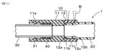
樹脂コネクタ連結構造1の構成について、図1を参照して説明する。図1に示すように、樹脂コネクタ連結構造1は、樹脂コネクタ10と、連結対象部材の一方を構成する樹脂チューブ20と、連結対象部材の他方を構成する配管30とを備える。樹脂コネクタ10は、樹脂チューブ20と配管30との連結を仲介する部材として機能する。また、樹脂コネクタ10、樹脂チューブ20および配管30は、それぞれ流体を流通するために筒状に形成されており、樹脂コネクタ10を介して樹脂チューブ20と配管30との間で流体を流通させる。 1. First Embodiment
(1-1. Configuration of Resin Connector Connection Structure 1)
The configuration of a resin
樹脂コネクタ10は、樹脂により筒状に形成される。ただし、樹脂コネクタ10は、直筒状に限られず、曲がり筒状としても良い。樹脂コネクタ10の筒状の両端のそれぞれには、連結対象部材としての樹脂チューブ20および配管30が連結される。本形態においては、樹脂コネクタ10と樹脂チューブ20とは、レーザ光B(図1の破線にて示す)を用いた溶着により接合される。一方、樹脂コネクタ10と配管30とは、爪などの係止により連結される。ただし、樹脂コネクタ10と配管30との連結は、係止に限られず、任意の方法により連結することができる。The
樹脂チューブ20は、長尺の筒状に形成される。樹脂チューブ20は、少なくとも樹脂コネクタ10よりも長尺に形成される。樹脂チューブ20は、樹脂コネクタ10の第一開口側(図1の右端側)に嵌装される。図1においては、樹脂チューブ20は、樹脂コネクタ10の第一開口側の内側に挿入される場合を図示する場合を例示するが、樹脂コネクタ10の第一開口側の外側に装着されるようにしても良い。The
樹脂チューブ20は、レーザ光Bの吸収率の高い材料により形成される。つまり、樹脂チューブ20は、レーザ光Bが照射されることにより発熱する。樹脂チューブ20は、例えば、ガソリンを流通する場合には、耐ガソリン性、耐燃料透過性、耐候性などを考慮して多層構造を有する。また、樹脂チューブ20は、直筒状に形成しても良いし、曲がり筒状に形成しても良い。The
配管30は、金属または樹脂により筒状に形成される。配管30は、樹脂コネクタ10の第二開口側(図1の左端側)に嵌装される。本形態では、配管30は、樹脂コネクタ10の第二開口側の内側に挿入されるが、樹脂コネクタ10の第二開口側の外側に嵌装されるようにしても良い。また、配管30は、先端から距離を隔てた位置に、径方向外側に突出する環状フランジ31を備える。配管30の環状フランジ31が、樹脂コネクタ10に対して、樹脂コネクタ10の第二開口部分の軸方向に係止される部位となる。The piping 30 is formed into a cylindrical shape from metal or resin. The piping 30 is fitted into the second opening side (the left end side in FIG. 1) of the
(1-2.樹脂コネクタ10の詳細構成)
樹脂コネクタ10の詳細構成について、図1を参照して説明する。樹脂コネクタ10は、コネクタ本体部11と、コネクタ端部12とを備える。 (1-2. Detailed configuration of resin connector 10)
The detailed configuration of the
コネクタ本体部11は、少なくとも、樹脂コネクタ10の軸方向(樹脂コネクタ10の筒状の中心軸方向)の中間部分に配置されている。ただし、本形態においては、コネクタ本体部11は、樹脂コネクタ10の軸方向の中間部分に加えて、第二開口端を構成する部分にも配置されている。そして、コネクタ本体部11は、高い曲げ弾性率を有する部位に対応する。特に、コネクタ本体部11は、配管30との十分な係止力を発揮するために、高い曲げ弾性率を有する。ここで、コネクタ本体部11には、樹脂チューブ20が溶着されていない。つまり、樹脂コネクタ10において、コネクタ本体部11が位置する軸方向位置には、樹脂チューブ20が溶着されていない。The
コネクタ本体部11は、筒状に形成され、配管30に係止される。コネクタ本体部11は、例えば、配管30の環状フランジ31に係止される係止爪11aを備える。係止爪11aは、弾性変形することにより、配管30の挿入を許容しつつ、配管30が挿入された後において環状フランジ31に係止される。つまり、係止爪11aは、配管30の抜け止め部材として機能する。The
また、コネクタ本体部11は、配管30が挿入される側とは反対側の端(図1の右端)に、コネクタ端部12と直接接合するための接合面11b、および、樹脂チューブ20の先端面との当接により樹脂チューブ20に対する位置決め用端面11cを備える。本形態では、位置決め用端面11cは、接合面11bの径方向内側に位置する。また、本形態では、接合面11bと位置決め用端面11cとは、同一平面状に形成したが、軸方向位置が異なる位置に形成するようにしても良い。The
コネクタ本体部11は、配管30と係止するために、変形に対する強度を要求される。そこで、コネクタ本体部11は、本体部用母材樹脂に、補強フィラーを含有して形成されている。The
本体部用母材樹脂は、例えば、ポリプロピレン、ポリアミド、ポリフェニレンスルフィド、ポリエチレンテレフタレート、ポリエチレンナフタレート、ポリブチレンテレフタレート、ポリブチレンナフタレート、ポリメチルペンテン、ポリエチレン、ポリアセタール、フッ素樹脂などが用いられる。ポリプロピレンとしては、例えば、屈折率が1.47~1.51のものが用いられる。また、ポリアミドとしては、例えば、屈折率が1.51~1.55のものが用いられる。For example, polypropylene, polyamide, polyphenylene sulfide, polyethylene terephthalate, polyethylene naphthalate, polybutylene terephthalate, polybutylene naphthalate, polymethylpentene, polyethylene, polyacetal, fluororesin, etc. are used as the base resin for the main body. For example, polypropylene with a refractive index of 1.47 to 1.51 is used. For example, polyamide with a refractive index of 1.51 to 1.55 is used.
補強フィラーは、ガラス繊維、カーボン繊維、チタン酸カリウム、ガラスビーズ、ミルドファイバーおよびタルクなどが用いられる。ここで、コネクタ本体部11は、溶着のためのレーザ光Bが照射される部位ではないため、コネクタ本体部11に用いられる補強フィラーは、レーザ光Bの透過率を考慮する必要がない。そこで、補強フィラーは、屈折率を考慮することなく適用できる。Reinforcing fillers include glass fiber, carbon fiber, potassium titanate, glass beads, milled fiber, and talc. Here, since the
なお、樹脂コネクタ連結構造1は、コネクタ本体部11の内周面と配管30の外周面との間に、Oリングなどの環状のシール部材40を備えるようにすると良い。シール部材40により、コネクタ本体部11と配管30との間のシール性を確保することができる。The resin
コネクタ端部12は、樹脂コネクタ10の第一開口側の部分、すなわち、樹脂チューブ20が挿入される側の端部を構成する。そして、コネクタ端部12は、樹脂チューブ20との溶着部位に対応する。コネクタ端部12は、筒状に形成されている。The
また、本形態においては、コネクタ端部12は、軸方向端部に、コネクタ本体部11の接合面11bと直接接合する接合面12aを備える。コネクタ端部12は、例えば、二色成形や摩擦圧接などにより、コネクタ本体部11と直接接合される。つまり、コネクタ端部12の接合面12aが、コネクタ本体部11の接合面11bと直接接合する。ただし、コネクタ端部12は、コネクタ本体部11との間に別部材を介して、間接的に接合されるようにしても良い。また、コネクタ端部12の接合面12aは、軸方向端部に限らず、外周面または内周面とすることもできる。In addition, in this embodiment, the
さらに、コネクタ端部12は、少なくとも軸方向の一部において、外周面および内周面が全周に亘って露出している。特に、コネクタ端部12において、樹脂コネクタ10の第一開口側の部分は、外周面および内周面が露出している。つまり、コネクタ端部12の当該露出部分には、コネクタ本体部11が存在しないことを意味する。Furthermore, the outer and inner peripheral surfaces of the
コネクタ端部12は、コネクタ端部12の開口端の内周面にテーパ状に形成されるガイド部12bを備える。ガイド部12bにおけるテーパ状の最大内径は、樹脂チューブ20の先端部分の外径と同程度、もしくは、樹脂チューブ20の先端部分の外径より僅かに大きい。また、ガイド部12bにおけるテーパ状の最小内径は、樹脂チューブ20の先端部分の外径よりも小さい。従って、樹脂チューブ20がコネクタ端部12の内側に挿入される際に、ガイド部12bは、樹脂チューブ20の外周面に当接する。そして、ガイド部12bは、樹脂チューブ20の縮管をガイドする。The
さらに、コネクタ端部12は、コネクタ端部12の内周面においてガイド部12bに隣接して形成され、円筒内周面状に形成された円筒内周面部12cを備える。円筒内周面部12cは、テーパ状のガイド部12bとコネクタ本体部11に直接接合する接合面12aとの軸方向間の全範囲に形成されている。The
コネクタ端部12の円筒内周面部12cの内径は、ガイド部12bの最小内径に一致する。つまり、円筒内周面部12cの内径は、樹脂チューブ20の先端部の外径よりも小さい。従って、樹脂チューブ20の先端部は、円筒内周面部12cの径方向内側に、縮管した状態で挿入されている。つまり、円筒内周面部12cは、縮径された樹脂チューブ20の外周面が密着した状態となる。The inner diameter of the cylindrical
コネクタ端部12は、樹脂チューブ20との接合強度が要求される。そして、上述したように、コネクタ端部12と樹脂チューブ20とは、レーザ光Bが照射されることにより溶着されることで接合される。ここで、樹脂チューブ20は、コネクタ端部12よりレーザ光Bの吸収率が高い材料により形成される。The
そして、コネクタ端部12は、レーザ光Bの透過率が高いほど良く、さらにレーザ光Bの透過率のばらつきが小さいほど良い。レーザ光Bの透過率が高いほど、溶着部位にレーザ光Bを照射することができる。レーザ光Bの透過率のばらつきが小さいほど、溶着による接合強度のばらつきが小さくなる。特に、レーザ光Bの透過率のばらつきに、フィラーが影響することが知られている。そこで、コネクタ端部12は、端部用母材樹脂に補強フィラーを含有せずに形成されるか、もしくは、端部用母材樹脂に、コネクタ本体部11よりも低い割合の補強フィラーを含有して形成される。The higher the transmittance of the laser light B of the
補強フィラーを含有しない場合には、端部用母材樹脂は、レーザ光Bを透過する樹脂材料であれば良い。補強フィラーを含有しない場合には、当然、補強フィラーの影響を受けることがないため、補強フィラーに起因するレーザ光Bの透過率のばらつきは無い。この場合の端部用母材樹脂は、例えば、ポリプロピレン、ポリアミド、ポリフェニレンスルフィド、ポリエチレンテレフタレート、ポリエチレンナフタレート、ポリブチレンテレフタレート、ポリブチレンナフタレート、ポリメチルペンテン、ポリエチレン、ポリアセタール、フッ素樹脂などが用いられる。When no reinforcing filler is contained, the base resin for the end portion may be a resin material that transmits the laser light B. When no reinforcing filler is contained, it is of course not affected by the reinforcing filler, and there is no variation in the transmittance of the laser light B caused by the reinforcing filler. In this case, for example, polypropylene, polyamide, polyphenylene sulfide, polyethylene terephthalate, polyethylene naphthalate, polybutylene terephthalate, polybutylene naphthalate, polymethylpentene, polyethylene, polyacetal, fluororesin, etc. are used as the base resin for the end portion.
ここで、コネクタ本体部11とコネクタ端部12との接合力の観点から、コネクタ本体部11の本体部用母材樹脂とコネクタ端部12の端部用母材樹脂とは、同種のポリマーとすると良い。ただし、異種のポリマーであっても、融点が近いものや官能基(例えば、無水マレイン酸など)を有するものであれば、機械的または化学的な連結が可能となる。From the viewpoint of the joining strength between the
コネクタ端部12が補強フィラーを含有する場合には、レーザ光Bの透過を妨げることなく、かつ、レーザ光Bの透過率のばらつきに大きく影響しないようにすることが求められる。そこで、第一として、補強フィラーの含有割合を極めて低くすることが有効である。第二として、端部用母材樹脂の屈折率と補強フィラーの屈折率とが近いものにすることも可能である。例えば、屈折率の差が、0.02以内であると良い。ただし、屈折率が近い補強フィラーを用いるとしても、補強フィラーの含有割合が低い方が好ましい。When the
補強フィラーを含有する場合、端部用母材樹脂は、ポリプロピレンおよびポリアミドなどが用いられる。ポリプロピレンとしては、例えば、屈折率が1.47~1.51のものが用いられる。また、ポリアミドとしては、例えば、屈折率が1.51~1.55のものが用いられる。When a reinforcing filler is included, polypropylene, polyamide, etc. are used as the base resin for the end portion. For polypropylene, for example, one with a refractive index of 1.47 to 1.51 is used. For polyamide, for example, one with a refractive index of 1.51 to 1.55 is used.
端部用母材樹脂の屈折率に近い屈折率を有する補強フィラーは、ガラス繊維フィラーが用いられる。ガラス繊維フィラーの屈折率は、例えば、1.4~1.7である。ガラスフィラーの材料であるガラス繊維としては、Dガラス(低誘電率ガラス)、NEガラス(耐酸性アルカリガラス)、Aガラス(アルカリガラス)、Sガラス(高強度・高弾性ガラス)、および耐アルカリガラスなどがあげられる。Glass fiber filler is used as a reinforcing filler with a refractive index close to that of the base resin for the end portion. The refractive index of glass fiber filler is, for example, 1.4 to 1.7. Examples of glass fiber, which is the material for glass filler, include D glass (low dielectric constant glass), NE glass (acid-resistant alkali glass), A glass (alkali glass), S glass (high strength, high elasticity glass), and alkali-resistant glass.
コネクタ端部12と樹脂チューブ20とは、レーザ光Bにより溶着されている。本形態においては、コネクタ端部12の円筒内周面部12cと樹脂チューブ20の先端部の外周面とが溶着されている。詳細には、コネクタ端部12と樹脂チューブ20との溶着部位は、全周に亘って閉じたリング状に形成されている。例えば、溶着部位は、軸方向の複数箇所に形成されるようにしても良いし、軸方向の1か所に形成されるようにしても良い。溶着による接合強度を確保するためには、溶着部位の幅を規定幅以上確保すると良い。なお、複数箇所形成される溶着部位とは、不連続となる複数のリング形状の溶着部位であることを意味する。The
溶着部位は、コネクタ本体部11とコネクタ端部12との境界部位から離間した位置に位置する。つまり、溶着部位には、コネクタ本体部11が含まれないようにされている。換言すると、樹脂チューブ20は、樹脂コネクタ10においてコネクタ本体部11が位置する軸方向位置以外の位置に溶着されている。さらに換言すると、樹脂チューブ20は、コネクタ端部12における外周面および内周面に露出している部位に溶着されている。さらに、樹脂チューブ20は、コネクタ端部12の円筒内周面部12cに溶着されているのに対して、ガイド部12bには溶着されていない。The welded portion is located at a position away from the boundary between the
(1-3.樹脂コネクタ連結構造1の製造方法)
次に、樹脂コネクタ連結構造1の製造方法について、図1および図2を参照して説明する。まず、図2に示すように、樹脂コネクタ10を製造する(S1)。本形態においては、二色成形により、コネクタ本体部11とコネクタ端部12とを一体的に形成する。このようにして、コネクタ本体部11とコネクタ端部12とが直接接合されている。 (1-3. Manufacturing method of resin connector connection structure 1)
Next, a method for manufacturing the resin
続いて、樹脂コネクタ10のコネクタ端部12側の開口(第一開口)から、樹脂チューブ20の先端部を挿入する(S2)。コネクタ端部12のガイド部12bの最大内径および最小内径と、樹脂チューブ20の先端部の外径との関係より、樹脂チューブ20の先端部の外周縁が、ガイド部12bに当接する。Next, the tip of the
樹脂チューブ20がコネクタ端部12に挿入されると、樹脂チューブ20の先端部の外周縁がガイド部12bに当接しながら、樹脂チューブ20の先端部は縮管される。樹脂チューブ20の先端部は、縮管された状態で、コネクタ端部12の円筒内周面部12cに密着する。樹脂チューブ20の先端が、コネクタ本体部11の位置決め用端面11cに当接する位置まで、樹脂チューブ20が挿入される。When the
続いて、樹脂チューブ20がコネクタ端部12に嵌装(本形態では挿入)されている範囲において、径方向においてコネクタ端部12側、すなわち、径方向外側からレーザ光Bを照射して、コネクタ端部12と樹脂チューブ20との径方向対向面を溶着する(S3)。Next, in the range where the
コネクタ端部12はレーザ光Bを透過する材料により形成されており、樹脂チューブ20はレーザ光Bを吸収する材料により形成されている。さらに、S2において、コネクタ端部12の円筒内周面部12cと樹脂チューブ20の先端部の外周面とは密着している。また、コネクタ端部12において樹脂チューブ20に密着している軸方向部位は、コネクタ端部12のうち外周面および内周面に露出している部分に相当する。The
この状態において、レーザ光Bをコネクタ端部12の径方向外側から照射する。つまり、レーザ光Bは、樹脂コネクタ10において、コネクタ端部12のうち外周面および内周面に露出している部分に照射される。換言すると、レーザ光Bが照射される部位は、樹脂コネクタ10において径方向の全幅に亘って、コネクタ端部12のみにより構成される部位である。そうすると、レーザ光Bの大部分がコネクタ端部12を透過し、コネクタ端部12と樹脂チューブ20との対向面(密着面)にて発熱し、コネクタ端部12と樹脂チューブ20とが溶着する。特に、コネクタ端部12と樹脂チューブ20との溶着部位が、軸方向に複数箇所形成され、かつ、全周に亘って閉じたリング状に形成されるように、レーザ光Bが照射される。In this state, the laser light B is irradiated from the radial outside of the
例えば、レーザ光Bを軸方向の複数箇所のそれぞれに照射することで、レーザ光Bの照射幅を有するリング状の溶着部位を、軸方向の複数箇所形成するようにしても良い。また、レーザ光Bの照射範囲の一部が重なるようにレーザ光Bを螺旋状に照射することで、レーザ光Bの照射幅よりも軸方向長さが長い1箇所のリング状の溶着部位を形成するようにしても良い。また、レーザ光Bの照射幅が接合強度を確保するための規定幅以上である場合には、レーザ光Bを軸方向の1箇所のみに照射することで、レーザ光Bの照射幅を有するリング状の溶着部位を軸方向の1箇所に形成するようにしても良い。For example, by irradiating laser light B to each of multiple locations in the axial direction, multiple ring-shaped welded areas having the irradiation width of laser light B may be formed in the axial direction. Laser light B may also be irradiated in a spiral shape so that parts of the irradiation range of laser light B overlap, forming a single ring-shaped welded area whose axial length is longer than the irradiation width of laser light B. In addition, when the irradiation width of laser light B is equal to or greater than a specified width for ensuring the joining strength, laser light B may be irradiated only to one location in the axial direction to form a ring-shaped welded area having the irradiation width of laser light B in one location in the axial direction.
続いて、配管30をコネクタ本体部11に挿入する(S4)。このようにして、樹脂コネクタ連結構造1が製造される。Next, the piping 30 is inserted into the connector body 11 (S4). In this manner, the resin
(1-4.効果)
樹脂コネクタ連結構造1によれば、樹脂コネクタ10のコネクタ本体部11は、補強フィラーを含有するため、高い曲げ弾性率を有する。樹脂コネクタ10のコネクタ端部12は、樹脂チューブ20との溶着部位を構成する。コネクタ端部12は、補強フィラーを含有しないか、または、コネクタ本体部11に比べて補強フィラーの含有割合が低い。従って、コネクタ端部12の曲げ弾性率は、コネクタ本体部11に比べて低くなる。 (1-4. Effects)
According to the resin
しかし、コネクタ端部12には、曲げ弾性率よりも、樹脂チューブ20との溶着による高い接合強度、および、接合強度のばらつきの小ささが求められる。ここで、コネクタ端部12は、補強フィラーを含有しないか、または、コネクタ本体部11に比べて補強フィラーの含有割合が低い。従って、コネクタ端部12は、コネクタ本体部11より高いレーザ光Bの透過率を有する。さらに、補強フィラーに起因した、レーザ光Bを照射することによるコネクタ端部12と樹脂チューブ20との溶着部位の接合強度のばらつきを抑制することができる。However, rather than the flexural modulus, what is required of the
つまり、樹脂コネクタ10は、コネクタ本体部11とコネクタ端部12とを機能で分離している。そして、コネクタ本体部11が、曲げ弾性率を確保する部位として機能し、コネクタ端部12が、樹脂チューブ20との溶着による接合強度を確保する部位として機能する。従って、樹脂コネクタ10と樹脂チューブ20との連結構造は、全体として、樹脂コネクタ10と樹脂チューブ20との接合強度にばらつきが生じることを抑制しつつ、樹脂コネクタ10の曲げ弾性率を確保することができる。In other words, the
特に、コネクタ端部12が補強フィラーを含有しないようにすることで、溶着部位における接合強度のばらつきを、より抑制することができる。仮に、補強フィラーを含有する場合には、その含有割合を低くしつつ、端部用母材樹脂と補強フィラーの屈折率が近いと良い。In particular, by ensuring that the
また、樹脂チューブ20がコネクタ端部12の径方向内側に挿入されており、樹脂チューブ20の外周面がコネクタ端部12の内周面に溶着されている。この構成により、レーザ光Bを径方向外側から照射することができるため、設備およびレーザ光Bの照射が容易となる。特に、樹脂チューブ20は、コネクタ端部12の径方向内側に縮管した状態で挿入されると良い。これにより、樹脂チューブ20とコネクタ端部12との密着性が高くなり、レーザ光Bによる溶着を容易に行うことができるとともに、接合強度のばらつきを抑制できる。The
また、溶着部位は、コネクタ端部12における円筒内周面部12cとしており、テーパ状のガイド部12bでない。仮に、テーパ状のガイド部12bを溶着部位とすると、コネクタ端部12の径方向厚みが軸方向において異なるため、レーザ光Bの照射により発生する熱エネルギーが位置によって異なるおそれがある。しかし、円筒内周面部12cを溶着部位とすることで、接合強度のばらつきを抑制できる。The welding part is the cylindrical inner
さらに、溶着部位は、コネクタ本体部11とコネクタ端部12との境界部位から離間した位置に位置する。これにより、レーザ光Bが、コネクタ本体部に含有する補強フィラーの影響を受けることを回避できる。従って、接合強度のばらつきを抑制できる。Furthermore, the welded portion is located away from the boundary between the
また、溶着部位は、全周に亘って閉じたリング状に形成される。これにより、溶着部位が、コネクタ端部12と樹脂チューブ20との間におけるシール機能を発揮する。さらに、溶着部位が、軸方向に複数箇所形成されると良い。これにより、高い接合強度を確保しつつ、高いシール機能を発揮することができる。The welded portion is formed in a closed ring shape around the entire circumference. This allows the welded portion to provide a seal between the
(2.第二実施形態)
第二実施形態の樹脂コネクタ連結構造2について図3を参照して説明する。本形態の樹脂コネクタ連結構造2は、第一実施形態の樹脂コネクタ連結構造1に対して、コネクタ本体部51とコネクタ端部52が相違する。ただし、樹脂コネクタ連結構造2において、第一実施形態の樹脂コネクタ連結構造1の構成と同一構成について同一符号を付して説明を省略する。 (2. Second embodiment)
A resin
コネクタ本体部51は、コネクタ端部52側に延びる筒状の本体顎部51bを備える。本体顎部51bは、軸方向端面のうち径方向外側部分から軸方向に突出する。本体顎部51bの軸方向端面、本体顎部51bの内周面、および、本体顎部51bの根本における軸方向を法線とする面51cが、コネクタ端部52と直接接合するための接合面を構成する。つまり、当該接合面は、階段状に形成されている。コネクタ本体部51は、本体顎部51bの径方向内側に、軸方向に法線を有する位置決め用端面51dを備える。本形態においては、面51cと位置決め用端面51dとは、同一平面状に位置する。The
コネクタ端部52は、コネクタ本体部51側に延びる筒状の端顎部52aを備える。端顎部52aは、軸方向端面のうち径方向内側部分から軸方向に突出する。端顎部52aの軸方向端面、端顎部52aの外周面、および、端顎部52aの根本における軸方向を法線とする面52bが、コネクタ本体部51と直接接合するための接合面を構成する。つまり、当該接合面は、階段状に形成されている。The
本形態によれば、コネクタ本体部51とコネクタ端部52との接合面の面積を拡大することができる。従って、コネクタ本体部51とコネクタ端部52との接合強度を高めることができる。According to this embodiment, the area of the joint surface between the
ここで、溶着部位は、コネクタ端部52において、端顎部52aよりも、コネクタ端部52の開口端側(樹脂コネクタ10の第一開口側)の部位である。つまり、レーザ光Bが照射される部位は、樹脂コネクタ10において径方向の全幅に亘って、コネクタ端部52のみにより構成される部位である。The welded portion is a portion of the
(3.第三実施形態)
第三実施形態の樹脂コネクタ連結構造3について図4を参照して説明する。樹脂コネクタ連結構造3は、樹脂コネクタ60、第一樹脂チューブ70、第二樹脂チューブ80を備える。樹脂コネクタ60は、コネクタ本体部61と、樹脂コネクタ60の第一開口側(図4の右側)に位置する第一コネクタ端部62と、樹脂コネクタ60の第二開口側(図4の左側)に位置する第二コネクタ端部63とを備える。 3. Third Embodiment
A resin
コネクタ本体部61は、例えば、相手部材に固定するための曲げ弾性率を必要とする。第一コネクタ端部62は、コネクタ本体部61の軸方向の一端(図4の右端)に直接接合される。第二コネクタ端部63は、コネクタ本体部61の軸方向の他端(図4の左端)に直接接合される。このようにして、コネクタ本体部61、第一コネクタ端部62、および、第二コネクタ端部63は、一体的に形成される。第一コネクタ端部62は、第一樹脂チューブ70に、レーザ光Bを用いた溶着により接合される。第二コネクタ端部63は、第二樹脂チューブ80に、レーザ光Bを用いた溶着により接合される。The
ここで、第一コネクタ端部62と第一樹脂チューブ70、および、第二コネクタ端部63と第二樹脂チューブ80は、第一実施形態におけるコネクタ端部12と樹脂チューブ20との関係と実質的に同一である。図4においては、第一実施形態における各部の符号を付す。Here, the relationship between the
(4.第四実施形態)
第四実施形態の樹脂コネクタ連結構造4について図5を参照して説明する。以下の説明において、樹脂コネクタ連結構造4において、第三実施形態の樹脂コネクタ連結構造3の構成と同一構成について同一符号を付して説明を省略する。 (4. Fourth embodiment)
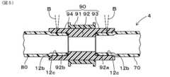
A resin
樹脂コネクタ連結構造4は、樹脂コネクタ90、第一樹脂チューブ70、第二樹脂チューブ80を備える。樹脂コネクタ90は、コネクタ本体部91と、低強度中間部92と、樹脂コネクタ90の第一開口側(図5の右側)に位置する第一コネクタ端部93と、樹脂コネクタ90の第二開口側(図5の左側)に位置する第二コネクタ端部94とを備える。The resin
コネクタ本体部91は、筒状に形成され、樹脂コネクタ90の軸方向の中間部分の外層を構成する。コネクタ本体部91は、例えば、相手部材に固定するための曲げ弾性率を必要とする。そこで、コネクタ本体部91は、本体部用母材樹脂に、補強フィラーを含有して形成されている。The
低強度中間部92は、筒状に形成され、樹脂コネクタ90の軸方向の中間部分の内層を構成する。低強度中間部92は、コネクタ本体部91の内周面に直接接合される。低強度中間部92は、第一開口側(図5の右側)を法線とする位置決め用端面92aを備えるとともに、第二開口側(図5の左側)を法線とする位置決め用端面92bを備える。位置決め用端面92aは、第一樹脂チューブ70の先端面との当接により第一樹脂チューブ70に対する位置決めを行う。位置決め用端面92bは、第二樹脂チューブ80の先端面との当接により第二樹脂チューブ80に対する位置決めを行う。The low-strength
低強度中間部92は、コネクタ本体部91のように高い曲げ弾性率を必要とせず、位置決め用端面92a,92bの形状を確保できれば良い。そこで、低強度中間部92は、母材樹脂に補強フィラーを含有せずに形成されるか、もしくは、母材樹脂に、コネクタ本体部91よりも低い割合の補強フィラーを含有して形成される。The low-strength
第一コネクタ端部93は、筒状に形成され、低強度中間部92の軸方向の一端(図5の右端)側に一体的に形成される。また、本形態においては、例えば、第一コネクタ端部93は、射出成形などにより、低強度中間部92と一体成形されるようにしても良い。ただし、第一コネクタ端部93は、低強度中間部92と異なる材料により成形され、接合されるようにしても良い。The
ここで、第一コネクタ端部93は、第三実施形態における第一コネクタ端部62と同様に構成される。従って、第一コネクタ端部93は、第一樹脂チューブ70に、レーザ光Bを用いた溶着により接合される。Here, the
第二コネクタ端部94は、筒状に形成され、低強度中間部92の軸方向の他端(図5の左端)側に一体的に形成される。また、本形態においては、例えば、第二コネクタ端部94は、射出成形などにより、低強度中間部92と一体成形されるようにしても良い。ただし、第二コネクタ端部94は、低強度中間部92と異なる材料により成形され、接合されるようにしても良い。The
ここで、第二コネクタ端部94は、第三実施形態における第二コネクタ端部63と同様に構成される。従って、第二コネクタ端部94は、第二樹脂チューブ80に、レーザ光Bを用いた溶着により接合される。Here, the
本形態においては、第一コネクタ端部93は、低強度中間部92に連続して配置され、コネクタ本体部91に対しては低強度中間部92を介して接続されている。つまり、第一コネクタ端部93は、低強度中間部92のみと直接接合し、コネクタ本体部91に直接接合していない。従って、第一コネクタ端部93は、コネクタ本体部91に、低強度中間部92を介して間接的に接合している状態となる。なお、第一コネクタ端部93は、コネクタ本体部91および低強度中間部92の両者に直接接合するようにしても良いし、コネクタ本体部91のみに直接接合するようにしても良い。In this embodiment, the
同様に、本形態においては、第二コネクタ端部94は、低強度中間部92に連続して配置され、コネクタ本体部91に対しては低強度中間部92を介して接続されている。つまり、第二コネクタ端部94は、低強度中間部92のみに直接接合し、コネクタ本体部91に直接接合していない。従って、第二コネクタ端部94は、コネクタ本体部91に、低強度中間部92を介して間接的に接合している状態となる。なお、第二コネクタ端部94は、コネクタ本体部91および低強度中間部92の両者に直接接合するようにしても良いし、コネクタ本体部91のみに直接接合するようにしても良い。Similarly, in this embodiment, the
本形態においても、第三実施形態と同様の効果を奏する。また、コネクタ本体部91の体積を小さくすることができるため、低コストにできる。さらに、低強度中間部92、第一コネクタ端部93、および、第二コネクタ端部94を射出成形などにより一体成形する場合には、当該一体成形体とコネクタ本体部91との接合面の面積を拡大することができる。従って、コネクタ本体部91と当該一体成形体との接合強度、すなわち、コネクタ本体部91とコネクタ端部93,94との接合強度を高めることができる。This embodiment also has the same effect as the third embodiment. In addition, the volume of the
(5.その他)
第一実施形態において、樹脂チューブ20がコネクタ端部12の内側に挿入された状態で、レーザ光Bを径方向外側から照射することにより、コネクタ端部12と樹脂チューブ20とが溶着されるようにした。この他に、樹脂チューブ20がコネクタ端部12の外側に嵌装された状態で、レーザ光Bを径方向内側、すなわち径方向においてコネクタ端部12側から照射することにより、コネクタ端部12と樹脂チューブ20とが溶着されるようにしても良い。 (5. Other)
In the first embodiment, the
また、第一実施形態において、コネクタ本体部11は、配管30に係止する爪を備える構成とした。この他に、以下のようにしても良い。コネクタ本体部11の外周面に、径方向に突出する環状凸部を、軸方向に複数形成する。配管30が、拡管してコネクタ本体部11の外周面に嵌装され、複数の環状凸部に対して軸方向に係止されるようにしても良い。In the first embodiment, the
また、第四実施形態において、樹脂コネクタ90は、低強度中間部92を備える構成とした。第一実施形態および第二実施形態においても、低強度中間部92に相当する部材を備えるようにしても良い。In the fourth embodiment, the
1,2,3 樹脂コネクタ連結構造
10,60,90 樹脂コネクタ
11,51,61,91 コネクタ本体部
12、52,62、63,93,94 コネクタ端部
20,70,80 樹脂チューブ(連結対象部材)
30 配管(連結対象部材)
B レーザ光REFERENCE SIGNS
30 Piping (connection target component)
B Laser light
Claims (14)
Translated fromJapanese前記連結対象部材の一方を構成し、筒状に形成され、前記樹脂コネクタの第一開口側に嵌装される樹脂チューブと、
を備え、
前記樹脂コネクタは、
本体部用母材樹脂に補強フィラーを含有して形成された筒状のコネクタ本体部と、
前記補強フィラーを含有せずに端部用母材樹脂により形成され、または、前記端部用母材樹脂に前記コネクタ本体部よりも前記補強フィラーを低い割合で含有して形成され、前記コネクタ本体部に直接または間接的に接合され、前記樹脂コネクタの第一開口側の端部を構成する筒状のコネクタ端部と、
を備え、
前記樹脂チューブは、前記コネクタ端部よりレーザ光の吸収率が高い材料により形成され、前記コネクタ端部に嵌装され、前記コネクタ端部の内周面または外周面に溶着されており、かつ、前記樹脂コネクタにおいて前記コネクタ本体部が位置する軸方向位置以外の位置に溶着されており、
前記樹脂コネクタにおいて、前記コネクタ端部は、軸方向の全体において、外周面および内周面が露出している、
樹脂コネクタ連結構造。 a resin connector formed in a cylindrical shape, with a connection target member being connected to each of both open ends;
a resin tube that constitutes one of the connection target members, is formed in a cylindrical shape, and is fitted to a first opening side of the resin connector;
Equipped with
The resin connector is
a cylindrical connector main body formed by including a reinforcing filler in a base resin for the main body;
a cylindrical connector end portion that is formed from a base resin for an end portion without containing the reinforcing filler, or that is formed by containing a lower proportion of the reinforcing filler in the base resin for the end portion than in the connector body portion, and is joined directly or indirectly to the connector body portion and constitutes an end portion on the first opening side of the resin connector;
Equipped with
the resin tube is made of a material having a higher laser light absorption rate than the connector end, is fitted into the connector end, is welded to an inner or outer peripheral surface of the connector end, andis welded to a position in the resin connector other than an axial position where the connector main body is located,
In the resin connector, the outer peripheral surface and the inner peripheral surface of the connector end are exposed over the entire axial direction.
Resin connector connection structure.
前記連結対象部材の一方を構成し、筒状に形成され、前記樹脂コネクタの第一開口側に嵌装される樹脂チューブと、
を備え、
前記樹脂コネクタは、
本体部用母材樹脂に補強フィラーを含有して形成された筒状のコネクタ本体部と、
前記補強フィラーを含有せずに端部用母材樹脂により形成され、または、前記端部用母材樹脂に前記コネクタ本体部よりも前記補強フィラーを低い割合で含有して形成され、前記コネクタ本体部に直接または間接的に接合され、前記樹脂コネクタの第一開口側の端部を構成する筒状のコネクタ端部と、
を備え、
前記樹脂チューブは、前記コネクタ端部よりレーザ光の吸収率が高い材料により形成され、前記コネクタ端部に嵌装され、前記コネクタ端部の内周面または外周面に溶着されており、かつ、前記樹脂コネクタにおいて前記コネクタ本体部が位置する軸方向位置以外の位置に溶着されており、
前記樹脂コネクタは、さらに、前記コネクタ本体部の内周面に直接接合される筒状の低強度中間部を有し、
前記コネクタ本体部は、前記樹脂コネクタの軸方向の中間部分の外層を構成し、
前記低強度中間部は、前記樹脂コネクタの軸方向の中間部分の内層を構成すると共に、前記補強フィラーを含有せずに中間部用母材樹脂により形成され、または、前記中間部用母材樹脂に、前記コネクタ本体部よりも前記補強フィラーを低い割合で含有して形成され、
前記コネクタ端部は、前記低強度中間部の軸方向の一端側に形成されていると共に、前記低強度中間部を介して前記コネクタ本体部に間接的に接合されており、
前記低強度中間部と前記コネクタ端部とは一体成形されている、
樹脂コネクタ連結構造。 a resin connector formed in a cylindrical shape, with a connection target member being connected to each of both open ends;
a resin tube that constitutes one of the connection target members, is formed in a cylindrical shape, and is fitted to a first opening side of the resin connector;
Equipped with
The resin connector is
a cylindrical connector main body formed by including a reinforcing filler in a base resin for the main body;
a cylindrical connector end portion that is formed from a base resin for an end portion without containing the reinforcing filler, or that is formed by containing a lower proportion of the reinforcing filler in the base resin for the end portion than in the connector body portion, and is joined directly or indirectly to the connector body portion and constitutes an end portion on the first opening side of the resin connector;
Equipped with
the resin tube is made of a material having a higher laser light absorption rate than the connector end, is fitted into the connector end, is welded to an inner or outer peripheral surface of the connector end, andis welded to a position in the resin connector other than an axial position where the connector main body is located,
The resin connector further has a cylindrical low-strength intermediate portion directly joined to an inner circumferential surface of the connector body,
the connector body constitutes an outer layer of an axially intermediate portion of the resin connector,
The low-strength intermediate portion constitutes an inner layer of an axial intermediate portion of the resin connector, and is formed of an intermediate portion base resin without containing the reinforcing filler, or is formed by containing a lower proportion of the reinforcing filler in the intermediate portion base resin than in the connector body,
the connector end portion is formed on one axial end side of the low-strength intermediate portion and is indirectly joined to the connector main body portion via the low-strength intermediate portion,
The low strength intermediate portion and the connector end portion are integrally molded.
Resin connector connection structure.
前記樹脂コネクタは、さらに、前記補強フィラーを含有せずに第二端部用母材樹脂により形成され、または、前記第二端部用母材樹脂に前記コネクタ本体部よりも前記補強フィラーを低い割合で含有して形成され、前記樹脂コネクタの前記第二開口側の端部を構成する筒状の第二コネクタ端部を備え、The resin connector further includes a cylindrical second connector end portion that is formed from a base resin for a second end portion without containing the reinforcing filler, or is formed by containing a base resin for the second end portion with a lower proportion of the reinforcing filler than the connector body, and that constitutes an end portion of the resin connector on the second opening side,
前記第二コネクタ端部は、前記低強度中間部の軸方向の他端側に形成されていると共に、前記低強度中間部を介して前記コネクタ本体部に間接的に接合されており、the second connector end portion is formed on the other axial end side of the low-strength intermediate portion and is indirectly joined to the connector body portion via the low-strength intermediate portion,
前記第二樹脂チューブは、前記第二コネクタ端部よりレーザ光の吸収率が高い材料により形成され、前記第二コネクタ端部に嵌装され、前記第二コネクタ端部の内周面または外周面に溶着されており、かつ、前記樹脂コネクタにおいて前記コネクタ本体部が位置する軸方向位置以外の位置に溶着されており、the second resin tube is formed of a material having a higher laser light absorption rate than the second connector end, fitted into the second connector end, welded to an inner or outer peripheral surface of the second connector end, and welded to a position in the resin connector other than an axial position where the connector main body is located,
前記低強度中間部と前記コネクタ端部と前記第二コネクタ端部とは一体成形されている、The low strength intermediate portion, the connector end portion, and the second connector end portion are integrally molded.
請求項2に記載の樹脂コネクタ連結構造。The resin connector connection structure according to claim 2.
前記連結対象部材の一方を構成し、筒状に形成され、前記樹脂コネクタの第一開口側に嵌装される樹脂チューブと、
前記連結対象部材の他方を構成し、筒状に形成され、前記樹脂コネクタの第二開口側に嵌装される配管と、
を備え、
前記樹脂コネクタは、
本体部用母材樹脂に補強フィラーを含有して形成された筒状のコネクタ本体部と、
前記補強フィラーを含有せずに端部用母材樹脂により形成され、または、前記端部用母材樹脂に前記コネクタ本体部よりも前記補強フィラーを低い割合で含有して形成され、前記コネクタ本体部に直接または間接的に接合され、前記樹脂コネクタの第一開口側の端部を構成する筒状のコネクタ端部と、
を備え、
前記樹脂チューブは、前記コネクタ端部よりレーザ光の吸収率が高い材料により形成され、前記コネクタ端部に嵌装され、前記コネクタ端部の内周面または外周面に溶着されており、かつ、前記樹脂コネクタにおいて前記コネクタ本体部が位置する軸方向位置以外の位置に溶着されており、
前記配管は、径方向に突出する環状フランジを備え、
前記樹脂コネクタは、前記環状フランジに係止される係止爪を備え、
前記係止爪は、弾性変形することにより、前記配管における前記樹脂コネクタの前記第二開口側への嵌装を許容しつつ、前記配管が嵌装された後において前記環状フランジに係止される、
樹脂コネクタ連結構造。 a resin connector formed in a cylindrical shape, with a connection target member being connected to each of both open ends;
a resin tube that constitutes one of the connection target members, is formed in a cylindrical shape, and is fitted to a first opening side of the resin connector;
a pipe that constitutes the other of the connection target members, that is formed in a cylindrical shape, and that is fitted to a second opening side of the resin connector;
Equipped with
The resin connector is
a cylindrical connector main body formed by including a reinforcing filler in a base resin for the main body;
a cylindrical connector end portion that is formed from a base resin for an end portion without containing the reinforcing filler, or that is formed by containing a lower proportion of the reinforcing filler in the base resin for the end portion than in the connector body portion, and is joined directly or indirectly to the connector body portion and constitutes an end portion on the first opening side of the resin connector;
Equipped with
the resin tube is made of a material having a higher laser light absorption rate than the connector end, is fitted into the connector end, is welded to an inner or outer peripheral surface of the connector end, andis welded to a position in the resin connector other than an axial position where the connector main body is located,
The pipe includes a radially protruding annular flange,
the resin connector includes a locking claw that is locked to the annular flange,
The locking claw is elastically deformed to allow the resin connector to be fitted to the second opening side of the pipe, and is locked to the annular flange after the pipe is fitted.
Resin connector connection structure.
前記コネクタ端部は、前記コネクタ本体部側に延び、前記本体顎部に対して径方向に対向して接合する筒状の端顎部を備える、請求項4に記載の樹脂コネクタ連結構造。 The connector body includes a cylindrical body jaw portion extending toward the connector end portion,
5. The resin connector connection structure according to claim4 , wherein the connector end portion includes a cylindrical end jaw portion extending toward the connector body portion and joined to face the body jaw portion in a radial direction.
前記コネクタ端部の開口端の内周面にテーパ状に形成され、前記樹脂チューブの縮管をガイドするガイド部と、
前記コネクタ端部の内周面において前記ガイド部に隣接して形成され、円筒内周面状に形成された円筒内周面部と、
を備え、
前記樹脂チューブは、前記コネクタ端部の前記円筒内周面部に溶着されており、かつ、前記ガイド部に溶着されていない、請求項9に記載の樹脂コネクタ連結構造。 The connector end includes:
a guide portion formed in a tapered shape on an inner peripheral surface of an opening end of the connector end portion, the guide portion guiding the contraction of the resin tube;
a cylindrical inner peripheral surface portion formed adjacent to the guide portion on an inner peripheral surface of the connector end portion and having a cylindrical inner peripheral surface shape;
Equipped with
10. The resin connector connection structure according to claim9 , wherein the resin tube is welded to the cylindrical inner peripheral surface of the connector end, and is not welded to the guide portion.
前記樹脂チューブが前記コネクタ端部に嵌装された状態で、径方向において前記コネクタ端部側からレーザ光を照射することにより、前記樹脂チューブと前記コネクタ端部との径方向対向面を溶着する、樹脂コネクタ連結構造の製造方法。 A method for manufacturing the resin connector connection structure according to any one of claims1 to 13 ,
A manufacturing method for a resin connector connection structure, in which the resin tube is fitted into the connector end, and laser light is irradiated radially from the connector end side to weld the radially opposing surfaces of the resin tube and the connector end.
Priority Applications (5)
| Application Number | Priority Date | Filing Date | Title |
|---|---|---|---|
| JP2021058510AJP7655758B2 (en) | 2021-03-30 | 2021-03-30 | Resin connector connection structure and manufacturing method thereof |
| DE112022000125.9TDE112022000125T5 (en) | 2021-03-30 | 2022-03-08 | RESIN CONNECTION STRUCTURE AND METHOD FOR MAKING THE SAME |
| CN202280005505.XACN115803554B (en) | 2021-03-30 | 2022-03-08 | Resin connector connection structure and method for manufacturing the same |
| PCT/JP2022/010007WO2022209628A1 (en) | 2021-03-30 | 2022-03-08 | Resin connector linking structure and method for manufacturing same |
| US18/150,182US12115735B2 (en) | 2021-03-30 | 2023-01-04 | Resin connector connection structure and method of manufacturing the same |
Applications Claiming Priority (1)
| Application Number | Priority Date | Filing Date | Title |
|---|---|---|---|
| JP2021058510AJP7655758B2 (en) | 2021-03-30 | 2021-03-30 | Resin connector connection structure and manufacturing method thereof |
Publications (2)
| Publication Number | Publication Date |
|---|---|
| JP2022155155A JP2022155155A (en) | 2022-10-13 |
| JP7655758B2true JP7655758B2 (en) | 2025-04-02 |
Family
ID=83458692
Family Applications (1)
| Application Number | Title | Priority Date | Filing Date |
|---|---|---|---|
| JP2021058510AActiveJP7655758B2 (en) | 2021-03-30 | 2021-03-30 | Resin connector connection structure and manufacturing method thereof |
Country Status (5)
| Country | Link |
|---|---|
| US (1) | US12115735B2 (en) |
| JP (1) | JP7655758B2 (en) |
| CN (1) | CN115803554B (en) |
| DE (1) | DE112022000125T5 (en) |
| WO (1) | WO2022209628A1 (en) |
Citations (11)
| Publication number | Priority date | Publication date | Assignee | Title |
|---|---|---|---|---|
| DE19927431A1 (en) | 1999-06-16 | 2000-12-21 | Mannesmann Sachs Ag | Connection for car hydraulic system comprises connector which is welded or glued to tube |
| JP2004090628A (en) | 2002-07-09 | 2004-03-25 | Ube Ind Ltd | How to join pipe-shaped products |
| WO2005063469A1 (en) | 2003-12-26 | 2005-07-14 | Kuraray Co., Ltd. | Method for manufacturing tubular article |
| JP2005193614A (en) | 2004-01-09 | 2005-07-21 | Ube Ind Ltd | How to join pipe-shaped products |
| JP2009083406A (en) | 2007-10-02 | 2009-04-23 | Kawano:Kk | Pipe joining method |
| JP2009532236A (en) | 2006-04-06 | 2009-09-10 | フレゼニウス メディカル ケアー ドイチュラント ゲゼルシャフト ミット ベシュレンクテル ハフツング | Laser transmission welding method for joining molded plastic bodies |
| US20110074145A1 (en) | 2007-05-11 | 2011-03-31 | Otfried Schwarzkopf | Connecting Device for Fluid Mediums |
| JP2012030559A (en) | 2010-08-02 | 2012-02-16 | Hayakawa Rubber Co Ltd | Joining method using laser beam |
| JP2012213867A (en) | 2011-03-31 | 2012-11-08 | Jms Co Ltd | Medical connecting member and method of manufacturing the same |
| CN103640212A (en) | 2013-12-21 | 2014-03-19 | 厦门建霖工业有限公司 | Laser welding process of water flowing assembly |
| CN206582457U (en) | 2017-01-24 | 2017-10-24 | 上海亚大汽车塑料制品有限公司 | Pipe joint component and pipeline connecting device |
Family Cites Families (7)
| Publication number | Priority date | Publication date | Assignee | Title |
|---|---|---|---|---|
| FR2812372B1 (en)* | 2000-07-26 | 2003-08-01 | Coutier Moulage Gen Ind | METHOD FOR CONNECTING TWO TUBULAR PARTS MADE OF PLASTIC MATERIALS |
| AU2003281367A1 (en) | 2002-07-09 | 2004-01-23 | Ube Industries, Ltd. | Method of joining pipe-shaped articles |
| DE10245355A1 (en) | 2002-09-27 | 2004-04-08 | Degussa Ag | pipe connection |
| JP4565958B2 (en)* | 2003-10-07 | 2010-10-20 | ウィンテックポリマー株式会社 | Laser welding resin composition and molded product |
| JP2007246716A (en)* | 2006-03-16 | 2007-09-27 | Mitsubishi Engineering Plastics Corp | Laser-welded polyester resin composition and molded article using the same |
| JP2008133341A (en)* | 2006-11-28 | 2008-06-12 | Mitsubishi Engineering Plastics Corp | Black laser-welded polyester resin composition and molded article using the same |
| DE202007006954U1 (en) | 2007-05-11 | 2008-09-18 | Voss Automotive Gmbh | Connecting device for flow media |
- 2021
- 2021-03-30JPJP2021058510Apatent/JP7655758B2/enactiveActive
- 2022
- 2022-03-08WOPCT/JP2022/010007patent/WO2022209628A1/ennot_activeCeased
- 2022-03-08DEDE112022000125.9Tpatent/DE112022000125T5/enactivePending
- 2022-03-08CNCN202280005505.XApatent/CN115803554B/enactiveActive
- 2023
- 2023-01-04USUS18/150,182patent/US12115735B2/enactiveActive
Patent Citations (11)
| Publication number | Priority date | Publication date | Assignee | Title |
|---|---|---|---|---|
| DE19927431A1 (en) | 1999-06-16 | 2000-12-21 | Mannesmann Sachs Ag | Connection for car hydraulic system comprises connector which is welded or glued to tube |
| JP2004090628A (en) | 2002-07-09 | 2004-03-25 | Ube Ind Ltd | How to join pipe-shaped products |
| WO2005063469A1 (en) | 2003-12-26 | 2005-07-14 | Kuraray Co., Ltd. | Method for manufacturing tubular article |
| JP2005193614A (en) | 2004-01-09 | 2005-07-21 | Ube Ind Ltd | How to join pipe-shaped products |
| JP2009532236A (en) | 2006-04-06 | 2009-09-10 | フレゼニウス メディカル ケアー ドイチュラント ゲゼルシャフト ミット ベシュレンクテル ハフツング | Laser transmission welding method for joining molded plastic bodies |
| US20110074145A1 (en) | 2007-05-11 | 2011-03-31 | Otfried Schwarzkopf | Connecting Device for Fluid Mediums |
| JP2009083406A (en) | 2007-10-02 | 2009-04-23 | Kawano:Kk | Pipe joining method |
| JP2012030559A (en) | 2010-08-02 | 2012-02-16 | Hayakawa Rubber Co Ltd | Joining method using laser beam |
| JP2012213867A (en) | 2011-03-31 | 2012-11-08 | Jms Co Ltd | Medical connecting member and method of manufacturing the same |
| CN103640212A (en) | 2013-12-21 | 2014-03-19 | 厦门建霖工业有限公司 | Laser welding process of water flowing assembly |
| CN206582457U (en) | 2017-01-24 | 2017-10-24 | 上海亚大汽车塑料制品有限公司 | Pipe joint component and pipeline connecting device |
Also Published As
| Publication number | Publication date |
|---|---|
| JP2022155155A (en) | 2022-10-13 |
| DE112022000125T5 (en) | 2023-07-20 |
| US20230158753A1 (en) | 2023-05-25 |
| US12115735B2 (en) | 2024-10-15 |
| WO2022209628A1 (en) | 2022-10-06 |
| CN115803554B (en) | 2025-09-09 |
| CN115803554A (en) | 2023-03-14 |
Similar Documents
| Publication | Publication Date | Title |
|---|---|---|
| RU2589974C1 (en) | Fitting, system containing such fitting, and airtight connection with such fitting | |
| CN103993994B (en) | Fueller and the manufacture method of fueller | |
| US7971911B2 (en) | Plug part of a plug-type connection arrangement and plug-type connection arrangement | |
| CN101490459A (en) | Integral pipe and fitting assembly of polymer material, and method of making same | |
| JP2008279730A (en) | Molding resin product and its manufacturing method | |
| JP4477888B2 (en) | Tube connection of fuel tank | |
| KR20010049578A (en) | Method for producing a connector | |
| JP7655758B2 (en) | Resin connector connection structure and manufacturing method thereof | |
| US20080138554A1 (en) | Weld Joint for Fuel Tank | |
| JP3440237B2 (en) | A tubular pipe element comprising a longitudinally rigid portion and a longitudinally flexible portion within a single member | |
| KR20140047544A (en) | Fuel tank connection assembly | |
| JP5688282B2 (en) | Manufacturing method of piping materials | |
| JP2008143350A (en) | Welding and fitting structure for welding joint and fuel tank | |
| JP7017989B2 (en) | Gasket mounting structure | |
| JP5403533B2 (en) | Synthetic resin pipe, manufacturing method and connecting method thereof | |
| JP2004502115A (en) | Spin welded fluid connectors using metal tubes coated with plastic | |
| JP3217505U (en) | Bellows type fitting | |
| JP2009270608A (en) | Synthetic resin pipe and its connection structure | |
| JP7413006B2 (en) | Synthetic resin flange pipe fittings | |
| US20130264816A1 (en) | Pipe connection system and method for producing a pipe connection system of this type | |
| JP6949756B2 (en) | Gasket mounting structure on the block | |
| JP7480006B2 (en) | Socket member for multi-layer joint, multi-layer joint and piping system | |
| JP6944893B2 (en) | Gasket mounting structure on the block | |
| JP7573859B2 (en) | Tubular body | |
| JP7573858B2 (en) | Tubular body and method for manufacturing the same |
Legal Events
| Date | Code | Title | Description |
|---|---|---|---|
| A621 | Written request for application examination | Free format text:JAPANESE INTERMEDIATE CODE: A621 Effective date:20231205 | |
| A131 | Notification of reasons for refusal | Free format text:JAPANESE INTERMEDIATE CODE: A131 Effective date:20241203 | |
| A521 | Request for written amendment filed | Free format text:JAPANESE INTERMEDIATE CODE: A523 Effective date:20250121 | |
| TRDD | Decision of grant or rejection written | ||
| A01 | Written decision to grant a patent or to grant a registration (utility model) | Free format text:JAPANESE INTERMEDIATE CODE: A01 Effective date:20250311 | |
| A61 | First payment of annual fees (during grant procedure) | Free format text:JAPANESE INTERMEDIATE CODE: A61 Effective date:20250321 | |
| R150 | Certificate of patent or registration of utility model | Ref document number:7655758 Country of ref document:JP Free format text:JAPANESE INTERMEDIATE CODE: R150 |