JP7655468B2 - Vehicle control device - Google Patents
Vehicle control deviceDownload PDFInfo
- Publication number
- JP7655468B2 JP7655468B2JP2022040881AJP2022040881AJP7655468B2JP 7655468 B2JP7655468 B2JP 7655468B2JP 2022040881 AJP2022040881 AJP 2022040881AJP 2022040881 AJP2022040881 AJP 2022040881AJP 7655468 B2JP7655468 B2JP 7655468B2
- Authority
- JP
- Japan
- Prior art keywords
- lane
- vehicle
- cpu
- specific
- proceeds
- Prior art date
- Legal status (The legal status is an assumption and is not a legal conclusion. Google has not performed a legal analysis and makes no representation as to the accuracy of the status listed.)
- Active
Links
Images


Landscapes
- Control Of Driving Devices And Active Controlling Of Vehicle (AREA)
- Traffic Control Systems (AREA)
Description
Translated fromJapanese本発明は、自車両が走行している自レーンに設定された目標走行ラインに沿って自車両を走行させるために操舵アクチュエータを制御する車線維持制御を実行する車両制御装置に関する。The present invention relates to a vehicle control device that performs lane keeping control to control a steering actuator so that the vehicle travels along a target driving line set in the lane in which the vehicle is traveling.
従来から、自車両を目標ラインに沿って走行させるために操舵アクチュエータを制御する車線維持制御(以下、「LKA」と称呼する。)を実行する車両制御装置が知られている。LKAは、Lane Keeping Assistの略である。Conventionally, there has been known a vehicle control device that performs lane keeping control (hereinafter referred to as "LKA") to control a steering actuator to make the vehicle travel along a target line. LKA is an abbreviation for Lane Keeping Assist.
例えば、特許文献1に記載の車両制御装置(以下、「従来装置」と称呼する。)は、上記車線維持制御の実行中に「自車両が走行している走行レーン(以下、「自レーン」と称呼する。)」に隣接する隣接レーンに他車両が存在するか否かを判定している。他車両が存在する場合、従来装置は、他車両が以下の何れかの条件1乃至条件3を満たしていれば、他車両が存在する隣接レーンから離れる方向に所定距離だけ離れた位置(オフセット位置)に目標走行ラインを設定する(オフセットする)。なお、通常時において目標走行ラインは、自レーンの幅方向中央位置(通常位置)に設定されている。For example, the vehicle control device described in Patent Document 1 (hereinafter referred to as the "conventional device") determines whether or not there is another vehicle in an adjacent lane adjacent to the "driving lane in which the vehicle is traveling (hereinafter referred to as the "own lane")" during execution of the lane keeping control. If there is another vehicle, the conventional device sets (offsets) the target driving line at a position (offset position) a predetermined distance away from the adjacent lane in which the other vehicle is present, if the other vehicle satisfies any of the following
条件1:他車両が大型車(トラック及びバス等)であること。
条件2:他車両の接近速度が所定の閾値速度以上であること。
条件3:車頭時間が所定の閾値時間以下であること。
車頭時間は、自車両と他車両との間の車間距離を他車両の接近速度で除算することにより得られる。 Condition 1: The other vehicle is a large vehicle (truck, bus, etc.).
Condition 2: The approaching speed of the other vehicle is equal to or greater than a predetermined threshold speed.
Condition 3: The headway time is less than or equal to a predetermined threshold time.
The headway time is obtained by dividing the distance between the host vehicle and another vehicle by the closing speed of the other vehicle.
ところで、バス専用レーン(又はバス優先レーン)、軌道敷及び大型車走行レーン等の特定通行帯では、バス、路面電車及びトラック等の大型車が走行する頻度が通常の走行レーンに比べて高くなる。自レーンが特定通行帯と隣接する場合、従来装置は、大型車を検出する度に目標走行ラインを通常位置からオフセット位置へと切り替え、その大型車を検出しなくなると目標走行ラインをオフセット位置から通常位置へと切り替える。このため、従来装置では、目標走行ラインの位置が頻繁に変化することとなり、車両挙動がふらつく可能性がある。車両挙動のふらつきは、自車両の乗員に不快感を与える可能性が高い。Meanwhile, in designated lanes such as bus lanes (or bus priority lanes), trackbeds, and large vehicle lanes, large vehicles such as buses, streetcars, and trucks travel more frequently than in normal lanes. When the vehicle's lane is adjacent to a designated lane, conventional devices switch the target driving line from the normal position to the offset position every time a large vehicle is detected, and when the large vehicle is no longer detected, switch the target driving line from the offset position to the normal position. For this reason, in conventional devices, the position of the target driving line changes frequently, which can cause the vehicle's behavior to stagger. The staggering of the vehicle's behavior is likely to cause discomfort to the vehicle's occupants.
自車両は停車したままで左右方向(横方向)に移動することができない。従来装置は、上記条件1乃至条件3の何れかを満たす他車両が存在しなければ、目標走行ラインを通常位置に設定するため、自レーンが特定通行帯と隣接する場合に目標走行ラインが通常位置に設定された状態で自車両が停車する場合がある。このような場合、上記したように特定通行帯は大型車が走行する頻度が高いため、大型車が「通常位置に停車した自車両の横」を通過する可能性が高くなる。車両の乗員は不安及び恐怖を感じる可能性が高い。The vehicle remains stopped and cannot move left or right (laterally). Conventional devices set the target driving line to the normal position if there is no other vehicle that satisfies any of the
そこで、本発明者等は、自レーンが特定通行帯と隣接する場合に目標走行ラインをオフセット位置へと切り替える車両制御装置(以下、「検討装置」と称呼する。)を検討している。大型車が上記特定通行帯を走行する頻度が高くなる時間帯と上記頻度が高くない時間帯とがある。上記検討装置は、上記頻度が高くない時間帯においても、目標走行ラインをオフセット位置に設定しまう。この場合、自車両は、「上記特定通行帯とは反対側の走行レーンを走行する他車両」又は「上記特定通行帯とは反対側に存在する障害物(ガードレール等)」と近い位置を走行することとなり、車両の乗員は不安及び恐怖を感じる可能性がある。The inventors are therefore studying a vehicle control device (hereinafter referred to as the "study device") that switches the target driving line to an offset position when the vehicle's lane is adjacent to a designated lane. There are time periods when large vehicles frequently drive in the designated lane and time periods when this frequency is low. The study device sets the target driving line to an offset position even during time periods when this frequency is low. In this case, the vehicle will be driving close to "other vehicles driving in the driving lane on the opposite side of the designated lane" or "obstacles (guardrails, etc.) on the opposite side of the designated lane," which may cause the vehicle occupants to feel uneasy and scared.
本発明は前述した課題に対処するためになされたものである。即ち、本発明の目的の一つは、目標走行ラインの頻繁な変化に起因して車両挙動がふらつく可能性を低減し、たとえ停車した自車両の横を大型車が通過したとしても乗員が不安及び恐怖を感じる可能性を低減し、「特定通行帯と反対側のレーンを走行する他車両」又は「特定通行帯と反対側に存在する障害物」に対して乗員が不安及び恐怖を感じる可能性を低減できる車両制御装置を提供することにある。The present invention has been made to address the above-mentioned problems. That is, one of the objectives of the present invention is to provide a vehicle control device that reduces the possibility of vehicle behavior swaying due to frequent changes in the target driving line, reduces the possibility that occupants will feel anxious or scared even if a large vehicle passes beside the stopped vehicle, and reduces the possibility that occupants will feel anxious or scared about "other vehicles traveling in the lane opposite the designated lane" or "obstacles on the opposite side of the designated lane."
本発明の車両制御装置(以下、「本発明装置」とも呼称する。)は、
自車両の操舵輪の舵角を変更するように構成された操舵アクチュエータ(41)と、
前記自車両が走行している走行レーンである自レーン(SL)に目標走行ライン(TL)を設定し、前記自車両が前記目標走行ラインに沿って走行するように前記操舵アクチュエータを制御する車線維持制御を実行するように構成された制御ユニット(10、40)と、
を備え、
前記制御ユニットは、
特定の種類の車両又は路面電車である特定車両が走行する可能性が通常の走行レーンよりも高い特定通行帯に前記自レーンが隣接し(ステップ615「Yes」、ステップ715「Yes」、ステップ815「Yes」)、且つ、前記特定車両が前記特定通行帯を走行している可能性が通常の時間帯よりも高い高頻度時間帯に現時刻が含まれる(ステップ610「Yes」、ステップ710「Yes」、ステップ810「Yes」)、との特定通行帯条件が成立した場合、前記目標走行ラインを、前記特定通行帯条件が成立していない場合に設定される目標走行ライン(LM)よりも前記特定通行帯から離れた位置(LO)に設定する(ステップ550)、
ように構成されている。 The vehicle control device of the present invention (hereinafter also referred to as the "present invention device") comprises:
A steering actuator (41) configured to change the steering angle of a steering wheel of the host vehicle;
A control unit (10, 40) configured to execute lane keeping control for setting a target driving line (TL) in a driving lane (SL) in which the host vehicle is driving, and controlling the steering actuator so that the host vehicle drives along the target driving line;
Equipped with
The control unit
If the specific lane condition is satisfied that the own lane is adjacent to a specific lane in which a specific vehicle, such as a specific type of vehicle or a streetcar, is more likely to travel than in a normal travel lane (
It is structured as follows.
本発明装置によれば、自レーンが特定通行帯に隣接し、且つ、現時刻が高頻度時間帯に含まれるとの特定通行帯条件が成立した場合には、目標走行ラインが通常の目標走行ラインよりも特定通行帯から離れた位置に設定される。これにより、目標走行ラインが頻繁に変化しなくなるので、車両挙動がふらつく可能性を低減できる。更に、自レーンに隣接するレーンを特定車両が走行する可能性が高いときに特定通行帯条件が成立し、目標走行ラインが特定通行帯から離れた位置に設定されるので、自車両の横を特定車両が通過した場合に乗員が不安及び恐怖を感じる可能性を低減できる。この場合、自車両は特定通行帯から離れた位置に停車することになるので、停車した自車両の横を特定車両が通過したとしても、乗員が不安及び恐怖を感じる可能性を低減できる。現時刻が高頻度時間帯に含まれない場合には、目標走行ラインが特定通行帯から離れた位置に設定されないため、「特定通行帯と反対側のレーンを走行する他車両」又は「特定通行帯と反対側に存在する障害物」に対して乗員が不安及び恐怖を感じる可能性を低減できる。According to the device of the present invention, when the specific lane condition is met, that is, the lane is adjacent to the specific lane and the current time is within the high frequency time period, the target driving line is set at a position farther away from the specific lane than the normal target driving line. As a result, the target driving line does not change frequently, so the possibility of the vehicle's behavior being unstable can be reduced. Furthermore, when there is a high possibility that a specific vehicle will be traveling in the lane adjacent to the lane, the specific lane condition is met and the target driving line is set at a position farther away from the specific lane, so the possibility that the occupant will feel anxiety and fear when the specific vehicle passes beside the vehicle can be reduced. In this case, the vehicle will stop at a position farther away from the specific lane, so even if the specific vehicle passes beside the stopped vehicle, the possibility that the occupant will feel anxiety and fear can be reduced. When the current time is not within the high frequency time period, the target driving line is not set at a position farther away from the specific lane, so the possibility that the occupant will feel anxiety and fear about "other vehicles traveling in the lane on the opposite side of the specific lane" or "obstacles on the opposite side of the specific lane" can be reduced.
なお、上記説明においては、発明の理解を助けるために、後述する実施形態に対応する発明の構成に対し、その実施形態で用いた名称及び/又は符号を括弧書きで添えている。しかしながら、発明の各構成要素は、前記名称及び/又は符号によって規定される実施形態に限定されるものではない。本発明の他の目的、他の特徴及び付随する利点は、以下の図面を参照しつつ記述される本発明の実施形態についての説明から容易に理解されるであろう。In the above description, in order to aid in understanding the invention, the names and/or symbols used in the embodiments described below are enclosed in parentheses with respect to the configuration of the invention corresponding to the embodiment. However, each component of the invention is not limited to the embodiment defined by the above names and/or symbols. Other objects, other features, and associated advantages of the present invention will be easily understood from the description of the embodiments of the present invention described below with reference to the drawings.
本発明の実施形態に係る車両制御装置(以下、「本制御装置」と称呼される場合がある。)は、図1に示すように、自車両SVに適用される。車両制御装置は、車両制御ECU10、エンジンECU20、ブレーキECU30、ステアリングECU40及びナビゲーションECU50を備えている。A vehicle control device according to an embodiment of the present invention (hereinafter, sometimes referred to as "this control device") is applied to a host vehicle SV, as shown in FIG. 1. The vehicle control device includes a
これらのECUは、マイクロコンピュータを主要部として備える電気制御装置(Electric Control Unit)であり、CAN(Controller Area Network)を介して相互にデータ交換可能に接続されている。本明細書において、マイクロコンピュータは、CPU、ROM、RAM及びインターフェース(I/F)等を含む。CPUはROMに格納されたインストラクション(プログラム、ルーチン)を実行することにより各種機能を実現する。上記ECU20乃至50の総て又は幾つかは、一つのECUに統合されてもよい。These ECUs are electric control units that include a microcomputer as their main component, and are connected to each other via a controller area network (CAN) so that they can exchange data with each other. In this specification, the microcomputer includes a CPU, ROM, RAM, and an interface (I/F), etc. The CPU realizes various functions by executing instructions (programs, routines) stored in the ROM. All or some of the
車両制御ECU10は、後述するセンサ(スイッチを含む。)と接続されていて、それらのセンサの検出信号又は出力信号を受信するようになっている。The
アクセルペダル操作量センサ11は、アクセルペダル11aの操作量(アクセル開度)を検出し、アクセルペダル操作量APを表す信号を発生させる。
ブレーキペダル操作量センサ12は、ブレーキペダル12aの操作量を検出し、ブレーキペダル操作量BPを表す信号を発生させる。 The accelerator pedal operation amount sensor 11 detects the operation amount (accelerator opening) of the
The brake pedal
操舵角センサ13は、操舵ハンドルSWの操舵角を検出し、操舵角θを表す信号を発生させる。操舵トルクセンサ14は、運転者の操舵ハンドルSWに対する操作(操舵操作)によってステアリングシャフトUSに作用する操舵トルクを検出し、操舵トルクTrを表す信号を発生させる。The
車速センサ15は、自車両SVの走行速度(車速)を検出し、車速SPDを表す信号を発生させる。第1加速度センサ16は、自車両SVの前後方向の加速度Gxを検出し、加速度Gxを表す信号を発生させる。第2加速度センサ17は、自車両SVの横方向の加速度Gyを検出し、加速度Gyを表す信号を発生させる。The
周囲センサ18は、自車両SVの周辺の状況を検出するセンサである。周囲センサ18は、自車両SVの周囲の道路(自車両SVが走行している走行レーン(自レーン)、及び、その自レーンに隣接する隣接レーンを含む。)に関する情報、及び、道路に存在する立体物に関する情報を取得する。立体物は、例えば、歩行者、四輪車及び二輪車などの移動物、並びに、ガードレール及びフェンスなどの固定物を含む。以下、これらの立体物は「物標」と称呼される場合がある。周囲センサ18は、レーダセンサ18a及びカメラセンサ18bを備えている。The surrounding
レーダセンサ18aは、例えば、ミリ波帯の電波(以下、「ミリ波」と称呼する。)を自車両SVの周辺領域に放射し、放射範囲内に存在する物標によって反射されたミリ波(即ち、反射波)を受信する。自車両SVの周辺領域は、自車両SVの前方領域、自車両SVの後方領域、自車両SVの右領域、及び、自車両SVの左領域を含む。レーダセンサ18aは、物標の有無について判定するとともに、自車両SVと物標との相対関係を示す物標情報を演算する。物標情報は、自車両SVと物標との間の距離、自車両SVに対する物標の横位置、及び、物標の自車両SVに対する相対速度等を含む。The
カメラセンサ18bは、車両の前方の風景を撮影して画像データを取得する。カメラセンサ18bは、その画像データに基いて、走行レーン及び隣接レーンを規定する複数の区画線を認識する。更に、カメラセンサ18bは、走行レーン及び隣接レーンの形状を示すパラメータ(例えば、曲率)、及び、自車両SVと走行レーンとの位置関係を示すパラメータ等を演算する。自車両SVと走行レーンとの位置関係を示すパラメータは、例えば、自車両SVの車幅方向の中心位置と左白線又は右白線上の任意の位置との間の距離を含む。カメラセンサ18bによって取得された情報は「車線情報」と称呼される。なお、カメラセンサ18bは、画像データに基いて、物標の有無を判定し、物標情報を演算するように構成されてもよい。The
周囲センサ18は、「物標情報及び車線情報」を含む車両の周辺状況に関する情報を「車両周辺情報」として車両制御ECU10に出力する。The surrounding
エンジンECU20は、エンジンアクチュエータ21に接続されている。エンジンアクチュエータ21は、内燃機関22のスロットル弁の開度を変更するスロットル弁アクチュエータを含む。エンジンECU20は、エンジンアクチュエータ21を駆動することによって、内燃機関22が発生するトルクを変更することができる。内燃機関22が発生するトルクは、図示しない変速機を介して駆動輪に伝達される。従って、エンジンECU20は、エンジンアクチュエータ21を制御することによって、車両の駆動力を制御し加速状態(加速度)を変更することができる。なお、車両は、内燃機関22に代えて又は加えて、車両駆動源として電動機を備えてもよい。この場合、エンジンECU20は、内燃機関及び/又は電動機が発生するトルクを変更することにより、自車両SVの駆動力を制御することができる。The
ブレーキECU30は、ブレーキアクチュエータ31に接続されている。ブレーキアクチュエータ31は、油圧回路を含む。油圧回路は、マスタシリンダ、制動液が流れる流路、複数の弁、ポンプ及びポンプを駆動するモータ等を含む。ブレーキアクチュエータ31は、ブレーキECU30からの指示に応じて、ブレーキ機構32に内蔵されたホイールシリンダに供給する油圧を調整する。その油圧により、ホイールシリンダは、車輪に対する摩擦制動力を発生させる。従って、ブレーキECU30は、ブレーキアクチュエータ31を制御することによって、車両の制動力を制御し加速状態(減速度、即ち、負の加速度)を変更することができる。The
ステアリングECU40は、操舵アクチュエータ41に接続されている。操舵アクチュエータ41は、転舵用モータを含み、当該モータは、ステアリング機構42に組み込まれている。ステアリング機構42は、操舵ハンドルSWの回転操作に応じて、操舵輪(左前輪及び右前輪)を転舵するための機構である。ステアリング機構42は、操舵ハンドルSW、操舵ハンドルSWに連結されたステアリングシャフトUS、及び、操舵用ギア機構等を含む。操舵アクチュエータ41は、ステアリングECU40からの指示に応じて、運転者の操舵ハンドルSWの操作をアシストするアシストトルクを発生させたり、操舵輪の舵角を変化させる後述の自動操舵トルクを発生させるようになっている。The steering
ナビゲーションECU50は、GPS受信機51、地図データベース(DB)52及び
VICS(VICSは登録商標である。)受信機53に接続されている。VICSは、「Vehicle Information and Communication System」の略である。 The
GPS受信機51は、自車両SVの現在位置の「緯度及び経度」を検出するためのGPS信号を受信する。The
地図DB52は、地図情報を格納している。地図情報は、道路に関する情報を含む。道路に関する情報は、走行レーンを規定する区画線の位置、区画線によって規定される走行レーンの幅員及び走行レーンの曲率等を含む。
更に、この道路に関する情報は、上記区画線の位置に対応し且つ上記走行レーンがバスレーンであるか否かを特定可能なバスレーン特定情報を含んでいる。ここで、バスレーンは、バス専用レーン及びバス優先レーンを含む。バス専用レーンは、規制時間帯においてはバス以外の車両の走行が禁止されるレーンである。バス優先レーンは、規制時間帯においてはバスの走行が優先されるレーンである。なお、バスレーン特定情報が走行レーンがバスレーンであることを示す場合、バスレーン特定情報は、上記規制時間帯を特定可能な情報を含んでいる。 The
Furthermore, the information about the road includes bus lane identification information that corresponds to the position of the dividing line and can identify whether the travel lane is a bus lane. Here, bus lanes include bus-only lanes and bus priority lanes. Bus-only lanes are lanes on which vehicles other than buses are prohibited from traveling during restricted time periods. Bus priority lanes are lanes on which buses have priority during restricted time periods. Note that when the bus lane identification information indicates that the travel lane is a bus lane, the bus lane identification information includes information that can identify the restricted time periods.
ナビゲーションECU50は、自車両SVの現在位置を表す情報及び地図情報を取得し、他のECU(例えば、車両制御ECU10)に送信することができる。なお、車両制御ECU10は、ナビゲーションシステム以外のシステムから地図情報を取得してもよい。
VICS受信機53は、道路等に配置されたVICS送信機から道路交通情報を受信する。 The
The
本制御装置は、更に、ETC2.0車載器60を備えている。ECU2.0車載器60は、道路(例えば、高速道路)に設けられたITSスポットから道路交通情報を受信する。This control device further includes an ETC 2.0 vehicle-mounted
ACC操作スイッチ70及びLKA操作スイッチ72は、運転者により操作されるスイッチである。運転者は、ACC操作スイッチ70を操作することにより、後述する追従車間距離制御の作動状態をオン状態又はオフ状態に設定することができる。追従車間距離制御は、「アダプティブ・クルーズ・コントロール(Adaptive Cruise Control)」と称呼される場合がある。以下において、追従車間距離制御を単に「ACC」と称呼する。The
運転者は、LKA操作スイッチ72を操作することにより、車線維持制御(LKA)の作動状態をオン状態又はオフ状態に設定することができる。LKAは、ACCの作動状態がオン状態である場合に限り、オン状態に設定される。ACCの作動状態がオン状態であって且つLKAの作動状態がオフ状態である場合にLKA操作スイッチ72が操作されたとき、LKAの作動状態がオン状態に設定される。ACCの作動状態がオン状態であって且つLKAの作動状態がオン状態である場合にLKA操作スイッチ72が操作されたとき、LKAの作動状態がオフ状態に設定される。LKAの作動状態がオン状態である場合にACCの作動状態がオフ状態に設定されると、LKAの作動状態はオフ状態に設定される。The driver can set the lane keeping control (LKA) operation state to on or off by operating the
(ACC)
車両制御ECU10は、周知のACCを実行するように構成されている(例えば、特開2014-148293号公報、特開2006-315491号公報、及び、特許第4172434号明細書等を参照。)。 (ACC)
The
ACCは、定速走行制御と先行車追従制御の2種類の制御を含む。車両制御ECU10は、「自車両SVと同じ走行レーンを走行し且つ自車両SVの直前に位置する先行車」が存在しない場合には定速走行制御を実行し、先行車が存在する場合には先行車追従制御を実行する。ACC includes two types of control: constant speed cruise control and preceding vehicle following control. The
定速走行制御は、アクセルペダル11a及びブレーキペダル12aの操作を要することなく、車速SPDを目標速度(設定速度)Vsetと一致させるように自車両SVの加速度を調整する制御である。
先行車追従制御は、アクセルペダル11a及びブレーキペダル12aの操作を要することなく、先行車と自車両SVとの車間距離を目標車間距離Dsetに維持しながら自車両SVに先行車を追従させる制御である。 The constant speed cruise control is a control for adjusting the acceleration of the host vehicle SV so that the vehicle speed SPD coincides with a target speed (set speed) Vset, without requiring operation of the
The preceding vehicle following control is a control for causing the host vehicle SV to follow the preceding vehicle while maintaining the inter-vehicle distance between the host vehicle SV and the preceding vehicle at a target inter-vehicle distance Dset, without requiring operation of the
(LKA)
車両制御ECU10は、運転支援制御の一態様として、周知のLKAを実行するように構成される。LKAは、区画線に基いて設定される目標走行ラインTLに沿って自車両SVが走行するように自車両SVの操舵輪の転舵角を変更する制御(操舵制御)である。LKA自体は周知である(例えば、特開2008-195402号公報、特開2009-190464号公報、特開2010-6279号公報、及び、特許第4349210号等を参照。)。 (L.K.A.)
The
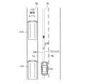
図2に示したように、車両制御ECU10が、車両周辺情報に含まれる車線情報に基いて、自レーンSLの「左区画線LL及び右区画線RL」についての情報を取得する。車両制御ECU10は、左区画線LLと右区画線RLとの間の道路幅方向(自レーンSLの幅方向)における「中央位置」を結ぶラインを「レーンの中央ラインLM」として推定する。車両制御ECU10は、中央ラインLMを目標走行ラインTLとして設定する。As shown in FIG. 2, the
車両制御ECU10は、LKAを実行するために必要なLKA制御パラメータを演算する。LKA制御パラメータは、図2に示すように、目標走行ラインTLの曲率CL(=中央ラインLMの曲率半径Rの逆数)、距離dL、及び、ヨー角θL等を含む。
図2において、x軸は、自車両SVの前後方向に延びる軸であり、y軸は、x軸と直交する軸である。距離dLは、目標走行ラインTLと、自車両SVの位置との間のy軸方向における距離である。本例において、「自車両SVの位置」とは、自車両SVの前端部の車幅方向の中央位置である。ヨー角θLは、目標走行ラインTLに対する上記x軸の角度である。 The
In Fig. 2, the x-axis is an axis extending in the longitudinal direction of the host vehicle SV, and the y-axis is an axis perpendicular to the x-axis. The distance dL is the distance in the y-axis direction between the target driving line TL and the position of the host vehicle SV. In this example, the "position of the host vehicle SV" is the central position of the front end of the host vehicle SV in the vehicle width direction. The yaw angle θL is the angle of the x-axis with respect to the target driving line TL.
車両制御ECU10は、LKA制御パラメータ(CL,dL,θL)を用いて、自車両SVの位置を目標走行ラインTLに一致させるための自動操舵トルクBtrを演算する。詳細には、車両制御ECU10は、例えば下記式1に従って自動操舵トルクBtrを演算する。The
(式1) Btr=K1・(SPD2・CL)+K2・dL+K3・θL
K1、K2、K3は、それぞれ制御ゲインである。 (Formula 1) Btr=K1・(SPD2・CL)+K2・dL+K3・θL
K1, K2, and K3 are control gains.
そして、車両制御ECU10は、自動操舵トルクBtrを含む操舵指令をステアリングECU40に送信する。ステアリングECU40は、操舵指令を受信した場合、ステアリング機構42に付与される実際のトルクが「受信した操舵指令に含まれる自動操舵トルクBtr」に一致するように、操舵アクチュエータ41を制御する。Then, the
(作動の概要)
図3を参照しながら、本制御装置の作動の概要を説明する。
本制御装置の車両制御ECU10は、LKAを実行している場合、特定通行帯条件が成立したか否かを判定する。特定通行帯条件は、以下の条件SP1及び条件SP2の両方が成立した場合に成立する。
条件SP1:自レーンSLがバスレーンBLに隣接すること。
条件SP2:現時刻が上記バスレーンBLの規制時間帯に含まれること。 (Overview of operation)
The operation of the control device will be outlined with reference to FIG.
When the
Condition SP1: The vehicle's own lane SL is adjacent to the bus lane BL.
Condition SP2: The current time is included in the restricted time period of the bus lane BL.
特定通行帯条件が成立していない場合、車両制御ECU10は、目標走行ラインTLを中央ラインLMに設定する。一方、特定通行帯条件が成立した場合、車両制御ECU10は、目標走行ラインTLをオフセットラインLOに設定する。オフセットラインLOは、中央ラインLMよりもバスレーンBLから離れる方向に所定距離ΔDだけ離れた位置に設定される。When the specific lane condition is not met, the
その後、車両制御ECU10は、上記LKA制御パラメータ(曲率CL、距離dL及びヨー角θL)を取得して、そのLKA制御パラメータを上記式1に適用することにより自動操舵トルクBtrを取得する。車両制御ECU10は、自動操舵トルクBtrを含む操舵指令をステアリングECU40に送信することにより、実際のトルクを自動操舵トルクBtrに一致するよう操舵アクチュエータ41を制御する。Then, the
以上から理解されるように、自レーンSLにバスレーンBLが隣接し且つそのバスレーンBLの規制時間帯に現時刻が含まれる場合、目標走行ラインTLはオフセットラインLOに設定される。従って、バスレーンBLをバスが走行する頻度が比較的高い時間帯においては、目標走行ラインTLがオフセットラインLOに設定される。これにより、自車両SVが「バスレーンBLに隣接する走行レーン」を走行する場合に目標走行ラインTLの位置が頻繁に変化することを防止できるので、自車両SVの車両挙動がふらつく可能性を低減できる。As can be understood from the above, when the bus lane BL is adjacent to the host lane SL and the current time falls within the restricted time period of the bus lane BL, the target driving line TL is set to the offset line LO. Therefore, during times when buses travel relatively frequently in the bus lane BL, the target driving line TL is set to the offset line LO. This makes it possible to prevent the position of the target driving line TL from changing frequently when the host vehicle SV travels in a "driving lane adjacent to the bus lane BL", thereby reducing the possibility of the vehicle behavior of the host vehicle SV becoming erratic.
更に、自車両SVはオフセットラインLO上で停車することになるので、自車両SVが停車した場合であっても、停車した自車両SVの横をバスが通過したときに乗員が不安及び恐怖を感じる可能性を低減できる。Furthermore, since the host vehicle SV will be stopped on the offset line LO, even if the host vehicle SV is stopped, the possibility that the occupants will feel anxiety or fear when a bus passes beside the stopped host vehicle SV can be reduced.
更に、上記バスの走行頻度が比較的高い時間帯にのみ目標走行ラインTLがオフセットラインLOに設定されるので、バスレーンBLとは反対側のレーンを走行する他車両等に対して乗員が不安及び恐怖を感じる可能性も低減できる。Furthermore, since the target driving line TL is set to the offset line LO only during times when the frequency of the bus traveling is relatively high, the possibility that the occupants will feel anxiety or fear about other vehicles traveling in the lane opposite the bus lane BL is also reduced.
(具体的作動)
<開始終了判定ルーチン>
車両制御ECU10のCPU(以下、「CPU」と表記した場合、特に断りがない限り、DSECU20のCPUを指す。)は、図4にフローチャートにより示したルーチン(開始終了判定ルーチン)を所定時間が経過する毎に実行する。 (Specific operation)
<Start/End Judgment Routine>
The CPU of the vehicle control ECU 10 (hereinafter, when the term "CPU" is used, it refers to the CPU of the
従って、所定のタイミングになると、CPUは、図4のステップ400から処理を開始してステップ405に進み、実行フラグXexeの値が「0」であるか否かを判定する。Therefore, at a predetermined timing, the CPU starts processing from
実行フラグXexeの値は、後述するLKA開始条件が成立した場合に「1」に設定され(ステップ415を参照。)、後述するLKA終了条件が成立した場合に「0」に設定される(ステップ425を参照。)。なお、自車両SVの図示しないイグニッション・キー・スイッチがオフ位置からオン位置へと変更されたときにCPUによって実行されるイニシャルルーチンにおいて、実行フラグXexeの値は「0」に設定される。The value of the execution flag Xexe is set to "1" when the LKA start condition described later is satisfied (see step 415), and is set to "0" when the LKA end condition described later is satisfied (see step 425). Note that in the initial routine executed by the CPU when the ignition key switch (not shown) of the host vehicle SV is changed from the OFF position to the ON position, the value of the execution flag Xexe is set to "0".
実行フラグXexeの値が「0」である場合、CPUは、ステップ405にて「Yes」と判定し、ステップ410に進む。ステップ410にて、CPUは、LKA開始条件が成立したか否かを判定する。LKA開始条件は、以下の条件ST1及び条件ST2の両方が成立した場合に成立する。If the value of the execution flag Xexe is "0", the CPU judges "Yes" in
条件ST1:ACCが実行されていること。
条件ST2:LKA操作スイッチ72が操作されたこと。 Condition ST1: ACC is being executed.
Condition ST2: The
LKA開始条件が成立していない場合、CPUは、ステップ410にて「No」と判定し、ステップ495に進んで本ルーチンを一旦終了する。If the LKA start condition is not met, the CPU judges "No" in
LKA開始条件が成立した場合、CPUは、ステップ410にて「Yes」と判定してステップ415に進み、実行フラグXexeの値を「1」に設定する。その後、CPUは、ステップ495に進んで本ルーチンを一旦終了する。If the LKA start condition is met, the CPU judges "Yes" in
一方、CPUがステップ405に進んだときに実行フラグXexeの値が「1」である場合、CPUは、ステップ405にて「No」と判定し、ステップ420に進む。ステップ420にて、CPUは、LKA終了条件が成立したか否かを判定する。LKA終了条件は、以下の条件EN1及び条件EN2の何れかが成立した場合に成立する。On the other hand, if the value of the execution flag Xexe is "1" when the CPU proceeds to step 405, the CPU determines "No" at
条件EN1:ACCが終了したこと。
条件EN2:LKA操作スイッチ72が操作されたこと。 Condition EN1: ACC has ended.
Condition EN2: The
LKA終了条件が成立してない場合、CPUは、ステップ420にて「No」と判定し、ステップ495に進んで本ルーチンを一旦終了する。If the LKA termination condition is not met, the CPU judges "No" in
LKA終了条件が成立した場合、CPUは、ステップ420にて「Yes」と判定してステップ425に進み、実行フラグXexeの値を「0」に設定する。その後、CPUは、ステップ495に進んで本ルーチンを一旦終了する。If the LKA end condition is met, the CPU judges "Yes" in
<LKAルーチン>
CPUは、図5にフローチャートにより示したルーチン(LKAルーチン)を所定時間が経過する毎に実行する。 <LKA routine>
The CPU executes a routine (LKA routine) shown in the flowchart of FIG. 5 every time a predetermined time elapses.
従って、所定のタイミングになると、CPUは、図5のステップ500から処理を開始してステップ505に進み、実行フラグXexeの値が「1」であるか否かを判定する。Therefore, at a predetermined timing, the CPU starts processing from
実行フラグXexeの値が「0」である場合、CPUは、ステップ505にて「No」と判定し、ステップ595に進んで本ルーチンを一旦終了する。If the value of the execution flag Xexe is "0", the CPU judges "No" in
実行フラグXexeの値が「1」である場合、CPUは、ステップ505にて「Yes」と判定し、ステップ510乃至ステップ525を順に実行する。If the value of the execution flag Xexe is "1", the CPU judges "Yes" in
ステップ510:CPUは、車線情報に基いて、自レーンSLの左区画線LL及び右区画線RLを特定する。
ステップ515:CPUは、左区画線LL及び右区画線RLに基いて中央ラインLMを特定する。
ステップ520:CPUは、特定通行帯条件が成立しているか否かを判定するための特定通行帯条件判定サブルーチンを実行する。 Step 510: The CPU identifies the left dividing line LL and the right dividing line RL of the own lane SL based on the lane information.
Step 515: The CPU identifies the center line LM based on the left dividing line LL and the right dividing line RL.
Step 520: The CPU executes a specific lane condition determination subroutine for determining whether or not a specific lane condition exists.
ステップ525:CPUは、特定フラグXspの値が「0」であるか否かを判定する。
特定フラグXspの値は、特定通行帯条件が成立した場合に「1」に設定され、特定通行帯条件が成立しなくなった場合に「0」に設定される。なお、特定フラグXspの値は、イニシャルルーチンにて「0」に設定される。 Step 525: The CPU determines whether the value of the specific flag Xsp is “0” or not.
The value of the specific flag Xsp is set to "1" when the specific lane condition is satisfied, and is set to "0" when the specific lane condition is no longer satisfied. The value of the specific flag Xsp is set to "0" in the initial routine.
特定フラグXspの値が「0」である場合、CPUは、ステップ525にて「Yes」と判定し、ステップ530乃至ステップ545を順に実行する。If the value of the specific flag Xsp is "0", the CPU judges "Yes" in
ステップ530:CPUは、目標走行ラインTLを中央ラインLMに設定する。
ステップ535:CPUは、車線情報に基いてLTA制御パラメータ(曲率CL、距離dL及びヨー角θL)を取得する。
ステップ540:CPUは、上記LTA制御パラメータ(曲率CL、距離dL及びヨー角θL)及び車速SPDを上記式1に適用することにより、自動操舵トルクBtrを取得する。
ステップ545:CPUは、自動操舵トルクBtrを含む操舵指令をステアリングECU40に送信する。
その後、CPUは、ステップ595に進んで本ルーチンを一旦終了する。 Step 530: The CPU sets the target driving line TL to the center line LM.
Step 535: The CPU obtains the LTA control parameters (curvature CL, distance dL, and yaw angle θL) based on the lane information.
Step 540: The CPU obtains the automatic steering torque Btr by applying the above LTA control parameters (curvature CL, distance dL, and yaw angle θL) and vehicle speed SPD to the
Step 545: The CPU transmits a steering command including the automatic steering torque Btr to the
Thereafter, the CPU proceeds to step 595 and temporarily ends this routine.
CPUがステップ525に進んだときに特定フラグXspの値が「1」である場合、CPUは、ステップ525にて「No」と判定し、ステップ550に進む。ステップ550にて、CPUは、目標走行ラインTLをオフセットラインLOに設定する。その後、CPUは、ステップ535以降の処理に進む。If the value of the specific flag Xsp is "1" when the CPU proceeds to step 525, the CPU determines "No" in
<特定通行帯条件判定サブルーチン>
CPUは、図5のステップ520に進むと、図6にフローチャートにより示したルーチン(特定通行帯条件判定サブルーチン)を実行する。即ち、CPUは、図5のステップ520に進むと、図6のステップ600から処理を開始し、ステップ605に進む。 <Specific lane condition determination subroutine>
When the CPU proceeds to step 520 in Fig. 5, it executes the routine (specific lane condition determination subroutine) shown in the flowchart in Fig. 6. That is, when the CPU proceeds to step 520 in Fig. 5, it starts the process from
ステップ605にて、CPUは、地図情報のバスレーン特定情報を参照し、自車両SVの現在位置を中心とする所定範囲内にバスレーンBLが存在するか否かを判定する。In
上記所定範囲内にバスレーンBLが存在する場合、CPUは、ステップ605にて「Yes」と判定し、ステップ610に進む。If a bus lane BL is present within the above-mentioned predetermined range, the CPU judges "Yes" in
ステップ610にて、CPUは、地図情報を用いて上記所定範囲内に存在するバスレーンBLの規制時間帯を特定し、現時刻が上記規制時間帯に含まれるか否かを判定する。
なお、規制時間帯が曜日で変わる場合もあるが、この場合、CPUは、現在の曜日に対応する規制時間帯に現時刻が含まれるか否かを判定する。 In
Note that the restricted time period may vary depending on the day of the week. In this case, the CPU determines whether the current time falls within the restricted time period corresponding to the current day of the week.
現時刻が規制時間帯に含まれる場合、CPUは、ステップ615にて「Yes」と判定し、ステップ615に進む。ステップ615にて、CPUは、自レーンSLがバスレーンBLに隣接するか否かを判定する。If the current time is within the restricted time period, the CPU judges "Yes" in
ステップ615を詳細に説明する。まず、CPUは、車線情報を用いて自レーンSLに隣接する隣接レーンが存在するか否かを判定する。隣接レーンが存在しない場合には、CPUは、ステップ615にて「No」と判定する。Step 615 will now be described in detail. First, the CPU uses the lane information to determine whether or not there is an adjacent lane adjacent to the vehicle's own lane SL. If there is no adjacent lane, the CPU determines "No" in
隣接レーンが存在する場合、CPUは、地図情報及び画像データを用いて、隣接レーンがバスレーンBLであるか否かを判定する。一例を挙げると、CPUは、以下の条件AC1及び条件AC2の両方が成立する場合、隣接レーンがバスレーンであると判定する。
条件AC1:「バスレーンBLを規定する区画線の位置のうち自車両SVの現在位置に最も近い最近位置」と現在位置との間の距離が所定距離以下であること。
条件AC2:画像データに「レーンがバスレーンBLであることを示すバスレーン標識」を表す画像及び「レーンがバスレーンBLであることを示すバスレーン路面標示」を表す画像の少なくとも一方が存在すること。 When an adjacent lane exists, the CPU uses the map information and image data to determine whether the adjacent lane is a bus lane BL. As an example, when both of the following conditions AC1 and AC2 are satisfied, the CPU determines that the adjacent lane is a bus lane.
Condition AC1: The distance between the "closest position among the positions of the dividing lines defining the bus lane BL that is closest to the current position of the vehicle SV" and the current position is equal to or less than a predetermined distance.
Condition AC2: The image data contains at least one of an image representing a "bus lane sign indicating that the lane is a bus lane BL" and an image representing a "bus lane road marking indicating that the lane is a bus lane BL".
条件AC1に関して、CPUは、地図情報を用いて上記最近位置を取得する。
条件AC2に関して、バスレーン標識及びバスレーン路面標示のテンプレート画像が予め登録されており、CPUは、パターンマッチングを用いて画像データにバスレーン標識を表す画像及びバスレーン路面標示を表す画像の少なくとも一方が存在するか否かを判定する。 Regarding the condition AC1, the CPU obtains the closest position by using map information.
Regarding condition AC2, template images of bus lane signs and bus lane road markings are registered in advance, and the CPU uses pattern matching to determine whether the image data contains at least one of an image representing a bus lane sign and an image representing a bus lane road marking.
隣接レーンがバスレーンである場合、CPUは、ステップ615にて「Yes」と判定し、ステップ620に進む。ステップ620にて、CPUは、特定フラグXspの値を「1」に設定し、ステップ695に進んで本ルーチンを一旦終了して図5に示したステップ525に進む。If the adjacent lane is a bus lane, the CPU determines "Yes" in
CPUがステップ605に進んだときに、現在位置を中心とする所定範囲内にバスレーンBLが存在しない場合、CPUは、ステップ605にて「No」と判定し、ステップ625に進む。When the CPU proceeds to step 605, if there is no bus lane BL within a predetermined range centered on the current position, the CPU determines "No" in
ステップ625にて、CPUは、特定フラグXspの値を「0」に設定し、ステップ695に進んで本ルーチンを一旦終了して図5に示したステップ525に進む。In
CPUがステップ610に進んだときに現時刻が規制時間帯に含まれない場合、CPUは、ステップ610にて「No」と判定し、ステップ625に進んで特定フラグXspの値を「0」に設定する。その後、CPUは、ステップ695に進んで本ルーチンを一旦終了し、図5に示したステップ525に進む。If the current time is not included in the restricted time period when the CPU proceeds to step 610, the CPU determines "No" at
CPUがステップ615に進んだときに自レーンSLがバスレーンBLに隣接しない場合、CPUは、ステップ615にて「No」と判定し、ステップ625に進んで特定フラグXspの値を「0」に設定する。その後、CPUは、ステップ695に進んで本ルーチンを一旦終了し、図5に示したステップ525に進む。If the own lane SL is not adjacent to the bus lane BL when the CPU proceeds to step 615, the CPU determines "No" in
本実施形態によれば、特定通行帯条件が成立した場合、特定通行帯条件が成立してない場合よりも、目標走行ラインTLを「特定通行帯である隣接レーン」から離れた位置(オフセットラインLO)に設定する。これにより、目標走行ラインTLの位置が頻繁に変化してしまうこと防止でき、自車両SVが停車したとしても、自車両SVの横を大型車(バス)が通過したときに乗員が不安及び恐怖を感じる可能性を低減できる。更に、特定通行帯条件が成立しない場合には、目標走行ラインTLは中央ラインLMに設定されるので、バスレーンBLとは反対側のレーンを走行する他車両等に対して乗員が不安及び恐怖を感じる可能性も低減できる。According to this embodiment, when the specific lane condition is met, the target driving line TL is set at a position (offset line LO) farther away from the "adjacent lane that is the specific lane" than when the specific lane condition is not met. This prevents the position of the target driving line TL from changing frequently, and even if the vehicle SV is stopped, the possibility that the occupants will feel anxious or scared when a large vehicle (bus) passes next to the vehicle SV can be reduced. Furthermore, when the specific lane condition is not met, the target driving line TL is set to the center line LM, which reduces the possibility that the occupants will feel anxious or scared about other vehicles, etc. traveling in the lane on the opposite side to the bus lane BL.
本発明は前述した実施形態に限定されることはなく、本発明の種々の変形例を採用することができる。The present invention is not limited to the above-described embodiment, and various modifications of the present invention may be adopted.
(第1変形例)
本変形例では、以下の条件SP3及びSP4の両方が成立した場合に特定通行帯条件が成立する。
条件SP3:自レーンSLが軌道敷に隣接すること。軌道敷は、路面電車が走行する通行帯である。
条件SP4:現時刻が予め設定されている高頻度時間帯に含まれること。高頻度時間帯は、例えば、1時間当たりの路面電車の運行本数が閾値本数以上となる時間帯である。 (First Modification)
In this modified example, the specific lane condition is met when both of the following conditions SP3 and SP4 are met.
Condition SP3: The own lane SL is adjacent to a track bed. The track bed is a lane on which streetcars run.
Condition SP4: The current time is included in a high frequency time period that is set in advance. The high frequency time period is, for example, a time period during which the number of streetcar operations per hour is equal to or exceeds a threshold number.
本変形例の車両制御ECU10のCPUは、図4に示した開始終了判定ルーチン及び図5に示したLKAルーチンを実行する。CPUは、図5に示したステップ520に進むと、図7に示した特定通行帯条件判定サブルーチンを実行する。なお、図7に示したフローチャートでは、図6に示したフローチャートと同じ処理は同じ符号を付与し、説明を省略する。The CPU of the
<特定通行帯条件判定サブルーチン>
従って、CPUは、図5のステップ520に進むと、図7のステップ700から処理を開始し、ステップ705に進む。ステップ705にて、CPUは、地図情報を用いて、自車両SVの現在位置を中心とする所定範囲内に軌道敷が存在するか否かを判定する。詳細には、地図情報は軌道敷の位置を含んでおり、CPUは、地図情報を参照し、上記所定範囲内に軌道敷の位置が含まれるか否かを判定する。 <Specific lane condition determination subroutine>
Therefore, when the CPU proceeds to step 520 in Fig. 5, it starts the process from
所定範囲内に軌道敷が存在する場合、CPUは、ステップ705にて「Yes」と判定し、ステップ710に進む。ステップ710にて、CPUは、現時刻が高頻度時間帯に含まれるか否かを判定する。If a trackbed is present within the specified range, the CPU judges "Yes" in
車両制御装置には路面電車の路線の時刻表が予め記憶されており、CPUは、上記所定範囲内に存在する軌道敷の路線の時刻表に基いて、この軌道敷の高頻度時間帯を特定する。
なお、曜日で時刻表が異なる場合には、CPUは、現在の曜日に対応する時刻表に基いて高頻度時間帯を特定する。 The vehicle control device prestores a timetable for the streetcar line, and the CPU identifies a high frequency time period for the track bed that exists within the above-mentioned specified range based on the timetable for the line.
When the timetable differs depending on the day of the week, the CPU identifies the high frequency time period based on the timetable corresponding to the current day of the week.
現時刻が高頻度時間帯に含まれる場合、CPUは、ステップ710にて「Yes」と判定し、ステップ715に進む。ステップ715にて、CPUは、自レーンSLが軌道敷に隣接するか否かを判定する。If the current time is within the high frequency time period, the CPU judges "Yes" in
より詳細には、CPUは、以下の条件AC3及び条件AC4の両方が成立する場合、自レーンSLが軌道敷に隣接すると判定する。
条件AC3:「軌道敷の位置のうち自車両SVの現在位置に最も近い最近位置」と現在位置との間の距離が所定距離以下であること。
条件AC4:画像データに軌道敷を表す画像、及び、「軌道敷内を通行可能なことを表す軌道敷内通行可標識」を表す画像の少なくとも一方が存在すること。なお、CPUは、パターンマッチングを用いてこの判定を行う。 More specifically, the CPU determines that the own lane SL is adjacent to the track bed when both of the following conditions AC3 and AC4 are satisfied.
Condition AC3: The distance between the "closest position among the positions on the track bed that is closest to the current position of the vehicle SV" and the current position is equal to or less than a predetermined distance.
Condition AC4: The image data includes at least one of an image showing a track bed and an image showing a "track bed passable sign indicating that the track bed is passable." The CPU performs this determination using pattern matching.
自レーンSLが軌道敷に隣接している場合、CPUは、ステップ715にて「Yes」と判定して図7に示したステップ620に進み、特定フラグXspの値を「1」に設定する。その後、CPUは、ステップ795に進んで本ルーチンを一旦終了し、図5に示したステップ525に進む。If the own lane SL is adjacent to the trackbed, the CPU judges "Yes" in
CPUがステップ705に進んだときに上記所定範囲内に軌道敷が存在しない場合、CPUは、ステップ705にて「No」と判定し、図7に示したステップ625に進む。図7に示したステップ625にて、CPUは、特定フラグXspの値を「0」に設定する。その後、CPUは、ステップ795に進んで本ルーチンを一旦終了し、図5に示したステップ525に進む。If the track bed is not present within the above-mentioned predetermined range when the CPU proceeds to step 705, the CPU determines "No" at
CPUがステップ710に進んだときに現時刻が高頻度時間帯に含まれない場合、CPUは、ステップ710にて「No」と判定する。そして、CPUは、図7に示したステップ625にて特定フラグXspの値を「0」に設定し、ステップ795に進んで本ルーチンを一旦終了して図5に示したステップ525に進む。If the current time is not included in the high frequency time period when the CPU proceeds to step 710, the CPU determines "No" at
CPUがステップ715に進んだときに自レーンSLが軌道敷に隣接していない場合、CPUは、ステップ715にて「No」と判定する。そして、CPUは、図7に示したステップ625にて特定フラグXspの値を「0」に設定し、ステップ795に進んで本ルーチンを一旦終了して図5に示したステップ525に進む。If the own lane SL is not adjacent to the trackbed when the CPU proceeds to step 715, the CPU determines "No" in
本変形例によれば、目標走行ラインTLの位置が頻繁に変化することを防止できる。更に、特定通行帯条件が成立した場合には、自車両SVが停車したとしても、自車両SVの横を路面電車が通過したときに乗員が不安及び恐怖を感じる可能性を低減できる。更に、特定通行帯条件が成立しない場合には、目標走行ラインTLは中央ラインLMに設定されるので、軌道敷とは反対側のレーンを走行する他車両等に対して乗員が不安及び恐怖を感じる可能性も低減できる。According to this modified example, it is possible to prevent the position of the target driving line TL from changing frequently. Furthermore, when the specific lane condition is met, even if the vehicle SV is stopped, it is possible to reduce the possibility that the occupants will feel anxious or scared when a streetcar passes beside the vehicle SV. Furthermore, when the specific lane condition is not met, the target driving line TL is set to the center line LM, which also reduces the possibility that the occupants will feel anxious or scared about other vehicles, etc. traveling in the lane on the opposite side of the trackbed.
(第2変形例)
本変形例では、以下の条件SP5及びSP6の両方が成立した場合に特定通行帯条件が成立する。
条件SP5:自レーンSLが大型車走行レーンに隣接していること。大型車走行レーンは、大型車が他車両を追い越す場合以外の通常時に走行しなければならないレーンである。
条件SP6:現時刻が高頻度時間帯に含まれること。 (Second Modification)
In this modified example, the specific lane condition is met when both of the following conditions SP5 and SP6 are met.
Condition SP5: The own lane SL is adjacent to a large vehicle driving lane. The large vehicle driving lane is a lane in which large vehicles must normally travel except when overtaking other vehicles.
Condition SP6: The current time is included in the high frequency time period.
条件SP6に関して、CPUは、自車両SVの現在位置から所定範囲内において自車両SVと同じ方向へ向かう大型車の数(以下、「大型車数」と称呼する。)が閾値以上である場合、現時刻が高頻度時間帯に含まれると判定する。ITSスポットが送信する道路交通情報は上記大型車数を含んでおり、ETC2.0車載器60はこの道路交通情報を受信する。CPUは、ETC2.0車載器60が受信した道路交通情報に基いて上記大型車数を特定する。Regarding condition SP6, the CPU determines that the current time is within the high frequency time period if the number of large vehicles (hereinafter referred to as the "number of large vehicles") traveling in the same direction as the vehicle SV within a specified range from the current position of the vehicle SV is equal to or greater than a threshold value. The road traffic information transmitted by the ITS spot includes the number of large vehicles, and the ETC 2.0 vehicle-mounted
なお、上記道路交通情報は自レーンSLを含む道路の予測混雑度を含んでおり、CPUは、ETC2.0車載器60が受信した道路交通情報に基いて上記予測混雑度を特定し、予測混雑度が所定の閾値混雑度以上である場合に現時刻が高頻度時間帯に含まれると判定してもよい。The road traffic information includes the predicted congestion level of the road including the own lane SL, and the CPU may determine the predicted congestion level based on the road traffic information received by the ETC 2.0
本変形例の車両制御ECU10のCPUは、図4に示した開始終了判定ルーチン及び図5に示したLKAルーチンを実行する。CPUは、図5に示したステップ520に進むと、図8に示した特定通行帯条件判定サブルーチンを実行する。なお、図8に示したフローチャートでは、図6に示したフローチャートと同じ処理は同じ符号を付与し、説明を省略する。The CPU of the
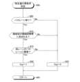
<特定通行帯条件判定サブルーチン>
従って、CPUは、図5のステップ520に進むと、図8のステップ800から処理を開始し、ステップ805に進む。ステップ805にて、CPUは、地図情報を用いて、自車両SVの現在位置を中心とする所定範囲内に大型車走行レーンが存在するか否かを判定する。詳細には、地図情報は、区画線の位置に対応する走行レーンが大型車走行レーンであるか否かを特定可能な大型車特定情報を含んでいる。CPUは、この大型車特定情報を参照し、上記所定範囲内に大型車走行レーンの位置が含まれるか否かを判定する。 <Specific lane condition determination subroutine>
Therefore, when the CPU proceeds to step 520 in Fig. 5, it starts processing from
所定範囲内に大型車走行レーンが存在する場合、CPUは、ステップ805にて「Yes」と判定し、ステップ810に進む。ステップ810にて、CPUは、上記したように、ETC2.0車載器60が受信したETC2.0情報に基いて、現時刻が高頻度時間帯に含まれるか否かを判定する。If a large vehicle lane exists within the specified range, the CPU judges "Yes" in
現時刻が高頻度時間帯に含まれる場合、CPUは、ステップ810にて「Yes」と判定し、ステップ815に進む。ステップ815にて、CPUは、自レーンSLが大型車走行レーンに隣接するか否かを判定する。If the current time is within the high frequency time period, the CPU determines "Yes" in
この判定は、上記ステップ615と同様である。即ち、自車両SVの現在位置と大型車走行レーンの区画線の最近位置との間の距離が所定距離以下であって、且つ、画像データに大型車走行レーン標識を表す画像及び大型車走行レーン路面標示を表す画像の少なくとも一方が存在する場合、CPUは、自レーンSLが大型車走行レーンに隣接すると判定する。This determination is the same as
自レーンSLが大型車走行レーンに隣接している場合、CPUは、ステップ815にて「Yes」と判定して図8に示したステップ620に進み、特定フラグXspの値を「1」に設定する。その後、CPUは、ステップ895に進んで本ルーチンを一旦終了し、図5に示したステップ525に進む。If the vehicle's own lane SL is adjacent to a large vehicle lane, the CPU judges "Yes" in
CPUがステップ805に進んだときに上記所定範囲内に大型車走行レーンが存在しない場合、CPUは、ステップ805にて「No」と判定し、図8に示したステップ625に進む。図8に示したステップ625にて、CPUは、特定フラグXspの値を「0」に設定する。その後、CPUは、ステップ895に進んで本ルーチンを一旦終了し、図5に示したステップ525に進む。If there is no large vehicle lane within the above-mentioned predetermined range when the CPU proceeds to step 805, the CPU determines "No" in
CPUがステップ810に進んだときに現時刻が高頻度時間帯に含まれない場合、CPUは、ステップ810にて「No」と判定する。そして、CPUは、図8に示したステップ625にて特定フラグXspの値を「0」に設定し、ステップ895に進んで本ルーチンを一旦終了して図5に示したステップ525に進む。If the current time is not included in the high frequency time period when the CPU proceeds to step 810, the CPU determines "No" at
CPUがステップ815に進んだときに自レーンSLが大型車走行レーンに隣接していない場合、CPUは、ステップ815にて「No」と判定する。そして、CPUは、図8に示したステップ625にて特定フラグXspの値を「0」に設定し、ステップ895に進んで本ルーチンを一旦終了して図5に示したステップ525に進む。If the own lane SL is not adjacent to the large vehicle lane when the CPU proceeds to step 815, the CPU determines "No" in
本変形例によれば、目標走行ラインTLの位置が頻繁に変化することを防止できる。更に、特定通行帯条件が成立した場合には、自車両SVが停車したとしても、自車両SVの横を大型車が通過したときに乗員が不安及び恐怖を感じる可能性を低減できる。更に、特定通行帯条件が成立しない場合には、目標走行ラインTLは中央ラインLMに設定されるので、大型車走行レーンとは反対側のレーンを走行する他車両等に対して乗員が不安及び恐怖を感じる可能性も低減できる。According to this modified example, it is possible to prevent the position of the target driving line TL from changing frequently. Furthermore, when the specific lane conditions are met, even if the host vehicle SV is stopped, it is possible to reduce the possibility that the occupants will feel anxious or scared when a large vehicle passes beside the host vehicle SV. Furthermore, when the specific lane conditions are not met, the target driving line TL is set to the center line LM, which also reduces the possibility that the occupants will feel anxious or scared about other vehicles, etc., traveling in the lane opposite the large vehicle driving lane.
以下では、バスレーンBL、軌道敷及び大型車走行レーンを総称して「特定通行帯」と称呼する場合がある。バス、路面電車及び大型車を総称して「特定車両」と称呼する場合がある。In the following, the bus lane BL, the track bed, and the large vehicle lane may be collectively referred to as the "specific traffic lane." Buses, streetcars, and large vehicles may be collectively referred to as the "specific vehicles."
(第3変形例)
VICS送信機は、自身から所定範囲内に存在するバスレーンの位置、軌道敷の位置及び大型車走行レーンの位置を含む道路交通情報を送信している。
図6に示したステップ605、図7に示したステップ705、図8に示したステップ805においては、それぞれ、CPUは、VICS受信機53が受信した道路交通情報を用いて、自車両SVを中心とする所定範囲内にバスレーンBLが存在するか否か、上記所定範囲内に軌道敷が存在するか否か、及び、上記所定範囲内に大型車走行レーンが存在するか否か、を判定してもよい。 (Third Modification)
The VICS transmitter transmits road traffic information including the positions of bus lanes, track beds, and large vehicle lanes within a predetermined range from the transmitter itself.
In
更に、図6に示したステップ605、図7に示したステップ705、及び図8に示したステップ805においては、CPUは、それぞれ、条件AC2、条件AC4及び条件AC6が成立するか否かを判定してもよい。CPUは、条件AC2が成立した場合には図6に示したステップ605にて「Yes」と判定し、条件AC4が成立した場合には図7に示したステップ705にて「Yes」と判定し、条件AC6が成立した場合には図8に示したステップ805にて「Yes」と判定する。Furthermore, in
(第4変形例)
図7に示したステップ710にて、CPUは、VICS受信機53が受信した道路交通情報に基いて現時刻が高頻度時間帯に含まれるか否かを判定してもよい。
具体的には、VICS送信機は、自身が設置された付近に軌道敷が存在する場合には、所定時間にその軌道敷を通過した路面電車の数(以下、「路面電車数」と称呼する。)をカウントしている。VICS送信機は、この路面電車数を道路交通情報に含めて送信する。
CPUは、VICS受信機53が受信した道路交通情報に基いて路面電車数が所定の閾値以上である場合、現時刻が高頻度時間帯であると判定する。 (Fourth Modification)
In
Specifically, when a trackbed is present near where the VICS transmitter is installed, the VICS transmitter counts the number of streetcars that pass over the trackbed in a given period of time (hereinafter referred to as the "tram count") and transmits this streetcar count together with road traffic information.
When the number of trams on the road is equal to or greater than a predetermined threshold based on the road traffic information received by the
(第5変形例)
特定通行帯条件が成立した場合に設定される目標走行ラインTLは中央ラインLMに限定されず、自レーンSLの適切な位置に設定されればよい。 (Fifth Modification)
The target driving line TL that is set when the specific lane condition is met is not limited to the center line LM, but may be set at any appropriate position in the own lane SL.
(第6変形例)
上記実施形態では、LKAの作動状態は、ACCがオン状態であるときにのみオン状態に設定でき、ACCがオフ状態に設定されるとオフ状態に設定されるが、これに限定されず、LKAの作動状態は、ACCの作動状態にかかわらずに独立して設定されるようにしてもよい。 (Sixth Modification)
In the above embodiment, the operation state of the LKA can be set to the on state only when the ACC is on, and is set to the off state when the ACC is set to the off state, but this is not limited to this, and the operation state of the LKA may be set independently regardless of the operation state of the ACC.
(第6変形例)
本制御装置は、エンジン自動車、ハイブリッド車(HEV:Hybrid Electric Vehicle)、プラグインハブリッド車(PHEV:Plug-in Hybrid Electric Vehicle)、燃料電池車(FCEV:Fuel Cell Electric Vehicle)及び電気自動車(BEV:Battery Electric Vehicle)等の車両に搭載可能である。 (Sixth Modification)
This control device can be installed in vehicles such as engine automobiles, hybrid electric vehicles (HEVs), plug-in hybrid electric vehicles (PHEVs), fuel cell electric vehicles (FCEVs), and battery electric vehicles (BEVs).
10…車両制御ECU、40…ステアリングECU、41…操舵アクチュエータ、TL…目標走行ライン、LM…中央ライン、LO…オフセットライン。10...vehicle control ECU, 40...steering ECU, 41...steering actuator, TL...target driving line, LM...center line, LO...offset line.
Claims (1)
Translated fromJapanese前記自車両が走行している走行レーンである自レーンに目標走行ラインを設定し、前記自車両が前記目標走行ラインに沿って走行するように前記操舵アクチュエータを制御する車線維持制御を実行するように構成された制御ユニットと、
を備え、
前記制御ユニットは、
特定の種類の車両又は路面電車である特定車両が走行する可能性が通常の走行レーンよりも高い特定通行帯に前記自レーンが隣接し、且つ、前記特定車両が前記特定通行帯を走行している可能性が通常の時間帯よりも高い高頻度時間帯に現時刻が含まれる、との特定通行帯条件が成立した場合、前記目標走行ラインを、前記特定通行帯条件が成立していない場合に設定される目標走行ラインよりも前記特定通行帯から離れた位置に設定する、
ように構成された、
車両制御装置。 A steering actuator configured to change a steering angle of a steering wheel of the host vehicle;
A control unit configured to execute lane keeping control by setting a target driving line in a vehicle lane in which the vehicle is traveling and controlling the steering actuator so that the vehicle travels along the target driving line;
Equipped with
The control unit
When a specific lane condition is met that the lane is adjacent to a specific lane in which a specific vehicle, which is a specific type of vehicle or a streetcar, is more likely to travel than in a normal travel lane, and the current time falls within a high frequency time period in which the specific vehicle is more likely to travel in the specific lane than in a normal time period, the target travel line is set at a position farther away from the specific lane than the target travel line that is set when the specific lane condition is not met.
It was configured as follows:
Vehicle control device.
Priority Applications (1)
| Application Number | Priority Date | Filing Date | Title |
|---|---|---|---|
| JP2022040881AJP7655468B2 (en) | 2022-03-16 | 2022-03-16 | Vehicle control device |
Applications Claiming Priority (1)
| Application Number | Priority Date | Filing Date | Title |
|---|---|---|---|
| JP2022040881AJP7655468B2 (en) | 2022-03-16 | 2022-03-16 | Vehicle control device |
Publications (2)
| Publication Number | Publication Date |
|---|---|
| JP2023135683A JP2023135683A (en) | 2023-09-29 |
| JP7655468B2true JP7655468B2 (en) | 2025-04-02 |
Family
ID=88145312
Family Applications (1)
| Application Number | Title | Priority Date | Filing Date |
|---|---|---|---|
| JP2022040881AActiveJP7655468B2 (en) | 2022-03-16 | 2022-03-16 | Vehicle control device |
Country Status (1)
| Country | Link |
|---|---|
| JP (1) | JP7655468B2 (en) |
Citations (5)
| Publication number | Priority date | Publication date | Assignee | Title |
|---|---|---|---|---|
| US20050228588A1 (en) | 2002-04-23 | 2005-10-13 | Goetz Braeuchle | Lateral guidance assistance for motor vehicles |
| JP2010086406A (en) | 2008-10-01 | 2010-04-15 | Fujitsu Ten Ltd | Image recognition device and image recognition method |
| JP2014089691A (en) | 2012-10-30 | 2014-05-15 | Google Inc | Vehicle lateral lane positioning control |
| JP2015189404A (en) | 2014-03-28 | 2015-11-02 | マツダ株式会社 | Lane keeping controller |
| JP2020038726A (en) | 2019-12-05 | 2020-03-12 | 本田技研工業株式会社 | Vehicle controller |
- 2022
- 2022-03-16JPJP2022040881Apatent/JP7655468B2/enactiveActive
Patent Citations (5)
| Publication number | Priority date | Publication date | Assignee | Title |
|---|---|---|---|---|
| US20050228588A1 (en) | 2002-04-23 | 2005-10-13 | Goetz Braeuchle | Lateral guidance assistance for motor vehicles |
| JP2010086406A (en) | 2008-10-01 | 2010-04-15 | Fujitsu Ten Ltd | Image recognition device and image recognition method |
| JP2014089691A (en) | 2012-10-30 | 2014-05-15 | Google Inc | Vehicle lateral lane positioning control |
| JP2015189404A (en) | 2014-03-28 | 2015-11-02 | マツダ株式会社 | Lane keeping controller |
| JP2020038726A (en) | 2019-12-05 | 2020-03-12 | 本田技研工業株式会社 | Vehicle controller |
Also Published As
| Publication number | Publication date |
|---|---|
| JP2023135683A (en) | 2023-09-29 |
Similar Documents
| Publication | Publication Date | Title |
|---|---|---|
| US11733708B2 (en) | Autonomous driving system | |
| US10717439B2 (en) | Traveling control system and vehicle control method | |
| CN111791894B (en) | Vehicle driving control device | |
| US11814048B2 (en) | Vehicle travel control apparatus | |
| US12103528B2 (en) | Driving assistance device | |
| JP7107095B2 (en) | Autonomous driving system | |
| EP4036869B1 (en) | Collision avoidance support apparatus | |
| US20230311875A1 (en) | Control device, method for operating control device, and non-transitory computer-readable storage medium | |
| JP3832380B2 (en) | Automatic vehicle speed control device | |
| JP2021077012A (en) | Driving support device | |
| JP2024509121A (en) | Lane keeping support based on departure rate | |
| JP2023032731A (en) | Automobile | |
| JP7655468B2 (en) | Vehicle control device | |
| CN116803798A (en) | Control device and control method | |
| US11767014B2 (en) | Vehicle control system | |
| JP2002157685A (en) | Vehicle traveling control system | |
| JP7211291B2 (en) | Vehicle running control device | |
| US20220176922A1 (en) | Driving assistance system | |
| JP7704797B2 (en) | Vehicle control device, control method, and program | |
| JP7740193B2 (en) | Collision avoidance support device | |
| JP7694335B2 (en) | Vehicle Control Systems | |
| US20230110942A1 (en) | Driving assistance apparatus, driving assistance method, and program | |
| US20250289432A1 (en) | Traveling control device and method for vehicle |
Legal Events
| Date | Code | Title | Description |
|---|---|---|---|
| A621 | Written request for application examination | Free format text:JAPANESE INTERMEDIATE CODE: A621 Effective date:20240411 | |
| TRDD | Decision of grant or rejection written | ||
| A977 | Report on retrieval | Free format text:JAPANESE INTERMEDIATE CODE: A971007 Effective date:20250218 | |
| A01 | Written decision to grant a patent or to grant a registration (utility model) | Free format text:JAPANESE INTERMEDIATE CODE: A01 Effective date:20250219 | |
| A61 | First payment of annual fees (during grant procedure) | Free format text:JAPANESE INTERMEDIATE CODE: A61 Effective date:20250304 | |
| R150 | Certificate of patent or registration of utility model | Ref document number:7655468 Country of ref document:JP Free format text:JAPANESE INTERMEDIATE CODE: R150 |