JP7654588B2 - Swash plate type rotating machine - Google Patents
Swash plate type rotating machineDownload PDFInfo
- Publication number
- JP7654588B2 JP7654588B2JP2022055165AJP2022055165AJP7654588B2JP 7654588 B2JP7654588 B2JP 7654588B2JP 2022055165 AJP2022055165 AJP 2022055165AJP 2022055165 AJP2022055165 AJP 2022055165AJP 7654588 B2JP7654588 B2JP 7654588B2
- Authority
- JP
- Japan
- Prior art keywords
- oil
- swash plate
- oil supply
- casing
- reducer
- Prior art date
- Legal status (The legal status is an assumption and is not a legal conclusion. Google has not performed a legal analysis and makes no representation as to the accuracy of the status listed.)
- Active
Links
Images


Landscapes
- Reciprocating Pumps (AREA)
- Hydraulic Motors (AREA)
Description
Translated fromJapanese本発明は、油圧ショベル、油圧クレーン、ホイールローダ等の建設機械に用いられる回転機械に係り、特に斜板を電動モータで駆動する斜板式回転機械に関する。The present invention relates to rotating machines used in construction machines such as hydraulic excavators, hydraulic cranes, and wheel loaders, and in particular to swash plate type rotating machines in which the swash plate is driven by an electric motor.
斜板式回転機械は、一般に中空のケーシングの内部でシリンダブロックの回転軸に対して斜板を傾動させ、シリンダブロックの回転に伴うピストンの往復距離を変えて容積を変化させる。ポンプであれば傾転角(斜板の傾斜角)を大きくすることで吐出流量が増加し、モータであれば傾転角を大きくすることで出力トルクが増加する。この種の斜板式回転機械において、電動モータで斜板を駆動するものがある(特許文献1等)。In swash plate type rotary machines, a swash plate is generally tilted relative to the rotating shaft of a cylinder block inside a hollow casing, and the volume is changed by changing the reciprocating distance of the pistons as the cylinder block rotates. In the case of a pump, the discharge flow rate is increased by increasing the tilt angle (the inclination angle of the swash plate), and in the case of a motor, the output torque is increased by increasing the tilt angle. Some swash plate type rotary machines of this type use an electric motor to drive the swash plate (Patent Document 1, etc.).
電動モータで斜板を駆動する場合、油圧で斜板を駆動する従来の構成では難しかった傾転角の微制御が可能となる。但し、斜板の駆動には大きな動力を要し、電動モータを現実的なサイズに抑えるためには、減速機を介して電動モータと斜板に連結する必要がある。減速機は歯車同士の固体接触によって回転力を伝達するため、潤滑油を要する。When driving the swash plate with an electric motor, it becomes possible to finely control the tilt angle, which was difficult with the conventional configuration in which the swash plate was driven hydraulically. However, driving the swash plate requires a large amount of power, and in order to keep the electric motor to a practical size, it is necessary to connect the electric motor to the swash plate via a reduction gear. The reduction gear transmits rotational force through solid contact between gears, so lubricating oil is required.
特許文献1の回転機械の場合、シリンダブロックを包囲するケーシングと減速機のギヤボックスとを連通孔で繋がっており、ケーシングとギヤボックスの内部がオイルで満たされる。しかし、同文献では単に回転機械のケーシングの内部とギヤボックスの内部とが連通孔で単に繋がっているだけで、ギヤボックスの内部で潤滑油が流動せず滞留してしまう。In the case of the rotating machine of Patent Document 1, the casing surrounding the cylinder block and the gearbox of the reducer are connected by a communication hole, and the inside of the casing and the gearbox are filled with oil. However, in this document, the inside of the casing of the rotating machine and the inside of the gearbox are simply connected by a communication hole, and the lubricating oil does not flow inside the gearbox and remains there.
本発明の目的は、斜板を電動モータで精度良く駆動することができ、減速機における潤滑油の滞留を合理的に改善することができる斜板式転機械を提供することにある。The object of the present invention is to provide a swash plate type rotating machine that can drive the swash plate with high precision using an electric motor and can rationally improve the retention of lubricating oil in the reduction gear.
上記目的を達成するために、本発明は、ケーシングと、前記ケーシングの内部に回転可能に設けられたシャフトと、前記シャフトの回転に伴って回転するように前記ケーシングに収容され、軸方向に延びるシリンダ穴を有するシリンダブロックと、前記シリンダ穴に往復運動可能に挿入されたメインピストンと、前記シリンダブロックが摺接するように前記ケーシングに固定され、前記シリンダ穴にオイルが流入する入口ポート及び前記シリンダ穴からオイルが流出する出口ポートを有する弁板と、前記メインピストンに連結されたシューと、前記シューが摺接する摺動面を有し、前記ケーシングに対して回転軸を介して傾動自在に支持され、当該傾動によって前記シリンダブロックの回転時における前記メインピストンの前記シリンダ穴内での往復距離を変化させる斜板と、前記斜板の回転軸に出力軸が連結された減速機と、前記減速機を駆動する電動モータとを備えた斜板式回転機械において、前記ケーシングに設けられた送出ポートと、前記減速機に設けた給油ポートと、前記ケーシングの送出ポート及び前記減速機の給油ポートを接続する給油通路と、前記送出ポートに接続されると共に、前記斜板に対向するように前記ケーシングに設けられた給油穴と、前記給油穴に挿入され、前記斜板の傾動によって前記給油穴内を移動することで、前記ケーシング内のオイルを前記減速機に供給する給油ピストンと、前記減速機に設けた排油ポートとを備えた斜板式回転機械を提供する。In order to achieve the above object, the present invention provides a valve plate that includes a casing, a shaft rotatably provided inside the casing, a cylinder block that is housed in the casing so as to rotate with the rotation of the shaft and has a cylinder bore extending in the axial direction, a main piston that is inserted into the cylinder bore so as to be capable of reciprocating motion, a valve plate that is fixed to the casing so as to be in sliding contact with the cylinder block and has an inlet port through which oil flows into the cylinder bore and an outlet port through which oil flows out of the cylinder bore, a shoe connected to the main piston, and a sliding surface against which the shoe slides, the valve plate being supported so as to be tiltable relative to the casing via a rotation axis, and the tilting causes a valve plate to rotate when the cylinder block rotates. In a swash plate type rotating machine having a swash plate that changes the reciprocating distance of the main piston in the cylinder bore, a reducer whose output shaft is connected to the rotating shaft of the swash plate, and an electric motor that drives the reducer, the machine is provided with a delivery port provided in the casing, an oil supply port provided in the reducer, an oil supply passage that connects the delivery port of the casing and the oil supply port of the reducer, an oil supply hole that is connected to the delivery port and is provided in the casing so as to face the swash plate, an oil supply piston that is inserted into the oil supply hole and moves within the oil supply hole as the swash plate tilts, thereby supplying oil from within the casing to the reducer, and an oil drain port provided in the reducer.
本発明によれば、斜板を電動モータで精度良く駆動することができ、減速機における潤滑油の滞留を合理的に改善することができる。According to the present invention, the swash plate can be driven with high precision by an electric motor, and the retention of lubricating oil in the reduction gear can be improved rationally.
以下に図面を用いて本発明の実施の形態を説明する。本発明に係る斜板式回転機械は、油圧ショベル、油圧クレーン、ホイールローダ等の建設機械に用いられる。以下においては油圧ショベルの油圧ポンプに本発明を適用した場合を例に挙げて説明するが、他の建設機械の油圧ポンプに本発明を適用対象とする場合や、油圧モータに本発明を適用する場合も、実体的な構成的は同様である。The following describes an embodiment of the present invention with reference to the drawings. The swash plate type rotating machine according to the present invention is used in construction machinery such as hydraulic excavators, hydraulic cranes, and wheel loaders. In the following, the present invention is applied to a hydraulic pump in a hydraulic excavator as an example, but the actual configuration is similar when the present invention is applied to a hydraulic pump in other construction machinery or when the present invention is applied to a hydraulic motor.
<第1実施形態>
-油圧ショベル-
図1は本発明の第1実施形態に係る斜板式回転機械を搭載する建設機械の一例である油圧ショベルの全体構造を表す側面図である。以降において、図1中の左側を油圧ショベル(厳密には旋回体)の前側とする。同図に示した油圧ショベルは、車体1及びフロント作業機2を含んで構成されている。車体1は、走行体3と旋回体4とから構成されている。 First Embodiment
- Hydraulic excavator -
Fig. 1 is a side view showing the overall structure of a hydraulic excavator, which is an example of a construction machine equipped with a swash plate type rotary machine according to a first embodiment of the present invention. Hereinafter, the left side in Fig. 1 will be referred to as the front side of the hydraulic excavator (strictly speaking, the rotating body). The hydraulic excavator shown in the figure is configured to include a vehicle body 1 and a
-走行体-
走行体3は、油圧ショベルの自力走行を可能とする基礎構造体であり、ホイール式の走行体でも良いが本実施形態ではクローラ式の走行体を採用した構成を例示する。走行体3は、トラックフレーム5、アイドラ(従動輪)6、走行駆動装置7、スプロケット(駆動輪)8及び履帯(クローラ)9等を含んで構成されている。トラックフレーム5は、センタフレーム5a及びセンタフレーム5aに連結した平行な左右一対のサイドフレーム5bにより、上方から見てH型に形成されている。左右のサイドフレーム5bの前後の一端側にはアイドラ6が、他端側にはスプロケット8がそれぞれ回転自在に支持されている。スプロケット8の回転軸には、走行駆動装置7の出力軸が連結されている。走行駆動装置7は走行用の油圧モータと減速機からなる。アイドラ6とスプロケット8の間には、環状の履帯9が掛け回されていて、履帯9をスプロケット8で駆動することによって走行体3が自走する。 -Running vehicle-
The running body 3 is a foundation structure that enables the hydraulic excavator to travel under its own power. Although a wheel-type running body may be used, the present embodiment illustrates a configuration in which a crawler-type running body is used. The running body 3 includes a
-旋回体-
旋回体4は、走行体3の上部に旋回可能に設けられており、旋回フレーム10、運転室11、カウンタウェイト12、機械室(エンジン室)13等を含んで構成されている。旋回フレーム10は、旋回体4のベースフレームであり、旋回輪14を介してトラックフレーム5のセンタフレーム5aの上部に設けられている。旋回フレーム10には、旋回輪14の付近に旋回モータ(不図示)が搭載されており、旋回モータの出力軸が旋回輪14に設けた歯車と噛み合うことで、走行体3に対して旋回体4が旋回する。旋回モータには電動モータを用いることもできるが、本実施形態では油圧モータが用いてある。 - Rotating body -
The rotating body 4 is provided rotatably on the upper part of the running body 3, and includes a rotating
旋回フレーム10の前部には、フロント作業機2の左右方向の一方側(本例では左側)に位置するように運転室11が設置されている。旋回フレーム10における運転室11の後側には、ボンネットカバーで画定された機械室13が設置されている。旋回フレーム10の後端には、カウンタウェイト12が取り付けられている。A
-フロント作業機-
フロント作業機2は、旋回体4に取り付けられており、作業腕21、バケット(アタッチメント)24、ブームシリンダ25、アームシリンダ26及びバケットシリンダ27を含む多関節型のフロント作業装置である。 -Front work equipment-
The
作業腕21は、ブーム22及びアーム23を含んで構成されている。ブーム22は、旋回体4の前部に上下方向に回動可能に、アーム23はブーム22の先端に、それぞれ回動可能に連結されている。バケット24は、アーム23の先端に回動可能に装着されている。ブームシリンダ25は、旋回体4及びブーム22に両端が連結されている。アームシリンダ26は、ブーム22及びアーム23に両端が連結されている。バケットシリンダ27は、基端がアーム23に連結される一方で、先端がリンクを介してアーム23の先端部及びバケット24に連結されている。ブームシリンダ25、アームシリンダ26、及びバケットシリンダ27は、いずれも油圧シリンダである。The working
-油圧システム-
図2は図1に示した油圧ショベルの油圧システムの油圧回路の要部を抜き出して表す図である。図2において、説明済みの要素については既出図面と同符号を付して説明を省略する。 - Hydraulic system -
Fig. 2 is a diagram showing the essential parts of the hydraulic circuit of the hydraulic system of the hydraulic excavator shown in Fig. 1. In Fig. 2, elements that have already been explained are given the same reference numerals as in the previously mentioned drawings, and explanations thereof will be omitted.
図2に示した油圧システムは、油圧ショベルの被駆動部材を駆動する装置であって主として機械室13に収容されている。被駆動部材は、例えば、フロント作業機2(ブーム22、アーム23及びバケット24)や車体1(走行体3及び旋回体4)である。この油圧システムは、原動機15、油圧ポンプ50、制御弁ユニット17、オイルタンク18、各種配管や配線等を含んで構成されている。The hydraulic system shown in FIG. 2 is a device that drives the driven members of the hydraulic excavator, and is mainly housed in the
原動機15にはエンジン(内燃機関)が用いられるが、電動機を用いることもある。油圧ポンプ50は、斜板式(可変容積型)の回転機械であり、原動機15で駆動されてオイルタンク18から吸入したオイル(作動油)を加圧し、油圧アクチュエータを駆動する圧油として吐出する。図2では油圧ポンプ50を1個のみ図示しているが、複数個設けられる場合もある。An engine (internal combustion engine) is used as the
制御弁ユニット17は、油圧ポンプ50から油圧アクチュエータへの圧油の方向及び流量を制御する複数の方向切換弁を含んで構成されている。制御弁ユニット17を構成する各方向切換弁は、オペレータの操作に応じて受圧室に作用するパイロット圧によりスプールが駆動されて作動する。図2では、油圧アクチュエータとして、ブームシリンダ25、アームシリンダ26、バケットシリンダ27のみを表しているが、走行体3を駆動する走行用油圧モータや旋回体4を旋回駆動する旋回モータ等も制御弁ユニット17で制御され得る。油圧アクチュエータからの戻り油は、制御弁ユニット17を介してオイルタンク18に戻される。油圧ポンプ50の吐出配管16には、リリーフ圧(換言すれば吐出配管16の最高圧力)を規定するリリーフ弁19が設けられている。The
本実施形態において、斜板57は減速機80を介して電動モータ90に連結しており、油圧ポンプ50の傾転角(斜板57の傾斜角)、つまりポンプ容積は電動モータ90により制御される。減速機80には、好ましくはサイズに対して高い減速比(例えば数十以上)のものが用いられる。減速機80としては、波動歯車、ハイポサイクロイド歯車、不思議遊星歯車等を用いた減速機を採用できる他、通常の遊星歯車を多段にして減速比を上げた減速機を用いることができる。油圧ポンプ50の構成については後述する。In this embodiment, the
なお、電動モータ90は、各種検出値(例えば油圧ポンプ50の吐出圧や操作装置(不図示)の操作量)に応じてコントローラ30により制御される。コントローラ30は、油圧ショベルに搭載された車載コンピュータであり、例えば入力インターフェース(ADコンバータ等)、メモリ(RAM、ROM、HHD等)、演算装置(CPU等)、出力インターフェース(DAコンバータ等)を含んで構成される。The
-斜板式回転機械-
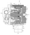
図3は油圧ポンプ50のシャフトの中心線と斜板の回転軸の中心線を含む部分断面図、図4は図3中のIV-IV線による油圧ポンプ50の断面図である。図4に表す断面は、油圧ポンプ50のシャフトの中心線で図3の断面に直交する断面である。図4においてケーシング51のパーツ51a(後述)は図示省略してある。 - Swash plate type rotating machine -
Fig. 3 is a partial cross-sectional view including the center line of the shaft of the
油圧ポンプ50は、ケーシング51、シャフト52、シリンダブロック53、メインピストン54、弁板55、シュー56、斜板57、減速機80(図2)、及び電動モータ90(図2)を含んで構成されている。The
ケーシング51は、油圧ポンプ50のボディ(外郭)であり、例えばボルトで複数のパーツ51a-51eを締結して箱状に構成されている。本実施形態のケーシング51は、筒状のパーツ51cの両端の開口が蓋状のパーツ51a,51bで閉止され、パーツ51cの側部に設けた開口にパーツ51d,51eを嵌め込んだ構成である。パーツ51aには、油圧ポンプ50に対するオイルの入口(不図示)及び出口(不図示)が設けられている。入口には配管を介してオイルタンク18(図2)が接続され、出口には吐出配管16(図2)が接続される。The
シャフト52は、ケーシング51の内部に回転可能に設けられている。具体的には、シャフト52は、ケーシング51の内部を通り、シャフト用軸受63,64により両端が支持されており、シャフト用軸受63,64を介してケーシング51のパーツ51a,51bに支持されている。シャフト52は、パーツ51b、斜板57、シリンダブロック53、弁板55を貫通している。このシャフト52には、原動機15の出力軸が連結される。The
シリンダブロック53は、スプライン66を介してシャフト52に連結されてケーシング51に収容され、ケーシング51の内部でシャフト52の回転に伴って回転する。このシリンダブロック53には、シャフト52の回転中心線C1を中心として周方向に等間隔で複数のシリンダ穴65が穿設されている。各シリンダ穴65は、シャフト52の回転中心線C1と平行に延びている。The
メインピストン54は、シリンダブロック53の各シリンダ穴65に1本ずつ一端(図3では左端)が往復動可能に挿入さている。One end of each of the main pistons 54 (the left end in FIG. 3) is inserted into each cylinder bore 65 of the
弁板55は、円環状の部材であり、例えばノックピン(不図示)でケーシング51のパーツ51aに固定される。この弁板55には、シリンダブロック53の軸方向の一方側(図3中の左側)の端面が接触し回転摺動する。また、弁板55には、入口ポート68及び出口ポート69が穿設されている。これら入口ポート68及び出口ポート69は、シリンダ穴65の回転軌道に沿って弧状に設けられている。入口ポート68は、ケーシング51の入口に連通し、シリンダ穴65に流入するオイルを通す。出口ポート69は、ケーシング51の出口に連通し、シリンダ穴65から流出するオイルを通す。The
シュー56は、メインピストン54に対応して複数設けられている。各々のシュー56は、一方側(図3では左端)がボールジョイント状に形成され、他方側(図3では右端)に摺動面を有する部材である。各シュー56のボールジョイント状の部分は、リング状のリテーナ72に通されて対応するメインピストン54の他端(図3では右端)に連結されている。シュー56は、メインピストン54に対して回動及び傾動が自在である。シュー56の摺動面は、斜板57の摺動面(シリンダブロック53側を向く面)に摺接する。リテーナ72は、シャフト52を通したリテーナガイド(ブッシング)73に支持されている。このリテーナガイド73の外周面は、球面状に形成されており、その球面でリテーナ72を揺動自在に支持している。また、リテーナガイド73は、シリンダブロック53の斜板57に対向して突き出した突出部にバネを介して装着されている。これにより、リテーナガイド73が斜板57側にリテーナ72を押し、リテーナ72によって各シュー56の摺動面が斜板57の摺動面に押し当てられ、各シュー56が斜板57の摺動面を摺動するようになっている。A plurality of
斜板57は、シリンダ穴65に対するメインピストン54の往復距離を変更し油圧ポンプ50の容積を変化させる要素であり、シリンダブロック53の他方側(図3では右側)の端面に対面して配置されている。斜板57のシリンダブロック53との対向面が、シュー56が摺接する摺動面である。この斜板57には、この斜板57の重心からシリンダブロック53側にオフセットした一対の回転軸58がブラケット部59を介して一体に連結されている。これら回転軸58はケーシング51のパーツ51d,51eに取り付けられた斜板用軸受74によって回転自在に支持されており、これによりケーシング51に対して斜板57が回転軸58を介して傾動自在に支持されている。回転軸58の回転中心線C2(図3)は、シャフト52の回転中心線C1との直交線(又はその平行線)である。このように、斜板57は、回転軸58の回転に伴って回転中心線C2を中心に図4に矢印で示したように揺動し傾動する。また、斜板57はフラットな板状であり、シュー56が摺動する摺動面と、この摺動面と反対を向く裏面57aは、フラットな平行面である。この斜板57の傾動によって、シリンダブロック53の回転時におけるメインピストン54のシリンダ穴65内での往復距離が変化する。The
斜板57の一方側の回転軸58には、減速機80を介して電動モータ90が連結されている。具板的には、減速機80の入力軸(不図示)は電動モータ90の出力軸に連結されており、減速機80は電動モータ90により駆動される。そして、減速機80の出力軸81は斜板57の回転軸58に連結されており、回転軸58に減速機80を介して電動モータ90の回転動力が伝達されて斜板57が駆動される(傾動する)。これにより油圧ポンプ50の傾転角が変化して容積が変化する。斜板57の傾転角の維持には、電動モータ90の電磁ブレーキを用いることができる。An
減速機80には、前述した通り、例えば波動歯車、ハイポサイクロイド歯車、不思議遊星歯車等、小型で減速比の大きなもの(例えば減速比数十以上のもの)を採用することが望ましい。通常の遊星歯車を多段に連結して構成しても小型で大きな減速比を得ることができ、複数段構成の遊星歯車機構も減速機80として採用することができる。As mentioned above, it is desirable to use a small gear with a large reduction ratio (e.g., a reduction ratio of several tens or more) such as a wave gear, hypocycloid gear, or paradoxical planetary gear for the
なお、不思議遊星歯車の減速比は、太陽外歯車及び固定内歯車の歯数で決まる第1減速比に、2つの内歯車の歯数の差で決まる第2減速比を掛け合わせた値である。第1減速比が1/10で第2減速比が1/12であれば、不思議遊星歯車の減速比は1/120にもなり、通常の遊星歯車を多段に連結するよりも小型でトルクの伝達効率も高くなる利点がある。不思議遊星歯車は、出力軸側にトルクを入力して入力軸を駆動しようとしても、減速比の大きさから出力軸に対して極めて大きなトルクを入力する必要があり、出力軸側にトルクを入力して駆動することは困難である。そのため、減速機80に不思議遊星歯車機構を採用した場合には、その特性により電動モータ90の電磁ブレーキを省略しても斜板57の傾転角を維持することができるメリットがある。The reduction ratio of the paradox planetary gear is the product of the first reduction ratio, which is determined by the number of teeth of the sun outer gear and the fixed internal gear, multiplied by the second reduction ratio, which is determined by the difference in the number of teeth of the two internal gears. If the first reduction ratio is 1/10 and the second reduction ratio is 1/12, the reduction ratio of the paradox planetary gear is 1/120, which has the advantage of being smaller and more efficient in transmitting torque than a multi-stage connection of normal planetary gears. Even if torque is input to the output shaft side of the paradox planetary gear to drive the input shaft, it is necessary to input an extremely large torque to the output shaft due to the large reduction ratio, and it is difficult to input torque to the output shaft side to drive it. Therefore, when a paradox planetary gear mechanism is used in the
-給油機構-
油圧ポンプ50は、ケーシング51及び減速機80のギヤボックス(ギヤ室)82の内部をオイルで満たした状態で駆動される。ケーシング51及び減速機80のギヤボックス82を満たすオイルは、オイルタンク18や油圧アクチュエータを循環する作動油である。油圧ポンプ50には、ケーシング51の内部から減速機80のギヤボックス82の内部にオイルを供給する給油機構100(図4)が備わっている。ケーシング51と減速機80との間でオイルが行き来する構成も考えられるが、本実施形態ではケーシング51と減速機80との間のオイルの流れはケーシング51から減速機80への一方向に限定される。ケーシング51の内部には、メインピストン54とシリンダ穴65の間の隙間、弁板55とシリンダブロック53との間の隙間、シュー56と斜板57との間の隙間等からのオイルのリークにより給油される。 - Refueling mechanism -
The
図5は給油機構100の要部を抜き出して表した模式図である。図1-図4と合わせて図5を参照して分かる通り、給油機構100は、送出ポート101(図2)、給油ポート102(図2)、給油通路103、給油穴(給油シリンダ)104、給油ピストン105、排油ポート106(図2)、及び逆止弁107を含んで構成されている。Figure 5 is a schematic diagram showing the main parts of the
送出ポート101は、ケーシング51の内部のオイルを減速機80に送り出す出口であり、斜板57の裏面57aに対面するケーシング51のパーツ51bに設けられている。The
給油ポート102は、ケーシング51から送り込まれるオイルを減速機80のギヤボックス82の内部に受け入れる入口であり、減速機80のギヤボックス82に設けられている。The
給油通路103は、ケーシング51の送出ポート101及び減速機80の給油ポート102を接続する油路である。給油通路103は、油圧ホースや鋼管で構成することができる。The
給油穴104は、一端(図4では左端)が斜板57の裏面57aに対向して開口し、他端(図4では右端)が適宜油路を介して送出ポート101に接続されるように、ケーシング51のパーツ51bに穿たれている。給油穴104は、ケーシング51に少なくとも1つ設けてあれば良いが、図4では2つ設けた構成を例示している。本実施形態において、斜板57からシャフト52の回転中心線C1が延びる方向に見て、これら2つの給油穴104は、回転中心線C1,C2を含む平面を挟んで対称な位置に配置されている。従って、給油穴104及び後述する給油ピストン105の組は、シリンダブロック53から斜板57の方向に見て、回転中心線C2の両側に存在する。給油穴104及び給油ピストン105の組数は、必要に応じて3組以上に増やしても構わない。給油穴104及び給油ピストン105の組を複数設ける場合、例えば複数の給油穴104から延びる油路が合流して送出ポート101に接続される。The
給油ピストン105は、各給油穴104に1つずつ他端側(図4では右端)が挿入されている。これら給油ピストン105は、それぞれ給油穴104の内部でスプリング108により斜板57に向かって押され、給油ピストン105の一端(図4では左端)が斜板57の裏面57aに押し付けられる。斜板57に押し付けられる給油ピストン105の端面は、球面若しくは球面に近い曲面で形成されている。従って、給油ピストン105は、傾動する斜板57の裏面57aに追従して給油穴104に沿って往復動作し、斜板57で駆動される格好となる。これにより、給油穴104から斜板57が離れる際、バネ力で給油穴104から給油ピストン105が押し出され、給油穴104及び給油ピストン105の間の隙間を介してケーシング51の内部から給油穴104にオイルが吸入される。その後、給油穴104に斜板57が接近する際、斜板57によって給油穴104に給油ピストン105が押し込まれ、給油穴104の内部のオイルが押し出されて給油通路103を介し減速機80のギヤボックス82に供給される。このように、斜板57の傾動によって給油ピストン105が給油穴104内を移動することで、ケーシング51内のオイルを減速機80に供給する。The other end (the right end in FIG. 4) of each
排油ポート106は、減速機80のギヤボックス82の内部から押し退けられるオイルをギヤボックス82から排出する出口であり、減速機80のギヤボックス82に設けられている。この排油ポート106は、排出通路109(図2)を介してオイルタンク18に接続されている。本実施形態では、図2の通りオイルタンク18への戻り配管に設けられたオイルフィルタ110の上流に排出通路109が接続しており、ギヤボックス82から排出されたオイルがオイルフィルタ110を経由してオイルタンク18に戻るように構成されている。給油通路103と同じく、排出通路109は、油圧ホースや鋼管で構成することができる。The
逆止弁107は、給油通路103のオイルの流れ方向を減速機80に向かう方向に限定する(減速機80のギヤボックス82からケーシング51の内部へのオイルの逆流を防止する)バルブであり、給油通路103に設けられている。図5では逆止弁107としてボールチェックバルブを例示しているが、逆流防止機能が発揮きできれば逆止弁107のタイプは変更可能である。The
-動作-
原動機15でシャフト52を回転駆動すると、シャフト52と共に、シリンダブロック53、メインピストン54、シュー56が回転中心線C1を中心に回転する。その際、各シュー56は、図4に示したようにシャフト52に対して傾斜した斜板57に摺動するため、回転中心線C1の周りを周回するのに伴ってシリンダブロック53に相対して進退し、対応するメインピストン54をシリンダ穴65の内部で往復動作させる。各メインピストン54は、入口ポート68を横切る際にシリンダ穴65から引き抜かれる方向(斜板57側)に、出口ポート69を横切る際にシリンダ穴65に押し込まれる方向(弁板55側)に移動する。これにより、油圧ポンプ50は、入口ポート68を介してシリンダ穴65に吸い込むことでオイルを吸入し、シリンダ穴65から押し出すことで出口ポート69を介してオイルを吐出する。 -- Operation --
When the
このとき、電動モータ90により斜板57が駆動され傾転角が変化すると、シリンダ穴65に対するメインピストン54の往復距離(つまりポンプ容積)が変化し、油圧ポンプ50の吐出流量が変化する。At this time, when the
本実施形態では、この斜板57の動作に伴って給油機構100が動作する。つまり、斜板57が傾動すれば、回転中心線C2を境界に片側部分の裏面57aがケーシング51のパーツ51bに接近し、もう片側部分の裏面57aがするパーツ51aから遠ざかる。これにより、一方の給油ピストン105が給油穴104に押し込まれ、他方の給油ピストン105が給油穴104から押し出される。上述したように、各給油ピストン105が押し出される際に給油穴104にオイルが吸い込まれる。給油穴104に吸い込まれたオイルは、各給油ピストン105が押し込まれる際に給油穴104から押し出され、給油通路103を介して減速機80のギヤボックス82に供給される。この間、減速機80からケーシング51へのオイルの逆流は逆止弁107で防止される。In this embodiment, the
なお、本実施形態では、油圧ポンプ50を斜板式回転機械の例として説明したが、入口ポート68を介してシリンダ穴65にオイルを送り込むことで油圧モータとしても用いることができる。つまり、入口ポート68を介してシリンダ穴65にオイルを送り込むと、シリンダ穴65からメインピストン54が押し出され、シュー56が斜板57に沿って摺動する。これにより、シリンダブロック53が回転し、シャフト52が出力軸として回転する。シリンダ穴65に送り込まれたオイルは、シリンダ穴65が出口ポート69を横切る際にメインピストン54によってシリンダ穴65から押し出され、出口ポート69を介して排出される。この場合も、給油機構100は同様に動作する。In this embodiment, the
-効果-
(1)本実施形態によれば、電動モータ90によって斜板57を駆動することにより、斜板57を精度良く駆動して油圧ポンプ50のオイルの吐出流量を高精度に制御することができる。 -effect-
(1) According to this embodiment, the
加えて、上記の通り斜板57に給油ピストン105が連動し、給油穴104から給油ピストン105が押し出される際に給油穴104に流入したオイルが、給油穴104に給油ピストン105が押し出される際に減速機80に供給される。このように、斜板57の動きを利用してケーシング51から減速機80のギヤボックス82にオイルを供給することができる。また、ギヤボックス82には排油ポート106が設けられており、給油ピストン105によってケーシング51から減速機80にオイルが注入されるのに伴って、余剰のオイルが排油ポート106を介してギヤボックス82から排出される。これにより、減速機80のギヤボックス82の内部のオイルを、ケーシング51の内部から供給されたオイルに順次置き換えることができる。しかも、このケーシング51から減速機80へのオイルの供給は必要以上に行われるのではなく、斜板57の動作時、つまりは減速機80の動作時にのみ行われ、給油動作に消費するエネルギー浪費の抑制や給油機会の適正化の観点でも合理的である。In addition, as described above, the
以上の通り、本実施形態によれば、斜板57を電動モータ90で精度良く駆動することができ、減速機80における潤滑油の滞留を合理的に改善することができる。As described above, according to this embodiment, the
(2)上記の通り、本実施形態によれば、減速機80の稼動に伴ってギヤボックス82の内部のオイルが流動し、また順次入れ替わっていくので、ギヤボックス82の内部の冷却効果も期待できる。(2) As described above, according to this embodiment, the oil inside the
(3)減速機80のオイルの滞留を抑制するだけなら、排油ポート106をケーシング51に接続して減速機80からケーシング51にオイルを戻し、ケーシング51と減速機80との間でオイルが循環する構成とすることも考えられなくなない。しかし、ギヤボックス82の内部では、ギヤ同士の固体接触により摩耗粉が生じ易く、減速機80からケーシング51にオイルが戻る構成とすると、減速機80で発生した摩耗粉がオイルに同伴してケーシング51の内部に入り込む恐れがある。(3) If the only goal was to prevent oil from accumulating in the
ケーシング51の内部には、シュー56と斜板57、メインピストン54とシリンダ穴65、シリンダブロック53と弁板55等の多くの部品摺動箇所がある。ポンプ効率を上げるべくこれらの箇所からのオイルのリークを抑えるために、部品摺動箇所の部品間の隙間は極力狭く設定されている。そのため、減速機80からケーシング51にオイルが戻る構成とすると、減速機80からのオイルに伴って浸入する摩耗粉が摺動部品間に噛み込み、部品の損傷や動作的不具合の要因となって回転機械の信頼性が低下する懸念がある。Inside the
それに対し、本実施形態では減速機80の排油ポート106をオイルタンク18に繋げ、ケーシング51に減速機80で発生した摩耗粉が入り込まないように配慮されている。In contrast, in this embodiment, the
更には、ケーシング51と減速機80とを繋ぐ給油通路103には逆止弁107が設けてあり、給油通路103において減速機80からケーシング51へのオイルの逆流にも対策が施されている。これにより、給油穴104から給油ピストン105が押し出される際に給油穴104に減速機80に送り出したオイルが戻ってくることがなく、給油通路103を介して摩耗粉がケーシング51に流入することも抑制できる。Furthermore, a
このように減速機80からケーシング51への摩耗粉を含み得るオイルの逆流を抑制し、ケーシング51の内部において摺動部品間に摩耗が噛み込むことを抑制することができ、油圧ポンプ50の高い信頼性を確保することができる。In this way, the backflow of oil that may contain wear particles from the
なお、減速機80からケーシング51への摩耗粉の流入を抑制する限りにおいては、逆止弁107に代えて又は加えて、減速機80のギヤボックス82にマグネットを設けて摩耗粉をマグネットで捕集する構成を適用することもできる。In addition, as long as the inflow of wear debris from the
(4)本実施形態では、斜板57の回転軸58を挟んで両側に給油穴104及び給油ピストン105を設けたことにより、傾転角が増加する際にも減少する際にもケーシング51から減速機80のギヤボックス82にオイルが送り込まれる。これにより減速機80の歯車が動く度に、いずれかの給油穴104からギヤボックス82にオイルが供給されて合理的である。(4) In this embodiment, oil supply holes 104 and
<第2実施形態>
図6は本発明の第2実施形態に係る斜板式回転機械の給油機構の要部を抜き出して表した模式図である。図6において、本実施形態と第1実施形態とで同一の又は対応する要素には既出図面と同符号を付して説明を省略する。 Second Embodiment
6 is a schematic diagram showing the main parts of an oil supply mechanism for a swash plate type rotating machine according to a second embodiment of the present invention. In FIG. 6, elements that are the same as or correspond to those in the first embodiment are given the same reference numerals as those in the previously mentioned drawings, and the description thereof will be omitted.
本実施形態が第1実施形態と相違する点は、給油機構100に、メイクアップ油路121、及びメイクアップ弁122が加わった点である。This embodiment differs from the first embodiment in that a
メイクアップ油路121は、ケーシング51のパーツ51bに設けられ、給油穴104とは別にケーシング51の内部に入口が開口している。このメイクアップ油路121は、給油通路103における逆止弁107の上流側(ケーシング51側)の部分に給油穴104をバイパスして(例えば並列に)接続している。The make-up
メイクアップ弁122は、メイクアップ油路121に設けた逆止弁であり、メイクアップ油路121のオイルの流れ方向を給油通路103に向かう方向に限定する(給油通路103からケーシング51へのオイルの逆流を防止する)。図6ではメイクアップ弁122としてボールチェックバルブを例示しているが、逆流防止機能が発揮きできればメイクアップ弁122のタイプは変更可能である。The
なお、本実施形態において、メイクアップ油路121及びメイクアップ弁122は、少なくとも1組を要する。給油穴104及び給油ピストン105が1組しかない場合は、メイクアップ油路121及びメイクアップ弁122は当然ながら1組で足りる。給油穴104及び給油ピストン105が複数組存在する場合、複数の給油穴104からそれぞれ送出ポート101(図2)に接続する複数の油路に対応してメイクアップ油路121及びメイクアップ弁122の組を設けることができる。但し、複数の給油穴104からそれぞれ延びる油路が合流して送出ポート101(図2)に接続する場合、この合流部分にメイクアップ油路121が繋がる構成とすれば、メイクアップ油路121及びメイクアップ弁122は1組で足りる。In this embodiment, at least one set of the
以上の点を除き、給油機構100のその他の構成を含め、本実施形態の油圧ポンプ50の構成は第1実施形態と同様である。Except for the above points, the configuration of the
本実施形態においては、給油ピストン105の作用により第1実施形態と同様の効果が得られることに加え、次の効果が得られる。In this embodiment, the action of the
既に説明したように、給油穴104には、給油ピストン105との間の隙間を介してケーシング51の内部からのオイルが吸い込まれる。但し、給油穴104と給油ピストン105との間の隙間が小さいと、給油穴104にオイルを吸い込むのに時間を要する。この場合、斜板57の傾斜角の変化が速く頻繁であると、斜板57の動作に追従して給油穴104にオイルが吸入されず、給油ピストン105が押し込まれる際に減速機80に相応量のオイルが減速機80に供給されない懸念がある。As already explained, oil is sucked into the
そこで、本実施形態においては、メイクアップ油路121及びメイクアップ弁122を設け、給油穴104から給油ピストン105が押し出される際にメイクアップ油路121を介して給油穴104にオイルが充填されるようにした。これにより、給油穴104に給油ピストン105が押し込まれる際には、給油ピストン105が押し出される際に給油穴104に充填されたオイルが減速機80に供給される。よって、傾転角の変化が速く頻繁であっても、斜板57の動作に追従して減速機80に給油することができる。メイクアップ弁122が設けられているため、給油穴104に給油ピストン105が押し込まれる際に、給油穴104に充填されたオイルがイクアップ弁122を経由してケーシング51の内部に戻ることもない。Therefore, in this embodiment, a
<第3実施形態>
図7は本発明の第3実施形態に係る斜板式回転機械の減速機の要部を一部断面で表した模式図である。図7において、本実施形態と第1実施形態とで同一の又は対応する要素には既出図面と同符号を付して説明を省略する。 Third Embodiment
7 is a schematic diagram showing a main part of a reducer of a swash plate type rotating machine according to a third embodiment of the present invention, partially in cross section. In FIG. 7, elements in this embodiment that are the same as or correspond to those in the first embodiment are given the same reference numerals as those in the previously mentioned drawings, and the description thereof will be omitted.
本実施形態が第1実施形態と相違する点は、減速機80の給油ポート102が、減速機80の歯車の噛み合い部に向かって開口している点である。その他の点において、本実施形態は第1実施形態と同様の構成である。This embodiment differs from the first embodiment in that the
前述した通り、減速機80には、波動歯車、ハイポサイクロイド歯車、又は不思議遊星歯車等、小型で高減速比の歯車が好ましく適用される。図7では、波動歯車を減速機80に適用した場合を例示している。As mentioned above, a small gear with a high reduction ratio, such as a wave gear, hypocycloid gear, or paradoxical planetary gear, is preferably used for the
図7の減速機80には、内歯歯車(外歯車)83、外歯歯車(内歯車)84、及び波動発生器85が備わっている。内歯歯車83は、サーキュラスプラインと呼ばれる剛性を有するリング状の歯車で、外歯歯車84の外周を包囲している。本実施形態において、内歯歯車83は、ギヤボックス82に固定される。外歯歯車84は、フレクスプラインと呼ばれる可撓性の筒形の歯車で、内歯歯車83と部分的に噛み合う。本実施形態において、内歯歯車83は、出力軸81と同軸に連結される。波動発生器85は、ウェーブジェネレータと呼ばれる楕円形の部品であり、電動モータ90により駆動されて外歯歯車84の内側で回転する。The
図7の構成において、外歯歯車84は、内側で回転する波動発生器85に押し広げられて変形し、波動発生器85の長軸上の付近でのみ内歯歯車83と噛み合い、その他の部分では内歯歯車83から離れる。波動発生器85が回転すると、内歯歯車83に対する外歯歯車84の噛み合い位置が波動発生器85の回転方向に移動する。そして、波動発生器85が一回転すると、内歯歯車83と外歯歯車84の歯数の差分だけ、内歯歯車83に対して外歯歯車84が波動発生器85の回転方向と反対方向に回転し、この外歯歯車84の回転が出力軸81の回転として出力される。In the configuration of Figure 7, the
本実施形態では、図7に示したように、内歯歯車83と外歯歯車84の噛み合い部に向かって給油ポート102が軸方向(内歯歯車83及び外歯歯車84の軸方向)に開口している。これにより、給油ポート102から内歯歯車83及び外歯歯車84の噛み合い部に向かってオイルが噴出し、噛み合い部で生じる摩耗粉を噛み合い部から早期かつ適時に排除することができる。給油ポート102からオイルが噴出するタイミングも、外歯歯車84に対して内歯歯車83が動くタイミングに一致するため、内歯歯車83及び外歯歯車84の噛み合い部で生じる摩耗粉を合理的に排除することができる。In this embodiment, as shown in FIG. 7, the
<変形例>
給油ピストン105が給油穴104から押し出すためにスプリング108を用いる構成を例示したが、例えばリンク機構等を介して給油ピストン105を斜板57に連結する構成とすることも考えられる。この場合、斜板57が給油穴104から遠ざかる際に斜板57によって給油穴104から給油ピストン105が引き抜かれ、斜板57が給油穴104に接近する際に斜板57によって給油穴104に給油ピストン105が押し込まれる。 <Modification>
Although the configuration in which the
50…油圧ポンプ(斜板式回転機械)、51…ケーシング、52…シャフト、53…シリンダブロック、54…メインピストン、55…弁板、56…シュー、57…斜板、58…回転軸、68…入口ポート、69…出口ポート、80…減速機、81…出力軸、90…電動モータ、101…送出ポート、102…給油ポート、103…給油通路、104…給油穴、105…給油ピストン、106…排油ポート、107…逆止弁、121…メイクアップ油路、122…メイクアップ弁、C2…回転中心線50...hydraulic pump (swash plate type rotary machine), 51...casing, 52...shaft, 53...cylinder block, 54...main piston, 55...valve plate, 56...shoe, 57...swash plate, 58...rotating shaft, 68...inlet port, 69...outlet port, 80...reduction gear, 81...output shaft, 90...electric motor, 101...delivery port, 102...oil supply port, 103...oil supply passage, 104...oil supply hole, 105...oil supply piston, 106...oil drain port, 107...check valve, 121...make-up oil passage, 122...make-up valve, C2...rotation centerline
Claims (5)
Translated fromJapanese前記ケーシングの内部に回転可能に設けられたシャフトと、
前記シャフトの回転に伴って回転するように前記ケーシングに収容され、軸方向に延びるシリンダ穴を有するシリンダブロックと、
前記シリンダ穴に往復運動可能に挿入されたメインピストンと、
前記シリンダブロックが摺接するように前記ケーシングに固定され、前記シリンダ穴にオイルが流入する入口ポート及び前記シリンダ穴からオイルが流出する出口ポートを有する弁板と、
前記メインピストンに連結されたシューと、
前記シューが摺接する摺動面を有し、前記ケーシングに対して回転軸を介して傾動自在に支持され、当該傾動によって前記シリンダブロックの回転時における前記メインピストンの前記シリンダ穴内での往復距離を変化させる斜板と、
前記斜板の回転軸に出力軸が連結された減速機と、
前記減速機を駆動する電動モータとを備えた斜板式回転機械において、
前記ケーシングに設けられた送出ポートと、
前記減速機に設けた給油ポートと、
前記ケーシングの送出ポート及び前記減速機の給油ポートを接続する給油通路と、
前記送出ポートに接続されると共に、前記斜板に対向するように前記ケーシングに設けられた給油穴と、
前記給油穴に挿入され、前記斜板の傾動によって前記給油穴内を移動することで、前記ケーシング内のオイルを前記減速機に供給する給油ピストンと、
前記減速機に設けた排油ポートと
を備えたことを特徴とする斜板式回転機械。 A casing;
A shaft rotatably disposed inside the casing;
a cylinder block that is accommodated in the casing so as to rotate with the rotation of the shaft and has a cylinder bore extending in the axial direction;
a main piston inserted in the cylinder bore so as to be capable of reciprocating motion;
a valve plate fixed to the casing so that the cylinder block is in sliding contact with the valve plate, the valve plate having an inlet port through which oil flows into the cylinder bore and an outlet port through which oil flows out of the cylinder bore;
A shoe connected to the main piston;
a swash plate having a sliding surface against which the shoe slides, the swash plate being tiltably supported by the casing via a rotation shaft, the tilting of the swash plate changing a reciprocating distance of the main piston within the cylinder bore when the cylinder block rotates;
a reducer having an output shaft connected to a rotating shaft of the swash plate;
and an electric motor that drives the reduction gear.
a delivery port provided in the casing;
an oil supply port provided in the reducer;
an oil supply passage connecting a delivery port of the casing and an oil supply port of the reducer;
an oil supply hole connected to the delivery port and provided in the casing so as to face the swash plate;
an oil supply piston that is inserted into the oil supply hole and moves within the oil supply hole as the swash plate tilts to supply oil from within the casing to the reducer;
and an oil drain port provided in the reduction gear.
前記給油通路に設けられ、前記給油通路のオイルの流れ方向を前記減速機に向かう方向に限定する逆止弁を備えたことを特徴とする斜板式回転機械。 2. The swash plate type rotary machine according to claim 1,
a check valve provided in the oil supply passage for limiting the flow direction of oil in the oil supply passage to a direction toward the reducer.
前記ケーシングの内部に入口が開口し、前記給油穴をバイパスして前記給油通路に接続するメイクアップ油路と、
前記メイクアップ油路に設けられ、前記メイクアップ油路のオイルの流れ方向を前記給油通路に向かう方向に限定するメイクアップ弁と
を備えたことを特徴とする斜板式回転機械。 3. The swash plate type rotary machine according to claim 2,
a make-up oil passage having an inlet opening inside the casing and bypassing the oil supply hole to connect to the oil supply passage;
a makeup valve provided in the makeup oil passage for limiting the flow direction of oil in the makeup oil passage to a direction toward the oil supply passage.
前記減速機の給油ポートが、前記減速機の歯車の噛み合い部に向かって開口していることを特徴とする斜板式回転機械。 2. The swash plate type rotary machine according to claim 1,
A swash plate type rotating machine, characterized in that an oil supply port of the reduction gear opens toward a meshing portion of the gears of the reduction gear.
前記給油穴及び前記給油ピストンは、前記シリンダブロックから見て、前記斜板の回転軸の回転中心線を挟んで両側に設けられていることを特徴とする斜板式回転機械。 2. The swash plate type rotary machine according to claim 1,
A swash plate type rotary machine, characterized in that the oil supply hole and the oil supply piston are provided on both sides of a rotation center line of the rotation shaft of the swash plate when viewed from the cylinder block.
Priority Applications (1)
| Application Number | Priority Date | Filing Date | Title |
|---|---|---|---|
| JP2022055165AJP7654588B2 (en) | 2022-03-30 | 2022-03-30 | Swash plate type rotating machine |
Applications Claiming Priority (1)
| Application Number | Priority Date | Filing Date | Title |
|---|---|---|---|
| JP2022055165AJP7654588B2 (en) | 2022-03-30 | 2022-03-30 | Swash plate type rotating machine |
Publications (2)
| Publication Number | Publication Date |
|---|---|
| JP2023147585A JP2023147585A (en) | 2023-10-13 |
| JP7654588B2true JP7654588B2 (en) | 2025-04-01 |
Family
ID=88289077
Family Applications (1)
| Application Number | Title | Priority Date | Filing Date |
|---|---|---|---|
| JP2022055165AActiveJP7654588B2 (en) | 2022-03-30 | 2022-03-30 | Swash plate type rotating machine |
Country Status (1)
| Country | Link |
|---|---|
| JP (1) | JP7654588B2 (en) |
Citations (2)
| Publication number | Priority date | Publication date | Assignee | Title |
|---|---|---|---|---|
| US5079996A (en) | 1991-01-08 | 1992-01-14 | General Motors Corporation | Positive displacement control for a variable displacement compressor |
| JP2017145851A (en) | 2016-02-16 | 2017-08-24 | 株式会社 神崎高級工機製作所 | Hydraulic device and drive unit with speed reduction mechanism |
- 2022
- 2022-03-30JPJP2022055165Apatent/JP7654588B2/enactiveActive
Patent Citations (2)
| Publication number | Priority date | Publication date | Assignee | Title |
|---|---|---|---|---|
| US5079996A (en) | 1991-01-08 | 1992-01-14 | General Motors Corporation | Positive displacement control for a variable displacement compressor |
| JP2017145851A (en) | 2016-02-16 | 2017-08-24 | 株式会社 神崎高級工機製作所 | Hydraulic device and drive unit with speed reduction mechanism |
Also Published As
| Publication number | Publication date |
|---|---|
| JP2023147585A (en) | 2023-10-13 |
Similar Documents
| Publication | Publication Date | Title |
|---|---|---|
| US6772591B2 (en) | Pump unit | |
| US10519990B2 (en) | Hydraulic apparatus | |
| CN104220750B (en) | Fluid Pressure Drive Unit | |
| KR101342565B1 (en) | Electricity-liquid drive system of operating machine | |
| US11274682B2 (en) | Hydraulic driving apparatus | |
| JP5342949B2 (en) | Pump for closed circuit configuration | |
| US20120097460A1 (en) | Hydraulically-powered working vehicle | |
| KR20140126405A (en) | Fluid pressure drive unit | |
| JP5094097B2 (en) | Method and apparatus for regenerating kinetic energy and / or potential energy of inertial body in construction machine | |
| US20070251378A1 (en) | Dual flow axial piston pump | |
| JP2012092670A (en) | Pump unit | |
| US20230160173A1 (en) | Drive device and construction machine | |
| JP7654588B2 (en) | Swash plate type rotating machine | |
| CN113195926A (en) | Working machine | |
| JP2014105621A (en) | Hydraulic device | |
| CN104822950B (en) | The hydraulic circuit of engineering machinery | |
| JP2012189149A (en) | Hydraulic continuously variable transmission | |
| JP2009121435A (en) | Axial piston device, hydraulic circuit and working machine | |
| JP6101168B2 (en) | Cavitation prevention device for construction machinery | |
| KR102733469B1 (en) | Hydraulic apparatus motor and pump equipped with a pulse-reducing orifice | |
| JP7703350B2 (en) | Variable Displacement Hydraulic Pump | |
| EP4484651A1 (en) | Construction machine | |
| EP4461882A1 (en) | Construction machine | |
| EP3081703A1 (en) | Lubrication system for slewing gear device | |
| JPH10272941A (en) | Hydrostatic transmission for running vehicle |
Legal Events
| Date | Code | Title | Description |
|---|---|---|---|
| A621 | Written request for application examination | Free format text:JAPANESE INTERMEDIATE CODE: A621 Effective date:20240708 | |
| TRDD | Decision of grant or rejection written | ||
| A977 | Report on retrieval | Free format text:JAPANESE INTERMEDIATE CODE: A971007 Effective date:20250228 | |
| A01 | Written decision to grant a patent or to grant a registration (utility model) | Free format text:JAPANESE INTERMEDIATE CODE: A01 Effective date:20250305 | |
| A61 | First payment of annual fees (during grant procedure) | Free format text:JAPANESE INTERMEDIATE CODE: A61 Effective date:20250319 | |
| R150 | Certificate of patent or registration of utility model | Ref document number:7654588 Country of ref document:JP Free format text:JAPANESE INTERMEDIATE CODE: R150 |