JP7653546B2 - Sample measurement device, sample measurement method, and sample measurement program - Google Patents
Sample measurement device, sample measurement method, and sample measurement programDownload PDFInfo
- Publication number
- JP7653546B2 JP7653546B2JP2023576695AJP2023576695AJP7653546B2JP 7653546 B2JP7653546 B2JP 7653546B2JP 2023576695 AJP2023576695 AJP 2023576695AJP 2023576695 AJP2023576695 AJP 2023576695AJP 7653546 B2JP7653546 B2JP 7653546B2
- Authority
- JP
- Japan
- Prior art keywords
- measurement
- unit
- voltage
- electrode
- sample
- Prior art date
- Legal status (The legal status is an assumption and is not a legal conclusion. Google has not performed a legal analysis and makes no representation as to the accuracy of the status listed.)
- Active
Links
Images


Classifications
- G—PHYSICS
- G01—MEASURING; TESTING
- G01N—INVESTIGATING OR ANALYSING MATERIALS BY DETERMINING THEIR CHEMICAL OR PHYSICAL PROPERTIES
- G01N27/00—Investigating or analysing materials by the use of electric, electrochemical, or magnetic means
- G01N27/26—Investigating or analysing materials by the use of electric, electrochemical, or magnetic means by investigating electrochemical variables; by using electrolysis or electrophoresis
- G01N27/28—Electrolytic cell components
- G01N27/30—Electrodes, e.g. test electrodes; Half-cells
- G01N27/327—Biochemical electrodes, e.g. electrical or mechanical details for in vitro measurements
- G01N27/3271—Amperometric enzyme electrodes for analytes in body fluids, e.g. glucose in blood
- G01N27/3274—Corrective measures, e.g. error detection, compensation for temperature or hematocrit, calibration
- A—HUMAN NECESSITIES
- A61—MEDICAL OR VETERINARY SCIENCE; HYGIENE
- A61B—DIAGNOSIS; SURGERY; IDENTIFICATION
- A61B5/00—Measuring for diagnostic purposes; Identification of persons
- A61B5/145—Measuring characteristics of blood in vivo, e.g. gas concentration or pH-value ; Measuring characteristics of body fluids or tissues, e.g. interstitial fluid or cerebral tissue
- A61B5/14532—Measuring characteristics of blood in vivo, e.g. gas concentration or pH-value ; Measuring characteristics of body fluids or tissues, e.g. interstitial fluid or cerebral tissue for measuring glucose, e.g. by tissue impedance measurement
- G—PHYSICS
- G01—MEASURING; TESTING
- G01N—INVESTIGATING OR ANALYSING MATERIALS BY DETERMINING THEIR CHEMICAL OR PHYSICAL PROPERTIES
- G01N27/00—Investigating or analysing materials by the use of electric, electrochemical, or magnetic means
- G01N27/26—Investigating or analysing materials by the use of electric, electrochemical, or magnetic means by investigating electrochemical variables; by using electrolysis or electrophoresis
- G01N27/28—Electrolytic cell components
- G01N27/30—Electrodes, e.g. test electrodes; Half-cells
- G01N27/301—Reference electrodes
- G—PHYSICS
- G01—MEASURING; TESTING
- G01N—INVESTIGATING OR ANALYSING MATERIALS BY DETERMINING THEIR CHEMICAL OR PHYSICAL PROPERTIES
- G01N27/00—Investigating or analysing materials by the use of electric, electrochemical, or magnetic means
- G01N27/26—Investigating or analysing materials by the use of electric, electrochemical, or magnetic means by investigating electrochemical variables; by using electrolysis or electrophoresis
- G01N27/28—Electrolytic cell components
- G01N27/30—Electrodes, e.g. test electrodes; Half-cells
- G01N27/308—Electrodes, e.g. test electrodes; Half-cells at least partially made of carbon
- C—CHEMISTRY; METALLURGY
- C12—BIOCHEMISTRY; BEER; SPIRITS; WINE; VINEGAR; MICROBIOLOGY; ENZYMOLOGY; MUTATION OR GENETIC ENGINEERING
- C12M—APPARATUS FOR ENZYMOLOGY OR MICROBIOLOGY; APPARATUS FOR CULTURING MICROORGANISMS FOR PRODUCING BIOMASS, FOR GROWING CELLS OR FOR OBTAINING FERMENTATION OR METABOLIC PRODUCTS, i.e. BIOREACTORS OR FERMENTERS
- C12M41/00—Means for regulation, monitoring, measurement or control, e.g. flow regulation
- C12M41/30—Means for regulation, monitoring, measurement or control, e.g. flow regulation of concentration
- C12M41/36—Means for regulation, monitoring, measurement or control, e.g. flow regulation of concentration of biomass, e.g. colony counters or by turbidity measurements
- G—PHYSICS
- G01—MEASURING; TESTING
- G01N—INVESTIGATING OR ANALYSING MATERIALS BY DETERMINING THEIR CHEMICAL OR PHYSICAL PROPERTIES
- G01N27/00—Investigating or analysing materials by the use of electric, electrochemical, or magnetic means
- G01N27/26—Investigating or analysing materials by the use of electric, electrochemical, or magnetic means by investigating electrochemical variables; by using electrolysis or electrophoresis
- G01N27/28—Electrolytic cell components
- G01N27/30—Electrodes, e.g. test electrodes; Half-cells
- G01N27/38—Cleaning of electrodes
Landscapes
- Health & Medical Sciences (AREA)
- Life Sciences & Earth Sciences (AREA)
- Chemical & Material Sciences (AREA)
- Physics & Mathematics (AREA)
- Pathology (AREA)
- General Health & Medical Sciences (AREA)
- Molecular Biology (AREA)
- Immunology (AREA)
- General Physics & Mathematics (AREA)
- Biochemistry (AREA)
- Analytical Chemistry (AREA)
- Electrochemistry (AREA)
- Chemical Kinetics & Catalysis (AREA)
- Hematology (AREA)
- Medical Informatics (AREA)
- Public Health (AREA)
- Veterinary Medicine (AREA)
- Animal Behavior & Ethology (AREA)
- Emergency Medicine (AREA)
- Surgery (AREA)
- Biophysics (AREA)
- Heart & Thoracic Surgery (AREA)
- Biomedical Technology (AREA)
- Engineering & Computer Science (AREA)
- Optics & Photonics (AREA)
- Apparatus Associated With Microorganisms And Enzymes (AREA)
Description
Translated fromJapanese本発明は、例えば、細胞培養を行う際に試料の測定を行う試料測定装置、試料測定方法および試料測定プログラムに関する。The present invention relates to a sample measurement device, a sample measurement method, and a sample measurement program for measuring samples, for example, when performing cell culture.
従来の細胞培養分析装置は、基体と、基体に設けられた貫通孔部分に固定されたセンサと、センサに接続され信号を取り出すためのリード線とを備えていた。
例えば、特許文献1には、液体細胞培地に浸漬された状態で、培地内の細胞培養環境の測定を行うセンサについて開示されている。
特許文献2には、培地にセンサを配置するための昇降機構(エレベータ)を備えた構成について開示されている。 A conventional cell culture analyzer includes a base, a sensor fixed to a through-hole portion provided in the base, and a lead wire connected to the sensor for extracting a signal.
For example,
特許文献3には、培地内にセンサが浸漬されて容器内の培地に含まれる細胞を分析する装置および方法について開示されている。
しかしながら、上記従来のセンサ、装置および方法では、以下に示すような問題点を有している。
一般的に、細胞培養は、複数の窪み部分(ウェル)を含むウェルプレートに培地を注入して行われるため、1個1個のウェルに注入される培地の量にばらつきが生じる場合がある。よって、培地にセンサを浸漬させた状態で細胞培養を行う際に、培地の入れ忘れ、培地の量のバラツキ等によってセンサの測定電極を含む部分が十分に浸漬されず、測定エラーが発生するおそれがある。 However, the above-mentioned conventional sensors, devices and methods have the following problems.
Generally, cell culture is performed by injecting culture medium into a well plate containing multiple recessed portions (wells), and the amount of culture medium injected into each well may vary. Therefore, when cell culture is performed with the sensor immersed in the culture medium, there is a risk that the part of the sensor containing the measurement electrode will not be sufficiently immersed due to forgetting to add culture medium or variations in the amount of culture medium, resulting in a measurement error.
また、細胞培養は、高温高湿環境下において行われるため、カビ等の不純物(コンタミ)がセンサに付着して測定結果に悪影響を及ぼすおそれがある。
このため、上記従来の構成では、センサの浸漬不良やカビ等のコンタミ発生を考慮した構成にはなっておらず、センサ浸漬不良やコンタミ発生等に起因する測定エラーの発生を正確に検出することは困難であった。 Furthermore, because cell culture is carried out in a high-temperature, high-humidity environment, there is a risk that impurities (contaminants) such as mold may adhere to the sensor and adversely affect the measurement results.
For this reason, the conventional configuration described above does not take into account improper sensor immersion or the occurrence of contamination such as mold, making it difficult to accurately detect the occurrence of measurement errors due to improper sensor immersion, the occurrence of contamination, etc.
本発明の課題は、正確な測定を行うために、センサ浸漬不良やコンタミ発生等に起因する測定エラーの発生を検出することが可能な試料測定装置、試料測定方法および試料測定プログラムを提供することにある。The objective of the present invention is to provide a sample measurement device, a sample measurement method, and a sample measurement program that are capable of detecting the occurrence of measurement errors caused by improper sensor immersion, the occurrence of contamination, etc., in order to perform accurate measurements.
本発明に係る試料測定装置は、電圧印加部と、電流測定部と、濃度測定部と、対極端子電圧測定部と、測定エラー検出部と、を備えている。電圧印加部は、少なくとも作用極、対極および参照極を含む電極部が試料に浸漬された状態で電圧が印加される試料測定センサの電極部に電圧を印加する。電流測定部は、電極部に印加された電圧によって試料測定センサに流れる電流値を測定する。濃度測定部は、電流測定部における測定結果に基づいて、試料に含まれる分析物の濃度を算出する。対極端子電圧測定部は、電圧印加部によって電圧が印加された状態で、電極部に含まれる対極の端子電圧を測定する。測定エラー検出部は、対極端子電圧測定部において測定された対極の端子電圧に基づいて、測定エラーを検出する。The sample measurement device according to the present invention includes a voltage application unit, a current measurement unit, a concentration measurement unit, a counter electrode terminal voltage measurement unit, and a measurement error detection unit. The voltage application unit applies a voltage to the electrode unit of the sample measurement sensor to which a voltage is applied while the electrode unit, which includes at least a working electrode, a counter electrode, and a reference electrode, is immersed in the sample. The current measurement unit measures the value of a current flowing through the sample measurement sensor due to the voltage applied to the electrode unit. The concentration measurement unit calculates the concentration of an analyte contained in the sample based on the measurement result in the current measurement unit. The counter electrode terminal voltage measurement unit measures the terminal voltage of the counter electrode included in the electrode unit while a voltage is applied by the voltage application unit. The measurement error detection unit detects a measurement error based on the terminal voltage of the counter electrode measured in the counter electrode terminal voltage measurement unit.
(発明の効果)
本発明に係る試料測定装置によれば、正確な測定を行うために、センサ浸漬不良やコンタミ発生等に起因する測定エラーの発生を検出することができる。(Effects of the Invention)
According to the sample measurement device of the present invention, the occurrence of measurement errors due to improper sensor immersion, the occurrence of contamination, etc. can be detected in order to perform accurate measurements.
本発明の一実施形態に係る細胞培養測定装置(試料測定装置)1について、図1~図14を用いて説明すれば以下の通りである。
なお、本実施形態では、必要以上に詳細な説明は省略する場合がある。例えば、既によく知られた事項の詳細説明や実質的に同一の構成に対する重複説明を省略する場合がある。これは、以下の説明が不必要に冗長になるのを避け、当業者の理解を容易にするためである。
また、出願人は、当業者が本発明を十分に理解するために添付図面および以下の説明を提供するのであって、これらによって特許請求の範囲に記載の主題を限定することを意図するものではない。 A cell culture measuring apparatus (sample measuring apparatus) 1 according to one embodiment of the present invention will be described below with reference to FIGS. 1 to 14.
In this embodiment, more detailed explanation than necessary may be omitted. For example, detailed explanation of already well-known matters or duplicate explanation of substantially the same configuration may be omitted. This is to avoid the following explanation from becoming unnecessarily redundant and to facilitate understanding by those skilled in the art.
Furthermore, the applicant provides the accompanying drawings and the following description so that those skilled in the art can fully understand the present invention, and they are not intended to limit the subject matter described in the claims.
<細胞培養分析装置1の概要説明>
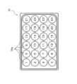
本実施形態の細胞培養分析装置1は、複数のウェル(培養容器)25aを含むウェルプレート25(図5参照)に入れられた培地(液体試料)X(図7参照)内にセンサ(試料測定センサ)30の一部を浸漬させた状態で電気化学的に培地Xに含まれる特定の成分(例えば、グルコース、乳酸等)の濃度を検出し、培養状態(細胞の代謝等)の分析を行う。 <Overview of
The cell
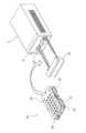
細胞培養分析装置1は、図1に示すように、分析ユニット2と、分析ユニット2が内部空間に載置されるインキュベータ3と、分析ユニット2を制御するとともに分析結果を表示する制御ユニット4と、を備えている。また、分析ユニット2と制御ユニット4とは、電気ケーブル5によって接続されている。
分析ユニット2は、インキュベータ3の正面に開閉可能に取り付けられた透明な扉3aを開けて、内部空間にセットされる。そして、分析ユニット2と電気ケーブル5を介して接続された制御ユニット4は、インキュベータ3の外部に配置されている。 1, the
The
これにより、使用者は、インキュベータ3の扉3aを開閉することなく、インキュベータ3内の培養状態を制御ユニット4によって分析することで、インキュベータ3内のコンタミネーションによる空気汚染を防止することができる。
分析ユニット2は、インキュベータ3内に複数台設置できるように、横(幅)方向は短く、高さ方向は低く、奥行き方向に長くなるように設計されている。 This allows the user to analyze the culture state in the
The
分析ユニット2は、図2および図3に示すように、センサ付き培養モジュール20、本体部21、引き出し部22および昇降機構23を備えている。
また、分析ユニット2は、図1に示すように、予めインキュベータ3内に配置され、電気ケーブル5によって制御ユニット4に接続される。そして、細胞の培養分析を行う時に、組み立てられたセンサ付き培養モジュール20が、図3に示すように、使用者によってインキュベータ3内の本体部21にセットされる。 As shown in FIGS. 2 and 3, the
1, the
分析ユニット2は、引き出し部22によって本体部21の内部にセンサ付き培養モジュール20を引き入れた状態で、昇降機構23によって、プローブホルダ(図示せず)側へ持ち上げられるように構成されている。
なお、分析ユニット2の詳細な構成については、後段にて詳述する。
センサ付き培養モジュール20は、図4に示すように、例えば、室温環境下(例えば、気温25度)の安全キャビネットC1内において、図5に示すウェルプレート25の各ウェル25aに培地Xが充填され(図7参照)、細胞が播種された後、組み立てられる。組み立てられたセンサ付き培養モジュール20は、高温多湿環境(37度、湿度90%以上)に保持されたインキュベータ3内の分析ユニット2にセットされる。つまり、組み立てられたセンサ付き培養モジュール20は、室温環境下から高温多湿環境下(例えば、気温37度、湿度90%以上)に移動される。 The
The detailed configuration of the
As shown in Fig. 4, for example, in a safety cabinet C1 in a room temperature environment (e.g., air temperature of 25°C), the sensor-equipped
なお、センサ付き培養モジュール20が室温環境下から高温多湿環境下へ移動した後、カビ等の不純物のセンサ表面への付着に起因するコンタミエラー、あるいはセンサ30が十分に培地Xへ浸漬されない浸漬不良エラー等を含む測定エラーの発生を抑制する構成については、後段にて詳述する。
センサ30は、例えば、樹脂材料であるPET(ポリエチレンテレフタレート)フィルム上面に、スパッタリングによってカーボンの電極層が形成されて構成されている。そして、センサ30は、図6に示すように、本体部31、検出部(電極部)31a、接続端子部31b、折り曲げ部32および連結部33を有している。 In addition, a configuration for suppressing the occurrence of measurement errors, including contamination errors caused by the adhesion of impurities such as mold to the sensor surface after the sensor-equipped
The
本体部31は、略長方形の平板状の部材であって、その上端部において折り曲げ部32と連結されている。
検出部(電極部)31aは、図7に示すように、本体部31の下端部に設けられ、ウェル25aに入れられた培地Xに浸漬された状態で各測定電極に所定の電圧が印加されることで、電気化学的に培地Xに含まれる特定の成分(例えば、グルコース、乳酸等)の濃度を測定する。検出部31aは、図8に示すように、下向きの略T字形状の本体部31の下端部の幅が広い部分の表面に設けられており、測定電極(作用極31aa,31ad、対極31ab、参照極31ac)を含む。 The
7, the detection unit (electrode unit) 31a is provided at the lower end of the
検出部31aに含まれる各測定電極は、レーザによって電極層を蒸散させ、分割されることによって形成される。なお、各測定電極は、配線間の絶縁性向上のため、スクリーン印刷によって電極パターンが形成されてもよい。
ここで、例えば、培地Xに含まれるグルコースの濃度を測定する場合には、作用極の表面に固定化された試薬層には、グルコース酸化酵素として、例えば、グルコースオキシダーゼ(GOx)、グルコースデヒドロゲナーゼ(GDH)、さらにはレドックスメディエータが含まれ得る。 Each measurement electrode included in the
Here, for example, when measuring the concentration of glucose contained in culture medium X, the reagent layer immobilized on the surface of the working electrode may contain, as a glucose oxidase, for example, glucose oxidase (GOx), glucose dehydrogenase (GDH), and further a redox mediator.
グルコースの濃度は、保護膜を通して培地Xから透過してきたグルコースが、試薬層の酵素(例えば、GOx、GDH)との反応で酸化されてグルコノラクトンとなり、同時に生成されるレドックスメディエータの還元体、もしくは過酸化水素の酸化反応によって生じる電子を電流値に変換することで測定される。
折り曲げ部32は、図6に示すように、本体部31と連結部33との間を連結する部分であって、所定の折り曲げ線に沿って略直角に折り曲げられる。これにより、連結部33は、本体部31に対して略直角に配置される。 The glucose concentration is measured by converting the glucose that has permeated from the culture medium X through the protective membrane into gluconolactone by reaction with an enzyme (e.g., GOx, GDH) in the reagent layer, and converting the electrons generated by the oxidation reaction of the reduced form of the redox mediator or hydrogen peroxide into a current value.
6, the
連結部33は、図6および図8に示すように、折り曲げ部32を介して、横方向に配置された4つのセンサ30の本体部31の上端部を互いに連結する。
接続端子部31bは、図8に示すように、4つ1組で1つのセンサ30の検出部31aの各測定電極に対応して配置された4つの電極31cと接続されている。
検出部31aに含まれる4つの測定電極のうち、作用極31aaは、センサ30の本体部31における左端に配置されており、乳酸を測定するための試薬が塗布された試薬層35を含んでいる。また、作用極31aaは、図9(a)に示すように、基材34の上面に形成された電極として設けられている。そして、作用極31aaの電極として使用される部分の上面に、試薬層35が設けられている。試薬層35の周囲には、試薬層35を取り囲むように絶縁層38が設けられている。さらに、試薬層35の上面には、測定対象(乳酸)を透過させる保護膜37が設けられている。絶縁層38の上面には、粘着層36を介して、さらに絶縁層38が設けられている。 As shown in FIGS. 6 and 8 , the connecting
As shown in FIG. 8, the
Of the four measurement electrodes included in the
これにより、作用極31aaの上面には、試薬層35が設けられているため、保護膜37を通じて浸透してきた乳酸が試薬層35において試薬と反応することで、作用極31aaにおいて測定される電流値が変化する。よって、この電流値の変化を検出することで、培地Xに含まれる乳酸の濃度変化を検出することができる。
対極31abは、センサ30の本体部31における作用極31aaと参照極31acとの間に配置されている。また、対極31abは、図9(b)に示すように、その表面が培地Xと直接接触するように、試薬層や保護膜が設けられておらず、露出した状態で設けられている。 As a result, since the
The counter electrode 31ab is disposed between the working electrode 31aa and the reference electrode 31ac in the
これにより、後述する対極端子電圧を測定する際に、例えば、対極31abの表面を覆うようにカビ等の不純物(コンタミ)が発生した場合には、対極31abの表面積が小さくなることで生じる対極端子電圧の変化を感度良く検出して、コンタミエラーを高精度に検出することができる。
また、対極31abの電極部分は、カーボンによって成形されている。カーボンは、金等の電極と比較して凹凸があり多孔質であることから、対極31abの表面には、カビが付着しやすく、電極の反応面積が低下してコンタミの発生を検知し易くなる。 As a result, when measuring the counter electrode terminal voltage described later, if impurities (contamination) such as mold occur and cover the surface of the counter electrode 31ab, a change in the counter electrode terminal voltage caused by a reduction in the surface area of the counter electrode 31ab can be detected with high sensitivity, and a contamination error can be detected with high accuracy.
The electrode portion of the counter electrode 31ab is made of carbon, which is uneven and porous compared to electrodes made of gold or the like, and therefore mold easily adheres to the surface of the counter electrode 31ab, reducing the reactive area of the electrode and making it easier to detect the occurrence of contamination.
参照極31acは、図8に示すように、センサ30の本体部31における対極31abと作用極31adとの間に配置されている。そして、参照極31acは、銀塩化銀によって形成されており、図9(b)に示すように、その表面が保護膜37によって覆われている。
作用極31adは、センサ30の本体部31における右端に配置されており、グルコースを測定するための試薬が塗布された試薬層35を含んでいる。また、作用極31adは、図9(a)に示すように、作用極31aaと同様に、基材34の上面に形成された電極として設けられている。そして、作用極31adの電極として使用される部分の上面に、試薬層35が設けられている。試薬層35の周囲には、試薬層35を取り囲むように絶縁層38が設けられている。さらに、試薬層35の上面には、測定対象(グルコース)を透過させる保護膜37が設けられている。絶縁層38の上面には、粘着層36を介して、さらに絶縁層38が設けられている。 As shown in Fig. 8, the reference electrode 31ac is disposed between the counter electrode 31ab and the working electrode 31ad in the
The working electrode 31ad is disposed at the right end of the
これにより、作用極31adの上面には、試薬層35が設けられているため、保護膜37を通じて浸透してきたグルコースが試薬層35において試薬と反応することで、作用極31adにおいて測定される電流値が変化する。よって、この電流値の変化を検出することで、培地Xに含まれるグルコースの濃度変化を検出することができる。
保護膜37は、培養中の細胞に対して毒性のある試薬を含む試薬層35および参照極31ac上に設けられた銀塩化銀等が、培地X中に溶出しないようにするために設けられている。また、保護膜37が設けられていることで、分析対象(グルコースおよび乳酸)の透過性を抑制し、試薬層35に含まれる試薬の反応性を制限することで、例えば、14日間の長期測定が可能になる。 As a result, because the
The
ここで、作用極31aa,31adは、平面視において略円形の開口から露出するように形成されている。これにより、作用極31aa,31adの上面に設けられる保護膜37を、略均等に塗布することができる。
一方、対極31abは、上述したように、試薬層や保護膜が設けられないため、培地Xと接触する表面積ができるだけ大きくなるように、略四角形の開口から吐出するように形成されている。これにより、後述する測定エラーの検出時に測定される対極端子電圧の測定感度を向上させることができる。 Here, the working electrodes 31aa, 31ad are formed so as to be exposed from substantially circular openings in a plan view, which allows the
On the other hand, as described above, the counter electrode 31ab is not provided with a reagent layer or a protective film, and is therefore formed to eject from a substantially rectangular opening so as to maximize the surface area in contact with the culture medium X. This can improve the measurement sensitivity of the counter electrode terminal voltage measured when a measurement error, which will be described later, is detected.
4つの電極31cは、細胞培養分析装置1(プローブホルダ(図示せず))と電気的に接続される接点として、センサ30の上部に設けられている。電極31cは、センサ30の本体部31の下部に配置された検出部31aに含まれる各測定電極(作用極31aa,31ad、対極31ab、参照極31ac)に電気的に接続されている。
本実施形態では、センサユニット28に含まれる複数のセンサ30は、図6に示すように、本体部31と、本体部31の下端側に配置され培地X内に浸漬されて培地Xの成分を測定する検出部31aと、本体部31の上端側において複数のセンサ30を連結する連結部33と、を備えている。 The four
In this embodiment, the
これにより、複数のセンサ30は、連結部33によって互いに連結された状態でボトムプレート27の上面に対して取り付けられるため、互いに連結されたセンサ30同士の位置を正確に規定することができる。
よって、ウェルプレート25に含まれる複数のウェル(培養容器)25aに対する個々のセンサ30の位置精度(位置・角度等)を向上させることができる。 As a result, the
Therefore, the positional accuracy (position, angle, etc.) of each
この結果、ウェル25a内に入れられた培地Xに対する個々のセンサ30の浸漬深さがほぼ一定になるため、安定した測定結果を得ることができる。
一方、ウェル15aに対する個々のセンサ30の位置精度は向上するものの、ウェルプレート25には、複数(本実施形態では24個)のウェル25aが含まれている。このため、個々のウェル25aに、規定量の培地Xを正確に注入することは困難であるとともに、人為的な培地Xの入れ忘れ、注入量の間違い等のミスも生じるおそれがある。よって、ウェル25aごとに入れられた培地Xの量にばらつきが生じ、センサ30の検出部31aをウェル25a内の培地Xに浸漬する際に、培地Xの量が少なすぎて検出部31aが十分に浸漬されない浸漬不良エラーが発生するおそれがある。 As a result, the immersion depth of each
On the other hand, although the positional accuracy of each
さらに、細胞培養を行う環境は、上述したように、高温多湿環境となるため、細胞の培養中にカビ等の不純物(コンタミ)が発生しやすい。例えば、このようなカビ等の不純物(コンタミ)が、ウェル25a内の培地Xに浸漬された状態でセンサ30の表面等に付着して成長すると、測定対象(グルコース、乳酸)の測定結果に悪影響を及ぼすおそれがある。Furthermore, as described above, the environment in which cells are cultured is a high-temperature and high-humidity environment, which makes it easy for impurities (contaminants) such as mold to occur during cell culture. For example, if such impurities (contaminants) such as mold adhere to and grow on the surface of the
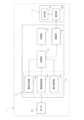
本実施形態の細胞培養分析装置1では、このような測定エラー(浸漬不良エラー、コンタミエラー)の発生を高精度に検出するために、分析ユニット2が、図10に示すように、電気化学測定部11と、制御部12と、記憶部13と、通信部14と、を備えている。
電気化学測定部11は、3極構成のセンサ30の電極に対して所定の電圧を印加して測定対象の濃度を測定するポテンショスタットであって、図10に示すように、電圧印加部11aと、電流測定部11bと、電圧測定部(対極端子電圧測定部)11cとを有している。 In the cell
The
電圧印加部11aは、上述した3極構成のセンサ30に対して、培地Xに含まれるグルコース、乳酸の濃度を測定するための所定の電圧を印加する。
電流測定部11bは、電圧印加部11aからセンサ30の電極に対して電圧が印加されて測定されるセンサ30を流れる電流値の変化を検出する。これにより、作用極31aaを流れる電流値の変化に応じて、乳酸の濃度を測定し、作用極31adを流れる電流値の変化に応じて、グルコースの濃度を測定することができる(図11参照)。 The
The
電圧測定部11cは、測定エラー(浸漬不良エラー、コンタミエラー)の発生を検出するために、センサ30の対極31abの端子電圧を測定する。電圧測定部11cにおいて測定された結果は、通信部14を介して、制御ユニット4へ送信される。
制御部12は、図10に示すように、電圧印加部11a、電流測定部11b、電圧測定部11c、記憶部13および通信部14と接続されている。制御部12は、電圧印加部11aに対して、センサ30に対して所定の電圧を印加するように制御するとともに、電流測定部11bおよび電圧測定部11cにおける測定結果を、制御ユニット4に送信するように、通信部14を制御する。 In order to detect the occurrence of a measurement error (poor immersion error, contamination error), the
10, the
記憶部13は、図10に示すように、制御部12と接続されており、例えば、測定対象ごとに予め設定された印加電圧の値、電流測定部11bおよび電圧測定部11cにおける測定結果等のデータを保存する。
通信部14は、図10に示すように、制御部12によって制御され、制御ユニット4の解析部42に対して、電流測定部11bおよび電圧測定部11cにおける測定結果等のデータを送信する。 As shown in FIG. 10, the
As shown in FIG. 10, the
制御ユニット4は、図10に示すように、通信部14を介して分析ユニット2との間で通信可能であって、表示部41と、解析部42とを備えている。
表示部41は、解析部42における解析の結果として、例えば、電流測定部11bにおいて測定されたセンサ電流値からグルコース、乳酸の濃度変化、電圧測定部11cにおいて測定された対極端子電圧の値から測定エラーの検出結果等を表示する。 As shown in FIG. 10 , the
The
解析部42は、例えば、PC(Personal Computer)であって、電流測定部11bにおいて測定された作用極31aa,31adを流れるセンサ電流値の変化に基づいて、測定対象となる乳酸、グルコースの濃度を測定することで、培養中の細胞の代謝分析を行う。また、解析部42は、電圧測定部11cにおいて測定された対極端子電圧の変化に基づいて、後述する測定エラー(コンタミエラー、浸漬不良エラー)の有無を検出する。The
<測定エラーの検出>
本実施形態の細胞培養分析装置1は、上述した構成を備えており、電圧測定部11cにおいて測定された対極端子電圧を測定することで、カビ等の不純物がセンサ表面に付着して測定結果の精度が低下するコンタミエラー、あるいはウェルプレート25のウェル25aに入れられた培地Xの充填量のバラツキによってセンサが十分に浸漬されない浸漬不良エラー等を含む測定エラーを検出する。 <Detection of measurement errors>
The
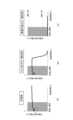
ここで、図11、図12(a)および図12(b)を用いて、対極端子電圧の測定によって、測定エラーの検出が可能となる原理について説明する。
なお、図12(a)および図12(b)は、対極端子電圧の振る舞いを分かりやすく説明するためのグラフであって、実際の測定では、細胞代謝はグルコースを消費して乳酸を産生するため、グルコース電流値は時間経過とともに減少し、乳酸電流は増加するものとする。 Here, the principle by which measurement of the counter terminal voltage enables detection of a measurement error will be described with reference to Figs. 11, 12(a) and 12(b).
Note that Figures 12(a) and 12(b) are graphs for easily explaining the behavior of the counter electrode terminal voltage, and in actual measurements, since cellular metabolism consumes glucose and produces lactic acid, the glucose current value decreases over time and the lactic acid current increases.
図11に示すセンサ30内の回路が正常に動作しているとき、対極31abと作用極31aa,31adに流れる電流iLac,iGlcは等価である。そして、図12(a)に示すように、作用極31aa,31adに流れる電流iLac,iGlcが増加すると、対極31ab側の電流が増加する方向に対極端子電圧が変化する。
換言すれば、対極31ab側の電流が増加する方向に対極端子電圧が変化するとは、対極31abにおける単位電極面積当たりの反応が増加することと同義である。これは、対極31abの駆動力が大きくなる、すなわち、図12(b)に示すように、参照極31acと対極31abとの間の電圧差(RE-CE)が大きくなる、ことを意味している。 When the circuit in the
In other words, a change in the counter electrode terminal voltage in a direction in which the current on the counter electrode 31ab side increases is synonymous with an increase in the reaction per unit electrode area of the counter electrode 31ab, which means that the driving force of the counter electrode 31ab increases, that is, the voltage difference (RE-CE) between the reference electrode 31ac and the counter electrode 31ab increases, as shown in FIG.
よって、回路的には、図12(b)に示すように、対極31abに接続されているオペアンプ出力(対極端子電圧)が、マイナス方向へ変化する。すなわち、センサ電流が増加すると、対極端子電圧は低下していく。
これにより、例えば、高温多湿環境下に設置されたセンサ30の表面、特に対極31abの表面に、カビ等の不純物が発生し増殖されていくと、対極端子電圧は急激に低下していく。 12B, the output of the operational amplifier connected to the counter electrode 31ab (counter electrode terminal voltage) changes in the negative direction. In other words, when the sensor current increases, the counter electrode terminal voltage decreases.
As a result, for example, when impurities such as mold are generated and grow on the surface of the
本実施形態の細胞培養分析装置1では、以上のことから、対極端子電圧を測定することで、センサ30において生じたコンタミエラーおよび浸漬不良エラーを検出し、精度が低下した状態でグルコース濃度および乳酸の濃度の測定が実施されることを回避する。
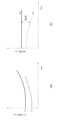
より具体的には、本実施形態の細胞培養分析装置1では、解析部42が、図13(a)に示すように、センサ30に対する電圧の印加開始からの所定の期間、測定を実施しない見逃し期間を設定している。 As described above, in the cell
More specifically, in the
この見逃し期間の設定は、センサ30への電圧印加を開始した直後の数時間は、電圧印加前のセンサ30の状態によって対極端子電圧が大きく変化するおそれがあり、測定結果にばらつきが生じるおそれがあるためである。
なお、センサ30を培地Xへ浸漬した後、電圧の印加前の状態ではメディエータ試薬の作用によって還元物質が増加していく。そのためセンサ30の浸漬から電圧印加までの時間によって、電圧印加直後に流れるセンサ電流の大きさに差が生じる。すなわち、浸漬から電圧印加までの時間が長いほど、大きなセンサ電流が流れる。よって、回路的には、作用極31aa,31adと等価の大きな電流を対極31abに流すために、対極31abの端子電圧を下げるよう制御する。 The reason for setting this oversight period is that, in the several hours immediately after starting to apply voltage to the
After the
このため、対極端子電圧の変動速度が大きくなりやすい電圧印加開始直後の数時間が、見逃し期間(不感帯)として設定される。
次に、コンタミエラーの検出について、図13(b)を用いて説明する。
図13(b)に示すように、見逃し期間を経過後、カビ等の不純物(コンタミ)がセンサ30の表面に発生して増殖されると、途中から急激に対極端子電圧が低下していく。 For this reason, the period of several hours immediately after the start of voltage application, during which the rate of change of the counter terminal voltage is likely to be large, is set as an overlooked period (dead zone).
Next, detection of a contamination error will be described with reference to FIG.
As shown in FIG. 13B, after the overlooked period has elapsed, when impurities (contaminants) such as mold appear and grow on the surface of the
このとき、対極端子電圧は、細胞代謝によっても低下するが、コンタミ発生時には、細胞代謝時よりもさらに急峻に低下する(細胞代謝と比較してマイナスの変化速度が大きい)。
よって、解析部42は、対極端子電圧のマイナス変化率が所定の閾値未満であるか否かを判定し、所定の閾値未満であった場合には、コンタミエラー発生と判定するとともに、表示部41へコンタミエラー発生と表示することで、使用者に対して異常の発生を報知することができる。 At this time, the counter terminal voltage also decreases due to cell metabolism, but when contamination occurs, the voltage decreases more steeply than during cell metabolism (the rate of negative change is greater than that during cell metabolism).
Therefore, the
次に、浸漬不良エラーの検出について、図13(c)を用いて説明する。
センサ30の検出部31aが培地Xに十分浸漬されている場合には、対極31abに接続されているオペアンプ出力と、参照極31acに接続されているオペアンプ反転入力とが液を介して接続され、クローズドループが形成される。対極31abに接続されているオペアンプ出力電圧は、参照極参照極31acに接続されている「オペアンプ反転入力の電圧」と、参照極電圧設定用DAコンバータに接続されている「オペアンプ非反転入力の電圧」とが、等しくなるように所定の範囲内で推移する。 Next, detection of an improper immersion error will be described with reference to FIG.
When the
一方で、センサ30の検出部31aが培地Xに十分浸漬されていない浸漬エラーが発生している場合には、対極31abに接続されているオペアンプ出力と、参照極31acに接続されているオペアンプ反転入力とが液を介して接続されないため、オープンループとなる。
そのためオペアンプは、コンパレータとして動作し、対極31abに接続されているオペアンプ出力電圧(対極端子電圧)は、初期の段階(見逃し期間中)でLoかHiかいずれかの状態となる。すなわち、対極端子電圧が底打ちする(ほぼ0になる)か、頭打ちする(ほぼオペアンプの最大出力電圧)ことになる。 On the other hand, if an immersion error occurs in which the
Therefore, the operational amplifier operates as a comparator, and the operational amplifier output voltage (counter electrode terminal voltage) connected to the counter electrode 31ab is in either a Lo or Hi state in the initial stage (during the over-the-air period). That is, the counter electrode terminal voltage hits bottom (becomes almost 0) or peaks (becomes almost the maximum output voltage of the operational amplifier).
なお、電圧印加開始時に浸漬状態に問題がない場合には、高温多湿環境下の細胞培養中に途中から浸漬エラーとなるケースは考えにくい。すなわち、ウェル25aに規定量の培地Xが注入されていれば、細胞培養中に培地Xの一部が蒸発したとしても浸漬エラーとなることはない。
よって、解析部42は、見逃し期間中に、対極端子電圧が所定の範囲を逸脱したか否かを判定し、所定の範囲を逸脱した場合には、浸漬エラー発生と判定するとともに、表示部41へ浸漬エラー発生と表示することで、使用者に対して異常の発生を報知することができる。 If there is no problem with the immersion state when the voltage application starts, it is unlikely that an immersion error will occur midway through cell culture in a hot and humid environment. In other words, if a specified amount of medium X is injected into
Therefore, the
<測定エラーの検出方法>
本実施形態の細胞培養分析装置1では、上述したように、3極構成のセンサ30の対極31abに係る対極端子電圧を測定することで、上述した測定エラー(コンタミエラーおよび浸漬不良エラー)を検出する。
ここでは、図14のフローチャートを用いて、測定エラーの検出方法の処理の流れを説明する。
すなわち、ステップS11では、分析ユニット2の電気化学測定部11に含まれる電圧印加部11aが、センサ30に対して所定の電圧を印加した後、解析部42が、電圧測定部11cから、通信部14を介して、センサ30の対極31abに掛かる対極端子電圧を受信する。 <How to detect measurement errors>
In the cell
Here, the process flow of the measurement error detection method will be described with reference to the flowchart of FIG.
That is, in step S11, the
次に、ステップS12では、解析部42が、受信した対極端子電圧が見逃し期間内に測定された結果であるか否かを判定する。
ここで、見逃し期間の測定結果であった場合には、ステップS13以降の浸漬エラーの判定処理へ進む。一方、見逃し期間内の測定結果ではなく、見逃し期間が経過した後の測定結果であった場合には、ステップS17以降のコンタミエラーの判定処理へ進む。 Next, in step S12, the
If the measurement result is from the oversight period, the process proceeds to the immersion error determination process from step S13 onwards. On the other hand, if the measurement result is not from within the oversight period but from after the oversight period has elapsed, the process proceeds to the contamination error determination process from step S17 onwards.
次に、ステップS13では、受信した対極端子電圧がステップS12において見逃し期間内の測定結果であると判定されたため、解析部42が、浸漬エラーの有無を判定するために、対極端子電圧の値が所定の範囲外であるか否かを判定する。
ここで、対極端子電圧の値が所定の範囲外である場合には、浸漬エラー発生ありと判断し、ステップS14へ進む。一方、対極端子電圧の値が所定の範囲内である場合には、浸漬エラーは発生していないと判断し、ステップS16へ進む。 Next, in step S13, since it was determined in step S12 that the received counter electrode terminal voltage is a measurement result within the overlooked period, the
If the counter electrode terminal voltage value is outside the predetermined range, it is determined that an immersion error has occurred, and the process proceeds to step S14. On the other hand, if the counter electrode terminal voltage value is within the predetermined range, it is determined that an immersion error has not occurred, and the process proceeds to step S16.
次に、ステップS14では、ステップS13において、対極端子電圧の値が所定の範囲外であると判定されたため、発生していると思われる浸漬エラーを、表示部41において使用者に報知済みであるか否かを判定する。
ここで、報知済みである場合には、ステップS16へ進み、報知されていない場合には、ステップS15へ進む。 Next, in step S14, it is determined whether an immersion error that is believed to have occurred because it was determined in step S13 that the value of the counter electrode terminal voltage is outside the predetermined range has been notified to the user on the
If the notification has already been given, the process proceeds to step S16, and if the notification has not been given, the process proceeds to step S15.
次に、ステップS15では、まだ報知されていない浸漬エラーの発生を報知するために、表示部41が、浸漬エラーが発生している旨の表示を行う。そして、培地Xにセンサ30の検出部31aが十分に浸漬されていない状態で電圧が印加されたままでは、センサ30が故障してしまうおそれがあるため、制御部12が、電圧印加部11aからセンサ30に対する電圧の印加を停止させ、ステップS22へ進む。Next, in step S15, in order to notify the occurrence of an immersion error that has not yet been notified, the
次に、ステップS16では、ステップS13において対極端子電圧の値が所定の範囲内であると判定された、あるいは、ステップS14において浸漬エラー発生を報知済みと判定されたため、培養を継続するか否かが判定される。
ここで、使用者が培養を継続することを選択すると、ステップS11へ戻って、測定エラーの判定処理を繰り返す。一方、使用者が培養を継続しないことを選択すると、処理を終了する。 Next, in step S16, because it was determined in step S13 that the value of the counter electrode terminal voltage is within a predetermined range, or because it was determined in step S14 that an immersion error has been notified, it is determined whether or not to continue the culture.
If the user selects to continue the culture, the process returns to step S11 and the measurement error determination process is repeated, whereas if the user selects not to continue the culture, the process ends.
一方、ステップS17では、受信した対極端子電圧がステップS12において見逃し期間外の測定結果であると判定されたため、解析部42が、コンタミエラーの有無を判定するために、経過時間における対極端子電圧のマイナスの変化速度を算出する。
次に、ステップS18では、ステップS17において算出された対極端子電圧のマイナスの変化速度が、所定の閾値未満であるか否かを判定する。 On the other hand, in step S17, since it is determined in step S12 that the received counter electrode terminal voltage is a measurement result outside the overlooked period, the
Next, in step S18, it is determined whether or not the rate of negative change in the counter terminal voltage calculated in step S17 is less than a predetermined threshold value.
ここで、閾値未満である場合には、コンタミエラー発生ありと判定し、ステップS19へ進む。一方、閾値以上である場合には、ステップS21へ進む。
次に、ステップS19では、ステップS18において、対極端子電圧のマイナスの変化速度が所定の閾値未満であると判定されたため、発生していると思われるコンタミエラーの発生を、表示部41において使用者に報知済みであるか否かを判定する。 If the difference is less than the threshold, it is determined that a contamination error has occurred, and the process proceeds to step S19, whereas if the difference is equal to or greater than the threshold, the process proceeds to step S21.
Next, in step S19, it is determined whether or not a contamination error that is believed to have occurred because it was determined in step S18 that the rate of negative change in the counter electrode terminal voltage is less than a predetermined threshold has been notified to the user on the
ここで、報知済みである場合には、ステップS21へ進み、報知されていない場合には、ステップS20へ進む。
次に、ステップS20では、まだ報知されていないコンタミエラーの発生を報知するために、表示部41が、コンタミエラーが発生している旨の表示を行う。
次に、ステップS21では、ステップS18において対極端子電圧の変化速度が所定の閾値以上であると判定された、あるいは、ステップS19においてコンタミエラー発生を報知済みと判定されたため、培養を継続するか否かが判定される。ここで、使用者が培養を継続することを選択すると、ステップS11へ戻って、測定エラーの判定処理を繰り返す。一方、使用者が培養を継続しないことを選択すると、処理を終了する。 If the notification has already been given, the process proceeds to step S21. If the notification has not been given, the process proceeds to step S20.
Next, in step S20, in order to notify the occurrence of a contamination error that has not yet been notified, the
Next, in step S21, since it has been determined in step S18 that the rate of change in the counter electrode terminal voltage is equal to or greater than a predetermined threshold value, or it has been determined in step S19 that a contamination error has been notified, it is determined whether or not to continue the culture. If the user selects to continue the culture, the process returns to step S11, and the measurement error determination process is repeated. On the other hand, if the user selects not to continue the culture, the process ends.
次に、ステップS22では、ステップS15において浸漬エラーの発生を報知、ステップS20においてコンタミエラーの発生を報知した後、培養を中断するか否かが選択される。
このとき、使用者の判断によって培養を中断するか否かを選択可能であるが、通常は、カビ等の付着がある場合には、培養の継続は不可能と判断して、処理を終了する。 Next, in step S22, after the occurrence of an immersion error has been notified in step S15 and the occurrence of a contamination error has been notified in step S20, it is selected whether or not to interrupt the culture.
At this time, the user can choose whether or not to interrupt the culture, but normally, if mold or the like is found to have adhered, it is determined that the culture cannot be continued and the process is terminated.
<主な特徴>
本実施形態の細胞培養分析装置1は、図10に示すように、電圧印加部11aと、電流測定部11bと、電圧測定部11cと、解析部42と、を備えている。電圧印加部11aは、センサ30の作用極31aa,31ad、対極31abおよび参照極31acを含む検出部31aが培地Xに浸漬された状態で、検出部31aに電圧を印加する。電流測定部11bは、検出部31aに印加された電圧によってセンサ30に流れる電流値を測定する。解析部42は、電流測定部11bにおける測定結果に基づいて、培地Xに含まれるグルコース、乳酸の濃度を算出する。電圧測定部11cは、電圧印加部11aによって印加された電圧によって、検出部31aに含まれる対極31abの端子電圧を測定する。解析部42は、電圧測定部11cにおいて測定された対極31abの端子電圧に基づいて、測定エラーを検出する。 <Main features>
As shown in FIG. 10, the
これにより、センサ30の検出部31aが十分に培地X内に浸漬されていない場合や、センサ30の表面にカビ等の不純物が付着した場合に、一定の挙動を示す対極端子電圧の変化をモニタリングすることで、測定エラーの発生を高精度に検出することができる。
この結果、センサ浸漬不良やコンタミ発生等に起因する測定エラーの発生を高精度に検出して、測定対象となるグルコース、乳酸等の測定を精度良く実施することができる。 As a result, when the
As a result, occurrence of measurement errors due to improper sensor immersion, the occurrence of contamination, etc. can be detected with high accuracy, and the measurement targets such as glucose, lactate, etc. can be measured with high accuracy.
[他の実施形態]
以上、本発明の一実施形態について説明したが、本発明は上記実施形態に限定されるものではなく、発明の要旨を逸脱しない範囲で種々の変更が可能である。
(A)
上記実施形態では、試料測定装置および試料測定方法として、本発明を実現した例を挙げて説明した。しかし、本発明はこれに限定されるものではない。
例えば、上述した試料測定装置による試料測定方法をコンピュータに実行させる試料測定プログラムとして本発明を実現してもよい。 [Other embodiments]
Although one embodiment of the present invention has been described above, the present invention is not limited to the above embodiment, and various modifications are possible without departing from the gist of the invention.
(A)
In the above embodiment, examples of the sample measurement device and sample measurement method according to the present invention have been described, but the present invention is not limited to this.
For example, the present invention may be realized as a sample measurement program that causes a computer to execute the sample measurement method using the sample measurement device described above.
この試料測定プログラムは、試料測定装置に搭載されたメモリ(記憶部)に保存されており、CPUがメモリに保存された試料測定プログラムを読み込んで、ハードウェアに各ステップを実行させる。より具体的には、CPUが試料測定プログラムを読み込んで、上述した電圧印加ステップと、電流測定ステップと、濃度測定ステップと、対極端子電圧測定ステップと、測定エラー検出ステップと、を実行することで、上記と同様の効果を得ることができる。
また、本発明は、試料測定プログラムを保存した記録媒体として実現されてもよい。 This sample measurement program is stored in a memory (storage unit) mounted on the sample measurement device, and the CPU reads the sample measurement program stored in the memory and causes the hardware to execute each step. More specifically, the CPU reads the sample measurement program and executes the above-mentioned voltage application step, current measurement step, concentration measurement step, counter electrode terminal voltage measurement step, and measurement error detection step, thereby achieving the same effects as those described above.
The present invention may also be realized as a recording medium on which a sample measurement program is stored.
(B)
上記実施形態では、本発明の試料測定装置に含まれる濃度測定部および測定エラー検出部が、制御ユニット4側の解析部42として設けられている例を挙げて説明した。しかし、本発明はこれに限定されるものではない。
例えば、分析ユニット2側の制御部12が、濃度測定部および測定エラー検出部として機能する構成であってもよい。 (B)
In the above embodiment, an example has been described in which the concentration measurement unit and the measurement error detection unit included in the sample measurement device of the present invention are provided as the
For example, the
(C)
上記実施形態では、グルコース測定用と乳酸測定用の2つの作用極31aa,31adを含むセンサ30を用いた例を挙げて説明した。しかし、本発明はこれに限定されるものではない。
例えば、作用極、対極、参照極が1つずつ設けられた3極構成のセンサを用いた構成であってもよい。 (C)
In the above embodiment, an example has been described in which the
For example, a three-electrode sensor having a working electrode, a counter electrode, and a reference electrode may be used.
(D)
上記実施形態では、本発明の試料測定装置を、細胞培養分析装置1に対して適用した例を挙げて説明した。しかし、本発明はこれに限定されるものではない。
例えば、細胞培養以外の装置であって、試料の測定を行う測定装置に対して、本発明が適用されてもよい。 (D)
In the above embodiment, an example has been described in which the sample measurement device of the present invention is applied to the
For example, the present invention may be applied to a measuring device that measures a sample, other than a cell culture device.
(E)
上記実施形態では、測定対象として、グルコースと乳酸の濃度を測定するセンサ30が用いられた例を挙げて説明した。しかし、本発明はこれに限定されるものではない。
例えば、測定対象物としては、グルコースと乳酸に限らず、他の物質であってもよい。 (E)
In the above embodiment, an example has been described in which the
For example, the measurement target is not limited to glucose and lactic acid, but may be other substances.
(F)
上記実施形態では、センサ30が折り曲げ部32において折り曲げた状態で使用される例を挙げて説明した。しかし、本発明はこれに限定されるものではない。
例えば、センサが折り曲げられることなく使用される構成であってもよい。
この場合でも、センサの本体部の上端部分において、複数のセンサが連結部によって連結された構成にすることで、センサの位置精度を向上させるという上記と同様の効果を得ることができる。 (F)
In the above embodiment, an example has been described in which the
For example, the sensor may be configured to be used without being bent.
Even in this case, by configuring the multiple sensors to be connected by connecting parts at the upper end portion of the main body of the sensor, the same effect as above of improving the positional accuracy of the sensors can be obtained.
(G)
上記実施形態では、逆向きに略T字形状のセンサ30を用いた例を挙げて説明した。しかし、本発明はこれに限定されるものではない。
例えば、略I字形状あるいは略L字形状のセンサが用いられていてもよい。 (G)
In the above embodiment, an example has been described in which the
For example, a sensor having a substantially I-shape or a substantially L-shape may be used.
(H)
上記実施形態では、本発明の試料測定装置を、細胞培養分析装置に適用した例を挙げて説明した。しかし、本発明はこれに限定されるものではない。
例えば、細胞培養以外でも、試料の測定を行う装置に対して、本発明を適用してもよい。 (H)
In the above embodiment, an example was given in which the sample measurement device of the present invention was applied to a cell culture analyzer, but the present invention is not limited to this.
For example, the present invention may be applied to devices for measuring samples other than cell culture.
本発明の試料測定装置は、正確な測定を行うために、センサ浸漬不良やコンタミ発生等に起因する測定エラーの発生を検出することができるという効果を奏することから、細胞培養の分野に限らず、各種試料の測定を行う装置に対して広く適用可能である。The sample measurement device of the present invention has the effect of being able to detect measurement errors caused by improper sensor immersion, contamination, etc., in order to perform accurate measurements, and is therefore widely applicable not only to the field of cell culture but also to devices that measure various samples.
1 細胞培養分析装置(試料測定装置)
2 分析ユニット
3 インキュベータ
3a 扉
4 制御ユニット
5 電気ケーブル
11 電気化学測定部
11a 電圧印加部
11b 電流測定部
11c 電圧測定部(対極端子電圧測定部)
12 制御部
13 記憶部
14 通信部
20 センサ付き培養モジュール
21 本体部
22 引き出し部
23 昇降機構
25 ウェルプレート
25a ウェル
27 ボトムプレート
28 センサユニット
30 センサ(試料測定センサ)
31 本体部
31a 検出部(電極部)
31aa 作用極
31ab 対極
31ac 参照極
31ad 作用極
31b 接続端子部
31c 電極
32 折り曲げ部
33 連結部
34 基材(PETシート)
35 試薬層
36 粘着層
37 保護膜
38 絶縁層
41 表示部
42 解析部(濃度測定部、測定エラー検出部)
C1 安全キャビネット
i 電流
X 培地 1. Cell culture analyzer (sample measurement device)
2
12
31
31aa Working electrode 31ab Counter electrode 31ac Reference electrode
35
C1 Safety cabinet i Current X Culture medium
Claims (11)
Translated fromJapanese前記電極部に印加された電圧によって前記試料測定センサに流れる電流値を測定する電流測定部と、
前記電流測定部における測定結果に基づいて、前記試料に含まれる分析物の濃度を算出する濃度測定部と、
前記電圧印加部によって電圧が印加された状態で、前記電極部に含まれる前記対極の端子電圧を測定する対極端子電圧測定部と、
前記対極端子電圧測定部において測定された前記対極の端子電圧に基づいて、測定エラーを検出する測定エラー検出部と、
を備え、
前記測定エラー検出部は、前記試料以外の不純物の混入に起因するコンタミエラーの有無を検出するとともに、
前記測定エラー検出部は、前記対極端子電圧測定部における測定結果の変動速度が所定の閾値以下である場合には、前記コンタミエラーであると判定する、
試料測定装置。 a voltage application unit that applies a voltage to an electrode unit including at least a working electrode, a counter electrode, and a reference electrode of the sample measurement sensor while the electrode unit is immersed in the sample;
a current measuring unit that measures a value of a current flowing through the sample measurement sensor due to a voltage applied to the electrode unit;
a concentration measuring unit that calculates a concentration of an analyte contained in the sample based on a measurement result by the current measuring unit;
a counter electrode terminal voltage measuring unit that measures a terminal voltage of the counter electrode included in the electrode unit while a voltage is applied by the voltage application unit;
a measurement error detection unit that detects a measurement error based on the terminal voltage of the counter electrode measured by the counter electrode terminal voltage measurement unit;
Equippedwith
The measurement error detection unit detects the presence or absence of a contamination error caused by the inclusion of impurities other than the sample, and
The measurement error detection unit determines that a contamination error has occurred when a fluctuation speed of the measurement result in the counter electrode terminal voltage measurement unit is equal to or less than a predetermined threshold value.
Sample measurement device.
請求項1に記載の試料測定装置。 the measurement error detection unit sets an oversight period during which the measurement is not performed until a predetermined time has elapsed since the voltage application unit applied the voltage, and determines whether or not the contamination error has occurred after the oversight period has elapsed.
The sample measurement device according to claim1 .
請求項1または2に記載の試料測定装置。 the measurement error detection unit detects the presence or absence of an immersion failure error caused by an immersion failure in which the electrode unit is not properly immersed in the sample;
3. The sample measurement device according to claim 1 or 2.
請求項3に記載の試料測定装置。 the measurement error detection unit sets an overlooked period during which the measurement is not performed until a predetermined time has elapsed since the voltage application unit applied the voltage;
The sample measurement device according to claim3 .
請求項4に記載の試料測定装置。 the measurement error detection unit determines that the immersion error has occurred when the terminal voltage of the counter electrode detected during the overlooked period is outside a predetermined range.
The sample measurement device according to claim4 .
請求項5に記載の試料測定装置。 When it is determined that the immersion failure error occurs, the voltage application unit stops applying the voltage.
The sample measurement device according to claim5 .
請求項1または2に記載の試料測定装置。 Further comprising a display unit that displays the detection result of the measurement error in the measurement error detection unit.
3. The sample measurement device according to claim 1 or 2.
前記電極部に印加された電圧によって前記試料測定センサに流れる電流値を測定する電流測定部と、
前記電流測定部における測定結果に基づいて、前記試料に含まれる分析物の濃度を算出する濃度測定部と、
前記電圧印加部によって電圧が印加された状態で、前記電極部に含まれる前記対極の端子電圧を測定する対極端子電圧測定部と、
前記対極端子電圧測定部において測定された前記対極の端子電圧に基づいて、測定エラーを検出する測定エラー検出部と、
を備え、
前記試料測定センサは、少なくとも前記作用極、前記対極および前記参照極を含む前記電極部を備えており、
前記作用極は、電極部分の表面に塗布された試薬が保護膜によって覆われており、
前記参照極は、電極部分の表面が保護膜によって覆われており、
前記対極は、前記試料に対して電極部分が露出している、
試料測定装置。a voltage application unit that applies a voltage to an electrode unit including at least a working electrode, a counter electrode, and a reference electrode of the sample measurement sensor while the electrode unit is immersed in the sample;
a current measuring unit that measures a value of a current flowing through the sample measurement sensor due to a voltage applied to the electrode unit;
a concentration measuring unit that calculates a concentration of an analyte contained in the sample based on a measurement result by the current measuring unit;
a counter electrode terminal voltage measuring unit that measures a terminal voltage of the counter electrode included in the electrode unit while a voltage is applied by the voltage application unit;
a measurement error detection unit that detects a measurement error based on the terminal voltage of the counter electrode measured by the counter electrode terminal voltage measurement unit;
Equipped with
The sample measurement sensor includes an electrode unit including at least the working electrode, the counter electrode, and the reference electrode,
The working electrode has a reagent applied to the surface of the electrode portion covered with a protective film,
The surface of the electrode portion of the reference electrode is covered with a protective film,
The counter electrode has an electrode portion exposed to the sample.
Sample measurement device.
請求項8に記載の試料測定装置。 The counter electrode portion is formed of carbon.
The sample measurement device according to claim8 .
前記電圧印加ステップにおいて印加された電圧によって前記試料測定センサに流れる電流値を測定する電流測定ステップと、
前記電流測定ステップにおける測定結果に基づいて、前記試料に含まれる分析物の濃度を算出する濃度測定ステップと、
前記電圧印加ステップにおいて電圧が印加された状態で、前記電極部に含まれる前記対極の端子電圧を測定する対極端子電圧測定ステップと、
前記対極端子電圧測定ステップにおいて測定された前記対極の端子電圧に基づいて、測定エラーを検出する測定エラー検出ステップと、
を備え、
前記測定エラー検出ステップでは、前記試料以外の不純物の混入に起因するコンタミエラーの有無を検出するとともに、
前記測定エラー検出ステップでは、前記対極端子電圧測定ステップにおける測定結果の変動速度が所定の閾値以下である場合には、前記コンタミエラーであると判定する、
試料測定方法。 a voltage application step of applying a voltage to an electrode portion including at least a working electrode, a counter electrode, and a reference electrode of the sample measurement sensor while the electrode portion is immersed in the sample;
a current measuring step of measuring a value of a current flowing through the sample measurement sensor due to the voltage applied in the voltage applying step;
a concentration measuring step of calculating a concentration of an analyte contained in the sample based on a measurement result in the current measuring step;
a counter electrode terminal voltage measuring step of measuring a terminal voltage of the counter electrode included in the electrode unit while a voltage is being applied in the voltage applying step;
a measurement error detection step of detecting a measurement error based on the terminal voltage of the counter electrode measured in the counter electrode terminal voltage measurement step;
Equippedwith
In the measurement error detection step, the presence or absence of a contamination error caused by the inclusion of impurities other than the sample is detected,
In the measurement error detection step, when a fluctuation speed of the measurement result in the counter electrode terminal voltage measurement step is equal to or less than a predetermined threshold, it is determined that there is a contamination error.
Sample measurement method.
前記電圧印加ステップにおいて印加された電圧によって前記試料測定センサに流れる電流値を測定する電流測定ステップと、
前記電流測定ステップにおける測定結果に基づいて、前記試料に含まれる分析物の濃度を算出する濃度測定ステップと、
前記電圧印加ステップにおいて電圧が印加された状態で、前記電極部に含まれる前記対極の端子電圧を測定する対極端子電圧測定ステップと、
前記対極端子電圧測定ステップにおいて測定された前記対極の端子電圧に基づいて、測定エラーを検出する測定エラー検出ステップと、
を備え、
前記測定エラー検出ステップでは、前記試料以外の不純物の混入に起因するコンタミエラーの有無を検出するとともに、
前記測定エラー検出ステップでは、前記対極端子電圧測定ステップにおける測定結果の変動速度が所定の閾値以下である場合には、前記コンタミエラーであると判定する、
試料測定方法をコンピュータに実行させる試料測定プログラム。 a voltage application step of applying a voltage to an electrode portion including at least a working electrode, a counter electrode, and a reference electrode of the sample measurement sensor in a state where the electrode portion is immersed in the sample;
a current measuring step of measuring a value of a current flowing through the sample measurement sensor due to the voltage applied in the voltage applying step;
a concentration measuring step of calculating a concentration of an analyte contained in the sample based on a measurement result in the current measuring step;
a counter electrode terminal voltage measuring step of measuring a terminal voltage of the counter electrode included in the electrode unit while a voltage is being applied in the voltage applying step;
a measurement error detection step of detecting a measurement error based on the terminal voltage of the counter electrode measured in the counter electrode terminal voltage measurement step;
Equippedwith
In the measurement error detection step, the presence or absence of a contamination error caused by the inclusion of impurities other than the sample is detected,
In the measurement error detection step, when a fluctuation speed of the measurement result in the counter electrode terminal voltage measurement step is equal to or less than a predetermined threshold, it is determined that there is a contamination error.
A sample measurement program that causes a computer to execute the sample measurement method.
Applications Claiming Priority (3)
| Application Number | Priority Date | Filing Date | Title |
|---|---|---|---|
| JP2022010830 | 2022-01-27 | ||
| JP2022010830 | 2022-01-27 | ||
| PCT/JP2022/046633WO2023145300A1 (en) | 2022-01-27 | 2022-12-19 | Sample measuring device, sample measuring method, and sample measuring program |
Publications (3)
| Publication Number | Publication Date |
|---|---|
| JPWO2023145300A1 JPWO2023145300A1 (en) | 2023-08-03 |
| JPWO2023145300A5 JPWO2023145300A5 (en) | 2024-08-05 |
| JP7653546B2true JP7653546B2 (en) | 2025-03-28 |
Family
ID=87471543
Family Applications (1)
| Application Number | Title | Priority Date | Filing Date |
|---|---|---|---|
| JP2023576695AActiveJP7653546B2 (en) | 2022-01-27 | 2022-12-19 | Sample measurement device, sample measurement method, and sample measurement program |
Country Status (5)
| Country | Link |
|---|---|
| US (1) | US20240337620A1 (en) |
| EP (1) | EP4425162A4 (en) |
| JP (1) | JP7653546B2 (en) |
| CN (1) | CN118318161A (en) |
| WO (1) | WO2023145300A1 (en) |
Citations (9)
| Publication number | Priority date | Publication date | Assignee | Title |
|---|---|---|---|---|
| JP2001066275A (en) | 1999-08-27 | 2001-03-16 | Nec Corp | Electrochemical sensor device and measurement method using the same |
| JP2001174436A (en) | 1999-12-21 | 2001-06-29 | Apollo Giken Kk | Method and apparatus for measuring ion concentration |
| WO2006132250A1 (en) | 2005-06-06 | 2006-12-14 | Nikkiso Co., Ltd. | Biosensor and biosensor cell |
| JP2009056311A (en) | 2007-09-01 | 2009-03-19 | F Hoffmann-La Roche Ag | Measuring system for biological monitoring of analyte concentration and method for detecting malfunctions in the measuring system |
| JP2011013072A (en) | 2009-07-01 | 2011-01-20 | Nikkiso Co Ltd | Electrode structure for enzyme sensor, enzyme sensor, and artificial pancreas device |
| JP2011099717A (en) | 2009-11-04 | 2011-05-19 | Osaka Gas Co Ltd | Method of diagnosing electrochemical sensor, and diagnosis device of electrochemical sensor |
| WO2013073074A1 (en) | 2011-11-18 | 2013-05-23 | 株式会社村田製作所 | Method for measuring substances |
| JP2016197109A (en) | 2012-06-08 | 2016-11-24 | メドトロニック・ミニメッド・インコーポレーテッド | Application of electrochemical impedance spectroscopy in sensor systems, devices, and related methods |
| JP2021185850A (en) | 2020-06-01 | 2021-12-13 | Phcホールディングス株式会社 | Culture measuring device and its manufacturing method, cell culture device, culture container |
Family Cites Families (4)
| Publication number | Priority date | Publication date | Assignee | Title |
|---|---|---|---|---|
| JP3104672B2 (en)* | 1998-03-31 | 2000-10-30 | 日本電気株式会社 | Current detection type sensor element and method of manufacturing the same |
| US7276351B2 (en) | 2003-09-10 | 2007-10-02 | Seahorse Bioscience | Method and device for measuring multiple physiological properties of cells |
| US8658349B2 (en) | 2006-07-13 | 2014-02-25 | Seahorse Bioscience | Cell analysis apparatus and method |
| JP2021101643A (en)* | 2019-12-25 | 2021-07-15 | Phcホールディングス株式会社 | Sensor and measuring apparatus, sensor unit, cell culture analyzer, and liquid sample measuring method equipped with the same |
- 2022
- 2022-12-19JPJP2023576695Apatent/JP7653546B2/enactiveActive
- 2022-12-19WOPCT/JP2022/046633patent/WO2023145300A1/ennot_activeCeased
- 2022-12-19EPEP22924150.0Apatent/EP4425162A4/enactivePending
- 2022-12-19CNCN202280078859.7Apatent/CN118318161A/enactivePending
- 2024
- 2024-06-20USUS18/749,209patent/US20240337620A1/enactivePending
Patent Citations (9)
| Publication number | Priority date | Publication date | Assignee | Title |
|---|---|---|---|---|
| JP2001066275A (en) | 1999-08-27 | 2001-03-16 | Nec Corp | Electrochemical sensor device and measurement method using the same |
| JP2001174436A (en) | 1999-12-21 | 2001-06-29 | Apollo Giken Kk | Method and apparatus for measuring ion concentration |
| WO2006132250A1 (en) | 2005-06-06 | 2006-12-14 | Nikkiso Co., Ltd. | Biosensor and biosensor cell |
| JP2009056311A (en) | 2007-09-01 | 2009-03-19 | F Hoffmann-La Roche Ag | Measuring system for biological monitoring of analyte concentration and method for detecting malfunctions in the measuring system |
| JP2011013072A (en) | 2009-07-01 | 2011-01-20 | Nikkiso Co Ltd | Electrode structure for enzyme sensor, enzyme sensor, and artificial pancreas device |
| JP2011099717A (en) | 2009-11-04 | 2011-05-19 | Osaka Gas Co Ltd | Method of diagnosing electrochemical sensor, and diagnosis device of electrochemical sensor |
| WO2013073074A1 (en) | 2011-11-18 | 2013-05-23 | 株式会社村田製作所 | Method for measuring substances |
| JP2016197109A (en) | 2012-06-08 | 2016-11-24 | メドトロニック・ミニメッド・インコーポレーテッド | Application of electrochemical impedance spectroscopy in sensor systems, devices, and related methods |
| JP2021185850A (en) | 2020-06-01 | 2021-12-13 | Phcホールディングス株式会社 | Culture measuring device and its manufacturing method, cell culture device, culture container |
Also Published As
| Publication number | Publication date |
|---|---|
| JPWO2023145300A1 (en) | 2023-08-03 |
| EP4425162A4 (en) | 2025-02-19 |
| EP4425162A1 (en) | 2024-09-04 |
| WO2023145300A1 (en) | 2023-08-03 |
| US20240337620A1 (en) | 2024-10-10 |
| CN118318161A (en) | 2024-07-09 |
Similar Documents
| Publication | Publication Date | Title |
|---|---|---|
| CN1975403B (en) | Method and apparatus for rapid electrochemical analysis | |
| US20200348306A1 (en) | Slope-Based Compensation | |
| AU2007201377B2 (en) | Systems and methods of discriminating control solution from a physiological sample | |
| KR101332738B1 (en) | Analyte determination method and analyte meter | |
| CN1296704C (en) | Timing passive sample test | |
| CN102778487B (en) | Oxidizable species as an internal reference in control solutions for biosensors | |
| US10352890B2 (en) | Biosensor system, sensor chip, and method of measuring analyte concentration in blood sample | |
| CA3126526C (en) | Electrical connector for substrate having conductive tracks | |
| US8431011B2 (en) | Method for automatically and rapidly distinguishing between control and sample solutions in a biosensor strip | |
| SK71596A3 (en) | Non-enzymatic method of determination of reducing sugars content in aqueous sulution | |
| JP2017151118A (en) | System and method for detecting used and dry sensor | |
| EP1522592A1 (en) | Method of measuring glucose concentration and glucose sensor with the use of glucose dehydrogenase | |
| JP3709919B2 (en) | Equipment for measuring components in liquid samples | |
| JP7653546B2 (en) | Sample measurement device, sample measurement method, and sample measurement program | |
| JP2010286423A (en) | Potential difference measurement method | |
| Alva | FreeStyle Lite—a blood glucose meter that requires no coding | |
| WO2025134124A1 (en) | Methods, systems, and devices for continuous analyte monitoring | |
| AU2013204104B2 (en) | Analyte determination method and analyte meter | |
| THÉVENOT | The use of microprocessors for the evaluation of the analytical performance of enzyme | |
| HK1053868A (en) | Passive sample detection to initiate timing of an assay | |
| HK1215071B (en) | System and method for detecting an analyte in a bodily-fluid sample | |
| AU2012204094A1 (en) | Method and apparatus for assay of electrochemical properties | |
| HK1152550B (en) | A method of discriminating control solution from a physiological sample | |
| HK1153542B (en) | A method of discriminating control solution from a physiological sample |
Legal Events
| Date | Code | Title | Description |
|---|---|---|---|
| A521 | Request for written amendment filed | Free format text:JAPANESE INTERMEDIATE CODE: A523 Effective date:20240520 | |
| A621 | Written request for application examination | Free format text:JAPANESE INTERMEDIATE CODE: A621 Effective date:20240520 | |
| A131 | Notification of reasons for refusal | Free format text:JAPANESE INTERMEDIATE CODE: A131 Effective date:20250204 | |
| A521 | Request for written amendment filed | Free format text:JAPANESE INTERMEDIATE CODE: A523 Effective date:20250220 | |
| TRDD | Decision of grant or rejection written | ||
| A01 | Written decision to grant a patent or to grant a registration (utility model) | Free format text:JAPANESE INTERMEDIATE CODE: A01 Effective date:20250311 | |
| A61 | First payment of annual fees (during grant procedure) | Free format text:JAPANESE INTERMEDIATE CODE: A61 Effective date:20250317 | |
| R150 | Certificate of patent or registration of utility model | Ref document number:7653546 Country of ref document:JP Free format text:JAPANESE INTERMEDIATE CODE: R150 |